PRE-FLIGHT CHECKLIST: ZODIAC CH 601 XL & 650. Feb-2010 - Page 1 Of 55 PRE-FLIGHT CHECKIST Zodiac CH 601 series & 650 February 2010 Rev 2 INTRODUCTION Use this inspection check list before flying your aircraft for the first time, when performing a major inspection (annual) or when reassembling the aircraft, after performing major alterations or repairs or in the event that you purchased the aircraft, after a hard landing, after exceeding the airframe design limitations, etc. This checklist is a useful guide to help you thoroughly inspect your aircraft. However, it may not accurately reflect your aircraft as it was originally built or equipped, especially as it relates to installed engine, engine accessories, options, installed avionics and other systems. USE THE ZODIAC CH 601 XL or 650 COMPLETE SET OF BLUEPRINTS AS YOU ASSEMBLE AND INSPECT YOUR AIRCRAFT. USE THE ENGINE MANUALS AS YOU ASSEMBLE AND INSPECT YOUR AIRCRAFT. USE THE PROPELLER MANUALS AS YOU ASSEMBLE AND INSPECT YOUR AIRCRAFT. Supporting documents / information needed for the pre-flight inspection: Zodiac kit assembly instructions (Zenith Aircraft Co.) Zodiac ground test procedure (AMD) Production flight test procedure (AMD) Service Manual (AMD) Flight Manual (AMD) Parts catalogue (Zenith Aircraft Co.) AC43-13-1b and AC43-13-2a (FAA) Design and Construction Manual (Zenith Aircraft Co.) Contact your local EAA Chapter for support and for a Technical Advisor Contact your local A&P Mechanic AMD Safety Alert, POH etc. http://www.newplane.com/amd/CH2000_Service.html FAA SAIB and other supporting documents. http://zenithair.com/news/ntsb-astm-4-09a.html When disassembling/reassembling or assembling the aircraft, see Appendix 1 of the AMD POH. As you inspect your aircraft and find discrepancies, write them down in the space provided under the inspection so that you can go back and make appropriate changes. For amateur built aircraft, some of this information may not be applicable based on your installed equipment, options, and/or configuration.

Welcome message from author
This document is posted to help you gain knowledge. Please leave a comment to let me know what you think about it! Share it to your friends and learn new things together.
Transcript

PRE-FLIGHT CHECKLIST: ZODIAC CH 601 XL & 650. Feb-2010 - Page 1 Of 55
PRE-FLIGHT CHECKIST
Zodiac CH 601 series & 650 February 2010 Rev 2
INTRODUCTION
Use this inspection check list before flying your aircraft for the first time, when performing a major inspection (annual) or when reassembling the aircraft, after performing major alterations or repairs or in the event that you purchased the aircraft, after a hard landing, after exceeding the airframe design limitations, etc.
This checklist is a useful guide to help you thoroughly inspect your aircraft. However, it may not accurately reflect your aircraft as it was originally built or equipped, especially as it relates to installed engine, engine accessories, options, installed avionics and other systems.
USE THE ZODIAC CH 601 XL or 650 COMPLETE SET OF BLUEPRINTS AS YOU ASSEMBLE AND INSPECT YOUR AIRCRAFT.
USE THE ENGINE MANUALS AS YOU ASSEMBLE AND INSPECT YOUR AIRCRAFT.
USE THE PROPELLER MANUALS AS YOU ASSEMBLE AND INSPECT YOUR AIRCRAFT. Supporting documents / information needed for the p re-flight inspection : Zodiac kit assembly instructions (Zenith Aircraft Co.) Zodiac ground test procedure (AMD) Production flight test procedure (AMD) Service Manual (AMD) Flight Manual (AMD) Parts catalogue (Zenith Aircraft Co.) AC43-13-1b and AC43-13-2a (FAA) Design and Construction Manual (Zenith Aircraft Co.) Contact your local EAA Chapter for support and for a Technical Advisor Contact your local A&P Mechanic AMD Safety Alert, POH etc. http://www.newplane.com/amd/CH2000_Service.html FAA SAIB and other supporting documents. http://zenithair.com/news/ntsb-astm-4-09a.html When disassembling/reassembling or assembling the aircraft, see Appendix 1 of the AMD POH.
As you inspect your aircraft and find discrepancies, write them down in the space provided under the inspection so that you can go back and make appropriate changes.
For amateur built aircraft, some of this information may not be applicable based on your installed equipment, options, and/or configuration.

PRE-FLIGHT CHECKLIST: ZODIAC CH 601 XL & 650. Feb-2010 - Page 2 Of 55
FIREWALL FORWARD
Propeller area – Remove spinner
Typical propeller and spinner installation. 1. For a wood propeller, see AMD Maintenance Manual Section XII
For ground adjustable & in-flight adjustable propellers etc. use the manufacturer’s maintenance instructions.
2. Inspect propeller bolts and safety wire. See AC43-13-1B section 7 Safetying for more info on safety wire. Use
minimum 0.041” stainless steel safety wire on the prop bolts.
3. Confirm that the propeller bolts are torqued to proper specifications. Make sure that the propeller bolt threads are
not bottoming out on the engine hub (too long) or that the bolts are not too short.
4. Inspect blades and hub for damage, etc. Make sure that the spinner and backing plate do not contact the
propeller blades.

PRE-FLIGHT CHECKLIST: ZODIAC CH 601 XL & 650. Feb-2010 - Page 3 Of 55
5. Inspect spinner and backing plate. Thread locking compound needs to be used on spinner screws.
Cowling area – with cowling on
6. Inspect general condition of cowling and baffle clearance. Engine and accessories should not touch the cowling.
7. Inspect muffler down tube clearance at bottom of cowling.
8. Inspect nose gear leg clearance at bottom of cowling.
9. Inspect cowling at fuselage all around the firewall. The cowling should fit tightly to the fuselage.
10. Inspect cowling fasteners and make sure they are easy to install.
11. Inspect oil door, Dzus fasteners and nylon retaining washers – door must be tight to cowling.
12. Inspect baffle clearance – look through oil door opening.
13. Inspect baffle tape and staples. Must be tight to top cowling. Look through front of cowl with flashlight.
14. With propeller installed, check propeller spinner clearance. Must have minimum clearance of ¼” between front of cowling and propeller.
15. Make sure that oil dip stick is not contacting the oil door on cowling. 16. Physically move cowling at front, it must be tight. 17. Inspect oil level.
Run engine then remove cowling at this time
18. When running the engine, confirm that the engine, all gauges, engine controls, etc. are working properly 19. After running engine, remove cowling, make sure that screws are easy to remove. Cowling must be re-installed
and inspected if any changes need to be made to the cowling.

PRE-FLIGHT CHECKLIST: ZODIAC CH 601 XL & 650. Feb-2010 - Page 4 Of 55
20. Inspect cowling anchor nuts. 21. Inspect cowling for indications of anything rubbing on the cowling such as baffling, air intake box, hoses, ect.
Inspect oil system area
22. Confirm that proper oil type was used (see engine manuals for specific information). 23. Inspect oil filter area for leaks. 24. If oil radiator is installed, inspect lines and condition of radiator. Inspect for leaks etc. 25. Inspect oil radiator mounting brackets for cracks etc. 26. Check safety wire on oil cooler filter, oil drain, sump, etc.
Fuel system area
27. Inspect fuel lines for fuel leaks. 28. Inspect fuel line ends and fire sleeve ends. 29. Inspect fuel lines for any sharp edges. They must not make contact with any sharp edges. Make sure that ALL
items cannot touch the muffler system.
30. Inspect (optional) electric fuel pump bolts to firewall and primer line. 31. Inspect engine mechanical fuel pump, bolts, and safety. 32. Disconnect the fuel line at the carburetor. Check the fuel flow by running the electric fuel pump and pumping fuel
from the tanks into an appropriate container. Fuel flow should be at least 2 times the required fuel flow at maximum throttle setting.
Throttle / mixture system area
33. Inspect the push/pull throttle cable in the cabin. It must feel smooth “IN” to OUT”.

PRE-FLIGHT CHECKLIST: ZODIAC CH 601 XL & 650. Feb-2010 - Page 5 Of 55
34. Throttle cable must be 1/8” out from instrument panel in “IN” position. Cable stop needs to be at the carburetor
and not the instrument panel.
35. Inspect cable jam nut at fork for the throttle cable at the carburetor.
Drawing of throttle arm at carburetor on 0-200 engine 36. Throttle cable at carburetor. Inspect fork that it moves freely on carburetor. Inspect arm and clearance through
the full range of travel. Check all bolts/nuts for tightness etc.
0-200 engine with dual throttles
37. Throttle cable “IN” and “OUT” position must stop at carburetor stops.

PRE-FLIGHT CHECKLIST: ZODIAC CH 601 XL & 650. Feb-2010 - Page 6 Of 55
38. Mixture cable must be 1/8” out from instrument panel in “IN” position. Cable stop needs to be at the carburetor and not the instrument panel.
39. Mixture cable at instrument panel must feel smooth “IN” to OUT”.
40. Mixture cable at engine mount must be tied with Adel clamps to engine mount so that it cannot move. 41. Mixture cable at carburetor must be bolted and cable end must be bent. 42. Mixture cable “IN” and “OUT” position must stop at carburetor stops.
Inspect carburetor air intake box area
43. Inspect carburetor bolts to carburetor air intake box / safety wire or safety washers. 44. Inspect carburetor bolts / safety washers to engine. 45. Inspect carburetor air intake box filter at front. Check bolts and proper fitting of filter. Check for cracks in the box. 46. Inspect carburetor air intake box control cable bolts and safety washers. 47. Inspect carburetor air intake box - muffler heat flap movement by moving cable. 48. Carburetor heat pull-push cable must feel smooth from the “IN” to “OUT” position. 49. Carburetor heat cable must be 1/8” out from instrument panel in “IN” position. 50. Carburetor heat cable must be bolted, bolt must rotate freely, and cable end must be bent. 51. Carburetor heat cable arm at air box must not contact the carburetor.
Muffler area
52. Inspect muffler nuts bolting muffler to engine.

PRE-FLIGHT CHECKLIST: ZODIAC CH 601 XL & 650. Feb-2010 - Page 7 Of 55
53. Inspect muffler nuts. Nuts must be self locking heat type. 54. Inspect muffler clearance at bottom of firewall area and bottom of engine mounts. Must have al least ¼”
clearance.
55. Inspect muffler shroud hose clamps positioned on shroud. 56. Inspect SCAT hose from muffler shroud to carburetor air box clamps. SCAT hose must not have sharp bends as
to make sure that airflow is not limited. Left Right
57. Inspect SCAT hose from muffler shroud to cabin air box – must be tightly secured.
Engine mount area
58. Inspect SL large nuts at engine mount.
Typical installation of engine mounts, on Continental 0-200 59. Inspect nuts and cotter pins at engine / engine mount.
60. Inspect paint on engine mount for any paint chips or cracks. 61. Inspect cables close to engine mount for any rubbing or loose cables. 62. Inspect the rubber engine vibration isolating mounts for proper installation.

PRE-FLIGHT CHECKLIST: ZODIAC CH 601 XL & 650. Feb-2010 - Page 8 Of 55
63. Inspect grounding strap. Make sure that there is no paint under strap connection and there is good conductivity to ground.
Engine gauge sender units
64. Make sure all the different sender units are tight and not leaking and that electric wires are tight. Inspect fuel pressure sender unit
65. Inspect oil pressure sender unit on engine. Must be tight and safety with thread locking compound. 66. Inspect oil temperature sender unit. Must be tight and safety with thread locking compound. 67. Check tachometer cable or wires. 68. Check for all other sender or engine units such as fuel flow meter etc.
Engine baffle area
69. Note that baffle tape at top of aluminum baffles must touch top of cowling as to make sure that the air is forced into engine cylinders. Aluminum Baffles must not contact cowling as to minimize baffle wear and cracking. Fiberglass cowling must not contact engine or anything at engine area.
70. Check general condition of engine baffles. 71. Check the baffle tape and staples. Also make sure that baffle tape is riveted to front of bottom cowling area for
carb. air intake.
72. Inspect baffles, left and right, to cowling clearance at front. Look for wear marks on baffles from cowling. 73. Inspect baffle black silicone sealer all around baffles at rear or engine. 74. Inspect baffle spring holding bottom cylinder baffles. 75. Inspect baffle screws to engine. Make sure they are tight and have safety washers. 76. Inspect air scoop at front baffle.

PRE-FLIGHT CHECKLIST: ZODIAC CH 601 XL & 650. Feb-2010 - Page 9 Of 55
77. When installing top and bottom cowlings, they must be easy to install and bolts must be easy to install.
Everything must fit nicely.
78. Inspect baffle clearance at front of cowling, left and right.
Cabin heat air intake area
79. Inspect SCAT hose and clamps at baffle to muffler shroud, everything must be tight. 80. Inspect SCAT hose and clamps from muffler shroud to air box at firewall. 81. Open and close air box at firewall from inside cabin. Make sure that in the closed position the box flap closes
completely.
82. Check air box bolt movement and clearance, cable connection, and that the cable end is bent. 83. Check that cabin heat cable at instrument panel is out 1/8” when closed.
Fuel primer area – (Fuel primer is optional)
84. Check fuel primer line coming out at fuel manifold.
85. Check that there is a big loop in the fuel primer line near engine in order to absorb vibrations. 86. Check that fuel primer line is well connected at engine and not rubbing on anything hard or sharp. 87. Check that fuel primer line has clearance at baffles.
Electrical area Left Right
88. Inspect voltage regulator connections and tightness of wires, ties, and not contacting any sharp edges. 89. Inspect alternator connections and tightness of wires, ties, and not contacting any sharp edges.

PRE-FLIGHT CHECKLIST: ZODIAC CH 601 XL & 650. Feb-2010 - Page 10 Of 55
90. Inspect noise suppressor at alternator connections and tightness of wires, ties, and not contacting any sharp edges.
91. Inspect starter connections and tightness of wires, ties, and not contacting any sharp edges. 92. Inspect starter mounting bolts and safety to engine. 93. Inspect starter wires at firewall connections and tightness of wires, ties, and not contacting any sharp edges. 94. Inspect starter solenoid on firewall. 95. Inspect starter solenoid unit connections and tightness of wires, ties, and not contacting any sharp edges. 96. Inspect ignition system insulated wire and that insulator is grounded. Inspect connections and tightness of wires,
ties, and not contacting any sharp edges. Do this for both left and right sides.
97. Inspect ignition system wire connections from key switch. Nuts at ignition system must be tight. 98. Inspect fuel pump connections and tightness of wires, ties, and not contacting any sharp edges. 99. Inspect top and bottom spark plug leads and ties. They must not rub on engine mount, baffles, or top of engine. Left Right
100. Make sure that no wires can / are touching any sharp edges.
Nose wheel area
Nose wheel bungee area
101. Bungee must be properly installed and must not touch or rub against stiffener sides or rivets. If bungee is damaged, replace.

PRE-FLIGHT CHECKLIST: ZODIAC CH 601 XL & 650. Feb-2010 - Page 11 Of 55
102. Inspect bungee pin and safety.
103. Inspect bungee clearance with rivets in center firewall stiffener on sides.
Bottom area of nose wheel bearing area 104. Inspect top and bottom nose gear bearings and safety wire bolts on bottom.
105. Inspect grease at top and bottom bearings on nose gear strut.
106. Inspect rudder pedal rod ends and witness holes at nose gear area.
107. Inspect nose gear self centering at full deflection left and right. Nose wheel must snap back to center by itself.

PRE-FLIGHT CHECKLIST: ZODIAC CH 601 XL & 650. Feb-2010 - Page 12 Of 55
Engine side of firewall. Slots for nose strut steering
108. Shown here are two metal plates with another plate inside that slides up and down with movement of rudder
rods. Baffle tape can also be used. Check the slides do not bind on the covers.
Left Right
109. Inspect clearance at center firewall stiffener for steering rods at full deflection left and right.
110. Inspect nose wheel axel, bolt, and side shimming of wheel.
111. Inspect nose wheel gear fork and bolts.
112. Inspect tire pressure and condition of tire.
Firewall area
113. Inspect all rivets THROUGH firewall. Make sure that there are no open holes. Inspect firewall sealer.
114. Inspect holes through firewall are sealed with fire type sealer. Sealer also needs to be applied around firewall edge.
115. Confirm bolt torques (use FAA AC 43.13 for all bolt torques, unless noted otherwise) and inspect engine mount
bolts and safety at firewall.
116. Inspect area around engine mount fittings at firewall. Fittings must be tight at firewall.
117. Inspect general condition of firewall and installed items to firewall.
PRE-FLIGHT CHECKLIST: ZODIAC CH 601 XL & 650. Feb-2010 - Page 13 Of 55
Battery area
118. Inspect battery strap and bolts. Battery must be tightly secure.
119. Inspect bottom extrusion holding battery up.
120. Inspect battery terminals. Check that they are tight and have SL nuts or lock washers.
Control cables
Typical cable end 121. See AC43-13-1a for cable ends and safety, chapter 7. Sleeve must be very tight inside cable.
NOTE: Before inspecting the aircraft control cables , make sure that they were properly installed with the proper tools.
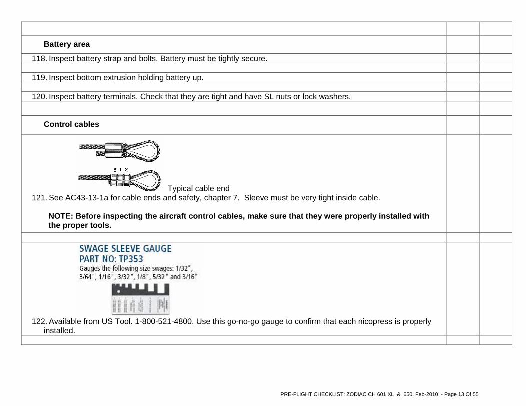
122. Available from US Tool. 1-800-521-4800. Use this go-no-go gauge to confirm that each nicopress is properly
installed.

PRE-FLIGHT CHECKLIST: ZODIAC CH 601 XL & 650. Feb-2010 - Page 14 Of 55
123. Use a calibrated cable gauge. Squeeze ball handle, put gauge on cable, release handle, and read tension on
rotation dial. See manufacturer’s manual for specific instructions.
124. When installing safety wire, use the proper tools. This wire twister is available from US Tool
125. Use aviation grade safety wire and proper diameter. Diameter varies on bolt diameter etc.

PRE-FLIGHT CHECKLIST: ZODIAC CH 601 XL & 650. Feb-2010 - Page 15 Of 55
WINGS Left Right
126. Inspect upper and lower wing skins and leading edges for missing rivets, loose fasteners, damage, etc.
127. Inspect wing tip light and area. 128. Inspect the external surfaces of the ailerons and flaps for clearance to wing and each other, missing rivets, and
general condition.
129. Inspect the ailerons at inboard area from bottom, and check for smooth movement. When flight controls are not
locked when parked on the ground, severe wind can do a significant amount of damage to the ailerons, stops, etc. See AMD Notification letter of January 2009.
130. Inspect Pitot tube and area. Confirm that ASI and ALT work.
131. Inspect landing/taxi, and strobe lights. Confirm that they work and are properly positioned.
132. Inspect wing locker (optional) area. Check the piano hinges are safety tied, opening and closing the door is
easy, and check the screws.
Typical root seal is glued to wing and fuselage from rear spar, wrapping around leading edge.
133. Inspect wing root black rubber seal. Check that it is glued to the wing.

PRE-FLIGHT CHECKLIST: ZODIAC CH 601 XL & 650. Feb-2010 - Page 16 Of 55
Ailerons Left Right
134. Inspect aileron bellcrank, rod, rod jam nuts, and cotter pins. Inspect cable ends at bellcrank.
Drawing shows part of the aileron bellcrank inside the wing 135. Bellcrank is held in place with a bolt which goes through a bushing. Make sure that bolt is tight on bushing. Also
make sure that bushing is not rusted and that it is lubricated.

PRE-FLIGHT CHECKLIST: ZODIAC CH 601 XL & 650. Feb-2010 - Page 17 Of 55
136. When inspecting the jam nuts, physically confirm tightness of jam nut with a wrench.
Left Right
137. Make sure that aileron rod end witness holes are in tolerance. Physically test each rod end witness hole with a wire.
View of aileron, from bottom of wing area
138. Inspect the aileron rod for binding at the rod ends. The aileron rod should easily rotate by hand. Lubricate rod ends if not rotating easily.

PRE-FLIGHT CHECKLIST: ZODIAC CH 601 XL & 650. Feb-2010 - Page 18 Of 55
139. Inspect safety wire on both ends of aileron piano hinge
Flaps Left Right
Typical safety tie end of piano hinge
140. All piano hinges need to be safety tied at each end. Inspect safety wire on both ends of flap piano hinge.
141. Check lubrication on the aileron and flap hinges. 142. LOWER flap and inspect the steel flap pin going into flap and clearance at fuselage. With flaps down, physically
move the flap up and down by hand lightly. There should be minimal movement.
143. Inspect the clearance between the flap and fuselage while deflecting the flap UP and Down. Flap and steel
torque tube must not contact fuselage side.
Top of wing at O/B flap area 144. Inspect flap “UP” position. Flap must have positive contact with flap stop. There must not be play in the flap
control system with flaps up.

PRE-FLIGHT CHECKLIST: ZODIAC CH 601 XL & 650. Feb-2010 - Page 19 Of 55
145. Left and right flap are connected with a torque tube. Both flaps must be evenly lined up with the top of the wings at the same time.
Flap installation
146. Inspect flap deflection. For all deflections, see AMD Maintenance Manual page 3-10.
Left Right

PRE-FLIGHT CHECKLIST: ZODIAC CH 601 XL & 650. Feb-2010 - Page 20 Of 55
Fuel Left Right
Typical installation of fuel line to gas tank
147. Check for fuel leaks and safety on fuel line hose clamp at fuel tank outlet. Confirm proper installation of fuel
tank finger screen and that hose clamps are safety tied.
148. Use aviation type fuel sealer when installing – reinstalling fuel fittings
149. Drain some fuel from wing fuel tank using sump drain. Check sump drains for leaks and debris.
150. Check fuel tank filler cap for security and condition.
Fuel tank breather tube 151. Inspect gas tank fuel breather. Breather must be cut at 45 Deg. at front of tube. If your gas tank does not have

PRE-FLIGHT CHECKLIST: ZODIAC CH 601 XL & 650. Feb-2010 - Page 21 Of 55
a fuel breather line, make sure that your fuel cap is properly vented.
Typical installation of fuel sender
Left Right
152. Inspect fuel tank sender unit access cover. The cover should be tightly secured to the wing.
153. Calibrate fuel gauge by filling tank in ¼ increments. Adjust calibration by adjusting the fuel sender arm. If sender outlet is leaking, remove unit, and install a new rubber gasket. Aviation fuel type sealer can also be used.
154. From outside aircraft, inspect gascolator. Confirm that gascolator bowl can be removed easily for inspection.
Check wire safety. Make sure that screen is clean and fitted properly.

PRE-FLIGHT CHECKLIST: ZODIAC CH 601 XL & 650. Feb-2010 - Page 22 Of 55
Aileron trim tab
155. Inspect the aileron trim.
156. Inspect trim motor arm. Check jam nut and cotter pin.
157. Move trim up-down full deflection and check deflection.
158. Inspect trim motor arm in full up-down movement for clearances.
159. Inspect the aileron trim electrical wire from aileron to rear wing spar. Check rubber grommets and that wire
does not interfere with aileron movement. Make sure that the cable is not contacting any sharp edges.
FUSELAGE
Main gear area Left Right
160. Inspect the main landing gear left and right steel bracket on fuselage. 161. Inspect gear cut-outs for welded bolts rear-front, L+R. They must be filed smooth. Gear must be tight at bolts,
so that gear does not shift.

PRE-FLIGHT CHECKLIST: ZODIAC CH 601 XL & 650. Feb-2010 - Page 23 Of 55
Narrower type gear spring. Gear attachment area at fuselage
162. Inspect top and bottom rubber pads. They must be centered on the gear supports and must be squeezed tight.
Inspect left and right sides of gear. Note : Torque value on the four bolts, tighten snug. Do not bend bracket / extrusion when tightening. Make sure that the rubber padding, bottom and top, are in place before tightening and that the aircraft is sitting on the gear.
Left Right
163. Inspect left and right rear bottom extrusions and SL nuts. 164. Make sure that gear is centered on the fuselage.
Typical wheel assembly 165. Inspect gear axel, bolts, and nuts.
166. Inspect the left and right axel nut and cotter pin.

PRE-FLIGHT CHECKLIST: ZODIAC CH 601 XL & 650. Feb-2010 - Page 24 Of 55
167. Inspect the left and right brake calipers. Brake assembly must be loose to wheel hub around brake disc. See manufactures recommendations for bolt torque.
168. Inspect the left and right brake fitting at caliper.
169. Inspect brake line at wheel and up to fuselage. Confirm that the lines are not contacting any sharp edges.
170. Inspect brake line entering fuselage. Check grommet and that brake line is not tight or contacting any sharp
edges.
171. Inspect the left and right tire pressure and condition of tire and area.
Rear fuselage (inside) Left Right
Inside rear fuselage, behind seat 172. Check that control cables are only touching fairleads and that the fairleads are not worn by cables. Check left
and right sides, including elevator and rudder cable fairleads, and properly lubricate the fairleads.

PRE-FLIGHT CHECKLIST: ZODIAC CH 601 XL & 650. Feb-2010 - Page 25 Of 55
173. Inspect aileron cables for obstructions. The aileron cables should ONLY make contact with fairleads. If wires, fuel line, pitot tubes, ect. could possibly make contact with the aileron cables, secure the obstruction or reroute the obstruction clear of the aileron cables.
174. Move flap “UP” and “DOWN”. Check clearance at rear spar. 175. Inspect flap torque tube at fuselage sides. Check clearances around the flap torque tube. 176. Inspect flap bolts on torque tubes and flap control arm. 177. Inspect flap motor area and welded bracket riveted to seat channel. Check rivets, bolts, and nuts. 178. Inspect electrical wire at flap motor. Check connection plug and bracket and that plug has silicone. 179. Inspect rear spar channel, upright, and rivets behind seat. 180. Inspect rudder and elevator control cables in rear fuselage.
Rear fuselage (outside)
181. Inspect fuselage bulkheads and stiffeners. Make sure that rivets were properly set.
182. Inspect tail tie down area, bolts, and nuts.
Rudder to fuselage
183. Inspect general condition of the rudder, rivets, etc.
184. Inspect rudder tail light fairing condition and quality of fiberglass fairing.

PRE-FLIGHT CHECKLIST: ZODIAC CH 601 XL & 650. Feb-2010 - Page 26 Of 55
Tail rudder area 185. Inspect rudder top and bottom hinge area, bolts, and bushings.
186. Check deflections of rudder
187. Inspect rudder deflection stops. The rudder horn must contact the stops at full deflection
188. Check that at full deflection the bottom hinge is not touching fuselage hinge.

PRE-FLIGHT CHECKLIST: ZODIAC CH 601 XL & 650. Feb-2010 - Page 27 Of 55
189. Check at full deflection, the rudder front fairing is not contacting anything.
Nose wheel area 190. Note: In order to have smooth rudder controls, make sure that the nose wheel strut is not tight when moving the
rudder pedals. Test by lowering the rear fuselage and with your hands, move the nose wheel left and right. It should return to the center by itself. If not, oil all the bearings at nose strut and at rudder pedal area. If still tight, loosen the bottom bearing block 6G2-1. If still tight, loosen all other bearings slightly.
Left Right

PRE-FLIGHT CHECKLIST: ZODIAC CH 601 XL & 650. Feb-2010 - Page 28 Of 55
Rudder control cables
191. Inspect rudder control cables and fairleads. Inspect cotter pins.
192. Inspect rudder turnbuckles, safety pins, and threads.
TAIL AREA – Stabilizer / Elevator Left Right
193. Inspect general condition of stabilizer and elevator, including rivets and fiberglass tips
Lining up the stabilizer with the fuselage

PRE-FLIGHT CHECKLIST: ZODIAC CH 601 XL & 650. Feb-2010 - Page 29 Of 55
194. Check that stabilizer is parallel to top of main wing center spar section. The stabilizer should be perpendicular to the aircraft center line and level to the main wing center spar section.
195. Line up top of elevator and stabilizer. Make sure that from left to right side, there is no twist. Elevator trailing
edge must be in line with stabilizer.
196. Inspect stabilizer bolts attaching the tail to the fuselage sides, and 4 brackets riveted to fuselage. Inspect rear
bracket riveted to stabilizer and bolted to fuselage. Check for loose rivets and cracks on all brackets.
197. Inspect piano hinge stabilizer to the elevator. Check safety at ends, lubrication, etc.
198. Inspect elevator control cable ends and cotter pins.
199. Check elevator UP and DOWN deflections.
Left Right

PRE-FLIGHT CHECKLIST: ZODIAC CH 601 XL & 650. Feb-2010 - Page 30 Of 55
Elevator deflection stops Above shows under side of tail area at fuselage.
200. Inspect elevator deflection stops. Note: when checking deflections, someone in the pilot seat must move the controls and the inspector must check at the tail for full movement. This applies to the ailerons, rudder, and elevator.
201. Check cable tension of elevator control cables from inside of fuselage.

PRE-FLIGHT CHECKLIST: ZODIAC CH 601 XL & 650. Feb-2010 - Page 31 Of 55
202. Check that in full “UP” and “DOWN” position the elevator horn does not contact anything.
Left Right
203. Inspect fiberglass saddle and clearance with rudder. Must be checked when elevator and rudder are at full
deflections up-down / left-right.
Elevator
204. Inspect trim motor arm. Check the jam nut and cotter pin.
205. Move trim up and down to full deflection and check deflection angles.

PRE-FLIGHT CHECKLIST: ZODIAC CH 601 XL & 650. Feb-2010 - Page 32 Of 55
CABIN Left Right
Instrument panel area – Behind Instrument panel and firewall area
209. Remove the top skin over the instrument panel or lower your head underneath the panel so that you can get an excellent view of everything.
210. Inspect the overall condition of all items and that they are not rubbing on any sharp edges, etc. 211. Inspect rear of firewall engine mount fittings. Check for cracks, SL nuts, etc.
Engine mount fittings at firewall
212. Welded steel fittings must have the same angles as the firewall as to fit properly. If angles are not the same, steel fittings will be stressed.
206. Inspect trim motor arm in full up and down movement for clearances.
207. Inspect safety wire at trim tab piano hinge ends.
208. Inspect the electrical trim wire from elevator and stabilizer to rear fuselage. Check rubber grommets and wire
does not interfere with elevator movement. Make sure that the cable does not touching any sharp edges and is properly tied.

PRE-FLIGHT CHECKLIST: ZODIAC CH 601 XL & 650. Feb-2010 - Page 33 Of 55
213. Make sure that when cables are routed through the firewall that fire retardant type sealer is used and that no
sharp edges are / can damage the cables, fuel line, electrical wires, etc.
Typical installation of the altimeter, airspeed and vertical speed indicators. Alternate static switch is for IFR operation, which includes a heated pitot spade at wing
214. Pitot static system. Check routing and connections of lines. Check that lines are clear of any sharp edges. Try to minimize low areas in the lines to minimize humidity build up.
Left Right
215. Check that there are no sharp or tight bends in the pitot / static lines.
216. Inspect attachment of encoder.
217. Inspect static line from flight instruments to encoder.
218. Transponder-Encoder and pitot static tests:
FAR 91.411 (...No person may operate an airplane, or helicopter, i n controlled airspace under IFR unless...Within the preceding 24 calendar months, e ach static pressure system, each altimeter instrument, and each automatic pressure a ltitude reporting system has been tested and inspected and found to comply...)
FAR 91.413 (No persons may use an ATC transponder.....unless, w ithin the preceding 24 calendar

PRE-FLIGHT CHECKLIST: ZODIAC CH 601 XL & 650. Feb-2010 - Page 34 Of 55
months, the ATC transponder has been tested and ins pected and found to comply...)
You need to consult with your local airworthiness requirements on this.
Typical installation of instrumentation
219. Inspect ELECTRICAL system behind instrument panel. Check that all electric wires are not contacting any sharp
edges. Check safety ties.
Left Right
220. Inspect rear of avionics and make sure that they are properly attached to instrument panel
221. Inspect avionic wires. Check that they are tied and not close to controls or contacting any sharp edges.

PRE-FLIGHT CHECKLIST: ZODIAC CH 601 XL & 650. Feb-2010 - Page 35 Of 55
222. Inspect headphone jack plugs.
223. Inspect tachometer cable behind instrument panel. Check tightness of cable nut at instrument.
Aluminum brackets are installed from the avionics box to the firewall
224. When installing avionics that extend close to the firewall, it is recommended that aluminum brackets be made and installed from the avionics box to the firewall. This will minimize vibrations and damage to instrument panel
Left Right
225. Inspect throttle and mixture cables behind instrument panel. Check that they are tight at panel.
226. Inspect cabin heat and carburetor heat cables behind instrument panel. Check that they are tight at panel.
227. Inspect fuel primer lines behind instrument panel. Check for clearances and safety ties. Check for fuel leaks.
228. Inspect tightness of primer at instrument panel.

PRE-FLIGHT CHECKLIST: ZODIAC CH 601 XL & 650. Feb-2010 - Page 36 Of 55
Rudder pedal area Left Right
Typical brake line system installation
229. Inspect Rudder Pedal master cylinders. Check for leaks, safety, etc. 230. Inspect (the optional) rudder pedal slave cylinder. Check for leaks, safety, etc. 231. Inspect cylinder cotter pins, top and bottom, and jam nuts. Cylinders must move freely. 232. Inspect brake lines and safety ties. Check that lines are not contacting any sharp edges. 233. Inspect RUDDER pedal center “green” nylon bearing and SL bolts going through the floor. Maintain
proper lubrication on the bearing.
234. Inspect side rudder pedal bearings and SL bolts going through the floor. Maintain proper lubrication on
the bearings.
235. Inspect brake pedals attached to rudder pedals. Check for safety on piano hinge, etc.

PRE-FLIGHT CHECKLIST: ZODIAC CH 601 XL & 650. Feb-2010 - Page 37 Of 55
Typical rudder pedal installation
236. Check firewall clearance of brake pedals with full rudder deflection with brakes applied.
Left Right
237. Inspect Rudder cable ends and cotter pins.
238. Inspect brake lines, safety, and grommets in floor.
239. Check holes in firewall where steering rods go through to nose gear leg. Holes need to be fire sealed.

PRE-FLIGHT CHECKLIST: ZODIAC CH 601 XL & 650. Feb-2010 - Page 38 Of 55
240. With upholstery side panels REMOVED, inspect wire conduits and ties on fuselage sides, LEFT and
RIGHT.
Left Right
241. Inspect fuel line between wing and fuselage. Check position of grommets. Fuel line must not contact any
sharp edges.
242. Inspect fuel lines at fuel selector valve. Check that clamps and fuel lines are tight on barbed fittings.
Fuel selector - 3 way valve set-up

PRE-FLIGHT CHECKLIST: ZODIAC CH 601 XL & 650. Feb-2010 - Page 39 Of 55
243. Inspect fuel selector valve. Check operation and installation screws.
Fuel system 244. Inspect gascolator. Check that silicone is used to seal around gascolator and bottom skin.
Left Right
245. Inspect fuel line going to gascolator in front of seats. 246. Inspect fuel line from gascolator to firewall. Make sure that it does not contact control cables, rudder
pedals, or any sharp edges.
247. Inspect fuel fitting at firewall. Check for fuel leaks.
248. Note that in order to not have water accumulate in the fuel lines, there cannot be any low points in the
fuel lines. The lowest points are at the drains.
249. Inspect fuel line safety clamps and safety wire. Check that clamps and fuel lines are tight on barbed
fittings.
250. Inspect grommets going through main wing spar.

PRE-FLIGHT CHECKLIST: ZODIAC CH 601 XL & 650. Feb-2010 - Page 40 Of 55
Cabin , seats, seatbelts, baggage area
251. Inspect LEFT and RIGHT seat back and bottom condition. Check seat bottom Velcro at front spar. Left Right 252. Inspect seatbelt attachment between seats. 253. Inspect seatbelt attachment on side at fuselage. Check bolt and nut. 254. Inspect seatbelt attachment in baggage area. Check bolts and nuts. 255. Inspect fitting of seatbelt when sitting in seat. Sit in seat and put the seatbelts on and remove. 256. Inspect cabin lights baggage area. Check for operation. 257. Inspect antenna installation and cables.
258. Inspect ELT and that battery life time placard is installed with expiration date.
259. Inspect electrical wiring for condition, security, routing on RIGHT side of fuselage in the cabin area. 260. Inspect electrical wiring for condition, security, routing on LEFT side of fuselage in the cabin area.
261. Check the fire extinguisher (and first aid kit). 262. Inspect electric wires between wing and fuselage. Check grommets and wires should not contact any sharp
edges.
Controls Left Right
263. Inspect straightness of stick(s) with the ailerons in the neutral position. Stick must not get too close to instrument panel when stick is in full forward position.
264. Inspect stick(s) and PPT. Check that stick (s) handle grips do not move. 265. Inspect stick(s) for free movement sideways and front-rear. Upholstery or arm rest must not limit stick movement.
Make sure that moving the control stick to all control limits nothing is touching the control cables or stick.

PRE-FLIGHT CHECKLIST: ZODIAC CH 601 XL & 650. Feb-2010 - Page 41 Of 55
266. Check flight control torque tube bearings and lubrication.
Control stick installation
267. Inspect elevator control cable connections at stick. Upholstery around the stick may have to be removed in order to
properly inspect.
268. Inspect rudder cables going between the seats as you are inspecting the elevator cables. Cables must not rub on
things other than fairleads.

PRE-FLIGHT CHECKLIST: ZODIAC CH 601 XL & 650. Feb-2010 - Page 42 Of 55
Aileron control cables with fairleads
269. Confirm aileron cable tension.
Left Right
270. Inspect rudder and elevator control cables and fairleads at main wing spar area. 271. Inspect control cables for proper clearance between seats. 272. Inspect elevator control cable ends between seats. Inspect cotter pins, turn buckle safety, and threads. 273. Inspect aileron control cable clearance around rudder and elevator cables behind seat. 274. Inspect aileron cable connection at aileron torque tube behind seat. Check cotter pins, turn buckle safety, and
threads.
275. Inspect aileron control turnbuckles for safety pins / wire and for turn buckle thread behind seat.

PRE-FLIGHT CHECKLIST: ZODIAC CH 601 XL & 650. Feb-2010 - Page 43 Of 55
CANOPY Left Right
I 650 canopy latching system inspect and operate
276. Latches from inside the aircraft. It is important that you can properly close the latches when seated.
277. Once the canopy is closed, push up and sideways on the canopy to see if it is truly closed. Also do this from
outside the aircraft.
278. Inspect canopy seals. 279. Inspect general condition of canopy. 280. Inspect side of canopy at front hinges and bolts. 281. Inspect side of canopy installation, flashings, and air vents. 282. Inspect gas strut area. Check top and bottom fittings and cotter pins.

PRE-FLIGHT CHECKLIST: ZODIAC CH 601 XL & 650. Feb-2010 - Page 44 Of 55
283. Canopy gas strut installation with cotter pins. 601 XL and 650
284. Details of the older type 601 XL canopy latching system. Must have positive double locking
Left Right

PRE-FLIGHT CHECKLIST: ZODIAC CH 601 XL & 650. Feb-2010 - Page 45 Of 55
Instrument panel
285. Make sure the colored arcs on your ASI all properly indicate the correct speed limits (CAS). See Appendix 1 of the AMD Service Manual. Incorrect markings could cause you to unintentionally exceed aircraft limitations. Before flying your aircraft, know all the flight limitations including VA. Mark VA on your airspeed indicator (or panel). Remember that all aircraft limitations should be included in your flight manual (POH).
286. Confirm instrument markings and warning notices such as NO SMOKING, NO SPINS, NO AEROBATICS,
etc.
287. Inspect all electrical breakers and markings. Make sure that breaker sizes are as per electrical drawings and
manufacturers recommendations.
INSPECTION OF COMPLETED UPGRADE KIT
288. confirm that the airframe upgrade has been completed. For details of the upgrade, see: http://www.zenithair.com/zodiac/xl/data/6-ZU-DEC9.pdf and http://zenithair.com/news/ntsb-astm-4-09a.html
As per drawings 6-ZU-1, 6-ZU-2, 6-ZU-3, 6-ZU-4 & LAA balanced ailerons. For full inspection use the drawings. Not all upgrade parts are shown in the following photos. To be used for quick check only.

PRE-FLIGHT CHECKLIST: ZODIAC CH 601 XL & 650. Feb-2010 - Page 46 Of 55
289. Confirm that the above correct bolts are used. For bolt torque and technique, see FAA43-13-1B. Note that for torque
values, all airframe bolts are standard AN type except for the wing spar bolts which are NAS type, as shown above. Use 120 to 145 inch/lbs for the wing attachment bolts NAS6205 only.
Left Right
290. Confirm minimum one washer under nut and threads are past nut. Not recommended to add more than 3 washers.
1 under head, 2 under nut.

PRE-FLIGHT CHECKLIST: ZODIAC CH 601 XL & 650. Feb-2010 - Page 47 Of 55
Front of wing area 291.
Left Right
292. Wing tip area
Left Right

PRE-FLIGHT CHECKLIST: ZODIAC CH 601 XL & 650. Feb-2010 - Page 48 Of 55
293. Tip of aileron o/b
294. Top of wing
Left Right

PRE-FLIGHT CHECKLIST: ZODIAC CH 601 XL & 650. Feb-2010 - Page 49 Of 55
295. Under wing at I/B of aileron
296. Fuselage side
Left Right

PRE-FLIGHT CHECKLIST: ZODIAC CH 601 XL & 650. Feb-2010 - Page 50 Of 55
297. Bottom of fuselage, in front of main gear
Left Right
298. Inside cabin area, front of centre spar, looking back

PRE-FLIGHT CHECKLIST: ZODIAC CH 601 XL & 650. Feb-2010 - Page 51 Of 55
299. Cabin seat area, looking forward
Left Right
300. Looking at wing root from bottom of aircraft.

PRE-FLIGHT CHECKLIST: ZODIAC CH 601 XL & 650. Feb-2010 - Page 52 Of 55
301. Rear spar area, under aircraft
Left Right
Rear spar area, at wing root 302. Inspect the rear spar to fuselage attachment bolt, check the bolt is at the proper torque value. Confirm minimum one
washer under nut and threads are past nut.

PRE-FLIGHT CHECKLIST: ZODIAC CH 601 XL & 650. Feb-2010 - Page 53 Of 55
Inside rear fuselage, behind seats 303. Inspect control stick aileron stop in rear fuselage. Move the control stick left and right. Confirm that aileron does touch stop at full deflections. Also confirm that stop at each aileron is touching at the same time as stop in fuselage.
Left Right
304. Inside rear fuselage, behind seats
305. In addition to a normal pre-flight inspection the following must be checked. The AMD POH includes a detailed everyday “pre-fligh t” inspection list. Download at
http://www.newplane.com/amd_downloads/MASTER_AMD_PO H_601_650_Nov-09_at_1320lbs.pdf

PRE-FLIGHT CHECKLIST: ZODIAC CH 601 XL & 650. Feb-2010 - Page 54 Of 55
306. Check all control cable tensions by hand. If in doubt about the cables being properly tensioned, check them with a calibrated cable tension gauge . If necessary, adjust the cable tension to the proper values. If unsure, get a licensed mechanic to check or adjust the cables. WARNING: Do not fly with control cables that are too loose or too tight
307. Check for free play in the aileron control system. When holding the control stick stationary, beyond minor flexing, there should be no free play in the system when gently pushing up or down on the aileron trailing edges. Note that if the ailerons are not locked when the aircraft is parked outside, wind can damage the system. WARNING: Do not fly with loose, sloppy or damaged controls.
308. Check the flaps for positive firm contact with the flap stops when in the “up” (retracted) position. Check for movement by gently pushing up and down on the flap trailing edges. WARNING: The flap system can get damaged if the flaps are stepped on. Do not fly with loose or damaged flaps.
309. When placing luggage/items in the wing lockers, baggage area behind seats, or in other places, check that it is well secured before take-off. WARNING: Do not fly with loose luggage or other items in the aircraft.
310. Check that your canopy closes and latches properly on both sides. If in doubt, add a secondary latching system as recommended by the Australian CAA. If your canopy does open in flight, keep your hands on the controls, lower your speed to approximately 60 knots, keep flying the aircraft and land as soon as practicable. WARNING: Do not try to close the canopy in flight: Fly the aircraft!
311. Note: “Self checkout” is not recommended. Before flying the aircraft, make sure that you have been properly checked out and that you are familiar with all flight limitations and the handling characteristics (feel and responsiveness) of the controls. Remember that, as with any light aircraft, if you encounter unexpected turbulence while cruising, ride it out rather than fight it – and slow down!
312. REMINDER TO PILOTS: Always get to know a new aircraft you plan to fly before taking the controls (this applies to any aircraft). A thorough condition inspection of the aircraft is essential; learn the operating limitations from the POH (and respect them); and get properly checked out to be familiar with the aircraft’s handling qualities.
313. AMD Safety Alerts, Service Bulletins and notices:

PRE-FLIGHT CHECKLIST: ZODIAC CH 601 XL & 650. Feb-2010 - Page 55 Of 55
http://www.newplane.com/amd/CH2000_Service.html Disclaimer:
The above checklist may not properly represent your aircraft. Data and information appearing in this checklist are for educational purposes only. The author is not responsible for any injury or damage resulting from use or reliance of this checklist. For all up-to-date information and documents including drawings and photos, you must contact the aircraft manufacturer. This checklist is not being updated on a regular basis and it therefore not be assumed that any of the above properly represents any aircraft.
Related Documents