PRC-025-1— Generator Relay Loadability 1 of 22 A. Introduction 1. Title: Generator Relay Loadability 2. Number: PRC-025-1 Purpose: To set load-responsive protective relays associated with generation Facilities at a level to prevent unnecessary tripping of generators during a system disturbance for conditions that do not pose a risk of damage to the associated equipment. 3. Applicability: 3.1. Functional Entities: 3.1.1 Generator Owner that applies load-responsive protective relays at the terminals of the Elements listed in 3.2, Facilities. 3.1.2 Transmission Owner that applies load-responsive protective relays at the terminals of the Elements listed in 3.2, Facilities. 3.1.3 Distribution Provider that applies load-responsive protective relays at the terminals of the Elements listed in 3.2, Facilities. 3.2. Facilities: The following Elements associated with Bulk Electric System (BES) generating units and generating plants, including those generating units and generating plants identified as Blackstart Resources in the Transmission Operator’s system restoration plan: 3.2.1 Generating unit(s). 3.2.2 Generator step-up (i.e., GSU) transformer(s). 3.2.3 Unit auxiliary transformer(s) (UAT) that supply overall auxiliary power necessary to keep generating unit(s) online. 1 3.2.4 Elements that connect the GSU transformer(s) to the Transmission system that are used exclusively to export energy directly from a BES generating unit or generating plant. Elements may also supply generating plant loads. 3.2.5 Elements utilized in the aggregation of dispersed power producing resources. 4. Background: After analysis of many of the major disturbances in the last 25 years on the North American interconnected power system, generators have been found to have tripped for conditions that did not apparently pose a direct risk to those generators and associated equipment within the time period where the tripping occurred. This tripping has often been determined to have expanded the scope and/or extended the duration of that 1 These transformers are variably referred to as station power, unit auxiliary transformer(s) (UAT), or station service transformer(s) used to provide overall auxiliary power to the generator station when the generator is running. Loss of these transformers will result in removing the generator from service. Refer to the PRC-025-1 Guidelines and Technical Basis for more detailed information concerning unit auxiliary transformers.

Welcome message from author
This document is posted to help you gain knowledge. Please leave a comment to let me know what you think about it! Share it to your friends and learn new things together.
Transcript
PRC-025-1— Generator Relay Loadability
1 of 22
A. Introduction
1. Title: Generator Relay Loadability
2. Number: PRC-025-1
Purpose: To set load-responsive protective relays associated with generation Facilities at a level to prevent unnecessary tripping of generators during a system disturbance for conditions that do not pose a risk of damage to the associated equipment.
3. Applicability:
3.1. Functional Entities:
3.1.1 Generator Owner that applies load-responsive protective relays at the terminals of the Elements listed in 3.2, Facilities.
3.1.2 Transmission Owner that applies load-responsive protective relays at the terminals of the Elements listed in 3.2, Facilities.
3.1.3 Distribution Provider that applies load-responsive protective relays at the terminals of the Elements listed in 3.2, Facilities.
3.2. Facilities: The following Elements associated with Bulk Electric System (BES) generating units and generating plants, including those generating units and generating plants identified as Blackstart Resources in the Transmission Operator’s system restoration plan:
3.2.1 Generating unit(s).
3.2.2 Generator step-up (i.e., GSU) transformer(s).
3.2.3 Unit auxiliary transformer(s) (UAT) that supply overall auxiliary power necessary to keep generating unit(s) online.1
3.2.4 Elements that connect the GSU transformer(s) to the Transmission system that are used exclusively to export energy directly from a BES generating unit or generating plant. Elements may also supply generating plant loads.
3.2.5 Elements utilized in the aggregation of dispersed power producing resources.
4. Background:
After analysis of many of the major disturbances in the last 25 years on the North American interconnected power system, generators have been found to have tripped for conditions that did not apparently pose a direct risk to those generators and associated equipment within the time period where the tripping occurred. This tripping has often been determined to have expanded the scope and/or extended the duration of that
1 These transformers are variably referred to as station power, unit auxiliary transformer(s) (UAT), or station service transformer(s) used to provide overall auxiliary power to the generator station when the generator is running. Loss of these transformers will result in removing the generator from service. Refer to the PRC-025-1 Guidelines and Technical Basis for more detailed information concerning unit auxiliary transformers.

PRC-025-1— Generator Relay Loadability
2 of 22
disturbance. This was noted to be a serious issue in the August 2003 “blackout” in the northeastern North American continent.2
During the recoverable phase of a disturbance, the disturbance may exhibit a “voltage disturbance” behavior pattern, where system voltage may be widely depressed and may fluctuate. In order to support the system during this transient phase of a disturbance, this standard establishes criteria for setting load-responsive protective relays such that individual generators may provide Reactive Power within their dynamic capability during transient time periods to help the system recover from the voltage disturbance. The premature or unnecessary tripping of generators resulting in the removal of dynamic Reactive Power exacerbates the severity of the voltage disturbance, and as a result changes the character of the system disturbance. In addition, the loss of Real Power could initiate or exacerbate a frequency disturbance.
5. Effective Date: See Implementation Plan
B. Requirements and Measures
R1. Each Generator Owner, Transmission Owner, and Distribution Provider shall apply settings that are in accordance with PRC-025-1 – Attachment 1: Relay Settings, on each load-responsive protective relay while maintaining reliable fault protection. [Violation Risk Factor: High] [Time Horizon: Long-Term Planning]
M1. For each load-responsive protective relay, each Generator Owner, Transmission Owner, and Distribution Provider shall have evidence (e.g., summaries of calculations, spreadsheets, simulation reports, or setting sheets) that settings were applied in accordance with PRC-025-1 – Attachment 1: Relay Settings.
C. Compliance
1. Compliance Monitoring Process
1.1. Compliance Enforcement Authority
As defined in the NERC Rules of Procedure, “Compliance Enforcement Authority” means NERC or the Regional Entity in their respective roles of monitoring and enforcing compliance with the NERC Reliability Standards.
1.2. Evidence Retention
The following evidence retention periods identify the period of time an entity is required to retain specific evidence to demonstrate compliance. For instances where the evidence retention period specified below is shorter than the time since the last audit, the Compliance Enforcement Authority (CEA) may ask an entity to provide other evidence to show that it was compliant for the full time period since the last audit.
2 Interim Report: Causes of the August 14th Blackout in the United States and Canada, U.S.-Canada Power System Outage Task Force, November 2003 (http://www.nerc.com/docs/docs/blackout/814BlackoutReport.pdf)
PRC-025-1— Generator Relay Loadability
3 of 22
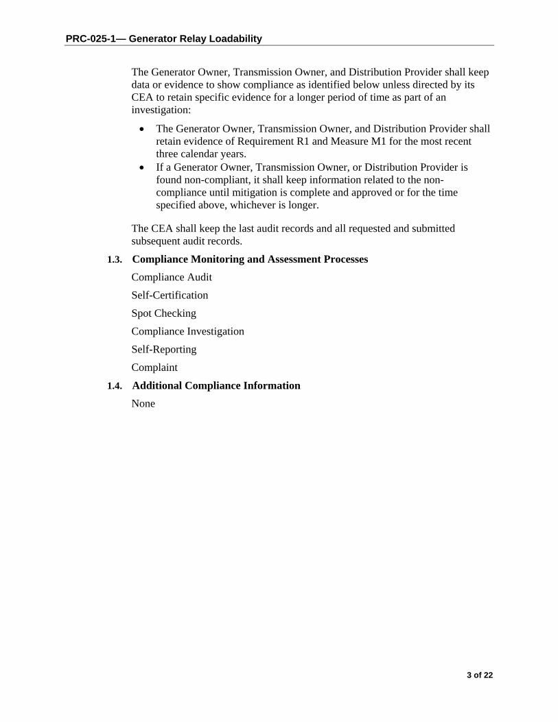
The Generator Owner, Transmission Owner, and Distribution Provider shall keep data or evidence to show compliance as identified below unless directed by its CEA to retain specific evidence for a longer period of time as part of an investigation:
The Generator Owner, Transmission Owner, and Distribution Provider shall retain evidence of Requirement R1 and Measure M1 for the most recent three calendar years.
If a Generator Owner, Transmission Owner, or Distribution Provider is found non-compliant, it shall keep information related to the non-compliance until mitigation is complete and approved or for the time specified above, whichever is longer.
The CEA shall keep the last audit records and all requested and submitted subsequent audit records.
1.3. Compliance Monitoring and Assessment Processes
Compliance Audit
Self-Certification
Spot Checking
Compliance Investigation
Self-Reporting
Complaint
1.4. Additional Compliance Information
None
PRC-025-1— Generator Relay Loadability
4 of 22
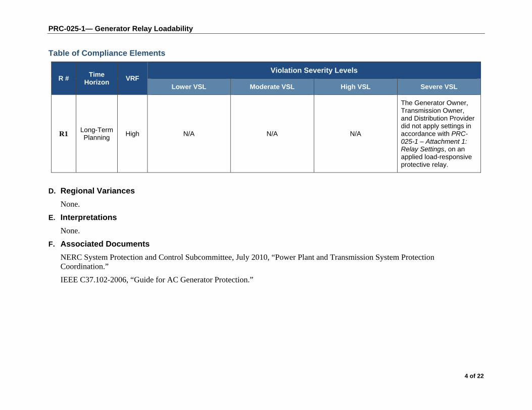
Table of Compliance Elements
R # Time
Horizon VRF
Violation Severity Levels
Lower VSL Moderate VSL High VSL Severe VSL
R1 Long-Term Planning
High N/A N/A N/A
The Generator Owner, Transmission Owner, and Distribution Provider did not apply settings in accordance with PRC-025-1 – Attachment 1: Relay Settings, on an applied load-responsive protective relay.
D. Regional Variances
None.
E. Interpretations
None.
F. Associated Documents
NERC System Protection and Control Subcommittee, July 2010, “Power Plant and Transmission System Protection Coordination.”
IEEE C37.102-2006, “Guide for AC Generator Protection.”
PRC-025-1— Generator Relay Loadability
5 of 22
PRC-025-1 – Attachment 1: Relay Settings
Introduction
This standard does not require the Generator Owner, Transmission Owner, or Distribution Provider to use any of the protective functions listed in Table 1. Each Generator Owner, Transmission Owner, and Distribution Provider that applies load-responsive protective relays on their respective Elements listed in 3.2, Facilities, shall use one of the following Options in Table 1, Relay Loadability Evaluation Criteria (“Table 1”), to set each load-responsive protective relay element according to its application and relay type. The bus voltage is based on the criteria for the various applications listed in Table 1.
Generators
Synchronous generator relay pickup setting criteria values are derived from the unit’s maximum gross Real Power capability, in megawatts (MW), as reported to the Transmission Planner, and the unit’s Reactive Power capability, in megavoltampere-reactive (Mvar), is determined by calculating the MW value based on the unit’s nameplate megavoltampere (MVA) rating at rated power factor. If different seasonal capabilities are reported, the maximum capability shall be used for the purposes of this standard.
Asynchronous generator relay pickup setting criteria values (including inverter-based installations) are derived from the site’s aggregate maximum complex power capability, in MVA, as reported to the Transmission Planner, including the Mvar output of any static or dynamic reactive power devices.
For the application case where synchronous and asynchronous generator types are combined on a generator step-up transformer or on Elements that connect the generator step-up (GSU) transformer(s) to the Transmission system that are used exclusively to export energy directly from a BES generating unit or generating plant (Elements may also supply generating plant loads.), the pickup setting criteria shall be determined by vector summing the pickup setting criteria of each generator type, and using the bus voltage for the given synchronous generator application and relay type.
Transformers
Calculations using the GSU transformer turns ratio shall use the actual tap that is applied (i.e., in service) for GSU transformers with deenergized tap changers (DETC). If load tap changers (LTC) are used, the calculations shall reflect the tap that results in the lowest generator bus voltage. When the criterion specifies the use of the GSU transformer’s impedance, the nameplate impedance at the nominal GSU transformer turns ratio shall be used.
Applications that use more complex topology, such as generators connected to a multiple winding transformer, are not directly addressed by the criteria in Table 1. These topologies can result in complex power flows, and may require simulation to avoid overly conservative assumptions to simplify the calculations. Entities with these topologies should set their relays in such a way that they do not operate for the conditions being addressed in this standard.

PRC-025-1— Generator Relay Loadability
6 of 22
Multiple Lines
Applications that use more complex topology, such as multiple lines that connect the generator step-up (GSU) transformer(s) to the Transmission system that are used exclusively to export energy directly from a BES generating unit or generating plant (Elements may also supply generating plant loads) are not directly addressed by the criteria in Table 1. These topologies can result in complex power flows, and it may require simulation to avoid overly conservative assumptions to simplify the calculations. Entities with these topologies should set their relays in such a way that they do not operate for the conditions being addressed in this standard.
Exclusions
The following protection systems are excluded from the requirements of this standard: 1. Any relay elements that are in service only during start up. 2. Load-responsive protective relay elements that are armed only when the generator is
disconnected from the system, (e.g., non-directional overcurrent elements used in conjunction with inadvertent energization schemes, and open breaker flashover schemes).
3. Phase fault detector relay elements employed to supervise other load-responsive phase distance elements (e.g., in order to prevent false operation in the event of a loss of potential) provided the distance element is set in accordance with the criteria outlined in the standard.
4. Protective relay elements that are only enabled when other protection elements fail (e.g., overcurrent elements that are only enabled during loss of potential conditions).
5. Protective relay elements used only for Special Protection Systems that are subject to one or more requirements in a NERC or Regional Reliability Standard.
6. Protection systems that detect generator overloads that are designed to coordinate with the generator short time capability by utilizing an extremely inverse characteristic set to operate no faster than 7 seconds at 218% of fullload current (e.g., rated armature current), and prevent operation below 115% of full-load current.3
7. Protection systems that detect transformer overloads and are designed only to respond in time periods which allow an operator 15 minutes or greater to respond to overload conditions.
Table 1
Table 1 beginning on the next page is structured and formatted to aid the reader with identifying an option for a given load-responsive protective relay.
The first column identifies the application (e.g., synchronous or asynchronous generators, generator step-up transformers, unit auxiliary transformers, Elements that connect the GSU transformer(s) to the Transmission system that are used exclusively to export energy directly from a BES generating unit or generating plant. Elements may also supply generating plant
3 IEEE C37.102-2006, “Guide for AC Generator Protection,” Section 4.1.1.2.
PRC-025-1— Generator Relay Loadability
7 of 22
loads). Dark blue horizontal bars, excluding the header which repeats at the top of each page, demarcate the various applications.
The second column identifies the load-responsive protective relay (e.g., 21, 50, 51, 51V-C, 51V-R, or 67) according to the applied application in the first column. A light blue horizontal bar between the relay types is the demarcation between relay types for a given application. These light blue bars will contain no text.
The third column uses numeric and alphabetic options (i.e., index numbering) to identify the available options for setting load-responsive protective relays according to the application and applied relay type. Another, shorter, light blue bar contains the word “OR,” and reveals to the reader that the relay for that application has one or more options (i.e., “ways”) to determine the bus voltage and pickup setting criteria in the fourth and fifth column, respectively. The bus voltage column and pickup setting criteria columns provide the criteria for determining an appropriate setting.
The table is further formatted by shading groups of relays associated with asynchronous generator applications. Synchronous generator applications and the unit auxiliary transformer applications are not shaded. Also, intentional buffers were added to the table such that similar options, as possible, would be paired together on a per page basis. Note that some applications may have an additional pairing that might occur on adjacent pages.
PRC-025-1— Generator Relay Loadability
8 of 22
Table 1. Relay Loadability Evaluation Criteria
Application Relay Type Option Bus Voltage4 Pickup Setting Criteria
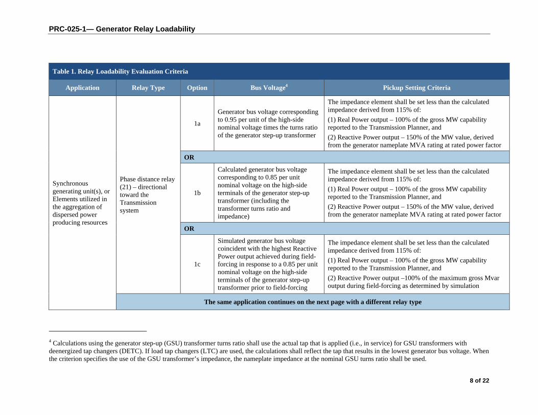
Synchronous generating unit(s), or Elements utilized in the aggregation of dispersed power producing resources
Phase distance relay (21) – directional toward the Transmission system
1a
Generator bus voltage corresponding to 0.95 per unit of the high-side nominal voltage times the turns ratio of the generator step-up transformer
The impedance element shall be set less than the calculated impedance derived from 115% of:
(1) Real Power output – 100% of the gross MW capability reported to the Transmission Planner, and
(2) Reactive Power output – 150% of the MW value, derived from the generator nameplate MVA rating at rated power factor
OR
1b
Calculated generator bus voltage corresponding to 0.85 per unit nominal voltage on the high-side terminals of the generator step-up transformer (including the transformer turns ratio and impedance)
The impedance element shall be set less than the calculated impedance derived from 115% of:
(1) Real Power output – 100% of the gross MW capability reported to the Transmission Planner, and
(2) Reactive Power output – 150% of the MW value, derived from the generator nameplate MVA rating at rated power factor
OR
1c
Simulated generator bus voltage coincident with the highest Reactive Power output achieved during field-forcing in response to a 0.85 per unit nominal voltage on the high-side terminals of the generator step-up transformer prior to field-forcing
The impedance element shall be set less than the calculated impedance derived from 115% of:
(1) Real Power output – 100% of the gross MW capability reported to the Transmission Planner, and
(2) Reactive Power output –100% of the maximum gross Mvar output during field-forcing as determined by simulation
The same application continues on the next page with a different relay type
4 Calculations using the generator step-up (GSU) transformer turns ratio shall use the actual tap that is applied (i.e., in service) for GSU transformers with deenergized tap changers (DETC). If load tap changers (LTC) are used, the calculations shall reflect the tap that results in the lowest generator bus voltage. When the criterion specifies the use of the GSU transformer’s impedance, the nameplate impedance at the nominal GSU turns ratio shall be used.

PRC-025-1— Generator Relay Loadability
9 of 22
Table 1. Relay Loadability Evaluation Criteria
Application Relay Type Option Bus Voltage4 Pickup Setting Criteria
Synchronous generating unit(s), or Elements utilized in the aggregation of dispersed power producing resources
Phase time overcurrent relay (51) or (51V-R) – voltage-restrained
2a
Generator bus voltage corresponding to 0.95 per unit of the high-side nominal voltage times the turns ratio of the generator step-up transformer
The overcurrent element shall be set greater than 115% of the calculated current derived from:
(1) Real Power output – 100% of the gross MW capability reported to the Transmission Planner, and
(2) Reactive Power output – 150% of the MW value, derived from the generator nameplate MVA rating at rated power factor
OR
2b
Calculated generator bus voltage corresponding to 0.85 per unit nominal voltage on the high-side terminals of the generator step-up transformer (including the transformer turns ratio and impedance)
The overcurrent element shall be set greater than 115% of the calculated current derived from:
(1) Real Power output – 100% of the gross MW capability reported to the Transmission Planner, and
(2) Reactive Power output – 150% of the MW value, derived from the generator nameplate MVA rating at rated power factor
OR
2c
Simulated generator bus voltage coincident with the highest Reactive Power output achieved during field-forcing in response to a 0.85 per unit nominal voltage on the high-side terminals of the generator step-up transformer prior to field-forcing
The overcurrent element shall be set greater than 115% of the calculated current derived from:
(1) Real Power output – 100% of the gross MW capability reported to the Transmission Planner or, and
(2) Reactive Power output –100% of the maximum gross Mvar output during field-forcing as determined by simulation
The same application continues with a different relay type below
Phase time overcurrent relay (51V-C) – voltage controlled (Enabled to operate as a function of voltage)
3
Generator bus voltage corresponding to 1.0 per unit of the high-side nominal voltage times the turns ratio of the generator step-up transformer
Voltage control setting shall be set less than 75% of the calculated generator bus voltage
A different application starts on the next page

PRC-025-1— Generator Relay Loadability
10 of 22
Table 1. Relay Loadability Evaluation Criteria
Application Relay Type Option Bus Voltage4 Pickup Setting Criteria
Asynchronous generating unit(s) (including inverter-based installations), or Elements utilized in the aggregation of dispersed power producing resources
Phase distance relay (21) – directional toward the Transmission system
4
Generator bus voltage corresponding to 1.0 per unit of the high-side nominal voltage times the turns ratio of the generator step-up transformer
The impedance element shall be set less than the calculated impedance derived from 130% of the maximum aggregate nameplate MVA output at rated power factor (including the Mvar output of any static or dynamic reactive power devices)
Phase time overcurrent relay (51) or (51V-R) – voltage-restrained
5
Generator bus voltage corresponding to 1.0 per unit of the high-side nominal voltage times the turns ratio of the generator step-up transformer
The overcurrent element shall be set greater than 130% of the calculated current derived from the maximum aggregate nameplate MVA output at rated power factor (including the Mvar output of any static or dynamic reactive power devices)
Phase time overcurrent relay (51V-C) – voltage controlled (Enabled to operate as a function of voltage)
6
Generator bus voltage corresponding to 1.0 per unit of the high-side nominal voltage times the turns ratio of the generator step-up transformer
Voltage control setting shall be set less than 75% of the calculated generator bus voltage
A different application starts on the next page
PRC-025-1— Generator Relay Loadability
11 of 22
Table 1. Relay Loadability Evaluation Criteria
Application Relay Type Option Bus Voltage4 Pickup Setting Criteria
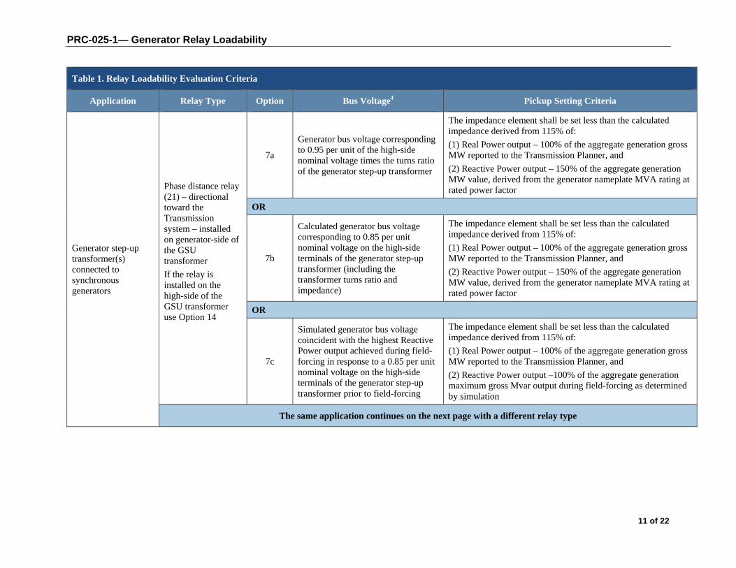
Generator step-up transformer(s) connected to synchronous generators
Phase distance relay (21) – directional toward the Transmission system – installed on generator-side of the GSU transformer
If the relay is installed on the high-side of the GSU transformer use Option 14
7a
Generator bus voltage corresponding to 0.95 per unit of the high-side nominal voltage times the turns ratio of the generator step-up transformer
The impedance element shall be set less than the calculated impedance derived from 115% of:
(1) Real Power output – 100% of the aggregate generation gross MW reported to the Transmission Planner, and
(2) Reactive Power output – 150% of the aggregate generation MW value, derived from the generator nameplate MVA rating at rated power factor
OR
7b
Calculated generator bus voltage corresponding to 0.85 per unit nominal voltage on the high-side terminals of the generator step-up transformer (including the transformer turns ratio and impedance)
The impedance element shall be set less than the calculated impedance derived from 115% of:
(1) Real Power output – 100% of the aggregate generation gross MW reported to the Transmission Planner, and
(2) Reactive Power output – 150% of the aggregate generation MW value, derived from the generator nameplate MVA rating at rated power factor
OR
7c
Simulated generator bus voltage coincident with the highest Reactive Power output achieved during field-forcing in response to a 0.85 per unit nominal voltage on the high-side terminals of the generator step-up transformer prior to field-forcing
The impedance element shall be set less than the calculated impedance derived from 115% of:
(1) Real Power output – 100% of the aggregate generation gross MW reported to the Transmission Planner, and
(2) Reactive Power output –100% of the aggregate generation maximum gross Mvar output during field-forcing as determined by simulation
The same application continues on the next page with a different relay type
PRC-025-1— Generator Relay Loadability
12 of 22
Table 1. Relay Loadability Evaluation Criteria
Application Relay Type Option Bus Voltage4 Pickup Setting Criteria
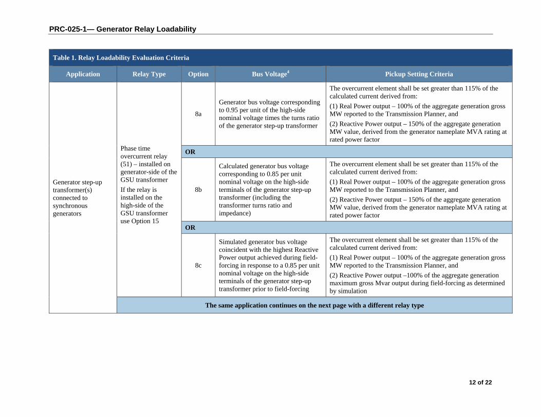
Generator step-up transformer(s) connected to synchronous generators
Phase time overcurrent relay (51) – installed on generator-side of the GSU transformer
If the relay is installed on the high-side of the GSU transformer use Option 15
8a
Generator bus voltage corresponding to 0.95 per unit of the high-side nominal voltage times the turns ratio of the generator step-up transformer
The overcurrent element shall be set greater than 115% of the calculated current derived from:
(1) Real Power output – 100% of the aggregate generation gross MW reported to the Transmission Planner, and
(2) Reactive Power output – 150% of the aggregate generation MW value, derived from the generator nameplate MVA rating at rated power factor
OR
8b
Calculated generator bus voltage corresponding to 0.85 per unit nominal voltage on the high-side terminals of the generator step-up transformer (including the transformer turns ratio and impedance)
The overcurrent element shall be set greater than 115% of the calculated current derived from:
(1) Real Power output – 100% of the aggregate generation gross MW reported to the Transmission Planner, and
(2) Reactive Power output – 150% of the aggregate generation MW value, derived from the generator nameplate MVA rating at rated power factor
OR
8c
Simulated generator bus voltage coincident with the highest Reactive Power output achieved during field-forcing in response to a 0.85 per unit nominal voltage on the high-side terminals of the generator step-up transformer prior to field-forcing
The overcurrent element shall be set greater than 115% of the calculated current derived from:
(1) Real Power output – 100% of the aggregate generation gross MW reported to the Transmission Planner, and
(2) Reactive Power output –100% of the aggregate generation maximum gross Mvar output during field-forcing as determined by simulation
The same application continues on the next page with a different relay type

PRC-025-1— Generator Relay Loadability
13 of 22
Table 1. Relay Loadability Evaluation Criteria
Application Relay Type Option Bus Voltage4 Pickup Setting Criteria
Generator step-up transformer(s) connected to synchronous generators
Phase directional time overcurrent relay (67) – directional toward the Transmission system – installed on generator-side of the GSU transformer
If the relay is installed on the high-side of the GSU transformer use Option 16
9a
Generator bus voltage corresponding to 0.95 per unit of the high-side nominal voltage times the turns ratio of the generator step-up transformer
The overcurrent element shall be set greater than 115% of the calculated current derived from:
(1) Real Power output – 100% of the aggregate generation gross MW reported to the Transmission Planner, and
(2) Reactive Power output – 150% of the aggregate generation MW value, derived from the generator nameplate MVA rating at rated power factor
OR
9b
Calculated generator bus voltage corresponding to 0.85 per unit nominal voltage on the high-side terminals of the generator step-up transformer (including the transformer turns ratio and impedance)
The overcurrent element shall be set greater than 115% of the calculated current derived from:
(1) Real Power output – 100% of the aggregate generation gross MW reported to the Transmission Planner, and
(2) Reactive Power output – 150% of the aggregate generation MW value, derived from the generator nameplate MVA rating at rated power factor
OR
9c
Simulated generator bus voltage coincident with the highest Reactive Power output achieved during field-forcing in response to a 0.85 per unit nominal voltage on the high-side terminals of the generator step-up transformer prior to field-forcing
The overcurrent element shall be set greater than 115% of the calculated current derived from:
(1) Real Power output – 100% of the aggregate generation gross MW reported to the Transmission Planner, and
(2) Reactive Power output –100% of the aggregate generation maximum gross Mvar output during field-forcing as determined by simulation
A different application starts on the next page
PRC-025-1— Generator Relay Loadability
14 of 22
Table 1. Relay Loadability Evaluation Criteria
Application Relay Type Option Bus Voltage4 Pickup Setting Criteria
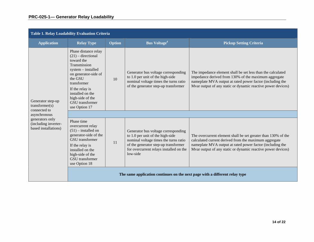
Generator step-up transformer(s) connected to asynchronous generators only (including inverter-based installations)
Phase distance relay (21) – directional toward the Transmission system – installed on generator-side of the GSU transformer
If the relay is installed on the high-side of the GSU transformer use Option 17
10
Generator bus voltage corresponding to 1.0 per unit of the high-side nominal voltage times the turns ratio of the generator step-up transformer
The impedance element shall be set less than the calculated impedance derived from 130% of the maximum aggregate nameplate MVA output at rated power factor (including the Mvar output of any static or dynamic reactive power devices)
Phase time overcurrent relay (51) – installed on generator-side of the GSU transformer
If the relay is installed on the high-side of the GSU transformer use Option 18
11
Generator bus voltage corresponding to 1.0 per unit of the high-side nominal voltage times the turns ratio of the generator step-up transformer for overcurrent relays installed on the low-side
The overcurrent element shall be set greater than 130% of the calculated current derived from the maximum aggregate nameplate MVA output at rated power factor (including the Mvar output of any static or dynamic reactive power devices)
The same application continues on the next page with a different relay type

PRC-025-1— Generator Relay Loadability
15 of 22
Table 1. Relay Loadability Evaluation Criteria
Application Relay Type Option Bus Voltage4 Pickup Setting Criteria
Generator step-up transformer(s) connected to asynchronous generators only (including inverter-based installations)
Phase directional time overcurrent relay (67) – directional toward the Transmission system – installed on generator-side of the GSU transformer
If the relay is installed on the high-side of the GSU transformer use Option 19
12
Generator bus voltage corresponding to 1.0 per unit of the high-side nominal voltage times the turns ratio of the generator step-up transformer
The overcurrent element shall be set greater than 130% of the calculated current derived from the maximum aggregate nameplate MVA output at rated power factor (including the Mvar output of any static or dynamic reactive power devices)
A different application starts below
Unit auxiliary transformer(s) (UAT)
Phase time overcurrent relay (51) applied at the high-side terminals of the UAT, for which operation of the relay will cause the associated generator to trip.
13a 1.0 per unit of the winding nominal voltage of the unit auxiliary transformer
The overcurrent element shall be set greater than 150% of the calculated current derived from the unit auxiliary transformer maximum nameplate MVA rating
OR
13b Unit auxiliary transformer bus voltage corresponding to the measured current
The overcurrent element shall be set greater than 150% of the unit auxiliary transformer measured current at the generator maximum gross MW capability reported to the Transmission Planner
A different application starts on the next page
PRC-025-1— Generator Relay Loadability
16 of 22
Table 1. Relay Loadability Evaluation Criteria
Application Relay Type Option Bus Voltage4 Pickup Setting Criteria
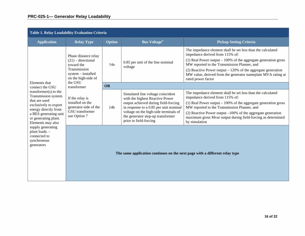
Elements that connect the GSU transformer(s) to the Transmission system that are used exclusively to export energy directly from a BES generating unit or generating plant. Elements may also supply generating plant loads. –connected to synchronous generators
Phase distance relay (21) – directional toward the Transmission system – installed on the high-side of the GSU transformer
If the relay is installed on the generator-side of the GSU transformer use Option 7
14a 0.85 per unit of the line nominal voltage
The impedance element shall be set less than the calculated impedance derived from 115% of:
(1) Real Power output – 100% of the aggregate generation gross MW reported to the Transmission Planner, and
(2) Reactive Power output – 120% of the aggregate generation MW value, derived from the generator nameplate MVA rating at rated power factor
OR
14b
Simulated line voltage coincident with the highest Reactive Power output achieved during field-forcing in response to a 0.85 per unit nominal voltage on the high-side terminals of the generator step-up transformer prior to field-forcing
The impedance element shall be set less than the calculated impedance derived from 115% of:
(1) Real Power output – 100% of the aggregate generation gross MW reported to the Transmission Planner, and
(2) Reactive Power output –100% of the aggregate generation maximum gross Mvar output during field-forcing as determined by simulation
The same application continues on the next page with a different relay type

PRC-025-1— Generator Relay Loadability
17 of 22
Table 1. Relay Loadability Evaluation Criteria
Application Relay Type Option Bus Voltage4 Pickup Setting Criteria
Elements that connect the GSU transformer(s) to the Transmission system that are used exclusively to export energy directly from a BES generating unit or generating plant. Elements may also supply generating plant loads. –connected to synchronous generators
Phase overcurrent supervisory element (50) – associated with current-based, communication-assisted schemes where the scheme is capable of tripping for loss of communications installed on the high-side of the GSU transformer or phase time overcurrent relay (51) – installed on the high-side of the GSU transformer
If the relay is installed on the generator-side of the GSU transformer use Option 8
15a 0.85 per unit of the line nominal voltage
The overcurrent element shall be set greater than 115% of the calculated current derived from:
(1) Real Power output – 100% of the aggregate generation gross MW reported to the Transmission Planner, and
(2) Reactive Power output – 120% of the aggregate generation MW value, derived from the generator nameplate MVA rating at rated power factor
OR
15b
Simulated line voltage coincident with the highest Reactive Power output achieved during field-forcing in response to a 0.85 per unit nominal voltage on the high-side terminals of the generator step-up transformer prior to field-forcing
The overcurrent element shall be set greater than 115% of the calculated current derived from:
(1) Real Power output – 100% of the aggregate generation gross MW reported to the Transmission Planner, and
(2) Reactive Power output –100% of the aggregate generation maximum gross Mvar output during field-forcing as determined by simulation
The same application continues on the next page with a different relay type
PRC-025-1— Generator Relay Loadability
18 of 22
Table 1. Relay Loadability Evaluation Criteria
Application Relay Type Option Bus Voltage4 Pickup Setting Criteria
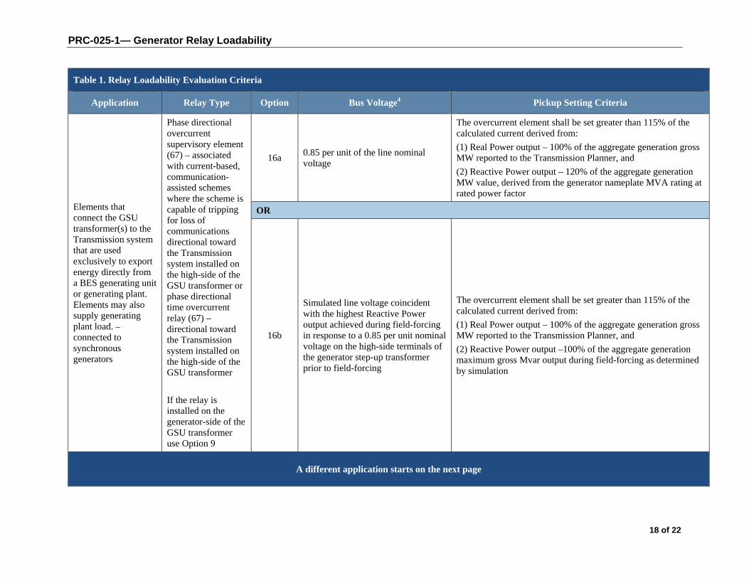
Elements that connect the GSU transformer(s) to the Transmission system that are used exclusively to export energy directly from a BES generating unit or generating plant. Elements may also supply generating plant load. –connected to synchronous generators
Phase directional overcurrent supervisory element (67) – associated with current-based, communication-assisted schemes where the scheme is capable of tripping for loss of communications directional toward the Transmission system installed on the high-side of the GSU transformer or phase directional time overcurrent relay (67) – directional toward the Transmission system installed on the high-side of the GSU transformer
If the relay is installed on the generator-side of the GSU transformer use Option 9
16a 0.85 per unit of the line nominal voltage
The overcurrent element shall be set greater than 115% of the calculated current derived from:
(1) Real Power output – 100% of the aggregate generation gross MW reported to the Transmission Planner, and
(2) Reactive Power output – 120% of the aggregate generation MW value, derived from the generator nameplate MVA rating at rated power factor
OR
16b
Simulated line voltage coincident with the highest Reactive Power output achieved during field-forcing in response to a 0.85 per unit nominal voltage on the high-side terminals of the generator step-up transformer prior to field-forcing
The overcurrent element shall be set greater than 115% of the calculated current derived from:
(1) Real Power output – 100% of the aggregate generation gross MW reported to the Transmission Planner, and
(2) Reactive Power output –100% of the aggregate generation maximum gross Mvar output during field-forcing as determined by simulation
A different application starts on the next page
PRC-025-1— Generator Relay Loadability
19 of 22
Table 1. Relay Loadability Evaluation Criteria
Application Relay Type Option Bus Voltage4 Pickup Setting Criteria
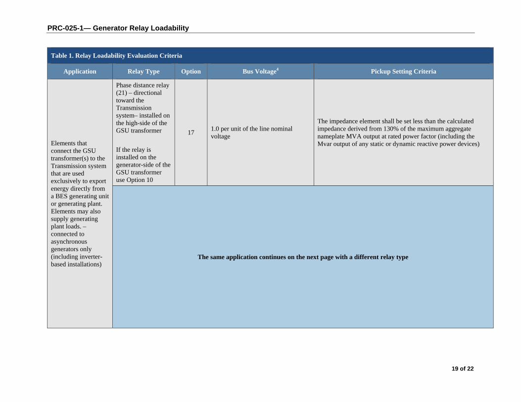
Elements that connect the GSU transformer(s) to the Transmission system that are used exclusively to export energy directly from a BES generating unit or generating plant. Elements may also supply generating plant loads. –connected to asynchronous generators only (including inverter-based installations)
Phase distance relay (21) – directional toward the Transmission system– installed on the high-side of the GSU transformer
If the relay is installed on the generator-side of the GSU transformer use Option 10
17 1.0 per unit of the line nominal voltage
The impedance element shall be set less than the calculated impedance derived from 130% of the maximum aggregate nameplate MVA output at rated power factor (including the Mvar output of any static or dynamic reactive power devices)
The same application continues on the next page with a different relay type

PRC-025-1— Generator Relay Loadability
20 of 22
Table 1. Relay Loadability Evaluation Criteria
Application Relay Type Option Bus Voltage4 Pickup Setting Criteria
Elements that connect the GSU transformer(s) to the Transmission system that are used exclusively to export energy directly from a BES generating unit or generating plant. Elements may also supply generating plant loads. – connected to asynchronous generators only (including inverter-based installations)
Phase overcurrent supervisory element (50) – associated with current-based, communication-assisted schemes where the scheme is capable of tripping for loss of communications installed on the high-side of the GSU transformer or Phase time overcurrent relay (51) – installed on the high-side of the GSU transformer
If the relay is installed on the generator-side of the GSU transformer use Option 11
18 1.0 per unit of the line nominal voltage
The overcurrent element shall be set greater than 130% of the calculated current derived from the maximum aggregate nameplate MVA output at rated power factor (including the Mvar output of any static or dynamic reactive power devices)
The same application continues on the next page with a different relay type
PRC-025-1— Generator Relay Loadability
21 of 22
Table 1. Relay Loadability Evaluation Criteria
Application Relay Type Option Bus Voltage4 Pickup Setting Criteria
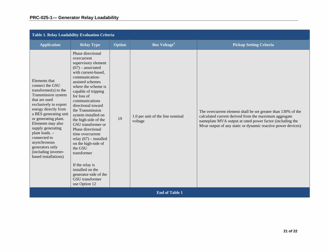
Elements that connect the GSU transformer(s) to the Transmission system that are used exclusively to export energy directly from a BES generating unit or generating plant. Elements may also supply generating plant loads. –connected to asynchronous generators only (including inverter-based installations)
Phase directional overcurrent supervisory element (67) – associated with current-based, communication-assisted schemes where the scheme is capable of tripping for loss of communications directional toward the Transmission system installed on the high-side of the GSU transformer or Phase directional time overcurrent relay (67) – installed on the high-side of the GSU transformer
If the relay is installed on the generator-side of the GSU transformer use Option 12
19 1.0 per unit of the line nominal voltage
The overcurrent element shall be set greater than 130% of the calculated current derived from the maximum aggregate nameplate MVA output at rated power factor (including the Mvar output of any static or dynamic reactive power devices)
End of Table 1
PRC-025-1— Generator Relay Loadability
22 of 22
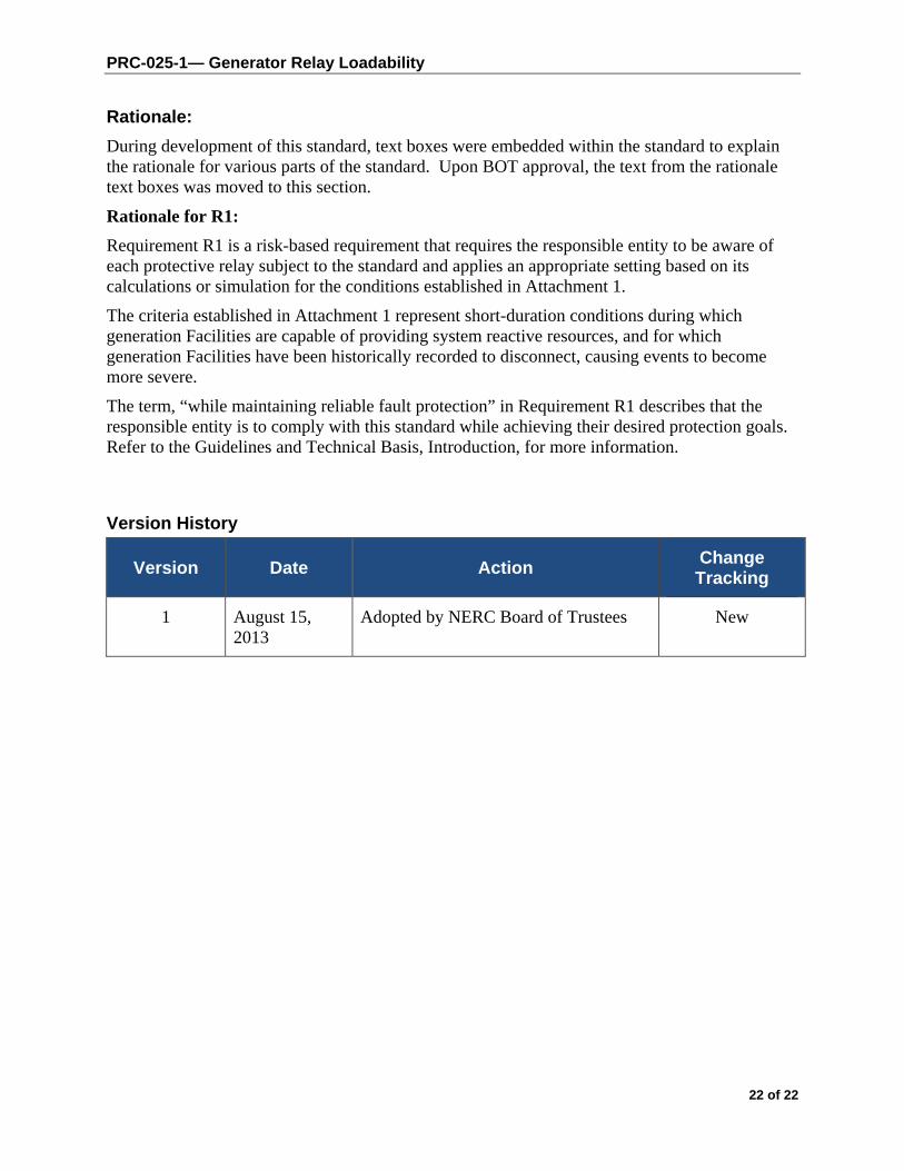
Rationale:
During development of this standard, text boxes were embedded within the standard to explain the rationale for various parts of the standard. Upon BOT approval, the text from the rationale text boxes was moved to this section.
Rationale for R1:
Requirement R1 is a risk-based requirement that requires the responsible entity to be aware of each protective relay subject to the standard and applies an appropriate setting based on its calculations or simulation for the conditions established in Attachment 1.
The criteria established in Attachment 1 represent short-duration conditions during which generation Facilities are capable of providing system reactive resources, and for which generation Facilities have been historically recorded to disconnect, causing events to become more severe.
The term, “while maintaining reliable fault protection” in Requirement R1 describes that the responsible entity is to comply with this standard while achieving their desired protection goals. Refer to the Guidelines and Technical Basis, Introduction, for more information.
Version History
Version Date Action Change Tracking
1 August 15, 2013
Adopted by NERC Board of Trustees New
Standard PRC-025-1 — Generator Relay Loadability
Appendix QC-PRC-025-1 Provisions specific to the standard PRC-025-1 applicable in Québec
Page QC-1 of 3
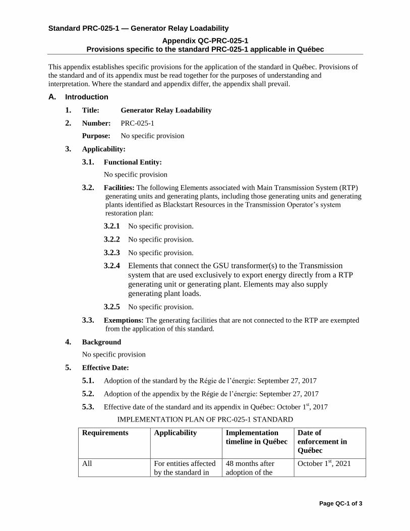
This appendix establishes specific provisions for the application of the standard in Québec. Provisions of
the standard and of its appendix must be read together for the purposes of understanding and
interpretation. Where the standard and appendix differ, the appendix shall prevail.
A. Introduction
1. Title: Generator Relay Loadability
2. Number: PRC-025-1
Purpose: No specific provision
3. Applicability:
3.1. Functional Entity:
No specific provision
3.2. Facilities: The following Elements associated with Main Transmission System (RTP)
generating units and generating plants, including those generating units and generating
plants identified as Blackstart Resources in the Transmission Operator’s system
restoration plan:
3.2.1 No specific provision.
3.2.2 No specific provision.
3.2.3 No specific provision.
3.2.4 Elements that connect the GSU transformer(s) to the Transmission
system that are used exclusively to export energy directly from a RTP
generating unit or generating plant. Elements may also supply
generating plant loads.
3.2.5 No specific provision.
3.3. Exemptions: The generating facilities that are not connected to the RTP are exempted
from the application of this standard.
4. Background
No specific provision
5. Effective Date:
5.1. Adoption of the standard by the Régie de l’énergie: September 27, 2017
5.2. Adoption of the appendix by the Régie de l’énergie: September 27, 2017
5.3. Effective date of the standard and its appendix in Québec: October 1st, 2017
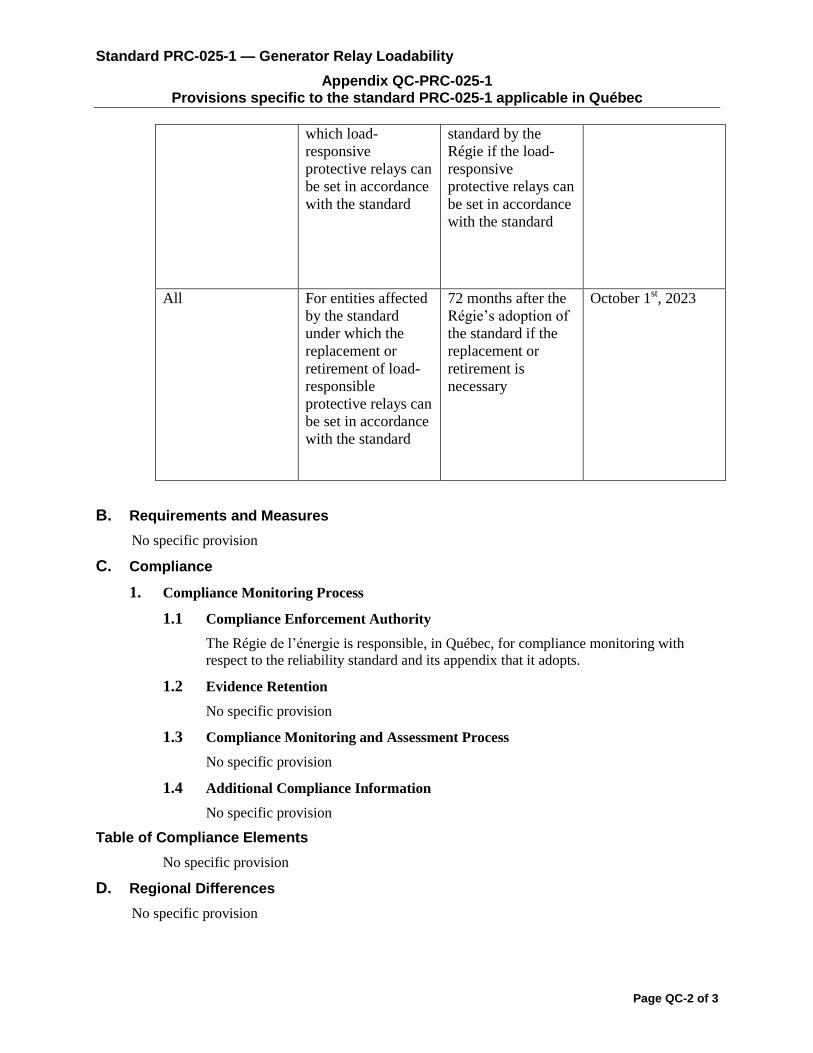
IMPLEMENTATION PLAN OF PRC-025-1 STANDARD
Requirements Applicability Implementation
timeline in Québec
Date of
enforcement in
Québec
All For entities affected
by the standard in
48 months after
adoption of the
October 1st, 2021
Standard PRC-025-1 — Generator Relay Loadability
Appendix QC-PRC-025-1 Provisions specific to the standard PRC-025-1 applicable in Québec
Page QC-2 of 3
which load-
responsive
protective relays can
be set in accordance
with the standard
standard by the
Régie if the load-
responsive
protective relays can
be set in accordance
with the standard
All For entities affected
by the standard
under which the
replacement or
retirement of load-
responsible
protective relays can
be set in accordance
with the standard
72 months after the
Régie’s adoption of
the standard if the
replacement or
retirement is
necessary
October 1st, 2023
B. Requirements and Measures
No specific provision
C. Compliance
1. Compliance Monitoring Process
1.1 Compliance Enforcement Authority
The Régie de l’énergie is responsible, in Québec, for compliance monitoring with
respect to the reliability standard and its appendix that it adopts.
1.2 Evidence Retention
No specific provision
1.3 Compliance Monitoring and Assessment Process
No specific provision
1.4 Additional Compliance Information
No specific provision
Table of Compliance Elements
No specific provision
D. Regional Differences
No specific provision
Standard PRC-025-1 — Generator Relay Loadability
Appendix QC-PRC-025-1 Provisions specific to the standard PRC-025-1 applicable in Québec
Page QC-3 of 3
E. Interpretations
No specific provision
F. Associated documents
No specific provision
PRC-025-1 – Attachment 1: Relays Settings
No specific provision
Table 1
No specific provision
Rationale
No specific provision
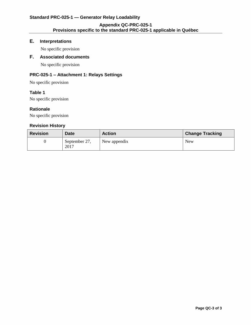
Revision History
Revision Date Action Change Tracking
0 September 27,
2017
New appendix New

Related Documents