EC202-Computer Aided Design amy/khk/jke/puo EC3.1 PRACTICAL EVALUATION FORM NAME:………………………………………………………. CLASS.: ……………… REGISTRATION NO.: ……………………………………… PRACTICAL WORK: 3 APPLICATION OF AUTOCAD PACKAGE IN TECHNICAL AND ELECTRICAL DRAWINGS: THE DRAW COMMANDS AND DRAWING AID COMMANDS No. Skill i. Accuracy ii. Within time frame Excellent (8-10 marks) Average (5-7 Marks) Weak (0-4 Marks) Total 1. Part A: Setting A4 Metric measurement 2. Part E: Exercise Sub-Total /20 No. Report Total 1. Discussions /10 2 Questions /8 3. Reflection /2 Sub-Total /20 Total /40

Welcome message from author
This document is posted to help you gain knowledge. Please leave a comment to let me know what you think about it! Share it to your friends and learn new things together.
Transcript
EC202-Computer Aided Design
amy/khk/jke/puo EC3.1
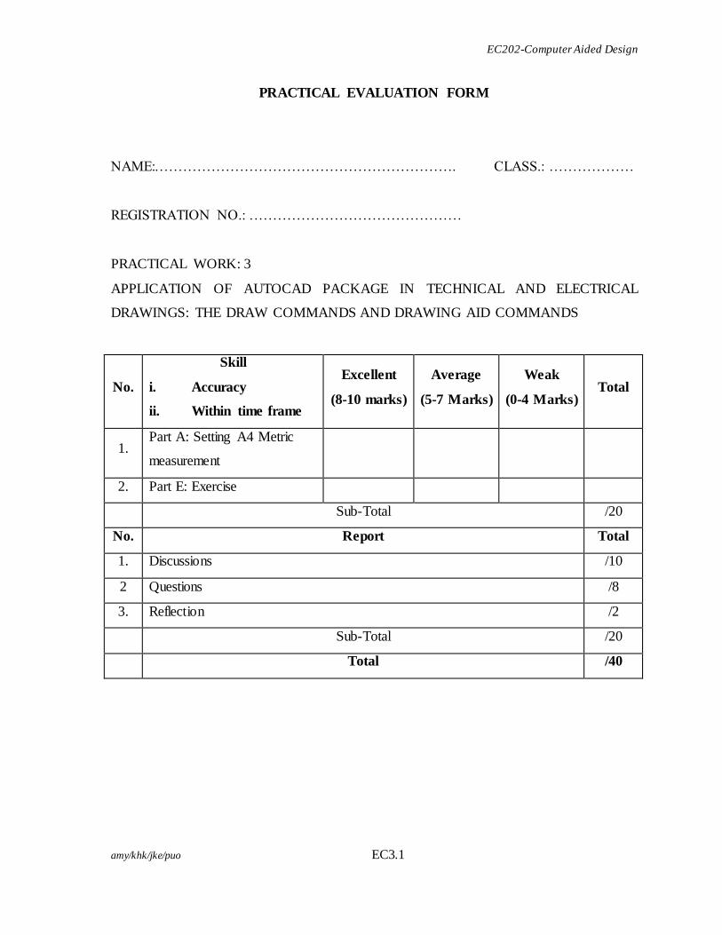
PRACTICAL EVALUATION FORM
NAME:………………………………………………………. CLASS.: ………………
REGISTRATION NO.: ………………………………………
PRACTICAL WORK: 3
APPLICATION OF AUTOCAD PACKAGE IN TECHNICAL AND ELECTRICAL
DRAWINGS: THE DRAW COMMANDS AND DRAWING AID COMMANDS
No.
Skill
i. Accuracy
ii. Within time frame
Excellent
(8-10 marks)
Average
(5-7 Marks)
Weak
(0-4 Marks) Total
1. Part A: Setting A4 Metric
measurement
2. Part E: Exercise
Sub-Total /20
No. Report Total
1. Discussions /10
2 Questions /8
3. Reflection /2
Sub-Total /20
Total /40
EC202-Computer Aided Design
amy/khk/jke/puo EC3.2
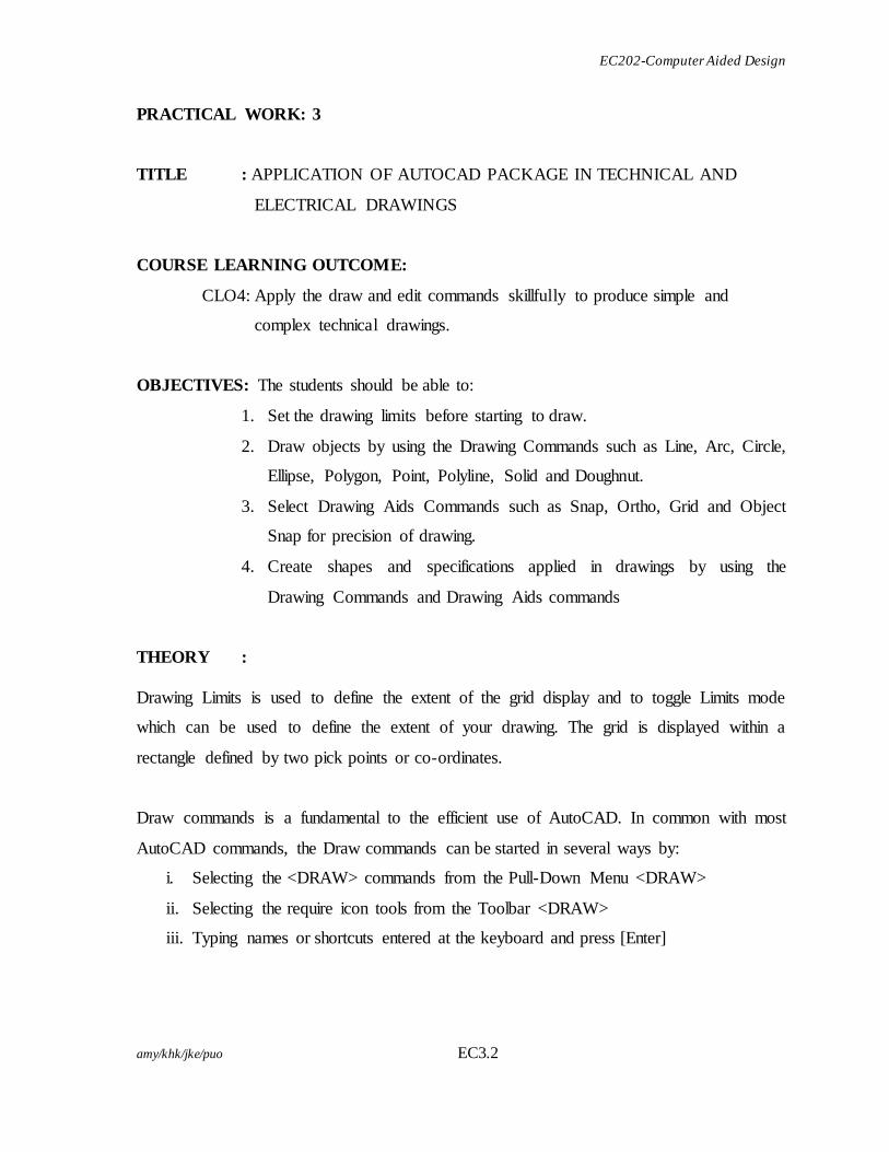
PRACTICAL WORK: 3
TITLE : APPLICATION OF AUTOCAD PACKAGE IN TECHNICAL AND
ELECTRICAL DRAWINGS
COURSE LEARNING OUTCOME:
CLO4: Apply the draw and edit commands skillfully to produce simple and
complex technical drawings.
OBJECTIVES: The students should be able to:
1. Set the drawing limits before starting to draw.
2. Draw objects by using the Drawing Commands such as Line, Arc, Circle,
Ellipse, Polygon, Point, Polyline, Solid and Doughnut.
3. Select Drawing Aids Commands such as Snap, Ortho, Grid and Object
Snap for precision of drawing.
4. Create shapes and specifications applied in drawings by using the
Drawing Commands and Drawing Aids commands
THEORY :
Drawing Limits is used to define the extent of the grid display and to toggle Limits mode
which can be used to define the extent of your drawing. The grid is displayed within a
rectangle defined by two pick points or co-ordinates.
Draw commands is a fundamental to the efficient use of AutoCAD. In common with most
AutoCAD commands, the Draw commands can be started in several ways by:
i. Selecting the <DRAW> commands from the Pull-Down Menu <DRAW>
ii. Selecting the require icon tools from the Toolbar <DRAW>
iii. Typing names or shortcuts entered at the keyboard and press [Enter]
EC202-Computer Aided Design
amy/khk/jke/puo EC3.3
Drawing Aids commands such as the SNAP, GRID and ORTHO mode buttons which can be
seen at the Status Bar and the Object Snap Toolbar are analogous to traditional drafting
tools. Just as you have a parallel motion and set squares to help you draw horizontal and
vertical lines on a drawing board, AutoCAD has similar drawing aids which can help you to
draw horizontal and vertical lines on a computer.
EQUIPMENT : 1. Desktop Computer/Laptop
2. AutoCAD 2004 Software
PROCEDURE :
Part A: Start the AutoCAD program
1. Create a New drawing.
2. Set the drawing measurement to metric..
3. Display the grid to the extent of drawing limits.
Part B: Determining drawing limits
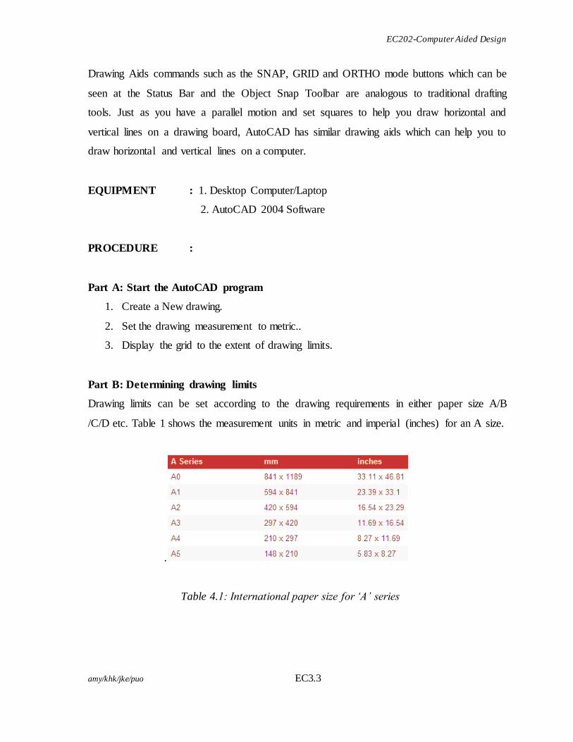
Drawing limits can be set according to the drawing requirements in either paper size A/B
/C/D etc. Table 1 shows the measurement units in metric and imperial (inches) for an A size.
.
Table 4.1: International paper size for ‘A’ series
EC202-Computer Aided Design
amy/khk/jke/puo EC3.4
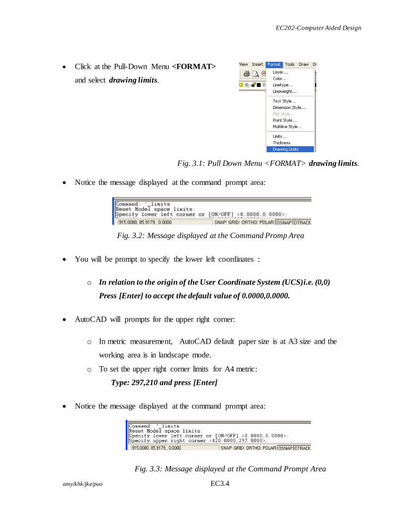
Click at the Pull-Down Menu <FORMAT>
and select drawing limits.
Fig. 3.1: Pull Down Menu <FORMAT> drawing limits.
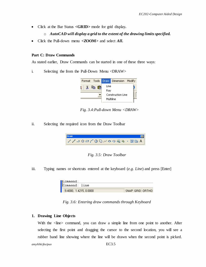
Notice the message displayed at the command prompt area:
Fig. 3.2: Message displayed at the Command Promp Area
You will be prompt to specify the lower left coordinates :
o In relation to the origin of the User Coordinate System (UCS)i.e. (0,0)
Press [Enter] to accept the default value of 0.0000,0.0000.
AutoCAD will prompts for the upper right corner:
o In metric measurement, AutoCAD default paper size is at A3 size and the
working area is in landscape mode.
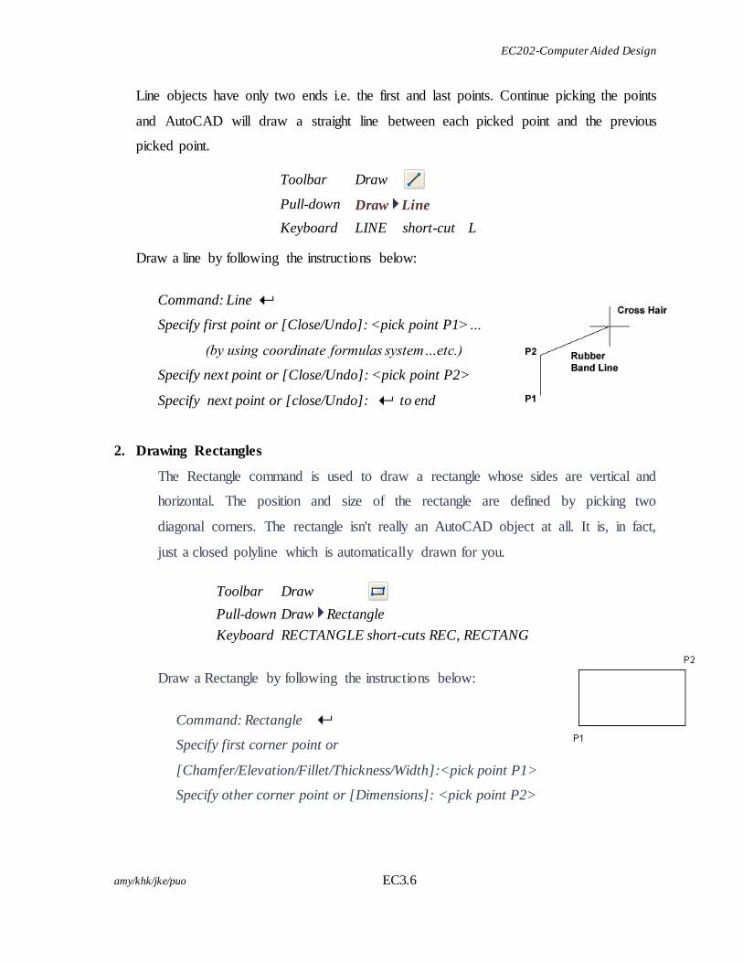
o To set the upper right corner limits for A4 metric:
Type: 297,210 and press [Enter]
Notice the message displayed at the command prompt area:
Fig. 3.3: Message displayed at the Command Prompt Area
EC202-Computer Aided Design
amy/khk/jke/puo EC3.5
Click at the Bar Status <GRID> mode for grid display.
o AutoCAD will display a grid to the extent of the drawing limits specified.
Click the Pull-down menu <ZOOM> and select All.
Part C: Draw Commands
As stated earlier, Draw Commands can be started in one of these three ways:
i. Selecting the from the Pull-Down Menu <DRAW>
Fig. 3.4:Pull-down Menu <DRAW>
ii. Selecting the required icon from the Draw Toolbar
Fig. 3.5: Draw Toolbar
iii. Typing names or shortcuts entered at the keyboard (e.g. Line) and press [Enter]
Fig. 3.6: Entering draw commands through Keyboard
1. Drawing Line Objects
With the <line> command, you can draw a simple line from one point to another. After
selecting the first point and dragging the cursor to the second location, you will see a
rubber band line showing where the line will be drawn when the second point is picked.
EC202-Computer Aided Design
amy/khk/jke/puo EC3.6
Line objects have only two ends i.e. the first and last points. Continue picking the points
and AutoCAD will draw a straight line between each picked point and the previous
picked point.
Toolbar Draw
Pull-down Draw Line
Keyboard LINE short-cut L
Draw a line by following the instructions below:
Command: Line
Specify first point or [Close/Undo]: <pick point P1>…
(by using coordinate formulas system…etc.)
Specify next point or [Close/Undo]: <pick point P2>
Specify next point or [close/Undo]: to end
2. Drawing Rectangles
The Rectangle command is used to draw a rectangle whose sides are vertical and
horizontal. The position and size of the rectangle are defined by picking two
diagonal corners. The rectangle isn't really an AutoCAD object at all. It is, in fact,
just a closed polyline which is automatically drawn for you.
Draw a Rectangle by following the instructions below:
Command: Rectangle
Specify first corner point or
[Chamfer/Elevation/Fillet/Thickness/Width]:<pick point P1>
Specify other corner point or [Dimensions]: <pick point P2>
Toolbar Draw
Pull-down Draw Rectangle
Keyboard RECTANGLE short-cuts REC, RECTANG
EC202-Computer Aided Design
amy/khk/jke/puo EC3.7
This method provides a good alternative to using relative cartesian coordinates for determining length and width.
Notice that, instead of picking a second point to draw the rectangle, you have the
option of entering dimensions. For example, draw a rectangle 20 units long and 10
units wide. The command sequence would look like this:
Command: Rectangle
Specify first corner point or
[Chamfer/Elevation/ Fillet/Thickness/Width]:
(pick point P1)
Specify other corner point or [Dimensions]: @20,10
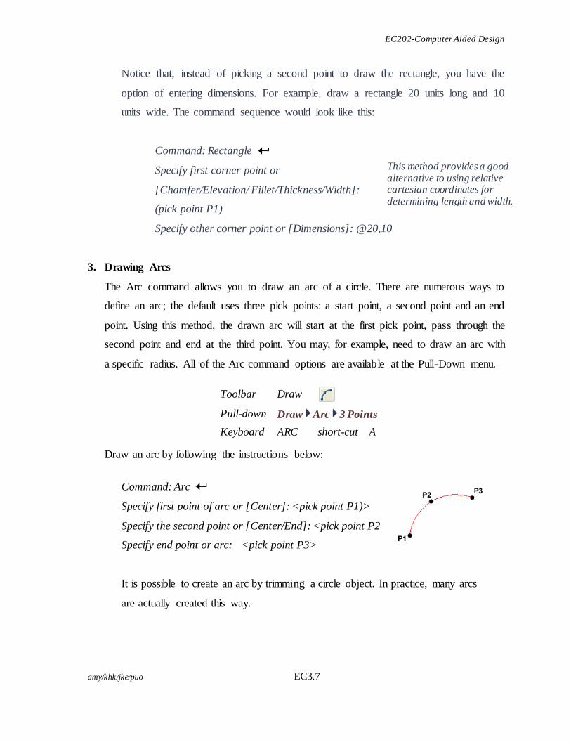
3. Drawing Arcs
The Arc command allows you to draw an arc of a circle. There are numerous ways to
define an arc; the default uses three pick points: a start point, a second point and an end
point. Using this method, the drawn arc will start at the first pick point, pass through the
second point and end at the third point. You may, for example, need to draw an arc with
a specific radius. All of the Arc command options are available at the Pull-Down menu.
Toolbar Draw
Pull-down Draw Arc 3 Points
Keyboard ARC short-cut A
Draw an arc by following the instructions below:
Command: Arc
Specify first point of arc or [Center]: <pick point P1)>
Specify the second point or [Center/End]: <pick point P2>
Specify end point or arc: <pick point P3>
It is possible to create an arc by trimming a circle object. In practice, many arcs
are actually created this way.
EC202-Computer Aided Design
amy/khk/jke/puo EC3.8
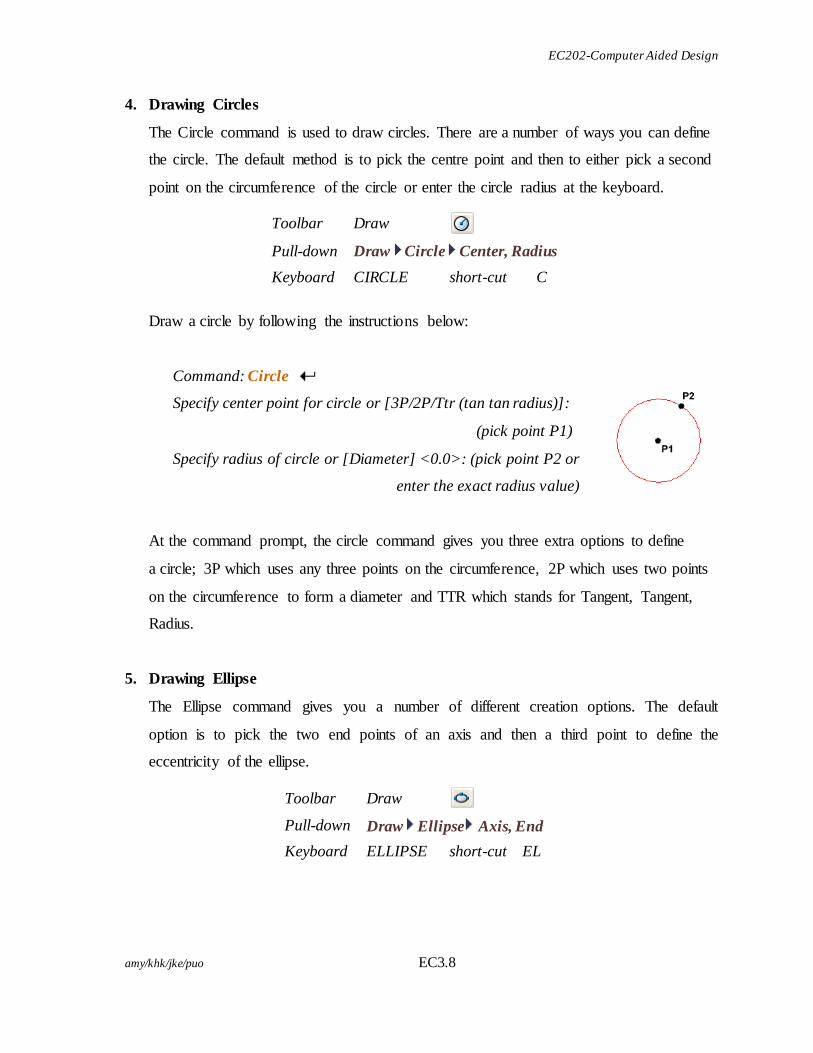
4. Drawing Circles
The Circle command is used to draw circles. There are a number of ways you can define
the circle. The default method is to pick the centre point and then to either pick a second
point on the circumference of the circle or enter the circle radius at the keyboard.
Toolbar Draw
Pull-down Draw Circle Center, Radius
Keyboard CIRCLE short-cut C
Draw a circle by following the instructions below:
Command: Circle
Specify center point for circle or [3P/2P/Ttr (tan tan radius)]:
(pick point P1)
Specify radius of circle or [Diameter] <0.0>: (pick point P2 or
enter the exact radius value)
At the command prompt, the circle command gives you three extra options to define
a circle; 3P which uses any three points on the circumference, 2P which uses two points
on the circumference to form a diameter and TTR which stands for Tangent, Tangent,
Radius.
5. Drawing Ellipse
The Ellipse command gives you a number of different creation options. The default
option is to pick the two end points of an axis and then a third point to define the
eccentricity of the ellipse.
Toolbar Draw
Pull-down Draw Ellipse Axis, End
Keyboard ELLIPSE short-cut EL
EC202-Computer Aided Design
amy/khk/jke/puo EC3.9
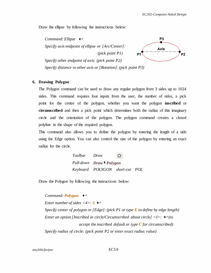
Draw the ellipse by following the instructions below:
Command: Ellipse
Specify axis endpoint of ellipse or [Arc/Center]:
(pick point P1)
Specify other endpoint of axis: (pick point P2)
Specify distance to other axis or [Rotation]: (pick point P3)
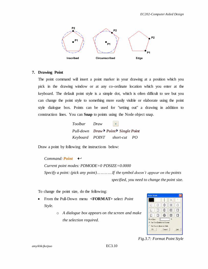
6. Drawing Polygon
The Polygon command can be used to draw any regular polygon from 3 sides up to 1024
sides. This command requires four inputs from the user, the number of sides, a pick
point for the centre of the polygon, whether you want the polygon inscribed or
circumscribed and then a pick point which determines both the radius of this imaginary
circle and the orientation of the polygon. The polygon command creates a closed
polyline in the shape of the required polygon.
This command also allows you to define the polygon by entering the length of a side
using the Edge option. You can also control the size of the polygon by entering an exact
radius for the circle.
Toolbar Draw
Pull-down Draw Polygon
Keyboard POLYGON short-cut POL
Draw the Polygon by following the instructions below:
Command: Polygon
Enter number of sides <4>: 5
Specify center of polygon or [Edge]: (pick P1 or type E to define by edge length)
Enter an option [Inscribed in circle/Circumscribed about circle] <I>: (to
accept the inscribed default or type C for circumscribed)
Specify radius of circle: (pick point P2 or enter exact radius value)
EC202-Computer Aided Design
amy/khk/jke/puo EC3.10
7. Drawing Point
The point command will insert a point marker in your drawing at a position which you
pick in the drawing window or at any co-ordinate location which you enter at the
keyboard. The default point style is a simple dot, which is often difficult to see but you
can change the point style to something more easily visible or elaborate using the point
style dialogue box. Points can be used for "setting out" a drawing in addition to
construction lines. You can Snap to points using the Node object snap.
Toolbar Draw
Pull-down Draw Point Single Point
Keyboard POINT short-cut PO
Draw a point by following the instructions below:
Command: Point
Current point modes: PDMODE=0 PDSIZE=0.0000
Specify a point: (pick any point)………….If the symbol doesn’t appear on the points
specified, you need to change the point size.
To change the point size, do the following:
From the Pull-Down menu <FORMAT> select Point
Style.
o A dialogue box appears on the screen and make
the selection required.
Fig.3.7: Format Point Style
EC202-Computer Aided Design
amy/khk/jke/puo EC3.11
8. Drawing the POLYLINE
The Polyline or Pline command is similar to the line command except that the resulting
object may be composed of a number of segments which form a single object. In
addition to the two ends a polyline is said to have vertices (singular vertex) where
intermediate line segments join. In practice the Polyline command works in the same
way as the Line command allowing you to pick as many points as you like. Again, just
press to end.
As with the Line command, you also have the option to automatically close a polyline
end to end. To do this, type C to use the close option instead of pressing
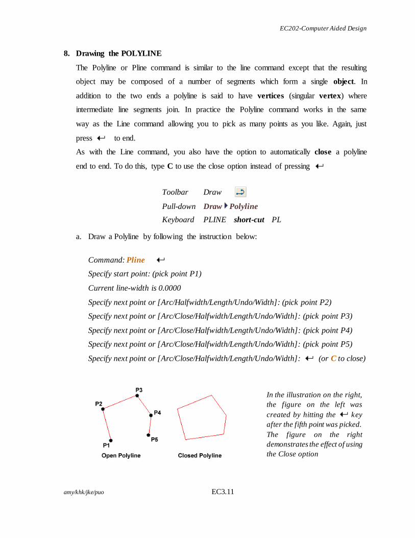
a. Draw a Polyline by following the instruction below:
Command: Pline
Specify start point: (pick point P1)
Current line-width is 0.0000
Specify next point or [Arc/Halfwidth/Length/Undo/Width]: (pick point P2)
Specify next point or [Arc/Close/Halfwidth/Length/Undo/Width]: (pick point P3)
Specify next point or [Arc/Close/Halfwidth/Length/Undo/Width]: (pick point P4)
Specify next point or [Arc/Close/Halfwidth/Length/Undo/Width]: (pick point P5)
Specify next point or [Arc/Close/Halfwidth/Length/Undo/Width]: (or C to close)
Toolbar Draw
Pull-down Draw Polyline
Keyboard PLINE short-cut PL
In the illustration on the right,
the figure on the left was
created by hitting the key
after the fifth point was picked.
The figure on the right
demonstrates the effect of using
the Close option
EC202-Computer Aided Design
amy/khk/jke/puo EC3.12
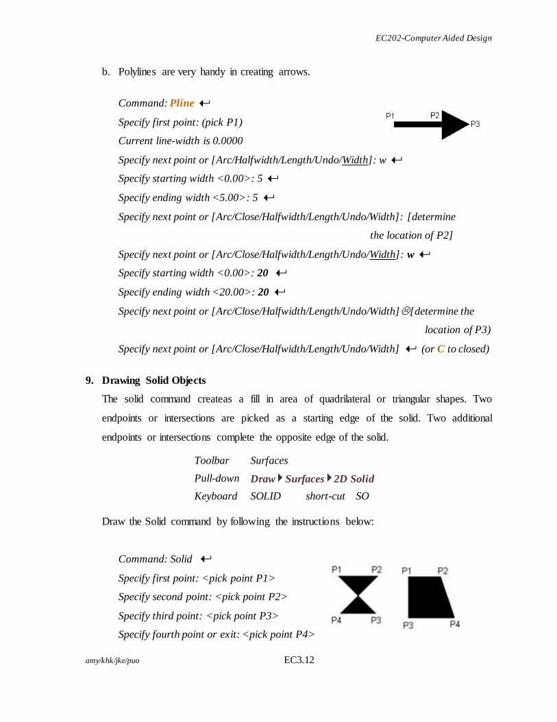
b. Polylines are very handy in creating arrows.
Command: Pline
Specify first point: (pick P1)
Current line-width is 0.0000
Specify next point or [Arc/Halfwidth/Length/Undo/Width]: w
Specify starting width <0.00>: 5
Specify ending width <5.00>: 5
Specify next point or [Arc/Close/Halfwidth/Length/Undo/Width]: [determine
the location of P2]
Specify next point or [Arc/Close/Halfwidth/Length/Undo/Width]: w
Specify starting width <0.00>: 20
Specify ending width <20.00>: 20
Specify next point or [Arc/Close/Halfwidth/Length/Undo/Width][determine the
location of P3)
Specify next point or [Arc/Close/Halfwidth/Length/Undo/Width] (or C to closed)
9. Drawing Solid Objects
The solid command createas a fill in area of quadrilateral or triangular shapes. Two
endpoints or intersections are picked as a starting edge of the solid. Two additional
endpoints or intersections complete the opposite edge of the solid.
Toolbar Surfaces
Pull-down Draw Surfaces 2D Solid
Keyboard SOLID short-cut SO
Draw the Solid command by following the instructions below:
Command: Solid
Specify first point: <pick point P1>
Specify second point: <pick point P2>
Specify third point: <pick point P3>
Specify fourth point or exit: <pick point P4>
EC202-Computer Aided Design
amy/khk/jke/puo EC3.13
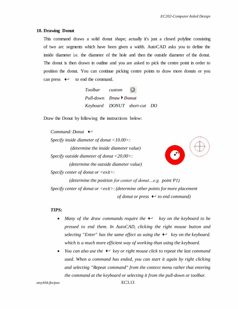
10. Drawing Donut
This command draws a solid donut shape; actually it's just a closed polyline consisting
of two arc segments which have been given a width. AutoCAD asks you to define the
inside diameter i.e. the diameter of the hole and then the outside diameter of the donut.
The donut is then drawn in outline and you are asked to pick the centre point in order to
position the donut. You can continue picking centre points to draw more donuts or you
can press to end the command.
Toolbar custom
Pull-down Draw Donut
Keyboard DONUT short-cut DO
Draw the Donut by following the instructions below:
Command: Donut
Specify inside diameter of donut <10.00>:
(determine the inside diameter value)
Specify outside diameter of donut <20.00>:
(determine the outside diameter value)
Specify center of donut or <exit>:
(determine the position for center of donut…e.g. point P1)
Specify center of donut or <exit>: (determine other points for more placement
of donut or press to end command)
TIPS:
Many of the draw commands require the key on the keyboard to be
pressed to end them. In AutoCAD, clicking the right mouse button and
selecting "Enter" has the same effect as using the key on the keyboard.
which is a much more efficient way of working than using the keyboard.
You can also use the key or right mouse click to repeat the last command
used. When a command has ended, you can start it again by right clicking
and selecting "Repeat command" from the context menu rather that entering
the command at the keyboard or selecting it from the pull-down or toolbar.
EC202-Computer Aided Design
amy/khk/jke/puo EC3.14
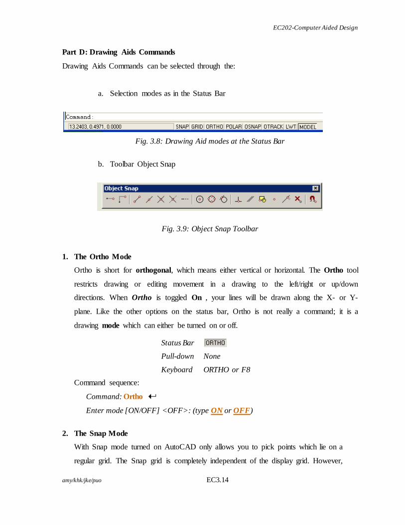
Part D: Drawing Aids Commands
Drawing Aids Commands can be selected through the:
a. Selection modes as in the Status Bar
Fig. 3.8: Drawing Aid modes at the Status Bar
b. Toolbar Object Snap
Fig. 3.9: Object Snap Toolbar
1. The Ortho Mode
Ortho is short for orthogonal, which means either vertical or horizontal. The Ortho tool
restricts drawing or editing movement in a drawing to the left/right or up/down
directions. When Ortho is toggled On , your lines will be drawn along the X- or Y-
plane. Like the other options on the status bar, Ortho is not really a command; it is a
drawing mode which can either be turned on or off.
Status Bar
Pull-down None
Keyboard ORTHO or F8
Command sequence:
Command: Ortho
Enter mode [ON/OFF] <OFF>: (type ON or OFF)
2. The Snap Mode
With Snap mode turned on AutoCAD only allows you to pick points which lie on a
regular grid. The Snap grid is completely independent of the display grid. However,
EC202-Computer Aided Design
amy/khk/jke/puo EC3.15
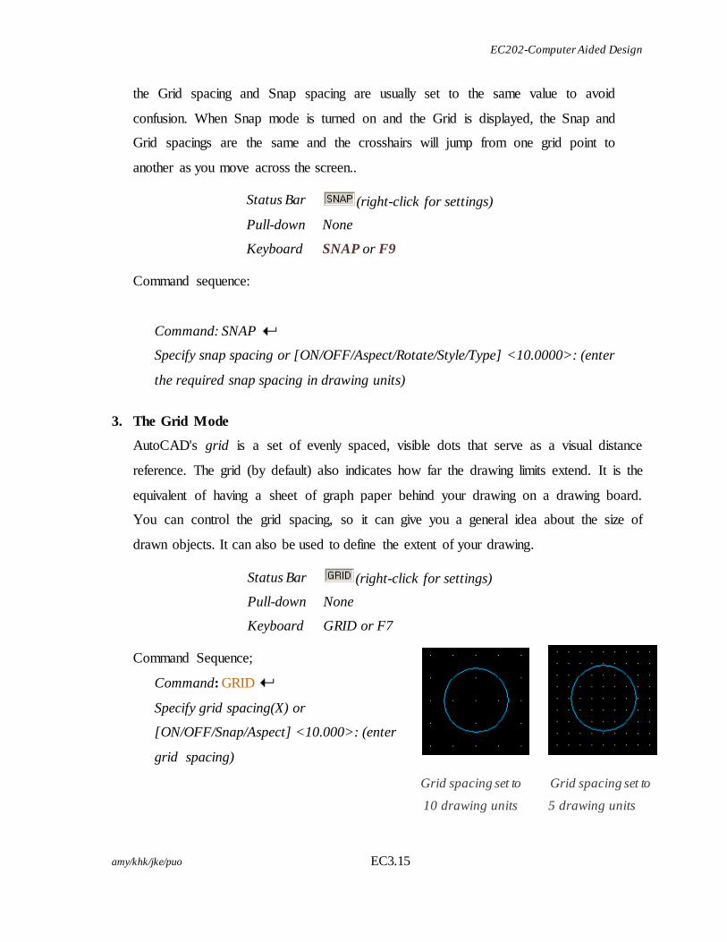
Grid spacing set to
10 drawing units
Grid spacing set to
5 drawing units
the Grid spacing and Snap spacing are usually set to the same value to avoid
confusion. When Snap mode is turned on and the Grid is displayed, the Snap and
Grid spacings are the same and the crosshairs will jump from one grid point to
another as you move across the screen..
Status Bar (right-click for settings)
Pull-down None
Keyboard SNAP or F9 Command sequence:
Command: SNAP
Specify snap spacing or [ON/OFF/Aspect/Rotate/Style/Type] <10.0000>: (enter
the required snap spacing in drawing units)
3. The Grid Mode
AutoCAD's grid is a set of evenly spaced, visible dots that serve as a visual distance
reference. The grid (by default) also indicates how far the drawing limits extend. It is the
equivalent of having a sheet of graph paper behind your drawing on a drawing board.
You can control the grid spacing, so it can give you a general idea about the size of
drawn objects. It can also be used to define the extent of your drawing.
Status Bar (right-click for settings)
Pull-down None
Keyboard GRID or F7 Command Sequence;
Command: GRID
Specify grid spacing(X) or
[ON/OFF/Snap/Aspect] <10.000>: (enter
grid spacing)
EC202-Computer Aided Design
amy/khk/jke/puo EC3.16
The Snap option allows you to automatically set the grid spacing to the current snap
spacing. By default, the X and Y spacing of the Grid are the same, resulting in a regular
square matrix of grid points. But you can display a grid with different X and Y spacing
by using the "Aspect" option.
4. The Object Snap
The Object Snaps (Osnaps for short) are drawing aids which are used in conjunction
with other commands to help you draw accurately. Osnaps allow you to snap onto a
specific object location when you are picking a point.
Osnaps in AutoCAD are so important that you cannot draw accurately without them. For
this reason, you must develop a good understanding of what the Osnaps are and how
they work.
Follow the instructions below to create how Osnaps work:
Firstly, draw a circle:
Command: Circle
Specify center point for circle or [3P/2P/Ttr (tan tan radius)]: (pick a point )
Specify radius of circle or [Diameter]: (specify the radius)
Next, draw a line:
Command: Line
Specify first point or [Close/Undo]: <pick point P1)>
Specify next point or [Close/ndo]: <pick point P2>
Specify next point or [close/Undo]: to end
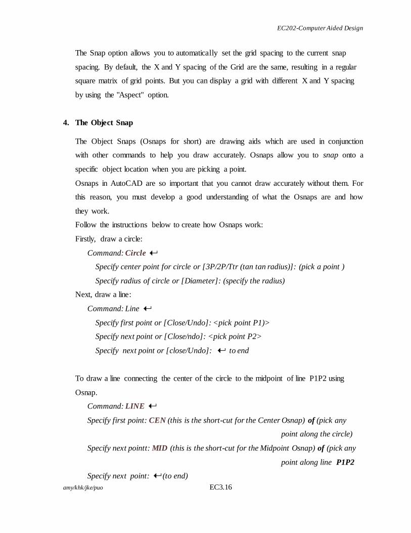
To draw a line connecting the center of the circle to the midpoint of line P1P2 using
Osnap.
Command: LINE
Specify first point: CEN (this is the short-cut for the Center Osnap) of (pick any
point along the circle)
Specify next pointt: MID (this is the short-cut for the Midpoint Osnap) of (pick any
point along line P1P2
Specify next point: (to end)
EC202-Computer Aided Design
amy/khk/jke/puo EC3.17
You have now drawn a line from the exact centre of the circle to the exact midpoint
of the line. The line is drawn with perfect geometric accuracy.
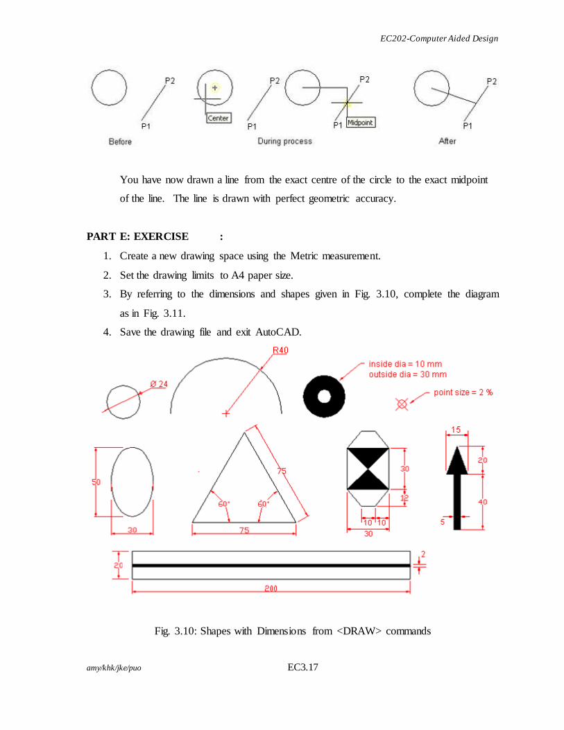
PART E: EXERCISE :
1. Create a new drawing space using the Metric measurement.
2. Set the drawing limits to A4 paper size.
3. By referring to the dimensions and shapes given in Fig. 3.10, complete the diagram
as in Fig. 3.11.
4. Save the drawing file and exit AutoCAD.
Fig. 3.10: Shapes with Dimensions from <DRAW> commands
EC202-Computer Aided Design
amy/khk/jke/puo EC3.18
(2 Marks )
(2 Marks )
(2 Marks )
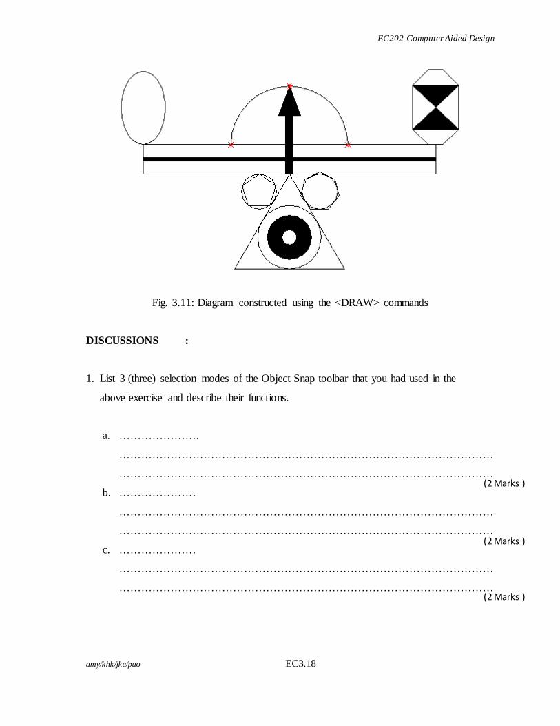
Fig. 3.11: Diagram constructed using the <DRAW> commands
DISCUSSIONS :
1. List 3 (three) selection modes of the Object Snap toolbar that you had used in the
above exercise and describe their functions.
a. ………………….
…………………………………………………………………………………………
…………………………………………………………………………………………
b. …………………
…………………………………………………………………………………………
…………………………………………………………………………………………
c. …………………
…………………………………………………………………………………………
…………………………………………………………………………………………

EC202-Computer Aided Design
amy/khk/jke/puo EC3.19
(4 Marks )
(4 Marks )
(4 Marks )
(2 Marks )
2. Describe the steps to create the 7-sided polygon in the exercise above?
……………………………………………………………………………………………
……………………………………………………………………………………………
……………………………………………………………………………………………
……………………………………………………………………………………………
……………………………………………………………………………………………
QUESTION :
1. How do you set and display an A4 imperial paper size on the screen?
…………………………………………………………………………………………………
…………………………………………………………………………………………………
…………………………………………………………………………………………………
…………………………………………………………………………………………………
…………………………………………………………………………………………………
2. Name the <Draw> commands used in the diagram:
……………………………
……………………………
……………………………
……………………………
REFLECTION:
At the end of this practical work, I have learnt that:
…………………………………………………………………………………………………
…………………………………………………………………………………………………
…………………………………………………………………………………………………
…………………………………………………………………………………………………
…………………………………………………………………………………………………
Related Documents