PRACTICAL WIRELESS, January 6th, 1940. BANDSPREAD SHORT-WAVE THREE-page 347 A NEWNES PUBLICATION EivtiteAiry F. J.CAMIYI vol. 15. No. 381. WEI cvyuct, PRACTICAL TELEVISION 3. EVERY IEDNESDAY Old Circuits Revived A Short-wave Band - spread Three Thermion's Commen- tary A Two -stage Regenera- tive Pre -selector Practical Television Loudspeaker Design Practical Hints Tone Control by Nega- tive Feedback Readers' Letters HOME-MADE COILS Jan. 6th, 1940. SIXTY TESTED WIRELESS CIRCUITS By F. J. Camm Circuits for Battery and Mains -Operated Receivers, Adaptors, Units, Portables, Short -Wave Receivers, All -Wave Receivers, Amplifiers, and a Room -to -Room Communicator. Diagrams and instructions for assembling and wiring. Details of components and notes on operation. 2/6 NET From all booksellers, or by post, 2110, from the publishers, GEORGE NEWNES, LTD. (Book Dept.), Tower House Southampton Street, Strand, London, W.C.2. ADVT.

Welcome message from author
This document is posted to help you gain knowledge. Please leave a comment to let me know what you think about it! Share it to your friends and learn new things together.
Transcript

PRACTICAL WIRELESS, January 6th, 1940.
BANDSPREAD SHORT-WAVE THREE-page 347
A
NEWNES
PUBLICATION
EivtiteAiry
F. J.CAMIYIvol. 15. No. 381.
WEI
cvyuct,
PRACTICAL TELEVISION
3.EVERY
IEDNESDAY
Old Circuits Revived
A Short-wave Band -spread Three
Thermion's Commen-tary
A Two -stage Regenera-tive Pre -selector
Practical Television
Loudspeaker Design
Practical Hints
Tone Control by Nega-tive Feedback
Readers' Letters HOME-MADE COILS
Jan. 6th, 1940.
SIXTY TESTED WIRELESS CIRCUITS By F. J. CammCircuits for Battery and Mains -Operated Receivers, Adaptors, Units, Portables, Short -Wave Receivers, All -WaveReceivers, Amplifiers, and a Room -to -Room Communicator. Diagrams and instructions for assembling and wiring.
Details of components and notes on operation.
2/6 NET From all booksellers, or by post, 2110, from the publishers, GEORGE NEWNES, LTD. (Book Dept.), Tower HouseSouthampton Street, Strand, London, W.C.2.
ADVT.

PRACTICAL WIRELESS
New-Authoritative
Technical-Practical
THIS work provides in a convenient form a comprehensive and reliable source of reference toAircraft Construction, Production, Maintenance and Overhaul. The wide adoption of metalconstruction has rendered a work of this kind necessary even for those men who have been
for many years associated with the aircraft industry.Never before has the whole aspect of Aircraft Production and Maintenance, from the originalspecification to the forty hours' inspection schedule, been covered within the confines of a single work.The operative in the production shop, whether engaged upon aeroplane construction, or upon themachining, fitting, assembly or testing of aeroplanes, will find the information ideally adapted tohis needs.
We have had the courteous and cordial co-operation of many of the larger manufacturers, and throughtheir assistance we have been able to deal thoroughly, and in a practical manner, with some of theleading types of British aircraft, both from the production sF , the point of view of the groundengineer.
VERY BRIEF OUTLINE OF" AERO ENGINEERING "
ESSENTIAL REQUIREMENTS OF MODERN AERO-PLANES. PRINCIPLES OF FLIGHT. SURVEY OFMODERN AIRCRAFT PRODUCTION. WORKSHOPPROCESSES USED IN AIRCRAFT PRODUCTION.MACHINE TOOLS. SHEET AND PLATE METALWORK. COMPONENT JIGS. AIR FRAME JIGS.MATERIALS USED IN AIRCRAFT CONSTRUCTION.HEAT TREATMENT. THE ANODIC PROCESS.METAL CUTTING. WELDING. SOLDERING ANDBRAZING. RIVETING. INSPECTION STANDARDSAND METHODS. AIR FRAME ASSEMBLY. ENGINEINSTALLATION. FITTING THE ELECTRICALEQUIPMENT. RIGGING. AEROPLANE MAIN-TENANCE. THE INSPECTION SCHEDULE,GROUND EQUIPMENT, ETC. ETC.
All the Chief Makes of Aero Engines and all representa-tive types of civil and military aircraft are covered.
50 FREE DATA SHEETSPrepared with the assistance of the Air Ministry andleading British Aircraft Manufacturers, these containdetails of the most popular types of civil and militaryaircraft-performance, pay load, fuel consumption,maximum speed, cruising speed, landing speed, etc.
§ § § §
FREE. Handsomely Bound Case forfiling your Data Sheets.
Bound inDurable ClothBinding withTinted TitleLettering
George Nelortes, Ltd.
January 6th, 1940
Indispensable toeverybody en.gaged in theaircraft industry.Written by menwith unsurpassedexperience intheir respectivebranches.
40EXPERT CONTRIBUTORS
2,500 PAGES OF THELATEST AND MOSTPRACTICAL INF OR-
MATION.
2,000 ILLUSTRATIONS,PLANS, DIAGRAMS.
50 DATA SHEETSCOVERING 50 CIVIL& MILITARY AIRCRAFT.TWO YEARS' TECHNI-CAL ADVISORY SER-
PURCHASER.
kERO a AFROfkiNEERits:
ER c'
POST THIS COUPON TO -DAYHOME LIBRARY BOOK COMPANY
(George Netene,, Ltd.)Tower House, Southampton St., London, W.C.2.Please send me a Free Copy of your Descriptive Booklet for" AERO ENGINEERING," together with full particulars showinghow I may obtain the work for a small initial subscription.
NAME
ADDRESS
Occupation P W. 6140If you do not wish to cat your copy, send a poster, mentioning
Practical Wireless'. to above caress.
amateur activities, and there- fore there is very little to help in judging the performance of a reeiver, other than the stan- dard commercial broadcasts, and it is therefore necessary to listen at the correct times on the correct wavelengths, rather thait to listen at any odd times in tite hope of hearing something.
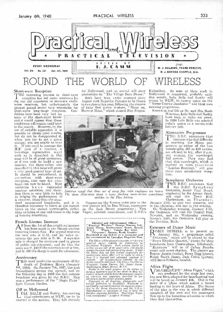
Statistics reveal 1/sat three 'out of every Jive radio employees are testet's. The above illustration shows a tester checking motor-drivers ts'avechange
switches in the Ekco factory.
'French Licence Increase As front the ist of this month an increase
has been made in time French wireless receiving licence fees. For crystal receivera the new rate is fr.l5, and for valve re- ceivers the new rate is fr. 90. A separate rate is charged for receivers used in places of public entertainment, and for this the rates are fr. 180 if the entertainment is free, and fr. 360 ifa charge is made for admission.
Anniversary
THIS week marks the anniversary of tIte
death of Professor Hertz (Jaiivay ist, 1894). On January 7th, 1927, tIme first transatlantic service was opened, and on the following day in 1923 the first outside broadcast was given by the B.B.C. This was a performance of time "Magic Flute" frOñì Covent Garden.
ff o Hollywood LBELLE and Scotty, top-ranking
iral entertainers at WLVbT, are to be starred in the movies. They left recently
Supporting the fainoims radio pair in the new picture will be Don Wilson, announcer on the Jack Benny programme Vera Vague, network comedienne, and N. B .C.'s
Editorial and Advertisement Othces Practical Wtreless," George Newnes, Ltd.,
Tower House, Southampton Street, Strand, W.C.2. 'Ph,ne: Temple Bar 4363.
Telegrams s- Newnes, Rand, London. Registered at the G.P.O. as a newspaper and t for transmission by Canadian Magazine Post.
The Editor a/fl be pleased to consider ari irles of a ¿
practical itatiirs sal/able for poblirntion in PiACTJCAL WtnELass. Sic/s aeticles shoitid te written on one side of ti/e paper ontii. s se/ a/iou/el
con tain the naine and address of the seniler. Whilst the Ei/ilse does not hold hiioieif responsible for manuscripts, every effort n'itt be nial/e to return tient 'if a stamped and ni/dressed envelope is enctoseit. Alt coiresposdenee intended for 1/ic Ji','ilor olio ii/it he addressed.' The Editor, Pr.ACTJCAL WIP,ELES9, fleorge Neones. Ltd., Totter ¡bose, .Soot/uimnptsa Street, Strand, ¡J.C..
Oto/ng to tite rapid progreso in tite design of n'i,'eleso apparatus and to os's' ef//ato to keep our readec8 in touch with 1/te latest Jerelspinenls,we give no warranty tisi apparatus described in oui' co/sosias is not the suibjert of lettera patent.
Copyright in eilt drawings, photographs and articles pilitished in F1OAC'nICAL Wlmsmitmsss is specifically rsoerned li/ron ghoul the countries signa- tory to the Berne Convention and the USA. I'saprodueiions or inoitatioys of any of these ore therefore ezpressly forbidden, PmuAc'nlcAL Wmiz- LESS isieorporcttes Amateur Wireless.'
t. ................................................................ s ........................
Orchestra, leader T'aol Beard, conducted by Sir Adrian BouIf, will visit the Town Hall, Cheltenhamn, on T h ut s da y,
January 11th, to give two concerts, oste in time afternoon and one in the evening.
On Wednesday evening, January 17th, tIme Orchestra will visit the Central Hall, Newport, and on Wednesday evening. January 24th, tite Orchestra will play at time Pavilion, Bath.
Extremes of Dance Music ROBIN RUSSELL is to present on
January 6th, a programme called Extremes,'' which will be played by the Sweet Rhythm Quartet,' known for timeir
broadcasts frotn Corstorphine, Edinburgh. "Extremes" will he of Cuban Runmba niusic and sweet rhythmni. Time players are Ronnie. Austin (violin), Percy Pegg (piano), Ralph Smith (bass), Jack Collin (guitar), wit-h Bette Roberts, vocalist.
Africa Flight VAL GIELGUD'S" Africa Flight," which
was produced for the stage last year, has now been adapted for broadcasting and will be heard on January 4th. This is the story of a 'plane which makes a forced landing ïmi time imeart of Africa, The theme of tIse play is the way in which different members of the crew anti time passengers face up to the hazardous situation in w bicho they find themselves.
'l
n
n.
io
present period seems very unsuitable foi of their first movie venture, "Shine on, short-wave long-range reception. Con- Harvest Moon," which starred Roy Rogers. ditions hayo been very had on some of the short,wave bands .
J and it would appear that these conditions will remain until latcr -
in the month. However, by the use of suitable apparatus it is possible to obtain good results, .
but do not be disappointed if, . .. when you try to get a given
:
station, you are unable to hear it. If you need to increase the HF. gain of a receiver, a two-stage regenerative u n i t
- J such as is described in this :. issue w ill be of great assistatice, - i- .
or if you wish to build a new receiver, the three-valver also '
described, in this issue will prove a very good general type of set. lt should be remembered, in '
L
connection with short-wave reception, that very few ama- teurs can now be heard. Most countries h a y e suspended ! - i''- ' ---
morning programme. Known in real life as Mr. and Mrs. Scott
Wiseman, Lulu Belle and Scotty have been in radio six years. in 1936 Lulu Belle was selected radio's queen in a nation-wide listener poll.
Alternative Prcgramme
rfHE B.B.C. announces that
listeners who find difficulty in receiving the Home pro- grarnnie cii either of the two wavelengths, 391 or 449 metres, are advised to try, after 6 p.m. any evening, the wíwélength 342 metres. They may find
¿ that this wavelength, winch is marked on most receivers
London Regional," will give them more satisfactory recep- tioi'ì.
i Symphony Orchestra HE B.B.C. announces that
the B.B.C. Symphony
' 1RACT1C4L TELEVISION *
EDITED BY EVERY WEDNESDAY w J DELANEY, FRANK PRESTON,
VcI.XV. No. 381 Jan. 6th, 1940
IlI H. J. BARTON CHAPPLE, B.Sc.
ROUND THE WORLD OF WIRELESS Short-wave Reception fòr Hollywood, and on arrien! will start Ki(loocllers. As soon as their work in
T11E increasing interest in short-wave production on The Village Barn Dance." Holly ood is completed, probably early reception has led many amateurs to Both have been under contract since this month, Lulu Belle and Scotty will
dig out old apparatus or renovate short- August with Republic Pictures to be filmed return to WLW, to appear again on the wave receivers, but unfotunatcly the in two shows this year, following the success Boone CountyJamboree " and their owls
Janu8ry 6th, 1940 PRACTICAL WIRELESS 333
PDF compression, OCR, web optimization using a watermarked evaluation copy of CVISION PDFCompressorPDF compression, OCR, web optimization using a watermarked evaluation copy of CVISION PDFCompressor

shown by numerous constructors in the winding of the coils required
for their receivers, or experiments, and it would appear that a few guí.ing remarks would not be amiss. For example, w mie coil design and construction can form a most interesting and fascinating subject, and, incidentally, save money, there are several considerations which, if not fully appreciated, can introduce very dis- appointing results.
Complete constructional details of coils for aerial and HF. circuits, oscillators and IF. transformers have been given more than once in past issues, and the present article deals with what might be termed practical considerations and simple formuln associated with tuning coils of normal design.
General Design The object of winding any coil for radio
purposes is to provide a certain value of inductance, and if the property of inductance is examined, it will be seen that there are certain undesirable factors which must be avoided if thc most efficient results are required. Without going into theoretical
Pre -determined variable condenser. The self-capacity would, in effect, increase the total capacity across the circuit and thus increase the minimum tuiing wavelength. On the short and ultra-short wavelengths, when the frequencies soar to very high figures. the matter becomes more serious, so much so, in fact, that, as an examination of any good short-wave coil will show, the necessary windings are built up with turns quite widely spaced from each other.
The simplest way of avoiding this self- capacity, therefore, is to use coil formera of reisonable diameter, say, a minimum of lj-ins., and wind the coils in the simple single layer solenoid fashion. It can be noted, however, that the trouble is not so pronounced with coils designed for long- wave work, but this does not mean that it can be ignored completely, but owing to the lower frequencies concerned and the fkct that a certain capacity across the coils will help to bring their fundamental wavelength closer to the band width required for this section, a little more latitude in design is permissible.
A solenoid single-layer coil to cover, say, 900 to 2,000 metres with a .0005 mfd.
Fig. 2.-An example of single lager solenoid winding not difficult to construct.
be many times that which it would offer to a steady direct or a low-frequency alternating current, and this is largely due to what is known as the "skin effèct." This effect obtains its name by reason of the peculiar paths taken by HF. currents which, unlike the more -familiar D.C., tends to avoid the whole mass of the conductor and seeks to flow on the outer surface or skin of the conducting material.
In addition to tise above, quite serious losses can be introduced into coil circuits carrying HF. currents by poor insulation and the presence of other conductors within the effective field of the winding under consideration. The losses can be caused by using formers of poor insulating material, poor dielectric strength of supporting insulating pillars or mountings holding the coilor any metal, such as other conductors or screens too close t.o the inductance therefore care has to be taken in riot only
'the design of the coil, but also its location in a layout. On the higher frequencies, i.e. short aisd ultra-short waves, these
1
I -
334 PRACTICAL WIRELESS
Hòmer'nàde Coils Essentiel FacJors which Must Be Considered Whén Designing and Making Coils, If Unsatisfactory Results are to be Avoided f
By L. O. SPARKS
Ç' ONSIDERABLE interest is now being wave-band width of aìy given coil with a
January -6th, 194Ó
I
the HF. currents, owing to the fact that the condenser will offer to them a path of very much lower resistance, and thus
ri kill the sole object of the inductance forming the choke.
With ordinary tuning coils, particularly those intended for use on the medium and short wave-bands, this property of self- capacity will not only directly affect the overall efficiency and characteristics of the tuned circuits, but it 'will also reveal its presence when one comes to check the
i A COMPLETE. LIBRARY OF STAOARD WORKS By F. J. CAMM
PRACTICAL WIRELESS ENCYCLOPÌEDÍA, SIXTY TESTED WIRELESS CIRCUITS, t 6/-. by post, 6/6. 2/6, by post, 2/IO.
EVERYMAN'S WIRELESS BOOK, 5/-, by. post, 5/6. WIRELESS COILS, CHOKES and TRANS-
TELEVISION and SHORT-WAVE HAND- FORMERS and HOW TO MAKE THEM,
BOOK, 5/-, by post, 5/6. 2/6, by post, 2/IO. .
AH obtainabte from or through Newsagent,, or from Gee. Newnes, Ltd., Tower House, Söutl,ampton St.. Strand, W.C.2
.-J
reasons too deeply, the following can be taken as those things which must be eliminated, as much as possible, when undertaking the winding of a coil. Self- H
¡ capacity. Resistance. Poor insnlation. F
Large magnetic field and fragility.
Self-capacity When any winding has a high vaine of
self-capacity, its effective inductance is reduced considerably or, in other words, part of the sole object of winding the
r coils is lost. A most striking example of this is a poorly-desied HF. choke, Figs. 1 and 3.-Self-capacity can be likened to a
the purpose of which is to stop the flow ot small condenser across the winding, as shown on the left. A typical slotted former often used for the hiah-frequency currents by presenting a
brier in the form of inductance. 1f the winding of the L. W. section is shown on the right.
choke is formed by connecting several variable condenser, would, unless very pile-wound coils, close together, on a fine wire was employed, become rather slotted former of poor material, in series, clumsy for average set work, so one is then it is highly possible that the sections foteed to adopt the sectionalised winding of the complete winding will act as the plates smiethod for this section. of a fixed condenser, and form, virtually,
I.
a condenser of measurable value. The Resistance a resultant effect would be similar to con- m'
fleeting a small condenser across the choke; %Vlìen speaking of resistance in relation therefore, if one bears in mind that the to coil windings, it is not meant to infer reactance (this can be likened to resistance) the normal resistance to direct current, of an inductor increases as the frequency but that offered to the high-frequency increases, while that of a condenser decreasés alternating currents which are dealt with under the same conditions it will be in. the circuits preceding the detector appreciated that the HF. choke will no longer present an impassable barrier to
valve. The HF. resistance of a conductor might
H.F. losses cams become a very serious problem, so it must, be appreciated that they represent a subject which, especially in that spisere of radio, must receive every consideration. Many constructors will, no doubt, have seen or used the SW. coils wound with hollow copper tubing, such as those used in many amateur transmitting stations, and these can be taken as one example of the attempts to reduce the H.F. resistance of the circuit by providing the largest skin area possible, within, of course, reasonable 1imit.
So far as ordinary dual-range coils are concerned, the best one can do is to use formers of high insulating material, and wire of the heaviest gauge consistent with available space. This must not be takemi too literally; it is not intended to suggest that 16 or 12 S.W.G. wire should be used for medium and long-wave requirements. H space permits using, say, 26 S.W.G. instead of 30 S.W. for the medium-wave section, then the former would be the more satisfactory, but the ultimate choice is so often governed by the size of the coil fonner, so the best way to set about designing a coil, when one does not have to consider space to a fraction of an inch, is to decide on what wire you are going to use and then select a former which will carry the required number of turns, but more about that later.
PDF compression, OCR, web optimization using a watermarked evaluation copy of CVISION PDFCompressorPDF compression, OCR, web optimization using a watermarked evaluation copy of CVISION PDFCompressor

- HT- Tuned Reaction -- The old-fashioned "swinging-coil"
method. of reaction was used, where the Fig 3-A modern version of an old-lype reflex circuil,;-using a iriode de1ècfòr
i.- -.-- -- ,- -
series I uning tiinec anode coupling will . . .
One ofthe earliest entries, iiiade in 192, serve without the addition of a coil. The 'phones. If you wi1i to try this circuit was based on the theme that a tuning reason for the difference is that in the early you can use aiiy standard, tuning coil, or circuit is most efficient when it contains a (lays the aerial was always joined directly you can wind 75 turns on a 3m, diameter maximum of inductance and a minimum of to the top of the aerial variometer, with formei, and take the earth tapping at the capacity. It went on to record that recep- the result that the inductance and capacity fiftieth turn. It will also be better to insert tion with a single-valve (one of the old of the aerial were added to the corres- a .0002-mfd. pre-set or fixed condenser in
j " R" valves, no doubt) receiver was appre- pouding properties of the tuning circuit, the aerial lead at the point marked X iii ciably better when using a series condenser Fig. 2. for tuning, in place of the more customary The Original Reinartz parallel one. The connections to the aerial A modified form of Reinartz circuit is One Valve for H.F. and L.F. coil and tuning condenser were as shown in employed almost universally for reaction Prior to 1926, or thereabouts, so-called Fig. 1, where it will be seen that the series
s tuning condenser is between the aerial - _____________________ and the top of the grid coil. Incidentally, P HT
-L__ HT
HC
__ S
however, it could be used equally well in t he earth lead, as indicated by broken lines. Often, the earth connection is better, since there are then no hand-capacity effects.
One fault with this arrangement is that selectivity is somewhat reduced by the -OE02
series-tuning system. It is alio evident M FD
that sensitivity must fall off as the minimum
Ge
2 MED lI-r- ) k position of the tuning condenser is
approached. The latter fault was less iioticeable in 1922 than to-day, since the
was nuichi higher, in relatioii to the maxi-
__ L M
H
±1 -
luinimuni capacity of a tuning condenser
infini, then than it is now. Still, you might consider it worth while to trythiis tuning
MED
MFD,
circuit. The coil used in the 1922 tests 1 J (D was a number 75 plugin, but a standard
2 tuning coil can be employed.
inefficient. We nere reminded of this electrode valve, and that if the anode cir- turns serve as both reaction and aerial- cuit were tuned to the same frequency as coupling winding. Reaction is controlled tue aerial circuit, the capacity would serve in the usual manner by means of a .0003- PhOHT.- for reaction coupling. As most aders mfd. variable condenser, this being con-
MED are aware, a circuit tuned to a particular nected between the anode of the detector frequency has an infinite resistance to signal valve and tise aerial. currents at that frequency., An H.F. choke is shown in Fig. 2, and is
According to the notebook, best results desfrable, although the cfrcuit in our note were obtained by employing a variometer book does not include this; instead, the -2 MED for timing the anode circuit, although necessary H.F. impedance was supplied
- -
- reaction could he obtained with a coil- (or was supposed to be supplied) by tise
¿ condenser circuit. The ad- vantage of the variometer \
2 MO is that it is a variable-in- 3MFO
ductanoc device and is not . NEC shunted by a condenser. If
'
PhO HT+ you have an old variometer in the junk-box you caneasily 2MFD
try this reaction arrange- LT- ment, and draw your own
I - f conclusions. It should be
mentioned that a variorneter -
Fig. 1.-Two condenser positions for series tuning, of the kind originally in- tended for tuning In the P I -,
and a tuned reaction circuit, aerial circuit will not serve
recently when turning the pages of an old unless it is connected in series with a small coil eon-
-
notebook in which a record of all experi- nient-s carried out were recorded.
sistitig of about 20 turns Fig. 2.-The original Reinariz circuit. A small-capacity condenser should be inserted ut on a 2m, diameter former.
the point marked X. One of tise type designed for
The Experimenters Describe Some Circuit Arrangements -Been Forgotten, But Which May be Worth Trying by
Have Not Previously Seen Them
IT is not always easy to think of new experiments which can be tried, hut many readers will probably find
interest iii testing a few of the circuits used in the earliest days of broadcasting. In many eases it ill be found that not only do the circuits provide interesting e.xperi- iiìeiìt, but that they are by no means
reaction coil took the place of the HF. choke used now, and was movably coupled to the aerial coil. Aotler forni of reaction is shown in Fig. i, however, this having formed the subject of another paragraph in the notebook. Tue underlying idea was that there is a certain amount of capacity between the grid and anode of a three-
Which Have Almost Those Readers Who
control to-day, but the osginal Reinartz, which was in use UI) to about 1923, ivas somewhat different from the moderii version. A single-tapped winding was used for tuning and reaction, and the end of the reaction portion of the winding was con-. nected to the aerial, as shown in Fig. 2. By this method of connection the reaction
--I
January 6th, 194O PRATICÁLWELESS - 335-
SomeOld Círcuíts Revived f
PDF compression, OCR, web optimization using a watermarked evaluation copy of CVISION PDFCompressorPDF compression, OCR, web optimization using a watermarked evaluation copy of CVISION PDFCompressor

insulating material of similar shape is Sec/ion of the improved sta/ion-selectin' contact this papei.
mounted in the upper surface of the plate, 3, described in the text. . ....................
..,j,
ACOMMON form of station-selectit g switch for motor-driven press-button tuning apparatus consists of a
rotor or commutator drum, which is mechanically coupled to a revemsi bio electric motor and to time tuning shaft of the receiver, and a stator which supports a number of station-selecting contacts radially round the periphery ot the rotor.
The rotor may consist of two commutator segments separated b narrow strips of insulating material ; tite stator usually consists of a semi-circular strip of metal formed with a longitudinal slot and moûnted concentrically with respect to the rotor station-selecting contacts are usually fric-
tionally supported in the groove in the stator and may ime slid in the groove and thus moved radially with respect to the rotor to vary the stations they select.
A disadvantage of this arrangement is that the angle through which anyone con- tact may be displac-ed in one direction is limited by the position of time adjacent contact in that direction thus ifa contact is set to select a station at one end of the wave-band, and it is desired to change the selection for a station at time other end of the waveband it is usually necesary to move the station-selecting contact nearest to the desired position into that position, and move the remaining contacts up one.
This tedious anti time-wasting proceed- ing may be avoided by constructing the station-selecting contacts so that they may l)e removed readily from the stator groove.
An im proved station-selecting contact of this kind is illustrated in the accompanying illustration awl consists of a hollow post i formed with a knurled head, 2, and provided at the opposite end with a substantially rectangular flange or plate 3. A strip, 4, of
and the (Ilmneimsions of t lie plate and strip are stick that their width is less thati the width of time slot in the stator and their length is greater than the width of the slot.
The stator is indicated at 13. and the post i may be placed iii time stator slot b liolcihag it by the knurled head with the long edges of the plate parallel to tite sides of the slot, and it is then rotated I hrough 90 degrees to prevent withdrawal.
The tipper surtce of tite strip 4 is prefer- abl cut away along its shorter edges whereby a projection is formed w hicim lies between the side walls of tite stator slot, and keys the station selector contact to tite slot.
Tite pest lis held in tite slot by means of the insulating bush 5 which is urged by a spring 6. hearing against a washer 12. into engageimmeimt with the upper surface of the
stator. The spring 6 also beam-s against a colar 7 on a sleeve 8, and the sleeve 8 is thremmdeci internally and mounted on a screw tlmreaded section of the post 1. The sleeve is rotated in tue correct direction to force tite bush 5 into firm engagemiment with time tipper surface of time stator 13, and locks the post in tite selected position within the slot.
When it is mmecessary to alter the position of the post time pressure on bush S is meduced by rotating the sleeve through ImaM a turn imm the opposite direction, so that the relatively light pressure of the -spring (i permits the post to be slid along the groove. When it is desired to remove the post front time stator slot time sleeve 8 is rotated thi-ough one or muore tut-na to permit axial movement of the post, and the post is depressed to wit hdraw the projecting pom4iomm of time plate 3 and strip 4 frommi the gmoove and then turned through 90 degrees and lifted out of the slot.
A plunger oi contact-making member 9 is siidingly mounted in the bore of the post I, and is urged by a spring iO into engrge. mept with the rotor indicated by the line 14. The spring iO is secured to the plunger 9, anti time post 1, in any suitable manner to prevent tite plunger from being completely withdrawn from within the post.
A terminal member 11 for a conducting lead may be riveted or otherwise secured to tite heads of time posti.
PATENTS AÑD TRADE MARKS. Any of our readers reuiring information
and advice respecting 'amenms, Trade Marks or ¡ Designs, should apply to Rayner & Co., Patent
Agents, of Bank Chamher, 29, Southampton ¿
Buildings, Chancery Lane, London, W.C.2, who will give free advice to readers mentioning
r k:-
successful was similar to that now given iii Fig. 3 It will .bé seen, however. that the Fig 3 circuit has been bfought fairly well lip to date b the use of decoupling for the troe detector and the use of an HF. (or LP.) pentode for amplification. We have actually used a circuit of this kind
currents iii the tuning circuit, but it is often possihie to reduce the value of' this condenser to .001 rnfd. without upsetting the H.F. stage ; there is then a certain improvement in the '' quality " of repro- duction.
Standard components can be used
connection frouì the two earpieces vas taken to a centre-tapping on tue, tuning winding of the coil. Despiteall efforts to find the exact centre-tapping point, we were ilever successful in obta' 'ng any better reception than could be.obtained from a single crystal.
A Station-selecting- Switch An Improved Unit for Lise in Conjunction with Motor-diven Preset Tuning Âpparatus
we were never able to obtain appreciably better results from it than we could froni
IL1 a carefully-adjusted siiigle-valver with steady reaction. And our opinion on this matter has not changed during the past sixteen years, except that ve are still - moie convinced that the inclusion of a Fig. 4.-One of many full-wave-detector circuits crystal is more trouble than it is worth. No which were tried with little success. doubt there will he a iew readers who will disagree on this matter, but we have given L.F. transformer is fed, back to the grid OUI 01)iiIiOIì. circuit of the HF. valve, instead of being
connected to a third, or ordinary L.F., valve. A Modern Reflex The secondary lias a .04)2-nifd. fixed cosi- - The reflex circuit which we found most denser in parallel with it to by-pass HF.
Full-wave Detection One of the aims of those experimenters
who fhvour the crystal detçetor has always been to obtain full-wave rectification, with conse({uent increase in volume. This is one of these things which looks all right on paper, but which seldom works out iii practice. The circuit shown in'g. 4 brought back memories of many viiant strug- gles when it was found in a 192f notebook it is one of many arrangements which were tried, with indifferent reaults. Two crystal detectors were used, and. the series
-
' 336 PRACTICAL WIRELESS Jauary 6th 1940
SOME OLD CIRCUITS REVIVED during more recent yeats, and it is by no throughout this circuit, and the voltage (Couthned from previotc page) means as unsatisfactory as might be applied to the screening grid of the 11F.
- imagined. Tite quality would not please pentocte should be as high as possible with- reflex circuits vere very popular, ami we tite music critic, but it need not be had, out impairing HF. efficiency: Tite higher find several exatnitles iii our old notebook. ]t will be seen front tite circuit that the titis voltage, the greater will be the L.F. t The idea of tite reflex, as many will rentenT- 11F. anti detector stages are conventional. output, although tins can never be high her, is that one valve is made to act as but that the secondary winding of the when using an HF. pentode. That is viìv hotu HF. and LF. amplifier. lt was usual, it is vot'tli while trying an economy output when using the reflex arrangement. to have pentode, such as the ossor 220 HPT. a crystal detector preceded by tite dual- With that valve, and when using a maxi- purpose valve-wiuicit was au ordinary
Despite tite use of tim tonni of 120 volts HT., the screening- N- tu-iode. widespread grid voltage cati he about 90 and Gil. valve-crystal reflex, we must confess that 3 or 4 volts.
- we never favoured it. The reason was that
PDF compression, OCR, web optimization using a watermarked evaluation copy of CVISION PDFCompressorPDF compression, OCR, web optimization using a watermarked evaluation copy of CVISION PDFCompressor
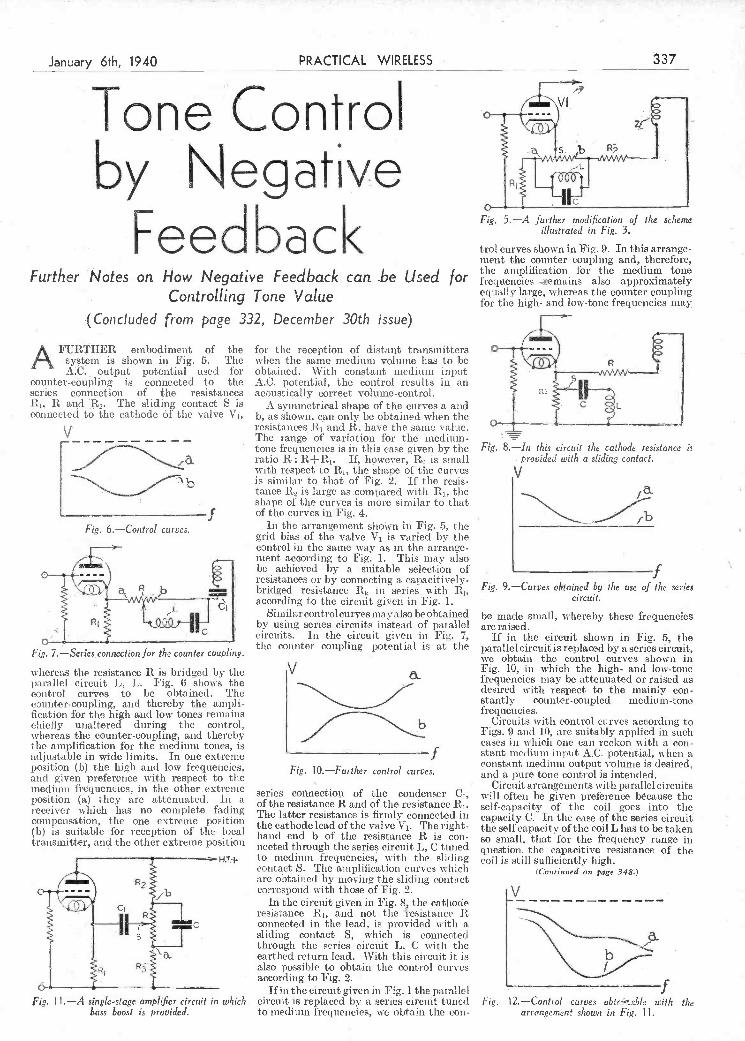
Fig. 11.-A single-stage amplijÇer circuit in w/iic/s circuit is replaced by a series circuit tuned Fig. 12-Control curves obtcjble with ¡he bass boost is provided, to medium frequencies, obtain the con- arrangement shown in Fig. 11.
- . .. -
'. ' _______...s.e.. .. _________ . ..
whereas the resistance R is bridged by the parallel circuit L, L. Fig. 6 shows the control curies to be obtained. The counter-coupling, and thereby the ampli- fication for the high and low tones remains chiefly unaltered during the control, whereas the counter-coupling, and thereby the amplification for the medium tones, is adjustable in wide limits. In one extreme position (b) the high and low frequencies, and given preference with respect to the medium frequencies, in the otherextreme position (a) they are attenuated. In a receiver which has no complete fading compensation, the one extreme position (b) is suitable for reception of the local transmitter, and the other extreme position
H.T.--
V
-f Fig. 10.-Further control curves.
series connection of the condenser C1,
of the resistance R and of the resistance R1. The latter resistance is firmnly connected in the cathode lead of the valve V1. The right- hand end b of the resistance R is cou- neeted through the series circuit L, C tuned to medium frequencies, with the sliding contact S. The amplification curves winch are obtained by moving the sliding contact correspond withì those of Fig. 2.
In the circuit given iii Fig. 8, the cathode resistance R1, and not the resistance R connected in the lead, is provided with a sliding contact S, which is connected through the series circuit L, C with the earthed return lead. With this circuit it is also possible to obtain the control curves according to Fig. 2.
If in the circuit given in Fig. i the parallel
Fig. 10, ill which the high- and low-tone frequencies may be attenuated or raised as desired with respect to the mainly con- stantly counter-coupled medium-tone frequencies.
Circuits with control curves according to Figs. 9 and 10, are suitably applied in such cases in w hichi one can reckon with a con- stant medium input AC. potential, w-lien a constant medium output volume is desired, and a pure tone control is intended.
Circuit arrangements with parallel circuits will often be given preference bêcause tile self-capacity of the coil goes into time capacity C. In tile ease of the series circuit the self capacity of tile coil L lias to be taken so small, that for the frequency range in question, the capacitive resistance of the coi] is still sufficiently high.
(Coti,,ed on page 348.)
Hl
b
Fig. 6.-Control curvos.
Fig. 7.-Series connection for the counter coupling.
with respect to R1, the shape of tite curves is similar to that of Fig. 2. If the resis tance R5 is large as compared with R1, the shape of the curves is more similar to that of the curves in Fig. 4.
In the arrangement shovn in Fig. 5, tite grid bias of the valve V1 is varied by the control in the same way as in the arrange ment according to Fig. 1. This may also be achieved by a suitable selection of resistances or by connecting a capacitively- bridged resistance R in series with R1,
according to tite circuit given in Fig. 1. Similar control curves may also be obtained
by using series circuits instead of parallel circuits. In the circuit given in Fig. 7, the counter coupling potential is at the
Fig. 9.-Curvos obtained by i/le use of 1/le series circuit.
be made small, whereby these frequencies are raised.
If in the circuit shown in Fig. 5, tIte parallel circuit is replaced by a series circuit, we obtain the control curves shown in -I.
Controlling Tone Value
(Concluded from page 332, December 30th issue)
A FURTHER embodiment of the system is shown in Fig. 5. The AC. output potential used for
counter-coupling is connected to the series connection of flic resistances
J ilj, R and R2. The sliding contact S is connected to the cathode 6f the valve V1,
V
I1 [--
fou the reception of distant transmitters when the same medium volume has to be obtained. With constant medium input AC. potential, the control results in an acoustically correct volume-control.
A symmetrical shape of the curves a and b, as shown, can only be obtained when the resistances R1 and R, have the same value. The range of variation foi the medium- tone frequencies is in this case given by the ratio R R+R1. If, however, R2 is small
equally large, whereas the counter c6upling for the high- and low-tone frequencies may
Fig. 8.-in this circuit the cathode resistance is
provided with a sliding contact.
by Negative
Feedback Furt her Notes on How Negative Feedback can -he Used for
i
Fig. 5.-A further modijication of the scheme illustrated in Fig. 3.
trol curves shown in Fig. 9. In this arrange- nient the counter coupling and, therefore, the amplification for the medium tone frequencies 4ernains also approximately
4 -
January_6th, 1940 PRACTICAL WIRELESS '337
j Tone Control 4
PDF compression, OCR, web optimization using a watermarked evaluation copy of CVISION PDFCompressorPDF compression, OCR, web optimization using a watermarked evaluation copy of CVISION PDFCompressor
7. Valse Triste, by Sibelius. as chairman of the R.M.A.
Popular Melodies
Up to a point, so fai' as a general type of music or mood in music is concerned, there is a remarkable fact, the reason foi' which could only be solved by passing right eyond the confines of music and on to
psychology and the national character and teinperanìent themselves. ' I start my
f» presentation of this fact (I shall not attempt to give reasons for it, here, at any rate) by appending a representative list of twelve compositions, the universal popularity of which few, if any, readers would care to dispute.
J. Moonlight Sonata, first movement. 2. Rachmaninoff's Prelude. 3. Chopin's Funeral March. 4. Handel's Largo. 5. "One Fine Day," from "Madanso
Butterfly." 6. "Softly Awakes My Hert," from Samson and Delilah."
Pis6ÑÑ:
George Taylor, who used to be with \Vhiteley Electrical, is now fixed up as Lincoln representative for J. Evershed and Company, the London pointers. Mi'. Taylor commenced his new dute or January ist.
H. Mitchell is back again at the Burndept and Vidor offices as puilicity manager. He had been at Baird'a for sonic time.
Sir Louis Sterling has been elected vice- chairman and managing director of A. C. Cossor, Ltd., Mr. J. H. Thomas having resigned his managing directorship. Mr. Thomas has also tendered his resignation
dreamy, contemplative music ii ill gain the majority of places every time. Thisk of the pieces of this kind that I did not find a place for but whose popularity is un- questioned: Liszt's Liebestraum, Chopin's Nocturnes. Debussy's Clair de Lune, Schumann?s Träumerei, Rubinstein's Melody in F, as well as all the famous ballads like " Little Grey Home in the West," " Bird Songs at Eventide," "Un. til," " Because,'' -' Trees,'' and a myriad of others. You'll hardly find a lively ono amongst the .first hundred.
HANDBOOK By F. J. CAMM
6/- or 6/6 by post from George Newnes, Lid.. $ Towu House, Southampton Street, W.C.2. -
T:
,1
anything of the thousand-and-one things we handle during the course of our passage through this transitory life, two lieces of soap, maybe, or two kinds of cigarette, one of which, for no apparent reason, flourishes and luxuriatcs by the side of the other-so do we find with two pieces of niusic. An ordinarily nuisica.l man ma.y hear two pieces of music of the same genre-- anything from symphonies to swing-and both may appeal to Juni as beiiig equally good in their own particular sphere. Yet one is bound to be the public's favourite. And again, when a work like Schuberts Unfinished Symphony is taken to the iop1e's hearts out of a collection of nine, of which most people are almost ignorant., except the ninth, we douu't ask why. Because, in a case like that, one possesses such an unmistakable quality and exercises such an irresistible appeal on our thoughts and emotions that the reasons are obvious, even though ne may not be able to give adequate expression to them.
But the most remarkable instances are of works which the public insists on taking to its hearts and bestowing on them its signal favours, but which are, in the unanimous opinion of everyone who knows anything about the subject at all, infetior as works of art to their companions in the collection bound up within the saine covers. Among such instances may be cited Rachmaninoff's famous Prelude in C Sharp Minor, Chopin's Study on Black Keys, Schubert's Ave Maria and Serenade, Elgar's "Pomp and Circumstance" march, containing "Land of Hope and Glory," and many others. There are scores of cxanuples from opera, musical comedy and revue which are nothing but a collection of tunes and melodies. Foi some un- accountable reason the public takes one of Them and crowns it favourite, when very often some of the others in the same show are just as good, and better. It is passing strange, and defies analysis,
12. " In a Monastery Garden." Please note that I have not attempted to
place these in any order of supposed 1)OPularitY. I have merely put them down as the titles occurred to nue.
Whilst admitting the enormous popu- larity of works like " Poet awl Peasant'' and " William Tell" (both of which arc more or less abruptly divided into two parts, grave and gay), I doubt very much whether there would be a majority vote for their inclusion in my list to the exclusion of any two of niy first choices. In any case, it wouldn't affect the propriety of my selection if we judge the popularity of a composition by the welcome given to it whenever it is performed, which must, after all, remain the final arbiter. Of course, I am quite prepared to admit that, at given momenta, works like "The Lambeth Walk" or 'Tea for Two" might elbow their way through to the front of the queue. But I feel that their fashion is very eplic. meral and transitory, whereas the others arc permanent.
What is the extraordinary thing about this list ? Why, that every piece in it is of a sad or contemplative character. There is not one single lively or jolly number in it from beginning to end. It is so remarkable, in fact, that you may think there is some thing "phoney" about it. But that ma
not so, as a brief examination w ill show. I set out to think of twelve tunes which
I thought the vast majority of people would find most acceptable on all ordinary occasions, such as when visiting theatres or cinemas, restaurants or cafés, cte.. and foi' flue life of inc I couldn'tthink of one lively one that I, personally, hear played on such occasions. Turn on your radio and listen to the many salon combinations that broadcast so frequently; they play at least eleven of them nuore often timan almost anything else. Ask granuophone record makers which records have the largest doy-
w-hmil.st time Menileissohmn at least aliares the honours with Wagner's from " 1'oheiugrin.'' Furthuernuoje, a funeral march is publie and is heai'tt by millions of people, w hilst a wedding is private and intimate. I venture to suggest that a public funeral without Chopin's work would be talked about as something of a novelty (has it ever been known), 's hilst thousands of bridal couples walk dowp the aisle t.o Wagner's immusic out of preference to Mendelssohn's. A Surprising Encore
I will tell you of an experience I had a short while ago. Although I vouclm for it, I shall forgive you if you choose to doubt it. It was remarkable, and surprised me and others at the time. The, hast occasion in which I gave a pianoforte recital at one of time biggest girls' public schools in the north of Eimgland-Casterton, at Kirkby Lonsdale-I was awarded the customnamy encore. But instead of playing something of my own choice I invited my audience to make their own selection-chancing to luck that. I could grant it. After a few moment s of contemplative silence, one young lady rose and! requested Chopin's FumeraI Marchi Furthemnmore, time suggestion was welcomed with rounds of applause and the per- formance of it accorded with as mucim enthusiasm as that given to anything else on mv programumne! Although it greatly surprised me as n-eli as the Head Mistress and everyone else I met there, it ivas an indisputable proof of the trend of thought of a large body of people, and juveniles to boot; which I think would interest thinkers in other brauches of thought as well.
Strauss waltzes would be certain to gain a large number of votes on any occasion, amid at any tinme, but I cammot think of ally merry amid bright work that I would con- sider as likely to hold .the affections of tIme majority, and to be agreeable to them on all average occasions, as the type of piece which makes up my list. Try and form one for yourselh and I'll wager that sad,
A'\Lisícãj. last Our Music Critic, Maurice Reeze, Discusses Popular Melodies
ONE'S taste, or fancy, is a most peculiar S. "Annie Laurie."to-day sales. You may ask why Chopin's thing. Often it is quite unaccount- 9. " Last Rose of Summer." Funeral March ? Why not Mendelssohn's able. And it is no more predictable 10. Schubert's Unfinished Symphony. \Vedding March ? Well, whilst neither are
in music than in anything else. Just as wo Il. The Indian Love Lyrics, by Wood- e-ver Played as entertainment, the Funeral meet on our travels with two of a kind- forde-Finden, and March stands by itself for its occasion.
338 - RACTCAL WIELESS Jaruar 6th 1940
Commen.t, Chat and Criticism
PDF compression, OCR, web optimization using a watermarked evaluation copy of CVISION PDFCompressorPDF compression, OCR, web optimization using a watermarked evaluation copy of CVISION PDFCompressor
N
-
of goods during the continuance of the war to endeavour to keep prices down lo the lowest possible level, as it is necessary that the cost of living shall not be needlessly inflated. The fteling in the country against profitcering is intense.
Presentation to Lt-Col. Ozanne ABOUT 6o members of the
R.M.A. had their first war- time lunch at the Russell Hotel
which is used for the purpose under discussion. If one knows the optimum load required by the valve and also the impedance of the speâker to be used with it, one can find a particular transformer ratio with which the valve and speaker will he matched. In the case of a moving-coil speaker the correct ratio is obtained by dividing the optimum load by the speaker impedance and taking the square root ol' the answer.
Physical Jerks THE B.B.C. has now good reason
to believe that several million men and women listeners have settled down to the routine of the early morning broadcasts of physical exer- cises. It is the ambition of both instructors, as they move anonymously through the stieets, to see in the carriage of men and women the dif- ference that their instruction is mak- ing to the nation.
unfortunately not able to serve in this as he was invalided from the service. Wireless is his sole recreation, and the issues concerned will help him to complete a set.
The Battery Racket REPORTS continue io reach me
that dealers are splitting up H.T. batteries and selling the in- dividual cells at 4d. each. In each case I have reported the matter to the appropriate authorities. In the mean- time, I suggest that the Associated Radio Battery Manufacturers should investigate this matter at once.
You have observed that the Board of Trade have an eye on the matter, for their first order under the Prices of Goods Act includes electric torches md accessories, including batteries and bulbs. Unfortunately, this Order did not come into lòrce until Jan- uary Ist. By that time manufac- turers undoubtedly caught up with the delivery of price - maintained
ods. The colossal demand has ceased, and the profiteers have vanished. I suggest that the Order should have been immediately operative. As from January Ist it was an offence to sell such goods at higher prices than those ruling on August 21st last, plus a permitted increase which must be calculated as defined in the Act. The 1lire purchase Trade Association has issued a bulle- tin on the matter in which it says that there is a duty on every supplier
recently, vit1i Mr. W. \V. Burnham in the Chair. Mr. A. F. Bulgin presenied Lt.-Col. G. D. Ozanne with a gold cigarette case, and a piece of jewellery Ihr his wilè, in appreciation of his efforts in organis- ing Radiolympia. Mr. Leslie McMichael also referred to Lt-Col. Ozanne's work. I, too, should like to pay my tribute, Ihr I know the enormous amount of work he put in io make this year's Radiolympia a success. His clibris were only defeated by the war.
The Output Stage IT is a prevalent idea that an im-
provement -follows the fitting of a new speaker. Möst speakers will Ihnction with an efficient receiver provided that they are connected in a suitable manner. This is because any valve operates most efficiently when the impedance connected in its anode circuit is of a fairly critical and definite value ; this value is called the " Optimum Load,'' and is measured in ohms.
The Transformer Ratio IT is evident that a peaker of
different impedance could not be employed for eích type of Output valve, and therefore some simpler system must be devised. All listeners know that a transformer can be used to " step up " or " step down '' AC. voltages, and it is this instrument
another are offered tile facilities ot this column.
Coupling Condenser Välues A TECHNICAL question I fre- P quently receive relates to the values of coupling condensers. The value of the coupling condenser de- pends upon the stage of the receiver in which it is employed, and the correct value of the condenser is best found by experiment. In the case of a. detector valve, the value depends to some extent upon the constants of the valve and upon operating conditions. In a power grid detector, for example, where the coupling condenser usually is smaller than the conventional .0003 mfd., say .000i mfd., and the valve h operated at a high anode voltage and current, a much smaller grid leak, generally of the order of a quarter megohm, is necessary. A Ihirly wide range of choice is usually given for the value of the coupling condenser in low-frequency resistance- capacity coupled amplifiers. A capacity value between .005 mfd. and .05 mfd. will be perfectly íttisfactory, but the actual choice depends very much upon the band of frequencies it is desired to pass. If the set builder wishes for frill round tone with plenty of bass, then the value of .05 mfd. or even greater should be chosen, while a lower value, by cutting off some of the bass, will give a higher pitched and perhaps more brilliant tone.
Back Issues Wanted I MR C P, of Muswell Hill F I urgently requires PRACTICAL :
r
WIRELESS dated January j9th, 1935,
I
January 26th, 1935, and February 2nd, 1935. These issues are entirely out ol print, so if any reader can oblige perhaps he will let me have ...............
fl ....................................
them. C. P. served in the last war, bit is By ThermLon
Readers' Change of Address Column IAM happy to comply with a
request made that I include a regular column of readers' changes of address. \Vhere these addresses relate to the Army, I am, of course, unable to publish them, but I can include the reader's name and district and offer to forward letters. Readers who wish to keep in touch with one
Japuary 6th, 1940 PRACTICAL_WIRELESS - 339
ON
PDF compression, OCR, web optimization using a watermarked evaluation copy of CVISION PDFCompressorPDF compression, OCR, web optimization using a watermarked evaluation copy of CVISION PDFCompressor
wav-range coverage according to the coils » use. There is, however, no reason why the unit should not be built with a set o coils, selected by a suitably ganged switch unit so that three or even four
ranges.
How To Use the Unit To enable tue unit to l)e used the aerial
ntiist be removed from the aerial teiininal
n any case, it is a simple matter to adjust the control as soon as a station is tuned in, bringing this up only so far as is necessary to gi e a worth while signal free froni interference.
intend to settle clown to the building of such a unit there is no season why, whilst we are about it, we should not make a two-stage unit, and in addition go to the trouble of incorporating some form of regeneration to add still further to its usefuhiess.
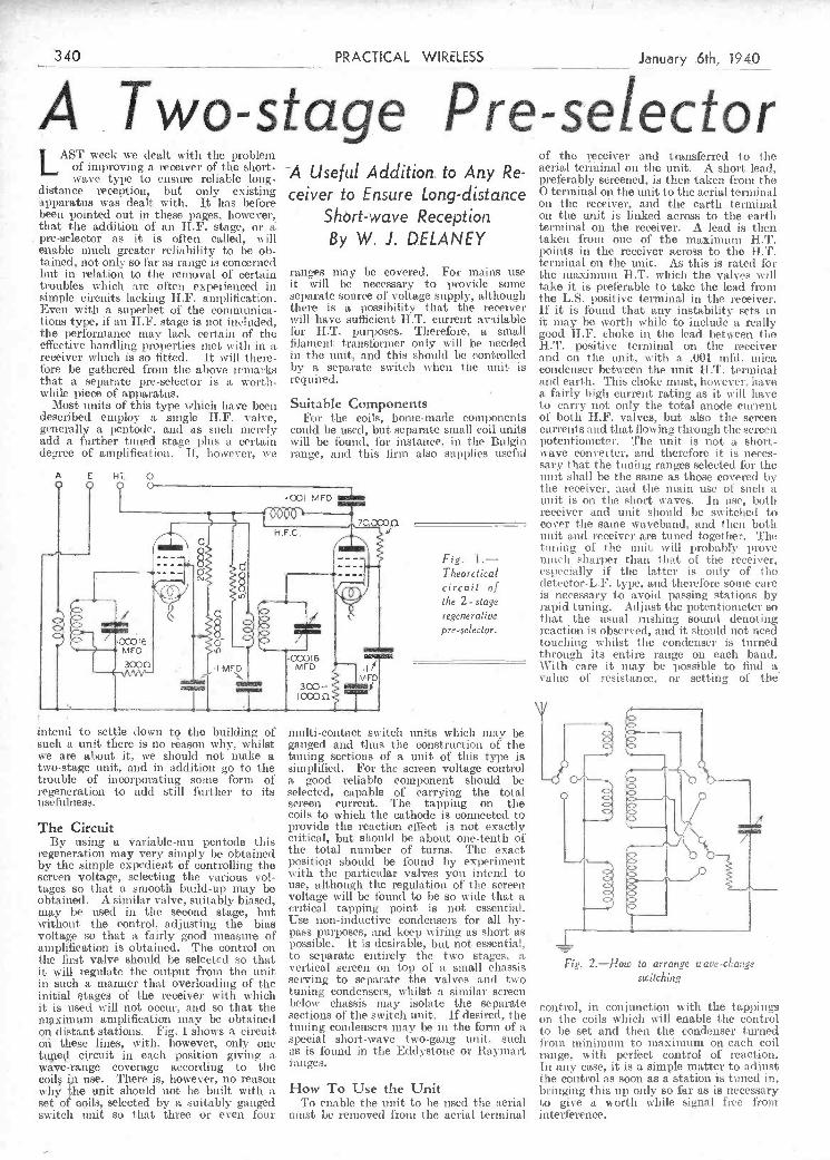
The Circuit By using a ariable-mnu ientocle this
regeneration may very simply be obtained by the simple expedient òf controlling the screen voltage, selecting the various vol- tages so that a smooth build-up may be obtained. A similar valve, suitably biased, may be used in the second stage, but without the control, adjusting the bias voltage so that a fairly good measure of amplification is obtained. The control on tise first valve should be selected so that it will i-egulatc tise output from the unit in such a manner that overloading of the initial stages of the receiver wth which it is used will not occur, and so that the maximum amplification ivay be obtained on distant stations. Fig. i shows a circuit ou these lines, with. however, only one tuned circuit irs each position giving a
multi-contact switch units which may be ganged and thins the construction of the tuning sections of a unit of this type is simplified. For the screen voltage contmiol a good reliable component should be selected, capable of carrying tise total screen current. The tappiug on the coils to which the cathode is connected to provide the reactlofl effect is not exactly critical; but should be about one-tenth of the total number of turns. The exact position should be found by experiment with tIme particular valves you intend to lise, although tise regulation of t lie screen voltage will be found to be so wide that a critical tapping point is not essential. Use non-inductive condensers for all by- pass purposes, and keep wir-ing as short as possible. It is desirable, but not essential, to separate entirely the two stages, a vertical screen on top of a small chassis serving to separate the valves arid two tuning condensers, whilst a simniiar screen below chassis may isolato the separate sections of the switch unit.. If desired, the tuning condensers may be in the form of a special short-wave two-gang unit. such as is found in the Eddystone or Baymìiart
Fig. 2.-How lo arrange wave-change
switching
control, in conjunction with the tappings on time coils which w ill enable the control to be set and their tise condenser turned from minimum to maximum on each coil range, with perfect control of reaction.
j-.
Ihre be gathered from the above remarks that a separate pre-selector is a worth- while piece of apparatus.
Most ussits of this type which have beers described employ a single HF. ialve, generally a pentocle. and as such merely add a further timed stage plus a certain degree of amplification. I! however, we
by a separate switch when t he unit is required.
Suitable Components For tise coils, bouse-made components
could be used, but separate small coil units will be foumsd, Ihr instance, in tise Bulgin range, and this firm also supplies useful
Fig. I.- Theoretical circuit of
the 2-stage regenerative
p re-selector.
condenser between the unit 1-1 i' terminal muid earth. This choke must, however, have a fairly high current rating as it inh have to carry not only the total anode current of both H.F. valves, but also the screen currents and that flowing through the screen potentiometer. Tise unit is not is short- wave converter, and therefore it is neces- saly that the tuuimig ranges selected for the unit shall be the saine as those covered by the receiver, and the main use of such a unit is ois the short waves. In use, both receiver asid unit should be switch ed to cover the saisie waveband, and then both nuit and receiver are tuned together. The tuning of the unit will probably rovC osneli sharper than that of the receiver, especially if tise latter is only of the (hetector-L.F. type, and therefore solite care is necessary to avoid passing stations by rapid tuning. Ailjnst the potentionseter so that the usual rushing sorimsul denoting reaction is observed, and it should not need touching whilst the condenser is tumi-ned through its entire range on cadi batid. \Vith care it immay be possible to find a. i aine of resistance, or setting of the
\
LAST week we dealt with tite problem of improving a ieceiver of the short- wave type to ensure reliable long-
distance reception, but oniy existing apparatus was dealt with. lt has before been pointed ont in these pages. however, that the addition of an HF. stage, or a pre-selector as it is often called, will enable much greater reliability to be ob- tained, not only so far as range is concerned but in relation to the removal 01 certain troubles which are often experienced in simple circuits lacking HF. amtl plification. Even with a superhet of the comnmunica- tions type, if an H.F. stage is not included, the perlorniance may lack certa in of the effective handling Properties met with in a receiver which is so fitted. It will there-
A Useful Addition. to Any Re-
ceiver to Ensure Long-distance Shôrt-wave Reception By W. J. DELANEY
ranges Iutay be covered. For mains use it will be necessary to provide some separate source of oltage supply, although there is a possibiht.v that the receiver will have sufficient H.T. current available lbr HT. purposes. Therefore, a small filament transformer only will he needed in the imit, and this should be controlled
of the rceiver and transferred to the aerial terminal on tite unit. A short lead, preferably screened, is then taken from the O terminal on the unit to the aerial terminal on the receiver, and the earth terminal on the unit is linked across to the earth terminal on the receiver. A lead is then taken from one of the maximum H.T. points in the receiver across to the HT. terminal on the unit. As this is rated for the maximum HT. which the valves will take it is preferable to take the lead froni the L.S. positive terminal in the receiver. If it is found that any instability sets in it umlay he worth while to include a really good H.F. choke in the lead between the H.T. positive terminal on the receiver and oui the unit, with a .001 mId, mica
340 PRACTICAL WIRELESS January .6th, 19kO
A . Two-stage Pre-selector
PDF compression, OCR, web optimization using a watermarked evaluation copy of CVISION PDFCompressorPDF compression, OCR, web optimization using a watermarked evaluation copy of CVISION PDFCompressor
member to use suitable soft rivets to tue sketch, which I think SECTIONAL VIEW prevent the possibility of the contact selI-e\pIiliatOIy.-H. W. DENNIs shiftiig into short-circuit with adjacent (l ralfoi i). svaves, no such trouble is likely to he pins or sockets. The sketch experienced.-R. L. GRAPEn (Chelmsford). is self-explanatory, and the k.
inset t heoretical diagram -- -;: - eìleservsiruply one 's
I PRACTICAL WIRELESS
(Bushe ) -
A FlashUnitforMorse á'.'" i.- ENCYCLOPßEDIA : Practice ND
TN company with an en- By F. J. CAMM if I thusisslic fuend T have
of Practical Edition beesi ti ¡ng to master e £$ONFÎC Wireless ) net morse code wit s uot PLL
oscillator and torch bulb \ - Wireless Construction, Terms, I -unit, but owing to the - - - and Definitions explained and
illustrated in concise, clear, shielded bulb, it occurred j language. - to me that an jmprov From all Booksellers, or by post 6/6 from - flash unit could quite
George Newnes, Ltd., Tower flouse, South- I easily be made using a am pion Street, Strand, London, W.C.2. small 1hiedd bit1aer. A simple morse key and flash unit arrañcrnnt
. - e - - -__ .
I
-4
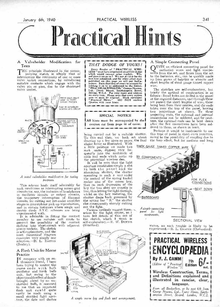
A Valveliolder Modification for Tests
THE principle illustrated in the accom- panynig sketch is siìnply that of
interrupting the continuity of one or niore valve socket connections, by introducini suitable contacts which engage with the valve pits or pins, due to tise shortened valve socket.
ft/RJ0PHo
EASE TO INTERRUPT
vr SCREEN GRID CIRCUIT
RIVETSI8GAUGE COPPER WIRE SOCI(ET CON
JICCKEL rt
::'ì H.T+
2MFO
'ïT A novel valve/wider modification Jor testing
purposes.
'l'bis scheme lends itself admirably for such conditions as interru pti ng screen-grid circuits tòr. say, the i rieltision ot' headphones in oscillator circuits or output circuits, tise temporary interruption of filament circuits, for cutting out pre-audio amplifier sta ges i n gramophone pick-up reproduction, and in certain instances where single and double diode A.V.C. schemes arc being xperinsented with. lt is advisable in fitting the contact
THAT DODGE OF YOURS! ¡
Every Reader of 'PRACTICAL WIRE- LESS" must have originated somelittle dodge
¡ which would interest other rradejs, Why I noi jass It on to us? We pay Li-10-O for the
best hint submitted, and for every other item - published ot's'- this page we will pay half-a-
¡ guinea, Turn that idea of yours to account by sending it in to us addressed to the Editor,
¡ "PRACTICALWIRELESS," George Newnes, Ltd., Towèr House, Southampton Street,
- Sttand, W.C.2. Put yols name and addre,s On every item. Please note that every notioñ sent in must be originaL' MarIs envelopes - "Practical Hints." DO NOT enclose $ Queries with your hints,
All hints must be accompanied by thea COUpOn Cut from pago iii of cover.
being carried out by a suitable shutter. To titis enti then, we both set about drawing up a fest- ides's on P)er, the fluai choice being as illustrated. With a little patience tve made two tHiÇ!, such units, dipping very fE-e-
quently into the multitude of odds and ends which make up TO COM the proverbial wireless den.
It will be seen that the light aperture constitutes simply a slot i n both t h e p a n e I a n d the aluminium shutter, tise shutter operating in such a way under the control of the spring loaded rocker arm of tise morse key, that on each depression of the -.
key tise two slots are exàctly iii hitse, thus letting the light through, whilst on tise key restoring, tite shutter drops back governed by BASE tIte spring bar " S," the shutter slot consequently sharply cutting out tLe light.
Various methods suggest them- selves for the light source, so I have left details of titis out of
A Simple Connecting Panel QVITE an eflicient connecting panel for
anchoring wiles and light 'cotupo- nents from tise set, and flexes from tise set to tite i)atteries. etc., eau be quickly made up froiss pieces 1)1' bakelite or ebonite md -
short lengths of stout gauge tinned copper wire.
Tite sketches are self-explanatory, but briefly tite method of construction is as follows : Small isoles at-c drilled its tise panel at the required distatices, and through these are passed the short lengths of wire, these being bent frotus their centres, sind the ends taken over tite top of tise panel, leaving two projections as shown. To these projecting cods, the external and internal connections can be soldered, and for neat- ness, tise external ends can be bent down after tise flex connections have been sol- dered to them, as shown in inset.
Perhaps it would be inadvisable to use this type ot panel in short-wave receivers, Owing to tise I)OSsiiJihitY of cOUi)lilsg due to tite loop effect, but foi' niedisttn and long
SUGE TItJNEb COPPER WIRE ___7 è -
y
4 ' .
FOR FLEX kg;- - ÇNÇTDNS
BOARD
A simple connecting panel for light
Components.
January 6th, 1940 PRACALRELESS
I Pr citi ca 1F II it in Is
PDF compression, OCR, web optimization using a watermarked evaluation copy of CVISION PDFCompressorPDF compression, OCR, web optimization using a watermarked evaluation copy of CVISION PDFCompressor
It is well known that man's natural instincts it lias already become apparent to the (Co,i:nued on page 34S) . . »
will enable the companies badly hit in tins respect to look for- ward with a measui'e of hope to the time when they can re-enter the market with the minimum of delay.
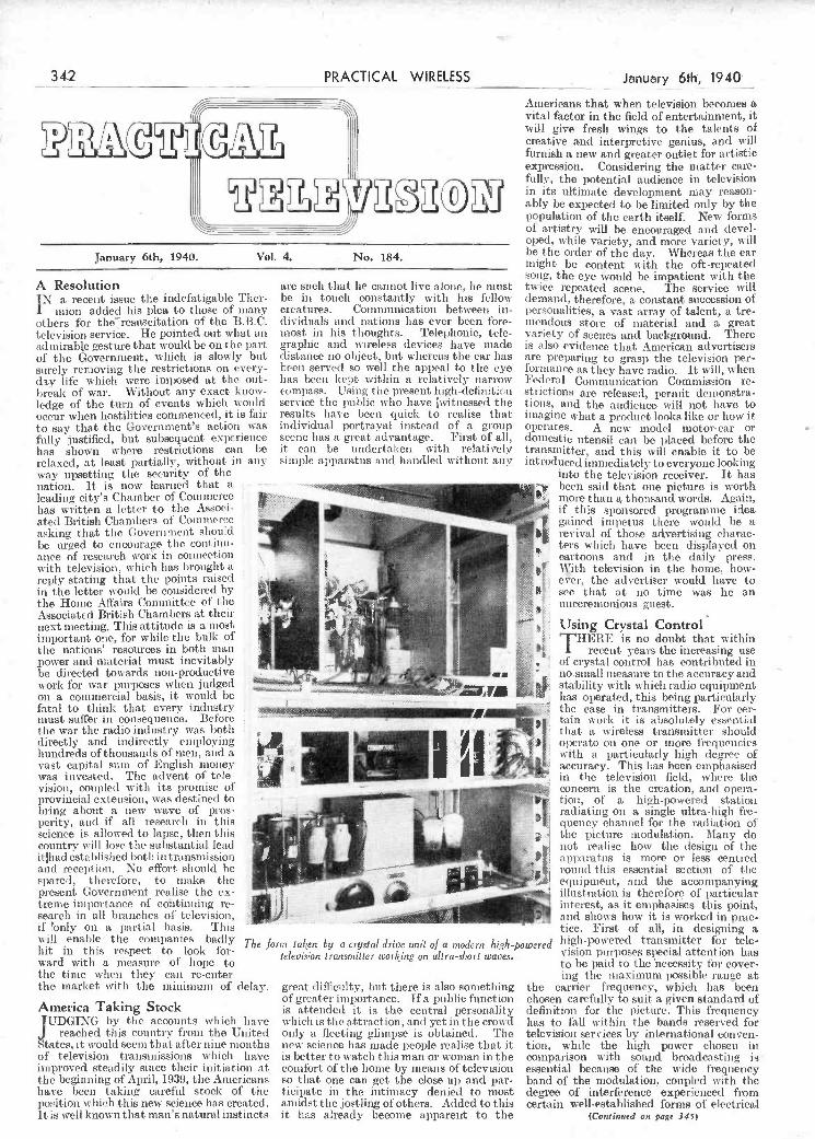
The form taken by a crys fai drive unit of a modern high-powered television transmitter working on ultra-short waves.
America Taking Stock JUDGIXG by the accounts which lieve
reached this country from the United btates, it would seem that after lime months of television transmissions which have improved steadily since their initiation at the beginning of April, 1939, the Americans have been taking careful stock of the position which this new science has created.
great difliculty, but there is also something of greater i niportance. Ifa public function is attended it is the central personality which is the attraction, and yet iii the crouch only a fleeting glimpse is obtained. The new science has suade people realise that it is better to watch this man or woman in the comfort of the home by means of television so that one can get the close-up and par- ticipate in the intimacy denied to most amidst the josthiqg of others. Added to tisis
h ighi -powered transmitter for tele- vision purposes special attention has to be paid to the necessity for cover- ing the maximum possible range at
the carriel frequency, which lias been chosen carefully to suit a given standard of definition for the picture. This frequency has to thll within the hands reserved for television services by international conven- tion, while the high power chosen in comparison with sound broadcasting is - essential because of tise wide frequency band of the modulation, coupled with the degree of interference experienced from certain well-established forms of electrical
break of war. Without any exact know- ledge of the turn of events which would occur when hostilities commenced, it is fair to say that the Go'ernment's action was fully justified, but sul)sequent experience has shown where restrictions can be relaxed, at least partially, without in any way upsetting the security of the nation. It is now learned that a leading city's Chamber of Commerce lias written a letter to the Associ- ated British Chambers of Commerce asking that the (Jovernmcnt should be urged to encourage the continu-
compass. Using t lie present high-definition service the public who have vitnessed the results have been quick to realise that individual portrayal instead of a group scene lias a great advantage. First of all, it can be undertaken with relatively simple apparatus and handled without any
-Ç.'--
aiice ot research wolle Ill COijiiCCiIUII
with television, which ha-s brought a -.
'
reply stating that the points raised in the letter would be considered by the Home Affairs Committee cl i he
1 .
& J Associated British Charnhcr,it their next meeting. Tins attitude is a most
Ç
Ø important one, for while the bulk of the nations' resources in both man
r
Ç
-,
power and material must inevitably be directed towards non-productive work for war purposes when judged -----
Ç
Ç
oil a commercial basis, it would be - - -- 4
Ç to think that every industry riiiisu auner iii curlacquclIce. Afield C
the war the radio industry was both directly and indirectly employing hundreds of thousands of men, arid a vast capital sum of English money was invested. The advent of tole- iillrl ,(111 ll1Ot %rif Il 11M isp nf
provincial extension, was destined to bring about a new wave of pros- perity, and if all research in this .
science is allowed to lapse, then tIns ,-. country will lose the substantial lead " Ç
ithad established both in transmission I
and reception. No effort should be .l -
spared, therefore, to iiiake the ' present (overnnient realise the ex- 'Ç' treme iniportauce of cohtinuing re- I -- -
seaich in ill hinches of telex sion if ronly on a hai-tisI basis. This - _"_
'r'9 IO
'-s -
sti-ictions are released, permit demonstra- tioiis, and tile audience will not have to Imagine what a product looks like or how it operates. A new model motor-car or domestic utensil can be iilaced before the transmitter, and this will enable it to be intrOduced immediately to everyone hooking
into the television receiver. It has been said that one picture is worth mOre than thousand worils, Again, if thus sponsored programme idea gained impetus there would be a
' revival of those advertising charac- ter5 which have been displayed on
- -
- cartoons and in tile daily press. - r With television in tile home, how-
ever, the advertiser would have to - see that at no time was he an
unceremonious guest.
IP
'r
Using Crystal Control1
T HERE is no doubt that within recent years the increasing use
of crystal control has contributed in no-sniahl measure to the accuracyand stability with which radio equipment has operated, this being particularly the case in transmitters. For cet- taus work it is absolutely essential that a wireless transmitter should operate on one or more frequencies vitli a particularly high degree of accuracy. This has been emphasised in tbe television field, where the concern is the creation, and opera- tion, of a high-powered station radiating on a single ultra-high fre- quency channel for the radiation of the picture modulation. Many do not realise how the design of t-he apparatus is more or less centred round this essential section of the ecn i pisient, and the accompanying illustration is therefore of particular interest, as it emphasises this point, suc1 shows how it is worked in prac. tice. First of all, in designing a
January 6th, 1940. VoI. 4. No. 184.
A Resolution
IN a. recent issue the indefatigable Tuìer-
mion added his plea to those of many others for tlìeresuscitation of the B.B.C. television service. He pointed out what an admirable gesture that would be on the part
I
of the Government, which is slowly but surely removing the restrictions on every- (liv life which were imposed at the ont-
are such that he cannot live alone, lie must be in touch constantly with his fellow creatures. Communication between in- dividuals and nations has ever been fore- most in his thoughts. Telephonic, tele- graphic and wireless devices have made distance no object, but whereas the ear has been served so well the appeal to the eye has beeiì kept within a relatively narrow
of artistry will be encouraged and devel- opecl, while variety, and more variety, will be the order of the day. Whereas the ear might be content with the oft-repeated song, the eye would be impatient with the twice repeated scene. The service will demand, therefore, a constant succession of personalities, a vast array of talent, a tre- iuendous store of material and a great variety of scelles and background. There is also evidence that American advertisers are preparing to grasp the television per- formance as they have radio. It will, hien Federal Communication Commission re-
I-
342 - PRACTICAL WIRELESS January 6th, 1940
Americans that when television becomes a vital factor in the field of entertainment, it will give fresh wings to the talents of creative and interpretive genius, and will furnish a new and greater outlet for artistic expression. Considering the matter care- fully, the l)otential audience in television in its ultimate development may reason- ably be expected to be limited only by the population of the earth itself. New forms i
PDF compression, OCR, web optimization using a watermarked evaluation copy of CVISION PDFCompressorPDF compression, OCR, web optimization using a watermarked evaluation copy of CVISION PDFCompressor

Frequency,c.Isec Frequencyclsec. - -T
- Fig. 4.-Comparison of diaphragms BI and CI, Fig. 5.-Comparison of diaphragms C2 and A7.
-- . -
- tion the eases and mountings used were not cone, to ali appearance of quite usual Cones to give lower breaking-load figures always the same, but the differences involved co n str u et io n. The for samples lin, square cut would only affect the low frequencies (below shape and dimensions
r from them, though such figures
about 300 c./sce.). On each chart is also of this cone are also can be very variable as between shown for comparison a standard curve which represents the design objective foi'
shown on the same sheet, and these apply IO
samples from the same cone.
(Continned on next page.)
o, ' O - -
r.' Sha sol n
J4/\J t) 5ØjØfl 200 400 600 800 1000 1500 2000 '3000 4000 .5000 ' 0 100200400 000 120016002000 3000 4000 5000 7000
.1
¶
4,
Freq uencyc./sec.
Fig. 2.-Comparison 0f diaphragms Al and A2.
exceptionally uniform characteristic a pproxiissately t he shape required-np to about 3,500 c/see. It was discovered that this cone (hereinafter referred to as Type Al) had been manufactured abroad, but tise manufacturer of tise loudspeaker (Manufacturer A) had installed plant for snnufacturing cones and ivas willing to co-operate in pr9ducing an equivalent or, if possible, an improved type of cone.
Only a few examples selected from tise very large number of frequency character- istics obtained with different diaphragnss casi be reproduced here. Each of these curves (Figs. 2 to 5) was taken on the axis of the diaphrogm at a distance of 2ft. froni the front of the loudspeaker. Iii each case the diaphragm was assembled with an outer centring device of three tapes in an enclosed case. Since tise curves were taken at different times throughout a long investiga-
Frequency,c/sec -
Fig. 3.--Comparison of diaphragms A5 and Ao.
frequency-ranges, of which the range O-5,000 c/sec. (Figs. 2 and 4) was often used since it covers the frequencies of greatest practical interest for the present purpose, The range of O-9,000 c/sec. (Figs. 3 and 5) was also very generally used.
The curves in Figs. 2 to .5 are direct reproductions of the curves taken off tise drum of tIse recorder; they, tlserefore, show all the minor irregularities in complete detail. A sca e converting the linear law for the ordinates into relative vaines in decibels has been added to tise curves.
Diaphragms Supplied by Manufac- turer A The full-lisse curve in Fig. 2 is typical
of the performance of the Al type of diaphragm. This is a nsouhled paper
manufacture; and the full-line curve, AS, of Fig. 3 is. typical of sansples submitted later as direct manufacturing copies of tise best sample of this second experinsental batch.
Further experinsents were made, but no further improvenscnt has so lar been obtained. Work on these tines, issvolving a close co-operation with manufacturers, could usefully he continued. 'Fise broken curve, A6, in Fig. 3, is typical of snore recent supplies, which have a different code number but are probably ol very silisilar manufacture.
A few of the sasssples have been subjected to chemical analysis and mechanical exanìi- nation. one of these tests, except perhaps a breaking test, gave any differentiation between cones which were consparatively good or bad as regards perforusance. There was a general tendency for tise better
speaker at low frequencies, it is on the ouId be recorded by the equipment that characteristics of the diaphragm, or was used for taking the records. This equip- cone, that the performance at other fre- ment is approximately equalised, so that quencies depends. the ordinates of the curves are roughly
Some previous experience with commer- proportional to sound pressure for Ire- cia! loudspeakers had shown that the cone quencies froni about loo to ,OOO c.lsec. supplied with a certain individual make of at higher frequencies the sensitivity of the loudspeaker was capable of producing an equipnient.falls away-to the extent shown
by the viatioiì from rectihinearity of the 7'? standard curve.
j r i f The equipment is provided' with different
Li
E
mitted a number of samples, all of which were true copies in size and shape but different in some details of manufiscture. One of the worst of these samples-as judged by comparison with the standard curve-is the olie designated A2 and shown by the broken curve in Fig. 2. A curve of this general shape has been very fre- quently encountered during the investi- gation.
Based on these tests the manufacturer then submitted a second, batch of samples made with furthiei' small modifications of
AOV (51m! ------\
0 50100 200 400 600 sooj000 1500 2000 3000 ' 4000 .0 100200400 800 120016002000 3000 4000 5000 7000 3000
J- -. Further Data ¡ri Relation to the Design and Construction of
Loudspeakers for Domestic Uses (Cöncluded from page 332, December 30th issue)
WHILE the stiffness of the centring the axial frequency-characteristic of a loud- equally to the diaphragms to which devices and the construction of speaker of this type. The standard curve Fig. 3 refers. the casmg exert the greatest is that for a sound pressure rising at a In attempting to obtain an equivalent
control on the perfOrmance of the loin1- uniform rate of 2.5 db. per octave-as it performance the manufacturer first sub-
January 6th, 1940 PRACTICAL WIRELESS
Loùdt ectker -__________ 343__
Desiun
PDF compression, OCR, web optimization using a watermarked evaluation copy of CVISION PDFCompressorPDF compression, OCR, web optimization using a watermarked evaluation copy of CVISION PDFCompressor

li'
Manufac- Cone tutor's Code No. Number.
Al - A2 9772/65 AS 9815/58 Ali 9981/49
A
justify pi-oceecliog with the experiment. (not illustrated) on the frame. The free Breaking At the saine time, the experiment shows lengths of these wires to be covered with ad for I in. that there is sonic promise of obtaining cotton sleeving.
sample. improvement of response at higher fre- quencies-witltout sacrifice of performance Spider
11h over tite main frequency range-by a Stiffness imposed by tite spider to aial 10-15 suitable shape and manufacture of flared movement of the cone should not be 18-35 diaphragnt. excessive. This can usually be achieved 12-15
. by tite pse of sufficiently thin material, An Outline of the Specification irrespective of the shape and manner of
Resulting from fixing of the spider. the Investigation Cone This section deals At present it is only possible to specify
with tite specifica- one make of cone, namely Tipe 9881/49, tiOn which was sug-
'gested supplied by Manuhteturer A.
as a result Jn view of possibilities of variations of of tite cxpertrtìents. supplies, it will be required initially titat On it was based it
i per cent.. of cones obtained for use in tite contntercial 51)ÇCi Post Office Eugitteering Department's fication which was contracts shall be tested by tite Departmert issued to a number for acceptance. of interested con- tractors. Latitude is Edge Suspension allowed to tite con- Tite óutside diameter of tite cone is tractor over (letails 71m. Tite clearance from tite inner edge which are not C01t of the outer ring of tite fi-ante (7in. sidered lt k el y to diameter) is free except at three points affect the perfor- where strips of uitstretched tape, 4m, wide, mance,e.g.,theshape cemented at tlteir ends to tite coite ami tt and si z e of the tite outer part of tite frame respectively, magnet. An outline comprise tite suspension. of tite specification
344
LOUDSPEAKER DESIGN (Cofflinued from previous pagr
Some particulars relating to the cones F
to which Figs. 2 and 3 refer are given in tue table. \Vitlr regard to tire manufactrrrer's cO(te number, the figure following the stroke (e.g. ' 65" in " 9772/65" grves tite weight of tire cone, in grains. lins ligure includes tire weight of a flat srrrrounmt extending to a diameter of 83m., winch is cut away for assembly by the 3.tapc suspensron.
PRACTICAL WIRELESS January 6th, 1940
frequencies, though tire irregularities are moie pronounced tirrorrghout tire range tiran uritli tire best of tire straigirt corre diaphragrrrs. An attempt was ruade to obtain tire advantage of better response at inigh frejuencies with less marked irregu. larities, arid some samples of flared dia- phragnis were obtained from Manufactu vr A. Tire performance of Orne of tireso is shown by Curve A7 irr 1"ig. 5.
It was not considered tirat a(lvantago was gained by the rise of this type of diaphragm, and circumstances did riot
adjusted to position tire coil correctly in th& air-ga p. Excessive obst ruetior r behind tire corre is to be avoided; for this reason the four bars connecting the outer ñng to tire inner part (which is secured to the iriagnet) are limited to tin, width.
Coil Total of 53è turns in two layers of 26t
t urns eacir, of 0.15 r92j n. diameter enamel- coverert copper ivire Ends of winding secured to furnier arid left suflicieritiy long fòr connection to insulated soldering points
leature of this curve being the re1atieIy Fig. 7. Fig. 7.-Suggesied cons!ruc/ion of the spea!er greater efficiency obtained at the higher The exact depth of the frame should be ¡rame.
- r :. ____ -
L5
IA ___I k-------------------- 14-
Fig. 6.-Deloils of the recommended speaker cabinet design.
follows. case T h e loudspeaker
[I layer Miback.sides,topand basel may be considered 1 . lIb.lee±backandsìdesortly to consist of two 1 corrugated paciunf apercorrugmons nia n part s, namely, inward.:back,eiaes,top,and base
the ease asid tise
Diaphragms Supplied by Other Manufacturers A considerable imnsber of diapli ragms
froiss tise stock of other manufacturers has been tested, but only those were selected which were of suitable size aisl shape for mounting in tise experimental loudspeaker unit. Record is made liete of only the few sansples whose js'iforstiatice approximates to tise standard desired.
Diaphragm Bi, shown in Fig. 4. is not moulded but formed froiss flat sheet paper into a straight cone, without corrugations. it i. normally mounted n ith rs cloth suiround-in which condition it was tested. Titis cone is heavier tisais nsost issosikted eones, and tise main resonance is therefore at a somewhat lower frequency.
1)iapisragm Ci, also shown in Fig. 4. is tise best example of tise straight-sided cosse diaphragms (inoulded) obtained fioin Manufacturer C. A number of diaphragms obtained from this manufact tirer si'ere snoulded with circumferential corrugations and the generai characteristic of these diaphragms was an enipliasis of tise mid- frequciscy range, tite greatest ordinate of tise curve lying, in most cases, between 1,001) and 2,000 cycles per sec.
Ais interesting variation in sisape is provided by forming tite diaphragsss with a flare. A diaphragm of suds shape is represented by the curve C2 in Fig. 5, a
loudspealcer 121lit.
Case The construction of tise ease is illustrated
in Fig. 6. 'rise case eonsisls of a box of .iis. plywood, vithì an aperture Sin. dianietet
its tite front. The two sides and back aro lined with each of the following
Felt. (about tin. thick) Lear! sheet (Soz. per srl. ft.) Corrugated packing pispes (ivitli tise
corrugations insvafds). Tise top and bottom are lined each wills
rectangles of tite felt and corrugated paper. which serve t.o hold tise linings on tise sides and back into position. No adhesive should he. used ; two or three light tacics tisrougls tise linings of the top and bottoni only should be used to retain the linings in position.
Two layers of felt on tise back of tise front panel are held round tise aperture to lorisi a bag surrounding the back of tise loudspeaker ussit, wisen in position.
Loudspeaker Unit Magnet' Pernianeist issagiset, not greater than
about 250 cui.3 total size, developing at least 6,01)0 lines per citi5. in an air-gap of
.1 075m. extensa! and 0.980m, internal diameter and 0.25iis. deep.
Frame Suggested construction is illustrated in
Stiffness of Suspension Tise 1esonaisce f requseiscy of tise unit
should be determined, before assembly its the case, by anplynsg a constant pd. of variable frequency to a circuit consisting f tise coil of tise loudspeaker unit and a
resistance of 5 ohsmsis, anti by observing tite Continued on opponse page)
PDF compression, OCR, web optimization using a watermarked evaluation copy of CVISION PDFCompressorPDF compression, OCR, web optimization using a watermarked evaluation copy of CVISION PDFCompressor

sound shoui be restricted to those which might ordinarily be heard, as original sources, in such rooms. In any such comparison the influence of the acoustics of the microphone studio should be negligible.
For loudspeakers to be used in living- rooms, tins criterion appears to be satis- factor]y met when the total jower radiated by the loudspeaker in free space is inde- pendent ofthe frequency. Tins requirement
PRACTICAL TELEVISION (Coeiisued Ira's page 342)
equipment. The forni taken by the whole trar.sinitter assembly w ill naturally var in its particular details. but on general lines will comprise first of ail the crystal con-
existing processes. The authors do not favour attempts to increase the response at higher frequencies by any means involving sacrifice of the smoothness of response already attained over the main audible spectrum. They prefer, in the absence of a diaphragm with smooth response up to higher frequencies, to expand the frequency range by a separate high-frequency unit- in cases where such a step is justified.
projection lamp is polarised before it reaches the crystal screen face, and it is therefore subjected to further polarisation as it passes through. In this way it produces an enlarged image of the television picture by passing the light emerging from the back face of the crystal screen through a polaris-
TWO CLEAR SCALES with MiRROR are on the DIX-ON EM ETER
The Dix-Onemete, - 1 with Out 6 Tee-
- /f11 - '
-'- lainais, hut 50 Ranges, is a valu- -- able Instrument of
-
portable size to go in F . the pocket, but big
enough to co ei the - / electrical measure-
'o ments.
'e ,,,
-
55/ (1Y Multipliers iron 7/6
each.
- DIX-Mir ANTA SR s -. - TEST /%IETE1I
- W' This is ii Versatile. high-grade moving
i - ' Iron multi - range meter for service on AC/D.C. jobs. No
- projecting tei minais. TmtEE ranges of
THE i)IX-ON3IEETER, 55j-. volts 0-7.5, O-150. O-300. In. black bakelite case. Only 2/in, by 2/in. 19/6.
:21 j
January 6th, 1940
LOUDSPEAKER DESIGN (Cent isucd fro,n fachg page)
frequency at which the pd; across this resistance of 5 ohms passes through a minimum value. The frequency of reson- ance so determined should not bc greater than 30 c/sec.
Conclusions On the question of how to judge the
quality of loudspeakers, the authors consider that the criterion of faithfulness of repro- duction. comparing a variety of types of sound reproduced by the loudspeaker with the original sources, heard in tite saine room, cannot be improved upon. The room should, of course, be of a kind similar to that for which tito use of the loudsneaker is intended, and the types of
PRACT1CAL WIRELESS
is, at low frequencies, fulfilled to a close approximation by moving-coil loudspeaker of usual type when it is mounted iii a closed and adequately soundproofed ease, so that the main resonance of the diaphragm lies near the lowest frequency which tue loudspeaker is required to transmit at full efficiency, and when this resonance is sufficiently damped, e.g., by a covering of felt closely surrounding the hack of the diaphragm.
The requirement of uniform power radiated can be simplified, for a loudspeaker of this kind with a paper cone diaphragm of about 7m, diameter, to one of axial sound pressure rising at a uniform rate of about 2.5 db. per octave. Diaphragms which produce a quite smooth characteristic of this kind for frequencies up to about 4,000 c/sec. can be manufactured b
345'
ELECTRADIX I OR i) tRI NIGHTS AT HOME. SOUND lORI COHDI's(,, at lo;n cost. The FEIGU RECORDER
fits any Radiogram, positive drive, worm gear and rack. Complete, ready for use, only
- 37/6. Super Feigh Fidelity __-- -- Set, 42/6. Tracking Gear, Only, 21/-. Either 3/3 dot,
- . metal blanks can be used fo the glass-coated simplets,1 lOin., 3/- each. Pie-ampli-
-. fiers for Recording Mikes, l-valve Battery Model iii
cabinet 251-. A C. Mains pre-amplifiers, willi valve rectifier, sleel-cased model, 60,'-.
\ IRR TOR I{,%'I'TER' ,.- ' - .
SUI'RRSF:DI'It, with metal rectifier, for lIT. No need tor HT. Battery 3 Output Volt BEW* '- tappings. R.'duceit fi'oni ..
£3/15/- 10 aI(' laici'. 31/-. ' UPEREDER ('IITSI'AL METS. plug-in 'i: i- coils. 2 tuning condensers,LT-1', semi-norm, detector. 7/I. ' -- Boudoir enclosed type, simple to usc, 6,8. One for your A.B.P. shelter.
screen obliquely. The resultant electric field produced in the immediate neigh- liourhood of this crystal screen causes the screen's optical polarising angle to rotate to a degree depending on the field strength, which, in turn, is changing in accordance with the degree of modulation applied to ftc electron beam by the received tele- vision signal. The beam of light from the
3"6 or by post 3110 from
GEORGE NEWNES, LTD., Tower House, Southampton St.,
London, W.C.2 $
-
New War-time Sale List "N" 2d. stamps.
5f- E1%IERG1NCY PA1tCELS of useful 5sperimenta1 electncal and radio repair material and apparatus, 7lbs. for 5'-. Post Free. .
ELECTRADIX RADIOS 218, Upper Thames Street, London, E.C.4.
Central 46iii
trolled master oscillator. The requirements here are ver'.' rigid and often demand a frequenc'. stability in the neighbourhood of one part in 50,000. This is only at- tained by careful design, and in the ap. ParatilS featured in the drive unit illustrated the crystal oscillator is housed in a thernìo- statically-controlled doubled oven to ensure e-ven tenìperat-ures.
Projection of Television Pictures There is still intense activity both in
Europe and America in connection with the production of satisfactory television pic-
tures whose size is comparable with that seen iii the average cinema, it being felt that no matter in what direct-ion television ultimately develops the need for large Pictures will always be present-. Many of the schemes favour a direct magnification of the brilliant primary received picture, this being undertakesi by an expensive projection lens. Another school of thought, however, favour an intermediary method whereby a relay screen interposed in the path of a steady light beam is modulated by the received telcyision signals, and quite good results have been claimed for this latter nethod of working. One of the most recent of these proposals uses an interposing crystal screen made up from ilativo zinc sulphide. This is interposed in the path of a projection lamp beam, the screen being accommodated in an evacuated glass cylinder to which is welded a neck inclined at an angle of about 45 degrees. The incoming television signals modulate a beam of electrons directed along this neck so that it strikes tile face of the
-ing filter and projection lens. The scanned sections of the crystal screen remain charged until they are neutralised by an auxiliary discharge electron beam, which works in synclnonisni wit-li the main modulated electron beam, and which is timed to precede it by a very short distance. As can be seen, therefore, there is an im portant storage effect associated with an electronic device of this character and, if desired, this could be applied to bringing about a reduction in the line and frame frequency without seriously reducing pic. ture detail or quality, and would help to solve the problem of flicker. TIme-net result is a reduction in the sideband necessary to accommodate the radiated television picture, a fkctor, the nnportance of which looms large once schemes for increasing service coverage are considered in this or in any other country at some future date.
WORKSHOP CALCIJLATOS TAELES AND FORMULAi
P BYF.J.CAMM
LVERSIIED '.IEGGELIS.-Diroct Reading ohms tû megs. Loig scale dial. from £4j1rJ/.. Bridge Meggers cor 1os and insu, res. tenu. Cheap. SILVERTOWN Portable Tester. Combinen Wheatatone Bridge, Gaivo, shunts and ratlos. as new. G.P.O. Plug-in Bridge Resistance Boxen. to 8,000 ohmS.
ELLIOTT & CE. No. 108. with moving-coil meter and graded Rheo, 37/6. Silvertown asiatic horlzontel (laIcos. jewel pivots, 7/-. Ammeters and Voltmeters, all rangos, Portable Sub-Standard Moving Coil Meters, mirror scale. CZ, ammetOrs 5-0.5 a,, reads to 1/10 amp., -in screened raae. 7m. X 7m. X 3/in,, unused, 50'. 3111{ROIt GALVOS, ReIlectir,t Beam, by Paul Clam. lire11, Sull ivan and Tinsley, 03. Standard Res. Boxes and Univer. Shunts, from 55/-. 219 /S!JLLLl3;,'f1l/Tt1Os,_y.., lauere the job calla mor something aiinp'e without ralibration cor lanini. Or "alto for testing. Back of panel type, is lins .
8 ma, lull male. Great B.,'alr at 3,9 post ries, 'sIII.LIAI'sILrp,J,.. Moving ml, 5, L_, III, 23, 50.500 ins, in various ei. es. fiom 2' in to Sin dia. Sn tclib,iaia Meters, . 3 to lin. dial, all ianges.
CABINET AND COMP3NENTB FOR P.W. -' - .
30/. THREE -- 'rudor OaSe Cabinet 53',rj,
arS 50 t'mesI panel siip, 120. Cosn:dm (us deruuhi, OXLY 10 j5 .0/ifa or 126 PoaS
a,id !',uckit'!''c. ',h.P. rI':rl{OL EI.J,t'ì'I{IC ¿'iLxERT.. l'cl i'iU'Is ha' LiglililLi and Cl-mining, 'i
hall lip. DIRSCT COUPLED, J'f watts Dc,. 1.300 r p.m., ii 2'stmoke water.Oooli'd 5-ivi, En. L-J.-
, une, magneto itriit ion. On bedlate with 30 VOlts 5 amps, Dytiaino, 012, 90 Larger size
- kW SizEloi ElvCtrc Sets.i 'f153 watts, 2-trokt 'i,uter-moled'
i li li 1 cyl casino on beil piate direct-conrad to 50,70 vomis io amrs liC. I 'Sn.imo ni.igrieto ignition, luel and ii turd., £16.
SEGN.%I. I'rimt:lr.\mI/\ 1.-Keys, Phonea, Burgers. Luces- Aidis I amp,', Heliographs, Morsa SoSera, EsSays, etc. Special leaflet free. -
.1'
.5
PDF compression, OCR, web optimization using a watermarked evaluation copy of CVISION PDFCompressorPDF compression, OCR, web optimization using a watermarked evaluation copy of CVISION PDFCompressor

0.'
-_____________________ ______________ ______________ _________ -- - - t
These particulars of New Patents of interest to readers have been selected from the Official
to 491935.) 515158-Renda]!, A. R. A.-Thernii-
Journal of Patents and are published by per- onic valve amplifiers. mission of the Controller of H.M. Stationery 515311.-Chillingsworth, L.-Sound-
f' - Office. The Official Journal of Patents can be obtained from the Patent Office, 25, South- reproducing apparatus. empton Buildings, London. W.C.2, price is. 515360.-Blumlein, A. D.-Television
weekly (annual subscription £2 lOs.), or other signal transmission sys- Latest Patent Applications.
31455.-Telefunken Ges. fur Drahtlose tetus.
515377.-Marconi's Wireless Telegraph Telegraphie. -Short-wave homing Co., Ltd.-Microphone apparatus.
ï receiver. December 4. 515383.-Koister-Brandes, Ltd., Smith K. G., and Tiller, P. A-Multi-
Specifications Published, range indicating devices lr radio- 515297.-Farnsworth Television, Inc. receivers.
515292.-Cole. Ltd., E. K., and Method of operating electron multipliers. Martin, A. W.-Electric control
5l5302.-Pye, Ltd., Jones, W., and apparatus for timing radio-re- Edwards, B. J.-Television and ceivers. like systems. Printed copies of the full Published
515304.-Scophony, Ltd., and Okolic- Specifications may be obtained fions the sanyi, F.-Television receivers. Patent Office, 25, Southampton Buildings,
515209.-Electric and- Musical Indus- London, W.C.2, at the uniform price of tries, Ltd., and White, E. L. C. Is. each.
_o_"_"-,i
in a certain colour sensitive photo.electric cell, and if the colour was below a certain pre-arranged standard a rapid action relay was brought into service which caused a jet of compressed air to blow each bad bean off the conveyor belt. In a similar way a machine was designed to incorporate n cell that rejected a packet of produce which had no label. Again, realising that when a packet of cigarettes is opened it is most impressive to see the printed name uppermost on every cigarette, some cigarette making firms use a machine which rotates the cigarette until the light ray, falling on' the print, reduces the incident light on the cell and the cigarette rotation is thereby stopped, aoci in that position it is boxed.
WORKSHOP CALCULATIONS I TABLES AND FORMULE
By F. J. CAMM 3/6, by post 3/9 from
- George Newnes, Ltd. (Rook Dept.), Tower House. Southampton St.,Strand,W.C.2.
ELECTROMAGNETS.-Gialluly, M. S. De, Mace, J., Paz, A., Cerf (nee Schladt), E., Scemama, L., Robert, P., Gory, M., and Villaron, R. No. 506421. In a nioving-coil loudspeaker comprising
an electromagnet for produciiig the magnetic field and a speech-coil transformer, the cores of the electromagnet and of the transformer are structurally combined so as to form an uninterrupted magnetic óircuit, As shown in Fig. 3, the core of the electromagnet comprises E-s}iaped laminations 25 formiig the core 28 of thé transformer. The primary and secondary windings 29, 30 (Fig. 4) of the transformer are mounted on the core 28 and the mag- netic cireuit of the loudspeaker is completed by a cylindrical polepiece 22 and a pole- plate 10. 'flic core of the transformer which may he formed of U-shaped lamina- tions may be closed by a laminated imiember which does not form a part of time core of
ELECTRIC TRANSFORMERS. - Koister- Brandes, Ltd., and Newman, L. G. No. 507605. A variable selectivity coupling comprises
two tuned circuits the coils Li, L2 (Fig. 6) of which are mounted
. ' in variable proximity L to the inductance L -i Lu L , -
JL c of a third circuit and LJ - having different cd-
Fig. 6. efficients of coupling
LaL_ L'
fl Fig.. 7. Fig. 8.
tlierewilh. Thus as coupling between Li and L is increased, that between L2 and L
could be employed to utilise solar energy, although the powers as yet generated have been very small. By reducing frictional losses to a minimum and using a special type of electric motor, timo incident light activating the electrode surfaces of a cas- cade of PE. cells has been made to turn the motor at speeds depending on the quantity of light available. Sun rays and lamp rays have each been capable of generating minute fractions of a horsepower from the motor, and although at the moment the whole device seenis little less than an ingenious toy, it may be developed to a commercial standard at a future ditte, In the saine country several large manufacturing firms leave been employing the photo-electric cell to act as a high-speed analyser. In one case a firma engaged in bean packing arranged for the separate beans to move along a conveyor belt at the rapid rate of ninety per second. They were made to pass across an "inspection beam" terminating
s.
I.,-
Abstracts Published. H;H-FREQUENCY TRANSFORMERS.-
Telefunken Ges. Fur Drahtlose Tele. graphie. No. 508042. The selectivity of a radio-receiver is
varied without substantial change iii
- aniplifiation 'by varying the coupling between two high.frequency eircuits and simultaneously varying a reaction coupling
Fg.f í'ig.2.
h .: in the opposing sense.
i -ri The auxiliary coupling coil K (Fig. i) and re-
' ° action coil R are mounted on a former
which slides on the former supporting the main circuit coils Li, L2, the movement being controlled by the lever H. As K approaches Li to increase coupling, R recedes from L2 to reduce the feed-back and vice-versa. Coil K may be dispensed with by rotating L2 with respect to Li and R which remain fixed in an alternative arrangement. The device may be operated manual I y or automatically. Specification 344017 (Group XL) is referred to.
the electromagnet, but is magnetically connected tlieretn. The housing I fur the diaphragm 5 is connected tu pole-plate 10
liv screws i2 and the )-25 cres arc enclosed by
a cylindrical easing 36 and a disc 35 (Fig.
I Fig- 5), the terminals of 3. the loudspeaker
Fig. 4. - Fig. 5.
I - Io
being mounted on the casing or on the disc. The core of the transformer may be closed by a member attached to, and magnetically insulated from, the core of the electrn- magnet, or the transformer may be mounted on the housing 1. The core of the electro- magnet may be U-shaped and in a modifi- catnin i transformer with a laminated core may be associated with a permanent magnet.
coils L1L2 which ai-c fixedly ninunted with lnngitudinal and angular displacement un the spindle 5, as shown in Figs. 7 and 8.
PHOTO-ELECTRIC DEVICES
THE principles governing the action of a phnto-electric cell have been known for
very many veers, but it is only of moro recent date that this electronic device lias found so many applications in industrial and commercial life. Its functioning in coni miction with various forms of auxiliary equipment has seemed so miraculous to the lay mind that it is often popularly termed the "Electric Eye," and yet it dues not "see" in ammy sense of the term. Its capabilities are, of course, assnciated with the detection of variatinns in the light to which the active electrode surfaces are exposed. Evemi if the variations am-e extremely minute the cell is able to take cognisance of them, and when connected up to a valve amplitìer or embodied with a secondary emissive multiplier, the light changes are con- i-erted to electrical changes which become amnphifìed and su carry out various forms of work as a useful signal. It is learned that experiments have beeiì conducted in America whereby photo-electric cells
346 PRACTICAL WIRELESS January 6th, 1940
is decreased and vice versa; a detuning
J[_JA'1[]ES'1[' IPI'1F]EiI1'][' iNiE/S effect is thereby produced each circuit L101L202 being detuned to opposite
Croup Abridgments can be obtained from the Patent Office 25, Southampton Buildings, London, sides of the resonant frequency. According
W.C.2, either sheet by sheet ac issued on payment of a sub'scription of 5s per Croup Volume, or to the invention the inductance is consti- in bound volumes price 2s. each.. toted by the screening casing 6 of the
PDF compression, OCR, web optimization using a watermarked evaluation copy of CVISION PDFCompressorPDF compression, OCR, web optimization using a watermarked evaluation copy of CVISION PDFCompressor
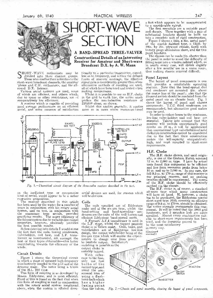
with the rotary aerial system mentioned fu s i n g Pol n.t above, when the stttem is rölated direc- than the valves, Fig 2.-Chassi anj panel assembly, slnwing 1/u layout ej panel ccrnponenls,
-
Fig. i .-Theoretical circuit diagram of I/te three-valve receiver described in I/te ¡cxl
on the inefficient type or compromise kind of aerial, would appear to he a rather expensive proposition.
The receiver described in this article lias been used by the witer for a number of years in conjunction with his rotary aerial system, and on test, in conjunction ìitli the commoner type aerials, provided gratifying results. The super efliciency of the former system due to variable directional properties, however, obviously provides the best possible results.
Before entering into details I would stress the fact that the coils, tuning condensers, valveholders. coil base, and L.F. trans- tòrmer as incorporated, are amongst the best of their types obtainable-this factor contributing towards the efficiency of tite whole.
Circuit Details Figure 1 shows the theoretical circuit
in which a stage of untuned high-frequency is inductively coupled to the grid coil of tite detector stage. The latter being a triode of the ILL. 210 type.
This form of coupling is as developed by i\lessrs. Eddystone, and is most efficient. Proof of this is found in the fact that when this fornì of coupling is used in conjunction
aerial devices are us&d, for reasons u liicli will be obvious.
Coils The coils specified are of Eddvstone
make and of he six-pin type, whilst the band-setting and band-spreading- con- densers are the units of the well-known and efficient Eddystone band-spread outfit.
A Ferranti A.F.4 transformer is used in the L.F. stage, whilst the tapped pentodo choke is of Telsen make. Coils, bases, and valveholders are of Eddystone low-loss design, the output valveholder being of the five-pin type which will enable the expeti- mnenter to change over from power to pentodo output. Satisfactot matching is possible as thQ output choke is suitably tapped.
With refer- ence to the fuse, only use fuse bulbs of the correct type, and avoid the non- sensical idea of io
using a flash- lamp bulb which has a higher
earthed via the chassis. The ll.F. choke is, of course, a standard
all-wave type which many constructors will have on hand. 1f howcvei', a choke has to be purchased the Eddystone special short-wave type 10l'O, covering an effective lange of 9,5 nl. to 170m. should be obtained. The writer strongly recomniends this corn- ponent It will be noted that the .0001 grid condenser, and 5 megohm leak are again specified. Almost every combination suit- able to short-wave requirements has beca. tried, and the foregoing proved to be the most satisfactory in every u ay.
overleaf.) (Continued
'\ eANDs:
RE ACT IO
- Q_p_f
5ANDSTTER
T' I
t--
I
low-loss valve-holders and coil base are -HT+, essential. Takiire into account that this SW.HF.C.
HT 4-2 receiver will provide exceptionally good SEE TEXT ,,r results on 10 in., it will be appreciated .4
4 IPED that conventional type valveliolders of solid 2 MED dielectric construction cannot be considered
2 'i-.---ft---o (lue to the fact thit their constuiction
UNSCREENED p in ike, the self capacity comi aratis el .- PLATE LEAD OUTPUT high, and most unsuited to short-wave '-t
_ in order to reduce losses to the minimum,
- - - requirements. MED
DET HT.- POWER ;-î-- H.P. Choke 3
I The H.F. choke shown, and used origin- ( 2 ] ally, is one of the Graham Farish screened
GB. - 12 in. to 2,000 m. type. I have by actual 6 4 MÇ
F(SE A tests found this component to be efficient SE TEXT I A
and free from resonance peaks from below 2MFD 10 in. and up to 2,000 m. In any ease, the 2 MFD / i--- - LT- full 9.5 in. to 170 in. range of this receiver is
'I i our principal concern, and no peaking j j troubles should be experienced. The screen
u LT.4- of the H.F. chiike should he effectively 4
SHOST -WkVI' enthusiasts may be divided into three distinct groups. Those who confine their activities to the
short-wave broadcast channels, the amateur 'phone and C.W. enthusiasts, and the all- round DX. listener.
Various aerial systems are used, some of which are efficient, and others which, due to space or other restrictions, are of comparatively low efficiency.
A receiver which is capable of providing good average performance ori an efficient aerial, and some measure of satisfaction
tionally to a particular transnlit ter, regard - less as to frequency, and within the defined limits of receiver coverage, the efièctive signal gain is considerably greater than when alternative methods of coupling ai-e used, all of which have been tried and tested when making comparisons.
Whilst it is possible to use an HF. choke iii the grid to earth line, the writer much prefers the non-inductive resistance of 250,000 ohms, as shown.
Whilst this applie generally, it applies moi-e so in cases where resonance-tuned
after a few months' use in a warm room, thus making chassis rcthoval difficult.
Panel Layout The layout of panel components is one.
that provides a comfortable operating; position. Note that the band-spread dial end condenser are mounted tin. above tile centre line of the panel ; also that tije filament switch should be insulated from the metal panel via an ebonite bush. Fig. 3 shows the layout of panel and chassis components. TOC. fixed condensers are recommended, hut alternative good makes may be used.
January 6th, 1940 ACTIAL RELESS .347
W \/ a fact which appears to be unappreciated to a considerahIe exteñt.
The first essentials are a suitable paiìet I and chassis. These together with a paji of
ci o N substantial brackets should be built up into a complete unit of rigid construction.
Figure 2 shows a 14m. x 8m, metal panel of the crackle finished type, a l3in. by 10m, by 2m, plywood chassis faced with twenty gauge aluminium sheet, and the two
A BAND-SPREAD THREE-VALVER panel brackets.
C .The chassis can he made tin. shorter than onstiuctiofla etai s o an nteresting the panel in oider to avoid the difficulty of Receiver for Amateur and Short-wave fitting same into a w ooden cabinet which, as
Broadcast DX. by A W Mann in nearly every ease, will shrink slightly '
PDF compression, OCR, web optimization using a watermarked evaluation copy of CVISION PDFCompressorPDF compression, OCR, web optimization using a watermarked evaluation copy of CVISION PDFCompressor

t'
Band-spread Tuning Next for discussion is band-spread
tuning arrangements used in this receiver. Before going further I would refer readers
to previous articles dealing with band- spreading by the writer and others.
As previously stated the Eddystone. band-spread outfit is incorporated in this receiver. The band-setting, or tank, cou- denser, is fitted with a ten-stop catch plate and ten-division scale, complete with pointer, whilst the band-spreading conden- ser has an integral slow-motion drive, a large diameter knob, and one hundred degree scale, the complete kit being designed for use with Eddystone foui'- and six-pin coils.
A useful amount of spread is obtainable on the 14 mc. band covering 40 degrees, using the 6LB coil. With the OY coil 80 degrees spread ìs obtainable on the 7 mc. band. A commendable feature is the care- fully worked out overlap beta-eon the band-setter positions which assures that nothing is missed. A point worthy ol consideration with regard to this receiver concerns calibration. With the coils and band-spread kit specified, the operator can calibrate the band-spread condenser dial over tite full scale, in association with the individual stop' positions of the band- setting condenser, through the full range of coils, and if desired, can prepare separate or composite calibration charts for reference purposes.
Taking into account that accurate cali- bration is he key in part to successful DX, other things being equa1,it will be appre- ciated tht the degree of accúracy made possible by means of the definite stop
It is not claimed, however, that the çonstant, the reaction condenser being untuned stage provides the signal gain. htted with integral slow-motion drive, and to be obtained with a fully tuned T.14.F. of Eddystone make." stage, but should the latter be conteni- A receiver built along the lines suggested plated at some future date, the necessar' will prove equally suitable for amateur
A E LT+ LT- - HT:- HI*I HTs-2 'PHONE ----- _ --
2MFD j: 1®7 \ \ H.F 'II 9vG'IB. II O O
J VALVE HOLDER ' 8ATTERY
Ii O _?) © HI°
2MFD. ccoc o L...
COQ HOLDER MO.
DET. - POWER OP
348 PRACTICAL WIRELESS
SHORT-WAVE SECTION 'phones. The same applies to other amateur (continued from previous page) lo m. stations in various parts of the world.
In order to eliminate wking between The addition of an untuned H.F. stage these components, the grid condenser is further improved the overall performance of the T.C.C. tag type. of the receiver on all bands, including SW.
broadcast channels, and C.W. channels.
January 6th, 1940
H.F. stage or stages out of circuit, such procedure edabling full advantage to be taken of 11.1'. in whatever form it is used.
In the original receiver dead spots are non-existent throughout the full tuning range, whilst reaction is smooth and
Performance The original model was in two-valve
form, the untuned stage being added at a later date, and on completion of over twelve months' tests under all conditions, the performance iii terms of results was remarkably good on all bands, including the 10 in. band, various U.S. amateurs and others on the Canadian border being heard in the afternoons at volume coni- parative with that of British 40m. amateur
which is connected by the not capacitively. bridged resistance R1 with the carthed return lead. The condenser C' lias such value that a considerable potential drop occurs for the low-tone frequencies, but not for the medium-tone frequencies which potential drop makes the counter coupling for the low-tone frequencies small. The resulting control curves are shown in Fig. 12. In the one extreme position (b) the amp] ification for the low tones is consider- ably less than for the high, and particularly
PRACTICAL WIRELESS
SERVICE MANUAL By F. J. CAMM.
From all. Booksellers 5/- net, or by post 5/6 direct from the publishers, George Plewnes, Ltd. (Book Dept.), Tower House, Southampton Street, Strand,
London, WC.2.
-'--------- -: -.. -' - ....L . =. ... ..' ..
positions provided by the and-setting con- denser, and the fact that once logged a station's frequency can, in conjunction with the band-spread dial, be spotted or registered accurately at any tinie as required, the DX possibilities appear rather attractive.
In order to get down to 10 ro., a special home-made coil is required, this coil being wound on a standard Eddystone six-pin coil former as follows
Ten-metres coil data. Grid coil: Two turns 20 gauge copper enamelled wire. Aperiodic coil winding Two turns 30 DCC. wire interwound with grid coil. Reaction coil winding: Tu-o turns 20 gauge C.E. wire as per grid coil.
Standard sparing between reaction turns, and double spacing between grid tui-ns. Standard spacing also between grid and reaction windings.
There is no place for old valves in this receiver; an emission test is therefore advisable in cases of doubt, and the manu- facturers' instructions should be followed i-dative to plate and bias voltages, etc.
OEANDSETTER REACTION 8.ANDSPREAD
Fig. 3.-Diagram showing layout oJ chassis components.
modification can be carried out without difficulty.
An untuned stage is usually regarded as a buffer stage, and as a means of re- moving dead spots. The writer, however, always makes sur that dead spots are not in evidence, and tests are carried out with
TONE CONTROL BY NEGATIVE FEEDBACK
(Conin,ed from page 337)
Single-stage Amplifier Control curves of a sinular kind may also
be obtained with condensers alone. Such an arrangement is shown in Fig. il, in the form of a single-stage amplifier. Between the anode and the earthed return lead of the valve is the series connection of the resistances R2, R, and R3. The resistance R is capacitively bridged by the con- denser C for the high-tone frequencies. The sliding contact S is connected across the condenser C' with the cathode of the valve
'phone, OW, and SW. broadcast reception, in fact, will be found to be a good all round proposition, whilst the calibration, and positive logging facilities it effects arc such as are not to be found, as a rule, in the simple types of receiver, but are common amongst the more expensive communication types.
for the low-tone frequencies (? WR). In the other extreme position the amplification for the medium-tone frequencies has risen considerably, so that it is now- larger than for the high-tone frequencies, whose degree of amplification has osily increased very little. The degree of amplification for the loiv-tone frequencies lias risen a little snore so that it reaches almost the value for the ampli- fication without counter coupling (dashed line). Tise circuit shown is recommended for receiving sets without complete fading compensation in which it is desired, for instance, because a loudspeaker of poorer quality is used, to achieve in any case a raising of the low--tone frequencies.
PDF compression, OCR, web optimization using a watermarked evaluation copy of CVISION PDFCompressorPDF compression, OCR, web optimization using a watermarked evaluation copy of CVISION PDFCompressor

-
-T- -.
SIR,-Being a reader of your very fine paper for quite a number of years now,
I enclose a photograph of my den which may interest other readers. I w ould also like to state that I shall be glad to exchange my QSL with any reader anywhere, either S.W.L., AA. or full call station, and will answer every one. Vishing your fine paper every success-VINCENT I,Ji'ToN (8, Falcon Terrace, Whitby). Correspondents Wanted SIR,-I have béen i regular reader of
yòur fine journal for the last two years, and must compliment you on the high standard of its contents. I would like to exchange my S.W.L. card with S.W.L.'s throughout the world, especially thqse in
Nemica, Ltd., Tower house, Southampton Street, Strand, London. W.C.2. Envelopes must be marked Problem No. 381 in the top lett-hand corner. and must be piated to reach tin s outre not later tua it the first post oit Ilomiday, January 8t1, 1940.
Solution to Problem No. 380.
Arthurs I sil an exposed spark-gal) aerial lightning arrester lit ed to lila aerial, amid titis hail heroine very ditty and was lea king. The graduai short-circuiting of the gap by dirt gave tite increasing loss whieh he experienced.
Tite following three readers suceessimilly solved Problem No. 3711. and books have accordingly been forwarded to theta
(No Signature), 6, Digton Road, Wandsworth, S.w.is.
D. Bates, 99, Groveley Lane, West Heath, Birmirtg- ham, 31.
G. A. Cohlings, 27, Lawileld iload, Acton, WI.
1\iarìy of us believe that the earths may not be the only planet to contain intelligent life. and this age-old problem is treated in "Is Mars Inhabited?" P.T.O. is obtainable through any news-
agent or bookstall, price 7d.
AMATEURS By F. J. CAMM
1/-, or 1/2 by post from George Newnes, Ltd., Tower House,
ISou ihampton Street, Strand, London, W.C.2. I
.1
half-wave 20 metre doublet. Results with this apparatus have been
most encouraging ; 07 countries have been heard on 'phone and C.W. on 14 inegacycles, and 45 States of the American Union have beets "hooked." Tite best verifications which I have received aie VR6AY l4nìc/s 'pitone; CR4M1\[, ZL2QA and K6BNR 14 mc/a C.W. ; and CE2BX 28 mc/a 'phone.
First G reports have been confirmed by W2KNP (7 me/s C'-W.) and W7GTU (14 mc/a C-W.).
Also in the photograph is to be seen a portion of the C.W. transmitter which was in course of construction when the war broke out. This is now safe in the hands of the G.P.O., but it is nìy firm intention to outlive Hitler, and see what can be done svitii QRP C.'IV.-LEsLIE J. J .MORGAN (Bournemouth).
PROBLEM No. 381 -
BRANDON obtained some surplus com- ponents and made up an AC. three-
valve set, which when tiled out, gave very hail hilo,. He made a few tests and finding nothing wrong with the wiring eventually decided that tite L.F. choke, which was in- chided in the us sal position, was too uinahl. 11e therefore ohitaine,l a siiiiils r coiupoiient uitd pii red this in the HT. negative lead to add to the snioothing, but w lien he switched ou the hain was worse. Why w as this ? TI ace books will be awarded for the Ii rst three, correct solutions opened. Entries should be addressed to flic Editor, l'IIACTICSL WIRELESS, George
"P.T.O." MOST of us these days have friendr in
the Forces, and most of them want something to read. Often billeted, or in tratning camps in the heart of the country, they lind that, in the black-out, time drags intermtnably. Good reading matter is, for SOPiC odd reason, at a premium, and this is where every reader of this journal can help. A magazine that slips into the tunic pocket is a godsend, and a good example is PTO. -the British pocket "Digest" of the world's news and views. The February issue, for instance, contains an important artIcle, " \Vhen We Have Won-What Then ? " by Harold Nicolson, and another on Russia's startling claims for a gigantic new oilfiekl which is being developed a thousand miles from the nearest frontier.
CW DX on 7 nIds. In addi- I also correspond 104) lier cent, with anyne. r tion an! vil'ing toexchtnge Wishin, your papei evers success in the
n'y S.W.L card by return of future-A. B. RICBARDSOx (The Watering, - post vii h any reader who may Parhan,, Woodbridge, Suffolk).
*
L
care to send
Herewith 'i JJUAID ¡ logof7 me/s. so 4.
statiousre-
VIT! 4
r -S.W.Adaptei: phone-
.T.,, k
i
- PJCl **
-
a
On dIv.- LU4J A;
- ' -
- K4DUZ,ER-A. KU, FAI;
A corne.r of Leslie J. J. Morgan's den. I K S Ii B ; ' '1AP;
-
home-built O-v-1 used exclusively for 28 XEII-IR ;
K5AK, AM 2 __ megacycles. This latter set has band- in PYI, 2, 3, 4, 5, and 7; all spread, and transformer coupling between districts W. i - - -
flic tuo triode valves (a D 210 detector, and Q.S.L.'s confli-miire 7 inc/s --- - -
ail H.L.2 L.F.), Uotl, of these sets are to reception have been received A reader, Vincent Upton of W/iitbg, send, us liii, interesting he seen in the photograph, The antenna fimo 'TOIB
; K5A1 ;
ES5C ; photo of his den. preferred here for receotion is a simple -4
of the sender (not nec2ssarîly for publication).
-
Readers' Dens SIR,-As a regular reader of your excel-
lent journal, I am sending you a photograph, together with a description of my station, which, until the beginning of Septeniber last, operated under tise call of 211N0.
rJ'he receivers used are a Haliicrafter's "Sky Chief'' (now prettXalicienl, but still in good trim !) and a battery-operated
U.S.A.. S. America and the West Indies. I nould also like to correspobd with any young reader in U.S.A. oi ftAtnerica, inlerested in SW. reception. \Vishirig your paper every success.-kRNNETII I. PROCTOR (P3, '.rliackeray's Lane, Woodthorpe, Not- t tiigliain).
Slfl,-I would like to correspond with any S.W.L. who is keen on logging
years, and have followed all I ho articles on short-wave raiho.
Also, I would like to correspond with any member of the British Short-wave League, and also the secretaiy of that society.- E. I'ESTELL (123, Victoria Street, Granthani, Lines. 1.
Exchanging S.W.L. Cards SIR,1 should very much like toexchangc
my S.W.L. card with any " Ham,'' A-A'' inni, or S.W.L., particularly
BS%VCC members, anywhere in the world.
g
:luery 6th, 1940 PRACTICAL WiRELESS
cpen eC0essP{i'if01 The Editor do s not nec arily ag s.,th the opin oi cap. sed by hi correspondents. All letters must be accompanied by the name and address
349
YU7AY; W1AW, KJU, 2110M, 2LEE, KPK, KXK, EYS, 4FTV, 7G111, SQOS, and PERP.-W. JI. Gorm (Newlialt Vicarage, Burton.on-Trent, Staffs).
SIR.,-May I express my appreciation of the new PRACTICAL WIRELESS,
T have been a reader for the !at -seven -
PDF compression, OCR, web optimization using a watermarked evaluation copy of CVISION PDFCompressorPDF compression, OCR, web optimization using a watermarked evaluation copy of CVISION PDFCompressor
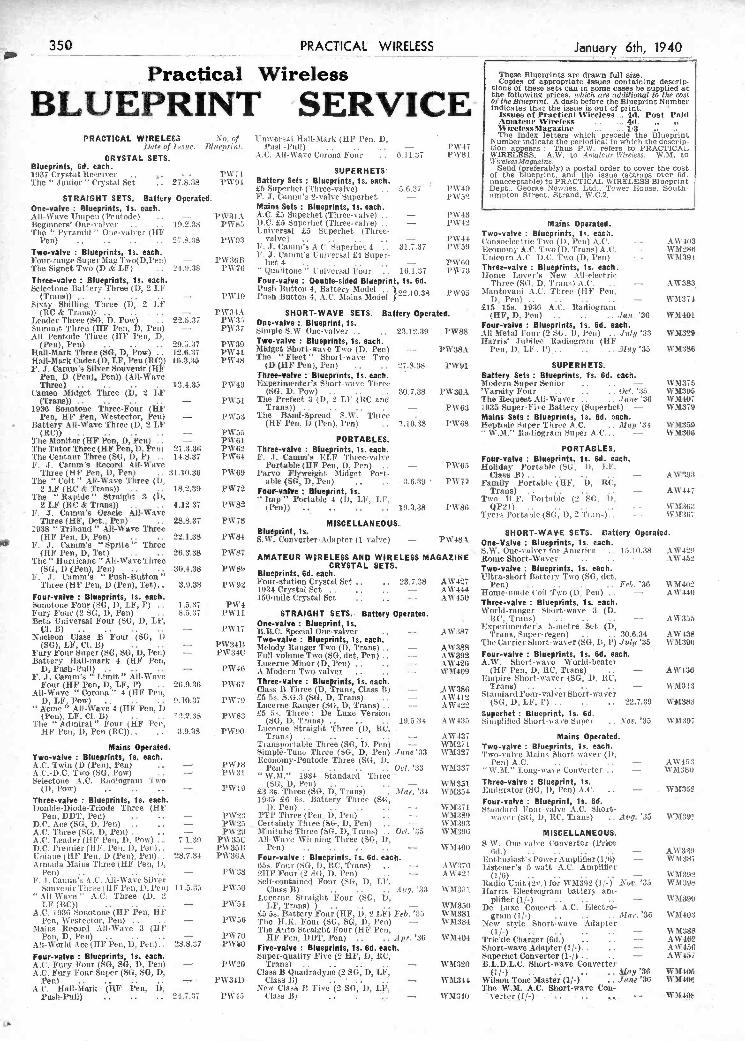
u Four-valve : Blueprints, is. each. Super-Quality Five (211F, 1.5, lIC, Superhet Converter (1-/) .... - AW417 AC. Fury 'FOUr (SG, SG, i), l'en) AC. Fury Four Super (SG, SO, I),
ren) - )'W20
¡'Vs ¿11)
Trans) ........ - Class JI Quadradyne (2 SG, D, LF,
Uass J ) - WM320 IJ.L.D.L.C. Short-wave Converter
(t).) ..... - .. ., May '36 WMJ4I 's\ sisees Tone Master (1/ ) Jesse ¡t
W11106 W \140t
- AC. 11,11-Mark (11F l'en, D, i PunIe-PoU) ...... 24.7,17 P\V41
Neve Class lt Five (2 SG, is, LF Class it) ... -
The W.M. AC. Short-wave Cou- W11341) verter (1/-) . .. .., ' ' '-WM4OS
Ir' -'
- -
. .
-
. :.,v
.
'Z.. . B
ama pera M ted TranportahIe Three (SG, D, Peli) - '33
VM37! Two-valve Blueprints, is. each. Two-valve Blueprints, Is. each. SimisleTtssic Three (SG, D, Pen) Jene
llcosiosny-I'entode Three (SG, h WM32í Two-valve Mains Short-waver (I),
AC. Twin (D (Peli), Pen) .. AC-D.C. rwo (MG, Pow) .
i's ........ Oct. '33 "
WM831' Peli) AC. ...... -
"W.M." Long-wave Converter .. - AW4S:I WM:380
.
Selectoite AO. Racliograns Two W.3l." 1934 Standard Titres -
(SU D Pet) . - \vMi5i Three-valve r Blueprint, Is. (t), Pow) ...... - SWILl £3 3s.'Tli'ree (SU. D, Tians) Mar. '34 DM354 IDisigrator (SG, D, l'en) AO. .. - -. WMoo
Three-valve Blueprints, Is. each. 1935 £6 On. liattery Three (Sil, Four-valve : Blueprint, is. 6d. Y Double-Diode-Triosle Three (HF D, Pen) ........ - - WM.3 I Mttii,dtird Four-valve AC, Short- .
Pen DDT Pesi) - PW J TI Three (Pen D Prit) - 'v\8l)8 l w ti r i (at I) SIX. Tian ) Avg Je W M .) I) C Ace (Md D J'en) - PW2S Certainty Three (SU, D, Pen) . - - WM3OS A three ('C D Pen) PVs Thnituhe Tin re (SC D Fran ) Oct Ja WMJ Jis MISCELLANEOUS AC. Leistler(HF Pen, )i, l'on) . .. 7.1.39 PW3SC All-Wave Witinitig Three (SG, 11,
S W. One-valve Convertor (Price D.C. l'reinier(HF. Peu, I), l'es). - . 1'W391i l'en) .... ,... \5M400
(511 ) -------- - ADS-Pt 1jhitise (Il F' l'en, D (Pesi), Pesi). 28.7.34 PW3SA Four-valve Blueprints, Is. 6d. each. tstst Poscr Ansplilier(l /51) - WM3S)
taG Armada Mains 'I'hree (HF Peu, Is, . 95. Four (SG, I), CC, Tians) . - - AW3II) Listener's 5-watt AC. Ansplther (ii Pen) --------- PD 38 911F' Four (2 SG, D, Pesi) . - AW421 (1/6) -------- - WM3SS i.- F. .1. Carnsst's AC. All-Wave Silver
'Jurar Self-contained Four (SU, D, Li", Radio Uisit (2v.) for WM3cIJ (1/-) Ear. '35 'sVMJLla
Souvenir (11F' Pois, Il, l'es) Il.5.3.i . PD .O Class B) ------ 4ug. '33 \%M31l. Harris Electrograns battery ans-
&l1 D si e k h J hiee (D - J eterne St tat lit I our (C D plifier (1/ ) - 11393 Y 1F (RC)) PD 54 1.1', Traits) ) ...... - WM35SJ De Lisxe Concert AC. Electro-
AC. 1930 Monotone (HF Pesi, 11F -' £5 Sn. l3atteryFossr(HF. D, 2 LF) Feb. '55 WM381 grusss (If-) ------ Mar. '56 WM403 Pen, Weetector, Pois) - . - . - l'WaS Tite 11K. Four (SG, SG, i), l'es) W'M384 New style Short-wave Adapter
Mains Record All-Wave 3 (II F TIse Auto Sts'aiglst Four (11F l'Oit, . (1/-) ......... - W 11388
Peu, D, Pen) ...... - i'D iO HF l'en. DDT, Pen) Apr. '36 W 11404 Trickle Charger (Od.) - AWIis8 AIl-D orki Ace (11F Pesi, D Pesi). - 28.8.17 .P\VO Five-valve Blueprints, is. 6d. each. Short-wave Adapter (1/-). . . - AW4511
, l'en D (Pen) Pen)) (All-Wave Threeva!ve :Bluepflnts, is. each. Battery Sets : Blueprints, Is. 6d. each. u
Three) . 13.4.3 I'W4 Epsrinientei's Short-ws\'e Three Moderii Super Senior .... - M3Th Cameo Midget Three ÇD, 11? (SG. D. Pow) 3o.7.3 P\VO .A'V arsty Four . Oct. ':, WM3tM
. (Trans)) . . . - P\%$L The Prefect 3 (I), 2 LI (hC and The Request A1-Vaver . ./ue 36 WM4O
. . 1936 Sonotosse Three-Fout (HF TiaiLs)) _ PW63 1935 Super-Five flattery (Siiperbet) - WM379 Pen, HF Pen, Westector, Pen) -- PW3 The Band-Spread SW T Itice Mains Sets : Blueprints, is. 6d. each.
. Battery All-Vave Three (D, 2 LE (HI' l'en, D (Pen), l'en) . i.iQ.38 I'W68 Heptoile 4sper Three AC. . . Mey '34 \VM359 . (RC» . - PW55 ..
wjfl.,, ta[iograni Super A.0 ... \VM361. t 'The Monitor (HF Pen, D, Pen) . . - P\VGI PORTABLES.
I'heTntorThree(HFPen,l),Pen) 2i.5.3n PW5 Three-valve : Blueprints, is. each. PORTABLES. 'Che Centaur Three (SO, D, P) . . 14.8.37 P\V4 F. J. Camnie ELF Three-vaI\c Four-valve : Blueprints, is. 6d. each.
. F. T. Casnms Record Aif-Vi ave PortbTe (HF Pen. O, Pen) . - PW( o1iday Portable (St D, LI' '
. 'Three (HF Pen, D, Pen) .. 31.10.36 PW6O Parvo Flyweight Nidget Port- (ass B) . . - AW O3 The " Colt " All-Wave Three (T), . able (SG, D, Pen) - PW Family Portzdle (UF D, RC, l 2 L! (RC& Trans)) . . 18.2..9 PW72 Four-valve : Blueprint, is. Traiss) ........ - AW44 ,
'lhç Rapide Straight 3 (1), - . 1sep " Portable 4 (D, Lt', LE, Two 11F. Portable (2 C, D, 2 LF (RC Trans)) .... 4,12.3, I'W2
(L'efl)> ........ 19.3.38 I'WSI QP21) ........ - WM36; ,
p - 1. . J. Ceirnn e Oracle kil Wave . Tvers l'ortahle(SG, D, 'l'ian). . - WM3ST Three (HF, Pet., Pen) . 28,8.37 P\V78 MISCELLANEOUS..
1938 'Iriband All-Wave Three Blueprint, is. SHORT-WAVE SETS. Cattery Operated.
F.J Three i W84 SW. Converter-Adapter (1 alvc) PW4SA One-Valve Blueprints, is. each.
Hi' Pen D Tel' O 355 p%, '
N., SW. Onc- slyer foi- America .. 15.10.38 AW1211
The" Hurs'icalie " All-Wave Three AMATEUR WIRELESS AND WIRELESS MAGAZINE Rouse Short-Waver .... - AW452 (SCi, i) (Pen), Pen) .... 30.4.38 PWSS CRYSTAL SETS. Two-valve Blueprints, is. each.
J' T, C:imm's " Posh-Button" Blueprints, 6d. each. - Ultra-short Battery Two (SO, det, ,
Three (HF Pen, i) (l'en), Tet).. 5.9.38 PW92 Jour-statsoss Crystal Set .... 23..8 A',S42 pesi) ........ Pet. '36 \VM4Ie1 - 19,14 Crystal bet Tb le-sws le tot T 0 'D Pee' - AlI 4411 Four-valve : Blueprints, is. each. 150-snil Crystal Set - AW45IJ
Souotone Four (SG, 1), LF, P) . . 1.5.117 PW'4 Three-valve Blueprints, is. each.
Fury Four (2 SC, i), Peu) . . 5.5.37 . I'Wll STRAIGHT SETS. Battery Operated. World-ranger Short-eeve .1 (D, Beta L'utvereal Four (SG, D, LF,
'
pwi- o - I BI - t i
.
.
ltC,T1JJ ......... - Lxperinieuter s a-metre Set (D,
A\113.so
- N eleon Clase B' F ur SC '; '(SG)
JIB_C. Specsal Oue-valver , . - is each
AlI 387 'i'raus, Super-regen) .... 30.6.34 AW4SS LF Cl L) - PW14J - AlI
TheCairier Short \ea\er(S1 11 1) J019 15
Fury Fonr Super (SU, SO, D, J'en) - PW :34C Fell-volume Two (SG. ilet, Pen) - - AW392 Four-valve Blueprints, is. 6d. each. Battery flail-mark 4 (HT Pesi, Lucerne Minor (D, Pèss) ,,.. - - AW426 A.W. Short-wave World-beater
D, Puais-Pull) ,. . . - PW4G A Modersi Two-valver - , , , WM409 (HF Pen, D, RC, Trans) . . - AW'436 F. J. amns s Limit All-Wave
- ree-va ve . ueprin s, e. cae ,
Empire Short-waver (SG, D, RC, Four (HF Pee, D, LF, P) ..
All-Wave "Corona" 4 (11F Peu, 26.9.56 FY67 Class B iliree(D, rrane, Class JI) - . AlI386 Trane) ........ -
Stniidardlj'our-valverShort-waver WM3II
D Lt J ow) 110 rw .
La 5 b t, I (Sb- J) Tr'sus) - UCCi i angel D, hails) ,- IVi 41
A V4 (SC D LI' 1) 02739 WM383 Acme" All-Wave 4 'HF Pen D (Pois) LF Cl B) - . ' . 12.2.38 P\V8a
. ,
£5 5. Three De Luxe Version Supsrhet : Blueprint, is. 6d. '35 The " Admiral" Four (HF Peu, (80, II, Trans)
, . , .
- 111.5.34 AW13.s Siniphilied Short-wave Saper , . Nm', WM397
t HF len I) Pen (RC)) 958 PlI to Ltsir,o)'trai lit Three (D lIC Mains Operated
- Amateus' Wireless. 4d.,,,. Wis'elessMagazsne . 1/3
PRACTICAl. WIRELESS A1o. of Universal I-Tail-Mark (HP Pfl. I), fiat« of Iaue. Bliseprin/. l'ush-Pull) 1'% 4' Clon appears Thus P.W, refers to PRACTICAL
CR STAL ET AC. All-Wave Corona Pour - . 0.11.37 FW81 WIRELESS. A.W. to A'n«lcsir Wireless. W.M. to -
Bluepnnts, 6d. each. .
Wi re1essMao.zine. Send (preferably) a postal order to cover the Cost
1937 Crystal Receiver - PW 71 - of the blueprint, and the issue (stamps over Gd. The " J unior" Crystal Set - - 27.5.38 Battery Sets : Blueprints, is. each. . unacceptable) to PRACTICAL WIRELESS Blueprint
£5 Superliet- (Three-valve) .5.11.37 }'W 40 Dept.. George Newnes. Ltd.. Tower House. South- STRAIGHT SETS. Battery Operated. ' J. Caiiìiii's 2-vàlveSsLperhct. i'wso ampton Street. Strand. W.C.2.
One-valve : Blueprints, is. each. Maine Sets Blueprints, is. each. ______________________ __________ All-Wave Unipeis (Pesstode) . - 'l'PeSIA AC. £5 Sisperhet (Three-valve) - PW43 Beginnere One s uses 10 '38 I 1) C La Supeulset (Three valse) - i W 4. Masis Operated Tise Pyrasokl " Ouie-vals'er (UI" tssverssl £5 Superhet (Three-
- Two-valve : Blueprints, is. each. l'en) ........ 27.8.1)5 i'woa, valve) .. .
., " ('osssoeleels-ie Two (1), Pen) AC. AW4(iS
T ale Blue riots is each 1. J. tatous e AC. -'usperhet 4 . .
JCrnussn s I-isis ein il £4 Stipe 31. 3e I W al) Economy AC. 'l'svo(t), Trans)A.C. - WM2SII
A, J'osuriau,e Supes 314), I wo(D Pet) - 1W 1fB - Unicorn ( J) t. iwo (D lesi) 3', 1(1394
rl e Signet Iwo (D t 1F) 4 4 Is PW sI Qualstone I- ussr s al i our i 1 1 3', 3 Three vl Blueprints is each
Three-valve Blueprints, is. each. Four-valve Double-sided Blueprint, is. 6d. TI (Sc) D 'fi-usas) All - &W58'3 Seleetone But) ery Three (I) LI lush Buttosa 4 Battes3 Model 10 rWJ., Mssitovasii & T. Ilirm (Fl1 t'es (Trans)).. .... . -, l'Vi 10 t'asIa Button 4, AC. Mains Model 1 ' I), Pets) ........ - WM374 Sixty SIsslissig Three (D, 2
¡ £15 1-Ss. 193(1 AU. Radiograusi -
(RC & Trasse)) ....... - ,, PW,4A SHORT-WAVE SETS. Battery Operated. (fly, D. Puss) ....... lau. '36 WM4OI eadles: Three (5G.),POss13 . .
e' est) -. One-valve :. Blueprint, 15. Four-valve : Blueprints, is. 6d. each. I'ii Simple S.W Onc-valver .... 23.12.39 PWSS All Metal 1-our (2 8G, I), J'en) July '33 WM32'J.
l'ena Pena ' ' 09 -, '17 W,30 Two-valve Blueprints, Is. each Jl'arris' Jubilee Rasliogrsssi (HF
Hall Mark Three (SG D Por) 1_t'i PW 41 Msdget Short rase Tuso (I) Pesi) .- 1W 38 C I cru B Lt I )
JIa,y 3., 33 MISt Hall-Mark Cadet(D, LT, Pen (liC)) 10.3.15 PW'dS flue Fleet Slsort-siave Tiro
T. amin's Silver Souvenir en,, ru) .... - .8.38 1 V, ji - R -
350 PRACTICAL WIRELESS - Jnury 6th, 1940
Praccl Wireless .:redsrnjng descrip- tions of these sets can in some cases be supplied at
B L J E P R I the following prices, which are additional to the cost ae A e0tt r1ntNmber - Issues of Practical Wireless ... 4d. Posi Paid
PDF compression, OCR, web optimization using a watermarked evaluation copy of CVISION PDFCompressorPDF compression, OCR, web optimization using a watermarked evaluation copy of CVISION PDFCompressor

a
iiiI
All-wave Aerial
" Once again I must call on your assist- ance in designing part of my radio equip- ment. Your previous advice regarding the receiver has been followed and I am more than pleased with the result, but now wish to improve the aerial so that I can rope in all those distant stations. Unfortunately I am living on the second floor of a three- storey house and the garden is only l5ft. in length. I do not want to put up a Jong pole in the garden and yet the indoor aerial does not seem all that I could desire. What is your advice to me now in this connec- tion ? "-K. D. (Bromley).
heavy gauge insulated sleeving over the flex lead and then to push this down to the plug after this has been fitted. If you use the type of plug having an end hole, the sleeving may be pushed into this and will keep tise flex from bending sharply, although not removing the flexibility.
Including a Meter " I wish to make periodic tests of a set
from points of view of anode current, etc. I have seen reference to jack connections in each circuit but this would appear to be expensive. Is there no simpler way of obtainingthe same end? "-B. T. (Heiston, Cornwall).
H. E. T. (Bognor). Try a much smaller condenser, sot larger than .00005 mfd. If this fails, I lien re-wind the coil in question.
5. R. (Thundersley). A form of wave-trap would be preferable and would eliminate all of the troubles.
P. S. (Ciapham). Only one Rl'. stage would be necessary. Band-pass coupling in the detector tue would be advised iii the second ease mentioned.
S. W. (Maiden). A large horn-type speaker would be probably best, but remember the additional room taken up. The good cone, properly mounted, would probably l,e indistinguishable with tue amplifier nieiitioiied.
r IeOe.afleueOeeOefaeflef
s The coupon on page iii of cover must be attached to every query.
tive condensers or tite electrolvtics may be used.
Contrast Expander "I note that you have again referred
to the Contrast Expander in your notes on the ideal set. I regret to say that I
tried out a circuit of this type some time ago, having got the circuit from an American magazine, but it did not appear to make any difference to the reproduction from records. Have you found that it does really do what is claimed for it, as I should certainly like to improve my results by using such a circuit if I could be assured that it does work? "-L. K. (N.W.5). THE circuit certainly does what is
claimed for it when it is properly constructed. You may have steed wrong values, wrong connections or unsuitablo valves in your experimental tests. You can see for yourself, when such a unit is made, that it does actually modify tite contrast, and in the special unit which we described we indicated how this could be done. A millianuneter is included in the anode circuit of the expander valve, and whilst listening to the reproduction you can see the current rise and fall with the volume of the music. Obviously some types of
record need no expansion and the difference may hardly he noticeable, but a really good symphonic record, or an organ, will reveal the effects, especially in the latter case, in the reproduction of the pedal notes.
We wish to draw the reader's attention to the
j. fact that the Queries Service is intended only - for the solution of problems or dilliculties arising from the construction of receivers described in our pages, from articles appearing I in our pages, or on general wireless matters. We regret that we cannot, for obvious reasons-
(1) Supply circuit diagrams of cotaplete multi-valve receivers.
j (2) Suggest alterations or modifications of - -. receivers described in our conten- jPoraries. -
- (3) Suggest alterations or modilications to jcommercial receivers.
(4) Answer queries over the telephone. j(5) Orant Interviews to querists. -
A stamped addressed envelope must be j enclosed lbr the reply. All sketches and -
drawings which are sent to us should bear - the name and address of the sender.
Requests for Blueprinte must not be enclosed j with queries as they are dealt with by a
separate department. jSeed Your queries te the Editor. PRACTICAL WIRELESS. I jGeorge Nenes, Ltd., Tower Rouse. Southomptsn Street.
Straud. London, W.C.2. The Coupon musi be enclosed With sorry query. L,,,e(a..ewu,,oett,.noJ
Strengthening Leads "J find difficulty in keeping my battery
leads in good condition, usually because the wire fractures where the lead enters a plug. The constant bending backwards and forwards seems to be the reason, and I note that in electric irons and similar apparatus there is a coil of wire to prevent this trouble. Is there any similar idea which can be applied to flex leads to help in overcoming this trouble? "-G. R. T.
(Shrewsbury).
THE easiest plan, and one of tite most
effective, is to slip a piece of fairly
ÍPLIES IN BRIEF 7'/se following replies to qsserieo are gívett in I
abbreviated forni either beco else of non-compliconce will, oc? roles or because tice pesitct raised oc not of j.
generalinterest. r
C
J. McL. (Upperlands). The meter in not suitable for measssrissg tite outpost frou a maille issit. Yost insist ssse a saetee with a high resistance, preferably 1,000 olsms per volt.
H. G. (Birmingham). Coil-winding data will be fount! in 01cr handbook, Coils, Chokes aitd Trans- for stiere. '
J. W. W. (ParkstOne). We do not supply blueprints of cosssntercial receivers. The makers may be able to assist Yost.
R. J. (DsvOnpOrt). The condenser may tse modified by resssoving titres plates from both moving and lixed sectio us.
L. R. (Stechford). We would recommessd the addition of a valve ist parallel with tise exioting osstpsit valve, isoisig. of course, exactly tIse same valve type.
K. E. (Gloucester). The current is ¡fluets toss high and isislictstes that tite valve in receiving too usuels HT. or insulticient OEB.
D. A. R. (Welshpool). The arrangement is defissitely not reconsissendeti and tise valve-makers instrssctiossn shossisi he adisered to.
L. V. C. (Shrewsbory). Ilse tise 28-gassge wire and keep it taut wlsilst winding. insulatioss is tsot isa- portaist ist this case.
N. T. (Aberystwyth). A resistance of approxinsately 100 ohms could be steed, but tite cssrrent stsossid not exceed 5 mA.
G. D. (Newport, Salop). Botis consponents are obsolete, cusd you sisoisid select stnsilar iteests frossi ast up-to-slate list.
W. V. (Perth). Write to tite Beonomic Electrio Company, Ltd., of 64. London Road, Twickenhiam.
S. E. L. (N.W.3). Scrape the carbon first and make certain tlsat it fits tightly. We do not think tite idea seul tisrn out very succesofully.
Bypass Condensers " I enclose a circuit of an H.F. amplifier
and detector stage which I am building and should like advice regarding the by- pass condensers which I have marked. I understand that non-inductive condensers are needed, but are these only available in tubular form ? If so, I cannot find the 4 or S mfd. type of condenser in any list in this type. Perhaps you could help me regarding suitable types."-J. H. (Perran- porth).
ALL H.F. by-pass condensers should be non-inductive, but the tubulais
condenser is not the only condenser which is of this type. Mica condensers are non- inductive and electrolytics are also of titis type. In addition, certain of the paper types of condensers are non-inductive and this is generally indicated on the case by the letters N.J. In the case of the large capacities, therefore, tite paper non-indue-
AVERTICAL aerial of the type we have often described is undoubtedly your
best solution. If you do not wish to enter tite upstairs fiat, then a rigid aerial will have to be used. This should be a length of steel or copper tubing, according to what you can afford or obtain in these days, about in. in diameter. Paint it with two or three coats of good outdoor paint to prevent corrosion and mount it on a strong bracket which will hold it about 12 or 18m, from the wall. The overall length of the tube should be not less than lift., longer if possible. To prevent swaying or bending, a length of wooden dowel may be driven down inside it. Solder a length of good covered stranded aerial wire to the lower end, and mount the bracket as high on the wall outside your window as possible.
anode lead for measuring current. Another is the split grid coimeetor which permits a pick-up to be inserted or grid current to be measured. One adaptor with each pin split could be used by you and trans- ferred from stage to stage as desired.
Bandspread Tuning Which is the best method of band-
spread tuning? I know yoU have men- tioned several different schemes from time to time, but I wish to include the system which gives the greatest control and easiest tuning in a new set which I am building up."-H. B. D. (Hornchurch).
UNDOUBTEDLY the standard arrange- ment of two condensers in parallel
is the best. The small condenser used for spreading should preferably have a direct relation to the band-setting condenser so that tite latter may be provided with a numbered dial or stop-plate device and then tite bandapreader may be adjusted by means of a slow-motion drive to spread every degree of the band-setting condenser.
'l
/
January 6th, 19:40 PRACTICAL WIRELESS 351
yOU dd ìt sti exactly which points QU wish to test- but it should be
are available which are inserted into II r e p 1 remembered that special split pin iidaptor/
valveholders between the valve and the holder and which permit meters or other apparatus to be included in various elec- trode circuits. A typical instance is the
tó'ruour letter split anode adaptor which will enable a meter to be included in series with the
(I
PDF compression, OCR, web optimization using a watermarked evaluation copy of CVISION PDFCompressorPDF compression, OCR, web optimization using a watermarked evaluation copy of CVISION PDFCompressor

i.
Coisìplete to the last detail, including all Valves and coi l, wiring diagrajiis and lucid instruct ions for Utiililing ionI working. Each Kit ja supplied with a
steel Chassis and Panel ajaS sises plug-in Coils .to tin e 1mm 13 ti) 171) metres. i Valve Short-Wave Receiver or Adaptor Kit 20g- 1 Valve Short-Wave Superhet Converter Kit . 23/-- i Valve Short-Wave 1-S.C. Superhet Converter
Kit ............. 26/3 2 Valve Short-Wave Receiver Kit .... 29/- 3 Valve Short-Wave Screen Grid and Pentode
Kit ............. 68/- REPLACEMENT VALVES FOR AU. SETS
EUROPA MAINS VALVES. 4 y., AC. Types, A.C./H.L., A.C./L., A.C./S.G., A.C./V.-M.S.G., A.C./H.P., A.C./V.H.P. (5-pin), all 5/3 each. A.C./H.P., A.C./V.H.P. (7-pin), 7/6 A.C./Pens- I.H,, 7,6 ; A.C.1P.X.4, 7/3 Oct. Freq. Changera, 8/6 Double Diode Triodes, 7/6 ; 350 y. F.W. Rect., 5/6 560v. F.W. Rect., 66 13 e. .2 amps. Gen. Purpose Triodes, 5/6 ; H.F. Pens and Var.- Mu. HF. Pen., Double Diode Triodes, Oct. Freq. Changers, 7/6 eaCh. Full and Halt-wave Rectifiers,
made betweesi the glass type and the densountable water-cooled tetrode type, and readers will remember that in a recent. issue the advantages of the. latter were explained at fair length. In tise case of a television transmitter the modulating sys- tern lslust be capable of handling both the synchronismg pulses asid the vision signal. Furthermore, at tisis stage the important point of the D.C. component hKs to be borne in mind if background illumination is to be nsaintained in the radiated picture in order to give a. true representation of the scene being transmitted. In some caeg tise output stage is D.C., coupled to tise grisT circuit of tise transmitter, and tilis D.C. conipossent of tise picture itself is restored at the grid of tise usodulator
COMMUNICATION RECEIVERS
FINES].' selection ¡n the country. Sole Agents for famous HALLICRAFTEItS Receivers, mugi ng in
erice from £11/10/0 to £150. Attractive easy terms. Desiiosetrations at our London Showrooms, 60-tage Catalogue post free 20.-Webb's Radio, 14, Solio Street, London, Wi. 'Phone : Gerrard 2089.
TECHNICAL LITERATURE
TECIINICSL BOOKS for tise enthusiast. Hun- Orals of constructional theoretical circuits short-
wave equipment. Radio Society of Great Briten Handbook, 2/1) post free. 1940 Edition American Radio Relay League Handbook, 6/- post free. American "Radio Handbook," 7/6 post free. R.C.A. American Receiving Yalve Massua I, 5/0 post free-Webb's Radio, 14, Solio Street, London, W,1. 'Phone: Gerra rd 2089.
r-
352
L WISH ALL FRIENDS A HAPPY NEW YEAR -AND GOOD LISTEING!
PREMIER SHORT-WAVE KITS for OVERSEAS NEWS
Incorporating the Premier 3-Band SW. Coi]. Il-8G Metrei without coil changing. aeli Kit. is complete with a il components, diagra us and 2- oli valves. 3-Band S.W. 1-Valve Kit, 14/9. 3-Band S.W. 2. Valve Kit, 22/6.
0E LUXE S.W. KITS
3.
PRACTICAL WIRELESS
FREQUENCY. DOUBLING ASSOCIATED with this drive unit are
the frequency doublers and necessart ampi iflers to provide sufficient electrical drive to supply the intermediate amplifier. \Vitli ultra-high frequency working it is usual to cut the crystal so that it pscillates at some fraction of the main carrier fre- quency, and by a series of doubling circuits bring this up to the required figure. For example, taking the B.B.C. 45 megacycle vision carrier the crystal frequency could he 1.406 megacycles, and by five stages of doubling this would give the 45 mega- cycles desired. Following on from this juncture we have the intermediate amplifier whose function is to obtain from the harmonic generator unit sufficsent i-adio frequency voltage and power to supply the output amplifier. In the main output amplifier the choice of valves must be
January 6th, 1940-
Classified Advertisements Advertisements are accepted for these columns at the rate of 2d. per word. Words in hlach face and/or capitals are charged double this rate (minimum charge 2/- per paragraph). Display lines are charged at 4/- per line. All advertisements must be prepaid. All communications should he addressed to the Advertisement Manager, "Practical Wireless," Towet House, Southampton Street, Strond, London, W.C.2.
(NEW CHASSIS
ARMSTI(ONG CO. recommending the following economically priced Radio Chassis for good
quality reproduction. ARMSTRONG Model AW3S-8-valve All-wave lladio-gram chassis, incorporating thc latest circuit, including (i watts push-pull output. Pricc £518/a + 5% war lomease. Armstrong Co. have many other models of equal interest, please w rite for catalogue. Armstrong Manufacturing Co., Warlters Bd., Holloway, London, NI.
----- - ---- ---- -- ----------.
8/6 each. TRIAD HIGH-GRADE U.S.A. VALVES, all types ¡rl stock. Staudar'i tubes, 5/6 each. Octal Base tubes, 6/6 each. PREMIER BATTERY CHARGERS Ihr AC. Maiu. Westinghouse Reetitìcation complete stat ready for use. To charge 2 volts at amp., 11/9 6 volts st amp., 19/- ; O volts at t amp., 22/6 Id olts at i amp., 24/6 Ii volts at 2 amps., 37/6 MOVING COIL SPEAKERS all coir/piete with transformer. Bola 8lit. P.M.s. 16/6 lOiti. P.M.s. 22/6 0.12 P.M.s, 66/-. Energised Models. Plessy 8hs., 2,100 or 7,500 ohm field, 7/6 ; 0.12 energised, 59/6. HUGE PURCHASE OF U.S.A. MAINS TRANS- FORMERS at Pre-War Prices. Manufacturers' surplus. All bramI new and Guaranteed. InPut 110 y. and 220 V. AC. Output 325-325 e., 1 21) ma. 6.3 e., 2-3 amps.. 5 V. 2 iIIiilS. UT., 7/6 each. Input 230 V. AC. Output 325-325 V., 75 tira., 5 y. 2 amps., 6.3 e. 2-li amps. CT., 6/6 each. Input 100-250 V., 300-300 V. 00 ma. 4v. 5 a. CT., 4 y., Ia., 6/11. PREMIER Short-Virive, Condensers all-brass construction, with Trolitul i nsulat loti. 17, 111m)'.,
1/9 ; 21, irnif., 1/10 .; 4(1 mml'., 2/- 1(114 nrinf., 2/3 100 mml'., 2/7 250 101111'., 2/11. PREMIER SHORT-WAVE COILS, 4- and 6-pin types, 13-26, 22-47, 41-41), 78-17h metres. 2/- Cae),. with circuit. Special set of S.W. Coils, 14-150 metres, 4/9 set, with circuit. Premier 3-Isirid SW. coil, 11-25, 11-43, 38-86 metres, Ssitable 5ny type cirCuit, 2/11. UTILITY Micro Cursor Dials. Direct ami 100:1 ilatios, 4/3 PREMIER PICK-UP HEADS, lIt arty arm, 5/3 each. CARDBOARD ELECTROLYTIC CONDENSERS. 8 ml'., 51)0 V., 1/9 ; 4 mf. 500 V., 1/9 8-f-S fliC aOO y. 3/6 ; 4+4+4 ml'. 500 y., 2/11. T.C.C. Dry Eleetrolyties 8+8+4 mf. 500 V., 2/4 each.
Orders 5f- ami over sent Post ÌCree, ¡Joder 5/- please add Od. postage.
YOU MUST HAVE A PREMER 19O CATALOGUE
111 PAGES - - - PRICE 611.
GET YOUR coPy o-ôAY!
ALL POSi ORDERS TO Jubilen Works, 167, Loser Clapton Road, London, E.5. Astlierst 1723
CALLERS TO : Jubilee Wàrkl, or our NEW MESES .169, FLEET STREET, E.C.4.
Central 2s33 orSO, l4igh Street, Clapham,S.W.4. Mica atop 2381
output stage.
NEW RECORDS Brunswick
BING CROSBY makes a new recording this month with " Poor Old Rover"
and "EI Rancho Grande" (My Ranch), accompanied by Tise Foursome, on Bruns, wick 0 2873. Judy Garland is iéatured on a 12m, record this illoslth singing " In Between," which is one of the songs from her latest fi]m, "Love Finds Andy Hardy," and " Sweet Sixteen "-'-Brunswick 0 148. Alfred Piccaver, the popular tenor, has recorded on Brunswick 0 2878 one of the songs from George Black's Show Shop of 1939-" The Little flog Laughed," entitled
There's Danger in tise Waltz," and couples it with ' Yours foi a Song."
TRANSFORMER INTERACTION
47HEJ'sf building a mains receiver it is often necessary fo place 1/te
smoothing choke ni such a posi/io n 1/ial no
coupling wi/li 1/le mauls lransjbrmer lakes place. In some rece wers sue/i coupling will illilOduCe liuni. If 011e component 'is
on lop of 1/ie chassis and 1/le other under- neath, this may not satisfy the requirements tncnlioned, as t/ie windings may still be in the sanie reiations/u/. Situ ilauly, standing the Iwo comPonents at right angles in a physical sense ma1 noi result in 1ie actual winnings being at right angles. T/tee- foie, in sec/I cases the components should fiust be caì'efully inspecled in err/er to see in what direction the windings 'un, and then 1/ley may be placed so that tite desired end is obtained.
RADIO MAP AND GLOBE
WEBB_S ItAD1O MAP of tIre World enables youto
locate any station heard. Size 40" by 30'. 2-colour heavy Art Paper, 4/6. Limited supply Ott Utica. 10/6.' WEBBS RADIO GLOBE-superb 12" full-eohour model. Radio prolIxes, zones, etc. heavy oxydised monat. Post Paid, 27/6.-Webbs Radio, 14 Solio Street, Lohdon, Wi. 'Phone: Gerrard 2089.
MORSE EQUIPMENT
FULL range o) Transmitting Iteys, Practice Sets,
Oscillators, Recorders and other Radio Telegraph. Apparatus, designed rind manufactured by T. lt. Slc'rlroy, World Champion Telegraphtst. Abso- lutely first-class construction. McElroy Amateur Key 7/6 post free-Webb's Radio, 14, Sobo Street, London, W, 1. 'l'lione: Gerrard 2089.
TORCH OR LAMP BATTERIES
SUPPOSE you ran, why buy new? When exhausted, revive by simple' inexpensive metho,5,
Patent applied for. Details, one shilling.-" Reviva1," Mruiety, Cobhram Road, East Ilorsley, Surrey.
MISCELLANEOUS
BE TALLER i! Extra Inches Count t Detailr
Gd. stamp -Malcolm Ross, Usight-Speciahist. Scarborough.
+' A,M,I.TtfeCh.E, A.N.I.iLE., t A.M.I.A.E., A.M.I.W.T.,
AleLES., and similar qualifica. lionS, WE GUARANTEE-" NO PASS-NO PEE." Details are cieco 5f over 150 DiplOma Csornes In all branches of Civil, leech., Elec., hector. Aero, Radio and Television En. gineering, Buisding, Government Employ. ment, etc. Writs for this enlightening Handbook
to-dal PREE and post free.
British Institute of Engineering Technology, 409. Shakespeare House. 17. 18, 19. Stratford PI. W.1
PDF compression, OCR, web optimization using a watermarked evaluation copy of CVISION PDFCompressorPDF compression, OCR, web optimization using a watermarked evaluation copy of CVISION PDFCompressor

January 6111, 1940 PRACTICAL WIRELESS iii
RECEIVERS, COMPONENTS ANDACCESSORIES
SOUTHERN RADIO'S BARGAINS.
ALL GUARANTEED. POSTAGE EXTRA.
5/ -Parcel of Useful Components, comprising5/^Condensers, Resistances, Volume Controls,
Wire, Circuits, etc. Value 25/-. 5/- per parcel.
15/- Man's Component Kit. ElectrolyticCondensers, Volume Controls, Resistances.
Tubular, Mica, Paper Condensers, Valve Holders, etc.120 articles contained in strong carrying case, 9" x7" x 7". 15/- the Kit.
21 /--LallTrader's Parcel of Components. 150
Holders, Resistances, Chokes, Coils, Wire, etc.Value 85/-. 21/- the parcel.a / -100 Wire -end Resistances, assorted capacitiesJP"
} and 1 watt, 5/- per 100.
5/ -6 Volume Controls, 5/-.
TELSEN 3 -Range Meters (Volts and Milliamps),4/- ; Ormond Loud -speaker Units, 2/6 ; Crystal
Sets, 5/6; Westectors Type W2, 2/6; Telsen W349Midget Iron Core Coils, 4/6 , Step-up Transformers,110-250 Volts, 7/-; 8 mfd. Electrolytic Condensers,500 volts, 1/8. Crystal Detectors, 2,-; Crystals, 6d.;Marconi V24 Valves, 9d.
2/ -Tool orInstrument Carrying Cases, ex-
- Government Stock ; Wood x 7" x 7", 2/-.SPECIAL Odor, Limited Quantity Torch Bulbs,
1.6v., 21/- per 100; 2.5v. and 3.5v., 17/6 per 100.SOUTHERN RADIO, 46, Lisle Street, London,
W.C. Gerrard 0653.
VAUXHALL. -All goods previously advertised arestill available ; send now for latest price list,
free. -Vauxhall Utilities, 163a, Strand, W.C.2.
BARGAIN PARCEL comprising Speaker Cabinet,5/ - Drilled steel Chassis, condensers, resistances
and many other useful components. Worth £2.Limited number. Postage 1/ -.-Bakers SelhurstRadio, 75. Sussex Rd. ,South Croydon.
BANKRUPT BARGAINS. Brand new 1939 models,makers' sealed cartons, with guarantees, at less
40 per cent. below listed prices; also Midgets, port-ables, car radio. Send 1113. stampgfbr lists. -RadioBargains, Dept. P.W., 201-3, Lichfield Road Aston,Birmingham. -
RELIABLE Switches, Resistances, and all qualityradio and electrical components. Unparalleled
range. Send 3d. stamps if you've not yet hadcatalogue No. 162. BULGIN, BARKING.
LOUDSPEAKER REPAIRS
LOUDSPEAKER repairs, British, American, anymake. 24 -hour service, moderate prices. -
Sinclair Speakers, Pulteney Terrace, CopenhagenStreet, London, N.1.
REPAIRS to moving coil speakers. Cones/coilsfitted or rewound. Fields altered or wound.
Prices quoted, including eliminators. Pick-ups andspeaker transformers rewound, 4/6. Trade invited.Guaranteed satisfaction. Prompt service.L.S. Repair Service, 5, Balham Grove, London, S.W.12.Battersea 1321.
NEW LOUDSPEAKERS
SPEAKERS from 6/6 each, P.M. andenergised 4in. to 14in. including several
Epoch 18in.-Sinclair Speakers, Pulteney Terrace,Copenhagen Street, London, N.1.
3,000
LOUDSPEAKER CONVERSIONS
BAKER'STriple Cone Conversions Will Immensely
Improve. Reproduction of Your PresentSpeaker. Enables you to .bring your speaker rightup to date and obtain really realistic reproductionat the cost of a few shillings ; free descriptive leafletfrom the Pioneer Manufacturers of Moving CoilSpeakers since 1025. -Bakers Selhurst Radio, 75,SuSsex ltd., South Croydon.
CABINETSACABINET for Every Radio Purpose.
SURPLUS Cabinets from noted makers under costof manufacture.
RADIOGRAM Cabinets from 30/-.
NDRILLED table, console And loudspeakerU rcabinets from 4/6.
INSPECTION Invited.
H. L. SMITH and Co., Ltd., 289, Edgware Road,W.2. Tel.: Pad. 5891.
RECEIVERS, COMPONENTS ANDACCESSORIES
RADIO CLEARANCE, LTD., 63, High Holborn, W.C.1.BRITISH BELMONT 8 Valve plus Magic Eye All -Wave A.C. Superhet Chassis, 4 wave -bands, twoshort, medium and long, fitted latest Mullard OctalBase American type Valves.Size of Chassis, 13r x 10" x 3". Supplied with Valvesand Knobs, but less Speaker.
Chassis only, 65/19/11 each.Speaker for above, 17/6 each.
GRAMPIAN 10" 10 watt, 2,500 ohm EnergisedSpeaker. Heavy Cast Frame .. .. 15/- eachWith heavy-duty Pentode Speech Transformer
17/8 eachHeavy-duty Speech Transformers, Pentode Matching
2/11 eachPLESSEY 2 -gang Straight Condensers .. 1/6 eachDitto, 3 -gang .. .. .. .. .. 2/- eachPLESSEY Motor Drive Press Button Unit. Suppliedcomplete with 8 -way Press Button Control. Precisionjob throughout. First Grade Motor. A.C. 24 volts
21/- eachPOLAR If meg. Volume Controls, with S.P. Switch
1/6 eachDitto, with D.P. Switch .. ..- .. 1/9 eachYAXLEY type 4 -pole 3 -way Single Bank Switches
9d. each2,500 ohm Fields Coils .. , . .. 9d. each1 (One) gross Assorted Resistances.. 5/- per grossMetal Chassis Drilled. 15" x 6" x 11" and 111" x 8" x 21"
1/6 eachPush Back Wire .. .. .. 12yds. 10d.ROLA P.M. Speakers, latest' type 71in. Cone, withPentode Transformer .. .. Boxed 14/6 each(lock -faced Dials, 5" x 3r, with printed 3 -wave scaleOx -Copper Escutcheons and Glass.. .. 3/6 eachDitto, less Escutcheons .. .. .. 2/6 eachHorizontal dials, with plain scale 71" x 3f" and pointer
1/- each100ft. Copper Aerials, Insulated .. .. 2/- eachFILAMENT TRANSFORMERS, input 200-250 volts,output 4 volts 4 amps, 4 volts 0 amps .. 4/11 eachG.E.C. Mains 'Transformer, American windings,350-0-350 volts, 65 ices. 5 volts 2 amps, 6.3 volt 2.5amp. Suitable for replacements in G.E.C. models
5/6 each24 mfd. Can type Electrolytics, 4.10 volts working
1,6 each
ilissPRESS BUTTON UNITS with 6 ''C
Buttons, readyfor wiring into set, ivith circuit .. .. 4/11 eachWEARITE Set of two Iron -Co 1 Coils, Aerial midH.F. Trans. with diagram .. ' .ti. .. 211 eachBULGIN 25 slims Wire -wound pots.. .. 1/- eachStranded Push -back Wire, id. per yard, 12 yards 10d.CHASSIS Mounting Valve 'Holders. American, 4-, 5-, ii -and 7 -pin, 4d. each. Octals 6d. each. Loctals 10. cacti.7 -pin English type, 3d. each.ROTHERMEL Piezo Crystal Speakers, 71in. Cone.List 55!-. Our price, 10/6 each. Min. Cone 12/6 each.CRYSTAL PICK-UP, high grade American. Bronzefinish, complete with arm .. .. .. 21/- eachPOLAR N.S.F. 1 watt resistances, 4d. each, 3/9 dozen.All sizes up to 2 meg.WEARITE MAINS TRANSFORMERS, R.C.B. type.350-0-350 v. 80 ma., 5 volt 2 amps. 0.3 volt 5 amps
6/11 eachType R.C.4. 500-0-500 v. 150 to.a. 4 volts 2 amps,4 volts 2.5 amps, 4 volts 5.6 amps.. .. 21 /- eachPHILO MAINS TRANSFORMERS. American What-ings, 350/350 volts 65 m.a., 0 volts 3 amps., 5 volts2 snips. 51- eachDitto, lint SO m.a. .. .. .. .. 6/6 each
-Ditto, but 00 m.a. .. .. .. .. 7/6 eachWEARITE 110 13/c I.F. Transformers .. 1/- eachAMERICAN C.T.S. Volition Controls, finest made,divided spindles, length 2/in. with switch, 2,000,5,000, 10,000, 25,000, 100,011(1 .. .. 2/6 eachWire -wound 5 watt (less switch), 10,000, 25,000 ohms,
2/- eachWEARITE CHOKES, Screened .. .. 1/6 eachPLESSEY DRY ELECTROLYTICS, CAN TYPE.12 x 10 mid. 350 volts working .. .. 1/6 each6 a 0 500 volts working .. .. 1/6 each12 450 volts working .. .. 1/6 eachS a 8 x S mil. 510 volts working .. .. 2/11 each10 asa4a 4 mil. 500 volts working .. 2/11 each12 aSailaSaft mfd. 500 volts working 2/11 each10 DIM. 450 volts working .. .. .. 1/3 each16 a 10 mill. :350 volts working .. .. 1/6 eachB.I. Wire -end type, -Bias Electrolytics.50 mfd. 12 volts .. .. .. .. 1/6 each50 mfd. 50 volts .. .. .. .. 2/- eachTubular Wire -end non -inductive paper, all sizes upto 0.1, 5ff. each, 4/9 dozen.Metal Case 1 hole fixing Electrolytic Condensers,550 volts working, 8 mfd. .. .. .. 3/-, eachSTANDARD TELEPHONE HEADPHONES, resistance2,000 ohms and 4,000 ohms .. .. 6/11 pairVolume Controls, 1,000 and 5,000 ohms, with switch.
1/3 each.0005 3 -gang Tuning Condenser Units, with trimmers.
1/9eachPLESSEY Energised Speakers, 10in. Cone, 2,500 and1,000 ohm field, with trans. . : .. 12/6 eachbin. Cone, 2,500 and 1,500 ohm field .. 5/11 each
(Continued in next 41unsn)
RECEIVERS, COMPONENTS, ANDACCESSORIES
(Continued from previous column)RUBBER GROMMETS .. .. .. 4d. dozenBATTERY Output Pentodes, well-known make.
4/6 eachBATTERY Double Diode Triode, well-known make.
3/11 eachRAYTHEON First -grade Valves, largest stockists, alltypes in stock,' including Glass Series, Glass OctalSeries, Metal Series, Bantom Series, Single -endedMetal Series, and Resistance Tubes, all at most com-petitive prices; send for Valve Lists.All Orders Must Include Sufficient Postage .to CoverHours of Business : 9 a.m.-6 p.m. Weekdays.. Satur-days 9 a.m.-1 p.m.RADIO CLEARANCE, LTD., 63 High Holborn, London,
W.C.1. TELEPHONE : HOLborn 4631.
MISCELLANEOUS
'THERE'S MONEY IN RADIO !-If von under-]. stand radio you can make substantial profits in
spare time. For hints and ideas get MONEY -MAKINGMADE EASY, by L. Harvey Wcx,d. Available fromall booksellers, 2/6 net, or by post, 2/10, from thePublisher, C. Arthur Pearson, Ltd., Tower House,Southampton Street, London, W.C.2.
"'THE OUTLINE OF WIRELESS," by RalphI Stranger. Fifth Edition, 10s. (id. -This book,
which covers the subject from A to Z. is to he recom-mended to all who desire to master the theory ofModern Wireless. At all Booksellers and Newsagents,or by post 11s., from George Newnes, Ltd. (BookDept.), Tower House, Southampton Street, Strand,London, W.C.2.
'THE PRACTICAL moToitisr S ENCYCLOP.E-J. DIA, by F. J. Camm, Gil. net. A lucid
exposition of the principles, upkeep and repair ofevery part of the car. 442 illustrations. From book-sellers everywhere, or by post 4s. from George Newnes,Ltd. (Book Dept.), Tower House, SouthamptonStreet, Strand, London, W.f
COILS, CHOKES &
TRANSFORMERS:and How to Make Them.
By F. J. CAMM
An important new Handbook forevery home constructor andanyone interested in radio. WithSpecial Chapters on Selectivity,Break -through, Coil Winders,Coil Troubles and theirRemedies. 18o pages, clothbound with tz6 easy -to -follow
illustrations.
2/6 by post 2/10
GEORGE NEWNES Ltd.(ROOK DEPT.',
Tower House, Southampton St.,London, W.C.2
FREE ADVICE BUREAU
COUPONThis coupon is available until January 13th,1940, and must accompany all Queries and
Hints.
PRACTICAL WIRELESS, 6/1/40.Ismsoi.o e.volou.o. oem000.s.vamso
I
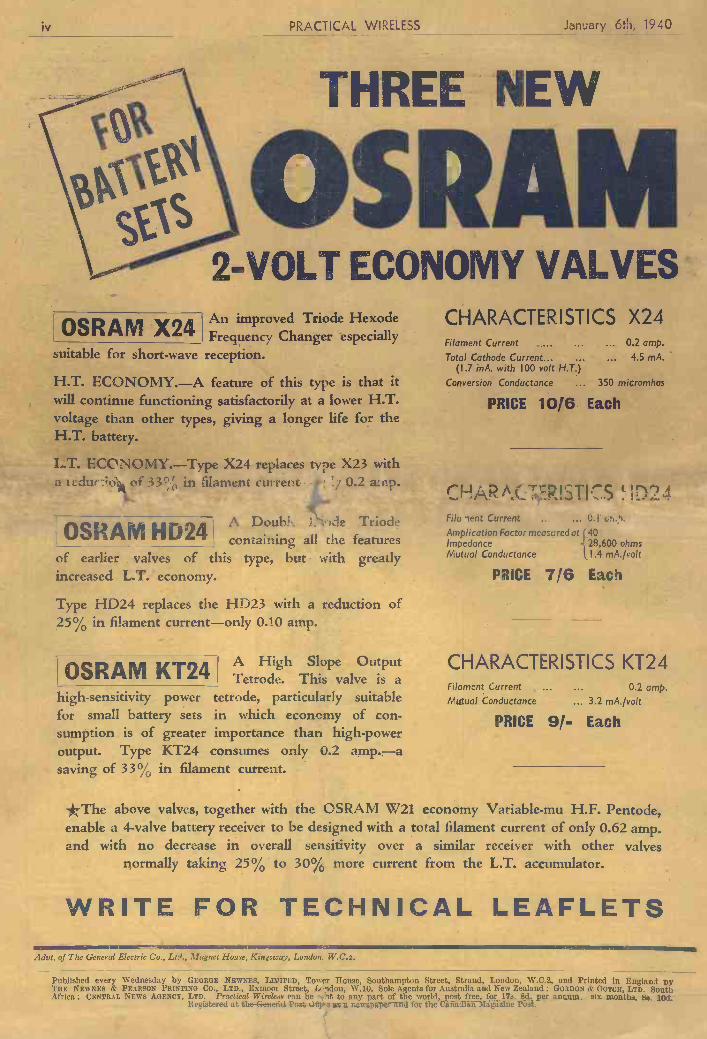
iv PRACTICAL WIRELESS January 6th, 1940
high -sensitivity powerfor small battery sets
THREE NEW
2 -VOLT ECONOMY VALVES
OSRAMX24 An improved Triode HexodeFrequency Changer especially
suitable for short-wave reception.
H.T. ECONOMY.-A feature of this type is that itwill continue functioning satisfactorily at a lower H.T.voltage than other types, giving a longer life for theH.T. battery.
ECONOMY.-Type X24 replaces type X23 witha tcdur or 33% in filament current # 0.2 a:np.
A Doubl._ Ide Triode0SRAM HD24 containing all the featuresof earlier valves of thisincreased L.T. economy.
Type HD24 replaces the HD23 with a reduction of25% in filament current-only 0.10 amp.
type, but with greatly
OSRAM KT24A High Slope Output
I Tetrode. This valve is atetrode, particularly suitablein which economy of con-
sumption is of greater importance than high -poweroutput. Type KT24 consumes only 0.2 amp.-asaving of 33% in filament current.
CHARACTERISTICS X24Filament Current ... ... 0.2 amp.
Total Cathode Current... ... ... 4.5 mA.(1.7 mA. with 100 volt H.T.)
Conversion Conductance ... 350 micromhos
PRICE 10/6 Each
r'HARA.Cr.:FR!STI7S !I:714Filet lent Current .. 0.1
Ampiication Factor measured at 140Impedance 28,600 ohmsMutual Conductance 1.4 mA./volt
PRICE 7/6 Each
CHARACTERISTICS KT24Filament Current ... 0.2 amp.Mutual Conductance ... 3.2 mA./volt
PRICE 9/- Each
*The above valves, together with the OSRAM W21 economy Variable -mu H.F. Pentode,enable a 4 -valve battery receiver to be designed with a total filament current of only 0.62 amp.and with no decrease in overall sensitivity over a similar receiver with other valves
normally taking 25% to 30% more current from the L.T. accumulator.
WRITE FOR TECHNICAL LEAFLETSAdvt. of The General Electric Co., Lt:?., Magnet House, Kin;sway, London, W.C.2.
Published every Wednesday by GEuRGE NEWNES, LIMITED, Tower Reuse, Southampton Street, Strand, London, W.C.2, and Printed in England AyTHE NEWNES & PEARSON PRINTING CO., LTD., Exmoor Street, Lerldon, W.10. Sole Agents for Australia and New Zealand : GORDON & GOTCII, LTD. SouthAfrica: CENTRAL NEWS AGENCY, LTD. Practical Wireless ran be fit :it to any part of the world, post free, for 17s. 8d. per Annum_ six_ month% 8s. led.
Registered at the.General Post ',Mte as a newspaper and for the Canadian Magazine Poit.

form f radie play produetión. An example L..._ . of the day's menus.
Ïhe B.B.C. Symphony Orchestra T'HE B.B.C. Symphony Orchestra, leader I Paul Beard, conducted by Sir Adrian
Bouif, will visit the Town Hall, Cheltetì- loam, on Thursday, January 11th, to give two programmes, one in the afternoon and one in the evening. On Wednesday evening, January 17th, the Orchestra will
mit the Central Hall, Newport, and on Wednesday evening, January 24th, the Orchestra will play at the Pavilion, Bath. Full details will be announced later.
Expeditionary Force Programme AS from January 7th, tIte B.B.C. are
including a special programme from 6 p.m. onwards on a wavelength of 342 metres. This progranime is designed especi- ally to appeal to the forces in France, and consists mainly of dance and similar light music, variety, sporting items, and so on. If the programme proves successful it will probably be expanded into a full daily piograulme. -
Will Shakespeare TiMING restrictions have developed a
new technique for dealing with one
WCTJMMING TAIT, the Scottish will be supported by the B.B.C. Theatre playwright, lias written a topical Chorus, trained by Charles Groves, and
adventure play, entitled " The Blacli tise B.B.C. Theatre Orchestra, conducted by , Stsìaafnrd Rohinann Production will he liv
gditorial and Advertisement Offices, Practical Wireless," George Newnes. Ltd.,
Tower House, Southampton Street, Strand, W.C.2. 'Phone: Temple Bar 4363.
Telegrams: Newnes, Rand, London. Registered a,t the G.P.O. as a nest spaper and for transmission by Canadian Magazine Post.
Tic Ed its, avili be pleased to consider artrelen of a practical nat,arr suitable sr publication ita PISACTICAL WIRELEsS. Suc t articles z/toatht be written ois one side of tite papee only, atte! should contain t'at nanae and address of the sender. tV/titel the Er/ilse does not hold Iiinwelf responsible for sapts, every effort will he anode fo return
lícito if a sta rnped and addressed envelope is enclosed. Ail correspondence intended for the Editor should be addressed: The liditar, PRACTICAL VInELEss. George Ne,rnes, Ltd., Tower flouse,
Southampton Street, Strand. IV.C.2. Owing to the rrspid progress in the design of
wireless apparatus and to our efforts-to Peep our rtadero on totali with the intent derelopnaen'o,we give na atar,'nniy that apparatus described in our cotant no io not tite subject of letters pal en!.
Copyright in all diawings, photographs and articles poPio.°.ed ian PII AC-TICAL WiaSiESS is opert [cal/ut ceservet! t/tront/aonl tite coot/tries sifsna- foty ta tie Berne Coatreniion asti flit USA. Jteprotttactions or mulot ions of any of tftetc are ther,'fa,,'e expressly forbidden. PRACTICAL WIRE- LESS -incorporates " .ireiateur Wireless.
Gordon McConnel and Staoiforcl 1tobinsoo'. -
Talks for the Housewife JANET QUIGLEY, who arrañges the
B.B.C.'s talks for women, has put together several interesting series for the new' schedule from January onwards. These have necessarily a 'wartime atmosphere.
The Tuesday morning talks, for example, are entitled '' W'artiane in the Kitchen." The B.B.C. is in- the closest possible touch with the Ministry of Food, and the talks have beemi designed to help housewives to solves tise thousand and one new problems with whlch they are at present faced. 1f, for example, there is a glut in any coin- inodity, listeners will hear of new and attractive methods of presenting this particular article of food. Speakers will include suelo familiar radio figures as Mrs. Arthur Webb, Mrs. Bosanquet, Ann Beaton, and Ann Hardy. The ea-ny (Thursday) morning marketing talks will be continued. TI-iene aie designed to assist -in the planning
this may be true, due to the fact that this component receives the most use, it is vere often due to the use of the Wroiig type of switch, or an unsuitable type of switch for the purlose. There are many different patterns of switch on tue - market atid the beginner often -
i-thinks that they all opcirate in the sanie , manner, and in an endeavour to save molles he obtains a low-price component-. w hieb, whilst it may be ideal for one purpose, may be un- suitable for continued use in -
the position-in which he intends to place it. Wave-changing is probably the most important part of a circuit frotit the switching point of view, as low resistance is essential and per- fect switching must be carried out or the receiver will fail to function corredtly. It is often found that the receiver scents to be working properly, but signals are weak, and much time may be spent in looking for a fault which is merely due to poor contact iii the wave-change witeh, In this issue we give
brief details of tite various teLles uf switch which are available and indicate sonic of the positions and circuits for which they n ii' müst isife1
the character of the central figure, is to be used in Barbara Burnhaio's production of Clemence Pane's " Will Shakespeare." on January 13th. In titis production scenes fioju different acts of the play arc kiiit
Wire-s/ripping machines Ekco Works, adjustable Io
i' all. sizes, strips auag (lie ir
cover . . exposet just bare Wile for solde
together to throw up the character of Shakespeare.
The Black Gmulley
heard in tise serial called "The Mystery of Dreid's Hill." In this play, listeners will hear the strange adventure of three boys who have been evacuated from a Scottish town to a wild part of the Highlands
how they encounter a mysterious ship known locally as the
at 1/je "haunted galley" and how wires of they hear unusual noises in the isulating dungeons of a ruined castle, enough which gives theta a clue to tise
ring, whole mystery.
Songs from "A Coiintry
Girl" NE of the niost popular of
George Edwardes' many famous productions, ''A Country Girl." was produced at Daly's On January 18th, 1902. with a cast containing many stars, O not-mg theni being C. Hayden- Collin, Rutland Barrington, Willie Ward. Bertram Walhs,
/Hunitley Wright, Maggie May, Ethel Irving, Topsy Simien, Nina Sevening, and Evie Greeen. lt ran for 729 performances.
On January 12th, songs from "A Country Girl," composed by Lionel Monek- toit, with additional melodies by l'atti A. Rubens, st ill be broadcast. The singers
i
I
-s
'-s -'is
ai!
PItACTIC4L .'?.TELEVISION £ O I T E B' B Y
j
EVERY WEDNESDAY n i I Skiff.
'- W.J DELANEY, FRANK PRESTON, Vo!. XV. No. 32 Jan. 13th. 1940 Ii. J. BARTON CHAPPLE, 9.Sc.
ROUND THE WORLD OF WIRELESS Switches and Switching of this was seen in the production of Galley," which will be produced for children LT has often bcen said that the cotfipoilerit '' Macbeth,'' which dealt in sequence with by Christine on January 13th It is a
part which givés most trouble in a tue dcterioration of the character of continuation of tihe adventures of David,r wireless receiver is the switch. Whilst ' Macbeth." The sante technique, stressing Eric, and Rubia, about whom children r
January 3ih, 1940 PRACTICAL WIRELESS____
PDF compression, OCR, web optimization using a watermarked evaluation copy of CVISION PDFCompressorPDF compression, OCR, web optimization using a watermarked evaluation copy of CVISION PDFCompressor
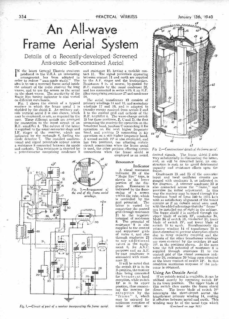
"frame" 1, which transformer primary winding 14, making -
may be oriented for it effective between aerial and earth. This - minimum reception of winding may be of the usual type which
Fig. i .-Circuii of pari of a receiver incorporating the frame aerial, noise or other ui:- (Contizued on page 365.)
- - .- -
-
k.. tional and signal potentials appear aòross has two positions, one àffectíng certain a resistance 8 connected between its anode circuit connections whei the frame aerial
t and cathode. This resistance is shunted by is used, the other position effecting circuit a potentiometer comprising condenser 9 connections when the frame shield is
employed as an aerial.
Resonance Indicator
A visual resonance indicator 20 of tite "Magic Eke" type, is shown in the lower portion of the dia- gram. Resonance is indicated by the fluor- escing of a screen within the tube, which is controlled by. the grid potential. The latter is varied by connecting the control grid through resistance 21 to the negative terminal 6f resistance 8. The potential of resistance 8' is also supplied to the control and suppressor grids of valve 4, and also throngh conductor 23 to any additional valves in the equip- ment ll, for A.V.C. purposes and an A.F. by-pass condenser is associated with resist- aiice 22.
It will be noted that the switch 19 is in its B-position, the receiver thus being connected for broadcast band reception, while switch 19' is in its upper position, thus connect- ing the receiver for reception by the
qQ.
63
Fi 2.-Constructional ¿e fails of the frame aeria
desired signals. Tise frame shield 2 aids very substantially iii eliminating the latter, and, as will be described later, its con- struction is such as to avoid detrimental capacity and resistance effects upon the frame.
Condensers 15 and 25 of the cônverter input and local oscillator circuits are ganged with condenser 5, as indicated in the diagram. A trimmer condenser 33 is also connected across the " frame," and provides for initial adjustment. In this way the receiver may be tuned through tite broadcast band of from 540 to 1575 kc/s with as satisfactory alignment of the tuned circuits as if an outside aerial were used. with the added advantage that the" frame" can be installed out of sight in tise cabinet. The frame shield 2 is eartlied through tite upper blade of switch 19', conduetor 34, blade 36 of switch 19, conductor 37, lower blade of switch 191, and lower blade of switch 19 to earth. Simultaneously the primary winding 14 of transformer 13 is short-circuited to prevent absorption effects due to stray capacity coupling and the circuits of the other transformer windings are open-circuited by tite switches 19 and 191. in the positions showit. At the same time tite full potential of resistance 8 is supplied through resistance 21 to the control grid of the visual resonance indi- cator 20, resistance 39 being open-circuited at the lower contact of switch 191. Ir, this condition maximum response of tise indi- cator is obtained.
Using An Outside Aerial If an outside aerial is availmibie, it can
utiiised merely by operating switch. 191 in its lower position. The upper blade of tisis switci then earths the frame shield direct. 'Tise lower blade of switch 191
interrupts the short-circuit across the
3Á. ÄttcAL 'iRELESS
An AI-wave Frame Aeria stern Details of a Recntly-deve1oped' Screened
Anti-static Self-contained Aerial IN the latest General Electric receivers and resistance 10, having a variable eon-
j produced in the U.S.A. an interesting tact 11. The signal potentials appearing arrangement lias been adopted in between contact ] i and earth are supplied
order to reduce "man-made static." The to the A.F. stages and the loudspeaker. idea is to use a screened frame aerial inside Resistaiico 8 is, of course, by-passed for
i. - the cabinet of the radio i-eceiver for long R.F. currents by the usual condenser 26, waves, and to use the screen as the aerial and has connected in series with it an R.F.
the short waves. Thesensitivity of the filtercomprisingresistance27 andcondensor Magie Eye tuning indicator is also varied 28. on different wavebands. The aerial transformer 13 consists of
Fig. i shows tuo circuit of a typical primary vindings 14 and 16, and secondary receiver in which the frame aerial i is windings 17 and 18, and is adapted Io shielded by the shield 2. An ordinary out- transfer energy received troni aerials 2 and sido vertical aerial 3 is also shown, which 3 to the control grid and cathode of the may be employed, or not, as required by the R.F, amplifier 4. The wave-change switch user. These (lifierent aerials are arranged 19 lias three positions, B, C and D, the first for connection to the input ci'cuit o an connecting the receiver for operation on the RF. amplifier 4. The output of the latter broadcast band, position C connecting it for is supplied to the usual converter stage and operation on the next higher frequency IF. stages of the receiver, which aro band, and position D connecting it for indicated by the rectangle 6, feeding the operation on a still higher frequency band. diode detector 7. The rectified unidirec- A second switch 191 is also employed, and
Jnry1th194O
----i #7
PDF compression, OCR, web optimization using a watermarked evaluation copy of CVISION PDFCompressorPDF compression, OCR, web optimization using a watermarked evaluation copy of CVISION PDFCompressor
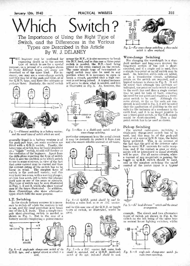
Fia. 6.-A single-pole change-ove.s.utic/i of lbe Frg. 7.-In a D.C.. receiver boh mains leads
Q M B type and a typical circuii ir is1 ch i i hould b operated and a Q M B double pole Fig 8 -A single pole chan,e over switch foi - used, switch of ih !qp indiat5J should b us.d. radia-.'ram switching.
-
1
In the simple battery receiver it is neces- sarv to switch off when the receiver is not in use, and the usual procedure is to break one of the LT. leads. Thu.a simple two- pole short-circuiting switch is needed a shown in Fig. L But in the cae of a battery receiver iñploying a potentiometer
breaking a mai/is lead, as in an AC receiver -
and in this case one of the QJsI.B. or togl Fi.. 5.-A local-distance switch and the circuit
-- - --' 9 arrangement. - . I- S I
example. The circuit and two alternative types of switch, are shown in Fig. 4, the switch on the left being of the same type as normal house lighting switches, whilst
Fig. 1.-Filament switching in chat/cry receiver; Fig. 3.-Here is a Jouble-pole switch used for
and the usuaz types of switch which are used, wave-change switching.
particular component is in the aerial circuit generally found in a battery receiver is of the push-pull type, yet sorno receivers are fitted with a Q.M.B. switch. Finally, the latter type of switch may be found described as a "toggle " switcl, to add still further to t he confusion of the beginner. Apart from the difficulties regarding the type ofswitclì there is also the problem as to which switch to tise in some receivers, in view of the fact that some current may be carried and thus the current rating of the su itch; has to be borne in - mind. The simplest forni of switch is the push.pnll variety, and Ibis may have two anus, with a moving phingcr, et even four arms and in some the plunger itself acts as one of the arms or contacts. This type of switch may be seen illustrated in Figs. 1, 2 and 3, which also show ts-pical' uses of the types illustrated. In addition; these illustrations also show alternati ve types which fulfil the same purpose.
L.T. Switching
it mas' be desirable to protect it from dust and also ensure reliable contact at all times,
I
For noi-mal radio-gram. switching a single.polc change-over switch has to be used, and this may be of the push-pull type or of a special Q.M.B; type, the latter being preferred. This is on account ot' the fact that the grid of the detector valve has to carry H.F. currents for radio recep- t ion, and if the contact is poor or dirt, noises will be introduced or signal strength will be poor. For all mains circuits, where a current of any magnitude is passing, the toggle or Q.M.B. switch should be used. and in the simplest switching the on/off control of the mains input is a typical
Types are Described in this Artiie -ByW
THE begiimer may be pardoned för expressing doubt as to the correct type of switch to use for a speciaf
purpose, as a perusal of a catalogue shows so many different types, yet many aro described as of the. same kind. For in- stance, one may see- a wave-change switch and this may be of the push-pull type, or of t lie Q.M.B. type, and have two contacts or perhaps three. Similarly, the on/off switch
\
DELANEY across the H.T.,. it is also necessary ta break the H.T. lead, and in th-s case a three-point switch is needed, the, H..T.lead being joined to the extra contact on the switch. The same sim pie type of" two-contact or on'òff' swith may also he used in any position where it is necessary to open or break a circuit, provided that a high cur rent is not being passed. A typical instance will serve to show what - is needed, and this is illustrated iii Fig. 5 As however, this
Fig. 2.-For wave-change switching, a three-point switch is often employed.
Wave-change Switching For changing the wavelength in a stan-
dard medium and long-wave receiver the long-wave section of the coil is short- circuited, and if a single coil is used, then a simple two-point or on/off switch mai' be used. As, however, extra coils are added,' as in a transformer circuit, additional points on the switch are required, and a typical instance is shown in Fig. 2. It will be noted that although two switches are indicated, one point on each switch is joined t-o the earth line and thus a single contact may be used for both of these, rcmdcing the need for one point and enabling a three- point switch to be used. Although t-ho sanie circuit, so far as the coils mire con- cerned, is indicated in Fig. 3, it will be noted t-bat time application of grid-bias to the coil calls for tise inclusion of a condenser in the earth lead, and it is no ionger possible to use a three-point switch, or the (IB. supply would he hort-eircuited. Then a four- point switch lias to be used as shown. -
Pick-up Switching
j
't
- -
j -
January 13th. PRACTlCA1WELESS 355 - t
Whích Swíteh? °Af The Importancc &f Using tie Riht j3e of Svitch, and the Differences in thé Various r i
:
PDF compression, OCR, web optimization using a watermarked evaluation copy of CVISION PDFCompressorPDF compression, OCR, web optimization using a watermarked evaluation copy of CVISION PDFCompressor

r-
s'
If'
t r
therinore may be ganged together, using Figs. 9 and I -The rotary wave-change switch in two dilerent patterns Connections and methods one for each coil. Special Iength of rod are of operation of the model on the left are shown in Fig. Il and for the switch on the right in Fig. 12. supplied so that the desired number of switch units nay be used. It would be impossible to givé circuit examples in view G
of the many different forms of su itching which may be used. Recently a small form
. G of this switch has been produced, although . .. e it cannot be ganged. It is illustrated in . :.
Fig. 10, and the various arrangements which . .'. .
are a%allable with tins su sieh 'ne shonrì in t e
A0° ......
:00o _______________________________________________________
0 00
O 0
00
Fig. 11.-How the rotary switches (Fig. 9) are designed. Three different patterns «re shoù,n.
ELECTRON . BOMBARDMENT
I
356
WHICH SWITCH? -
(Continued from previous page)
that on the rilìt has exactly the same internal movement, but has a rotary con- trol actioñ, and this enables panel controls to be matched more satisfactorily. An interesting version of the toggle switch is shown in Fig. 6, where the internal connec- tions permit a change-over effect so that a trickle charger and an H.T. eliminator may
r- - he brought into circuit with the maiñs as
desired. When the set is switched off, the trickle charger is switched on. On J).C. mains it is very desirable to disconnect both mains leads when the set is switched off, and thus a double-pole Q.M.B. swit cli is the needed, circuit and a typical sample being shown iii Fig. 7.
Coil Switching
Modern receivers utilise several coils, and if the receiver isof tue all-wave type this introduces further difficulties. Special
f.: switch units have, however, been introduced for this purpose, and three examples are shown in Fig. 9. These switches have low losses and make reliable contact and fur-
______PRACTICAL__WIRELESS - January 13th1 1940
contact is selected for the appropriate toggle is raised to the "off" position, it contact jìoints. immediately flies back to the " on"
Timore is one final type of switch which, position when the finger is removed from although not very well known yet, has the switch. In a permanent "on'" switch many interesting, applications. This is it will only be " on" whilst the toggle is k-noun as a "momentai-y action" toggle held down. It is ideal for bringing into switch, and - lias only one permanent circuit a meter to measure anode eurrent position. Fo instance, in one fornì the for instance, the reading being noted whilst switch isfpermatntly " on,'' and mf the the switch is held " off,'' and the meter
- .... .' .. ...... . . - . ........ _... short - circuited in the normal position of the switch.
._;,.. -
-
\ _
\t ,e
I1
our 30/- A11Wave 3 receiver, and the only in practice, and havé èrved to make the equipment is performing at its maximum point to wbtcli is that the correct arm operation of the d&vice a fáI more compli- efficiency: -
r-.
I1.
li
s s s .
s . s
B
(o/o\ (oJ oi o o QQ Fig. 12.-Connections available for te type of
switch shown in Fig. IO.
Fig. 12. This indicates, by a heavy line, tise contact point and the wiper and arm which are fitted. It will be seen that in one Ibim a wiping arm may take selection on any one of 18 points, or two or niore arms may be provided, and will select various contacts. This type of switch was used in
THE bnìbadthent of elètrons against a surface, either in a narrow directed
stream, or as a random impact, is a very inhl)ortant process in the science of tele- vision. The function of this process is really twofold, oñe being related to the transmitting end of the chain, and the other at tue receiving cud. In tise ease of the former, the brightness variations of tise scene to be radiated are translated into electrical signals, and if consideration is given to tise iconoscope type of camera, it is these electrons which are made to fall ors a metal mosaic which is insulated and charged ist varyisig potentials over its surface. Secondary emission is the medium which brings about the desired discharge, and in carrying this out, several other factors are brought into being, and these have to be considered carefully when design problems are tackled. For example, there is the question of the saturation effects of the mosaic, the space charge brought into being in tise immediate vicinity, secondary electron redistribution and the rate at which these sccondaries are collected, tise electrical charges on the glass envelope, etc. All these items occur
cated one than was originallysupposed by those engaged on the initiai dèvelopment. Coming now to the other end of the chain we liare the cathode-ray tube, which r-, verses the original process by converting the electrical signai variations into grad- ations of light and shade distributed oer1 the sci-een in brightness areas. The electrön stream impact in this case brings about a combined state of fluorescence and plios- phoresccnce, causes a certain amount of heating to both the powder and the glass, and finally gives rise to segondisry electrons which are collected by charged electrodes in the tube. It is clear that with this device the emission of the tecondary elec- trons must determine the potentials and loss of energy of the electrons in the various sections of the travel stages, and with this is wrapped up the efficiency of the tube as a converter of electrical energy into light. The research laboratories are therefore concerned with the study of the functional relationships of these items one to the other, for by so doing the best possible picture quality will be obtained, it being assumed that the receiver and auxiliary
PDF compression, OCR, web optimization using a watermarked evaluation copy of CVISION PDFCompressorPDF compression, OCR, web optimization using a watermarked evaluation copy of CVISION PDFCompressor

licence granted could he allowed. " If and, when experimental wireless
facilities, are restored, the question of an adjustment of fees aid of the grant of fresh licences will be given consideration." (This was ip answer to the following cjsiestion Will new licences for trans- nutting h etò be taken out afterthe war, or will thOse' holding them at the time of confiscation be able to carry n with the old licence until the number of months, etc., for which it was still available are ended 1'')
If it wisria for their 011015v sae ti rrreless, Larindsakes It would lie frichrtfri' glu Wednesdays
carri aroorud Ii we liad nile news o' rail io a ed wirrrr'eless.''
And thins for cuico-a id only osee lii history Io we li ad John Bull and Sau ndy, Ta thy, Pa t, A re of the self-sa lie rut id. Arid in t hie long, dark days of war Share to the frill tI is view-
Thin k lies veri, j i tterui iiave riot std pod Olio paper, like ourselves IT JIEJ NS TO S'E THI\GS ThROUGH.
NOTE TO READEIIS,-" ,Dyehr nilyd " is sot a Welsh sues r word it only beans horrible '' or '' f rihitmuh.'' it is pronounced, roughly; like ' duehriiuìthlld,''
"Toicl"
IGATHER fr0111 manufacturers that they are not spending any considerable
sums of money in experimental designs for the 1940 receivers. Instead, they are directing their efforts to produce cheaper and simpler receivers so that they can market them without having to ines-case price. Many of the old constructors who deserted tise pastime are now coming back to it and are finding in short-wave listening an. interesting means of occupying the evenings they are now compelled to spend at home.
-s-
1-IT. battery consisting ol three 9-volt grid-bias batteries. - On top of this battery, but carefily insulated' from it. he has placed on dfthe old 8d. cycle batteries as the LT. This i used with a 5-ohm resistance foi the P.M.2 1)X, unii H.L.2 valves, and brings the .lilainent current (town to' its correct amount. The aerial is forMed by a wire which passes over the shoulder, and my reader says he can walk about with it using one ear-piece. The appended photograph shows Mr. S. E. James's gear taken just before the u ar.
North'Manchester Radio and Tele. vision Society
THE hpn. sec. of the above club tells inc that since the commencement of
war their ,pieetingplace lias been moved from \Vhfields to the centre of the city, close to theaín station, for the cotivenience of nietibrs; .11e invites other members arQiuld Manchester to co-operate. This clubjs keepitig a-watch on local ramps in th -irless business, particularly' in the bateiy lin, The Consul for Fihiand has señt the club his sincere thanks for their sympathetic message to the radio l'steners in. Finland. whuc nessage has been pMded on to the authorities in Hel. sinki.
,Çonfication of Sets THE secetary f the satise club sent
a questiohnaire to the Engineer-in- Chief of the Radio Section of the Post Office, relating to amateur radio trans- mitters. Ypu will see from the appended s-eplies the nature of the questions.
"Relative .to the confiscation of amateur radio transmitting apparatus, I have to inform you that it is the intention to return such appaeatus to the owners after the war, and a ppli cations- for restoration shot 11(1. be addi-esscd tp, this Department on the cessation of hostilities.
"You can be assured that every reasoñ able precaution will be taken to ensure the safe eusfody of apparatus whilst held by the ost Office.
"The call-signs previously held by licensees. are cancelled simrdtaneously with the relative,licences, and no claim to the jse of a narticular call-sin in any future
- By Thérmion
"And So Say All Of Us" WHEN Pat and Talfv, l'awky Sairndy, readers
all, once mot, Their conuiroii interests drawing them together, They talked at length nl radio a nil television, loo, Of sport and draina, litera tir re, a nil wejithe r; dníl then said l'ut-v I en these ran try
Me bhoys. now get dIas attirate. 01 wouldn't miss P.W.' oli nil accolait at aal, '01 orther mid, and so ut's never laute, "ris tija oiiiy raddio paper fusta lift av aal the lot, ht01 missed ut-shurc 'twould make trie rave aim'
shwear. Troth Oid crack the selilsiil t av a unywa ri that tu riad -"to kape rit hack
Loike they aarvedaomslrl Paddy Riley at the I"nr."
Anti-Dazzle Battery
4d." Apparently, thus dishonest profiteering will continue in spite of the (Jovernnient.
Television in Germany
A CCOR DING to recent newspaper i'eports television is proceeding in
Germany ill spite of wsr' conditions. %Ve
shioulI certainly reconsider time question over here,
The Short-wavelength Muddle IN city reference library I lma't-e several
books which purport to give a list of short-wave stations, and their allotted wavelengths. I also have the list issued by tise BBC, in connection
'i.e , '- "\ ith their publications. ,- .11 '
: '«j O) thema agrees. Even -' the list iSSlIc(1 by tise BBC.
: from timsie to time differs as to important stationis.
, The time has arrived when "I s}som't-w'ave transmitters
. : should be compelled to " I stmsrlOumhco their wavelengths
I
'
.1 antI stick to tlieni. The
Î ]im'escimt chaotic conditions jsuet'elv indicate that the
i short-wave transmissions are i-turi by niudcllers. Quite often the ssndden changing
a of' a wavelength will causa severe interference with an adjacent station. Those
interested ins listensiusg oms the short waves are jimmdiug it most coisfuising to have to search around each night for a station which does not maintain its wavelength. This in itself causes further interference. Perhaps mv readers would care to discuss this problem, and to give reasons why so many sjìoi-t-w-ave stations stray from their announced wavelengths. There cannot be any tenable reason for this. I should also welcome details of the worst offenders.
naI T'7
.: i,
I-', '
-
«e.-
corner of Mr. S. E. James's den
Well, look you," said tIme Welshmuman (late of Llaufcr Pu.)
(Usi' tliealphabeb to bind tise rest.ansl himiislm "gogoroch") if I vasa riot get mrmy copy, ilveliryrihlyil, rvtiai a biais'
Oh, l'es, immteet to goodness, quile a shock"
A'w&'et,'' saisi Pawl 'Sa.rmtsll ''russell mull mio deny, It's graumid tac thank its prier is mio incm'e,maeel. Ali like flic brase w-ce paper, r,, it aim hike irmli si lier
musli'. If they'd raised the price, mali pus'rreluiaa umirhit 'a
ceased Forbyc ah ilinmia always like dIrei r joaks ai ,00t time
Scot, Though mmiavlie dites' mi fitti are only penned. But ye coimldua ria flic Elimisi erre if it ss'ismma for
oorsels, A fauct that vanna lie tac widely kemsicil, Still, ah willnia argy-hsa r'g', for rame dont Oie bons
mucan well, The 1940 Scs
li
January 13th, 1940
ONYC PRACTICAL WIRELESS 357
ii'! A Midget Receiver il-
SL JAMI'S of (iodon Suries has sent me the detsiIs of s midget-
receiver whiçh he has built in a gas-mask box. It is built on a baseboard 3in. by 3m., with a ,anel 3in. by 5m. This just -
fits in the end of the boi, leaving enough space under the lid for the control, and the ........
..
Another Battery Racket ECl, of the North, exposes a racket
which is going on in that district. One. dealer is selling special ' torch batteries consisting ofa grid-bias battery cell neatly covered with pink-coloured paper containing the magic legend:
"ARI'.
PDF compression, OCR, web optimization using a watermarked evaluation copy of CVISION PDFCompressorPDF compression, OCR, web optimization using a watermarked evaluation copy of CVISION PDFCompressor

January 13th, 194Ò. Vol. 4. No.
Tekvision Transmitting Aerials
ALL the w ork devoted to improving the
efficiency of an ultra-short-wave radie transmitter used for a television service will be nullified if it is not used in conjunction with an aerial array having a very high jrthrmance factor. To increase the range of propagation this section of the whole installation must be so designed that the energy losses are reduced to the
furnished stating that the beam must be kept oit the move wlcn patteiis or pictures ol brilliant intensity 'are being built up ori the tube face. Even so, a measure of wear and tear is inevitable if t.ho'same section of the available screen area is used over and over again, while special precautions have to be adopted to offset the damage re- sulting from a failure of the time hase generatoi- to impart the combined lion-
I cies for all forms of communication, where long distances do not have to be couì- sideied, has extended very materially the auuìouiìt of research which is being applied II) the propagation characteristics of wavei in that pam-t of time spectrum. ObviOusly, the degree of signal attenuation w ill vary according to whether the transmissions are eFfected over water or land or a couuubi- nation of both, while reflections from the various tipper ionisecl layers of the atmos- pluem present no menu problem to -timse who are concerned with point to point ìvonlo i g. Quite recently an i nvestigat lumi
35S PATICC 'WIRELESS -- Ja\ua 13th>4O
principle could of course be applied to the photo electric or mosaic assembly screens used in the different forms of electron
F F £ V cameras, fog hcr gain.thé active life of
________ thcapparatusis very often a function et
V
troni the continuous impact of the high VV V -
- velocity seamling beam of clectroibs.
The Attenuation of High Frequencies HE increasing use of the ligherfrequeii-
t-.
lt was designed to give maximum horizont al radiation, and the eight spokes are clearly visible as an array a definite fi:actioii of a wavelength below the vertical radrating conductor. Hurmountlig this dipole is a small disc to give capacity tuning, and the whole installation was used in conjunction with a 10-kilowatt transiti i tter. Another method of reducing losses and ini proving horizontal radiation is tu eiuiplov dipole aerials with reflectors and i i the radiation is to be uniform in all directions, then this becomes a spoked array something like a skeleton cylinder, as in the ease of the B.B.0 station at Alexandra Palace.
Preventing Screen Damage -
¡T is well known that if the beam of I electrons in a cathode-ray tube is allowed to rematn stationary, so that the point of' impact nu the fluorescent semen is evidenced by a tiny brilliant a-rea of fluor- escenco thep .thc screen will he brnddmtt that point.. That is why instiuctions ai-e
A good example of a sp&ed aerial arromj capc radiation in a lin izontal direct
zontal and vertical motion to t lie ebd ron beam As an alternative to these muctlioil another scheine bas been suggintcd mvfiiAì has for its ivainobject. a prolongation of tb-am
lito of t he cathode-ray tube in ternis of the .rctent cii of screen eflicicncv For tri is purpose t lie t ube employed has a uirmci larger screen area than is necessary fi ir t lie particular purpose for which it is to b employed. The screen, or screen amid tube, accord ing to the method of instruct-iou, is then made to rotate about ' its central axis, ivhile the area of scan isarramiged tri ho eccentric to this axis. Fitted to t he out er rim of the screen are vanes, and at. pi-ele- tenuined intervals tue electron boam s defIer-ted so as to strike thec vamlos, and by this action rotate the screen in miì ueb t.lm
sanie way as therotui' of a turbine is re-
yolved by the direction 'of t,eani jets against, specially shaped vanes. The saine
die 0f giving efficient inverse power equa- ion. tion. In other words,
between 80 and 4 niegaeveles the signal varied inxersely as i-lie 2.3 tirer of the distance. At was also founui that the variation of attenuation vi tim respect to frequency could he predicteit, but that in daytime these predicted results were always less than t-lie measured values.
PRAC11CAL WIRELESS
SERVICE 'MANUAL By F. J. CAMM.
From ati Rooksellers 5!- net, or by post 5/6 direct from the Publishers, earg Newnez, Ltd. (Rook Dept.), Tower House, Southampton Street, Strand,
London, W.C.2.
-1
barest, and considerable ieseailì lias x'1l . . _- . .. . . . ..,... . . . .. .. , was eaiJ-leI out iii applied to this side of the probkiu boLh . . .
Anienca iiìto the rate -
in this country and il)rOad. For exa.intie, . . . .
of attenua'tioiì up to .
jt is a weII-estab1ihecl fet that a cou- . ... j;':. . .
distanees of approxi- ' -
doctor otìc quarter of a wavelength long .. . ' .
iiiately 10 miles over is an efficient aerial, but if thisis erected at . -
. land, the bail of a great height, so as to increase the ìaiig. . . :
: . .. . : recjuencies involved ìt. signal rece[)tíon, then losses oeiy accrue L
; . . .
be ing. froni 80 to i 5 flit edci chle eonnectui, the c t i rl to ' megac3 cict that
the output circuit of tite radio tranintitter .... tite short and ultra- 'l'he proper. It lias been (leinotistrated recently - -
short spectrum. that one ii-av to reduce these losses is to . - results proved most adopt a speciat fono of eai-thing systetit -- - i n te ic st i n g a ti d for tIte fedei.. This is done by using - showed that flota L-5
capacity wires which aie less titan a quarter - up to 4 megacc1cw wavelength long, and tuned to t he earrhr - .- -- there was au morena- frequency, thereby giving a low isn1-edànte ing attenuation with at the point lo which they areeonuected. ' frequency but that -. This simulates a low earth itnpedatiee. . from 4 to 80 mega- and beais a relationship to the. capacity i \1'[' \ cycles the degree of earth screens which were used with broad- .Ç attenuation remained cast aerials sonic years ago, n-ben real almost constant On earthing facilities were not available. In '
- the other hand, with frequencies belo some eases this capacity eai-tlt for televiion iv
transmitting aerials is made up in the 125megacyclesthere forni of spokes radiating from tito fr-eder
-
was a greater attenti- located at the centre. These spokes and i-ito are adjustable in length if more than otte
¿ I .
a t- joli ni e a su veci during tIte hours of
irequency is to he but '
N (It
daylight titan could carrie,- employed, can be designed to a fixed length in the case Y
j -
tP ho titcasured u lieu of a single radiating carrier frequency . tite sun liad set. which is usually the case. An actual desga .. - By careful interpol- based en somewhat similar reasoning, I hai . - ation of t-lie results t is improving the radiating efficiency tif - was shown that tite the television aerial, is illustrated in the ' . .
variation of sigtuiJ - accompatlyitig photograph. This shoivs .
st s'e n g t h w i t lt the corona aerial at the top of t-lie chininey (Iistanc-e could he breast of one of the Crystal Palace towers. j__ - -t - --Tm- - - - expressed h ait
PDF compression, OCR, web optimization using a watermarked evaluation copy of CVISION PDFCompressorPDF compression, OCR, web optimization using a watermarked evaluation copy of CVISION PDFCompressor
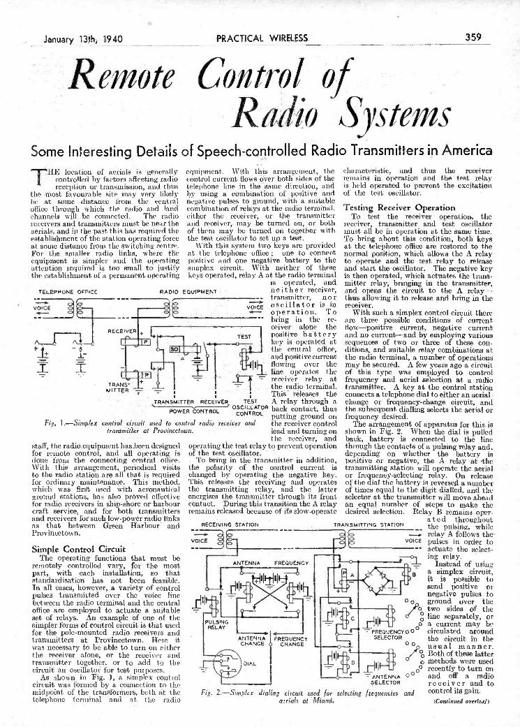
TRANSMITTER RECEIVER TEST A relay- through a - - - 0WERONTOL OSCflLATOR -back contact, thus
CO OL putting ground on Fig. 1.-Simplex control circúli uséd io control radio receiver and the receiver control
transmitler ai Provincetown. ------lead and turning on
staff, the iadioequipment ha-sbeen designed for remote control, and all operating is done from the connecting central office. \Vit-h this arrangement, periodical visits to the radio station are all that i required for ordinary maintenance. This method, which was first used with aeronautical ground stations, lias also prOved effective for radio receivers in ship-shore or harbolir craft service, and for both tranmitters and recêivers for such low-power ritdio links as that between Green Harbour and Provincetown.
Simple Control Circuit The operating functions that must be
remotely controlled vary, or the most part, with each installation, so that standardisation has not been feasible. In all cases, however, a variety of control pulses transmitted over the voice tine between the radio terminal and the central office are employed to actuate a suitable set of relays. An example - of onp of the simpler forms of control circuit is that used for the pole-mounted radio receivers aiid transmitters at. Provineetown. Here it was necessary to be able to turn on either the receiver alone, or the receiver and transmitter together, or to add to the circuit an oscillator for test purposes.
As shown in Fig. 1, a simplex control cruit was formed by a connection to tle midpOint of the t-i-ansforñicrs, both at t he telephone terminal and at the radio
tile receiver, anU operating the test relay to pievent operation 6f the teSt bacillator.
To bring in the transmitter -in addition, the polarity of t-ho control current is changed by- operating thb negative key. This releases the receiving and operates the transmitting relay, and the latter energises the transmitter through its front côntaet. During this transition the A relay remains released because of ifs slow-operate
RECEIVING STATION - - c.--- -
VOICE
ANTENNA FREQUENCY -
ANTENNA FREQUENCY CHANGE CHANGE
DIAL
Ohange or frequency.change circuit, and the subsequent dialling selects the aerial or frequency desired.
- The arrangement- of apparatus for this is shown in Fig. 2. When the dial i pulled back, battery is connect-ed to the line through the contacts of a pulsing-rejay and, depending on whether the battery- is positive or negative, the A relay -at tìie transmitting station will operate the aerial or frequency-selecting relay. On release of the dial the battery is reversed a num ber of times equal to the digit dialled, and the selector at the transmitter will move ahead an equl, number of steps- to make the desired selection. Relay B remains oper-
ated t-hrouehout TRANSMITTING STATION
- the pulsing, vhilc relay A follows the
VOICE pu1ses in order to actuate the select-
- ing relay.
Instead of using a simplex circuit, it is possible to send positive er
00
<: FREQUENCY 00 SELECTOR
0000
SELECTOR
Fig. 2.-Simphìx diallg circuit used- for selectIng frequencies and - -
- aerials at Miami.
negative pulses to gtound over the two sides of the line separately, or a current may be circulated around the circuit in the usual manner. Both of these latter methods were nind recently to turn on and off a radio receiver and to control its gain.
tCoruinued overleaf)
be at some distance from the central office through which the radio and land channels will be connected. The radio receivers and transmitters must be near the aerials, and in the past this has required the establishment of the station operating force at some distance from the switching centre. For the, smaller radio links, where the equipment is simpler and the operating attention required is too small to justify tue establishment of a permanent operating
TELEFNONE OFFICE RADIO E
[A RECR+L
-
- TRANS- +
MITTER - -
negative pulses to ground, with a suitable combination of relays at the radio terminal. either the receiver, or the transmitter and receiver,. may be turned, on, or botti of them may be turned on together with the test oscillator to set up a test.
With this system two keys are provided at the telejilione office; one to connect positive and one negative battery to the simplex circuit. With neither of these keys operated, relay A at the radio terminal
is operated, and QUPMENT neither receiver,
- ' --- transmitter, nor oscillator is in
' '- operation. To ___________ -. bring in the re-
ceiver alone the fEST positive battery
J I the
- receiver relay at the radio terminal. This releases the
Testing Receiver Operation To test the receiver operation the
receiver, transmitter and tet oscillator must all be in operation at the sanie time. To bring about this coñditiòn, both keys at the telej)hc)ne office are restored to the normal position, which allows the A relay- to operate and the test relay to release and start the oscillator. The negative key is then operated, which actuates the trans- mitter relay, bringing in the transmitter, and opens the circuit to the A relay- thus allowing it to release and bring in the receiver.
\Vithi such a simplex control circuit there are three possible conditions of current flow-positive current, negative current and no current-and by employing variòus sequences of two or three of these con- ditions, and suitable relay combinations at the radio terminal, a number of operations may be secured. A few years ago a circuit of this type was employed to control frequency and aerial selection at a radio transmitter. A key at the control station connects a telephone dial to either an aerial.
4
If
Radio 3Systems Sorné Interesting Details of speech-controlled Radio Transmitters ip merica
THE location of aerials is geiìera.1ly equipment.. \Vi.t.h this arrangement, the characteristic, and thus. the receiver
controlled by factors aflecting radio control current flows dyer both sides of the remains in operation nd th test sèly reception or transmission, and .t.hus telephone line in thé sanle direction, and is. held operated to prevent the excitation
the most favourable site may very likely by using a combination of.. positive and of the test oscillator. . . .
J-- -- -
PRACTICAL_WIRLSS.
Control --
359
PDF compression, OCR, web optimization using a watermarked evaluation copy of CVISION PDFCompressorPDF compression, OCR, web optimization using a watermarked evaluation copy of CVISION PDFCompressor

centres iii January as follows : Thursday, January 11th, Cheltenham Town Hall; Wednesday, January 17th, Newport central Hall ; and \Vedncsday, January 24th, Bath Pavilion.
A series of monthly concerts to be given in the presence of an invited audience is being planned. - These will combine the idea of the concerts of Contepìporary Music which the B.B.C. has given in London since 1926 and sorne f the best material revived or first produced in ìirogìaulmnes
Symphom ice. lt is hoped that the B.B.C.. Music Produc-
tions Unit will be able to include occasonal performances of opera special y adapted for broadcasting, and also special shows on Sundays which will include performances, from time to time, of Gilbert and Sullivan opera. Feature progranmies, such as
Brief Interlude,' '''The Table Under the 'l'ree," Cities of Music," and regular orchestral concerte will be given under the direction of Stanford Robinson.
foremost contemporary British players, will also be included.
Outside light orchestras, particularly those popular before the war, both in London and the regions, will he engaged to the maximum extent, having'- regard to studio accommodation, regulated not by the B.B.C., but by considerations of National Defence, and by the available programme pace. In the third wcek of January, for exanìple twelve outside orchestras will be heard rn the prograimnes.
_____________________________ ...5» _ ' _ -
i
e
Mûsic Plans, for 1940 THE chief items in the B.B.C.'s broad-
cast music plans for the early 1)at of ] 940 are as follows:
The absence of an alternative programme lias made it necessary for every concert to appeal to an infinitely uider audience than in pre-war days, and it is felt that the widening of appeal must come through the shortening of programmes where artistically possible and rigorous concentration on the highest grade of music and perforniauce.
Special concerts will be given by the B.B.C.Symphony Orchestra at ' local
broadcast under the title of " Special Recitals ." Thus the programmes will have a special appeal to music-lowers, though a Palt of each concert will appeal to a wider public.
The policy of broadcasting every week a classical symphony conducted b3 Sir Adrian Boult will be continued. In this series the B.B.C. Symphony Orchestra, cuider Sir Adrian Boult, has already broadcast Beethoven's Seventh Svui phony Brahnus' Fourt h Symphony Schubert's C Major 811(1 Mendelssohn's Scottish
A weekly organ recital will be included alternately in day-time and evening pro- grammes.
The B.B.C. Salon Orchestra programmes w Il assume ai increasing individual il3-. This will he contributed, for instance, by the regular inclusion of free transcriptions of, or fantasias upon, current popular successes, ou successes of the last thirty years, made by experts like Ben Berlifu, Michael Kiein, Fred Hartley and Max Saunders. A regular ingredieht will he English folk music, selected by Cerrard Williams from the library of the English Folk Song and T)ance Society, transcribed and arranged by him for the Salon Orches- tra. Numbers featuring solo w ork by leaders of the orchestra, who are amone the
on two of the polai-ised relays at the receiver because it divides equally between the opposing windings on each, and no effect on the power-control relay. It also lias no effect on the operation of the line as a voice circuit; its oriiy effect is oil the codan-controlled relay.
When the three-position key is in either of the operated positions, current flows down one side of the line and back the other, and operates one or the other of the balanced polarised relays depending on the direction. of flow. Operation of the gain-control key
F1. 3.-Conjrol circuit for 223A radio
all additional control circuit is provided to disconnect the tone after the pou er fid lure has been noted at the central office. Tite tone is also applied when the regular power comes back on, and then another control circuit is requited to remove the tone.
Testing Tone To stop tile test tolle after the receiver
has transferred to the emergency battery,
- restore the circuit receiving eçuiprnent. to its normal opera-
ting condition. These circuits are ypicaI of the various
arrangements that can be provided for conti-oiling radio equipment over a con- necting voice-frequency lilIe. The par- ticular foi-m they take is dictated loi- the iiiost part by the number and type of operations that these circuits are requited to perform.
The above details ai-c reprinted from the Bell Laboratories Record.
Cçrnbined Simplex and Circulating Circuit
For the 223 radio-receiving equipment, a combination of simplex and circulating circuit, is employed. This receiver is nor- mally energised all the time, so that no arrangement need be provided for turning it onor off. It incorporates a codan, how- ever, that operate a relay whenever carrier is being received, and a circuit must be
rovidecl over which the carrier-operated 1-clay can ol)elate a relay at the central office to perform a number of circuit
-functions. In addition means must be .provided for operating a test oscillator, reducing thc gain of the receiver to meet certain operating conditions, und operat.iug or releasing u lock-up relay used in connec-
- tion with the signals transmitted when the regular l)1 fails,
The circuit, shown in Fig, 3, eniplovs a two-position emergency pos er-signal key and a three-position key. One is the unoperated position, and the other two are marked" gain control'' and 'lest oscillator control.'' With the keys in the unoperated positiOnS, a circuit is closed froui the positive pole of the battery through both windings of a codan-controlled rela', a simplex line circuit, through two opposed windings on each of two polarised relays at the receiver, the primary winding of the power-control relay, and thence to a front cositact of the codan relay. When the codais relay operates, current flows over this simplex circuit to operate the relay at the centrai office. This current has no effect
oscillator. The receiver includes an emergency
power supply which is switched on auto- niatically whenever tite regular power fails, and is disconnected when the regular power comes back on. The central office is notified of a lsilure of the power by a cii'cuit at the receiver that coimects the test oscillator and transmits a steady tone Since th circuit cannot he used while the tone is on,
TELEPHONE OSFICE
CODAN- ONTROL
CONTROLLED RELAY
OSCIL- LATOR
EMERGENCYiI CONTROL POWER SIONAL
I
"I
RADIO PECEI\
VOICE
POW
1:
battery, and reverses the circuit so that the three-position key operates in the normal manner. Change in the polarity of the signalling battery operates the power- control relay at the next closure of the contacts of the carrier-operated rda. The power-control relay operates the power- lock-up relay, causing these rela4 to lock lip under each other's control and release the signalling tone. To stop the test toue after
commercial 1)0 iver (ER ON POLE has been restored, __-_ the emergency
power-signal key + '
a the central office is released. Re-
- I
lease of this key _________
ICARRIER-OPER- restores the normal ATEO RELAY negative - grounded
t battery to tise signalling circuit. At the next closu t'e
_________ CONTROL
- of the contacts of ___________- thecarriei--operated
ITEST oScIL- relay, the current (CORRO through ' the
_________ N L primary winding of ' the power-eontol
relay 'is large ER -
enough to over- conte the effect of
i
the- holding current in the secondary winding. so that tisis elay
- '
LOCK-UP releases, and re-
L .' leases the power- lock-up relay to
360 PRACTICAL 'NIRELESS January 13th, 1940
REMOTB CONTROL OP reduces the gain of the receiver to a pre- the emergency power-signal key at the RADIO SYSTEMS determined point, mid operation of the test- central office is operated. This key switches
(coutinued from prev.ous page) oscillator key in a similar manner operates the entire couttol system from negative. the oscillator-control relay to the test grounded battery to positive-grounded
PDF compression, OCR, web optimization using a watermarked evaluation copy of CVISION PDFCompressorPDF compression, OCR, web optimization using a watermarked evaluation copy of CVISION PDFCompressor

nests are prevented from turning after An ola' torch case is ulilised for making assenibly. Final fitment is secured by this microphone.
cap permits the easy litaient of the valve cap conneòtor.-$. A. LoNG (Letchworth).
for the cam assembly, an old variable condenser movement being commissioned for the vane sequence, these vaties bei ng cut. as depicted, and separated by the old method of brass washers on. a square section shaft.
The method I adopted for rigkliy mount lug the contact nests consists of a reinforced aluminium bracket of 16 gauge, tite two sections being clamped with 4BA bolts, as shown.
Owing to the slight protrusion of the nest fixing screws (H), it was necessary to sliglttly sink two holes (G) in each side of the bracket so that these protruding screws could recess neatly. In this way the
LETAL -
- SUPPORT
S(WLING WAX FILLING
This little experience PrOfliPted tite idea of a detachable fly lead connection, suitably insulated, as shown in the accompanying illustration.
The scheme consists simply of mounting another valve cap (obtained from an old valve) on an ebonite rod, being shouded by adapting a brilliantine bottle cap as clepiéted in the inset diagram.
To insulate the cap which, as will be noticed, is soldered to tise lock nuts of a 2BA bolt (soldering being carried out by drilling a small hole in the top of the valve cap) fibre embossed washers are fitted wiseui, tise bolt passes through a metal chassis. A slot cut in one of the "flats" of the bottle
j
A.novel motor-control movement.
finally lilt upon the idea of tiing two nests of contacts obtained froto a telephone relay
J which i purchased quite cheaply. I found that if properly aligned, tite
contacts (A to F) could be positioned or interleaved with the vanes of a condenser, that is to say, with the moving vanes (V).
On rotating the vanes, I noticed that owing to the thickness of tite vanes (T)
i exceeding the width of the contact air gaps -as illustrated by the inset diagrani-an
I et en and definite contact sequence was
i obtainable. I immediately set about making a cam " unit" as a separate piece of apparatus to permit its adaptation under
I different conditions of operation during mv experiments.
To this end, I constructed the cam unit iii such a way that after assembly and
I coupling to the motor unit, the vanes could be lined up so that the cut-out ortions w'onld meet the contact sequence desired at tite different settings. Ebonite was used
Ltd., Tower House, Southampton Street, Strand, W.C.2. Put your name and address on every item. Please note that every notion sent in must be original. Mark envelopes "Practical Hints." DO NOT enclose Queries with your hints.
SPECIAL NOTICE I
All hints must be accompanied .by the I coupòn cùt from page iii of cover.
I
using a length of 8B threaded brass rod (K); an(l nuts as depicte(l in t he inset sketches-E. V. CASTLE (Putitev).
A Small Microphone BEING in need of a small microphone,
i hit on the ides of utilisitig an oid torchi ease for a hand or stand mike, as shown in the accompanying sketch. The torch case bad a glass front, 2in. diameter, and this i removed, together with the reflector. I next purchasetl a G.P.O. carboti mike capsule, price is. (ich., and fitted it in the end of the torch in piace of tite glass front. The adapter is flla(le by taking an old pea-lamp aoci removing the bulb and cement. A lead finiti the bottom of the mike capsule is then soldered to the bottom contact of the adapter, which is titeo filled with sealing wax, or itchm. The bottom of the torch case is drilled with a -%-in. hole
- A Safety Device for T.C. Coñncctions WHEN servicing a receiver the otherday,
I had reason to remove tite anode cap of a valve while the set was switched on, and although one deprecates such actions, I thought in this instance thist with a little care, and as a common screen and anode circuit was in evidence, there would not be any trouble. But I accidentally short- circuited tite cap to chassis, with the
SOL DER
A method ofensuring safely for T.C. cormneclions.
result that a feed resistance became over- loaded, auch, as could be anticii;atecl, this resistance tvas located in a very awkward 1xmsition in tite wiring layout.
A Motor-control Movement
.I
HAY l' been trying to perfect a motor- contrcl movement in which the con-
denser settings are governed by a cani action along the lines indicatedin the article on "Improving and Stabilising Remote Control." which appeared a few years ago in Pmcficjil and Amateur lVirek-ss. After poncleting over a number of schemes, I
THAT DODGE OF YOURS !1 Evy Reader of "PRACTICAL WIRE-
LESS" must have originated somelittle dodge $ which would interest other readers. Why not pass it on tö us? We pay 1-jO-O for the I
best hint submitted, and tor every othrr item J published on this page we will pay half-a-
guinel. Turn that idea of yours to account by sending it in to us addressed to the Editor, "PRACTICALWIRELESS,"GeorgeNewnes. t
'y
itt the centre to take a 4BA screw which is insulated with two bakelite washers. A piece of thin springy brass is bent, as shown, orte end of which is drilled and clantl)ed under the screw head, the other end making contact with the end of the adapter. The other connection is made to tite metal ease of the torch.-P. S. M. MArrltEws.(Leicester).
I
January 13th, 1940 PRACTICAL__WIRELESS
kJII
0
ir Ciii Cdl flints
361
PDF compression, OCR, web optimization using a watermarked evaluation copy of CVISION PDFCompressorPDF compression, OCR, web optimization using a watermarked evaluation copy of CVISION PDFCompressor

han that. And thât. is where we get
______ - --,- . . -- ______
great pungency and aroma-I have no doubt we are slandering those gentlemen who also work in that same medium w hen we say they are imitating Debussy. The two things are entirely different. To run up and down the keyboard in whole tones and call it Debussy, as to pound out torrents of dominant and diminishéd Sevenths and say "that's Liszt," is a misuse of terms. What we are really doing is showing the públic the medium that Debussy and Liszt worked on at the same time, as wo admit we cannot think òf anything to say beyond what they said. That is not necessarily their idiom. Ask anyone of thése supposed piagiárists to make a reasonably accurate imitat.ion of Wavier's ' Wedding March "from" Lohen- grin," or Grieg's "Wedding Day," and they would most likely fail eomÁetSly. No, to get at. that "something" which makes one man's music so entirely, different from another'swe must look much deelr
one third ih sequence. But the interval of quotations from their works-a procedure a third is there, and it persists throughout a not possible on this page. íiijjk1
By F. J. CAMM. I
J PRACTICAL WIRELESS ENCYCLOPAEDIA 6/., by post 6/6. I
EVERYMAN'S WIRELESS BOOK 5/., by post 5/6. TELEVISION and SHORT-WAVE HANDBOOK 5/-, by post 5/6.
J SIXTY TESTED WIRELESS CIRCUITS 2/6, by post 2/10. ¡ WIRELESS COILS, CHOKES and. TRANSFORMERS and ¡ HOW TO MAKE THEM 2/6, by. post 2/10.
j
j PRACTICAL WIRELESS SERVICE MANUAL 5/., by .post 5j6.
j WORKSHOP' CALCULATIONS, TABLES & FORMUL/E -
3/6, by post, 3/lo. PRACTICAL MECHANICS HANDBOOK .6/., by post .6/6.'.
! AH obtainbI from or througfrNewpoioot, or from Geo. Newoe, Ltd.. Tower. Hoaoe SouthamptooSt., Straod. W.C? - -
Similar Mediums I think we can take it for granted that
flO composer ever set out after careful study of his predecessors or contemporaries to "invent" a modo of musical speech and then go away and patent it. There is nothing whatever to stop anyone plagiaris' ing, say, Wagner-presumably out of admiration for that master, and avoiding an actual copy-to such an extent that we would be forced to say: "Why, the luau's music is just like Wagner's." This has frequently ben done with Debussy. But as Debussy perfected an entirely new medium-the whole tone scale through which to express himsélf-a medium of
-both the minor and major sections; Piano and Violin Sonata in C minor, first and last movements, and the first and second subjects in each-four themes in all ; "Morning" and" In the Hall of the Mountain King," from "Peer 0-ynt"; the theme fronì the beautiful Ballade for Piano; and the exquisite song, " Ich Liebe Dich." This is a short list, hut as it comprises some of the master's very finest compositions, it can justly be called representative. In all these themes there is the striking recurrence of the drop of a third at sorne point or other. It is most often a drop, though in "Ich Liebe Dich"it becomes a rise. Also in the second subject of the sonata. Further, there may be more than
Prelude in Act I of "Tristan"-the "love potion" theme-the first bars of the Prelude to Act III of "Die Meistersinger" -the Motif of "Poetic Illusion "-and the divine Brünuhilde motif from "Götter- dämmerung," you will find one of Wagner's most personal idioms-the biggish interval of a fifth or a sixth either preceded (ex. i and 3) or followed (ex. 2) by the small intervals of tones or semitones. Dozens of his celebrated motifs are built up on this pattern, and the trait can 1)0 traced right throughout his output-Seiita's Ballad from the "Flying Dutchman" shows it.
A study of a composer's harmonic OI
rhythmic characteristics would entail
make one man's music so different from .another's ? What is that "something' that gives Grieg's music, for instance, that peculiar tang or flavour which makes it so characteristic of the man, and so different from any one else's that., hav- ing once heard one single piece by the Norwegian master, whose father was a Seotehman, we could tell his stuff a mile off? And the same with Liszt or Wagner, and in more subtle ways, Bach or Beeth- oven. We talk of this one's or that one's idiom in the same way that we talk of Johnnie Walker as something quite different from Haig, or Black and White. And in the same way that an inveterate smoker of Gold Flake will go a long way before smoking any other brand, so will the musician name one man's music apart from another's, even when he has never heard the current example of it before. It is a most intriguing problem that has baffled much profound thought and scholar- ship. And perhaps it will interest my readers if I express some opinions on the subject this week. I cannot include musical quotations, but I will name a few well- known works which you may care to refer to.
It is subconscious, like one's personality. In fact, it is part of one's personality; Having found the secret, I have no doubt they afterwards exploit it for all thejr are worth. If we study the actual notation of different composers' thematic and melodic material, we can be struck with certain characteristies that run through their works. It should not be overlooked, however, that this is only one of several departments, and not the most important at that. Their. harmonisation, their treat- ment of form, their employment of rhythm all these are factors that must be carefully studiej. In fact, it will he obvious to any- one that the union of all these ingredients becomes the work itself-a melody or a theme is merely a part.
Grieg Grieg is one of the most characteristic
writers who ever lived, if not omie of the deepest or most profound. His idiom stands out a mile, and ne can easily have a look at his music, now, to illustrate this article, the more so as we have already mentioned him. Here is a slioit list of some of his most famous melodies. "Solveig's Song"
obviously entitled in calling it a charater- istic of Grieg's music that largely contri- butes towards making his music what it is -something quite different from anyone else's, and a music that stands out a mile whenever we hear it.
Wagner As Grieg confined himself to the smaller
musical forms, his music would naturally be a very convenient medium for studying this question froiuì a melodic point of view. It limits our research within convenient boundaries, whereas with Beethoven or Wagner we find ourselves, as it were, on the limitless tracts of some vast con- tinent with enormous journeys to traverse between each two points. Wagner, I think, is the most characteristically indi- vidual and personal of all .the composers. Nobody had ever done anything remotely like his work before ; he hammered it out from his own crucible and probably owed less to his predecessors than any of the other great masters (he was, however, a man of great erudition and vast learning).
If you take the very first bar of his
/V\ore Coposers' idíoms Our Music Critic, Mdurice Reeve, Discusses the Outstandin
Characteristics of the Music of Grieg and Wagner
WHAT is the definition of the quality baffled, and up against an almost insoluble large number of Grieg's works. So persistent
or ingredient which goes to problem. and so forceful is it. that we are ciuite
362 PRACTICAL WIRELESS Januar.y_13th, 1940
Comment, Chat and CrLttcisrn
PDF compression, OCR, web optimization using a watermarked evaluation copy of CVISION PDFCompressorPDF compression, OCR, web optimization using a watermarked evaluation copy of CVISION PDFCompressor

So much 4or the power supply. The The order of construe- O
Bet itself is designed totake advantage of tion is siwple. Dfill .
- ---- O-
10-aud in practice this nieansavery sensitive valve.
Then the Into(le output valve has an amplification -fahtor of 100. which again helps to strengthen the weakest of input signals. Altogether, this ttvo-val ve cotti bi - nation, with its robust power from the mains; gives great amplification to tite faintest whispers front the world at large.
The Power Supply Titis incorporates a mains transformer
having a normal output of 230 volts-but the valve needs 250 volts. It operates quite well, hon ever, on the output w hich is delivered. Tite only alternative would have been a much larger transformer than is actually needed.
Smoothing is a very great point about a short-wave mains set. But it is not a di Ri cult business, especially with modern components. Two electrolytic condensers are used for the capacity part of tite smoothing. In conjunction with these is a specially low-resistance choke of high inductance. There are 19 ntfd. of capacity with titis choke-more titan enough to ensure absolute silence.
Silence until tite oscillation point-, any- way. Then there comes into the picture a thing called modulation-which can 1)0
cured with two .01 mfd. fixed condensers across tite anodes of the mains réctifyiñg valve. These lìhvé therefore been included in the circuit.,
The smoothing in titis set is so complete that you can hear absolutely no sign of Itutu unless the set is actually oscillating. As you will never be listening with the set in this condition, the slight hum that comes up titen does not matter.
175 metres, and is quite suitable for recep- tion of 160-metre batid signais.
All these tanges assunte a .00025 mfd. tuning condenser with -a reasonably low minintunh capacity-and a situ ilar va lue of condenser for- reaction.
There are two windings l- - for each coil unit. These are entirely separate, 1% making four connections
I.. - - in ali. No. 1 goes to the j
grid of the valve, No. 2 to earth. That is for the V
-
.
tuning coil. No. 3 goes to the moving plates of ____________ tite reactioij cdndenser ,hIIIilihiliiluuIllhuhuh11I!llhiT
and No. 4 to the anode of the valve. That is tite re- action winding, of course.
Now for the actual construction. You want liti-ce pieces of ebonite tubing, 3iit. long and -
I lin, diameter, this in- -- cluding tite ribs. You will want twelve Clix valve pins 1vitit three tints foi- each I)iIl. For tite complete set of coils about 6ft. of No. 20 gauge round tinned-copper wire and 8ft. of No. 20 gauge enamelled wire will he needed. The tinned- copper wire is needed for tite smallest and middle- sized coils, the enamelled for the largest coils.
Order of Construction
still be able to muster rip a good oscilla- tion. There are actually two series aerial coitdensers. the smaller being of only .000012 mfd. and tite larger tite usual .0001 mfd. With tite average 45 to tiOft.
I
You will notice that the reaction winding pins are closer together than the tuning- r
coil pins. This avoids the possibility of wrongly ínserting the complete coil unit iii the base.
The three coils tune easily over all the Fig. I-Theoretical nr- useful wavehands on short waves, with the '
cuit diagram of the A.C. wave engths overlapping in such a way Tu'o-oalver. hat you can always be sure of a high
i tiduotance-to-capacity ratio foi' the most- -- tised wavehands.
Many persist in using a longish aerial. Foi' such readers, we have included a specially small input condenser, so that even with the longest aerial, the set will
THIS is a two-valver for all.the usual short-wave channels, workiuig entirely fi-orn its self-contained mains power
pack-suitable for all AC. supplies from 2() to 250 volts and frequencies from 40 to loo cycles. .
If js a detector and pentodo combination (see Fig. I), the third valve being a full. wave rectifier for the mains supply of high tension. The detector valve comes under the heading of high slope,'' which means that it lias a very good amplification factor lr a medium impedance. The factor is
home-made short-wave coils, which are made as follows. (See Fig. 2.)
A set of three coils is needed, the smallest. coil tuning from about 12 up to 28.5 metres. Although this coil goes up to 25 metres it is not intended that voti should tune ht 25-metro signals on that coil.
The second-sized coil noes that. It tunes from 19 to 59 metres, and thus gives you the 25-metre signals with a high inductance . to - capacity ratio .- signal strength will, therelbre, be good.
Tite third-sized coil tunes from 55 to
enamelled wire. There is no spacing between the turns, the coil being wound simple solenoid fashion. You need 23 turns between pins one and two, and 10 turns between three nd four.
Don't forget when anchoring the ends of this wire that the enamel must be scraped off, otherwise -there will be no pin contact.
l'ue base for the coils is quite easily made from a- strip of ebonite and two supports, as shown by the sketch. The sockets are spaced exactly the saine distances as the pins in the coils, of course.
1lJ
January -13th, 1940; PRACTICAL WIRELESS 363
OPT- WAV E first the ebonite former to take the pins, which shouJd. fit. tightly. Then, with pliers and a vice, stretch some of the - - -
wire until it gives, when it will he ready for winding on the former.
Dealing with the smallest coil, start at .1
SECTION the first pin aild wind on as tightly as possible 3 turns, finishing off at pin two. Start again at pin three with 3 more turns,
AN A.C. TWO-VALVER finishing off at what will be pin four.
Reprinted from Amateur Wireless, The middle coil is wound in the saine
way, except that between pins one and Dated November -10th, 1934, Which is two there are 8 turne, and between three Now Out of Print. The Blueprint is and four there are 5 turns.
No 453 Now we corne to the largest of the short- wave coils, wound with the No. 20 gauge
PDF compression, OCR, web optimization using a watermarked evaluation copy of CVISION PDFCompressorPDF compression, OCR, web optimization using a watermarked evaluation copy of CVISION PDFCompressor

L ,
In its main outlines, the programme follows along the lines laid down in peace- tune. Mondays are devoted to Herbert Wiseman's " Singing Together,'' World History, Book Talks for the Senior Engisli Course. The Practice and Science of Gardening, Preparatory Concert broadcasts, and English for Uiicler-Nines '' (action stories and plays). Herbert Wisenian lìas chosen his songs for their simplicity and, while titles will be found in the music leaflet, most songs appear in well-known song hooks.
'«oìlil History will be a continuation of last term's séries byRhoda. Power, with the
by Dickens, John Bnchan, Kipling and Daniel Defoe.
Tuesday's programmes include a con. tinuatiotì of Edith .Dowling's popular Physical Training broadcasts; Talks for Fifth Forms, which will again be entitled
Science and the Community,'' and have been planned by J. Lauwcrys ; and a series,
For Rural Schools,'' entitled" The River.''- The centre of interest in this series is the story of an imaginary river described by an intelligent old tramp called Matt Wetherby who has spent most of his life wandering by its banks. Senior English (Good Writing), also to be broadcast on Tuesdays,
working at home either alone or in groups of not moie than ten, with or without the supervision of a teacher, the series is entitled " Mr. Cobbett and the Indians," and introduces a miUmaii back froiìi Northern Canada, full of stories about Red Indians, lumberjacks and fur trappeis, which he relates on his " round.''
"Music Making," with Sir Wal ford Davies in charge, Biology and Junior English (plays and stories) will also be broadcast on Wednesdays.
Finally, each Friday, Senior English broadcasts (rhyme and reason) will be given by L. A. G. Strong.
to the desired winding through a 2 mId. static s ippressor.
School Broadcasting in
War time WE are informed by the B.B.C.
that, despite necessary moditi. cations im posed by w ar-time
cop(lition5, .s Broadcasts to Schools'' will, iiutn .January 8th onwards, occupy ail important placé in the programmes. De- tails of the broadcasts fur tue Spring Tenu, 19-IP, are now available. -
title " The Strange Adventures of John and Professor Wiseiiiaii.'' Simple and vivid stories froni world history will introduce schools to such characters as Peter the Hermit, Akbar the Great, and Mahoniet.
Tile Book Talks in the Senior English Course will again be given by S. P. B. 1\iais. He lias chosen a varied list, including works
has been planned as a contribution to n
general background in English. L. du Garde Peach ivill give three talks on l'lay-writing and dramatic readings and feature pro. grammes will also be broadcast.
Curreñt Affairs '' is a new Wednesday series in which " Aif,'' the lively young lorry-driver well-known to listeners to "History in the Making," will come to the iiiicrophoiie with an expert on various topical subjects. A new series for juniors entitled " Rouie Listening,' has also been included for broadcasting on Wednesdays. Designed specially for those children under eleven who, owing to war conditions, are
there is a 50 mfd. electrolytic across tifo automatic bias resistance-thus enuring complete stability of opei'atioi;. The 350 ohms resistance iii the cathode lead provides the coircèt working bias for the specified valve-this 'being derived from the main high-tension supply in tite usual va In the anode circuit of the pentocle there are one or two very important ioints to note. For one thing, you will see that a choke-filter system is included to isolato tite phones or loudspeaker winding from the mains high-tension current. A choke ta kes t he place of the phones or loudspeaker winding, and the A.C. speech currents pass
- LS.- (Clix), type 16. One fixed resistance, 350 ohm (Erie)- r
Two fixed resistances, 5,000 ohm (Erie). r One fixed resistance, 30,000 ohm (Erie). r
One fixed resistance. 3 megohm (Erie). r Connecting wire and sleeving (Goltone). r
Four dozen lin. 6 BA. boit, and nuts (Peto.Scott). r l4yds. twin flexible lead (Peto-Scott). -
One double.pole on-off switch, type S104 (Bulgin) r One single.pole on-off switch, type S102 (Bulgin). r
One L.F. transformer, 1.3.5 ratio, type Niclet r (Varley). r
One mains transformer with windings 230-0-2301 - volts, 35 mA; 2-0.2 volts, i ampere; 2-0-2 -
volts, 2 amperes. - One permanent magnet loudspeaker, type PM52 r
J (W.B.). $
r One MHL4 met. valve (Osram). - One MPT4 valve (Osram).
r One lilo valve (Osram),
One of the modern tuning conde; vitIi a very open scale dial has specified. This is provided with fast slow motions-the slow motion hei; real short.wave asset. The scale is ma froiti O to 180 degrees-the -only n satisfactory method of divisioning on short waves with a set of this type..
Reaction is applied in the usual with a variable condenser whieh you find mounted on the lefts of the tu condenser. On tile right, of the tu is the little mains on-off switch. completes the Iront controls-but cl
overlook the switch at the back for
sers been and
ig n rked ahly flic
way a ill
fling tong fhat io;i't the
th high-frequency as soon as its job is over-rather than to let it wander about in tite low-frequency side and then by-pass it at the phones.
The lou -frequency coupling for the pentode output valve is perfectly standard. There is the usual decouplingoircuit in tim primary winding, of course. This consists here of a 30,000 ohnis resistance and a 2 mfd. fixed condenser. Rather essential, all this, as the set is working front the mains.
The pentode circuit, too, is perfectly standard., Perhaps it is worth noting that
or T.C.C.). -
One fixed condenser. 4 mid, type electrolytic,
$500 volt (Dubilier or T.C.C.).
One fixed condenser, S mid, type electrolytic, - 500 volt (Dubilier or T.C.C.).
One fixed condenses', 50 mId, type electrolytic, 50 volt (Dubilier).
One variable condenser, .00025 mId, short-wave (I.E.).
One variable condenser. .00025 mId. Popular - Log (j.B.). - IOne full-vision dual-ratio slow-motion dial, type
Arcuate (J.ß.). IOne 4-pin chassis-mounting valveholder (Clix).
One 5-pin chassis-mounting valveholder (Clix).: IOne 7-pin chassis-mounting valveholder (Clix).
One strip, marked L.S.-4- and LS.- (Clix). I One strip marked Ai, A2 and E (Clix).
Four plugs, marked Aerial, Earth, L.S +,
Ijiece of engineering thiat will give no trouhle when interpreted as a metal-chassis set.
Vhich brings us to one or two points in the construction you ought to kiio* about before embarking on the as.sembly. Tite set is built on au all-metal chassis.
If you obtain a flat sheet of aluminium, you can bend it into chassis shape yourself. Do the bending on the edge of the bench or table with a smooth piece of wood-don't hammer the metal or you will spoil the jo)). No need for a sharp bend-the chassi may be nicely rounded.
Mr.
I,.
364
SHORT-WAVE SECTION (Cont:u sed from previoss page)
aerial tite larger condenser connection is advisable.
For detection, we have employed the usual leaky-grid system, but note that the grid-leak ite1f, which is of 3 megohms, goes direct to the chassis or earth.
We come now to the very important (1uestiolì of anode by-passing-au aspect of short-wave technique often sadly over- looked. If you will glance at the circuit, you witi see that we have used the usual anode H.F. choke-actually it is a special short-wave one-but with it there are associated two by-pass condensers.
Both have the same value-.0003 nifd., these going to earth from each side of the choke. In this way, the high-frequency by-passing is complete-and no. high- frequency will trickle through into the low-frequency section to introduce ha.nd capacity eflècts when you s'ant to wear phions. -
It is much more scientific to eliminate
PRACTICAL WIRELESS
condenser that effectively prevents the passage of the direct current.
If you are going to use headphones, this filter is absolutely essential unless you want to risk a nasty shock. .lven with the flutet, you may possibly notice a slight tingling when you touch one of the leads-this being quite harmless, though-the AC. currents representing tile actual signal.
LIST OF. COMPONENTS 1 One aluminium chassis, 12m. by 9m, by 3m.
- (Peto-Scott). r One H.F. choke, type SW. (B.T.S.). $ One L.F. choke, type CC38M (Savage), r One L.F. choke, type HT35 (Wearite).
- One Set of home-made coils, as described, r
$ One fixed condenser, .000012 mfd., type CM2$ f (Bulgin). r
I One fixed condenser, .0001 mfd. type tubular $ (Dubilier).
One fixed condenser, .0002 mId, type tubular f (Dubilier). r ITwo fixed condensers, .0003 mfd. type tubular$
(Dubilier). Three fixed condensers, .01 mId, type tubular
(Dubilier). I Two fixed condeners, 2 mId, type BB (Dubilier$ r or T.C.C.). - -. I One fixed condenser. 1 mId, type BB (Dubilier
January 13th, 1940
Secondly, across the loidspeakr terminals-or virtually so-is what we aro pleased to refer to as a static suppressor. Actually, this is our old friend, the high-note cutter-a S,O0O-ohni resistance in series with a .01 infd. fixed condenset'. In series with these two components is a little oui-off switch, so that the effect of the high-note cutter can be brought in as required by conditions.
When static is bad, you will want to cut down the background as much as PoSSible-- and this you can do by switching in the high-note cutter. Most of the noise is at high Frequencies and an appreciable easing of the torments of static-especially oui phones-can be noticed w hen tite device is in circuit.
Under good conditions you will want to make the most of the pentode incisive cuality-and then is the tune to switch out the high-note cutter, enabling the pentode to reproduce speech with clarity, and music with great brilliance.
There is really nothing more to say about the circuit. exceujt that it -is a sound
PDF compression, OCR, web optimization using a watermarked evaluation copy of CVISION PDFCompressorPDF compression, OCR, web optimization using a watermarked evaluation copy of CVISION PDFCompressor

aal should be received First Post each Monda,! ¡Îlot nitty for publication in t lie following week's issue.
CLAYESMORE RADIO CLUB Hon. Sec. : J. H, Uortlon, Claycaitiore School, Iweune
3linster. Itlaitiltord, l)orset.. QN T"riday, flecetil bei' 5th most of tite tttout fiers
saw tite litai, Cossor in the Making,'' kindly leaned by A. C. Cossor, Ltd.
On aaturday, December 16th. at 7.30 pin., tIte clii b's annua i dinner wag held itt the clii b motu, ti'ltieii wits gaily decorated for tite occasion All tite cnteringorrattgetileLtts werectirried out by tite titetabers titi'niselven and tite clue1 guest oi tito evening was tite i Lt'atiutaitcr, R r. E. M, King, who itas always taken a keen interest in tite clubs activities. lit a Itriet citeeds tite club secretac' reviewed the york of the clii b during f lie put yea r, and also thanked all those -wl i) lias! assisted itt tito biulding up of tite ein b. The serretary is rclittquisliitttr tite work of tite club as lie is leaving tIte school titis teritt ; tite habe of his successor will lie antiottitced late,.
NORTH MANCHESTER RADIO AND TELEVISION CLUB
Secretary:R. I,awton, 10, Dalton Avenue, Thatch 1.eielt l.atte W'huteitehtl, tir. Manchester,
J\ T a Ittiblic nteei ing of tite above society, hehl oit
December ill It, 1939, at 17-21, Viel Oria Sttltititi Al h
roach, Mttnchenl er, tite following annoti tit'ettieiits aitd suggesl lotis sucre titade and altitros ed, and liii ve silice been ]tut into three
1. It ivas derided lItai a tttessage of seasotittliie greetings siiouiti be se ut to radio ettI Itusiast n itt othtet' hart s of tite wOrld t lirotight tite vztrious cotisa In itt
Post Oflice Engineering Sect toit wag read, rttvei tite certtsi u poitits disetisseti, and statitig I hat apçtttral us wotild tie returned to lite owners at tite etti! of it,,s' tilities. Severtil ot lier points about this tua itt' r are heiit f aiteti up wit it tito POint horitieg, atal litI h
detttils wilh, it is ltopcth, be available Ihr I lie next meet lug.
4, As tite result of tite Post Office reftisitig to send listeners reitOrl s o! receptiOti, etc., ttt glitt lotis iii cOtuitries to tihicit correspondence is sltietly rettsored (these countries have been aititouneeti itt hite I'ress), it. was atinounced at tite meeting that t hie secret ary f Mr. lt. Lawf Ott) tetto negotiating with tite thief Postal I ettsor ait ttrraitgeniettt whereby it will be possi hile for S. Lw's, etc., to get reports ott reception through to statiotis in the censored countries, anti also receive tieknowledgtitettt s of sanie. (Seo tins ltitPC r t id tite 1oct11 l'reso for further details.)
Attiottg tite retitaitting itetus of interest .hrei e tite tititititer of lurotesls froth those ireeettt, fohlosviitg lite reading of it letter front I lie B.B.C., te tite societvo stiggestiolt tIlgt tttlks ott short-wave radio reerlititult should hie broadcast. TIte letter was cotisithered very ttttsatisftclory ¡tut!, as a result of tIte proteuls. corres- hiotideutee is to be couttinueil oit tite suh,)ect srit ht t tie B.B.C. The utext nieetittg will be held at 17-dl, Victoriti Statioti Approach, Matteiteste r, eotutttteuicii tg itt 7 pitt., Ott January 23rd (Tuesday). The attendattce al, these titeetings will decide whether future nteeliitgs wihi tue lurid or not, so, radio " titos" atid eutthueittsts, if yoti traut to litt ve a societ y active lut Matichester duri ng war-Bitte give tIte ttteethttgs your sttppftrt, so I att this uttered Cuit lie ittutitttuuitted, tinI tite rights ott Ite raum etithnsiaal s, ut nil t hue radio-otiitded put bile, cati be cuirelitily with chieti.
LVOMINOR: R59y T,'ao'e,31u'l ELECTRICAL MEASURING INSTRUMENT,
Use lite D.0 .AvoMittor' periodicallv to check mtp
bat- ,
valve perfortttae, teries and pow'er otutput» Thits you'll always keep your set in good trint. A
Î 13-ratige precision - butit fi tuahrunaetit, it tells votI all
i yott need to knosv, rulid en- ables you tolocate specdciy
the seat of any lrouhle. Direct readitigs. No
, N ' ', ' calculatiotss. Coni- .
" 1. pleteiuicase,wilhiti-
structioji booklet, ,r,, leads, interchange- able test prods rind crocodile chps.
tiettuee !i C suits if 'd.uQ Volts
Crnt Eesiitance i
s-. t) mjuwps. (t-'l(t.fsutu sii,,,, t ti- 12 volte O-itt) V,iIt O-lis volt, O-655 vstuu
(t- 35 rn/amps. O-SofistI ottsii .1
5-125 rn/amps. e-1.aiii,.Otitu slitti0 tu-3 itieOtltii!5 .
January_13th, 1940
Climb Repoi, stot,ld ist ea'ceeti 200 trocS, it, Ie,tgtlm
PRACTICAL WIRELESS
lanchester. In fornier sears it has (teen possible to convey such greetings via atuatcur traiLsiujil t n tinting teste, etc. (Titis message was passed on to ali within two days of the meeting.)
2. lt was decided that- the public be asked to advise the oflicers of tite society if t-bey cante across any eases of radio &tpparat us of a it inferior t r te be big offereti to I (tetti ttt exorbitattt prices ((tiring lie tear iterioti. Tite society is oliering its services to the ptiblic to he lit in any matters coitceriii ltg rtttl io. md is prepared to co-operate lit tIny plans, t'i r,, tilnt1t ally radio tlealers or manufacturers eure to mt (briard, regarding product ion and selling during tttr-t tile.
t. Tite tenhltorary cotifiscatioti of stoat dir t rit its- Titiiting apparttttts was tliscussed, and a letter front tite
365
çr rnSet t-
fhstened to uprights 44, 45, 46 and 47 extending between end discs 48 and 49. The earth, or low I)Oteiltial end of the frame goes to terminal 54,. and thìe high- potential end to terminal 55, located within the intulated tOt) beaiing 56. An insulated bearing is also j)rovide(1 on the lower dise, so that the whole structure can be rotated.
placed in the most convenient position in the house, and the frame aerial rotated STEELanI TE)iI'EtING TOOLSwiiiFLUXiTU to the position giving maximum noise-free reception. lt i.then left in that I)OSitiOfl, and it has heeti fdund that, in this was', ' and through action of the shield 59, recep- timi conditions are greatly improved,, noise SIMPLIFIES. ALL. SOLDERING currentsbeing much ièduced.
\
- - - . - ,.. . .-: - - -,
i j
AN ALL-WAVE FRAME AERIAL SYSTEM
(Conii,,cd from page 354)
icsonates with Ithe aerial capacit at a frequency lower than the lowest one to lie received. At the same time, t he lower contacts of switch 191 connect resistance 39 between the grid of the tuning indicator and earth, sufficient current theiì flowing through resistances 21 and 39 to reduce the sensitivity of the tuning device to give an equivalent response with the outside aerial as with the ' frame.''
For operation in tue iiext higher frequency band (i.e., the C' hand) switch 19 is moved to its middle positiOn. On this band the middle position of switch 19 increases the sensitivity of t lie visual tuning indicator 20 by its lower armature open-circuiting resistance 39. The external aerial 3 may be omitted entirely, frame aeriai shield 2 being used in its place. This is effected by operating switch 19' in its upper posi- tion, thus connecting the shield to the aerial terminal of the receiver, so that it operates as an aerial on the SW. baud, reception proving very satisfactory.
For operation in d still higher frequency band 1) switch 19 is moved to its lowest position. Tite aerial circuit then extends front shield 2 through conductor 34 and the entire transformer primary winding 16 to earth.
Constructional Details The construction of the fi'ame aerial
aiid shield is shown iii detail in Fig. 2, the frame comprising turns of conductor 43 wound upon cross pieces 50, 51, 52 and 53,
The cross-pieces and uprights, together with tite cud discs, can be of wood, but the latter are provided with conductive surfaces 57 and 58, of sheet copper, för example, which serve as shields for flic top and bottom turns of the frame aerial. The tides of tite hatter are shielded by a screen 59-preferably of mesh form, coni- prising vertical strands 60 of conductor. with horizontal strands 61 of w ooi, cotton or other non-conductive material. This screen is big enough to go round the end discs, and overlaps them slightly at the to1) and bottoni. being stapled to the fòrmi-s as indicated at 62 and 63. The top ends oiilv of the vertical conductors arc joined together, itS shown at 64, and also soldered to the copper end Plate 57 at a number of points 645. Tite lower ends of the vertical conductors 60 are left free and insulated from each other, to prevent the circulation of currents in them, but as it. is desirable that tite lower end shield 58 be connected to the upper one 57 and to the other parts of the shitld, one vertical conductor is connected to it as shown at 66, thus inaintaiuiing all parts of the thield at the saine potential.
It will be seen in Fig. 2 that tite axis of the fi-ame aerial is eccentrically placed in relation to tite axis of tite cylindrical shield. This arrangement is better illustrated in Fig. 3, showing tite high potential and 55 of the fuame aerial located on a diameter of tite shield, while the other end 54, normally carthed, and at low jadio fu-equency po- tential, may be au-tanged in closer proximity to the shield. The capacity effect of the latter upon the " frame" is thus reduced.
In lise the t'eceiver will normally be
31(1018« MADO, ............................... S Wriie for fully descriptive literature and
current prices of all Ago' Instruments. Sole Pro enebro t M«nufi,niunen: s-.
Automatic Coil Winder& Electrical Equipment Co., Ltd., Wiiod,r Hou,., Dooglis lt.. Losdoo, S.W.l. .1508.' l'kbo,'hi 340-4/7,
Introducing the "Fluxite" Quins -
j:
"EH." "ES." "01,,' "OFf" and "00"- We'rc TISE FLUX] TE QUJIÇS-caijinp YOU-
For things you nahe Or ,itend- You'll find ou can DEPEND On I'S-when f iteres SoldCring fo do
See 11ml rIUNITE is always by you-lit Clic lIouse-gai'-age-workshojo_wlej-g'er sticidy sol- ii*'i'lilg is flceticil. Uscii dot' 30 yeah-s In govern- nIent so orks aliti by leading cngineei-s and ihliinit- fact itt-ei's. 0 lronmouget's-jn lins, 4e., 8d., 114 a tul 2 8. Ask to see the FLUXITE SMALL-SPACE SOL- DElI IN(4 SF.T-conuiiaet bitt subsiantial- COIfli)lele WI Cli dull instiuciions, 7/8.
TO CYCLISTS! Your wheels will NOT keep round and true, unless ihe spokes are tied wilt fine wire at the crossings AND SOLDERED. Titis flukes a nuch stronger wheel, lt's sin, pie -._-wit/i FLUXITE-buf IMPORTANT.
The FLLJXI'I'E GUN is always ready lo pitt Fluxi t,' titi the soiticrtrtg lois Instantly. A little I)I'CSSUI'e places lite light qualiel t y on 01,1, rigt. t spot and one charging lasts loi agua, twice
116, or tilled 2/6 FLUxITE LTD. (Dept. W.P.), DRAGON WOflKS
BERM0NDSEY SI'., SEi.
PDF compression, OCR, web optimization using a watermarked evaluation copy of CVISION PDFCompressorPDF compression, OCR, web optimization using a watermarked evaluation copy of CVISION PDFCompressor

fitted increasingly by receiver manu facturers; this means that, in timo, new vMves of these types will probably be more easily obtaiabl. Of course, there aie söme valve types nöt available with sven
-
It is sometimes satisfactory to replace a large output Valve ¿sy two similar smaller Valves in parallel. They should be -decoupled, and Ibis diagram shows
how tisis can ¿se done adequately.
pmvious valve would probably have been of the directly-heated type with a filament current of two asaps, as against the one amp each for the heaters of the new valves.
(continued on page 369.) -
___ _____
Valve-base Types Ifthe detector valve is to be replaced,
and ít was originally a triode, we should favour the substitution of an H.F. pentode or screened tetrode, which will give better reaction contiol and thus help to increase the range of the receiver. For preference, the screening grid should be supplied through a 100,000-ohm potentiometer. which will serve as an excellent additional reaction control.
Tri all cases there is something to be said for replacing existing four-pin and five-pin valves by their seven-pin counterparts. The reason is that seven-pin valves are being
o LS,
- cori
o,ocxn
bias resistors-which should then be of normal rating. Sometimes it is also a good plan to include a 100-ohm resistor in each anode lead, taking both of these to the H.T.+ line; this ensures ample decoupling, which is desirable if the valves have slightly differing characteristics. Actually, - - - it is far better in every way, of course, to modify the output stage to push-pull. Two tetrodes or triodes in push-pull will
- give two and a half times the output of one of the valves.
Heater Supply There will seldom be any difficulty with
regard to the heater current since the
Stopper Chokes Another method which is often success-
ful, despite its simplicity, is to include, a small .H.F. choke in the anodê circuit, between the H.T. line and the anode- coupling component (chókc or tuning coil). Incidentally, this simple method of pre- venting instability can frequently be used with success in the frequency-changer stage of a superhet; in that case, a choke may be inserted between the prImary of the IF.' transformer apd H.T.+ and another between sreening grids (inter- nally joined together) and the dropping resistor in the screen circuit. The choke required is of extremely simple type, and can be made by winding a.bout 10 turns of wire on a iin. diameter former. Screening
is not always essential, but the effect of enclosing the component in a small earthed metal cylindrical box may be tried. -
lot fT Small, '10-turn H.F. stopper chokes will often prevent instability when wired in the anode and/or screening grid circuit of a frequency changer
or H.F. pentode.
valve is usually more efficient. Many of the latest types are more economical of both LT. and H.T. than their predecessors, and this point is worth bearing in mind, now that batteries 'are not always easy to obtain, and when there is often niore difficulty in connection ivith accumulator charging.
As an example, it is often possible to replace a valve such as the Cossor 230 PT
WIRELESS dated December :16th last, refers to "electronic valves capable of an anode dissipation 'exceeding 10 watts." This figure, it should be noted, is not the nlaxisnnm undistorted output of the valve,, for that is only about one-third of the anode dissipation, on the average.
It is not yet quite clear exactly how the regulation will work out in practice, for it is hardly likely that we shall be entirely precluded from obtaining replacement valves for a receiver, but some difficulty might he experienced. One way out of time difficulty might be to wire two lower-power valves in parallel, inserting a 10,000-ohm stopper resistor in the grid lead to each, and using a bias resistor of half the re- sistance and twice time wattage normally required for a single valve. A better method is to connect the anodes together, feed the two grids through the stopper resistors, wire the heaters in parallel and "return" the cathodes separately through their own
necessary or desirable to use different re- placements. In the case of a set in which
j the valves are of fairly old types-possibly obsolescent even if still obtainable-far better results may be obtainable byusing valves of newer and fiore efficient. types.
On the other hand, the simple substitu- tion of the more efficient valves might result. in moie difficult, operation or in general H-F. or L.F. instability. There are not maiy snags where a battery set is concerned, and if a variable-mu valve is used to replace a fairly old type of screen- grid , r screened-pentode, stability can nearly always be ensured by adjustment of
r-. the V.M. volume control. On the other hand. it will often be found that the receiver breaks into oscillation if the volume control is turned full on. Sometimes adj ustment. of the screening-grid voltage will overcome the trouble, but in other cases it niay be necessary to provide better decoupling, and also to screen the anode lead ii this is more than a few inches in length.
47eu4 Economy Tetrodes
Another point in connection with pen. tode replacement is that it is generally better to fit a new valve of the tetrode type. The connections are precisely the same as those for a corresponding pentode, but the
Hf C. HT-i-
output, but it is actually more efficient if the input is cut down-by a reduction in ILT. voltage, for instance.
Most of the points mentioned above in relation to battery valves are similarly applicable to mains types. There is, how- ever, an additional point to be watched, which is that the correct value of bias resistor for the new valve might be dif- ferent from that specified for the original one. If that is so, the bias resistor should be changed before installing time new valve, even for test purposes.
Output Valves When fitting a new output valve in a
mains set of the more powerful type a new difficulty will sometimes arise nowadays. This is due to the recently introduced regulations against the sale, purchase or possession without special permission of valves which could be used for trans- mission. The regulations, details of which were given on page 285 of PR,&CTICAL
r Receiver Performance can Often Be Improved by Replacing Worn-out Va1ves with
'Others of Ñewer Types, but Certain Precautións should be Taken whenThis is Done -
ris, apparently, a very simple umher to obtain and fit new valves to take the place of others which' have lailecl;
or u'hich have been in use forse long t hat their emiSSmomi has fallen. It in every in- stance the new valves-were exact replicas of those previously in use, the immat ter would be perfectly straighthòrward, but it is often
pin bases, in which case the uggcstiqn just hunde cannot be followed.
Where battery output ientodes of the four-pin t ype, with side terminal, were previously fitted they should certainly be replaced by live-pin types, for the side- terminal valves aro not now readily obtain- able in many instanees
by a 220 OT. The former is a power pen- tode taking .3 amp. on the filament, and having a maximum anode and screen cur- rent of 17 mA; the latter has a filament taking .2 amp., whjle the maximum HT. current is about 11 mA. The "economy" tetrode will not handje as great an input, and has a smaller maximum undistorted
366_____________ PRACTICAL:WIRELESS January.13th.194O
Valve Replacement Pàinters
PDF compression, OCR, web optimization using a watermarked evaluation copy of CVISION PDFCompressorPDF compression, OCR, web optimization using a watermarked evaluation copy of CVISION PDFCompressor

extension of "sound" bt'oadcastiug Ove' many of theni from going to their New War-time Sale List N" 2d. stamps. wires foi' reasons of national security and normal sottices of entertainment-, they were EOERGENV PARCELS of-useful safet .
able to sit at home and have their ExperimentaLeiectricai and rpdio repair y . material and apparatus. 7lbs. for 51-. There are- technical, financial. entertain- entertainment provided by television. Post Free. ment and -administrative problems invo!ved And, of course, the reintroduction o! - in my "plug-inand view" plan. Some of teie-ision would citable Britain t-o maintain ELECTRA IX RADIOS tite mai01' ones have already been con- lier lead in the field gained as the -result- 218, Upper.Thames Etret, Londbi, E,C.4, sidcrecl, others'iiray still have to be worked of years of patient research work. ini -
- - -.
'-
wired transmissions over short distances with the aid of intermediate ivpeatet stations bas been proved in titis country and abroad. Such transmissions could take place under war-time conditions, and in some respeëts they would be au improve. merit ou pre.war broadcasts. Obviously, there could be no strategical objections to
plug-in and view" television. Such a wired service, when it becomes universal, ihay évcn be used for "sound" and visual andOuncements of the Defence Authorities. It may be useful to remember ini this connetioñ that earlier in the summer it was stated by the Postniaster-General t hat encouragement would be given lo tite
in is (a) adequate isotertainnient, and (b) trouble-free service. If the public were satisfied that these two essentials were being fulfilled the majority of householders and flat-dwellers would be prepared to i uy, say, a sum of 5s. a n cek or the like for the rental of the set, tIte rental to itic]ucle a contribution towards the provision 6f the programme. The " plug-in and view " service would, therefore, pay its n ay without encroaching either upon the resources of the B.B.C. or upon tIte taxpayers' money.
What a boon it would be to tire community if during the long wintry evenings when tle gloom of unlit streets
3/9 ',JILLJAMMETERS.-New. Where the jot) calls foi something simple
for testing. Back of panel type, as il lus., without calibration for tuning or galvo
8 ma. full scale. Great Bargain at 3Ø post free,
MILLS AMMETERS.-Moving coil. 5, to, as, 50.500 ma., in various sizes, from 2Iin. to Sin, dia. Switchboard Jiteters, 3 to sin, dial, aU ranges.
A.81.P. PETROL ELECTJU 6Eì'EIl.T- i ', IN( SETS Im' Lighting and CJ,arglng.
T 2-stroke water-cooled 1-cyl. Es- 150 watts D.C.. 1,3(11) r.p.m.,
gifle, magneto Ignition. Ori
h.p. DIRECT COUPLED.
beäplate with 30 volts 5 ames. Dynamo, £12. '90 Larger sise 4 kW. Petrol Electric Sete 500 watts. 2-stroke 'water-cooted
O h.p. i cyl. engine on bed plats direct-coupled to 5070 volte 10 amps. D.C. Dynamo, magneto ignition, fuel and oil 5airk £18.
.1
1
worth of television apparatus installed in homes,:as well as sets lying in the factories and warehouses, became useless.
Progress in U.S.A. rJ1ie United States aie, however, pushing
ahead with television t.ransnussions. The indications are that television is destined to grow there by leaps and bounds. If the ivar were to bist two or three years I am canvinced that America would gail! absólute e3rnmereial and telinical supremacy in t lie field in which we held up to the outbreak of the war undsputed leadership.
But need television be "b]acked-out" for the duratioi of the war ? Xo, this need not be so.
As a result of a quite thorough examiu- ation of the position in all its aspects, I am g )ing to urge upon the Postmaster-(eìieraI a ad Lord Cadman's television committee to e3nsider seriously the question of restarting talevision transmissions. If the object ions of the Defence Authorities to the trails- mission of television by radio are inca]!- trovertible, the possibility of introducing television over wires, i.e., over telephone lines or their equivalent, should now be carefully considered by the Government Departments in conjunction with represe!!- tative television interests.
Wirèd - Transmissions The ptaetical technical feasibility of
would provide a considerable additional source of revenue to the Exchequer. The plan would therefore overcome one of t he greatest of the ply-war obstacles t the growth of television, namely, the difficulty of providing adequate enance for attractive programmes and for the expansIon of the service. Indeed, just before the war the point had been reached when the ten million or so listeners t-o the sound pro- grammes had a valid criticism to thake, in that the B.B:C. were utilising part of the licence money in urdei to provide television 1)roglainmes for the benefit of a few.
Co.operation Ensured I am assured by leaders of the entertain-
nient mdnstry that they would co-operate w holeheartedly in the provision of wired t elevision. Indeed, without tile aid of the experts in the art of visual entertainment, namely, the film industry, it is impossible to provide an adequate visual service.
A wired television system would really he the ideal method of making television accessible to the bulk of the population. lu it-s ivake would come a- rental system tor television sets. After all, no one owns a telephone nor does anyone boy an electric meter. A television set, which is a complicated piece of apparatus, will always be much more costly in the first place than ami ordinary radio set. A certain amount of servicing may also be required; All the publie are interested
m/.z-:Rs. small type, with cover, 1/8. Font Huzzer.. with screw contact and adjustable sprhtg armature, 2,6. hoes's' Buzzei' in Bakelite case. 3i6. Magneto Exploders. 2Cl-. Portable Field Telegraph Seit, Details on request. Cheap Morse Practice sets available, CAMP LAMPS. Portable Accumulator Hand Lamm
-are independent of dry cella. Miners' type. 2 volts. Steel body, indestructible, ifs!-. Battery 101-. SIGNAL LAMPS bs' Lucas and Aldip. for night a, I
day use, telescope sights, key and dinas tor tria'! or hand use. Heliographs Mai-k V, with spare' mItt-ott lu leather case, with mahogany tripod. -
SIGN l. EQUIPIHtNT.-Keys. Pitones, Luzzere. Lurni Aldis Lamps, Beliographs; Morse bEers, Iteiays, etc. special leaflet." CIV.' free. - -
MORSE RECO1tDING. G.P.O type lakers, on naipe- any base with tape reel under, in first-class order. Lt. Ligbtweieht'Freneh At-ny Field Morse Inkers, fold -up into tn'ood case. £7 10-. Super Model Army C P.O. Field HO. Morse Inker, brand new; entirely enclosed and fitted every i'efinemsatt, current indicator, Sete, taro container, etc., LS. Mahogany Tape Contaiodr. ts.P.O., desk top with brass reel in drawer, cost 40/-. for 36 otili'. Morse Paper Reel. Sd. -Home Recorders. AcoustIc, 5/6,10/6,15/.. Feilh Electric, -37 6, Flexible track discs, 1,-. VIllitATOR BTTER rectifier, for ST. No tired for H.T. Battery 3 output voit SUPERSEDER. willi
tappings. Reduced from £3/15/- lo sale mIte, 35/-. CRYST.'.L SEIS, plug-in coils. 2 tuning condensers, I senti-perm, detector. 7/6. Boudoir enclosed type, simple to use, 6/6. One for your AR.?. shelter. -
CABINET AND COMPONENTS FOR P.W.
j 30/- THREE
- - - -ci"-- by lin, by lin; Fitted Tudor Oak Cabinet 131m.
- - 00118 Slow Motion Cori-
- - - - -- denser dial window, ver- - nier microdenser 3-way i switch, chassis valve-
- ,- holders, wiring, clips, three fined condensers
- and . 10. terminal panel strIp. 12/6.
C'otp1e1e an detailed. ONLY 10'- fo callers :'or 12/6 PonI and Packing Free.
he FOJIVMg -Notes Have Been R'eceived fornMr . dgaH,
the Managing Director
DURING the last war, while Europe was otherwise cligaged, the United States captured the film market. A
world industry worth probably six hundred imihon 1)OUIidS passed largely under the control of Wall Street financirs and Hollywood film ma guates. 'There is nòw st ,gtave danger that the saiuie will happen t) television, an industry which over the next ten years in this country alone will probably be worth one hun(Ired and fifty ei illion pon ads.
So that enemy aircraft should not be able to take bearings by picking up the ultra-short wave signals radiated from 'Alexándin 'Palace, tele ision transmissions rere stopped on the outbreak of w1ar. As
a result the young television industry, which -was emergin successfully from the labora- 'tories into the commercial field, practically ceased. Many hundred thousand pounds'
of Scophony Limited
out. There ale,, of course, technical difficulties, but I hin advised by experts that they are not insuperable. Moreover, the technical problems involved would provide an interesting outlet for tile ingenuity and resourcefulness of some of the world's finest television technical brains concentrated in the various vcsearch laboratories and at present more or less idle ei' diverted to channels which tire, perhaps, less useful.
The technical advantages of wired television are that atmospherics will not interfere w ith it, and viewers will not he irritated by flashings on the screen caused by passing motoi'-ears, trams, or by neon signs and elertro-medical apparatus.
Financially, the scheme I venture to outline has eoxissdei'able merits. Neither the Covermnent nor 'the B.B.C. would be required to finanee it. On the contrary it
NeW Wir-time Sak List "N " 2d. Stamps. SIGNAL EQUIPMENT FOR ARMY & NAVY W011E
SERVICE TYPE SIGNALLER S
a DOUBLE HEADPhONES, with flat leather headbands for steel helmet wear. 120 ohms5 by ST. Co.. 3/6. 45t, cordS, .6J. Singlo 60 ohm, phones with cord fIJI. 116. FIEL!) Telephone Er.- changes. 5-line and 20-line port-
- able. Twin and Single Cable.
Light Signais of Aray aPa
Sit. fitted 2-pin plugs and 2-hole eocfcet. 2/-. Radio Phone Cords, HEADPHONE CORDS. Service
2/6. CRYSTAL SErS. Boudoir'. 6/6.B.M.Table,7/IAEHS "/ MORSE PB ACTI 5Er. High Grade Model for Buzzer and
lItAD PHO5s[l Navy. W,lnut cabinet fitted W.D, turret brass swivel lamp. revolving cap. '4' sizes of light
aperture, With Osram 2-voit tube bulb and spare. Morse Key and 2-way switch. Aduatable 2-coil Buzsr'r inside, with battery Clips, etc. A superior and useful set, 10/6. Ny-Army Buzzer Transmitter, with fine key and brass cased quick adjustment power Buzzer on mahogany base, by Siemens and A.T.M. Co., 37 6.
MORSE KEYS. First-class at low prices. A good small key on moulded base
- . is the TX piyot arm, excellent for
/,
J' learners, 3/ti. Full size, weil finish, 6
- --. .'-.-; key, alt brass, solid pivot tsr. 'a, adiustable tension, etc.. n.a, 7g'. .Super'or Type, H.P.. fully adJust- able, nickel frijieh, 96. Hieb
Grade Ts'pc IV. plated ilttings, polished Wood fisse, a fine ber'. 106. Special Key on 3-switch box los' buzzer and 2 isies. CAy., 6.6.
ñùar13th194O PC1tCÀL WIRELESS
?THE ..:EUTURE OF TELEV1SION k! EÇTRDX
PDF compression, OCR, web optimization using a watermarked evaluation copy of CVISION PDFCompressorPDF compression, OCR, web optimization using a watermarked evaluation copy of CVISION PDFCompressor
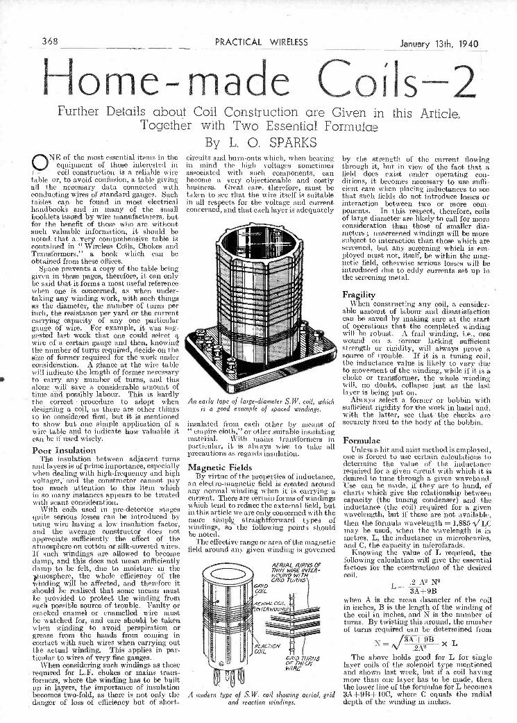
danger of loss of efficiency but of short- and reaction windings. depth of the winding in inches.
_____________________________j
danip, and this does not mean sufficiently damp to be felt, due to moisture in the )fmosphere, the whole efficienéy of the winding will be affected, and therefore it
Ç should be realised that some means must be provided to protect the winding from such possible source of trouble. Faulty or cracked enamel or enamelled wire must be watched for, and care should be taken when winding to avoid perspiration or grease from the hands from coming in contact with such wires when carrying out the actual winding. This applies in par- ticular to. wires of very fine gauges.
When considering such windings as those required for L.F, chokes or mains tramis- formers, where the winding has to be built. up in layers, the importance of insulation becomes two-fold, as there is not only tue
AERIAL IVE! VS
(II 1/1/N WIRE /N7 WOL/N9 WI 1/1
CR/b lOANS
.4ER..4L COIL-
1/1 TEA? WOO,VO)
-
Cr.'CN
IllIiJ) OTh
A inoderji lype of S. W. coil slìowi,n' aerial, grid
f011owing calculation, will give the essential factors for the construction of the desired coil.
.2 A N2 L= 3A+9B when A is the mean diameter of the cil in inches, Bis the length of the winding of the coil in inches, and N is the number of turns. By twisting this around, the iìumber of turns required cali be determined from
x L
The above holds good for L for single layer coils of the solenoid type mentioned and shown last week, but if a coil having more thaim one layer lias to be made, thmeti the lower line of.the forniulae for L becomes 3A+9B+ 100, where C equals the radial
to show but one sinp1e application of a wire table and to indicate how vahiable it can be if used wisely.
Poor Insulation The insulation between adjacent turns
and layers is of prime importance, especially when dealing with high-frequency and high vóltages, and the constructor cannot pay too much attention to this item which in o many instances appears to be treated with scant consideration.
With coils used in pre-detector stages ciuite serious losses can be iìtroducecl by using wire having a low insulation factor, and the average constructor does not appreciate sufficiently the effect of the atmosphere on cotton or silk-covered wires. If such windings are allowed to become
insulated from each other by means of empire cloth,'' or other suitable insulating
mateiial. With mains transformers in particular, it is always wise to take all precautions as regards insulation.
Magnetic Fields By virtue òf the properties of inductance,
an elcctro-magnetic field is created around any normal winding when it is carrying a current. There are certain forms of windings which tend to reduce the external field, but in this article we are only concerned with the niore simpl straightfonvard types of windings, so the following points should be noted.
The effective range or area' of the magnetic field around any given winding is governed
securely fixed to the body of the bobbin.
Formulae Unless a hit and miss method is employed,
one is forced to use certain calculations to determine the value of the inductance required for a given circuit with which it is desired to tune through a given waveband: Use can be made, if they are to hand, of charts which give the relationship between capacity (the tuning condenser) and the inductance (the coil) required for a given wavelength, but if these are not available, then the formula wavelength = 1,885 / LC may be used, when the wavelength is in metres, L, the inductance in microhenties, and C, the capacity in nìierofarads.
Knowing the value of L required, the
Further Details about Coil Construction are Given in this Article, Together with Two Essential Formulae
ONE of the most essential items in the equipment of those interested iii coil construction is a reliable wire
table or, to avoid confusion, a table giving all the necessary data connected with conducting wires of standard gauges. Such tab1es can be found in most electrical handbooks and in many of the small booklets issued by wire manufacturers, but for the benefit of those who are without such valuable information, it should be noted. that avery comprehensive table is contained in -' Wireless Co'ils, Chokes and Transformers,'' a book which can be obtained from these offices.
Space prevents a copy of the table being given in these pages, therefore, it can only be said that it forms a iiiost useful reference when one is concerned, as when under- taking any winding u ork, with such things as tIte dianeter, the number of turns per inch, the resistance per. yard or the current carrying capacity of any, one particular gauge of wire. For example, it was sug- gested last week that one could select ag
wire of a certain gauge and then, knowiii the number of tur.ns required, decide on the size of former required for the work under considÑ'ation. A glance at the wire table will indicate the length of former necessary to cari-y, any number of turns, and this alone wilI save a considerable amount of time, añd posiibly labour. This is hardly the correct procedure to adopt when designing ,a coil, as there are other things -to he considered first. but it is mentioned
By L. O. SPARKS circuits and burn-outs which, when hearing in mind the high voltages soinetinies associated with such components, can become a very objectionable and costly business. (ireat care, therefore, must be taken to see that the wire itself is suitable in all respects for the voltage and current concerned, and that each layer is adequately
An early type of large-diameter S. W. coil, which is a good exemple of spaced windings.
by the strength of the current flowing through it, but us view of the fact that a field does exist tinder operating con- ditions, it becomes necessary to use suffi- cient care when placing inductances to see that such fields do not introduce losses or interaction between two or more com- ponents. In this respect, therefore, coils of large diameter are likely to call for more consideration than those of smaller dia- meters; unscreened wmdings will be more subject to interaction than those which are screened, but any screening which is ens- ployed must not, itself, be within the mag- netic field, otherwise serious losses will be introduced due to eddy currents set up in the sci-eening metal.
Fragility When constructing any coil, a consider-
able amount of labour and dissatisfaction cali be saved by making sure at the start of operations that tite completed winding will be robust. Afsail winding, Le., otte wound on a former lacking sufficient strength or rigidity, u-ill always prove a source of trouble. If it is a tuning coil. the inductance value is likely to vary due to movement of the winding, while if it is a choke or transformet, the whoin wi udiñg will, no doubt, collapse just as the last layer is being put on.
Always select a former or bobbin with suflicient rigidity for the uork'in hand ahd, with tise latter, see that 'the cheeks aro
368 PRACTICAL WELESS Januery_13th, 1940,
Home-made CoíJs2
PDF compression, OCR, web optimization using a watermarked evaluation copy of CVISION PDFCompressorPDF compression, OCR, web optimization using a watermarked evaluation copy of CVISION PDFCompressor

school, but owing to the war I did siot return. I find that reception results houe are much better than in Scotland. mci- dentally I was up at Fort Augustus in the Highlands. Of course, the fact that there are many mountain ranges about up there may make a difference to reception. But, anyhow, I am more than satisfied with the -above-mentioned receivers. In Scotland,
The choke winch Brandon usciI was too suini! for eftective snioothin. The seconI choke was similar, but \vhen connected in the HT: negative lead it was also so placed that the inductive field coupled with that of the other choke a id thus the hum was induced from one to the oilier svitI1 an increase in the hum. Re should have placed the second choke in series with the existing one, bolli in the HT. positive lead.
Only one reader succeestully solved Problem SSO, and a book has, therefore, been awarded to J. P. Cook, e/o 29,- Salt Hill Way, Slough, Bucks.
at any one instant, tite positive end of one winding would be connected to the negative of the other, and vice versa. Not only would the output voltage be practically nil, but the transformer would overhêat and damage might result. Apart from this, paralleling of two windings, which have- jirobab]y different characteristics, is ot good practice. -
- -.,- - ',- , -,
-
- - - -. sxa-co u &s5. e , -
"P.W." Short-wave Sets SIR,-I thank you for sending nie my
B.L.1).L.C. enrolment card. I have been studying for an exam,, so have had very little time for any radio work. The first set I built was the Simple Short-waver in the beginning of 1938. Last. year I made the two-valve Simple Short-n aver. I have had remarkable success with tIme above receivers. I have logged 51st Hams and best DX on B.C. bands were VLR, Cliung- king and Tokio. I use six-pin plug-in coils, and a l5ft, indoor antenna. i built the above receivers in Scotland, where I was at
later, when lie was cleaning up, he did sorne. thing which resulted in a short-circuit of R.'J'. to filaments, amid the valves again blew, but the fuse was found afterwards to be intact, i Re was assured that it was the correct type and should have ì,town and saved the vah es. Why did it liii! to do so ? Three hooks will be awarded for the first three correct solutions i
t opened. Jntries should be addressed to The Rditor, PRACTICAL WIRIiaF.S5, Oeorge Newnes, Ltd., Tower Rouse, Southampton Street, Strand, London, W.C.2. Envelopes must be
i marked Problem No. 38 in the top left-hand i i corner, and must be posted to reach this 01lire i
not later than the first post ou Monday, January 15f h, 1540.
Solution to. Problem No. 381
necessary.
A Transformer Point When two L.T. windings wore used
originally-one for the 1.11. valves and a separate one for a D.H. output valve-and an I.H. valve is t.o be used for Output, it may. be thought desirable to. connect. the two windings in parallel. This should not be done, for the I.H. valve can be fed frons the separate winding. If two wìndings are ,ïoined together,' and they should he wired so that they are out of phase, the effect is comparable with that of shoi-t- circuitinc the transformer. This is because.
"The Kestrel S.W. 4 " SIR,-In reference to my query in regard
to "The Kestrel SW. 4," 1 ant glad t say that the set is now working perfectly, and I am more than pleased with its per- förmance.
My experience should he a warning to other constructors. Ta or(ler to economico I made alterations to the design : wood chassis, different components (which iccessitated altering t he layout), etc.
Result; poor performance, blind spots, excessive reaction, and in the end I spent mor& money than I should have done if I had stuck to the original design.
I have now constructed an aluminium ehasis, followed the layout, and now have a set to. he proud of.
I have, learnt my lesson, and it will do inc a lot of good. Wishing you every success in the New Year.-R. HowARD (lowlands Castle, Hunts).
Correspondents Wanted SIIR,-Th rough tite medium of
excellent weekly'I should like YO VALVE REPLACEMENT POINTERS
fo ask any snort-wave sistener resiumg near my address to please communicate with nie. I have only recently moved to the address given below, and through doing so have lost touch with my S.W.L. friends at my
PROBLEM No. 382.
JACKSON hadan accidentan! blew the three 4
valves iii his battery set. He decided that it would therefore lie advisable to lit a ruse and purchased one of t lie baseboard mounting types of l'useliolder and proper fuse. and
t mounted this on bis baseboard. Souse time
(Continued from page 366)
The centre-tap of the heater winding must, however, he joined to the earth uñe when changing to 1.H. valves. If a centre tap is not provided, the same result can be obtained by using the potentiometer which was previously wired across the winding and earth-connected through the bias resistor.
If a new output valve is used singly, and this requires an L.T. current appreciably less than that taken by the valve employed originally, it might sometimes be desirable to connect a "load" resistor in parallel with the winding, this being designed to "absorb" the difference in current. Thus, if t.he winding is designed for two amps at foui- volts and the new valve, takes only otte amp, a thur-ohm resistor could be used. With most transformers having good regulation this complication is not
.kc/s; Jaii. 13th, 08.00-09.00 G.M.T., CHLT, Sherbrooke, Canada, 1,210 kc/s; Jal1. 13th, 08.00-09.00 G.M.T., CFAR, Flin, Flon, Canada, 1,370 kc/s; Jan. 14th, 05.30-06.00 OEM.T., KOB, New Mexico, U.S.A., 1,180 kc/s; Jan. 14th, 06.00-07.30 G.M,T., WTAM, Cleveland, Ohio, U.S.A, 1,070 kc/s.
This DX programme promises to be one of the biggest shows ever put on the air for DX'crs
Jan. 14th, 07.00-08.00 GJ\l.T., CMHJ, Cienfuegos, Cuba, 1,160 kc/s; Feb. 18th, 07.00-08.00 M.T., CMIIJ, Cienfuegos, Cuba, 1,160 kc/s.-N. BURTON, Assistant European Representative. International DX'crs Alliance (London, ES).
The" Pocket Two " : Correspondent Wanted
SIR,-I should like to correspond with any of your readers who are building
or anticipating building your "Pocket Two.'' -
I should also be pleased to correspond with any member ol' the B.L.D,L.C. er t-lie W.F.S.R,A.
I have been experimenting with short- wave wireless for several years, both in this country and abroad, and lve found your journal of great assistance.-L. D. JEFFERY (Railway Transport Office, Central Ord. nance Depot, Weedon, Nort-hants).
cards with me, and all cards will be answered direct, if possible. Here's wishing your paper bug life and sucoes in the fiiture.-D. W. SumeAN (1, Brônt Road, Dad's Lane, Stirchley, Birmingham).
DX on the Medium Waves SIR,-Please add my name to Mr. Bur-
ton's, regarding DX on mFdium waves. A set of the superhet type would be greatly welcomed. I llave no doubt that you agree, since the selectivity needed in present-day sets makes all other types, in my opinion, out of date. In my district, at any rate, it would have to be a battery type.- 1-I. MITCHELL (Cawthorne).
The Editor does not ,secessarily agree with the opinions expressed by his Ñ voit for such a fitte weekly as PRACTICAu correspondents. All letters must be accompanied by the name and address WIRELESS. I have been taking it for the of the sender (not necessarily for publication). past three years and find it gets better
;,, s sa - every month-LESLIE BaO WMG (5, Charles
Feature DX Broadcasts SIR,--The appended list of special trans-
missions will, no doubt, be of interest to sonic of your readers:
Short-wa ve Transinissions.-Jan. 2 Ist, 22.00-23.00 G.M.T., I2AA Ethiopia, 9,650 kc/s.
Broadcast Band-Jan, 8th, 08.00-09.00 G.M.T., CKCW, Mon eton, Canada, 1,370
when I was using the one-valver, I had a medium-wave plug-in coil, which worked very well. We are very unfortunate over here as to the price of parts. There is a 33 per cent, duty on all wireless parts, which is no joke when one wants to build a set .-Mor,esr O'CONNELL (Kil- lamey).
Exchanging S.W.L. Cards SIR,-I have been a keen reader of your
most excellent journal for nearly three years now, and have found it most helpful in solving problems which arise in short- wave experimenting. I shall be very pleased indeed if any short-wave listener in any part of the world would exchanee S.W.L
January 13th, 1940 PRACTICAL WIRELESS
en t Víicuiiioii
369
old QRA ; therefore, if any listeners living near nie wouid care to call or write I shall be greatly obliged.
I am very keen on short-wave listening mid transmitting, and I have about 80 -
Q SL cards froni various parts of the world. May I take this opportunity of thanking
PDF compression, OCR, web optimization using a watermarked evaluation copy of CVISION PDFCompressorPDF compression, OCR, web optimization using a watermarked evaluation copy of CVISION PDFCompressor

Four-valve : Blueprints, Is. each. Super-quality ]flve (2 11F, D, RC, Superhet Converter (1-!) . . - AW437 AC. Fury Four (SO, SG, D, Pen) - I'W20 Trans) .......... - WM32) BL.D.L.C. Short-wave Coaverter A.C. Fury Four Super (SG, SG, D, Ciass]) Quadradync (2 SO, D, Lt', (1/-) ........ May '20 WM402 ................... - tW4D Gasa B) . . ._ .. - WM344 WiIon Tonc-Master (1/-) .. June'BJ WM4OS, A-0. llaR-Mark (HF Pen, D, Now C1as B Five (2.SG, D, LF, The \V.M. AC. Short-wave Con-
1'uah'Pullt . .. .. . 21.7.37 IW5 Cinas B) ...... - S MOto verer(i/- .... - St.t4o5 7..; - . .
-- -..-a-''--: - - -
Mains Opera e .
Transportable Three (SG, D Pen) - W111271 Two-valve Blueprinfs, Is. each. Two-valve Blueprints, le. taciL
-
Siiiplc-Tun Three- (SO, D, Pen) June'33 Eeonocny-i'cntode 'ricrec (SO, D,
\\.31327 Two-valve Mains Short-waver (D, len) AC 13.140 AH-153 AC. Twm (D (l'en), Pen) -
I 'IJ1 Peel) ........ Oct. '33
...... "W.M." Long-wave Converter . - W1138U AC-D.C. Two (SU, Pow) - - "W.M." 1931 Standard, Three
eeleetone AC. l{adlogram Two . (SG D l'en) ...... - W11351 Three-valve : Blueprint, la.
(I), Pow) ...... - L'Vt il £3 3s.'Thec (SG D Trans) Mar '34' WM354 Lniigrator (SG, D, len) LOE ., - Three-valve Blueprints, le. each. 1935 £6 Os. Batteiy Three (SU, Four-valve : Blueprint, le. 6d.- Doslble-Diode-Triode Three (11F D, Pen) ....... .. WM31 Standard Four-valve AC. Short-
Pen PD'!' l'en) .. - I'WI3 PTP Three (Pen, D, Pen) ..L, VM3S9 waver (SG, D, RC, Trane) Aug, '35 WM3t)1 C ce SG 1) Pen) .
'D P\V23 Certainty Three (SG, D, Pen) ,, - %VMIO3
A C Three (SG Pen) - PWIO Slinitube Three (SG, D, Trans)- Oct. '3 MISCELLANEOUS.. Ac. Leader (Ill? 11en, D, Pow) 7.1.30 FW35C All-Wava Winning Three (SG,.»,
WMIOO SW. One-valve Converter (Price
11.0. Prender (li F. l'en, D, Pen).. J'W3511 Pen) ........ - Gd.) ........ - AWI2(1 Ubigue (HF Nu, D (Pen), Pen) 2S.7.3l PV36A Four-valve : Blueprints, lu. Gd. cac. Entlueiat'e Power Annp!iller(1/ti) W51387. Armada Mains 'Three (11F Pen, D, 05e, Four (SG, D, RC, Trane) - AW3dO Listener's 3-ss-att AC. Amplillor Pen) ........ - FW3S 211F Four (2 90, D5 Pen) ... AW4II (1/0) . ....... - W11302 1". i. Camrifs AC. All-Wave Silver
Souvo:iirThree(llF' Pen,D Pen) 11.5.35 ,.
l'ViSO Sell-vontalned Four (SG, D, Li",
Clase 13) .. .. Aug. 33 W51331 Itdio Ut,it (2v.) for WM92 (11-) Z'c'oe. '35 Harris Eloctrograrn battery sm-
WIlDS All-Wave " AC. Three (b, 2
. Lucerne Straight Four (SG, D, pulleT (1/-) - . . . WIlDS l.LC (liC)) .. .. . -
- P\ SI LP, Trans) )
-
ViSIDO .
Do Lnp< Concert AC.. Electro- AC. 1036 Sonotone (HF. Pen, HF £5 5e. Battery Four (HF, 1Y 2 LT) Fet. '35 ViM3SI grani (If-) ........ Var. '3G S 11103
Peu Westector, Pen) .. -- - Record All-Wave S (1115
IW50 The HR. Four (SG, SG D, Pen) - Pein,
Vi 51354 New style- Short-wave Adapter - W113815 Stains
PW.O Tice Auto Straight Four (HF
'36 (1/.) .......... -
J'en, D, Pen) - - ..... - 11F Peni, DDT, Pen) ,. Apr. Vi'11404 Trickle Charger (Od.) - AW462 All-World Aee(IIF Pen, D,, Pen) 28.8.3? l'ViSO Fisc-valve Blueprintu. le.6d. each.. Short-wave Adaptcr(T/-). - .. AW4III
I.
-i
Sixty ShUling Three (D, L'I (RC & 'frans)) . - PW'4A SHORT-WAVE SETS. atery Operated.
leader Three (St, DPow) . .
Semmit Three (HF i en, D, Pen) 22.6.2 P\Y - I \\ 3
One-valve :. Blueprint, Is.
AflPentocte1hrce (H1 len, D, OC) 5 7 1'W')
sw Onc-valver .... 31?3 Two-valve : BIueprnts, is. each.
PWSs
q1I \Tak IIire (( D I ow) 12 6 37 1 \\ 41 Midget Short wave Inn (I) I eri) - IIC Feot Iiort-wae rsso
PW SA
Hail-Mark Cadet (1), LF, Pen (RC)) 10.3.35 l'VI-IS en Cli ¿.5.3 1 I?. J. (lamine Sthcr Souvenir (HF
Pen D (Pon) l'en)) (All-Wave .
, ...... Three-valve : Blueprints, is. each.
Thre) - . ...... . 13.4.35 L'W40 EXperit)senlCr's Sbort-svase Three
Cameo lidgct Three (D, 2 LS' (SG, D, l'ow) ....... O.7.38 PW3OA (Trans)) ......... '''
,
Prefect 3 (D, 2 LT (lIC and 1936 Sonotone Three-Four (11F Trans)) ........ - PWG3
Pen UF Pen, Westector, Pen) - i.'Wsi Tus Hand-Spread SW. Three Battery All-Wave Three (D, 2 LF (UF Pen, I) (Pen), l'en) .. 310.3$ P%GS
(RC)) ......... - J'Wll The Monitor (HF Pen, D, Pens .. 1'WGl PORTABLES. The Tutor Three (HF Pen, D, Pen) 21.316 l'W02 Three-valve : Blueprints, ls. each. Tise Centaur Three (SG, D, P) .. 34.8.17 l'W61 l'. J. Gamme ELF' Three-valvo F. J. Comm's Record All-Wave l'orioble (Ii 1' l'es, D, l'ce) . - - PW'65
Three (HF l'en, D, Pen) .. 31.10.30 P\\ 66 Parvo l"Iyiveigiit Midget l'oit- The "Coltj' All-Wave Three (D, able (SG, 1), l'on) .. .. 0.6.31 FW77
2 LF (RC & Trans)) .. .. 18.2.31 1'\V73 Foer-vlvs Blueprint, is. The ' RapIdo" Straight 3 (D, Imp" l'oitsblc 4 (1) LP LP
' ' 2 I.F RC & Trans)) .... 4.12.37 PW (Pen)) - 10 3 '3
S
l'WSO F. J. Lamm's Oracle All-Wave S
Three (HF', DeL, l'en) .. 28.8.37 IV, ,3 MISCELL.ANEOUS. 1938 " Trlband" Ahi-W ave Three Cluepr'nt Is
(11F Pen, D, Pen) .
.. 22.1.38 I'WS4 S.\V. Conrorer-Adapter (1 valve) . - PW4SA F. J. Camine Slitte Threo
20.1.38 PWS7 AMATEUR. WIRELESS AND WIRELESS MAGAZINE
(SG, D (Pen). Pn) .. - 30.1.30 l'\' Blueprints Gil. eaciSTPL SETS.
Teem, - 3.0.38 I'W02 e
rIetal Set: 23.7.00
Four-valve Blueprints, Is, cach.. , 150-mile Crystal Set ,,. - AW4IO
Sonotone Four (SO, D, 1F. l'y ., 1.5.37 I'W I
Fury Four (2 SG, D, Pen) - - 8.5.37 PWI1 STRAIGHT SETS. Battery Operats. lieta Universal- F'our (SG, D, LF, - - One-valvs Blueprint, is. -
Ci. t» PW li .B.l(.C. Special One-valver , - %V3S7 l'suelcon Clave B Four (SG,. D Two-valve : Blueprints, Iu each.
(8(1), Lt, Cl. 15) PW.,4B Melody Ranger Two (D. Trane) - AWISS 1' m'y Foist Super (SC,SG, D, Pefr) LIst Icry liaIt-marI 4 (11-1' len,
I'W3IC lull-volume Two(SG, det, Pen) - AW302
H, I usli-l'nil) ........ I WIG J.iscersie Minor (D, l'en) - . . - -
- A Modern 'l'svo-valver AW426 WM4O'J
1. J. Comm s 1,1ml Ail-W ava Four (11F l'en, 1), IF, I') 26.03 FW07
.. - Three-valve Blueprints, Is. each1,
Ail-\Vave " Corona " 4 (UF' Pass, (1as 15 Tlirec(D, Irons, Class 33) - A%S 380
1) LF l'ow) ...... 010.17 p\V70 £ 3e. 8.0.3 (SG, D, frane) - AW412 Acme " All-Wave 4 (HF Pen, D licerne Ranger (SO. D, Tians) - iW422 (l'en) LF Cl. B) - - 12.2.38 PWSI i. .'L Three: De Luxe \ erejon
The -. Atlmi'ral' Four (UF Pe (SO, D, Trauss) ............ s, AW435 UF Pen, D. Pen (RC))' 1.9.58 hWOt LuieernoSts'aighst. Three (D, RL, ....
£15 15e. 1936 AC. Radiogram (11F, D, Peut) ...... Jais. '36 WM4O1
Four-valve': Blueprints, in. Gd. each. All Metal Four (2 SG, D, Pen) - . July '13 WM320 Marris' Jubilee liadiogram (HF
Feti, D, LP, I') ...... May '33 WM3SC
SU PE R H ETS. Battery lets : Blueprints, lu. 6d cacti. Sloderus Super Senior - VM3'5 '\Tarsity Fouir ...... Oct. '35 WMIOI Tite Request AIh-WavCr ..... luise '36 WM407 1915 Sillier-Five Battery (Superhet) - WM37.'J Mami Seto : Blueprints,, le. Gd. each. Ilehutode Stuper Thuree A.0 Muy 3: WM35íI
W.M." Radiograsn Stipe. AC -, WM3OU
I'ORTABLES. Four-valve : Blueprints, le. Gd. each, ltoliday Portable (SG, B, LE,
Clase B) ......... - AW393 Family l'ortable (11F. D, RC,
Traue) ...... - . - AW417 Tuvo lh.P. l'ortsubhe (2 SG, D,
QL'21) ........ - W'11I61 Tyers Pou table (SO,,D, 2 Tians)., - W11167
IHORT-WAVE SETS. Battery Operatói. Ons-Valve : Blueprints,, is. each. S.\V. One-waIver for America .. 13,10.33 AW420 Rosie Short-Waver .. . - - AW4[iS Two-valve : Blueprints,, is.. each- Ultra-short Bottes-y Two (SG, deL,
l'eut) -........ Feb. 'lii WM402 Home-made Coil Two (1), Pen) .. - AW44U Three-valve : Blueprinte, is. each. World-ranger Short-wave 3 (D,
BC, Trans) ....... - AWI5I Ex,crisnentei-'s 5-metre 8es tD,
'Irises, Super-regen)' .... 30.6,34 AW435 The Carrier Short-waver.(SG, D, P) Judy '35. WRISt Four-valve : Blueprints,,. lu. Gd.. each.. A.W. Short-wave World-beater
(11F l'eus, D,i.tC, Tone) -. - AW116 lmpirc Short-waver (SG, D, RC,
Trane) ........ - WM3rI Standard Four-valve. Short-waver -
(SG, D, LP,. P.) ..,. 22. 7,35 WM383 Superhet":' Bldeprint. is.. Gd. l htisplilled Short-wave Super - .. Nov. '33 W31307
- Mains Oserated.
rRACTICAI. WIRELESS .No..oJ Universal unu-Mark (UF Pen, D, Date of Issae Iilueprint. Push-Pull) ........ -
CRYSTAL SETS. AC. All-Wave Corona Foui .,. 6H37 Blueprints, Cd. each. - I 557 Crystal Receiver . PW71. SUPERHETS. ...... 'J.'he 'Jusiior" Crystal Set.. 21.8,33 i'WOi BatterySets : Blueprints, Is. each.
£5 Sisperlset (Three-valve) .. 5.0.31
STRAIGHT SETS. Battery Operated. F. J. Camms 2-valve Superheli - One-valve : Blueprints, Is. each. Mains Sets : Blueprints, is; each. All-Wave Un/pen (Pentode) - FWI1A AC. £5 Superhet (Three-valve) -. Beginners' One-valver 19.2.33 PWSS 1)0. £3 Supertiet (Three-valve) , - The " Pyramid ' Osse-valver (ISP Universal £5 Superhet (Three-
l'en) ........ 27838 PW03 ''5lV5)
j.'
- F. J. Camina AC. Superhet 4 81.7.31
Two-vaive : Blueprints, is. each. F. J. Camrns Universal £4 Super- Foisr-risisge Super Mag Two(D,Pen) - P\VSÛB hot 4 - TIse SiguetTwo (D LI?) . - 21.9.33 Ì'W7li
......... "Quauitonc» Universal Foist 10.i.37
Three-valve : Blueprints, is. each. Four-valve : Double-sided Blueprint, Is. Od. Scierions Battery Three (H, 2 LI? Push hutton 4, Battery Model
(Trans)) .... - PW15 Push Button 4, AC. Mains Model
WlrelessMagazlne ...... 1/3 lueint The Indet lel.ters which precede the Number indicate the periodical in which the descrlp- II
I'W47 tion appears: Thus P;W. i-siero to PRACTICAL U
PWSS WIRELESS... A.W. to Amateur Wireless. W.M. to I
Wireless Ma Sasine. J
Send (preferably) a postai order to.cover the cost pr the blueprInt., and the Issue (stamPs over 6d. unacceptable) to PRACTICAL WIRELESB Blueprint
I'W4() Dept.. George Newnes. Ltd.. Tower House, Soutlir p- ampton Street. Strand, W.C.2, u
PW4S - Ì'W42 Mains Operafed
Two-valve : Blueprints is. each. I PW44 Consoelectric Two (D,..'en) AO. - AW403 I'W59 BconossyA.C.Two(D,Trans)A.C, - WM286 I
Un/corn AC-D.C. Two (D, 1n) ' WM3/1 I I
Three-valve : Blueprints, is. each. Home Lover's New All-electric - .
Three (SO, D, Trans) AC. - AWS8S pwss Mantovani AC. Three (Iii? Peu, -
D. Pon) ......... -. W51374 k
a 370 __________PAClCAL__WIRELESS Jahuary '13Th, 1940
Copies of appropriate tsssies con taln1n descrip- I
tions of these sets can in somecases be supplied at I
r Practicál \Ti'reIess mese Blueprints are drswn-fufl lze, I
the following prices, which are add Wona1 to the cost I Of the Blueprtnt A dash before the Blueprint Number t BLtEP1UNT SERVICE indicates that the issue Is out 01 prInt.
- Issues of Prartical WIreless.... 411. Post P*id Amateur Wlroless ..,. ,,. 4d,,., I
PDF compression, OCR, web optimization using a watermarked evaluation copy of CVISION PDFCompressorPDF compression, OCR, web optimization using a watermarked evaluation copy of CVISION PDFCompressor
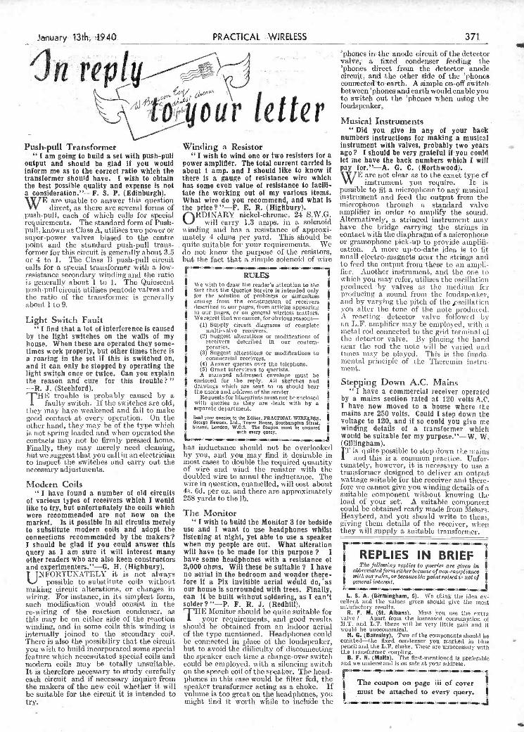
It is therefore necessary to study carefully each circuit and if necessary inquire from the makers of the new coil whether it will be süitable for the circuit it is intended to try.
on the speech coil of the speakei. The head- phones in this case would be filter fed, the i speaker transformer acting as a choke. If ne coupon on page iii oi cover volume is too great on the, headphones, must be attached to every query. I
might find it worth while to inchide the
I should be glad il you could answer this query as I am sure it will interest many other readers who are also keen constructors and experimenters.' '-G. H. (Highbury).
UNFORTUNATELY it is not always possible to substitute coils without
making circuit alterations, or changes in wiring. For instance, in its simplest fornì, such modification wou1d consist in the re-wiring of the reaction condenser, as this may be on either side of the reaction winding, and in some coils this winding is internally joined to the secondary coi!. There is also the possibility that the circuit you wish to build incorporated some special feature which necessitated special coils and modern coils may be totally unsuitable.
when my people are out. What alteration will have to be made for this purpose ?. I have some headphones with a resistance of 2,000 ohms. Will these be suitable? I have no aerial in the bedroom and wonder there- fore if a Pix invisible aerial wduld do, 'as our house is surrounded with trees. Finally, can it be built without soldering, as I can't solder? "-P. F. R. J. (Redhill).
THE Monitor should be quite suitable for your requirements, and -good results
should be obtained from an indoor aerial of the type mentioned. Headphones could be connected in place of the loudspeaker, but to avoid the difficulty of disconnecting the speaker each time a change-over switch could be employed, with a silencing switch
[ REPLIES IN BRIEF The following replies to Queries are given in
$ atbrernatedforueithierbeeauoe of non-coospliance
ji'itkosmru1es or becausethe poi-at raised is not of $ general interest.- flOtellOSOeefleç
L. S. A. (Birmingham, 5). Wo think the idea ex cellent and the values given should give the moat uatiotiictory results.
R. F. M. (St. Albaes). Must you use the - extra valve h Apart fro,iì the increased consumption of ITT. and LT. there will be very little gain and it would be uneconomical. -
H. G. (Barnsley). Two of the components should be omitted-the fixed condensei' you marked in blue pencil and the L.'. choIce. These are unnecessary with the transformer coupling.
B. F. N. (Malta). The first-mentioned is prefeablo and we understand Is on sale at your address.
I
i'
the reason and cure for. this trouble? " -R. J. (Stechiord).
J'll E trouble is probably caused by a faulty switch. If tise switches are old5
t hey may have weakened and fail tO make good contact at every operation. On the other hand, they may be of the type which is not spring laded and when operated the contacts may not be firmly pressed home. Finally, they may merely need cleaning, bht we suggest that you call iii an electrician to inspect tise switches and carry out tise necessary adjustments.
Modern Coils I have found a number of óld circuits
of various types of receivers which I would like to try, but unfortunately the coils which were recommended are not now on the market. Is it possible in all circuits merely to substitute modern coils and adopt thö connections recommended by the makers?
enclosed tor the reply. All sketches and - - drawings which are sent to us should bear
the naine and address of the sender. Requests for Blueprints must not be enclosed
with queries as they are dealt with by a separate department. Sessi your queries to the Editor, PRACTICAL WIRELESS.
tGeorge Newueg, Ltd., Tower House, Southaoipton Street, s
Strand. Loodon, W.C.2. The Coupon must be ooctosed - with every query. .
L ie}eI has inductance should not be overlooked by you, and you may find it desirable in most cases to double tite required quantity of wire and wind the resistor with the doubled wire to annul tite inductance. The wire in question, enamelled, will cost about 4s. 6d. per oz. and there are approximately 258 yards to tite ib.
The Monitor " I wish to build the Monitor 3 for bedside
use and I want to use headphones whilst listening at night, yet able to use a speaker
Stepping Down A.C. Mains I have a commercial receiver operated
by a mains section rated at 120 volts A.C. I have now moved to a house where the mains are 250 volts. Could I step down the voltage to 120, and if so could you give nie winding details of a transformer which would be suitable for my purpose."-W. W (Gilhingham).
IT is quite possible to step down the itsains and this is a common practice. Ijisfor-
tunately, however, it is necessary to tise a transformer designed to deliver an output wattage suitable for the receiver and there- fore we cannot give you winding details of a suitable component without knowing the load of your set A suitable component could be obtained ready made from Mesrs. Heayberd, and you should write to them, giving them details of the receiver, whets they will supply a suitable transformer.
-u
Push-pull Transformer I am going to build a set with push-pull
output and should be glad if you would inform me as to the correct ratio which the transformer should have. I wish to obtain the best possible quality and expense is not a consideration."-F. S. P. (Edinburgh).
WE are unable to answer this question direct, as there are several forms of
push-pull, each of which calls for special requirements. The standard form of Push- pull, known as Class A, utilises two power or super-power valves biased to the centre point and the standard push-pull trans- former for this circuit is generally about 3.5 or 4 to 1. The Class B push-pull circuit calls for a special transformer with a low- resistance secondary winding and the ratio i3 generally about I to 1. The Quiescent push-pull circuit utilises pentode valves and the ratio of the transformer is generally about i to 9.
Light Switch Fault I find that a lot of interference is caused
by the light switches on the walls of my house. When these are operated they some- times work properly, but other times there is a roaring in the set if this is switched on, and it can only be stopped by operating thé light switch once or twice. Can you explain
Winding a Resistor " I wish to wind one or two resistors for a
power ampliflr. The total current carried is about i amp. and I should like to know if there is a gauge of resistance wire which has some even value of resistance to facili- tate the working out of my various items. What wire do you recommend, and what is the price?"-F. E. R. (Highbury).
ORDINARY nickel-chrome, 24 S.W.G. will easry 1.3 amps. in a solenoid
winding and has a resistance of approxi- mately 4 ohms per yard. This should be quite suitable for your requirements. We do not know the purpose of the resistors, but the fact that a simple solenoid of wire
i We wish to draw the reader's attention to theI fact that tite Queries Service is intended only for the solution of problems or difficulties arisitig from the construction of receivers r
described iii our pages, frOm articles appearing I
our pages, or on general wireless matters. Z
We regret that we cannot, for Obvious reasons- (1) Supply circuit diagrams of complete
multi-valve receivers. (2) Suggest alterations or modifications of
receivers described in our costem- poraries.
r (3) Suggest alterations or modifications to commercial receivers. -
r (4) Answer queries over the telephone. (5) Grant interviews to querists. - A stamped addressed envelope must be
"Did you give in any of your hack numbers instructions for making a musical instrument with valves, probably two years ago? I should be very grateful ifyou could let me have the back numbers which I will pay for."-A. G. C. (Northwood).
WE are not clear as to the exact type of instrument you require. lt is
possible to fit a microphoneto an musical instrument and feed tise output from the microphone through a standard valve amplifier in order to amplify the sound. Alternatively, a stringed instrument may have the bridge carrying the strings in contact with the diaphragm of a microphone or gramophone pick-up to provide amplifi- cation. A more up-todate idea is to fit small electro-magnets near the strings and to feed the output from-these to an ampli- fier. Another instrument, anti the one to winch you may refer, utilises the oseillaticn proderced by valves as tite medium fer producing a sound from the loudspeaker, and by varying tise pitch of the scihIation you alter the tone of the urote produced. A reacting. detector valve followed by an L.F. amplifier may be employed, with a sirotai rod connected to the grid terminal of tise detector valve. By placing the hand near tite rod the note vili be varied and tUlleS may he played. This is the funda- mental principie of the rIileremin intru- irrent.
-j January- 13th, 4940. PRACTICAL :WIRELESS 37L
'I)hOflCS in the anode circuit of the detector
'3 n rep - - \ -
connected to-earth. A simple on-off switch-
O' \ to switch out the 'phones when using the - between'phonesandearthwouldenableyou
--'to o u r ¡ et te r strumeits
PDF compression, OCR, web optimization using a watermarked evaluation copy of CVISION PDFCompressorPDF compression, OCR, web optimization using a watermarked evaluation copy of CVISION PDFCompressor

L...oeaieoeeon (Ccnin ued in next column) T lord Avenue, Bright on.
and thé connecting wire will (heu be
firm/v attached to the terminal and be, in effect, an extension çf (lie terminal shank. Ordinary terminals may be drilled by
clamping (hein in a vice, first rnnnin a
nui down the shank, which may afterwards be rento,ed to take oíl any burr which may
be made On tile end threads. /
iÍjj ¡
HANDBOOK By F. J. CAMM.
400 pages, 6/- or 6/6 by post from
GEORGE NEWNES, 'LTD., Tower House, Southampton Street,
Strand, W.C.2.
CRYSTAL PICK-UP, high grade American. Bronze finish, complete wit], aro, ...... 21f- each POLAR N.S.F. 1 watt resistances, 4d. each, 3/9 doze,,. A]] sizes up to 2 ,ieg. WEARITE MAINS TRANSFORMERS, It.C.B. type. 350-0-350 V. SO Ins., 5 volt 2 anips. 0.3 volt S amps
6/I I each Type 11Cl. 500-0-500 y. 150 n'a. 4 volts 2 ailips, 4 volts 2.5 liflhpS, 4 volts 5.0 amps . . - 21/. cacti PHILCO MAINS TRANSFORMERS. American WimI- inge, 130/350 volts (iS ins., 0 volts 3 amps., 5 volts 2 amps .......... 5/- cacti Ditto, but 80 ma ......... 6/6 each Ditto, but 90 ova --------- - 7/6 escI, WEARITE 110 k/a I.F. Transformers - - 1/- each AMERICAN CTS. Volume Controls, linest made, ,tivided spindles, length 21m. with so itclt, 2,000, 5,000, 10,000, 25,000, 100,000 ---- 2/6 each Wire-wound 5 watt (less switch), 10,000, 25,000 ohms,
21- each
WEARITE CHOKES, Screened .... !16 each
PLESSEY DRY ELECTROLYTICS, CAN TYPE. 12 X 10 nif,). 310 volts irorking .... 1/6 each 6 x O ,, 500 volts working .... 1/6 esel, 12 450 volts working .. 1/6 cacti S x fix 8 nihI. 501) volts working ...-. 2/Il esci, 10 X 8 .x 4 t 4 mCI. 500 volts working -. 2/II east, 12 x 8x8x8x8 n,fd. 500 volts working 2/Il each 16 mfd. 4511 volts working ...... 1/3 each 16 x 10 nitil. 350 volts w6rking ..,. 1/6 earl,
V boxe,], 2ts. Moderi, tiick-m,iis, ti n. in,] iSa. Ott.. iritli vol,i,,,e ro,t ois.
VkXIlA J,. 'iCC at,,iii,sitii,i enutsisers. 8 nthl. (55) y. lis. ; 'Il 0 rs r,lboa rd 8 tofu 51)0 v. ?s.
8 pIus 8 mf,].. Ss. 1(1.
VAUX1IALL. Volume controls, Ss.
; with switch,
Is. 't'tiltitiar eo,i,le,,sers, (1.1 nd,] lid. 0.23 ,,,f,l 4,1. Renisl ors, 1 wstt. 4i t.
%tXiTA Lt UTILITIES. 101a, Stramt, T,oision,
Il .0.2. lost paid over 25. (ht. Write for free list,
BANKRUPT BARGAINS. llral,,] co 1939 moilels,
,,,akers' seate,l cartons, witt, guarantees, at less 40 ter cent, below listed prices; ,,lno Midgets, ori- tables, car radio. 8eit 11(1. sitimmip for lists.-tla,lio Bargains, Dept. 1'.W., 201-8, Licl,lield Road, Aslon, iJir,ìiiugl,nii'.
ST" Crystal Set. Specified coil, 2. case. lsd. ; or coiìplete kit 01 parts. los. 3d., post
f me-T. W. Thompson ud Co., 170, (4resnwict, SUgli Road, S.E.10.
BANKRUPT BARGAINS-Alt CIV goods. Sparta,,
5v. A.C. superhiets press butto,,, £3/IS!-. Tri,- phonic 5v. nIl-wave supsrl,ets, AC., 7 gite. Belmont tilt-dry portaliles. sii 'eri et 5 gos. l'orta,) ync 8 go. superhet porlilli's, fIl. Porta,,] \'l,e 4y. I 'attc'rc s ko-ave supertiets. LO. Sissy others. (till quote rf'tuirententa, l'uil stork valves alit servite goods.-li,Lthi,i, ti. Sian-
markings, and a clean rag should then he
wiped over to remove excess from the dial itself. Uhen dry the dial should be as good as new.
Terminal Connections
f4/J-IEJV making a-' s/tort-wave or
similar receiver, where fairly beau j'- gauge wire is used for connection pur/loses, some constructors eAperience difficulty in making connection to tite shank of a terminal. Owing to lite small space available the connecticut is not usually made soundly, and an idea worth reinem- bering is that which was employed in old. pattern Government apparatus. The shank of the teiminal was drilled down for a s/tort distance, and the wire used /r con- nection was of sue/i a gauge that it just fitted inside the hole down the terminal shank. If the wire is tinned, and ¡mv is
inserted inside the terminal hole, and ¡he wire then inserted, upon the application nf the soldering iron canting a good " blob of solder, it will run down into the hole
complete with S-way Press Button Control. Precision job throughout. First Grade Motor. AC. 24 volts
21/- each POLAR meg. Volume Controls, with SP. Switch
1/6 each Ditto, with D.P. Switch ...... 1/9 each YAXLEY type 4-pole 3-way Single Bank Switches
Od. each 2,500 ohm Fields Coils ...... Od. each 1 (One) groas Assorted Resistances.. 5/- per gross MetaiChiassis Drilled. 15" x 6" ir auth i1i'xS" x ir
1/6 carli Push Bark Wire ...... l2yds. bd. ROLA P.M. Speakers, latest type 71m. Cone, with Pentode Transformer Boxed 14/6 each Clock-fared TuaIs, 5" X 3)", with printed 3-wave scalo Ox-opper Rscutchieons and 0-lass .... 3/6 each Ditto, less Escutcheons ...... 2/6 each HOrizontal dials, with plain scale 7)" x 31" and pointer
1/- each I OOft.. Coppet Aerials, Insulated . . .. 2/- each FILAMENT TRANSFORMERS, input 200-250 volts, output 4 volts 4 amps, 4 vOlts (i amps . . 4/Il each G.E.C. Mains Transformer, American windings, 350-0-350 volts, (',5 ma. 5 volts 2 amps, 6.3 volt 2.5 àmp. Suitable for replacements iii C.E.O. models
5/6 each i4 mId, Ccii type Electrolytics, 450 volts woriting
l6 cccli PRESS BUTTON UNITS with 6 Press Buttons, ready for wiring into set, with circuit - - -. . 4/Il each WEARITE Set of two Iron-Cored Coils, Aerial and RS. Trans. with diagram ------ 2/11 each BULGIN 25 ohms Wire-wound pots .... 1/- each Stranded Push-back Wire, id. per yard, 12 yards bd. CHASSIS Mounting Valve Holders, American, 4-, 5-, 6- and 7-pin, 4d. each. Octals 6d. each. Loctals bd. carli. 7-pin English type, 3d. each. ROTHERMEL Pieno Crystal Speakers, 71m. Cono. List 55/-. Our price, 10/6 cacti. I 0m. Colic 12/6 each.
SOUTHILIR RAluO'S BARGAINS. -
LL GUARANTEED. l'oSTAO,E EXTRA.
5 / -Parcel of useful Component a, counprisi ltg /- (onde lisera, I esist coces, lunte ('octrois,
Vire, Circuits, etc, 'alue 25/-. 5/- icr psi-eel
1 5 ¡ -Service Slaui'sCompoaeutt cit - Elecìrolytic I - ('omleutsera, \'eulunae ('ontrols, Resistances,
'J'ubuilar. Mica, l'i ter Condensers, Val t'e Hohle rs, el r. I 2 i articles routai tied iii Strong ta rryi uig enaCt, il" X 7" r, 15/- tite Kit.
2 1' -Sunah I Tr;uleu''s Parcel of Coltil,ouletit 5. 1711
/- Articles eoiit(riSing ui It tites Ct,s,ieuuue is. Vail t'e Holders, Resistances, ('liokes, Coils, Wire, ett'. Value 85/-. II/- Ihr itarcel.
5 / -100 W'ire-e,al Resistances, associ cd raised ca, / - 1 tintI I wall, 5,- ,er SOI).
5/_-6 Volnute Controls, 5/-.
TELSFIN ; Oruiion,l Louil-speaker Units. 2/6 Crystal Sels, li/Im \Vestectou-u Type WI, 2/6
8 mid, Eleclrolvl.ic Coaderisers, 5(10 volts, i/S. ('r'slsiI Detectors, 5/- ; Crystals, liti. ; Nareolil VII Valves, 11,1.
2 / -Tuoi or lustra tient l'arrei tig Cases, ca
¡ - (Cou'e,'anieu,t Stock; '«oOuI J" x 1" x 7", 2/-.
,Sl'EC'LkL Offer, I liait ed Quantity 'l'orchi Bull,s
1 .3v,, 1/- l-ter 100 '2.5v', and 3.5v., 17/6 ver 1011.
SOt"J'FhEhlN liA DIO, 411, l.islc Street., London, WC, Cerracil (1653.-
VAUXH\l.l. ilola 8lit. l'.l%i. speakers, ils. liii.
lbS, loin. ',lvi, sprakers, 15e, liti. Cotuipicte teitlu i utpuut tra usi', 'unters.
¡AUXI-IAT.L. Collaro AC, granurti,luOuie unotom.
g being used. Generally these have deep cu/s for the degree markings and these are filled wit/i white enamel or paint. After some
time they iney become discoloured and djfficult to read. They may be rénova ted,
however, and made almost as good as new
by dip ping them in ordinary turps fbi a
short timize and wiping with a rough clot/i, so 1/mat ail the old paint j.c cleaned out. If necessamy they may be scratched, taking care lo avoid over-running the original mnarking.c, and then the (liai should be
úiped carefully with a piece of rag cammying a small quantity of good while baint or enamel. This will fill time
RECEIVERS, COMPONENTS AND ACCESSORIES
RADIO CLEARANCE, LTD., 63, High Holborn, W.C.1. BRITISH BELMONT S salve pills Magic Eye All. Wave AC. Superhet Chassis, 4 w-ave-bauds, ts:o short., medium and long, litted latest Mullard Octal Base America i type Valves. Size of Chassis, iar x 1O'x 3". Supplied w-jth Vahes and Knobs, hut less Speaker.
Chassis only, £5/19/6 each. Speaker for above, 17/6 each.
CRAMPIAN 10" 10 watt, 2,3Oö ohm Energised Speaker. Heavy Cast Frame .... 15f- each With heavy-duty Peutode Speech Transformer
17/6 each Heayy-duty Speech Transformers, Pentode Matching
2/11 each PLESSEY 2-gang Straight Condensers .. 116 each Ditto, 3-gang .......... 2f- each PLESSEY Motor Drive Press Button Usit. Supplied
Volunse Controls, 1,000 aiìd 5,000 ohms, with switch. 1/3 cacti
.0005 3-gang TLlning Condenser Units, with trimmers. 1/9 each
PLESSEY Energised Speakers, lOin. Cono, 2,504) arnE 1,000 ohm field, with trans 12/6 cacti Ihn. Cone, 2.500 and 1,500 ohm field 5/Il each RUBBER CROMMETS ...... 4d. dozen BATTERY Output l'entodea, well-known make.
4/6 each BATTERY Double Diode Triode, wllknown make.
3/11 each RAYTHEON First.grade Valves, largest stockiste, all types in stock, Including Glass Series, Glass Octal Series, Metal Series, Bantous Series, single-ended Metal Series, and Resistance TILbeS, all at most com- pel itive prices; send for Valve Lists. All Orders Must Include Sufficient Postage t.o Cover Hours of llusiiiess: U am-li p.m. Weekdays. Satur- (lays 9 am-i p.m. RADIO CLEARANCE, LTD., 63 High Holborn, London,
W.C.1. TELEPHONE HOLborn 4531.
L 372
Not ,rom the St Beh ch
Renewing Dials
THERE are still mary receivers in use in which engraved ebonite dials are
PRACTICAL WIRELESS January- 13th, -1940
Classified Ativertisements RECÉWERS, COMPONENTS AND
ACCESSORIES Advertisements are accepted for these
(Continued from pre,dous co!ùrsn) columns at the rate of 2d. per word. Words in black face and/or, capitale ate charged, B.l. Wire-end type, Thai Electrolytics. double this rate (minimum charge 2/- pet 50 inlTd. 12 volts ........... 1/d each paragraph). Display -lines 9re charged at 50 mId. 50 ts ........ 2/- each 4/- per line. All advertisements must ha Tubultir Wife-end non-inductive parer, all sizes -up prepaid. All communications should be to 0.1, Sd. each, 4/9 dozen. addressed to the Advertisement - Manager, "Practical Wireless." Tower House,. Metal Case i bole fixing EIectroltic Condensera, Southampton Street, Strand, London, W.C.2
550 vOlts working, 8 mlii ....... 3/- each STANDARD TELEPHONE HEADPHONES, resistance fi,(J00 ohmt and 4,000 ohms 6/11 pair
PDF compression, OCR, web optimization using a watermarked evaluation copy of CVISION PDFCompressorPDF compression, OCR, web optimization using a watermarked evaluation copy of CVISION PDFCompressor
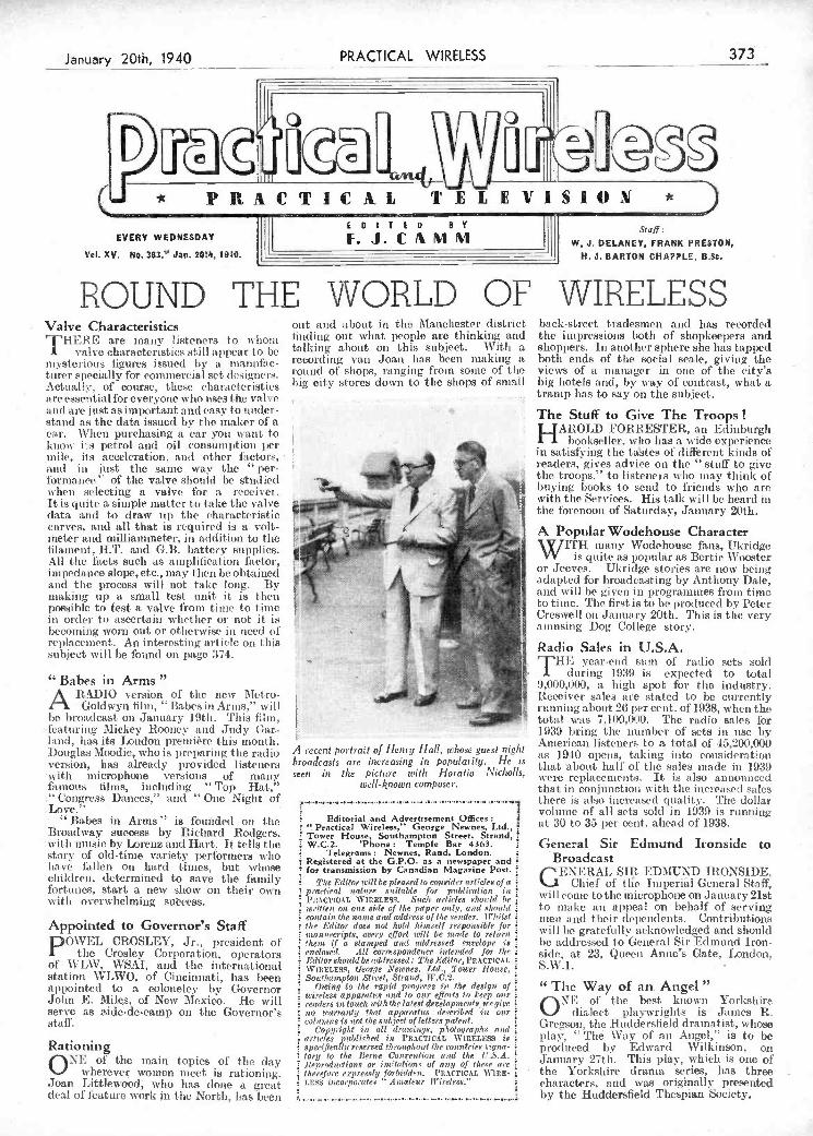
deal of 1ature work in the Norh, hasleen I by the Huddersfield Thespian Society
_c.i__,--- - - -
i." Congress Dances," and " One Night of tLove."
Babes in Arms" i8 founded on lije Broadway success by Richard Rodgers. 'vitlt music by Lorenz and Hart. It tells tite story of old-time variety performers who have ItJlen on hard tintes, but. whose children, determined to save the family fortunes, start a new show on their ou n with overwhelming sut'cess.
Appointed to Governor's Staff PO\VEL CROSLEY, Jr., president of
the Crosley Corporation, operators of WLW. VSAI, and tite international station WLWO, of Cincinnati, lias been
PPointed to a colonelev by Governor John E. Milqs, of New Mexico. Ho will serve as aide-de-camp on the Governor's staff.
Rationing .
ONE of the main topics of tito clay wherever women meet is rationing.
Joan Littiewood who Iras done a ereat
iEditorial end Advertisement Offices "Practical Wireless," George Newnes. Ltd., Tower House, Southampton Street, Strand, W.C.2. 'Phone: Temple Bar 4363.
Telegrams: Newnes, Rand, London. L
Registered at the G.P.O. s a new,pper and for transmission by Canadian Magazine Post.
Tite Editor trill be pleased to con 514er art 'ries of a i prttrtirol tiqiur' soitble for publication in PJ,.scT:cAL \V!CELES$. Such art irles sito titi he written ott Otte 8itie of tite paper o,,!:,, and si,st,ld
i coulais the n'unte and address of tite sender. Whilst i
1/te Editor does not told /titnsel.f responsible for i manureripts, every efort will b,t Situ e to retnr,t 1/teto if a. stamped and addressed envelope is
i en,.lsoed. 1t1 cortespoodeser intended for i/tr i
i iltitlor ohotuld be addressed: The Editor, PCACTLCAL i
\W:t:ELESS, 1/sorge Newnes. liti., Tower ¡Joute, i Sonthatszplott Street, Strand, ff0.2.
Owing to the rapiti prot,reso in the design of wireless apparat ito titti io our efforts to Jeep our i
i readers iii lone/i tt'ithtite latest devel.opsneti'o.ne gire uto tttarranii, thai apparatus de.trribest in our rottunitto is not the subject of leIters pot ettI.
¡ Copyright itt till drawings, p'tolographa fOitti
articles jstthtithett itt PRACTICAL WLREL}SS is i
i specifically reserved t/ììotttihotit tite countries signa- tory to tite Bertue Cottrention tt,td lite ('SA. i
I J!ejtrsdurtiotts or ittiitation t of asty of tinte are ; titet'efttre e,rprenoiy forltitldrn. i'RACTtCAL W'htig-
SEOS ¿ttcoiJssrstes ' 4tetotesir Jl'ireleos." i
there is also increased quality. Tite dollar volume 'of ail sets sold in 1939 is running at 30 to 35 per cent, ahead of 1938.
General Sir Edmund Ironside to Broadcast GEN ERAL SIR EDMUND IRONSIDE,
Chief of tle Imperiâl General Staff, Wi li couic to the microphone on January 21st to titale an aI)peal on behalf of serving niet! and their dependents. Contributions will be gratefrthiy acknow'iedged and should he addressed to General Sir Edmund Iron- si(lr', at 23, Queen Anne5o Gate, London, S.W.1.
"The Way of an, Angel" ONE of the best known Yorkshire
dialect playwrights is James R. G regson, the Hudclersfiel d dramatist., ivhose play, ' The Way of an Angel," is to be produced by Edward Wilkinson, on January 27th. This play, which is one of the Yorkshire drama series, has three characters, and was originali y presented
attO are just as important and easy to under- stand as the data issued by the maker of a ear. When purchasing ti car you vant to know its petrol and oil eoiiSuinI,tiOn per titile, ils acceleration, and other factors, nfl(t in just the sante way the " per- fòrnianee" of the valve should be studied when selecting a valve for a receiver. It is quite a simple matter to lake the valve data and to (iraw up tite characteristic curves, and all that j8 required is a volt- meter and niilliammeter. iii addition to tite lilaineitt, ILT. and GB. battery supplies. All the facts such as antl)lillealiort bietor, impedance slope, etc., may t hen be obtained. and the process will not take long. By making up a small test unit it is t hen possible to test a valve front tinte to lime in order ti) ascertain whet lier or not it is becoiniiìg tvorn out or otherwise iii need of replacement. An interesting article on titis subject will be found on pago 374.
" Babes ¡n Arms " ARADIO version of the new Metro-
Goidwyn flint, ' Babesin Arms," will be broadcast on January 19th. Titis filin, lëaturiuig Mickey Rooncy and Judy (lar- land, lias its London première this month. Douglas Moodie, who is preparing the radio version, has already provided listeners with microphone versions of many Luttions hIrns, including " Top Hat,"
.,,_41
»
The Stuff to Give The Troops! HAROLD FOR RESTER, an Edinburgh
bookseller, who has a wide experience in satisfying tite tastes of different kinds of
readers, gives advice on tite "stuff to give tite troops," to listeners who may think of buying books to send to friends who are
Iuvitit the Services. His talk will be heard iii the fòrenoon of Saturday, January 20th.
A ecent portrait of Henry Hall, whose guest night broadcasts are increasing in popularity. He is
seen in the picture wi/li Horatio Nicholls, well-known composer.
A Popular Wodehouse Character \YJITH ninny Wodehouse fans, Ukridge
VV is cluite as 1)oPulai as Bertie Wooster or Jeeves. Ukridge stories are now being adapted for broadcasting by Anthony Dale, and will be given in programmes fiotti timo to time. 'l'he first is to be produced by Peter Cresuvelt on January 20th. This is the very amusing Dog College story.
Radio Sales in U.S.A. THE year-end senti of radio sets sold
uluring 1939 is expected to total 9,000,000, a high spot for the industry. Receiver sales are stated to be currently running about 26 per cent. of 1938, when the total was 7.11(0,090. Tite radio sales for 1939 bring the siumber of sets in lise by American listeners to a total of 45,200,000 as 1940 opens, taking into consideration that nhout half of tite sales made itt 1939 were replacements. It is also announced that in conjunction with the increased sales
VRACTIC4I TELEVISION EDITED BY
Staff: EVERY WEDNESDAY I. J. C 1 I'1 jjj W, J. DELANEY, FRANK PRESTON,
Vol. XV. No. 3B3. Jan. BOUt, 15O. H. J. BARTON CHAPPLE, BBc.
ROUND THE WORLD OF WIRELESS Valve Characteristics 'T'HERE are many listeners to tvitoni
A valve characteristics still appèar to be mysterious figures issued by a itiatinfac- titrer specially for commercial set desigijers. Actual e, of course, these characteristics are esset itial for everyone who tises the voire
ont and about in tite Manchester district finding out what people are thinking and talking about on this subject. With a r000r(hing van Joan has been making a round of shop, ranging from some of the big city stores down to the shops of small
back-street tradesme n and has recorded tite impressions both of shopkeepers and shoppers. In another sphere she lias tapped both ends of the social scale, giving the views of a manager in one of the city's big hotels and, by way of contrast, what a tramp has to say on the subject.
January 20th, 1940 PRACTICAL WIRELESS 373
:1
PDF compression, OCR, web optimization using a watermarked evaluation copy of CVISION PDFCompressorPDF compression, OCR, web optimization using a watermarked evaluation copy of CVISION PDFCompressor

(I::
L:
L) How to Determine the Cheracteristic Curve, the Amplification Factor, and the Impedance of Valves is
Explained in This Article by L. O. SPARKS
fJ1E majority of constructors wish at sorno time or other to check the characteristics of the valves they
nse, and this is no doubt responsible for the many requests received for details of a valve-testing unit.,
To design a init which would satisfy all demands is no thsy matter, bearing in mind the very wide range of valves now in use, and the fact that those fitted with multi- pin bases are as common as the more simple four and five-pin types, a valve tester which would be capable of catering for all classes of valves would naturally have to become a much more complicated piece of apparatus than many readers seem to appreciate. It is not, therefore, intended in this article to give the constructional details of what might be termed a universal valve tester, although in ali fairness to the Technical. Staff it must be mentioned that such iin item is receiving their careful attention, but rather the general outlines of a unit which will serve the purposes of most onstructors and provide the basis for individual design and constructional work.
If, for example,ia constructor wishes to find a subject 'hich will lend itself to any originalit, ingenuity and skill on the part of the designer-constructor, then the unit in question is an- ideal item for such con- siderations, especially during the long winter evenings. -
Sò far as designing goes, there are many 'things which will call for careful thought, such as compactness, accuracy, range of application, what method-of circuit chang- ing to be employed, current and voltage supplies and, of course, ease of manipula- tion.
Essential Requirements As will be seen later, the most simple of
valve testers requires a reliable milliam meter and two voltmeters. If a dual range volt- meter is to hand, reading, say, O to 10 volts and O to 120 volts, that can, of course, be used instead of the two separato volt- meters. A potentiometer, some valve- holders, one or two switches, and a suitable piece of material for a panel, plus a small box or cabinet in which to house the unit, form the main requirements. It is highly possible that most constructors have the majority of - these items amongst their equipment.
Before proceeding with tise details of how to apply the various tests, the funthmontal circuit of a simple tester, shown in Fig. 1, should be examined, as it will make the
shown in the diagram, could be obtained by fitting a variable resistance iii the positive H.T. supply. A value of 50,000 ohms would be suitable, provided the component is of a good and reliable make.
Testing Procedure The simplest test to apply to a valve is
to determine its emission which, in turn, will allow its anode current/grid voltage curve to be plotted and give a visual indi- cation of one bf the valve's characteristics.
1L? it
- A
a
_j Fig. 1.-A suggested circuit for a simple valve lester. Refinements can be added to suit require-
ments.
Most valve makers publish sufficient details about their various types to enable one to check results and thus see if the one under teat is normal. For example, it will be noted that current values are specified against certain anode, screen and grid voltages, so when comparisons are being made the voltages mentioned should he applied. . -
Assürning that a simple triodo valve is being testéd, the following procedure should be -adopted. With the valve in the holder and its filament accumulator con- iieeted, connect the grid to the negativa sido of the filament supply and plug in the H.T. supply, adjusting it until its volt- meter indicates 120 volts. Note the anode current, i.e., Is, and plot it on squared paper as shown by the point x in Fig. 2. Now adjust the grid - battery potentiometer until the grid voltmeter shows i volt, and then read off Ia again and mark its position
The amplification factor or, as it is more often called, the Mu of a valve, is a very important item as it indicates what gain or signal amplification ono might expect from it when it is operated under ideal conditions. A glance at any valve maker's booklet will reveal that the Mu ol a valve varies over a very wide range, according to the numerous types, but nhatever type is under consideration, its amplification facte can be deterssmimicd quite esLsily.
Assuming that the valve used for the previou test is being examined, the following readings must be taken. \Vtls Vg at zero, i.e., the arm of the potentio- msieter making contact with the negativé filansent/H.T. line, adjust the Va to 100 volts and then note Ia. Now increase Va to 120 volts, and when the meters are steady adjust the gm-id potentiometer until the value of Ia-which increased when Va was increased-returrss to its first or original value. Measure accurately Vg and then carry out the following simple calculation.
Va2-Val . . .
Vg or, in other words, divide the difference in the two anode voltages applied, i.e., 120-100=20, by the gmid voltage applied to rest-ore the anode current reading back to its value when 100 vòlts was applied to the anode. Supposing that Vg was 2 volts, then the amplification factor, or the Mu, of the valve equals
20 -i--
or 10.
The Mrs is simply denoted by a number which is an arbitrary term.
\Vhemi carrying out this and any other tests conneeted with valve characteristics, it is absolutely essential to make frequent
checks to see that ali applied vOltages
. are remaining con- stant,including the filament or heater voltage, as any
- fluctuations or in- -
accurate readings will upset all ca!- culations.
Fig. 2.-The anode- current grid-volts curve mentioned in the article. Note cut-off point and the effect of negative bias.
Impedance Another vital
characteristic of a valve is its impe- dance or AC. re- sistance as the value of this plays a very important part in the design and selection o! suitable inter-valve couplings. The im- pedance of a valve, which is expressed ill ohms, can be
374 PRACTICAL WIRELESS J8nuary 20th,. 1940
, .- ,of this voltage will depend on the type of V a I y e I e s t i n :::::::tb0h1
t
fi;-
I:
explanations of the testing procedure more easy to follow.
It will be seen that provision has been made to allow the anode current, the anode voltage and the grid voltage to be measured at will, and these will be referred to as Ia, Va and Vg respectively in the remarks below.
The potentiometer across the battery supplying the voltages for Vg is not abso- lutely essential as the voltage can be varied by adjusting the supply voltage via tapping points on the battery, but the potentio- meter gives a smoother and more accurate setting. Another simple refinement, not
(y) on the graph (Fig. 2). Repeat this pro. cedure, inereasingVg by i volt each time a reading is taken, until the point z is reached, which denotes what is known as the cub-off point of the valve under test. When all readings have been taken, connect all points with a line, thus forming the com- pleted curve, as shown by the solid line in Fig. 2. From this, the value of Ia can be read off for any value of Vg between zero and that required to produce eut-off.
With SG., HF. and L.F. pentodo valve, a constant H.T. positive voltage must, of course, be. applied to the screening-grid during the above operations. The value
-aererminea ny applying the following tests. With Vg at zero, apply loo volts to Va and note the current reading Ja. Now increase the value of Va by a definite amount, say, 20 volts and note new reading of Ja. The impedance can ijow be calculated from the formula:
Change in anode volts x 1,000 Change in anode current (mA's)
Assuming that the change in anode eurreñt for tise above example is 4 mA's, then the impedance would equal
20 x J,000, or 5,000 ohms.:
PDF compression, OCR, web optimization using a watermarked evaluation copy of CVISION PDFCompressorPDF compression, OCR, web optimization using a watermarked evaluation copy of CVISION PDFCompressor
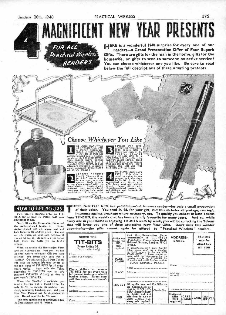
L
COD 4 HERE is a wonderful 1940 surprise for every one of our ______ readers-a Grand Presentation Offer of Four Superb
cf1ieà/ 'pe/ess Gifts: There are gifts for the man in the home, gifts for the -
housewife, or gifts to send to someone on active service! RE.4û k'.. You can choose whichever one you like. Be sure to read
below the full descriptións of these amazing presents.
w.. m ..
t2'
%.
il 7i i4 ' - _-1 L- 'fl" -..... '
L. -. ... j
a, Ç i'
i -
\ Choose Whichever You Like J, -
-il. OS LUXE SANDWICH 5-PIECE TEA SET. J
- 1 r Oli CAKE $TAND. This comprising Tablecloth ( -$ is heavily chromium- 361e square with 4 e
plated. A swing handle Serviettes each 9k in. " ' -
a is provided so that the s q u a re. C r e a t ed - complete stand may, if desired, specially for this 09er In a \.. be placed in a shallow drawer, linen finish, and trimmed with Hest quality heavy English fashion's latest edg'ng. Dyed Glass is uped. etched with a In neutral shade to harmonise pleasing flower design, and the with any colour scheme. Hard -
ss p-.-'-" edges are smoothed. A present wearIng, this Gift Set will ' f, - - ' every woman will proudly show keep like new for years. -' I - ,.- " i' oli to her friends i
. / t
, «-j - STURDY POCKET -
- i- . 1 FLASK. Thovery thing equal in valuo to any L'S
for ARR workers on pen selling in the shops I duty or mon on active los' Is. Cd. it is buy . r .1 -- .
t» service. Mûdo in very goaranteed and fitted with . 'L
I .
strong glass. Covered with the solid 14-ct. gold nib. iridium '-- f f - .. finest leather. Provided with tipped. Lever fillIng with- .
I (I .
polished cup manufactured Chromium-plated- pocket clip - ./' .P from the most hygienic metal and fittings, and unbreakable
. I - .... for drinking. With screw top- let black barrel. - .- '-
January 20th,.. .1940______ PRACTICAL. WIRELESS -
1 MMNLÑ(FNT NE# YEAR
f375 .
I H e, k
'qY14.l.QG U.R S First, place a standing order for Tu-
IOITS for at least 10 weeks, with your newsagent to-dày.
Next, fill up the Reervatián Form' and the Address-Label beside it, Stamp Address-Label, with d. stamp and' post' both forms to the address given. You can use d. stamp on your own envelope it you do not seal it. Be sure to strike out ou both forms the Gifts you do NOT require.
Yhen we receive the Reservatjon Form r.d the Address-Label from you, wo will
at once reserve whichever Gift you hase selected, and immediately send you a
Voucher. On this you affix 10 Dato Tohess cut troni the bottom lefthande corner o? tise. bach cover of TIT-BITS for 10 come- cqtive weeks. Start with the Token appearing in UT-BITS now on saie (marked TIT-BITS 27.1.40) or that in next week's 'UT-BITS.
When your Voucher is complete you send it together with a Postal Order for only is. 9d. to include all packing, car- riage, insurance, handling, etc., and your New Year Present will be dispatched to you Do not send the Is. 9d. now.
This offer applies only to persons residing in Great Driiqin and N. Ireland.
WytHESE New Year Gifts are presented-one to. every reader-for only a small proportion of their value. You send Is. 9d. tor your gift, and this includes all postage, carriagé, insurance against breakage where necessary, etc. To qualify you collect IO DateTokens
from TIT.BITS, the weekly that has been a family favourite for many years. And so, while. every one in your home is enjoying TIT-BITS. week by week yoi will be collecting the Tokens that will bring yoù one. of these attractive New Year Gifts. Don't miss this wonder opportunity-the gifts cannot again be offered to Practical Wireless" readers.
ORDER FOR : 'k BFf ADDRESS- lid.
'aZ TI T-B ITS b .W.Gifts),Presentati:n LABEL :
Every Friday 2d (Pleaee witte clearly) rcs. in acr4anee with poor Special BY !
Offer, please send me a Voucher on which to qualify for my NEW
To TEAR GIFT, I 'have placed an 'V ..... eme e cieca gee Order with my Newsagent for the
regular supply of flT-BITS for Addresc STAND II) weeks and until further notice.
BLOCK LETTEES PLEASE Stime ................................................. _______
Please ¿cliver or' reserve Name............................................ TIT-BITS for mc every week, for the'next tenissne..anduntrl
FLASK Address Address .... further notice. Please start ttn full) with this week's or neab week's inane.
TEA 'ET Fill np this form and For Office wie Name the Addreu-Label on
Address right in BLOCK LET.
Checked fi TESS. Stamp the Label ....................................... _________
Strike out as directed and poet thu frn, in an an- Gifts CAKE VLASK TESt
PEIv Date
. sealed envelope (lid. - T' f -'. NOT STANC .-. sET ............................... stamp. sal, required). -
required..
PDF compression, OCR, web optimization using a watermarked evaluation copy of CVISION PDFCompressorPDF compression, OCR, web optimization using a watermarked evaluation copy of CVISION PDFCompressor
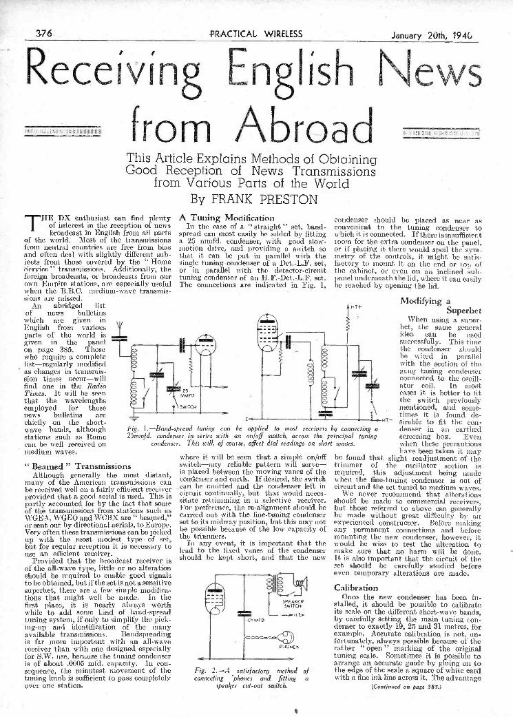
is of about .0005 ifd. apacity. In con- seuenee, the minutest movement f the tuñing knob is sufficient ta pass completely óvér one station. -
s-.
- r
Fig. 2.-A satisfactory method of
connecting 'phones and fitting a speaker it-out suitch.
I
arrange an accurate guide by gluing on to the, edge of the scale a square of white card with a fine ink line across it. The advantage
)Cen:.nued on page 385.) - -
wave bands, although stations such as Rome can be well received on
h medium waves. ,urse, affect dial readings on short
Fig. I-Band-spread tuning can 25mmfd. condenser in series with
condenser. This will, of a
"Beamed" Transmissions Although generally the most distant,
many of the American transmissions can be received well on a fairly efficient receiver provided that a good aerial is used. This is partly accounted for by tise fact that some of the transmissions from stations such as \VGEA,WGEO and WCBX are" beaied," or sent out by directional aerials, to Europe. Very often these transmissions can be picked up with the most modest type of set, but for regular reception it is necessary lo use an efficient receiver.
Provided that the broadcast receiver is of the all-wave type, little or no alteration should be required to enable good signals to be obtained, but if the set is not a sensitive superhet, there are a ièv simple modifica- tions that might well be made. In the first place, it is nearly always worth while to add sonic kind of baud-spread tuning system, if only to simplify the pick- ing-up and identification of the many available transmissions. Bandspreading is far more important with an all-wave receiver than with one designed especially for S.W. use, because the tuning condenser
be applied fo most receivers i an on/off switch, across the pi
where it will be seen that a simple on/off switch-any reliable pattern will serve- is placed between the moving vanes of tise cosidenser and earth. If desired, the switch can be emitted and the condenser left in circuit continually, but that would neces- sitate retrinuning in a selective receiver. For preference, the re-alignment should be carried out with the fine-tuning condenser set to its midway position, but this may not be possible because of the low capacity of the trimmers.
In any event, it is important that the lead to tise fixed vanes of the condenser should he kept short, and that the new
_! J,, ) L_ CS Mro
PHOS5
ig connecting a denser in an eartlsed incipal tuning screening box. Even waves, when these precautions
have been taken it may be found that slight readjustment of the trima nier of the oscillator section is required, this adjustment being imsade when the fine-tuning condenser is out of circuit and the set tuned to medium waves.
We never recoissmend that alterations should be niade to commercial receivers, but those referred to above can generally be made without great diffleulty by ass experienced constructor. Before niaking any permanent connections and before mounting the new condensef, however, it would be wise to test the alteration to make sure that no harm will be doñe it is also important that the circuit of the set should be carefully studiéd before even temporary alterations are made.
Calibration Once the new condenser has been in-
stalled, it should be possible to calibrate its scale on the different short--ave bands, by caiefully setting the main tuning con- denser to exactly 19, 25 and 31 metres, for example. Accurate calibration is not, un- fortunately, always possible because of the rather "open" marking of the original tuning scale. Sometimes it is possible to
THE DX enthusiast can find plenty of interest in the reception of news broadcast in English from all parts
of the world. Most of the transmissions from neutral countries are free from bias and often deal with slightly different sub- jects fr0111 those covered by. the Home
Service" transmissions. Additionally, the foreign broadcasts, or broadcasts from our own Empire stations, are especially useful when the B.B.C. medium-wave transmis- sions arc missed.
An abridged list of news bulletins which are given in English frenI various parts of the world is given in the panel on page 385. Those who require a complete list-regularly modified as changes in transmis- sion times occur-will find one in tite Radio Times. It will be seen that the n avelengths employed for these news bulletins arc chiefly Oil the short-
ii
By FRANK PRESTON A Tuning Moiification
In the case of a "straight" set, band- spread, can most easily be added by fitting a 25 mnifd. condenser, with good slow- motion drive, and providing a su itch so that it can be put in patnhlel with the single tuning condenser of a Det. -L.F. set, or in parallel with the detecfor-circüit toning condenser of an H.F-Det.,L.F. set. The connections are indicated hi Fig. 1,
condenser should be placed as near as convenient to the tuning condenser to which it is connected. If there is insufficient room for the extra condenser on the panel, Or if placing it there would spoil the sym- metry of the controls, it might be satis- factory to mount it on the end or top of:
tite cabinet, or even on an inclined sub- panel underneath the lid, where it can easily be reached by opening t.he lid.
Modifying a Superhet
When using a super- het, the same general idea can be used successfully. This time the condenser sl1ould be wired in parallel with the section of the gang tuning condenser coimected to- the ocill- ator coil. Tn mast eases it is better to lit the switch previously mentioned, and some- times it is found (le- sirable to fit the con-
U L)
fr ø rn i\br c a d This Artic1eE*plais Method of Obtaining Good Reception of News Transmissions
from Various Parts of the World
376 4RCTICAL WIRELESS January 20th; 194C
TReceívtnR EnRIísh News
PDF compression, OCR, web optimization using a watermarked evaluation copy of CVISION PDFCompressorPDF compression, OCR, web optimization using a watermarked evaluation copy of CVISION PDFCompressor

under the affluence of inkohol. They think that an Editor's job is to dot i's and cross t's. Althoùkh a journalist,! have no lies ita- tion in saying that journalism demands a higher degree of education, knowledge and the exparience only gained in the university of life thaa any of the other professions. Sir John has in his time suet all of the sinporlant journalists-including me !-and thus he will be able to bringto bear on his new job a knowledge of the repiireinents of the Press and the public. He w Il know h e to- prevent the whispering campaigns, which the undue suppression of news os- the publication of half truths encourages. My be3t wishes for his success in his new job.
shop and was selling 1h-volt HT. cells in series of two at Od. each. They were wrapped in white paper, and were printed in blue with the magic words "Double Life Battery- British Make." One of the ditheulties in the battery trade has been the enormous num- ber of different sizes of case for which the manufacturers are expected to supply batteries. The time has corne when tIse battery manufacturers should standardise no more than three sizes of torch battery, and thu force the stupid people who manufacture ridiculous battery casei to go out of business. Sorne of the torches which are sold are too tiny to give more than a few minutes' life from the midget battery
operator or als equipment.
Wireless for the Blind IAM pleased to note the announcement by
The National Institute for the Blind that more than £10,000 has already been received in response to the broadctst appeal by an '' unknown blind man '' on Christmas Day. He was appealing for the fund which provides and maintains wireless sets in the homes of needy blind people.
Several children have answered the blind man's call by raiding their money-boxes, and many old-age pensioners have sent something. Quite a number of the gifts are from the B.E.F., one being described as " the result of a whip-round in our
J
I
il
;/
'
;:-. -' ' i - .
l
- - PRACTICAL WIREESS . 37
QN_YOURa'ELENGTH :Ii = t It L I J -
Sir John Reith's New Job . of building and operating a receiver which O Sir John Reith ieturns iltliougli in 4 i1l eceie the niore distant transmissions s
ici indirect way to broadcisstmg which ou mg to then geogi ipliicij positions lus neu job as Ministic of Information he atmospheuc conditions and, in mans will of course,controlneus SirJohnisnot cises lou pouer necessit'tte i reasonable of comae a journalist 'Vhilst he imount of skill pitience and efficienc on Director ,cneral of the B B C be did in J the part of the receiving station fact on a number of occasions and, of It liis alvays been a rule that a station course, facetioualy, refer to journalists ici .................................................... operating in Great Britain shall not be smnewhat slighting terms. There are accepted for the European class, as it is p many who-do not understand the quilifica- B h
perfectly obvious to anyone with the .'
tions andfhe particular work of a journalist. : erinLorL slightest experience of short-wave work f
They think his life is one round of social that reception of a G station is in no way functions, and that he is permanently ....m ........ .......... .......... ........... a criterion of the efficiency of either the
The Torch Battery Ramp IHAVE stirred up a hornets' nest in my
exposure of the ramp which is going on in connection with batteries. Perhaps I should have used the word vampires instead of hornets, for what can be said of people who in a time of emergency will stoop to tite filthy low -trick of breaking up high- tension batteries Inade for a maxiniuni dis- charge of about 15 mAs, and sell them for use in torches requiring at the least over a quarter of an apipere, and usually about lia If an ampere. One of my Midland readers saw an advertisement in one of the Midland papers which said: "Thousands of batteries in stock, bring your case ; all sizes." This advertisement was inserted at a time when even the battery manu hic- tnrers could not deliver. Our reader investigated thecase and found that some enterprising gentleman had taken over the
in Europe ? Besides, anyone in Britain can receive European stations at any old time, using any old set, in any half-efficient conditions. i could send you a dozen or so European cards from countries other titan Great Britain. Having clearly carried out the conditions as published I demcntd a ertificate and will not be satisfied until
I. get it The Editor replied: "According to you
we should award a certificate to anyone who receives any sort of statiolt, even though the stationis on his doorstep." rfhis reader should have sent the verifications from the European stations which he says lie receives for investigation, and in spite of his demand he will not receive an A.C.R. certilicate. Moreover, he has not clearly carried out tite conci itions.
The sole object of grantitig the A.C.R. certificate is to give some encouragement to those short-wave enthusiasts who are capable
which gives the orchestra an opportunity of rendering tite brilliant Venusherg music of the opera. The broadcast ends with Tchaikovsky's symphonie poeni " Romeo and Juliet.'' It is interesting to recall that this was first suggested to Tchaikovsky by lus eider colleague Balakireff, who felt that Tchaikovsky was the very man to write such a work successfully. His idea was to have an ititroduction-something after the style of a chorale-presenting Friar Law- rence ; then a bustling section would tell of the feud between the tu-o families and lyric melody would represent the young lovers the coda would represent tite tragic end of tite story. The piece was composed much on these lines, but it is safe to say that as sheer music it has such lovely tunes and tises to climaxes of such passionate intensity that most of those who know it so well barely give a thought to the original story which inspired it.
- - -
Our New Sister Journal MY ccfgratu1ations also to the dynamic
Editor of this journal who, I see, i founding yet another important weekly publi cation - Practical Engineering -the first issue of which will be published on Thni-sday, January 25th. The new journal is a weekly, and costs 4d. It is planned to appeal to all engaged in the engineering trades.. Designers and draughtsmen, works Illallagers and shop foremen, fitters and turnei-s, millers, planers and shapers. w-eiders and sheet-metal workers, tool makers and gauge makers, erectors and maintenance engineers, inspectors and viewers, in fact, every one associated with mechanical engineering and its kinn-ed trades, such as plastics, should read Practzcat Engineering-the new and modern cngiñeering weekly. Make a note of the date, Thursday, January 25th, and aider a copy from your newsagent to-da.
they can accommodate. The public must be encouraged to buy a proper size of torch.
A Quaint Request ONE of our readers, Mr. J. A. C., of
Forfar, sent us recently a letter which said " Enclosed are six QSL cards as verifications of reception reports. Please send B.L.D.L.C. A.C.R. certificate at your earliest. His verifications w ere f rom British home stations, and so we replied, pointing out that we could not accept vena of British home stations for an A.C.R. certificate. I should have thought that this would have been obvious to the meanest intellect, for anyone would be entitled to a certificate under such an arrangement. Noi so our reader, however, for he replied "I wish to draw attention to the fact that I fulfilled all the conditions as publied. Yorrnon-acceptance of a British card to rhpreseìm tke European zone is just silly. Where is Britain if not
dug-out.'' A Viennese musician, now a fugitive from
the Nazis arel living on a small allowance given by the Christian Council for Pefugees, sent the pennies he had been saving for the pus-chase of a wireless set. " I find I can no more live without music than I can live without bread,'' he wrote. " Anyhow, I have my sight.. My shadows are transitory, but those of tIme blind remain.''
B.B.C.Symphony Orchestra THOSE of. my readers who fellow the
activities of the B.B.C. Symphony Orchestra should listen, on January 17th, to the broadcast from Newport., where flic orchestra is visiting the Central Hall. This bioadcast opens with a great string work, time Introduction and Allegro for String Quartet. and String Orchestra by Elgar. Parry Jones will .siiig a big scena from 'fannhauser," denoted in the programme as Tannhauser's I'ilgriniage,''
,II
PDF compression, OCR, web optimization using a watermarked evaluation copy of CVISION PDFCompressorPDF compression, OCR, web optimization using a watermarked evaluation copy of CVISION PDFCompressor
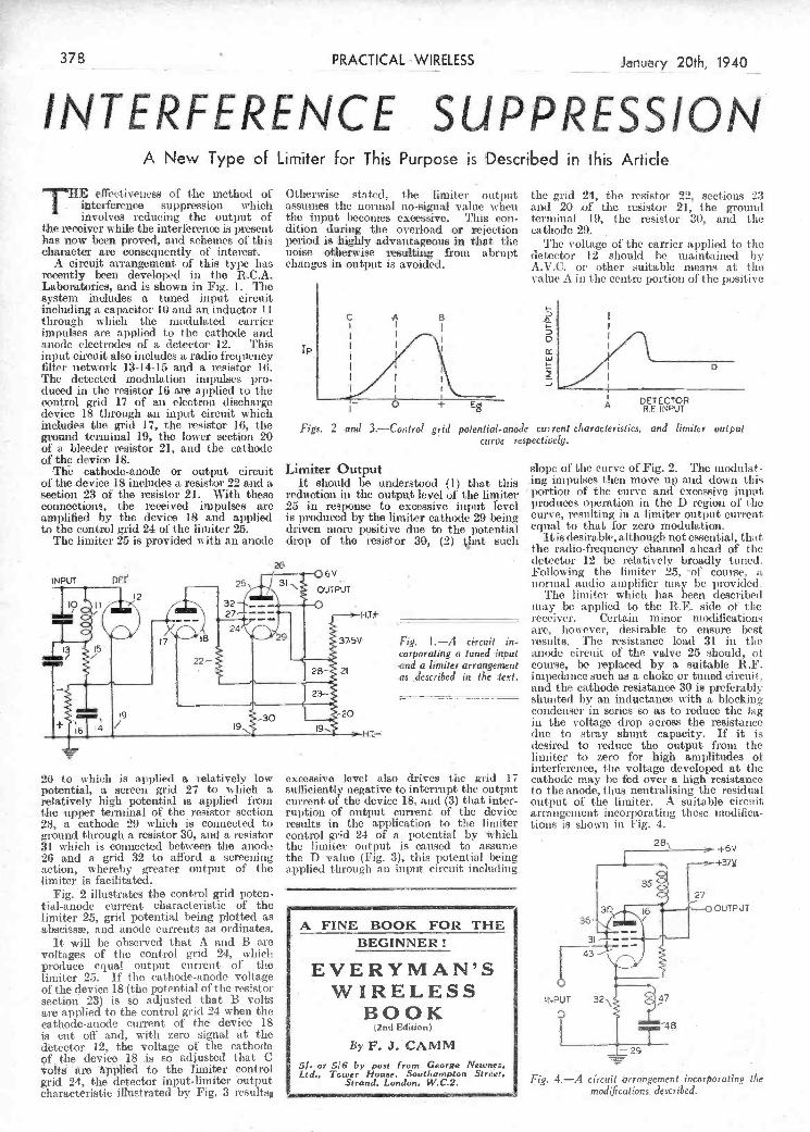
f.
26 to svhich is applied a relatively low potential, a screen grid 27 to which a relatively high potential is applied froni tise upper terminal of the resistor section 28, a cathode 29 which is connected to ground through a resistor 30, and a resistor 31 which is connected between the anode 26 and a grid 32 to aflòrd a screening action, whereby greater output of the limiter is facilitated.
Fig: 2 illustrates the control grid poten- tial-anode current characteristic of the limiter 25, grid potential being plotted as abscissn, cud anode currents as ordinates.
It will be observed that A and B are voltages of tite control grid 24, which produce equal Output current of tise limiter 25. If the cathode-anode voltage of the device 18 (the potential of theresistor section 23) is sé adjusted that B volts are applied to the control grid 24 when the cathode-anode current of the device 18 is cut off and, with zero signal at the detector 12, the voltage of the cathode of the device 18 is so adjusted that C volti aro 'pplied' to the limiter control grid 24, the detector input-limiter output characteristic illustrated by Fig. 3 results
excessive level also drives the grid. 17 sufficiently negative to interrupt the output current of the device 18, and (3) that inter- ruption of output current of the device results in the application to tire limiter control grid 24 of a potential by 'which the limiter output is caused to assume the I) value (Fig. 3), this potential being applied through an input circuit including
A FINE BOOK FOR THE BEGINNER!
E VE RYMA N'S WIRELESS BOOK (2nd Edition)
By F. J. ÇAMM 5F- or 516 by post from George Newnes. Ltd., Tower House. Southampton Street.
Strand. London. W.C.2.
desired to reduce the output from the limiter to zero for high amplitudes of interterenee, tise voltage developed at the cathode may 1)0 fed over a high resistance to the anode, thus neutralising the residual output of the limiter. A suitable circuit arrangement incorporating these modifica- tions is shown in Fig. 4.
.IN
uT
Fig. 4.-A circiit .arrangenient incorporating tite modifithtions dçscribea'.
- - - 1 . -.
L
INPUT DEf
lo H' , f.
'13 i5
detector 12 be relatively broadly tuned.
!': nd a limiter arrangement course, be replaced by a suitable R.F.
ev Following the limiter 25 of course, a OUTPUT
' normal audio amplifier urny he provided The limiter which has been described
may be applied to the FR. side of the receiver. Certain minor modifications
24 are, hou ever, desirable to ensure best 37CV ' Fig. 1.-A thcuit in- results. 'flic resistance load 31 in the
corporating a tuned input anode circuit of the valve 25 should, of
as ,4escribed ici the :text. impedance such as a choke or tuned circuit..
23- ____________ and the cathode resistance 30 is preferably
20
shunted by an inductance With a blocking condensci in series so as to reduce the lag
9 - in the voltage drop across the resistance
duc to stray shunt capacity. If it is
including a capacitor 10 and an inductor li through u liicli the modulated carrier impulses are applied to the cathode and anode electrodes of a detector 12. This input circuit also includes a radio frequency jilter network 13,-14-15 and a resistor 16. The detected modulation impulses pro- duced in the resistor 16 are applied to the control grid 17 of an electron discharge device 18 through an inputS circuit which includes the grid 17, the resistor 16, the ground terminal 19, the lower section 20 of a bleeder resistor 21, and the cathode of the device 18.
'The cathode-anode or output circuit of the device 18 includes a resistor 22 and a section 23 ol' the resistor 21. With these connections, the received impulses aro amplified by the device 18 and applied to the control grid 24 of the limiter 25.
The limiter 25 is provided with an anode
IP
I-'
-
D
DETECTOR A R.E INPUT
Figs. 2 'and 3.---Control grid po!en1ia'l-andc cui rent c/iaracleristics, and limiter output curve respectively.
Limiter Output It should be understood (1) that this
reduction iii the outpu,t level of the limitci ,25 in response to excessive input level is produced by the limiter cathode 29 being driven more 1)OSitiVC due to the potential drop of the resistor 30, (2) that such
slope of the curve of Fig. 2. The modulat- ing impulses then move up and down this portiosi of the curve and excessive input produces operation in the Dregion of tue curve, resulting in a limiter output current equal to that for zero modulation.
it is desirable, although not essential, that the radio-frequency channel ahead of the
A New Type of Limiter for- This Purpose is Described in this Artide.
T11E effeiitivencss of the method of intei-fcrcnce suppression which involves reducing the output of
the receiver while the interlrcnce is present has now been proved, and schemes of this character are consequently of interest.
A circuit arrangement of this type has recently bceii developed in the R.C.A. Laboratories, and is shown in Fig. 1. The system includes a tuned input circuit
Otherwise stated,- the limiter output assumes the itormal no-signal value when the input becomes excessive. This con- dition during the overload or rejection period is: highly advantageous in that the noise otherwise resulting from abrupt changos in output is avoided.
the grid 24, the resistor 22, Sections 23 and 20 af the reistoL' 21, the ground teiminal 19, the resistoi 30, and the cathode 29.
The voltage of the carrier applied to the detector 12 should be maintained by A.V.C. oi other suitable means at tuo value A in the cóntre portion of the positive
-37_____ PRACTKAL-WRELESS anury2Oth, 1940
H !NTERFERENCE. SUPPRESSION:
PDF compression, OCR, web optimization using a watermarked evaluation copy of CVISION PDFCompressorPDF compression, OCR, web optimization using a watermarked evaluation copy of CVISION PDFCompressor

I
- - -±
carried out on the H.F. side or on the L.F. ful, or some value side of the receiver, and no doubt the usual between these Figs. 3 (left) and 4 (right).-Volum control al detector output, and aerial L.F. controls are familiar to most listeners, extremes. volume control. -
These are of a type found in standard broad- cast receivers, the usual scheme being a variable grid leak in an RC. coupled stage, or a similar component connected across PRACTICAL WIRESS SERVICE MNUAL tite secondary of the L.F. transformer- preferably in the first stage, if there aie two or more L.F. stages. The circuits of By F. J. CAMM both
of these are shown in Figs, I and 2, and if you are now using an ordinary R.C. From all Booksellers 5/. net, or by post 5/6 direct from the Publishers, arrangement all that is necessary is to re- George Newnes, Ltd. (Book Dept.), Tower House, Southampton Street, place the fixed grid leak by a potentiometer having a similar value, whilst if transformer . Strand, London, W.C2. coupling is fitted, the component is joined .... -
.
bed and asleep and this means that in thè ordinary way headphones have to be worn. If a loudspeaker is fitted and reception is being carried out on the speaker, then a volume control is absolutely essential in order to avoid disturbing the other members of the household, whilst if headphones aie fitted in place of a speaker, then volume must be cut down in order to avoid blasting in the 'phones. A good receiver will, of course, be provided with a volume control, but there are many eases where such a fitment is not provided and the problem is then where to apply such a device-pre- ferably with the minimum of alteration to the receiver. There are many schemes available, and each possesses some merit which makes it ideal for one listener, whilst it may not perhaps suit another receiver or another listener.
H.F. or L.F. Control ?
The control of signal voltage may be
amplified and heard on the output side. Thus, a noisy control uill prove very troublesome in use, but there is a simple way of avoiding this, and that is by connecting a fixed condenser across the arm of the control
carbonised or graphite controls having a wiping carbon block is really best and the value should be between .1 and .5 inegohma -again a trial being necessary to find which is most suitable for the particular receiver in use.
and the ''live'' end. The value HT+ of the condenser
as it may affect tone, or even the smoothness of the ii Illay prove critical,
reaction control. A general value is
.1 mfd., hut you À - may care to
a more suitable experiment to find
H.F.C. capacity. The value of the resistance '' is not so critical, ,-+-----.
and either 10,000 (is\ or 25,000 ohms )DETECT0R should prove use- \ J
fi
r
»
) 25 or 5 Mfl
i -
25 t MO (left) and 2 (right).-L.F. volume
control for reus/once -capacity and trans-
G.B. fou mer coupling.
back to this arrange- ment, to be found in the fact that the anode current of the preved. ing valve will flow through the resistance as well as through the transfortuer p r i in a r y. It will be seen that the effect is gradually to short-circuit the trans- former pi-imary, and as this is part of the L.F. coupling, any noise present in the primary circuit will be trans- ferred to the secondary,
earth, and thus it acts very well as an input volume control. It is, in fact, often regarded as the only really effective short- wave volume control. The only snag is the value of the resistance. Until a suitable -
value has been found you may experience difficulty. Either erratic volume-ecmt rol effects, or noises, or even sudden jumps in volume may be obtained, especially if a
sw-ash '' plate type of resistance is used. As this rotates it may make uneven varia- tions in the resistance and this may result in difficulty in controlling the volume. If a wire-wound component is used it may give rise to noises or prove jumpy due to short-circuited tui-ns or uneven windings on the resistance element. One of the
WHILST short-wave signals may be received at alt times of the day, it is an undoubted
fact that the most interesting signals are picked up after dark, and many of the better types of American programme are only available in the early hours of the morning. The keen short-wave listener is thus generally listening-in when the other members of the household are in
across the secondary terminals of the transformer. In both cases the grid con- nection is taken from its present Position and joined to the arm or centre terminal of the volume control. So mut-h for the simplest scheme. If it is desired to apply the control without altering any wiring, and L.F. control is desired, a variable resistance may be joined across the pritnary of - the first transformer as
shown in Fig. 3. There is, however, one draw-
receivers the choke, if this is used, may be replaced by a fixed resistance; but this must be noiì-inductive, remember. By re- placing the resistance by a variable corn- ponent, there is an ideal way of controlling volume-the circuit is shown in Fig. 4. It will be seen that when the arm of the resistance is at the lower end, we have the standard resistance arrangement. As it i
turned towards the" top" of the resistance it is successively short-circuited and this not only reduces the signal voltage present across the i-esistance, but at the same time gradually short-circuits the aerial to
il
January 20th, 1940
-t -'i
PRACTICAL_WIRELESS 379
Í\ FYT % A J . / r' H. nrIsS.d there is not a great deal which can be done. If the receiver U K d employs an SG. or ILF. pentode valve a variation in the screen voltage will enable volume control to be carried out or if a
-
S - EC[ IOI\1 variable-mu valve is employed the usual bias variation will prove effective. Unfor. tunately, hou eve!-, these valves arc not very popular for normal H.F. circuits oli
w to Fit Volume Control Systems to Short-wave Apparatus
slOrt wayes. ançi thu the scheme is not of wide application. There are, however, dozens of receivers which employ an aperiodic H.F. stage. This usuali consists of an HF.
By W j DELANEY choke or fixed resistance in the aerial -
circuit in place of a tuning coil. In lilOSt -
PDF compression, OCR, web optimization using a watermarked evaluation copy of CVISION PDFCompressorPDF compression, OCR, web optimization using a watermarked evaluation copy of CVISION PDFCompressor

Schubert's songs and you will find that, musically, it gives coiiiplete satisfaction- it concludes with a full stop. But iday over any of the THEM ES from his Un- finished Symphony and, although just as beautiful, they do not satisfy. 'rlìey leave a feeling that something has to follow -they rio not end on a full stop. -
As mentioned in my article on Chopin, that master's persistent use of his national (lance rhythms, even in his bigger works in the classical forms, is a great characteristic, and stamps his writing with an iiicLi- vidnality as ñiuch as any other ingredient in his music. It also, of corn-se, stamps him as a Pole of unmistakable complexion.
Liszt's torrents of diminished sevenths- the like of which had never previously been heard, nor have since been heard -were one of his most conspicuous traits. Unlike Chopin. however, he seldom employed his native Hungarian rhythms outside works which, like the famous Hungarian Rhapsodies, set out to speci. fica.hly exploit them. Brahms' fondness for tenths, and for the hiaiids far apart at the extreme ends of the keyboard (1 refer to his piano music, of course). aie two of his l)et devices, though as regards (he latter one he followed in the steps of his great predecessor, Beethoven (see Waldstein Sonata, 32 and 33 Variations, and nany other works).
Debussy's marvellous use of the whole tone scale, the passion of Albeniz for crossed or interlocked hands-and for the use of tIse melodic minor-Bach's contrapunta.l style ansi sequences rsually built on a pedal 1oint ; Handel's -c-igol'ous ma sculinil y
-. ,,,-,-.'--
musical form on whk-h lie is going to plan and build p his work. From the musician's 1ioint of view tisis must come lit-st in importance ; everything else de- pends opon it. The proportions a lid design of the building and the influence it- is going to exercise on futnie writers. Beethoven is universally considered to be the world's greatest musician oli two counts - the mastery of his handling of the largea musical forms, and the reforms and innovations he made in them which have all been accepted as law by subsequent composes-s ; and the nobility and loftiness of the citai-acter of his music. But that tite fit-st of these qualities (althoUgh the second, largely dependent on the first, is the supreme quality iii all
JOIN NEWNES' -
PRACTICAL -GROUP! PRACTICAL MOTORIST
The owner-driver's journal which tells yoh how to repair, overhaul, and Obtain tie best l,er(onu- mce fron, your car.
3d-Every Friday. PRACTICAL MECHANICS
The only English journal of its type. lt deals with every branch of Science, Mechanics Invention, Model-Making, Chemistry, Ast ron. omy, Photography, Television.
CU-Every Month. THE CYCLIST
TIja leading weekly for every Cyclist,tlubman, Utility Çyclist, or Tourist.
Join "The Cyclist" Road Club and also take advantage of the F1IEE Insurance oitered.
2U.-Every Wednesday.
Pl0P01t-lOflS.
Melody, Harmony and Rhythm lt might be serviceable to d-onclude
this week's notes with an enumeration ni
the itenas which are necessary foi- the fashioning of a satisfactory piece 01 music. Unquestionably the first need is a plais. What lòi-rn is it going to he written iii ? 1f ose of the large forms-a syniphonv or sonata., with movements, then more thais the conventional "first movement" is required. What is the mood of tite lìiece going tobe ? The third or sixth Beethoven Synlpliony, tite op. 53 or t-lic op. 57 Sonata ? Then come melody, harmony and ihyt-lun. Tbese, of course, are largely gOvel-ned by tIte mood-the stat-c of the composer's mind. Melody- is- obviously fit-st because, although harmony and bei-in are moi-e important to the' finished w orh-, it is difficult to imaginea composer getting isis music paper and pen_obt until sorne
tune'' or other has come into his mind. It is that" tune" which is the focal point round which the work is built-it-s ve y lue. In the case 01 a short work it becomes melody; in a symphonic work, a theme. Then, according to h lie manner of tt-ea.tnteiit decider! upon, enter the extremely im- POltahit quest-ions of the employment of a coda, tise length of the development section, and ninny more. All of these bear the imprint of tite composer's individuality- a Beethoven coda is as strongly stani ped as a Beethoven melody or anything else- and all forni integral parts- of -that most mysterious and engmatie thing-a work of music. -
that, and subsidiary themes whilst songs and their like ale nothing but thenies or melodies. A good theme, like Schubert's in the Unfinished,." hits one in the eye" so forcibly that it at once becomes an ever- living reality. They are the first things we would be expected to catch on to. But a composer's personal style or idiom by no means begins and ends with his themes or the way he spaces his notes in making one up. -
Melody and Theme It may be of interest if I define the
difference between a melody and a theme. A melody is complete in itself, whereas a theme. is not. Play over one verse of any of
yourself. But I doubt very much whether a composer's idiom could be condensed into a recipe foi' others to imitate and rel)roduce, not even the strongest indi- viduality such as Liszt or Grieg. The master's handling would always he con- spicuous by its absence. And although Lucullus himself might give i, s his formula for his nectar or ambrosia, we would ourselves llave to be Lucullus to reproduce it so that no one could tell which from t'other. As tile mscription says ou Beethoven's tomb, " I am Beechus who makes the nectar foi Man's delight."
Musical Forni Then comes a master's handling of the
down to the sea. Consequently his music is stamped and dyed with that unmistakable characteristic of struggle, strife and seeking which is unique amongst all musicians, and which cannot be reduced to a lbrmula of " gaps of a third." or this, or that. it stamps the music with an indelible person- ality ofthc deepest profundity, and in a manner that no lucre harmonic trick or device can hope to rival. And when we also realise that, for its day, Beethoven's music was just as original in this respect (the flattened ninths in the Eroica Sym- phony mid the Moonlight Sonata iimade i he world junip out of its lethargy, and stili mimake us gasp to-day) as it was architec- turally, uc get sonic measure of it mighty
posei, Wagner and Greg. So persistent and òft-recuriing were these two features in their melodies - and themes that we naturally concluded that their musical minds worked, even sul)-consciousl y, in some groove or to some pattern, the reason for which can, partially, at any rate, be t raced back to their in usical antecedents (vide article on " Nationalism in Music ''). It is obvions that we should begin a study of this subject with an examination of melodies and themes, because they cori- liont us first of all. Every work begins with a theme of some sort or other ; it is, in fact, the raison d'1re for the work-
than J. S. Bach. Hundreds of his move- tiients are nioulded after them,
Arrangement But how exactly one must arrange time
notes and build up a movement iii order fo arrive at, say, Handel's garons masculinity or Elgar's English-ness. is a linge subject requiring iiiaiìy tonics. Therein lies the ieal formula, of course. That is why you would have to study if
on wanted to faithfully copy Han(lel or Elgar, just as you would have to procure the recipe of a dish you had tasted some- where amid which you wanted to cook fòr
nificent music, amid of the loftiest and most altruistic character, but he made few innovations.
He accepted Beethoven's legacy grate- fully and dutifully, and fashioned in it, leaving little new so !r as the constructive pattemii t music is considered. Ile didn't divert the historical river bed of music one iota ; it continued to flow along its course serenely and beautifully, through him and in spite of him. He greatly beautified its banks and ornamented it enviions, whereas Beethoven hewed out of plains and mountainsides huge new gorges and clefts for it to rush through
Composers' Idioms Further Considerèd Their Style and Characteristics are Discussed in This Article
by Our Music Critic. Maurice Reeve
LAST time I touched uponì this subject these and many more tlings go to make art.) would be sufficient to kep Beethoven
I not unnaturally enlarged upod a up a composer's style difièrentiating him on hi throne may be proved by ?L coin- melodic characteristic of two of the fronì other writers-incidentally, no corn- parison with other musicians of the sanie
most individual and personal ol. all corn- poser ever used (hulee ilivtlnns more ofteut school. Brahms. for instance. wrote mae-
PRACTICAL WIRELESS Jariu&y2Oth, 1940
Çomment, Chat and Criticism
PDF compression, OCR, web optimization using a watermarked evaluation copy of CVISION PDFCompressorPDF compression, OCR, web optimization using a watermarked evaluation copy of CVISION PDFCompressor

i
A Holder for Solder BEING a srvice engineer I sim cou-
staittly using solder, and have evolved a holder which is quite easily made anti very handy in use, It is made from the case of an old electrolytic condenser. The first step is to remove the threaded base and all the
ç áL
it to cool and complete by winding the wire THAT DODGE OF YOURS! and soldering same-to short al! the toros
Every Rçader RACTICAL together. The screw constitutes one niet hod LESS" mûst hive originated vorne little dndge of contacting with the solidified silver paper. which wòuld interest other readers. Why (reat care should he exercised when no ssit tous? pay £i-IQ-O fo the compressing the paper to ensute that no published on this pige w will pai' half-a. cut fingers are sustained through slipping. guinea. Turn that idea of yours to account by -W. R. Hones (Ilford). sending it in to us addressed to the Editor, "PRACTICALWIPLESS," George Newnes, -
Ltd.; Tower House, S9utharnpton Street, - Strand, W,C.2. Put your name and address $ on every item. Please note that every notion
jsent ap must be origi,&. Mark envelopes -
"Practical Hints." DO NOT eñclose
ÍQueries with your hints. -
flecleflai)Ç t SPECIAL NOTICE
tAll hints must be accompanied by the
coupon Cut from page iii of cover. 4U..IIetISs,eIS.ljli4,lICffle4I.flo. twisted niild steel extension arms, and springy brass clips, for the headphone attaehuients. I
The rest of the asseuiblv detailing is clearly defined iñ the illustration, which A novel method of making small tubular condensers. also indicates briefly the wiring to a ittixer -
16 GAUGE COPPER WIRE
::S1
January .0th, 1940 PRACTICAL WIRELESS 381
( IPra citi calE IHlihnits
piatto is situated at an angle to one cornet of the room, to obtain ait aeel'ntilatc(l tre i)lc and bass response leaving the middle register to the differential reproduction of the I wo headphones.
pressed-by t he head of a na il or st rand of 16-gauge wire-heat the tithe and silver paper until red hot, care being taken to sec that it does not bend or warp, allow
rflt is scheme called PIANO Oi
for a suit&ble means ,
of anchoring for each iieadphoiic, and in "
order that resonance effects would not in- ,
fluence reproduction, i carried out various (j'
tests te determine the ;,i
for each 'phone. Apart from the loca-
tion of the headphones, HANDLE
it was necessaryin each lnstance to glue apad 01 balze on to the piano H fabric, as indicated in the sketch.
I found that with '
the simple angle brackets depicted, a rigid and vibration- " '
proof fitnient to each piano carrying handle An efficient met/tod was obtainable, using
T i.
CONTROL UNIT
smP
.1 i h EF,T r-Ii t I/ ¡/11
-
ii BRASS 'J
HEADPHONE
'-' TOM,AEIAAFADEB
SPRINGY - .D STEEL
of adapting /i'eadihoñes as piano miles ¡or. experimentaL -purposes. -
Screen.pentode Detectors WHEN fitting a screen pentode detector
in place of sta ordinary diode detec- tor, it w-iii often be found' that a set oscil- lates at the bottom of the short -w-ave dial when reaction is turned to minimum, dite, of course, to the readiness with which this type of valve will oscillate. To avoid tamnl)ering ivithì the actual reaction winding, which is probably housed in a can, a resist. anec iiia- be placed in series with the coil (between anode asid' coil). its value cuit, of course, only be found by experimenting, but 1,001) ohms is suggested as a stas'ting loint. A resistance of a composition tyjie shOuld be used as, generally speaking, a wjrewound resistance is unsuitable,-C. QUENTOE (London, N.).
PRACTICAL MECHANICS HANDBOOK -ByF. J. CAMM
s! 6/- or 6/6 by posi from-George Newnes5 Lid., I Tower House. Soui/iamp Ion Street,.W.C.2.-
SA'A14.I,a,I -C I
,
/1 han' dy hc!dcr for cored solder
inside materiaJ. - A coil of solder is wound rouIi(l a pencil about as long as the case, and with two or three layers. The pencil is reniovod and the coil is put in the ease. The end from the inside of the coil is put through the hole in the base, which is theii replaccd.-E. SIJRTEES (Middles- brough).
Adapting Headphones as Piano Mikes
WHE N carrying out some experi unen ts oui piano reproduction through m radio
set, I decided, in view of the fact that the
and fader control unit-S. F. STOICE (Forest Gate);
Sma1 Condenser Construction WHILST experimenting -with aunai! con-
densers and resistances, I hit upon the idea illustrated. It wifl bnseen that the only requirements for the construct ion o! a nuniber of condensers of cliffrent values are as follow
(1)A few short lengths of different gauge bare copper Wire.
(2) A length of glass I tubing (internal diameter, one-sixteenth i neh-approx.).
(3) Some silver faLlut-r, and a- few iin. uvooci screws.
W'iicn the silver paper. lias been coin-
Series Dropping Resistance
WHEN designing a mains set some
constructors prefer to use the trailer (series dropping) resitànce to feed the screen jut preference to a potentiometer. While the former motlfod is in many ways de- siráble, great cal-e should be taken to see t ist the req uirecl voltage drop is obtained, as many modern mains screen-grid valves take very little screen current. Wo came across a well-known type recently which, although of more than average, efficiency, had a negligible screen' current, and the use of a 5 megohms series resistance tidied to make any measurable decrease of the 5cm-ren voltage .-D. WATTS (Hendon).
PDF compression, OCR, web optimization using a watermarked evaluation copy of CVISION PDFCompressorPDF compression, OCR, web optimization using a watermarked evaluation copy of CVISION PDFCompressor

out really accurate tests, expensive and very accurately designed apparatus is required, and this is generally outside the means of the average listener.
Apparatus Needéd To commence with the simplest and
cheapest test, it can be ascertained easily whether a speaker has a reasonable bass response by applying a 50-cycle note obtained from the A.C. electric light mains. Connect a fairly long length of flex, say, 5 or 6 yards, to the grid and cathode terminals of one of the low-frequency valvei and run this flex as close as possible to söme wires carrying the alternating current house supply, such as tle mains lead to your receiver or the flex connecting a standard lamp, for instance. No connec- tion, of course, 8hOUld be made to the light supply itself. The result will be that the appreciable alternating voltage at a fre- quency of 50 cycles will in picked up by the trailing flex and will be amplified by the
The áccompanying illustration, in which Sp js the coil and K the core, shows one such electrical field line in broken line. Since the dielectric constant of the moulded core is very high, and moreover, may have a very high temperature co-efficient, the behaviour of the core as a dielectric may become unpleasantly obtrusive when the coil is used as a frequency-determining element, especially on short waves. [t would, of course, be possible to screen the core by means of an electrically conductive shield, but this would obviously involve the use of an additional component, namely, the shield.
Semi-conductive Bending An alternative method, which avoids
this disadvantage, is to use a semi-conduc- tive medium for binding the finely divided iron powder of which the core is composed, a suitable material being carbon in an extremely finely divided state. It is true that this gives rise to a conductance appre-
of the dielectric is iio longer an important factor. The upper limit to this conductance is set by the additional attenuation brought about in the core as a result of eddy currnts and depends on the frequency in questioh and the dielectric constant of the materiaL The best compromise is therefore obtained by making the conductance of the whole core just so high that the eddy current
losses are still sup- Sp. portable and the
dielectric losses are - low in consequence
of the semi- conductive shunt. Theoretically, it would be sufficient to have only the outer layer of the core formed in the manner suggested, but unfortunately this would lead to production
Section of an H.F. coil, difficulties.
____ _ ----
artificial deficiency of the speaker. On the other hand, the human ear is notoriously accomrnodative and is more easily deceived than any other human organ.. It therefore recognises and accepts for reasonably life- like reproduction sounds which vary con- siderably from the original produced in the studio, and it is a fact that listeners may become so used to what is really very poor reproduction that they do not realise the extent to which the sounds produced by their loudspeaker fall short of perfection.
It is, however, not a difficult matter to carry out at home one or two practical tests which will indicate roughly what kind of response curve a speaker bas. To carry
(25-30-40-50-60-70 DB4037 J 80 - 90. Gliding Frequency.
8,500 to 25 cycles. Constant lei abo-ge 300 cycles per second.
.Ä- .Mbülded
- -course, it is difficult to judge when the - sounds performed at the microphone are of
el equal intensity, but they do give a fair indication of performance.
Iron Cöre for High-f requéncy Coils
WHEN moukieci cores are used for ciably higher than the susceptanee of the
high-frequency coils, the éore capacity formed by the iron core as dielectric is traversed notonly by magnetic -although not so high as that of the iron
field lines but also by electrical field lines. -but the advantage is that the behaviour
pi
poor reproduction of very low notes and of the very high notes, together with undue prominence of certain notes at various parts of the scale. These are generally due to unwanted mechanical resonances which are difficult to eradicate. The human ear is ìsot, however, equally responsive to all freque- cies. As a matter of fact, it is most senitie to frequencies of the order of l,000cycles per second, which corresponds to notos about two octaves above middle C on the piano.
The Accommodating flar For the lower frequencies (below 100
cycles) arid for the extreme upper register (above 8,000 cycles) the response of tile ear is much more feeble. Now, un- fortunately, it is just those frequencies to which the ear is the least sensitive that some loudspeakers reproduce the worst, so the natural deficiency of the ear is aggra- vated by what may be termed the
A far more accurate series of tests can be carried out with the aid of special gramo- phone records giving constant frequency notes. These constant frequency records are not usually stocked by gramophone dealers, but they can be obtained, or it thhy bepssibl to borrow them from a 'progressive radio dealer. They are issued by the H.M.V. company and are num- bered and grouped as follows:
f soo -- 8000 - 7500'- 7000- 6500 -- 6000 - 5500 5000 -
pB4o34 4500 - 4000 - 3750 3500 J3250-300Ø-2750-25O0-
225O. r
(2000- l800-- 1600-1400- DB 1200- 1100 - 1000- 900 -
i 850-800-750---700-650----- )..OQQ-:550,-500. ' 150- 425 -400 -- 375- 350-
.,j 325-300-275-250-225- Uoo.
well as a full decription of the records and suggestions for their use.
Each record produces a practically constant volume at given frequencies. The last record, which lias a " sliding" note will probably prove most useful to the amateur who is not concerneì with elaborate frequency tests at different parts of the musical spectrum.
A Simpler Method There are other less accurate devices
which anyone can try at home if he possesses a fairly sensitive microphone. Time micro- phone should be installed in a room away from the speaker, and sounds, as near as can he judged, of equal intensity should be produced, running right up and down the scale. This can be done by means of a piano or by means of other stringed instru- mnents. If you possess a violin, this will be -excellent for the upper' frequencies, but a 'cello will he required to give a good test in the deeper notes. With such a test, of
j
How to Check the Output of Any Type of Receiver
AQUESTION which nearly every lis. tener asks himself froni time to time is whether or not tue receiver
in use is delivering a faithful output; so far as quality is concerned. The question of purity is one which concerns every amateur, and nearly every listener claims that his set gives the best reproduction which lie has heard-on a home-broadcast receiver as distinct from a demonstration of labora. tory type of apparatus. The faults which are most likely to occur in a receiver are
valves and applied as a strong 50-cycle signal to the speaker. If this component has a reasonable bass response, a good volume of dccl) hum should be heard. Unfortunately, this test only gives an indication for one particular frequency, but if a good performance is obtained at 50 cycles it is fairly safe to say that there is nothing wrong with its bass response.
Gramophone Records
These records are of the 12m, type and cost 6s. each.
In addition, there is a special Sound Denionstration record, No. DB4033 (6s.) which has on one side Frequency-Anipli- tude-Interference - Modulation, and 01)
the other, Harmonics-Itesonance-Charac. teristic Sounds-Music and Speech.
A five-pocket album to hold the above records (No. 252) is available and includes a Stroboscopic Speed Indicator, and the new Automatic Record Groove Indicator, as
L
Checking PRACTICAL WIRELESS January 20th, 1940
Frequency Response i
r1
PDF compression, OCR, web optimization using a watermarked evaluation copy of CVISION PDFCompressorPDF compression, OCR, web optimization using a watermarked evaluation copy of CVISION PDFCompressor
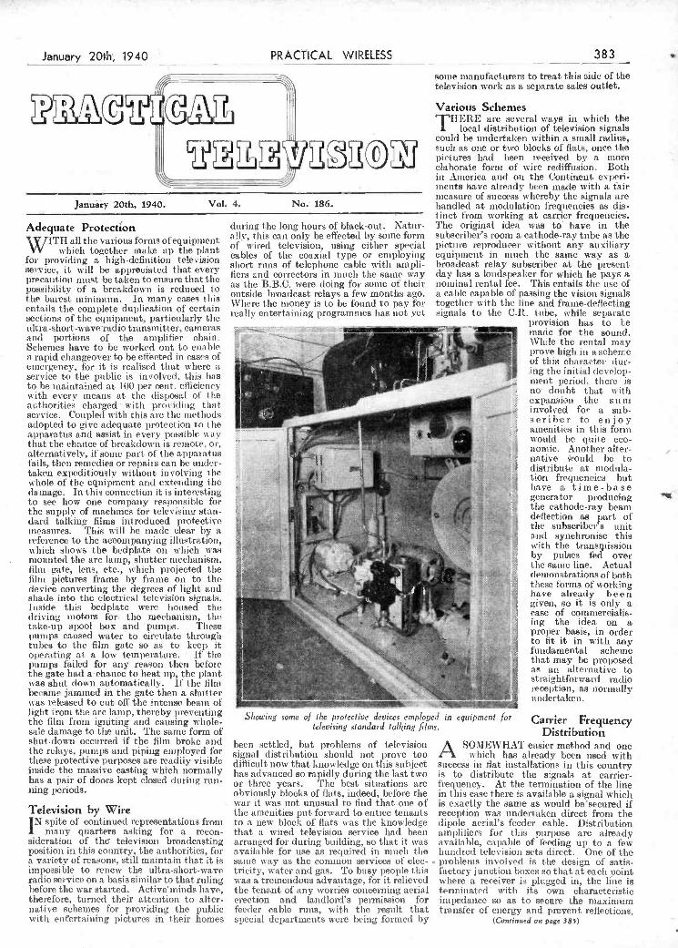
January 20th, 1940. VoL 4. No. 186.
Adequate Protection X JITH all the various forms of equipment VV which together make up the plant
for providing a high-definition teleision SeLvice, it will be appreciated that every l)recalltiOJl nMISt be taken to ensure thattlie possibility of a breakdown is reduced to the barest minimum. In many cases this entails the complete duplication of certain sections of the equipment, particularly the ultra -short-wave radio transmitter, camelas aoci portions of the amplifier chain. Schemes have to be worked out to enable n rapid changeover to he effected in eases of emergency, for it is realised that where a service to the public is involved, this has to be maintained at 100 lier cent. efficiency with every means at the disposal of the authorities charged with proeiliug that service. Coupled with this are the methods adopted to give adequate lirotect ion to the apparatus and assist in every possible way that the chance of breakdown is remote, or, alternatively, if some part of the apparatus fails, then remedies or repairs can he under- taken expeditiously without involving the whole of the equipment arid extending the damage. In this connection it is interesting to see how one Company responsible for the suppiy of machines for televising stan- dard talking films introduced protective measures. This will be made clear by a ri'ference to t he accompanying illustration, which shows tue bedplate on which was niounted the arc lamp, shutter mechanism, film gate, lens, etc., w hich projected the film pictures frame by frame on to the deviceconverting the degrees of light and shade into the electrical television signals. Inside this bedplate were housed the driving motors for. the mechanism, the take-up spool box and pumps. These pumps caused water to circulate through tubes to the film gate so as to keel) it operating at a low temperature. If the pumps failed for any reason then before the gate had achance to heat up, the plant was shut (lawn automatically. If the film became jammed in the gate then a shutter was released to cut off the intenso beam of
during t he long hours of black-out. Natur- ally, this can only be effected l)y some form of w ired television, using either special cables of the coaxial type or employing short runs of telephone cable with ampli- fiers and correctors in much the same way as the B.B.C. were doing foi some ot their outside broadcast relays a few months ago. Where the money is to be found to pay for really entertaining programmes has not yet
inents have already lacn niade ivithi a fair lileasure of success whereby the signals are handled at nioclulation frequencies as dis. t blet from working at cariier frequencies. The original idea was to have in the subscriber's room a cathode-ray tube as the l)icture reproducer without any auxiliary equipment in much the same way as a broadcast relay subscriber at the present clay has a loudspeaker for which he pays a nominal rental fee. This entails the use of a cable capable of passing the vision signals together with the line and frame-deflecting signals to the CR. tube, while separate
provision has to Le made foc the sound. While the rental may prove high in ascheir.e of titis character dur- ing the initial develop- ment period, there is no doubt that with expansion the s u ni involved for a sub- scriber to enjoy amenities in titis form would be quite eco- iìonde. Another alter- native *ould be to distribute at modula- tion frequencies but have a time-base generator producing the cathode-ray beam
i deflection as part of the subscriber's unit and synchronise this with the transrission by pulses fed over
- the same line. Actual - deinonstratons of both
1 these forms of working
I have already 1) ce n given, so it is only a
j ease of coinmcrciaiis- ing the idea on a proper basis, in order to fit it in with any fundamental scheine that may be proposed
g a an alternative to straightforward radio recepticsri, as normally undertaken.
-I'
-s
January 20th', 1940
i L
PRACTICAL WIRELESS____________ 383
some manufacturers to treat this side of the k
television work as a separate sales outlet.
Various Schemes
T I] ERE are several ways in which the local distribution of television signals
could he undertaken within a small radius, such as one or two blocks of flats, once the pictures had been received by a more elaborate form of wile rediffusion. Both in America and on the Continent ex peri-
a variety of reasons, still maintain that it is impossible to renew the ultra-short-wave radio sei-vice on a basis similar to that ruling before the war started. Activeminds have, therefore, turned their attention to alter- native schemes for providing the public with eiitertaining pictures in their homes
same way as the common services of elec- tricity, water and gas. To busy people this was a tremendous advantage, for it relieved the tenant of any worries concerning aerial erection and landlord's permission for feeder cable runs, vitli the result that special departments were being formed by
__.__;
problems involved is the design of satis- iictory junction boxes so that at ea cli point where a receiver is plugged in, the hue is terminated with its own characteristic impedance so as to secure the maximum transfer of energy and prevent reflections. s
(Continued on page 385) -
-
light from tite arc lamp, thereby preventing the files from igríting and causing whole. sale damage to the unit. The same form of shut-down occurred if the film broke and the relays, pumps and piping employed for these protective purposes are readily visible inside the massive casting which normally has a pair of doors kept closed during runS ning periods.
Television by Wire
IN spite of continued representations from many quarters asking for a recou
sideration of th television broadcasting position in this country, the authorities, for
Showing some of the protective devices employed in equipment for Carrier Frequency televising standard talling films. Distribution
been settled, but problems of television signal distribution should siot prove too difficult now that knowledge on this suhSect has advanced so rapidly during the last two or three years. Tite best situations are obviously blocks of flats, indeed, before the war it was not unusual to find that one of the amenities put forward to entice tenants to a new block of flats was tise knowledge that a wired television service liad been arranged for during building, so that it was available for use as required in much the
ASOMEWHAT easier method and one w hielt lias already been used with
success in fiat installations in this country is to distribute tise signais at carrier- frequency. At tite termination of tise line in this case there is available a signal which is exactly the sause as would be'secured if reception was undertaken direct front the dipole aerial's feeder cable. Distribution amplifiers for this purpose are already available, capable of feeding up to a few hundred television sets direct. One of the
PDF compression, OCR, web optimization using a watermarked evaluation copy of CVISION PDFCompressorPDF compression, OCR, web optimization using a watermarked evaluation copy of CVISION PDFCompressor
: foundry worker, the miller, the planer, the -.
.\ shaI)er, the borer, the fitter, the turner, the .. .. \
.precision ginder-these are but a few of -- -- . . . irS \ the occupations which to-clay employ tens
-
.\ of thousands of skilled people. Even the
. electrical trade is now largely dependent ee'l upon the mechanical engineer.
\ IMPORTANT \ NEVV VEEKLY
-'
a' -
FOR ENGINEERS ,: _.- -- Many months ago it was suggested to
us by lie executives of important engineer- ing firmS that there existed a need for -
- a modern weekly periodical covering authoritatively and extensively the whole
\ t4, field of moderti mechanical engineering
\. I processes. Support was given to this I' \.
, r o suggestion by our inquiries among many of . - the leaders of the engineering trades.
Practical En(jineering, the first issue
't. of which will be published on January 25th,
y is intended to fill this gap in engineering t . periodicals. Entirely modern in its
't . . . -
-
selection of subjects, it will deal week by t L k week with every workshop process, and
No i . -
- \ the use of every type of niachmine employed - .
- in this country. The leading authorities
have been ON SALE .
on special subjects retained to serve the new journal, which will he pub-
JANUARY lished everv Thursday at 4d. The staff
25th, 1940 . - By are practical engineers, having the highest
F1 J. ÇAMM qualifications. -. . ,.
- Practical Engiaecring will be read by - of thousands of people have been absorbed all the key executives in the metal working
384 ______PRACTICAL WIRELESS J&wary 20th, 19Á0
PRACTICAL ENGINEERING
to engineering. I lieve been encouraged to go ahead with
this journal in spite .o.flt.he war whieh, quite naturally, introduedd próblems which did
;hot Iiguie in the original schthne. The r chginéering pròfessions, however. . have 6 .ssume(I a hew signifleanec SiflC the
otlireak -of The fáct,oriesof.. this country arc wrking' at top speed. r1ii
*
new and special machines have been created to cope with them. New steels and new alloys have been introduced. Many new and important subsidiary industries, such as plasties, have been created and, with them, new professions. The tool- maker, the gauge-maker, the capstan setter, the sheet metal worker, the drop-forger, the operatot of the hydthulic press, the
engineering. The news and other features will keep the reader dilly infòrnied of the latest development in this and other countries. The Advice Bureau, consisting of a i)anel of experts, exists to advise engineers on all matters relating to their business. Aji important featùie will be the informed criticism of matters affecting the engineering trade ..
ITAKE tdeasu-e n announcing that on Thursday, January 25th, the first issue of my new weekly publication, entitled
I'ractical Engineering, and on which I have beeti engaged for many mouths past. will be published at 4cl.
It was over a year ago thai I forniecitlie conclusion that there was a need for ail up-to-date weekly publication dcàhing in a unoclei'im way with the new processes, new inclutt.ries, and new trades which liare krOWil UP 111 connection with mneclianical enginccrihg; 'for it is obvious thât in the last quarter of a century the engineering i cades luave undergone radical changes. Accordingly, -I consulted many of the most italuortant firnms engaged in engineering, and found that tiley, too, shared my views. Prwticat Engineersng represents the but- come of my visits and disctussions. Althommh planned over a year ago, it has taken those months to select suitable contributors, and to negotiate with suitable authorities on special subjects. These have been retained specially for the new journal, and they will, as with PRACTICAL \VIRELuSS. also act as advisers to readers on all matters relating
by the engineering trade since the war comnlénceci. The new journal will thus act as an important link between machine- tool manufacturers, their purchasers, and their users. The late Prince Albert once said that if lie wished to talI about a subject he sent for an architect, and if lie wanted something done he sent for an engineer.
The British Engineering Industry is rightly considered as the workshop of the world, for nearly every importamit process, machine, and system was originated by British engineers. The mass-production system of interchangeability amici rapid manufacture of parts was introduced by Bntisli engineers, amici the numerous new materials 110W cniployed were time discovery of British clìenìists and metallurgists.
The engineer is called upon to-clay to manufiseture a vastly greater range of products than he uvas a quarter of a cent ui-y ago. Tile motor-car, the aeroplane, the motor-cycle, the container-vending of goods, typewriters. clothing, furniture, buildings, and agriaultural work-all to-day call for the services of the engineer.
Apart from the greatly enlarged range of manufacturing processes which this ex- tension of engineering has brought about,
industry, by time designers, the shoj, superintendents, by time production 1111(1
plant emmgineem-s; in fact, by all those who are in a position to influence the purchase of machinery amid equipment. The l)Ower- ful resources and unrivalled distributing methods of the famous firm of George Newnes, Ltd., will ensure that this new high-class journal will be read by engineers in every factory, works, and machine shop throughout the country.
WTe shall not only deal with modern processes of manufacture and machine tocds, but also with works layout, finie- saving methods, the drawing office, finishing processes, test equipment and inspection iIi fact, with every sub-division of time mechanical engineering industry. We shall review new machiue and equipment and explain by practical articles, illustrated by first-class drawings, time latest methods of mpanc&facturc
We have been encouraged to publish Practical Engineering becaufe we feel that such a journal is even more vital to-day timan it was several mont lis ago when the idea was first mooted. It will perform a national service, and, we hope, encourage an even livelier interest in meeluanmeal
PDF compression, OCR, web optimization using a watermarked evaluation copy of CVISION PDFCompressorPDF compression, OCR, web optimization using a watermarked evaluation copy of CVISION PDFCompressor
_____ _____ ______ _________ ----- ___)
'phones. These should he connected be- tween the anode of the output valve and earth-through a fixed condenser-as shown in Fig2. By this means the speaker traits. fonne continues to carrythe inode current to tite output valve, and the eoiieet output matching is retained. If provision is rna(lo for connecting an external speaker it is usually quite safe to use the terminals or sockets provided ter making the 'phone connections. Should there be any doubt about the method of wiring these terminals, insert a .01 n3fd. fixed coticiciiser iii each 'phone lead ; this is to make sure that hic 'phones are completely insulated troni the H.T, supply.
On certain commercial receivers the extra-speaker terminals are so wired that a lov-reistance speaker is required. In that ease it would be necessary to employ a step-down output transloriner " in reverse " ; that is, with tite secondary winding connected to the set and the pmnnary to the 'phones. Isolating coiìden- sers are not then required, foi the tians- fornìcr preveiith any direct coni ietioi heilig made with the HT. circuit.
there is no possibility of interaction bet,w-een receivers in reasonable proximity to oiie another. This is usually (lone by arranging attenuator pad boxes which give an attenuatìoii in signal of the order of 40 to 50 decibels. Spurious signals fed back from the receiver due to defects in design aie theretere ìeduced to a very low level when compared with the television signal
.input. At the 111am distribution amplifier position, provision is usually iiìade for a monitor picture to be observed by the visitiiig engineer, for as a rule the amplifier is not under continuous obsei-vat ion. Time-sw-itches ensure that tile complete circuits are iìiade alive fr operational purvoscs during the pre-armanged periods of transmission. Tfthere is a resident. engineer in the block of flats then warning-signals cf a visual or aural form can be provided to allow for lite lèw occasiáns when break- clowns arise. Should the piopo.sals which aie now ou toot materialise, then it is certain that one of the louai distil lI)utnun schemes which have beeji described briefly will be u.ed, atid it will he interesting to see which one proves the most satisfactory.
RADIO SERVICE MANUAL Servicing and Modernising Radio Receivers ¡s easy with this New Manual, with its 280 pictorial and theoretical diagrams, and clear, concise, section- alised text. Solves your problems.
Price 1/- post tree.
To: A. F. BIgin & Co., Ltd., Barking, ES'ex. 1'leio send nie the New 128 pp. Catalogue
No. 11i2, showing full range of Buulgin Products, for which I enclose 3d. stamps.
Naine ......
Address -
I it. :O;i;.i') .................... .
. I
_ c: n 1 .. '
i i . i
LP L P U a'-'J.; QUALITY COMPONENTS
Advert. t 1.. F. Bule & Co., Ltd., Abbey Road. Barkir.g. lisse. Tel. : RiPpleway 3174 t3 Linet..
I
1.0 Pm'is-11ondio!, 30.99 in. 1.55 IVCAB, 49.5 iii. (Mon., lied., So/.). 3.0 )VIICA, 81.02 ni.; ¡'ario- Bondial,
2,58, 25.24 n,. 4.0 WPIT, 48.86 in. (Mo,i. - .S',il.); B.B.C.
Overseas, 31.32, 25.53 n'.
4.30 1','rio-itondial, 30.99, 25.24 so. 8.55 WCBI, .48.62 in.
8.0 Moscase, 19.76 'a. 9.15 Melbourne, 31.32 ni. (0.20 on Sun.). 9.45 Born,', 19.61 ni.
10.45 11.13.0. Overseog. 16.86, 13.97 n. 11.0 Ronie, 25.4, 16.81 on. 11.30 B.B.C. Oi'er8eas, 16.86, 13.07 ii.
1.0 p.»i. I'CJJX, 13.9! in. 1.15 B.B.C. O 'crse".s. 111,84, 13.91 n. 1:10 Valico i City. 25.55 in. ('lies.). 2.4) Wi'! T, 19.72 in. (Moi.. . Sot..), 3.30 ¡(liii king (i/usc/i i'kio), 23.48 on. 3.25 ìladri,I, 30.43 ni. 43) B.B.C. Ore 'sens, 10.82, 10.84 nl.;
ii'CBX, 13.01 si. 4,30 P"rio-iiondia/, 19.68 in. 5.4) JJC12.I, 19.57 in. 8.0 Vatican Ui/y, 19.84 so,. (Sui,.). 8.30 iloinh'inq, 25.48 n.
8.45 Radio-Rires iii,, 531 n,, (ex. S'iiii.). 7.0 Valicai, City, 48.47 ni. (Tues., Fri.). 8.4) Mosco,!', 49.75, 37.22, 31.51, 31.25 in. 8.5 Tokio. 41.14, 25.42 ii.
8.30 li'EO, 31.48 in. (Sin.). 8.45 Melbourne, 25.25 n,. (ex Sat.). 0.0 iJelgi'si/c. 49.18. 31.58, 35.56, 19,69 in. 14.15 lIa,,,,', 420.8, 31.35 n,. ¶4.10 Lu/ill, 807, 31.58. 1.713 ni. 9.45 itw/io-i'uris, 1,658.,,.; Radio-37, 360.6 n.
ifEO. 3I.48 i,i. (Mon-kil.); JVGI2A, 10.57 ni. (21cm-l'ri.).
10.0 Rodio-Eire,,nii, 521 ni. ; C/,n,uj k-lag, 25.21 ni.
10.15 lIartos, 2:18 io. 10.31) 8/. .10/in's (_Veu'fos,n,tlaiid), 31.37 n,. 11.0 )l'll (JA, 49.417 io. (ex Sun.). 11.25 WGEO, 31.48 ni. (JIon.-8u1.). 11.10 B.B.C. Orerseos, 31.12, 25.3.1 ni. 11.45 IVCÁB, 49.5 in. (Tues., Weil., Fri.);
WCA B, 31.28 os. (ils,.., Tlrecn., Sul.).
ilace the switch more than a few iisehes frosi tile speaker, see that the connecting leads arc of heavy-gauge flex, for the secondaI-v circuit has a very low resistance atid an extra 4 01,1111 might affect the avail- able outptit-.
RADIO CLUBS & SOCIETIES SLOUGH AND DISTRICT SHORT-WAVE GLUS Hon. Sec. : X. A. Sly ((.11MB), 16, llucklai,d Avci,ae,
Slough, Bucks.. Headquarters 'roc II Headquarters, William Street.,
Slough, Bucks. Meetings : Alternate Thursdays at 7.30 p.o.
THE meeting hehl on December 21st, 1939,, proVeil vere interesting. the chief item s'eiug a litri lier
talk i. Mr. 1{ouchiin (GIGZ) on the Fuisilotnteiitals of llatho, this I One the speaker dcalt with the pli tui pies of the oscillator, t ud loitited ont some of tite fallarles fouiul in sottie of flic transmitters snitch le liai! exaitìi,ied . lie t heu described the fusilo ciii il IIi!,- il les which, lie toyed would be emboit cil i i meit,l,ers'
transmitiera whet, they could once more get oit the t ir. Titels t mi-sting, held ou January 411., 1040, as flic
auttmal general sticeliuig. '11w agemid:i mois very 11,11; tIte lirst. item Icing the election of new oli/t'ero. Sir. l'o i ie ((.161' il) s,',s -c-elects,! cliairittai,, ihr. Ilouchin (G3GZ) vice.chtairuiaut. Mr. K. .1. Sly (043111) secretary, Mr. 1-', j, 'l'utclolield treasurer, anti Mesare. Gilbert., ho, litwit,, st ud FI jite were elected to the Committee. 'Ilse secretary ilteti ressi an account of tise jiast year's activities 1011owed by tite presentation of tite l.alasee sheet by hie treasurer. Siorse practice followed, the tacet i ltg bei ti closed ibm' query Conter. '
Metal ers st re still remitlire, I. tinti a nyomie mvlo conies to nie oh' 01i' ,,teel i migo trill be wciconte. itletitbers of His Majest yo Torves trill 11e i,,a,lO honorary is,esst1ro.
PRACTICAL TELEVISION (continued ¡Soin page 383)
Furthermore, it, is necessary to ensure' that
are used with clamp-shrouds, and flexible leads for connexion. Wind- ings are mono-metallic throughout- a sure precaution against any possi- bility of breakdown.t STANDARD L.F. CHOKES J
There clamp-xhrouàed L.FÌ Chokes are all of high efilciotIcy and, low price. Flexible leads tor connection are fitted. Shrouds finished
-niait grey cellulose, and prevent "lamination buzz." 2.65 in. 'by 2 in. by 3 in. high.
List, Na. Henries @ niA, Q ,
L.F.14.8 20 50 lumi 9/ed. L.F.15.S , 32' 30 600 9/Gd. L,F.14h.H 20 20 70o 6/ed. LJ".17.8 50 25 10140 1O/6d. L.T.1S.S 10 80 520 1O/6d. L.K2ti.S 82 15 f44441 7/6d. L.F:2h.M ' ' 15 1(40 4/its 15/Od.
-9 L.F.:44-:M 1044 10 ISihli 12/Od. -u L.F.47M 0.25 0.75 (1.1 12/od.
SMALLL.F. CHOKES '-'J
Tisi; nw range ot L.F. Chokes com'prises eonomy types cl extreme utility. With welded joints, these thebes are true to rating and are tested at 1KV. to earth. Fitted with gapped high-permea. bility iron core fitted with grey cellulosed shroud, with fixing lugs. Provided with 6 in. leads. - t 515e 2 in. by 1/in, by 1.58 in. high.
Lint No. Henries , mA. Q L.F.4ì7 5 60 210 1,,FiiS 7 514 250 L. 8.410 10 45 800 1 1 each
L.F.70 15 35 580J L.F.71 20 80 660 LY.72 30 '25 hisS) L.F.73 40 20 1250 t
.eac L.ii.74 50 15 15,411
L,F.3'.) 81 60 400 - 7/Gd. each
passing under the scale, parallax is generally avoided, and a calibration line for each of the wavebauds can be marked directly on the scale.
Using 'Phones Even with a moderately sensitive all-
wave receiver reception will vary con- siderably with changing conditions. But regular reception can often be ensured by making provision for connecting a pair of
CONDENSED LIST OF NEWS BROAD. CASTS IN ENGLiSH.
12 (midny/il) Mooeoi', 49.75, 31.25, 25, 19.93 n. JVCJB, 49.6 n. (Mon.).
32.30 «in. Ilndapest, 32.88 ni.; liBO. Orer«e«s, 31.32, 25.53 n.
series across the extra-speaker terminals.
Switching Out the Speaker Signal strength on the headphones is
increased if the built-in speaker is put out of action, and if there is no switch for this purpose an ordinary on/off switch may be included in the speech-coil circuit, as also show-n in Fig. 2. The s*ïtch is inserted betu ecu onè secondary tei-minal of the output. transformei and the speech winding. The switch must be of a reliable type- or else there will be crackling noises when the speaker is in use-and must be moiiiited close to the speaker. If necessary, it can be operated by means of an extension rod. Should it be desirable for env 1-caso]! to
Range of L. l or A.F. Chokes in- dudes models
- tó meet all requirements
1rJ,F ' both for new
r. .
.
receivers and .
'
equipment,and for .hF j' replace- ments. All
types are true to rating, and, the induct-
ances given .are working values. Generous a 110 y cores
.1
January 20th, 1940
RECEIVING ENGLISH NEWS FROM ABROAD.
(C'otitined fro,, page 376.)
of this is that the face of the card can be made alniost to touch the pointer, where- as tue scale itself is probably as niucli as in. away. Such a spacingi'esults iii a marked parallax error. 1f tunin is by a shadow
PRACTICAL WIRELESS
One of the difficulties often niet when using bead phones with a set not originally intended for them, is that background noises (usually " sizzlings '') are very I)IOnounce(l. This can be minjiniseil by turnii g the tone control towards the bass position or b connecting a .O mfd. con- denser and a 1O,OOU olmi fixed resIstor in
385
-
"10
PDF compression, OCR, web optimization using a watermarked evaluation copy of CVISION PDFCompressorPDF compression, OCR, web optimization using a watermarked evaluation copy of CVISION PDFCompressor

i.
'ir
i.
k: ,
fi-s
N.T.S. New Year Otters You Must Not Miss. Lists Freei FREE VALVES. S.G.3 Kit for all-wave Operation OnOto 2.000 metres. Available less coils to a000inmo- date those already possessing B.P.S. or -N.T.S. One-shot coils. ,&jmple to assemble and an amazing performer on all bands. -Two SG, and Pentode Output stages. GomM'ete Kit with metal chassie: transformer, etc., and 3 FREE valves and building Instructions. Bargain, Cash or COD.. 3216. Complete kit with 10 coils, 59/6. - -. COMMUNICATION RECEIVER. We. cannot repeat Famous name AC. 5-valve model with Continuous wave-range 10-550 metres (switched coil unit), for World News and B.B.C. listening: A.V.C. and B.F.O.. switches. Built-in high-fidelity speaker. Employs band-sprad tuning. Supplied complete in cabinet and ready for instant use oi6 A.C. mains 200/250 v.40 to 300 cycles. Terms 40/-deposit and 4 monthly payments of 38/8. Pre-War,Price CLASS B. 4-VALVE CHASSIS. New limited supply. Suitable fol' fitting in your present cabinet or for emergency use. Wave-range 200 to 2,000 metres. Selective and sensitive. Volume equal to a mains set. Fully tested chassis (size 114m. x 9m. x Olin. high). Complete with all val\'es, 6116. carriagc paid. Terms' available. - - , - -
A3IIL1F1EIt. Battery 4-watts-model, requiring ordinary 120/150 V. JOT. Push-Pull output. Mike and Gramo sockets. Can be used also foc increasing volume of existing battery sets. Fully tested, with
2.000/3,550 ohms field suitable for all N.T.S. Al C. radio chassis, BARGAIN. 17/6, carriage. 1/-. P.M. niovisg-cOil type for battery chassis. 25/-. Model for Class B chassis same price. VALUABLE RADIO PARCELS, Our new oder comprises yartable condensers. coil, fixed resistances and condenSers useful control knobs and a brand new universallY drilled cadmium-plated steel Chassis. Amazing BARGAIN only 51-. plus 1/- for special packing and postage. ALI,-W-AVE Battery Il. MIS. CAMM confirms
Selective, Very Sensitive and Quality Reproduc- tion," -Wave-range 14 to 2,500 metres. Powerful 5.0. 3-valve Circuit with pentode output. -Station- name scale. Size 1210. X Olin. a 9m, deep. Complete with all valves. BARGAIN. 69/6. or 1716 depOsit and 4 monthlY payments of 14/3. - -
NEWTIMSS SALES CO., 56 (Pr.W16), LUDGATE HILL LONDON, E.C.4.
''Phsne: Cite 5516 Est. I
A Simple Piece of Test Apparatus for the Experimenter -
THE apparat-us described in tilis article is a very economical and versatile tester and audio, frequency oscillator
which should prove useful to any radio amateur. Tise component -parts will usually be found in the "Jmlk box."
This unit may be used as a sensitive continuity tester for point-to-point testing, and also for tise testing of the component parts of a- receiver or transmitter such as condensers (utica-, paper or electrolytic). transformers, coils, resistors, chokes, etc.
The oscillator may be used as a code practice set, keying monitor or audio- oscillator. Tile frequency of the oscillator is variable from 50 to 10,000 cycles/second.
CI_IZ' j
¿ MEO "- T PU T
i t/2W I - L0- KEY
Sed
9-
may be tested by measuring tile resistance of the.condenscr, and any t-ha-t do not have a fairly high Insista-11cc should be relee-ted. (Note: In using a resistance meter in this test reverse tile test prods if a low reading results, as the polarity of the resistance tests may be Causing tise low reading.) Electrolytic condensers may be tested at their rated voltage by increasing the voltage at tise terminals marked "D.C. Input" t-o the propel- value. Electro- lytic condensers will canse the Neon -lamp to flash once when connected or at regular intervals ; if the rate of flash is not- over 15 times per second the condenser is satis- factory. - Condensers which flash niore
- oft-en are leaky, and will cause trouble sooner or later. Condensers which do not XD5
MED IMFD MFD IE"Lflash intermittently but ca-use
. a partial glow of the Neon
not be used. A short-ed
cI
lamp are lea-ky and should
condenser will cause a bright glow of the Neon lamp, and failure of the lamp to glow indicates an open condenser.
As a Keying Monitor In using the unit as a code - + practice set, or keying moni-
,c INPUT tor, connect a 90v, D.C.
9 -- supply to terminals marked "D.C. Input," throw switch
386 PRACTICAL WIRELESS January 20th, 1940'
äÁRcÌÏÑsÏ A Neon» tube Test Unit
a.
ARMSTRONG pologise for delay in delivery of some models,
this unfortunately hasbeen unavoidable owing to the preséflt great difficulty in obtaining raw materials. However, we are pleased to announce that we are now in the position to give immediate delivery of our popular model, A.W.38, illustrated below.
1H- tf'- t
t. :." .,... J
.-s i
w:.
.' MODEL AW3B. - S-valve All-wave Super-
heterodyne chassis. This All-wave Radiograin chassie has resistance capacity coupled push-pull output capable of handling G watts, and gives good quality reproduction on both radio and gramo- phone, for an economical price of 8 gns. Plus 5% war 'increase.
Armstrong Push-pull Speaker to match AW3S chassis, £1 : I 0 PSis 5% war inòredse,
We suggest Model AW3S together with matched speaker at £9 : 9 : O, islus 5% war increase, coin- plete, represents thw most outstanding value on the market to-day. ILLUSTRATED ART CATALOGUE ON REQUEST ALL CHASSIS SENT ON 7 DAYS' APPROVAL
ARMSTRONG MANFG. Co. WARLTERS ROAD, HOLLOWAY, 'LONDON, N3,
AdJoining HollowayArcade) 'Plaise NORd1 3213
Fig. I -Wiring diagram of ¡he simple Neon-tub Eli/icr batteries or external power pack may
Tli'e component pacts are connected as shown in the diagram, Fig. 1.
Operation For point-to-point testing, and as a
continuity tester, a 90v D.C. supply is connected to the terminals marked "1).C. Input.'' Sw. i is thrown to the " Off'' positioffi. The apparatus to be tested ss connected to the terminals marked "Key" by means of test prods.
In testing chokes (both audio and radio frequency), transformer windisigs, resistors up to i megolsm, coils, etc., a steady glow indicates a continuous circuit ; an inter mitteilt flash indicates poor connection or intermittent circuit ; and failure of the Neon lamp to glow indicates an open circuit (jr flO connection.
In testing condensers (paper or mica type) a good condenser will cause one flash of the Neon lamp when tise condenser is connected to the test prods. A condenser that causes the Neon to glow faintly and does not flash leas poor insulation and should be discarded. Failure of the Neon lansp to glow indicates an open condenser and a continuous glow indicates a shorted condenser.
Testing Electrolytic Condensers In testing electrolytic condensers, be
sure tise correct polarity is applied to the condenser under test, and also do not apply more than tise rated voltage. The majority of electrolytic condensers will withstand 90 volts, but some of tise by- iass variety are designed only for use at lower voltage, and must not be tested with 90 volts. These low-voltage condensers
"S 1'' to the " On e test mind, position, connect the head- ce aPPuea, phones to terminals usarkeci
"Key." Close the circuit l)y nseans of the key and adjust resistance 1H until a steady note is obtained, then adj isst " Cl '' and '' Sw. 2 '' until desired tone is obtained.
20©.. o OUTPUT
Òilir Fig. 2.-Panel layout for the lest unit.'
As a Modulátor: Signal - Generator The unit could also he used as a moths-
lator for a - radio-frequency oscillator - or "signal generator," and as such would furnish a modulated signal of any fre- quency within the limits of the audio- oscillator, In connection with a valve voltmeter a fairly accurate response curve could be run on a radio receiver. The audio-frequency should be compared with a known standard or estimated by ear in each case, and the voltage at input and output for each frequency measured with the valve voltmeter.
The Neon tube circuit will oscillate moro uniformly if allowed to run for several hours, previous to the test-, at twice its rated voltage.
PDF compression, OCR, web optimization using a watermarked evaluation copy of CVISION PDFCompressorPDF compression, OCR, web optimization using a watermarked evaluation copy of CVISION PDFCompressor
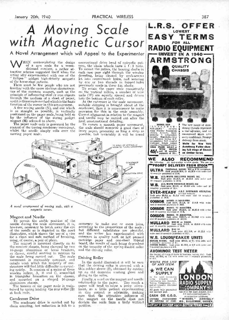
:
i,
for a clean and safe method, of breaking, using, of course, a pair of pliers.
The magnet is mounted directly on to the receiver chassis, being clamped by two 16-gauge aluminium or brass brackets, as Ihown, careful centring in relation to the scale being carried out-. The set le movement is reasonably compact,. and entails work which the majority of con- structors will find little difficulty in execut- ing neàtly. It consists of a series of three wooden rollers, A, B and C, assembled in triangular fordiation on the chassis and mounted on a shaped 16'gauge aluminium chassis.
The tension of the paper scale is main- tained by spring loading the rear roller (B) at both ends.
sure that the attractive influence of the magnet on the needle does . not Condenser Drive
The condenser drive is carried out by chain coupling, but reduction is left -to- a position... -
extremes in quality such as hot jfressed cartridge paper and one-sheet- Bristol hoard, the merits of each being dependent on the tenacity of the spring-loäded roller and the driving roller,
Driving Roller
In the model illustrated it sviti be seen that the driving roller is covered vitli a thin rubber sleeve (S), obtained by cutting up an old domestic washing glove and gluing to the roller.
Finally, a word on the magnet and noédie relationship to the paper. Too mugit a. paper will tend to cause a jerky move- ment, so n little patient experimenting in this respect is advisable, making
deviate the scale from a truly- vertical
W.B. LOUDSPEAKER. UNITS SENIOR MODEL. Cash price £26.0, or 7f- vitlo Order and -
7 moothly' paument, of 6/-. .
JUNIOR MODEL. Cash prien £1.150, op 0/6 with order an,] -
monthly payments 01.5/4. - -
AVOMINOR TEST METE R (for trw-ing oli lindo of fault's iñreoeivera, valve,, Cs,h price £210.0, or 7,0 nilS Order 'oud 7 monthly poywento ci 6/9.
WRiTE FOR LIST . -
OFANYITEM.
SUPPLY - -
50 LON. D O N' ,,-eli-knOwn set,, Speaker,, , ' --
volve,, Componente, ele, RÂDIO-SU PPL Eqotment,
guaranteed ES1D.MPANYI92 und carriage paid, ate ri Oaf Lane,LoonC.T
-
. All cotantunteations to CASH OR C. D. evacuatio]t address, -
ORDERS DISPATCEED "WINDEN," ARDINGLV BY RETURN OF POST. RD., BI5LCOMBE SUSSE%.
1
:0
1
A ALUMINIUM B
I
v
H )II
A iovel arrangcrneni of moving sca1, with a magnetic cursor.
t I «
Magnet and Needle To per nit the stable position of tite
needle during the scale movement, it is, necessary to snake oie or more joins, ho*ever, necessary to break away the eye according to the ilroPortions of the scale of the needle as is depioted in the inset but different substitutes are plentiful. illustration, s bici shows the use of a vice and the writer has experimented with
' circuits, Sluperhc$verodyne i every corañdeiaee. Promipt V -
I deIivcry from stock. pU,lv'»ulI Tslode OUtPUt Write tor New '1940 capable ox lvondlmg 8 WAtte. -
CASM PRICE 813.4.0 or I Armstrong Folder show-
451 TH20 OED1R Ing full range of Chassis
'6 f payments el '21/-. on similar terms.
LSO' . ECO MMEND tho folloolng. All flrot-quaUty ro}ialle goods, 'e ran give
'PROMPT DELIVERY FROM STOCK J PORTABLE MODEL POi P70 or (oaoxpkte).. U LTRA 81:12.0 COSO pCOe 88.19 6, or with order aed
lo monthly poynients ni 17/6, . .11
N
W B ALL-WAVE RECEIVER 9100CL 393. V
-
Cash price £9.196, or 81.12.0 voltI, order and 10 monthI poymenos oX i7vO.
- VV
W B ALLV'WAVE RECEIVER MODELu64- V 'Cash price 28.8.0, or £i.e.0 sviti, order. and 10' '
monthly payments OX 15/-. V V
V
EVER I A.R P. PORTABLE -I1ECEI VER (alI dry lvattcry). .
Cash price 88.9.0, or 81.3,0 citi, order amI .10 monthly payments Of 14/8. V
ts"SS0R MODEL 131 RECEIVER. Cash price, LOLO, or 21,8vO will, 0,dev
and 10 monthly payments eI 14/6,
C OSSOR MODEL 71 RECEIVER. Casis price £916.4, or 81.11.0 vellI, order
arel 10 monthly payments of 17 3. . ,,, V.., VV V
._ . ,
C0Ss0R MODEL 72 ,RECEIVER.- . V
Cash 812.2.7. £114.0- peleo or volli, ovvio,
and 10 monthly paymento el 81.0.0. :
MULLARD MBSSI or MASOS. - Cash pelee £9.5 .0, or £19.0 vviIlv onice
and 19 monthly poymeetto of 18j6. .. , V
Mo-" 'LARD RAS 04. ' . .
Cash 211.11.0, vetee or 81,12,0 volti,
order end 10 monthly paymoata el 21/. .
r
A Novel Arrangement which will Appeal o the Experimenter
WHEN conten' plating the design of a new scale for a recon- ditioned receiver, a rather at-
tractive scheme suggested itself w lien the vi riter idly experimented with one of the
Eclipse" midget high-debsity magnets ot the horse-shoe pattern.
There must 1)0 few peopie w ho are not familiar with the more obvious characteris- tics of the common magnet, stich as the principle ot influencing steel or iron objects tlirouh the medium of a sheet of paper, and it is this simple method which is the basic function of the cursor in this arrangement.
A fine sewing needle (N), and one winch is as straight as possible, is vertically positioned on th' paper scale, being held so by the influence of the strong nidget magnet (M) referred to above.
The papel' scale only is governed by the control of the tuning condenser movement, whilst the needle simply rolls over the mOving paper scale.
conventional drive head of epicyclic pat- tern, thebhain wheels have a I ratio. To mount the rollers, tile bearing shafts in each ease pass right through the wonden doweling, being cleated by grub-screws let into countersunk holes. and securing hy one or two threads in tapped holes previously made in these tin, shafts.
To retain the paper scale consistently on the vertical rollers, a number of wire nails (\V) are equally spaced and driven iiito the bottom of each roller.
At the extremes in t lie scale movement. suitable stopping is brought about at the condenser, thus it is lilinecessaly to make provision for this in the Correct alignment in relation to the magnet and needle may be carried out after the final, constructional detailing. -
T'o ensure a smooth paper mimovement, the scale should comprise a good class o!' ivory paper, procuring as long a atril) as possible, hut invariably it will be lòund
--NVEST A 1940
ARMSTRONG' QUALITY CHASSIS
ill)- -
-'- , ,-i -
MODEL SS1O The new range of Arm- RJII strong Chassis re1reaen
Rig1 i'idiitty r,uagm a real advance, and ,se ' recommend timeni viIIi
j'
January 2Oth, 1940 PRACTICAL_WIRELESS 87
:Ä MovLng Scale H
I wLth Â/LagrtetLc Cursor.IRA *o'°MET-
PDF compression, OCR, web optimization using a watermarked evaluation copy of CVISION PDFCompressorPDF compression, OCR, web optimization using a watermarked evaluation copy of CVISION PDFCompressor
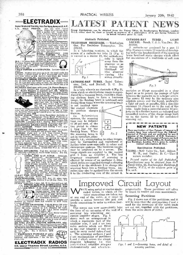
- Lit. SOLO PIlONES. Por use with fumer
f_\ morse. Usefulasacircuittester with a pqcket cell. Single Ear-
- - - ,. ,' pIece, 40 ohms, metal hook loop, f with cord, 1/3. Ditto 0.3.60 ohms.
with Cord, 1/6. WE. 1.000 ohms. with Cord. 2/-. 2,000 Ohms Ear- ': piece, with Cord. 2/6.
Ç -.ç L.R.00UISLEIIEADPHONES. Pilot Slgnallersl20olims, Phones. All leather headbands with slide
g' ,idustment chin strap and 41t. 't " Cord. Comfortable. 3/8. Sullivan
'. - 'z'-":, i 4' 120 ohms, Aluminium Headbands, - 'i i ).e3/9. cords 1/6 extra.
i - r-5. 111(011 RESISTANCE AND pliai RADIO ¡'fONES. The finest .K',AÍiERS' ISSt r aiways is the adjustable Browns
I--. , A Reed Phone, aluminium swivel, i headband, 4,000 ohms,
35/6.1 .... Q olims,21/6. 120 ohms, 17/6. COrds. 1/6. Vus-ion', ,1 akt's. Second-hand Headphones, in good, order, 2,000 ohms and 4,000 ohms, 5/-, 6/6 and 7/8, with cords. Western Electric,
t - 2,000 ohms. 4/8. -' fIELt) PIlONES & EXC1IAGES. Leather-cased or wood. CORDS. Makers new pr/ce up to 2/- for head cords, but we have in stock tough ex W.D. headphone Cords that will wear better at 1/6. Service 2-pin plugs, 6d. 2-hole sockets. mounted. 6d. Supplied with phones. LEARNERS', MORSE PRACTECE SET. Sound Type No. 10. with Key and Buzzer on liase: 3/-.' -Visual Type No. 2A with Key and Lamp on base, NO. IA Duplex with
r' , Key and Buzzer unii Lamp for sound and visual, line plug
is on base. 7/-. . -
BUZZERS. small (00e. with cover. 1/6. Power Buzzei's.
Group Abridgments can be obtained'írom the Patent Office, 25, Southampton Buildinls, London, W.C.2, either sheet by sheet as issued, on payment of a subscription of 5s-..per.-..Group Volume, or
in bound volumes price 2s. each.
Abstracts Published. CATHODE-RAY TUBES; LIGHT TELEVISION RECEIVERS. - Telefunken VALVES.-Bosch, F. J. G. Van Dcii. No.
Ges: Fur Drahtlose Telegraphic. No. 501816. ' ' -.
501532. A cathode-ray 'produced by a gun 11
lia a television receiver, in which the (Fig. 3) scans a screen 12 capable of devc!op- screen of a cathode-ray tube n (Fie. I) ng under tlle bombardment of the scanning is viewed in a mirror 12, the catliode-rav beam localIzed static charges which affect
- ,, j tube is tilteL the orientatioii of a multitude of soft iron 1<12 _- T a-way from the /2
-
Lobservel' so as to reduce. the
CATHODE-RAY TUBES.-Baird Televi- siois, Ltd., and Nuttall, To C. No. - Fig. 3
a
L 388 PRACTICAL WIRELESS Januay 2Oth( 1940
t: PATENT NEW
AY TIME SWITCRES. Vefleser i amp. lamps., tops.. 200 amps. From 17/6. RMOMETERS. Panel Din, dial. 5ft. ether tube. istant indicating, reading O to loo deg. Cent., 7/6. "'i ,ie'e 10/6.
I' L'SES CIass tubo, lamp.. 6d. With clips and base. Od. PETROL ELECTRIC GENERATING SETS
- FOR LIGHTING AND CHARGING FOR -. ifiS ONLY. A 500-watt, single cyl. 2 stroke,
s water-cooled, self-oiling Stuart Turner engine: mag. Ign. Coupled
I
to50/7Ovolts,lOampa,suntdyna mo, 1,000 r.p.m., £16. No increase in price, these are £40 sets ready
- for immediate delivery. FOR £12. A 150-watt engine and
dynamo on similar flues, but Coupled to 25/10 Volts. 0 amPs, dynamo.. A.('. ROTARY ChARGERS. 3 phase Motor 200 volts to D.C. Dynamo 8 VOlts 15 amps., £411716. R.C.A. 3 ph. Motor ?50 volts. Coupled to D.C. Dynamo 400 volts. 200 ma,, £5110. Metvick O ph. 1 h.p. Motor coupled
to D.i 1)4'.! t volt
Motor Coupled
voit D.C. Motor Motor 21 volts Volts 50 amps.
800 CELL A.C.[I.).U. uitìrru SUItOR-URN. SET. For 220v. AC. mains. For Radio Celi Circuits and ten 12- volt 10 ampCar Batte, D.C. oUtpsit 160 volts 20 amps, £32. ACOUSTIC RECORDERS. Cost 1510w. New MIVOICE acoustic sets, Complete Outfits in Carton de luxe, 16/-. No. 2 Mivoice. 10/6. Junior, 5/6. 5/- EMERGENCY PARCELS of uneul staed-by elettrica! and radio repair material and apparatus, - 7 lbs. for 5/-. Post Free.
ELECTRADIX RADIOS 218. Upper Thames Street, London. E.C.4.
"Tclephone: Central 4611
's_ .-.;a.__.-. at
Irnproved Ci HEN using metal or similar single-
ended valves. ¡11 which all the valve connections are token out
at one end of the valve, it is usual to provide a screen between the grid and anode connections in order to t'educe feed- back.
This screen can very conveniently take the form of an extension of the wall of a scl'eening box separating suc- cessive amplifier stages. Fig. i shows such an arrangensent in which a represents pas-t of the amplifier case, b and e are two valve sockets which are fitted on the ease (chassis) a. and al-e used to carry metal tubes d and e. The screening surfaces f and q are continuations of partitions is and i which screen the circuit elements belonging t o t lie individual amplifier stages Figs.. electrostatically and e lee t- ro -
.rcuit LQyout magnetically. These I)artitiolìs will often be foslnd to render coil cans unnecessary.
Screening Partitions Fig. 2 shows one of'the partitions, and it
will be seen that the continuations f and q used for the screening of the valve leads are cut out, together with the partitions, from the saine sheet of metal.
I and 2.-Screenieg boxes, and -Je/all o,! screening par/ilion.
with screw contact and adjustable spring 2/6. Ileavy Buzzers in Bakelite case, 3/6. illorse Transmitters, with key and brass-cl Buzzer. 17/6. Magneto Exploders. 25/-. Field Sets with Sounder, Relay and Calvo., etc. -
KEYS. Morse Signal Re3 t f' Practice Keys. 3/-. 1, T.
- Key on black moulded b i - . . small key, 3/6. la, LOIB " .11-.' - Practice Rev. T.X.2 wil
rc
--
t
r
PJflL. OJO. L. Oupet LUS IZIUUOI nL. with back contact, a well finished
key on poiiAb5i wood base, 7/6. 3, Operators' PF. plated pivot baie and' terminals, mahogany base. 9/6.- 4. Type IV. Superior ditto, nickel-plated pivot bar and fittings, on polished tase, 10/6. ]%IOitSE INKER. Tape Strip Recorders: portal,le or table. Cheap: Wheatstone Strip Band - Perforators, 151-. Paper Tape for Morse and Wheatstones, green or white. Od. reel. Brass Tape Reels in mahogany case. 2/6. alETEES. Liflcliip.n's Q & I. Galvos Two ranges with three terminals fdr circuit testing. In leather case, 15/-. I 101t 1'IONTAL BRASS-CASE I) (IALVOS. 7/6. CELL TESTERS: Megger 3-0-3 moving y Coil, Alu-' minium Case. 25/.,
"IJix-Mipanta" Balcehite case, 21m, by lin. NO pro- lecting] terminals, Universal versatile, high-grade, moving-Iron multlrange meter for service on AC. or D.C. battery or,maths, No proiectingitermmnals. Three ranges of volts: 0-7.5 Volts: O-150 volts: O-100 volts. In black Bakelite case. lito, by 21m.. 19/6 only. ALARM BELLS, Small and large. BatterY or mains D.C. oc AC. lOin gong, Domestic Bells and Fire Bells, cheap, Please state wants. Single Bell Wire, 1/- per 100 yds. iIETER MOVEMENTS. Full Size, moving coil. P.M.. l'or adapting home-made multi-range testers. For 3m, o' Sin, dials, 5f-. post 1/-.
Lfl,HT AND RAY CELLS, Selenium, lolo; Electroceil, Self-generating. 25/-; }iaycraft Outfit with i-clay arid amplifier, 45/-. - Photo-Cells for Sound 00 Film, Tele- sision and'RaY work, R.C.A., 23/-. . Beck, Angle Prisms, mounted in carrier. 5/6. RELAYS: Single and multiple Contact tele- phone type in 15 models Irom 5/-. Send for
i i ' "Relay" List, Genuine G.P.O. Vertical (,,,,J Belays, brass case, glass top. 3/- to clear.
Complete with original platinum contacts, 17/6. Worth double. MOv. Coil Weston, 60/-.
In a tube wherein an electrode 4 (Fig. 2), llOfl which an electrostatic image is repro- duced by a scanning beam, controls it flood- ing electron beam to fornì a lUlIliliOUs image, the flooding beam is produced only during those times when the scanning beani is not incident upon the control electrode 3 to produce charges : thereon.
In television systems, the scanning time may be reduced
' s to 50 per cent, of the line period to obtain 6 -
it long line for the flooding beam. When time scanning beani is 2 Fig. 2
flot in operation, other ignals, e.g., corresponding to. other images,
may be transmitted and reproduced in further tubes more especially in colour and stereoscopic systems. The luminous images may be projected on to a screen. Tise- image signals are supplied to the control grid 3 from an aniplifiet' 2. TIle line frequency component of scanning is effected by means of an oscillator 5. from which pulses are supplied through a shaping circuit 6 to the electrode 3 to change the scanning beam into a- flooding beam. lIn- pulses may also be applied from tise circuit 6 to the conducting core of time mosaic 4.
particles or filings suspended in a clear liquid so as to permit the passage of light between the particles on to a larger screen The screen 12 may be the ordinary zinc sulphide screen and the liquid, preferably alight oil such as paraffin, fills a disc-like container 15 clipped on to the end of the tube. Light from a powerful source 14 pro- jects onto a further sct'een an enlarged and intensified replica of the charge image built tip on the screen 12 by the modulated scanning ray.
NEW PATENTS jThese particulars of New Patents of interest to
readers have been selected from the Official $journal of Patents and are published by per-t - mission of the Controller of H.M. Stationery'
Office, and the Official journal of Patents can be = obtained from the Patent Office, 25, Southamp- - $ton Buildings, London, W.C.2, price ls. wedkly
(annual subscription, £2 lOs.). j
Specification Published. 515982.-M-O Valve Co., Ltd., Aldons.
W. H., and Espley, D. C.-Ther-$ rectifier,
j
- Printed copies of time f-eli Published -
,Spec-ificnlions maj be obtained from the
j Patent Office, 25, Southampton Buildings,
-London, H'.C.2, at f/iC nn-iforsn price of' 1s. each,
PDF compression, OCR, web optimization using a watermarked evaluation copy of CVISION PDFCompressorPDF compression, OCR, web optimization using a watermarked evaluation copy of CVISION PDFCompressor
DX on Medium Waves SIR,-With reference to your recent
article on medium-wave DX, I beg to add my sentiments. Having been a reader of your journal since its inception, and, prior to theii, of Ámatur JITiieless, since 1924-5, -1 think I can claim to have seen qîiite a few changes in tlìe world of radio. Commencing my activities witlì a huinbe crystal set in 1924, I graduated to a single valve (Bright Emitter !) thence to simple (Det. L.F.) two and three valvers, venturing iii 1926 to tuned anode (11F.) arid sundry rientrahised circuits. My liistSW. set caine
7 rn/cs C.W.: PY1FD, PY2IM, PY2XH, PY2OE, PY2HH, PY2KG, W9CTG and LU2BD.
Latest (SL's received are VQSJM (Mauritius),POQ5IM (14 me/s C.W.), but I have stoppeil sending reports since the beginning of hostilities..
Like many other ì-eaders I was troubled with very bad fading on the "Home Service" stations, but discovered I could cure it by removing the earth wire from the set. Wishing PRACTICAL WIRELESS the very best in 1940.-J. STEWART (Bonhill, Dunibartorishire).
Finland's Brave FgIit
ís arousing the adthiration of the whole world. Here is a fascinating new book which tells you about this country
and its people.
I:
4
January 20th, 194Ò PRACTICAL WIRELESS
." . -, .. --. I,
[Unento' íií,i IThe Editor dors not necessarilyagree with the opinions expressed by hi
correspondenti. All letters mutt be accompanied by tbename and address . of the tender (not necestarily for publication). I
- :
't Practical Wireless " with the B.E.F. ttre1' stich a set would be possible of only do I lind your papel of design and construction, even should it SIR,-Not
great interest, I also have found for fail to give the super selectivity of the years one page of great inportance to nie, more advanced supeihet circuit. Again and that is the " In Reply to Your Letter" tatiking you for the splendid articles, page. These replies gave me my first urge circuits, etc., and not forgetting our old
" to have a try to dabble with wireless, friend Therniion," with his weekly As I aul now serving with the B.E.F. i contributions which go so far to make your greatly miss listening to DX, etc., on paper always worth reading. I trust
"trumper'' my old two.valver which I built myself. 1940 may irove a year for Nevertheless, I am pleased to say that your endeavours and that you may con-
nìy wife sends on your fine paper to me tinue in publication right through hostilities, each week while I lie in hospital. Although until pe(ICC is once more established, and we have plenty of reading matter PRACTICAL many years beyond that-S. C4E0FFREY
WIRELESS is sought after by all the Boon (Rotherhamn). Patients here.-A. EDEN (No. 2 Jencral Hospital, B.E.F.). A 7 mc/s Log from Scotland
Correspondent Wanted S IR,-Xoticing the increasing interest of your readers in 7 me/s logs I here-
SIR,-I have been a reader of your fine with submit mine. The EX Itere is a publication for the past four years, 1-v-2 working from an eliminator (home-
and have found its articles very helpful, built), and the time is frem 23.00 G.M.T. I shall be glad to get in touch with aily onwards. short-wave fns in my district.-R, FAuLEr 7 tile/s Pitone: PY1FX. PY2LN, (59, Westdale Road, Plunistead, S.E.18). PY4CB, PY4CT, PY4DE, PY4DJ, LU2EE.
LLT3KV, PU9A\V.
389 :::: :i
ASPÂDES For Everì Purpose 7 ,i?°° 1m0!I,No.414 ... Rd.
// Large. N0. 415 ... 2d. n 'I .1/ Heavy Wiring. N0. 415 3d. <r //I K h' N 418 2d Hk,'o.49 .. 2d:
Usua! colours and engravings
tLLll. British Mechanical Prodtic!ions Lid, I, Church Road, Leaiherhead, Surrey.
INGINEERING... ÑOPPOPTUNITIE'
I the nary way to recaer "3. '' . I A.M1.C.E.. A.M.t.Meeh.E., :g5 l)aeaecld AMORE.. - A.Mf.A.E.,
So' , *0 a - A.M.LW.T., A.M.LR.E.. and rmmtiar qonllltcatlona. u' WE GUARANTEE-
Details aro givra of over 150 "NO PASS-NO FEE." Dtplos,a Cancre, in sil branches - of Civil, Nook., Ele,.. Motor.
PROFESSOR Aera. Radio nod Teleoi,ioo OTO A' 14 LOI' Engrneeriut, Building, Douera. - osent Enoploynstat. oto.
Write truc tiri, eo]gbtcuing Band-book to-dy FREE o.nd pion irer. Britmoh Institute of Engineering Technology,
500, Ibakeepeare Rouie, 17, 18,19. SirotIonS Piare. Wi. I -
i
'- 41
direction sooner or later. Your paper has catered widely for this class o experi- menter, therefore I would suggest,iF possible, a short series of suitable circuits, or sets, which could be built up from the usual assortment of gear, etc., usually to be. found in the ardent experimenter's workshop (not the more finished sets, aemanding expensive Litz wound coils, and sundry, and complicated, tuned circuits).
-.
Solution to Problem No. 382. WI en Jackson mounted his fuse-holder he overlooked
I he fact that his métal chassis would short-circuit the terminal heads, as they were level on the underside. He should lia'.e placed a layer of. insulating material 5111(1er the hohler and ndt bolted it down so tightly.
Only two readers correctly solved Problem No. 3Sl, and boolm have accordingly been forwarded to H. Dixon, 7, Clarence Place, off Castle Road, Scar- borough. J. Lyslap, '.' 'he Shìack," 29, 'Victoria Park, Kirkcudbriglit.
daa
3! J ÑET
From dl lcokreller,, or by post 3/IO /rom (lu,
publishers, GEORGE NEWNES, LID. (Resi Dept.), Towcr House, Southompbon Street, Strand,
Lojulon, -W.C.2.
ni
'-li
in 1927, which was a lucky yeiir for DX. In that year I nianaged to receive \V2XAF' (then a remarkable fèat !). It was not, however, until some years later, 1931-2 to be exact, that I succeeded in receiving any medium-wave Dx. I then successtully received \VGY (Schenectady) oli a straight (l-v-1) battery set, using an indoor aerial! My interest in B.C.L. radio seemed to %lalse about that titile, and I turned ruy attention to short waves once again; this time to the transmitting side, and in 1935 I was lssue(l with my first AA. permit. The following year, 1936, iwas granted a full ticket, with the call sign GSUJ. Since that time, right up to the cominenceitient of hostilities, i have been conducting various experi- ments, and have liad the utmost pleasure out of itsy bobby. Now, unfortunately, owing to the war, I am banned from this particular side of my activities, and natur- ally incline towards the other end of the scale, i.e. medium -wave (B.C.L.) DX, etc., as an alternative. It,lany ex-hanis will, I am sure, turn their attention in this
PROBLEM No. 383. AFTE1t using liii three-valve battery set
for seine titile, Atkins ilecided that lie would like lo go iii or short-wave listening, cisl accordingly purchased a well-known inal;e of short-wave converter. He tried tini with Ifs receiver, adopting lije connections recoin- ineisied uy t lie makers, l,ut it failed to function. He hiad lattis tise enliTertec Sud his receiver lestcd sud t hey wece both found to be - i n order. \Vliat was wrong ? Three books will be awarded tor tite first three correct soltitioiìs opesed. Entries should be addressed to The Editor. PRACTICAL WII1SLSSS, george Jdewses,
Ltd., Tower House, Souths utipton Street, Strand, London, W.V.2. uveiopes insist lic marked Problem No. 383 in the top left-lund corser and toast be posted to reach this 0111cc not later than tite first post on Monday, January 22iai, 1940.
By John Gibbons
The author's route took him through Finland, Estonia, Lithuania and Latvia, and his book will help you to under- stand the reason for the great changes which are taking place in the Baltic States
to-day.
PDF compression, OCR, web optimization using a watermarked evaluation copy of CVISION PDFCompressorPDF compression, OCR, web optimization using a watermarked evaluation copy of CVISION PDFCompressor
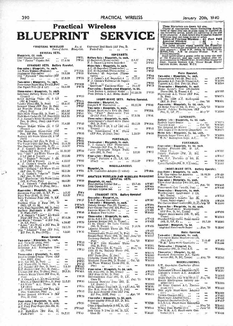
s-
reur-valve B!ueprints, le. each. A.O. Fury Four (SG, SG, D, Pen) - AC. Fury Four Super (50,-8G, D1
Pen) ....... ... - A.C. Mall-Mark (UF Pen D,
i'uah-Puli) .. .. 24.L87
Super-quaity Five.(2 nF, D, RO, FW2O Trans) . .. .. . - -
Class B Quadradyne (2 SG, D, LP1 1'W34D Class B) .. .. ,
New Class Il 1ve (2 SG, B, LP, FW45 Class B) .. .. ,. --
Superhet Oonerter(1.f).. - WM320 B.L.D.L.O. Short-wave Converter
(1f-) ....... _. May'86 WM814 Wilson Tone Master (If-) ., June'36
- The WM. A.0 Short-wave Chu. WM3&O verter (1/-) ...---
AW45
W1HO WM10
WUlos
---'- 5 '--- __________________________________
1938 "Trlband" All-Wave Three (11F Pen, D, l'en) .. .. 22:1.38
L i." F. J. Camm's. "-Sprite" Three.. (HF Pen, D, Tet) .. .. 26.3.38
The" Hurricane " All-Wave Three (SG, D (Pen), Pen) .. .. 30.4.38
F. 1, Camm's "Push-Button" Three (UI l'en, D (Pen), Tet).. 8.9.33
Four-valve : BIuprints, is. each. Sonotone Four (SG,fl, LF, P ... 1.5.17
» Fury Four (2 SG D, Pen) .. lieta Universal tour (SG, D, LF
8.5,37
ChU) t
Nucleon Class B Four (SG, D (SG),LF Cl.B) ,,
Fury Four uer (SG, SG D, Peli) Battery BaIl-mark 4 (*F Pen,.
- -
D, Push-Pull) ........... - F, J. Camm's "Limit" All-Wave
Four (UF Pen, D, LP, P) 20.0.36 MI-Wave "Corona" 4 (11F Fon,
D, LF, Pow) ...... t'Acme" 4 111! Pen, D
9.10.87 AIl-Wavo
(Pen), LP, Cl. B) .. 12.2.18 The ' Admiral" Four (11F Pen,
HF l'en, D, Pea (lIC)).. 1.9.38
Mains Operated. Two-valve Blueprints, is. each., A.C.Twin(D(Pen),Pefl) ... - AC-D.C. Two (SO, Pow) .. - Seleetone A.C. Iladiogram Two
(D, Pow)
Three-valve : Blueprints is. each. Doub!c-Diode-Triede Tfirec (11F
l'eri, DDT l'eri) .. ..
¡J.C. Aec (Sd, D, Pan) .. ..
- - AC. Three (SG, D, Pen) .. ..
AC. Leader (EF Pen, D, Pow).. -
7.1.10 D.C. Peen:ier(llF, Pen, D, Pen),. -. UbiCuo (TIF Pen, Il (Pen), Pen)... 28.7.3.1. Armada Mains Three (HF l'en, D,
'L J'en) F. J. Camm'e LC. AIl-Wve Silver
Souve.dr Three (UF Pen, D, Pen) 11.5.33 All-\VaVO" A.C. Three (D,, 2 LP (RC)) .. ' .. .. -
AC. itrIo Sonotone (HF Pen, El' l'on, Weatector, Pen) ., . - ...
Mains Record All-Wave 3 (EF p .
Pen, D, l'en)
Blueprint,,ls. .
FW81 SW, Converter-Adapter (1 valve) PW4SA
PW87 AMATEUR WIRELESS AND WIRELESS MAGAZINE CRYSTAL SETS.
I'W89 Blueprints, Gd. each. Four-station Crystal Set., 23788 AW427 1934 Crystal'Set ,,,,_ - A.W444 150-mlle Crystal Sot . ., - AWO5O
PW4 PWT1 OTRAIGHT lETS, Battery Operatet
-One-valva : Blueprint, Is. FWIT B.B.C. Seelal One-vateer ..,. -
TWO-valve : Blueprints, is. each. PW34B Melody ¡langer Two (D, Frs na).. - I'W34C Full-volume Two (SO, riet, Pen)... -
Lucerne Minor (D, T'en) _. . - PW46' A Modern Two-valver .. PW67 Three-valve.: Blueprints, is. each,
£5 Ss. S.G.3 (SU D, Trans) .,. - PW7O Lucerne Rsnger'(SO, I), Trarre).. -
Lo So. Three: l)c Lute Version PWSI (SG, D, Trans) ....... 1.5.14
Lucerne Straight Three ID RO. pWOO Trans) .......
Transportable Three (SO, D, Pen) - Simple-Tuno Three (FIG, D, l'en) June'33 Economy-Pentode Three (SO, D, ......... IWIS
FWRI
Pen) Oct. '33 "W.M.' lull Standard Three
(SO, D, Pen) ...... - £3 Is. Three (SG, D, Tress) ,, Mier. '34
» 1935 £6 6e, BatterT Three (SU, D,Pen) ........ -
l'TP Three (Pen D Ferì) . - PW23 Certainty Three isd, D, l'en) .. -
-pw25 Minitube Three (SG, D, Trans) .. Get, '35 PW2I All-Wave Winning Three (SG, D,
FW350 Pen) .......... - PW85B Four-valve : Blueprints, le. sel, each. PW3OA 65s.Feur(SO, D, TIC Trans) .. -
j'en) l'WlS
211F Four (2 SO, D, .. - Self-contained Four (SG, D, Lit',
Clase B) ...... Aug. 33 PW50 Lucerne Straight Four (SG, D,
l'W5b LP, Trane) ) ...... -
£5 5e. Battery Four (11F, D, S LF) Feb, '85
I'W53 The 11.K. Four (SG, SG D, Pen) The Auto Straight Four HF Pen, EF Pen, DDT, Pen) Apr.'38
S'W70 ..
Five-valve : Blueprints, Is. Gd. each.
AWlS?
AW3S& AW3I)2 A W426 VM400
A W412 AW422
HORT-WAVE SETS. Battery Operate One-Valva : Blueprints, is. each. SW. One-valver for America .. 15.10.38 Rome Short-Waver ,. .. - Two-valve : Blueprints, is. each. Ultra-short Battery Two (SG, dût,
Pan) ......... . - Feb. '36' Uouro.made Coil two(D, Pen) - Thres-vales : Blueprinto, is. each. World-ranger Short-wave I (D,
RU, Trans) ....... - Experimenter's 5-metr. Set (E,
Trane, Super-regen) ...... s0,6,3 The Carrier Short-waver (SG, D,?) July '83 Four-valve : Blueprints, is. 6d. each. »
A.W. Short-wsvo Worldbeater I1F Pen, D, RC, Trane) -
Empire Short-waver (SG, D, 1tO -
Trans) ........... - Standard Four-valve Short-waver
(SG, D, LP, P) ....... 22.7.30 Euperhet : Blueprini. is. Od. 'Iinplitled Sliod-wae-Super , ZQ'ov. '35
AW437 WMS7T Mains Operated. \VM327 Two-valve : Blueprints is. each.
Two-vaiveMsins Short-waver (D, j337 l'en) AC ....... 13.1.40
"W.itL" Long-wave Converter - - tvars5i Three-valve : Glueprint,, le. WM354 Eenigrator (SO_B, Pen) A.C. .. - WM371 rour-valve : S[ueprinl, is. Gd. »
WM380 Standard Four-valve AC. Short- WM393 'waver (SG, D, RC; Trane) . ..
WM3UII '» -
I'4ISCEI.l.ANEOUS.
WMIOO S.W, One-valve Convertor (Price Od.) ......... -
AW370 Enthusiast's Power Amptlilcr(1/5) - AW421 L(stenor'e 5-watt AC. Amplifier
(1/6) ........... - WM3IT Radio Unit (Sv.)'Ior SVMIO2 (1/-) Sos. 35
Harris iilectrogram battery am- ........ WM350 WM3SI
- pIlGer (1/.) Da Luxe Concert AC. Electro-
WMI8I gram (1/-) ..... Mar, 36 Now etylo hoit wave Adapter
WM4OI (1/-) . , Trickle Clsaer (6d) ,. ,. - Short-wave Adapter (1f-)., ,. -
A W 121) A \l'432
W5l402' A W 44(1
A WIll
AW4IS WIllIG.
AW4TO
WM313
WM383
WIllis?
i
AW451 I,
WM35, -
W11301 k
AW320 WM3SZ
W34392 WMlisa
WM398
WM4OF
WM3&II AW462 AW4SO
Three-valve : Blueprints, le. each Push Button 4, Battery Model }221o.3s rw9 Selectone Battery Three (D, 2 LP Push Button 4, AC. Mains Model (Trans)) ...... . -
Sixty Shilling Three (D, 2 LP PW34A, SHORT-WAVE ST3.. Battery Operated..
(ftC & Tr8fl8)) Leader Three (5G D Pow) 225 27 Pw35 One-valve :. Blueprint,is.
Simple S.W Onc-valver 23.12.39 FW88 Summit Three (U'F j'en, D, PeS) All Pentodo Three (11F Pen, D,
FW37 .. Two-valve : Blueprints, is. each.
(Pen), Pc-n) ........ 29587 PWIO Midget Short-wave Two (D, Pen) FW3SA lau-Mark Three (SG, D, Pow) .. 12.6.37 PW41 The "Fleet" Short-wave Two flail-Mark Cadet (D, LP, Pen (MC)) 10.3.85 l'W48 (D (HF Pen), l'en) .. 27.8.38 rwot F. J. Camm's Silver Souvenir (UI" Three-valve : Blueprints, is. each
Pen, D (Pen), Peo)) (All-Wave Experimenter's Short-wave Three Three) ........ 13.485 FWI9 (SG D, Pow) . 80,7.38 PW30A
Cameo Midget Three (D, 2 LP The Prefect 3 LP (itC and (Trane)) .......... - W51 Trans)) - j",v03
1030 Sonotone Three-Four (MF The Band.pread' S,W Tlir Ç''' Pen, 31F Pen, Westector, Pen) - FW53 (HF Pen, D (Pen), l'en) 1.10.38 F\V0S
Battery All-Wave Three (D, 2 LP (RC)) ......... PWS5 PORTABLES.
The Monilor (11F J'en. D, Pen) .. ThoTutorThree(HFPen,D,Pen)
- 2L330 PWG2 Three-valve : Blueprints, is. each.
The Centaur ThÑe (SG D, P) .. 14.8.37 PWOI , . ELF Three-valve l'ortable (11F Pen D, Pen) PWO5
-
- F. J. Camm's Reòord' All-Wave Three (11F Pen, D, Pen) -. 31.10.3 EWOD
.., Parvo Flyweight 1didgct Porti
FW7? The "Colt" All-Wave Three (D, able (SG, D, Pen) 3,0.33
2 Lii' (RC & Trans)) .. .. 18.2.39 FW72 Four-valve : Blueprint is. The "Itapide" Straight I (D, ° link 'i' Portable 4 (b, LP, LP,.
2 LP (RC & Trans)) ,. ..
F. Camm'e Oracle All-Wave 4.12.37 I'W82 (Pen)) .......... 19.3.33 IWSO
L, - .7. Three (11F, DOL, Pen) ,. 28.8.37 I'W71 MISCELLANEOUS., -'
Three (SG, D, Trane) AC. AW383 Slantovanl AC. Three (UF Pen,
D, Pen) ......... - W11374 £15 15e. 1936 AC. Itadiogi-Isin -
(11F, D, Pen) ....... Jan. '841 WM401 Four-valve: Blueprints, is. Ed. each. All Metal Four (2 SG, D, Pen) -. July 533 1111329 Harris' Jubilee Radiogrnm (UP
Pen, D, LF, P) ...... May'8 WM386
S UPE R H ETS. Battery Gets : Blueprints, is. 64. each. Modern Super Senior -. VM371 'Varsity Four ....... Oct:'35 WIllol The Request All-Waver ,, ,. June '80 1131407 1935 Super-Five Battery (Superhet) - WM37U Maine Sets : Blueprints, l, 6d eaCh, flept-ode Super Three AC. .. May '3l 1131359 "%y.M." Itadiogram Supc- AC,,. - WM3IJ6
FO R TAB L ES. Four--,a!ve : Blueprints, is. Ed. each. floliday Portable (SG, D, LP,
Class B) .......... - AW393 1-amily l'ortable (11F, D,. BC,
Trans) .......... - AW417 Two 11F Portable- (2 SG, D,
QP2l) .......... - 11143363 'PyciaPortsble(SG, D, 2Trans) -
RACTICAL WIRELESS No. oJ Universel Hall-Mark (HF-Pen, D, Date of 188116. Blueprint. Push-Pull) ... .. -
CRYSTAL SETS. Blueprinte, C. tech SUPERHETS. ]037 Crystal iteceiver PW71 Battery Sels : Blueprints, Is. each. The "Junior Crystal Set .. 27.8.38 l'WOl £5 Superhet (Three-valve) .. 6.6.37
F. J. Camm's 2-valve Superhet - STRAIGHT SETS., Battery Operaba Mains Sets : Blueprints, is. each.
One-valve: Blueprints, is. each. AC. £5 Superhet(Three.valve .. - -All-Wave Upipen (Pentode) , - PW31A D.C. £5 Superhet (Three-valve) . -
liegtnnere' One-valver ..... 10,2.38 PWS5 Universal £5 Superhet (Three. 'l'ho "Pyramid" One-valver (HF valve>
Pen) .. -. -. .. 27.8.33 I'W03. F. J. Cameo's A.C. Superhet 4 -. 21.7.3?
Two-valve : Blueprints, is. each. ' 1.J. Cameo's Unlversal4 Super-- -
loor ran"e Super Map Uss o(D Pen) 24033 Q tone Unis ersel Four 16137
Four-valve : Double-sided Bluenrint. lO. Cd,
Amateur WlreleS ...... 4d t WlrelesoMagazlne ------- 1/8 The Index letters which precede the 'lnOptflt f
Number Indicate the periodical ¡n which the desorip- l'W37 - tion appears: Thus P.W, rotera to PRACTICAL,
- WIRELESS. A.W. t Ansateur Wireless. W.M. to Wireless Magazine.
Send (preferably) a postal order to cover the cost of the blueprint, and the Issue (stamps over 6(1.
i'W40 unacceptable) to PRACTICAL WIRELESS Blueprint py Dept.. George Newnes, Ltd., Tower House. South-
ampton Street Strand. W.C.2.
PW43 PW42
Mains Operated. PW4-i Two-valve : Blueprints, ls each. PW5O Consoelectric Two (O, Pen)A.C. - AW4OI
Economy A.C. Two (I), Trans) AC. _ WM286 PWIIO Unicorn A.C.-D.C. Two (D, Pen)- - W0194 PW73 Three-valve : Blueprints is each.
- Home Lover's Iew A'll-electrlc
390 PCTICÀ1 VIRELESS JaUay2Oth4O
Practicäl Wireless - tiOnt Of these can In some os be SuppliOlt
H 1 I of the Blueprint, A dash before the Blueprint Number E I - the following prices. Which areaclthtional to the COSf
U PEW. WI . ¡ 3 Indicates that the lsse 18 out of print, - esse S \s V Lssùps of praejleat Wireless ... 44. Poet L'D.Id
PDF compression, OCR, web optimization using a watermarked evaluation copy of CVISION PDFCompressorPDF compression, OCR, web optimization using a watermarked evaluation copy of CVISION PDFCompressor
D. L. (Dunstable). tli&grid winding. J
i -
' - ¿1L .... .. .. -.
way. You have used twd serie s resistances, nd two condensers which are, in effect,
in parallel, and thus one resistance of 50,000 ohms and a 4 mfd. fixed condenser may ¡cave worked just as well. On the other hand, there is sometimes a difficulty in removing instability by simple decoupling schemes, and a double circuit such as that you have tried may have to be used. It is generally better, however, to try to find the cause of the trouble so that nôrmal methods may ho applied, rather than to use elaborate decoupling schemes.
Negative Feed-baçk
"I wish to apply negative feed-back to my .push-pull amplifier, but am uncertain regarding the proper method of doing so. Could you give a circuit and values for the necessary components? I am using two Osram KT.66's in thø output stage."-
"1 am having difficulty in getting smpoth reaction on the set. I have tried all condènsers, but they do not appear to make things better. The coil is an old pattern (I believe home-made) and I wonder if this is the cause of the trouble. Can you suggest any improvement or way out of the difficulty ? "-B. M. (Southampton).
THE reactiQn winding may be too large, and thus need a very small capacity
for reaction control purposes. We suggest you first make certain that HF'. choke and grid condenser and leak are suitable, and thon ti-y the effect of a smaller winding. These remarks only apply if the reaction is fierce, that is, oscillation takes place before the signal has been built UI) to sufficient volume. If, however, it is difficult to make the set oscillate, oven with a large condenser, then the reaction winding is too small oris too far away from
through the anode load, results in voltitge dilTerences across the load, and these arc passed on to the next stage.
p.N. R. (Gravesend). \Ve are unable to supply blueprints of coi,ìisereial receivers. You slionlil write to the maLers.
G. T. (W.2). You will probably find that thetrouble is due to the transmitter, and is one of the dihticulties met with in the new arrangements caused by tue war. There is no eure.
A. E. (Kenfig Hill). Time amplifier will work with ary good pick-up such as that mentioned by you.
T. W. (Leeds 12). The disc machine is now obsolete and in any case there arc no television tranenmissioss now.
J. B. (Southampton). We would not advise the modificatiou. Could' you let us hare your reasons, when we may be able to suggest sonic alternative scheme? A stamped, addressed envelope will ensure a postal reply.
W. T. (Edinburgh). \Ve have no details of the particular cet and therefore cannot gi'.e instructions for modifying it.
The coupon on page in of cover must be attached,to. every query. I
atio= f 2xTotal valve impedance 'V Speaker impedance.
This formula applies to moving-coil speakers, and it is usual in the case of the old-pattern horn-or reed type of speaker to take the tôtaf valve impedance only, and not double the impedance as in the above fórmula.
Double Decoupling Is there any objection in the arrange-
ment shown in my sketch for decoupling a detector stage? I have used a 50,000 ohms anode resistance, with two :25,000 ohms decouplers, having 2 mId, fixed condensers from each side of the decouplors to. earth. Il seems to have cut out the trouble I was experiencing, but I am wondering if there is any drawback in using such a schenie."-L. J. H. (Hinckley').
T HERE is nothing wrong in tise scheme, but you may find that you could have
obtained the desired end iù an alterñativo
In our pages, or on general wireless matters.- We regret that we cannot, for obvious reasons-
(1) Supply circuit diagrame of complete - multi-valve receivers.
, (2) Suggest alterations or modifIcatiìs of receivers described in our contem- porarics.
- '(3) Suggest alterations or modlilcatlons to commercial receivers.
(4) Answer queries over the telephone. (5) Grant interviews to queriste.
- A stamped addressed envelope must be - enclosed for the reply. All sketches and drawings which are sent to us should bear the name and address of the sender.
Requests for Blueprints must not be enclosed - with queries as they are dealt with by a
- separate department. SeoS your queries to the Editor. PRACTICAL WIRELESS,
: Ocupes Newnes, Ltd.. Tower Rouse, Southampton Street, - Strand. London, W.C.2. The Coupon must be enclosed
with every query. - L,ete,,aseeueu...nsoa,,.u.swe.,a,J
already done this, and furthermore that a 100,000-ohm resistance be shunted across each half of the secondary winding.
Reaction Control
ing of wire is taken round the point where glass and base join, snd this wire is taken to the filament pin. If the glass bulb has become .losened, or has broken, the metallising may not, be Joined to the filament pm, and thus is not being earthed. On tite other hand, the metallised surface may have fractured at the point where the wire makes contact, and this is having the sante effect. Probably the best solution is to obtain one of the small aluminium valve screens and place this over the valve and earth it, when your trouble should be removed.
Tite following replies lo queries are gis en its I atbreviated fortin eu lier beeaoee of non-compliance willi sor rules, or because tite point raised is sot of I
! eiteral interest.
E. A. M. (Dentan). Itrietly, tite anode current Sow is controllcçt by tite incoming signal, resulting ist an anotle current variation, 'ibis variation, Ilowiog
S,-
dO'Vf a \'
iìo7your letter Speaker Matching
"i have a receiver with à valve in the oútput stage, which, according to the maker's lists, requires a load for proper matching of 4,000 ohms. The speaker which I wish to use, and which has given me very good service for a long time, is rated at 1,250 ohms, and so that I can get the best from It I should like to know what ratio of transformer must be used. The speaker has a transformer with various terminals giving different ratios, but on test I do not seem to notice a great deal of difference. But I should like to tise the proper ratio and should, therefore, be glad if you could give this."-S. G. (Bolton). FOR the speaker and valve load in
question the ratio of. transformer required is approximately 2.7 to 1. Your tests were probably made with the low ratio tappings, and these may all have been round about 3 to 1, and thus you would fail to.notice a great deal of difference in the results. The formula for obtaining transformer ratio for speaker matching is:
IF you are using transfornier coupling in the push-pull stage, you should
employ one of the split-secondary L.F. transformers so that each "leg" of the output stago may be isolated. Tite feed- back components are merely a resistance and condenser joined between anode and grid, and to enable the decoupling to be applied the feed-back is taken to the centre or low-potential end of the grid winding on tise transformer. Therefore, with the split second transformer, each low-potential end is joined to earth through a 5,000-ohm resistance, and a resistance of 100,000 ohms is joined from the anodes of the output valves through a .25 mfd. condenser to the low-potential end of the grid winding. It is recommended that a 100-ohm resistance be joined in each anode lead if you have not
We wish t.û draw the reader's attention to the fact that the Queries Service is intended only -
- for the solution of probiense or ditliculties arising frcn the construction of receivers -
- described in our pages, from articles appearine -
I wonder il you can, from this, tell what is wrong with the set and how to cure it. I am using it on A.C. supply, 240 volts."- R. H. (S.E.11).
THE trouble sounds very much like a raw A.C. supply getting through to
tise set-that is, ineffective smoothing. We imagine that the receiver is one of the "Midgets" with a field speaker winding used as a smoothing choke, and think that the most likely entise of the trouble is an open-circuited smoothing condenser. This is, no doubt, an electrolytic, and we suggest that you try the effect of connecting a new electrolytic condenser between each side of tite field and earth. This will no doubt curo the trouble.
Valve Screening I use in my set a metallised valve in
the detector stage, but am troubled by instability. When I was testing round the set I found, however, that when I held my hand tight round the detector the trouble stopped, although the valve is metahhised and I have connected the correct filament pin to earth. This is indicated by a label ' E ' stuck on the valves Can you suggest why the metallising fails to stop the trouble in this case, and why my hand does do it? "-B. D. R. (Newport, Mon.).
THE metahlising is generally corrieri down on to the bakehite valve baso and a
a
4 , -,
January' 20th,, 1940 PRACTICAL WIRELESS
1n. r1Uiç1 391
Faulty Smoothing Co'idenser "I have a small Universal mains set
wìich has developed a fault in the form of very rough music and speech, the' latter, in fact, being almost indistinguishable.
PDF compression, OCR, web optimization using a watermarked evaluation copy of CVISION PDFCompressorPDF compression, OCR, web optimization using a watermarked evaluation copy of CVISION PDFCompressor

of' hum. - (C'ontinued ;, next column) Batersea 1321.
-e- - -
Lii4' -'-- -_;-___í'-'-
If, Jiowever any doubts extst as Io lite suitability of the choke the idea of con- necling special short-wave chokes in series at each side of the choke should be I ned. Ano//ter idea which is not ojien seen in practice is to include a low-value non- inductive resistance on each si'de of the choke, in place of the short-wave chokes. Values up to 5,000 ohms niay be tried.
Microphone Leads
1-IEjY using a microphone and it is desired to place this some
distance from the arnpifier, it is quite in omder to use long leads, provided that they are screened. ¡f a transverse current tipe of instrument is used, the tranforwer and battei j; associated with lite mike should be placed as near to the instru- ment as possible, and the secondary then connected, zia the extension leads to the receiver. - Do not use the long leads on ¡lie
primnaly side, as this may give rice to
various troubles apart from tite introduction
24 mfd. Can type Electrolytics, 450 volts working 16 each
PRESS BUTTON UNITS with 6 Press Buttons, ready for wiring into net, vitl, circuit .... 4111 each Stranded Puslt-1,acle \Vire, ld. per yard, 12 yarùs bd. CHASSIS Mounting Valve Holders, American, 4-, 5-, ti- and 7-pin, 4d.eacb. Octab Sd. each, Loctals lCd. each. 7-pin English type, 3d. each. ROTHERMEL Pinzo Crystal Speakers, 74in. Cone. List 55/-. Our price, 10/6 each. lOin. Coite 12/6 each. POLAR N.S.F. i watt resistances, 4d. each, 3/9 dozen. All sizes up to 2 meg. WEARITE MAINS TRANSFORMERS, E.C.B. type. 550-0-550 V. 80 ma., 5 Volt 2 amps. '6.5 volt S snips
6/11 each Type ito. t. o-o-soo y. 150 ma. 4 volts 2 amps, 4 volts 2 elope, 4 volts 2.5 amps, 4 volts j5.S amps,
21/- each
PHILCO MAINS TRANSFORM ERS. American Wind- ¡tics, 550/350 volts 65 m.a, (i volts S amps.,5 volts 2 snipS .......... 5/- each Ditto, but SO ma ......... 6/S each Ditto, but 00 ¡n.a ......... 7/6 cacti WEARITE lii) k/c S.F. Transformers .. 1/- cacti AMERICAN CTS. Volume Controls, Ortest made, divided spindles, length 25to. with switch, 2,000, 5,000, 10,000, 25,000, 100,000 .. .. 2/6 each Wire-wound S watt (less switch), 50,000, 25,000 ohms,
2/-each PLESSEY DRY ELECTROLYTICS, CAN TYPE. 12x111 mfd. 350 volts working .. 1/6 each 6x6 ,, 500 volts working .. 1/6 each 12 ,, 450 volts working .. 1/6 each 8 x 8 x S infd. 500 volta working 2/11 each lOx 8x4 x 4 mfd 500 volts working 2/11 each 12 x fix fix 8x8 mfd, 500 volts working 2/Il each 10 mfd. 450 volte workiitg ...... 1/3 each 16 y 16 mfd. 350 volte working ., .. 1/3 each
VAUXIIALL-All goods previously advertised are still avaib, hie send now foe batest price list,
fuee,-Vauxliull Utilities, 163a,Strand, \V.Cft.
B ANKRUPT BARGAINS. Brand new ISSt) models, makegs' sealed cartons, with guaranteee, at less
40 per cent. l,elo,r' listed prices also Slidgets. port- tables, car radio. Send ltd. stamp ¡Sr Jists.-ihdio Bargains, Dept. P.W,, 261-3, 1,ïchlield Road, Astos, Birniiitgliam.
5 f BARGAIN PARCEL coinpriaìng Speaker Cabinet, f - Drilled steel Chassis, condensers, reuistancés
sud many other useful components. Worth £2. Limited nui,iber. Postage I I--Bakers Selhursi Radio, 75, Sussex Std., South Croy,ton.
C OULPHONE RADIO, Ormskirk. 1941) Brand. New goods only. Cotlaro motors iDo, turntable, 25/-.
Speakers, valves, receivers. 1d. stamp lists.
LOUDSPEAKER REPAIRS
LOUDSPEAKEI1. repairs, British, American, any make. 24-hour service, moderate prices.-
Sinclair Speakers, Pulteney Terrace, Copenhages Street. London, Nl.
REPATIlS to moving coil speakers. Cones/cotta fitted or rewound. Fields altered or wound.
Prices quoted, including eliminai ors. Pick-ups and speaker transformers rewound, 4/6. Trade invited. Guaranteed satisfaction. Prompt service. L.S. Repair Service, 5, Balliam Giove, Loudon, S,W.l2.
g;
Green .. .. 5 . 00000 Blue -. 6 .. 000000 Violet - ..,. 7.
Grey .. .. 8 lt7hite . 9
H.F. Chokes
W HEY using an all-wave receiver some c4flìcuity is often experi-
e(iced in obtaining smooth reaction effects
on all wavebands. The use of a properly designed all-wave choke should, however, ensure that the choking effect is adequate, and i/such a component is used, and reaction is erratic, attention should be paid Io
other components in the detector stage.
POLAR meg. Volume Controls, with SP. Switch 1/6 each
Ditto, with PP. Switch - .. .. 1/9 each
YAXLEY tps 4-pole 3-way Single Bank Switches 9d. euch
2,500 ohm Fields Coils ------ 9d. cIcli i (One) gross Assorted Resistances. - 5/- per gross Metal Chassis Drilled. 15' x G" x ir and ill" x 8" X
1/6 cacti PuehBack Wire ...... iSyds. bd. ROLA 1'.M. Speakers, latest type 7in. Cone, with Pcntode Transformer -. .. Boxed 14/6 each Clock-faced Dials, 5" x 3", with printed 3-wave scale Ox-Copper Escutcheons and Glass .... 3/6 each Ditto, lese Escutcheons ...... 2/6 each ilorizoirtal dials, with plain scalo 7" x 5" and pointer
1/- each 10011.. Copper Aerials, Insulated - - - - 2f- each
FI LAMENT TRANSFORMERS, input 200-SSO volts, output 4 volts 4 amps, 4 volts O amps - - 4/11 each G.E.C. Mains Transformer, American ivindiugs, 330-O-350 volts, 65 ma. 5 volts 2 amps, 6.3 volt 2.5 amp. Suitable for replacements in h3.E.C. models
5/6 each
\\rire, Circuits, etc. Value 25f-. 5/- per psrcel.
I5 -Service Sian's Component Kit.. Electrolytic
t Condensers, Volume Controls, Itcaistasees, Tuhitilar, Mira, l'auer Condensers, Valve Holders, etc, 12th articles contained in strong carrying casa, 0,' x 7" x 7", 15/- the Nit.
2 1 /
-Small Trader's Parcel of Components. 150 t - Articles comprising all types Condensers, Valve
Molders, Resistances, Chokes, Coils, Wire, ele. Value 85/-. 21/- the larcel,
5 / -100 Wire-end Resistances, assortod capacities, t - and i watt, 5/- per 100,
'f ELSEN ; Orinoird Loud-speaker Units, 9/ti;
Crystal Sets, 5/O; Westeclors i'ype W2, 3/6; S mid, Electrolytic Condensers, 500 voila, 1/8, Crystal Detectors, 2/-; Crystals, Gd. Marconi V24 Salves, Ori.
2 / -Tool or Instrunicitt Carrying Cases, ex -Government Stock; Wood O" x 7" x 7", 2/-,
SPECIAL 011er, Limited Quantity lorch Buhl,s 5v., 21/- per 100 ;
23v. and 1.5v,, 17/6 lier 100.
SOUTHERN SIADIO. 46, Lisle Street, London, W'.C, Gerrard 6653.
ç
ing a somewhat different procedure, and in place of colouring the entire component, rings or bands of colour are placed al one
end. In this case the first colour band is the equivalent of the body colour, i/ic next is I/te equivalent of the tip colour, and the remaining hand is equivalent to the usual dot. Tite three bands are thus read in order-body, tip, dot. The colour refer- ences are repeated for the benefit of those
who are not familiar wit fi i/tern
COLOUR FIGURE No of noz&rla BloeL- - O .. 0 Brown . . . i . O Red .. 2 .. 00 Oianqe . . 3 . 000 Yellow . .. 4 .. 0000
BRITISH BELMONT S Valve plus Magie Eye All. Wave AC. Superliet Chassis, 4 wave-bands, two short, medium and long, titted latest Mullard Octal base American type Valves. Size of Chassis, 11/" X 10" x 3. Supplied with Valves and Knobs, but less Speaker.
Chassis only, £5/i 9/6 each. Speaker l'or above, 17/6 carli.
RICE-KELLOGG SENIOR 12 Noviisa Coil Speakers, 20 watts, 1,000 obtus, Il, ohnss Speech Coil. Vil bout Speech Transformer, 32/6 with Tra,sslòriner tapped :3,000 ohms and 7,000 ohnis, 35/-. GRAMPIAN 10' 10 watt, 2,500 ohm Energised Speaker. Heavy Cast Frame .... 15f- each With heavy-duty Pentode Speech Transformer
17/6 each Heavy-duty Speech Transformers, Pentode Matching
2/11 each
PLESSEY 2-gang Straight Condensert 1/6 each Ditto, 3-gang ......... 2f- each PLESSEY Motor DrIve Press Button Unit. Supplied complete'with 8-way Press Button Control. Precision job thrdughout. First Grads Motor. AC. 24 volts
21/- each
Gin. Cone, 2,500 and 1,500 ohio field 5/li cccli RUBBER GROMMETS' ...... 4d. dozeit BATTERY Output I'entodes, well-known make.
4/6 eclì BATTERY Double Diode Triode, well-known iisske.
3/11 each RAYTHEON First-grade Valves, largest stockists, all types in stock, including Glss Series, Glass Octal Series, Metal Series, Bantous Series, Single-ended Metal Serica, and Resistance 'l'ubes, all.at most Coni. petitive prices; send for Valve Lists. All Orders Must Include Sullielent l'ostage to Cover. Hours of Business: 9 am-O p.m. Weekdays. Satur- days O a.m.-1 p.m. RADIO CLEARANCE, LTD., 63 High Holborn, London,
WC.1. TELEPHONE : HOLborn 4631.
SOUTHERN RADiO'S BARGAINS.
ALL ÇtUARARTEED. POSTAGE EXTRA.
5 / -l'areci nl useful Components, comprising I - Condensers, ]lesistaiiees, \'oliiinc Coni rois,
I.
.5
1-
S
L -
392
No?' Colour Codes
7'iJE najority of resistors are colour- coded by having the body pain/ed
one colour, one of the ends coloured, and a dot or a band of colour round the body about the centre point. There aie, how- ever, several manufacturers who are ado pt-
PRACTICAL WIRELESS
Classified Advertisements Advertisements are accepted for these columns at the rate of 2d. per word. Words io black face and/or capitals are charged, double this rate (minimum charge 2/- per paragraph). Display lines are charged at .41- per line. All advertisements must be prepaid. All communications should be addressed to the Advertisement Manager.
Practical Wireless." Tower House, Southampton Street, Strand, London. W.C.2
RECEIVERS, COMPONENTS AND ACCESSORIES
RADIO CLEARANCE. LTD.. 63. High Holborn, W.C.1.
January 20th, 1940
RECEIVERS,. COMPONENTS AND ACCESSORIES
(Contin,ied from prevous column) S.L Wire-end type, Bias Electrolytics. 50 nifd. 12 volts ........ 1/6 each 50 mfd. 50 volts ........ 2/- each Tubular Wire-end non-inductive paper, all sizes up to 0.1, 5d. escI,, 4/9 dozen. Ifotal Case i hole fixing Electrolytic Condensers, 510 volts working, 8 mf,! ....... 3/- each STANDARD TELEPHONE HEADPHONES, resistance 2,0(10 ohms and 4,000 obme .... 6/Il pair Volume Controls, 1,000 sod 5,000 ohms, with switch.
1/3 each .0005 3-gang Tuning Condenser toits, with trimmers.
1/9 cacti PLESSEY Energised Speakers, lOi,,. Coite, 2,500 and 1.000 olin, field, with tracs. .... 12/6 carli
PDF compression, OCR, web optimization using a watermarked evaluation copy of CVISION PDFCompressorPDF compression, OCR, web optimization using a watermarked evaluation copy of CVISION PDFCompressor

In Goon King Charles's Go'den I)avs,'' .... ' _
standing interpreters.
pursuing his policy of introducing frequent ac10 serials owing to the great potularity of Tise Four Feathers," "The Count of Monte Cristo," and " Scenes from Pick- wick,'' au of which have liad an ilnnselose listener following. Recently orinan Edwards's specially written serial thriller. "Curiouser and Curiouser,'' began. Another projected serial is " White Velvet," by Sax Rolitner. Anthony Hope's ' Prisoner of Zenda " is to be followed by its coin- paiiion romance, "Rupert of Hentzau." Kipling's '' Jungle Book " will, like the "Just So Stories," bc serialised Ihr broad- casting
The last act from Shaw's latest play.
written on one si,!,' of i/e poner u/si. and o/n'id i conti the nasne ami ad/in., qf tie tender. Ihitot
the Editor ,toeo not ho/ti himself csponoibie for i nlan'arripis, every effort will be made lo return the n if a stampe! and addressed envelope is
i roclonet. Ail correspondence intended for the i liditor should be addressed: The Sdilor, PIUCTICAL
\VIIIELES5, George Nemico. Ltd., Tower !Iooe. i Sou thOrn pIon Street, Strand, W,C,2.
Owing to the ropid progreso in the design of wireless apparatus and to our efforts to Leep our i
i readers tn touch with the latest deretopmen's, we give t no mero nl, that apparatus described in or i
colarnos is not tie abject of letters patent. Copyright in all drawings, photographs and
articles ptdiohed in PRACTICAT WIRELESS is i i specificati ti reserved throughoul I/ic countrie8 signa- i
tor/ to the Berne Convention and the U.S.A. Reproductions or imitations of any of these are therefore expressly forbidden. PRACTICAL WIRE- s LESS incorporates " Amateur Wireless." ¡
Ile broadcast and a selection of other choral miinsic Wi Il i miclude Gaelic mouth music.
Crosb.y Band on "Caravan" Series BOB CROSBY and his hand have
replaced Benny Goodman's orchestra on the weekly "Caravan" series over WLW and NBC, which began on Sat urday, January 6th. at 10 p.m. EST. Helen \Vard, songstress, and tise Bobcats, '' live group within the baud, will he featured.
Bob, brother of the illustrious Bing, lias had a rapid rise to PoPularity since organising lus outfit several years ago, Exponent of the Dixieland type of dance usilsic, his Players are considered omit. - - i's
of this type by them or au equi- va ent, and this may be used without difficulty. The ampi fier lias been built from spare parts, but a fitll detailed list of parts used-is included for those clto wish to reproduce the original
design.
Draina aid Feature Plans for 1940
..r i.. nR
ON "MOON RIVER" !lloo,t River, a lazy stream of dreams ..... Seven nigh!s
a week. at 12.30 orn.. EST., these words are heard over WLW as " Moon River," one of the most consistently popular late-hour programmes, comes on the air. The words were spoken by King Whijie, who is pictured above. He has now been calle'1 for military service in the Canadian Forces, and his
place has been taken by Loa Clarke.
LISTENERS are to hear more serial plays like '' The Four Feathers,'' ¡flore
extracts from current stage 1)lays, more comedies of the Wodehouse kind. alì(l llore iadio documentaries like " The 5115(10w of the Swastika." These aie some of the prospects held out by the B.B.C.'s i)raina and Feature plans for the New Yeai'.
Val Gielgud. Director of Draina, is
...,,.-. ................................................................
i Editorial and Advertisement Offices
Practical Wireless," George Newnes, Ltd., Tower House, Southampton Street, Strand, W.C.2. 'Phone: Temple Bar 4363.
Telegrams:Newnes, Rand, London. 'Registered at the G.P.O. a, a newspaper and for transmission by Canadian Magazine Post.
The Editor wilt tie peaoed to consider articles of o practico! natur, auit'ible for publication in PRACTICAL WIIIELESS. Sue/i rticteo should h
Return of Glasgow Orpheus Choir
LOVERS of choral singing will, on. -January 27th, welcome back for
their second war-time broadcast the famous Glasgow Orpheus Choir under Sir Hugh S. Roberton. The Chois' will begin its programme b paying tribute to the memory of Robert Burns in the
anniversary week of his birth b- singing (iraiiville Bantock's arrangement of" s \Vha Hae." It is a tradition of the Choir to sing the old Scottish tunes to which the metrical psalms used iii Scottish churches have been set. In tisis programme the tradition will be represented by the tune "Crimond." Items specially arranged for the women's voices of the Choir will also
4,4
U PRACTIC4L TELEVISION * j '
-
jJflJ E DIT I D B Y jEVERY WEDNESDAY f. J. C M Vol. XV. No. 384. ian. 27th, 1940 L
ROUND THE WORLD OF Quality Amplifiers ,
-
FHE design of ail amplifier to
deliver really good quality lias been discussed bejore in these pages. Usually it is recommended that a very high audio output be aimed at, as the amplifier may then be run vell wjtliiii its Lapacity and better quality thereby obtained. For many domestic pitt-
poses. however, a PX4 type of valve vill deliver sufficient output to enable
the valve tobe run vitlun ils lìmaxim1100i i-at ing muid still provide sufficic ut volume for normal purposes. l\laiiy listeners. in fact, do not like a loud signal, especially for talks and similar items. They prefer a quiet, subdued output wlucli must be listened to without any backgrouiid of talking or other noises. For these purposes the aiiiplifier described in this issue will he fremd ideal, the iliaxi w im rated output being (fully loaded) 3.5 watts. 'l'ue valve is, of course, of the type having an anode dissipation greater tIman 10 watts and aceotdingiy a licence has to be obtained iii order to purchase it. This is not a difficult rocedure, however, and it vill ouI y
take a few days to obtain time required ¡ermit. There are, however, mmiam amateurs e ho already have a valve
S'ofl w. J. DELANEY, FRANK PRESTON,
H. J. BARTON CHAPPLE, B.Sc.
WIRELESS -. ''P is shortly tu be broadcast. intl
Ernest Thesiger and li'ene \aumbrmigl, in time leading parts.
"Songs-of the British Isles" "
Uit BiU," froto the Cotswolds " Charlie '' from 1)evuii-
:,i shire will coimupère the seventh of the series of programmes entitled "Songs of tue British Isles,'' which will be presented by Gwen Williams and George Lestrange on January 98th. The rogrammes comprise folk songs. traditional and national aims and dialect songs of England, Scotland, Ireland and Wales.
In the seventh of tile series, three of the best-known singers from tlmei respective countiies will take part. They are James iIeCafferty froui Northern Ireland. John Tainsh front Scotland, and Haydn Adams from Wales. The flag will be kept 11i-ium
on behalf of England by the compères, "Our Bill" and "Charlie.' played by
-Freddie Grisewood and luarles \Vre- ford respectively. They vihl be heard in dialect and will probably sing a song or two also. The B.B.C. Theatre Chorus. trained by Charles Groves, and the B.B.C. 'l'heatre Orchestra will be conducted by Stanford liobinson.
'g
1.
-1'
- January 27th, 1940
4,
PRACTICAL WIRELESS 393
ftç\.j@.
PDF compression, OCR, web optimization using a watermarked evaluation copy of CVISION PDFCompressorPDF compression, OCR, web optimization using a watermarked evaluation copy of CVISION PDFCompressor

ja-
Fig. l-A device for cutting bass in a trans/ormei-couple.d amplifier.
IT has often been explained in these jiages that hass attenuation can be effected by reducing the value of the coupling
condenser C in ti resista tice-ea pa.cit y-coii tied amplifier. The saille result, it should be noted, can be obtained by reducing the value of the grid leak R (Sec Fig. ). This can he explained by considering the con- denser C atti! the leak R in series asti kind of fixed tatio potentiometer. By decreasing tite value of C the impedance ni that a rin of the-potentioltiet(r is increased to a greater extent for low notes thais loi high, and Ute voltage available across the resistance R will be reduced for low notes, whet eus for high notes there will be little change. I t, however, tite alite of tite resistance i! is i-educed, tite relative iinpedaiice - ratio will be altered in exactly the Saisie Way 11' is not possible to gis-e actual values, but interesting exleriments in toile control can be made by trying t lie effects ol s aulons yak es of grid leak.
Bass cut in tite case 01 a traits- H.t±
loi'tner-eoit pie(1 aniphiier nay lie achieved by coimecti ng a resist alice of, say, J 0.0)11 to 20)4)0. olmi a in series svitli the ninia cv si tiding, between the winding and tin- anude of the valve, and shunt ing this rcistance with a condenser of front Oh to 4)2 ostI. eapacil y.
'Flic elect of a resistance alone svould he
is less because of the nose i tait t lic' low but only ti t to a ceri alu ('tilia city shunt, aitti a ¡sip- fieq nency. above wit i cii lite h igit n ni es a re I tient iou will lits reduced. nut aliti iii fled but act titille su i ressed.
High-note Compensation 'l'ue effect of very selective tunlng circuits
s to cut tite sitie bainis corresposiding to tite higher audio fts'queuicies. To au extent titis loss of opter rtgistet cati be costs- uensatccl fiar by etti plovi ig a iiesto1c-octtput valve . Abetter and more scientific tdan is to tise a low-freqtscncy coupling winch amplifies high ¡toles more titan low itotes.
Fig. 2.-Jn an R.C. HTI
coupled amplifier, tite reduction of either C or R will reduce tite N bass reiponse.
Frequency Cut-off 'rhe circuit is showit in Fig. 5, attn is
siustihir tu t lint itt Fig. 4, si itli tite exception t lia I LI it i sil it (tance arm is t ctncd -by a Butti li eûttdtuaer. The values of tite iii- dtieta ncc a titi condenser ase so eliosett i ittit titis l)arl of tIte circo it is itcd to a la ny high audio trecuenev, in tite neighbourhood of 4,000 cycles. At, or a.bottt. I lint fie- ttteitcv tite circuit R will give tttaxiutmns atti pl i iicti flow iii d teilt tints replace notch of the high j,, itote liauactenistic. Aboce 4,04)1) cycles, hiovever. st utthiflctt -
tton rapidly bilis nfl -
tisI ti tiere is more
In tite case ol a resistanee-cutacity. coupled stage, titis can lic achieved by using, instead of a puse anode resistance, a resistor in series with an inductance of
394
(B:
9,.
I'KAL IILAL WIKLbSS January 27th, 1940
Tone Correction I
scfl Various Forms of Filter. Corrector and Booster .02 infd. capacity. As olietatise over the whole range of audio far as bass notes are frequencies, so that very high frequencies,
J t concerned, the impedance including the sq neals of atmospherics au'.j - ut the coupling resistance tise whistles of heterodyning stations
is R plus B1, and full will be very much over-accentuated. For- amplification is obtained. tiinatcly. it is not difficult to avoid this
-. For the higher notes, effict. 'flic method is to adopt a. circuit however, the impedaiice ivliicli. tidied. ainpilies I lic ingli ilotes
Fig. 4.-The arrangemn! for o srnple treble booster. Fi'. 5.-A tebIe booster giving a definite /zig!-note ca!-oØ
--_________ - .=- Y. - J -
- .-
to inahe an overall drop iii volume, but tife presence of tire shunting condenser perniits a greater proportion of the higher note energy to i-each the transformer, whilst eneI'gV eorrespoudrug to the lower notes will ho t o a greater extent a bsoi'hed in the resistance (Fig. 1).
Fig. 1 shows a bass booster for use in a resistance-capacity-eon pled am plitier. lt will be seen that hie snodo resistance is divided ¡jito two port ions 'R. which should be approxiinatetv equal to the valve impedance, and 1, of about twu'e the value.
R1 is shunted by a condenser of .01 to
-
about half a henry, t he resistance beiiìg approximately equal to the valve usi pedairce (Fig. 4). Here the impedance of the circuit increases with frequency and is therefore greater for high ilotes than for low. - Since the overall sin pluhcatioil depends upon the impedance of the external circuit compared with that of the total circuit. tise gais! tor high notes Will be greater than t'or low.
Tins arrangement has one grave disadvantace, however, in that this rising characteristic is
II
Fig. 3.-A bass booster for ari RC coup/el
ci rcuiL
oi less coin siete cut-off. The actual resonant t'reti uencv of the eu-cuit can ix' adjusted to out individuai needs, but it vihl be bituid t hat the figure suggested gives a very satisfactory degree of correct ion and at the sanie tinìe avoids hetej-odv ne whistles to a vers' great extent. Certa iuiiy
all whistles of frequencies above
PDF compression, OCR, web optimization using a watermarked evaluation copy of CVISION PDFCompressorPDF compression, OCR, web optimization using a watermarked evaluation copy of CVISION PDFCompressor

consists of a resistance B. inserted directly in the grid circuit of the first stage of the low- frequency amplifier s"ct ion Fig. 8.-Alternaiive arrangement of multiple filters.
il
s
- -'I._____ -- - -.
is the best position; and one of the many commercial turnia may be inserted either n series with an ordinary high-resistance
speaker or in the primary circuit of the out ¡nit transformer.
A typical forjo of this li lier ejru it is sljowti in 7. Complete filter 1n rif ilii.i fvnp iIsenrid III
about 1.01)0 cycles- the vaiiah]e resistance in series broadens t lie tuning and makes the control ojeratii-e over a batid of f're9lleneies
cut off at some deli rute frequency stich as 3,500or!O00cycles.a,e jrjr ohtainahle. FigS indicates tiro UlIC ilIritit t-III U ItijiiC 11IUt] CI! -
cuits. Fig. t) shows a typical arrangemmient. using air - cored chokes, employed as a scratch tiller with a gramophone j',iek- up. -
Tone Contro' Another system of combinim g
tone control and whistle sup- pression ishown iii Fig. iO, nod
Fig. 9.-One arrangement of granmo-scratcli Jilter.
o
LIT
-.
o peratve at one particular lieterodyne frequency, -namel , that to thich it is timed. it is true that it may be retumied for other frequencies, but this does not fall in with motern ideas of simplicity of control. Present-day practice, therefore, hLvour5 minother forni of heterodvne whistle eliminator, namely, a low-pass filter, which is a circuit designed to pass al] audio frequencies up to a certain value, aftem- which there is a mnorg or less sharp cut-off. such a circuit can be inserted at varions points in the receiver, either between stages or iii the output circuit. Wrhere the filter is to be added to an existing set., the latter
about one-fifth flic bottoni ctmd of the potentiometer. Across flic bottoni f i it h of t lie potenti omet er is coli -
miected tite aceeptnr circuit, winch coni -
prises ami inductance L of about 50 mnilli- henrys. and a .5 mId. condenser C, ivitim a variable resistance R2 of 5,pt 4) to 10,4)444) ohms, n Il connected iii series. The inductance and condenser tuile to
of time way frote (Continued on page 405-)
LjJ L11J
T
't
suppress, the acceptor achieves a very low impedance to energy of that particular frequency, which is tItus by-passed Iront tite twain circuit. The arrangement is shown in Fig. G ; the inductance may have a value of about half a lient-v, while tite condenser may be of the pre-set type and of .1)01 mfd. capacity. This circuit stifte from the disaris autage that it is only
iNÇ
ohms. \Vililt' the situntitig cunden- Fig. 6-A sei C must not have a capacity exceeding .001 nttd.
Mw form of voiriute controiwhich i-educes all fret nencies unjfoi-nilv will eventually result. in il serious loss of apparent strength of both ver\ high and very low fieq uencies, and the bass and very high frequencies
wtll become so attenuated that re- production viil he niarred by the over-preponderance of tite middle frequencies. Of tite numerous mimethods put fbi-ward for avoiding titis tiefect. the one here (kseribe(i. consisting of an adaptation of tite timed-acceptor circuit, is the most satisfartor - Tite artangeinent is shown diagrammatically in Fig. Il.
is tite usual volunte-controi potentiometer, in this case applied to a gramophone pick-tip. Tim
addit toit to tite slider tapping, which gives tite control of voluiìie. tImen is a permanent tapping itt
Pig. 7-A lòw-pass Jilter for elimi;ta!ing ,telerodyne whistles in hie output stage.
tuned acceptor whistle eliminator.
in tite neighbouihiood of .000. \Vltett tite main slidem-is at tite top ofthcpotentiotnetei-, corresponding to big volume, tite effect of tite acceptor is slight, bitt at a lower setting tito proportion of the middle m-egistei- absorbed by the acceptor increases progressively, thus maintaining normai tonal quality. An ai-raitgement such as titis cati very easily be mitade sip b tite amaten!-. it is possible to obtain poteiitiottieters svitii two sliders. but, alternatively, tite tapping for the acceptot- can he made by carelul soldering.
As this is probably one of the cirçiiits sylt ich wil i provide n tost interest for listeners vlto are interested in experiotental work,
on account of its rather novel fornì and the use of non-standard apparatus, it might be worth while to give one or two suggestions as to the best met hod of finding the best work ing va lues. Use a standard vo1 nine- control totentiomueter (tite value will be
j -1
Circuit are Discussed in this Article Another forni of hcterodvne eliminator
which has been used is the tuned-acceptor circuit. This consists of an inductance and variable condenser in series; ami is coimected in parallel with the circuit froni vhicb it is required to eliminate the lietero- dyne whistle. Thus, the acceptor may be connected across the resistance of an RC. coupling, or in parallel with the loud- speaker. By tuning the circuit to the frequency of the whistle it is (les!1-ed to
of the recei er. lt follows a resist- ance-ca jacity in- tervalve coupling. the bias for the grid of the L.F. amplifier he i n g furnished 1ro in -
the resistance R. R5 should be -
about tOO,OOO
UT-t-
NPUT OtJTPU
1
-s
.5
-, -
January 27th, 1940 PRACTICAL WIRELESS
and Filters
PDF compression, OCR, web optimization using a watermarked evaluation copy of CVISION PDFCompressorPDF compression, OCR, web optimization using a watermarked evaluation copy of CVISION PDFCompressor

L
xaiììiiiation, before applying any.voltages.
No Signals A nìtiltitude of faults can produce this -
annoying effect. 1f no special c-lue is avail- Fig. 2.-Points for checking in a standard 3-velve circui! -
- ,. -..- - --,, --
General Tests When testing any apparatus which is new
or unknown, always take the precatioii of including a suitable fuse in the II.T. negative supply 01, as in the case of a mains-operated receiver, apply a simple con- tinuity test between HT. positi\ e and the common negative earth line. This pro- cedute will prevent any additional ha cm being done if. by chance, the fault, is con- nected vitli the HT. supplies to the various parts of the circuit. With batteryopei-ated reeei\ ers. always make quite sure that the
Y HT., LT., and G.B. batteries are above suspicion. One cannot alays trust verbal evidence on such matters, as it i not un-
' knowii, as rely maiiy practical examples have proved, for a faulty or dirty, con- nection or cell to be entirely responsible. 'for various alleged faults.
If it is possible, make quite sui-e that all wiring connections ale secure and that all components are so fixed that they will not float about nr come schritt if the set is tUVfled over during further stagès of its
feed to each valve is complete, i.e., any manner. Connect the aerial through a valve not indicating a. current flow should sinai I ixed condenser to the conñecíion be subjected to further examination. For Cont),d o page 405.)
1T
_As it is not possïble o ta aulate all likely ilelects and their symptoms, some of the moie general troubles will be discussed, as it should be possible, by applying a little reasoning, to track clown even obscure faults by following the suggestions givell below. If sonic predeternmed procedure is adopted by the tester, lie will find, after a little practice, that lie will undertake to sen-ice receivers or aniplifiers large and sinaI! with much more confidence than when hit-ami-miss methods vere applied at- random. One's abilities will, pute nat u ally, be ] united by on's practical and theoretical knowledge, and so it Ixhoves all serious constructors, especia il y t-lie beginners, t.o take eve-i- opportunity to increase their knowledge as -much -a-s possible. These nights of black-out oiler good opportunities for a little serious i-eading of good text-books on tIme subject.
negative lead. For battery-operated ets a meter having allia-xi mum reading of25 to 30 mA's should be sufficient, but foi mains set-s a higher naximum reading would be advisable, say, 50 to I ti) in A's, accord ing to the number an.l t pe of valves employed.
Biasing Voltages Ifa reasonable total coi-i-eut consumimption
is indicated, that will denote that HT. and biasing voltages arc moore om- less satis- factory, but this should be verified by noting inA-nietem- i-eading and renloving one valve at a time and seeing what coi-i-eut it is taking. This will be shown hy.the fall in the meter icading. Note, tins procedure is not applicable to mains sets where the current consumption of each valve should be checked by connecting t-lie meter in the HT. supply to each anode in tuin.
These tests will also show if time HT.
switches, coupling and cle-coupling con- densers, LF. transformers, LS. or primary of output-transformer, anti the reaction circuit, iii the case of a detector.
On the GB. side, one ninst also cheek up on time continuity of the giid return circuit, -
i.e.. the coil, grid-leak or secondary of L.F. trausforiuier.
Localisis-ig the Trouble Assuming, at this stage, that the set
under test is a simple threc-valver of the. HF. -detector-L.F. type, the following procedure should be adopted to limit the field of tests to single stages, thus allowing the testei- to eliminate as many likely points of trouble as possible.
In this instance, it would he advisable to concentrate on the detect-or valve, and the preceding H.F. stage and t-lie output stage can he cut out of eiruit in the following
structors of several veus' staiìdiig cannot (or vill not) apply their knowledge i n such a inaimerthattlie fault casi be localised. Vlietlier this failure indicates that their
knowledge of radio only covers assembling a few components and wiring them up according to a full-size blueprint, or whether it shows that, while their knowledge might he quite sound, tlreT lack the ability to apply it in a systematic sense to indi- vidual sections of a receiver, one cannot say, but it is hoped that the brief details given in this article will help all to tackle their problems in an active manner, rather than sit down and adopt, sim to speak, a dcRatist's attitude, and send ont frantic s f) S's.
any h.iults, reidace valves and check current consumption of receiver. This can most easily be done by connecting a suitable snilliamnmneter in series with the HT.
METER
R
Fig. 1.-Circuit of a lest meter showing range- increasing resistance R
checks on anode and/or screen voltages and bias voltages, when such are applied. High H.T. or low GB. will he responsible. while the opposites will produce low anode currents.
1f the G. B. vaIne is in order for the valve concerned, i lien attention should be given to the HT. supply, which, if correct at the HT. baitery or rectifier, is no doubt being reduced to a low value by an unsuitable value of resistance, i.e., decoupling or anode load.
It must he realised that when speaking of HT. and bias voltages, any tests applied to determine these values naturally bring under observatiou all components in the anode circuits. i.e., H.F. chokes, coils.
Methods of Tracking Down the More Cenerai Troubles Met With ¡n Receivers ere Discussed by the Technical Staff
FROM t-lie correspondence received by the Query Service ])epart.nient, it is very evident that it is not only the
beginners who experience difficulty in lucating receiving faults which arise from finie- to time. Wiule on.e can fully appie- ciate a new-corner to the hobbs' being at a loss as to the cause of the trouble, and the necessary procedure to adopt- to trace it, it seeuis rather peculiar that, say, cou-
able, then one must start at the very begin- lung and apply the following Iroutixie tests. After bearing in mind the above general remarks, and before a pplying -any voltages. remove each vals*e in turn and, with a simple continuity tester, i.e., a- small dry battery in series with a low reading volt- meter, oi a high-reading galvanometer or nìilliammeter, test- the filaments or heaters for continuity. If these tests do not reveal
example, voltage test-s between anode and HT. negative and screening grid and H.T. negative, when valves of the S.G. and pentode types are being inspected. With mains valves, the cathode circuit most also he exansineil as a break in the bias resistance or the connect-ion between cathode and earth (HT.-) will also result in absence of anode curtent. -
High anode current calls for careful
r 96 * PRAcTICAL WIRELESS Jenury 27th, 1940
Loca 'ng Faults
PDF compression, OCR, web optimization using a watermarked evaluation copy of CVISION PDFCompressorPDF compression, OCR, web optimization using a watermarked evaluation copy of CVISION PDFCompressor
The B.E.F. Programme HAVE you tried the B.E.F. programme
now put out by the B. lIC on 342 metres ? I have listened to it on a number of occasions, and found the alterna- tive programme very good. I generally fin ti t traasmission is marred by
appropriate music, and, at the close of the programme, a serenade to the city whose history has been dramatised.
In his search for authentic information. Carder will comb each city thoroughly. He plans to see the mayor, newspaper editors, officials of historical societies and old residents-the latter ,to 1yovide the
foreign broadcasts in a hut on a hilltop somewhere in England, and the output of this receiving station is at present more than a quarter of a million words a day. Detailed digests are sent to various Government departments who have, since the outbreak of war, found the service of ever.increasing importance.
-
- -
i.
4!
their own T,roceedngs.
Torch Battery Prices ISEE that the Central Price Regulation
Committee have warned retailers that they must not charge ubre than the prices marked on most torch batteries, and that such must nt 'be offered for sale at more than that price. Such prices were, of course, announced ay the battery manufacturers as long ago as November 6th. and these in- cluded certain price increases. The public are invited not to pay more, and to report any cases vhere list prices of British batteries are exceeded.- Some of the foreign batteries are, of course, dearer, and it is not possible to control such prices. Members of the public should be wary of batteries the labels of which have been tampered with.
accident which Played a part in the build- ing of each City will be brought out in Scripts by E. Carder of the WL'IV Con- tinuity l)ivision. who w ill visit each city to obtain material for the series.
The initial programme told the story of Richmond, Indiana, incorporated in 1840. On the personal history of a iìian and his wife, from youth to old age, was super- imposed highlights in the story of the city, ranging from the first council meeting to the present. One dramatic seiiuence dealt with the selection of a name for the city fronì three submitted to its inhabitants. The name Richmond was ofibred by David Hoover, an uncle, three generations re- moved, of former President Hoover. -
A full dramatic staff will lai-ticipate in the new series, with. Harold Carr as in-odu ction supervisor. A 30- piece orchestra, directed by Uberto Neely. will supply
B.B.C. Monitoring Service THE vital importance of broadcasting
in time of war needs no stressing. Eut phasis, how-ever, on outgoing broadcasts might overshadow' the enormously important work undertaken by what is known inside the BBC. as the Monitoring Service.
On the outbreak of war, the B.B.C., on behalf of the Ministry of Information and at its charge, put into operation an interception station by which, ever since. a day and night check has been kept upon foreign broadcasts fi-orn enemy and neutral countries. Throughout every twenty-four hours, a team of -expert linguists with a wide knowledge of international affairs, listens to and flotes down about one hundred and sixty foreign bulletins, con- taining in bulk over three hundrd thousand words. This involves the reception of the
where they ar3 independent ofsueh methods. In these days, when the black-ont is causing most of the population to spend longer periods at hotne in tite evenings, anything that can be (lone to entertain theta should be (lone. 'l'ho television service, of course, serves the Home Counties, but there are 8,OOki.00() people in Greater London. and tite reinstatement of tite television service might encourage the sales of television receivers, Some hundreds of people at Iresent have expensive te evisiomi receivers which t hey catiminI use.
The B.L.R.E IUNDERSTAND from Sir Harold Moir
that the Institution of Radio Engineers proposes to continue to hold its examina- tions, and as far as possible assist in the req uirements of commercial enterprises. Meetings have, of course, been left. in abeyance, a!t.hough it is hoped to recom- mence tneetittgs very shortly. Meanwhile. papers which would have 1)0011 read at Members' Meetings are to be published in the Journal of the Institution. Tite decision to Push ahead with the publication of the ,Jonrnal ivas taken by the Council after careful consideration, and although war-time cost.s may affect tite si',.e of the Journal, it will. henceforward, be published at least once every quarter.
In deciding to proceed with this mtiat.ter, the Institution claims to be the first Radio Institution in the world, apart fiotti tite American Institute of Radio Encineers, whose activities are solely concerned with Radio Eiii neerine who i oeil larl y nublish
By Therm kn
slow fading, although so far I ha e always been able to " hold it.'' Many of my friends, however, tell nte that they cannot receive it at all in Certain districts around Lonclo t. Others Can get it, but only at loor strength.
Of coni-se, we must not complain, for we are only " eavesdroppers.'' Neverthe- less, i hope that tite programme is received much better by those for n Itont it is intended titan it is by most listeners of toy acquaint- ance.
One suggestion which has been titado is that the ti-ansmission is beamed'' to our troops in France, but I have other theories concerning the fhding and lack of punch.
"This Land of Ours" THE history of American cities, re-
lated in tenus of tite pioneers who founded theni and succeeding generations responsible for their development, is being presented in a new dramatic series
ThisLand of Ours," which began on on Sunda-i-, ,January J 4th, at 10.30
p.m.. ES'l. Tite programmes. which replace '' Salute
to the Cites,'' will be presented in a form differing substantially front the latter. Tite elements of comedy, eneIv. pathos and
.1 suoi of £78,000 lias already been collected as a result of Lord Baldwin's appea' for Seamen and their Depetidants on December 17th ; this figure includes Lord Nuffield's cheque fer £25,000 Tite previous record collection was in response to Lord Sotithw-ood's Wireless for tite Blind appeal at Christmas, 1938, which realised £42, l3.
'l'ue response to broadcast. appeals since their resuml,tion on November 5th has reached time outstanding figure of £175,981 Is. 2i.i. Titis exceeds the sum collected by similar appeals in any whole sear up to and including 1935.
The second most successful appeal of tite ivar was that of the Polish Ambassador on behalf of the l'olish Relief Fund on Novemnhem 19th, which realised £27,400. Miss &racie Fields' appeal foi- Voluntary Hospitals brought in £18,000, while the ''unknown blind man '' who appealed for the British Wireless for the Blind Fund at Christmas secured £12,850.
Comparison with the response in tite corresponding months of 1937 and 1938 is interesting.
in November. 1937 and 1938, the appeals yielded £12,588 lUs, lid. and £14,718 is. 6d. respectively, compared with £39,202 16s. 9d. in Noventher, 1939. The 1)ecembem, 1937. amid 1938 f igimres were respectively £45.456 l8s. 6d. and £56,574 15s. 2d., coni- pared with £119,778 4s. 5d. in l)ecenmher last.
The response to the appeal on behalf of the Finland Fund broadcast. by 1)r. Tancred Borenius on January 7th is already £17.000, amid many letters have yet to lie opened.
:1
t
NYOI The Television Question Again
ONCE again I put in the plea that the television programmes should be
reinstated. I do not believe that our enemies abroad would rely upon stich ait indirpctt ìnt hnd tf (Ìitcetinli-findine as using tite television signal. I know tliat aircraft, instruments have reached a stage
4V/
E«((
ELENGTH flavour'' of the cit.v' life as they found
it in th past. I think this idea could be applied to this
country, which has a w ealth of historie interest.
Response to Broadcast War Appeals ¡T ¡s gratifying fo note that tite record
January 27th, 1940 PRACTICAL WIRELESS 397
PDF compression, OCR, web optimization using a watermarked evaluation copy of CVISION PDFCompressorPDF compression, OCR, web optimization using a watermarked evaluation copy of CVISION PDFCompressor
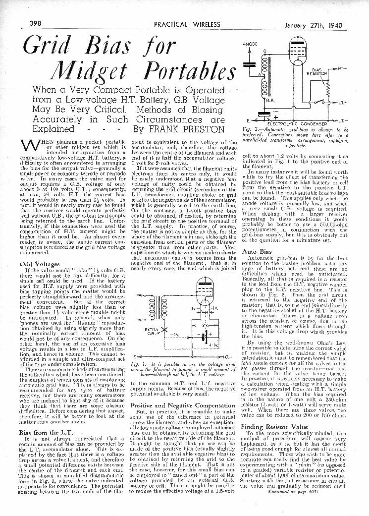
_ __I __ j _________________
matter from another angle.
Bias from the L.T. It is not always appreciated that a
certain amount of bias can be provided by the L.T. accumulator alone. Tins is ex- plained by the fact that there is a voltage drop access a valve filament, and therefore a small potential difference exists between the centre of the filament and each end. This is shown in simplified diagrammatic form in Fig. 1, where tue valve indicated is a pentode for convenience. Tue potential existing between the tu-o ends of the fila-
across the filament, and when an exception- ally low anode voltage is employed suflicient bias can be obtained by returning the grid circuit to the negative side of the filament. It might be thought that no lise can be made of the positive bias (usually slightly greater than the available negative bias) to be obtained by returning the arid to the positive side of the fIlament. That is not the case, hoever, for this small bias can be employed to "cancel out" a part of the voltage provided by an external G.B. battery or cell. Thus, it might be possible to reduce the effective voltage of a 1.5-volt
Finding Resistor Value To the more, scientifically minded, this
method of procedure will appear very haphazard, as it is. but it has the merit of being good enough for almost all normal requirements. Those vlio wish to be more accurate can easily find tile best value by experimenting with a " plain '' (as opposed t.o a graded) variablc resistor or potentio- meter of about 1,000 ohms maximum value. Starting with the full resistance in circuit-, the value can gradually be reduced until
(Continued on page 405)
¡u
sumption is reduced as the grid-bias voltage is 5greater than from other parts. Most is increased. experiments which have been made indicate
that maximum emission occurs froni the Odd Voltages negative end of the filament that is, in i « « c - nearly every case, the end which is joined ihei-e would not be any difficulty, for a single cell could be used. If the battery used for H.T. supply were provided with bias tapping points the matter would be perfectly straightfdrward and the arrange- ment convenient. Bist if the correct bias voltage were slightly less than or greater than I - volts some trouble might be anticipated. In general, when only 'phones are used the "thinner" reproduc- tion obtained by using slightly more than the nominally correct amount of bias would not be of any consequence. On the otlir hand, the use of an excessive bias voltage results in a loss in LF. ainplifica- tion, and hence in volume. Tins cannot be afforded in a simple and ultra-compact sèt of the type under consideration.
There are various methods of surmounting. the difficulties which have been mentioned. the simplest of iiihiclì consists of employing automatic grid bias. This is always to be recommended for any type of battery receiver, but there ave many constructors who are inclined to fight shy of it because they think that there are some obscure difficulties. Before considering that aspect, therefore, it will be better to look at the
2V.11
EXTRA GB- -lv. - +
tIv.
Fig. I-It is possible to use tise voltage drop across the filament to provide a small amount of
hias-alt bough not half the L. T. voltage.
to the common H.T. and L.T. negative supply points. Because of this, t-ho negative potential available is very small.
Positive and Negative Compensation But-, in practice, it is possible t-o make
suisse lise of the difference in potential
Auto Bias Autoniat-ic grid-bias is by far the best
solution to the biasing problem with any type of battery set, and there are no difficulties which need be anticipated. Basically, all that is require-cl is a resist-or in t-11e lead from the H. T. negative wander plug to the LT. negative line. This is shown in Fig. 2. Then the grid circuit- is returned to the negative end of the resistor ; that is, to the end Joined directly to the negative socket of the HT. bat-tory or eliminator. There is a voltage drop across the resistor, of course, due to the high-tension current which flows through it. It is this voltage drop which provides the bias.
By using tile well.known Ohm's Law it is possible to determine t-lie cors'eet value of resistor, but in making the simple calculation it niust be remembered that the total anode curseist for all the vâlves in t-lie set passes through the resistor-net just tise cut-rent for t-lie valve being biased. in practice, it is scarcely necessary to snake a calculation when dealing with a simple two.valver operated from an H.T. battery of low voltage. When the bias required is in t-he nature of one volt a 250-ohm resistor (.watt or l.watt) will serve quite well. When there are three valves, the value eau be reduced to 200 or 150 ohms.
j
May Be Very Critidal. Methods of Biasing Accurately in Such Circumstances are Explained - - - By FRANK PRESTON
WHEN planning a pocket portable or other midget set which is intended for operation from a
comparatively low-voltage H.T. battery, a difficulty is often encountered in arrangiñg the bias for the output valve-generally a small power or economy tetrode or pentode valve. In many cases the valve used for output requires a GB. voltage of only about 3 at 100 volts H.T. ; consequently, at, say, 50 volts H.T. the correct bias would probably be less tban l volts. In fact, it would in nearly every case be found that the receiver would operate perfectly well without G.B., the grid-bias lead simply being returned to the earth line. Unfor. tunately, if this connection were used the consumption of HT. current might be higher than it need be. As almost every reade,r is aware, the anode current con-
ment is equivalent to the voltage of tIse accumulator, and, therefore, the voltage between the centre of the filament and each end of it is half the accumulator voltage i volt for 2-volt valves.
If it were assumed that the filament emits electrons from its centre only, it would be easily understood that a negative bias voltage of unity could be obtained by returning the grid circuit (secondary of the L.F. transformer, coupling choke or grid leak) to the negative side of the accumulator, w hicli is generally wired to the earth line. On the contrary, a l-volt positive bias could be obtained, if desired, by returning the grid circuit to the positive terminal of the L.T. supply. In practice, of course, the matter is not as simple as this, for the whole of the filament is in use, although time emission from certain parts of the filament
E-.T ¡ - ELECTROLYTIC CONDENSER
Fig. 2.-Automatic grid-bias is always io be preferred. Connections shown here refer to a parallel-fed transformer arrangement, supplying
a pen/ode.
cell to about 1.2 volts by connecting it as indicated in Fig. 1 to the positive cisc! of the filament.
In many instances it will be found worth while to try the eftect of transferring the positive lead froni the bias battery or cell frons the negative to the positive LT. point so that the most suitable bias voltage can he found. This applies only when the anode voltage is unusually low, and when a very small GB. voltage is required. When dealing with a larger receiver operating in these conditions it would probably be better to use a 50,C00-ohm potentiometer in conjunction with the grid-bias supply, but tIsis is obviously out of the question for a miniature set.
398 PRACTICAL WIRELESS January 27th, 1940 --
Grid B ¡as for I iWidget Portables A i
When a Very Compact Portable is Operated' I
from a .Low-voltage H.T. Battery, G.B. Voltage G.B.
PDF compression, OCR, web optimization using a watermarked evaluation copy of CVISION PDFCompressorPDF compression, OCR, web optimization using a watermarked evaluation copy of CVISION PDFCompressor

drastic measures of this nature are oiilv resorted to under very extreme conditions. Behind the control desk can be seen the monitor rack on which is traced out the complete picture, so that a check can be iìiade on its characteristics during the whole period that a transmission is on the air.
of an outside broadcast unit were situated of reflected energy in the line, otherwise the J at the spot and they focused on the circling quality of the picture would be ruined by
machine and kept it within the field of multiple images. Special attention has view of the lens right up to the point of therefore to be given to the maintenance handing. It has been suggested that this of a constant resistance at the frequencies last section of the performance represents employed, while steps have to be taken to in broad principle one method whereby an (Continued on next page).
- ."--------,-.-.-,,.--,-
in evidence and show the expert straight- wa\ where the fault lies. On this sante control desk are the meters which portray the voltage and current conditions in various sections of the equipment, together with the starting buttons and control handles. Wten running up a radio trans- mitter of this type, and also when closing down, the various operations must be carried out in a definite order, otherwise a breakdown may occur, and at this desk time engineer in charge lias complete control of the equipment in much the sanie way as a captain of a ship on the bridge. In an emergency, parsie buttons can be depressed, and this will close down tise station, but
A typical laijoul of a modern /ttgh-pou'ered ulra-shcr1-uave leletiskn transmiting sia Lni
poration of America in conjunction with the National Broadcasting Co., and when over 20,000 feet above Philadelphia, tite tele- vision experts in the inachitte CaIne within range of the standard United States trans- missions and saw on the cathode-ray tube of their receiver housed in the aeroplane, the standard testpattern which is normally radiated so that set owners can adjust their controls. After tisis the occupants watched a football match in progress, and finally, when approaching their landing field tlie were rewarded with pictures of their own machine. It appears that electron cameras
that any tower sidebarids should be suppressed at, tite transmitter as otherwise serious interference may be caused to any other television or national service which happens to be operating on adjacent channels. For this reason specially- designed filters have to he incorporated in the transmission equipment. so that fo
unwanted signal reaches tite radiating aerial system. As a general rule tins equipment is embodied in the transmission lute from the output stage of tite transmitter to the aerial. It will be obvious that tinder no circumstances insist there he any suggestion
and ensure that the signal coìfornis to the standards agreed upon by the authorities charged with providing the service. For this to he undertaken satisfactorily, suitable monitoring equipment has to be incor- porated, and in this w-av a constant watch can be maintained and adjustments efTected quite radilv by the supervisory statT. As an i lhistratioii of how this w ork can be undertaken under iracfícal conditions, reference ctn be macle to the accompanying illustration, which shows a corner of a modern high -powered ultra-short-wave tele- vision station. In the foreground is the coatiol desk, and mounted in the centre of the sloping back is a cowl over the screen of an oscillographic cathode-ray tube. The horizontal trace ou this tube can be seen very clearly, and under rcnning conditions the uavch)rm of the video signal, that is, vision modulation and injected synchro- nising pulses, is traced out on the screen. This simple device shows straight away whethor the form of modulation is correet (poiti-e or negative). The ratio of synchro- nising pulse to full depth of I)ictnre modit- lation can be examined and adjustments undertaken immediately if thus figure (loes
ot conform exactly to time published standards.
Enierrncy Provisions DEFECTS in the shaping uf the syncliro-
nising pulses are also made visible at this p )int if they should exist. while blurred pictures brought about b mal- adiustmncnt of tIme corrector circuits will be
Television in the Air AMER[CA ha followed up the work
already carried out in Europe in connection with the reception of television signals in an aeroplane by conducting experiments at a very high altitude. This work vas sponsored by tIme Radio Cor-
:j ,
I
L_ ITII
H1 -'
sideband working is the order of the day in that continent. The sound-signals aie radiated' below this 1.25 megacycle limit, and the scheme adopted is such that any signal which reaches to below 0.75 megacycle of the channel allocation is not accepted by the receiver employed to tune-in the transmission. lt is essential, therefore,
- i
iiÏ . -
,, I
i,- -
- ,, -
!. s-
- T. -
'Ti- - " - .4
1, r - - - -. ._*, - - -
-
-
January 27th, 1940. Vol. 4. No. 187.
Proper Control IN the radio transmitting room of a
modern television broadcasting station every facility must be provi(led for the engineers in charge to exercise adequate contro! over tire vision signal, prior to its being fed to the ultra-short-wave aerial array. This is of extreme importance, for at this last stage in the chain of events. from -scene to be televised to thìe radiated electro-inagnetic wave, steps can be taken within certain limits to rectify any defects
To the left of this are further modulator oscillographs for vision and synohronising, while iii the background are the racks housing the equipment for tire transmitter proper. Built on clean engineering lines, with every part of the apparatus readily ac- cessible for servicing and routine inspection l)urposes. the example chosen is indicative of modern practice both in Europe and America although, naturally, the details vary according to the power employed arid the design usen.
the safety of pilots forced to fly in bad weather conditions.
Sideband Filters THE television transmission standards
which are in use at the present time by America for all the t annsniission centres On the air are vastly dithient from those which were employed in this eountii'. A six-megacycle channel is assigned - for the radiated sonni [I. vision, and synch ronising signals, and the carrier of the picture transmitter is located at a point I .2ií niegacycles froni the lower ]iniit of the sideband, it being appreciated that single
January 27th1 1940 PRACTICAL WIRELESS 399
aeroplane can reach an airport safely, although the held may be shrouded in fog. An mfra-red sensitive camera would have to be employed, and the pilot, once within range, would he enabled to see pictures of the approach of lus machine towards the landing ground by watching a television set in his own cockpit. How satisfactory tins will prove in actual practice cannot yet be ascertained, but it is an alternative to the many other blind landing schemes which have been used or proposed to aid
PDF compression, OCR, web optimization using a watermarked evaluation copy of CVISION PDFCompressorPDF compression, OCR, web optimization using a watermarked evaluation copy of CVISION PDFCompressor
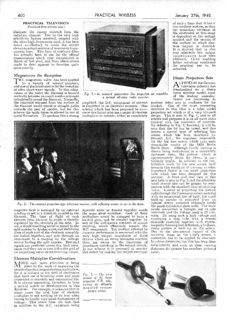
L____________________________
an amplifying valve in the receiving circuit, this defect by making the output electrode value.
Electron Multiplier Considerations . .. ... .. . ..... ............ ..
\ /jORE and more attention is being r IVI given to the work of improving the -. j
practicalapphcations of electron multipliers, for it is realised in the field of electronics
Fig. 3. The n e w ,
i. that their use is becoming more and more imnpoi tant in scientific anl commercial life It is always interesting, therefore, to keep
version of the home projection CR. tube,
.
. .
using an o ique L a carotid watch on developments in this opaque direction. }orexample,mtisknownthatm oso mied .
many cases the grid type of electron picture screen, . "c
iinsltiplier is not working at its best when ' .
having to liamlie very small fluctuations of __________________ - \. voltage. This arises from the fact that .
in addition to the AC. variations being . -
Fig. 2.-The compact projection type television receiver, with reflecting screen, in use in the home
magnetic field is arranged by an external winding to act in a direction parallel to the filaiiient. The time of flight of each election from filament to anode is thereby regulated by the strength of the field. In use, a dipole receiving aerial is joined to the split anodes by Lecher wires, and stabilising discs at each end of the electrode assembly are linked togethe-r, and pass through an impedance to a tapping on the voltage source feeding the split anodes. Rectified signals are produced across this load resis- tance and they are in turn fed to the grid of
separate units or housed together inside the same glass envelope. Each of these multipliers would be arranged to have a limited gain, and be coupled together by any of tise well-known methods of circuit coupling, which effectively remove the D.C. component. Yet another attempt to improve performance is concerned with the very high output impedance of these devices which on many occasions restricts their use ou inc to the limitation of impedance matching in the output circuit. In 011e scheine it is proposed to counter
opaque screen mounted obliquely inside the small cylindrical glass walls. The main anode connection is brought out to side terminals and the voltage used is 25 kilo- volts. By using such a high voltage and employing a long tube with a remote electrode assembly together with electro- magnetic focusing and deflection, a brilliant, sharp picture is built up ois time screen. Due to the non-normal impact of tise scanning heani on the tube's screen, a correction has to be applied to eliminate keystone distortion, but this lias been done satisfactorily and even at close viewing distances the picture lias excellent pictorial
of ultra-short-wave signals. In this adap- tation of the valve the filament is located centrally between two split anodes arranged cylindrically round tiLe filament. Normally,
r the electron released from the surliice of -r the filament would travel in straight paths
towards the pair of anodes, but for this
i4
r
scheme the route taken is altered to one of spiral formation. To produce this a strong
;
. standardised on a - cheap Fig. l-In outward appearance this projection set resembles home receiver model, some
a normal all-wave radio receiver, of the leading manufac- turers aie continuing to
amplified, tise D.C. component of current produce other sets iii readiness for the is amplified in an identical measure. One market. One of the snot interesting scheine which has been proposed to over- receivers in tins class is a table model come this factor is to use a series of electron projection set which is of a very compact multipliers in cascade, either as completely design. This is seen in Fig. 1, and to all
intents and purposes it is an all-wave radio -. receiver with the- inininluns of controls.
- -
By referring to Fig. 2, however, it will be - - seen that the lid can be raised, awl this
houses a special type of reflecting iena screen which has been developed by
- - - Fernseh _A.G., the company responsible
- ; '. l'or the big lens screen which gave such - remarkable results at the 1938 Berlin
- Radio Show. Although family viewing is shown being undertaken in a completely
- - darkened room, the pictnre, which is
-, -
-. approximately 2Oins. by ] 6ins., is par- - - - T ticularly bright. In addition to time cosi-
- . . - tribution made by tise new sci-ecn itself - , - -
- towards tins condition of viewing, acother . important factor is the small projection
- . .---- . tube u hieb lias been designed ter this -
purpose. A front and rear dew of this new tube is seen in Fig. 3 and the relatively
- - small overall size can be gauged by corn-
- -_ - - palison with the standard form of reeei\ing
-
-- valve. Instead of projectiig the picture - - right through the fluorescent screen naterial
- - with its consequent loss of light, time small - built-up picture is projected from an
i
400 PRACTICAL WIRELESS January 27th 1940
PRACTICAL TELEVISION of such a fornì that it has a (Co,mnued from preruus page ) non uniform surf ice so that
aj th secondary emission of dissipate the energ' rejected from the - -
A the electrodes at this stage radiation channel. Duc to the very high J is dependent on the voltage selectivity factors involved, coupled with the ultra-high frequencies used, it has been
I
applied and the section of
tourl(l satisfactory to make the circuit . the surface to which eIec
trou impact is directed. elements actual sections of concentric tians-
lines TIns foim filter It is claimed that in this
mission ot sidebmd I
°i- iiay ielatively Ion output his actually been in use loi the official impedances have been
transmissions which n ere inaugurated in I
.
I obtained thus enabling \lai ch of last ye ir and from obsei y itions
I better matching conditions made to dite appeirs to function quite
l --- I
foi practical use to be satms!rctonly
a achieved I
Magnetrons for Reception it ---
11h magnetron valve has been applied ----- IL
-. -- .
-
.
-
i Home Projection Sets
k I
to a aiiety of special purposes, .
. . ..
- LTHOUGH the German
and one of the latest uses is for the reception . . - television industry has
PDF compression, OCR, web optimization using a watermarked evaluation copy of CVISION PDFCompressorPDF compression, OCR, web optimization using a watermarked evaluation copy of CVISION PDFCompressor

grRi lead. BRAID
-. - - - J . - - -
tite form of mounting, etc., an! a suggestion is gicen in the sket.h. The dial is coupled direct to tite condenser vanes.
In order to eliminate possille slipping, it is best to tighten uit the condenser's integral reduction device slightly, and then if tite knob is rotated when tite vanes are all in (or out), it will only be the
brackets at tite points marked C. To keel) the insulating material rcasonabl dry for preventing leakage I used the two halves of a circular wool container, which cali be purchased at any cheap stores for Gd. A hole is made in the centre of each part, and also a slot iii each to fit over the brackets, as indicated in tite sketch. Collars. D,
additional driving head that slips. For tite sante reason, care must he taken if the pointer is used as a quick
band-setter," as suggested. -J. W. HonwooD (West.. Bergholt) PANEL
A Screetied. Input Jack BEING unable to obtain a
shielded jack for a mains- driven amplifier at short notice, 'a -
I hit on tite following dodge. I obtained an empty mUstar(l tin, of oval shape, about fin. TIN LID
deep. First, I drilled a bn. hole in the cenire of the lid (to GRID
LEAD take tuo neck of an ordinary single circuit jack), and titen I drilled another -itì. hole its tite bottom of tite tin for the output
An improvised screen for a - mains amplifier inpu! jac!'.
METALLISED SCREENING
PRACTICAL MOTORIST The owner-driver's journal which tells you how to repair, overhaul and obtain the best performance from your car.
3d.-Every Friday.
PRACTICAL MECHANICS The only English ournal of its type. lt deals with every branch of Science, Mechanics, invention, Model-making, Chemistry, Astronomy, Photography.
7d-Every month.
THE CYCLIST The leading weekly for every Cyclist, Clubman, Utility Cyclist or Tourist. Join "The Cyclist " Road Club and also take advantage of the FREE
insurance, - 3d.-Every Wednesday.
PRACTICAL ENGINEERING The new weekly journal for those engaged in all branches of the Engineer-
ing and kindred industries. 4d.-Every Thursday.
A simple mechanical bandsp read drive
sketch, a total reductire (in my case) of 72-1 was obtained. Tise pointer traversing
r the '' bandspread '' dial must he double ended, and by providing it vitii suitable projectors it can he uses! for more rapid
band-setting." This l)ointer is fastened to the usual place ois the siriving head, i.e., to the condenser through its integral reduction device.
Tise" band-set ''dial is home constructed, and is divided into a number of (livisions equal to the reduction rates of the condenser's integral device (in my case 8). The actual position of the dial depends on
The remainder of the grid lead between the screening box and the valve pin was covered with metallised braiding, soldered at one end lo the box, and eartlsed to chassis at tise other. This removed the last vestage of hum, and also has the meïit of cheai sness.-JAs. Tisis ELFALL (Blaekpool).
Preventing Aerial Lakage to Earth THE accompanying sketch shows a
dodge for niinimising aerial leakage to earth dise to lain, OF moisture accumulati ng during misty weather.
rfise vertical aerial, A, is ssipportcd by brackets, B, fixed to tise chimney stack. The aeriai rod is insulated from these
A novel dedge forpreventing aeria! leakage Io earth.
sealed with bitumen-L. BURTON (Sheffield).
Join Newnes' Practical Group !
-4'
A Bandspread Drive r
-
ar also fitte4 t:o support the i-eircula
BELOW, I give details of a very simple THAT DODGE OF YOURS! shields, the joints at these pÒint seing
mechanical bandspread drive whichEvery Reade. of "PRACTICAL WIRE- '
Idevised for use in my short-wave receiver. LESS" must haveoriginatedsomelittledodge The condenser which I had previously ifltere:t ,ther readers. W
used had an integral reduction device of 8-1, and by couplinc this to an additional
a'' best hini submitted, and for every other item published on this page we will pay half-a-
slow-motion driving head, as shown in the ?' that ide otoact thy - T&
-i. BaNDSET1DaL VISIBLE ,- I
f:IrI
" PRACTICAL WIRELESS," George Newnes, Ltd., Tower House, Southampton Street,
.' 114E w. V. t'.. 1,
Tb. »: Ijjjihj Strand. W.C.2. Put your name and address C0NTAI'E
on e ry item. Please note that every notion , /< s
TEBAL UMtis. -.'aJr sent in must be original. Mark enve1ope I be" - HEAOTIGUTENJ\
fl 1)lilJddri '. "Practical Hints." DO NOT enclose
DIAL OIRICT COUPLED" - ro COsV.ENSER
Queries with your hints.
S O II SLOT ,.-
SPECIAL NOTICE All hints must be accompanied by th4
$ coupon Cut from page iir of cover.
'i :1C
It was but a minute's work then to push - the jack through the lid (using it instead of one of the spacing washers) and screw it up tight to tue panel. I titen pushed the lead through the hole in tite bottons of the tin-
- u pushed the hox on to tise lid, and the jack was completely enclosed and screened. LEAO
Januáry 27th, 1940 _____________V PRACTICAC WIRELESS 40
i (" lPlract]rcdìlF 1hiitinïs
PDF compression, OCR, web optimization using a watermarked evaluation copy of CVISION PDFCompressorPDF compression, OCR, web optimization using a watermarked evaluation copy of CVISION PDFCompressor

Circuit Details The anode circuit of the valve is de-
coupled by the 25,000-ohm resistance and 8-mfd. condenser (see theoretical diagram Fig. 1), while bias is applied to tite valve by means of the self-bias resistance of 750 ohms coitnected in the cathode circuit. The bias resistance is shunted by the usual ô0-nifci. electrolytic smoothing condenser.
The optimuni load of the M.H.4 valve is 50,000 ohms, so a load resistance of this value is included in the anode-circuit.
'rile voltages developed across this load resistance are fed via a 0.5-mfd. coupling condenser to the primary of the parallel- feed transformer of ratio 1 :4, tile secondary of which is connected to the grid circuit of the i'.X.4 output valve.
This valve has a mutual conductance of 6.0 mA./volt, with an amplification factor of 5, and gives considerable power output with an anode voltage up to 300 volts.
The vahe is of the directly-heated type,
i M.H.4 valve, Osram 0 7 6 i P.X.4 valve, Osram - 0 9 6
1 17 0 POWER PACK 1 Westinghouse H.T.16
Metal Rectifier 0 13 0 I mains transformer, suit-
able for H.T.16, Varley E.P.37 ...... i 5 6
I smoothing choke, 2Ohy. l2OmA. 250 ohms, Var- ley DP51 0 12 0
1 4+4 mfd. paper con- denser block, Dobilier BE355 ...... 0 13 0
1 8 mfd surge- proof electrolytic condenser, Dubilier 0281, style A 0 4 0
1 900 ohm 10-watt power resistor, Bulgin A.R.1.K O I O
i 100,000 ohm 1-watt resistance, Dubilier F 0 0 3
1- 12 mfd SOy, electrolytic condenser,Dubilier30ió 0 1 6 -3 10 3
573 The above prices may be subject to some
slight increase in some instances due to war conditions.
of the rectifier by a voltage depending upon that produced across the resistance, i.e., on the total current flowing through the insistance and the value of the resistance.
If, therefore, we insert a 900-ohm self- bias resistance between H.T. negative of the rectifier and chassis, connect tite grid circuit of the output valve to the rectifier HT. negative terminai, and earth the centre-tap of the filament winding in the normal manner, we make the grid more n'gative than tile heater by the amount of- tile voltage developed across the resistance, and thus apply grid-bias to t-lie valve. rylle 900-oho resistance produces a voltage cl top of some 44 volts. which is the bias necessary for the P.XA valve with an anode voltage of 292 volts. The usual cathode by-pass condenset- may be connected across this resistance, but it is very itnpOrtant to note that it must be of the 50-v. working type and that- the positive terminal must he connected to the chassis,
Fig. i -Theoretical circuit diagram of the amplifier.
give a wealth of entertainment and good reproduction from gramophone records.
Further, by the addition of a simple leaky-grid detector unit, which may con- veniently be pie-tuned, the amplifier can he converted into a suitable three-valve receiver for the B.B.C. Home Service. As such, it lias already given a good account of itself in an isolated area.
The input to the receiver consists of a potentiometer volume-control feeding into the grid of a high-impedance triode valve of the M.H.4 class. 'the fèatures of high amplification factor. combined with high mutual conductance to he found in this class of valve, enable a high stage-gain to be obtained, and the P.X.4 output valve can be adequately loaded, by tramisfoimer coupling, without tite need for an inter- mediate L.F. stage. s
f LIST OF COMPONENTS FOR A SiMPLE QUALITY AMPLIFIER
AMPLIFIER £ s. d. £ sd, -
I 2 insulated terminais, Bui- gin type T,L., 0 0 7
1 250.000 ohm volume control and switch, Du' bilier type J 0 4 0
2 5-pin vssls-eholders, Bui- s gin VFi,48 ---- 0 1 0
125,000 ohm i-watt resist. -
since, Dubilier Fl - 0 0 3 150,000 ohm t-watt resist- s
ance, Dubilier Ft ,. 0 0 3 = 1 750 ohm t-watt resist.
since, Dubilier F 0 0 3 i 8 mfd, surge.proof dee- s
trolytic condenser, Du' s bilier 0281, style A 0 4 0
1 0.5 mfd. tubular con. - denser, Dubilier 4608/S 0 1 8
I parallel fed L-F. trans' - former, ratio i : 4, BuI- -
gin "Senator" ,, 0 6 6 $
o 1 50 mfd. 12 volt dry eire. trolytic condenser, Du-
I bilier 3016 0 1 6 -
Fig. 2.-Cicuit diagram of a suggested detector unit for use wir
gramme has resulted in a great deal of attention being paid to gramophone record ivproduction, and we describe here an amplifier which is very suitable for this clats of work. Its cost, including two valves, rectifier and mains transformer, is less than £5 lOs. It is very simple to build, uses only standard and inexpensive com- ponents, is economical in operation and, with a g*jod pick-up and loudspeaker, a ill
and bias is usually obtained by the insertion of a selt-bias resistance between the centre- tap of the filament transformer winding and the chassis, to wiP ch, of course, is connected H.T. negative of the rectifier. Tins biasing arrangement nieans a separate filament winding for the P.X.4 valve, and another for the M.H.4 (or any other preceding valves,
Constructional Details of c Intended for Reproduction-
as well of the indirectly-heated type). A common filament winding with the bias resistance in time centre-tap/chassis circuit is quite impracticable when indirectly heated, and chrectly-heated valves are fed irom a common filament wnding.
L
Grid-bias Arrangement To overcome the necessity of using a non-
standard mains transformer with ta o separate and independent filament windings, we have resorted to a rather unusual method of obtaining the grid-bias for time directly-heated output valve.
If a resistance is inserted between the HT. negative terminal of the rectifier and the earth-line (chassis) time curient Ilows from the rectifier through the smoothing circuit amid valves and back to the rectifier through the bias-resistance, and produces a voltage drop across it.
This means that time chassis (earth-hue) is muore positive timan the true HT, negative
\
F
402 PRACTICAL WIRELESS January 27thH940
OWEVER good the B.B.C. Home Service may be, it cannot please
i A S i m D e O u
PDF compression, OCR, web optimization using a watermarked evaluation copy of CVISION PDFCompressorPDF compression, OCR, web optimization using a watermarked evaluation copy of CVISION PDFCompressor

(the current of the P.X.4 and M.H.4. valves) 4 T NECE55ATh' O 5CPEEW ThIS WIS'
:. - - - - - '-----= ,_---_I-_ -
J The fact that the earth line, L or chassis, is positive iii respect
of the true HT. negative does not affect the bias applied to tite M.H.4 valve. This is an
h ¡he amp/ier. indirectly-heated va Ive and derives its bias front the
voltage drop across a resistance in the cathode circuit. 'l'be grid is taken to chas- sis and thus becomes more negative than the cathode by the amount of the voltage developed ac oss the resistance. The fact that tite chassis itself is mote positive than 1-1 T. negative does noit atìet the question of the gridbias applied to this valve at all, hut does result in a potential difference between the heater and cathode of the indirectly-heated valve by an amount ecpial to the voltage developed across the resistance in the H.T, negative lead. The insulation between t lie cathode and heater, however, is more than. sufficent to with- stand this, and there is no fear of breakdown in titis direction.
Tite HI'. power supply is obtained front I a Westinghouse metal rectifier type H.T.16
connected in the voltage-doubler circuit, with an AC. voltage input of 205 volts. Titis gires an Output of 310 volts at 52tuA
8
-. Md Px4 o
C 4+4mfd J e
8 ', 3 IOO,000Jl
0
E
0
G
GB
:°°°
e/ + 2m
o 5000012
MB 250000 05mJd
- F 2 O MH4
E
raLOs MB - so SLACK
f JOtNT TO FLEX O ot
- 5 4 -
- -
not exceed a value of 250,000 ohms with the l'.X.4 valve, and 100,000 ohms is a good value to use and quite effective.
it should be noted that the current of the i\l.H.4 valve also flous through the biasing resistance, but it is so low as lo make no appreciable difference to the bias voltage developed across the resistance. Actually, the bias developed is just under 4 per cent, higher than the correct bias for the P.X.-1 valve, but this does no liarni. Slight over-biasing is far preferable to
under-biasing. Should it be decided to run other valves from the sanie filament winding, it will be necessary to take into account their total
n current consumption and to alter the valueofthe biasing resistance accordingly. For example, suppose the total cousu i i ptiOn of the valve iii Ilse rose to 6OmA and that the resistance was kept - at a value of 900 ohms. It is
100.000.ci q nite a simple matter tocalculate I rom Ohm's Law thatthe voltage developed across the resistance would be 54 volts, and this would mean that the P.X.4 valve was greatly over-biased. Inthiscase,it wouldbe necessary
0001 to use a resistance Witi) a value
wo ol only 700 ohms to obtain a bias of 44 volts.
WIRING DIAGRAM OF THE AMPLIFIER
'\0 /205, ' I
L BLACK
4
E,. Ço°o)
AC G -
Ic i
- lull il
IEEE
a
/H4 ECeO
(0 0 0) ,iAres TRANSFORMER
\J i] [I
VCLL.OW MAINS
4 - -8LACK
- VOLUME CONTROL J, on the metal reclilier are the en,Ie J connections for the transfcrmr end plate. ii
i Useful Unit Especially f Gramophone Records
as the latter is more positive than H.T. negative (see dotted connections, Fig. 1).
A cheaper, and probably just as simple, means of smoothing the bias to the output valve is to decouple it by means of a resistance and 12-nìfd. electrolytic con- denser, as shown in the theoretical diagram. It is important that this resistance should
and is smoothed by a choke o 250 ohms D.C. resistance and an 8 mId, electrolytic condenser. The snioothed HT. voltage is just over 290 volts. Titis arrangement allows of the use of a 1)ernmnent-magnet type of loudspeaker.
Voltage Doubler Note that tite negative side of the
voltage-doubler condensers is taken to H.T. negative and not chassis.
The voltage-doubler condensers are of the
in use, input voltage and load current, should be specified.
For those vhio wish to urea mains- energised loudspeaker, the input to the rectifier may be increased to 240 volts, and there is a tapping on the mains transformer to allow of this. In this case, the lui- smoothed output of tite rectifier at 52nìA is some 390 volts, which, after being smoothed by a speaker field of 2,504) ohms 1).C. resistance, leaves a voltage of approxi- inalely 265 volts for the amplifier valves.
(Cohtinued on sex! page).
January_27th, 1940 PRACTICAL WIRELESS 403
SSSS SSeSSSSSeS ses eueS sSSS
. r paper type, .500 y. D.C. working. Actually, I
the voltage they have to withstand never
i i t y A m p Ii F i e r tizrers' approval, when the type of rectifier
PDF compression, OCR, web optimization using a watermarked evaluation copy of CVISION PDFCompressorPDF compression, OCR, web optimization using a watermarked evaluation copy of CVISION PDFCompressor
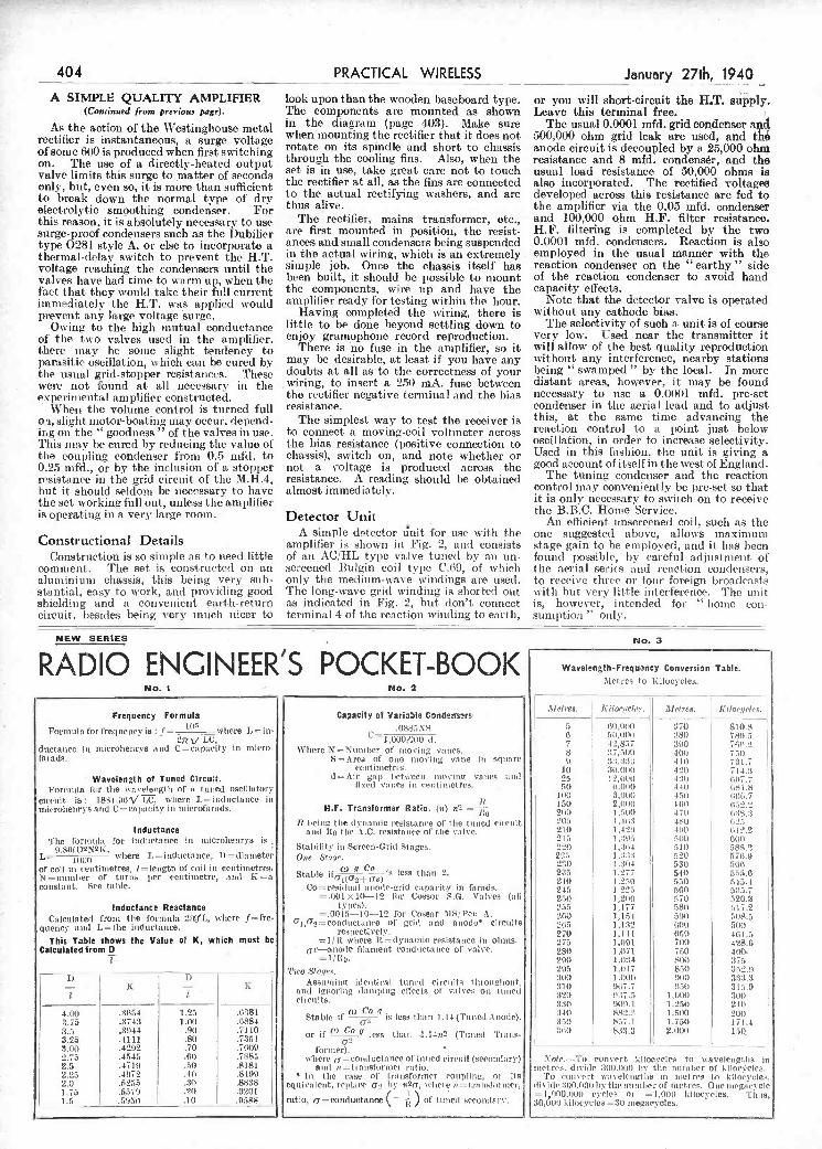
L.a
-
. A simple detector unit for use wit li the one suggested above, allows maximum Constructional Details amplifier is shown in Fig. 2, and consists stage gain to he employed, and it has been Construction is so simple as to need little of are AC/ilL typo valve tuned b an un- found possible, by careful adjustment of
comment. The set is constructed on an screened Bulgin coil type CliP, of which the aerial series and reaction condensers, aluminium chassis, this being very sub- only the medium-wave windings are used, to receive three or four foreign broadcasts sta.ntial, easy to work, and providing good The long-wave grid winding is shorted out vitle but very little interference. The unit shielding and a convenient earth-return as indicated in Fig. but don't connect is, however, intended foi' " home con- circuit. besides being very muele nicer to terminal 4 of the reaction winding to earth, suniption" only.
NEW SERIES Filo. 3
R ì ED I c E I\I 2I I\I E E R S PC K ET-B I( Wavelength-Frequìncy Conversian Table. Met res to Xilocycics.
NO.1 No.2
Frequency Formula
Formula for frequency is : f = _wttere L = in- Oyrv LU,
ductanec a microhenrys and C=ctpacity in nudo- I fnrads.
- Wavelength of Tuned Circuit. FOrutitla fc r the vavelesgt li of n tu Tied Oseille tory
circuit is: i88-t.I)CV iC, where L= iriductatice in microlìenrys it cd C = rit airiLy iii iitterofttrttds.
T Inductance The formula for itiducta flee tu microhenrve is
L=9S0itl where L =iuduetauee, I) =iliaitteter of coil in ceittittietree, I length of coil i ti centimetres, N icuotlier of turns icr ectitinsetre, and K a constant. See table.
Inductance Reactance Calculated from tice lorcicula 27rf 1., where f= frs'
quener a nil L = the i tiduetaitce.
This Table shows the Value of K, which must be Calculated from D
1) - i
K 1) - I. K
.n881 4.00 .1Cl-i 1.25 5.75 .37-lI 1_00 .6884 3.5 .11(44 .91) .7110 3.23 .4111 .50 .7311 3.00 .4292 .70 .7609 2.75 .4515 .6(1 .7885 2.5 .4711) .50 .8181 2.25 .41(72 .40 .84Cl) 2.0 .5285 .30 .88:S 1.75 .5571) .2(1 .0201 1.1 .5950 .10 .0588
Capacity of Variaule Condeesers .0885N8
C=10001110 d. W Itere N = 7a timber of noci ng eches.
S =Area of Otte moving cuite in square centimetres.
il =Air ga;t I,etsveetc ittovina vanes attil fi sed vii tes in cetiti nietres. -
ULF. Transformer Ratio. (n) it2 = R lieittO t Ite dvnatttic -esistarice of I tie totted ci relut
atìtl 10 lite AC. resistance of tIte vals-e.
Stability ill Screett-Orid Stages. Ocie .Stiiye.
Stable ifa2v> is leas than 2.
Co= resiclitul ticoi1egríd ra pat-jig' ¡n farads. = .001 X itt-12 for Cossor SG. Valves (all
types). =.0048-10-12 for Cossor SIS/Peic A.
7l,t7i =condlietalti-e of grid a nil aicode Circuits resitecti rely.
= 1/IL oliere Il. dyitanuic resista lire itt 01 tute. av-anuite ftltnielut rottdiuetaiiee of valve.
=1fil. Tuo SI sii,' a.
Assiiiitiic2 identical tunciil CirdilitS t lcroicdliont, and allori tug ilaitij ittg effects of cut Ives ori iii ceci circuits.
Sta hIe i f is less t lia t i .14 (Tutied A node).
or if (2_J' less than -1.14cc3 (Tuned fra i us'
fcttuuer). -
where =eon,l acts flee of tuned riretcit (secoittlary) 81111 n = tra ssft,rctcer rut Ito.
itt the ease of trattsforiner coupling, or its equi l'ut leitt, replace Oar icy na(T, unir re n = tua icsfori act-,
i
ratio, a =eortcluetsoee ( -) of t cctceil secondary.
licItes. .kilocyclen. 1Iu"tre8. Kiloecìelt's.
5 )i1l,0lll) 570 810.8 -6 5l(,l)t((l IS)) 7811.5 7 -si,857 590 761(2 8 :17,50V) 40(5 711) i) :1:1.1:13 41(1 731.7
10 30.0U0 42(1 714.3 25 t 1,0(11) 4311 f97.7 ISO (1.111(0 440 (iSI .8
1(10 3,ti((0 411) 516.7 150 2,(I(((l 160 152.5 21(1) 1 tillO 4711 11:15:1 505 I , lId:) 480 (idI 210 1,421) 400 (112.2 till 1:11(5 Still (lIlO Ill) 1:11(1 510 588.9 255 1 :14:1 520 57)1.9 2110 i :104 530 7,11(1
255 i 1177 540 24))
) .dll) 550 f154 245 1,255 SOI) 5:15.7 2rlI i 2)10 1,711 526.3 255 1,177 ftS(l 1ul7.'2 5>10 1,154 518) 508.5 5(15 1 .132 (10)) 50(1 270 i,l Il liti) 461.5 277a 1,001 700 498.6 281) 1 .1171 7>10 400- 200 1.03-t
- 800 37a 21)5 14)1 7 880 355.5 :100 1.11)1)1 lt(I) 3:13.3 310 9)17.7 115(1 115.9 320 11:17.5 1)111)) 500 3:10 1)1(11.1 1 .25)1 240 :140 885.3 1.5(10 20)1 :1111 857.1 1,750 171.4 lInt) 831.3 2,1)1)1) 150,
o convert kilocyelen to wavelengt.tte in itlet res. di ville 3003581 1v tice itic slicer of h i beteles.
To c'oiu vert wut veleligtIcs ill ti et res to hi IoeeIes. iliii>li' 11)0,60)) Ici' tite cl)ItiI,er of litetres. Otte rluegu)c'\-cte = I 01)0)10)1 cycles or = I,t))5 kilocycles. mils, 30,000 kiloeyeles=30 taegacycles.
1-
As the action 'of the Westinghouse metal rectifier is instantaneous, a surge voltage of some 600 is produced when first switching on. The use of a directly-heated output valve limits this surge to matter of seconds only, but, even so, it is more than sufficient to break down the normal type of dry electrolytic smoothing condenser. For this reason, it is absolutely necessary to usc surge-proof condensers such as the Dubilier type 0281 style A. or else to incorporate a thermal-delay switch to prevent the HT. voltage reaching the condensers until the valves have had time to warm up, when the fact that they would take their full current immediately the HT. was applied would prevent any large voltage surge.
Owing to the high mutual conductance of the two valves used in the amplilier. there may he sonic slight tendency to parasitic oscillation, which eau be cured by the usual gril-stopper resistances. These were not found at all necessary in the experimental amplifier constructed.
When the volume control is turned full oi, slight motor-boating may occur, depend- ing on the "goodness" of the valves in use. This may be cured by reducing the value of the coupling condenser from 0.5 mfch to 0.25 mfd., or by the inclusion of a stopper resistance in the grid circuit of the M.H.4, but it should seldom be necessary to have the set working full out, unless the amplifier is operating in a very large room.
in the diagram (page 403). Make sure when mounting the rectifier that it does not rotate on its spindle and short to chassis through the cooling fins. Also, when the set is in use, take great care not to touch the rectifier at ali, as the fins are connected to the actual rectifying washers, and are thus alive.
- The rectifier, mains trañsformer, etc., are first mounted in position, the resist- ances and small condensers being suspended in the actual wiring, which is an extremely simple job. Once the chassis itself has been built, it should be possible to mount the components, wire up and have the amplilierready for testing within the hour.
Having completdll the wiring, there is little to be done beyond settling down to enjoy gramophone record reproduction.
There is no fuse in the amplifier, so it may be desirable, at least if you have any doubts at all as to the correctness of your wiring, to insert a 250 mA. fuse between the rectifier negative terminal and the bias resistance.
The simplest way to test the receiver is to connect a moving-coil voltmeter across the bias resistance (positive connection to chassis), switch oui, and note whether or not a voltage is produced across the resistance. A reading should be obtained almost immediately.
Detector Unit
The usual 0.0001 mfd. grid condenser and 500000 ohm grid leak are used, and the anode circuit is decoupled by a 25,000 ohm resistance and 8 mfd. condenser, and the usual load resistance of 50,000 ohms is also incorporated. The rectified voltages developed across this resistance are fed to the amplifier via the 0.05 mfd. condenser and 100,000 ohm H.P.- filter resistance. H.P. filtering is completed by the two 0.0001 mfd. condensers. Reaction is also employed in the usual manner with the reaction condenser on the "earthy" side of the reaction condenser to avoid hand capacity effects.
Note that the detector valve is operated without any cathode bias.
The selectivity of such a unit is of course very low. Used -near the transmitter it will allow of the best quality reproduction without any interference, nearby stations being "swamped" by the local. In more distant areas, however, it may be found necessary to use a 00001 mfd. pre-set condenser in the aerial lead and to adjust this, at the same time advancing the reaction control to a 1)Oint just below oscillation, in order to increase selectivity. Used in this fashion, the unit is giving a good account of itself in the west of England.
The tuning condenser and the reaction control may conveniently be I)re-set so that it is only necessary to switch on to receive the B.B.C. Home Service.
An efficient unscreened coil. such as the
404 PRACTICAL WIRELESS January 27th, 1940
A SIMPLE QUALITY AMPLIFIER look upon than the wooden baseboard type, or you *ill short-circuit the H.T. sip1y. (Continued from prerious page). The components are mounted as shown Leave this terminal free.
PDF compression, OCR, web optimization using a watermarked evaluation copy of CVISION PDFCompressorPDF compression, OCR, web optimization using a watermarked evaluation copy of CVISION PDFCompressor
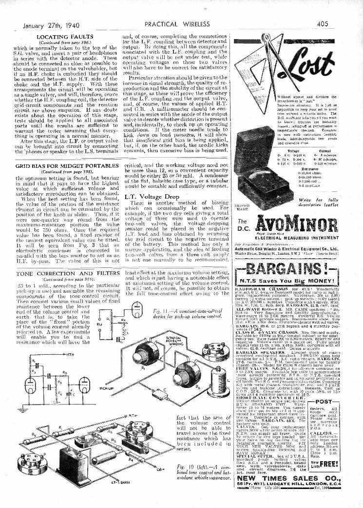
-
position of the knob or slider. Thus, if it ivere onequarter way round from the niaxiniuni-resistance position the value would he 750 ohms. Once the required value has been found, a fixed resistor of the nearest equivalent value can be fitted. lt will be seen from Fig. 3 that an electrolytic condenser is connected in paralle1 with the bias resistor to act as an H.F. by-pass. Tite vaine of this is not
example, if the two dry cells giving a total voltage of three were used to operate two-volt valves, the voltage-dropping resistor could be placed in the negative LT. lead and bias obtained by returning the grid circuit to the negative terminal of the battery. This method has only a narrow application, and the idea of feeding two-volt valves from n three-volt supply is not one normally to be recommended.
TONE CORRECTION AND FILTERS least effect at the maximum volume setting, (continued from page 395). and which is just having a noticeable effect
to i mfd., according to tue partictilar at mitimmnuni setting of the volume control. .25 pick-up iii usc) and assemble the remaining It will not, of course, be possible to obtain components of the tone-control circuit, the full tone-control effect owing to the Then connect various small values of fixed resistance between tire lower end of the volume control and - - Fig. Il -A conslant_tonc_coutrol earth-that is, to take the device for pick-up volume control. place of the fixed" portion of the volume control already referred to. A few experiments
Î will enable you to find a resistance which will have the
!!iIi 17+
. fact that the arm of tIse volume control will not be able to travel across the fixed resistance which has Ro been included in
Fig. 10 (left).-A com- bined ione control and stmle t- erodqne whistle suppressor,
-
LT- EARTH
The AvobüNo D.C. -Qera r,a',si.,,s
ELECTRICAL MEASURING INSTR(JMENT
Sote Proprietors ,t Zlfoonfoe Surer s .- -
'Automatic Coil Winder & Electrical Eqsipmnent Co., Ltd., Winter Hour,, Douglas Si. , London, SW.i. 'P1.o-s - iirtorto 340-1/7
BAPGANS !- N.T.S Saves You Big MONEY!
IIAIIHOGRAM CIIASSSS for 6116 ! Wonderfully efficient SG. 4-valve Bandpass modei for rafflo or radio- gram replacement purpooes. Waverange. 200 to 2.0011 metres 3 watts Output pick-up sockets fully tested for A C. 2001240 V- supplies. Complete with 4 valves. size 12m. w.. 71/n, h.. 9/in. deep. IIARGAIN. 61/6, carr. paid .'.LL-'V'.VE Iiati,'ry 3. MR. CAMM confirms : Se- lectivo. Very Sensitive and Quality Reproduction." Wave-range 14 to 2.000 metres. Powerful SG, 3-valve Circuit vith pentode output. Station-name scale. Size 12m. x 81m. X 9m. deep. Complete chassis with ali valves, IIAR(;Ape. 69/6. or 1716 deposit and 4 monthly pay- mento of 14/3. Ci.AsS Il. 4-VALVE CIIIASSIS .,. New limited supply. Suitable for fitting in Your present cabinet or for emer- gency use. Wave-range 200 to 2,000 metres. Seiective and sensitive, Volume equal to a mains set, Fully tested chassis (sine Ulm. X Sin. X 81m. high). complete with all valves. 61/6. carriage paid. Terms available, IIARGAIN SPE.'tKIIRS. Limited stock of n'ains energised moving-coil speakers, 2.000/2.500 ohms field suitable for all Nr.5, AC. rad/o chassis, IIARGAIN, 17/6. carriage. 1/-. P.M. moving-coil type for battery
I chassis. 25-. Model for Class B chassis same price. I FREE VALVES. S,G.3kit for all-wave operation on I
9 to 2.000 metres, Available less coils to accommodate I
those already possessing fiTS. or N.T.S. one-shot typeo. Sinople to assemble and an amazing performer cn all bando, Two S.C. and Pentode Output stages, Complete Kit with metal chassis. transformer. etc.. and 3 FREE
I vr,lees and building instructions, Ilargain, Cash or I COD,. 32/6. Complete kit svith 10 coils, 59/6, or 15/- I down ansi 4 monthly paymenls of 12/ii. I SIIORT.WA%E C O N % E II T E It I
Unique Chance tO secure well-known I B.T.S. ADABAND UNIT. Wave- I
range 13 to 74 metres, You merely OrOCi's. All I stami your set on top and it /s con- b goods sent b
J
verted for important short-wave lis I carriage paid. I telling. Complete in cabinet, with Please regio-
h two valves. IOAItGAJN, 49/8. FOr ' ter curreucy I battery sets only, a n d C r o s s I YAI,S'ES. Get your replacement pos I valves NOW while prices remain low.'
, I
I N.T.S. can supply all types. Quote I
CALLERS. - I
by return for any type needed, Set All lines avail- I your name on our mailing list for i able from our
catalogue available shortly. FIT I only London i
I YOUE NEW VALVES NOW and address. Hours ensure trouble-tree listening and i to 6 p.m. SAVE MONEY I Clase 1 pin. I
I SPECS -tL OFFER. Set of 3 U.S.A. I Sats. I
standard 2-volt battery valves I I (two S.G,s and a Pentodo), brandi New FDC! i
ness, wit h valveliolilers, data I Lists b
I and 'ircuit diagranis, 7/6 tite I______________________ lot, post s'ree.
I NEW TIMES SALES CO., 56(Pr. W17), LUDGATE HILL, LONDON, E.C.4
'P1mone: City 5516 -Est. 1924
- "i
'e
i
January 27th, 1940 PRACTICAL WIRELESS
LOCATING FAULTS (Continued from page 396.)
which is normally taken to the top of the SG. valve, and insert a pair of headphones in series with the detector anode, These should be connected as close as possible to the anode terminal on the valveholder, but if an H.P. choke is embodied they should be connected between the HT. side of the choke and the HT, supply. With these arrangements the circuit will he operating as a single valver, and will, therefore, PI'OVe whether the HF. coupling coil, the detector grid-circuit components and the reaction Circuit are above suspicion. If any doubt exists about the operation oí this stage, tests should be applied to all associated parts until the results are sufficient to warrant the tester assuming that every- thing is operating in a normal manner.
After this stage, the L.F. or output valve c;in he brought into circuit by connecting tite 'pitones or speaker to tite L.S. terminals
GRID BIlAS FOR MIDGET PORTABLES (Continued from page 398).
the optimum setting is found, but bearing in mind that it pays to have the highest value at which sufficient volume and satisfactory reproduction can be obtained.
When the best setting has been found, the value of the portion of the resistance element in circuit can be estimated by tite
and, of course, completing the connections for the L.F. coupling between detector and output. By doing this, all tite components associated with the L.F. coupling and tite output valve will be put under test, while operating voltages on these two valves will also have to be correct for satisfactory results.
Particular' attention should be given .to the increase in signal strength, the quality of re- production and tite stability of the circuit at titis stage, as these will prove tite efficiency of the L.F. coupling arid the output valve, arid, of course, the values of applied H.T. and GB. A milliammeter should be coil- nectecl in series with tite anode of the output valve to denote whether distortion is present arid, incidentally, to check np on operating conditions. If the meter needle tends to kick down on loud passages, it wili show that itisufficieni grid bias is being applied, but, if, on the other hand, the needle kicks upwards, titen excessive bias is being used.
critical, and the )vorking voltage need not be more than i2, so a convenient capacity would be either 25 or 50 nifd. A condenser of the flat., bakelite-case type, or a tubular would be suitable and sufficiently contpact.
L.T. Voltage Drop There is another method of biasing
witichi cari occasionally be used. For
405
's
ro and dividers the s " toot." tation. it is just as keep your set in good a reliable meter. Tue
D.C. Avolijoor tell, you alt you want to know; troubles ace instantly traced; fatling-oft in perlorniance io
ims9ediatety cbeeked. Coaoptete in oase with iootroetjoa booklet, teads, interchangeable test prods and crocodile clip,.
Voltage Current 0. 6 s-. 0-240 V. 0' .6 mamps. 0- 12 e. i-300 e. 0- 30 mai01,., 0-no V. 0.000v. 0-t'20 selomr,e.
y, ..i;:: os ,,
Resistance 0-iO,000 ohms.
"0
rf2..
0-60.000 ebro,. 0.t,20,0c0 o_3
.0 BRITI',II
MADE
Wrste for íuiiy deocriptive leaflet
o.
.4
PDF compression, OCR, web optimization using a watermarked evaluation copy of CVISION PDFCompressorPDF compression, OCR, web optimization using a watermarked evaluation copy of CVISION PDFCompressor

that. the directio'n in which it should be turned for a known setting Is not im- All obtn&ble from or throub Newaget or from Geo. fewer, Ltd.. Fower House, Southamptou St.. Straol. WC. 2 -
mediately obvions. A large (liai could be
band-spread device. 'Fuis is not simple, but there are many interesting schemes which can be tried using either the special gear wheels. worni drives and similar ¿tems from the well-known constructional toy, or by pulleys and cords. The latter-must, however, be so arranged that there is_no slip which will result in different settings of the driven member for given dial indica-
t tions. It might be possible to arrange two
L windows through winch the dial markings show, so that the decimal figure could be
L given its correct relation to the main dial settings, although an obscured dial, that is, one which only shows its individpal setting. is not dea,l owing to the fact
By F. J. CAMM.
PRACTICAL WIRELESS ENCYCLOPIEDIA 6/., by post 6/6.
EVERYMAN'S WIRELESS BOOK 5/-, by post 5/6.
TELEVISION and SHORTWAVE HANDBOOK 5/-, by post 5/6.
SIXTY TESTED WIRELESS CIRCUITS 2/6, by post 2/lo. WIRELESS COILS, CHOKES and TRANSFORMERS and
HOW TO MAKE THEM 2/6, by post 2/lo. PRACTICAL WjRELESS SERVICE MANUAL 5/-, by post 5/6.
WORKSHOP CALCULATIONS. TABLES & FORMULIE 3/6, by post, 3/10.
PRACTICAL MECHANICS HANDBOOK 6/., by post 6/6.
simply because they are not capable of being smoothly adjusted by very small steps. Here then is one field for construc- tional work, but whilst experimenting with drives it would be a good plan to endeavour to incorpora5e in the drive a hand-spreading device. This should be of such a type that. it is not only adjustable separately but that, it interlocks wit h the main drive. That is, supposing for instance that the band-spread ing device gives 10 degrees hand-spread movement for each degree of the main dial, it should also be so arranged that the setting for, say, O.9 degrees can alu ays be repeated by exactly the saine settings of both the main and the
good photographic dealer's ot scientific instrument stores, and the box could be built up with sheet metal. It must be rigid and well screened, and the movement must be really smooth.
As an alternative, especially where only one coil is needed on each band, as in the simpler type of receiver, the coils to give tite required coverage could be mounted on a rotating disc, arranged either lion-
of this type available for the purpose, they may be taken fm-orn a 4-volt winding which delivers current to sparc after supplying one or more of time valves in the receiver.
Obviously every idea has not been included in this article, bitt there should be sorne grounds for )roviding the mechanic wit,!ì ideas which vil I help hito to pass away the time during these dark nights.
A' COMPLETE LIBRARY OF STANDARD WORKS
wer srIop equipment tnere are nianv ingenious aod interesting ideas which may be tried out or built up, and the follow- ing details will give some ideas for those who may not yet have delved into this branch of rad io construction.
Condenser Drives Tise modern receiver is inconìpletc
without a really good slow-motion drive, and en short waves this drive must have not sinlv a really good slow-motion action but must also be easy to handle. Many good components in this connection aro rendered unsuitable for short-wave work
hand in a die-cast aluminium box occupy- ing iieat'ly half the underside of the chassis. The connections for each set of coils are brought out to wiping contacts and the entire box is carried across the chassis, from one side to another, through a worm drive or rack and pinion movement. Definite stops are provided when each set of coils is brought into circuit, and a l)ointer on the panl indicates the band to which the set is tunable. This is a remarkably fine movement and very accu- rate and reliable in use, but is not difficult to copy with suitable workshop appliances. Rack and pinion may be obtained at any
although the depressed button wil I indicate the station. It cannot, however, be seen from across a room, and with the amai I
illuminated windows, any doubt as to which station is being heard may he chis- peiled at a glance, even across a fair-sized room, if the window idea is incos-porated. Obviously with these (hal-light ideas, some care is necessary in a mains receiver of the AC. type, to avoid hum due to the number of leads whicis may be used and which will nu doubt carry the raw AC. supply for the lights. They will, of course, be run from a 4-volt winding on t lie trans- former, and if there is not a spare winding
THERE are two main types of list ener- those who are mainly interested in the stations they can receive and the
logs they can compile, and those who are more concerned with the construction and operation of the receiver. Among the lattei there are many who are not only interested in the mechanics of the appara- tus but who are also very good workmen, in many cases with quite elaborate work. shops. This is borne out by the many ingenious suggestions which have been sent in from time to time for inclusion in our Junta page. The ordinary standard broadcast receiver (for medium and long- wave reception only) does not, how-ever, lend itself so well to mechanical ideas as the short-wave receiver, and it is in this class, therefore, that the highest ingenuity is shown. For those who have suitable
By W J. DELANEY
perforated so that the band-spread setting is viewed through it, or dual pointer devices are more reliable, hut there is endless scope here for experimental work.
Coil Switching A good sham-f-wave set utilises separate
small coils for narrow bandwidths, and this simplifies tuning. Unfortunately, this generally means coil changing, and many sets are restricted to only two short-wave bands, these being rather too wide for comfortable Joug-distance woi-ki ng. Pl eg- ging-in individual coils is tedious but the most satisfactory scheme for the real short-wave fan, and therefore some form of coi 1-changing mechanism is a good line for experiment. One well-known Amnerictin communications receiver has the coils arranged in sets of three for each wave-
Signal Lights Many constructors have already in-
corporated (liai lights of the two-colour type which indicate vlieii the set is switched to long or medium waves, amid this idea may be incorporated in the above wave- band switching devices, only instead of coloured lights, sinai I windows with indica- tions showing the band covered could be fitted and the lights behind the windows brought imito circuit with the coils, thus showing instantly to what range the set is adjusted.
The well-known Science Museum receiver is built for two stations only, and lias two windows-National and Regional. These arc illuminated as the set is adjusted and this idea may be extended upon in a modern home-built set to indicate any station to which the set tunes, in place of a tuning dial - This is ideal for operating in coli- junction with a push-button mechanism,
406 PRACTICAL WIRELESS
ORTWAVE SECT ION
SHORT-WAVE MECHANICS Suggestions of Things to Make for the Mechanically - minded Short
wave Enthusiast
January 27th, 1940
zontallv or vertically, and again wiping contacts can be arranged round the peri- phery. When concerned with coil-switch- ing, howeer, a perfectly firm contact must be obtained when the coils are in circuit, as failure to do this will result in noisy working and perhaps in signal losses.
To avoid noises when the coils are chang- ing from one band to another, a switeh could be operated thr&ngh the coil-chang- ing mechanism to break the H.T. negative lead and thus tender the set '' dead between band setting.
PDF compression, OCR, web optimization using a watermarked evaluation copy of CVISION PDFCompressorPDF compression, OCR, web optimization using a watermarked evaluation copy of CVISION PDFCompressor

____________ --'-- -
also 37 states ol' the U.S.A. My best DX includes
CE3AT, 3CG, 4AC; CXI, CX8; CO2JJ, 2J1', 2RR; CT2BP; CXÌAG, 2CO3 2TN, 3CJ, FA, liC; HH2HB; li13N; HK1AG, 2CC, 3Cl, 3CO3 4TF; J2BC; KA1FH, 3KK; K4, K5AM, K6OQE, NYV; LU3, LU4, LU5, LU7, LU8; PK4KS, PY1, PY2, PY3, PY4, PY5, PY7AR, PY9AE; SU, TI2RC, TG9BA; VE!, VE2. VE3, VE4, VESEK, VK, VO!, V02, VP1WB, VP2, VP3CO. VP5TZ, 5VN. VPO, VP7NS, VP9L. OR; VQ2CM; VS7RA; VU2F'A, \V (all districts), YV1, YV5ÂBF, 5AK; ZB1, ZB2; ZC6HS.
I should also like to get in touch t ith any reader of this paper who has got a call-book to dispose of.
In closing, I wish your veryinteresting paper every success.-LE0NAitD F. CROSBY, 7, Fleetwood House, East Hill Estate, Wandsworth, S.W.18.
Back Number Wanted
SIR,-As it is impossible to buy the coil
ready made for the 150-mile crystal set, I shall he glad if any reader would
SSHTHE1IS wanted a super-capacity HT.
battery (60 volts) for his receiver, lint owing to battery shortage could not cl tain one. The nearest lie coutil get was a low -priced salait capacity battery, and lie eventually i decided to act this. Knowing that the ca liacit r. was dependent Ill on the size of the cells, lie decided to go to the troulle of i
i connecting all the cella in parallel in his battery i
in oider to. increase the capacity, and he accordingly did this. \Vlien lie connected it to his set, however, he failed to obtain aey signals. Where liad he gone wrong 'Three i books will lie awarded for the first three correct ¿
solutions opened. Entries mort be addressed to 'l'lie Editor PRACTICAL \VInELESS, George New neo, Ltd., Toner Hone, Southampton Street, Strand, London, W.C,2. Ens elopes mast he niarked l'rotilein Ho. 384 iii the top
i left-hand corner a ad must be posted to reach tins ollice siot later titas the liest lost on
i Ilonday, January lOtIt, 1940.
Solution to Problem No. 383. AttCtlis overlooked tIte fact that a short-wave
converter can only be used with a ceceO er eniploying 13.1". amplification, asid his set was a detector-S LI". cosnlinat ion.
The following three readers successfnlly solved ProlIclil No. 382, rod books have accordingly been tkcwirdeij to theni B. Young, Braay," Oetways Lane, Achtend, Surrey. J. W. leiter, 57, Eleniore Lasser Easington Lane,
Hetton-le-Hole, (io. Dnrham. F. W. York. 177. 'l'Isirinsere Avenue, Tilehurst, Berla.
meter Cor servire on AC. or D.C. lobs. No piojecting terminals. THREE sanees of Colts 0-7.1. 0-150, 5-300. In black Paketite case. IOn. by 2lìn. with pair of test leads und plugs. Leaflet
N " gives lull information. 196.
l ETEICS.-New, Fer- ranti. Somethinc sim-
3.9 SET MILI.lAlbl-
pie without calibration
PANJ':L METERS-Moving coil, 5,
t'or tuning or calvo for testtng. Back of panel type, as illus.,
fi ma, full scale. Bargain at 39 peat free.
Oie, 25. 50, 500 ma., in various sizes, from 21m, to lin, dia. Switchboard Meters, 3 to Sin, dial, all ranges. SILVER- TOWN Portable Tester. Combines
" Wheatstone Bridge. Galvo shunts and rAtios, as new. 125. G.P.O. Plug-in
Bridge Resistance Boxes. to 5.000 Ohms, 60/-. New war-time Sale List N" 2d. Stamps
KEEP YOUR BATTERY RE,DY. R%TTE1SY CIIARIIiING ON A.C. MAINS WIT!!
6/8 volts fi amp.. 15/-. olOdel '/R6. 1e0i250 volta to D.C. 6/8 volts 1 amp.. 25/-. l,,,lel N/CO. 100/250 volts to D C., 6/fi volts 4 amps , 350. Io(leI N/PlO, 1001200 volts to 12 volts 1 amp.. 32/-. Ditto 12 volta 2 amps with 8-volt tap 55/-. 5 amp.. £31101-.
5/- EMERGENCY PARCELS of useful Experimental electrical and radio repais' matertal and apparatua. 7lbo. for 5/-. Post Free.
ELECTRADIX RADIOS 218, Upper Thames Street, London, E.C.4.
Cetslral 461i
-1
i4
:1
wavebands (medium and long) this would allow many short-wave enthusiasts to incorporate their own short-wave attach- inent.
(3) Prov'sion for 'phone reception after fourth valve (D) to allow of long- di tance reception, thus, the set would be suitable for entertainment purposes, and also urovide an added attraction for the "logger'' and long-distance receptionist. -R. RAIL (Birmingham).
Exchanging S.W.L. Cards: A DX Log
SIR,-I would like to exchange my S.W.L. card with any S.W.L., A.A.,
or full-ticket ham anywhere on the globe. I have been an S.W.L. foi just over two years and have heard 67 countries on 14 inc/s. the receiver used is a home constructed O-v-2 run off a mains eliminator, and used in con)imetion with a 3Oft. indoor aerial running N.W.-S.E.
All continents have been received,
during that time have logged 2,500 hams in all continents. Severity countries have been heard on 20m. 'phone. The RX is a home-constructed O-v-2 using batteries, and my aerial a doublet running N-S.
I have been QRT since October. DX heard during October includes 170 W's (in all districts and 39 states), BI, YV, LU, l'y, KA, ER, CE, ZS, TF, CP-all on 20 ni. 'phone.
I should like to exchange my S.W.L. card with anyone (S.W.L.s, A.A. or hams), and will QSL the saine day as I receive their eard.-D. BOOTMAN (65, Eagle Road, \Veonbley, Middlesex).
PROBLEM No. 384.
set. 10/6. Ex-Army Buzzer Transmitter, with fine key and brass cased quick adjustmest power Buzzer on mahogany base, by Siemens and A.T.M. Co., 17/6. MORSE KEYS. First-class at low prices.
A good small key on mouliled base
is the TX pivot arno, excellent for
learners. 3/6. Full size, well finished lucy, all brass, solid pivot bar, adjustable tension. etc.. B.2, 7/6. Superior Type EF.. tully adjust- able, nickel finish, 0/6. High
Grade Type IV, plated fittings, polished wood base, a fine key, 10/6. Special Key on 3-switch box lcr buzzer and 2 lampa, CAy., 616. RUZZERS, small type, with cover, 1/6. Power llU,.cer'S, with screw contact and adjustable spring armature, 2/6. Ileact iluzze,' in Bakelite case, 3/6. Magneto Exploders, 25/-. Portable Field Telegraph Sets. Details on request. Cheap Morse Practice sets available. CAMP LAIn'S. Portable Accumulator Band Lamps are independent of dry cells. Miners' type. 2 volts. SIGNAL LAMPS by Lucas sod Aldis. l'or night and day use, telescope sights, key and discs for tripod or hand use, lieliographs Mark V. with space misrocs in leather case, with mahogany tripod, MORSE RECORDING, G.P.O. type inliers, on mahog- any base ivith tepe reel under, in first-class order, £6. Lightweight French Army Field Morse Inluers, fold -up into wood case, £7110!-. Super Model Army G.P.O. Field HO. Morse mIcer, brand new, entirely enclosed and ntted every refinement, current indicator. hey, tape, container, etc., £8. Mahogany Tape Container, G.P.O. desk top with brass reel in drawer, cost 40/-, for 3/6 only. Morse Paper Reel, 5ml. Home Recorders, Acoustic, 5/6. 10/6, 15/-. Feigh Electric. 37/8, Flexible track discs, 1/-. t.C.-Dí'. DIX-MIPANTA VEST POCKET TESTER. A versatile moving-iron mulG -range ;51
f,ì F .i° a
Our New Year's Set STR,-With i'eferenee to the request on
page 319, December 30th, 1939, Issue, regarding "New Year's Set."
May J humbly suggest that many of your readers would be very interested in a receiver of the type as described on page 254, December 9th, issue. This seems to be substantiated by Mr. W. Burton, in Ins letter on page 329 of the saine issue.
I would suggest (i) That the L.F. portion of the set be made optional (i.e., a switching device for cutting out saine when not required). Thousands of listeners live within "good volume range" of the "home" programme, and, generally speak- ing, L.F. in such a receiver would be a st aste of current, except when required for
distant'' reception. (2) Wavelength range should be optional,
i.e., specification of compOnents to include two waveband coils, or (and) three wave- bands.
If receiver only designed for two
loan me a copy of Amateur Wireless, dated October 27th, 1934, as this issue is out of print ; it explains the making of the coil and set in question -A. H. BARKER, 5, Rosebank, Main Road, Upper Doser- court, Essex. Correspondent Wanted SIR,-Thanks for my B.L.D.L.C. card.
Recently I have taken considerable interest in corresponding with SJW enthusi- asts, but as yet I have only two pen-pals to correspond with, and I should be very pleased to correspond with anyone inter- ested. I have been a reader of PRAcTICAL WIRELESS for nearly four years. I have made the Rapid Two and am very pleased with the results:-F. C. HART (18, Debden Road, Saffron Walden, Essex). Exchanging S.W.L. Cards
SIR,-I am a reader of your fine maga- zine, and always like to see lists of
"calls heard" logged by other S.W.L's. I have been an S.W.L. for two years, and
made HT. Battery Superseders. Bargain price. 10/-. CABINET ANI) COMPONENTS l'OR-
1'.W. 301 'fIRER. - - - Ti..' - Tudor Oak cabinet 131m. - - - by 710. by 7m. Fitted
- - .0005 Slow MOt0n Con- -- denser, dial window. ver-
nier microdenser, 3-way switch, cha00is. valve- -.' holders, wiring. cUps, --' three flaed condensers and 10-terminal panel strip, 12/6.
Cempleleas detailed, ONLY 10/- lo callers. or 12/6 Posi and l'urtino Free.
CRYSTAL SETS, plug-in coils, 2 tuning Condensera, semi-germ, detector, 7/6. Boudoir enclosed type, simple to use. 6/6. One for your A.R.P, shelter. SI(.NAL l.QLIPMENT.-Keys. Pr.ones. Buzzers, Lucas- Aldis Lamps, Heliographs, Morse Inkers. Relays. etc.
FOR ARMY & NAVI %%ORK SEI{%ICETYPESIGN,.LLEIiS
f. .... DOUBLE IIEADI'IIONES, with P '', - flat leather headbands for steel
- . helmet wear, 120 ohmo. by ST. -- -'L, ' Co., 316. 41t. cords, 6e. Single - - 60 ohm, phones with cord DlII,
' - 116. FIELD Telephone Ex- . changes, 5-line and 20-line port-
able. Twin and Single Cable. UIIADI'UONE CORL)S. Seivice
5 'l - 6ft. fitted 2-pin plugs and 2-bole , - ,,/. socket, 2-.7,IOItSE Pli AC-
is .'-'-v . TICE SET Righ Grade Model for Buzzer and Light Signals of Army and Navy, Walnut Cabinet
Pitos sowarrEeg fitted WO, turret br5ss swivel alEaD reuNes lamp, revoiv'ng cap. 4 sizeo of ji light aperture, With Osram
2-voit tube bulb and spare, Morle Key and 2-way switch. Adiustable 2-coil Buzzer inside, with battery Clips. etc. A superior and useful
January 27th, 1940
- ---
PRACTICAL WIRELESS 407
Upen tc Viicuiiio'n The Editor does flot necessa iJy ag ee ssuh the opinions xv ess d by his correspondeflts. All letters must be accompanied by the name and address
of the sender (flot necessarily for publication).
ELECTRADIX BARGAINS lliRATOR BATTERY ',\ e- .
SUPERSEDER, with metal for HT. No need
,etikiLthL5'. 5 - Hi rectifier,
for HT. Battery 3 Output volt tap inge. Reduced fioul £315I- to sale pitee, SUPEREDER 351-. .
Large Vibrator Set Model EJ. SiS for 5-valve sets. 65!-. VIRHATORS only. with double tungsten contacts, enclosed in rubber lined metal case, See P. and A. W. last July. American 4-ein model for makers 01 home-
PDF compression, OCR, web optimization using a watermarked evaluation copy of CVISION PDFCompressorPDF compression, OCR, web optimization using a watermarked evaluation copy of CVISION PDFCompressor

the composer and ourselves and, whilst never transgressing from what should be to him i lie immutable commands of the author, lie should be big enough to add his own personality to the original. rphe two together form an irresistible combina- tion, aoci to suggest that anY mechanical
h reproduction wholly supplies the reality is to suggest that a photograph is the equivalent of a living person. Composing and performing are twin arts, the one the servant of the other. Or perhiaiis I should use the expression companion. For a
j'.
humble and menial approach to the music
L.S.O. Concert I heard him three times before 1914-
in two recitals and once at a memorable L.S.O. concert, when the one and oniy Arthur Nikitseh conducted him in his own concerto. His reappearance after the war-1923, i think, was unforgettable. Time and suriow had greatly mellowed him, snd his playing had takco on an added philosophy, and a sweeter reasonableness.
The years inumnediately fòhlowing - the war produced a natural reaction, and a musicali y starved populace welcomed almost
break a hammer is rare. Such is luck
THE ARGON CHARGER TV. THOMPSON, the makers of tIre specified transformer for the Argon
L.T. charger. inform us that the Osramu Argon valve is no longer obtainable, and the only counterpart of this is the Philips' rectifying valve (type 1038), which retails at 14s. 6d. This valve has identical characteristics to the Argon and can, therefore, be substituted without any mcdifieaticn to the original design.
b we want to start it, as the wireless lecturers do, we have instruction and example coml)ined, to the eth degree.
But it is of something else I want to talk about this week-the personal element. Can this he wholly eliminated without losing a vital spark ? Can we dispense wholly with tIte personality of the artist. and still feel we have the complete thing Whilst admitting the undeniable fact tbat the composer is greater than the performer -that the work transcends the perform- ance-we should be able to enjoy two arts at the salite time rather than one. It is the duty of the executant to breathe life into the music-to be the intermediar- between
the normal concert prices. Then, when his lean, spare figure. surrounded with the most marvel fous aureole of red hair, eventually stepped on to the platform, the audience would rise to its feet and break into a pandemonium of applause lasting several minutes. Using his own Erard piano, worn threadbare with his work, he would pound it with a series of satanic blows struck from the level of his head. \Vhen these came to an end in the tonic chord of the first Imiece on the pro- gramme, further salvos would greet him. But when he commenced in earnest, what a player ! What a poet A prince of pianists
painful incidents when on both occasions he clutched his temples and uttered Oh mon I)ieu, nioii Dieu '' 'I'he music did not come back to him, and he had to resume it at tIme most convenient point. I remember Nikitseh's baton flying into the audience-purposely. I tli nk, and Heifitz breaking a string and having to start his piece over again on another fiddle. A bass string also Snal>ped during a recital of Rosenthal's, and the clang reverberated right round the hall-a most unusual incident. The pianist always gets the Cre(hit for breaking a string, and is deemed a great showman in consequence, though sucht a thing is quite impossible. Even to
Gramophone and Radio It naiv be pleaded, of course, that the
gramophone and the wireless are c'lìectve suhst tutes. In some ways they are. No one could deny that the possession of a record of something we are learning, and the ability to play it over and over again without having to leave our practice room, is of the utmost convenence and value. So nmuchi so. in fact, that many schools and private teachers are co-operating their use. Incidentally it must relieve the professor of euch of his responsi hihit%. and the pupil of his nervous tension. When we mark the record at the exact spot where
take precedence. Not only was, he a suprenìelv great pianist, hut his person- ality absolutely unique and terrific. With him the personal clemeiit entered into the music to a greater degree than with any other artist of his time, but as he was of the most catholic tastes lie gave us a perfect combination of the twin elements already alluded, to. That lie was first- class entertainment nobody can forget who saw him in his hedav. The packed hail was always in a fever heat of excite- ment and expectancy. He always kept them waiting several minutes over the advertised time of starting. He also charged them between two and three times
and one of the world's great artists. These are the really magical ones whose names fill a concert hall of any size in ans- part of the world, and whose deeds cause a catch of tue breath, and a thump of I he heart. Jtusoni is now dead auch Paclerewski ietired. I should not have forgotten Melba or Chahiapin-botim no longer with us, either.
There are literally scores of other splendid artists as well. Pianists are 'ten a penn, and conductors almost as cheap. Neither is there a shortage of fiddlers.
Cortot is an extraordip.ary chap. and the only first-class artist I know whose memory fails him in publie. i witnessed two very
.5
not the east pleasant-lies in tise attendance of concerts and recitals given by the great executants of the [lay. The critical listening to works that are being studied when they aie played authorita- tively js of the utmost value and necessity. If the work being performed is vell known beforehand, many an error-very often of minute di nension-can be spotted which otherwise goes by unnoticed in the practice room. Also tue larger sweep of phrase and movement are heard in perspective, as if we vere looking at a play being acted from the stalls instead of as oile of the participants on the stage. This is a most valuable asset, as otherwise we are depen- dent either on our own personal judgment cf our work or on that of friends or ac- quaintances-neither of which is alwas impartial. Then come the al l-important questions of tone, dynamics, style. and the general lout ensemble of the artist on the concert platform.
St. James's Hall I have been the privileged witness of
many wonderful scenes and the delighted partaker of unforgettable experiences in the concert hall. The first of all was when I was taken to the old St. James's Hall as a small lad of some four or five summers, to hear the inimitable (le l'achmann- that magical Chopin player and Platform buffoon-and remember vividly both his playing the Waldsteiri Sonata, and my sitting up on the back of the chair with my feet on the seat. Of pre-1914 memories I best remember Paderewski. iodowsky, Sauer, Rosenthal, Backhaus and a truly wonderful sixteen-year-old Hungarian genius, von Lengyel. whose performance of the Liszt Sonata has probably never been surpassed. Although pianists claim first place, I vividly recaI I other instru- mentalists such as Ysaye, Mischa Elman, Kreisler. etc. Of these l'aderewski must
J ust as vocifrous and joyous was Kreisler's. w-ho came back in a se ries of four wonderful recitals, all of which i shall never forget. At the first one the warmth of the greeting (he was the first as well as the greatest of time ex-enemy masters to return-alas, they are again our opponents)-- so moved him that his performance was almost negligible. But all was forgiven-the huge audience just cheered and cheered.
Postwar Masters Giants of the post-d'ar decade-most
of whose appearances I lieve heard- u ere, in addition to Paderewski and Km-eisler, Busoni, leonine colossus of the keyboard ; Cortot, sleek Frenchman Bach- maninow, he of time Prelude ; Heifitz, the modern Paganini ; Menuhin, greatest of executive prodigies ; Toscanini. prince of conductors Galli-Cui-ci, the modern nightingale; Cigli. Caruso's onl possible commipetitor; Casals, the only great 'cellist.
In the Concert Room Some Memorable Occasions Which Linger in the Memory, I
Described by Our Music Critic, Maurice Reeve I.
AN important part of theeducation of a is just as objectionable in its results as one anybody, and everybody, with open arms. pi'ofesiona1 musician-and certainly of arrogant and uuwrranted superiority. Paderewskis return I bave mentioned.
408
Comment, Chat and Criticism
PRACTICAL WIRELESS Jonury 27th, 1940
p.
PDF compression, OCR, web optimization using a watermarked evaluation copy of CVISION PDFCompressorPDF compression, OCR, web optimization using a watermarked evaluation copy of CVISION PDFCompressor
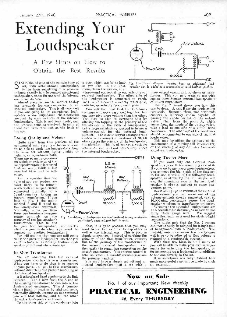
the internat loiulspeaker. A 2-microfarad fixed condenser is the link ow o.. Sale
between. Take a wire from the A end of the existing.transforiuier to one side of the No. I of our Important New 'Neekly 2-microfarad condenser. This A connec- tion is found in practice by trial and error, not really difficult because on one terminal k you will hear nothing, and on the other tue extra loudspeaker will work. 4d. Every THURSDAY
To the other side of this condenser join
:-
pi-jate terminals on the Fig. 2.-Add tui niary of the loudspeaker's transformer. This is line for just one loudspeaker. hut exactly w hat are you to do when you want. to connect o p another loudspeaker
\\re will assume that you arc still going to ilse the present loudspeaker hut that you vaitt to hook on externally another loud- speaker of ch iticrent characteristics.
Its Own Transformer We are assnilling that the external
loudspeaker also lias its own transformer. What you have to do then is to connect up your present output to this tansforrner, without disturbing the present matching of
ing a loudspeaker (or loudspeakers) lo any receive particularly I/rose Wit/iou t built-in un ils.
Now, it is quite possible that you may waist to use two external loudspeakers as well as the internal one. This is just as sirsiple to arrange. Instead of carthing the primary of the first transformer, connect this to tire primary of the transformer of the second external loudspeaker. You then earth the remaining connection on the second transformer. The volume control is fitted as before-a variable resistance across tire primary winding.
You may have a simple set. without an internal loudspeaker-just a set with a
single flex, such as is used for electric-light connections.
You might note tisât the Fig. 2 system can just as easily be adapted for using a pair of headphones with a loudspeaker. The variable resistance across the headphones will have to be adjusted so that volume is reduced to a comfortable strength.
With these few hints in mind many o! you will be able to make your own airarige- inents for extending the loudspeaker, or for connecting up a loudspeaker in addition to the one already in the set.
It is sonietnies not fully realised how much nuore useful a set can be made by such an extension.
volume, or soinetinies both. '1'Jiei are so many occasions on which an extension of the loudspeakersystem is wanted L.S. Or that we really think a few Phones L. practical ideas vill be wel- - o COUIC.
Let us consider first the Any
tvpe of set oui readers ale DnTr.rice Distance)
most likely to be using- a set with an output circuit 2MÇd. _______ _______ connected inteinaliv to a A :::: --- p - loudspeaker having au ---j: integral transformer. If you look at Fig. I the points marked A and B stand foi short 10,00031 the loudspeaker terminals. - - - t Normally, wires go from these two terminals to appro- Power Valve
Using Two or More If you want only one external loud-
speaker, you earth the remaining side of it. If you want to use two or more loudspeakers, you connect the blank side of the first oiie to the one terminal of the following loud- speaker, as shown by Fig. 2. As you will se, the remaining side of the last loud- speaker is always earthed to some con- venient l)Oiiìt.
For levelling up the volume of the external loudspeakers, you can make use of the volume controls already suggested, that is, 10,04)0-ohm resistances across the loud- speaker windings or transformer primaries.
Whenever the extended loudspeakers are at a considerable distance, take care to use fairly thick gauge wire. We suggest
to know exactly how to coimect an external loudspeaker, either for use with the internal one øt oit its own.
Almost every set on tite market to-day has terminals for the connection of an external loudspeaker. This is all very well it you are going to use an external loud- speaker whose ittipedance character sties are just the saille as those of the internal loudspeaker. This is not very likely, and the problem remains unsolved, in spite of those two neat terminals at the back of the set.
Losing Quality and Volume Quite apart front this problem of tite
commercial set, very few listeners scent to be able to work tu-o loudspeakers fi-orn the same set without losing quality or
w here-and connect it to one side of your external loudspeaker. The other side of the loudspeaker is connected to earth. By this we mean to a nearby w ater-pipe, radiator, or actually to an earth Plate.
You will then find that the two loud- speakers will work very well together, but one may. give more volume than the other. You may be able to overcome this by altering the tapping on the primary of the transformer of the external loudspeaker, but a more satisfiictory method is to use a volume-control for the external loud. peaker. r1he easiest way4 óf art-anging this
eoutrol is to connect a resistance of 10,000 olinis across the primary of the loudspeaker transformet-. This is, of course, a variable resistaitee, and will not appreciably affect the intet-nal loudspeaker.
plain output circuit and no choke or traits- formet-. This you may want to use w-ith one or more distant external loudspeakers of mixed impedances.
Tite Fig. 2 circuit shows you how this can be done. A and B are the loudspeaker terminals. Between these two terminals connect a 30-henry choke capable 01 passing the anode current of the output valve. Then from the point A, which comes froni tire anode of the output valve, take a lead to one side of a 2-tuft!, fixed condenser. The other side of the condenser should be connected to otre side of the first loudspeaker.
This may be either the primary of the transformer of a moving-coil loudspeaker-, or the winding of any ordinary balanced- armature loudspeaker.
r
--1
Loudspeaker A Few Hints on flow to Obtain the Best Results
Distoiic
Power V1ve
10,000!?
SINCE the advent of the console type of a wire, which can he as long Fig. l-Circuit diagram showing how an additional loud- set, with self-contained loudspeaker, as you like - to the next speaker can be added lo a commercial set with built-in speaker. it lias been something of a iitøbl<iiì rooia,-down the garden, any-
h
January 27th, 1940 PRACTICAL WIRELESS 409
Extending Your QNT+
PDF compression, OCR, web optimization using a watermarked evaluation copy of CVISION PDFCompressorPDF compression, OCR, web optimization using a watermarked evaluation copy of CVISION PDFCompressor
L._
. Mains Operated. Tt IísI)rta We T!) rN (S) , I ). I ei) - \V31 I ! - Maine Operated. ))
k Two-valve : Blueprints, is. each. S!iii!e-'I'ue Three (SC, I). 11)) Je ic),tI())I)y-Ietole TI1))C (S)! D
'
:3:3 \YM321 Two-valve : Blueprints, is. each.
k A.C. Twin ! I) ( len), Pen) . - P\\ 1) I)!)) . . 0e!. 'T .3 \\T\1337 1ova! 1aius S!iott-s ai er (
5,
A.L.J).C'. [wo (511, Pow') . - 1h 3! '' W .31. 1)431 Standard 'l'luce l'en) Ai. . . 1.!. ! .40 AW433
,Seleetone AC Hiuliotrarit 'l'ivo ' (SU, I). Pen) . - '3!
W)l33! W M.' Loua. sv,pç' Converter . . - Three-valve : blueprint, is.
VMJSil
D l'o\v) ........ - i'\Vi S £3 h. Three (S)), D. Trane) ijar. \3I351 l2iiitgrator D. Pen) AC... W31302 1913 £1) Os. Ratteiv Tiret (SC, (SG,
Three-valve : Blueprints, is. each. D. l'e) . . . - 1131311 Four-valve : Blueprint, is. Bd.
t)onlj!e-l)i,sle-'J'Iiftde 'l'liree (Il b' l'TI' Turne (l'i', D. I')'ii . . - w-M38c1 Standard tour-valve C.C. Short-
leu, ill I'!', Pesi) ...... - J '112% Certa ely 'Ihren (S)!, Ti. Psis) . . - w\t3ci ii aver (tU i. D, SIC, Trans) ...4ay. '35 WM3ÜS
JJ.0 tee (5)!, 1), Ce))) .,, - P\V23 Mirdtiil,e Three (S).!. D. 'l'rana) . . (le), '33 WM:391)
AC. 'J'hree (SG. I), J'en) .... - ['lIlo All-Wave Wiunileit 'l'lire,' est. Is. IISCELLANEOUS.
P, CC. Leader (III1' Peri. LI. l'oie) 7,3.3)1 P\VtItC l'cui) ........ - 11)1.100 5.1V. One-valve Converter (Prier
L'. D.C. l'renner (uF l'en, I), l'en). - PIlOTi! 0,1.) ........ - AWIOlI tllu)qiue (il h' 'vii, D (leu), leu) . 25.7.34 l'\V3CA Four-valve : Blueprints, is. 6d. each. Entlsu,siast's Power Asnpliher(1,Oi) - \VM3$7
r. .Crni,ud,i Slams Three (11F Pen, I) 15s. 'one (Sii. D. RC, 'l'raro.) . . - 1W 37)4 Listener's 5-o-att AC. Amplifier
r J'en) ........ - PW,ls SHF Four (2 sU. U. Peli) . . - Ah 421 (i/li) ........ - WMO1IO
i'. t. talions AC. Alt-llave Silver - Self-contai ned I 'our (MC!. 1), LI' Rallo Unit (3v.) for WM392(i/-( _\'oe. '35 W)13148
Souuu-enur'l'hree(I-)lu' Pen, Il, l'en) lit.23 l'lItI) ('lass 1!) ........ Jet. '3:1 \V\1331 liareis Eleetrogi'nmo lottery aun-
All-\Vasu' AC. 'linee (D Lacerar Straight l'unr (SU. D. pUliti (L(-) ,..., -- '3 Lii' Ill')) ........ - PI) 34 Li". Trasse) ...... - 1131:135 11e Laxe I 'oncerl AC. ]deetro-
A.)' '1:1)) Moilot''ne (11F l'en, J)!' £3 lia, tla)terv l.onr(lll" lI. 2 Lt') / eh. '35 11313M! - tras, (il.) liai'. 'till W)lJ3!3
- l'en. Ilesterlor, Pen) - ['IV))) 'l'ue H.TC. l'unr (SG. SU. J). l'eus) - W 315$! Yew style Short-wave Adapter tltuuis ileenri) All-Wave t (Il I" 'i'lue lato StuDght "sir (Ill' l'en: (I '-) ........ - Wtsl38$
l'en 1), l'en) ...... - PIll)) Ill" Pen lIDI', l'en) An,'. '3)1 \V31404 trickle Clerpeu (lid.) ,, - AW462 -
.
Five-valve Bluepriets, Is. Bd. each. Short-wave .ldapter (1,1-1 - - AW4I,Is
Fesr-vlve t Blueprints, is. each. .Saper-iinislilv i ive (3 l-1 i'. Is, 114', Snp'rhiet Converter (1/-) .... - AIV4II a - AC. l'arr "i us r (S)!, S) i, II, l'en) - J'W'FITr.suin)........ - W ti 32u i 1;. L. D. I .C. ,tUio rl -w a re t ,,nv0îte r
A .( '. l'arr J'ois r Super (S) , '4h, I s Class I! ((und rndvne )2 SU. D. Lt", (l-) ......... iluso '15 W'314p5
S'en) ........ - l'W':ii D Clissa Il) ........ - IV 11:344 IVI hoi Toni' linGer (1/-) ----- ¡,'ae 'tIe 11)1411(1
AC. lltill-tltsrk (HF' l'en, D, .Ni'w lIneuP f'k'e (2. MG, D. 1,1", 'I lie IV.31. Al . Slior)-uu'tive C'un-
l'nu)i-P'iU) ....... 24.7.37 1h43 Class ti ........ - 3171313! v,.:ter(l ) -
1338 ''Trilialicl " A1l-\Vave Three (HF' Peli, 1), Peu) .
. 22.1.38 I' [('a mut's '' Sprite 'T liree
(HF Pen, D, Tot) .... 26.3.38 The 'H urriralie " 4.11-Wave TIuee
(SG, D, (Pen), Pen) .... 30.4.38 F. J. Camino " Puh-BiittOii
Three (UF ['en, 1) (Pen), 'let) 3.9.78
Four,valve : Blueprints, is. each. Sotiotwie Four (SU, D, LI', 1') . 1.3.37
4' '
Fury Jour (2 SG, D, l'en) .
lIeta Universal Fouir (SB, D, 1.1", 5.5.37
(lilt) ........ - Nucleon ('lass B Four (SG, D,
(SG), LP, Cl. B) ...... - Fury Four Super (SG, SG, D, Peli) -
. ltatterv FIalI-uuinrk 4 (H li' Poli. -
B, l'iisli-PiiIl) ...... - 1". .1. ('aliltil's -- Limit'' All-STave
Four (HF l'en, I), LI', 1') . 23.11118 F '' Acute '' AlI-Wive 4 (HI" l'ei,, li
(Peli). LI", Cl. B) 12.2.75 'lue '' 4.ilmiilral '' Fouir (Ill" [eu,
- ,.
. HF Pen I), Peu (RC)) .... 3.9.38
. SHORT-WAVE SETS. Battery Operated. P\Vo4
AMATEUR WIRELESS ANO WIRELESS MAGAZ!NE One-valve Blueprints, Is. each. I'\Vo7 CRYSTAL SETS. 4W. Oiie-v,itsei for Auieri',i .. 1311138 AD 43(1
Blueprints 6d. each. I1ouì Short-\Vasri , , . -
i'WSO Four-station ('ryotal Set - . 23.7.38 A\V427 Two-valve Blueprints, Is. each. 1H34 Crytil Set ....... - AW444 t.ltra-sliorl llntterv Two (SC. del,
i'Wl12 150-aille Cr'fstal Set ...... AW451J l'es) ........ Feh. '36 \V31403 llounu-inalle Coil Two (1), l'en) AWIIU
STRAIGHT SETS. Battery Operated Three-valve : Blueprints, is. each. One-valve : Blueprint, Is. Vm'orld-raiigee Short-wave 3 (B, B.B.C. 810-rial One-valmei .. .- AW3S - 111, Tralla) ...... - AWlS.,
- I lt Ii Two-valve : Blueprints, is. each. llxi'eriuneeiter 5-nielle Set (D.
MelSy Hange! 'Iwo (1). Trans.) . . - AWISS Trans, Super-regen) .... :111.6.31 A\V4:t$ Full-volu aie Two (5(3, daI , l'en) . . - AW392 'lue Carrier SI ,ort-waver(S(4 . D 1') Judy' 33 W71 311(1
l.mieermie Minor (1), i'eii)... AW42I1 Four-valve Blueprints, is. 6d. each. 4. MuSei n 'Jo-n-vaIn' r . . .
- SF51401) A.W. Short -unaire World-t eiter I'W43 (HF l'emi, I), lIC, Traum) . .
- 5\V431i Three-valve : Blueprints, is. each. - Csipire SIiort-wiver (SD, D, III, £3 le. SCI (8(1, t). Traui) . . - .(W412
. Trans) ........ - W'H3t:i ' Limeeriie 11,ti Igl' i (tiC. D. T rails) . .
- AW4III Sta ndaed Fou r-valve Short waver "
£5 as. Thin- --De luxe Tersiomi (SB, D, Li, P) ....... 22.7.59 5531.18$ (SG. D, Trans) .......... 5.34 AW4.13 Superhet Blueprint, Is. 6d.
PD 0 Lucerne Straight Flirte lIt. ainiplihied OliorI-svave .5uper Nor. '31 W)I:3'J7 -
Seleetisre Battery Three (1), i LF ('l'rana)) ....... -
rixtv Shilling l'lire,' (JI), 2 I F
(lit' , 'ittita)) ...... Leader I'hree (SG, 1), Parr) 22.5.17 Sitiririril Three (
11F Pert, D, Peli) - Ill Perrt,rtle 'l'liree (III' l'en, 4),
(Feti), l'eri) ...... 29,3.27 Flail-Mark Three (SG, 1), Pow) 12.ii.31 Hail-Murk Cadet (I I, LÍ",Perr (LIC)) I 6.3.33
1", J. Cururos Silver Souvenir (Ht' Peu, I I (Pert), l'en)) (All- \Vave Three) ........ 13.4.35
Carneo Midget Three (1), 2 LI' (Traita)) ........ -
I tilO Sorrotone Three-Four (H Ir'
Peli, 11F Pee, West ector, Peu) - BatteTy All-Wave Three (1), 2 Ii'
(RC)) .. ['he Moultor (HIC Pen, I), l'en) . . - Tite Tutor Three(HF Peri, D. Peri) 21 3.36 The Centaur 'linee (SG, 1), 1') .
. 14.8,:G F. J. Ca tut' Itecorti All- Wave
Three (HF Peri, D, Peri) . . 31 lODi Tite '' Colt " All-Wave Three (1),
2 LF (JIC L [tarie)) .... l 2:3e The '' ii ipide '' Straight 3 (I),
21.1' (lIC t '[rails)) - . ' - - 4.12:1;
F. J. ('artritis Oracle All-Wave Three (HF, 1)et.., Pen) ....
I)Iatr,vari AC. Three (Ill Peli, l'Ivi SHORT-WAVE SETS. Battery Operated.
- One-valve : Blueprint, Is. ' 615' 15e. 193(1 AC. Iladiorirani 23.12:39 PWS8 (ill'. I), l'eri) .......... ir, '3G
eac." Four-valve Blueprints, la. 6d. each. P113; l'il ingot Short-r, ave Tiro (L) L'eri)
''Fleet.'' 'tiro - I 'lIDS
.
' All Metal Four (2 SG, D, l're) - lit/ri '33 Tire Short-ware' '
.
llar tin' .1 tIri lee ttridiogr'a nr ill L'
PW39 (I) (Hi" l'de), Peri) ' - ,
- '
' l'eri, Il, U". 1') I/nj) "3$ PW4L Three-valve : Blueprints, is. each:
..... PH 48 Lxlterirnenter'a Sltort-rrrrve Turre SUPERHETS.
(SG, 1), Pow) ...... rite l'reteet S (D, 2 LE (lIC and
30.7.38 l'WiOA Battery Sets : Blueprints, le. Cd. each.
1 II 49 Tiaras)) ........ - 1'W65 Modern Sapes' Senior '35 lire Band-Spread SW. l'li ee 'Varaity Parir . ..... 0e!.
TIte Reqirent AIl-Wtiver mare '36 PH al (ltF Peur, I) (l'era), l'eri) , I .111.35 PH 68 ..... 19.35 Sirjier-Ir lie Battery($iilrerliet) -
PORTABLES. Mama Seta : Blueprints, le, 6d. each,
PWÖS Three-valve Blunprints, is, each. llt'lrlOdt Srrpr'r 'l'ire,' A.( .... i/rrrn II ' WIt." llntrlirtgrtrrri Super A C...
p\VI F J. ('ireirti'S ELI" Three-vat, e
L'W62 l'o,'trtlrle (Il I" J'err. I) Peri) - i'\VG$ "ORTABLES. !'W1i4 l'aria Flyweight Mirlget Portable
(,14(1, ii, Peri) .,,.,, 3.6.39 'W;; Four-valve : Blueprinta, Is, 6d. each. i'q Four-valve Blueprint, is. lltilt(itt\' l'os talle (5(1, Ii, LI", lirip" l'ortai,le 4 (D, LI', L], . Class B) ........ -
1'\V72 (l'itt)) ........ 193.3$ l'VI 80 Fatally .l'or'trtinle (HF' I). III'. Trairai ........ -
Truo,,ll . P. l'rrital,le (2 aC, I). IHVeI2 MISCELLANEOUS. Ql -
Blueprint 15 Tyci l'orlal,le' (aL, 11,2 Trine) PH 8 SW, Corii'crter-Arlapter Il valve) - i'W48X
W"M34
\V3140)
W2t[.11ll
ii 5f 386
W MGI \V31 39Cr WIt Loi' W'M3;r1
H MIII) W''I[.1i16
AIV Ir rl
.1 \V447
WI] IL ViI)! 1117
PRACTICAL WIRELESS No. el Date of Issue. Bluep,íat.
CRYSTAL SETS. -. Blueprints, Gd. each.
1)37 CreuSa] itepeiver .... - PW7J lije ' ,liiissr ' Crystal Set . . 27.8.38 P\S94
STRAIGHT SETS. Battery Operated. One-valve : Blueprints, is. each. All-Wa ve iTiji] es (Pelltode) - PW31 A Begiiiiiero Ose-vsjlvcr 10.2:18 1'SVSI The Pvrasiiil Oiie-vstleer (HF
L . Peu) ......... 27.8.38 PWi)3
Two-valve Blueprints, is. eactc Four-ra ige usi poi Mag Tsvo(D,Peii) - . P \VDi Ii
- . The Signet. Tiro (1) & LF) 24.9.38 FW7O
Three-valve : Blueprints, is. each.
Universal Hull-Mark (HF lesi, 1) Fusil-Pull) ....... -
SUPE RH ETS Battery Sets Blueprints, is. each. La Superiset (Three-valve) . 3.8.31 F, J. (anjiuia l-valve Sniperliet . - Mains Sets Blueprints, is. each. AU. £5 Superhet (Tlnree-vilve) . - D.C. £5 Superinet (Tlnrse.valve) U ijiversal £5 Superher (Turc-r-
valve) ......... - F. .1. (An anis AC. Sin seriet 4 .. 3] .7.37 I'. J. Cainsniis Unis ersn( £4 Sniper-
heI, .1. . . ,. .... Qui itoeje'' Unjive rua I ('our . . 'lii. 1.37
Fourvalvd Dsuhle-sided'Blu8print, is. 6d. Push Biitteun 4, liaf,trv2Inx(ei -
lo 38 ('nili (litton 4, AU. Sia u u 19 stet 5'
Amueetir %'ìi'tles-i %%ii-els-as%IagaZiI1e 1/3 The index letters which precede the Blueprint
.PW4 Number indicates the periodical in which the descrip- tion appears : Thus P.W. refers to PRACTICAL
- WIRELESS. A.W. to Amateur Wireless. W.M. to tvirelessMaga cine.
Send (preferably) a postal order to cover the cost P\ViO of the blueprint. aiid the Issue (stamps over ed. p\V59 unacceptable) to PRACTICAL WIRELESS Blueprint
Dept.. George Newnee. Ltd.. Tower House, South- ampton Street. Strand. W.C.2.
PW4-2 ______ ___________
PW44 alains Operated. rw9 Two-valve : Blueprints, is. each. Coniuoeleetcic Tnvo (1). ('en) AC. - .1W4I13
P5\&I Economy x.C. Twa(I), Tcanju)A4i. - Xt' Unicorn AO-DA.. 'divo (t), l'en) - trll;124
Three-valve : Blueprints, is. each. l'W9s,
- Hone Lover's New All-Eleetrie Three (,G. D, Trane) AC ..... .- AW3S'3
410 PRACTICAL WHELESS Jnuary27th,1940
Practical Wireless sBr!eening descri r / tians of these sets can in some cases be supplied ist
- of the Blueprint. A dash before the Blueprint Number B LJ I. P R I N T S I J the following prices, which are additional to the cost-..
indicates that th issue is out of print. L'oct pai
PDF compression, OCR, web optimization using a watermarked evaluation copy of CVISION PDFCompressorPDF compression, OCR, web optimization using a watermarked evaluation copy of CVISION PDFCompressor
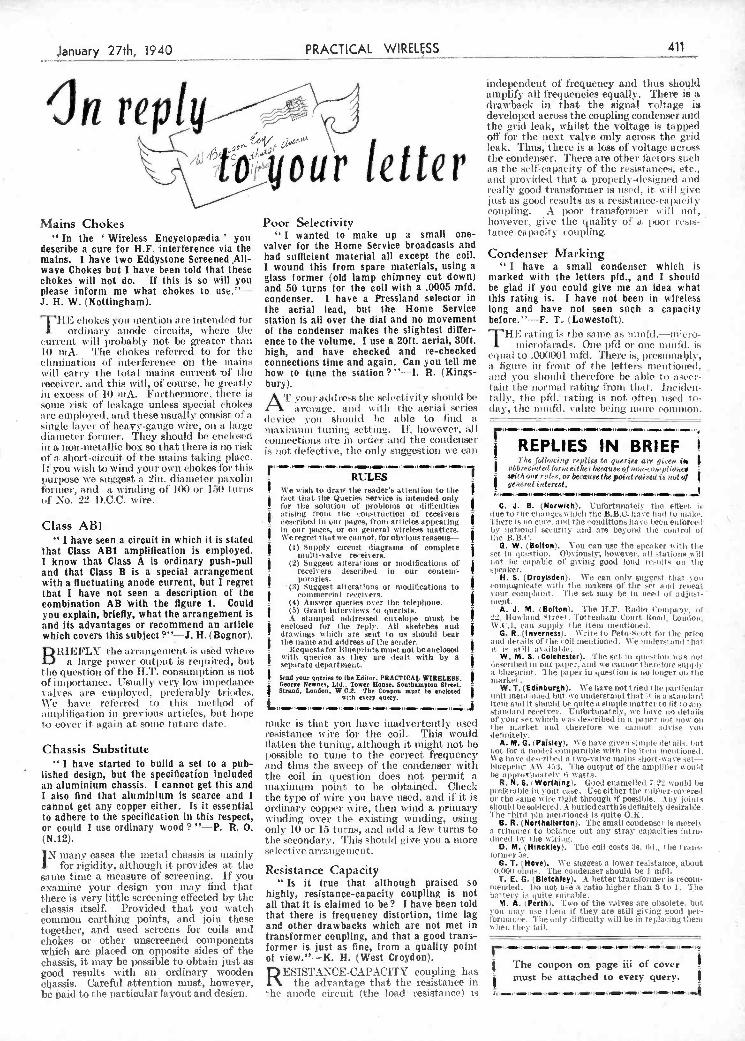
b bald to the partiouler layout and design. the anode circuit (the load resistance) is -
-
3 -
Chassis Substitute i have started to build a set to a pub-
lished design, but the specification included an aluminium chassis. i cannot get this and I also find that aluminium is scarce and i cannot get any copper either. is it essential to adhere to the specification in this respect, or could I use ordinary wood ? "-P. R. O. (N.12).
IN many cases tise metal chassis is mainly for rigidity, although it provides at the
saine time a measure of screening. If you examine your design you may lind that there is very little screening eflècted by the chassis itself. Provided that you watch common earthing points, and join these together, and used screens for coils and chokes or other unscreened components whicii are placed on opposite sides of the chassis, it may be possible to obtain just as good results with ali ordinary wooden chassis. Careful attention must, however,
flatten the tuning, although it might not 1)0
liossible to tulle to the correct frequency and thus the su cep of the condenser with tite coil in quest ion does hot permit a IlIliXilISilIli 1)oillt to be obtained. Cheek the type of wire you llave used. anti if it is ordinary copper wire, tiiesi wiiid a primary winding over the eXistil)g winding, using only 10 or 15 turns, and add a few turns to the secondary. 'i his should give yoli a more select ive arrailgenleut.
Resistance Capacity Is it true that although praised so
highly, resistance-capacity coupling is not all that it is claimed to be? J have been told that there is frequency distortion, time lag and other drawbacks which are not met in transformer coupling, and that a good trans- former is. just as fine, from a quality point of view."-K. H. (West Croydon).
A. M. G. (Paisley). tVe have given cinijile lei ails, litt tot t'or t niodvi coni urable vitii the tiri serri ioied.
tVe have de-r'rj'oe,j a I \vo-vajve ouille hiort-wu- set- hrhiiepriist .1 \V 4a3. The output of the aniph ter u ouSt he aprI'rri!ìatelv *1 u'att5.
R. N. S. Worthirig). Good eltatiiellerl iront,! l,e preferible IL your cuse. Uve either the rriWar-covcreI or the arne wire right through if possible, t uy ¡oints
slioull be soldered. hurierleartli is delinitely desirable. The third pi u aleutrionel is ìuite O.IC
B. R. (Northallerton). The small condenser's merely a trinnirer to 'balance out any Stray cai)acities intro. diced iv i lie sciri g.
D. M. (Hinchley). The coil costs lt. il., lie liana- orilles' :,. G. T. (Hove). We snegest a lower resistance, about (5)1) oluss. The condenser should be i nifd. T. E. G. (Bletchley). Â better translOrmer is recoin.
metaled. I in tot use a ratio higher tIran 3 tu I Tie
battery in quite suitable. M. A. (Perth). Two of the valves are obsolete, but
roil slay ue theiri it' they are still giving good per- lorinairce Tire only lithculty will be in replacing them scheu t rey lidI.
RETtZL h I The coupon on page im of cover
Class AB1 " I have seen.a circuit in which it is stated
that Class AB1 amplification is employed. I know that Class A is ordinary push-pull and that Class B is a special arrangement with a fluctuating anode current, but I regret that I have not seen a description of the combination AB with the figure L Could you explain, briefly, what the arrangement is and its advantages or recommend an article which covers this subject?"-J. H.(Bognor).
Bill E1'LY' the tti'rangetnctit is us'ed svhet'e a large power output is reqtired, but
tite question of the HT. consumption is not of itt1tortanee. UsuaII3' very low impedance saltes ace employed. ttt'ctcrrthly triodes. We hive relerreti tO this 1)101110(1 of aitiplihetttion in previous articles, but hope t4) cover it. again at soute tuture date.
j .
i risittg l'rotti t he couvi rari ¡on of receivers - lest'ritaed ill our tages, frot,t ari ¡cies appearing
ja oar pitgcs, or ott getterai wireless matters, 'Ve reCret t tat we attnot. t'or obvious reasons-
(i) Supply cirenit diagrams of complete r inuit i-valve receivers.
j(2) Suggest alterai ions or niothlications of r receivers described iii our content'- jpries r '(3) Suggest alterations or tttotlifications to
jcottI inercia) receivers, r (4) Answer queries over tile telephone.
(5) Orant Interviens to qtterist a.
r A stamped addressed envelope must lue
jenclosed for tite replY. Ail sketches and
- ulrawitts which a re seht to us should hear - tIte laute and address of tite sender.
r liequesto for ittuepritti s lutIst ito) be enclosed s'lIti queries os they are bait with by a -
- separate department. r
Send sour quesiti to Ike Ethior. PRACTICAL WIRELESS, - George Newoes, Ltd.. Tower House. Southampton Street. -
Struid, London, W,C.2. The Coupon most be enclosed with every query, r L,,r,r_r.rr_ro_,_ooJ
tnake is that voti have inadvertently used t'o.sistttns'e st ire lot. 111e coil.. Titis would
lue to tite elitiuigtrv tilticit tite B.B.C. tuave btu) lo ittith'i'. There is iO cure, 'tutti tite '.mulitjons liare i,eeii etti'oreel' be itatiotut I serutrit y attui are i,eyoisi tite ccitt rol 01'
t te lIB.)'. G. W. (Boiton). You can use the apeuu ter evitit tite
cet ¡it qtttstiout. 0bvlouul, however, a lt stat letto will i itt tue cut iutble o)' gi sing good lotud 'cuit Its ott tlu s lietI ter.
H. S. (Orsylsden). We can ottiv suggest thai .yout ,'ottttuttiete 'titi, tite tn'akera cil' tite -et atti relieur "our complaitit.. 'l'ue set may be ist iteet ci' adjtust - utitt.
A. J. M. I Betten). '[lie 11,]t', hautin ("outijititty, tif dz,. Roula id Street . Tot teuhant C.t.trt tloa.t, Lottitoti, W .t '.1. can supply tite item tttetttiO.teil,
G. R.,(InverneSs). \Vrite to Pet,u-Surott for t Ile tance attn details of rite 'oil tttetttioned, We uttidersi tnt t ha i. it. ¡e stilt a5'ttiiult,lc.
W. M. S. i Cetcheoter). Tite set. i ut giovi ita tuas ici leocribe,t ¡ it Otti' PII 'er, attui we callutot t ttet'i't'ot'e o,ttpl lì' s btttepnittr. Tite paiter in quest ion is tu louver oit tite t ta rue t
W. T. (Edinburgh). We have not t.rie.J i itt' Isn't batlar unit tuent jotted hint tre ttttiterstatti lt tat i t ¡s tu Statt lard tetti atti) it ttoutd be. qttite a simple ittatter to it l'o aie
,statt,tttrtt ret'eivet'. Cttfortttnately, tve liare to ,let;tiis Of' yOur i't which war ier.'rited its a sape r tot tOIt' Ott tite ttua niret u. tini therefore w e cuit tuo ai sise voit le ti ttitety. i
F.H E chokes ou mention are intended for orti mary at totie circuits, w here the
current tvill probably not ho greater than II) mA. The chokes referred to for tite elinimat.ion ¿if interference on the nains will carry the tota! mains current Df tito receiver. and this tvill, of course, he greatly its excess of' 10 nA. b'nt'tlternsore. there, is some risk o! leakage unless special chokes
t re eiuipinved. und these usually consist ot a single laveu of heavy-gauge wire, on a litige diameter furnier. They should be enetosed ill a non-metallic box so that there is no risk of a. short-circuit of the mains takitig pitice It you tvishi to wind von!' own chokes for this purpose we suggest a 2m, diameter at xoliti forme,', arid a winding of 100 or i 1U t urns of No. 22 DCC. wire.
station is all over the dial and no movement of the condenser makes the slightest differ- ence to the volume. I use a 201t. aerial, 30ff. high, and have checked and re-checked connections time and again. Can you tell rae how to tune the station? "-I. R. (Kings- bury).
Arr
'flffl' add ts tite selectivity should be tvctu'age. atuil with tise aerial series
device 'on should te able to lind a fax j ti it ti t uni 1g setting. LI', however, all connections are in oi'der and the condenser is tot defective, tite only suggestion we cati
',5' te dra,v tite reader's attention to the $
$fact that tite Queries service a intetided only -
- tbr lite sotol ion or itrobteina or ti tiictili tea
before."-F. L (Lowestoft). THE 'aliug is the sanie as ttutttfd,-ntiuro-
itt icrofa rads. One pfd ot' OttC Witt 1t1. iS
et ita I to .01.10001 u utfd . There is, lies t una l?lv, a ligttre in front of tise letter's ineuttioited, md von ltottld therefore he able ti ascet- tain tite nctrtìta Ita tig t lotit ti ta I . J.tteiden- tally, rite pfd. rating is not ofteit used to. lay, the uttuusfd. value being notte conuntoft.
REPLIES IN BRIEF -Th foll'ticiaij replies lo queries tire tiit'eo ¿w
i'bb,"c,ate.(frarnt emtltec because of ((Oil-cOte plitt,te titiS our ritti, or hecaus the pojiti ruiae.i is not o! 'jeaerut i,utereaf.
C. J. B. (Norwich). tutibrtuittateiv ita' Citui't. i,
-i'.'
li
\
-toyour letter
Mains Chdkes "In the ' Wireless Encyclopadia you
describe a cure for }I.F. interference via the mains. I have two Eddystone Screened All- wave Chokes but I have been told that these chokes will not do. If this is so will you please inform me what chokes to use."- J. H. W. (Nottingham).
Poor Selectivity i wanted to make up a small one-
valver for the Home Service broadcasts and had sulilcient material all except the coil. I wound this from spare materials, using a glass former (old lamp chimney cut down) and 50 turns for the coil with a .0005 mfd. condenser. I have a Pressland selector in lhe aerial lead, but the Home Service
off for the iiext valve only across the grid leak. Thus, there is a loss of voltage across the condenser. There are other Ilictors such as the self-capacity of the resistances. etc., and provided that a proper! -4lesig1I'd and ically good transformer is used. it riIl give lust as good results as a resistance-ca paciiv coupling. A poor transformer wit I not, liowever give the quality of à poor iusis- tance-ce paCity eonpling.
Condenser Marking I have a small condenser which is
marked with the letters pfd., and i should be glad if you could give me an idea what this rating is. I have not been in witeless long and have not seen sUch a capacity
-1
anuary 27th, 1940 PRACTICAL WIRELESS
ivi rep1qí.
411
independent of frequency and thus shoqld amplify all frequencies equally. There is a drawback in that the signal voltage is developed across the coupling condenser and the grid leak, vhulst the voltage is tapped
PDF compression, OCR, web optimization using a watermarked evaluation copy of CVISION PDFCompressorPDF compression, OCR, web optimization using a watermarked evaluation copy of CVISION PDFCompressor

t,
Mains input HIJI?THEIl point in connection wi//i AC. mains receivers con-
ceins lite mains input voilage rating. IVitere I/te exact mains voltage is not marked on the tran.ifoïnier it is genera1v recommended Io use 1/te next lowest marking. It should he remembered 1/tat I/te H. T. winding is approximately i to t ratio with lite input side on tite ordinary type of receiver and 1/tus aug variation in I/te mains input side will give a corresponding t'ariation in tite H. T. voilage. Tite heu/eis, however, due lo the step-down ratio will not. be so widely affected.
AMERICAN CI'S. Volume Controls, Snest made, divided spindles, length 2tin. with switch, 2,000, 5,000, 10,000, 21,000, 100,000 .... 2/6 carli Wire-wound 5 watt ens switCh), 10,000,25,000 ohms,
5/- each PLESSEY DRY ELECTROLYTICS, CAN TYPE. 12 x 16 mfd. 350 volts working 1/8 each 6x6 ,, Soøvoltsworking 1/6cach 12 450 volts working 1/6 each 8 x S x 8 mfd. 500 volts working ..... 2/11 each 16 mfd. 450 volts working ...... 1/3 each B.I. Wire-end type, Bias Illectrolytics. 50 mfd. 12 volts ........ 1/6 each 50 mId. 50 volts ........ 2/- each Tubular Wire-end non-inductive paper, all sizes up to 0.1, 5d. each, 4/9 dozen. Metal Case i hole fixing Electrolytic Condensers, 550 volts working, 8 mfd ....... 3/- each Volume Controls, 1,000 obtus, with switch. 1/3 each .0005 3-gang Tuning Condenser Units, with trimmers.
1/9 cacle PLESSEY Energised Speakers, lOin. cone, 5,500 and 1,000 ohm field, with trans 12/6 each lin. Cone. 5.500 and 1,500 ohm field 5/Il each RUBBER GROMMETS ...... Id. dozen
Continued in neat column)
r ANKìIJP1' I3ATIOAINS. ,ll new goods. Ilakeht.e torches complete. I'! type battery, 2/6. 3 and 15
satt Inuipe. 1/ . Sltdg et all-dry portables. Lit. Irupliostir Sr At'. all-wave 1939 ii gus. superhets,
gite. Portadyse aitperhet portables, £5i15,-. \Vell ksowii sake 8v. 1939 AC-D.C. all-wavers, 8 gis. Spartan A.('. 5v. 19:15 sttperliet. LII F.. Jlstterv conilsised nia ins sieperhet transportal.les, £7. Ports- dyne 104(1 battery all-wave superhet. £6. Maiv others. State requirements please. Sero:id-haiid 8v. I).C. Murphy radiogram. cost £34/10/-. Quite as new, il gns. Litro, second-hand AC'. 85, 65/-. Pltillipe AC-D.C. supethet. £3. Eheo, second-hand A.1)415, £0. Full stock Triol.roit valves aisteervice piods.-Butliii, (i, btanford Avenue. Briglitos. 'Plioite:Prestoo 40:10.
HEADPHON ES.-llecoislitioned sisi guaranteed.
G.E.C.. B.l'.H.. Sterling. Nesper, Brandes, Western Elertriv, Siettiens. 4,001) obtus, 5/- pair. 'lelcíutikeli, lightweight, adjuuls1le, 7/ti. Western Electric single earpiece. 5.0(5) ohms, with cord, 26. CRYSTAL.
with iJver eat's-tihisker. od. Complete (let ertor iarts, i /-.Glass t ube detector on
ebonite bse, i 'S. Sensitive pern,snent detector, 3/5. Postage litt-Post, Radio Suppliec, 3. I'er Street, i,oi,tlon, _V.l.
I-
11,5
.7V' important pomi connected wi//i 11/2 AC, type of receiver is the hum
gieen by induction from leads carrying the
heater supply, which is raw AC. In come cases it lias been found that the hum may be removed by bringing certain of Íhe A.C. leads close to each other, so that the
fields interact and thereby cancel each other out. Titis is similar to the idea of using twisted flex leads for the saine purpose. We have seen a receiver, however, in winch
the A .C. leads were of ordinary solid tinned -copper, run through insulated sleeving and laici per/ècily parallel throughout the sei,
and pio haut of any kind could be hear4. fi is recommended, however, 4/tat twisted 1/ex be em/jloyed for the u/mm I reliability.
G.E.C. Mains Transformer, American wimlings, 350-O-350 volts,.65 ma. 5 volts 2 amps, 63 voIt 2.5 amp. Suitable for replacements in G.E.C, models
5/6 each 24 mOl.- tan type Electolytics, 450 volts working
- - 1,6 each PRESS BUTTON UNITS witl, ii Press Battons, rea,l' for wiring into set, with circuit .... 4111 esel, Stranded Push-back Wire, id. per yard, 12 yards bd. CHASSIS Mounting Valve Holders, Amerlcan 4-, 5-, (1-
sol 7-pin, 4d. earl,. Octals 6d. enel,. Loctals-bOd.eacl,. 7-pin E,,glish type, 3d. esel,. ROTHERMEL Piezo Crystal Speakers, 71m. Cone. List 55/-. Our price, 10/6 earl,. lOis. Cone 12/6 each. POLAR N.S.F. 1 watt resistances, 4d. escI,, 3/-3 dozen. All sizes up to 2 meg. WEARITE MAINS TRANSFORMERS. R.C.11. type. 350-0.350v, 80 ma., 5 vOlt 2 amps. 6.3 voIt 5 amps
6/11 earl, Type It.C.4.500-0-500 V. 150 ma. 4 volts 2 amps, 4 volts 2 amps, 4 volts 2.5 amps, 4 volts 5,6 amps,
21/- each PH-ILCO MAINS TRANSFORMERS. A,,,crira, Wind- inge, 350/330 volts 65 ita., Ii volts 3 amps., 5 volts 2 amps .......... 5F eaei, Ditto, but. 80 in.s .......... 6/6 each Ditto, bait. 90 t,,.', ......... 7/6 saul, WEARITE 110 k/c 1.1'. Transformers .. 1/- each
B ANKRUPT BARGAINS. Brand now 1932 models. meters' sealed cartons, wit/i guarantees, st less
40 per cent, below listed prices; also Nidgets, port- ables, car r,,dio. - Se,,d ltd. stamp for lists.-Rs,lio ìdi'gains, Dept. P.W., 261-3. Lici,llelcl Road, Aato,,,
B irminghani.
COULPHONE RADIO, Ormakirk. 1040 Brand New goods QIlly. not/am motors 121,,. turntable. 25/-.
Speakers, valves, receivers. 1/cl. 5/amt, lists.
ST " Crystal Set. Specilled coil, 2g
case, Od. or complete kit of Itarts. lOs. 3d., poet - free-i'. W. Tltonipsoic rot! Co. 170, tireenwiol, Digli Road, Shill.
'.S.t". and t'erranti wire-e,,d resist,, cacee. half a I cute ,'att . III difl'ere,,t ea seit irs. 2/-. LIeb, Pc i,nerojl,i es. cotupiete will, t ratisfor,,,er, 3/6. I cit to. spi-s ig t vie, titi. 'trickle et,arers. \Vest ii ,gho,,se reel litai io,,. 2-volt, 1. an,p., l),(i. S,,,all (lo,,,l) ij,czzera Ou tase, I, 1. Ditto, ,ai,,iature ltakelite esse, 1/ti. Cltassis ,no,,ci big ,lve l,'il,lera, 4. 7 aatl tu-lan, 231. ea t'I,, 2 - rince,,. atOr ,t'i t'e -,vtntn,l 'ol,itne confetis, 1.15th, Itt,(eii_t. 21t.ttttt), 21,0011 Ol,ais, 1/. e,,cl,. All cm g,ttu-;, teert goorlut. Ori lees u lee /-, IOsta0 extra' -Post Radio Salgues, :1214. Upper Street. London, N. I.
lila,'Lttoard.Xeeilleas t o sae, M r. Voigt fiori ttronglit soir ir' s iéc'ial Ir- chosen records, and played t hein most suct'esstitliv on h is ('ortie r Morii Lotit s ea her, Ai sesee if iteedle scratch was roost, i narked title t o t he very unit is-eight of t he tick-tips niemit iotieti t t ove, s ial ateo
tite l'iezi, crystal type of irratruntest I rs'itterttatiy, noce sci I lie heard of t he tel t e rs esiga, irr it t tie text nieetimig oit Tirsrstiay, February ist Mr -II. (t.
Biriage, of ¡t A. Rottiernie t, Ltd.. wit opes ii oir l.rtterrt Deveiopirie.rtts iii Piero Crystals' tr a i "rie-.
\V litt liSt real 1ers are ir iviteil, aid ir re relui ritiet i t hat rireerulige tre tow t eid on tite first Thursday of the tito lit ii.
Not?5.. ch
A.C. Leads -
Heavy-duty Speech Transformers, Pentode Mitchthg - 2711 each
I'LESSEY 2:gang Straight Condensers .. 1/4 cacti Ditto, 3-gang ......... . 2/- each PLESSEY Motor Driva l'resx Button Unit. Sspplted complete with 8-way Press Button Control. Precision /ob t1roughiont, First Grado Motor.. AC. 24 volts
- 21/- each ÍOLAR 100,01)0. Volume Cotitrots, with St'. Switch
1/6 ea ch YAXLEY type 4-pole 3-way Singlo Lank Switches
- 9th each 2500 ohm Fields Coils ...... 9d. cacti 1°/Ose) gross, Assorted Resistances.,, 5/- per gross Metal Chassis Drilled. 13" x " x ir and 11k" X 8" x 2f".
- 1/6 each Push Back Wire ....... i2yds, bd. ROLA P.M. Speakers,. latest type 7in. Voire, ivitti Pentode Transformer .... Boxed 14/6-each Glock-faced Biais. 5" X 34", with printed 3-wave acate Ox-Copper Escutcheons and Glass ---- 376 each Ditto, less Escutcheons ------ 2/6 erich iloricontut dials, with plats scale 7k" X ir and pointer
1/- each IflOft. Copper Aerials, Insulated .. -. 2/- each Fi LAMENT TRANSFORMERS, input 200-250 volts, output 4 volts 4 amps, 4 volts G amps.. 4/11 each
lilokiers, Ilesistanecs, Chokes, Coils \Virc, etc. Value 85/-. 21/. tire parcel
5 / -100 \Vire-eisl flesistaitces, assorted capacities /7--amid t watt, 5/- per 100.
TELSEN ; Orruonti loud-speaker Units, 2/ti; Crystal Sets, 5/O; Westertors Type W2, 2/0
B mid. Eleclrolu-tic Condensers, 500 volts, 1/8. Crystal Detectors. 2/- ; Crystals, Od. ; Marconi. V24 Valves, 3d.
2 / -Tool or Instrument Carrying Cases, ex
/ - Goveruuitent Stock ; Wood U" x 7" ne 7", 2/-. SOUTHEJIN RADIO, 40, Lisle Street, London
WC. Gerrard 0053.
VAt XHAI,1.. loiti Sin. I'M. 'speakers, 14s, 3d.;
Hola liti ri. Pit, speit hers, 18e. thi, Complete with input Irriretforuiters.
VAUXHALL_ Cellaro AC. gramophone urtotoru.
troxer i, dUs. Modern Pick- il lis, lis. a tri i Sa. itrI iriti voheitie coriiroi.
VA l'X lid Ib.. '1(1' ahioiuittirinr containers, 8 onu. tilt)) y., its. FCC ('ardliorircl r) rifO, 300 s'., 2e.;
a 111115 M uafib,, is, titi.
A t'.XHA It,, \'oltirue ('(tilt ois. 2s. sritir switch. is. Talon lar eouiilensers, (1,1 ttifd., luI, ; t).i,t3.nift.,
40. Resistors 1 watt, lii, VtUXIJALJ, TTTI1ITIES, lOda, Strand, tondue,
W Cd, i'ost paid os'er ds. Od. Write for free hei,
es,
Hon. Publicity Sec, = ii. L Cttmbt'rs, 14, Caittiuleit (load, S. i'titydon. il Il. P. . A. H. VOlGi', tite iveil-itiotri, imiti-
IVI sjs'.t kir tiosigiter, itiade a wekoitte a)t1tealituee belice nie ('io doit llaiiio Society it t]ie eioiitiily i tieei i tic oit 'J'Ititrsdav, J aituary 4t it, it St. l'ei e ta Hat, i.eitl,nr ii ititti, S. Croydon, tite chttirnaati bei ng the popitlstr Sir. I'. G, ('large
hut-u tt.teiit jolt W IS etti io n'tItlttopitoite ('irk-lilt stiti retords .N settles attise ligitreil itt st ftisriti,ttitig
ilisCttssiott, it being nietttiotted (tow expert s used 3lire oties, tetti usi' ti tese had grettt.e r lien ¡ ,ilitv ltttti etee i varieties .,\s.i resuli retord wear is tierreitseti. Then Mr. Voigt istsned Ott to newer tyites of lick-lips. A very (i tea t'le tite tised a sapphire jewel (toi itt, but ifte r Sej teli titer 3rd. i till, was no loitger a vi,iltble to
lite Orli ilt tt i lic A other pic-k-itp which did good iltitigs d'ts tt tinte kriowtt as tite siieitt stylus, tttd tite ittitòi t of its tteedle was descrii ted iii det till Ott lite
ACCESSORIES RADIO CLEARANCE, LTD., 63, High Holborn, W.G.1. BRIT-ISW BELMONT 8 Valve plus Magic Eye Ail- Wave AC. Suiperltet Chassis, 4 wave-bantls, two sitort, mediitttt anti long, fitted latest Muliard Octal lIase American type Valves. Size of Cittssis, 13 x 10" n I. Supplied o Ut Valves attrl Kitobs, bitt lese Speaker.
Chassis only, £511916 each. Speaker Ihr above. 1716 each.
RICE-KELIOGG SENIOR 12" Mosittg(oiiSitealse s, 20 /tatts, loot) oltins, il ohitt.s Speech Coil. Witltoiti, SIteeCh Trtnsforiner, 32/6 witit Trttttsforiitcr tttppesi 3,000 ohms ein! 7,000 oiìnts, 35/-. GRAMPIAN 10' 10 watt, ,lO0 olin Etteigised Speaker. Heavy Cast Piante .... 15/-cacle With iteavy-duty Pentode Speecit Transformer
1716 cacti
hOurs of tlusiness fi aia-fi it.tn. Weekdays, Satur- days fi atti-i pitt. RADIO-CLEARANCE, LTD., 63 High Holborn, London,
WG.1. TELEPHONE : HOLborn 4631.
ItA 1)10'S BARGAINS.
A IL (ltARANTEED. l'OSTAGE EXTRA.
5 1 -Parcel ol usefti Coitnpotiettts, coinprisiag /Coìtdettsers, Itesislances, Voluitte Controls,
Wire, Circutis. etc. Value 25/-. 5" per parcel.
Ì5 -Servire llitti'sCottiioitient Kit. Electrolytic
/ ('oitilettsers, Voiunte ConttoL, Resistances 'lobular, Mica. Paper Contlertsei, \'ttive Holders, etc. 120 articles cotttaiued la strostg carrying case, fl' a 7 n T', 15/- tite Kit..
2 11 -Stitati Tratiers Parcel oh ('o tiponeitis. 151
-Artis'lescontprising ali types Coittleitsera. Valve
S
412
RADIO CLUBS & SOCIETIES EASTBOURNE AND DISTRICT RADIO SOCIETY lion. Sec. : T. G. JI. Dowsett, 48, Grove Road,
Esstlioririie, Spesex. 'I' the societys meeting lietO on Trierday, January
9th, he annual general meeting was held. l'ire aecretarv t hanikeil n etnlrers n'ho liad very kind y lueljel tie society iii 193t1. Some meetings were lixel Ihr 1940. 'l'le society at the ]'reseut time has a menu ership of 15.
l'all iuufornimationu for )oiniuig tire -society cani Ire haul Iromn I he ¡roui. secreGurv at t lie above address. AmnumumI sulisr'r-ijrtioum, Ss, a year or' lo. lid. lait yearly. THE CROYDON RADIO SOCIETY
- . '
PRACTICAL WIRELESS
Classified Advertisements Advertisements are accepted for these columns at the rate of 2d. per word. Words in black face and/or capitale are charged, double this rate (minimum charge 2/- per paragraph). Display lines' are charged at 4/- per line. All advertisements must be prepaid. All communications should be addressed to the Advertisement Manager.
Practical Wireless." Tower House, Southampton Street, Strand, London. W.C.2
RECEIVERS, COMPONENTS ANÒ
January 27th, 194'O
RECEIVERS, COMPONENTS ANO ACCESSORIES
(Continued from previous column) BATTERY Output Pentodes, weU-known make.
4/8 each BATTERY Double Diode Triode, well-known make.
3/11 each RAYTHEON First-grade Valves, largest stockists, all types in stock, including Glass Series, Glass Octal Series, Metal Series, Bantommu Series, Single-ended Metal Series, and Resistance Tubes, all at most corn petitive prices; senti for Valve Lists. All Orders Rust Include Suflirient Postaee to Cover.
PDF compression, OCR, web optimization using a watermarked evaluation copy of CVISION PDFCompressorPDF compression, OCR, web optimization using a watermarked evaluation copy of CVISION PDFCompressor
Related Documents