Database Systems Session 4 – Main Theme Practical Relational Database Design Dr. Jean-Claude Franchitti New York University Computer Science Department Courant Institute of Mathematical Sciences Presentation material partially based on textbook slides Fundamentals of Database Systems (6 th Edition) by Ramez Elmasri and Shamkant Navathe Slides copyright © 2011 2 Agenda 1 Session Overview Session Overview 5 Summary and Conclusion Summary and Conclusion 2 ER and EER to Relational Mapping ER and EER to Relational Mapping 3 Database Design Methodology and UML Database Design Methodology and UML 4 Mapping Relational Design to ER/EER Case Study Mapping Relational Design to ER/EER Case Study

Welcome message from author
This document is posted to help you gain knowledge. Please leave a comment to let me know what you think about it! Share it to your friends and learn new things together.
Transcript

1
Database Systems
Session 4 – Main Theme
Practical Relational Database Design
Dr. Jean-Claude Franchitti
New York UniversityComputer Science Department
Courant Institute of Mathematical Sciences
Presentation material partially based on textbook slidesFundamentals of Database Systems (6th Edition)
by Ramez Elmasri and Shamkant NavatheSlides copyright © 2011
2
Agenda
11 Session OverviewSession Overview
55 Summary and ConclusionSummary and Conclusion
22 ER and EER to Relational MappingER and EER to Relational Mapping
33 Database Design Methodology and UMLDatabase Design Methodology and UML
44 Mapping Relational Design to ER/EER Case StudyMapping Relational Design to ER/EER Case Study

3
Session Agenda
Session Overview
ER and EER to Relational Mapping
Database Design Methodology and UML
Mapping Relational Design to ER/EER Case Study
Summary & Conclusion
4
What is the class about?
Course description and syllabus:» http://www.nyu.edu/classes/jcf/CSCI-GA.2433-001
» http://cs.nyu.edu/courses/fall11/CSCI-GA.2433-001/
Textbooks:» Fundamentals of Database Systems (6th Edition)
Ramez Elmasri and Shamkant NavatheAddition WesleyISBN-10: 0-1360-8620-9, ISBN-13: 978-0136086208 6th Edition (04/10)

5
Icons / Metaphors
5
Common Realization
Information
Knowledge/Competency Pattern
Governance
Alignment
Solution Approach
6
Agenda
11 Session OverviewSession Overview
55 Summary and ConclusionSummary and Conclusion
22 ER and EER to Relational MappingER and EER to Relational Mapping
33 Database Design Methodology and UMLDatabase Design Methodology and UML
44 Mapping Relational Design to ER/EER Case StudyMapping Relational Design to ER/EER Case Study

7
Agenda
SetsRelations and tablesRelational schemaPrimary keysRelational Database Design Using ER-to-Relational MappingMapping EER Model Constructs to RelationsDesign a relational database schema
Based on a conceptual schema design
Seven-step algorithm to convert the basic ER model constructs into relationsAdditional steps for EER model
8
Sets, Relations, and Tables
In this unit, we learn the semantics of specifying a relational database, later we will learn the syntax of SQL for doing thisThe basic “datatype”, or “variable” of a relational database is a relationIn this unit, such a variable will be a setLater, we will extend this, and such a variable will be a multisetIn SQL, such a variable is called a tableWe may use the term table for a relation in this unit too
9
Sets
We will not use axiomatic set theoryA set is a “bag” of elements, some/all of which could be sets themselves and a binary relationship “is element of” denoted by ∈, such as 2 ∈ {2, 5, 3, 7}, {2,8} ∈ {2, {2, 8}, 5, 3, 7}, You cannot specify» How many times an element appears in a set (if you could, this
would be a multiset)» In which position an element appears (if you could, this would
be a sequence)
Therefore, as sets: {2, 5, 3, 7} = {2, 7, 5, 3, 5, 3, 3}Note: in many places you will read: “an element can appear in a set only once”This is not quite right. And it is important not to assume this, as we will see in the next unit
10
Sets
Two sets A and B are equal iff (if and only if) they have the same elementsIn other words, for every x: x is an element of A iff (if and only if) x is an element of B“More mathematically,”∀ x { x ∈ A ⇔ x ∈ B } if and only if A = BTherefore, as sets: {2, 5, 3, 7} = {2, 7, 5, 3, 5, 3, 3}This reiterates what we have said previously
11
Relation
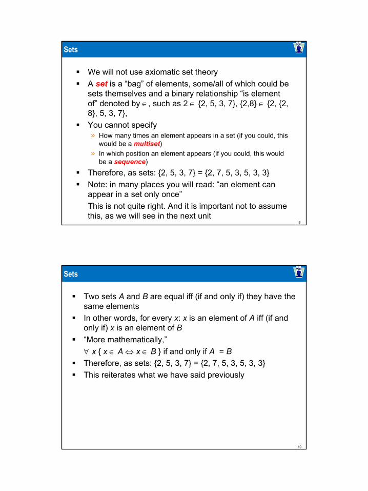
Consider a table, with a fixed number of columns where elements of each column are drawn from some specific domainThe columns are labeled and the labels are distinctWe will consider such a table to be a set of rows (another word for “row”: tuple)Here is an example of a table S of two columns A and B
A relation is such a tableWe will also write S(A,B) for table S with columns A and B
S A Ba 2a 2b 3c 4d 3
12
Relational Schema
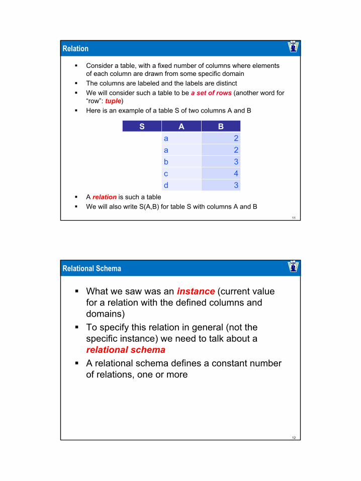
What we saw was an instance (current value for a relation with the defined columns and domains)To specify this relation in general (not the specific instance) we need to talk about a relational schemaA relational schema defines a constant number of relations, one or more
13
Relational Schema
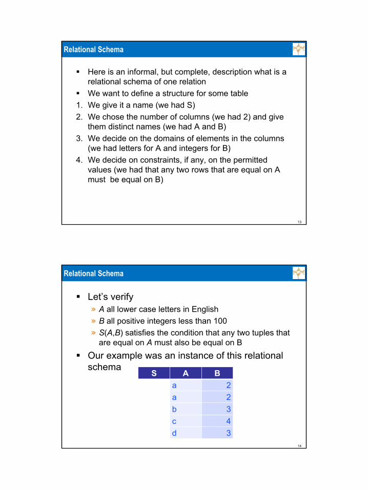
Here is an informal, but complete, description what is a relational schema of one relationWe want to define a structure for some table
1. We give it a name (we had S)2. We chose the number of columns (we had 2) and give
them distinct names (we had A and B)3. We decide on the domains of elements in the columns
(we had letters for A and integers for B)4. We decide on constraints, if any, on the permitted
values (we had that any two rows that are equal on A must be equal on B)
14
Relational Schema
Let’s verify» A all lower case letters in English» B all positive integers less than 100» S(A,B) satisfies the condition that any two tuples that
are equal on A must also be equal on BOur example was an instance of this relational schema
S A Ba 2a 2b 3c 4d 3

15
Relations (1/8)
Since relations are sets of tuples, the following two relations are equal (are really one relation written in two different ways)(This is a different example, not an instance of the previous relational schema)
S A Ba 2a 56b 2
S A Ba 56a 2b 2a 56a 2a 56
16
Relations (2/8)
Since the positions in the tuple (1st, 2nd, etc.) are labeled with the column headings, the following two relations are equal (are really one relation written in two different ways)
S A Ba 2a 56b 2
S B A56 a2 a2 b
56 a2 a
56 a

17
Relations (3/8)
To specify relations, it is enough to do what we have done aboveAs long as we understand what are the domains for the columns, the following are formally fully specified relations» Relational (schema) P(Name, SSN, DOB, Grade)
with some (not specified, but we should have done it) domains for attributes
» Relational (schema) Q(Grade, Salary) with some (not specified, but we should have done it) domains for attributes
P Name SSN DOB GradeA 121 2367 2B 101 3498 4C 106 2987 2
Q Grade Salary1 90
2 80
3 70
4 70
18
Relations (4/8)
But we will do more. We will specify, as appropriate for the schema:» Primary keys» Keys (beyond primary)» Foreign keys and what they reference (we will see
soon what this means)» Additional constraints
Some of the constraints involve more than one relationThe above most important structurallyLater, when we talk about SQL DDL, we will specify additional properties

19
Relations (5/8)
Consider relation (schema) Person(FN, LN, Grade, YOB)Instance:
We are told that any two tuples that are equal on both FN and LNare (completely) equal» We have some tuples appearing multiple times: this is just for clarifying
that this permitted in the definition, we do not discuss here why we would have the same tuple more than one time (we will talk about this later)
This is a property of every possible instance of Person in our application—we are told thisThen (FN, LN) is a superkey of Person, and in fact a key, because neither FN nor LN by themselves are sufficient (we are told thattoo)
Person FN LN Grade YOBJohn Smith 8 1976Lakshmi Smith 9 1981John Smith 8 1976John Yao 9 1992
20
Relations (6/8)
Consider relation (schema) Q(Grade, Salary)Example:
We are told that for any instance of Pay, any two tuples that are equal on Grade are (completely) equal» Of course, if each Grade appears in only one tuple, this is
automatically true
Then, similarly to before, Grade is a keyWhat about Salary, is this a key also?No, because we are not told that any two tuples that are equal on Salary are equal on Grade in every instance of Pay
Pay Grade Salary8 1289 1397 147

21
Relations (7/8)
A set of columns in a relation is a superkey if and only any two tuples that are equal on the elements of these columns are (completely equal) A relation always has at least one superkeyThe set of all the attributes is a superkeyBecause any two tuples that are equal on all attributes are completely equalA minimal superkey, is a keyA relation always has at least one key (start with any superkey and remove unnecessary columns)There may be more than one keyExactly one key is chosen as primary keyOther keys are just keysSometimes they are called candidate keys (as they are candidates for the primary key, though not chosen)
22
Relations (8/8)
We will underline the attributes of the chosen primary keyReturning to the City example: City(Longitude,Latitude,Country,State,Name,Size)We can have» City(Longitude,Latitude,Country,State,Name,Size)» This implies that Longitude,Latitude form a primary key» We also have a candidate key: Country,State,Name
We can have» City(Longitude,Latitude,Country,State,Name,Size)» This implies that Country,State,Name form a primary key» We also have a candidate key: Longitude,Latitude

23
Relational Databases
A relational database is basically a set of relations and is an instance of a relational schema
24
Relational Database Design Using ER-to-Relational Mapping

25
Sample Mapping of ER Schema to Relational Database Schema
26
ER-to-Relational Mapping Algorithm (1/9)
COMPANY database exampleAssume that the mapping will create tables with simple single-valued attributes
Step 1: Mapping of Regular Entity TypesFor each regular entity type, create a relation R that includes all the simple attributes of ECalled entity relations
• Each tuple represents an entity instance

27
ER-to-Relational Mapping Algorithm (2/9)
Step 2: Mapping of Weak Entity TypesFor each weak entity type, create a relation R and include all simple attributes of the entity type as attributes of RInclude primary key attributes of owner as foreign key attributes of R
28
ER-to-Relational Mapping Algorithm (3/9)
29
ER-to-Relational Mapping Algorithm (4/9)
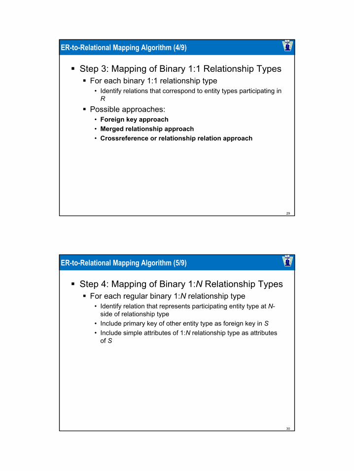
Step 3: Mapping of Binary 1:1 Relationship TypesFor each binary 1:1 relationship type
• Identify relations that correspond to entity types participating in R
Possible approaches: • Foreign key approach• Merged relationship approach• Crossreference or relationship relation approach
30
ER-to-Relational Mapping Algorithm (5/9)
Step 4: Mapping of Binary 1:N Relationship TypesFor each regular binary 1:N relationship type
• Identify relation that represents participating entity type at N-side of relationship type
• Include primary key of other entity type as foreign key in S • Include simple attributes of 1:N relationship type as attributes
of S
31
ER-to-Relational Mapping Algorithm (6/9)
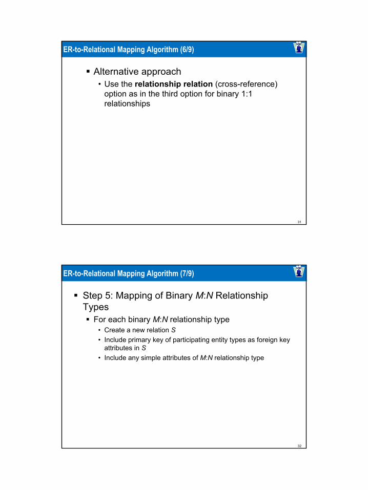
Alternative approach • Use the relationship relation (cross-reference)
option as in the third option for binary 1:1 relationships
32
ER-to-Relational Mapping Algorithm (7/9)
Step 5: Mapping of Binary M:N Relationship Types
For each binary M:N relationship type• Create a new relation S • Include primary key of participating entity types as foreign key
attributes in S• Include any simple attributes of M:N relationship type

33
ER-to-Relational Mapping Algorithm (8/9)
Step 6: Mapping of Multivalued AttributesFor each multivalued attribute
• Create a new relation• Primary key of R is the combination of A and K• If the multivalued attribute is composite, include its simple
components
34
ER-to-Relational Mapping Algorithm (9/9)
Step 7: Mapping of N-ary Relationship TypesFor each n-ary relationship type R
• Create a new relation S to represent R• Include primary keys of participating entity types as foreign
keys• Include any simple attributes as attributes

35
Discussion and Summary of Mapping for ER Model Constructs (1/2)
36
Discussion and Summary of Mapping for ER Model Constructs (2/2)
In a relational schema relationship, types are not represented explicitly
Represented by having two attributes A and B: one a primary key and the other a foreign key
37
Mapping EER Model Constructs to Relations
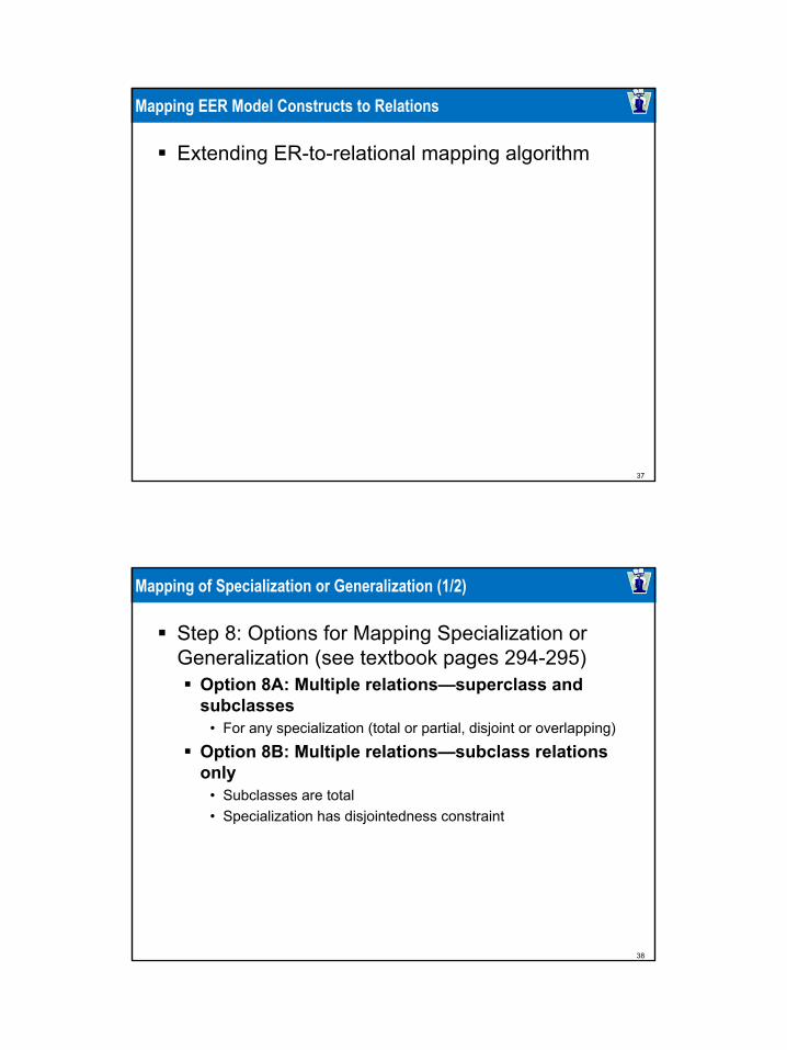
Extending ER-to-relational mapping algorithm
38
Mapping of Specialization or Generalization (1/2)
Step 8: Options for Mapping Specialization or Generalization (see textbook pages 294-295)
Option 8A: Multiple relations—superclass and subclasses
• For any specialization (total or partial, disjoint or overlapping)
Option 8B: Multiple relations—subclass relations only
• Subclasses are total• Specialization has disjointedness constraint

39
Mapping of Specialization or Generalization (2/2)
Option 8C: Single relation with one type attribute• Type or discriminating attribute indicates subclass of tuple• Subclasses are disjoint
• Potential for generating many NULL values if many specific attributes exist in the subclasses
Option 8D: Single relation with multiple type attributes
• Subclasses are overlapping • Will also work for a disjoint specialization
40
Mapping of Shared Subclasses (Multiple Inheritance)
Apply any of the options discussed in step 8 to a shared subclass
41
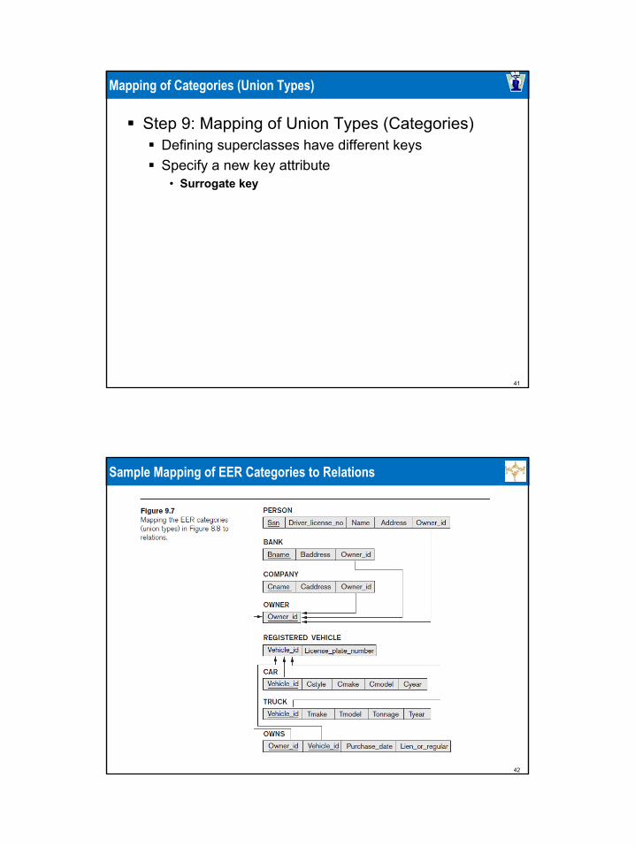
Mapping of Categories (Union Types)
Step 9: Mapping of Union Types (Categories)Defining superclasses have different keysSpecify a new key attribute
• Surrogate key
42
Sample Mapping of EER Categories to Relations

43
Summary
Map conceptual schema design in the ER model to a relational database schema
Algorithm for ER-to-relational mappingIllustrated by examples from the COMPANY database
Include additional steps in the algorithm for mapping constructs from EER model into relational model
44
Agenda
11 Session OverviewSession Overview
55 Summary and ConclusionSummary and Conclusion
22 ER and EER to Relational MappingER and EER to Relational Mapping
33 Database Design Methodology and UMLDatabase Design Methodology and UML
44 Mapping Relational Design to ER/EER Case StudyMapping Relational Design to ER/EER Case Study

45
Agenda
The Role of Information Systems in OrganizationsThe Database Designand Implementation ProcessUse of UML Diagrams as an Aid to Database Design SpecificationRational Rose: A UML-Based Design ToolAutomated Database Design Tools
46
Practical Database Design Methodology and Use of UML Diagrams
Design methodologyTarget database managed by some type of database management system
Various design methodologiesLarge database
Several dozen gigabytes of data and a schema with more than 30 or 40 distinct entity types
47
The Role of Information Systems in Organizations (1/3)
Organizational context for using database systems
Organizations have created the position of database administrator (DBA) and database administration departmentsInformation technology (IT) and information resource management (IRM) departments
• Key to successful business management
48
The Role of Information Systems in Organizations (2/3)
Database systems are integral components in computer-based information systemsPersonal computers and database system-like software products
• Utilized by users who previously belonged to the category of casual and occasional database users
Personal databases gaining popularityDatabases are distributed over multiple computer systems
• Better local control and faster local processing

49
The Role of Information Systems in Organizations (3/3)
Data dictionary systems or information repositories
• Mini DBMSs • Manage meta-data
High-performance transaction processing systems require around-the-clock nonstop operation
• Performance is critical
50
The Information System Life Cycle (1/4)
Information system (IS)Resources involved in collection, management, use, and dissemination of information resources of organization
51
The Information System Life Cycle (2/4)
Macro life cycleFeasibility analysisRequirements collection and analysisDesignImplementationValidation and acceptance testingRequirements collection and analysis
52
The Information System Life Cycle (3/4)
The database application system life cycle: micro life cycle
System definitionDatabase designDatabase implementationLoading or data conversion

53
The Information System Life Cycle (4/4)
Application conversionTesting and validationOperationMonitoring and maintenance
54
The Database Design and Implementation Process (1/4)
Design logical and physical structure of one or more databases
Accommodate the information needs of the users in an organization for a defined set of applications
Goals of database designVery hard to accomplish and measure
Often begins with informal and incomplete requirements
55
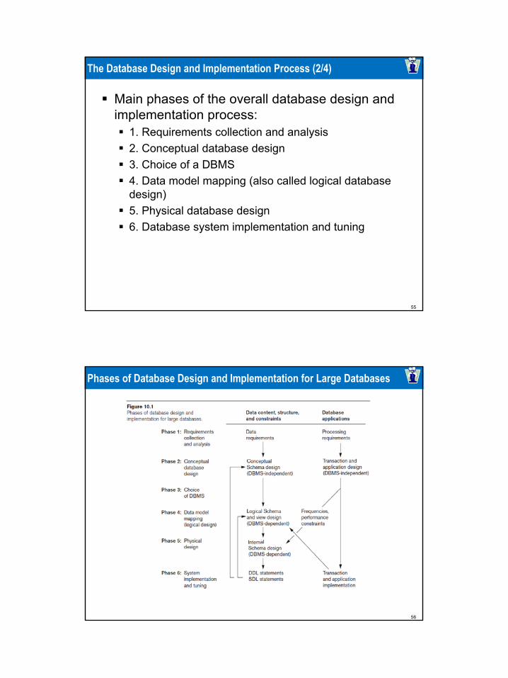
The Database Design and Implementation Process (2/4)
Main phases of the overall database design and implementation process:
1. Requirements collection and analysis2. Conceptual database design3. Choice of a DBMS4. Data model mapping (also called logical database design)5. Physical database design6. Database system implementation and tuning
56
Phases of Database Design and Implementation for Large Databases
57
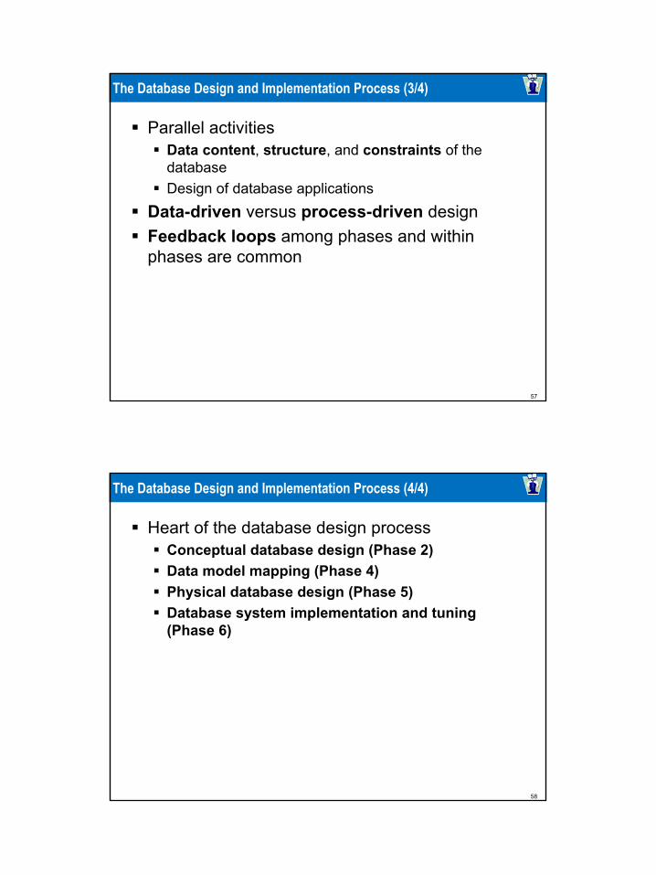
The Database Design and Implementation Process (3/4)
Parallel activitiesData content, structure, and constraints of the databaseDesign of database applications
Data-driven versus process-driven designFeedback loops among phases and within phases are common
58
The Database Design and Implementation Process (4/4)
Heart of the database design processConceptual database design (Phase 2)Data model mapping (Phase 4)Physical database design (Phase 5)Database system implementation and tuning (Phase 6)

59
Phase 1: Requirements Collection and Analysis (1/2)
ActivitiesIdentify application areas and user groupsStudy and analyze documentationStudy current operating environmentCollect written responses from users
60
Phase 1: Requirements Collection and Analysis (2/2)
Requirements specification techniquesOriented analysis (OOA)Data flow diagrams (DFDs)Refinement of application goalsComputer-aided

61
Phase 2: Conceptual Database Design (1/3)
Phase 2a: Conceptual Schema DesignImportant to use a conceptual high-level data modelApproaches to conceptual schema design
• Centralized (or one shot) schema design approach• View integration approach
62
Phase 2: Conceptual Database Design (2/3)
Strategies for schema design• Top-down strategy• Bottom-up strategy• Inside-out strategy• Mixed strategy
Schema (view) integration• Identify correspondences/conflicts among schemas:
• Naming conflicts, type conflicts, domain (value set) conflicts, conflicts among constraints
• Modify views to conform to one another• Merge of views and restructure
63
Phase 2: Conceptual Database Design (3/3)
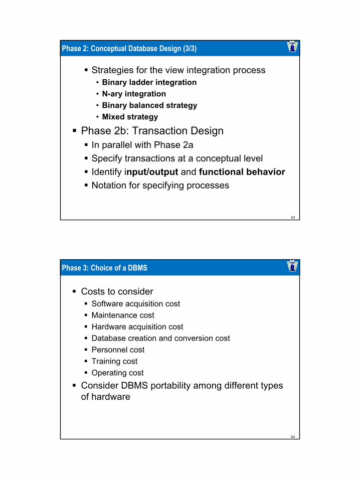
Strategies for the view integration process• Binary ladder integration• N-ary integration• Binary balanced strategy• Mixed strategy
Phase 2b: Transaction DesignIn parallel with Phase 2aSpecify transactions at a conceptual level Identify input/output and functional behaviorNotation for specifying processes
64
Phase 3: Choice of a DBMS
Costs to considerSoftware acquisition costMaintenance costHardware acquisition costDatabase creation and conversion costPersonnel costTraining costOperating cost
Consider DBMS portability among different types of hardware
65
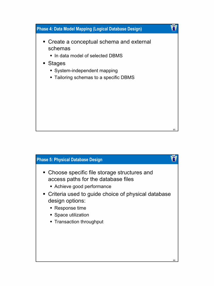
Phase 4: Data Model Mapping (Logical Database Design)
Create a conceptual schema and external schemas
In data model of selected DBMSStages
System-independent mappingTailoring schemas to a specific DBMS
66
Phase 5: Physical Database Design
Choose specific file storage structures and access paths for the database files
Achieve good performanceCriteria used to guide choice of physical database design options:
Response timeSpace utilizationTransaction throughput

67
Phase 6: Database System Implementation and Tuning
Typically responsibility of the DBACompose DDLLoad databaseConvert data from earlier systems
Database programs implemented by application programmersMost systems include monitoring utility to collect performance statistics
68
Use of UML Diagrams as an Aid to Database Design Specification
Use UML as a design specification standardUnified Modeling Language (UML) approach
Combines commonly accepted concepts from many object-oriented (O-O) methods and methodologiesIncludes use case diagrams, sequence diagrams, and statechart diagrams

69
UML for Database Application Design
Advantages of UML Resulting models can be used to design relational, object-oriented, or object-relational databasesBrings traditional database modelers, analysts, and designers together with software application developers
70
Different Types of Diagrams in UML (1/4)
Structural diagramsClass diagrams and package diagramsObject diagramsComponent diagramsDeployment diagrams

71
Different Types of Diagrams in UML (2/4)
Behavioral diagramsUse case diagramsSequence diagramsCollaboration diagramsStatechart diagramsActivity diagrams
72
Use Case Diagram Notation

73
Different Types of Diagrams in UML (3/4)
74
Different Types of Diagrams in UML (4/4)

75
Modeling and Design Example: UNIVERSITY Database
76
Sample Sequence Diagram

77
Sample Class Diagram
78
Rational Rose: A UML-Based Design Tool
Rational Rose for database designModeling tool used in the industry to develop information systems
Rational Rose data modelerVisual modeling tool for designing databasesProvides capability to:
• Forward engineer a database• Reverse engineer an existing implemented database into
conceptual design
79
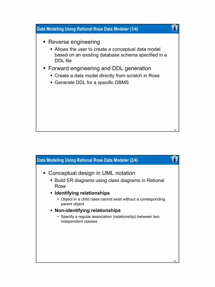
Data Modeling Using Rational Rose Data Modeler (1/4)
Reverse engineeringAllows the user to create a conceptual data model based on an existing database schema specified in a DDL file
Forward engineering and DDL generationCreate a data model directly from scratch in RoseGenerate DDL for a specific DBMS
80
Data Modeling Using Rational Rose Data Modeler (2/4)
Conceptual design in UML notationBuild ER diagrams using class diagrams in Rational RoseIdentifying relationships
• Object in a child class cannot exist without a corresponding parent object
Non-identifying relationships • Specify a regular association (relationship) between two
independent classes

81
Data Modeling Using Rational Rose Data Modeler (3/4)
Converting logical data model to object model and vice versa
Logical data model can be converted to an object modelAllows a deep understanding of relationships between conceptual and implementation models
82
Data Modeling Using Rational Rose Data Modeler (4/4)
Synchronization between the conceptual design and the actual databaseExtensive domain support
Create a standard set of user-defined data typesEasy communication among design teams
Application developer can access both the object and data models
83
Automated Database Design Tools (1/3)
Many CASE (computer-aided software engineering) tools for database designCombination of the following facilities
DiagrammingModel mappingDesign normalization
84
Automated Database Design Tools (2/3)
Characteristics that a good design tool should possess:
Easy-to-use interfaceAnalytical componentsHeuristic componentsTrade-off analysisDisplay of design resultsDesign verification

85
Automated Database Design Tools (3/3)
Variety of products availableSome use expert system technology
86
Summary
Six phases of the design processCommonly include conceptual design, logical design (data model mapping), physical design
UML diagrams Aid specification of database models and design
Rational Rose and the Rose Data ModelerProvide support for the conceptual design and logical design phases of database design

87
Agenda
11 Session OverviewSession Overview
55 Summary and ConclusionSummary and Conclusion
22 ER and EER to Relational MappingER and EER to Relational Mapping
33 Database Design Methodology and UMLDatabase Design Methodology and UML
44 Mapping Relational Design to ER/EER Case StudyMapping Relational Design to ER/EER Case Study
88
A Case Study
Implementing an ER diagram as a relational schema (relational database)General implementation of strong entitiesHandling attributes of different typesGeneral implementation of relationshipsPossible special implementation of binary many-to-one relationshipsImplementation of ISAImplementation of weak entities Foreign keysPrimary key / foreign key constraints inducing many-to-one relationships between tablesConcept of referential integrityCrow’s feet notation: ends of linesCrow’s feet notation: pattern of lines

89
From ER Diagrams To Relational Database
We are now ready to convert ER diagrams into relational databasesGenerally, but not always» An entity set is converted into a table» A relationship is converted into a table
We will first go through a simple exampleThen, we will go through our large example, studied previouslyThen, we look at some additional points of interestFinally, we summarize the process, so we are sure we understand it
90
Small ER Diagram

91
More About The Example
The given ER diagram is clear, other than» Discovered, which is the continent in which a particular species was
first discoveredEach child is a “dependant” of only one employee in our database» If both parents are employees, the child is “assigned” to one of them
We are given additional information about the application» Values of attributes in a primary key must not be missing (this is a
general rule, not only for this example)» Other than attributes in a primary key, other attributes unless stated
otherwise may be missing» The value of Name is known for every Employee
To build up our intuition, let’s look at some specific instance of our application
92
Country
There are four countries, listing for them: Cname, Population (the latter only when known):» US» IN, 1150» CN, 1330» RU
We create a table for Country “in the most obvious way,” by creating a column for each attribute (underlying the attributes of the primary key) and this works:
Country Cname PopulationUSIN 1150CN 1330RU

93
Animal
There are five animals, listing for them: Species, Discovered (note, that even though not required, Discovered happens to be known for every Species):» Horse, Asia» Wolf, Asia» Cat, Africa» Yak, Asia» Zebra, Africa
We create a table for Animal as before, and this works:
Animal Species Discovered
Horse AsiaWolf AsiaCat AfricaYak AsiaZebra Africa
94
Employee
There are five employees, listing for them: ID#, Name, (name of)Child (note there may be any number of Child values for an Employee, zero or more):» 1, Alice, Erica, Frank» 2, Bob, Bob, Frank» 4, Carol» 5, David» 6, Bob, Frank
We create a table for Employee in the most obvious way, and thisdoes not work:
Employee ID# Name Child Child1 Alice Erica Frank2 Bob Bob Frank4 Carol5 David6 Bob Frank

95
Employee
Child is a multivalued attribute so, the number of columns labeled “Child” is, in principle, unboundedA table must have a fixed number of columns» It must be an instance in/of a relational schema
If we are ready to store up to 25 children for an employee and create a table with 25 columns for children, perhaps tomorrow we get an employee with 26 children, who will not “fit”We replace our attempted single table for Employee by two tables» One for all the attributes of Employee other than the multivalued
one (Child)» One for pairs of the form (primary key of Employee, Child)
Note that both tables have a fixed number of columns, no matter how many children an employee has
96
Employee And Child
Replace (incorrect)
By (correct)
Employee ID# Name Child Child1 Alice Erica Frank2 Bob Bob Frank4 Carol5 David6 Bob Frank
Employee ID# Name1 Alice2 Bob4 Carol5 David6 Bob
Child ID# Child1 Erica1 Frank2 Bob2 Frank6 Frank
97
Employee And Child
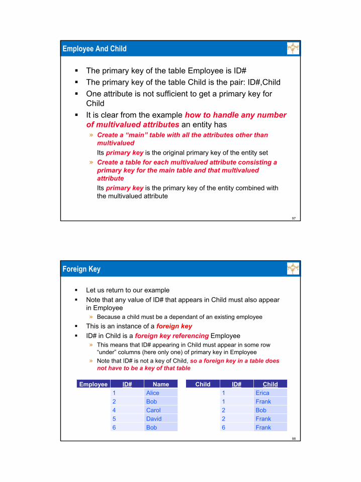
The primary key of the table Employee is ID#The primary key of the table Child is the pair: ID#,ChildOne attribute is not sufficient to get a primary key for ChildIt is clear from the example how to handle any number of multivalued attributes an entity has» Create a “main” table with all the attributes other than
multivaluedIts primary key is the original primary key of the entity set
» Create a table for each multivalued attribute consisting a primary key for the main table and that multivalued attributeIts primary key is the primary key of the entity combined with the multivalued attribute
98
Foreign Key
Let us return to our exampleNote that any value of ID# that appears in Child must also appear in Employee» Because a child must be a dependant of an existing employee
This is an instance of a foreign keyID# in Child is a foreign key referencing Employee» This means that ID# appearing in Child must appear in some row
“under” columns (here only one) of primary key in Employee» Note that ID# is not a key of Child, so a foreign key in a table does
not have to be a key of that table
Employee ID# Name1 Alice2 Bob4 Carol5 David6 Bob
Child ID# Child1 Erica1 Frank2 Bob2 Frank6 Frank

99
Foreign Key Induces A Many-To-One Relationship Between Tables
Note:» Every row of Child has a single value of a primary
key of Employee, so every row of Child “maps” to a single row of Employee
» Every row of Employee has zero or more rows of Child mapped into itIn other words, no constraint
100
Likes (1/3)
Likes needs to specify which employees like which animalsSuch specification can be done using the primary keys of the entitiesWe do not need other attributes such as Name or DiscoveredThe table for likes contains some tuples:» 1 likes Horse» 1 likes Cat» 2 likes Cat» 6 likes Yak
Likes ID# Species1 Horse1 Cat2 Cat6 Yak
101
Likes (2/3)
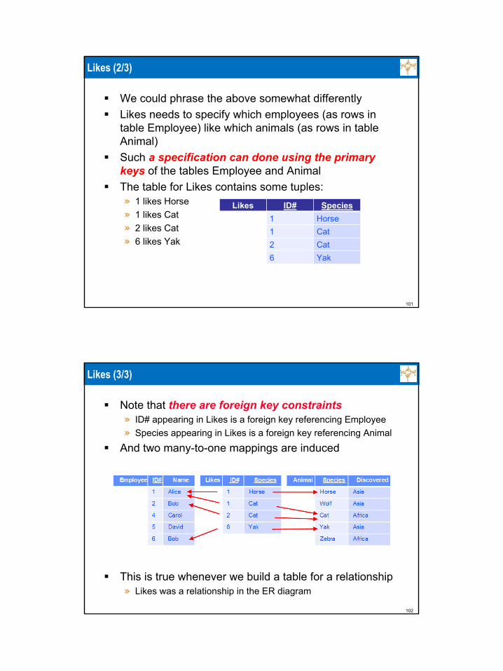
We could phrase the above somewhat differentlyLikes needs to specify which employees (as rows in table Employee) like which animals (as rows in table Animal)Such a specification can done using the primary keys of the tables Employee and AnimalThe table for Likes contains some tuples:» 1 likes Horse» 1 likes Cat» 2 likes Cat» 6 likes Yak
Likes ID# Species1 Horse1 Cat2 Cat6 Yak
102
Likes (3/3)
Note that there are foreign key constraints» ID# appearing in Likes is a foreign key referencing Employee» Species appearing in Likes is a foreign key referencing Animal
And two many-to-one mappings are induced
This is true whenever we build a table for a relationship» Likes was a relationship in the ER diagram

103
Born (1/3)
Born needs to specify which employees were born in which countries (for whom this information is known)Such specification can done using the primary keys of the entities/tables The relation Born contains some tuples:» 1, US» 2, IN» 5, IN» 6, CN
Born ID# Cname1 US2 IN5 IN6 CN
104
Born (2/3)
Note that there are foreign key constraints» ID# appearing in Born is a foreign key referencing Employee» Cname appearing in Born is a foreign key referencing Country
And two many-to-one mappings are induced» One of them happens to be one-to-one as an employee can be born in
only one country» This follows from the fact that in the ER diagram Born was a many-to-
one relationship» Compare with Likes, where an employee can like more than one
animal and an animal can be liked by more than one Employee

105
Born (3/3)
Let us focus on ID# in EmployeeNo two different tuples in Born can have the same ID#Therefore ID# serves as a primary key, and we do not need Cname as part of the primary key
106
Using Visio
Visio can be used to designing/specifying relational databasesYou can look at a tutorial, to get familiar with the mechanics of VisioThis is greatly oversimplified, but a good start» http://www.youtube.com/watch?v=1BYt3wmkgXE but foreign
keys are not explained» http://www.youtube.com/watch?v=55TpWp4TmMw&NR=1» http://www.youtube.com/watch?v=r0x8ZMyPoj4&NR=1 but this
third part• Is misleading in the context of relational databases, due to the
handling of many-to-many relationships and • The use of the second page, all the pages in a single Visio drawing
refer to a single ER diagram, so each ER diagram needs its own Visio drawing/file
107
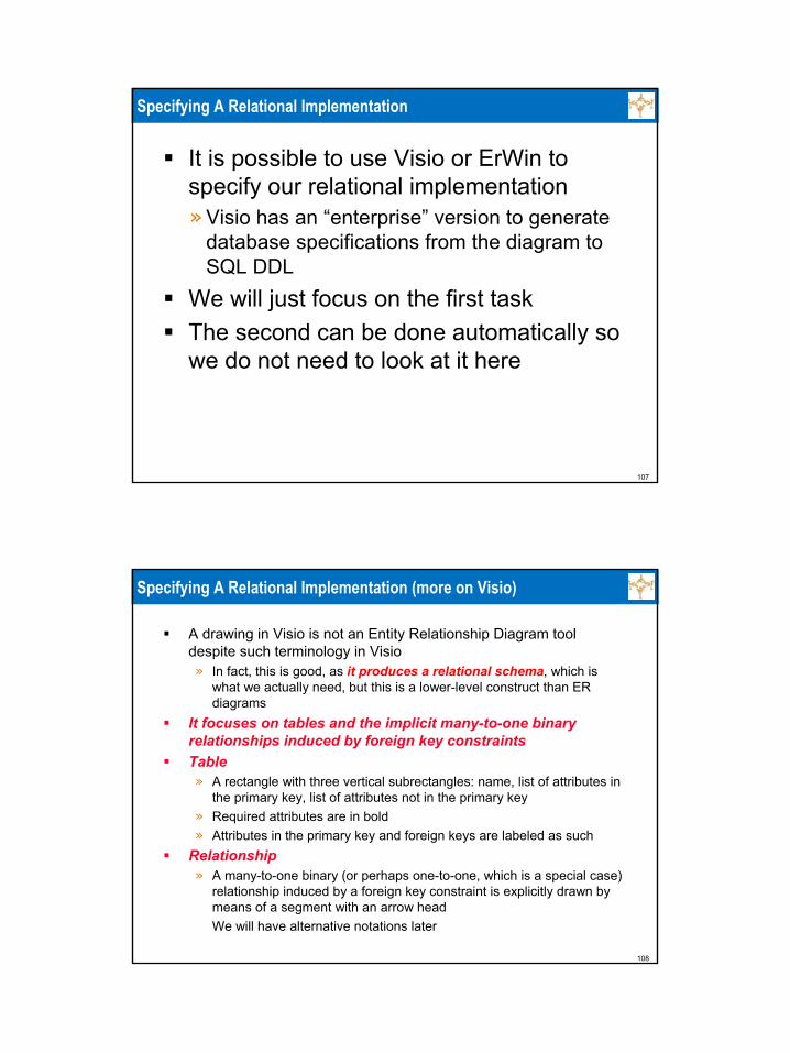
Specifying A Relational Implementation
It is possible to use Visio or ErWin to specify our relational implementation» Visio has an “enterprise” version to generate
database specifications from the diagram to SQL DDL
We will just focus on the first taskThe second can be done automatically so we do not need to look at it here
108
Specifying A Relational Implementation (more on Visio)
A drawing in Visio is not an Entity Relationship Diagram tool despite such terminology in Visio» In fact, this is good, as it produces a relational schema, which is
what we actually need, but this is a lower-level construct than ER diagrams
It focuses on tables and the implicit many-to-one binary relationships induced by foreign key constraintsTable» A rectangle with three vertical subrectangles: name, list of attributes in
the primary key, list of attributes not in the primary key» Required attributes are in bold» Attributes in the primary key and foreign keys are labeled as such
Relationship» A many-to-one binary (or perhaps one-to-one, which is a special case)
relationship induced by a foreign key constraint is explicitly drawn by means of a segment with an arrow headWe will have alternative notations later
109
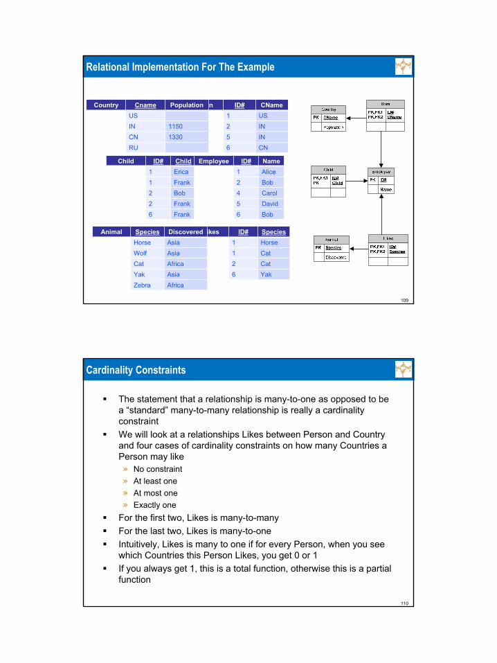
Relational Implementation For The Example
Child ID# Child1 Erica1 Frank2 Bob2 Frank6 Frank
Employee ID# Name1 Alice2 Bob4 Carol5 David6 Bob
Born ID# CName1 US2 IN5 IN6 CN
Country Cname PopulationUSIN 1150CN 1330RU
Likes ID# Species1 Horse1 Cat2 Cat6 Yak
Animal Species DiscoveredHorse AsiaWolf AsiaCat AfricaYak AsiaZebra Africa
110
Cardinality Constraints
The statement that a relationship is many-to-one as opposed to be a “standard” many-to-many relationship is really a cardinality constraintWe will look at a relationships Likes between Person and Countryand four cases of cardinality constraints on how many Countries a Person may like» No constraint» At least one» At most one» Exactly one
For the first two, Likes is many-to-manyFor the last two, Likes is many-to-oneIntuitively, Likes is many to one if for every Person, when you see which Countries this Person Likes, you get 0 or 1If you always get 1, this is a total function, otherwise this is a partial function
111
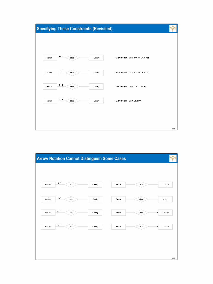
Specifying These Constraints (Revisited)
112
Arrow Notation Cannot Distinguish Some Cases
113
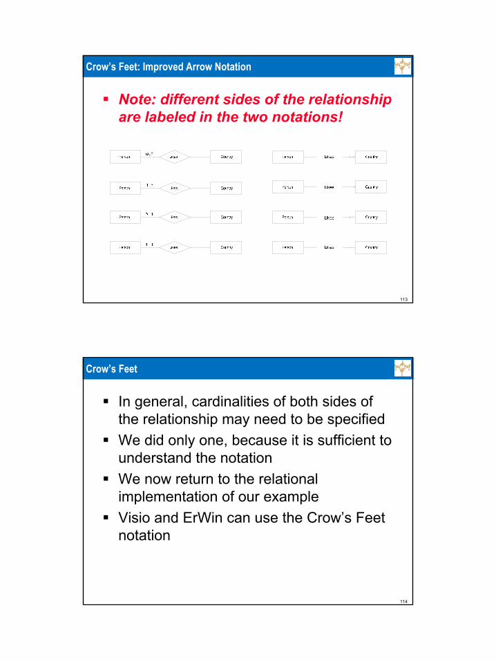
Crow’s Feet: Improved Arrow Notation
Note: different sides of the relationship are labeled in the two notations!
114
Crow’s Feet
In general, cardinalities of both sides of the relationship may need to be specifiedWe did only one, because it is sufficient to understand the notationWe now return to the relational implementation of our exampleVisio and ErWin can use the Crow’s Feet notation
115
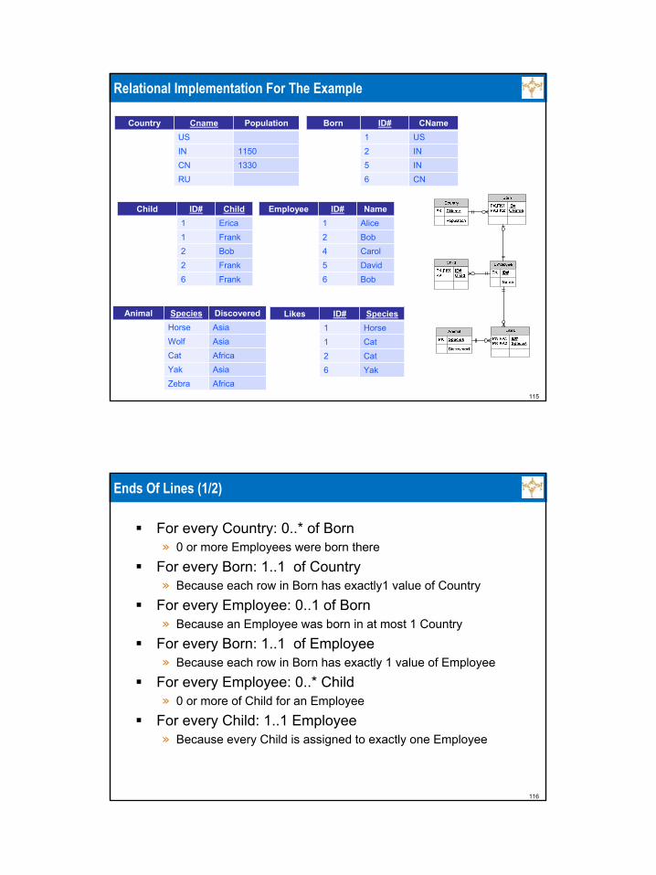
Relational Implementation For The Example
Animal
Species
DiscoveredHorse Asia
Wolf AsiaCat AfricaYak AsiaZebra Africa
Child ID# Child1 Erica1 Frank2 Bob2 Frank6 Frank
Employee ID# Name1 Alice2 Bob4 Carol5 David6 Bob
Born ID# CName1 US2 IN5 IN6 CN
Country Cname PopulationUSIN 1150CN 1330RU
Likes ID# Species1 Horse1 Cat2 Cat6 Yak
Animal Species DiscoveredHorse AsiaWolf AsiaCat AfricaYak AsiaZebra Africa
116
Ends Of Lines (1/2)
For every Country: 0..* of Born» 0 or more Employees were born there
For every Born: 1..1 of Country» Because each row in Born has exactly1 value of Country
For every Employee: 0..1 of Born» Because an Employee was born in at most 1 Country
For every Born: 1..1 of Employee» Because each row in Born has exactly 1 value of Employee
For every Employee: 0..* Child» 0 or more of Child for an Employee
For every Child: 1..1 Employee» Because every Child is assigned to exactly one Employee
117
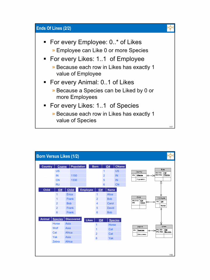
Ends Of Lines (2/2)
For every Employee: 0..* of Likes» Employee can Like 0 or more Species
For every Likes: 1..1 of Employee» Because each row in Likes has exactly 1
value of EmployeeFor every Animal: 0..1 of Likes» Because a Species can be Liked by 0 or
more EmployeesFor every Likes: 1..1 of Species» Because each row in Likes has exactly 1
value of Species
118
Born Versus Likes (1/2)
Child ID# Child1 Erica1 Frank2 Bob2 Frank6 Frank
Employee ID# Name1 Alice2 Bob4 Carol5 David6 Bob
Born ID# CName1 US2 IN5 IN6 CN
Country Cname PopulationUSIN 1150CN 1330RU
Likes ID# Species1 Horse1 Cat2 Cat6 Yak
Animal Species DiscoveredHorse AsiaWolf AsiaCat AfricaYak AsiaZebra Africa

119
Born Versus Likes (2/2)
Note that the many-to-one relationships are not of the same type in both casesThe relationship between Likes and Employee indicates than when you start from a row of Employee you end up in between 0 and unbounded number of rows of Likes: no restrictionAn employee can like any number of animalsThe relationship between Born and Employee indicates that when you start from a row of Employee you end up in between 0 and 1 rows of BornAn employee can be born in at most one country and therefore from a row of Employee you end up in between 0 and 1 rows of Born: a restrictionBorn is really a (partial) one-to-one relationshipSuch relationships are considered “strange”
120
Treating Born Differently From Likes
The above discussion implies that for every row in Employee there is at most one “relevant” row of BornTherefore, the “extra” information about an employee that is currently stored in Born can be added to EmployeeBorn can be removed from the designThis sounds very formal, but intuitively very clear as we can see from an alternative design

121
Alternative For Born
Replace
by
Employee ID# Name1 Alice2 Bob4 Carol5 David6 Bob
Born ID# Cname1 US2 IN5 IN6 CN
Employee ID# Name Cname1 Alice US2 Bob IN4 Carol5 David IN6 Bob CN
122
Alternative Relational Implementation For The Example
Child ID# Child1 Erica1 Frank2 Bob2 Frank6 Frank
Employee ID# Name CName1 Alice US2 Bob IN4 Carol5 David IN6 Bob CN
Likes ID# Species1 Horse1 Cat2 Cat6 Yak
Animal Species DiscoveredHorse AsiaWolf AsiaCat AfricaYak AsiaZebra Africa
Country CName PopulationUSIN 1150CN 1330RU
123
Alternative Relational Implementation For The Example
Likes ID# Species1 Horse1 Cat2 Cat6 Yak
Animal Species DiscoveredHorse AsiaWolf AsiaCat AfricaYak AsiaZebra Africa
Country CName PopulationUSIN 1150CN 1330RU
Child ID# Child1 Erica1 Frank2 Bob2 Frank6 Frank
Employee ID# Name CName1 Alice US2 Bob IN4 Carol5 David IN6 Bob CN
124
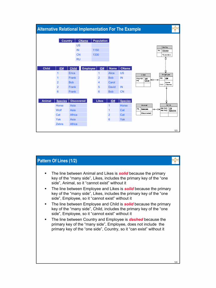
Pattern Of Lines (1/2)
The line between Animal and Likes is solid because the primary key of the “many side”, Likes, includes the primary key of the “one side”, Animal, so it “cannot exist” without itThe line between Employee and Likes is solid because the primary key of the “many side”, Likes, includes the primary key of the “one side”, Employee, so it “cannot exist” without itThe line between Employee and Child is solid because the primary key of the “many side”, Child, includes the primary key of the “one side”, Employee, so it “cannot exist” without itThe line between Country and Employee is dashed because the primary key of the “many side”, Employee, does not include the primary key of the “one side”, Country, so it “can exist” without it

125
Pattern Of Lines (2/2)
This is not a question of the ends of lines “forcing”the pattern of linesIn the next slide, we see a slight modification of our example in which all lines have the same pair of endingsWe required that for each Employee the Country of Birth is knownNevertheless, as Cname is not part of the primary key of Country, the line is dashedFor technical reasons, the tables have slightly different names, but this has nothing to do with our point
126
Example

127
Which Implementation To Use For Born?
We cannot give a general ruleThe first implementation uses more tablesThe second implementation may introduce NULLs (empty values), which we do not likeFor the purpose of the class we will always use the second version, to have better exercisesSo do this for all the homeworks and tests, when relevant
128
To Remember!
Structurally, a relational database consists of1. A set of tables2. A set of many-to-one binary relationships
between them, induced by foreign key constraintsIn other words; a set of functions (in general partial), each from a table into a table
When designing a relational database, you must specify both (or you will produce a bad specification)» Technically, tables are enough, but this a very bad
practice as you do not specify the relationships between tables
129
Very Bad Diagram
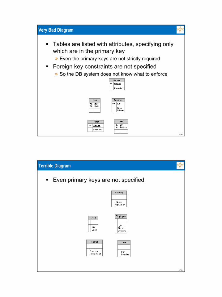
Tables are listed with attributes, specifying only which are in the primary key» Even the primary keys are not strictly required
Foreign key constraints are not specified» So the DB system does not know what to enforce
130
Terrible Diagram
Even primary keys are not specified

131
From ER Diagram To Relational Database
We now convert our big ER diagram into a relational databaseWe specify» Attributes that must not be NULL» Primary keys» Keys (beyond primary)» Foreign keys and what they reference» Cardinality constraints» Some additional “stubs”
We both give a narrative description, similar to actual SQL DDL (so we are learning about actual relational databases) and Visio/Erwin diagramsWe should specify domains also, but we would not learn anything from this here, so we do not do itWe go bottom up, in the same order as the one we used in constructing the ER diagram
132
Our ER Diagram

133
Hierarchy For Our ER Diagram
134
We Will Produce

135
Horse (1/2)
Define Table Horse (Name NOT NULL,Primary Key (Name));This represents the simplest possible relational database» One table with one attribute
136
Horse (2/2)
137
Person (1/3)
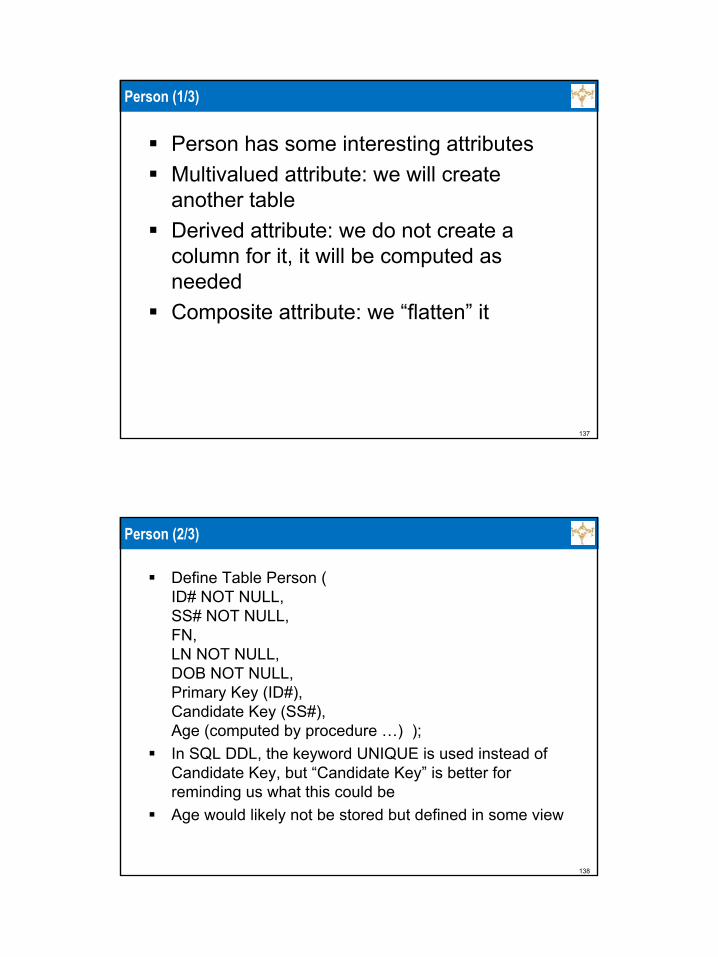
Person has some interesting attributesMultivalued attribute: we will create another tableDerived attribute: we do not create a column for it, it will be computed as neededComposite attribute: we “flatten” it
138
Person (2/3)
Define Table Person (ID# NOT NULL,SS# NOT NULL,FN,LN NOT NULL,DOB NOT NULL,Primary Key (ID#),Candidate Key (SS#),Age (computed by procedure …) );In SQL DDL, the keyword UNIQUE is used instead of Candidate Key, but “Candidate Key” is better for reminding us what this could beAge would likely not be stored but defined in some view

139
Person (3/3)
140
Child
Define Table Child (ID# NOT NULL,ChildName NOT NULL,Primary Key (ID#,ChildName),Foreign Key (ID#) References Person );This lists all pairs (ID# of person, a child’s name)» We have chosen a more descriptive attribute name than the
one in the ER diagram for children’s names
Note» A person may have several children, each with a different name» Two different persons may have children with the same name
Because of this, no single attribute can serve as primary key of Child
141
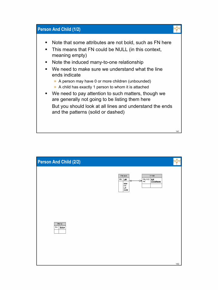
Person And Child (1/2)
Note that some attributes are not bold, such as FN hereThis means that FN could be NULL (in this context, meaning empty)Note the induced many-to-one relationshipWe need to make sure we understand what the line ends indicate» A person may have 0 or more children (unbounded)» A child has exactly 1 person to whom it is attached
We need to pay attention to such matters, though we are generally not going to be listing them hereBut you should look at all lines and understand the ends and the patterns (solid or dashed)
142
Person And Child (2/2)
143
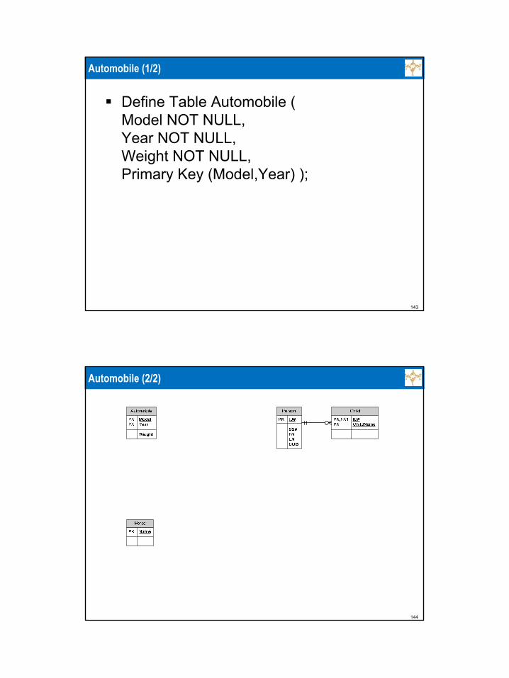
Automobile (1/2)
Define Table Automobile (Model NOT NULL,Year NOT NULL,Weight NOT NULL,Primary Key (Model,Year) );
144
Automobile (2/2)

145
Likes (1/2)
Define Table Likes (ID# NOT NULL,Model NOT NULL,Year NOT NULL,Primary Key (ID#,Model,Year),Foreign Key (ID#) References Person,Foreign Key (Model,Year) References Automobile );
146
Likes (2/2)

147
Car (1/2)
Define Table Car (VIN NOT NULL,Color,Primary Key (VIN) );
148
Car (2/2)

149
Type
There is no need for a table for Type as Type is a binary many-to-one relationshipIt is essentially “stored” in the “many” side, that is in Car
150
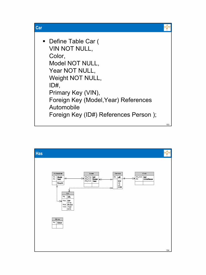
Car
Define Table Car (VIN NOT NULL,Color,Model NOT NULL,Year NOT NULL,Weight NOT NULL,Primary Key (VIN),Foreign Key (Model,Year) References Automobile );

151
Type
152
Has
As Has is a binary many-to-one relationship, the attributed of this relationship, Date, is stored in the “many” side, CarThere is no need for a table for Has as Has is a binary many-to-one relationshipIt is essentially “stored” in the “many” side, that is in CarWe can only specify that a Person has at least 1 Car with the notation we currently useThe CHECK condition is specified using appropriate SQL constraint syntaxThis can actually be done in Visio/Erwin also
153
Car
Define Table Car (VIN NOT NULL,Color,Model NOT NULL,Year NOT NULL,Weight NOT NULL,ID#,Primary Key (VIN),Foreign Key (Model,Year) References Automobile Foreign Key (ID#) References Person );
154
Has
155
ISA
We do not define a table for ISAThis/these relationship/s is/are “embedded” in Student and Professor
156
Student
Define Table Student (ID# NOT NULL,Primary Key (ID#),Foreign Key (ID#) References Person,GPA (computed by procedure …) );Note, how ISA, the class/subclass (set/subset) relations, is modeled by Visio/Erwin

157
Student And ISA
158
Professor
Define Table Professor (ID# NOT NULL,Salary NOT NULL,Primary Key (ID#),Foreign Key (ID#) References Person );

159
Professor And ISA
160
Course (1/2)
Define Table Course (C# NOT NULL,Title NOT NULL,Description,Primary Key (C#) );

161
Course (2/2)
162
Prerequisite (1/3)
Define Table Prereq (First NOT NULL,Second NOT NULL,Primary Key (First,Second),Foreign Key (First) References Course,Foreign Key (Second) References Course );
163
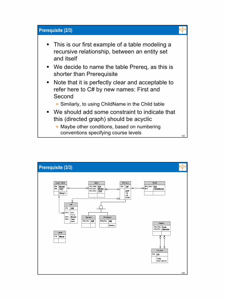
Prerequisite (2/3)
This is our first example of a table modeling a recursive relationship, between an entity set and itselfWe decide to name the table Prereq, as this is shorter than PrerequisiteNote that it is perfectly clear and acceptable to refer here to C# by new names: First and Second» Similarly, to using ChildName in the Child table
We should add some constraint to indicate that this (directed graph) should be acyclic» Maybe other conditions, based on numbering
conventions specifying course levels
164
Prerequisite (3/3)

165
Book (1/2)
Define Table Book (Author NOT NULL,Title NOT NULL, Primary Key (Author,Title) );
166
Book (2/2)
167
Required (1/3)
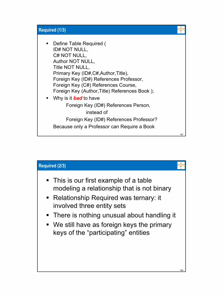
Define Table Required (ID# NOT NULL,C# NOT NULL, Author NOT NULL, Title NOT NULL,Primary Key (ID#,C#,Author,Title),Foreign Key (ID#) References Professor,Foreign Key (C#) References Course, Foreign Key (Author,Title) References Book );Why is it bad to have
Foreign Key (ID#) References Person, instead of
Foreign Key (ID#) References Professor?Because only a Professor can Require a Book
168
Required (2/3)
This is our first example of a table modeling a relationship that is not binaryRelationship Required was ternary: it involved three entity setsThere is nothing unusual about handling itWe still have as foreign keys the primary keys of the “participating” entities

169
Required (3/3)
170
Section (1/2)
Define Table Section (C# NOT NULL,Year NOT NULL,Semester NOT NULL,Sec# NOT NULL, MaxSize,Primary Key (C#,Year,Semester,Sec#),Foreign Key (C#) References Course );Note on the end of the edge between Course and Section, the Section end, on the drawing how the requirement of having at least one Section is modeled
171
Section (2/2)
Section is our first example of a weak entity
172
Offered
We do not define a table for OfferedRelationship Offered is implicit in the foreign key constraint

173
Section + Offered
174
Took (1/3)
Define Table Took (ID# NOT NULL,C# NOT NULL,Year NOT NULL,Semester NOT NULL,Sec# NOT NULL, Grade,Primary Key (ID#,C#,Year,Semester,Sec#),Foreign Key (ID#) References Student,Foreign Key (C#,Year,Semester, Sec#) References
Section );Note on the end of the edge between Section and Took, the Took end, on the drawing how the requirement of having between 3 and 50 students in a section is not fully modeledWe can only show 1 or more using current notation
175
Took (2/3)
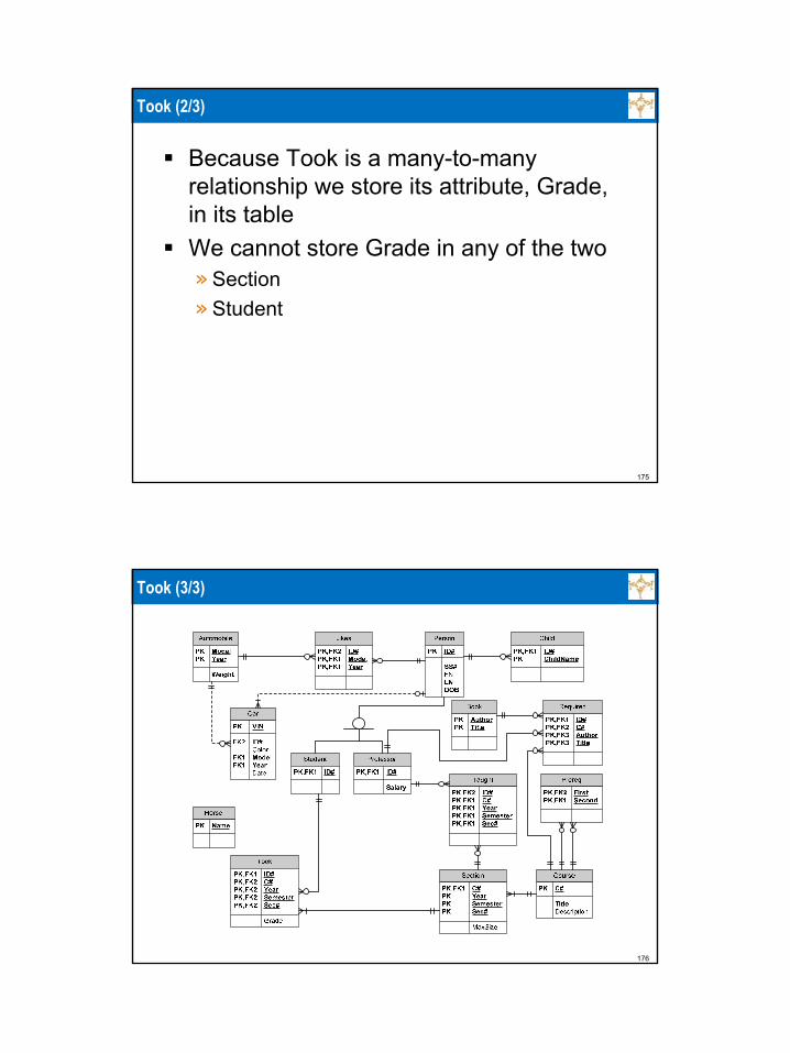
Because Took is a many-to-many relationship we store its attribute, Grade, in its tableWe cannot store Grade in any of the two» Section» Student
176
Took (3/3)

177
Taught (1/2)
Define Table Taught (ID# NOT NULL,C# NOT NULL,Year NOT NULL,Semester NOT NULL,Sec# NOT NULL,Primary Key (ID#,C#,Year,Semester,Sec#),Foreign Key (ID#), References Professor,Foreign Key (C#,Year,Semester,Sec#) References Section );
178
Taught (2/2)

179
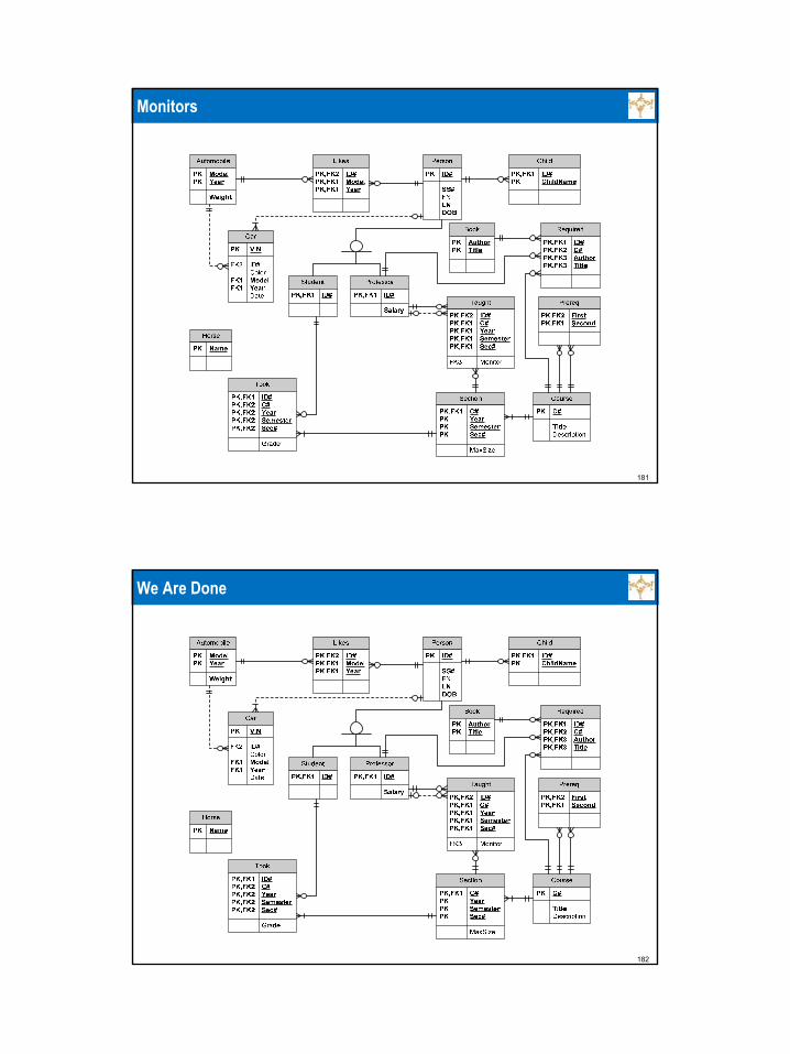
Monitors
This is our first example in which a table, Taught, that “came from” a relationship is treated as if it came from an entity and participates in a relationship with other tablesNothing special needs to be done to “convert” a table that models a relationship, to be also treated as a table modeling an entityIn this case, Monitors is a binary many-to-one relationship, so we do not need to create a table for it, and it can be stored in the “many” side, Taught
180
Taught
Define Table Taught (ID# NOT NULL,C# NOT NULL,Year NOT NULL,Semester NOT NULL,Sec# NOT NULL,MonitorPrimary Key (ID#,C#,Year,Semester,Sec#),Foreign Key (ID#), References Professor,Foreign Key (C#,Year,Semester,Sec#) References Section Foreign Key (Monitor) References Professor );
181
Monitors
182
We Are Done

183
Arrow Notation
184
Arrows And Cardinality Notation
185
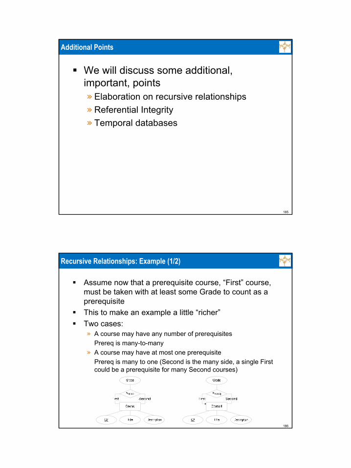
Additional Points
We will discuss some additional, important, points» Elaboration on recursive relationships» Referential Integrity» Temporal databases
186
Recursive Relationships: Example (1/2)
Assume now that a prerequisite course, “First” course, must be taken with at least some Grade to count as a prerequisiteThis to make an example a little “richer”Two cases:» A course may have any number of prerequisites
Prereq is many-to-many» A course may have at most one prerequisite
Prereq is many to one (Second is the many side, a single First could be a prerequisite for many Second courses)

187
Recursive Relationships: Example (2/2)
Nothing special, we handle the second case of Prereq by storing it in the “many” side of the relationshipSo there are two additional attributes in Course1» The prerequisite course, if any» The required grade, if any
188
Referential Integrity: Example (1/3)
Assume that we have some professors in table Professor, with rows: 5,1 and 7,2There is a row in Taught 5,G22.2433,2009,Spring,001,7This means that 5 teaches a specific section and 7 monitors this assignment
Taught ID# C# Year Semester Sec# Monitor5 G22.2433 2009 Spring 001 7
Professor ID# Salary5 17 2

189
Referential Integrity: Example (2/3)
A user accesses the database and attempts to delete row (or all rows like this, recall that duplicates are permitted) 5,1 from ProfessorWhat should happen, as there is a row in Taught referencing thisrow in Professor?A user accesses the database and attempts to delete row 7,2 fromProfessor?What should happen, as there is a row in Taught referencing thisrow in Professor?
Taught ID# C# Year Semester Sec# Monitors5 G22.2433 2009 Spring 001 7
Professor ID# Salary5 17 2
190
Referential Integrity: Example (3/3)
Part of specification of foreign key in in TaughtAn action on Professor can be denied, or can trigger an action on TaughtFor example» ON DELETE NO ACTION
This means that the “needed” row in Professor cannot be deletedOf course, it is possible to delete the row from Taught and then from the Professor (if no other row in in any table in the database “needs”the row in Professor)
» ON DELETE CASCADEThis means that if the a row is deleted from Professor, all the rows in Taught referring to it are deleted too
» ON DELETE SET NULLThis means, that the value referring to no-longer-existing professor is replaced by NULLIn our example, this is not possible for ID# as it is a part of the primary key of Taught, but is possible for Monitor

191
Referential Integrity: Another Example
Part of specification of foreign key in in ProfessorAn action on Person can be denied, or can trigger an action on ProfessorFor example» ON UPDATE CASCADE
This means that if the value of ID# in Person is changed, this value of ID# also propagates to Professor
Could (and probably should) add to Taught and Required:» ON UPDATE CASCADE
In appropriate attributes, so that the change of ID# in Professor also propagates to themIn Taught in both ID# and MonitorIn Required in ID#
Excellent mechanism for centralized maintenance
192
Temporal Databases
Of course, we may want to maintain historical dataSo, in practice one may have some indication that the professor no longer works, but still keep historical information about the pastBut we do not assume this for our example

193
Summary: Strong Entity (1/2)
Example: PersonCreate a table for the entity without multivalued and derived attributes, flattening composite attributesThe primary key of this table will consist of the attributes serving as primary key of the entityExample table: PersonIf there is a derived attribute, describe how it is computed, but do not store itIf there is a multivalued attribute, create a table for it consisting of it and attributes of the primary key of the entity; do not put it in the table for the entityExample table: ChildThe primary key of this table will consist of all its attributes
194
Summary: Strong Entity (2/2)
There could be an attribute that is composite with some components being multivalued and some derivedAnd similar complexitiesExample, without drawing the appropriate entity using the ER model (this is getting too hairy)» A person has many children (multivalued)» Each child has both FirstName and MiddleName» The child has DOB» The child has Age
Then the table for child will look like
Child ID# FirstName MiddleName DOB5432 Krishna Satya 2006-11-05

195
Summary: ISA And A Subclass
Example: ISA and ProfessorDo not do anything for ISAThe class “above” ISA (here Person) has already been implemented as a tableCreate a table with all the attributes of the subclass (as for strong entity above) augmented with the primary key of the table “above” ISA, and no other attributes from itThe primary key is the same as the primary key of the table “above” ISAExample table: Professor
196
Summary: Weak Entity And Defining Relationship
Example: Offered and SectionDo not do anything for the defining relationship, here OfferedImagine that the weak entity is augmented by the primary key of the “stronger” table through which it is defined (the table for it has been created already)Treat the augmented weak entity the same way as a strong entityThe primary key is the primary key of the “stronger”table augmented by the attributes in the discriminant of the weak entity (a discriminant may consist of more than one attribute)Example table: Section and Offered

197
Summary: A Relationship That Is Not Binary Many-To-One
Example TookThe tables for the participating entities have already been createdCreate a table consisting of the primary keys of the participating tables and the attributes of the relationship itselfOf course, treat attributes of the relationship that are derived, multivalued, or composite, appropriately, not storing them, producing additional tables, flattening themThe primary key consists of all the attributes of the primary keys of the participating tablesExample table: Took
198
Summary: A Relationship That Is Binary Many-To-One
Example: HasDo not create a table for this relationshipPut the attributes of the primary key of the “one” side and the attributes of the relationship itself into the table of the “many” sideOf course, treat attributes of the relation that are derived, multivalued, or composite, appropriately, not storing them, producing additional tables, flattening them, as the case may beYou may decide to treat such a relationship the way you treat a relationship that is not binary many to one (but not in our class)If the relationship is one-to-one, choose which side to treat as if it were “many”Example table: Has
199
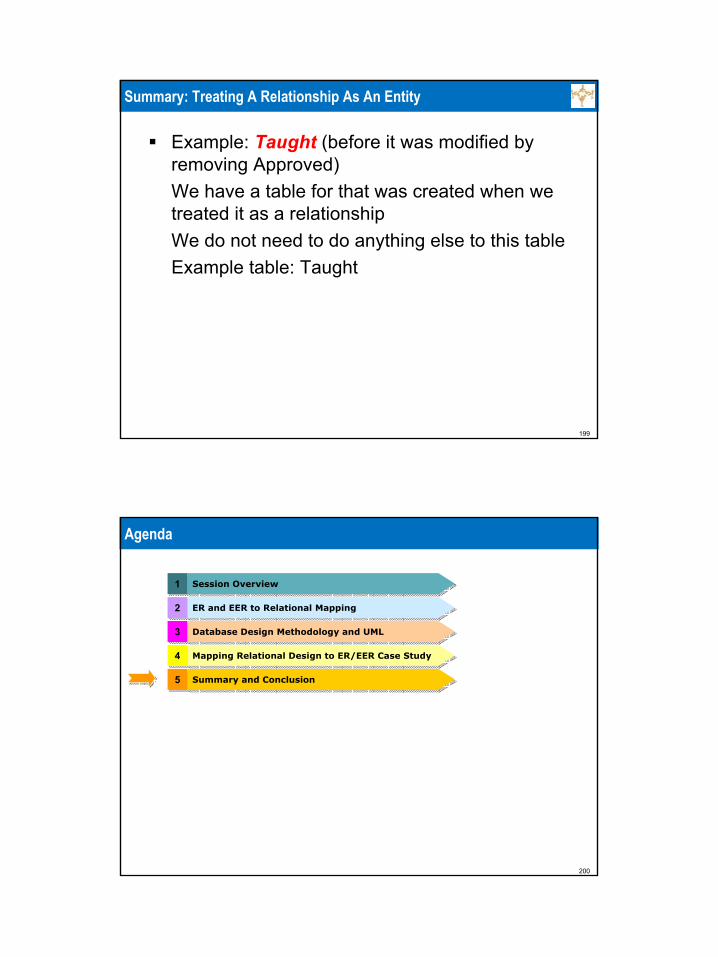
Summary: Treating A Relationship As An Entity
Example: Taught (before it was modified by removing Approved)We have a table for that was created when we treated it as a relationshipWe do not need to do anything else to this tableExample table: Taught
200
Agenda
11 Session OverviewSession Overview
55 Summary and ConclusionSummary and Conclusion
22 ER and EER to Relational MappingER and EER to Relational Mapping
33 Database Design Methodology and UMLDatabase Design Methodology and UML
44 Mapping Relational Design to ER/EER Case StudyMapping Relational Design to ER/EER Case Study
201
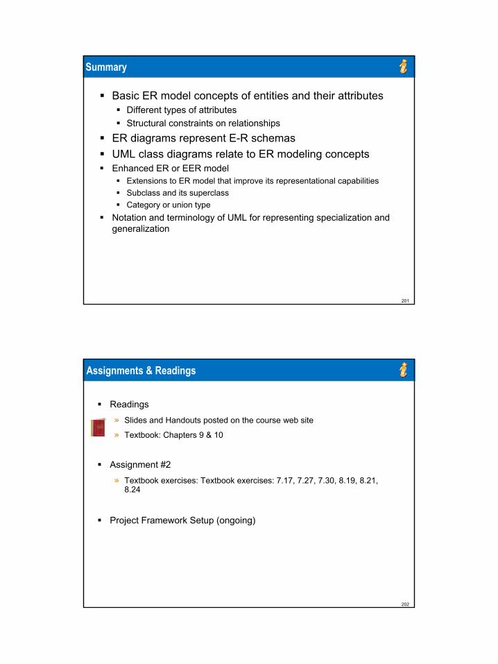
Summary
Basic ER model concepts of entities and their attributesDifferent types of attributesStructural constraints on relationships
ER diagrams represent E-R schemasUML class diagrams relate to ER modeling conceptsEnhanced ER or EER model
Extensions to ER model that improve its representational capabilitiesSubclass and its superclassCategory or union type
Notation and terminology of UML for representing specialization and generalization
202
Assignments & Readings
Readings
» Slides and Handouts posted on the course web site
» Textbook: Chapters 9 & 10
Assignment #2
» Textbook exercises: Textbook exercises: 7.17, 7.27, 7.30, 8.19, 8.21, 8.24
Project Framework Setup (ongoing)
203
Next Session: Relational Algebra, Relational Calculus, and SQL
204
Any Questions?
Related Documents