Practical Modeling of Metal Hydride Hydrogen Storage Systems Sarang A. Gadre, Armin D. Ebner, Shaheen A. Al-Muhtaseb, and James A. Ritter* Department of Chemical Engineering, Swearingen Engineering Center, University of South Carolina, Columbia, South Carolina 29208 A new approach is introduced to model the discharge behavior of a metal hydride hydrogen storage bed. The reversible reaction kinetics and the empirical van’t Hoff relationship used in a typical reactor model are replaced by a solid-phase diffusion equation and a semiempirical equilibrium P-C-T relationship. Two new semiempirical P-C-T models are also introduced based on modified virial and composite Langmuir expressions. By varying the heat- and mass- transfer coefficients, the model was calibrated to experimental pressure and temperature histories obtained from a commercially viable metal hydride bed containing Lm 1.06 Ni 4.96 Al 0.04 . Overall, the results of this study showed that a fairly simple numerical model can do a reasonable job in predicting the discharge behavior of a fairly complicated metal hydride hydrogen storage bed over a wide range of hydrogen flow-rate demands. The extreme theoretical limits of isothermal equilibrium (analytical model), adiabatic equilibrium, nonadiabatic equilibrium, isothermal nonequilibrium, and adiabatic nonequilibrium conditions were also studied and compared to the actual behavior under nonadiabatic nonequilibrium conditions. These limiting cases revealed that the metal hydride hydrogen storage vessel was definitely heat-transfer-limited and only minimally mass-transfer-limited over a wide range of hydrogen discharge flow rates. Introduction Hydrogen as an energy source is receiving increasing attention around the world because the demand for environmentally cleaner fuels is on the rise. Its use, however, necessitates the development of a hydrogen refueling and storage infrastructure, with safety being a major concern. Consequently, metal hydrides, as a hydrogen storage medium, have been under consider- ation for many years 1,3-17 because they have the ability to store H 2 reversibly in the solid state at relatively low pressures and ambient temperatures. The utility of metal hydrides as a hydrogen storage medium was demonstrated recently by the Savannah River Technol- ogy Center (SRTC). They developed an on-board hydro- gen storage system for a hybrid electric bus, 1 based on the commercially viable Lm 1.06 Ni 4.96 Al 0.04 metal hydride (Lm ) La 55.7, Ce 2.5, Pr 7.7, and Nd 34.1 atomic %). This system consists of a bank of horizontal tubes partially filled with metal hydride interdispersed within a highly porous aluminum foam matrix for heat trans- fer. Each column contains a horizontal porous metal filter feed tube and a U-tube, single-pass heat exchanger for additional heat transfer via an aqueous medium. These intricacies of the SRTC hydrogen storage system are shown in Figure 1. 1,3-5 Clearly, this metal hydride hydrogen storage system is quite challenging to describe mathematically; nevertheless, a mathematical descrip- tion is highly desirable for design, development, and optimization. Therefore, the objective of this paper is to introduce a new approach for modeling metal hydride H 2 storage systems from a very practical point of view. H 2 is stored in a metal hydride by a process called hydrogenation, and it is withdrawn from the material by a process called dehydrogenation. This charge/ discharge process is quite complicated because of the inherent heat- and mass-transfer/reaction phenomena associated with it. Most of the mathematical models presented in the literature that describe these dynamic phenomena, in addition to the mass and energy bal- ances, necessarily make use of reactor design equations that include a reaction kinetics equation. The reason for this approach is that this process can be classi- fied as a reversible chemical reaction. However, because the reaction rate tends to be very fast, the charge/ discharge process from a metal hydride bed can also be modeled as a heat-transfer-limited, solid-state, diffu- sion-controlled process with the equilibrium relation- ship described by a reversible pressure-composition- temperature (P-C-T) diagram. Thus, in this new approach, the reversible reaction kinetics and the empirical van’t Hoff relationship used in a typical reactor model (that includes mass and energy balances) are replaced by a solid-phase diffusion equation and a semiempirical equilibrium P-C-T relationship. The first part of this paper introduces two new adsorption isotherm relationships that describe the S-shaped characteristics of the P-C diagram as a function of temperature. Then a very simple dynamic model of the H 2 discharge process is introduced, which, under isothermal and equilibrium conditions, represents an upper thermodynamic limit for the process perfor- mance. This model can be used to rapidly determine the feasibility of a metal hydride material for H 2 storage. A more complex and hence more realistic model of the H 2 discharge process is introduced next. This model, by accounting for heat- and mass-transfer resistances, represents a more realistic picture of the process performance; therefore, it can be used for process design and development. These models are compared to experimental discharge curves obtained from one of the SRTC metal hydride hydrogen storage columns, identical with that used in * To whom correspondence should be addressed. Phone: (803) 777-3590. Fax: (803) 777-8265. E-mail: [email protected]. 1713 Ind. Eng. Chem. Res. 2003, 42, 1713-1722 10.1021/ie020839i CCC: $25.00 © 2003 American Chemical Society Published on Web 03/20/2003

Welcome message from author
This document is posted to help you gain knowledge. Please leave a comment to let me know what you think about it! Share it to your friends and learn new things together.
Transcript
Practical Modeling of Metal Hydride Hydrogen Storage Systems
Sarang A. Gadre, Armin D. Ebner, Shaheen A. Al-Muhtaseb, and James A. Ritter*
Department of Chemical Engineering, Swearingen Engineering Center, University of South Carolina,Columbia, South Carolina 29208
A new approach is introduced to model the discharge behavior of a metal hydride hydrogenstorage bed. The reversible reaction kinetics and the empirical van’t Hoff relationship used ina typical reactor model are replaced by a solid-phase diffusion equation and a semiempiricalequilibrium P-C-T relationship. Two new semiempirical P-C-T models are also introducedbased on modified virial and composite Langmuir expressions. By varying the heat- and mass-transfer coefficients, the model was calibrated to experimental pressure and temperature historiesobtained from a commercially viable metal hydride bed containing Lm1.06Ni4.96Al0.04. Overall,the results of this study showed that a fairly simple numerical model can do a reasonable job inpredicting the discharge behavior of a fairly complicated metal hydride hydrogen storage bedover a wide range of hydrogen flow-rate demands. The extreme theoretical limits of isothermalequilibrium (analytical model), adiabatic equilibrium, nonadiabatic equilibrium, isothermalnonequilibrium, and adiabatic nonequilibrium conditions were also studied and compared tothe actual behavior under nonadiabatic nonequilibrium conditions. These limiting cases revealedthat the metal hydride hydrogen storage vessel was definitely heat-transfer-limited and onlyminimally mass-transfer-limited over a wide range of hydrogen discharge flow rates.
Introduction
Hydrogen as an energy source is receiving increasingattention around the world because the demand forenvironmentally cleaner fuels is on the rise. Its use,however, necessitates the development of a hydrogenrefueling and storage infrastructure, with safety beinga major concern. Consequently, metal hydrides, as ahydrogen storage medium, have been under consider-ation for many years1,3-17 because they have the abilityto store H2 reversibly in the solid state at relatively lowpressures and ambient temperatures. The utility ofmetal hydrides as a hydrogen storage medium wasdemonstrated recently by the Savannah River Technol-ogy Center (SRTC). They developed an on-board hydro-gen storage system for a hybrid electric bus,1 based onthe commercially viable Lm1.06 Ni4.96Al0.04 metal hydride(Lm ) La 55.7, Ce 2.5, Pr 7.7, and Nd 34.1 atomic %).
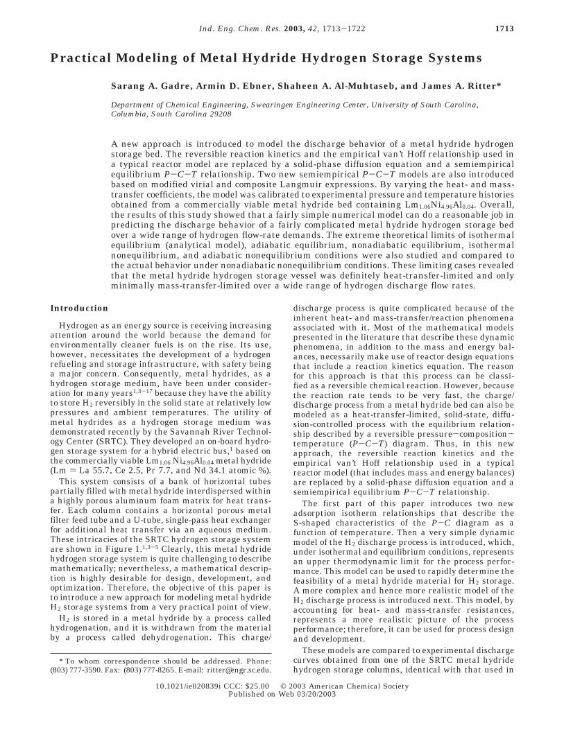
This system consists of a bank of horizontal tubespartially filled with metal hydride interdispersed withina highly porous aluminum foam matrix for heat trans-fer. Each column contains a horizontal porous metalfilter feed tube and a U-tube, single-pass heat exchangerfor additional heat transfer via an aqueous medium.These intricacies of the SRTC hydrogen storage systemare shown in Figure 1.1,3-5 Clearly, this metal hydridehydrogen storage system is quite challenging to describemathematically; nevertheless, a mathematical descrip-tion is highly desirable for design, development, andoptimization. Therefore, the objective of this paper isto introduce a new approach for modeling metal hydrideH2 storage systems from a very practical point of view.
H2 is stored in a metal hydride by a process calledhydrogenation, and it is withdrawn from the materialby a process called dehydrogenation. This charge/
discharge process is quite complicated because of theinherent heat- and mass-transfer/reaction phenomenaassociated with it. Most of the mathematical modelspresented in the literature that describe these dynamicphenomena, in addition to the mass and energy bal-ances, necessarily make use of reactor design equationsthat include a reaction kinetics equation. The reasonfor this approach is that this process can be classi-fied as a reversible chemical reaction. However, becausethe reaction rate tends to be very fast, the charge/discharge process from a metal hydride bed can also bemodeled as a heat-transfer-limited, solid-state, diffu-sion-controlled process with the equilibrium relation-ship described by a reversible pressure-composition-temperature (P-C-T) diagram. Thus, in this newapproach, the reversible reaction kinetics and theempirical van’t Hoff relationship used in a typicalreactor model (that includes mass and energy balances)are replaced by a solid-phase diffusion equation and asemiempirical equilibrium P-C-T relationship.
The first part of this paper introduces two newadsorption isotherm relationships that describe theS-shaped characteristics of the P-C diagram as afunction of temperature. Then a very simple dynamicmodel of the H2 discharge process is introduced, which,under isothermal and equilibrium conditions, representsan upper thermodynamic limit for the process perfor-mance. This model can be used to rapidly determine thefeasibility of a metal hydride material for H2 storage.A more complex and hence more realistic model of theH2 discharge process is introduced next. This model, byaccounting for heat- and mass-transfer resistances,represents a more realistic picture of the processperformance; therefore, it can be used for process designand development.
These models are compared to experimental dischargecurves obtained from one of the SRTC metal hydridehydrogen storage columns, identical with that used in
* To whom correspondence should be addressed. Phone:(803) 777-3590. Fax: (803) 777-8265. E-mail: [email protected].
1713Ind. Eng. Chem. Res. 2003, 42, 1713-1722
10.1021/ie020839i CCC: $25.00 © 2003 American Chemical SocietyPublished on Web 03/20/2003
the hybrid bus demonstration project.1 The heat- andmass-transfer coefficients associated with the SRTCsystem are also obtained by comparing the theoreticaldischarge curves with the experimental ones. Theextreme theoretical limits of isothermal equilibrium,adiabatic equilibrium, nonadiabatic equilibrium, iso-thermal nonequilibrium, and adiabatic nonequilibriumconditions are also explored to gain an appreciation forthe limiting and actual behaviors of the SRTC system.
Theoretical Section
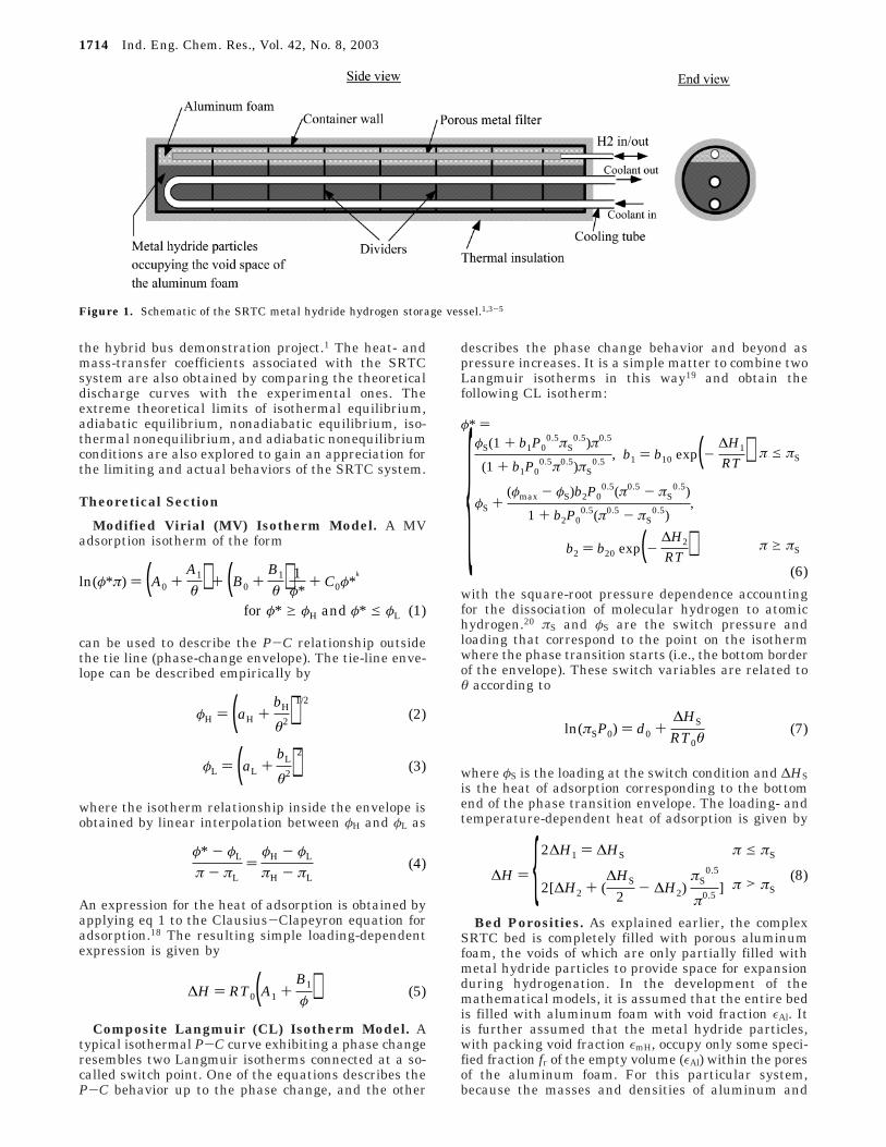
Modified Virial (MV) Isotherm Model. A MVadsorption isotherm of the form
can be used to describe the P-C relationship outsidethe tie line (phase-change envelope). The tie-line enve-lope can be described empirically by
where the isotherm relationship inside the envelope isobtained by linear interpolation between φH and φL as
An expression for the heat of adsorption is obtained byapplying eq 1 to the Clausius-Clapeyron equation foradsorption.18 The resulting simple loading-dependentexpression is given by
Composite Langmuir (CL) Isotherm Model. Atypical isothermal P-C curve exhibiting a phase changeresembles two Langmuir isotherms connected at a so-called switch point. One of the equations describes theP-C behavior up to the phase change, and the other
describes the phase change behavior and beyond aspressure increases. It is a simple matter to combine twoLangmuir isotherms in this way19 and obtain thefollowing CL isotherm:
with the square-root pressure dependence accountingfor the dissociation of molecular hydrogen to atomichydrogen.20 πS and φS are the switch pressure andloading that correspond to the point on the isothermwhere the phase transition starts (i.e., the bottom borderof the envelope). These switch variables are related toθ according to
where φS is the loading at the switch condition and ∆HSis the heat of adsorption corresponding to the bottomend of the phase transition envelope. The loading- andtemperature-dependent heat of adsorption is given by
Bed Porosities. As explained earlier, the complexSRTC bed is completely filled with porous aluminumfoam, the voids of which are only partially filled withmetal hydride particles to provide space for expansionduring hydrogenation. In the development of themathematical models, it is assumed that the entire bedis filled with aluminum foam with void fraction εAl. Itis further assumed that the metal hydride particles,with packing void fraction εmH, occupy only some speci-fied fraction fr of the empty volume (εAl) within the poresof the aluminum foam. For this particular system,because the masses and densities of aluminum and
Figure 1. Schematic of the SRTC metal hydride hydrogen storage vessel.1,3-5
ln(φ*π) ) (A0 +A1
θ ) + (B0 +B1
θ ) 1φ*
+ C0φ*k
for φ* g φH and φ* e φL (1)
φH ) (aH +bH
θ2)1/2
(2)
φL ) (aL +bL
θ2)2
(3)
φ* - φL
π - πL)
φH - φL
πH - πL(4)
∆H ) RT0(A1 +B1
φ ) (5)
φ* )
{φS(1 + b1P00.5πS
0.5)π0.5
(1 + b1P00.5π0.5)πS
0.5, b1 ) b10 exp(-
∆H1
RT ) π e πS
φS +(φmax - φS)b2P0
0.5(π0.5 - πS0.5)
1 + b2P00.5(π0.5 - πS
0.5),
b2 ) b20 exp(-∆H2
RT ) π g πS
(6)
ln(πSP0) ) d0 +∆HS
RT0θ(7)
∆H ) {2∆H1 ) ∆HS π e πS
2[∆H2 + (∆HS
2- ∆H2)
πS0.5
π0.5] π > πS
(8)
1714 Ind. Eng. Chem. Res., Vol. 42, No. 8, 2003
metal hydride particles are known, the following ex-pressions are easily derived:
where ε1 represents the fraction of the bed volume notoccupied by the metal hydride particles; thus, 1 - ε1represents the fraction of the bed occupied solely by themetal hydride particles. Similarly, ε2 represents thefraction of the bed not occupied by either the metalhydride particles or the aluminum foam; i.e., ε2 repre-sents the total void fraction in the bed. The expressionson the right-hand side of eqs 9 and 10 can be used ifthe masses and densities of the aluminum foam andmetal hydride particles are not known, which is moretypical. In fact, they are more amenable for scaling anddesign studies because they only depend on the porosi-ties, εAl and εmH, and the specified fraction fr.
Analytical Charge/Discharge Model. The analyti-cal model (AM) for discharge is based on the followingassumptions: The H2 discharge process, starting froma fully charged state at constant temperature andpressure, is carried out isothermally, with no mass- orheat-transfer resistances. The H2 discharge flow rateis so slow that axial pressure gradients are negligibleand ideal plug flow is assumed. The gas is also assumedto be ideal. Based on these assumptions, the one-dimensional (1-D) mass balance in a packed metalhydride bed is given by
By substituting c ) P/RT and assuming instantaneousequilibrium,
Also, by assuming a linear velocity profile, v(z) ) k′z,one end closed, v(0) ) 0, and a constant outlet velocity,v(L) ) vout,
As the pressure decreases during discharge, the outletvelocity changes. If the molar flow rate (and, hence, fluxf) exiting the column is predefined as a constant value,the variation of the outlet velocity with pressure canbe written as
where k ) fRT/Lε2. Substituting eq 14 into eq 11 resultsin the following ordinary differential equation:
Integrating eq 12 with initial conditions: at t ) 0,
P ) Pi, and q ) qi yields
which describes the discharge time as f(P) in terms ofthe metal hydride properties (FS and P-C-T), the bedlength (L), and the molar flux (f), which also specifiesthe column diameter. Any adsorption isotherm relation-ship, like the MV and CL models, can be used to obtainthe expression for q as a function of P (as well as q0,corresponding to P0). It is also a simple matter to convertthis model into one that describes the charge processby simply changing the initial conditions and followingan increase in pressure instead of a decrease.
Numerical Charge/Discharge Model. The numer-ical model (NM) for discharge is based on the followingassumptions: To simplify the mathematical descriptionof the heat-transfer phenomena in the complex systemshown in Figure 1, the U-tube heat exchanger ispositioned axially down the center of the column andapproximated as a single tube with the diameterdoubled. The outside of the column is assumed to beperfectly insulated, whereas the water temperatureinside the heat exchanger is assumed to be constantthroughout the discharge process. All heat-transferprocesses between the material and the heat exchangerare lumped together and described by an overall heat-transfer coefficient. The heat transfer is assumed tooccur between the solid mixture and the outside wallsof the heat-exchanger tube, which is held at a constanttemperature equal to the water temperature. The effectof the mass-transfer resistance is accounted for basedon a linear driving force (LDF) approximation, whichrigorously assumes a solid diffusion mechanism.22 Thedischarge process starts from a fully charged state at aconstant temperature and pressure. Because the hy-drogen flow rate is constant at the discharge end andzero at the closed end, this leads to the assumption thatthe flux variation inside the column is linear.2 All radialgradients are also ignored; hence, ideal plug flow isassumed. The H2 flow rate demand at the outlet (fo) isalso left as an arbitrary user- or system-defined func-tion.
Based on these assumptions and assuming ideal gasbehavior, the 1-D mass balance is given by
where φ, π, θ, and ω denote dimensionless loading,pressure, temperature, and molar flux, respectively. Thecorresponding energy balance, including compression,is written as
where ka, kb, kc, and kh are defined as
t )Lε2
f [(Pi - P)RT
+FmH(1 - ε1)
MH2ε2
(qi - q)] (16)
1θ
∂π∂τ
- πθ2
∂θ∂τ
+ ∂ω∂ê
+ ∂φ
∂τ) 0 (17)
[1 + kaθπ] ∂θ
∂τ+ kc
θπ
∂φ
∂τ- kb
θπ
∂π∂τ
+ ωθπ
∂θ∂ê
+
kh(θ - θW) ) 0 (18)
ka )Cps
q0Cpg; kb ) R
Cpg; kc ) ∆H
CpgT0;
kh )2hrit0RT0
ε2(ro2 - ri
2)CpgP0MH2
ε1 ) 1-mmH/FmH
π(ro2 - ri
2)L) 1 - εAlfr(1 - εmH) (9)
ε2 ) 1-mmH/FmH + mAl/FAl
π(ro2 - ri
2)L) (1 - fr)εAl + frεAlεmH (10)
ε2∂c∂t
+ ε2∂(vc)∂z
+FmH
MH2
(1 - ε1)∂q∂t
) 0 (11)
ε21
RT∂P∂t
+ ε2P
RT∂v∂z
+FmH
MH2
(1 - ε1)∂q∂t
) 0 (12)
∂v∂z
) k′ )vout
L(13)
∂v∂z
) kP
(14)
ε21
RTdPdt
+ fL
+FmH
MH2
(1 - ε1)dqdt
) 0 (15)
Ind. Eng. Chem. Res., Vol. 42, No. 8, 2003 1715
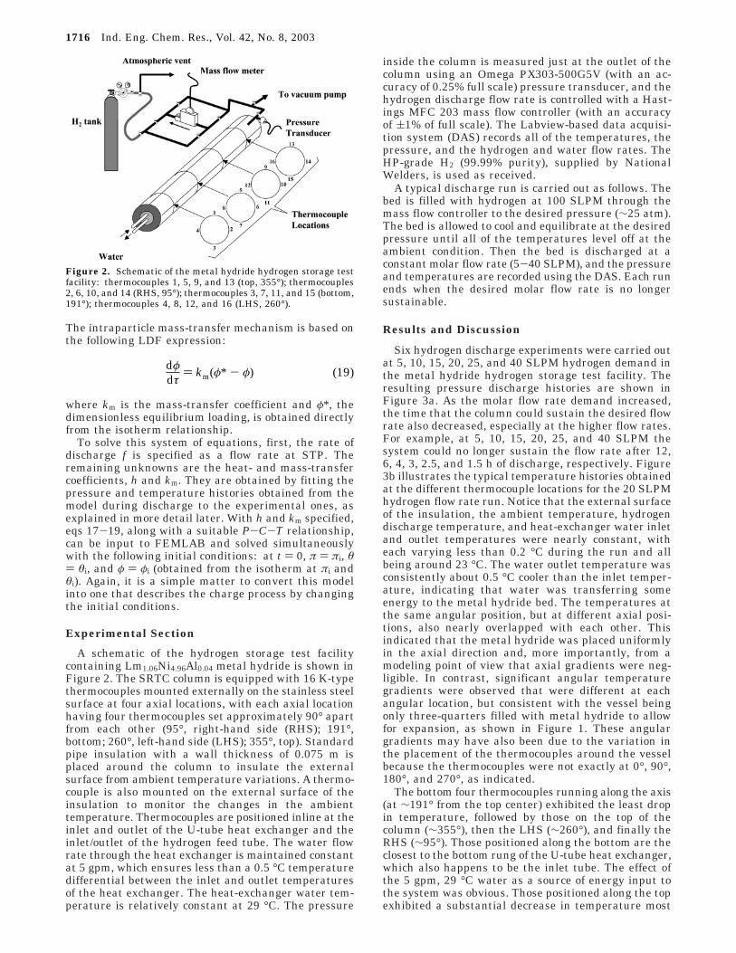
The intraparticle mass-transfer mechanism is based onthe following LDF expression:
where km is the mass-transfer coefficient and φ*, thedimensionless equilibrium loading, is obtained directlyfrom the isotherm relationship.
To solve this system of equations, first, the rate ofdischarge f is specified as a flow rate at STP. Theremaining unknowns are the heat- and mass-transfercoefficients, h and km. They are obtained by fitting thepressure and temperature histories obtained from themodel during discharge to the experimental ones, asexplained in more detail later. With h and km specified,eqs 17-19, along with a suitable P-C-T relationship,can be input to FEMLAB and solved simultaneouslywith the following initial conditions: at t ) 0, π ) πi, θ) θi, and φ ) φi (obtained from the isotherm at πi andθi). Again, it is a simple matter to convert this modelinto one that describes the charge process by changingthe initial conditions.
Experimental Section
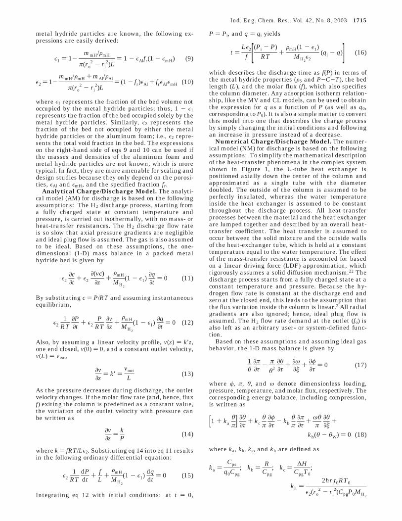
A schematic of the hydrogen storage test facilitycontaining Lm1.06Ni4.96Al0.04 metal hydride is shown inFigure 2. The SRTC column is equipped with 16 K-typethermocouples mounted externally on the stainless steelsurface at four axial locations, with each axial locationhaving four thermocouples set approximately 90° apartfrom each other (95°, right-hand side (RHS); 191°,bottom; 260°, left-hand side (LHS); 355°, top). Standardpipe insulation with a wall thickness of 0.075 m isplaced around the column to insulate the externalsurface from ambient temperature variations. A thermo-couple is also mounted on the external surface of theinsulation to monitor the changes in the ambienttemperature. Thermocouples are positioned inline at theinlet and outlet of the U-tube heat exchanger and theinlet/outlet of the hydrogen feed tube. The water flowrate through the heat exchanger is maintained constantat 5 gpm, which ensures less than a 0.5 °C temperaturedifferential between the inlet and outlet temperaturesof the heat exchanger. The heat-exchanger water tem-perature is relatively constant at 29 °C. The pressure
inside the column is measured just at the outlet of thecolumn using an Omega PX303-500G5V (with an ac-curacy of 0.25% full scale) pressure transducer, and thehydrogen discharge flow rate is controlled with a Hast-ings MFC 203 mass flow controller (with an accuracyof (1% of full scale). The Labview-based data acquisi-tion system (DAS) records all of the temperatures, thepressure, and the hydrogen and water flow rates. TheHP-grade H2 (99.99% purity), supplied by NationalWelders, is used as received.
A typical discharge run is carried out as follows. Thebed is filled with hydrogen at 100 SLPM through themass flow controller to the desired pressure (∼25 atm).The bed is allowed to cool and equilibrate at the desiredpressure until all of the temperatures level off at theambient condition. Then the bed is discharged at aconstant molar flow rate (5-40 SLPM), and the pressureand temperatures are recorded using the DAS. Each runends when the desired molar flow rate is no longersustainable.
Results and Discussion
Six hydrogen discharge experiments were carried outat 5, 10, 15, 20, 25, and 40 SLPM hydrogen demand inthe metal hydride hydrogen storage test facility. Theresulting pressure discharge histories are shown inFigure 3a. As the molar flow rate demand increased,the time that the column could sustain the desired flowrate also decreased, especially at the higher flow rates.For example, at 5, 10, 15, 20, 25, and 40 SLPM thesystem could no longer sustain the flow rate after 12,6, 4, 3, 2.5, and 1.5 h of discharge, respectively. Figure3b illustrates the typical temperature histories obtainedat the different thermocouple locations for the 20 SLPMhydrogen flow rate run. Notice that the external surfaceof the insulation, the ambient temperature, hydrogendischarge temperature, and heat-exchanger water inletand outlet temperatures were nearly constant, witheach varying less than 0.2 °C during the run and allbeing around 23 °C. The water outlet temperature wasconsistently about 0.5 °C cooler than the inlet temper-ature, indicating that water was transferring someenergy to the metal hydride bed. The temperatures atthe same angular position, but at different axial posi-tions, also nearly overlapped with each other. Thisindicated that the metal hydride was placed uniformlyin the axial direction and, more importantly, from amodeling point of view that axial gradients were neg-ligible. In contrast, significant angular temperaturegradients were observed that were different at eachangular location, but consistent with the vessel beingonly three-quarters filled with metal hydride to allowfor expansion, as shown in Figure 1. These angulargradients may have also been due to the variation inthe placement of the thermocouples around the vesselbecause the thermocouples were not exactly at 0°, 90°,180°, and 270°, as indicated.
The bottom four thermocouples running along the axis(at ∼191° from the top center) exhibited the least dropin temperature, followed by those on the top of thecolumn (∼355°), then the LHS (∼260°), and finally theRHS (∼95°). Those positioned along the bottom are theclosest to the bottom rung of the U-tube heat exchanger,which also happens to be the inlet tube. The effect ofthe 5 gpm, 29 °C water as a source of energy input tothe system was obvious. Those positioned along the topexhibited a substantial decrease in temperature most
Figure 2. Schematic of the metal hydride hydrogen storage testfacility: thermocouples 1, 5, 9, and 13 (top, 355°); thermocouples2, 6, 10, and 14 (RHS, 95°); thermocouples 3, 7, 11, and 15 (bottom,191°); thermocouples 4, 8, 12, and 16 (LHS, 260°).
dφ
dτ) km(φ* - φ) (19)
1716 Ind. Eng. Chem. Res., Vol. 42, No. 8, 2003
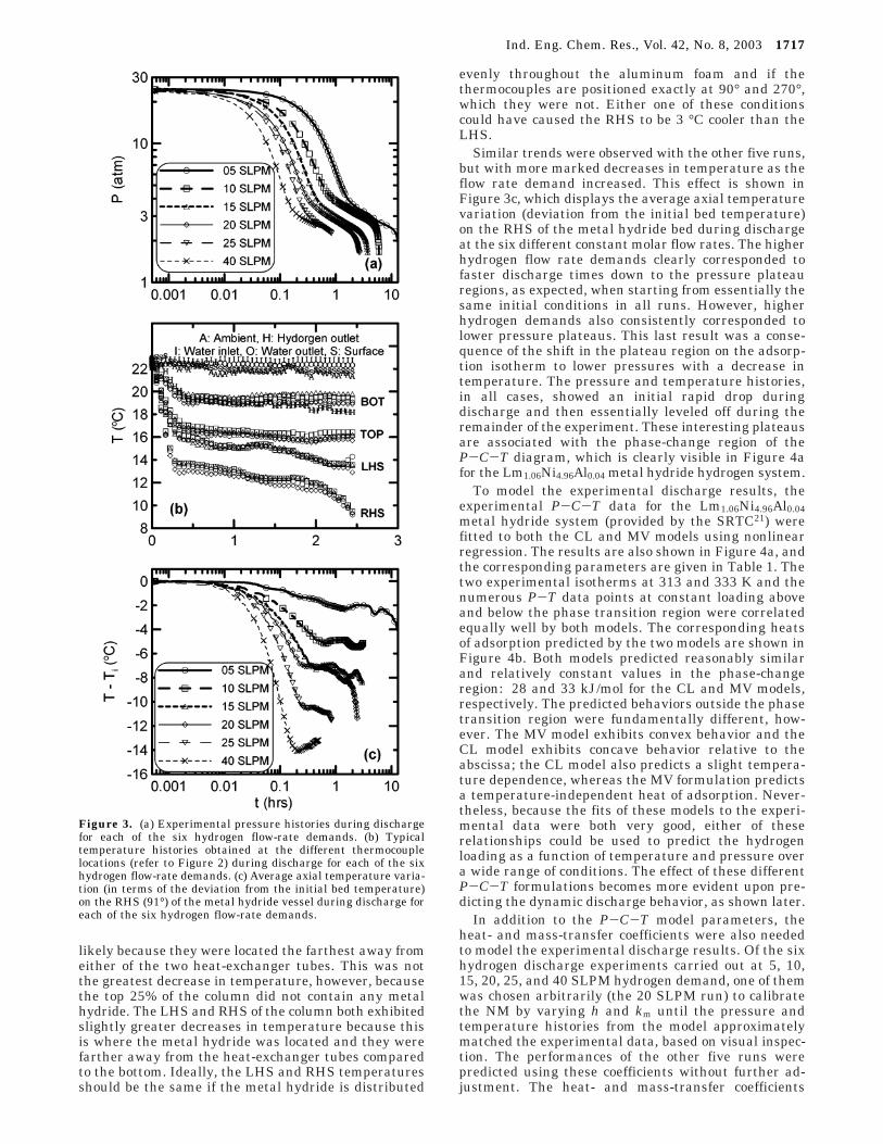
likely because they were located the farthest away fromeither of the two heat-exchanger tubes. This was notthe greatest decrease in temperature, however, becausethe top 25% of the column did not contain any metalhydride. The LHS and RHS of the column both exhibitedslightly greater decreases in temperature because thisis where the metal hydride was located and they werefarther away from the heat-exchanger tubes comparedto the bottom. Ideally, the LHS and RHS temperaturesshould be the same if the metal hydride is distributed
evenly throughout the aluminum foam and if thethermocouples are positioned exactly at 90° and 270°,which they were not. Either one of these conditionscould have caused the RHS to be 3 °C cooler than theLHS.
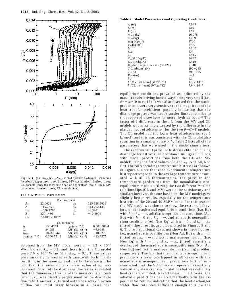
Similar trends were observed with the other five runs,but with more marked decreases in temperature as theflow rate demand increased. This effect is shown inFigure 3c, which displays the average axial temperaturevariation (deviation from the initial bed temperature)on the RHS of the metal hydride bed during dischargeat the six different constant molar flow rates. The higherhydrogen flow rate demands clearly corresponded tofaster discharge times down to the pressure plateauregions, as expected, when starting from essentially thesame initial conditions in all runs. However, higherhydrogen demands also consistently corresponded tolower pressure plateaus. This last result was a conse-quence of the shift in the plateau region on the adsorp-tion isotherm to lower pressures with a decrease intemperature. The pressure and temperature histories,in all cases, showed an initial rapid drop duringdischarge and then essentially leveled off during theremainder of the experiment. These interesting plateausare associated with the phase-change region of theP-C-T diagram, which is clearly visible in Figure 4afor the Lm1.06Ni4.96Al0.04 metal hydride hydrogen system.
To model the experimental discharge results, theexperimental P-C-T data for the Lm1.06Ni4.96Al0.04metal hydride system (provided by the SRTC21) werefitted to both the CL and MV models using nonlinearregression. The results are also shown in Figure 4a, andthe corresponding parameters are given in Table 1. Thetwo experimental isotherms at 313 and 333 K and thenumerous P-T data points at constant loading aboveand below the phase transition region were correlatedequally well by both models. The corresponding heatsof adsorption predicted by the two models are shown inFigure 4b. Both models predicted reasonably similarand relatively constant values in the phase-changeregion: 28 and 33 kJ/mol for the CL and MV models,respectively. The predicted behaviors outside the phasetransition region were fundamentally different, how-ever. The MV model exhibits convex behavior and theCL model exhibits concave behavior relative to theabscissa; the CL model also predicts a slight tempera-ture dependence, whereas the MV formulation predictsa temperature-independent heat of adsorption. Never-theless, because the fits of these models to the experi-mental data were both very good, either of theserelationships could be used to predict the hydrogenloading as a function of temperature and pressure overa wide range of conditions. The effect of these differentP-C-T formulations becomes more evident upon pre-dicting the dynamic discharge behavior, as shown later.
In addition to the P-C-T model parameters, theheat- and mass-transfer coefficients were also neededto model the experimental discharge results. Of the sixhydrogen discharge experiments carried out at 5, 10,15, 20, 25, and 40 SLPM hydrogen demand, one of themwas chosen arbitrarily (the 20 SLPM run) to calibratethe NM by varying h and km until the pressure andtemperature histories from the model approximatelymatched the experimental data, based on visual inspec-tion. The performances of the other five runs werepredicted using these coefficients without further ad-justment. The heat- and mass-transfer coefficients
Figure 3. (a) Experimental pressure histories during dischargefor each of the six hydrogen flow-rate demands. (b) Typicaltemperature histories obtained at the different thermocouplelocations (refer to Figure 2) during discharge for each of the sixhydrogen flow-rate demands. (c) Average axial temperature varia-tion (in terms of the deviation from the initial bed temperature)on the RHS (91°) of the metal hydride vessel during discharge foreach of the six hydrogen flow-rate demands.
Ind. Eng. Chem. Res., Vol. 42, No. 8, 2003 1717
obtained from the MV model were h ) 1.3 × 10⁻²
W/cm2/K and km ) 0.1, and those from the CL modelwere 7.6 × 10⁻³ W/cm2/K and km ) 0.1. These valueswere uniquely defined in each case, with both modelsresulting in the same km and nearly the same h. Thefact that the same dimensionless value of km wasobtained for all of the discharge flow rates suggestedthat the dimensional value of the mass-transfer coef-ficient (kL) was directly proportional to the dischargeflow rate. However, kL turned out to be a weak functionof flow rate, most likely because in all cases near
equilibrium conditions prevailed as indicated by themass-transfer driving force always being very small (i.e.,φ* - φ ∼ 0 in eq 17). It was also observed that the modelpredictions were very sensitive to the magnitude of theheat-transfer coefficient, possibly indicating that thedischarge process was heat-transfer-limited, similar tothat reported elsewhere for metal hydride beds.23 Thefactor of 2 difference in the h’s from the MV and CLmodels was most likely caused by the difference in theplateau heat of adsorption for the two P-C-T models.The CL model had the lower heat of adsorption (by 5kJ/mol), and this was consistent with the CL model alsoresulting in a smaller value of h. Table 2 lists all of theparameters that were used in the model simulations.
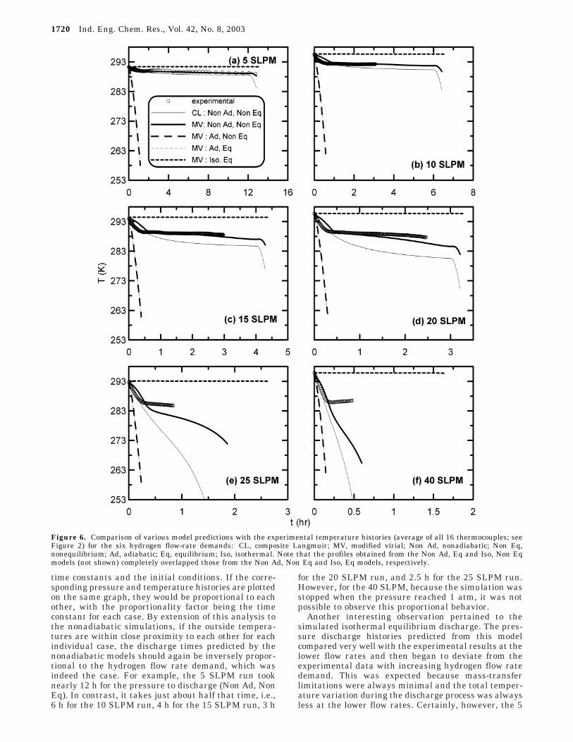
The experimental pressure histories obtained duringdischarge for all six runs are shown in Figure 5, alongwith model predictions from both the CL and MVmodels using the fitted values of h and km (Non Ad, NonEq). The corresponding temperature histories are shownin Figure 6. Note that each experimental temperaturehistory corresponds to the average temperature associ-ated with all 16 thermocouples. The pressure andtemperature predictions from the nonadiabatic non-equilibrium models utilizing the two different P-C-Trelationships (CL and MV) were quite satisfactory andsimilar; however, the one based on the MV model gaveslightly better results, especially for the temperaturehistories of the 20 and 40 SLPM runs. For this reason,the MV model was chosen to show the extreme behav-iors, under isothermal equilibrium conditions (Iso, Eq)with h ) km ) ∞, adiabatic equilibrium conditions (Ad,Eq) with h ) 0 and km ) ∞, and adiabatic nonequilib-rium conditions (Ad, Non Eq) with h ) 0 and km ) km(fitted); these results are also plotted in Figures 5 and6. The two additional cases not shown in these figures,i.e., nonadiabatic equilibrium (Non Ad, Eq) with h ) h(fitted) and km ) ∞ and isothermal nonequilibrium (Iso,Non Eq) with h ) ∞ and km ) km (fitted) essentiallyoverlapped the nonadiabatic nonequilibrium (Non Ad,Non Eq) and isothermal equilibrium (Iso, Eq) profiles,respectively. The fact that the nonadiabatic equilibriumpredictions always overlapped in all cases with thenonadiabatic nonequilibrium predictions further sub-stantiated that the SRTC system operated essentiallywithout any mass-transfer limitations but was definitelyheat-transfer-limited. Nevertheless, in all cases, theadiabatic predictions deviated markedly from the ex-perimental results, indicating that the heat-exchangerwater flow rate was sufficient enough to allow the
Figure 4. (a) Lm1.06Ni4.96Al0.04 metal hydride hydrogen isotherms(symbols, experiment; solid lines, MV correlation; dashed lines,CL correlation). (b) Isosteric heat of adsorption (solid lines, MVcorrelation; dashed lines, CL correlation).
Table 1. P-C-T Parameters
MV IsothermA0 22.0628 aH 525 528.8838A1 -15.2353 bH 343 762.133B0 -576.1705 aL 20.3901B1 320.1486 bL -10.0091C0 7.8109 × 10-40
CL IsothermφS 130.4753 b20 (atm-0.5) 0.002 506 4d0 24.053 ∆H1 (kJ kg-1) -6.9285φmax 1028.1644 ∆H2 (kJ kg-1) -10.3270b10 (atm-0.5) 0.000 751 2 ∆HS (kJ kg-1) -13.8575
Table 2. Model Parameters and Operating Conditions
ro (m) 0.045ri (m) 0.02L (m) 1.52mmH (kg) 26.078mAl (kg) 1.789FmH (kg/m3) 8700FAl (kg/m3) 2700fr 0.702εmH 0.4εAl 0.915Cpg (kJ/kg/K) 14.42Cps (kJ/kg/K) 0.419H2 discharge flow rate (SLPM) 5-40T (ambient) (K) 292-295Ti (K) 292-295Pi (atm) ∼25km 0.1h (MV isotherm) (W/cm2/K) 1.3 × 10⁻²
h (CL isotherm) (W/cm2/K) 7.6 × 10⁻³
1718 Ind. Eng. Chem. Res., Vol. 42, No. 8, 2003
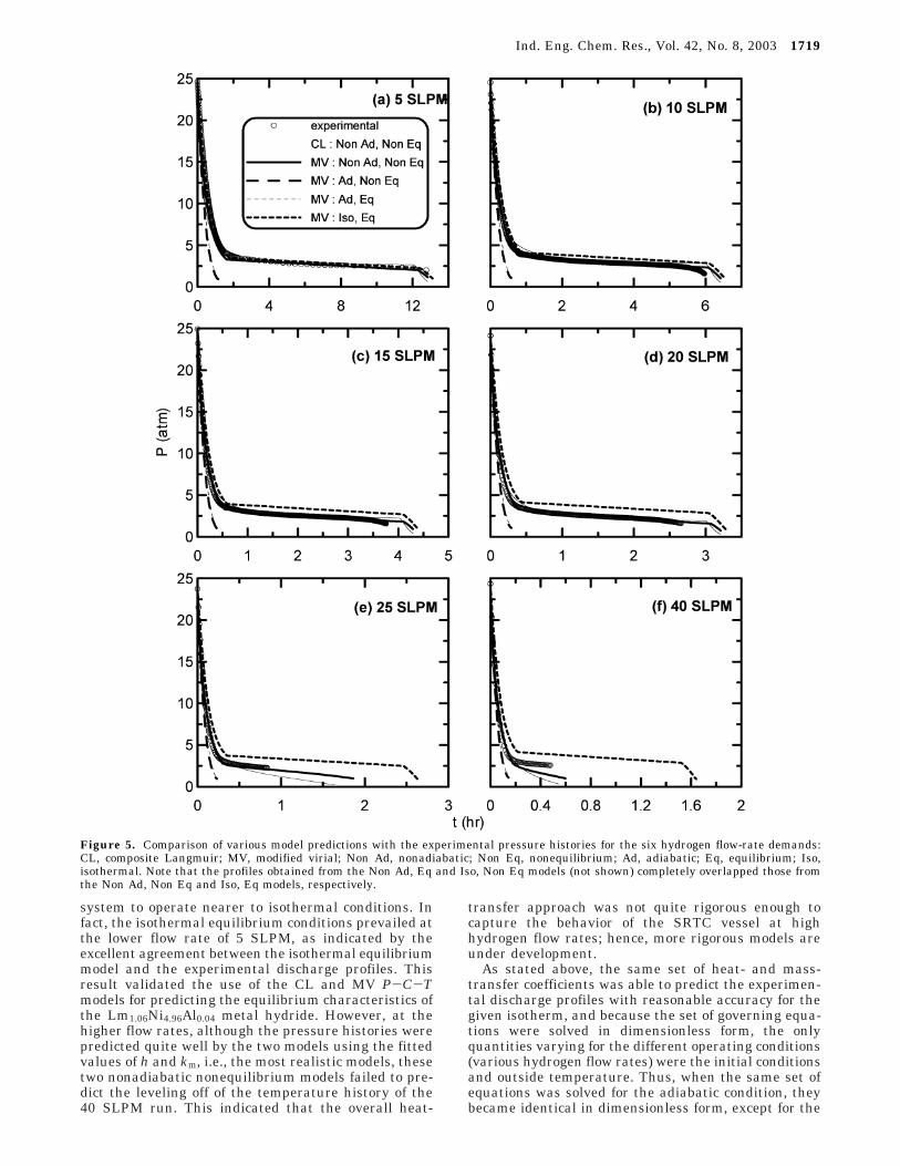
system to operate nearer to isothermal conditions. Infact, the isothermal equilibrium conditions prevailed atthe lower flow rate of 5 SLPM, as indicated by theexcellent agreement between the isothermal equilibriummodel and the experimental discharge profiles. Thisresult validated the use of the CL and MV P-C-Tmodels for predicting the equilibrium characteristics ofthe Lm1.06Ni4.96Al0.04 metal hydride. However, at thehigher flow rates, although the pressure histories werepredicted quite well by the two models using the fittedvalues of h and km, i.e., the most realistic models, thesetwo nonadiabatic nonequilibrium models failed to pre-dict the leveling off of the temperature history of the40 SLPM run. This indicated that the overall heat-
transfer approach was not quite rigorous enough tocapture the behavior of the SRTC vessel at highhydrogen flow rates; hence, more rigorous models areunder development.
As stated above, the same set of heat- and mass-transfer coefficients was able to predict the experimen-tal discharge profiles with reasonable accuracy for thegiven isotherm, and because the set of governing equa-tions were solved in dimensionless form, the onlyquantities varying for the different operating conditions(various hydrogen flow rates) were the initial conditionsand outside temperature. Thus, when the same set ofequations was solved for the adiabatic condition, theybecame identical in dimensionless form, except for the
Figure 5. Comparison of various model predictions with the experimental pressure histories for the six hydrogen flow-rate demands:CL, composite Langmuir; MV, modified virial; Non Ad, nonadiabatic; Non Eq, nonequilibrium; Ad, adiabatic; Eq, equilibrium; Iso,isothermal. Note that the profiles obtained from the Non Ad, Eq and Iso, Non Eq models (not shown) completely overlapped those fromthe Non Ad, Non Eq and Iso, Eq models, respectively.
Ind. Eng. Chem. Res., Vol. 42, No. 8, 2003 1719
time constants and the initial conditions. If the corre-sponding pressure and temperature histories are plottedon the same graph, they would be proportional to eachother, with the proportionality factor being the timeconstant for each case. By extension of this analysis tothe nonadiabatic simulations, if the outside tempera-tures are within close proximity to each other for eachindividual case, the discharge times predicted by thenonadiabatic models should again be inversely propor-tional to the hydrogen flow rate demand, which wasindeed the case. For example, the 5 SLPM run tooknearly 12 h for the pressure to discharge (Non Ad, NonEq). In contrast, it takes just about half that time, i.e.,6 h for the 10 SLPM run, 4 h for the 15 SLPM run, 3 h
for the 20 SLPM run, and 2.5 h for the 25 SLPM run.However, for the 40 SLPM, because the simulation wasstopped when the pressure reached 1 atm, it was notpossible to observe this proportional behavior.
Another interesting observation pertained to thesimulated isothermal equilibrium discharge. The pres-sure discharge histories predicted from this modelcompared very well with the experimental results at thelower flow rates and then began to deviate from theexperimental data with increasing hydrogen flow ratedemand. This was expected because mass-transferlimitations were always minimal and the total temper-ature variation during the discharge process was alwaysless at the lower flow rates. Certainly, however, the 5
Figure 6. Comparison of various model predictions with the experimental temperature histories (average of all 16 thermocouples; seeFigure 2) for the six hydrogen flow-rate demands: CL, composite Langmuir; MV, modified virial; Non Ad, nonadiabatic; Non Eq,nonequilibrium; Ad, adiabatic; Eq, equilibrium; Iso, isothermal. Note that the profiles obtained from the Non Ad, Eq and Iso, Non Eqmodels (not shown) completely overlapped those from the Non Ad, Non Eq and Iso, Eq models, respectively.
1720 Ind. Eng. Chem. Res., Vol. 42, No. 8, 2003
gpm, 29 °C heat-exchanger water had a substantialinfluence on the heat-transfer characteristics of thissystem. Nevertheless, according to the model, theisothermal equilibrium discharge represents the upperthermodynamic limit and therefore represents the bestpossible performance. One of the goals during designconsiderations is to achieve this performance becauseit extends the duration for which this unit could keepon supplying hydrogen at the desired flow rate. Thismeans that better heat-transfer characteristics have tobe achieved to improve the performance of a metalhydride hydrogen storage unit. To this end, the SRTCmetal hydride vessel uses aluminum foam for improvedinternal heat conduction and the heat exchanger forheat transfer, as shown in Figure 1. Whether this is themost optimum design has yet to be determined; adetailed study is underway.
Conclusions
Mathematical models of varying complexity, rangingfrom isothermal equilibrium to isothermal nonequilib-rium to adiabatic equilibrium to nonadiabatic equilib-rium to adiabatic nonequilibrium to nonadiabatic non-equilibrium conditions, were developed to predict thedischarge performance of a commercially viable metalhydride hydrogen storage vessel containing Lm1.06 Ni4.96-Al0.04. Two new semiempirical P-C-T models, onebased on a MV isotherm relationship and the otherbased on a CL isotherm relationship, were also intro-duced and used within the models to predict theequilibrium behavior in lieu of the typical empiricalvan’t Hoff P-C-T relationship. Also, the typical revers-ible reaction kinetic mechanism was replaced with asolid diffusion mechanism, which is a new approach inthe modeling of metal hydride hydrogen storage vessels.
The predictive ability of these models was contrastedagainst six experimental discharge runs obtained overa wide range of hydrogen flow rate demands (5-40SLPM). Under isothermal equilibrium conditions, ananalytical solution was obtained for the dischargeperformance, which represented the upper thermody-namic limit and hence the best possible performance.For the experimental conditions, which in all casesincluded heat exchange within the vessel using 29 °Cwater flowing at 5 gpm through a U-tube heat ex-changer, the run carried out at the 5 SLPM hydrogenflow rate demand compared very well with the isother-mal equilibrium model. This result validated the use ofthe CL and MV P-C-T models for predicting theequilibrium characteristics of the Lm1.06Ni4.96Al0.04 metalhydride. The other runs at the higher flow rates, asexpected, did not agree with the isothermal equilibriummodel and required a more realistic approach to predictthe performance. The remaining models required anumerical solution because they realistically accountedfor heat- and mass-transfer resistances.
The nonadiabatic nonequilibrium model, the mostrealistic model, was used to determine the heat- andmass-transfer coefficients that characterized the experi-mental system by fitting the model to one of theexperimental discharge experiments (arbitrarily se-lected). The same dimensionless mass-transfer coef-ficient (km ) 0.1) and nearly the same heat-transfercoefficients (7.6 × 10⁻³ versus 1.3 × 10⁻² W/cm2/K) wereobtained when using either the CL or MV isothermmodels, respectively. These results gave some credenceto the assumed heat- and mass-transfer mechanisms.
Overall, the results showed that a fairly simple NMcould do a reasonable job in predicting the dischargebehavior (i.e., the pressure and temperature histories)of a fairly complicated metal hydride hydrogen storagebed over a wide range of hydrogen demands. However,the MV model did perform slightly better than the CLmodel in predicting the pressure and temperaturehistories; therefore, it was used to model the behaviorof the system under extreme, limiting conditions.
These limiting cases revealed that the metal hydridehydrogen storage vessel was definitely heat-transfer-limited and only minimally mass-transfer-limited overa wide range of hydrogen discharge flow rates. Also, inall cases, the adiabatic predictions deviated markedlyfrom the experimental results, indicating that theinternal heat-exchanger water flow rate (5 gpm) andtemperature (∼29 °C) were sufficient enough to allowthe system to operate nearer to isothermal conditions.However, although the pressure histories were predictedvery well in all cases, the nonadiabatic nonequilibriummodel failed to predict the temperature history of the40 SLPM run. This indicated that a more rigorousapproach than the use of an overall heat-transfermechanism needs to be considered. For this reason,more sophisticated models are being developed that willeventually lead to better designs of metal hydridehydrogen storage vessels.
Acknowledgment
Financial support provided by the National Recon-naissance Office under Contract No. NRO-00-C-0134 isgreatly appreciated. The metal hydride hydrogen stor-age vessel and the metal hydride P-C-T data providedby the Hydrogen Technology Section of the SavannahRiver Technology Center are also greatly appreciated.
Nomenclature
c ) gas-phase hydrogen concentration (kg/m3)Cps ) specific heat of the solid (kJ/kg/K)Cpg ) specific heat of the gas (kJ/kg/K)d0 ) bed diameter (m)f ) molar flux (mol/cm2/s)f0 ) standard flux (mol/cm2/s)fr ) fraction of aluminum voids filled with metal hydride
particles with packing porosity εmHh ) heat-transfer coefficient (W/cm2/K)∆H ) isosteric heat of adsorption (kJ/kg/K)k ) velocity gradient in the bed (vout/L)kL ) LDF mass-transfer coefficient (s-1)km ) dimensionless mass-transfer coefficient used in the
simulation (kLt0)L ) bed length (m)MH2 ) molecular weight of hydrogen (g/mol)mmH ) mass of metal hydride (kg)mAl ) mass of aluminum (kg)Pi ) initial pressure (atm)P0 ) standard pressure (1 atm)q ) hydrogen loading (kg/kg)qi ) initial hydrogen loading (kg/kg)q0 ) standard hydrogen loading (ε2P0/(1 - ε1)FmHRT0)ro ) outside radius of the vessel (m)ri ) radius of the coaxial heat-exchanger tube (m)R ) gas law constant (m3‚atm/kmol‚K)t ) discharge time (s)T ) temperature (K)Ti ) initial temperature (K)T0 ) standard temperature (273.15 K)
Ind. Eng. Chem. Res., Vol. 42, No. 8, 2003 1721
t0 ) time constant (ε2P0L/RT0 f0) (s)v ) gas-phase velocity (m/s)vout ) constant outlet velocity (m/s)z ) axial distance inside the bed (m)
Greek Letters
π ) dimensionless pressure (P/P0)θ ) dimensionless temperature (T/T0)φ ) dimensionless hydrogen loading (q/q0)φ* ) dimensionless equilibrium loading (q*/q0)FmH ) metal hydride density (kg/m3)FAl ) aluminum skeleton density (kg/m3)ε1 ) volume fraction of bed not occupied by metal hydride
particlesε2 ) volume fraction of bed not occupied by either metal
hydride particles or aluminum foamεAl ) volume fraction of pores in aluminum foamεmH ) volume fraction of interstitial voids between packed
metal hydride particlesτ ) dimensionless time (t/t0)ω ) dimensionless molar flux demand (f/f0)
Literature Cited
(1) Heung, L. K. On-board Hydrogen Storage System UsingMetal Hydride. HYPOTHESIS II 1997, 1.
(2) Lamari, M.; Aoufi, A.; Malbrunot, P. Thermal Effects inDynamic Storage of Hydrogen by Adsorption. AIChE J. 2000, 46,632.
(3) Mat, M. D.; Kaplan, Y. Numerical Study of HydrogenAbsorption in an Lm-Ni5 Hydride Reactor. Int. J. Hydrogen Energy2001, 26, 957.
(4) Levesque, S.; Ciureanu, M.; Roberge, R.; Motyka, T. Hy-drogen Storage for Fuel Cell Systems with Stationary ApplicationssI. Transient Measurement Technique for Packed Bed Evaluation.Int. J. Hydrogen Energy 2000, 25, 1095.
(5) Klein, J. E.; Brenner, J. R.; Dye, E. F. Development of aPassively Cooled, Electrically Heated (PACE) Bed. Fusion Technol.2002, 41, 782.
(6) Das, L. M. On-board Hydrogen Storage Systems for Auto-motive Application. Int. J. Hydrogen Energy 1996, 21, 789.
(7) Berry, G. D.; Aceves, S. M. On-board Storage Alternativesfor Hydrogen Vehicles. Energy Fuels 1998, 12, 49.
(8) Mungole, M. N.; Balasubramaniam, R. Effect of HydrogenCycling on the Hydrogen Storage Properties of MmNi4.2Al0.8. Int.J. Hydrogen Energy 2000, 25, 55.
(9) Gopal, M. R.; Murthy, S. S. Parametric Studies on Heat andMass Transfer in Metal Hydride Beds. Chem. Eng. Proc. 1993,32, 217.
(10) Sun, D.; Deng, S. Study of the Heat and Mass TransferCharacteristics of Metal Hydride Beds. J. Less-Common Met. 1988,141, 37.
(11) Jemni, A.; Nasrallah, S. B.; Lamloumi, J. Experimentaland Theoretical Study of a Metal-Hydrogen Reactor. Int. J.Hydrogen Energy 1999, 24, 631.
(12) Nakagwa, T.; Inomata, A.; Aoki, H.; Miura, T. NumericalAnalysis of Heat and Mass Transfer Characteristics in the MetalHydride Bed. Int. J. Hydrogen Energy 2000, 25, 339.
(13) Guo, Z. Enhancement of Heat and Mass Transfer in MetalHydride Beds with the Addition of Al Plates. Heat Mass Transfer1999, 34, 517.
(14) Gopal, M. R.; Murthy, S. S. Studies on Heat and MassTransfer in Metal Hydride Beds. Int. J. Hydrogen Energy 1995,20, 911.
(15) Jemni, A.; Nasrallah, S. B. Study of Two-Dimensional Heatand Mass Transfer During Desorption in a Metal-HydrogenReactor. Int. J. Hydrogen Energy 1995, 20, 881.
(16) Jemni, A.; Nasrallah, S. B. Heat and Mass Transfer Modelsin Metal-Hydrogen Reactor. Int. J. Hydrogen Energy 1997, 22,67.
(17) Isselhorst, A. Heat and Mass Transfer in Coupled HydrideReaction Beds. J. Alloys Compds. 1995, 871.
(18) Valenzuela, D. P.; Myers, A. L. Adsorption EquilibriumData Handbook; Prentice Hall: Englewood Cliffs, NJ, 1989.
(19) Ritter, J. A.; Yang, R. T. Equilibrium Theory for HysteresisDependent Fixed Bed Desorption. Chem. Eng. Sci. 1990, 46, 563.
(20) Mueller, W.; Blackledge, J. P.; Libowitz, G. G. MetalHydrides; Academic Press: New York, 1968.
(21) Savannah River Technology Center, Aiken, SC, unpub-lished data, 2002.
(22) Liaw, C. H.; Wang, J. S. P.; Greenkorn, R. H.; Chao, K. C.Kinetics of Fixed-Bed Adsorption: A New Solution. AIChE J. 1979,54, 376.
(23) Fleming, W. H.; Khan, J. A.; Rhodes, C. A. Effective HeatTransfer in a Metal-Hydride-Based Hydrogen Separation Process.Int. J. Hydrogen Energy 2001, 26, 711.
Received for review October 31, 2002Revised manuscript received February 6, 2003
Accepted February 11, 2003
IE020839I
1722 Ind. Eng. Chem. Res., Vol. 42, No. 8, 2003
Related Documents


