Practical Guide Industrial Flue Gas Analysis Emissions and process measurement guidelines 3rd, revised edition

Welcome message from author
This document is posted to help you gain knowledge. Please leave a comment to let me know what you think about it! Share it to your friends and learn new things together.
Transcript
Practical Guide Industrial Flue Gas Analysis
Emissions and process measurement guidelines3rd, revised edition

Copyrights, warranty and liability
The information put together in this Practical Guide is protected by copyright. All rights belong exclusively to Testo SE & Co. KGaA. The contents and pictures may not be commercially reproduced, modified or used for purposes other than the intended application described without the prior written consent of Testo SE & Co. KGaA.
The information in this Practical Guide has been produced with the utmost care. Nevertheless, the information provided is not binding, and Testo SE & Co. KGaA reserves the right to make changes or additions. Testo SE & Co. KGaA therefore offers no guarantee or warranty for the correctness and completeness of the information provided. Testo AG accepts no liability for damages resulting directly or indirectly from the use of this guide, insofar as these cannot be attributed to wilful intent or negligence.
Testo SE & Co. KGaA, in January 2018
Foreword
Dear Reader
Determining flue gas concentrations
allows legally required emission limit
values to be monitored, thus enabling
protection of the environment. On the
other hand, gas concentrations or gas
matrices generated during the process
often provide a very good indication
of the existing process quality, which
ultimately has a considerable influence
on the product quality.
This Practical Guide contains the basic
principles of common combustion
processes, with a specific focus on
their use in industrial applications. The
available measurement methods, the
characteristics associated with the
measuring tasks, the expected gas
measurement parameters, concentra-
tions and their significance with regard
to the process are also described. This
is a useful reference guide for using
portable gas analyzers in industry,
based on the experiences of global
users of Testo measuring instruments.
Additional ideas and suggestions for
improvement are always welcome.
Happy reading!
Prof. Burkart Knospe,
Chairman of the Board of Directors
2
Contents
Foreword 11. The combustion process 5 1.1 Energy and combustion 5 1.2 Combustion plants 8 1.3 Fuels 10 1.4 Combustion air, air ratio 11 1.4.1 Ideal combustion, fuel-air ratio, material balance 11 1.4.2 Determining the air ratio 14 1.4.3 Combustion air requirement 16 1.4.4 Gas volume, diluting effect, reference value 16 1.5 Flue gas (exhaust gas) and its composition 19 1.6 Gross calorific value, net calorific value, efficiency 23 1.7 Dew point, condensate 262. Gas analysis for industrial flue gases 29 2.1 Combustion optimization 31 2.2 Process control 34 2.2.1 Process heaters 34 2.2.2 Industrial combustion plants 35 2.2.3 Thermal surface treatment 36 2.2.4 Safety measurements 37 2.3 Emission control 38 2.3.1 Legal framework in Germany 39 2.3.2 Guidelines in Germany (German Federal Immission Control Ordi-
nance (BImSchV) and TI Air (TA-Luft)) 41 2.3.3 Situation in the USA 48 2.3.4 Procedures for purifying flue gas 503. Gas analysis technology 54 3.1 Terminology used in gas analysis technology 54 3.1.1 Concentration, standard conditions 54 3.1.2 Sample preparation, condensate, heating 60 3.1.3 Cross-sensitivity 62 3.1.4 Calibration 64 3.2 Gas analyzers 65 3.2.1 Terminology and use 65 3.2.2 Measuring principles 70
3
4. Industrial gas analysis applications 79 4.1 Power generation 80 4.1.1 Solid-fuel firing systems 80 4.1.2 Gas-fired installations 82 4.1.3 Gas turbines 84 4.1.4 Oil-fired installations 86 4.1.5 Coal-fired power plants 88 4.1.6 Cogeneration plants 91 4.1.7 Combined cycle power plants 93 4.2 Waste disposal 94 4.2.1 Waste incineration 94 4.2.2 Waste pyrolysis 96 4.2.3 Thermal afterburning 98 4.3 Non-metallic minerals industry 100 4.3.1 Cement production 100 4.3.2 Ceramics/porcelain production 102 4.3.3 Brickworks 104 4.3.4 Glass production 106 4.3.5 Lime production 109 4.4 Metal/ore industry 111 4.4.1 Sintering plants 111 4.4.2 Iron production 113 4.4.3 Steel production 115 4.4.4 Coking plants 117 4.4.5 Aluminium production 119 4.4.6 Surface treatment 121 4.5 Chemical industry 123 4.5.1 Process heaters 123 4.5.2 Refineries 124 4.5.3 Flare stack measurements 126 4.5.4 Residue incineration 127 4.6 Other 129 4.6.1 Crematoria 129 4.6.2 Engine test beds 1305. Testo gas analysis technology 131 5.1 The company 131 5.2 Typical instrument features 133 5.3 Overview of gas analyzers 135 5.4 Overview of accessories 139
Addresses 143 Index 144

4
1. The combustion process
5
1. The combustion process
1.1 Energy and combustion
Energy
(from the Greek) means “acting force”
and is defined as the ability of a
substance, body or system to carry
out work. Energy can be assigned to
certain energy types depending on
their form.
Energy can be classified into six cat-
egories:
• Mechanical energy (flowing water,
driving car, helical spring)
• Thermal energy (boiling water, gas
flame)
• Chemical energy (chemical reac-
tions, combustion, explosion)
• Electrical energy (car battery, electric
current)
• Electromagnetic energy (light, ther-
mal radiation)
• Nuclear energy (nuclear fission)
The various forms of energy can be
converted from one form into other,
whereby, within an ideally closed sys-
tem, the sum of all energies remains
constant (conservation of energy).
This actually applies in respect of
the universe as a system. In practice,
however, energy is lost to a greater or
lesser extent when energy is convert-
ed, and this loss affects the efficiency
of the conversion process. The natural
energy carriers (coal, natural gas,
petroleum, solar radiation, hydro-
power, etc.) are described as primary
energies, while the forms generated
through energy conversions (electrici-
ty, heat, etc.) are called secondary en-
ergies. These energy carriers differ not
only in their appearance, but also in
their energy content. For the purposes
of comparison, the quantity of energy
that could be released if a given quan-
tity of the energy source were fully
burned is generally specified. Table 1
gives a few examples to illustrate this.
The measuring unit for energy is the
joule (J).
6
1. The combustion process
Combustion
is the conversion of primary chemical
energy contained in fuels such as coal,
oil or wood into secondary thermal en-
ergy through the process of oxidation.
Combustion is therefore the technical
term for the reaction of oxygen with
the combustible components of fuels,
during which energy is released.
Combustions take place at high tem-
peratures (up to 1000 °C and higher)
and whilst emitting heat. The neces-
sary oxygen is supplied as part of the
combustion air. At the same time, a
considerable volume of flue gas and,
depending on the type of fuel, a cer-
tain quantity of residual materials (ash,
slag) are formed.
Conversion of energy units:1 erg 10-7 J1 cal 4.184 J1 Btu 1055.06 JBtu: British thermal unit
Energy source Energy content [MJ]1 kg lignite 9.01 kg wood 14.71 kg hard coal 29.31 m3 natural gas 31.71 kg crude oil 42.61 kg light fuel oil 42.71 kg gasoline 43.5For comparison 1 kWh 3.6
Tab. 1: Energy content of various fuels

7
Oxidation
Term for all chemical reactions during
which a substance combines with
oxygen. During oxidation, energy is
released. Oxidation is of great signif-
icance when it comes to technology
(combustion) and biology (respiration).
Greenhouse effect
In principle, the greenhouse effect is
a natural phenomenon and a prereq-
uisite for life on earth. Without this
effect, the average global temperature
near the Earth’s surface would be
-18 °C instead of +15 °C today; the
earth would be uninhabitable! The
cause of this natural effect is primar-
ily the water vapour content of the
atmosphere near the Earth’s surface,
which allows solar radiation to pass
through, but prevents the long-wave
thermal radiation that develops on the
ground from escaping; this is reflect-
ed back to the Earth’s surface. The
heat management of greenhouses is
also based on this principle. Howev-
er, excessive burning of fossil fuels
(carbon dioxide emissions) and the
release of substances from chemicals
and agriculture (CFCs, methane, etc.)
considerably intensify this natural
effect, which leads to a slow increase
in the Earth’s temperature and affects
climatic conditions, etc.
More details on the topic of combus-
tion can be found in Section 1.4.
8
1.2 Combustion plants
Combustion plants are facilities for
generating heat by burning solid, liquid
or gaseous fuels. They are needed for
many different purposes, for example
• For heating purposes (heating plants
and building heating systems)
• For generating electricity
• For generating steam or hot wa-
ter (used in processing plants, for
example)
• For manufacturing certain materials
(for use in the cement, glass or ce-
ramics industry, for example)
• For thermal surface treatment of
metallic workpieces
• For burning waste and scrap materi-
als (waste, used tyres etc.)
Please refer to the detailed application
examples in Section 4.
The combustion takes place in a
furnace; other parts of the plant supply
and distribute the fuel, supply the
combustion air, transfer the heat and
carry away the combustion gases and
combustion residues (ash and slag).
Solid fuels are burnt either in a fixed
bed, a fluidized bed or in an entrained
dust cloud. Via a burner, liquid fuels
are fed to the combustion chamber
together with the combustion air in the
form of mist; gaseous fuels are already
mixed with the combustion air in the
burner.
Flue gas from combustion plants
contains the reaction products of fuel
and combustion air as well as residual
substances, generating primarily dust,
sulphur and nitrogen oxides and also
carbon monoxide. During the combus-
tion of coal, HCl and HF, and during
the combustion of scrap material, their
constituents (HCl and HF, but also var-
ious hydrocarbons, heavy metals, etc.)
may also be present in the flue gas.
1. The combustion process
9
Within the context of environmental
protection, the flue gas from combus-
tion plants is subject to strict regu-
lations with regard to the limit values
of pollutants such as dust, sulphur
and nitrogen oxides and also carbon
monoxide which are permissible in
the clean gas (when released into the
atmosphere). To comply with these
limit values, combustion plants are
equipped with extensive facilities for
cleaning flue gas, such as dust filters
and various flue gas scrubbers. In Ger-
many, the specific requirements are
laid down in the 13th and 17th Federal
Immission Control Ordinance (BIm-
SchV) and in TI Air. Further information
about this can be found in Section 2.3.
10
The composition of some solid fuels is shown in the following table.
Please refer to Section 1.6 for explanations relating to the calorific value of fuels.
1.3 Fuels
Fuels are available in various forms
and compositions:
• Solid fuels (coal, peat, wood, straw)
primarily contain carbon (C), hydro-
gen (H₂), oxygen (O₂) and small quan-
tities of sulphur (S), nitrogen (N2) and
water (H2O).
• Liquid fuels derive from petroleum or
the processing of it, whereby a dis-
tinction is made between extra-light
(EL), light (L), medium (M) and heavy
(S) fuel oils.
• Gaseous fuels are a mixture of com-
bustible (CO, H₂ and hydrocarbons)
and non-combustible gases. These
days, natural gas is very often used,
the main component of which is the
hydrocarbon gas methane (CH₄).
Knowledge of the composition of the
fuel is essential to managing com-
bustion as efficiently, and therefore
as economically, as possible. An
increasing portion of non-flammable
(inert) substances reduces the gross/
net calorific value and increases the
level of dirt that collects on the heating
surfaces. An increasing water con-
tent pushes up the water vapour dew
point and consumes fuel energy to
evaporate the water in the flue gas.
The sulphur contained in the fuel is
combusted to SO₂ and SO₃, which can
generate aggressive sulphurous acid
or sulphuric acid when the gas cools
down to below the dew point. Please
also refer to Section 1.7
1. The combustion process
Tab. 2: Composition of fuels
Fuel Content (mass content in %)
Carbon in dry matter Sulphur Ash Water
Hard coal 80-90 1 5 3-10
Ortho-lignite 60-70 2 5 30-60
Meta-lignite 70-80 10-30
Wood (air-dry) 50 1 1 15
Peat 50-60 1 5 15-30
11
1.4 Combustion air, air ratio
The combustion air provides the
oxygen required for combustion. It
consists of nitrogen (N₂), oxygen (O₂),
a small proportion of noble gases and
a variable proportion of water vapour
(Tab. 3). In some cases, even pure ox-
ygen or an oxygen/air mixture is used
for combustion.
Essential combustion air constituents
(except the oxygen used in the com-
bustion process) can all be found in
the flue gas.
Component Volume content [%]Nitrogen 78.07Oxygen 20.95Carbon dioxide 0.03Hydrogen 0.01Argon 0.93Neon 0.0018
Tab. 3: Composition of pure and dry air on the Earth’s surface
1.4.1 Ideal combustion, fuel-air
ratio, material balance
The minimum oxygen requirement for
complete (ideal) combustion of the
combustible constituents depends on
the fuel composition: For example, the
combustion of 1 kg of carbon requires
2.67 kg of oxygen, but 1 kg of hydro-
gen requires 8 kg and 1 kg of sulphur
only 1 kg of oxygen. This case of exact
quantity ratios is considered an ideal
combustion or combustion under stoi-
chiometric conditions.
The corresponding chemical equations
are as follows:
Carbon: C + O₂ CO₂
Hydrogen: 2H₂ + O₂ 2H₂O
Sulphur: S + O₂ SO₂
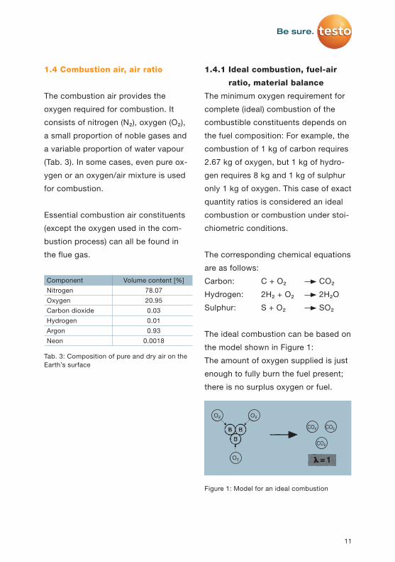
The ideal combustion can be based on
the model shown in Figure 1:
The amount of oxygen supplied is just
enough to fully burn the fuel present;
there is no surplus oxygen or fuel.
O₂ O₂
CO₂ CO₂
CO₂
O₂
Figure 1: Model for an ideal combustion
12
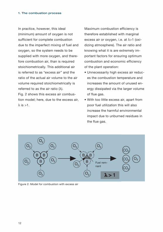
In practice, however, this ideal
(minimum) amount of oxygen is not
sufficient for complete combustion
due to the imperfect mixing of fuel and
oxygen, so the system needs to be
supplied with more oxygen, and there-
fore combustion air, than is required
stoichiometrically. This additional air
is referred to as “excess air” and the
ratio of the actual air volume to the air
volume required stoichiometrically is
referred to as the air ratio (λ).
Fig. 2 shows this excess air combus-
tion model; here, due to the excess air,
λ is >1.
Maximum combustion efficiency is
therefore established with marginal
excess air or oxygen, i.e. at λ>1 (oxi-
dizing atmosphere). The air ratio and
knowing what it is are extremely im-
portant factors for ensuring optimum
combustion and economic efficiency
of the plant operation:
• Unnecessarily high excess air reduc-
es the combustion temperature and
increases the amount of unused en-
ergy dissipated via the larger volume
of flue gas.
• With too little excess air, apart from
poor fuel utilization this will also
increase the harmful environmental
impact due to unburned residues in
the flue gas.
1. The combustion process
Figure 2: Model for combustion with excess air
Fuel rem-nant
CO₂
CO₂
CO₂ O₂
13
Table 4 shows the typical air ratio
ranges for various combustion plants.
As a matter of principle, the follow-
ing applies: the smaller the reaction
surface for the fuel in relation to the
unit of mass (coarse-grained fuel), the
higher the amount of excess air that
must be chosen to ensure complete
combustion. The reverse is also true,
which is why solid fuels are ground
finely and liquid fuels are atomized.
However, special processes, e.g. ther-
mal surface treatment, are deliberately
operated with insufficient air at λ<1,
as this is necessary to ensure the
required refinement process.
Combustion plant Range for λCombustion engines 0.8-1.2Pressure jet gas-fired instal-lation 1.1-1.3
Oil burner 1.2-1.5Coal dust burner 1.1-1.3Grate furnace for brown coal 1.3-1.7Neon 0.001
Tab. 4: Typical ranges for air ratio λ
Oxidizing atmosphere
Here, more oxygen is available than is
necessary for the oxidation of oxidiz-
able substances in the fuel. Complete
oxidation (combustion) is therefore
possible.
Simply put: Oxidation = addition of
oxygen (CO is oxidized to CO₂).
Reducing atmosphere
Here, there is too little oxygen to
oxidize all oxidizable substances. The
opposite of oxidation occurs, i.e. a
reduction.
Simply put: Reduction = removal of
oxygen (SO₂ is reduced to S).
14
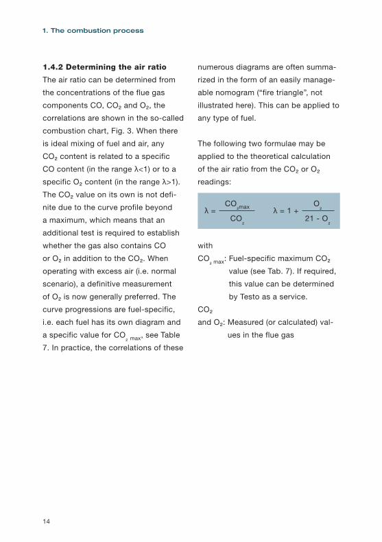
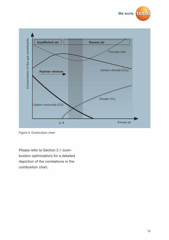
1.4.2 Determining the air ratio
The air ratio can be determined from
the concentrations of the flue gas
components CO, CO₂ and O₂, the
correlations are shown in the so-called
combustion chart, Fig. 3. When there
is ideal mixing of fuel and air, any
CO₂ content is related to a specific
CO content (in the range λ<1) or to a
specific O₂ content (in the range λ>1).
The CO₂ value on its own is not defi-
nite due to the curve profile beyond
a maximum, which means that an
additional test is required to establish
whether the gas also contains CO
or O₂ in addition to the CO₂. When
operating with excess air (i.e. normal
scenario), a definitive measurement
of O₂ is now generally preferred. The
curve progressions are fuel-specific,
i.e. each fuel has its own diagram and
a specific value for CO₂ max, see Table
7. In practice, the correlations of these
numerous diagrams are often summa-
rized in the form of an easily manage-
able nomogram (“fire triangle”, not
illustrated here). This can be applied to
any type of fuel.
The following two formulae may be
applied to the theoretical calculation
of the air ratio from the CO₂ or O₂
readings:
λ = λ = 1 +CO₂max O₂
CO₂ 21 - O₂
with
CO₂ max: Fuel-specific maximum CO₂
value (see Tab. 7). If required,
this value can be determined
by Testo as a service.
CO₂
and O₂: Measured (or calculated) val-
ues in the flue gas
1. The combustion process
15
Please refer to Section 2.1 (com-
bustion optimization) for a detailed
depiction of the correlations in the
combustion chart.
Flue gas loss
Fuel/air mixture Carbon dioxide (CO₂)
Carbon monoxide (CO)
Oxygen (O₂)
Excess air
Con
cent
ratio
n of
flu
e ga
s co
nstit
uent
s
Insufficient air Excess air
Figure 3: Combustion chart
16
1.4.3 Combustion air requirement
The actual air requirement is calculated
• From the minimum oxygen required
for ideal combustion (this depends
on the fuel)
• The required excess oxygen and
• The relative oxygen content in the
air. For dry air under atmospheric
pressure, this is 20.95 %. In practice,
however, the ambient air used as
combustion air is never completely
dry, which means that the humidity
also has to be factored into the cal-
culation of the air volume to ensure
an exact process.
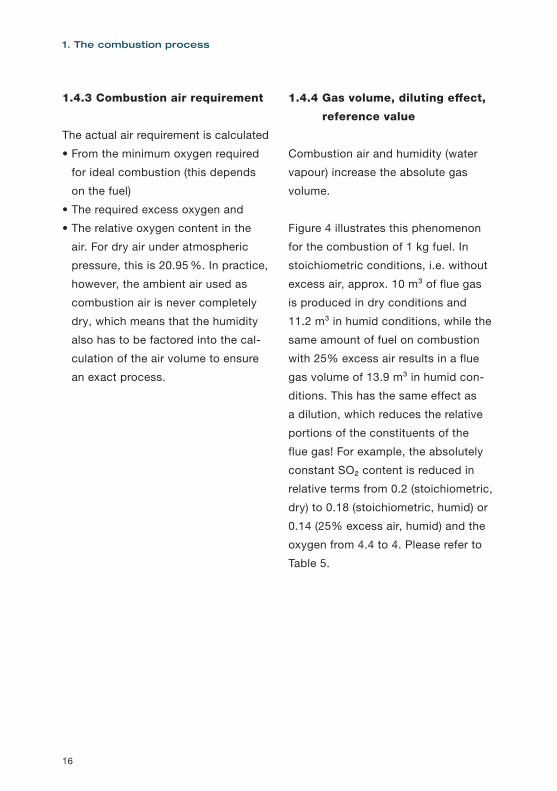
1.4.4 Gas volume, diluting effect,
reference value
Combustion air and humidity (water
vapour) increase the absolute gas
volume.
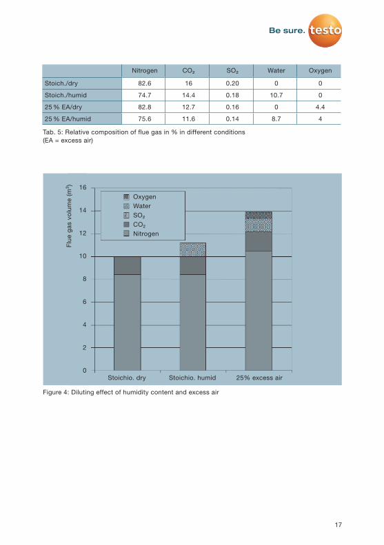
Figure 4 illustrates this phenomenon
for the combustion of 1 kg fuel. In
stoichiometric conditions, i.e. without
excess air, approx. 10 m³ of flue gas
is produced in dry conditions and
11.2 m³ in humid conditions, while the
same amount of fuel on combustion
with 25% excess air results in a flue
gas volume of 13.9 m³ in humid con-
ditions. This has the same effect as
a dilution, which reduces the relative
portions of the constituents of the
flue gas! For example, the absolutely
constant SO₂ content is reduced in
relative terms from 0.2 (stoichiometric,
dry) to 0.18 (stoichiometric, humid) or
0.14 (25% excess air, humid) and the
oxygen from 4.4 to 4. Please refer to
Table 5.
1. The combustion process
17
Nitrogen CO₂ SO₂ Water Oxygen
Stoich./dry 82.6 16 0.20 0 0
Stoich./humid 74.7 14.4 0.18 10.7 0
25 % EA/dry 82.8 12.7 0.16 0 4.4
25 % EA/humid 75.6 11.6 0.14 8.7 4
Tab. 5: Relative composition of flue gas in % in different conditions (EA = excess air)
OxygenWaterSO₂CO₂Nitrogen
Stoichio. dry Stoichio. humid 25% excess air
16
14
12
10
8
6
4
2
0
Figure 4: Diluting effect of humidity content and excess air
Flue
gas
vol
ume
(m³)
18
Reference values
From the depicted correlations, it is
clear that concentration observations
can usually only be made in conjunc-
tion with reference values. It is only
then that the readings have any mean-
ing and can be compared with other
measurement results, and in particular
with statutory requirements! In prac-
tice, the following are used:
• Reference to a specific dilution due
to excess air; a measure of this is
the oxygen content, the reference is
expressed by e.g.”Reference value
8% oxygen”.
This reference to the oxygen value
is generally applied in the specifica-
tions of the TI Air; however, it is also
used outside of the TI Air: for a plant,
the reference point is defined close
to the oxygen content when the plant
is started up.
• Reference to a specific dilution due
to the humidity content of the gas; a
measure of this is the temperature of
the gas, the reference is expressed,
for example, by “based on dry flue
gas” or “at dew point 4 °C”.
• Reference to the normal state of a
gas. This pertains to the dependence
of a gas volume on the actual values
of pressure and temperature, please
refer to Section 3.1.1
1. The combustion process
19
1.5 Flue gas (exhaust gas) and its
composition
The flue gas generated in combus-
tion processes is also referred to as
exhaust gas. Its composition depends
on the fuel and the combustion con-
ditions, e.g. the air ratio. Many of the
constituents of flue gas are classified
as air pollutants, and must therefore
be removed from the flue gas before
it is released into the atmosphere
via cleaning processes, which are
extremely time-consuming and costly
in some cases, in conformity with
statutory regulations (please refer to
Section 2.3). Flue gas in its original
composition after combustion is also
referred to as crude gas, and once it
has passed through the cleaning stag-
es it is called clean gas.
The most important flue gas compo-
nents are explained below.
Nitrogen (N₂)
At 79 vol.%, nitrogen is the main
component of the air. This colour-
less, odourless and tasteless gas is
supplied via the combustion air, but
does not play a direct role in the actual
combustion process; it is carried as a
ballast and a waste heat carrier and is
returned to the atmosphere. However,
parts of the nitrogen, in combination
with the nitrogen contained in the fuel,
contribute to the formation of the haz-
ardous nitrogen oxides (see below).
Carbon dioxide (CO₂)
Carbon dioxide is a colourless and
odourless gas with a slightly sour
taste, which is generated in all com-
bustion processes and by breathing.
Due to its property of filtering radiated
heat, it is a major contributor to the
greenhouse effect. Natural air only
contains 0.03 %; the permissible MAC
(maximum allowable concentration)
is 0.5 %; concentrations of more than
15 % in the air inhaled by humans
cause unconsciousness.
Water vapour (humidity)
The hydrogen contained in the fuel
combines with oxygen to form water
(H₂O). Together with the water from the
fuel and the combustion air, depend-
ing on the flue gas temperature (FT)
this is discharged as flue gas humidity
(at high FT) or as condensate (at low
FT).
20
Oxygen (O₂)
Oxygen that has not been used in
combustion in the event of excess air
is discharged as a gaseous flue gas
component and is a measure of com-
bustion efficiency. It is used for the
determination of combustion parame-
ters and as a reference value.
Carbon monoxide (CO)
Carbon monoxide is a colourless
and odourless toxic gas. It is main-
ly generated during the incomplete
combustion of fossil fuels (furnaces)
and automotive fuels (motor vehicles)
and other materials containing carbon.
CO is generally innocuous to humans,
since it soon bonds with the oxygen
in the air to form CO₂. However, within
enclosed spaces CO is very danger-
ous, because a concentration of only
700 ppm in the air inhaled by humans
will cause death within a few hours.
The MAC value is 50 ppm.
Nitrogen oxides (NO and NO₂, total
formula NOX)
In combustion processes, the nitrogen
from the fuel and, at high tempera-
tures, also from the combustion air,
is combined to a certain extent with
the combustion air/oxygen, initially
forming nitrogen monoxide NO (fuel
NO and thermal NO), which in the
presence of oxygen is oxidized in a
further step to form the hazardous
nitrogen dioxide (NO₂) in the flue gas
duct and later in the atmosphere. Both
oxides are toxic; NO₂ in particular is a
dangerous respiratory poison and, in
combination with sunlight, contributes
to the formation of ozone. Sophisti-
cated technologies such as the SCR
process are used to clean flue gases
containing NOX. Special combustion
measures, e.g. staged air supply, are
used to reduce nitrogen oxides during
combustion.
Sulphur dioxide (SO₂)
Sulphur dioxide is a colourless, toxic
gas with a pungent smell. It is pro-
duced as a result of the oxidation of
the sulphur contained in the fuel. The
MAC value is 5 ppm. In combination
with water or condensate, sulphur-
ous acid (H₂SO₃) and sulphuric acid
(H₂SO₄) are produced, both of which
are linked to numerous types of envi-
ronmental damage to vegetation and
building fabrics. Flue gas desulphuri-
zation plants (FGD) are used to reduce
sulphur oxides.
1. The combustion process
21
Hydrogen sulphide (H₂S)
Hydrogen sulphide is a toxic and ex-
tremely malodorous gas, even in very
low concentrations (approx. 2.5 µg/
m³). It is a naturally occurring constit-
uent of natural gas and petroleum and
is therefore present in refineries and
natural gas processing plants, but also
in tanneries, agricultural business-
es and, last but not least, following
incomplete combustion in vehicle cat-
alytic converters. Combustion to SO₂,
certain absorption processes or, in the
case of larger quantities, conversion
to elemental sulphur in a Claus plant
are some of the processes used to
eliminate H₂S from flue gases.
Hydrocarbons
(HC or CXHY)
Hydrocarbons are an extensive group
of chemical compounds composed ex-
clusively of carbon and hydrogen. HCs
are the most important substances in
organic chemistry; they occur naturally
in petroleum, natural gas or carbon.
HCs can be emitted both when HC
products are manufactured (e.g. in
refineries) but also when they are used
and disposed of (solvents, plastics,
paints, fuels, waste etc.). Incomplete
combustions are a particular source
of HC emissions. This also includes
forest and bush fires as well as ciga-
rettes, for example. HCs contribute to
the greenhouse effect.
Examples of HCs include methane
(CH₄), butane (C₄H10) and benzene
(C₆H₆), but also the carcinogenic sub-
stance benzo[a]pyrene. The whole po-
tential of a flue gas for volatile organic
compounds is often referred to as the
total C or Ctotal. This total is usually
determined in the flue gas.
Hydrogen cyanide (HCN)
Hydrogen cyanide (also known as
hydrocyanic acid) is a very toxic liquid
with a boiling point of 25.6 °C; it exists
in flue gases, if present, in gaseous
form. HCN may exist in waste inciner-
ation plants.
22
Ammonia (NH₃)
Ammonia plays a role in flue gases in
conjunction with the SCR process for
flue gas denitrification. In the denitrifi-
cation reactors, it is added to the flue
gas in precisely metered quantities
and causes the conversion of the ni-
trogen oxides into nitrogen and water.
The unused residue (NH₃ slip) is great-
ly reduced via downstream cleaning
stages, and in the clean gas is usually
at or below 2 mg/m³.
Halogen halides (HCl, HF)
During the combustion of coal and/or
waste materials, the hydrogen halides
HCl and HF may form, and these form
aggressive acids in combination with
humid atmospheres. These substanc-
es are largely washed out of the flue
gas by the flue gas cleaning plants
(scrubbers).
Solids (dust, soot)
Solid pollutants in the flue gas come
from the incombustible components of
solid and liquid fuels. These include,
for example, the oxides of silicon,
aluminium, calcium etc. in the case of
coal and the sulphates of various sub-
stances in the case of heavy fuel oil.
The harmful effect of dust on humans
is mainly due to the accumulation of
toxic and carcinogenic substances in
the dust particles.
1. The combustion process
23
1.6 Gross calorific value, net
calorific value, efficiency, flue
gas loss
Gross calorific value, net calorific
value
The gross calorific value (formerly
referred to as the upper net calorific
value) is a characteristic value for
fuel and refers to the energy released
during full combustion in relation to
the quantity of fuel used. The net cal-
orific value (formerly referred to as the
lower net calorific value), on the other
hand, is the released energy minus the
evaporation heat of the water vapour
generated during combustion at 25 °C,
again in relation to the quantity of fuel
used.
Basically, the net calorific value is less
than the gross calorific value.
Condensing boiler
Condensing boilers are boilers which,
in addition to the combustion heat,
also make use of the condensa-
tion heat of the flue gas by means
of heat exchangers. In terms of the
net calorific value, these boilers can
achieve combustion efficiencies of
107%. However, the condensate that
is generated and contaminated with
pollutants must be disposed of in an
environmentally friendly manner.
Efficiency of a combustion
The efficiency is a variable determined
from performance values while the
plant is in stationary operation. The ef-
ficiency (this is always less than 100%)
is the ratio of the energy supplied to
the combustion chamber overall to the
energy required or used to carry out
the process (heating, melting, sin-
tering, etc.). Efficiency is made up of
several components:
• The combustion efficiency describes
the proportion of the total input
power (energy per time unit) that is
available in the combustion chamber
after combustion. This makes it an
important factor for the quality of the
combustion.
• The furnace efficiency, which largely
depends on its design, describes the
quality of the furnace and the oper-
ation via the relationship between
the supplied energy and the energy
available in the furnace.
• The total efficiency is obtained by
multiplying the combustion and fur-
nace efficiencies.
24
Energy balance of a combustion
plant
In stationary operating mode, the sum
of all the energies supplied to the
plant must be equal to the sum of the
energies delivered by the plant; please
refer to Table 6.
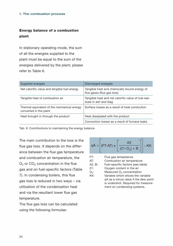
The main contribution to the loss is the
flue gas loss. It depends on the differ-
ence between the flue gas temperature
and combustion air temperature, the
O₂ or CO₂ concentration in the flue
gas and on fuel-specific factors (Table
7). In condensing boilers, this flue
gas loss is reduced in two ways – via
utilization of the condensation heat
and via the resultant lower flue gas
temperature.
The flue gas loss can be calculated
using the following formulae:
FT: Flue gas temperatureAT: Combustion air temperatureA2, B: Fuel-specific factors (see table)21: Oxygen content in the airO₂: Measured O₂ concentrationKK: Variable which shows the variable
qA as a minus value if the dew point is undershot. Required for measure-ment on condensing systems.
1. The combustion process
qA = (FT-AT) x - KKA2
(21-O2) + B
Supplied energies Discharged energies
Net calorific value and tangible fuel energy Tangible heat and chemically bound energy of flue gases (flue gas loss)
Tangible heat of combustion air Tangible heat and net calorific value of fuel resi-dues in ash and slag
Thermal equivalent of the mechanical energy converted in the plant
Surface losses as a result of heat conduction
Heat brought in through the product Heat dissipated with the product
Convection losses as a result of furnace leaks
Tab. 6: Contributions to maintaining the energy balance
25
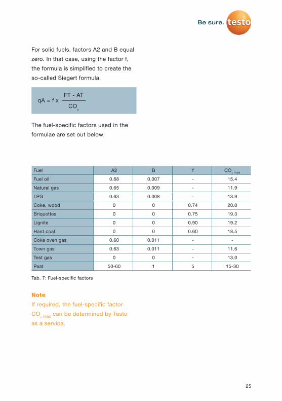
For solid fuels, factors A2 and B equal
zero. In that case, using the factor f,
the formula is simplified to create the
so-called Siegert formula.
The fuel-specific factors used in the
formulae are set out below.
Note
If required, the fuel-specific factor
CO₂ max can be determined by Testo
as a service.
qA = f xFT - AT
CO₂
Fuel A2 B f CO₂ max
Fuel oil 0.68 0.007 - 15.4
Natural gas 0.65 0.009 - 11.9
LPG 0.63 0.008 - 13.9
Coke, wood 0 0 0.74 20.0
Briquettes 0 0 0.75 19.3
Lignite 0 0 0.90 19.2
Hard coal 0 0 0.60 18.5
Coke oven gas 0.60 0.011 - -
Town gas 0.63 0.011 - 11.6
Test gas 0 0 - 13.0
Peat 50-60 1 5 15-30
Tab. 7: Fuel-specific factors
26
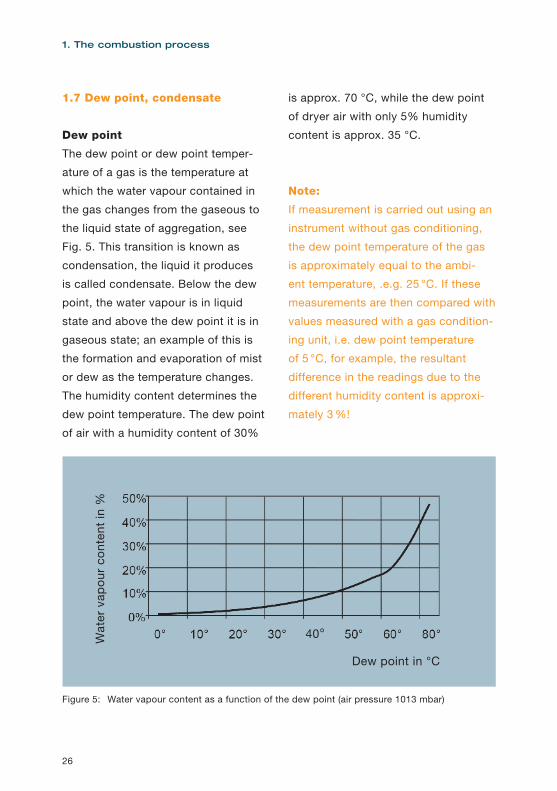
1.7 Dew point, condensate
Dew point
The dew point or dew point temper-
ature of a gas is the temperature at
which the water vapour contained in
the gas changes from the gaseous to
the liquid state of aggregation, see
Fig. 5. This transition is known as
condensation, the liquid it produces
is called condensate. Below the dew
point, the water vapour is in liquid
state and above the dew point it is in
gaseous state; an example of this is
the formation and evaporation of mist
or dew as the temperature changes.
The humidity content determines the
dew point temperature. The dew point
of air with a humidity content of 30%
is approx. 70 °C, while the dew point
of dryer air with only 5% humidity
content is approx. 35 °C.
Note:
If measurement is carried out using an
instrument without gas conditioning,
the dew point temperature of the gas
is approximately equal to the ambi-
ent temperature, .e.g. 25 °C. If these
measurements are then compared with
values measured with a gas condition-
ing unit, i.e. dew point temperature
of 5 °C, for example, the resultant
difference in the readings due to the
different humidity content is approxi-
mately 3 %!
1. The combustion process
40°
Dew point in °C
Wat
er v
apou
r co
nten
t in
%
Figure 5: Water vapour content as a function of the dew point (air pressure 1013 mbar)
27
Heated lines,
measuring gas coolers
Flue gases with 8% humidity, for
example, have a dew point of about
40°C, which means that condensate
forms below this temperature. This
has two important consequences for
the plant as a whole as well as for the
measuring equipment:
• If the flue gas contains sulphur
dioxides, for instance, then at
temperatures below 40 °C (e.g. in
unheated pipes) these combine with
the condensing water vapour to form
sulphurous acid (H₂SO₃) and sulphu-
ric acid (H₂SO₄), both of which are
extremely corrosive and can cause
considerable damage to the system
components that come into contact
with them. For this reason, the tem-
perature of the flue gas in the plant
is kept above the dew point (i.e.
above 40 °C in the case of the above
example) until the flue gas reaches
the scrubber.
The same applies to those com-
ponents of measuring instruments
through which the flue gas flows and
above all to the components of the
sampling device, such as probes
and hoses. For this reason, heated
probes and measurement gas lines
are used and their temperature is
kept above the dew point of the gas.
Failure to observe this measure will
result in damage to the measuring
instruments and incorrect measure-
ments!
• Testo’s newly developed and patent-
ed method of particularly high gas
flow velocity combined with a spe-
cially coated surface of the meas-
urement gas lines offers a further
alternative for preventing the forma-
tion of condensation. As a result, it
is no longer necessary to heat the
lines, which is extremely important
for mobile devices in view of the re-
sulting reduction in power consump-
tion. Water vapour is absent from the
cooled flue gas to a greater or lesser
extent depending on the temperature
to which the gas is cooled, with the
result that the other components of
the gas, such as CO, which have not
changed quantitatively form a higher
relative portion of the flue gas; the
corresponding readings are then
higher than in the moist flue gas! For
comparable readings, the respective
measurement gas must therefore
have the same temperatures and
therefore the same humidity content.
28
As a consequence, measuring gas
coolers (they could also be called
measuring gas dryers) are used in the
gas analysis upstream of the analyzer;
these bring the gas to a defined tem-
perature and therefore a defined level
of drying and keep it there.
Note
• Cooling gas means drying gas.
• In dry gas, the readings for gas com-
ponents are comparatively higher
than those in humid gas.
Testo instruments use what is known
as a Peltier cooler for measurement
gas cooling, its function is based on
the fact that the interface between two
different types of metals heats up or
cools down depending on the direction
of current flow. This cooler can cool
the measurement gas in the testo 350
to +3 °C and keep it constant.
Permeation coolers, which are also
common on the market, have the
disadvantage of not being able to
maintain a defined dew point; moreo-
ver, they are susceptible to clogging
by dust particles, which leads to
increased spare parts costs.
1. The combustion process

Would you like to read the other chapters too?
Then click here.
Related Documents


