u S . . <� Indoor Environment and Air Quality 35 Chapter 3 Practical Aspects of Pressure Testing Commercial Buildings. Brian CWebb* INTRODUCTION The aiightness of UK commercial bꭐldings is becoming much more of an impoant issue than previously been the case. Several yea ago air infiltration represented a smaller peentage of the design heat loss than at thugh the building fabric. Nowadays with improved insulation sd the heat loss om a infiltration has now become a much more significant ctor. Also, with changes in building techniques and materials over recent years, it is not srisg that we end up with buildings in the UK with a wide variability in aiightness. When a bꭐlding has been specifically designed and constructed to be aiight there is a need r an independent testing body to measure its air leage index. This determines whether it meets the airtighess specification as required by the client This paper describes the practical aspects of pressure testing commercial buildings. Also, to give an indication of the levels of aightness being achieved in buildings today results will be presented of typical buildings along with good practise air leakage targets. *Brian C Webb is a Senior Scientist at the Building Resech Establishment, Garston

Welcome message from author
This document is posted to help you gain knowledge. Please leave a comment to let me know what you think about it! Share it to your friends and learn new things together.
Transcript

..._
uS ;,;.... ""' .... ... <� ::n:
Indoor Environment and Air Quality 35
Chapter 3
Practical Aspects of Pressure
Testing Commercial Buildings.
Brian CWebb*
INTRODUCTION
The airtightness of UK commercial buildings is becoming much more of an important issue than has previously been the case. Several years ago air infiltration represented a smaller percentage of the design heat loss than that through the building fabric. Nowadays
with improved insulation standards the heat loss from air infiltration has now become a much more significant factor. Also, with changes in building techniques and materials over recent years, it is not surprising that we end up with buildings in the UK with a wide variability in airtightness.
When a building has been specifically designed and constructed to be airtight there is a
need for an independent testing body to measure its air leakage index. This determines whether it meets the airtightness specification as required by the client This paper describes the practical aspects of pressure testing commercial buildings. Also, to give an
indication of the levels of airtightness being achieved in buildings today results will be
presented of typical buildings along with good practise air leakage targets.
*Brian C Webb is a Senior Scientist at the Building Research Establishment, Garston

.....
36 Indoor Environment and Air Quality
Figure 3.1 Large BREFAN (BRE's Large Fan Pressurisation System)
FAN TESTING METHODS Building air leakage indices can be measured by one of the following techniques:
I. External fan pressurisation technique.
2. Building (HVAC system) fan pressurisation technique.
3. Using an alternating applied pressure technique.
The exteroal fan pressurisation technique is the most common method used in the UK Th.e teehnique ofusing a buildings supply fan(s) to pressurise the building bas been used in the USA and Canada. lt is used to measure the air leakage index oflarge me<:hanically
veutila�ed buildings. The A/C technique, i.e. using a pulsating pressurising system is
thought to be little used in practise, and it will not be discussed any further in th.is paper.
EXTERNAL FAN PRESSURISATION TECHNIQUE This is by far the most common method used in the UK for measuring the air leakage
index of commercial b�ildings 1. The technique involves connecting a portable fan (or
Practical Aspects of Pressure Testing Commercial Buildings 37
fans) to the building under test using flexible ductwork and a temporary wooden panel, which is installed in a suitable external doorframe in the building
2. The existing doors do
not have to be removed they only need to be are opened to 90.
There are two different fan pressurisation systems used by BRE for commercial buildings, Figures 3. 1 and 3.2. BRE's large fan pressurisation system (Large BREFAN), shown in Figure 3.1, is testing a large retail store. The smaller system (Medium BREFAN), shown
in Figure 3.2, is testing an office building.
Fan capacity
To carry out pressure tests in the size of commercial buildings in the UK requires largescale equipment. Such systems are costly to build and develop. The fans in these systems need to be of a high capacity and powered from the most convenient and w10btrusive source. BRE's Large BREFAN has a capacity of32m3
/s at a building pressure differential of 50Pa and is powered from a stand alone 3-phase generator. The Mediwn BREFAN
Figure 3.2 Medium BREFAN (BRE 's Medium Sized Fan Pressurisation System)

i...
38 Indoor Environment and Air Quality
systems (of which there are three) each have a capacity of5.5m3/s at 50Pa and operate
from ordinary 13 amp socket outlets. One, two or three fans can be used depending on the size and leakiness of the building being tested.
Principle The fan(s) is used to supply air, at a constant flow rate, to the building under test. This air subsequently "leaks" out through gaps and cracks in the building envelope. The fan is set to a range of flow rates required to maintain a set of pressure differences across the building envelope. At each setting the airflow rate through the fan(s) and the pressure
difference created between the inside and outside of the building are measured. From
these parameters, and the building envelope area the air leakage index can be calculated.
Connecting panel
The temporary panel used to connect the ductwork from the fan can be made, for example, from l 8mm plywood. It is advisable to have this painted as it provides a good bonding surface for the adhesive tape used to seal the panel/doorframe interface. This is done to ensure an airtight seal. It is important to ensure minimal air leakage around this temporary panel; it should not be a variable air leakage element. Should the building need to be tested again it is important that any air leakage around this temporary panel is small.
Pressure measurements The pressure difference created by the fan between the inside and outside of the building should be measured with a micromanometer with an operating range of at least 0 to 7 5Pa and have an accuracy of 2Pa. A small-bore tube (6mm maximum internal diameter) should be extended away from the building to measure the external pressure. If possible
the end should be placed about 10 metres from the building. An internal pressure tube
should also be placed inside the building and out of direct influence of the pressurisation fan.
Air flow rate measuring system Whatever device is used to measure the air volume flow rate it should be with an accuracy of 7%. If the flow measurement device does not fully conform to the requirements of
BS1042: l 981 and 1984 or BS848: part 1 :1980 3,4 then it must be calibrated after the whole system has been assembled.
The airflow rates measured need to be corrected for air density. This is predominately a correction for the temperature difference when the test was undertaken which would be different from that when the device was calibrated.
The temperature inside and outside the building needs to be measured during the test
period. Care should be taken where the external temperature sensor is placed, as it should
be out of the influence of direct sunlight or any other influence that may affect its accuracy.
Practical Aspects of Pressure Testing Commercial Buildings 39
BUILDING FAN PRESSURISATION TECBNlQUE This technique 11as been used in Canada
5 and the USA 6. It can be the only practical method of measuring the air leakage in large multistorey office buildings. The external fan used, as above, is replaced by using the buildings own HVAC system air supply fan(s) to pressurise the building. This technique is fully described elsewhere
7.
Fan capacity
The supply fan(s) int.be building's air handling unit(s) shouJd have the capacity of creatiJ1g a pressure difference across the building envelope of at least 60Pa. Also, tbere should be a method of controlling the air volume flow rate delivered by the air bandHng units. Th is can either be by using a fan speed contro ller (e.g. inverter) or control dampers, in series with the fan(s).
The exhaust fans in the building need to be turned off and the external grille sealed with either board or polythene sheeting and tape.
Principle
The air supplied by the air handling unit is adjusted to obtain a series of airflow rate and
pressure differentials in the same way as the external fan technique. However, accurate measurement of the air volume flow is an important issue, requiring special techniques.
Air volume flow rate measurement
There are two methods commonly used for measuring the air volume flow in the air
supply ducts using trus technique, tracer gas dilution and direct flow measurement using
a calibrated probe. The tracer gas method is described more fully by Grot6
, and the direct flow measurement meiliod by Shaw
5.
The tracer gas method involves injecting a tracer gas (100% pure) continuously at a measured rate into the air handling unit and measuring tile gas concentration furtlJer down the duct after it has fully mixed with the incoming air. Sulphur Hexaflouride (SF 6) is the most widely used tracer gas for this purpose. A calibrated infrared gas analyser is needed to measure the gas concentration in the supply duct. Two lengths of tubing need to be inserted into the duct through convenient or purpose made holes to inject the tracer gas and sample the air from the duct. Thernte at which the tracer gas is injected into the �uct must be measured accurately. A bubble flow meter is well suited to this task.
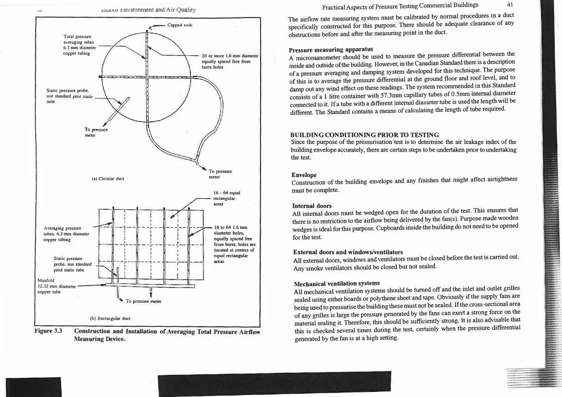
The direct flow measurement technique is fully described in ilie Canadian Standard 7. J t outlines the design of an airflow-measuring device, which basically consists of a set of total pressuring averaging tubes. Two tubes are needed for circular ducts and a grid
pattern of tubes for rectangular ducts, see Figure 3.3. A separate. static pressure probe needs to be inserted also in the supply duct.
rnuvv1 environment and Air Quality
Total pressure averaging tubes 6.3 mm diameter copper tubing
Slatic pressure probe. use standard pitot static -----.._ lube
meter
(a) Circular duct
Averaging pressure lubes, 6.3 nun diameter copper tubing
Static pressure probe. use standard pitot stalic tube
I I I
--+--' I I '
--,--' I I I '---r--
� Capped ends
I I I I - -r- -' I r ' -- r --
1 I I
1----t--I I
I --1-1 I I
-- ,--1
Manfold --c--1L " I c; 12.52 mm diameter If II copper tube
(b) Rectangular duct
20 or more 1.6 mm diameter equally spaced free from burrs holes
"'- To pressure meter
16 - 64 equal rectangular areas
16 to 64 1.6 mm diameter holes, equally spaced free from burrs; holes are located at centres of equal rectangular areas
Figure 3.3 Construction and Installation of Averaging Total Pressure A irflow Measuring Device.
Practical Aspects of Pressure Testing Commercial Buildings 41
The airflow rate measuring system must be calibrated by normal procedures in a duct
specifically constructed for this purpose. There should be adequate clearance of any
obstructions before and after the measuring point in the duct.
Pressure measuring apparatus
A micrornanometer should be used to measure the pressure differential between the
inside and outside of the building. However, in the Canadian Standard there is a description
of a pressure averaging and damping system developed for this technique. The purpose
of this is to average the pressure differential at the ground floor and roof level, and to
damp out any wind effect on these readings. The system recommended in this Standard
consists of a 1 litre container with 57.3mm capillary tubes of O.Smm internal diameter
connected to it. If a tube with a different internal diameter tube is used the length will be
different. The Standard contains a means of calculating the length of tube required.
BUILDING CONDITIONING PRIOR TO TESTING Since the purpose of the pressurisation test is to determine the air leakage index of the building envelope accurately, there are certain steps to be undertaken prior to undertaking the test.
Envelope
Construction of the building envelope and any finishes that might affect airtightness
must be complete.
Internal doors
All internal doors must be wedged open for the duration of the test. This ensures that
there is no restriction to the airflow being delivered by the fan(s). Purpose made wooden
wedges is ideal for this purpose. Cupboards inside the building do not need to be opened
for the test.
External doors and windows/ventilators
All external doors, windows and ventilators must be closed before the test is carried out.
Any smoke ventilators should be closed but not sealed.
Mechanical ventilation systems
All mechanical ventilation systems should be turned off and the inlet and outlet grilles
sealed using either boards or polythene sheet and tape. Obviously if the supply fans are 'bemg used to pressurise the building these must not be sealed. If the cross-sectional area
of any grilles is large the pressure generated by the fans can exert a strong force on the
material sealing it. Therefore, this should be sufficiently strong. It is also advisable that
this is checked several times during the test, certainly when the pressure differential
generated by the fan is at a high setting.

42 Indoor Environment and Air Quality Plant rooms
Since plant rooms are outside the conditioned space of a building and they usually contain ventilation grilles they should be eliminated from the test. This is achieved by sealing any doors linking them to the main part of the building.
Other areas to check If the buildfag is new check that there is water in the U-bends of all the sinks and WC's. If there are any loft/ceiling hatches a weight should be placed on top of them to ensure that they do not lift up when the building is pressurised. Any combustion appliances in the test area should be turned off. Also, any flue or chimney should be sealed either by taping over the appliance or flue outlet, or even inflating a football bladder inside the flue/ chimney.
RESTRICTIONS ON CARRYING OUT A TEST . ' A test should not be undertaken if the mean wind speed as measured at the test site is greater than 3rn!s.
The draft CEN Standard8 deals with restrictions on carrying out tests due to the difference between the internal and external temperatures and also building height. With the fan aperture temporarily sealed a test should not be carried out ifthe stack induced pressure difference is greater than 5Pa. The Standard also states that if the product of this temperature difference and building height (in metres) exceeds 500 mK it is unlikely that a satisfactory zero flow pressure difference (i.e. < 5 Pa) wiU be obtained. However, it is possible to compensate for this in the data processing.
ENVELOPE AREA. The calculation of the building envelope area is an important element in determining the air leakage index. Therefore, this should be carried out with great care using accurately scaled AO plans and elevations, and if necessary backed up by photographs. The envelope area is calculated using the gross internal dimensions of the building, i.e. the dimensions bordering the interior volume of the building under test. This means the external walls, upper ceiling or roof, and the ground floor area, but only if it is a suspended floor with a direct access to the external air. No deductions are to be made for any internal partitions, floors, ceilings or fittings etc.
EXTERNAL FAN TEST PROCEDURE
1. Check that all the instruments have warmed up, stabilised, and have been levelled and zeroed as necessary. The micromanometer should be zeroed with the external pressure tube temporarily disconnected.
2.
3.
4.
5.
Practical Aspects of Pressure Testing Conunercial Buildings 43
Set up an air temperature sensor and datalogger outside to record the external
temperature during the test. Ideally it should be set to record once a minute.
Also, set up a number of air temperature sensors and dataloggers inside the building, e.g. one per :floor in a multistorey building, or several in a single- storey building to record the internal temperature, also once a minute.
Check that the average wind speed is below 3m/s.
Check that the building is ready for the test (i.e. internal doors open, external
doors and windows closed and mechanical ventilation systems sealed).
Temporarily cover up the fan using polythene sheet and tape and measure the zero flow rate pressure difference.
6. Uncover the fan and start it operating at a relatively slow speed so as not to over presswise a tight building. Adjust the airflow rate such that a pressure difference ofbetween55 to 60 Pa is obtained. Check that no temporary sealed components have started to leak. If so, reseal them. When the readings have stabilised take at least ten pairs of values of the pressures difference and airflow rate. Calculate the average of these readings. Record the time each set of readings is taken. If a pressure difference greater than 50 Pa cannot be obtained with the equipment, readings should be taken at the maximum pressure difference possible. If 25 Pa can be obtained with the equipment the test will be valid
7. Adjust the fan speed to obtain a lower pressure difference, and take another set of readings. Repeat this sequence so as to obtain at least eight equally spaced sets of measurements. If possible avoid measurements below l 0 Pa. Further checks should be made during the test to see if there have been any changes to the building openings, e.g. doors or windows opened or any sealed component leaking.
Sometimes it is obvious from the measurements that something has "gone wrong"
with the test. If this happens the problem should be dealt with and the set of readings repeated.
BUILDING FAN TEST PROCEDURE
1. Carry out the first 4 items listed above.
2. Jnstall the pre-calibrated averaging total pressure tubes and static pressure tube,
or tracer gas injection and sampling tubing into each supply duct. The total
, averaging tubes should be installed at least five duct diameters downstream or upstream of any fan and two diameters upstream or downstream of any elbow or damper. The tracer gas injection tube should be inserted in the duct before the fan, and the sample tube after the fan .
3. Turn off the exhaust fan(s) and seal the grilles.
4. Install a reference pressure tapping at the centre of a typical floor, located near
44 Indoor Environment and Air Quality the mid-height of the building.
5. Install an exterior pressure tapping at both ground floor and roof JeveJs, using identical lengths of tubing. Connect both tubes to the pressure averaging/damping vessel.
6.
7.
"� .§.
Switch on the supply fans and adjust the air volume flow rates using the speed controUers or dampers to obtain a pressure difference between 55 and 60Pa. If this pressure difference cannot be reached record the maximum pressure difference obtained from the buildings air handling units.
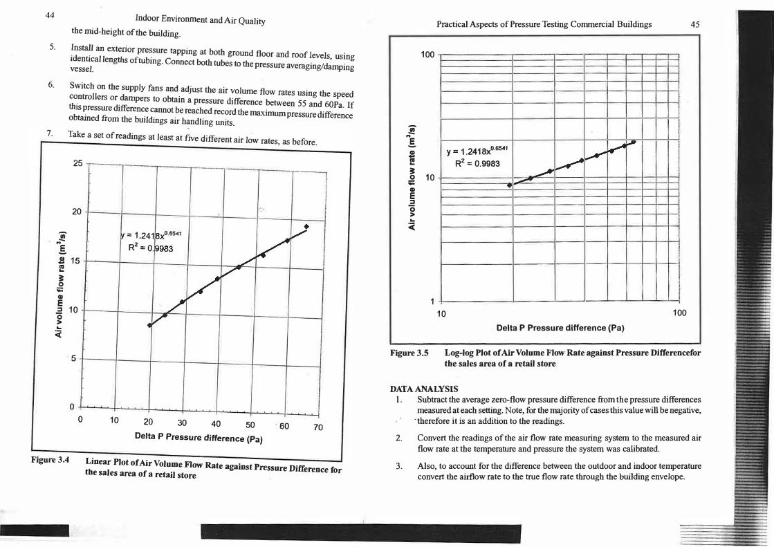
Take a set of readings at least at five different air low rates, as before.
25 I I r-· -
20 L_ I v = 1.24 1 axo.s541 / 1
R2 = 0 .9983 .s 15 I!
-
v /
v � 0 ;;::: GJ E = 10 0 > ...
v / 4 v -
cc
5
0 .
0
Figure 3.4
I I 10 20 30 40 50 60 70
Delta P Pressure difference (Pa)
Linear Plot of Air Volume Flow Rate against Pressure Difference for the sales area of a retail store
Practical Aspects of Pressure Testing Commercial Buildings 45
100
'.!' .. .§. GI -111 ... � 10 0 ;;:::
Y - 1.2418xo.s541 � ....
R2 = 0.9983 � L......- I �
GI E = 0 > ... :c
-
--
1 10 100
Delta P Pressure difference (Pa)
Figure 3.S Log-log Plot of Air Volume Flow Rate against Pressure Differencefor
the sales area of a retail store
DATA ANALYSIS l. Subtract the average zero-flow pressure difference from the pressure differences
measured at each setting. Note, for the majority of cases this value will be negative, ·therefore it is an addition to the readings.
2.
3.
Convert the readings of the air flow rate measuring system to the measured air
flow rate at the temperature and pressure the system was calibrated.
Also, to account for the difference between the outdoor and indoor temperature convert the airllow rate to the true flow rate through the building envelope.

46 4.
5.
6. 7.
Indoor Environment and Air Quality Plot the aitflow rate through the building envelope against the corresponding pressure differences on a linear/linear plot and a log-log plot; see Figures 3.4 and 3.5. Carry out a least squares power-law curve fit on the data in accordance with the equation
Where
Q =
KPn
Q = Air volume flow rate through the building envelope (m3/s) K = air leakage coefficient (m3/s Pan) n = exponent {value between 0.5 and 1}
Determine the correlation coefficient of the curve fit. Calculate either the Qso or Q15 value and using the envelope area (S) calculate the air leakage index Qso/S or Qz5/S. These have units of m3 /h m2 of envelope area.
AIR AUDI TS/SMOKE TESTS lf follow.ing a fan pressurisation test a building does not meet its air leakage specification there may be a requirement to carry out a brief or detailed arr leakage audit to identify the air leakage paths. A smoke tracer or even an infrared camera can be used to identify the areas of air leakage.
There are two methods of using smoke as an identifier of air leakage paths. T he first is where the whole building or a part of it is filled with smoke from multiple smoke machines. With the building pressurised using a pressurisation fan points where air leaks through the envelope can be observed from the outside. This method however, suffers from the fact that where the air leaks out from the inner leaf, may not be in close proximity to where it leaks out from the building. Therefore, there would be some confusion on how to deal with the areas identified.
The second methods uses small hand-held smoke tubes. Ideally a building should be under depressurisation for an air leakage audit. This can be achieved by operating the pressurisation fan In reverse. The smoke tubes are ideal for identifying air leakage paths in a building envelope. The use of ladders or a lifting platform may be required to reach the ceiling/roof areas. To carry out the air leakage audit thoroughly floor tiles will probably need to be taken up and drop ceiling tiles removed It is worth pointing out that this type of survey; especially a detailed air leakage audit is best undertaken outside of nonnal working hours.
Infrared cameras can also be used to detect air leakage paths. Using a fan to depressurise the building is required with this method so that colder outside air is drawn in through
Practical Aspects of Pressure Testing Commercial Buildings 47
the air leakage paths. The "colder" image colours or shades of grey show up localised cooling adjacent to these areas on the video display. If the building was pressurised you would have the same problem with whole building smoke tests in trying to correlate external leakage points to internal ones. This technique is quite successful in the winter but less so during the summer months.
CURREN T LEVELS OF AIR LEAKAGE INDEX
To give an indication of the range of the air leakage index in UK commercial buildings (i.e. offices/educational/retail) I have included a cumulative frequency plot of the results from buildings measured both by BRE and BSRIA, see Figure 3.6. For convenience I have plotted out the data for two reference pressures 25 and 50Pa. There are both new build and existing buiJdings included in this data set. As can be seen very few of the buildings meet BRE's designated tight building criteria of 5m3 llun2 of envelope area at 25 Pa. The average value is of the order of l 0 m3 /h m2 and leaky is 20 m3 /h m2. The comparable values at 50 Pa are 7.5, 15, and 34 m3/h m2.
BSRIA have published a leaflet on air tightness specification9 which contains a table of the maximum and best practise air leakage values for various types of new buildings. The industry leaders in requiring their buildings to have a high air tightness specification are the main superstore chains. Their normal specification is for the buildings to have an air leakage index of 5m3 /h m2 at 50 Pa, but in several cases they have achieved 3m3 /h m2. Both these values also apply to air conditioned/low energy offices. For naturally ventilated offices and factories/warehouses the nonnal air leakage index specification would be 10m3/hm2.
MINIMISING AIR INFILTRATION
One of the current driving forces motivating some UK designers, builders and clients to address the airtiffhtness issue in commercial buildings is the Approved Document Part L (1995 edition)1 which supports the Building Regulations in England and Wales. The AD states that it is desirable to limit air leakage by reducing unintentional air paths as far is practicable, but does not specify an air leakage index limit. However, this AD is to undergo revision and air leakage is likely to be much more of a feature in the revised document.
It is important that the issue of airtightness is approached at the building design stage. ' Specialist advice should be sought if necessary. BRE have produced a 34 page report
BR 265 "Minimising Air Infiltration in Office Buildings": 199411
. This guidance document covers all aspects of minimising air infiltration in commercial buildings, especially offices. Examples are presented in the document on designing for a tight envelope and the materials to use in achieving this. The important issue of construction phase inspections is also discussed along with the fan testing method.

48
100%
90%
80%
70%. � "' i 60%
.::: 50% 0 >
-; -40% E � 0
30%-
20%
10%
0% N
r 100%
90%
80%
70% � "' � 60% il-!:. 50% 0 > � :; 40% � 0
30%
20%
10%
0% N
Figure 3.6
Indoor Environment and Air Quality
Cumulative Frequency of Q25/S
L �
Leaky r- 1 _/' I
Average 1� /-'
I I
Tightr,J /-' .., ... "' "' ... "' .. � :: � � ;! � � :: � � 0 ;;; N .., N N N
� fm'lhr per m1) ,._
Cumulative Frequency of Q50/S
�
� � � ... ., g: � N N :E
Leaky � �·--·
/ �
Average --r /-'
r /
Tight I� _,,-Y- ' .. "' ., � � ;! "' � 0 i::: ;!; lll "' g N � :!l "' � � N N .., "'
Qso/S (m'Jhr per mi ::!
Cumulative Frequency Diagrams of Air Leakage Index at 25 and 50Pa
Practical Aspects of Pressure Testing Commercial Buildings 49
PROVISION OF ADEQUATE VENTILATION/IAQ Good building design needs to separate the air supply mechanisms from the adverse and Wlpredictable effects of air infiltration. Therefore, attention should not only be ·paid to minimising air infiltration but also to providing good ventilation design. Obviously ventilation can be supplied by natural or mechanical means or a combination of both i.e. mixed mode ventilation. Guidance on the design can be found in several publications,
BRE Digest399 Natural Ventilation in Non-Domestic buildin1s12, DETR Good Practise Guide 237 Natural Ventilation in Non-Domestic Buildings
1 , AIVC Guide to Energy
Efficient Ventilation14 and CIBSE Applications Manual AM lO Natural Ventilation in
Non-domestic Buildings15. -
The benefits from minimising air infiltration in buildings can be grouped into three main groups: occupants, building and environment.
Occupants will be benefit from the avoidance of discomfort from draughts. In severe cases a leaky building may not reach comfort temperatures in the winter. It is likely that productivity will improve since staff feeling comfortable in their working environment will get on with their work. With a well-designed ventilation system contaminants from outdoor air will be suitably f iltered etc.
Air infiltration through the building envelope can lead to potential problems with condensation within the structure and affect the perfonnance of the thermal insulation in the outer leaf.
Energy costs will be much higher than necessary with high air infiltration rates. The reduction of air infiltration in a building will allow designers of HVAC systems to reduce the size of the plant and plant room.
With about 50% of UK C02 emissions being attributed to delivered energy use in buildings any energy efficiency measures targeted at buildings will represent a major contribution towards achieving the desired �eductions.
CONCLUSIONS The minimisation of air infiltration in new and existing commercial buildings has benefits not only for the occupants but also in the reduction in energy costs and C02 emissions. The common methods of carrying out pressure tests in buildings have been described along with the practical aspects of undertaking them. Typical values of air leakage index for commercial buildings have been presented and best practise values listed for various types of buildings.

50
REFERENCES
Indoor Environment and Air Quality
I. Perera M DA E S, Stephen R and Tull R, BRE Information Paper IP 6/89 "Use of BREFAN to measure the airtightness of non-domestic buildings", BRE, Garston, 1989.
2. R K Stephen "Detennining the airtightness of buildings by the fan-pressurisation method: BRE recommended procedure". BRE Occasional paper 1987.
3. British standard BS1042: Section 1.1: 1981; and Sections 1.2 & 1.4: 1984. "Measurement of fluid flow in closed conduits, Part 1. Pressure d-ifferential devices". British Standards Institution, London.
4. British Standard BS848: Part!: 1980. "Fans for general purposes, Part I. Methods of testing perfonnance". British Standards Institution, London.
5. CY Shaw, J T Reardon and M S Cheung, "Changes in air leakage levels of six Canadian office buildings'', NRCC report 3206, National Research Council Canada, 1993.
6. RA Grot &AK Persily, "Air infiltration and air tightness tests in eight U.S. office buildings", 3rd AIC Conference, September 1982, London.
-� 7. Canadian General Standards Board - 149 . l 5-96 "Determination of the overall
envelope airtightness of buildings by the fan pressurisation method using the building's air handling systems", Canada General Standards Board, 1996.
8. Draft CEN Standard, prEN WI 00089005:1998-05, "Determination of building airtightness, Fan pressurisation method",
9. IN Potter, "Air tightness specifications", BSRIA 10/98, Bracknell 1998.
10. Approved Document Part L "Conservation of Fuel and Power", Building Regulations 1995 edition, Department of the Environment and Regions, HMSO.
11. Perera M DA E S, Turner C and Scviyer C, "Minimising Air Infiltration in Office Buildings" Building Research Establishment Ltd. Report BR 265: 1994.
12. BRE Digest 399, "Natural Ventilation in Non-Domestic Buildings", BRE 1994.
13. DETR Good Practise Guide 237, ''Natural Ventilation in Non-Domestic Buildings", DETRR< London, 1998.
14. Liddament M, "A Guide to Energy Efficient Ventilation", AIVC, Coventry, 1996.
15. CIBSE Applications Manm1.l AMl 0: 1997, ''Natural Ventilation in Non-domestic Buildings, CIBSE, London.
l
51
Chapter 4
Guidelines for Minimising the
Ingress of Urban Pollution
Paul Ajiboye*
INTRODUCTION
The aim of this Chapter is to breakdown barriers to concepts of natural ventilation. The
study is part of a Pan European project titled NatVent, that involves seven COWl.tries in
the north of Europe. The project leaders are the UK Building Research establishment.
Urban pollution is a major barrier to the adoption of natural ventilation, so successful
ways of avoiding these problems need to be found. -�. ,_.
The traditional approach to ventilating non domestic buildings located in urban areas is
to specify mechanical ventilation_ This strategy can seal buildings from pollution along
facades, and where necessary draw air via cleaning filters to remove contaminants; the
pressure drop associated with this process is not a practical. option for passive ventilation.
The draw back in relying upon air conditioning systems is in the amount of energy
required to run them, hence the negative environmental impact. If natural ventilation
systems are not adversely affected by external pollution then it offers an ideal alternative.
*Paul Ajiboye is a� Environmental Scientist, Willan Building Services, Tonbridge,Kent
"I l
Related Documents