PR601 (MS-163K)Disassemble SOP ■ 1、Battery Pack ■ 2、BOTTOM DOOR ASSY ■ 3、THERMAL-KIT And CPU Module ■ 4、RAM、WLAN、MDC and BT Module ■ 5、HDD Module ASSY ■ 6、ODD Module ASSY ■ 7、HINGE COVER ASSY ■ 8、UP CASE ASSY ■ 9、LOWER CASE ASSY ■ 10、LCD MODULE ASSY

Welcome message from author
This document is posted to help you gain knowledge. Please leave a comment to let me know what you think about it! Share it to your friends and learn new things together.
Transcript

PR601 (MS-163K)Disassemble SOP
■ 1、Battery Pack
■ 2、BOTTOM DOOR ASSY
■ 3、THERMAL-KIT And CPU Module
■ 4、RAM、WLAN、MDC and BT Module
■ 5、HDD Module ASSY
■ 6、ODD Module ASSY
■ 7、HINGE COVER ASSY
■ 8、UP CASE ASSY
■ 9、LOWER CASE ASSY
■ 10、LCD MODULE ASSY

PR601(MS-163K)Disassemble SOP
■ 1、Battery Pack 1-1:Push the battery Unlock button in the direction shown below;
1-2:Push the battery Release button in the direction shown below, then slide the battery pack out of the slot;
NO. Part Name Part No. Qty
1 Battery Pack S9N-0364210-SB3 1

PR601(MS-163K)Disassemble SOP ■ 2、BOTTOM DOOR ASSY
2-1:Remove the following 4pcs M2.5*5mm screws on Bottom Door with Screw Driver.
Note:Screw driver torque is 2.0~2.5kgf.cm
2
4
31
2-2:Remove Bottom Door Assy;
NO. Part Name Part No. Qty
1 Screw E43-1255007-H29 4
2 BOTTOM DOOR ASSY 307-631J202-Y31 1
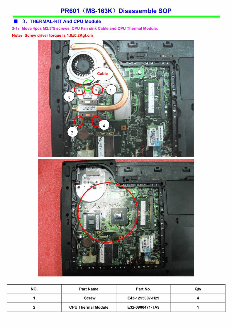
PR601(MS-163K)Disassemble SOP ■ 3、THERMAL-KIT And CPU Module
3-1:Move 4pcs M2.5*5 screws, CPU Fan sink Cable and CPU Thermal Module.
Note:Screw driver torque is 1.8±0.2Kgf.cm
42
Cable
13
NO. Part Name Part No. Qty
1 Screw E43-1255007-H29 4
2 CPU Thermal Module E32-0900471-TA9 1
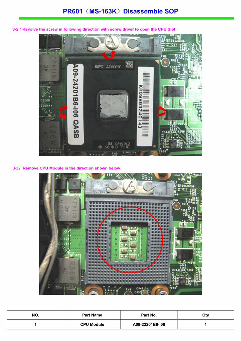
PR601(MS-163K)Disassemble SOP 3-2:Revolve the screw in following direction with screw driver to open the CPU Slot ;
3-3:Remove CPU Module in the direction shown below;
NO. Part Name Part No. Qty
1 CPU Module A09-22201B6-I06 1

PR601(MS-163K)Disassemble SOP
■ 4、RAM、WLAN、MODEM And BT Module
4-1:Push the RAM locks away;
4-2:Take off the RAM Module as below;
NO. Part Name Part No. Qty
1 RAM Module S7C-S347701-T10 1
PR601(MS-163K)Disassemble SOP
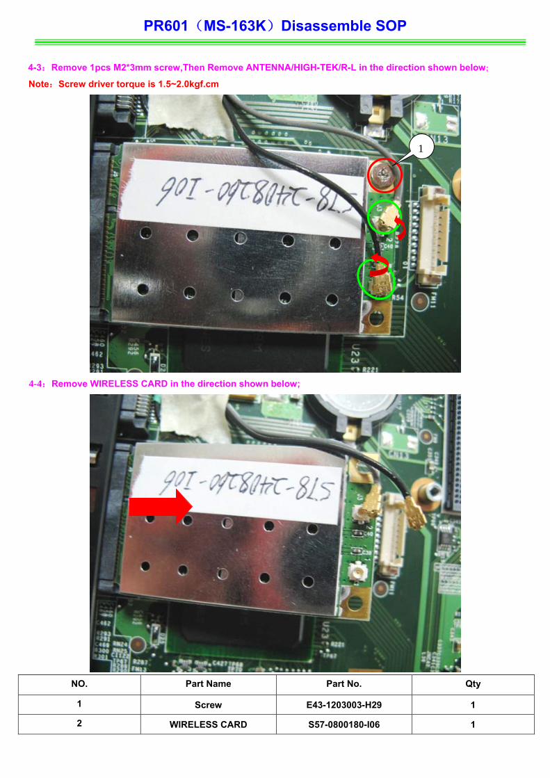
4-3:Remove 1pcs M2*3mm screw,Then Remove ANTENNA/HIGH-TEK/R-L in the direction shown below;
Note:Screw driver torque is 1.5~2.0kgf.cm
1
4-4:Remove WIRELESS CARD in the direction shown below;
NO. Part Name Part No. Qty
1 Screw E43-1203003-H29 1
2 WIRELESS CARD S57-0800180-I06 1

PR601(MS-163K)Disassemble SOP
4-5:Remove 2pcs M2*L3mm screws, Then Remove MDC Cable in the direction shown below;
Note:Screw driver torque is 1.8±0.2kgf.cm
1
2
4-6:Remove MODEM in the direction shown below;
NO. Part Name Part No. Qty
1 MODEM S52-2801180-C59 1
2 MDC Cable K10-3002088-H39 1
3 Screw E43-1203003-H29 2

PR601(MS-163K)Disassemble SOP
4-7:Remove Bluetooth Antenna ,Then Remove Bluetooth Cable in the direction shown below;
4-8:Remove BlueTooth Board in the direction shown below;
NO. Part Name Part No. Qty
1 BlueTooth Board 605-6837D-070 1

PR601(MS-163K)Disassemble SOP ■ 5、HDD Module ASSY 5-1:Remove 2pcs M2.5*5mm Screws , then remove HDD Door Assy in the direction shown below;
Note:Screw driver torque is2.0~2.5kgf.cm
2
1
5-1:Remove HDD SPONGE , then remove HDD MODULE in the direction shown below;
NO. Part Name Part No. Qty
1 Screw E43-1255007-H29 2
2 HDD DOOR ASSY 307-632K215-SE0 1
3 HDD SPONGE E2Y-6110111-G40 1

PR601(MS-163K)Disassemble SOP 5-2:Remove 2pcs M3*3.5mm Screws, Then Remove HDD Bracket in the direction shown below;
Note:Screw driver torque is 2.0~2.5kgf.cm
2
1
NO. Part Name Part No. Qty
1 Screw E43-1304003-H29 2
2 HDD Bracket Assy 307-6320112-Y28 1
3 HDD MODULE ASSY S71-2416524-W36 1

PR601(MS-163K)Disassemble SOP
■ 6、ODD Module ASSY 6-1:Use screw driver to move 1pcs M2.5*5mm Screw, then take out ODD Module Assy ;
Note:Screw driver torque is 1.5~2.0kgf.cm
1
NO. Part Name Part No. Qty
1 Screw E43-1255007-H29 1

PR601(MS-163K)Disassemble SOP
6-2:Remove ODD Bezel in the direction shown below;
NO. Part Name Part No. Qty
1 ODD Bezel 307-633F202-SE0 1
PR601(MS-163K)Disassemble SOP
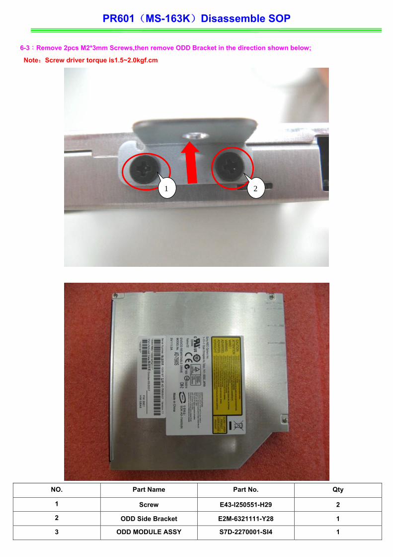
6-3:Remove 2pcs M2*3mm Screws,then remove ODD Bracket in the direction shown below;
Note:Screw driver torque is1.5~2.0kgf.cm
2 1
NO. Part Name Part No. Qty
1 Screw E43-I250551-H29 2
2 ODD Side Bracket E2M-6321111-Y28 1
3 ODD MODULE ASSY S7D-2270001-SI4 1

PR601(MS-163K)Disassemble SOP
■ 7、HINGE COVER ASSY 7-1:Push Fastener in the direction shown below;
PR601(MS-163K)Disassemble SOP
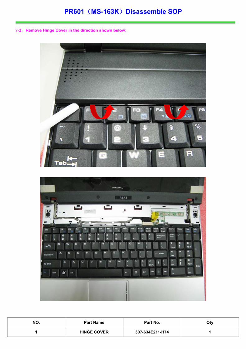
7-2:Remove Hinge Cover in the direction shown below;
NO. Part Name Part No. Qty
1 HINGE COVER 307-634E211-H74 1

PR601(MS-163K)Disassemble SOP
7-3:Pull out LCD LVDS Cable, Then Remove MICROPHONE Cable;
7-4:Pull out CMOS CABLE;
NO. Part Name Part No. Qty
1 LCD LVDS Cable K19-3040002-H39 1
2 CMOS CABLE K10-3005054-H39 1

PR601(MS-163K)Disassemble SOP
7-5:Take the Cable out of the slot in the direction shown below;

PR601(MS-163K)Disassemble SOP 7-6:Remove 2pcs M2.5*5mm Screws in the direction shown below;
Note:Screw driver torque is 2.0-2.5kgf.cm
7-7:Remove 4pcs M2.5*5mm Screws in the direction shown below;
Note:Screw driver torque is2.5-3.0kgf.cm
3
21
42
1
NO. Part Name Part No. Qty
1 Screw E43-1255007-H29 6

PR601(MS-163K)Disassemble SOP
■ 8、UP CASE ASSY 8-1:Remove 5pcs M2*3mm Screws, Then Remove Keyboard in the direction shown below;
Note:Screw driver torque is 1.5~2.0kgf.cm
53
4 1
2
8-2:Remove Keyboard Cable in the direction shown below;
NO. Part Name Part No. Qty
1 Screw E43-1203003-H29 5
2 Keyboard S1N-3UTC131-C54 1
PR601(MS-163K)Disassemble SOP
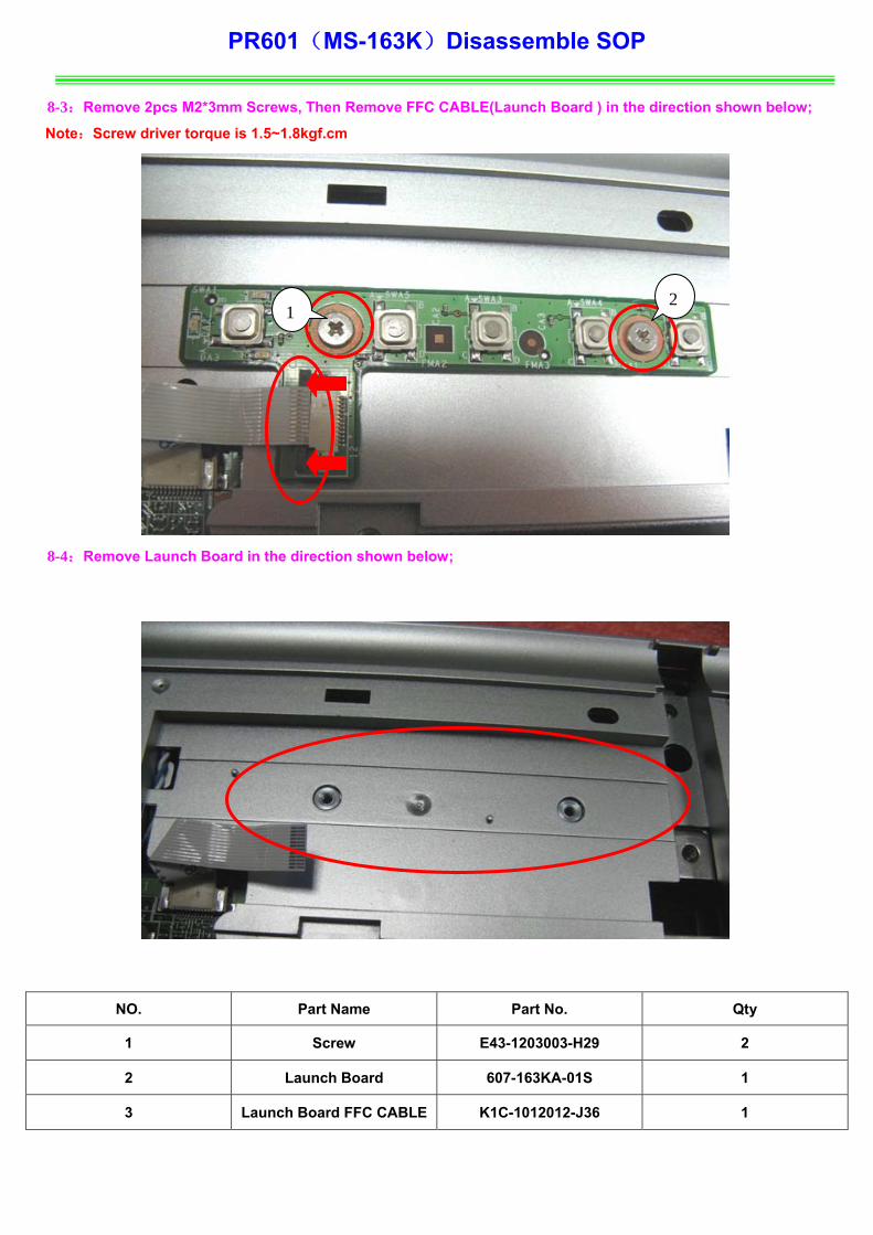
8-3:Remove 2pcs M2*3mm Screws, Then Remove FFC CABLE(Launch Board ) in the direction shown below;
Note:Screw driver torque is 1.5~1.8kgf.cm
8-4:Remove Launch Board in the direction shown below;
2 1
NO. Part Name Part No. Qty
1 Screw E43-1203003-H29 2
2 Launch Board 607-163KA-01S 1
3 Launch Board FFC CABLE K1C-1012012-J36 1

PR601(MS-163K)Disassemble SOP
8-5:Remove Touchpad FPC (connected with M/B ) in the direction shown below;
NO. Part Name Part No. Qty
1 Touchpad FPC (To M/B ) K1C-1026016-J36 1

PR601(MS-163K)Disassemble SOP 8-6:Remove 15pcs M2.5*L5mm Screws in the direction shown below;
Note:Screw driver torque is 2.0~2.5kgf.cm
9
8
7
6
4
5
14 1513 12
11
10 3
2
1
NO. Part Name Part No. Qty
1 Screws E43-1255007-H29 15

PR601(MS-163K)Disassemble SOP
8-7:Remove DUMMYCARD_EXPRESS ,Then Remove CARD READ in the direction shown below;
NO. Part Name Part No. Qty
1 DUMMYCARD_EXPRESS E2P-6323215-H76 1
2 CARD READ E2P-6323311-H76 1

PR601(MS-163K)Disassemble SOP
8-8:Remove 3pcs M2*L3 mm Screws in the direction shown below;
Note:Screw driver torque is1.8±0.2kgf.cm
3
2
1
NO. Part Name Part No. Qty
1 Screws E43-1203003-H29 3
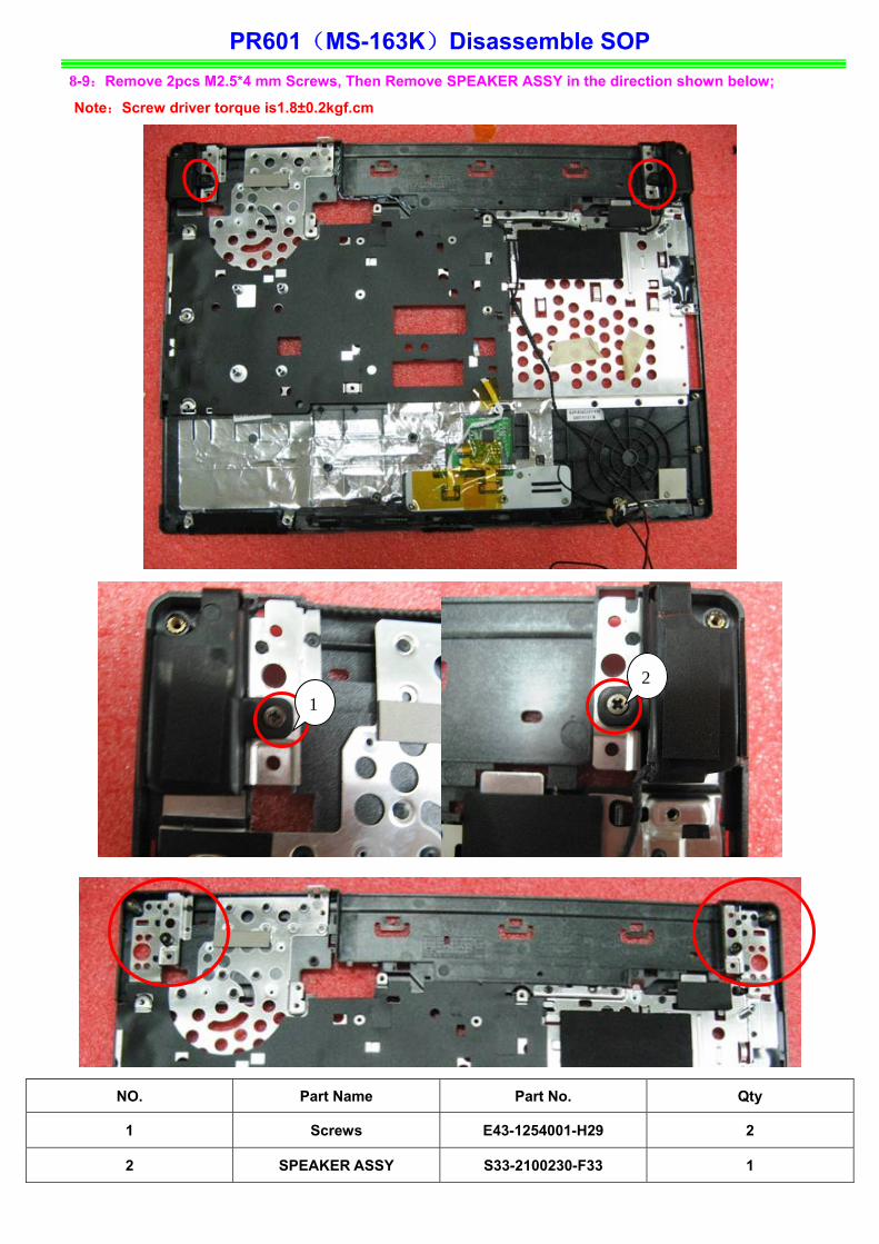
PR601(MS-163K)Disassemble SOP 8-9:Remove 2pcs M2.5*4 mm Screws, Then Remove SPEAKER ASSY in the direction shown below;
Note:Screw driver torque is1.8±0.2kgf.cm
2
1
NO. Part Name Part No. Qty
1 Screws E43-1254001-H29 2
2 SPEAKER ASSY S33-2100230-F33 1
PR601(MS-163K)Disassemble SOP
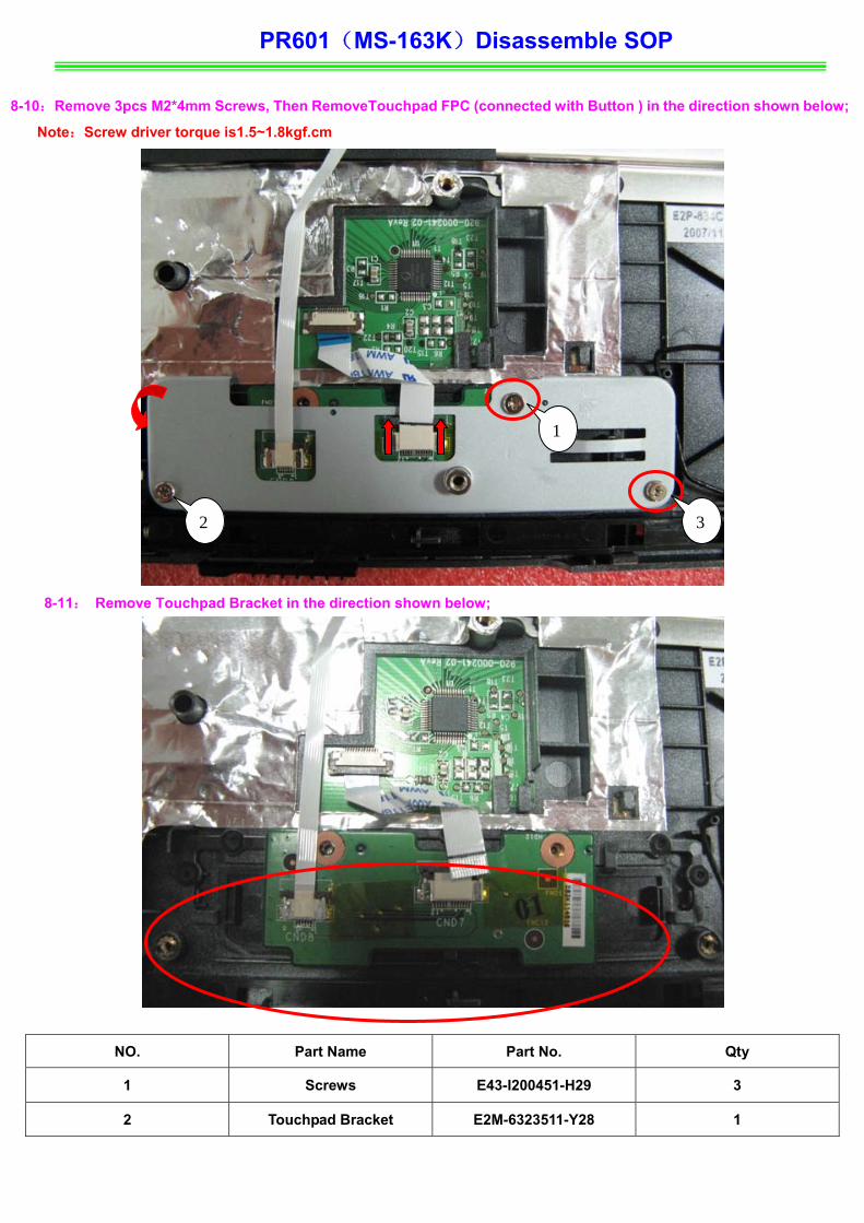
8-10: Remove 3pcs M2*4mm Screws, Then RemoveTouchpad FPC (connected with Button ) in the direction shown below;
Note:Screw driver torque is1.5~1.8kgf.cm
1
8-11: Remove Touchpad Bracket in the direction shown below;
3 2
NO. Part Name Part No. Qty
1 Screws E43-I200451-H29 3
2 Touchpad Bracket E2M-6323511-Y28 1

PR601(MS-163K)Disassemble SOP
8-12:Remove Touchpad FPC (To M/B ), Then Remove Touch Pad Board in the direction shown below;
NO. Part Name Part No. Qty
1 Touchpad FPC (To M/B ) K1C-1006009-J36 1
2 TouchPad Button Board 607-163KD-01S 1

PR601(MS-163K)Disassemble SOP
8-13:Remove TOUCHPAD MODULE in the direction shown below;
NO. Part Name Part No. Qty
1 TOUCHPAD MODULE S78-3700210-SD2 1

PR601(MS-163K)Disassemble SOP
8-14:Remove FFC CABLE(Launch Board ) in the direction shown below;
NO. Part Name Part No. Qty
1 FFC CABLE(Launch
Board ) K1C-1012012-J36 1
8-15:Remove FFC Cable Touchpad FFC (To Button );
NO. Part Name Part No. Qty
1 Touch Pad Board S78-3700360-SD2 1
2 Touchpad FFC (To Button ) K1C-1012022-J36 1
PR601(MS-163K)Disassemble SOP
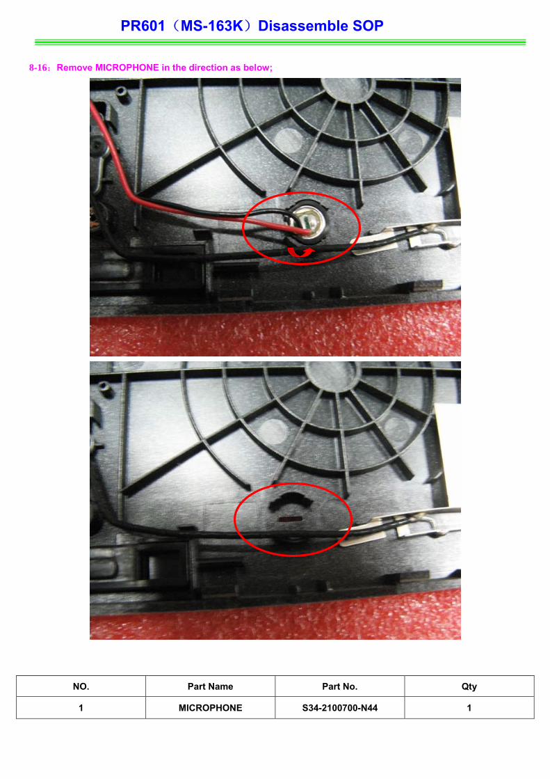
8-16:Remove MICROPHONE in the direction as below;
NO. Part Name Part No. Qty
1 MICROPHONE S34-2100700-N44 1

PR601(MS-163K)Disassemble SOP 8-17:Remove 1pcs M2*3mm Screw,Then Remover BLUETOOTH ANTENN in the direction shown below;
Note:Screw driver torque is1.8±0.2kgf.cm
1
NO. Part Name Part No. Qty
1 Screws E43-1203003-H29 1
2 BLUETOOTH ANTENNA S79-1800280-H39 1
3 UPPER CASE ASSY 307-634C132-H74 1

PR601(MS-163K)Disassemble SOP ■ 9、LOWER CASE ASSY
9-1:Remove (USB Board Cable) in the direction shown below;
NO. Part Name Part No. Qty
1 USB Board Cable K1C-1026017-J36 1

PR601(MS-163K)Disassemble SOP 9-2:Remove USB Board in the direction shown below;
Note:Screw driver torque is 1.5~2.0kgf.cm
NO. Part Name Part No. Qty
1 USB Board 607-163KC-01S 1

PR601(MS-163K)Disassemble SOP
9-3:Pull out Bluetooth Cable ,Then Remove MICROPHONE Cable in the direction shown below;
NO. Part Name Part No. Qty
1 BLUETOOTH CABLE K10-3008069-H39 1
2 MICROPHONE CABLE S34-2100700-N44 1

PR601(MS-163K)Disassemble SOP
9-4:Remove 1pcs M 2.5*5 mm Screw , Then Remove M/B in the direction shown below;;
Note:Screw driver torque is1.8±0.2kgf.cm
1
9-5:Remov Low Case ASSY in the direction shown below;

PR601(MS-163K)Disassemble SOP
NO. Part Name Part No. Qty
1 MAIN Board 607-163K1-01S 1
2 Low Case ASSY 307-632D26D-H76 1
3 Screws E43-1255007-H29 1

PR601(MS-163K)Disassemble SOP
■ 10、LCD MODULE ASSY 10-1:Remove 8pcs LCD Rubbers ,Then Remove 8pcs M2.5*5mm screws in the direction shown below;
Note:Screw driver torque is 1.5~2.0kgf.cm
75 6
8
43
21
1
5 6 7 8
4 3 2
NO. Part Name Part No. Qty
1 LCD BEZEL RUBBER E2Y-6120211-Y40 8
2 Screw E43-1255007-H29 8
PR601(MS-163K)Disassemble SOP
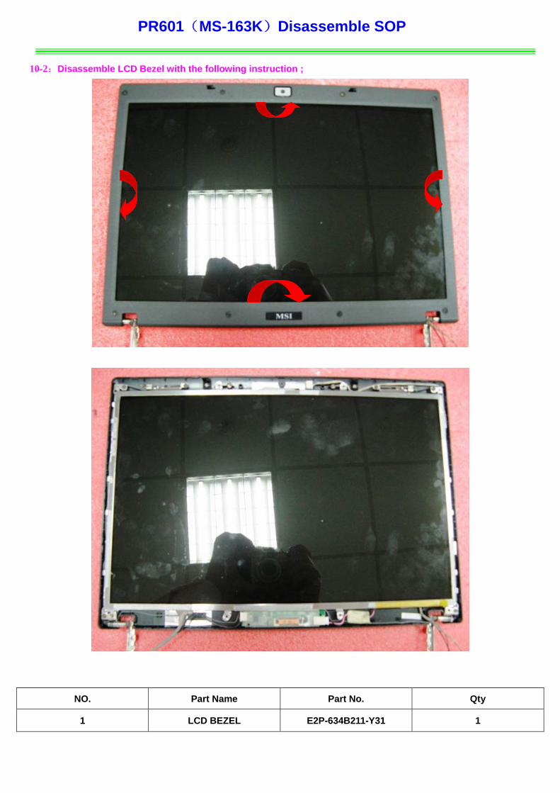
10-2:Disassemble LCD Bezel with the following instruction ;
NO. Part Name Part No. Qty
1 LCD BEZEL E2P-634B211-Y31 1

PR601(MS-163K)Disassemble SOP 10-3:Remove 4pcs M2.5*5mm screws , Then Remove 1pcs magnet in the direction shown below;
Note:Screw driver torque is3.5+/-0.2kgf.cm
2 1
1
3 4
10-4:Remove LCD_HINGE_L-R in the direction shown below;
NO. Part Name Part No. Qty
1 Screw E43-1255007-H29 4
2 MAGNET E2Y-6313111-SF7 1
3 LCD_HINGE_L E2M-6320312-G60 1
4 LCD_HINGE_R E2M-7211811-G60 1
PR601(MS-163K)Disassemble SOP
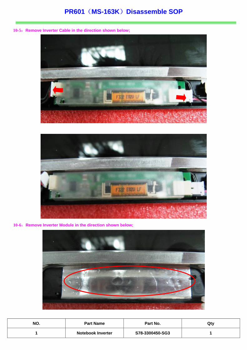
10-5:Remove Inverter Cable in the direction shown below;
10-6:Remove Inverter Module in the direction shown below;
NO. Part Name Part No. Qty
1 Notebook Inverter S78-3300450-SG3 1
PR601(MS-163K)Disassemble SOP
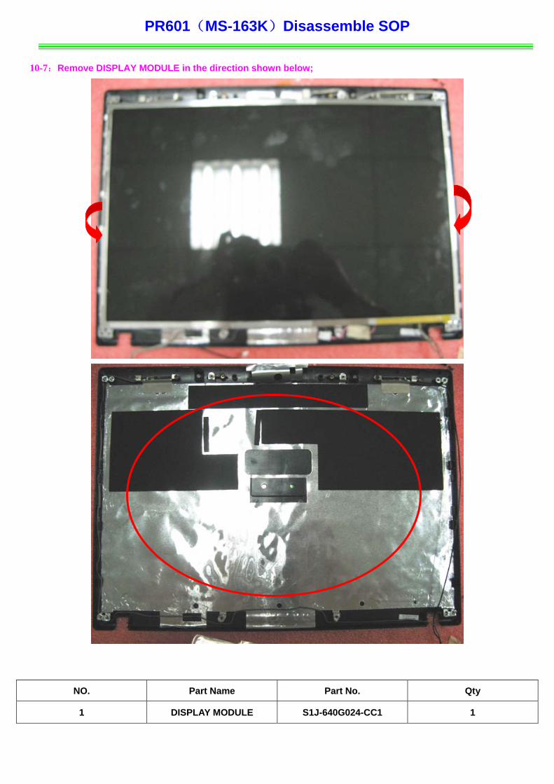
10-7:Remove DISPLAY MODULE in the direction shown below;
NO. Part Name Part No. Qty
1 DISPLAY MODULE S1J-640G024-CC1 1

PR601(MS-163K)Disassemble SOP
10-8:Remove CMOS Cable ,Remove CMOS Camera Module in the direction shown below;
NO. Part Name Part No. Qty
1 CMOS Camera Module S1F-0001200-AF5 1
2 CMOS Cable K10-3005054-H39 1

PR601(MS-163K)Disassemble SOP
10-9:Remove 4pcs M2.5*5mm screws , Then Remove ANTENNA in the direction shown below;
Note:Screw driver torque is 1.5~1.8kgf.cm
432
1
NO. Part Name Part No. Qty
1 ANTENNA/HIGH-TEK/RIGHT S79-1800260-H39 1
2 ANTENNA/HIGH-TEK/LEFT S79-1800270-H39 1
3 Screw E43-1255007-H29 4
4 LCD COVER ASSY 307-634A212-H74 1

PR601(MS-163K)Disassemble SOP
10-10:Remove LCD LVDS Cable in the direction shown below;
NO. Part Name Part No. Qty
1 LCD LVDS Cable K19-3040002-H39 1
2 Display Module S1J-640G024-CC1 1

PR601(MS-163K)Disassemble SOP 10-11:Remove 8pcs M2*3mm Screws as illustration, Then Remove LCD Bracket in the direction shown below;
Note:Screw driver torque is 1.5~2.0kgf.cm
2 4 3
1
8
5
6
3 7
4
2
1
NO. Part Name Part No. Qty
1 Screw E43-1203003-H29 8
2 LCD-Bracket E2M-6320723-Y28 2
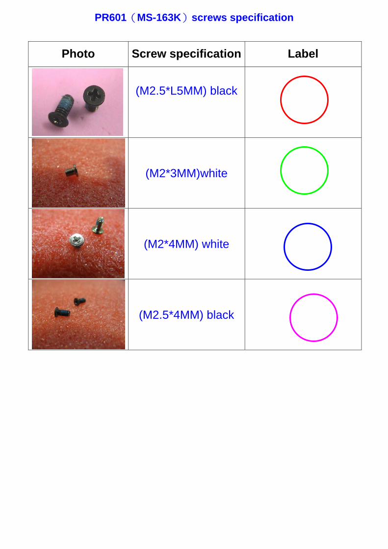
PR601(MS-163K)screws specification
Photo Screw specification Label
(M2.5*L5MM) black
(M2*3MM)white
(M2*4MM) white
(M2.5*4MM) black
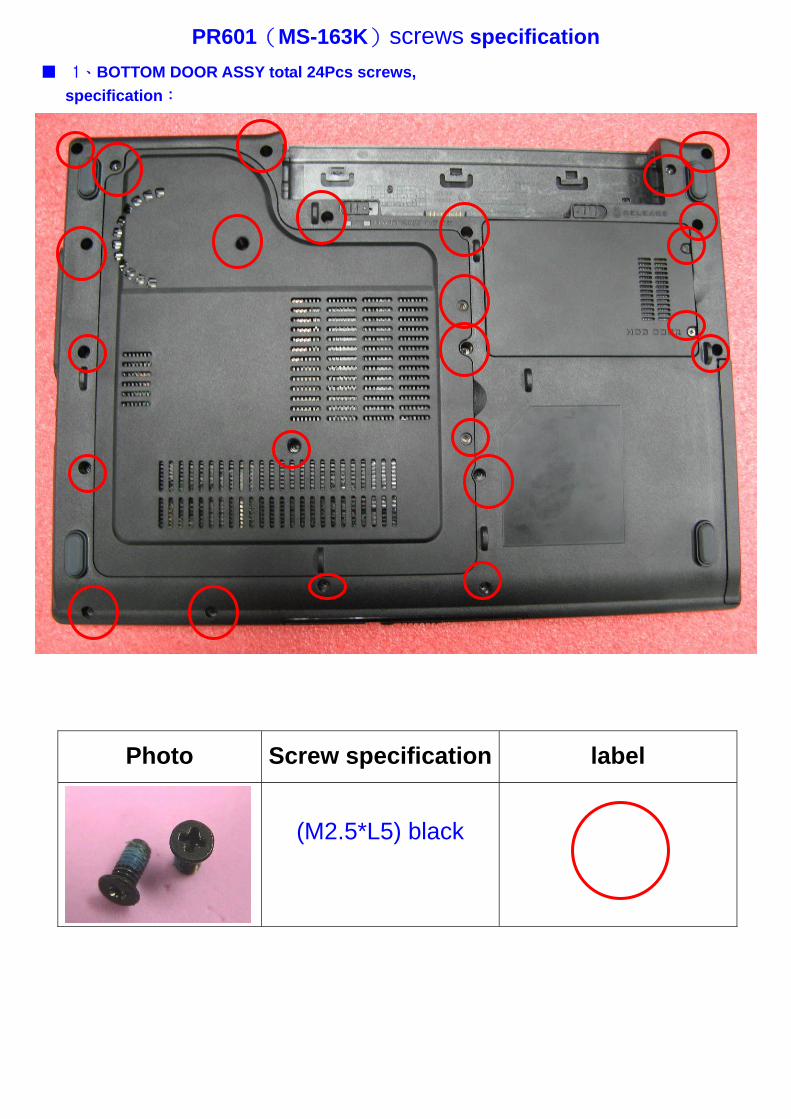
PR601(MS-163K)screws specification ■ 1、BOTTOM DOOR ASSY total 24Pcs screws,
specification:
Photo Screw specification label
(M2.5*L5) black

PR601(MS-163K)screws specification ■ 2、THERMAL-KIT and WIRELESS CARD total 7Pcs screws, specification:
Photo Screw specification label
(M2.5*L5) black
(M2*L3)white
3
2
1
4
Note:CPU Thermal Module screws on the order of lock

PR601(MS-163K)screws specification ■ 3、UPCASE ASSY and SPEAKER ASSY total 10Pcs screws ,
specification:
Photo Screw specification Label
(M2.5*L5) black
(M2*L3)white

PR601(MS-163K)screws specification ■ 4、LCD BEZEL total 8Pcs screws,
specification:
Photo Screw specification label
(M2.5*L5) black

PR601(MS-163K)screws specification ■ 5、LCD MODULE ASSY total 16Pcs screws ,
specification:
Photo Screw specification label
(M2.5*L5) black
(M2*L3)white

PR601(MS-163K)screws specification ■ 6、UP CASE and LOWER CASES total 3pcs screws,
specification:
Photo Screw specification label
(M2*L3)white

PR601(MS-163K)screws specification ■ 7、NB total 1pcs screw,
specification:
Photo Screw specification label
(M2.5*L5) black

PR601(MS-163K)screws specification ■ 8、Touch Pad Board total 6pcs screws,specification:
Photo Screw specification label
(M2*L3)white
(M2*4MM) white
(M2.5*4MM) black
Related Documents