PQube 3 Instruction Manual Page 1 of 111 PQube® 3 Instruction Manual Revision 2.1 Power Sensors Limited 980 Atlantic Ave. #100 Alameda CA 94501 USA www.PowerSensorsLtd.com © 2008-2016 Power Sensors Limited

Welcome message from author
This document is posted to help you gain knowledge. Please leave a comment to let me know what you think about it! Share it to your friends and learn new things together.
Transcript

PQube 3 Instruction Manual
Page 1 of 111
PQube® 3
Instruction Manual Revision 2.1
Power Sensors Limited 980 Atlantic Ave. #100
Alameda CA 94501 USA www.PowerSensorsLtd.com © 2008-2016 Power Sensors Limited

PQube 3 Instruction Manual
Page 2 of 111
If this equipment is used in a manner not specified by the manufacturer, the protection provided by the equipment may be impaired. Installation, service, and maintenance of your PQube must only be done by qualified personnel for electrical installations.
© 2008-2016 Power Sensors Ltd. All rights reserved. No parts of this document may be copied, reproduced, or translated to another language without the prior written consent of Power Sensors Ltd. “PQube 3” is a registered trademark of Power Sensors Ltd. “Windows” “Excel”, and “PowerPoint” are registered trademarks of Microsoft Corporation.
The information contained in this document is subject to change without notice.
PSL MAKES NO WARRANTY OF ANY KIND WITH REGARD TO THIS MATERIAL, INCLUDING, BUT NOT LIMITED TO, THE IMPLIED WARRANTIES OF MERCHANTABILITY AND FITNESS FOR A PARTICULAR USE.
PSL shall not be liable for errors contained herein or for incidental or consequential damages in connection with the furnishing, performance, or use of this material. If you do not accept this limitation on liability, please return the product to PSL prior to use.
Produced in the United States of America.
Symbol Meaning
Caution. Consult this manual in all cases where this symbol is marked, in order to find out the nature of the potential hazards and any actions which have to be taken to avoid them.
Caution. Risk of electric shock
Alternating current
Alternating current (a.c.) or direct current (d.c.)
Double or Reinforced insulation
Functional earth terminal not relied on for safety
Document Release Date: September 2016
WARNING: Death, serious injury, or fire hazard could result from improper connection or operation of this instrument. Carefully read and understand manual before connecting this instrument.
AVERTISSEMENT: Si l'instrument est mal connecté, la mort, des blessures graves, ou un danger d'incendie peuvent s'en suivre. Lisez attentivement le manuel avant de connecter l'instrument.
WARNUNG: Der falsche Anschluß dieses Gerätes kann Tod, schwere Verletzungen oder Feuer verursachen. Bevor Sie dieses Instrument anschließen, müssen Sie die Anleitung lesen und verstanden haben.
ADVERTENCIA: Una conexión incorrecta de este instrumento puede producir la muerte,
lesiones graves y riesgo de incendio. Lea y entienda el manual antes de conectar.

PQube 3 Instruction Manual
Page 3 of 111
1 Introduction 7
1.1 What is a PQube® 3? ......................................................................................................... 7
1.1.1 What does my PQube 3 record? 7
1.1.2 What kind of software do I need? 7
1.1.3 Which configurations are supported? 8
1.1.4 How do I power my PQube 3? 8
1.1.5 How do I communicate with my PQube 3? 8
1.2 How Is Your PQube 3 Different? ....................................................................................... 9
1.3 Overview of PQube 3 Ports, Connections, and Controls ................................................. 10
1.4 Choosing Modules .......................................................................................................... 12
1.4.1 Power your PQube 3 from 100~240Vac 14
1.4.2 Backup your PQube 3 during a power outage 14
1.4.3 Measure the 1A or 5A secondary wires of external current transformers 15
1.4.4 Measure Environmental Conditions 15
1.4.5 Synchronize your PQube 3 to GPS time 16
2 Installing Your PQube 3 17
2.1 Installation Guide ............................................................................................................ 17
2.1.1 Disconnect mains prior to servicing 17
2.1.2 Mount your PQube 3 properly and securely 17
2.1.3 Include overcurrent protection and a disconnecting device 18
2.1.4 Protect the operator from the hazardous terminals 18
2.1.5 Connect your PQube 3 to the power supply 20
2.1.6 Connecting the wires 22
2.1.7 Connect mains AC voltage wires 24
2.1.8 Protect antenna terminals from lightning 25
2.1.9 Installing Your PM1 Power Supply Module 25
2.1.10 Installing Your UPS Module 25
2.1.11 Installing Current Transformers (CTs) 26
2.1.12 Connecting the ENV2 environmental probes 29
2.1.13 Installing Your MS1 Sync Module (GPS option) 29
2.2 Wiring Diagrams ............................................................................................................. 31
2.2.1 Single Phase L1-N 31
2.2.2 Single Phase L1-L2 31

PQube 3 Instruction Manual
Page 4 of 111
2.2.3 Single Split Phase 32
2.2.4 Delta – 3 CTs 32
2.2.5 Delta – 2 CTs (PQube 3 calculates current on remaining channel) 33
2.2.6 Wye/Star 33
2.2.7 Measuring Neutral Current (applies to any power configuration with Neutral) 34
2.2.8 Measuring Earth Current (applies to any power configuration) 34
2.2.9 Measuring Net Earth Current – Delta 35
2.2.10 Measuring Net Earth Current – Wye/Star 35
2.3 Low Voltage Input/Output Terminals ............................................................................. 36
3 Setting Up Your PQube 3 37
3.1 Your Setup File ................................................................................................................ 37
3.2 Initial Device Setup ......................................................................................................... 38
3.2.1 Set the Date and Time 38
3.2.2 Set Your Languages 38
3.2.3 Set Your Potential Transformer (PT) Ratio 39
3.2.4 Set Your Current Transformer (CT) Ratio 40
3.2.5 Verify your PQube 3 has been configured correctly 41
3.2.6 Common Installation Errors 41
4 PQube 3 Operation 43
4.1 User Controls .................................................................................................................. 43
4.1.1 Navigating the Touchscreen Display 43
4.1.2 Rebooting Your PQube 3 51
4.1.3 Ejecting your USB thumb drive or microSD card 52
4.2 Accessing the FTP Server on Your PQube 3 ..................................................................... 53
4.3 Accessing the HTTP Web Server on Your PQube 3 .......................................................... 54
4.3.1 Status 55
4.3.2 Meters 56
4.3.3 Events 57
4.3.4 Trends 58
4.3.5 Commands 59
4.4 PQube 3 Email Setup ...................................................................................................... 60
4.4.1 Setting up an email account for your PQube 3 60
4.4.2 Getting event notifications and trend data from your PQube 3 by email 61
4.4.3 Sending commands to your PQube 3 over email 62

PQube 3 Instruction Manual
Page 5 of 111
4.5 Modbus Setup................................................................................................................. 64
4.5.1 Basics 64
4.5.2 Scan rates, client load, and limitations 64
4.5.3 Supported Clients 64
4.5.4 Register List (refer to Modbus Reference Manual) 64
4.5.5 Downloads 64
4.6 LED Definitions ................................................................................................................ 65
4.6.1 PQube 3 65
4.6.2 MS1 66
4.6.3 PM1/PM2 66
4.6.4 UPS1 67
4.6.5 ENV1/ENV2 67
4.7 Upgrading the Firmware on your PQube 3 ..................................................................... 68
4.8 Maintenance ................................................................................................................... 70
4.8.1 Turning Off Your PQube 3 70
4.8.2 Replacing Your PQube 3’s Clock Battery 70
4.8.3 Life Expectancy of the PQube 3 and the PM1 module 70
4.8.4 UPS1 Life Expectancy and Long Term Storage Instructions 70
4.8.5 Cleaning Instructions 71
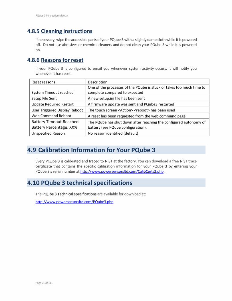
4.8.6 Reasons for reset 71
4.9 Calibration Information for Your PQube 3 ...................................................................... 71
4.10 PQube 3 technical specifications ..................................................................................... 71
5 Appendix 1: Setup File Guide 72
5.1.1 Device Setup 72
5.1.2 Event Triggering 81
5.1.3 Network Configuration 91
5.1.4 Protocols and Synchronization 97
5.1.5 System and Services 99
5.1.6 Trend Setup 100
6 Appendix 2: PQube3 events 103
7 Appendix 2: Major Sag (Dip) Curves 108
7.1.1 STANDARD 108
7.1.2 SEMI F47 109
7.1.3 Samsung Power Vaccine 109

PQube 3 Instruction Manual
Page 6 of 111
7.1.4 ITIC 110
7.1.5 CBEMA 110
7.1.6 MIL-STD 704E 111
7.1.7 MIL-STD 1399 111

PQube 3 Instruction Manual
Page 7 of 111
1 Introduction
1.1 What is a PQube® 3?
Your PQube® 3 is an instrument for monitoring electric power systems and environmental conditions, designed to help you solve problems that impact the quality and reliability of your product or process.
Think of it as a black box for your electric power and environment. It is a combination of a power disturbance monitor, a power/energy meter, a data logger, and a digital fault recorder – it combines the best features of all four. It’s easy to use, too. Just transfer the data to your computer using a standard flash device like a USB drive or SD card, like you would with a digital camera. No special training is needed to operate your PQube 3.
1.1.1 What does my PQube 3 record?
Your PQube 3 records disturbances on the mains circuit: sags/dips, swells, interruptions, frequency variations, impulses, and waveform snapshots. It also records power quality parameters like flicker, unbalance, THD and harmonics.
Your PQube 3 also generates daily, weekly, and monthly trends/statistics reports automatically!
When equipped with compatible current transformers, your PQube 3 also records current waveforms, RMS amps, power and carbon. It measures watts, watt-hours, VAR’s, power factor, and other power-related parameters.
It includes channels for measuring auxiliary voltages – typically 24V AC or 48V DC.
It also has a general-purpose digital input, which you can toggle with switch contacts or a logic signal, and a relay contact output, which opens for at least 3 seconds whenever your PQube 3 detects an event.
Your PQube 3 also measures and triggers on temperature, humidity and pressure at up to two locations, using optional ENV1 environmental probes using the USB ports under the Ethernet port.
1.1.2 What kind of software do I need?
You don’t need special software to use your PQube 3. It records all data on internal memory plus a removable microSD card, which can be read by any computer.
No special software is required – just open the GIF picture files with standard image programs, or even Microsoft Word® and Microsoft PowerPoint®, or open the CSV files with any spreadsheet program such as Microsoft Excel® (or OpenOffice.org Calc if you prefer something free).
Configure your PQube 3 with our free PQube Configurator program, or by editing a text file.

PQube 3 Instruction Manual
Page 8 of 111
1.1.3 Which configurations are supported?
Your PQube 3 can monitor circuits anywhere in the world (single-phase all the way up to 3-phase). It supports nominal voltages up to 960VAC phase-to-phase (600 VAC phase-to-earth) and mains frequencies of 16.7 Hz, 50 Hz, 60 Hz, and 400* Hz. For medium and high voltage applications, your PQube 3 supports PT and CT ratios up to 50000:1.
Your PQube 3 can also be used to monitor DC voltage, which can be useful for solar applications (monitor the AC and DC voltages of your inverter).
*coming soon! Contact PSL for free firmware upgrade!
1.1.4 How do I power my PQube 3?
It can be directly powered from 24V AC or 24~48V DC or Power over Ethernet (PoE), or it can be equipped with an optional snap-in PM1 Module that operates from AC 100V ~ 240V, 50/60/400 Hz. You can also apply DC 120V ~ 370V too!
1.1.5 How do I communicate with my PQube 3?
No network is required to retrieve files from your PQube 3. Simply copy the data to your computer using a USB thumb drive or microSD card.
If you have a network connection available, your PQube 3 can automatically send you e-mails whenever it detects an event. You can send your PQube 3 a new setup file, or even update its firmware via e-mail. It also includes a built-in web server, FTP server, and supports communication protocols including MODBUS TCP/IP, SNMP and more, giving you many ways to communicate with your PQube 3.

PQube 3 Instruction Manual
Page 9 of 111
1.2 How Is Your PQube 3 Different?
There are many power quality meters, energy meters, and energy recorders available. What makes the PQube 3 stand out from other products?
No software. No rental fees. Open data. -- You don’t need any software from PSL to use the PQube 3. Do you have a web browser? A text editor? A spreadsheet program like Microsoft Excel®? That’s all you need! All the data that the PQube 3 records are in open formats that are easy to understand. You don’t have to buy or lease software from Power Sensors Ltd, you don’t have to pay us to see your data, and the files are easy to pass on to third parties.
Friendly data. – When you need information about your electric power, you don’t have time to learn how to use complex software to get the view that you want. You simply want your data organized and presented to you in a format you can understand. Your PQube 3 presents power quality events and trends in formats you can easily use and lays the data out in a way that’s understandable. Your PQube 3 knows what’s important.
Works out of the box, or configure everything to work for you – With our patent-pending auto configuration, you can connect your PQube 3 to the power that you want to measure and the PQube 3 will immediately start recording data. If you don’t like the default settings you can change almost any setting using the PQube 3 Configurator program, or by editing a text file on a USB drive or SD card.
Works with or without a network – Do you have an Ethernet network? Plug the cable into your PQube 3’s Ethernet port and get emails when an event occurs, browse the recorded events and trends with your web browser, integrate it into your Modbus system, or send traps to your SNMP server. Don’t have a network? No problem, just walk up to the PQube 3 and extract the data onto a USB thumb drive. You can look at all the files on any computer (you don’t need proprietary software). You don’t need a sophisticated centralized data collection system to get started. Just connect a PQube 3 and start getting data right away.
Store years of data on standard SD cards. – Your PQube 3 comes with an 8GB microSD card which can hold up to 1 year of data under normal conditions. It automatically deletes the oldest data when it becomes full, so no maintenance is required!
Small size – The PQube 3 is tiny (a little bit bigger than your fist), and that makes it easier to integrate into your equipment, enclosure, or electrical panel.
Great value – At Power Sensors Ltd, we’re experts at building power sensor electronics. We know how to do it right, and we know how to do it inexpensively. The PQube 3 provides high-end features at an affordable price.
It’s everything you need. – Power quality data: dips, swells, frequency variations, rapid voltage changes, voltage and current harmonics, high frequency emissions and high frequency impulses. Energy data: kWh, kVAh, kVARh, and carbon. Trend data: daily, weekly, and monthly strip charts, cumulative probability and load duration. Why buy multiple meters when your PQube 3 can do it all?

PQube 3 Instruction Manual
Page 10 of 111
1.3 Overview of PQube 3 Ports, Connections, and Controls

PQube 3 Instruction Manual
Page 11 of 111
A Coin-cell battery (keeps real time clock alive when instrument power is lost)
I 10/100 Ethernet RJ-45 port. 48V PoE compatible.
B USB-1 High-Speed USB 2.0 port for USB hard drives and adjacent microSD card slot (format using FAT32 filesystem)
J
USB-2 Standard USB 1.0 port for use with ENV2 environmental probes.
C Touchscreen display
K USB-3 Standard USB 1.0 port for use with ENV2 environmental probes.

PQube 3 Instruction Manual
Page 12 of 111
D Signal relay output. Normally closed during recording mode. Opens ½ cycle after event or device shutdown.
L
Current transformer inputs – nominal 0.333V RMS (LOW range) or ±10Vpk (HIGH range)
E Analog inputs. Maximum ±60VDC or 33VAC to earth. Can be used as differential inputs.
M L1, L2, L3 voltage inputs. See page 23 for maximum voltage ratings.
F
Earth – functional. Use as a reference point for analog inputs (not needed if using analog channels in differential mode).
N Neutral terminal – optional depending on your power configuration
G Digital input. Wetted with 2.4V at 3 microamps. 1.5-volt threshold. 60-volt tolerant.
O Not connected.
H Power supply input. 24VAC, or 24VDC to 48VDC (either polarity) nominal. 20VA max.
P
Earth – functional. Used as the reference point for voltage measurements.
IMPORTANT: this terminal must be properly connected to ground for safety, accuracy, and reliability.
1.4 Choosing Modules
IMPORTANT: Installation, service, and maintenance of your PQube 3 must only be done by qualified personnel for electrical installations.
Each PQube 3 comes standard with the following features:
Three AC mains voltage channels
Eight current channels (for CTs with 0.333V secondary)
Four analog input channels for additional signals (for example, the output of a power
supply)
One digital input channel (monitor the state of an interlock switch)
One signal output relay (notify your PLC that an event has occurred)
Power supply input rated for 24VAC or 24-48VDC
One 10/100 Ethernet port (PoE compatible!)

PQube 3 Instruction Manual
Page 13 of 111
One Hi-speed USB 2.0 port (for USB drive or ENV2 environmental probe)
Two standard USB 1.0 ports (for ENV2 environmental probes)
Full color touchscreen
16GB internal memory
One 16GB microSD card
One USB drive included with each PQube 3 (contains manual, quickstart guide, setup file,
Configurator program, Report Writer program)
If you need additional functionality or inputs beyond the standard PQube 3 feature set, you can purchase optional modules for your PQube 3.
To choose modules for your application, you’ll need to answer four simple questions:
Do I need to power my PQube 3 from 100~240Vac (50/60/400 Hz)?
Do I need battery backup in the event of a power outage?
Do I need current inputs to measure the 1A or 5A secondary of a CT?
Do I need ANSI Class 0.2 or IEC 62053-22 Class 0.2S revenue energy accuracy?
Do I need ultra-precise GPS timestamps on your data?
Do I want to record the environmental conditions such as temperature, humidity, pressure, or acceleration in addition to everything about the electric power?
Do I need to measure full spectrum radiation using a Pyranometer?
PQube 3 Instruction Manual
Page 14 of 111
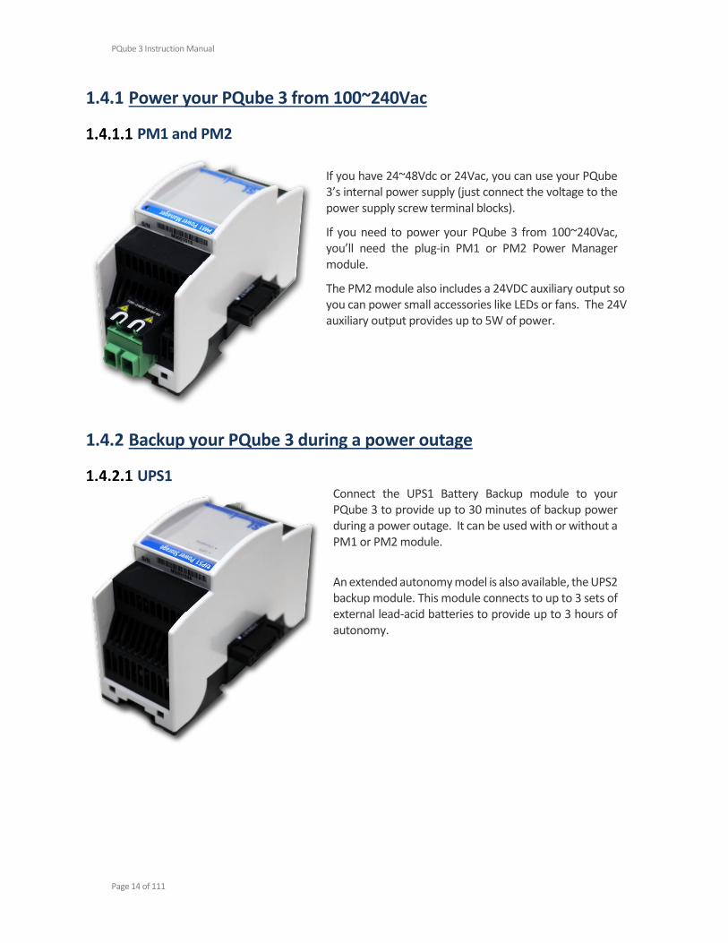
1.4.1 Power your PQube 3 from 100~240Vac
PM1 and PM2
If you have 24~48Vdc or 24Vac, you can use your PQube 3’s internal power supply (just connect the voltage to the power supply screw terminal blocks).
If you need to power your PQube 3 from 100~240Vac, you’ll need the plug-in PM1 or PM2 Power Manager module.
The PM2 module also includes a 24VDC auxiliary output so you can power small accessories like LEDs or fans. The 24V auxiliary output provides up to 5W of power.
1.4.2 Backup your PQube 3 during a power outage
UPS1 Connect the UPS1 Battery Backup module to your PQube 3 to provide up to 30 minutes of backup power during a power outage. It can be used with or without a PM1 or PM2 module.
An extended autonomy model is also available, the UPS2 backup module. This module connects to up to 3 sets of external lead-acid batteries to provide up to 3 hours of autonomy.

PQube 3 Instruction Manual
Page 15 of 111
1.4.3 Measure the 1A or 5A secondary wires of external current transformers
CTI-1A and CTI-5A Your PQube 3 comes standard with 8 current channels which are compatible with CTs with 0.333V secondary.
But if you need to measure CTs with 1A or 5A secondary wires for your application, use the CTI Current Transformer Input module.
There are two versions; one with 1A input and one with 5A input. Use the CTI module that matches the secondary rating of your external CTs.
There are four current inputs per module. Your PQube 3 can accommodate up to two CTI modules.
Use this module if your application requires ANSI C12.20 Class 0.2 or IEC 62052-22 Class 0.2S revenue grade accuracy.
1.4.4 Measure Environmental Conditions
ENV2 Environmental Probe
The ENV2 environmental probe allows your PQube 3 to measure ambient temperature, humidity, pressure.
It also includes an accelerometer to measure shock and vibration, a thermocouple input for wide temperature ranges, and a solar irradiation input.
Connect up to 2 probes to your PQube 3 using a microUSB to USB cable.
You can use a USB cable with a length of up to 15ft /5 meters.

PQube 3 Instruction Manual
Page 16 of 111
1.4.5 Synchronize your PQube 3 to GPS time
Your PQube 3 can synchronize its time clock to GPS, which provides better than 1 microsecond accuracy. This is useful for Class A measurements, or if you need to make phasor measurements with a microPMU.
MS1 The MS1 module interfaces with the GPS1 receiver to provide your PQube 3 with ultra-precise time, (no drift) time stamping for power quality events.
GPS1
The GPS1 receiver locks onto GPS satellites in the sky to provide your PQube 3 with ultra-precise GPS timing. It is designed to be weather-resistant and you can install it outside using optional mounting hardware. It has 600V functional isolation at both ends of the cable for safety.
Connect the GPS1 receiver to your MS1 module using the included cable. You can extend the cable up to 25 meters using a female-female RJ-45 coupler and standard CAT5E cable.
PQube 3 Instruction Manual
Page 17 of 111
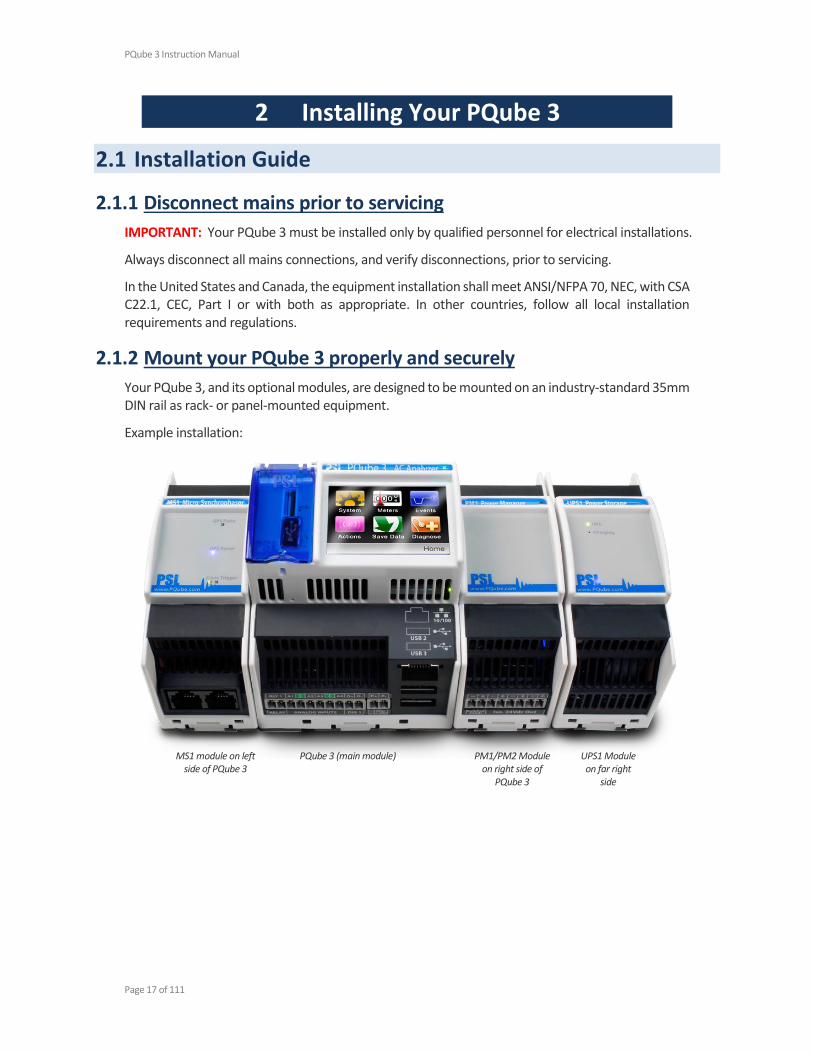
MS1 module on left side of PQube 3
PQube 3 (main module) PM1/PM2 Module on right side of
PQube 3
UPS1 Module on far right
side
2 Installing Your PQube 3
2.1 Installation Guide
2.1.1 Disconnect mains prior to servicing
IMPORTANT: Your PQube 3 must be installed only by qualified personnel for electrical installations.
Always disconnect all mains connections, and verify disconnections, prior to servicing.
In the United States and Canada, the equipment installation shall meet ANSI/NFPA 70, NEC, with CSA C22.1, CEC, Part I or with both as appropriate. In other countries, follow all local installation requirements and regulations.
2.1.2 Mount your PQube 3 properly and securely
Your PQube 3, and its optional modules, are designed to be mounted on an industry-standard 35mm DIN rail as rack- or panel-mounted equipment.
Example installation:

PQube 3 Instruction Manual
Page 18 of 111
2.1.3 Include overcurrent protection and a disconnecting device
An external overcurrent protection device, such as a fuse or a circuit breaker, must be installed on each mains connection. The device shall be UL Listed, branch circuit type overcurrent protector, rated max. 10A.
Your PQube 3 can share the overcurrent protection device with other loads.
An operator-activated disconnecting device, such as a switch or a circuit breaker, must be installed on the mains connections. This device must be clearly marked as the disconnecting device for your PQube 3, and must be marked to indicate the disconnection function. Do not install your PQube 3 in such a way that it becomes difficult to operate this disconnecting device. The disconnecting device must not disconnect the earth connection. The disconnecting device should be installed near your PQube 3, within easy reach of the operator.
2.1.4 Protect the operator from the hazardous terminals
IMPORTANT: All high voltage parts must be covered, including the AC power to your PQube 3. Install your PQube 3 so that all of the screw terminal blocks are not ACCESSIBLE1 to the operator. Your PQube 3 can also be installed without a cover if installed in a lockable IUL 508 control panel.
The operator must be protected from the hazardous screw terminal blocks by a barrier. The screw terminal blocks must be made “not ACCESSIBLE”, as defined in UL /IEC 61010-1 6.2, using an enclosure or barrier that meets the rigidity requirements of UL /IEC 61010-1 8.1 and that requires a tool to remove.
1

PQube 3 Instruction Manual
Page 19 of 111
If you choose to install your PQube 3 in an enclosure, select a UL-listed enclosure that is appropriate for the purpose. If you plan to use an enclosure of this type, you should review its mechanical compatibility with any optional features of your PQube 3 that you plan to use: optional USB connections, optional temperature-humidity probes, etc.
Note the 1-amp, 3-phase circuit breaker, at far right, used both as external overcurrent protection and disconnecting device, near your PQube 3.

PQube 3 Instruction Manual
Page 20 of 111
2.1.5 Connect your PQube 3 to the power supply
Your PQube 3 can take its operating power from four different sources:
24VAC or ±24–48VDC power supply terminals on PQube 3
Power over Ethernet (PoE)
Optional PM1 Power Supply module
Rechargeable UPS module (automatically provides up to 30 minutes of battery backup
when the main power supply source drops out)
PQube 3 power supply terminals The instrument power terminals (45 and 46) on the front of your PQube 3 must be connected to 24VAC (±20%) or 24–48VDC (±20%), supplied by a certified isolating power supply.
WARNING: Applying voltages outside of this range can cause permanent damage to your PQube 3.
Polarity does not matter. Also, your PQube 3 provides a minimum of 150V of transformer-based isolation between these terminals and all other terminals, eliminating any problems with ground loops.
Power over Ethernet (PoE) Plug in an Ethernet cable leading to a 48V PoE source (PoE switch/hub/router or PoE injector).
If no other power sources are available, your PQube 3 will request power from the PoE switch.
If your PQube 3 is already powered from another source (24V power supply or PM1 power supply module, for example) then it will not request power from the PoE switch when you plug it in.
UPS1 Module Plug the UPS1 module on the right side of your PQube 3 or PM1/PM2 module. This module is always the outermost module on the right side.
By default, the UPS timer interval is 3 minutes. However, you can choose the operating duration by writing a value in your Setup.ini file. The value can be set from 1 to 30 minutes. This guarantees that there will be enough charge in the battery to record several successive power interruptions.
PQube 3 Instruction Manual
Page 21 of 111
As the lithium ion battery inside the module ages, its capacity will decline. Depending on operating conditions and requirements, it may be necessary to replace your UPS1 Module every 3 to 5 years or 500 cycles, whichever comes first.
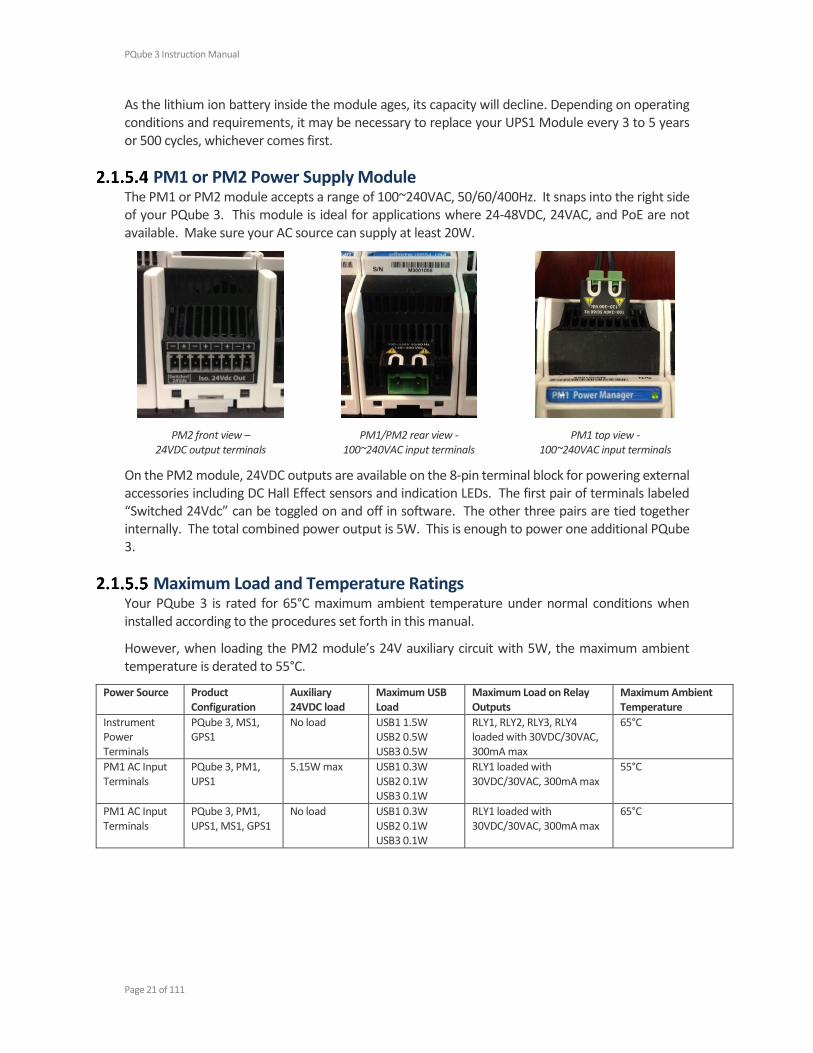
PM1 or PM2 Power Supply Module The PM1 or PM2 module accepts a range of 100~240VAC, 50/60/400Hz. It snaps into the right side of your PQube 3. This module is ideal for applications where 24-48VDC, 24VAC, and PoE are not available. Make sure your AC source can supply at least 20W.
PM2 front view – 24VDC output terminals
PM1/PM2 rear view - 100~240VAC input terminals
PM1 top view - 100~240VAC input terminals
On the PM2 module, 24VDC outputs are available on the 8-pin terminal block for powering external accessories including DC Hall Effect sensors and indication LEDs. The first pair of terminals labeled “Switched 24Vdc” can be toggled on and off in software. The other three pairs are tied together internally. The total combined power output is 5W. This is enough to power one additional PQube 3.
Maximum Load and Temperature Ratings Your PQube 3 is rated for 65°C maximum ambient temperature under normal conditions when installed according to the procedures set forth in this manual.
However, when loading the PM2 module’s 24V auxiliary circuit with 5W, the maximum ambient temperature is derated to 55°C.
Power Source Product Configuration
Auxiliary 24VDC load
Maximum USB Load
Maximum Load on Relay Outputs
Maximum Ambient Temperature
Instrument Power Terminals
PQube 3, MS1, GPS1
No load USB1 1.5W USB2 0.5W USB3 0.5W
RLY1, RLY2, RLY3, RLY4 loaded with 30VDC/30VAC, 300mA max
65°C
PM1 AC Input Terminals
PQube 3, PM1, UPS1
5.15W max USB1 0.3W USB2 0.1W USB3 0.1W
RLY1 loaded with 30VDC/30VAC, 300mA max
55°C
PM1 AC Input Terminals
PQube 3, PM1, UPS1, MS1, GPS1
No load USB1 0.3W USB2 0.1W USB3 0.1W
RLY1 loaded with 30VDC/30VAC, 300mA max
65°C
PQube 3 Instruction Manual
Page 22 of 111
2.1.6 Connecting the wires
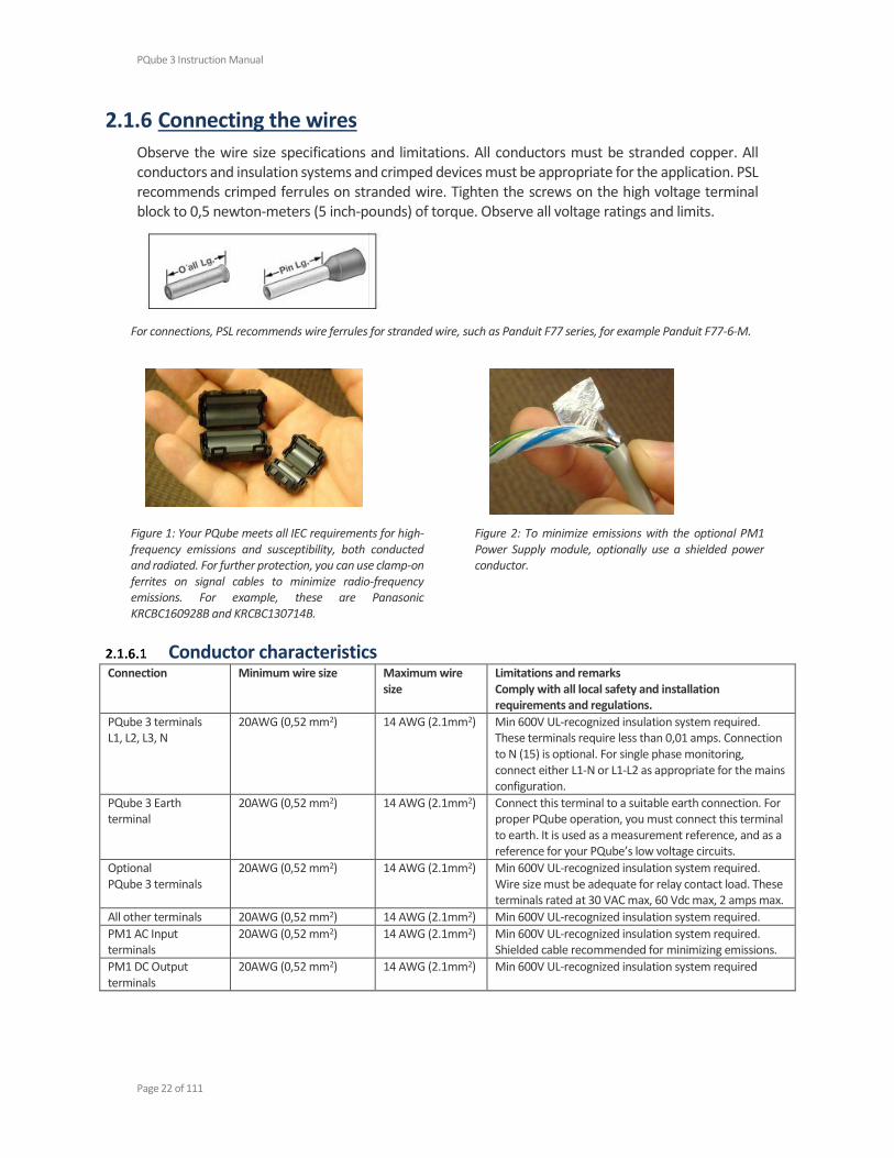
Observe the wire size specifications and limitations. All conductors must be stranded copper. All conductors and insulation systems and crimped devices must be appropriate for the application. PSL recommends crimped ferrules on stranded wire. Tighten the screws on the high voltage terminal block to 0,5 newton-meters (5 inch-pounds) of torque. Observe all voltage ratings and limits.
For connections, PSL recommends wire ferrules for stranded wire, such as Panduit F77 series, for example Panduit F77-6-M.
Figure 1: Your PQube meets all IEC requirements for high-frequency emissions and susceptibility, both conducted and radiated. For further protection, you can use clamp-on ferrites on signal cables to minimize radio-frequency emissions. For example, these are Panasonic KRCBC160928B and KRCBC130714B.
Figure 2: To minimize emissions with the optional PM1 Power Supply module, optionally use a shielded power conductor.
Conductor characteristics Connection Minimum wire size Maximum wire
size Limitations and remarks Comply with all local safety and installation requirements and regulations.
PQube 3 terminals L1, L2, L3, N
20AWG (0,52 mm2) 14 AWG (2.1mm2) Min 600V UL-recognized insulation system required. These terminals require less than 0,01 amps. Connection to N (15) is optional. For single phase monitoring, connect either L1-N or L1-L2 as appropriate for the mains configuration.
PQube 3 Earth terminal
20AWG (0,52 mm2) 14 AWG (2.1mm2) Connect this terminal to a suitable earth connection. For proper PQube operation, you must connect this terminal to earth. It is used as a measurement reference, and as a reference for your PQube’s low voltage circuits.
Optional PQube 3 terminals
20AWG (0,52 mm2) 14 AWG (2.1mm2) Min 600V UL-recognized insulation system required. Wire size must be adequate for relay contact load. These terminals rated at 30 VAC max, 60 Vdc max, 2 amps max.
All other terminals 20AWG (0,52 mm2) 14 AWG (2.1mm2) Min 600V UL-recognized insulation system required.
PM1 AC Input terminals
20AWG (0,52 mm2) 14 AWG (2.1mm2) Min 600V UL-recognized insulation system required. Shielded cable recommended for minimizing emissions.
PM1 DC Output terminals
20AWG (0,52 mm2) 14 AWG (2.1mm2) Min 600V UL-recognized insulation system required
PQube 3 Instruction Manual
Page 23 of 111
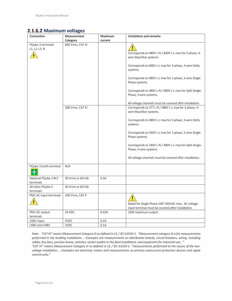
Maximum voltages Connection Measurement
Category Maximum current
Limitations and remarks
PQube 3 terminals L1, L2, L3, N
600 Vrms, CAT III
Corresponds to 480V L-N / 830V L-L max for 3-phase, 4-wire Wye/Star systems. Corresponds to 600V L-L max for 3-phase, 3-wire Delta systems. Corresponds to 480V L-L max for 1-phase, 2-wire Single Phase systems. Corresponds to 480V L-N / 960V L-L max for Split-Single-Phase, 3-wire systems. All voltage channels must be covered after installation.
300 Vrms, CAT IV Corresponds to 277 L-N / 480V L-L max for 3-phase, 4-wire Wye/Star systems. Corresponds to 480V L-L max for 3-phase, 3-wire Delta systems. Corresponds to 240V L-L max for 1-phase, 2-wire Single Phase systems. Corresponds to 240V L-N / 480V L-L max for Split-Single-Phase, 3-wire systems. All voltage channels must be covered after installation.
PQube 3 Earth terminal
N/A
Optional PQube 3 RLY terminals
30 Vrms or 60 Vdc 0.3A
All other PQube 3 terminals
30 Vrms or 60 Vdc
PM1 AC input terminals
240 Vrms, CAT II
Rated for Single-Phase 100~240VAC max. AC voltage input terminal must be covered after installation.
PM1 DC output terminals
24 VDC 0.42A 10W maximum output
USB1 Input 5VDC 0.2A
USB2 and USB3 5VDC 0.1A
Note: “CAT III” means Measurement Category III as defined in UL / IEC 61010-1: “Measurement category III is for measurements performed in the building installation…. Examples are measurements on distribution boards, circuit-breakers, wiring, including cables, bus-bars, junction boxes, switches, socket-outlets in the fixed installation, and equipment for industrial use…” “CAT IV” means Measurement Category IV as defined in UL / IEC 61010-1: “measurements performed at the source of the low-voltage installation…. Examples are electricity meters and measurements on primary overcurrent protection devices and ripple control units.”
PQube 3 Instruction Manual
Page 24 of 111
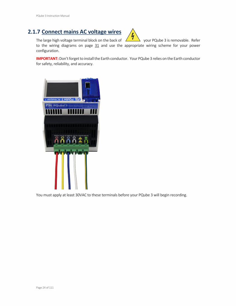
2.1.7 Connect mains AC voltage wires
The large high voltage terminal block on the back of your PQube 3 is removable. Refer to the wiring diagrams on page 31 and use the appropriate wiring scheme for your power configuration.
IMPORTANT: Don’t forget to install the Earth conductor. Your PQube 3 relies on the Earth conductor for safety, reliability, and accuracy.
You must apply at least 30VAC to these terminals before your PQube 3 will begin recording.
PQube 3 Instruction Manual
Page 25 of 111
PQube 3 PM1
PQube 3 PM1 UPS1
2.1.8 Protect antenna terminals from lightning
If you install an antenna in an outdoor location where it may be exposed to lightning, you must include a properly installed UL-497C-listed lightning protection device on the antenna cable and the antenna must be reliably earthed. Follow all local installation safety requirements and regulations.
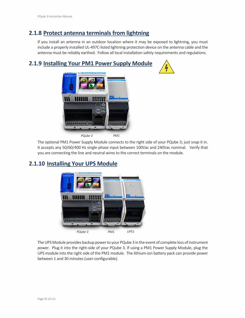
2.1.9 Installing Your PM1 Power Supply Module
The optional PM1 Power Supply Module connects to the right side of your PQube 3; just snap it in. It accepts any 50/60/400 Hz single-phase input between 100Vac and 240Vac nominal. Verify that you are connecting the line and neutral wires to the correct terminals on the module.
2.1.10 Installing Your UPS Module
The UPS Module provides backup power to your PQube 3 in the event of complete loss of instrument power. Plug it into the right-side of your PQube 3. If using a PM1 Power Supply Module, plug the UPS module into the right side of the PM1 module. The lithium-ion battery pack can provide power between 1 and 30 minutes (user-configurable).

PQube 3 Instruction Manual
Page 26 of 111
2.1.11 Installing Current Transformers (CTs)
Your PQube 3 records AC current by measuring the secondary circuit of a current transformer (CT).
When installing current transformers, it is important to match the phases to the voltage inputs and current input (connect the L1 voltage input and the L1 current sensor to the same conductor). This is necessary for correct power and energy calculations.
Instructions for setting your CT ratio can be found on page 40.
IMPORTANT: You must only use UL listed energy monitoring current transformers with your PQube 3.
PSL Ultra-Precise CTs PSL Ultra-Precise CTs are specifically designed for your PQube 3. They are calibrated to match the input impedance of your PQube 3’s current input channels, and each CT comes with its own NIST-Traceable calibration certificate and table which you can upload to your PQube 3. This is important if you need to measure high-order current harmonics or if you need revenue-grade accuracy for your application.
PSL Ultra-Precise CTs are UL listed and utilize a 0.333V secondary to match your PQube 3’s current input terminals. A burden resistor is built into the CT so you do not need to worry about hazardous open circuit voltages.
You can see the list of available PSL Ultra-Precise CTs for your PQube 3 here:
http://www.powersensorsltd.com/CTOption3.php
You can look up the calibration certificate for your CTs here:
http://www.powersensorsltd.com/CalibCerts3.php
A note on choosing the appropriate range of CT’s for your application:
If the PQube 3 is installed to monitor power and load, the nominal rated current of the CT should be the most common load current throughout the consumption period (e.g. work days). Your PQube 3 makes current measurements with a Crest Factor of 3.5. This means that your PQube 3 can measure instantaneous currents up to 350% of the nominal rated current (for example, if you have selected a 300-amp current transformer, your PQube 3 will accurately measure up to ±1050 amps instantaneous). This is a very useful feature when dealing with inrush currents, and currents with high harmonic contents.
If the PQube 3 is installed to troubleshoot circuit breaker trip operation, the nominal rated current should be selected closer to the trip settings. In all cases the PQube crest factor of 3.5 provides a margin to capture properly the peak currents.

PQube 3 Instruction Manual
Page 27 of 111
Installing CTs with 0.333V secondary Your PQube 3 comes standard with 8 current input channels, which are typically used to measure L1, L2, L3, N, E, plus 3 additional single-phase channels. The current channels on your PQube 3 are rated for 0.333V nominal input, and they are designed to be used with CTs with 0.333V secondary.
For PSL CTs, white wires are positive and black wires are negative.
If using PSL Ultra-Precise CTs with the shielded secondary wires, red is positive and black is negative. Connect the shield conductor to ground. If using another manufacturer’s CTs, verify which wires are positive and negative before installing them.
Clamp the CT around the conductor. For all PSL CTs, the label faces towards the source.
From source
To load
Labels on CT facing source
PQube 3 Instruction Manual
Page 28 of 111
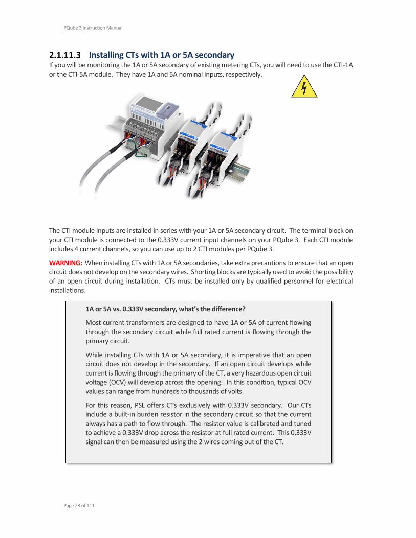
Installing CTs with 1A or 5A secondary If you will be monitoring the 1A or 5A secondary of existing metering CTs, you will need to use the CTI-1A or the CTI-5A module. They have 1A and 5A nominal inputs, respectively.
The CTI module inputs are installed in series with your 1A or 5A secondary circuit. The terminal block on your CTI module is connected to the 0.333V current input channels on your PQube 3. Each CTI module includes 4 current channels, so you can use up to 2 CTI modules per PQube 3.
WARNING: When installing CTs with 1A or 5A secondaries, take extra precautions to ensure that an open circuit does not develop on the secondary wires. Shorting blocks are typically used to avoid the possibility of an open circuit during installation. CTs must be installed only by qualified personnel for electrical installations.
1A or 5A vs. 0.333V secondary, what’s the difference?
Most current transformers are designed to have 1A or 5A of current flowing through the secondary circuit while full rated current is flowing through the primary circuit.
While installing CTs with 1A or 5A secondary, it is imperative that an open circuit does not develop in the secondary. If an open circuit develops while current is flowing through the primary of the CT, a very hazardous open circuit voltage (OCV) will develop across the opening. In this condition, typical OCV values can range from hundreds to thousands of volts.
For this reason, PSL offers CTs exclusively with 0.333V secondary. Our CTs include a built-in burden resistor in the secondary circuit so that the current always has a path to flow through. The resistor value is calibrated and tuned to achieve a 0.333V drop across the resistor at full rated current. This 0.333V signal can then be measured using the 2 wires coming out of the CT.
PQube 3 Instruction Manual
Page 29 of 111
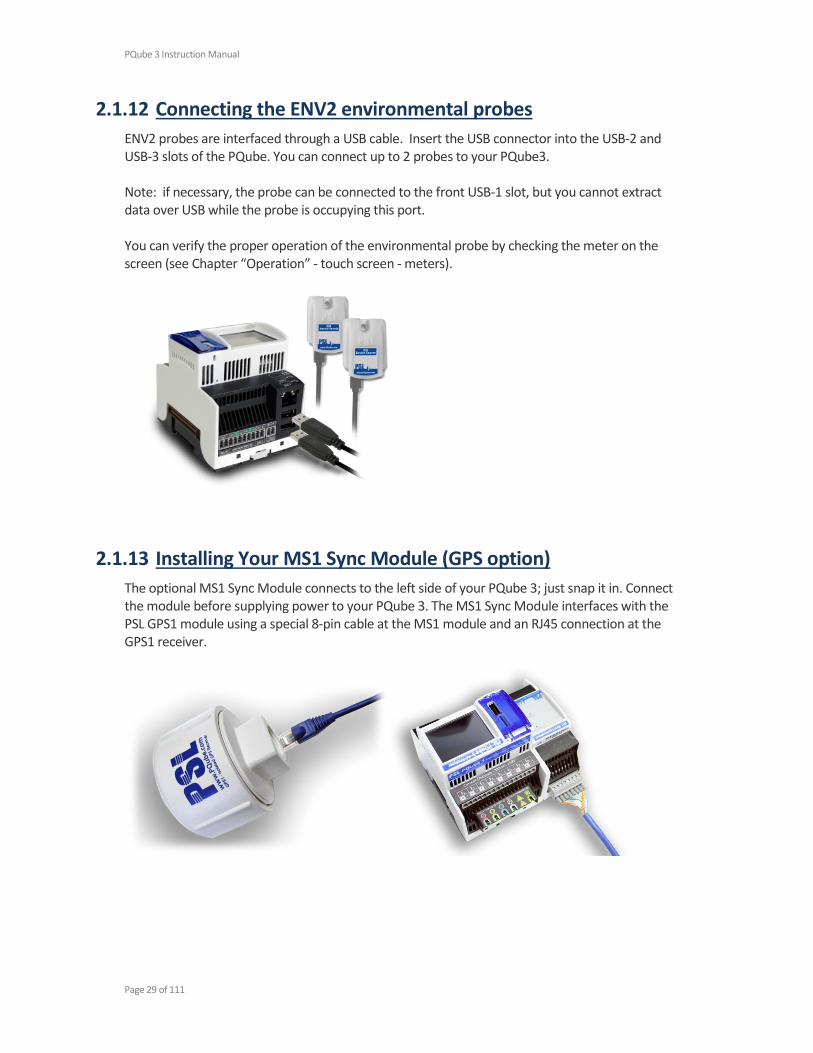
2.1.12 Connecting the ENV2 environmental probes
ENV2 probes are interfaced through a USB cable. Insert the USB connector into the USB-2 and USB-3 slots of the PQube. You can connect up to 2 probes to your PQube3. Note: if necessary, the probe can be connected to the front USB-1 slot, but you cannot extract data over USB while the probe is occupying this port. You can verify the proper operation of the environmental probe by checking the meter on the screen (see Chapter “Operation” - touch screen - meters).
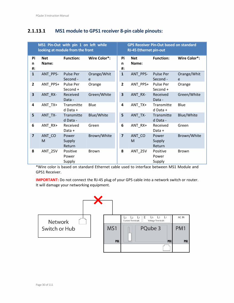
2.1.13 Installing Your MS1 Sync Module (GPS option)
The optional MS1 Sync Module connects to the left side of your PQube 3; just snap it in. Connect the module before supplying power to your PQube 3. The MS1 Sync Module interfaces with the PSL GPS1 module using a special 8-pin cable at the MS1 module and an RJ45 connection at the GPS1 receiver.
PQube 3 Instruction Manual
Page 30 of 111
MS1 module to GPS1 receiver 8-pin cable pinouts:
MS1 Pin-Out with pin 1 on left while looking at module from the front
GPS Receiver Pin-Out based on standard RJ-45 Ethernet pin-out
Pin #:
Net Name:
Function: Wire Color*:
1 ANT_PPS- Pulse Per Second -
Orange/White
2 ANT_PPS+ Pulse Per Second +
Orange
3 ANT_RX- Received Data -
Green/White
4 ANT_TX+ Transmitted Data +
Blue
5 ANT_TX- Transmitted Data -
Blue/White
6 ANT_RX+ Received Data +
Green
7 ANT_COM
Power Supply Return
Brown/White
8 ANT_25V Positive Power Supply
Brown
*Wire color is based on standard Ethernet cable used to interface between MS1 Module and GPS1 Receiver.
IMPORTANT: Do not connect the RJ-45 plug of your GPS cable into a network switch or router. It will damage your networking equipment.

PQube 3 Instruction Manual
Page 31 of 111
2.2 Wiring Diagrams
2.2.1 Single Phase L1-N
2.2.2 Single Phase L1-L2

PQube 3 Instruction Manual
Page 32 of 111
2.2.3 Single Split Phase
2.2.4 Delta – 3 CTs

PQube 3 Instruction Manual
Page 33 of 111
2.2.5 Delta – 2 CTs (PQube 3 calculates current on remaining channel)
2.2.6 Wye/Star

PQube 3 Instruction Manual
Page 34 of 111
2.2.7 Measuring Neutral Current (applies to any power configuration with Neutral)
2.2.8 Measuring Earth Current (applies to any power configuration)

PQube 3 Instruction Manual
Page 35 of 111
2.2.9 Measuring Net Earth Current – Delta
2.2.10 Measuring Net Earth Current – Wye/Star

PQube 3 Instruction Manual
Page 36 of 111
2.3 Low Voltage Input/Output Terminals
Phoenix Contact MC 1,5/10-ST-3,5 - 1840447 Phoenix Contact MC 1,5/ 2-ST-3,5 - 1840366

PQube 3 Instruction Manual
Page 37 of 111
3 Setting Up Your PQube 3
3.1 Your Setup File
All of your PQube 3’s settings are contained in a simple text file called Setup.ini.
The factory-default setup file can be found on the USB drive that shipped with your PQube 3.
You can retrieve your PQube 3’s existing setup file via USB, SD card, email, web, or FTP.
Edit it using the PQube 3 Configurator program (recommended for most users). It is a graphical editing utility to help avoid mistakes and possible conflicts across settings. For advanced users, you can edit it using a text editor like Notepad.
You can download the PQube 3 Configurator program for free here:
http://www.powersensorsltd.com/PQube3.php#config
After you’ve made your changes, save the file as Setup.ini and upload it back to your PQube 3 via email, web, FTP, and it will automatically reboot and load the new settings on startup. You can also copy your new Setup file onto a USB drive or microSD card and insert it directly into your PQube 3. After detecting the new Setup file, your PQube will ask you to reboot so it can load the new settings.
For details about each of the Setup file tags, refer to Appendix 1 on page 72.

PQube 3 Instruction Manual
Page 38 of 111
3.2 Initial Device Setup
Your PQube 3 will work right out of the box. Once your PQube 3 has been installed, connected to the monitoring circuit, and powered on, it will begin recording data immediately. The default settings will work for most applications, but if you have special requirements you may need to change a few settings. Don’t worry, it’s an easy process.
3.2.1 Set the Date and Time
After your PQube 3 is installed and running, the first thing you need to do is set the date and time. Setting the date and time is important because all of the output files your PQube produces include a time stamp.
Your PQube 3 is synchronized to UTC time at the factory.
If your PQube 3 has an internet connection, you can configure it to synchronize to UTC time via SNTP or NTP server.
If your PQube 3 is equipped with the MS1 and GPS1 modules, it will automatically synchronize to UTC time through GPS.
If you specify a time zone in the setup file, your PQube 3 will automatically adjust the clock to your local time after synchronizing to UTC time via GPS or SNTP/NTP.
If your PQube 3 does not have GPS and is not configured for SNTP or NTP, you can manually set the time using the controls on the display.
3.2.2 Set Your Languages
Specify a primary language and secondary language in your Setup file. Events and trends will be generated using both languages.
You can also choose which language shows up on the display from the Languages screen on the display.

PQube 3 Instruction Manual
Page 39 of 111
3.2.3 Set Your Potential Transformer (PT) Ratio
If you are using Potential Transformers (PT) to monitor voltages above 690Vac Phase-to-Phase (400Vac Phase-to-Earth) you can program the PT ratio into your PQube 3 so that it reports the actual primary voltage.
For example, to use your PQube 3 on a 24 kilovolt distribution system, you might use a 100:1 potential transformer to reduce the 24 kilovolts to 240 volts.
In setup file, set the PT ratio to 24000:240 or 100:1. You will also need to set your nominal voltage using the primary voltage of your PT. Even though your PQube 3 has 240V applied to its mains AC voltage terminals, you need to set the nominal voltage to 24000.

PQube 3 Instruction Manual
Page 40 of 111
3.2.4 Set Your Current Transformer (CT) Ratio
If you are using CTs with 0.333V secondary To set the CT ratio, simply enter the primary current and secondary voltage into your CT ratio. For example, if you have a current transformer rated at 300 amps, with 0.333V secondary, then you would set your CT ratio to 300:0.333. The value in the Current Transformer Ratio field is applied to the L1, L2, and L3 current channels.
If you are using CTs with 1A or 5A secondary Use the CTI-1A or CTI-5A modules are designed to accept the 1A or 5A secondary of metering CTs.
The CTI-1A module has a ratio of 1A:0.333V. The CTI-5A module has a ratio of 5A:0.333V.
To calculate your CT ratio, multiply the ratio of your metering CT by the ratio of your CTI module.
CT Ratio CTI Module CT Ratio Calculation CT Ratio in Setup File
Example 1 300A:5A CTI-5A module 300𝐴
5𝐴 ×
5𝐴
0.333𝑉=
300𝐴
0.333𝑉
300:0.333
Example 2 300A:5A CTI-1A module 300𝐴
5𝐴 ×
1𝐴
0.333𝑉=
300𝐴
1.666𝑉
300:1.666
Example 3 300A:1A CTI-5A module 300𝐴
1𝐴 ×
5𝐴
0.333𝑉=
1500𝐴
0.333𝑉
1500:0.333

PQube 3 Instruction Manual
Page 41 of 111
3.2.5 Verify your PQube 3 has been configured correctly
Check Power Configuration From the main menu on the touchscreen display, go to System, Config, Power Config. Verify that the power configuration, nominal voltage, and nominal frequency look correct. This is important for proper event detection and data recording. Your PQube will not begin recording until it has locked onto the power configuration. The minimum lock-on voltage is 30VAC applied between L1 and N, or between L1 and L2.
If you are using your PQube for DC monitoring only, and do not wish to record AC voltage, you can set your Power Configuration to “NO_MAINS” in your setup file.
Verify meter readings From the display, press the Meters button and check that everything looks correct. If you entered PT and CT ratios into your setup file, verify that your voltage and current values look appropriate. Also make sure that your values for power (watts) and power factor look appropriate. If you have inverted your CTs or installed the CTs on the wrong phases, your power readings will be inaccurate.
Verify voltage and current vectors You will also want to verify that your voltage and current vectors look appropriate. Our vector convention for a balanced 3-phase system is L1 voltage at 0°, with L2 voltage at -120° and L3 voltage at +120°.
3.2.6 Common Installation Errors
Negative Sequence Unbalance Excessively High If your PQube 3 reports an excessively high negative sequence unbalance ratio, this means your phase rotation is reversed. If you were connecting a 3-phase motor using this sequence, it would begin rotating in the opposite direction as intended. To change your phase rotation, swap any 2 phases.
Power Readings Lower Than Expected If your watts and power factor readings are much lower than expected, double check that your CTs are installed on the correct conductors. For example if your L1 current sensor is installed on the L2 conductor, your L1 power will be much lower than expected, and possibly negative.
Unexpected Negative Power Readings During installation, it is easy to make a mistake in your current transformer connections, either by reversing the secondary connections or by feeding the main power conductor through your current transformer backwards.

PQube 3 Instruction Manual
Page 42 of 111
Why Bother?
It is important to correctly connect your CTs (or use the method above to correct a wiring error). Power (watt) calculations are made by multiplying the instantaneous current by the instantaneous voltage. If one or more of your current transformers is incorrectly set up, your PQube will calculate negative power for that phase.
You can always shut the power down and open up the cabinet to fix your wiring; but an easier way is to invert your CT polarity in your setup file.
For example, if you realize that you have installed your L2 current transformer backwards, just invert the L2 current channel in your setup file.
PQube 3 Not Locking Onto Power Configuration Your PQube 3 does not have an ON/OFF switch for recording data. It is designed to automatically begin recording data as soon as it has locked onto the power configuration. If it cannot lock onto a power configuration, it cannot record data.
If your PQube 3 is having trouble locking on, check the following:
First, verify that you have at least 30VAC applied between the L1 and N terminals or the L1 and L2 terminals.
Next, verify that you’ve connected the Earth conductor to your PQube 3. If you forget to install the Earth conductor to your PQube 3, your PQube 3 may have problems locking onto the power configuration. Connecting the Earth conductor is required to ensure the safety, reliability, and accuracy of your PQube 3.
Still need help? Contact us at [email protected].

PQube 3 Instruction Manual
Page 43 of 111
4 PQube 3 Operation
4.1 User Controls
4.1.1 Navigating the Touchscreen Display
Use the touchscreen on your PQube 3 to navigate the display. You can view live meters, recent events, system information, and perform actions like ejecting removable media and rebooting the unit.
Use the Back button on to go back up one level.
Use the Home button (2nd to left) to go directly to the main screen.
You can save screenshots if you have a USB drive plugged in.
Diagnosis – coming soon!
PQube 3 Instruction Manual
Page 44 of 111
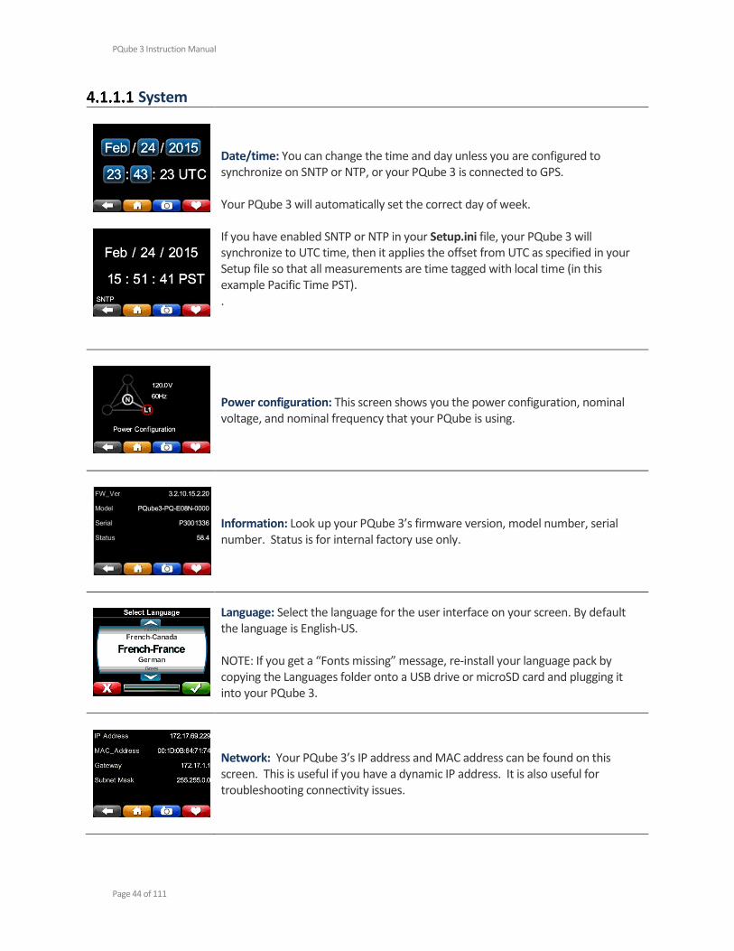
System
Date/time: You can change the time and day unless you are configured to synchronize on SNTP or NTP, or your PQube 3 is connected to GPS. Your PQube 3 will automatically set the correct day of week. If you have enabled SNTP or NTP in your Setup.ini file, your PQube 3 will synchronize to UTC time, then it applies the offset from UTC as specified in your Setup file so that all measurements are time tagged with local time (in this example Pacific Time PST). .
Power configuration: This screen shows you the power configuration, nominal voltage, and nominal frequency that your PQube is using.
Information: Look up your PQube 3’s firmware version, model number, serial number. Status is for internal factory use only.
Language: Select the language for the user interface on your screen. By default the language is English-US. NOTE: If you get a “Fonts missing” message, re-install your language pack by copying the Languages folder onto a USB drive or microSD card and plugging it into your PQube 3.
Network: Your PQube 3’s IP address and MAC address can be found on this screen. This is useful if you have a dynamic IP address. It is also useful for troubleshooting connectivity issues.
PQube 3 Instruction Manual
Page 45 of 111
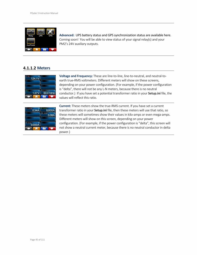
Advanced: UPS battery status and GPS synchronization status are available here. Coming soon! You will be able to view status of your signal relay(s) and your PM2’s 24V auxiliary outputs.
Meters
Voltage and Frequency: These are line-to-line, line-to-neutral, and neutral-to-earth true-RMS voltmeters. Different meters will show on these screens, depending on your power configuration. (For example, if the power configuration is “delta”, there will not be any L-N meters, because there is no neutral conductor.) If you have set a potential transformer ratio in your Setup.ini file, the values will reflect this ratio.
Current: These meters show the true-RMS current. If you have set a current transformer ratio in your Setup.ini file, then these meters will use that ratio, so these meters will sometimes show their values in kilo-amps or even mega-amps. Different meters will show on this screen, depending on your power configuration. (For example, if the power configuration is “delta”, this screen will not show a neutral current meter, because there is no neutral conductor in delta power.)

PQube 3 Instruction Manual
Page 46 of 111
Power: These are the true power, apparent power, and reactive power readings, and they correctly handle harmonics (distorted voltages and distorted currents). If you have set a current transformer ratio and/or potential transformer ratio in your Setup.ini file, then these meters will reflect those ratios.
Peaks : These meters show the peak values on Load , Watts and VARS reached .
The Peak accumulators can be reset by pressing the Reset button
PQube 3 Instruction Manual
Page 47 of 111
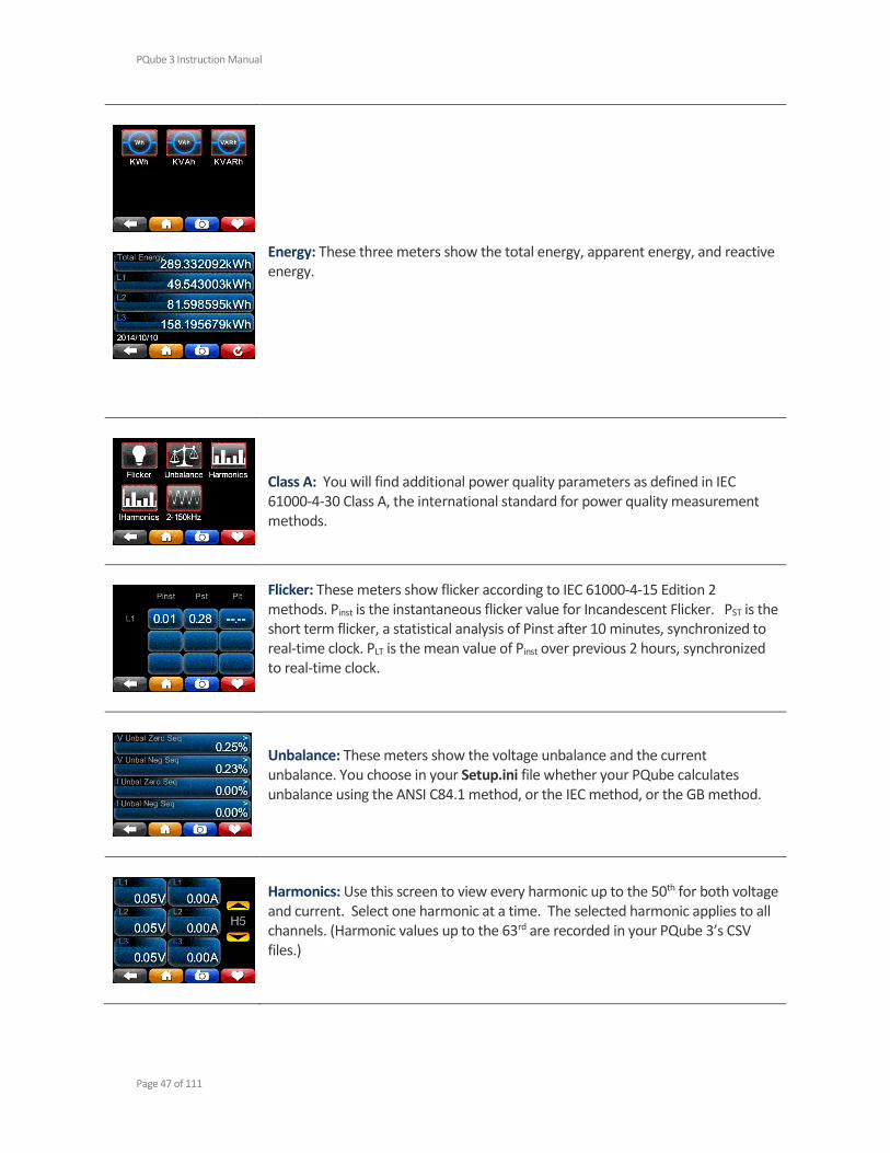
Energy: These three meters show the total energy, apparent energy, and reactive energy.
Class A: You will find additional power quality parameters as defined in IEC 61000-4-30 Class A, the international standard for power quality measurement methods.
Flicker: These meters show flicker according to IEC 61000-4-15 Edition 2 methods. Pinst is the instantaneous flicker value for Incandescent Flicker. PST is the short term flicker, a statistical analysis of Pinst after 10 minutes, synchronized to real-time clock. PLT is the mean value of Pinst over previous 2 hours, synchronized to real-time clock.
Unbalance: These meters show the voltage unbalance and the current unbalance. You choose in your Setup.ini file whether your PQube calculates unbalance using the ANSI C84.1 method, or the IEC method, or the GB method.
Harmonics: Use this screen to view every harmonic up to the 50th for both voltage and current. Select one harmonic at a time. The selected harmonic applies to all channels. (Harmonic values up to the 63rd are recorded in your PQube 3’s CSV files.)
PQube 3 Instruction Manual
Page 48 of 111
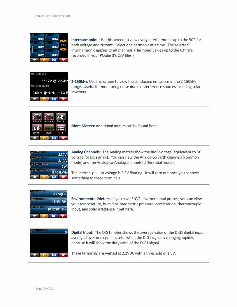
Interharmonics: Use this screen to view every interharmonic up to the 50th for both voltage and current. Select one harmonic at a time. The selected interharmonic applies to all channels. (Harmonic values up to the 63rd are recorded in your PQube 3’s CSV files.)
2-150kHz: Use this screen to view the conducted emissions in the 2-150kHz range. Useful for monitoring noise due to interference sources including solar inverters.
More Meters: Additional meters can be found here.
Analog Channels: The Analog meters show the RMS voltage (equivalent to DC voltage for DC signals). You can view the Analog-to-Earth channels (common mode) and the Analog-to-Analog channels (differential mode). The internal pull-up voltage is 2.5V floating. It will zero out once you connect something to these terminals.
Environmental Meters: If you have ENV2 environmental probes, you can view your temperature, humidity, barometric pressure, acceleration, thermocouple input, and solar irradiance input here.
Digital Input: The DIG1 meter shows the average value of the DIG1 digital input averaged over one cycle – useful when the DIG1 signal is changing rapidly, because it will show the duty cycle of the DIG1 signal. These terminals are wetted at 2.2VDC with a threshold of 1.5V.
PQube 3 Instruction Manual
Page 49 of 111
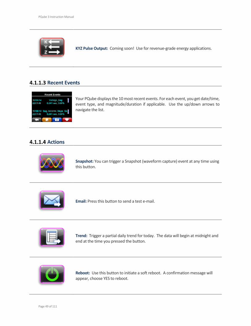
KYZ Pulse Output: Coming soon! Use for revenue-grade energy applications.
Recent Events
Your PQube displays the 10 most recent events. For each event, you get date/time, event type, and magnitude/duration if applicable. Use the up/down arrows to navigate the list.
Actions
Snapshot: You can trigger a Snapshot (waveform capture) event at any time using this button.
Email: Press this button to send a test e-mail.
Trend: Trigger a partial daily trend for today. The data will begin at midnight and end at the time you pressed the button.
Reboot: Use this button to initiate a soft reboot. A confirmation message will appear, choose YES to reboot.

PQube 3 Instruction Manual
Page 50 of 111
Eject: Use this button to safely remove any flash media (USB or microSD) that you have plugged into your PQube 3.
Clear: Use this button to clear all events and trends from your PQube 3.
Save Files
USB: Use this button to save your recorded data to the USB drive. For now you are able to copy all of the data to the drive, but in a future update you will be able to choose data only from today, this week, or this month as well.
SD: Coming soon! You will be able to use this button to copy data to the removable microSD card in a future firmware update.
PQube 3 Instruction Manual
Page 51 of 111
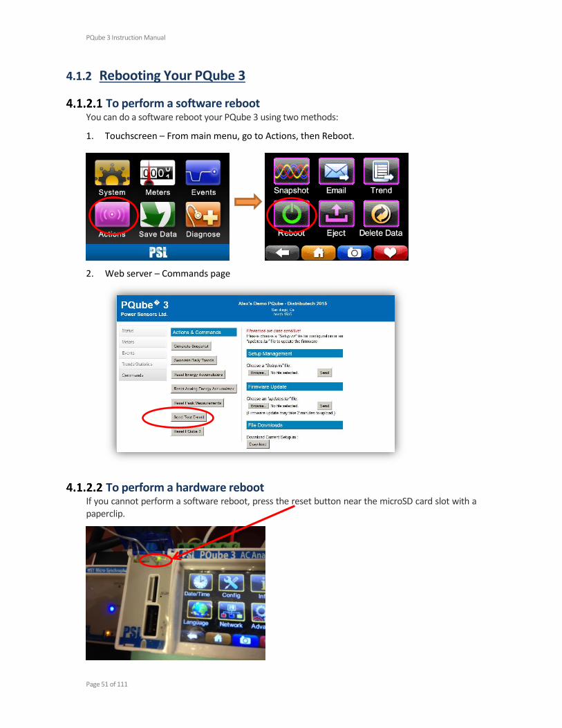
4.1.2 Rebooting Your PQube 3
To perform a software reboot You can do a software reboot your PQube 3 using two methods:
1. Touchscreen – From main menu, go to Actions, then Reboot.
2. Web server – Commands page
To perform a hardware reboot If you cannot perform a software reboot, press the reset button near the microSD card slot with a paperclip.

PQube 3 Instruction Manual
Page 52 of 111
4.1.3 Ejecting your USB thumb drive or microSD card
You can insert a USB thumb drive or microSD card into your PQube 3. Your PQube 3 will automatically detect it.
To remove the USB drive or microSD card, go to the Actions screen and press the Eject button. After the progress bar is complete, you can remove the drive from your PQube 3.
PQube 3 Instruction Manual
Page 53 of 111
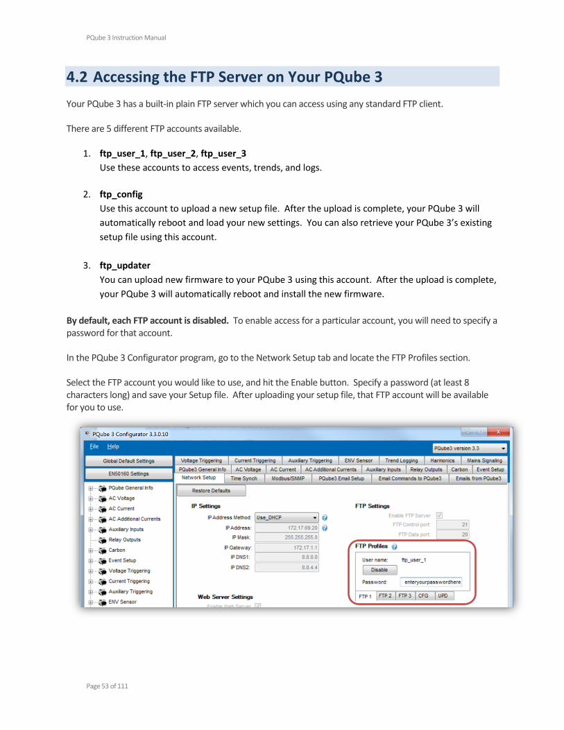
4.2 Accessing the FTP Server on Your PQube 3
Your PQube 3 has a built-in plain FTP server which you can access using any standard FTP client. There are 5 different FTP accounts available.
1. ftp_user_1, ftp_user_2, ftp_user_3
Use these accounts to access events, trends, and logs.
2. ftp_config
Use this account to upload a new setup file. After the upload is complete, your PQube 3 will
automatically reboot and load your new settings. You can also retrieve your PQube 3’s existing
setup file using this account.
3. ftp_updater
You can upload new firmware to your PQube 3 using this account. After the upload is complete,
your PQube 3 will automatically reboot and install the new firmware.
By default, each FTP account is disabled. To enable access for a particular account, you will need to specify a password for that account. In the PQube 3 Configurator program, go to the Network Setup tab and locate the FTP Profiles section. Select the FTP account you would like to use, and hit the Enable button. Specify a password (at least 8 characters long) and save your Setup file. After uploading your setup file, that FTP account will be available for you to use.
PQube 3 Instruction Manual
Page 54 of 111
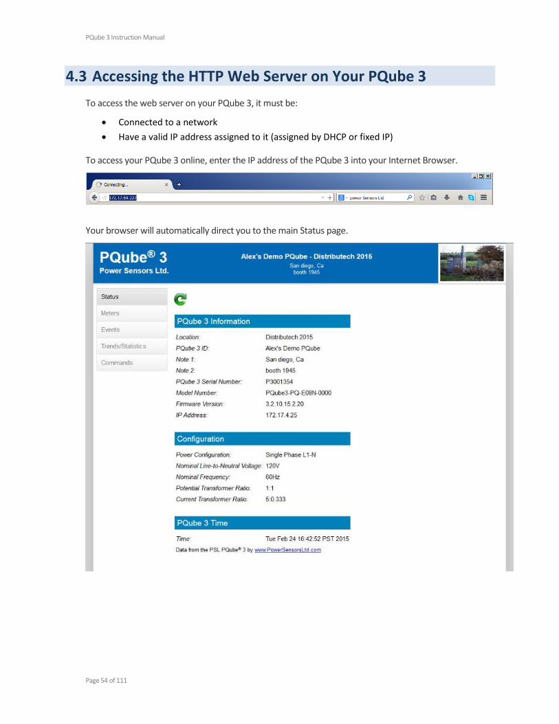
4.3 Accessing the HTTP Web Server on Your PQube 3
To access the web server on your PQube 3, it must be:
Connected to a network
Have a valid IP address assigned to it (assigned by DHCP or fixed IP)
To access your PQube 3 online, enter the IP address of the PQube 3 into your Internet Browser.
Your browser will automatically direct you to the main Status page.
PQube 3 Instruction Manual
Page 55 of 111
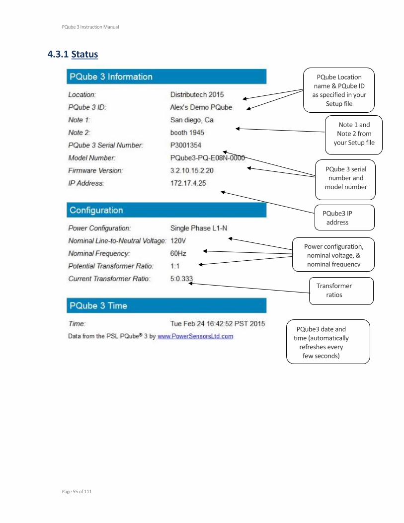
4.3.1 Status
PQube3 date and time (automatically
refreshes every few seconds)
PQube3 IP address
PQube Location name & PQube ID as specified in your
Setup file
Note 1 and Note 2 from
your Setup file
PQube 3 serial number and
model number
Transformer ratios
Power configuration, nominal voltage, & nominal frequency
PQube 3 Instruction Manual
Page 56 of 111
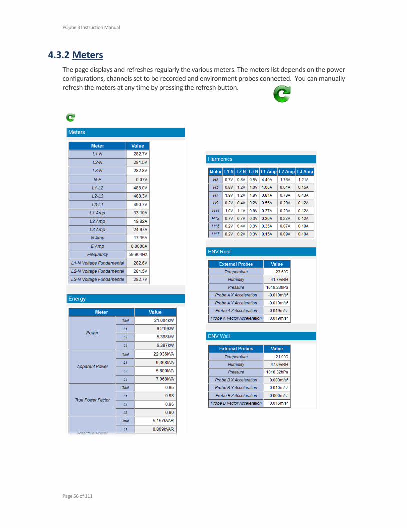
4.3.2 Meters
The page displays and refreshes regularly the various meters. The meters list depends on the power configurations, channels set to be recorded and environment probes connected. You can manually refresh the meters at any time by pressing the refresh button.

PQube 3 Instruction Manual
Page 57 of 111
4.3.3 Events
The page displays the list of events organized around years, and months. Clicking the links provides access to more details down the data files and graphs for each of the events. You can refresh the events listing at any time by pressing the refresh button.
Links to the details of the events for a
given month.
Links to the data files and
waveform and RMS graphs for
each event

PQube 3 Instruction Manual
Page 58 of 111
4.3.4 Trends
You can refresh the trends listing at any time by pressing the refresh button.
Links to daily/weekly/ monthly trend files
Clicking on “File List” brings the
list of daily trends for each
day
Clicking on “File List” brings the daily trend files

PQube 3 Instruction Manual
Page 59 of 111
4.3.5 Commands
From the Commands page, you can trigger snapshots or daily trends, send test emails, or reset your PQube 3. You can also apply new setup files and firmware updates from here.
You can restrict access to this page by specifying a username and password for the HTTP Administrator in your setup file.
PQube 3 Instruction Manual
Page 60 of 111
4.4 PQube 3 Email Setup
You can configure your PQube 3 to send you an email whenever new data is available, or if there is any system activity. You can also execute commands on your PQube 3 by sending emails with the command name in the subject line. All you need to do is provide a dedicated email account for your PQube 3, and define a list of email recipients.
4.4.1 Setting up an email account for your PQube 3
Your PQube 3 needs its own email account. All emails from your PQube will be sent from this email address, and all email commands from you will be sent to this email address.
PSL provides a free email account for every PQube 3. Use the PQube 3 Configurator to automatically set up the pqube.com email account for your PQube 3.
If you don’t want to use your free pqube.com email account, our PQube 3 supports accounts from common email providers such as Yahoo! and Google. At this time, Microsoft Exchange Server is not supported.
If you want to use an email account using your own company’s domain, go to the PQube3 Email Setup section of your Setup file and enter the following information below. You will need to obtain this information from your IT or System Administrator.
Please tell your System Administrator that:
Your PQube 3 is a standard e-mail client.
For outgoing mail, your PQube supports plain-text authentication, SSL, Cram-MD5, or MD5-Digest login protocols.
For incoming mail, your PQube supports plain-text authentication, SSL, Cram-MD5, MD5-Digest, USER-PASS, or APOP login protocols.
Ask your System Administrator to set up an e-mail account, and get the following information from them:
SMTP Server: __________________________ Port: _______ Auth method: _______
POP Server: ___________________________ Port: _______ Auth method: _______
PQube e-mail address: _________________________
PQube e-mail user name: _______________________
PQube e-mail password: ________________________
Use this information to fill in your Setup.ini file in the PQube3 Email Setup tab.
WARNING
Do not assign your personal email address to your PQube 3. Your PQube 3 must have its own dedicated email address that it can use to send and receive email. Power Sensors Ltd. is not responsible for any loss of data.

PQube 3 Instruction Manual
Page 61 of 111
4.4.2 Getting event notifications and trend data from your PQube 3 by email
To begin with, choose what type of data you would like to receive from your PQube 3. You can choose Event data, Trend data, Reset emails, or all email types. If applicable, your PQube 3 will include output files as attachments.
You need to specify who will be receiving these emails. You can specify up to five Email_To recipients, five Email_CC_To recipients, and five Email_BCC_To recipients.
For events, you can also set up to nine total recipients for event summary emails. This is useful for people who only need quick notifications that an event occurred, without requiring detailed waveforms and graphs.
PQube 3 Instruction Manual
Page 62 of 111
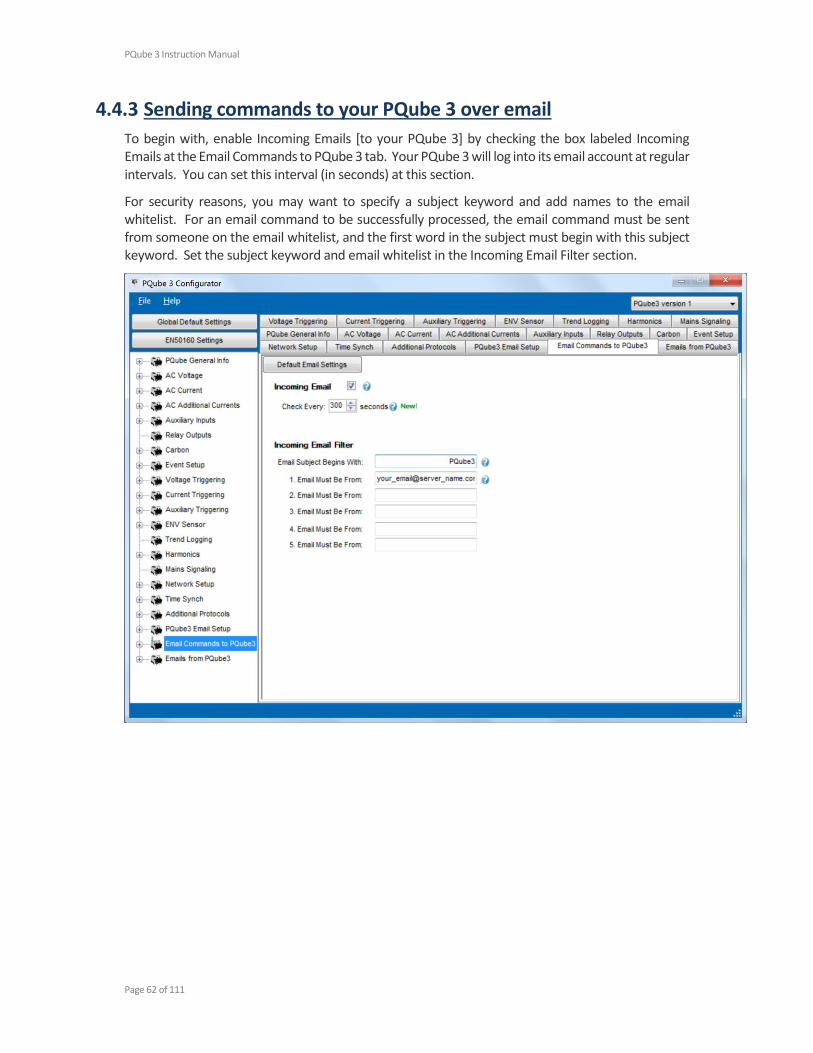
4.4.3 Sending commands to your PQube 3 over email
To begin with, enable Incoming Emails [to your PQube 3] by checking the box labeled Incoming Emails at the Email Commands to PQube 3 tab. Your PQube 3 will log into its email account at regular intervals. You can set this interval (in seconds) at this section.
For security reasons, you may want to specify a subject keyword and add names to the email whitelist. For an email command to be successfully processed, the email command must be sent from someone on the email whitelist, and the first word in the subject must begin with this subject keyword. Set the subject keyword and email whitelist in the Incoming Email Filter section.

PQube 3 Instruction Manual
Page 63 of 111
List of Email Commands Command (case sensitive) Description
New Setup File Your new setup file must be named Setup.ini, and must be attached to the e-mail.
Your PQube 3 will send you two reply e-mails: one when it receives the new setup file, and another when the new setup file has been successfully installed.
Firmware Update Obtain a firmware update from www.PowerStandards.com and attach it to the email. If your PQube 3 receives a valid firmware update, it will reset and perform the update.
Reset PQube Resets PQube 3 upon receipt of email. This is useful when loading a new setup file or firmware via FTP.
Send Logs You can ask your PQube 3 to send you its log files via e-mail. The log files can help diagnose PQube setup problems, and they show the complete history of your PQube.
For faster technical support, please include these files when contacting our technical support department.
Send Setup Retrieve the existing setup file from your PQube 3.
Generate Snapshot Takes a waveform recording of your power.
Generate Daily Trends Generates the Daily Trends for today. The data ranges from Midnight to the moment the email request is received.
Reset Energy Accumulators Resets all accumulated energy values.
Reset Peak Measurements Resets all peak values for the Peak Amps, Peak Demand, and Peak VA meters.
Reset Analog Energy Accumulator* Resets accumulated Analog energy values.
Set Harmonic of Interest to #* Sets the Harmonic of Interest on the PQube display and Web Server. Replace # with the desired harmonic order of interest (1-50).
* = coming soon

PQube 3 Instruction Manual
Page 64 of 111
4.5 Modbus Setup
4.5.1 Basics
Your PQube 3 has a built-in Modbus-over-TCP server that you can use to read meters and determine when new event or trend recordings are available.
You can set the following parameters in your PQube 3’s setup.ini file:
Modbus Base Address: The global base address from which all registers are offset. Default is 0x7000.
Modbus Query Port: The TCP/IP port on which the Modbus server listens. Default is port 502.
Modbus Byte Order: Data values spanning multiple registers (such as floats) can be reported in BIG ENDIAN or LITTLE ENDIAN. Default is BIG_ENDIAN.
Modbus Slave ID: The PQube can be assigned a slave ID required in queries. Default value is 0x1.
4.5.2 Scan rates, client load, and limitations
The Modbus protocol limits single query register results to 125 registers per scan. A scan of sets of registers can occur at client, PQube, and network speeds. However, the PQube3 modbus register values only update at the internal meter update rate, which is around 2 Hz. Therefore, high rate scans of values in sets of registers will only change returned at 2 Hz, even if scanning at higher rates is supported.
The PQube supports multi-client, multi-session modbus, with conventional limit to 10 clients at a time. This value can be changed internally in software.
4.5.3 Supported Clients
The PQube3 supports the PSL Modbus Client, third party free Modbus clients, or any software conforming to the Modbus protocol (such as groov).
4.5.4 Register List (refer to Modbus Reference Manual)
Refer to the PQube 3 Modbus Reference Manual for the register tables.
4.5.5 Downloads
The PSL Modbus Client and PQube 3 Modbus Reference Manual are available for download at:
http://www.powersensorsltd.com/PQube3_Reg.php

PQube 3 Instruction Manual
Page 65 of 111
Purple = Seeking phase lock (still waiting to record data)
or
Green = Locked onto power configuration (recording has started)
Green = Ethernet Link
4.6 LED Definitions
4.6.1 PQube 3
Yellow = Ethernet Activity
Red = Disk activity
Green = USB activity
Yellow = Supercap discharging
Green = Supercap charging
Green = Ethernet Link
Yellow = Ethernet Activity
Blue = Powered from PoE

PQube 3 Instruction Manual
Page 66 of 111
4.6.2 MS1
4.6.3 PM1/PM2
Green = PPS pulse (blinks at 1Hz)
Blue = GPS power ON
Orange = Cross Trigger (future extension)
Green = AC input power detected
Blue = 24V auxiliary outputs are ON
(PM2 only)

PQube 3 Instruction Manual
Page 67 of 111
4.6.4 UPS1
4.6.5 ENV1/ENV2
Green blinking at 1Hz = Normal operation
Green blinking at 2Hz = Acceleration event in progress (ENV2 only)
Red blinking = Powered, but not communicating with PQube 3
Red solid = Transmitting event data to PQube 3
Green = Battery is discharging
Blue = Battery is charging

PQube 3 Instruction Manual
Page 68 of 111
4.7 Upgrading the Firmware on your PQube 3
The process to perform firmware updates is similar to applying new setup files.
To apply firmware updates locally Copy updates.tar onto a USB thumb drive or microSD card, then insert it into your PQube 3. The update process will begin automatically and the device will restart after several minutes. PSL provides the firmware updates as compressed tar files. Make sure the file name is updates.tar when you copy it to your flash drive.
After successful update and reboot, your PQube 3 automatically renames updates.tar to updatesYYYYMMDDHHMMSS.tar so it does not repeatedly initiate the firmware update process. Look at the filename to verify that your PQube 3 successfully processed the firmware update.
To apply firmware updates over the web You can also update the firmware through the Web page <Command> by selecting the file with the [browse] button, and then pressing [send]. Although the browser states that the file is sent, it may take up to 15 minutes for the PQube 3 to update its firmware and reboot, depending on the firmware file size and network connection speeds.
Web page for sending a configuration or updating the firmware
PQube 3 Instruction Manual
Page 69 of 111
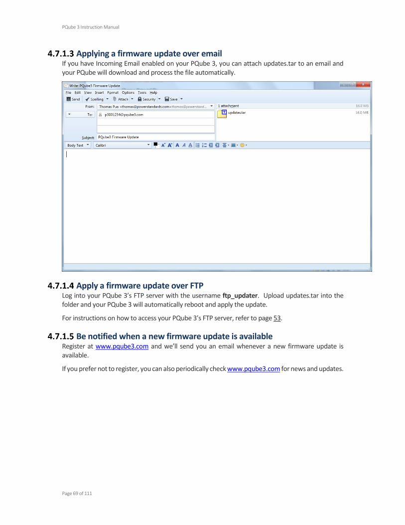
Applying a firmware update over email If you have Incoming Email enabled on your PQube 3, you can attach updates.tar to an email and your PQube will download and process the file automatically.
Apply a firmware update over FTP Log into your PQube 3’s FTP server with the username ftp_updater. Upload updates.tar into the folder and your PQube 3 will automatically reboot and apply the update.
For instructions on how to access your PQube 3’s FTP server, refer to page 53.
Be notified when a new firmware update is available Register at www.pqube3.com and we’ll send you an email whenever a new firmware update is available.
If you prefer not to register, you can also periodically check www.pqube3.com for news and updates.
PQube 3 Instruction Manual
Page 70 of 111
4.8 Maintenance
4.8.1 Turning Off Your PQube 3
Your PQube 3 is designed to be a permanently installed monitor. It does not have an on/off switch because it is designed to run continuously. If you need to turn off your PQube 3, remove your PQube 3’s instrument power (either the power screw terminal block on your PQube 3, the optional PM1 Power Supply Module, or PoE). Your PQube 3 will automatically initiate graceful shutdown to prevent any write damage to flash.
If you have a UPS module installed, your PQube 3 will continue to run for the allotted amount of time. To immediately power down the device while on backup power from the UPS module, go to the Actions screen and press Reboot. With no permanent power source available, your PQube 3 will simply turn off.
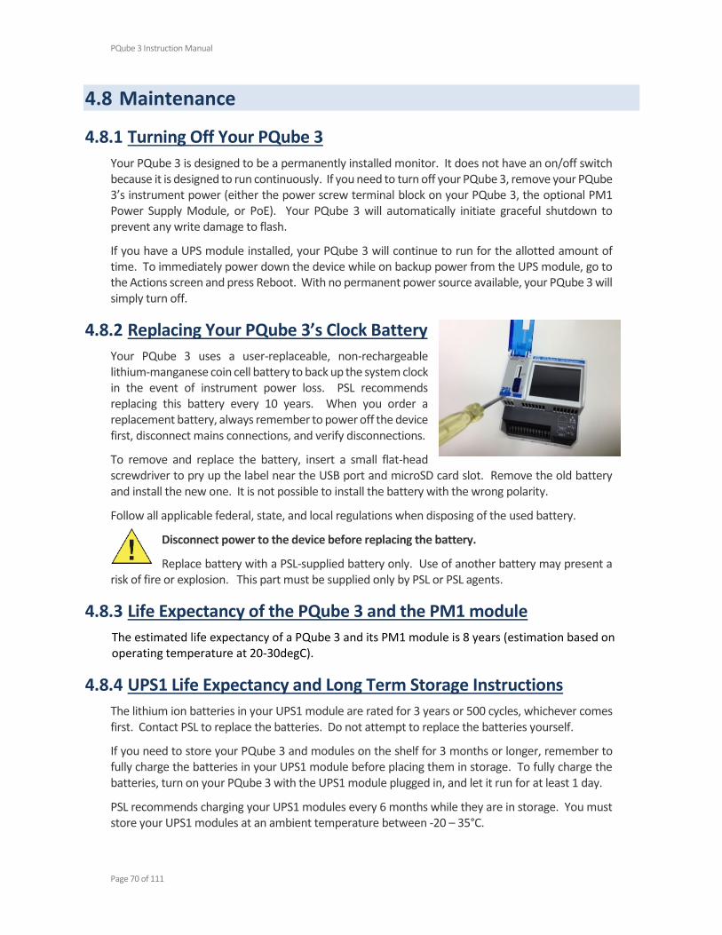
4.8.2 Replacing Your PQube 3’s Clock Battery
Your PQube 3 uses a user-replaceable, non-rechargeable lithium-manganese coin cell battery to back up the system clock in the event of instrument power loss. PSL recommends replacing this battery every 10 years. When you order a replacement battery, always remember to power off the device first, disconnect mains connections, and verify disconnections.
To remove and replace the battery, insert a small flat-head screwdriver to pry up the label near the USB port and microSD card slot. Remove the old battery and install the new one. It is not possible to install the battery with the wrong polarity.
Follow all applicable federal, state, and local regulations when disposing of the used battery.
Disconnect power to the device before replacing the battery.
Replace battery with a PSL-supplied battery only. Use of another battery may present a risk of fire or explosion. This part must be supplied only by PSL or PSL agents.
4.8.3 Life Expectancy of the PQube 3 and the PM1 module
The estimated life expectancy of a PQube 3 and its PM1 module is 8 years (estimation based on operating temperature at 20-30degC).
4.8.4 UPS1 Life Expectancy and Long Term Storage Instructions
The lithium ion batteries in your UPS1 module are rated for 3 years or 500 cycles, whichever comes first. Contact PSL to replace the batteries. Do not attempt to replace the batteries yourself.
If you need to store your PQube 3 and modules on the shelf for 3 months or longer, remember to fully charge the batteries in your UPS1 module before placing them in storage. To fully charge the batteries, turn on your PQube 3 with the UPS1 module plugged in, and let it run for at least 1 day.
PSL recommends charging your UPS1 modules every 6 months while they are in storage. You must store your UPS1 modules at an ambient temperature between -20 – 35°C.
PQube 3 Instruction Manual
Page 71 of 111
4.8.5 Cleaning Instructions
If necessary, wipe the accessible parts of your PQube 3 with a slightly damp cloth while it is powered off. Do not use abrasives or chemical cleaners and do not clean your PQube 3 while it is powered on.
4.8.6 Reasons for reset
If your PQube 3 is configured to email you whenever system activity occurs, it will notify you whenever it has reset.
Reset reasons Description
System Timeout reached One of the processes of the PQube is stuck or takes too much time to complete compared to expected
Setup File Sent A new setup.ini file has been sent
Update Required Restart A firmware update was sent and PQube3 restarted
User Triggered Display Reboot The touch screen <Action> <reboot> has been used
Web Command Reboot A reset has been requested from the web command page
Battery Timeout Reached. Battery Percentage: XX%
The PQube has shut down after reaching the configured autonomy of battery (see PQube configuration).
Unspecified Reason No reason identified (default)
4.9 Calibration Information for Your PQube 3
Every PQube 3 is calibrated and traced to NIST at the factory. You can download a free NIST trace certificate that contains the specific calibration information for your PQube 3 by entering your PQube 3’s serial number at http://www.powersensorsltd.com/CalibCerts3.php .
4.10 PQube 3 technical specifications
The PQube 3 Technical specifications are available for download at:
http://www.powersensorsltd.com/PQube3.php
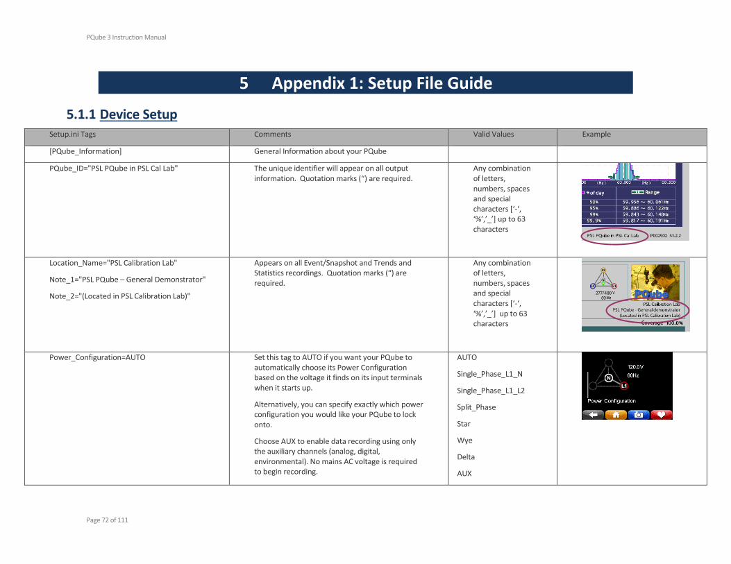
PQube 3 Instruction Manual
Page 72 of 111
5 Appendix 1: Setup File Guide
5.1.1 Device Setup Setup.ini Tags Comments Valid Values Example
[PQube_Information] General Information about your PQube
PQube_ID="PSL PQube in PSL Cal Lab" The unique identifier will appear on all output information. Quotation marks (“) are required.
Any combination of letters, numbers, spaces and special characters [‘-‘, ‘%’,’_’] up to 63 characters
Location_Name="PSL Calibration Lab"
Note_1="PSL PQube – General Demonstrator"
Note_2="(Located in PSL Calibration Lab)"
Appears on all Event/Snapshot and Trends and Statistics recordings. Quotation marks (“) are required.
Any combination of letters, numbers, spaces and special characters [‘-‘, ‘%’,’_’] up to 63 characters
Power_Configuration=AUTO Set this tag to AUTO if you want your PQube to automatically choose its Power Configuration based on the voltage it finds on its input terminals when it starts up.
Alternatively, you can specify exactly which power configuration you would like your PQube to lock onto.
Choose AUX to enable data recording using only the auxiliary channels (analog, digital, environmental). No mains AC voltage is required to begin recording.
AUTO
Single_Phase_L1_N
Single_Phase_L1_L2
Split_Phase
Star
Wye
Delta
AUX

PQube 3 Instruction Manual
Page 73 of 111
Time_Zone=PST Enter the time zone where your PQube is located. UTC sometimes called Greenwich Mean Time (GMT)
Any combination of 3 or 4 capital letters
Offset_From_UTC_In_Hours= Choose the number of hours your PQube should add or subtract from UTC to calculate your local time, if you are using SNTP protocol to set your PQube’s time.
For example, the offset from UTC in Pacific Standard Time is -8.
Your PQube will automatically apply this offset after synchronizing to an external time source like a time server or GPS receiver.
-24 to +24
UPS_Time_In_Minutes= Choose the number of minutes your PQube UPS1 battery autonomy. This allows to program sufficient back up power for several outages in short sequence..
By default the autonomy is 3 minutes.
3 to 30
Fan_Temperature_Threshold= Your PQube 3's internal fan turns on when the CPU temperature exceeds this threshold.
By default, the temperature threshold for the internal fan is 60.
40-60
PQube_Primary_Language=
PQube_Secondary_Language=
Choose the language amongst a list of 30+ languages.
Default is English-American.
Arabic-Standard
Cambodian
Chinese-Simplified
Chinese-Traditional
Croatian
Czech
Danish
Dutch
Magyar
Malaysian-Bahasa
Norwegian
Persian
Polish
Portuguese-Brazil
Portuguese-Portugal
Romanian
Russian

PQube 3 Instruction Manual
Page 74 of 111
English-American
English-British
English-India
Finish
French-Canada
French-France
German
Greek
Hebrew
Hindi-Devenagari
Indonesian-Bahasa
Italian
Japanese
Korean
Serbian
Slovakian
Slovenian
Spanish-LatinAmerica
Spanish-Mexico
Spanish-Spain
Swedish
Tagalog
Thai
Turkish
Ukrainian
Vietnamese
[Nominal_Inputs]
Nominal_Phase_To_Phase_Voltage=AUTO
Nominal_Phase_To_Neutral_Voltage=AUTO
By default, your PQube will automatically detect your nominal voltage if it is one of the following:
Phase-Neutral 69V, 120V, 230V, 277V, 350V, or 400V
Phase-Phase 69V, 100V, 200V, 208V, 240V, 400V, 480V, 600V, or 690V
If using Potential Transformers, you will need to enter the actual primary voltage.
AUTO
Any number between 50 to 400 for Phase-Neutral
Any number between 50 to 690 for Phase-Phase
Nominal_Phase_To_Phase_Voltage=110
If using a 1000:1 Potential Transformer:
Nominal_Phase_To_Phase_Voltage=110000
Nominal_Frequency=AUTO By default, your PQube will automatically detect your nominal frequency if it is 50, 60, or 400 Hz.
AUTO
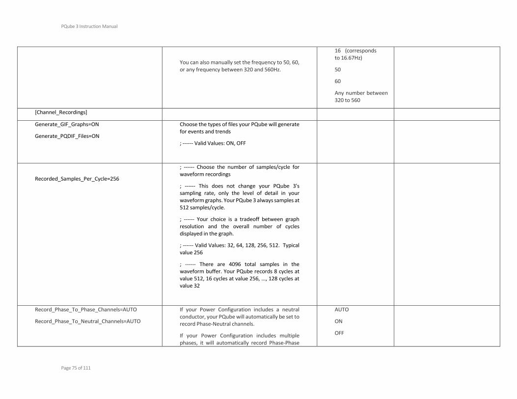
PQube 3 Instruction Manual
Page 75 of 111
You can also manually set the frequency to 50, 60, or any frequency between 320 and 560Hz.
16 (corresponds to 16.67Hz)
50
60
Any number between 320 to 560
[Channel_Recordings]
Generate_GIF_Graphs=ON
Generate_PQDIF_Files=ON
Choose the types of files your PQube will generate for events and trends
; ------ Valid Values: ON, OFF
Recorded_Samples_Per_Cycle=256
; ------ Choose the number of samples/cycle for waveform recordings
; ------ This does not change your PQube 3's sampling rate, only the level of detail in your waveform graphs. Your PQube 3 always samples at 512 samples/cycle.
; ------ Your choice is a tradeoff between graph resolution and the overall number of cycles displayed in the graph.
; ------ Valid Values: 32, 64, 128, 256, 512. Typical value 256
; ------ There are 4096 total samples in the waveform buffer. Your PQube records 8 cycles at value 512, 16 cycles at value 256, ..., 128 cycles at value 32
Record_Phase_To_Phase_Channels=AUTO
Record_Phase_To_Neutral_Channels=AUTO
If your Power Configuration includes a neutral conductor, your PQube will automatically be set to record Phase-Neutral channels.
If your Power Configuration includes multiple phases, it will automatically record Phase-Phase
AUTO
ON
OFF

PQube 3 Instruction Manual
Page 76 of 111
channels in the Meters (on display, webpage, and Modbus), GIFs, and CSV files.
Record_Current_I1_I2_I3_Channel=OFF
Record_Current_I4_Channel=AUTO
Record_Current_I5_Channel=AUTO
Record_Current_I6_Channel=OFF
Record_Current_I7_Channel=OFF
Record_Current_I8_Channel=OFF
New tags in PQube 3. You can choose to show or hide any or all of the 8 current channels.
AUTO
ON
OFF
Record_AN1_E_Channel=AUTO
Record_AN2_E_Channel=AUTO
Record_AN1_AN2_Differential_Channel=AUTO
Record_AN3_E_Channel=AUTO
Record_AN4_E_Channel=AUTO
Record_AN3_AN4_Differential_Channel=AUTO
Record_DIG1_Channel=AUTO
The AUTO setting records the Analog and Digital Input channels if Events are enabled on these channels.
AUTO
ON
OFF
Record_Flicker=ON
Record_Voltage_THD=ON
Record_Current_TDD=ON
Record_Voltage_Unbalance=ON
Record_Current_Unbalance=ON
Toggles recordings for the selected parameters. When set to ON, the selected parameter will show up in the Meters (display, webpage, and Modbus), as well as the GIF and CSV files.
You might want to toggle some of these parameters OFF in order to reduce file size and bandwidth.
ON
OFF
[Measurement_Setup]
Peak_Demand_Interval_In_Minutes=15 ; ------ Define peak demand - peak Watt and VA - 1 cycle and min are included
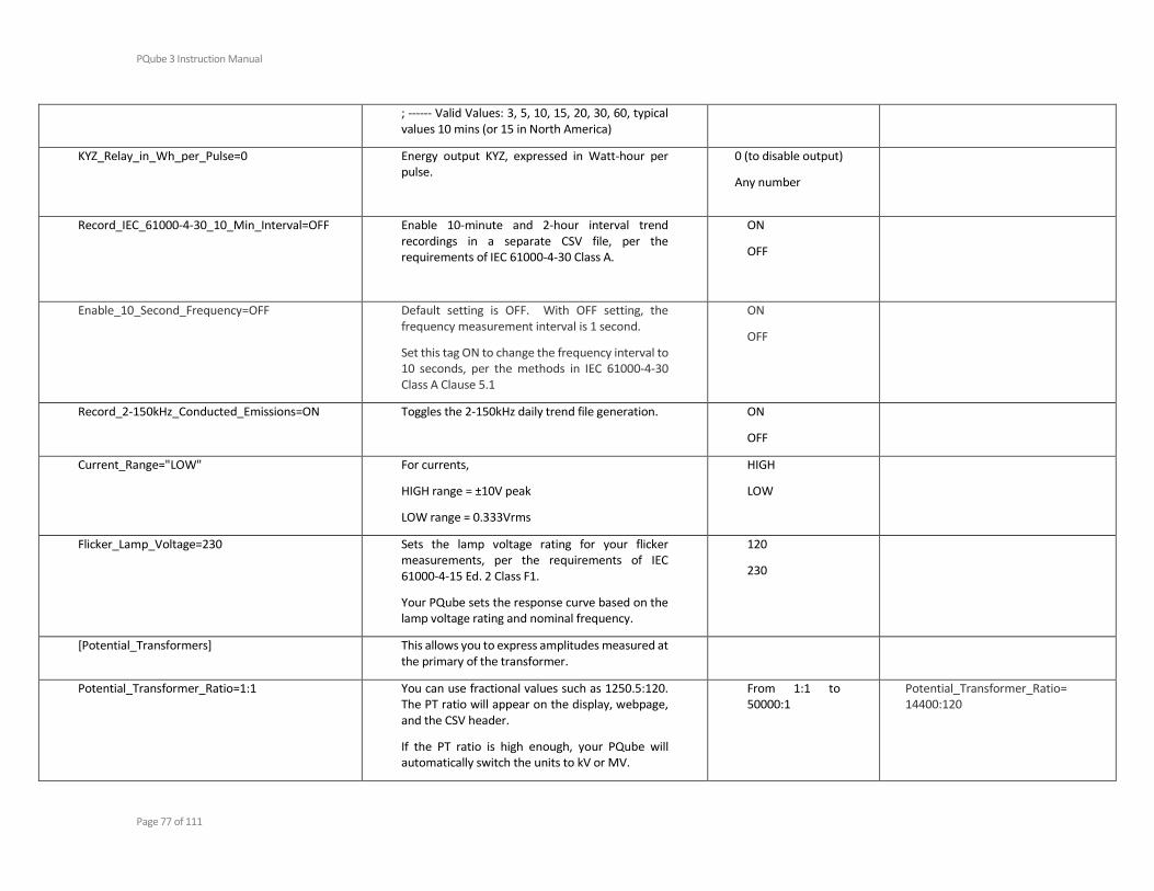
PQube 3 Instruction Manual
Page 77 of 111
; ------ Valid Values: 3, 5, 10, 15, 20, 30, 60, typical values 10 mins (or 15 in North America)
KYZ_Relay_in_Wh_per_Pulse=0 Energy output KYZ, expressed in Watt-hour per pulse.
0 (to disable output)
Any number
Record_IEC_61000-4-30_10_Min_Interval=OFF Enable 10-minute and 2-hour interval trend recordings in a separate CSV file, per the requirements of IEC 61000-4-30 Class A.
ON
OFF
Enable_10_Second_Frequency=OFF
Default setting is OFF. With OFF setting, the frequency measurement interval is 1 second.
Set this tag ON to change the frequency interval to 10 seconds, per the methods in IEC 61000-4-30 Class A Clause 5.1
ON
OFF
Record_2-150kHz_Conducted_Emissions=ON Toggles the 2-150kHz daily trend file generation. ON
OFF
Current_Range="LOW" For currents,
HIGH range = ±10V peak
LOW range = 0.333Vrms
HIGH
LOW
Flicker_Lamp_Voltage=230 Sets the lamp voltage rating for your flicker measurements, per the requirements of IEC 61000-4-15 Ed. 2 Class F1.
Your PQube sets the response curve based on the lamp voltage rating and nominal frequency.
120
230
[Potential_Transformers] This allows you to express amplitudes measured at the primary of the transformer.
Potential_Transformer_Ratio=1:1 You can use fractional values such as 1250.5:120. The PT ratio will appear on the display, webpage, and the CSV header.
If the PT ratio is high enough, your PQube will automatically switch the units to kV or MV.
From 1:1 to 50000:1
Potential_Transformer_Ratio= 14400:120

PQube 3 Instruction Manual
Page 78 of 111
[Current_Transformers] Allows you to express the amplitude of currents measured at the primary of the current transformer.
Current_Transformer_Ratio=1:1
Neutral_Current_Transformer_Ratio=1:1
Earth_Current_Transformer_Ratio=1:1
Current_I6_Transformer_Ratio=1:1
Current_I7_Transformer_Ratio=1:1
Current_I8_Transformer_Ratio=1:1
When using PSL CTs with 0.333V secondary rating, the second number is the voltage.
You can use fractional values such as 100.35:0.333
If the CT ratio is high enough, your PQube will automatically switch the units to kA.
From 1:1 to 50000:1
Current_Transformer_Ratio=5:0.333
[Adjust_Phase_Connections]
Invert_Current_I1_Channel=OFF
Invert_Current_I2_Channel=OFF
Invert_Current_I3_Channel=OFF
Invert_Current_I4_Channel=OFF
Invert_Current_I5_Channel=OFF
Invert_Current_I6_Channel=OFF
Invert_Current_I7_Channel=OFF
Invert_Current_I8_Channel=OFF
Those tags are used to virtually invert cabling of current inputs (swap wires), individually for each input.
This can be useful if a wiring mistake has been made during the commissioning.
ON
OFF
[Analog_Channel_Setup]
AN1xAN2_Energy_Mode=OFF
AN3xAN4_Energy_Mode=OFF
Toggle Analog Energy mode.
AN1-AN2 differential channel becomes Analog Power (AN1×AN2) and Analog Energy (AN1×AN2×Hours).
AN3-AN4 differential channel becomes Analog Power (AN3×AN4) and Analog Energy (AN3×AN4×Hours)

PQube 3 Instruction Manual
Page 79 of 111
Apply voltage to AN1 and current to AN2.
Apply voltage to AN3 and current to AN4.
AN1_E_Channel_Ratio=1:1
AN2_E_Channel_Ratio=1:1
AN3_E_Channel_Ratio=1:1
AN4_E_Channel_Ratio=1:1
You can use fractional values. From 1:1 to 10000:1
AN1_E_Range="HIGH"
AN2_E_Range="HIGH"
AN3_E_Range="HIGH"
AN4_E_Range="HIGH"
Range for ANx_E input channels.
HIGH range is (±100V Full scale)
LOW range is (±10V Full scale)
HIGH
LOW
AN1_and_AN2_Measurement_Mode=DC
AN3_and_AN4_Measurement_Mode=DC
If you are measuring an AC signal on the analog channels, set the measurement mode to AC to compute RMS (positive values only).
If you are measuring a DC signal on the analog channels, set the measurement mode to DC to compute average (positive and negative values).
AC
DC
AN1_E_Channel_Name=AN1-E
AN1_E_Channel_Unit=V
AN2_E_Channel_Name=AN2-E
AN2_E_Channel_Unit=A
AN3_E_Channel_Name=AN3-E
AN3_E_Channel_Unit=V
AN4_E_Channel_Name=AN4-E
AN4_E_Channel_Unit=A
Customize the names and units of your analog channels.
Valid names can be up to ? characters.
Valid units are:
“V”, “A”, “W”, “DEG”, “%”, “NONE”

PQube 3 Instruction Manual
Page 80 of 111
[EnviroSensor_Probe_Setup]
Probe_A_Serial_Number=
Probe_A_Channel_Name=
Probe_B_Serial_Number=
Probe_B_Channel_Name=
If these tags are left blank, Probe_A is the first detected probe, Probe_B is the second detected probe.
The environment Probe serial number format is "E" followed by 7 digits (e.g. "E3001163")
Serial Number: E300xxxx
Valid names can be up to 7 characters.
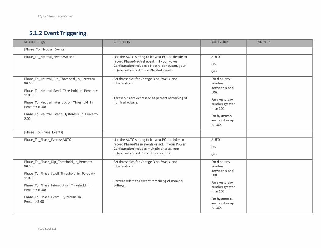
PQube 3 Instruction Manual
Page 81 of 111
5.1.2 Event Triggering Setup.ini Tags Comments Valid Values Example
[Phase_To_Neutral_Events]
Phase_To_Neutral_Events=AUTO Use the AUTO setting to let your PQube decide to record Phase-Neutral events. If your Power Configuration includes a Neutral conductor, your PQube will record Phase-Neutral events.
AUTO
ON
OFF
Phase_To_Neutral_Dip_Threshold_In_Percent= 90.00
Phase_To_Neutral_Swell_Threshold_In_Percent=110.00
Phase_To_Neutral_Interruption_Threshold_In_ Percent=10.00
Phase_To_Neutral_Event_Hysteresis_In_Percent=2.00
Set thresholds for Voltage Dips, Swells, and Interruptions.
Thresholds are expressed as percent remaining of nominal voltage.
For dips, any number between 0 and 100.
For swells, any number greater than 100.
For hysteresis, any number up to 100.
[Phase_To_Phase_Events]
Phase_To_Phase_Events=AUTO Use the AUTO setting to let your PQube infer to record Phase-Phase events or not. If your Power Configuration includes multiple phases, your PQube will record Phase-Phase events.
AUTO
ON
OFF
Phase_To_Phase_Dip_Threshold_In_Percent= 90.00
Phase_To_Phase_Swell_Threshold_In_Percent= 110.00
Phase_To_Phase_Interruption_Threshold_In_ Percent=10.00
Phase_To_Phase_Event_Hysteresis_In_ Percent=2.00
Set thresholds for Voltage Dips, Swells, and Interruptions.
Percent refers to Percent remaining of nominal voltage.
For dips, any number between 0 and 100.
For swells, any number greater than 100.
For hysteresis, any number up to 100.

PQube 3 Instruction Manual
Page 82 of 111
[Phase_To_Neutral_RVC_Events]
Phase_To_Neutral_RVC_Events=AUTO
Phase_To_Neutral_RVC_Threshold_In_Percent=2.5
Phase_To_Neutral_RVC_Hysteresis_In_Percent=1.5
AUTO
ON
OFF
[Phase_To_Phase_RVC_Events]
Phase_To_Phase_RVC_Events=AUTO
Phase_To_Phase_RVC_Threshold_In_Percent=6
Phase_To_Phase_RVC_Hysteresis_In_Percent=2
AUTO
ON
OFF
[Snapshot_Events]
Waveform_Snapshot_Interval_In_Hours=24 Trigger a waveform/RMS recording at scheduled time intervals.
OFF
3
6
24
Enable_Snapshot_Harmonics=ON Toggle Snapshot harmonic recordings ON
OFF
Waveform_Snapshot_At_Startup=OFF Set this tag to ON to take a Snapshot of your electric power every time your PQube is powered on or reset.
ON
OFF
Snapshot_Trigger_Hour=12 Define a specific time to trigger the Snapshot. Any integer between 0 and 23
To record at 5:00pm everyday: Waveform_Snapshot_Interval_In_Hours=24 Snapshot_Trigger_Hour=17
To record every 3 hours starting at 8:00am: Waveform_Snapshot_Interval_In_Hours=3 Snapshot_Trigger_Hour=8
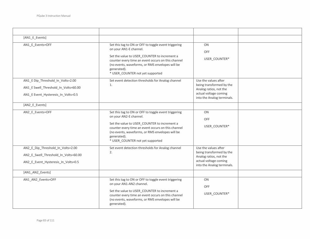
PQube 3 Instruction Manual
Page 83 of 111
[AN1_E_Events]
AN1_E_Events=OFF Set this tag to ON or OFF to toggle event triggering on your AN1-E channel.
Set the value to USER_COUNTER to increment a counter every time an event occurs on this channel (no events, waveforms, or RMS envelopes will be generated). * USER_COUNTER not yet supported
ON
OFF
USER_COUNTER*
AN1_E Dip_Threshold_In_Volts=2.00
AN1_E Swell_Threshold_In_Volts=60.00
AN1_E Event_Hysteresis_In_Volts=0.5
Set event detection thresholds for Analog channel 1.
Use the values after being transformed by the Analog ratios, not the actual voltage coming into the Analog terminals.
[AN2_E_Events]
AN2_E_Events=OFF Set this tag to ON or OFF to toggle event triggering on your AN2-E channel.
Set the value to USER_COUNTER to increment a counter every time an event occurs on this channel (no events, waveforms, or RMS envelopes will be generated). * USER_COUNTER not yet supported
ON
OFF
USER_COUNTER*
AN2_E_Dip_Threshold_In_Volts=2.00
AN2_E_Swell_Threshold_In_Volts=60.00
AN2_E_Event_Hysteresis_In_Volts=0.5
Set event detection thresholds for Analog channel 2.
Use the values after being transformed by the Analog ratios, not the actual voltage coming into the Analog terminals.
[AN1_AN2_Events]
AN1_AN2_Events=OFF Set this tag to ON or OFF to toggle event triggering on your AN1-AN2 channel.
Set the value to USER_COUNTER to increment a counter every time an event occurs on this channel (no events, waveforms, or RMS envelopes will be generated).
ON
OFF
USER_COUNTER*
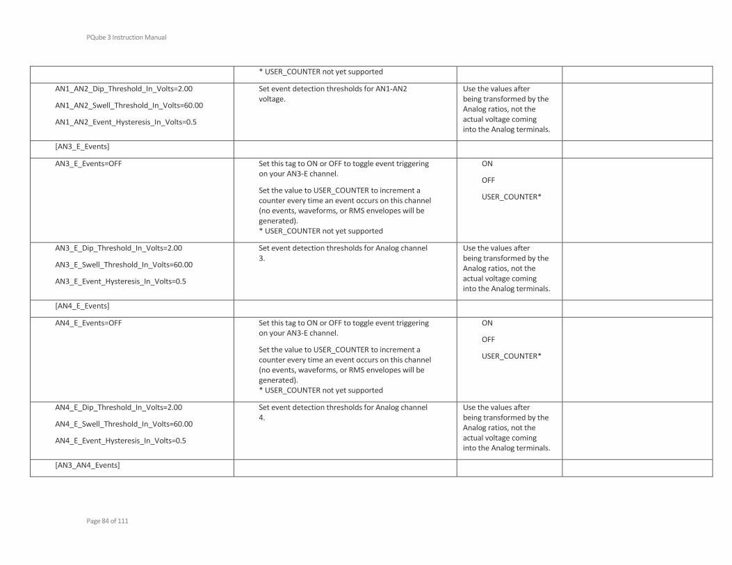
PQube 3 Instruction Manual
Page 84 of 111
* USER_COUNTER not yet supported
AN1_AN2_Dip_Threshold_In_Volts=2.00
AN1_AN2_Swell_Threshold_In_Volts=60.00
AN1_AN2_Event_Hysteresis_In_Volts=0.5
Set event detection thresholds for AN1-AN2 voltage.
Use the values after being transformed by the Analog ratios, not the actual voltage coming into the Analog terminals.
[AN3_E_Events]
AN3_E_Events=OFF Set this tag to ON or OFF to toggle event triggering on your AN3-E channel.
Set the value to USER_COUNTER to increment a counter every time an event occurs on this channel (no events, waveforms, or RMS envelopes will be generated). * USER_COUNTER not yet supported
ON
OFF
USER_COUNTER*
AN3_E_Dip_Threshold_In_Volts=2.00
AN3_E_Swell_Threshold_In_Volts=60.00
AN3_E_Event_Hysteresis_In_Volts=0.5
Set event detection thresholds for Analog channel 3.
Use the values after being transformed by the Analog ratios, not the actual voltage coming into the Analog terminals.
[AN4_E_Events]
AN4_E_Events=OFF Set this tag to ON or OFF to toggle event triggering on your AN3-E channel.
Set the value to USER_COUNTER to increment a counter every time an event occurs on this channel (no events, waveforms, or RMS envelopes will be generated). * USER_COUNTER not yet supported
ON
OFF
USER_COUNTER*
AN4_E_Dip_Threshold_In_Volts=2.00
AN4_E_Swell_Threshold_In_Volts=60.00
AN4_E_Event_Hysteresis_In_Volts=0.5
Set event detection thresholds for Analog channel 4.
Use the values after being transformed by the Analog ratios, not the actual voltage coming into the Analog terminals.
[AN3_AN4_Events]
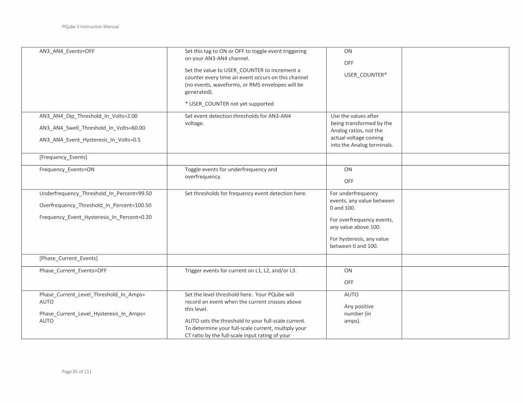
PQube 3 Instruction Manual
Page 85 of 111
AN3_AN4_Events=OFF Set this tag to ON or OFF to toggle event triggering on your AN3-AN4 channel.
Set the value to USER_COUNTER to increment a counter every time an event occurs on this channel (no events, waveforms, or RMS envelopes will be generated).
* USER_COUNTER not yet supported
ON
OFF
USER_COUNTER*
AN3_AN4_Dip_Threshold_In_Volts=2.00
AN3_AN4_Swell_Threshold_In_Volts=60.00
AN3_AN4_Event_Hysteresis_In_Volts=0.5
Set event detection thresholds for AN3-AN4 voltage.
Use the values after being transformed by the Analog ratios, not the actual voltage coming into the Analog terminals.
[Frequency_Events]
Frequency_Events=ON Toggle events for underfrequency and overfrequency.
ON
OFF
Underfrequency_Threshold_In_Percent=99.50
Overfrequency_Threshold_In_Percent=100.50
Frequency_Event_Hysteresis_In_Percent=0.20
Set thresholds for frequency event detection here. For underfrequency events, any value between 0 and 100.
For overfrequency events, any value above 100.
For hysteresis, any value between 0 and 100.
[Phase_Current_Events]
Phase_Current_Events=OFF Trigger events for current on L1, L2, and/or L3. ON
OFF
Phase_Current_Level_Threshold_In_Amps= AUTO
Phase_Current_Level_Hysteresis_In_Amps= AUTO
Set the level threshold here. Your PQube will record an event when the current crosses above this level.
AUTO sets the threshold to your full-scale current. To determine your full-scale current, multiply your CT ratio by the full-scale input rating of your
AUTO
Any positive number (in amps).

PQube 3 Instruction Manual
Page 86 of 111
current inputs (0.333V for LOW range, ±10Vpk for high range).
Example: CT ratio = 100A:0.333V Full-scale of current input=0.333V 100:0.333 * 0.333 = 100A
AUTO for hysteresis defaults to 4% of threshold.
Phase_Current_Inrush_Threshold_In_Amps=AUTO
Phase_Current_Inrush_Threshold_In_Cycles=2
Set the inrush threshold here. Your PQube will record an event when the increase of current exceeds the Inrush_Threshold_In_Amps value, within a period of the Inrush_Threshold_In_Cycles or less.
AUTO sets the threshold to your full-scale current. To determine your full-scale current, multiply your CT ratio by the full-scale input rating of your current inputs (0.333V for LOW range, ±10Vpk for high range).
Example: CT ratio = 100A:0.333V Full-scale of current input=0.333V 100:0.333 * 0.333 = 100A
AUTO
Any value greater than 0 for inrush threshold in amps.
Any integer value greater than 0 for inrush threshold in cycles.
[Neutral_Current_Events]
Neutral_Current_Events=OFF Trigger events for current on the Neutral channel. ON
OFF
Neutral_Current_Level_Threshold_In_Amps=AUTO
Neutral_Current_Level_Hysteresis_In_Amps=AUTO
Set the level threshold here. Your PQube will record an event when the current crosses above this level.
AUTO sets the threshold to your full-scale current. To determine your full-scale current, multiply your CT ratio by the full-scale input rating of your
AUTO
Any positive number in amps.
PQube 3 Instruction Manual
Page 87 of 111
current inputs (0.333V for LOW rnage, ±10Vpk for high range).
Example: CT ratio = 100A:0.333V Full-scale of current input=0.333V 100:0.333 * 0.333 = 100A
AUTO for hysteresis defaults to 4% of threshold.
Neutral_Current_Inrush_Threshold_In_Amps=AUTO
Neutral_Current_Inrush_Threshold_In_Cycles=2
Set the inrush threshold here. Your PQube will record an event when the increase of current exceeds the Inrush_Threshold_In_Amps value, within a period of the Inrush_Threshold_In_Cycles or less.
AUTO sets the threshold to your full-scale current. To determine your full-scale current, multiply your CT ratio by the full-scale input rating of your current inputs (0.333V for LOW range, ±10Vpk for high range).
Example: CT ratio = 100A:0.333V Full-scale of current input=0.333V 100:0.333 * 0.333 = 100A
AUTO
Any value greater than 0 for inrush threshold in amps.
Any integer value greater than 0 for inrush threshold in cycles.
[Earth_Current_Events]
Earth_Current_Events=OFF Trigger Earth Current events. ON
OFF
Earth_Current_Level_Threshold_In_Amps= AUTO
Earth_Current_Level_Hysteresis_In_Amps= AUTO
Set the level threshold here. Your PQube will record an event when the current crosses above this level.
AUTO sets the threshold to your full-scale current. To determine your full-scale current, multiply your CT ratio by the full-scale input rating of your current inputs (0.333V for LOW range, ±10Vpk for high range).
AUTO
Any positive number in amps.
PQube 3 Instruction Manual
Page 88 of 111
Example: CT ratio = 100A:0.333V Full-scale of current input=0.333V 100:0.333 * 0.333 = 100A
AUTO for hysteresis defaults to 4% of threshold.
Earth_Current_Inrush_Threshold_In_Amps=AUTO
Earth_Current_Inrush_Threshold_In_Cycles=2
Set the inrush threshold here. Your PQube will record an event when the increase of current exceeds the Inrush_Threshold_In_Amps value, within a period of the Inrush_Threshold_In_Cycles or less.
AUTO sets the threshold to your full-scale current. To determine your full-scale current, multiply your CT ratio by the full-scale input rating of your current inputs (0.333V for LOW range, ±10Vpk for high range).
Example: CT ratio = 100A:0.333V Full-scale of current input=0.333V 100:0.333 * 0.333 = 100A
AUTO
Any value greater than 0 for inrush threshold in amps.
Any integer value greater than 0 for inrush threshold in cycles.
[Major_Dip_Events]
Major_Dip_Threshold_Settings=OFF Major Dips are defined by the selected depth/duration curve. This is useful for emulating PSL’s PQ1 Power Quality Relay.
When a dip exceeds the thresholds as specified by the selected standard, it will be characterized as a Major Dip.
Major_Dip_Threshold_Level_1_in_Percent=OFF
Major_Dip_Threshold_Level_1_Duration_in_Seconds=0
Major_Dip_Threshold_Level_2_in_Percent=OFF
Major_Dip_Threshold_Level_2_Duration_in_Seconds=0
Major_Dip_Threshold_Level_3_in_Percent=OFF
This configuration is only valid if you set the Major_Dip_Threshold_Setting to CUSTOM for the user to create their own custom threshold. Each additional threshold has to be lower than the previous, and each duration has to be shorter.
Example of valid Usage:
Major_Dip_Threshold_Level_1_in_Percent=80

PQube 3 Instruction Manual
Page 89 of 111
Major_Dip_Threshold_Level_3_Duration_in_Seconds=0
Major_Dip_Threshold_Level_4_in_Percent=OFF
Major_Dip_Threshold_Level_4_Duration_in_Seconds=0
Major_Dip_Threshold_Level_1_Duration_in_Seconds=5
Major_Dip_Threshold_Level_2_in_Percent=50
Major_Dip_Threshold_Level_2_Duration_in_Seconds=0.5
Example of invalid Usage:
Major_Dip_Threshold_Level_1_in_Percent=70
Major_Dip_Threshold_Level_1_Duration_in_Seconds=2
Major_Dip_Threshold_Level_2_in_Percent=80
Major_Dip_Threshold_Level_2_Duration_in_Seconds=1
[Waveshape_Change_Events]
Waveshape_Change_Events=ON Trigger a Waveshape Change when the voltage waveform changes abruptly. This is useful for detecting power factor correction capacitor switching.
ON
OFF
Voltage_Threshold_In_Percent_Of_Nominal=20.00
Duration_Threshold_In_Percent_Of_Cycle=10.00
Uses the “Floating Window” algorithm. Each Nth sample of the present cycle defines the threshold for the Nth sample of the next cycle.
If the voltage change from one cycle to the next exceeds the selected threshold, for the selected duration or longer, a Waveshape Change will be triggered.
For voltage threshold, any number up to 100.
For duration threshold, any number to 100.
[DIG1_Events]
Enable_DIG1_Low_Event=OFF
Enable_DIG1_High_Event=OFF
Trigger events on the DIG1 channel.
WARNING: Do not enable both DIG1_Low and DIG1_High events at the same time. It will result in an infinitely long event which will prevent your PQube from recording waveform and RMS graphs for other events.
ON
OFF
DIG1_Low_Threshold=0.2
DIG1_Event_Hysteresis=0.1
DIG1_High_Threshold=0.7
Any number between 0 and 1.
PQube 3 Instruction Manual
Page 90 of 111
[EnviroSensor_Probe_Events]
Probe_A_Overtemperature_Events=OFF
Probe_A_Undertemperature_Events=OFF
Probe_A_Undertemperature_Threshold_in_Deg_C=0
Probe_A_Overtemperature_Threshold_in_Deg_C=50
Probe_A_Temperature_Event_Hysteresis_in_Deg_C=2
Probe_A_High_Humidity_Events=OFF
Probe_A_Low_Humidity_Events=OFF
Probe_A_Low_Humidity_Threshold_in_Percent_RH=5
Probe_A_High_Humidity_Threshold_in_Percent_RH=90
Probe_A_Humidity_Event_Hysteresis_in_Percent_RH=2
Probe_B_Overtemperature_Events=OFF
Probe_B_Undertemperature_Events=OFF
Probe_B_Undertemperature_Threshold_in_Deg_C=0
Probe_B_Overtemperature_Threshold_in_Deg_C=50
Probe_B_Temperature_Event_Hysteresis_in_Deg_C=2
Probe_B_High_Humidity_Events=OFF
Probe_B_Low_Humidity_Events=OFF
Probe_B_Low_Humidity_Threshold_in_Percent_RH=5
Probe_B_High_Humidity_Threshold_in_Percent_RH=95
Define upper/lower thresholds and hysteresis for temperature and humidity here.
ON
OFF
For temperature events, any number in degrees C.
For humidity events, any number in %RH.
PQube 3 Instruction Manual
Page 91 of 111
Probe_B_Humidity_Event_Hysteresis_in_Percent_RH=2
[HF_Impulse_Events]
HF_Impulse_Recording=OFF Toggle high-frequency impulse detection and recording. ON
OFF
HF_Impulse_Configuration=4-channels Record HF impulses on one channel (L1-E) at 4MHz sampling rate, or on 4 channels at 1MHz sampling rate per channel.
L1-E
4-channels
HF_Impulse_Threshold_in_Volts=2000 Threshold for positive and negative HF impulse events in Volts
Range between 200 x the PT ratio and 5000 x the PT ratio
[Mains_Signaling]
Mains_Signaling_Events=OFF
Mains_Signaling_Threshold_In_Volts=60
Mains_Signaling_Recording_Period_In_Seconds=60
Set up Mains Signaling events (also called ripple control) according to the requirements of IEC 61000-4-30 Class A Section 5.10.
Define the threshold and recording period here.
Mains_Signaling_Channel=L1 Set which channel your PQube 3 monitors the Mains Signaling frequency on.
L1
L2
L3
Mains_Signaling_Harmonic_In_Hz= Specify the Mains Signaling frequency of interest.
5.1.3 Network Configuration Setup.ini Tags Comments Valid Values Example
[Network_Setup]

PQube 3 Instruction Manual
Page 92 of 111
IP_Address_Method=Use_DHCP If you are automatically assigned an IP address by your network, use DHCP. If you are using a static IP, use Fixed IP.
Use_DHCP
Use_Fixed_IP
[Fixed_IP]
IP_Address=
IP_Mask=
IP_Gateway=
IP_DNS1=
IP_DNS2=
Enter your IP address information here. This information is ignored if DHCP is selected.
[Email_Server_Settings] Set up the email account for your PQube 3 here.
IMPORTANT: Your PQube needs its own e-mail account. Do not assign your personal email account to your PQube – PSL is not liable for any loss of data. All PQubes come with a free, temporary PQube.com e-mail account from PSL. Contact [email protected] for more information.
POP_Email_Server_Address=
POP_Email_Server_Port=
Incoming_Email_Protocol=
Incoming email server settings. Ask your IT administrator for this information.
POP_Email_Server_Address= [mail.pqube.com]
POP_Email_Server_Port=110
Incoming_Email_Protocol=POP
Incoming_Email_SSL_Encryption=OFF Toggle SSL/TLS encryption while retrieving email commands
ON
OFF
SMTP_Server_Address=
SMTP_Server_Port=
Outgoing email server settings. Ask your IT administrator for this information.
SMTP_Server_Address= [mail.pqube.com]
SMTP_Server_Port=25
Outgoing_Email_SSL_Encryption=OFF Toggle SSL/TLS encryption while sending emails ON
OFF
PQube_Email_Account=
PQube_Email_Password=
IMPORTANT: Your PQube needs its own e-mail account.
PQube_Email_Account= [email protected]

PQube 3 Instruction Manual
Page 93 of 111
Do NOT assign your personal e-mail account to your PQube.
Your PQube automatically clears out the inbox after processing email commands.
PQube_Email_Password= p3001234
Email_Address_Provider=PSL Use pre-programmed email server settings. The server settings above do not need to be specified if using PSL, GMAIL, or NTT.
PSL
GMAIL
NTT
OTHER
[Email_Commands_To_PQube3] You can send commands to your PQube using the email subject line. Your PQube checks its inbox for new incoming emails and processes each command one at a time.
Refer to page 63 for a list of available email commands.
Email_Commands=OFF Toggle email commands (incoming emails to your PQube 3)
ON
OFF
Check_Every_N_Seconds=300 How often your PQube 3 checks its inbox for new email commands.
IMPORTANT: For PQube 3, this interval is in seconds, not minutes (like the original PQube).
Subject_Must_Begin_With=PQube3 Your PQube will only accept incoming emails when the Subject begins with this keyword. Use this as an added layer of security.
Subject_Must_Begin_With=PQube3
Email Subject: PQube3 Firmware Update
Email_Must_Be_From_1=
Email_Must_Be_From_2=
Email_Must_Be_From_3=
Email_Must_Be_From_4=
Email_Must_Be_From_5=
Your PQube 3 only accepts email commands from the email addresses in this list.
If no email addresses are specified, your PQube 3 will accept email commands from anyone.

PQube 3 Instruction Manual
Page 94 of 111
Ignore_Sender_Containing_1=
Ignore_Sender_Containing_2=
Ignore_Sender_Containing_3=
Ignore_Sender_Containing_4=
Ignore_Sender_Containing_5=
Your PQube 3 ignores emails from email addresses that contain the following keywords, and are not on the Email_Must_Be_From list.
Ignored emails do not trigger notifications to be sent to the email postmaster.
Valid keywords are 2 to x characters.
[Email_Notifications_From_PQube3] Your PQube can send you an email whenever it generates an event, snapshot, trend, or if it resets.
Enable_Event_Summary_Email=OFF Summary emails are short, plain-text event notifications. These are typically sent to a manager who does not need the specific details of an event.
ON
OFF
Send_Reset_Emails=ON
Send_Events_Emails=ON
Send_Trends_Emails=ON
Send_Snapshot_Emails=ON
Choose which types of emails you want from your PQube. Useful for reducing your data usage by receiving only the types of emails that you need.
ON
OFF
Email_Body_Type=Human_Readable_HTML Set the format of the email body.
Use HTML for easy viewing of the email.
Use text to read the email without an HTML interpreter.
Use XML if you want a program to process the emails.
Human_Readable_HTML
Human_Readable_Text
Machine_Readable_XML
; ------ Distribution list of summary emails
Event_Summary_Email_To_1=
Event_Summary_Email_To_2=
Event_Summary_Email_To_3=
; ------ CC distribution list of summary emails
Event_Summary_Email_CC_1=
Set the To, CC, and BCC recipients of the summary emails.

PQube 3 Instruction Manual
Page 95 of 111
Event_Summary_Email_CC_2=
Event_Summary_Email_CC_3=
; ------ BCC distribution list of summary emails
Event_Summary_Email_BCC_1=
Event_Summary_Email_BCC_2=
Event_Summary_Email_BCC_3=
; ------ Distribution list of emails
Email_To_1=
Email_To_2=
Email_To_3=
Email_To_4=
Email_To_5=
; ------ CC Distribution list of emails
Email_CC_1=
Email_CC_2=
Email_CC_3=
Email_CC_4=
Email_CC_5=
; ------ BCC Distribution list of emails
Email_BCC_1=
Email_BCC_2=
Email_BCC_3=
Email_BCC_4=
Email_BCC_5=
Set the To, CC, and BCC recipients of the standard PQube emails which contain detailed email bodies and attachments.
Email_Errors_To= The recipient in the Errors_To field will receive a notification whenever an email command was sent

PQube 3 Instruction Manual
Page 96 of 111
unsuccessfully, with the reason for failure (wrong subject keyword, email not on whitelist, etc.).

PQube 3 Instruction Manual
Page 97 of 111
5.1.4 Protocols and Synchronization [Modbus]
Modbus_Slave_Device_Address=1 Set according to the Modbus SCADA/master application
Modbus_TCP_port=502 Set according to the Modbus SCADA/master application
Modbus_Register_Start_Address=7000
Byte_Order=BIG_ENDIAN Big Endian byte order stores the most significant number in the first byte.
Little Endian byte order stores the least significant number in the first byte.
BIG_ENDIAN
LITTLE_ENDIAN
[Output_Formatting]
Decimal_Separator="."
Date_Separator="/"
Time_Separator=":"
CSV_Separator=","
Set the Decimal, Date, Time, and CSV separator characters here. These affect the PQube display, the meters on the web interface, emails, and output files.
NOTE: You must still use a decimal point as the decimal separator for all numbers that you enter in the Setup.ini file.
[SNMP_Settings]
SNMPD_Polling=OFF Toggle SNMP polling. ON
OFF
SNMPD_Traps=OFF Toggle SNMP traps. ON
OFF
SNMP_Trap_Server=
SNMP_Port=161
Set the IP address and port of your SNMP trap server.
Valid IPv4 address and port number
SNMP_Trap_Version=v3
Choose SNMP v2c or v3 and define SNMP settings. v2c
v3
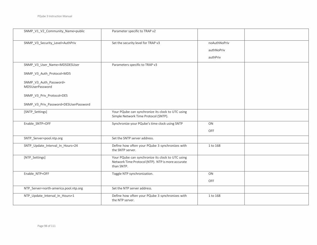
PQube 3 Instruction Manual
Page 98 of 111
SNMP_V1_V2_Community_Name=public
Parameter specific to TRAP v2
SNMP_V3_Security_Level=AuthPriv Set the security level for TRAP v3 noAuthNoPriv
authNoPriv
authPriv
SNMP_V3_User_Name=MD5DESUser SNMP_V3_Auth_Protocol=MD5 SNMP_V3_Auth_Password= MD5UserPassword SNMP_V3_Priv_Protocol=DES SNMP_V3_Priv_Password=DESUserPassword
Parameters specific to TRAP v3
[SNTP_Settings] Your PQube can synchronize its clock to UTC using Simple Network Time Protocol (SNTP).
Enable_SNTP=OFF Synchronize your PQube’s time clock using SNTP ON
OFF
SNTP_Server=pool.ntp.org Set the SNTP server address.
SNTP_Update_Interval_In_Hours=24 Define how often your PQube 3 synchronizes with the SNTP server.
1 to 168
[NTP_Settings] Your PQube can synchronize its clock to UTC using Network Time Protocol (NTP). NTP is more accurate than SNTP.
Enable_NTP=OFF Toggle NTP synchronization. ON
OFF
NTP_Server=north-america.pool.ntp.org Set the NTP server address.
NTP_Update_Interval_In_Hours=1 Define how often your PQube 3 synchronizes with the NTP server.
1 to 168

PQube 3 Instruction Manual
Page 99 of 111
5.1.5 System and Services [HTTP_Web_Server_Settings]
HTTP_Web_Server_Commands_Page=ON Toggle the Commands page on the web server. ON
OFF
HTTP_Web_Server_Port=80 HTTP port used to access the PQube3 web server pages - default is 80
HTTP_Web_Server_Command_Port=8888 HTTP port used to access the PQube3 web server Commands page - default is 8888
Require_HTTP_Authorization=OFF
HTTP_User_Name=
HTTP_Password=
Restrict general access to your PQube’s Web Server (default tag OFF), you will be prompted with user and password to access the web pages
Require_HTTP_Admin_Authorization=OFF
HTTP_Admin_User_Name=admin
HTTP_Admin_Password=admin
Restrict access to the Commands section of your PQube’s Web Server (tag default OFF) , you will be prompted with user and password to access the web pages
[FTP Settings] Manage the built-in FTP server in your PQube 3.
FTP_Password_1=
FTP_Password_2=
FTP_Password_3=
FTP_Password_4=
FTP_Password_5=
You can manage up to 5 FTP users: Those users are: ftp_user_1 ftp_user_2 ftp_user_3
ftp_config – for retrieving or sending the setup file. This user uses FTP_Password_4.
ftp_updater – for firmware update via FTP
The user names are fixed and cannot be changed.
If no password is assigned for a profile, that user does not have access.
Password must be at least 8 characters.
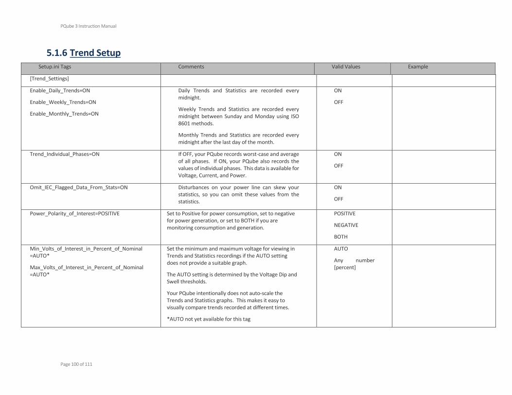
PQube 3 Instruction Manual
Page 100 of 111
5.1.6 Trend Setup Setup.ini Tags Comments Valid Values Example
[Trend_Settings]
Enable_Daily_Trends=ON
Enable_Weekly_Trends=ON
Enable_Monthly_Trends=ON
Daily Trends and Statistics are recorded every midnight.
Weekly Trends and Statistics are recorded every midnight between Sunday and Monday using ISO 8601 methods.
Monthly Trends and Statistics are recorded every midnight after the last day of the month.
ON
OFF
Trend_Individual_Phases=ON If OFF, your PQube records worst-case and average of all phases. If ON, your PQube also records the values of individual phases. This data is available for Voltage, Current, and Power.
ON
OFF
Omit_IEC_Flagged_Data_From_Stats=ON Disturbances on your power line can skew your statistics, so you can omit these values from the statistics.
ON
OFF
Power_Polarity_of_Interest=POSITIVE Set to Positive for power consumption, set to negative for power generation, or set to BOTH if you are monitoring consumption and generation.
POSITIVE
NEGATIVE
BOTH
Min_Volts_of_Interest_in_Percent_of_Nominal =AUTO*
Max_Volts_of_Interest_in_Percent_of_Nominal=AUTO*
Set the minimum and maximum voltage for viewing in Trends and Statistics recordings if the AUTO setting does not provide a suitable graph.
The AUTO setting is determined by the Voltage Dip and Swell thresholds.
Your PQube intentionally does not auto-scale the Trends and Statistics graphs. This makes it easy to visually compare trends recorded at different times.
*AUTO not yet available for this tag
AUTO
Any number [percent]

PQube 3 Instruction Manual
Page 101 of 111
Min_Current_of_Interest_in_Amps=AUTO*
Max_Current_of_Interest_in_Amps=AUTO*
Set the minimum and maximum current for viewing in Trends and Statistics recordings if the AUTO setting does not provide a suitable graph.
The AUTO setting is determined by your full-scale current.
*AUTO not yet available for this tag
AUTO
Any number [amps]
Min_Neutral_Current_of_Interest_in_Amps=AUTO*
Max_Neutral_Current_of_Interest_in_Amps=AUTO*
If your PQube is calculating the Earth Current, AUTO sets the Max_Earth_Current_of_Interest_in_Amps to 5% of the Max_Current_of_Interest_in_Amps value.
If measuring the Earth Current with a current transformer, the AUTO setting is determined by your CT ratio and the nominal current rating of your current sensing module.
*AUTO not yet available for this tag
AUTO
Any number [amps]
Min_Earth_Current_of_Interest_in_Amps=AUTO*
Max_Earth_Current_of_Interest_in_Amps=AUTO*
If your PQube is calculating the Earth Current, AUTO sets the Max_Earth_Current_of_Interest_in_Amps to 5% of the Max_Current_of_Interest_in_Amps value.
If measuring the Earth Current with a current transformer, the AUTO setting is determined by your CT ratio and the nominal current rating of your current sensing module.
*AUTO not yet available for this tag
AUTO
Any number [amps]
Min_Frequency_of_Interest_in_Percent_of_Nominal=AUTO*
Max_Frequency_of_Interest_in_Percent_of_Nominal=AUTO*
The AUTO values are determined by the Underfrequency and Overfrequency thresholds.
*AUTO not yet available for this tag
AUTO
Any number [Hz]
Min_AN1_E_of_Interest_in_RMS_volts=AUTO*
Max_AN1_E_of_Interest_in_RMS_volts=AUTO*
The AUTO values are determined by the Dip and Swell thresholds on Analog Channel 1.
*AUTO not yet available for this tag
AUTO
Any number [volts]
Min_AN2_E_of_Interest_in_RMS_volts=AUTO*
Max_AN2_E_of_Interest_in_RMS_volts=AUTO*
The AUTO values are determined by the Dip and Swell thresholds on Analog Channel 2.
*AUTO not yet available for this tag
AUTO
Any number [volts]

PQube 3 Instruction Manual
Page 102 of 111
Min_AN1_AN2_of_Interest_in_RMS_volts=AUTO*
Max_AN1_AN2_of_Interest_in_RMS_volts=AUTO*
The AUTO values are determined by the AN1-AN2 Dip and Swell thresholds.
*AUTO not yet available for this tag
AUTO
Any number [volts]
Min_AN3_E_of_Interest_in_RMS_volts=AUTO*
Max_AN3_E_of_Interest_in_RMS_volts=AUTO*
The AUTO values are determined by the Dip and Swell thresholds on Analog Channel 3.
*AUTO not yet available for this tag
AUTO
Any number [volts]
Min_AN4_E_of_Interest_in_RMS_volts=AUTO*
Max_AN4_E_of_Interest_in_RMS_volts=AUTO*
The AUTO values are determined by the Dip and Swell thresholds on Analog Channel 4.
*AUTO not yet available for this tag
AUTO
Any number [volts]
Min_AN3_AN4_of_Interest_in_RMS_volts=AUTO*
Max_AN3_AN4_of_Interest_in_RMS_volts=AUTO*
The AUTO values are determined by the AN3-AN4 Dip and Swell thresholds.
*AUTO not yet available for this tag
AUTO
Any number [volts]
Min_Temperature_of_Interest_in_DegC=0
Max_Temperature_of_Interest_in_DegC=50
Set the minimum and maximum temperature for viewing in Trends and Statistics recordings if the AUTO setting does not provide a suitable graph.
Any number [degrees °C]
Min_Humidity_of_Interest_in_%_RH=0
Max_Humidity_of_Interest_in_%_RH=100
Set the minimum and maximum relative humidity in % for viewing in Trends and Statistics recordings.
Any number [%RH]
Max_Voltage_Unbalance_of_Interest_in_Percent=10%
Set the full scale Voltage Unbalance in Trends and Statistics recordings.
Any number [%]
Max_Current_Unbalance_of_Interest_in_Percent=99%
Set the full scale Current Unbalance in Trends and Statistics recordings.
Any number [%]
Max_Voltage_THD_of_Interest_in_Percent=10% Set the full scale THD voltage in Trends and Statistics recordings.
Any number [%]
Max_Current_TDD_of_Interest_in_Percent=25%* Set the full scale TDD current in Trends and Statistics recordings.
Any number [%]
Max_Flicker_of_Interest=4 Set the full scale RMS Flicker in Trends and Statistics recordings.
Any number

PQube 3 Instruction Manual
Page 103 of 111
6 Appendix 2: PQube3 events
Your PQube comes with an embedded library of event triggers. A trigger event is a condition that can be detected by the PQube3. When triggering on an event, the PQube3 will record and store an event summary. For certain types of events, the PQube3 also records a waveform and an RMS evolution will also be recorded.
The PQube3 can trigger on voltage amplitude deviations , such as sag (dips) , swells , interruptions, wave shape changes, on frequency deviations, but it also can trigger on current amplitude exceeded (load current), or inrush currents.
The PQube can also trigger on any of its 4 analog input channels or its digital input channel. If equipped with one or more ENV2 EnviroSensors, the PQube can trigger on temperature humidity and even on external events such as mechanical shocks or seismic type of disturbances.
The chapter below describes the various types of events and what information is recorded:
EVENT TYPE Recordings
VOLTAGE events Event summary
Waveform RMS
Voltage_Sags X X X
Voltage_Swells X X X
Voltage_Interruptions X X X
Major_Sags (see annex 7 below) X X X
Over-frequency X X X
Under-frequency X X X
RVC (Rapid Voltage Changes) X X* X*
Waveshape Changes X X X
High Frequency Impulse (If HF function enabled) X X* X*
CURRENT events
Phase Current Trigger X X X
Phase Current Trigger X X X
Analog channels Events
AN1-E (thru AN4-E) Sags X X X
AN1-E (thru AN4-E) Swells X X X
ENVIROSENSOR (ENV) events
Probe A/B Low temperature X
Probe A/B High temperature X
Probe A/B Low Humidity X
Probe A/B High Humidity X
Probe A/B Mechanical Shock X X**
Probe A/B Seismic Disturbance X X**
Note: (*) with PQube3 firmware 3.5.0, (**) acceleration signature
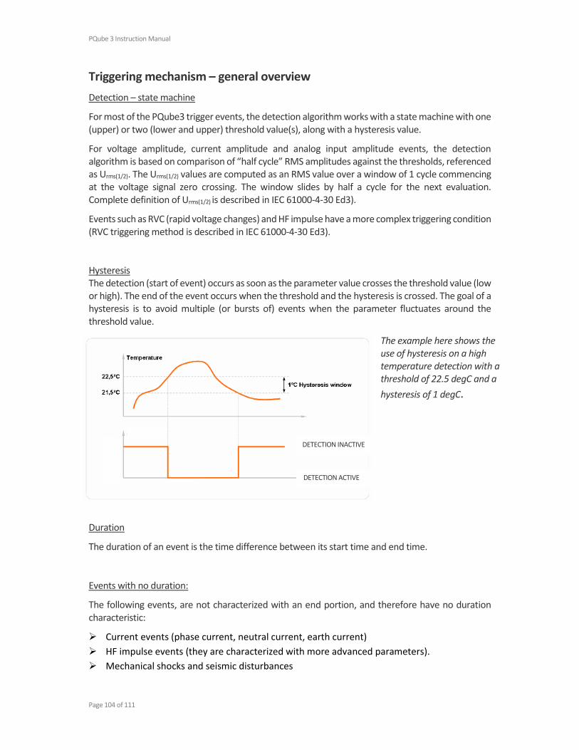
PQube 3 Instruction Manual
Page 104 of 111
Triggering mechanism – general overview
Detection – state machine
For most of the PQube3 trigger events, the detection algorithm works with a state machine with one (upper) or two (lower and upper) threshold value(s), along with a hysteresis value.
For voltage amplitude, current amplitude and analog input amplitude events, the detection algorithm is based on comparison of “half cycle” RMS amplitudes against the thresholds, referenced as Urms(1/2). The Urms(1/2) values are computed as an RMS value over a window of 1 cycle commencing at the voltage signal zero crossing. The window slides by half a cycle for the next evaluation. Complete definition of Urms(1/2) is described in IEC 61000-4-30 Ed3).
Events such as RVC (rapid voltage changes) and HF impulse have a more complex triggering condition (RVC triggering method is described in IEC 61000-4-30 Ed3).
Hysteresis The detection (start of event) occurs as soon as the parameter value crosses the threshold value (low or high). The end of the event occurs when the threshold and the hysteresis is crossed. The goal of a hysteresis is to avoid multiple (or bursts of) events when the parameter fluctuates around the threshold value.
The example here shows the use of hysteresis on a high temperature detection with a threshold of 22.5 degC and a
hysteresis of 1 degC.
Duration
The duration of an event is the time difference between its start time and end time.
Events with no duration:
The following events, are not characterized with an end portion, and therefore have no duration characteristic:
Current events (phase current, neutral current, earth current)
HF impulse events (they are characterized with more advanced parameters).
Mechanical shocks and seismic disturbances
DETECTION INACTIVE
DETECTION ACTIVE

PQube 3 Instruction Manual
Page 105 of 111
Temperature/humidity events
3 phase Voltage sags, swells and interruptions events:
A full description of the algorithm is found in chapter 5.4.2 and 5.4.3 of the IEC 61000-4-30 Ed3.
A 3 phase sag starts as soon as one of the phase Urms(1/2) values amplitude crosses the sag (lower) threshold and ends when all 3 phase voltage amplitudes are back within the threshold plus the hysteresis.
A 3 phase swell starts as soon as one of the phase Urms(1/2) values crosses the swell (upper) threshold and ends when all 3 phase Urms(1/2) are back within the threshold minus the hysteresis.
A 3 phase interruption starts when all 3 phase Urms(1/2) values crosses the swell (upper) threshold and ends when at least one of the phase voltage “half cycle” amplitudes are back within the threshold + the hysteresis.
Frequency events: Frequency events are based on frequency measurements done based on counting of zero crossings on a given period. The frequency triggering method uses a frequency refreshed every cycle, and the value is computed on window of 64 cycles.
Note: the PQube3 also computes frequency aggregated at a 10s interval as per IEC 61000-4-30 Ed3. This frequency aggregation, however, is not used for triggering, but is recorded in a specific 10s frequency file
Inrush current events: Inrush triggers have thresholds for magnitude and time. If the current increases by the Inrush Threshold value or more, within the specified time period or less, the PQube will trigger an inrush current event.
Waveshape Change events: Your PQube triggers a Waveshape Change when the voltage waveform changes abruptly. It uses the “floating window” algorithm to compare each cycle to the previous cycle. It is especially useful for detecting Power Factor Correction capacitor switching.
If the voltage change from one cycle to the next exceeds the selected threshold, for the selected duration or longer, your PQube will trigger a Waveshape change.

PQube 3 Instruction Manual
Page 106 of 111
Event parameters
The section below presents a list of recommended /default thresholds for events:
The event [name] is the name that can be seen in the web event list page, is part of the event file names, or email subjects (emails sent by the PQube3).
Event type/name Description Threshold default
Min/max threshold
Voltage events
Voltage_Sags Voltage Sags as per IEC 61000-4-30, on Ph-N channels and Ph-Ph channels
90.0%Un (remaining voltage)
99.0~X%Un X=interruption threshold
Voltage_Swells Voltage Swells as per IEC 61000-4-30, on Ph-N channels and Ph-Ph channels
110.0%Un 101.0 ~200%Un
Voltage_Interruptions Voltage Interruptions as per IEC 61000-4-30, on Ph-N channels and Ph-Ph channels
10%Un (remaining voltage)
1~10%Un
Major_Sags (see annex below)
Voltage sag with minimum depth and minimum duration criterion(3 Phase, Ph-Ph )
See Annex See Annex
Over-frequency Frequency above the upper threshold 100.5% (Nominal Frequency)
100.001%~ 200.000%
Under-frequency Frequency below the lower threshold 99.5% (Nominal Frequency)
1.000%~ 99.990%
RVC Rapid voltage changes as per IEC 61000-4-30 Ed3. on Ph-N channels and Ph-Ph channels
6%Un 0.01%~99.99%
Waveshape Change Wave shape change compared to the previous portion of the wave shape (see definition above)
20% 10 cycles
5%~50% 0.5 ~30 cycles
High Frequency Impulse Sub millisecond fast transients down to 250ns duration events.
2000V 300V~6000V
Current events
Phase Current Trigger Current RMS amplitude exceeds threshold 1A 0.001A~no limit
Phase Current Trigger Current inrush (current gradient) exceeds a gradient threshold
1A 1 cycle
0.001A~no limit 1 cycle~no limit
Analog channels Events

PQube 3 Instruction Manual
Page 107 of 111
AN1/2/3/4 Sag Analog Channel AN1 through AN4-E Sag (method as per IEC61000-4-30 Ed3)
2V No limits
AN1/2/3/4 Swell Analog Channel AN1 through AN4-E Swell (method as per IEC61000-4-30 Ed3)
60V No limits
ENVIROSENSOR events
Probe A/B Undertemperature Temperature below the lower threshold 0 degC No limit
Probe A/B Overtemperature Temperature above the upper threshold 50 degC No limits
Probe A/B Low Humidity Humidity below the lower threshold 0 % No limits
Probe A/B High Humidity Humidity above the upper threshold 90% No limits
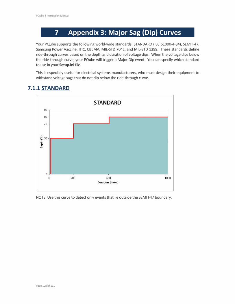
PQube 3 Instruction Manual
Page 108 of 111
7 Appendix 3: Major Sag (Dip) Curves
Your PQube supports the following world-wide standards: STANDARD (IEC 61000-4-34), SEMI F47, Samsung Power Vaccine, ITIC, CBEMA, MIL-STD 704E, and MIL-STD 1399. These standards define ride-through curves based on the depth and duration of voltage dips. When the voltage dips below the ride-through curve, your PQube will trigger a Major Dip event. You can specify which standard to use in your Setup.ini file.
This is especially useful for electrical systems manufacturers, who must design their equipment to withstand voltage sags that do not dip below the ride-through curve.
7.1.1 STANDARD
NOTE: Use this curve to detect only events that lie outside the SEMI F47 boundary.
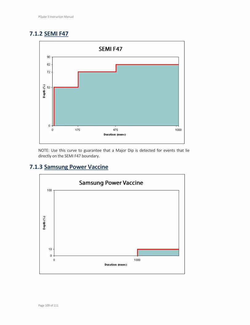
PQube 3 Instruction Manual
Page 109 of 111
7.1.2 SEMI F47
NOTE: Use this curve to guarantee that a Major Dip is detected for events that lie directly on the SEMI F47 boundary.
7.1.3 Samsung Power Vaccine

PQube 3 Instruction Manual
Page 110 of 111
7.1.4 ITIC
7.1.5 CBEMA

PQube 3 Instruction Manual
Page 111 of 111
7.1.6 MIL-STD 704E
7.1.7 MIL-STD 1399
Related Documents