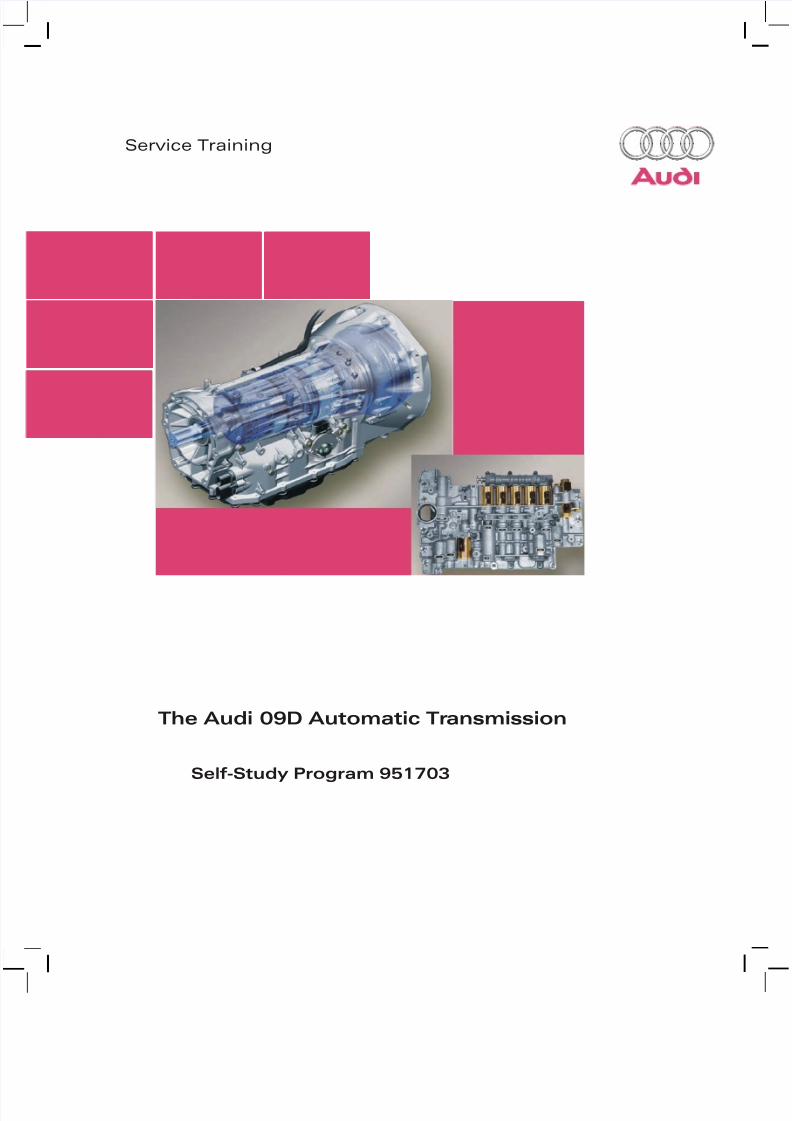
Service Training The Audi 09D Automatic Tr ansmission Self-Study Program 951703

Welcome message from author
This document is posted to help you gain knowledge. Please leave a comment to let me know what you think about it! Share it to your friends and learn new things together.
Transcript
7/23/2019 Pps 951703 Audi 09d Transmission Eng
http://slidepdf.com/reader/full/pps-951703-audi-09d-transmission-eng 1/79
Service Training
The Audi 09D Automatic Transmission
Self-Study Program 951703

7/23/2019 Pps 951703 Audi 09d Transmission Eng
http://slidepdf.com/reader/full/pps-951703-audi-09d-transmission-eng 2/79
Audi of America, Inc.
Service TrainingPrinted in U.S.A.
Printed 1/2008Course Number 951703
©2008 Audi of America, Inc.
All rights reserved. All information contained in this manual is
based on the latest information available at the time of printingand is subject to the copyright and other intellectual property
rights of Audi of America, Inc., its affiliated companies, and itslicensors. All rights are reserved to make changes at any time
without notice. No part of this document may be reproduced,
stored in a retrieval system, or transmitted in any form or byany means, electronic, mechanical, photocopying, recording, or
otherwise, nor may these materials be modified or reposted to
other sites without the prior expressed written permission of thepublisher.
All requests for permission to copy and redistribute information
should be referred to Audi of America, Inc.
Always check Technical Bulletins and the latest electronic repair
literature for information that may supersede any information
included in this booklet.
Trademarks: All brand names and product names used in thismanual are trade names, service marks, trademarks, or registered
trademarks and are the property of their respective owners.
7/23/2019 Pps 951703 Audi 09d Transmission Eng
http://slidepdf.com/reader/full/pps-951703-audi-09d-transmission-eng 3/79
i
Table of Contents
Knowledge Assessment . . . . . . . . . . . . . . . . . . 73
The Self-Study Program teaches the design and function of new vehicle models,automotive components, and technologies.
The Self-Study Program is not a Repair Manual!
The values given are only intended as a guideline. Refer to
the software version valid at the time of publication of the SSP.
For maintenance and repair work, always refer to the current technical literature.
Reference Note
Introduction . . . . . . . . . . . . . . . . . . . . . . . . . 1
Transmission Subassemblies . . . . . . . . . . . . . . . 9
Transmission Control. . . . . . . . . . . . . . . . . . . . 37
Transmission Periphery . . . . . . . . . . . . . . . . . . 59
Glossary . . . . . . . . . . . . . . . . . . . . . . . . . . . 69
Index. . . . . . . . . . . . . . . . . . . . . . . . . . . . . 71

7/23/2019 Pps 951703 Audi 09d Transmission Eng
http://slidepdf.com/reader/full/pps-951703-audi-09d-transmission-eng 4/79
1
Introduction
The 09D Six-Speed Automatic Transmission in the Audi Q7
Unlike the Audi longitudinal AWD configurations
where the front axle differential and transfer case are
integrated with the transmission, the 09D six-speedautomatic transmission in the Audi Q7 is designed as an
independent component.
The powertrain of the Audi Q7 has a modular
configuration. This means that the various
subassemblies – the transmission, the front axledifferential, and the transfer case – are separate units.
Note
In addition to the general descriptionsof the 09D transmission, this Self-
Study Program covers special features
in the context of the Audi Q7.
For information about the power
transmission in the Audi Q7 and
transfer case 0AQ, refer to Self-Study
Program 993603, The Audi Q7 Power
Transmission.
Rear Axle
Differential 0AB

7/23/2019 Pps 951703 Audi 09d Transmission Eng
http://slidepdf.com/reader/full/pps-951703-audi-09d-transmission-eng 5/79
2
Introduction
367_093
The 09D transmission can transmit up to 553.1 lb ft(750 Nm) of engine torque and is currently used in
combination with the most powerful engines in the
Audi Q7.
– A special low ATF pick-up point and a high ATFcapacity ensure reliable oil intake in rough terrain.
– A large ATF cooler maintains the ATF temperature at a
safe level.
– The elevated transmission breather hose preventsingress of water into the transmission, even underadverse conditions.
– A large torque converter with lockup clutch reducesheat build-up in the ATF and allows power to betransmitted directly.
Special Features Designed for Off-Road Use
Front Axle Differential 0AA
Transfer Case 0AQ
Six-Speed Automatic
Transmission 09D

7/23/2019 Pps 951703 Audi 09d Transmission Eng
http://slidepdf.com/reader/full/pps-951703-audi-09d-transmission-eng 6/79
3
Introduction
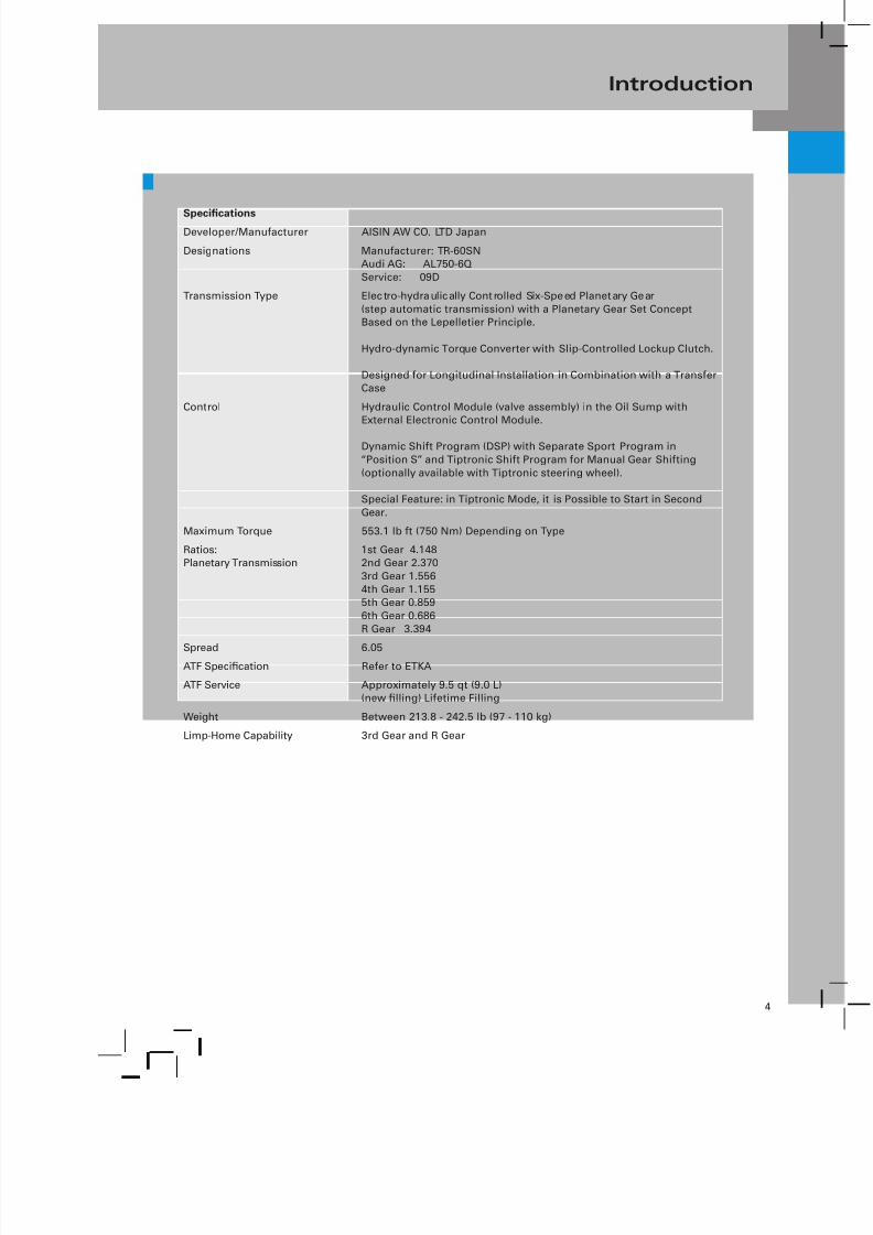
Specifications
Transmission
Breather
367_008
Multi-Function SwitchConnections of the ATF Cooler
367_010
Transmission
Breather
Electrical
Connections
Manufacturer
Serial Number
Manufacturer
Part Number
AISIN Model
Number
Production Date
Transmission
Code
367_009
7/23/2019 Pps 951703 Audi 09d Transmission Eng
http://slidepdf.com/reader/full/pps-951703-audi-09d-transmission-eng 7/79
4
Introduction
SpecificationsDeveloper/Manufacturer AISIN AW CO. LTD Japan
Designations Manufacturer: TR-60SNAudi AG: AL750-6Q
Service: 09D
Transmission Type Electro-hydraulically Controlled Six-Speed Planetary Gear
(step automatic transmission) with a Planetary Gear Set ConceptBased on the Lepelletier Principle.
Hydro-dynamic Torque Converter with Slip-Controlled Lockup Clutch.
Designed for Longitudinal Installation in Combination with a TransferCase
Control Hydraulic Control Module (valve assembly) in the Oil Sump withExternal Electronic Control Module.
Dynamic Shift Program (DSP) with Separate Sport Program in
“Position S” and Tiptronic Shift Program for Manual Gear Shifting
(optionally available with Tiptronic steering wheel).
Special Feature: in Tiptronic Mode, it is Possible to Start in Second
Gear.
Maximum Torque 553.1 lb ft (750 Nm) Depending on Type
Ratios:Planetary Transmission
1st Gear 4.1482nd Gear 2.370
3rd Gear 1.556
4th Gear 1.1555th Gear 0.859
6th Gear 0.686
R Gear 3.394
Spread 6.05ATF Specification Refer to ETKA
ATF Service Approximately 9.5 qt (9.0 L)(new filling) Lifetime Filling
Weight Between 213.8 - 242.5 lb (97 - 110 kg)
Limp-Home Capability 3rd Gear and R Gear

7/23/2019 Pps 951703 Audi 09d Transmission Eng
http://slidepdf.com/reader/full/pps-951703-audi-09d-transmission-eng 8/79
5
Introduction
Cutaway View of the 09D Transmission
Brake B1
Transmission Input Speed
(RPM) Sensor G182
ATF Pump
ATF Strainer/Filter
Freewheel
Clutch K3
Clutch K1
Manual Selector Lever

7/23/2019 Pps 951703 Audi 09d Transmission Eng
http://slidepdf.com/reader/full/pps-951703-audi-09d-transmission-eng 9/79
6
Introduction
367_011
Transmission Output
Speed (RPM) Sensor G195
Locking Pawl for
Parking Lock
Electrical Pressure
Control Valve ATF Pick-up Point
Brake B2
Clutch K2
Shift Solenoid

7/23/2019 Pps 951703 Audi 09d Transmission Eng
http://slidepdf.com/reader/full/pps-951703-audi-09d-transmission-eng 10/79
7
Introduction
Gear Selector
Connection to
Transmission Output
Speed (RPM) Sensor G195
Transmission Control
Module J217
Electromagnetic Valves
(actuators)
Connection to
Transmission
Input Speed (RPM)
Sensor G182
Multi-Function
Transmission Range (TR)
Switch F125
Hydraulic
Control (valve
assembly)
367_066
Connector for Sensors
Connector for Actuators
Bottom View of the Transmission — Looking at the Hydraulic Control (valve assembly)
Hydraulic Parts, Hydraulic Control, ATF
Legend to Sectional View of Transmission
Components of Planetary Gear Sets
Shafts and Gears
Multi-Plate Clutches, Bearings, Washers,
and Circlips
Plastics, Seals, Rubber, and Washers
Components of Shift Elements
Cylinders, Pistons, and Air Sensor Plates
Housings, Screws, and Bolts
Electrical Components
Transmission
Fluid Temperature
Sensor G93

7/23/2019 Pps 951703 Audi 09d Transmission Eng
http://slidepdf.com/reader/full/pps-951703-audi-09d-transmission-eng 11/79
8
Notes

7/23/2019 Pps 951703 Audi 09d Transmission Eng
http://slidepdf.com/reader/full/pps-951703-audi-09d-transmission-eng 12/79
9
Transmission Subassemblies
Torque Converter
In the 09D transmission, torque is transmitted from the
engine to the transmission by a hydro-dynamic torque
converter with slip-controlled lockup clutch.
Different types of torque converters are used depending
on engine power output and characteristics.
They differ in respect of the following:– size (capacity)
– torque conversion factor
– torque converter characteristic
– torsion damper
– lockup clutch configuration
Mounting
The torque converter runs in a wear resistant roller
bearing. This design provides a durable mountingparticularly in operating states with slow oil feed (forexample, during cold starting).
Roller Bearing
367_077
367_075
Torque
Converter
Lockup
Clutch
Configuration: Typical
Torsion
Damper

7/23/2019 Pps 951703 Audi 09d Transmission Eng
http://slidepdf.com/reader/full/pps-951703-audi-09d-transmission-eng 13/79
10
Transmission Subassemblies
Torque Converter Mounting
367_071
Pinion
ATF Pump
Ring Gear
Driver
Pinion
Driver
Torque
Converter Hub
Roller Bearing
Mounting Depth -Torque Converter
ATF Pump
(removed)
Note
When installing the torque converter
and before installing the transmission,special care must be taken to ensure
the ATF pump drivers engage properly
into the grooves on the torqueconverter hub. This can be checked
by measuring the installed position
of the torque converter (refer to theWorkshop Manual).
Note
Always make sure the mounting
bushings are installed correctlybetween the engine and the
transmission. Missing bushings will
result in irreparable damage to theroller bearing, the torque converter
hub, and the shaft oil seal due to
offset between the engine and thetransmission.
ATF Pump

7/23/2019 Pps 951703 Audi 09d Transmission Eng
http://slidepdf.com/reader/full/pps-951703-audi-09d-transmission-eng 14/79
11
Transmission Subassemblies
Torque Converter Lockup Clutch
Configuration: Typical
367_035
Torque Converter
Lockup Clutch
Torsion
Damper
Design
The torque converter has a lockup clutch with integrated
torsion dampers. The torsion dampers reduce torsionalvibration when the torque converter lockup clutch is
closed. This allows the operating range “converterlockup clutch closed” to be extended.
Basically, distinctions are made between the following
functional states:– Converter Lockup Clutch - Open
– Converter Lockup Clutch - Controlled Operation
– Converter Lockup Clutch - Closed
During normal vehicle operation, the lockup clutch isengaged in 4th gear and higher (upwards of speeds of
approximately 24.8 mph [40 kph]).

7/23/2019 Pps 951703 Audi 09d Transmission Eng
http://slidepdf.com/reader/full/pps-951703-audi-09d-transmission-eng 15/79
12
Transmission Subassemblies
Controlled Operation
At defined operating points, the lockup clutch isoperated with a low slip (controlled operation).
Controlled operation provides better fuel economy thanwith the converter lockup clutch open and better driving
comfort than with the converter lockup clutch closed.
367_039
Converter Lockup Clutch - Open
Converter Lockup Clutch
- Controlled Converter Lockup Clutch - Closed
Road Speed
E
n g i n e L o a d
In Tiptronic mode and in the “S” program, the converterlockup clutch is closed at the earliest possible moment.
The direct frictional engagement between the engine
and the transmission accentuates the sporty drivingfeel.
In the hill-climbing program, the converter lockup clutch
is closed in 3rd gear.
In the Hot-mode program, the lockup clutch is no longeroperated in a controlled manner, but is closed early to
reduce heat transfer due to friction in the lockup clutch
and hydro-dynamic power transmission.
ReferencePlease see page 47 for a description ofthe Hot-mode program.
7/23/2019 Pps 951703 Audi 09d Transmission Eng
http://slidepdf.com/reader/full/pps-951703-audi-09d-transmission-eng 16/79
13
Transmission Subassemblies
Oil Supply/Lubrication
ATF (Automatic Transmission Fluid)
As mentioned previously, the 09D transmission is
designed as an independent component, without the
usual integrated transfer case and front axle differential.This is why the 09D transmission only has a single ATF
oil supply.
The exacting requirements with regard to shift quality,
functional reliability, and ease of maintenance put
extreme demands on the ATF.
The ATF is a key factor influencing the coefficient of
friction of the clutches and brakes. For this reason, ATF
development is carried out in parallel with the designand testing phases.
No ATF change is normally needed within themaintenance intervals. If the ATF has to be changed after
repairs or for some other reason, the adaption values
must be cleared and an adaption drive performed usingthe VAS Scan Tool. Refer to the “ Transmission Adaption”
section on page 55.
ATF Pump
Housing
367_050
Thrust Plate
Driver on
Pinion
Torque
Converter
Roller
Bearing
Intake Port
StatorShaft
ATF Pump
Ring Gear
Pinion
367_052
ATF Pump (fully assembled)
Roller
Bearing
Stator
Shaft
Note
Only use the ATF specified for the 09D
transmission.
Use a separate, dedicated ATF fluid
container for Special Tool VAG 1924 toavoid contaminating the ATF.

7/23/2019 Pps 951703 Audi 09d Transmission Eng
http://slidepdf.com/reader/full/pps-951703-audi-09d-transmission-eng 17/79
14
Transmission Subassemblies
The ATF pump is designed as an internal gear pump(duocentric pump). It is directly driven by the engine via
the converter housing and the converter hub.
Two grooves on the torque converter hub engage thepinion drivers. The torque converter hub runs on low-
friction bearings in the pump housing.
ATF Pump
HousingRoller
Bearing
Stator
Shaft
367_094367_053
Thrust
Plate
Driver
Ring
GearPinion
Note
When installing the torque converter
and before installing the transmission,special care must be taken to ensure
the ATF pump drivers engage properlyinto the grooves on the torque
converter hub. This can be checked
by measuring the installed positionof the torque converter (refer to the
Workshop Manual).
Note
Always make sure the mounting
bushings are installed correctlybetween the engine and the
transmission. Missing bushings willresult in irreparable damage to the
roller bearing, the torque converter
hub, and the shaft oil seal due to anoffset between the engine and the
transmission.
367_074
Converter
HousingTorque
Converter HubPinion Ring Gear

7/23/2019 Pps 951703 Audi 09d Transmission Eng
http://slidepdf.com/reader/full/pps-951703-audi-09d-transmission-eng 18/79
15
Transmission Subassemblies
ATF cooling is thermostat-controlled by means of an
oil-to-air heat exchanger (ATF cooler). The ATF cooler is
mounted in front of the A/C condenser.
ATF Cooling
367_012
ATF Cooler
Oil Temperature
Regulator
(thermostat)
ATF CoolerReturn Line
ATF Cooler
Supply Line
Note
Please note that impurities in the ATF (forexample, abrasion, chips, emulsions) aredistributed throughout the ATF cooling system
and deposit here. The cooling system must,
therefore, be flushed thoroughly before repairor replacement. The lines must be disconnected
from the thermostat and the cooler in order toflush out individual components.
Make sure all contaminants are removed. Ifin doubt, components such as the ATF cooleror thermostat must be replaced. Residual
contaminants will lead to further damage of
the transmission. Always follow the WorkshopManual instructions when servicing the ATF
system.
Oil Temperature Regulator (thermostat)
An expanding wax-type thermostat is used on the 09D
transmission. It is integrated with the ATF cooler supplyand return lines.

7/23/2019 Pps 951703 Audi 09d Transmission Eng
http://slidepdf.com/reader/full/pps-951703-audi-09d-transmission-eng 19/79
16
Transmission Subassemblies
Thermostat Closed
The expanding wax element acts as the thermostat
slide valve and regulates the ATF feed to the cooler.In the closed state, a small fraction of the ATF flows
through the bypass, thereby heating the expanding waxelement.
At a temperature of approximately 167 °F (75 °C), the
plunger of the expanding wax element begins to pressdownwards against the force of the spring, thereby
opening the inlet to the cooler (see next figure).
Plunger
Seal
367_014
G
G
K
K
367_013
G = From or To Transmission
K = From or To Cooler
G
G
K
K
Note
If the cooling system has been openedduring repairs (thereby draining theATF cooler), the ATF temperature must
be raised to at least 194 °F (90 °C) by
performing a test drive in order to setthe ATF level correctly. This ensures
the ATF cooler is filled. The ATF level
must be set after the ATF has cooledto normal test temperature (refer to
Workshop Manual).
Note
Contaminants can clog the thermostatbypass, thereby impairing the functionof or disabling the thermostat.
This can cause the transmission to
overheat! At an ambient temperatureof 77 °F (25 °C) and during normal
vehicle operation, the ATF temperature
barely exceeds 230 °F (110 °C).
Expanding
Wax
Element
Bypass
Thermostat Open
At a temperature of approximately 194 F (90 C), the
thermostat is fully open.

7/23/2019 Pps 951703 Audi 09d Transmission Eng
http://slidepdf.com/reader/full/pps-951703-audi-09d-transmission-eng 20/79
17
Transmission Subassemblies
Planetary Gear Set
ATF Pump
367_073
Single Planetary
Gear Set
The 09D transmission is based on the Lepelletier
planetary gear set concept (six forward gears and one
reverse gear).
The Lepelletier planetary gear set is based on a single
planetary gear set (primary planetary gear set) and aRavigneaux planetary gear set (secondary planetary gear
set) further down the drive train.
367_022
Sun Gear S1
Single Planetary Gear Set
(primary planetary gear set)Freewheel F
Ravigneaux Planetary Gear Set
(secondary planetary gear set)
Transmission Output Shaft

7/23/2019 Pps 951703 Audi 09d Transmission Eng
http://slidepdf.com/reader/full/pps-951703-audi-09d-transmission-eng 21/79
18
Transmission Subassemblies
Inner Plate Carrier
Clutch K3
Planet Carrier PT1
Planetary Gears P1
Ring Gear H1
Turbine Shaft
367_016
367_017
Large Sun Gear S2
Small Sun Gear S3
Planetary Gear P3
Inner Plate Carrier
Brake B2
Planet Carrier PT2
Planetary Gear P2
Inner Plate Carrier
Clutch K2
Ring Gear H2
Ravigneaux
Planetary Gear Set
The special feature of the Lepelletier planetary gear
set is that the sun gears and the planet carrier of the
Ravigneaux gear set are driven at different speeds. Thisprovides a large number of ratios.
The sun gears of the Ravigneaux gear seat are driven atthe reduced output speed of the single planetary gear
set. The planet carrier of the Ravigneaux gear seat isdriven at transmission input speed.
A feature of the Lepelletier planetary gear set is thatonly five shift elements are required for engaging all six
forward gears and reverse gear.
Advantages of the Lepelletier Planetary
Gear Set Concept
– It allows a very compact design, despite a widerratio spread and more gear steps.
– It has much fewer components, significantlyreducing weight and cost of manufacture.
– The wide ratio spread, the closer ratios, and thereduced number of gear shifting componentsensure a high level of efficiency.

7/23/2019 Pps 951703 Audi 09d Transmission Eng
http://slidepdf.com/reader/full/pps-951703-audi-09d-transmission-eng 22/79
19
Transmission Subassemblies
Shift Elements
A continuous flow of power and different ratios can be
obtained in a planetary gear set by introducing torque
into a corresponding component (for example, on theplanet carrier) and by holding a different component
stationary (for example, the sun gear) or interconnecting
two components of a planetary gear set (for example,connecting the planet carrier to the sun gear).
367_018
Brake B1 Clutch K3 Clutch K1

7/23/2019 Pps 951703 Audi 09d Transmission Eng
http://slidepdf.com/reader/full/pps-951703-audi-09d-transmission-eng 23/79
20
Transmission Subassemblies
367_073
Freewheel F
Outer Plate Carrier of Clutch K2
(pulled back slightly to provide a
better view of K2)
367_019
Inner Plate Carrier,
Clutch K1
The shift elements (brakes and clutches), in combination
with the planetary gear sets, establish a flow of powerand execute gear shifts under load, without any
interruption in tractive power.
The following shift elements are used:
– Three Planetary Multi-plate Clutches (K1, K2, and K3)
– Two Fixed Plate Brakes (B1 and B2)
– One Freewheel (F)
Clutches K1, K2, and K3 introduce engine torque into the
planetary gear set. All clutches have a dynamic pressurecompensation function, with the result that clutch
response is independent of engine speed.
Brakes B1 and B2, or freewheel F, establish a torque
counter-point with the transmission housing.
All clutches and brakes are activated indirectly by
electronic pressure control valves.
Freewheel F, which is also a shift element, is arranged
in parallel with brake B2. During automatic operation,it takes over the function of brake B2. The freewheel
simplifies electro-hydraulic shift control when selectinggears and when shifting up and down between 1st and
2nd gear.
Brake B2 Clutch K2
367_020
7/23/2019 Pps 951703 Audi 09d Transmission Eng
http://slidepdf.com/reader/full/pps-951703-audi-09d-transmission-eng 24/79
21
Transmission Subassemblies
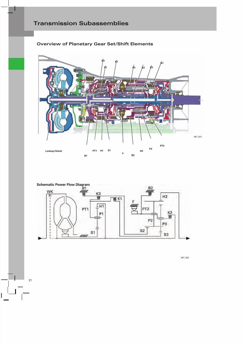
Overview of Planetary Gear Set/Shift Elements
367_022
Schematic Power Flow Diagram
K3
367_021
P1
K1
P3 S2 S3
K2
Lockup Clutch
B1
PT1 H1 S1
FB2
H2P2
PT2

7/23/2019 Pps 951703 Audi 09d Transmission Eng
http://slidepdf.com/reader/full/pps-951703-audi-09d-transmission-eng 25/79
22
Transmission Subassemblies
367_031
Primary Planetary Gear Set
Component: Connected to:
H1 – Ring Gear 1 Turbine Shaft (drive)/Clutch K2P1 – Planetary Gears 1 Power Transmission in Planetary Gear Set
S1 – Sun Gear 1 Stationary
PT1 – Planet Carrier 1 Clutches K1 and K3
Secondary Planetary Gear Set
Component: Connected to:
H2 – Ring Gear 2 Output
P2 – Planetary Gears 2, Long Power Transmission in Planetary Gear Set
P3 – Planetary Gears 3, Short Power Transmission in Planetary Gear SetS2 – Sun Gear 2, Large Clutch K3/Brake B1
S3 – Sun Gear 3, Small Clutch K1
PT2 – Planet Carrier 2 Clutch K2/Brake B2/Freewheel F
Clutches, Brakes, Freewheel
Component: Task:
H2 – Clutch 1 Planet Carrier PT1 (primary gear set) Connected to Small Sun Gear S3
(secondary gear set)
K2 – Clutch 2 Turbine Shaft (input) Connected to Planet Carrier PT2 of the
Secondary Planetary Gear Set
K3 – Clutch 3 Planet Carrier PT1 (primary gear set) Connected to Small Sun Gear S2
(secondary gear set)
B1 – Brake 1 Holds Large Sun Gear S2 (secondary gear set) Stationary
B2 – Brake 2 Holds Planet Carrier PT2 (secondary gear set) Stationary
F – Freewheel Holds Planet Carrier PT2 (secondary gear set) Stationary Counter to the
Direction of Rotation of the Drive and is Used when Driving Under Throttle
in 1st Gear (no engine brake)
Converter Lockup Clutch

7/23/2019 Pps 951703 Audi 09d Transmission Eng
http://slidepdf.com/reader/full/pps-951703-audi-09d-transmission-eng 26/79
23
Transmission Subassemblies
Function of the Shift Elements
Clutches and Brakes
The function of the shift elements is explained here
using clutch K2, which is exemplary of clutches K1 andK3, as well as brakes B1 and B2. Unlike the clutches,
the brakes require no dynamic pressure compensation,because their clutch pistons and cylinders are non-
rotating and therefore are not subject to a dynamic
increase in pressure.
The shift elements are actuated hydraulically. Pressure
oil is supplied to the shift elements by the valveassembly through stationary and rotating ports in the
transmission housing, on the shafts, and on othercomponents. Lube oil is supplied to the bearings and the
shift elements in the same manner.
The clutch plate carriers are perforated, allowing the ATF
to flow through each clutch from the inside outwards(normally when the clutch is open). The design of the
lined plates and the centrifugal force are conducive to oilflow through the clutches.
Clutch K2 - Open
367_054
Inner Plate
Carrier
Transmission Shaft -
Connected to the
Turbine Shaft
Planet Carrier PT2
Coil Spring
Clutch Plates
(steel plates and
lined plates)
Baffle Plate
Clutch PistonOuter Plate Carrier
Clutch Piston Cylinder
Pressure Compensation
Chamber
Output Shaft
Transmission
Housing
Pressure Port
Clutch K2
Clearance
Lubricating
Oil
Oil Pressure
High 0

7/23/2019 Pps 951703 Audi 09d Transmission Eng
http://slidepdf.com/reader/full/pps-951703-audi-09d-transmission-eng 27/79
24
Transmission Subassemblies
In order to close the clutch, oil pressure is directed
into the clutch cylinder chamber. The clutch piston
compresses the clutch plate assembly, and the clutchengages when the required oil pressure is reached. If
the clutch cylinder chamber is pressureless, the clutch
piston is forced back into its initial position by springpressure (in this case, by multiple coil springs). A
clearance is maintained between the clutch piston andthe clutch plate assembly so friction can be minimized
when the clutch is open.
In order to match transmission efficiency to the engine
as best possible, the number of clutch plates is adapted
to the engine power output. Drag losses of openclutches are thus kept to a minimum.
Clutch K2 - Closed
367_084
Coil Spring
Clutch Plates/
Clutch Plate
Assembly Clutch Piston
Clutch Cylinder
Chamber
Output Shaft
Shift Pressure
Lubricating
Oil
Oil Pressure
High 0

7/23/2019 Pps 951703 Audi 09d Transmission Eng
http://slidepdf.com/reader/full/pps-951703-audi-09d-transmission-eng 28/79
25
Transmission Subassemblies
367_072
Oilway
Clutch K2
Baffle Plate
Clutch Piston
Clutch Cylinder
ChamberPressure Compensation
Chamber
Transmission
HousingShift Pressure
Lubricating
Oil
Oil Pressure
High 0
Baffle Plate
At high engine speeds, due to rotation, the oil is subject
to high centrifugal forces inside the clutch cylinder
chamber.
This causes the pressure inside the clutch cylinder
chamber to increase towards the largest radius. Thisprocess is referred to as “dynamic pressure increase.”
Dynamic pressure increase is best avoided because
it unduly increases the surface pressure and makes
it more difficult to control the increase and reductionof pressure inside the pressure chamber. To ensure
controlled closing and opening of the clutches, clutches
K1, K2, and K3 have a pressure compensation function.
It allows gearshifts to be controlled precisely, and this,
in turn, greatly enhances shift comfort. Leaks in the
pressure equalization chamber can, at high enginespeeds, lead to uncontrolled frictional engagement of
the clutch and damage it.
Dynamic Pressure Compensation in Clutches
Principle/Mode of Operation (example - K2)
The clutch pistons are swept by ATF on both sides. Thisis caused by means of a baffle plate. The baffle plate
creates a sealed space leading to the clutch piston.
This space is referred to as the pressure compensationchamber. The pressure compensation chamber is filled
with low pressure via an oil passage branching off the
main oil line.
The ATF in the pressure compensation chamber issubjected to the same centrifugal forces (dynamic
pressure increase) as the ATF in the clutch cylinder
chamber. This compensates for the increase in forceacting upon the clutch piston (due to dynamic pressure
increase).

7/23/2019 Pps 951703 Audi 09d Transmission Eng
http://slidepdf.com/reader/full/pps-951703-audi-09d-transmission-eng 29/79
26
Transmission Subassemblies
Freewheel
The freewheel transmits torque in one direction of
rotation only. No torque is transmitted in the opposite
direction.
In the 09D transmission, the freewheel is used for
driving away in 1st gear. The freewheel holds planetcarrier PT2 stationary and thus allows power to flow.
Principle/Mode of Operation
The freewheel in the 09D transmission is a spragtype freewheel. It consists of an outer ring (positively
connected to the transmission housing), an inner ring
(positively connected to planet carrier PT2), and spragslocated between the inner and outer rings. The sprags
are asymmetrically shaped and accommodated in thespace between the inner and outer rings.
Direction of Rotation
In the direction of rotation of the planet carrier (inner
ring), the sprags change their orientation withoutcreating any resistance, because of their shape.
Locking Direction
In the locking direction of the planet carrier (inner ring),the sprags stand up because of their shape, and fill
the annular space between the inner and outer rings insuch a way that the inner and outer rings are positively
engaged. In this instance, the planet carrier is held
stationary, since the outer ring is positively connectedto the transmission housing.
Note
Due to the freewheel, no engine braking
effect is available in 1st gear duringnormal automatic operation.
If the freewheel is faulty, no power flow
will be possible in 1st gear during normal
automatic operation. In this case, a flowof power can be achieved by selecting 1st
gear using the Tiptronic function.
367_110
Outer Ring
(stationary)
Inner Ring
Sprag “Free”
Sprag “Locked”
367_109
Inner Ring
Planet Carrier PT2Outer Ring
Sprag

7/23/2019 Pps 951703 Audi 09d Transmission Eng
http://slidepdf.com/reader/full/pps-951703-audi-09d-transmission-eng 30/79
27
Transmission Subassemblies
Hydraulic Control
Valve Assembly
The clutches and brakes (shift elements) are controlledby the valve assembly by means of hydraulic shift control
valves (gate valves). The gate valves are controlled by
electromagnetic valves, which, in turn, are activated byTransmission Control Module J217.
In addition to the shift elements, the valve assemblycontrols the lockup clutch and the various pressures
throughout the transmission (for example, mainpressure, control pressure, torque converter pressure,
lubricating pressure, etc.). The valve assembly is largely
responsible for oil supply and therefore for properfunctioning of the transmission.
The valve assembly consists of the followingcomponents:
– Mechanically Actuated Selector Valve
– Hydraulic Shift Control Valves
– Two Electrically Controlled Shift Solenoids(3/2-way valves)
– Six Electronic Pressure Control Valves (modulatingvalves)
– ATF Temperature Sensor
367_067
G93
Transmission Oil Temperature Sensor
Bottom View of Valve Assembly
Electronic Pressure Control Valves (EPCV)Shift SolenoidsOPEN-CLOSE Valves
Selector
Valve
N91 N93 N90 N92 N283 N282 N88 N89
To/From Transmission
Control Module J217
Connection to
Transmission Output
Speed (RPM) Sensor G95
Connection to
Transmission
Input Speed
(RPM) Sensor
G182
Oil Intake Port

7/23/2019 Pps 951703 Audi 09d Transmission Eng
http://slidepdf.com/reader/full/pps-951703-audi-09d-transmission-eng 31/79
28
Transmission Subassemblies
Electromagnetic Valves
In the case of the electromagnetic valves, a distinctionis made between shift solenoids with two switching
positions (OPEN - CLOSE) and electronic pressure control
valves (known as EPCVs or modulating valves).
The shift solenoids (N88/N89) are 3/2-way valves orOPEN-CLOSE valves.
3/2 valve means the valves have three connections andtwo switching positions (open/closed or OPEN–CLOSE).
These valves are used for switching hydraulic shift
control valves.
The EPCVs convert an electrical current to a proportional,
hydraulic control pressure. This control pressure, in turn,
activates hydraulic shift control valves, which controlthe “working pressure” of the shift elements (the lockup
clutch and the master pressure).
Two types of EPCVs are used.
EPCVs with a rising characteristic increase pilot pressure
(P) as a function of rising control current (I) - no current
- zero pilot pressure (0 mA = 0 bar).
EPCVs with a falling characteristic reduce pilot pressure
as a function of rising control current - no current- maximum pilot pressure.
367_069
EPCV with Rising
Characteristic
EPCV with Falling
Characteristic
367_070
Effects of MalfunctioningIf the self-diagnostics detect a faulty electromagneticvalve, the limp-home mode is normally activated.
Electrical and mechanical malfunctions havevery different effects due to the complexity of the
electrohydraulic control system. The effects may be
confined to the actual malfunctioning system (forexample, in the case of N91, the lockup clutch), but they
can also cause the vehicle to enter limp-home mode if
safe operation is no longer assured.
Examples:
N93 controls the master pressure. If EPCV N93 fails, thetransmission will operate at maximum system pressure.
The effects are “clunky” shifting from “P” or “N” to “D/S”
or “R” and during gearshifting in general.
EPCV N91 controls the lockup clutch. If EPCV N91 fails,
the lockup clutch cannot be activated and thereforeremains open.
N88N91 N93 N90 N92 N283 N282
N88
N89
Shift
Solenoids
OPEN-CLOSE
Valves

7/23/2019 Pps 951703 Audi 09d Transmission Eng
http://slidepdf.com/reader/full/pps-951703-audi-09d-transmission-eng 32/79
29
Transmission Subassemblies
Function Assignments of the
Electromagnetic Valves
N90 Controls Clutch K3
N91 Controls the Torque Converter Lockup Clutch
N92 Controls Clutch K1N93 Controls the Master Pressure/System Pressure
N282 Controls Clutch K2
N283 Controls Brake B1
Solenoid valves N88 and N89 are used for controlling
gearshifts from 4th to 6th gear and are activated(energized) temporarily or alternately during gearshift
operations.
Solenoid valves N88 and N89 also control brake B2 in
1st gear - Tiptronic mode (for the engine brake).
Note
Function is inverse to electrical currentapplied, since EPCVs N92, N93, N282, and
N283 have a falling characteristic. This
means a shift element is operated if thecorresponding EPCV is not activated.
Shift Logic
384_030
P
Solenoid Logic
3/2 Valves Electronic Pressure Control Valves
Gear Shifting Component Logic
Clutches, Brakes, Freewheel
N
Reverse (R) Gear
First Gear
Second Gear
Third Gear
Fourth Gear
Fifth Gear
Sixth Gear
T T
T/Z z
T/Z z
T/Z z
z
T
Legend of Solenoid Valve Logic
Solenoid Valve is Not Activated(current approximately 100 mA) or ShiftElement Open
Solenoid Valve is Activated(solenoid valve open)
Solenoid Valve is Activated(current approximately 1.0 A)
Corresponding Clutch Closed
Corresponding Brake Closed
Freewheel Locked
The Current Applied to the Solenoid Valve
Differs Depending on its Operating State
T – Tiptronic Mode
(1st gear with engine brake)
Z – Solenoid Valves are Activated OnlyTemporarily During Gearshifts
7/23/2019 Pps 951703 Audi 09d Transmission Eng
http://slidepdf.com/reader/full/pps-951703-audi-09d-transmission-eng 33/79
30
Transmission Subassemblies
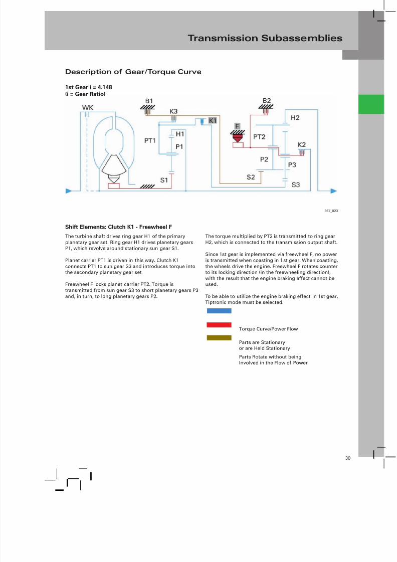
Description of Gear/Torque Curve
1st Gear i = 4.148
(i = Gear Ratio)
367_023
Shift Elements: Clutch K1 - Freewheel F
The turbine shaft drives ring gear H1 of the primary
planetary gear set. Ring gear H1 drives planetary gears
P1, which revolve around stationary sun gear S1.
Planet carrier PT1 is driven in this way. Clutch K1
connects PT1 to sun gear S3 and introduces torque intothe secondary planetary gear set.
Freewheel F locks planet carrier PT2. Torque is
transmitted from sun gear S3 to short planetary gears P3
and, in turn, to long planetary gears P2.
The torque multiplied by PT2 is transmitted to ring gear
H2, which is connected to the transmission output shaft.
Since 1st gear is implemented via freewheel F, no power
is transmitted when coasting in 1st gear. When coasting,
the wheels drive the engine. Freewheel F rotates counterto its locking direction (in the freewheeling direction),
with the result that the engine braking effect cannot beused.
To be able to utilize the engine braking effect in 1st gear,Tiptronic mode must be selected.
Torque Curve/Power Flow
Parts are Stationaryor are Held Stationary
Parts Rotate without beingInvolved in the Flow of Power

7/23/2019 Pps 951703 Audi 09d Transmission Eng
http://slidepdf.com/reader/full/pps-951703-audi-09d-transmission-eng 34/79
31
Transmission Subassemblies
367_024
1st Gear in Tiptronic Mode
(with engine braking effect)
The engine braking effect will be utilized in 1st gear
under special driving situations - for example, on steepdownhill gradients - by selecting 1st gear in Tiptronic
mode (B2 closed).
The engine braking effect will only be utilized in 1st gear
by closing brake B2. Brake B2 locks planet carrier PT2 likefreewheel F. Unlike F, however, B2 holds PT2 stationary in
both directions of rotation. This is necessary in order toengage reverse and utilize the engine braking effect in
1st gear.
Shift Elements: Clutch K1 - Brake B2
367_025
2nd Gear i = 2.370
The turbine shaft drives ring gear H1 of the primary
planetary gear set. Ring gear H1 drives planetary gearsP1, which revolve around stationary sun gear S1.
Planet carrier PT1 is driven in this way. Clutch K1
connects PT1 to sun gear S3 and introduces torque into
the secondary planetary gear set.
Brake B1 locks large sun gear S2 in place. Torque is
transmitted from sun gear S3 to short planetary gears P3and, in turn, long planetary gears P2.
Long planetary gears P2 roll around stationary sun gear
S2 and drive ring gear H2, which is connected to the
transmission output shaft.
Shift Elements: Clutch K1 - Brake B1

7/23/2019 Pps 951703 Audi 09d Transmission Eng
http://slidepdf.com/reader/full/pps-951703-audi-09d-transmission-eng 35/79
32
Transmission Subassemblies
367_026
3rd Gear i = 1.556
The turbine shaft drives ring gear H1 of the primary
planetary gear set. Ring gear H1 drives planetary gears
P1, which revolve around stationary sun gear S1. Planetcarrier PT1 is driven in this way.
Clutch K1 connects PT1 to sun gear S3 and introduces
torque into the secondary planetary gear set. Clutch K3
likewise introduces torque into the secondary planetarygear set driving sun gear S2. The secondary planetary
gear set is locked when clutches K1 and K3 close. Torque
is now transmitted directly from the primary planetarygear set to the transmission output shaft.
Shift Elements: Clutch K1 - Clutch K3
367_027
4th Gear i = 1.155
The turbine shaft drives ring gear H1 of the primaryplanetary gear set and the outer plate carrier of clutch
K2.
Ring gear H1 drives planetary gears P1, which revolve
around stationary sun gear S1. Planet carrier PT1 isdriven in this way.
Clutch K1 connects PT1 to sun gear S3 and introducestorque into the secondary planetary gear set.
Clutch K2 connects the turbine shaft to planet carrierPT2, and likewise introduces torque into the secondary
planetary gear set.
Long planetary gears P2, which mesh with short
planetary gears P3, together with planet carrierPT2, drive ring gear H2, which is connected to the
transmission output shaft.
Shift Elements: Clutch K1 - Clutch K2
7/23/2019 Pps 951703 Audi 09d Transmission Eng
http://slidepdf.com/reader/full/pps-951703-audi-09d-transmission-eng 36/79
33
Transmission Subassemblies
367_028
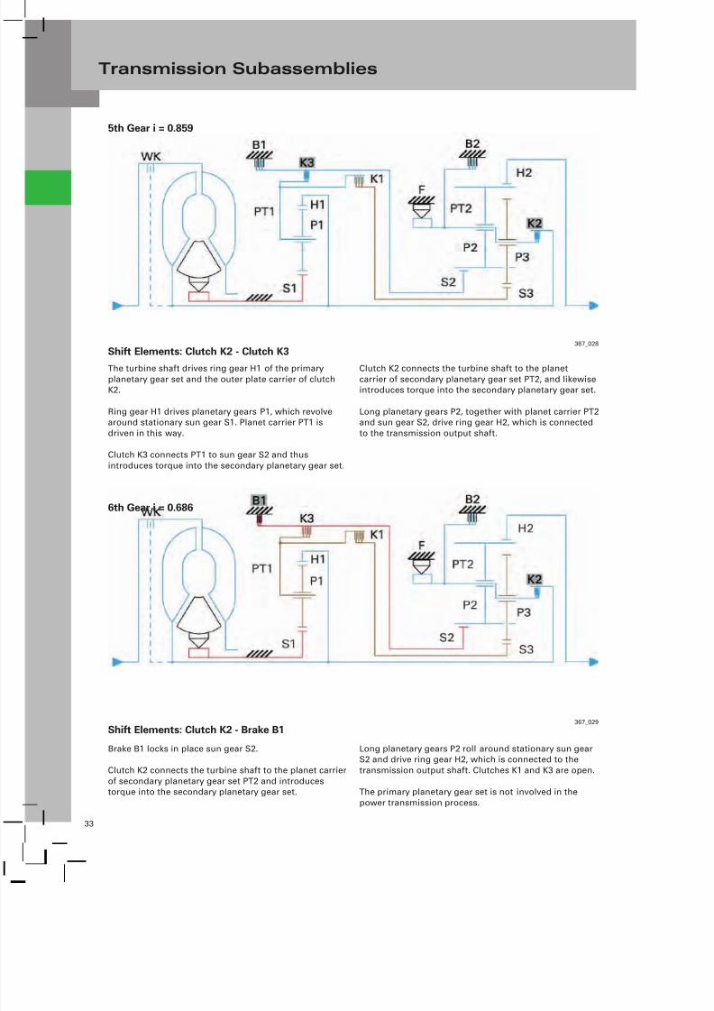
5th Gear i = 0.859
The turbine shaft drives ring gear H1 of the primary
planetary gear set and the outer plate carrier of clutchK2.
Ring gear H1 drives planetary gears P1, which revolvearound stationary sun gear S1. Planet carrier PT1 is
driven in this way.
Clutch K3 connects PT1 to sun gear S2 and thus
introduces torque into the secondary planetary gear set.
Clutch K2 connects the turbine shaft to the planet
carrier of secondary planetary gear set PT2, and likewiseintroduces torque into the secondary planetary gear set.
Long planetary gears P2, together with planet carrier PT2and sun gear S2, drive ring gear H2, which is connected
to the transmission output shaft.
Shift Elements: Clutch K2 - Clutch K3
367_029
6th Gear i = 0.686
Brake B1 locks in place sun gear S2.
Clutch K2 connects the turbine shaft to the planet carrier
of secondary planetary gear set PT2 and introducestorque into the secondary planetary gear set.
Long planetary gears P2 roll around stationary sun gearS2 and drive ring gear H2, which is connected to the
transmission output shaft. Clutches K1 and K3 are open.
The primary planetary gear set is not involved in the
power transmission process.
Shift Elements: Clutch K2 - Brake B1

7/23/2019 Pps 951703 Audi 09d Transmission Eng
http://slidepdf.com/reader/full/pps-951703-audi-09d-transmission-eng 37/79
34
Transmission Subassemblies
367_028
R Gear i = 3.394
The turbine shaft drives ring gear H1 of the primary
planetary gear set. Ring gear H1 drives planetary gearsP1, which revolve around stationary sun gear S1. Planet
carrier PT1 is driven in this way.
Clutch K3 connects PT1 to sun gear S2 and introduces
torque into the secondary planetary gear set.
Brake B2 locks planet carrier PT2 in place. Torque is
transmitted from sun wheel S2 to long planetary gearsP2.
The torque multiplied by PT2 is transmitted to ring gearH2, which is connected to the transmission output shaft.
At the same time, ring gear H2 (output) is driven counterto the direction of engine rotation.
Shift Elements: Clutch K3 - Brake B2
7/23/2019 Pps 951703 Audi 09d Transmission Eng
http://slidepdf.com/reader/full/pps-951703-audi-09d-transmission-eng 38/79
35
Transmission Subassemblies
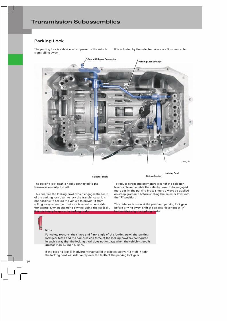
Parking Lock
The parking lock is a device which prevents the vehicle
from rolling away.
It is actuated by the selector lever via a Bowden cable.
367_040
Parking Lock Linkage
Locking Pawl
Gearshift Lever Connection
Return SpringSelector Shaft
The parking lock gear is rigidly connected to thetransmission output shaft.
This enables the locking pawl, which engages the teethof the parking lock gear, to lock the transfer case. It is
not possible to secure the vehicle to prevent it fromrolling away when the front axle is raised on one side
(for example, when changing a wheel using the car jack).
It is necessary to apply the parking brake.
To reduce strain and premature wear of the selectorlever cable and enable the selector lever to be engaged
more easily, the parking brake should always be applied
on steep gradients before shifting the selector lever intothe “P” position.
This reduces tension at the pawl and parking lock gear.
Before driving away, shift the selector lever out of “P”
before releasing the parking brake.
Note
For safety reasons, the shape and flank angle of the locking pawl, the parking
lock gear teeth and the compression force of the locking pawl are configured
in such a way that the locking pawl does not engage when the vehicle speed isgreater than 4.3 mph (7 kph).
If the parking lock is inadvertently actuated at a speed above 4.3 mph (7 kph),the locking pawl will ride loudly over the teeth of the parking lock gear.

7/23/2019 Pps 951703 Audi 09d Transmission Eng
http://slidepdf.com/reader/full/pps-951703-audi-09d-transmission-eng 39/79
36
Transmission Subassemblies
367_041
Parking Lock
Linkage
Locking Pawl
RetainerReturn Spring
Parking
Lock Gear
367_082
Parking Lock Linkage
Tooth of
Locking Pawl
Retainer Stop
Guides on
the Retainer
Locking Pawl
Taper
Compression
Spring
ParkingLock Gear
Tooth of
ParkingLock Gear
367_083
Stop
Compression
Spring
Preloaded
367_092
Stop
Compression
Spring
Released
Selector Lever Positions R/N/D/S
Selector Lever Position “P”
(parking lock gear tooth opposed to
locking pawl tooth)
Selector Lever Position “P”(locking pawl engages)
In selector lever positions R/N/D/S, the parking lock
linkage is in a position in which the taper is notengaging the locking pawl. The locking pawl is held in
an initial position with sufficient clearance to the teeth
of the parking lock gear by the return spring.
When the vehicle moves (the parking lock gear rotates
further), the locking pawl is automatically pressed bythe preloaded taper into the next tooth space on the
parking lock gear.
In selector lever position “P” the taper is thrust between
the retainer and the locking pawl. The locking pawl is
pushed towards the parking lock gear. If the tooth of thelocking pawl is opposed to a tooth of the parking lock
gear, the taper is preloaded by the compression spring.
This preload acts across the diagonal of the taper and inturn exerts a preloading force on the locking pawl.

7/23/2019 Pps 951703 Audi 09d Transmission Eng
http://slidepdf.com/reader/full/pps-951703-audi-09d-transmission-eng 40/79
37
Transmission Control
Function Diagram — 09D Transmission on the Audi Q7
367_034
Switch for P/N
(Park/Neutral) Signal
Shift Matrix for F125
R (Reverse) Signal to J519
and Y7
R (Reverse) Signal for
Self-Diagnostics
P/N signal to J518, Prerequisite for Controlling Terminal 50
09D Valve Body
Volkswagen Technical Site: http://volkswagen.msk.ru http://vwts.ru огромный архив документации по автомобилям Volkswagen

7/23/2019 Pps 951703 Audi 09d Transmission Eng
http://slidepdf.com/reader/full/pps-951703-audi-09d-transmission-eng 41/79
38
Transmission Control
PRNDS Signal
(Park) Signal to E415 for
Enabling Ignition Key
Withdrawal Lock Release
Note
Always use the current version of the current
flow diagram to troubleshoot the vehicle.
E313 Selector Lever
E415 Access/Start Authorization Switch
F41 Back-up Switch
F125 Multi-Function Transmission Range
(TR) Switch
F189 Tiptronic SwitchF305 Transmission Park Selector Switch
G93 Transmission Fluid Temperature SensorG182 Transmission Input Speed (RPM) Sensor
G195 Transmission Output Speed (RPM) Sensor
J217 Transmission Control Module
J518 Access/Start Control ModuleJ519 Vehicle Electrical System Control Module
J587 Selector Lever Sensor System Control
Module
N88 Solenoid Valve 1
N89 Solenoid Valve 2N90 Solenoid Valve 3
N91 Solenoid Valve 4N92 Solenoid Valve 5
N93 Solenoid Valve 6
N110 Shift Lock SolenoidN282 Solenoid Valve 9
N283 Solenoid valve 10
Y7 Automatic Day/Night Interior Mirror
Y26 Selector Lever Transmission Range (TR)
Position Display Unit
Selector Lever E313
Diagnostics CAN Bus
Data Link Connector
Powertrain CAN Bus Low
Powertrain CAN Bus High
K Line
Tiptronic Signal
Input
Output
Gold-Plated Contact
Twisted Wire

7/23/2019 Pps 951703 Audi 09d Transmission Eng
http://slidepdf.com/reader/full/pps-951703-audi-09d-transmission-eng 42/79
39
Transmission Control
Transmission Control Module J217
The Transmission Control Module (TCM) on the Audi
Q7 is located under the front right seat below Vehicle
Electrical System Control Module 2 J520.
The TCM is manufactured by AISIN AW Co. Ltd. of
Japan. The control module programming can beupdated using the VAS Scan Tools.
Note
After replacing the Transmission Control
Module, the basic setting procedure must beperformed using the Scan Tool (under “Guided
Fault Finding”).
The adaption values have to be cleared after
specific repair work on the transmission (forexample, change of ATF, etc.) or after replacing
the transmission.
The control module has a 52-pin connector. VAS adapter
cable 1598/48 is available for static and dynamicmeasurements on the system.
367_096
367_055
Vehicle Electrical System
Control Module 2 J520
Transmission Control
Module

7/23/2019 Pps 951703 Audi 09d Transmission Eng
http://slidepdf.com/reader/full/pps-951703-audi-09d-transmission-eng 43/79
40
Transmission Control
367_042
Coil
Multi-Function
Transmission Range (TR)
Switch F125
Multi-Function Transmission Range (TR) Switch F125
Multi-Function Transmission Range (TR) Switch F125
has the following tasks and controls the followingfunctions:
– Starter inhibitor control.
– P/N lock control (activation of Shift Lock SolenoidN110).
– It identifies the vehicle operating states forward/reverse/neutral/sport program, and this informationis used by Transmission Control Module J217 forcontrolling the transmission.
– It identifies backing up or the intention to reverse foruse in controlling all functions relevant to backing up,for example, backup lights, anti-dazzle rearviewmirror, acoustic parking system, trailer towing mode,mirror fold-back, etc.
Connector C (on wiring harness)
367_043
Sliding Contact
Switch
Contact Lever
Adjusting Nut
367_097
Effects of Signal Failure
Faults in F125 manifest themselves in very different
ways. The effects vary depending on which switch
contacts or interfaces are affected. The following canoccur:
– Engine Does Not Start (starter does not turn)– No Transmission Power Flow
– Transmission MIL Enters Electrical or MechanicalLimp-home Mode
– Transmission MIL Comes on(inverted LEDs on shift indicator)
– P/N Lock does not Function Properly
– DTC Entry

7/23/2019 Pps 951703 Audi 09d Transmission Eng
http://slidepdf.com/reader/full/pps-951703-audi-09d-transmission-eng 44/79
41
Transmission Control
Contact Assignments — Multi-Function Switch
Shift Logic F125
Coding of Connector C (on the wiring harness)
384_041
Switch for Positions
“P” and “N” Back-up Switch
P/N Signal
367_099
R Signal Position Signal Data Block 9/4. Value
The multi-function switch is a mechanical multiposition
switch with six sliding contacts.– Four Switches for Identification of Selector Valve
Position and Selector Lever Position– One Switch for Activating Functions Relevant to
Reversing (F41)
– One Switch for Starter Control in Selector LeverPositions “P” and “N”
Since the switch contact is fully mechanical, F125 can
be checked using an ohmmeter.

7/23/2019 Pps 951703 Audi 09d Transmission Eng
http://slidepdf.com/reader/full/pps-951703-audi-09d-transmission-eng 45/79
42
Transmission Control
Multi-Function Transmission Range (TR)
Switch F125
367_044
Setting Gauge
T10173
Note
Special care must be taken to ensure the
correct torque is applied to the contact lever
adjusting nut. If the nut is over-torqued, themulti-function switch will move stiffly and the
rubber seals will be damaged. If the nut is nottightened sufficiently, it can lead to ATF leaking
at the multi-function switch.
Note
The multi-function switch must be set after
installation or if the wrong gear is indicated
in the Instrument Cluster display (refer toWorkshop Manual).
Use setting gauge T1073 to set the multi-function
switch. Please follow the instructions given in the
Workshop Manual.

7/23/2019 Pps 951703 Audi 09d Transmission Eng
http://slidepdf.com/reader/full/pps-951703-audi-09d-transmission-eng 46/79
43
Transmission Control
367_116
Transmission Input Speed
(RPM) Sensor G182
Transmission Input Shaft
(turbine shaft)
Milled Recesses for Engine
Speed Sensing
Bottom View of Transmission
367_059
Transmission Input Speed
(RPM) Sensor G182
G182 is integrated in the ATF pump housing and
measures the direct transmission input speed (turbinespeed) by means of a ring gear on the transmission
input shaft.
The Transmission Control Module requires the exactturbine speed for the following functions:
– Control, Adaption, and Monitoring of Gearshifts andGear Selection
– Regulation and Monitoring of Converter LockupClutch
– Diagnosis of Shift Elements and Plausibility Checkingof Engine RPM and Transmission Output Speed
Note
Due to torque converter slip, the transmission
input speed (turbine speed) is not equivalentto the engine speed (except when the torque
converter lockup clutch is fully closed).
Stator Shaft
Protective/Substitute Function
in Case of Failure
367_116
Transmission Input Speed
(RPM) Sensor G182
ATF Pump
Transmission Input Shaft
(turbine shaft)
Connector for Transmission
Input Speed (RPM) Sensor
G182
– Engine RPM is Used as a Substitute Value
– No Adaption of Gearshifts
– No Controlled Operation of Converter LockupClutch (open or closed only)
– No Pressure Regulation when Selecting Gear
(for example, N-D or N-R), -Clunky- Shift Action

7/23/2019 Pps 951703 Audi 09d Transmission Eng
http://slidepdf.com/reader/full/pps-951703-audi-09d-transmission-eng 47/79
44
Transmission Control
Function
367_037
Ground and Signal
Voltage Supply
DSO Image - Signal from G182
367_057
Voltage level when the turbine shaft is stationary, i.e. gear selected, driving
speed 0 mph/kph (depending on whether a tooth space or a tooth is located
in front of the sensor)
DSO Connection for G182
G182 is based on the Hall principle. The output signal is
a square-wave signal whose frequency is proportionalto turbine speed.
– Black Probe Tip Pin 1
– Red Probe Tip Pin 39
Test Conditions:
– Engine Idling
– Selector Lever Position “N” or “P”
Auxiliaries:
– VAS 5051
– VAG 1598/48 with 1598/42

7/23/2019 Pps 951703 Audi 09d Transmission Eng
http://slidepdf.com/reader/full/pps-951703-audi-09d-transmission-eng 48/79
45
Transmission Control
Transmission Output Speed (RPM) Sensor G195
367_049
Transmission Output Speed
(RPM) Sensor G195
G195 is located behind the valve assembly. It is
bolted to the transmission housing and measuresthe transmission output speed at the ring gear of the
Ravigneaux planetary gear set. The ring gear has specialmilled recesses for this purpose and serves as an
encoder disc.
One of the principal signals of the electronic
transmission control system is the transmissionoutput speed. There is a direct correlation between
transmission output speed and driving speed.
The transmission output speed is required for the
following functions:
– Shift Point Selection
– Dynamic Shift Program (DSP), for example,
Driving Status Evaluation– Shift Component and Plausibility Checking of Engine
and Turbine Speed (gear monitoring)
Ring Gear of the Ravigneaux
Planetary Gear Set
367_048
Milled Recesses for Engine
Speed Sensing
Transmission Output Speed
(RPM) Sensor G195Protective/Substitute Function
in Case of Failure
– The Wheel Speed Value Generated by the ESP ControlModule is used as a Substitute Value (via CAN bus)
– Limited DSP Capability

7/23/2019 Pps 951703 Audi 09d Transmission Eng
http://slidepdf.com/reader/full/pps-951703-audi-09d-transmission-eng 49/79
46
Transmission Control
Function
367_037
Ground and Signal
Voltage Supply
DSO Image - Signal from G195
367_113
Voltage level at a road speed of 0 mph/kph (depending on whether a tooth
space or a tooth is located in front of the sensor)
DSO Connection for G195
G195 is based on the Hall principle. The output signalis a square-wave signal, the frequency of which is a
function of transmission output speed (driving speed).
– Black Probe Tip Pin 1
– Red Probe Tip Pin 50
Test Conditions:
– Road Speed Approximately 6.2 mph (10 kph)
– Selector Lever in “D” Position, Engine Idling(vehicle raised on lift)
Auxiliaries:
– VAS 5051
– VAG 1598/48 with 1598/42

7/23/2019 Pps 951703 Audi 09d Transmission Eng
http://slidepdf.com/reader/full/pps-951703-audi-09d-transmission-eng 50/79
47
Transmission Control
Transmission Fluid Temperature Sensor G93
G93 is integrated inside the valve assembly and is
submerged in ATF. It generates an ATF temperature
signal for Transmission Control Module J217.
G93 is an NTC (Negative Temperature Coefficient)
resistor and an integral part of the wiring harness.
367_059
Transmission Fluid
Temperature Sensor G93
The ATF temperature is required for the following
functions:
– To adapt shift pressures (system pressure) and toincrease and reduce pressure during gearshifts
– To activate and deactivate temperature dependentfunctions (warm-up program, converter lockupclutch, etc.)
– To activate transmission protection measures if ATFtemperature is too high (Hot-mode)
– To activate transmission adaption functions(EPCV control current)
As protection against overheating, countermeasures
(Hot-mode) are taken when defined temperaturethreshold values are exceeded.
Hot-mode Stage 1 (approximately 302 °F [150 °C]): The
shift characteristics are adjusted towards higher enginespeeds using the DSP function, the operating range
for the torque converter lockup clutch being closed isextended.
Hot-mode Stage 2 (approximately 338 °F [170 °C]): Enginetorque is reduced.

7/23/2019 Pps 951703 Audi 09d Transmission Eng
http://slidepdf.com/reader/full/pps-951703-audi-09d-transmission-eng 51/79
48
Transmission Control
Wiring Harness with G93
367_037
Wiring Harness -
Sensors in the
Transmission
Connector B –
Pins 1 and 2 for G93
367_060Temperature in °C
NTC Resistor Characteristic of the G93
R e s i s t o r i n Ω
Protective/Substitute Function
in Case of Failure
– A Substitute Value is Generated from the EngineTemperature and Operating Time.
– There is no Controlled Operation of Converter LockupClutch (open or closed only).
– There is no Shift Pressure Adaption(which usually results in clunkier gearshifts).
G93

7/23/2019 Pps 951703 Audi 09d Transmission Eng
http://slidepdf.com/reader/full/pps-951703-audi-09d-transmission-eng 52/79
49
Transmission Control
CAN Data Exchange — 09D Transmission on the Audi Q7
Note
The CAN information exchange processes
shown here refer only to information relevantto the transmission.
J217 – Transmission Control Module•
System Status• Fault Memory Entry/Status
• Selector Mechanism Active
• Coding in Engine Control Module
• Momentary Gear or Target Gear
• Selector Lever Position
• Motion Resistance Index
• Information on Emergency Running Modeand Self-Diagnosis
• OBD Status
• Nominal Idling Speed
• Torque Gradient Limitation(converter/transmission protection)
• Converter/Transmission Protection Status
• Selector Lever Position Display
• Nominal Engine Torque(transmission intervention)
• CAN Sleep Indication
• Torque Converter Lockup Clutch Status
• Self-Diagnosis/Measured Data
• Compressor “Off”
• Cooling Demand
• Turbine Speed
J285 – Instrument Cluster Control Module• Ambient Temperature
• Mileage
CAN Node
P o w e r t r a i n C A N B u s
Instrument Cluster CAN Bus
Data Link Connector
Diagnostics CAN Bus
E x t e n d e d C A N B u s
= Information Sent by the
Transmission Control Module
= Information Received by the
Transmission Control Module

7/23/2019 Pps 951703 Audi 09d Transmission Eng
http://slidepdf.com/reader/full/pps-951703-audi-09d-transmission-eng 53/79
50
Transmission Control
JXXX* – Engine Control Module• Accelerator Pedal Angle
• Kick-Down
• Engine Torque Data (nominal/actual)
• Engine Speed
• Driver Torque Input
• Coolant Temperature
• Brake Light/Brake Pedal Switch
• Air Conditioning System Activation
• CCS Status
• Altitude Info
• System Status
• Transmission Control Module Coding• A/C Activation
• Warm Up Cycle
• Exhaust Emission Type (for example, EOBD)
• Oil Temperature Protection
J533 – Data Bus On Board
Diagnostic Interface (gateway)• Mileage (km)
• Time, Date
• CAN Sleep Acknowledge
J428 – Distance Regulation Control
Module (ACC**)• Deceleration Request
• Sensor Detection(whether cruise control or ACC)
J104 – ABS Control Module• Lateral Acceleration
• ABS, TCS, and ESP Intervention
• TCS Shift Control
• Wheel Speeds (front left, front right,rear left, rear right)
• System Status
• ABS Warning Lamp “on”
• ESP in Passive Mode
J527 – Steering Column Electronic
Systems Control ModuleControl module J527 serves as a LIN master
for control module J453.
G85 – Steering Angle Sensor
J453 – Multi-Function Steering
Wheel Control Module• Tiptronic Status
• Tiptronic Shift Request +
• Tiptronic Shift Request –
367_111
* XXX = Denotes Various Engine Control Modules
** ACC = Adaptive Cruise Control
CAN Node
L I N D a t a B u s
• Steer Angle
• Steer Angle Speed
• System Status
Volkswagen Technical Site: http://volkswagen.msk.ru http://vwts.ru огромный архив документации по автомобилям Volkswagen
7/23/2019 Pps 951703 Audi 09d Transmission Eng
http://slidepdf.com/reader/full/pps-951703-audi-09d-transmission-eng 54/79
51
Transmission Control
Interfaces/Auxiliary Signals
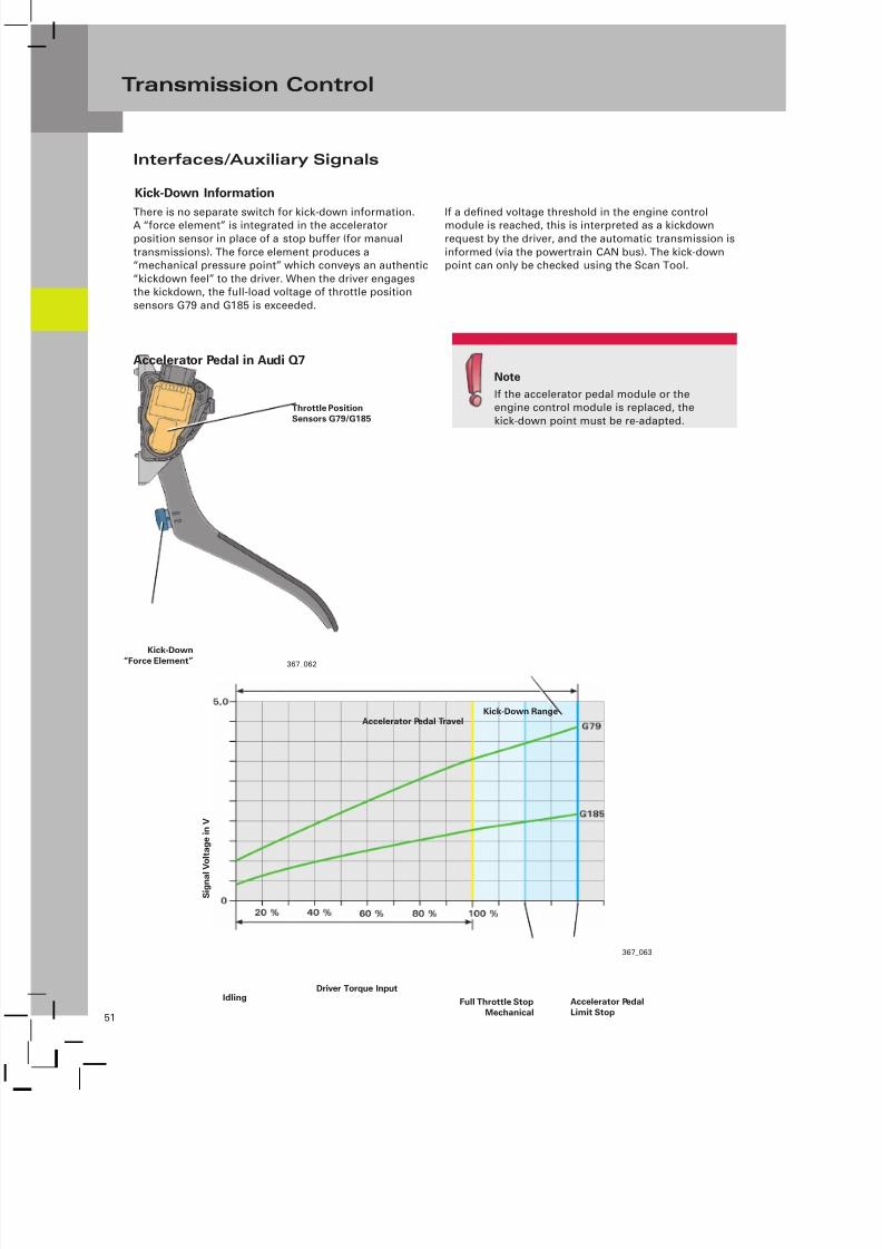
Kick-Down Information
There is no separate switch for kick-down information.A “force element” is integrated in the accelerator
position sensor in place of a stop buffer (for manual
transmissions). The force element produces a“mechanical pressure point” which conveys an authentic
“kickdown feel” to the driver. When the driver engagesthe kickdown, the full-load voltage of throttle position
sensors G79 and G185 is exceeded.
If a defined voltage threshold in the engine controlmodule is reached, this is interpreted as a kickdown
request by the driver, and the automatic transmission is
informed (via the powertrain CAN bus). The kick-downpoint can only be checked using the Scan Tool.
Note
If the accelerator pedal module or theengine control module is replaced, the
kick-down point must be re-adapted.
Accelerator Pedal in Audi Q7
367_062
Throttle Position
Sensors G79/G185
Kick-Down
“Force Element”
Accelerator Pedal TravelKick-Down Range
367_063
Accelerator Pedal
Limit Stop
S i g n a l V o l t a g e i n V
Driver Torque InputIdling
Full Throttle Stop
Mechanical

7/23/2019 Pps 951703 Audi 09d Transmission Eng
http://slidepdf.com/reader/full/pps-951703-audi-09d-transmission-eng 55/79
52
Transmission Control
Starter Inhibitor/Starter Control
Distributed Functions in the Audi Q7
Back-up Switch F41
Dynamic Shift Program DSP
367_078
F41
Switch for P/N Signal
Multi-Function Transmission Range (TR) Switch F125
As a modern automatic transmission, the 09D alsofeatures the latest generation of the Dynamic Shift
Program (DSP).
The DSP evaluates vehicle operating parameters such as
motion resistance (for example, uphill gradient), route
profile (for example, corner), and driver type (drivingstyle).
The main parameters used to compute the gearselection have not changed fundamentally compared to
previous automatic transmissions. Due to the increased
networking of the Transmission Control Module andother vehicle systems, such as engine, ESP, and steering
angle sensor, today a larger volume of information
is available, providing an even better description ofmomentary driving status and driving style for the
Transmission Control Module.
The starter control/starter inhibitor function is
implemented via Access/Start Control Module J518.
The P/N signal (ground), a requirement for start
enabling, is generated by a separate switch in Multi-Function Transmission Range (TR) Switch F125. The P/N
signal is transmitted to J518 via a discrete line.
J518 only enables Engine Control Module J623 to
activate terminal 50 in selector lever position “P” or “N.”
For self-diagnostic purposes, the selector lever positionis also indicated to J518 via the databus.
Multi-Function Transmission Range (TR) Switch F125
supplies a voltage signal (R signal) to Vehicle Electrical
System Control Module J519 and other control moduleswhich utilize the R signal.
The R signal is required for the following functions and
systems:– Back-up Light
– Anti-Dazzle RearView Mirror
– Self-Diagnosis of Transmission Control Module J217
The back-up lights are activated by Comfort System
Central Control Module 2. The information path is asfollows: F41 > discrete line Vehicle Electrical System
Control Module J519 > Comfort System Central Control
Module 2 J773 via the convenience CAN > discrete lineto back-up lights.
The R signal is also sent to Transmission ControlModule J217 via a discrete line.
The self-diagnostics in J217 utilize the R signal to checkthe plausibility of Multi-Function Transmission Range
Switch F125.
If the R signal is faulty, the transmission enters limp-
home mode.

7/23/2019 Pps 951703 Audi 09d Transmission Eng
http://slidepdf.com/reader/full/pps-951703-audi-09d-transmission-eng 56/79
53
Transmission Control
Tiptronic Shift Strategy
– Automatic Upshift Upon Reaching MaximumEngine Speed.
– Automatic Downshift when Engine Speed Drops BelowMinimum Threshold.
– Kick-Down.
– Drive-Away in Second Gear by Selecting SecondBefore driving Off.1)
– Upshift Prevention and Downshift Prevention.2)
1) The vehicle is normally driven away in first gear. It canalso be driven away in second gear by shifting up into
second before driving off (with steering wheelTiptronic or selector lever). This makes driving awayeasier on low friction road surfaces, for example, onicy or snow-covered roads.
2) In addition to manual gearshifting, the Tiptronicfunction is, for example, necessary for making use ofthe engine braking effect. The selector lever gate (withpositions “D” and “S”) does not allow intervention inorder to prevent upshifts or downshifts. The Tiptronicfunction (selector lever in Tiptronic gate) can beused to maintain the actual gear position or to selecta different gear within the shift limits. In this way, asmentioned, it is possible to use the engine brakingeffect and prevent repeated shifting back-and-forthbetween gears (for example, in trailer towing mode).
Sport Program “S”
In the selector lever “S” position, a performance-oriented
shift program is available to the driver.
When the Transmission Control Module is informed
that the selector lever is in the “S” position, it alters theshift characteristic so it is biased toward higher engine
speeds. This enhances driving dynamics.
When the selector lever is in the “S” position, the DSP
also adapts to driver inputs (driver type analysis) anddriving situations.
The “S” program also has the following special features:
– If the selector lever is moved into the “S” positionunder constant acceleration, the transmission kicksdown within defined limits.
– To ensure a more direct driving response to movementof the accelerator, the vehicle is, where possible,operated with the converter lockup clutch closed.
– If sixth gear is configured as an overdrive gear, only
gears 1 to 5 are selected.
7/23/2019 Pps 951703 Audi 09d Transmission Eng
http://slidepdf.com/reader/full/pps-951703-audi-09d-transmission-eng 57/79
54
Transmission Control
In the event of faults/malfunctions which activate
the mechanical limp-home mode, 3rd gear is always
selected during vehicle operation in any gear up tothird.
If the transmission is already in fourth, fifth, or sixthgear, the momentary gear is maintained until the
selector lever is moved into neutral or the ignition isswitched off.
When driving away again (with the selector lever ineither the “D” or “S” position), or restarting the engine,
third gear is always selected.
Reverse gear is available (R gear lock is disabled).
The maximum system pressure is set and, as a
result, maximum shift pressure is applied to the shift
elements. This results in harsh gear engagements.
The converter lockup clutch stays open.
Limp-home Mode
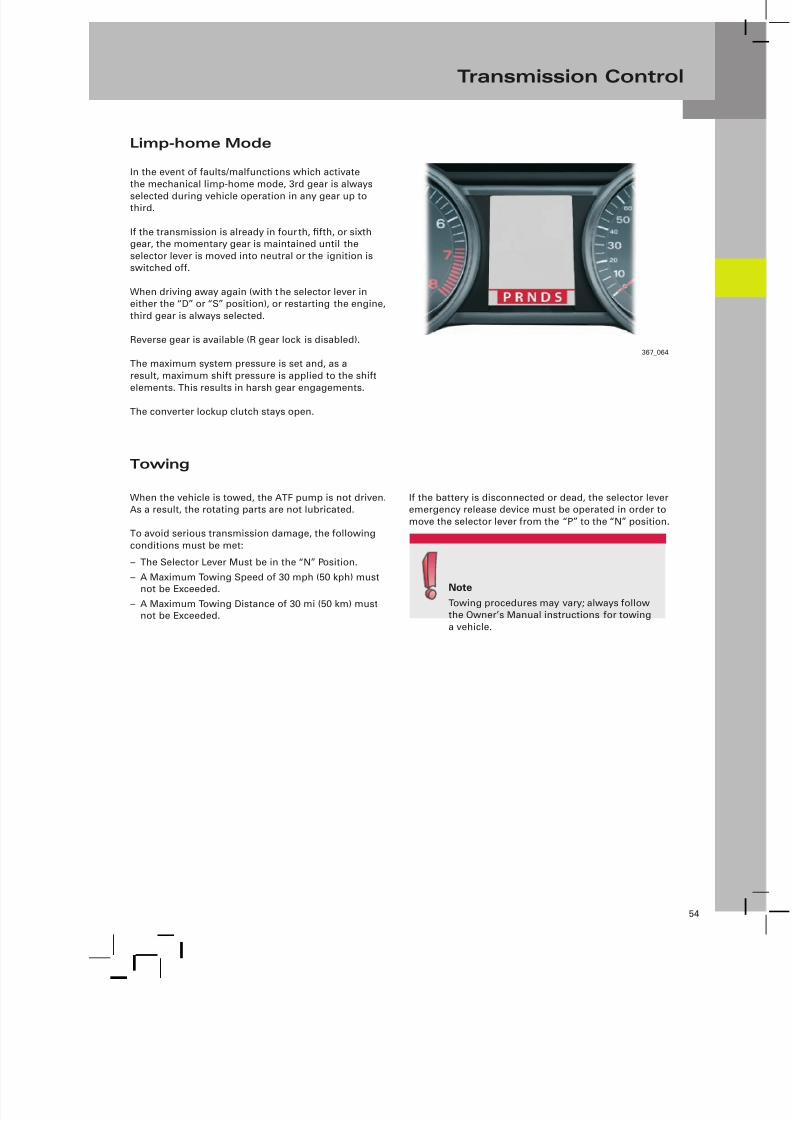
Towing
When the vehicle is towed, the ATF pump is not driven.As a result, the rotating parts are not lubricated.
To avoid serious transmission damage, the following
conditions must be met:
– The Selector Lever Must be in the “N” Position.
– A Maximum Towing Speed of 30 mph (50 kph) must
not be Exceeded.– A Maximum Towing Distance of 30 mi (50 km) must
not be Exceeded.
If the battery is disconnected or dead, the selector leveremergency release device must be operated in order to
move the selector lever from the “P” to the “N” position.
367_064
NoteTowing procedures may vary; always followthe Owner’s Manual instructions for towing
a vehicle.

7/23/2019 Pps 951703 Audi 09d Transmission Eng
http://slidepdf.com/reader/full/pps-951703-audi-09d-transmission-eng 58/79
55
Transmission Control
Transmission Adaption – 09D Transmission
Introduction
A prerequisite for good and consistent shift quality,in addition to the design, is precision control of the
shift elements. This is the purpose of the transmission
adaption feature. In order to maintain constant shiftquality during the entire service life of the transmission,
it is necessary to continuously adapt the various openand closed-loop control parameters and save acquired
adaption data. These adjustments and the teach-in
process are collectively defined as “adaption.”
The task of the adaption function is to compensate for
production tolerances in transmission components and
changes which occur during their service life.
The adaption values serve as corrective values, or
so-called offsets, which are either added to or subtractedfrom the default values (applied values) stored in the
Transmission Control Module.
Adaption Example Adaption Limits
367_115
Adaption Range
Correction “–2”
Adapted Value “18”
Adapted Value “20”
Note
Transmission adaption is a very complex subject. Only basic principles and
general topics are discussed in the content of this Self-Study Program. You will
find further information in the relevant Service Training Course.

7/23/2019 Pps 951703 Audi 09d Transmission Eng
http://slidepdf.com/reader/full/pps-951703-audi-09d-transmission-eng 59/79
56
Transmission Control
Mechanical and Hydraulic Influencing Factors
The shift elements are actuated hydraulically. For this
reason, allowance must be made for the characteristicsof the electrical and mechanical control valves. The
resistances produced by mechanical friction incomponents, as well as the pressure of the piston returnsprings, have to be overcome. In addition, attention
must be paid to the filling of all ports, lines, and
cylinder chambers, as well as the clutch clearance. Allof these are factors which affect the overall gearshifting
sequence, not to mention the parameters which apply to
the shift elements themselves.
Shift Element Parameters
Clutch torque is dependent on the following parameters:– Type of Engine.
– Contact Pressure (clutch pressure).
– Coefficient of Friction.
Note:These parameters must always be in correct correlation
with each other so that a specific amount of torque can
be transmitted.
The type is defined in design terms and therefore
constant. Contact pressure is regulated by the clutchpressure. Clutch pressure is the parameter which is
used to control clutch torque and which is most easilyinfluenced. The coefficient of friction is a parameter
which changes continuously during vehicle operation
and throughout the service life of the vehicle.
Now, therefore, let us look the variable parameters,
clutch pressure, and coefficient of friction.
The coefficient of friction is dependent on the followinginfluencing factors:
– Materials of the Friction Partners(specification, quality, aging, and wear).
– ATF (specification, quality, aging, and wear)
– ATF Temperature
– Clutch Temperature
– Clutch Slip
In addition to the previously mentioned mechanical
and hydraulic influencing factors, the above influencingfactors have to be compensated by adaption.
Fig. 367_117 shows, in a simplified manner, thesequence of a so-called overlap gearshift (upshift under
acceleration) and the adaption ranges within which
adaption processes take place.
In an overlap gearshift, the power-transmitting clutchmaintains the torque at a reduced pressure level until
the engaging clutch has taken up the torque. To make
the gearshift sequence as comfortable as possible andto conserve the clutches, engine torque is reduced while
the overlap gearshift is being performed.
367_117
Legend
n_mot = Engine Speed
n_t = Turbine Speed
m_mot = Engine Torque
P_zu = Engaging Clutch
P_ab = Disengaging Clutch
t = Time
A, B, C = Adaption Range
Upshift Under Acceleration Sequence
A
Pre-Filling
B
Shift Pressure
C
Holding Pressure

7/23/2019 Pps 951703 Audi 09d Transmission Eng
http://slidepdf.com/reader/full/pps-951703-audi-09d-transmission-eng 60/79
57
Transmission Control
367_117
Legend
n_mot = Engine Speed
n_t = Turbine Speed
m_mot = Engine Torque
P_zu = Engaging Clutch
P_ab = Disengaging Clutch
t = Time
A, B, C = Adaption Range
Upshift Under Acceleration Sequence
A
Pre-Filling
B
Shift Pressure
C
Holding Pressure
Quick Filling Time
(quick filling)
Filling Pressure
The following aspects of the gearshift sequence areadapted:
– Quick Filling Time (pre-filling)
– Filling Pressure (pre-filling)
– Shift Pressure (engaging and disengaging clutch)
– Holding Pressure
Quick Filling Time = period during which increased
pressure is applied to the clutch in order to engage the
clutch assembly and fill the clutch cylinder chamber.
Filling Pressure = pressure which is required to compressthe clutch plate assembly to the point where the clutch
just comes into engagement but a significant amount of
this torque is still not transmitted.
Shift Pressure = pressure which acts during the slip
phase.
Holding Pressure = pressure required to keep the clutchsecurely closed.
Adaptions are made during gearshift cycles and whenthe vehicle is stationary with the engine operating at
idling speed.
The following adaption conditions must be met soadaptions can be performed:
– ATF Temperature Must be Between 151 °F and 230 °F(66 °C and 110 °C).
– Engine Load Must be Within Defined Range
(very low engine load or low accelerator pedal angle).– No Faults Registered in Fault Memory of the
Transmission Control Module.
– Defined driving state (for example, certain adaptionsare only performed when vehicle is stationary andwhen engine is running at idling speed).
– Good Road Conditions (no uphill gradient or downhillgradient, straight road).
The transmission adaption status is established over a
prolonged period of time in service. A further feature ofthe Transmission Control Module is that the adaption
frequency is reduced with increasing mileage. This
means the adaption frequency of a transmission withlow mileage or with cancelled adaption values is very
high. On the other hand, transmissions with highmileage have longer adaption intervals.

7/23/2019 Pps 951703 Audi 09d Transmission Eng
http://slidepdf.com/reader/full/pps-951703-audi-09d-transmission-eng 61/79
58
Transmission Control
Deleting Adaption Values
The adaption values of the 09D transmission are
preserved even if the power supply to the TransmissionControl Module is cut off (for example, battery is
disconnected, etc.); however, they can be deleted usingthe Basic Setting test plan of the Scan Tool.
Basic Setting can be used not only to delete adaption
values, but also to program in the kick-down pointand activate the steering wheel Tiptronic function (if
available).
The following are situations when the basic setting
procedure must be performed:
– After Replacing the Transmission
– After Replacing the Transmission Control ModuleJ217
– After Changing the ATF
– After Repair Work on the Transmission
(for example, replacing the valve assembly,clutch repairs)
– After Replacing or After Removing and InstallingThrottle Position Sensors G79/G185
– After Complaints About Shift Comfort
– Possibly After Engine Repairs (for example, afterreplacing the engine, engine control module, etc.)
– Possibly After a Software Flash Update
It is recommended to perform an adaption drive afterdeleting adaption values or carrying out the basic
setting procedure.
An adaption drive must always be performed after
deleting adaption values due to complaints about shift
comfort.
Adaption Drive
Step 1:
First, the previously mentioned adaption conditionsmust be fulfilled.
Step 2:When the engine is operating at idling speed, the
vehicle is stationary, and the brake is applied, move the
selector lever from “N” to “D” and keep it in position“D” for at least three seconds. Repeat this procedure
five times, then carry out the same procedure for thegearshift from “N” to “R.”
Step 3:Accelerate the vehicle in selector lever position “D”
from a standing start until 6th gear is engaged and the
vehicle is travelling at a speed of approximately 50 mph(80 kph), or more. An accelerator pedal angle between
25% and 30% must be maintained (check this using
the Scan Tool). After this, allow the vehicle to coast
and then bring it to a standstill within 60 seconds by
applying minimal brake pressure. Repeat this procedure10 times.
Step 4:Shift quality assessment.

7/23/2019 Pps 951703 Audi 09d Transmission Eng
http://slidepdf.com/reader/full/pps-951703-audi-09d-transmission-eng 62/79
59
Transmission Periphery
Gear Selector
The gear selector mechanism is connected mechanically
to the transmission via the selector lever cable.
It also performs several tasks and functions, for which an
electrical connection exists to the Transmission Control
Module and the vehicle periphery.
Mechanical Functions
– Actuation of Parking Lock
– Actuation of Selector Valve of Hydraulic Valve Body
– Actuation of Multi-Function Switch on Transmission
– P/N Lock (shift lock)
Electrical Functions
– P/N Lock Control
– Ignition Key Withdrawal Lock
– Activation of Selector Lever Transmission Range(TR) Position Display Unit
– Tiptronic Function
367_101
Gate Valve with
Permanent Magnet (2x)
Selector Lever
Transmission Range (TR)
Position Display Unit Y26
Connector A
(10-pin, to vehicle wiring
harness/ transmission)
Connector C
(10-pin, to display unit Y26)
Selector Lever Sensor System
Control Module J587 with
Tiptronic Switch F189

7/23/2019 Pps 951703 Audi 09d Transmission Eng
http://slidepdf.com/reader/full/pps-951703-audi-09d-transmission-eng 63/79
60
Transmission Periphery
The design and functioning of the selector lever
mechanism on the Audi Q7 are largely identical to the
mechanism on the 2005 Audi A6 (up to approximatelymid-2006).
Here are the main differences:
The selector lever mechanism can be removed fromthe interior of the vehicle in order to make repairs (for
example, to replace microswitch F305).
When replacing the selector lever mechanism, the
selector housing (installed from the outside) remains
in the vehicle. Only the internal components of themechanism need to be replaced.
367_100Selector Lever Cable
Funnel/Guide
The Funnel Aids
Releasing the P Lock in an
Emergency
Shift Lock Solenoid N110
Gearshift Housing
Internal Components of the
Selector Lever Mechanism
Selector Lever Transmission
Range (TR) Position Display Unit
J587 and Tiptronic Switch F189
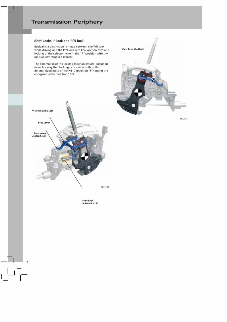
7/23/2019 Pps 951703 Audi 09d Transmission Eng
http://slidepdf.com/reader/full/pps-951703-audi-09d-transmission-eng 64/79
61
Transmission Periphery
Shift Locks (P lock and P/N lock)
Basically, a distinction is made between the P/N lock
while driving and the P/N lock with the ignition “on” and
locking of the selector lever in the “P” position with the
ignition key removed (P lock).
The kinematics of the locking mechanism are designedin such a way that locking is possible both in the
de-energized state of the N110 (position “P”) and in the
energized state (position “N”).
367_102
View from the Right
367_103
Stop Lever
Emergency
Unstop Lever
Shift Lock
Solenoid N110
View from the Left

7/23/2019 Pps 951703 Audi 09d Transmission Eng
http://slidepdf.com/reader/full/pps-951703-audi-09d-transmission-eng 65/79
62
Transmission Periphery
Shift Lock – Selector Lever Position “P”
Locking of the selector lever in position “P” is ensured bythe automatic locking of the stop lever in this position.
If N110 is de-engergized, the stop lever (assisted by aspring in solenoid N110) drops automatically (by gravity)
into the P lock as soon as the selector lever is moved intothe “P” position.
To release the shift lock, solenoid N110 is energized, withthe result that the solenoid pushes the stop lever back
out of the P lock.
In the event of a fault or power failure, the selector
lever remains locked in position. There is an emergencyrelease mechanism for such cases.
367_104
Stop Lever
Terminal 31
P Lock
N110
Shift Lock – Selector Lever Position “N”If the selector lever is in the “N” position, N110 is
activated and pushes the upper hook of the stop lever
into the N lock and locks the selector lever.
To release the shift lock, N110 is de-energized, and the
stop lever drops down. (Refer to the Shift Lock - Selector
Lever Position “P” explanation.)
367_105
N Lock
Terminal 31
N110
Voltage from
J217

7/23/2019 Pps 951703 Audi 09d Transmission Eng
http://slidepdf.com/reader/full/pps-951703-audi-09d-transmission-eng 66/79
63
Transmission Periphery
367_106
Ashtray Insert
Emergency
Release Lever
Ashtray
Trim Clip
Emergency Release – P Lock
Due to the fact the P lock is only unlocked when N110 is
activated, the selector lever remains locked in position“P” in the event of a malfunction (for example, dead
battery, failure of solenoid N110, etc.).
To enable the vehicle to be moved in such a situation,
there is an emergency release lever on the left-hand sideof the stop lever.
The emergency release mechanism can be accessed by
removing the ashtray insert and the trim clip behind it.
The stop lever is unlocked by pushing down on theemergency unlocking lever (for example, using a ballpoint pen). At the same time, the button on the selector
lever must be pressed and the selector lever pulled back.
Selector Lever Transmission Range Position
Display Unit Y26
The LEDs on the display unit are powered by SelectorLever Sensor System Control Module J857 and activated
according to the selector lever position.
The brightness of the LEDs is controlled via terminal58d (PWM signal, dimming) and varies with voltagelevel (generated by J587). This means the LED, whichindicates the current selector lever position, is activatedby a “pulsed voltage” of approximately 12V, whileapproximately 4V are applied to all other LEDs.
367_003
Selector Lever
Transmission Range
Position Display Unit Y26
367_112

7/23/2019 Pps 951703 Audi 09d Transmission Eng
http://slidepdf.com/reader/full/pps-951703-audi-09d-transmission-eng 67/79
64
Transmission Periphery
The ignition key withdrawal lock is actuated
automatically by a mechanical locking mechanism
integrated in Access/Start Authorization Switch E415.
The ignition key withdrawal lock is released
electromechanically by brief activation of IgnitionSwitch Key Lock Solenoid N376. For this purpose, E415
requires information on selector lever “P” position.
The information on selector lever position “P” is
supplied by Transmission Park Selector Switches F305.These two switches are connected in series and form a
unit.
In selector lever “P” position, the two switches are
closed and deliver a ground signal directly to E415. Ifthe ignition is turned to the “off” position, solenoid
N376 is energized by E415 for a short time, and an
unlocking mechanism cancels the ignition key lock.
Ignition Key Withdrawal Lock
367_107
Microswitch 1
with ResistorMicroswitch 2
P Signal
Emergency Release
For safety reasons, two microswitches are installed.
Microswitch 1 is closed when the selector lever button
is released in selector lever position “P” (button is notpressed).
The series-connected resistor enables the signal line tobe diagnosed.
Microswitch 2 is closed when the stop lever for the P/Nlock is in its home position. It signals when the selector
lever is actually locked in the “P” position.
367_108
Microswitch 1 Microswitch 2

7/23/2019 Pps 951703 Audi 09d Transmission Eng
http://slidepdf.com/reader/full/pps-951703-audi-09d-transmission-eng 68/79
65
Transmission Periphery
Selector Lever Sensor System Control Module J587
The functions of the Selector Lever Sensor System
Control Module are limited to generating the Tiptronic
signal for the Tiptronic function (from F189) and the P/R/ N/D/S signal for activating Selector Lever Transmission
Range Position Display Unit Y26.
P/R/N/D/S Signal
The information on the selector lever position (P/R/N/D/S
signal) is sent from the Transmission Control Module
to the selector lever sensor system in the form of afrequency-modulated square-wave signal (FMR signal).
The relevant LEDs on display unit Y26 are then activated.
A defined signal frequency is assigned to each selector
lever position (see DSO images). The selector lever
sensor system evaluates the signal and activates therelevant LED on display unit Y26 (ground activation).
Advantages
– Synchronous Indication of Selector Lever Position inInstrument Panel and on Selector Lever
– Cost Savings through Simplification of Selector LeverSensor System Control Module J587 (elimination ofadditional Hall sensors)
367_005
P/R/N/D/S Signal
Functional Diagram of the Gear Selector Mechanism with 09D Transmission
Tiptronic Signal
F189 Tiptronic Switch
F305 Transmission Park Selector Switch
J587 Selector Lever Sensor System Control ModuleN110 Shift Lock Solenoid
Y26 Selector Lever Transmission Range Position Display Unit
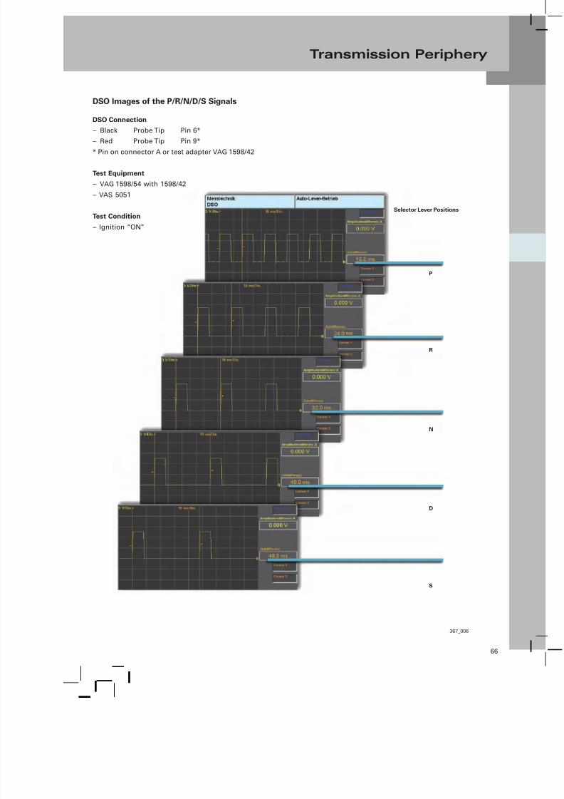
7/23/2019 Pps 951703 Audi 09d Transmission Eng
http://slidepdf.com/reader/full/pps-951703-audi-09d-transmission-eng 69/79
66
Transmission Periphery
367_006
Selector Lever Positions
P
R
N
D
S
DSO Images of the P/R/N/D/S Signals
DSO Connection
– Black Probe Tip Pin 6*
– Red Probe Tip Pin 9*
* Pin on connector A or test adapter VAG 1598/42
Test Equipment
– VAG 1598/54 with 1598/42
– VAS 5051
Test Condition
– Ignition “ON”

7/23/2019 Pps 951703 Audi 09d Transmission Eng
http://slidepdf.com/reader/full/pps-951703-audi-09d-transmission-eng 70/79
67
Transmission Periphery
367_007
Selector Lever
Positions
P/R/N/D/S
Tiptronic Gate
Tiptronic Tip +
Tiptronic Tip –
Test adaptor VAG 1598/54 is available in combination
with test box VAG 1598/42 for testing the signals to and
from the gear selector mechanism.
Test adaptor VAG 1598/48 is available in combination
with test box VAG 1598/42 for testing the signals to and
from the 09D transmission.
DSO Images of the Tiptronic Signal
DSO Port
– Black Probe Tip Pin 6*
– Red Probe Tip Pin 3*
* Pin on connector A ortest adapter VAG 1598/42
Test Equipment
– VAG 1598/54 with 1598/42
– VAS 5051
Test Condition
– Ignition “ON”
Tiptronic Signal
The information of the selector lever in the Tiptronic
gate (selector lever in Tip+ position or selector lever inTip– position) is transferred via a discrete line (see DSO
images) to the Transmission Control Module in the form of
a frequency-modulated square-wave signal (FMR signal).
Advantages
– Higher Operational Reliability - only one line to controlmodule is required (instead of three), thereby reducingthe number of potential fault sources.
– Improved Self-Diagnosis

7/23/2019 Pps 951703 Audi 09d Transmission Eng
http://slidepdf.com/reader/full/pps-951703-audi-09d-transmission-eng 71/79
68
Notes
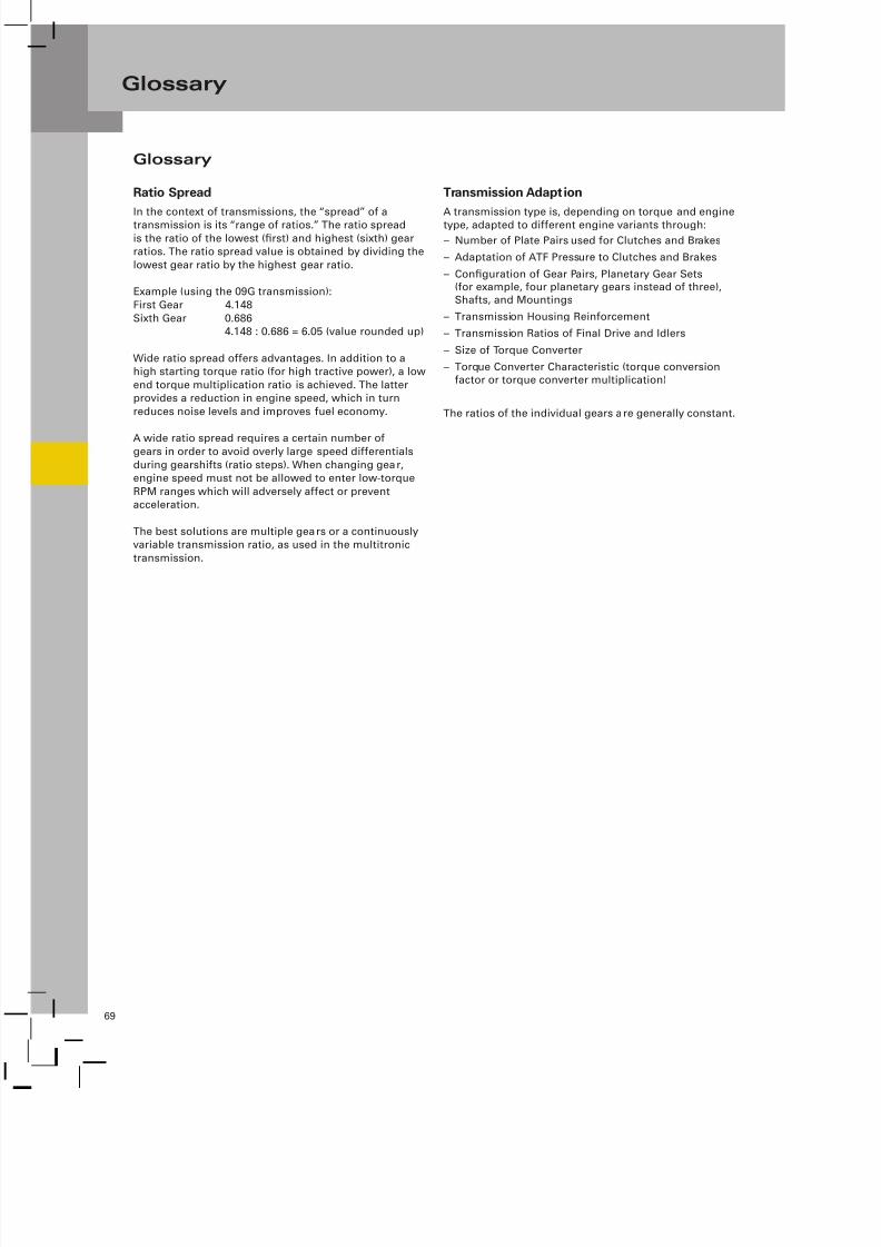
7/23/2019 Pps 951703 Audi 09d Transmission Eng
http://slidepdf.com/reader/full/pps-951703-audi-09d-transmission-eng 72/79
69
Glossary
Ratio Spread
In the context of transmissions, the “spread” of atransmission is its “range of ratios.” The ratio spread
is the ratio of the lowest (first) and highest (sixth) gearratios. The ratio spread value is obtained by dividing the
lowest gear ratio by the highest gear ratio.
Example (using the 09G transmission):
First Gear 4.148
Sixth Gear 0.6864.148 : 0.686 = 6.05 (value rounded up)
Wide ratio spread offers advantages. In addition to ahigh starting torque ratio (for high tractive power), a low
end torque multiplication ratio is achieved. The latterprovides a reduction in engine speed, which in turn
reduces noise levels and improves fuel economy.
A wide ratio spread requires a certain number ofgears in order to avoid overly large speed differentials
during gearshifts (ratio steps). When changing gear,engine speed must not be allowed to enter low-torque
RPM ranges which will adversely affect or preventacceleration.
The best solutions are multiple gears or a continuouslyvariable transmission ratio, as used in the multitronic
transmission.
Transmission Adaption
A transmission type is, depending on torque and enginetype, adapted to different engine variants through:
– Number of Plate Pairs used for Clutches and Brakes
– Adaptation of ATF Pressure to Clutches and Brakes
– Configuration of Gear Pairs, Planetary Gear Sets(for example, four planetary gears instead of three),Shafts, and Mountings
– Transmission Housing Reinforcement
– Transmission Ratios of Final Drive and Idlers
– Size of Torque Converter
– Torque Converter Characteristic (torque conversionfactor or torque converter multiplication)
The ratios of the individual gears are generally constant.
Glossary

7/23/2019 Pps 951703 Audi 09d Transmission Eng
http://slidepdf.com/reader/full/pps-951703-audi-09d-transmission-eng 73/79
70
Notes
7/23/2019 Pps 951703 Audi 09d Transmission Eng
http://slidepdf.com/reader/full/pps-951703-audi-09d-transmission-eng 74/79
71
Index
AAdaption . . . . . . . . . . . . . . . . . . . . . . . . . . . . . . . . . . . 55
Adaption Conditions . . . . . . . . . . . . . . . . . . . . . . . . . 57
Adaption Drive . . . . . . . . . . . . . . . . . . . . . . . . . . . . . . 58
ATF (Automatic Transmission Fluid). . . . . . . . . . . . . 13
ATF Cooling. . . . . . . . . . . . . . . . . . . . . . . . . . . . . . . . . 15
ATF Pump . . . . . . . . . . . . . . . . . . . . . . . . . . . . . . . . . . 13
ATF Temperature . . . . . . . . . . . . . . . . . . . . . . . . . . . . 47
Automatic Transmission Control Module J217. . . . 39
Auxiliary Signals . . . . . . . . . . . . . . . . . . . . . . . . . . . . . 51
BBack-up Switch F41 . . . . . . . . . . . . . . . . . . . . . . . . . . 52
Brakes . . . . . . . . . . . . . . . . . . . . . . . . . . . . . . . . . . . . . 23
CCAN Information Exchange. . . . . . . . . . . . . . . . . . . .49
Clutches. . . . . . . . . . . . . . . . . . . . . . . . . . . . . . . . . . . . 23
Clutch Pressure. . . . . . . . . . . . . . . . . . . . . . . . . . . . . . 56
Coefficient of Friction . . . . . . . . . . . . . . . . . . . . . . . . 56
Controlled Operation, Lockup Clutch. . . . . . . . . . . . 12
Control Pressure . . . . . . . . . . . . . . . . . . . . . . . . . . . . . 27
Cutaway View of the 09D . . . . . . . . . . . . . . . . . . . . 5 - 6
DDeleting Adaption Values . . . . . . . . . . . . . . . . . . . . .58
Description of Gear/Torque Curve . . . . . . . . . . . . . .301st Gear. . . . . . . . . . . . . . . . . . . . . . . . . . . . . . . . . 312nd Gear . . . . . . . . . . . . . . . . . . . . . . . . . . . . . . . . 313rd Gear . . . . . . . . . . . . . . . . . . . . . . . . . . . . . . . . 324th Gear. . . . . . . . . . . . . . . . . . . . . . . . . . . . . . . . . 325th Gear. . . . . . . . . . . . . . . . . . . . . . . . . . . . . . . . . 336th Gear. . . . . . . . . . . . . . . . . . . . . . . . . . . . . . . . . 33
Distributed Functions . . . . . . . . . . . . . . . . . . . . . . . . 52
Drive-Away in 2nd Gear . . . . . . . . . . . . . . . . . . . . . . . 53
DSO Images . . . . . . . . . . . . . . . . . . . . . . . 44, 46, 66, 67
Dynamic Pressure Compensation. . . . . . . . . . . . . . .25
Dynamic Shift Program DSP . . . . . . . . . . . . . . . . . . .52
EElectromagnetic Valves . . . . . . . . . . . . . . . . . . . . . . . 28
Emergency Release - P Lock . . . . . . . . . . . . . . . . . . .63
FF41 . . . . . . . . . . . . . . . . . . . . . . . . . . . . . . . . . . . . . . . . 52
F125 . . . . . . . . . . . . . . . . . . . . . . . . . . . . . . . . . . . . . . . 40
F189 . . . . . . . . . . . . . . . . . . . . . . . . . . . . . . . . . . . . . . . 59
Filling Pressure . . . . . . . . . . . . . . . . . . . . . . . . . . . . . . 57
Freewheel . . . . . . . . . . . . . . . . . . . . . . . . . . . . . . . . . . 26
Function Diagram - 09D Transmission. . . . . . . . . . . 37
Function of the Shift Elements. . . . . . . . . . . . . . . . .23
GG85. . . . . . . . . . . . . . . . . . . . . . . . . . . . . . . . . . . . . . . . 50
G93. . . . . . . . . . . . . . . . . . . . . . . . . . . . . . . . . . . . . . . . 47
G182. . . . . . . . . . . . . . . . . . . . . . . . . . . . . . . . . . . . . . . 43
G195. . . . . . . . . . . . . . . . . . . . . . . . . . . . . . . . . . . . . . . 45
Gear Selector . . . . . . . . . . . . . . . . . . . . . . . . . . . . . . . 59
HHolding Pressure . . . . . . . . . . . . . . . . . . . . . . . . . . . . 57
Hot-mode . . . . . . . . . . . . . . . . . . . . . . . . . . . . . . . . . . 47
Hydraulic Control . . . . . . . . . . . . . . . . . . . . . . . . . . . . 27
IIgnition Key Withdrawal Lock . . . . . . . . . . . . . . . . . .64
Interfaces . . . . . . . . . . . . . . . . . . . . . . . . . . . . . . . . . . 51
JJ104 . . . . . . . . . . . . . . . . . . . . . . . . . . . . . . . . . . . . . . . 50
J217 . . . . . . . . . . . . . . . . . . . . . . . . . . . . . . . . . . . . . . . 39
J285 . . . . . . . . . . . . . . . . . . . . . . . . . . . . . . . . . . . . . . . 49
J428 . . . . . . . . . . . . . . . . . . . . . . . . . . . . . . . . . . . . . . . 50
J453 . . . . . . . . . . . . . . . . . . . . . . . . . . . . . . . . . . . . . . . 50
J527 . . . . . . . . . . . . . . . . . . . . . . . . . . . . . . . . . . . . . . . 50
J533 . . . . . . . . . . . . . . . . . . . . . . . . . . . . . . . . . . . . . . . 50
J587 . . . . . . . . . . . . . . . . . . . . . . . . . . . . . . . . . . . . . . . 65
KKick-Down Information . . . . . . . . . . . . . . . . . . . . . . . 51
LLepelletier Planetary Gear Set. . . . . . . . . . . . . . . . . .17
Limp-home Mode . . . . . . . . . . . . . . . . . . . . . . . . . . . . 54
7/23/2019 Pps 951703 Audi 09d Transmission Eng
http://slidepdf.com/reader/full/pps-951703-audi-09d-transmission-eng 75/79
72
Index
MMulti-Function Switch F125. . . . . . . . . . . . . . . . . . . .40
NN88. . . . . . . . . . . . . . . . . . . . . . . . . . . . . . . . . . . . . . . . 28
N89. . . . . . . . . . . . . . . . . . . . . . . . . . . . . . . . . . . . . . . . 28
N90. . . . . . . . . . . . . . . . . . . . . . . . . . . . . . . . . . . . . . . . 29
N91. . . . . . . . . . . . . . . . . . . . . . . . . . . . . . . . . . . . . . . . 29
N92. . . . . . . . . . . . . . . . . . . . . . . . . . . . . . . . . . . . . . . . 29
N93. . . . . . . . . . . . . . . . . . . . . . . . . . . . . . . . . . . . . . . . 29
OOffroad Use. . . . . . . . . . . . . . . . . . . . . . . . . . . . . . . . . . 2
Oil Supply/Lubrication . . . . . . . . . . . . . . . . . . . . . . . . 13
Oil Temperature Regulator (thermostat) . . . . . . . . . 15
O v e r l a p G e a r s h i f t s . . . . . . . . . . . . . . . . . . . . . . . . . . . 5 6
PParking Lock . . . . . . . . . . . . . . . . . . . . . . . . . . . . . . . . 35
P Lock, P/N Lock . . . . . . . . . . . . . . . . . . . . . . . . . . . . . 61
Primary Planetary Gear Set . . . . . . . . . . . . . . . . . . . .17
P/R/N/D/S Signal . . . . . . . . . . . . . . . . . . . . . . . . . . . . . 65
Q Quick Filling Time . . . . . . . . . . . . . . . . . . . . . . . . . . . . 57
RRatio Spread . . . . . . . . . . . . . . . . . . . . . . . . . . . . . . . . 69
R Gear . . . . . . . . . . . . . . . . . . . . . . . . . . . . . . . . . . . . . 34
SSchematic Power Flow Diagram. . . . . . . . . . . . . . . .21
Secondary Planetary Gear Set. . . . . . . . . . . . . . . . . .17
Selector Lever Sensor System J587 . . . . . . . . . . . . . 65
Shift Elements . . . . . . . . . . . . . . . . . . . . . . . . . . . . . . 19
Shift Locks (P lock and P/N lock) . . . . . . . . . . . . . . . .61
Shift Logic . . . . . . . . . . . . . . . . . . . . . . . . . . . . . . . . . . 29Shift Logic F125 . . . . . . . . . . . . . . . . . . . . . . . . . . . . . 41
Shift Pressure . . . . . . . . . . . . . . . . . . . . . . . . . . . . . . .57
Specifications . . . . . . . . . . . . . . . . . . . . . . . . . . . . . . . . 3
Sport Program “S” . . . . . . . . . . . . . . . . . . . . . . . . . . . 53
Starter Control . . . . . . . . . . . . . . . . . . . . . . . . . . . . . . 52
Starter Inhibitor . . . . . . . . . . . . . . . . . . . . . . . . . . . . . 52
TThermostat . . . . . . . . . . . . . . . . . . . . . . . . . . . . . . . . . 15
Tiptronic Shift Strategy . . . . . . . . . . . . . . . . . . . . . . . 53
Tiptronic Signal . . . . . . . . . . . . . . . . . . . . . . . . . . . . . 67
Tiptronic Switch F189 . . . . . . . . . . . . . . . . . . . . . . . . 59
Torque Converter . . . . . . . . . . . . . . . . . . . . . . . . . . . . . 9
Torque Converter Lockup Clutch. . . . . . . . . . . . . . . .11
Towing . . . . . . . . . . . . . . . . . . . . . . . . . . . . . . . . . . . . . 54
Transmission Adaption . . . . . . . . . . . . . . . . . . . . . . . 55
Transmission Breather. . . . . . . . . . . . . . . . . . . . . . . . . 2
Transmission Input Speed Sensor G182 . . . . . . . . . 43
Transmission Oil Temperature Sensor G93 . . . . . . . 47
Transmission Output Speed Sensor G195. . . . . . . . 45
UUpshift Under Acceleration . . . . . . . . . . . . . . . . . . . .57
VValve Assembly. . . . . . . . . . . . . . . . . . . . . . . . . . . . . . 27
YY26 . . . . . . . . . . . . . . . . . . . . . . . . . . . . . . . . . . . . . . . . 63

7/23/2019 Pps 951703 Audi 09d Transmission Eng
http://slidepdf.com/reader/full/pps-951703-audi-09d-transmission-eng 76/79
73
Notes

7/23/2019 Pps 951703 Audi 09d Transmission Eng
http://slidepdf.com/reader/full/pps-951703-audi-09d-transmission-eng 77/79
Knowledge Assessment
ii
An on-line Knowledge Assessment (exam) is available for this SSP.
The Knowledge Assessment may or may not be required for Certification.
You can find this Knowledge Assessment at:
www.accessaudi.com
From the accessaudi.com homepage:
Click on the “ACADEMY” Tab–
Click on the “Academy Site” Link–
Click on the ”CRC Certification” Link–
For assistance, please call:
Audi Academy
Learning Management Center Headquarters
1-877-AUDI-LMC (283-4562)
(8:00 a.m. to 8:00 p.m. EST)
Knowledge Assessment

7/23/2019 Pps 951703 Audi 09d Transmission Eng
http://slidepdf.com/reader/full/pps-951703-audi-09d-transmission-eng 78/79
75
Notes

7/23/2019 Pps 951703 Audi 09d Transmission Eng
http://slidepdf.com/reader/full/pps-951703-audi-09d-transmission-eng 79/79
951703
Related Documents