P OWERT ECH 4.5L & 6.8L Diesel Engines Mechanical Fuel Systems TECHNICAL MANUAL POWERT ECH 4.5 L & 6.8 L Diesel Engines — Mechanical Fuel Systems CTM207 06OCT04 (ENGLISH) For complete service information also see: POWERTECH 4.5 L and 6.8 L Diesel Engines—Base Engine ................. CTM104 Alternators and Starter Motors ........... CTM77 OEM Engine Accessories ...... CTM67 (English Only) POWERTECH 4.5 L and 6.8 L Diesel Engines—Level 4 Electronic Fuel Systems with Bosch VP44 Pump................. CTM170 POWERTECH 4.5 L and 6.8 L Diesel Engines—Level 12 Electronic Fuel Systems with Stanadyne DE10 Pump ............. CTM331 POWERTECH 4.5 L and 6.8 L Diesel Engines—Level 1 Electronic Fuel Systems with Delphi/Lucas DP201 Pump .......... CTM284 POWERTECH 4.5 L and 6.8 L Diesel Engines—Level 11 Electronic Fuel Systems with Denso High Pressure Common Rail. . . CTM220 John Deere Power Systems LITHO IN U.S.A.

Welcome message from author
This document is posted to help you gain knowledge. Please leave a comment to let me know what you think about it! Share it to your friends and learn new things together.
Transcript

POWERTECH 4.5L & 6.8LDiesel Engines
Mechanical FuelSystems
TECHNICAL MANUALPOWERTECH 4.5 L & 6.8 L Diesel
Engines — Mechanical FuelSystems
CTM207 06OCT04 (ENGLISH)
For complete service information also see:
POWERTECH 4.5 L and 6.8 L DieselEngines—Base Engine . . . . . . . . . . . . . . . . . CTM104Alternators and Starter Motors. . . . . . . . . . . CTM77OEM Engine Accessories . . . . . . CTM67 (English Only)POWERTECH 4.5 L and 6.8 L DieselEngines—Level 4 Electronic Fuel Systemswith Bosch VP44 Pump. . . . . . . . . . . . . . . . . CTM170POWERTECH 4.5 L and 6.8 L DieselEngines—Level 12 Electronic Fuel Systemswith Stanadyne DE10 Pump . . . . . . . . . . . . . CTM331POWERTECH 4.5 L and 6.8 L DieselEngines—Level 1 Electronic Fuel Systemswith Delphi/Lucas DP201 Pump . . . . . . . . . . CTM284POWERTECH 4.5 L and 6.8 L DieselEngines—Level 11 Electronic Fuel Systemswith Denso High Pressure Common Rail. . . CTM220
John Deere Power SystemsLITHO IN U.S.A.
Doosan
Date
Doosan
Disclaimer

Introduction
OUO1032,00014BA –19–19AUG04–1/1
Foreword
This manual is written for an experienced technician.Essential tools required in performing certain servicework are identified in this manual and arerecommended for use.
This manual (CTM207) covers only mechanical fuelsystems. It is one of six volumes on 4.5 L and 6.8 Lengines. The following five companion manuals coverthe base engine plus electronic fuel system repair,operation and diagnostics:
• CTM104—Base Engine• CTM170—Level 4 Electronic Fuel Systems with
Bosch VP44 Pump• CTM331—Level 12 Electronic Fuel Systems with
Stanadyne DE10 Pump• CTM284—Level 1 Electronic Fuel Systems with
Delphi/Lucas DP201 Pump• CTM220—Level 11 Electronic Fuel Systems with
Denso High Pressure Common Rail
Other manuals will be added in the future to provideadditional information on electronic fuel systems asneeded.
Live with safety: Read the safety messages in theintroduction of this manual and the cautions presentedthroughout the text of the manual.
This is the safety-alert symbol. When you see thissymbol on the machine or in this manual, be alert tothe potential for personal injury.
Use this component technical manual in conjunctionwith the machine technical manual. An applicationlisting in Section 01, Group 001 identifiesproduct-model/component type-model relationship. Seethe machine technical manual for information on
component removal and installation, and gainingaccess to the components.
Information is organized in sections and groups for thevarious components requiring service instruction.Section 05 summarizes all applicable essential tools,service equipment and tools, other materials needed todo the job, and service parts kits. Section 06summarizes all specifications, wear tolerances, andtorque values.
Before beginning repair on an engine, clean the engineand mount on a repair stand.
This manual contains SI Metric units of measurefollowed immediately by the U.S. customary units ofmeasure. Most hardware on these engines is metricsized.
Some components of this engine may be servicedwithout removing the engine from the machine. Referto the specific machine technical manual forinformation on components that can be servicedwithout removing the engine from the machine and forengine removal and installation procedures.
Read each block of material completely beforeperforming service to check for differences inprocedures or specifications. Follow only theprocedures that apply to the engine model number youare working on. If only one procedure is given, thatprocedure applies to all the engines in the manual.
CALIFORNIA PROPOSITION 65 WARNINGDiesel engine exhaust and some of its constituentsare known to the State of California to causecancer, birth defects and other reproductive harm.
CTM207 (06OCT04) 4.5 L & 6.8 L Mechanical Fuel Systems100604
PN=2

Introduction
OUO1032,00014C2 –19–23AUG04–1/1
John Deere Dealers
Discard CTM207 dated 17SEP02 or 14MAY03 andreplace with this new manual.
Also, copy this page listing changes to this newCTM207 and route through your Service Department.
SECTION 01—GROUP 001 (Engine Identification)
• Updated engine model designation chart.• Updated engine application charts.
SECTION 01—GROUP 002 (Fuels)
• Revised diesel fuel specifications.• Revised lubricity of diesel fuel specifications.• Added bio-diesel fuel specifications.• Added Dieselscan fuel analysis specifications.
SECTION 02—GROUP 090 (Mechanical FuelSystem Repair and Adjustments)
• Added note regarding substitution of longer fuel filterelements and addition of sediment bowls whenappropriate.
• Added remove and install procedure forDelphi/Lucas fuel shut-off solenoid.
• Added remove and install procedure forDelphi/Lucas cold start advance switch and harness.
• Revised inspection procedure for Stanadyneinjection pump drive gear ID and shaft OD.
• Revised Stanadyne DB2 fuel injection pump drivegear-to-shaft retaining nut torque specification.
• Revised repair instruction for Motorpal fuel injectionpumps.
• Revised bleeding procedure.
SECTION 03—GROUP 130 (Mechanical FuelSystems Operation)
• Revised operational description of rotary fuel supplypumps.
SECTION 04—GROUP 150 (Mechanical FuelSystems Observable Diagnostics and Tests)
• Added warning statements regarding air, water, andcontaminants in fuel pump housings leading topremature pump failure.
• Revised specifications for supply pump pressuretests.
• Revised rotary pump cold start advance check torefer to new solenoid removal and installation storyin Section 02.
• Added warning statement to fuel injection nozzle testregarding fluids under pressure.
• Revised bleeding procedure.
SECTION 05 (Tools and Other Materials)
• All essential tools, service tools, dealer fabricatedtools and other materials listed throughout thismanual are consolidated in this section for ease ofreference.
SECTION 06 (Specifications)
• All repair, test and diagnostic specifications listedthroughout this manual are consolidated in thissection for ease of reference.
CTM207 (06OCT04) 4.5 L & 6.8 L Mechanical Fuel Systems100604
PN=3

Introduction
DPSG,OUO1004,129 –19–09SEP02–1/1
POWERTECH 4.5L Engine with Mechanical Fuel System
RG
7636
–UN
–23N
OV
97
3/4 Right Rear View
RG
7638
–UN
–23N
OV
97
3/4 Left Rear View
RG
7639
–UN
–23N
OV
97
3/4 Right Front View
RG
7637
–UN
–23N
OV
97
3/4 Left Front View
POWERTECH is a registered trademark of Deere & Company
CTM207 (06OCT04) 4.5 L & 6.8 L Mechanical Fuel Systems100604
PN=4

Introduction
DPSG,OUO1004,130 –19–09SEP02–1/1
POWERTECH 6.8L Engine with Mechanical Fuel System
RG
7641
–UN
–23N
OV
97
3/4 Right Front View
RG
7640
–UN
–23N
OV
97
3/4 Left Front View
RG
7643
–UN
–23N
OV
97
3/4 Right Rear View
RG
7642
–UN
–23N
OV
97
3/4 Left Rear View
POWERTECH is a registered trademark of Deere & Company
CTM207 (06OCT04) 4.5 L & 6.8 L Mechanical Fuel Systems100604
PN=5
Introduction
CTM207 (06OCT04) 4.5 L & 6.8 L Mechanical Fuel Systems100604
PN=6

Contents01
SECTION 01—General InformationGroup 000—SafetyGroup 001—Engine Identification and ApplicationsGroup 002—Fuels
02SECTION 02—Repair and AdjustmentsGroup 090—Mechanical Fuel System Repair and
Adjustments
SECTION 03—Theory of OperationGroup 130—Mechanical Fuel Systems Operation
SECTION 04—DiagnosticsGroup 150—Observable Diagnostics and Tests
SECTION 05—Tools and Other Materials
03
Group 170—Repair Tools and Other MaterialsGroup 180—Diagnostic Service Tools and Other
MaterialsGroup 190—Dealer Fabricated Service Tools
SECTION 06—SpecificationsGroup 200—Repair and General OEM
SpecificationsGroup 210—Diagnostic Specifications
04
05
All information, illustrations and specifications in this manual are based onthe latest information available at the time of publication. The right isreserved to make changes at any time without notice.
06
COPYRIGHT 2004DEERE & COMPANY
Moline, IllinoisAll rights reserved
A John Deere ILLUSTRUCTION ManualPrevious Editions
Copyright 2000, 2002, 2003
INDX
CTM207 (06OCT04) i 4.5 L & 6.8 L Mechanical Fuel Systems100604
PN=1

Contents
01
02
03
04
05
06
INDX
CTM207 (06OCT04) ii 4.5 L & 6.8 L Mechanical Fuel Systems100604
PN=2

01
Section 01General Information
Contents
Page
Group 000—Safety . . . . . . . . . . . . . . . . . . . .01-000-1
Group 001—Engine Identification and ApplicationsEngine Model Designation. . . . . . . . . . . . . . . .01-001-1Engine Serial Number Plate Information . . . . .01-001-2OEM Engine Option Code Label . . . . . . . . . . .01-001-3Engine Application Charts . . . . . . . . . . . . . . . .01-001-4
Group 002—FuelsLubricants and Coolants . . . . . . . . . . . . . . . . .01-002-1Diesel Fuel . . . . . . . . . . . . . . . . . . . . . . . . . . .01-002-1Bio-Diesel Fuel . . . . . . . . . . . . . . . . . . . . . . . .01-002-2Lubricity of Diesel Fuel . . . . . . . . . . . . . . . . . .01-002-3Dieselscan Fuel Analysis. . . . . . . . . . . . . . . . .01-002-3
CTM207 (06OCT04) 01-1 4.5 L & 6.8 L Mechanical Fuel Systems100604
PN=1

Contents
01
CTM207 (06OCT04) 01-2 4.5 L & 6.8 L Mechanical Fuel Systems100604
PN=2

Group 000Safety
010001
DX,FLAME –19–29SEP98–1/1
Handle Fluids Safely—Avoid Fires
TS
227
–UN
–23A
UG
88
When you work around fuel, do not smoke or work nearheaters or other fire hazards.
Store flammable fluids away from fire hazards. Do notincinerate or puncture pressurized containers.
Make sure machine is clean of trash, grease, and debris.
Do not store oily rags; they can ignite and burnspontaneously.
DX,FIRE3 –19–16APR92–1/1
Handle Starting Fluid Safely
TS
1356
–UN
–18M
AR
92
Starting fluid is highly flammable.
Keep all sparks and flame away when using it. Keepstarting fluid away from batteries and cables.
To prevent accidental discharge when storing thepressurized can, keep the cap on the container, and storein a cool, protected location.
Do not incinerate or puncture a starting fluid container.
DX,FIRE2 –19–03MAR93–1/1
Prepare for Emergencies
TS
291
–UN
–23A
UG
88
Be prepared if a fire starts.
Keep a first aid kit and fire extinguisher handy.
Keep emergency numbers for doctors, ambulance service,hospital, and fire department near your telephone.
CTM207 (06OCT04) 01-000-1 4.5 L & 6.8 L Mechanical Fuel Systems100604
PN=11

Safety
01000
2
DX,FLUID –19–03MAR93–1/1
Avoid High-Pressure Fluids
X98
11–U
N–2
3AU
G88
Escaping fluid under pressure can penetrate the skincausing serious injury.
Avoid the hazard by relieving pressure beforedisconnecting hydraulic or other lines. Tighten allconnections before applying pressure.
Search for leaks with a piece of cardboard. Protect handsand body from high pressure fluids.
If an accident occurs, see a doctor immediately. Any fluidinjected into the skin must be surgically removed within afew hours or gangrene may result. Doctors unfamiliar withthis type of injury should reference a knowledgeablemedical source. Such information is available from Deere& Company Medical Department in Moline, Illinois, U.S.A.
DX,WEAR –19–10SEP90–1/1
Wear Protective Clothing
TS
206
–UN
–23A
UG
88
Wear close fitting clothing and safety equipmentappropriate to the job.
Prolonged exposure to loud noise can cause impairmentor loss of hearing.
Wear a suitable hearing protective device such asearmuffs or earplugs to protect against objectionable oruncomfortable loud noises.
Operating equipment safely requires the full attention ofthe operator. Do not wear radio or music headphoneswhile operating machine.
CTM207 (06OCT04) 01-000-2 4.5 L & 6.8 L Mechanical Fuel Systems100604
PN=12

Safety
010003
DX,LOOSE –19–04JUN90–1/1
Service Machines Safely
TS
228
–UN
–23A
UG
88
Tie long hair behind your head. Do not wear a necktie,scarf, loose clothing, or necklace when you work nearmachine tools or moving parts. If these items were to getcaught, severe injury could result.
Remove rings and other jewelry to prevent electricalshorts and entanglement in moving parts.
DX,AIR –19–17FEB99–1/1
Work In Ventilated Area
TS
220
–UN
–23A
UG
88
Engine exhaust fumes can cause sickness or death. If it isnecessary to run an engine in an enclosed area, removethe exhaust fumes from the area with an exhaust pipeextension.
If you do not have an exhaust pipe extension, open thedoors and get outside air into the area
DX,CLEAN –19–04JUN90–1/1
Work in Clean Area
T66
42E
J–U
N–1
8OC
T88
Before starting a job:
• Clean work area and machine.• Make sure you have all necessary tools to do your job.• Have the right parts on hand.• Read all instructions thoroughly; do not attempt
shortcuts.
CTM207 (06OCT04) 01-000-3 4.5 L & 6.8 L Mechanical Fuel Systems100604
PN=13

Safety
01000
4
DX,PAINT –19–19JUL01–1/1
Remove Paint Before Welding or Heating
TS
220
–UN
–23A
UG
88
Avoid potentially toxic fumes and dust.
Hazardous fumes can be generated when paint is heatedby welding, soldering, or using a torch.
Remove paint before heating:
• Remove paint a minimum of 76 mm (3 in.) from area tobe affected by heating.
• If you sand or grind paint, avoid breathing the dust.Wear an approved respirator.
• If you use solvent or paint stripper, remove stripper withsoap and water before welding. Remove solvent orpaint stripper containers and other flammable materialfrom area. Allow fumes to disperse at least 15 minutesbefore welding or heating.
Do not use a chlorinated solvent in areas where weldingwill take place.
Do all work in an area that is well ventilated to carry toxicfumes and dust away.
Dispose of paint and solvent properly.
DX,TORCH –19–03MAR93–1/1
Avoid Heating Near Pressurized Fluid Lines
TS
953
–UN
–15M
AY
90Flammable spray can be generated by heating nearpressurized fluid lines, resulting in severe burns toyourself and bystanders. Do not heat by welding,soldering, or using a torch near pressurized fluid lines orother flammable materials. Pressurized lines can beaccidentally cut when heat goes beyond the immediateflame area.
CTM207 (06OCT04) 01-000-4 4.5 L & 6.8 L Mechanical Fuel Systems100604
PN=14

Safety
010005
DX,LIGHT –19–04JUN90–1/1
Illuminate Work Area Safely
TS
223
–UN
–23A
UG
88
Illuminate your work area adequately but safely. Use aportable safety light for working inside or under themachine. Make sure the bulb is enclosed by a wire cage.The hot filament of an accidentally broken bulb can ignitespilled fuel or oil.
DPSG,OUO1004,899 –19–19MAY99–1/1
Construct Dealer-Made Tools Safely
LX10
1674
9–U
N–0
1JU
L97
Construct Dealer-Made Tools Safely
Faulty or broken tools can result in serious injury. Whenconstructing tools, use proper, quality materials and goodworkmanship.
Do not weld tools unless you have the proper equipmentand experience to perform the job.
CTM207 (06OCT04) 01-000-5 4.5 L & 6.8 L Mechanical Fuel Systems100604
PN=15

Safety
01000
6
DX,SERV –19–17FEB99–1/1
Practice Safe Maintenance
TS
218
–UN
–23A
UG
88
Understand service procedure before doing work. Keeparea clean and dry.
Never lubricate, service, or adjust machine while it ismoving. Keep hands, feet , and clothing frompower-driven parts. Disengage all power and operatecontrols to relieve pressure. Lower equipment to theground. Stop the engine. Remove the key. Allow machineto cool.
Securely support any machine elements that must beraised for service work.
Keep all parts in good condition and properly installed. Fixdamage immediately. Replace worn or broken parts.Remove any buildup of grease, oil, or debris.
On self-propelled equipment, disconnect battery groundcable (-) before making adjustments on electrical systemsor welding on machine.
On towed implements, disconnect wiring harnesses fromtractor before servicing electrical system components orwelding on machine.
DX,REPAIR –19–17FEB99–1/1
Use Proper Tools
TS
779
–UN
–08N
OV
89Use tools appropriate to the work. Makeshift tools andprocedures can create safety hazards.
Use power tools only to loosen threaded parts andfasteners.
For loosening and tightening hardware, use the correctsize tools. DO NOT use U.S. measurement tools onmetric fasteners. Avoid bodily injury caused by slippingwrenches.
Use only service parts meeting John Deere specifications.
CTM207 (06OCT04) 01-000-6 4.5 L & 6.8 L Mechanical Fuel Systems100604
PN=16
Safety
010007
DX,DRAIN –19–03MAR93–1/1
Dispose of Waste Properly
TS
1133
–UN
–26N
OV
90
Improperly disposing of waste can threaten theenvironment and ecology. Potentially harmful waste usedwith John Deere equipment include such items as oil, fuel,coolant, brake fluid, filters, and batteries.
Use leakproof containers when draining fluids. Do not usefood or beverage containers that may mislead someoneinto drinking from them.
Do not pour waste onto the ground, down a drain, or intoany water source.
Air conditioning refrigerants escaping into the air candamage the Earth’s atmosphere. Government regulationsmay require a certified air conditioning service center torecover and recycle used air conditioning refrigerants.
Inquire on the proper way to recycle or dispose of wastefrom your local environmental or recycling center, or fromyour John Deere dealer.
DX,LIVE –19–25SEP92–1/1
Live With Safety
TS
231
–19–
07O
CT
88
Before returning machine to customer, make suremachine is functioning properly, especially the safetysystems. Install all guards and shields.
CTM207 (06OCT04) 01-000-7 4.5 L & 6.8 L Mechanical Fuel Systems100604
PN=17

Safety
01000
8
CTM207 (06OCT04) 01-000-8 4.5 L & 6.8 L Mechanical Fuel Systems100604
PN=18

Group 001Engine Identification and Applications
010011
RG,01,DT7028 –19–19AUG04–1/1
Engine Model Designation
John Deere Engine Model—4045 and 6068 Engines
John Deere engine model designation includes number ofcylinders, displacement in liters, aspiration, user code, andapplicable code. For example:
Engine Model Designation—Continued4045TF150 Engine4 ............................. Number of cylinders4.5 .......................... Liter displacementT ............................ Aspiration codeF ............................ User code1 ............................. Internal engine configuration type50 ........................... POWERTECH application codeAspiration CodeD ............................ Naturally aspiratedT ............................ Turbocharged, no aftercoolingA ............................ Turbocharged and Air-to-Coolant AftercooledH ............................ Turbocharged and Air-to-Air AftercooledUser Factory CodeAP .......................... Saltillo (Mexico)AT .......................... Agritalia srl (Vittoria, Sicily, Italy)CQ ......................... S.L.C. Horizontina (Brazil)DW ......................... John Deere Davenport Works (Iowa)E ............................ John Deere Ottumwa Works (Iowa)F ............................ OEM (Outside Equipment Manufacturers)FF .......................... Kernersville Deere-HitachiFG .......................... Goldoni (Italy)FM ......................... Marine EnginesH ............................ John Deere Harvester Works (Illinois)KV .......................... John Deere Knoxville (Tennessee)L ............................. John Deere Werke Mannheim (Germany)LA .......................... John Deere Werke Mannheim (Germany)
(Engines with Bosch VP44 Injection Pump)LV .......................... John Deere Augusta (Georgia)N ............................ John Deere Des Moines Works (Iowa)P ............................ Saltillo/Monterrey (Mexico)PY .......................... Larson & Toubro Ltd. (Pune, India)RW ......................... John Deere Waterloo Tractor Works (Iowa)T ............................ John Deere Dubuque Works (Iowa)T8 .......................... Cameco (Deere) (Louisiana)TJ ........................... Timberjack (Deere) (Sweden/Finland/Canada)YC .......................... John Deere Jialian Harvester Co. Limited
(China)Z ............................ John Deere WERKE Zweibrucken (Germany)Model Designation1 or 2 ..................... Indicates different internal engine componentsApplication Code50 or above ........... POWERTECH code for specific application
POWERTECH is a registered trademark of Deere & CompanyPOWERTECH is a trademark of Deere & Company
CTM207 (06OCT04) 01-001-1 4.5 L & 6.8 L Mechanical Fuel Systems100604
PN=19
Engine Identification and Applications
01001
2
RG,01,DT7029 –19–09SEP02–1/1
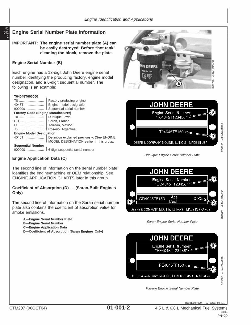
Engine Serial Number Plate Information
RG
7778
–UN
–11N
OV
97
RG
9060
–UN
–16M
AR
98
Dubuque Engine Serial Number Plate
RG
9061
–UN
–16M
AR
98Saran Engine Serial Number Plate
RG
9062
–UN
–16M
AR
98
Torreon Engine Serial Number Plate
A—Engine Serial Number PlateB—Engine Serial NumberC—Engine Application DataD—Coefficient of Absorption (Saran Engines Only)
IMPORTANT: The engine serial number plate (A) canbe easily destroyed. Before “hot tank”cleaning the block, remove the plate.
Engine Serial Number (B)
Each engine has a 13-digit John Deere engine serialnumber identifying the producing factory, engine modeldesignation, and a 6-digit sequential number. Thefollowing is an example:
T04045T000000T0 ........................... Factory producing engine4045T ..................... Engine model designation000000 ................... Sequential serial numberFactory Code (Engine Manufacturer)T0 ........................... Dubuque, IowaCD .......................... Saran, FrancePE .......................... Torreon, MexicoJ0 ........................... Rosario, ArgentinaEngine Model Designation4045T ..................... Definition explained previously. (See ENGINE
MODEL DESIGNATION earlier in this group.Sequential Number000000 ................... 6-digit sequential serial number
Engine Application Data (C)
The second line of information on the serial number plateidentifies the engine/machine or OEM relationship. SeeENGINE APPLICATION CHARTS later in this group.
Coefficient of Absorption (D) — (Saran-Built EnginesOnly)
The second line of information on the Saran serial numberplate also contains the coefficient of absorption value forsmoke emissions.
CTM207 (06OCT04) 01-001-2 4.5 L & 6.8 L Mechanical Fuel Systems100604
PN=20

Engine Identification and Applications
010013
DPSG,OUO1004,482 –19–07NOV98–1/1
OEM Engine Option Code Label
CD
3043
3–U
N–1
0MA
Y95
An option code label is secured to the top of the valvecover and identifies the factory installed options on eachOEM engine to ensure correct parts acquisition.
Always provide option code information and engine basecode when ordering repair parts. A listing of option codesis given in Parts Catalogs and Operator’s Manuals.
NOTE: Before “hot tank” cleaning, ensure that optioncodes are recorded elsewhere.
CTM207 (06OCT04) 01-001-3 4.5 L & 6.8 L Mechanical Fuel Systems100604
PN=21

Engine Identification and Applications
01001
4
DPSG,OUO1004,2764 –19–20AUG04–1/10
Engine Application Charts
JOHN DEERE AGRICULTURAL EQUIPMENT
Machine Model Engine Model
Des Moines, Iowa
4700/4710 Sprayer (138 kW) T06068TN050, T06068TN053, PE6068TN050, PE6068TN053
4700/4710 Sprayer (149 kW) PE6068TN052
6700/6700S Sprayer T04045TN050, PE4045TN050
7455 Cotton Stripper T06068TN051, PE6068TN051
7460 Cotton Stripper PE6068TN054
9935 Cotton Picker T06068TN051, PE6068TN051
East Moline, Illinois
9400 Combine T06068HH050
9410 Combine T06068HH051
9450 Combine T06068HH052, PE6068HH052
Horizontina, Brazil
1075 Combine J06068TYC50
1165 Combine J06068TCQ11
1170 Combine CD6068TCQ50
1175 Combine J06068TJ12
1450 Combine J06068TCQ04, J06068TJ04
1550 Combine J06068ACQ01
3518 Combine J06068TYC51
5403/5605 Tractor J04045DCQ01, J04045DJ01
5705 Tractor J04045TJ02
6400 Tractor J04045TCQ01
6403 Tractor J04045TP057
6405 Tractor J04045TCQ01
6415 Tractor J04045TCQ03
6603 Tractor J6068TP03
6605 Tractor J06068TJ02
6615 Tractor J06068TCQ13
7505 Tractor J06068TCQ03
7515 Tractor J06068TCQ14
Jiamusi, China
1065 Combine CD4045TYC50
1075 Combine CD6068TYC50
3060 Combine CD4045DYC50
3518 Combine CD6068TYC51, CD6068HYC50
Zweibrucken, Germany
2254 Combine CD6068HZ050
CTM207 (06OCT04) 01-001-4 4.5 L & 6.8 L Mechanical Fuel Systems100604
PN=22
Continued on next page

Engine Identification and Applications
010015
DPSG,OUO1004,2764 –19–20AUG04–2/10
JOHN DEERE AGRICULTURAL EQUIPMENT
Machine Model Engine Model
3200/3400 Telehandler CD4045TZ050
Ottumwa, Iowa
4890 Windrower T04045TE050, PE4045TE050
4895 Windrower T04045TE051, PE4045TE051
4990 Windrower T06068TE050, PE6068TE050
4995 Windrower PE6068TE051
Waterloo, Iowa
7210 Tractor (SYNCROPLUS) T06068TRW53, PE6068HRW53
7210 Tractor (POWRQUAD) T06068TRW50, PE6068TRW50
7220 Tractor CD6068TRW01
7410 Tractor (SYNCROPLUS) T06068TRW54, PE6068HRW54
7410 Tractor (POWRQUAD) T06068TRW51, PE6068TRW51
7510 Tractor (POWRQUAD) T06068TRW70, PE6068TRW70
7610 Tractor (105 kW) T06068TRW52, PE6068TRW52
7610 Tractor (110 kW) T06068TRW72, PE6068TRW72
7810 Tractor (Export-Brazil) PE6068TRW73
Mannheim, Germany (European Market)
3210 Tractor CD4045DRT50
3310 Tractor CD4045DRT51
3410 Tractor CD4045TRT50
5620 Tractor CD4045DL270
5720 Tractor CD4045DL273
5820 Tractor CD4045DL274
6010 Tractor CD4045DL050
6020 Tractor CD4045DL070
6110 Tractor (Direct Fan Drive) CD4045TL058
6110 Tractor (Viscous Fan Drive) CD4045TL050
6120 Tractor CD4045TL070
6205 Tractor CD4045TL064
6210 Tractor (Direct Fan Drive) CD4045TL059
6210 Tractor (Viscous Fan Drive) CD4045TL051
6215 Tractor (Classic) (Non—Certified) CD4045TL072
6215 Tractor (Classic) (Certified) CD4045TL071
6220 Tractor CD4045TL071
6310 Tractor (Direct Fan Drive) CD4045TL060
6310 Tractor (Viscous Fan Drive) CD4045TL052
6320 Tractor CD4045HL072
SYNCROPLUS is a trademark of Deere & CompanyPOWRQUAD is a trademark of Deere & Company
CTM207 (06OCT04) 01-001-5 4.5 L & 6.8 L Mechanical Fuel Systems100604
PN=23
Continued on next page

Engine Identification and Applications
01001
6
DPSG,OUO1004,2764 –19–20AUG04–3/10
JOHN DEERE AGRICULTURAL EQUIPMENT
Machine Model Engine Model
6320SE Tractor CD4045TL073
6410 Tractor (Direct Fan Drive) CD4045TL061
6410 Tractor (Viscous Fan Drive) CD4045TL053
6420 Tractor CD4045HL070
6505 Tractor CD6068DL051
6510 Tractor CD6068DL050
6515 Tractor (Classic) (77 kW) CD6068DL071
6515 Tractor (Classic) (85 kW) CD6068DL070
6520/6520SE Tractor CD6068DL070, CD6068TL073
6610 Tractor CD6068TL050
6810 Tractor CD6068TL051
6910 Tractor (99 kW) CD6068TL052
6910 Tractor (107 kW) CD6068TL054
Mannheim, Germany (North American Market)
6110/6110L Tractor CD4045TL063
6120 Tractor CD4045TL070
6210/6210L Tractor CD4045TL054
6215 Tractor (Advantage) CD6068TL071
6220 Tractor CD4045TL071
6310/6310L/6310S Tractor CD4045TL055
6320 Tractor CD4045HL073, CD4045TL074
6403/6405 Tractor (Advantage) CD4045TL062
6410/6410L/6410S Tractor CD4045TL056
6415 Tractor (Advantage) CD4045TL075
6420 Tractor CD4045HL070
6510L/6510S Tractor CD4045TL057
6520L Tractor CD4045HL071
6603/6605 Tractor (Advantage) CD6068TL053
6615 Tractor (Advantage) CD6068TL071
6715 Tractor (Advantage) CD6068TL072
Saltillo, Mexico
110C Excavator PE4045TP058
110CFX Excavator PE4045TP058
5415 Tractor PE4045DP050, PE4045DP052
5615 Tractor PE4045DP051, PE4045DP053
5715 Tractor PE4045TP050, PE4045TP059
6103 Tractor PE4045TP055
6203 Tractor PE4045TP056
6400 Tractor PE4045TP054
CTM207 (06OCT04) 01-001-6 4.5 L & 6.8 L Mechanical Fuel Systems100604
PN=24
Continued on next page

Engine Identification and Applications
010017
DPSG,OUO1004,2764 –19–20AUG04–4/10
JOHN DEERE AGRICULTURAL EQUIPMENT
Machine Model Engine Model
6403 Tractor PE4045TP057 (Non-Certified), PE4045TP060 (Tier I Certified)
6415 Tractor PE4045TP061 (Tier 2)
6603 Tractor PE6068TP053 (Non-Certified), PE6068TP054 (Tier I Certified)
7220 Tractor PE6068TP055
7320 Tractor PE6068TP056 (Tier 2)
7405 Tractor (Advantage) CD6068TP051, PE6068TP051
7410 Tractor CD6068TP052
7420 Tractor PE6068TP057 (Tier 2)
7500 Tractor PE6068TP052
7520 Tractor PE6068TP058 (Tier 2)
Tekirdag, Turkey
5615 Tractor CD4045DTK20
5715 Tractor CD4045TTK20
Cameco (Deere) (Thibodaux, Louisiana)
S30 Harvester PE6068DT850
SP1800 Cane Loader PE6068DT850
SP2252 Cane Loader PE6068TT850
SP3000 Cane Loader PE6068DT850
100 Loader/ Harvester (Kanaf) PE6068TT850
110T Cane Tractor PE4045TT851
215 4WD Tractor PE6068DT850
220 Tractor PE6068TT851
220 4WD Tractor/Pineapple Harvester/Sprayer PE6068TT850
404 Vegetable Sprayer T04045TT850, PE4045TT850, T04045TT801
Continued on next page
CTM207 (06OCT04) 01-001-7 4.5 L & 6.8 L Mechanical Fuel Systems100604
PN=25
Engine Identification and Applications
01001
8
DPSG,OUO1004,2764 –19–20AUG04–5/10
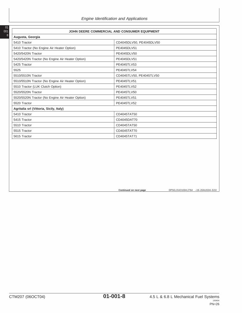
JOHN DEERE COMMERCIAL AND CONSUMER EQUIPMENT
Augusta, Georgia
5410 Tractor CD4045DLV50, PE4045DLV50
5410 Tractor (No Engine Air Heater Option) PE4045DLV51
5420/5420N Tractor PE4045DLV50
5420/5420N Tractor (No Engine Air Heater Option) PE4045DLV51
5425 Tractor PE4045TLV53
5525 PE4045TLV54
5510/5510N Tractor CD4045TLV50, PE4045TLV50
5510/5510N Tractor (No Engine Air Heater Option) PE4045TLV51
5510 Tractor (LUK Clutch Option) PE4045TLV52
5520/5520N Tractor PE4045TLV50
5520/5520N Tractor (No Engine Air Heater Option) PE4045TLV51
5520 Tractor PE4045TLV52
Agritalia srl (Vittoria, Sicily, Italy)
5410 Tractor CD4045TAT50
5415 Tractor CD4045DAT70
5510 Tractor CD4045TAT50
5515 Tractor CD4045TAT70
5615 Tractor CD4045TAT71
Continued on next page
CTM207 (06OCT04) 01-001-8 4.5 L & 6.8 L Mechanical Fuel Systems100604
PN=26

Engine Identification and Applications
010019
DPSG,OUO1004,2764 –19–20AUG04–6/10
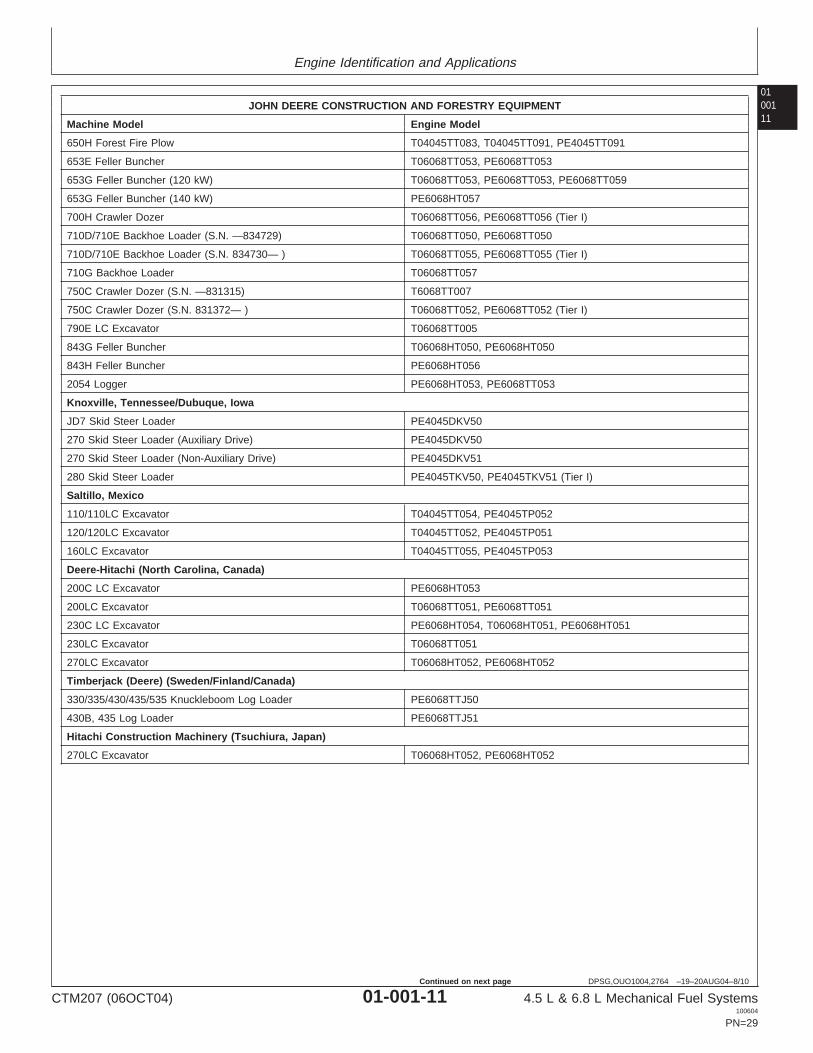
JOHN DEERE CONSTRUCTION AND FORESTRY EQUIPMENT
Machine Model Engine Model
Davenport, Iowa
LX80 Loader T4045HDW51
LX100 Loader (Hitachi Construction Machine) T06068TDW53, PE6068TDW53
LX100-3 Loader (Hitachi Construction Machine) T06068TDW50, PE6068TDW50
LX120 Loader (Hitachi Construction Machine) T06068HDW52, T06068HDW70, PE6068HDW70
TC44H Tool Carrier T04045TDW50, PE4045TDW50
TC54H Tool Carrier T06068TDW50, PE6068TDW50
TC62H Tool Carrier T06068HDW50, PE6068HDW50
TJ460 TC Skidder Tool Carrier T06068TDW57, PE6068TDW57
360D Skidder (Timberjack) T06068TDW54, PE6068TDW54
444H Loader T04045TDW50, PE4045TDW50
460 Skidder (Direct Drive) (Timberjack) T06068TDW55, PE6068TDW55
460D Skidder (Torque Converter) (Timberjack) (S.N. —586336) T06068TDW57, PE6068TDW57
540/548H Skidder T06068TDW54, PE6068TDW54
540/548G Skidder (S.N. 558205—565684) T06068TDW51
540/548G-II Skidder (S.N. 565685—576602) T06068TDW54, PE6068TDW54
540G-III, 548G-III Skidder (S.N. 576603-586336) T06068TDW54, PE6068TDW54
540G-III, 548G-III Skidder (S.N. 586337— ) PE6068HDW58 (Tier 2)
544/544H Loader T06068TDW50, PE6068TDW50
624H Loader T06068HDW50, PE6068HDW50
640G/648G Skidder (S.N. 558205—565684) T06068TDW52
640/648G-II Skidder (S.N. 565685—576602) T06068TDW55, PE6068TDW55
640G-III, 648G-III Skidder (Direct Drive) T06068TDW55, PE6068TDW55(S.N. 576603—586336)
640G-III, 648G-III Skidder (Torque Converter) T06068TDW57, PE6068TDW57(S.N. —586336)
640/648H Skidder T06068TDW55
670C Grader T06068HDW53, PE6068HDW53
670C Series II Grader T06068HDW53, PE6068HDW53
670CH Series II, 672CH Series II Grader T06068HDW58, PE6068HDW58(S.N. —589368)
670CH Grader T06068HDW55, PE6068HDW55
690E LC Excavator (S.N. 559603— ) T06068TDW56
Dubuque, Iowa
CFX110 Excavator PE4045TP058
CFX120/CFX160 Excavator PE4045HP050
CFX270 Excavator PEPE6068HT055
CFX270LC Excavator T06068HT052, PE6068HT052
DX75 Crawler Dozer (Japan) T04045DT052
DX75 HST Crawler Dozer (Japan) T04045TT070, PE4045TT070 (Tier I)
CTM207 (06OCT04) 01-001-9 4.5 L & 6.8 L Mechanical Fuel Systems100604
PN=27
Continued on next page

Engine Identification and Applications
01001
10
DPSG,OUO1004,2764 –19–20AUG04–7/10
JOHN DEERE CONSTRUCTION AND FORESTRY EQUIPMENT
Machine Model Engine Model
HYEX Military Excavator PE4045TT050
120/120C Excavator T04045TT052
210LE Landscape Loader T04045DT050, PE4045DT050
310/310E Backhoe Loader T04045DT055
310E Backhoe Loader (Alt Comp) T04045TT056
310G Backhoe Loader (Nat. Asp.) (S.N. —910005) T04045DT056, PE4045DT056 (Tier I)
310G Backhoe Loader (S.N. 910006— ) T04045TT058, PE4045TT058 (Tier I)
310G Backhoe Loader (Alt Comp) (S.N. —910007) T04045TT080, PE4045TT080 (Tier I)
310SE Backhoe Loader T04045TT050
310SG Backhoe Loader (S.N. —910004) T04045TT081, PE4045TT081 (Tier I)
310SG Backhoe Loader (Alt Comp) (S.N. 909514— ) T04045TT080
315SE Backhoe Loader T04045TT060
315SG Backhoe Loader (Side-Shift) (S.N. —909995) T04045TT081 (Tier I)
344H Loader CD4045TAT71
410E Backhoe Loader T04045TT053
410G Backhoe Loader T04045TT082, PE4045TT082 (Tier I)
450G Crawler Dozer (Direct Drive) (S.N. 840528—840890) T04045DT004, T04045TT005 (Non-Certified)
450G Crawler Dozer (Direct Drive) (S.N. 841246—879425) T04045TT061, PE4045TT061 (Tier I)
450G Crawler Dozer (Torque Converter) (S.N. 840529— ) T04045TT013 (Non-Certified)
450G/450GTC Crawler Dozer T04045TT061, PE4045TT061 (Tier I)
450GTC Series IV Crawler Dozer (S.N. 840461— ) T04045TT067, PE4045TT067 (Tier I)
450H Crawler Dozer T04045DT053
450H LGP Crawler Dozer (S.N. —XXXXXX) T04045TT058, PE4045TT058 (Tier I)
450H Crawler Dozer (Alt Comp) (S.N. —XXXXXX) T04045TT057, PE4045TT057 (Tier I)
455G Series IV Crawler Loader (S.N. 840461— ) T04045TT061, PE4045TT061
455GTC Crawler Loader T04045TT067, PE4045TT067 (Tier I)
485E/486E/488E Forklift T04045DT050, PE4045DT050
550G Crawler Dozer (S.N. 840461— ) T04045TT062
550GTC Crawler Dozer (S. N. 840461— ) T04045TT062, T04045TT068
550H Crawler Dozer (S.N. —909830) T04045TT064, PE4045TT064 (Tier I)
550H LGP Crawler Dozer (S.N. —909667) T04045TT065, PE4045TT065 (Tier I)
550H Forest Fire Plow (S.N. 898487—909788) T04045TT083, PE4045TT083
555G Crawler Loader (Direct Drive) (S.N. 840461— ) T04045TT063, PE4045TT063 (Tier I)
555GTC Crawler Loader T04045TT069, PE4045TT069 (Tier I)
643G Feller Buncher T06068TT053, PE6068TT053
643H Feller Buncher PE6068TT058
650G Crawler Dozer (Direct Drive) T04045TT063, PE4045TT063
650GTC Crawler Dozer T04045TT069, PE4045TT069 (Tier I)
650H Crawler Dozer T04045TT066, PE4045TT066
CTM207 (06OCT04) 01-001-10 4.5 L & 6.8 L Mechanical Fuel Systems100604
PN=28
Continued on next page
Engine Identification and Applications
0100111
DPSG,OUO1004,2764 –19–20AUG04–8/10
JOHN DEERE CONSTRUCTION AND FORESTRY EQUIPMENT
Machine Model Engine Model
650H Forest Fire Plow T04045TT083, T04045TT091, PE4045TT091
653E Feller Buncher T06068TT053, PE6068TT053
653G Feller Buncher (120 kW) T06068TT053, PE6068TT053, PE6068TT059
653G Feller Buncher (140 kW) PE6068HT057
700H Crawler Dozer T06068TT056, PE6068TT056 (Tier I)
710D/710E Backhoe Loader (S.N. —834729) T06068TT050, PE6068TT050
710D/710E Backhoe Loader (S.N. 834730— ) T06068TT055, PE6068TT055 (Tier I)
710G Backhoe Loader T06068TT057
750C Crawler Dozer (S.N. —831315) T6068TT007
750C Crawler Dozer (S.N. 831372— ) T06068TT052, PE6068TT052 (Tier I)
790E LC Excavator T06068TT005
843G Feller Buncher T06068HT050, PE6068HT050
843H Feller Buncher PE6068HT056
2054 Logger PE6068HT053, PE6068TT053
Knoxville, Tennessee/Dubuque, Iowa
JD7 Skid Steer Loader PE4045DKV50
270 Skid Steer Loader (Auxiliary Drive) PE4045DKV50
270 Skid Steer Loader (Non-Auxiliary Drive) PE4045DKV51
280 Skid Steer Loader PE4045TKV50, PE4045TKV51 (Tier I)
Saltillo, Mexico
110/110LC Excavator T04045TT054, PE4045TP052
120/120LC Excavator T04045TT052, PE4045TP051
160LC Excavator T04045TT055, PE4045TP053
Deere-Hitachi (North Carolina, Canada)
200C LC Excavator PE6068HT053
200LC Excavator T06068TT051, PE6068TT051
230C LC Excavator PE6068HT054, T06068HT051, PE6068HT051
230LC Excavator T06068TT051
270LC Excavator T06068HT052, PE6068HT052
Timberjack (Deere) (Sweden/Finland/Canada)
330/335/430/435/535 Knuckleboom Log Loader PE6068TTJ50
430B, 435 Log Loader PE6068TTJ51
Hitachi Construction Machinery (Tsuchiura, Japan)
270LC Excavator T06068HT052, PE6068HT052
CTM207 (06OCT04) 01-001-11 4.5 L & 6.8 L Mechanical Fuel Systems100604
PN=29
Continued on next page
Engine Identification and Applications
01001
12
DPSG,OUO1004,2764 –19–20AUG04–9/10
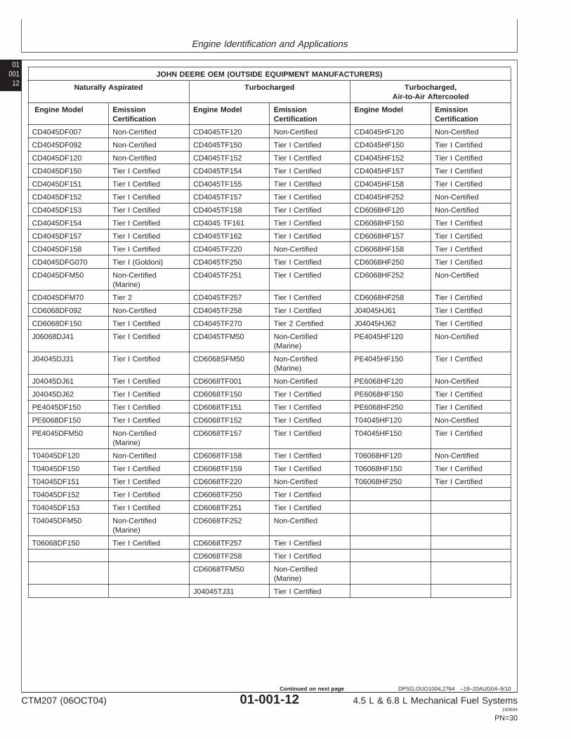
JOHN DEERE OEM (OUTSIDE EQUIPMENT MANUFACTURERS)
Naturally Aspirated Turbocharged Turbocharged,Air-to-Air Aftercooled
Engine Model Emission Engine Model Emission Engine Model EmissionCertification Certification Certification
CD4045DF007 Non-Certified CD4045TF120 Non-Certified CD4045HF120 Non-Certified
CD4045DF092 Non-Certified CD4045TF150 Tier I Certified CD4045HF150 Tier I Certified
CD4045DF120 Non-Certified CD4045TF152 Tier I Certified CD4045HF152 Tier I Certified
CD4045DF150 Tier I Certified CD4045TF154 Tier I Certified CD4045HF157 Tier I Certified
CD4045DF151 Tier I Certified CD4045TF155 Tier I Certified CD4045HF158 Tier I Certified
CD4045DF152 Tier I Certified CD4045TF157 Tier I Certified CD4045HF252 Non-Certified
CD4045DF153 Tier I Certified CD4045TF158 Tier I Certified CD6068HF120 Non-Certified
CD4045DF154 Tier I Certified CD4045 TF161 Tier I Certified CD6068HF150 Tier I Certified
CD4045DF157 Tier I Certified CD4045TF162 Tier I Certified CD6068HF157 Tier I Certified
CD4045DF158 Tier I Certified CD4045TF220 Non-Certified CD6068HF158 Tier I Certified
CD4045DFG070 Tier I (Goldoni) CD4045TF250 Tier I Certified CD6068HF250 Tier I Certified
CD4045DFM50 Non-Certified CD4045TF251 Tier I Certified CD6068HF252 Non-Certified(Marine)
CD4045DFM70 Tier 2 CD4045TF257 Tier I Certified CD6068HF258 Tier I Certified
CD6068DF092 Non-Certified CD4045TF258 Tier I Certified J04045HJ61 Tier I Certified
CD6068DF150 Tier I Certified CD4045TF270 Tier 2 Certified J04045HJ62 Tier I Certified
J06068DJ41 Tier I Certified CD4045TFM50 Non-Certified PE4045HF120 Non-Certified(Marine)
J04045DJ31 Tier I Certified CD6068SFM50 Non-Certified PE4045HF150 Tier I Certified(Marine)
J04045DJ61 Tier I Certified CD6068TF001 Non-Certified PE6068HF120 Non-Certified
J04045DJ62 Tier I Certified CD6068TF150 Tier I Certified PE6068HF150 Tier I Certified
PE4045DF150 Tier I Certified CD6068TF151 Tier I Certified PE6068HF250 Tier I Certified
PE6068DF150 Tier I Certified CD6068TF152 Tier I Certified T04045HF120 Non-Certified
PE4045DFM50 Non-Certified CD6068TF157 Tier I Certified T04045HF150 Tier I Certified(Marine)
T04045DF120 Non-Certified CD6068TF158 Tier I Certified T06068HF120 Non-Certified
T04045DF150 Tier I Certified CD6068TF159 Tier I Certified T06068HF150 Tier I Certified
T04045DF151 Tier I Certified CD6068TF220 Non-Certified T06068HF250 Tier I Certified
T04045DF152 Tier I Certified CD6068TF250 Tier I Certified
T04045DF153 Tier I Certified CD6068TF251 Tier I Certified
T04045DFM50 Non-Certified CD6068TF252 Non-Certified(Marine)
T06068DF150 Tier I Certified CD6068TF257 Tier I Certified
CD6068TF258 Tier I Certified
CD6068TFM50 Non-Certified(Marine)
J04045TJ31 Tier I Certified
CTM207 (06OCT04) 01-001-12 4.5 L & 6.8 L Mechanical Fuel Systems100604
PN=30
Continued on next page

Engine Identification and Applications
0100113
DPSG,OUO1004,2764 –19–20AUG04–10/10
JOHN DEERE OEM (OUTSIDE EQUIPMENT MANUFACTURERS)
Naturally Aspirated Turbocharged Turbocharged,Air-to-Air Aftercooled
J04045TJ61 Tier I Certified
J4045TJ62 Tier I Certified
J06068TJ31 Tier I Certified
J06068TJ32 Tier I Certified
J06068TJ61 Tier I Certified
J06068TJ62 Tier I Certified
PE4045TF120 Non-Certified
PE4045TF150 Tier I Certified
PE4045TF151 Tier I Certified
PE4045TF220 Non-Certified
PE4045TF250 Tier I Certified
PE4045TF270 Tier 2 Certified
PE4045TFM50 Non-Certified(Marine)
PE6068TF120 Non-Certified
PE6068TF150 Tier I Certified
PE6068TF151 Tier I Certified
PE6068TF220 Non-Certified
PE6068TF250 Tier I Certified
T04045TF120 Non-Certified
T04045TF150 Tier I Certified
T04045TF151 Tier I Certified
T04045TF152 Tier I Certified
T04045TF220 Non-Certified
T04045TF250 Tier I Certified
T04045TF251 Tier I Certified
T04045TF270 Tier 2 Certified
T04045TFM50 Non-Certified(Marine)
T06068TF120 Non-Certified
T06068TF150 Tier I Certified
T06068TF151 Tier I Certified
T06068TF220 Non-Certified
T06068TF250 Tier I Certified
T06068TFM50 Non-Certified(Marine)
CTM207 (06OCT04) 01-001-13 4.5 L & 6.8 L Mechanical Fuel Systems100604
PN=31

Engine Identification and Applications
01001
14
CTM207 (06OCT04) 01-001-14 4.5 L & 6.8 L Mechanical Fuel Systems100604
PN=32

Group 002Fuels
010021
DPSG,OUO1004,2761 –19–19AUG04–1/1
Lubricants and Coolants
NOTE: Refer to Section 01, Group 002 of CTM104 BaseEngine Manual for information on lubricants andcoolants.
DX,FUEL1 –19–19DEC03–1/1
Diesel Fuel
Consult your local fuel distributor for properties of thediesel fuel available in your area.
In general, diesel fuels are blended to satisfy the lowtemperature requirements of the geographical area inwhich they are marketed.
Diesel fuels specified to EN 590 or ASTM D975 arerecommended.
In all cases, the fuel shall meet the followingproperties:
Cetane number of 40 minimum. Cetane numbergreater than 50 is preferred, especially fortemperatures below -20°C (-4°F) or elevations above1500 m (5000 ft).
Cold Filter Plugging Point (CFPP) below theexpected low temperature OR Cloud Point at least5°C (9°F) below the expected low temperature.
Fuel lubricity should pass a minimum of 3100 gramload level as measured by the BOCLE scuffing test.
Sulfur content:
• Sulfur content should not exceed 0.5%. Sulfurcontent less than 0.05% is preferred.
• If diesel fuel with sulfur content greater than 0.5%sulfur content is used, reduce the service interval forengine oil and filter by 50%.
• DO NOT use diesel fuel with sulfur content greaterthan 1.0%.
Bio-diesel fuels may be used ONLY if the fuelproperties meet DIN 51606 or equivalent specification.
DO NOT mix used engine oil or any other type oflubricant with diesel fuel.
CTM207 (06OCT04) 01-002-1 4.5 L & 6.8 L Mechanical Fuel Systems100604
PN=33
Fuels
01002
2
DX,FUEL7 –19–08MAR04–1/1
Bio-Diesel Fuel
Consult your local fuel distributor for properties of thebio-diesel fuel available in your area.
Bio-diesel fuels may be used ONLY if the bio-dieselfuel properties meet the latest edition of ASTM D6751,EN 14214, or equivalent specification.
The maximum allowable bio-diesel concentration is a5% blend (also known as B5) in petroleum diesel fuel.It has been found that bio-diesel fuels may improvelubricity in concentrations up to this 5% blend.
When using a blend of bio-diesel fuel, the engine oillevel must be checked daily when the air temperatureis –10°C (14°F) or lower. If oil becomes diluted withfuel, shorten oil change intervals accordingly.
IMPORTANT: Raw pressed vegetable oils are NOTacceptable for use as fuel in anyconcentration in John Deereengines.
These oils do not burn completely,and will cause engine failure byleaving deposits on injectors and inthe combustion chamber.
A major environmental benefit of bio-diesel fuel is itsability to biodegrade. This makes proper storage andhandling of bio-diesel fuel especially important. Areasof concern include:•
• Quality of new fuel• Water content of the fuel• Problems due to aging of the fuel
Potential problems resulting from deficiencies in theabove areas when using bio-diesel fuel inconcentrations above 5% may lead to the followingsymptoms:
• Power loss and deterioration of performance• Fuel leakage• Corrosion of fuel injection equipment• Coked and/or blocked injector nozzles, resulting in
engine misfire• Filter plugging• Lacquering and/or seizure of internal components• Sludge and sediments• Reduced service life of engine components
Consult your fuel supplier for additives to improvestorage and performance of bio-diesel fuels.
CTM207 (06OCT04) 01-002-2 4.5 L & 6.8 L Mechanical Fuel Systems100604
PN=34

Fuels
010023
DX,FUEL5 –19–19DEC03–1/1
Lubricity of Diesel Fuel
Diesel fuel must have adequate lubricity to ensureproper operation and durability of fuel injection systemcomponents.
ASTM D975 and EN 590 specifications do not requirefuels to pass a fuel lubricity test.
Sulfur content of diesel fuel for highway use is lessthan 0.05% (500 ppm) in the United States andCanada, and less than 0.035% (350 ppm) in theEuropean Union.
Experience shows that some low sulfur diesel fuelsmay have inadequate lubricity and their use mayreduce performance in fuel injection systems due toinadequate lubrication of injection pump components.The lower concentration of aromatic compounds in
these fuels also adversely affects injection pump sealsand may result in leaks.
Use of low lubricity diesel fuels may also causeaccelerated wear, injection nozzle erosion or corrosion,engine speed instability, hard starting, low power, andengine smoke.
Fuel lubricity should pass a minimum load level of3100 grams as measured by ASTM D6078 ormaximum scar diameter of 0.45 mm as measured byASTM D6079 or ISO 12156-1.
If fuel of low or unknown lubricity is used, add JohnDeere PREMIUM DIESEL FUEL CONDITIONER (orequivalent) at the specified concentration.
DX,FUEL6 –19–06DEC00–1/1
Dieselscan Fuel Analysis
DIESELSCAN is a John Deere fuel sampling program tohelp you monitor the quality of your fuel source. It verifiesfuel type, cleanliness, water content, suitability for coldweather operation, and if fuel is within ASTMspecifications. Check with your John Deere dealer foravailability of DIESELSCAN kits.
DIESELSCAN is a trademark of Deere & Company
CTM207 (06OCT04) 01-002-3 4.5 L & 6.8 L Mechanical Fuel Systems100604
PN=35

Fuels
01002
4
CTM207 (06OCT04) 01-002-4 4.5 L & 6.8 L Mechanical Fuel Systems100604
PN=36

Section 02Repair and AdjustmentsContents 02
Page Page
Group 090—Mechanical Fuel System Repair and Denso and Motorpal In-Line Injection PumpAdjustments Static Timing . . . . . . . . . . . . . . . . . . . . . . .02-090-32
Fuel System—General Information . . . . . . . . .02-090-1 Remove Stanadyne Model DB2 and DB4Relieve Fuel System Pressure . . . . . . . . . . . .02-090-2 Injection Pump. . . . . . . . . . . . . . . . . . . . . .02-090-34Remove and Install Final Fuel Filter and/or Inspect Stanadyne Injection Pump Drive
Primary Fuel Filter/Water Separator Gear ID and Shaft OD . . . . . . . . . . . . . . . .02-090-36Base . . . . . . . . . . . . . . . . . . . . . . . . . . . . . .02-090-3 Repair Stanadyne Fuel Injection Pump . . . . .02-090-36
Primary Fuel Filter/Water Separator Install Stanadyne Model DB2 and DB4Assembly (Optional). . . . . . . . . . . . . . . . . . .02-090-6 Injection Pump. . . . . . . . . . . . . . . . . . . . . .02-090-37
Final Fuel Filter Assembly . . . . . . . . . . . . . . . .02-090-7 Remove Delphi/Lucas Fuel InjectionReplace Final Fuel Filter and Primary Fuel Pump. . . . . . . . . . . . . . . . . . . . . . . . . . . . .02-090-40
Filter/Water Separator . . . . . . . . . . . . . . . . .02-090-8 Repair Delphi/Lucas Fuel Injection Pump . . .02-090-42Remove Lucas and Stanadyne Fuel Install Delphi/Lucas Fuel Injection Pump . . . .02-090-43
Supply Pump . . . . . . . . . . . . . . . . . . . . . . .02-090-10 Remove Denso Fuel Injection Pump . . . . . . .02-090-46Bench Test Lucas and Stanadyne Fuel Repair Denso Fuel Injection Pump . . . . . . . .02-090-48
Supply Pump . . . . . . . . . . . . . . . . . . . . . . .02-090-11 Install Denso Fuel Injection Pump . . . . . . . . .02-090-49Install Lucas and Stanadyne Fuel Supply Replace Motorpal Fuel Injection Pump
Pump. . . . . . . . . . . . . . . . . . . . . . . . . . . . .02-090-13 Delivery Valve O-Rings . . . . . . . . . . . . . . .02-090-53Remove Denso In-Line Fuel Supply Remove Motorpal Fuel Injection Pump . . . . .02-090-54
Pump. . . . . . . . . . . . . . . . . . . . . . . . . . . . .02-090-14 Repair Motorpal Fuel Injection Pump . . . . . .02-090-57Test Denso In-Line Fuel Supply Pump for Install Motorpal Fuel Injection Pump . . . . . . .02-090-58
Leaks. . . . . . . . . . . . . . . . . . . . . . . . . . . . .02-090-15 Repair Aneroid . . . . . . . . . . . . . . . . . . . . . . .02-090-63Disassemble Denso In-Line Fuel Supply Transfer Fuel Injection Pump Timing Mark
Pump. . . . . . . . . . . . . . . . . . . . . . . . . . . . .02-090-16 onto Replacement Front Plate . . . . . . . . . .02-090-64Inspect and Repair Denso In-Line Fuel Fuel Injection Nozzle Identification . . . . . . . .02-090-65
Remove Fuel Injection Nozzles . . . . . . . . . . .02-090-65Supply Pump Components . . . . . . . . . . . .02-090-19Clean Fuel Injection Nozzle Bore . . . . . . . . .02-090-67Assemble Denso In-Line Fuel SupplyClean Fuel Injection Nozzles . . . . . . . . . . . . .02-090-68Pump. . . . . . . . . . . . . . . . . . . . . . . . . . . . .02-090-21Diagnose Fuel Injection NozzleInstall Denso In-Line Fuel Supply Pump . . . .02-090-22
Malfunctions . . . . . . . . . . . . . . . . . . . . . . .02-090-69Remove Motorpal Fuel Supply Pump . . . . . .02-090-22Test Fuel Injection Nozzles . . . . . . . . . . . . . .02-090-70Inspect Motorpal Fuel Supply Pump . . . . . . .02-090-23Disassemble Fuel Injection Nozzles . . . . . . .02-090-76Install Motorpal Fuel Supply Pump . . . . . . . .02-090-23Inspect and Clean Fuel Injection NozzleService Denso Injection Pump Overflow
Body . . . . . . . . . . . . . . . . . . . . . . . . . . . . .02-090-79Valve . . . . . . . . . . . . . . . . . . . . . . . . . . . . .02-090-24Inspect and Clean Valve and Valve Seat . . .02-090-80Remove and Install Denso Fuel Shut-OffInspect Valve Adjusting Mechanism . . . . . . .02-090-82Solenoid . . . . . . . . . . . . . . . . . . . . . . . . . .02-090-25Assemble Fuel Injection Nozzles. . . . . . . . . .02-090-83Remove and Install Delphi/Lucas FuelAdjust Fuel Injection Nozzles . . . . . . . . . . . .02-090-84Shut-Off Solenoid . . . . . . . . . . . . . . . . . . .02-090-26Install Seals on Fuel Injection Nozzle . . . . . .02-090-90Remove and Install Motorpal FuelInstall Fuel Injection Nozzles . . . . . . . . . . . . .02-090-91Shut-Off Solenoid—If Equipped . . . . . . . . .02-090-26Bleed the Fuel System . . . . . . . . . . . . . . . . .02-090-93Remove and Install Stanadyne Cold Start
Advance Solenoid and Valve . . . . . . . . . . .02-090-27Remove and Install Delphi/Lucas Cold
Start Advance Switch and Harness . . . . . .02-090-29Delphi/Lucas and Stanadyne Rotary Fuel
Injection Pump Timing . . . . . . . . . . . . . . . .02-090-30
CTM207 (06OCT04) 02-1 4.5 L & 6.8 L Mechanical Fuel Systems100604
PN=1

Contents
02
CTM207 (06OCT04) 02-2 4.5 L & 6.8 L Mechanical Fuel Systems100604
PN=2

Group 090Mechanical Fuel System Repair and Adjustments
020901
DPSG,OUO1004,2698 –19–08JUL02–1/1
Fuel System—General Information
NOTE: For repair and diagnostics of electronic fuelsystems, see CTM170—Level 4 ElectronicFuel Systems with Bosch VP44 Pump,CTM331—Level 12 Electronic Fuel Systemswith Stanadyne DE10 Pump, CTM284—Level1 Electronic Fuel Systems with Delphi/LucasDP201 Pump, or CTM220—Level 11Electronic Fuel Systems with Denso HighPressure Common Rail.
Engines may be equipped with a Stanadyne orDelphi/Lucas rotary-type injection pump or a Denso orMotorpal in-line injection pump. Engines with rotarypumps are dynamically timed at the factory. SeeCHECK AND ADJUST ROTARY INJECTION PUMPDYNAMIC TIMING in Section 04, Group 150.
Some injection pumps are equipped with an aneroid.
On Stanadyne and Delphi/Lucas rotary pumps, the fuelsupply pump is a separate component mounted onupper right-hand side of engine block and is actuatedby a pin in block that rides on engine camshaft lobe.
On rotary pumps, a cold start switch may be installedin the thermostat housing/water manifold and is
connected to a wiring harness from the pump. Thisswitch helps during cold start-up operation.
On in-line pumps, the fuel supply pump is acomponent mounted on the side of the pump actuatedby a lobe on injection pump camshaft.
Engines may be equipped with a primary fuelfilter/water separator.
All engines are equipped with a round final fuel filter.Hand primer on top of filter element is optional.
All engines use 9.5 mm pencil-type nozzles.
Field-installed options include fuel heater, waterseparator bowl and hand fuel primer.
IMPORTANT: Never steam clean or pour coldwater on an injection pump while itis still warm. To do so may causeseizure of pump internal parts.
CTM207 (06OCT04) 02-090-1 4.5 L & 6.8 L Mechanical Fuel Systems100604
PN=39

Mechanical Fuel System Repair and Adjustments
02090
2
RG,35,JW7625 –19–20NOV97–1/1
Relieve Fuel System Pressure
X98
11–U
N–2
3AU
G88
CAUTION: Escaping diesel fuel under pressurecan have sufficient force to penetrate the skin,causing serious injury. Before disconnectinglines, be sure to relieve pressure. Beforeapplying pressure to the system, be sure ALLconnections are tight and lines, pipes andhoses are not damaged. Keep hands and bodyaway from pinholes and nozzles which ejectfluid under pressure. Use a piece of cardboardor wood, rather than hands, to search forsuspected leaks.
If ANY fluid is injected into the skin, it must besurgically removed within a few hours by adoctor familiar with this type injury or gangrenemay result. Doctors unfamiliar with this type ofinjury may call the Deere & Company MedicalDepartment in Moline, Illinois, or otherknowledgeable medical source.
Any time the fuel system has been opened up for service(lines disconnected or filters removed), it will be necessaryto bleed air from the system. (See BLEED THE FUELSYSTEM in this group.)
CTM207 (06OCT04) 02-090-2 4.5 L & 6.8 L Mechanical Fuel Systems100604
PN=40
Mechanical Fuel System Repair and Adjustments
020903
RG,35,JW7624 –19–02DEC99–1/3
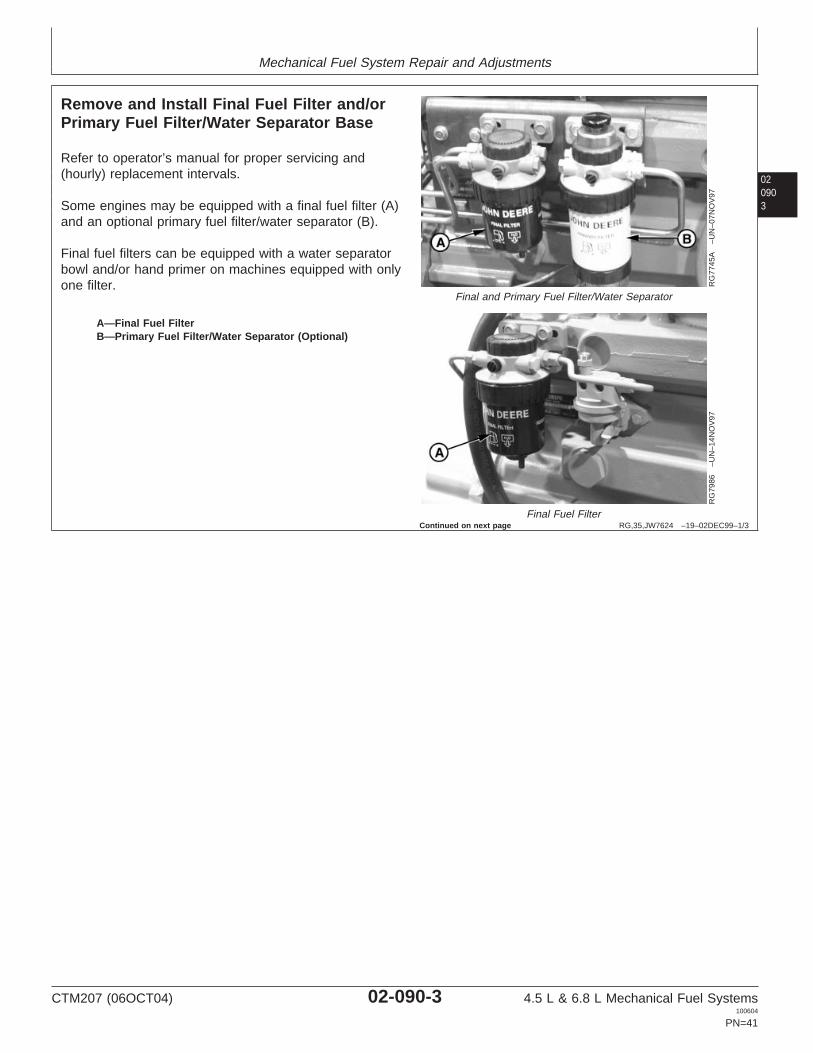
Remove and Install Final Fuel Filter and/orPrimary Fuel Filter/Water Separator Base
RG
7745
A–U
N–0
7NO
V97
Final and Primary Fuel Filter/Water Separator
RG
7986
–UN
–14N
OV
97
Final Fuel Filter
A—Final Fuel FilterB—Primary Fuel Filter/Water Separator (Optional)
Refer to operator’s manual for proper servicing and(hourly) replacement intervals.
Some engines may be equipped with a final fuel filter (A)and an optional primary fuel filter/water separator (B).
Final fuel filters can be equipped with a water separatorbowl and/or hand primer on machines equipped with onlyone filter.
Continued on next page
CTM207 (06OCT04) 02-090-3 4.5 L & 6.8 L Mechanical Fuel Systems100604
PN=41

Mechanical Fuel System Repair and Adjustments
02090
4
RG,35,JW7624 –19–02DEC99–2/3
RG
1038
3–U
N–1
8NO
V99
Final and Primary Fuel Filter/Water Separator
A—Final Fuel Filter BaseB—Primary Fuel Filter BaseC—Primary Filter Outlet Port(s) to Supply PumpD—Final Filter Outlet Port(s) to Injection PumpE—Final Filter Inlet Port(s) from Supply PumpF—Primary Filter Inlet Port(s) from Fuel Tank
1. Thoroughly clean fuel filter/water separator assemblyand surrounding area to keep from getting dirt anddebris into fuel system.
2. Connect a drain line to filter drain adapters and drainall fuel from system.
NOTE: The fuel filters are keyed to the filter header. Ifboth primary and final filters are removed, ensurethat they are reinstalled in the correct headers.
3. Remove final fuel filter element and primary (round)fuel filter/water separator, if desired. (See REPLACEFINAL FUEL FILTER AND PRIMARY FUELFILTER/WATER SEPARATOR, as described later inthis group.)
NOTE: Fuel lines may be connected to different filter inletand outlet ports depending on engine application.
4. Disconnect fuel lines from all ports.
5. Remove final fuel filter base (A).
6. If equipped, remove primary fuel filter base (B).
7. Replace parts as necessary.
8. Install mounting brackets and tighten to torquespecifications provided below.
SpecificationFuel Filter Base MountingBracket-to-Cylinder Head—Torque 35 N•m (26 lb-ft).............................................................................Primary Fuel Filter/WaterSeparator MountingBase-to-Bracket—Torque 35 N•m (26 lb-ft)................................................Final Fuel Filter MountingBase-to-Bracket—Torque 35 N•m (26 lb-ft)................................................
9. Install water separator and fuel filter elements. SeeREPLACE FINAL FUEL FILTER AND PRIMARY FUELFILTER/WATER SEPARATOR, as described later inthis group.
10. Connect fuel lines to all ports.
CTM207 (06OCT04) 02-090-4 4.5 L & 6.8 L Mechanical Fuel Systems100604
PN=42
Continued on next page

Mechanical Fuel System Repair and Adjustments
02090
RG,35,JW7624 –19–02DEC99–3/3
11. Bleed the fuel system as detailed in this group. (SeeBLEED THE FUEL SYSTEM in this group.)
5
CTM207 (06OCT04) 02-090-5 4.5 L & 6.8 L Mechanical Fuel Systems100604
PN=43
Mechanical Fuel System Repair and Adjustments
02090
6
OUO1032,00014BC –19–19AUG04–1/1
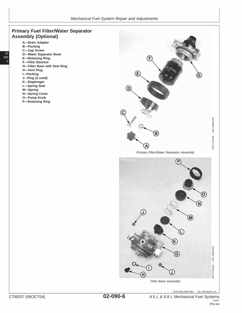
Primary Fuel Filter/Water SeparatorAssembly (Optional)
RG
T77
51H
R–U
N–1
9NO
V97
Primary Filter/Water Separator Assembly
RG
T77
51H
S–U
N–1
9NO
V97
Filter Base Assembly
A—Drain AdapterB—PackingC—Cap ScrewD—Water Separator BowlE—Retaining RingF—Filter ElementG—Filter Base with Seal RingH—Vent PlugI—PackingJ—Plug (2 used)K—DiaphragmL—Spring SeatM—SpringN—Spring CoverO—Pump KnobP—Retaining Ring
CTM207 (06OCT04) 02-090-6 4.5 L & 6.8 L Mechanical Fuel Systems100604
PN=44

Mechanical Fuel System Repair and Adjustments
020907
RG,35,JW7623 –19–20NOV97–1/1
Final Fuel Filter Assembly
RG
9091
–UN
–31M
AR
98
Final Fuel Filter
1—Retaining Ring2—Fuel Heater (Optional)3—Fitting4—O-Ring5—O-Ring6—Bleed Screw7—O-Ring8—Retaining Ring9—Filter10—O-Ring11—O-Ring12—Drain Adapter13—Screw14—O-Ring15—Water Separator Bowl16—Adapter17—O-Ring18—O-Ring19—Fitting20—Plug21—O-Ring22—Filter Base23—Primer Assembly (Optional)24—O-Ring25—Stem26—Cap
CTM207 (06OCT04) 02-090-7 4.5 L & 6.8 L Mechanical Fuel Systems100604
PN=45

Mechanical Fuel System Repair and Adjustments
02090
8
RG,35,JW7622 –19–19AUG04–1/2
Replace Final Fuel Filter and Primary FuelFilter/Water Separator
RG
7745
C–U
N–0
7NO
V97
Final and Primary Fuel Filter/Water Separator
A—Retaining RingB—Filter Element
IMPORTANT: Prevent machine damage. Drain waterand sediment and replace filterelements at specified intervals.Contaminated fuel can cause prematurefailure of fuel injection pump.
If appropriate, substitute longer filterelements and/or add sediment bowls tofilter elements.
NOTE: Refer to operator’s manual for proper servicingand (hourly) replacement intervals.
Final fuel filters can be equipped with a sedimentbowl and/or hand primer.
Replacement of primary and final fuel filterelements are similar. Differences will be noted.
1. Thoroughly clean fuel filter/water separator assemblyand surrounding area, if not previously done.
2. Connect a drain line to filter drain adapters and drainall fuel from filters.
NOTE: Lifting up on retaining ring (A) as it is rotatedhelps to get it past raised locators.
3. Firmly grasp the retaining ring and rotate itcounterclockwise 1/4 turn (when viewed from top).Remove ring with filter element (B).
4. Inspect filter mounting base for cleanliness. Clean asrequired.
5. Remove sediment bowl, if equipped. Drain and cleansediment bowl. Dry with compressed air.
6. Install sediment bowl, if equipped, onto new filterelement. Tighten securely.
7. Thoroughly inspect filter base seal ring. Replace asneeded.
CTM207 (06OCT04) 02-090-8 4.5 L & 6.8 L Mechanical Fuel Systems100604
PN=46
Continued on next page
Mechanical Fuel System Repair and Adjustments
020909
RG,35,JW7622 –19–19AUG04–2/2
NOTE: The fuel filters must be indexed properly and thekey on canister must be oriented in slot ofmounting base for correct installation.
8. Install new filter element onto mounting base andposition element using a slight rocking motion. Be sureelement is properly indexed on mounting base.
9. Install retaining ring onto mounting base and tightenabout 1/3 turn until ring “snaps” into the detent. DONOT overtighten the retaining ring.
10. Bleed fuel system. (See BLEED THE FUEL SYSTEM,in this group.)
CTM207 (06OCT04) 02-090-9 4.5 L & 6.8 L Mechanical Fuel Systems100604
PN=47

Mechanical Fuel System Repair and Adjustments
02090
10
RG,35,JW7621 –19–26OCT99–1/1
Remove Lucas and Stanadyne Fuel SupplyPump
RG
1054
8–U
N–0
1DE
C99
Fuel Supply Pump with Metal Cover
RG
1054
7–U
N–0
1DE
C99
Fuel Supply Pump with Composite Cover
RG
9051
–UN
–16M
AR
98
Remove Fuel Supply Pump
RG
7628
–UN
–06N
OV
97
Fuel Supply Pump Push Rod
A—Cap ScrewsB—Push RodC—Supply Pump Inlet from Fuel TankD—Supply Pump Outlet to Final Fuel Filter
IMPORTANT: A backup wrench must always be usedwhen disconnecting fittings or fuel linesfrom supply pump to avoid damage tofittings.
1. Disconnect fuel inlet line (C) and outlet line (D) andcap connections on fuel supply pump and fuel lines tokeep debris out of fuel system.
2. Remove cap screws (A) and remove fuel supply pumpassembly from cylinder block.
NOTE: The fuel supply pump is driven by a push rod (B)that rides on an eccentric camshaft lobe. Thecylinder head must be removed to remove thispush rod.
3. Cover opening on cylinder block to prevent dirt fromentering the engine.
4. Inspect face of pump lever for wear. If lever face isworn flat or concave, replace pump.
CTM207 (06OCT04) 02-090-10 4.5 L & 6.8 L Mechanical Fuel Systems100604
PN=48

Mechanical Fuel System Repair and Adjustments
0209011
RG,35,JW7620 –19–26OCT99–1/3
Bench Test Lucas and Stanadyne FuelSupply Pump
RG
9052
–UN
–16M
AR
98
Fuel Supply Pump with Metal Cover
RG
1054
6–U
N–0
3DE
C99
Fuel Supply Pump with Composite Cover
A—LeverB—Outlet Side of PumpC—Inlet Side of PumpD—Primer Lever
The following bench tests can be performed on a supplypump installed on the engine when the pump is suspectedto be defective. (See MEASURE FUEL SUPPLY PUMPPRESSURE or in Section 04, Group 150.)
Perform the Vacuum/Pressure Test and Leakage Test,listed below. Replace the supply pump if either test showsthe pump to be defective. There is no repair procedure.
Vacuum/Pressure Test
NOTE: This test will give a good indication of condition ofboth the inlet and outlet valves, as well as thediaphragm. The numerical values obtained onboth the vacuum and pressure sides are notimportant; rather it is the needle movement that isimportant (very slow for a good pump; very fast ornot at all for a defective pump).
1. Remove inlet and outlet fittings.
2. Install vacuum/pressure gauge to inlet side of pump(C).
3. Move primer lever (D) all the way downward. Releaselever and at the same time observe gauge:
• The gauge needle should read the same value eachtime, and then very slowly return to “0”. Thisindicates that the inlet valve and diaphragm are ingood condition. Proceed to next step.
• If the gauge needle does not move at all, or theneedle rapidly returns to “0”, the pump is defectiveand must be replaced.
4. Remove vacuum/pressure gauge and install onto outletside of pump (B).
5. Move priming lever all the way to upward position.Release lever and at same time observe gaugereading:
CTM207 (06OCT04) 02-090-11 4.5 L & 6.8 L Mechanical Fuel Systems100604
PN=49
Continued on next page

Mechanical Fuel System Repair and Adjustments
02090
12
RG,35,JW7620 –19–26OCT99–2/3
• The gauge needle should initially read 28—41 kPa(0.28—0.41 bar) (4—6 psi), then return to “0” veryslowly. This indicates that the outlet valve anddiaphragm are in good condition. Supply pump isoperating properly and should be reinstalled onengine.
SpecificationRotary Fuel Supply Pump (Lucasand Stanadyne)—Pressure 28—41 kPa (0.28—0.41 bar)
(4—6 psi)..........................
• If the gauge needle initially reads same value asabove and then returns immediately back to “0”, thepump is defective and must be replaced.
RG,35,JW7620 –19–26OCT99–3/3
RG
9052
–UN
–16M
AR
98
Fuel Supply Pump with Metal Cover
RG
1054
6–U
N–0
3DE
C99
Fuel Supply Pump with Composite Cover
A—LeverB—Outlet Side of PumpC—Inlet Side of PumpD—Primer Lever
Leakage Test
The leakage test should be performed if a supply pump issuspected of leaking fuel externally, or internally into theengine crankcase.
1. Install an air line on inlet side of pump (C) and apply140 kPa (1.4 bar) (20 psi) pressure.
2. Hold finger over outlet side of pump (B) or install aplug. Submerge pump into a container of clean dieselfuel.
• If air bubbles occur around banded connectionholding the two halves of pump together (indicatingleakage), replace pump.
• If the diaphragm is bad, there will be leakagethrough vent holes (if equipped) and around therocker arm. Replace pump as necessary.
CTM207 (06OCT04) 02-090-12 4.5 L & 6.8 L Mechanical Fuel Systems100604
PN=50

Mechanical Fuel System Repair and Adjustments
0209013
RG,35,JW7619 –19–26OCT99–1/1
Install Lucas and Stanadyne Fuel SupplyPump
RG
1054
8–U
N–0
1DE
C99
Fuel Supply Pump with Metal Cover
RG
1054
7–U
N–0
1DE
C99
Fuel Supply Pump with Composite Cover
A—Cap ScrewsC—Supply Pump Inlet from Fuel TankD—Supply Pump Outlet to Final Fuel Filter
IMPORTANT: Apply LOCTITE 242 to threads of supplypump mounting screws (A) and fuel linefittings when reinstalling supply pump.DO NOT allow sealant to get into fuelsystem.
1. Install the fuel supply pump to cylinder block withpumping lever resting on top of push rod, using a newO-ring. Tighten cap screws to specifications.
SpecificationFuel Supply Pump Cap Screws(Rotary)—Torque 30 N•m (22 lb-ft)............................................................
IMPORTANT: ALWAYS use a backup wrench wheninstalling fittings and/or fuel lines ontosupply pump to avoid damage tofittings.
2. Connect supply pump inlet line (C) and outlet line (D)and tighten securely.
3. Bleed fuel system. (See BLEED THE FUEL SYSTEMin this group.)
CTM207 (06OCT04) 02-090-13 4.5 L & 6.8 L Mechanical Fuel Systems100604
PN=51

Mechanical Fuel System Repair and Adjustments
02090
14
RG,35,JW7618 –19–20NOV97–1/1
Remove Denso In-Line Fuel Supply Pump
RG
7748
A–U
N–0
7NO
V97
Fuel Supply Pump—In-Line Injection
A—Fuel Inlet LineB—Fuel Outlet LineC—Mounting Nuts
NOTE: To diagnose fuel supply pump malfunctions, seeF1—FUEL SUPPLY SYSTEM CHECK in Section04, Group 150. To test for leaks, see TEST FUELSUPPLY PUMP FOR LEAKS—IN-LINEINJECTION PUMP in Section 04, Group 150.
1. Thoroughly clean exterior of supply pump. Also cleanaround supply pump mounting area on injection pumphousing.
2. Disconnect fuel inlet line (A) and outlet line (B). Cap allline openings so contaminants do not enter fuelsystem.
3. Remove mounting nuts (C).
4. Pull fuel supply pump straight out from injection pumphousing. Cover supply pump mounting bore so debriscannot enter injection pump.
CTM207 (06OCT04) 02-090-14 4.5 L & 6.8 L Mechanical Fuel Systems100604
PN=52
Mechanical Fuel System Repair and Adjustments
0209015
RG,35,JW7617 –19–20NOV97–1/1
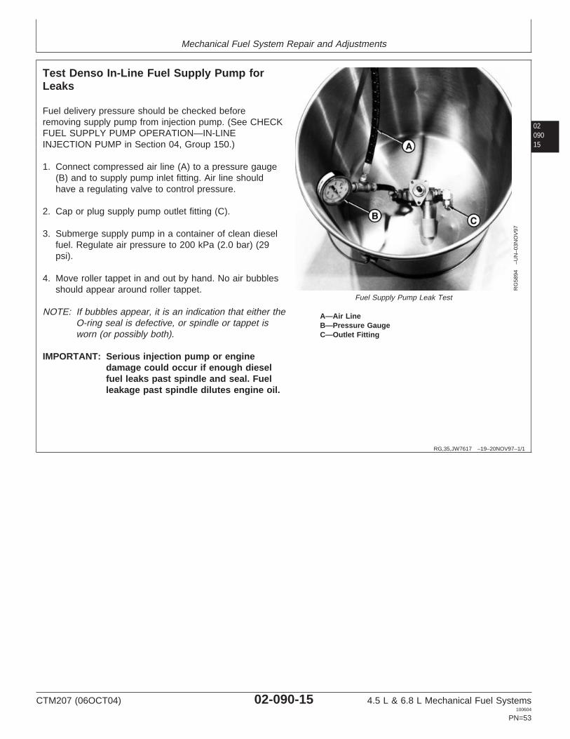
Test Denso In-Line Fuel Supply Pump forLeaks
RG
5894
–UN
–03N
OV
97
Fuel Supply Pump Leak Test
A—Air LineB—Pressure GaugeC—Outlet Fitting
Fuel delivery pressure should be checked beforeremoving supply pump from injection pump. (See CHECKFUEL SUPPLY PUMP OPERATION—IN-LINEINJECTION PUMP in Section 04, Group 150.)
1. Connect compressed air line (A) to a pressure gauge(B) and to supply pump inlet fitting. Air line shouldhave a regulating valve to control pressure.
2. Cap or plug supply pump outlet fitting (C).
3. Submerge supply pump in a container of clean dieselfuel. Regulate air pressure to 200 kPa (2.0 bar) (29psi).
4. Move roller tappet in and out by hand. No air bubblesshould appear around roller tappet.
NOTE: If bubbles appear, it is an indication that either theO-ring seal is defective, or spindle or tappet isworn (or possibly both).
IMPORTANT: Serious injection pump or enginedamage could occur if enough dieselfuel leaks past spindle and seal. Fuelleakage past spindle dilutes engine oil.
CTM207 (06OCT04) 02-090-15 4.5 L & 6.8 L Mechanical Fuel Systems100604
PN=53

Mechanical Fuel System Repair and Adjustments
02090
16
RG,35,JW7616 –19–19AUG04–1/6
Disassemble Denso In-Line Fuel Supply Pump
RG
1037
8–U
N–1
9OC
T99
Fuel Supply Pump
A—Hand Primer E—Pump Housing I—Spring M—O-RingB—Washer (4 used) F—O-Ring/Spindle Seal J—Washer N—Roller/Tappet AssemblyC—Spring (2 used) G—Pressure Spindle K—Plug O—Snap RingD—Valve H—Plunger L—Flex Fitting P—O-Ring
Continued on next page
CTM207 (06OCT04) 02-090-16 4.5 L & 6.8 L Mechanical Fuel Systems100604
PN=54

Mechanical Fuel System Repair and Adjustments
0209017
RG,35,JW7616 –19–19AUG04–2/6
RG
8071
–UN
–18N
OV
97
Fuel Supply Pump Primer
A—Hand PrimerB—Flex Fittings
1. Remove hand primer (A) and flex fittings (B) fromhousing. Discard O-rings.
RG,35,JW7616 –19–19AUG04–3/6
RG
2323
–UN
–30O
CT
97
Pump Valves and Springs
A—ValveB—Spring
2. Remove valves (A) and springs (B).
Continued on next page
CTM207 (06OCT04) 02-090-17 4.5 L & 6.8 L Mechanical Fuel Systems100604
PN=55
Mechanical Fuel System Repair and Adjustments
02090
18
RG,35,JW7616 –19–19AUG04–4/6
RG
8049
–UN
–14N
OV
97
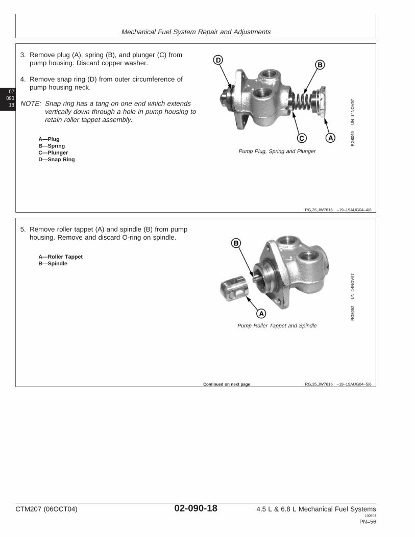
Pump Plug, Spring and Plunger
A—PlugB—SpringC—PlungerD—Snap Ring
3. Remove plug (A), spring (B), and plunger (C) frompump housing. Discard copper washer.
4. Remove snap ring (D) from outer circumference ofpump housing neck.
NOTE: Snap ring has a tang on one end which extendsvertically down through a hole in pump housing toretain roller tappet assembly.
RG,35,JW7616 –19–19AUG04–5/6
RG
8052
–UN
–14N
OV
97
Pump Roller Tappet and Spindle
A—Roller TappetB—Spindle
5. Remove roller tappet (A) and spindle (B) from pumphousing. Remove and discard O-ring on spindle.
Continued on next page
CTM207 (06OCT04) 02-090-18 4.5 L & 6.8 L Mechanical Fuel Systems100604
PN=56

Mechanical Fuel System Repair and Adjustments
0209019
RG,35,JW7616 –19–19AUG04–6/6
RG
4029
–UN
–30O
CT
97
Pump Housing Spindle/Seal O-Ring
A—SpindleB—Spindle/Seal O-Ring
NOTE: Spindle/seal O-ring (B) is pressed into pumphousing. This seal keeps diesel fuel from leakingpast spindle (A) and entering injection pumpcrankcase.
6. Remove spindle seal from housing using needle nosepliers. Discard seal.
RG,35,JW7615 –19–20NOV97–1/4
Inspect and Repair Denso In-Line FuelSupply Pump Components
RG
8050
–UN
–15J
AN
98
Fuel Supply Pump Housing
1. Inspect supply pump housing for cracks and wear. Besure valve seating areas are not pitted. Replacehousing as necessary.
2. Check roller tappet and plunger bore for wear andscoring. Remove any deposits in housing with asuitable solvent. Rinse housing in clean diesel fuel.
3. Check condition of threads for inlet and outlet fittings.Pump elbow fittings have 1/2-20 threads.
Continued on next page
CTM207 (06OCT04) 02-090-19 4.5 L & 6.8 L Mechanical Fuel Systems100604
PN=57

Mechanical Fuel System Repair and Adjustments
02090
20
RG,35,JW7615 –19–20NOV97–2/4
RG
8051
–UN
–14N
OV
97
Inspect Roller Tappet Assembly
A—RollerB—PinC—TappetD—Sliding Block (2 used)
4. Inspect roller (A) OD for excessive wear. Be sure rollerturns freely on pin (B) and in tappet (C).
5. Inspect sliding blocks (D). Edges should be square andunpitted. Blocks should slide in and out of tappeteasily.
6. Inspect tappet for wear and scoring. Remove anydeposits with a suitable solvent.
Be sure land on tappet that contacts pressure spindleis flat and undamaged.
RG,35,JW7615 –19–20NOV97–3/4
RG
2322
–UN
–30O
CT
97
Inspect Press Spindle Plunger and Spring
A—SpindleB—PlungerC—Spring
7. Inspect pressure spindle (A) and plunger (B) for pitsand burrs. Replace parts as necessary.
8. Inspect spring (C) for cracks and distortion. Replaceparts as necessary.
Continued on next page
CTM207 (06OCT04) 02-090-20 4.5 L & 6.8 L Mechanical Fuel Systems100604
PN=58

Mechanical Fuel System Repair and Adjustments
0209021
RG,35,JW7615 –19–20NOV97–4/4
RG
2323
–UN
–30O
CT
97
Inspect Valves and Springs
A—ValveB—Spring
9. Inspect valves (A), especially valve face, for cracks,pits and wear. Replace as necessary.
10. Spring (B) should not be bent or broken.
RG,35,JW7614 –19–19AUG04–1/1
Assemble Denso In-Line Fuel Supply Pump
RG
2013
–UN
–30O
CT
97
Fuel Supply Housing Spindle/Seal O-Ring
A—DriverB—Pump HousingC—Spindle/Seal O-Ring
IMPORTANT: Hands should be wet with diesel fuelwhen assembling internal componentsof fuel supply pump.
1. Install new spindle/seal O-ring (C) into pump housing(B) using JDF15 Driver (A). Be sure spindle/seal O-ringis started straight in housing bore and drive until drivercontacts housing.
2. To assemble supply pump, reverse disassemblyprocedure using new O-rings. Perform leak test. (SeeTEST FUEL SUPPLY PUMP FOR LEAKS—IN-LINEINJECTION PUMP in Section 04, Group 150.)
CTM207 (06OCT04) 02-090-21 4.5 L & 6.8 L Mechanical Fuel Systems100604
PN=59

Mechanical Fuel System Repair and Adjustments
02090
22
RG,35,JW7613 –19–20NOV97–1/1
Install Denso In-Line Fuel Supply Pump
RG
7753
A–U
N–1
0NO
V97
Fuel Supply Pump—Denso In-Line Injection
A—Mounting StudsB—Inlet LineC—Outlet Line
IMPORTANT: Before installing supply pump, testpump to make sure fuel will not leakaround spindle and spindle seal. (SeeTEST FUEL SUPPLY PUMP FORLEAKS—IN-LINE INJECTION PUMP inSection 04, Group 150.)
1. Put a new O-ring in counterbore of injection pumphousing next to fuel supply pump mounting face.
2. Position pump over mounting studs (A). Tightenmounting studs to specifications.
SpecificationFuel Supply Pump (Denso) CapScrews—Torque 5—7 N•m (4—5 lb-ft)
(45—60 lb-in.).......................................................
3. Install fuel inlet (B) and outlet lines (C) when engine isinstalled in vehicle. Tighten all connections securely.
4. Bleed fuel system. (See BLEED THE FUEL SYSTEMin this group.)
DPSG,OUO1004,2601 –19–19AUG04–1/1
Remove Motorpal Fuel Supply Pump
RG
1072
0A–U
N–1
9AP
R00
Remove Fuel Supply Pump
A—Fuel Inlet LineB—Fuel Outlet LineC—Bracket (2 used)D—Cap Screw (2 used)E—Fuel Supply Pump
Thoroughly clean exterior of supply pump. Also cleanaround supply pump mounting area on injection pumphousing.
1. Disconnect fuel inlet line (A) and outlet line (B). Cap allline openings so contaminants do not enter fuelsystem.
2. Remove cap screws (D), brackets (C), and fuel supplypump (E).
3. Cover supply pump mounting bore so debris cannotenter injection pump housing.
CTM207 (06OCT04) 02-090-22 4.5 L & 6.8 L Mechanical Fuel Systems100604
PN=60

Mechanical Fuel System Repair and Adjustments
0209023
DPSG,OUO1004,2607 –19–19AUG04–1/1
Inspect Motorpal Fuel Supply Pump
RG
1071
3A–U
N–0
4AP
R00
Fuel Supply PumpA—O-RingB—Fuel Supply Pump HousingC—O-Ring (2 used)D—Fitting (2 used)E—Hand Primer PumpF—Copper Washer
1. Inspect supply pump housing (B) for cracks and wear.Be sure plunger or roller tappet bore is not worn orscored. Check condition of threads for inlet and outletfittings (D) and hand primer pump (E).
2. If pump housing or plunger mechanism is worn ordamaged, replace pump assembly. Use new O-rings(A and C) on fittings and new copper washer (F) onprimer.
DPSG,OUO1004,2602 –19–19AUG04–1/1
Install Motorpal Fuel Supply Pump
RG
1072
0A–U
N–1
9AP
R00
Remove Fuel Supply Pump
A—Fuel Inlet LineB—Fuel Outlet LineC—Bracket (2 used)D—Cap Screw (2 used)E—Fuel Supply Pump
1. Using a new O-ring, install fuel supply pump (E) ininjection pump bore. Pump should be oriented asshown. Install brackets (C) over flange of supply pumpand install cap screws (D). Tighten cap screws tospecifications.
SpecificationMotorpal Fuel Supply PumpMounting Cap Screws—Torque 8 N•m (6 lb-ft) (72 lb-in.)..........................
2. Install fuel inlet and outlet lines (A and B) and tightento specifications.
SpecificationFuel Supply Pump Inlet andOutlet Lines—Torque 10 N•m (7 lb-ft)........................................................
3. Bleed fuel system. (See BLEED THE FUEL SYSTEMin this group.)
CTM207 (06OCT04) 02-090-23 4.5 L & 6.8 L Mechanical Fuel Systems100604
PN=61

Mechanical Fuel System Repair and Adjustments
02090
24
RG,35,JW7612 –19–20NOV97–1/2
Service Denso Injection Pump OverflowValve
RG
7749
–UN
–07N
OV
97
Injection Pump Overflow Valve
A—Overflow Valve
NOTE: Overflow valve (A) can be serviced with injectionpump installed.
1. Disconnect leak-off line and remove overflow valve (A).
RG,35,JW7612 –19–20NOV97–2/2
RG
3549
–UN
–22N
OV
97
Inspect Injection Pump Overflow Valve
A—ReducerB—Copper WasherC—Valve BodyD—Spring SeatE—SpringF—ValveG—Washer
2. Remove reducer (A) and copper washer (B) from valvebody (C). Discard copper washer.
3. Unscrew spring seat (D); then remove spring (E) andvalve (F).
4. Inspect for foreign material imbedded in seat of nylonvalve.
5. Check spring to see that it is not weak or broken.
6. Wash all parts in solvent and air dry.
NOTE: There is no adjustment on valve to regulatehousing pressure. If it is suspected that valve ismalfunctioning, replace valve to restore properoperation.
7. Reverse order of removal for reassembly of overflowvalve. Install new copper washers.
CTM207 (06OCT04) 02-090-24 4.5 L & 6.8 L Mechanical Fuel Systems100604
PN=62
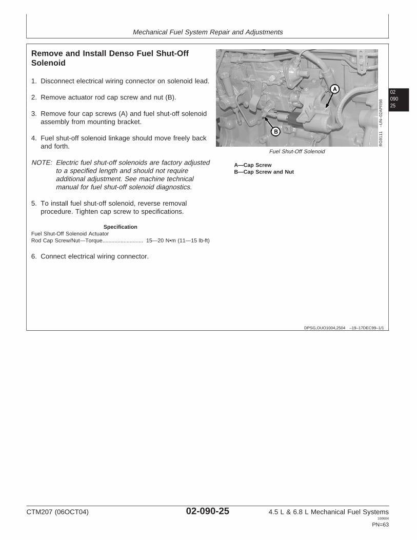
Mechanical Fuel System Repair and Adjustments
0209025
DPSG,OUO1004,2504 –19–17DEC99–1/1
Remove and Install Denso Fuel Shut-OffSolenoid
RG
9111
–UN
–02A
PR
98
Fuel Shut-Off Solenoid
A—Cap ScrewB—Cap Screw and Nut
1. Disconnect electrical wiring connector on solenoid lead.
2. Remove actuator rod cap screw and nut (B).
3. Remove four cap screws (A) and fuel shut-off solenoidassembly from mounting bracket.
4. Fuel shut-off solenoid linkage should move freely backand forth.
NOTE: Electric fuel shut-off solenoids are factory adjustedto a specified length and should not requireadditional adjustment. See machine technicalmanual for fuel shut-off solenoid diagnostics.
5. To install fuel shut-off solenoid, reverse removalprocedure. Tighten cap screw to specifications.
SpecificationFuel Shut-Off Solenoid ActuatorRod Cap Screw/Nut—Torque 15—20 N•m (11—15 lb-ft)...........................
6. Connect electrical wiring connector.
CTM207 (06OCT04) 02-090-25 4.5 L & 6.8 L Mechanical Fuel Systems100604
PN=63

Mechanical Fuel System Repair and Adjustments
02090
26
OUO1079,0000504 –19–09JUL02–1/1
Remove and Install Delphi/Lucas FuelShut-Off Solenoid
D
B
C
A
RG
1241
4–U
N–2
6JU
L02
A—Injection Pump BodyB—NutC—Shut-Off SolenoidD—O-Ring
1. Remove nut (B). Disconnect electrical wiring lead fromsolenoid terminal.
2. Remove shut-off solenoid (C) from injection pump body(A).
3. Inspect and replace parts as necessary. Solenoidlinkage should move freely back and forth. ReplaceO-ring (D).
4. Install solenoid in injection pump body. Tighten tospecification.
Remove and Install Delphi/Lucas Fuel Shut-Off Solenoid—Specification
Solenoid Tightening—Torque 24 N•m (18 lb-ft)..........................................
5. Connect electrical wiring lead to solenoid terminal.Tighten nut.
DPSG,OUO1004,2603 –19–19AUG04–1/1
Remove and Install Motorpal Fuel Shut-OffSolenoid—If Equipped
RG
1072
0B–U
N–1
8AP
R00
Remove and Install Fuel Shut-Off Solenoid
A—WasherB—Cotter PinC—Cap ScrewsD—Fuel Shut-Off Solenoid
1. Disconnect wiring connector from solenoid.
2. Remove cotter pin (B) and washer (A) and detachsolenoid shaft from fuel shut-off lever.
3. Remove cap screws (C) and remove shut-off solenoid(D).
4. Inspect condition of solenoid and replace parts asnecessary.
IMPORTANT: Fuel shut-off solenoid linkage shouldmove freely back and forth.
NOTE: Electric fuel shut-off solenoids are factory adjustedto a specified length and should not requireadditional adjustment.
5. To install fuel shut-off solenoid, reverse removalprocedure.
CTM207 (06OCT04) 02-090-26 4.5 L & 6.8 L Mechanical Fuel Systems100604
PN=64
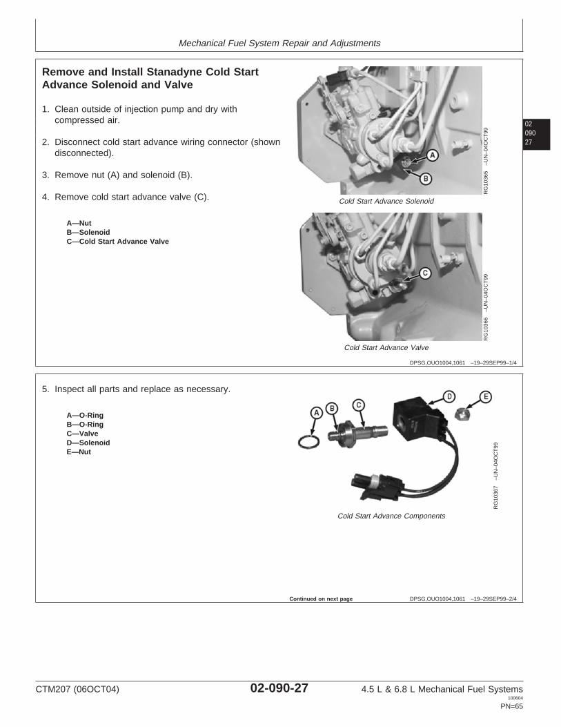
Mechanical Fuel System Repair and Adjustments
0209027
DPSG,OUO1004,1061 –19–29SEP99–1/4
Remove and Install Stanadyne Cold StartAdvance Solenoid and Valve
RG
1036
5–U
N–0
4OC
T99
Cold Start Advance Solenoid
RG
1036
6–U
N–0
4OC
T99
Cold Start Advance Valve
A—NutB—SolenoidC—Cold Start Advance Valve
1. Clean outside of injection pump and dry withcompressed air.
2. Disconnect cold start advance wiring connector (showndisconnected).
3. Remove nut (A) and solenoid (B).
4. Remove cold start advance valve (C).
DPSG,OUO1004,1061 –19–29SEP99–2/4
RG
1036
7–U
N–0
4OC
T99
Cold Start Advance Components
A—O-RingB—O-RingC—ValveD—SolenoidE—Nut
5. Inspect all parts and replace as necessary.
Continued on next page
CTM207 (06OCT04) 02-090-27 4.5 L & 6.8 L Mechanical Fuel Systems100604
PN=65

Mechanical Fuel System Repair and Adjustments
02090
28
DPSG,OUO1004,1061 –19–29SEP99–3/4
RG
1036
8–U
N–0
4OC
T99
Cold Start Valve
RG
1036
9–U
N–0
4OC
T99
Cold Start Solenoid
A—O-RingB—O-RingC—NutD—Solenoid
IMPORTANT: Install O-ring (A) carefully over threadsof valve body to prevent damage to IDof seal.
6. Lubricate O-rings (A) and (B) with clean diesel fuel andinstall on valve. Install valve into fuel pump body andtighten to specifications.
SpecificationCold Start Advance Valve—Torque 11.5 N•m (8.5 lb-ft).........................................................................
7. Install solenoid (D) and nut (C). Tighten nut tospecifications.
SpecificationCold Start AdvanceSolenoid-to-Valve—Torque 5.5 N•m (48 lb-in.)...........................................
DPSG,OUO1004,1061 –19–29SEP99–4/4
RG
1037
4–U
N–0
9OC
T99
Cold Start Wiring Connections
A—ConnectorB—Grounded TerminalC—Ungrounded Terminal
8. Connect harness connector (A). If disconnected,connect terminal ends of cold start wiring harness tofuel shut-off solenoid terminals. Red lead should beconnected to ungrounded terminal (C).
CTM207 (06OCT04) 02-090-28 4.5 L & 6.8 L Mechanical Fuel Systems100604
PN=66

Mechanical Fuel System Repair and Adjustments
0209029
OUO1079,000050C –19–20AUG04–1/2
Remove and Install Delphi/Lucas Cold StartAdvance Switch and Harness
CD
690P
01–U
N–1
0OC
T00
CD
690P
02–U
N–1
0OC
T00
A—Thermostat Housing PlugB—Cold Start Advance Temperature SwitchC—Alternative PortD—Alternative Port
NOTE: Cold start advance kits are available for 6010Series tractors that experience cold weatherstarting difficulties.
Cold start advance kit must be installed ininjection pump by an authorized Delphi/LucasOfficial Dealer, according to Delphi/Lucas bulletinDT282/2.
To install cold start advance temperature switch:
NOTE: For some engine applications, alternative port (Cor D) may be used.
A small amount of engine coolant may escapewhen plug is removed.
1. Remove plug (A) from thermostat housing.
2. Install temperature switch (B) with O-ring. Tighten tospecification.
SpecificationDelphi/Lucas Cold Start AdvanceTemperature Switch—Torque 5 N•m (44 lb-in.)..........................................
Continued on next page
CTM207 (06OCT04) 02-090-29 4.5 L & 6.8 L Mechanical Fuel Systems100604
PN=67

Mechanical Fuel System Repair and Adjustments
02090
30
OUO1079,000050C –19–20AUG04–2/2
CD
690P
03–U
N–1
0OC
T00
A—Fuel Shut-Off Solenoid B—Cold Start Advance C—Wiring Harness Connector D—Temperature SwitchTerminal Terminal Connector
3. Connect RED wire of harness to fuel shut-offsolenoid terminal (A).
4. Connect ORANGE wire of harness to cold startadvance terminal (B).
5. Connect temperature switch connector (D) toharness connector (C).
RG,35,JW7610 –19–09JUL02–1/2
Delphi/Lucas and Stanadyne Rotary FuelInjection Pump Timing
CD
7320
–UN
–23M
AY
95
Timing Fuel Injection Pump
A—Mark on Front PlateB—Mark on Pump Flange
Static Timing With External Marks
1. Loosen attaching hex nuts of fuel injection pump andpivot pump housing away from cylinder block as far asslots will allow. Then pivot it back again, but only farenough to align timing mark on pump flange (B)exactly with timing mark on cylinder block front plate(A).
2. Tighten the three hex nuts securing pump to front plateto specifications.
SpecificationDelphi/Lucas and StanadyneRotary Injection Pump MountingNuts—Torque 27 N•m (20 lb-ft)..................................................................
Also see CHECK AND ADJUST ROTARY INJECTIONPUMP DYNAMIC TIMING in Section 04, Group 150.
CTM207 (06OCT04) 02-090-30 4.5 L & 6.8 L Mechanical Fuel Systems100604
PN=68
Continued on next page

Mechanical Fuel System Repair and Adjustments
0209031
RG,35,JW7610 –19–09JUL02–2/2
CD
7321
–UN
–23M
AY
95
Fuel Injection Pump Timing
C—Timing Marks
Static Timing With Internal Timing Marks (StanadynePumps)
1. Make sure piston No. 1 is at TDC compression strokeand remove timing hole cover from injection pump.
2. With attaching hex nuts finger tight, pivot the pumphousing away from the block as far as slots will allow.Then pivot it back until the timing marks (C) on camring and governor weight retainer are aligned. Tightenpump attaching nuts to specifications.
SpecificationDelphi/Lucas and StanadyneRotary Injection Pump MountingNuts—Torque 27 N•m (20 lb-ft)..................................................................
CTM207 (06OCT04) 02-090-31 4.5 L & 6.8 L Mechanical Fuel Systems100604
PN=69

Mechanical Fuel System Repair and Adjustments
02090
32
DPSG,OUO1004,2668 –19–19AUG04–1/2
Denso and Motorpal In-Line Injection PumpStatic Timing
RG
8053
A–U
N–1
8NO
V97
Time Denso Injection Pump
A—Timing PointerB—Mark on Drive HubC—Timing Pin
NOTE: On some engines with in-line injection pumps, atiming pin may be screwed into the side of thepump. This pin may be used instead of JDG886Timing Pin.
1. Static lock-pin timing is accomplished duringinstallation of the injection pump with engine locked atNo. 1 TDC.
2. On Denso pumps: Align pump timing mark on drivehub (B) with stationary timing pointer (A). Lock pumpsin position with JDG886 Injection Pump Timing Pin (C).
IMPORTANT: The normal backlash of gears is enoughto throw the pump timing off by severaldegrees, resulting in poor engineperformance. It is important that pumptiming be rechecked after pump hasbeen installed.
NOTE: Normal engine rotation is counterclockwise,viewed from flywheel end.
To check alignment of injection pump and eliminatebacklash of timing gear train, remove both timing pinsand rotate the flywheel opposite the direction of normalrotation. Install JDE81-4 or JDG1571 Timing Pin androtate flywheel in the direction of normal rotation untiltiming pin engages in timing pin hole.
If JDG886 Timing Pin will not install through drive huband bottom out, loosen drive gear cap screws androtate hub until timing pin can be installed and lockedin place.
Continued on next page
CTM207 (06OCT04) 02-090-32 4.5 L & 6.8 L Mechanical Fuel Systems100604
PN=70

Mechanical Fuel System Repair and Adjustments
0209033
DPSG,OUO1004,2668 –19–19AUG04–2/2
RG
1071
1A–U
N–3
1MA
R00
Time Motorpal Injection Pump
A—CapB—SpringC—Timing Pin
3. On Motorpal pumps:
NOTE: If missing, timing pin assembly is availablethrough John Deere Service Parts.
Install injection pump timing pin (C) into bore and makesure it is fully engaged in pump timing slot. Installspring (B) on the outboard side of pin.
Reinstall cap (A) and tighten finger tight.
Applying a light turning force, attempt to rotate pumpby hand to verify pump is locked.
NOTE: When tightening pump drive gear cap screws,apply light force (clockwise) to gear to eliminateany backlash with camshaft gear.
4. Tighten pump drive gear cap screws to specifications.
SpecificationDenso Injection Pump Drive GearCap Screws—Torque 47 N•m (35 lb-ft)......................................................Motorpal Injection Pump DriveGear Cap Screws—Torque 61 N•m (45 lb-ft).............................................
5. Remove cap (A), spring (B), and timing pin (C).
6. Install spring (B) into pin bore.
7. Install timing pin (C) onto spring.
8. Reinstall cap (A).
CTM207 (06OCT04) 02-090-33 4.5 L & 6.8 L Mechanical Fuel Systems100604
PN=71
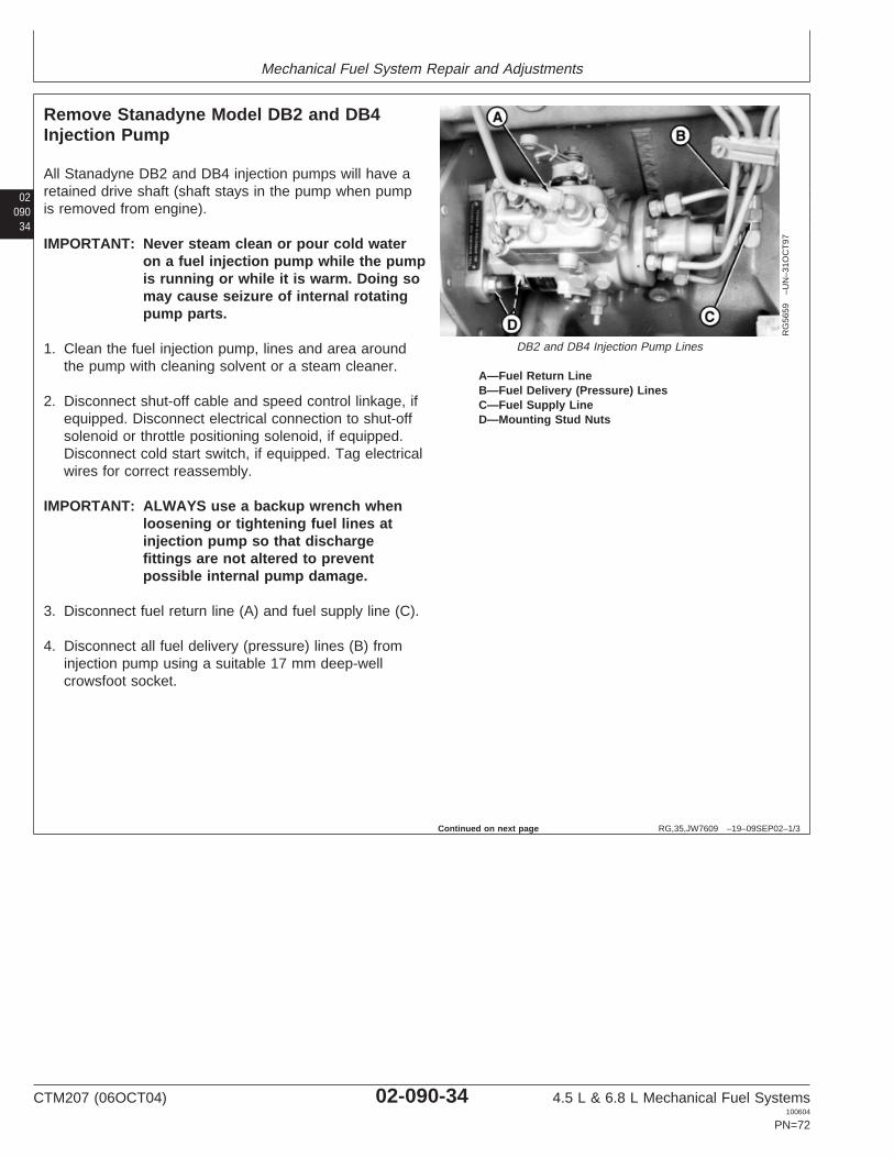
Mechanical Fuel System Repair and Adjustments
02090
34
RG,35,JW7609 –19–09SEP02–1/3
Remove Stanadyne Model DB2 and DB4Injection Pump
RG
5659
–UN
–31O
CT
97
DB2 and DB4 Injection Pump Lines
A—Fuel Return LineB—Fuel Delivery (Pressure) LinesC—Fuel Supply LineD—Mounting Stud Nuts
All Stanadyne DB2 and DB4 injection pumps will have aretained drive shaft (shaft stays in the pump when pumpis removed from engine).
IMPORTANT: Never steam clean or pour cold wateron a fuel injection pump while the pumpis running or while it is warm. Doing somay cause seizure of internal rotatingpump parts.
1. Clean the fuel injection pump, lines and area aroundthe pump with cleaning solvent or a steam cleaner.
2. Disconnect shut-off cable and speed control linkage, ifequipped. Disconnect electrical connection to shut-offsolenoid or throttle positioning solenoid, if equipped.Disconnect cold start switch, if equipped. Tag electricalwires for correct reassembly.
IMPORTANT: ALWAYS use a backup wrench whenloosening or tightening fuel lines atinjection pump so that dischargefittings are not altered to preventpossible internal pump damage.
3. Disconnect fuel return line (A) and fuel supply line (C).
4. Disconnect all fuel delivery (pressure) lines (B) frominjection pump using a suitable 17 mm deep-wellcrowsfoot socket.
Continued on next page
CTM207 (06OCT04) 02-090-34 4.5 L & 6.8 L Mechanical Fuel Systems100604
PN=72
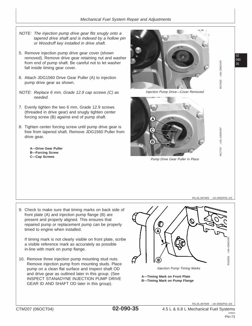
Mechanical Fuel System Repair and Adjustments
0209035
RG,35,JW7609 –19–09SEP02–2/3
RG
7630
–UN
–23N
OV
97
Injection Pump Drive—Cover Removed
RG
7757
–UN
–10N
OV
97
Pump Drive Gear Puller in Place
A—Drive Gear PullerB—Forcing ScrewC—Cap Screws
NOTE: The injection pump drive gear fits snugly onto atapered drive shaft and is indexed by a hollow pinor Woodruff key installed in drive shaft.
5. Remove injection pump drive gear cover (shownremoved). Remove drive gear retaining nut and washerfrom end of pump shaft. Be careful not to let washerfall inside timing gear cover.
6. Attach JDG1560 Drive Gear Puller (A) to injectionpump drive gear as shown.
NOTE: Replace 6 mm, Grade 12.9 cap screws (C) asneeded.
7. Evenly tighten the two 6 mm, Grade 12.9 screws(threaded in drive gear) and snugly tighten centerforcing screw (B) against end of pump shaft.
8. Tighten center forcing screw until pump drive gear isfree from tapered shaft. Remove JDG1560 Puller fromdrive gear.
RG,35,JW7609 –19–09SEP02–3/3
RG
6293
–UN
–03N
OV
97
Injection Pump Timing Marks
A—Timing Mark on Front PlateB—Timing Mark on Pump Flange
9. Check to make sure that timing marks on back side offront plate (A) and injection pump flange (B) arepresent and properly aligned. This ensures thatrepaired pump or replacement pump can be properlytimed to engine when installed.
If timing mark is not clearly visible on front plate, scribea visible reference mark as accurately as possiblein-line with mark on pump flange.
10. Remove three injection pump mounting stud nuts.Remove injection pump from mounting studs. Placepump on a clean flat surface and inspect shaft ODand drive gear as outlined later in this group. (SeeINSPECT STANADYNE INJECTION PUMP DRIVEGEAR ID AND SHAFT OD later in this group).
CTM207 (06OCT04) 02-090-35 4.5 L & 6.8 L Mechanical Fuel Systems100604
PN=73
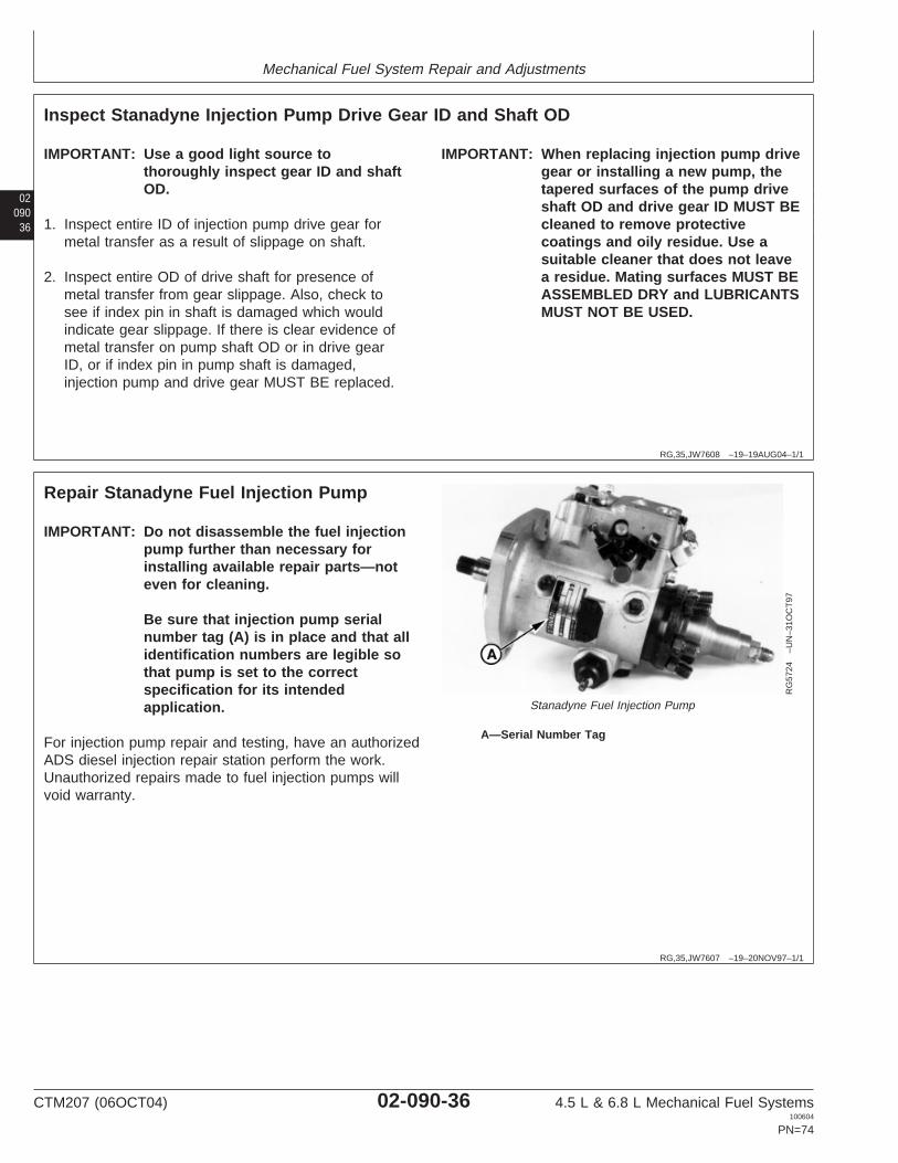
Mechanical Fuel System Repair and Adjustments
02090
36
RG,35,JW7608 –19–19AUG04–1/1
Inspect Stanadyne Injection Pump Drive Gear ID and Shaft OD
IMPORTANT: Use a good light source tothoroughly inspect gear ID and shaftOD.
1. Inspect entire ID of injection pump drive gear formetal transfer as a result of slippage on shaft.
2. Inspect entire OD of drive shaft for presence ofmetal transfer from gear slippage. Also, check tosee if index pin in shaft is damaged which wouldindicate gear slippage. If there is clear evidence ofmetal transfer on pump shaft OD or in drive gearID, or if index pin in pump shaft is damaged,injection pump and drive gear MUST BE replaced.
IMPORTANT: When replacing injection pump drivegear or installing a new pump, thetapered surfaces of the pump driveshaft OD and drive gear ID MUST BEcleaned to remove protectivecoatings and oily residue. Use asuitable cleaner that does not leavea residue. Mating surfaces MUST BEASSEMBLED DRY and LUBRICANTSMUST NOT BE USED.
RG,35,JW7607 –19–20NOV97–1/1
Repair Stanadyne Fuel Injection Pump
RG
5724
–UN
–31O
CT
97
Stanadyne Fuel Injection Pump
A—Serial Number Tag
IMPORTANT: Do not disassemble the fuel injectionpump further than necessary forinstalling available repair parts—noteven for cleaning.
Be sure that injection pump serialnumber tag (A) is in place and that allidentification numbers are legible sothat pump is set to the correctspecification for its intendedapplication.
For injection pump repair and testing, have an authorizedADS diesel injection repair station perform the work.Unauthorized repairs made to fuel injection pumps willvoid warranty.
CTM207 (06OCT04) 02-090-36 4.5 L & 6.8 L Mechanical Fuel Systems100604
PN=74

Mechanical Fuel System Repair and Adjustments
0209037
RG,35,JW7606 –19–08JUL02–1/4
Install Stanadyne Model DB2 and DB4 Injection Pump
RG
6278
–UN
–03N
OV
97
Injection Pump Timing Marks
RG
7630
C–U
N–0
6NO
V97
Pump Drive Gear Retaining Nut
A—Front Plate Timing Mark B—Pump Timing Mark C—Pump Drive Gear RetainingNut
Injection pump mounting flange timing mark (B) andfront plate timing mark (A) presence and alignmentMUST BE verified before removing pumps fromengine. When pump is reinstalled on engine, timepump by aligning these two (external) marks. DO NOTreference internal timing marks (on pump cam ring andgovernor weight retainer) for accurate pump timing.
1. Lubricate a new square sealing ring with cleanengine oil. Install ring into groove on front face ofpump mounting flange. Slide injection pump ontomounting studs while inserting pump shaft into drivegear.
IMPORTANT: Shaft roll pin may be easily damagedif improperly assembled. Pump drivegear should not move when initiallyinstalling pump index pin into drivegear key slot.
2. Check pump shaft and index pin for properalignment with pump drive gear key slot.
3. Install injection pump partially onto mounting studswithout engaging pump pilot hub into engine frontplate.
IMPORTANT: DO NOT tighten hex nuts more thanthree full turns on mounting studs.
Pump drive shaft index pin may bedamaged if pin is not properlyaligned with drive gear key slot andnuts are tightened more than threeturns.
4. Install three flat washers, lock washers, and hexnuts onto pump mounting studs. Tighten nuts threeturns only so that pump will not fall off mountingstuds.
NOTE: The pump drive gear should begin to moveforward (away from engine front plate) with thepump when flange is approximately 3.2 mm(1/8 in.) away from engine front plate.
5. Install pump mounting flange flush to engine frontplate with drive gear held flush against front side ofengine front plate.
IMPORTANT: DO NOT use tightening force ofpump mounting stud nuts to pullpump shaft into drive gear ID.
6. With the pump shaft index pin properly engaged inthe drive gear key slot, finger tighten mounting studnuts.
CTM207 (06OCT04) 02-090-37 4.5 L & 6.8 L Mechanical Fuel Systems100604
PN=75
Continued on next page

Mechanical Fuel System Repair and Adjustments
02090
38
RG,35,JW7606 –19–08JUL02–2/4
7. Push pump drive gear firmly onto shaft taper. Installwasher and retaining nut (C) onto end of shaft.Tighten retaining nut to the following torquespecification:
SpecificationStanadyne DB2 Fuel InjectionPump Drive Gear-to-ShaftRetaining Nut—Torque 125 N•m (92 lb-ft)...........................................Stanadyne DB4 Fuel InjectionPump Drive Gear-to-ShaftRetaining Nut—Torque 200 N•m (148 lb-ft).........................................
Continued on next page
CTM207 (06OCT04) 02-090-38 4.5 L & 6.8 L Mechanical Fuel Systems100604
PN=76
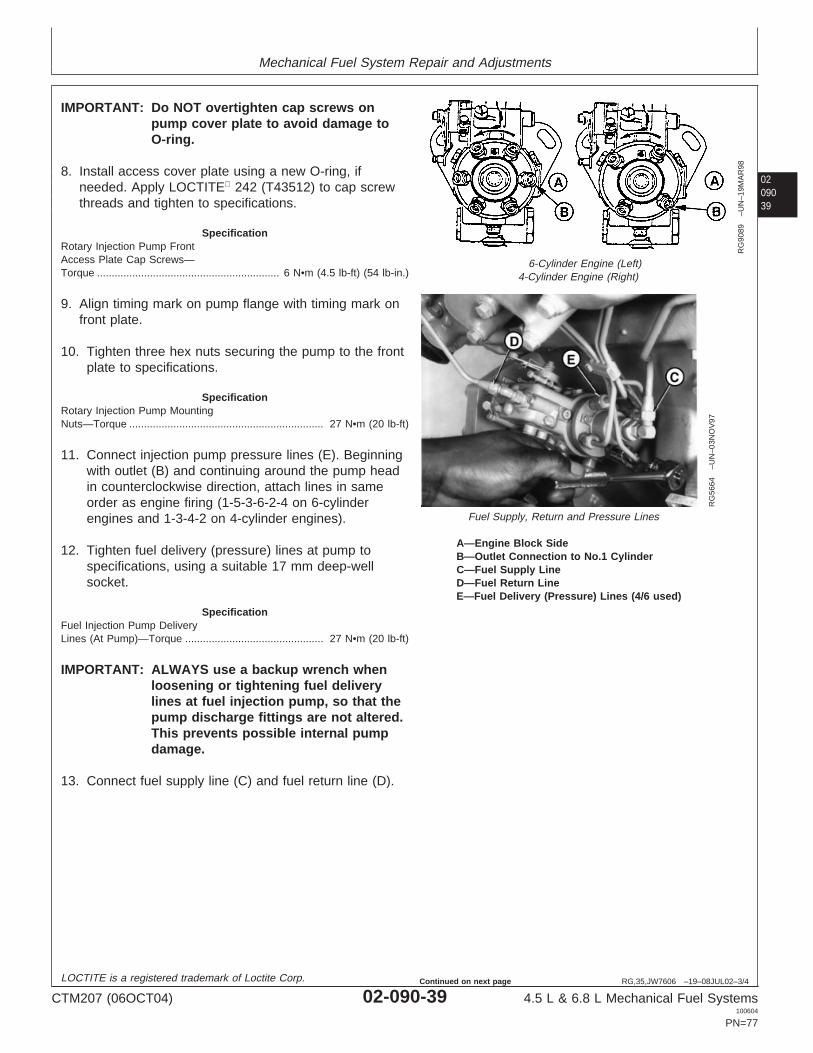
Mechanical Fuel System Repair and Adjustments
0209039
RG,35,JW7606 –19–08JUL02–3/4
RG
9089
–UN
–19M
AR
98
6-Cylinder Engine (Left)4-Cylinder Engine (Right)
RG
5664
–UN
–03N
OV
97
Fuel Supply, Return and Pressure Lines
A—Engine Block SideB—Outlet Connection to No.1 CylinderC—Fuel Supply LineD—Fuel Return LineE—Fuel Delivery (Pressure) Lines (4/6 used)
IMPORTANT: Do NOT overtighten cap screws onpump cover plate to avoid damage toO-ring.
8. Install access cover plate using a new O-ring, ifneeded. Apply LOCTITE 242 (T43512) to cap screwthreads and tighten to specifications.
SpecificationRotary Injection Pump FrontAccess Plate Cap Screws—Torque 6 N•m (4.5 lb-ft) (54 lb-in.)..............................................................
9. Align timing mark on pump flange with timing mark onfront plate.
10. Tighten three hex nuts securing the pump to the frontplate to specifications.
SpecificationRotary Injection Pump MountingNuts—Torque 27 N•m (20 lb-ft)..................................................................
11. Connect injection pump pressure lines (E). Beginningwith outlet (B) and continuing around the pump headin counterclockwise direction, attach lines in sameorder as engine firing (1-5-3-6-2-4 on 6-cylinderengines and 1-3-4-2 on 4-cylinder engines).
12. Tighten fuel delivery (pressure) lines at pump tospecifications, using a suitable 17 mm deep-wellsocket.
SpecificationFuel Injection Pump DeliveryLines (At Pump)—Torque 27 N•m (20 lb-ft)...............................................
IMPORTANT: ALWAYS use a backup wrench whenloosening or tightening fuel deliverylines at fuel injection pump, so that thepump discharge fittings are not altered.This prevents possible internal pumpdamage.
13. Connect fuel supply line (C) and fuel return line (D).
LOCTITE is a registered trademark of Loctite Corp.
CTM207 (06OCT04) 02-090-39 4.5 L & 6.8 L Mechanical Fuel Systems100604
PN=77
Continued on next page

Mechanical Fuel System Repair and Adjustments
02090
40
RG,35,JW7606 –19–08JUL02–4/4
14. Connect fuel shut-off cable and speed control linkage,if equipped. Install and securely tighten electricalconnections to shut-off solenoid and throttlepositioning solenoid, if equipped. Connect cold startswitch, if equipped.
15. Bleed air from fuel system as outlined in this group.(See BLEED THE FUEL SYSTEM in this group.) Startengine, run for several minutes and check entire fuelsystem for leaks.
RG,35,JW7605 –19–08JUL02–1/4
Remove Delphi/Lucas Fuel Injection Pump
RG
7722
–UN
–07N
OV
97
Delphi/Lucas Fuel Injection Pump
RG
9069
–UN
–16M
AR
98
Fuel Supply, Return and Pressure Lines
A—Fuel Return LineB—Fuel Delivery (Pressure) LinesC—Fuel Supply LineD—Aneroid Line
NOTE: The injection pump serial number tag (bold arrow)is located on the bottom of the pump.
IMPORTANT: Never steam clean or pour cold wateron a fuel injection pump while the pumpis running or while it is warm. Doing somay cause seizure of internal rotatingpump parts.
1. Clean the fuel injection pump, lines and area aroundthe pump with cleaning solvent or a steam cleaner.
2. Disconnect shut-off cable and speed control linkage, ifequipped. Disconnect electrical connection to shut-offsolenoid or throttle positioning solenoid, if equipped.Disconnect cold start switch, if equipped. Tag electricalwires for correct reassembly.
IMPORTANT: ALWAYS use a backup wrench whenloosening or tightening fuel lines atinjection pump so that dischargefittings are not altered to preventpossible internal pump damage.
3. Disconnect fuel return line (A), fuel supply line (C) andaneroid line (D).
4. Disconnect all fuel delivery (pressure) lines (B) frominjection pump using a suitable 17 mm deep-wellcrowsfoot socket.
CTM207 (06OCT04) 02-090-40 4.5 L & 6.8 L Mechanical Fuel Systems100604
PN=78
Continued on next page

Mechanical Fuel System Repair and Adjustments
0209041
RG,35,JW7605 –19–08JUL02–2/4
RG
7629
A–U
N–0
6NO
V97
Injection Pump Drive Cover
RG
7630
B–U
N–0
6NO
V97
Pump Drive Gear Retaining Nut
A—Drive Gear CoverB—Drive Gear Retaining Nut
5. Remove injection pump drive gear cover (A). Removedrive gear retaining nut (B) and washer from end ofpump shaft. Be careful not to let washer fall insidetiming gear cover.
RG,35,JW7605 –19–08JUL02–3/4
RG
7631
–UN
–06N
OV
97
Pump Drive Gear Puller in Place
A—Drive Gear PullerB—Forcing ScrewC—Cap Screws
NOTE: The injection pump drive gear fits snugly onto atapered drive shaft and is indexed by a Woodruffkey installed in drive shaft. Use JDG1560 DriveGear Puller (A) to remove drive gear from shaft.
6. Attach JDG1560 Injection Pump Drive Gear Puller toinjection pump drive gear as shown. Follow instructionsprovided with tool set.
NOTE: Replace 6 mm, Grade 12.9 cap screws (C) asneeded.
7. Evenly tighten the two 6 mm, Grade 12.9 screws(threaded in drive gear) and snugly tighten centerforcing screw (B) against end of pump shaft.
8. Tighten center forcing screw until pump drive gear isfree from tapered shaft. Remove JDG1560 InjectionPump Drive Gear Puller from drive gear.
CTM207 (06OCT04) 02-090-41 4.5 L & 6.8 L Mechanical Fuel Systems100604
PN=79
Continued on next page
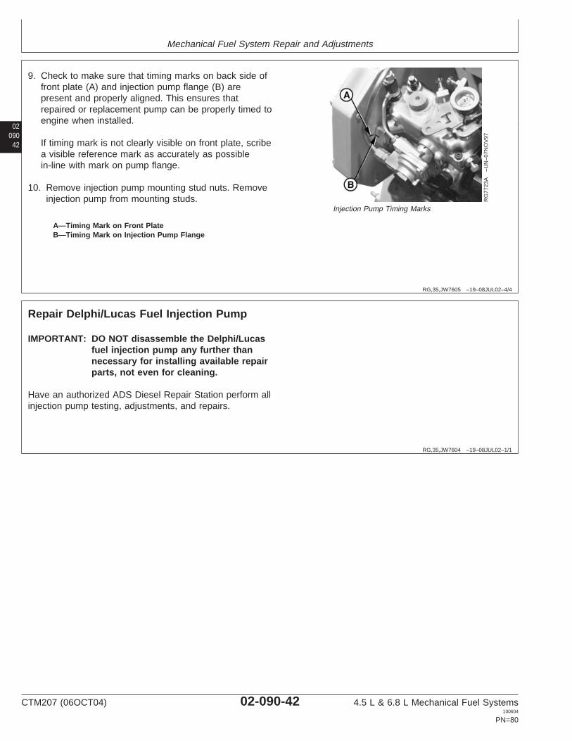
Mechanical Fuel System Repair and Adjustments
02090
42
RG,35,JW7605 –19–08JUL02–4/4
RG
7723
A–U
N–0
7NO
V97
Injection Pump Timing Marks
A—Timing Mark on Front PlateB—Timing Mark on Injection Pump Flange
9. Check to make sure that timing marks on back side offront plate (A) and injection pump flange (B) arepresent and properly aligned. This ensures thatrepaired or replacement pump can be properly timed toengine when installed.
If timing mark is not clearly visible on front plate, scribea visible reference mark as accurately as possiblein-line with mark on pump flange.
10. Remove injection pump mounting stud nuts. Removeinjection pump from mounting studs.
RG,35,JW7604 –19–08JUL02–1/1
Repair Delphi/Lucas Fuel Injection Pump
IMPORTANT: DO NOT disassemble the Delphi/Lucasfuel injection pump any further thannecessary for installing available repairparts, not even for cleaning.
Have an authorized ADS Diesel Repair Station perform allinjection pump testing, adjustments, and repairs.
CTM207 (06OCT04) 02-090-42 4.5 L & 6.8 L Mechanical Fuel Systems100604
PN=80

Mechanical Fuel System Repair and Adjustments
0209043
RG,35,JW7603 –19–08JUL02–1/5
Install Delphi/Lucas Fuel Injection Pump
IMPORTANT: When replacing injection pump drivegear or installing a new pump, thetapered surfaces of the pump driveshaft OD and drive gear ID MUST BEcleaned to remove protectivecoatings and oily residue. Use asuitable cleaner that does not leavea residue. Mating surfaces MUST BEassembled dry. LUBRICANTS MUSTNOT BE USED.
1. Place a new O-ring onto front face of pumpmounting flange with mounting slots aligned. Slideinjection pump onto mounting studs while insertingpump shaft into drive gear.
2. Check pump shaft Woodruff key for properalignment with pump drive gear key slot.
3. Install injection pump partially onto mounting studswith engaging pump pilot hub into engine frontplate.
4. Install three flat washers, lock washers, and hexnuts onto pump mounting studs. Tighten nuts threeturns only so that pump will not fall off mountingstuds.
5. Install pump mounting flange flush to engine frontplate with drive gear held flush against front side ofengine front plate.
6. With the pump shaft key properly engaged in thedrive gear key slot, finger tighten mounting studnuts.
RG,35,JW7603 –19–08JUL02–2/5
RG
7630
A–U
N–0
6NO
V97
Pump Drive Gear Retaining Nut
A—Drive Gear Retaining Nut
7. Push pump drive gear firmly onto shaft taper. Installwasher and retaining nut (A) onto end of shaft. Tightenretaining nut to following specifications:
SpecificationDP201 and DP203 Delphi/LucasFuel Injection Pump DriveGear-to-Shaft Retaining Nut—Torque 80 N•m (60 lb-ft).............................................................................
Continued on next page
CTM207 (06OCT04) 02-090-43 4.5 L & 6.8 L Mechanical Fuel Systems100604
PN=81

Mechanical Fuel System Repair and Adjustments
02090
44
RG,35,JW7603 –19–08JUL02–3/5
RG
7629
B–U
N–0
6NO
V97
Injection Pump Drive Gear Access PlateB—Injection Pump Drive Gear Access Plate
IMPORTANT: DO NOT overtighten cap screws onpump cover plate to avoid damage toO-ring.
8. Install access plate (B) using a new O-ring, if needed.Apply LOCTITE 242 (T43512) to cap screw threadsand tighten to specifications.
SpecificationRotary Injection Pump FrontAccess Plate Cap Screws—Torque 6 N•m (4.5 lb-ft) (54 lb-in.).............................................................
LOCTITE is a registered trademark of Loctite Corp.
RG,35,JW7603 –19–08JUL02–4/5
RG
7723
A–U
N–0
7NO
V97
Injection Pump Timing Marks
A—Timing Mark on Front PlateB—Timing Mark on Injection Pump Flange
9. Align timing mark on the pump flange (B) with timingmark on front plate (A).
10. Tighten hex nuts securing the pump to the front plateto specifications.
SpecificationRotary Injection Pump MountingNuts—Torque 27 N•m (20 lb-ft)..................................................................
Continued on next page
CTM207 (06OCT04) 02-090-44 4.5 L & 6.8 L Mechanical Fuel Systems100604
PN=82

Mechanical Fuel System Repair and Adjustments
0209045
RG,35,JW7603 –19–08JUL02–5/5
RG
9089
–UN
–19M
AR
98
6-Cylinder Engine (Left)4-Cylinder Engine (Right)
RG
9070
–UN
–16M
AR
98
Fuel Supply, Return and Pressure Lines
A—Engine Block SideB—Outlet Connection to No. 1 CylinderC—Fuel Supply LineD—Fuel Return LineE—Fuel Delivery (Pressure) LinesF—Aneroid Line
11. Connect injection pump pressure lines (E). Beginningwith outlet (B) and continuing around the pump headin counterclockwise direction, attach lines in sameorder as engine firing (1-5-3-6-2-4 on 6-cylinderengines and 1-3-4-2 on 4-cylinder engines).
12. Tighten fuel delivery (pressure) lines at pump tospecifications, using a suitable 17 mm deep-wellsocket.
SpecificationFuel Injection Pump DeliveryLines—Torque 27 N•m (20 lb-ft).................................................................
IMPORTANT: ALWAYS use a backup wrench whenloosening or tightening fuel deliverylines at fuel injection pump, so that thepump discharge fittings are not altered.This prevents possible internal pumpdamage.
13. Connect fuel supply line (C), fuel return line (D) andaneroid line (F).
14. Connect fuel shut-off cable and speed control linkage,if equipped. Install and securely tighten electricalconnections to shut-off solenoid and throttlepositioning solenoid, if equipped. Connect cold startswitch, if equipped.
15. Bleed air from fuel system as outlined in this group.(See BLEED THE FUEL SYSTEM in this group.) Startengine, run for several minutes and check entire fuelsystem for leaks.
CTM207 (06OCT04) 02-090-45 4.5 L & 6.8 L Mechanical Fuel Systems100604
PN=83

Mechanical Fuel System Repair and Adjustments
02090
46
RG,35,JW7602 –19–19AUG04–1/3
Remove Denso Fuel Injection Pump
RG
7748
–UN
–06D
EC
96
In-Line Injection Pump
IMPORTANT: Never steam clean or pour cold wateron an injection pump while pump isrunning, or while it is still warm. To doso may cause seizure of pump parts.
1. Clean injection lines and area around the injectionpump with cleaning solvent or a steam cleaner.
2. Using JDG820, JDE81-1, or JDE83 Flywheel TurningTool as required, rotate engine flywheel (in normalrunning direction) until No. 1 piston is at TDC of itscompression stroke. At this point, JDE81-4 orJDG1571 Timing Pin should enter hole in flywheel.
Continued on next page
CTM207 (06OCT04) 02-090-46 4.5 L & 6.8 L Mechanical Fuel Systems100604
PN=84
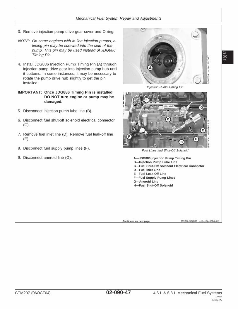
Mechanical Fuel System Repair and Adjustments
0209047
RG,35,JW7602 –19–19AUG04–2/3
RG
8065
A–U
N–1
8NO
V97
Injection Pump Timing Pin
RG
7750
A–U
N–1
8JU
L02
Fuel Lines and Shut-Off Solenoid
A—JDG886 Injection Pump Timing PinB—Injection Pump Lube LineC—Fuel Shut-Off Solenoid Electrical ConnectorD—Fuel Inlet LineE—Fuel Leak-Off LineF—Fuel Supply Pump LinesG—Aneroid LineH—Fuel Shut-Off Solenoid
3. Remove injection pump drive gear cover and O-ring.
NOTE: On some engines with in-line injection pumps, atiming pin may be screwed into the side of thepump. This pin may be used instead of JDG886Timing Pin.
4. Install JDG886 Injection Pump Timing Pin (A) throughinjection pump drive gear into injection pump hub untilit bottoms. In some instances, it may be necessary torotate the pump drive hub slightly to get the pininstalled.
IMPORTANT: Once JDG886 Timing Pin is installed,DO NOT turn engine or pump may bedamaged.
5. Disconnect injection pump lube line (B).
6. Disconnect fuel shut-off solenoid electrical connector(C).
7. Remove fuel inlet line (D). Remove fuel leak-off line(E).
8. Disconnect fuel supply pump lines (F).
9. Disconnect aneroid line (G).
Continued on next page
CTM207 (06OCT04) 02-090-47 4.5 L & 6.8 L Mechanical Fuel Systems100604
PN=85

Mechanical Fuel System Repair and Adjustments
02090
48
RG,35,JW7602 –19–19AUG04–3/3
RG
7750
B–U
N–0
7NO
V97
Pump Fuel Delivery Lines and Stud Nuts
RG
8066
B–U
N–1
8NO
V97
Pump Drive Gear Cap Screws
A—Injection Line NutsB—Mounting NutsC—Cap Screws
10. Remove fuel injection line nuts (A).
11. Remove four injection pump drive gear cap screws(C).
12. Remove four mounting stud nuts (B) which secureinjection pump to cylinder block.
13. Carefully remove injection pump from mounting studsand place it on a clean flat surface.
RG,35,JW7601 –19–20NOV97–1/1
Repair Denso Fuel Injection Pump
RG
8065
A–U
N–1
8NO
V97
Injection Pump Timing Pin
A—Timing Pin
IMPORTANT: Do not disassemble fuel injection pumpfurther than necessary for installingavailable service parts, not even forcleaning.
Be sure that injection pump serialnumber tag is in place and that allidentification numbers are legible sothat pump is set to the correctspecifications for its intended use.
NOTE: Remove JDG886 Injection Pump Timing Pin (A)when sending an injection pump out for repair.
For injection pump repair and testing, have an authorizeddiesel injection pump repair station perform the work.Unauthorized repairs made to the injection pump will voidwarranty.
CTM207 (06OCT04) 02-090-48 4.5 L & 6.8 L Mechanical Fuel Systems100604
PN=86

Mechanical Fuel System Repair and Adjustments
0209049
RG,35,JW7600 –19–19AUG04–1/6
Install Denso Fuel Injection Pump
RG
7711
A–U
N–0
7NO
V97
Engine Timing Pin
A—Timing Pin
NOTE: To eliminate any backlash that might exist in thetiming gear train, rotate flywheel in the direction ofnormal engine rotation (counterclockwise viewedfrom flywheel end) when installing JDE81-4 orJDG1571 Timing Pin.
1. If engine was rotated after injection pump wasremoved, rotate flywheel in the direction of normalengine rotation until JDE81-4 or JDG1571 Timing Pin(A) enters flywheel at No. 1 cylinder’s TDCcompression stroke.
NOTE: When No. 1 cylinder is at TDC compressionstroke, intake and exhaust valves for No. 1cylinder will be closed and both rocker arms willbe loose.
Continued on next page
CTM207 (06OCT04) 02-090-49 4.5 L & 6.8 L Mechanical Fuel Systems100604
PN=87

Mechanical Fuel System Repair and Adjustments
02090
50
RG,35,JW7600 –19–19AUG04–2/6
RG
8053
B–U
N–1
8NO
V97
Hub to Pointer Timing Marks
RG
8065
B–U
N–1
8NO
V97
Injection Pump Timing Pin
A—PointerB—Drive HubC—O-RingD—Bearing PlateE—JDG886 Injection Pump Timing Pin
2. Rotate injection pump drive hub until marks on drivehub (B) and pointer (A) are aligned.
NOTE: On some engines with in-line injection pumps, atiming pin may be screwed into the side of thepump. This pin may be used instead of JDG886Timing Pin.
NOTE: It may be necessary to rotate pump hub slightly toallow JDG886 Injection Pump Timing Pin (E) toenter bearing plate.
3. Thread JDG886 Timing Pin into drive hub as shown,and tighten until it bottoms against the drive hub withthe timing pin located in hole of pointer (A).
4. Install a new O-ring (C) on bearing plate. Lightlylubricate O-ring with AR54749 Soap Lubricant to aid inpump installation and prevent O-ring damage.
5. Install injection pump using moderate forward pressureand slight rocking motion to work O-ring into mountingbore. Injection pump flange should seat solidly againstcylinder block.
6. Install mounting stud nuts and tighten to specifications.
SpecificationDenso Injection Pump MountingNuts—Torque 70 N•m (52 lb-ft)..................................................................
NOTE: The injection pump needs to be properly timedduring installation of pump to ensure that gearbacklash is removed. See DENSO ANDMOTORPAL IN-LINE INJECTION PUMP STATICTIMING in this group for proper injection pumptiming and elimination of backlash with camshaftgear.
7. Carefully install drive gear on pump drive hub. Positiongear so mounting cap screws are approximatelycentered in mounting slots. This will allow for minoradjustment of pump timing, should the need arise.
CTM207 (06OCT04) 02-090-50 4.5 L & 6.8 L Mechanical Fuel Systems100604
PN=88
Continued on next page

Mechanical Fuel System Repair and Adjustments
0209051
RG,35,JW7600 –19–19AUG04–3/6
RG
8065
A–U
N–1
8NO
V97
Injection Pump Timing Pin
RG
9138
–UN
–18M
AY
98
Pump Drive Gear Cap Screws
A—Timing PinB—Cap Screws
8. Install drive gear-to-pump hub cap screws (B) andtighten to specifications.
SpecificationDenso Injection Pump Drive GearCap Screws—Torque 47 N•m (35 lb-ft)......................................................
9. Remove JDG886 Injection Pump Timing Pin (A) frominjection pump hub.
10. Install injection pump drive gear cover using a newO-ring, if needed. Tighten cap screws tospecifications.
SpecificationDenso Injection Pump Drive GearCover—Torque 6 N•m (4.5 lb-ft) (54 lb-in.).................................................
RG,35,JW7600 –19–19AUG04–4/6
RG
7750
C–U
N–0
7NO
V97
Pump Fuel Delivery Lines
A—Fuel Delivery Lines
IMPORTANT: DO NOT move delivery valve fittingswhile tightening line nuts. If deliveryvalve and barrel housing rotates whiletightening a fuel line nut, injectionpump fuel delivery will be altered. Theinjection pump will have to berecalibrated on a test stand by anauthorized diesel repair station.
NOTE: Remove protective caps and plugs that wereinstalled on fuel system components duringinjection pump removal.
11. Connect fuel delivery lines (A). Tighten line nuts tospecifications.
SpecificationFuel Injection Pump DeliveryLines—Torque 27 N•m (20 lb-ft).................................................................
CTM207 (06OCT04) 02-090-51 4.5 L & 6.8 L Mechanical Fuel Systems100604
PN=89
Continued on next page
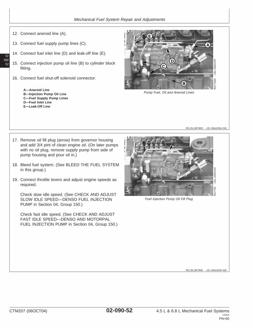
Mechanical Fuel System Repair and Adjustments
02090
52
RG,35,JW7600 –19–19AUG04–5/6
RG
7750
D–U
N–2
6NO
V97
Pump Fuel, Oil and Aneroid LinesA—Aneroid LineB—Injection Pump Oil LineC—Fuel Supply Pump LinesD—Fuel Inlet LineE—Leak-Off Line
12. Connect aneroid line (A).
13. Connect fuel supply pump lines (C).
14. Connect fuel inlet line (D) and leak-off line (E).
15. Connect injection pump oil line (B) to cylinder blockfitting.
16. Connect fuel shut-off solenoid connector.
RG,35,JW7600 –19–19AUG04–6/6
RG
7752
–UN
–10N
OV
97
Fuel Injection Pump Oil Fill Plug
17. Remove oil fill plug (arrow) from governor housingand add 3/4 pint of clean engine oil. (On later pumpswith no oil plug, remove supply pump from side ofpump housing and pour oil in.)
18. Bleed fuel system. (See BLEED THE FUEL SYSTEMin this group.)
19. Connect throttle levers and adjust engine speeds asrequired.
Check slow idle speed. (See CHECK AND ADJUSTSLOW IDLE SPEED—DENSO FUEL INJECTIONPUMP in Section 04, Group 150.)
Check fast idle speed. (See CHECK AND ADJUSTFAST IDLE SPEED—DENSO AND MOTORPALFUEL INJECTION PUMP in Section 04, Group 150.)
CTM207 (06OCT04) 02-090-52 4.5 L & 6.8 L Mechanical Fuel Systems100604
PN=90

Mechanical Fuel System Repair and Adjustments
0209053
DPSG,OUO1004,2604 –19–27MAR00–1/1
Replace Motorpal Fuel Injection PumpDelivery Valve O-Rings
RG
1070
9A–U
N–3
1MA
R00
Delivery Valve O-Rings
A—Delivery Valve HolderB—O-Ring
IMPORTANT: ALWAYS clean area around injectionpump and fuel delivery lines with asteam cleaner and/or compressed air asneeded so that no dirt or debris isallowed to enter injection pump. Neversteam clean or pour cold water on aninjection pump while pump is runningor while pump is warm. This couldcause seizure of internal pump parts.
NOTE: Delivery valve O-rings (B) may be replaced withpump removed or installed on engine.
1. Clean area around injection pump and delivery lines asneeded.
2. Remove delivery valve holder (A) using a 17 mm deepwell socket.
3. Remove O-ring (B) from delivery valve and discard.
4. Clean delivery valve in diesel fuel and dry withcompressed air.
5. Lightly lubricate new O-ring with clean engine oil or dipin clean diesel fuel. Install O-ring against shoulder ofdelivery valve as shown.
6. Carefully install delivery valve and tighten to thefollowing specification.
SpecificationFuel Injection Pump DeliveryValve (Motorpal)—Torque 47 N•m (35 lb-ft)...............................................
7. After installation, cover delivery valve with a clean capto keep dirt out of fuel system.
8. Repeat procedure on remaining delivery valves asneeded.
CTM207 (06OCT04) 02-090-53 4.5 L & 6.8 L Mechanical Fuel Systems100604
PN=91

Mechanical Fuel System Repair and Adjustments
02090
54
DPSG,OUO1004,2605 –19–19AUG04–1/4
Remove Motorpal Fuel Injection Pump
RG
1071
0A–U
N–3
1MA
R00
Flywheel Turning/Locking Tools
A—Bore for Flywheel Turning ToolB—Bore for JDE81-4 or JDG1571 Timing Pin
IMPORTANT: Never steam clean or pour cold wateron an injection pump while pump isrunning, or while it is still warm. To doso may cause seizure of pump parts.
1. Clean injection lines and area around the injectionpump with cleaning solvent or a steam cleaner.
2. Drain enough coolant from radiator to remove heaterhose and upper radiator hose from water pump inletelbow (shown removed) for access to injection pumpdrive gear cover.
3. Rotate engine flywheel (in normal running direction)with JDG820, JDE81-1 or JDE83 Flywheel TurningTool until No. 1 piston is at TDC of its compressionstroke. At this point, JDE81-4 or JDG1571 Timing Pinshould enter hole in flywheel.
Continued on next page
CTM207 (06OCT04) 02-090-54 4.5 L & 6.8 L Mechanical Fuel Systems100604
PN=92
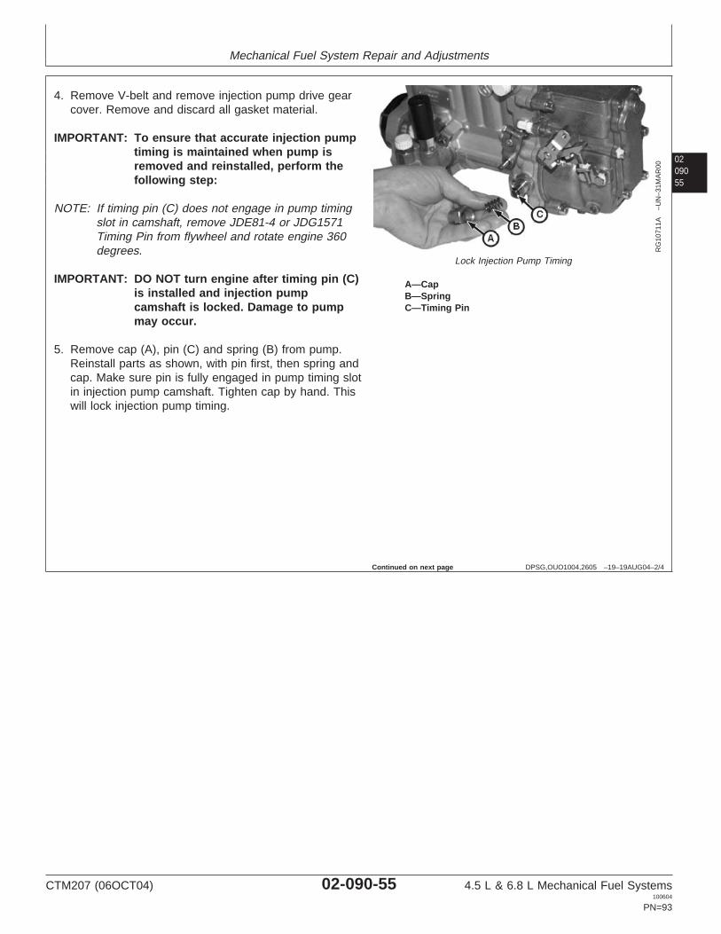
Mechanical Fuel System Repair and Adjustments
0209055
DPSG,OUO1004,2605 –19–19AUG04–2/4
RG
1071
1A–U
N–3
1MA
R00
Lock Injection Pump Timing
A—CapB—SpringC—Timing Pin
4. Remove V-belt and remove injection pump drive gearcover. Remove and discard all gasket material.
IMPORTANT: To ensure that accurate injection pumptiming is maintained when pump isremoved and reinstalled, perform thefollowing step:
NOTE: If timing pin (C) does not engage in pump timingslot in camshaft, remove JDE81-4 or JDG1571Timing Pin from flywheel and rotate engine 360degrees.
IMPORTANT: DO NOT turn engine after timing pin (C)is installed and injection pumpcamshaft is locked. Damage to pumpmay occur.
5. Remove cap (A), pin (C) and spring (B) from pump.Reinstall parts as shown, with pin first, then spring andcap. Make sure pin is fully engaged in pump timing slotin injection pump camshaft. Tighten cap by hand. Thiswill lock injection pump timing.
Continued on next page
CTM207 (06OCT04) 02-090-55 4.5 L & 6.8 L Mechanical Fuel Systems100604
PN=93

Mechanical Fuel System Repair and Adjustments
02090
56
DPSG,OUO1004,2605 –19–19AUG04–3/4
RG
1071
9A–U
N–1
9AP
R00
Remove Injection Pump
A—Fuel Delivery LineB—Fuel Inlet LineC—Oil Fill PlugD—Rear BracketE—Throttle Cable ClampF—Throttle LeverG—Fuel Shut-Off Solenoid ShaftH—Lube LineI—Front BracketJ—Air Conditioning CompressorK—Supply Pump Inlet LineL—Supply Pump Outlet LineM—Leak-Off Line
6. See machine technical manual for removal of airconditioning compressor (J) if required.
NOTE: Use a thin-wall 17 mm open-end crowsfootwrench to keep delivery valve fittings from turningwhen loosening line nuts at injection pump.
If delivery valves are disturbed when looseninglines, valves are retorqued to 47 N•m (35 lb-ft).
O-rings on delivery valves are available forservice.
7. Remove all fuel delivery lines (A) from injection pumpusing JDF22 Crowsfoot Wrench and an open endwrench. Cap all delivery valves and lines to keepdebris out.
8. Disconnect leak-off line (M), supply pump inlet line (K),supply pump outlet line (L) and fuel inlet line (B) frominjection pump. Cap lines and fittings.
9. Disconnect throttle cable from injection pump throttlelever (F). Disconnect throttle cable clamp (E).
10. Disconnect injection pump lube line (H) from block.Lube line will remain with injection pump duringremoval.
11. Disconnect fuel shut-off solenoid harness connector.
12. Disconnect fuel shut-off solenoid shaft (G) frominjection pump. Shut-off solenoid will remain with rearbracket when removed.
13. Remove bracket (D) with shut-off solenoid and setaside.
14. Disconnect bracket (I) from block. Bracket will beremoved with pump.
15. Remove four injection pump drive gear-to-pump hubcap screws using a T45 TORX adapter.
16. Remove four injection pump mounting stud nuts.
TORX is a registered trademark of Camcar/Textron
CTM207 (06OCT04) 02-090-56 4.5 L & 6.8 L Mechanical Fuel Systems100604
PN=94
Continued on next page

Mechanical Fuel System Repair and Adjustments
02090
DPSG,OUO1004,2605 –19–19AUG04–4/4
17. Carefully remove injection pump from mounting studs.
18. Remove injection pump drive gear from timing gearcover.
57
RG,35,JW7601 –19–09SEP02–1/1
Repair Motorpal Fuel Injection Pump
IMPORTANT: Do not disassemble fuel injection pumpfurther than necessary for installingavailable service parts, not even forcleaning.
Be sure that injection pump serialnumber tag is in place and that allidentification numbers are legible sothat pump is set to the correctspecifications for its intended use.
No internal repair parts are furnished for the Motorpal fuelinjection pump. If pump fails, return complete pump for areplacement.
Contact your John Deere Parts System (DNS) forassistance in replacement of fuel injection pump.
CTM207 (06OCT04) 02-090-57 4.5 L & 6.8 L Mechanical Fuel Systems100604
PN=95

Mechanical Fuel System Repair and Adjustments
02090
58
DPSG,OUO1004,2606 –19–19AUG04–1/5
Install Motorpal Fuel Injection Pump
RG
1071
1A–U
N–3
1MA
R00
Install Pump Timing Pin
A—CapB—SpringC—Timing Pin
NOTE: To eliminate any backlash that might exist in thetiming gear train, rotate flywheel in the direction ofnormal engine rotation (counterclockwise viewedfrom flywheel end) when installing JDE81-4 orJDG1571 Timing Pin in flywheel.
1. If engine was rotated after injection pump wasremoved, rotate flywheel in the direction of normalengine rotation until JDE81-4 or JDG1571 Timing Pin(C) enters flywheel at No. 1 cylinder’s TDCcompression stroke.
NOTE: When No. 1 cylinder is at TDC compressionstroke, intake and exhaust valves for No. 1cylinder will be closed and both rocker arms willbe loose.
NOTE: If missing, injection pump timing pin assembly isavailable through John Deere Service Parts.
2. Install injection pump timing pin (C) into bore and makesure it is fully engaged in pump timing slot. Installspring (B) on the outboard side of pin.
3. Reinstall cap (A) and tighten finger tight.
Applying a light turning force, attempt to rotate pumpby hand to verify pump is locked.
Continued on next page
CTM207 (06OCT04) 02-090-58 4.5 L & 6.8 L Mechanical Fuel Systems100604
PN=96

Mechanical Fuel System Repair and Adjustments
0209059
DPSG,OUO1004,2606 –19–19AUG04–2/5
RG
1071
4A–U
N–0
4AP
R00
Injection Pump O-Ring
A—O-Ring
4. Install new O-ring (A) in groove of pump mounting hub.Lubricate O-ring with AR54749 Soap Lubricant to aid inpump installation and prevent damage to O-ring.
5. Install injection pump drive gear in timing gear coverwith part number facing front of engine. Four slots ingear should be at 3, 6, 9 and 12 o’clock positions.
NOTE: It may be necessary to reposition drive gear intiming gear cover so that mounting slots align withthreaded holes in pump drive hub.
6. Install lube line on injection pump before installingpump on engine.
7. Install injection pump onto mounting studs as O-ringseats in mounting bore using moderate forwardpressure and a slight rocking motion. Injection pumpflange should seat solidly against cylinder block andinjection pump drive hub nut should be positioned in IDof pump drive gear.
8. If necessary, rotate and reposition pump drive gear sothat four threaded holes in drive hub line up in themiddle of gear slots.
9. Install four mounting stud nuts and tighten tospecifications.
SpecificationMotorpal InjectionPump-to-Cylinder Block StudNuts—Torque 47 N•m (35 lb-ft)..................................................................
NOTE: When tightening pump drive gear cap screws,apply light force (clockwise) to gear to eliminateany backlash with camshaft gear.
10. Using a T45 TORX adapter, install four drivegear-to-pump hub cap screws and tighten to thefollowing specifications.
SpecificationMotorpal Injection Pump DriveGear-to-Pump Hub Cap Screws—Torque 61 N•m (45 lb-ft).............................................................................
TORX is a registered trademark of Camcar/Textron
CTM207 (06OCT04) 02-090-59 4.5 L & 6.8 L Mechanical Fuel Systems100604
PN=97
Continued on next page
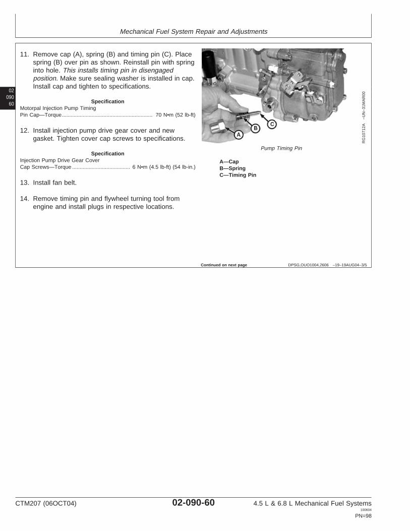
Mechanical Fuel System Repair and Adjustments
02090
60
DPSG,OUO1004,2606 –19–19AUG04–3/5
RG
1071
2A–U
N–3
1MA
R00
Pump Timing Pin
A—CapB—SpringC—Timing Pin
11. Remove cap (A), spring (B) and timing pin (C). Placespring (B) over pin as shown. Reinstall pin with springinto hole. This installs timing pin in disengagedposition. Make sure sealing washer is installed in cap.Install cap and tighten to specifications.
SpecificationMotorpal Injection Pump TimingPin Cap—Torque 70 N•m (52 lb-ft).............................................................
12. Install injection pump drive gear cover and newgasket. Tighten cover cap screws to specifications.
SpecificationInjection Pump Drive Gear CoverCap Screws—Torque 6 N•m (4.5 lb-ft) (54 lb-in.).......................................
13. Install fan belt.
14. Remove timing pin and flywheel turning tool fromengine and install plugs in respective locations.
Continued on next page
CTM207 (06OCT04) 02-090-60 4.5 L & 6.8 L Mechanical Fuel Systems100604
PN=98

Mechanical Fuel System Repair and Adjustments
0209061
DPSG,OUO1004,2606 –19–19AUG04–4/5
RG
1071
9A–U
N–1
9AP
R00
Install Injection Pump
A—Fuel Delivery LineB—Fuel Inlet LineC—Oil Fill PlugD—Rear BracketE—Throttle Cable ClampF—Throttle LeverG—Fuel Shut-Off Solenoid ShaftH—Lube LineI—Front BracketJ—Air Conditioning CompressorK—Supply Pump Inlet LineL—Supply Pump Outlet LineM—Leak-Off Line
15. Install bracket (D) with fuel shut-off solenoid. Connectshut-off solenoid shaft (G) to injection pump. Connectsolenoid harness connector.
16. Connect throttle cable clamp (E) to bracket andconnect cable end to injection pump throttle lever (F).
17. Install front bracket (I) on injection pump (if removed)and tighten cap screws.
IMPORTANT: Use a thin-wall crowsfoot open-endwrench to keep delivery valve fittingsfrom turning when tightening line nutsat injection pump.
IMPORTANT: Tighten all fuel system connectionssecurely to avoid leakage and airentering system.
18. Connect all fuel injection pump delivery lines (A) topump delivery valves using JDF22 Crowsfoot Wrenchand an open end wrench. Tighten line nuts tospecifications.
SpecificationInjection Pump Fuel DeliveryLines—Torque 27 N•m (20 lb-ft).................................................................
19. Connect injection pump inlet line (B) and tighten tospecifications.
SpecificationMotorpal Fuel InletLine-to-Injection Pump—Torque 10 N•m (7 lb-ft)........................................
20. Connect leak-off line (M) and tighten to specifications.
SpecificationMotorpal Fuel Leak-OffLine-to-Injection Pump—Torque 13 N•m (10 lb-ft)......................................
21. Connect injection pump lube line (H) and tighten tospecifications.
SpecificationMotorpal Injection Pump LubeLine—Torque 4.5 N•m (3 lb-ft) (36 lb-in.)....................................................
22. Connect fuel supply pump lines (K and L) and tightento specifications.
CTM207 (06OCT04) 02-090-61 4.5 L & 6.8 L Mechanical Fuel Systems100604
PN=99
Continued on next page
Mechanical Fuel System Repair and Adjustments
02090
62
DPSG,OUO1004,2606 –19–19AUG04–5/5
SpecificationMotorpal Fuel Supply PumpLines-to-Injection Pump—Torque 10 N•m (7 lb-ft)......................................
IMPORTANT: NEVER operate injection pump withoutengine lubricating oil in pump housing.Doing so may cause damage to internalpump rotating parts.
23. Remove oil fill plug (C) on top of injection pump andadd 230 cc (7.8 oz) of clean engine oil. Install plugand tighten to specifications.
SpecificationMotorpal Injection Pump HousingOil Fill Plug—Torque 25 N•m (18 lb-ft).......................................................
24. Bleed fuel system. (See BLEED THE FUEL SYSTEMin this group.)
25. Adjust engine speeds as required.
Check slow idle speed. (See CHECK AND ADJUSTSLOW IDLE SPEED—MOTORPAL FUEL INJECTIONPUMP in Section 04, Group 150.)
Check fast idle speed. (See CHECK AND ADJUSTFAST IDLE SPEED—DENSO AND MOTORPALFUEL INJECTION PUMP in Section 04, Group 150.)
CTM207 (06OCT04) 02-090-62 4.5 L & 6.8 L Mechanical Fuel Systems100604
PN=100

Mechanical Fuel System Repair and Adjustments
0209063
RG,35,JW7599 –19–09JUL02–1/1
Repair Aneroid
RG
7748
B–U
N–0
7NO
V97
Denso Aneroid
RG
9092
–UN
–27M
AR
98
Delphi/Lucas Aneroid
RG
9093
–UN
–27M
AR
98
Stanadyne Aneroid
A—Aneroid
For aneroid (A) repair and adjustment, have an authorizeddiesel repair station perform the work.
The aneroid controls fuel delivery when intake manifoldpressure is about 100 kPa (1.00 bar) (15 psi) or less.Therefore, all final adjustments are to be made on the teststand with aneroid mounted on injection pump.
SpecificationAneroid Pressure (LeverLift-Off)—Pressure 76—102 mm Hg (3—4 in. Hg)
10—14 kPa (1.5—2.0 psi)......................................
Aneroid Pressure (Lever at FullTravel)—Pressure 330—380 mm Hg (13—14 in. Hg)
44—51 kPa (6.4—7.4 psi).................................
IMPORTANT: Correct aneroid adjustments areessential for satisfactory engineperformance. Whenever aneroid hasbeen disassembled or adjustments havebeen altered, injection pump (includinganeroid) must be calibrated on teststand before releasing pump forservice.
CTM207 (06OCT04) 02-090-63 4.5 L & 6.8 L Mechanical Fuel Systems100604
PN=101

Mechanical Fuel System Repair and Adjustments
02090
64
RG,35,JW7598 –19–20NOV97–1/1
Transfer Fuel Injection Pump Timing Markonto Replacement Front Plate
RG
9057
–UN
–16M
AR
98
Front Plate (Viewed from Pump Side)
A—Injection Pump Timing MarkB—Aluminum TemplateC—Front Plate
IMPORTANT: Replacement front plates do not havean injection pump timing mark. It isextremely important that the timingmark be accurately transferred fromoriginal front plate to the replacementplate in the exact location for correctinjection pump timing.
1. Position DFRG5 Aluminum Template (B) onto originalfront plate (C) as shown. (See Section 05, Group 190,Dealer Fabricated Tools, for manufacturing details.)Install three 3/8-16 cap screws securely.
2. Transfer injection pump timing mark (A) from previousfront plate onto template using a fine-tip marker andstraightedge. Remove template from front plate beingreplaced.
3. Attach template (with timing mark) to new replacementfront plate and tighten cap screws securely.
4. Transfer timing mark from the template to the new frontplate using a scribe. Scribe deep enough so markbecomes a permanent reference.
5. Remove template from front plate and refer to CTM104Base Engine Repair Manual for front plate installationprocedure.
CTM207 (06OCT04) 02-090-64 4.5 L & 6.8 L Mechanical Fuel Systems100604
PN=102

Mechanical Fuel System Repair and Adjustments
0209065
OUO1032,0001504 –19–04OCT04–1/1
Fuel Injection Nozzle Identification
CD
3081
0–U
N–1
7AP
R01
A—Conventional NozzleB—Rate Shaping Nozzle (RSN)
Two types of fuel injection nozzles can be found onPOWERTECH 4.5 L and 6.8 L engines.
• Conventional nozzle (A)• Rate Shaping Nozzle (B)
The Rate Shaping Nozzle (RSN) allows engines to complywith exhaust emission regulations.
POWERTECH is a registered trademark of Deere & Company
RG,35,JW7597 –19–18MAY00–1/4
Remove Fuel Injection Nozzles
General Nozzle Service Precautions
Before removal, thoroughly remove all dirt from thecylinder head around fuel injection nozzles. Clean withcompressed air to prevent dirt from entering the cylinders.Plug the bore in the cylinder head after each nozzle hasbeen removed. Cap fuel line openings as soon as theyare disconnected.
Immediately fit protective caps over the nozzle tips andthe line connections to avoid handling damage and gettingdebris in fuel system.
Do not bend the fuel delivery lines, as this may affect theirdurability. When loosening the fuel pressure lines, holdmale union of nozzle line stationary with a backup wrench.
Continued on next page
CTM207 (06OCT04) 02-090-65 4.5 L & 6.8 L Mechanical Fuel Systems100604
PN=103

Mechanical Fuel System Repair and Adjustments
02090
66
RG,35,JW7597 –19–18MAY00–2/4
RG
7724
–UN
–23N
OV
97
Fuel Leak-Off Lines
NOTE: When all fuel injection nozzles have to beremoved, disconnect leak-off line and remove asa complete assembly. For individual nozzleremoval, remove only the section of leak-off linenecessary for nozzle removal.
1. Loosen tube nuts at each nozzle to remove leak-offlines and T-fittings as an assembly.
RG,35,JW7597 –19–18MAY00–3/4
RG
7725
–UN
–08J
AN
97
Fuel Injection Line at Nozzle
2. Disconnect fuel injection line from nozzle using abackup wrench on nozzle connection as shown.
3. Remove cap screw securing nozzle in cylinder headnozzle bore.
Continued on next page
CTM207 (06OCT04) 02-090-66 4.5 L & 6.8 L Mechanical Fuel Systems100604
PN=104

Mechanical Fuel System Repair and Adjustments
0209067
RG,35,JW7597 –19–18MAY00–4/4
RG
7726
–UN
–07N
OV
97
Injection Nozzle Puller Set
A—Nozzle Puller
4. Pull injection nozzle out of cylinder head using JDE38BInjection Nozzle Puller Set (A) or JDG716 Adapterandslide handle from JDE38 or JDE38A Puller Set. UseJDG1515-1 for RSN nozzles.
IMPORTANT: Do not use screwdrivers, pry bars, orsimilar tools for this as they mightdamage the injection nozzle beyondrepair.
RG,35,JW7596 –19–20NOV97–1/1
Clean Fuel Injection Nozzle Bore
RG
7743
–UN
–07N
OV
97
Clean Injection Nozzle BoreA—Nozzle Bore Cleaning Tool
IMPORTANT: Always turn tool clockwise in bore toprevent dulling of cutting edges, evenwhen removing tool from bore.
Clean injection nozzle bore using JDE39 Nozzle BoreCleaning Tool (A). Blow debris from bore usingcompressed air, and plug the bore to prevent entry offoreign material.
CTM207 (06OCT04) 02-090-67 4.5 L & 6.8 L Mechanical Fuel Systems100604
PN=105

Mechanical Fuel System Repair and Adjustments
02090
68
RG,35,JW7595 –19–20NOV97–1/1
Clean Fuel Injection Nozzles
RG
7798
–UN
–11N
OV
97
Clean Fuel Injection Nozzle
A—Carbon Stop SealB—Upper Sealing Washer
1. Remove carbon stop seal (A) from groove in nozzlebody using razor blade or sharp knife and removeupper sealing washer (B). Discard seal and washer.
2. Place nozzle in solvent or clean diesel fuel, so carbonstop seal groove is submerged, and soak for a while.
IMPORTANT: Do not scrape or disturb the TEFLON
coating on the nozzle body above thecarbon stop seal groove. This coatingwill become discolored during normaloperation, but this is not harmful. Donot use a motor-driven brush to cleannozzle body.
3. After soaking, clean nozzle tip with brass wire brush.Never use a steel wire brush or scraper.
TEFLON is a registered trademark of the DuPont Co.
CTM207 (06OCT04) 02-090-68 4.5 L & 6.8 L Mechanical Fuel Systems100604
PN=106

Mechanical Fuel System Repair and Adjustments
0209069
RG,115,JW7680 –19–24NOV97–1/2
Diagnose Fuel Injection Nozzle Malfunctions
Problem Possible Cause Suggested Remedy
Failed Carbon Stop Seal Washer Nozzle replaced without using new seal or Install new seal or washer.washer.
Carbon stop seal groove not cleaned when Clean groove. Install new seal.new seal was installed.
Incorrect Opening Pressure Improper adjustment. Adjust opening pressure.
Broken spring. Replace spring.
Nozzle Will Not Open Plugged orifices. Clean.
Chipped orifices. Replace nozzle.
Bottomed lift screw. Adjust lift screw.
Poor Spray Pattern Plugged orifices. Clean.
Chipped orifices. Replace nozzle.
Cracked nozzle tip. Replace nozzle.
Poor Atomization Plugged orifice. Clean.
Chipped orifice. Replace nozzle.
Cracked nozzle tip. Replace nozzle.
Valve not free. See “Inconsistent Chatter”.
Inconsistent Chatter Spring components misaligned. Adjust opening pressure.
Varnish on valve. Clean guide area.
Deposits in seat area. Clean seat.
Bent valve. Replace nozzle.
Distorted body. Replace nozzle.
No Chatter Spring components misaligned. Adjust opening pressure.
Varnish on valve. Clean guide area.
Deposits in seat area. Clean seat.
Bent valve. Replace nozzle.
Valve seat eroded or pitted. Lap valve to seat. Replace nozzle asnecessary.
Tip seat pitted. Lap tip to seat. Replace nozzle asnecessary.
Seat interference angle worn. Replace nozzle.
Distorted body. Replace nozzle.
Seat Leakage Deposits in seat area. Clean seat.
Valve seat eroded or pitted. Lap valve to seat. Replace nozzle asnecessary.
Tip seat pitted. Lap tip to seat. Replace nozzle asnecessary.
CTM207 (06OCT04) 02-090-69 4.5 L & 6.8 L Mechanical Fuel Systems100604
PN=107
Continued on next page

Mechanical Fuel System Repair and Adjustments
02090
70
RG,115,JW7680 –19–24NOV97–2/2
Problem Possible Cause Suggested Remedy
Valve not free. See “Inconsistent Chatter”.
See “No Chatter”.
Distorted body. Replace nozzle.
Cracked tip. Replace nozzle.
High Leak-Off Wear or scratched at guide. Lap valve to guide. Replace nozzle asnecessary.
Low Leak-Off Varnish on valve. Clean guide area.
Insufficient clearance. Clean nozzle. Lap valve to guide. Replacenozzle as necessary.
RG,35,JW7592 –19–04OCT04–1/6
Test Fuel Injection Nozzles
X98
11–U
N–2
3AU
G88
High Pressure Fluid
CAUTION: The nozzle tip should always bedirected away from the operator. Fuel from thespray orifices can penetrate clothing and skincausing serious personal injury. Enclosing thenozzle in a clear glass beaker is recommended.
Before applying pressure to the nozzle tester,be sure that all connections are tight, and thatthe fittings are not damaged. Fluid escapingfrom a very small hole can be almost invisible.To search for suspected leaks, use a piece ofcardboard or wood, rather than hands.
If ANY fluid is injected into the skin, it must besurgically removed within a few hours by adoctor familiar with this type injury or gangrenemay result.
1. Connect injection nozzle to nozzle tester.
Continued on next page
CTM207 (06OCT04) 02-090-70 4.5 L & 6.8 L Mechanical Fuel Systems100604
PN=108

Mechanical Fuel System Repair and Adjustments
0209071
RG,35,JW7592 –19–04OCT04–2/6
RG
7799
–UN
–11N
OV
97
Injection Nozzle Tester
A—Nozzle TesterB—Fuel LineC—AdaptersD—Beaker
NOTE: When using the JT25510 Bosch Bench MountedNozzle Tester, use the KJD10109 Fuel Line andconnect line to tester and nozzle.
2. Use Y900-3 and Y900-5 Adapters (C) and Y900-2 FuelLine (B) from D01110AA Fuel Injection Nozzle TesterAdapter Set to connect nozzles to D01109AA OTCPortable Nozzle Tester (A).
3. Position tip of nozzle below top of beaker (D) and backout 30° from vertical. This is necessary to contain allspray in beaker, as nozzle spray pattern is at an angleto the nozzle centerline. Leave connections slightlyloose.
NOTE: Rapid operation of pump handle will result ininaccurate cracking pressure readings and causeundue wear on gauge.
4. Pump handle several strokes to flush air from lines andto determine the pumping rate required for proper fuelatomization. Tighten all connections securely after allair has been expelled from nozzle and line.
IMPORTANT: Make sure that nozzle tester is in goodcondition and that gauge worksproperly. Service nozzle tester asrecommended in the operatinginstructions provided with tester.
Opening Pressure Test
NOTE: Actual nozzle opening pressure is less importantthan equal opening pressure of all nozzles. Formaximum variation between nozzles seespecifications below.
1. Actuate the nozzle tester rapidly several times to allowthe valve to seat rapidly.
2. Open gauge valve, actuate the tester and raise thepressure to a point where the gauge needle fallsrapidly. This is the nozzle opening pressure, andshould be as specified for a new or used nozzle.
CTM207 (06OCT04) 02-090-71 4.5 L & 6.8 L Mechanical Fuel Systems100604
PN=109
Continued on next page

Mechanical Fuel System Repair and Adjustments
02090
72
RG,35,JW7592 –19–04OCT04–3/6
NOTE: In a few applications, RE60062 Nozzles (normallyused on aspirated engines), may be specified forturbocharged (T or H) engines. In these cases,use specifications listed below for naturallyaspirated (D) engines.
IMPORTANT: If any of the nozzle opening pressuresare not within specified range, resetpressure and valve lift BEFOREchecking chatter and spray pattern.Otherwise, these characteristics may beaffected. (See ADJUST FUELINJECTION NOZZLES later in thisgroup.)
3. Compare readings to the following specifications:
Fuel Injection RE60062 Nozzles (Naturally Aspirated Engines)—Specification
New or Reconditioned Nozzlewith New Internal Parts—OpeningPressure for Setting 23 856—24 407 kPa
(238—244 bar)(3460—3540 psi)
..................................................
Opening Pressure for Checking(Minimum) 21 856 kPa (218 bar)
(3170 psi).................................................................
Used Nozzle—Opening Pressurefor Checking (Minimum) 19 850 kPa (198 bar)
(2880 psi)...........................................
Opening Pressure Differencebetween Cylinders—PressureDifference (Maximum) 700 kPa (7 bar) (100 psi).......................................
Fuel Injection RE48786 Nozzles (Turbocharged Engines)—Specification
New or Reconditioned Nozzlewith New Internal Parts—OpeningPressure for Setting 25 511—26 062 kPa
(255—260 bar)(3700—3780 psi)
..................................................
Opening Pressure for Checking(Minimum) 24 683 kPa (246 bar)
(3580 psi).................................................................
Used Nozzle—Opening Pressurefor Checking (Minimum) 23 511 kPa (235 bar)
(3410 psi)...........................................
Opening Pressure Differencebetween Cylinders—PressureDifference (Maximum) 700 kPa (7 bar) (100 psi).......................................
CTM207 (06OCT04) 02-090-72 4.5 L & 6.8 L Mechanical Fuel Systems100604
PN=110
Continued on next page

Mechanical Fuel System Repair and Adjustments
0209073
RG,35,JW7592 –19–04OCT04–4/6
Rate Shaping Nozzle (Tier II Certified Engines)—SpecificationNew or Reconditioned Nozzle—Opening Pressure for Setting 24 400—24 900 kPa (244—249
bar) (3540—3620 psi)..................
Opening Pressure for Checking(Minimum) 24 100 kPa (241 bar) (3500 psi)...............................................Used Nozzle—Opening Pressurefor Setting 23 000—23 600 kPa (230—236
bar) (3340—3420 psi)................................................
Opening Pressure for Checking(Minimum) 21 800 kPa (218 bar) (3170 psi)...............................................Opening Pressure Differencebetween Cylinders—PressureDifference (Maximum) 700 kPa (7 bar) (100 psi).......................................
Chatter Test
NOTE: On RSN injectors, nozzle chatter may or may notbe noticeable during this test. An RSN injectorpasses this test if its opening pressure, seatleakage, and return fuel are acceptable.
1. Close gauge shut-off valve and operate nozzle testerat a pumping rate that will cause the nozzle to chatter.Nozzle should chatter softly, and spray pattern shouldbe broad and finely atomized.
If nozzle fails to chatter, the nozzle valve may be bentor tight in its guide due to accumulated lacquerdeposits. Disassemble nozzle and correct as detailedlater in this group.
NOTE: Until the chattering range is reached, fuel willemerge in non-atomized streams.
2. Using the pumping rate for proper atomization, operatetester for ten strokes. The nozzle must atomize on atleast eight of the ten strokes without consecutivemisses.
If the nozzle fails to meet this requirement, repeatprocedure. Nozzles which do not meet the requirementafter second test should be considered unacceptableand should be either repaired or replaced.
CTM207 (06OCT04) 02-090-73 4.5 L & 6.8 L Mechanical Fuel Systems100604
PN=111
Continued on next page

Mechanical Fuel System Repair and Adjustments
02090
74
RG,35,JW7592 –19–04OCT04–5/6
Spray Pattern Test
NOTE: On RSN injectors, nozzle chatter may or may notbe noticeable during this test.
1. Close gauge shut-off valve and operate nozzle testerat a pumping rate that will cause the nozzle to chatter.
NOTE: Partially clogged, chipped, or eroded orifices willcause the spray to deviate from the correct angle.Spray will be streaky, rather than finely atomized.
2. Observe spray pattern and check for plugged orifices.
If nozzle fails to chatter or spray properly, disassemble,clean and recondition as outlined later in this group.
SpecificationFuel Injection Nozzle Tip—SprayAngle 144°...................................................................................................
Leakage Test
1. Check nozzle for fuel leakage past valve seat bypositioning nozzle on nozzle tester with nozzle tipdown.
2. Operate pump handle rapidly to firmly seat valve. Wipethe nozzle tip dry with a clean, lint-free cloth.
3. Slowly raise pressure at nozzle to about 2800—3500kPa (28—35 bar) (400—500 psi) under specifiedopening pressure and hold at that pressure. Watch foran accumulation of fuel around the nozzle tip orifices.
If fuel drips from nozzle within 5 seconds, nozzle mustbe lapped.
SpecificationNozzle Valve/Seat TightnessCondition at Pressure Test of2800—3500 kPa (28—35 bar)(400—500 psi)—Leakage Nozzle tip dry after 5 seconds.
(Slight dampness permissible onused nozzles.)
.........................
Valve Stem and Guide Wear Test
1. Position nozzle with tip slightly above the horizontalplane.
CTM207 (06OCT04) 02-090-74 4.5 L & 6.8 L Mechanical Fuel Systems100604
PN=112
Continued on next page
Mechanical Fuel System Repair and Adjustments
0209075
RG,35,JW7592 –19–04OCT04–6/6
CAUTION: Completely enclose spray zone in aglass beaker to avoid possible personal injuryfrom spray.
2. Slowly raise pressure to 10 300 kPa (103 bar) (1500psi) on test gauge.
NOTE: Leakage rate based on use of No. 2 diesel fuel oran equivalent viscosity of test oil at 18°—24°C(65°—75°F) ambient temperature.
3. Look for leakage from the return end of nozzle. Afterone drop, leakage should be within specifications.
SpecificationFuel Injection Nozzle ReturnLeakage at Pressure Test of 10300 kPa (103 bar) (1500 psi)—Leakage 3—10 Drops/30 Seconds..............................................................
If nozzle leakage is not within specified range, nozzlemust be reconditioned as outlined later in this group.
CTM207 (06OCT04) 02-090-75 4.5 L & 6.8 L Mechanical Fuel Systems100604
PN=113

Mechanical Fuel System Repair and Adjustments
02090
76
RG,35,JW7591 –19–04OCT04–1/4
Disassemble Fuel Injection Nozzles
RG
7800
A–U
N–1
3NO
V97
Fuel Injection Nozzles
A—Nozzle Tip E—Upper Sealing Washer I—Upper Seal M—Lift Adjusting ScrewB—Carbon Stop Seal F—Edge-Type Filter J—Spring Seat N—Lock NutC—Nozzle Body G—Fuel Inlet K—Spring Screw O—Pressure Adjusting ScrewD—Nozzle Valve H—Upper Guide L—Spring Washer P—Lock Nut
NOTE: If an RSN injection nozzle is not operatingproperly and must be disassembled for
cleaning and/or reconditioning, see yourStanadyne dealer.
Continued on next page
CTM207 (06OCT04) 02-090-76 4.5 L & 6.8 L Mechanical Fuel Systems100604
PN=114

Mechanical Fuel System Repair and Adjustments
0209077
RG,35,JW7591 –19–04OCT04–2/4
RG
9086
–UN
–16M
AR
98
Nozzle Disassembly
A—Nozzle AssemblyB—Tube NutC—PackingD—Leak-Off FittingE—Cap ScrewF—Carbon Stop SealG—Upper Sealing WasherH—Spacer
General Nozzle Repair Notes
NOTE: Disassembly of nozzles is not recommendedunless servicing is indicated by nozzle operationand testing.
Since dirt and water are the worst contaminants in the fuelinjection system, the working area, tools and cleaningmaterials must be kept spotlessly clean. Wheneverpossible, work in an isolated, dust-free area.
Cover the work bench with clean paper before beginningdisassembly of injection nozzles.
As parts are disassembled, place then in a pan of cleandiesel fuel and leave there until needed. Do not permitthese parts to strike each other.
Use a separate pan of clean fuel for washing parts beforeassembly.
RG,35,JW7591 –19–04OCT04–3/4
RG
7802
–UN
–21M
AY
01
Injection Nozzle in Holding Fixture
A—Nozzle Index ClampB—Pressure Adjusting Lock NutC—Lift Adjusting Screw Lock Nut
To Disassemble Fuel Injection Nozzle
1. Place nozzle in index clamp (A)1 and secure clamp in avise.
2. Loosen pressure adjusting lock nut (B).
3. Back out lift adjusting screw lock nut (C) and liftassembly.
4. Invert nozzle and allow pressure adjusting spring seatand lift adjusting assembly to fall into your hand. Donot bend stem during removal.
1If available, ROS17787 Holding Fixture (obsolete) can be used.
CTM207 (06OCT04) 02-090-77 4.5 L & 6.8 L Mechanical Fuel Systems100604
PN=115
Continued on next page

Mechanical Fuel System Repair and Adjustments
02090
78
RG,35,JW7591 –19–04OCT04–4/4
RG
7803
–UN
–11N
OV
97
Injection Nozzle Body and Valve
A—Valve BodyB—Valve Retractor
5. If valve does not slide freely from body (A), use No.16481 Valve Retractor1 (B) to remove valve.
6. Remove locating clamps and spacer from nozzle body.
1No. 16481 Valve Retractor is a Stanadyne tool.
CTM207 (06OCT04) 02-090-78 4.5 L & 6.8 L Mechanical Fuel Systems100604
PN=116

Mechanical Fuel System Repair and Adjustments
0209079
RG,35,JW7590 –19–23NOV99–1/2
Inspect and Clean Fuel Injection Nozzle Body
RG
7804
–UN
–11N
OV
97
Clean Injection Nozzle Body
A—HolderB—Inspection Magnifier
NOTE: Unless otherwise indicated, all tools required fornozzle cleaning can be found in the JDF13BNozzle Cleaning Kit.
Clean carbon stop seal groove and nozzle tip with anozzle cleaning wire inserted in holder (A).
Inspect tip for cracks and spray orifices for chipping anderosion using an inspection magnifier (B).1
To Clean Carbon from Nozzle Orifices
NOTE: Stoning the wire to provide a flat surface on oneside will help in reaming carbon from a cloggedhole.
1. Begin with a cleaning wire 0.07—0.10 mm (0.003—0.004 in.) smaller than the nominal orifice size given inspecifications below.
SpecificationFuel Injection Nozzle TipOrifice—Number of Orifices perNozzle 4.......................................................................................................Fuel Injection Nozzle Tip Orifice(Naturally Aspirated Engines)—ID 0.27 mm (0.0106 in.)...........................Fuel Injection Nozzle Tip Orifice(Turbocharged Engines)—ID 0.29 mm (0.0116 in.)....................................
NOTE: In a few applications, RE60062 Nozzles (normallyused on aspirated engines), may be specified forturbocharged (T or H) engines. In these cases,use specifications listed for naturally aspirated (D)engines.
2. Clamp the wire in pin vise from nozzle cleaning kit.Wire should not protrude from the vise more than 0.8mm (1/32 in.).
3. Insert wire in orifice and rotate.
4. Use scraper from cleaning kit to clean deposits fromvalve seating area.
1If available, ROS16487 Inspection Magnifier (obsolete) can be used.
CTM207 (06OCT04) 02-090-79 4.5 L & 6.8 L Mechanical Fuel Systems100604
PN=117
Continued on next page
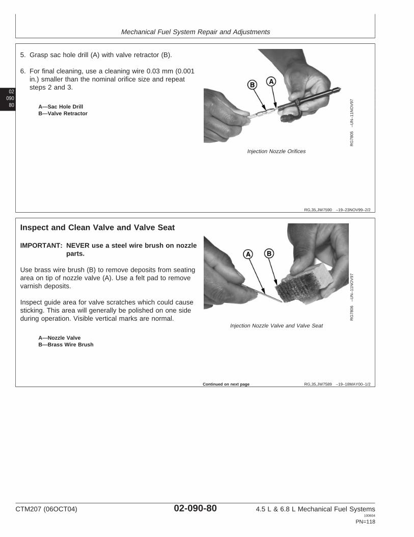
Mechanical Fuel System Repair and Adjustments
02090
80
RG,35,JW7590 –19–23NOV99–2/2
RG
7805
–UN
–11N
OV
97
Injection Nozzle Orifices
A—Sac Hole DrillB—Valve Retractor
5. Grasp sac hole drill (A) with valve retractor (B).
6. For final cleaning, use a cleaning wire 0.03 mm (0.001in.) smaller than the nominal orifice size and repeatsteps 2 and 3.
RG,35,JW7589 –19–18MAY00–1/2
Inspect and Clean Valve and Valve Seat
RG
7806
–UN
–11N
OV
97
Injection Nozzle Valve and Valve Seat
A—Nozzle ValveB—Brass Wire Brush
IMPORTANT: NEVER use a steel wire brush on nozzleparts.
Use brass wire brush (B) to remove deposits from seatingarea on tip of nozzle valve (A). Use a felt pad to removevarnish deposits.
Inspect guide area for valve scratches which could causesticking. This area will generally be polished on one sideduring operation. Visible vertical marks are normal.
Continued on next page
CTM207 (06OCT04) 02-090-80 4.5 L & 6.8 L Mechanical Fuel Systems100604
PN=118

Mechanical Fuel System Repair and Adjustments
0209081
RG,35,JW7589 –19–18MAY00–2/2
RG
7803
–UN
–11N
OV
97
Nozzle Valve in Nozzle Body
A—Nozzle BodyB—Retractor
Inconsistent Chatter or No Chatter
A nozzle which during test had spotty chatter or showeddefinite signs of sticking accompanied by low returnleakage, may be corrected by polishing the valve guidearea as follows:
1. Place a small amount of nozzle lapping compound onthe nozzle valve in guide area only. DO NOT use anyother compound for this purpose.
2. Slide valve into body (A).
IMPORTANT: Never attempt to rotate the valve in amotor driven chuck for this purpose.
3. Grip top of the valve with retractor (B) and rotate valvein the guide by turning retractor. The amount of lappingrequired can be accomplished in 10—20 turns byhand. The valve should be raised and lowered in theguide every 3—4 revolutions and direction of rotationchanged for best results.
4. Wash nozzle body and valve thoroughly in clean fuelbefore reassembly.
Seat Leakage
Seat leakage may be caused by dirt, carbon or fueldeposits in valve area. Inspect valve seat and clean asfollows:
1. Apply a small amount of lapping compound to valve tipand insert valve in nozzle body.
2. Gripping valve with retractor, rotate valve 3—5 turns toclean up seat.
3. Wash valve and nozzle body thoroughly in clean fuel.
CTM207 (06OCT04) 02-090-81 4.5 L & 6.8 L Mechanical Fuel Systems100604
PN=119
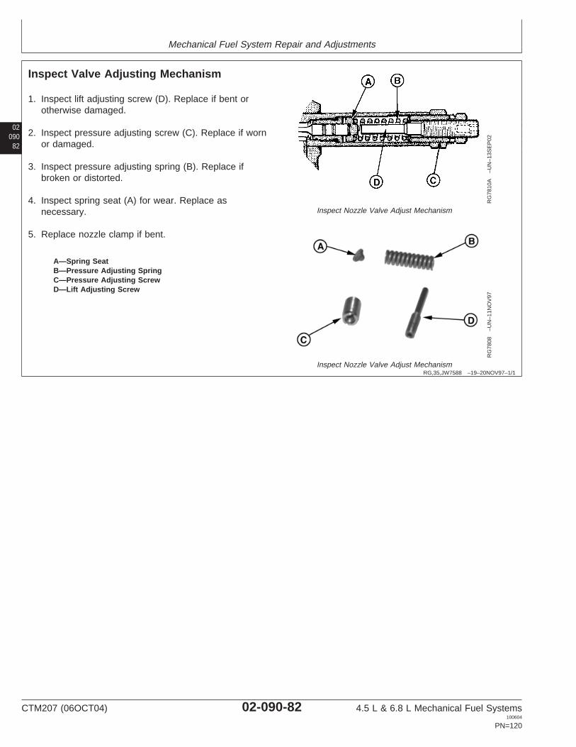
Mechanical Fuel System Repair and Adjustments
02090
82
RG,35,JW7588 –19–20NOV97–1/1
Inspect Valve Adjusting Mechanism
RG
7810
A–U
N–1
3SE
P02
Inspect Nozzle Valve Adjust Mechanism
RG
7808
–UN
–11N
OV
97
Inspect Nozzle Valve Adjust Mechanism
A—Spring SeatB—Pressure Adjusting SpringC—Pressure Adjusting ScrewD—Lift Adjusting Screw
1. Inspect lift adjusting screw (D). Replace if bent orotherwise damaged.
2. Inspect pressure adjusting screw (C). Replace if wornor damaged.
3. Inspect pressure adjusting spring (B). Replace ifbroken or distorted.
4. Inspect spring seat (A) for wear. Replace asnecessary.
5. Replace nozzle clamp if bent.
CTM207 (06OCT04) 02-090-82 4.5 L & 6.8 L Mechanical Fuel Systems100604
PN=120

Mechanical Fuel System Repair and Adjustments
0209083
RG,35,JW7587 –19–20NOV97–1/1
Assemble Fuel Injection Nozzles
RG
8042
–UN
–14N
OV
97
Fuel Injection Nozzles
A—Nozzle Body E—Spring Seat I—Pressure Adjusting Screw K—Pressure Adjusting ScrewB—Spacer F—Pressure Adjusting Spring Lock Nut L—Hold-Down ClampsC—Indexing Clamp G—Washer J—Lift Adjusting ScrewD—Nozzle Valve H—Lift Adjusting Screw Lock
Nut
1. Install nozzle spacer (B) onto upper nozzle body(A). Position nozzle indexing clamp (C) over uppernozzle body with flanges pointing downward. Installthree remaining clamps (L) onto nozzle body.
IMPORTANT: Wear rubber gloves whenassembling nozzles.
2. Dip valve (D) in clean fuel and insert into nozzlebody.
3. Thread lift adjusting screw (J) into pressureadjusting screw (K) until top just enters screw.
4. Invert adjusting screw assembly and assemblespring seat (E) and spring (F) to adjusting screw.
5. Tilt body, DO NOT allow valve to fall out, and installspring and adjusting screws to body. Be careful notto dislodge spring or seat during initial assembly.
6. Turn pressure adjusting screw down as far aspossible by hand, usually about ten full turns.Adjust nozzle as detailed later in this group.
CTM207 (06OCT04) 02-090-83 4.5 L & 6.8 L Mechanical Fuel Systems100604
PN=121

Mechanical Fuel System Repair and Adjustments
02090
84
RG,35,JW7631 –19–04OCT04–1/7
Adjust Fuel Injection Nozzles
X98
11–U
N–2
3AU
G88
High Pressure Fluids
CAUTION: Nozzle tip should always be directedaway from operator. Fuel from spray orificescan penetrate clothing and skin causing seriouspersonal injury. Enclosing nozzle in a glassbeaker is recommended.
Before applying pressure to nozzle tester, besure all connections are tight, and fittings arenot damaged. Fluid escaping from a very smallhole can be almost invisible. Use a piece ofcardboard or wood, rather than hands, tosearch for suspected leaks.
If ANY fluid is injected into the skin, it must besurgically removed within a few hours by adoctor familiar with this type injury or gangrenemay result.
Connect nozzle to nozzle tester. (See TEST FUELINJECTION NOZZLES earlier in this group.)
Continued on next page
CTM207 (06OCT04) 02-090-84 4.5 L & 6.8 L Mechanical Fuel Systems100604
PN=122
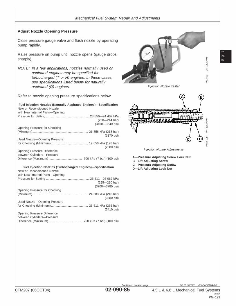
Mechanical Fuel System Repair and Adjustments
0209085
RG,35,JW7631 –19–04OCT04–2/7
RG
7809
–UN
–15J
AN
98
Injection Nozzle Tester
RG
7810
B–U
N–1
1NO
V97
Injection Nozzle Adjustments
A—Pressure Adjusting Screw Lock NutB—Lift Adjusting ScrewC—Pressure Adjusting ScrewD—Lift Adjusting Lock Nut
Adjust Nozzle Opening Pressure
Close pressure gauge valve and flush nozzle by operatingpump rapidly.
Raise pressure on pump until nozzle opens (gauge dropssharply).
NOTE: In a few applications, nozzles normally used onaspirated engines may be specified forturbocharged (T or H) engines. In these cases,use specifications listed below for naturallyaspirated (D) engines.
Refer to nozzle opening pressure specifications below.
Fuel Injection Nozzles (Naturally Aspirated Engines)—SpecificationNew or Reconditioned Nozzlewith New Internal Parts—OpeningPressure for Setting 23 856—24 407 kPa
(238—244 bar)(3460—3540 psi)
..................................................
Opening Pressure for Checking(Minimum) 21 856 kPa (218 bar)
(3170 psi).................................................................
Used Nozzle—Opening Pressurefor Checking (Minimum) 19 850 kPa (198 bar)
(2880 psi)...........................................
Opening Pressure Differencebetween Cylinders—PressureDifference (Maximum) 700 kPa (7 bar) (100 psi).......................................
Fuel Injection Nozzles (Turbocharged Engines)—SpecificationNew or Reconditioned Nozzlewith New Internal Parts—OpeningPressure for Setting 25 511—26 062 kPa
(255—260 bar)(3700—3780 psi)
..................................................
Opening Pressure for Checking(Minimum) 24 683 kPa (246 bar)
(3580 psi).................................................................
Used Nozzle—Opening Pressurefor Checking (Minimum) 23 511 kPa (235 bar)
(3410 psi)...........................................
Opening Pressure Differencebetween Cylinders—PressureDifference (Maximum) 700 kPa (7 bar) (100 psi).......................................
CTM207 (06OCT04) 02-090-85 4.5 L & 6.8 L Mechanical Fuel Systems100604
PN=123
Continued on next page

Mechanical Fuel System Repair and Adjustments
02090
86
RG,35,JW7631 –19–04OCT04–3/7
RG
7810
B–U
N–1
1NO
V97
Adjust Nozzle Pressure
A—Pressure Adjusting Screw Lock NutB—Lift Adjusting ScrewC—Pressure Adjusting ScrewD—Lift Adjusting Lock Nut
If Opening Pressure is Incorrect:
1. Remove nozzle from tester and install in holdingfixture.
2. Remove lift adjusting lock nut (D).
3. Loosen pressure adjusting screw lock nut (A), usingJDG949 Nozzle Wrench.
4. Reconnect nozzle to tester with tip pointing downward.
5. Back out lift adjusting screw (B) far enough (two orthree turns) to prevent bottoming when pressureadjusting screw (C) is turned.
6. Turn pressure adjusting screw in (clockwise) toincrease opening pressure, or out (counterclockwise) todecrease opening pressure.
NOTE: It is desirable to set opening pressure to the highlimit of specification. If required, repeat procedureto obtain proper result.
RG,35,JW7631 –19–04OCT04–4/7
RG
7811
–UN
–15J
AN
98
Nozzle Pressure Adjusting Screw and Lock Nut
7. Remove nozzle from tester and secure in holdingfixture. While holding pressure adjusting screw, tightenpressure adjusting screw lock nut to specificationsusing a crowsfoot wrench or torque wrench adapter, ifavailable.1
SpecificationInjection Nozzle PressureAdjusting Screw Lock Nut—Torque 10 N•m (7 lb-ft)...............................................................................
1If available, ROS18958 (English) or No. 24374 (Stanadyne, Metric)Torque Wrench Adapter (obsolete) can be used.
Continued on next page
CTM207 (06OCT04) 02-090-86 4.5 L & 6.8 L Mechanical Fuel Systems100604
PN=124

Mechanical Fuel System Repair and Adjustments
0209087
RG,35,JW7631 –19–04OCT04–5/7
RG
9103
–UN
–31M
AR
98
Injection Nozzle Valve Lift Adjustment
Adjust Nozzle Valve Lift—Conventional Nozzle
1. Reconnect nozzle to tester. While pumping fuelthrough nozzle, hold pressure adjusting screw andslowly turn lift adjusting screw in (clockwise) until valveceases to open.
IMPORTANT: DO NOT manually bottom the valve withexcessive force as bending of the valvemay result.
2. Check for valve bottoming by raising pressure to1380—3450 kPa (14—34 bar) (200—500 psi) abovenozzle opening pressure.
Although some fuel may collect at nozzle tip, a rapiddribble should not occur.
3. Remove nozzle from tester and install in holdingfixture.
4. Carefully turn lift adjusting screw out specified amount.A tolerance of 1/8 turn is permissible.
SpecificationFuel Injection Nozzle Valve—Needle Lift (Based on Zero Lift) 3/4 Turn Counterclockwise......................
Continued on next page
CTM207 (06OCT04) 02-090-87 4.5 L & 6.8 L Mechanical Fuel Systems100604
PN=125

Mechanical Fuel System Repair and Adjustments
02090
88
RG,35,JW7631 –19–04OCT04–6/7
RG
7811
–UN
–15J
AN
98
Nozzle Pressure Adjusting Screw and Lock Nut
5. Hold pressure adjusting screw stationary and tighten liftadjusting screw lock nut to specifications. Use acrowsfoot wrench or torque wrench adapter, ifavailable.1
SpecificationFuel Injection Nozzle LiftAdjusting Screw Lock Nut—Torque 5 N•m (3.5 lb-ft) (42 lb-in.)..............................................................
6. Recheck nozzle opening pressure.
If nozzle chatter is incorrect after servicing, valve partsmay be misaligned. To correct, screw pressureadjusting screw through its range of adjustment severaltimes and reset valve lift. Recheck nozzle for chatter.
7. Clean nozzle with brass wire brush.
1If available, ROS18958 (English) or No. 24374 (Stanadyne, Metric)Torque Wrench Adapter (obsolete) can be used.
Continued on next page
CTM207 (06OCT04) 02-090-88 4.5 L & 6.8 L Mechanical Fuel Systems100604
PN=126

Mechanical Fuel System Repair and Adjustments
0209089
RG,35,JW7631 –19–04OCT04–7/7C
D30
811
–UN
–28M
AY
01
A—Lift Adjusting Screw Lock NutB—Pressure Adjusting Screw Lock NutC—Pressure Adjusting ScrewD—Lift Adjusting ScrewE—Spring SeatF—Spring Chamber Cap
Adjust Nozzle Valve Lift—RSN Nozzle
1. Unscrew spring chamber cap (F) using JDG1521Spring Chamber Cap Wrench.
2. Loosen and remove lock nut (A) of lift adjusting screw(D).
3. Loosen lock nut (B) of pressure adjusting screw (C)using JDG1515-2 Pressure Adjustment Screw LockNut.
4. Connect nozzle to tester, then adjust opening pressureto specifications by turning the pressure adjustingscrew (C). Use JDG1522 Pressure Adjustment ScrewTool.
5. Tighten lock nut (B) to specification, then recheckopening pressure.
6. Carefully turn lift adjusting screw (D) until it bottoms onspring seat (E).
7. Unscrew lift adjusting screw withe the number of turnsas specified.
8. Tighten lock nut of lift adjusting screw to specification.
9. Recheck opening pressure.
RSN Nozzle Valve Lift—SpecificationPressure Adjusting Screw LockNut—Torque 10 N•m (7 lb-ft)......................................................................Lift Adjusting Screw Lock Nut—Torque 5 N•m (3.5 lb-ft)..............................................................................RSN Nozzle (Tier II CertifiedEngines) Valve—Lift 7/8 turn.......................................................................
CTM207 (06OCT04) 02-090-89 4.5 L & 6.8 L Mechanical Fuel Systems100604
PN=127

Mechanical Fuel System Repair and Adjustments
02090
90
RG,35,JW7586 –19–20NOV97–1/1
Install Seals on Fuel Injection Nozzle
RG
9096
–UN
–27M
AR
98
Fuel Injection Nozzle Seals
A—Carbon Stop Seal InstallerB—Carbon Stop SealC—Seal Washer
IMPORTANT: Each time an injection nozzle isremoved from the cylinder head,replace carbon stop seal (B) with a newone.
1. Position JD258 (JD-258) Nozzle Carbon Stop SealInstaller (A) over nozzle tip.
2. Install a new seal washer (C) onto nozzle body.
3. Position a new carbon stop seal (B) on seal installer.Slide the carbon seal until it seats in its groove onnozzle body.
NOTE: If nozzle is not going to be installed at this time,install a No. 16189 Nozzle Protector Cap overnozzle tip. Plug all other openings in nozzle toprevent contamination.
CTM207 (06OCT04) 02-090-90 4.5 L & 6.8 L Mechanical Fuel Systems100604
PN=128

Mechanical Fuel System Repair and Adjustments
0209091
RG,35,JW7632 –19–08JUL02–1/3
Install Fuel Injection Nozzles
RG
7744
–UN
–23N
OV
97
Injection Nozzle in Cylinder Head
IMPORTANT: Before installing injection nozzles, makesure nozzles are clean and free from oilor grease.
NOTE: If nozzle bore in cylinder head must be cleaned,use JDE39 Nozzle Bore Cleaning Tool. (SeeREMOVE FUEL INJECTION NOZZLES earlier inthis group.)
1. Remove plug (if installed previously) from nozzle borein cylinder head and blow out bore with compressedair.
NOTE: Make sure that the sealing surface of the cylinderhead (on which the seal washer will be resting) issmooth and free of damage or dirt. This couldprevent proper sealing. Dirt and roughness couldalso cause nozzle to be distorted when theattaching screw is tightened, making the valvestick.
2. Install nozzle with spacer and clamps in cylinder headusing a slight twisting motion as nozzle is seated inbore. Illustration shows relationship of parts requiredfor proper installation.
3. Align nozzle clamps and install cap screw. Do nottighten cap screw at this stage.
4. Connect fuel pressure line to nozzle. Leave connectionslightly loose until air is bled from system.
5. Tighten nozzle hold-down clamp cap screws tospecifications.
SpecificationFuel Injection Nozzle Hold-DownClamp Cap Screws—Torque 40 N•m (30 lb-ft)...........................................
Continued on next page
CTM207 (06OCT04) 02-090-91 4.5 L & 6.8 L Mechanical Fuel Systems100604
PN=129

Mechanical Fuel System Repair and Adjustments
02090
92
RG,35,JW7632 –19–08JUL02–2/3
IMPORTANT: Avoid machine damage. Do NOTovertighten fuel leak-off lines.
6. Install leak-off line assembly.
SpecificationFuel Leak-Off Line Hex Nut—Torque 5 N•m (3.7 lb-ft)
(44 lb-in.)..............................................................................
RG,35,JW7632 –19–08JUL02–3/3
RG
7725
–UN
–08J
AN
97
Nozzle Delivery Line Nut Tightening
7. Bleed air from loose injection line connection. Tightenconnection to specification, using two wrenches asshown.
SpecificationFuel Injection Nozzle DeliveryLine—Torque 27 N•m (20 lb-ft)...................................................................
(See BLEED THE FUEL SYSTEM in this group.)
CTM207 (06OCT04) 02-090-92 4.5 L & 6.8 L Mechanical Fuel Systems100604
PN=130
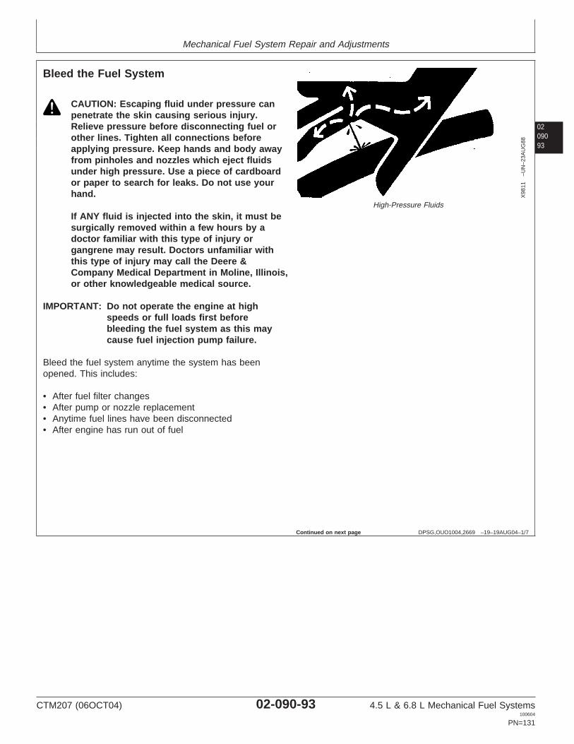
Mechanical Fuel System Repair and Adjustments
0209093
DPSG,OUO1004,2669 –19–19AUG04–1/7
Bleed the Fuel System
X98
11–U
N–2
3AU
G88
High-Pressure Fluids
CAUTION: Escaping fluid under pressure canpenetrate the skin causing serious injury.Relieve pressure before disconnecting fuel orother lines. Tighten all connections beforeapplying pressure. Keep hands and body awayfrom pinholes and nozzles which eject fluidsunder high pressure. Use a piece of cardboardor paper to search for leaks. Do not use yourhand.
If ANY fluid is injected into the skin, it must besurgically removed within a few hours by adoctor familiar with this type of injury organgrene may result. Doctors unfamiliar withthis type of injury may call the Deere &Company Medical Department in Moline, Illinois,or other knowledgeable medical source.
IMPORTANT: Do not operate the engine at highspeeds or full loads first beforebleeding the fuel system as this maycause fuel injection pump failure.
Bleed the fuel system anytime the system has beenopened. This includes:
• After fuel filter changes• After pump or nozzle replacement• Anytime fuel lines have been disconnected• After engine has run out of fuel
Continued on next page
CTM207 (06OCT04) 02-090-93 4.5 L & 6.8 L Mechanical Fuel Systems100604
PN=131
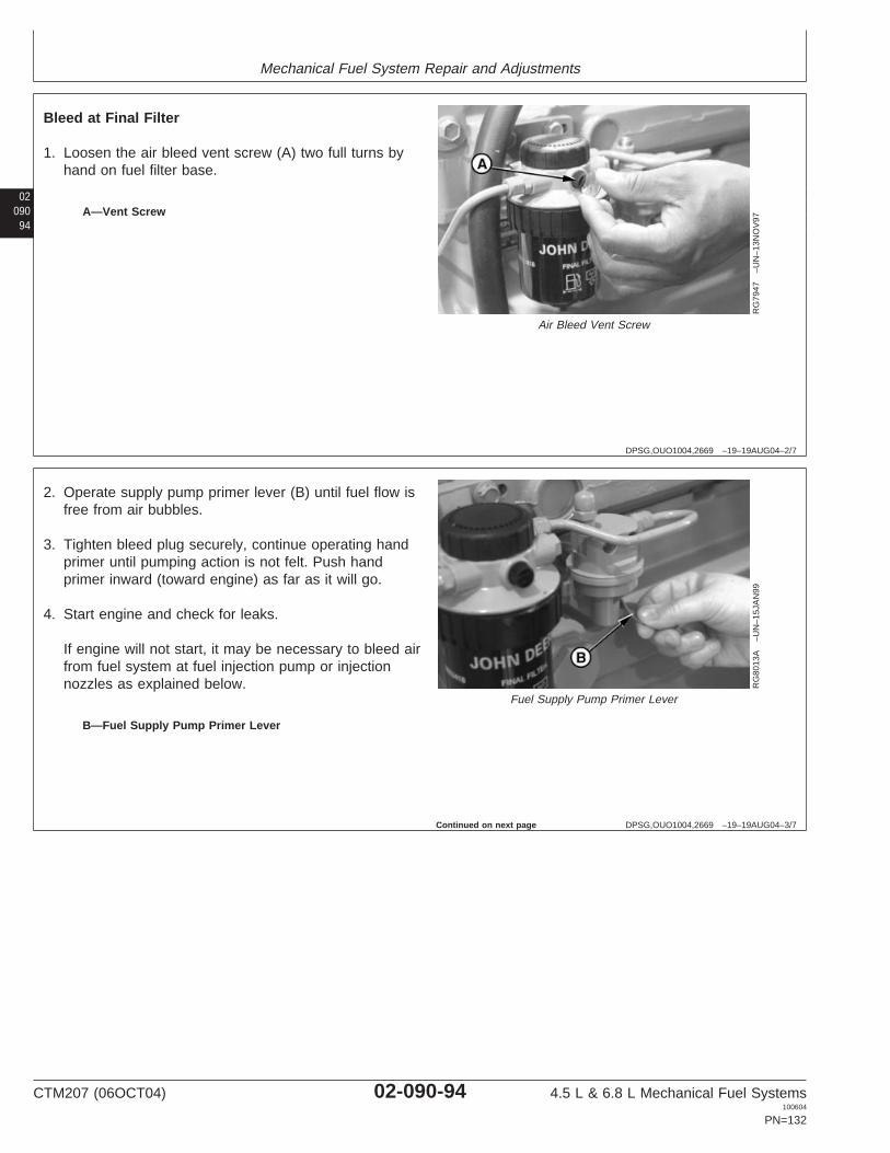
Mechanical Fuel System Repair and Adjustments
02090
94
DPSG,OUO1004,2669 –19–19AUG04–2/7
RG
7947
–UN
–13N
OV
97
Air Bleed Vent Screw
A—Vent Screw
Bleed at Final Filter
1. Loosen the air bleed vent screw (A) two full turns byhand on fuel filter base.
DPSG,OUO1004,2669 –19–19AUG04–3/7
RG
8013
A–U
N–1
5JA
N99
Fuel Supply Pump Primer Lever
B—Fuel Supply Pump Primer Lever
2. Operate supply pump primer lever (B) until fuel flow isfree from air bubbles.
3. Tighten bleed plug securely, continue operating handprimer until pumping action is not felt. Push handprimer inward (toward engine) as far as it will go.
4. Start engine and check for leaks.
If engine will not start, it may be necessary to bleed airfrom fuel system at fuel injection pump or injectionnozzles as explained below.
Continued on next page
CTM207 (06OCT04) 02-090-94 4.5 L & 6.8 L Mechanical Fuel Systems100604
PN=132

Mechanical Fuel System Repair and Adjustments
0209095
DPSG,OUO1004,2669 –19–19AUG04–4/7
RG
6264
–UN
–03N
OV
97
Stanadyne Rotary Fuel Injection Pump
A—Fuel Return Line Connector
Bleed at Fuel Injection Pump
On Stanadyne rotary pumps:
1. Slightly loosen fuel return line connector (A) at fuelinjection pump.
2. Operate fuel supply pump primer lever until fuel,without air bubbles, flows from fuel return lineconnection.
3. Tighten return line connector to specification.
SpecificationStanadyne Fuel Injection PumpReturn Line Connector—Torque 27 N•m (20 lb-ft).....................................
4. Primer lever is spring-loaded and will return to normalposition.
DPSG,OUO1004,2669 –19–19AUG04–5/7
RG
7948
–UN
–13N
OV
97
Delphi/Lucas Rotary Fuel Injection Pumps
B—Bleed ScrewC—Screw
On Delphi/Lucas rotary pumps:
CAUTION: NEVER loosen screw (C) securingpump head, otherwise damage may occur.
1. Loosen bleed screw (B) on pump cover.
NOTE: On injection pump models DP200/201/203, bleedscrew is located on top of cover near the fuelreturn line.
2. Operate fuel supply pump primer lever or turn ignitionswitch to “ON”.
3. Wait until fuel flow is free of air bubbles. Tighten bleedscrew.
4. Primer lever is spring-loaded and will return to normalposition.
CTM207 (06OCT04) 02-090-95 4.5 L & 6.8 L Mechanical Fuel Systems100604
PN=133
Continued on next page

Mechanical Fuel System Repair and Adjustments
02090
96
DPSG,OUO1004,2669 –19–19AUG04–6/7
RG
8069
–UN
–23N
OV
97
Denso Fuel Injection Pump Shown
On Denso and Motorpal in-line pumps:
1. On Denso pump shown, unscrew hand primer on fuelsupply pump until it can be pulled by hand.
2. Open fuel filter port plug.
3. Operate the hand primer until smooth flow of fuel, freeof bubbles, comes out of the filter plug hole.
4. Simultaneously stroke the hand primer down and closethe filter port plug. This prevents air from entering thesystem. Tighten plug securely. DO NOT overtighten.
IMPORTANT: Be sure hand primer is all the waydown in barrel before tightening toprevent internal thread damage.
5. On Denso pump shown, lock hand primer in position.
Continued on next page
CTM207 (06OCT04) 02-090-96 4.5 L & 6.8 L Mechanical Fuel Systems100604
PN=134

Mechanical Fuel System Repair and Adjustments
0209097
DPSG,OUO1004,2669 –19–19AUG04–7/7
RG
7725
–UN
–08J
AN
97
Fuel Line Connection
Bleed at Fuel Injection Nozzles
1. Move the engine speed control lever to half throttleposition. On engines equipped with electronic fuelshut-off solenoid, energize solenoid.
IMPORTANT: To avoid damage to fuel lines, alwaysuse a backup wrench when looseningor tightening fuel lines at nozzles orinjection pump.
2. Using two open-end wrenches, loosen fuel lineconnection at injection nozzle as shown.
3. Crank engine over with starter motor (but do not startengine), until fuel free from bubbles flows out ofloosened connection.
4. Tighten connection to specification.
SpecificationFuel Injection Line-to-NozzleConnector—Torque 27 N•m (20 lb-ft).........................................................
5. Repeat procedure for remaining injection nozzles (ifnecessary) until all air has been removed from fuelsystem.
If engine will not start, see your authorized servicingdealer or engine distributor.
CTM207 (06OCT04) 02-090-97 4.5 L & 6.8 L Mechanical Fuel Systems100604
PN=135

Mechanical Fuel System Repair and Adjustments
02090
98
CTM207 (06OCT04) 02-090-98 4.5 L & 6.8 L Mechanical Fuel Systems100604
PN=136
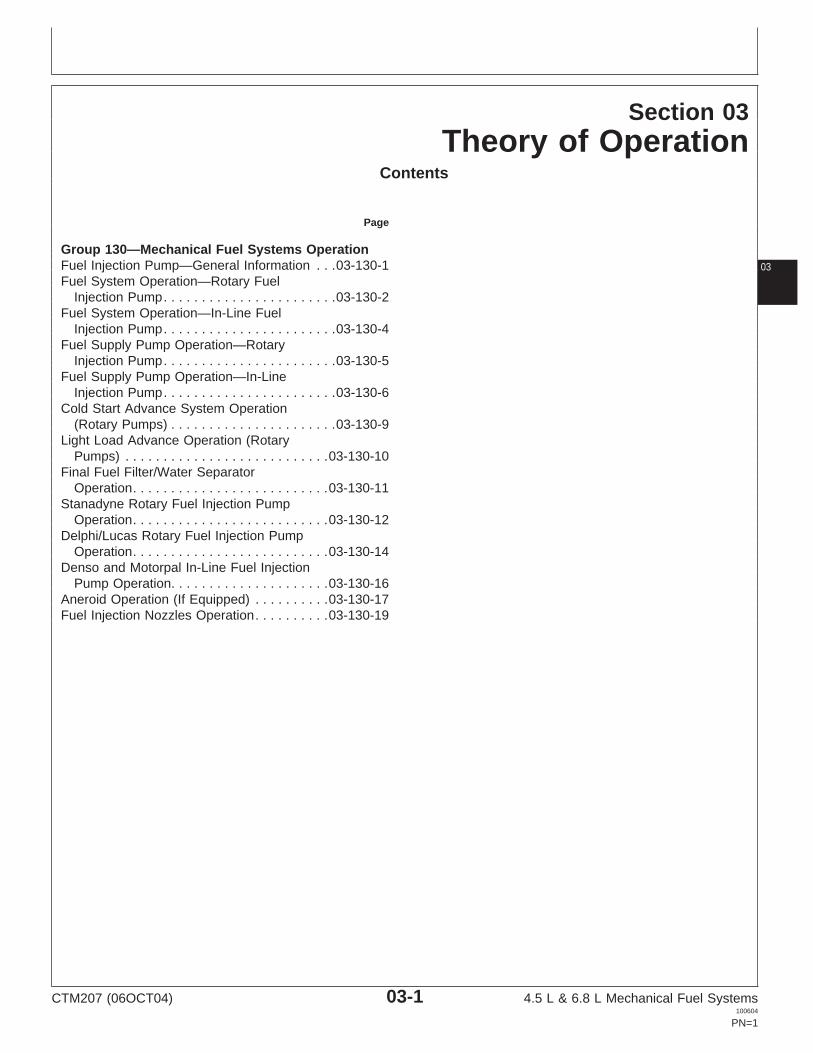
Section 03Theory of Operation
Contents
Page
Group 130—Mechanical Fuel Systems OperationFuel Injection Pump—General Information . . .03-130-1 03Fuel System Operation—Rotary Fuel
Injection Pump. . . . . . . . . . . . . . . . . . . . . . .03-130-2Fuel System Operation—In-Line Fuel
Injection Pump. . . . . . . . . . . . . . . . . . . . . . .03-130-4Fuel Supply Pump Operation—Rotary
Injection Pump. . . . . . . . . . . . . . . . . . . . . . .03-130-5Fuel Supply Pump Operation—In-Line
Injection Pump. . . . . . . . . . . . . . . . . . . . . . .03-130-6Cold Start Advance System Operation
(Rotary Pumps) . . . . . . . . . . . . . . . . . . . . . .03-130-9Light Load Advance Operation (Rotary
Pumps) . . . . . . . . . . . . . . . . . . . . . . . . . . .03-130-10Final Fuel Filter/Water Separator
Operation. . . . . . . . . . . . . . . . . . . . . . . . . .03-130-11Stanadyne Rotary Fuel Injection Pump
Operation. . . . . . . . . . . . . . . . . . . . . . . . . .03-130-12Delphi/Lucas Rotary Fuel Injection Pump
Operation. . . . . . . . . . . . . . . . . . . . . . . . . .03-130-14Denso and Motorpal In-Line Fuel Injection
Pump Operation. . . . . . . . . . . . . . . . . . . . .03-130-16Aneroid Operation (If Equipped) . . . . . . . . . .03-130-17Fuel Injection Nozzles Operation. . . . . . . . . .03-130-19
CTM207 (06OCT04) 03-1 4.5 L & 6.8 L Mechanical Fuel Systems100604
PN=1

Contents
03
CTM207 (06OCT04) 03-2 4.5 L & 6.8 L Mechanical Fuel Systems100604
PN=2

Group 130Mechanical Fuel Systems Operation
031301
DPSG,OUO1004,2670 –19–09JUL02–1/1
Fuel Injection Pump—General Information
Most engines are equipped with a Stanadyne orDelphi/Lucas rotary-type injection pump. Rotary injectionpumps are dynamically timed at the producing factory andreference timing marks are accurately stamped on frontplate and injection pump hub. Timing can be checked andadjusted as covered below using the TIME TRAC Kit.
Higher horsepower engines use multiple-plunger, in-linetype Denso or Motorpal fuel injection pumps with amechanical flyweight governor. Injection pumps may beequipped with an aneroid control.
In-line injection pumps are statically timed by lockingengine at No.1 TDC compression when installing pumpwith injection pump drive hub lock-pinned (refer to Section02, Group 090 for installation of injection pumps andpump timing.)
TIME TRAC is a registered trademark of Stanadyne Automotive Corp.
CTM207 (06OCT04) 03-130-1 4.5 L & 6.8 L Mechanical Fuel Systems100604
PN=139

Mechanical Fuel Systems Operation
03130
2
RG,115,JW7716 –19–09JUL02–1/2
Fuel System Operation—Rotary Fuel Injection Pump
F
G
H
I
C
A
D
E
A
A
C
BC
RG
7788
–UN
–25F
EB
98
Rotary Fuel Injection Operation
CTM207 (06OCT04) 03-130-2 4.5 L & 6.8 L Mechanical Fuel Systems100604
PN=140
Continued on next page

Mechanical Fuel Systems Operation
031303
RG,115,JW7716 –19–09JUL02–2/2
A—Fuel Supply (Transfer) C—Final Fuel Filter F—Supply Pump Pressure H—Fuel Return Leak-OffPump D—Fuel Injection Nozzles Fuel I—Suction Fuel from Tank
B—Primary Fuel Filter/Water E—Fuel Injection Pump G—Injection Pressure FuelSeparator
Refer to illustration on previous page.
The fuel supply pump (A) draws fuel under vacuumfrom the tank, through the primary filter (B). The fuelsupply pump pressurizes the fuel, which then flows tothe final filter (C). Fuel flowing out of the final filtercharges the transfer pump of the injection pump (E).
With the fuel injection pump charged with fuel by thefuel supply pump, the injection pump plungerspressurize the fuel to approximately 50 000 kPa (500bar) (7255 psi). Delivery (pressure) lines are used toroute this high pressure fuel to the fuel injectionnozzles (D).
Fuel enters the injection nozzle at a pressure whicheasily overcomes the pressure required to open thenozzle valve. When the nozzle valve opens, fuel isforced out through the orifices in the nozzle tip andatomizes as it enters the combustion chamber.
Incorporated into the fuel system is a means ofreturning excess (or unused) fuel (H) back to the fueltank. Excess fuel comes from two sources:
1. Fuel Injection Pump: A quantity of fuel greater thanthat required by the engine is supplied to the fuelinjection pump.
2. Fuel Injection Nozzles: A small amount of fuelseeps past the nozzle valve for lubricationpurposes.
To get the excess fuel back to the tank, a return linefrom the injection pump is connected to the middle ofthe nozzle leak-off line. Fuel from both sources is thenreturned to the tank by a return pipe connected to thefront end of the leak-off pipe.
CTM207 (06OCT04) 03-130-3 4.5 L & 6.8 L Mechanical Fuel Systems100604
PN=141

Mechanical Fuel Systems Operation
03130
4
RG,115,JW7717 –19–24NOV97–1/2
Fuel System Operation—In-Line Fuel Injection Pump
I
J
L
K
B
CA
H
DGF
E
RG
7789
–UN
–25F
EB
98
In-Line Fuel Injection Pump Operation
A—Final Fuel Filter D—Aneroid Inlet Line H—Fuel Shut-Off Solenoid K—Injection Pressure FuelB—Primary Fuel Filter/Water E—Fuel Return (Leak-Off) Line I—Suction Fuel from Tank L—Return (Leak-Off) Line
Separator F—Fuel Supply Pump J—Supply Pump PressureC—Injection Nozzles G—Fuel Injection Pump Fuel
The supply pump (F) draws fuel from the vented fueltank through the primary filter (B).
The supply pump pressurizes the fuel so that it flowsthrough the filter to the injection pump galley. Supply
pump output pressure will vary depending on load andapplication.
CTM207 (06OCT04) 03-130-4 4.5 L & 6.8 L Mechanical Fuel Systems100604
PN=142
Continued on next page

Mechanical Fuel Systems Operation
031305RG,115,JW7717 –19–24NOV97–2/2
The galley is kept full by the supply pump. Injectionpump plungers further pressurize the fuel. Injectionpressure lines route the fuel to the nozzles (C).
The high pressure fuel (K) opens the nozzle valve andforces fuel out the small orifices in the nozzle tip. Thisatomizes the fuel as it enters the combustion chamber.
There are two sources of excess fuel incorporated intothe system. The supply pump supplies more fuel to thepump than is required by the engine, and the nozzlerequires excess fuel to lubricate the nozzle valve. Aleak-off line (L) returns this excess fuel to the tankfrom both the pump and nozzles.
RG,115,JW7709 –19–09JUL02–1/1
Fuel Supply Pump Operation—RotaryInjection Pump
RG
9119
–UN
–17A
PR
98
Fuel Supply Pump Operation
A—Fuel OutletB—Outlet Check ValveC—Inlet Check ValveD—Fuel InletE—Return SpringF—RodG—LeverH—Hand Primer LeverI—Diaphragm
The Sofabex fuel supply pump used with Delphi/Lucasand Stanadyne rotary fuel injection pumps uses aneccentric lobe on the engine camshaft to operate lever (G)on supply pump to pressurize fuel system.
Fuel flows from the fuel tank at gravity pressure to theinlet side (D) of the diaphragm-type pump.
As lever (G) rides on the high side of the camshaft lobe,rod (F) pulls diaphragm (I) down. Suction pressure opensthe inlet check valve (C) and fuel is drawn into the pump.
As the camshaft lobe rotates to the low side, return spring(E) forces diaphragm (I) upward. The resulting fuelpressure closes inlet check valve (C) and opens outletcheck valve (B), delivering fuel through outlet (A) to theinjection pump.
Hand primer lever (H) is provided for manually forcing fuelthrough the system to bleed air from the fuel filter, lines,etc.
CTM207 (06OCT04) 03-130-5 4.5 L & 6.8 L Mechanical Fuel Systems100604
PN=143

Mechanical Fuel Systems Operation
03130
6
RG,115,JW7706 –19–24NOV97–1/3
Fuel Supply Pump Operation—In-LineInjection Pump
RG
7753
B–U
N–1
0NO
V97
Fuel Supply Pump Operation (Denso Pump Shown)A—Fuel InletB—PlungerC—Fuel OutletD—Hand Primer
The plunger-type Denso and Motorpal fuel supply pumpsare mounted on the side of the injection pump housingand driven by the injection pump camshaft. Fuel entersthe supply pump at (A), is pressurized by the plunger (B),and discharged through outlet (C). The hand primer (D)provides manual pump operation for bleeding the fuelsystem.
Continued on next page
CTM207 (06OCT04) 03-130-6 4.5 L & 6.8 L Mechanical Fuel Systems100604
PN=144
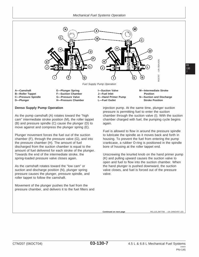
Mechanical Fuel Systems Operation
031307
RG,115,JW7706 –19–24NOV97–2/3
RG
5787
–UN
–06A
UG
91
Fuel Supply Pump Operation
A—Camshaft E—Plunger Spring I—Suction Valve M—Intermediate StrokeB—Roller Tappet F—Suction Chamber J—Fuel Inlet PositionC—Pressure Spindle G—Pressure Valve K—Hand Primer Pump N—Suction and DischargeD—Plunger H—Pressure Chamber L—Fuel Outlet Stroke Position
Denso Supply Pump Operation
As the pump camshaft (A) rotates toward the “highcam” intermediate stroke position (M), the roller tappet(B) and pressure spindle (C) cause the plunger (D) tomove against and compress the plunger spring (E).
Plunger movement forces the fuel out of the suctionchamber (F), through the pressure valve (G), and intothe pressure chamber (H). The amount of fueldischarged from the suction chamber is equal to theamount of fuel delivered for each stroke of the plunger.Towards the end of the intermediate stroke, thespring-loaded pressure valve closes again.
As the camshaft rotates toward the “low cam” orsuction and discharge position (N), plunger springpressure causes the plunger, pressure spindle, androller tappet to follow the camshaft.
Movement of the plunger pushes the fuel from thepressure chamber, and delivers it to the fuel filters and
injection pump. At the same time, plunger suctionpressure is permitting fuel to enter the suctionchamber through the suction valve (I). With the suctionchamber charged with fuel, the pumping cycle beginsagain.
Fuel is allowed to flow in around the pressure spindleto lubricate the spindle as it moves back and forth inhousing. To prevent the fuel from entering the pumpcrankcase, a rubber O-ring is positioned in the spindlebore of housing at the roller tappet end.
Unscrewing the knurled knob on the hand primer pump(K) and pulling upward causes the suction valve toopen and fuel to flow into the suction chamber. Whenthe hand plunger is pushed downward, the suctionvalve closes, and fuel is forced out of the pressurevalve.
Continued on next page
CTM207 (06OCT04) 03-130-7 4.5 L & 6.8 L Mechanical Fuel Systems100604
PN=145
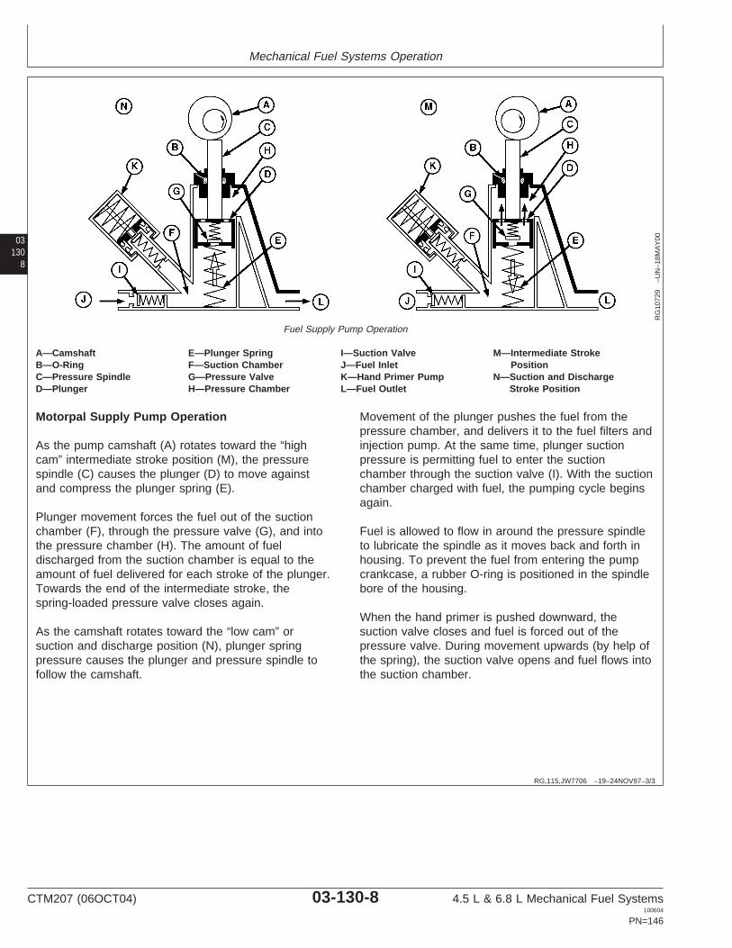
Mechanical Fuel Systems Operation
03130
8
RG,115,JW7706 –19–24NOV97–3/3
RG
1072
9–U
N–1
8MA
Y00
Fuel Supply Pump Operation
A—Camshaft E—Plunger Spring I—Suction Valve M—Intermediate StrokeB—O-Ring F—Suction Chamber J—Fuel Inlet PositionC—Pressure Spindle G—Pressure Valve K—Hand Primer Pump N—Suction and DischargeD—Plunger H—Pressure Chamber L—Fuel Outlet Stroke Position
Motorpal Supply Pump Operation
As the pump camshaft (A) rotates toward the “highcam” intermediate stroke position (M), the pressurespindle (C) causes the plunger (D) to move againstand compress the plunger spring (E).
Plunger movement forces the fuel out of the suctionchamber (F), through the pressure valve (G), and intothe pressure chamber (H). The amount of fueldischarged from the suction chamber is equal to theamount of fuel delivered for each stroke of the plunger.Towards the end of the intermediate stroke, thespring-loaded pressure valve closes again.
As the camshaft rotates toward the “low cam” orsuction and discharge position (N), plunger springpressure causes the plunger and pressure spindle tofollow the camshaft.
Movement of the plunger pushes the fuel from thepressure chamber, and delivers it to the fuel filters andinjection pump. At the same time, plunger suctionpressure is permitting fuel to enter the suctionchamber through the suction valve (I). With the suctionchamber charged with fuel, the pumping cycle beginsagain.
Fuel is allowed to flow in around the pressure spindleto lubricate the spindle as it moves back and forth inhousing. To prevent the fuel from entering the pumpcrankcase, a rubber O-ring is positioned in the spindlebore of the housing.
When the hand primer is pushed downward, thesuction valve closes and fuel is forced out of thepressure valve. During movement upwards (by help ofthe spring), the suction valve opens and fuel flows intothe suction chamber.
CTM207 (06OCT04) 03-130-8 4.5 L & 6.8 L Mechanical Fuel Systems100604
PN=146

Mechanical Fuel Systems Operation
031309
DPSG,OUO1004,122 –19–09JUL02–1/2
Cold Start Advance System Operation(Rotary Pumps)
CD
3069
2–U
N–1
6JU
N98
Cold Start Advance (Stanadyne Pump Shown)
A—Cold Start Advance Solenoid AssemblyB—Wiring Connector for Cold Start SwitchC—Solenoid ValveD—Cold Advance PistonE—Advance Piston
To comply with exhaust emissions regulations, the timingof injection pumps should be around 6—9 degrees beforeTDC. This timing value does not allow for proper start-upwhen the engine is cold. A cold start advance system isused to temporarily advance injection pump timing duringcold engine start-up conditions.
Stanadyne Cold Start Advance
On engines equipped with Stanadyne injection pumps, themajor components of the cold start advance system arethe cold start advance switch, cold start advance solenoidand cold start advance piston.
The cold start advance switch is mounted in the watermanifold/thermostat housing. The switch is normallyclosed at coolant temperatures below 60°C (140°F),providing current to energize the cold start solenoid. Atcold start-up, the solenoid plunger is unseated, allowingpressurized fuel to flow to the cold start advance piston(D). This forces advance piston (E) to the fully advancedposition, advancing engine timing 7—10 degrees.
When engine coolant temperature rises above 60°C(140°F), the cold start advance switch opens, cutting offcurrent flow to the solenoid. The solenoid plunger seats,cutting off fuel flow to the cold start advance piston (D)and timing returns to normal operating levels.
Delphi/Lucas Cold Start Advance
On engines equipped with Delphi/Lucas injection pumps,the major components of the cold start advance systemare the cold start advance switch, wax motor, cold startadvance piston and springs, auto advance housing, pistonand springs.
The cold start advance switch is mounted in the watermanifold/thermostat housing. The switch is normally openat coolant temperatures below 60°C (140°F). At coldstart-up, there is no current flow to the wax motor.Maximum fuel pressure is applied to the auto advancepiston and engine timing is advanced 7—10 degrees.
CTM207 (06OCT04) 03-130-9 4.5 L & 6.8 L Mechanical Fuel Systems100604
PN=147
Continued on next page
Mechanical Fuel Systems Operation
03130
10 DPSG,OUO1004,122 –19–09JUL02–2/2
When engine coolant temperature rises above 60°C(140°F), the cold start advance switch closes and currentflows to the wax motor. A heating element in the waxmotor heats the wax, causing it to expand. As the waxexpands, the wax motor plunger extends, opening a ballvalve and applying fuel pressure to the cold start advancepiston. Equal pressure between the cold start advancepiston and the auto advance piston and the net forceapplied to the advance springs returns injection pumptiming to normal operating levels.
DPSG,OUO1004,135 –19–01JUN98–1/1
Light Load Advance Operation (Rotary Pumps)
Light load advance is used on engines with rotaryinjection pumps to maintain injection pump timing andengine speed as load decreases. Under full and/orconsistent loads, transfer pressure in the injectionpump is stable, acting on the advance piston tomaintain pump timing and rated engine speed.
As the load begins to decrease, a correspondingdecrease in transfer pressure occurs which tends to
retard timing and drop engine rpm under the remainingload. To compensate, the governor begins to close ametering valve in the light load advance circuit. As flowthrough the metering valve drops, transfer pressurebegins to rise again and acts on the advance piston toadvance pump timing and maintain engine rpm.
CTM207 (06OCT04) 03-130-10 4.5 L & 6.8 L Mechanical Fuel Systems100604
PN=148

Mechanical Fuel Systems Operation
0313011
RG,115,JW7696 –19–24NOV97–1/1
Final Fuel Filter/Water Separator Operation
RG
9090
–UN
–27M
AR
98
Final Fuel Filter
A—Bleed ScrewB—Fuel OutletC—Fuel InletD—Filter ElementE—Drain PlugF—Primer Pump
Fuel enters the filter at inlet (C), then flows through filterelement (D) and exits through outlet (B) to the fuelinjection pump. The filter element is housed in a sedimentbowl attached to the base with a threaded retaining ring.
Since water and contaminants settle at the bottom of thesediment bowl, a drain plug (E) is provided.
Air in the system can be expelled through the air ventwhen bleed screw (A) is loosened. Optional priming pump(F) draws fuel from the fuel tank to fill the filter bowl whenthe filter element is changed. The priming pump alsosupplies fuel from the filter to the injection pump.
CTM207 (06OCT04) 03-130-11 4.5 L & 6.8 L Mechanical Fuel Systems100604
PN=149
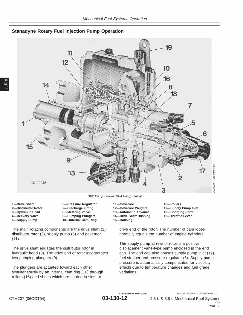
Mechanical Fuel Systems Operation
03130
12
RG,115,JW7694 –19–24NOV97–1/2
Stanadyne Rotary Fuel Injection Pump Operation
CD
3003
9–U
N–0
8MA
R95
DB2 Pump Shown, DB4 Pump Similar
1—Drive Shaft 6—Pressure Regulator 11—Governor 16—Rollers2—Distributor Rotor 7—Discharge Fitting 12—Governor Weights 17—Supply Pump Inlet3—Hydraulic Head 8—Metering Valve 13—Automatic Advance 18—Charging Ports4—Delivery Valve 9—Pumping Plungers 14—Drive Shaft Bushing 19—Throttle Lever5—Supply Pump 10—Internal Cam Ring 15—Housing
The main rotating components are the drive shaft (1),distributor rotor (2), supply pump (5) and governor(11).
The drive shaft engages the distributor rotor inhydraulic head (3). The drive end of rotor incorporatestwo pumping plungers (9).
The plungers are actuated toward each othersimultaneously by an internal cam ring (10) throughrollers (16) and shoes which are carried in slots at
drive end of the rotor. The number of cam lobesnormally equals the number of engine cylinders.
The supply pump at rear of rotor is a positivedisplacement vane-type pump enclosed in the endcap. The end cap also houses supply pump inlet (17),fuel strainer and pressure regulator (6). Supply pumppressure is automatically compensated for viscosityeffects due to temperature changes and fuel gradevariations.
CTM207 (06OCT04) 03-130-12 4.5 L & 6.8 L Mechanical Fuel Systems100604
PN=150
Continued on next page

Mechanical Fuel Systems Operation
0313013
RG,115,JW7694 –19–24NOV97–2/2
The distributor rotor incorporates two charging ports(18) and a single axial bore (passage) with onedischarge port to serve all head outlets (7) to theinjection lines. The rotor rotates in bore of hydraulichead. Metering valve (8) bore, charging ports anddischarge fittings are located in the head.
This pump contains its own mechanical governor. Thecentrifugal force of the weights (12) in their retainer istransmitted through a sleeve to a governor arm andthrough a positive linkage to the metering valve. Themetering valve can be closed to shut off fuel through asolid linkage by an independently operated shut-offlever.
The automatic speed advance (13), advances orretards (hydraulically) the beginning of fuel deliveryfrom the pump. The advance responds to changes inspeed only, or to a combination of speed and loadchanges.
Fuel is drawn from the supply tank through filters intothe pump inlet through the inlet filter screen by thevane type fuel transfer pump. Some fuel is bypassedthrough the pressure regulator assembly to the suctionside.
Fuel under transfer pump pressure flows through thecenter of the transfer pump rotor, past the rotorretainer into a circular groove on the rotor. It then flowsthrough a connecting passage in the head to theautomatic advance and up through a radial passageand then through a connecting passage to the
metering valve. The radial position of the meteringvalve, controlled by the governor, regulates flow of thefuel into the radial charging passages whichincorporates the head charging ports.
As the rotor revolves, the two rotor inlet passagesregister with the charging ports in the hydraulic head,allowing fuel to flow into the pumping chamber. Withfurther rotation, the inlet passages move out of registryand the discharge port of the rotor registers with oneof the head outlets. While the discharge port isopened, the rollers contact the cam lobes, forcing theplungers together. Fuel trapped between the plungersis then pressurized and delivered by the nozzle to thecombustion chamber.
Self-lubrication is an inherent feature of the pump’sdesign. As fuel at transfer pump pressure reaches thecharging ports, slots on the rotor shank allow fuel andany entrapped air to flow into the pump housing cavity.
Additionally, an air vent passage in the hydraulic headconnects the outlet side of the transfer pump with thepump housing. This allows air and some fuel to bebled back to the fuel tank via the return line. The fuelthus bypassed fills the housing, lubricates the internalcomponents, cools and carries off any small airbubbles. The pump operates with the housingcompletely full of fuel; there are no dead air spacesanywhere within the pump.
A cold start switch is optional and aids in cold start-upoperation.
CTM207 (06OCT04) 03-130-13 4.5 L & 6.8 L Mechanical Fuel Systems100604
PN=151

Mechanical Fuel Systems Operation
03130
14
RG,115,JW7693 –19–09JUL02–1/2
Delphi/Lucas Rotary Fuel Injection Pump Operation
RG
8088
–UN
–18N
OV
97
Rotary Fuel Injection Pump—Delphi/Lucas
A—Governor Housing E—Distributor Rotor H—Delivery Valve K—Pump HousingB—Throttle Lever F—End Plate I—Internal Cam Ring L—Automatic AdvanceC—Pumping Plungers G—Supply Pump J—Drive Shaft M—Electric Shut-OffD—Hydraulic Head
The Delphi/Lucas fuel injection pump is a horizontallymounted distributor pump with mechanical governorand automatic hydraulic speed advance. The movingparts of the pump are simultaneously lubricated andcooled by diesel fuel flowing through the pump; noadditional lubricant is required.
Diesel fuel for injection is fed to the cylinders by asingle unit. The pumping plungers (C) and distributorrotor (E) are fitted with two opposed plungerscontrolled by an internal cam ring (I).
On the other end of the rotor, there is a supply pump(G) which delivers the fuel, drawn from the fuel filter,through the metering valve into the inlet bore in thepump hydraulic head (D), at a pressure that varies withengine speed.
As the rotor rotates, the inlet bore in pump head alignswith inlet bore in the rotor. Fuel coming from thetransfer pump reaches the pump plunger chamber’sthrough bore, regulated by the metering valve andforces the two plungers apart.
During further rotation of the distributor rotor, inlet borein the pump head is closed and distributor channel inthe rotor eventually aligns with one of the outlet boresin the pump head. Meanwhile the two pump plungershave reached the cam so that they move toward eachother. The trapped, metered fuel is forced (under highpressure) through a channel in the rotor and outletopening in the pump head, through the pressurizingvalve and pressure line, to the injection nozzle, andinto the appropriate cylinder.
CTM207 (06OCT04) 03-130-14 4.5 L & 6.8 L Mechanical Fuel Systems100604
PN=152
Continued on next page

Mechanical Fuel Systems Operation
0313015
RG,115,JW7693 –19–09JUL02–2/2
A pressurizing valve is located at each outlet in thepump head where the pressure line leading to the fuelinjection nozzle is connected. After injection, thepressure valve closes again, and with its small reliefpiston, draws in a quantity of fuel from the pressureline.
The resulting relief in the pressure line causes a quickand firm closing of the nozzle valve. This prevents fuelfrom leaking into the combustion chamber.
The quantity of fuel which is needed at any givenmoment for each cylinder and combustion cycle isregulated by a metering valve. The metering valve iscontrolled by the speed control rod and throttle lever(B), and by the governor inside the governor housing(A). In the “NO-FUEL” (“OFF”) position, the meteringvalve completely cuts the supply of fuel from supplypump to the rotor.
At slow idle speed or under full load, the supply pumpfeeds more fuel to the metering valve than is neededfor injection. The excessive fuel flows through thepressure regulating valve back to the suction side ofthe transfer pump. A very small amount of this surplusfuel escapes through the top of the governor housing.
To obtain the best possible performance over theentire speed range, the fuel injection pump is fittedwith an automatic, hydraulically operated speedadvance (L). This speed advance is preset at thefactory. The speed advance adjusts timing of the fuelinjection pump in relation to engine speed and load.
The light load advance is standard on Model DP203pumps and optional on DP201 pumps.
A cold advance switch is optional on these pumps.The switch consists of a housing to which is fitted aspring-loaded piston assembly, a “wax motor”, and aspring-loaded ball valve. It is fitted at the top of thespring end of the auto advance housing.
IMPORTANT: Remember that all adjustments tothe injection pump, except for slowidle, MUST BE carried out on a testbench by a specialist injection pumprepair station only. Internaladjustments in the field are notpermitted, as this pump is a sealedunit.
CTM207 (06OCT04) 03-130-15 4.5 L & 6.8 L Mechanical Fuel Systems100604
PN=153

Mechanical Fuel Systems Operation
03130
16
DPSG,OUO1004,2671 –19–19APR00–1/1
Denso and Motorpal In-Line Fuel InjectionPump Operation
RG
9100
–UN
–27M
AR
98
In-Line Fuel Injection Pump Operation (Denso PumpShown/Motorpal Similar)
A—CrankcaseB—CamshaftC—Roller TappetD—Control SleeveE—Control RackF—PlungerG—Fuel GalleryH—Delivery ValveI—Delivery Pipe
Filtered fuel under pressure by the supply pump fills theinjection pump fuel gallery (G). As the camshaft rotates,roller tappets (C) riding on the camshaft (B) lobes operatethe plungers (F) to supply high pressure fuel through thedelivery valves (H) to the injection nozzles.
A governor-operated control rack (E) is connected to thecontrol sleeves (D) and plungers to regulate the quantityof fuel delivered to the engine.
Engine lubricating oil is piped to the injection pumpcrankcase (A) to provide splash lubrication of the workingparts. Two drain holes at the front end of the pumpdetermine the level of oil maintained in the crankcase.Excess oil drains out these holes and returns back to theengine through the timing gear housing.
CTM207 (06OCT04) 03-130-16 4.5 L & 6.8 L Mechanical Fuel Systems100604
PN=154

Mechanical Fuel Systems Operation
0313017
RG,115,JW7683 –19–25APR00–1/2
Aneroid Operation (If Equipped)
RG
8086
–UN
–18N
OV
97
Aneroid Operation
RG
8111
–UN
–18N
OV
97
Aneroid Control Lever and Block
RG
8081
–UN
–18N
OV
97
Injection Pump Throttle Lever
A—Intake Manifold Pressure Line ConnectionB—Diaphragm Adjusting ScrewC—Diaphragm ChamberD—DiaphragmE—SpringF—Aneroid Control ShaftG—Guide LeverH—Control LeverI—Control RackJ—Control BlockK—Aneroid Control LeverL—Throttle Lever
NOTE: In-line injection pump shown. Operation of aneroidon rotary pumps is similar in theory.
Intake manifold pressure (created by the turbocharger)enters aneroid at (A). It is directed to upper side ofdiaphragm chamber (C) and exerts pressure ondiaphragm (D).
When the pressure rises to about 100 kPa (1 bar) (15psi), or about 1000 engine rpm under moderate to heavyloads, spring (E) pressure is overcome. Diaphragm thenmoves aneroid control shaft (F) downward.
Control lever (H) has “two” legs. The inner leg connectswith control block (J) and the aneroid control lever (K) andbears on the flat surface of aneroid control shaft. Theouter leg bears against a block riveted to the control rack(I).
NOTE: Diaphragm adjusting screw (B) regulates theminimum fuel delivery quantity at a specified rpmand zero pressure acting on the diaphragm. Thediaphragm spring determines acceleration time(the greater the spring tension, the greater themanifold pressure required to overcome springtension; hence, a slower acceleration).
Downward movement of the throttle lever (L) causes armto rotate on fuel control shaft, permitting control rack tomove its normal amount.
CTM207 (06OCT04) 03-130-17 4.5 L & 6.8 L Mechanical Fuel Systems100604
PN=155
Continued on next page

Mechanical Fuel Systems Operation
03130
18 RG,115,JW7683 –19–25APR00–2/2
If the intake manifold pressure is below 100 kPa (1 bar)(15 psi) because of low engine speed, or is under lightload at higher engine speeds, the aneroid spring pressureis greater than the intake manifold pressure. As a result,the control rack travel is limited (therefore, fuel delivery islimited) by the arm and adjusting shaft.
Aneroid control will be in effect until the manifold pressureis high enough to overcome diaphragm spring pressure.
CTM207 (06OCT04) 03-130-18 4.5 L & 6.8 L Mechanical Fuel Systems100604
PN=156
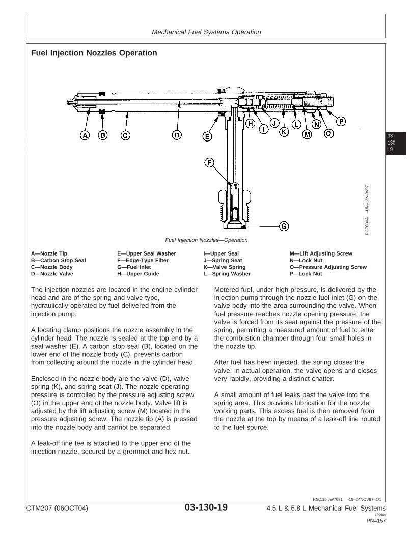
Mechanical Fuel Systems Operation
0313019
RG,115,JW7681 –19–24NOV97–1/1
Fuel Injection Nozzles Operation
RG
7800
A–U
N–1
3NO
V97
Fuel Injection Nozzles—Operation
A—Nozzle Tip E—Upper Seal Washer I—Upper Seal M—Lift Adjusting ScrewB—Carbon Stop Seal F—Edge-Type Filter J—Spring Seat N—Lock NutC—Nozzle Body G—Fuel Inlet K—Valve Spring O—Pressure Adjusting ScrewD—Nozzle Valve H—Upper Guide L—Spring Washer P—Lock Nut
The injection nozzles are located in the engine cylinderhead and are of the spring and valve type,hydraulically operated by fuel delivered from theinjection pump.
A locating clamp positions the nozzle assembly in thecylinder head. The nozzle is sealed at the top end by aseal washer (E). A carbon stop seal (B), located on thelower end of the nozzle body (C), prevents carbonfrom collecting around the nozzle in the cylinder head.
Enclosed in the nozzle body are the valve (D), valvespring (K), and spring seat (J). The nozzle operatingpressure is controlled by the pressure adjusting screw(O) in the upper end of the nozzle body. Valve lift isadjusted by the lift adjusting screw (M) located in thepressure adjusting screw. The nozzle tip (A) is pressedinto the nozzle body and cannot be separated.
A leak-off line tee is attached to the upper end of theinjection nozzle, secured by a grommet and hex nut.
Metered fuel, under high pressure, is delivered by theinjection pump through the nozzle fuel inlet (G) on thevalve body into the area surrounding the valve. Whenfuel pressure reaches nozzle opening pressure, thevalve is forced from its seat against the pressure of thespring, permitting a measured amount of fuel to enterthe combustion chamber through four small holes inthe nozzle tip.
After fuel has been injected, the spring closes thevalve. In actual operation, the valve opens and closesvery rapidly, providing a distinct chatter.
A small amount of fuel leaks past the valve into thespring area. This provides lubrication for the nozzleworking parts. This excess fuel is then removed fromthe nozzle at the top by means of a leak-off line routedto the fuel source.
CTM207 (06OCT04) 03-130-19 4.5 L & 6.8 L Mechanical Fuel Systems100604
PN=157

Mechanical Fuel Systems Operation
03130
20
CTM207 (06OCT04) 03-130-20 4.5 L & 6.8 L Mechanical Fuel Systems100604
PN=158

Section 04Diagnostics
Contents
PagePage
Check Cold Start Switch Operation—Group 150—Observable Diagnostics and TestsRotary Pumps . . . . . . . . . . . . . . . . . . . . . .04-150-48About This Section of the Manual . . . . . . . . . .04-150-1
Check Cold Start Advance SystemE1—Engine Cranks/Won’t Start. . . . . . . . . . . .04-150-3Operation—Rotary Pumps . . . . . . . . . . . . .04-150-49E1—Engine Cranks/Won’t Start Diagnostic
Check Light Load Advance Operation—Procedure . . . . . . . . . . . . . . . . . . . . . . . . . .04-150-3Rotary Pumps . . . . . . . . . . . . . . . . . . . . . .04-150-51E2—Engine Misfires/Runs Irregularly . . . . . . .04-150-6
Check Fuel Shut-Off SolenoidE2—Engine Misfires/Runs Irregularly 04Operation—In-Line Injection Pumps. . . . . .04-150-52Diagnostic Procedure. . . . . . . . . . . . . . . . . .04-150-7
Test Fuel Shut-Off Solenoid Resistance—E3—Engine Does Not Develop FullDelphi/Lucas Pump . . . . . . . . . . . . . . . . . .04-150-53Power . . . . . . . . . . . . . . . . . . . . . . . . . . . .04-150-10
Test Fuel Shut-Off Solenoid Resistance—E3—Engine Does Not Develop Full PowerDenso Pump . . . . . . . . . . . . . . . . . . . . . . .04-150-54Diagnostic Procedure. . . . . . . . . . . . . . . . .04-150-11
Test Fuel Shut-Off Solenoid Resistance—E4—Engine Emits Excessive WhiteMotorpal Pump . . . . . . . . . . . . . . . . . . . . .04-150-55Exhaust Smoke . . . . . . . . . . . . . . . . . . . . .04-150-15
Adjust Fuel Shut-Off SolenoidE4—Engine Emits Excessive WhiteLinkage—In-Line Injection Pumps . . . . . . .04-150-55Exhaust Smoke Diagnostic Procedure . . . .04-150-16
Check and Adjust Engine Speeds onE5—Engine Emits Excessive Black or GrayDelphi/Lucas Pump . . . . . . . . . . . . . . . . . .04-150-57Exhaust Smoke . . . . . . . . . . . . . . . . . . . . .04-150-18
Adjust Variable Speed on Generator SetE5—Engine Emits Excessive Black orEngines (Delphi/Lucas Pumps Only) . . . . .04-150-58
Gray Exhaust Smoke DiagnosticCheck and Adjust Engine Speeds on
Procedure . . . . . . . . . . . . . . . . . . . . . . . . .04-150-19 Stanadyne Pump . . . . . . . . . . . . . . . . . . . .04-150-59E6—Engine Will Not Crank . . . . . . . . . . . . . .04-150-22 Adjust Variable Speed (Droop) on GeneratorE7—Engine Idles Poorly . . . . . . . . . . . . . . . .04-150-22 Set Engines (3—5% GovernorE8—Abnormal Engine Noise . . . . . . . . . . . . .04-150-23 Regulation)—Stanadyne DB2 and DB4 InjectionF1—Fuel Supply System Check . . . . . . . . . .04-150-25 Pumps . . . . . . . . . . . . . . . . . . . . . . . . . . . .04-150-61F2—Excessive Fuel Consumption. . . . . . . . .04-150-28 Check and Adjust Fast Idle Speed—F3—Fuel in Oil . . . . . . . . . . . . . . . . . . . . . . .04-150-28 Denso and Motorpal Fuel InjectionCylinder Misfire Test (Engine Running) . . . . .04-150-29 Pump. . . . . . . . . . . . . . . . . . . . . . . . . . . . .04-150-62Using TIME TRAC as a Tachometer . . . . . .04-150-30 Check and Adjust Slow Idle Speed—Check and Adjust Rotary Injection Pump Denso Fuel Injection Pump . . . . . . . . . . . .04-150-63
Dynamic Timing. . . . . . . . . . . . . . . . . . . . .04-150-30 Check and Adjust Slow Idle Speed—Check and Adjust In-Line Injection Pump Motorpal Fuel Injection Pump . . . . . . . . . .04-150-65
Static Timing . . . . . . . . . . . . . . . . . . . . . . .04-150-37 Change Engine Rated Speed and AdjustCheck Fuel Supply Quality . . . . . . . . . . . . . .04-150-39 Droop—Denso Fuel Injection Pump. . . . . .04-150-66Test Air in Fuel . . . . . . . . . . . . . . . . . . . . . . .04-150-40 Test Fuel Injection Nozzles (EngineCheck for Restricted Fuel Return Line. . . . . .04-150-41 Running) . . . . . . . . . . . . . . . . . . . . . . . . . .04-150-68Measure Fuel Supply Pump Fuel Drain-Back Test Procedure . . . . . . . . . .04-150-69
Pressure—Rotary Injection Pump . . . . . . .04-150-42 Bleed the Fuel System . . . . . . . . . . . . . . . . .04-150-70Measure Fuel Supply Pump
Pressure—In-Line Injection Pump . . . . . . .04-150-43Test Fuel Supply Pump for Leaks—In-Line
Injection Pump. . . . . . . . . . . . . . . . . . . . . .04-150-44Check Fuel Supply Pump Operation—In-Line
Injection Pump. . . . . . . . . . . . . . . . . . . . . .04-150-45Service Denso Fuel Supply Pump. . . . . . . . .04-150-47
CTM207 (06OCT04) 04-1 4.5 L & 6.8 L Mechanical Fuel Systems100604
PN=1

Contents
04
CTM207 (06OCT04) 04-2 4.5 L & 6.8 L Mechanical Fuel Systems100604
PN=2

Group 150Observable Diagnostics and Tests
041501
DPSG,RG41221,18 –19–11JUL02–1/2
About This Section of the Manual
This section of the manual contains necessary informationto diagnose general engine and fuel system observablesymptoms for engines using a mechanical fuel system.Use this information in conjunction with 4.5 L & 6.8 LDiesel Engines—Base Engine Manual (CTM104). Thissection is divided into two areas: diagnosing observablemalfunctions and testing procedures. The observablediagnostic section is divided into the following symptoms:
• (E) Diagnosing General Engine Malfunctions:– E1—Engine Cranks/Won’t Start– E2—Engine Misfires/Runs Irregularly– E3—Engine Does Not Develop Full Power– E4—Engine Emits Excessive White Exhaust Smoke– E5—Engine Emits Excessive Black or Gray Exhaust
Smoke– E6—Engine Will Not Crank– E7—Engine Idles Poorly– E8—Abnormal Engine Noise
• (F) Diagnosing Fuel System Malfunctions– F1—Fuel Supply System Check– F2—Excessive Fuel Consumption– F3—Fuel in Oil
Procedures for diagnosing some of the above symptomsare formatted such that a test or repair is recommended,then, based on the results, another test or repair isrecommended. Other symptoms are formatted in asymptom—problem—solution format. For thesesymptoms, the problems are arranged in the most likely oreasiest to check problems first. Symptoms arranged inboth formats refer to testing procedures in the second partof this section. The second part of this section of themanual contains the following testing procedures:
• Fuel System Testing Procedures:– Cylinder Misfire Test (Engine Running)– Using TIME TRAC as a Tachometer– Check and Adjust Rotary Injection Pump Dynamic
Timing– Check and Adjust In-Line Injection Pump Static
Timing– Check Fuel Supply Quality– Test Air in Fuel– Check for Restricted Fuel Return Line
CTM207 (06OCT04) 04-150-1 4.5 L & 6.8 L Mechanical Fuel Systems100604
PN=161
Continued on next page

Observable Diagnostics and Tests
04150
2
DPSG,RG41221,18 –19–11JUL02–2/2
– Measure Fuel Supply Pump Pressure—RotaryInjection Pump
– Measure Fuel Supply Pump Pressure—In-LineInjection Pump
– Test Fuel Supply Pumps for Leaks—In-Line InjectionPumps
– Check Fuel Supply Pump Operation—In-LineInjection Pump
– Service Denso Fuel Supply Pump– Check Cold Start Switch Operation—Rotary Pumps– Check Cold Start Advance System Operation—
Rotary Pumps– Check Light Load Advance Operation—Rotary
Pumps– Check Fuel Shut-Off Solenoid Operation—In-Line
Injection Pumps– Test Fuel Shut-Off Solenoid Resistance—
Delphi/Lucas Pump– Test Fuel Shut-Off Solenoid Resistance—Denso
Pump– Test Fuel Shut-Off Solenoid Resistance—Motorpal
Pump– Adjust Fuel Shut-Off Solenoid Linkage—In-Line
Injection Pumps– Check and Adjust Engine Speeds on Delphi/Lucas
Pump– Adjust Variable Speed on Generator Set Engines
(Delphi/Lucas Pumps Only)– Check and Adjust Engine Speeds on Stanadyne
Pump– Adjust Variable Speed (Droop) on Generator Set
Engines (3–5% Governor Regulation)—StanadyneDB2 and DB4 Injection Pumps
– Check and Adjust Fast Idle Speed—Denso andMotorpal Fuel Injection Pump
– Check and Adjust Slow Idle Speed—Denso FuelInjection Pump
– Check and Adjust Slow Idle Speed—Motorpal FuelInjection Pump
– Change Engine Rated Speed and Adjust Droop—Denso Fuel Injection Pump
– Test Fuel Injection Nozzles (Engine Running)– Fuel Drain-Back Test Procedure– Bleed the Fuel System
CTM207 (06OCT04) 04-150-2 4.5 L & 6.8 L Mechanical Fuel Systems100604
PN=162

Observable Diagnostics and Tests
DPSG,RG40049,14 –19–19AUG04–1/1
E1—Engine Cranks/Won’t Start
041503
– – –1/1
E1—Engine Cranks/Won’t Start Diagnostic Procedure
NOTE: This procedure applies to engines using mechanical fuel systems. For engines using electronic fuelsystems, refer to the manual that corresponds to the ECU being used.
NOTE: This procedure should be used if engine cranking speed is OK, but it will not start or starts only afterprolonged cranking. If the engine will not crank, determine problem in the starting/charging system.
Before using this diagnostic procedure:
Ensure fuel quantity and quality are OK. See CHECK FUEL SUPPLY QUALITY later in this group.
Ensure engine cranking speed is OK. See TEST ENGINE CRANKING SPEED in Group 150 in Section 4 of 4.5 L &6.8 L Diesel Engines Base Engine Manual (CTM104).
– – –1/1
1 FUEL SHUT-OFFOPERATION CHECK
In-Line Injection Pumps:
Check operation of fuel shut-off mechanism. See CHECK FUEL SHUT-OFFSOLENOID OPERATION—IN-LINE INJECTION PUMPS later in this group.
Rotary Injection Pumps:
While turning key to ON position, listen for fuel shut-off solenoid to click.
Operationnormal/solenoid clicks:Go to 3.
Problem found withshut-off mechanism: Goto 2.
– – –1/1
2 FUEL SHUT-OFFSOLENOIDRESISTANCE CHECK
In-Line Injection Pumps:
Check resistance of fuel shut-off mechanism. See TEST FUEL SHUT-OFF SOLENOIDRESISTANCE—DENSO PUMP or TEST FUEL SHUT-OFF SOLENOIDRESISTANCE—MOTORPAL PUMP later in this group.
Rotary Injection Pumps:
Check resistance of fuel shut-off mechanism. See TEST FUEL SHUT-OFF SOLENOIDRESISTANCE—DELPHI/LUCAS PUMP later in this group.
Resistance is withinspecifications: Checkwiring harness.
Resistance is not withinspecifications: Replacesolenoid.
CTM207 (06OCT04) 04-150-3 4.5 L & 6.8 L Mechanical Fuel Systems100604
PN=163

Observable Diagnostics and Tests
04150
4
– – –1/1
3 FUEL PRESENT ATINJECTION NOZZLECHECK
Perform the following procedure to check for fuel at injection pump:
CAUTION: Escaping fluid under pressure can penetrate the skin causingserious injury. Keep hands and body away from pinholes and nozzleswhich could inject fluids under high pressure.
If ANY fluid is injected into the skin, it must be surgically removed withina few hours by a doctor familiar with this type of injury or gangrene mayresult. Doctors unfamiliar with this type of injury may call the Deere &Company Medical Department in Moline, Illinois, or other knowledgeablemedical source.
1. Using two open-ended wrenches, loosen fuel line at one of the injection nozzles.
2. Crank engine while monitoring loosened fuel connection for consistent squirts offuel.
3. Retighten connection at nozzle to specification.
Fuel Present at Injection Nozzle Check—SpecificationFuel Injection Nozzle Delivery Lines—Torque 27 N•m (20 lb-ft)....................................................................................................
Consistent squirts offuel observed: Go to 4.
Don’t see consistentsquirts of fuel: Go toF1—FUEL SUPPLYSYSTEM CHECK later inthis group.
– – –1/1
4 INTAKE ANDEXHAUSTRESTRICTION CHECK
Check for intake and exhaust restrictions. See CHECK FOR INTAKE AND EXHAUSTRESTRICTIONS in Group 150 in Section 4 of 4.5 L & 6.8 L Diesel Engines BaseEngine Manual (CTM104).
No restrictions arefound: Go to 5.
Restrictions are found:Repair or replacecomponents as needed.
– – –1/1
5 INJECTION PUMPTIMING CHECK
Rotary Injection Pumps:
See CHECK AND ADJUST ROTARY INJECTION PUMP DYNAMIC TIMING later inthis group.
In-Line Injection Pumps:
See CHECK AND ADJUST IN-LINE INJECTION PUMP STATIC TIMING later in thisgroup.
Timing is correct: Go to6.
Timing is not correct:Follow adjustmentprocedure in timing checkprocedure.
– – –1/1
6 COMPRESSIONPRESSURE CHECK
Check compression pressure. See TEST ENGINE COMPRESSION PRESSURE inGroup 150 in Section 4 of 4.5 L & 6.8 L Diesel Engines Base Engine Manual(CTM104).
Compression pressureis within specification:Go to 7.
Compression pressureis not withinspecification: Go to 8.
CTM207 (06OCT04) 04-150-4 4.5 L & 6.8 L Mechanical Fuel Systems100604
PN=164

Observable Diagnostics and Tests
041505
– – –1/1
7 FUEL INJECTIONNOZZLE CHECK
Test fuel injection nozzles. See TEST FUEL INJECTION NOZZLES (ENGINERUNNING) later in this group.
Injection nozzles testgood: Have Stanadyneinjection pump repairedby authorized dieselrepair station or replaceinjection pump. HaveDelphi/Lucas injectionpump repaired byauthorized diesel repairstation or replaceinjection pump. HaveDenso injection pumprepaired by authorizeddiesel repair station orreplace injection pump.Have Motorpal injectionpump repaired byauthorized diesel repairstation or replaceinjection pump. SeeSection 02, Group 090 ofthis manual.
Faulty injectionnozzle(s) found: Repairor replace injectionnozzles.
– – –1/1
8 PISTONS, RINGS,CYLINDER LINERSCHECK
At this point, the most likely cause of the low engine compression pressure is one ofthe following failures in the pistons, rings, and/or cylinder liners or in the valve guides.Check the most likely items as needed.
• Oil control rings worn or broken• Scored cylinder liners or pistons• Piston ring grooves excessively worn• Piston rings sticking in ring grooves• Insufficient piston ring tension• Piston ring gaps not staggered• Cylinder liners glazed (insufficient load during engine break-in)• Worn valve guides or stems• Cylinder head may need reconditioning
Problem found withpistons, rings, and/orliners or valve guides:Repair problem asnecessary.
CTM207 (06OCT04) 04-150-5 4.5 L & 6.8 L Mechanical Fuel Systems100604
PN=165
Observable Diagnostics and Tests
RG40854,0000001 –19–19AUG04–1/1
E2—Engine Misfires/Runs Irregularly
04150
6
CTM207 (06OCT04) 04-150-6 4.5 L & 6.8 L Mechanical Fuel Systems100604
PN=166

Observable Diagnostics and Tests
– – –1/1
E2—Engine Misfires/Runs Irregularly Diagnostic Procedure
NOTE: This procedure applies to engines using mechanical fuel systems. For engines using electronic fuelsystems, refer to the manual that corresponds to the ECU being used.
Before using this diagnostic procedure:
Ensure fuel quantity and quality are OK. See CHECK FUEL SUPPLY QUALITY later in this group.
041507
– – –1/1
1 CYLINDER MISFIRECHECK
Check cylinders for misfire. See CYLINDER MISFIRE TEST (ENGINE RUNNING) laterin this group.
Single cylinder misfire:Go to 2.
Random or all cylindermisfire: Go to F1—FUELSUPPLY SYSTEMCHECK later in thisgroup.
– – –1/1
2 HEAD GASKETCHECK
Check for head gasket joint failures. See CHECK FOR HEAD GASKET FAILURES inGroup 150 in Section 4 of 4.5 L & 6.8 L Diesel Engines Base Engine Manual(CTM104).
No sign of head gasketfailure: Go to 3.
Signs of head gasketfailure found: Replacehead gasket and retest.
– – –1/1
3 FUEL DELIVERY LINECHECK
Perform the following steps to determine if fuel delivery lines are restricted:
1. Disconnect the suspected fuel delivery line on the injection nozzle end and injectionpump end.
2. Force air through one end of the delivery line.
3. If the delivery line is not restricted, the compressed air should flow freely out theother side.
4. If air does not flow freely, there are restrictions in the fuel line.
Lines are not restricted:Go to 4.
Lines are restricted:Repair or replace linesand retest.
CTM207 (06OCT04) 04-150-7 4.5 L & 6.8 L Mechanical Fuel Systems100604
PN=167
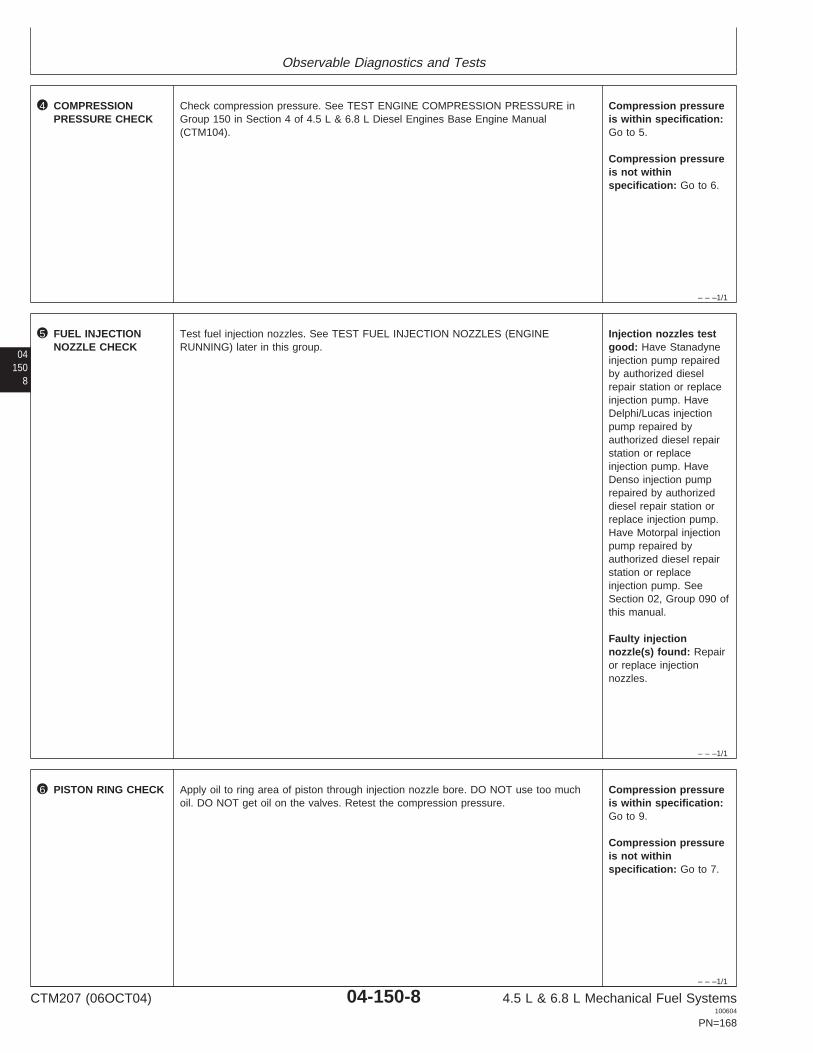
Observable Diagnostics and Tests
– – –1/1
4 COMPRESSIONPRESSURE CHECK
Check compression pressure. See TEST ENGINE COMPRESSION PRESSURE inGroup 150 in Section 4 of 4.5 L & 6.8 L Diesel Engines Base Engine Manual(CTM104).
Compression pressureis within specification:Go to 5.
Compression pressureis not withinspecification: Go to 6.
04150
8
– – –1/1
5 FUEL INJECTIONNOZZLE CHECK
Test fuel injection nozzles. See TEST FUEL INJECTION NOZZLES (ENGINERUNNING) later in this group.
Injection nozzles testgood: Have Stanadyneinjection pump repairedby authorized dieselrepair station or replaceinjection pump. HaveDelphi/Lucas injectionpump repaired byauthorized diesel repairstation or replaceinjection pump. HaveDenso injection pumprepaired by authorizeddiesel repair station orreplace injection pump.Have Motorpal injectionpump repaired byauthorized diesel repairstation or replaceinjection pump. SeeSection 02, Group 090 ofthis manual.
Faulty injectionnozzle(s) found: Repairor replace injectionnozzles.
– – –1/1
6 PISTON RING CHECK Apply oil to ring area of piston through injection nozzle bore. DO NOT use too muchoil. DO NOT get oil on the valves. Retest the compression pressure.
Compression pressureis within specification:Go to 9.
Compression pressureis not withinspecification: Go to 7.
CTM207 (06OCT04) 04-150-8 4.5 L & 6.8 L Mechanical Fuel Systems100604
PN=168

Observable Diagnostics and Tests
– – –1/1
7 VALVE LASH CHECK Check valve lash. See CHECK AND ADJUST VALVE CLEARANCE in Group 020 inSection 2 of 4.5 L & 6.8 L Diesel Engines Base Engine Manual (CTM104).
Valve lash is withinspecification: Go to 8.
Valve lash on one ormore valves out ofspecification: Adjustvalve lash and retest.
041509
– – –1/1
8 VALVE LIFT CHECK Check valve lift. See MEASURE VALVE LIFT in Group 020 in Section 2 of 4.5 L & 6.8L Diesel Engines Base Engine Manual (CTM104).
Lift on all valves withinspecification: Go to 9.
Valve lift on one ormore valves is out ofspecification: Resetclearance to specificationafter measuring lift. SeeCHECK AND ADJUSTVALVE CLEARANCE inGroup 020 in Section 2 of4.5 L & 6.8 L DieselEngines Base EngineManual (CTM104).
– – –1/1
9 PISTONS, RINGS,CYLINDER LINERSCHECK
At this point, the most likely cause of the low engine compression pressure is one ofthe following failures in the pistons, rings, and/or cylinder liners or in the valve guides.Check the most likely items as needed.
• Oil control rings worn or broken• Scored cylinder liners or pistons• Piston ring grooves excessively worn• Piston rings sticking in ring grooves• Insufficient piston ring tension• Piston ring gaps not staggered• Cylinder liners glazed (insufficient load during engine break-in)• Worn valve guides or stems• Cylinder head may need reconditioning
Problem found withpistons, rings, and/orliners or valve guides:Repair problem asnecessary.
CTM207 (06OCT04) 04-150-9 4.5 L & 6.8 L Mechanical Fuel Systems100604
PN=169
Observable Diagnostics and Tests
RG40854,0000002 –19–19AUG04–1/1
E3—Engine Does Not Develop Full Power
04150
10
CTM207 (06OCT04) 04-150-10 4.5 L & 6.8 L Mechanical Fuel Systems100604
PN=170

Observable Diagnostics and Tests
– – –1/1
E3—Engine Does Not Develop Full Power Diagnostic Procedure
NOTE: This procedure applies to engines using mechanical fuel systems. For engines using electronic fuelsystems, refer to the manual that corresponds to the ECU being used.
Before using this diagnostic procedure:
Ensure fuel quantity and quality are OK. See CHECK FUEL SUPPLY QUALITY later in this group.
Check for restricted or plugged air filter.
0415011
– – –1/1
1 EXHAUST EMISSIONCHECK
Operate engine at full load rated speed. Under these conditions, determine type ofexhaust emitted.
Small amount or nosmoke: Go to 2.
Heavy white exhaustsmoke: Go to E4—ENGINE EMITSEXCESSIVE WHITEEXHAUST SMOKEdiagnostic procedure laterin this group.
Heavy gray or blackexhaust smoke: Go toE5—ENGINE EMITSEXCESSIVE BLACK ORGRAY EXHAUSTSMOKE diagnosticprocedure later in thisgroup.
– – –1/1
2 POWER ANDRESPONSE TEST
Run engine through different loads at multiple speeds. Check for low power at eachrange and responsiveness to the increase in speeds.
Engine does notdevelop full power: Goto 5.
Engine does notaccelerate satisfactorily:Go to 3.
– – –1/1
3 THROTTLE CABLEBINDING CHECK
Check throttle cable for any binding that could restrict the movement of the cable. Throttle cable is OK: Goto 4.
Throttle cable is bound:Repair or replace throttlecable and retest.
CTM207 (06OCT04) 04-150-11 4.5 L & 6.8 L Mechanical Fuel Systems100604
PN=171

Observable Diagnostics and Tests
– – –1/1
4 FAST IDLE CHECK In-Line Injection Pumps:
Check fast idle speed. See CHECK AND ADJUST FAST IDLE SPEED—DENSO ANDMOTORPAL FUEL INJECTION PUMP later in this group.
Rotary Injection Pumps:
Check fast idle speed. See CHECK AND ADJUST ENGINE SPEEDS ON ADELPHI/LUCAS PUMP or CHECK AND ADJUST ENGINE SPEEDS ON STANADYNEPUMP
Fast idle is withinspecification: Go to 5.
Fast idle is belowspecification: Contactyour authorized dieselrepair station.
04150
12
– – –1/1
5 TURBOCHARGERBOOST PRESSURECHECK
Check turbo boost pressure. See MEASURE INTAKE MANIFOLD PRESSURE(TURBO BOOST) in Group 150 in Section 4 of 4.5 L & 6.8 L Diesel Engines BaseEngine Manual (CTM104).
Pressure withinspecification: Go to 6.
Pressure belowspecification: Go to 7.
– – –1/1
6 EXCESSIVEPARASITIC LOADCHECK
At this point it appears that the engine is producing the correct power. The low powercomplaint is most likely a result of excessive parasitic load on the engine. Theexcessive load could be caused by incorrect vehicle ballasting, faulty hydraulic pump,faulty transmission, etc. Investigate problems associated with excessive parasitic load.
Excessive parasitic loadfound: Repair cause ofexcessive load and retest.
– – –1/1
7 FUEL SUPPLYSYSTEM CHECK
Perform fuel supply system check. See F1—FUEL SUPPLY SYSTEM CHECK later inthis group.
No problem found: Goto 8.
Problem found: Nofurther analysis isnecessary.
– – –1/1
8 FUEL RETURN LINECHECK
Check for restricted fuel return line and fittings. See CHECK FOR RESTRICTED FUELRETURN LINE later in this group.
Return line and fittingOK: Go to 9.
Return line and fittingrestricted: Repair orreplace return line and/orfitting.
– – –1/1
9 INTAKE ANDEXHAUSTRESTRICTION OR AIRLEAK CHECK
Check for intake and exhaust restrictions and air leaks. See CHECK FOR INTAKEAND EXHAUST RESTRICTIONS and TEST FOR INTAKE AIR LEAKS and CHECKFOR EXHAUST AIR LEAKS (TURBOCHARGED ENGINES) in Group 150 in Section 4of 4.5 L & 6.8 L Diesel Engines Base Engine Manual (CTM104).
No restrictions or leaksfound: Go to 10.
Restrictions or leaksfound: Repair or replacecomponents as needed.
CTM207 (06OCT04) 04-150-12 4.5 L & 6.8 L Mechanical Fuel Systems100604
PN=172

Observable Diagnostics and Tests
– – –1/1
10 INJECTION PUMPTIMING CHECK
Rotary Injection Pumps: See CHECK AND ADJUST ROTARY INJECTION PUMPDYNAMIC TIMING later in this group.
In-Line Injection Pumps: See CHECK AND ADJUST IN-LINE INJECTION PUMPSTATIC TIMING later in this group.
Timing is correct: Go to11.
Timing is not correct:Follow adjustmentprocedure in timing checkprocedure.
0415013
– – –1/1
11 TURBOCHARGERFAILURE CHECK
Check for turbocharger failures. See TURBOCHARGER SEVEN-STEP INSPECTIONin Group 080 in Section 2 of 4.5 L & 6.8 L Diesel Engines Base Engine Manual(CTM104).
No turbochargerfailures found: Go to 12.
Failures are found:Follow appropriate repairprocedure in Group 080in Section 2 of 4.5 L &6.8 L Diesel EnginesBase Engine Manual(CTM104).
– – –1/1
12 VALVE CLEARANCECHECK
Check valve clearance. See CHECK AND ADJUST VALVE CLEARANCE in Group020 in Section 2 of 4.5 L & 6.8 L Diesel Engines Base Engine Manual (CTM104).
Valve clearance on allvalves withinspecification: Go to 13.
Valve clearance on oneor more valves out ofspecification: Adjustvalve clearance andretest.
CTM207 (06OCT04) 04-150-13 4.5 L & 6.8 L Mechanical Fuel Systems100604
PN=173

Observable Diagnostics and Tests
04150
14
– – –1/1
13 FUEL INJECTIONNOZZLE CHECK
Test fuel injection nozzles. See TEST FUEL INJECTION NOZZLES (ENGINERUNNING) later in this group.
Injection nozzles testgood: Have Stanadyneinjection pump repairedby authorized dieselrepair station or replaceinjection pump. HaveDelphi/Lucas injectionpump repaired byauthorized diesel repairstation or replaceinjection pump. HaveDenso injection pumprepaired by authorizeddiesel repair station orreplace injection pump.Have Motorpal injectionpump repaired byauthorized diesel repairstation or replaceinjection pump. SeeSection 02, Group 090 ofthis manual.
Faulty injectionnozzle(s) found: Repairor replace injectionnozzles.
CTM207 (06OCT04) 04-150-14 4.5 L & 6.8 L Mechanical Fuel Systems100604
PN=174

Observable Diagnostics and Tests
RG40854,0000003 –19–19AUG04–1/1
E4—Engine Emits Excessive White ExhaustSmoke
0415015
CTM207 (06OCT04) 04-150-15 4.5 L & 6.8 L Mechanical Fuel Systems100604
PN=175

Observable Diagnostics and Tests
04150
16
– – –1/1
E4—Engine Emits Excessive White Exhaust Smoke Diagnostic Procedure
NOTE: This procedure applies to engines using mechanical fuel systems. For engines using electronic fuelsystems, refer to the manual that corresponds to the ECU being used.
NOTE: This procedure should be used if the engine emits excessive white exhaust smoke. This type of exhaustsmoke causes a burning sensation to the eyes. If engine emits a less heavy, bluish exhaust smoke Go to L1—EXCESSIVE OIL CONSUMPTION diagnostic procedure in Group 150 in Section 4 of 4.5 L & 6.8 L Diesel EnginesBase Engine Manual (CTM104).
Before using this diagnostic procedure:
Ensure fuel quantity and quality are OK. See CHECK FUEL SUPPLY QUALITY later in this group.
Ensure engine coolant temperature isn’t extremely low.
– – –1/1
1 FAILED HEADGASKET CHECK
Check for failed head gasket. See CHECK FOR HEAD GASKET FAILURES in Group150 in Section 4 of 4.5 L & 6.8 L Diesel Engines Base Engine Manual (CTM104).
No sign of head gasketfailure: Go to 2.
Sign of head gasketfailures are found: SeeHEAD GASKETINSPECTION ANDREPAIR SEQUENCE inGroup 030 in Section 2 of4.5 L & 6.8 L DieselEngines Base EngineManual (CTM104).
– – –1/1
2 INJECTION PUMPTIMING CHECK
Rotary Injection Pumps: See CHECK AND ADJUST ROTARY INJECTION PUMPDYNAMIC TIMING later in this group.
In-Line Injection Pumps: See CHECK AND ADJUST IN-LINE INJECTION PUMPSTATIC TIMING later in this group.
Timing is correct: Go to3.
Timing is incorrect:Follow adjustmentprocedure in timing checkprocedure.
CTM207 (06OCT04) 04-150-16 4.5 L & 6.8 L Mechanical Fuel Systems100604
PN=176

Observable Diagnostics and Tests
– – –1/1
3 COMPRESSIONPRESSURE CHECK
Check compression pressure. See TEST ENGINE COMPRESSION PRESSURE inGroup 150 in Section 4 of 4.5 L & 6.8 L Diesel Engines Base Engine Manual(CTM104).
Compression pressureis within specification:Go to 4.
Compression pressureis not withinspecification: Go to 5.
0415017
– – –1/1
4 FUEL INJECTIONNOZZLE CHECK
Test fuel injection nozzles. See TEST FUEL INJECTION NOZZLES (ENGINERUNNING) later in this group.
Injection nozzles testgood: Have Stanadyneinjection pump repairedby authorized dieselrepair station or replaceinjection pump. HaveDelphi/Lucas injectionpump repaired byauthorized diesel repairstation or replaceinjection pump. HaveDenso injection pumprepaired by authorizeddiesel repair station orreplace injection pump.Have Motorpal injectionpump repaired byauthorized diesel repairstation or replaceinjection pump. SeeSection 02, Group 090 ofthis manual.
Faulty injectionnozzle(s) found: Repairor replace injectionnozzles.
– – –1/1
5 PISTONS, RINGS,CYLINDER LINERSCHECK
At this point, the most likely cause of the low engine compression pressure is one ofthe following failures in the pistons, rings, and/or cylinder liners or in the valve guides.Check the most likely items as needed.
• Oil control rings worn or broken• Scored cylinder liners or pistons• Piston ring grooves excessively worn• Piston rings sticking in ring grooves• Insufficient piston ring tension• Piston ring gaps not staggered• Cylinder liners glazed (insufficient load during engine break-in)• Worn valve guides or stems• Cylinder head may need reconditioning
Problem found withpistons, rings, and/orliners or valve guides:Repair problem asnecessary.
CTM207 (06OCT04) 04-150-17 4.5 L & 6.8 L Mechanical Fuel Systems100604
PN=177

Observable Diagnostics and Tests
RG40854,0000004 –19–19AUG04–1/1
E5—Engine Emits Excessive Black or GrayExhaust Smoke
04150
18
CTM207 (06OCT04) 04-150-18 4.5 L & 6.8 L Mechanical Fuel Systems100604
PN=178

Observable Diagnostics and Tests
0415019
– – –1/1
E5—Engine Emits Excessive Black or Gray Exhaust Smoke Diagnostic Procedure
NOTE: This procedure applies to engines using mechanical fuel systems. For engines using electronic fuelsystems, refer to the manual that corresponds to the ECU being used.
NOTE: This procedure should be used if the engine emits excessive black or gray exhaust smoke. If engine emitsa less heavy, bluish exhaust smoke Go to L1—EXCESSIVE OIL CONSUMPTION diagnostic procedure in Group150 in Section 4 of 4.5 L & 6.8 L Diesel Engines Base Engine Manual (CTM104).
Before using this diagnostic procedure:
Ensure fuel quantity and quality are OK. See CHECK FUEL SUPPLY QUALITY later in this group.
Ensure engine is not excessively loaded.
Ensure air filter is not restricted or plugged.
– – –1/1
1 INTAKE ANDEXHAUSTRESTRICTION OR AIRLEAK CHECK
Check for intake and exhaust restrictions and air leaks. See CHECK FOR INTAKEAND EXHAUST RESTRICTIONS, TEST FOR INTAKE AIR LEAKS, and CHECK FOREXHAUST AIR LEAK (TURBOCHARGED ENGINES) in Group 150 in Section 4 of 4.5L & 6.8 L Diesel Engines Base Engine Manual (CTM104).
No restrictions or leaksfound: Go to 2.
Restrictions or leaksfound: Repair andreplace components asneeded.
– – –1/1
2 INJECTION PUMPTIMING CHECK
Rotary Injection Pumps: See CHECK AND ADJUST ROTARY INJECTION PUMPDYNAMIC TIMING later in this group.
In-Line Injection Pumps: See CHECK AND ADJUST IN-LINE INJECTION PUMPSTATIC TIMING later in this group.
Timing is correct: Go to3.
Timing is not correct:Follow adjustmentprocedure in timing checkprocedure.
CTM207 (06OCT04) 04-150-19 4.5 L & 6.8 L Mechanical Fuel Systems100604
PN=179

Observable Diagnostics and Tests
– – –1/1
3 TURBOCHARGERFAILURE CHECK
Check for turbocharger failure. See TURBOCHARGER SEVEN-STEP INSPECTION inGroup 080 in Section 2 of 4.5 L & 6.8 L Diesel Engines Base Engine Manual(CTM104).
No turbocharger failurefound: Go to 4.
Failures are found:Follow appropriate repairprocedure in Group 080in Section 2 of 4.5 L &6.8 L Diesel EnginesBase Engine Manual(CTM104).
04150
20
– – –1/1
4 VALVE CLEARANCECHECK
Check valve clearance. See CHECK AND ADJUST VALVE CLEARANCE in Group020 in Section 2 of 4.5 L & 6.8 L Diesel Engines Base Engine Manual (CTM104).
Valve clearance on allvalves withinspecification: Go to 5.
Valve clearance on oneor more valves out ofspecification: Adjustvalve clearance andretest.
– – –1/1
5 FUEL RETURN LINECHECK
Check for restricted fuel return line and fitting. See CHECK FOR RESTRICTED FUELRETURN LINE later in this group.
Return line and fittingOK: Go to 6.
Return line and fittingrestricted: Repair orreplace return line and/orfitting.
CTM207 (06OCT04) 04-150-20 4.5 L & 6.8 L Mechanical Fuel Systems100604
PN=180

Observable Diagnostics and Tests
0415021
– – –1/1
6 FUEL INJECTIONNOZZLE CHECK
Test fuel injection nozzles. See TEST FUEL INJECTION NOZZLES (ENGINERUNNING) later in this group.
Injection nozzles testgood: Have Stanadyneinjection pump repairedby authorized dieselrepair station or replaceinjection pump. HaveDelphi/Lucas injectionpump repaired byauthorized diesel repairstation or replaceinjection pump. HaveDenso injection pumprepaired by authorizeddiesel repair station orreplace injection pump.Have Motorpal injectionpump repaired byauthorized diesel repairstation or replaceinjection pump. SeeSection 02, Group 090 ofthis manual.
Faulty injectionnozzle(s) found: Repairor replace injectionnozzles.
CTM207 (06OCT04) 04-150-21 4.5 L & 6.8 L Mechanical Fuel Systems100604
PN=181

Observable Diagnostics and Tests
04150
22
DPSG,RG41221,26 –19–19AUG04–1/1
E6—Engine Will Not Crank
Symptom Problem Solution
E6—Engine Will Not Crank Weak battery Replace battery.
Corroded or loose battery Clean battery terminals andconnections connections.
Defective main switch or start safety Repair switch as required.switch
Starter solenoid defective Replace solenoid.
Starter defective Replace starter.
DPSG,RG41221,37 –19–19AUG04–1/1
E7—Engine Idles Poorly
Symptom Problem Solution
E7—Engine Idles Poorly Poor fuel quality Drain fuel and replace with qualityfuel of the proper grade.
Air leak on suction side of air intake Check hose and pipe connectionssystem for tightness; repair as required. See
AIR INTAKE AND EXHAUSTSYSTEM SPECIFICATIONS inGroup 080 in Section 2 of 4.5 L &6.8 L Diesel Engines Base EngineManual (CTM104).
Electronic control system problem or See E2—ENGINE MISFIRES/RUNSbasic engine problem IRREGULARLY earlier in this group.
CTM207 (06OCT04) 04-150-22 4.5 L & 6.8 L Mechanical Fuel Systems100604
PN=182

Observable Diagnostics and Tests
0415023
DPSG,RG41221,36 –19–19AUG04–1/2
E8—Abnormal Engine Noise
Symptom Problem Solution
E8—Abnormal Engine Noise Worn main or connecting rod Determine bearing clearance. Seebearings INSPECT AND MEASURE
CONNECTING ROD BEARINGS(ROD AND CRANKSHAFT INENGINE) or CHECK MAINBEARING OIL CLEARANCE inGroup 030 in Section 2 of 4.5 L &6.8 L Diesel Engines Base EngineManual (CTM104).
Excessive crankshaft end play Check crankshaft end play. SeeCHECK CRANKSHAFT END PLAYin Group 040 in Section 2 of 4.5 L &6.8 L Diesel Engines Base EngineManual (CTM104).
Loose main bearing caps Check bearing clearance; replacebearings and bearing cap screws asrequired. See CHECK MAINBEARING OIL CLEARANCE inGroup 030 of Section 2 of 4.5 L &6.8 L Diesel Engines Base EngineManual (CTM104).
Worn connecting rod bushings and Inspect piston pins and bushings.piston pins See INSPECT PISTON PINS AND
BUSHINGS in Group 030 in Section2 of 4.5 L & 6.8 L Diesel EnginesBase Engine Manual (CTM104).
Scored pistons Inspect pistons. See PRELIMINARYLINER, PISTON, AND RODCHECKS in Group 030 in Section 2of 4.5 L & 6.8 L Diesel EnginesBase Engine Manual (CTM104).
Worn timing gears or excess back Check timing gear backlash. Seelash MEASURE TIMING GEAR
BACKLASH in Group 050 in Section2 of 4.5 L & 6.8 L Diesel EnginesBase Engine Manual (CTM104).
CTM207 (06OCT04) 04-150-23 4.5 L & 6.8 L Mechanical Fuel Systems100604
PN=183
Continued on next page

Observable Diagnostics and Tests
04150
24
DPSG,RG41221,36 –19–19AUG04–2/2
Symptom Problem Solution
Abnormal Engine Noise— Excessive valve clearance Check and adjust valve clearance.Continued See CHECK AND ADJUST VALVE
CLEARANCE in Group 020 inSection 2 of 4.5 L & 6.8 L DieselEngines Base Engine Manual(CTM104).
Worn camshaft Inspect camshaft. See VISUALLYINSPECT CAMSHAFT in Group 040in Section 2 of 4.5 L & 6.8 L DieselEngines Base Engine Manual(CTM104).
Worn rocker arm shaft(s) Inspect rocker arm shafts. SeeDISASSEMBLE AND INSPECTROCKER ARM SHAFT ASSEMBLYin Group 020 in Section 2 of 4.5 L &6.8 L Diesel Engines Base EngineManual (CTM104).
Insufficient engine lubrication See L2—ENGINE OIL PRESSURELOW in Group 150 in Section 4 of4.5 L & 6.8 L Diesel Engines BaseEngine Manual (CTM104).
Turbocharger noise See TURBOCHARGERSEVEN-STEP INSPECTION inGroup 080 in Section 2 of 4.5 L &6.8 L Diesel Engines Base EngineManual (CTM104).
CTM207 (06OCT04) 04-150-24 4.5 L & 6.8 L Mechanical Fuel Systems100604
PN=184

Observable Diagnostics and Tests
DPSG,OUOE003,2770 –19–19AUG04–1/1
F1—Fuel Supply System Check
0415025
– – –1/1
F1—Fuel Supply System Check
NOTE: This procedure applies to engines using mechanical fuel systems. For engines using electronic fuelsystems, refer to the manual that corresponds to the ECU being used. This procedure should be used if problemhas been diagnosed to be a fuel problem.
Before using this diagnostic procedure:
Ensure fuel quantity and quality are OK. See CHECK FUEL SUPPLY QUALITY later in this group.
Inspect all fuel lines and fittings for ruptures or leaks.
If fuel system has recently been opened, bleed fuel system. See BLEED THE FUEL SYSTEM later in this group.
– – –1/1
1 AIR IN FUEL CHECK Check for air in the fuel. See TEST AIR IN FUEL later in this group. No air found in fuelsystem: Go to 2.
Air found in fuelsystem: Bleed fuelsystem. See BLEED THEFUEL SYSTEM later inthis group.
– – –1/1
2 FUEL SUPPLYPRESSURE CHECK
Rotary Injection Pumps:
Check fuel supply pressure for rotary injection pumps. See MEASURE FUEL SUPPLYPUMP PRESSURE—ROTARY INJECTION PUMP later in this group.
In-Line Injection Pumps:
Check fuel supply pressure for in-line injection pumps. See MEASURE FUEL SUPPLYPUMP PRESSURE—IN-LINE INJECTION PUMP later in this group.
Pressure withinspecification: Go to 6.
Pressure is belowspecification: Go to 3.
CTM207 (06OCT04) 04-150-25 4.5 L & 6.8 L Mechanical Fuel Systems100604
PN=185

Observable Diagnostics and Tests
– – –1/1
3 FUEL FILTER TEST 1. Replace final fuel filter and retest.
2. Replace primary fuel filter (if equipped) and retest.
Problem solved: Nofurther investigating isneeded.
Problem still exists: Goto 4.
– – –1/1
4 FUEL SUPPLY LINESCHECK
Remove fuel supply lines and determine if there are any internal restrictions. No restrictions found:Go to 5.
Restrictions found:Repair or replacecomponents as needed.
04150
26
– – –1/1
5 FUEL SUPPLY PUMPCHECK
At this point, the most likely cause for low fuel pressure is one of the following failuresin the fuel supply pump. Check the most likely items as needed.
IMPORTANT: Visually inspect the fuel inlet fitting and pump filter for possibleplugging before disassembling pump to determine cause of malfunction.
In-Line Injection Pumps:
• Test fuel supply pump for in-line injection pump leaks. See CHECK FUEL SUPPLYPUMP OPERATION—IN-LINE INJECTION PUMP or TEST FUEL SUPPLY PUMPFOR LEAKS—IN-LINE INJECTION PUMP later in this group.
• Hand primer not screwed down tight, allowing dirt to enter hand primer plungerchamber.
• Worn or pitted valves.• Missing or broken spring(s).• Hand primer lever left in upward position.
Rotary Injection Pumps:
• Loose or damaged fuel line connections.• Hand primer lever left in upward position.
No supply pumpproblems found: Go to6.
Supply pump problemsfound: Refer to Section02, Group 090 of thismanual for repair.
– – –1/1
6 RETURN FUELCHECK
1. Disconnect fuel line from injection pump overflow valve.
2. Loosen overflow valve from injection pump.
3. Turn ignition switch to “ON” position.
4. Operate hand primer on fuel supply pump until fuel flows out the overflow valvefitting location. If fuel flow out the hole cannot be obtained, retighten all fittings.
Good fuel flow out ofloose overflow valve,but engine still doesn’tstart: Go to 7.
NOT good fuel flow orno flow out of looseoverflow valve: Go to 8.
CTM207 (06OCT04) 04-150-26 4.5 L & 6.8 L Mechanical Fuel Systems100604
PN=186

Observable Diagnostics and Tests
0415027
– – –1/1
7 FUEL DELIVERY LINECHECK
Perform the following steps to determine if fuel delivery lines are restricted:
1. Disconnect the suspected fuel delivery line on the injection nozzle end and injectionpump end.
2. Force air through one end of the delivery line.
3. If the delivery line is not restricted, the compressed air should flow freely out theother side.
4. If air does not flow freely, there are restrictions in the fuel line.
Lines are not restricted:Have Stanadyne injectionpump repaired byauthorized diesel repairstation or replaceinjection pump. HaveDelphi/Lucas injectionpump repaired byauthorized diesel repairstation or replaceinjection pump. HaveDenso injection pumprepaired by authorizeddiesel repair station orreplace injection pump.Have Motorpal injectionpump repaired byauthorized diesel repairstation or replaceinjection pump. SeeSection 02, Group 090 ofthis manual.
Lines are restricted:Repair or replace linesand retest.
– – –1/1
8 RESTRICTEDPRE-INJECTION FUELLINE CHECK
This check will help determine if the pre-injection fuel line is restricted.
• Disconnect fuel line from the final filter.• Disconnect fuel line from injection pump.• Force air through the fuel line.• If the fuel line is not restricted, the compressed air should freely flow out the other
side.• If air does not flow freely, there are restrictions in the fuel line.
No restrictions found:Go to 9.
Restrictions found:Repair or replacecomponents as needed.
– – –1/1
9 FUEL INJECTIONPUMP CHECK
NOTE: If you are here because engine does not develop full power, return to E3 -ENGINE DOES NOT DEVELOP FULL POWER earlier in this group and proceed withdiagnostics.
Have Stanadyne injection pump repaired by authorized diesel repair station or replaceinjection pump. Have Delphi/Lucas injection pump repaired by authorized diesel repairstation or replace injection pump. Have Denso injection pump repaired by authorizeddiesel repair station or replace injection pump. Have Motorpal injection pump repairedby authorized diesel repair station or replace injection pump. See Section 02, Group090 of this manual.
CTM207 (06OCT04) 04-150-27 4.5 L & 6.8 L Mechanical Fuel Systems100604
PN=187

Observable Diagnostics and Tests
04150
28
DPSG,RG41221,25 –19–25APR01–1/1
F2—Excessive Fuel Consumption
Symptom Problem Solution
F2—Excessive Fuel Consumption Poor fuel quality Drain fuel and replace with qualityfuel of the proper grade.
Engine overloaded Reduce engine load.
Air cleaner restricted or dirty Replace air cleaner element asrequired.
Compression too low Determine cause of low compressionand repair as required.
Leaks in fuel supply system Locate source of leak and repair asrequired.
DPSG,RG41221,38 –19–25APR01–1/1
F3—Fuel in Oil
Symptom Problem Solution
F3—Fuel In Oil Cracked cylinder head Locate crack, repair/replacecomponents as required.
CTM207 (06OCT04) 04-150-28 4.5 L & 6.8 L Mechanical Fuel Systems100604
PN=188

Observable Diagnostics and Tests
0415029
DPSG,RG40854,23 –19–25NOV98–1/1
Cylinder Misfire Test (Engine Running)
CAUTION: Escaping fluid under pressure canpenetrate the skin causing serious injury. Keephands and body away from pinholes andnozzles which could inject fluids under highpressure.
If ANY fluid is injected into the skin, it must besurgically removed within a few hours by adoctor familiar with this type of injury organgrene may result. Doctors unfamiliar withthis type of injury may call the Deere &Company Medical Department in Moline, Illinois,or other knowledgeable medical source.
1. Operate engine at intermediate speed with no load.
2. Place a shop towel around nozzle-to-line connection toabsorb escaping fuel.
3. Slowly loosen the fuel pressure line at one of thenozzles until fuel escapes at the connection (fuel notopening nozzle valve).
• If engine speed changes, the cylinder is probablyworking satisfactorily.
• If engine speed does not change, a cylinder is faulty.
4. Repeat test for each remaining cylinder.
5. Tighten fuel lines to specifications.
Cylinder Misfire Test (Engine Running)—SpecificationFuel Injection Nozzle DeliveryLine—Torque 27 N•m (20 lb-ft)...................................................................
CTM207 (06OCT04) 04-150-29 4.5 L & 6.8 L Mechanical Fuel Systems100604
PN=189

Observable Diagnostics and Tests
04150
30
DPSG,OUO1004,115 –19–20APR00–1/1
Using TIME TRAC as a Tachometer
RG
1072
5–U
N–2
0AP
R00
Transducer
A—JT07177 6 mm (Green) Clamp-On TransducerB—Fuel Injection Delivery LineC—JT07172 Transducer CableD—No. 1 Injector
The TIME TRAC meter can be used as a tachometer byusing clamp-on transducer JT07177 (A) at nozzle end ofany high-pressure fuel injection line.
1. Remove paint and thoroughly clean the area of thehigh-pressure line to which the clamp-on transducer isto be attached.
2. Install transducer (A) on high-pressure fuel delivery line(B) close to No. 1 injector and connect JT07172 cable(C) between transducer and JT07170 meter portmarked “SR”.
3. Switch on meter and start the engine to measure andrecord engine speed.
TIME TRAC is a registered trademark of Stanadyne Automotive Corp.
DPSG,OUO1004,2683 –19–20APR00–1/9
Check and Adjust Rotary Injection PumpDynamic Timing
RG
7246
–UN
–23N
OV
97
TIME TRAC Kit
The JT07158 (or FKM10429A) TIME TRAC Kitelectronically indicates start of injection with respect topiston top dead center (TDC), and allows accurate settingof injection pump timing to provide optimum power,smoke, and exhaust emissions.
Timing engines with this timing kit improves consistencybetween engines and helps to control cylinder firingpressures which can be a factor in head gasket failures aswell as improve overall engine performance efficiencies.
TIME TRAC is a registered trademark of Stanadyne Automotive Corp.
CTM207 (06OCT04) 04-150-30 4.5 L & 6.8 L Mechanical Fuel Systems100604
PN=190
Continued on next page
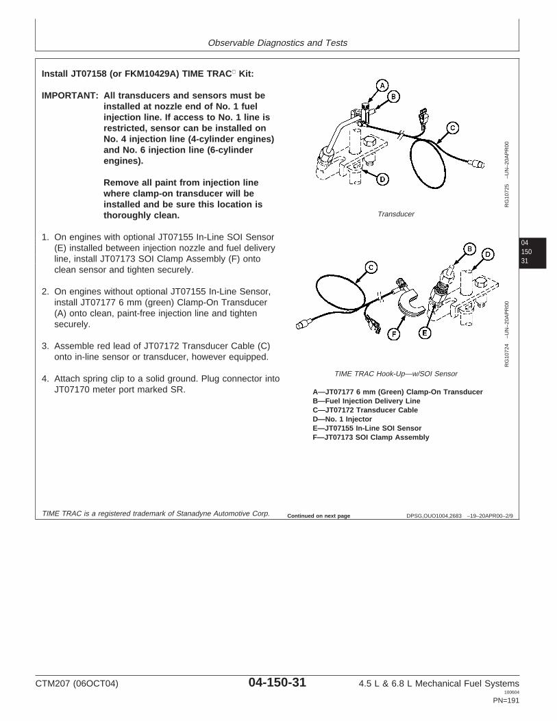
Observable Diagnostics and Tests
0415031
DPSG,OUO1004,2683 –19–20APR00–2/9
RG
1072
5–U
N–2
0AP
R00
Transducer
RG
1072
4–U
N–2
0AP
R00
TIME TRAC Hook-Up—w/SOI Sensor
A—JT07177 6 mm (Green) Clamp-On TransducerB—Fuel Injection Delivery LineC—JT07172 Transducer CableD—No. 1 InjectorE—JT07155 In-Line SOI SensorF—JT07173 SOI Clamp Assembly
Install JT07158 (or FKM10429A) TIME TRAC Kit:
IMPORTANT: All transducers and sensors must beinstalled at nozzle end of No. 1 fuelinjection line. If access to No. 1 line isrestricted, sensor can be installed onNo. 4 injection line (4-cylinder engines)and No. 6 injection line (6-cylinderengines).
Remove all paint from injection linewhere clamp-on transducer will beinstalled and be sure this location isthoroughly clean.
1. On engines with optional JT07155 In-Line SOI Sensor(E) installed between injection nozzle and fuel deliveryline, install JT07173 SOI Clamp Assembly (F) ontoclean sensor and tighten securely.
2. On engines without optional JT07155 In-Line Sensor,install JT07177 6 mm (green) Clamp-On Transducer(A) onto clean, paint-free injection line and tightensecurely.
3. Assemble red lead of JT07172 Transducer Cable (C)onto in-line sensor or transducer, however equipped.
4. Attach spring clip to a solid ground. Plug connector intoJT07170 meter port marked SR.
TIME TRAC is a registered trademark of Stanadyne Automotive Corp. Continued on next page
CTM207 (06OCT04) 04-150-31 4.5 L & 6.8 L Mechanical Fuel Systems100604
PN=191

Observable Diagnostics and Tests
04150
32
DPSG,OUO1004,2683 –19–20APR00–3/9
RG
7287
–UN
–03N
OV
97
Magnetic Pick-Up in Timing Hole
A—Magnetic Pick-UpB—JDG793 Threaded Magnetic Pick-Up AdapterC—JDG821 Tapered Magnetic Pick-Up AdapterD—Flywheel Timing Hole
5. Use JDE81-4 or JDG1571 Timing Pin in flywheeltiming hole (D) to ensure engine is NOT stopped atTDC. Magnetic pick-up probe will enter TDC timinghole in flywheel and be damaged when engine isstarted. An air gap of 0.64 mm (0.025 in.) isrecommended between tip of probe and flywheel face.
6. Install JDG793 Threaded Magnetic Pick-Up Adapter(B) into flywheel housings with tapped hole until itbottoms. Insert probe of magnetic pick-up (A) intoadapter until it contacts flywheel. Back out hex head ofadapter two flats and tighten lock nut; this will providerecommended air gap.
7. Install JDG821 Tapered Magnetic Pick-Up Adapter (C)into flywheel housings without tapped hole. Lightly tapadapter to lock into position. Insert probe into adapteruntil it contacts the flywheel. Pull probe back out toprovide 0.64 mm (0.025 in.) gap.
8. Plug magnetic pick-up connector into JT07170 meterport marked MP.
DPSG,OUO1004,2683 –19–20APR00–4/9
RG
7031
–UN
–27S
EP
94
TIME TRACDisplay Shows R=0
Check Rotary Injection Pump Rated Load DynamicTiming:
1. Engine OFF. Push ON/CLEAR button.
Display shows: R=0
Continued on next page
CTM207 (06OCT04) 04-150-32 4.5 L & 6.8 L Mechanical Fuel Systems100604
PN=192

Observable Diagnostics and Tests
0415033
DPSG,OUO1004,2683 –19–20APR00–5/9
RG
7032
–UN
–27S
EP
94
TIME TRACDisplay Shows Trig Level: 70%
2. Push MAG PROBE button.
Display shows: Trig Level: 30%
3. Change to 70% and push ENTER.
DPSG,OUO1004,2683 –19–20APR00–6/9R
G70
33–U
N–2
7SE
P94
TIME TRACDisplay Shows Offset: 0.0
4. Display shows: Offset: 20.0°
Change to offset 0° and push ENTER.
Continued on next page
CTM207 (06OCT04) 04-150-33 4.5 L & 6.8 L Mechanical Fuel Systems100604
PN=193
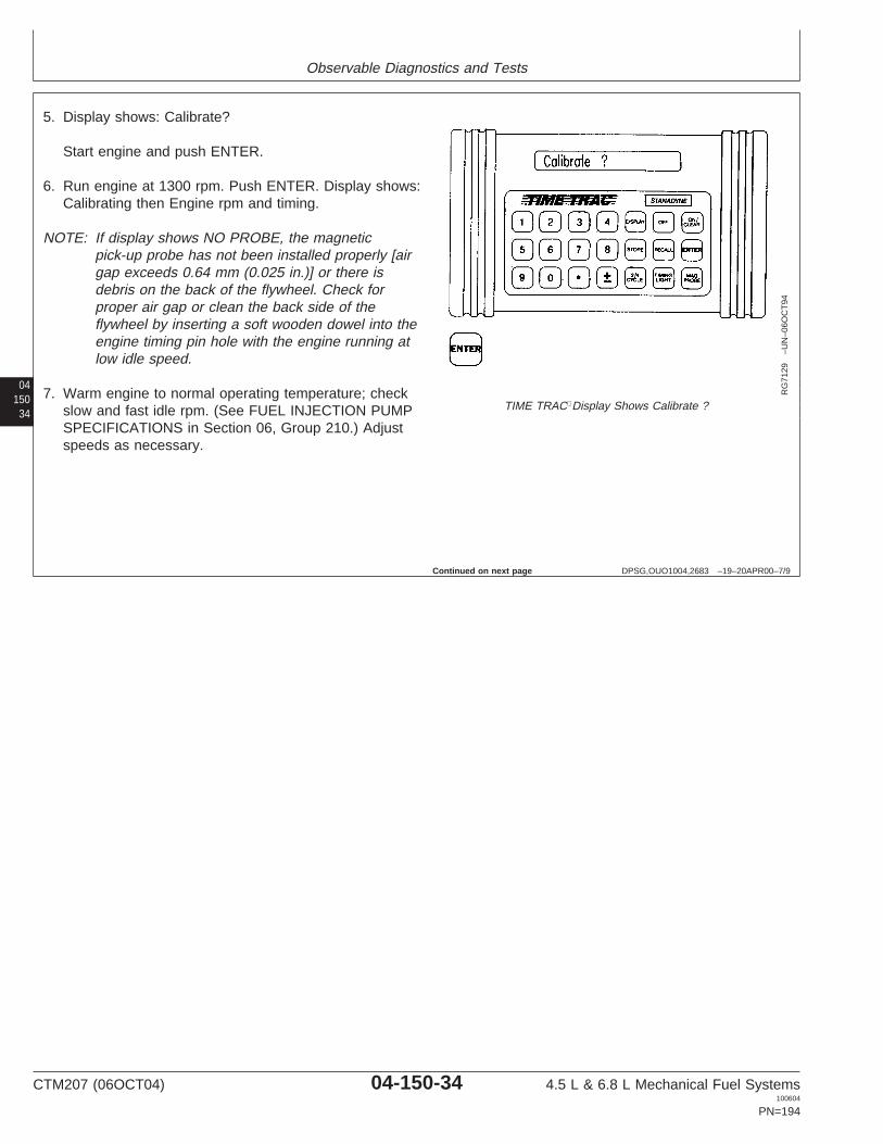
Observable Diagnostics and Tests
04150
34
DPSG,OUO1004,2683 –19–20APR00–7/9
RG
7129
–UN
–06O
CT
94
TIME TRACDisplay Shows Calibrate ?
5. Display shows: Calibrate?
Start engine and push ENTER.
6. Run engine at 1300 rpm. Push ENTER. Display shows:Calibrating then Engine rpm and timing.
NOTE: If display shows NO PROBE, the magneticpick-up probe has not been installed properly [airgap exceeds 0.64 mm (0.025 in.)] or there isdebris on the back of the flywheel. Check forproper air gap or clean the back side of theflywheel by inserting a soft wooden dowel into theengine timing pin hole with the engine running atlow idle speed.
7. Warm engine to normal operating temperature; checkslow and fast idle rpm. (See FUEL INJECTION PUMPSPECIFICATIONS in Section 06, Group 210.) Adjustspeeds as necessary.
Continued on next page
CTM207 (06OCT04) 04-150-34 4.5 L & 6.8 L Mechanical Fuel Systems100604
PN=194

Observable Diagnostics and Tests
0415035
DPSG,OUO1004,2683 –19–20APR00–8/9
RG
7037
–UN
–27S
EP
94
TIME TRACDisplay Shows R=? MP=?
IMPORTANT: Many machines have hydraulic pumpsthat have adequate flow to load enginewell below rated load rpm. Someequipment may need to be driven inhigh gear or pull a load to bring enginespeed to rated load rpm.
8. Run engine at wide open throttle (WOT) and loadengine down gradually to rated speed rpm.
9. Record engine speed (rpm) and timing degrees.
10. Compare recorded speeds and timing degrees tocharts in Section 06, Group 210 for OEM applicationsor refer to machine technical manual.
IMPORTANT: Stop engine prior to making timingadjustments. Injection pump can seize ifadjustment is made with enginerunning.
11. Stop engine.
If dynamic timing reading is more than 8 degrees retardedwith pump flange and front plate timing marks at originallocation as shipped from factory, this may indicate thepump advance is not functioning. Check the following:
• Change fuel filter(s).• Check transfer pump for positive fuel pressure to
injection pump.• Check camshaft movement on injection pumps with
rectangular timing window.• Check pump drive shaft-to-gear key or pin to ensure
key or pin has not sheared.• If none of the above checks are conclusive, remove
pump and have necessary repairs made at anauthorized diesel repair station.
Continued on next page
CTM207 (06OCT04) 04-150-35 4.5 L & 6.8 L Mechanical Fuel Systems100604
PN=195

Observable Diagnostics and Tests
04150
36
DPSG,OUO1004,2683 –19–20APR00–9/9
RG
7723
A–U
N–0
7NO
V97
Rotary Injection Pump Timing Marks
A—Front Plate Timing MarkB—Pump Timing Mark
Adjust Rotary Injection Pump Dynamic Timing:
1. Loosen injection pump mounting flange nuts and adjustpump timing.
To advance pump timing, rotate top of pump clockwise,viewed from rear (flywheel end) of engine. To retardtiming, rotate top of pump counterclockwise. Pumpflange movement of 1.524 mm (0.060 in.) is equivalentto 2 degrees of engine timing.
2. Tighten injection pump mounting flange nuts tospecifications.
SpecificationRotary Injection Pump MountingNuts—Torque 27 N•m (20 lb-ft)..................................................................
3. Start engine and check injection pump dynamic timingagain. Adjust timing as needed.
4. After all adjustments are made and engine isperforming to specification, perform the following:
a. Grind away the original timing mark (A) on frontplate.
b. Stamp a new timing mark (A) on front plate, alignedwith timing mark (B) on injection pump flange.
CTM207 (06OCT04) 04-150-36 4.5 L & 6.8 L Mechanical Fuel Systems100604
PN=196
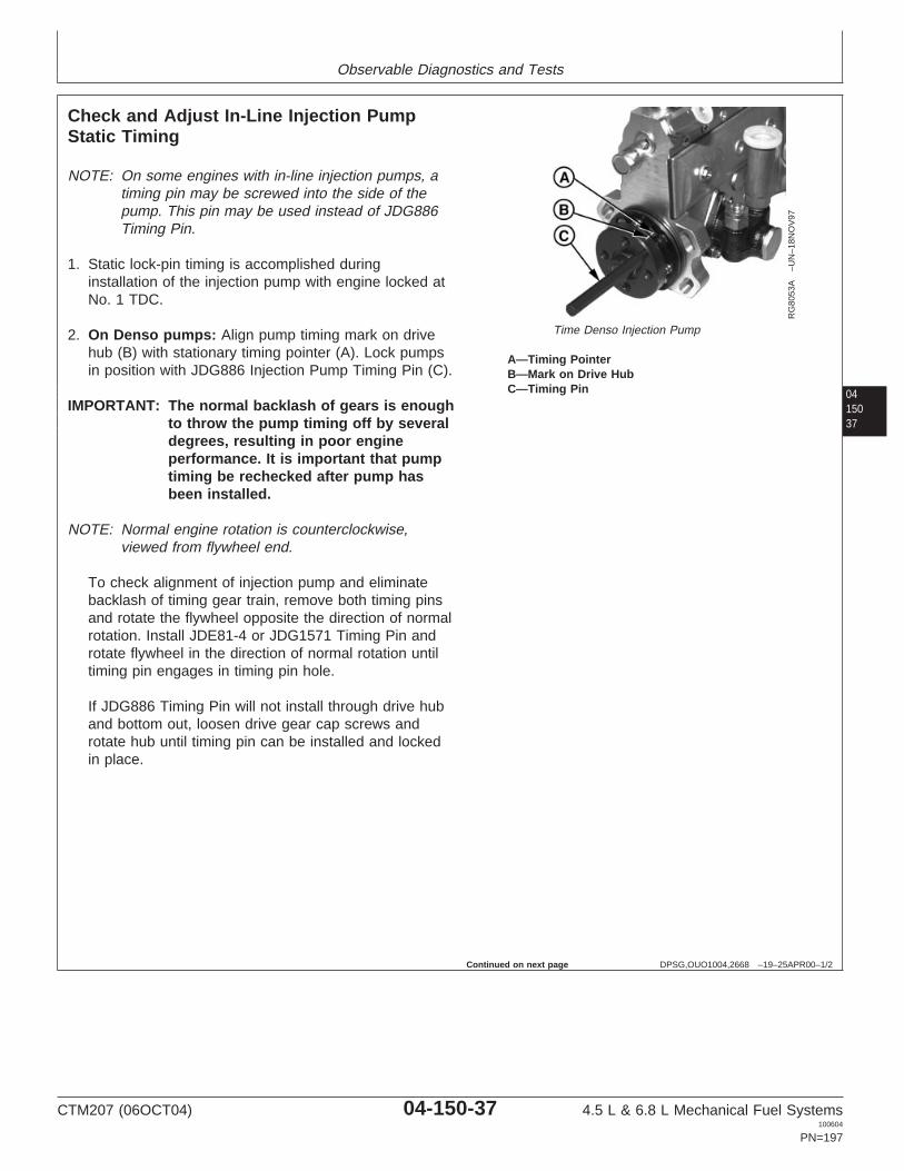
Observable Diagnostics and Tests
0415037
DPSG,OUO1004,2668 –19–25APR00–1/2
Check and Adjust In-Line Injection PumpStatic Timing
RG
8053
A–U
N–1
8NO
V97
Time Denso Injection Pump
A—Timing PointerB—Mark on Drive HubC—Timing Pin
NOTE: On some engines with in-line injection pumps, atiming pin may be screwed into the side of thepump. This pin may be used instead of JDG886Timing Pin.
1. Static lock-pin timing is accomplished duringinstallation of the injection pump with engine locked atNo. 1 TDC.
2. On Denso pumps: Align pump timing mark on drivehub (B) with stationary timing pointer (A). Lock pumpsin position with JDG886 Injection Pump Timing Pin (C).
IMPORTANT: The normal backlash of gears is enoughto throw the pump timing off by severaldegrees, resulting in poor engineperformance. It is important that pumptiming be rechecked after pump hasbeen installed.
NOTE: Normal engine rotation is counterclockwise,viewed from flywheel end.
To check alignment of injection pump and eliminatebacklash of timing gear train, remove both timing pinsand rotate the flywheel opposite the direction of normalrotation. Install JDE81-4 or JDG1571 Timing Pin androtate flywheel in the direction of normal rotation untiltiming pin engages in timing pin hole.
If JDG886 Timing Pin will not install through drive huband bottom out, loosen drive gear cap screws androtate hub until timing pin can be installed and lockedin place.
Continued on next page
CTM207 (06OCT04) 04-150-37 4.5 L & 6.8 L Mechanical Fuel Systems100604
PN=197

Observable Diagnostics and Tests
04150
38
DPSG,OUO1004,2668 –19–25APR00–2/2
RG
1071
1A–U
N–3
1MA
R00
Time Motorpal Injection Pump
A—CapB—SpringC—Timing Pin
3. On Motorpal pumps:
NOTE: If missing, timing pin assembly is availablethrough John Deere Service Parts.
4. Install injection pump timing pin (C) into bore and makesure it is fully engaged in pump timing slot. Installspring (B) on the outboard side of pin.
Reinstall cap (A) and tighten finger tight.
Applying a light turning force, attempt to rotate pumpby hand to verify pump is locked.
NOTE: When tightening pump drive gear cap screws,apply light force (clockwise) to gear to eliminateany backlash with camshaft gear.
5. Tighten pump drive gear cap screws to specifications.
SpecificationDenso Injection Pump Drive GearCap Screws—Torque 47 N•m (35 lb-ft)......................................................Motorpal Injection Pump DriveGear Cap Screws—Torque 61 N•m (45 lb-ft).............................................
CTM207 (06OCT04) 04-150-38 4.5 L & 6.8 L Mechanical Fuel Systems100604
PN=198

Observable Diagnostics and Tests
0415039
DPSG,OUO1004,158 –19–01AUG02–1/1
Check Fuel Supply Quality
RG
9566
–UN
–17J
UL9
8
Fuel Quality Check
IMPORTANT: Excessive water or sedimentcontamination can cause prematurefailure of fuel injection pump.
NOTE: Illustration shows fuel supply pump on engineswith rotary injection pumps. On engines within-line injection pumps, the supply pump ismounted on the side of the injection pump. Thefollowing procedure is the same for both.
The quality of diesel fuel affects engine performance.Check your Operator’s Manual for correct fuelspecifications.
Poor quality or contaminated fuel will make the enginehard to start, misfire, run rough or produce low power.
If poor quality or contaminated fuel is suspected, performthe following:
1. Check primary (if equipped) and final fuel filters forserviceability. If filter is equipped with a waterseparator, empty and clean separator bowl.
2. Start engine and operate under load, observing engineperformance.
3. Disconnect fuel line from inlet side of primary fuel filter(if equipped) or inlet side of supply pump on engineswithout primary filter.
4. Connect a hose to inlet port.
5. Submerge hose in a container of clean, good qualityfuel meeting engine specifications.
6. Operate engine under load and observe performance.
If performance improves, fuel is contaminated or not ofthe proper grade. Check fuel source.
CTM207 (06OCT04) 04-150-39 4.5 L & 6.8 L Mechanical Fuel Systems100604
PN=199

Observable Diagnostics and Tests
04150
40
DPSG,OUO1004,157 –19–01AUG02–1/1
Test Air in Fuel
RG
9559
–UN
–17J
UL9
8
Air in Fuel Test
IMPORTANT: Air in fuel injection pump can causepremature pump failure.
NOTE: Illustration shows in-line injection pump. Rotarypump is similar.
Air in the fuel system will make the engine hard to start,run rough, misfire or produce low power. Additionally, itcan cause excessive smoke and knocking.
Whenever the fuel system is opened for repair, it must bebled to remove any air that has entered the system.
1. Disconnect hose from end of fuel leak-off lineassembly. Connect a hose to end of leak-off lineassembly and place opposite end of hose in a suitablecontainer filled with fuel as shown.
2. Operate engine and check for air bubbles in container.If bubbles are present, bleed the fuel system andrepeat test. (See BLEED THE FUEL SYSTEM in thisgroup.)
3. If bubbles are still present, check the following:
• Check for loose fuel fittings from the suction side of thefuel supply pump to the fuel tank to include all lines andfilters.
• Check fuel tank suction tube (if equipped) and weldedjoints for cracks or holes.
Perform any necessary repairs, bleed fuel system andrepeat test.
CTM207 (06OCT04) 04-150-40 4.5 L & 6.8 L Mechanical Fuel Systems100604
PN=200

Observable Diagnostics and Tests
0415041
DPSG,OUO1004,289 –19–23JUL98–1/1
Check for Restricted Fuel Return Line
RG
9578
–UN
–22J
UL9
8
Restricted Fuel Line Check
A—Fuel Leak-Off Line
This check will help determine if the fuel return line isrestricted.
1. Disconnect fuel leak-off line (A) at the engine.
2. Remove fuel tank cap.
3. Force compressed air through the fuel return linewhile listening at the fuel tank filler neck.
4. If the return line isn’t restricted, the compressed airbubbling into the fuel tank should be audiblethrough the tank filler neck.
5. If no air bubbling through the tank is audible,completely check the fuel return line for anypossible restrictions.
CTM207 (06OCT04) 04-150-41 4.5 L & 6.8 L Mechanical Fuel Systems100604
PN=201

Observable Diagnostics and Tests
04150
42
RG,115,JW7707 –19–11JUL02–1/1
Measure Fuel Supply Pump Pressure—Rotary Injection Pump
RG
7946
–UN
–15J
AN
98
Fuel Supply Pump Pressure Test
1. Remove plug on fuel filter base.
2. Install test equipment as shown.
3. Start engine. Fuel pump should maintain minimumpositive pressure listed below. If pressure is low,replace filter element and recheck pressure.
SpecificationRotary Fuel Supply Pump—Operating Pressure 21—34 kPa (0.21—0.34 bar)
(3—5 psi)......................................
Rotary Fuel Supply Pump—Minimum Flow at 2400 rpmEngine Speed 1.5 L/min (0.42 gpm)...........................................................
If pressure is still low, perform the following:
1. Disconnect pump-to-filter fuel line at the filter.
2. With throttle set at no-fuel position (or injection pumpshut-off solenoid wire disconnected) so engine will notstart, turn engine over several times with startingmotor.
3. If fuel spurts from the line, the pump is operatingproperly.
NOTE: Look for a possible restriction in filter/filter base.Make sure pressure gauge/hose assembly is notat fault.
CTM207 (06OCT04) 04-150-42 4.5 L & 6.8 L Mechanical Fuel Systems100604
PN=202

Observable Diagnostics and Tests
0415043
DPSG,OUO1004,152 –19–11JUL02–1/1
Measure Fuel Supply Pump Pressure—In-Line Injection Pump
RG
9146
–UN
–23J
UL9
8
In-Line Supply Pump Pressure
1. Remove plug on fuel filter base.
2. Install test equipment as shown.
3. Start engine and run at 2400 rpm. Fuel pump shouldmaintain minimum positive pressure listed below. Ifpressure is low, replace filter element and recheckpressure.
SpecificationDenso In-Line Fuel SupplyPump—Minimum Pressure at2400 rpm Engine Speed 69 kPa (0.69 bar) (10 psi)..................................Denso In-Line Fuel SupplyPump—Minimum Flow at 2400rpm Engine Speed 2.0 L/min (0.53 gpm)....................................................Motorpal In-Line Fuel SupplyPump—Minimum Pressure at2000 rpm Engine Speed 80 kPa (0.80 bar) (11.6 psi)...............................Motorpal In-Line Fuel SupplyPump—Minimum Flow at 1000rpm Engine Speed 1.3 L/min (0.34 gpm)....................................................
If pressure is still low, perform the following:
1. Disconnect pump-to-filter fuel line at the filter.
2. With throttle set at no-fuel position (or injection pumpshut-off solenoid wire disconnected) so engine will notstart, turn engine over several times with startingmotor.
3. If fuel spurts from the line, the pump is operatingproperly.
NOTE: Look for a possible restriction in filter/filter base.Make sure pressure gauge/hose assembly is notat fault.
CTM207 (06OCT04) 04-150-43 4.5 L & 6.8 L Mechanical Fuel Systems100604
PN=203

Observable Diagnostics and Tests
04150
44
RG,115,JW7703 –19–24NOV97–1/1
Test Fuel Supply Pump for Leaks—In-LineInjection Pump
RG
5894
–UN
–03N
OV
97
Fuel Supply Pump Leak Test
A—Air LineB—Pressure GaugeC—Outlet Fitting
Fuel delivery pressure should be checked beforeremoving supply pump from injection pump. (See FUELSUPPLY PUMP OPERATION—IN-LINE INJECTIONPUMP, in Section 03, Group 130.)
1. Connect compressed air line (A) to a pressure gauge(B) and to supply pump inlet fitting. Air line shouldhave a regulating valve to control pressure.
2. Cap or plug supply pump outlet fitting (C).
3. Submerge supply pump in a container of clean dieselfuel. Regulate air pressure to 200 kPa (2.0 bar) (29psi).
4. Move roller tappet in and out by hand. No air bubblesshould appear around roller tappet.
NOTE: If bubbles appear, it is an indication that either theO-ring seal is defective or tappet is worn (orpossibly both).
IMPORTANT: Serious injection pump or enginedamage could occur if enough dieselfuel leaks past spindle and seal. Fuelleakage past spindle dilutes engine oil.
CTM207 (06OCT04) 04-150-44 4.5 L & 6.8 L Mechanical Fuel Systems100604
PN=204

Observable Diagnostics and Tests
0415045
DPSG,OUO1004,2759 –19–12MAY00–1/3
Check Fuel Supply Pump Operation—In-LineInjection Pump
RG
7978
–UN
–14N
OV
97
Check Fuel Supply Pump Operation (Denso Pump Shown)
A—Supply PumpB—Hand Primer
NOTE: The following test procedure can best beperformed under moderate air temperatureconditions to reduce electrical loads whencranking the engine is required.
Test fuel supply pump and hand primer for leaks:
1. Make a preliminary inspection of supply pump (A).Thoroughly clean area around pump. All connectionsmust be tight and not leaking.
2. Start engine and bring to operating temperature. Shutoff engine.
NOTE: Denso primers can be screwed down and lockedin position. Motorpal pumps do not have thisoption.
If fuel leaks around hand primer (B) that isscrewed down tight when engine is running,replace the hand primer.
3. Check operation of hand primer. With engine shut off,operate hand primer through several strokes. Moderateto heavy leakage of fuel between plunger and barrelindicates seal is defective. Replace hand primer.
NOTE: Appearance of a slight quantity of fuel around theplunger is normal.
IMPORTANT: On Denso pumps, be sure hand primeris seated all the way down in barrelbefore tightening to prevent internalthread damage.
4. On Denso pumps, tighten hand primer knob, but do notovertighten. If knob will not tighten (indicating internalthread damage), replace hand primer.
Test operation of suction side of pump:
1. Disconnect suction and discharge lines at pump.
2. Drain all fuel from pump by operating hand primer.Then reconnect suction line to pump.
CTM207 (06OCT04) 04-150-45 4.5 L & 6.8 L Mechanical Fuel Systems100604
PN=205
Continued on next page

Observable Diagnostics and Tests
04150
46
DPSG,OUO1004,2759 –19–12MAY00–2/3
NOTE: When operating hand primer, a moderateresistance should be felt. When only a slightresistance (or no resistance) occurs, replace handprimer or repair pump (valves may be defective).
3. Operate hand primer until fuel flows from pump outlet(discharge). Fuel should flow within 15—25 strokes. Ifnot, the suction line may be obstructed or leaking air(replace in-line filter when used).
If fuel does not flow, and if no leak or obstruction isfound, pump is defective. Repair or replace pump.(See Section 02, Group 090.)
Test operation of discharge side of pump:
1. Suction line must be connected and discharge(pressure) line disconnected.
2. Tighten hand primer and place injection pump fuelshut-off control in “STOP” position to prevent enginefrom starting.
3. Crank engine with starting motor. Fuel should flow frompump outlet within 10 seconds. If not, the suction linemay be obstructed or leaking air (replace in-line filterwhen used).
Test pump output pressure while cranking engine:
1. Connect a 0—400 kPa (0—4 bar) (0—60 psi) pressuregauge to one end of a pressure hose about 250—300mm (10—12 in.) long. Connect other end of hose topump outlet. All air must be out of system.
IMPORTANT: The starting motor must crank theengine at normal cranking speed. Usebooster batteries if necessary.
2. Crank engine for 10 seconds with starting motor(approximately 300 engine rpm).
3. Compare measured output with the minimum pressurespecifications.
CTM207 (06OCT04) 04-150-46 4.5 L & 6.8 L Mechanical Fuel Systems100604
PN=206
Continued on next page
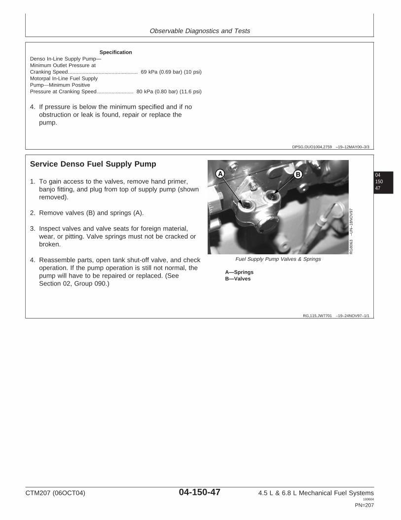
Observable Diagnostics and Tests
DPSG,OUO1004,2759 –19–12MAY00–3/3
SpecificationDenso In-Line Supply Pump—Minimum Outlet Pressure atCranking Speed 69 kPa (0.69 bar) (10 psi)................................................Motorpal In-Line Fuel SupplyPump—Minimum PositivePressure at Cranking Speed 80 kPa (0.80 bar) (11.6 psi).........................
4. If pressure is below the minimum specified and if noobstruction or leak is found, repair or replace thepump.
0415047
RG,115,JW7701 –19–24NOV97–1/1
Service Denso Fuel Supply Pump
RG
8063
–UN
–18N
OV
97
Fuel Supply Pump Valves & Springs
A—SpringsB—Valves
1. To gain access to the valves, remove hand primer,banjo fitting, and plug from top of supply pump (shownremoved).
2. Remove valves (B) and springs (A).
3. Inspect valves and valve seats for foreign material,wear, or pitting. Valve springs must not be cracked orbroken.
4. Reassemble parts, open tank shut-off valve, and checkoperation. If the pump operation is still not normal, thepump will have to be repaired or replaced. (SeeSection 02, Group 090.)
CTM207 (06OCT04) 04-150-47 4.5 L & 6.8 L Mechanical Fuel Systems100604
PN=207

Observable Diagnostics and Tests
04150
48
RG,115,JW7700 –19–11JUL02–1/1
Check Cold Start Switch Operation—RotaryPumps
RG
9143
–UN
–18M
AY
98
Cold Start Switch Check
A—ConnectorB—Cold Start Switch
The cold start switch (B) is an option available on rotaryinjection pumps.
1. Disconnect cold start switch connector (A) from pumpwiring harness.
2. Remove cold start switch from thermostathousing/water manifold.
3. Submerge switch in water at 60°C (140°F) for a fewminutes.
4. Check for open or closed switch. On Delphi/Lucaspumps, the switch should be closed. On Stanadynepumps, the switch should be open.
5. Replace switch if defective.
6. Install switch in thermostat housing/water manifold andtighten to specifications.
SpecificationCold Start Switch—Torque 5 N•m (3.5 lb-ft) (42 lb-in.)...............................
7. Connect cold start switch connector to pump wiringharness.
CTM207 (06OCT04) 04-150-48 4.5 L & 6.8 L Mechanical Fuel Systems100604
PN=208

Observable Diagnostics and Tests
0415049
DPSG,OUO1004,123 –19–11JUL02–1/2
Check Cold Start Advance SystemOperation—Rotary Pumps
RG
9144
–UN
–18M
AY
98
Cold Start Advance System Check
A—ConnectorB—Cold Start Advance Solenoid
NOTE: To check operation of the cold start advancesystem, the engine will be operating in anadvanced timing mode. After checks arecompleted, be sure that the cold start circuits arereturned to their original configuration to ensureproper injection pump timing and conformance toemission control standards.
Use JT07158 (FKM10429A) TIME TRAC Kit to checkinjection pump timing when performing operational checkson the cold start advance system. (See CHECK ANDADJUST ROTARY INJECTION PUMP DYNAMIC TIMINGearlier in this group.)
Stanadyne Cold Start Advance
NOTE: Checks must be performed on a cold engine.
1. Install JT07158 (FKM10429A) TIME TRAC Kit.
2. Ensure that cold start switch is working by verifying avoltage potential (12 or 24 volts, depending onapplication) to the cold start solenoid.
3. Disconnect wiring connector (A) from the cold startadvance solenoid (B).
4. Start cold engine and run at 1200 rpm. Check andrecord injection pump timing.
5. Connect wiring connector (A) to cold start advancesolenoid. After approximately 30 seconds, checkinjection pump timing.
There should be a 7—10° increase in timing, indicatingproper operation of the cold start advance system.
If no increase in timing was noted, service the coldstart advance solenoid and valve. (See REMOVE ANDINSTALL STANADYNE COLD START ADVANCESOLENOID AND VALVE in Section 02.)
TIME TRAC is a registered trademark of Stanadyne Automotive Corp.
CTM207 (06OCT04) 04-150-49 4.5 L & 6.8 L Mechanical Fuel Systems100604
PN=209
Continued on next page

Observable Diagnostics and Tests
04150
50
DPSG,OUO1004,123 –19–11JUL02–2/2
Delphi/Lucas Cold Start Advance
NOTE: Checks must be performed on a cold engine.
The cold start advance solenoid is located on thebottom, outboard side of the injection pump.There is a single terminal input lead to the waxmotor.
1. Install JT07158 (FKM10429A) TIME TRAC Kit.
2. Disconnect wiring connector from the cold start switchto wax motor harness. Verify that there is a voltagepotential (12 or 24 volts, depending on application) atthe wax motor connector.
3. Start cold engine and run at 1200 rpm. Check andrecord injection pump timing.
4. Connect a jumper wire across the wax motor connectorterminals. After approximately 30 seconds, checkinjection pump timing.
There should be a 7—10° decrease in timing,indicating proper operation of the cold start advancesystem.
If no decrease in timing was noted, have the injectionpump serviced/repaired by an authorized ADS DieselRepair Station.
TIME TRAC is a registered trademark of Stanadyne Automotive Corp.
CTM207 (06OCT04) 04-150-50 4.5 L & 6.8 L Mechanical Fuel Systems100604
PN=210

Observable Diagnostics and Tests
0415051
DPSG,OUO1004,136 –19–01AUG02–1/1
Check Light Load Advance Operation—Rotary Pumps
IMPORTANT: Avoid machine damage. Air trapped infuel injection pump can cause internaldamage to light load advancemechanism. Bleed fuel supply systemthoroughly before performing this test.
To check operation of the light load advance, perform thefollowing:
1. Install JT07158 (FKM10429A) TIME TRAC Kit.
2. Operate engine at full load and rated speed. Noteinjection pump timing on TIME TRAC.
3. Gradually decrease load to the engine. Timing shouldcontinue to retard as the load is removed, but shouldstart to advance again as the light load advance beginsto operate at about 50 percent load.
4. If timing does not advance, the light load advance isnot operating properly. Have the injection pumpserviced/repaired by an authorized ADS Diesel RepairStation.
TIME TRAC is a registered trademark of Stanadyne Automotive Corp.
CTM207 (06OCT04) 04-150-51 4.5 L & 6.8 L Mechanical Fuel Systems100604
PN=211
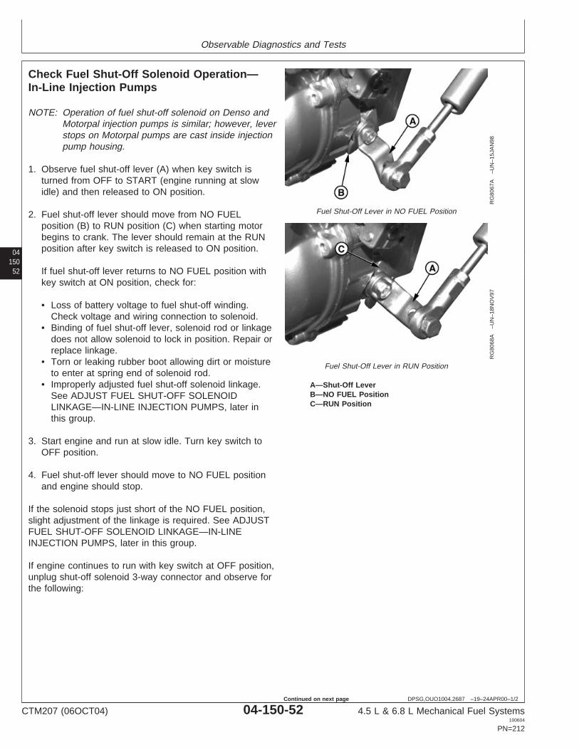
Observable Diagnostics and Tests
04150
52
DPSG,OUO1004,2687 –19–24APR00–1/2
Check Fuel Shut-Off Solenoid Operation—In-Line Injection Pumps
RG
8067
A–U
N–1
5JA
N98
Fuel Shut-Off Lever in NO FUEL Position
RG
8068
A–U
N–1
8NO
V97
Fuel Shut-Off Lever in RUN Position
A—Shut-Off LeverB—NO FUEL PositionC—RUN Position
NOTE: Operation of fuel shut-off solenoid on Denso andMotorpal injection pumps is similar; however, leverstops on Motorpal pumps are cast inside injectionpump housing.
1. Observe fuel shut-off lever (A) when key switch isturned from OFF to START (engine running at slowidle) and then released to ON position.
2. Fuel shut-off lever should move from NO FUELposition (B) to RUN position (C) when starting motorbegins to crank. The lever should remain at the RUNposition after key switch is released to ON position.
If fuel shut-off lever returns to NO FUEL position withkey switch at ON position, check for:
• Loss of battery voltage to fuel shut-off winding.Check voltage and wiring connection to solenoid.
• Binding of fuel shut-off lever, solenoid rod or linkagedoes not allow solenoid to lock in position. Repair orreplace linkage.
• Torn or leaking rubber boot allowing dirt or moistureto enter at spring end of solenoid rod.
• Improperly adjusted fuel shut-off solenoid linkage.See ADJUST FUEL SHUT-OFF SOLENOIDLINKAGE—IN-LINE INJECTION PUMPS, later inthis group.
3. Start engine and run at slow idle. Turn key switch toOFF position.
4. Fuel shut-off lever should move to NO FUEL positionand engine should stop.
If the solenoid stops just short of the NO FUEL position,slight adjustment of the linkage is required. See ADJUSTFUEL SHUT-OFF SOLENOID LINKAGE—IN-LINEINJECTION PUMPS, later in this group.
If engine continues to run with key switch at OFF position,unplug shut-off solenoid 3-way connector and observe forthe following:
CTM207 (06OCT04) 04-150-52 4.5 L & 6.8 L Mechanical Fuel Systems100604
PN=212
Continued on next page

Observable Diagnostics and Tests
DPSG,OUO1004,2687 –19–24APR00–2/2
• If solenoid moves lever to NO FUEL position, problemis in the electrical circuit.
• If solenoid does not shut off fuel to engine, checklinkage for binding or excessive tightness. Replacementservice kit is available with a swivel rod which is lesssensitive to misalignment and binding.
0415053
DPSG,OUO1004,124 –19–10SEP02–1/1
Test Fuel Shut-Off Solenoid Resistance—Delphi/Lucas Pump
1. Disconnect wire to solenoid.
2. Remove solenoid, noting if plunger is binding in bore.
3. Check coil resistance with ohmmeter and comparereading to the following specification.
SpecificationDelphi/Lucas Fuel Shut-OffSolenoid—Resistance 9 Ohms...................................................................
4. Check plunger retraction using a 12-V or 24-V source,as appropriate.
Connect positive cable to connector terminal andnegative cable to solenoid body. From the relaxedposition, plunger should retract into the solenoid bodywhen voltage is applied.
If resistance specification is not met and/or plungerdoes not retract, replace solenoid.
CTM207 (06OCT04) 04-150-53 4.5 L & 6.8 L Mechanical Fuel Systems100604
PN=213

Observable Diagnostics and Tests
04150
54
RG,115,JW7698 –19–10SEP02–1/1
Test Fuel Shut-Off Solenoid Resistance—Denso Pump
Disconnect shut-off solenoid 3-way WEATHER PACKconnector.
1. Measure “PULL” coil resistance between black leadwire “C” and white lead wire “B”.
2. Measure “HOLD” coil resistance between black leadwire “C” and red lead wire “A”.
Replace solenoid if resistance is not withinspecification given below.
Denso Fuel Shut-Off Solenoid (12-Volt System: RE67325)—Specification
Pull Coil—Resistance 0.134—0.200 Ohms.................................................Hold Coil—Resistance 6.63—8.11 Ohms....................................................
Denso Fuel Shut-Off Solenoid (24-Volt System: RE67256)—Specification
Pull Coil—Resistance 0.560—0.684 Ohms.................................................Hold Coil—Resistance 24.35—29.76 Ohms................................................
WEATHER PACK is a trademark of Packard Electric.
CTM207 (06OCT04) 04-150-54 4.5 L & 6.8 L Mechanical Fuel Systems100604
PN=214
Observable Diagnostics and Tests
0415055
DPSG,OUO1004,2673 –19–10SEP02–1/1
Test Fuel Shut-Off Solenoid Resistance—Motorpal Pump
Disconnect shut-off solenoid 3-way WEATHER PACKconnector.
1. Measure “PULL” coil resistance between black leadand white lead.
2. Measure “HOLD” coil resistance between black leadand red lead.
Replace solenoid if resistance is not withinspecification given below.
Motorpal Fuel Shut-Off Solenoid—SpecificationPull Coil—Resistance 0.174—0.260 Ohms.................................................Hold Coil—Resistance 10.035—12.265 Ohms............................................
WEATHER PACK is a trademark of Packard Electric.
RG,115,JW7697 –19–20APR00–1/3
Adjust Fuel Shut-Off Solenoid Linkage—In-Line Injection Pumps
Shut-off solenoid linkage is factory adjusted and usuallywill not require additional field adjustment. ALWAYS checklinkage and lever for alignment and binding before makingadjustments.
Thoroughly lubricate all linkage and lever pivot points.
Continued on next page
CTM207 (06OCT04) 04-150-55 4.5 L & 6.8 L Mechanical Fuel Systems100604
PN=215
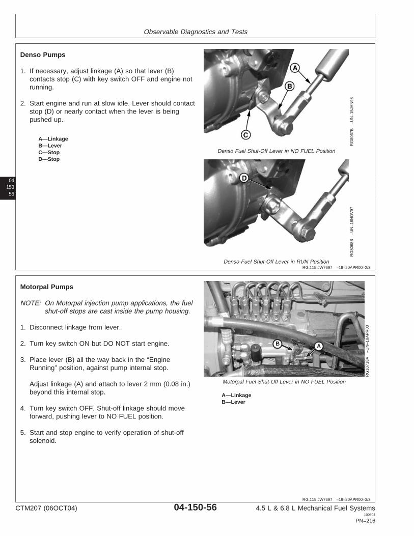
Observable Diagnostics and Tests
04150
56
RG,115,JW7697 –19–20APR00–2/3
RG
8067
B–U
N–1
5JA
N98
Denso Fuel Shut-Off Lever in NO FUEL Position
RG
8068
B–U
N–1
8NO
V97
Denso Fuel Shut-Off Lever in RUN Position
A—LinkageB—LeverC—StopD—Stop
Denso Pumps
1. If necessary, adjust linkage (A) so that lever (B)contacts stop (C) with key switch OFF and engine notrunning.
2. Start engine and run at slow idle. Lever should contactstop (D) or nearly contact when the lever is beingpushed up.
RG,115,JW7697 –19–20APR00–3/3
RG
1071
8A–U
N–1
8AP
R00
Motorpal Fuel Shut-Off Lever in NO FUEL Position
A—LinkageB—Lever
Motorpal Pumps
NOTE: On Motorpal injection pump applications, the fuelshut-off stops are cast inside the pump housing.
1. Disconnect linkage from lever.
2. Turn key switch ON but DO NOT start engine.
3. Place lever (B) all the way back in the “EngineRunning” position, against pump internal stop.
Adjust linkage (A) and attach to lever 2 mm (0.08 in.)beyond this internal stop.
4. Turn key switch OFF. Shut-off linkage should moveforward, pushing lever to NO FUEL position.
5. Start and stop engine to verify operation of shut-offsolenoid.
CTM207 (06OCT04) 04-150-56 4.5 L & 6.8 L Mechanical Fuel Systems100604
PN=216

Observable Diagnostics and Tests
0415057
RG,115,JW7691 –19–11JUL02–1/2
Check and Adjust Engine Speeds onDelphi/Lucas Pump
RG
7949
–UN
–13N
OV
97
Engine Speed Adjustments—Lucas Pump
A—Slow Idle Adjusting ScrewB—Fast Idle Adjusting ScrewC—Throttle Lever
NOTE: Before checking and adjusting engine speed,make sure engine has reached its normaloperating temperature.
Check Slow and Fast Idle Speeds:
NOTE: Check fast idle and slow idle speeds perspecifications listed in FUEL INJECTION PUMPSPECIFICATIONS, Section 06, Group 210 forOEM engines. See machine technical manual forother applications.
1. Start engine and run at 50% load and rated speed untilengine reaches normal operating temperature.
2. Stop engine and disconnect speed control rod fromfuel injection pump throttle lever (C).
3. Start engine and move injection pump lever to slowidle position against slow idle adjusting screw (A).Using a tachometer, read and record engine speed.Compare reading with specifications. Adjust slow idleas necessary as detailed below.
4. Move injection pump lever to fast idle position againstfast idle adjusting screw (B). Using a tachometer, readand record engine speed. Compare reading withspecifications.
Adjust Slow Idle Speed:
NOTE: Adjust slow idle speed per specifications listed inSection 06, Group 210 for OEM engines. Seemachine technical manual for other applications.
Move pump throttle lever to slow idle position against slowidle adjusting screw (A).
Loosen slow idle screw lock nut. Turn adjusting screwclockwise to increase speed and counterclockwise todecrease engine speed.
CTM207 (06OCT04) 04-150-57 4.5 L & 6.8 L Mechanical Fuel Systems100604
PN=217
Continued on next page

Observable Diagnostics and Tests
04150
58
RG,115,JW7691 –19–11JUL02–2/2
Adjust Fast Idle Speed:
IMPORTANT: Fast idle speeds are preset at thefactory. It is recommended that fast idleadjustments be performed only by anauthorized diesel repair station.
Adjust fast idle speed per specificationslisted in Section 06, Group 210 for OEMengines. See machine technical manualfor other applications. If necessary toreset fast idle speed, reset only tospecifications. If fast idle speed is notset to specification, the engine may notcomply with federal emissionsregulations.
DO NOT adjust fast idle speed abovespecifications or pump and enginedamage may occur.
Move pump throttle lever to fast idle position against fastidle adjusting screw (B). Refer to appropriate MachineTechnical Manual for specified engine speeds.
Loosen fast idle screw lock nut and adjust fast idle tospecifications.
RG,115,JW7718 –19–11JUL02–1/1
Adjust Variable Speed on Generator SetEngines (Delphi/Lucas Pumps Only)
See your authorized Delphi/Lucas Repair Station forspeed droop adjustment. This service requires that aninternal pump adjustment be made.
CTM207 (06OCT04) 04-150-58 4.5 L & 6.8 L Mechanical Fuel Systems100604
PN=218

Observable Diagnostics and Tests
0415059
RG,115,JW7690 –19–18MAY00–1/2
Check and Adjust Engine Speeds onStanadyne Pump
RG
T60
05A
A–U
N–1
9NO
V97
Engine Speed Adjustments—Stanadyne Pump
A—Slow Idle Adjusting Screw1
B—Control Rod PinC—Fast Idle Adjusting ScrewD—Slow Idle Adjusting Screw1
NOTE: Before checking and adjusting engine speed,make sure engine has reached its normaloperating temperature.
Check Slow and Fast Idle Speeds:
NOTE: Check fast idle and slow idle speeds perspecifications listed in FUEL INJECTION PUMPSPECIFICATIONS, Section 06, Group 210 forOEM engines. See machine technical manual forother applications.
1. Start engine and run at 50% load and rated speed untilengine reaches normal operating temperature.
2. Stop engine and remove control rod pin (B), if used.Disconnect speed control rod (or control cable) fromfuel injection pump throttle lever.
3. Start engine and move injection pump lever to slowidle position against slow idle adjusting screw (A or D).Using a tachometer, read and record engine speed.Compare reading with specifications. Adjust asnecessary as detailed below.
4. Move injection pump lever to fast idle position againstfast idle adjusting screw (C). Using a tachometer, readand record engine speed. Compare reading withspecifications.
Adjust Slow Idle Speed:
NOTE: Adjust slow idle speed per specifications listed inSection 06, Group 210 for OEM engines. Seemachine technical manual for other applications.
1. Move pump throttle lever in slow idle position againstslow idle adjusting screw (A or D). See specificationsfor specified engine speeds.
1Slow idle adjusting screw location varies by injection pump application.Will either be at location A or D.
CTM207 (06OCT04) 04-150-59 4.5 L & 6.8 L Mechanical Fuel Systems100604
PN=219
Continued on next page
Observable Diagnostics and Tests
04150
60
RG,115,JW7690 –19–18MAY00–2/2
2. Loosen slow idle screw lock. Turn adjusting screwclockwise to increase engine speed andcounterclockwise to decrease speed. Tighten lock nut.
Adjust Fast Idle Speed:
IMPORTANT: Fast idle speeds are preset at thefactory. It is recommended that fast idleadjustments be performed only by anauthorized diesel repair station.
Adjust fast idle speed per specificationslisted in Section 06, Group 210 for OEMengines. See machine technical manualfor other applications. If necessary toreset fast idle speed, reset only tospecifications. If fast idle speed is notset to specification, the engine may notcomply with federal emissionsregulations.
DO NOT adjust fast idle speed abovespecifications or pump and enginedamage may occur.
1. Move pump throttle lever in fast idle position againstfast idle adjusting screw (C). See appropriate MachineTechnical Manual for specified engine speeds.
2. Loosen fast idle screw lock and adjust fast idle speedto specification. Tighten lock nut.
CTM207 (06OCT04) 04-150-60 4.5 L & 6.8 L Mechanical Fuel Systems100604
PN=220

Observable Diagnostics and Tests
0415061
RG,115,JW7689 –19–24NOV97–1/1
Adjust Variable Speed (Droop) on GeneratorSet Engines (3—5% Governor Regulation)—Stanadyne DB2 and DB4 Injection Pumps
RG
5754
–UN
–03N
OV
97
External Speed Droop Adjust—DB2 & DB4
RG
6395
–UN
–03N
OV
97
Speed Droop Adjust Cap—DB2 & DB4
RG
6397
–UN
–03N
OV
97
Throttle Configuration—Early/Current
A—Speed Droop Adjusting CapB—Fast Idle ScrewC—Slow Idle ScrewD—Early Throttle LeverE—Current Throttle
An external speed droop adjusting cap (A) at the rear ofthe injection pump housing provides precise control ofgovernor sensitivity by decreasing or increasing theeffective length (and thereby the rate) of the governorcontrol spring. Fine adjustments can be made while theengine is operating.
1. Start engine and run at rated speed with 50% loadapplied until it reaches normal operating temperature.
NOTE: If serious surging occurs during the warm-upperiod, turn the speed droop adjusting capclockwise until surging stops.
2. When engine has warmed to normal operatingtemperature, position throttle lever (D or E) to attain fullload rated speed (e.g., 1500, 1800 rpm) and apply100% (full) load.
Adjust the throttle if necessary to obtain satisfactory fullload performance.
NOTE: Whenever speed droop adjustments are made,throttle position adjustments will also benecessary.
3. Remove load and check for specified no-load speed orfrequency.
If incorrect, adjust speed droop adjusting cap slightly(clockwise for increased droop or counterclockwise forless droop).
If surging exists upon removing the load, turn theadjusting cap clockwise to eliminate.
4. Recheck full load and no-load performance andreadjust as necessary.
CTM207 (06OCT04) 04-150-61 4.5 L & 6.8 L Mechanical Fuel Systems100604
PN=221

Observable Diagnostics and Tests
04150
62
RG,115,JW7686 –19–20APR00–1/1
Check and Adjust Fast Idle Speed—Densoand Motorpal Fuel Injection Pump
RG
8082
–UN
–18N
OV
97
Denso Fast Idle Check
RG
1072
2A–U
N–1
8AP
R00
Motorpal Fast Idle Check
A—Governor Control LeverB—Fast Idle Stop Screw
IMPORTANT: Fast idle speeds are preset at thefactory. It is recommended that fast idleadjustments be performed only by anauthorized diesel repair station.
Check and adjust fast idle speed perspecifications listed in FUEL INJECTIONPUMP SPECIFICATIONS, Section 06,Group 210 for OEM engines. Seemachine technical manual for otherapplications.
If necessary to reset fast idle speed,reset only to specifications. If fast idlespeed is not set to specification, theengine may not comply with federalemissions regulations.
1. Remove speed control rod. With the engine running,move governor control lever (A) against the fast idlestop screw (B).
NOTE: The governor control lever on injection pump maybe inboard (next to engine block) or outboard(away from engine block), depending upon engineapplication.
2. Using a tachometer, check fast idle speed to see if it iswithin specification.
IMPORTANT: If fast idle speed is adjusted, DO NOTadjust idle speed above specifications,or pump and engine damage mayoccur.
3. Adjust fast idle stop screw (B), as required, to specifiedfast idle speed.
NOTE: For some applications such as generator sets,special equipment may be required for fast idleadjustment in conjunction with droop adjustment.See your OEM dealer or John Deere EngineDistributor.
CTM207 (06OCT04) 04-150-62 4.5 L & 6.8 L Mechanical Fuel Systems100604
PN=222
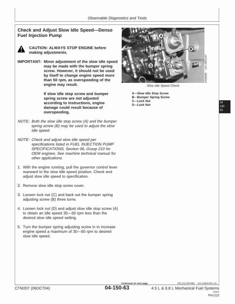
Observable Diagnostics and Tests
0415063
RG,115,JW7685 –19–12MAY00–1/3
Check and Adjust Slow Idle Speed—DensoFuel Injection Pump
RG
8080
B–U
N–1
8NO
V97
Slow Idle Speed Check
A—Slow Idle Stop ScrewB—Bumper Spring ScrewC—Lock NutD—Lock Nut
CAUTION: ALWAYS STOP ENGINE beforemaking adjustments.
IMPORTANT: Minor adjustment of the slow idle speedmay be made with the bumper springscrew. However, it should not be usedby itself to change engine speed morethan 50 rpm, as overspeeding of theengine may result.
If slow idle stop screw and bumperspring screw are not adjustedaccording to instructions, enginedamage could result because ofoverspeeding.
NOTE: Both the slow idle stop screw (A) and the bumperspring screw (B) may be used to adjust the slowidle speed.
NOTE: Check and adjust slow idle speed perspecifications listed in FUEL INJECTION PUMPSPECIFICATIONS, Section 06, Group 210 forOEM engines. See machine technical manual forother applications.
1. With the engine running, pull the governor control leverrearward to the slow idle speed position. Check andadjust slow idle speed to specification.
2. Remove slow idle stop screw cover.
3. Loosen lock nut (C) and back out the bumper springadjusting screw (B) three turns.
4. Loosen lock nut (D) and adjust slow idle stop screw (A)to obtain an idle speed 30—50 rpm less than thedesired slow idle speed setting.
5. Turn the bumper spring adjusting screw in to increaseengine speed a maximum of 30—50 rpm to desiredslow idle speed.
CTM207 (06OCT04) 04-150-63 4.5 L & 6.8 L Mechanical Fuel Systems100604
PN=223
Continued on next page
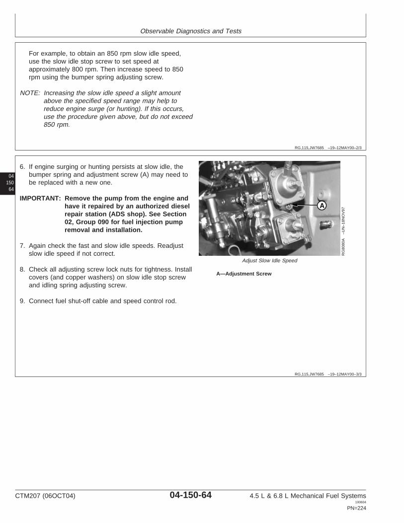
Observable Diagnostics and Tests
RG,115,JW7685 –19–12MAY00–2/3
For example, to obtain an 850 rpm slow idle speed,use the slow idle stop screw to set speed atapproximately 800 rpm. Then increase speed to 850rpm using the bumper spring adjusting screw.
NOTE: Increasing the slow idle speed a slight amountabove the specified speed range may help toreduce engine surge (or hunting). If this occurs,use the procedure given above, but do not exceed850 rpm.
04150
64
RG,115,JW7685 –19–12MAY00–3/3
RG
8080
A–U
N–1
8NO
V97
Adjust Slow Idle Speed
A—Adjustment Screw
6. If engine surging or hunting persists at slow idle, thebumper spring and adjustment screw (A) may need tobe replaced with a new one.
IMPORTANT: Remove the pump from the engine andhave it repaired by an authorized dieselrepair station (ADS shop). See Section02, Group 090 for fuel injection pumpremoval and installation.
7. Again check the fast and slow idle speeds. Readjustslow idle speed if not correct.
8. Check all adjusting screw lock nuts for tightness. Installcovers (and copper washers) on slow idle stop screwand idling spring adjusting screw.
9. Connect fuel shut-off cable and speed control rod.
CTM207 (06OCT04) 04-150-64 4.5 L & 6.8 L Mechanical Fuel Systems100604
PN=224

Observable Diagnostics and Tests
0415065
DPSG,OUO1004,2674 –19–19AUG04–1/1
Check and Adjust Slow Idle Speed—MotorpalFuel Injection Pump
RG
1072
2B–U
N–1
8AP
R00
Adjust Slow Idle Speed
A—LeverB—Slow Idle Stop Screw
NOTE: Check and adjust slow idle speed perspecifications listed in FUEL INJECTION PUMPSPECIFICATIONS, Section 06, Group 210 forOEM engines. See machine technical manual forother applications.
1. With the engine running, pull the governor control lever(A) rearward to the slow idle speed position. Checkand adjust slow idle speed to machine specification.(See machine technical manual.)
2. Loosen lock nut and adjust slow idle stop screw (B) toobtain specified idle speed.
3. Tighten adjusting screw lock nut.
4. Check all adjusting screw lock nuts for tightness.
CTM207 (06OCT04) 04-150-65 4.5 L & 6.8 L Mechanical Fuel Systems100604
PN=225

Observable Diagnostics and Tests
04150
66
RG,115,JW7684 –19–19AUG04–1/2
Change Engine Rated Speed and AdjustDroop—Denso Fuel Injection Pump
RG
5752
–UN
–03N
OV
97
Change Rated Speed
A—Fast Idle (Stop) ScrewB—Droop Adjusting Screw Access Plug LocationC—Droop Adjusting ScrewD—Slow Idle (Adjusting) ScrewE—Idle (Bumper) Spring ScrewF—Throttle LeverG—Mechanical Shut-Off Lever
1. Start engine and apply 50% load at rated speed until itreaches operating temperature. Remove cap nuts fromadjusting screws before making adjustments.
2. When the engine has reached normal operatingtemperature, adjust fast idle (stop) screw (A) clockwise(CW) to 1500 rpm (50 Hz) with 100% (full) load.
3. Remove load and back out the idle (bumper) springscrew (E), while observing the corresponding drop inengine rpm’s until engine stops losing speed.
4. Screw in idle (bumper) spring screw until engine speedincreases 5—10 rpm.
5. Check for specified no-load (frequency). If governorregulation is within 5—7% range, proceed to step 8.
NOTE: A noticeable click will occur at each 1/4 turn ofdroop adjusting screw. One click CW will increaseno-load speed approximately 10 rpm,counterclockwise (CCW) will reduce speed by 10rpm.
6. If governor regulation is above 7% or below 5%, stopengine and remove droop adjusting screw access plug(B, shown removed) from top of governor housing.
a. Back out slow idle (adjusting) screw (D) andbumper screw. Pull back on throttle lever (F, towardrear of governor housing) by hand until the droopadjusting screw (C) inside housing can be adjustedthrough the access plug hole.
b. Turn the droop screw in (CW), counting the turnsuntil screw bottoms out. Then, return screw tooriginal setting.
c. Turn the droop screw in (CW) no more than 1/2 turn(two clicks) at a time to reduce governor droop.Turn the droop screw out (CCW) no more than twoclicks at a time to increase governor droop (toreduce governor sensitivity).
CTM207 (06OCT04) 04-150-66 4.5 L & 6.8 L Mechanical Fuel Systems100604
PN=226
Continued on next page

Observable Diagnostics and Tests
0415067
RG,115,JW7684 –19–19AUG04–2/2
d. Replace access plug in top of governor housing.Start engine, apply full (100%) load, and readjusthigh idle adjusting screw until 1500 rpm (50 Hz) isobtained at the specified power.
e. Screw in idle (bumper) spring until engine speedincreases 5—10 rpm.
7. Repeat steps 6 (a—d) until governor regulation iswithin the 5—7% range.
8. Replace all cap nuts onto adjusting screws and tightenlock nuts securely.
CTM207 (06OCT04) 04-150-67 4.5 L & 6.8 L Mechanical Fuel Systems100604
PN=227

Observable Diagnostics and Tests
04150
68
RG,115,JW7679 –19–11JUL02–1/1
Test Fuel Injection Nozzles (Engine Running)
X98
11–U
N–2
3AU
G88
High Pressure Fluids
RG
7725
–UN
–08J
AN
97
Nozzle Delivery Line Nut Tightening
CAUTION: Escaping fluid under pressure canpenetrate the skin causing serious injury. Forthis test, loosen the fuel line fittings SLOWLYuntil fuel seeps from connection. DO NOTover-loosen fittings.
If an accident occurs, see a doctor immediately.Any fluid injected into the skin must besurgically removed within a few hours organgrene may result. Doctors unfamiliar withthis type of injury may call the Deere &Company Medical Department in Moline, Illinois,or other knowledgeable medical source.
1. Operate engine at intermediate speed with no load.
2. Slowly loosen the fuel pressure line, using twowrenches as shown, at one of the nozzles until fuelescapes at the connection (fuel not opening nozzlevalve).
If engine speed changes, the injection nozzle isprobably working satisfactorily.
If engine speed does not change, a nozzle is faultyand must be checked and repaired (or replaced).
NOTE: The injection nozzle before and/or after nozzlebeing checked could be the faulty nozzle.
3. Repeat test for each remaining nozzle assembly.
4. Remove faulty injection nozzles and repair as required.(See Section 02, Group 090.)
5. Tighten fuel lines to specifications.
SpecificationFuel Injection Nozzle DeliveryLine—Torque 27 N•m (20 lb-ft)...................................................................
CTM207 (06OCT04) 04-150-68 4.5 L & 6.8 L Mechanical Fuel Systems100604
PN=228

Observable Diagnostics and Tests
0415069
RG,115,JW7678 –19–13SEP02–1/1
Fuel Drain-Back Test Procedure
RG
1241
6–U
N–2
2AU
G02
Fuel Drain-Back Test
A—Fuel Return LineB—Fuel Supply Line
Fuel draining back through the fuel system may causehard starting. This procedure will determine if air isentering the system at connections and allowing fuel tosiphon back to the fuel tank.
1. Disconnect fuel supply and return lines at fuel tank.
IMPORTANT: Fuel return line MUST extend below fuellevel in fuel tank before performing thistest. Fill fuel tank if necessary.
2. Drain all fuel from the system, including the fueltransfer pump, fuel injection pump, fuel filters, andwater separator (if equipped).
3. Securely plug off the tank end of the fuel return line(A).
CAUTION: Maximum air pressure should be 100kPa (1 bar) (15 psi) when performing this test.
4. Using a low pressure air source, pressurize the fuelsystem at the tank end of fuel supply line (B).
5. Apply liquid soap and water solution to all joints andconnections in the fuel system and inspect for leaks.
NOTE: Connections may allow air to enter the systemwithout allowing fuel to leak out.
6. If any leaks are found, take necessary steps to repair.
7. Reconnect supply and return lines and prime system.
8. Start engine and run for approximately 10 minutes.
9. Allow engine to sit overnight and try starting thefollowing morning.
CTM207 (06OCT04) 04-150-69 4.5 L & 6.8 L Mechanical Fuel Systems100604
PN=229
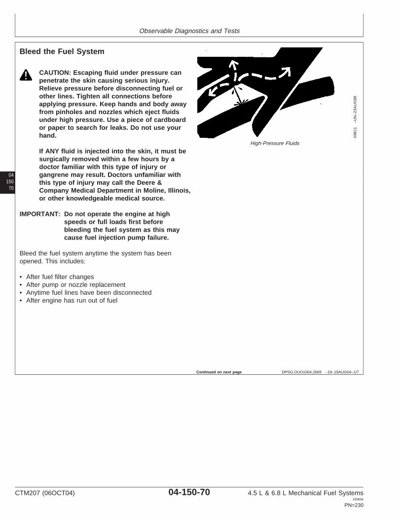
Observable Diagnostics and Tests
04150
70
DPSG,OUO1004,2669 –19–19AUG04–1/7
Bleed the Fuel System
X98
11–U
N–2
3AU
G88
High-Pressure Fluids
CAUTION: Escaping fluid under pressure canpenetrate the skin causing serious injury.Relieve pressure before disconnecting fuel orother lines. Tighten all connections beforeapplying pressure. Keep hands and body awayfrom pinholes and nozzles which eject fluidsunder high pressure. Use a piece of cardboardor paper to search for leaks. Do not use yourhand.
If ANY fluid is injected into the skin, it must besurgically removed within a few hours by adoctor familiar with this type of injury organgrene may result. Doctors unfamiliar withthis type of injury may call the Deere &Company Medical Department in Moline, Illinois,or other knowledgeable medical source.
IMPORTANT: Do not operate the engine at highspeeds or full loads first beforebleeding the fuel system as this maycause fuel injection pump failure.
Bleed the fuel system anytime the system has beenopened. This includes:
• After fuel filter changes• After pump or nozzle replacement• Anytime fuel lines have been disconnected• After engine has run out of fuel
Continued on next page
CTM207 (06OCT04) 04-150-70 4.5 L & 6.8 L Mechanical Fuel Systems100604
PN=230
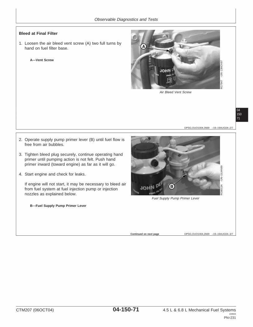
Observable Diagnostics and Tests
0415071
DPSG,OUO1004,2669 –19–19AUG04–2/7
RG
7947
–UN
–13N
OV
97
Air Bleed Vent Screw
A—Vent Screw
Bleed at Final Filter
1. Loosen the air bleed vent screw (A) two full turns byhand on fuel filter base.
DPSG,OUO1004,2669 –19–19AUG04–3/7
RG
8013
A–U
N–1
5JA
N99
Fuel Supply Pump Primer Lever
B—Fuel Supply Pump Primer Lever
2. Operate supply pump primer lever (B) until fuel flow isfree from air bubbles.
3. Tighten bleed plug securely, continue operating handprimer until pumping action is not felt. Push handprimer inward (toward engine) as far as it will go.
4. Start engine and check for leaks.
If engine will not start, it may be necessary to bleed airfrom fuel system at fuel injection pump or injectionnozzles as explained below.
Continued on next page
CTM207 (06OCT04) 04-150-71 4.5 L & 6.8 L Mechanical Fuel Systems100604
PN=231

Observable Diagnostics and Tests
04150
72
DPSG,OUO1004,2669 –19–19AUG04–4/7
RG
6264
–UN
–03N
OV
97
Stanadyne Rotary Fuel Injection Pump
A—Fuel Return Line Connector
Bleed at Fuel Injection Pump
On Stanadyne rotary pumps:
1. Slightly loosen fuel return line connector (A) at fuelinjection pump.
2. Operate fuel supply pump primer lever until fuel,without air bubbles, flows from fuel return lineconnection.
3. Tighten return line connector to specification.
SpecificationStanadyne Fuel Injection PumpReturn Line Connector—Torque 27 N•m (20 lb-ft).....................................
4. Primer lever is spring-loaded and will return to normalposition.
DPSG,OUO1004,2669 –19–19AUG04–5/7
RG
7948
–UN
–13N
OV
97
Delphi/Lucas Rotary Fuel Injection Pumps
B—Bleed ScrewC—Screw
On Delphi/Lucas rotary pumps:
CAUTION: NEVER loosen screw (C) securingpump head, otherwise damage may occur.
1. Loosen bleed screw (B) on pump cover.
NOTE: On injection pump models DP200/201/203, bleedscrew is located on top of cover near the fuelreturn line.
2. Operate fuel supply pump primer lever or turn ignitionswitch to “ON”.
3. Wait until fuel flow is free of air bubbles. Tighten bleedscrew.
4. Primer lever is spring-loaded and will return to normalposition.
CTM207 (06OCT04) 04-150-72 4.5 L & 6.8 L Mechanical Fuel Systems100604
PN=232
Continued on next page

Observable Diagnostics and Tests
0415073
DPSG,OUO1004,2669 –19–19AUG04–6/7
RG
8069
–UN
–23N
OV
97
Denso Fuel Injection Pump Shown
On Denso and Motorpal in-line pumps:
1. On Denso pump shown, unscrew hand primer on fuelsupply pump until it can be pulled by hand.
2. Open fuel filter port plug.
3. Operate the hand primer until smooth flow of fuel, freeof bubbles, comes out of the filter plug hole.
4. Simultaneously stroke the hand primer down and closethe filter port plug. This prevents air from entering thesystem. Tighten plug securely. DO NOT overtighten.
IMPORTANT: Be sure hand primer is all the waydown in barrel before tightening toprevent internal thread damage.
5. On Denso pump shown, lock hand primer in position.
Continued on next page
CTM207 (06OCT04) 04-150-73 4.5 L & 6.8 L Mechanical Fuel Systems100604
PN=233
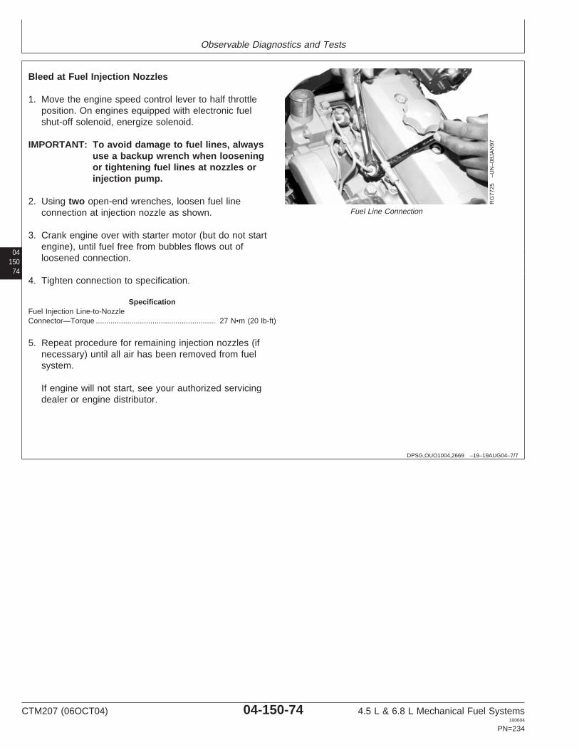
Observable Diagnostics and Tests
04150
74
DPSG,OUO1004,2669 –19–19AUG04–7/7
RG
7725
–UN
–08J
AN
97
Fuel Line Connection
Bleed at Fuel Injection Nozzles
1. Move the engine speed control lever to half throttleposition. On engines equipped with electronic fuelshut-off solenoid, energize solenoid.
IMPORTANT: To avoid damage to fuel lines, alwaysuse a backup wrench when looseningor tightening fuel lines at nozzles orinjection pump.
2. Using two open-end wrenches, loosen fuel lineconnection at injection nozzle as shown.
3. Crank engine over with starter motor (but do not startengine), until fuel free from bubbles flows out ofloosened connection.
4. Tighten connection to specification.
SpecificationFuel Injection Line-to-NozzleConnector—Torque 27 N•m (20 lb-ft).........................................................
5. Repeat procedure for remaining injection nozzles (ifnecessary) until all air has been removed from fuelsystem.
If engine will not start, see your authorized servicingdealer or engine distributor.
CTM207 (06OCT04) 04-150-74 4.5 L & 6.8 L Mechanical Fuel Systems100604
PN=234

Section 05Tools and Other Materials
Contents
Page
Group 170—Repair Tools and Other MaterialsMechanical Fuel System Essential Tools. . . . .05-170-1Mechanical Fuel System Other Material . . . . .05-170-8Mechanical Fuel System Service Equipment
and Tools. . . . . . . . . . . . . . . . . . . . . . . . . . .05-170-8
Group 180—Diagnostic Service Tools and OtherMaterials
Mechanical Fuel System DiagnosticEssential Tools . . . . . . . . . . . . . . . . . . . . . .05-180-1
Mechanical Fuel System DiagnosticService Equipment and Tools . . . . . . . . . . .05-180-4
05Group 190—Dealer Fabricated Service ToolsHow to Make Tools . . . . . . . . . . . . . . . . . . . . .05-190-1DFRG5—Injection Pump Front Plate
Timing Mark Transfer Tool. . . . . . . . . . . . . .05-190-1
CTM207 (06OCT04) 05-1 4.5 L & 6.8 L Mechanical Fuel Systems100604
PN=1

Contents
05
CTM207 (06OCT04) 05-2 4.5 L & 6.8 L Mechanical Fuel Systems100604
PN=2
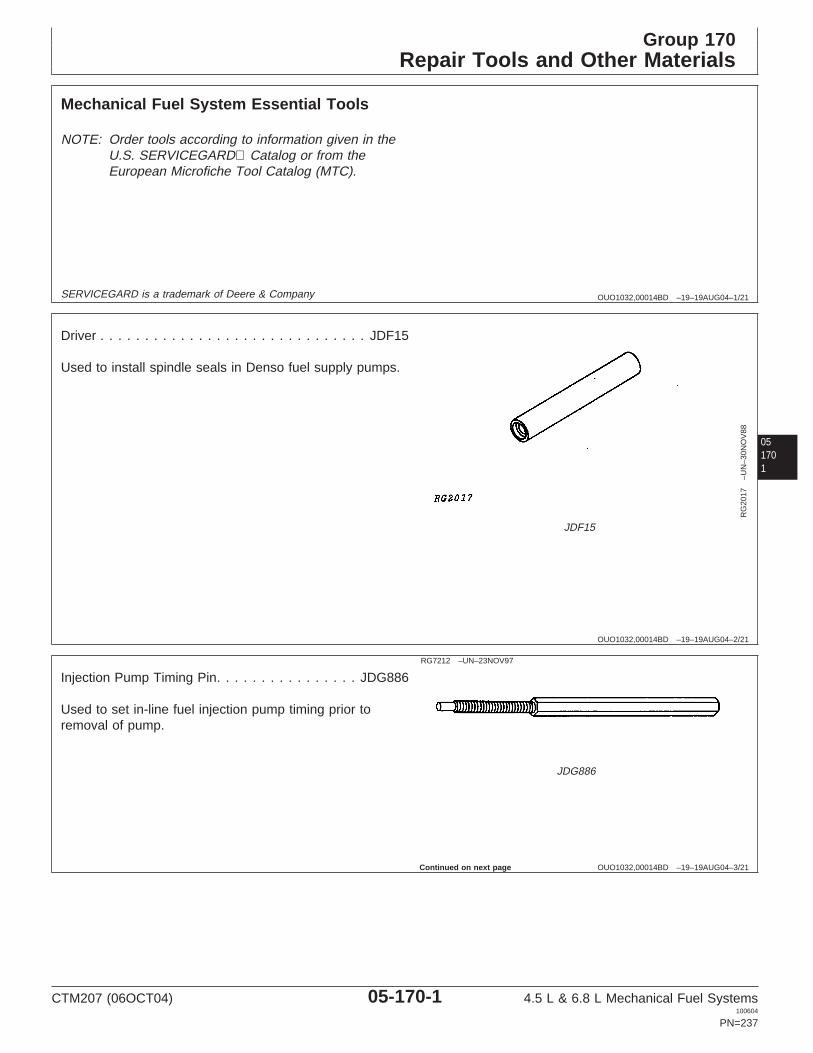
Group 170Repair Tools and Other Materials
OUO1032,00014BD –19–19AUG04–1/21
Mechanical Fuel System Essential Tools
NOTE: Order tools according to information given in theU.S. SERVICEGARD Catalog or from theEuropean Microfiche Tool Catalog (MTC).
SERVICEGARD is a trademark of Deere & Company
051701
OUO1032,00014BD –19–19AUG04–2/21
RG
2017
–UN
–30N
OV
88
JDF15
Driver . . . . . . . . . . . . . . . . . . . . . . . . . . . . . . JDF15
Used to install spindle seals in Denso fuel supply pumps.
OUO1032,00014BD –19–19AUG04–3/21
RG7212 –UN–23NOV97
JDG886
Injection Pump Timing Pin. . . . . . . . . . . . . . . . JDG886
Used to set in-line fuel injection pump timing prior toremoval of pump.
Continued on next page
CTM207 (06OCT04) 05-170-1 4.5 L & 6.8 L Mechanical Fuel Systems100604
PN=237

Repair Tools and Other Materials
OUO1032,00014BD –19–19AUG04–4/21
RG5068 –UN–05DEC97
Timing Pin
Timing Pin . . . . . . . . . . . . . . . . . . . . . . . . . . JDE81-4
Used to lock flywheel at No. 1 TDC for injection pumptiming.
05170
2
OUO1032,00014BD –19–19AUG04–5/21
RG
1203
1–U
N–2
0DE
C01
JDG1571
Timing Pin . . . . . . . . . . . . . . . . . . . . . . . . . JDG1571
Used to lock flywheel at No. 1 TDC for injection pumptiming. This timing pin MUST be used on engineapplications using the tapered-nose crankshaft due to thehigher torque specification for damper retaining capscrew.
OUO1032,00014BD –19–19AUG04–6/21
RG
6032
–UN
–13J
AN
92
JDG1560
Injection Pump Drive Gear Puller . . . . . . . . . . JDG1560
Remove drive gear from tapered shaft on Stanadyne DB2(with retained drive shafts) and DB4 fuel injection pumps.Also used to remove drive gear on Delphi/Lucas injectionpumps.
CTM207 (06OCT04) 05-170-2 4.5 L & 6.8 L Mechanical Fuel Systems100604
PN=238
Continued on next page

Repair Tools and Other Materials
OUO1032,00014BD –19–19AUG04–7/21
RG
7056
–UN
–05D
EC
97
JDG820
Flywheel Turning Tool . . . . . . . . . . . . . . . . . . JDG820
Used to rotate flywheel on engines with 129-tooth flywheelring gear and a 29.9 mm (1.18 in.) ID flywheel housingguide bore diameter. JDE81-1 may be used if JDG820 isnot available.
051703
OUO1032,00014BD –19–19AUG04–8/21
RG
7056
–UN
–05D
EC
97
JDE81-1
Flywheel Turning Tool . . . . . . . . . . . . . . . . . . JDE81-1
Used to rotate flywheel on engines with 129-tooth flywheelring gear and a 29.9 mm (1.18 in.) flywheel housing guidebore diameter. JDG820 may be used if JDE81-1 is notavailable. JDG820 MUST be used for 6.8L engines in7400 and 7600 Tractors.
OUO1032,00014BD –19–19AUG04–9/21
RG
6251
–UN
–22J
UL9
2
JDE83
Flywheel Turning Tool . . . . . . . . . . . . . . . . . . . JDE83
Used to rotate flywheel on engines with 142-tooth flywheelring gear and a 26.5 mm (1.04 in.) ID flywheel housingguide bore diameter.
CTM207 (06OCT04) 05-170-3 4.5 L & 6.8 L Mechanical Fuel Systems100604
PN=239
Continued on next page

Repair Tools and Other Materials
OUO1032,00014BD –19–19AUG04–10/21
RG5068 –UN–05DEC97
Timing Pin
Timing Pin . . . . . . . . . . . . . . . . . . . . . . . . . . JDE81-4
Used to lock engine at TDC.
05170
4
OUO1032,00014BD –19–19AUG04–11/21
RG
6251
–UN
–22J
UL9
2
JDE83
Flywheel Turning Tool . . . . . . . . . . . . . . . . . . . JDE83
Used to rotate flywheel on engines with 142-tooth flywheelring gear and a 26.5 mm (1.04 in.) ID flywheel housingguide bore diameter.
OUO1032,00014BD –19–19AUG04–12/21
RG5288 –UN–23AUG88
JDF22
Crowsfoot Wrench. . . . . . . . . . . . . . . . . . . . . . JDF22
Used to loosen and tighten fuel pipes at injection nozzlesand at injection pump.
Continued on next page
CTM207 (06OCT04) 05-170-4 4.5 L & 6.8 L Mechanical Fuel Systems100604
PN=240

Repair Tools and Other Materials
OUO1032,00014BD –19–19AUG04–13/21
RG
9478
–UN
–12N
OV
98
JDE38B
Injection Nozzle Puller . . . . . . . . . . . . . . . . . . JDE38B
Remove injection nozzles. If JDE38B is not available,JDE38A Nozzle Puller with JDG716 Adapter can be used.JDG716 can be used with slide handle adapter fromJDE38 or JDE38A to remove 9.5 mm nozzles withoutremoving the rocker arm cover. JDG716-1 Repair Kit isavailable if leg of JDG716 Adapter is damaged.
051705
OUO1032,00014BD –19–19AUG04–14/21
RG5084 –UN–23AUG88
JDE39
Nozzle Bore Cleaning Tool . . . . . . . . . . . . . . . . JDE39
Clean injection nozzle bore in cylinder head.
OUO1032,00014BD –19–19AUG04–15/21
RG5224 –UN–23AUG88
JDF13B
Nozzle Cleaning Kit . . . . . . . . . . . . . . . . . . . . JDF13B
Clean injection nozzles.
Continued on next page
CTM207 (06OCT04) 05-170-5 4.5 L & 6.8 L Mechanical Fuel Systems100604
PN=241

Repair Tools and Other Materials
OUO1032,00014BD –19–19AUG04–16/21
RG
7644
–UN
–23N
OV
97
JDG949
Injection Nozzle Wrench . . . . . . . . . . . . . . . . . JDG949
Used to loosen or tighten lift adjusting screws on injectionnozzles.
05170
6
OUO1032,00014BD –19–19AUG04–17/21
RG
6254
–UN
–22J
UL9
2
JD258 (JD-258)
Nozzle Carbon Stop Seal Installer . . . . .JD2581 (JD-258)
Used to install carbon stop seal in injection nozzle groove.
1Order JD-258 when tool is ordered from European Part Distribution(EPDC)
OUO1032,00014BD –19–19AUG04–18/21
Injection Nozzle Puller for RSN Nozzles. . . . . JDG1515-1
Remove RSN nozzles.
OUO1032,00014BD –19–19AUG04–19/21
Spring Chamber Cap Wrench . . . . . . . . . . . . JDG1521
Remove spring chamber cap from RSN nozzles.
OUO1032,00014BD –19–19AUG04–20/21
Pressure Adjustment Screw Lock Nut . . . . . . JDG1515-2
Loosen pressure adjusting screw lock nut on RSNnozzles.
CTM207 (06OCT04) 05-170-6 4.5 L & 6.8 L Mechanical Fuel Systems100604
PN=242
Continued on next page

Repair Tools and Other Materials
OUO1032,00014BD –19–19AUG04–21/21
Pressure Adjustment Screw Tool . . . . . . . . . . JDG1522
Adjust pressure of RSN nozzles.
051707
CTM207 (06OCT04) 05-170-7 4.5 L & 6.8 L Mechanical Fuel Systems100604
PN=243

Repair Tools and Other Materials
OUO1032,00014BE –19–20AUG04–1/1
Mechanical Fuel System Other Material
Number Name Use
T43512 (U.S.) Thread Lock and Sealer (Medium Apply to fuel supply pump mountingTY9473 (Canadian) Strength) screws, fuel line fittings, injection242 (LOCTITE) pump front access plate cap screws
and injection pump timing hole plug.
AR54749 (U.S.) Soap Lubricant Injection pump mounting flangeO-ring.
05170
8
LOCTITE is a registered trademark of Loctite Corp.
OUO1032,00014BF –19–20AUG04–1/10
Mechanical Fuel System Service Equipmentand Tools
NOTE: Order tools according to information given in theU.S. SERVICEGARD Catalog or from theEuropean Microfiche Tool Catalog (MTC). Sometools may be available from a local supplier.
SERVICEGARD is a trademark of Deere & Company
OUO1032,00014BF –19–20AUG04–2/10
Adapter . . . . . . . . . . . . . . . . . . . . . . . . . . TORX T45
Injection pump drive gear-to-hub cap screws and injectionpump drive gear-to-hub cap screws.
TORX is a registered trademark of Camcar/Textron.
OUO1032,00014BF –19–20AUG04–3/10
Bosch Bench Mounted Nozzle Tester . . . . . . . . JT25510
Check nozzle opening pressure.
CTM207 (06OCT04) 05-170-8 4.5 L & 6.8 L Mechanical Fuel Systems100604
PN=244
Continued on next page

Repair Tools and Other Materials
OUO1032,00014BF –19–20AUG04–4/10
Fuel Line . . . . . . . . . . . . . . . . . . . . . . . . . .KJD10109
Use with JT25510 Nozzle Tester to check nozzle openingpressure.
OUO1032,00014BF –19–20AUG04–5/10
Fuel Injection Nozzle Tester Adapter Set . . . . D01110AA
Check nozzle opening pressure.
OUO1032,00014BF –19–20AUG04–6/10
OTC Portable Nozzle Tester . . . . . . . . . . . . D01109AA
Check nozzle opening pressure.
051709
OUO1032,00014BF –19–20AUG04–7/10
Clamp-On Transducer . . . . . . . . . . . . . . . . . . JT07177
Use with TIME TRAC meter to measure engine speed.
OUO1032,00014BF –19–20AUG04–8/10
Cable . . . . . . . . . . . . . . . . . . . . . . . . . . . . . JT07172
Use with TIME TRAC meter to measure engine speed.
OUO1032,00014BF –19–20AUG04–9/10
Pressure Gauge 0—200 kPa (0—2 bar) (0—30 psi), Hoseand Fittings. . . . . . . . . . . . . . . . . . . . . . . . . . JT05470
Measure transfer pump pressure in rotary injection pumpsystems. Assemble test equipment from JT05470Universal Pressure Test Kit or any other suitableequipment.
Continued on next page
CTM207 (06OCT04) 05-170-9 4.5 L & 6.8 L Mechanical Fuel Systems100604
PN=245

Repair Tools and Other Materials
OUO1032,00014BF –19–20AUG04–10/10
Pressure Gauge 0—400 kPa (0—4 bar) (0—60 psi), Hoseand Fittings. . . . . . . . . . . . . . . . . . . . . . . . . . JT05470
Leak test in-line fuel injection pump and measure transferpump pressure in in-line injection pump systems.Assemble test equipment from JT05470 UniversalPressure Test Kit or any other suitable equipment.
05170
10
CTM207 (06OCT04) 05-170-10 4.5 L & 6.8 L Mechanical Fuel Systems100604
PN=246

Group 180Diagnostic Service Tools and Other Materials
DPSG,OUO1004,2679 –19–20APR00–1/8
Mechanical Fuel System Diagnostic EssentialTools
NOTE: Order tools according to information given in theU.S. SERVICEGARD Catalog or from theEuropean Microfiche Tool Catalog (MTC).
SERVICEGARD is a trademark of Deere & Company
051801
DPSG,OUO1004,2679 –19–20APR00–2/8
RG
7246
–UN
–23N
OV
97
JT07158
TIME TRAC Kit (Tester Kit) . . . . JT07158 (FKM10429A)
Used to perform the dynamic timing of engines. JT07158TIME TRAC Kit consists of the following: JT07170(26932) Meter, JT07171 (30641) Magnetic Pickup,JT07172 (30640) Transducer Cable, JT07173 (28037)SOI Clamp Assembly, JT07174 (28062) InstructionManual, JT07175 (30642) TIME TRAC Quick ReferenceSheet, JT07176 (26924) Carrying Case, JT07177 (28026)6 mm Green Clamp-On Transducer, JT07178 (28027) 1/4in. Black Clamp-On Transducer, JDE81-4 Timing Pin,JDG793 Threaded Magnetic Pickup Adapter, JT07155(29066) 9/16 in. In-Line SOI Sensor1 and JDG281Tapered Adapter1 for Flywheel Housing without tappedhole. FKM10429A Tester Kit consists of the following:FKM10429-1 Meter, FKM10429-4 Sensor Clamp,FKM10429-5 6 mm Clamp-On Transducer, FKM10429-8Instruction Manual, JDE81-4 Timing Pin, FKM10465-1Magnetic Probe, FKM10465-2 Transducer Cable,FKM10465-3 1/4 in. Clamp-On Transducer, JDG793Threaded Magnetic Pickup Adapter and JDG281 TaperedAdapter for Flywheel Housing without tapped hole.
TIME TRAC is a registered trademark of Stanadyne Automotive Corp.
1Optional Accessories
Continued on next page
CTM207 (06OCT04) 05-180-1 4.5 L & 6.8 L Mechanical Fuel Systems100604
PN=247

Diagnostic Service Tools and Other Materials
DPSG,OUO1004,2679 –19–20APR00–3/8
RG5068 –UN–05DEC97
JDE81-4
Timing Pin . . . . . . . . . . . . . . . . . . . . . . . . . . JDE81-4
Used to lock flywheel at No. 1 TDC for injection pumptiming. Do not use to lock engine when removing orinstalling damper retaining cap screws.
05180
2
DPSG,OUO1004,2679 –19–20APR00–4/8
RG
1203
1–U
N–2
0DE
C01
JDG1571
Timing Pin . . . . . . . . . . . . . . . . . . . . . . . . . JDG1571
Used to lock flywheel at No. 1 TDC for injection pumptiming. This timing pin MUST be used on engineapplications using the tapered-nose crankshaft due to thehigher torque specification for damper retaining capscrew.
DPSG,OUO1004,2679 –19–20APR00–5/8
RG
6251
–UN
–22J
UL9
2
JDE83
Flywheel Turning Tool . . . . . . . . . . . . . . . . . . . JDE83
Used to rotate flywheel on engines with 142-tooth flywheelring gear and a 26.5 mm (1.04 in.) ID flywheel housingguide bore diameter.
Continued on next page
CTM207 (06OCT04) 05-180-2 4.5 L & 6.8 L Mechanical Fuel Systems100604
PN=248

Diagnostic Service Tools and Other Materials
DPSG,OUO1004,2679 –19–20APR00–6/8
RG
7056
–UN
–05D
EC
97
JDG820
Flywheel Turning Tool . . . . . . . . . . . . . . . . . . JDG820
Used to rotate flywheel on engine to check damper radialrunout and time engine. JDE81-1 may be used also ifJDG820 is not available.
051803
DPSG,OUO1004,2679 –19–20APR00–7/8
RG
7056
–UN
–05D
EC
97
JDE81-1
Flywheel Turning Tool . . . . . . . . . . . . . . . . . . JDE81-1
Used to rotate flywheel on engines with 129-tooth flywheelring gear and a 29.9 mm (1.18 in.) flywheel housing guidebore diameter. JDG820 may be used if JDE81-1 is notavailable. JDG820 MUST be used for 6.8L engines in7400 and 7600 Tractors.
DPSG,OUO1004,2679 –19–20APR00–8/8
RG7212 –UN–23NOV97
JDG886
Injection Pump Timing Pin. . . . . . . . . . . . . . . . JDG886
Used to set in-line fuel injection pump timing prior toremoval of pump.
CTM207 (06OCT04) 05-180-3 4.5 L & 6.8 L Mechanical Fuel Systems100604
PN=249

Diagnostic Service Tools and Other Materials
DPSG,OUO1004,2680 –19–20APR00–1/5
Mechanical Fuel System Diagnostic ServiceEquipment and Tools
NOTE: Order tools according to information given in theU.S. SERVICEGARD Catalog or from theEuropean Microfiche Tool Catalog (MTC). Sometools may be available from a local supplier.
SERVICEGARD is a trademark of Deere & Company
05180
4
DPSG,OUO1004,2680 –19–20APR00–2/5
Clamp-On Transducer . . . . . . . . . . . . . . . . . . JT07177
Use with TIME TRAC meter to measure engine speed.
DPSG,OUO1004,2680 –19–20APR00–3/5
Cable . . . . . . . . . . . . . . . . . . . . . . . . . . . . . JT07172
Use with TIME TRAC meter to measure engine speed.
DPSG,OUO1004,2680 –19–20APR00–4/5
Pressure Gauge 0—200 kPa (0—2 bar) (0—30 psi), Hoseand Fittings. . . . . . . . . . . . . . . . . . . . . . . . . . JT05470
Measure transfer pump pressure in rotary injection pumpsystems. Assemble test equipment from JT05470Universal Pressure Test Kit or any other suitableequipment.
DPSG,OUO1004,2680 –19–20APR00–5/5
Pressure Gauge 0—400 kPa (0—4 bar) (0—60 psi), Hoseand Fittings. . . . . . . . . . . . . . . . . . . . . . . . . . JT05470
Measure transfer pump pressure in in-line injection pumpsystems. Assemble test equipment from JT05470Universal Pressure Test Kit or any other suitableequipment.
CTM207 (06OCT04) 05-180-4 4.5 L & 6.8 L Mechanical Fuel Systems100604
PN=250

Group 190Dealer Fabricated Service Tools
RG,199,JW7719 –19–25NOV97–1/1
How to Make Tools
These tools can be made in a service shop usingcommon shop tools and locally obtained materials.
051901
RG,199,JW7720 –19–25NOV97–1/1
DFRG5—Injection Pump Front Plate Timing Mark Transfer Tool
RG
9056
–UN
–16M
AR
98
DFRG-5
Material—Aluminum
This template is used to transfer the injection pumptiming mark from the engine’s original front plate to the
replacement front plate (which does not have themark). Refer to Section 02, Group 090 for procedure touse this tool.
CTM207 (06OCT04) 05-190-1 4.5 L & 6.8 L Mechanical Fuel Systems100604
PN=251
Dealer Fabricated Service Tools
05190
2
CTM207 (06OCT04) 05-190-2 4.5 L & 6.8 L Mechanical Fuel Systems100604
PN=252
Section 06Specifications
Contents
Page
Group 200—Repair and General OEMSpecifications
Unified Inch Bolt and Cap Screw TorqueValues . . . . . . . . . . . . . . . . . . . . . . . . . . . . .06-200-1
Metric Bolt and Cap Screw Torque Values . . .06-200-2General OEM Engine Specifications . . . . . . . .06-200-3Mechanical Fuel System Repair
Specifications. . . . . . . . . . . . . . . . . . . . . . . .06-200-5
Group 210—Diagnostic SpecificationsFuel Injection Pump Specifications . . . . . . . . .06-210-1Mechanical Fuel System Diagnostic and Test
Specifications. . . . . . . . . . . . . . . . . . . . . . .06-210-30
06
CTM207 (06OCT04) 06-1 4.5 L & 6.8 L Mechanical Fuel Systems100604
PN=1

Contents
06
CTM207 (06OCT04) 06-2 4.5 L & 6.8 L Mechanical Fuel Systems100604
PN=2

Group 200Repair and General OEM Specifications
062001
DX,TORQ1 –19–01OCT99–1/1
Unified Inch Bolt and Cap Screw Torque Values
TO
RQ
1A–U
N–2
7SE
P99
Top, SAE Grade and Head Markings; Bottom, SAE Grade and Nut Markings
Grade 1 (No Mark) Grade 2a (No Mark) Grade 5, 5.1 or 5.2 Grade 8 or 8.2
Size Lubricatedb Dryc Lubricatedb Dryc Lubricatedb Dryc Lubricatedb Dryc
N•m(lb-ft) N•m(lb-ft) N•m(lb-ft) N•m(lb-ft) N•m(lb-ft) N•m(lb-ft) N•m(lb-ft) N•m(lb-ft)
1/4 3.8 (2.8) 4.7 (3.5) 6 (4.4) 7.5 (5.5) 9.5 (7) 12 (9) 13.5 (10) 17 (12.5)
5/16 7.7 (5.7) 9.8 (7.2) 12 (9) 15.5 (11.5) 19.5 (14.5) 25 (18.5) 28 (20.5) 35 (26)
3/8 13.5 (10) 17.5 (13) 22 (16) 27.5 (20) 35 (26) 44 (32.5) 49 (36) 63 (46)
7/16 22 (16) 28 (20.5) 35 (26) 44 (32.5) 56 (41) 70 (52) 80 (59) 100 (74)
1/2 34 (25) 42 (31) 53 (39) 67 (49) 85 (63) 110 (80) 120 (88) 155 (115)
9/16 48 (35.5) 60 (45) 76 (56) 95 (70) 125 (92) 155 (115) 175 (130) 220 (165)
5/8 67 (49) 85 (63) 105 (77) 135 (100) 170 (125) 215 (160) 240 (175) 305 (225)
3/4 120 (88) 150 (110) 190 (140) 240 (175) 300 (220) 380 (280) 425 (315) 540 (400)
7/8 190 (140) 240 (175) 190 (140) 240 (175) 490 (360) 615 (455) 690 (510) 870 (640)
1 285 (210) 360 (265) 285 (210) 360 (265) 730 (540) 920 (680) 1030 (760) 1300 (960)
1-1/8 400 (300) 510 (375) 400 (300) 510 (375) 910 (670) 1150 (850) 1450 (1075) 1850 (1350)
1-1/4 570 (420) 725 (535) 570 (420) 725 (535) 1280 (945) 1630 (1200) 2050 (1500) 2600 (1920)
1-3/8 750 (550) 950 (700) 750 (550) 950 (700) 1700 (1250) 2140 (1580) 2700 (2000) 3400 (2500)
1-1/2 990 (730) 1250 (930) 990 (730) 1250 (930) 2250 (1650) 2850 (2100) 3600 (2650) 4550 (3350)a Grade 2 applies for hex cap screws (not hex bolts) up to 6 in. (152 mm) long. Grade 1 applies for hex cap screws over 6 in. (152 mm) long,and for all other types of bolts and screws of any length.b "Lubricated" means coated with a lubricant such as engine oil, or fasteners with phosphate and oil coatings.c "Dry" means plain or zinc plated without any lubrication.
DO NOT use these values if a different torque value or tightening Make sure fastener threads are clean and that you properly startprocedure is given for a specific application. Torque values listed are thread engagement. This will prevent them from failing whenfor general use only. Check tightness of fasteners periodically. tightening.
Shear bolts are designed to fail under predetermined loads. Always Tighten plastic insert or crimped steel-type lock nuts to approximatelyreplace shear bolts with identical grade. 50 percent of the dry torque shown in the chart, applied to the nut,
not to the bolt head. Tighten toothed or serrated-type lock nuts to thefull torque value.
Fasteners should be replaced with the same or higher grade. Ifhigher grade fasteners are used, these should only be tightened tothe strength of the original.
CTM207 (06OCT04) 06-200-1 4.5 L & 6.8 L Mechanical Fuel Systems100604
PN=255
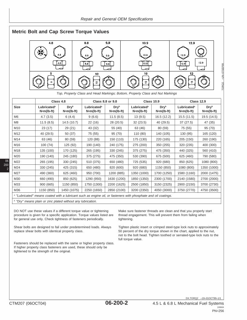
Repair and General OEM Specifications
06200
2
DX,TORQ2 –19–01OCT99–1/1
Metric Bolt and Cap Screw Torque Values
TO
RQ
2–U
N–0
7SE
P99
Top, Property Class and Head Markings; Bottom, Property Class and Nut Markings
Class 4.8 Class 8.8 or 9.8 Class 10.9 Class 12.9
Size Lubricateda Dryb Lubricateda Dryb Lubricateda Dryb Lubricateda Dryb
N•m(lb-ft) N•m(lb-ft) N•m(lb-ft) N•m(lb-ft) N•m(lb-ft) N•m(lb-ft) N•m(lb-ft) N•m(lb-ft)
M6 4.7 (3.5) 6 (4.4) 9 (6.6) 11.5 (8.5) 13 (9.5) 16.5 (12.2) 15.5 (11.5) 19.5 (14.5)
M8 11.5 (8.5) 14.5 (10.7) 22 (16) 28 (20.5) 32 (23.5) 40 (29.5) 37 (27.5) 47 (35)
M10 23 (17) 29 (21) 43 (32) 55 (40) 63 (46) 80 (59) 75 (55) 95 (70)
M12 40 (29.5) 50 (37) 75 (55) 95 (70) 110 (80) 140 (105) 130 (95) 165 (120)
M14 63 (46) 80 (59) 120 (88) 150 (110) 175 (130) 220 (165) 205 (150) 260 (190)
M16 100 (74) 125 (92) 190 (140) 240 (175) 275 (200) 350 (255) 320 (235) 400 (300)
M18 135 (100) 170 (125) 265 (195) 330 (245) 375 (275) 475 (350) 440 (325) 560 (410)
M20 190 (140) 245 (180) 375 (275) 475 (350) 530 (390) 675 (500) 625 (460) 790 (580)
M22 265 (195) 330 (245) 510 (375) 650 (480) 725 (535) 920 (680) 850 (625) 1080 (800)
M24 330 (245) 425 (315) 650 (480) 820 (600) 920 (680) 1150 (850) 1080 (800) 1350 (1000)
M27 490 (360) 625 (460) 950 (700) 1200 (885) 1350 (1000) 1700 (1250) 1580 (1160) 2000 (1475)
M30 660 (490) 850 (625) 1290 (950) 1630 (1200) 1850 (1350) 2300 (1700) 2140 (1580) 2700 (2000)
M33 900 (665) 1150 (850) 1750 (1300) 2200 (1625) 2500 (1850) 3150 (2325) 2900 (2150) 3700 (2730)
M36 1150 (850) 1450 (1075) 2250 (1650) 2850 (2100) 3200 (2350) 4050 (3000) 3750 (2770) 4750 (3500)a "Lubricated" means coated with a lubricant such as engine oil, or fasteners with phosphate and oil coatings.b "Dry" means plain or zinc plated without any lubrication.
DO NOT use these values if a different torque value or tightening Make sure fastener threads are clean and that you properly startprocedure is given for a specific application. Torque values listed are thread engagement. This will prevent them from failing whenfor general use only. Check tightness of fasteners periodically. tightening.
Shear bolts are designed to fail under predetermined loads. Always Tighten plastic insert or crimped steel-type lock nuts to approximatelyreplace shear bolts with identical property class. 50 percent of the dry torque shown in the chart, applied to the nut,
not to the bolt head. Tighten toothed or serrated-type lock nuts to thefull torque value.
Fasteners should be replaced with the same or higher property class.If higher property class fasteners are used, these should only betightened to the strength of the original.
CTM207 (06OCT04) 06-200-2 4.5 L & 6.8 L Mechanical Fuel Systems100604
PN=256

Repair and General OEM Specifications
062003
DPSG,OUO1004,102 –19–19AUG04–1/2
General OEM Engine Specifications
ITEM ENGINE
4045DF120 4045DF270 4045DF150 4045TF120 4045TF150 4045TF250 4045TF270 4045HF120 4045HF150
Number of Cylinders 4 4 4 4 4 4 4 4 4
Bore 106 mm 106 mm 106 mm 106 mm 106 mm 106 mm 106 mm 106 mm 106 mm(4.19 in.) (4.19 in.) (4.19 in.) (4.19 in.) (4.19 in.) (4.19 in.) (4.19 in.) (4.19 in.) (4.19 in.)
Stroke 127 mm 127 mm 127 mm 127 mm 127 mm 127 mm 127 mm 127 mm 127 mm(5.0 in.) (5.0 in.) (5.0 in.) (5.0 in.) (5.0 in.) (5.0 in.) (5.0 in.) (5.0 in.) (5.0 in.)
Displacement 4.5L 4.5L 4.5L 4.5L 4.5L 4.5L 4.5L 4.5L 4.5L(276 cu (276 cu (276 cu (276 cu (276 cu (276 cu (276 cu (276 cu (276 cu
in.) in.) in.) in.) in.) in.) in.) in.) in.)
Compression 17.6:1 17.6:1 17.6:1 17.0:1 17.0:1 17.0:1 17.0:1 17.0:1 17.0:1
Max. Crank Pressure 0.5 kPa 0.5 kPa 0.5 kPa 0.5 kPa 0.5 kPa 0.5 kPa 0.5 kPa 0.5 kPa 0.5 kPa(2 H2O) (2 H2O) (2 H2O) (2 H2O) (2 H2O) (2 H2O) (2 H2O) (2 H2O) (2 H2O)
Governor Regulation 7—10 % 7—10 % 7—10 % 7—10 % 7—10 % 7—10 % 7—10 % 7—10 % 7—10 %(Industrial)
Governor Regulation 5 % 5 % 5 % 5 % 5 % 5 % 5 % 5 % 5 %(Generator)
Oil Pressure at Full 345 kPa 345 kPa 345 kPa 345 kPa 345 kPa 345 kPa 345 kPa 345 kPa 345 kPaLoad at Rated Speed (50 psi) (50 psi) (50 psi) (50 psi) (50 psi) (50 psi) (50 psi) (50 psi) (50 psi)
Oil Pressure Low Idle 105 kPa 105 kPa 105 kPa 105 kPa 105 kPa 105 kPa 105 kPa 105 kPa 105 kPa(15 psi) (15 psi) (15 psi) (15 psi) (15 psi) (15 psi) (15 psi) (15 psi) (15 psi)
Length 861.0 mm 861.0 mm 861.0 mm 861.0 mm 861.0 mm 861.0 mm 861.0 mm 861.0 mm 861.0 mm(33.9 in.) (33.9 in.) (33.9 in.) (33.9 in.) (33.9 in.) (33.9 in.) (33.9 in.) (33.9 in.) (33.9 in.)
Width 598 mm 612 mm 598 mm 598 mm 598 mm 598 mm 612 mm 598 mm 598 mm(23.5 in.) (24.1 in.) (23.5 in.) (23.5 in.) (23.5 in.) (23.5 in.) (24.1 in.) (23.5 in.) (23.5 in.)
Height 854 mm 856 mm 854 mm 980 mm 980 mm 980 mm 994 mm 980 mm 980 mm(33.6 in.) (33.7 in.) (33.6 in.) (38.6 in.) (38.6 in.) (38.6 in.) (39.1 in.) (38.6 in.) (38.6 in.)
Weight 387 kg 387 kg 387 kg 396 kg 396 kg 396 kg 451 kg 396 kg 396 kg(851 lb) (851 lb) (851 lb) (872 lb) (872 lb) (872 lb) (993 lb) (872 lb) (872 lb)
Continued on next page
CTM207 (06OCT04) 06-200-3 4.5 L & 6.8 L Mechanical Fuel Systems100604
PN=257

Repair and General OEM Specifications
06200
4
DPSG,OUO1004,102 –19–19AUG04–2/2
ITEM ENGINE
6068DF150 6068TF120 6068TF150 6068TF250 6068HF120 6068HF150 6068HF250
Number of Cylinders 6 6 6 6 6 6 6
Bore 106 mm 106 mm 106 mm 106 mm 106 mm 106 mm 106 mm(4.19 in.) (4.19 in.) (4.19 in.) (4.19 in.) (4.19 in.) (4.19 in.) (4.19 in.)
Stroke 127 mm (5.0 127 mm (5.0 127 mm (5.0 127 mm (5.0 127 mm (5.0 127 mm (5.0 127 mm (5.0in.) in.) in.) in.) in.) in.) in.)
Displacement 6.8L 6.8L 6.8L 6.8L 6.8L 6.8L 6.8L(414 cu in.) (414 cu in.) (414 cu in.) (414 cu in.) (414 cu in.) (414 cu in.) (414 cu in.)
Compression 17.6:1 17.0:1 17.0:1 17.0:1 17.0:1 17.0:1 17.0:1
Max. Crank Pressure 0.5 kPa 0.5 kPa 0.5 kPa 0.5 kPa 0.5 kPa 0.5 kPa 0.5 kPa(2 H2O) (2 H2O) (2 H2O) 2 H2O) (2 H2O) (2 H2O) (2 H2O)
Governor Regulation 7—10 % 7—10 % 7—10 % 7—10 % 7—10 % 7—10 % 7—10 %(Industrial)
Governor Regulation 5 % 5 % 5 % 5 % 5 % 5 % 5 %(Generator)
Oil Pressure at Full Load at 345 kPa (50 345 kPa (50 345 kPa (50 345 kPa (50 345 kPa (50 345 kPa (50 345 kPa (50Rated Speed psi) psi) psi) psi) psi) psi) psi)
Oil Pressure Low Idle 105 kPa (15 105 kPa (15 105 kPa (15 105 kPa (15 105 kPa (15 105 kPa (15 105 kPa (15psi) psi) psi) psi) psi) psi) psi)
Length 1117 mm 1117 mm 1117 mm 1117 mm 1116 mm 1116 mm 1141 mm(44.0 in.) (44.0 in.) (44.0 in.) (44.0 in.) (43.9 in.) (43.9 in.) (44.9 in.)
Width 598 mm 598 mm 598 mm 598 mm 623 mm 623 mm 623 mm(23.5 in.) (23.5 in.) (23.5 in.) (23.5 in.) (24.5 in.) (24.5 in.) (24.5 in.)
Height 956 mm 984 mm 984 mm 984 mm 1009 mm 1009 mm 1009 mm(37.6 in.) (38.7 in.) (38.7 in.) (38.7 in.) (39.7 in.) (39.7 in.) (39.7 in.)
Weight 522 kg (1149 533 kg 533 kg 533 kg (1172 550 kg (1210 550 kg (1210 568 kglb) (1172 lb) (1172 lb) lb) lb) lb) (1250 lb)
CTM207 (06OCT04) 06-200-4 4.5 L & 6.8 L Mechanical Fuel Systems100604
PN=258

Repair and General OEM Specifications
062005
OUO1032,00014C3 –19–23AUG04–1/8
Mechanical Fuel System RepairSpecifications
Item Measurement Specification
Fuel Filter Base Mounting Torque 35 N•m (26 lb-ft)Bracket-to-Cylinder Head
Primary Fuel Filter/Water Separator Torque 35 N•m (26 lb-ft)Mounting Base-to-Bracket
Final Fuel Filter Mounting Torque 35 N•m (26 lb-ft)Base-to-Bracket
Fuel Supply Pump (Engine with Pressure 28—41 kPa (0.28—0.41 bar)Rotary Injection Pump) (4—6 psi)
Fuel Supply Pump Cap Screws Torque 30 N•m (22 lb-ft)(Rotary)
Fuel Supply Pump (Denso) Cap Torque 5—7 N•m (4—5 lb-ft)Screws (45—60 lb-in.)
Motorpal Fuel Supply Pump Torque 8 N•m (6 lb-ft) (72 lb-in.)Mounting Cap Screws
Fuel Supply Pump Inlet and Outlet Torque 10 N•m (7 lb-ft)Lines
Fuel Shut-Off Solenoid Actuator Rod Torque 15—20 N•m (11—15 lb-ft)Cap Screw/Nut
Remove and Install Delphi/LucasFuel Shut-Off Solenoid
Solenoid Tightening Torque 24 N•m (18 lb-ft)
Cold Start Advance Valve Torque 11.5 N•m (8.5 lb-ft)
Cold Start Advance Torque 5.5 N•m (48 lb-in.)Solenoid-to-Valve
Delphi/Lucas Cold Start Advance Torque 5 N•m (44 lb-in.)Temperature Switch
Delphi/Lucas and Stanadyne Rotary Torque 27 N•m (20 lb-ft)Injection Pump Mounting Nuts
CTM207 (06OCT04) 06-200-5 4.5 L & 6.8 L Mechanical Fuel Systems100604
PN=259
Continued on next page

Repair and General OEM Specifications
06200
6
OUO1032,00014C3 –19–23AUG04–2/8
Item Measurement Specification
Denso Injection Pump Drive Gear Torque 47 N•m (35 lb-ft)Cap Screws
Motorpal Injection Pump Drive Gear Torque 61 N•m (45 lb-ft)Cap Screws
Stanadyne DB2 Fuel Injection Pump Torque 125 N•m (92 lb-ft)Drive Gear-to-Shaft Retaining Nut
Stanadyne DB4 Fuel Injection Pump Torque 200 N•m (148 lb-ft)Drive Gear-to-Shaft Retaining Nut
Rotary Injection Pump Front Access Torque 6 N•m (4.5 lb-ft) (54 lb-in.)Plate Cap Screws
Rotary Injection Pump Mounting Nuts Torque 27 N•m (20 lb-ft)
Fuel Injection Pump Delivery Lines Torque 27 N•m (20 lb-ft)(At Pump)
DP201 and DP203 Delphi/Lucas Torque 80 N•m (60 lb-ft)Fuel Injection Pump DriveGear-to-Shaft Retaining Nut
Rotary Injection Pump Front Access Torque 6 N•m (4.5 lb-ft) (54 lb-in.)Plate Cap Screws
Rotary Injection Pump Mounting Nuts Torque 27 N•m (20 lb-ft)
Fuel Injection Pump Delivery Lines Torque 27 N•m (20 lb-ft)
Denso Injection Pump Mounting Nuts Torque 70 N•m (52 lb-ft)
Denso Injection Pump Drive Gear Torque 47 N•m (35 lb-ft)Cap Screws
Denso Injection Pump Drive Gear Torque 6 N•m (4.5 lb-ft) (54 lb-in.)Cover
Fuel Injection Pump Delivery Lines Torque 27 N•m (20 lb-ft)
Fuel Injection Pump Delivery Valve Torque 47 N•m (35 lb-ft)(Motorpal)
Motorpal Injection Pump-to-Cylinder Torque 47 N•m (35 lb-ft)Block Stud Nuts
CTM207 (06OCT04) 06-200-6 4.5 L & 6.8 L Mechanical Fuel Systems100604
PN=260
Continued on next page

Repair and General OEM Specifications
062007
OUO1032,00014C3 –19–23AUG04–3/8
Item Measurement Specification
Motorpal Injection Pump Drive Torque 61 N•m (45 lb-ft)Gear-to-Pump Hub Cap Screws
Motorpal Injection Pump Timing Pin Torque 70 N•m (52 lb-ft)Cap
Injection Pump Drive Gear Cover Torque 6 N•m (4.5 lb-ft) (54 lb-in.)Cap Screws
Injection Pump Fuel Delivery Lines Torque 27 N•m (20 lb-ft)
Motorpal Fuel Inlet Line-to-Injection Torque 10 N•m (7 lb-ft)Pump
Motorpal Fuel Leak-Off Torque 13 N•m (10 lb-ft)Line-to-Injection Pump
Motorpal Injection Pump Lube Line Torque 4.5 N•m (3 lb-ft) (36 lb-in.)
Motorpal Fuel Supply Pump Torque 10 N•m (7 lb-ft)Lines-to-Injection Pump
Motorpal Injection Pump Housing Oil Torque 25 N•m (18 lb-ft)Fill Plug
Aneroid Pressure (Lever Lift-Off) Pressure 76—102 mm Hg (3—4 in. Hg)10—14 kPa (1.5—2.0 psi)
Aneroid Pressure (Lever at Full Pressure 330—380 mm Hg (13—14 in. Hg)Travel) 44—51 kPa (6.4—7.4 psi)
Fuel Injection RE60062 Nozzles(Naturally Aspirated Engines)
New or Reconditioned Nozzle with Opening Pressure for Setting 23 856—24 407 kPaNew Internal Parts (238—244 bar)
(3460—3540 psi)Opening Pressure for Checking 21 856 kPa (218 bar)(Minimum) (3170 psi)
Used Nozzle Opening Pressure for Checking 19 850 kPa (198 bar)(Minimum) (2880 psi)
Opening Pressure Difference Pressure Difference (Maximum) 700 kPa (7 bar) (100 psi)between Cylinders
CTM207 (06OCT04) 06-200-7 4.5 L & 6.8 L Mechanical Fuel Systems100604
PN=261
Continued on next page

Repair and General OEM Specifications
06200
8
OUO1032,00014C3 –19–23AUG04–4/8
Item Measurement Specification
Fuel Injection RE48786 Nozzles(Turbocharged Engines)
New or Reconditioned Nozzle with Opening Pressure for Setting 25 511—26 062 kPaNew Internal Parts (255—260 bar)
(3700—3780 psi)Opening Pressure for Checking 24 683 kPa (246 bar)(Minimum) (3580 psi)
Used Nozzle Opening Pressure for Checking 23 511 kPa (235 bar)(Minimum) (3410 psi)
Opening Pressure Difference Pressure Difference (Maximum) 700 kPa (7 bar) (100 psi)between Cylinders
Fuel Injection Nozzle Tip Spray Angle 144°
Nozzle Valve/Seat Tightness Leakage Nozzle tip dry after 5 seconds.Condition at Pressure Test of 2800— (Slight dampness permissible on3500 kPa (28—35 bar) (400—500 used nozzles.)psi)
Fuel Injection Nozzle Return Leakage 3—10 Drops/30 SecondsLeakage at Pressure Test of 10 300kPa (103 bar) (1500 psi)
Fuel Injection Nozzle Tip Orifice Number of Orifices per Nozzle 4
Fuel Injection Nozzle Tip Orifice ID 0.27 mm (0.0106 in.)(Naturally Aspirated Engines)
Fuel Injection Nozzle Tip Orifice ID 0.29 mm (0.0116 in.)(Turbocharged Engines)
Fuel Injection Nozzles (NaturallyAspirated Engines)
New or Reconditioned Nozzle with Opening Pressure for Setting 23 856—24 407 kPaNew Internal Parts (238—244 bar)
(3460—3540 psi)Opening Pressure for Checking 21 856 kPa (218 bar)(Minimum) (3170 psi)
Used Nozzle Opening Pressure for Checking 19 850 kPa (198 bar)(Minimum) (2880 psi)
CTM207 (06OCT04) 06-200-8 4.5 L & 6.8 L Mechanical Fuel Systems100604
PN=262
Continued on next page

Repair and General OEM Specifications
062009
OUO1032,00014C3 –19–23AUG04–5/8
Item Measurement Specification
Opening Pressure Difference Pressure Difference (Maximum) 700 kPa (7 bar) (100 psi)between Cylinders
Fuel Injection Nozzles (TurbochargedEngines)
New or Reconditioned Nozzle with Opening Pressure for Setting 25 511—26 062 kPaNew Internal Parts (255—260 bar)
(3700—3780 psi)Opening Pressure for Checking 24 683 kPa (246 bar)(Minimum) (3580 psi)
Used Nozzle Opening Pressure for Checking 23 511 kPa (235 bar)(Minimum) (3410 psi)
Opening Pressure Difference Pressure Difference (Maximum) 700 kPa (7 bar) (100 psi)between Cylinders
Rate Shaping Nozzle (Tier IICertified Engines)
New or Reconditioned Nozzle Opening Pressure for Setting 24 400—24 900 kPa (244—249 bar)(3540—3620 psi)
Opening Pressure for Checking 24 100 kPa (241 bar) (3500 psi)(Minimum)
Used Nozzle Opening Pressure for Setting 23 000—23 600 kPa (230—236 bar)(3340—3420 psi)
Opening Pressure for Checking 21 800 kPa (218 bar) (3170 psi)(Minimum)
Opening Pressure Difference Pressure Difference (Maximum) 700 kPa (7 bar) (100 psi)between Cylinders
Injection Nozzle Pressure Adjusting Torque 10 N•m (7 lb-ft)Screw Lock Nut
Fuel Injection Nozzle Valve Needle Lift (Based on Zero Lift) 3/4 Turn Counterclockwise
Fuel Injection Nozzle Lift Adjusting Torque 5 N•m (3.5 lb-ft) (42 lb-in.)Screw Lock Nut
CTM207 (06OCT04) 06-200-9 4.5 L & 6.8 L Mechanical Fuel Systems100604
PN=263
Continued on next page

Repair and General OEM Specifications
06200
10
OUO1032,00014C3 –19–23AUG04–6/8
Item Measurement Specification
RSN Nozzle Valve Lift
Pressure Adjusting Screw Lock Torque 10 N•m (7 lb-ft)Nut
Lift Adjusting Screw Lock Nut Torque 5 N•m (3.5 lb-ft)
RSN Nozzle (Tier II Certified Lift 7/8 turnEngines) Valve
Fuel Injection Nozzle Hold-Down Torque 40 N•m (30 lb-ft)Clamp Cap Screws
Fuel Leak-Off Line Hex Nut Torque 5 N•m (3.7 lb-ft)(44 lb-in.)
Fuel Injection Nozzle Delivery Line Torque 27 N•m (20 lb-ft)
Stanadyne Fuel Injection Pump Torque 27 N•m (20 lb-ft)Return Line Connector
Fuel Injection Line-to-Nozzle Torque 27 N•m (20 lb-ft)Connector
Fuel Present at Injection NozzleCheck
Fuel Injection Nozzle Delivery Torque 27 N•m (20 lb-ft)Lines
Cylinder Misfire Test (EngineRunning)
Fuel Injection Nozzle Delivery Line Torque 27 N•m (20 lb-ft)
Rotary Injection Pump Mounting Nuts Torque 27 N•m (20 lb-ft)
Denso Injection Pump Drive Gear Torque 47 N•m (35 lb-ft)Cap Screws
Motorpal Injection Pump Drive Gear Torque 61 N•m (45 lb-ft)Cap Screws
CTM207 (06OCT04) 06-200-10 4.5 L & 6.8 L Mechanical Fuel Systems100604
PN=264
Continued on next page

Repair and General OEM Specifications
0620011
OUO1032,00014C3 –19–23AUG04–7/8
Item Measurement Specification
Rotary Fuel Supply Pump Operating Pressure 21—34 kPa (0.21—0.34 bar) (3—5psi)
Rotary Fuel Supply Pump Minimum Flow at 2400 rpm Engine 1.5 L/min (0.42 gpm)Speed
Denso In-Line Fuel Supply Pump Minimum Pressure at 2400 rpm 69 kPa (0.69 bar) (10 psi)Engine Speed
Denso In-Line Fuel Supply Pump Minimum Flow at 2400 rpm Engine 2.0 L/min (0.53 gpm)Speed
Motorpal In-Line Fuel Supply Pump Minimum Pressure at 2000 rpm 80 kPa (0.80 bar) (11.6 psi)Engine Speed
Motorpal In-Line Fuel Supply Pump Minimum Flow at 1000 rpm Engine 1.3 L/min (0.34 gpm)Speed
Denso In-Line Supply Pump Minimum Outlet Pressure at 69 kPa (0.69 bar) (10 psi)Cranking Speed
Motorpal In-Line Fuel Supply Pump Minimum Positive Pressure at 80 kPa (0.80 bar) (11.6 psi)Cranking Speed
Cold Start Switch Torque 5 N•m (3.5 lb-ft) (42 lb-in.)
Delphi/Lucas Fuel Shut-Off Solenoid Resistance 9 Ohms
Denso Fuel Shut-Off Solenoid(12-Volt System: RE67325)
Pull Coil Resistance 0.134—0.200 Ohms
Hold Coil Resistance 6.63—8.11 Ohms
Denso Fuel Shut-Off Solenoid(24-Volt System: RE67256)
Pull Coil Resistance 0.560—0.684 Ohms
Hold Coil Resistance 24.35—29.76 Ohms
Motorpal Fuel Shut-Off Solenoid
Pull Coil Resistance 0.174—0.260 Ohms
CTM207 (06OCT04) 06-200-11 4.5 L & 6.8 L Mechanical Fuel Systems100604
PN=265
Continued on next page
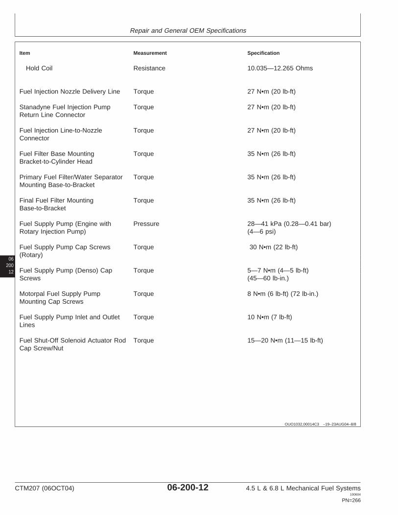
Repair and General OEM Specifications
06200
12
OUO1032,00014C3 –19–23AUG04–8/8
Item Measurement Specification
Hold Coil Resistance 10.035—12.265 Ohms
Fuel Injection Nozzle Delivery Line Torque 27 N•m (20 lb-ft)
Stanadyne Fuel Injection Pump Torque 27 N•m (20 lb-ft)Return Line Connector
Fuel Injection Line-to-Nozzle Torque 27 N•m (20 lb-ft)Connector
Fuel Filter Base Mounting Torque 35 N•m (26 lb-ft)Bracket-to-Cylinder Head
Primary Fuel Filter/Water Separator Torque 35 N•m (26 lb-ft)Mounting Base-to-Bracket
Final Fuel Filter Mounting Torque 35 N•m (26 lb-ft)Base-to-Bracket
Fuel Supply Pump (Engine with Pressure 28—41 kPa (0.28—0.41 bar)Rotary Injection Pump) (4—6 psi)
Fuel Supply Pump Cap Screws Torque 30 N•m (22 lb-ft)(Rotary)
Fuel Supply Pump (Denso) Cap Torque 5—7 N•m (4—5 lb-ft)Screws (45—60 lb-in.)
Motorpal Fuel Supply Pump Torque 8 N•m (6 lb-ft) (72 lb-in.)Mounting Cap Screws
Fuel Supply Pump Inlet and Outlet Torque 10 N•m (7 lb-ft)Lines
Fuel Shut-Off Solenoid Actuator Rod Torque 15—20 N•m (11—15 lb-ft)Cap Screw/Nut
CTM207 (06OCT04) 06-200-12 4.5 L & 6.8 L Mechanical Fuel Systems100604
PN=266

Group 210Diagnostic Specifications
06OUO1032,00014B2 –19–18AUG04–1/29
Fuel Injection Pump Specifications
The following charts include pumps for John DeereAgricultural Equipment, Construction Equipment, andCommercial and Consumer Equipment, as well as OEMengine applications. They apply to Dubuque, Torreon andSaran-built engines.
Other sources for fuel injection pump timing specificationsare as follows:
• Agricultural Equipment–DB1216 SpecificationsHandbook
• Construction Equipment–SP458 SpecificationsHandbook
If your pump specifications are not listed in the abovesources, refer to DTAC solutions 6717 (ConstructionEquipment), 33925 (OEM Engines), or 33926 (AgriculturalEquipment).
If your rotary pump application is not listed in any of thesesources, contact the factory DTAC for assistance.
2101
Continued on next page
CTM207 (06OCT04) 06-210-1 4.5 L & 6.8 L Mechanical Fuel Systems100604
PN=267

Diagnostic Specifications
06210
2
OUO1032,00014B2 –19–18AUG04–2/29
NOTE: Engine speeds are as preset to factoryspecifications. In most cases, slow idle speed willbe reset upon specific vehicle applicationrequirements. Refer to your machine technicalmanual for engine speeds that are different fromthose preset at the factory.
IMPORTANT: Make sure engine is warmed up tooperating temperature and running atfull load/rated speed when settingdynamic timing on injection pump.
FUEL INJECTION PUMP SPECIFICATIONS (AGRICULTURAL APPLICATIONS)
Machine Model Engine Model Original Replaced By Slow Rated Fast Idle Dynamic DDInjection Injection Idle Speed (rpm) Timing EnginePump Pump Speed (rpm) (Degrees No.a (for(Part No.) (Part No.) (rpm) Before European
TDC) Tier Ionly)
Des Moines, Iowa
4700/4710 Sprayer T06068TN050 RE62366 RE69791 925 2400 2600 6.5(138 kW)
RE69791 925 2400 2600 8.5
PE6068TN050 RE69791 925 2400 2600 8.5
T06068TN053 RE504153b 925 2400 2600 4.3
PE6068TN053 RE504153b 925 2400 2600 4.3
4700/4710 Sprayer PE6068TN052 RE504321b 925 2400 2600 4.0(149 kW)
6700/6700S Sprayer T04045TN050 RE69155 850 2200 2400 6.5
PE4045TN050 RE69155 850 2200 2400 6.5
7455 Cotton Stripper T06068TN051 RE63559 RE501302 950 2200 2400 6.6
RE501302 950 2200 2400 7.3
RE503674 950 2200 2400 7.3
PE6068TN051 RE63559 RE501302 950 2200 2400 6.6
RE501302 950 2200 2400 7.3
RE503674 950 2200 2400 7.3
7460 Cotton Stripper PE6068TN054 RE516791 950 2200 2400 7.0
9935 Cotton Picker T06068TN051 RE63559 RE501302 950 2200 2400 6.6
RE501302 950 2200 2400 7.3
RE503674 950 2200 2400 7.3
PE6068TN051 RE63559 RE501302 950 2200 2400 6.6
RE501302 950 2200 2400 7.3
RE503674 950 2200 2400 7.3
East Moline, IllinoisaReference number is listed on label on side of rocker arm cover and represents applications which are certified to European Tier Iregulations. The dynamic timing value is different than the non-certified applications.bIn-line mechanical fuel injection pump.
CTM207 (06OCT04) 06-210-2 4.5 L & 6.8 L Mechanical Fuel Systems100604
PN=268
Continued on next page
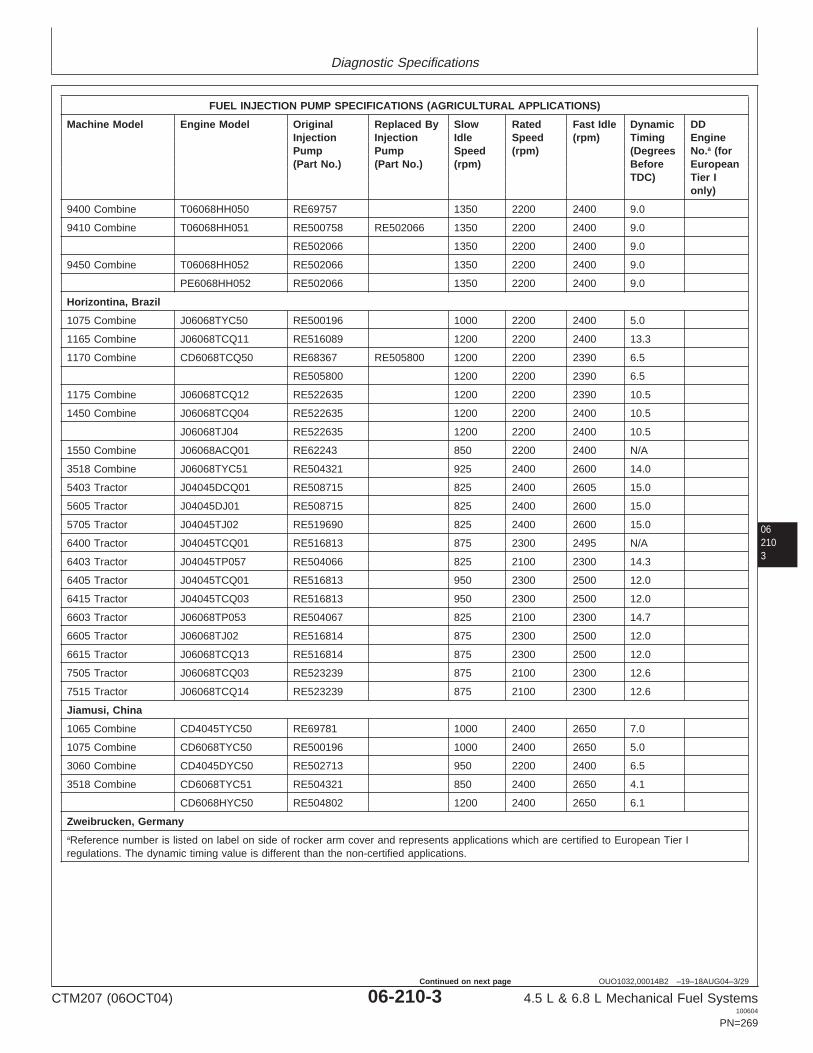
Diagnostic Specifications
062103
OUO1032,00014B2 –19–18AUG04–3/29
FUEL INJECTION PUMP SPECIFICATIONS (AGRICULTURAL APPLICATIONS)
Machine Model Engine Model Original Replaced By Slow Rated Fast Idle Dynamic DDInjection Injection Idle Speed (rpm) Timing EnginePump Pump Speed (rpm) (Degrees No.a (for(Part No.) (Part No.) (rpm) Before European
TDC) Tier Ionly)
9400 Combine T06068HH050 RE69757 1350 2200 2400 9.0
9410 Combine T06068HH051 RE500758 RE502066 1350 2200 2400 9.0
RE502066 1350 2200 2400 9.0
9450 Combine T06068HH052 RE502066 1350 2200 2400 9.0
PE6068HH052 RE502066 1350 2200 2400 9.0
Horizontina, Brazil
1075 Combine J06068TYC50 RE500196 1000 2200 2400 5.0
1165 Combine J06068TCQ11 RE516089 1200 2200 2400 13.3
1170 Combine CD6068TCQ50 RE68367 RE505800 1200 2200 2390 6.5
RE505800 1200 2200 2390 6.5
1175 Combine J06068TCQ12 RE522635 1200 2200 2390 10.5
1450 Combine J06068TCQ04 RE522635 1200 2200 2400 10.5
J06068TJ04 RE522635 1200 2200 2400 10.5
1550 Combine J06068ACQ01 RE62243 850 2200 2400 N/A
3518 Combine J06068TYC51 RE504321 925 2400 2600 14.0
5403 Tractor J04045DCQ01 RE508715 825 2400 2605 15.0
5605 Tractor J04045DJ01 RE508715 825 2400 2600 15.0
5705 Tractor J04045TJ02 RE519690 825 2400 2600 15.0
6400 Tractor J04045TCQ01 RE516813 875 2300 2495 N/A
6403 Tractor J04045TP057 RE504066 825 2100 2300 14.3
6405 Tractor J04045TCQ01 RE516813 950 2300 2500 12.0
6415 Tractor J04045TCQ03 RE516813 950 2300 2500 12.0
6603 Tractor J06068TP053 RE504067 825 2100 2300 14.7
6605 Tractor J06068TJ02 RE516814 875 2300 2500 12.0
6615 Tractor J06068TCQ13 RE516814 875 2300 2500 12.0
7505 Tractor J06068TCQ03 RE523239 875 2100 2300 12.6
7515 Tractor J06068TCQ14 RE523239 875 2100 2300 12.6
Jiamusi, China
1065 Combine CD4045TYC50 RE69781 1000 2400 2650 7.0
1075 Combine CD6068TYC50 RE500196 1000 2400 2650 5.0
3060 Combine CD4045DYC50 RE502713 950 2200 2400 6.5
3518 Combine CD6068TYC51 RE504321 850 2400 2650 4.1
CD6068HYC50 RE504802 1200 2400 2650 6.1
Zweibrucken, GermanyaReference number is listed on label on side of rocker arm cover and represents applications which are certified to European Tier Iregulations. The dynamic timing value is different than the non-certified applications.
CTM207 (06OCT04) 06-210-3 4.5 L & 6.8 L Mechanical Fuel Systems100604
PN=269
Continued on next page

Diagnostic Specifications
06210
4
OUO1032,00014B2 –19–18AUG04–4/29
FUEL INJECTION PUMP SPECIFICATIONS (AGRICULTURAL APPLICATIONS)
Machine Model Engine Model Original Replaced By Slow Rated Fast Idle Dynamic DDInjection Injection Idle Speed (rpm) Timing EnginePump Pump Speed (rpm) (Degrees No.a (for(Part No.) (Part No.) (rpm) Before European
TDC) Tier Ionly)
2254 Combine CD6068HZ050 RE500574 1200 2200 2390 9.0
3200/3400 CD4045TZ050 RE501192 850 2200 2400 6.0Telehandler
Ottumwa, Iowa
4890 Windrower T04045TE050 RE63309 RE69779 850 2500 2700 7.0
RE69779 RE502708 850 2500 2700 7.0
RE502708 850 2500 2700 7.0
PE4045TE050 RE63309 RE69779 850 2500 2700 7.0
RE69779 RE502708 850 2500 2700 7.0
RE502708 850 2500 2700 7.0
4895 Windrower T04045TE051 RE69781 850 2500 2700 7.0
PE4045TE051 RE69781 850 2500 2700 7.0
4990 Windrower T06068TE050 RE70390 RE502709 900 2300 2500 6.5
RE502709 900 2300 2500 6.5
PE6068TE050 RE70390 RE502709 900 2300 2500 6.5
RE502709 900 2300 2500 6.5
4995 Windrower PE6068TE051 RE509430 900 2300 2500 6.0
Waterloo, Iowa
7210 Tractor T06068TRW53 RE59526 RE70937 900 2100 2300 6.5(SYNCROPLUS)
RE70937 RE502824 900 2100 2300 6.5
RE502824 900 2100 2300 6.5
PE6068HRW53 RE502824 900 2100 2300 6.5
7210 Tractor T06068TRW50 RE59526 RE70937 900 2100 2300 6.5(POWRQUAD)
RE70937 RE502824 900 2100 2300 6.5
RE502824 900 2100 2300 6.5
PE6068TRW50 RE59526 RE70937 900 2100 2300 6.5
RE70937 RE502824 900 2100 2300 6.5
RE502824 900 2100 2300 6.5
7220 Tractor CD6068TRW01 RE516840 850 2300 2460 5.6
7410 Tractor T06068TRW54 RE59527 RE70938 900 2100 2300 6.5(SYNCROPLUS)
RE70938 RE502825 900 2100 2300 6.5
RE502825 900 2100 2300 6.5aReference number is listed on label on side of rocker arm cover and represents applications which are certified to European Tier Iregulations. The dynamic timing value is different than the non-certified applications.
SYNCROPLUS is a trademark of Deere & CompanyPOWRQUAD is a trademark of Deere & Company
CTM207 (06OCT04) 06-210-4 4.5 L & 6.8 L Mechanical Fuel Systems100604
PN=270
Continued on next page
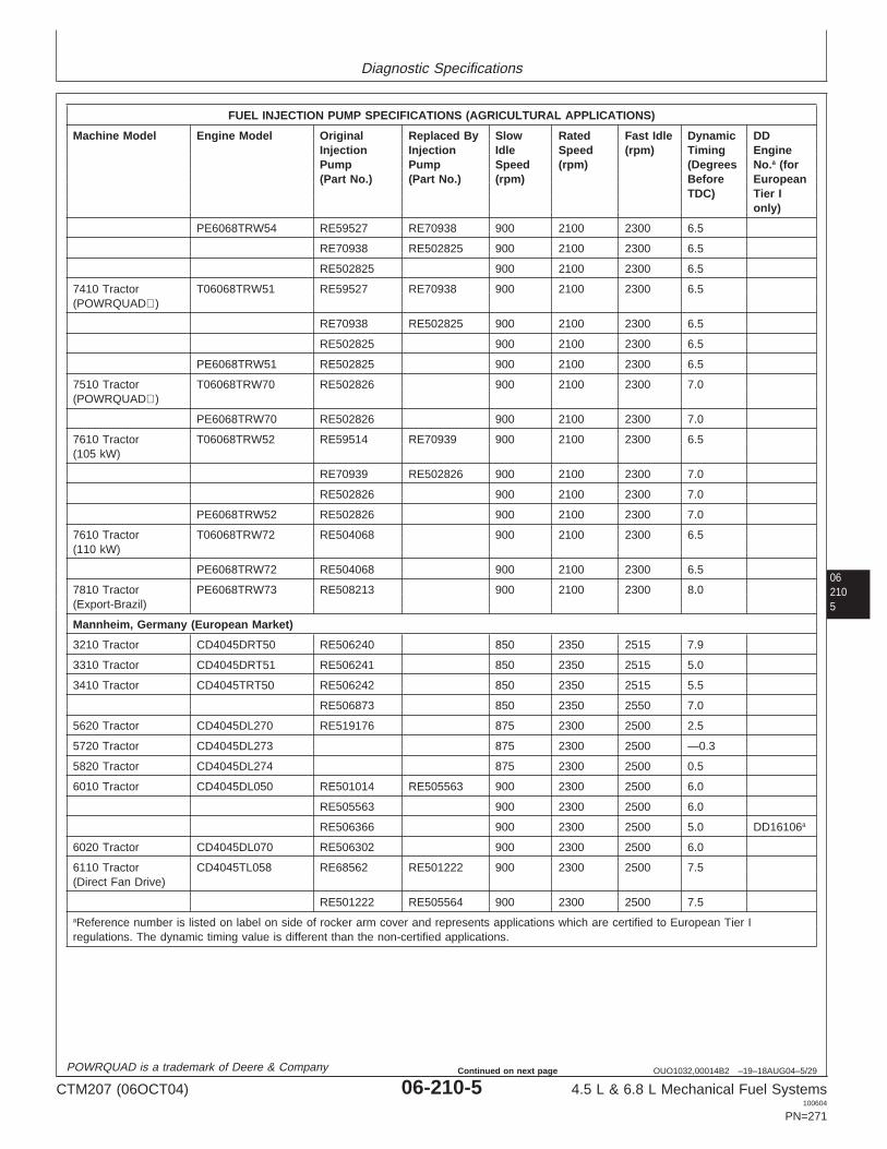
Diagnostic Specifications
062105
OUO1032,00014B2 –19–18AUG04–5/29
FUEL INJECTION PUMP SPECIFICATIONS (AGRICULTURAL APPLICATIONS)
Machine Model Engine Model Original Replaced By Slow Rated Fast Idle Dynamic DDInjection Injection Idle Speed (rpm) Timing EnginePump Pump Speed (rpm) (Degrees No.a (for(Part No.) (Part No.) (rpm) Before European
TDC) Tier Ionly)
PE6068TRW54 RE59527 RE70938 900 2100 2300 6.5
RE70938 RE502825 900 2100 2300 6.5
RE502825 900 2100 2300 6.5
7410 Tractor T06068TRW51 RE59527 RE70938 900 2100 2300 6.5(POWRQUAD)
RE70938 RE502825 900 2100 2300 6.5
RE502825 900 2100 2300 6.5
PE6068TRW51 RE502825 900 2100 2300 6.5
7510 Tractor T06068TRW70 RE502826 900 2100 2300 7.0(POWRQUAD)
PE6068TRW70 RE502826 900 2100 2300 7.0
7610 Tractor T06068TRW52 RE59514 RE70939 900 2100 2300 6.5(105 kW)
RE70939 RE502826 900 2100 2300 7.0
RE502826 900 2100 2300 7.0
PE6068TRW52 RE502826 900 2100 2300 7.0
7610 Tractor T06068TRW72 RE504068 900 2100 2300 6.5(110 kW)
PE6068TRW72 RE504068 900 2100 2300 6.5
7810 Tractor PE6068TRW73 RE508213 900 2100 2300 8.0(Export-Brazil)
Mannheim, Germany (European Market)
3210 Tractor CD4045DRT50 RE506240 850 2350 2515 7.9
3310 Tractor CD4045DRT51 RE506241 850 2350 2515 5.0
3410 Tractor CD4045TRT50 RE506242 850 2350 2515 5.5
RE506873 850 2350 2550 7.0
5620 Tractor CD4045DL270 RE519176 875 2300 2500 2.5
5720 Tractor CD4045DL273 875 2300 2500 —0.3
5820 Tractor CD4045DL274 875 2300 2500 0.5
6010 Tractor CD4045DL050 RE501014 RE505563 900 2300 2500 6.0
RE505563 900 2300 2500 6.0
RE506366 900 2300 2500 5.0 DD16106a
6020 Tractor CD4045DL070 RE506302 900 2300 2500 6.0
6110 Tractor CD4045TL058 RE68562 RE501222 900 2300 2500 7.5(Direct Fan Drive)
RE501222 RE505564 900 2300 2500 7.5aReference number is listed on label on side of rocker arm cover and represents applications which are certified to European Tier Iregulations. The dynamic timing value is different than the non-certified applications.
POWRQUAD is a trademark of Deere & Company
CTM207 (06OCT04) 06-210-5 4.5 L & 6.8 L Mechanical Fuel Systems100604
PN=271
Continued on next page

Diagnostic Specifications
06210
6
OUO1032,00014B2 –19–18AUG04–6/29
FUEL INJECTION PUMP SPECIFICATIONS (AGRICULTURAL APPLICATIONS)
Machine Model Engine Model Original Replaced By Slow Rated Fast Idle Dynamic DDInjection Injection Idle Speed (rpm) Timing EnginePump Pump Speed (rpm) (Degrees No.a (for(Part No.) (Part No.) (rpm) Before European
TDC) Tier Ionly)
RE505564 900 2300 2500 7.5
6110 Tractor CD4045TL050 RE68562 RE501222 900 2300 2500 7.5(Viscous Fan Drive)
RE501222 RE505564 900 2300 2500 7.5
RE505564 900 2300 2500 7.5
RE506367 900 2300 2500 4.0 DD16107a
6120 Tractor CD4045TL070 RE506504 900 2300 2500 6.0 DD16065a
6205 Tractor CD4045TL064 RE503084 900 2300 2500 14.0
6210 Tractor CD4045TL059 RE68563 RE501223 900 2300 2500 6.0(Direct Fan Drive)
RE501223 RE505565 900 2300 2500 6.0
RE505565 900 2300 2500 6.0
6210 Tractor CD4045TL051 RE68563 RE501223 900 2300 2500 6.0(Viscous Fan Drive)
RE501223 RE505565 900 2300 2500 6.0
RE505565 900 2300 2500 6.0
RE506368 900 2300 2500 3.5 DD16108a
6215 Tractor CD4045TL072 RE503084 900 2300 2500 3.5(Non-Certified)
6215 Tractor CD4045TL072 RE506508 900 2300 2500 14.0 DD16067a
(Classic)
6215 Tractor CD4045TL071 RE506305 900 2300 2500 6.1(Classic)(Certified)
6220 Tractor CD4045TL071 RE506305 900 2300 2500 3.5
RE506506 2300 2500 6.1 DD16066a
6310 Tractor CD4045TL060 RE68543 RE501224 900 2300 2500 6.0(Direct Fan Drive)
RE501224 900 2300 2500 6.0
RE505566 900 2300 2500 6.0
6310 Tractor CD4045TL052 RE68543 RE501224 900 2300 2500 6.0(Viscous Fan Drive)
RE501224 900 2300 2500 6.0
RE506369 900 2300 2500 3.0 DD16109a
RE505566 900 2300 2500 6.0
6320 Tractor CD4045HL072 RE509071 900 2300 2495 6.5
6320SE Tractor CD4045TL073 RE506307 850 2300 2500 5.5aReference number is listed on label on side of rocker arm cover and represents applications which are certified to European Tier Iregulations. The dynamic timing value is different than the non-certified applications.
CTM207 (06OCT04) 06-210-6 4.5 L & 6.8 L Mechanical Fuel Systems100604
PN=272
Continued on next page

Diagnostic Specifications
062107
OUO1032,00014B2 –19–18AUG04–7/29
FUEL INJECTION PUMP SPECIFICATIONS (AGRICULTURAL APPLICATIONS)
Machine Model Engine Model Original Replaced By Slow Rated Fast Idle Dynamic DDInjection Injection Idle Speed (rpm) Timing EnginePump Pump Speed (rpm) (Degrees No.a (for(Part No.) (Part No.) (rpm) Before European
TDC) Tier Ionly)
6410 Tractor CD4045TL061 RE68544 RE501226 900 2300 2500 6.5(Direct Fan Drive)
RE501226 900 2300 2500 6.5
RE505568 875 2300 2500 6.5
6410 Tractor CD4045TL053 RE68544 RE501226 900 2300 2500 6.5(Viscous Fan Drive
RE501226 900 2300 2500 6.5
RE506371 900 2300 2500 4.0 DD16111a
RE505568 900 2300 2500 6.5
6420 Tractor CD4045HL070 RE506311 900 2300 2500 7.5
RE506312 900 2300 2500 7.5
6505 Tractor CD6068DL051 RE503085 875 2300 2500 7.5
6510 Tractor CD6068DL050 RE68872 RE501230 875 2300 2500 5.5
RE501230 RE505577 875 2300 2500 5.5
RE505577 875 2300 2500 5.5
RE505577 875 2300 2500 5.0 DD16113a
6515 Tractor CD6068DL071 RE503085 875 2300 2495 14.0(Classic)(77 kW)
6515 Tractor CD6068DL070 RE506267 RE506268 875 2300 2460 6.5(Classic)(85 kW)
RE506268 875 2300 2500 6.5
6520 Tractor CD6068DL070 RE506267 900 2300 2500 6.5
RE506268 875 2300 2500 6.5
6520/6520SE Tractor CD6068TL073 RE522297 850 2300 2495 9.1
6610 Tractor CD6068TL050 RE501232 RE503887 875 2300 2500 6.0
RE503887 RE505579 875 2300 2500 6.0
RE505579 875 2300 2500 6.0
RE505579 850 2300 2500 8.0 DD16115a
6810 Tractor CD6068TL051 RE501234 RE503889 875 2100 2300 6.0
RE503889 RE505581 875 2100 2300 6.0
RE505581 875 2100 2300 6.0
RE505581 875 2100 2300 5.5 DD16117a
6910 Tractor CD6068TL052 RE501236 RE503891 875 2100 2300 6.0(99 kW)
RE503891 RE505583 875 2100 2300 6.0
RE505583 875 2100 2300 6.0aReference number is listed on label on side of rocker arm cover and represents applications which are certified to European Tier Iregulations. The dynamic timing value is different than the non-certified applications.
CTM207 (06OCT04) 06-210-7 4.5 L & 6.8 L Mechanical Fuel Systems100604
PN=273
Continued on next page

Diagnostic Specifications
06210
8
OUO1032,00014B2 –19–18AUG04–8/29
FUEL INJECTION PUMP SPECIFICATIONS (AGRICULTURAL APPLICATIONS)
Machine Model Engine Model Original Replaced By Slow Rated Fast Idle Dynamic DDInjection Injection Idle Speed (rpm) Timing EnginePump Pump Speed (rpm) (Degrees No.a (for(Part No.) (Part No.) (rpm) Before European
TDC) Tier Ionly)
6910 Tractor CD6068TL054 RE502412 RE505585 875 2100 2300 5.9(107 kW)
RE505585 875 2100 2300 5.9
RE505585 875 2100 2300 5.4 DD16119a
Mannheim, Germany (North American Market)
6110/6110L Tractor CD4045TL063 RE501008 RE501222 900 2300 2500 4.0
RE501222 RE505564 900 2300 2500 4.0
RE505564 RE506367 900 2300 2500 4.0
RE506367 900 2300 2500 4.0
RE505570 900 2300 2500 5.0
6120 Tractor CD4045TL070 RE506504 2300 2500 6.0 DD16065a
6210/6210L Tractor CD4045TL054 RE501441 RE505570 900 2300 2500 5.0
6215 Tractor CD4045TL071 RE506506 900 2300 2500 6.1 DD16066a
(Advantage)
6220 Tractor CD4045TL071 RE506506 900 2300 2500 6.1 DD16066a
6310/6310L/6310S CD4045TL055 RE501442 RE505571 900 2300 2500 4.5Tractor
RE505571 900 2300 2500 4.5
6320 Tractor CD4045HL073 RE509071 900 2300 2495 5.5
CD4045TL074 RE506309 RE505571 900 2300 2500 4.5
RE505571
RE506310 RE505573 900 2300 2500 4.5
RE505573
6403/6405 Tractor CD4045TL062 RE501006 900 2300 2500 6.0(Advantage)
6410/6410L/6410S CD4045TL056 RE501443 RE505574 900 2300 2500 4.0Tractor
RE505574 900 2300 2500 4.0
6415 Tractor CD4045TL075 RE501006 900 2300 2495 6.0(Advantage)
6420 Tractor CD4045HL070 RE506311 850 2300 2460 7.5
RE506312 850 2300 2460 7.5
6510L/6510S Tractor CD4045TL057 RE501287 RE505576 900 2300 2500 3.5
RE505576 900 2300 2500 3.5
6520L Tractor CD4045HL071 RE506313 900 2300 2500 7.5
6603/6605 Tractor CD6068TL053 RE500993 875 2300 2500 8.0(Advantage)aReference number is listed on label on side of rocker arm cover and represents applications which are certified to European Tier Iregulations. The dynamic timing value is different than the non-certified applications.
CTM207 (06OCT04) 06-210-8 4.5 L & 6.8 L Mechanical Fuel Systems100604
PN=274
Continued on next page

Diagnostic Specifications
062109
OUO1032,00014B2 –19–18AUG04–9/29
FUEL INJECTION PUMP SPECIFICATIONS (AGRICULTURAL APPLICATIONS)
Machine Model Engine Model Original Replaced By Slow Rated Fast Idle Dynamic DDInjection Injection Idle Speed (rpm) Timing EnginePump Pump Speed (rpm) (Degrees No.a (for(Part No.) (Part No.) (rpm) Before European
TDC) Tier Ionly)
6615 Tractor CD6068TL071 RE515743 850 2300 2495 5.6(Advantage)
RE506340 850 2300 2500 5.6 DD16092a
6715 Tractor CD6068TL072 RE517315 RE519514 850 2300 2500 6.1 DD20565a
(Advantage)
RE519514 850 2300 2500 6.1 DD20879a
Saltillo, Mexico
5415 Tractor PE4045DP050 RE502362 825 2400 2600 9.0
PE4045DP052 RE504061 825 2400 2600 14.0
5615 Tractor PE4045DP051 RE70452 825 2400 2600 9.0
PE4045DP053 RE504062 825 2400 2600 13.0
5715 Tractor PE4045TP050 RE502792 825 2400 2600 8.0
PE4045TP059 RE504063 825 2400 2600 14.0
6103 Tractor PE4045TP055 RE504064 825 2100 2300 13.0
6203 Tractor PE4045TP056 RE504065 825 2100 2300 13.0
6400 Tractor PE4045TP054 RE501006 850 2300 2500 6.0
6403 Tractor PE4045TP057 RE504066 825 2100 2300 13.5
PE4045TP060 RE508830 825 2100 2300 5.1
6415 Tractor PE4045TP061 RE501006 850 2300 2500 6.0
6603 Tractor PE6068TP053 RE504067 825 2100 2300 15.0
PE6068TP054 RE508831 825 2100 2300 5.1
7220 Tractor PE6068TP055 RE515743 850 2300 2500 6.0
7320 Tractor PE6068TP056 RE517322 900 2300 2500 6.0
7405 Tractor CD6068TP051 RE64720 RE59527 875 2100 2275 6.0(Advantage)
RE59527 875 2100 2275 6.0
PE6068TP051 RE70938 900 2100 2300 6.5
7410 Tractor CD6068TP052 RE64721 RE501236 875 2100 2275 6.0
RE501236 RE503891 875 2100 2275 6.0
RE503891 RE503571 875 2100 2275 6.0
RE503571 RE505961 875 2100 2275 6.0
RE505961 875 2100 2275 6.0
7420 Tractor PE6068TP057 RE505961 900 2100 2300 6.0
7500 Tractor PE6068TP052 RE501236 RE503571 900 2100 2300 6.0
RE503571 RE505961 900 2100 2300 6.0
RE505961 900 2100 2300 6.0aReference number is listed on label on side of rocker arm cover and represents applications which are certified to European Tier Iregulations. The dynamic timing value is different than the non-certified applications.
CTM207 (06OCT04) 06-210-9 4.5 L & 6.8 L Mechanical Fuel Systems100604
PN=275
Continued on next page

Diagnostic Specifications
06210
10
OUO1032,00014B2 –19–18AUG04–10/29
FUEL INJECTION PUMP SPECIFICATIONS (AGRICULTURAL APPLICATIONS)
Machine Model Engine Model Original Replaced By Slow Rated Fast Idle Dynamic DDInjection Injection Idle Speed (rpm) Timing EnginePump Pump Speed (rpm) (Degrees No.a (for(Part No.) (Part No.) (rpm) Before European
TDC) Tier Ionly)
7520 Tractor PE6068TP058 RE517323 900 2100 2300 5.0
Tekirdag, Turkey
5615 Tractor CD4045DTK20 RE504062 825 2400 2600 13.0
5715 Tractor CD4045TTK20 RE504063 825 2400 2600 14.0
Cameco (Deere) (Thibodaux, Louisiana)
S30 Harvester PE6068DT850 RE59861 850 2500 2700 6.0
SP1800 Cane PE6068DT850 RE59861 850 2500 2700 6.0Loader
SP2252 Cane PE6068TT850 RE69791 850 2400 2600 8.5Loader
SP3000 Cane PE6068DT850 RE59861 850 2500 2700 6.0Loader
100 Loader/ PE6068TT850 RE69791 850 2400 2600 8.5Harvester (Kanaf)
110T Cane Tractor PE4045TT851 RE502376 950 2200 2400 6.0
RE516345 950 2300 2500 N/A
215 4WD Tractor PE6068DT850 RE59861 RE505929 850 2500 2700 6.0
RE505929 RE509503 850 2500 2700 6.0
RE509503 850 2500 2700 6.0
220 Tractor PE6068TT851 RE69791 850 2400 2600 8.5
220 4WD PE6068TT850 RE69791 850 2400 2600 8.5Tractor/PineappleHarvester/Sprayer
404 Vegetable T04045TT850 RE69155 850 2200 2400 6.5Harvester
PE4045TT850 RE69155 850 2200 2400 6.5
T04045TT801 RE503037 850 2200 2400 6.5aReference number is listed on label on side of rocker arm cover and represents applications which are certified to European Tier Iregulations. The dynamic timing value is different than the non-certified applications.
Continued on next page
CTM207 (06OCT04) 06-210-10 4.5 L & 6.8 L Mechanical Fuel Systems100604
PN=276

Diagnostic Specifications
0621011
OUO1032,00014B2 –19–18AUG04–11/29
FUEL INJECTION PUMP SPECIFICATIONS (COMMERCIAL AND CONSUMER EQUIPMENT APPLICATIONS)
Machine Model Engine Model Original Replaced By Slow Idle Rated Fast Idle Dynamic DDInjection Pump Injection Pump Speed Speed (rpm) Timing Engine(Part No.) (Part No.) (rpm) (rpm) (Degrees Numbera
BeforeTDC)
Augusta, Georgia
5410 Tractor CD4045DLV50 RE70452 825 2400 2600 9.0
PE4045DLV50 RE70452 825 2400 2600 9.0
5410 Tractor PE4045DLV51 RE70452 825 2400 2600 9.0(No Engine AirHeater Option)
5420/5420N Tractor PE4045DLV50 RE70452 850 2400 2600 9.0
5420/5420N Tractor PE4045DLV51 RE70452 825 2400 2600 9.0(No Engine AirHeater Option)
5425 Tractor PE4045TLV53 RE521589 850 2400 2600 9.5
5510/5510N Tractor CD4045TLV50 RE70453 RE502792 850 2400 2600 8.0
RE502792 825 2400 2600 8.0
PE4045TLV50 RE70453 RE502792 825 2400 2600 8.0
RE502792 825 2400 2600 8.0
5510 Tractor PE4045TLV51 RE502792 825 2400 2600 8.0(No Engine AirHeater Option)
5510 Tractor PE4045TLV52 RE521136 825 2400 2600 N/A(LUK Clutch Option)
5520/5520N Tractor PE4045TLV50 RE502792 825 2400 2600 8.0
5520/5520N Tractor PE4045TLV51 RE502792 825 2400 2600 8.0(No Engine AirHeater Option)
5520 Tractor PE4045TLV52 RE521136 825 2400 2600 N/A
5525 Tractor PE4045TLV54 RE521590 850 2400 2600 9.5
Agritalia srl (Vittoria, Sicily, Italy)
5410 Tractor CD4045TAT50 RE508874 850 2300 2460 6.0
5415 Tractor CD4045DAT70 RE520272 850 2300 2500 2.5
5510 Tractor CD4045TAT50 RE509044 850 2300 2500 2.5 DD16148a
5515 Tractor CD4045TAT70 RE520273 850 2300 2500 0.0 DD20669a
5615 Tractor CD4045TAT71 RE520274 850 2300 2500 1.0 DD20670a
aReference number is listed on label on side of rocker arm cover and represents applications which are certified to European Tier Iregulations. The dynamic timing value is different than the non-certified applications.
CTM207 (06OCT04) 06-210-11 4.5 L & 6.8 L Mechanical Fuel Systems100604
PN=277
Continued on next page

Diagnostic Specifications
06210
12
OUO1032,00014B2 –19–18AUG04–12/29
FUEL INJECTION PUMP SPECIFICATIONS (CONSTRUCTION AND FORESTRY EQUIPMENT APPLICATIONS)
Machine Model Engine Model Original Injection Replaced By Slow Idle Rated Fast Idle DynamicPump Injection Pump Speed Speed (rpm) Timing(Part No.) (Part No.) (rpm) (rpm) (Degrees
BeforeTDC)
Davenport, Iowa
LX80 Loader T04045HDW51 RE60174 950 2200 2400 N/A
LX100 Loader T06068TDW53 RE59962a 950 2100 2300 5.0(Hitachi ConstructionMachine)
PE6068TDW53 RE59962a 950 2100 2300 5.0
LX100-3 T06068TDW50 RE59542 950 2100 2300 N/A(Hitachi ConstructionMachine)
PE6068TDW50 RE59542 950 2100 2300 N/A
LX120 Loader T06068HDW52 RE59958 950 2200 2400 6.0(Hitachi ConstructionMachine)
T06068HDW70 RE59958a 950 2200 2400 6.0
PE6068HDW70 RE59958a 950 2200 2400 6.0
TC44H Tool Carrier T04045TDW50 RE69547 950 2200 2400 5.0
PE4045TDW50 RE69547 950 2200 2400 5.0
TC54H Tool Carrier T0608TDW50 RE67598 950 2200 2400 6.5
PE06068TDW50 RE67598 950 2200 2400 6.5
TC62H Tool Carrier T06068HDW50 RE59958a 950 2200 2400 6.0
PE6068HDW50 RE59958a 950 2200 2400 6.0
TJ460 TC Skidder Tool T06068TDW57 RE508301 900 2200 2400 4.0Carrier
PE6068TDW57 RE508301 900 2200 2400 4.0
360D Skidder T06068TDW54 RE67669 1000 2200 2400 6.5(Timberjack)
PE6068TDW54 RE67669 1000 2200 2400 6.5
444H Loader T04045TDW50 RE69547 950 2200 2400 5.0
PE4045TDW50 RE69547 950 2200 2400 5.0
460 Skidder T06068TDW55 RE500196 1000 2200 2400 5.0(Timberjack)
RE506159 1000 2200 2400 5.0
PE6068TDW55 RE500196 1000 2200 2400 5.0
RE506159 1000 2200 2400 5.0
460D Skidder (Torque T06068TDW57 RE508301 900 2200 2400 4.0Converter) (Timberjack)(S.N. —586336)
PE6068TDW57 RE508631 900 2200 2400 5.0
540/548G Skidder T06068TDW51 RE67669 1000 2200 2400 6.5(S.N. 558205—565684)aIn-line mechanical fuel injection pump.
CTM207 (06OCT04) 06-210-12 4.5 L & 6.8 L Mechanical Fuel Systems100604
PN=278
Continued on next page

Diagnostic Specifications
0621013
OUO1032,00014B2 –19–18AUG04–13/29
FUEL INJECTION PUMP SPECIFICATIONS (CONSTRUCTION AND FORESTRY EQUIPMENT APPLICATIONS)
Machine Model Engine Model Original Injection Replaced By Slow Idle Rated Fast Idle DynamicPump Injection Pump Speed Speed (rpm) Timing(Part No.) (Part No.) (rpm) (rpm) (Degrees
BeforeTDC)
540/548G-II/548G-III T06068TDW54 RE67669 1000 2200 2400 6.5Skidder(S.N. 565685—576602)
PE6068TDW54 RE67669 1000 2200 2400 6.5
540G-III/548G-III Skidder T06068TDW54 RE59983 RE71495 1000 2200 2400 N/A(S.N. 576603—586336)
RE71495 1000 2200 2400 N/A
540G-III/548G-III Skidder PE6068HDW58 RE507583 1000 2200 2400 N/A(S.N. 586337— )
540/548H Skidder T06068TDW54 RE67669 1000 2200 2400 6.5
PE6068TDW54 RE67669 1000 2200 2400 6.5
544/544H Loader T06068TDW50 RE67598 950 2200 2400 6.5
PE6068TDW50 RE67598 950 2200 2400 6.5
624H Loader T06068HDW50 RE59958a 950 2200 2400 6.0
PE6068HDW50 RE59958a 950 2200 2400 6.0
640G/648G Skidder T06068TDW52 RE59920a RE500196a 950 2200 2400 5.0(S.N. 558205—565684)
RE500196a 1000 2200 2400 5.0
640/648G-II Skidder T06068TDW55 RE500196a 1000 2200 2400 5.0(S.N. 565685—576602)
PE6068TDW55 RE500196a 1000 2200 2400 5.0
RE506159 1000 2200 2400 5.0
648G-III Skidder T06068TDW55 RE500196a 1000 2200 2400 5.0(S.N. —586336)
T06068TDW57 RE508301 900 2200 2400 4.0
PE6068TDW57 RE508301 900 2200 2400 4.0
640/648H Skidder T06068TDW55 RE500196a 1000 2200 2400 5.0
670C Grader T06068HDW53 RE59964a RE500922a 850 2000 2200 5.0
RE500922a RE501033a 900 2000 2200 5.0
RE501033a 825 2000 2200 4.0
PE6068HDW53 RE501033a 825 2000 2200 4.0
670C Series II Grader T06068HDW53 RE59964a RE500922a 850 2000 2200 5.0
RE500922a RE501033a 900 2000 2200 5.0
RE501033a 825 2000 2200 4.0
PE6068HDW53 RE501033a 825 2000 2200 4.0
670CH Grader T06068HDW55 RE69563a 800 2000 2200 3.0
PE6068HDW55 RE69563a 800 2000 2200 3.0
672CH Grader T06068HDW58 RE507583 800 2100 2300 2.0(S.N. —589368)aIn-line mechanical fuel injection pump.
CTM207 (06OCT04) 06-210-13 4.5 L & 6.8 L Mechanical Fuel Systems100604
PN=279
Continued on next page

Diagnostic Specifications
06210
14
OUO1032,00014B2 –19–18AUG04–14/29
FUEL INJECTION PUMP SPECIFICATIONS (CONSTRUCTION AND FORESTRY EQUIPMENT APPLICATIONS)
Machine Model Engine Model Original Injection Replaced By Slow Idle Rated Fast Idle DynamicPump Injection Pump Speed Speed (rpm) Timing(Part No.) (Part No.) (rpm) (rpm) (Degrees
BeforeTDC)
PE6068HDW58 RE69563a 800 2190 2325 2.0
690E LC Excavator T06068TDW56 RE67765 RE501328 875 2100 2300 6.0(S.N. 559603— )
RE501328 950 2100 2300 6.0
Dubuque, Iowa
CFX110 Excavator PE4045TP058 RE507968 850 2200 2350 N/A
CFX120/CFX160 PE4045HP050 RE507969 850 2200 2350 N/AExcavator
CFX270 Excavator PE6068HT055 RE506681 800 2150 2440 N/A
CFX270LC Excavator T06068HT052 RE59946 950 2150 2350 N/A
PE6068HT052 RE59946 950 2150 2350 7.0
DX75 Crawler Dozer T04045DT052 RE68012a 900 2100 2300 5.0(Japan)
DX75 HST Crawler T04045TT070 RE502006a 950 2200 2400 4.2Dozer (Japan)
PE4045TT070 RE502006a 950 2200 2400 4.2
HYEX Military Excavator PE4045TT050 RE69782 2500 2700 N/A
120/120C Excavator T04045TT052 RE59910a 950 2100 2400 5.0
210LE Landscape T04045DT050 RE67594 RE500877 950 2200 2400 8.0Loader
RE500877 RE502380 950 2200 2400 6.5
RE502380 RE506123 950 2200 2400 6.5
RE506123 950 2200 2400 6.0
PE4045DT050 RE502380 RE506123 950 2200 2400 6.5
RE506123 950 2200 2400 6.0
310/310E Backhoe T04045DT055 RE67594 RE500877 950 2200 2400 8.0Loader
RE500877 RE502380 950 2200 2400 6.5
RE502380 950 2200 2400 6.5
310E Backhoe Loader T04045TT056 RE67925 RE500878 950 2200 2400 6.5(Alt Comp)
RE500878 RE502377 950 2200 2400 6.0
RE502377 950 2200 2400 6.0
310G Backhoe Loader T04045DT056 RE502380 950 2200 2400 6.5(Nat. Asp.)(S.N. —910055)
PE4045DT056 RE502380 950 2200 2400 6.5
310G Backhoe Loader T04045TT058 RE508066 950 2200 2400 6.0(S.N. 910056— )aIn-line mechanical fuel injection pump.
CTM207 (06OCT04) 06-210-14 4.5 L & 6.8 L Mechanical Fuel Systems100604
PN=280
Continued on next page

Diagnostic Specifications
0621015
OUO1032,00014B2 –19–18AUG04–15/29
FUEL INJECTION PUMP SPECIFICATIONS (CONSTRUCTION AND FORESTRY EQUIPMENT APPLICATIONS)
Machine Model Engine Model Original Injection Replaced By Slow Idle Rated Fast Idle DynamicPump Injection Pump Speed Speed (rpm) Timing(Part No.) (Part No.) (rpm) (rpm) (Degrees
BeforeTDC)
PE4045TT058 RE508066 950 2200 2400 6.0
310G Backhoe Loader T04045TT080 RE502377 950 2200 2400 6.0(Alt Comp)(S.N. —910007)
PE4045TT080 RE502377 950 2200 2400 6.0
310SE Backhoe Loader T04045TT050 RE67595 RE502378 950 2200 2400 6.5
RE502378 950 2200 2400 6.5
310SG Backhoe Loader T04045TT081 RE502378 950 2200 2400 6.5(S.N. —910004)
PE4045TT081 RE502378 950 2200 2400 6.5
310SG (Alt Comp) T04045TT080 RE506279 950 2200 2400(S.N. 909514— )
315SE Backhoe Loader T04045TT060 RE67595 RE502378 950 2200 2400 6.5
RE502378 950 2200 2400 6.5
315SG Backhoe Loader T04045TT081 RE502378 950 2200 2400 6.5(Side-Shift)(S.N. —909995)
410E Backhoe Loader T04045TT053 RE67599 RE502376 950 2200 2400 6.0
RE502376 950 2200 2400 6.0
410G Backhoe Loader T04045TT082 RE502376 950 2200 2400 6.0
PE4045TT082 RE502376 950 2200 2400 6.0
450G/450GTC Crawler T04045TT061 RE500616 RE502638 950 2100 2300 6.5Dozer
RE502638 950 2100 2300 6.5
PE4045TT061 RE500616 RE502638 950 2100 2300 6.5
RE502638 950 2100 2300 6.5
450GTC Series IV T04045TT067 RE500616 950 2100 2300 6.5Crawler Dozer(S.N. 840461— )
PE4045TT067 RE500616 RE502638 950 2100 2300 6.5
RE502638 950 2100 2300 6.5
450H Crawler Dozer T04045DT053 RE500877 RE501100 950 2200 2400 6.5
RE501100 RE508065 950 2200 2400 6.5
RE508065 950 2200 2400 6.5
450H LGP Crawler T04045TT058 RE70666 950 2200 2400 6.0Dozer(S.N. —XXXXXX)
PE4045TT058 RE70666 RE508066 950 2200 2400 6.0
RE508066 950 2200 2400 6.0
CTM207 (06OCT04) 06-210-15 4.5 L & 6.8 L Mechanical Fuel Systems100604
PN=281
Continued on next page
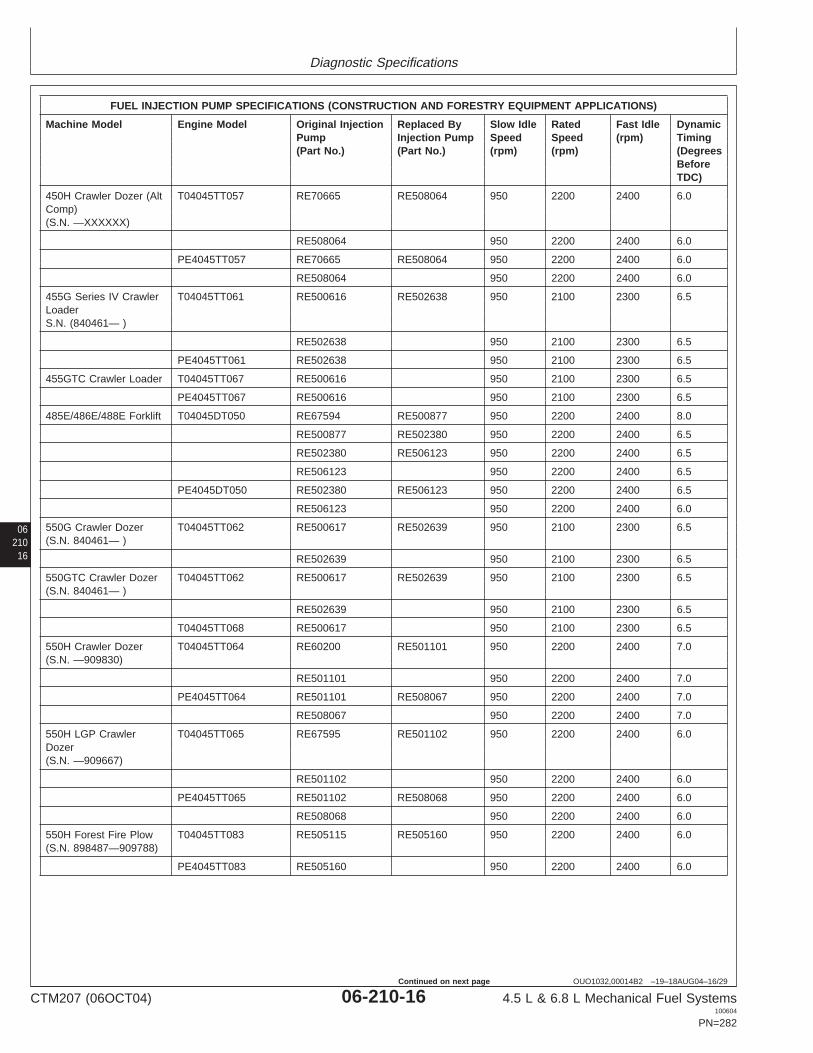
Diagnostic Specifications
06210
16
OUO1032,00014B2 –19–18AUG04–16/29
FUEL INJECTION PUMP SPECIFICATIONS (CONSTRUCTION AND FORESTRY EQUIPMENT APPLICATIONS)
Machine Model Engine Model Original Injection Replaced By Slow Idle Rated Fast Idle DynamicPump Injection Pump Speed Speed (rpm) Timing(Part No.) (Part No.) (rpm) (rpm) (Degrees
BeforeTDC)
450H Crawler Dozer (Alt T04045TT057 RE70665 RE508064 950 2200 2400 6.0Comp)(S.N. —XXXXXX)
RE508064 950 2200 2400 6.0
PE4045TT057 RE70665 RE508064 950 2200 2400 6.0
RE508064 950 2200 2400 6.0
455G Series IV Crawler T04045TT061 RE500616 RE502638 950 2100 2300 6.5LoaderS.N. (840461— )
RE502638 950 2100 2300 6.5
PE4045TT061 RE502638 950 2100 2300 6.5
455GTC Crawler Loader T04045TT067 RE500616 950 2100 2300 6.5
PE4045TT067 RE500616 950 2100 2300 6.5
485E/486E/488E Forklift T04045DT050 RE67594 RE500877 950 2200 2400 8.0
RE500877 RE502380 950 2200 2400 6.5
RE502380 RE506123 950 2200 2400 6.5
RE506123 950 2200 2400 6.5
PE4045DT050 RE502380 RE506123 950 2200 2400 6.5
RE506123 950 2200 2400 6.0
550G Crawler Dozer T04045TT062 RE500617 RE502639 950 2100 2300 6.5(S.N. 840461— )
RE502639 950 2100 2300 6.5
550GTC Crawler Dozer T04045TT062 RE500617 RE502639 950 2100 2300 6.5(S.N. 840461— )
RE502639 950 2100 2300 6.5
T04045TT068 RE500617 950 2100 2300 6.5
550H Crawler Dozer T04045TT064 RE60200 RE501101 950 2200 2400 7.0(S.N. —909830)
RE501101 950 2200 2400 7.0
PE4045TT064 RE501101 RE508067 950 2200 2400 7.0
RE508067 950 2200 2400 7.0
550H LGP Crawler T04045TT065 RE67595 RE501102 950 2200 2400 6.0Dozer(S.N. —909667)
RE501102 950 2200 2400 6.0
PE4045TT065 RE501102 RE508068 950 2200 2400 6.0
RE508068 950 2200 2400 6.0
550H Forest Fire Plow T04045TT083 RE505115 RE505160 950 2200 2400 6.0(S.N. 898487—909788)
PE4045TT083 RE505160 950 2200 2400 6.0
CTM207 (06OCT04) 06-210-16 4.5 L & 6.8 L Mechanical Fuel Systems100604
PN=282
Continued on next page

Diagnostic Specifications
0621017
OUO1032,00014B2 –19–18AUG04–17/29
FUEL INJECTION PUMP SPECIFICATIONS (CONSTRUCTION AND FORESTRY EQUIPMENT APPLICATIONS)
Machine Model Engine Model Original Injection Replaced By Slow Idle Rated Fast Idle DynamicPump Injection Pump Speed Speed (rpm) Timing(Part No.) (Part No.) (rpm) (rpm) (Degrees
BeforeTDC)
555G Crawler Loader T04045TT063 RE500618 RE500640 950 2100 2300 6.0(Direct Drive)(S.N. 840461— )
RE500640 950 2100 2300 6.0
PE4045TT063 RE500618 RE500640 950 2100 2300 6.0
RE500640 950 2100 2300 6.0
555GTC Crawler Loader T04045TT069 RE500618 950 2100 2300 6.0
PE4045TT069 RE500618 950 2100 2300 6.0
643G Feller Buncher T06068TT053 RE59959a 1050 2200 2400 5.0
PE6068TT053 RE59959 1050 2200 2400 5.0
643H Feller Buncher PE6068TT058 RE59959a 1050 2200 2400 5.0
650G Crawler Dozer T04045TT063 RE500618 RE502640 950 2100 2300 6.0(Direct Drive)
RE502640 950 2100 2300 6.0
PE4045TT063 RE500618 RE502640 950 2100 2300 6.0
RE502640 950 2100 2300 6.0
650GTC Crawler Dozer T04045TT069 RE500618 950 2100 2300 6.0
PE4045TT069 RE500618 RE502640 950 2100 2300 6.0
RE502640 950 2100 2300 6.0
650H Crawler Dozer T04045TT066 RE67599 RE501103 950 2200 2400 6.0
RE501103 950 2200 2400 6.0
PE4045TT066 RE501103 RE508069 950 2200 2400 6.0
RE508069 950 2200 2400 6.0
650H Forest Fire Plow T04045TT083 RE505161 950 2200 2400 6.0
PE4045TT083 RE505161 RE508070 950 2200 2400 6.0
RE508070 950 2200 2400 6.0
T04045TT091 RE507659 950 2200 2400 5.0
RE508071 950 2200 2400 5.0
PE4045TT091 RE507659 950 2200 2400 5.0
RE508071 950 2200 2400 5.0
653E Feller Buncher T06068TT053 RE59959a 1050 2200 2400 5.0
PE6068TT053 RE59959a 1050 2200 2400 5.0
653G Feller Buncher T06068TT053 RE59959a 1050 2200 2400 5.0(120 kW)
PE6068TT053 RE59959a 1050 2200 2400 5.0
PE6068TT059 RE59959a 1050 2200 2400 5.0
653G Feller Buncher PE6068HT057 RE59930a 1050 2200 2400 6.5(140 kW)
700H Crawler Dozer T06068TT056 RE502024 RE508072 950 2100 2300 6.5aIn-line mechanical fuel injection pump.
CTM207 (06OCT04) 06-210-17 4.5 L & 6.8 L Mechanical Fuel Systems100604
PN=283
Continued on next page

Diagnostic Specifications
06210
18
OUO1032,00014B2 –19–18AUG04–18/29
FUEL INJECTION PUMP SPECIFICATIONS (CONSTRUCTION AND FORESTRY EQUIPMENT APPLICATIONS)
Machine Model Engine Model Original Injection Replaced By Slow Idle Rated Fast Idle DynamicPump Injection Pump Speed Speed (rpm) Timing(Part No.) (Part No.) (rpm) (rpm) (Degrees
BeforeTDC)
RE508072 950 2100 2300 6.5
PE6068TT056 RE502024 RE508072 950 2100 2300 6.5
RE508072 950 2100 2300 6.5
710D/710E Backhoe T06068TT050 RE59757 RE67597 900 2200 2400 6.5Loader(S.N. —834729)
RE67597 900 2200 2400 6.5
PE6068TT050 RE67597 900 2200 2400 6.5
710D/710E Backhoe T06068TT055 RE67597 RE502379 900 2200 2400 6.5Loader(S.N. 834730— )
RE502379 900 2200 2400 6.5
PE6068TT055 RE502379 900 2200 2400 6.5
710G Backhoe Loader T06068TT057 RE515525 900 2200 2400 N/A
750C Crawler Dozer T06068TT007 950 2100 2300 N/A(S.N. —831315)
750C Crawler Dozer T06068TT052 RE71275 950 2100 2300 6.0(S.N. 831372— )
PE6068TT052 RE71275 RE508073 950 2100 2300 6.0
RE508073 950 2100 2300 6.0
843G Feller Buncher T06068HT050 RE59930a 1050 2200 2400 6.5
PE6068HT050 RE59930a 1050 2200 2400 6.5
843H Feller Buncher PE6068HT056 RE59930a 1050 2200 2400 6.5
Knoxville, Tennessee/Dubuque, Iowa
JD7 Skid Steer Loader PE4045DKV50 RE70452 1025 2400 2600 9.0
270 Skid Steer Loader PE4045DKV50 RE70452 1025 2400 2600 9.0(Auxiliary Drive)
270 Skid Steer Loader PE4045DKV51 RE506699 1025 2400 2600 11.5(Non-Auxiliary Drive)
280 Skid Steer Loader PE4045TKV50 RE507198 925 2400 2600 7.5
PE4045TKV51 925 2400 2600 N/A
Saltillo, Mexico
110/110LC Excavator T04045TT054 RE60200 950 2200 2400 7.0
PE4045TP052 RE60200 950 2200 2400 7.0
120/120LC Excavator T04045TT052 RE59910a 950 2200 2400 5.0
PE4045TP051 RE59910a 950 2200 2400 5.0
160LC Excavator T04045TT055 RE59944a 950 2300 2500 4.0
PE4045TP053 RE59944a 950 2300 2500 4.0
Deere-Hitachi (North Carolina, Canada)aIn-line mechanical fuel injection pump.
CTM207 (06OCT04) 06-210-18 4.5 L & 6.8 L Mechanical Fuel Systems100604
PN=284
Continued on next page

Diagnostic Specifications
0621019
OUO1032,00014B2 –19–18AUG04–19/29
FUEL INJECTION PUMP SPECIFICATIONS (CONSTRUCTION AND FORESTRY EQUIPMENT APPLICATIONS)
Machine Model Engine Model Original Injection Replaced By Slow Idle Rated Fast Idle DynamicPump Injection Pump Speed Speed (rpm) Timing(Part No.) (Part No.) (rpm) (rpm) (Degrees
BeforeTDC)
200C LC Excavator PE6068HT053 RE506681 800 2150 2400 N/A
200LC Excavator T06068TT051 RE59911a 950 2150 2350 5.0
PE6068TT051 RE59911a 950 2150 2350 5.0
230C LC Excavator PE6068HT054 RE506681 800 2100 2350 N/A
T06068HT051 RE59945 950 2100 2300 6.0
PE6068HT051 RE59945 950 2100 2300 6.0
230LC Excavator T06068HT051 RE59945a 950 2100 2300 6.0
270LC Excavator T06068HT052 RE59946a 950 2150 2350 7.0
PE6068HT052 RE59946a 950 2150 2350 7.0
Timberjack (Deere) (Sweden/Finland/Canada)
330/335/430/435/535 PE6068TTJ50 RE59959 1050 2200 2400 N/AKnuckleboom LogLoader
430B, 435 Log Loader PE6068TTJ51 RE520818 1050 2200 2400 6.0
Hitachi Construction Machinery (Tsuchiura, Japan)
270LC Excavator T06068HT052 RE59946a 950 2150 2350 7.0
PE6068HT052 RE59946a 950 2150 2350 7.0aIn-line mechanical fuel injection pump.
Continued on next page
CTM207 (06OCT04) 06-210-19 4.5 L & 6.8 L Mechanical Fuel Systems100604
PN=285

Diagnostic Specifications
06210
20
OUO1032,00014B2 –19–18AUG04–20/29
FUEL INJECTION PUMP SPECIFICATIONS OUTSIDE EQUIPMENT MANUFACTURERS (OEM) APPLICATIONS
Engine Number Injection Original Replaced by Slow Idle Rated Fast Idle DynamicPump Option Injection Injection Speed (rpm) Speed Speed (rpm) TimingCode Pump (Part Pump (Part (rpm) (Degrees
Number) Number) Before TDC)
4045DF007 16KG N/A 1500 1550 15.0
16KH N/A 1500 1570 14.0
4045DF092 1651 RE500499 800 2400 2605 14.0
1652 800 2200 2390 15.0
4045DF120 16MR RE504463 850 2500 2700 15.0
16MS RE504464 850 2500 2700 15.0
4045DF150 1601 RE61649 RE67557 850 2500 2700 8.0
1601 RE67557 850 2500 2700 8.5
1602 RE59809 850 2500 2700 7.0
1603 RE63555 RE67558 1150 1800 1870 7.0
1603 RE67558 RE505070 1400 1800 1870 7.0
1603 RE505070 RE506132 1400 1800 1870 7.0
1603 RE506132 1400 1800 1870 7.0
1663 RE71089 RE500949 850 2500 2700 8.5
1663 RE500949 1600 2500 2700 4.5
1671 RE67559 RE502714 850 2500 2700 8.5
1671 RE502714 850 2500 2700 8.5
1673 RE60085 RE67560 1150 1800 1870 7.0
1673 RE67560 RE506130 1400 1800 1870 7.0
1673 RE506130 1400 1800 1870 7.0
1674 RE60089 RE67561 1150 1800 1870 7.0
1674 RE67561 RE506131 1400 1800 1870 7.0
1674 RE506131 1400 1800 1870 7.0
1691 RE61649 RE500831 1400 2500 2700 8.0
1691 RE500831 RE500948 1400 2500 2700 8.0
1691 RE500948 1400 2500 2700 8.5
16BG RE69778 RE502712 850 2500 2700 8.5
16BG RE502712 850 2500 2700 8.5
16BH RE500873 RE502715 850 2500 2700 8.5
16BH RE502715 850 2500 2700 8.5
16BJ RE500589 850 2250 2450 8.5
16CL RE501364 RE502713 950 2200 2400 6.5
16CL RE502713 950 2200 2400 6.5
16DL RE70452 850 2400 2600 9.0
16EN RE502019 850 2500 2700 8.5
16GB RE502711 850 2500 2700 8.5
16GC RE502716 850 2500 2700 8.5
16HJ RE500948 850 2500 2700 8.5
16HK RE500949 1600 2500 2700 4.5
16HV RE503258 850 2250 2450 8.0
16KE RE503560 850 2500 2700 9.5
16LM RE502711 850 2500 2700 8.5
CTM207 (06OCT04) 06-210-20 4.5 L & 6.8 L Mechanical Fuel Systems100604
PN=286
Continued on next page

Diagnostic Specifications
0621021
OUO1032,00014B2 –19–18AUG04–21/29
FUEL INJECTION PUMP SPECIFICATIONS OUTSIDE EQUIPMENT MANUFACTURERS (OEM) APPLICATIONS
Engine Number Injection Original Replaced by Slow Idle Rated Fast Idle DynamicPump Option Injection Injection Speed (rpm) Speed Speed (rpm) TimingCode Pump (Part Pump (Part (rpm) (Degrees
Number) Number) Before TDC)
16LN RE67558 RE505070 1400 1800 1870 7.0
16LN RE505070 RE506132 1150 1800 1870 7.0
16LN RE506132 1400 1800 1870 7.0
16RB RE503729 1400 1500 1560 9.0
16RC RE504693 1400 1500 1560 9.0
RE502886 850 2500 2700 8.5
4045DF151 1663 RE71089 RE500949 1600 2500 2700 4.5
1663 RE500949 1600 2500 2700 4.5
4045DF152 1601 RE67557 850 2500 2700 8.0
16GB RE502711 850 2500 2700 8.5
4045DF153 16AY RE500505 850 2400 2600 9.0
4045DF154 16AY RE500505 850 2400 2600 9.0
16JS RE500505 850 2400 2600 9.0
4045DF157 16RB RE503729 N/A 1500 1560 9.0
16RC RE504693 N/A 1500 1560 9.0
4045DF158 1673 RE67560 N/A 1800 1870 7.0
1674 RE67561 N/A 1800 1870 7.0
16RB RE503729 N/A 1500 1560 9.0
16RC RE504693 N/A 1500 1560 9.0
16CC RE503731 N/A 1800 1870 7.0
16DD RE504694 N/A 1800 1870 7.0
4045DF270 162Q RE519023 1400 1800 1870 2.0
164L RE519019 850 2500 2700 2.5
164M RE519020 850 2500 2700 2.5
164N RE519021 850 2500 2700 4.0
164O RE519022 850 2500 2700 4.0
164P RE519023 1400 1800 1870 2.0
164Q RE519024 1400 1800 1870 2.0
165K RE523789 850 2500 2710 2.5
165L RE523790 850 2500 21710 4.0
165M Re523791 850 2500 2710 4.0
168Y RE522755 1500 2500 2710 3.5
16Z RE523788 850 2500 2710 2.5
4045DFG70 (Goldoni) 164N RE519001 800 2300 2460 6.1
4045DFM50 (Marine) 16HR RE503164 700 2500 2700 13.0
16HS RE503165 700 2500 2700 13.0
16HT RE503166 N/A 1800 1870 13.0
16HU RE503167 N/A 1800 1870 13.0
4045DFM70 167E (12V) RE521300 850 2500 2710 4.0
167F (24V) RE521301 850 2500 2710 4.0
167G (12V) RE519023 1400 1800 1870 2.0
CTM207 (06OCT04) 06-210-21 4.5 L & 6.8 L Mechanical Fuel Systems100604
PN=287
Continued on next page

Diagnostic Specifications
06210
22
OUO1032,00014B2 –19–18AUG04–22/29
FUEL INJECTION PUMP SPECIFICATIONS OUTSIDE EQUIPMENT MANUFACTURERS (OEM) APPLICATIONS
Engine Number Injection Original Replaced by Slow Idle Rated Fast Idle DynamicPump Option Injection Injection Speed (rpm) Speed Speed (rpm) TimingCode Pump (Part Pump (Part (rpm) (Degrees
Number) Number) Before TDC)
167H (24V) RE519024 1400 1800 1870 2.0
167J (12V) RE503729 1400 1500 1570 9.0
167K (24V) RE504693 1400 1500 1570 9.0
4045DJ31 RE508715 825 2400 2600 15.0
4045DJ61 RE503729 1400 1500 1565 8.8
4045DJ62 RE506132 1400 1800 1875 7.0
4045HF120 16GR RE503050 RE506965 1400 1500 1560 4.5
16GR RE506965 1400 1500 1560 4.5
16LW RE503832 RE506966 1400 1500 1560 4.5
16LW RE506966 1400 1500 1560 4.5
4045HF150 1610 RE68826 RE505928 850 2400 2600 8.5
1610 RE505928 800 2400 2600 8.5
1611 RE60237 1400 1800 1870 9.8
160B RE68827 1400 1800 1870 9.8
160C RE69588 RE505959 800 2400 2600 8.5
160C RE505959 800 2400 2600 8.5
16GR RE503050 1150 1500 1560 4.4
16LW RE503832 1150 1500 1560 4.4
16ME (12V) RE503739 1400 1800 1870 6.0
16ME (24V) RE504966 1400 1800 1870 6.0
16QZ RE503050 RE506965 1800 1500 1880 4.5
16QZ RE506965 1800 1500 1880 4.5
16RA RE503832 RE506966 1800 1500 1880 4.5
16RA RE506966 1800 1500 1880 4.5
4045HF152 16RM RE505959 850 2400 2600 8.5
4045HF157 16GR RE503050 N/A 1500 1560 4.4
16LW RE503832 N/A 1500 1560 4.4
4045HF158 16GR RE503050 1150 1500 1560 4.4
16LW RE503832 1150 1500 1560 4.4
16ME RE503739 1400 1800 1870 5.9
16MF RE504698 RE504966 1400 1800 1870 5.9
16MF RE504966 1400 1800 1870 5.9
4045HF252 169E RE522414 850 3000 3120 4.0
169F RE522698 850 3000 3120 4.0
4045HJ61 RE506965 1150 1500 1565 4.4
4045HJ62 RE60237 1400 1800 1875 9.8
4045TF120 16MT RE503733 RE506989 1400 1500 1560 6.5
16MT RE506989 1400 1500 1560 6.5
16MU RE504695 RE505050 1400 1500 1560 6.5
16MU RE505050 RE506990 1400 1500 1560 6.5
CTM207 (06OCT04) 06-210-22 4.5 L & 6.8 L Mechanical Fuel Systems100604
PN=288
Continued on next page

Diagnostic Specifications
0621023
OUO1032,00014B2 –19–18AUG04–23/29
FUEL INJECTION PUMP SPECIFICATIONS OUTSIDE EQUIPMENT MANUFACTURERS (OEM) APPLICATIONS
Engine Number Injection Original Replaced by Slow Idle Rated Fast Idle DynamicPump Option Injection Injection Speed (rpm) Speed Speed (rpm) TimingCode Pump (Part Pump (Part (rpm) (Degrees
Number) Number) Before TDC)
16MU RE506990 1400 1500 1560 6.5
4045TF150 1605 RE61668 RE69781 850 2500 2700 7.0
1605 RE69781 850 2500 2700 7.0
1606 RE64133 850 2400 2600 4.0
1656 RE63610 RE67562 1150 1800 1870 5.5
1656 RE67562 1150 1800 1870 5.5
1675 RE60091 RE69782 850 2500 2700 7.0
1675 RE69782 850 2500 2700 7.0
1676 RE60093 850 2500 2700 7.0
1677 RE60096 RE67563 1150 1800 1870 6.0
1677 RE67563 1150 1800 1870 6.0
1692 RE61668 RE500881 850 2500 2700 6.0
1692 RE500881 RE502416 1400 2500 2700 7.0
1692 RE502416 1400 2500 2700 7.0
1694 RE67863 RE69779 850 2500 2700 7.0
1694 RE69779 850 2500 2700 7.0
1695 RE69739 RE69780 850 2500 2700 7.0
1695 RE69780 850 2500 2700 7.0
16AB RE69779 850 2500 2700 7.0
16BF RE500848 950 2200 2400 6.0
16CE RE501180 850 2500 2700 7.0
16CM RE501365 950 2200 2400 6.5
16GL RE502706 850 2300 2500 6.5
16LP RE67562 1150 1800 1870 6.0
16LZ RE503735 1400 1800 1870 5.5
16MA RE504696 RE504931 1400 1800 1870 5.5
16MA RE504931 1400 1800 1870 5.5
16MT RE503733 RE506989 1400 1500 1560 6.5
16MT RE506989 1400 1500 1560 6.5
16MU RE504695 RE505050 1400 1500 1560 6.5
16MU RE505050 RE506990 1400 1500 1560 6.5
16MU RE506990 1400 1500 1560 6.5
16PZ 950 2200 2390 6.0
16TG RE507941 850 2000 2185 N/A
16YG RE508834 850 2000 2185 N/A
16YU RE508754 1150 1800 1870 6.0
16ZC RE518799 950 2200 2390 6.0
4045TF151 1677 RE67563 850 1800 1870 6.0
16CU RE501192 850 2200 2400 6.0
16NH RE505411 1150 1800 2240 6.0
4045TF152 16AX RE500551 850 2400 2600 5.5
4045TF154 1605 RE69781 850 2500 2700 7.0
CTM207 (06OCT04) 06-210-23 4.5 L & 6.8 L Mechanical Fuel Systems100604
PN=289
Continued on next page

Diagnostic Specifications
06210
24
OUO1032,00014B2 –19–18AUG04–24/29
FUEL INJECTION PUMP SPECIFICATIONS OUTSIDE EQUIPMENT MANUFACTURERS (OEM) APPLICATIONS
Engine Number Injection Original Replaced by Slow Idle Rated Fast Idle DynamicPump Option Injection Injection Speed (rpm) Speed Speed (rpm) TimingCode Pump (Part Pump (Part (rpm) (Degrees
Number) Number) Before TDC)
4045TF155 16AX RE500551 850 2400 2600 5.5
16JT RE500551 850 2400 2600 5.5
4045TF157 16GQ RE503048 N/A 1500 1560 8.0
16LV RE503830 N/A 1500 1560 8.0
4045TF158 16GQ RE503048 N/A 1500 1560 8.0
16LZ RE503735 N/A 1800 1870 5.5
16MA RE504696 N/A 1800 1870 5.5
16MT RE503733 RE506989 N/A 1500 1560 6.5
16MT RE506989 N/A 1500 1560 6.5
16MU RE504695 RE505050 N/A 1500 1560 6.5
16MU RE505050 RE506990 N/A 1500 1560 6.5
16MU RE506990 N/A 1500 1560 6.5
165D RE506989 N/A 1500 1570 4.4
165E RE506990 N/A 1500 1570 4.4
4045TF161 16PZ RE500848 950 2200 2390 6.0
4045TF162 16GL RE502706 850 2000 2185 6.2
4045TF220 16GQ RE503048 RE506544 1400 1500 1560 8.0
16GQ RE506544 1400 1500 1560 8.0
16LV RE503830 RE506545 1400 1500 1560 8.0
16LV RE506545 1400 1500 1560 8.0
16MV RE503736 1400 1800 1870 7.5
16MW RE505051 1400 1800 1870 7.5
16NT RE504465 850 2500 2700 15.0
16NU RE504466 850 2500 2700 15.0
4045TF250 1606 RE64133 RE505927 850 2400 2600 4.5
1606 RE505927 850 2400 2600 4.5
1608 RE67564 1400 1800 1870 6.0
1667 RE59968 850 2400 2600 4.0
1682 RE67566 1400 1800 1870 6.0
1683 RE60124 RE505926 850 2400 2600 4.5
1683 RE505926 850 2400 2600 4.5
160R RE70941 1400 1800 1870 6.0
16CV RE501346 950 2200 2400 5.0
16GQ RE503048 RE506544 1150 1500 1560 8.0
16GQ RE506544 1150 1500 1560 8.0
16LQ RE67564 1400 1800 1870 6.0
16LV RE503830 RE506545 1150 1500 1560 8.0
16LV RE506545 1150 1500 1560 8.0
16MB RE503737 1400 1800 1870 5.5
16MC RE504932 1400 1800 1870 5.5
161C RE507525 RE506881 1400 1800 1870 N/A
CTM207 (06OCT04) 06-210-24 4.5 L & 6.8 L Mechanical Fuel Systems100604
PN=290
Continued on next page

Diagnostic Specifications
0621025
OUO1032,00014B2 –19–18AUG04–25/29
FUEL INJECTION PUMP SPECIFICATIONS OUTSIDE EQUIPMENT MANUFACTURERS (OEM) APPLICATIONS
Engine Number Injection Original Replaced by Slow Idle Rated Fast Idle DynamicPump Option Injection Injection Speed (rpm) Speed Speed (rpm) TimingCode Pump (Part Pump (Part (rpm) (Degrees
Number) Number) Before TDC)
RE506881 1400 1800 1870 5.5
161D RE507526 RE506882 1400 1800 1870 N/A
RE506882 1400 1800 1870 5.5
4045TF251 1606 RE64133 RE505927 850 2400 2600 4.0
1606 RE505927 850 2400 2600 4.0
4045TF257 16GQ RE503048 N/A 1500 1560 8.0
16LV RE503830 N/A 1500 1560 8.0
4045TF258 16GQ RE503048 N/A 1500 1560 8.0
16LV RE503830 N/A 1500 1560 8.0
16MB RE503737 1400 1800 1870 5.5
16MC RE504932 1400 1800 1870 5.5
16MV RE503736 1400 1800 1870 7.5
16MW RE504682 1400 1800 1870 7.5
168Q RE522426 N/A 1500 1570 3.0
168R RE522427 N/A 1500 1570 3.0
4045TF262 169P RE522714 3000 3120 6.0
169Q RE522697 3000 3120 6.0
4045TF270 163N RE519069 1400 1800 1870 2.0
164R RE519025 850 2500 2700 2.5
164S RE519026 850 2500 2700 2.5
164T RE519027 850 2200 2400 0.0
164U RE519028 850 2200 2400 0.0
164V RE519029 850 2500 2700 2.5
164W RE519030 850 2500 2700 2.5
164X RE519069 1400 1800 1870 2.0
164Y RE519070 1400 1800 1870 2.0
4045TFM50 (Marine) 16HM RE503163 N/A 1800 1870 13.0
16HN RE503162 N/A 1800 1870 13.0
16HP RE503861 700 2500 2700 13.0
16HQ RE503860 700 2500 2700 13.0
16LK RE503160 700 2600 2800 10.5
16LL RE503161 700 2600 2700 10.5
4045TJ31 RE516813 950 2300 2500 12.0
4045TJ61 RE506989 1400 1500 1565 6.5
4045TJ62 RE67562 1150 1800 1875 6.0
6068DF092 1654 850 2200 2390 14.0
16EZ 850 2200 2390 14.0
6068DF150 1613 RE59861 RE505929 850 2500 2700 6.0
1613 RE505929 850 2500 2700 6.0
1678 RE60101 RE505960 850 2500 2700 6.0
1678 RE505960 850 2500 2700 6.0
CTM207 (06OCT04) 06-210-25 4.5 L & 6.8 L Mechanical Fuel Systems100604
PN=291
Continued on next page

Diagnostic Specifications
06210
26
OUO1032,00014B2 –19–18AUG04–26/29
FUEL INJECTION PUMP SPECIFICATIONS OUTSIDE EQUIPMENT MANUFACTURERS (OEM) APPLICATIONS
Engine Number Injection Original Replaced by Slow Idle Rated Fast Idle DynamicPump Option Injection Injection Speed (rpm) Speed Speed (rpm) TimingCode Pump (Part Pump (Part (rpm) (Degrees
Number) Number) Before TDC)
16LR RE59861 RE505929 850 2500 2700 6.0
16LR RE505929 RE509503 850 2500 2700 6.0
16LR RE509503 850 2500 2700 6.0
6068DJ31 RE520873 850 2500 2700 9.4
6068DJ41 RE520873 850 2500 2700 9.4
6068HF120 16GT RE503051 1400 1500 1560 5.1
16LX RE503834 1400 1500 1560 5.1
16LY RE503834 RE503836 1400 1500 1560 5.1
16LY RE503836 1400 1500 1560 5.1
16RL RE506085 950 2100 2200 7.5
16SJ RE506627 950 2100 2200 7.5
16TP (12V) RE506883 1400 1500 1560 3.5
16TP (24V) RE506884 1400 1500 1560 3.5
16TQ RE506884 1400 1500 1550 3.5
16ZQ RE509428 950 2100 2200 7.5
16ZR RE509429 950 2100 2200 7.5
6068HF150 1621 RE66575 RE505930 850 2400 2600 9.0
1621 RE505930 850 2400 2600 9.0
160D RE69589 RE505962 850 2400 2600 9.0
160D RE505962 850 2400 2600 9.0
16CY RE501345 1350 2200 2400 9.0
16GT RE503051 1400 1500 1560 5.1
16LY RE503836 1400 1500 1560 5.1
16ML RE503746 1400 1800 1870 5.5
16MM RE504702 RE505049 1400 1800 1870 5.5
16MM RE505049 1400 1800 1870 5.5
16QV RE503051 1400 1800 1870 5.1
16QW RE503836 1400 1800 1870 5.1
16TM (12V) RE506885 1400 1800 1870 3.7
16TM (24V) RE506886 1400 1800 1870 3.7
16TN RE506886 1400 1800 1880 3.7
6068HF157 16GT RE503051 N/A 1500 1560 5.1
16LY RE503836 N/A 1500 1560 5.1
6068HF158 16GT RE503051 N/A 1500 1560 5.1
16LY RE503836 N/A 1500 1560 5.1
16ML RE503746 N/A 1800 1870 5.5
16MM RE504702 RE505049 N/A 1800 1870 5.5
16MM RE505049 N/A 1800 1870 5.5
6068HF250 1622 RE59521a 850 2400 2600 7.0
1623 RE66761a 1150 1800 1870 6.9aIn-line Fuel Injection Pump.
CTM207 (06OCT04) 06-210-26 4.5 L & 6.8 L Mechanical Fuel Systems100604
PN=292
Continued on next page

Diagnostic Specifications
0621027
OUO1032,00014B2 –19–18AUG04–27/29
FUEL INJECTION PUMP SPECIFICATIONS OUTSIDE EQUIPMENT MANUFACTURERS (OEM) APPLICATIONS
Engine Number Injection Original Replaced by Slow Idle Rated Fast Idle DynamicPump Option Injection Injection Speed (rpm) Speed Speed (rpm) TimingCode Pump (Part Pump (Part (rpm) (Degrees
Number) Number) Before TDC)
16TV RE506398 800 2400 2550 4.0
16YH RE59969 850 2400 2600 N/A
6068HF252 168Z RE522415 850 3000 3120 6.4
169A RE522694 850 3000 3120 6.4
6068HF258 16TM RE506885 1400 1800 1870 4.0
16TN RE506886 1400 1800 1870 4.0
16TP RE506883 1400 1500 1560 3.5
16TQ RE506884 1400 1500 1560 3.5
6068HJ61 RE506883 1400 1500 1565 4.0
6068HJ62 RE503746 1400 1800 1875 5.5
6068TF120 16MX RE503740 1400 1500 1560 5.5
16MY RE505052 1400 1500 1560 5.5
16MY RE506398 800 2400 2550 4.0
6068TF150 1614 RE61669 RE69789 850 2500 2700 6.0
1614 RE69789 850 2500 2700 8.0
1680 RE60105 RE69790 850 2500 2700 6.0
1680 RE69790 850 2500 2700 8.0
1681 RE67571 1150 1800 1870 8.0
1688 RE67572 1150 1800 1870 8.0
1696 RE67864 RE69787 850 2500 2700 7.5
1696 RE69787 850 2500 2700 7.5
1697 RE68740 RE69788 850 2500 2700 7.5
1697 RE69788 850 2500 2700 7.5
16BE RE63559 RE501302 950 2200 2400 6.6
16BE RE501302 950 2200 2400 7.3
16CN RE501522 RE509681 950 2100 2300 6.0
16CN RE509681 950 2100 2300 6.0
16CP RE501523 950 2200 2400 6.5
16DK RE70938 900 2100 2300 6.5
16DY RE501758 850 2500 2700 7.5
16GM RE502693 850 2300 2500 7.5
16GN RE502704 850 2400 2600 8.0
16LS RE67572 1150 1800 1870 7.5
16MG RE503742 1400 1800 1870 6.5
16MH RE504967 1400 1800 1870 6.5
6068TF151 1681 RE67571 RE505358 1150 1800 1870 8.0
1681 RE505358 2000 1800 2240 7.5
1696 RE69787 850 2500 2700 7.5
1697 850 2500 2700 7.5
16DY 850 2500 2700 7.5
16JU 850 2500 2700 7.5
CTM207 (06OCT04) 06-210-27 4.5 L & 6.8 L Mechanical Fuel Systems100604
PN=293
Continued on next page

Diagnostic Specifications
06210
28
OUO1032,00014B2 –19–18AUG04–28/29
FUEL INJECTION PUMP SPECIFICATIONS OUTSIDE EQUIPMENT MANUFACTURERS (OEM) APPLICATIONS
Engine Number Injection Original Replaced by Slow Idle Rated Fast Idle DynamicPump Option Injection Injection Speed (rpm) Speed Speed (rpm) TimingCode Pump (Part Pump (Part (rpm) (Degrees
Number) Number) Before TDC)
16NJ RE505358 1150 1800 2240 7.5
6068TF152 1696 RE69787 850 2500 2700 7.5
1697 850 2500 2700 7.5
16DY 850 2500 2700 7.5
16JU RE69787 850 2500 2700 7.5
6068TF157 16GS RE503049 N/A 1500 1560 6.0
16LX RE503834 N/A 1500 1560 8.9
6068TF158 16GS RE503049 N/A 1500 1560 6.0
16MG RE503742 N/A 1800 1870 6.2
16MH RE504966 RE504967 N/A 1800 1870 6.2
16MH RE504967 N/A 1800 1870 6.2
16MX RE503740 N/A 1500 1560 5.5
16MY RE504699 RE505052 N/A 1500 1560 5.5
16MY RE505052 N/A 1500 1560 5.5
6068TF159 16PD RE70938 850 2100 2250 6.3
6068TF220 16GS RE503049 1400 1500 1560 6.0
16KK RE502694 850 2500 2700 15.7
16LX RE503836 1400 1500 1560 6.0
16RK RE506083 850 2600 2700 9.0
16RJ RE506084 1400 2100 2200 6.5
16SG RE506625 1400 2100 2200 6.5
16SH RE506626 850 2600 2700 9.0
16ZL RE509284 950 2100 2200 6.5
16ZM RE509285 950 2100 2200 6.5
16ZN RE509286 850 2600 2700 9.0
16ZP RE509287 850 2600 2700 9.0
RE503834 1400 1500 1560 6.0
6068TF250 163D 850 2200 2390 5.5
1615 RE62366 RE69791 850 2400 2600 7.0
1615 RE69791 850 2400 2600 8.5
1619 RE67573 1150 1800 1870 7.5
1668 RE59969a 850 2400 2600 4.0
1685 RE67574 1150 1800 1870 7.5
1686 RE60131 RE69792 850 2400 2600 7.0
1686 RE69792 850 2400 2600 8.5
16CW RE501344 950 2200 2400 6.5
16CX RE70390 900 2300 2500 6.5
16GS RE503049 1400 1800 1870 8.9
16LT RE69791 850 2400 2600 8.5
16LU RE67573 1150 1800 1870 7.5aIn-line Fuel Injection Pump.
CTM207 (06OCT04) 06-210-28 4.5 L & 6.8 L Mechanical Fuel Systems100604
PN=294
Continued on next page

Diagnostic Specifications
0621029
OUO1032,00014B2 –19–18AUG04–29/29
FUEL INJECTION PUMP SPECIFICATIONS OUTSIDE EQUIPMENT MANUFACTURERS (OEM) APPLICATIONS
Engine Number Injection Original Replaced by Slow Idle Rated Fast Idle DynamicPump Option Injection Injection Speed (rpm) Speed Speed (rpm) TimingCode Pump (Part Pump (Part (rpm) (Degrees
Number) Number) Before TDC)
16LX RE503834 1400 1500 1550 5.5
16MJ RE503744 1400 1800 1870 6.0
16MK RE504701 RE504968 1400 1800 1870 6.0
16MK RE504968 1400 1800 1870 6.0
16UG RE506956 RE504321 850 2400 2600 4.0
16UG RE504321 925 2400 2600 4.0
16YH RE59959 925 2400 2600 4.0
6068TF251 1615 RE62366 850 2400 2600 7.0
16ZH RE62366 850 2400 2600 7.0
6068TF252 169B RE522695 N/A 3000 3120 6.0
169C RE522696 N/A 3000 3120 6.0
6068TF257 16GS RE503049 N/A 1500 1560 8.9
16LX RE503834 N/A 1500 1560 8.9
6068TF258 16GS RE503049 N/A 1500 1560 8.9
16LX RE503834 N/A 1500 1560 8.9
16MJ RE503744 N/A 1800 1870 6.0
16MK RE504701 RE504968 N/A 1800 1870 6.0
16MK RE504968 N/A 1800 1870 6.0
6068TFM50 (Marine) 16FA RE502619 700 2600 2800 10.7
16FB RE502620 700 2600 2800 10.7
16FC RE502621 700 2400 2600 13.3
16FD RE502622 700 2400 2600 13.3
16FE RE502623 N/A 1800 1870 13.3
16FF RE502624 N/A 1800 1870 13.3
6068TJ31 RE516089 1200 2200 2400 13.3
6068TJ32 RE522635 1200 2200 2400 6.5
6068TJ61 RE503049 1400 1500 1565 6.0
6068TJ62 RE67573 1150 1800 1875 7.5
CTM207 (06OCT04) 06-210-29 4.5 L & 6.8 L Mechanical Fuel Systems100604
PN=295

Diagnostic Specifications
06210
30
OUO1032,00014C0 –19–20AUG04–1/12
Mechanical Fuel System Diagnostic and TestSpecifications
Item Measurement Specification
Fuel Filter Base Mounting Torque 35 N•m (26 lb-ft)Bracket-to-Cylinder Head
Primary Fuel Filter/Water Separator Torque 35 N•m (26 lb-ft)Mounting Base-to-Bracket
Final Fuel Filter Mounting Torque 35 N•m (26 lb-ft)Base-to-Bracket
Fuel Supply Pump (Engine with Pressure 28—41 kPa (0.28—0.41 bar)Rotary Injection Pump) (4—6 psi)
Fuel Supply Pump Cap Screws Torque 30 N•m (22 lb-ft)(Rotary)
Fuel Supply Pump (Denso) Cap Torque 5—7 N•m (4—5 lb-ft)Screws (45—60 lb-in.)
Motorpal Fuel Supply Pump Torque 8 N•m (6 lb-ft) (72 lb-in.)Mounting Cap Screws
Fuel Supply Pump Inlet and Outlet Torque 10 N•m (7 lb-ft)Lines
Fuel Shut-Off Solenoid Actuator Rod Torque 15—20 N•m (11—15 lb-ft)Cap Screw/Nut
Remove and Install Delphi/LucasFuel Shut-Off Solenoid
Solenoid Tightening Torque 24 N•m (18 lb-ft)
Cold Start Advance Valve Torque 11.5 N•m (8.5 lb-ft)
Cold Start Advance Torque 5.5 N•m (48 lb-in.)Solenoid-to-Valve
Delphi/Lucas Cold Start Advance Torque 5 N•m (44 lb-in.)Temperature Switch
Delphi/Lucas and Stanadyne Rotary Torque 27 N•m (20 lb-ft)Injection Pump Mounting Nuts
CTM207 (06OCT04) 06-210-30 4.5 L & 6.8 L Mechanical Fuel Systems100604
PN=296
Continued on next page

Diagnostic Specifications
0621031
OUO1032,00014C0 –19–20AUG04–2/12
Item Measurement Specification
Delphi/Lucas and Stanadyne Rotary Torque 27 N•m (20 lb-ft)Injection Pump Mounting Nuts
Denso Injection Pump Drive Gear Torque 47 N•m (35 lb-ft)Cap Screws
Motorpal Injection Pump Drive Gear Torque 61 N•m (45 lb-ft)Cap Screws
Stanadyne DB2 Fuel Injection Pump Torque 125 N•m (92 lb-ft)Drive Gear-to-Shaft Retaining Nut
Stanadyne DB4 Fuel Injection Pump Torque 200 N•m (148 lb-ft)Drive Gear-to-Shaft Retaining Nut
Rotary Injection Pump Front Access Torque 6 N•m (4.5 lb-ft) (54 lb-in.)Plate Cap Screws
Rotary Injection Pump Mounting Nuts Torque 27 N•m (20 lb-ft)
Fuel Injection Pump Delivery Lines Torque 27 N•m (20 lb-ft)(At Pump)
DP201 and DP203 Delphi/Lucas Torque 80 N•m (60 lb-ft)Fuel Injection Pump DriveGear-to-Shaft Retaining Nut
Rotary Injection Pump Front Access Torque 6 N•m (4.5 lb-ft) (54 lb-in.)Plate Cap Screws
Rotary Injection Pump Mounting Nuts Torque 27 N•m (20 lb-ft)
Fuel Injection Pump Delivery Lines Torque 27 N•m (20 lb-ft)
Denso Injection Pump Mounting Nuts Torque 70 N•m (52 lb-ft)
Denso Injection Pump Drive Gear Torque 47 N•m (35 lb-ft)Cap Screws
Denso Injection Pump Drive Gear Torque 6 N•m (4.5 lb-ft) (54 lb-in.)Cover
Fuel Injection Pump Delivery Lines Torque 27 N•m (20 lb-ft)
Fuel Injection Pump Delivery Valve Torque 47 N•m (35 lb-ft)(Motorpal)
CTM207 (06OCT04) 06-210-31 4.5 L & 6.8 L Mechanical Fuel Systems100604
PN=297
Continued on next page
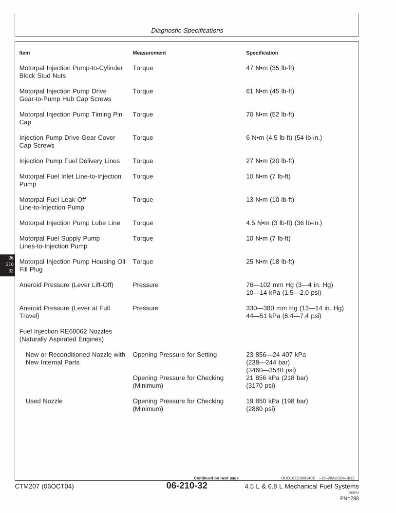
Diagnostic Specifications
06210
32
OUO1032,00014C0 –19–20AUG04–3/12
Item Measurement Specification
Motorpal Injection Pump-to-Cylinder Torque 47 N•m (35 lb-ft)Block Stud Nuts
Motorpal Injection Pump Drive Torque 61 N•m (45 lb-ft)Gear-to-Pump Hub Cap Screws
Motorpal Injection Pump Timing Pin Torque 70 N•m (52 lb-ft)Cap
Injection Pump Drive Gear Cover Torque 6 N•m (4.5 lb-ft) (54 lb-in.)Cap Screws
Injection Pump Fuel Delivery Lines Torque 27 N•m (20 lb-ft)
Motorpal Fuel Inlet Line-to-Injection Torque 10 N•m (7 lb-ft)Pump
Motorpal Fuel Leak-Off Torque 13 N•m (10 lb-ft)Line-to-Injection Pump
Motorpal Injection Pump Lube Line Torque 4.5 N•m (3 lb-ft) (36 lb-in.)
Motorpal Fuel Supply Pump Torque 10 N•m (7 lb-ft)Lines-to-Injection Pump
Motorpal Injection Pump Housing Oil Torque 25 N•m (18 lb-ft)Fill Plug
Aneroid Pressure (Lever Lift-Off) Pressure 76—102 mm Hg (3—4 in. Hg)10—14 kPa (1.5—2.0 psi)
Aneroid Pressure (Lever at Full Pressure 330—380 mm Hg (13—14 in. Hg)Travel) 44—51 kPa (6.4—7.4 psi)
Fuel Injection RE60062 Nozzles(Naturally Aspirated Engines)
New or Reconditioned Nozzle with Opening Pressure for Setting 23 856—24 407 kPaNew Internal Parts (238—244 bar)
(3460—3540 psi)Opening Pressure for Checking 21 856 kPa (218 bar)(Minimum) (3170 psi)
Used Nozzle Opening Pressure for Checking 19 850 kPa (198 bar)(Minimum) (2880 psi)
CTM207 (06OCT04) 06-210-32 4.5 L & 6.8 L Mechanical Fuel Systems100604
PN=298
Continued on next page

Diagnostic Specifications
0621033
OUO1032,00014C0 –19–20AUG04–4/12
Item Measurement Specification
Opening Pressure Difference Pressure Difference (Maximum) 700 kPa (7 bar) (100 psi)between Cylinders
Fuel Injection RE48786 Nozzles(Turbocharged Engines)
New or Reconditioned Nozzle with Opening Pressure for Setting 25 511—26 062 kPaNew Internal Parts (255—260 bar)
(3700—3780 psi)Opening Pressure for Checking 24 683 kPa (246 bar)(Minimum) (3580 psi)
Used Nozzle Opening Pressure for Checking 23 511 kPa (235 bar)(Minimum) (3410 psi)
Opening Pressure Difference Pressure Difference (Maximum) 700 kPa (7 bar) (100 psi)between Cylinders
Fuel Injection Nozzle Tip Spray Angle 144°
Nozzle Valve/Seat Tightness Leakage Nozzle tip dry after 5 seconds.Condition at Pressure Test of 2800— (Slight dampness permissible on3500 kPa (28—35 bar) (400—500 used nozzles.)psi)
Fuel Injection Nozzle Return Leakage 3—10 Drops/30 SecondsLeakage at Pressure Test of 10 300kPa (103 bar) (1500 psi)
Fuel Injection Nozzle Tip Orifice Number of Orifices per Nozzle 4
Fuel Injection Nozzle Tip Orifice ID 0.27 mm (0.0106 in.)(Naturally Aspirated Engines)
Fuel Injection Nozzle Tip Orifice ID 0.29 mm (0.0116 in.)(Turbocharged Engines)
Continued on next page
CTM207 (06OCT04) 06-210-33 4.5 L & 6.8 L Mechanical Fuel Systems100604
PN=299

Diagnostic Specifications
06210
34
OUO1032,00014C0 –19–20AUG04–5/12
Item Measurement Specification
Fuel Injection Nozzles (NaturallyAspirated Engines)
New or Reconditioned Nozzle with Opening Pressure for Setting 23 856—24 407 kPaNew Internal Parts (238—244 bar)
(3460—3540 psi)Opening Pressure for Checking 21 856 kPa (218 bar)(Minimum) (3170 psi)
Used Nozzle Opening Pressure for Checking 19 850 kPa (198 bar)(Minimum) (2880 psi)
Opening Pressure Difference Pressure Difference (Maximum) 700 kPa (7 bar) (100 psi)between Cylinders
Fuel Injection Nozzles (TurbochargedEngines)
New or Reconditioned Nozzle with Opening Pressure for Setting 25 511—26 062 kPaNew Internal Parts (255—260 bar)
(3700—3780 psi)Opening Pressure for Checking 24 683 kPa (246 bar)(Minimum) (3580 psi)
Used Nozzle Opening Pressure for Checking 23 511 kPa (235 bar)(Minimum) (3410 psi)
Opening Pressure Difference Pressure Difference (Maximum) 700 kPa (7 bar) (100 psi)between Cylinders
Injection Nozzle Pressure Adjusting Torque 10 N•m (7 lb-ft)Screw Lock Nut
Fuel Injection Nozzle Valve Needle Lift (Based on Zero Lift) 3/4 Turn Counterclockwise
Fuel Injection Nozzle Lift Adjusting Torque 5 N•m (3.5 lb-ft) (42 lb-in.)Screw Lock Nut
Fuel Injection Nozzle Hold-Down Torque 40 N•m (30 lb-ft)Clamp Cap Screws
Fuel Leak-Off Line Hex Nut Torque 5 N•m (3.7 lb-ft)(44 lb-in.)
CTM207 (06OCT04) 06-210-34 4.5 L & 6.8 L Mechanical Fuel Systems100604
PN=300
Continued on next page

Diagnostic Specifications
0621035
OUO1032,00014C0 –19–20AUG04–6/12
Item Measurement Specification
Fuel Injection Nozzle Delivery Line Torque 27 N•m (20 lb-ft)
Stanadyne Fuel Injection Pump Torque 27 N•m (20 lb-ft)Return Line Connector
Fuel Injection Line-to-Nozzle Torque 27 N•m (20 lb-ft)Connector
Fuel Present at Injection NozzleCheck
Fuel Injection Nozzle Delivery Torque 27 N•m (20 lb-ft)Lines
Cylinder Misfire Test (EngineRunning)
Fuel Injection Nozzle Delivery Line Torque 27 N•m (20 lb-ft)
Rotary Injection Pump Mounting Nuts Torque 27 N•m (20 lb-ft)
Denso Injection Pump Drive Gear Torque 47 N•m (35 lb-ft)Cap Screws
Motorpal Injection Pump Drive Gear Torque 61 N•m (45 lb-ft)Cap Screws
Rotary Fuel Supply Pump Operating Pressure 21—34 kPa (0.21—0.34 bar) (3—5psi)
Rotary Fuel Supply Pump Minimum Flow at 2400 rpm Engine 1.5 L/min (0.42 gpm)Speed
Denso In-Line Fuel Supply Pump Minimum Pressure at 2400 rpm 69 kPa (0.69 bar) (10 psi)Engine Speed
Denso In-Line Fuel Supply Pump Minimum Flow at 2400 rpm Engine 2.0 L/min (0.53 gpm)Speed
Motorpal In-Line Fuel Supply Pump Minimum Pressure at 2000 rpm 80 kPa (0.80 bar) (11.6 psi)Engine Speed
Motorpal In-Line Fuel Supply Pump Minimum Flow at 1000 rpm Engine 1.3 L/min (0.34 gpm)Speed
CTM207 (06OCT04) 06-210-35 4.5 L & 6.8 L Mechanical Fuel Systems100604
PN=301
Continued on next page
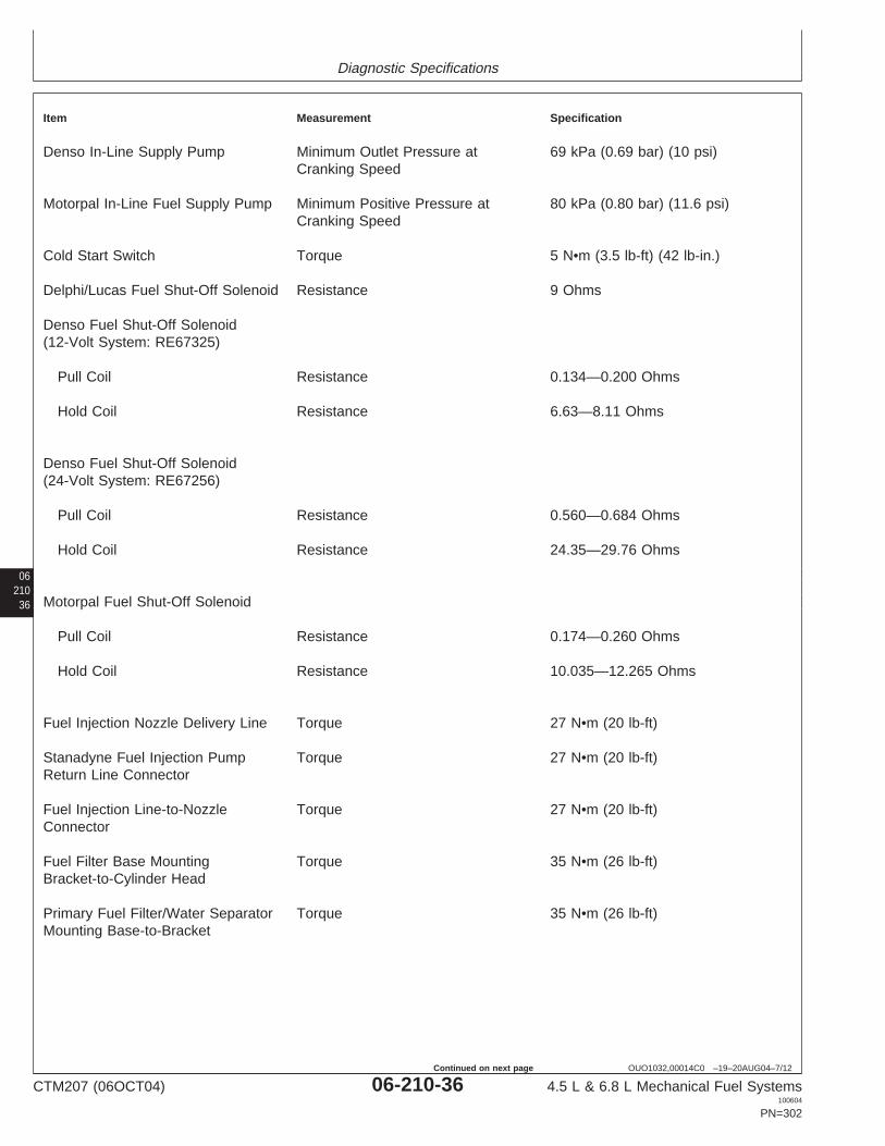
Diagnostic Specifications
06210
36
OUO1032,00014C0 –19–20AUG04–7/12
Item Measurement Specification
Denso In-Line Supply Pump Minimum Outlet Pressure at 69 kPa (0.69 bar) (10 psi)Cranking Speed
Motorpal In-Line Fuel Supply Pump Minimum Positive Pressure at 80 kPa (0.80 bar) (11.6 psi)Cranking Speed
Cold Start Switch Torque 5 N•m (3.5 lb-ft) (42 lb-in.)
Delphi/Lucas Fuel Shut-Off Solenoid Resistance 9 Ohms
Denso Fuel Shut-Off Solenoid(12-Volt System: RE67325)
Pull Coil Resistance 0.134—0.200 Ohms
Hold Coil Resistance 6.63—8.11 Ohms
Denso Fuel Shut-Off Solenoid(24-Volt System: RE67256)
Pull Coil Resistance 0.560—0.684 Ohms
Hold Coil Resistance 24.35—29.76 Ohms
Motorpal Fuel Shut-Off Solenoid
Pull Coil Resistance 0.174—0.260 Ohms
Hold Coil Resistance 10.035—12.265 Ohms
Fuel Injection Nozzle Delivery Line Torque 27 N•m (20 lb-ft)
Stanadyne Fuel Injection Pump Torque 27 N•m (20 lb-ft)Return Line Connector
Fuel Injection Line-to-Nozzle Torque 27 N•m (20 lb-ft)Connector
Fuel Filter Base Mounting Torque 35 N•m (26 lb-ft)Bracket-to-Cylinder Head
Primary Fuel Filter/Water Separator Torque 35 N•m (26 lb-ft)Mounting Base-to-Bracket
CTM207 (06OCT04) 06-210-36 4.5 L & 6.8 L Mechanical Fuel Systems100604
PN=302
Continued on next page

Diagnostic Specifications
0621037
OUO1032,00014C0 –19–20AUG04–8/12
Item Measurement Specification
Final Fuel Filter Mounting Torque 35 N•m (26 lb-ft)Base-to-Bracket
Fuel Supply Pump (Engine with Pressure 28—41 kPa (0.28—0.41 bar)Rotary Injection Pump) (4—6 psi)
Fuel Supply Pump Cap Screws Torque 30 N•m (22 lb-ft)(Rotary)
Fuel Supply Pump (Denso) Cap Torque 5—7 N•m (4—5 lb-ft)Screws (45—60 lb-in.)
Motorpal Fuel Supply Pump Torque 8 N•m (6 lb-ft) (72 lb-in.)Mounting Cap Screws
Fuel Supply Pump Inlet and Outlet Torque 10 N•m (7 lb-ft)Lines
Fuel Shut-Off Solenoid Actuator Rod Torque 15—20 N•m (11—15 lb-ft)Cap Screw/Nut
Remove and Install Delphi/LucasFuel Shut-Off Solenoid
Solenoid Tightening Torque 24 N•m (18 lb-ft)
Cold Start Advance Valve Torque 11.5 N•m (8.5 lb-ft)
Cold Start Advance Torque 5.5 N•m (48 lb-in.)Solenoid-to-Valve
Delphi/Lucas Cold Start Advance Torque 5 N•m (44 lb-in.)Temperature Switch
Delphi/Lucas and Stanadyne Rotary Torque 27 N•m (20 lb-ft)Injection Pump Mounting Nuts
Delphi/Lucas and Stanadyne Rotary Torque 27 N•m (20 lb-ft)Injection Pump Mounting Nuts
Denso Injection Pump Drive Gear Torque 47 N•m (35 lb-ft)Cap Screws
Motorpal Injection Pump Drive Gear Torque 61 N•m (45 lb-ft)Cap Screws
CTM207 (06OCT04) 06-210-37 4.5 L & 6.8 L Mechanical Fuel Systems100604
PN=303
Continued on next page

Diagnostic Specifications
06210
38
OUO1032,00014C0 –19–20AUG04–9/12
Item Measurement Specification
Stanadyne DB2 Fuel Injection Pump Torque 125 N•m (92 lb-ft)Drive Gear-to-Shaft Retaining Nut
Stanadyne DB4 Fuel Injection Pump Torque 203 N•m (150 lb-ft)Drive Gear-to-Shaft Retaining Nut
Rotary Injection Pump Front Access Torque 6 N•m (4.5Lb-ft) (54 lb-in.)Plate Cap Screws
Rotary Injection Pump Mounting Nuts Torque 27 N•m (20 lb-ft)
Fuel Injection Pump Delivery Lines Torque 27 N•m (20 lb-ft)(At Pump)
DP201 and DP203 Delphi/Lucas Torque 81 N•m (60 lb-ft)Fuel Injection Pump DriveGear-to-Shaft Retaining Nut
Fuel Injection Pump Delivery Lines Torque 27 N•m (20 lb-ft)
Denso Injection Pump Mounting Nuts Torque 70 N•m (52 lb-ft)
Denso Injection Pump Drive Gear Torque 47 N•m (35 lb-ft)Cap Screws
Denso Injection Pump Drive Gear Torque 6 N•m (4.5 lb-ft) (54 lb-in.)Cover
Fuel Injection Pump Delivery Valve Torque 47 N•m (35 lb-ft)(Motorpal)
Motorpal Injection Pump-to-Cylinder Torque 47 N•m (35 lb-ft)Block Stud Nuts
Motorpal Injection Pump Drive Torque 61 N•m (45 lb-ft)Gear-to-Pump Hub Cap Screws
Motorpal Injection Pump Timing Pin Torque 70 N•m (52 lb-ft)Cap
Motorpal Fuel Inlet Line-to-Injection Torque 10 N•m (7 lb-ft)Pump
Motorpal Fuel Leak-Off Torque 13 N•m (10 lb-ft)Line-to-Injection Pump
Motorpal Injection Pump Lube Line Torque 4.5 N•m (3 lb-ft) (36 lb-in.)
CTM207 (06OCT04) 06-210-38 4.5 L & 6.8 L Mechanical Fuel Systems100604
PN=304
Continued on next page

Diagnostic Specifications
0621039
OUO1032,00014C0 –19–20AUG04–10/12
Item Measurement Specification
Motorpal Fuel Supply Pump Torque 10 N•m (7 lb-ft)Lines-to-Injection Pump
Motorpal Injection Pump Housing Oil Torque 25 N•m (18 lb-ft)Fill Plug
Aneroid Pressure (Lever Lift-Off) Pressure 76—102 mm Hg (3—4 in. Hg)10—14 kPa (1.5—2.0 psi)
Aneroid Pressure (Lever at Full Pressure 330—380 mm Hg (13—14 in. Hg)Travel) 44—51 kPa (6.4—7.4 psi)
Fuel Injection RE60062 Nozzles(Naturally Aspirated Engines)
New or Reconditioned Nozzle with Opening Pressure for Setting 23 856—24 407 kPaNew Internal Parts (238—244 bar)
(3460—3540 psi)Opening Pressure for Checking 21 856 kPa (218 bar)(Minimum) (3170 psi)
Used Nozzle Opening Pressure for Checking 19 850 kPa (198 bar)(Minimum) (2880 psi)
Opening Pressure Difference Pressure Difference (Maximum) 700 kPa (7 bar) (100 psi)between Cylinders
Fuel Injection RE48786 Nozzles(Turbocharged Engines)
New or Reconditioned Nozzle with Opening Pressure for Setting 25 511—26 062 kPaNew Internal Parts (255—260 bar)
(3700—3780 psi)Opening Pressure for Checking 24 683 kPa (246 bar)(Minimum) (3580 psi)
Used Nozzle Opening Pressure for Checking 23 511 kPa (235 bar)(Minimum) (3410 psi)
Opening Pressure Difference Pressure Difference (Maximum) 700 kPa (7 bar) (100 psi)between Cylinders
Fuel Injection Nozzle Tip Spray Angle 144°
CTM207 (06OCT04) 06-210-39 4.5 L & 6.8 L Mechanical Fuel Systems100604
PN=305
Continued on next page

Diagnostic Specifications
06210
40
OUO1032,00014C0 –19–20AUG04–11/12
Item Measurement Specification
Nozzle Valve/Seat Tightness Leakage Nozzle tip dry after 5 seconds.Condition at Pressure Test of 2800— (Slight dampness permissible on3500 kPa (28—35 bar) (400—500 used nozzles.)psi)
Fuel Injection Nozzle Return Leakage 3—10 Drops/30 SecondsLeakage at Pressure Test of 10 300kPa (103 bar) (1500 psi)
Fuel Injection Nozzle Tip Orifice Number of Orifices per Nozzle 4
Fuel Injection Nozzle Tip Orifice ID 0.27 mm (0.0106 in.)(Naturally Aspirated Engines)
Fuel Injection Nozzle Tip Orifice ID 0.29 mm (0.0116 in.)(Turbocharged Engines)
Fuel Injection Nozzles (NaturallyAspirated Engines)
New or Reconditioned Nozzle with Opening Pressure for Setting 23 856—24 407 kPaNew Internal Parts (238—244 bar)
(3460—3540 psi)Opening Pressure for Checking 21 856 kPa (218 bar)(Minimum) (3170 psi)
Used Nozzle Opening Pressure for Checking 19 850 kPa (198 bar)(Minimum) (2880 psi)
Opening Pressure Difference Pressure Difference (Maximum) 700 kPa (7 bar) (100 psi)between Cylinders
Fuel Injection Nozzles (TurbochargedEngines)
New or Reconditioned Nozzle with Opening Pressure for Setting 25 511—26 062 kPaNew Internal Parts (255—260 bar)
(3700—3780 psi)Opening Pressure for Checking 24 683 kPa (246 bar)(Minimum) (3580 psi)
Used Nozzle Opening Pressure for Checking 23 511 kPa (235 bar)(Minimum) (3410 psi)
CTM207 (06OCT04) 06-210-40 4.5 L & 6.8 L Mechanical Fuel Systems100604
PN=306
Continued on next page

Diagnostic Specifications
0621041
OUO1032,00014C0 –19–20AUG04–12/12
Item Measurement Specification
Opening Pressure Difference Pressure Difference (Maximum) 700 kPa (7 bar) (100 psi)between Cylinders
Injection Nozzle Pressure Adjusting Torque 10 N•m (7 lb-ft)Screw Lock Nut
Fuel Injection Nozzle Valve Needle Lift (Based on Zero Lift) 3/4 Turn Counterclockwise
Fuel Injection Nozzle Lift Adjusting Torque 5 N•m (3.5 lb-ft) (42 lb-in.)Screw Lock Nut
Fuel Injection Nozzle Hold-Down Torque 40 N•m (30 lb-ft)Clamp Cap Screws
Fuel Leak-Off Line Hex Nut Torque 5 N•m (3.7 lb-ft)(44 lb-in.)
Stanadyne Fuel Injection Pump Torque 27 N•m (20 lb-ft)Return Line Connector
Fuel Injection Line-to-Nozzle Torque 27 N•m (20 lb-ft)Connector
CTM207 (06OCT04) 06-210-41 4.5 L & 6.8 L Mechanical Fuel Systems100604
PN=307

Diagnostic Specifications
06210
42
CTM207 (06OCT04) 06-210-42 4.5 L & 6.8 L Mechanical Fuel Systems100604
PN=308

IndexPage Page
A E
Air in fuel test . . . . . . . . . . . . . . . . . . . . . . .04-150-40 EngineAneroid Application charts . . . . . . . . . . . . . . . . . . .01-001-4
Operation . . . . . . . . . . . . . . . . . . . . . . . .03-130-17 Model designation. . . . . . . . . . . . . . . . . . .01-001-1Repair (Denso, Delphi/Lucas, Serial number plate. . . . . . . . . . . . . . . . . .01-001-2
Stanadyne) . . . . . . . . . . . . . . . . . . . . .02-090-63
FB
Front plate timing mark, transfer. . . . . . . . .02-090-64Bleed fuel system. . . . . . . . . . .02-090-93, 04-150-70Fuel
Diesel . . . . . . . . . . . . . . . . . . . .01-002-1, 01-002-2Lubricity . . . . . . . . . . . . . . . . . . . . . . . . . .01-002-3
Fuel drain-back test . . . . . . . . . . . . . . . . . .04-150-69CFuel filter
Exploded view (final). . . . . . . . . . . . . . . . .02-090-7Check Exploded view (primary) . . . . . . . . . . . . . .02-090-6
Fuel supply system . . . . . . . . . . . . . . . . .04-150-25 Install . . . . . . . . . . . . . . . . . . . . . . . . . . . .02-090-8Cold start advance
Operation . . . . . . . . . . . . . . . . . . . . . . . .03-130-11Check operation . . . . . . . . . . . . . . . . . . .04-150-49
Remove and install . . . . . . . . . . . . . . . . . .02-090-3Switch, operational check . . . . . . . . . . . .04-150-48
Replace . . . . . . . . . . . . . . . . . . . . . . . . . .02-090-8System operation . . . . . . . . . . . . . . . . . . .03-130-9Fuel injection nozzlesCold start advance solenoid and valve
Adjust . . . . . . . . . . . . . . . . . . . . . . . . . . .02-090-84Remove and install (Stanadyne) . . . . . . .02-090-27Assemble . . . . . . . . . . . . . . . . . . . . . . . .02-090-83Cold start advance switch and harnessBore, clean . . . . . . . . . . . . . . . . . . . . . . .02-090-67Remove and install (Delphi/Lucas) . . . . .02-090-29Clean . . . . . . . . . . . . . . . . . . . . . . . . . . .02-090-68Coolant. . . . . . . . . . . . . . . . . . . . . . . . . . . . .01-002-1Clean and inspect body . . . . . . . . . . . . .02-090-79Cylinder misfire test . . . . . . . . . . . . . . . . . .04-150-29Diagnose malfunctions . . . . . . . . . . . . . .02-090-69 IndxDisassemble . . . . . . . . . . . . . . . . . . . . . .02-090-76 1Identification . . . . . . . . . . . . . . . . . . . . . .02-090-65Inspect valve adjusting mechanism. . . . .02-090-82DInstall . . . . . . . . . . . . . . . . . . . . . . . . . . .02-090-91Install seals. . . . . . . . . . . . . . . . . . . . . . .02-090-90Dealer fabricated tools . . . . . . . . . . . . . . . . .05-190-1Operation . . . . . . . . . . . . . . . . . . . . . . . .03-130-19DiagnosticsRemove . . . . . . . . . . . . . . . . . . . . . . . . .02-090-65Abnormal engine noise . . . . .04-150-23, 04-150-24Test . . . . . . . . . . . . . . . . . . . . . . . . . . . .02-090-70Engine cranks/won’t start . . . . . . . . . . . . .04-150-3Test (engine running) . . . . . . . . . . . . . . .04-150-68Engine does not develop full power . . . .04-150-11Valve, inspect and clean . . . . . . . . . . . . .02-090-80Engine emits excessive black or gray exhaust
Fuel injection pumpsmoke . . . . . . . . . . . . . . . . . . . . . . . . .04-150-19General information. . . . . . . . . . . . . . . . . .03-130-1Engine emits excessive white exhaustTiming specifications. . . . . . . . . . . . . . . . .06-210-1smoke . . . . . . . . . . . . . . . . . . . . . . . . .04-150-16
Fuel injection pump (Delphi/Lucas)Engine idles poorly . . . . . . . . . . . . . . . . .04-150-22Dynamic timing . . . . . . . . . . . . . . . . . . . .04-150-30Engine misfires/runs irregularly . . . . . . . . .04-150-7Engine speed, check and adjust . . . . . . .04-150-57Engine will not crank. . . . . . . . . . . . . . . .04-150-22Install . . . . . . . . . . . . . . . . . . . . . . . . . . .02-090-43Fuel supply system . . . . . . . . . . . . . . . . .04-150-25Operation . . . . . . . . . . . . . . . . . . . . . . . .03-130-14Fuel system, low pressureRemove . . . . . . . . . . . . . . . . . . . . . . . . .02-090-40Excessive fuel consumption. . . . . . . . .04-150-28Repair . . . . . . . . . . . . . . . . . . . . . . . . . . .02-090-42Fuel in oil . . . . . . . . . . . . . . . . . . . . . .04-150-28
Diesel fuel . . . . . . . . . . . . . . . . . .01-002-1, 01-002-2 Static timing . . . . . . . . . . . . . . . . . . . . . .02-090-30
CTM207 (06OCT04) Index-1 4.5 L & 6.8 L Mechanical Fuel Systems100604
PN=1

Index
Page Page
Fuel injection pump (Denso) Operation . . . . . . . . . . . . . . . . . . . . . . . . .03-130-6Change rated speed and adjust Remove . . . . . . . . . . . . . . . . . . . . . . . . .02-090-14
droop. . . . . . . . . . . . . . . . . . . . . . . . . .04-150-66 Service . . . . . . . . . . . . . . . . . . . . . . . . . .04-150-47Fast idle speed, check and adjust . . . . . .04-150-62 Fuel supply pump (Lucas and Stanadyne)Install . . . . . . . . . . . . . . . . . . . . . . . . . . .02-090-49 Bench test. . . . . . . . . . . . . . . . . . . . . . . .02-090-11Operation . . . . . . . . . . . . . . . . . . . . . . . .03-130-16 Install . . . . . . . . . . . . . . . . . . . . . . . . . . .02-090-13Overflow valve . . . . . . . . . . . . . . . . . . . .02-090-24 Remove . . . . . . . . . . . . . . . . . . . . . . . . .02-090-10Remove . . . . . . . . . . . . . . . . . . . . . . . . .02-090-46 Fuel supply pump (Motorpal)Repair . . . . . . . . . . . . . . . . . . . . . . . . . . .02-090-48 Check operation . . . . . . . . . . . . . . . . . . .04-150-45Slow idle speed, check and adjust . . . . .04-150-63 Inspect . . . . . . . . . . . . . . . . . . . . . . . . . .02-090-23Static timing . . . . . . . . . . . . .02-090-32, 04-150-37 Install . . . . . . . . . . . . . . . . . . . . . . . . . . .02-090-23
Fuel injection pump (Motorpal) Leak test . . . . . . . . . . . . . . . . . . . . . . . . .04-150-44Delivery valve O-rings, replace . . . . . . . .02-090-53 Measure pressure . . . . . . . . . . . . . . . . . .04-150-43Fast idle speed, check and adjust . . . . . .04-150-62 Operation . . . . . . . . . . . . . . . . . . . . . . . . .03-130-6Install . . . . . . . . . . . . . . . . . . . . . . . . . . .02-090-58 Remove . . . . . . . . . . . . . . . . . . . . . . . . .02-090-22Operation . . . . . . . . . . . . . . . . . . . . . . . .03-130-16 Fuel supply quality check . . . . . . . . . . . . . .04-150-39Remove . . . . . . . . . . . . . . . . . . . . . . . . .02-090-54 Fuel systemRepair . . . . . . . . . . . . . . . . . . . . . . . . . . .02-090-57
Air in fuel test . . . . . . . . . . . . . . . . . . . . .04-150-40Slow idle speed, check and adjust . . . . .04-150-65
Bleed . . . . . . . . . . . . . . . . . .02-090-93, 04-150-70Static timing . . . . . . . . . . . . .02-090-32, 04-150-37
DiagnosticsFuel injection pump (Stanadyne)Excessive fuel consumption. . . . . . . . .04-150-28Check and adjust engine speeds . . . . . .04-150-59Fuel in oil . . . . . . . . . . . . . . . . . . . . . .04-150-28Dynamic timing . . . . . . . . . . . . . . . . . . . .04-150-30
Fuel supply quality check . . . . . . . . . . . .04-150-39Inspect . . . . . . . . . . . . . . . . . . . . . . . . . .02-090-36General information. . . . . . . . . . . . . . . . . .02-090-1Install . . . . . . . . . . . . . . . . . . . . . . . . . . .02-090-37Operation (in-line pump) . . . . . . . . . . . . . .03-130-4Operation . . . . . . . . . . . . . . . . . . . . . . . .03-130-12Operation (rotory pump) . . . . . . . . . . . . . .03-130-2Remove . . . . . . . . . . . . . . . . . . . . . . . . .02-090-34Relieve pressure . . . . . . . . . . . . . . . . . . . .02-090-2Repair . . . . . . . . . . . . . . . . . . . . . . . . . . .02-090-36Restricted fuel return line check . . . . . . .04-150-41Static timing . . . . . . . . . . . . . . . . . . . . . .02-090-30
Fuel shutoff solenoid (Delphi/Lucas)Remove and install . . . . . . . . . . . . . . . . .02-090-26Test . . . . . . . . . . . . . . . . . . . . . . . . . . . .04-150-53
Fuel shutoff solenoid (Denso) IIndx
2
Linkage adjustment . . . . . . . . . . . . . . . . .04-150-55Operational check . . . . . . . . . . . . . . . . . .04-150-52 Inch torque values . . . . . . . . . . . . . . . . . . . .06-200-1Remove and install . . . . . . . . . . . . . . . . .02-090-25 Injection nozzlesTest . . . . . . . . . . . . . . . . . . . . . . . . . . . .04-150-54
Adjust . . . . . . . . . . . . . . . . . . . . . . . . . . .02-090-84Fuel shutoff solenoid (Motorpal)
Assemble . . . . . . . . . . . . . . . . . . . . . . . .02-090-83Linkage adjustment . . . . . . . . . . . . . . . . .04-150-55Bore, clean . . . . . . . . . . . . . . . . . . . . . . .02-090-67Operational check . . . . . . . . . . . . . . . . . .04-150-52Clean . . . . . . . . . . . . . . . . . . . . . . . . . . .02-090-68Remove and install . . . . . . . . . . . . . . . . .02-090-26Clean and inspect body . . . . . . . . . . . . .02-090-79Test . . . . . . . . . . . . . . . . . . . . . . . . . . . .04-150-55Diagnose malfunctions . . . . . . . . . . . . . .02-090-69Fuel supply pump (Delphi/Lucas and Stanadyne)Disassemble . . . . . . . . . . . . . . . . . . . . . .02-090-76Measure pressure . . . . . . . . . . . . . . . . . .04-150-42Identification . . . . . . . . . . . . . . . . . . . . . .02-090-65Operation . . . . . . . . . . . . . . . . . . . . . . . . .03-130-5Inspect valve adjusting mechanism. . . . .02-090-82Fuel supply pump (Denso)Install . . . . . . . . . . . . . . . . . . . . . . . . . . .02-090-91Assemble . . . . . . . . . . . . . . . . . . . . . . . .02-090-21Install seals. . . . . . . . . . . . . . . . . . . . . . .02-090-90Check operation . . . . . . . . . . . . . . . . . . .04-150-45Operation . . . . . . . . . . . . . . . . . . . . . . . .03-130-19Disassemble . . . . . . . . . . . . . . . . . . . . . .02-090-16Remove . . . . . . . . . . . . . . . . . . . . . . . . .02-090-65Inspect and repair . . . . . . . . . . . . . . . . . .02-090-19Test . . . . . . . . . . . . . . . . . . . . . . . . . . . .02-090-70Install . . . . . . . . . . . . . . . . . . . . . . . . . . .02-090-22Test (engine running) . . . . . . . . . . . . . . .04-150-68Leak test . . . . . . . . . . . . . . . .02-090-15, 04-150-44
Measure pressure . . . . . . . . . . . . . . . . . .04-150-43 Valve, inspect and clean . . . . . . . . . . . . .02-090-80
CTM207 (06OCT04) Index-2 4.5 L & 6.8 L Mechanical Fuel Systems100604
PN=2

Index
Page Page
L Remove . . . . . . . . . . . . . . . . . . . . . . . . .02-090-40Repair . . . . . . . . . . . . . . . . . . . . . . . . . . .02-090-42Static timing . . . . . . . . . . . . . . . . . . . . . .02-090-30Light load advance
Operational checkout . . . . . . . . . . . . . . .04-150-51 Pump, fuel injection (Denso)Change rated speed and adjustTheory of operation. . . . . . . . . . . . . . . . .03-130-10
Lubricants. . . . . . . . . . . . . . . . . . . . . . . . . . .01-002-1 droop. . . . . . . . . . . . . . . . . . . . . . . . . .04-150-66Fast idle speed, check and adjust . . . . . .04-150-62Lubricity of diesel fuel. . . . . . . . . . . . . . . . . .01-002-3Install . . . . . . . . . . . . . . . . . . . . . . . . . . .02-090-49Operation . . . . . . . . . . . . . . . . . . . . . . . .03-130-16Remove . . . . . . . . . . . . . . . . . . . . . . . . .02-090-46MRepair . . . . . . . . . . . . . . . . . . . . . . . . . . .02-090-48Slow idle speed, check and adjust . . . . .04-150-63
Metric torque values . . . . . . . . . . . . . . . . . . .06-200-2Static timing . . . . . . . . . . . . .02-090-32, 04-150-37
Pump, fuel injection (Motorpal)Delivery valve O-rings, replace . . . . . . . .02-090-53Fast idle speed, check and adjust . . . . . .04-150-62NInstall . . . . . . . . . . . . . . . . . . . . . . . . . . .02-090-58Operation . . . . . . . . . . . . . . . . . . . . . . . .03-130-16Nozzles, fuel injection
Adjust . . . . . . . . . . . . . . . . . . . . . . . . . . .02-090-84 Remove . . . . . . . . . . . . . . . . . . . . . . . . .02-090-54Repair . . . . . . . . . . . . . . . . . . . . . . . . . . .02-090-57Assemble . . . . . . . . . . . . . . . . . . . . . . . .02-090-83
Bore, clean . . . . . . . . . . . . . . . . . . . . . . .02-090-67 Slow idle speed, check and adjust . . . . .04-150-65Static timing . . . . . . . . . . . . .02-090-32, 04-150-37Clean . . . . . . . . . . . . . . . . . . . . . . . . . . .02-090-68
Clean and inspect body . . . . . . . . . . . . .02-090-79 Pump, fuel injection (Stanadyne)Check and adjust engine speeds . . . . . .04-150-59Diagnose malfunctions . . . . . . . . . . . . . .02-090-69
Disassemble . . . . . . . . . . . . . . . . . . . . . .02-090-76 Dynamic timing . . . . . . . . . . . . . . . . . . . .04-150-30Inspect . . . . . . . . . . . . . . . . . . . . . . . . . .02-090-36Identification . . . . . . . . . . . . . . . . . . . . . .02-090-65
Inspect valve adjusting mechanism. . . . .02-090-82 Install . . . . . . . . . . . . . . . . . . . . . . . . . . .02-090-37Operation . . . . . . . . . . . . . . . . . . . . . . . .03-130-12Install . . . . . . . . . . . . . . . . . . . . . . . . . . .02-090-91
Install seals. . . . . . . . . . . . . . . . . . . . . . .02-090-90 Remove . . . . . . . . . . . . . . . . . . . . . . . . .02-090-34Repair . . . . . . . . . . . . . . . . . . . . . . . . . . .02-090-36Operation . . . . . . . . . . . . . . . . . . . . . . . .03-130-19
Remove . . . . . . . . . . . . . . . .02-090-65, 02-090-82 Static timing . . . . . . . . . . . . . . . . . . . . . .02-090-30IndxTest . . . . . . . . . . . . . . . . . . . . . . . . . . . .02-090-70 Pump, fuel supply (Delphi/Lucas and Stanadyne) 3
Test (engine running) . . . . . . . . . . . . . . .04-150-68 Measure pressure . . . . . . . . . . . . . . . . . .04-150-42Operation . . . . . . . . . . . . . . . . . . . . . . . . .03-130-5Valve, inspect and clean . . . . . . . . . . . . .02-090-80
Pump, fuel supply (Denso)Assemble . . . . . . . . . . . . . . . . . . . . . . . .02-090-21Check operation . . . . . . . . . . . . . . . . . . .04-150-45ODisassemble . . . . . . . . . . . . . . . . . . . . . .02-090-16Inspect and repair . . . . . . . . . . . . . . . . . .02-090-19
Overflow valveInstall . . . . . . . . . . . . . . . . . . . . . . . . . . .02-090-22
Fuel injection pump (Denso) . . . . . . . . . .02-090-24Leak test . . . . . . . . . . . . . . . .02-090-15, 04-150-44Measure pressure . . . . . . . . . . . . . . . . . .04-150-43Operation . . . . . . . . . . . . . . . . . . . . . . . . .03-130-6Remove . . . . . . . . . . . . . . . . . . . . . . . . .02-090-14PService . . . . . . . . . . . . . . . . . . . . . . . . . .04-150-47
Pump, fuel supply (Motorpal)Pump, fuel injectionGeneral information. . . . . . . . . . . . . . . . . .03-130-1 Check operation . . . . . . . . . . . . . . . . . . .04-150-45
Inspect . . . . . . . . . . . . . . . . . . . . . . . . . .02-090-23Timing specifications. . . . . . . . . . . . . . . . .06-210-1Pump, fuel injection (Delphi/Lucas) Install . . . . . . . . . . . . . . . . . . . . . . . . . . .02-090-23
Leak test . . . . . . . . . . . . . . . . . . . . . . . . .04-150-44Dynamic timing . . . . . . . . . . . . . . . . . . . .04-150-30Engine speed, check and adjust . . . . . . .04-150-57 Measure pressure . . . . . . . . . . . . . . . . . .04-150-43
Operation . . . . . . . . . . . . . . . . . . . . . . . . .03-130-6Install . . . . . . . . . . . . . . . . . . . . . . . . . . .02-090-43Operation . . . . . . . . . . . . . . . . . . . . . . . .03-130-14 Remove . . . . . . . . . . . . . . . . . . . . . . . . .02-090-22
CTM207 (06OCT04) Index-3 4.5 L & 6.8 L Mechanical Fuel Systems100604
PN=3

Index
Page
S
Serial number plate . . . . . . . . . . . . . . . . . . .01-001-2Solenoid, fuel shutoff
Remove and install (Delphi/Lucas) . . . . .02-090-26Remove and install (Denso) . . . . . . . . . .02-090-25Remove and install (Motorpal) . . . . . . . .02-090-26
Solenoid, fuel shutoff (Delphi/Lucas)Test . . . . . . . . . . . . . . . . . . . . . . . . . . . .04-150-53
Solenoid, fuel shutoff (Denso)Linkage adjustment . . . . . . . . . . . . . . . . .04-150-55Operational check . . . . . . . . . . . . . . . . . .04-150-52Test . . . . . . . . . . . . . . . . . . . . . . . . . . . .04-150-54
Solenoid, fuel shutoff (Motorpal)Linkage adjustment . . . . . . . . . . . . . . . . .04-150-55Operational check . . . . . . . . . . . . . . . . . .04-150-52Test . . . . . . . . . . . . . . . . . . . . . . . . . . . .04-150-55
SpecificationsGeneral OEM engine specifications . . . . .06-200-3Injection pump, timing . . . . . . . . . . . . . . . .06-210-1
T
TIME TRAC, using as a tachometer . . . . . .04-150-30Timing mark, front plate, transfer . . . . . . . .02-090-64Tools
Dealer fabricated. . . . . . . . . . . . . . . . . . . .05-190-1Diagnostic . . . . . . . . . . . . . . . . . . . . . . . . .05-180-1
Torque valuesInch. . . . . . . . . . . . . . . . . . . . . . . . . . . . . .06-200-1Metric . . . . . . . . . . . . . . . . . . . . . . . . . . . .06-200-2
Indx4
V
Variable speed, generator set engines (Delphi/Lucas)Adjust . . . . . . . . . . . . . . . . . . . . . . . . . . .04-150-58
Variable speed, generator set engines (Stanadyne)Adjust . . . . . . . . . . . . . . . . . . . . . . . . . . .04-150-61
CTM207 (06OCT04) Index-4 4.5 L & 6.8 L Mechanical Fuel Systems100604
PN=4
Related Documents