PowerStore Technical Overview April 14, 2021

Welcome message from author
This document is posted to help you gain knowledge. Please leave a comment to let me know what you think about it! Share it to your friends and learn new things together.
Transcript
PowerStore Technical OverviewApril 14, 2021
© Copyright 2021 Dell Inc.2 of 292
Presentation sections• Hardware Overview
• PowerStore 1000T/X – 9000T/X Hardware
Overview
• PowerStore 500T Hardware Overview
• PowerStore T Architecture Overview
• PowerStore X Architecture Overview
• PowerStore Discovery
• PowerStore Clustering
• Resource Balancing
• PowerStore Manager GUI
• CLI
• Rest API
• Data Path
• File
• NVMe-FC
• Storage Network Scaling
• Volumes & Volume Groups
• Protection Policies
• Snapshots
• Thin Clones
• Block Remote Replication
• PowerStore metro node
• Virtualization Integration
• Serviceability
• Security Overview
• Import External Storage
• Services
© Copyright 2021 Dell Inc.3 of 292
For Presenters: What has been updated in the presentation since the last version
• April update
– Content added:
▪ PowerStore 500T
▪ PowerStoreOS 2.0:
• Data Path enhancements
• Cluster support for PowerStore X
• NVMe-FC
• Storage Network Scaling
• Additional Import External Storage support
– Content deleted:
▪ System Limits section (this information can be found in the Support Matrix)
© Copyright 2021 Dell Inc.4 of 292
Hardware Overview

© Copyright 2021 Dell Inc.5 of 292
OverviewTerminology (Hardware) - PowerStore
PowerStore Term Definition Previous Terms
NodeComponent within the base enclosure that contains processors
and memory. Each appliance consists of 2 nodes.Storage Processor (SP), Controller
Base EnclosureUsed to reference the enclosure containing both Nodes (Node A
and Node B) and 25x NVMe drive slotsDisk Processor Enclosure (DPE), Array
Expansion EnclosureEnclosures that can be attached to a base enclosure to provide
additional storage in the form of SAS drivesDisk Array Enclosure (DAE), JBOD
Appliance
Term used for solution containing a base enclosure and any
attached expansion enclosures. The size of an appliance could
be just the base enclosure or the base enclosure plus expansion
enclosures.
N/A
Cluster
Multiple appliances in a single grouping. Clusters can consist of
one appliance or more. Clusters are expandable by adding more
appliances (up to 4).
N/A
Embedded ModuleModule embedded to each node providing mgmt, host front-end
connectivity, SAS expansion ports, and selectable 4-port cardN/A
4-Port CardCard for each node that provides 4 ports for mgmt. and front-end
ports. Selectable in 25GbE and 10GbE Base-T options.N/A
© Copyright 2021 Dell Inc.6 of 292
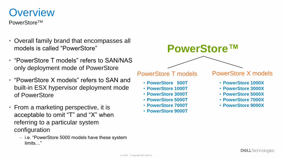
OverviewPowerStoreTM
• Overall family brand that encompasses all
models is called “PowerStore”
• “PowerStore T models” refers to SAN/NAS
only deployment mode of PowerStore
• “PowerStore X models” refers to SAN and
built-in ESX hypervisor deployment mode
of PowerStore
• From a marketing perspective, it is
acceptable to omit “T” and “X” when
referring to a particular system
configuration– i.e. “PowerStore 5000 models have these system
limits…”
PowerStore™
• PowerStore 500T
• PowerStore 1000T
• PowerStore 3000T
• PowerStore 5000T
• PowerStore 7000T
• PowerStore 9000T
PowerStore T models PowerStore X models
• PowerStore 1000X
• PowerStore 3000X
• PowerStore 5000X
• PowerStore 7000X
• PowerStore 9000X
© Copyright 2021 Dell Inc.7 of 292
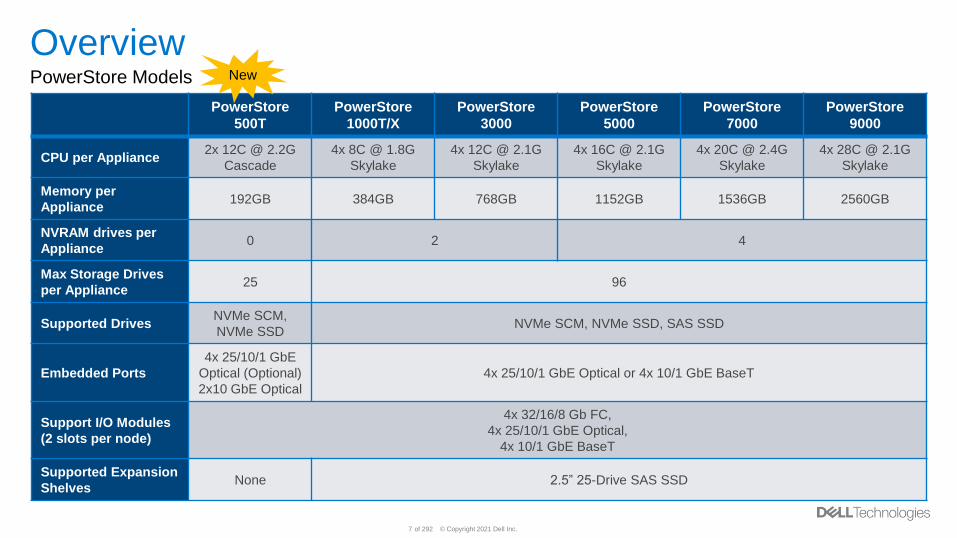
OverviewPowerStore Models
PowerStore
500T
PowerStore
1000T/X
PowerStore
3000
PowerStore
5000
PowerStore
7000
PowerStore
9000
CPU per Appliance2x 12C @ 2.2G
Cascade
4x 8C @ 1.8G
Skylake
4x 12C @ 2.1G
Skylake
4x 16C @ 2.1G
Skylake
4x 20C @ 2.4G
Skylake
4x 28C @ 2.1G
Skylake
Memory per
Appliance192GB 384GB 768GB 1152GB 1536GB 2560GB
NVRAM drives per
Appliance0 2 4
Max Storage Drives
per Appliance25 96
Supported DrivesNVMe SCM,
NVMe SSDNVMe SCM, NVMe SSD, SAS SSD
Embedded Ports
4x 25/10/1 GbE
Optical (Optional)
2x10 GbE Optical
4x 25/10/1 GbE Optical or 4x 10/1 GbE BaseT
Support I/O Modules
(2 slots per node)
4x 32/16/8 Gb FC,
4x 25/10/1 GbE Optical,
4x 10/1 GbE BaseT
Supported Expansion
ShelvesNone 2.5” 25-Drive SAS SSD
New
© Copyright 2021 Dell Inc.8 of 292
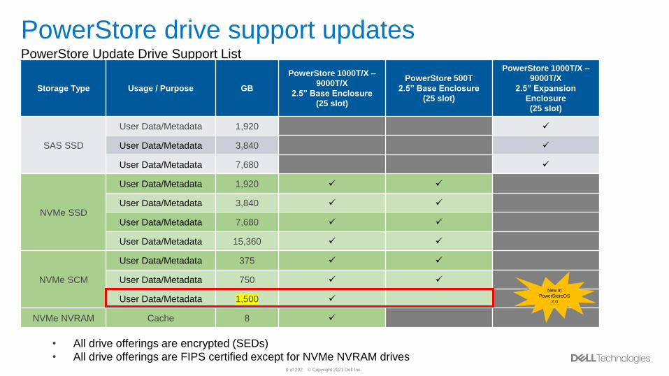
PowerStore drive support updatesPowerStore Update Drive Support List
Storage Type Usage / Purpose GB
PowerStore 1000T/X –
9000T/X
2.5” Base Enclosure
(25 slot)
PowerStore 500T
2.5” Base Enclosure
(25 slot)
PowerStore 1000T/X –
9000T/X
2.5” Expansion
Enclosure
(25 slot)
SAS SSD
User Data/Metadata 1,920 ✓
User Data/Metadata 3,840 ✓
User Data/Metadata 7,680 ✓
NVMe SSD
User Data/Metadata 1,920 ✓ ✓
User Data/Metadata 3,840 ✓ ✓
User Data/Metadata 7,680 ✓ ✓
User Data/Metadata 15,360 ✓ ✓
NVMe SCM
User Data/Metadata 375 ✓ ✓
User Data/Metadata 750 ✓ ✓
User Data/Metadata 1,500 ✓
NVMe NVRAM Cache 8 ✓
• All drive offerings are encrypted (SEDs)
• All drive offerings are FIPS certified except for NVMe NVRAM drives
New in
PowerStoreOS
2.0
© Copyright 2021 Dell Inc.9 of 292
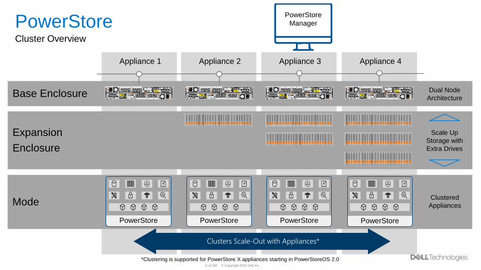
Appliance 1 Appliance 2 Appliance 3 Appliance 4
Base Enclosure
PowerStoreCluster Overview
Expansion
Enclosure
Dual Node
Architecture
Scale Up
Storage with
Extra Drives
Mode
PowerStore
Clustered
Appliances
PowerStore
Clusters Scale-Out with Appliances*
PowerStore PowerStore
PowerStore
Manager
*Clustering is supported for PowerStore X appliances starting in PowerStoreOS 2.0
© Copyright 2021 Dell Inc.10 of 292
PowerStore 1000T/X – 9000T/X Hardware Overview
© Copyright 2021 Dell Inc.11 of 292
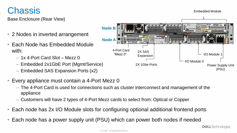
ChassisBase Enclosure (Rear View)
• 2 Nodes in inverted arrangement
• Each Node has Embedded Module
with:
– 1x 4-Port Card Slot – Mezz 0
– Embedded 2x1GbE Port (Mgmt/Service)
– Embedded SAS Expansion Ports (x2)
• Every appliance must contain a 4-Port Mezz 0
– The 4-Port Card is used for connections such as cluster interconnect and management of the
appliance
– Customers will have 2 types of 4-Port Mezz cards to select from: Optical or Copper
• Each node has 2x I/O Module slots for configuring optional additional frontend ports
• Each node has a power supply unit (PSU) which can power both nodes if needed
Node A
Node B
Power Supply
Unit (PSU)
2X 1Gbe Ports
Power Supply Unit
(PSU)
I/O Module 1
I/O Module 00
2X SAS
Expansion
2X 1Gbe Ports
4-Port Card
“Mezz 0””
Embedded Module
© Copyright 2021 Dell Inc.14 of 292
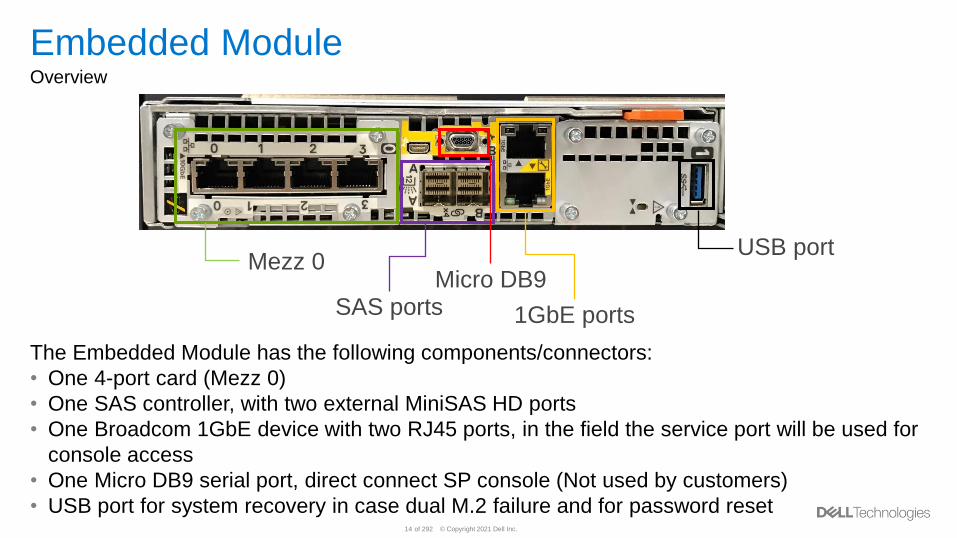
Embedded ModuleOverview
The Embedded Module has the following components/connectors:
• One 4-port card (Mezz 0)
• One SAS controller, with two external MiniSAS HD ports
• One Broadcom 1GbE device with two RJ45 ports, in the field the service port will be used for
console access
• One Micro DB9 serial port, direct connect SP console (Not used by customers)
• USB port for system recovery in case dual M.2 failure and for password reset
Mezz 0
SAS portsMicro DB9
USB port
1GbE ports
© Copyright 2021 Dell Inc.15 of 292
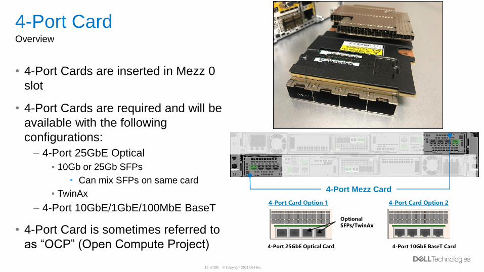
4-Port CardOverview
• 4-Port Cards are inserted in Mezz 0
slot
• 4-Port Cards are required and will be
available with the following
configurations:
– 4-Port 25GbE Optical
▪ 10Gb or 25Gb SFPs
• Can mix SFPs on same card
▪ TwinAx
– 4-Port 10GbE/1GbE/100MbE BaseT
• 4-Port Card is sometimes referred to
as “OCP” (Open Compute Project) 4-Port 25GbE Optical Card 4-Port 10GbE BaseT Card
4-Port Card Option 1 4-Port Card Option 2
Optional
SFPs/TwinAx
4-Port Mezz Card
© Copyright 2021 Dell Inc.16 of 292
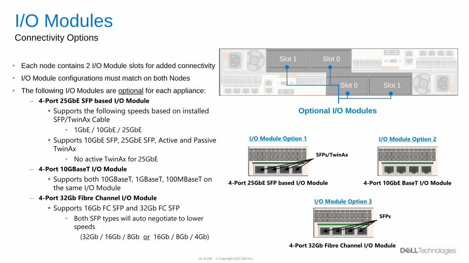
I/O ModulesConnectivity Options
• Each node contains 2 I/O Module slots for added connectivity
• I/O Module configurations must match on both Nodes
• The following I/O Modules are optional for each appliance:
– 4-Port 25GbE SFP based I/O Module
▪ Supports the following speeds based on installed
SFP/TwinAx Cable
• 1GbE / 10GbE / 25GbE
▪ Supports 10GbE SFP, 25GbE SFP, Active and Passive
TwinAx
• No active TwinAx for 25GbE
– 4-Port 10GBaseT I/O Module
▪ Supports both 10GBaseT, 1GBaseT, 100MBaseT on
the same I/O Module
– 4-Port 32Gb Fibre Channel I/O Module
▪ Supports 16Gb FC SFP and 32Gb FC SFP
• Both SFP types will auto negotiate to lower
speeds
(32Gb / 16Gb / 8Gb or 16Gb / 8Gb / 4Gb)
Slot 1 Slot 0
Slot 0 Slot 1
Optional I/O Modules
4-Port 25GbE SFP based I/O Module 4-Port 10GbE BaseT I/O Module
I/O Module Option 1
SFPs/TwinAx
I/O Module Option 2
I/O Module Option 3
SFPs
4-Port 32Gb Fibre Channel I/O Module
v
© Copyright 2021 Dell Inc.17 of 292
PowerStore Drive SupportNVMe NVRAM
• Every system has either 2 or 4 NVMe NVRAM Write Cache drives depending on model
–Each NVRAM drive is 8GB in size and mirrored
–All writes to the system must be written to the NVRAM drives prior to being acknowledged to the source
• There will be a maximum of 4 NVRAM drives depending on model of the system and this is locked
–Customers cannot scale write cache
• NVMe NVRAM drives are self-encrypting, but not FIPS certified
© Copyright 2021 Dell Inc.18 of 292
PowerStore Drive SupportNVMe SCM
• Customers have the option to use NVMe SCM drives in their PowerStore system
• If only NVMe SCM drives are chosen, a minimum of 6 drives are required per appliance
• NVMe SCM drives can now be mixed with NVMe SSD and SAS SSD drives
– When mixed, NVMe SCM drives will serve as a dedicated metadata tier, improving performance with the low latency capability of NVMe SCM drives
– When mixed, NVMe SSD drives will server as the storage tier and a minimum of 6 NVMe SSD drives are required
New in
PowerStoreOS 2.0
© Copyright 2021 Dell Inc.19 of 292
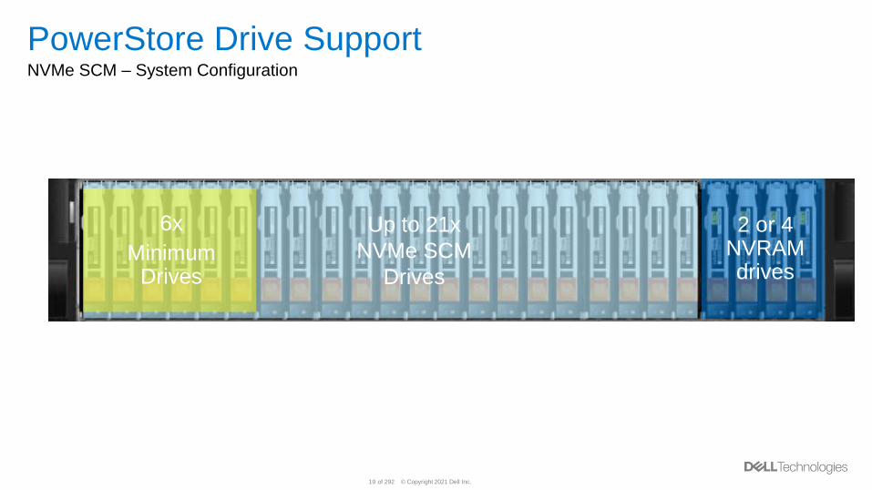
PowerStore Drive SupportNVMe SCM – System Configuration
Up to 21x
NVMe SCM
Drives
6x
Minimum Drives
2 or 4 NVRAM drives
© Copyright 2021 Dell Inc.20 of 292
PowerStore Drive SupportNVMe SSD
• Customers have the option to use NVMe SSD drives in their
PowerStore system
• If NVMe SSD is chosen, a minimum of 6 drives are required
per appliance
• The base enclosure with NVMe SSD drives can attach
expansion enclosure(s) with SAS SSD drives–Note, in terms of ordering, the base enclosure must be completely filled
before expansion enclosures can be attached
© Copyright 2021 Dell Inc.21 of 292
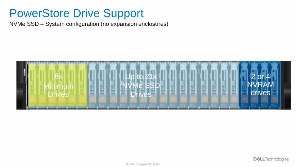
PowerStore Drive SupportNVMe SSD – System configuration (no expansion enclosures)
Up to 21x
NVMe SSD
Drives
6x
Minimum Drives
2 or 4 NVRAM drives
© Copyright 2021 Dell Inc.22 of 292
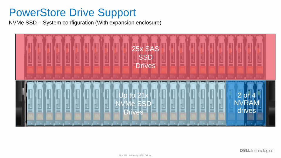
PowerStore Drive SupportNVMe SSD – System configuration (With expansion enclosure)
Up to 21x
NVMe SSD
Drives
2 or 4 NVRAM drives
25x SAS
SSD
Drives
© Copyright 2021 Dell Inc.23 of 292
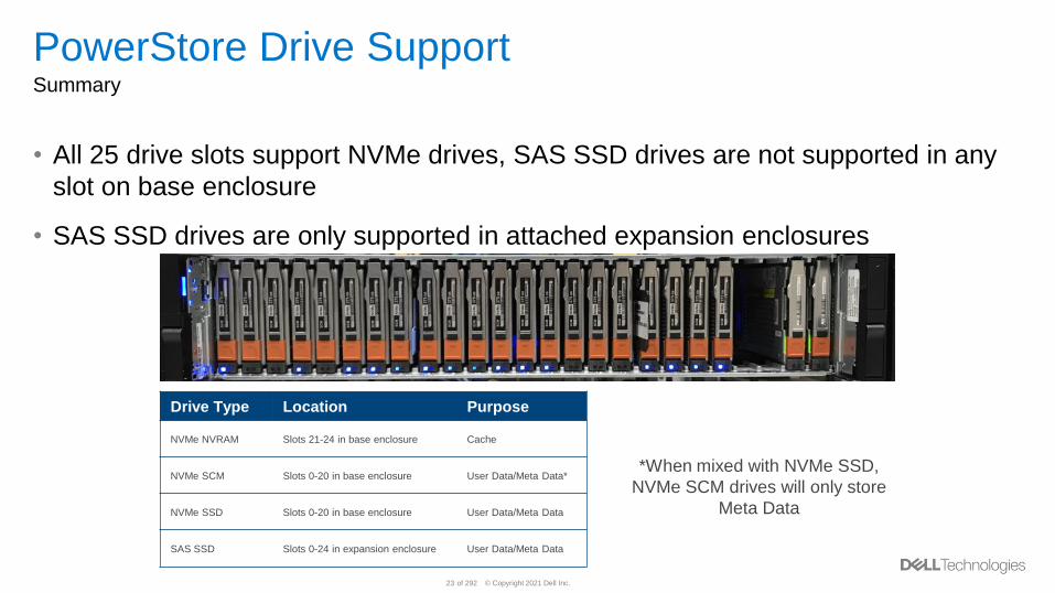
PowerStore Drive SupportSummary
• All 25 drive slots support NVMe drives, SAS SSD drives are not supported in any
slot on base enclosure
• SAS SSD drives are only supported in attached expansion enclosures
Drive Type Location Purpose
NVMe NVRAM Slots 21-24 in base enclosure Cache
NVMe SCM Slots 0-20 in base enclosure User Data/Meta Data*
NVMe SSD Slots 0-20 in base enclosure User Data/Meta Data
SAS SSD Slots 0-24 in expansion enclosure User Data/Meta Data
*When mixed with NVMe SSD,
NVMe SCM drives will only store
Meta Data
© Copyright 2021 Dell Inc.24 of 292
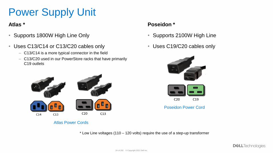
Power Supply Unit Atlas *
• Supports 1800W High Line Only
• Uses C13/C14 or C13/C20 cables only– C13/C14 is a more typical connector in the field
– C13/C20 used in our PowerStore racks that have primarily
C19 outlets
Poseidon Power Cord
Atlas Power Cords
* Low Line voltages (110 – 120 volts) require the use of a step-up transformer
Poseidon *
• Supports 2100W High Line
• Uses C19/C20 cables only
© Copyright 2021 Dell Inc.25 of 292
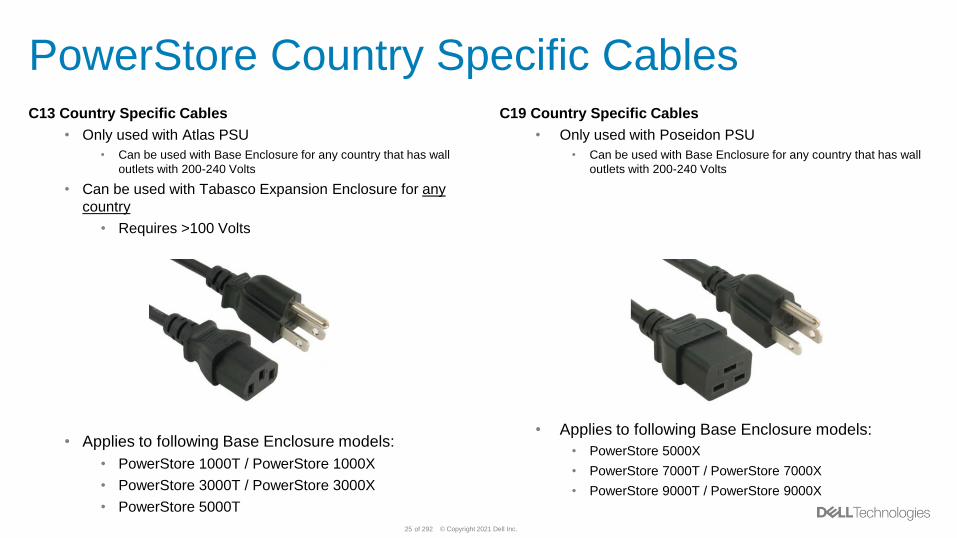
PowerStore Country Specific CablesC13 Country Specific Cables
• Only used with Atlas PSU
• Can be used with Base Enclosure for any country that has wall
outlets with 200-240 Volts
• Can be used with Tabasco Expansion Enclosure for any
country
• Requires >100 Volts
• Applies to following Base Enclosure models:
• PowerStore 1000T / PowerStore 1000X
• PowerStore 3000T / PowerStore 3000X
• PowerStore 5000T
C19 Country Specific Cables
• Only used with Poseidon PSU
• Can be used with Base Enclosure for any country that has wall
outlets with 200-240 Volts
• Applies to following Base Enclosure models:
• PowerStore 5000X
• PowerStore 7000T / PowerStore 7000X
• PowerStore 9000T / PowerStore 9000X
© Copyright 2021 Dell Inc.26 of 292
PowerStore 500T Hardware Overview
© Copyright 2021 Dell Inc.27 of 292
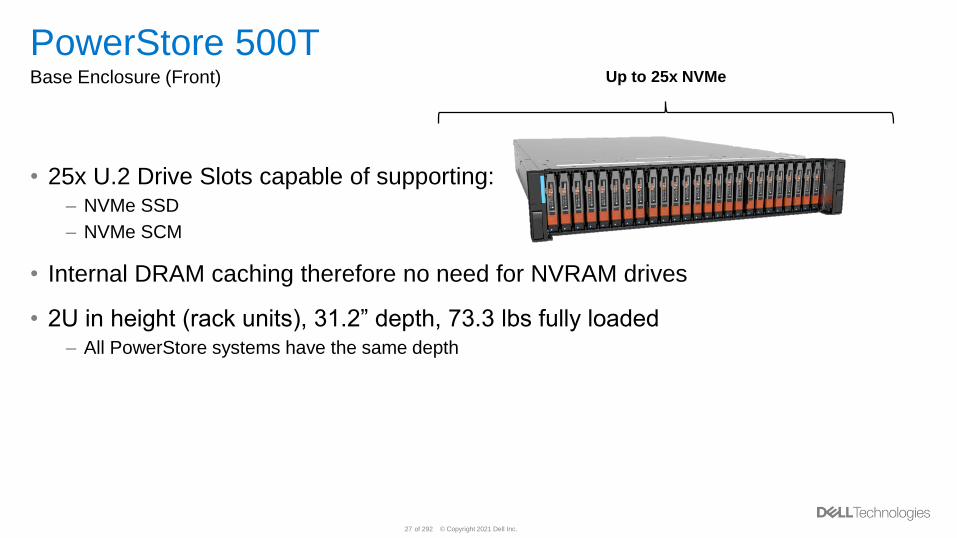
PowerStore 500TBase Enclosure (Front)
• 25x U.2 Drive Slots capable of supporting:– NVMe SSD
– NVMe SCM
• Internal DRAM caching therefore no need for NVRAM drives
• 2U in height (rack units), 31.2” depth, 73.3 lbs fully loaded– All PowerStore systems have the same depth
Up to 25x NVMe
© Copyright 2021 Dell Inc.28 of 292
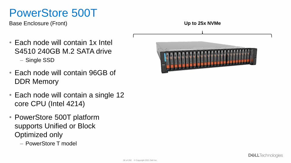
PowerStore 500TBase Enclosure (Front)
• Each node will contain 1x Intel
S4510 240GB M.2 SATA drive– Single SSD
• Each node will contain 96GB of
DDR Memory
• Each node will contain a single 12
core CPU (Intel 4214)
• PowerStore 500T platform
supports Unified or Block
Optimized only– PowerStore T model
Up to 25x NVMe
© Copyright 2021 Dell Inc.29 of 292
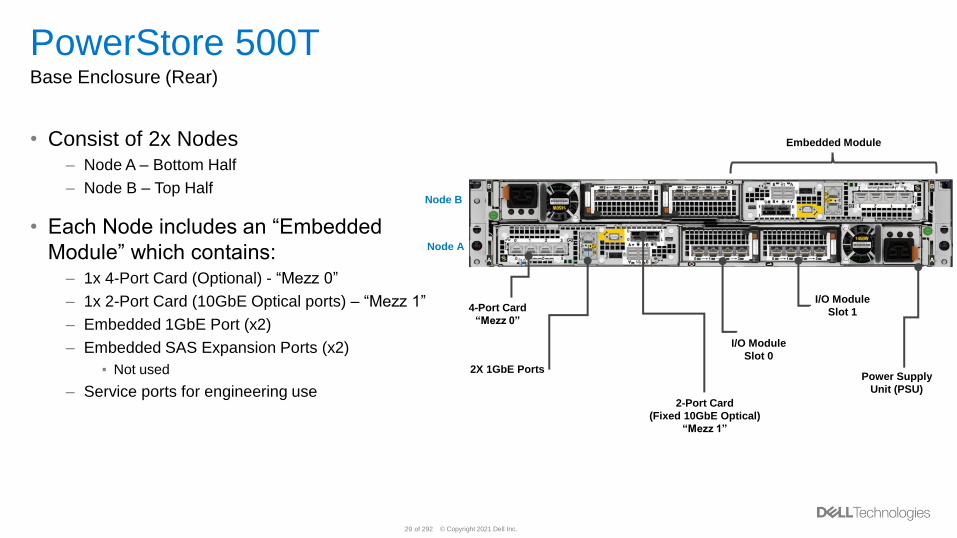
PowerStore 500TBase Enclosure (Rear)
• Consist of 2x Nodes– Node A – Bottom Half
– Node B – Top Half
• Each Node includes an “Embedded
Module” which contains:– 1x 4-Port Card (Optional) - “Mezz 0”
– 1x 2-Port Card (10GbE Optical ports) – “Mezz 1”
– Embedded 1GbE Port (x2)
– Embedded SAS Expansion Ports (x2)
▪ Not used
– Service ports for engineering use
Node A
Node B
Embedded Module
Power Supply
Unit (PSU)
I/O Module
Slot 1
I/O Module
Slot 0
2X 1GbE Ports
2-Port Card
(Fixed 10GbE Optical)
“Mezz 1”
4-Port Card
“Mezz 0”
© Copyright 2021 Dell Inc.30 of 292
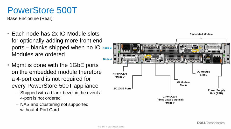
PowerStore 500TBase Enclosure (Rear)
• Each node has 2x IO Module slots
for optionally adding more front end
ports – blanks shipped when no IO
Modules are ordered
• Mgmt is done with the 1GbE ports
on the embedded module therefore
a 4-port card is not required for
every PowerStore 500T appliance– Shipped with a blank bezel in the event a
4-port is not ordered
– NAS and Clustering not supported
without 4-Port Card
Node A
Node B
Embedded Module
Power Supply
Unit (PSU)
I/O Module
Slot 1
I/O Module
Slot 0
2X 1GbE Ports
4-Port Card
“Mezz 0”
2-Port Card
(Fixed 10GbE Optical)
“Mezz 1”
© Copyright 2021 Dell Inc.33 of 292
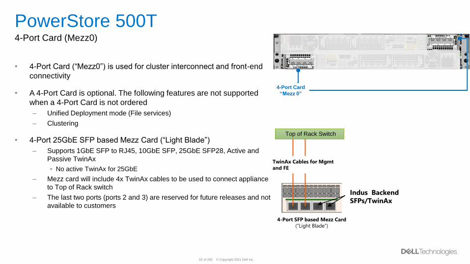
PowerStore 500T4-Port Card (Mezz0)
• 4-Port Card (“Mezz0”) is used for cluster interconnect and front-end
connectivity
• A 4-Port Card is optional. The following features are not supported
when a 4-Port Card is not ordered
– Unified Deployment mode (File services)
– Clustering
• 4-Port 25GbE SFP based Mezz Card (“Light Blade”)
– Supports 1GbE SFP to RJ45, 10GbE SFP, 25GbE SFP28, Active and
Passive TwinAx
▪ No active TwinAx for 25GbE
– Mezz card will include 4x TwinAx cables to be used to connect appliance
to Top of Rack switch
– The last two ports (ports 2 and 3) are reserved for future releases and not
available to customers
4-Port SFP based Mezz Card
(“Light Blade”)
TwinAx Cables for Mgmt
and FE
Top of Rack Switch
Indus Backend
SFPs/TwinAx
4-Port Card
“Mezz 0”
© Copyright 2021 Dell Inc.34 of 292
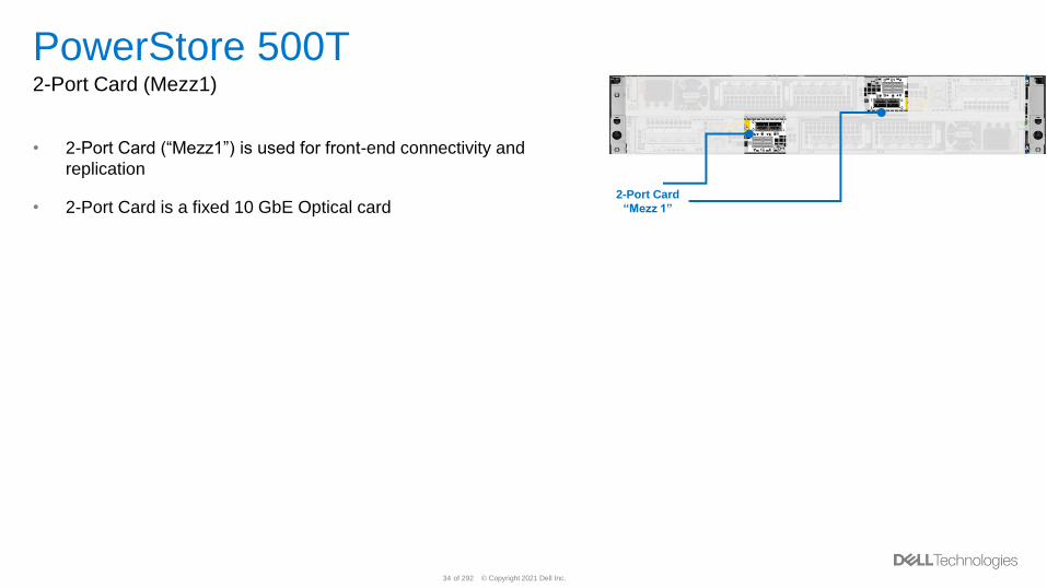
PowerStore 500T2-Port Card (Mezz1)
• 2-Port Card (“Mezz1”) is used for front-end connectivity and
replication
• 2-Port Card is a fixed 10 GbE Optical card2-Port Card
“Mezz 1”
© Copyright 2021 Dell Inc.35 of 292
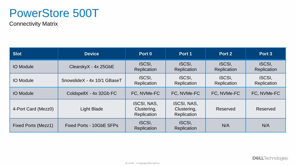
PowerStore 500TConnectivity Matrix
Slot Device Port 0 Port 1 Port 2 Port 3
IO Module ClearskyX - 4x 25GbEiSCSI,
Replication
iSCSI,
Replication
iSCSI,
Replication
iSCSI,
Replication
IO Module SnowslideX - 4x 10/1 GBaseTiSCSI,
Replication
iSCSI,
Replication
iSCSI,
Replication
iSCSI,
Replication
IO Module ColdspellX - 4x 32Gb FC FC, NVMe-FC FC, NVMe-FC FC, NVMe-FC FC, NVMe-FC
4-Port Card (Mezz0) Light Blade
iSCSI, NAS,
Clustering,
Replication
iSCSI, NAS,
Clustering,
Replication
Reserved Reserved
Fixed Ports (Mezz1) Fixed Ports - 10GbE SFPsiSCSI,
Replication
iSCSI,
ReplicationN/A N/A
© Copyright 2021 Dell Inc.36 of 292
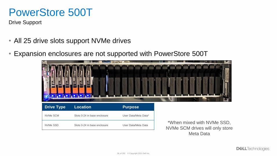
PowerStore 500TDrive Support
• All 25 drive slots support NVMe drives
• Expansion enclosures are not supported with PowerStore 500T
Drive Type Location Purpose
NVMe SCM Slots 0-24 in base enclosure User Data/Meta Data*
NVMe SSD Slots 0-24 in base enclosure User Data/Meta Data*When mixed with NVMe SSD,
NVMe SCM drives will only store
Meta Data
© Copyright 2021 Dell Inc.37 of 292
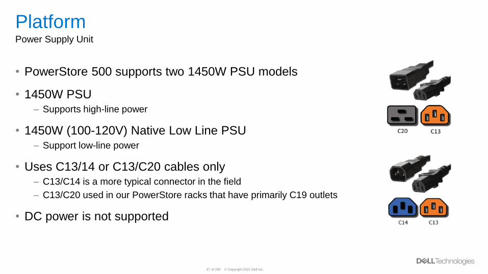
PlatformPower Supply Unit
• PowerStore 500 supports two 1450W PSU models
• 1450W PSU – Supports high-line power
• 1450W (100-120V) Native Low Line PSU– Support low-line power
• Uses C13/14 or C13/C20 cables only– C13/C14 is a more typical connector in the field
– C13/C20 used in our PowerStore racks that have primarily C19 outlets
• DC power is not supported
© Copyright 2021 Dell Inc.38 of 292
PowerStore T Architecture Overview(applicable to 500T – 9000T models)
© Copyright 2021 Dell Inc.39 of 292
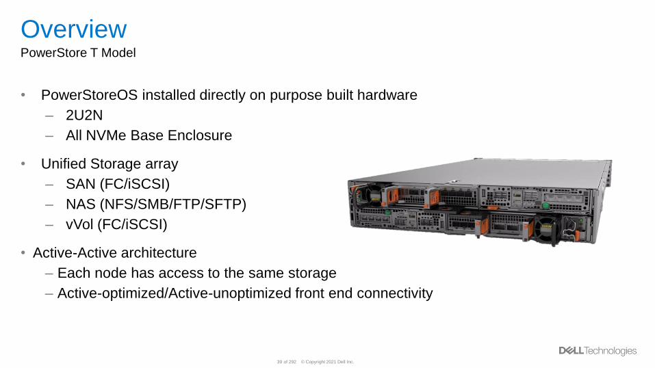
OverviewPowerStore T Model
• PowerStoreOS installed directly on purpose built hardware
– 2U2N
– All NVMe Base Enclosure
• Unified Storage array
– SAN (FC/iSCSI)
– NAS (NFS/SMB/FTP/SFTP)
– vVol (FC/iSCSI)
• Active-Active architecture
– Each node has access to the same storage
– Active-optimized/Active-unoptimized front end connectivity
© Copyright 2021 Dell Inc.40 of 292
OverviewPowerStore T Storage Configuration
• PowerStore T has two user configured deployment modes
• Different deployment modes are called Storage Configuration– Unified:
▪ Default storage configuration (factory state)
▪ Supports SAN, NAS, and vVol
▪ Resources shared between block and file components
– Block Optimized
▪ Alternate storage configuration (requires reboot)
▪ Supports SAN and vVol
▪ Resources dedicated to block components
• Storage Configuration is selected at time of Initial Configuration– Changing Storage Configuration requires a factory reset
– Currently, multi-appliance clusters support a maximum of one Unified appliance.
© Copyright 2021 Dell Inc.41 of 292
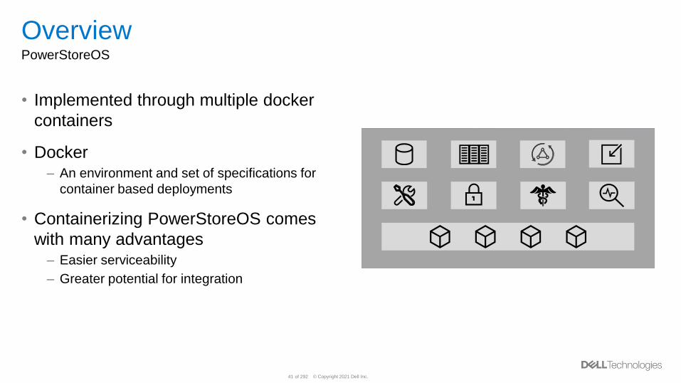
OverviewPowerStoreOS
• Implemented through multiple docker
containers
• Docker– An environment and set of specifications for
container based deployments
• Containerizing PowerStoreOS comes
with many advantages– Easier serviceability
– Greater potential for integration

© Copyright 2021 Dell Inc.42 of 292
NetworkingSystem Bond
• PowerStore T models contain a system bond by default
• Ports 0 & 1 of 4-Port Card are automatically bonded together in LACP mode
• This bond is essential to the networking configuration and cannot be removed
• System bond can provide high availability to cluster data and metadata traffic
• Link aggregation configuration on the switch side is optional– If switches are not configured to support LACP, Ports 0 & 1 will operate in Active/Passive mode
© Copyright 2021 Dell Inc.43 of 292
NetworkingStorage Network Scaling
• PowerStore T models support 32Gb FC I/O Modules for SAN and NVMe-FC connectivity
– Traditional block and vVol storage presented to external hosts over FC
• iSCSI Storage network can be scaled up to support more iSCSI targets
• The following components are available for iSCSI port scaling:
– Ports 2 & 3 of 4-Port Card
– 4-Port I/O Modules
• No additional link aggregation can be configured
– System bond cannot be expanded
• Workflow:
1. Add additional IPs to the existing storage network (unless unused IPs exist)
2. Map unmapped ports to the additional IPs
New in
PowerStoreOS
2.0
© Copyright 2021 Dell Inc.44 of 292
DeploymentConfigure Switches - Ethernet Switches (Dell)
• Dual ethernet switches are required to provided high availability
• Dell EMC PowerSwitches running OS10 Enterprise Edition (OS10EE)– S4148F-ON
▪ 48 Fixed 10 GbE SFP+ ports
▪ 8 Fixed 50 GbE QSFP28 ports
▪ 4 Fixed 100 GbE QSFP28 ports
– S4148T-ON
▪ 48 Fixed 10 GBASE-T ports
▪ 8 Fixed 50 GbE QSFP28 ports
▪ 4 Fixed 100 GbE QSFP28 ports
– S5248F-ON
▪ 48 Fixed 25 GbE SFP28 ports
▪ 4 Fixed 100 GbE QSFP28 ports
▪ 2 Fixed 200 GbE QSFP28-DD ports
© Copyright 2021 Dell Inc.45 of 292
DeploymentConfigure Switches - Ethernet Switches (Third-party)
• Customers can use third party switches– Reference E-Lab for complete list of qualified switches
• Ethernet switches are used for a variety of network traffic– Traffic is determined by model and deployment type
▪ iSCSI (PowerStore T and PowerStore X)
▪ Replication (PowerStore T and PowerStore X)
▪ Native Import (PowerStore T and PowerStore X)
▪ NAS (PowerStore T Unified)
▪ vMotion (PowerStore X)
▪ Management (PowerStore X)
© Copyright 2021 Dell Inc.46 of 292
DeploymentConfigure Switches - Ethernet Switches - Topology
• Virtual Link Trunking interconnect (VLTi) (or third-party equivalent)– Recommended configuration
– Creates a single logical switch out of two physical switches
– Automatic configuration of VLANs on VLTi interface
– Synchronized MAC tables support faster failover
– Supports link aggregation across two physical switches
▪ Best practice is to configure LACP on switch side to support the PowerStore T system bond
▪ Provides full bandwidth potential across system bond
• Alternative Layer 2 connectivity options– Dynamic Link Aggregation Group (LAG), Static LAG, or reliable L2 uplinks
– Provides connectivity between two physical switches
– System bond will enter degraded mode
▪ Bond ports presented in active / passive states
▪ Bandwidth potential limited to 50% on system bond
▪ High availability remains
© Copyright 2021 Dell Inc.47 of 292
DeploymentConfigure Switches – Out of Band Management
• PowerStore T model deployments require Out of Band (OOB) Management switch
connectivity– 1x OOB Management switch is required
– 2x OOB Management switch is supported for high availability
– The document and this presentation outline 1x OOB Management
• OOB Management switch can be configured with or without a management VLAN– Switch ports must support untagged native VLAN traffic for system discovery
© Copyright 2021 Dell Inc.48 of 292
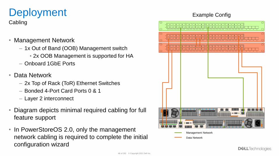
DeploymentCabling
• Management Network
– 1x Out of Band (OOB) Management switch
▪ 2x OOB Management is supported for HA
– Onboard 1GbE Ports
• Data Network
– 2x Top of Rack (ToR) Ethernet Switches
– Bonded 4-Port Card Ports 0 & 1
– Layer 2 interconnect
• Diagram depicts minimal required cabling for full
feature support
• In PowerStoreOS 2.0, only the management
network cabling is required to complete the initial
configuration wizard
Management Network
Data Network
Example Config
© Copyright 2021 Dell Inc.49 of 292
PowerStore X Architecture Overview(applicable to 1000X – 9000X models)
© Copyright 2021 Dell Inc.50 of 292
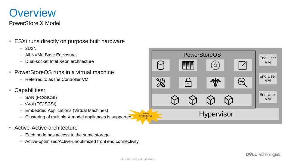
OverviewPowerStore X Model
• ESXi runs directly on purpose built hardware
– 2U2N
– All NVMe Base Enclosure
– Dual-socket Intel Xeon architecture
• PowerStoreOS runs in a virtual machine
– Referred to as the Controller VM
• Capabilities:
– SAN (FC/iSCSI)
– vVol (FC/iSCSI)
– Embedded Applications (Virtual Machines)
– Clustering of multiple X model appliances is supported
• Active-Active architecture
– Each node has access to the same storage
– Active-optimized/Active-unoptimized front end connectivity
Hypervisor
End User VM
End User VM
End User VM
PowerStoreOS
New in
PowerStoreOS
2.0
© Copyright 2021 Dell Inc.51 of 292
OverviewESXi
• VMware ESXi 6.7P04 installed directly onto each node
• PowerStore X model appliance contains ESXi Cluster of two ESXi hosts– 1 ESXi host per node
• Requires existing vCenter and license for deployment– VMware vSphere Enterprise Plus or vSphere Remote Office Branch Office license
– Customer can purchase license or use existing
• VMware components are automatically configured– ESXi Cluster
– vSphere HA
– Distributed Virtual Switch
– Etc.
• Customer Virtual Machines will leverage PowerStore storage and data services
© Copyright 2021 Dell Inc.52 of 292
OverviewController VM
• PowerStoreOS runs inside of a Controller VM– VMware Virtual Machine
– “Virtualized” instance of the PowerStore series OS
• One Controller VM fixed per node– Will never fail-over to other node
• Reserves 50% of node resources– CPU and Memory
• Key platform devices passed through directly to Controller VM– Removes latency involved with ESXi layer
• Stored on M.2 device local to host and node
© Copyright 2021 Dell Inc.53 of 292
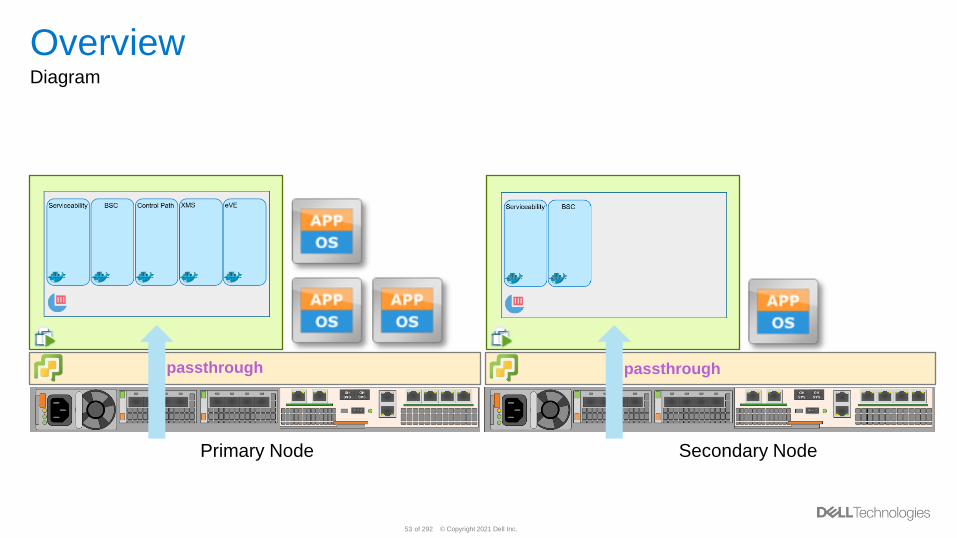
OverviewDiagram
Primary Node Secondary Node
passthrough passthrough
© Copyright 2021 Dell Inc.54 of 292
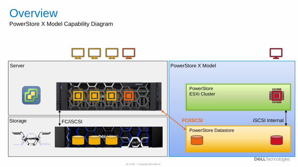
OverviewPowerStore X Model Capability Diagram
PowerStore Datastore
PowerStore
ESXi Cluster
PowerStore X ModelServer
Storage FC/iSCSI iSCSI InternalFC/iSCSI
© Copyright 2021 Dell Inc.55 of 292
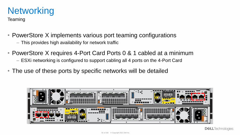
NetworkingTeaming
• PowerStore X implements various port teaming configurations– This provides high availability for network traffic
• PowerStore X requires 4-Port Card Ports 0 & 1 cabled at a minimum– ESXi networking is configured to support cabling all 4 ports on the 4-Port Card
• The use of these ports by specific networks will be detailed
© Copyright 2021 Dell Inc.56 of 292
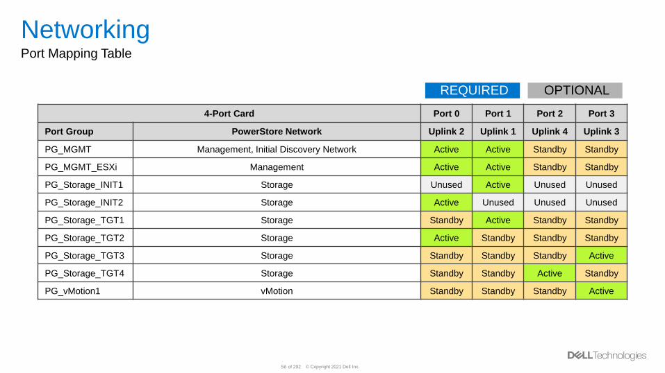
NetworkingPort Mapping Table
4-Port Card Port 0 Port 1 Port 2 Port 3
Port Group PowerStore Network Uplink 2 Uplink 1 Uplink 4 Uplink 3
PG_MGMT Management, Initial Discovery Network Active Active Standby Standby
PG_MGMT_ESXi Management Active Active Standby Standby
PG_Storage_INIT1 Storage Unused Active Unused Unused
PG_Storage_INIT2 Storage Active Unused Unused Unused
PG_Storage_TGT1 Storage Standby Active Standby Standby
PG_Storage_TGT2 Storage Active Standby Standby Standby
PG_Storage_TGT3 Storage Standby Standby Standby Active
PG_Storage_TGT4 Storage Standby Standby Active Standby
PG_vMotion1 vMotion Standby Standby Standby Active
REQUIRED OPTIONAL
© Copyright 2021 Dell Inc.57 of 292
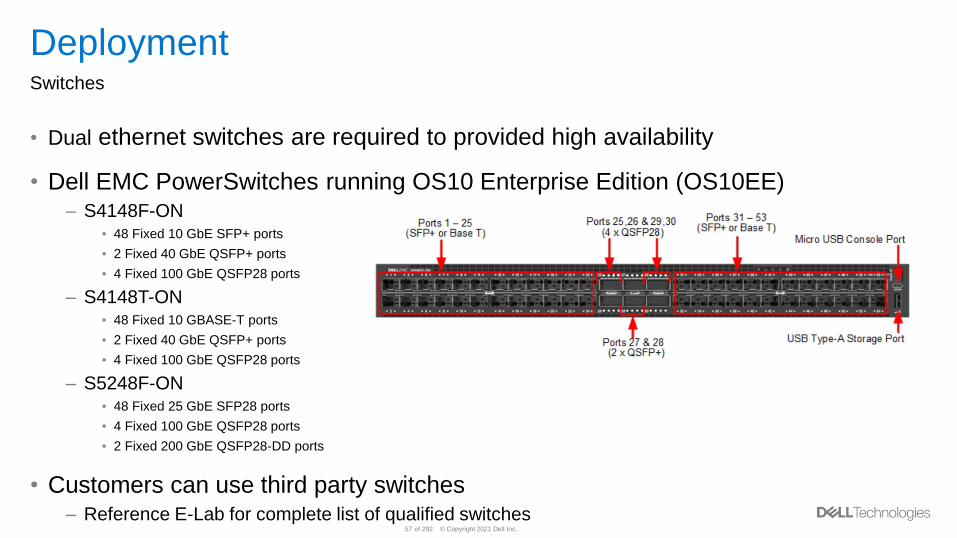
DeploymentSwitches
• Dual ethernet switches are required to provided high availability
• Dell EMC PowerSwitches running OS10 Enterprise Edition (OS10EE)– S4148F-ON
▪ 48 Fixed 10 GbE SFP+ ports
▪ 2 Fixed 40 GbE QSFP+ ports
▪ 4 Fixed 100 GbE QSFP28 ports
– S4148T-ON▪ 48 Fixed 10 GBASE-T ports
▪ 2 Fixed 40 GbE QSFP+ ports
▪ 4 Fixed 100 GbE QSFP28 ports
– S5248F-ON▪ 48 Fixed 25 GbE SFP28 ports
▪ 4 Fixed 100 GbE QSFP28 ports
▪ 2 Fixed 200 GbE QSFP28-DD ports
• Customers can use third party switches– Reference E-Lab for complete list of qualified switches
© Copyright 2021 Dell Inc.58 of 292
DeploymentSwitches - Configuration
• Virtual Link Trunking interconnect (VLTi) (or third-party equivalent)– Recommended configuration
– Creates a single logical switch out of two physical switches
– Automatic configuration of VLANs on VLTi interface
– Synchronized MAC tables support faster failover
• Alternative Layer 2 connectivity options– Dynamic Link Aggregation Group (LAG), Static LAG, or reliable L2 uplinks
– Provides connectivity between two physical switches
• Reference Configuring Switches and External Networks
© Copyright 2021 Dell Inc.59 of 292
DeploymentConfigure Switches - Ethernet Switches - Management
• PowerStore X model deployments do not use an Out of Band (OOB) Management
switch
• Management is in-band on 4-Port Card Port 0 & 1– This ensures high availability for management traffic to vCenter
• Switch ports must support untagged native VLAN traffic for system discovery
© Copyright 2021 Dell Inc.60 of 292
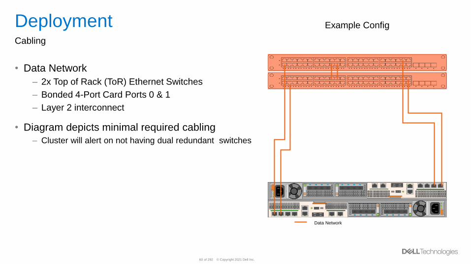
DeploymentCabling
• Data Network
– 2x Top of Rack (ToR) Ethernet Switches
– Bonded 4-Port Card Ports 0 & 1
– Layer 2 interconnect
• Diagram depicts minimal required cabling
– Cluster will alert on not having dual redundant switches
Data Network
Example Config
© Copyright 2021 Dell Inc.61 of 292
PowerStore Discovery• Discovery Utility
• Static IP Discovery
© Copyright 2021 Dell Inc.62 of 292
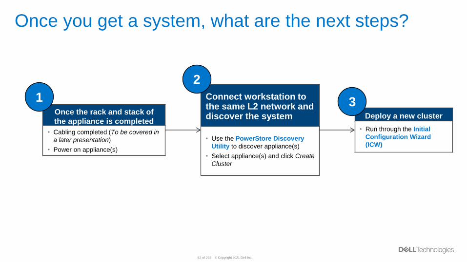
Once you get a system, what are the next steps?
Once the rack and stack of
the appliance is completed
• Cabling completed (To be covered in
a later presentation)
• Power on appliance(s)
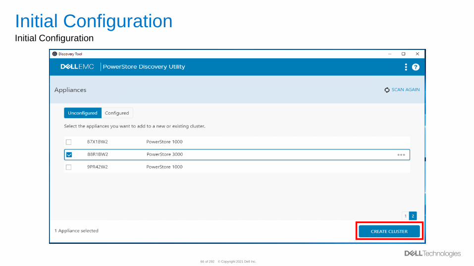
Connect workstation to the same L2 network and discover the system
• Use the PowerStore Discovery
Utility to discover appliance(s)
• Select appliance(s) and click Create
Cluster
Deploy a new cluster
• Run through the Initial
Configuration Wizard
(ICW)
1
2
3
© Copyright 2021 Dell Inc.63 of 292
Discovery Utility
© Copyright 2021 Dell Inc.64 of 292
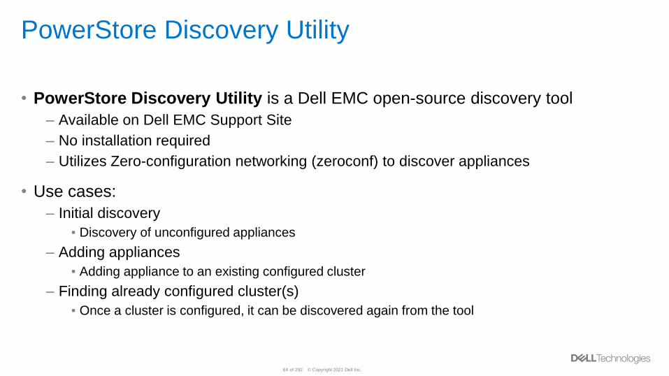
PowerStore Discovery Utility
• PowerStore Discovery Utility is a Dell EMC open-source discovery tool
– Available on Dell EMC Support Site
– No installation required
– Utilizes Zero-configuration networking (zeroconf) to discover appliances
• Use cases:
– Initial discovery
▪ Discovery of unconfigured appliances
– Adding appliances
▪ Adding appliance to an existing configured cluster
– Finding already configured cluster(s)
▪ Once a cluster is configured, it can be discovered again from the tool
© Copyright 2021 Dell Inc.65 of 292
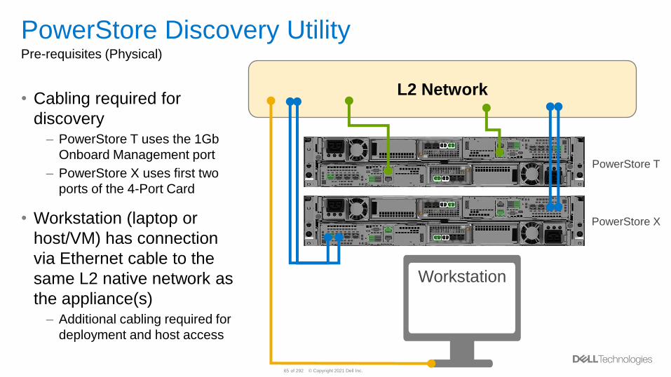
L2 Network
PowerStore Discovery UtilityPre-requisites (Physical)
• Cabling required for
discovery– PowerStore T uses the 1Gb
Onboard Management port
– PowerStore X uses first two
ports of the 4-Port Card
• Workstation (laptop or
host/VM) has connection
via Ethernet cable to the
same L2 native network as
the appliance(s)– Additional cabling required for
deployment and host access
Workstation
PowerStore T
PowerStore X
© Copyright 2021 Dell Inc.66 of 292
Initial ConfigurationInitial Configuration
© Copyright 2021 Dell Inc.67 of 292
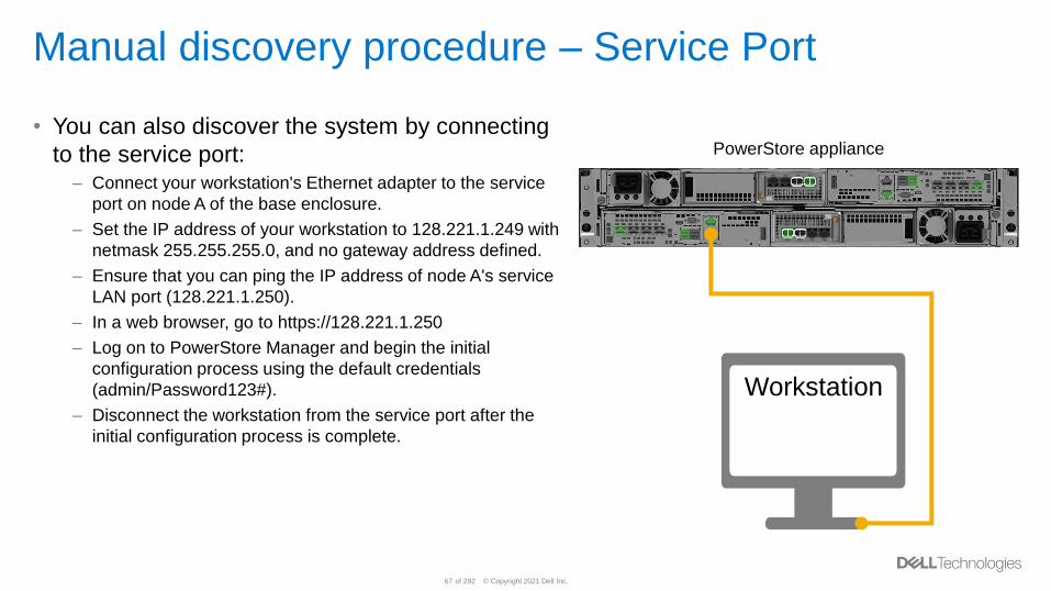
Manual discovery procedure – Service Port
• You can also discover the system by connecting
to the service port:– Connect your workstation's Ethernet adapter to the service
port on node A of the base enclosure.
– Set the IP address of your workstation to 128.221.1.249 with
netmask 255.255.255.0, and no gateway address defined.
– Ensure that you can ping the IP address of node A's service
LAN port (128.221.1.250).
– In a web browser, go to https://128.221.1.250
– Log on to PowerStore Manager and begin the initial
configuration process using the default credentials
(admin/Password123#).
– Disconnect the workstation from the service port after the
initial configuration process is complete.
Workstation
PowerStore appliance
© Copyright 2021 Dell Inc.68 of 292
PowerStore Static IP Discovery
© Copyright 2021 Dell Inc.69 of 292
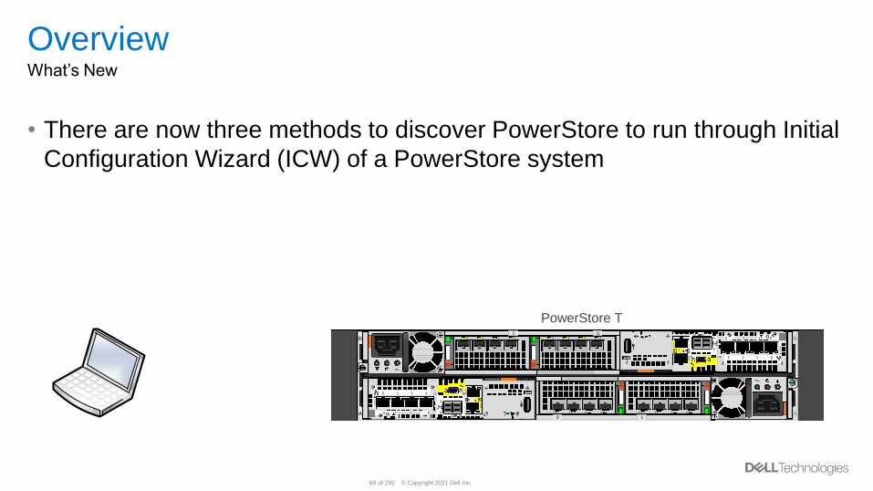
OverviewWhat’s New
• There are now three methods to discover PowerStore to run through Initial
Configuration Wizard (ICW) of a PowerStore system
B B
AA
01
10
2200W
2200W
3210 3210
3 2 1 03 2 1 0
1
A
A
12
1G
bE
1G
bEB
10
Gb
E
Bx4
0
SS
3210
3210
1
A
A
12
1G
bE
1G
bE
B
10
Gb
E
B x4
0
SS
3 2 1 0
3 2 1 0
PowerStore T
© Copyright 2021 Dell Inc.70 of 292
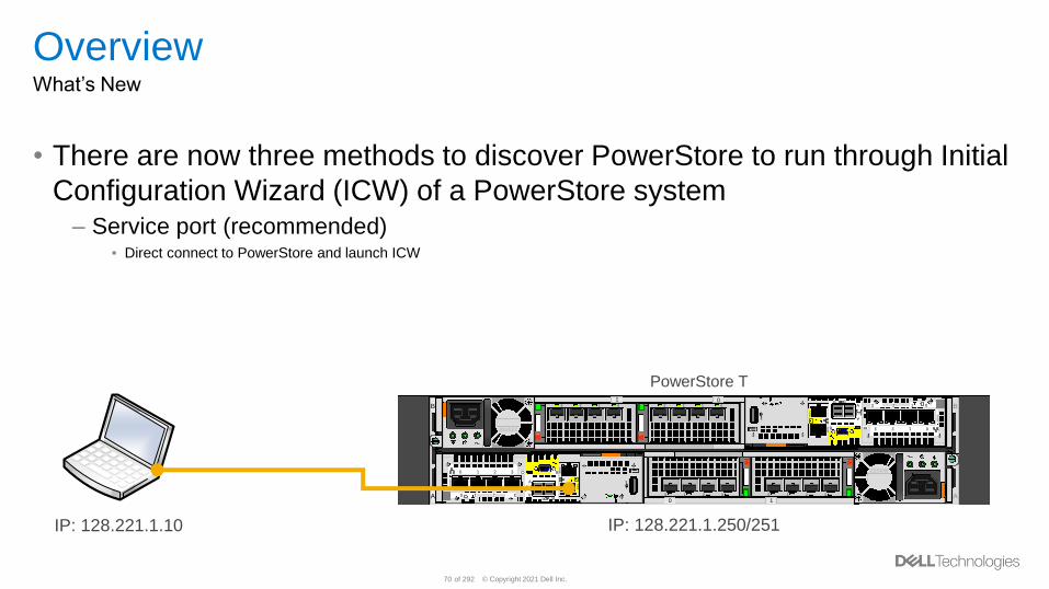
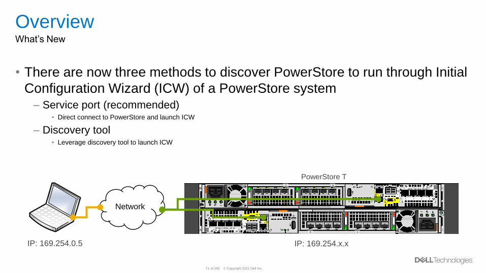
OverviewWhat’s New
• There are now three methods to discover PowerStore to run through Initial
Configuration Wizard (ICW) of a PowerStore system– Service port (recommended)
▪ Direct connect to PowerStore and launch ICW
B B
AA
01
10
2200W
2200W
3210 3210
3 2 1 03 2 1 0
1
A
A
12
1G
bE
1G
bEB
10
Gb
E
Bx4
0
SS
3210
3210
1
A
A
12
1G
bE
1G
bE
B
10
Gb
E
B x4
0
SS
3 2 1 0
3 2 1 0
IP: 128.221.1.10 IP: 128.221.1.250/251
PowerStore T
© Copyright 2021 Dell Inc.71 of 292
OverviewWhat’s New
• There are now three methods to discover PowerStore to run through Initial
Configuration Wizard (ICW) of a PowerStore system– Service port (recommended)
▪ Direct connect to PowerStore and launch ICW
– Discovery tool▪ Leverage discovery tool to launch ICW
B B
AA
01
10
2200W
2200W
3210 3210
3 2 1 03 2 1 0
1
A
A
12
1G
bE
1G
bEB
10
Gb
E
Bx4
0
SS
3210
3210
1
A
A
12
1G
bE
1G
bE
B
10
Gb
E
B x4
0
SS
3 2 1 0
3 2 1 0
Network
IP: 169.254.0.5 IP: 169.254.x.x
PowerStore T
© Copyright 2021 Dell Inc.72 of 292
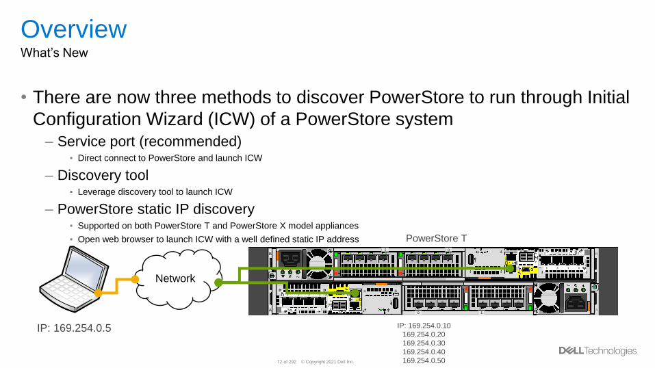
OverviewWhat’s New
• There are now three methods to discover PowerStore to run through Initial
Configuration Wizard (ICW) of a PowerStore system– Service port (recommended)
▪ Direct connect to PowerStore and launch ICW
– Discovery tool▪ Leverage discovery tool to launch ICW
– PowerStore static IP discovery▪ Supported on both PowerStore T and PowerStore X model appliances
▪ Open web browser to launch ICW with a well defined static IP address
B B
AA
01
10
2200W
2200W
3210 3210
3 2 1 03 2 1 0
1
A
A
12
1G
bE
1G
bEB
10
Gb
E
Bx4
0
SS
3210
3210
1
A
A
12
1G
bE
1G
bE
B
10
Gb
E
B x4
0
SS
3 2 1 0
3 2 1 0
Network
IP: 169.254.0.5 IP: 169.254.0.10
169.254.0.20
169.254.0.30
169.254.0.40
169.254.0.50
PowerStore T
© Copyright 2021 Dell Inc.73 of 292
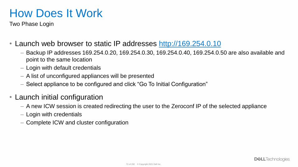
How Does It WorkTwo Phase Login
• Launch web browser to static IP addresses http://169.254.0.10– Backup IP addresses 169.254.0.20, 169.254.0.30, 169.254.0.40, 169.254.0.50 are also available and
point to the same location
– Login with default credentials
– A list of unconfigured appliances will be presented
– Select appliance to be configured and click “Go To Initial Configuration”
• Launch initial configuration– A new ICW session is created redirecting the user to the Zeroconf IP of the selected appliance
– Login with credentials
– Complete ICW and cluster configuration
© Copyright 2021 Dell Inc.74 of 292
PowerStore Clustering
© Copyright 2021 Dell Inc.75 of 292
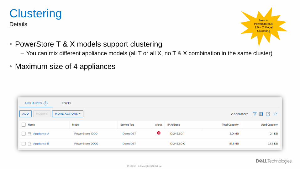
ClusteringDetails
• PowerStore T & X models support clustering– You can mix different appliance models (all T or all X, no T & X combination in the same cluster)
• Maximum size of 4 appliances
New in
PowerStoreOS
2.0 – X Model
Clustering
© Copyright 2021 Dell Inc.76 of 292
ClusteringWhat’s New in PowerStoreOS 2.0
• Automatic primary appliance selection – Create cluster utilizes the most effective appliance as primary appliance
• Create cluster roll forward– Multi appliance clusters will attempt to continue with creating the cluster as a best effort in the event of
a single appliance failure
• Create cluster REST API– REST interface for creating a cluster and adding an appliance
Also new in
PowerStoreOS
2.0
© Copyright 2021 Dell Inc.77 of 292
ClusteringPrimary Appliance
• Each Cluster contains a Primary appliance that runs all control path services
• Primary appliance specific services include:– Global Management IP
– Primary Management DB
– Cluster high availability (pacemaker)
• All other appliances are standby appliances from primary control path perspective– They run a subset of control path services to manage themselves and communicate with primary
– These appliances still serve I/O, only standby in regard to Primary appliance specific services
• Primary appliance specific services will failover to standby appliance if needed– Effectively creating new Primary appliance
© Copyright 2021 Dell Inc.78 of 292
ClusteringPrimary Appliance
• Primary appliance can be configured in Block optimized or Unified mode– Unified mode will support file services
– All additional appliances are configured automatically as Block optimized
• The following Cluster configurations are supported:– Unified Cluster
▪ Primary appliance is deployed as Unified storage configuration running file services
▪ Appliances 2-4 (depending on cluster size) are deployed as Block optimized
– Block optimized Cluster
▪ All appliances are deployed as Block optimized
• Cannot convert Block optimized Cluster to Unified– Cannot add a Unified appliance to a Block optimized Cluster
• File resources and services will always run on the primary appliance of a Unified Cluster– File does not failover to a new Primary appliance
– File is highly available on the Primary appliance
© Copyright 2021 Dell Inc.79 of 292
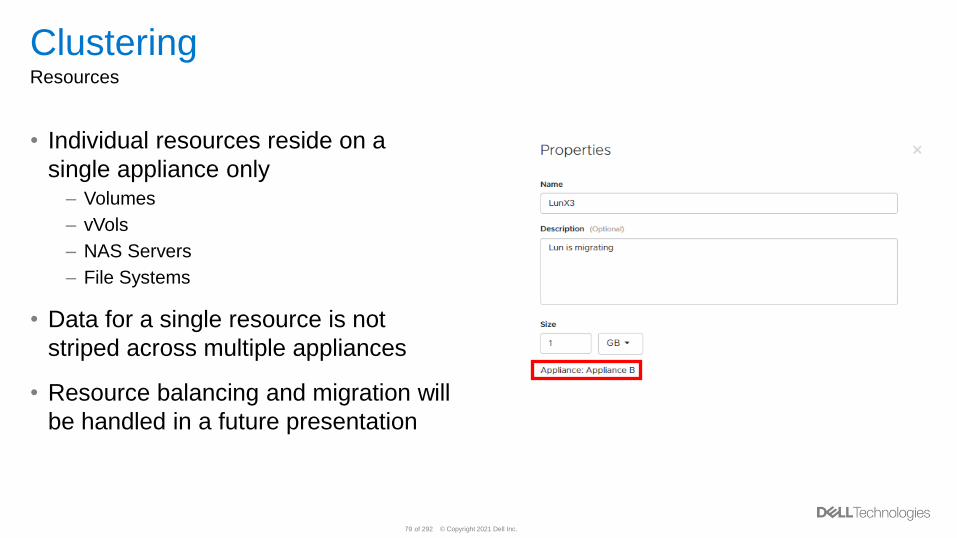
ClusteringResources
• Individual resources reside on a
single appliance only– Volumes
– vVols
– NAS Servers
– File Systems
• Data for a single resource is not
striped across multiple appliances
• Resource balancing and migration will
be handled in a future presentation
© Copyright 2021 Dell Inc.80 of 292
ClusteringCreation
• How to create and modify a Cluster– Initial Configuration (1-4 appliances)
– Add Appliance
– Remove Appliance
• Cluster creation can only be done via the GUI– REST and CLI are not supported
© Copyright 2021 Dell Inc.81 of 292
Resource Balancing
© Copyright 2021 Dell Inc.82 of 292
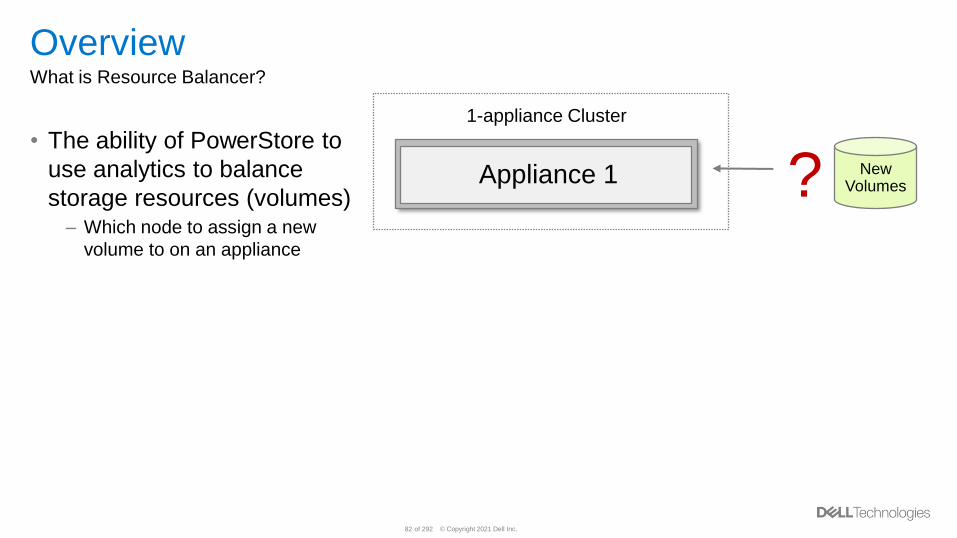
OverviewWhat is Resource Balancer?
• The ability of PowerStore to
use analytics to balance
storage resources (volumes)– Which node to assign a new
volume to on an appliance
New Volumes?Appliance 1
1-appliance Cluster
© Copyright 2021 Dell Inc.83 of 292
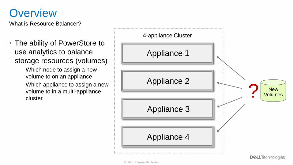
OverviewWhat is Resource Balancer?
• The ability of PowerStore to
use analytics to balance
storage resources (volumes)– Which node to assign a new
volume to on an appliance
– Which appliance to assign a new
volume to in a multi-appliance
cluster
New Volumes?
Appliance 1
Appliance 2
4-appliance Cluster
Appliance 3
Appliance 4
© Copyright 2021 Dell Inc.84 of 292
OverviewWhat is Resource Balancer?
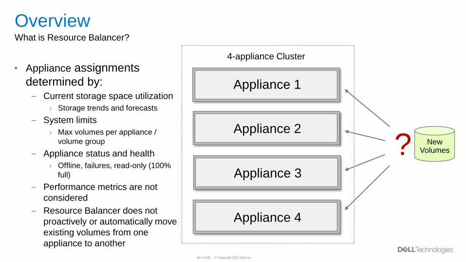
• Appliance assignments
determined by:– Current storage space utilization
› Storage trends and forecasts
– System limits
› Max volumes per appliance /
volume group
– Appliance status and health
› Offline, failures, read-only (100%
full)
– Performance metrics are not
considered
– Resource Balancer does not
proactively or automatically move
existing volumes from one
appliance to another
New Volumes?
Appliance 1
Appliance 2
4-appliance Cluster
Appliance 3
Appliance 4
© Copyright 2021 Dell Inc.85 of 292
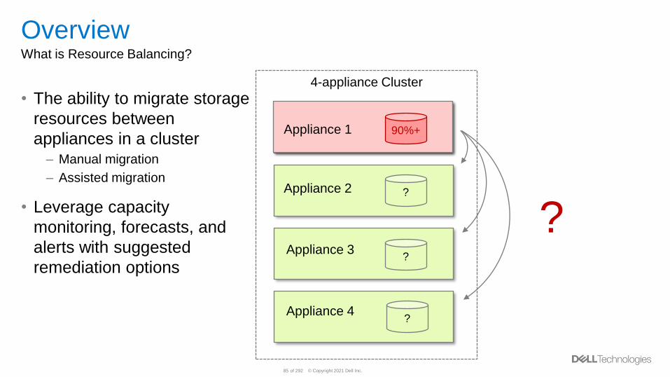
OverviewWhat is Resource Balancing?
• The ability to migrate storage
resources between
appliances in a cluster– Manual migration
– Assisted migration
• Leverage capacity
monitoring, forecasts, and
alerts with suggested
remediation options
Appliance 2
Appliance 3
Appliance 4
?
4-appliance Cluster
?
?
?
Appliance 1Appliance 1 90%+
© Copyright 2021 Dell Inc.86 of 292
Volume PlacementPlacement Options
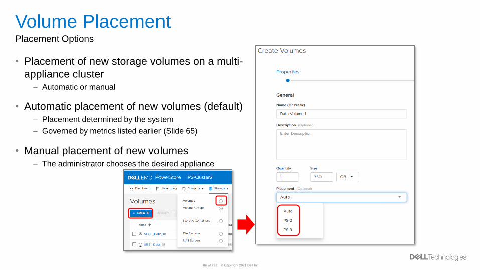
• Placement of new storage volumes on a multi-
appliance cluster– Automatic or manual
• Automatic placement of new volumes (default)– Placement determined by the system
– Governed by metrics listed earlier (Slide 65)
• Manual placement of new volumes– The administrator chooses the desired appliance
© Copyright 2021 Dell Inc.87 of 292
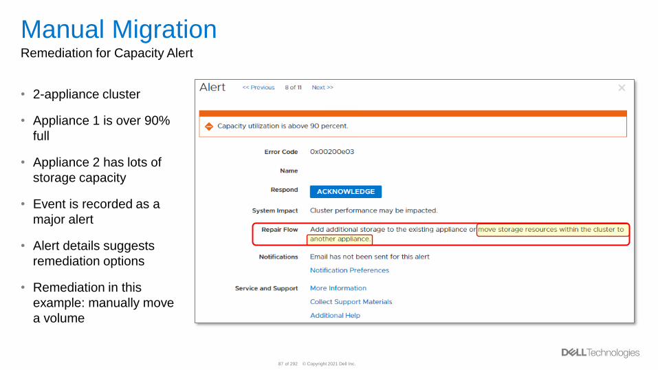
Manual MigrationRemediation for Capacity Alert
• 2-appliance cluster
• Appliance 1 is over 90%
full
• Appliance 2 has lots of
storage capacity
• Event is recorded as a
major alert
• Alert details suggests
remediation options
• Remediation in this
example: manually move
a volume
© Copyright 2021 Dell Inc.88 of 292
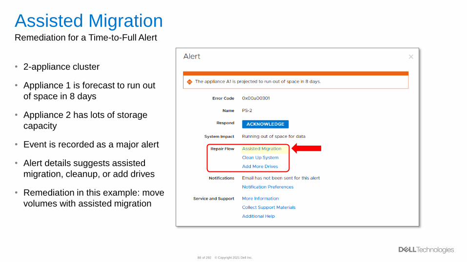
Assisted MigrationRemediation for a Time-to-Full Alert
• 2-appliance cluster
• Appliance 1 is forecast to run out
of space in 8 days
• Appliance 2 has lots of storage
capacity
• Event is recorded as a major alert
• Alert details suggests assisted
migration, cleanup, or add drives
• Remediation in this example: move
volumes with assisted migration
© Copyright 2021 Dell Inc.89 of 292
PowerStore Manager GUI
© Copyright 2021 Dell Inc.90 of 292
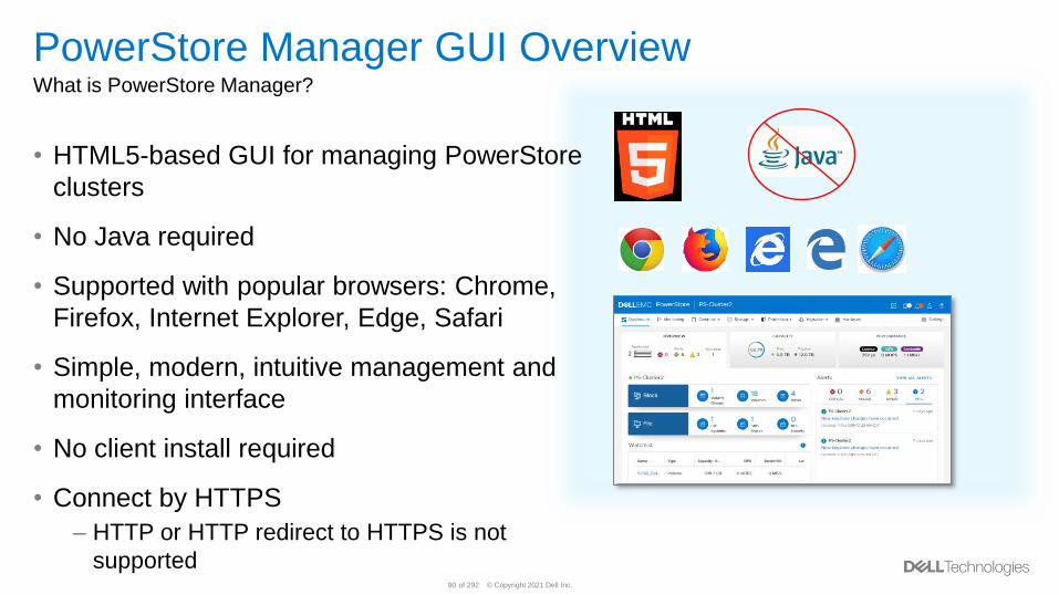
PowerStore Manager GUI OverviewWhat is PowerStore Manager?
• HTML5-based GUI for managing PowerStore
clusters
• No Java required
• Supported with popular browsers: Chrome,
Firefox, Internet Explorer, Edge, Safari
• Simple, modern, intuitive management and
monitoring interface
• No client install required
• Connect by HTTPS
– HTTP or HTTP redirect to HTTPS is not
supported
© Copyright 2021 Dell Inc.91 of 292
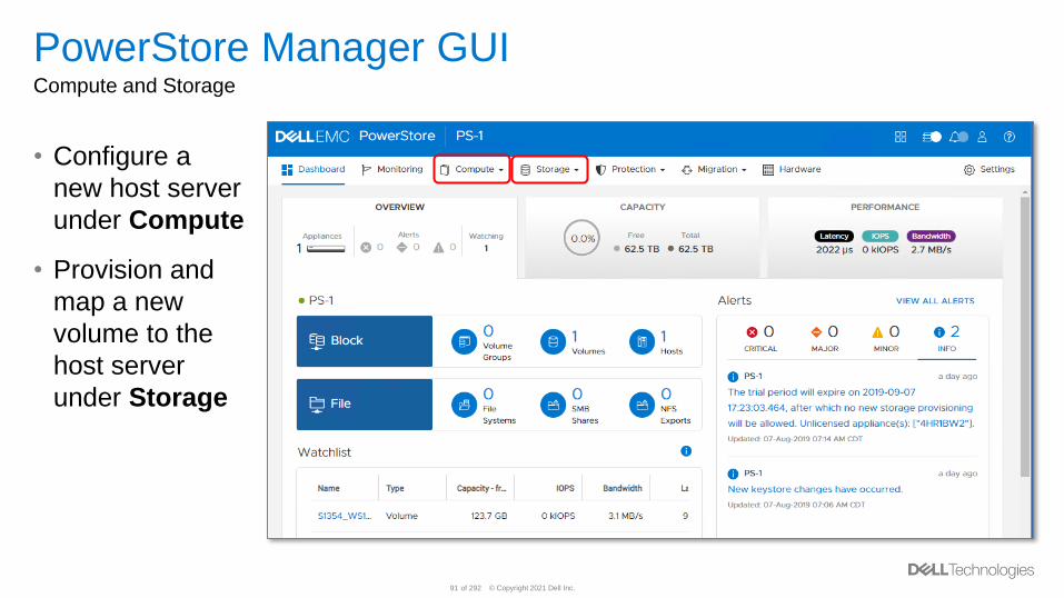
PowerStore Manager GUICompute and Storage
• Configure a
new host server
under Compute
• Provision and
map a new
volume to the
host server
under Storage
© Copyright 2021 Dell Inc.92 of 292
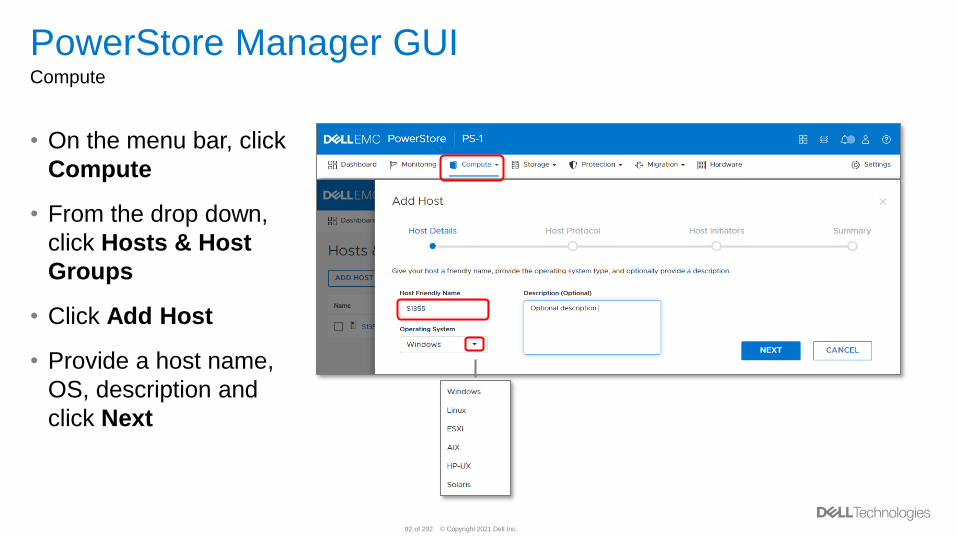
PowerStore Manager GUICompute
• On the menu bar, click
Compute
• From the drop down,
click Hosts & Host
Groups
• Click Add Host
• Provide a host name,
OS, description and
click Next
© Copyright 2021 Dell Inc.93 of 292
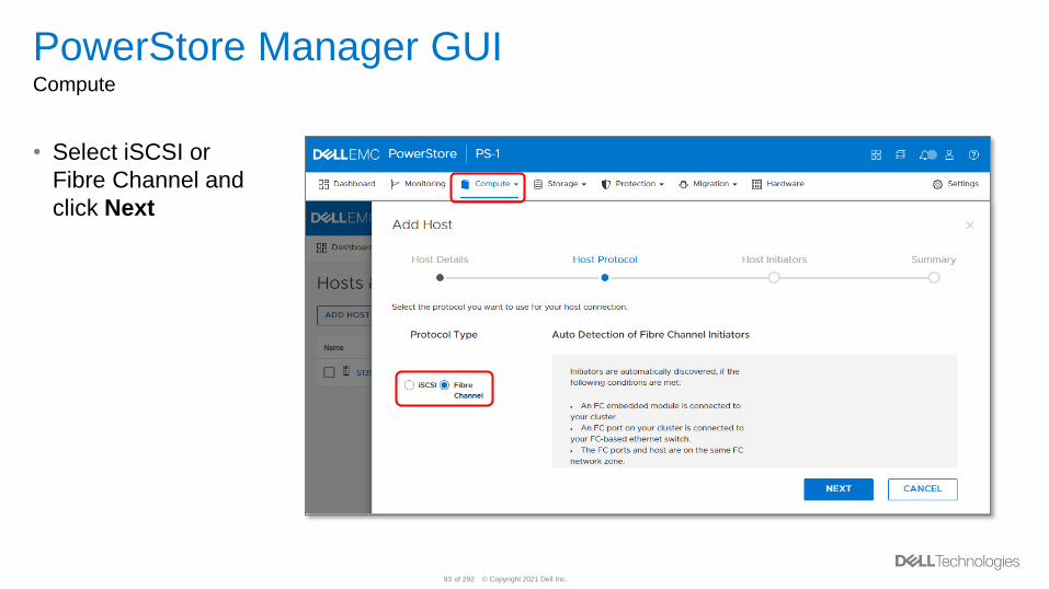
PowerStore Manager GUICompute
• Select iSCSI or
Fibre Channel and
click Next
© Copyright 2021 Dell Inc.94 of 292
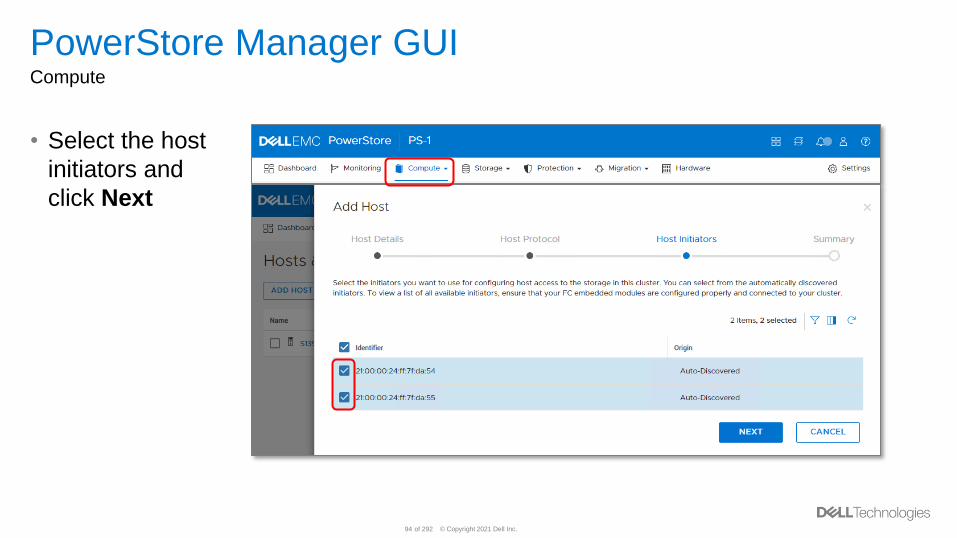
PowerStore Manager GUICompute
• Select the host
initiators and
click Next
© Copyright 2021 Dell Inc.95 of 292
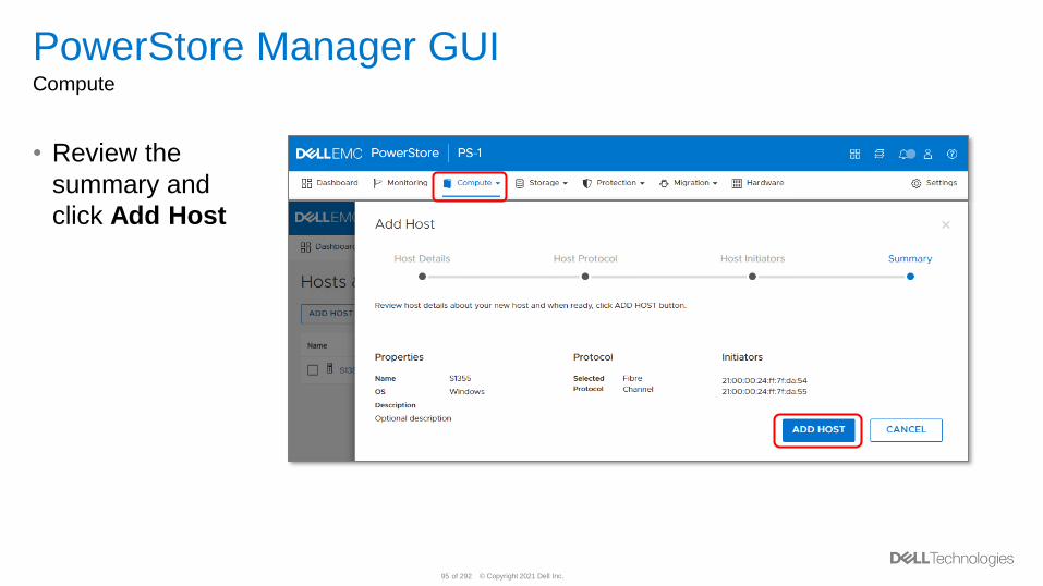
PowerStore Manager GUICompute
• Review the
summary and
click Add Host
© Copyright 2021 Dell Inc.96 of 292
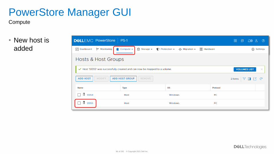
PowerStore Manager GUICompute
• New host is
added
© Copyright 2021 Dell Inc.97 of 292
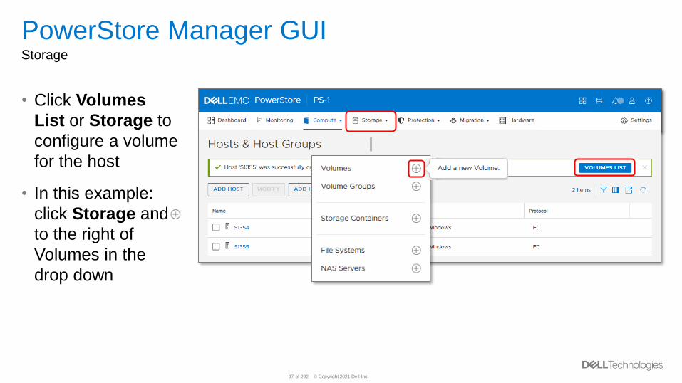
PowerStore Manager GUIStorage
• Click Volumes
List or Storage to
configure a volume
for the host
• In this example:
click Storage and
to the right of
Volumes in the
drop down
© Copyright 2021 Dell Inc.98 of 292
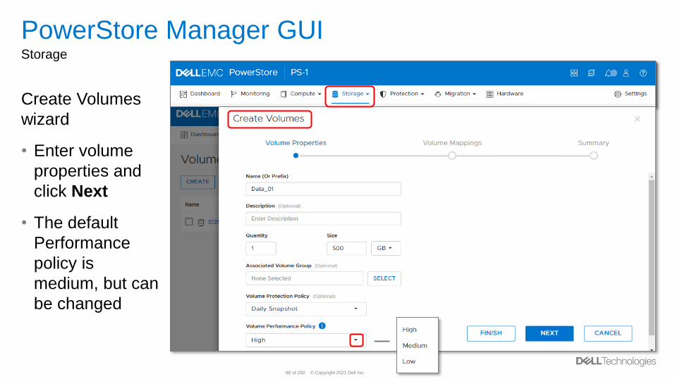
PowerStore Manager GUIStorage
Create Volumes
wizard
• Enter volume
properties and
click Next
• The default
Performance
policy is
medium, but can
be changed
© Copyright 2021 Dell Inc.99 of 292
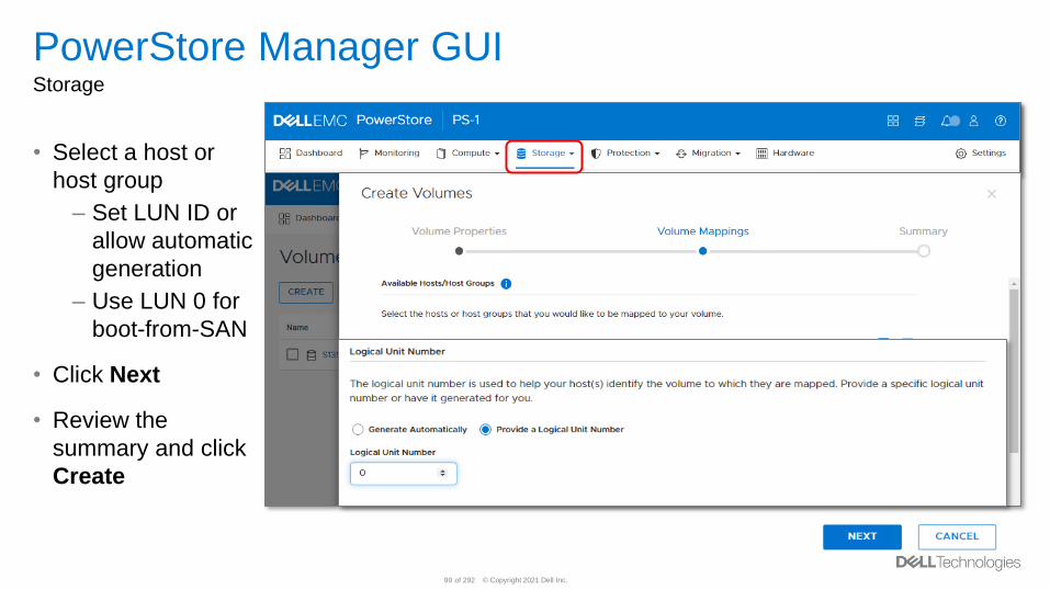
PowerStore Manager GUIStorage
• Select a host or
host group
– Set LUN ID or
allow automatic
generation
– Use LUN 0 for
boot-from-SAN
• Click Next
• Review the
summary and click
Create
© Copyright 2021 Dell Inc.100 of 292
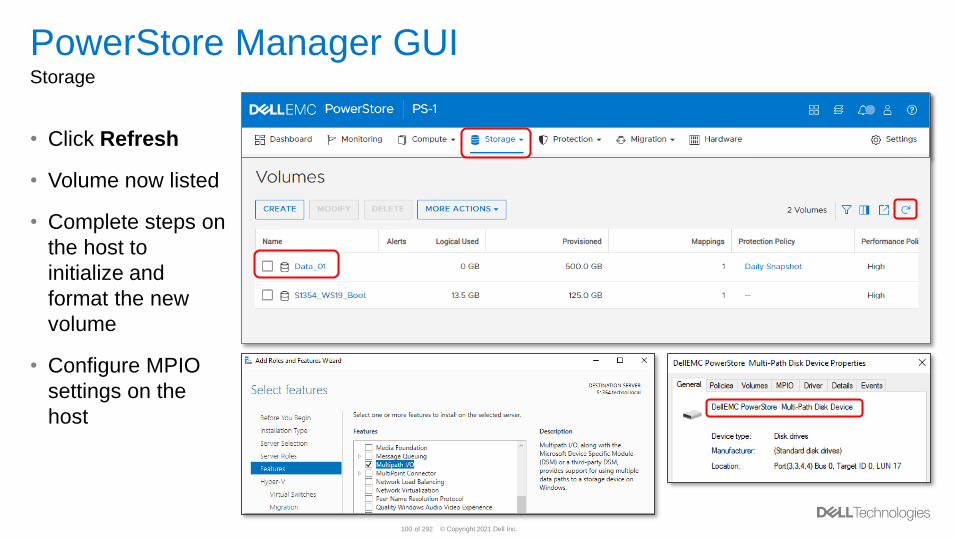
PowerStore Manager GUIStorage
• Click Refresh
• Volume now listed
• Complete steps on
the host to
initialize and
format the new
volume
• Configure MPIO
settings on the
host
© Copyright 2021 Dell Inc.101 of 292
CLI
© Copyright 2021 Dell Inc.102 of 292
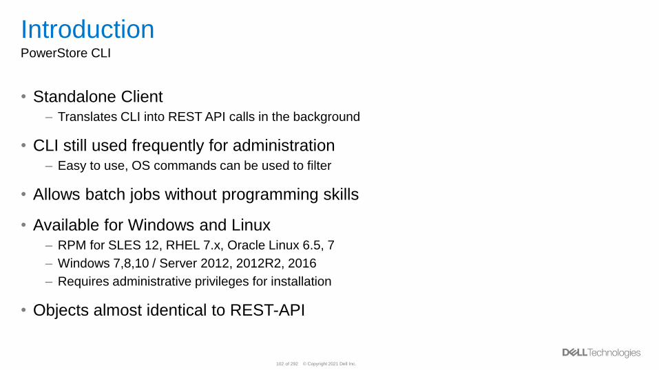
IntroductionPowerStore CLI
• Standalone Client– Translates CLI into REST API calls in the background
• CLI still used frequently for administration– Easy to use, OS commands can be used to filter
• Allows batch jobs without programming skills
• Available for Windows and Linux– RPM for SLES 12, RHEL 7.x, Oracle Linux 6.5, 7
– Windows 7,8,10 / Server 2012, 2012R2, 2016
– Requires administrative privileges for installation
• Objects almost identical to REST-API
© Copyright 2021 Dell Inc.103 of 292
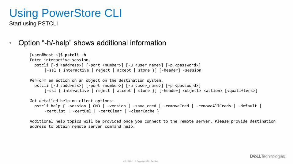
Using PowerStore CLIStart using PSTCLI
[user@host ~]$ pstcli -hEnter interactive session.pstcli [-d <address>] [-port <number>] [-u <user_name>] [-p <password>]
[-ssl { interactive | reject | accept | store }] [-header] -session
Perform an action on an object on the destination system.pstcli [-d <address>] [-port <number>] [-u <user_name>] [-p <password>]
[-ssl { interactive | reject | accept | store }] [-header] <object> <action> [<qualifiers>]
Get detailed help on client options:pstcli help { -session | CMD | -version | -save_cred | -removeCred | -removeAllCreds | -default |
-certList | -certDel | -certClear | -clearCache }
Additional help topics will be provided once you connect to the remote server. Please provide destination address to obtain remote server command help.
• Option “-h/-help” shows additional information
© Copyright 2021 Dell Inc.104 of 292
REST API
© Copyright 2021 Dell Inc.105 of 292
Functionality
• The REST API allows you to interact with PowerStore Management functionality,
including:
– System settings and monitoring
– Host and remote system connections
– Network settings
– Storage management
– Data protection
– Support configuration
• Presents a single, consistent interface to manage
• SSL encryption allows secure connection from client to system

© Copyright 2021 Dell Inc.106 of 292
SwaggerUISwagger UI – https://<PowerStoreClusterIP>/swaggerui
© Copyright 2021 Dell Inc.107 of 292
Data Path
© Copyright 2021 Dell Inc.108 of 292
PowerStore Data PathOverview
• A PowerStore’s read and write path depends on the system model– Described in detail in later slides
• PowerStore’s data path includes hardware and software algorithms working
together to accept and store user as efficiently as possible
• PowerStore’s Dynamic Resiliency Engine (PowerStore DRE) automatically
consumes the drives within an appliance and creates appropriate redundancy
using all the drives– Space is consumed from the drives to store data after it passes through deduplication and
compression
© Copyright 2021 Dell Inc.109 of 292
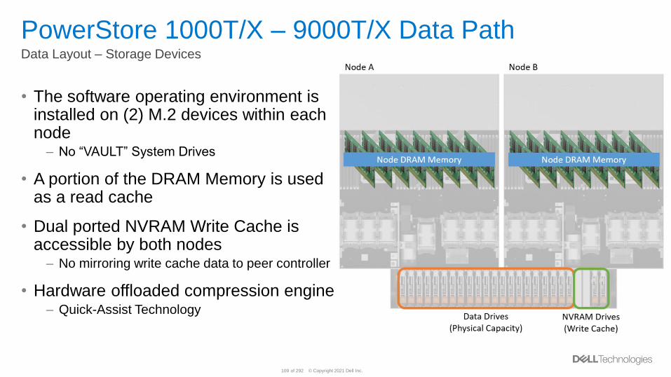
PowerStore 1000T/X – 9000T/X Data PathData Layout – Storage Devices
• The software operating environment is installed on (2) M.2 devices within each node
– No “VAULT” System Drives
• A portion of the DRAM Memory is used as a read cache
• Dual ported NVRAM Write Cache is accessible by both nodes
– No mirroring write cache data to peer controller
• Hardware offloaded compression engine– Quick-Assist Technology
© Copyright 2021 Dell Inc.110 of 292
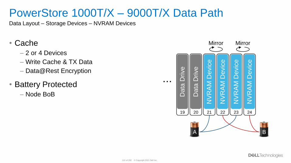
PowerStore 1000T/X – 9000T/X Data PathData Layout – Storage Devices – NVRAM Devices
• Cache– 2 or 4 Devices
– Write Cache & TX Data
– Data@Rest Encryption
• Battery Protected– Node BoB
19
Data
Drive
20
Data
Drive
21
NV
RA
M D
evic
e
22
NV
RA
M D
evic
e
23
NV
RA
M D
evic
e
24
NV
RA
M D
evic
e
...
MirrorMirror
A B
© Copyright 2021 Dell Inc.111 of 292
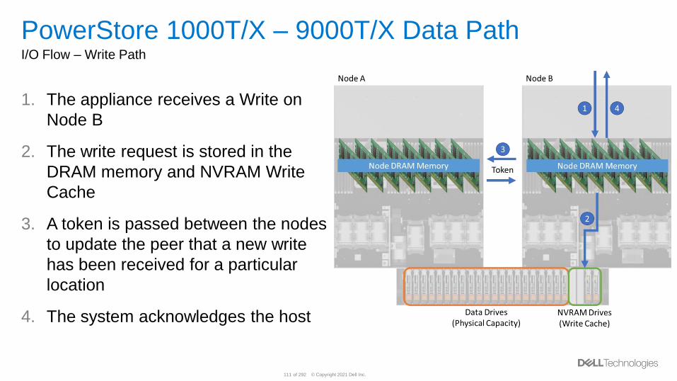
PowerStore 1000T/X – 9000T/X Data PathI/O Flow – Write Path
1. The appliance receives a Write on
Node B
2. The write request is stored in the
DRAM memory and NVRAM Write
Cache
3. A token is passed between the nodes
to update the peer that a new write
has been received for a particular
location
4. The system acknowledges the host
© Copyright 2021 Dell Inc.112 of 292
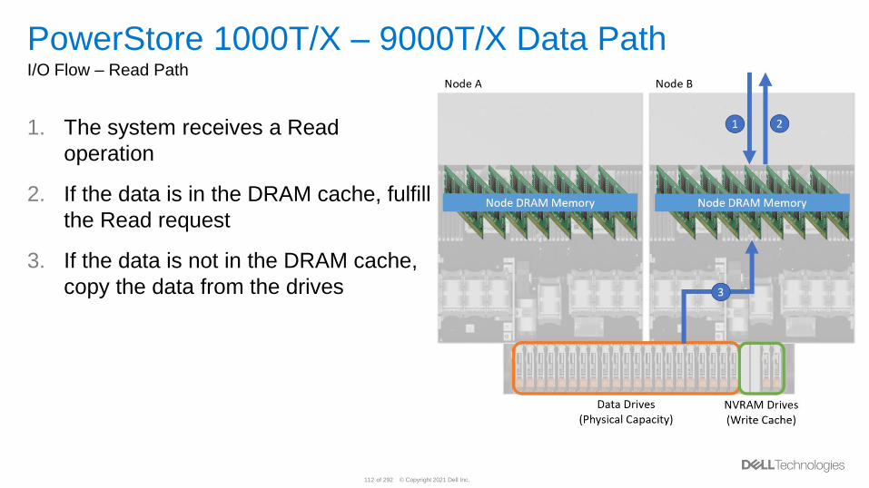
PowerStore 1000T/X – 9000T/X Data PathI/O Flow – Read Path
1. The system receives a Read
operation
2. If the data is in the DRAM cache, fulfill
the Read request
3. If the data is not in the DRAM cache,
copy the data from the drives
© Copyright 2021 Dell Inc.113 of 292
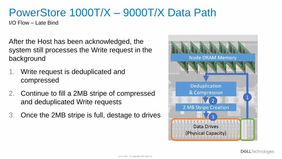
PowerStore 1000T/X – 9000T/X Data PathI/O Flow – Late Bind
After the Host has been acknowledged, the
system still processes the Write request in the
background
1. Write request is deduplicated and
compressed
2. Continue to fill a 2MB stripe of compressed
and deduplicated Write requests
3. Once the 2MB stripe is full, destage to drives
© Copyright 2021 Dell Inc.114 of 292
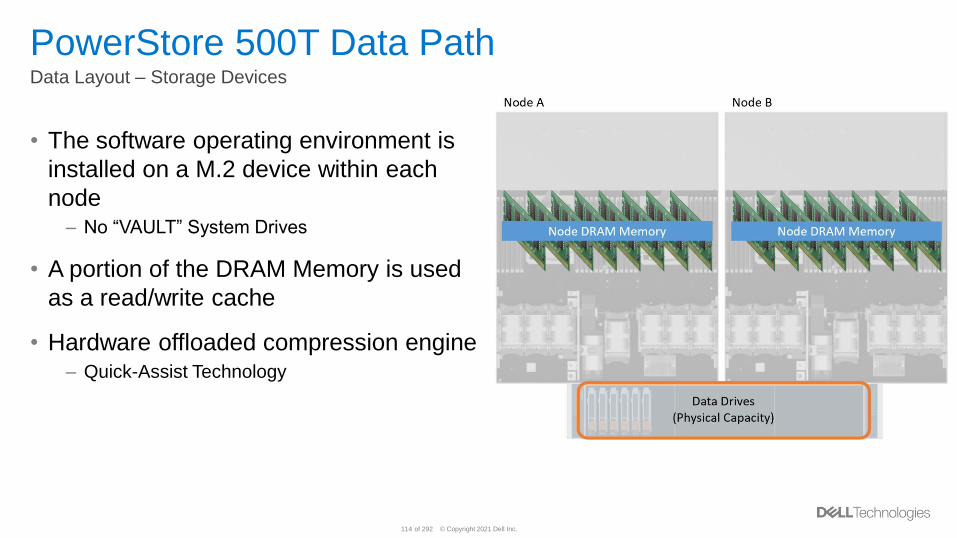
PowerStore 500T Data PathData Layout – Storage Devices
• The software operating environment is
installed on a M.2 device within each
node– No “VAULT” System Drives
• A portion of the DRAM Memory is used
as a read/write cache
• Hardware offloaded compression engine– Quick-Assist Technology
© Copyright 2021 Dell Inc.115 of 292
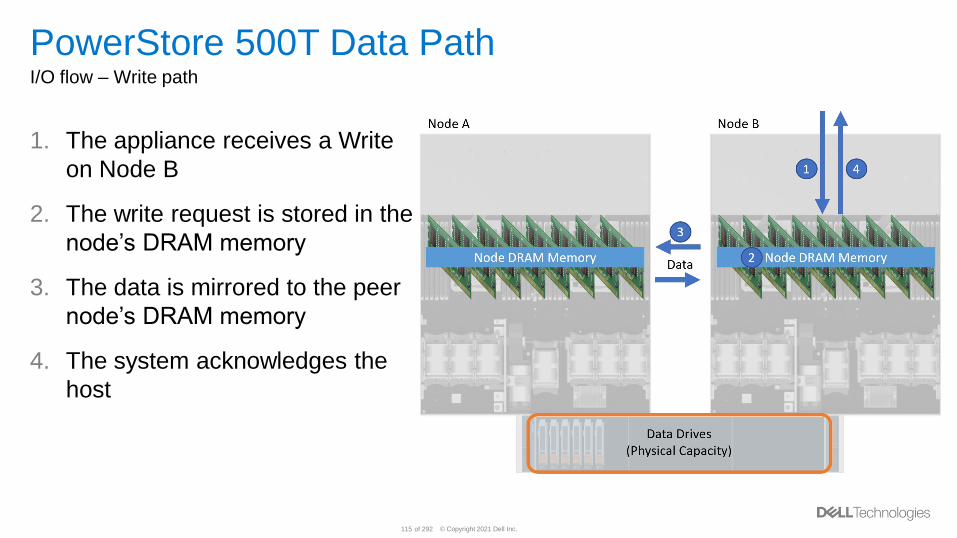
PowerStore 500T Data PathI/O flow – Write path
1. The appliance receives a Write
on Node B
2. The write request is stored in the
node’s DRAM memory
3. The data is mirrored to the peer
node’s DRAM memory
4. The system acknowledges the
host
© Copyright 2021 Dell Inc.116 of 292
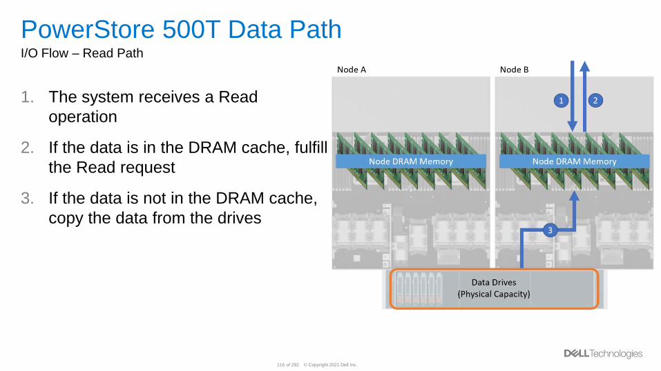
PowerStore 500T Data PathI/O Flow – Read Path
1. The system receives a Read
operation
2. If the data is in the DRAM cache, fulfill
the Read request
3. If the data is not in the DRAM cache,
copy the data from the drives
© Copyright 2021 Dell Inc.117 of 292
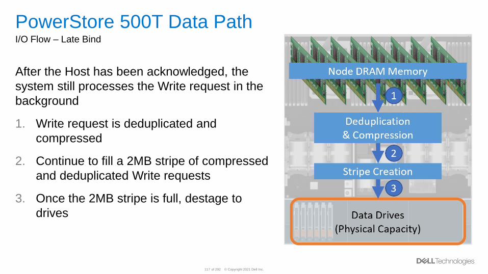
PowerStore 500T Data PathI/O Flow – Late Bind
After the Host has been acknowledged, the
system still processes the Write request in the
background
1. Write request is deduplicated and
compressed
2. Continue to fill a 2MB stripe of compressed
and deduplicated Write requests
3. Once the 2MB stripe is full, destage to
drives
© Copyright 2021 Dell Inc.118 of 292
PowerStore - Global DeduplicationOverview
• Deduplication savings within a PowerStore appliance works across nodes within
an appliance– Data entering a node can be compared and deduplicated against data received on the peer node
– Potentially increases the amount of savings that can be achieved within an appliance
• The fingerprint cache is not mirrored across the nodes– Each node contains a fingerprint cache containing unique fingerprints created on that node
▪ When data enters a node and a new/unique fingerprint is generated and that node owns that fingerprint
– To achieve global deduplication, fingerprint compares will occur across nodes using internal links
– By not mirroring the fingerprint cache, more fingerprints can be held in the appliance’s memory
Deduplication utilizes a 4 KB granularity
© Copyright 2021 Dell Inc.119 of 292
PowerStore - Fingerprint Cache SizeOverview
• The size of the fingerprint cache is based on the capacity of the appliance when
the software boots on the system
– The fingerprint cache does not expand as drives are added to the appliance
– This size is not exposed to the user
• System memory and drive capacity is used to create a fingerprint cache
– The fingerprint cache spans the memory within a node and the drives
– Reduces the usable capacity of the system
• Goal: Increase the amount of deduplication that can be achieved by tracking a
larger number of fingerprints
– A larger fingerprint cache allows for a greater chance of deduplication occurring
© Copyright 2021 Dell Inc.120 of 292
PowerStore – Persisted Fingerprint CacheOverview
• The contents of the fingerprint cache within system memory is updated to a backup
location on the data drives periodically– This operation is not configurable and is hidden from the user
• The periodic update process is based on the number of entries that are different
than the backup location– Only the new entries are updated to the backup location when an update occurs
– The threshold varies by model
• As the fingerprint cache update process is based on a threshold, some new
fingerprints can be lost if the node reboots– Deduplication savings is not lost if a fingerprint is lost
– The ability to deduplicate to that piece of data is lost
© Copyright 2021 Dell Inc.121 of 292
PowerStore Dynamic Resiliency EngineOverview
• Within PowerStore’s Dynamic Resiliency Engine (DRE), all drives within the
system are automatically consumed within an appliance and the appropriate
amount of redundancy is applied– Proprietary algorithms are used to store and protect data within the system
– Resiliency sets are use as fault domains to improve the reliability while minimizing spare space
overhead
▪ Resiliency sets are also known as fault resiliency sets in customer facing documentation
– Having multiple failure domains increases the reliability of the system
• Drive fault tolerance is the amount of concurrent drive failures, per resiliency set,
that a system can sustain without causing a Data Unavailable/Data Loss (DU/DL)
situation– The protection scheme within the resiliency set defines how many failures can occur
© Copyright 2021 Dell Inc.122 of 292
PowerStore Dynamic Resiliency EngineOverview (Continued)
• In the PowerStoreOS 2.0 release, the drive tolerance level can be set to single
drive failure or double drive failure during the initial configuration of an appliance
• Initial configuration could be initial cluster creation or when the appliance is being
added to an existing cluster
• Configuring the drive tolerance level sets the data protection tolerance level for all
resiliency sets created within the appliance
• The drive tolerance level is set for the lifetime of the appliance and cannot be
changed without a non-data-in-place factory reset– Pre-2.0 systems utilize single drive failure protection
• Different appliances within a cluster can have different tolerance levels
© Copyright 2021 Dell Inc.123 of 292
PowerStore Dynamic Resiliency EngineTolerance Level: Single Drive Failure vs. Double Drive Failure
• Tolerance Level: Single Drive Failure– Default value
– Single drive parity protection is used within each resiliency set for user data
– Up to one simultaneous drive failure per resiliency set without encountering DU/DL
– Metadata and other mirrored data uses 2-way mirroring
• Tolerance Level: Double Drive Failure– Dual drive parity protection is used within each resiliency set for user data
– Up to two simultaneous drive failure per resiliency set without encountering DU/DL
– Metadata and other mirrored data uses 3-way mirroring
– Reduced capacity in similar configurations when compared to single
© Copyright 2021 Dell Inc.124 of 292
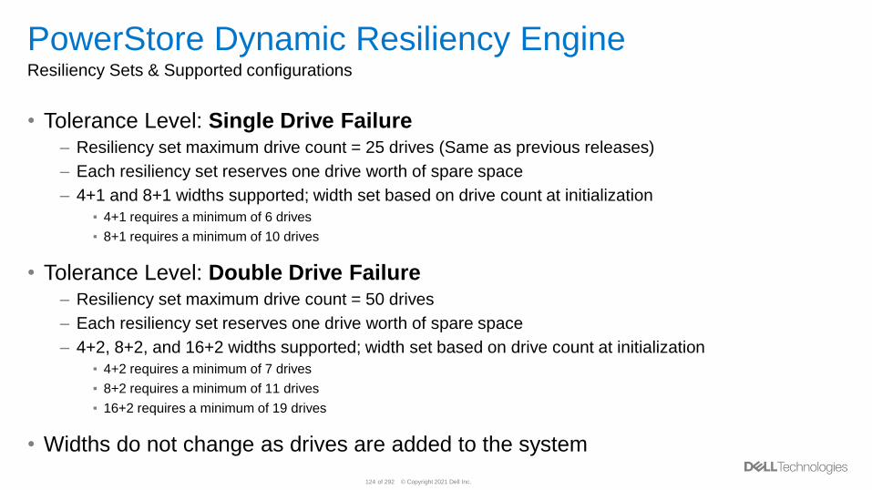
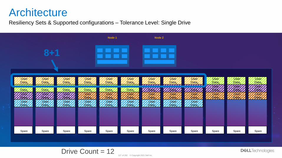
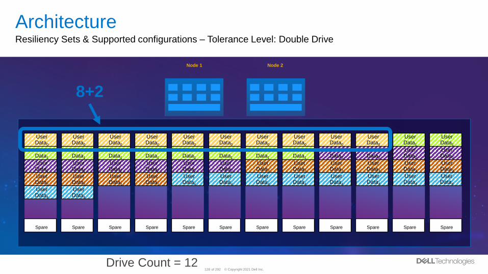
PowerStore Dynamic Resiliency EngineResiliency Sets & Supported configurations
• Tolerance Level: Single Drive Failure– Resiliency set maximum drive count = 25 drives (Same as previous releases)
– Each resiliency set reserves one drive worth of spare space
– 4+1 and 8+1 widths supported; width set based on drive count at initialization
▪ 4+1 requires a minimum of 6 drives
▪ 8+1 requires a minimum of 10 drives
• Tolerance Level: Double Drive Failure– Resiliency set maximum drive count = 50 drives
– Each resiliency set reserves one drive worth of spare space
– 4+2, 8+2, and 16+2 widths supported; width set based on drive count at initialization
▪ 4+2 requires a minimum of 7 drives
▪ 8+2 requires a minimum of 11 drives
▪ 16+2 requires a minimum of 19 drives
• Widths do not change as drives are added to the system
© Copyright 2021 Dell Inc.125 of 292
PowerStore Dynamic Resiliency EngineBenefits
• Shorten Rebuild Times
• Reduce Drive Overhead
• Mix Drive Capacities
• Single-Drive Granularity Scale-Up
• Distributed Spare
© Copyright 2021 Dell Inc.126 of 292
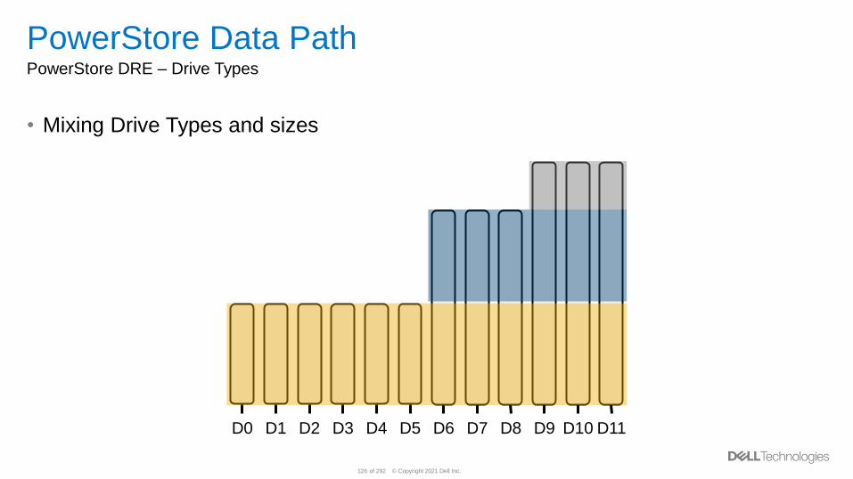
PowerStore Data PathPowerStore DRE – Drive Types
• Mixing Drive Types and sizes
D0 D1 D2 D3 D4 D5 D6 D7 D8 D9 D10 D11
© Copyright 2021 Dell Inc.127 of 292
ArchitectureResiliency Sets & Supported configurations – Tolerance Level: Single Drive
Node 1 Node 2
User Data0
User Data1
User Data0
User Data0
User Data0
User Data0
User Data0
User Data0
User Data0
User Data1
User Data0
User Data1
User Data1
User Data1
User Data1
User Data1
User Data1
User Data2
User Data2
User Data2
User Data2
User Data2
User Data2
User Data1
User Data3
User Data2
User Data2
User Data3
User Data3
User Data3
User Data3
User Data3
User Data3
User Data3
User Data3
User Data2
User Data4
User Data4
User Data4
User Data4
User Data4
User Data4
User Data4
User Data4
User Data4
SpareSpareSpareSpare Spare Spare Spare Spare Spare SpareSpareSpare
8+1
Drive Count = 12
© Copyright 2021 Dell Inc.128 of 292
ArchitectureResiliency Sets & Supported configurations – Tolerance Level: Double Drive
Node 1 Node 2
User Data0
User Data1
User Data0
User Data0
User Data0
User Data0
User Data0
User Data0
User Data0
User Data0
User Data0
User Data1
User Data1
User Data1
User Data1
User Data1
User Data1
User Data1
User Data2
User Data1
User Data2
User Data2
User Data2
User Data1
User Data2
User Data2
User Data2
User Data2
User Data2
User Data3
User Data3
User Data3
User Data3
User Data3
User Data3
User Data2
User Data3
User Data3
User Data3
User Data3
User Data4
User Data4
User Data4
User Data4
User Data4
SpareSpareSpareSpare Spare Spare Spare Spare Spare SpareSpareSpare
8+2
Drive Count = 12
User Data4
User Data4
User Data4
User Data4
User Data4
© Copyright 2021 Dell Inc.129 of 292
PowerStore Data Path – Performance PoliciesI/O Priority mechanism
• PowerStore performance policies allow a user to define the I/O priority for volumes
within an appliance– Can be customized at time of creation or can be changed at any time
– This is supported only for block volumes at this time
– This is not a limits based policy approach rather it is a shared based I/O prioritization mechanism
– When in affect, I/O for volumes set to High will receive priority over resources set to Medium or Low
• The performance policy setting on a volume can be set to Low, Medium or High– Medium is the default setting at resource creation
• The performance policies only take affect when there is contention of resources
© Copyright 2021 Dell Inc.130 of 292
File
© Copyright 2021 Dell Inc.131 of 292
PowerStore File Overview
• PowerStore File enables clients to access data over file protocols:– Server Message Block (SMB)
– Network File System (NFS)
– File Transfer Protocol (FTP)
– SSH File Transfer Protocol (SFTP)
• Currently File Replication is not available
• File is only available on PowerStore T model appliances– Currently PowerStore X model appliances do not support File

© Copyright 2021 Dell Inc.132 of 292
Block Optimized or Unified
• PowerStore T model appliances can be configured as Block Optimized or Unified
(block and file)– Selection determines resource allocation on the appliance
– PowerStore X model appliances do not have this option as they do not support NAS
• Must be decided during initial configuration– Select Unified if there is a chance that you will need file functionality
– No option to convert between Block Optimized and Unified afterwards
• PowerStore Sizer will have performance details for each configuration– Block-optimized systems have slightly higher block IOPS potential
• If Unified is selected, NAS installation is performed automatically after cluster
creation completes
© Copyright 2021 Dell Inc.133 of 292
Unified Appliance
• File functionality is only available on the primary appliance in the cluster– Remaining appliances are configured as Block Optimized
• Only the capacity on the primary appliance is available for File– Capacity available on other appliances within the same cluster can be used for volumes and vVols
• Both nodes on the primary appliance are used for File– Active/active architecture enables load balancing and high availability
© Copyright 2021 Dell Inc.134 of 292
NAS Servers
• NAS servers enable access to the data on file systems– Contains protocol and environmental configuration
– Required before creating file systems
• NAS servers are used to enforce multi-tenancy– NAS Servers are logically segregated from each other
– Clients of one NAS Server do not have access to data on other NAS Servers
– IP multi-tenancy is not available
• Each NAS server has its own independent configuration– E.g., DNS, LDAP, NIS, interfaces, protocols, etc.
© Copyright 2021 Dell Inc.135 of 292
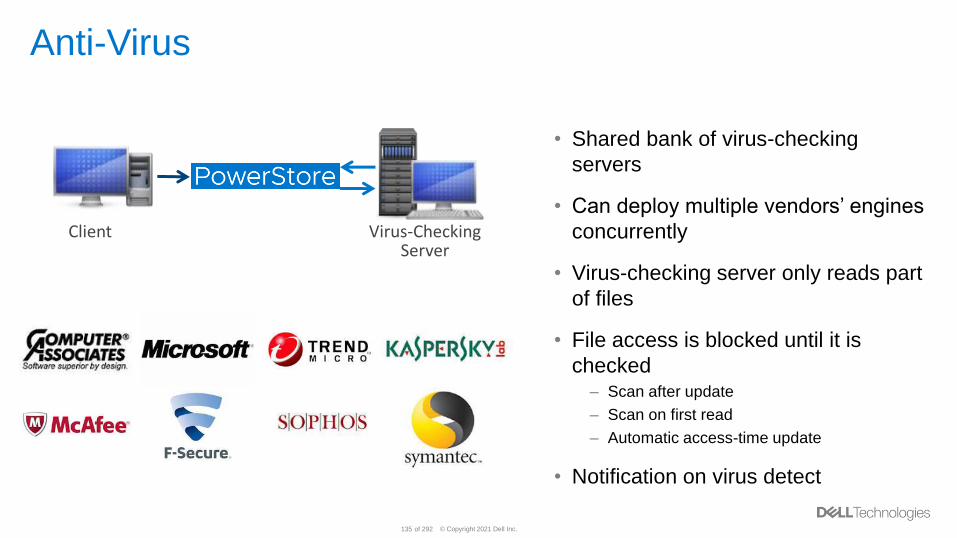
Anti-Virus
Virus-CheckingServer
Client
• Shared bank of virus-checking
servers
• Can deploy multiple vendors’ engines
concurrently
• Virus-checking server only reads part
of files
• File access is blocked until it is
checked– Scan after update
– Scan on first read
– Automatic access-time update
• Notification on virus detect
© Copyright 2021 Dell Inc.136 of 292
Supported Protocols
• NFS– NFSv3
– NFSv4 - 4.1
– Secure NFS
• SMB – Standalone or Domain Joined– SMB1
– SMB2
– SMB3 – 3.1.1
• Multiprotocol - Access using both SMB and NFS simultaneously– Automatically enabled when both the SMB and NFS protocols are enabled on the NAS Server
• FTP/SFTP
© Copyright 2021 Dell Inc.137 of 292
NAS Server High Availability
• In the event of a PowerStore node failure, NAS Servers automatically failover from
one NAS node to the other– Failover generally completes within 30 seconds to avoid host timeouts
– NAS Servers are automatically moved to the peer node during NDU
– Failback is a manual process
• New NAS Servers are automatically assigned round-robin across nodes– All file systems associated with the NAS Server are served by the NAS Server’s current node
• Current Node– The node that the NAS server is currently running on
– Changing this moves the NAS server to run on a different node
• Preferred Node– The node that the NAS server should be ideally running on
– Acts as a marker that is based on the round-robin algorithm
© Copyright 2021 Dell Inc.138 of 292
NDMP Backups
• NDMP – Network Data Management Protocol– A backup and recovery protocol used to transport data between NAS and backup systems
• Components– Primary Storage – Source system to be backed up, such as PowerStore
– Data Management Application (DMA) – Backup application that orchestrates the backup sessions,
such as Dell EMC NetWorker
– Secondary Storage – The backup target, such as Data Domain
• PowerStore supports 3-way NDMP – 3-way NDMP transfers both the metadata and backup data over the LAN
– 2-way NDMP is not supported
• Both full and incremental backups are supported
© Copyright 2021 Dell Inc.139 of 292
File Systems
• A file system can be created once a NAS Server is available– Once created, file systems cannot be moved from one NAS Server to another
• The file system creation wizard prompts for:– NAS Server
– File System Details
▪ Name
▪ Description (optional)
▪ Size
– NFS Export Details (if enabled on the NAS Server)
▪ Name
▪ Description (optional)
▪ NFS access configuration
– SMB Share Details (if enabled on the NAS Server)
▪ Name
▪ Description (optional)
▪ Advanced SMB options
– Protection Policy
© Copyright 2021 Dell Inc.140 of 292
SMB Options
• Advanced SMB Settings (File System)– Sync Writes Enabled
– Oplocks Enabled (Default)
– Notify on Write Enabled
– Notify on Access Enabled
• Advanced SMB Settings (Share)– Continuous Availability (SMB3)
– Protocol Encryption (SMB3)
– Access-Based Enumeration
– Brach Cache Enabled
– Offline Availability
▪ None (Default)
▪ Manual
▪ Documents
▪ Programs
– UMASK (022 Default)
© Copyright 2021 Dell Inc.141 of 292
NFS Options
• Minimum Security – Minimum security allowed when connecting to a NFS export– Sys
– Kerberos
– Kerberos with Integrity
– Kerberos with Encryption
• Access Levels – Can be set for Default Access or individual hosts– No Access
– Read/Write
– Read-Only
– Read/Write, Root Only
– Read-Only, Root Only
© Copyright 2021 Dell Inc.142 of 292
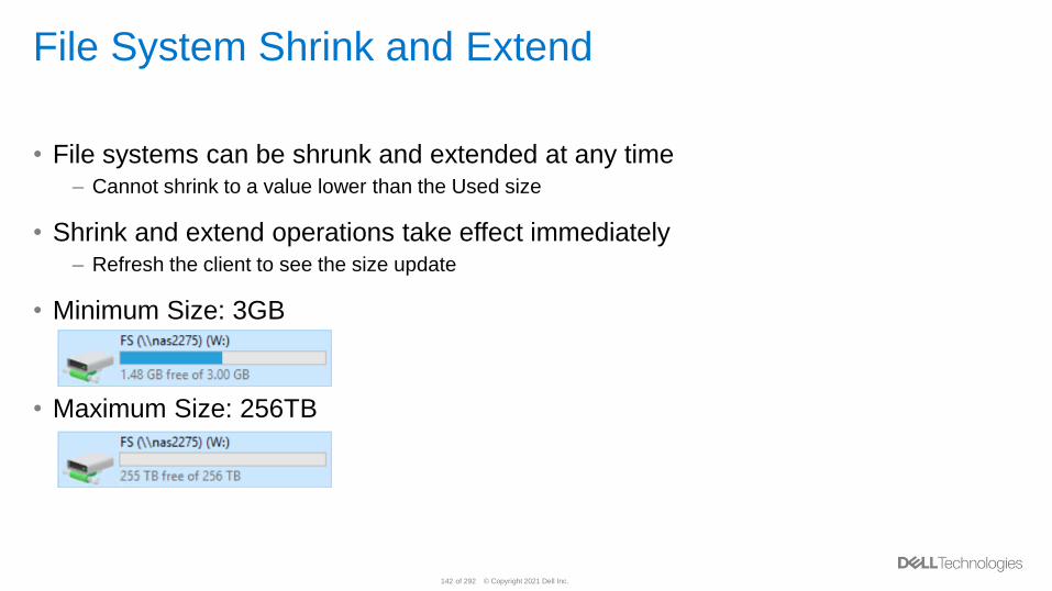
File System Shrink and Extend
• File systems can be shrunk and extended at any time– Cannot shrink to a value lower than the Used size
• Shrink and extend operations take effect immediately– Refresh the client to see the size update
• Minimum Size: 3GB
• Maximum Size: 256TB
© Copyright 2021 Dell Inc.143 of 292
File System Quotas
• Quotas - Provides the ability to regulate capacity consumption
• User Quotas – Limits the capacity consumed by an individual user on the file
system– All users are identified by their UNIX User ID
• Tree Quotas – Limits the capacity consumed on a specific directory on the file
system– All files in the directory and subdirectories contribute towards the limit
• Default Quotas – Applied to all users on the file system automatically– Ability to configure exceptions to the default
• Can create user quotas in a tree quota– Limits capacity by users in a specific directory
© Copyright 2021 Dell Inc.144 of 292
NVMe-FC
© Copyright 2021 Dell Inc.145 of 292
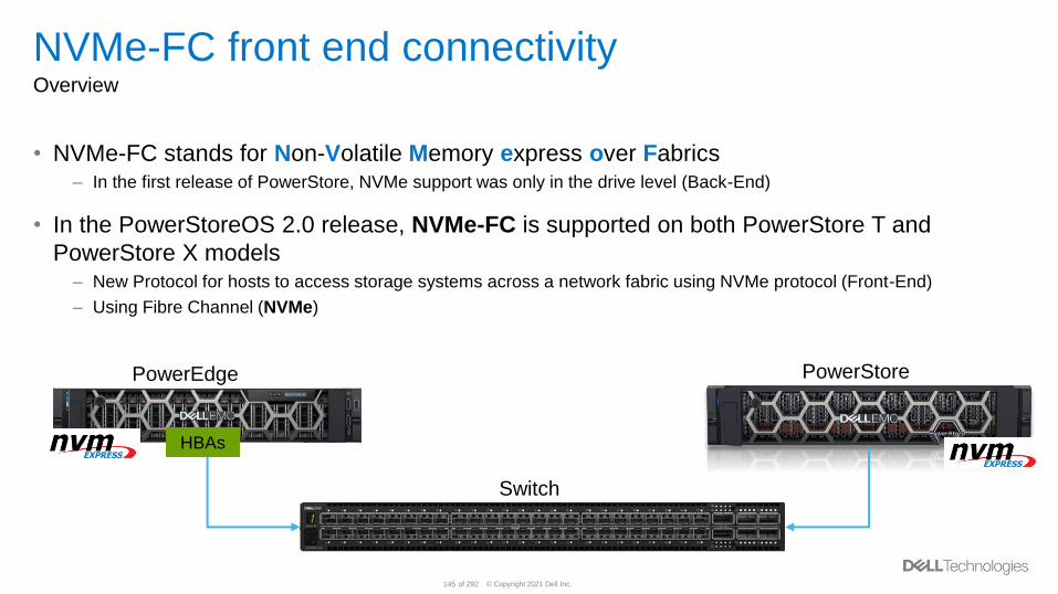
NVMe-FC front end connectivity Overview
• NVMe-FC stands for Non-Volatile Memory express over Fabrics– In the first release of PowerStore, NVMe support was only in the drive level (Back-End)
• In the PowerStoreOS 2.0 release, NVMe-FC is supported on both PowerStore T and
PowerStore X models– New Protocol for hosts to access storage systems across a network fabric using NVMe protocol (Front-End)
– Using Fibre Channel (NVMe)
PowerStorePowerEdge
Switch
HBAs
© Copyright 2021 Dell Inc.146 of 292
NVMe-FC front end connectivity Benefits
• Highly scalable and parallel
• Better efficiency
• End-to-End NVMe Model
• NVMe drive level
• NVMe extended over the network fabric
© Copyright 2021 Dell Inc.147 of 292
NVMe-FC front end connectivity Connectivity Considerations
• NVMe-FC is over Fibre Channel (FC) – Front end connectivity 32Gb FC I/O modules
– NVMe-FC will be supported on any 32G FC switches running Brocade FOS 8.1.0 or later and Cisco
NX-OS 8.1(1) or later
• Fibre Channel front end port simultaneously supports SCSI and NVMe access– User can choose whether to use both protocols on same port or use each protocol on separate ports
– Always support both protocols with no option to disable one of them
• Host Bus Adapter (HBA) supports 32Gb Gen6/7 – Marvell QLogic QLE series
– Broadcom Emulex LPe series
• NVMe Expansion shelf not supported in the PowerStoreOS 2.0 release
© Copyright 2021 Dell Inc.148 of 292
NVMe-FC front end connectivity Connectivity Setup
• Users can setup NVMe host through:– PowerStore Manager
– PowerStore CLI
– REST API
• Connectivity flow:– Set up Fibre Channel Front End ports (zoned)
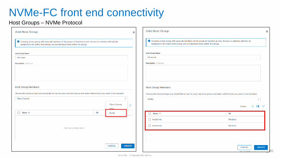
– Create Host or Host Groups and select NVMe as protocol
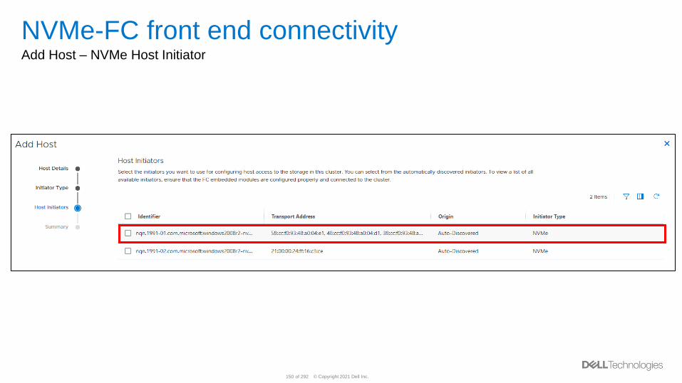
▪ Add initiator(s)
▪ nqn. is the NVMe identifier similar to the iqn. for iSCSI
– Create Volume/Thin Clone or Volume Groups
▪ Not support with vVol
– Map the NVMe Host to the Volume(s)
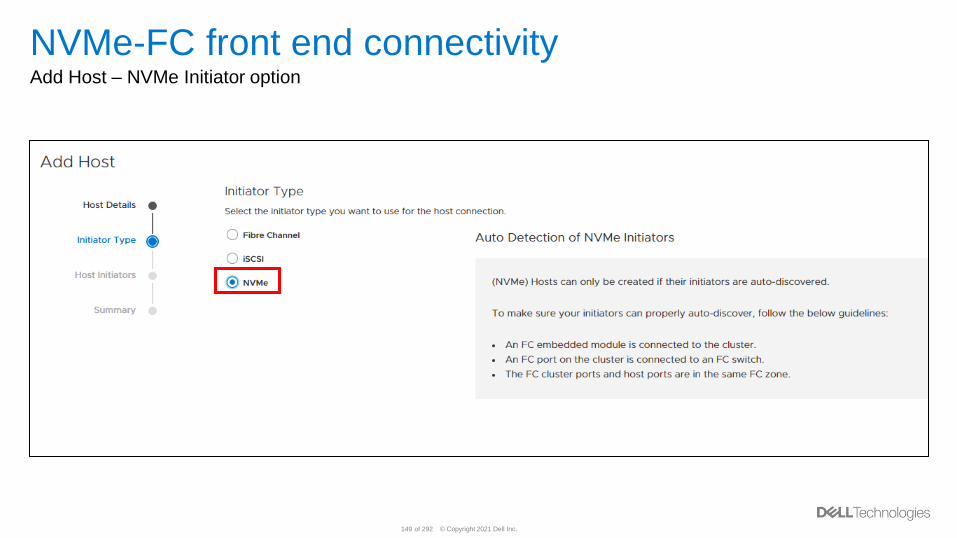
© Copyright 2021 Dell Inc.149 of 292
NVMe-FC front end connectivity Add Host – NVMe Initiator option
© Copyright 2021 Dell Inc.150 of 292
NVMe-FC front end connectivity Add Host – NVMe Host Initiator
© Copyright 2021 Dell Inc.151 of 292
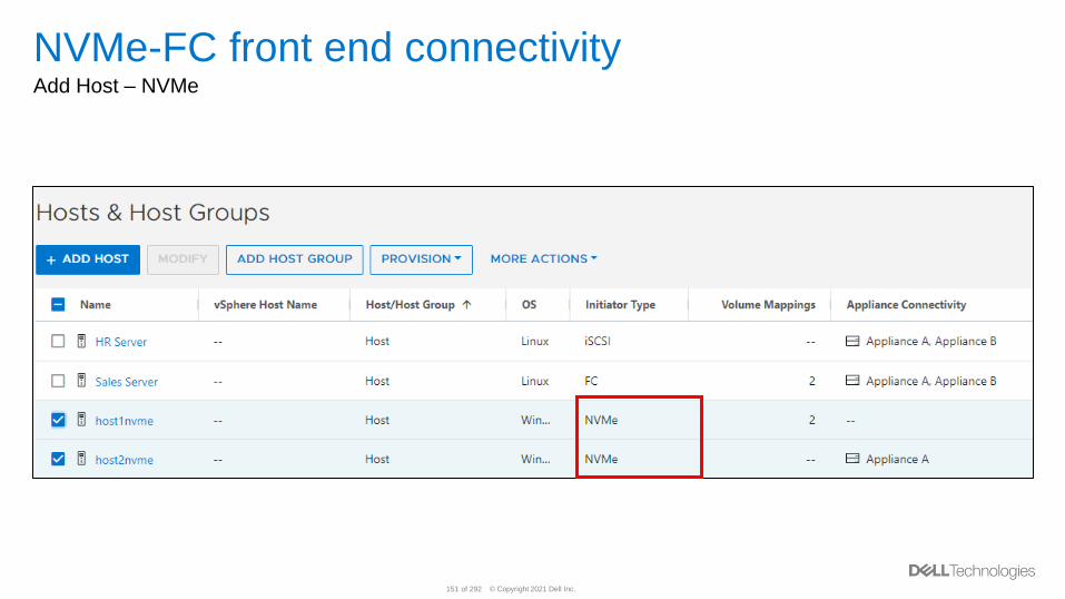
NVMe-FC front end connectivity Add Host – NVMe
© Copyright 2021 Dell Inc.152 of 292
NVMe-FC front end connectivity Host Groups – NVMe Protocol
© Copyright 2021 Dell Inc.153 of 292
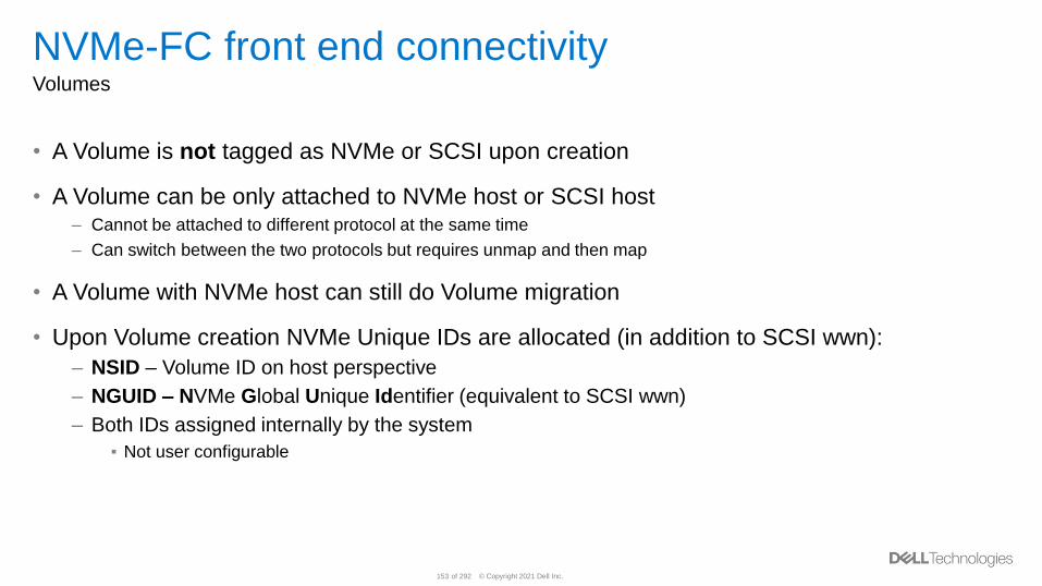
NVMe-FC front end connectivity Volumes
• A Volume is not tagged as NVMe or SCSI upon creation
• A Volume can be only attached to NVMe host or SCSI host– Cannot be attached to different protocol at the same time
– Can switch between the two protocols but requires unmap and then map
• A Volume with NVMe host can still do Volume migration
• Upon Volume creation NVMe Unique IDs are allocated (in addition to SCSI wwn):
– NSID – Volume ID on host perspective
– NGUID – NVMe Global Unique Identifier (equivalent to SCSI wwn)
– Both IDs assigned internally by the system
▪ Not user configurable
© Copyright 2021 Dell Inc.154 of 292
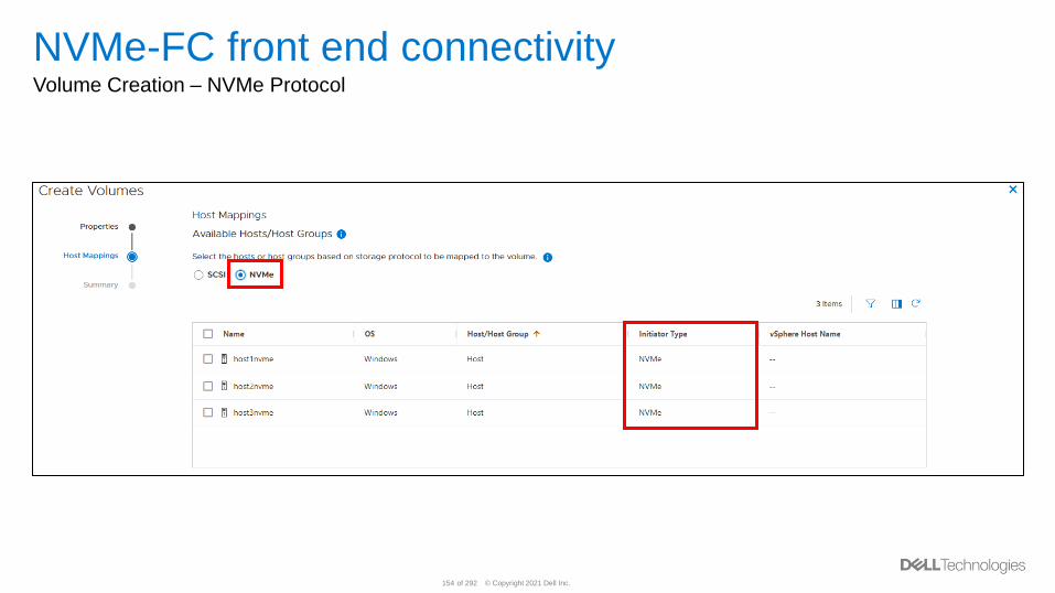
NVMe-FC front end connectivity Volume Creation – NVMe Protocol
© Copyright 2021 Dell Inc.155 of 292
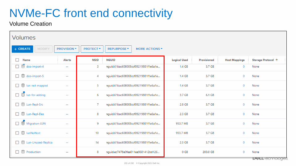
NVMe-FC front end connectivity Volume Creation
© Copyright 2021 Dell Inc.156 of 292
NVMe-FC front end connectivity Supported Operating Systems - Host
• VMware ESX 7.0
• RHEL 7.6-7.8, 8.0-8.3
• SLES 12 SP4-SP5, 15
© Copyright 2021 Dell Inc.157 of 292
Storage Network Scaling
© Copyright 2021 Dell Inc.158 of 292
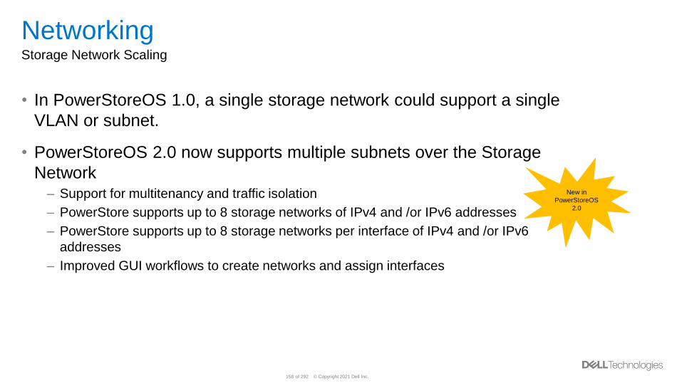
NetworkingStorage Network Scaling
• In PowerStoreOS 1.0, a single storage network could support a single
VLAN or subnet.
• PowerStoreOS 2.0 now supports multiple subnets over the Storage
Network– Support for multitenancy and traffic isolation
– PowerStore supports up to 8 storage networks of IPv4 and /or IPv6 addresses
– PowerStore supports up to 8 storage networks per interface of IPv4 and /or IPv6
addresses
– Improved GUI workflows to create networks and assign interfaces
New in
PowerStoreOS
2.0
© Copyright 2021 Dell Inc.159 of 292
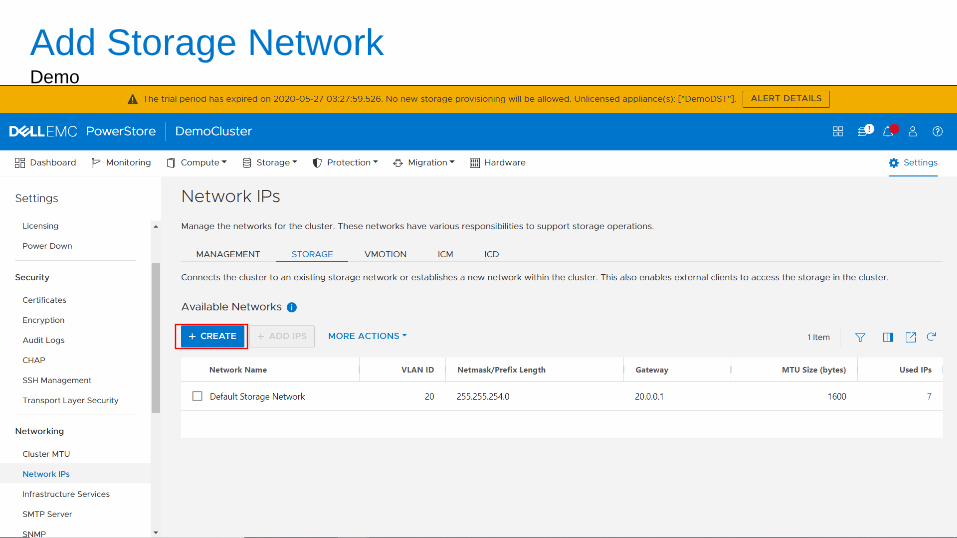
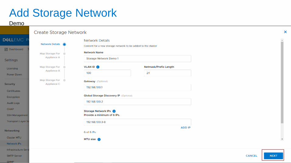
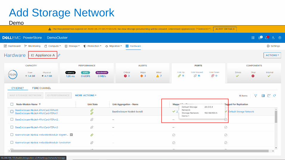
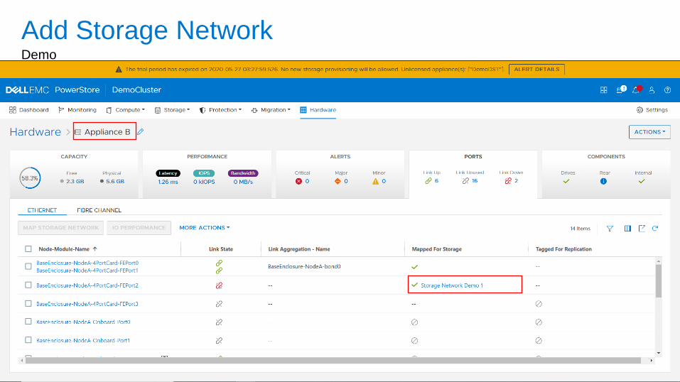
NetworkingStorage Network Scaling GUI Workflow
• Navigate to the settings network IP page
• Click on the storage tab
• Create a new storage network
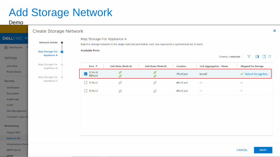
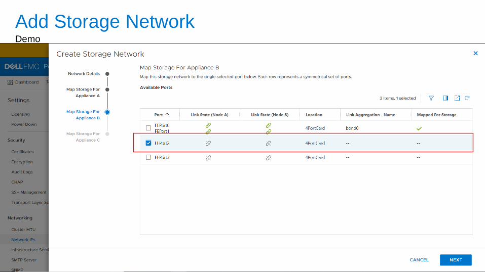
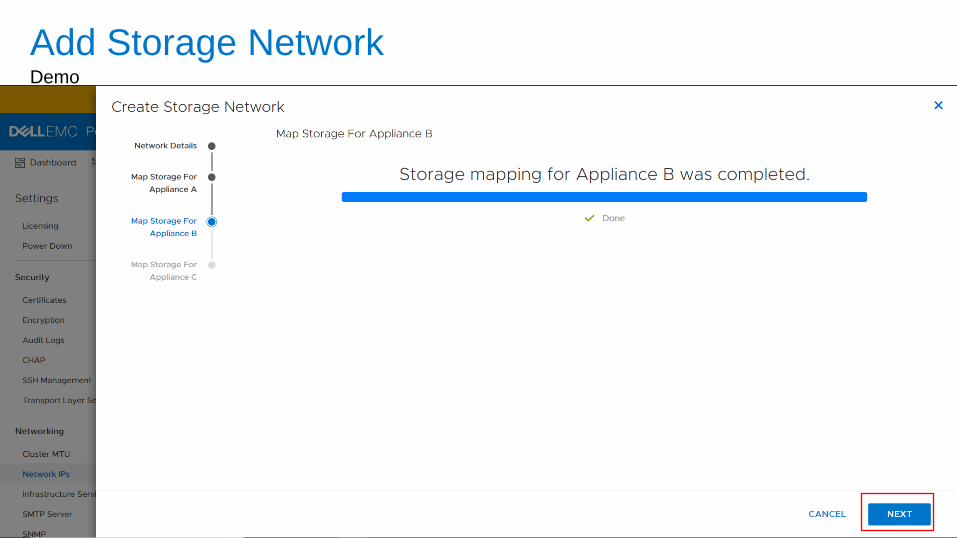
• Map the network to desired interfaces to appliance(s) in the cluster
© Copyright 2021 Dell Inc.160 of 292
Add Storage NetworkDemo
© Copyright 2021 Dell Inc.161 of 292
Add Storage NetworkDemo
© Copyright 2021 Dell Inc.162 of 292
Add Storage NetworkDemo

© Copyright 2021 Dell Inc.163 of 292
Add Storage NetworkDemo
© Copyright 2021 Dell Inc.164 of 292
Add Storage NetworkDemo
© Copyright 2021 Dell Inc.165 of 292
Add Storage NetworkDemo
© Copyright 2021 Dell Inc.166 of 292
Add Storage NetworkDemo
© Copyright 2021 Dell Inc.167 of 292
Add Storage NetworkDemo
© Copyright 2021 Dell Inc.168 of 292
Volumes & Volume Groups
© Copyright 2021 Dell Inc.169 of 292
Block Resources
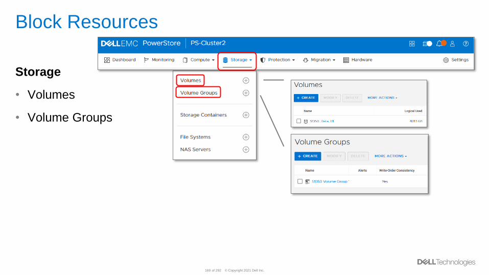
Storage
• Volumes
• Volume Groups
© Copyright 2021 Dell Inc.170 of 292
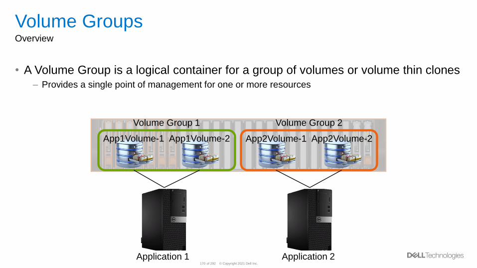
Volume GroupsOverview
• A Volume Group is a logical container for a group of volumes or volume thin clones– Provides a single point of management for one or more resources
App2Volume-1 App2Volume-2App1Volume-1 App1Volume-2
Application 1 Application 2
Volume Group 1 Volume Group 2
© Copyright 2021 Dell Inc.171 of 292
Volume GroupsConsiderations
• A Volume can only belong to one Volume Group at a time
• All Volumes must reside on the same appliance– To utilize a Volume Group you must plan Volume creation accordingly
• If a Protection Policy is assigned to a Volume Group, you cannot assign a
Protection Policy to an individual resource within the group
• Host/Host Group Mapping cannot be done at the Volume Group level– Host access must be configured by other means
• Single volume restore operations are only allowed when “write order consistency”
is disabled on the Volume Group
© Copyright 2021 Dell Inc.172 of 292
Protection Policies
© Copyright 2021 Dell Inc.173 of 292
Protection PoliciesOverview
• A Protection Policy is a set of user defined rules used to establish local or remote
data protection across storage resources
– Users do not configure snapshot schedules or replication sessions on a resource, but
rather assign a Protection Policy to it
• A Protection Policy consists of rules which define what level of protection to apply
• When a Protection Policy is assigned to a resource:
– The Snapshot Rule is automatically applied
– Replication is automatically configured
© Copyright 2021 Dell Inc.174 of 292
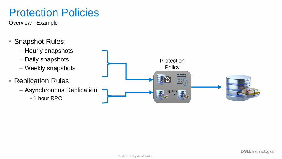
Protection PoliciesOverview - Example
• Snapshot Rules:
– Hourly snapshots
– Daily snapshots
– Weekly snapshots
• Replication Rules:
– Asynchronous Replication
▪ 1 hour RPO
RPO
Protection
Policy
© Copyright 2021 Dell Inc.175 of 292
Protection PoliciesUse Cases
• Create one or more Protection Policies and use them across multiple resources
– I.E. Create a Gold, Silver, and Bronze service levels and assign them as needed
Example:
• Create a Protection Policy Containing:
– 3 Snapshot Rules:
▪ Hourly snapshots
▪ Daily snapshot at midnight
▪ Weekly snapshot taken on Sundays
– 1 Replication Rule:
▪ Remote Replication with 1 hour Recovery Point Objective (RPO)
© Copyright 2021 Dell Inc.176 of 292
Snapshots
© Copyright 2021 Dell Inc.177 of 292
SnapshotsOverview
• Snapshots are crash-consistent point-in-time copies of data that are stored in
supported storage resources
– Snapshots are the local data protection solution within PowerStore
– Note: A crash-consistent snapshot is not application consistent. Application consistency
requires I/O to be quiesced at the host, host buffers flushed, and a snapshot taken.
• Snapshots are not full copies of the original data
– Pointer based, redirect on write technology
– You should not rely on snapshots for mirrors, disaster recovery, etc.
• Snapshots consume overall system storage capacity as changes to the source are
made
– Ensure that the system has enough capacity to accommodate snapshots
© Copyright 2021 Dell Inc.178 of 292
SnapshotsOverview (Continued)
• Snapshots are supported on volumes, volume groups, virtual machines, file
systems, and thin clones
• Snapshots can be created:
– Manually
– Automatically via a user created Snapshot Rule within the system
▪ To have snapshots automatically created via a predefined schedule on a storage resource, a
Protection Policy containing a Snapshot Rule must be added to the storage resource
– Automatically by a feature within the system
▪ Such as replication
▪ Hidden from the user
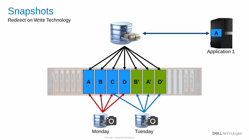
© Copyright 2021 Dell Inc.179 of 292
Application 1
SnapshotsRedirect on Write Technology
D’A’B’DCBA
D’A’B’DCBA
Monday Tuesday
© Copyright 2021 Dell Inc.180 of 292
Volume/Volume Group SnapshotsOverview
• Volume and Volume Group snapshots cannot be attached/accessed by hosts
– To access the data within a snapshot, create a Thin Clone
• Volume snapshot names are case insensitive and are limited to 128 characters
– Example of a valid snapshot name: SnApShOt`~!@#$%^&*()-_=+[]\;',./{}|:"<>?
– Names for existing snapshots can be edited
– Snapshots names need to be unique within the Volume family
• Taking a snapshot of a Volume Group creates a snapshot on all members of the
Volume Group at particular moment in time
– Snapshot consistency will depend on the “write order consistency” setting
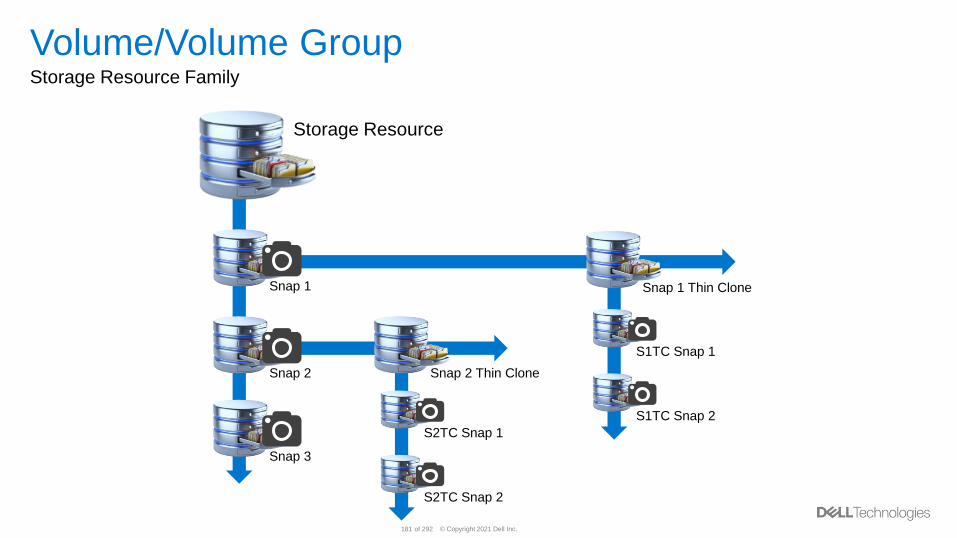
© Copyright 2021 Dell Inc.181 of 292
Volume/Volume GroupStorage Resource Family
Snap 1
Snap 2
Snap 1 Thin Clone
Snap 2 Thin Clone
S2TC Snap 1
S2TC Snap 2
S1TC Snap 1
S1TC Snap 2
Snap 3
Storage Resource
© Copyright 2021 Dell Inc.182 of 292
File SnapshotsOverview
• There are 2 different file snapshot types, both used for data protection:
– Protocol (Read-Only)
▪ Read-Only snapshot that can be exported as an SMB share and/or NFS export
• Access is provided by the parent NAS Server
▪ This is the default type created by a Snapshot Rule
– .Snapshot (Read-Only)
▪ Read-Only snapshot that can be accessed through Previous Versions or .snapshot
• Note: You may customize the name when taking a manual snapshot, but editing
the name or the access type of a file system snapshot is not possible
© Copyright 2021 Dell Inc.183 of 292
SnapshotsSnapshot Aging
• When manually creating a snapshot, the user can customize when the snapshot is
retained until
– To ensure a snapshot doesn’t expire, choose “No Automatic Deletion”
– Can change existing snapshots to “No Automatic Deletion” if needed
• Snapshots created by a schedule are automatically assigned an expiration
Date/Time
– Can change existing snapshots to “No Automatic Deletion” if needed
• The snapshot aging service runs hourly in the background and cleans up expired
snapshots as needed
– Snapshots are deleted in batches to improve performance and efficiency
© Copyright 2021 Dell Inc.184 of 292
Volume/Volume Group SnapshotsData Recovery
• Need access when some amount of data has been deleted or corrupted?
1.Find a snapshot which contains the data needed
2.Create a Thin Clone of the snapshot
3.Provide host access to the Thin Clone to access the data
• All data within the source has been deleted or corrupted?
1.Find a snapshot which contains the data needed
2.Utilize the Restore function to return the source volume to the desired point in time
© Copyright 2021 Dell Inc.185 of 292
File SnapshotsData Recovery
• Need access when some amount of data has been deleted or corrupted?
1.Find a snapshot which contains the data needed
2.Depending on the snapshot type:
a. Protocol (Read-Only) – Create an SMB share and/or NFS export
b. .Snapshot – Access the snapshot data via Previous Versions or .snapshot
• All source data has been deleted or corrupted?
1.Find a snapshot which contains the data needed
2.Utilize the Restore function to return the source file system to the desired point in time
© Copyright 2021 Dell Inc.186 of 292
Snapshot RulesOverview
• Snapshot Rules are used to automatically take snapshots on a supported storage
resource
– Defines the Frequency to take a snapshot, and the Retention period for snapshots of a
given storage resource
• To have the system automatically take snapshots on a resource:
1.Create a Snapshot Rule
2.Add the Snapshot Rule to a new/existing Protection Policy
3.Add the Protection Policy to the storage resource
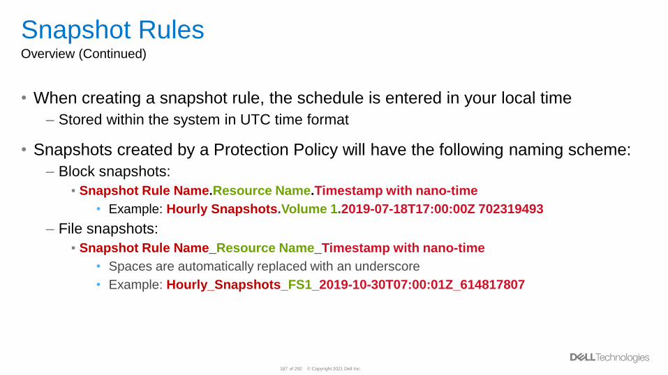
© Copyright 2021 Dell Inc.187 of 292
Snapshot RulesOverview (Continued)
• When creating a snapshot rule, the schedule is entered in your local time
– Stored within the system in UTC time format
• Snapshots created by a Protection Policy will have the following naming scheme:
– Block snapshots:
▪ Snapshot Rule Name.Resource Name.Timestamp with nano-time
• Example: Hourly Snapshots.Volume 1.2019-07-18T17:00:00Z 702319493
– File snapshots:
▪ Snapshot Rule Name_Resource Name_Timestamp with nano-time
• Spaces are automatically replaced with an underscore
• Example: Hourly_Snapshots_FS1_2019-10-30T07:00:01Z_614817807
© Copyright 2021 Dell Inc.188 of 292
Snapshot RulesModifying and Deleting Snapshot Rules
• A Snapshot Rule can be edited at any point in time, even while in use
– Storage resources will automatically inherit the new settings once the rule is updated
within the Protection Policy
– If the Retention is changed, all existing snapshots created by the rule will be updated
• A Snapshot Rule cannot be deleted while assigned to a Protection Policy
• When deleting a Snapshot Rule, the user is provided the option to delete all
snapshots created by that rule
– Checkbox (Disabled by default)
© Copyright 2021 Dell Inc.189 of 292
Restore OperationOverview
• The restore operation is used to replace the contents of a parent storage resource
with data from an associated snapshot
– Returns the parent resource to a previous point in time of itself
– Only pointer updates occur (near instantaneous)
– Snapshot/Thin Clone hierarchy is preserved
• When completing a restore operation, it is highly suggested to:
– Take a backup snapshot of the resource before proceeding
▪ Within the GUI, a checkbox is provided to take a backup snapshot before proceeding with the
restore operation (Enabled by default)
– To prevent data corruption during the restore, it is recommended that you first quiesce
any applications running on the production host and flush the host cache
• For virtual volumes, utilize vSphere to revert to a previous snapshot
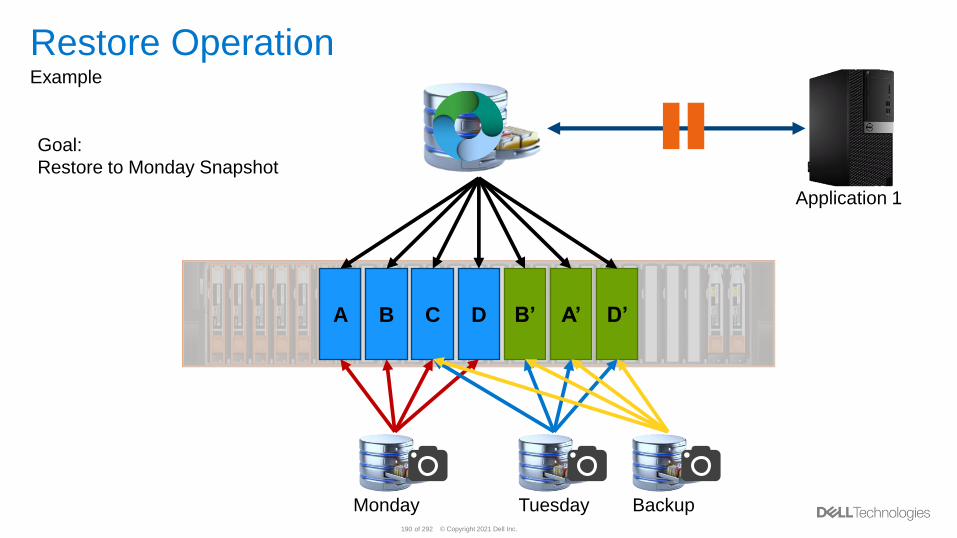
© Copyright 2021 Dell Inc.190 of 292
Application 1
Restore OperationExample
D’A’B’DCBA
Monday Tuesday
Goal:
Restore to Monday Snapshot
Backup
© Copyright 2021 Dell Inc.191 of 292
Volume/Volume Group Refresh OperationOverview
• The refresh operation is used to replace the contents of a resource with data from
a resource within the same family
– Only pointer updates occur (near instantaneous)
– Snapshot/Thin Clone hierarchy is preserved
• When completing a refresh operation, it is highly suggested to:
– Take a backup snapshot of the resource before proceeding
▪ Within the GUI, a checkbox is provided to take a backup snapshot before proceeding with the
refresh operation (Enabled by default)
– To prevent data corruption during the refresh, it is recommended that you first quiesce
any applications running on the production host and flush the host cache
• Snapshots of Volumes, Volume Groups, and Thin Clones cannot be refreshed
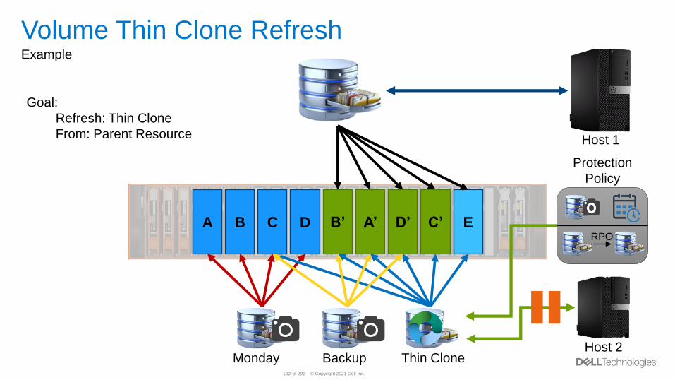
© Copyright 2021 Dell Inc.192 of 292
Host 1
Volume Thin Clone RefreshExample
Monday Thin Clone
D’A’B’DCBA EC’RPO
Protection
Policy
Host 2
Goal:
Refresh: Thin Clone
From: Parent Resource
Backup
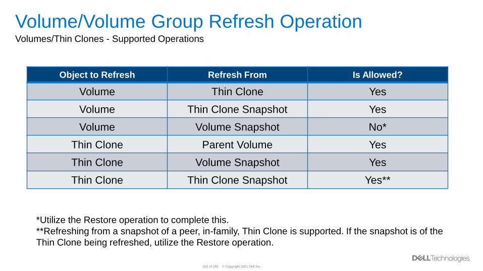
© Copyright 2021 Dell Inc.193 of 292
Volume/Volume Group Refresh OperationVolumes/Thin Clones - Supported Operations
Object to Refresh Refresh From Is Allowed?
Volume Thin Clone Yes
Volume Thin Clone Snapshot Yes
Volume Volume Snapshot No*
Thin Clone Parent Volume Yes
Thin Clone Volume Snapshot Yes
Thin Clone Thin Clone Snapshot Yes**
*Utilize the Restore operation to complete this.
**Refreshing from a snapshot of a peer, in-family, Thin Clone is supported. If the snapshot is of the
Thin Clone being refreshed, utilize the Restore operation.
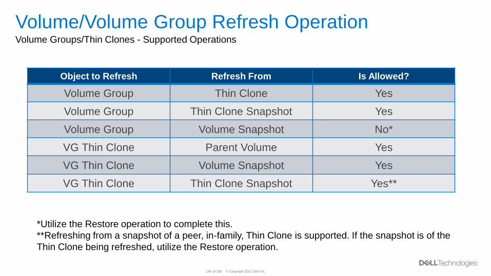
© Copyright 2021 Dell Inc.194 of 292
Volume/Volume Group Refresh OperationVolume Groups/Thin Clones - Supported Operations
Object to Refresh Refresh From Is Allowed?
Volume Group Thin Clone Yes
Volume Group Thin Clone Snapshot Yes
Volume Group Volume Snapshot No*
VG Thin Clone Parent Volume Yes
VG Thin Clone Volume Snapshot Yes
VG Thin Clone Thin Clone Snapshot Yes**
*Utilize the Restore operation to complete this.
**Refreshing from a snapshot of a peer, in-family, Thin Clone is supported. If the snapshot is of the
Thin Clone being refreshed, utilize the Restore operation.
© Copyright 2021 Dell Inc.195 of 292
File System Refresh OperationOverview
• A file system or file system thin clone refresh operation replaces the contents of a
snapshot with the current view of the parent object
– Only pointer updates occur (near instantaneous)
– Snapshot/Thin Clone hierarchy is preserved
• When completing a refresh operation, it is highly suggested to:
– Take a backup snapshot of the resource before proceeding
▪ Within the GUI, a checkbox is provided to take a backup snapshot before proceeding with the
refresh operation (Enabled by default)
– To prevent data corruption during the refresh, it is recommended that you first quiesce
any applications running on the production host and flush the host cache
© Copyright 2021 Dell Inc.196 of 292
File System Refresh OperationOverview – File Systems
• When refreshing a file system snapshot
– The creation time of the snapshot is preserved, and the Last Refresh Time value is
updated
– Host accessing the restored snapshot will not know that it was refreshed (The original
creation date/time preserved)
• File system Thin Clones behave the same way
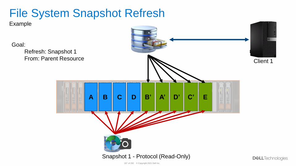
© Copyright 2021 Dell Inc.197 of 292
Client 1
File System Snapshot RefreshExample
Snapshot 1 - Protocol (Read-Only)
D’A’B’DCBA EC’
Goal:
Refresh: Snapshot 1
From: Parent Resource
© Copyright 2021 Dell Inc.198 of 292
Thin Clones
© Copyright 2021 Dell Inc.199 of 292
Thin ClonesOverview
• A Thin Clone is a read-write copy of a resource that shares blocks with the parent
resource
• Thin Clones are not full copies of the original data
– Pointer based, redirect on write technology
– Creating a Thin Clone is near instantaneous
• Protection Policies can be assigned to Thin Clones
– Allows the Thin Clone to be protected during usage
– The Protection Policy can be different than the one assigned to the source
© Copyright 2021 Dell Inc.200 of 292
Thin ClonesOverview (Continued)
• A Thin Clone of a Volume, Volume Group (VG) or File System can be created
using the latest image of the Volume, File System, Snapshot, or another Thin
Clone
– The Thin Clone is automatically assigned to the same NAS Server
• When created, the Thin Clone is displayed in the same page as the parent
resource
• Parent resources can be deleted without deleting the associated Thin Clone
– No blocks used by the Thin Clone are removed
– The Thin Clone becomes its own resource
– Only unique blocks within the parent resource and snapshots will be reclaimed
© Copyright 2021 Dell Inc.201 of 292
Thin ClonesUse Cases
• Test and development environments
– Ability to create multiple copies of the same data for multiple teams
– When used with a Protection Policy, ability to replicate* and create snapshots
▪ *If replication is supported
• Parallel processing
– Ability to create and provide multiple copies of the same data to multiple servers/clients
for parallel processing
• System deployment
– Quickly utilize a common image to easily deploy new environments
© Copyright 2021 Dell Inc.202 of 292
Block Remote Replication
© Copyright 2021 Dell Inc.203 of 292
OverviewUse Cases - Remote Data Protection
• Redundancy– Increase data redundancy and fault tolerance levels
– Failover to a secondary site
• Compliance– Require additional footprint.
– for instance insurance companies, bank, and government sites
• Migration– Migrate data between storage systems
– Tech Refresh
© Copyright 2021 Dell Inc.204 of 292
Replication ConceptsSupported Replication with PowerStore T / PowerStore X
• Supports PowerStore T model Arrays and PowerStore X model Arrays – also mixed
• RPO based Asynchronous Remote Replication
The acceptable amount of data, measured in units of time, which may be lost due to a failure
– With RPO the also frequency of synchronization between Source and Destination is defined
– Factor of time, not amount of changed data
– PowerStore supports fixed RPO values between 5min and 24hr
• Replication is supported for following Storage Resources
– Volumes
– Volume Groups
– Thin Clones
• IP based only
• Policy based
• Leverage PowerStore Snapshot technology
© Copyright 2021 Dell Inc.205 of 292
Replication TopologiesOverview
Supported Replication Topologies with PowerStore platform
• One-to-One (1:1)– Uni Directional
▪ One or multiple Volumes are replicated from one cluster to one other cluster
– Bi-Directional
▪ Various Volumes are replicated in different directions between two clusters
• One-to-many (1:n)– Different Volumes are replicating to multiple destination clusters
– No Support for fan-out or cascaded/chain replication
• Many-to-One (n:1)– Individual Volumes from different cluster are replicating to a single cluster
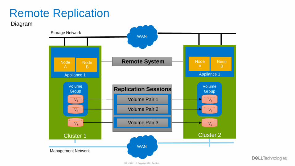
© Copyright 2021 Dell Inc.207 of 292
Remote ReplicationDiagram
Management NetworkWAN
Storage NetworkWAN
Remote System Node A
Node B
Appliance 1
Cluster 2
Node A
Node B
Appliance 1
Cluster 1
V1
V2
V3
Volume
Group
V1
V2
V3
Volume
Group Replication Sessions
Volume Pair 3
Volume Pair 2
Volume Pair 1
• Clustername
• Connection for
- Management
- Data
• SSL Certificates
• Latency
Manage Replication
• Volume Pair
• Policy & Rule
• RPO
• Systems
Replication Sessions
Volume Pair 3
Volume Pair 2
Volume Pair 1

© Copyright 2021 Dell Inc.208 of 292
Replication Data ConnectionNetwork Port
• Replication Traffic is routed via Storage Network and their corresponding Network Interfaces
• One individual Port or system bond mapped for Storage Network can be tagged for replication
traffic. Default is bond0 / first two ports on Mezz Card and share host-, and replication workload
• Source and Destination System may use different configuration, but symmetric port tagging on
Nodes within same Appliance
• As replication Port can be tagged
on IP Ports located on
– Mezz Card Ethernet Ports
– Ethernet I/O Modules
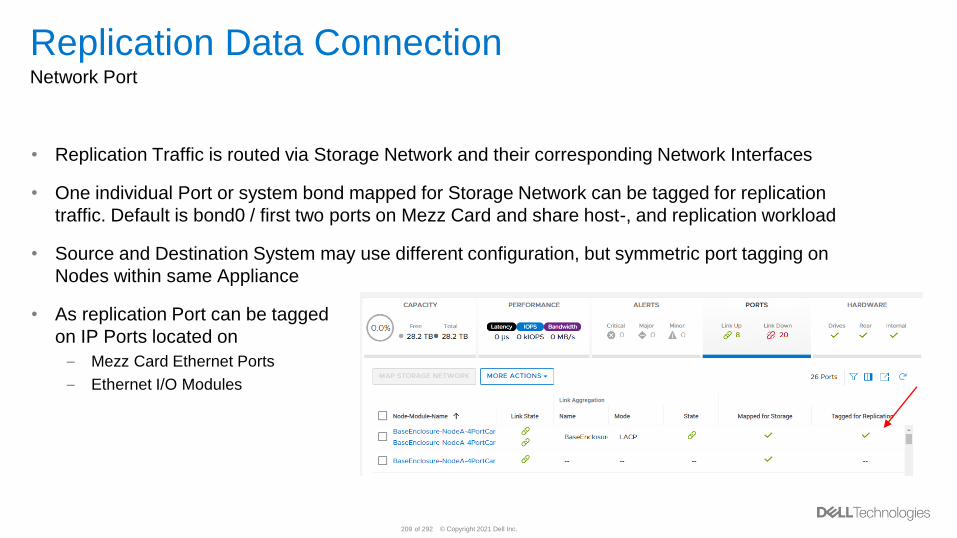
© Copyright 2021 Dell Inc.209 of 292
Replication Data ConnectionNetwork Port
• Replication Traffic is routed via Storage Network and their corresponding Network Interfaces
• One individual Port or system bond mapped for Storage Network can be tagged for replication
traffic. Default is bond0 / first two ports on Mezz Card and share host-, and replication workload
• Source and Destination System may use different configuration, but symmetric port tagging on
Nodes within same Appliance
• As replication Port can be tagged
on IP Ports located on
– Mezz Card Ethernet Ports
– Ethernet I/O Modules
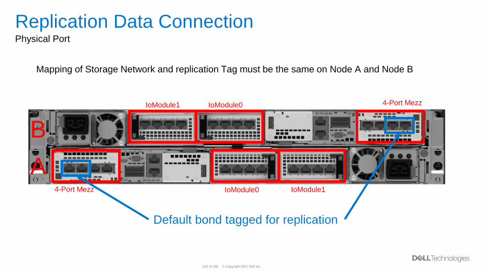
© Copyright 2021 Dell Inc.210 of 292
Replication Data ConnectionPhysical Port
Mapping of Storage Network and replication Tag must be the same on Node A and Node B
4-Port Mezz
IoModule0
IoModule0
IoModule1
IoModule1
A
B
Default bond tagged for replication
4-Port Mezz
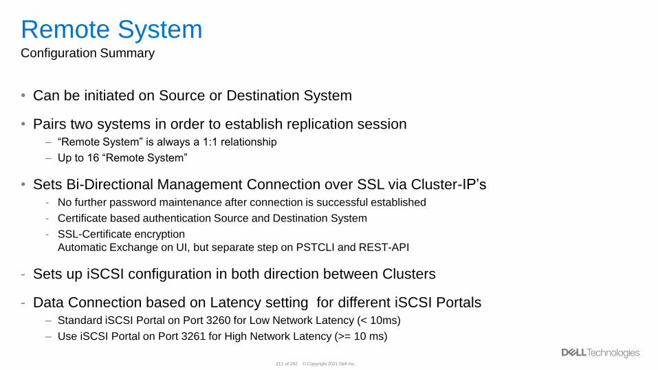
© Copyright 2021 Dell Inc.211 of 292
Remote SystemConfiguration Summary
• Can be initiated on Source or Destination System
• Pairs two systems in order to establish replication session– “Remote System” is always a 1:1 relationship
– Up to 16 “Remote System”
• Sets Bi-Directional Management Connection over SSL via Cluster-IP’s- No further password maintenance after connection is successful established
- Certificate based authentication Source and Destination System
- SSL-Certificate encryption
Automatic Exchange on UI, but separate step on PSTCLI and REST-API
- Sets up iSCSI configuration in both direction between Clusters
- Data Connection based on Latency setting for different iSCSI Portals – Standard iSCSI Portal on Port 3260 for Low Network Latency (< 10ms)
– Use iSCSI Portal on Port 3261 for High Network Latency (>= 10 ms)
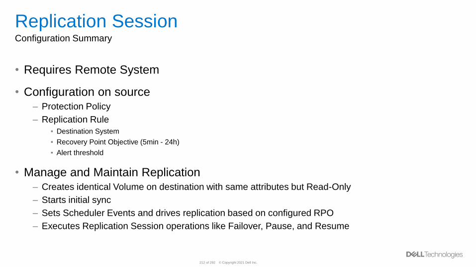
© Copyright 2021 Dell Inc.212 of 292
Replication SessionConfiguration Summary
• Requires Remote System
• Configuration on source– Protection Policy
– Replication Rule
▪ Destination System
▪ Recovery Point Objective (5min - 24h)
▪ Alert threshold
• Manage and Maintain Replication– Creates identical Volume on destination with same attributes but Read-Only
– Starts initial sync
– Sets Scheduler Events and drives replication based on configured RPO
– Executes Replication Session operations like Failover, Pause, and Resume
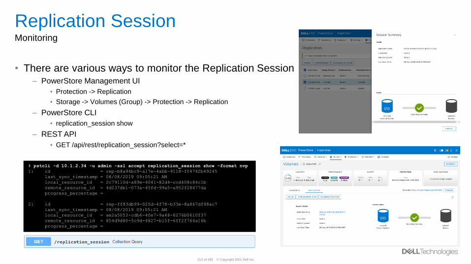
© Copyright 2021 Dell Inc.213 of 292
Replication SessionMonitoring
• There are various ways to monitor the Replication Session– PowerStore Management UI
▪ Protection -> Replication
▪ Storage -> Volumes (Group) -> Protection -> Replication
– PowerStore CLI
▪ replication_session show
– REST API
▪ GET /api/rest/replication_session?select=*
# pstcli -d 10.1.2.34 -u admin -ssl accept replication_session show –format nvp
1: id = rep-b8a94bc9-a17e-4abb-9118-ff4742b49245
last_sync_timestamp = 08/08/2019 09:05:21 AM
local_resource_id = 2c79110d-a89e-4041-82d4-ccd408c84c1b
remote_resource_id = 4d237db1-073a-45fd-99a5-a952f28477da
progress_percentage =
2: id = rep-ff83db99-025d-4f78-b33e-8a867df98ac7
last_sync_timestamp = 08/08/2019 09:05:21 AM
local_resource_id = ae2a5053-cdb6-4fe7-9a48-8276b0610f37
remote_resource_id = 854d9d80-5c9d-4827-b15f-6ff2f764a16b
progress_percentage =
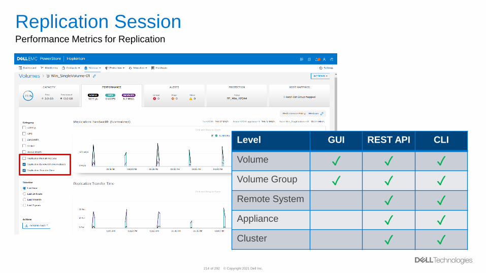
© Copyright 2021 Dell Inc.214 of 292
Replication SessionPerformance Metrics for Replication
Level GUI REST API CLI
Volume ✓ ✓ ✓
Volume Group ✓ ✓ ✓
Remote System ✓ ✓
Appliance ✓ ✓
Cluster ✓ ✓
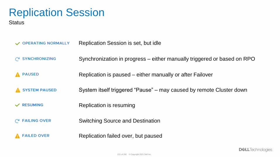
© Copyright 2021 Dell Inc.215 of 292
Replication SessionStatus
Replication Session is set, but idle
Synchronization in progress – either manually triggered or based on RPO
Replication is paused – either manually or after Failover
Replication failed over, but paused
Switching Source and Destination
System itself triggered “Pause” – may caused by remote Cluster down
Replication is resuming
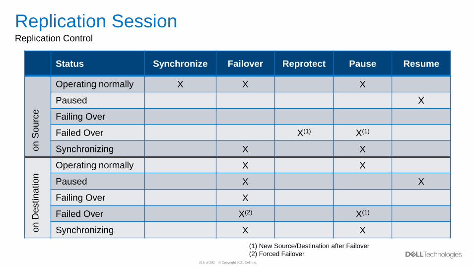
© Copyright 2021 Dell Inc.216 of 292
Replication SessionReplication Control
Status Synchronize Failover Reprotect Pause Resume
on
So
urc
e
Operating normally X X X
Paused X
Failing Over
Failed Over X(1) X(1)
Synchronizing X X
on
De
stin
atio
n
Operating normally X X
Paused X X
Failing Over X
Failed Over X(2) X(1)
Synchronizing X X
(1) New Source/Destination after Failover
(2) Forced Failover
© Copyright 2021 Dell Inc.217 of 292
Replication SessionDR aspects
• When Session is DR Failing-Over– Replication Session can be Deleted
– All other operations are restricted
• When in Failed-over state– Volume could be resized on DR Site volume
– Volume Group membership could be changed on DR site Volume Group
– Possible to Reprotect
– Possible to Delete session
– Issue Snapshot
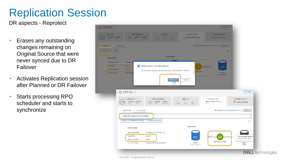
© Copyright 2021 Dell Inc.218 of 292
Replication SessionDR aspects - Reprotect
• Erases any outstanding
changes remaining on
Original Source that were
never synced due to DR
Failover
• Activates Replication session
after Planned or DR Failover
• Starts processing RPO
scheduler and starts to
synchronize
© Copyright 2021 Dell Inc.219 of 292
Replication SessionConclusion - Protection Policy
• A Protection Policy can be assigned only on Source– During creation of Volumes or Volume Groups (VG), or
– On existing Volumes or VG
• Removal of a Protection Policy is only possible on Source – Independent from current State
• Size changes on Source are replicated to Destination
other attributes can/must be modified on Source and Destination individually
• A Volume remains on Destination when Protection Policy with Replication Rule
is removed on a Volume / VG
© Copyright 2021 Dell Inc.220 of 292
Replication SessionConclusion - Protection Policy
• Volume Groups (VG)– Only Volumes without Protection Policy can be added into a VG
– Protection Policy need to be assigned to whole VG
– New Volumes in a VG inherit Replication Policy
• Snapshots– Snapshots on Source are replicated in chronological order during RPO sync
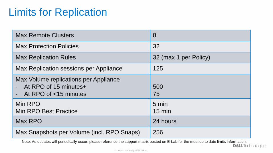
© Copyright 2021 Dell Inc.221 of 292
Limits for Replication
Max Remote Clusters 8
Max Protection Policies 32
Max Replication Rules 32 (max 1 per Policy)
Max Replication sessions per Appliance 125
Max Volume replications per Appliance
- At RPO of 15 minutes+
- At RPO of <15 minutes
500
75
Min RPO
Min RPO Best Practice
5 min
15 min
Max RPO 24 hours
Max Snapshots per Volume (incl. RPO Snaps) 256
Note: As updates will periodically occur, please reference the support matrix posted on E-Lab for the most up to date limits information.
© Copyright 2021 Dell Inc.222 of 292
PowerStore metro node
© Copyright 2021 Dell Inc.223 of 292
Introducing PowerStore metro nodeHardware add-on feature for PowerStore (block storage)
• Enables automated business continuity with zero Recovery Point Objective (RPO)
and Recovery Time Objective (RTO)– Zero RPO means there’s an expectation for zero data loss
– Zero RTO means that there is no loss of data access
• Provides true active-active synchronous replication over metro distances
• Provides the ability to automatically initiate an instant site failover through its
unique virtual machine (VM) witness technology (expected FY 2022 Q2)
• Also supports local configurations for – Continuous application availability
– Data mobility to non-disruptively relocate workloads
– Provides storage technology refresh without application downtime
© Copyright 2021 Dell Inc.224 of 292
Key features and functionality• Low cost and designed for six 9’s availability
• Configurations– Metro node metro - two clusters supported within 5ms distance
▪ Up to 10 ms depending on application
– Metro node local allows mirroring for two arrays within a data center
▪ Or mirroring across appliances within PowerStore multi-appliance cluster
• 32 Gb/s Fibre Channel support (16Gb/s supported now, 32Gb/s expected FY 2022 Q2)
• 64TB virtual volume support
• Embedded management server
• Support for Ansible 1.1 automation
• Events alerts and support– iDrac based HW monitoring
– Dial home support
• FRU support
© Copyright 2021 Dell Inc.225 of 292
Hardware componentsMetro node Hardware Configuration
• Based on proven Dell EMC hardware technology– Intel Xeon Silver 4208 CPUs (8 cores per CPU), Dual CPU
– 64GB RDIMM Memory, 2 x 16GB DIMMs per CPU
– 480GB SATA Solid State Drive, read intensive, < 1 DWPD
▪ Using UEFI Boot
– 8x 2.5” Drive Chassis (no PERC/RAID support)
– Basic PE Bezel w/no LCD with metro node brand insert
• IO Adapter configuration targeting– Three PCIe Low Profile IO Cards
– One NDC (Network Daughter Card)
• BMC (Baseboard Management Controller)– iDRAC 9 Enterprise / racadm cli interface
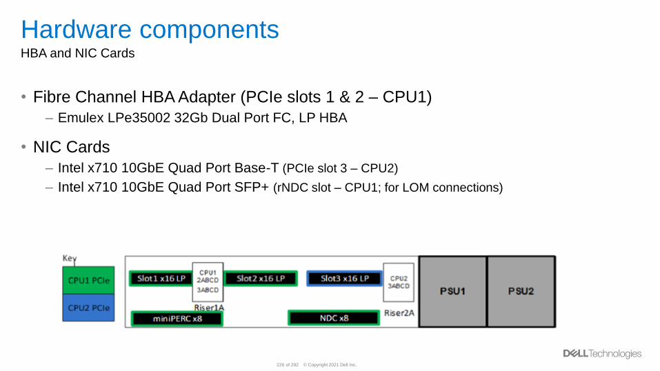
© Copyright 2021 Dell Inc.226 of 292
Hardware componentsHBA and NIC Cards
• Fibre Channel HBA Adapter (PCIe slots 1 & 2 – CPU1)
– Emulex LPe35002 32Gb Dual Port FC, LP HBA
• NIC Cards
– Intel x710 10GbE Quad Port Base-T (PCIe slot 3 – CPU2)
– Intel x710 10GbE Quad Port SFP+ (rNDC slot – CPU1; for LOM connections)
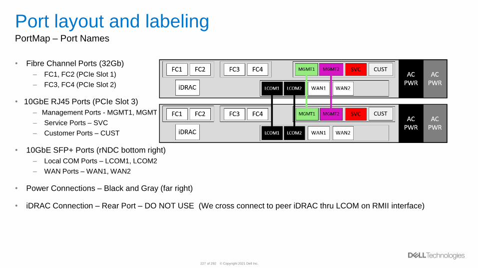
© Copyright 2021 Dell Inc.227 of 292
Port layout and labelingPortMap – Port Names
• Fibre Channel Ports (32Gb)
– FC1, FC2 (PCIe Slot 1)
– FC3, FC4 (PCIe Slot 2)
• 10GbE RJ45 Ports (PCIe Slot 3)
– Management Ports - MGMT1, MGMT2
– Service Ports – SVC
– Customer Ports – CUST
• 10GbE SFP+ Ports (rNDC bottom right)
– Local COM Ports – LCOM1, LCOM2
– WAN Ports – WAN1, WAN2
• Power Connections – Black and Gray (far right)
• iDRAC Connection – Rear Port – DO NOT USE (We cross connect to peer iDRAC thru LCOM on RMII interface)
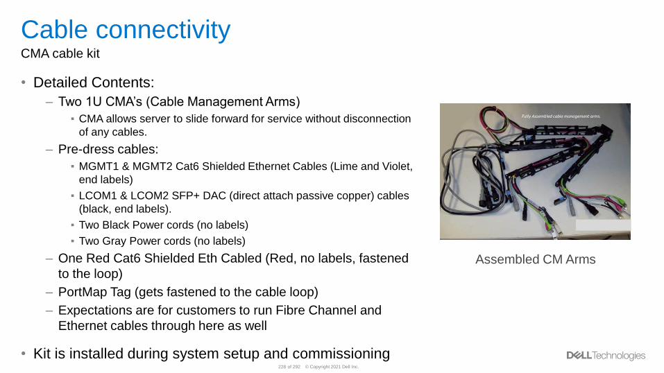
© Copyright 2021 Dell Inc.228 of 292
Cable connectivityCMA cable kit
• Detailed Contents:
– Two 1U CMA’s (Cable Management Arms)
▪ CMA allows server to slide forward for service without disconnection
of any cables.
– Pre-dress cables:
▪ MGMT1 & MGMT2 Cat6 Shielded Ethernet Cables (Lime and Violet,
end labels)
▪ LCOM1 & LCOM2 SFP+ DAC (direct attach passive copper) cables
(black, end labels).
▪ Two Black Power cords (no labels)
▪ Two Gray Power cords (no labels)
– One Red Cat6 Shielded Eth Cabled (Red, no labels, fastened
to the loop)
– PortMap Tag (gets fastened to the cable loop)
– Expectations are for customers to run Fibre Channel and
Ethernet cables through here as well
• Kit is installed during system setup and commissioning
Assembled CM Arms
© Copyright 2021 Dell Inc.229 of 292
Virtualization Integration
© Copyright 2021 Dell Inc.230 of 292
vSphere Integration Overview
• PowerStore features deep vSphere integration which enables:– Discovering VMs
– Managing VM snapshots
– Automatic registration of the VASA Provider (PowerStore X models only)
– Automatic mounting of Storage Containers (PowerStore X models only)
• Benefits:– Perform monitoring and active management from PowerStore Manager
– Monitor events without requiring continuous polling
– Automation for configuration process
• vCenter must be registered in PowerStore Manager to enable this functionality– Each cluster can only be registered to a single vCenter instance at a time
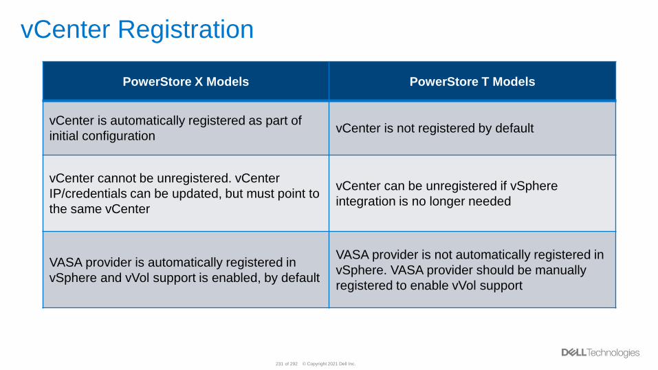
© Copyright 2021 Dell Inc.231 of 292
vCenter Registration
PowerStore X Models PowerStore T Models
vCenter is automatically registered as part of
initial configurationvCenter is not registered by default
vCenter cannot be unregistered. vCenter
IP/credentials can be updated, but must point to
the same vCenter
vCenter can be unregistered if vSphere
integration is no longer needed
VASA provider is automatically registered in
vSphere and vVol support is enabled, by default
VASA provider is not automatically registered in
vSphere. VASA provider should be manually
registered to enable vVol support
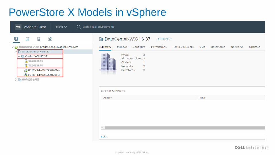
© Copyright 2021 Dell Inc.232 of 292
PowerStore X Models in vSphere
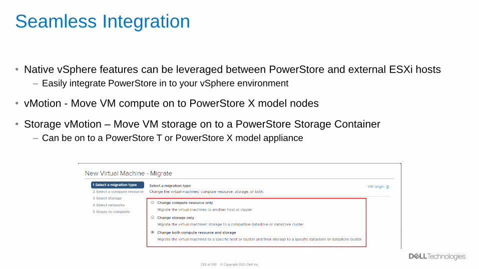
© Copyright 2021 Dell Inc.233 of 292
Seamless Integration
• Native vSphere features can be leveraged between PowerStore and external ESXi hosts
– Easily integrate PowerStore in to your vSphere environment
• vMotion - Move VM compute on to PowerStore X model nodes
• Storage vMotion – Move VM storage on to a PowerStore Storage Container
– Can be on to a PowerStore T or PowerStore X model appliance
© Copyright 2021 Dell Inc.234 of 292
Storage Containers
• PowerStore arrays automatically provision a default Storage Container– Name: PowerStore <Cluster_Name>
• Once the VASA Provider is registered, this Storage Container becomes accessible– Exposes all of the storage available on the cluster as a vVol datastore
– Enables external hosts to use it for VM storage
• Hosts must be registered using iSCSI or Fibre Channel– All registered hosts are automatically provided access to this Storage Container
• Additional Storage Containers can also be created
• A quota can be enabled on Storage Containers– Enables under or over-provisioning capacity to vSphere
– High Water Mark determines when an alert will be generated for the administrator
© Copyright 2021 Dell Inc.235 of 292
VM Details
• PowerStore discovers VM details and displays them in PowerStore
Manager
• Subscribes to VM object change events
– No need for continuous polling
• Available for all vVol-based VMs provisioned on the PowerStore Storage
Containers
– Regardless of internal or external compute
© Copyright 2021 Dell Inc.236 of 292
VM Snapshot Details
• VM Snapshot information is also displayed and can be managed from PowerStore
Manager
– Available for vVol-based VMs that are provisioned on PowerStore’s Storage Containers
– Manual snapshots can be taken and deleted
– Protection policies can be assigned for automatic snapshot creation/deletion
• VMware has a limit of 31 snapshots per VM
– If the limit is reached, the oldest scheduled snapshot is deleted
– Manually created snapshots are never deleted automatically
• PowerStore sends a maximum of 20 simultaneous snapshot operations to vSphere
– Additional operations are queued in order to avoid overloading the system
© Copyright 2021 Dell Inc.237 of 292
VAAI Support
• Block
– Atomic Test & Set (ATS) with Compare and Write (CAW) – Manages locking of files on
shared volumes▪ Enables multiple ESXi hosts to write to the same volume without corruption
– Block Zero – Hardware-assisted zeroing using Write Same▪ Speeds up VM provisioning
– Full Copy – Hardware-assisted copying using XCOPY▪ Saves network traffic by offloading the copy operation to the storage
– Thin Provisioning and Unmap – Free capacity reporting and enables space reclaim▪ Maximizes efficiency by reclaiming unused space
• File VAAI primitives are currently not supported

© Copyright 2021 Dell Inc.238 of 292
VMware Plugins
• Virtual Storage Integrator (VSI) - Enables provisioning, managing, and monitoring
storage from vSphere
• vRealize Operations Manager (vROps) Plugin – Monitor performance, capacity,
and analytics of the PowerStore system along with your virtualized environment
• vRealize Orchestrator (vRO) Plugin – Streamline VMware and PowerStore tasks
through automation workflows
• Storage Replication Adapter (SRA) – Leverage Site Recovery Manager for
VMware disaster recovery
© Copyright 2021 Dell Inc.239 of 292
Serviceability

© Copyright 2021 Dell Inc.240 of 292
PowerStore LicensingAutomatic Licensing
• In PowerStore, the license will be installed
automatically during the Initial Configuration
Wizard– All inclusive license e.g. replication, snapshot,
migration…etc.
• License will be issued to each Appliance in
the cluster– Management will be centralized for the customer to run
from the primary Appliance
– The primary Appliance will be the point of contact for
all the Appliances
• License will be obtained by sending request
to Dell EMC via HTTPS– Port 443 needs to be open
Appliance _1 Appliance _2
PowerStore Cluster
License
File
License
File
Primary
Appliance
Point of
Contact
HT
TP
S
© Copyright 2021 Dell Inc.241 of 292
SupportAssistOverview
• Customers can use SupportAssist to provide remote support from Dell EMC to the
PowerStore cluster in case of issues – Gathering Data Collects
– Troubleshooting
• SupportAssist is a rebranded from ESRS with a new simple Connect Home solution– Same backend of the ESRS channel
– New and simple frontend
– Does NOT require any support account or user’s information
• Each Appliance will be connected directly to Dell EMC– Can enabled from the ICW or from the Settings page
– Centralized management
• SupportAssist types:– Direct Connect
– Gateway Connect
• It should also be noted that CloudIQ supports PowerStore
© Copyright 2021 Dell Inc.242 of 292
Support MaterialsOverview
• Support Materials also known as Data Collects
• To help troubleshoot PowerStore clusters and find what is the issue– System degraded state
– Performance problem
– DU/DL
• Support Materials include:– System logs
– Configuration details
– Diagnostic information
• Collects from both Nodes (A and B)
• Used mainly by Dell EMC
© Copyright 2021 Dell Inc.243 of 292
Disabled Support NotificationOverview
• An administrator can pause the alert notifications that sent to Dell EMC Support
during a maintenance time– E.g. unplugging cables, swapping drives ..etc.
• Disable Support Notifications can disable the call home to one or multiple
Appliance(s) in the cluster– Enabled/disable at anytime
• The Maintenance Window Duration counted by hourly– 1 hour min
– 48 hours max
• The Maintenance Window Duration can be changed at anytime during the suspend
© Copyright 2021 Dell Inc.244 of 292
SSH ManagementOverview
• SSH – Secure shell a cryptographic network protocol
• A user can enable/disable SSH in the Appliances level at any point of time– Login to the primary node
• SSH is enabled by default before the Appliance gets initialize– Once the Appliance is configured SSH is disabled
• Benefits:– Execute service commands in the Appliances
– Run scripts and user CLI commands
© Copyright 2021 Dell Inc.245 of 292
Service ModeOverview – What’s Service Mode?
• PowerStore’s node may encounter hardware or software failures that trigger the
Node unable to boot– E.g. Take SLIC out
• Node would be placed into the Service Mode state if failures occur– E.g. Boot loop, or D@RE lockbox copies are corrupted
• While in Service Mode the Appliances does NOT serve any customer I/O on that
Node– It fail over to the other Node
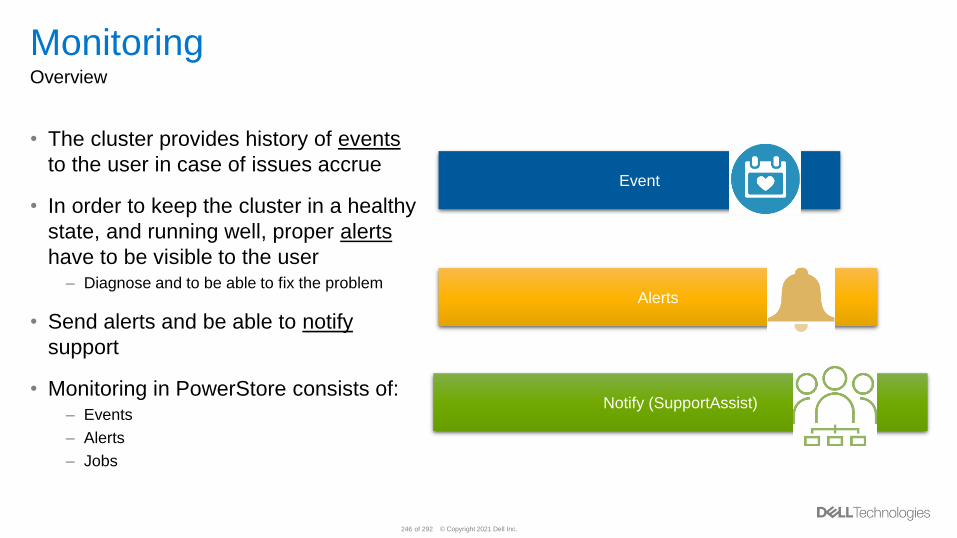
© Copyright 2021 Dell Inc.246 of 292
MonitoringOverview
• The cluster provides history of events
to the user in case of issues accrue
• In order to keep the cluster in a healthy
state, and running well, proper alerts
have to be visible to the user– Diagnose and to be able to fix the problem
• Send alerts and be able to notify
support
• Monitoring in PowerStore consists of:– Events
– Alerts
– Jobs
Event
Alerts
Notify (SupportAssist)
© Copyright 2021 Dell Inc.247 of 292
SMTPOverview
• SMTP (Simple Mail Transfer Protocol) is a TCP/IP protocols used in sending and
receiving e-mail
• The SMTP server is used to send alerts notifications from the PowerStore cluster
to the user’s email address
• It can be enabled and disabled at anytime
• In order to enable SMTP:– Server address
– From Email Address
– Port
• Send Test Email is available to check if the SMTP Server is set up correctly– Send a test email by entering an email address
© Copyright 2021 Dell Inc.248 of 292
Reboot and Power DownOverview
• An administrator has the ability to Reboot and Power down a Single Node in
PowerStore Appliance– Done through the GUI, REST API or service script
– Customers can perform maintenance on their Nodes
▪ Replaced a failed hardware, such as, SLIC or power supply… etc.
• When Reboot or Power Down the Primary Node, the docker containers failover to
the secondary Node– Primary will be switch over to the other Node
• In order to bring a Node back after a Power down, accessing a service script is
required– Running the service script svc_node power_up will power up the nodes
© Copyright 2021 Dell Inc.249 of 292
Non Disruptive Upgrade
• Non-Disruptive Upgrade
• Customer Driven
• Software, Hotfixes and Disk Firmware
• One Node at a Time for Availability
© Copyright 2021 Dell Inc.250 of 292
Security Overview
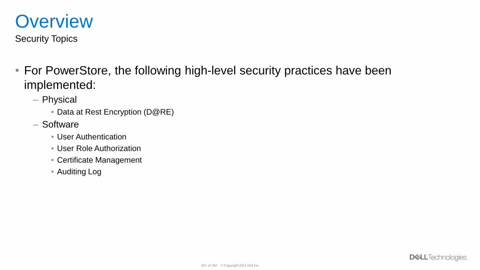
© Copyright 2021 Dell Inc.251 of 292
OverviewSecurity Topics
• For PowerStore, the following high-level security practices have been
implemented:– Physical
▪ Data at Rest Encryption (D@RE)
– Software
▪ User Authentication
▪ User Role Authorization
▪ Certificate Management
▪ Auditing Log
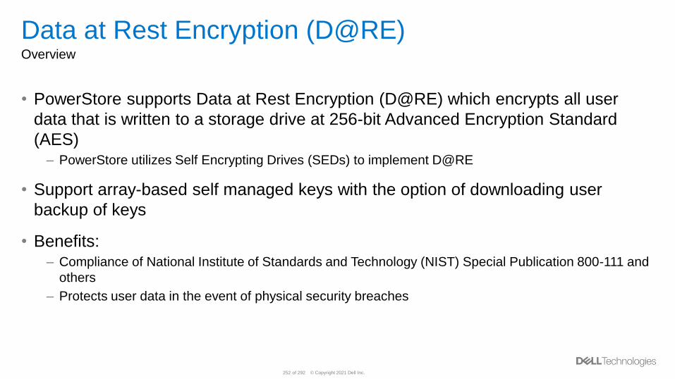
© Copyright 2021 Dell Inc.252 of 292
Data at Rest Encryption (D@RE)Overview
• PowerStore supports Data at Rest Encryption (D@RE) which encrypts all user
data that is written to a storage drive at 256-bit Advanced Encryption Standard
(AES)– PowerStore utilizes Self Encrypting Drives (SEDs) to implement D@RE
• Support array-based self managed keys with the option of downloading user
backup of keys
• Benefits:– Compliance of National Institute of Standards and Technology (NIST) Special Publication 800-111 and
others
– Protects user data in the event of physical security breaches
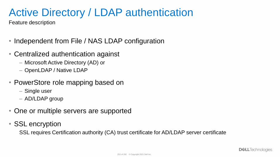
© Copyright 2021 Dell Inc.253 of 292
Active Directory / LDAP authenticationFeature description
• Independent from File / NAS LDAP configuration
• Centralized authentication against– Microsoft Active Directory (AD) or
– OpenLDAP / Native LDAP
• PowerStore role mapping based on– Single user
– AD/LDAP group
• One or multiple servers are supported
• SSL encryptionSSL requires Certification authority (CA) trust certificate for AD/LDAP server certificate
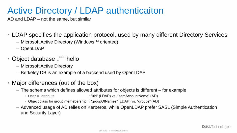
© Copyright 2021 Dell Inc.254 of 292
Active Directory / LDAP authenticaitonAD and LDAP – not the same, but similar
• LDAP specifies the application protocol, used by many different Directory Services– Microsoft Active Directory (WindowsTM oriented)
– OpenLDAP
• Object database „““““hello– Microsoft Active Directory
– Berkeley DB is an example of a backend used by OpenLDAP
• Major differences (out of the box)– The schema which defines allowed attributes for objects is different – for example
▪ User ID attribute : “uid“ (LDAP) vs. “samAccountName“ (AD)
▪ Object class for group memebership : “groupOfNames“ (LDAP) vs. “groups“ (AD)
– Advanced usage of AD relies on Kerberos, while OpenLDAP prefer SASL (Simple Authentication
and Security Layer)
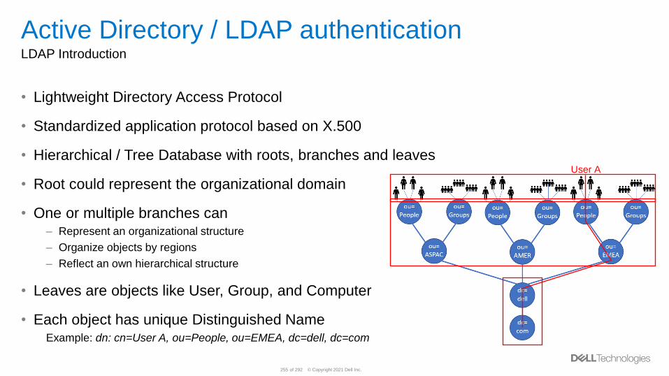
© Copyright 2021 Dell Inc.255 of 292
Active Directory / LDAP authenticationLDAP Introduction
• Lightweight Directory Access Protocol
• Standardized application protocol based on X.500
• Hierarchical / Tree Database with roots, branches and leaves
• Root could represent the organizational domain
• One or multiple branches can– Represent an organizational structure
– Organize objects by regions
– Reflect an own hierarchical structure
• Leaves are objects like User, Group, and Computer
• Each object has unique Distinguished NameExample: dn: cn=User A, ou=People, ou=EMEA, dc=dell, dc=com
User A
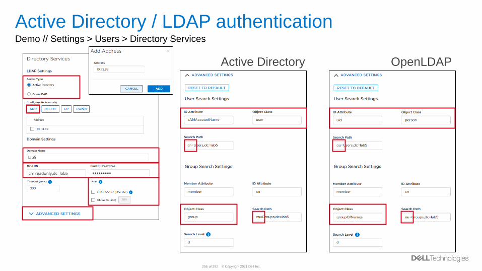
© Copyright 2021 Dell Inc.256 of 292
Active Directory / LDAP authenticationDemo // Settings > Users > Directory Services
Active Directory OpenLDAP
lab5
cn=readonly,dc=lab5 •••••••••
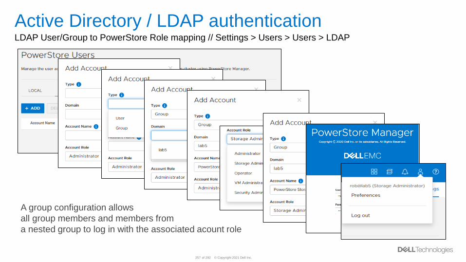
© Copyright 2021 Dell Inc.257 of 292
Active Directory / LDAP authenticationLDAP User/Group to PowerStore Role mapping // Settings > Users > Users > LDAP
A group configuration allows
all group members and members from
a nested group to log in with the associated acount role
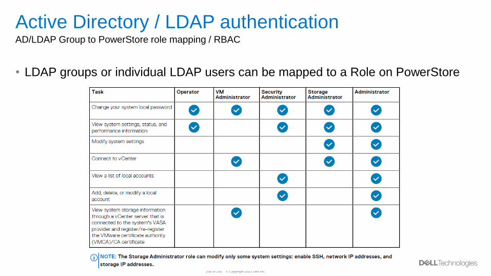
© Copyright 2021 Dell Inc.258 of 292
Active Directory / LDAP authenticationAD/LDAP Group to PowerStore role mapping / RBAC
• LDAP groups or individual LDAP users can be mapped to a Role on PowerStore
© Copyright 2021 Dell Inc.259 of 292
Import External Storage
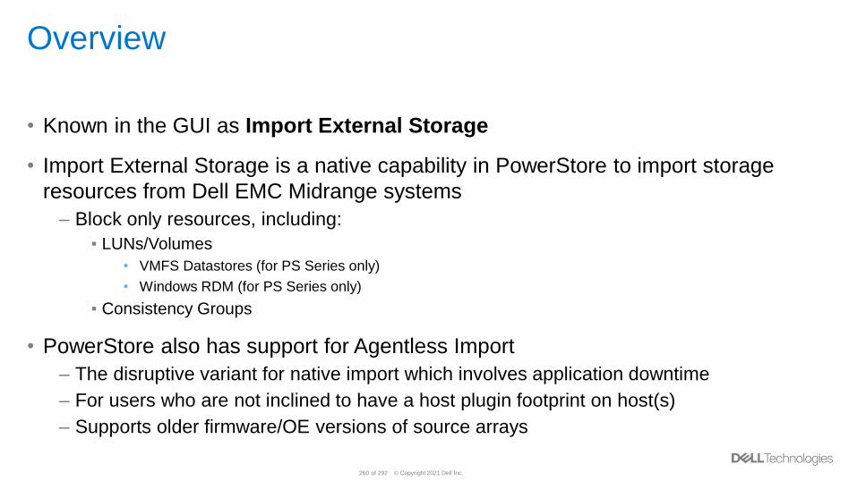
© Copyright 2021 Dell Inc.260 of 292
Overview
• Known in the GUI as Import External Storage
• Import External Storage is a native capability in PowerStore to import storage
resources from Dell EMC Midrange systems
– Block only resources, including:
▪ LUNs/Volumes
• VMFS Datastores (for PS Series only)
• Windows RDM (for PS Series only)
▪ Consistency Groups
• PowerStore also has support for Agentless Import
– The disruptive variant for native import which involves application downtime
– For users who are not inclined to have a host plugin footprint on host(s)
– Supports older firmware/OE versions of source arrays
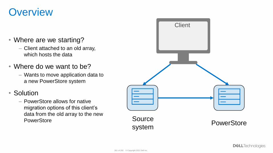
© Copyright 2021 Dell Inc.261 of 292
Overview
• Where are we starting?– Client attached to an old array,
which hosts the data
• Where do we want to be?– Wants to move application data to
a new PowerStore system
• Solution– PowerStore allows for native
migration options of this client’s
data from the old array to the new
PowerStore Source
systemPowerStore
Client
© Copyright 2021 Dell Inc.262 of 292
Overview Use cases
• Data migration–Move your data to a future proven
infrastructure, PowerStore
• Application migration–Move your existing applications to
PowerStore
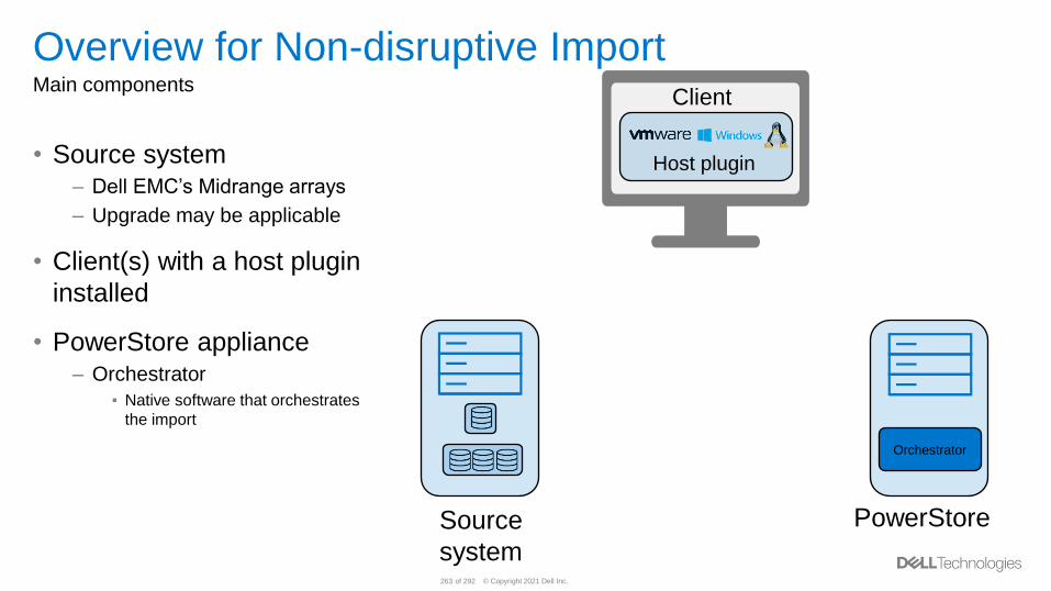
© Copyright 2021 Dell Inc.263 of 292
Overview for Non-disruptive ImportMain components
• Source system– Dell EMC’s Midrange arrays
– Upgrade may be applicable
• Client(s) with a host plugin
installed
• PowerStore appliance– Orchestrator
▪ Native software that orchestrates
the import
Source
system
PowerStore
Client
Host plugin
Orchestrator
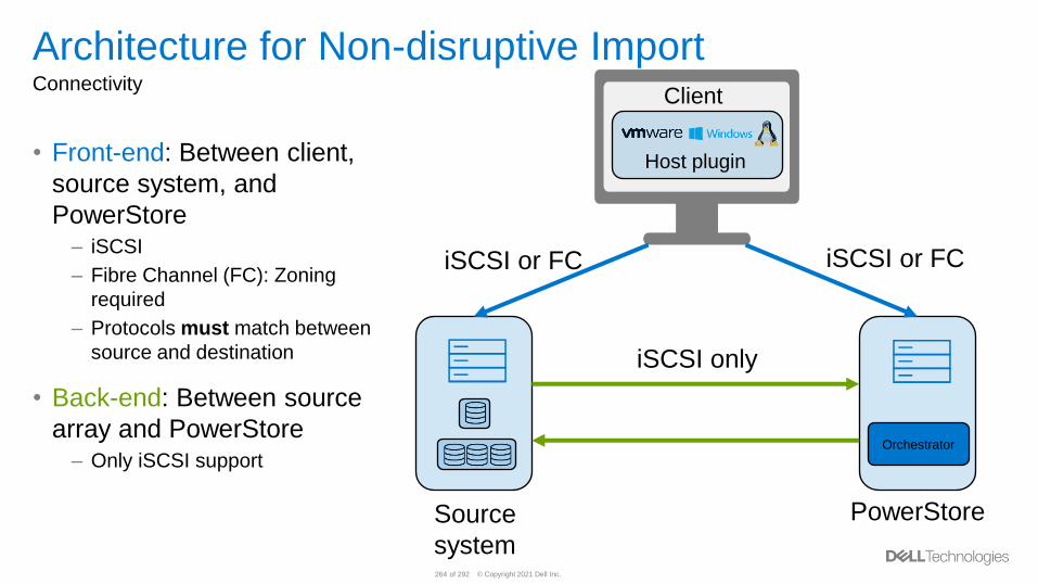
© Copyright 2021 Dell Inc.264 of 292
Architecture for Non-disruptive ImportConnectivity
• Front-end: Between client,
source system, and
PowerStore– iSCSI
– Fibre Channel (FC): Zoning
required
– Protocols must match between
source and destination
• Back-end: Between source
array and PowerStore– Only iSCSI support
Source
system
PowerStore
Client
Host plugin
iSCSI or FC iSCSI or FC
iSCSI only
Orchestrator
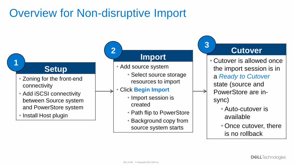
© Copyright 2021 Dell Inc.265 of 292
Overview for Non-disruptive Import
Setup• Zoning for the front-end
connectivity
• Add iSCSI connectivity
between Source system
and PowerStore system
• Install Host plugin
Cutover
• Cutover is allowed once
the import session is in
a Ready to Cutover
state (source and
PowerStore are in-
sync)
• Auto-cutover is
available
• Once cutover, there
is no rollback
1
3
Import• Add source system
• Select source storage
resources to import
• Click Begin Import
• Import session is
created
• Path flip to PowerStore
• Background copy from
source system starts
2
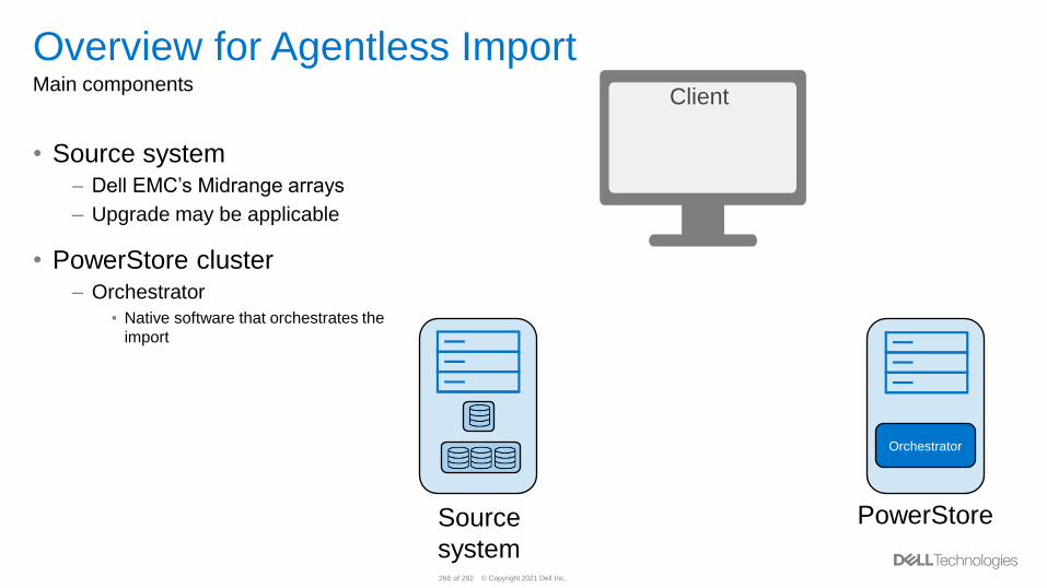
© Copyright 2021 Dell Inc.266 of 292
Overview for Agentless ImportMain components
• Source system– Dell EMC’s Midrange arrays
– Upgrade may be applicable
• PowerStore cluster– Orchestrator
▪ Native software that orchestrates the
import
Source
system
PowerStore
Client
Orchestrator
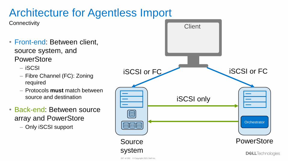
© Copyright 2021 Dell Inc.267 of 292
Architecture for Agentless ImportConnectivity
• Front-end: Between client,
source system, and
PowerStore– iSCSI
– Fibre Channel (FC): Zoning
required
– Protocols must match between
source and destination
• Back-end: Between source
array and PowerStore– Only iSCSI support
Source
system
PowerStore
Client
iSCSI or FC iSCSI or FC
iSCSI only
Orchestrator
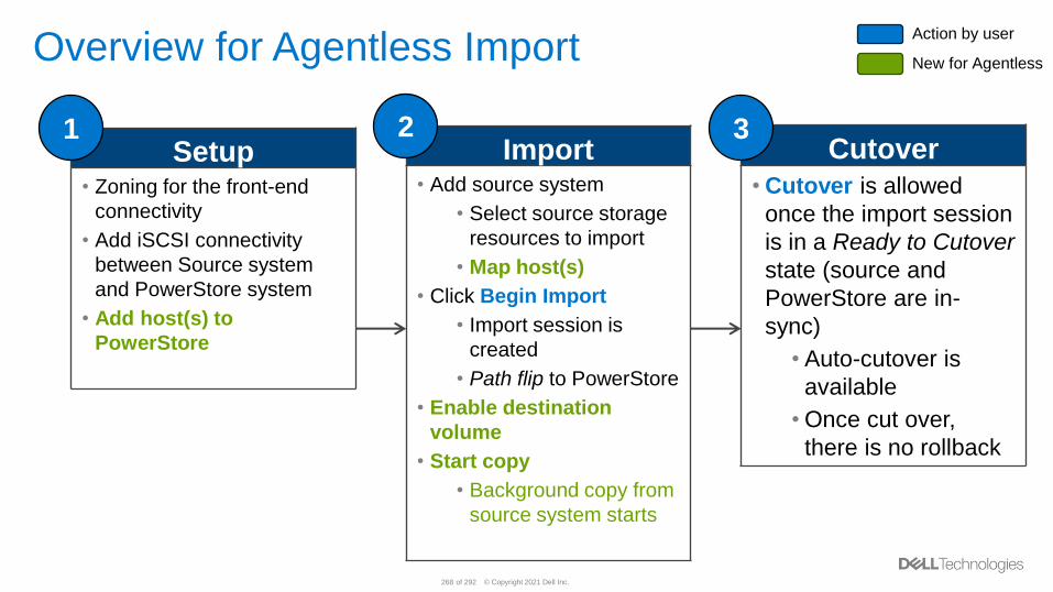
© Copyright 2021 Dell Inc.268 of 292
Overview for Agentless Import
Setup• Zoning for the front-end
connectivity
• Add iSCSI connectivity
between Source system
and PowerStore system
• Add host(s) to
PowerStore
Cutover
• Cutover is allowed
once the import session
is in a Ready to Cutover
state (source and
PowerStore are in-
sync)
• Auto-cutover is
available
• Once cut over,
there is no rollback
1 3Import
• Add source system
• Select source storage
resources to import
• Map host(s)
• Click Begin Import
• Import session is
created
• Path flip to PowerStore
• Enable destination
volume
• Start copy
• Background copy from
source system starts
2
Action by user
New for Agentless
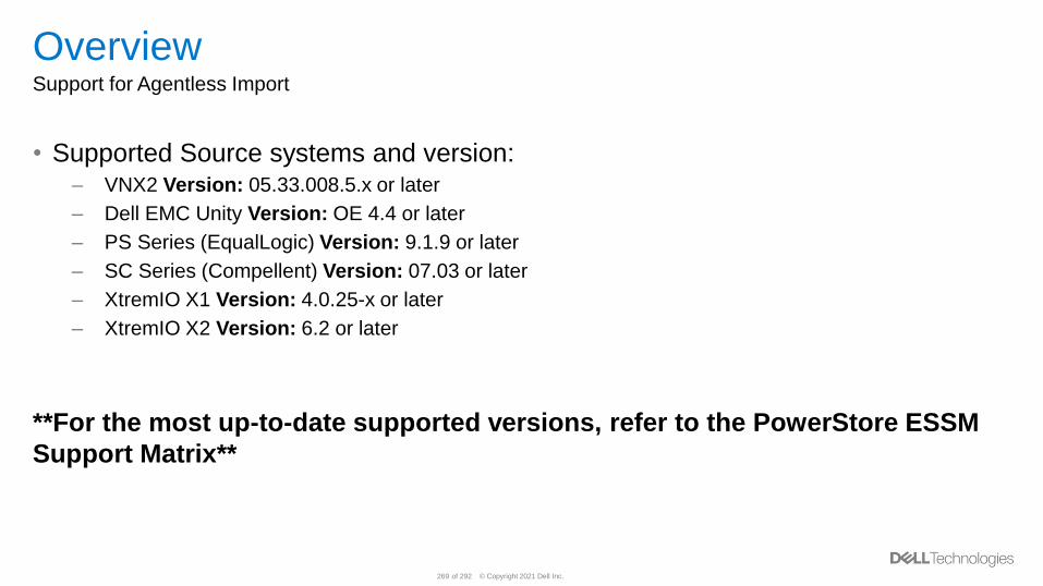
© Copyright 2021 Dell Inc.269 of 292
OverviewSupport for Agentless Import
• Supported Source systems and version:– VNX2 Version: 05.33.008.5.x or later
– Dell EMC Unity Version: OE 4.4 or later
– PS Series (EqualLogic) Version: 9.1.9 or later
– SC Series (Compellent) Version: 07.03 or later
– XtremIO X1 Version: 4.0.25-x or later
– XtremIO X2 Version: 6.2 or later
**For the most up-to-date supported versions, refer to the PowerStore ESSM
Support Matrix**

© Copyright 2021 Dell Inc.270 of 292
OverviewSupport for Non-disruptive Import
Operating System OS VersionMultipath Module
VNX2 PS Series Dell EMC Unity SC Series
iSCSI FC-FE FC-BE iSCSI iSCSI FC-FE FC-BE iSCSI FC-FE FC-BE
VMware vSphere 6.7DC Array Plugin
EQL MPIO NA NA NA
Linux SLES 15DC Array Plugin
EQL MPIO NA NA NA
New PowerStoreOS 2.0
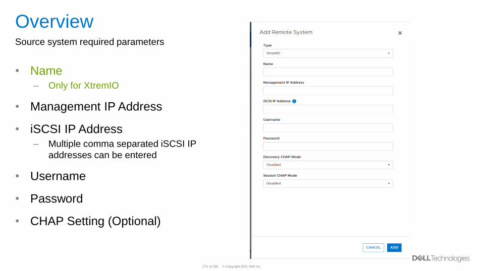
© Copyright 2021 Dell Inc.271 of 292
OverviewSource system required parameters
• Name– Only for XtremIO
• Management IP Address
• iSCSI IP Address– Multiple comma separated iSCSI IP
addresses can be entered
• Username
• Password
• CHAP Setting (Optional)
© Copyright 2021 Dell Inc.272 of 292
Dell Technologies Services for PowerStore
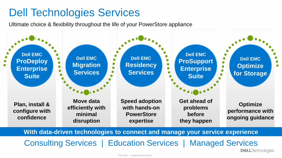
© Copyright 2021 Dell Inc.273 of 292© Copyright 2020 Dell Inc.
273Internal Use - Confidential
Speed adoption
with hands-on
PowerStore
expertise
Optimize
performance with
ongoing guidance
Plan, install &
configure with
confidence
Move data
efficiently with
minimal
disruption
Get ahead of
problems
before
they happen
With data-driven technologies to connect and manage your service experience
Dell EMC
Migration
Services
Dell EMC
Residency
Services
Dell EMC
ProSupport
Enterprise
Suite
Dell EMC
Optimize
for Storage
Dell EMC
ProDeploy
Enterprise
Suite
Dell Technologies ServicesUltimate choice & flexibility throughout the life of your PowerStore appliance
Consulting Services | Education Services | Managed Services
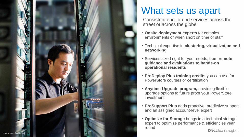
© Copyright 2021 Dell Inc.274 of 292
What sets us apart
• Onsite deployment experts for complex environments or when short on time or staff
• Technical expertise in clustering, virtualization and networking
• Services sized right for your needs, from remote guidance and evaluations to hands-on operational residents
• ProDeploy Plus training credits you can use for PowerStore courses or certification
• Anytime Upgrade program, providing flexible upgrade options to future proof your PowerStore investment
• ProSupport Plus adds proactive, predictive support and an assigned account-level expert
• Optimize for Storage brings in a technical storage expert to optimize performance & efficiencies year round
Consistent end-to-end services across the street or across the globe
Internal Use - Confidential
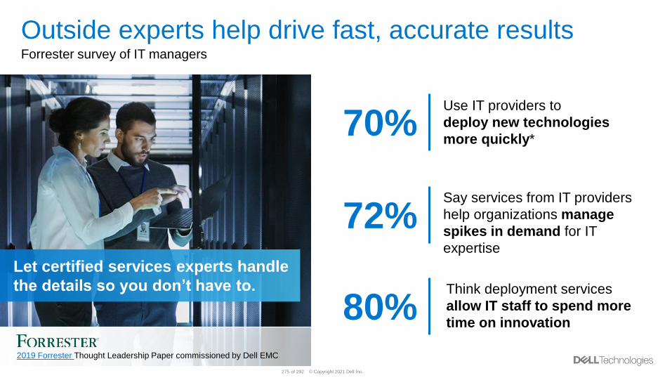
© Copyright 2021 Dell Inc.275 of 292
Use IT providers to
deploy new technologies
more quickly*70%
Say services from IT providers
help organizations manage
spikes in demand for IT
expertise
72%
Think deployment services
allow IT staff to spend more
time on innovation80%
2019 Forrester Thought Leadership Paper commissioned by Dell EMC
Let certified services experts handle
the details so you don’t have to.
Outside experts help drive fast, accurate results Forrester survey of IT managers
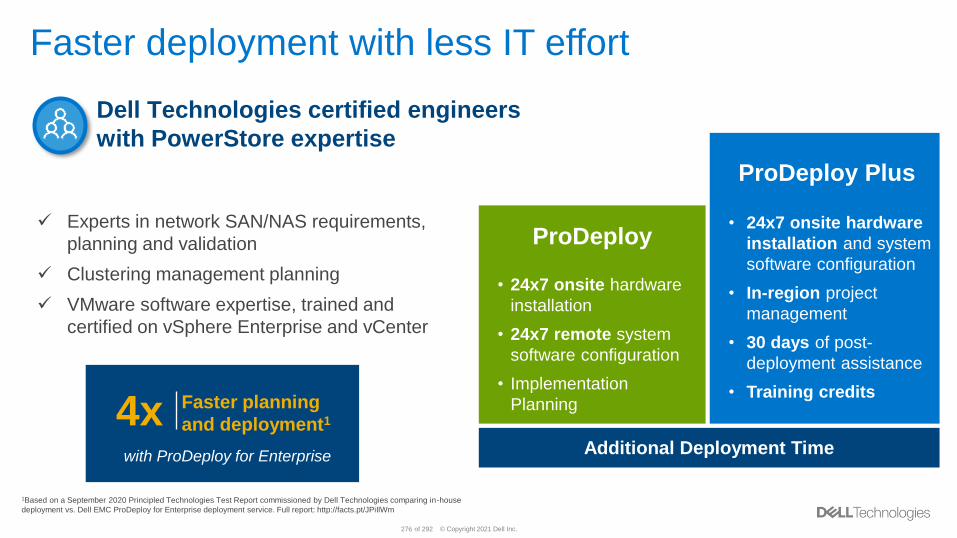
© Copyright 2021 Dell Inc.276 of 292
Faster deployment with less IT effort
276
Additional Deployment Time
ProDeploy
ProDeploy Plus
• 24x7 onsite hardware
installation and system
software configuration
• In-region project
management
• 30 days of post-
deployment assistance
• Training credits
• 24x7 onsite hardware
installation
• 24x7 remote system
software configuration
• Implementation
Planning
✓ Experts in network SAN/NAS requirements,
planning and validation
✓ Clustering management planning
✓ VMware software expertise, trained and
certified on vSphere Enterprise and vCenter
Dell Technologies certified engineers
with PowerStore expertise
Dell – Internal Use – Confidential
4x Faster planning
and deployment1
with ProDeploy for Enterprise
1Based on a September 2020 Principled Technologies Test Report commissioned by Dell Technologies comparing in-house
deployment vs. Dell EMC ProDeploy for Enterprise deployment service. Full report: http://facts.pt/JPiIlWm
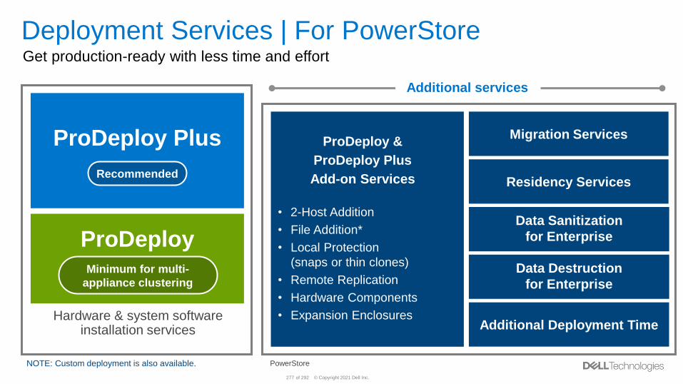
© Copyright 2021 Dell Inc.277 of 292
Deployment Services | For PowerStoreGet production-ready with less time and effort
ProDeploy &
ProDeploy Plus
Add-on Services
• 2-Host Addition
• File Addition*
• Local Protection
(snaps or thin clones)
• Remote Replication
• Hardware Components
• Expansion Enclosures
*PowerStore T models
ProDeploy
ProDeploy Plus
Hardware & system software installation services
NOTE: Custom deployment is also available.
Recommended
Data Sanitization
for Enterprise
Migration Services
Residency Services
Minimum for multi-
appliance clustering
Additional services
Additional Deployment Time
Data Destruction
for Enterprise
Dell – Internal Use – Confidential
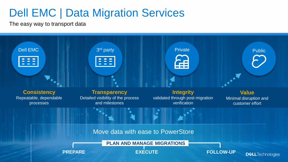
© Copyright 2021 Dell Inc.278 of 292 © Copyright 2020 Dell Inc.27
8
Dell EMC | Data Migration ServicesThe easy way to transport data
PREPARE EXECUTE
PLAN AND MANAGE MIGRATIONS
ValueMinimal disruption and
customer effort
Integrity validated through post migration
verification
ConsistencyRepeatable, dependable
processes
TransparencyDetailed visibility of the process
and milestones
Dell EMC Private Public3rd party
Move data with ease to PowerStore
FOLLOW-UP
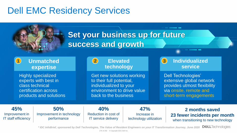
© Copyright 2021 Dell Inc.279 of 292
Dell EMC Residency Services
Unmatched expertise
Elevated technology
Individualized service
Set your business up for future
success and growth
Highly specialized experts with best in class technical certification across products and solutions
Get new solutions working to their full potential, individualized to your environment to drive value back to the business
Dell Technologies’ extensive global network provides utmost flexibility via onsite, remote and short-term engagements
1 2 3
40%Reduction in cost of
IT service delivery
47%Increase in
technology utilization
45%Improvement in
IT staff efficiency
* IDC InfoBrief, sponsored by Dell Technologies, The Value of Resident Engineers on your IT Transformation Journey, June 2020
50%Improvement in technology
performance
2 months saved
23 fewer incidents per month when transitioning to new technology
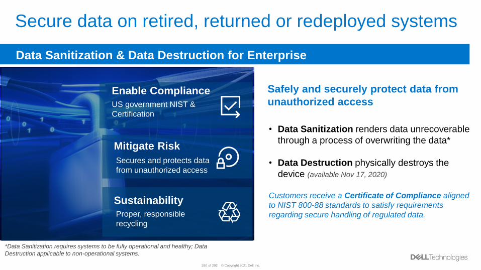
© Copyright 2021 Dell Inc.280 of 292
Secure data on retired, returned or redeployed systems
Safely and securely protect data from
unauthorized access
• Data Sanitization renders data unrecoverable
through a process of overwriting the data*
• Data Destruction physically destroys the
device (available Nov 17, 2020)
Customers receive a Certificate of Compliance aligned
to NIST 800-88 standards to satisfy requirements
regarding secure handling of regulated data.
*Data Sanitization requires systems to be fully operational and healthy; Data
Destruction applicable to non-operational systems.
Data Sanitization & Data Destruction for Enterprise
Enable Compliance
US government NIST &
Certification
Mitigate Risk
Secures and protects data
from unauthorized access
Sustainability
Proper, responsible
recycling

© Copyright 2021 Dell Inc.281 of 292
Support Services | For PowerStoreGet ahead of problems before they happen
Available with 4-hour mission critical or next
Available with 4-hour mission critical or next
business day
business day
ProSupport
ProSupport Plus
Optimize for Storage
Pre-requisite:
ProSupport, ProSupport Plus or
ProSupport One for Data Center
Keep Your Hard Drive
For Enterprise
Note: Customers with 1000+ Dell EMC infrastructure assets may be eligible for ProSupport One. Learn more.
PowerStore includes a 1-year limited warranty on hardware only.
Additional support services
Keep Your Component
for Enterprise
Onsite Diagnosis
Anytime UpgradeSelect or Standard
Pre-requisite:
ProSupport, ProSupport Plus or
ProSupport One for Data Center
Dell – Internal Use – Confidential
Available with 4-hour mission critical
or next business day
Recommended
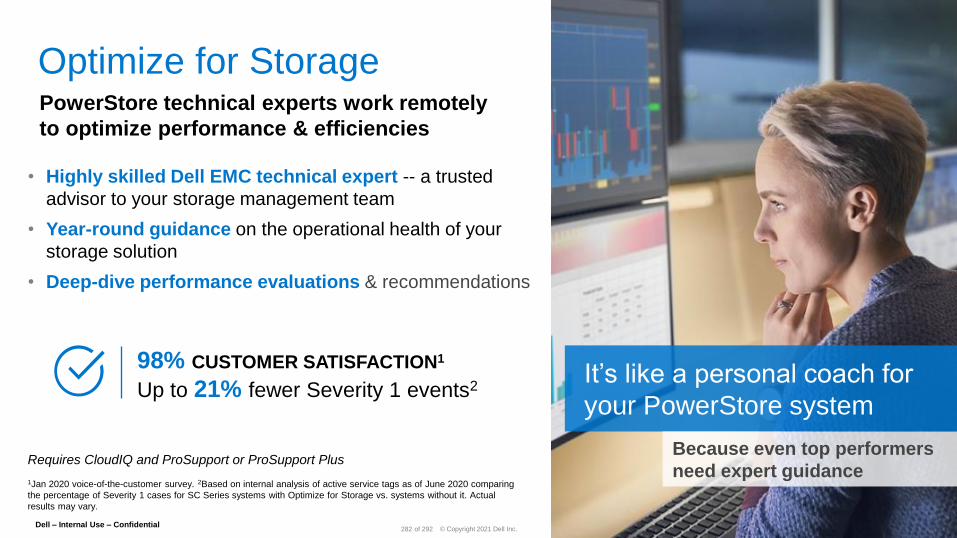
© Copyright 2021 Dell Inc.282 of 292
PowerStore technical experts work remotely
to optimize performance & efficiencies
Optimize for Storage
98% CUSTOMER SATISFACTION1
Up to 21% fewer Severity 1 events2It’s like a personal coach for
your PowerStore system
Because even top performers
need expert guidance Requires CloudIQ and ProSupport or ProSupport Plus
1Jan 2020 voice-of-the-customer survey. 2Based on internal analysis of active service tags as of June 2020 comparing
the percentage of Severity 1 cases for SC Series systems with Optimize for Storage vs. systems without it. Actual
results may vary.
Dell – Internal Use – Confidential
• Highly skilled Dell EMC technical expert -- a trusted
advisor to your storage management team
• Year-round guidance on the operational health of your
storage solution
• Deep-dive performance evaluations & recommendations
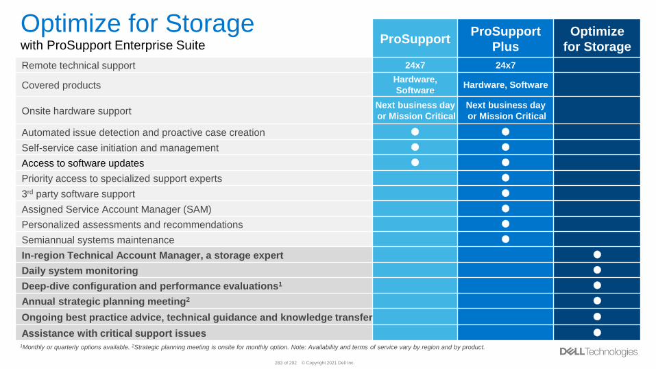
© Copyright 2021 Dell Inc.283 of 292
ProSupport ProSupport
Plus
Optimize
for Storage
Remote technical support 24x7 24x7
Covered productsHardware,
SoftwareHardware, Software
Onsite hardware supportNext business day
or Mission Critical
Next business day
or Mission Critical
Automated issue detection and proactive case creation
Self-service case initiation and management
Access to software updates
Priority access to specialized support experts
3rd party software support
Assigned Service Account Manager (SAM)
Personalized assessments and recommendations
Semiannual systems maintenance
In-region Technical Account Manager, a storage expert
Daily system monitoring
Deep-dive configuration and performance evaluations1
Annual strategic planning meeting2
Ongoing best practice advice, technical guidance and knowledge transfer
Assistance with critical support issues
1Monthly or quarterly options available. 2Strategic planning meeting is onsite for monthly option. Note: Availability and terms of service vary by region and by product.
Optimize for Storagewith ProSupport Enterprise Suite
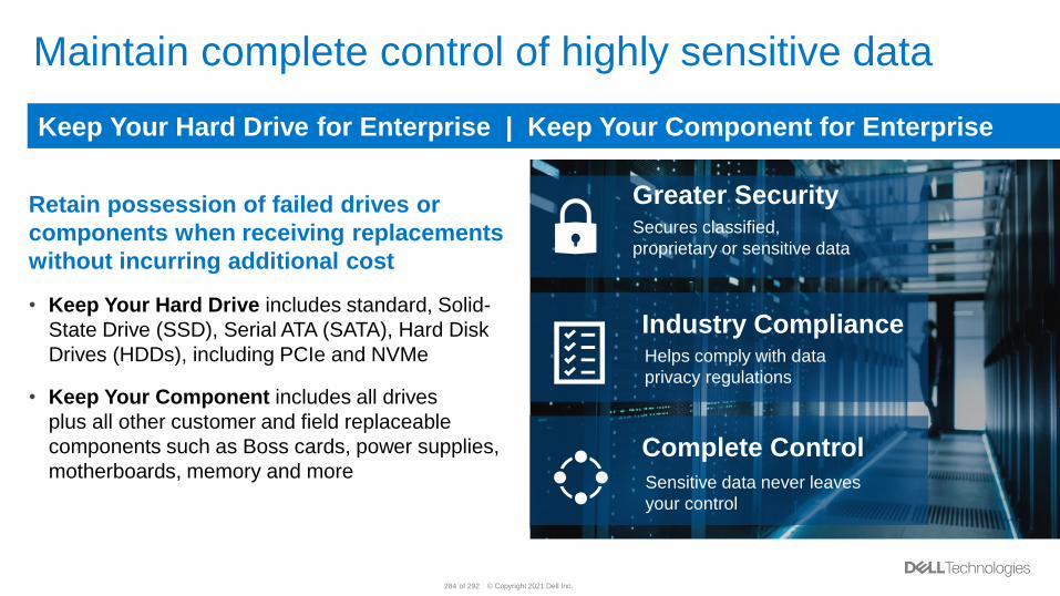
© Copyright 2021 Dell Inc.284 of 292
Maintain complete control of highly sensitive data
Retain possession of failed drives or
components when receiving replacements
without incurring additional cost
• Keep Your Hard Drive includes standard, Solid-
State Drive (SSD), Serial ATA (SATA), Hard Disk
Drives (HDDs), including PCIe and NVMe
• Keep Your Component includes all drives
plus all other customer and field replaceable
components such as Boss cards, power supplies,
motherboards, memory and more
Keep Your Hard Drive for Enterprise | Keep Your Component for Enterprise
Greater SecuritySecures classified,
proprietary or sensitive data
Industry ComplianceHelps comply with data
privacy regulations
Complete Control
Sensitive data never leaves
your control
© Copyright 2021 Dell Inc.285 of 292
Data-driven Technologies to connect and manage your service experience
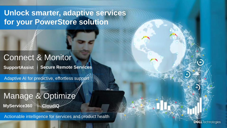
© Copyright 2021 Dell Inc.286 of 292
Unlock smarter, adaptive services
for your PowerStore solution
Connect & Monitor
Adaptive AI for predictive, effortless support
Manage & Optimize
Actionable intelligence for services and product health
CloudIQMyService360
SupportAssist Secure Remote Services
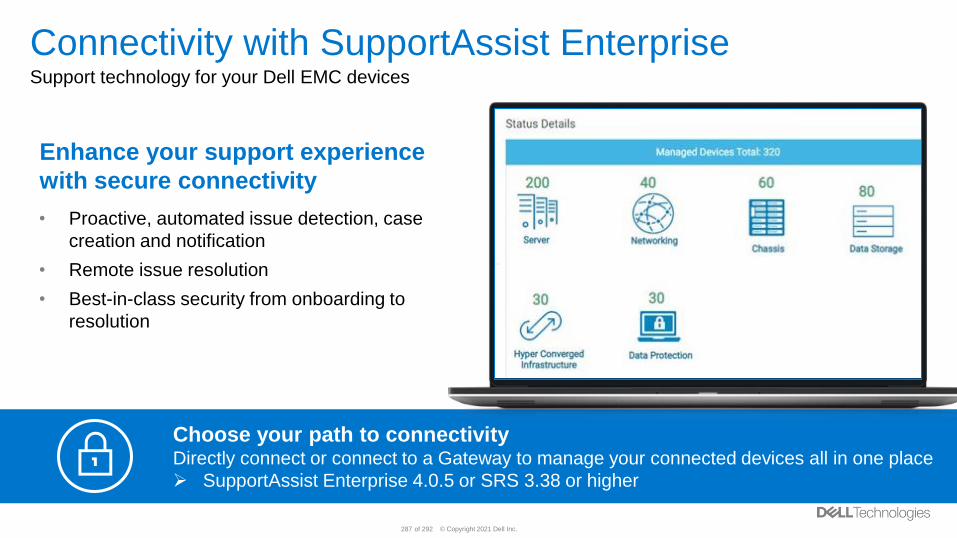
© Copyright 2021 Dell Inc.287 of 292
Connectivity with SupportAssist EnterpriseSupport technology for your Dell EMC devices
Enhance your support experience
with secure connectivity
• Proactive, automated issue detection, case
creation and notification
• Remote issue resolution
• Best-in-class security from onboarding to
resolution
Choose your path to connectivityDirectly connect or connect to a Gateway to manage your connected devices all in one place
➢ SupportAssist Enterprise 4.0.5 or SRS 3.38 or higher
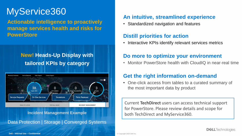
© Copyright 2021 Dell Inc.288 of 292
MyService360Actionable intelligence to proactively
manage services health and risks for
PowerStore
An intuitive, streamlined experience
• Standardized navigation and features
Distill priorities for action
• Interactive KPIs identify relevant services metrics
Do more to optimize your environment
• Monitor PowerStore health with CloudIQ in near-real time
Get the right information on-demand
• One-click access from tables to a curated summary of
the most important data by product
Data Protection | Storage | Converged Systems
New! Heads-Up Display with
tailored KPIs by category
Incident Management Example
Dell – Internal Use – Confidential © Copyright 2020 Dell Inc.
Current TechDirect users can access technical support for PowerStore. Please review details and scope for both TechDirect and MyService360.
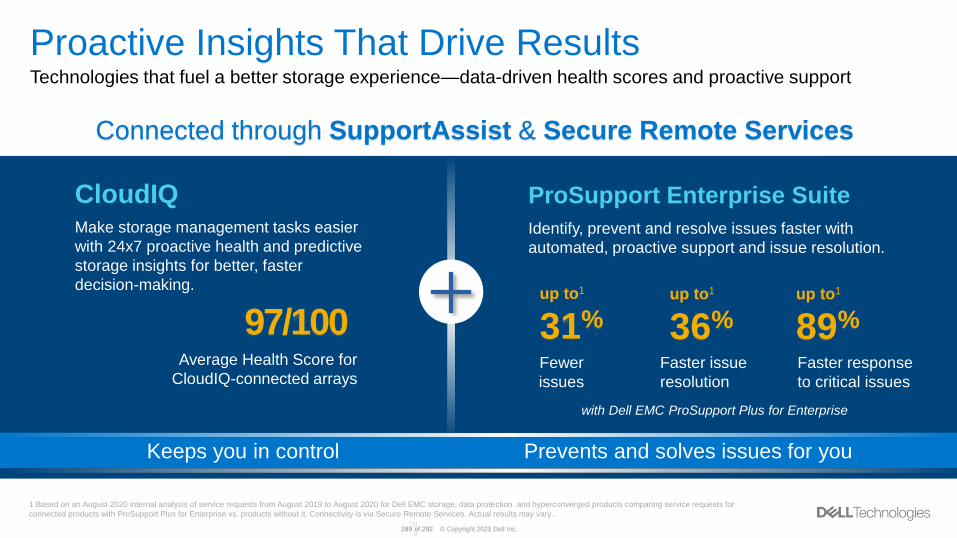
© Copyright 2021 Dell Inc.289 of 292
Proactive Insights That Drive ResultsTechnologies that fuel a better storage experience—data-driven health scores and proactive support
Connected through SupportAssist & Secure Remote Services
Keeps you in control Prevents and solves issues for you
CloudIQ ProSupport Enterprise Suite
Make storage management tasks easier
with 24x7 proactive health and predictive
storage insights for better, faster
decision-making.
97/100Average Health Score for
CloudIQ-connected arrays
Identify, prevent and resolve issues faster with
automated, proactive support and issue resolution.
up to1
89%
1 Based on an August 2020 internal analysis of service requests from August 2019 to August 2020 for Dell EMC storage, data protection and hyperconverged products comparing service requests for
connected products with ProSupport Plus for Enterprise vs. products without it. Connectivity is via Secure Remote Services. Actual results may vary..
up to1
36%up to1
31%
Fewer
issues
Faster issue
resolution
Faster response
to critical issues
© Copyright 2020 Dell Inc.28
9
with Dell EMC ProSupport Plus for Enterprise
© Copyright 2021 Dell Inc.290 of 292
Dell Technologies Education Services
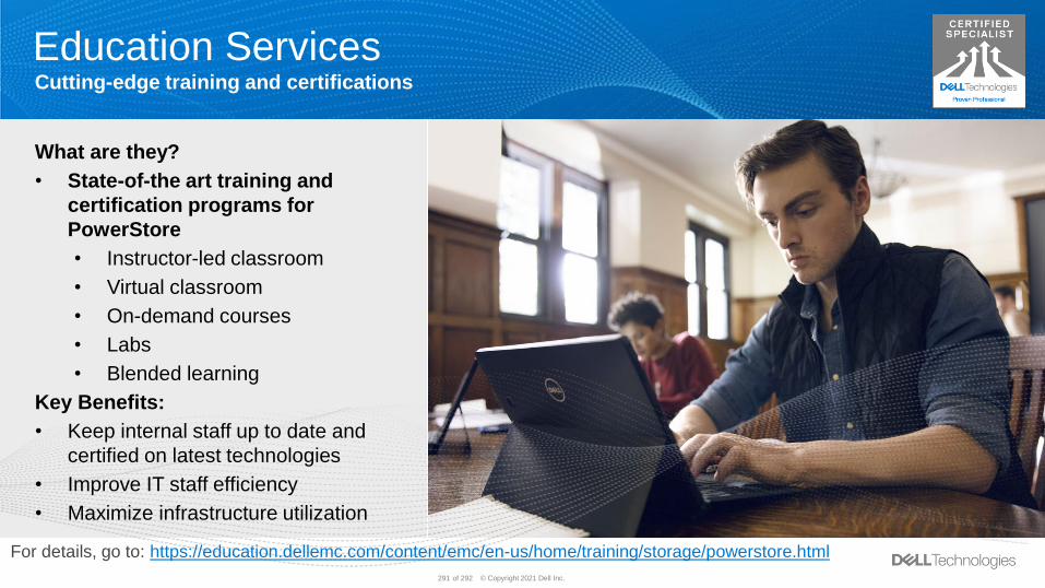
© Copyright 2021 Dell Inc.291 of 292
Cutting-edge training and certifications
Education Services
What are they?
• State-of-the art training and
certification programs for
PowerStore
• Instructor-led classroom
• Virtual classroom
• On-demand courses
• Labs
• Blended learning
Key Benefits:
• Keep internal staff up to date and
certified on latest technologies
• Improve IT staff efficiency
• Maximize infrastructure utilization
For details, go to: https://education.dellemc.com/content/emc/en-us/home/training/storage/powerstore.html
Related Documents


