Power Semiconductor Devices Power Electronics Power Semiconductor Devices 1

Powersemiconductordevices 140513040047-phpapp01
Jul 16, 2015
Welcome message from author
This document is posted to help you gain knowledge. Please leave a comment to let me know what you think about it! Share it to your friends and learn new things together.
Transcript

Power Semiconductor Devices
Power Electronics Power Semiconductor Devices 1
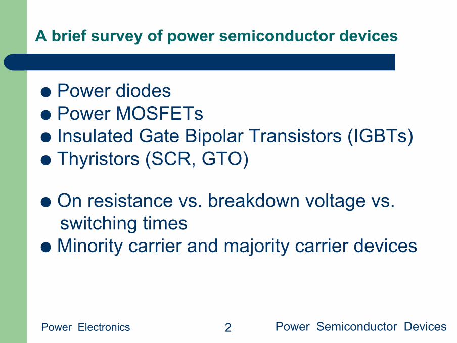
A brief survey of power semiconductor devices
Power Electronics Power Semiconductor Devices 2
● Power diodes● Power MOSFETs● Insulated Gate Bipolar Transistors (IGBTs)● Thyristors (SCR, GTO)
● On resistance vs. breakdown voltage vs. switching times
● Minority carrier and majority carrier devices

The power diode
Power Electronics Power Semiconductor Devices 3
Appearance
Construction Symbol

Reverse-biased power diode
Power Electronics Power Semiconductor Devices 4
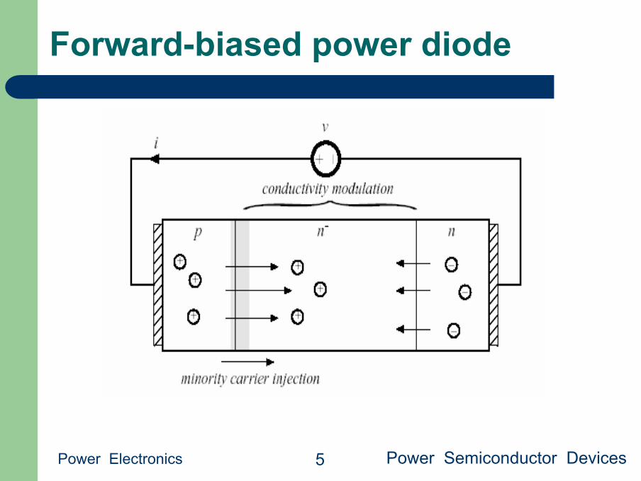
Forward-biased power diode
Power Electronics Power Semiconductor Devices 5

Typical power diode characteristics
Power Electronics Power Semiconductor Devices 6

Typical diode switching waveforms
Power Electronics Power Semiconductor Devices 7

Types of power diodes
Power Electronics Power Semiconductor Devices 8
Standard recoveryReverse recovery time not specified, intended for 50/60Hz
Fast recovery and ultra-fast recoveryReverse recovery time and recovered charge specifiedIntended for converter applications
Schottky diodeA majority carrier deviceEssentially no recovered chargeModel with equilibrium i-v characteristic, in parallel withdepletion region capacitanceRestricted to low voltage (few devices can block 100V or more)
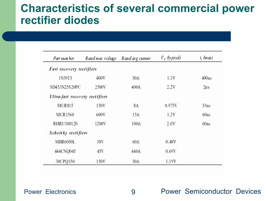
Characteristics of several commercial power rectifier diodes
Power Electronics Power Semiconductor Devices 9
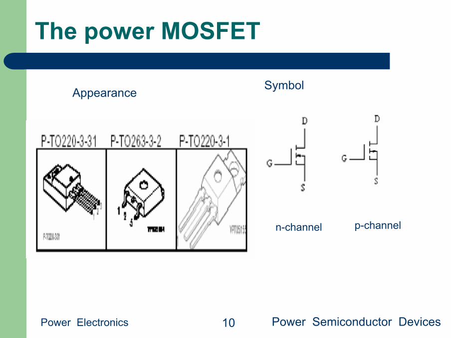
The power MOSFET
Power Electronics Power Semiconductor Devices 10
Appearance Symbol
n-channel p-channel

The construction of Power MOSFET
Power Electronics Power Semiconductor Devices 11

MOSFET: Off state
Power Electronics Power Semiconductor Devices 12
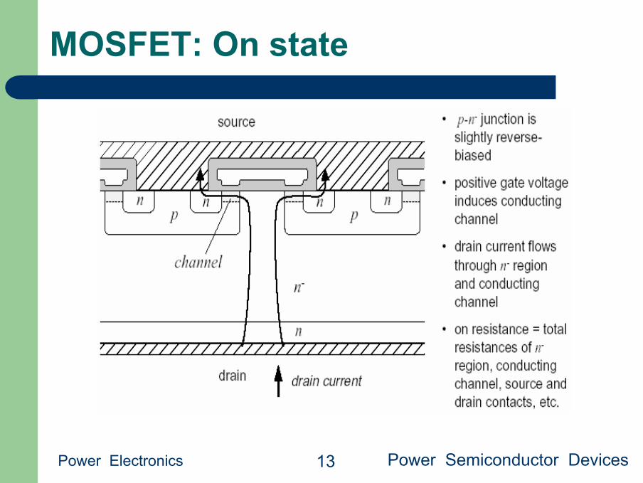
MOSFET: On state
Power Electronics Power Semiconductor Devices 13

MOSFET body diode
Power Electronics Power Semiconductor Devices 14
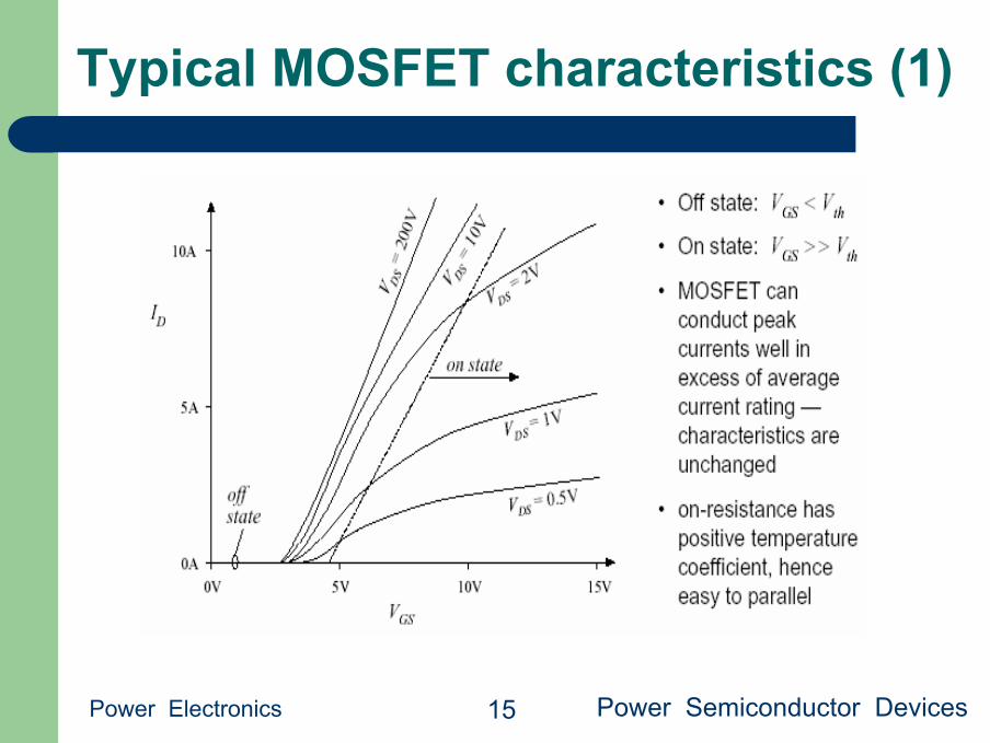
Typical MOSFET characteristics (1)
Power Electronics Power Semiconductor Devices 15
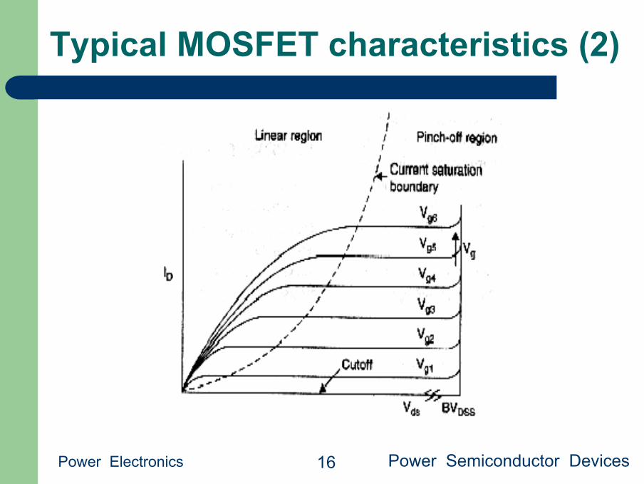
Typical MOSFET characteristics (2)
Power Electronics Power Semiconductor Devices 16
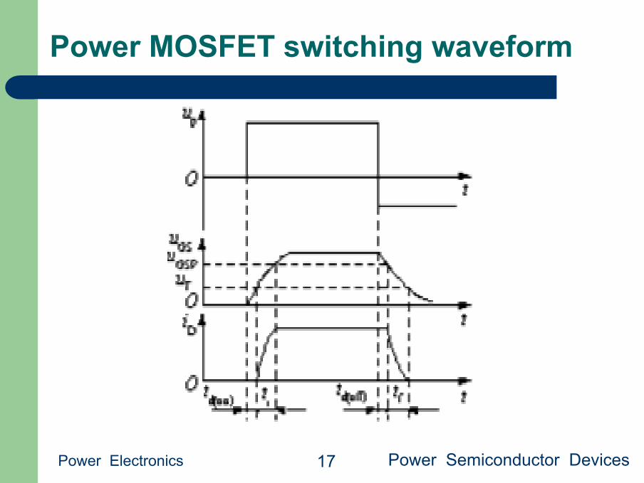
Power MOSFET switching waveform
Power Electronics Power Semiconductor Devices 17
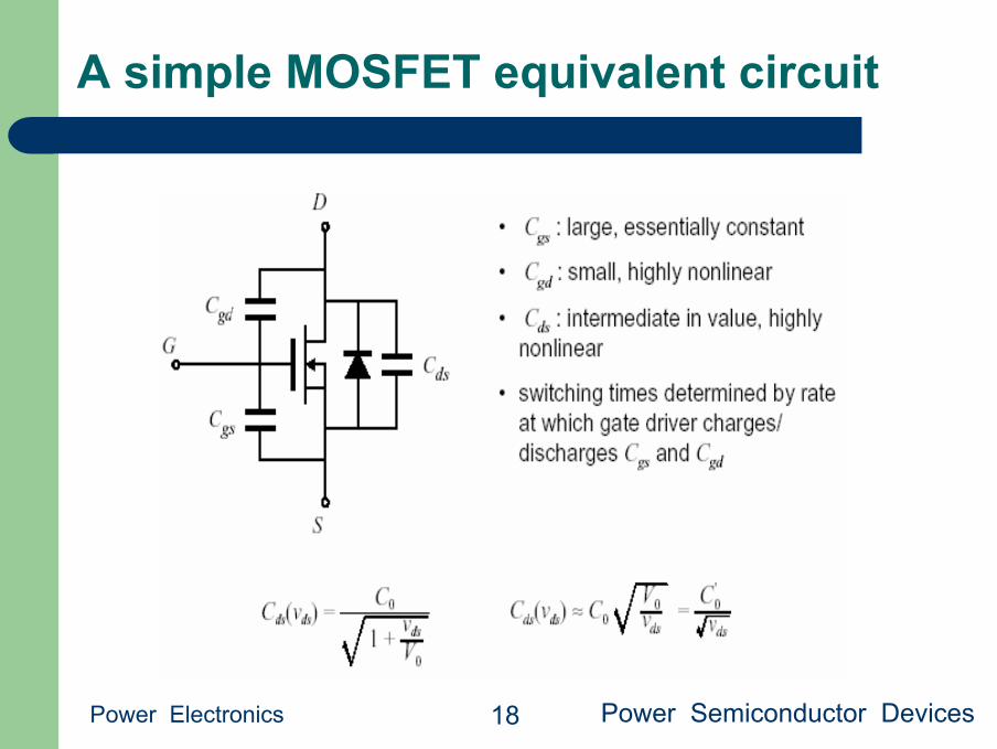
A simple MOSFET equivalent circuit
Power Electronics Power Semiconductor Devices 18
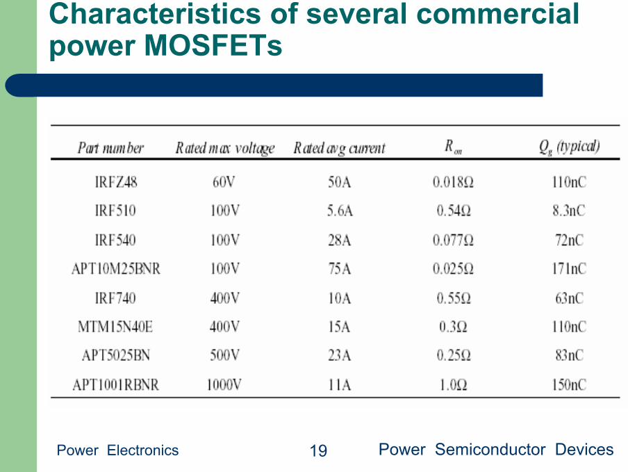
Characteristics of several commercial power MOSFETs
Power Electronics Power Semiconductor Devices 19

MOSFET: conclusion
Power Electronics Power Semiconductor Devices 20
● A majority-carrier device: fast switching speed● Typical switching frequencies: tens and
hundreds of kHz● On-resistance increases rapidly with rated
blocking voltage● Easy to drive● The device of choice for blocking voltages less than
500V● 1000V devices are available, but are useful only at low power
levels(100W)● Part number is selected on the basis of on-resistance rather than
current rating

The Insulated Gate Bipolar Transistor (IGBT)
Power Electronics Power Semiconductor Devices 21
Appearance Symbol
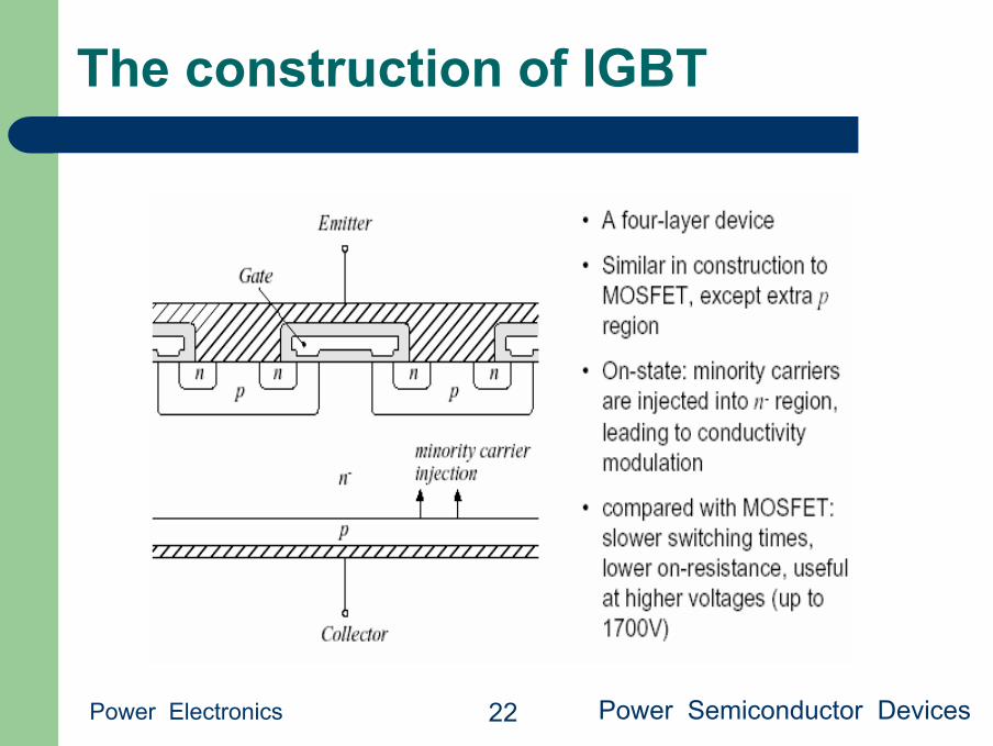
The construction of IGBT
Power Electronics Power Semiconductor Devices 22
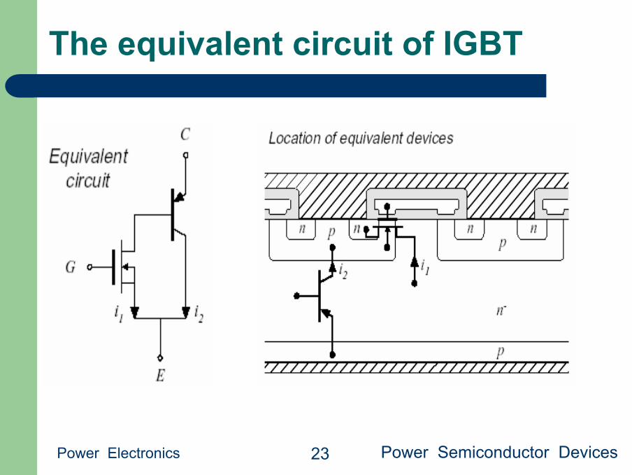
The equivalent circuit of IGBT
Power Electronics Power Semiconductor Devices 23
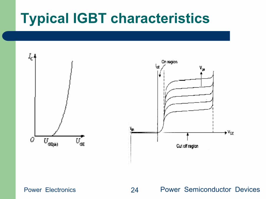
Typical IGBT characteristics
Power Electronics Power Semiconductor Devices 24

IGBT switching waveform
Power Electronics Power Semiconductor Devices 25
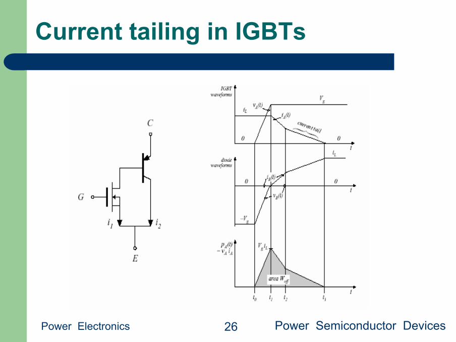
Current tailing in IGBTs
Power Electronics Power Semiconductor Devices 26
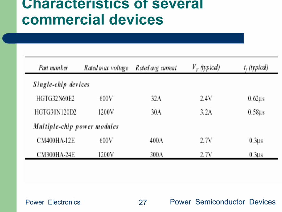
Characteristics of several commercial devices
Power Electronics Power Semiconductor Devices 27

Conclusions: IGBT
Power Electronics Power Semiconductor Devices 28
● Becoming the device of choice in 500-1700V applications, atpower levels of 1-1000kW
● Positive temperature coefficient at high current —easy to parallel and construct modules
● Forward voltage drop: diode in series with on-resistance. 2- 4V typical
● Easy to drive —similar to MOSFET● Slower than MOSFET, but faster than Darlington, GTO, SCR● Typical switching frequencies: 3-30kHz● IGBT technology is rapidly advancing —next generation:
2500V

The Thyristor (silicon controlled rectifier, SCR)
Power Electronics Power Semiconductor Devices 29
Appearance Symbol
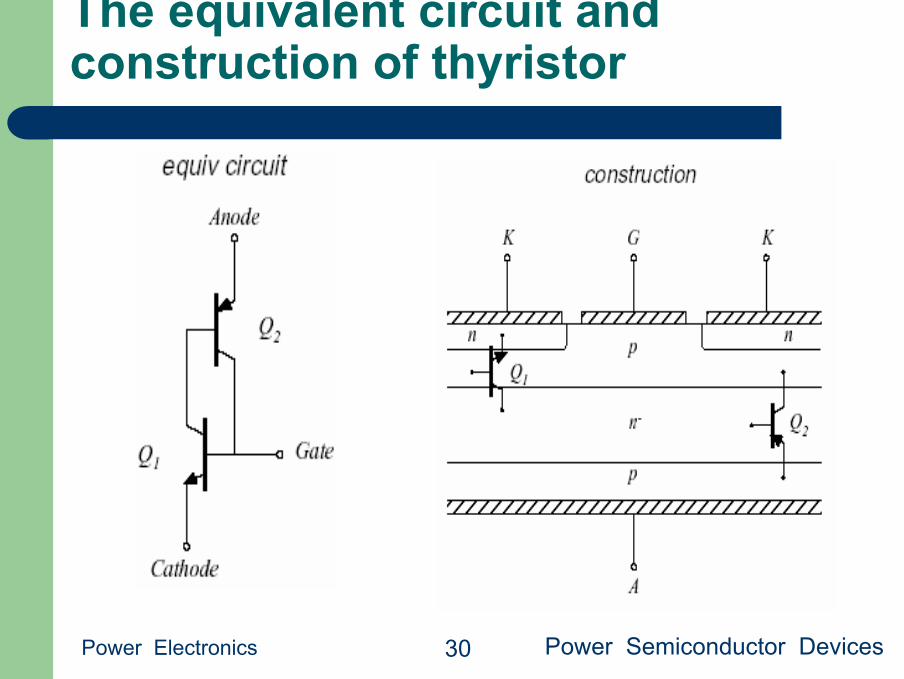
The equivalent circuit and construction of thyristor
Power Electronics Power Semiconductor Devices 30

Typical thyristor characteristics
Power Electronics Power Semiconductor Devices 31

Thyristor switching waveform
Power Electronics Power Semiconductor Devices 32
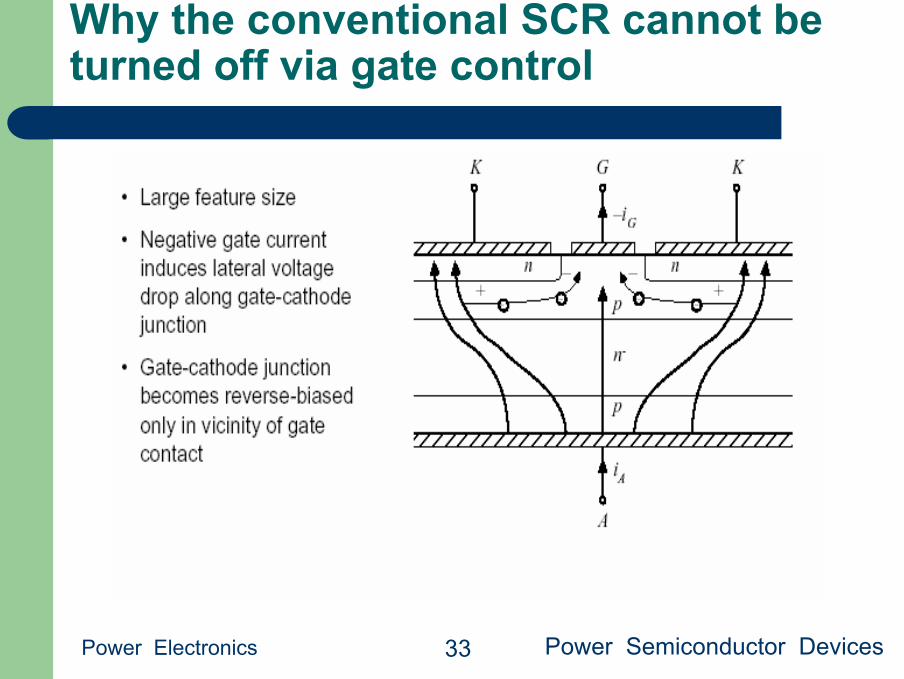
Why the conventional SCR cannot be turned off via gate control
Power Electronics Power Semiconductor Devices 33
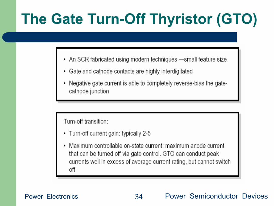
The Gate Turn-Off Thyristor (GTO)
Power Electronics Power Semiconductor Devices 34
Summary: Thyristors
Power Electronics Power Semiconductor Devices 35
● The thyristor family: double injection yields lowest forwardvoltage drop in high voltage devices. More difficult toparallel than MOSFETs and IGBTs
● The SCR: highest voltage and current ratings, low cost, passive turn-off transition
● The GTO: intermediate ratings (less than SCR, somewhatmore than IGBT). Slower than IGBT. Slower than MCT. Difficult to drive.
● The MCT: So far, ratings lower than IGBT. Slower than IGBT.Easy to drive. Still emerging devices?

Summary of power semiconductor devices
Power Electronics Power Semiconductor Devices 36
1. Majority carrier devices, including the MOSFET and Schottky diode, exhibitvery fast switching times, controlled essentially by the charging of thedevice capacitances. However, the forward voltage drops of these devicesincreases quickly with increasing breakdown voltage.
2. Minority carrier devices, including the BJT, IGBT, and thyristor family, canexhibit high breakdown voltages with relatively low forward voltage drop.However, the switching times of these devices are longer, and arecontrolled by the times needed to insert or remove stored minority charge.
3. Energy is lost during switching transitions, due to a variety of mechanisms.The resulting average power loss, or switching loss, is equal to this energyloss multiplied by the switching frequency. Switching loss imposes anupper limit on the switching frequencies of practical converters.
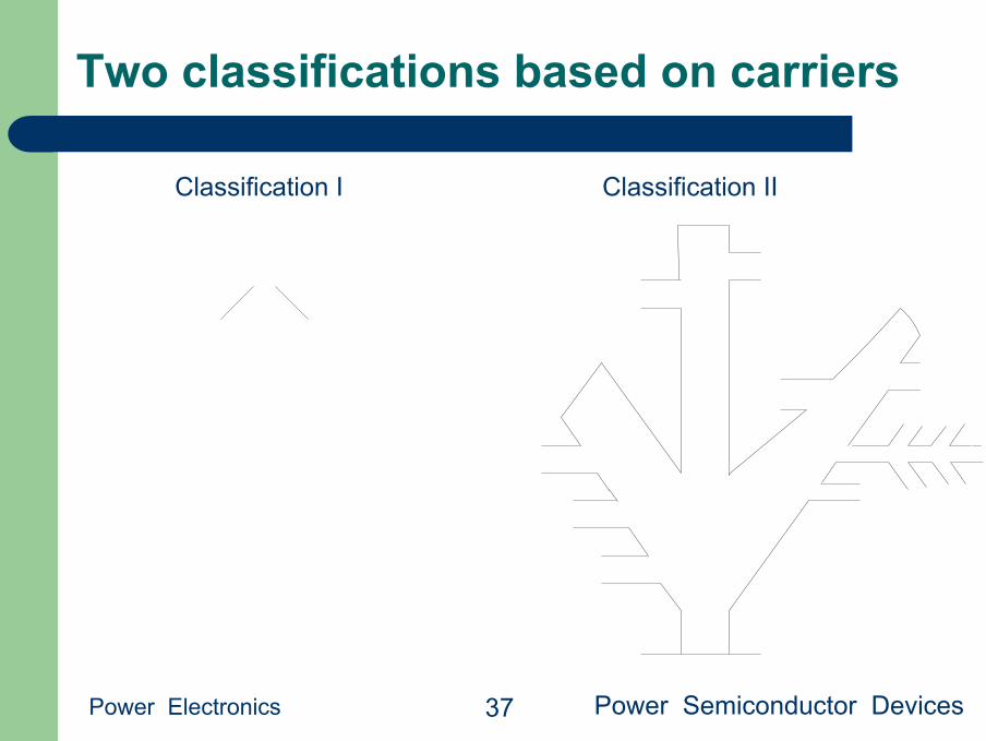
Two classifications based on carriers
Power Electronics Power Semiconductor Devices 37
Classification I Classification II
Related Documents