Powering Implantable and Ingestible Electronics So-Yoon Yang, Department of Electrical Engineering and Computer Science, Massachusetts Institute of Technology, Cambridge, MA 02139, USA; Koch Institute for Integrative Cancer Research, Massachusetts Institute of Technology, Cambridge, MA 02139, USA; Department of Mechanical Engineering, Massachusetts Institute of Technology, Cambridge, MA 02139, USA Vitor Sencadas, Koch Institute for Integrative Cancer Research, Massachusetts Institute of Technology, Cambridge, MA 02139, USA; School of Mechanical, Materials & Mechatronics Engineering, University of Wollongong, Wollongong, NSW 2522, Australia Siheng Sean You, Koch Institute for Integrative Cancer Research, Massachusetts Institute of Technology, Cambridge, MA 02139, USA; Department of Mechanical Engineering, Massachusetts Institute of Technology, Cambridge, MA 02139, USA; Division of Gastroenterology, Hepatology and Endoscopy, Department of Medicine, Brigham and Women’s Hospital, Harvard Medical School, Boston, MA 02115, USA Neil Zi-Xun Jia, Koch Institute for Integrative Cancer Research, Massachusetts Institute of Technology, Cambridge, MA 02139, USA Shriya Sruthi Srinivasan, Koch Institute for Integrative Cancer Research, Massachusetts Institute of Technology, Cambridge, MA 02139, USA; Department of Mechanical Engineering, Massachusetts Institute of Technology, Cambridge, MA 02139, USA; Division of Gastroenterology, Hepatology and Endoscopy, Department of Medicine, Brigham and Women’s Hospital, Harvard Medical School, Boston, MA 02115, USA Hen-Wei Huang, Koch Institute for Integrative Cancer Research, Massachusetts Institute of Technology, Cambridge, MA 02139, USA; Department of Mechanical Engineering, Massachusetts Institute of Technology, Cambridge, MA 02139, USA; Division of Gastroenterology, Hepatology and Endoscopy, Department of Medicine, Brigham and Women’s Hospital, Harvard Medical School, Boston, MA 02115, USA Abdelsalam Elrefaey Ahmed, [email protected], [email protected]. Conflict of Interest G. T. is a co-inventor on multiple patent applications involving energy harvesting systems as well as systems involving electronics for therapeutic applications. G.T. reports receiving consulting fees from Novo Nordisk, Verily, Merck. G.T. has a financial interest in Lyndra Therapeutics, Suono Bio and Celero Systems which are all biotechnology companies developing therapeutics via the gastrointestinal tract which can include electronics in some embodiments. Complete details of all relationships for profit and not for profit for G.T. can found at the following link: https://www.dropbox.com/sh/szi7vnr4a2ajb56/AABs5N5i0q9AfT1IqIJAE-T5a?dl=0. HHS Public Access Author manuscript Adv Funct Mater. Author manuscript; available in PMC 2021 October 28. Published in final edited form as: Adv Funct Mater. 2021 October 26; 31(44): . doi:10.1002/adfm.202009289. Author Manuscript Author Manuscript Author Manuscript Author Manuscript

Welcome message from author
This document is posted to help you gain knowledge. Please leave a comment to let me know what you think about it! Share it to your friends and learn new things together.
Transcript
Powering Implantable and Ingestible Electronics
So-Yoon Yang,Department of Electrical Engineering and Computer Science, Massachusetts Institute of Technology, Cambridge, MA 02139, USA; Koch Institute for Integrative Cancer Research, Massachusetts Institute of Technology, Cambridge, MA 02139, USA; Department of Mechanical Engineering, Massachusetts Institute of Technology, Cambridge, MA 02139, USA
Vitor Sencadas,Koch Institute for Integrative Cancer Research, Massachusetts Institute of Technology, Cambridge, MA 02139, USA; School of Mechanical, Materials & Mechatronics Engineering, University of Wollongong, Wollongong, NSW 2522, Australia
Siheng Sean You,Koch Institute for Integrative Cancer Research, Massachusetts Institute of Technology, Cambridge, MA 02139, USA; Department of Mechanical Engineering, Massachusetts Institute of Technology, Cambridge, MA 02139, USA; Division of Gastroenterology, Hepatology and Endoscopy, Department of Medicine, Brigham and Women’s Hospital, Harvard Medical School, Boston, MA 02115, USA
Neil Zi-Xun Jia,Koch Institute for Integrative Cancer Research, Massachusetts Institute of Technology, Cambridge, MA 02139, USA
Shriya Sruthi Srinivasan,Koch Institute for Integrative Cancer Research, Massachusetts Institute of Technology, Cambridge, MA 02139, USA; Department of Mechanical Engineering, Massachusetts Institute of Technology, Cambridge, MA 02139, USA; Division of Gastroenterology, Hepatology and Endoscopy, Department of Medicine, Brigham and Women’s Hospital, Harvard Medical School, Boston, MA 02115, USA
Hen-Wei Huang,Koch Institute for Integrative Cancer Research, Massachusetts Institute of Technology, Cambridge, MA 02139, USA; Department of Mechanical Engineering, Massachusetts Institute of Technology, Cambridge, MA 02139, USA; Division of Gastroenterology, Hepatology and Endoscopy, Department of Medicine, Brigham and Women’s Hospital, Harvard Medical School, Boston, MA 02115, USA
Abdelsalam Elrefaey Ahmed,
[email protected], [email protected].
Conflict of InterestG. T. is a co-inventor on multiple patent applications involving energy harvesting systems as well as systems involving electronics for therapeutic applications. G.T. reports receiving consulting fees from Novo Nordisk, Verily, Merck. G.T. has a financial interest in Lyndra Therapeutics, Suono Bio and Celero Systems which are all biotechnology companies developing therapeutics via the gastrointestinal tract which can include electronics in some embodiments. Complete details of all relationships for profit and not for profit for G.T. can found at the following link: https://www.dropbox.com/sh/szi7vnr4a2ajb56/AABs5N5i0q9AfT1IqIJAE-T5a?dl=0.
HHS Public AccessAuthor manuscriptAdv Funct Mater. Author manuscript; available in PMC 2021 October 28.
Published in final edited form as:Adv Funct Mater. 2021 October 26; 31(44): . doi:10.1002/adfm.202009289.
Author M
anuscriptA
uthor Manuscript
Author M
anuscriptA
uthor Manuscript
Division of Gastroenterology, Hepatology and Endoscopy, Department of Medicine, Brigham and Women’s Hospital, Harvard Medical School, Boston, MA 02115, USA
Jia Ying Liang,Koch Institute for Integrative Cancer Research, Massachusetts Institute of Technology, Cambridge, MA 02139, USA; Department of Mechanical Engineering, Massachusetts Institute of Technology, Cambridge, MA 02139, USA; Division of Gastroenterology, Hepatology and Endoscopy, Department of Medicine, Brigham and Women’s Hospital, Harvard Medical School, Boston, MA 02115, USA
Giovanni TraversoDepartment of Mechanical Engineering, Massachusetts Institute of Technology, Cambridge, MA 02139, USA; Division of Gastroenterology, Hepatology and Endoscopy, Department of Medicine, Brigham and Women’s Hospital, Harvard Medical School, Boston, MA 02115, USA
Abstract
Implantable and ingestible biomedical electronic devices can be useful tools for detecting
physiological and pathophysiological signals, and providing treatments that cannot be done
externally. However, one major challenge in the development of these devices is the limited
lifetime of their power sources. The state-of-the-art of powering technologies for implantable and
ingestible electronics is reviewed here. The structure and power requirements of implantable
and ingestible biomedical electronics are described to guide the development of powering
technologies. These powering technologies include novel batteries that can be used as both power
sources and for energy storage, devices that can harvest energy from the human body, and devices
that can receive and operate with energy transferred from exogenous sources. Furthermore,
potential sources of mechanical, chemical, and electromagnetic energy present around common
target locations of implantable and ingestible electronics are thoroughly analyzed; energy
harvesting and transfer methods befitting each energy source are also discussed. Developing power
sources that are safe, compact, and have high volumetric energy densities is essential for realizing
long-term in-body biomedical electronics and for enabling a new era of personalized healthcare.
Keywords
batteries; energy harvesting; energy transfer; implantable electronics; ingestible electronics
1. Introduction
1.1. Motivation
As the human life expectancy has increased, access to high-quality healthcare has become
essential for ensuring a high quality of life.[1] This increase in lifespan is associated with
a rising prevalence of disease, disability, dementia, and other ailments.[2] More than 60%
of adults in the United States (US) have a chronic disease such as heart disease, cancer,
stroke, and diabetes. Consequently, management of chronic conditions account for 75% of
healthcare spending in the US.[3,4] ≈61 million adults (26%) in the US have some type
of disability, such as a mobility impairment, a cognitive disability, hearing loss, or vision
Yang et al. Page 2
Adv Funct Mater. Author manuscript; available in PMC 2021 October 28.
Author M
anuscriptA
uthor Manuscript
Author M
anuscriptA
uthor Manuscript
loss, and depend on the reliable assistance of one or more medical devices for the rest
of their lives.[5] Worldwide, about three million people are living with a pacemaker and
about 0.3 million people are living with a cochlear implant.[6,7] In order to lower the
morbidity rate, it is important to monitor, intervene, and prevent diseases more effectively.
Biomedical electronic devices have played a significant role in managing these medical
demands. Developing energy-dense power sources is a major challenge for realizing the next
generation of personalized biomedical electronics that are multifunctional, compact, and
long-lived.
The energy requirements of biomedical electronic devices are highly dependent on their
application and the complexity of the required electrical systems. Biomedical electronic
devices can be divided into three main categories depending on their application: diagnostic,
therapeutic, and closed-loop systems. Each category has a different degree of complexity
in the electronic system, which will be discussed in Section 1.2. Diagnostic devices are
used to monitor existing or potential medical conditions, to track disease progression and
to evaluate the effects of any medical interventions. Diagnostic biomedical electronics are
currently used to monitor the progression of diseases such as diabetes, cancer, hypertension,
heart disease, stroke, respiratory disease, chronic kidney disease, arthritis, and obesity.
Clinicians can also assess the efficacy of treatment through therapeutic drug monitoring or
medication adherence monitoring; therapeutic prescriptions can then be altered to optimize
efficacy. Furthermore, diagnostic electronic devices can collect clinical data from patients
over an extended period of time without clinical consultations, which enables quicker, more
efficient, and more accurate diagnoses and prognoses.
Therapeutic electronic devices enable potentially more efficient and effective therapeutic
interventions than conventional treatment methods such as pill-type medications. For
example, tissue/nerve stimulation is used to repair neurological dysfunction or to relieve
pain by modulating the nervous system: examples include deep brain stimulation for
Parkinson’s disease, gastric stimulation for gastroparesis, and peripheral nerve and spinal
cord stimulation for chronic pain relief. Programmable drug pumps can increase medication
adherence and maintain analyte concentrations within a targeted therapeutic window.
Therapeutic efficacy can be optimized when the diagnostic and therapeutic devices are
combined into a closed-loop system.
In a closed-loop system, diagnostic sensors monitor biomarkers related to a target
disease and a central processing unit analyzes the measured data and adjusts the
treatment accordingly. A closed-loop algorithm can achieve high therapeutic efficacy in
pharmacologic treatment by maintaining the medication levels within a tight predetermined
threshold; in electrical stimulation, closed-loop systems support stimulation in response
to measured endogenous electrical activity. There are many medical treatments that
can be enhanced by closed-loop medical devices: chemotherapy, anesthesia, opioids
for postsurgical management of pain, methotrexate for control of rheumatoid arthritis,
tacrolimus for post-transplant immunosuppression, phenytoin to control epileptic seizures,
and the anticoagulant warfarin.[8] A well-recognized biomedical closed-loop electronic
device is the type 1 diabetes glucose monitoring and insulin pump system, also known as an
artificial pancreas, that continuously measures blood glucose levels and delivers the required
Yang et al. Page 3
Adv Funct Mater. Author manuscript; available in PMC 2021 October 28.
Author M
anuscriptA
uthor Manuscript
Author M
anuscriptA
uthor Manuscript
insulin dose. Another closed-loop electronic medical device is a transgastric sensor and
gastric stimulator, which is used to treat obesity. This implantable device detects food intake
and triggers a gastric stimulator which makes a patient feel satiated.[9] Other examples of
implantable biomedical closed-loop systems include closed-loop pacemakers, which treat
cardiac arrhythmia, and closed-loop deep brain stimulators (DBS), which treat Parkinson’s
disease. Table 1 summarizes clinical applications in which implantable/ingestible biomedical
electronic devices are used.
Due to recent technological developments, the features available and implantation locations
of biomedical electronic devices has increased substantially. Advances in wireless
communication enable medical devices to be untethered when in the human body. Advances
in minimally invasive or semi-invasive surgical implantation procedures have enabled
biomedical devices to be implanted in locations where clinically important biomarkers and
physiological signals can be detected; it has also enabled direct administration of medication
or treatment to a target location. This leads to higher therapeutic efficacy and lower levels
of patient discomfort. Nevertheless, a significant challenge arises when these electronic
devices operate inside the body: power is a fundamental bottleneck. This is because the
major functionalities of the device, such as diagnostic/therapeutic modalities, duty cycle,
and operation lifetime, are often constrained by the amount of power that is available.
Furthermore, additional features are constantly being added to biomedical electronic
devices as a result of technological development. For instance, smartphones and internet
of things (IoT) technologies facilitate physiological data collection; artificial intelligence
(AI) algorithms provide advanced data analysis and personalized medical decision-making.
As a result, the power demand for biomedical electronic devices is constantly increasing.
Thus, technology related to powering devices is a major determinant in the ability to develop
in-body biomedical electronics. Figure 1 shows the major milestones of implantable and
ingestible electronic devices and relevant technologies to power these devices.
1.2. Structure and Power Consumptions of Implantable and Ingestible Biomedical Electronic Devices
The power requirements of implantable and ingestible biomedical electronics are determined
by their structure and components. This section discusses the functional blocks that are
typically found in a biomedical electronic device and their power requirements.
1.2.1. Structure and Components of Biomedical Electronic Devices—Most
biomedical electronic devices are composed of a common set of components, including
a power unit, sensors, actuators, a signal processing and control unit, and a data storage unit
(Figure 2). Implantable and ingestible devices that require a great deal of data manipulation
or large quantities of data logging also need to be wirelessly connected to an external device
so that data can be transmitted to an external receiver and signal processing, data storage,
and display can be performed more efficiently. The power unit, which is composed of one
or more energy sources as well as power management circuits, supplies electrical energy
to the whole system. The sensors and actuators interface with the biomedical environment
to record the external stimuli or generate appropriate medical interventions. The signal
processing and control unit is the central processing unit that has many functionalities
Yang et al. Page 4
Adv Funct Mater. Author manuscript; available in PMC 2021 October 28.
Author M
anuscriptA
uthor Manuscript
Author M
anuscriptA
uthor Manuscript
including input/output (I/O) operations, analog and digital signal conversion and processing,
peripheral control, memory, and timing operations. This unit supervises the algorithm and
operation of the entire system. Usually, a single mixed-signal microcontroller unit (MCU)
is used for biomedical electronics since it enables all functionalities to be integrated onto a
single chip that is small in size, requires little power, and is low in cost. The data storage unit
can be integrated into a signal processing and control unit like memory is embedded onto an
MCU, or it can be added as a separate memory unit if needed. The basic components of a
wireless communication unit are a transmitter/receiver/transceiver and an antenna.
The system complexity of each of the three biomedical electronic systems is shown in
Figure 2. Therapeutic tools are usually the least complex systems and primarily require
a controlled actuator. Control of the therapeutic devices can be achieved in one of three
ways: wirelessly, by an external user for an on-demand application; by a microcontroller
that has a pre-programmed algorithm that operates at a specific time and situation;
or by environmental stimuli.[90-93] Microcontrollers and wireless communication units
are optional components for therapeutic devices. However, systems composed of only
actuators, which do not have computational elements and communication modules, can
only implement simple on-off control. Adding a microcontroller and a radiofrequency (RF)
communication module enables more sophisticated therapeutic procedures such as time
controlled drug delivery or feedback control. At the same time, these additional modules
increase the power consumption of the devices and require the power management circuits
to be more complex.[92]
A diagnostic device relies on different modules than a therapeutic device: sensors to collect
biological information, a microcontroller to convert the analog inputs into digital data and
perform signal processing, and a wireless communication module and/or additional on-board
memory to transmit/store the processed data for further analysis.[80,94-98] Thus, a diagnostic
device requires a more complicated circuit design than a therapeutic device. A closed-loop
system has the most complex configuration since it must contain a sensor, an actuator,
and a microcontroller. The microcontroller plays an important role in coordinating the
sensory input with the output of the actuator. An RF communication module is an optional
component in a closed-loop system. If the microcontroller unit in a closed-loop system, such
as a pacemaker and artificial pancreas, does not require intervention from an external user
to make a therapeutic decision, no communication component is needed.[99,100] However, if
a system needs to be highly miniaturized and cannot incorporate a powerful microcontroller
due to size and power consumption limitations, then having an RF communication module
can shift the heavy computational load to a powerful external device.[101]
1.2.2. Power Requirements of Biomedical Electronic Devices—For implantable
and ingestible devices, power requirements are a critical and often constraining parameter.
There is a wide variety of biomedical devices that are currently used in clinical settings;
these devices have a range of power requirements (Table 2). Among other factors, the
functionality and longevity of the device are characteristics that need to be balanced with
energy consumption. Devices that require relatively low power, such as pacemakers (10–
30 μW) and artificial urinary sphincters (200 μW), can last for 8–12 years before they
require a battery replacement or maintenance.[79,102] These devices can be implanted in the
Yang et al. Page 5
Adv Funct Mater. Author manuscript; available in PMC 2021 October 28.
Author M
anuscriptA
uthor Manuscript
Author M
anuscriptA
uthor Manuscript
body and only require battery replacement surgery, a low risk and convenient procedure,
approximately once every decade.
Similarly, for single-use devices, such as capsule endoscopes, batteries provide enough
energy to power the devices for their entire lifetime. On the other hand, devices that
consume higher amounts of power or operate over a longer time period cannot rely on
simple primary batteries. Muscle stimulators and cochlear implants consume substantial
amounts of energy and their batteries need to be recharged regularly. Devices with tight
size constraints, such as retinal prostheses or brain implants, are not able to accommodate
enough batteries within a single device. Implantable neurostimulators (INS), for example,
consist of two parts: one is the network of implantable stimulating electrodes and the
other is the external control unit. The external control unit is located in an infraclavicular
or abdominal implant site outside the skull; it is connected to the electrodes through
external connectors.[103] Different powering technologies, such as novel energy-dense
batteries, energy harvesting techniques, and energy transfer techniques, can be used to
continuously power the device or recharge its batteries which reduces the number of surgical
procedures needed, minimizes infection risks, reduces the number of electrical components
and connections needed, increases the device’s reliability, and lowers costs. Some transient
electronic devices, such as medication adherence monitors, use biodegradable batteries or
energy harvesting devices rather than conventional lithium (Li) batteries to perform their
function.
The rest of this paper discusses three different powering methods for implantable and
ingestible electronic devices: the use of batteries, energy harvesting, and energy transfer.
In Section 2, we will review the fundamental principles and state-of-the-art technologies of
batteries for biomedical electronics. In Section 3, we will cover the working principles and
provide examples of energy harvesting systems, which scavenge naturally occurring energy
from the human body. We will also thoroughly analyze the characteristics of each available
energy source for devices implanted in or ingested into the human body in Section 3. In
Section 4, we will review the energy transfer technologies which can deliver energy from
outside the body to implanted or ingested devices.
2. Batteries to Power Biomedical Electronic Devices
Since the first pacemaker was implanted in 1958, batteries have been the main source of
power for biomedical electronic devices. In this section, we will cover the history and
the state of the art of battery technology for biomedical electronic devices. The important
characteristics of batteries for biomedical applications will be discussed.
2.1. Important Characteristics of Batteries for Biomedical Electronic Devices
A battery is an electrochemical energy storage system which is composed of four
main components: a cathode, an anode, the electrolyte, and a membrane separator. The
electrochemical reactions between these components determine the characteristics of the
batteries. When evaluating whether a particular battery is appropriate for a specific use,
several parameters should be considered: nominal voltage, energy density and capacity,
lifetime, and discharge profile. Energy density can be defined as either gravimetric energy
Yang et al. Page 6
Adv Funct Mater. Author manuscript; available in PMC 2021 October 28.
Author M
anuscriptA
uthor Manuscript
Author M
anuscriptA
uthor Manuscript
density (specific energy), which is energy capacity in weight, or volumetric energy density,
which is energy capacity in volume. For secondary or rechargeable batteries, cycle life and
charging speed are two additional characteristics to consider. Other major characteristics to
consider include the battery’s cost, its internal resistance, and the long-term effects of aging.
For biomedical applications, especially for implantable and ingestible electronic devices, the
most significant parameters that should be considered are volumetric energy density and
safety. Volumetric energy density is more important than specific energy because biomedical
electronic devices often have size limitations but rarely have restrictions on their weight.[113] Safety factors to be considered include the battery’s risk of explosion and leakage,
which could potentially lead to toxicity, reduced biocompatibility, and immunogenicity.
The battery’s lifetime, its long-term stability and reliability, and the predictability of its
performance are other important characteristics to consider for in-body applications. Indeed,
the safety of implantable/ingestible batteries and battery-powered medical devices are
generally regulated by government agencies such as the Food and Drug Administration
(FDA, United States of America) and the European Medicines Agency (EMA, European
Union). The standards set by the FDA and the EMA are meant to ensure the safe operation
of primary and secondary batteries for medical devices under intended use and reasonably
foreseeable misuse. FDA-recognized consensus standards for primary and secondary
batteries include IEC 60086-4 (primary batteries—Part 4: safety of lithium batteries);
IEC 60086-5 (primary batteries—Part 5: safety of batteries with aqueous electrolyte); UL
1642 (lithium batteries); and IEC 62133 (secondary cells and batteries containing alkaline
or other non-acid electrolytes—safety requirements for portable sealed secondary cells,
and for batteries made from them, for use in portable applications); IEC 62485 (safety
requirements for secondary batteries and battery installations); UL 2054 (household and
commercial batteries).[114-123] The standard IEC 60601-1 (medical electrical equipment—
general requirements for basic safety and essential performance) also provides the general
safety requirement of batteries for medical devices. The EMA has adopted “Regulation
(EU) 2017/745 on Medical Devices (MDR)” and harmonized standards such as EN/IEC
60601-1 (EU-adopted version of IEC 60601-1) and EN/IEC 62133 (EU-adopted version
of IEC 62133) to regulate the safety and performance of implantable medical devices and
batteries[117,118,124-126]
2.2. Development of Battery Technologies for Biomedical Electronic Devices
As mentioned above, batteries that power biomedical electronic devices are required to meet
specific standards in order to be sold in certain markets. In this section, a brief history and
the state of the art of battery technology for implantable and ingestible biomedical electronic
devices will be reviewed. Challenges facing battery technology for biomedical devices will
be addressed as well as recent technological advances that attempt to resolve these issues.
2.2.1. Batteries to Power Biomedical Electronic Devices
Lithium-Based Batteries for Biomedical Electronic Devices: Since the development
of lithium batteries and lithium-ion batteries (LIBs), they have been standard choices for
on-board energy supplies in medical devices. Both types of batteries are made with Li metal,
which has high theoretical energy densities of 2062 mAh cm−3 and 3862 mAh g−1; because
Yang et al. Page 7
Adv Funct Mater. Author manuscript; available in PMC 2021 October 28.
Author M
anuscriptA
uthor Manuscript
Author M
anuscriptA
uthor Manuscript
of this, lithium-based batteries have a higher cell voltage and energy density than other
battery chemistries.[127] Lithium-based batteries also have a flat, predictable, and reliable
discharge profile, which is desirable in medical devices.[68,128] However, drawbacks include
high manufacturing cost, moderate discharge current, safety issues, and limited recyclability.
Lithium and lithium-ion batteries share several common features; however, they exhibit
quite different electrochemical characteristics. All lithium batteries have pure lithium metal
as their anodes but they can have many types of cathodes, including iodine (Li/I2),
manganese oxide (Li/MnO2), carbon monofluoride (Li/CFx), silver vanadium oxide (Li/
SVO) or hybrid cathodes (Li/CFx–SVO).[105] Lithium batteries generally have a higher
capacity and longer shelf life than lithium-ion batteries, but since pure lithium metal is
highly reactive, damage to the batteries can pose a serious safety issue.[105,128]
LIBs use lithium-intercalated compounds as cathodes, which are more stable than pure
lithium metal. Examples of commonly used cathode material in LIBs include lithium
cobalt (Co) oxide (LiCoO2), lithium iron (Fe) phosphate (LiFePO4), lithium manganese
oxide (LiMn2O4, Li2MnO3, or LMO), and lithium nickel (Ni) manganese cobalt oxide
(LiNiMnCoO2 or NMC).[129] Lithium-ion batteries are rechargeable, which results in an
extended lifetime compared to lithium batteries, which is especially useful for medical
devices that have high power requirements. Using rechargeable batteries can significantly
improve patient comfort because it reduces the frequency of battery replacement, which
often needs to be done surgically. LIBs exhibit the highest battery capacity among existing
rechargeable battery technologies, with no memory effect and a low self-discharge rate.
Lithium-ion batteries are also safer than lithium batteries, but there are still some safety
issues to be addressed. Physical damage, elevated temperatures or electrical abuse such
as shorting the circuits and overcharging, can cause the batteries to experience a thermal
runaway or explode. Also, if LIBs leak, their electrolytes are toxic to humans.[130] Adding a
battery protection circuit is one way to keep LIBs within a safe operating range.
There is a long history of using lithium and lithium-ion batteries in implantable
and ingestible biomedical devices.[131] A large portion of today’s commercial medical
devices use lithium-based batteries as their on-board power source due to their reliability.[132] Lithium-based batteries have been used to power implantable devices such as
pacemakers, neurostimulators, cochlear implants, implantable cardiac defibrillators, cardiac
resynchronization devices, drug delivery systems, and bone growth generators.[102] Lithium
based batteries are also the preferred choice for hard-to-retrieve and single-use devices due
to their high energy density. The most well-known biomedical devices that utilize lithium
batteries as their power sources are cardiac pacemakers. Li/I2 batteries have been powering
pacemakers since they were first developed in 1972 and are still used in pacemakers today
due to their reliability and predictability.[167] Some applications that demand high power
often utilize rechargeable lithium-ion batteries to increase the lifetime and reduce the size of
the implant. For example, neurostimulators, which operate in the milliwatts power range, are
one type of device that use secondary LIBs.[102]
Silver Oxide (AgO) Batteries for Ingestible Electronic Devices: Other than lithium-based
batteries, there are very few battery options for biomedical electronic devices on the market.
Yang et al. Page 8
Adv Funct Mater. Author manuscript; available in PMC 2021 October 28.
Author M
anuscriptA
uthor Manuscript
Author M
anuscriptA
uthor Manuscript
Silver oxide batteries, which consist of an AgO/zinc (Zn) cathode/anode pair, have energy
densities that are similar to or slightly lower than standard LIBs. One advantage of silver
oxide batteries for implantable or ingestible medical devices is that they are not prone
to thermal runaway.[133] Indeed, silver oxide batteries are preferred for on-board power
supplies in ingestible electronics and they are the only type of battery that has been approved
for clinical use to power capsule endoscopes.[80,110,133] However, the toxic metal and caustic
electrolytes in silver oxide batteries can still be hazardous if the battery is retained or
ruptured.[79]
There are other types of primary cells such as zinc-air batteries, which have the highest
energy densities among all commercially available cells. However, these batteries are not
suitable for in-body medical devices due to the lack of oxygen flow inside the body. Zinc-air
batteries are used for hearing aids and in the external units of cochlear implants. Zinc carbon
and alkaline batteries have low energy densities and are considered outdated technologies.
Non-Lithium-Based Rechargeable Batteries: For rechargeable batteries in biomedical
applications, there are not many viable alternatives to lithium ion batteries. Before the
mid-1990s, nickel cadmium (NiCd) batteries had an overwhelming market share for
rechargeable batteries due to their high current discharge rate, fast charging rate, and thermal
stability.[134] However, since cadmium is toxic to humans and poses an environmental
hazard, the sale of NiCd batteries has been restricted since 2006 by the EU battery
directive.[124] Nickel metal hybrid (NiMH) batteries was developed as a substitute for NiCd
batteries in 1990s.[134] NiMH batteries have a higher energy density and are less toxic
than NiCd batteries but they also have a shorter cycle life and a shelf life. NiMH batteries
are considered to be safer than lithium ion batteries under reasonable misuse such as
physical, thermal, and overcharging stress. But they suffer from the same problems as NiCd
batteries, such as memory effect, a high self-discharge rate, and the risk of explosion when
overcharging. Lead acid batteries are the most economical rechargeable batteries for large
power applications, but they have a low energy density and a short cycle life, are heavy,
and contain hazardous lead, which make them unsuitable for biomedical devices. NiCd,
NiMH, and lead acid batteries are still widely used in various types of devices, including
industrial applications or motive power systems, but they are considered inferior to lithium
ion batteries for implantable and ingestible biomedical devices in terms of both safety and
performance.[135]
The major characteristics of the batteries introduced in this section are summarized in Table
3, which also lists the desirable characteristics of implantable and ingestible biomedical
electronic devices.
2.2.2. Efforts toward Current Challenges in Batteries for Biomedical Electronic Devices—In the last few decades, new battery technology has led to increases
in the performance, reliability, and lifetime of batteries. However, challenges remain,
especially in terms of volumetric energy density and safety. Electronic miniaturization
allows more functionalities to be added to devices, which increases power requirements.
Recently, new material-based battery systems have been developed with higher energy
densities. Also, battery components can be arranged in different geometric orientations
Yang et al. Page 9
Adv Funct Mater. Author manuscript; available in PMC 2021 October 28.
Author M
anuscriptA
uthor Manuscript
Author M
anuscriptA
uthor Manuscript
in order to efficiently leverage the limited space in biomedical devices. Researchers have
also been focused on developing electrolyte and electrode materials that are nonflammable,
nontoxic, and biodegradable in order to improve the safety of batteries.
Rechargeable Batteries Based on Non-Lithium Metals: To overcome the inherent danger
of lithium-based batteries, there has been a lot of research that has focused on developing
new battery technologies that are not based on lithium metals.[140] Alkali metals and alkaline
earth metals such as sodium (Na), potassium (K), calcium (Ca), and magnesium (Mg) have
been proposed as alternative materials to Li for batteries. In addition to being safer than
Li, they are also less expensive and more abundant in nature. The raw materials which
are essential in LIBs, such as Co, Ni, and Li, are limited in supply and would potentially
increase the price of LIBs in the near future. [141,142] Alkali metals, including Li, Na, and
K, are very reactive and electropositive monovalent metals, while alkaline earth metals, such
as Ca and Mg, are divalent metals. Sodium-ion batteries (NIBs), potassium-ion batteries
(KIBs), and calcium-ion batteries (CIBs) are some of the most promising alternatives to
LIBs because they have high energy densities and are relatively safer. NIBs and KIBs can be
manufactured using the same techniques as LIBs at room temperature due to the chemical–
physical similarities of Na and K metals to Li metal.[143-145] CIBs use multivalent ions
as charge carriers, which are capable of transferring multiple electrons per ion.[146] This
means, in theory, that the energy capacities of CIBs have the potential to be doubled that of
monovalent ion-based batteries. However, CIBs use different materials than LIBs for anodes
and cathodes due to the difference between monovalent and multivalent ions.
Na and K, which are alkali metals, are two of the most abundant elements in the earth’s
crust.[147] Na is the second alkali metal after Li; Li and Na share some chemical properties.
NIBs are more common than KIBs, and high-temperature NIBs, such as the sodium-nickel
chloride (ZEBRA) battery, have already been commercialized.[148] NIBs are considered
safer than LIBs and are less prone to thermal runaway.[149] Potassium has a lower
reduction potential than Na: the reduction potential of K is −2.93 V (vs standard hydrogen
electrode, SHE) and Na is −2.71 V (vs SHE). With its lower reduction potential, KIBs
can theoretically have higher working voltage and energy densities than NIBs. However,
there is a fundamental limit on the energy densities that NIBs and KIBs can have. The
theoretical energy densities of Na (1166 mAh g−1, 1131 mAh cm−3) and K (685 mAh g−1,
590 mAh cm−3) metals are small compared to Li (3862 mAh g−1, 2062 mAh cm−3).[127]
Furthermore, the common cathode materials for LIBs would be easily disrupted in NIBs or
KIBs, because the large radius of Na+ ions (0.102 nm) and K+ ions (0.138 nm) would cause
large changes in the volume of the electrodes due to the frequent insertion and extraction of
ions during the charge and discharge process.[150] This results in a low practical capacity,
reduced performance, poor cyclability, and sometimes even electrochemical inactivity. Thus,
the selection of host materials for the intercalation cathode in NIBs and KIBs is very limited.[140,151] Additionally, most NIBs and KIBs are only operational in high temperatures, which
inhibit NIBs and KIBs from being used in biomedical applications. Even though there are
some commercialized NIBs on the market, they are mostly developed for electromobility
or large-scale energy storage and still have high manufacturing costs which make them
just as expensive as LIBs.[152] Hence, understanding the structural and electrochemical
Yang et al. Page 10
Adv Funct Mater. Author manuscript; available in PMC 2021 October 28.
Author M
anuscriptA
uthor Manuscript
Author M
anuscriptA
uthor Manuscript
properties of different electrode and electrolyte materials for NIBs and KIBs is important for
developing fully functional batteries based on non-lithium metals for biomedical electronic
devices.[151,153-157]
Calcium is the third alkaline earth metal, and is the fifth most abundant element in the
earth’s crust.[147] The standard reduction potential of Ca (−2.87 V vs SHE) is similar to
Li (−3.04 V vs SHE); the theoretical energy densities of Ca (1340 mAh g−1, 2072 mAh
cm−3) is also similar to that of Li (3862 mAh g−1, 2062 mAh cm−3).[127,158] Calcium has
a lower polarizing character than magnesium or aluminum, thus Ca2+ ions are more mobile
in liquid. Compared to LIBs, CIBs are less toxic and less prone to thermal runaway.[159]
However, the technology is still in its infancy: there are few actual prototypes and their
operating temperatures are outside the range that is appropriate for medical applications.
Recent efforts have focused on finding suitable Ca metal anodes, Ca intercalation cathodes,
electrolytes that can allow CIBs to operate at room temperature, and steadily efficient
compatible battery chemistries.[140,142,146,160] One hurdle to developing rechargeable CIBs
for long-term applications is that passivation layers form at the Ca anodic surface during
use. Passivation layers reduce the ability to reversibly plate and strip the Ca metal anode.
Another challenge is developing an intercalation host material for the Ca cathode that is able
to accommodate Ca ions, which, at 0.112 nm, are relatively large; only a few candidates
have been proposed to date.[146,150]Ca2+ ions have a low diffusion rate and a high reduction
potential which makes the development of suitable electrolytes for CIBs that operate at room
temperature challenging.
There are other non-lithium based battery technologies that have the potential to be used
in biomedical devices. For instance, potassium sulfur and sodium–sulfur batteries that do
not use pure metal Na and K anodes can offer comparable or even higher energy densities
than LIBs, but they do not have the same safety risks as pure alkali metal anodes.[161,162]
Other candidates for next-generation, energy-dense, safe, and cost-efficient batteries for
biomedical applications include magnesium batteries, aluminum ion batteries, nickel–zinc
batteries, a silicon-based anode for LIBs, proton batteries, and graphite dual ion batteries.[163-173] However, most of these state-of-the-art battery technologies are being developed for
large-scale applications, such as for energy grids or electric vehicles, and they do not reliably
and efficiently operate at room temperature yet. Further research and efforts will be needed
to achieve not only high volumetric energy density and safety, but also miniaturization, cost
efficiency, and efficient operation at room temperature for biomedical applications.
Solid-State Batteries: LIBs, like most other types of batteries, use liquid electrolytes,
which are volatile, flammable, and toxic. As such, liquid electrolytes, which in LIBs consist
of lithium salts in an organic solvent, are the reason LIBs can be hazardous, especially in
biomedical applications. Aqueous electrolytes, which are water-based, are less hazardous
than liquid electrolytes, but they limit the cell voltage and energy density.
Solid electrolytes exhibit number of advantages including reduced risk of thermal runaway
and leakages. Solid electrolytes are also less flammable, more robust and flexible, and
more resilient to shock, vibration, and high temperatures.[174] They have a slower self
discharge rate, a higher gravimetric energy density, and a more uniform output voltage
Yang et al. Page 11
Adv Funct Mater. Author manuscript; available in PMC 2021 October 28.
Author M
anuscriptA
uthor Manuscript
Author M
anuscriptA
uthor Manuscript
than conventional liquid electrolytes. They eliminate the need for separators and other
packaging restrictions, which enable flexible cell structure designs with various form
factors.[175] As an example, the volumetric energy density of solid-state batteries can
be significantly increased when they are made into the form of thin-film cells.[174] Solid
state primary or secondary batteries are already capable of meeting lifetime and power
density requirements for low-power medical devices such as cardiac pacemakers.[175]
Various kinds of materials have been investigated for use as solid-state electrolytes. They
can be broadly classified by type: polymers, polymeric gels, ceramics, glassy materials,
and hybrid composites.[176] The thickness of the electrolyte can range from hundreds
of nanometers to hundreds of micrometers, depending on the fabrication method.[174]
The most common solid-state electrolyte materials used in lithium-based batteries include
oxide-type, sulfide-type, hydride-type, halide-type, borate or phosphate-type, thin film
type, and polymer-type.[176-178] For example, sodium superionic conductor (NASICON),
lithium superionic conductor (LISICON), lithium phosphorus oxynitride (LiPON), and
poly(ethylene oxide) (PEO) are some of the most well-known solid-state electrolytes for
lithium-ion batteries.[177,178] One of the first solid-state electrolyte designs was a plastic
based lithium phosphorous oxy-nitride (LiPON or PLiON) glassy thin-film electrolyte; it
was a conventional coin-type cell, which was flexible and easy to use.[68] For non-lithium
based battery systems, ceramics are the most commonly used solid-state electrolytes.[179]
Phosphates, such as NASICON, are the most promising solid-state electrolytes for sodium
ion batteries, and sulfide-based solid-state electrolytes are used in many solid-state battery
systems.[174,180]
However, there are still many issues that are preventing the broad adoption of solid-state
batteries in biomedical devices. One major problem is that solid-state electrolytes exhibit
high ionic resistance in ambient temperatures, which causes their power density to decrease.
In addition, it is not yet cost-effective to replace conventional liquid electrolyte-based
LIBs with solid-state batteries: the manufacturing cost of the most common commercial
solid-state battery, lithium polymer (LiPo) batteries, is 10% to 30% higher than standard
LIBs. Solid-state batteries are not fully biocompatible or biodegradable, which can cause
safety issues especially for biomedical applications. Other improvements needed for the
wide-spread adoption of solid-state batteries in biomedical devices include increasing the
cycle lifespan, preventing dendrite formation on the electrode/electrolyte interface, and
increasing mechanical and chemical stability.[174,181-192]
Transient Batteries: One safety hazard for LIBs, especially when used in implantable or
ingestible biomedical devices, is the release of toxic materials upon accidental rupture. Since
LIBs and other commercial batteries are not biodegradable, the devices can only be retrieved
through invasive or semi-invasive surgical procedures, which can cause complications
including patient discomfort and inflammation. To solve these issues, researchers have
been developing biocompatible and/or biodegradable batteries for implantable and ingestible
biomedical electronic devices.
In order for a battery to be fully biocompatible, all of its components, including the
cathode, the anode, the electrolytes, and the packaging, must be made from nontoxic and
biodegradable materials. The most promising materials for nontoxic transient anodes are
Yang et al. Page 12
Adv Funct Mater. Author manuscript; available in PMC 2021 October 28.
Author M
anuscriptA
uthor Manuscript
Author M
anuscriptA
uthor Manuscript
biodegradable metals such as Mg and Zn, since they each possess a high theoretical energy
density (Mg: 2200 mAh g−1, Zn: 820 mAh g−1) and excellent biocompatibility (maximum
daily allowance Mg: 350 mg day−1, Zn: 40 mg day−1).[193-196]
Conventional Mg- or Zn-based primary batteries use silver chloride (AgCl), copper
chloride (CuCl), or copper (Cu) as cathode materials which are nonbiodegradable and
toxic. Biodegradable metals such as Fe, tungsten (W), or molybdenum (Mo) can serve
as substitutes for conventional cathode materials.[197] Utilizing micro/nano-fabrication
technology, metal electrodes can be formed into very thin films in order to increase
surface area and power output of the battery, if necessary. Note that the redox reaction
and degradation rate of the metal electrodes also increases as the surface area increases, so
the battery should be designed to keep the amount of metal dissolved into the body within
the maximum daily allowance. Moreover, any dissolvable metals being evaluated in the body
should undergo rigorous testing in pre-clinical models prior to human translation.
Biocompatible electrolytes, such as a magnesium chloride (MgCl2) solution, can be used
or physiological fluid itself can serve as the electrolyte with support material such as a
biodegradable hydrogel or polymer. Biocompatible and degradable packaging made from
for example polyanhydrides, polycaprolactone (PCL), or polylactic acid (PLA) could ensure
the complete biodegradability, longevity, and stability of the batteries. In one study, a fully
transient biodegradable Mg/Fe battery system with an MgCl2 electrolytic solution was
fabricated using a MEMS process.[198] Its performance was sufficient to power transient
implantable electronic systems, with an energy capacity of 0.7 mAh and a peak power
output of 26 μW.
Biocompatible metals can still have the potential to induce adverse effects if the released
amount exceeds the daily dose limitation. Other potential sources of electrode materials are
biologically derived electrochemically active materials, such as natural melanin pigments
and their synthetic analogs (“melanins”). Melanins can be used as both anodes and
cathodes, depending on the reduction potential of the opposite electrode. One research
group developed edible primary cells consisting of pre-oxidized melanin cathodes, benign
ceramic-based anodes, and an aqueous sodium-ion electrolyte; the nominal voltage for these
cells was 0.5 V and the nominal specific energy capacity was 25 mWh g−1.[79] Another
group developed a biodegradable, flexible micro-supercapacitor that consisted of melanin
drop-casted carbon paper electrodes operating in aqueous electrolytes. This supercapacitor
had a power density of 5.24 mW cm−2, an energy density of 0.44 mJ cm−2, and a specific
capacitance of 4.3 mF cm−2.[199] Both examples demonstrate that biologically derived
materials have great potential to make fully biocompatible and biodegradable on-board
energy supply and storage systems for implantable and ingestible electronic devices.
Batteries with Versatile form Factors: Implantable and ingestible biomedical devices
often have size and shape constraints. The dimensions and shape of ingestible electronic
devices are especially limited due to the risk of GI obstruction and device retention.[80]
Pill-shaped and round ingestible systems are normally used as a reference point when
developing ingestible electronics, since they have a known safety profile:[80] the largest
standard capsule (000) has a diameter of 9.91 mm and a locked length of 26 mm. Ingestible
Yang et al. Page 13
Adv Funct Mater. Author manuscript; available in PMC 2021 October 28.
Author M
anuscriptA
uthor Manuscript
Author M
anuscriptA
uthor Manuscript
devices that are larger than these dimensions, such as the PillCam COLON capsule, which
has a diameter of 11.6 mm and length of 33 mm, are sometimes unable to be passed
out of the GI tract: the retention rate of the PillCam is 1.4% and it is often linked to
obstruction of the GI tract.[200-204] In ingestible electronics, rigid batteries occupy more
than half of the total volume of the device and are unable to provide power for more than
several days.[80] Designing batteries with various shapes and sizes would reduce the overall
size of these devices and reduce the risk of obstruction. Characteristics to consider when
selecting batteries include their footprint (micro/large area batteries), thickness (thin film or
bulk), mechanical properties (flexibility, bendability, rollability, stretchability, foldability),
manufacturing methods (deposition, printing, coating), and technology (solid-state, lithium
polymer, carbon-zinc).
It is challenging to change the shape of bulky and rigid conventional batteries because
they have composite electrodes and liquid electrolytes. There has been much research on
new electrode and electrolyte materials for the purpose of developing flexible, low profile,
or microsized batteries without compromising energy density. One major breakthrough for
miniaturized battery (microbattery) and flexible battery technologies was the development of
solid-state electrolytes, which was discussed previously. Using thin-film or 3D architecture
techniques to overcome low ion conductivities, the thickness of these microbatteries can
be reduced to a few micrometers. Typically, the electrodes of these microbatteries are
composed of thin-film solid-state materials such as polymers, silicon, or carbon pillars; they
can be fabricated by thick film technology or vapor deposition.[205-207] In some studies,
nanocarbons, graphene, carbon nanotubes, or paper were combined with electrochemically
active materials to make flexible electrodes.[208-211] Most of these flexible batteries are
based on well-studied battery chemistry, such as lithium-ion, zinc-carbon, or lithium, but
there have been efforts to make flexible batteries based on other battery chemistries, such as
NIBs.[212]
There are a few microbatteries and flexible batteries that are already on the market.
Commercial microbatteries available today are able to perform sufficiently well for several
biomedical applications, including implantable orthodontic systems.[213] For example, the
smallest lithium-ion microbattery on the market has a size of 1.75 × 2.15 × 0.02 mm3
(EnerChip, Cymbet Corporation).[214] However, the energy densities are very low (≈5 μAh)
and typically only allow a few hours of active operation.[215] Flexible batteries are already
widely used in various applications, such as smartphones, wearable healthcare devices, and
skin patches; their capacity is comparable to conventional rigid LIBs. [216] One flexible
lithium-ion polymer battery that was recently released to the market is the J.Flex battery by
Jenax. This battery can be twisted, bent, and folded like paper and has a capacity of 30 mAh
(27 × 48 mm, 2.3 mAh cm−2, 3.8 V), making it suitable for medical devices and consumer
electronics.[217] The market size for flexible batteries was $98 million in 2020, and in 2025
it is expected to be $220 million.
There are also several academic groups that are researching ways to develop microbatteries
with various shapes, sizes, and other physical characteristics. Kutbee et al. developed a
biocompatible flexible LIB using the standard CMOS process; it had an unprecedented
energy density of 200 mWh cm−3 (6 mWh cm−2), was lightweight at 236 μg for each
Yang et al. Page 14
Adv Funct Mater. Author manuscript; available in PMC 2021 October 28.
Author M
anuscriptA
uthor Manuscript
Author M
anuscriptA
uthor Manuscript
microcell (2.25 mm × 1.7 mm × 30 μm), and was mechanically stable during 120 cycles of
operation.[213] These batteries were integrated into an implantable orthodontic system with
near-infrared (NIR) LEDs, which demonstrated the potential for flexible microbatteries to
be used in biomedical microelectronic applications including medical implants, hearing aids,
and wireless sensor networks.[213] Another group developed gel-based microbatteries that
were safe, noncorrosive, and nonflammable and demonstrated that they could be used for
low power ingestible and implantable devices.[218] The energy density of these gel-based
microbatteries was 3.94 mAh cm−3, for a total capacity of 0.79 mAh, which is enough to
power ingestible sensors requiring 4.69 mA for 168 h. (OCV 0.7 V, 7 mm × 7 mm)
Figure 3 summarizes the major challenges of developing batteries for implantable/ingestible
biomedical electronic devices and corresponding examples of technology that address these
issues.
3. Energy Harvesting to Power Biomedical Electronic Devices
Different locations and organ systems in the human body have access to different types
of energy sources, such as mechanical, chemical, and electromagnetic (EM) energies.
Mechanical energy generally refers to the energy associated with the motion and position
of an object. The contraction of muscles is a form of mechanical energy; most mechanical
energy sources within the body are low in frequency (below 10 Hz). Ultrasound, which is a
type of mechanical energy that can be produced artificially, has a frequency range between
20 kHz and 20 MHz. Chemical energy is potential energy stored in the bonds of chemical
substances. This energy can be released by undergoing a chemical reaction. Molecules or
ions that can act donate or accept electrons can be used as chemical energy sources; glucose,
ethanol, and hydrogen ions are examples of electron donors or acceptors that are naturally
found in the body.
These energy sources can be classified into endogenous or exogenous energy sources based
on how they are produced. Endogenous energy is naturally existing energy inside the body,
while exogenous energy is artificially generated from human or external system activities.
The circulatory system includes the endogenous mechanical energy of the heartbeat and
blood flow and the chemical energy of blood glucose. The contraction and relaxation of the
diaphragm generate mechanical energy in the respiratory system. In the GI tract, or digestive
system, gastric motility can be a mechanical energy source. Endogenous chemical energy
sources include glucose that is present in the brain’s cerebrospinal fluid (CSF) and the
interstitial fluids. The pH gradients and nutrients present in GI fluid also possess chemical
energy. Bioelectrical energy is another type of endogenous energy, which is a result of the
electrochemical gradient found across cell membranes; it is actively maintained by energy
(ATP)-consuming cell membrane ion pumps. In mammals, the largest direct current (DC)
electrochemical potential can be found in the cochlear endolymphatic spaces, and ranges
from 70 to 100 mV. Normally, part of these energies are used to operate and maintain the
body, but a large portion of remaining energies are lost to the surroundings through heat
or other types of energy. These energies can be collected and converted to electrical energy
to power in-body electronics: this is called energy harvesting. If devices are implanted at
the locations where there are no accessible endogenous energies, exogenous energies in the
Yang et al. Page 15
Adv Funct Mater. Author manuscript; available in PMC 2021 October 28.
Author M
anuscriptA
uthor Manuscript
Author M
anuscriptA
uthor Manuscript
form of ultrasonic or electromagnetic waves can penetrate through the biological barriers
and wirelessly deliver the energies to the devices: this is called energy transfer, which will be
discussed in Section 4.
Figure 4 shows available energy sources present inside and outside the body as well as
clinical applications that can be powered by these energy sources, and Table 4 summarizes
the amount of energy available from the endogenous and exogenous energy sources shown
in Figure 4. Employing suitable energy harvesting or transfer methods will empower
sustainable ways to power in-body electronics.
3.1. Mechanical Energy Harvesting and Energy Sources
3.1.1. Mechanical Energy Harvesting Methods
Piezoelectric Energy Harvesters: Piezoelectric effect is the phenomenon of conversion
between mechanical vibration and electrical charges in piezoelectric materials such as
quartz, topaz, cane sugar, zincblende, tourmaline, and Rochelle salt.[239] Applying an
electrical voltage to a piezoelectric material will generate a change in its geometry—it will
either expand or contract: this is called the converse piezoelectric effect. In addition, when
a mechanical stress is applied to a piezoelectric material, it will generate an output voltage
that is directly proportional to the amount of pressure applied: this is called the direct
piezoelectric effect (Figure 5b).[239-241] Due to the direct piezoelectric effect, piezoelectric
material-based energy harvesters, or piezoelectric nanogenerators (PENGs), can convert the
mechanical energy present in small vibrations into electrical energy.
The piezoelectric phenomenon is often associated with non-centrosymmetric crystalline
materials: synthetic poly(vinylidene fluoride) (PVDF) and vinylidene fluoride (VDF)
copolymers have some of the highest piezoelectric coefficients among polymeric materials.[240-242] Amorphous polymers can also be piezoelectric; however, their piezoelectric
mechanism differs from that in semicrystalline polymers and inorganic materials. To exhibit
piezoelectric activity, amorphous polymers must have dipoles present in their polymer
chains that are able to rotate and align in the direction of the poling electric field. This
process usually occurs when the temperature of the polymer is greater than its glass
transition temperature (Tg), during which the polymer chains are adequately mobile so that
their dipoles can align in the direction of the applied poling field. A partial orientation of
the dipoles can be achieved by lowering the temperature below the Tg in the presence of an
electric field, which gives rise to a remanent polarization in the direction of the electric field,
and, consequently, induces piezoelectricity in the polymer.[243]
Due to the nature of the piezoelectric activity in amorphous polymers, electroactivity is
only observed below Tg, when the chains are “frozen” and a cooperative movement of
the backbone atoms in the polymer is restricted. Above Tg, there are cooperative and
segmental movements of the polymer chains which cause depolarization to occur; as a
result, amorphous polymers are not electroactive at these temperatures. In semicrystalline
polymers like PVDF and its copolymers, the lock-in of the polymerization is supported by
the crystalline lamellar structure of the polymer, and for that reason the piezoelectricity is
stable above the Tg, and up to the Curie temperature (Tc).[243]
Yang et al. Page 16
Adv Funct Mater. Author manuscript; available in PMC 2021 October 28.
Author M
anuscriptA
uthor Manuscript
Author M
anuscriptA
uthor Manuscript
The piezoelectric effect can be quantified by the piezoelectric coefficients (dxy), which is
defined as the ratio between the induced or applied electric polarization and the applied
mechanical stress or induced strain of the piezoelectric material. The subscript letter
“x” represents the direction of the applied mechanical stress or induced strain of the
piezoelectric material, and “y” represents the direction of the induced or applied electric
polarization. The axes to define the piezoelectric coefficients are shown in Figure 5a.
The direct piezoelectric coefficients represent the amount of electric charge generated by
the mechanical stress. A piezoelectric material with a higher piezoelectric coefficient will
generate more electrical energy from the same mechanical stress.
Most of the piezoelectric materials that are commonly used for in-body applications can be
categorized into the synthetic or natural polymers. Table 5 lists characteristic piezoelectric
coefficients for the most commonly used synthetic polymers. Biological macromolecules
like poly(lactic acid) (PLA) or poly(3-hydroxybutyrate) (PHB) are piezoelectric under shear
deformation and have coefficients similar to those observed in bone (d14 = 0.7–10 pC
N−1); this property has been explored for use in tissue engineering applications.[250,255]
Furthermore, natural polymers and proteins can be used to create biocompatible energy
harvesting devices, which are potentially biodegradable, for on-demand electronic power
sources. Table 6 lists the piezoelectric coefficients of natural electroactive polymers.
PENGs can be worn externally or implanted in the body; they can be used to convert
small mechanical vibrations generated by the human body from activities such as walking,
breathing, or fluxes in biofluids, into energy to power implantable medical devices.[265,266]
The manufacturing process is easily scalable and often compatible with CMOS fabrication
process. PENGs can also be used for flexible and stretchable devices.[267] The lifetime,
reliability, and high energy density of piezoelectric materials make them ideal for use in
implantable energy harvesting devices.
Triboelectric Energy Harvesters: In triboelectric devices, electrostatic charges are
generated when two different materials, which have electrically charged surfaces, are
brought into contact. A typical triboelectric nanogenerator (TENG) consists of two thin
films with opposite tribo-polarity; each film has an electrode attached to its back side. When
the materials come into close contact, charges are transferred between the films leaving
one side positive and the other negative; when the materials are separated, the transferred
charges create a triboelectric potential. This potential then causes electrons to flow in the
electrodes at the back side of the materials. The triboelectric series of the most common
triboelectric materials used for biomedical applications is shown in Figure 6a.
There are four basic modes of operation for a triboelectric generator: vertical separation,
lateral sliding, single electrode, and free-standing. In the vertical separation mode, two
dissimilar dielectric surfaces face each other and the electrodes are located on the back
sides of each surface (Figure 6b). When the dielectric surfaces are brought into physical
contact, the surfaces accumulate opposite electrical charges. Separating the charged surfaces
generates an electric field, which causes a potential difference across the electrodes. In the
lateral sliding mode, two different dielectric surfaces are placed in contact with each other;
the tangential movement of one surface with respect to the other changes the contact area
Yang et al. Page 17
Adv Funct Mater. Author manuscript; available in PMC 2021 October 28.
Author M
anuscriptA
uthor Manuscript
Author M
anuscriptA
uthor Manuscript
of the charged surfaces which leads to transverse polarization along the sliding direction
(Figure 6c). This polarization creates an electric potential, causing electrons to a flow
between the two electrodes.[268,269]
The single electrode mode is similar to the vertical separation mode in the direction
of relative motion, but the two moving parts are not electrically connected (Figure 6d).
One of the moving parts is a dielectric layer and the other is an electrode. Separating
the dielectric layer from the electrode generates an electric field which induces a current
between the electrode and ground.[268,269] This mode is widely used for mobile applications
like walking, where it is difficult to electrically connect dielectric materials to an external
load.[268] Finally, in the free-standing mode, two identical electrodes coated with a dielectric
material are in contact with a sliding dielectric surface, in which triboelectrification and
electrostatic induction causes a cyclic movement of charges between the electrodes (Figure
6e).[268,269]
Wang and co-workers first developed TENGs in 2012 and demonstrated their ability to
output high voltages and harvest energy from a variety of vibrational sources.[276-279]
There are many advantages of using triboelectric generators including high output
voltages, efficiency, simplicity in their structural design, high versatility in their design
and fabrication, stability, and low environmental impact.[280-283] While PENGs are better
at harvesting energy for high-frequency vibrations, TENG devices are more efficient at
converting mechanical energy at frequencies below 4 Hz to electrical energy, which enables
them to scavenge energy from the low frequency movement of the human body such as
GI motility.[280,284] TENGs are a promising energy harvesting technology and could soon
allow the conversion of mechanical energy from human motion, like walking, typing, and
breathing, into useful electrical energy in order to power small electronic devices for various
healthcare application.[285,286]
Electrical Generators: An electrical generator is a device that converts mechanical energy
to electrical energy; it consists of a coil of wire surrounded by an array of permanent
magnets; an external mechanical force drives the relative movement between the coil of
wire and the magnets (Figure 7). The magnetic flux experienced by the coil changes as
either the coil or the magnets move, causing electrons to flow through the wire according
to Faraday’s law.[287] The first electrical generator was developed by Michael Faraday and
consisted of an electrically conductive disk that could be rotated between magnets to induce
a current to flow through a wire (Figure 7c).[288] This type of homopolar generator, also
called the Faraday disk, can generate DC without rectifiers or switches, while other types of
electrical generator can produce only alternating current (AC). Today, there are many types
of electrical generators but the basic principle is the same. The relative movement between
the coils and magnets can be linear (Figure 7a) or rotation (Figure 7b), and movement can
be induced by various types of motion such as vibrational, shaking, fluid flow, and swirling
vortices.[289-291] The ability of an electrical generator to produce power from a variety
of motion types would be especially advantageous when harvesting energy from human
motion, which has many different modes and velocities.[7] Also, there is no mechanical
contact between the moving parts of the device, which enhances the viability and durability
of the system by reducing mechanical losses due to friction.[287] Efforts have been made to
Yang et al. Page 18
Adv Funct Mater. Author manuscript; available in PMC 2021 October 28.
Author M
anuscriptA
uthor Manuscript
Author M
anuscriptA
uthor Manuscript
harvest energy from a variety of motions produced by the human body such as abdominal
movement, body vibration, and walking.[292-294] However, the power output range of this
type of generator is highly variable and depends on the size of the device; it is also less
efficient for low frequency movements. Most electromagnetic induction energy harvesters
are implemented for wearable devices,[294] and there are only few examples of implantable
electromagnetic induction energy harvesters reported in the literature.
Automatic Wristwatch Systems (AWSs): The AWS, also known as an automatic power
generating system, automatic generating system (AGS), or mass imbalance oscillation
generator (MIOG), is a type of self-powered watch that uses wrist motion as the power
source. Figure 8 shows the working principle of this device as a biomechanical energy
harvester. When external movement causes an eccentric weight to oscillate, a mechanical
rectifier transforms this oscillatory movement into a unidirectional rotation; this rotation
winds a spring to temporarily store mechanical energy. When the torque reaches the detent
torque of the generator, the spring unwinds which drives the electrical generator. This
generates an electrical impulse with duration of a few milliseconds. When the spring is
completely uncoiled, the whole process is repeated. The amount of energy produced by
one electrical impulse depends on several parameters including spring stiffness, transmission
gear ratio, and load resistance.[295] For example, the oscillation weight needs to be deflected
about 2.5 rad in order to generate one electrical impulse, and the induced electrical impulse
yields an average of 66.0 μJ (±10.7 μJ).[295] Furthermore, the energy conversion efficiency
of an AWS is significantly affected by its coupling to a mechanical energy source: the
original vibration of the mechanical energy source will be significantly dampened if the
device is not tightly fixed to the mechanical energy source at the right tilting angle.[295]
This system is commonly used in a wristwatch and the fabrication cost is relatively low.
However, like an electrical generator, it is large and bulky compared to other mechanical
energy harvesters. This is because it relies on a pendulum configuration which becomes
insensitive to mechanical motion if the size is reduced. Researchers have used the energy
transforming mechanism of the automatic wristwatch to harvest mechanical energy in vivo
from cardiac contractions.[296]
3.1.2. Endogenous Mechanical Energy Sources and Corresponding Energy Harvesting Methods
Heartbeat and Blood Circulation in the Circulatory System: The circulatory system
is responsible for transporting nutrients to and removing waste materials from cells in the
body. From an energy harvesting perspective, the energy accessible in this system exists
either in the form of mechanical energy from the contraction of the heart and the flow and
pulses of blood, or in the form of chemical energy from the nutrients being transported in the
circulatory system. The cardiac output power for an adult at rest is estimated to be around
0.93–1.4 W; the typical cardiac frequency, or intrinsic heart rate (IHR), for an adult at rest is
60–120 bpm.[297,298] The output power and frequency of a beating heart can vary depending
on numerous factors including fitness and activity level, smoking status, cardiovascular
health, metabolic health, ambient air temperature, body position, emotional state, body
size, and medication use. The mechanical energy present in blood vessels depends on the
dynamics of the blood flow. The cardiac cycle of the heart causes a cyclic change in blood
Yang et al. Page 19
Adv Funct Mater. Author manuscript; available in PMC 2021 October 28.
Author M
anuscriptA
uthor Manuscript
Author M
anuscriptA
uthor Manuscript
pressure, which ranges from a maximum pressure while the heart is contracted, called
systolic pressure, to a minimum pressure between contractions, called diastolic pressure.
The systolic/diastolic blood pressure (SBP/DBP) range can vary depending on age, but
the normal ranges are 90–120/60–80 mmHg for SBP/DBP.[299,300] The velocity of normal
human blood flow, which can be measured by 4D flow MRI, varies with age, cardiac
output, and anatomical site.[230] The average blood flow rate in the ascending aorta is 50–75
cm s−1 and peak systolic velocity can be up to 100–150 cm s−1.[230] Devices implanted
close to the heart, such as pacemakers, implantable cardioverter defibrillators (ICD), or
electrocardiogram (ECG) recorders, can potentially be powered from these mechanical
energy sources. PENGs, TENGs, electrical generators, and automatic watch harvesters show
promise in their ability to harvest energy from vibrational sources in the circulatory system.
One device, developed by Dagderiven et al., was able to harvest enough mechanical energy
from the movement of the heart to continuously power a pacemaker; the monolithic and
flexible system used lead zirconate titanate (PZT), a piezoelectric material, to harvest
energy (Figure 9a).[301] Other piezoelectric materials are also being explored to convert
the mechanical movement generated by the circulatory system into useful electrical energy.
Piezoelectric ceramics like PZT and piezoelectric single crystals like PZN-PT and PMN-PT
have high piezoelectric coefficients and electromechanical coupling factors; however, they
contain lead, which is toxic and unsuitable in implantable energy harvesting applications.[302] Furthermore, they are brittle, which creates additional manufacturing challenges since
PENG devices should ideally have some degree of flexibility so that they can be attached
to soft tissues like the lungs or the heart without creating damage on either the devices or
the organs. To overcome these obstacles, new scavenging devices based on piezoelectric
polymers and polymer-based TENGs are being explored for energy harvesting applications
to power the next generation of implantable medical devices.
Ouyang et al. developed an implantable TENG device that harvests energy from cardiac
motion to power cardiac pacemakers (Figure 9b).[303] This TENG device was able to
generate a maximum energy of 0.495 μJ from each cardiac cycle, which is enough to
stimulate the heart to beat (the endocardial pacing threshold energy in humans is 0.377
μJ).[304] In another study, an implantable and biocompatible multilayered TENG attached
to a porcine adult heart was able to achieve a maximum electrical output voltage of 14 V
and a current of 5 μA from each heartbeat cycle.[305] This TENG device was able to power
a cardiac monitoring system developed for a real-time remote health assessment. Another
group developed a self-powered and multifunctional implantable TENG sensor made of
electrodes, spacers, and triboelectric films packed with biocompatible polymer layers; this
sensor was able to monitor multiple pathological and physiological parameters continuously
and accurately. When tested in large-scale animals, the TENG sensor accurately monitored
heart rate, detected arrhythmias, and measured respiratory rates and phases.[306]
Several studies have used automatic watch energy harvesting systems to harvest vibration
energy from the heart. The first in vivo demonstration of such a system was realized in
1999 on the right ventricular wall of a mongrel dog.[74] More recent studies, which used
computational and MRI-based analysis to optimize coupling between the heart motion and
the AWSs, have led to higher energy conversion efficiencies and power outputs (Figure
Yang et al. Page 20
Adv Funct Mater. Author manuscript; available in PMC 2021 October 28.
Author M
anuscriptA
uthor Manuscript
Author M
anuscriptA
uthor Manuscript
9c).[295,307] The power output harvested by AWSs ranges from 16.7 to 44 μW and the
approximate conversion efficiency is 16.8%.[74,295,307] Since the power consumption of a
low-power cardiac pacemaker can be reduced to 8 μW, AWSs could power pacemakers by
harvesting energy from the heart’s motion.[308]
Electrical generators have also been proposed to harvest energy generated by blood flow.[289,309-312] In one study, an electrical generator was designed to allow blood to flow through
a housing to drive the rotation of a rotor (Figure 9e).[309] When the rotor, which contained
permanent magnet bars, rotated inside the housing, which contained four pairs of coils,
electricity could be generated. The conversion efficiency of the device was 1.04% with a
maximum electrical power output of 3.4 mW at a blood pressure drop of 54.75 mmHg and a
blood flow of 2.68 L min−1. The device had a diameter of 23 mm and a thickness of 10 mm.
This electrical generator was rigid and bulky compared to PENG and TENG devices, which
can be flexible and thinned down to 100 μm.[301,305] These energy harvesters are not only
able to power cardiac electronic implants but could also be used to power blood pressure
monitoring systems.
Breathing Motion in the Respiratory System: The respiratory system is the group of
organs and tissues that are responsible for gas exchange. One way to access mechanical
energy during respiratory motion is through the change in airway pressure during inhalation
and exhalation. This pressure varies depending on the lung volume: the approximate
maximum pressure for females is 66 cmH2O and for males is 102 cmH2O.[313] The most
ideal location to place an energy harvester is near the diaphragm, which is the muscle that
induces the contraction and relaxation of the lungs. The power output of the diaphragm is
estimated to be 0.41 W.[104] The normal respiratory rate is 12–20 bpm for an adult at rest.[314,315] The energy harvested from the diaphragm could be used to power nearby devices
such as a pacemaker or a subcutaneous drug delivery system.
The cyclic movement of the lungs and diaphragm makes them desirable places to harvest
mechanical energy and convert it into useful electrical energy to power small biomedical
devices. Dagdeviren et al. developed a device made from flexible piezoelectric PZT
elements, rectifiers and microbatteries to store energy harvested from respiratory movements
(Figure 10a).[301] A mechanical-to-electrical energy conversion efficiency of ≈2% was
achieved in in vivo experiment. The overall energy generated was enough to power
pacemakers without being assisted by external batteries.
Zheng et al. introduced the first application of an implanted triboelectric nanogenerator
(iTENG) that harvested energy from the mechanical movement of breathing to directly
drive a pacemaker (Figure 10b).[77] The energy harvested by the iTENG was stored in
a capacitor which powered a pacemaker that regulated the heart rate of a mouse. This
approach demonstrated the feasibility of scavenging biomechanical energy and converting
it to useful mechanical energy and represents a milestone in the pursuit of a completely
self-powered implantable medical device.
In another study, an electrical generator with two linear permanent magnet arrays was
developed to harvest energy from respiration (Figure 10c).[292] The device, which consisted
Yang et al. Page 21
Adv Funct Mater. Author manuscript; available in PMC 2021 October 28.
Author M
anuscriptA
uthor Manuscript
Author M
anuscriptA
uthor Manuscript
of four pairs of permanent magnets and a coil loaded on a spring, was designed to harvest
the mechanical energy from the diaphragm muscle in the abdominal wall. Vibration caused
the coil loaded on the spring to move relative to the magnets that were fixed on the platform,
which generated electrical power. The total volume of this device was 27.9 cm3. At its
resonant frequency, which was 0.3 Hz, the device reached its highest efficiency and had
a maximum power output voltage of 1.5 V. With an external load of 1 kΩ, the maximum
power output was 1.1 mW.
GI Motility in the Digestive System: In the GI tract, there is a wide range of mechanical
motion that aids in the passage, mixing, and mechanical digestion of ingested foods. At a
fundamental level, this mechanical motion arises from the smooth muscle cells present in
the lining of the gut; these cells can depolarize, triggering an influx of Ca2+ which activates
tropomyosin, resulting in cell contraction.[316] The selective contraction of cells results in
the endogenous activities of the GI tract. In general, the GI wall consists of several layers of
mucosa, muscle, and connective tissue (Figure 11a).[317] Of particular interest are the layers
of radial and longitudinal muscle which contract together to generate mechanical motion for
enabling peristalsis, or the passage of food, as well as segmentation, which is the mechanical
digestion of the food bolas.
The current clinical standard for measuring GI mechanical motion is to use manometry,
in which pressure waves generated by GI contraction are measured by a pressure-sensitive
catheter. Manometry studies have been extensively conducted in most regions of the GI tract
in humans including the esophagus, stomach, small intestine, and colon, and the measured
pressure amplitudes and waveforms can be used to represent mechanical activity (Figure
11b, Table 7).[320-324] Electrical impedance and electrogastrogram measurements have also
been used to characterize GI motility, but their use is less widespread clinically.[318,325]
Electrical measurements can be used to characterize GI motility because the extracellular
potential of smooth muscle cells in the GI tract changes during contraction, which is called
the slow-wave or basal electrical rhythm (Figure 11c, Table 7).[319,326]
Each section of the GI tract has its own unique mechanical characteristics, which depends
on its particular function. Food first enters the esophagus, which functions to transport food
into the stomach for digestion. The oral end of the esophagus contains striated muscle which
can be controlled directly by the central nervous system (unlike the majority of the GI tract),
while the lower end contains primarily smooth muscle which undergo distension-induced
peristalsis to transport the food bolus to the stomach.[328] Since the top end of the esophagus
is under voluntary control, it is not a desirable location for device placement; however,
the distal end of the esophagus has been demonstrated as an acceptable location for the
placement of electronic sensors.[320] The peristalsis in the esophagus is divided into two
phases: in Phase I, the esophagus expands its luminal diameter to allow the passage of food;
in Phase II, the esophagus contracts and the luminal diameter is reduced.[331] When an adult
swallows 5 mL of water, the luminal radius of the esophagus can expand from 3.5 to 12 mm
during the Phase I distension. The wall thickness drops from 5 to 3 mm and the pressure
drops as well. Afterward, in Phase II contraction, the luminal radius goes back to 3.5 mm.
The wall thickness increases from 3 to 6 mm. After Phase II contraction, the wall thickness
goes back to its original thickness. Since a typical human esophagus is 180–250 mm in
Yang et al. Page 22
Adv Funct Mater. Author manuscript; available in PMC 2021 October 28.
Author M
anuscriptA
uthor Manuscript
Author M
anuscriptA
uthor Manuscript
length and esophagus transit time for liquid is around 8 s, the velocity of digested food or
liquid is 22.5–31.25 mm s−1.[332,333]
The stomach is a j-shaped muscular organ containing the fundus, corpus, and antrum,
all which have separate mechanical activities. The fundus, the region closest to the
esophagus, relaxes and distends to allow food to enter, while peristaltic contractions occur
circumferentially, from the corpus to the antrum, which allows the food to mix with
digestive juices and be transported through the pylorus into the small intestine.[334] Given
these properties, the corpus could be a potential source for harvesting mechanical energy.
Notably, the stomach contains three types of muscle layers: radial, longitudinal, and oblique.
Oblique muscle layers aid in the mechanical digestion of food via grinding. The small
intestine contains three separate parts: the duodenum, which releases additional digestion
enzymes and is connected to the stomach by the pylorus; the jejunum, which is responsible
for the absorption of sugars, amino acids, and fatty acids; and the ileum, which absorbs
any remaining nutrients. Mechanical motion in the small intestine aids in the digestion and
absorption of nutrients.
The stomach and small intestine together as a system undergo state changes between
an active “interdigestive state” and a more passive “fed state.” During the interdigestive
state, in the period between meals, a migrating myoelectric complex (MMC) passes
along the stomach, small intestine, and large intestine every 80–110 min.[335] When
it passes an individual segment, that region undergoes intense contractions of variable
frequencies ranging from 2–3 contractions per minute in the antrum of the stomach to 11–12
contractions per minute in the duodenum.[335] Following MMC contractions (termed Phase
III), the region undergoes a period of lower activity (Phase IV), followed by quiescence
(Phase I), and then irregular contractions (Phase II), before returning to intense activity.
During the “fed state,” the MMC cycle disappears, but irregular phasic contractile activities
continue in the stomach and small intestine. In the lower part of the stomach, the contraction
is called antral contraction waves, which are controlled by electrical slow waves generated
by the interstitial cells of Cajal.[334] The slow waves originate from the mid part of the
corpus at the greater curvature and propagate toward the pylorus.[336] Slow waves, which
have been measured via electrical mapping, have a frequency of around three cycles per
minute and a propagation velocity of around 3 mm s−1. In the small intestine, the contraction
propagates at a velocity of about 0.25 cm s−1 and the duration of each contraction is around
5 s.[337] When the contraction happens in the stomach, the lumen wall squeezes the liquid
in the stomach and produces a retropulsive jet, which can reach a peak velocity of 5 cm
s−1.[338] It is worth noting that the velocity of the liquid passing through the pylorus is an
order of magnitude higher than in other parts of the GI tract. In a human subject experiment,
it was shown that 45 min after taking 800 mL of a 5% glucose liquid, 40% of the liquid
meal was left.[338] Assuming the pyloric ring has a diameter of 1 cm, the average velocity of
liquid passing through the pylorus is 0.23 cm s−1 if the secretion/absorption in the stomach
is neglected.[339]
The large intestine extracts water and salts from the waste that passes through the small
intestine. The large intestine undergoes periodical low amplitude motions at a frequency
of ≈1 min−1 as measured by manometry; this motion has been hypothesized to induce
Yang et al. Page 23
Adv Funct Mater. Author manuscript; available in PMC 2021 October 28.
Author M
anuscriptA
uthor Manuscript
Author M
anuscriptA
uthor Manuscript
segmentation and optimize the extraction of water and salts via continuous mixing.[324,330]
The large intestine also undergoes mass movements, also known as giant migrating
contractions, which occur once or twice per day during which sudden, uniform peristaltic
contractions rapidly push feces toward the rectum to be emptied. In one study, which
recorded pressure waves for 24 h using manometry with a sampling resolution of 1 cm,
antegrade pressure waves occurred 73 times while retrograde pressure waves occurred 144
times.[340] The average propagation speed of the contraction waves inside the colon is 25
cm min−1.[341] Depending on the phase of contraction and the viscosity of the feces, the
maximum antegrade volume flow rate can be as large as 34 mL s−1.[342]
There are only a few reports within the literature about harvesting mechanical energy
from the GI tract. In one study, a flexible implantable triboelectric nanogenerator was
attached to the surface of the stomach; it was used to stimulate gastric nerves in order to
reduce food intake and achieve weight control (Figure 12b).[93] The electrical pulses were
generated in response to the peristaltic movement of the stomach, which were delivered to
the vagal afferent fibers. In another study, a flexible piezoelectric device was delivered to the
stomach for gastric motility sensing; this principle could be repurposed for power generation
(Figure 12a).[343] The corpus of the stomach is an ideal location for harvesting energy:
its large volume enables devices to reside there without obstructing flow and it undergoes
significant distension (from 15 to 1500 mL), which can be a source of mechanical energy
for a piezoelectric or triboelectric generator.[334] The fluid flow in the esophagus and the
retropulsive jet in the stomach near the pylorus are two mechanical energy sources that are
worth further investigation. In addition to the stomach, parts of the small intestine or the
distal end of the esophagus could be potential candidates for harvesting energy, due to their
relatively high contraction frequency. However, there are still significant challenges to be
overcome in order to harvest mechanical energy from the GI tract. Devices must be designed
to minimize obstruction and must not significantly alter the function of organs. Furthermore,
they need to conform to the surface of the target organ in order to optimize mechanical
coupling and energy transfer; mechanical energy harvesting in other organs is relatively
inefficient (≈1%), and consequently their applicability is limited to electronics with low
power requirements.[301] Additionally, motion in the GI tract tends to be irregular, dependent
on feeding patterns and food bolus transition, and the direction of mechanical contractions
is unpredictable, especially in the stomach, since it is designed to mix and break down food.
Even though mechanical energy remains an abundant energy source in the GI tract, there are
considerable challenges to harvesting it.
Table 8 summarizes recent studies which have implemented in vivo mechanical energy
harvesters that scavenge energy from various mechanical energy sources inside the body.
3.2. Chemical Energy Harvesting and Energy Sources
3.2.1. Chemical Energy Harvesting Methods
Galvanic Cells: A galvanic cell, also known as a voltaic cell, is an electrochemical cell
that derives electrical energy from redox reactions. It is a building block of today’s battery,
which is comprised of single or multiple galvanic cells. A galvanic cell consists of two
electrodes, the electrolyte, and the salt bridge or membrane (Figure 13a). The electrodes,
Yang et al. Page 24
Adv Funct Mater. Author manuscript; available in PMC 2021 October 28.
Author M
anuscriptA
uthor Manuscript
Author M
anuscriptA
uthor Manuscript
where the substances are oxidized or reduced, are called the anode and the cathode,
respectively. When the anode and cathode are electrically connected, the electrons flow
from the anode to the cathode, which enables the redox reactions to continue to occur at
each electrode. This electron flow is electrical energy which has been converted from the
chemical energy stored in the redox substances.
The voltage generated from a galvanic cell is determined by the chemical potential
difference between the redox reactions at the anode and cathode. The standard reduction
potentials of typical redox reactions at the anode and cathode are listed in Figure 13b. In
practice, the cell voltage is governed by the extended version of the Nernst equation, in
which the cell voltage is a function of not only the concentration of the active substances
and the temperature, but also the current, overpotential, and inner resistance of the cell.
The magnitude of the current flow from the cathode to the anode depends on the number
of chemical substances oxidized or reduced at the surface of electrodes. Overpotential is
the potential difference between the thermodynamically determined reduction potential and
the experimentally observed potential of a half-reaction.[346] In other words, it is additional
energy required for the reaction to occur. There are three common forms of overpotential:
activation overpotential, which is activation energy required to transfer an electron from an
electrode to an analyte; concentration overpotential, which is caused by the depletion of
charge carriers at the electrode surface; and resistance overpotential, which is affected by the
conductivity of the electrolyte and geometry of the cell. Thus, to maximize power output,
a galvanic cell should be designed with the following characteristics: a large potential
difference between the reduction potential of the anode and cathode, a high concentration of
chemical substances, a large surface area, a short distance between the electrodes, and highly
conductive electrolytes.
When the electrodes of a galvanic cell are in contact with physiological fluid, chemicals
in the fluid can be leveraged as either redox substances and/or electrolytes. The chemical
substances in human physiological fluid are sometimes called biogalvanic energy sources
and an electrochemical cell that uses human physiological fluid is called a biogalvanic cell.
Hydrogen ions and oxygen in gastric juice or interstitial fluid can be utilized as reducing
substances for the cathode of a biogalvanic cell. Biocompatible and benign metals, such
as Mg, Zn, Fe, W, Mo, and AZ31B Mg alloy, are the most common materials for the
anode; inert metals, such as Au, Pt, Pd, and Cu, are commonly used for the cathode.[347]
The oxidized form of a metal such as CuCl can also be used for the cathode.[35] In a
biogalvanic cell, the salt bridge or membrane is often omitted for a simpler and more
compact design. A biogalvanic cell can continuously harvest a large amount of power
once it contacts the redox fuel but several limiting factors can potentially deteriorate its
performance. The power output of a biogalvanic cell is highly dependent on the fluid
composition, which often varies with external conditions such as food intake and circadian
rhythm.[78] The diffusion rate of the reducing substances can be decreased due to protein
absorption, biofouling, or anodic-corrosion deposits on the cathode.[348] To mitigate this
effect, one can introduce semipermeable coatings to the electrodes, which restrict diffusion
of external contaminants without preventing diffusion of redox substances to the electrodes.
The lifetime of a biogalvanic cell is determined by both the anode oxidation rate and the
anodic corrosion rate: the anode oxidizes and dissolves into the physiological fluid as a cell
Yang et al. Page 25
Adv Funct Mater. Author manuscript; available in PMC 2021 October 28.
Author M
anuscriptA
uthor Manuscript
Author M
anuscriptA
uthor Manuscript
generates energy. Consequently, a commercial product that utilizes a biogalvanic cell as its
power source is limited to short-term use: for instance, ingestible event markers.[35] The
cell life can be prolonged by increasing the amount of anode metal and limiting the anodic
corrosion products.
Biofuel Cells: One promising endogenous energy source that can be used to power
electronics are biological molecules, in the form of carbohydrates and fats, which the human
body naturally utilizes to store and transport energy. Converting this chemical energy into
electricity for powering biomedical devices can be accomplished via oxidation/reduction
reactions involving the biomolecules. Biofuel cells operate based on this principle: the
target load is connected to an anode and a cathode and the biomolecular fuel source
is oxidized at the anode, which drives electron transfer; oxygen reduction occurs at the
cathode.[349-352] Glucose is a common fuel for these biofuel cells, since it is relatively
abundant and continuously replenished in the body. The oxidation/reduction reaction of
glucose and oxygen provides a theoretical cell voltage of 1.24 V for complete oxidation
and 1.18 V for oxidation to gluconic acid. However, the observed voltage is significantly
lower in physiological conditions (0.1–0.7 V) and must be increased via the use of a boost
converter or by connecting multiple cells in series to be able to provide voltages sufficiently
high to power conventional electronic systems.[71,353-355]
Biofuel cells can be classified into three separate types, depending on the mechanism
which enables oxidation/reduction: 1) abiotic fuel cells, which use inorganic mediating
species (Figure 14a); 2) enzymatic biofuel cells (EBFC), which use biological enzymes
such as glucose oxidase or lactase to catalyze the breakdown of the biological fuel and
enable electron transfer (Figure 14b); and 3) microbial fuel cells (MFCs) which utilize
electrochemically active microorganisms, which donate electrons from their surface after
consuming biofuel (Figure 14c). Abiotic fuel cells have been demonstrated in implantable
devices in dogs and used extracorporeally in sheep; however, low current densities and
undesirable side reactions on the electrode surfaces resulted in overpotential issues which
limited voltage output.[356] More recently, enzymatic fuel cells have been miniaturized and
were demonstrated in vivo with a variety of different materials and enzymes (Table 10)
where the enzyme was immobilized physically or mechanically on the electrode. Enzymatic
fuels have been demonstrated for both short-term and long-term implantation in invertebrate
organisms including snails, lobsters, clams, and insects, as well as in mammals such as
rats and rabbits (Table 10) [76,353,354,357-362] Microbial fuel cells have been proposed
for implants but are currently too large for in vivo applications and require that the
microorganisms from the surrounding environment be maintained and segregated. Another
notable limitation of biofuel cells is their reliance on local concentrations of oxygen at the
anode: current density may be limited by oxygen diffusion and local oxygen depletion could
further exacerbate any fibrosis caused by the implant and may induce hypoxia in the tissue
surrounding the implant.[363]
3.2.2. Endogenous Chemical Energy Sources and Corresponding Energy Harvesting Methods—As shown in Figure 4, chemical energy sources such as glucose
and electrolytes are distributed throughout the human body. Once glucose is absorbed from
Yang et al. Page 26
Adv Funct Mater. Author manuscript; available in PMC 2021 October 28.
Author M
anuscriptA
uthor Manuscript
Author M
anuscriptA
uthor Manuscript
food in the digestive system, it is transported throughout the body by the circulatory system.
Physiological fluids also contain various dissolved ions, which are essential nutrients for the
body to function.
Blood Glucose in the Circulatory System: About 4 g of glucose circulates in the
bloodstream in a 70 kg human adult; blood glucose concentration ranges from 4.5 × 10⁻³
to 10 × 10−3 M, depending on the prandial state.[231] Glucose also exists in the form of
glycogen in the liver (100 g) and in the muscle (400 g).[364] If 1% of this available energy
(5.04 g of glucose, 20 kCal of energy) is used in a biofuel cell, which operates at an
efficiency of 1%, the biofuel cell would be able to provide 77.50 mAh of capacity at 3 V.
This compares favorably with coin cell batteries, which have capacities of 10–500 mAh at
1.5–3.7 V, since blood glucose can also be replenished from ingestible foods.
Biofuel cells have been implanted into animals, such as lobsters, clams, and snails, where
they successfully harvested energy from the hemolymph, a fluid equivalent to blood for
invertebrates.[353,357,358] Furthermore, several studies have demonstrated the use of biofuel
cells for harvesting energy from mammalian blood under in vitro conditions as well as ex
vivo via an extracorporeal arteriovenous shunt in sheep.[365] One study demonstrated that Ioc
and peak power levels in biofuel cells implanted in the thoracic vein were noticeably higher
than biofuel cells implanted in other locations (Figure 15b, Table 10).[366] This is possibly
because the circulatory system contains a higher glucose concentration and blood flow and
oxygenation mitigates local oxygen depletion.[366] However, the scarcity of implants that
harvest energy from the bloodstream may be due to the potential for such devices to induce
scarring, cause damage, or obstruct the blood flow. These issues are not insurmountable:
recently, flexible electronics used for the placement of “smart” catheters and stents have
been developed which can operation in vivo over the long-term without inducing obstruction
or damage.[367,368] These advances demonstrate that harvesting energy from the circulatory
system to power self-contained implantable electronics is feasible.
Glucose in Cerebrospinal Fluid of the Brain: Electrical sensors and stimulators integrated
within the brain can be used to study the biological basis for perception, memory, learning,
and other higher-order brain functions.[369] From the clinical perspective, implanting neural
stimulators for deep brain stimulation is an effective treatment for tremors resulting from
Parkinson’s disease or other mobility and affective disorders. Also, brain–machine interfaces
have the potential to be used to control prosthetic limbs. Given the relative ease with which
the brain can be physically accessed, these devices have traditionally been powered by a
transcranial physical tether with replaceable batteries; more recently, wireless power transfer
(WPT) strategies have been used. Harvesting endogenous energy from glucose in the brain
could provide an alternative strategy to power these devices: according to measurements
made using 13C magnetic resonance spectroscopy, the plasma glucose level in healthy
human brains is between 4 × 10⁻³ and 25 × 10−3 M and it is well known that ≈20% of the
body’s glucose-derived energy is used in the brain.[232-234]
Researchers have demonstrated the in vitro viability of using an abiotic biofuel cell
to harvest energy from artificial cerebrospinal fluid.[370] A separate research group
demonstrated the acute implantation of an enzymatic glucose biofuel cell into the brain
Yang et al. Page 27
Adv Funct Mater. Author manuscript; available in PMC 2021 October 28.
Author M
anuscriptA
uthor Manuscript
Author M
anuscriptA
uthor Manuscript
of a rat, which achieved a power density of 2 μW cm−2 (Figure 15a).[371] Interestingly,
the authors of this study noted that when a barbiturate was administered to the animal, the
open-circuit voltage (Voc) dropped by 50%; they hypothesized that this drop was the result
of the cession of blood flow, which consequently depleted oxygen around the implanted
tissue. Currently, the low power density achieved, the risks associated with hypoxia of brain
tissue, and the comparative ease of access for wireless power transfer makes biofuel cell
technologies for brain implants undesirable for clinical applications.
Glucose in Interstitial Fluid in the Subcutaneous Space: The abdominal cavity, and
in particular the peritoneal space, is commonly used for biomedical implants; implanting
devices in this space is associated with lower surgical risks and high mechanical stability.
Implantable insulin pumps are commonly placed in the peritoneal space so that it causes
minimal interference with patients’ daily life.[372,373]
The retroperitoneal space has been a popular target for implanting glucose fuel cells,
most likely because it is easy to access for surgical implantation, particularly in rodent
models. The retroperitoneal space contains peritoneal fluid, which has about the same
concentration of glucose as the bloodstream in healthy dogs, cats, and horses; this suggests
that harvesting energy from the retroperitoneal space could be a viable strategy for powering
electronic devices.[374] However, fuel cells implanted in the retroperitoneal space have not
been able to generate nearly the same power as fuel cells powered by the blood: in one
study, a retroperitoneal space fuel cell generated an order of magnitude less power than
blood-powered fuel cells (Table 10).[361,366] A possible explanation of this disparity is that
power generation is limited by local concentrations of oxygen, which are replenished more
slowly in the retroperitoneal space than in the bloodstream. Nevertheless, for electronics
with lower power requirements, biofuel harvesting from the retroperitoneal space/abdominal
cavity may still be viable, as devices implanted in this region have shown long-term stability
of 10 days to 2 weeks in rats, and up to 2 months in rabbits.[76,354,361]
The interstitial fluids in the subcutaneous space of living organisms can also be the source
of electrolytes and energy for biogalvanic cells. Oxygen and hydrogen ions act as reduction
substrates at the cathode. There are several in vivo studies on implantable biogalvanic
cells from the 1960s, which aimed to power implantable cardiac pacemakers (Figure 17c).[348,375-378] Zn, Mg, Al were used as anode materials and platinum (Pt) black cathode
material. Recently, most of the studies on implantable galvanic cells have been focused
on fabrication techniques to make the galvanic cells thin and flexible or on creating
biodegradable electrode or electrolyte materials.[194,197,379-381] However, galvanic cells that
harness energy from interstitial fluid produce less power compared to those that harness
energy from gastric fluid. This can be potentially explained by the higher pH, or lower
concentration of hydrogen ions, of the interstitial fluid. Additionally, beyond interstitial fluid
adjacent sweat glands in the dermis and specifically sweat has been shown recently to serve
as a potential biofuel for wearable electronics. Though given the location of sweat glands,
this may also serve as a biofuel source for implants.[382-386] Examples of implantable
biogalvanic cells and their features are summarized in Table 10.
Yang et al. Page 28
Adv Funct Mater. Author manuscript; available in PMC 2021 October 28.
Author M
anuscriptA
uthor Manuscript
Author M
anuscriptA
uthor Manuscript
pH and Nutrients in GIF of the Digestive System: The GI tract contains a complex
mixture of substances, which include electrolytes, nutrients, microbes, hormones, and
enzymes. Among these substances, hydrogen ions and nutrients are the most promising
chemical energy sources. When paired with a redox reaction, they can act as electron donors
or acceptors and convert chemical energy to electrical energy in an electrochemical cell.
An abundant amount of electrolytes is secreted into the lumen of the GI tract by
different glands, making it a valuable organ system for energy harvesting. Hydrogen ions
have distinctive functions in the stomach: they activate pepsin and destroy potentially
harmful pathogens or bacteria. Hydrogen ions can also act as electron acceptors in an
electrochemical cell to generate electrical energy. The power output will increase as the
concentration of hydrogen ions increases and the GI pH decreases. GI pH varies depending
on the location in the GI tract, the prandial state, and diet. The approximate mean pH values
for each prandial state in each location are shown in Figure 16 and Table 9. The pH at
the entrance of the GI tract, in the mouth, and in the esophagus are close to neutral for
both fasted and fed states. The stomach has the lowest pH in the entire GI tract because
hydrochloric acid is secreted into the stomach by parietal cells in the gastric glands.
Abundant hydrogen ions make the stomach an ideal place for a galvanic cell to harvest
energy. Gastric pH is maintained around 1.4 to 2.1 in the fasted state but it can increase to
between 3 and 7 in the fed state. The upper and lower parts of the stomach can have different
acidity levels, which can be due to swallowed saliva or sporadic duodenogastric reflux.[403]
After the stomach, gastric chyme enters the duodenum and the pH starts to increase due to
the bicarbonate in bile acid. The pH gradually increases throughout the small intestine and
the pH becomes slightly alkaline in the distal ileum. The pH at the upper small intestine is
more acidic in the fed state than in the fasted state due to gastric acid, which is transported
from the stomach. After the small intestine, the pH drops again in the caecum, which is
caused by short-chain fatty acids produced by bacterial fermentation.[403] In the distal ileum
and proximal colon, the pH in the fed state is lower than the fasted state due to an increase
in bacterial fermentation activity after meal consumption.[398] GI pH values also vary from
person to person: usually, a wide range of values are observed.
The GI tract is responsible for the digestion and absorption of food. Carbohydrates, proteins,
and fats are broken down into simpler forms, such as monosaccharides, amino acids, and
fatty acids, by enzymes and gut microorganisms in different locations. Most nutrients are
absorbed in the small intestine and used as energy sources to power the human body.
But the remaining intraluminal nutrients make the human gut a substantially reductive
environment for enzymes and fermentative microbes. Any biodegradable organic material,
either complex or simple, such as carbohydrates, amino acids, and alcohols can be oxidized
by enzymes or fermentative microbes and used as energy sources for electrochemical cells.
The intraluminal concentration of specific nutrients is determined by the digestion and
absorption rates of the nutrients in each organ. The median values of carbohydrate, protein,
and lipid concentrations in each GI organ for both prandial states are shown in Figure 18
and Table 10. The amount of nutrients in the intraluminal space tends to stay near the
baseline concentration in the fasted state, but it is highly dependent on the specific meal
composition in the fed state, especially in the stomach and upper small intestine. In one
Yang et al. Page 29
Adv Funct Mater. Author manuscript; available in PMC 2021 October 28.
Author M
anuscriptA
uthor Manuscript
Author M
anuscriptA
uthor Manuscript
study, the carbohydrate and protein content in the stomach was measured to be 49.1–152.1
and 11.2–23.3 mg mL−1 when a liquid meal with a carbohydrate and protein content of 202
and 62 mg mL−1, respectively, was administered.[392] The concentration of carbohydrates,
proteins, and lipids gradually decreases as they are digested into their final metabolites and
absorbed by the small intestine. When the food chyme reaches the colon, the concentration
of proteins and lipids is very low, since the digestion and absorption of proteins and lipids
is mostly completed in the small intestine. However, undigested polysaccharides and starch
can reach the colon: according to one study, ≈30% of the carbohydrates that reach the upper
small intestine end up reaching the colon.[393]
In addition to hydrogen ions and nutrients, physicochemical factors also affect the
performance of electrochemical cells (Figure 16 and Table 9). Oxygen acts as an electron
acceptor in the cathode of biofuel cell. Thus, its concentration is directly related to the
power output of the electrochemical cell and is often a limiting factor. The partial pressure
of oxygen decreases along the GI tract; the colon environment exhibits near anaerobic
conditions. Nitrate or sulfate can also serve as electron acceptors for microbial fuel cells, but
their concentration is usually below 10 × 10−3 M. Total osmolality of electrolytes also affects
performance, since electrochemical cells utilizes the intraluminal fluid as its electrolyte.
Lower osmolality will increase the internal resistance of electrochemical cells and, as a
result, the power output will decrease. Osmolality in the fed stomach and upper intestine
is highly dependent on diet: it can vary from 200 to 600 mOsm kg−1. Total osmolality
decreases slightly as one descends in the GI tract in both prandial states (100–200 mOsm
kg−1 in the fasted state and 200 mOsm kg−1 in the fed state). The buffer capacity of a fluid
is the amount of an acid or base that is needed to change the pH of a solution by 1. When
the buffer capacity of the intraluminal contents is higher, the electrochemical cell will have
a lower effect on the physicochemical characteristics of the GI tract. The baseline buffer
capacity of the GI tract lies in the range of tens of mmol L−1 ΔpH−1 but in the fed state, it is
usually two times higher.
Considering the abundant chemical energy that exists in the GI tract, the most promising
energy harvesting methods are galvanic cells and biofuel cells. There are several studies
that have utilized galvanic cells to harvest energy in the stomach, where hydrogen ions are
most abundant. The idea of utilizing gastric juice as both a chemical energy source and
an electrolyte for the galvanic cell was first proposed in 2008.[404] This proof-of-concept
prototype used zinc as the anode, platinum as the cathode, and a porous ceramic filter
to retain gastric juice. It achieved 2 mW cm−3 of maximum power density in an in vitro
verification test with synthetic gastric fluid that had a pH of Other proof-of-concept in vitro
examples include a flexible Zn/Pd gastric battery that had a surface power density of 8.3
mW cm−2.[405] Mg/Au tablet-shaped cells that had an output voltage of 1.2 V successfully
powered ingestible core-body thermometers and transmitted data via a magnetic-field
coupling telecommunication system through pork meat blocks. In another study, edible,
biodegradable, and flexible current sources utilized activated carbon/MnO2 as the anode/
cathode pair and gastric juice as the electrolyte.[406] Potentials up to 0.6 V and currents in
the range of 5–20 mA were generated in a 1 M Na2SO4 buffer. The first in vivo device that
demonstrated the ability to harvest chemical energy from the GI tract was reported in 2015.
This prototype used Mg/CuCl for the electrode pair and used gastric fluid as the electrolyte.
Yang et al. Page 30
Adv Funct Mater. Author manuscript; available in PMC 2021 October 28.
Author M
anuscriptA
uthor Manuscript
Author M
anuscriptA
uthor Manuscript
Upon contact with gastric fluid, sufficient power was generated to allow an integrated
circuit to transmit a signal for 2 s (Figure 17b).[35] In 2017, an in vivo galvanic cell was
demonstrated to be able to operate for one week. This cell used Zn/Cu as the electrode
pair and the device had an average (surface) power density of 23 μW cm−2 for an average
of 6.1 days. The galvanic cell was used to power a device that measured and transmitted
the temperature in the porcine GI tract to an outside receiver (Figure 17a).[78] Even though
galvanic cells have been successful at harvesting energy from gastric juice, there are two
major hurdles that need to be addressed to improve their performance: chemical interference
and lifetime. Integrating semipermeable membranes such as Nafion coatings to galvanic
cells would mitigate the effects of other chemicals such as mucus or albumin which can
change ion diffusion characteristics at the electrode surface.[405] Extending the lifetime of
the metal anode is key for a prolonged operation of the galvanic cell. In contrast to the
performance of galvanic cells in the stomach, a galvanic cell in the small intestine and colon
can only generate nanowatts of power due to the neutral pH environment.[78]
Even though the abundant chemical energy sources make GI tract an appropriate place
for a biofuel cell to harvest energy, the application of biofuel cells to GI tract has not
been sufficiently explored. Very few proof-of-concept studies have been able to harvest
energy from nutrients in GI tract utilizing biofuel cells. To date, we have not found an
example in the literature of an in vivo validation of enzymatic or microbial biofuel cells,
but several in vitro proof-of-concept studies have shown that biofuel cells have the potential
to be used to power implantable/ingestible devices in the GI tract. While the stomach is
abundant in nutrients in the fed state,[398] its acidic environment inhibits operation of most
of the enzymes or microbes, so neither enzymatic nor microbial biofuel cells would be able
to efficiently harvest energy in the stomach.[407] Complex nutrients and their metabolites
coexist in the small intestine in the fed state, since the small intestine is the place where final
digestion occurs; therefore, the small intestine is an ideal environment for both enzymes
and microbes. In contrast to the stomach, the neutral or slightly acidic environment of
the small intestine also allows enzymes and microbes to oxidize substrates. One research
group developed a fully edible EBFC, based on biocompatible food-driven materials, which
targeted ethanol in the small intestine (Figure 15d).[387] It had a (surface) power density of
282 μW cm−2 with Voc of 0.24 V when placed in a pH of 7.4 PBS that contained 500 × 10−3
M of ethanol. However, for in vivo implementation of implantable or ingestible EBFCs, there
are several challenges to be solved: the deficiency of electron acceptors needs to be reduced,
enzymes need to be stabilized in the intestinal fluid, and enzymes need to be protected
from gastric acid. Oxygen, the major electron acceptor for a biofuel cell, is scarce in the
small intestine compared to the concentration of electron donors. Thus, the oxygen level
could be a potential limiting factor for power output, even when the intestinal fluid flows
to replenish oxygen. One solution is to increase the surface area of the cathode to mitigate
the effect of oxygen deficiency. Enzyme stability in physiological fluids can be enhanced by
immobilizing enzymes in carbon paste electrodes or by using semipermeable membranes.
Utilizing enzymes and mediators that have optimum pH values that match the pH of the
location in which they operate would be also improve the performance of EBFCs. Biofuel
cells are generally not suitable for the stomach since enzymes can be unstable and denature
in highly acidic environments, but some studies have shown that carbon paste electrodes can
Yang et al. Page 31
Adv Funct Mater. Author manuscript; available in PMC 2021 October 28.
Author M
anuscriptA
uthor Manuscript
Author M
anuscriptA
uthor Manuscript
protect glucose oxidase from a harsh acidic environment and confine enzymes to a nonpolar
environment to a certain degree: after 90 min of incubation in synthetic gastric fluid with a
pH of 1.5, glucose oxidase activity declined only about 50%.[408] Some studies have sought
to deliver enzymatic biofuel cells to the small intestine; pH-responsive enteric coating is
one method that has been used to protect enzymes during passage through the stomach and
only allow exposure to fluid once it enters the intestines.[408] Since the power output of the
EBFCs is dependent on the fuel concentration, it can be used not only as a power supply for
ingestible electronics but also as a self-powered sensor for monitoring intestinal health.
Compared to enzymes, which have specificity to certain molecules, microbes can oxidize
a broader range of substrates. Gut microorganisms catabolize carbohydrates, amino acids,
and some lipids, and produce a variety of metabolites: short-chain fatty acids and alcohols
are produced from monosaccharides; ammonia, branched-chain fatty acids, amines, sulfur
compounds, phenols, and indoles are produced from amino acids; and glycerol and choline
derivatives are produced from lipids.[409] Some gut microbes, called exoelectrogenic
microorganisms, exhibit extracellular electron transfer (EET), a phenomenon in which
electrons generated by nutrient fermentation are transferred from inside their surface to
the extracellular space. A recent study showed that a large portion of healthy human gut
microbiota is exoelectrogenic.[410] One of the most abundant gut microbes, Faecalibacterium prausnitzii, which comprises of 5% to 20% of the total gut microbiota, is capable of EET
when it produces butyrate from a carbon-based source.[411] Exoelectrogenic gut microbes
could be used for microbial fuel cells since they exhibit excellent biocompatibility; using
the microbes could also reduce the cost of manufacturing implantable medical devices.[412]
Implantable microbial fuel cells that harvest energy from the human colon have also been
tested in several in vitro studies. In 2010, a MFC consisting of immobilized gut microbes
as the cathode and a Pt anode, was investigated for use in the transverse colon (Figure 15e).[413] Utilizing nutrients and oxygen in simulated intestinal fluid (SIF) as energy sources, the
MFC was able to generate power after two months of inoculation; it produced Voc of 522
mV, a maximum (surface) power density of 7.3 μW cm−2, and an average voltage of 308
mV. Moreover, the changes in environmental conditions in the chambers of the MFC did
not have a significant impact on the human body, as demonstrated by an analysis of pH and
dissolved oxygen (DO) values. Another MFC implantable prototype was demonstrated in
2013, which exhibited a maximum (surface) power density of 1.173 μW cm−2 at a voltage
of 155 mV for over 100 h of operation in simulated colonic content with fresh feces at
a flow rate of 31.2 mL h−1.[388] Using human microorganisms such as white blood cells
or mitochondria for microbial fuel cells has also been suggested as a possibility to power
implantable devices.[414-416] However, an in vivo validation needs to be demonstrated.
To deliver an MFC through ingestible devices, immobilized microorganisms should be
protected from the various environments during its passage through the GI tract to the colon.
Despite the low partial pressure of oxygen inside the large intestine, studies have shown that
it does not disturb the electricity-generating reactions of colonic microorganisms since most
of them are anaerobes.[413]
Yang et al. Page 32
Adv Funct Mater. Author manuscript; available in PMC 2021 October 28.
Author M
anuscriptA
uthor Manuscript
Author M
anuscriptA
uthor Manuscript
4. Energy Transfer to Power Biomedical Electronic Devices
4.1. Mechanical Energy Transfer Methods: Acoustic Power Transfer (APT)
APT, also called acoustic wireless powering or ultrasonic-based wireless power
transmission, is another novel solution that can be used to power in-body electronics.
Ultrasound, which is also called sound waves or acoustic waves, is pressure waves traveling
through a medium. It has frequencies greater than 20 kHz, which is the frequency of
the upper limit of human hearing.[418] Ultrasound propagates through various media and
transfers energy through mechanical vibrations. Acoustic wireless powering utilizes a
mechanical vibration energy harvester to convert ultrasonic energy into electricity.[419]
In an ultrasonic power transfer system, the transducer mechanically vibrates to generate
pressure waves; the pressure waves propagate through the human tissue layer, hit the
receiver, and force the receiver to vibrate (Figure 18a).[421] Ultrasound has high directivity:
ultrasonic energy tends to be concentrated in a single direction.[422] To maximize transfer
efficiency, ultrasonic transducers can be designed to focus ultrasound to a focal line or
focal point and the power carried by the ultrasound can be concentrated to a small area
of interest.[423-425] Since ultrasonic imaging is so common, off-the-shelf ultrasonic sources
are easy to access. The most common ultrasound frequencies used in medical diagnostics
range from 3 to 10 MHz, but lower frequency bands are often selected in order to reduce
attenuation.[426-429] Inside the body, ultrasonic waves attenuate less than electromagnetic
waves; however, attenuation is still a significant factor that affects the power transfer
efficiency. The approximate one-way attenuation rate for ultrasound inside the body is 0.5
dB cm−1 MHz−1; it indicates that low-frequency waves penetrate farther than high-frequency
waves.[430] For instance, 2 MHz waves can travel 30 mm in tissue before losing half of
their power; 2 GHz waves lose half their power after traveling 3 mm. Figure 18b shows
the normalized acoustic power of ultrasound with various frequencies as they propagate
through the tissue. Standing waves, which occur when ultrasound reflects off the surfaces of
a transmitter and receiver, can also affect the transfer efficiency of sound waves.[431] One
way to address this problem is to modify the input ultrasonic frequency when standing wave
formation occurs as demonstrated in the broadband piezoelectric ultrasonic energy harvester
(PUEH).[431] In the past, ultrasonic receivers were based on mechanoelectrical energy
converters which were usually too bulky and large to be implanted. But flexible and thin
ultrasonic receivers have been developed for biomedical implants, which use piezoelectric,
triboelectric, capacitive, or electrostatic materials, as discussed in other sections.[419,431-436]
The transducer and receiver are equipped with a matching layer and an impedance matching
circuit to ensure that they vibrate at the same frequencies.
Acoustic wireless powering has several favorable characteristics, including high power
transfer and deep penetration.[437] Exposure to ultrasound must be limited since high
intensity ultrasound can increase body temperature and induce cavitation.[438] The FDA
regulations for the acoustic exposure for imaging can also be used as a guideline for
ultrasonic power transfer.[237] The maximum exposure intensity varies depending on the
part of the body, the duration of exposure, and how the temperature of the body responds
to ultrasound. The FDA has established peak temporal average intensity limits for acoustic
Yang et al. Page 33
Adv Funct Mater. Author manuscript; available in PMC 2021 October 28.
Author M
anuscriptA
uthor Manuscript
Author M
anuscriptA
uthor Manuscript
transfer for different parts of the body, which are listed in Table 11. FDA regulations
allow the transmission up to 190 W cm−2 of spatial peak pulse-averaged power density in
order to deliver power to an implanted device, but more in-depth studies are necessary to
determine the safety and thermal impact of acoustic transfer on the tissue. Nevertheless,
using ultrasound to deliver power to implanted devices has been tested in vivo: a micro
oxygen generator was successfully powered via ultrasound in mice.[439] In another study,
devices implanted in pigs were able to be repeatedly recharged via ultrasound over the
course of five weeks.[440]
Ultrasound generated from exogenous ultrasound transmitters can reach most of the organs
inside the human body using safe frequency and power levels, since ultrasonic energy
attenuates far less than EM radiation in tissue.[442] Furthermore, ultrasound does not
introduce a large amount of unwanted power into tissue via scattering or absorption, which
makes ultrasound transmission safer than EM transmission for a given power.[442] The
power threshold for ultrasound in the human body is 72 times greater than that for radio
waves.[441,443] For these reasons, ultrasound technologies have been used for diagnostic and
therapeutic purposes for a long time.
The power transmission efficiency of ultrasound is highest for subcutaneous implants, but
ultrasound can also deliver energy to deeper areas within the body, such as the brain or
heart.[442,444] The thickness of the tissue layers is the major factor that affects transfer
efficiency. There have been a few in vivo studies that demonstrated the use of ultrasonic
power transmission to charge implanted devices.[440,442,444,445] In one, ultrasonic power was
transferred to the subcutaneous tissue in swine in order to repeatedly charge a lithium battery
(Figure 19c).[440] The authors demonstrated that 1 MHz of externally supplied ultrasound
was able to deliver about 300 mW of power to a battery implanted 10–15 mm under the
tissue; they were able to charge a 50% depleted, 4.1 V battery within 2 h with an average
efficiency of 20%.
The thickness of ultrasonic receivers can be scaled down to hundreds of micrometers
without sacrificing their transfer efficiency since the wavelength of ultrasound in the
frequency range of 3–10 MHz in soft tissue is on the order of hundreds of micrometers. The
minimum thickness that an ultrasonic receiver can be is ≈1 wavelength of the transmitted
ultrasound; the thickness of the piezoelectric element is typically half of the wavelength
and the optimal thickness of the matching layer is one-fourth of the wavelength.[446] For
example, the wavelength of ultrasound at 10 MHz is ≈150 μm in tissue while the wavelength
of a radio wave at 1 GHz is 0.3 m; the size of implanted receiver for ultrasound can be
much smaller than the one for radio waves.[447] Thus, sub-millimeter scale implantable
devices, such as neural probes, could potentially be charged using ultrasonic power transfer.
In one study, an ultrasound backscattering system was developed for peripheral nerve neural
recording in rats (Figure 19a).[442] The device was powered by an external ultrasonic
transceiver which included modulated data in the ultrasonic waves. It used low-power
ultrasound at 120 μW and had a transfer efficiency of 25%. A simulation conducted in the
same study indicated that a 100 μm receiver embedded at a 2 mm depth into the brain would
receive around 500 μW of ultrasonic power with a 7% efficiency, which would be sufficient
for high power applications such as neurostimulation.[447]
Yang et al. Page 34
Adv Funct Mater. Author manuscript; available in PMC 2021 October 28.
Author M
anuscriptA
uthor Manuscript
Author M
anuscriptA
uthor Manuscript
The idea of acoustic power transfer was first proposed in 1958, but its applicability
was often overlooked because of the superior efficiency of radiofrequency transfer at
short distances with large apertures.[447,448] However, ultrasonic power transfer has many
advantages over electromagnetic power transfer in tissue and is gaining favor for powering
subcutaneous or deep medical implants such as retinal electrical stimulation devices, cardiac
pacing stimulation devices, and ingestible electro nics.[427,428,444,449]
4.2. Electromagnetic Energy Transfer Methods
Electromagnetic waves, or electromagnetic radiation, refer to the waves of oscillating
electric and magnetic fields, which mutually induce each other. Electromagnetic waves
propagate through space carrying electromagnetic radiant energy, which is the principle
used for wireless powering via electromagnetic waves; the behavior of an electromagnetic
wave is highly dependent on its wavelength. In general, an electromagnetic wave with a
wavelength of 400 to 700 nm is classified as visible light, 0.7 to 10 μm is NIR light,
and 1 mm to 100 km is RF radiation.[450] The electromagnetic spectrum in Figure 20
lists the different frequency ranges for each category. The transmission mechanism and
the interaction between the human body and electromagnetic radiation vary significantly
depending on the type of electromagnetic radiation. Generally, radiofrequency radiation
has the greatest penetration depth compared to visible and near-infrared light. To receive
and harvest energy from radiofrequency waves, both antennas and radio frequency wave
harvesters are needed; to harvest visible and near-infrared radiation, photovoltaic materials
are used.
4.2.1. WPT—WPT, RF power transfer, or electromagnetic power transfer, is the
transmission of electrical energy from a transmitter to a receiver that are not physically
wired. The energy is carried in the form of an electromagnetic field. One common type of
electromagnetic radiation used for wireless power transfer is radiofrequency radiation.[451]
Using RF waves to wirelessly power a device was first proposed and tested by Tesla in
the 1890s.[451] In Tesla’s experimental setup, which is now referred to as a Tesla coil, a
transmitter coil was connected to a capacitor-inductor oscillating loop and a receiving coil
was connected to the load. The power transfer principle of his setup was very similar to an
electrical inductor: the time-varying magnetic field from the transmitter coil induced the curl
of the electrical field in the receiving coil. Tesla successfully powered incandescent bulbs
connected to the receiving coil over a short distance. Although the Tesla coil does not have
much practical use anymore, it was the precursor for today’s wireless powering.
Depending on the distance from the electromagnetic source, electromagnetic fields can be
classified into near-field and far-field regions.[452] In the near-field region, which is defined
as the area within a wavelength from the source, there is interference between the source and
the electromagnetic field. The energy does not propagate but bounce back and forth between
the source and the field in reactive near-field region. In the furthest part of the near-field
region, which is called radiative near-field region (or Fresnel region), the energy starts to
radiate but the electric and magnetic fields are still out of phase due to the interference. The
behavior of the electromagnetic fields in the near-field region is complicated due to wave
interference. However, near-field amplitudes decay in proportion to the inverse square to
Yang et al. Page 35
Adv Funct Mater. Author manuscript; available in PMC 2021 October 28.
Author M
anuscriptA
uthor Manuscript
Author M
anuscriptA
uthor Manuscript
cube of the distance (1/r2 – 1/r3), so near-field components are confined to the area very
close to the source. In the far field, which is the region that is more than one wavelength
from the source, electromagnetic radiation can be modeled as originating from a point
source and propagating through space. In the far field, amplitudes decay in proportion to
the inverse of the distance (1/r). The intermediate region between the near-field and far-field
region is called transition region. The near-field and far-field regions are shown in Figure
21a.
WPT can be categorized as using near-, mid-, and far-field techniques by comparing
the distance between the energy emitter and the energy receiver with the wavelength of
electromagnetic waves (Figure 21b).[454] If the distance between the emitter and receiver is
less than the wavelength being emitted, then near-field techniques should be used, which
transfer power through the coupling of magnetic or electric field. Since these near-field
behavior decays rapidly as distance increases from the source, the receiver for the near-field
regime should be located as close as possible to the source to ensure a high coupling ratio
and transfer efficiency. Thus, its application is limited to the location near the skin such
as subcutaneous implants. Near-field powering techniques usually employ relatively low
frequencies—Hz to MHz—in order to ensure reasonable transfer ranges, which, in air, are
often a few centimeters. If the distance is much greater than one wavelength, the near-field
behavior decays out and the far-field behavior dominates, so that the operation is governed
by far-field behavior. Since far-field behavior decays more slowly than near-field behavior,
using far-field techniques enables more flexibility in the operation range in air. Since the
radiation energy of an electromagnetic wave is proportional to the square of its frequency,
far-field techniques generally use a high frequency—MHz to GHz or THz. For systems that
use far-field techniques, emitters can be designed to have high directivity, so placing the
receiver in the right location is important to maximize energy transfer. Mid-field techniques,
used for systems in which the emitter and receiver are separated by ≈1 wavelength, is
an emerging field in wireless powering of medical devices. Devices that rely on mid-field
techniques require less power than far-field techniques but can be larger than near-field
devices.[455]
To power implantable devices via electromagnetic waves, one should consider penetration
depth, safety, and directivity when choosing the frequency of the EM source. One obstacle
to WPT is attenuation of the electromagnetic waves in tissue. Penetration depth, the depth
where the field strength reduces to 1/e of its original value, where e is Euler’s number
(≈2.71828), is the most common measurement used to evaluate the field attenuation in
materials. For high-frequency waves of 40–90 GHz, the penetration depth is only 1–3 mm
in fat and 0.2–0.4 mm in muscle.[456] In contrast, the penetration depth can be as large as
≈30 mm for lower frequency RF waves such as 434 MHz, which is a common frequency for
wireless RF transmitters.[457] This is one of the reasons why high-frequency RF waves are
rarely used to wirelessly power implantable devices. Thus, far-field WPT, which generally
operates at GHz range, is not suitable to power most of the implantable or ingestible devices
even though far-field WPT has long transfer range in air; one exception is ocular implants
since the attenuation is less significant in the transparent vitreous body of the eyes. Mid-field
WPT has a shorter transfer range than far-field WPT in air, but the attenuation in tissue is
less significant; mid-field WPTs are used to power the devices located deep inside the body
Yang et al. Page 36
Adv Funct Mater. Author manuscript; available in PMC 2021 October 28.
Author M
anuscriptA
uthor Manuscript
Author M
anuscriptA
uthor Manuscript
such as in the brain, heart, or GI tract. Figure 21c shows the penetration depth of RF waves
with different frequencies in various tissues. However, since low-frequency RF waves have
longer wavelengths, the size of the receiving antenna needs to be larger in order to allow
the waves to oscillate, which is essential for optimal performance.[458] There is a reasonable
trade-off between the attenuation effect and the size of the in-body receiving antenna when
using RF waves with frequencies around 1–10 GHz. For example, in one study, electronics
inside the GI tract of swine were powered with RF waves at 1.2 GHz.[459] The wavelength
at this frequency is 0.25 m. The distance between the emitting antenna and the receiving
antennas was the same order of magnitude as the wavelength. Thus, the system was able to
operate using mid-field techniques.
When choosing the operating frequency for wireless transfer, one must also consider the
maximum safe dose. In general, the specific absorption rate (SAR) should not be larger than
1.6 mW cm−3 under IEEE guidelines,[460] which provides safety standards for RF exposure.[236] With frequencies higher than 5 MHz, thermal effects on biological tissue is the biggest
safety concern. The safety standard includes both dose limits and exposure limits. Dose
limits set the maximum power density that can be absorbed by the tissue; exposure limits
set the maximum incident electromagnetic field strength and power density allowed by an
RF source. In an unrestricted environment, within a frequency range of 100 kHz to 6 GHz,
the dose limit for whole-body exposure is 0.08 W kg−1; for the head and torso, the dose
limit is 2 W kg−1; and for the limbs and pinnae, the dose limit is 4 W kg−1. For radiation
with frequencies between 6 and 300 GHz, the dose limit for the surface of the body is
20 W m−2 in an unrestricted environment. The maximum safe exposure limits depend on
multiple factors, including the frequency, body part, and exposure time, but cannot exceed a
maximum of 10 mW cm−2.[236]
Another consideration in choosing the frequency of RF waves is the directivity of the
transmitter. Some transmitters are better than others at emitting RF waves in a particular
direction. Directivity depends on the geometry of the transmitter as well as the frequency of
waves being emitted.[458] Recent advances in electromagnetism modeling allow researchers
to predict directivity via in silico models, which facilitates the development process.[461-463]
The final consideration of wireless powering is that the transmitter and receiver are working
as a pair. The impedances of the transmitter and receiver need to match in order to maximize
transfer efficiency.[451] It has been reported that efficiency can be as high as 70% depending
on wave attenuation in the tissue.[464]
RF power transfer is becoming a popular choice to power implantable and ingestible
devices. Many RF-powered devices have been tested in vivo inside the GI tract, skull, and
eye.[106,459,465,466] RF power transfer has a large powering capacity and a high efficiency.
The amount of power that can be delivered through wireless power transfer can be hundreds
of microwatts if the device is deeply implanted, or hundreds of milliwatts if superficially
implanted.[106,459] Still, one of the biggest challenges for using RF power transfer for
implantable devices is miniaturizing the devices. There is a physical limit to the transmitter
design: the device must be large enough (on the order of a wavelength of the RF wave) to
receive sufficient power. In general, RF transmitters/receivers have a minimum feature size
Yang et al. Page 37
Adv Funct Mater. Author manuscript; available in PMC 2021 October 28.
Author M
anuscriptA
uthor Manuscript
Author M
anuscriptA
uthor Manuscript
of 1–10 mm. Attempts are being made to miniaturize RF transfer devices.[462,467] Table 12
summarized the characteristics of each WPT regimes.
RF waves are one of the most popular power sources used to recharge medical electronic
devices inside the body without surgical intervention. The design of a WPT system depends
on many factors, including the thickness of the tissue layer between the transmitter and the
location of the device on the body.
Implants close to the skin can be powered using near-field WPT techniques since the
distance between the emitter and receiver is small. In one study, near-field wireless powering
techniques were used to power a peripheral nerve prostheses in rats.[470] The implanted
receiver coil was 20 mm in diameter and the operating frequency was 1 MHz (Figure 22a).
The receivers were implanted in two locations: 5 mm beneath skin and 10 mm beneath
the muscle. When the separation between the transmitter and the implanted receiver coils
reached 5 mm and the two coils were perfectly aligned, 127 mW of power was able
to be transferred to the implanted coil. The power transfer was highly dependent on the
alignment: increasing the misalignment significantly reduced power transfer efficiency. In
another study, a small antenna was implanted in a swine to power a brain-machine interface
device using radio-frequency identification (RFID)-inspired backscattering via near-field
inductive links (Figure 22b).[466] A 1 × 1 × 1 mm3 loop was placed in the skull of the swine
to receive radio waves with a frequency of 907.5 MHz; the device was continuously powered
with 15.8 μW of RF to operate the RFID backscattering circuitry.
Using mid-field wireless powering techniques to transfer energy to deeply implanted
electronics has been previously demonstrated. In one study, a 1.6 GHz radio wave was
chosen to transfer power to various locations in swine and rabbit models (Figure 22c).[91]
The device was 2 mm in diameter and 3.5 mm in height, which was small enough to fit
into a catheter. In the swine study, when the animal was exposed to the maximum permitted
exposure of radio waves, the device was able to receive 2.191 mW of power when implanted
in the porcine chest and 1.709 mW when implanted inside the porcine brain. In the rabbit
model, researchers also showed that cardiac pacers implanted on the rabbit heart can be
powered by their WPT system. In another study, mid-field WPT was used to power a
device in the GI tract of a swine model (Figure 22d).[459] Using a 6.8 mm × 6.8 mm
antenna which emitted a 1.2 GHz radio wave, the device was able to transfer 37.5, 123, and
173 μW of power to the esophagus, stomach, and colon, respectively, which is sufficient
to operate low-power ingestible electronics while keeping radiation exposure levels below
safety thresholds.
Even though wireless powering can operate over long distances in the air, electromagnetic
waves are significantly attenuated in living tissue. A 10 GHz RF wave transmitted through
2 mm of tissue will attenuate by about 20 dB, even without considering additional loss
caused by misalignment or antenna efficiency.[447] Thus, devices powered by WPT must
be implanted at shallow depths or within transparent tissue. For example, in one study, an
intraocular sensor, implanted in a New Zealand white rabbit, was powered using WPT
(Figure 22e).[106] To fit into the anterior chamber of the eye, a discrete device was
constructed in which all of the components were connected on a string. The total size of
Yang et al. Page 38
Adv Funct Mater. Author manuscript; available in PMC 2021 October 28.
Author M
anuscriptA
uthor Manuscript
Author M
anuscriptA
uthor Manuscript
the device was 8 × 4 × 2 mm3. A 3 GHz radio wave was chosen to transfer the power and 1
V was generated across a 27 kΩ load at a distance of 5 cm. The average power transmitted
was estimated to be as high as 300 mW, which is enough to operate a low-power ocular
implant such as an intraocular pressure (IOP) sensor.
4.2.2. Optical Transfer—Converting light to electrical energy occurs via the
photovoltaic effect, wherein electrons in semiconductor material jump from lower to higher
energy levels upon exposure to light. The most widely used structure for a photovoltaic
device is a semiconductor p–n junction.[471] When an electron is excited from the lower
energy band (valence band) to a higher energy band (conduction band) in the p-type region,
the electron will move to the n-type region due to the potential difference formed in
the area near the junction; this generates an electric current (Figure 23a,b). The bandgap
energy, which is the energy gap between the valance band and conduction band in the
semiconducting material, dictates the voltage generated by a photovoltaic cell. The bandgap
energy of a semiconductor must be smaller than the energy of the incident light in order to
allow the transition of electrons from the valence band to the conduction band. Choosing
the right type of material, which can include silicon and gallium arsenide (GaAs), depends
on the wavelengths of the incident light, which is directly related to its energy.[472,473] For
instance, silicon is used for retinal prosthesis implants because it can receive both visible
and near-infrared light; on the other hand, GaAs is more efficient when used with near
infrared light.[474-476] In the interest of widescale power generation, tremendous resources
have been devoted in the last few decades to develop photovoltaic materials that generate
energy from a wide spectrum of sunlight.[477] Furthermore, recent developments in flexible
photovoltaic materials have enabled the powering of wearable/epidermal electronics where
there is readily available access to direct sunlight.[478]
Using photovoltaics to power biomedical electronic devices inside the body is possible;
however, the attenuation and absorption of visible light in the tissue presents unique
challenges (Figure 23c). The penetration depth of visible light is generally less than 2
mm.[479] However, there are two near-infrared “windows” in the tissue, near 800 and 1000–
1400 nm, where the attenuation of light is relatively low. For wavelengths close to 800 nm,
the penetration depth in muscle is around 3.5 mm.[479,480] The near-infrared light in the
second window is believed to have a penetration depth of 1 to 2 cm.[481] Overexposure to
visible or near-infrared light can cause damage to the eyes and skin; thus, staying under the
safe limit for light intensity is important for implantable or ingestible photovoltaic devices.
The International Commission on Non-Ionizing Radiation Protection (ICNIRP) provides
guidelines on the maximum recommended exposure of visible/near-infrared light on the eyes
and skin.[482] For a normal continuous light source, the exposure limit for skin is 200–1600
mW cm−2; the retinal thermal exposure limit is 2800 mW cm−2 in flux and 710 mJ cm−2
in dose.[483] To address these limitations, utilizing photovoltaics for light energy harvesting
in implantable systems has focused on tissues where optical attenuation is reduced compare
to the other parts of the body, such as in the retina, where photovoltaics have been used
for sight restoration, or superficially under the skin.[474-476,484,485] Alternatively, harvesting
energy from endogenous thermal radiation emitted by the body in the near-infrared region
has been proposed for deeper implants. One report used custom quantum-dot-sensitized
Yang et al. Page 39
Adv Funct Mater. Author manuscript; available in PMC 2021 October 28.
Author M
anuscriptA
uthor Manuscript
Author M
anuscriptA
uthor Manuscript
PV cells to directly harvest emitted thermal radiation (2.2 μW cm−2) from the surface of
the human body; these cells could potentially be developed to power deeper implants or
ingestible systems.[486] However, these approaches are still in their infancy, and require
more experimentations in material choice and upconversion strategies in order to convert
the long wavelengths available in the body to wavelengths suitable for commonly used
photovoltaic materials.
Visible light is abundant in nature. The intensity of solar radiation can be as much as 1000
W m−2, which is sufficient for powering many in-body electronic devices.[488] Biomedical
electronics implanted at shallow depths can harvest energy either from natural sunlight or
an artificial light source. Subdermal implants have shown promise but energy harvesting
capabilities are significantly determined by the depth of the implant and the wavelength
being harvested.[476,489-491] For example, in one study, a flexible GaInP/GaAs solar cell
array was subcutaneously implanted at the depth of 600 μm in mice (Figure 24b).[489] The
device was able to harvest 0.1 mW mm−2 when exposed to standard sunlight; it successfully
powered a pacemaker that consumed about 284 μAh per day when exposed to a light source
for 126 min each day.
NIR light is a promising energy source for the implants due to its extended penetration
depth. A detailed study was conducted to determine the conversion efficiency of silicon
and GaAs photovoltaic cells implanted in the subcutaneous tissue of mice.[476] Using an
NIR source with a frequency of 850 nm and an intensity of 134 μW mm−2, the conversion
efficiencies were 5.79% for silicon and 9.13% for GaAs at a depth of 4 mm and 0.12%
for silicon and 0.21% for GaAs at a depth of 15 mm. NIR light is also preferred over
visible light for retinal prosthesis because an NIR laser image projection system can produce
pulsed illumination of sufficient intensity to drive a photodiode array and directly stimulate
neurons while remaining invisible to any remaining photoreceptors.[475] Several studies have
demonstrated the stability of photovoltaic cells implanted in the retina, which are used for
sight restoration. PV retinal implants can be repurposed for energy harvesting since the
operating principles are the same.[474,475,492,493] However, even NIR light cannot reach
tissue located deeper than 2 cm, such as the GI tract, which limits the implant location of
photovoltaic cells (Table 13).
5. Outlook
Here, the broad range of technologies to power biomedical electronic devices are presented,
specifically focused on implantable and ingestible devices. In this paper, various powering
methods are reviewed, limitations and challenges are discussed, and the potential trajectories
of different powering technologies are given. Several common challenges of powering
methods are covered in this review: improving power output, increasing energy conversion
efficiency, creating more durable devices, and ensuring their safety. To improve energy
storage, it is essential to increase the volumetric energy density and improve the safety of
batteries for biomedical electronics. In addition, low energy conversion efficiency and power
output are the fundamental bottlenecks of energy harvesting and transfer devices. Additional
studies are needed to improve the power output of energy harvesting and transfer devices
so that they can be used to power various biomedical electronics. For example, there is
Yang et al. Page 40
Adv Funct Mater. Author manuscript; available in PMC 2021 October 28.
Author M
anuscriptA
uthor Manuscript
Author M
anuscriptA
uthor Manuscript
room to improve the mechanical coupling between mechanical energy sources and energy
harvesters in order to enhance the conversion efficiency of mechanical energy harvesting.
Furthermore, durability studies of promising energy harvesters should be performed to
evaluate their use in long-term applications. For degradable energy harvesting devices, such
as friction-based energy harvesters and galvanic cells, improving the device lifetime is
essential for use in real-life applications. Manufacturing cost is another factor to consider
when commercializing novel batteries, energy harvesters, or energy transfer devices as
power sources for medical devices.
Implantable and ingestible medical devices such as pacemakers, neurostimulators,
subdermal blood sensors, capsule endoscopes, and drug pumps have been undergoing
continuous and rapid development in recent years. Development of technologies that
store, harvest and transfer energy to power these implantable and ingestible, biomedical
electronics will enable such devices to be more efficient, more powerful, and to perform a
range of diagnostic and therapeutic treatments that are difficult to perform from outside the
body.
Acknowledgements
This work was funded in part by grants from Novo Nordisk, NIH Grant No. EB-000244, a grant from the Leona M. and Harry B. Helmsley Charitable Trust. S.-Y.Y. was supported by Kwanjeong Educational Foundation through Study Abroad Scholarship program (Award number: 19AmB32G). V.S. was supported by the University of Wollongong, Australia. N.Z.-X.J. was supported by Whitaker Health Sciences Fund Fellowship (Massachusetts Institute of Technology). S.S. was funded by the Schmidt Science Fellows program. J.Y.L. was supported by the Department of Mechanical Engineering at the Massachusetts Institute of Technology and the Division of Gastroenterology at Brigham and Women’s Hospital. G.T. was also supported in part by the Division of Gastroenterology, Brigham and Woman’s Hospital and the Department of Mechanical Engineering, Massachusetts Institute of Technology and the Karl van Tassel (1925) Career Development Professorship.
Biography
So-Yoon Yang received her B.S. degree in Electrical Engineering and Computer Science at
Seoul National University in 2017 and M.S. degree in Electrical Engineering at California
Institute of Technology in 2019. She is pursuing her Ph.D. degree in Electrical Engineering
and Computer Science at Massachusetts Institute of Technology. Her research interest
focuses on the energy harvesting systems for biomedical electronic devices and their
application to ingestible electronics.
Yang et al. Page 41
Adv Funct Mater. Author manuscript; available in PMC 2021 October 28.
Author M
anuscriptA
uthor Manuscript
Author M
anuscriptA
uthor Manuscript
Vitor Sencadas is a senior lecturer in the School of Mechanical, Materials, Mechatronic,
and Biomedical Engineering at the University of Wollongong, Australia. His current
research interest focuses on the development of noninvasive energy harvesting systems,
electronic-skins, and wearable devices, for continuous and early detection of abnormal
health conditions, facilitating improved diagnosis.
Giovanni Traverso, a gastroenterologist and biomedical engineer, is an assistant professor
in the Department of Mechanical Engineering, Massachusetts Institute of Technology, and
at Brigham and Women’s Hospital, Harvard Medical School. His current research program
is focused on developing the next generation of drug delivery systems to enable safe and
efficient delivery of therapeutics as well as developing novel ingestible electronic devices for
sensing a broad array of physiologic and pathophysiologic parameters.
References
[1]. Oeppen J, Vaupel JW, Science 2002, 296, 1029. [PubMed: 12004104]
[2]. Brown GC, EMBO Rep. 2015, 16, 137. [PubMed: 25525070]
[3]. Chronic Diseases in America ∣ CDC, 2020.
[4]. LeRoy L, Bayliss E, Domino M, Miller BF, Rust G, Gerteis J, Miller T, A. M. R. Network, Med. Care 2014, 52, S15. [PubMed: 24561753]
[5]. CDC, Disability Impacts All of Us Infographic ∣ CDC, 2019.
[6]. Wood Mark A, Ellenbogen Kenneth A, Circulation 2002, 105, 2136. [PubMed: 11994244]
[7]. Cochlear Implants, 2015.
[8]. Li J, Liang JY, Laken SJ, Langer R, Traverso G, Trends Chem. 2020, 2, 319.
[9]. Horbach T, Thalheimer A, Seyfried F, Eschenbacher F, Schuhmann P, Meyer G, Obes. Surg 2015, 25, 1779. [PubMed: 25771794]
[10]. CDC, Facts About Hypertension ∣ cdc.gov, 2020.
[11]. Parati G, J. Hypertens 2005, 23, S19.
[12]. Chesnut RM, Temkin N, Carney N, Dikmen S, Rondina C, Videtta W, Petroni G, Lujan S, Pridgeon J, Barber J, Machamer J, Chaddock K, Celix JM, Cherner M, Hendrix T, N. Engl. J. Med 2012, 367, 2471. [PubMed: 23234472]
[13]. Smith M, Anesth. Analg 2008, 106, 240. [PubMed: 18165584]
[14]. Patkar AA, Hill KP, Weinstein SP, Schwartz SL, J. ECT 2000, 16, 189. [PubMed: 10868329]
[15]. Czosnyka M, Pickard JD, Journal of Neurology, J. Neurol., Neurosurg. Psychiatry 2004, 75, 813. [PubMed: 15145991]
[16]. Sommer A, Am. J. Ophthalmol 1989, 107, 186. [PubMed: 2913813]
[17]. Heijl A, Leske MC, Bengtsson B, Hyman L, Bengtsson B, Hussein M, Arch. Ophthalmol 2002, 120, 1268. [PubMed: 12365904]
[18]. Medeiros FA, Weinreb RN, Zangwill LM, Alencar LM, Sample PA, Vasile C, Bowd C, Ophthalmology 2008, 115, 934. [PubMed: 17936908]
[19]. Hunter JD, Damani Z, Anaesthesia 2004, 59, 899. [PubMed: 15310355]
[20]. Cheatham ML, White MW, Sagraves SG, Johnson JL, Block EFJ, J. Trauma Acute Care Surg 2000, 49, 621.
Yang et al. Page 42
Adv Funct Mater. Author manuscript; available in PMC 2021 October 28.
Author M
anuscriptA
uthor Manuscript
Author M
anuscriptA
uthor Manuscript
[21]. Ivatury RR, Diebel L, Porter JM, Simon RJ, Surg. Clin. North Am 1997, 77, 783. [PubMed: 9291981]
[22]. Webb Ralph J, Griffiths Clive J, Ramsden Peter D, Neal David E, J. Urol 1992, 148, 1477. [PubMed: 1433551]
[23]. Fealey RD, Low PA, Thomas JE, Mayo Clin. Proc 1989, 64, 617. [PubMed: 2747292]
[24]. Cheshire WP, Auton. Neurosci 2016, 196, 91. [PubMed: 26794588]
[25]. Groeneveld Y, Petri H, Hermans J, Springer MP, Diabetic Med. 1999, 16, 2. [PubMed: 10229287]
[26]. Stranders I, Diamant M, van Gelder RE, Spruijt HJ, Twisk JWR, Heine RJ, Visser FC, Arch. Intern. Med 2004, 164, 982. [PubMed: 15136307]
[27]. Zorn JV, Schür RR, Boks MP, Kahn RS, Joëls M, Vinkers CH, Psychoneuroendocrinology 2017, 77, 25. [PubMed: 28012291]
[28]. Young AH, Stress 2004, 7, 205. [PubMed: 16019585]
[29]. Yehuda R, Boisoneau D, Mason JW, Giller EL, Biol. Psychiatry 1993, 34, 18. [PubMed: 8373936]
[30]. Shepherd SF, McGuire ND, Costello B. P. J. de L., Ewen RJ, Jayasena DH, Vaughan K, Ahmed I, Probert CS, Ratcliffe NM, J. Breath Res 2014, 8, 026001. [PubMed: 24674940]
[31]. Ljung T, Lundberg S, Varsanyi M, Johansson C, Schmidt PT, Herulf M, Lundberg JO, Hellström PM, World J. Gastroenterol 2006, 12, 3386. [PubMed: 16733856]
[32]. Chen JD, Lin Z, Pan J, McCallum RW, Dig. Dis. Sci 1996, 41, 1538. [PubMed: 8769276]
[33]. Piotrowicz E, Jasionowska A, Banaszak-Bednarczyk M, Gwilkowska J, Piotrowicz R, Telemed. J. Telecare 2012, 18, 193.
[34]. Khan NK, Goode KM, Cleland JGF, Rigby AS, Freemantle N, Eastaugh J, Clark AL, de Silva R, Calvert MJ, Swedberg K, Komajda M, Mareev Vi., Follath F, Eur. J. Heart Failure 2007, 9, 491.
[35]. Hafezi H, Robertson TL, Moon GD, Au-Yeung K-Y, Zdeblick MJ, Savage GM, IEEE Trans. Biomed. Eng 2015, 62, 99. [PubMed: 25069107]
[36]. Kang J-S, Lee M-H, Korean J. Intern. Med 2009, 24, 1. [PubMed: 19270474]
[37]. Alnaim L, J. Oncol. Pharm. Pract 2007, 13, 207. [PubMed: 18045780]
[38]. Bernier M, Lancrerot SL, Parassol N, Lavrut T, Viotti J, Rocher F, Drici M-D, J. Cardiovasc. Pharmacol 2020, 76, 472. [PubMed: 33030858]
[39]. Ell C, Remke S, May A, Helou L, Henrich R, Mayer G, Endoscopy 2002, 34, 685. [PubMed: 12195324]
[40]. Gueye L, Yildirim-Yayilgan S, Cheikh FA, Balasingham I, 2015 IEEE Int. Conf. on Image Processing (ICIP), IEEE, Piscataway, NJ 2015, pp. 1061–1064.
[41]. Rodriguez-Oroz MC, Krack P, Kumar R, Lang AE, N. Engl. J. Med 2001, 345, 956. [PubMed: 11575287]
[42]. Deuschl G, Schade-Brittinger C, Krack P, Volkmann J, Schäfer H, Bötzel K, Daniels C, Deutschländer A, Dillmann U, Eisner W, Gruber D, Hamel W, Herzog J, Hilker R, Klebe S, Kloß M, Koy J, Krause M, Kupsch A, Lorenz D, Lorenzl S, Mehdorn HM, Moringlane JR, Oertel W, Pinsker MO, Reichmann H, Reuß A, Schneider G-H, Schnitzler A, Steude U, Sturm V, Timmermann L, Tronnier V, Trottenberg T, Wojtecki L, Wolf E, Poewe W, Voges J, N. Engl. J. Med 2006, 355, 896. [PubMed: 16943402]
[43]. Tinkhauser G, Pogosyan A, Little S, Beudel M, Herz DM, Tan H, Brown P, Brain 2017, 140, 1053. [PubMed: 28334851]
[44]. Tesfaye S, Watt J, Benbow SJ, Pang KA, Miles J, MacFarlane IA, Lancet 1996, 348, 1698. [PubMed: 8973433]
[45]. Jéhannin P, Craughwell M, Omarjee L, Donnelly A, Jaquinandi V, Mahé G, Le Faucheur A, Vasc. Med 2020, 25, 354. [PubMed: 32303155]
[46]. Young RF, Kroening R, Fulton W, Feldman RA, Chambi I, J. Neurosurg 1985, 62, 389. [PubMed: 3871844]
[47]. Abell TL, van Cutsem E, Abrahamsson H, Huizinga JD, Konturek JW, Galmiche JP, VoelIer G, Filez L, Everts B, Waterfall WE, Domschke W, des Varannes SB, Familoni BO, Bourgeois IM, Janssens J, Tougas G, Digestion 2002, 66, 204. [PubMed: 12592096]
Yang et al. Page 43
Adv Funct Mater. Author manuscript; available in PMC 2021 October 28.
Author M
anuscriptA
uthor Manuscript
Author M
anuscriptA
uthor Manuscript
[48]. Abell T, McCallum R, Hocking M, Koch K, Abrahamsson H, LeBlanc I, Lindberg G, Konturek J, Nowak T, Quigley EMM, Tougas G, Starkebaum W, Gastroenterology 2003, 125, 421. [PubMed: 12891544]
[49]. McCallum RW, Snape W, Brody F, Wo J, Parkman HP, Nowak T, Clin. Gastroenterol. Hepatol 2010, 8, 947. [PubMed: 20538073]
[50]. Lin Z, Forster J, Sarosiek I, McCallum RW, Diabetes Care 2004, 27, 1071. [PubMed: 15111523]
[51]. Lin T-C, Chang H-M, Hsu C-C, Hung K-H, Chen Y-T, Chen S-Y, Chen S-J, J. Chin. Med. Assoc 2015, 78, 501. [PubMed: 26142056]
[52]. Yanai D, Weiland JD, Mahadevappa M, Greenberg RJ, Fine I, Humayun MS, Am. J. Ophthalmol 2007, 143, 820. [PubMed: 17362868]
[53]. Zeng F-G, Trends Amplif. 2004, 8, 1. [PubMed: 15247993]
[54]. Lee S, Su MY, Liang M, Chen Y, Hsieh C, Yang C, Lai H, Lin J, Fang Q, IEEE Trans. Biomed. Circuits Syst 2011, 5, 511. [PubMed: 23852549]
[55]. Gold MR, Theuns DA, Knight BP, Sturdivant JL, Sanghera R, Ellenbogen KA, Wood MA, Burke MC, J. Cardiovasc. Electrophysiol 2012, 23, 359. [PubMed: 22035049]
[56]. Klute GK, Tasch U, Geselowitz DB, IEEE Trans. Biomed. Eng 1992, 39, 394. [PubMed: 1592405]
[57]. Humes HD, Buffington D, Westover AJ, Roy S, Fissell WH, Pediatr. Nephrol 2014, 29, 343. [PubMed: 23619508]
[58]. Kim S, Fissell WH, Humes HD, Roy S, Front. Biosci 2015, 7, 215.
[59]. Bergenstal RM, Garg S, Weinzimer SA, Buckingham BA, Bode BW, Tamborlane WV, Kaufman FR, JAMA, J. Am. Med. Assoc 2016, 316, 1407.
[60]. Muluneh B, Schneider M, Faso A, Amerine L, Daniels R, Crisp B, Valgus J, Savage S, J. Oncol. Pract 2018, 14, e324. [PubMed: 29799768]
[61]. Absalom AR, Sutcliffe N, Kenny GN, Anesthesiology 2002, 96, 67. [PubMed: 11753004]
[62]. Absalom AR, De Keyser R, Struys MMRF, Anesth. Analg 2011, 112, 516. [PubMed: 21350226]
[63]. Volta A, Philos. Trans. R. Soc. London 1800, 90, 403.
[64]. BAJ Website ∣ The history of the battery : 2) Primary batteries.
[65]. Reddy MV, Mauger A, Julien CM, Paolella A, Zaghib K, Materials 2020, 13, 1884.
[66]. Holmes C, ECS Trans. 2007, 6, 1.
[67]. Scrosati B, J. Solid State Electrochem 2011, 15, 1623.
[68]. Tarascon J-M, Armand M, Materials for Sustainable Energy: A Collection of Peer-Reviewed Research and Review Articles from Nature Publishing Group, World Scientific, Singapore 2011, pp. 171–179.
[69]. World’s First Environmentally Friendly Mercury Free Solver Oxide Battery Commercialised by Sony, 2004.
[70]. Ho JS, Poon ASY, Prog. Electromagn. Res 2014, 148, 151.
[71]. Shleev S, ChemPlusChem 2017, 82, 522. [PubMed: 31961581]
[72]. Häsler E, Stein L, Harbauer G, Ferroelectrics 1984, 60, 277.
[73]. Cochran GVB, Johnson MW, Kadaba MP, Vosburgh F, Ferguson-Pell MW, Palmeiri VR, J. Orthop. Res 1985, 3, 508. [PubMed: 4067708]
[74]. Goto H, Sugiura T, Harada Y, Kazui T, Med. Biol. Eng. Comput 1999, 37, 377. [PubMed: 10505390]
[75]. Laube T, Brockmann C, Buß R, Lau C, Höck K, Stawski N, Stieglitz T, Richter HA, Schilling H, Clin. Exp. Ophthalmol 2004, 242, 661.
[76]. Cinquin P, Gondran C, Giroud F, Mazabrard S, Pellissier A, Boucher F, Alcaraz JP, Gorgy K, Lenouvel F, Mathé S, Porcu P, Cosnier S, PLoS One 2010, 5, e10476. [PubMed: 20454563]
[77]. Zheng Q, Shi B, Fan F, Wang X, Yan L, Yuan W, Wang S, Liu H, Li Z, Wang ZL, Adv. Mater 2014, 26, 5851. [PubMed: 25043590]
[78]. Nadeau P, El-Damak D, Glettig D, Kong YL, Mo S, Cleveland C, Booth L, Roxhed N, Langer R, Chandrakasan AP, Traverso G, Nat. Biomed. Eng 2017, 1, 0022. [PubMed: 28458955]
[79]. Bettinger CJ, Angew. Chem., Int. Ed 2018, 57, 16946.
Yang et al. Page 44
Adv Funct Mater. Author manuscript; available in PMC 2021 October 28.
Author M
anuscriptA
uthor Manuscript
Author M
anuscriptA
uthor Manuscript
[80]. Steiger C, Abramson A, Nadeau P, Chandrakasan AP, Langer R, Traverso G, Nat. Rev. Mater 2019, 4, 83.
[81]. Aquilina O, Images Paediatr. Cardiol 2006, 8, 17. [PubMed: 22368662]
[82]. Greatbatch W, Holmes CF, IEEE Eng. Med. Biol. Mag 1991, 10, 38.
[83]. 510(k) Premarket Notification.
[84]. Gardner J, Soc. Stud. Sci 2013, 43, 707.
[85]. Patrick JF, Clark GM, Ear Hear. 1991, 12, 3S. [PubMed: 1955088]
[86]. MetaCure treats diabetes without meds, 2011.
[87]. Humanitarian Device Exemption (HDE).
[88]. Premarket Approval (PMA).
[89]. O. of the Commissioner, FDA approves first automated insulin delivery device for type 1 diabetes, FDA, 2020.
[90]. Bansal A, Yang F, Xi T, Zhang Y, Ho JS, Proc. Natl. Acad. Sci. USA 2018, 115, 1469. [PubMed: 29378941]
[91]. Ho JS, Yeh AJ, Neofytou E, Kim S, Tanabe Y, Patlolla B, Beygui RE, Poon ASY, Proc. Natl. Acad. Sci. USA 2014, 111, 7974. [PubMed: 24843161]
[92]. Trani ND, Silvestri A, Bruno G, Geninatti T, Xuan Chua CY, Gilbert A, Rizzo G, Filgueira CS, Demarchi D, Grattoni A, Lab Chip 2019, 19, 2192. [PubMed: 31169840]
[93]. Yao G, Kang L, Li J, Long Y, Wei H, Ferreira CA, Jeffery JJ, Lin Y, Cai W, Wang X, Nat. Commun 2018, 9, 1. [PubMed: 29317637]
[94]. Lee YY, Erdogan A, Rao SSC, J. Neurogastroenterol. Motil 2014, 20, 265. [PubMed: 24840380]
[95]. Xiao Z, Tan X, Chen X, Chen S, Zhang Z, Zhang H, Wang J, Huang Y, Zhang P, Zheng L, Min H, IEEE J. Biomed. Health Inf 2015, 19, 910.
[96]. Kalantar-zadeh K, Ha N, Ou JZ, Berean KJ, ACS Sens. 2017, 2, 468. [PubMed: 28723186]
[97]. Kalantar-Zadeh K, Berean KJ, Ha N, Chrimes AF, Xu K, Grando D, Ou JZ, Pillai N, Campbell JL, Brkljača R, Taylor KM, Burgell RE, Yao CK, Ward SA, McSweeney CS, Muir JG, Gibson PR, Nat. Electron 2018, 1, 79.
[98]. Mimee M, Nadeau P, Hayward A, Carim S, Flanagan S, Jerger L, Collins J, McDonnell S, Swartwout R, Citorik RJ, Bulović V, Langer R, Traverso G, Chandrakasan AP, Lu TK, Science 2018, 360, 915. [PubMed: 29798884]
[99]. Gutruf P, Yin RT, Lee KB, Ausra J, Brennan JA, Qiao Y, Xie Z, Peralta R, Talarico O, Murillo A, Chen SW, Leshock JP, Haney CR, Waters EA, Zhang C, Luan H, Huang Y, Trachiotis G, Efimov IR, Rogers JA, Nat. Commun 2019, 10, 5742. [PubMed: 31848334]
[100]. Kovatchev B, Bioelectron. Med 2018, 4, 14. [PubMed: 32232090]
[101]. Mickle AD, Won SM, Noh KN, Yoon J, Meacham KW, Xue Y, McIlvried LA, Copits BA, Samineni VK, Crawford KE, Kim DH, Srivastava P, Kim BH, Min S, Shiuan Y, Yun Y, Payne MA, Zhang J, Jang H, Li Y, Lai HH, Huang Y, Park S-I, Gereau RW, Rogers JA, Nature 2019, 565, 361. [PubMed: 30602791]
[102]. Bock DC, Marschilok AC, Takeuchi KJ, Takeuchi ES, Electrochim. Acta 2012, 84, 155.
[103]. Coffey RJ, Artif. Organs 2009, 33, 208. [PubMed: 18684199]
[104]. Yoon H-J, Kim S-W, Joule 2020, 4, 1398.
[105]. Amar AB, Kouki AB, Cao H, Sensors 2015, 15, 28889. [PubMed: 26580626]
[106]. Chow EY, Yang C-L, Ouyang Y, Chlebowski AL, Irazoqui PP, Chappell WJ, IEEE Trans. Antennas Propag 2011, 59, 2379.
[107]. Weiland JD, Liu W, Humayun MS, Annu. Rev. Biomed. Eng 2005, 7, 361. [PubMed: 16004575]
[108]. Kim S, Cho N, Song S-J, Kim D, Kim K, Yoo H-J, 2006 Symp. on VLSI Circuits, 2006. Digest of Technical Papers, IEEE, Piscataway, NJ 2006, pp. 55–56.
[109]. Sarpeshkar R, Salthouse C, Sit Ji-Jon, Baker MW, Zhak SM, Lu TK-T, Turicchia L, Balster S, IEEE Trans. Biomed. Eng 2005, 52, 711. [PubMed: 15825873]
[110]. Basar MR, Malek F, Juni KM, Idris MS, Saleh MIM, Ingestible Wireless Capsule Technology: A Review of Development and Future Indication, Vol. 2012, Hindawi, London, UK 2012, p. e807165.
Yang et al. Page 45
Adv Funct Mater. Author manuscript; available in PMC 2021 October 28.
Author M
anuscriptA
uthor Manuscript
Author M
anuscriptA
uthor Manuscript
[111]. Arriagada A, Jurkov AS, Neshev E, Muench G, Mintchev MP, Andrews CN, Neurogastroenterol. Motil 2011, 23, 271. [PubMed: 21129125]
[112]. Saati S, Lo R, Li P-Y, Meng E, Varma R, Humayun MS, Curr. Eye Res 2010, 35, 192. [PubMed: 20373877]
[113]. Kyeremateng NA, Hahn R, ACS Energy Lett 2018, 3, 1172.
[114]. Recognized Consensus Standards IEC 60086-5.
[115]. Recognized Consensus Standards IEC 60086-4.
[116]. Recognized Consensus Standards UL 1642.
[117]. Recognized Consensus Standards IEC 62133-1.
[118]. Recognized Consensus Standards IEC 62133-2.
[119]. Recognized Consensus Standards IEC 62485-1.
[120]. Recognized Consensus Standards IEC 62485-2.
[121]. Recognized Consensus Standards IEC 62485-3.
[122]. Recognized Consensus Standards IEC 62485-4.
[123]. Recognized Consensus Standards UL 2054.
[124]. EUR-Lex-32017R0745-EN-EUR-Lex.
[125]. IEC 60601-1:2020 SER ∣ IEC Webstore ∣ electromagnetic compatibility, EMC, smart city.
[126]. E. Standards, ISO/IEC 14771.
[127]. Yabuuchi N, Kubota K, Dahbi M, Komaba S, Chem. Rev 2014, 114, 11636. [PubMed: 25390643]
[128]. Vincent CA, Solid State Ionics 2000, 134, 159.
[129]. Mauger A, Julien C, Ionics 2017, 23, 1933.
[130]. Townsend JA, Curran R, J. Dent. Child 2016, 83, 42.
[131]. Li P, Bashirullah R, IEEE Trans. Circuits Syst. II: Express Briefs 2007, 54, 912.
[132]. Clemens K, The Vital Role of Lithium Ion Batteries in the Medical Device Market, https://www.designnews.com/electronics-test/vital-role-lithium-ion-batteriesmedical-device-market, (accessed: August 2020).
[133]. Ciuti G, Menciassi A, Dario P, IEEE Rev. Biomed. Eng 2011, 4, 59. [PubMed: 22273791]
[134]. Putois F, J. Power Sources 1995, 57, 67.
[135]. Koehler U, in Electrochemical Power Sources: Fundamentals, Systems, and Applications (Eds: Garche J, Brandt K), Elsevier, Amsterdam 2019, pp. 21–46.
[136]. Reddy T, Linden’s Handbook of Batteries, 4th ed., McGraw Hill Professional, New York 2010.
[137]. Brodd RJ, Bullock KR, Leising RA, Middaugh RL, Miller JR, Takeuchi E, J. Electrochem. Soc 2004, 151, K1.
[138]. Whittingham MS, Proc. IEEE 2012, 100, 1518.
[139]. Demirocak DE, Srinivasan SS, Stefanakos EK, Appl. Sci 2017, 7, 731.
[140]. El Kharbachi A, Zavorotynska O, Latroche M, Cuevas F, Yartys V, Fichtner M, J. Alloys Compd 2020, 817, 153261.
[141]. Vaalma C, Buchholz D, Weil M, Passerini S, Nat. Rev. Mater 2018, 3, 18013.
[142]. Li Z, Fuhr O, Fichtner M, Zhao-Karger Z, Energy Environ. Sci 2019, 12, 3496.
[143]. Molenda J, Delmas C, Hagenmuller P, Solid State Ionics 1983, 9–10, 431.
[144]. Delmas C, Nadiri A, Soubeyroux JL, Solid State Ionics 1988, 28–30, 419.
[145]. Doeff MM, Ma Y, Visco SJ, Jonghe LCD, J. Electrochem. Soc 1993, 140, L169.
[146]. Arroyo-de Dompablo ME, Ponrouch A, Johansson P, Palacín MR, Chem. Rev 2020, 120, 6331. [PubMed: 31661250]
[147]. Fleischer M, Recent Estimates of the Abundances of the Elements in the Earth’s Crust, Geological Survey Circular 285, United States Department of the Interior, Washington, D.C., USA 1953.
[148]. Sudworth JL, J. Power Sources 2001, 100, 149.
[149]. Xia X, Dahn JR, J. Electrochem. Soc 2012, 159, A515.
Yang et al. Page 46
Adv Funct Mater. Author manuscript; available in PMC 2021 October 28.
Author M
anuscriptA
uthor Manuscript
Author M
anuscriptA
uthor Manuscript
[150]. Shannon RD, Acta Crystallogr. 1976, A32, 751.
[151]. Rajagopalan R, Tang Y, Ji X, Jia C, Wang H, Adv. Funct. Mater 2020, 30, 1909486.
[152]. Choi JW, Aurbach D, Nat. Rev. Mater 2016, 1, 16013.
[153]. Skundin AM, Kulova TL, Yaroslavtsev AB, Russ. J. Electrochem 2018, 54, 113.
[154]. Chen L, Fiore M, Wang JE, Ruffo R, Kim D-K, Longoni G, Adv. Sustainable Syst 2018, 2, 1700153.
[155]. Zou X, Xiong P, Zhao J, Hu J, Liu Z, Xu Y, Phys. Chem. Chem. Phys 2017, 19, 26495. [PubMed: 28951925]
[156]. Hwang J-Y, Myung S-T, Sun Y-K, Adv. Funct. Mater 2018, 28, 1802938.
[157]. Pramudita JC, Sehrawat D, Goonetilleke D, Sharma N, Adv. Energy Mater 2017, 7, 1602911.
[158]. Classification and Nomenclature of Electroanalytical Techniques, Elsevier, Amsterdam 1976, pp. 83–95.
[159]. Cohen R, Lavi Y, Peled E, J. Electrochem. Soc 1990, 137, 2648.
[160]. Ponrouch A, Palacin MR, Curr. Opin. Electrochem 2018, 9, 1.
[161]. Hwang J-Y, Kim HM, Yoon CS, Sun Y-K, ACS Energy Lett. 2018, 3, 540.
[162]. Kumar D, Rajouria SK, Kuhar SB, Kanchan DK, Solid State Ionics 2017, 312, 8.
[163]. Cen Y, Sisson RD, Qin Q, Liang J, C J. Carbon Res 2018, 4, 18.
[164]. Luo J, Zhao X, Wu J, Jang HD, Kung HH, Huang J, J. Phys. Chem. Lett 2012, 3, 1824. [PubMed: 26291867]
[165]. Andrews J, Seif Mohammadi S, Int. J. Hydrogen Energy 2014, 39, 1740.
[166]. Kravchyk KV, Bhauriyal P, Piveteau L, Guntlin CP, Pathak B, Kovalenko MV, Nat. Commun 2018, 9, 4469. [PubMed: 30367050]
[167]. Li Z, Liu J, Niu B, Li J, Kang F, Small 2018, 14, 1800745.
[168]. Fan J, Xiao Q, Fang Y, Li L, Yuan W, Ionics 2019, 25, 1303.
[169]. Wang S, Kravchyk KV, Filippin AN, Müller U, Tiwari AN, Buecheler S, Bodnarchuk MI, Kovalenko MV, Adv. Sci 2018, 5, 1700712.
[170]. Walter M, Kravchyk KV, Böfer C, Widmer R, Kovalenko MV, Adv. Mater 2018, 30, 1705644.
[171]. Cui C, Li M, Zhang X, Sci. Rep 2018, 8, 5657. [PubMed: 29618793]
[172]. Son S-B, Gao T, Harvey SP, Steirer KX, Stokes A, Norman A, Wang C, Cresce A, Xu K, Ban C, Nat. Chem 2018, 10, 532. [PubMed: 29610460]
[173]. Canepa P, Bo S-H, Sai Gautam G, Key B, Richards WD, Shi T, Tian Y, Wang Y, Li J, Ceder G, Nat. Commun 2017, 8, 1759. [PubMed: 29170372]
[174]. Kim JG, Son B, Mukherjee S, Schuppert N, Bates A, Kwon O, Choi MJ, Chung HY, Park S, J. Power Sources 2015, 282, 299.
[175]. Garche J, Dyer CK, Moseley PT, Ogumi Z, Rand DAJ, Scrosati B, Encyclopedia of Electrochemical Power Sources, Newnes, Oxford 2013.
[176]. Zhang Q, Liu K, Ding F, Liu X, Nano Res. 2017, 10, 4139.
[177]. Manthiram A, Yu X, Wang S, Nat. Rev. Mater 2017, 2, 16103.
[178]. Zheng F, Kotobuki M, Song S, Lai MO, Lu L, J. Power Sources 2018, 389, 198.
[179]. Fergus JW, J. Power Sources 2010, 195, 4554.
[180]. Knauth P, Solid State Ionics 2009, 180, 911.
[181]. Soo PP, Huang B, Jang Y-I, Chiang Y-M, Sadoway DR, Mayes AM, J. Electrochem. Soc 1999, 146, 32.
[182]. Zhang Y, Liu Y, Liu M, Chem. Mater 2006, 18, 4643.
[183]. Li Y, Tan B, Wu Y, Nano Lett. 2008, 8, 265. [PubMed: 18072799]
[184]. Nishio Y, Kitaura H, Hayashi A, Tatsumisago M, J. Power Sources 2009, 189, 629.
[185]. Takada K, Ohta N, Zhang L, Fukuda K, Sakaguchi I, Ma R, Osada M, Sasaki T, Solid State Ionics 2008, 179, 1333.
[186]. Tatsumisago M, Nagao M, Hayashi A, J. Asian Ceram. Soc 2013, 1, 17.
[187]. Sakuda A, Hayashi A, Ohtomo T, Hama S, Tatsumisago M, Electrochemistry 2012, 80, 839.
Yang et al. Page 47
Adv Funct Mater. Author manuscript; available in PMC 2021 October 28.
Author M
anuscriptA
uthor Manuscript
Author M
anuscriptA
uthor Manuscript
[188]. Sakurai Y, Sakuda A, Hayashi A, Tatsumisago M, Solid State Ionics 2011, 182, 59.
[189]. Hayashi A, Noi K, Sakuda A, Tatsumisago M, Nat. Commun 2012, 3, 856. [PubMed: 22617296]
[190]. Sakuda A, Hayashi A, Tatsumisago M, Sci. Rep 2013, 3, 2261. [PubMed: 23877241]
[191]. Hayashi A, Nishio Y, Kitaura H, Tatsumisago M, Electrochem. Commun 2008, 10, 1860.
[192]. Lu Y, Li L, Zhang Q, Niu Z, Chen J, Joule 2018, 2, 1747.
[193]. Wang F, Borodin O, Gao T, Fan X, Sun W, Han F, Faraone A, Dura JA, Xu K, Wang C, Nat. Mater 2018, 17, 543. [PubMed: 29662160]
[194]. Tsang M, Armutlulu A, Martinez AW, Allen SAB, Allen MG, Microsyst. Nanoeng 2015, 1, 15024.
[195]. Office of Dietary Supplements—Zinc.
[196]. Office of Dietary Supplements—Magnesium.
[197]. Yin L, Huang X, Xu H, Zhang Y, Lam J, Cheng J, Rogers JA, Adv. Mater 2014, 26, 3879. [PubMed: 24652717]
[198]. Tsang M, Armutlulu A, Martinez A, Herrault F, Allen SAB, Allen MG, 2014 IEEE 27th Int. Con. on Micro Electro Mechanical Systems (MEMS), IEEE, Piscataway, NJ 2014, pp. 358–361.
[199]. Kumar P, Mauro ED, Zhang S, Pezzella A, Soavi F, Santato C, Cicoira F, J. Mater. Chem. C 2016, 4, 9516.
[200]. Li F, Gurudu SR, De Petris G, Sharma VK, Shiff AD, Heigh RI, Fleischer DE, Post J, Erickson P, Leighton JA, Gastrointest. Endosc 2008, 68, 174. [PubMed: 18513723]
[201]. Xin L, Liao Z, Du Y, Jiang Y-P, Li Z-S, Interv J. Gastroenterol 2012, 2, 15.
[202]. Rogers AM, Kuperman E, Puleo FJ, Shope TR, J. Sci. Lett 2008, 12, 85.
[203]. Skovsen AP, Burcharth J, Burgdorf SK, Capsule Endoscopy: A Cause of Late Small Bowel Obstruction and Perforation, Vol. 2013, Hindawi, London, UK, 2013, p. e458108.
[204]. Tashiro Y, Kawai M, Takehara K, Munakata S, Ishiyama S, Sugimoto K, Takahashi M, Kojima Y, Goto M, Tomiki Y, Shibuya T, Osada T, Watanabe S, Sakamoto K, Case Rep. Gastroenterol 2014, 8, 206. [PubMed: 25028577]
[205]. Fleischauer MD, Li J, Brett MJ, J. Electrochem. Soc 2008, 156, A33.
[206]. Teixidor GT, Zaouk RB, Park BY, Madou MJ, J. Power Sources 2008, 183, 730.
[207]. Kim H, Auyeung RCY, Piqué A, J. Power Sources 2007, 165, 413.
[208]. Li N, Chen Z, Ren W, Li F, Cheng H-M, Proc. Natl. Acad. Sci. USA 2012, 109, 17360. [PubMed: 23045691]
[209]. Noerochim L, Wang J-Z, Chou S-L, Wexler D, Liu H-K, Carbon 2012, 50, 1289.
[210]. Pushparaj VL, Shaijumon MM, Kumar A, Murugesan S, Ci L, Vajtai R, Linhardt RJ, Nalamasu O, Ajayan PM, Proc. Natl. Acad. Sci. USA 2007, 104, 13574. [PubMed: 17699622]
[211]. Hu L, Wu H, La Mantia F, Yang Y, Cui Y, ACS Nano 2010, 4, 5843. [PubMed: 20836501]
[212]. Zhao C, Lu Y, Chen L, Hu Y-S, InfoMat 2020, 2, 126.
[213]. Kutbee AT, Bahabry RR, Alamoudi KO, Ghoneim MT, Cordero MD, Almuslem AS, Gumus A, Diallo EM, Nassar JM, Hussain AM, Khashab NM, Hussain MM, npj Flexible Electron. 2017, 1, 7.
[214]. EnerChip™ Solid State Batteries.
[215]. Lee PM, Xiong Z, Ho J, Bioelectron. Med 2018, 1, 201.
[216]. R. and M. Ltd, Flexible Battery Market with COVID-19 Update by Type (Thin-film, Printed), Voltage, Capacity, Rechargeability (Primary Batteries, Secondary Batteries), Application (Medical Devices, Smart Packaging), Region—Global Forecast to 2025.
[217]. Jenax ∣ Flexible Batteries ∣ Thin Film Rechargeable Lithium Ion Battery.
[218]. Crespilho FN, Sedenho GC, Porcellinis DD, Kerr E, Granados-Focil S, Gordon RG, Aziz MJ, J. Mater. Chem. A 2019, 7, 24784.
[219]. Yao P, Yu H, Ding Z, Liu Y, Lu J, Lavorgna M, Wu J, Liu X, Front. Chem 2019, 7, 522. [PubMed: 31440498]
[220]. Kim YJ, Khetan A, Wu W, Chun S-E, Viswanathan V, Whitacre JF, Bettinger CJ, Adv. Mater 2016, 28, 3173. [PubMed: 26924536]
Yang et al. Page 48
Adv Funct Mater. Author manuscript; available in PMC 2021 October 28.
Author M
anuscriptA
uthor Manuscript
Author M
anuscriptA
uthor Manuscript
[221]. Jia X, Wang C, Ranganathan V, Napier B, Yu C, Chao Y, Forsyth M, Omenetto FG, MacFarlane DR, Wallace GG, ACS Energy Lett. 2017, 2, 831.
[222]. Lin J, Zhang C, Yan Z, Zhu Y, Peng Z, Hauge RH, Natelson D, Tour JM, Nano Lett. 2013, 13, 72. [PubMed: 23237453]
[223]. Mercier PP, Lysaght AC, Bandyopadhyay S, Chandrakasan AP, Stankovic KM, Nat. Biotechnol 2012, 30, 1240. [PubMed: 23138225]
[224]. Ghannad-Rezaie M, Yang LJ, Garton HJL, Chronis N, J. Microelectromech. Syst 2012, 21, 23.
[225]. Ayton LN, Barnes N, Dagnelie G, Fujikado T, Goetz G, Hornig R, Jones BW, Muqit MMK, Rathbun DL, Stingl K, Weiland JD, Petoe MA, Clin. Neurophysiol 2020, 131, 1383. [PubMed: 31866339]
[226]. Kral A, Neuroscience 2013, 247, 117. [PubMed: 23707979]
[227]. Cheng X, Xue X, Ma Y, Han M, Zhang W, Xu Z, Zhang H, Zhang H, Nano Energy 2016, 22, 453.
[228]. Mastrototaro J, Welsh JB, Lee S, J. Diabetes Sci. Technol 2010, 4, 733. [PubMed: 20513341]
[229]. Kowalczyk JJ, Spicer DL, Mulcahy JJ, J. Urol 1996, 156, 1300. [PubMed: 8808858]
[230]. Garcia J, van der Palen RLF, Bollache E, Jarvis K, Rose MJ, Barker AJ, Collins JD, Carr JC, Robinson J, Rigsby CK, Markl M, Magn. Reson. Imaging 2018, 47, 487.
[231]. CDC, Manage Blood Sugar, 2019.
[232]. Gruetter R, Novotny EJ, Boulware SD, Rothman DL, Mason GF, Shulman GI, Shulman RG, Tamborlane WV, Proc. Natl. Acad. Sci. USA 1992, 89, 1109. [PubMed: 1736294]
[233]. Mergenthaler P, Lindauer U, Dienel GA, Meisel A, Trends Neurosci. 2013, 36, 587. [PubMed: 23968694]
[234]. Van De Ven KCC, Van Der Graaf M, Tack CJ, Heerschap A, De Galan BE, Diabetes 2012, 61, 1974. [PubMed: 22688331]
[235]. Wahlgren M, Axenstrand M, Håkansson Å, Marefati A, Lomstein Pedersen B, Pharmaceutics 2019, 11, 95.
[236]. IEEE Standard for Safety Levels with Respect to Human Exposure to Electric, Magnetic, and Electromagnetic Fields, 0 Hz to 300 GHz, IEEE Std C95.1-2019 (Revision of IEEE Std C95.1-2005/ Incorporates IEEE Std C95.1-2019/Cor 1–2019) 2019, 1.
[237]. C. for D. and R. Health, Marketing Clearance of Diagnostic Ultrasound Systems and Transducers, 2019.
[238]. Arnau A, Soares D, In Piezoelectric Transducers and Applications (Ed: Vives AA), Springer, Berlin 2008, pp. 1–38.
[239]. Curie J, Curie P, Bull. Mineral 1880, 3, 90.
[240]. Kawai H, Jpn. J. Appl. Phys 1969, 8, 975.
[241]. Lovinger AJ, In Developments in Crystalline Polymers—1 (Ed: Bassett DC ), Springer, Dordrecht, Netherlands 1982, pp. 195–273.
[242]. Influence of the β-phase content and degree of crystallinity on the piezo- and ferroelectric properties of poly(vinylidene fluoride)—IOPscience.
[243]. Ounaies Z, Design Requirements for Amorphous Piezoelectric Polymers, NASA Langley Research Center, Hampton, VA, USA 1999.
[244]. Gomes J, Nunes JS, Sencadas V, Lanceros-Mendez S, Smart Mater. Struct 2010, 19, 065010.
[245]. Sencadas V, Ribeiro C, Bdikin IK, Kholkin AL, Lanceros-Mendez S, Phys. Status Solidi A 2012, 209, 2605.
[246]. Nalwa HS, J. Macromol. Sci., Part C: Polym. Rev 1991, 31, 341.
[247]. Burianova L, Hana P, Tyagur YI, Kulek J, Ferroelectrics 1999, 224, 29.
[248]. Bar-Cohen Y, Electroactive Polymer (EAP) Actuators as Artificial Muscles: Reality, Potential, and Challenges, Society of Photo Optical, Bellingham, WA 2001.
[249]. Sultana A, Ghosh SK, Sencadas V, Zheng T, Higgins MJ, Middya TR, Mandal D, J. Mater. Chem. B 2017, 5, 7352. [PubMed: 32264185]
[250]. Fukada E, Biorheology 1995, 32, 593. [PubMed: 8857351]
[251]. Bharti V, Kaura T, Nath R, IEEE Trans. Dielectr. Electr. Insul 1995, 2, 1106.
Yang et al. Page 49
Adv Funct Mater. Author manuscript; available in PMC 2021 October 28.
Author M
anuscriptA
uthor Manuscript
Author M
anuscriptA
uthor Manuscript
[252]. von Berlepsch H, Pinnow M, Stark W, J. Phys. D: Appl. Phys 1989, 22, 1143.
[253]. Tasaka S, Inagaki N, Okutani T, Miyata S, Polymer 1989, 30, 1639.
[254]. Simpson J, Ounaies Z, Fay C, Polarization and Piezoelectric Properties of a Nitrile Substituted Polyimide, Springer, Berlin 1996.
[255]. Fukada E, Yasuda I, J. Phys. Soc. Jpn 1957, 12, 1158.
[256]. Fukada E, Sasaki S, J. Polym. Sci., Polym. Phys. Ed 1975, 13, 1845.
[257]. Fukada E, Yasuda I, Jpn. J. Appl. Phys 1964, 3, 117.
[258]. Fukada E, Ueda H, Rinaldi R, Biophys. J 1976, 16, 911. [PubMed: 938730]
[259]. Liu Y, Cai H-L, Zelisko M, Wang Y, Sun J, Yan F, Ma F, Wang P, Chen QN, Zheng H, Meng X, Sharma P, Zhang Y, Li J, Proc. Natl. Acad. Sci. USA 2014, 111, E2780. [PubMed: 24958890]
[260]. Zelisko M, Li J, Sharma P, Extreme Mech. Lett 2015, 4, 162.
[261]. Sencadas V, Garvey C, Mudie S, Kirkensgaard JJK, Gouadec G, Hauser S, Nano Energy 2019, 66, 104106.
[262]. Ghosh SK, Adhikary P, Jana S, Biswas A, Sencadas V, Gupta SD, Tudu B, Mandal D, Nano Energy 2017, 36, 166.
[263]. Fukada E, Ando Y, Int. J. Biol. Macromol 1986, 8, 361.
[264]. Knowles JC, Mahmud FA, Hastings GW, Clin. Mater 1991, 8, 155.
[265]. Yang Z, Zhou S, Zu J, Inman D, Joule 2018, 2, 642.
[266]. Haq M, Mater. Res. Express 2018, 6, 022002.
[267]. Li H, Tian C, Deng ZD, Appl. Phys. Rev 2014, 1, 041301.
[268]. Molnar O, Electrotech. Rev 2018, 1, 169.
[269]. Ahmed A, Hassan I, El-Kady MF, Radhi A, Jeong CK, Selvaganapathy PR, Zu J, Ren S, Wang Q, Kaner RB, Adv. Sci 2019, 6, 1802230.
[270]. Kim YJ, Lee J, Park S, Park C, Park C, Choi H-J, RSC Adv. 2017, 7, 49368.
[271]. Zou H, Zhang Y, Guo L, Wang P, He X, Dai G, Zheng H, Chen C, Wang AC, Xu C, Wang ZL, Nat. Commun 2019, 10, 1427. [PubMed: 30926850]
[272]. Galembeck F, Burgo TAL, Balestrin LBS, Gouveia RF, Silva CA, Galembeck A, RSC Adv. 2014, 4, 64280.
[273]. Kanik M, Say MG, Daglar B, Yavuz AF, Dolas MH, El-Ashry MM, Bayindir M, Adv. Mater 2015, 27, 2367. [PubMed: 25722118]
[274]. Liu S, Zheng W, Yang B, Tao X, Nano Energy 2018, 53, 383.
[275]. Invernizzi F, Dulio S, Patrini M, Guizzetti G, Mustarelli P, Chem. Soc. Rev 2016, 45, 5455. [PubMed: 27398416]
[276]. Zhang C, Zhou T, Tang W, Han C, Zhang L, Wang ZL, Adv. Energy Mater 2014, 4, 1301798.
[277]. Han C, Zhang C, Tang W, Li X, Wang ZL, Nano Res. 2015, 8, 722.
[278]. Zhou T, Zhang C, Han CB, Fan FR, Tang W, Wang ZL, ACS Appl. Mater. Interfaces 2014, 6, 14695. [PubMed: 25065506]
[279]. Zhou T, Zhang L, Xue F, Tang W, Zhang C, Wang ZL, Nano Res. 2016, 9, 1442.
[280]. Wang ZL, Faraday Discuss. 2015, 176, 447.
[281]. Cao X, Jie Y, Wang N, Wang ZL, Adv. Energy Mater 2016, 6, 1600665.
[282]. Zi Y, Wang ZL, APL Mater. 2017, 5, 074103.
[283]. Zheng Q, Shi B, Li Z, Wang ZL, Adv. Sci 2017, 4, 1700029.
[284]. Wang Y, Yang Y, Wang ZL, npj Flexible Electron. 2017, 1, 10.
[285]. Wu C, Wang AC, Ding W, Guo H, Wang ZL, Adv. Energy Mater 2019, 9, 1802906.
[286]. Chen X, Xie X, Liu Y, Zhao C, Wen M, Wen Z, Adv. Funct. Mater 2020, 30, 2004673.
[287]. Ghomian T, Mehraeen S, Energy 2019, 178, 33.
[288]. Valone T, The Homopolar Handbook: A Definitive Guide to Faraday Disk and N-Machine Technologies, Integrity Research Institute, Beltsville, MD 1998.
[289]. Wang D-A, Chiu C-Y, Pham H-T, Mechatronics 2012, 22, 746.
[290]. Wang D-A, Chang K-H, Microelectron. J 2010, 41, 356.
Yang et al. Page 50
Adv Funct Mater. Author manuscript; available in PMC 2021 October 28.
Author M
anuscriptA
uthor Manuscript
Author M
anuscriptA
uthor Manuscript
[291]. Halim MA, Cho H, Park JY, Energy Convers. Manage 2015, 106, 393.
[292]. Nasiri A, Zabalawi SA, Jeutter DC, IEEE Trans. Power Electron 2011, 26, 192.
[293]. Han M, Yuan Q, Sun X, Zhang H, J. Microelectromech. Syst 2014, 23, 204.
[294]. Romero E, Warrington RO, Neuman MR,2009 Ann. Int. Conf. of the IEEE Engineering in Medicine and Biology Society, IEEE, Piscataway, NJ 2009, pp. 2752–2755.
[295]. Zurbuchen A, Haeberlin A, Pfenniger A, Bereuter L, Schaerer J, Jutzi F, Huber C, Fuhrer J, Vogel R, IEEE Trans. Biomed. Circuits Syst 2016, 11, 78. [PubMed: 27662683]
[296]. Shi B, Li Z, Fan Y, Adv. Mater 2018, 30, 1801511.
[297]. Pfenniger A, Jonsson M, Zurbuchen A, Koch VM, Vogel R, Ann. Biomed. Eng 2013, 41, 2248. [PubMed: 23949656]
[298]. Jose AD, Collison D, Cardiovasc. Res 1970, 4, 160. [PubMed: 4192616]
[299]. American Heart Association, Understanding Blood Pressure Readings, https://www.heart.org/en/health-topics/high-blood-pressure/understanding-blood-pressure-readings (accessed: August 2020).
[300]. Lin J-D, Chen Y-L, Wu C-Z, Hsieh C-H, Pei D, Liang Y-J, Chang J-B, Medicine 2016, 95, e3188. [PubMed: 27057846]
[301]. Dagdeviren C, Yang BD, Su Y, Tran PL, Joe P, Anderson E, Xia J, Doraiswamy V, Dehdashti B, Feng X, Lu B, Poston R, Khalpey Z, Ghaffari R, Huang Y, Slepian MJ, Rogers JA, Proc. Natl. Acad. Sci. USA 2014, 111, 1927. [PubMed: 24449853]
[302]. Safaei M, Sodano HA, Anton SR, Smart Mater. Struct 2019, 28, 113001.
[303]. Ouyang H, Liu Z, Li N, Shi B, Zou Y, Xie F, Ma Y, Li Z, Li H, Zheng Q, Qu X, Fan Y, Wang ZL, Zhang H, Li Z, Nat. Commun 2019, 10, 1821. [PubMed: 31015519]
[304]. Ritter P, Duray GZ, Steinwender C, Soejima K, Omar R, Mont L, Boersma LV, Knops RE, Chinitz L, Zhang S, Narasimhan C, Hummel J, Lloyd M, Simmers TA, Voigt A, Laager V, Stromberg K, Bonner MD, Sheldon TJ, Reynolds D, Eur. Heart J 2015, 36, 2510. [PubMed: 26045305]
[305]. Zheng Q, Zhang H, Shi B, Xue X, Liu Z, Jin Y, Ma Y, Zou Y, Wang X, An Z, Tang W, Zhang W, Yang F, Liu Y, Lang X, Xu Z, Li Z, Wang ZL, ACS Nano 2016, 10, 6510. [PubMed: 27253430]
[306]. Ma Y, Zheng Q, Liu Y, Shi B, Xue X, Ji W, Liu Z, Jin Y, Zou Y, An Z, Zhang W, Wang X, Jiang W, Xu Z, Wang ZL, Li Z, Zhang H, Nano Lett. 2016, 16, 6042. [PubMed: 27607151]
[307]. Zurbuchen A, Pfenniger A, Stahel A, Stoeck CT, Vandenberghe S, Koch VM, Vogel R, Ann. Biomed. Eng 2013, 41, 131. [PubMed: 22805983]
[308]. Wong LSY, Hossain S, Ta A, Edvinsson J, Rivas DH, Naas H, IEEE J. Solid-State Circuits 2004, 39, 2446.
[309]. Kim SH, Yu C-H, Ishiyama K, IEEE/ASME Trans. Mechatron 2016, 21, 122.
[310]. Pfenniger A, Wickramarathna LN, Vogel R, Koch VM, Med. Eng. Phys 2013, 35, 1256. [PubMed: 23414917]
[311]. Pfenniger A, Vogel R, Koch VM, Jonsson M, Artif. Organs 2014, 38, E68. [PubMed: 24646095]
[312]. Jonsson M, Zurbuchen A, Haeberlin A, Pfenniger A, Vogel R, Exp. Clin. Cardiol 2014, 20, 2000.
[313]. Lausted CG, Johnson AT, Scott WH, Johnson MM, Coyne KM, Coursey DC, Biomed. Eng. Online 2006, 5, 29. [PubMed: 16677384]
[314]. Rawlings-Anderson K, Hunter J, Nurs. Stand 2008, 22, 41.
[315]. Cretikos MA, Bellomo R, Hillman K, Chen J, Finfer S, Flabouris A, Med. J. Aust 2008, 188, 657. [PubMed: 18513176]
[316]. Sanders KM, Koh SD, Ro S, Ward SM, Nat. Rev. Gastroenterol. Hepatol 2012, 9, 633. [PubMed: 22965426]
[317]. McLin VA, Henning SJ, Jamrich M, Gastroenterology 2009, 136, 2074. [PubMed: 19303014]
[318]. Moosavi S, Rezaie A, Pimentel M, Pichetshote N, Atlas of High-Resolution Manometry, Impedance, and pH Monitoring, Springer International Publishing, Switzerland 2020.
[319]. Sanders KM, Koh SD, Ward SM, Annu. Rev. Physiol 2006, 68, 307. [PubMed: 16460275]
Yang et al. Page 51
Adv Funct Mater. Author manuscript; available in PMC 2021 October 28.
Author M
anuscriptA
uthor Manuscript
Author M
anuscriptA
uthor Manuscript
[320]. Pandolfino JE, Kahrilas PJ, Gastroenterology 2005, 128, 209. [PubMed: 15633138]
[321]. Herbella FAM, Aprile LRO, Patti MG, Updates Surg. 2014, 66, 177. [PubMed: 25106472]
[322]. Husebye E, Skar V, Aalen OO, Osnes M, Dig. Dis. Sci 1990, 35, 1057. [PubMed: 2390920]
[323]. Quigley EMM, Deprez PH, Hellstrom P, Husebye E, Soffer EE, Stanghellini V, Summers RW, Wilmer A, Wingate DLW, Dig. Dis. Sci 1997, 42, 2395. [PubMed: 9440610]
[324]. Rao SSC, Sadeghi P, Beaty J, Kavlock R, Ackerson K, Am. J. Physiol.: Gastrointest. Liver Physiol 2001, 280, G629. [PubMed: 11254489]
[325]. Parkman HP, Urbain JLC, Knight LC, Brown KL, Trate DM, Miller MA, Maurer AH, Fisher RS, Gut 1998, 42, 243. [PubMed: 9536950]
[326]. Kunze WAA, Furness JB, Annu. Rev. Physiol 1999, 61, 117. [PubMed: 10099684]
[327]. Bogte A, Bredenoord AJ, Oors J, Siersema PD, Smout AJPM, Neurogastroenterol. Motil 2013, 25, 762. [PubMed: 23803156]
[328]. Ghosh SK, Pandolfino JE, Zhang Q, Jarosz A, Shah N, Kahrilas PJ, Am. J. Physiol.: Gastrointest. Liver Physiol 2006, 290, G988. [PubMed: 16410365]
[329]. Desipio J, Friedenberg FK, Korimilli A, Richter JE, Parkman HP, Fisher RS, Neurogastroenterol. Motil 2007, 19, 188. [PubMed: 17300288]
[330]. Chen JH, Yu Y, Yang Z, Yu WZ, Chen WL, Yu H, Kim MJM, Huang M, Tan S, Luo H, Chen J, Chen JDZ, Huizinga JD, Sci. Rep 2017, 7, 41436. [PubMed: 28216670]
[331]. Puckett JL, Bhalla V, Liu J, Kassab G, Mittal RK, Neurogastroenterol. Motil 2005, 17, 791. [PubMed: 16336494]
[332]. Kou W, Bhalla APS, Griffith BE, Pandolfino JE, Kahrilas PJ, Patankar NA, J. Comput. Phys 2015, 298, 446. [PubMed: 26190859]
[333]. Wegener M, Adamek RJ, Wedmann B, Jergas M, Altmeyer P, Dig. Dis. Sci 1994, 39, 2209. [PubMed: 7924744]
[334]. Brandstaeter S, Fuchs SL, Aydin RC, Cyron CJ, Ges. Angew. Math. Mech 2019, 42, e201900001.
[335]. Deloose E, Janssen P, Depoortere I, Tack J, Nat. Rev. Gastroenterol. Hepatol 2012, 9, 271. [PubMed: 22450306]
[336]. Cheng LK, Du P, O’Grady G, Physiology 2013, 28, 310. [PubMed: 23997190]
[337]. Stavitsky D, Macagno EO, Christensen J, J. Biomech 1981, 14, 183. [PubMed: 7240280]
[338]. Boulby P, Moore R, Gowland P, Spiller RC, Neurogastroenterol. Motil 1999, 11, 27. [PubMed: 10087532]
[339]. Ferrua MJ, Singh RP, J. Food Sci 2010, 75, R151. [PubMed: 21535567]
[340]. Arkwright JW, Underhill ID, Maunder SA, Blenman N, Szczesniak MM, Wiklendt L, Cook IJ, Lubowski DZ, Dinning PG, Opt. Express 2009, 17, 22423. [PubMed: 20052166]
[341]. Hardcastle JD, Mann CV, Gut 1968, 9, 512. [PubMed: 5717099]
[342]. Sinnott MD, Cleary PW, Arkwright JW, Dinning PG, Comput. Biol. Med 2012, 42, 492. [PubMed: 22297431]
[343]. Dagdeviren C, Javid F, Joe P, von Erlach T, Bensel T, Wei Z, Saxton S, Cleveland C, Booth L, McDonnell S, Collins J, Hayward A, Langer R, Traverso G, Nat. Biomed. Eng 2017, 1, 807. [PubMed: 31015594]
[344]. Hayakawa M, Conges European de Chronometrie, C, E, C, 9, 23–24, 19861986, 81.
[345]. Silberberg MS, Principles of General Chemistry, McGraw Hill Education, New York 2010.
[346]. Bard AJ, Faulkner LR, Electrochemical Methods: Fundamentals and Applications, Wiley, Hoboken, NJ 2000.
[347]. Yin L, Cheng H, Mao S, Haasch R, Liu Y, Xie X, Hwang S-W, Jain H, Kang S-K, Su Y, Li R, Huang Y, Rogers JA, Adv. Funct. Mater 2014, 24, 645.
[348]. Roy OZ, Wehnert RW, Med. Biol. Eng 1974, 12, 50. [PubMed: 4465552]
[349]. Katz E, MacVittie K, Energy Environ. Sci 2013, 6, 2791.
[350]. Dagdeviren C, Li Z, Wang ZL, Annu. Rev. Biomed. Eng 2017, 19, 85. [PubMed: 28633564]
Yang et al. Page 52
Adv Funct Mater. Author manuscript; available in PMC 2021 October 28.
Author M
anuscriptA
uthor Manuscript
Author M
anuscriptA
uthor Manuscript
[351]. Beilke MC, Klotzbach TL, Treu BL, Sokic-Lazic D, Wildrick J, Amend ER, Gebhart LM, Arechederra RL, Germain MN, Moehlenbrock MJ, Sudhanshu, Minteer SD , Micro Fuel Cells 2009, 24, 179.
[352]. Miyake T, Haneda K, Nagai N, Yatagawa Y, Onami H, Yoshino S, Abe T, Nishizawa M, Energy Environ. Sci 2011, 4, 5008.
[353]. MacVittie K, Halámek J, Halámková L, Southcott M, Jemison WD, Lobel R, Katz E, Energy Environ. Sci 2013, 6, 81.
[354]. Zebda A, Cosnier S, Alcaraz JP, Holzinger M, Le Goff A, Gondran C, Boucher F, Giroud F, Gorgy K, Lamraoui H, Cinquin P, Sci. Rep 2013, 3, 1516. [PubMed: 23519113]
[355]. Yoshino S, Miyake T, Yamada T, Hata K, Nishizawa M, Adv. Energy Mater 2013, 3, 60.
[356]. Drake RF, Kusserow BK, Messinger S, Matsuda S, Trans.—Am. Soc. Artif. Inter. Organs 1970, 16, 199.
[357]. Halámková L, Halámek J, Bocharova V, Szczupak A, Alfonta L, Katz E, J. Am. Chem. Soc 2012, 134, 5040. [PubMed: 22401501]
[358]. Szczupak A, Halámek J, Halámková L, Bocharova V, Alfonta L, Katz E, Energy Environ. Sci 2012, 5, 8891.
[359]. Rasmussen M, Ritzmann RE, Lee I, Pollack AJ, Scherson D, J. Am. Chem. Soc 2012, 134, 1458. [PubMed: 22239249]
[360]. Castorena-Gonzalez JA, Foote C, MacVittie K, Halámek J, Halámková L, Martinez-Lemus LA, Katz E, Electroanalysis 2013, 25, 1579.
[361]. El Ichi S, Zebda A, Alcaraz JP, Boucher F, Boutonnat J, Cinquin P, Martin DK, IECBES 2014, Conference Proceedings—2014 IEEE Conference on Biomedical Engineering and Sciences: “Miri, Where Engineering in Medicine and Biology and Humanity Meet,”, IEEE, Piscataway, NJ 2014, p. 51.
[362]. El Ichi-Ribault S, Alcaraz JP, Boucher F, Boutaud B, Dalmolin R, Boutonnat J, Cinquin P, Zebda A, Martin DK, Electrochim. Acta 2018, 269, 360.
[363]. Zebda A, Alcaraz JP, Vadgama P, Shleev S, Minteer SD, Boucher F, Cinquin P, Martin DK, Bioelectrochemistry 2018, 124, 57. [PubMed: 30007207]
[364]. Wasserman DH, Am. J. Physiol.: Endocrinol. Metab 2009, 296, E11. [PubMed: 18840763]
[365]. Malachesky P, Holleck G, McGovern F, Devarakonda R, Proceedings of the 7th Intersociety Energy Conversion Engineering Conference, San Diego, California, USA 1972, pp. 727–732.
[366]. Sales FCPF, Iost RM, Martins MVA, Almeida MC, Crespilho FN, Lab Chip 2013, 13, 468. [PubMed: 23242477]
[367]. Klinker L, Lee S, Work J, Wright J, Ma Y, Ptaszek L, Webb RC, Liu C, Sheth N, Mansour M, Rogers JA, Huang Y, Chen H, Ghaffari R, Extreme Mech. Lett 2015, 3, 45.
[368]. Lee SP, Klinker LE, Ptaszek L, Work J, Liu C, Quivara F, Webb C, Dagdeviren C, Wright JA, Ruskin JN, Slepian M, Huang Y, Mansour M, Rogers JA, Ghaffari R, Proc. IEEE 2015, 103, 682.
[369]. Kringelbach ML, Jenkinson N, Owen SLF, Aziz TZ, Nat. Rev. Neurosci 2007, 8, 623. [PubMed: 17637800]
[370]. Rapoport BI, Kedzierski JT, Sarpeshkar R, PLoS One 2012, 7, e38436. [PubMed: 22719888]
[371]. Andoralov V, Falk M, Suyatin DB, Granmo M, Sotres J, Ludwig R, Popov VO, Schouenborg J, Blum Z, Shleev S, Sci. Rep 2013, 3, 3270. [PubMed: 24253492]
[372]. Dassau E, Renard E, Place J, Farret A, Pelletier MJ, Lee J, Huyett LM, Chakrabarty A, Doyle FJ, Zisser HC, Diabetes, Obes. Metab 2017, 19, 1698. [PubMed: 28474383]
[373]. Witkowski CJ, Saudek C, J. Diabetes Sci. Technol 2008, 2, 703. [PubMed: 19885248]
[374]. Bonczynski JJ, Ludwig LL, Barton LJ, Loar A, Peterson ME, Vet. Surg 2003, 32, 161. [PubMed: 12692761]
[375]. RoY O, Wenhert R, Electronics 1966, 39, 105.
[376]. Massie H, Racine P, Pasker R, Hahn AW, Sun HH, Med. Biol. Eng 1968, 6, 503. [PubMed: 5713520]
[377]. Satinsky VP, Cassel J, Salkind A, J. Assoc. Adv. Med. Instrum 1971, 5, 3.
[378]. Tseung ACC, King WJ, Wan BYC, Med. Biol. Eng 1971, 9, 175. [PubMed: 5558434]
Yang et al. Page 53
Adv Funct Mater. Author manuscript; available in PMC 2021 October 28.
Author M
anuscriptA
uthor Manuscript
Author M
anuscriptA
uthor Manuscript
[379]. Tsang M, Armutlulu A, Herrault F, Shafer RH, Allen SAB, Allen MG, J. Microelectromech. Syst 2014, 23, 1281.
[380]. Garay EF, Bashirullah R, J. Microelectromech. Syst 2015, 24, 70.
[381]. Huang X, Wang D, Yuan Z, Xie W, Wu Y, Li R, Zhao Y, Luo D, Cen L, Chen B, Wu H, Xu H, Sheng X, Zhang M, Zhao L, Yin L, Small 2018, 14, 1800994.
[382]. Bandodkar AJ, Wang J, Electroanalysis 2016, 6, 1188.
[383]. Yu Y, Nassar J, Xu C, Min J, Yang Y, Dai A, Doshi R, Huang A, Song Y, Gehlhar R, Ames AD, Gao W, Sci. Rob 2020, 5, eaaz7946.
[384]. Bandodkar AJ, You J-M, Kim N-H, Gu Y, Kumar R, Mohan AMV, Kurniawan J, Imani S, Nakagawa T, Parish B, Parthasarathy M, Mercier PP, Xu S, Wang J, Energy Environ. Sci 2017, 10, 1581.
[385]. Wang C, Shim E, Chang H-K, Lee N, Kim HR, Park J, Biosens. Bioelectron 2020, 169, 112652. [PubMed: 33007613]
[386]. Garcia SO, Ulyanova YV, Figueroa-Teran R, Bhatt KH, Singhal S, Atanassov P, ECS J. Solid State Sci. Technol 2016, 5, M3075. [PubMed: 27375962]
[387]. Jeerapan I, Ciui B, Martin I, Cristea C, Sandulescu R, Wang J, J. Mater. Chem. B 2018, 6, 3571. [PubMed: 32254452]
[388]. Dong K, Jia B, Yu C, Dong W, Du F, Liu H, Biosens. Bioelectron 2013, 41, 916. [PubMed: 23122754]
[389]. Tutuian R, Castell DO, GI Motility online 2006.
[390]. Kalantar-Zadeh K, Berean KJ, Burgell RE, Muir JG, Gibson PR, Nat. Rev. Gastroenterol. Hepatol 2019, 16, 733. [PubMed: 31520080]
[391]. Metheny N, Fluid and Electrolyte Balance, Jones & Bartlett Publishers, Burlington, MA 2011.
[392]. Kalantzi L, Goumas K, Kalioras V, Abrahamsson B, Dressman JB, Reppas C, Pharm. Res 2006, 23, 165. [PubMed: 16308672]
[393]. Pentafragka C, Symillides M, McAllister M, Dressman J, Vertzoni M, Reppas C, J. Pharm. Pharmacol 2019, 71, 557. [PubMed: 30203429]
[394]. Espey MG, Free Radicals Biol. Med 2013, 55, 130.
[395]. Mowat AM, Agace WW, Nat. Rev. Immunol 2014, 14, 667. [PubMed: 25234148]
[396]. Lindahl A, Ungell A-L, Knutson L, Lennernäs H, Pharm. Res 1997, 14, 497. [PubMed: 9144738]
[397]. Pedersen PB, Vilmann P, Bar-Shalom D, Müllertz A, Baldursdottir S, Eur. J. Pharm. Biopharm 2013, 85, 958. [PubMed: 23727368]
[398]. Vertzoni M, Augustijns P, Grimm M, Koziolek M, Lemmens G, Parrott N, Pentafragka C, Reppas C, Rubbens J, Van Den Abeele J, Vanuytsel T, Weitschies W, Wilson CG, Eur. J. Pharm. Sci 2019, 134, 153. [PubMed: 30991092]
[399]. Bleier JIS, Hedrick T, Clin. Colon Rectal Surg 2010, 23, 142. [PubMed: 21886463]
[400]. Maurer JM, Schellekens RCA, van Rieke HM, Wanke C, Iordanov V, Stellaard F, Wutzke KD, Dijkstra G, van der Zee M, Woerdenbag HJ, Frijlink HW, Kosterink JGW, PLoS One 2015, 10, e0129076. [PubMed: 26177019]
[401]. Diakidou A, Vertzoni M, Goumas K, Söderlind E, Abrahamsson B, Dressman J, Reppas C, Pharm. Res 2009, 26, 2141. [PubMed: 19572187]
[402]. Pye G, Evans DF, Ledingham S, Hardcastle JD, Gut 1990, 31, 1355. [PubMed: 2176170]
[403]. Koziolek M, Grimm M, Becker D, Iordanov V, Zou H, Shimizu J, Wanke C, Garbacz G, Weitschies W, J. Pharm. Sci 2015, 104, 2855. [PubMed: 25411065]
[404]. Jimbo H, Miki N, Sens. Actuators, B 2008, 134, 219.
[405]. Mostafalu P, Sonkusale S, Biosens. Bioelectron 2014, 54, 292. [PubMed: 24287419]
[406]. Kim YJ, Chun S-E, Whitacre J, Bettinger CJ, J. Mater. Chem. B 2013, 1, 3781. [PubMed: 32261130]
[407]. Scott K, Yu EH, Ghangrekar MM, Erable B, Duteanu NM, Comprehensive Renewable Energy, Elsevier, Amsterdam 2012, pp. 277–300.
Yang et al. Page 54
Adv Funct Mater. Author manuscript; available in PMC 2021 October 28.
Author M
anuscriptA
uthor Manuscript
Author M
anuscriptA
uthor Manuscript
[408]. Ruiz-Valdepeñas Montiel V, Sempionatto JR, Campuzano S, Pingarrón JM, Esteban Fernández de Ávila B, Wang J, Anal. Bioanal. Chem 2019, 411, 4597. [PubMed: 30552492]
[409]. Oliphant K, Allen-Vercoe E, Microbiome 2019, 7, 91. [PubMed: 31196177]
[410]. Light SH, Su L, Rivera-Lugo R, Cornejo JA, Louie A, Iavarone AT, Ajo-Franklin CM, Portnoy DA, Nature 2018, 562, 140. [PubMed: 30209391]
[411]. Khan MT, Duncan SH, Stams AJM, van Dijl JM, Flint HJ, Harmsen HJM, ISME J 2012, 6, 1578. [PubMed: 22357539]
[412]. Xu Q, Zhang F, Xu L, Leung P, Yang C, Li H, Renewable Sustainable Energy Rev. 2017, 67, 574.
[413]. Han Y, Yu C, Liu H, Biosens. Bioelectron 2010, 25, 2156. [PubMed: 20299200]
[414]. Justin GA, Zhang Yingze, Sun Mingui, Sclabassi R, In The 26th Annu. Int. Conf. of the IEEE Engineering in Medicine and Biology Society, IEEE, Piscataway, NJ 2004, pp. 4096–4099.
[415]. Arechederra R, Minteer SD, Electrochim. Acta 2008, 53, 6698.
[416]. Bhatnagar D, Xu S, Fischer C, Arechederra RL, Minteer SD, Phys. Chem. Chem. Phys 2011, 13, 86. [PubMed: 21069214]
[417]. Newnham J, Br. Med. J 1972, 1, 250.
[418]. Acoustical Society Standards.
[419]. Zhu Y, Moheimani SOR, Yuce MR, IEEE Sens. J 2011, 11, 155.
[420]. Stauffer PR, Paulides MM, Comprehensive Biomedical Physics (Ed: Brahme A ), Elsevier, Oxford 2014, pp. 115–151.
[421]. Graff KF, In Power Ultrasonics (Eds: Gallego-Juarez JA ; Graff KF), Woodhead Publishing, Oxford 2015, pp. 127–158.
[422]. Fazlyyyakhmatov M, J. Phys.: Conf. Ser 2018, 1038, 012109.
[423]. Rivens IH, Clarke RL, ter Haar GR, IEEE Trans. Ultrason., Ferroelectr. Freq. Control 1996, 43, 1023.
[424]. Fjield T, Fan X, Hynynen K, J. Acoust. Soc. Am 1996, 100, 1220. [PubMed: 8759971]
[425]. Bawiec CR, N’Djin WA, Bouchoux G, Sénégond N, Guillen N, Chapelon J-Y, IRBM 2018, 39, 295.
[426]. Carovac A, Smajlovic F, Junuzovic D, Acta Inform. Med 2011, 19, 168. [PubMed: 23408755]
[427]. Mazzilli F, Thoppay PE, Praplan V, Dehollain C, 2012 IEEE Int. Symp. on Circuits and Systems (ISCAS), IEEE, Piscataway, NJ 2012, pp. 2865–2868.
[428]. Jiang L, Yang Y, Chen R, Lu G, Li R, Xing J, Shung KK, Humayun MS, Zhu J, Chen Y, Zhou Q, Adv. Funct. Mater 2019, 29, 1902522.
[429]. Donohoe M, Jennings B, Jornet JM, Balasubramaniam S, IEEE Trans. Nanotechnol 2017, 16, 919.
[430]. The European Aesthetic Guide Supplement Spring 2010.
[431]. Shi Q, Wang T, Lee C, Sci. Rep 2016, 6, 24946. [PubMed: 27112530]
[432]. Hinchet R, Yoon H-J, Ryu H, Kim M-K, Choi E-K, Kim D-S, Kim S-W, Science 2019, 365, 491. [PubMed: 31371614]
[433]. Jiang L, Yang Y, Chen Y, Zhou Q, Nano Energy 2020, 77, 105131. [PubMed: 32905454]
[434]. Shi Q, Wang T, Kobayashi T, Lee C, 2016 IEEE 29th International Conference on Micro Electro Mechanical Systems (MEMS), IEEE, Piscataway, NJ 2016, pp. 1256–1259.
[435]. Jiang L, Yang Y, Chen R, Lu G, Li R, Li D, Humayun MS, Shung KK, Zhu J, Chen Y, Zhou Q, Nano Energy 2019, 56, 216. [PubMed: 31475091]
[436]. Fowler AG, Moheimani SOR, Behrens S, J. Microelectromech. Syst 2014, 23, 1454.
[437]. Taalla RV, Arefin Md. S., Kaynak A, Kouzani AZ, IEEE Access 2019, 7, 2092.
[438]. ter Haar G, Interface Focus 2011, 1, 686. [PubMed: 22866238]
[439]. Maleki T, Cao N, Song SH, Kao C, Ko S-C, Ziaie B, IEEE Trans. Biomed. Eng 2011, 58, 3104. [PubMed: 21824840]
[440]. Radziemski L, Makin IRS, Ultrasonics 2016, 64, 1. [PubMed: 26243566]
Yang et al. Page 55
Adv Funct Mater. Author manuscript; available in PMC 2021 October 28.
Author M
anuscriptA
uthor Manuscript
Author M
anuscriptA
uthor Manuscript
[441]. Center for Devices and Radiological Health in United States Food and Drug Administration, Marketing Clearance of Diagnostic Ultrasound Systems and Transducers, https://www.fda.gov/regulatory-information/search-fda-guidance-documents/marketing-clearance-diagnostic-ultrasound-systems-and-transducers, (accessed: August 2020).
[442]. Seo D, Neely RM, Shen K, Singhal U, Alon E, Rabaey JM, Carmena JM, Maharbiz MM, Neuron 2016, 91, 529. [PubMed: 27497221]
[443]. Institute of Electrical and Electronics Engineers, IEEE standard for safety levels with respect to human exposure to radio frequency electromagnetic fields, 3 kHz to 300 GHz, Institute of Electrical and Electronics Engineers, New York, 2006.
[444]. Auricchio A, Delnoy P-P, Regoli F, Seifert M, Markou T, Butter C, Europace 2013, 15, 1191. [PubMed: 23703364]
[445]. Kawanabe H, Katane T, Saotome H, Saito O, Kobayashi K, Jpn. J. Appl. Phys 2001, 40, 3865.
[446]. Rathod VT, Electronics 2019, 8, 169.
[447]. Seo D, Carmena JM, Rabaey JM, Alon E, Maharbiz MM, (preprint) arXiv, arXiv:1307.2196, v1, submitted: 7 2013.
[448]. Rosen CA, Fish KA, Rothenberg HC, US2830274, 1958.
[449]. Wang J, Memon F, Touma G, Baltsavias S, Jang JH, Chang C, Rasmussen MF, Olcott E, Jeffrey RB, Arbabian A, Khuri-Yakub BT, 2017 IEEE Int. Ultrasonics Symp. (IUS), IEEE, Piscataway, NJ 2017, pp. 1–4.
[450]. Howell JR, Menguc MP, Siegel R, Thermal Radiation Heat Transfer, 5th ed., CRC Press, Boca Raton, FL 2010.
[451]. Hui SYR, Zhong W, Lee CK, IEEE Trans. Power Electron 2014, 29, 4500.
[452]. Amin S, Ahmed B, Amin M, Abbasi MI, Elahi A, Aftab U, 2017 IEEE Asia Pacific Microwave Conference (APMC), IEEE, Piscatway, NJ 2017, pp. 57–60.
[453]. Houston BJ, Nixon B, King BV, Iuliis GND, Aitken RJ, Reproduction 2016, 152, R263. [PubMed: 27601711]
[454]. Triviño-Cabrera A, González-González JM, Aguado JA, In Wireless Power Transfer for Electric Vehicles: Foundations and Design Approach (Eds: Triviño-Cabrera A ; González-González JM ; Aguado JA ), Springer International Publishing, Cham 2020, pp. 1–18.
[455]. Ho JS, Kim S, Poon ASY, Proc. IEEE 2013, 101, 1369.
[456]. Edrich J, Hardee PC, IEEE Trans. Microwave Theory Tech 1976, 24, 273.
[457]. Curto S, McEvoy P, Bao X, Ammann MJ, IEEE Trans. Antennas Propag 2009, 57, 2564.
[458]. Blake LV, Long MW, Antennas: Fundamentals, Design, Measurement, Institution of Engineering and Technology, Stevenage, UK 2009.
[459]. Abid A, O’Brien JM, Bensel T, Cleveland C, Booth L, Smith BR, Langer R, Traverso G, Sci. Rep 2017, 7, 46745. [PubMed: 28447624]
[460]. Yakovlev A, Kim S, Poon A, IEEE Commun. Mag 2012, 50, 152.
[461]. Kim Jaehoon, Rahmat-Samii Y, IEEE Trans. Microwave Theory Tech 2004, 52, 1934.
[462]. Merli F, Fuchs B, Mosig JR, Skrivervik AK, IEEE Trans. Antennas Propag 2011, 59, 21.
[463]. Xia W, Saito K, Takahashi M, Ito K, IEEE Trans. Antennas Propag 2009, 57, 894.
[464]. Zhong WX, Hui SYR, IEEE Trans. Power Electron 2015, 30, 4025.
[465]. Zhang F, Liu X, Hackworth SA, Sclabassi RJ, Sun M, In 2009 IEEE/NIH Life Science Systems and Applications Workshop, IEEE, Piscataway, NJ 2009, pp. 84–87.
[466]. Moradi E, Amendola S, Björninen T, Sydänheimo L, Carmena JM, Rabaey JM, Ukkonen L, IEEE Trans. Antennas Propag 2015, 63, 719.
[467]. Kiourti A, Christopoulou M, Nikita KS, 2011 IEEE International Symposium on Antennas and Propagation (APSURSI), IEEE, Piscataway, NJ 2011, pp. 392–395.
[468]. Sun T, Xie X, Wang Z, Wireless Power Transfer for Medical Microsystems, Springer-Verlag, New York, 2013.
[469]. Karalis A, Joannopoulos JD, Soljačić M, Ann. Phys 2008, 323, 34.
[470]. Jegadeesan R, Nag S, Agarwal K, Thakor NV, Guo Y-X, IEEE J. Biomed. Health Inf 2015, 19, 958.
Yang et al. Page 56
Adv Funct Mater. Author manuscript; available in PMC 2021 October 28.
Author M
anuscriptA
uthor Manuscript
Author M
anuscriptA
uthor Manuscript
[471]. Green MA, Phys. E 2002, 14, 11.
[472]. Madelung O, In Semiconductors: Data Handbook (Ed: Madelung O ), Springer, Berlin 2004, pp. 7–70.
[473]. Markvart T, McEvoy A, Castaner L, Practical Handbook of Photovoltaics: Fundamentals and Applications, Elsevier, Amsterdam 2003.
[474]. Lorach H, Goetz G, Smith R, Lei X, Mandel Y, Kamins T, Mathieson K, Huie P, Harris J, Sher A, Palanker D, Nat. Med 2015, 21, 476. [PubMed: 25915832]
[475]. Mathieson K, Loudin J, Goetz G, Huie P, Wang L, Kamins TI, Galambos L, Smith R, Harris JS, Sher A, Palanker D, Nat. Photonics 2012, 6, 391. [PubMed: 23049619]
[476]. Moon E, Blaauw D, Phillips JD, IEEE Trans. Electron Devices 2017, 64, 2432. [PubMed: 29056754]
[477]. Polman A, Knight M, Garnett EC, Ehrler B, Sinke WC, Science 2016, 352, aad4424. [PubMed: 27081076]
[478]. Ray TR, Choi J, Bandodkar AJ, Krishnan S, Gutruf P, Tian L, Ghaffari R, Rogers JA, Chem. Rev 2019, 119, 5461. [PubMed: 30689360]
[479]. Stolik S, Delgado JA, Pérez A, Anasagasti L, J. Photochem. Photobiol., B 2000, 57, 90. [PubMed: 11154088]
[480]. Welsher K, Sherlock SP, Dai H, Proc. Natl. Acad. Sci. USA 2011, 108, 8943. [PubMed: 21576494]
[481]. Smith AM, Mancini MC, Nie S, Nat. Nanotechnol 2009, 4, 710. [PubMed: 19898521]
[482]. I. C. on N.-I. R. Protection, Health Phys. 2013, 105, 74.
[483]. Goldschmidt JC, Fischer S, Adv. Opt. Mater 2015, 3, 510.
[484]. Wu C-Y, Sung W-J, Kuo P-H, Tzeng C-K, Chiao C-C, Tsai Y-C, 2015 IEEE Biomedical Circuits and Systems Conference (BioCAS), IEEE, Piscataway, NJ 2015, pp. 1–4.
[485]. Ayazian S, Akhavan VA, Soenen E, Hassibi A, IEEE Trans. Biomed. Circuits Syst 2012, 6, 336. [PubMed: 23853178]
[486]. Ghomian T, Kizilkaya O, Choi JW, Appl. Energy 2018, 230, 761.
[487]. Rumyantsev KA, Turoverov KK, Verkhusha VV, Sci. Rep 2016, 6, 36588. [PubMed: 27833162]
[488]. Hulstrom R, Bird R, Riordan C, Sol. Cells 1985, 15, 365.
[489]. Song K, Han JH, Lim T, Kim N, Shin S, Kim J, Choo H, Jeong S, Kim Y-C, Wang ZL, Lee J, Adv. Healthcare Mater 2016, 5, 1572.
[490]. Song K, Han JH, Yang HC, Nam KI, Lee J, Biosens. Bioelectron 2017, 92, 364. [PubMed: 27836601]
[491]. Lu L, Yang Z, Meacham K, Cvetkovic C, Corbin EA, Vázquez-Guardado A, Xue M, Yin L, Boroumand J, Pakeltis G, Sang T, Yu KJ, Chanda D, Bashir R, Gereau RW, Sheng X, Rogers JA, Adv. Energy Mater 2018, 8, 1703035.
[492]. Wang L, Mathieson K, Kamins TI, Loudin JD, Galambos L, Goetz G, Sher A, Mandel Y, Huie P, Lavinsky D, Harris JS, Palanker DV, J. Neural Eng 2012, 9, 046014. [PubMed: 22791690]
[493]. Mandel Y, Goetz G, Lavinsky D, Huie P, Mathieson K, Wang L, Kamins T, Galambos L, Manivanh R, Harris J, Palanker D, Nat. Commun 2013, 4, 1.
Yang et al. Page 57
Adv Funct Mater. Author manuscript; available in PMC 2021 October 28.
Author M
anuscriptA
uthor Manuscript
Author M
anuscriptA
uthor Manuscript
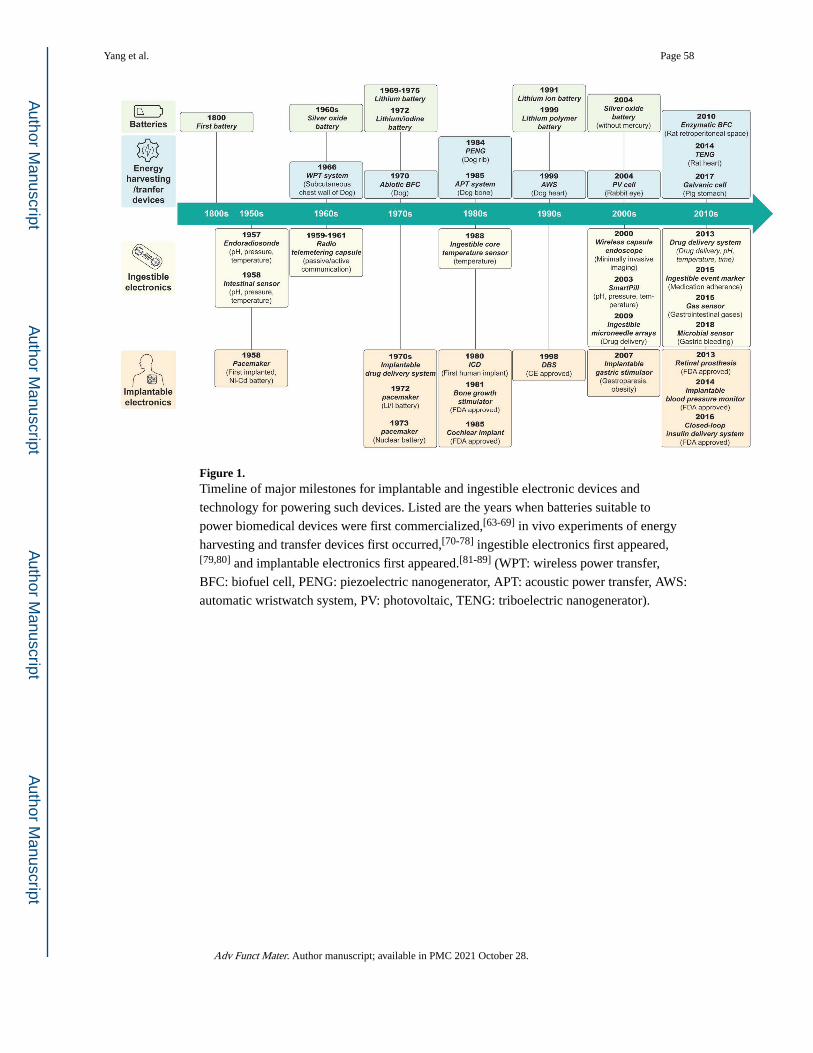
Figure 1. Timeline of major milestones for implantable and ingestible electronic devices and
technology for powering such devices. Listed are the years when batteries suitable to
power biomedical devices were first commercialized,[63-69] in vivo experiments of energy
harvesting and transfer devices first occurred,[70-78] ingestible electronics first appeared,[79,80] and implantable electronics first appeared.[81-89] (WPT: wireless power transfer,
BFC: biofuel cell, PENG: piezoelectric nanogenerator, APT: acoustic power transfer, AWS:
automatic wristwatch system, PV: photovoltaic, TENG: triboelectric nanogenerator).
Yang et al. Page 58
Adv Funct Mater. Author manuscript; available in PMC 2021 October 28.
Author M
anuscriptA
uthor Manuscript
Author M
anuscriptA
uthor Manuscript
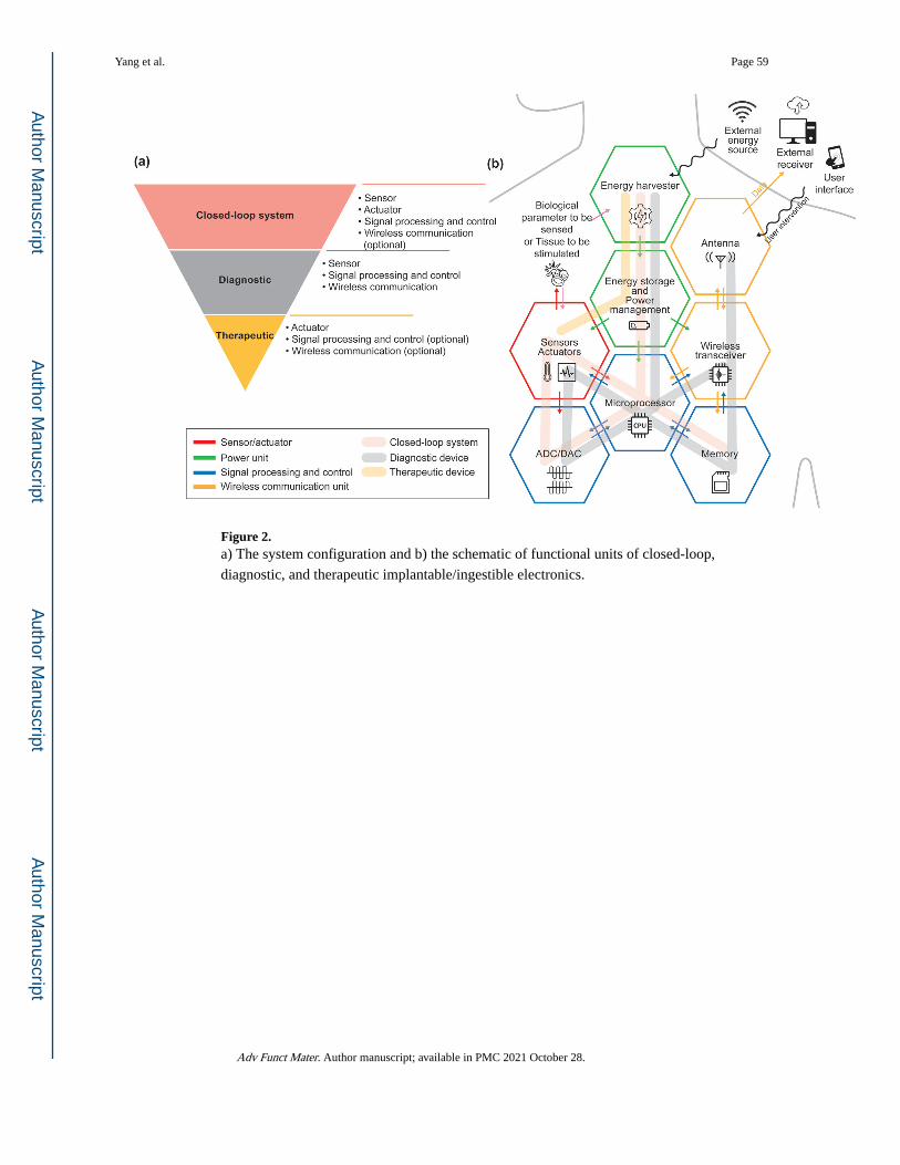
Figure 2. a) The system configuration and b) the schematic of functional units of closed-loop,
diagnostic, and therapeutic implantable/ingestible electronics.
Yang et al. Page 59
Adv Funct Mater. Author manuscript; available in PMC 2021 October 28.
Author M
anuscriptA
uthor Manuscript
Author M
anuscriptA
uthor Manuscript
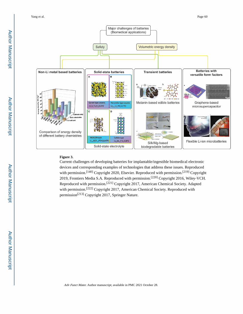
Figure 3. Current challenges of developing batteries for implantable/ingestible biomedical electronic
devices and corresponding examples of technologies that address these issues. Reproduced
with permission.[140] Copyright 2020, Elsevier. Reproduced with permission.[219] Copyright
2019, Frontiers Media S.A. Reproduced with permission.[220] Copyright 2016, Wiley-VCH.
Reproduced with permission.[221] Copyright 2017, American Chemical Society. Adapted
with permission.[222] Copyright 2017, American Chemical Society. Reproduced with
permission[213] Copyright 2017, Springer Nature.
Yang et al. Page 60
Adv Funct Mater. Author manuscript; available in PMC 2021 October 28.
Author M
anuscriptA
uthor Manuscript
Author M
anuscriptA
uthor Manuscript
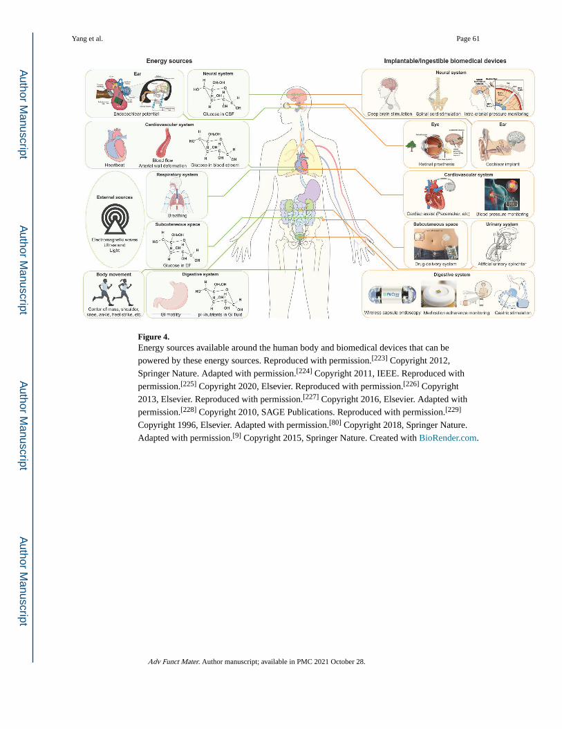
Figure 4. Energy sources available around the human body and biomedical devices that can be
powered by these energy sources. Reproduced with permission.[223] Copyright 2012,
Springer Nature. Adapted with permission.[224] Copyright 2011, IEEE. Reproduced with
permission.[225] Copyright 2020, Elsevier. Reproduced with permission.[226] Copyright
2013, Elsevier. Reproduced with permission.[227] Copyright 2016, Elsevier. Adapted with
permission.[228] Copyright 2010, SAGE Publications. Reproduced with permission.[229]
Copyright 1996, Elsevier. Adapted with permission.[80] Copyright 2018, Springer Nature.
Adapted with permission.[9] Copyright 2015, Springer Nature. Created with BioRender.com.
Yang et al. Page 61
Adv Funct Mater. Author manuscript; available in PMC 2021 October 28.
Author M
anuscriptA
uthor Manuscript
Author M
anuscriptA
uthor Manuscript
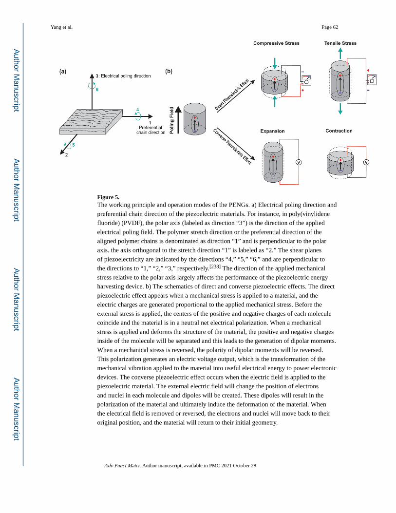
Figure 5. The working principle and operation modes of the PENGs. a) Electrical poling direction and
preferential chain direction of the piezoelectric materials. For instance, in poly(vinylidene
fluoride) (PVDF), the polar axis (labeled as direction “3”) is the direction of the applied
electrical poling field. The polymer stretch direction or the preferential direction of the
aligned polymer chains is denominated as direction “1” and is perpendicular to the polar
axis. the axis orthogonal to the stretch direction “1” is labeled as “2.” The shear planes
of piezoelectricity are indicated by the directions “4,” “5,” “6,” and are perpendicular to
the directions to “1,” “2,” “3,” respectively.[238] The direction of the applied mechanical
stress relative to the polar axis largely affects the performance of the piezoelectric energy
harvesting device. b) The schematics of direct and converse piezoelectric effects. The direct
piezoelectric effect appears when a mechanical stress is applied to a material, and the
electric charges are generated proportional to the applied mechanical stress. Before the
external stress is applied, the centers of the positive and negative charges of each molecule
coincide and the material is in a neutral net electrical polarization. When a mechanical
stress is applied and deforms the structure of the material, the positive and negative charges
inside of the molecule will be separated and this leads to the generation of dipolar moments.
When a mechanical stress is reversed, the polarity of dipolar moments will be reversed.
This polarization generates an electric voltage output, which is the transformation of the
mechanical vibration applied to the material into useful electrical energy to power electronic
devices. The converse piezoelectric effect occurs when the electric field is applied to the
piezoelectric material. The external electric field will change the position of electrons
and nuclei in each molecule and dipoles will be created. These dipoles will result in the
polarization of the material and ultimately induce the deformation of the material. When
the electrical field is removed or reversed, the electrons and nuclei will move back to their
original position, and the material will return to their initial geometry.
Yang et al. Page 62
Adv Funct Mater. Author manuscript; available in PMC 2021 October 28.
Author M
anuscriptA
uthor Manuscript
Author M
anuscriptA
uthor Manuscript
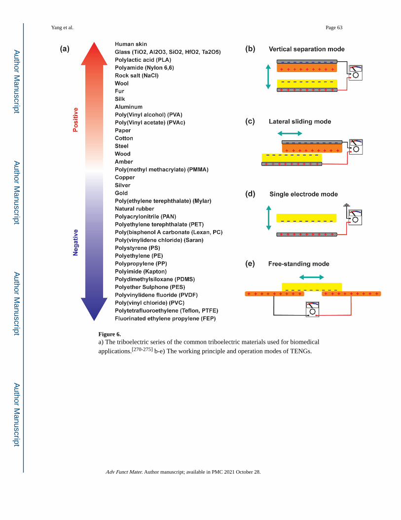
Figure 6. a) The triboelectric series of the common triboelectric materials used for biomedical
applications.[270-275] b-e) The working principle and operation modes of TENGs.
Yang et al. Page 63
Adv Funct Mater. Author manuscript; available in PMC 2021 October 28.
Author M
anuscriptA
uthor Manuscript
Author M
anuscriptA
uthor Manuscript
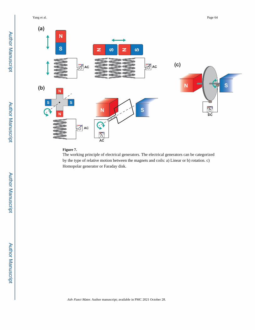
Figure 7. The working principle of electrical generators. The electrical generators can be categorized
by the type of relative motion between the magnets and coils: a) Linear or b) rotation. c)
Homopolar generator or Faraday disk.
Yang et al. Page 64
Adv Funct Mater. Author manuscript; available in PMC 2021 October 28.
Author M
anuscriptA
uthor Manuscript
Author M
anuscriptA
uthor Manuscript
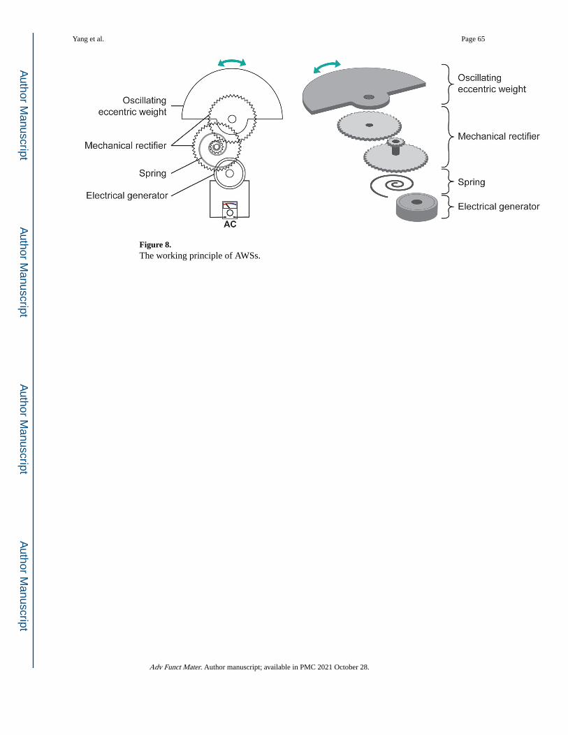
Figure 8. The working principle of AWSs.
Yang et al. Page 65
Adv Funct Mater. Author manuscript; available in PMC 2021 October 28.
Author M
anuscriptA
uthor Manuscript
Author M
anuscriptA
uthor Manuscript
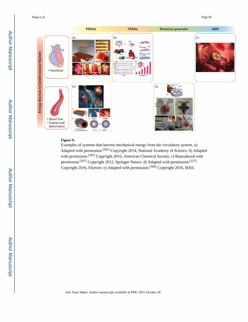
Figure 9. Examples of systems that harvest mechanical energy from the circulatory system. a)
Adapted with permission.[301] Copyright 2014, National Academy of Science. b) Adapted
with permission.[305] Copyright 2016, American Chemical Society. c) Reproduced with
permission.[307] Copyright 2012, Springer Nature. d) Adapted with permission.[227]
Copyright 2016, Elsevier. e) Adapted with permission.[309] Copyright 2016, IEEE.
Yang et al. Page 66
Adv Funct Mater. Author manuscript; available in PMC 2021 October 28.
Author M
anuscriptA
uthor Manuscript
Author M
anuscriptA
uthor Manuscript
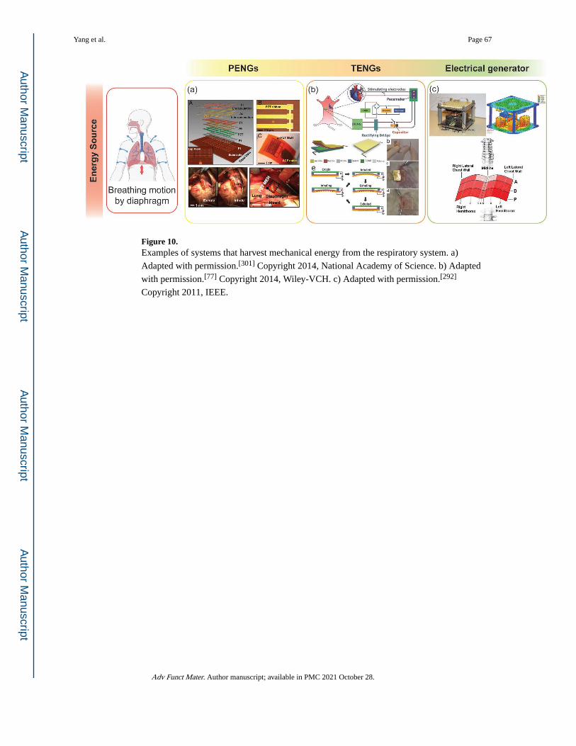
Figure 10. Examples of systems that harvest mechanical energy from the respiratory system. a)
Adapted with permission.[301] Copyright 2014, National Academy of Science. b) Adapted
with permission.[77] Copyright 2014, Wiley-VCH. c) Adapted with permission.[292]
Copyright 2011, IEEE.
Yang et al. Page 67
Adv Funct Mater. Author manuscript; available in PMC 2021 October 28.
Author M
anuscriptA
uthor Manuscript
Author M
anuscriptA
uthor Manuscript
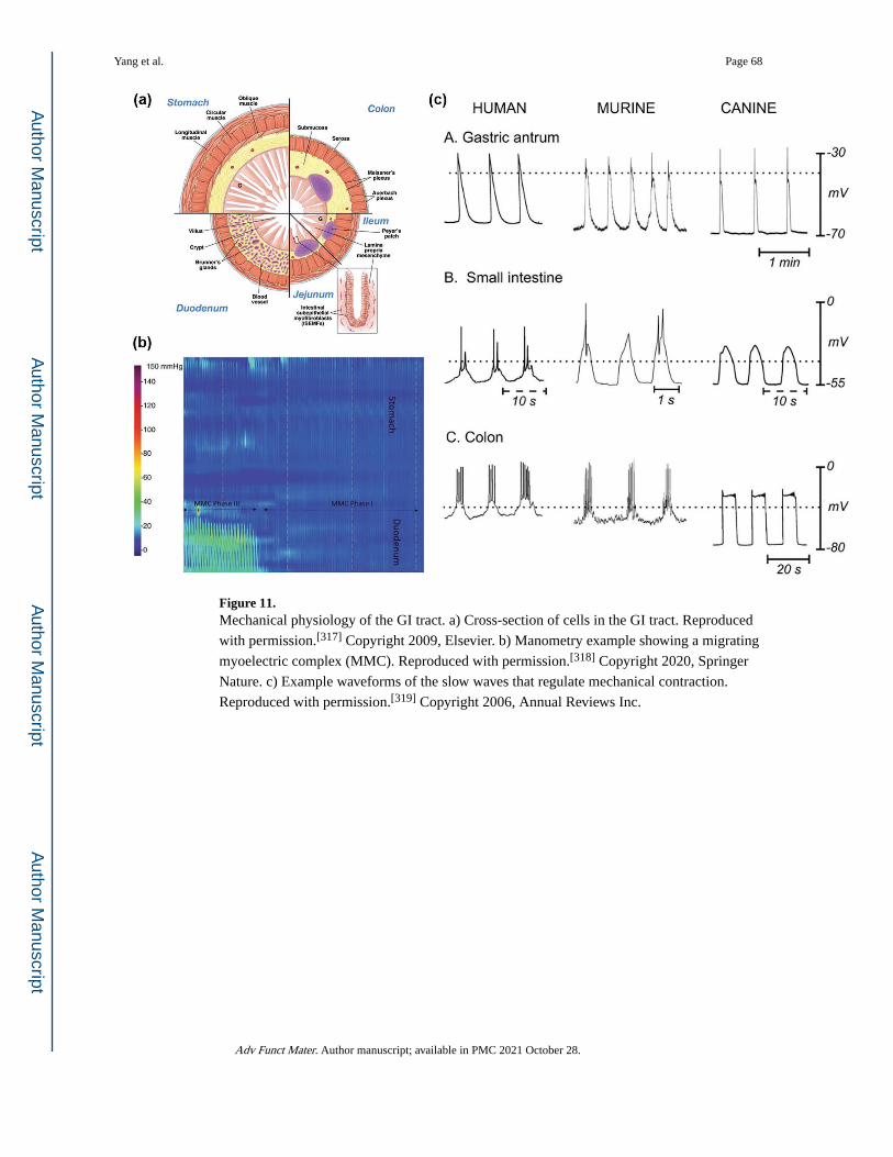
Figure 11. Mechanical physiology of the GI tract. a) Cross-section of cells in the GI tract. Reproduced
with permission.[317] Copyright 2009, Elsevier. b) Manometry example showing a migrating
myoelectric complex (MMC). Reproduced with permission.[318] Copyright 2020, Springer
Nature. c) Example waveforms of the slow waves that regulate mechanical contraction.
Reproduced with permission.[319] Copyright 2006, Annual Reviews Inc.
Yang et al. Page 68
Adv Funct Mater. Author manuscript; available in PMC 2021 October 28.
Author M
anuscriptA
uthor Manuscript
Author M
anuscriptA
uthor Manuscript
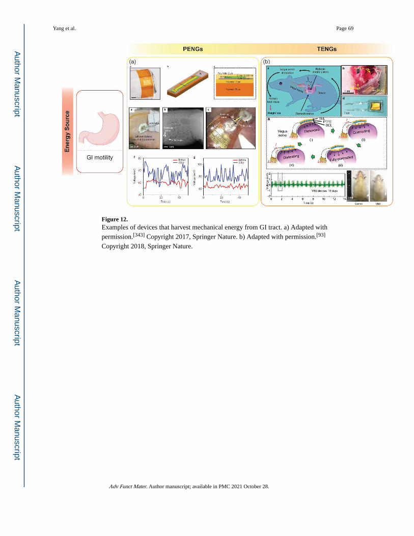
Figure 12. Examples of devices that harvest mechanical energy from GI tract. a) Adapted with
permission.[343] Copyright 2017, Springer Nature. b) Adapted with permission.[93]
Copyright 2018, Springer Nature.
Yang et al. Page 69
Adv Funct Mater. Author manuscript; available in PMC 2021 October 28.
Author M
anuscriptA
uthor Manuscript
Author M
anuscriptA
uthor Manuscript
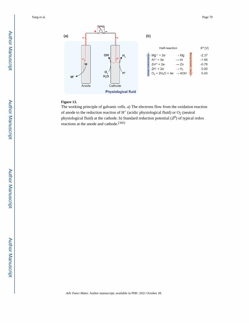
Figure 13. The working principle of galvanic cells. a) The electrons flow from the oxidation reaction
of anode to the reduction reaction of H+ (acidic physiological fluid) or O2 (neutral
physiological fluid) at the cathode. b) Standard reduction potential (E0) of typical redox
reactions at the anode and cathode.[345]
Yang et al. Page 70
Adv Funct Mater. Author manuscript; available in PMC 2021 October 28.
Author M
anuscriptA
uthor Manuscript
Author M
anuscriptA
uthor Manuscript
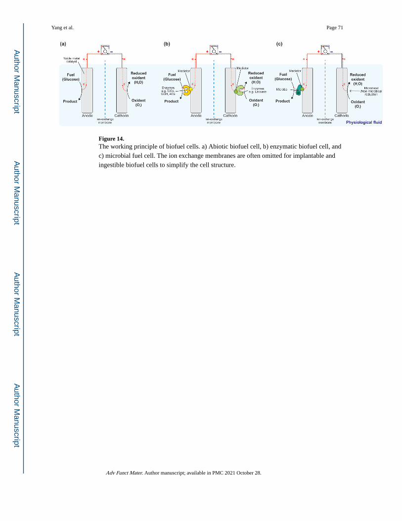
Figure 14. The working principle of biofuel cells. a) Abiotic biofuel cell, b) enzymatic biofuel cell, and
c) microbial fuel cell. The ion exchange membranes are often omitted for implantable and
ingestible biofuel cells to simplify the cell structure.
Yang et al. Page 71
Adv Funct Mater. Author manuscript; available in PMC 2021 October 28.
Author M
anuscriptA
uthor Manuscript
Author M
anuscriptA
uthor Manuscript
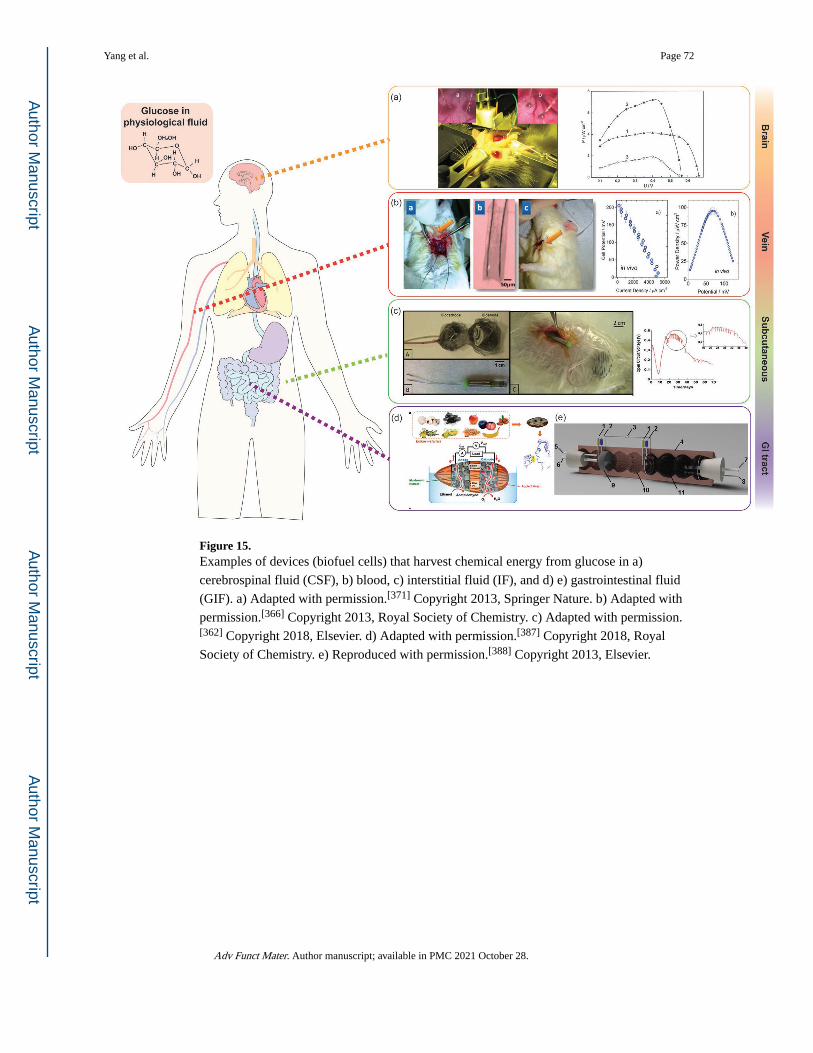
Figure 15. Examples of devices (biofuel cells) that harvest chemical energy from glucose in a)
cerebrospinal fluid (CSF), b) blood, c) interstitial fluid (IF), and d) e) gastrointestinal fluid
(GIF). a) Adapted with permission.[371] Copyright 2013, Springer Nature. b) Adapted with
permission.[366] Copyright 2013, Royal Society of Chemistry. c) Adapted with permission.[362] Copyright 2018, Elsevier. d) Adapted with permission.[387] Copyright 2018, Royal
Society of Chemistry. e) Reproduced with permission.[388] Copyright 2013, Elsevier.
Yang et al. Page 72
Adv Funct Mater. Author manuscript; available in PMC 2021 October 28.
Author M
anuscriptA
uthor Manuscript
Author M
anuscriptA
uthor Manuscript
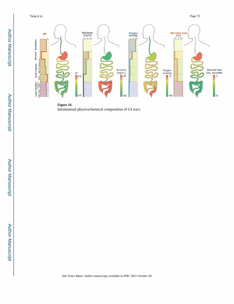
Figure 16. Intraluminal physicochemical composition of GI tract.
Yang et al. Page 73
Adv Funct Mater. Author manuscript; available in PMC 2021 October 28.
Author M
anuscriptA
uthor Manuscript
Author M
anuscriptA
uthor Manuscript
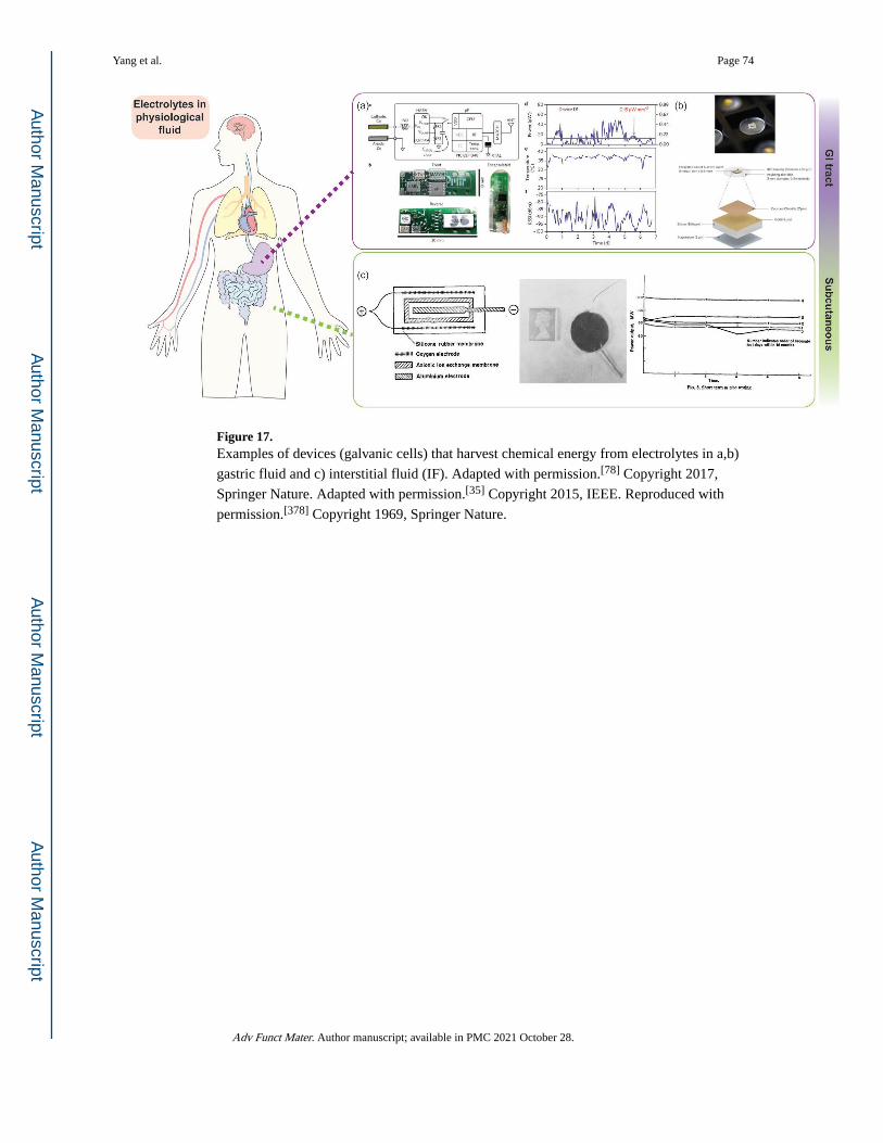
Figure 17. Examples of devices (galvanic cells) that harvest chemical energy from electrolytes in a,b)
gastric fluid and c) interstitial fluid (IF). Adapted with permission.[78] Copyright 2017,
Springer Nature. Adapted with permission.[35] Copyright 2015, IEEE. Reproduced with
permission.[378] Copyright 1969, Springer Nature.
Yang et al. Page 74
Adv Funct Mater. Author manuscript; available in PMC 2021 October 28.
Author M
anuscriptA
uthor Manuscript
Author M
anuscriptA
uthor Manuscript
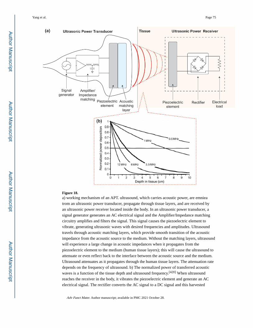
Figure 18. a) working mechanism of an APT. ultrasound, which carries acoustic power, are emniea
trom an ultrasonic power transducer, propagate through tissue layers, and are received by
an ultrasonic power receiver located inside the body. In an ultrasonic power transducer, a
signal generator generates an AC electrical signal and the Amplifier/Impedance matching
circuitry amplifies and filters the signal. This signal causes the piezoelectric element to
vibrate, generating ultrasonic waves with desired frequencies and amplitudes. Ultrasound
travels through acoustic matching layers, which provide smooth transition of the acoustic
impedance from the acoustic source to the medium. Without the matching layers, ultrasound
will experience a large change in acoustic impedances when it propagates from the
piezoelectric element to the medium (human tissue layers); this will cause the ultrasound to
attenuate or even reflect back to the interface between the acoustic source and the medium.
Ultrasound attenuates as it propagates through the human tissue layers. The attenuation rate
depends on the frequency of ultrasound. b) The normalized power of transferred acoustic
waves is a function of the tissue depth and ultrasound frequency.[420] When ultrasound
reaches the receiver in the body, it vibrates the piezoelectric element and generate an AC
electrical signal. The rectifier converts the AC signal to a DC signal and this harvested
Yang et al. Page 75
Adv Funct Mater. Author manuscript; available in PMC 2021 October 28.
Author M
anuscriptA
uthor Manuscript
Author M
anuscriptA
uthor Manuscript
electrical energy can drive the electrical load to perform the desired task. Reproduced with
permission.[420] Copyright 2014, Elsevier.
Yang et al. Page 76
Adv Funct Mater. Author manuscript; available in PMC 2021 October 28.
Author M
anuscriptA
uthor Manuscript
Author M
anuscriptA
uthor Manuscript
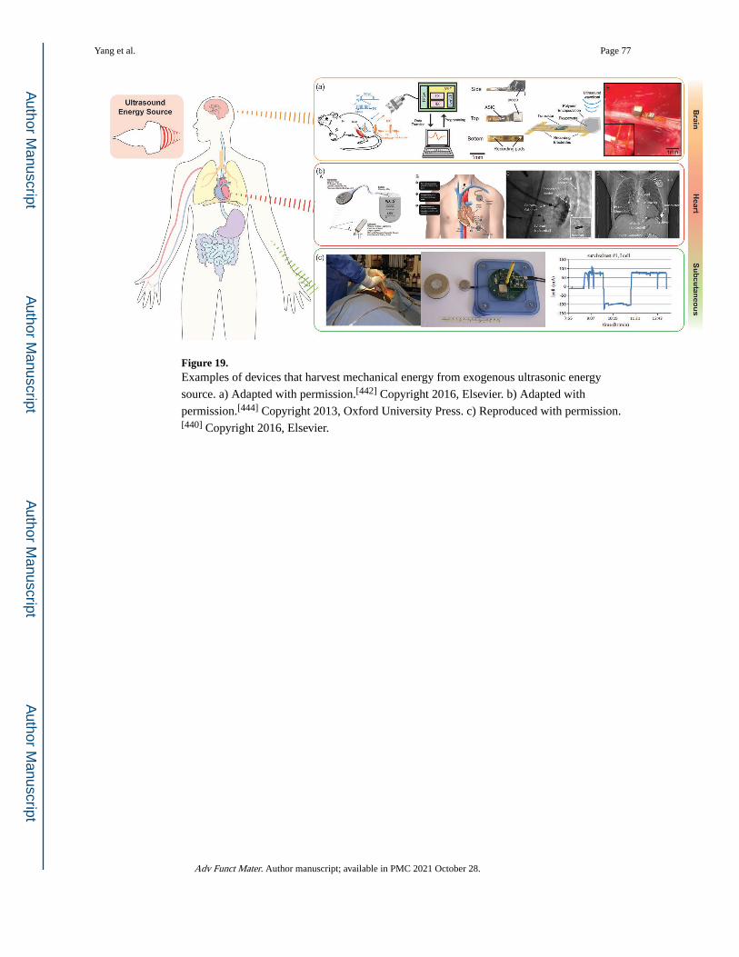
Figure 19. Examples of devices that harvest mechanical energy from exogenous ultrasonic energy
source. a) Adapted with permission.[442] Copyright 2016, Elsevier. b) Adapted with
permission.[444] Copyright 2013, Oxford University Press. c) Reproduced with permission.[440] Copyright 2016, Elsevier.
Yang et al. Page 77
Adv Funct Mater. Author manuscript; available in PMC 2021 October 28.
Author M
anuscriptA
uthor Manuscript
Author M
anuscriptA
uthor Manuscript
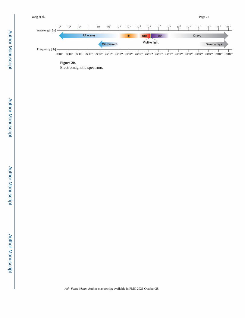
Figure 20. Electromagnetic spectrum.
Yang et al. Page 78
Adv Funct Mater. Author manuscript; available in PMC 2021 October 28.
Author M
anuscriptA
uthor Manuscript
Author M
anuscriptA
uthor Manuscript
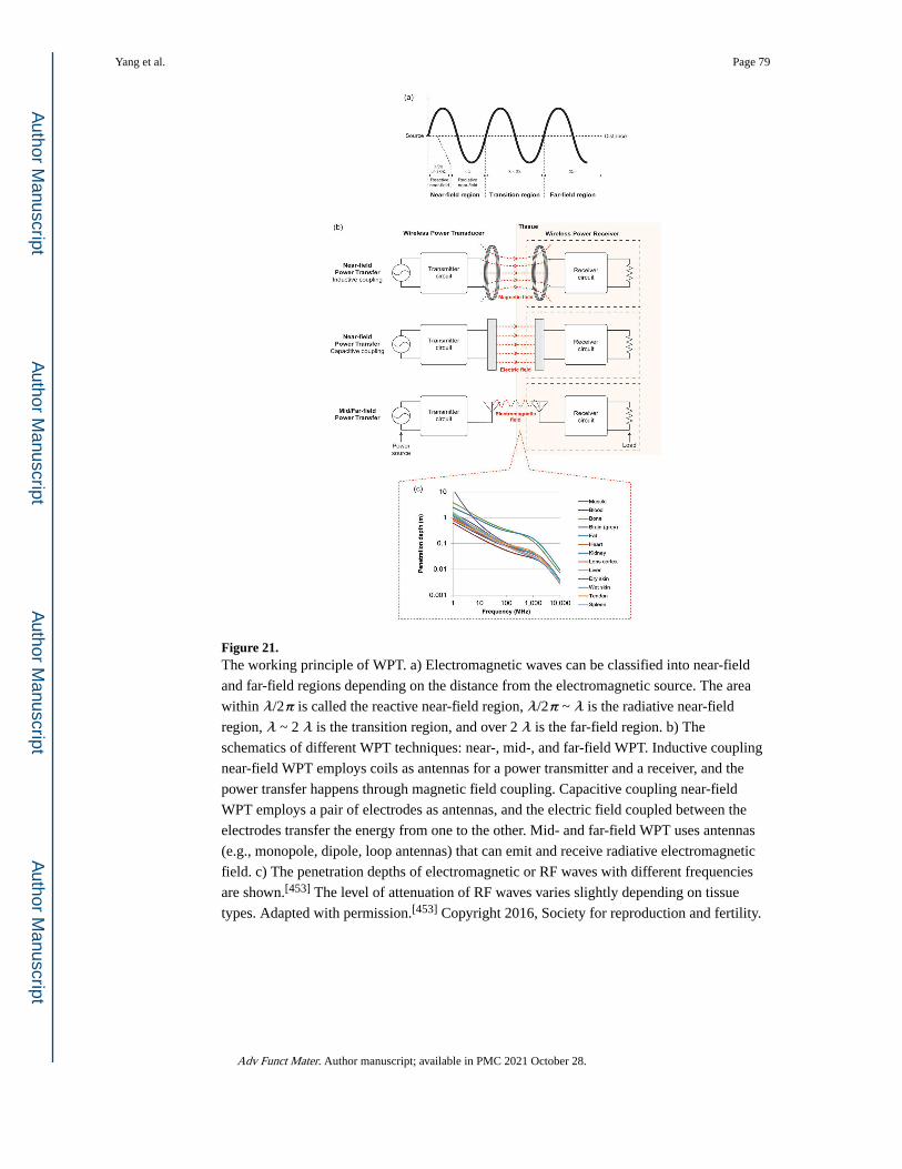
Figure 21. The working principle of WPT. a) Electromagnetic waves can be classified into near-field
and far-field regions depending on the distance from the electromagnetic source. The area
within λ/2π is called the reactive near-field region, λ/2π ~ λ is the radiative near-field
region, λ ~ 2 λ is the transition region, and over 2 λ is the far-field region. b) The
schematics of different WPT techniques: near-, mid-, and far-field WPT. Inductive coupling
near-field WPT employs coils as antennas for a power transmitter and a receiver, and the
power transfer happens through magnetic field coupling. Capacitive coupling near-field
WPT employs a pair of electrodes as antennas, and the electric field coupled between the
electrodes transfer the energy from one to the other. Mid- and far-field WPT uses antennas
(e.g., monopole, dipole, loop antennas) that can emit and receive radiative electromagnetic
field. c) The penetration depths of electromagnetic or RF waves with different frequencies
are shown.[453] The level of attenuation of RF waves varies slightly depending on tissue
types. Adapted with permission.[453] Copyright 2016, Society for reproduction and fertility.
Yang et al. Page 79
Adv Funct Mater. Author manuscript; available in PMC 2021 October 28.
Author M
anuscriptA
uthor Manuscript
Author M
anuscriptA
uthor Manuscript
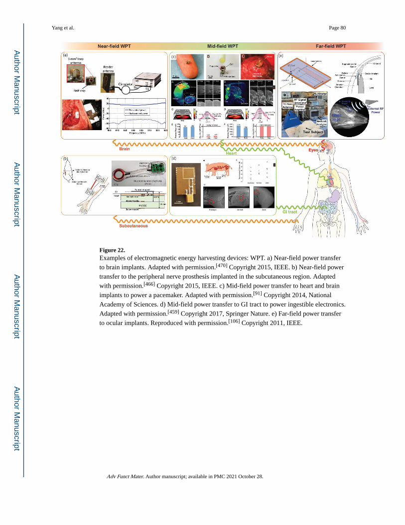
Figure 22. Examples of electromagnetic energy harvesting devices: WPT. a) Near-field power transfer
to brain implants. Adapted with permission.[470] Copyright 2015, IEEE. b) Near-field power
transfer to the peripheral nerve prosthesis implanted in the subcutaneous region. Adapted
with permission.[466] Copyright 2015, IEEE. c) Mid-field power transfer to heart and brain
implants to power a pacemaker. Adapted with permission.[91] Copyright 2014, National
Academy of Sciences. d) Mid-field power transfer to GI tract to power ingestible electronics.
Adapted with permission.[459] Copyright 2017, Springer Nature. e) Far-field power transfer
to ocular implants. Reproduced with permission.[106] Copyright 2011, IEEE.
Yang et al. Page 80
Adv Funct Mater. Author manuscript; available in PMC 2021 October 28.
Author M
anuscriptA
uthor Manuscript
Author M
anuscriptA
uthor Manuscript
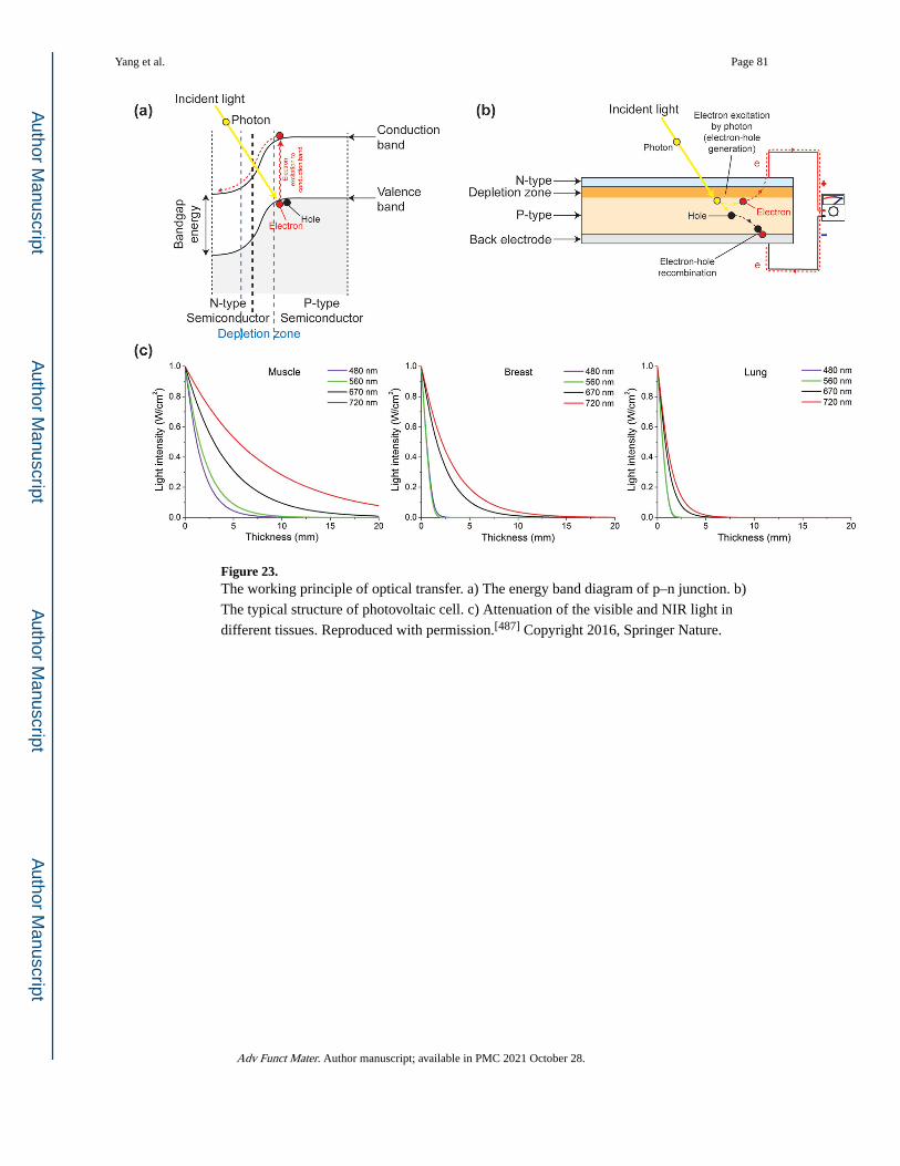
Figure 23. The working principle of optical transfer. a) The energy band diagram of p–n junction. b)
The typical structure of photovoltaic cell. c) Attenuation of the visible and NIR light in
different tissues. Reproduced with permission.[487] Copyright 2016, Springer Nature.
Yang et al. Page 81
Adv Funct Mater. Author manuscript; available in PMC 2021 October 28.
Author M
anuscriptA
uthor Manuscript
Author M
anuscriptA
uthor Manuscript
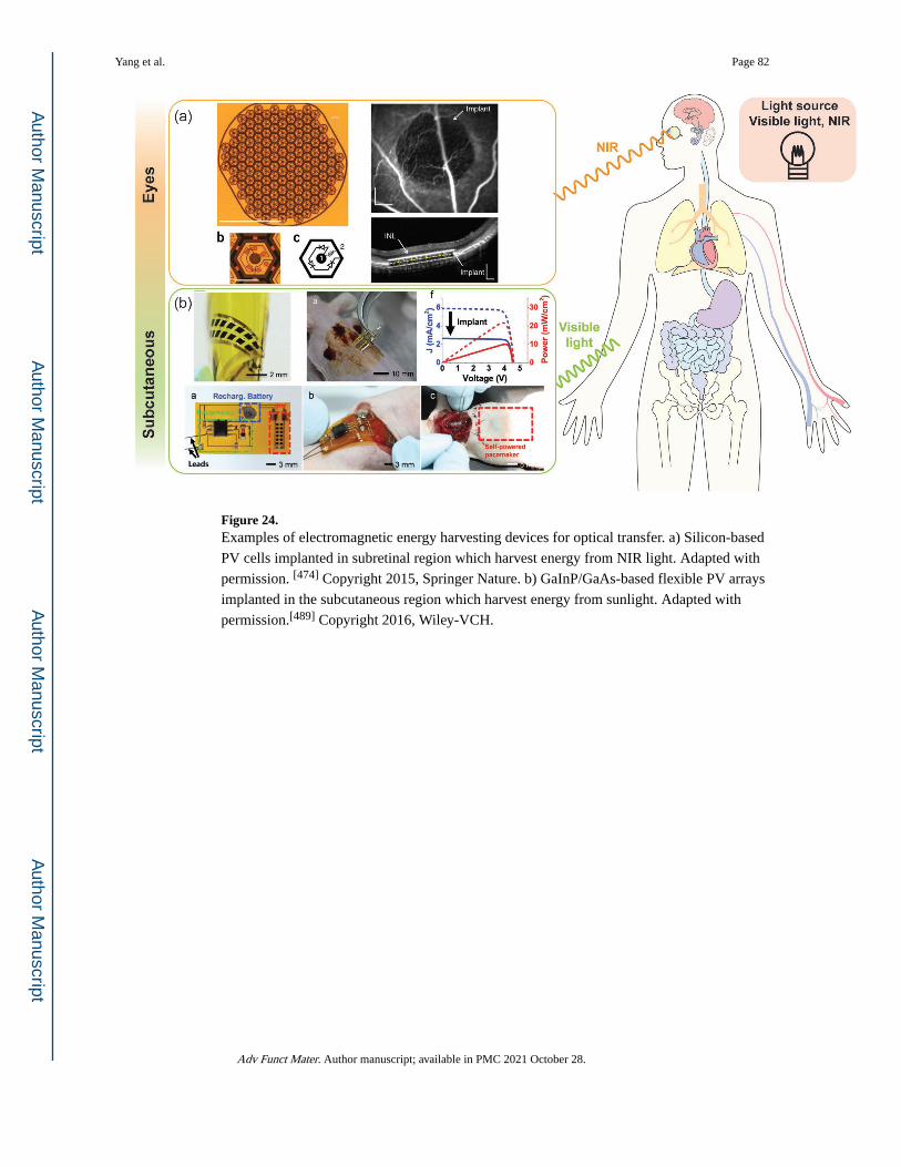
Figure 24. Examples of electromagnetic energy harvesting devices for optical transfer. a) Silicon-based
PV cells implanted in subretinal region which harvest energy from NIR light. Adapted with
permission. [474] Copyright 2015, Springer Nature. b) GaInP/GaAs-based flexible PV arrays
implanted in the subcutaneous region which harvest energy from sunlight. Adapted with
permission.[489] Copyright 2016, Wiley-VCH.
Yang et al. Page 82
Adv Funct Mater. Author manuscript; available in PMC 2021 October 28.
Author M
anuscriptA
uthor Manuscript
Author M
anuscriptA
uthor Manuscript
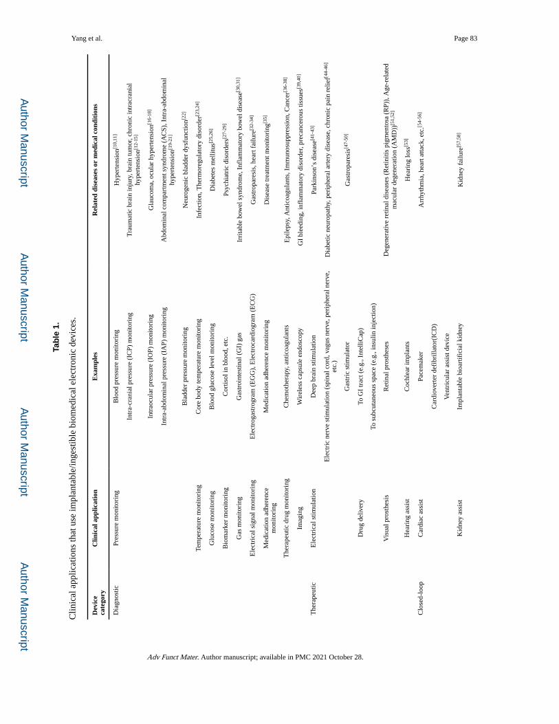
Author M
anuscriptA
uthor Manuscript
Author M
anuscriptA
uthor Manuscript
Yang et al. Page 83
Tab
le 1
.
Clin
ical
app
licat
ions
that
use
impl
anta
ble/
inge
stib
le b
iom
edic
al e
lect
roni
c de
vice
s.
Dev
ice
cate
gory
Clin
ical
app
licat
ion
Exa
mpl
esR
elat
ed d
isea
ses
or m
edic
al c
ondi
tion
s
Dia
gnos
ticPr
essu
re m
onito
ring
Blo
od p
ress
ure
mon
itori
ngH
yper
tens
ion[1
0,11
]
Intr
a-cr
ania
l pre
ssur
e (I
CP)
mon
itori
ngT
raum
atic
bra
in in
jury
, bra
in tu
mor
, chr
onic
intr
acra
nial
hy
pert
ensi
on[1
2-15
]
Intr
aocu
lar
pres
sure
(IO
P) m
onito
ring
Gla
ucom
a, o
cula
r hy
pert
ensi
on[1
6-18
]
Intr
a-ab
dom
inal
pre
ssur
e (I
AP)
mon
itori
ngA
bdom
inal
com
part
men
t syn
drom
e (A
CS)
, Int
ra-a
bdom
inal
hy
pert
ensi
on[1
9-21
]
Bla
dder
pre
ssur
e m
onito
ring
Neu
roge
nic
blad
der
dysf
unct
ion[2
2]
Tem
pera
ture
mon
itori
ngC
ore
body
tem
pera
ture
mon
itori
ngIn
fect
ion,
The
rmor
egul
ator
y di
sord
er[2
3,24
]
Glu
cose
mon
itori
ngB
lood
glu
cose
leve
l mon
itori
ngD
iabe
tes
mel
litus
[25,
26]
Bio
mar
ker
mon
itori
ngC
ortis
ol in
blo
od, e
tc.
Psyc
hiat
ric
diso
rder
s[27-
29]
Gas
mon
itori
ngG
astr
oint
estin
al (
GI)
gas
Irri
tabl
e bo
wel
syn
drom
e, I
nfla
mm
ator
y bo
wel
dis
ease
[30,
31]
Ele
ctri
cal s
igna
l mon
itori
ngE
lect
roga
stro
gram
(E
GG
), E
lect
roca
rdio
gram
(E
CG
)G
astr
opar
esis
, hea
rt f
ailu
re[3
2-34
]
Med
icat
ion
adhe
renc
e m
onito
ring
Med
icat
ion
adhe
renc
e m
onito
ring
Dis
ease
trea
tmen
t mon
itori
ng[3
5]
The
rape
utic
dru
g m
onito
ring
Che
mot
hera
py, a
ntic
oagu
lant
sE
pile
psy,
Ant
icoa
gula
nts,
Im
mun
osup
pres
sion
, Can
cer[3
6-38
]
Imag
ing
Wir
eles
s ca
psul
e en
dosc
opy
GI
blee
ding
, inf
lam
mat
ory
diso
rder
, pre
canc
erou
s tis
sues
[39,
40]
The
rape
utic
Ele
ctri
cal s
timul
atio
nD
eep
brai
n st
imul
atio
nPa
rkin
son’
s di
seas
e[41-
43]
Ele
ctri
c ne
rve
stim
ulat
ion
(spi
nal c
ord,
vag
us n
erve
, per
iphe
ral n
erve
, et
c.)
Dia
betic
neu
ropa
thy,
per
iphe
ral a
rter
y di
seas
e, c
hron
ic p
ain
relie
f[44-
46]
Gas
tric
stim
ulat
orG
astr
opar
esis
[47-
50]
Dru
g de
liver
yTo
GI
trac
t (e.
g., I
ntel
liCap
)
To s
ubcu
tane
ous
spac
e (e
.g.,
insu
lin in
ject
ion)
Vis
ual p
rost
hesi
sR
etin
al p
rost
hese
sD
egen
erat
ive
retin
al d
isea
ses
(Ret
initi
s pi
gmen
tosa
(R
P)),
Age
-rel
ated
m
acul
ar d
egen
erat
ion
(AM
D))
[51,
52]
Hea
ring
ass
ist
Coc
hlea
r im
plan
tsH
eari
ng lo
ss[5
3]
Clo
sed-
loop
Car
diac
ass
ist
Pace
mak
erA
rrhy
thm
ia, h
eart
atta
ck, e
tc.[5
4-56
]
Car
diov
erte
r de
fibr
illat
or(I
CD
)
Ven
tric
ular
ass
ist d
evic
e
Kid
ney
assi
stIm
plan
tabl
e bi
oart
ific
ial k
idne
yK
idne
y fa
ilure
[57,
58]
Adv Funct Mater. Author manuscript; available in PMC 2021 October 28.
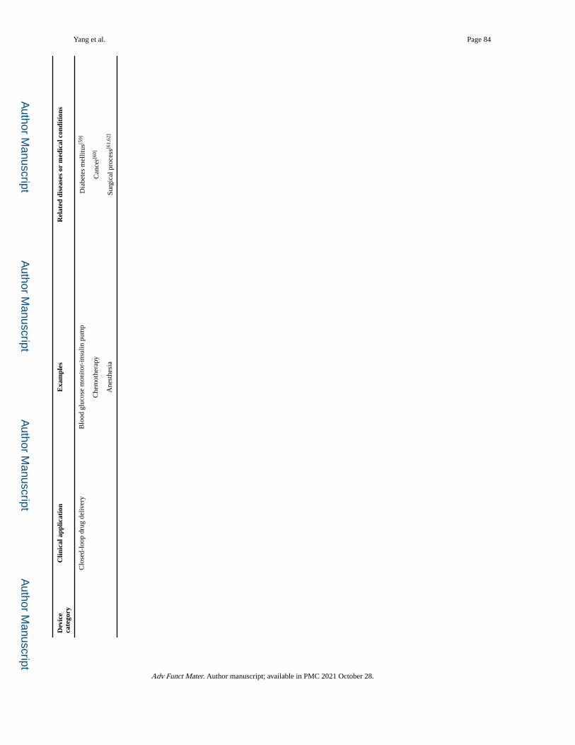
Author M
anuscriptA
uthor Manuscript
Author M
anuscriptA
uthor Manuscript
Yang et al. Page 84
Dev
ice
cate
gory
Clin
ical
app
licat
ion
Exa
mpl
esR
elat
ed d
isea
ses
or m
edic
al c
ondi
tion
s
Clo
sed-
loop
dru
g de
liver
yB
lood
glu
cose
mon
itor-
insu
lin p
ump
Dia
bete
s m
ellit
us[5
9]
Che
mot
hera
pyC
ance
r[60]
Ane
sthe
sia
Surg
ical
pro
cess
[61,
62]
Adv Funct Mater. Author manuscript; available in PMC 2021 October 28.
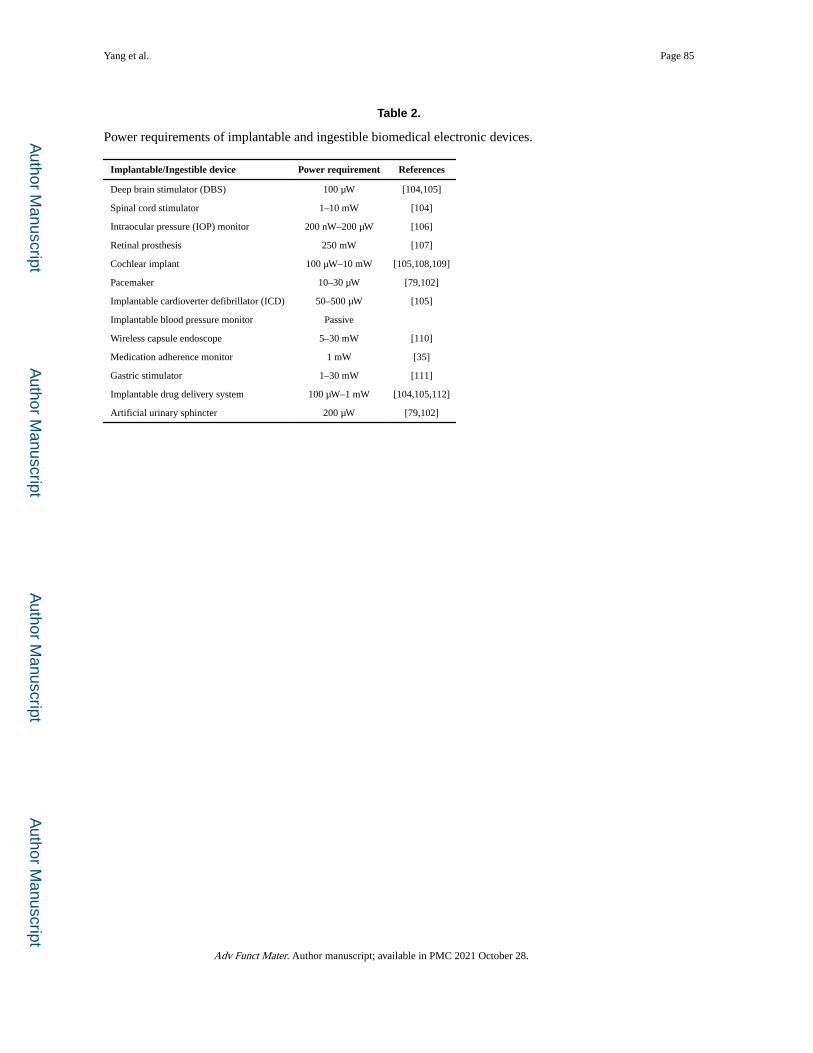
Author M
anuscriptA
uthor Manuscript
Author M
anuscriptA
uthor Manuscript
Yang et al. Page 85
Table 2.
Power requirements of implantable and ingestible biomedical electronic devices.
Implantable/Ingestible device Power requirement References
Deep brain stimulator (DBS) 100 μW [104,105]
Spinal cord stimulator 1–10 mW [104]
Intraocular pressure (IOP) monitor 200 nW–200 μW [106]
Retinal prosthesis 250 mW [107]
Cochlear implant 100 μW–10 mW [105,108,109]
Pacemaker 10–30 μW [79,102]
Implantable cardioverter defibrillator (ICD) 50–500 μW [105]
Implantable blood pressure monitor Passive
Wireless capsule endoscope 5–30 mW [110]
Medication adherence monitor 1 mW [35]
Gastric stimulator 1–30 mW [111]
Implantable drug delivery system 100 μW–1 mW [104,105,112]
Artificial urinary sphincter 200 μW [79,102]
Adv Funct Mater. Author manuscript; available in PMC 2021 October 28.
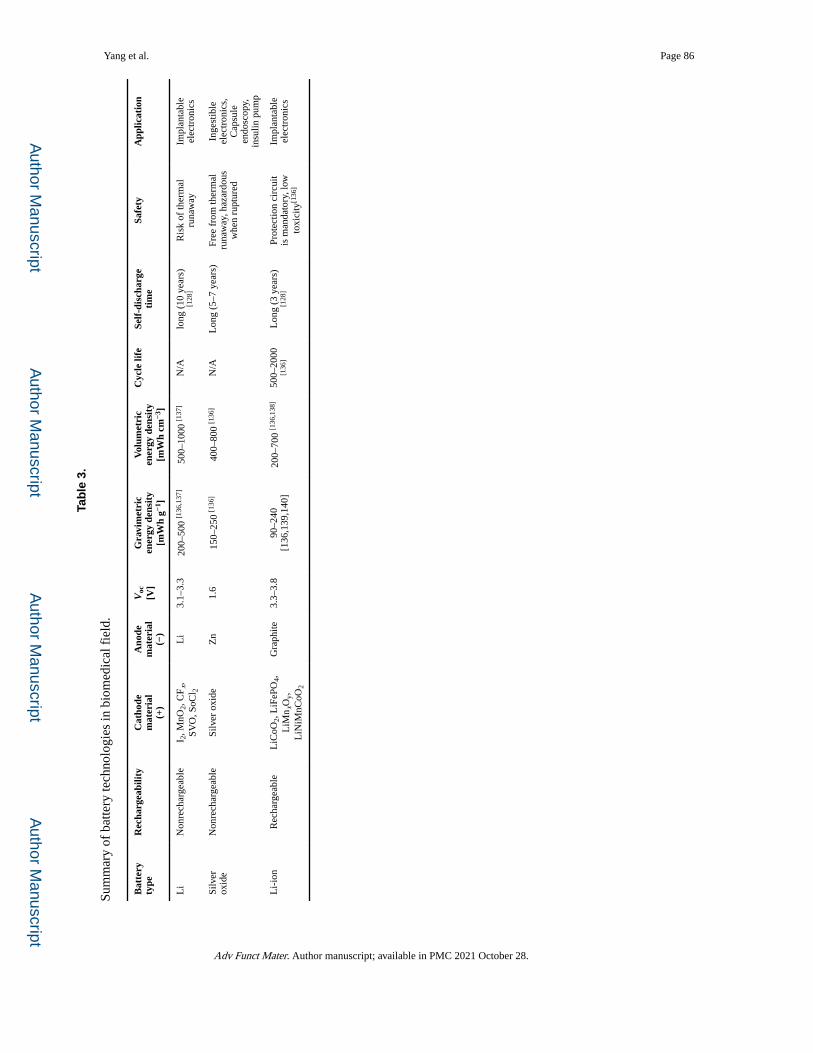
Author M
anuscriptA
uthor Manuscript
Author M
anuscriptA
uthor Manuscript
Yang et al. Page 86
Tab
le 3
.
Sum
mar
y of
bat
tery
tech
nolo
gies
in b
iom
edic
al f
ield
.
Bat
tery
ty
peR
echa
rgea
bilit
yC
atho
dem
ater
ial
(+)
Ano
dem
ater
ial
(−)
Voc
[V]
Gra
vim
etri
cen
ergy
den
sity
[mW
h g−1
]
Vol
umet
ric
ener
gy d
ensi
ty[m
Wh
cm−3
]
Cyc
le li
feSe
lf-d
isch
arge
ti
me
Safe
tyA
pplic
atio
n
Li
Non
rech
arge
able
I 2, M
nO2,
CF x
, SV
O, S
oCl 2
Li
3.1–
3.3
200–
500
[136
,137
]50
0–10
00 [1
37]
N/A
long
(10
yea
rs)
[128
]R
isk
of th
erm
al
runa
way
Impl
anta
ble
elec
tron
ics
Silv
er
oxid
eN
onre
char
geab
leSi
lver
oxi
deZ
n1.
615
0–25
0 [1
36]
400–
800
[136
]N
/AL
ong
(5–7
yea
rs)
Free
fro
m th
erm
al
runa
way
, haz
ardo
us
whe
n ru
ptur
ed
Inge
stib
le
elec
tron
ics,
C
apsu
le
endo
scop
y,
insu
lin p
ump
Li-
ion
Rec
harg
eabl
eL
iCoO
2, L
iFeP
O4,
L
iMn x
Oy,
L
iNiM
nCoO
2
Gra
phite
3.3–
3.8
90–2
40
[136
,139
,140
]20
0–70
0 [1
36,1
38]
500–
2000
[1
36]
Lon
g (3
yea
rs)
[128
]Pr
otec
tion
circ
uit
is m
anda
tory
, low
to
xici
ty[1
36]
Impl
anta
ble
elec
tron
ics
Adv Funct Mater. Author manuscript; available in PMC 2021 October 28.
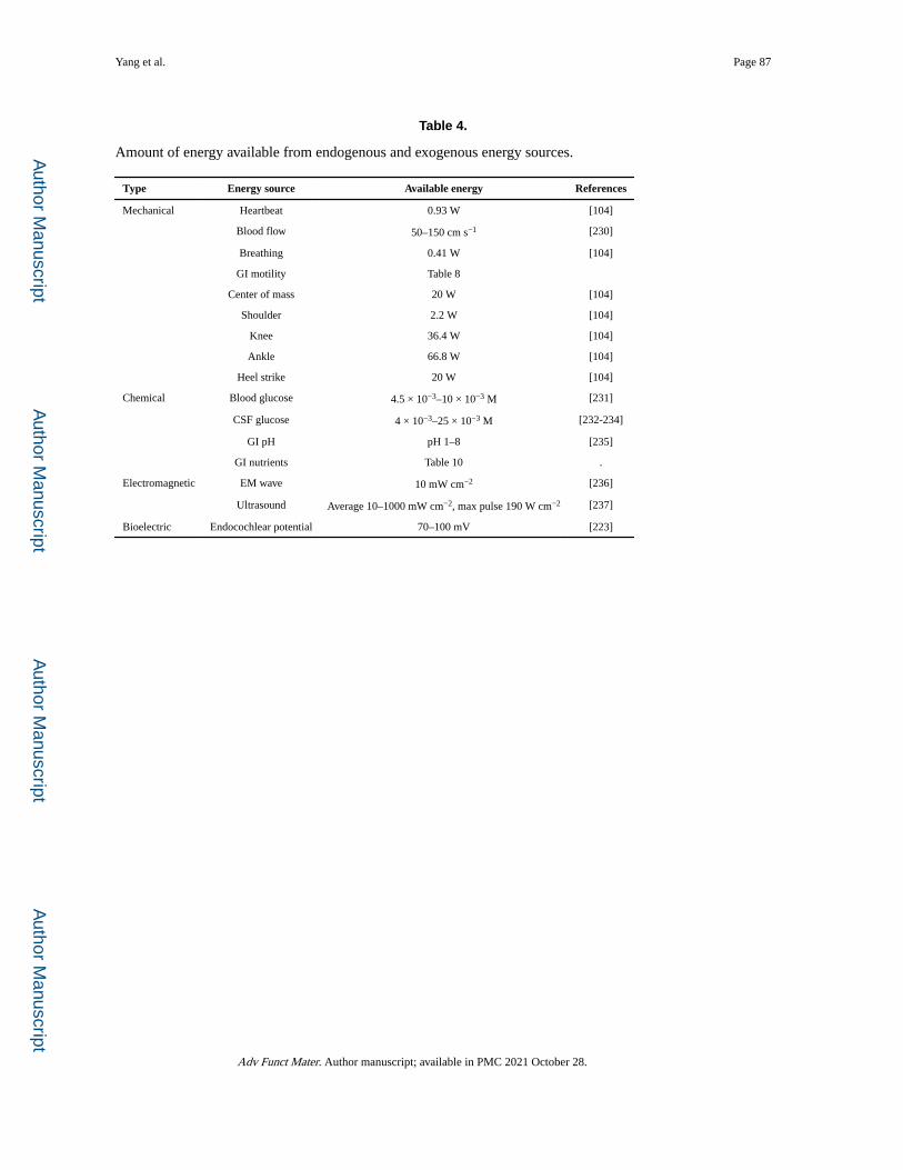
Author M
anuscriptA
uthor Manuscript
Author M
anuscriptA
uthor Manuscript
Yang et al. Page 87
Table 4.
Amount of energy available from endogenous and exogenous energy sources.
Type Energy source Available energy References
Mechanical Heartbeat 0.93 W [104]
Blood flow 50–150 cm s−1 [230]
Breathing 0.41 W [104]
GI motility Table 8
Center of mass 20 W [104]
Shoulder 2.2 W [104]
Knee 36.4 W [104]
Ankle 66.8 W [104]
Heel strike 20 W [104]
Chemical Blood glucose 4.5 × 10⁻³–10 × 10−3 M [231]
CSF glucose 4 × 10⁻³–25 × 10−3 M [232-234]
GI pH pH 1–8 [235]
GI nutrients Table 10 .
Electromagnetic EM wave 10 mW cm−2 [236]
Ultrasound Average 10–1000 mW cm−2, max pulse 190 W cm−2 [237]
Bioelectric Endocochlear potential 70–100 mV [223]
Adv Funct Mater. Author manuscript; available in PMC 2021 October 28.
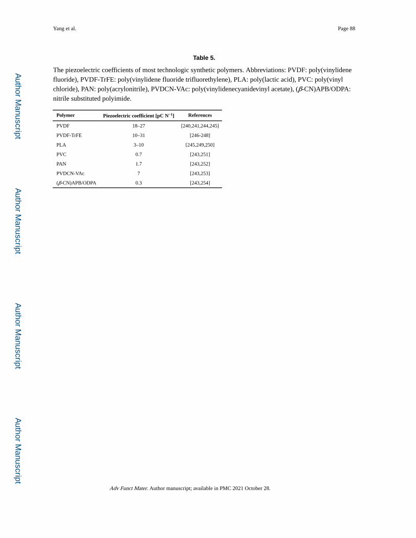
Author M
anuscriptA
uthor Manuscript
Author M
anuscriptA
uthor Manuscript
Yang et al. Page 88
Table 5.
The piezoelectric coefficients of most technologic synthetic polymers. Abbreviations: PVDF: poly(vinylidene
fluoride), PVDF-TrFE: poly(vinylidene fluoride trifluorethylene), PLA: poly(lactic acid), PVC: poly(vinyl
chloride), PAN: poly(acrylonitrile), PVDCN-VAc: poly(vinylidenecyanidevinyl acetate), (β-CN)APB/ODPA:
nitrile substituted polyimide.
Polymer Piezoelectric coefficient [pC N−1] References
PVDF 18–27 [240,241,244,245]
PVDF-TrFE 10–31 [246-248]
PLA 3–10 [245,249,250]
PVC 0.7 [243,251]
PAN 1.7 [243,252]
PVDCN-VAc 7 [243,253]
(β-CN)APB/ODPA 0.3 [243,254]
Adv Funct Mater. Author manuscript; available in PMC 2021 October 28.
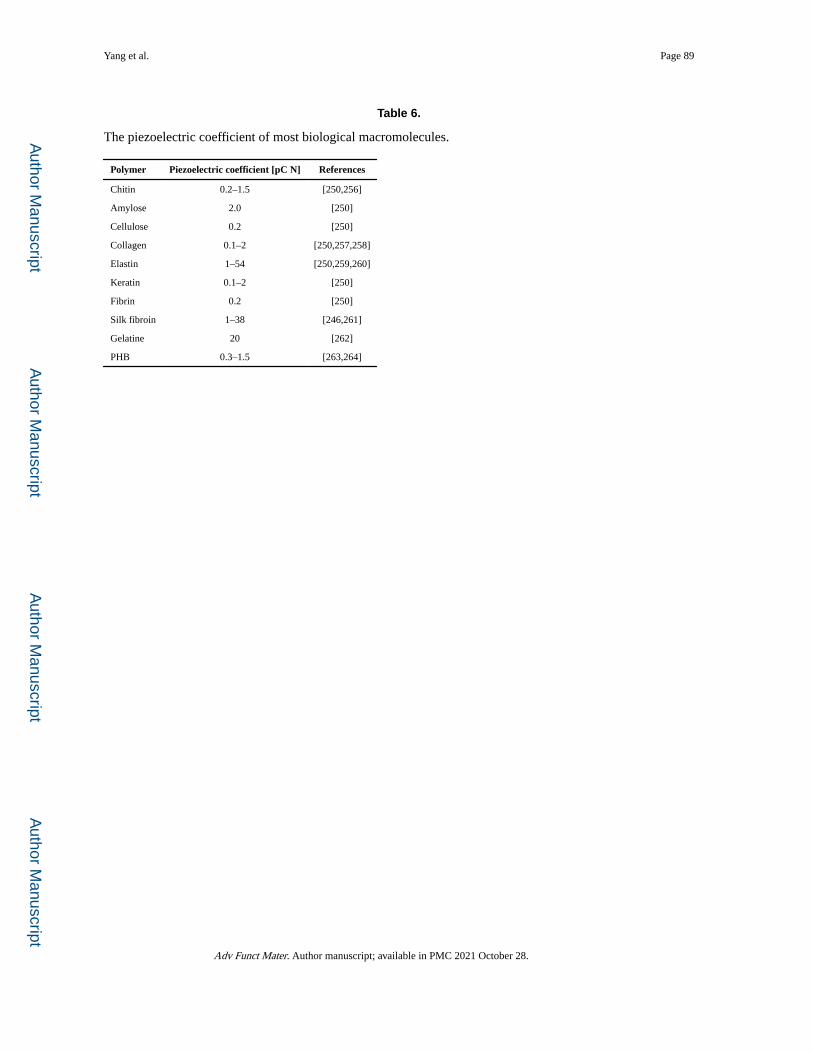
Author M
anuscriptA
uthor Manuscript
Author M
anuscriptA
uthor Manuscript
Yang et al. Page 89
Table 6.
The piezoelectric coefficient of most biological macromolecules.
Polymer Piezoelectric coefficient [pC N] References
Chitin 0.2–1.5 [250,256]
Amylose 2.0 [250]
Cellulose 0.2 [250]
Collagen 0.1–2 [250,257,258]
Elastin 1–54 [250,259,260]
Keratin 0.1–2 [250]
Fibrin 0.2 [250]
Silk fibroin 1–38 [246,261]
Gelatine 20 [262]
PHB 0.3–1.5 [263,264]
Adv Funct Mater. Author manuscript; available in PMC 2021 October 28.
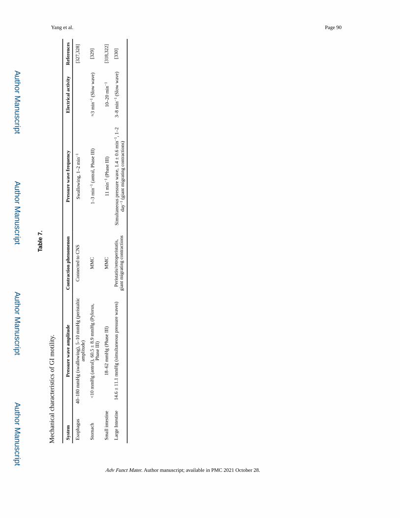
Author M
anuscriptA
uthor Manuscript
Author M
anuscriptA
uthor Manuscript
Yang et al. Page 90
Tab
le 7
.
Mec
hani
cal c
hara
cter
istic
s of
GI
mot
ility
.
Syst
emP
ress
ure
wav
e am
plit
ude
Con
trac
tion
phe
nom
enon
Pre
ssur
e w
ave
freq
uenc
yE
lect
rica
l act
ivit
yR
efer
ence
s
Eso
phag
us40
–180
mm
Hg
(sw
allo
win
g), 5
–10
mm
Hg
(per
ista
ltic
ampl
itude
)C
onne
cted
to C
NS
Swal
low
ing,
1–2
min
−1
[327
,328
]
Stom
ach
<10
mm
Hg
(ant
ral)
, 60.
5 ±
8.9
mm
Hg
(Pyl
orus
, Ph
ase
III)
MM
C1–
3 m
in−
1 (a
ntra
l, Ph
ase
III)
≈3
min
−1
(Slo
w w
ave)
[329
]
Smal
l int
estin
e18
–62
mm
Hg
(Pha
se I
II)
MM
C11
min
−1
(Pha
se I
II)
10–2
0 m
in−
1[3
18,3
22]
Lar
ge I
ntes
tine
14.6
± 1
1.1
mm
Hg
(sim
ulta
neou
s pr
essu
re w
aves
)Pe
rist
atis
/ret
rope
rist
atis
, gi
ant m
igra
ting
cont
ract
ions
Sim
ulta
neou
s pr
essu
re w
ave,
1.4
± 0
.6 m
in−
1 , 1
–2
day−
1 (g
iant
mig
ratin
g co
ntra
ctio
ns)
3–8
min
−1
(Slo
w w
ave)
[330
]
Adv Funct Mater. Author manuscript; available in PMC 2021 October 28.
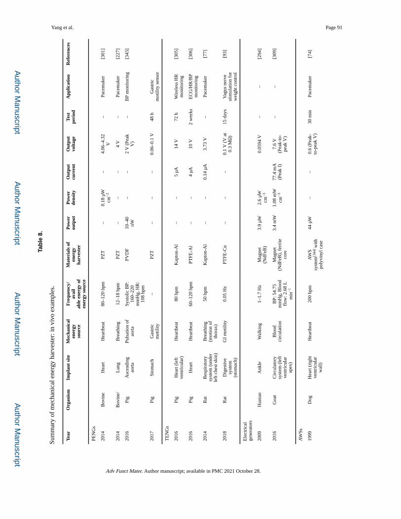
Author M
anuscriptA
uthor Manuscript
Author M
anuscriptA
uthor Manuscript
Yang et al. Page 91
Tab
le 8
.
Sum
mar
y of
mec
hani
cal e
nerg
y ha
rves
ter:
in v
ivo
exam
ples
.
Yea
rO
rgan
ism
Impl
ant
site
Mec
hani
cal
ener
gyso
urce
Fre
quen
cy/
avai
lab
le e
nerg
y of
ener
gy s
ourc
e
Mat
eria
ls o
fen
ergy
ha
rves
ter
Pow
erou
tput
Pow
er
dens
ity
Out
put
curr
ent
Out
put
volt
age
Test
pe
riod
App
licat
ion
Ref
eren
ces
PEN
Gs
2014
Bov
ine
Hea
rtH
eart
beat
80–1
20 b
pmPZ
T–
0.18
μW
cm
−2
–4.
06–4
.32
V–
Pace
mak
er[3
01]
2014
Bov
ine/
Lun
gB
reat
hing
12–1
8 bp
mPZ
T–
––
4 V
–Pa
cem
aker
[227
]
2016
Pig
Asc
endi
ng
aort
aPu
lsat
ion
of
aort
aSy
stol
ic B
P:
160–
220
mm
Hg,
HR
: 10
8 bp
m
PVD
F10
–40
nW–
–2
V (
Peak
V
)–
BP
mon
itori
ng[3
43]
2017
Pig
Stom
ach
Gas
tric
m
otili
ty–
PZT
––
–0.
06–0
.1 V
48 h
Gas
tric
m
otili
ty s
enso
r
TE
NG
s
2016
Pig
Hea
rt (
left
ve
ntri
cula
r)H
eart
beat
80 b
pmK
apto
n-A
l–
–5
μA14
V72
hW
irel
ess
HR
m
onito
ring
[305
]
2016
Pig
Hea
rtH
eart
beat
60–1
20 b
pmPT
FE-A
l–
–4
μA10
V2
wee
ksE
CG
/HR
/BP
mon
itori
ng[3
06]
2014
Rat
Res
pira
tory
sy
stem
(un
der
left
che
st s
kin)
Bre
athi
ng
(mot
ion
of
thor
ax)
50 b
pmK
apto
n-A
l–
–0.
14 μ
A3.
73 V
–Pa
cem
aker
[77]
2018
Rat
Dig
estiv
e sy
stem
(s
tom
ach)
GI
mot
ility
0.05
Hz
PTFE
-Cu
––
–0.
1 V
(V
at
0.3
MΩ
)15
day
sV
agus
ner
ve
stim
ulat
ion
for
wei
ght c
ontr
ol
[93]
Ele
ctri
cal
gene
rato
rs
2009
Hum
anA
nkle
Wal
king
1–1.
7 H
zM
agne
t (N
dFeB
)3.
9 μW
2.6
μW
cm−
30.
0594
V–
–[2
94]
2016
Goa
tC
ircu
lato
ry
syst
em (
left
ve
ntri
cula
r ap
ex)
Blo
od
circ
ulat
ion
BP:
54.
75
mm
Hg,
Blo
od
flow
: 2.6
8 L
m
in−
1
Mag
net
(NdF
eB),
fer
rite
co
re
3.4
mW
1.08
mW
cm
−3
77.4
mA
(P
eak
I)7.
6 V
(P
eak-
to-
peak
V)
––
[309
]
AW
Ss
1999
Dog
Hea
rt (
righ
t ve
ntri
cula
r w
all)
Hea
rtbe
at20
0 bp
mA
WS
syst
em[3
44] w
ith
poly
viny
l cas
e
44 μ
W–
–0.
6 (P
eak-
to-p
eak
V)
30 m
inPa
cem
aker
[74]
Adv Funct Mater. Author manuscript; available in PMC 2021 October 28.
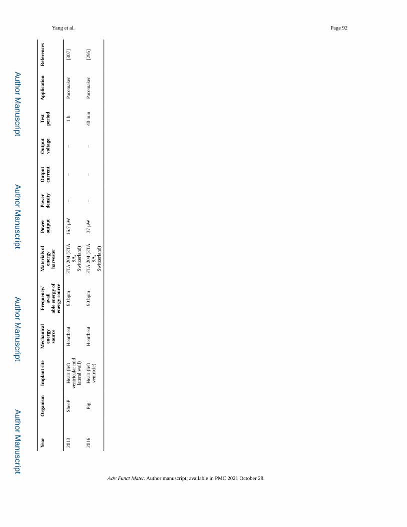
Author M
anuscriptA
uthor Manuscript
Author M
anuscriptA
uthor Manuscript
Yang et al. Page 92
Yea
rO
rgan
ism
Impl
ant
site
Mec
hani
cal
ener
gyso
urce
Fre
quen
cy/
avai
lab
le e
nerg
y of
ener
gy s
ourc
e
Mat
eria
ls o
fen
ergy
ha
rves
ter
Pow
erou
tput
Pow
er
dens
ity
Out
put
curr
ent
Out
put
volt
age
Test
pe
riod
App
licat
ion
Ref
eren
ces
2013
Shee
PH
eart
(le
ft
vent
ricu
lar
mid
la
tera
l wal
l)
Hea
rtbe
at90
bpm
ETA
204
(E
TA
SA,
Switz
erla
nd)
16.7
μW
––
–1
hPa
cem
aker
[307
]
2016
Pig
Hea
rt (
left
ve
ntri
cle)
Hea
rtbe
at90
bpm
ETA
204
(E
TA
SA,
Switz
erla
nd)
37 μ
W–
––
40 m
inPa
cem
aker
[295
]
Adv Funct Mater. Author manuscript; available in PMC 2021 October 28.
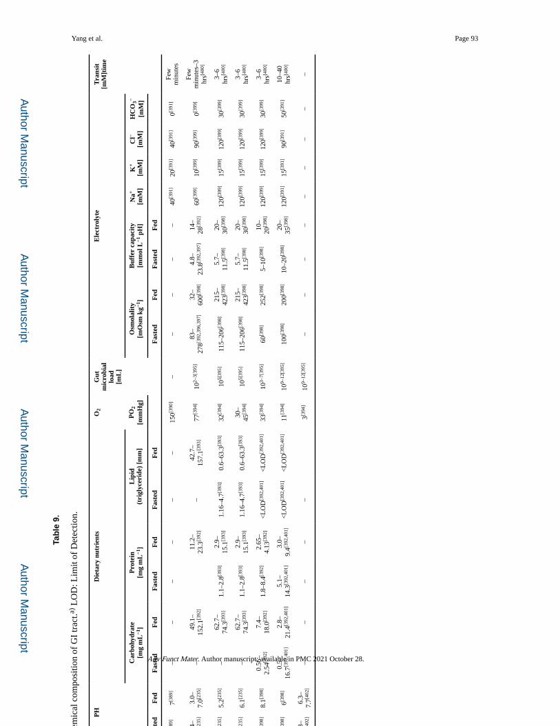
Author M
anuscriptA
uthor Manuscript
Author M
anuscriptA
uthor Manuscript
Yang et al. Page 93
Tab
le 9
.
Intr
alum
inal
phy
sico
chem
ical
com
posi
tion
of G
I tr
act.a)
LO
D: L
imit
of D
etec
tion.
Loc
atio
nP
HD
ieta
ry n
utri
ents
O2
Gut
m
icro
bial
load
[m
L]
Ele
ctro
lyte
Tra
nsit
[mM
]tim
e
Car
bohy
drat
e[m
g m
L−1
]P
rote
in[m
g m
L−1
]L
ipid
(tri
glyc
erid
e) [
mm
]P
O2
[mm
Hg]
Osm
olal
ity
[mO
sm k
g−1]
Buf
fer
capa
city
[mm
ol L
−1 p
H]
Na+
[mM
]K
+
[mM
]C
l−
[mM
]H
CO
3−
[mM
]
Fas
ted
Fed
Fas
ted
Fed
Fas
ted
Fed
Fas
ted
Fed
Fas
ted
Fed
Fas
ted
Fed
Eso
phag
us7[3
89]
7[389
]–
––
––
–15
0[390
]–
––
––
40[3
91]
20[3
91]
40[3
91]
0[391
]Fe
w
min
utes
Stom
ach
1.4–
2.1[2
35]
3.0–
7.0[2
35]
–49
.1–
152.
1[392
]11
.2–
23.3
[392
]–
42.7
–15
7.1[3
93]
77[3
94]
102–
3[39
5]83
–27
8[392
,396
,397
]32
–60
0[398
]4.
8–23
.8[3
92,3
97]
14–
28[3
92]
60[3
99]
10[3
99]
90[3
99]
0[399
]Fe
w
min
utes
–3
hrs[4
00]
Duo
denu
m6.
2[235
]5.
2[235
]–
62.7
–74
.3[3
93]
1.1–
2.8[3
93]
2.9–
15.1
[393
]1.
16–4
.7[3
93]
0.6–
63.3
[393
]32
[394
]10
5[39
5]11
5–20
6[398
]21
5–42
3[398
]5.
7–11
.5[3
98]
20–
30[3
98]
120[3
99]
15[3
99]
120[3
99]
30[3
99]
3–6
hrs[4
00]
Smal
l in
test
ine
Jeju
num
6.9[2
35]
6.1[2
35]
–62
.7–
74.3
[393
]1.
1–2.
8[393
]2.
9–15
.1[3
93]
1.16
–4.7
[393
]0.
6–63
.3[3
93]
30–
45[3
94]
105[
395]
115–
206[3
98]
215–
423[3
98]
5.7–
11.5
[398
]20
–30
[398
]12
0[399
]15
[399
]12
0[399
]30
[399
]3–
6 hr
s[400
]
ileum
8.1[3
98]
8.1[3
98]
0.56
–2.
54[3
92]
7.4–
18.0
[392
]1.
8–8.
4[392
]2.
65–
4.13
[392
]<
LO
D[3
92,4
01]
<L
OD
[392
,401
]33
[394
]10
3–7[
395]
60[3
98]
252[3
98]
5–10
[398
]10
–20
[398
]12
0[399
]15
[399
]12
0[399
]30
[399
]3–
6 hr
s[400
]
Lar
ge
inte
stin
e
Prox
imal
7.8[3
98]
6[398
]0.
5–16
.7[3
92,4
01]
2.8–
21.4
[392
,401
]5.
1–14
.3[3
92,4
01]
3.0–
9.4[3
92,4
01]
<L
OD
[392
,401
]<
LO
D[3
92,4
01]
11[3
94]
109–
12[3
95]
100[3
98]
200[3
98]
10–2
0[398
]20
–35
[398
]12
0[391
]15
[391
]90
[391
]50
[391
]10
–40
hrs[4
00]
Dis
tal
colo
n6.
3–7.
7[402
]6.
3–7.
7[402
]–
––
––
3[394
]10
9–12
[395
]–
––
––
––
––
Adv Funct Mater. Author manuscript; available in PMC 2021 October 28.
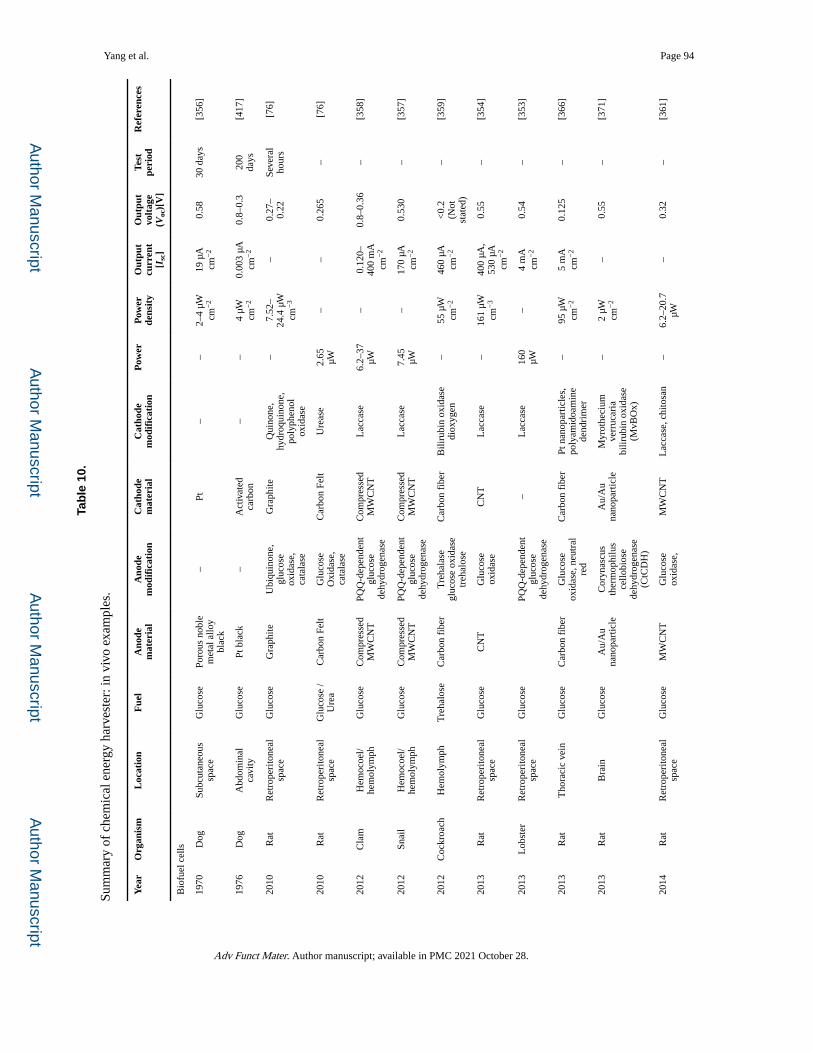
Author M
anuscriptA
uthor Manuscript
Author M
anuscriptA
uthor Manuscript
Yang et al. Page 94
Tab
le 1
0.
Sum
mar
y of
che
mic
al e
nerg
y ha
rves
ter:
in v
ivo
exam
ples
.
Yea
rO
rgan
ism
Loc
atio
nF
uel
Ano
de
mat
eria
lA
node
m
odif
icat
ion
Cat
hode
mat
eria
lC
atho
de
mod
ific
atio
nP
ower
Pow
er
dens
ity
Out
put
curr
ent
[Isc
]
Out
put
volt
age
(Voc
)[V
]
Test
peri
odR
efer
ence
s
Bio
fuel
cel
ls
1970
Dog
Subc
utan
eous
sp
ace
Glu
cose
Poro
us n
oble
m
etal
allo
y bl
ack
–Pt
––
2–4
μW
cm−
219
μA
cm
−2
0.58
30 d
ays
[356
]
1976
Dog
Abd
omin
al
cavi
tyG
luco
sePt
bla
ck–
Act
ivat
ed
carb
on–
–4
μW
cm−
20.
003
μA
cm−
20.
8–0.
320
0 da
ys[4
17]
2010
Rat
Ret
rope
rito
neal
sp
ace
Glu
cose
Gra
phite
Ubi
quin
one,
gl
ucos
e ox
idas
e,
cata
lase
Gra
phite
Qui
none
, hy
droq
uino
ne,
poly
phen
ol
oxid
ase
–7.
52–
24.4
μW
cm
−3
–0.
27–
0.22
Seve
ral
hour
s[7
6]
2010
Rat
Ret
rope
rito
neal
sp
ace
Glu
cose
/ U
rea
Car
bon
Felt
Glu
cose
O
xida
se,
cata
lase
Car
bon
Felt
Ure
ase
2.65
μW
––
0.26
5–
[76]
2012
Cla
mH
emoc
oel/
hem
olym
phG
luco
seC
ompr
esse
d M
WC
NT
PQQ
-dep
ende
nt
gluc
ose
dehy
drog
enas
e
Com
pres
sed
MW
CN
TL
acca
se6.
2–37
μW
–0.
120–
400
mA
cm
−2
0.8–
0.36
–[3
58]
2012
Snai
lH
emoc
oel/
hem
olym
phG
luco
seC
ompr
esse
d M
WC
NT
PQQ
-dep
ende
nt
gluc
ose
dehy
drog
enas
e
Com
pres
sed
MW
CN
TL
acca
se7.
45
μW–
170
μA
cm−
20.
530
–[3
57]
2012
Coc
kroa
chH
emol
ymph
Tre
halo
seC
arbo
n fi
ber
Tre
hala
se
gluc
ose
oxid
ase
treh
alos
e
Car
bon
fibe
rB
iliru
bin
oxid
ase
diox
ygen
–55
μW
cm
−2
460
μA
cm−
2<
0.2
(Not
st
ated
)
–[3
59]
2013
Rat
Ret
rope
rito
neal
sp
ace
Glu
cose
CN
TG
luco
se
oxid
ase
CN
TL
acca
se–
161
μW
cm−
340
0 μA
, 53
0 μA
cm
−2
0.55
–[3
54]
2013
Lob
ster
Ret
rope
rito
neal
sp
ace
Glu
cose
PQQ
-dep
ende
nt
gluc
ose
dehy
drog
enas
e
–L
acca
se16
0 μW
–4
mA
cm
−2
0.54
–[3
53]
2013
Rat
Tho
raci
c ve
inG
luco
seC
arbo
n fi
ber
Glu
cose
ox
idas
e, n
eutr
al
red
Car
bon
fibe
rPt
nan
opar
ticle
s,
poly
amid
oam
ine
dend
rim
er
–95
μW
cm
−2
5 m
A
cm−
20.
125
–[3
66]
2013
Rat
Bra
inG
luco
seA
u/A
u na
nopa
rtic
leC
oryn
ascu
s th
erm
ophi
lus
cello
bios
e de
hydr
ogen
ase
(CtC
DH
)
Au/
Au
nano
part
icle
Myr
othe
cium
ve
rruc
aria
bi
lirub
in o
xida
se
(MvB
Ox)
–2
μW
cm−
2–
0.55
–[3
71]
2014
Rat
Ret
rope
rito
neal
sp
ace
Glu
cose
MW
CN
TG
luco
se
oxid
ase,
M
WC
NT
Lac
case
, chi
tosa
n–
6.2–
20.7
μW
–
0.32
–[3
61]
Adv Funct Mater. Author manuscript; available in PMC 2021 October 28.
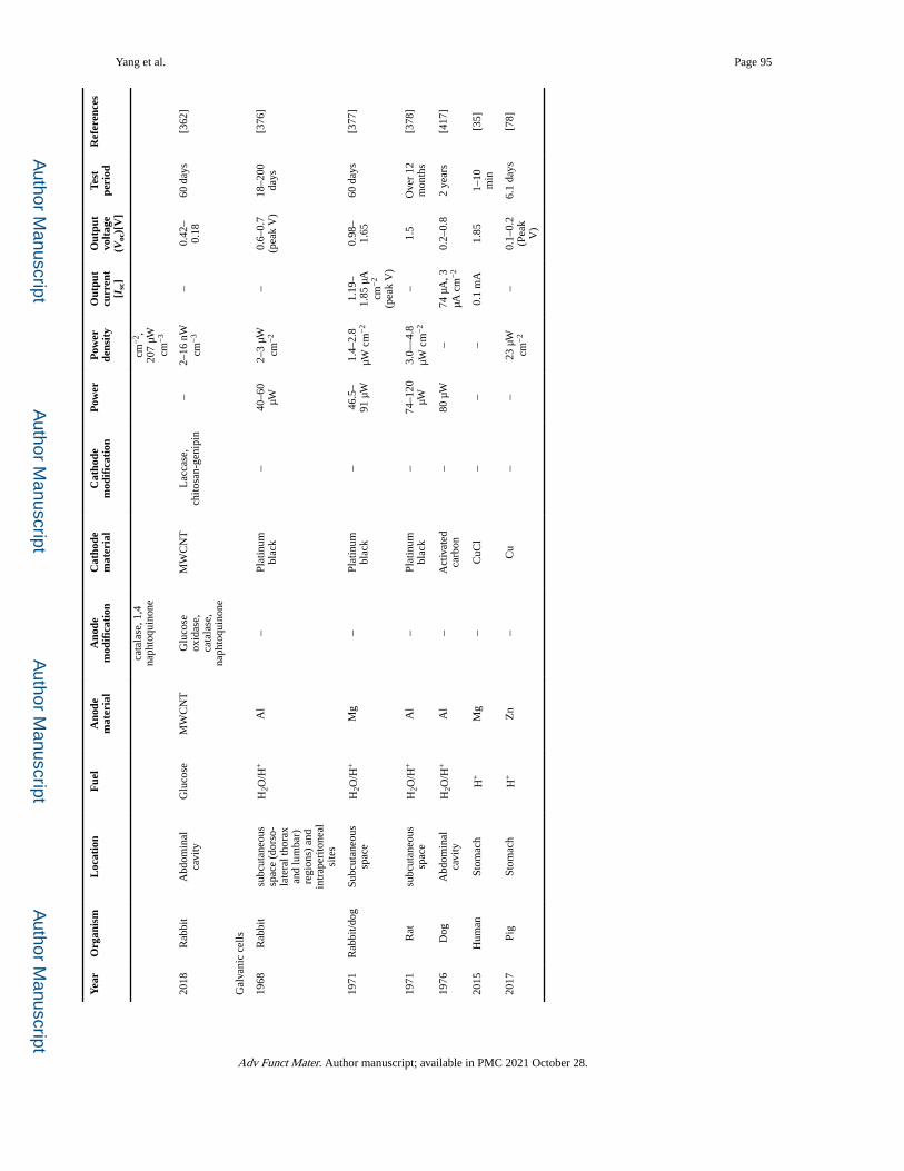
Author M
anuscriptA
uthor Manuscript
Author M
anuscriptA
uthor Manuscript
Yang et al. Page 95
Yea
rO
rgan
ism
Loc
atio
nF
uel
Ano
de
mat
eria
lA
node
m
odif
icat
ion
Cat
hode
mat
eria
lC
atho
de
mod
ific
atio
nP
ower
Pow
er
dens
ity
Out
put
curr
ent
[Isc
]
Out
put
volt
age
(Voc
)[V
]
Test
peri
odR
efer
ence
s
cata
lase
, 1,4
na
phto
quin
one
cm−
2 ,
207
μW
cm−
3
2018
Rab
bit
Abd
omin
al
cavi
tyG
luco
seM
WC
NT
Glu
cose
ox
idas
e,
cata
lase
, na
phto
quin
one
MW
CN
TL
acca
se,
chito
san-
geni
pin
–2–
16 n
W
cm−
3–
0.42
–0.
1860
day
s[3
62]
Gal
vani
c ce
lls
1968
Rab
bit
subc
utan
eous
sp
ace
(dor
so-
late
ral t
hora
x an
d lu
mba
r)
regi
ons)
and
in
trap
erito
neal
si
tes
H2O
/H+
Al
–Pl
atin
um
blac
k–
40–6
0 μW
2–3
μW
cm−
2–
0.6–
0.7
(pea
k V
)18
–200
da
ys[3
76]
1971
Rab
bit/d
ogSu
bcut
aneo
us
spac
eH
2O/H
+M
g–
Plat
inum
bl
ack
–46
.5–
91 μ
W1.
4–2.
8 μW
cm
−2
1.19
–1.
85 μ
A
cm−
2
(pea
k V
)
0.98
–1.
6560
day
s[3
77]
1971
Rat
subc
utan
eous
sp
ace
H2O
/H+
Al
–Pl
atin
um
blac
k–
74–1
20
μW3.
0—4.
8 μW
cm
−2
–1.
5O
ver
12
mon
ths
[378
]
1976
Dog
Abd
omin
al
cavi
tyH
2O/H
+A
l–
Act
ivat
ed
carb
on–
80 μ
W–
74 μ
A, 3
μA
cm
−2
0.2–
0.8
2 ye
ars
[417
]
2015
Hum
anSt
omac
hH
+M
g–
CuC
l–
––
0.1
mA
1.85
1–10
m
in[3
5]
2017
Pig
Stom
ach
H+
Zn
–C
u–
–23
μW
cm
−2
–0.
1–0.
2 (P
eak
V)
6.1
days
[78]
Adv Funct Mater. Author manuscript; available in PMC 2021 October 28.

Author M
anuscriptA
uthor Manuscript
Author M
anuscriptA
uthor Manuscript
Yang et al. Page 96
Table 11.
Spatial-peak temporal-average intensity of diagnosis acoustic transfer for nonfetal Doppler application[441].
Location/use Intensity [mW cm−2]
Peripheral vessel 720
Cardiac system 430
Fetal imaging and other 94
Ophthalmic sites 17
Adv Funct Mater. Author manuscript; available in PMC 2021 October 28.
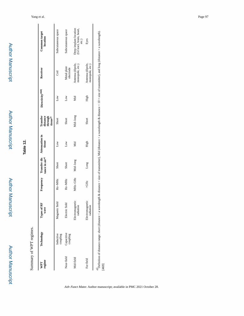
Author M
anuscriptA
uthor Manuscript
Author M
anuscriptA
uthor Manuscript
Yang et al. Page 97
Tab
le 1
2.
Sum
mar
y of
WPT
reg
imes
.
WP
T
regi
me
Tech
nolo
gyT
ypes
of
RF
wav
eF
requ
ency
Tra
nsfe
r di
sta
nce
in a
ira)
Att
enua
tion
inti
ssue
Tra
nsfe
r di
stan
ceth
roug
h ti
ssue
a)
Dir
ecti
vity
[468
]R
ecei
ver
Com
mon
tar
get
loca
tion
Indu
ctiv
e co
uplin
gM
agne
tic f
ield
Hz–
MH
zSh
ort
Low
Shor
tL
owC
oil
Subc
utan
eous
spa
ce
Nea
r-fi
eld
Cap
aciti
ve
coup
ling
Ele
ctri
c fi
eld
Hz–
MH
zSh
ort
Low
Shor
tL
owM
etal
pla
te
elec
trod
eSu
bcut
aneo
us s
pace
Mid
-fie
ldE
lect
rom
agne
tic
radi
atio
nM
Hz–
GH
zM
id–l
ong
Mid
Mid
–lon
gM
idA
nten
na (
dipo
le,
mon
opol
e, e
tc.)
Dee
p im
plan
t loc
atio
n (G
I tr
act,
brai
n, h
eart
, et
c.)
Far-
fiel
dE
lect
rom
agne
tic
radi
atio
n>
GH
zL
ong
Hig
hSh
ort
Hig
hA
nten
na (
dipo
le,
mon
opol
e, e
tc.)
Eye
s
a)D
efin
ition
of
dist
ance
ran
ge: s
hort
(di
stan
ce <
a w
avel
engt
h &
dis
tanc
e <
siz
e of
tran
smitt
er),
Mid
(di
stan
ce <
a w
avel
engt
h &
dis
tanc
e <
10
× s
ize
of tr
ansm
itter
), a
nd lo
ng (
dist
ance
> a
wav
elen
gth)
.[4
69]
Adv Funct Mater. Author manuscript; available in PMC 2021 October 28.
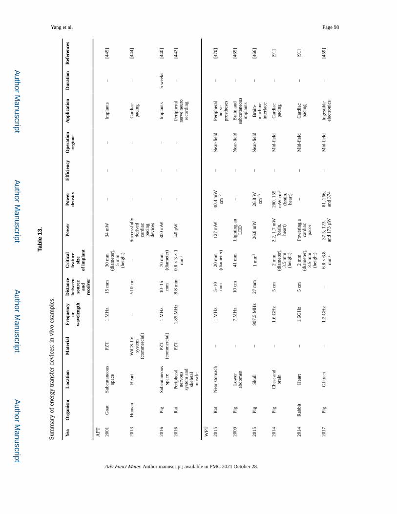
Author M
anuscriptA
uthor Manuscript
Author M
anuscriptA
uthor Manuscript
Yang et al. Page 98
Tab
le 1
3.
Sum
mar
y of
ene
rgy
tran
sfer
dev
ices
: in
vivo
exa
mpl
es.
Yea
Org
anis
mL
ocat
ion
Mat
eria
lF
requ
ency
or
wav
elen
gth
Dis
tanc
e be
twee
nso
urce
an
d re
ceiv
er
Cri
tica
l fe
atur
e si
zeof
impl
ant
Pow
erP
ower
de
nsit
yE
ffic
ienc
yO
pera
tion
regi
me
App
licat
ion
Dur
atio
nR
efer
ence
s
APT
2001
Goa
tSu
bcut
aneo
us
spac
ePZ
T1
MH
z15
mm
30 m
m
(dia
met
er),
5
mm
(h
eigh
t)
34 m
W–
––
Impl
ants
–[4
45]
2013
Hum
anH
eart
WiC
S-LV
sy
stem
(c
omm
erci
al)
–≈
10 c
m–
Succ
essf
ully
de
rive
d ca
rdia
c pa
cing
de
vice
s
––
–C
ardi
ac
paci
ng–
[444
]
2016
Pig
Subc
utan
eous
sp
ace
PZT
(c
omm
erci
al)
1 M
Hz
10–1
5 m
m70
mm
(d
iam
eter
)30
0 m
W–
––
Impl
ants
5 w
eeks
[440
]
2016
Rat
Peri
pher
al
nerv
ous
syst
em a
nd
skel
etal
m
uscl
e
PZT
1.85
MH
z8.
8 m
m0.
8 ×
3 ×
1
mm
340
μW
––
–Pe
riph
eral
ne
rve
neur
o re
cord
ing
–[4
42]
WPT
2015
Rat
Nea
r st
omac
h–
1 M
Hz
5–10
m
m20
mm
(d
iam
eter
)12
7 m
W40
.4 m
W
cm−
2–
Nea
r-fi
eld
Peri
pher
al
nerv
e pr
osth
eses
–[4
70]
2009
Pig
Low
er
abdo
men
–7
MH
z10
cm
41 m
mL
ight
ing
an
LE
D–
–N
ear-
fiel
dB
rain
and
su
bcut
aneo
us
impl
ants
–[4
65]
2015
Pig
Skul
l–
907.
5 M
Hz
27 m
m1
mm
326
.8 m
W26
.8 W
cm
−3
–N
ear-
fiel
dB
rain
-m
achi
ne
inte
rfac
e
–[4
66]
2014
Pig
Che
st a
nd
brai
n–
1.6
GH
z5
cm2
mm
(d
iam
eter
),
3.5
mm
(h
eigh
t)
2.2,
1.7
mW
(b
rain
, he
art)
200,
155
m
W c
m3
(bra
in,
hear
t)
–M
id-f
ield
Car
diac
pa
cing
–[9
1]
2014
Rab
bit
Hea
rt–
1.6G
Hz
5 cm
2 m
m
(dia
met
er),
3.
5 m
m
(hei
ght)
Pow
erin
g a
card
iac
pace
r
––
Mid
-fie
ldC
ardi
ac
paci
ng–
[91]
2017
Pig
GI
trac
t–
1.2
GH
z–
6.8
× 6
.8
mm
237
.5, 1
23,
and
173
μW
81, 2
66,
and
374
–M
id-f
ield
Inge
stib
le
elec
tron
ics
–[4
59]
Adv Funct Mater. Author manuscript; available in PMC 2021 October 28.
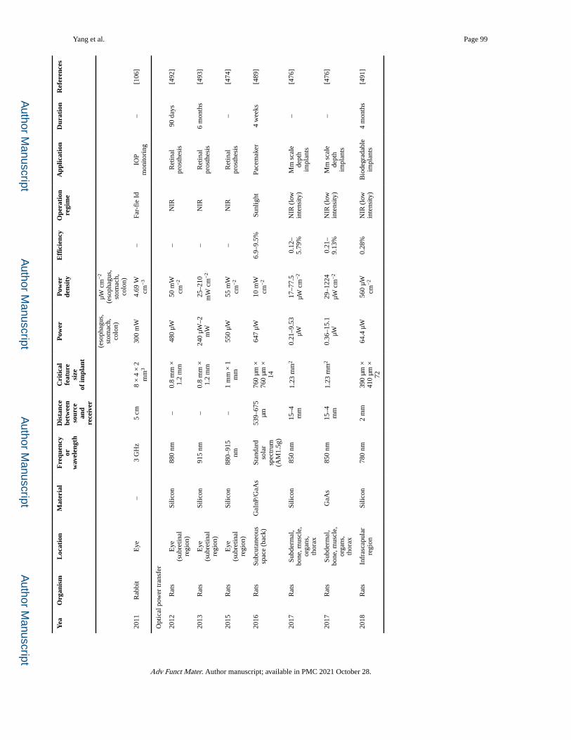
Author M
anuscriptA
uthor Manuscript
Author M
anuscriptA
uthor Manuscript
Yang et al. Page 99
Yea
Org
anis
mL
ocat
ion
Mat
eria
lF
requ
ency
or
wav
elen
gth
Dis
tanc
e be
twee
nso
urce
an
d re
ceiv
er
Cri
tica
l fe
atur
e si
zeof
impl
ant
Pow
erP
ower
de
nsit
yE
ffic
ienc
yO
pera
tion
regi
me
App
licat
ion
Dur
atio
nR
efer
ence
s
(eso
phag
us,
stom
ach,
co
lon)
μW c
m−
2
(eso
phag
us,
stom
ach,
co
lon)
2011
Rab
bit
Eye
–3
GH
z5
cm8
× 4
× 2
m
m3
300
mW
4.69
W
cm−
3–
Far-
fie
IdIO
P m
onito
ring
–[1
06]
Opt
ical
pow
er tr
ansf
er
2012
Rat
sE
ye
(sub
retin
al
regi
on)
Silic
on88
0 nm
–0.
8 m
m ×
1.
2 m
m48
0 μW
50 m
W
cm−
2–
NIR
Ret
inal
pr
osth
esis
90 d
ays
[492
]
2013
Rat
sE
ye
(sub
retin
al
regi
on)
Silic
on91
5 nm
–0.
8 m
m ×
1.
2 m
m24
0 μW
–2
mW
25–2
10
mW
cm
−2
–N
IRR
etin
al
pros
thes
is6
mon
ths
[493
]
2015
Rat
sE
ye
(sub
retin
al
regi
on)
Silic
on88
0–91
5 nm
–1
mm
× 1
m
m55
0 μW
55 m
W
cm−
2–
NIR
Ret
inal
pr
osth
esis
–[4
74]
2016
Rat
sSu
bcut
aneo
us
spac
e (b
ack)
GaI
nP/G
aAs
Stan
dard
so
lar
spec
trum
(A
M1.
5g)
539–
675
μm76
0 μm
×
760
μm ×
14
647
μW10
mW
cm
−2
6.9–
9.5%
Sunl
ight
Pace
mak
er4
wee
ks[4
89]
2017
Rat
sSu
bder
mal
, bo
ne, m
uscl
e,
orga
ns,
thor
ax
Silic
on85
0 nm
15–4
m
m1.
23 m
m2
0.21
–9.5
3 μW
17–7
7.5
μW c
m−
20.
12–
5.79
%N
IR (
low
in
tens
ity)
Mm
sca
le
dept
h im
plan
ts
–[4
76]
2017
Rat
sSu
bder
mal
, bo
ne, m
uscl
e,
orga
ns,
thor
ax
GaA
s85
0 nm
15–4
m
m1.
23 m
m2
0.36
–15.
1 μW
29–1
224
μW c
m−
20.
21–
9.13
%N
IR (
low
in
tens
ity)
Mm
sca
le
dept
h im
plan
ts
–[4
76]
2018
Rat
sIn
fras
capu
lar
regi
onSi
licon
780
nm2
mm
390
μm ×
41
0 μm
×
72
64.4
μW
560
μW
cm−
20.
28%
NIR
(lo
w
inte
nsity
)B
iode
grad
able
im
plan
ts4
mon
ths
[491
]
Adv Funct Mater. Author manuscript; available in PMC 2021 October 28.
Related Documents