POWERFLOW ™ CONVEYOR Manufacturers of Innovative Materials Handling Equipment since 1957. Installation and Operation Manual 491 North Emerson Street • Cambridge MN 55008-1316 U.S.A. Toll Free (800) 328-8002 FAX (763) 689-5310 Local / International (763) 689-5991 EMAIL [email protected] www.schlagel.com

Welcome message from author
This document is posted to help you gain knowledge. Please leave a comment to let me know what you think about it! Share it to your friends and learn new things together.
Transcript

POWERFLOW™ CONVEYOR
Manufacturers of Innovative Materials Handling Equipment since 1957.
Installation and Operation Manual
491 North Emerson Street • Cambridge MN 55008-1316 U.S.A.Toll Free (800) 328-8002 FAX (763) 689-5310
Local / International (763) 689-5991 EMAIL [email protected]

TABLE OF CONTENTS
Page 1
SECTION 1 - GENERAL
Pages 2 . . . . . . . . Introduction 2 . . . . . . . . Use of Manual 2 . . . . . . . . Information Service 3 . . . . . . . . Uncrating and Inspection 3 . . . . . . . . Safety Code
SECTION 2 - ASSEMBLY AND INSTALLATION
Pages 4 . . . . . . . . Electrical Requirements 4 . . . . . . . . Supporting Structure 5 . . . . . . . . Assembly, Basic Components 5 . . . . . . . . Aligning Conveyor Tails & Troughs 6 . . . . . . . . Roller Return Assemblies 6 . . . . . . . . Installation of Optional EZ-Glide Return Assembly 6 . . . . . . . . Installation of Heavy Duty Nose Cone 7 . . . . . . . . EZ-Glide Rail Parts Replacement 8-10. . . . . . Assembly of Basic Components 11-14 . . . . . Chain Installation and Tensioning 15 . . . . . . . Side Guides 15 . . . . . . . Inlet Transitions 16 . . . . . . . Discharge Transitions 16 . . . . . . . Drives 17 . . . . . . . Tensioning Drive Belts 18 . . . . . . . Weather Covers 18 . . . . . . . Start-up Procedures 19 . . . . . . . Installer/Contractor Responsibilities 19 . . . . . . . Maintenance Procedures
SECTION 3 - OPTIONAL EQUIPMENT
Pages 20 . . . . . . . Intermediate Discharge 20-25 . . . . Intermediate Discharge Installation 26 . . . . . . . Intermediate Discharge Drape 26-27 . . . . Drape Installation 28 . . . . . . . Detector Tail Terminal 28 . . . . . . Theory of Operation 29 . . . . . . . Detector Tail Installation 30 . . . . . . . Plug Switches 31 . . . . . . . Electrical - LSXYAB4L Limit Switch 32 . . . . . . . Electrical - Diaphragm Switch 32-33. . . . . Electrical - BSE1V10C Binswitch
SECTION 4 - INCLINED CONVEYORS
Pages 34 . . . . . . . Incline Conveyor 35 . . . . . . Theory of Operation 35 . . . . . . . Trough Alignment 36 . . . . . . . Incline Conveyor Chain Travel 37 . . . . . . . Assembly of Basic Components 37 . . . . . . . Chain Tensioning 38 . . . . . . . Bypass Inlet Side Shields
SECTION 5 - TROUBLE SHOOTING
Pages 39-42. . . . . Problem / Remedy

2Page
INTRODUCTION
Schlagel, Inc. of Cambridge, Minnesota, has had many years of experience in producing industrial quality material handling equipment.
The exclusive design of the PowerFlow™ Conveyor combines high capacity, high conveyed product integrity, and high mechanical reliability with a low horsepower requirement and low noise operation with many options to meet capacity and installation requirements.
All Equipment manufactured by Schlagel, Inc. is guaranteed to be free from defects in materials and workmanship, providing no alteration or repair has been made by the user unless authorized in writing by Schlagel, Inc.
The items in this manual may be covered by one of the following Patents: U.S.3339691, 3952864, 4058199, 5593019; CAN. 803312. Other U.S. Foreign Patents Pending.
USE OF MANUAL
This manual provides installation, operation, service recommendations and replacement parts identification for Schlagel PowerFlow™ Conveyors.
Each section of the manual is fully illustrated for fast, accurate reference. It is highly recommended that this manual be read thoroughly by those who are responsible for the installation, operation and maintenance of this conveyor. Refer to the Table of Contents, Page 1 for the location of specific information.
As new information and equipment become available, service and parts bulletins will be issued by Schlagel, Inc. So that they will be readily available for reference, all bulletins should be inserted with this manual. This manual covers standard conveyor equipment only. For any items or special equipment not covered in this manual, please consult our service department for recommendations or instructions regarding this equipment.
INFORMATION SERVICE
Our service department will provide consultation on installation, operation and maintenance at no cost to you. Also, information from you, regarding encountered operation or service problems that are not covered in this manual will be greatly appreciated.
Contact Schlagel, Inc. for information on adding new equipment to your system or changing your installation such as: Lengthening or shortening troughs, adding or deleting inlets and discharges, horsepower and speed requirements, etc.
Schlagel, Inc. keeps a complete record of each customer’s order. However, valuable time can be saved if the information below is provided with your inquiry. It is suggested that you obtain the model number and serial number from the Packing Slip, or on the discharge terminal end of the conveyor, and enter it below for each conveyor in your system.
Date of Purchase:
Purchased from:
Installed by: Date:
Model Number: Serial Number:
Email or Call: Schlagel, Inc. 491 North Emerson Street Cambridge, MN 55008 (763) 689-5991 or 1-800-328-8002 [email protected]
SECTION 1 - GENERAL
HEAD SECTIONMODEL & SERIAL # TAG

UNCRATING AND INSPECTION
All parts have been carefully checked before shipment from our factory. Carefully inspect all parts for damage that may have occurred during shipment. Look for dents in trough sections and bent or misaligned flanges or shafts. If these are not corrected, one can expect continuing problems and reduced life of the conveyor. Check to make sure that all items listed in your Packing List are included.
If damages or shortages are noted, have the transportation company’s representative note this on the Bill of Lading and notify Schlagel, Inc. Locate the model and serial number on the conveyor end discharge and reference the missing or damaged part from the Packing List. Forward this information along with the shipping date so that we may expedite the replacement parts.
IMPORTANT
All claims for shipping damages must be noted by the consignee at the time of delivery and filed with the transportation company.
SAFETY CODE
Page 3
SECTION 1 - GENERAL
WARNING
The icon shown below was proposed as a safety alert symbol by the Farm and Industrial Equipment Institute (FIEI) and approved by the American Society of Automotive Engineers (ASAE) and others for the purpose of calling attention to safety precautions which if not heeded might lead to bodily injury.
Please read instructions carefully and follow the instructions exactly wherever this symbol appears in the manual.
Walking or standing onConveyor Covers orGratings can causeSerious Injury or Death
STAY OFF

4Page
SECTION 2 - ASSEMBLY AND INSTALLATION
ELECTRICAL REQUIREMENTS
All electrical connections should be made by a qualified electrician. Check local codes before installation. A lockable external line disconnect switch, in compliance with local codes, must be provided and located as close as possible to the conveyor.
When the conveyor is connected with other machinery, electrical interlock priorities should be maintained so that if the last conveyor fails, all preceding equipment will stop.
SUPPORTING STRUCTURES
It will be the responsibility of the contracting installer to provide adequate conveyor supports. Overhead clearance and maintenance accessibility should be considered. The conveyor should be supported in such a way that building movements will not tend to deflect it. This might necessitate using telescoping spouting into and away from the conveyor.
Welding supports to the conveyor are not recommended Figure 2.1 illustrates the proper method of supporting the conveyor at it’s strongest point. We recommended a suspended or supporting stand (as shown) be used at every trough joint.
Figure 2.1
WARNING
Before removing conveyor covers or drive guards to attempt any repairs or adjustments, shut off and lock the line disconnect switch. For electrical information on optional equipment, see appropriate section or specific engineering drawings in the back of this manual.
ANGLE CLIP STYLE
SQUARE TUBE WITH WELDED BAR

TAIL STICKS ABOVE TROUGH
TOP OF TROUGH LINER & TAIL BOTTOM ARE FLUSH
TROUGH LINER STICKS ABOVE TAIL BOTTOM
TROUGH & TAIL LEVEL ON TOP
5
SECTION 2 - ASSEMBLY AND INSTALLATION
Page
ASSEMBLY OF BASIC COMPONENTS
Various combinations of components are shown in Figure 2.6 - the difference being which type of take up terminal is being used. Detail A, Figure 2.6 illustrates five types of trough configurations. Your Packing List will list the combination of components you have received and indicate what fasteners are required for assembly. The following instructions refer to the variations. Installation of intermediate discharges, detector tail assembly, inlet, hoppers, etc., are covered later in this section.
Troughs are supplied in standard 10' lengths for Type #1 or Type #2 troughs and in standard 9'-10" lengths for Type #3 troughs and a shorter section is generally required to accommodate a given overall length. Troughs should be layed out end -to-end as they are intended to be installed and bolted loosely together with proper fasteners (see Bill of Materials).
NOTE: If intermediate discharges are to be used, the location must be determined before proceeding with the assembly. Since intermediate discharges cannot be installed over a trough joint, it may be necessary to position a shorter trough section as a “spacer” in order to place the discharge where desired.
IMPORTANT
Carefully inspect each flange joint as the bolts and nuts are tightened, so that the inside bottom and side surfaces of the trough are flush. If the trough is misaligned by as little as 1/32", conveyor chain wings could be broken or cause rapid wear. A chalk line is helpful in obtaining straightness during assembly
Attach the head and tail terminals using the same alignment precautions as noted above.
ALIGNING CONVEYOR TAILS AND TROUGHS
When installing En-Masse conveyors, it is very important that the inside of all troughs be properly aligned to prevent the chain from catching on any ledges. Many conveyors have liners on the bottom and/or sides of the trough to extend their service life. Since no grain is conveyed in the tail section and clearance below the tail sprocket is limited, we do not install liners in the bottom of the tail. It is important to adjust the tail section properly so the liner in the trough does not stick above the bottom of the tail housing. We slot the bolt holes in the tail flange so the tail can be raised up to align the two surfaces on the bottom. This will make the tail stick above the trough slightly, but a few extra layers of gasket between the trough end by the tail and the cover will make this connection work. See diagrams in Figure 2.2.
Figure 2.2
CAUTION
The head terminal must be well braced to allow for drive weight and torque transmission through the head.
CORRECT
INCORRECT

ROLLER RETURN ASSEMBLY
The Roller Return Assembly is installed in the pre-punched holes in the upper portion of trough sides with hex head bolts and lock washers (Figure 2.3). They support the return chain and add rigidity to the trough sides. The rollers are self lubricating and pre-set to center under the conveyor chain.
Figure 2.3
ROLLER RETURN
OPTIONAL EZ-GLIDE RETURN ASSEMBLY
This patented assembly is installed in the same holes roller returns are, using the same mounting hardware as shown in Figure 2.4.
Some conveyors require a heavy duty nose cone to be installed in the trough section near the head. Check the packing list to see if one is supplied for the conveyor being installed. See figure 2.5.
Figure 2.4
EZ-GLIDE RETURN
INSTALLATION OF HEAVY DUTY NOSE CONE
1. Remove 3/8"Ø bolt that holds nose end (3” Long) in the EZ-Glide rails.
2. Remove the (3" long) nose end from the EZ-Glide rails.
3. Drill (2) new holes in trough sides per chart.
4. Install new return shaft thru the larger hole in the (4 1/8" long) nose cone.
5. Slide nose cone and shaft into place on the EZ-Glide rails as shown in Figure 2.5
6. Replace the 3/8"Ø bolt that holds the nose cone in the EZ-Glide rails.
7. Install bolts thru the trough and into the new return shaft.
Figure 2.5
6
SECTION 2 - ASSEMBLY AND INSTALLATION
Page
STEP 5SHOWN HERE
OPTIONAL ANTI-TIP RAILS
1 1/2" 118" TROUGHS ONLY
*DRILL NEW HOLES IN TROUGH SIDES HERE.
2 1/2"
3/8" Ø BOLT“A”
TROUGH DIMENSION
DEPTH “A” *HOLE Ø SHAFT Ø 10" 2 1/2" 7/16" 5/8"
14" 3" 7/16" 5/8"
18" 3" 7/16" 5/8"
20" 4" 7/16" 3/4"
26" 4 3/4" 9/16" 1"
36" 4 3/4" 9/16" 1"
NOTE: Nose cone width must match EZ-Glide UHMW slide width.
CAUTION
Failure to install heavy duty nose cone may result in damage to conveyor.

EZ-GLIDE RAIL RETURN PARTS REPLACEMENT
The EZ-Glide Rail Return is supplied in our larger size and/or very heavily used conveyors instead of roller returns. The replaceable center strip and nose ends are a UHMW material available in several types to suit each application. They may be white, blue or red in color. Conveyors having a high width-to-height ratio will also incorporate the anti-tip rails shown in the diagram. The name of the anti-tip rails describes their function, they are intended only to keep the top return chain from tipping, not to carry the chain in any way, they are located below the top surface of the EZ-Glide rail center strip. Wear on the center UHMW strips and nose ends should be closely monitored. Replacement parts are cost-effective and they are relatively simple to replace so long as repairs are made before the steel side angles and shafts have been ruined.
To replace the center strip and nose ends, remove the 3/8" bolt from the UHMW nose end. Loosen the set screw in each of the shaft collars on one side of the EZ-Glide rail and push them out towards the side of the trough. Pull the formed steel angle out of the slot in the UHMW. Remove the old UHMW pieces and replace with new ones. Insert the steel angle back into the slot in the new UHMW pieces. Push your shaft collars back in, remembering to tighten the set screws and put the end 3/8" bolts back in.
ASSEMBLY OF BASIC COMPONENTS
STD. EZ GLIDE RAIL ASSEMBLY
W/ OPTIONAL ANTI-TIP RAILSEZ GLIDE RAIL ASSEMBLY SHOWN
SEE CHART FOR WIDTH
SHAFT SETCOLLARS
113 3/4" 12 GA. GALV. RAILS
109 1/2" STD. LENGTH UHMW STRIP
NOSE END
7
SECTION 2 - ASSEMBLY AND INSTALLATION
Page

Figure 2.6
ASSEMBLY OF BASIC COMPONENTS
8
SECTION 2 - ASSEMBLY AND INSTALLATION
Page NOTE: SEE SHAFT CENTERING COLLAR DETAIL ON PAGE 9.
TYPE #3S TROUGH
TYPE #3 TROUGH
TYPE #2S TROUGH
TYPE #2 TROUGH
TYPE #1 TROUGH
TYPE #3SB TROUGH
DETAIL A
CONTOUR TAILTERMINAL
TAKE-UP HEADTERMINAL
MATERIAL FLOW
TROUGH SECTION
ROLLER RETURN ASS'Y
CONVEYOR CHAIN
CHAIN GUIDES
EZ-GLIDERETURN ASS'Y
COVER CLAMPS(6 PER FULL
LENGTH COVER)
COVER SPLICE
WEATHER COVER
DETECTOR TAILTERMINAL
TAKE-UP TAILTERMINAL
COVER SPLICE
COVER CLAMPS(6 PER FULL
LENGTH COVER)
STANDARDHEAD
TERMINAL
HEAD TERMINAL COVER"HIP ROOF STYLE"
(OPTIONAL)
TAIL TERMINAL COVER"HIP ROOF STYLE"
(OPTIONAL)
*STD. TYPE "HIP ROOF" COVERS HAVE A SLIGHT BREAKER BEND TO PROMOTE RUN OFF(OPTIONAL)
*NOTE: STD. TYPE "HIP ROOF" COVERS HAVE A SLIGHT BREAKER BEND TO PROMOTE RUN OFF. (SHOWN) ALSO AVAILABLE IS A SUPER TYPE "HIP ROOF" COVER WHICH HAS A GREATER PITCH.
HARDENED TOOTH SPROCKETS IN HEAD AND TAIL

9
SECTION 2 - ASSEMBLY AND INSTALLATION
Page
SHAFT CENTERING COLLAR ASSEMBLY
All conveyor heads and tails use centering collars as shown below to keep the chain sprocket centered in the housing. If you replace your head or tail sprocket it is very important to re-install the centering collars. If replacement centering collars are sent, they are shipped in pieces that must be field welded. If you replace a solid sprocket with a split sprocket, make sure you order new centering collars as the length through the bore of a split sprocket is different than the length through the bore on a solid one piece sprocket.
2 BEARINGS
2 CENTERING COLLARS
10
SECTION 2 - ASSEMBLY AND INSTALLATION
Page
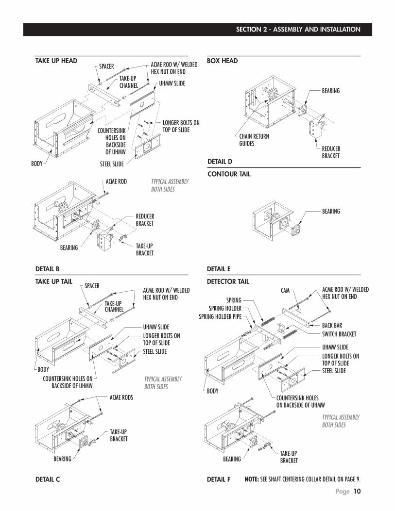
DETAIL C DETAIL F
BEARING
CHAIN RETURNGUIDES
REDUCERBRACKET
BEARING
ACME ROD W/ WELDEDHEX NUT ON END
UHMW SLIDE
STEEL SLIDE
LONGER BOLTS ONTOP OF SLIDE
BODYCOUNTERSINK HOLESON BACKSIDE OF UHMW
SPRING HOLDERSPRING HOLDER PIPE
SPRING
BACK BARSWITCH BRACKET
CAM
TYPICAL ASSEMBLYBOTH SIDES
SPACER
TAKE-UPCHANNEL
ACME ROD W/ WELDEDHEX NUT ON END
UHMW SLIDE
STEEL SLIDE
LONGER BOLTS ONTOP OF SLIDE
BODYCOUNTERSINK HOLES ON
BACKSIDE OF UHMWTYPICAL ASSEMBLYBOTH SIDES
BEARING
TAKE-UPBRACKET
ACME RODS
ACME ROD W/ WELDEDHEX NUT ON END
TYPICAL ASSEMBLYBOTH SIDES
SPACER
TAKE-UPCHANNEL UHMW SLIDE
LONGER BOLTS ONTOP OF SLIDE
STEEL SLIDEBODY
COUNTERSINKHOLES ONBACKSIDEOF UHMW
BEARING TAKE-UPBRACKET
REDUCERBRACKET
ACME ROD
BEARINGTAKE-UPBRACKET
TAKE UP HEAD BOX HEAD
DETAIL B
TAKE UP TAIL
DETAIL E
DETECTOR TAIL
DETAIL D
CONTOUR TAIL
NOTE: SEE SHAFT CENTERING COLLAR DETAIL ON PAGE 9.

11
SECTION 2 - ASSEMBLY AND INSTALLATION
Page
1/2" MAX.
20 LBS.
CHAIN INSTALLATION
The illustrations on the following two pages show some of the many types of conveyor chain that we offer. The chain supplied in your conveyor was specifically selected to suit the application. Refer to the packing list that came with your conveyor to determine the chain type.
IMPORTANT
Be sure to install the chain in the proper direction. While some chains can operate effectively in either direction, some will not, so it is important to make sure it is installed the right way.
CHAIN TENSIONING
Making sure your chain is properly tensioned is a very important factor in determining how long your conveyor will last. If your chain is too tight, premature chain wear will result. Chain that is excessively loose can damage your return rails or result in catastrophic failure if it wraps around the sprocket.
Most conveyors that we supply use our patented detector tail (see further detail Page 28). One of the many features of the detector is that it constantly maintains the proper tension on your chain. If you have the detector style tail on your conveyor, disregard the following instructions.
FLOW
CHAIN TENSION FOR “LARGE” CONVEYORS WITH EZ-GLIDE RAIL RETURN AND NO DETECTOR TAIL.
When conveyor is operating loaded, you will normally see a slight “droop” in the chain between the head sprocket and the EZ-Glide rail in the trough as shown. If there is no slight droop, your chain is too tight. If the droop is excessive, the chain needs to be tightened.
CHAIN TENSION FOR “SMALL” CONVEYORS WITH ROLLER RETURNS AND NO DETECTOR TAIL.

SECTION 2 - ASSEMBLY AND INSTALLATION
Page 12
Figure 2.7
D88C CHAIN DOUBLE FLIGHT
D88C CHAIN SINGLE FLIGHT
MATERIAL FLOWDIRECTION
MATERIAL FLOWDIRECTION
MATERIAL FLOWDIRECTION
MATERIAL FLOWDIRECTION
WH124(HD), WH132 and WH157 CHAIN w/RECLAIM CUPS
WH124(HD), WH132 and WH157 CHAIN SINGLE FLIGHT (NO DOUBLE FLIGHT USED)

SECTION 2 - ASSEMBLY AND INSTALLATION
Page 13
Figure 2.7 continued
MATERIAL FLOWDIRECTION
MATERIAL FLOWDIRECTION
MATERIAL FLOWDIRECTION
81X CHAIN & 81XHD CHAIN SINGLE FLIGHT
81X CHAIN & 81X-HD CHAIN DOUBLE FLIGHT
81X CHAIN w/RECLAIM CUPS

SECTION 2 - ASSEMBLY AND INSTALLATION
Page 14
Figure 2.7 continued
ENGLISH CHAIN “L” FLIGHT
ENGLISH CHAIN “U” FLIGHT
ENGLISH CHAIN w/RECLAIM CUPS
MATERIAL FLOWDIRECTION
NOTE: English chain can run in either direction.
NOTE: English chain can run in either direction.
MATERIAL FLOWDIRECTION
MATERIAL FLOWDIRECTION

UPPER SIDE GUIDES
Align the two upper chain guides, (Figure 2.8) near the top of head terminal so that the return chain flights will be guided smoothly when entering the trough area. Tighten fasteners securely.
Figure 2.8
INLET TRANSITIONS
In most cases, inlets, discharge spouts and bins are designed, supplied and installed by the contractor/installer. Special considerations such as; type of product conveyed, trough capacity and chain speed must be made to determine the proper design for optimum feeding performance. Inlets and hoppers that are bolted onto the trough will allow alterations, and will make replacement of trough or trough liners easier. A clean out door or inspection window might be advantageous. It is usually not possible to spout directly into the conveyor cover. Instead, a low tapered box, the full width of the conveyor is required to provide flow relief in front of and behind the spout (Figure 2.9). The reason for this is that material has to be fed through the return chain which acts both as an obstruction to the free flow of material into the trough and, also attempts to reverse the flow of conveyed material because of its direction of travel.
The back of the inlet box must be located far enough forward of the tail sprocket so that material fed into conveyor does not enter sprocket area and cause jamming.
Flow relief ahead of and behind the spout permits material to flush into the trough, allowing 100% filling. If it is not possible to taper the inlet box at the back of the inlet, a guide angle should be installed onto the inner rear bottom edge of the inlet opening,
(Figure 2.9) so that the return chain cannot catch on the inlet box. If you are unsure as to how to make an inlet for your particular application, our engineering department is available for consultation.
Figure 2.9
CB
6" (STD.)
TROUGHHEIGHT
FLOW
FLOW
A - BOX TAIL
A - TAIL TAKEUP
A - BOX TAIL
A - TAIL TAKEUP
SECTION 2 - ASSEMBLY AND INSTALLATION
Page 15
CAUTION
Be careful to see that no fabricated components sag or protrude below the top flange of the conveyor and restrict the movement of the return chain flights.
TROUGH A A B C HEIGHT TAIL TAKEUP BOX TAIL (APPROXIMATE) (INLET LENGTH)
6" 31" 21" 16" 24"
10" 38" 27" 16" 24"
14" 44" 33" 14" 24"
18" 48" 39" 17" 30"
20" 54" 42" 17" 30"
26" 66" 51" 18" 36"
30" 69" 57" 24" 42"
36" 80”" 66" 26" 48"
NOTE:1. DIMENSION “B” IS CALCULATED WITH A COMMON SIZE SPOUT AND MAY
VARY SLIGHTLY.
2. INFORMATION FOR HORIZONTAL CONVEYORS ONLY. DIMENSION “A” INCREASES WITH INCLINE.
SECTION 2 - ASSEMBLY AND INSTALLATION
Page 16
DISCHARGE TRANSITIONS
It will be necessary for the installer to design and construct suitable discharge spouting. Considerations must be made for clearance, clean-out accessibility and a free-flowing design. Product plugging could be a potential problem if adequate slope is not provided in connecting transitions. Keep in mind that the conveyed material is essentially at rest as it leaves the bottom surface of the conveyor and must be accelerated before it can be confined to a smaller spout size. An electrically interlocked bin detector which would cut conveyor power if plugging occurred would be desirable.
Discharge transitions and spouting configurations may vary greatly according to the type of product conveyed, conveyor size and conveyor chain speed. Contact Schlagel Inc. for recommendations on your particular application.
DRIVES
It will be the responsibility of the contractor to assemble and construct the drive mechanism so that it will conform to or exceed all safety and electrical codes - regardless of whether the drive is supplied with the conveyor or whether the drive is supplied by installer or user. Horsepower requirements have been determined at the time of order and company recommendations must be followed to insure trouble free operation.
The most common type of drive used with the PowerFlow™ Conveyor is the shaft mounted type. This drive combination is recommended because the reducer is mounted on the conveyor shaft and the motor is directly fastened to the reducer, thus making one integral unit. This is especially advantageous when the chain take-ups are located at the drive end. Locating the drive on the tail terminal (intake end) is not recommended.
When installing a shaft mount drive, refer to the reducer manufacturer’s instructions for mounting position options and procedures. If the position of the drive shaft must be changed, it is important that all collars and the head sprocket be returned to their original locations. Refer to page 9 for basic assembly.
Mount the torque arm in a position so it remains in tension not in compression with conveyor head section when under load. Determine proper rotation (bottom chain to discharge), rotate drive shaft by hand and check torque arm to see that it is pulling against the reducer.
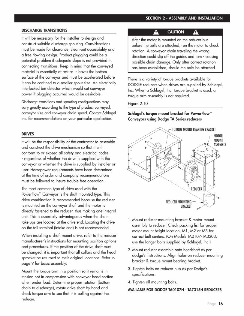
There is a variety of torque brackets available for DODGE reducers when drives are supplied by Schlagel, Inc. When a Schlagel, Inc. torque bracket is used, a torque arm assembly is not required.
Figure 2.10
Schlagel’s torque mount bracket for PowerFlow™ Conveyors using Dodge TA Series reducers
1. Mount reducer mounting bracket & motor mount assembly to reducer. Check packing list for proper motor mount height location, M1, M2 or M3 for correct belt centers. (On Models TA0107-TA3203, use the longer bolts supplied by Schlagel, Inc.)
2. Mount reducer assemble onto headshaft as per dodge’s instructions. Align holes on reducer mounting bracket & torque mount bearing bracket.
3. Tighten bolts on reducer hub as per Dodge’s specifications.
4. Tighten all mounting bolts.
AVAILABLE FOR DODGE TA0107H - TA7315H REDUCERS
MOTORMOUNTASSEMBLY
REDUCER
REDUCER MOUNTINGBRACKET
TORQUE MOUNT BEARING BRACKET
CAUTION
After the motor is mounted on the reducer but before the belts are attached, run the motor to check rotation. A conveyor chain traveling the wrong direction could slip off the guides and jam - causing possible chain damage. Only after correct rotation has been established, should the belts be attached.

SECTION 2 - ASSEMBLY AND INSTALLATION
Page 17
TENSIONING DRIVE BELTS
1. Align the sheaves looking from both the side of the drive as well as the top of the drive.
2. Ideal tension is the lowest tension at which the belts will not slip under load.
3. Recheck tension during the first 24-48 hours of run-in operation.
4. Remember that over tensioning shortens belt and bearing life.
5. Re-tension when slipping. NEVER apply belt dressing.
CAUTION
All reducers are SHIPPED WITHOUT OIL.
Be sure you fill the reducer with the proper amount and type of oil after assembly.
CAUTION
Dodge Hydra-lock breather plugs are standard on Dodge TA7 and larger reducers. Make sure vent plugs are removed.
INPUT SHAFT
E
OD
D
G
? H
?AT ?
?
E
OD
D
G
? H
?AT ?
?
E
OD
D
G
? H
?AT ?
?
BRACKETS MOUNT TO FRONT SIDE OF HOUSING FLANGE.
REDUCER POSITION BMOTOR MOUNT POSITION M1
REDUCER POSITION BMOTOR MOUNT POSITION M2
REDUCER POSITION BMOTOR MOUNT POSITION M3
Check reducer vent location and fill reducer with oil. Although manufacturer’s oil recommendations may be followed as listed on their data sheet, it is generally acceptable to use a good automobile grade oil with viscosity suitable for your operating conditions and temperatures.
Install approved guards on all exposed rotating equipment.

SECTION 2 - ASSEMBLY AND INSTALLATION
Page 18
WEATHER COVERS
Weather covers are supplied with your conveyor in 10' sections of sufficient quantity to enclose completely the tops of all components.
After assembly has been completed and chain has been tested and adjusted, install foam seal tape along bottom of both outside edges of covers so that seal will make full contact with top flange of trough and terminal components (Figure 2.11). This method of installation is preferred over installing seals on trough flange because when the covers are removed for maintenance, the seals will not be exposed to damage.
Some cutting of weather covers might be necessary to fit areas over terminals and up to inlets or hoppers. When covers are in position, install cover splices over matching end flanges and secure edges with six (6) cover clamps for each 10' section (Detail, Figure 2.11)
Figure 2.11
START-UP PROCEDURES
1. Check and retighten all bolts.
2. Check to see that there is the recommended oil level in drive reducer.
3. Run the conveyor empty and listen for hammering noises. If they exist, the potential problem must be found and corrected before major damage or undue wear occurs.
4. Introduce product and check for evidence of: A. Inlet transition accepting product freely. B. Product being conveyed at rated capacity. C. Machine running quietly with no intermittent loud noises. D. Proper operation of intermediate discharge open and close. E. Ample slope in discharge terminal to allow product to discharge freely.
NOTE: Refer to Assembly instructions, Operation and Maintenance or Troubleshooting sections to correct any exceptions to above.
WARNING
In addition to providing protection against contamination, trough rust and deadening of operational sound, it is absolutely essential that the weather covers be installed at all times to insure personal safety.
WARNING
Before allowing operators to use this conveyor, all weather covers must be in place on troughs and guards must be installed on all moving parts of the drive. Because of the variety of installation applications, the operating procedure can only be described in a general manner as follows:
COVER SPLICE
TAKE-UP TAILTERMINAL
STANDARD COVER
TROUGH SECTION
COVER CLAMPS(6 PER FULL
LENGTH COVER)
STANDARD HIP ROOF COVER (OPTIONAL)
SUPER HIP ROOF COVER (OPTIONAL)
DEFINED PEAK10˚ TO 15˚ SLOPES
SLIGHT BEND TOPROMOTE RUN OFF
OPTIONALBOLTED COVER
OPTIONALBOLTED COVER
STANDARDCOVER CLAMP
STANDARDCOVER CLAMP
*NOTE: ALL CONVEYOR COVER STYLES ARE AVAILABLE WITH THE STANDARD COVER CLAMPS OR MAY BE ORDERED WITH THE BOLT ON OPTION. NEW CONVEYOR ORDERS WITH THE STANDARD COVER CLAMPS USE SIX CLAMPS FOR EACH 118” LENGTH COVER. IF THE BOLT ON OPTION WAS CHOSEN, ALL TROUGHS AND COVERS HAVE BOLT HOLES AND ALL ASSEMBLY BOLTS ARE PROVIDED.

SECTION 2 - ASSEMBLY AND INSTALLATION
Page 19
INSTALLER/CONTRACTOR RESPONSIBILITIES
After the installer/contractor is satisfied that conveyor is operating properly, it is their responsibility to point out the following information to the operator:
1. The importance of following recommended procedures contained in this manual.
2. A basic explanation of the operating principles of the Schlagel PowerFlow™ Conveyor and how it differs from other types of conveying systems.
3. Machinery that must be running prior to starting the conveyor (electrical interlocks).
4. Location of the start/stop station(s).
5. Location of the electrical disconnect.
6. Operation of intermediate discharges and valves.
7. Shutdown sequence.
8. How to clear the system of plugs, foreign objects, etc.
9. Instructions on various maintenance procedures.
10. Demonstration of the operation of the detector tail, if used.
MAINTENANCE PROCEDURES
The correct tension of the chain is important to prolong chain and sprocket life and should be periodically checked as part of a scheduled maintenance plan. The correct chain tension procedure is explained on pages 11 and 37 of this manual.
The drive oil level should be maintained per the drive manufacturer’s instructions. Make certain that any torque arm bolts and brackets are tight and in good condition.
Bearings have been greased at the factory and are ready to run. When establishing a relubrication schedule, note that a small amount of grease at frequent intervals is preferable to a large amount at infrequent intervals. The schedule is unique for each installation and must be determined by experienced maintenance personnel. Frequency and type of lubrication depends on operating conditions, environment, speed and loads. In cases of severe duty operation, it may be necessary to contact the bearing manufacturers for help in determining the schedule.
Generally, low speed bearings (under 250 RPM) should be lubricated by slowly pumping grease into the bearing, while it is rotating, until a thin bead forms at the seal, purging contaminants from the bearing. Bearings should then be greased as often as necessary (daily if required) to maintain a slight leakage at the seals. Normal temperature and a slight showing of grease at the seals indicate proper lubrication.
Any unusual noises in the conveyor should be checked immediately and corrected.
Worn trough sections should be replaced or lined. If you are installing any side liners then make certain they will not interfere with the chain paddles or else narrow the paddles so that there is sufficient operating clearance.
The tail section is normally never lined. This means that the tail terminal should be raised up so it is level with the bottom liner and also that any trough side liners are beveled at the tail end so that the chain paddles cannot get caught.

Page 20
INTERMEDIATE DISCHARGE ASSEMBLY
INTRODUCTION
The optional patented PowerFlow™ Intermediate Discharge is available in several types of actuators (chain wheel, hand wheel, air or electric). It makes possible the discharge of any free flowing material at almost any point in the conveyor between the inlet and the head terminal. Due to difficulty in installation, it is not recommended that an intermediate discharge be placed over the trough flanges. Therefore, if a critical placement requires an installation over the trough flanges, a short trough section may be used to “space” the flange so that there is no interference.
INSTALLATION
If your conveyor uses Type 2 or Type 3 trough (Detail A, Figure 3.2), the liner must be removed from the area of installation before proceeding.
Refer to Table 1 and Figure 3.1 for the correct length of cut for your particular model of conveyor. Mark and cut distance “A” plus 1/4" long by the full width of the trough.
NOTE: Preferred intermediate discharge mounting orientation is with the wide end of the V-pattern “carryover strips” or “carryover bars” toward head. See detail below.
PREFERRED INSTALLATION DETAIL
SECTION 3 - OPTIONAL EQUIPMENT
INLINE INTERMEDIATE DISCHARGE SHOWN
SIDE TRAVEL INTERMEDIATE DISCHARGE SHOWN
HEADENDFLOW
CARRYOVER BARS
HEADENDFLOW
CARRYOVER STRIPS

SECTION 3 - OPTIONAL EQUIPMENT
Page 21
Figure 3.1
TYPE #1 TROUGH
1. Cut out opening as per body length w/ cut out the entire bottom of the trough, not extending up the sides.
2. Position intermediate & frame on trough, making sure inside bottom of trough & carryover bars are flush.
3. Weld frame to trough & caulk all un-welded areas 2" long welds on top of frame & full welds on ends.
FULL WELDS on LIP of FRAME ENDS
GRAIN FLOW
FULL WELDS on LIP of FRAME ENDS
GRAIN FLOW
by EACH BOLT2" LONG WELDS
1/4"
2" LONG WELDSby EACH BOLT
CUT OUT = BODY LENGTH
CUT OUT = BODY LENGTH + 1/4"
BODY LENGTH
BODY LENGTH
LONG TRAVEL STYLE I.D.
SIDE TRAVEL STYLE I.D.
IMPORTANT If the chain or chain paddles catch on anything in the discharge area, this condition will have to be corrected or excessive wear will result.

SECTION 3 - OPTIONAL EQUIPMENT
Page 22
Figure 3.1 continued
TYPE 2 and 2S TROUGHS
1. Cut out opening as per body length w/ cut out the entire bottom of the trough; not extending up the sides (on Type 2S, side liners do not need trimming).
2. Position intermediate & frame on trough, making sure inside top of trough liner & carryover bars are flush.
3. Drill holes through liner, trough & frame lip. Countersink liner & install flat head bolts.
4. Weld frame to trough & caulk all un-welded areas 2" long welds on top of frame & full welds on ends.
LINERMOUNTING BOLTS
FULL WELDS on LIP of FRAME ENDS
GRAIN FLOW
FULL WELDS on LIP of FRAME ENDS
MOUNTING BOLTS
LINER
GRAIN FLOW
by EACH BOLT2" LONG WELDS
1/4"
2" LONG WELDSby EACH BOLT
CUT OUT = BODY LENGTH
CUT OUT = BODY LENGTH + 1/4"
BODY LENGTH
BODY LENGTH
LONG TRAVEL STYLE I.D.
SIDE TRAVEL STYLE I.D.
IMPORTANT If the chain or chain paddles catch on anything in the discharge area, this condition will have to be corrected or excessive wear will result.
# OF MOUNTING BOLTS USED PER END6",8" & 12" WIDE CONV. USE 2 BOLTS16",18" & 20" WIDE CONV. USE 3 BOLTS24" & 30" WIDE CONV. USE 4 BOLTS36" WIDE CONV. USE 5 BOLTS

SECTION 3 - OPTIONAL EQUIPMENT
Page 23
Figure 3.1 continued
TYPE #3 TROUGHS
1. Cut out bottom plate length as per drawing do not cut outside flange of bottom plate to this dimension
2. Cut out trough side flanges, and flanged part of bottom plate per drawing, not extending up the sides (on TYPE #3s, side liners do not need to be trimmed).
3. Position intermediate & frame on trough, making sure inside bottom of trough & carry over bars are flush.
4. Drill holes through trough bottom plate & frame lip. Countersink bottom plate & install flat head bolts.
5. Weld frame to trough & caulk all un-welded areas only weld the frame’s top mounting angle, not on the frame ends.
CONV. HEIGHT BODY LENGTH 10" & 14" 30" 18" & 20" 39" 26" & 30" 48" 36" 60"
TROUGH SIDE BOTTOM FLANGE
TROUGH BOTTOM PLATE
TROUGH SIDE BOTTOM FLG
TROUGH BOTTOM PLATE
FRAME'S TOP MOUNTING ANGLE
GRAIN FLOW
MOUNTING BOLTS
FRAME'S TOP MOUNTING ANGLE
GRAIN FLOW
by EACH BOLT2" LONG WELDS
& EACH END
1/4"
2" LONG WELDSby EACH BOLT& EACH END
3" MORE THAN BODY LENGTHTROUGH BOTTOM FLG & BODY SIDE FLANGE
TROUGH BOTTOM ONLYCUT OUT = BODY LENGTH + 1/4"
TROUGH BOTTOM FLG & BODY SIDE FLANGE3/4" MORE THAN BODY LENGTH
CUT OUT = BODY LENGTHTROUGH BOTTOM ONLY
BODY LENGTH
BODY LENGTH
MOUNTINGBOLTS
LONG TRAVEL STYLE I.D.
SIDE TRAVEL STYLE I.D.
IMPORTANT If the chain or chain paddles catch on anything in the discharge area, this condition will have to be corrected or excessive wear will result.
# OF MOUNTING BOLTS USED PER END6",8" & 12" WIDE CONV. USE 2 BOLTS16",18" & 20" WIDE CONV. USE 3 BOLTS24" & 30" WIDE CONV. USE 4 BOLTS36" WIDE CONV. USE 5 BOLTS
SECTION 3 - OPTIONAL EQUIPMENT
Page 24
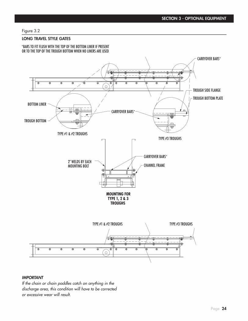
Figure 3.2
LONG TRAVEL STYLE GATES
MOUNTING FORTYPE 1, 2 & 3
2" WELDS BY EACHMOUNTING BOLT
TROUGHS
TYPE #1 & #2 TROUGHS
CARRYOVER BARS*
*BARS TO FIT FLUSH WITH THE TOP OF THE BOTTOM LINER IF PRESENTOR TO THE TOP OF THE TROUGH BOTTOM WHEN NO LINERS ARE USED
CHANNEL FRAME
TYPE #3 TROUGHS
CARRYOVER BARS*
TROUGH BOTTOM PLATE
TROUGH SIDE FLANGE
TROUGH BOTTOM
BOTTOM LINER
CARRYOVER BARS*
TYPE #1 & #2 TROUGHSTYPE #3 TROUGHS
IMPORTANT If the chain or chain paddles catch on anything in the discharge area, this condition will have to be corrected or excessive wear will result.

25
SECTION 3 - OPTIONAL EQUIPMENT
Page
Figure 3.3
SIDE TRAVEL STYLE GATES
2" WELDS BY EACHMOUNTING BOLT
WELDED
OR
BOLTED
LINERS ARE FACTORY SUPPLIED
TROUGHSTYPE 1 & 2 TYPE 3
TROUGH
2" WELDS
PRODUCT FLOW
BOLTED OR WELDED
TROUGH
R&PINTERMEDIATE DISCHARGETROUGHS
TYPE 1 & 2MOUNTING FOR
TYPE 3 TROUGHMOUNTING FOR
CARRYOVER STRIPS*
*STRIPS TO FIT FLUSH WITH THE TOP OF THE BOTTOM LINER IF PRESENTOR TO THE TOP OF THE TROUGH BOTTOM WHEN NO LINERS ARE USED
BEVEL EDGE
SLIDE LINER
IMPORTANT If the chain or chain paddles catch on anything in the discharge area, this condition will have to be corrected or excessive wear will result.

SECTION 3 - OPTIONAL EQUIPMENT
Page 26
INTERMEDIATE DISCHARGE DRAPE
The intermediate discharge drape is used in conveyors when intermediate discharge carry over becomes a problem. Although it can reduce the normal carry over by 95% with most material, critical installations such as seed conveyors should be designed so that any carry over is removed by the end discharge for disposal. Consult the factory for recommendations.
DRAPE INSTALLATION FOR CONVEYORS WITH ROLLER RETURNS
1. Drill a hole per shaft bolt size on each side of the trough, the same distance from the top as the roller return assembly and centered over the discharge opening. Bolt the drape/roller assembly in place.
2. Drill holes per shaft bolt size and mount a second (bare) shaft only, allowing the drape to extend 1-1/2" past this shaft as if the neoprene drape were extended to a horizontal position.
3. Check to see that the return (top) chain cannot catch the neoprene when the discharge is closed and the conveyor is full.
DRAPE INSTALLATION FOR CONVEYORS WITH EZ-GLIDE RETURNS
1. Drill a hole per shaft bolt size on each side of the trough, the same distance from the top as the EZ-Glide return assembly and centered over the discharge opening. Bolt the drape assembly in place. The Galvanized EZ-Glide rail has to be drilled or notched.
2. Check to see that the return (top) chain cannot catch the neoprene when the discharge is closed and the conveyor is full.
1 1/2"CENTER OF
I.D. OPENING
PRODUCT FLOW
CENTER OFI.D. OPENING
PRODUCT FLOW
HOLES ORNOTCHES
CENTER OFI.D. OPENING
PRODUCT FLOW

SECTION 3 - OPTIONAL EQUIPMENT
Page 27
SHAFT RUNS THROUGH THEEZ-GLIDE RAIL, NOT UNDERNEATH
CHAIN
FLOW
CORRECT INSTALLATION
OPERATION
When the discharge is open the drape lays on the bottom chain to unbalance any material that may be on the chain. When the discharge is closed, material passing over the area lifts the neoprene drape to a horizontal position. The return chain cannot catch the neoprene drape because of the second roller shaft.
SHAFT RUNS UNDERNEATH THEEZ-GLIDE RAIL, NOT THROUGH IT
CHAIN
FLOW
INCORRECT INSTALLATION

SECTION 3 - OPTIONAL EQUIPMENT
Page 28
DETECTOR TAIL TERMINAL INTRODUCTION
The optional Patented PowerFlow™ Detector Tail Terminal (Figure 3.4) has been designed to automatically provide chain tension adjustment and will sense excessive slack in the conveyor chain (such as chain breaking) or greatly increased chain tension (such as product or a foreign object jamming the chain) and electrically shut off power to the conveyor drive. This safety device will react to conveyor problems faster than other types of detectors, making it a more desirable design.
Figure 3.4
It is important to keep in mind that the sole purpose of the detector tail is to help prevent damage to the conveyor chain. It is not meant to be used as a plugged conveyor sensor, for drive protection, personnel safety or for any other purpose.
THEORY OF OPERATION
When the conveyor chain is adjusted to the proper tension and the machine is operating normally, the take-up portion of the detector tail will allow 1" forward movement and 2" rearward movement. This movement allows for normal expansion and contraction of chain due to temperature, wear and load conditions. Tension springs on each side of the detector have been factory pre tensioned to a minimum of 300 lbs each so there is sufficient pressure to keep the chain tight and actuate the detector during a malfunction.
A correctly adjusted conveyor will detect a malfunction in either of two ways:
NOTE: See page 31 for switch wiring information.
1. Forward Motion (Figure 3.5) - An abnormal force attempting to stop the movement of the conveyor chain such as a foreign object lodged in the conveyor, will add excessive tension to the chain. When the tension exceeds the preset limits, the take-up assembly moves forward, compressing springs and moving the cam on the take-up assembly off the sensor arm of the limit switch. The limit switch immediately directs a power disconnect, thereby preventing serious mechanical damage.
Figure 3.5
2. Rearward Motion (Figure 3.6) - Lack of chain tension caused by chain stretch (most common on new chain), chain that has slipped off the sprocket or chain that has broken will extend compression springs, move the take-up assembly rearward and slide the cam off the sensor arm of the limit switch. The drive is immediately shut down by the limit switch, preventing further mechanical damage
Figure 3.6
TAKE-UP ASSEMBLY
BROKEN CHAIN
CAM
MICROSWITCH
REAR MOTION
TAKE-UP ASSEMBLY
CAM
MICROSWITCH
FORWARD MOTION
FOREIGN OBJECT
SECTION 3 - OPTIONAL EQUIPMENT
Page 29
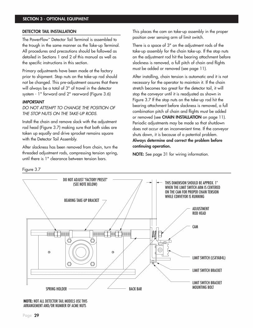
DETECTOR TAIL INSTALLATION
The PowerFlow™ Detector Tail Terminal is assembled to the trough in the same manner as the Take-up Terminal. All procedures and precautions should be followed as detailed in Sections 1 and 2 of this manual as well as the specific instructions in this section.
Primary adjustments have been made at the factory prior to shipment. Stop nuts on the take-up rod should not be changed. This pre-adjustment assures that there will always be a total of 3" of travel in the detector system - 1" forward and 2" rearward (Figure 3.6)
IMPORTANT DO NOT ATTEMPT TO CHANGE THE POSITION OF THE STOP NUTS ON THE TAKE-UP RODS.
Install the chain and remove slack with the adjustment rod head (Figure 3.7) making sure that both sides are taken up equally and drive sprocket remains square with the Detector Tail Assembly.
After slackness has been removed from chain, turn the threaded adjustment rods, compressing tension spring, until there is 1" clearance between tension bars.
This places the cam on take-up assembly in the proper position over sensing arm of limit switch.
There is a space of 3" on the adjustment rods of the take-up assembly for the chain take-up. If the stop nuts on the adjustment rod hit the bearing attachment before slackness is removed, a full pitch of chain and flights must be added or removed (see page 11).
After installing, chain tension is automatic and it is not necessary for the operator to maintain it. If the chain stretch becomes too great for the detector tail, it will stop the conveyor until it is readjusted as shown in Figure 3.7 If the stop nuts on the take-up rod hit the bearing attachment before slackness is removed, a full combination pitch of chain and flights must be added or removed (see CHAIN INSTALLATION on page 11). Periodic adjustments may be made so that shutdown does not occur at an inconvenient time. If the conveyor shuts down, it is because of a potential problem. Always determine and correct the problem before continuing operation.
NOTE: See page 31 for wiring information.
Figure 3.7
THIS DIMENSION SHOULD BE APPROX. 1"WHEN THE LIMIT SWITCH ARM IS CENTEREDON THE CAM FOR PROPER CHAIN TENSIONWHILE CONVEYOR IS RUNNING
SPRING HOLDER
NOTE: NOT ALL DETECTOR TAIL MODELS USE THISARRANGEMENT AND/OR NUMBER OF ACME NUTS
LIMIT SWITCH BRACKETMOUNTING BOLT
LIMIT SWITCH (LSXYAB4L)
BACK BAR
LIMIT SWITCH BRACKET
CAM
ADJUSTMENTROD HEAD
BEARING TAKE-UP BRACKET
DO NOT ADJUST "FACTORY PRESET"(SEE NOTE BELOW)

SECTION 3 - OPTIONAL EQUIPMENT
Page 30
PLUG SWITCHES
It is always a good idea to have your conveyor system protected by a plug switch, whether or not it comes equipped with our Detector Tail. The best location for a plug switch is always as far down-stream as possible from the conveyor. This allows the maximum amount of reaction time to rectify the problem before the conveyor
becomes plugged. Since many applications like a pit conveyor dumping into a leg have virtually no space until the next piece of equipment to put a plug switch, we offer several styles of switches mounted in the conveyor housing. Most types and suggested applications are shown below.
HINGED RELIEF COVER
Application notes:
1. Works on both box head or take-up head.
2. Possible interference with motor mount on some sizes.
3. Top flange must be cleaned off after activation so cover will contact switch arm.
USES: LSXYAB4L MICRO-SWITCHNOTE: See page 31 for wiring information.
HINGED RELIEF END DOOR
Application notes:
1. For use on box head only; will not fit on take-up head.
2. Weld on take-up head versions may be available on request.
USES: LSXYAB4L MICRO-SWITCHNOTE: See page 31 for wiring information.
CAPACITANCE PROBE
Application notes:
1. Do not use for fill conveyor that has head shut-off gate and reclaim cups.
USES: 4B #BP1V10FC SWITCHNOTE: See pages 33 for wiring information.
DIAPHRAGM SWITCH
Application notes:
1. Do not use for fill conveyor that has head shut-off gate and reclaim cups.
2. For use on box head only, will not fit on take-up head.
3. Alternate location on top cover would work with reclaim cups but may interfere with some size motor mounts.
MULTIPLE OPTIONS AVAILABLENOTE: See pages 32 for wiring information.

TO STARTER CONTACTOR
STOP
START
ON
CO
NTA
CTS
5 -
8O
PTIO
NA
L A
UXI
ALL
IARY
CIR
CU
IT
#LSXYAB4LLIMIT SWITCH
2
1
N.C.
6
5
N.C.
N.O.
4
3
N.0.
8
7
SECTION 3 - OPTIONAL EQUIPMENT
Page 31
TYPICAL WIRING DIAGRAM FOR ELECTRICRACK & PINION DISCHARGE GATES
WE RECOMMEND USING THIS REVERSING STYLE ALSO FOR PLC CONTROLLED DROP BOTTOM UNITS
STOP
1
2
5
T3
T1
T2 M
CLOSE
OPEN 4 L1
STARTERREVERSING
7
3
6L3
L2
6
OPTIO
NAL A
UXIA
LLIA
RY CI
RCUI
TON
CONT
ACTS
5 -
8
2
OPEN SWITCH
1
N.C.
5
N.C.
N.O.
3
4
N.0.
7
8
#LSXYAB4LCLOSED SWITCH
2
N.C.
1
N.O.
3
4
ON CO
NTAC
TS 5
- 8
OPTIO
NAL A
UXIA
LLIA
RY CI
RCUI
T
6
5
N.C.
N.0.
7
8
#LSXYAB4L
ELECTRICAL
The general procedure for electrical interconnection places the normally open (N.O.) connections of the limit switch in series with the “stop” push button of the start-stop switch (Figure 3.8). When the conveyor is connected in a system with other machinery, electrical interlock priorities should be maintained so that if the last conveyor fails, all proceeding equipment in the system would stop. All wiring is the responsibility of the contractor/installer and should only be done by a qualified electrician familiar with local wiring codes.
Figure 3.8
TYPICAL WIRING DIAGRAM FOR DETECTOR TAIL LSXYAB4L Limit Switch used on detector tail or hinged relief door.
THE LIMIT SWITCHES ARE THE ONLY DEVICES PROVIDED.
INDICATOR LIGHTS ARE TO BE SUPPLIED BY CUSTOMER.

SECTION 3 - OPTIONAL EQUIPMENT
Page 32
ELECTRICAL
The BinMaster housing has provisions for connection to a 3/4 inch conduit.
Remove the back plate of the BM65D. This will expose the double pole double throw snap-switch.
The switch rating is: 10A@125VAC or 250VAC, 1/8 HP-125VAC, 1/4 HP-250VAC, 1/2A@125VDC, 1/4A@250VDC.
There are three terminals on each side of the switch: “Common”(C), “Normally Closed”(NC), and “Normally Open”(NO). The condition referred to as “normal” is with no material covering the diaphragm of the BM65D.
To wire the BinMaster switch to stop the motor when material covers the diaphragm, use the “Common” and “Normally Closed” switch terminals.
To wire the BinMaster switch to turn on a light, or sound an alarm when material covers the diaphragm, use “Common” and “Normally Open”.
INSTALLATION NOTE:
Install the BinMaster switch with the conduit opening facing downward. When installing the BinMaster switch in high moisture areas or where moist air could enter the enclosure through the electrical conduit, use a duct seal compound to seal the conduit opening.
TYPICAL WIRING DIAGRAM FOR BM65DHFT Diaphragm (Used as a plug switch).
NOTE: SEE THE PROVIDED MANUFACTURE’S WIRING INFORMATION FOR SINGLE POLE DOUBLE THROW DIAPHRAGM SWITCH.
NO NC C
NO NC C
CAUTION
Wiring to this unit must conform to the National Electrical Code and any local codes. Contact a qualified electrician.

SECTION 3 - OPTIONAL EQUIPMENT
Page 33
ELECTRICAL WIRING OF BSE1V10C ELITE BINSWITCH
Suggested connection of capacitance probe used as a plugged conveyor shutoff.
The normal procedure for electrical inter-connection places the normally open contacts in series with the STOP push button of the START-STOP switch as shown below. When the conveyor is connected in a system with other machinery, an electrical interlock should be maintained so that if the conveyor is shut off by the probe that all proceeding equipment would stop.
1. The unit must be installed before calibration takes place. Connect the Binswitch to power and a suitable control unit
2. Check that the tip of the Binswitch is not covered or obstructed.
3. Carefully turn the calibration control screw fully counter clockwise to set the sensor sensitivity to zero.
Do not use excessive force, the control has end stops.
4. A magnet is taped to the wire of the sensor. Place the magnet on the magnetic calibration point on the end of the sensor (see illustration), the red LED will flash on and off.
• A NORMALLY DE-ENERGIZED sensor is required (with no material present), remove the magnet when the LED is “OFF”.
5. Wait approximately one minute for the automatic compensation system to stabilize. Then either fill the vessel until the tip of the Binswitch is covered, or remove the Binswitch and place the tip of the sensor in a bucket filled with the material to be monitored and then calibrate the unit as follows:
• NORMALLY DE-ENERGIZED - Slowly turn the sensitivity control screw clockwise until the LED turns “ON”.
To set the sensor sensitivity to optimum setting, turn the control screw an additional 10 degrees clockwise.
Turning the sensitivity control screw counter clockwise decreases the sensitivity, turning clockwise increases the sensitivity.
NOTE: If the material being monitored creates dust, you may need to re-calibrate the sensor. Dust build up on the Binswitch will affect the initial calibration. DO NOT remove the Binswitch and clean off the dust. Always check that the Binswitch detects material after the sensitivity has been adjusted.
See manufactures manual for more detailed instructions.
It is necessary for the operating voltage input power to the probe unit to be present before the conveyor can be started as COM and N.O. would not have closed contacts without the input power voltage.
The LED light will turn on when material touches the probe.
CAUTION
If the switch does not seem to shut the equipment down when plugged, the sensitivity control screw may need to be adjusted. See manufacturer’s manual for more details.
WARNING
If the system does not immediately shutdown as expected or alarm as required, then remove the machine from service until the problem has been diagnosed and corrected.
STOP
START
CONNECT THESE (2) TO EITHER:12-240VDC or 24-240VACBLUE (NEUTRAL)
BROWN (LIVE)
NOT USEDBLACK/ORANGE (N.C.)
BLACK/RED (N.O.)(CHANGES TO N.C. WHEN MAT’L PRESENT)
BLACK (COM)
BINSWITCH #BSE1V10C
SENSITIVITYCONTROLSCREW
LED LIGHT
MAGNETIC CALIBRATION POINT
OFF = NO MATERIAL CONTACT ON = MATERIAL CONTACT
TO MAGNETIC STARTER
START/STOP STATIONBY CUSTOMER
1 3 2
TYPICAL WIRING DIAGRAM FOR BP1V10FC BINSWITCH

SECTION 4 - INCLINED CONVEYORS
Page 34
INCLINE CONVEYORS
Model I conveyors are used when you can use a straight conveyor and your angle of incline is between 10 to 50 degrees. They are commonly used on the sloped pitch of a bin top or anywhere the angle is too great for a standard type of drag conveyor.
Model IC conveyors are used when you want to convey material horizontally for a certain distance and then curve the conveyor up at angles of 50 degrees or less. These are commonly used for truck or rail receiving where you want to eliminate having the boot of a bucket elevator in a pit. They are also used to gain extra hopper capacity by having a deeper hopper without having to also lower the inlet point of the equipment you are feeding into.
Model DC conveyors are used when you want to convey material horizontally for a certain distance, then curve the conveyor up at inclines up to 90 degrees and then reverse curve back to an incline of 50 degrees or less. These would also be used in places that you would select the “IC” conveyor but have to clear an overhead or ground obstacle that you cannot clear with just one curved section.
Model ICV conveyors are used when you want to convey material horizontally for a certain distance and then curve the conveyor up at inclines from 51 to 90 degrees. These would be used in places that you would select the above “IC” conveyor but need the steeper incline ability.

SECTION 4 - INCLINED CONVEYORS
Page 35
THEORY OF OPERATION
This series of conveyors differs from our standard conveyors in many ways. The trough area utilized for material conveying is only about 40% compared to approximately 85% in the standard series. This results in a larger trough housing for a particular capacity requirement.
The Incline series conveyors cannot be flood or choke fed unless a bypass inlet section of trough is used. If you are going to control feed the conveyor then your inlet must be placed far enough in front of the tail sprocket so that material is not fed directly into the sprocket area.
Figure 4.1 shows the control fed method by which the capacity is determined by a feeding device such as a bucket elevator, another conveyor or a process machine. The conveyor speed is adjusted so that at maximum capacity the material conveying chamber within the trough is never more than 95% full.
Figure 4.1
Figure 4.2 shows the flood fed method by which the capacity is determined entirely by the speed of the conveyor. The material conveying chamber is always nearly 100% full. It cannot be overfed because the bottom of the bypass shroud does not allow excess product to enter the conveyor. This feature is very useful when used with truck or rail dump hoppers, or when reclaiming material from storage bins. It is important to remember that when using a bypass inlet that full capacity requires material to be fed around both sides of the bypass shroud.
Figure 4.2
TROUGH ALIGNMENT
On this style of conveyor it is important to not only have the main trough housing aligned on the inside but also the divider in the trough. The easiest way is to align troughs with the solid divider is to align the outside edges of the mating flanges at the bottom corners and then the upper inside edge of the trough before tightening the flange bolts.
TROUGH TYPES
FLOW
FLOW
Type 1
Type 2
Type 3
Type 2S
Type 3S

SECTION 4 - INCLINED CONVEYORS
Page 36
CHAIN
TRAVE
L
SEE DETAIL “A”
DETAIL “A”
CHAIN & MATERIAL MUST TRAVEL INTHIS DIRECTION TOWARDS DISCHARGE
IF CHAIN IS INSTALLED BACKWARDS,PADDLES WILL ACT AS A CUPAND CARRY MATERIAL PAST DISCHARGE AND BACK INTO TROUGH.
CHAIN & MATERIAL MUST TRAVEL INTHIS DIRECTION TOWARDS DISCHARGE
SEE DETAIL “A”
SEE DETAIL “A”
CHAIN TRAVEL
CHAIN TRAVEL
CHAIN TRAVEL
POWERFLOW™ INCLINE STYLE DRAG CONVEYOR
I AND IC STYLE CHAIN
ICV STYLE CHAIN

CHAIN TENSIONING
Before starting the conveyor you should initially tension the chain so that the top chain’s UHMW paddles going away from the head or tail sprocket sags down to the center trough divider and touches it about 5' to 10' away.
Be certain that the motor rotation is correct before starting the conveyor in the following step so that the bottom (material carrying) chain is traveling towards the head discharge.
Start the conveyor and observe the top chain coming off the head sprocket into the upper half of the trough. The chain should not be so loose that it tries to wrap around the sprocket and jam into the middle head divider guide.
On “I” style conveyors you would want the running chain’s paddles to sag down to the trough divider the 5' to 10' distance stated above.
On “IC”, “DC” and “ICV” models it is better to observe the curved (incline) trough with the cover removed and set the running chain tension so that the paddles are slightly above or just starting to touch the trough divider.
If you look inside a conveyor when it is shut off and see that the UHMW paddles are not standing upright in the lower material conveying chamber but rather look like they are “laying down”, then the chain tension is too loose.
The most common problem we see with the chain tension in these conveyors is that the chain tension is too tight. This will make conveyors with curved troughs quite noisy from the slapping of the paddles against the trough divider and the top cover and also shorten the life of the conveyor. The chain should never be “bow string tight” on these conveyors.
SECTION 4 - INCLINED CONVEYORS
Page 37
BOTTOM CHAINTRAVEL DIRECTION
BYPASS INLET
TROUGH WITHDIAMOND DIVIDER CURVED TROUGH
CENTER DIVIDER
TROUGH WITHCENTER DIVIDER
BOX HEAD
OPTIONALBAR GRATE
TAKE-UP TAIL MODELS:I, IC, DC
MODEL:ICV
HARDENED TOOTH SPROCKETS IN HEAD AND TAIL
INCLINE STYLE CONVEYOR
ASSEMBLY OF BASIC COMPONENTS
ASSEMBLED VIEW

38
SECTION 4 - INCLINED CONVEYORS
Page
BYPASS INLET SIDE SHIELDS
Bypass inlets for inclined conveyors (IC type) that are 84" and longer have side shields on the sides of the hogback to allow the hopper above to empty at an even rate. Without the side shields the hopper will empty from one end more than the other.
The side shields should be set at an angle so that the end nearest the head is above the trough center divider and the end nearest the tail is as low as it can go, but no less than 2" from the trough bottom. When using a long bypass that is divided into multiple sections, each section will have its own set of side shields. In this case the side shields in the section nearest the tail may be set as low as 2" or set at an angle as described above, but
not above the trough center divider on the head end. The side shields in the next section would pick up where the preceding section side shields left off until the side shield is above the trough center divider at the head end of the complete bypass inlet.
With certain products it may work best to have the side shields moved up completely. When handling products where bridging is a concern the side shields can be removed from the bypass inlet.
The side shields are not preset at the factory so that the bypass inlet can be installed in either direction. That is, the standard bypass does not a definite tail end or head end.
2" MINIMUM
2" MINIMUM
2" MINIMUM
CENTER DIVIDER
CENTER DIVIDER
CENTER DIVIDER
TAILEND
HEADEND
TAILEND
HEADEND
TAILEND
HEADEND

PROBLEM CAUSE REMEDY
39
Capacity not correct.
Both low capacity and plugging in tail.
Both low capacity and material depth in trough higher by inlet then down by the discharge. May even be plugging ahead of inlet and bulging up the top cover.
Both low capacity and plugging at discharge.
Chain not riding on trough bottom.
Conveyer is at to steep an incline and not easily possible to reduce the amount of incline.
Detector tail is shutting conveyer off.
See if problem is with conveyor first
Incorrect chain speed.
Improper conveyor inlet.
Bent or missing flights / paddles, especially on an inclined conveyor.
Customer has installed UHMW liners.
Improper inlet location - too close to tail.
Conveyor at too great an incline for specific product or incorrect chain in conveyor.
Operator might not be filling the conveyor because this causes the head discharge to plug.
Product type or product buildup.
Maybe nothing is wrong with tail!
Wired incorrectly.
Incorrect springs in the tail.
Reversing or tail drive conveyor.
Switch arm facing wrong way.
Find out if problem has always existed or is a new problem.Take covers off by tail, in front of inlet and by head discharge and check material level in the trough to see if it is running full. Try and isolate where problem is occurring.
Verify actual head shaft RPM (not tail shaft), if not possible then check for correct sheave sizes, reducer gear ratio and motor label RPM.
Inlet too small. maybe needs inlet (cushion) box. If the conveyor is at an incline and there is a full bypass shroud then the conveyor will never get full trough fill. If there is a hogback angle it should be several inches above the top chain.
Replace or straighten.
Put U or double flights on the chain. Replace liners with steel.
If inlet is too close to tail then it may start plugging in tail. If tail cover is removed and product spills over top of tail then inlet must be moved or conveyor extended.
Sometimes a bottom baffle and maybe a top wiper may help. If a large hopper try putting a shed plate inside on the tail end. Also a center hogback angle can help but see above hogback angle information.
Verify angle of conveyor and style of chain.Check to see if trough is polished.See incline problems below.
Improper discharge transition, spouting too small or equipment conveyor is feeding is not taking the product away fast enough. Some fluffy-stringy-sticky products may be building up at the angle iron head plow (just have it removed).
See "Chain rising off bottom" problems towards end.
• If conveyor is control fed then try speeding up chain to lower material depth. If the conveyor is flood fed then this can be tried but you would need to put a shear plate or damper in front of the inlet to| decrease material depth.• Check to see if chain style will allow the addition of more flights onto chain.• Check to see if taller flights can be put in by taking out roller returns and putting in side angle iron return rails.
Was or is there something in the conveyor? Is the chain too loose? What is the space between the 2 back bars?
The conveyor should run when switch arm is pressed down by the cam and the conveyor should shut off when the switch arm is free. If this is just the opposite of what is taking place then the switch is wired N.C. instead of N.O.
Long conveyors and long, flood fed inlets (especially with heavy products) need heavy springs. Inlets over 12 ft. probably need a hogback or shroud.
Replace with a take-up tail. CANNOT use a detector tail.
See page 27 drawing showing correct installation.
PROBLEM CAUSE REMEDY
SECTION 5 - TROUBLE SHOOTING
Page

PROBLEM CAUSE REMEDY
Page 40
SECTION 5 - TROUBLE SHOOTING
Detector tail is NOT shutting conveyor off.
Conveyor making unusual noises.
Carryover of product past an open intermediate discharge gate.
What happened that the tail did not shut the conveyor down for ?
Wired incorrectly.
Someone has wired the switch arm down.
Someone has jumpered the wires in switch.
Bad limit switch.
Misalignment.
Shaft in take-up end crooked.
Sprocket not centered in housing.
Missing chain guides.
Incorrectly cut sprocket.
Chain installed upside down.
Bent paddles (typically only on English chain with bolted flights).
Chain too close to top covers.
Flow ability of product and particle size and shape.
Carryover bars or not full width trough cutout.
Chain speed too fast for opening length.
No rubber drape wiper or installed in wrong location.
No reclaim cups with end discharge gate or else a 2-way valve on end discharge.
Gate not opening all the way.
Detector Tail is NOT MEANT to be a plugged conveyor device although it will often shut a conveyor off due to a plugged condition. The tail only senses the tension in the top chain tension, not the bottom chain.
The conveyor should run when switch arm is pressed down by the cam and the conveyor should shut off when the switch arm is free. If this is just the opposite of what is taking place then the switch is wired N.C. instead of N.O.
Reset switch arm to proper position.
Open switch cover to check. Rewire correctly.
Check with an electrical tester to verify. See if inside of switch is wet. If it is then check to see if water might be coming in through the conduit.
Check alignment of trough, any liners and intermediate discharge edges. Maybe some inlet piece is sticking down.
Straighten shaft so it is square with housing. If it is a detector tail then see if one slide is binding in guides.
Re-center. Replace or rework shaft collar pipe spacers.
Check for the guides in head sections and flared inlets. Are the guides positioned properly or maybe missing? Is this a reversing conveyor which needs both bottom and side chain guides in both head sections?
See if chain wraps smoothly around sprocket. If not then chain may climb on teeth or exit hard from sprocket.
UHMW paddle centers catching in sprockets. Flip chain over. Sometimes only one roll of chain in the entire conveyor may be incorrect.
See if banging is on head cover or bottom of tail. Straighten or replace paddles as necessary.
Move top chain return guides down in trough or space covers and inlets up by means of bars or thicker gasket.
There is ALWAYS some carryover since some material will balance on top of chain links, flights and paddles as the chain goes across an open intermediate discharge. A ground and/or sticky product will have more carryover than a whole material. Use rubber drape / reclaim cups.
Remove and put on end ramp guide only or see reclaim cups / 2-way valve information listed below.
Slow conveyor down if not running very full or lengthen discharge opening.
The drape should be installed at or slightly past center of opening. The drape is not required but can reduce carryover dramatically, up to 90% on some products. A second drape can help but you should never try to weight the end of the drape with a piece of bar stock.
Installing these will help prevent or eliminate cross material contamination.
Find reason for blockage, repair / readjust gate.
PROBLEM CAUSE REMEDY

PROBLEM CAUSE REMEDY
41
Intermediate discharge gate leaking.
Chain is breaking.
Conveyor is plugging.
Chain rising off bottom of trough.
Not properly adjusted. Slide or doors not closing all the way.
Drop bottom (bomb bay) style gate doors with top material buildup on edges. Operator probably closing gate with product still flowing.
Chain is roller type and chain pins seem loose in side plates as if they have been rotating.
Chain outer side plates are splitting open and pulling apart.
Same as above plus a lot of radial cracks by pins in side plates where chain has not yet pulled apart.
Rollers breaking on chain (this has only occurred on English chain).
All stainless steel chain that is wearing out too soon,
See if problem is with conveyor first.
More than one inlet is being fed and they are trying to fill the conveyor up from this latter inlet. Conveyor is plugging in front of this latter inlet
Feeding too close to tail section, especially if conveyor is at an incline.
Product not discharging from head or open intermediate fast enough.
Conveyor is control fed by some other equipment and our conveyor is not going fast enough.
Customer is leaving intermediate discharge gates open and carrying product past when bin is full.
Bottom of trough has material buildup from sticky products such as feed with fat / molasses or products such as DICAL.
Trough bottom is clean but chain not staying down resulting in loss of En-masse action. This would normally occur with heavy material or edible beans.
Try to determine reason for mis-adjustment, correct and readjust.
Scrape off the material buildup on the door and also the underside frame / trough edge the door seals against. Inform the operator that they must stop the product flow or stop the conveyor before closing gate doors.
Product being conveyed is abrasive and/or corrosive and is seizing space between roller-bushing-pin so that they do not rotate in each other going around sprocket but rather turn as if they were one piece. Replace with a different style of chain (and sprockets if different pitch).
Verify all parameters to see what may have changed.Possibly the wrong chain strength was selected.Maybe the chain is catching on top return roller/rail shafts.Is this a wide conveyor under a mixer surge where we need to install anti-tipping bars ?
Probably bad chain from factory. If old 81X chain then check to see if rollers are one piece or curled strip style. If the latter than replace with new 81X chain.
Factory probably over hardened rollers. You should be able to hit the roller with a hammer without it breaking. If it does break then replace with new chain.
See if conveyor has a spring loaded detector tail. Replace with a std. tail or block out springs and jumper switch.
Find out if problem has always existed or is a new problem.Take covers off by tail, in front of inlet and by head discharge. Also remove any cover that seems bulged up, especially if there is an intermediate or 2nd inlet nearby. Start the conveyor up with product running to see where plugging is occurring.
Regulate inlet feed rates so that the total final fill in the conveyor leaves some air space under the roller/rail return shafts. Under certain conditions a raised trough cover or pan feeder inlets may allow flood feeding from a latter inlet.
See page 1 under "CAUSE: Improper inlet location - too close to tail."
Check to see if the discharge transition is too flat or has too small of an opening and correct transition. If transition seems okay then is conveyor feeding some piece of equipment that cannot handle the conveyors capacity? Is the speed of our conveyor incorrect that it is putting out too much capacity?
Speed up our conveyor so trough fill is less than full. There should always be an air space between top of product pile and underside of roller/rail return shafts.
Do same conveyor speed as explained above.
Install scrapper paddles on chain.
Put digger flights on chain approximately every 5 feet to make it plow towards trough bottom. In place of this you could make extra thick UHMW paddles with a full front bevel.
PROBLEM CAUSE REMEDY
SECTION 5 - TROUBLE SHOOTING
Page

PROBLEM CAUSE REMEDY
Page 42
SECTION 5 - TROUBLE SHOOTING
Product being conveyed has too high a percentage of damage being done to it.
Improper chain tension.
Customer questioning staggered paddles on English chain.
How often do you need to support the conveyor trough.
Feeding too close to tail section and chewing up product between sprocket and chain, especially if conveyor is at an incline.
Conveyor has very little product in it and the normal "bouncing" of the chain as it comes off the tail sprocket is causing the paddles to "chop" up the product.
Long flood fed inlet with top chain pulling through product.
Misaligned trough joints or liners or gaps between liners.
No detector tail.
With detector tail.
Paddles are facing opposite directions so one UHMW paddle is pushing the product and the other would be pulling.
Non English chains or English chains with welded steel flights.
See page 1 under "CAUSE: Improper inlet location - too close to tail."
If capacity is always low then slow conveyor down. If not possible due to varying capacity then put urethane wipers on chain at least every 5 feet to cushion chain impact as it bounces.
Put in a hogback angle or a flared trough with a full shrouded bypass. If conveyor is at an incline then this would reduce the conveyor's capacity.
Align all edges, grind if necessary. If there is a gap between liners that product can fall into then close gaps or grind a long bevel on the one side.
Chain SHOULD NOT be bow string tight. There should be a slight amount of sag if roller returns are used. See the Installation manual.
Chain will be bow string tight. Operator does not need to concern themselves with tension. See the back sticker on tail and the Installation manual.
This is the way the English chain is supposed to be.By staggering the paddles we do not need to ask a customer ordering replacements whether they need lefts or rights. Also the chain is better supported.It makes absolutely NO DIFFERENCE to the conveying of the product whether a UHMW paddle pushes or pulls.
The UHMW paddle is on the front of the steel flights and pushes the product being conveyed.
We recommend every 10 ft. but every 20 to 30 ft. will normally be okay.Conveyors buried in the product itself at the bottom of a bin should be supported every 10 ft.
PROBLEM CAUSE REMEDY
One of the most effective means of determining the cause and remedy for a conveyor is to remove the conveyor covers so that you can see exactly what is taking place. Obviously considerable caution must be used as the moving chain of the conveyor is exposed and dust will be released into the air. The removal of the covers allows a person to see physically what is taking place.
WARNING

Please contact our service department for help with any concerns or questions about your POWERFLOW™ Conveyor.
491 North Emerson Street • Cambridge MN 55008-1316 U.S.A.Toll Free (800) 328-8002 FAX (763) 689-5310
Local / International (763) 689-5991 EMAIL [email protected]
www.schlagel.com©2017 Schlagel Inc. 8/17 Rev. K Printed in U.S.A.
Related Documents