Journal of Theoretical and Applied Mechanics, Sofia, Vol. 48 No. 1 (2018) pp. 23-36 GENERAL MECHANICS POWERED UPPER LIMB ORTHOSIS ACTUATION SYSTEM BASED ON PNEUMATIC ARTIFICIAL MUSCLES DIMITAR CHAKAROV ∗ ,I VANKA VENEVA ,MIHAIL TSVEOV , PAVEL VENEV Institute of Mechanics, Bulgarian Academy of Sciences, Acad. G. Bonchev Str., bl. 4, 1113, Sofia, Bulgaria [Received 16 October 2017. Accepted 04 December 2017] ABSTRACT: The actuation system of a powered upper limb orthosis is studied in the work. To create natural safety in the mutual “man-robot” interaction, an actuation system based on pneumatic artificial muscles (PAM) is selected. Experimentally obtained force/contraction diagrams for bundles, consisting of different number of muscles are shown in the paper. The pooling force and the stiffness of the pneumatic actuators is assessed as a function of the number of muscles in the bundle and the supply pressure. Joint motion and torque is achieved by antagonistic actions through pulleys, driven by bundles of pneu- matic muscles. Joint stiffness and joint torques are determined on condition of a power balance, as a function of the joint position, pressure, number of muscles and muscles KEY WORDS: Upper limb orthosis, actuation system, pneumatic artificial mus- cles, experimental diagrams, stiffness, torques. 1. I NTRODUCTION In recent years, the increase of applications, related to interaction in virtual envi- ronments increases the importance of the exoskeletons used as Haptic device. The subject physically interacts with virtual objects, while the forces generated through the interactions are feed back to the user through the exoskeleton haptic device [1]. Powered upper limb orthosis can simulate forces at the hand or the arm, like the weight of an object held. This is achieved by providing feedback to the various joints of the arm: the shoulder, elbow, and wrist. Many exoskeletons possessing very different mechanical structure and drive are presented in literature, with or without force feedback effect [1-4]. These devices have to meet the safety requirements in addition to the traditional requirements for performance. It is important to develop exoskeletons possessing naturally low impe- dance in order to achieve natural safety in the mutual “human-robot” interaction. * Corresponding author e-mail: [email protected]

Welcome message from author
This document is posted to help you gain knowledge. Please leave a comment to let me know what you think about it! Share it to your friends and learn new things together.
Transcript
Journal of Theoretical and Applied Mechanics, Sofia, Vol. 48 No. 1 (2018) pp. 23-36
GENERAL MECHANICS
POWERED UPPER LIMB ORTHOSIS ACTUATION SYSTEM
BASED ON PNEUMATIC ARTIFICIAL MUSCLES
DIMITAR CHAKAROV∗, IVANKA VENEVA, MIHAIL TSVEOV,
PAVEL VENEV
Institute of Mechanics, Bulgarian Academy of Sciences,
Acad. G. Bonchev Str., bl. 4, 1113, Sofia, Bulgaria
[Received 16 October 2017. Accepted 04 December 2017]
ABSTRACT: The actuation system of a powered upper limb orthosis is studied
in the work. To create natural safety in the mutual “man-robot” interaction,
an actuation system based on pneumatic artificial muscles (PAM) is selected.
Experimentally obtained force/contraction diagrams for bundles, consisting of
different number of muscles are shown in the paper. The pooling force and
the stiffness of the pneumatic actuators is assessed as a function of the number
of muscles in the bundle and the supply pressure. Joint motion and torque is
achieved by antagonistic actions through pulleys, driven by bundles of pneu-
matic muscles. Joint stiffness and joint torques are determined on condition
of a power balance, as a function of the joint position, pressure, number of
muscles and muscles
KEY WORDS: Upper limb orthosis, actuation system, pneumatic artificial mus-
cles, experimental diagrams, stiffness, torques.
1. INTRODUCTION
In recent years, the increase of applications, related to interaction in virtual envi-
ronments increases the importance of the exoskeletons used as Haptic device. The
subject physically interacts with virtual objects, while the forces generated through
the interactions are feed back to the user through the exoskeleton haptic device [1].
Powered upper limb orthosis can simulate forces at the hand or the arm, like the
weight of an object held. This is achieved by providing feedback to the various joints
of the arm: the shoulder, elbow, and wrist.
Many exoskeletons possessing very different mechanical structure and drive are
presented in literature, with or without force feedback effect [1-4]. These devices
have to meet the safety requirements in addition to the traditional requirements for
performance. It is important to develop exoskeletons possessing naturally low impe-
dance in order to achieve natural safety in the mutual “human-robot” interaction.
∗Corresponding author e-mail: [email protected]
24 Dimitar Chakarov, Ivanka Veneva, Mihail Tsveov, Pavel Venev
Two basic approaches are known to reduce the device stiffness: the active and
the passive approaches. Active compliance guarantees a wide range of compliance
variations; however, it does not ensure a high level of safety due to low resolution or
noise in the sensors, long calculation time and servo system instability. Passive com-
pliance, being independent of servo-responses, is reasonable for the implementation
of increased safety. Different approaches to implement passive compliance are well
known. All of them require the use of a passive or intrinsic compliant element [5].
One of the most common approaches to implement natural compliance is the us-
age of pneumatic artificial muscles (PAM), [6-9]. The air muscles originally pre-
sented by McKibben in the late 1950s for prosthetic applications are now being seen
as an effective solution to safety problems in robotic manipulators [6]. Compared to
other actuation systems, high power/weight and power/volume ratios allow air mus-
cles to be a good solution for lightweight actuation design [7]. Air muscle output
impedance is low over a wide frequency range because of low inertia and inherent
compliance from the compressible gas, reducing uncontrolled impact forces to poten-
tially safe levels. This natural compliance, however, limits the actuation performance
in terms of bandwidth (dynamic force response). Moreover, energy losses caused by
the inner rubber core and friction between the outer threads produce a noticeable and
problematic force/displacement hysteresis phenomenon.
An air muscle actuator on its own can only produce pulling forces. For use in
robotics, therefore, further consideration is necessary in order to generate bidirec-
tional torques at a joint [8]. Such torques can be provided by a biologically inspired
antagonistic configuration, in which two air muscles would produce torque propor-
tional to the difference of the applied pulling forces. Furthermore, the redundancy in
actuation allows adjustment of the stiffness of the joint in an open loop manner by
air muscle co-contraction [7]. The advantage of co-contraction instead of active stiff-
ness control is noteworthy as it overcomes the closed loop gain limitations related to
transmission delay and bandwidth.
A number of different approaches have been proposed in the literature in order
to solve the air muscle limitations. Some strategies focus on air flow effects and
air muscle physical structure, showing that reducing the dead volume in the muscle
and carefully monitoring the air flow rate increases actuation bandwidth, increases
system stiffness and reduces air consumption [10]. In addition to low dynamic force
response, artificial muscle – based joint have restricted torque capacity and restricted
range of motion due to the limited muscle contraction. Typically, torque capacity can
be increased by utilizing a larger pulley [11]. Several methods have been proposed in
literature to kinematical adjust spring force/torque, using a variable radius pulley.
Other approaches rely more upon improved control strategies. A hybrid actuation
approach is proposed [12], which consists of a pair of PAMs coupled to a low-inertia
Powered Upper Limb Orthosis Actuation System Based on Pneumatic ... 25
DC-motor in parallel. The macro torque component is primarily sustained by the
muscles, while the ‘resultant torque error is compensated by the DC motor. This
configuration improves the overall bandwidth, as the fast DC motor compensates for
the slow dynamics of the muscles. In this control scheme, the DC motor supports
the low density, high frequency part of the torque command, while the air muscle
actuation provides high density, low frequency torque.
The aim of the present work is to propose a solution for actuation of the upper limb
orthosis, based on pneumatic artificial muscles, which will provide force refection on
the human arm on the one hand and natural safety in the mutual interaction of the
“human-robot” on the other. This solution has to be performed with the limitations
of the pneumatic muscles mentioned above, by looking approach to overcome them.
2. CHARACTERISTIC OF PNEUMATIC ACTUATORS USED
To develop a powered upper limb orthosis, possessing natural safety in the mutual
“man-robot” interaction, an actuation system, based on pneumatic artificial muscles
(PAM) is selected [13]. One approach of using actuators with different numbers
of PAM is developed to overcome air muscle limitations. For the development of
this approach, the present work explores the actuation of a rotating joint from the
structure of the orthosis, through artificial pneumatic muscles. Orthosis has 4 degrees
of freedom and all joints have a similar actuation.
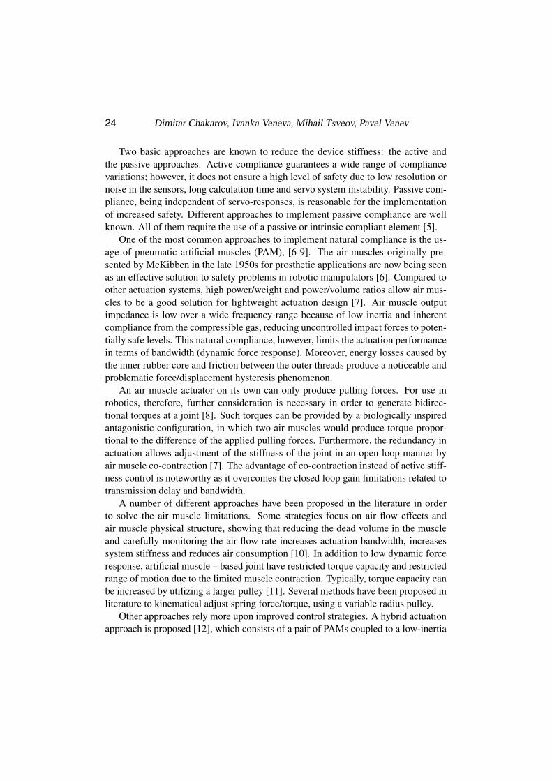
Self-made PAM are used, which allow greater control over the dimensions, the
forces and the general performance. Each PAM consists of two layers: an inner one,
representing rubber liner and outer one, representing braided nylon. Endcaps are al-
located at both ends, to which the two layers are clamped by clips. A pipeline for
supplying the pressurized air is located in one of the endcaps. The muscles possess
a maximum diameter D0 = 0.016 m and nominal length Ln = 0.390 m. The actu-
ators have been created representing a bundle of several pneumatic muscles (Fig. 1).
Muscles from the bundle are fed in parallel with air at a maximum pressure 600 kPa
(6 bars). The supply pipeline is connected with two parallel arranged valves – one to
supply the maximum pressure and the other one – for discharge to the atmosphere.
All the muscles of the bundle are connected together mechanically at one and at the
other end.
a maximum diameter D0 = 0.016 m and nominal length Ln =0.390 m. The actuators
have been created representing a sheaf of several pneumatic muscles (Fig. 1).
Muscles from the bundle are fed in parallel with air at a maximum pressure 600 kPa
(6 bars). The supply pipeline is connected with two parallel arranged valves - one to
supply the maximum pressure and the other one - for discharge to the atmosphere.
All the muscles of the bundle are connected together mechanically at one and at the
other end.
Fig 1. Sheaves pneumatic muscle actuators
Muscle bundle contraction is defined as the difference between their nominal
value Ln and the current value L:
(1)
LLC n � ,
Experiments were conducted under static load of the used PAM, as the number
of muscles in a bundle and the magnitude of the supply pressure has been altered.
At the pressure set, the contraction of muscles is measured from their nominal value
Ln to a minimum value Lmin. The maximum contraction of the muscle bundle is the
difference:
(2)
minnmax LLC � .
Experiments have been carried out to assess the rate of muscle response at a
different state of muscle contraction. Muscle contraction C is represented as a
percentage c of the nominal muscle length Ln, determined by the outer braided
layer.
(3)
c =100 C/Ln .
Experiments were performed with a muscle fixed at both ends with a set of different
contractions, at pressure change of 0 to 500 kPa by switching on the supply valve
for each contraction set. The change in muscle force P is measured by a computer
Fig. 1. Pneumatic muscle bundle.
26 Dimitar Chakarov, Ivanka Veneva, Mihail Tsveov, Pavel Venev
Muscle bundle contraction is defined as the difference between their nominal
value Ln and the current value L:
(1) C = Ln − L ,
Experiments were conducted under static load of the used PAM, as the number
of muscles in a bundle and the magnitude of the supply pressure has been altered.
At the pressure set, the contraction of muscles is measured from their nominal value
Ln to a minimum value Lmin. The maximum contraction of the muscle bundle is the
difference
(2) Cmax = Ln − Lmin .
Experiments have been carried out to assess the rate of muscle response at a differ-
ent state of muscle contraction. Muscle contraction C is represented as a percentage
c of the nominal muscle length Ln, determined by the outer braided layer
(3) c = 100C/Ln .
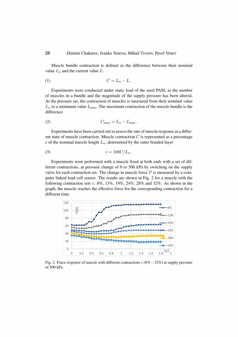
Experiments were performed with a muscle fixed at both ends with a set of dif-
ferent contractions, at pressure change of 0 to 500 kPa by switching on the supply
valve for each contraction set. The change in muscle force P is measured by a com-
puter linked load cell sensor. The results are shown in Fig. 2 for a muscle with the
following contraction sets c: 8%, 13%, 19%, 24%, 28% and 32%. As shown in the
graph, the muscle reaches the effective force for the corresponding contraction for a
different time.
linked load cell sensor. The results are shown in Fig. 2 for a muscle with the
following contraction sets c: 8%, 13%, 19%, 24%, 28% and 32%. As shown in the
graph, the muscle reaches the effective force for the corresponding contraction for a
different time.
Fig. 2. Force response of muscle with different contractions c / 8% - 32% / at
supply pressure of 500 kPa
Response time is lower in muscle with low contraction and higher in muscle
with high contraction. The increase in force is a non-linear function of time with a
drop in the beginning. When the contraction is about 24%, the force changes, but
does not exceed its original size. When the contraction is 28%, 32% and so on,
muscle feeding leads to a decrease in muscle strength.
Experimentally obtained force/contraction diagrams for the used bundles,
consisting of 1, 2 and 3 muscles at constant supply pressure of 500 kPa, are shown
in Fig. 3 a) and at a pressure of 0 kPa in Fig. 3 b). The experiments were carried out
on a stand allowing a change in muscle contraction from 0 to 35%. The muscle
force P is recorded by a load cell sensor. The charts in Fig. 3 are captured at
loading/unloading, and hysteresis is reported to 7.5%. The experiment was
performed with an overload over the nominal length of the muscles L> Ln.
0
20
40
60
80
100
120
0 0.2 0.4 0.6 0.8 1 1.2 1.4 1.6 1.8 2
P[N
]
x 0
.1
t[s]
8%
13%
19%
24%
28%
32%
Fig. 2. Force response of muscle with different contractions c (8% – 32%) at supply pressure
of 500 kPa.
Powered Upper Limb Orthosis Actuation System Based on Pneumatic ... 27
Response time is lower in muscle with low contraction and higher in muscle with
high contraction. The increase in force is a non-linear function of time with a drop
in the beginning. When the contraction is about 24%, the force changes, but does
not exceed its original size. When the contraction is 28%, 32% and so on, muscle
feeding leads to a decrease in muscle strength.
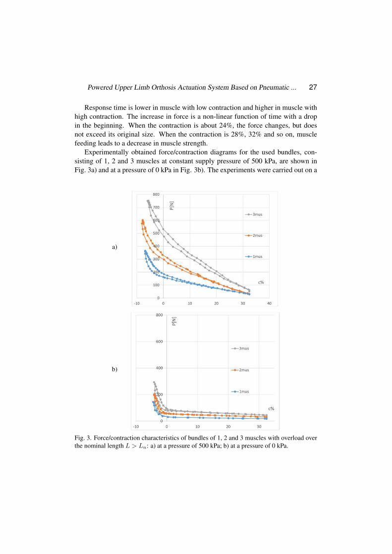
Experimentally obtained force/contraction diagrams for the used bundles, con-
sisting of 1, 2 and 3 muscles at constant supply pressure of 500 kPa, are shown in
Fig. 3a) and at a pressure of 0 kPa in Fig. 3b). The experiments were carried out on a
a)
a) b)
Fig. 3. Force /contraction characteristics of bundles of 1, 2 and 3 muscles with
overload over the nominal length L> Ln: a) at a pressure of 500 kPa; b) at a
pressure of 0 kPa
As shown in the graphs, at deformations larger than their nominal length, the
muscle actuators have a big change in their characteristics. This is due to the fact
that these are deformations of the nylon braid, which determines the strength of the
muscle. For position and force control, the sheaves pneumatic muscle actuators will
be used at deformations not exceeding their nominal length, where the hysteresis is
smaller and the characteristic is closer to linear. For this reason, additional
experiments were made in deformation up to their nominal lengths with bundles of
1 to 6 muscles, and the characteristic was reported under load. Experimentally
obtained force/contraction diagrams at constant supply pressure of 400 kPa are
shown in Fig. 4 a) and at a pressure of 0 kPa in Fig. 4 b).
As seen from the graphs, the increase in the muscle number leads to an increase
in the bundle stiffness. At zero pressure, the muscles show elastic properties,
determined by inner rubber liner. Braided pneumatic muscle behaves like a
pressure-dependent variable compliance spring. For a definition of the used PAM,
as a nonlinear quadratic spring, a simplified static model [6] can be used, which is
described in [9] by the following equation:
(4)
)LL(pLKP mingas � ,
where: P is the force of the muscles, Kgas is a muscle geometry dependent
coefficient, p is the supply pressure.
b)
a) b)
Fig. 3. Force /contraction characteristics of bundles of 1, 2 and 3 muscles with
overload over the nominal length L> Ln: a) at a pressure of 500 kPa; b) at a
pressure of 0 kPa
As shown in the graphs, at deformations larger than their nominal length, the
muscle actuators have a big change in their characteristics. This is due to the fact
that these are deformations of the nylon braid, which determines the strength of the
muscle. For position and force control, the sheaves pneumatic muscle actuators will
be used at deformations not exceeding their nominal length, where the hysteresis is
smaller and the characteristic is closer to linear. For this reason, additional
experiments were made in deformation up to their nominal lengths with bundles of
1 to 6 muscles, and the characteristic was reported under load. Experimentally
obtained force/contraction diagrams at constant supply pressure of 400 kPa are
shown in Fig. 4 a) and at a pressure of 0 kPa in Fig. 4 b).
As seen from the graphs, the increase in the muscle number leads to an increase
in the bundle stiffness. At zero pressure, the muscles show elastic properties,
determined by inner rubber liner. Braided pneumatic muscle behaves like a
pressure-dependent variable compliance spring. For a definition of the used PAM,
as a nonlinear quadratic spring, a simplified static model [6] can be used, which is
described in [9] by the following equation:
(4)
)LL(pLKP mingas � ,
where: P is the force of the muscles, Kgas is a muscle geometry dependent
coefficient, p is the supply pressure.
Fig. 3. Force/contraction characteristics of bundles of 1, 2 and 3 muscles with overload over
the nominal length L > Ln: a) at a pressure of 500 kPa; b) at a pressure of 0 kPa.
28 Dimitar Chakarov, Ivanka Veneva, Mihail Tsveov, Pavel Venev
stand allowing a change in muscle contraction from 0 to 35%. The muscle force P is
recorded by a load cell sensor. The charts in Fig. 3 are captured at loading/unloading,
and hysteresis is reported to 7.5%. The experiment was performed with an overload
over the nominal length of the muscles L > Ln.
As shown in the graphs, at deformations larger than their nominal length, the
muscle actuators have a big change in their characteristics. This is due to the fact
that these are deformations of the nylon braid, which determines the strength of the
muscle. For position and force control, the bundles of pneumatic muscle actuators
will be used at deformations not exceeding their nominal length, where the hystere-
a)
a) b)
Fig. 4. Force �FRQWUDFWLRQ�RI�PXVFOH�EXQGOHV�RI�������«���PXVFOHV�DW�VXSSO\�Sressure
of: a) 400 kPa and b) 0
As a result of experiments conducted under static load on the used PAM, in
which the number of muscles in a bundle and the magnitude of the supply pressure
were altered, it was obtained that at zero pressure the muscles show elastic
properties determined by inner rubber liner. Taking into account this property of the
muscles and according to (1) and (2), the equation (4) is transformed as follows:
(5)
)CC)(CL)(pkk(P maxno ��� 1 .
Above, ko and k1 are empirically derived coefficients. In the process of
approximation, the following relations of the coefficients ko and k1 have been
determined in accordance to the number m of bundle muscles.
(6) k0 = -39+321mus, k1 =-21+4.41mus.
Approximated characteristics are composed for bundles of different muscle
number mus = 1, 2, 3, 4, 5 and 6, at pressure p = 100, 200, 300 and 400 kPa.
Approximated characteristics at a supply pressure of 400 kPa and a supply pressure
of 0 kPa, are shown in Fig. 4 a) and Fig. 4 b), where they are compared with
experimentally obtained characteristics. Unlike other PAM models, the proposed
static model takes into account more parameters, such as: the number of muscles in
the bundle, the current contraction and the maximum contraction, as well as the
nominal length of the used muscles and the pressure. The muscle force at zero
pressure is also taken into account. By accepting that the supply pressure is kept at a
constant value, the stiffness of the muscle bundle can be determined as a derivative
of the muscle force (5) over muscle contractions, or:
b)
a) b)
Fig. 4. Force �FRQWUDFWLRQ�RI�PXVFOH�EXQGOHV�RI�������«���PXVFOHV�DW�VXSSO\�Sressure
of: a) 400 kPa and b) 0
As a result of experiments conducted under static load on the used PAM, in
which the number of muscles in a bundle and the magnitude of the supply pressure
were altered, it was obtained that at zero pressure the muscles show elastic
properties determined by inner rubber liner. Taking into account this property of the
muscles and according to (1) and (2), the equation (4) is transformed as follows:
(5)
)CC)(CL)(pkk(P maxno ��� 1 .
Above, ko and k1 are empirically derived coefficients. In the process of
approximation, the following relations of the coefficients ko and k1 have been
determined in accordance to the number m of bundle muscles.
(6) k0 = -39+321mus, k1 =-21+4.41mus.
Approximated characteristics are composed for bundles of different muscle
number mus = 1, 2, 3, 4, 5 and 6, at pressure p = 100, 200, 300 and 400 kPa.
Approximated characteristics at a supply pressure of 400 kPa and a supply pressure
of 0 kPa, are shown in Fig. 4 a) and Fig. 4 b), where they are compared with
experimentally obtained characteristics. Unlike other PAM models, the proposed
static model takes into account more parameters, such as: the number of muscles in
the bundle, the current contraction and the maximum contraction, as well as the
nominal length of the used muscles and the pressure. The muscle force at zero
pressure is also taken into account. By accepting that the supply pressure is kept at a
constant value, the stiffness of the muscle bundle can be determined as a derivative
of the muscle force (5) over muscle contractions, or:
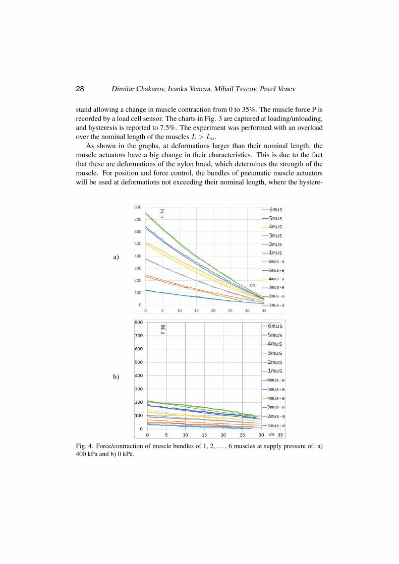
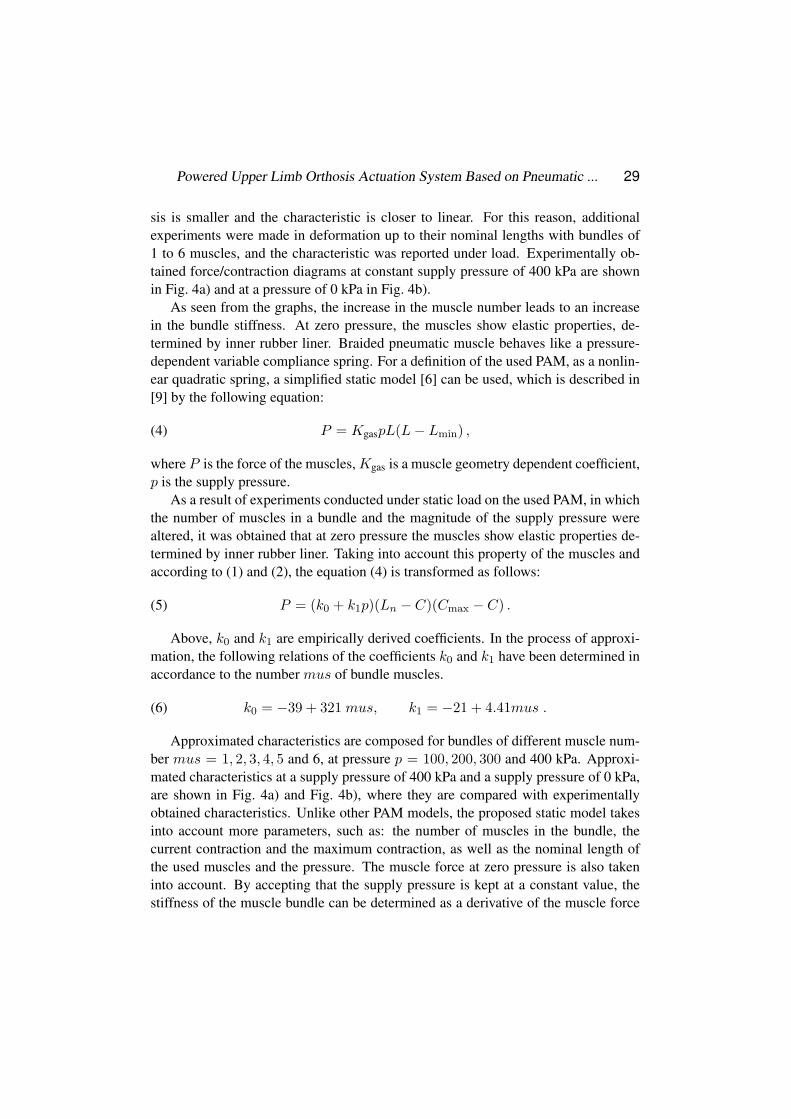
Fig. 4. Force/contraction of muscle bundles of 1, 2, . . . , 6 muscles at supply pressure of: a)
400 kPa and b) 0 kPa.
Powered Upper Limb Orthosis Actuation System Based on Pneumatic ... 29
sis is smaller and the characteristic is closer to linear. For this reason, additional
experiments were made in deformation up to their nominal lengths with bundles of
1 to 6 muscles, and the characteristic was reported under load. Experimentally ob-
tained force/contraction diagrams at constant supply pressure of 400 kPa are shown
in Fig. 4a) and at a pressure of 0 kPa in Fig. 4b).
As seen from the graphs, the increase in the muscle number leads to an increase
in the bundle stiffness. At zero pressure, the muscles show elastic properties, de-
termined by inner rubber liner. Braided pneumatic muscle behaves like a pressure-
dependent variable compliance spring. For a definition of the used PAM, as a nonlin-
ear quadratic spring, a simplified static model [6] can be used, which is described in
[9] by the following equation:
(4) P = KgaspL(L− Lmin) ,
where P is the force of the muscles, Kgas is a muscle geometry dependent coefficient,
p is the supply pressure.
As a result of experiments conducted under static load on the used PAM, in which
the number of muscles in a bundle and the magnitude of the supply pressure were
altered, it was obtained that at zero pressure the muscles show elastic properties de-
termined by inner rubber liner. Taking into account this property of the muscles and
according to (1) and (2), the equation (4) is transformed as follows:
(5) P = (k0 + k1p)(Ln − C)(Cmax − C) .
Above, k0 and k1 are empirically derived coefficients. In the process of approxi-
mation, the following relations of the coefficients k0 and k1 have been determined in
accordance to the number mus of bundle muscles.
(6) k0 = −39 + 321 mus, k1 = −21 + 4.41mus .
Approximated characteristics are composed for bundles of different muscle num-
ber mus = 1, 2, 3, 4, 5 and 6, at pressure p = 100, 200, 300 and 400 kPa. Approxi-
mated characteristics at a supply pressure of 400 kPa and a supply pressure of 0 kPa,
are shown in Fig. 4a) and Fig. 4b), where they are compared with experimentally
obtained characteristics. Unlike other PAM models, the proposed static model takes
into account more parameters, such as: the number of muscles in the bundle, the
current contraction and the maximum contraction, as well as the nominal length of
the used muscles and the pressure. The muscle force at zero pressure is also taken
into account. By accepting that the supply pressure is kept at a constant value, the
stiffness of the muscle bundle can be determined as a derivative of the muscle force
30 Dimitar Chakarov, Ivanka Veneva, Mihail Tsveov, Pavel Venev
(5) over muscle contractions, or
(7) k =∂P
∂C= (k0 + k1p)(2C − (Ln + Cmax)) .
The stiffness according to (7), (5) and (6) is a linear function of the pressure, the
contraction and the number of the pneumatic muscles in the bundle.
3. ACTUATION SYSTEM, JOINT TORQUES AND JOINT STIFFNESS CONTROL
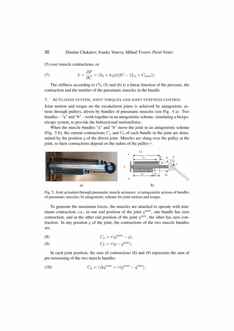
Joint motion and torque on the exoskeleton joints is achieved by antagonistic ac-
tions through pulleys, driven by bundles of pneumatic muscles (see Fig. 4 a). Two
bundles – “a” and “b” – work together in an antagonistic scheme, simulating a biceps-
triceps system, to provide the bidirectional motion/force.
When the muscle bundles “a” and “b” move the joint in an antagonistic scheme
(Fig. 5 b), the current contractions Ca and Cb of each bundle in the joint are deter-
mined by the position q of the driven joint. Muscles are slung over the pulley at the
joint, so their contractions depend on the radius of the pulley r.
(7)
))CL(C)(pkk(C
Pk maxno ���
w
w 21 .
The stiffness according to (7), (5) and (6) is a linear function of the pressure, the
contraction and the number of the pneumatic muscles in the bundle.
3. ACTUATION SYSTEM, JOINT TORQUES AND JOINT STIFFNESS CONTROL
Joint motion and torque on the exoskeleton joints is achieved by antagonistic
actions through pulleys, driven by sheaves pneumatic muscles (see Fig. 4 a). Two
bundles -³D´�DQG�³E´��ZRUN�WRJHWKHU�LQ�DQ�DQWDJRQLVWLF�VFKHPH��VLPXODWLQJ�D�ELFHSV-
triceps system, to provide the bidirectional motion/force.
When the muscle bundles ³D´�DQG�³E´�move the joint in an antagonistic scheme
(Fig. 5 b), the current contractions Ca and Cb of each bundle in the joint are
determined by the position q of the driven joint. Muscles are slung over the pulley
at the joint, so their contractions depend on the radius of the pulley r.
r
q
0
a Ln
La Ca
Cb Lb
b
PZ
Pb
a) b)
Fig. 5. Joint actuation through pneumatic muscle actuators: a) antagonistic actions
of sheaves pneumatic muscles; b) antagonistic scheme for joint motion and torque
To generate the maximum forces, the muscles are attached to operate with
minimum contraction; i. e., in one end position of the joint qmax
, one bundle has zero
contraction, and at the other end position of the joint qmin
, the other has zero
contraction. In any position q of the joint, the contractions of the two muscle
bundles are:
(8)
)qq(rCmax
a � ,
(9)
)qq(rCmin
b � .
a) b)
Fig. 5. Joint actuation through pneumatic muscle actuators: a) antagonistic actions of bundles
of pneumatic muscles; b) antagonistic scheme for joint motion and torque.
To generate the maximum forces, the muscles are attached to operate with min-
imum contraction; i.e., in one end position of the joint qmax, one bundle has zero
contraction, and at the other end position of the joint qmin, the other has zero con-
traction. In any position q of the joint, the contractions of the two muscle bundles
are
Ca = r(qmax− q) ,(8)
Cb = r(q − qmin) .(9)
In each joint position, the sum of contractions (8) and (9) represents the sum of
pre-tensioning of the two muscle bundles
(10) Cq = r∆qmax = r(qmax− qmin) .
Powered Upper Limb Orthosis Actuation System Based on Pneumatic ... 31
Then, according to (4), (5), (8) and (9), the forces of joint muscle bundles “a” and
“b” are
Pa = (ka0 + ka1pa)(Ln − r(qmax− q))(Cmax − r(qmax
− q) ,(11)
Pb = (kb0 + kb1pb)(Ln − r(q − qmin))(Cmax − r(q − qmin)) .(12)
According to (7), (5), (8) and (9), the stiffness of muscle bundles a and b are
ka = (ka0 + ka1pa)(2r(qmax
− q)− (Ln + Cmax)) ,(13)
kb = (kb0 + kb1pb)(2r(q − qmin)− (Ln + Cmax)) .(14)
The joint stiffness can be defined as a derivative of joint torque with respect to
joint position
(15) Kq =∂Q
∂q.
The generated torque in the rotation joint is
(16) Q = [−r; r]PPP ,
where
(17) PPP = [Pa;Pb]T
is the vector of the driving forces in the actuators (11) and (12) and r is the pulley
radius. If the muscle contractions (8) and (9) are unified in the matrix
(18) CCC = [Ca;Cb]T ,
after substituting equations (16), (17) and (18) into (15), it follows that:
(19) Kq = [−r; r]∂PPP
∂CCC
∂CCC
∂qqq.
The derivative of the muscle forces about muscle contractions gives the stiffness of
the selected muscle bundles (13) and (14), incorporated in the matrix
(20)∂PPP
∂CCC=
[
ka 00 kb
]
.
The derivative of the muscle contractions (8) and (9), about the joint position,
represents a vector with constant components
(21) ∂C/∂q = [−r; r]T .
32 Dimitar Chakarov, Ivanka Veneva, Mihail Tsveov, Pavel Venev
After substitution into (19), it follows that:
(22) Kq = r2[ka + kb] .
Joint stiffness Kq (eq. (22)) is determined by the stiffness of muscle bundles kaand kb (eqs. (13) and (14)). When both muscle bundles are different, the joint stiffness
depends on the joint position, as well as on the pressure, number of muscles and
pre-tensioning of muscle bundles (10). The stiffness in the joint is realized in the
condition of the antagonist equilibrium of forces (11) and (12) of the two muscle
bundles. The antagonistic balance in each joint is achieved by generating control
torques (16) in each joint, according to the equality
(23) Q = (Pb − Pa)r = Qb −Qa .
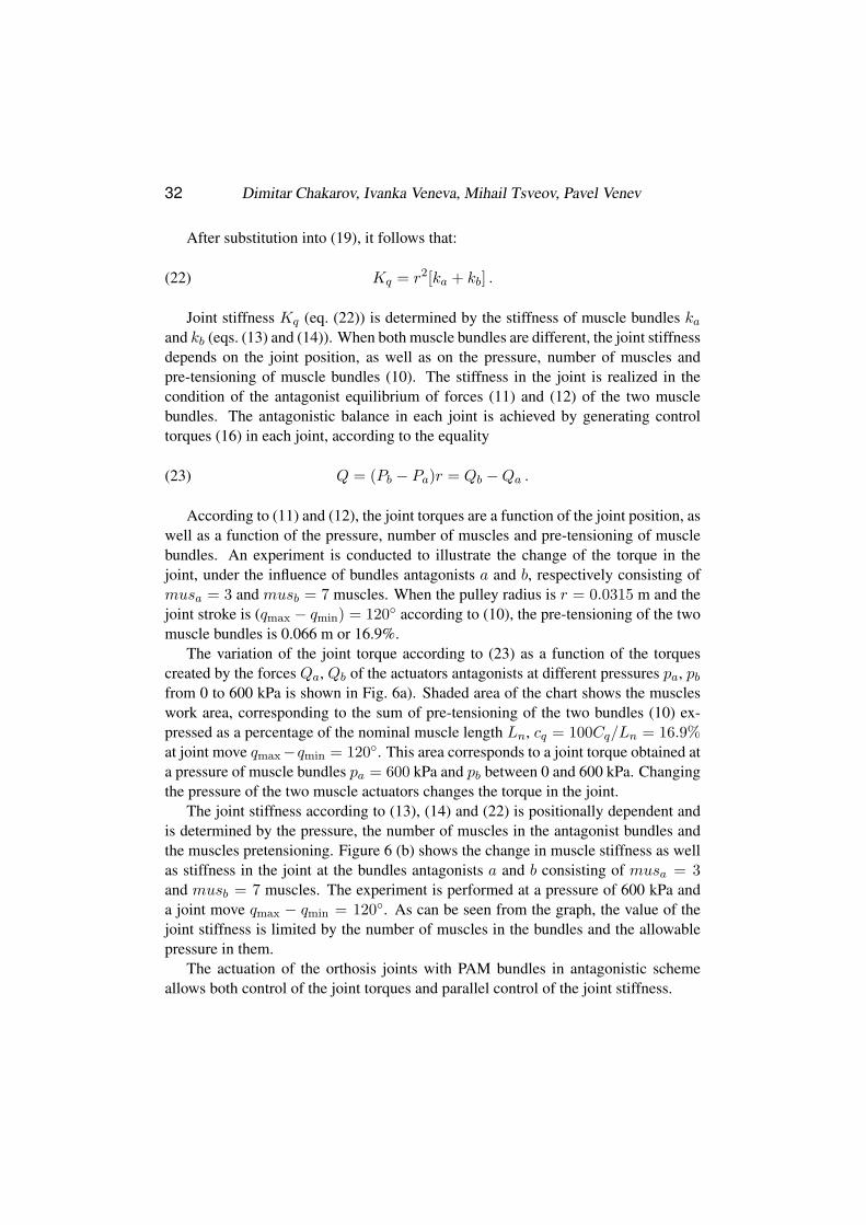
According to (11) and (12), the joint torques are a function of the joint position, as
well as a function of the pressure, number of muscles and pre-tensioning of muscle
bundles. An experiment is conducted to illustrate the change of the torque in the
joint, under the influence of bundles antagonists a and b, respectively consisting of
musa = 3 and musb = 7 muscles. When the pulley radius is r = 0.0315 m and the
joint stroke is (qmax − qmin) = 120◦ according to (10), the pre-tensioning of the two
muscle bundles is 0.066 m or 16.9%.
The variation of the joint torque according to (23) as a function of the torques
created by the forces Qa, Qb of the actuators antagonists at different pressures pa, pbfrom 0 to 600 kPa is shown in Fig. 6a). Shaded area of the chart shows the muscles
work area, corresponding to the sum of pre-tensioning of the two bundles (10) ex-
pressed as a percentage of the nominal muscle length Ln, cq = 100Cq/Ln = 16.9%at joint move qmax−qmin = 120◦. This area corresponds to a joint torque obtained at
a pressure of muscle bundles pa = 600 kPa and pb between 0 and 600 kPa. Changing
the pressure of the two muscle actuators changes the torque in the joint.
The joint stiffness according to (13), (14) and (22) is positionally dependent and
is determined by the pressure, the number of muscles in the antagonist bundles and
the muscles pretensioning. Figure 6 (b) shows the change in muscle stiffness as well
as stiffness in the joint at the bundles antagonists a and b consisting of musa = 3and musb = 7 muscles. The experiment is performed at a pressure of 600 kPa and
a joint move qmax − qmin = 120◦. As can be seen from the graph, the value of the
joint stiffness is limited by the number of muscles in the bundles and the allowable
pressure in them.
The actuation of the orthosis joints with PAM bundles in antagonistic scheme
allows both control of the joint torques and parallel control of the joint stiffness.

34 Dimitar Chakarov, Ivanka Veneva, Mihail Tsveov, Pavel Venev
Pressures in the muscle bundles pa and pb are monitored by pressure sensors
mounted to each muscle bundle. When the torque and stiffness of the joint are con-
trolled simultaneously, the pressure pa for actuator antagonists is set to achieve the
desired stiffness in the joint. For this purpose, an optimization procedure has been
developed [14], which finds the pressures pa according to equations (13), (14) and
(22). In this procedure, the pressure pb for the actuators’ agonists is calculated, using
equations (23), (11) and (12) to achieve the required joint force command Q.
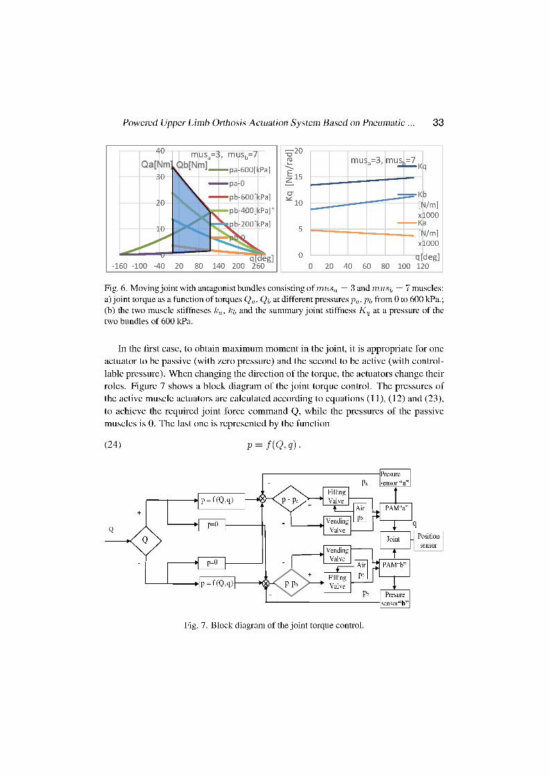
4. JOINT SYSTEM CONTROL
The control of the exoskeleton system is built up as a Distributed Control Scheme
(DCS). The exoskeleton consists of several Micro-controller Units (MCUs) which
communicate with the Master controller through standard Two Wire Interface (i2c)
communication protocol and perform the following tasks for each joint: actuation,
sensing, signal processing and control. The master controller can be used as an inter-
face between the PC and the valve controllers that coordinates all the valve control
units and feeds them with self-generated data, based on the exoskeleton’s operating
mode.
MCUs are connected to the sensors and actuators by a control loop, consisting
of a pressure sensor, controller, and control valves. Each MCU runs at 16 MHz
and can control up to 8 PAMs (8 inlets + 8 outlets) with the joint torque control
scheme illustrated in Fig. 7. Joint muscle pair is controlled by a local micro-controller
(Atmega 2560). In each joint, 4 pneumatic valves (type on/off, 3 Port Solenoid Valve,
series V114, SMC Automation) are used for joint actuation.
Positional and pressure measurements are transmitted to the controller, through
the aid of a signal conditioning input/output (I/O) device. Control algorithm and
program application are build up, according to control schemes in Fig. 7, using C++program code.
5. CONCLUSION
A solution for actuation of upper limb orthosis, based on pneumatic artificial muscles
(PAM) is presented in the work, which provides force refection on the human arm on
the one hand and natural safety in the mutual interaction “human-robot” on the other.
To overcome the limitations of the existing muscles, one approach of using actuators
with a different number of PAMs is studied.
Experimentally obtained characteristics of actuators, consisting of different num-
ber of muscles are shown in the paper. It is reported, that muscle actuators have a
strong change in their characteristics at deformations larger than their nominal length.
To control the force, bundles of PAM are used at deformation to their nominal length
where the hysteresis is smaller and the characteristic is closer to the linear one. For
Powered Upper Limb Orthosis Actuation System Based on Pneumatic ... 35
replication of PAM based actuators as a nonlinear spring, quadratic functions of mus-
cle contraction are used. The force and the stiffness of the pneumatic actuators are
assessed as a function of the number of muscles in the bundle and the supply pressure.
Approximated characteristics are composed for bundles of different muscle number,
where they are compared with experimentally obtained characteristics. Unlike other
PAM models, the proposed static model takes into account more parameters such as:
the number of muscles in the bundle and the muscle force at zero pressure.
Joint motion and torque on the exoskeleton arm is achieved by antagonistic ac-
tions through pulleys, driven by bundles of pneumatic muscles. An approach is
presented for the joint control by antagonistic interaction of bundles with different
numbers of pneumatic muscles. Joint stiffness and joint torques are determined on
condition of a power balance, as a function of the joint position, pressure, number
of muscles and muscles’ pretensioning. The actuation of the upper limb orthotics
with bundles from different number of muscles in an antagonistic scheme allows
both joints torque control and parallel joint stiffness control. The range of torque and
the range of stiffness in the joint are regulated by selecting an appropriate number of
muscles in the antagonist actuators.
ACKNOWLEDGEMENTS
This work was funded by the Bulgarian Science Found, Call: 2016, through Project
AWERON – DN 07/9, to which the authors would like to express their deepest grati-
tude.
REFERENCES
[1] PERRY, J., J. ROSEN, S. BURNS. Upper-limb Powered Exoskeleton Design.
IEEE/ASME Transactions on Mechatronics, 12 (2007), No. 4, 408-417.
[2] FRISOLI, A., F. SALSEDO, M. BERGAMASCO, B. ROSSI , M. C. CARBONCINI. A
Force-feedback Exoskeleton for Upper-limb Rehabilitation in Virtual Reality. Applied
Bionics and Biomechanics, 6 (2009), No. 2, 115-126.
[3] NEF, T., M. MIHELJ, R. RIENER. Armin: A Robot for Patient-cooperative Arm Ther-
apy. Medical & Biological Engineering & Computing, 45 (2007), 887-900.
[4] VITIELLO, N., T. LENZI, ST. ROCCELLA, ST. MARCO, M. DE ROSSI, EM. CATTIN,
FR. GIOVACCHINI, M. C. CARROZZA. NEUROExos: A Powered Elbow Exoskeleton
for Physical Rehabilitation. IEEE Transactions on Robotics. 29 (2013), No. 1, 220-235.
[5] VANDERBORGHT, B. ET AL., Variable Impedance Actuators: A Review. Robotics and
Autonomous Systems, 61 (2013), 1601-1614.
[6] CHOU, P., B. HANNAFORD. Measurement and Modelling of McKibben Pneumatic
Artificial Muscles. IEEE TRANS On Robotics and Automation, 12 (1996), No. 1, 90-
102.
36 Dimitar Chakarov, Ivanka Veneva, Mihail Tsveov, Pavel Venev
[7] TSAGARAKIS, N., D. G. CALDWELL. Improved Modelling and Assessment of Pneu-
matic Muscle Actuators, ICRA 2000, USA, San Francisco, May 2000, IEEE pres, 3641-
3646.
[8] DAERDEN, FR., D. LEFEBER. Pneumatic Artificial Muscles: Actuators for Robotics
and Automation. European Journal of Mechanical and Environmental Engineering, 47
(2002), No. 1, 1-11.
[9] CALDWELL, D. G. ET AL. “Soft” Exoskeletons for Upper and Lower Body Rehabil-
itation – Design, Control and Testing. International Journal of Humanoid Robotics. 4
(2007), No. 3, 549-573.
[10] DAVIS, J., J. CANDERLE, P. ARTRIT, N. TSAGARAKIS, D. G. CALDWELL. Enhanced
Dynamic Performance in Pneumatic Muscle Actuators, Pros. of the 2002 IEEE ICRA,
DOI: 10.1109/ROBOT.2002.1013662, 2002, 2836-2841.
[11] SHIN, D., X. YEH, O. KHATIB. Variable Radius Pulley Design Methodology for Pneu-
matic Artifical Muscle-based Antagonistic Actuation Systems, 2011 IEEE/RSJ Interna-
tional Conference on Intelligent Robots and Systems, September 25–30, 2011, USA,
CA, San Francisco, 2011, 1830-1835.
[12] SARDELLITTI, I., J. PARK, D. SHIN, O. KHATIB. Air Muscle Controller Design
in the Distributed Macro-mini (DM2) Actuation Approach, Proceedings of the 2007
IEEE/RSJ International Conference on Intelligent Robots and Systems, 2007, 1822-
1827.
[13] CHAKAROV, D., IV. VENEVA, M. TSVEOV, T. TIANKOV. New Exoskeleton Arm Con-
cept Design and Actuation For Haptic Interaction with Virtual Objects. Journal of The-
oretical and Applied Mechanics, 44, (2014), No. 4, DOI: 10.2478/jtam-2014-0019.
[14] CHAKAROV, D., IV. VENEVA, M. TSVEOV. Specifying the Natural Stiffness of an
Exoskeleton Arm used as Haptics Device. Series on Biomechanics, 30 (2016), No. 4,
3-12.
Related Documents