Welcome message from author
This document is posted to help you gain knowledge. Please leave a comment to let me know what you think about it! Share it to your friends and learn new things together.
Transcript

User's Manual
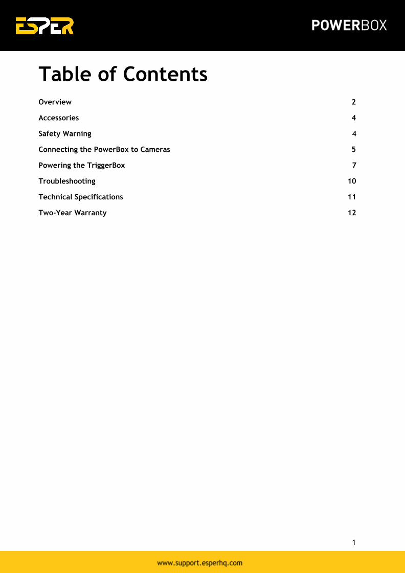
Table of Contents
Overview 2
Accessories 4
Safety Warning 4
Connecting the PowerBox to Cameras 5
Powering the TriggerBox 7
Troubleshooting 10
Technical Specifications 11
Two-Year Warranty 12
1
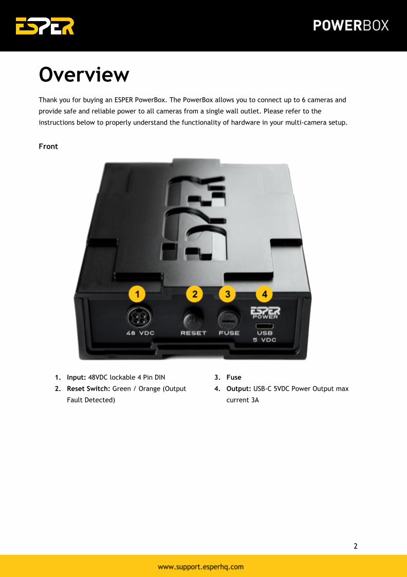
Overview
Thank you for buying an ESPER PowerBox. The PowerBox allows you to connect up to 6 cameras and
provide safe and reliable power to all cameras from a single wall outlet. Please refer to the
instructions below to properly understand the functionality of hardware in your multi-camera setup.
Front
1. Input: 48VDC lockable 4 Pin DIN
2. Reset Switch: Green / Orange (Output
Fault Detected)
3. Fuse
4. Output: USB-C 5VDC Power Output max
current 3A
2
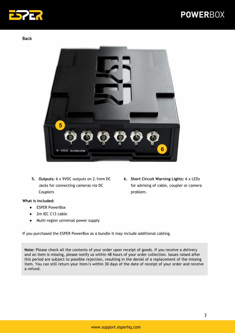
Back
5. Outputs: 6 x 9VDC outputs on 2.1mm DC
Jacks for connecting cameras via DC
Couplers
6. Short Circuit Warning Lights: 6 x LEDs
for advising of cable, coupler or camera
problem.
What is included:
● ESPER PowerBox
● 2m IEC C13 cable
● Multi-region universal power supply
If you purchased the ESPER PowerBox as a bundle it may include additional cabling.
Note: Please check all the contents of your order upon receipt of goods. If you receive a delivery
and an item is missing, please notify us within 48 hours of your order collection. Issues raised after
this period are subject to possible rejection, resulting in the denial of a replacement of the missing
item. You can still return your item/s within 30 days of the date of receipt of your order and receive
a refund.
3

Accessories
ESPER PowerBox is designed to stack neatly together with the TriggerBox units. Multi-camera trigger
solution can be purchased at https://www.esperhq.com/product/multiple-camera-trigger-triggerbox/.
Camera power cables and DC-couplers are available for many different cameras makes and models.
Additional camera cables can be purchased at https://www.esperhq.com/products/?show=all.
Safety Warning
To prevent injury to yourself or to others make sure to read the following safety precautions before
using the equipment. Please read and follow these instructions:
● Do not disassemble or modify the product.
● Do not expose the product to high temperatures, severe cold or high humidity.
● Keep out of the reach of children.
● Turn off immediately in the event of a malfunction.
● Do not operate the unit in the presence of flammable gas or vapours.
● Do not attempt to disassemble or perform any unauthorised modification.
● Turn off the power of the camera before inserting or removing the trigger cables.
● Make sure the item is intact and that there are no missing parts.
● Turn off the cameras, before attaching or removing the ESPER PowerBox.
4

Connecting the PowerBox to
Cameras Follow these 3 steps and you'll get your PowerBox up and running in no time. By the end, you'll have
your cameras connected and ready to start using.
Step 1. Powering up the PowerBox
Connect the 48V PSU 4 pin connector to the PowerBox connection on the front panel (fig.1 a).
Figure 1. ESPER PowerBox Front Panel
Step 2. Connecting the DC Couplers to the PowerBox
Take the plug end of the DC Coupler and plug it into 1 of the 6 power outputs (fig.2 a) on the rear side
of the PowerBox.
Note: If your DC Coupler has a connector end (Female connector) rather than a plug end you will
need to use the power extension cables supplied to connect your DC Couplers to the PowerBox
Figure 2. ESPER PowerBox Rear Panel.
5
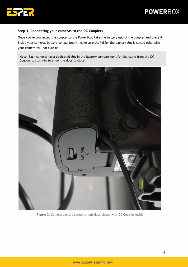
Step 3. Connecting your cameras to the DC Couplers
Once you've connected the coupler to the PowerBox, take the battery end of the coupler and place it
inside your cameras battery compartment. Make sure the lid for the battery slot is closed otherwise
your camera will not turn on.
Note: Each camera has a dedicated slot in the battery compartment for the cable from the DC
Coupler to slot into to allow the door to close.
Figure 3. Camera battery compartment door closed with DC Coupler inside
6
Powering the TriggerBox
The PowerBox allows you to power the TriggerBox. Follow these steps to get your TriggerBox powered
using the PowerBox and not have to worry about more wall outlets to power your TriggerBoxes.
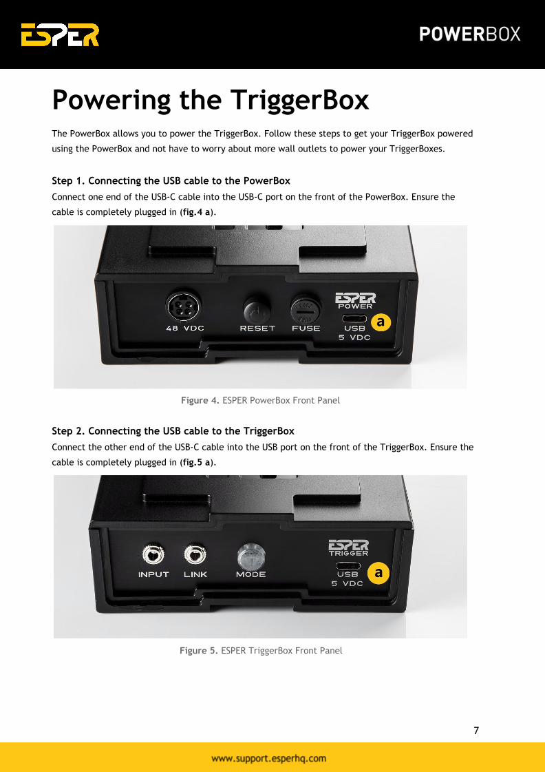
Step 1. Connecting the USB cable to the PowerBox
Connect one end of the USB-C cable into the USB-C port on the front of the PowerBox. Ensure the
cable is completely plugged in (fig.4 a).
Figure 4. ESPER PowerBox Front Panel
Step 2. Connecting the USB cable to the TriggerBox
Connect the other end of the USB-C cable into the USB port on the front of the TriggerBox. Ensure the
cable is completely plugged in (fig.5 a).
Figure 5. ESPER TriggerBox Front Panel
7
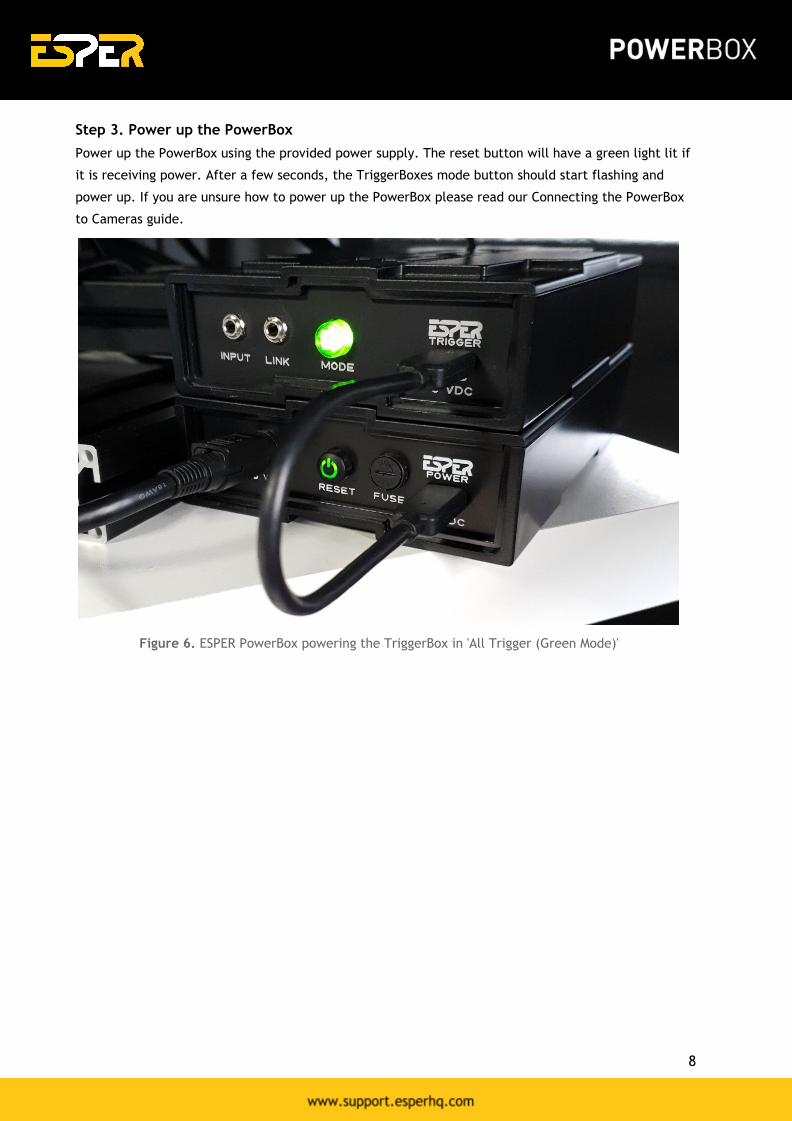
Step 3. Power up the PowerBox
Power up the PowerBox using the provided power supply. The reset button will have a green light lit if
it is receiving power. After a few seconds, the TriggerBoxes mode button should start flashing and
power up. If you are unsure how to power up the PowerBox please read our Connecting the PowerBox
to Cameras guide.
Figure 6. ESPER PowerBox powering the TriggerBox in 'All Trigger (Green Mode)'
8
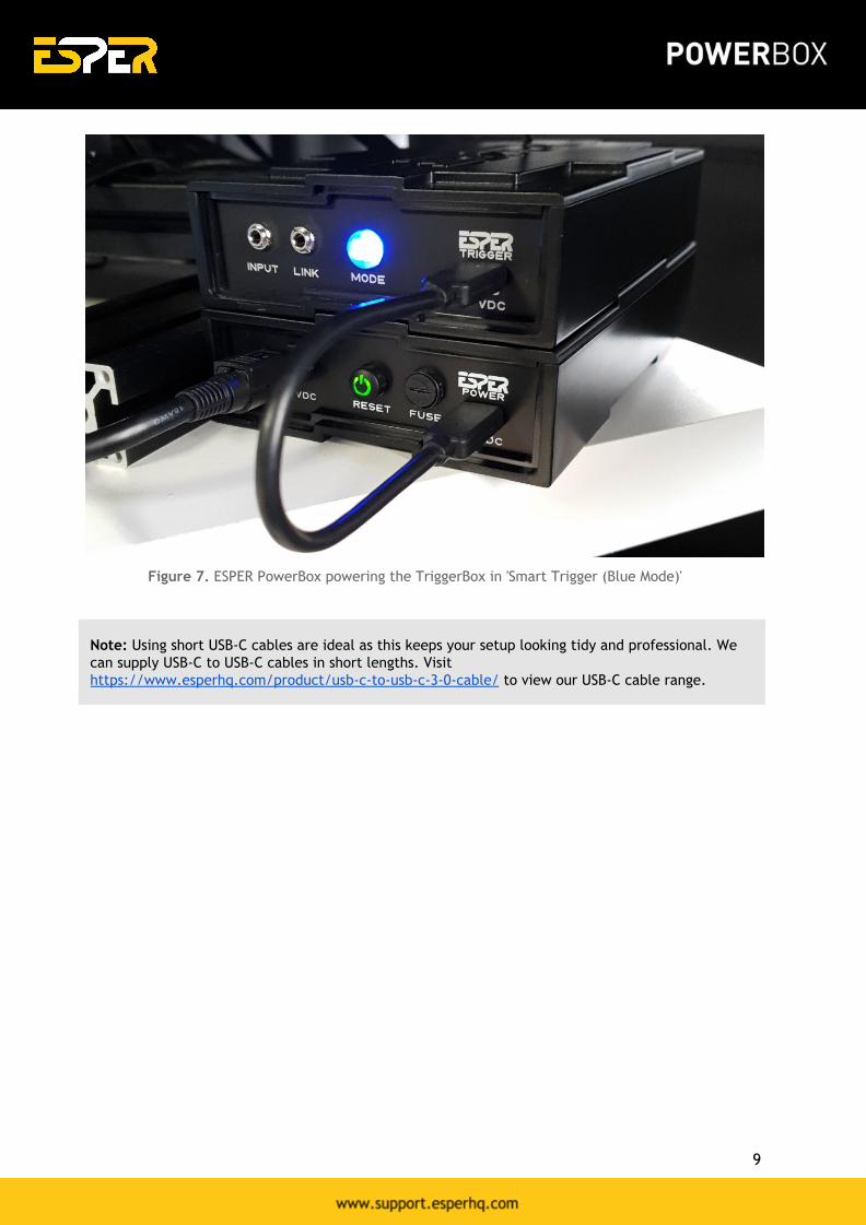
Figure 7. ESPER PowerBox powering the TriggerBox in 'Smart Trigger (Blue Mode)'
Note: Using short USB-C cables are ideal as this keeps your setup looking tidy and professional. We
can supply USB-C to USB-C cables in short lengths. Visit
https://www.esperhq.com/product/usb-c-to-usb-c-3-0-cable/ to view our USB-C cable range.
9
Troubleshooting
Find step-by-step guides to help you solve the most common PowerBox problems.
Issue: Power to the PowerBox keeps on cutting out and making the cameras power down.
Fix: The connection from the power supply may be loose which is causing power to drop. Ensure that
the power supply connector is completely plugged in.
Issue: Cable connection is really loose and causes cameras to go offline. These cables
weren't purchased from your store.
Fix: All cables supplied by Esper have been fully tested and provide a solid connection as these cables
have a screw-on connector meaning there is no risk of the cable coming loose when connecting up your
cameras or during events.
Note: We cannot guarantee that cables purchased outside of our shop to work correctly with our
PowerBox.
Issue: I've connected my Canon 5D to the PowerBox using the correct DC Coupler but the
camera powers off every time I take a shot. Why is this?
Fix: The Canon 5D is a full-frame camera. Most full-frame cameras draw more power when firing,
unlike crop sensor cameras. We supply combiner cables to ensure they receive the power they need to
stay on during shoots and events. Get in touch to learn more via [email protected]
Issue: My camera isn't powering on. I have connected the DC Coupler to the PowerBox but
the camera isn't turning on.
Fix 1: Ensure that you are using the correct DC Coupler to connect. This can be checked through our
compatibility checker located on our PowerBox product page.
Fix 2: Ensure that the battery door is fully shut. There is a dedicated slot where your cable coming
from the DC Coupler slots into to allow the door to fully close. If the door isn't closed properly, the
camera will not power on.
10
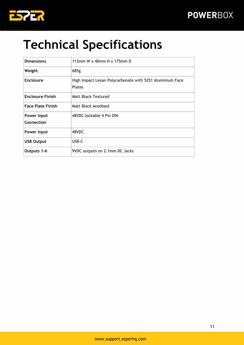
Technical Specifications
Dimensions 113mm W x 40mm H x 175mm D
Weight 685g
Enclosure High Impact Lexan Polycarbonate with 5251 Aluminium Face
Plates
Enclosure Finish Matt Black Textured
Face Plate Finish Matt Black Anodised
Power Input
Connection
48VDC lockable 4 Pin DIN
Power Input 48VDC
USB Output USB-C
Outputs 1-6 9VDC outputs on 2.1mm DC Jacks
11

Two-Year Warranty
ESPER PowerBox has been manufactured to the highest standards of quality. We guarantee that this
product will not contain any defects caused by manufacturing processes, workmanship, or materials for
two years. This guarantee starts from the date of purchase or thirty days after replacement, whichever
occurs later. ESPER at its discretion, either repair or replace prepaid, returned equipment free of
charge. The warranty does not cover damage or defect caused by misuse, neglect, accident,
alteration, abuse, improper installation or maintenance.
The warranty shall only apply if the ESPER PowerBox is used in conjunction with a compatible camera
and flash equipment, as to which, ESPER, shall have no responsibility. The warranty covers all defects
encountered in normal use of the ESPER PowerBox, and does not apply in any of the following cases:
1. Loss of or damage to the ESPER PowerBox due to abuse, mishandling, improper packaging by
you, alteration, accident, and/or electrical current fluctuations.
2. Failure to follow operating, maintenance or environmental instructions prescribed in ESPER
PowerBox user’s manual.
3. Without limiting the foregoing, water damage, sand/corrosion damage, dropping the unit,
scratches, abrasions or damage to the body, or damage to the cables will be presumed to have
resulted
See Terms of Sale for full details: https://www.esperhq.com/terms-conditions/.
12
Related Documents