WINDSHIELD / WINDOWGLASS – POWER WINDOW CONTROL SYSTEM (w/ Jam Protec- tion Function) WS–1 WS POWER WINDOW CONTROL SYSTEM (w/ Jam Protection Function) PRECAUTION NOTICE: When disconnecting the cable from the negative (-) battery terminal, initialize the following system(s) after the cable is reconnected. System Name See procedure Power Window Control System IN-23 Sliding Roof Control System

Welcome message from author
This document is posted to help you gain knowledge. Please leave a comment to let me know what you think about it! Share it to your friends and learn new things together.
Transcript
WINDSHIELD / WINDOWGLASS – POWER WINDOW CONTROL SYSTEM (w/ Jam Protec-tion Function) WS–1
S
WPOWER WINDOW CONTROL SYSTEM (w/ Jam Protection Function)PRECAUTIONNOTICE:When disconnecting the cable from the negative (-) battery terminal, initialize the following system(s) after the cable is reconnected.
System Name See procedure
Power Window Control SystemIN-23
Sliding Roof Control System
WS–2 WINDSHIELD / WINDOWGLASS – POWER WINDOW CONTROL SYSTEM (w/ Jam Protec-tion Function)
WS
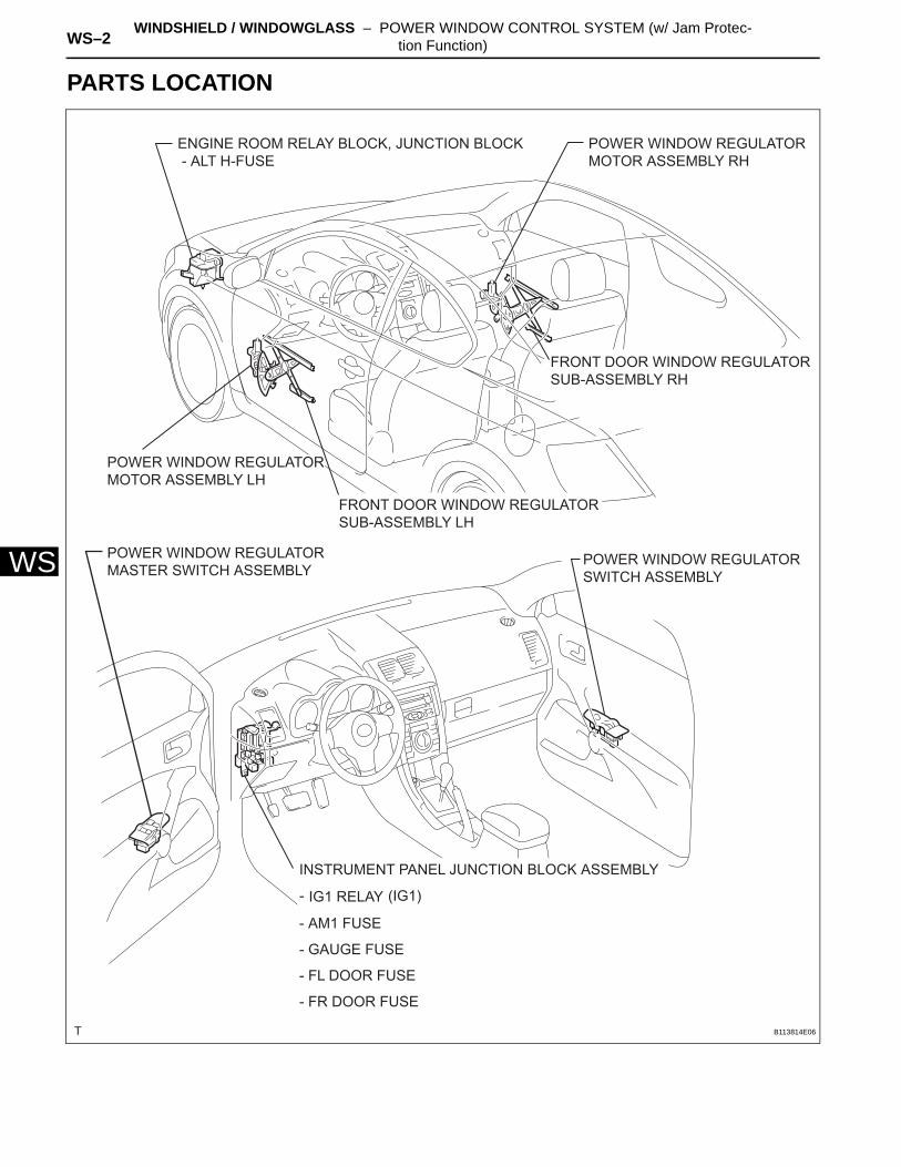
PARTS LOCATION
ENGINE ROOM RELAY BLOCK, JUNCTION BLOCK - ALT H-FUSE
POWER WINDOW REGULATOR MOTOR ASSEMBLY RH
FRONT DOOR WINDOW REGULATOR SUB-ASSEMBLY RH
POWER WINDOW REGULATOR MOTOR ASSEMBLY LH
FRONT DOOR WINDOW REGULATOR SUB-ASSEMBLY LH
POWER WINDOW REGULATOR MASTER SWITCH ASSEMBLY
POWER WINDOW REGULATOR SWITCH ASSEMBLY
INSTRUMENT PANEL JUNCTION BLOCK ASSEMBLY
IG1 RELAY
- AM1 FUSE
- GAUGE FUSE
(IG1)
- FL DOOR FUSE
- FR DOOR FUSE
-
B113814E06
WINDSHIELD / WINDOWGLASS – POWER WINDOW CONTROL SYSTEM (w/ Jam Protec-tion Function) WS–3
S
WSYSTEM DESCRIPTION1. POWER WINDOW CONTROL SYSTEM
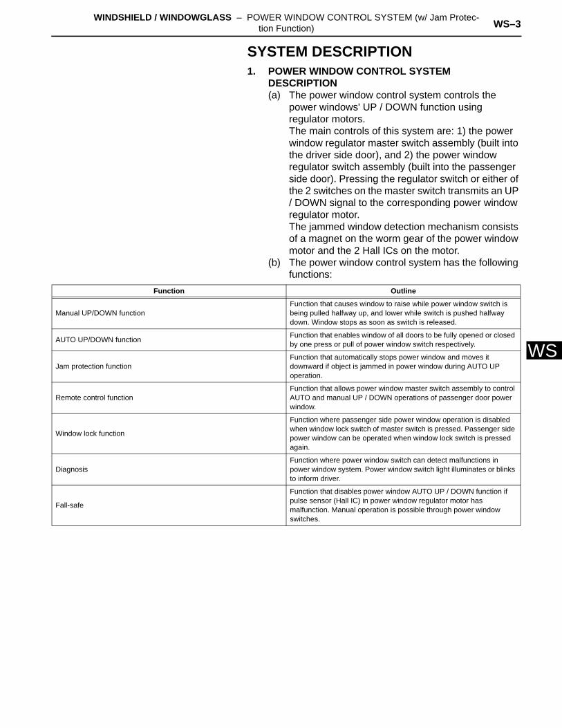
DESCRIPTION(a) The power window control system controls the
power windows' UP / DOWN function using regulator motors.The main controls of this system are: 1) the power window regulator master switch assembly (built into the driver side door), and 2) the power window regulator switch assembly (built into the passenger side door). Pressing the regulator switch or either of the 2 switches on the master switch transmits an UP / DOWN signal to the corresponding power window regulator motor.The jammed window detection mechanism consists of a magnet on the worm gear of the power window motor and the 2 Hall ICs on the motor.
(b) The power window control system has the following functions:
Function Outline
Manual UP/DOWN functionFunction that causes window to raise while power window switch is being pulled halfway up, and lower while switch is pushed halfway down. Window stops as soon as switch is released.
AUTO UP/DOWN function Function that enables window of all doors to be fully opened or closed by one press or pull of power window switch respectively.
Jam protection functionFunction that automatically stops power window and moves it downward if object is jammed in power window during AUTO UP operation.
Remote control functionFunction that allows power window master switch assembly to control AUTO and manual UP / DOWN operations of passenger door power window.
Window lock function
Function where passenger side power window operation is disabled when window lock switch of master switch is pressed. Passenger side power window can be operated when window lock switch is pressed again.
DiagnosisFunction where power window switch can detect malfunctions in power window system. Power window switch light illuminates or blinks to inform driver.
Fall-safe
Function that disables power window AUTO UP / DOWN function if pulse sensor (Hall IC) in power window regulator motor has malfunction. Manual operation is possible through power window switches.
WS–4 WINDSHIELD / WINDOWGLASS – POWER WINDOW CONTROL SYSTEM (w/ Jam Protec-tion Function)
WS
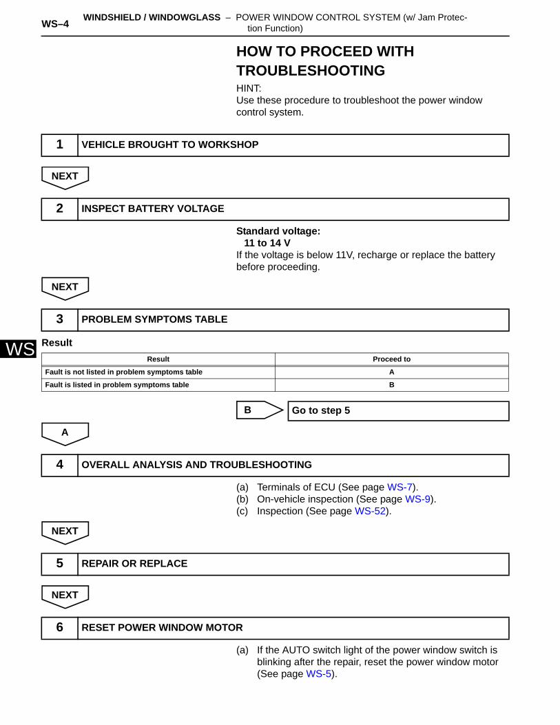
HOW TO PROCEED WITH TROUBLESHOOTINGHINT:Use these procedure to troubleshoot the power window control system.
NEXT
Standard voltage:11 to 14 V
If the voltage is below 11V, recharge or replace the battery before proceeding.
NEXT
Result
B
A
(a) Terminals of ECU (See page WS-7).(b) On-vehicle inspection (See page WS-9).(c) Inspection (See page WS-52).
NEXT
NEXT
(a) If the AUTO switch light of the power window switch is blinking after the repair, reset the power window motor (See page WS-5).
1 VEHICLE BROUGHT TO WORKSHOP
2 INSPECT BATTERY VOLTAGE
3 PROBLEM SYMPTOMS TABLE
Result Proceed to
Fault is not listed in problem symptoms table A
Fault is listed in problem symptoms table B
Go to step 5
4 OVERALL ANALYSIS AND TROUBLESHOOTING
5 REPAIR OR REPLACE
6 RESET POWER WINDOW MOTOR
WINDSHIELD / WINDOWGLASS – POWER WINDOW CONTROL SYSTEM (w/ Jam Protec-tion Function) WS–5
S
WNEXT
NEXT
7 CONFIRMATION TEST
END
WS–6 WINDSHIELD / WINDOWGLASS – POWER WINDOW CONTROL SYSTEM (w/ Jam Protec-tion Function)
WS
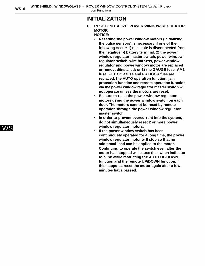
INITIALIZATION1. RESET (INITIALIZE) POWER WINDOW REGULATOR
MOTORNOTICE:• Resetting the power window motors (initializing
the pulse sensors) is necessary if one of the following occur: 1) the cable is disconnected from the negative (-) battery terminal: 2) the power window regulator master switch, power window regulator switch, wire harness, power window regulator and power window motor are replaced or removed/installed: or 3) the GAUGE fuse, AM1 fuse, FL DOOR fuse and FR DOOR fuse are replaced. the AUTO operation function, jam protection function and remote operation function via the power window regulator master switch will not operate unless the motors are reset.
• Be sure to reset the power window regulator motors using the power window switch on each door. The motors cannot be reset by remote operation through the power window regulator master switch.
• In order to prevent overcurrent into the system, do not simultaneously reset 2 or more power window regulator motors.
• If the power window switch has been continuously operated for a long time, the power window regulator motor will stop so that no additional load can be applied to the motor. Continuing to operate the switch even after the motor has stopped will cause the switch indicator to blink while restricting the AUTO UP/DOWN function and the remote UP/DOWN function. If this happens, reset the motor again after a few minutes have passed.
WINDSHIELD / WINDOWGLASS – POWER WINDOW CONTROL SYSTEM (w/ Jam Protec-tion Function) WS–7
S
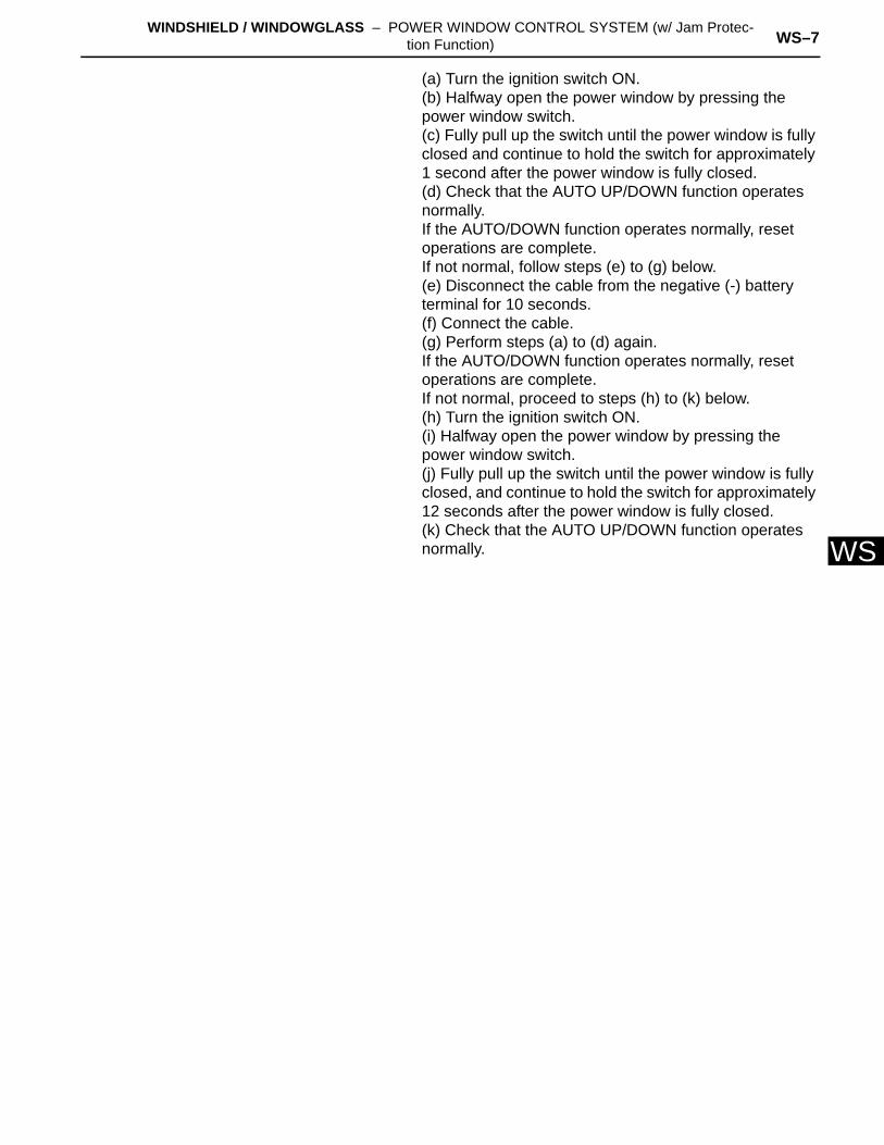
W(a) Turn the ignition switch ON.(b) Halfway open the power window by pressing the power window switch.(c) Fully pull up the switch until the power window is fully closed and continue to hold the switch for approximately 1 second after the power window is fully closed.(d) Check that the AUTO UP/DOWN function operates normally.If the AUTO/DOWN function operates normally, reset operations are complete. If not normal, follow steps (e) to (g) below.(e) Disconnect the cable from the negative (-) battery terminal for 10 seconds.(f) Connect the cable.(g) Perform steps (a) to (d) again.If the AUTO/DOWN function operates normally, reset operations are complete.If not normal, proceed to steps (h) to (k) below.(h) Turn the ignition switch ON.(i) Halfway open the power window by pressing the power window switch.(j) Fully pull up the switch until the power window is fully closed, and continue to hold the switch for approximately 12 seconds after the power window is fully closed.(k) Check that the AUTO UP/DOWN function operates normally.
WS–8 WINDSHIELD / WINDOWGLASS – POWER WINDOW CONTROL SYSTEM (w/ Jam Protec-tion Function)
WS
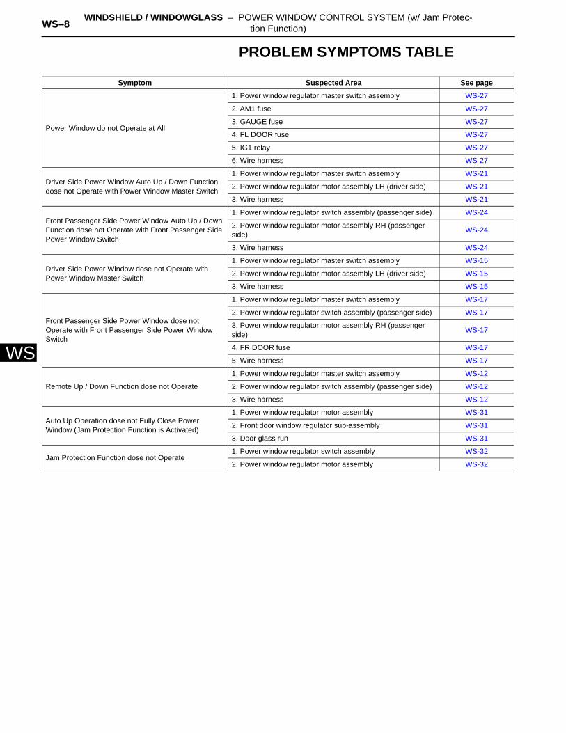
PROBLEM SYMPTOMS TABLE
Symptom Suspected Area See page
Power Window do not Operate at All
1. Power window regulator master switch assembly WS-27
2. AM1 fuse WS-27
3. GAUGE fuse WS-27
4. FL DOOR fuse WS-27
5. IG1 relay WS-27
6. Wire harness WS-27
Driver Side Power Window Auto Up / Down Function dose not Operate with Power Window Master Switch
1. Power window regulator master switch assembly WS-21
2. Power window regulator motor assembly LH (driver side) WS-21
3. Wire harness WS-21
Front Passenger Side Power Window Auto Up / Down Function dose not Operate with Front Passenger Side Power Window Switch
1. Power window regulator switch assembly (passenger side) WS-24
2. Power window regulator motor assembly RH (passenger side) WS-24
3. Wire harness WS-24
Driver Side Power Window dose not Operate with Power Window Master Switch
1. Power window regulator master switch assembly WS-15
2. Power window regulator motor assembly LH (driver side) WS-15
3. Wire harness WS-15
Front Passenger Side Power Window dose not Operate with Front Passenger Side Power Window Switch
1. Power window regulator master switch assembly WS-17
2. Power window regulator switch assembly (passenger side) WS-17
3. Power window regulator motor assembly RH (passenger side) WS-17
4. FR DOOR fuse WS-17
5. Wire harness WS-17
Remote Up / Down Function dose not Operate
1. Power window regulator master switch assembly WS-12
2. Power window regulator switch assembly (passenger side) WS-12
3. Wire harness WS-12
Auto Up Operation dose not Fully Close Power Window (Jam Protection Function is Activated)
1. Power window regulator motor assembly WS-31
2. Front door window regulator sub-assembly WS-31
3. Door glass run WS-31
Jam Protection Function dose not Operate1. Power window regulator switch assembly WS-32
2. Power window regulator motor assembly WS-32
WINDSHIELD / WINDOWGLASS – POWER WINDOW CONTROL SYSTEM (w/ Jam Protec-tion Function) WS–9
S
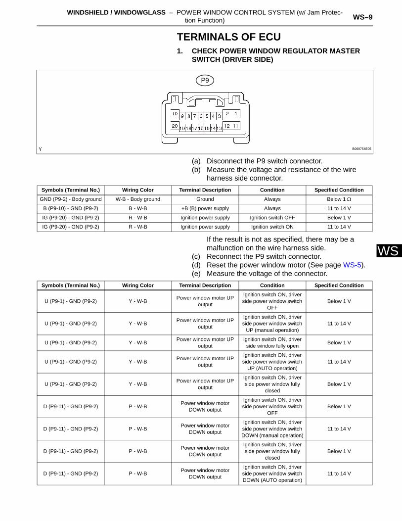
WTERMINALS OF ECU1. CHECK POWER WINDOW REGULATOR MASTER
SWITCH (DRIVER SIDE)
(a) Disconnect the P9 switch connector.(b) Measure the voltage and resistance of the wire
harness side connector.
If the result is not as specified, there may be a malfunction on the wire harness side.
(c) Reconnect the P9 switch connector.(d) Reset the power window motor (See page WS-5).(e) Measure the voltage of the connector.
P9
B069754E05
Symbols (Terminal No.) Wiring Color Terminal Description Condition Specified Condition
GND (P9-2) - Body ground W-B - Body ground Ground Always Below 1 Ω
B (P9-10) - GND (P9-2) B - W-B +B (B) power supply Always 11 to 14 V
IG (P9-20) - GND (P9-2) R - W-B Ignition power supply Ignition switch OFF Below 1 V
IG (P9-20) - GND (P9-2) R - W-B Ignition power supply Ignition switch ON 11 to 14 V
Symbols (Terminal No.) Wiring Color Terminal Description Condition Specified Condition
U (P9-1) - GND (P9-2) Y - W-B Power window motor UP output
Ignition switch ON, driver side power window switch
OFFBelow 1 V
U (P9-1) - GND (P9-2) Y - W-B Power window motor UP output
Ignition switch ON, driver side power window switch
UP (manual operation)11 to 14 V
U (P9-1) - GND (P9-2) Y - W-B Power window motor UP output
Ignition switch ON, driver side window fully open Below 1 V
U (P9-1) - GND (P9-2) Y - W-B Power window motor UP output
Ignition switch ON, driver side power window switch
UP (AUTO operation)11 to 14 V
U (P9-1) - GND (P9-2) Y - W-B Power window motor UP output
Ignition switch ON, driver side power window fully
closedBelow 1 V
D (P9-11) - GND (P9-2) P - W-B Power window motor DOWN output
Ignition switch ON, driver side power window switch
OFFBelow 1 V
D (P9-11) - GND (P9-2) P - W-B Power window motor DOWN output
Ignition switch ON, driver side power window switch DOWN (manual operation)
11 to 14 V
D (P9-11) - GND (P9-2) P - W-B Power window motor DOWN output
Ignition switch ON, driver side power window fully
closedBelow 1 V
D (P9-11) - GND (P9-2) P - W-B Power window motor DOWN output
Ignition switch ON, driver side power window switch DOWN (AUTO operation)
11 to 14 V
WS–10 WINDSHIELD / WINDOWGLASS – POWER WINDOW CONTROL SYSTEM (w/ Jam Protec-tion Function)
WS
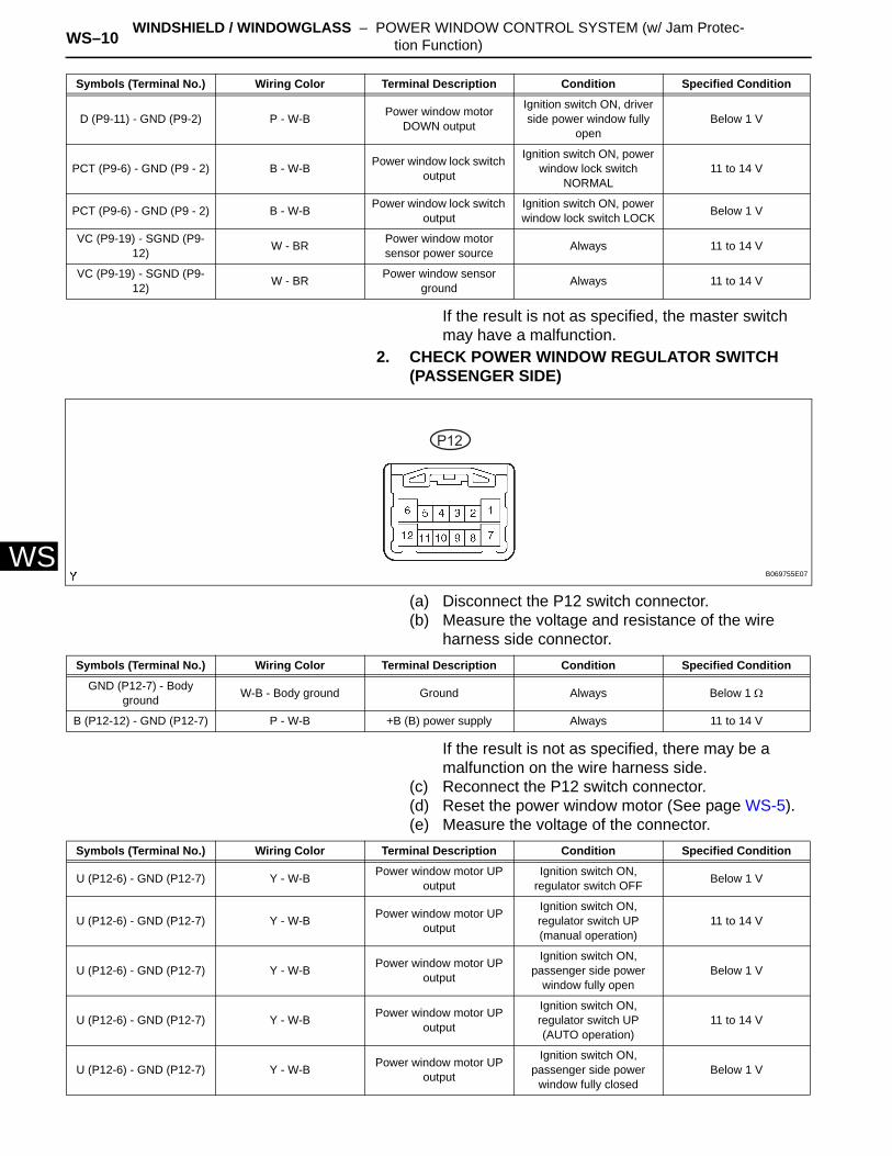
If the result is not as specified, the master switch may have a malfunction.
2. CHECK POWER WINDOW REGULATOR SWITCH (PASSENGER SIDE)
(a) Disconnect the P12 switch connector.(b) Measure the voltage and resistance of the wire
harness side connector.
If the result is not as specified, there may be a malfunction on the wire harness side.
(c) Reconnect the P12 switch connector.(d) Reset the power window motor (See page WS-5).(e) Measure the voltage of the connector.
D (P9-11) - GND (P9-2) P - W-B Power window motor DOWN output
Ignition switch ON, driver side power window fully
openBelow 1 V
PCT (P9-6) - GND (P9 - 2) B - W-B Power window lock switch output
Ignition switch ON, power window lock switch
NORMAL11 to 14 V
PCT (P9-6) - GND (P9 - 2) B - W-B Power window lock switch output
Ignition switch ON, power window lock switch LOCK Below 1 V
VC (P9-19) - SGND (P9-12) W - BR Power window motor
sensor power source Always 11 to 14 V
VC (P9-19) - SGND (P9-12) W - BR Power window sensor
ground Always 11 to 14 V
Symbols (Terminal No.) Wiring Color Terminal Description Condition Specified Condition
P12
B069755E07
Symbols (Terminal No.) Wiring Color Terminal Description Condition Specified Condition
GND (P12-7) - Body ground W-B - Body ground Ground Always Below 1 Ω
B (P12-12) - GND (P12-7) P - W-B +B (B) power supply Always 11 to 14 V
Symbols (Terminal No.) Wiring Color Terminal Description Condition Specified Condition
U (P12-6) - GND (P12-7) Y - W-B Power window motor UP output
Ignition switch ON, regulator switch OFF Below 1 V
U (P12-6) - GND (P12-7) Y - W-B Power window motor UP output
Ignition switch ON, regulator switch UP (manual operation)
11 to 14 V
U (P12-6) - GND (P12-7) Y - W-B Power window motor UP output
Ignition switch ON, passenger side power
window fully openBelow 1 V
U (P12-6) - GND (P12-7) Y - W-B Power window motor UP output
Ignition switch ON, regulator switch UP (AUTO operation)
11 to 14 V
U (P12-6) - GND (P12-7) Y - W-B Power window motor UP output
Ignition switch ON, passenger side power
window fully closedBelow 1 V
WINDSHIELD / WINDOWGLASS – POWER WINDOW CONTROL SYSTEM (w/ Jam Protec-tion Function) WS–11
S
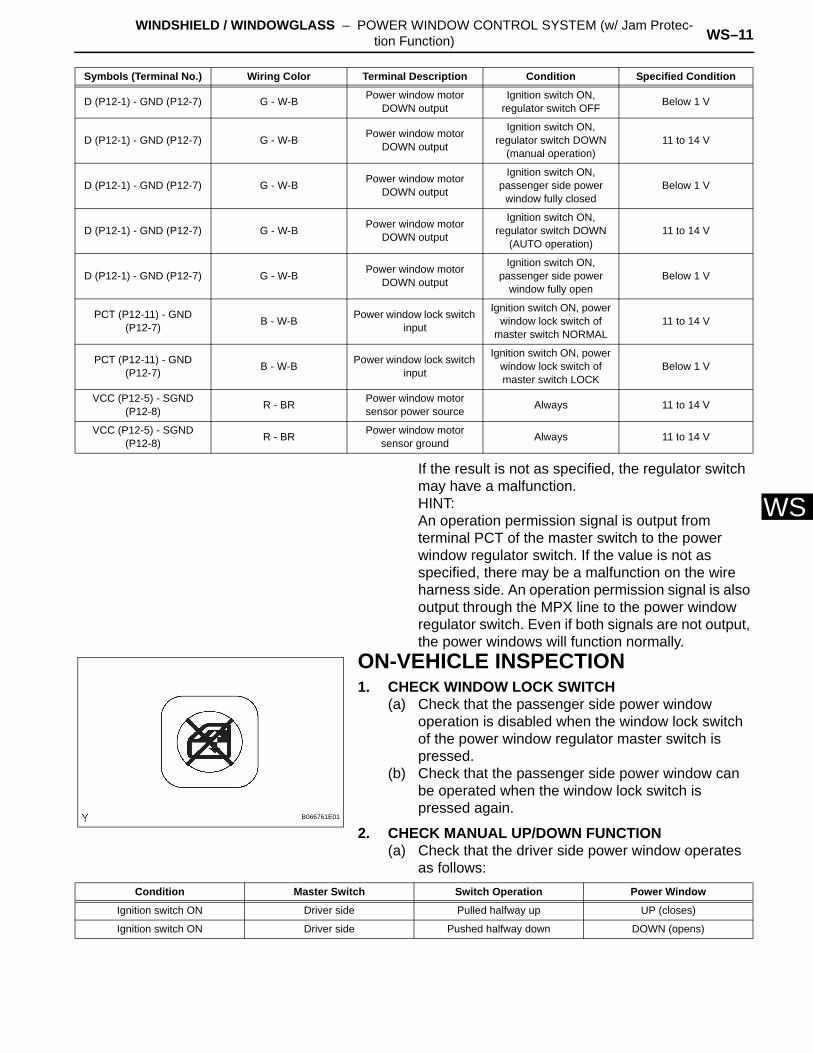
WIf the result is not as specified, the regulator switch may have a malfunction.HINT:An operation permission signal is output from terminal PCT of the master switch to the power window regulator switch. If the value is not as specified, there may be a malfunction on the wire harness side. An operation permission signal is also output through the MPX line to the power window regulator switch. Even if both signals are not output, the power windows will function normally.ON-VEHICLE INSPECTION1. CHECK WINDOW LOCK SWITCH
(a) Check that the passenger side power window operation is disabled when the window lock switch of the power window regulator master switch is pressed.
(b) Check that the passenger side power window can be operated when the window lock switch is pressed again.
2. CHECK MANUAL UP/DOWN FUNCTION(a) Check that the driver side power window operates
as follows:
D (P12-1) - GND (P12-7) G - W-B Power window motor DOWN output
Ignition switch ON, regulator switch OFF Below 1 V
D (P12-1) - GND (P12-7) G - W-B Power window motor DOWN output
Ignition switch ON, regulator switch DOWN
(manual operation)11 to 14 V
D (P12-1) - GND (P12-7) G - W-B Power window motor DOWN output
Ignition switch ON, passenger side power
window fully closedBelow 1 V
D (P12-1) - GND (P12-7) G - W-B Power window motor DOWN output
Ignition switch ON, regulator switch DOWN
(AUTO operation)11 to 14 V
D (P12-1) - GND (P12-7) G - W-B Power window motor DOWN output
Ignition switch ON, passenger side power
window fully openBelow 1 V
PCT (P12-11) - GND (P12-7) B - W-B Power window lock switch
input
Ignition switch ON, power window lock switch of
master switch NORMAL11 to 14 V
PCT (P12-11) - GND (P12-7) B - W-B Power window lock switch
input
Ignition switch ON, power window lock switch of master switch LOCK
Below 1 V
VCC (P12-5) - SGND (P12-8) R - BR Power window motor
sensor power source Always 11 to 14 V
VCC (P12-5) - SGND (P12-8) R - BR Power window motor
sensor ground Always 11 to 14 V
Symbols (Terminal No.) Wiring Color Terminal Description Condition Specified Condition
B066761E01
Condition Master Switch Switch Operation Power Window
Ignition switch ON Driver side Pulled halfway up UP (closes)
Ignition switch ON Driver side Pushed halfway down DOWN (opens)
WS–12 WINDSHIELD / WINDOWGLASS – POWER WINDOW CONTROL SYSTEM (w/ Jam Protec-tion Function)
WS
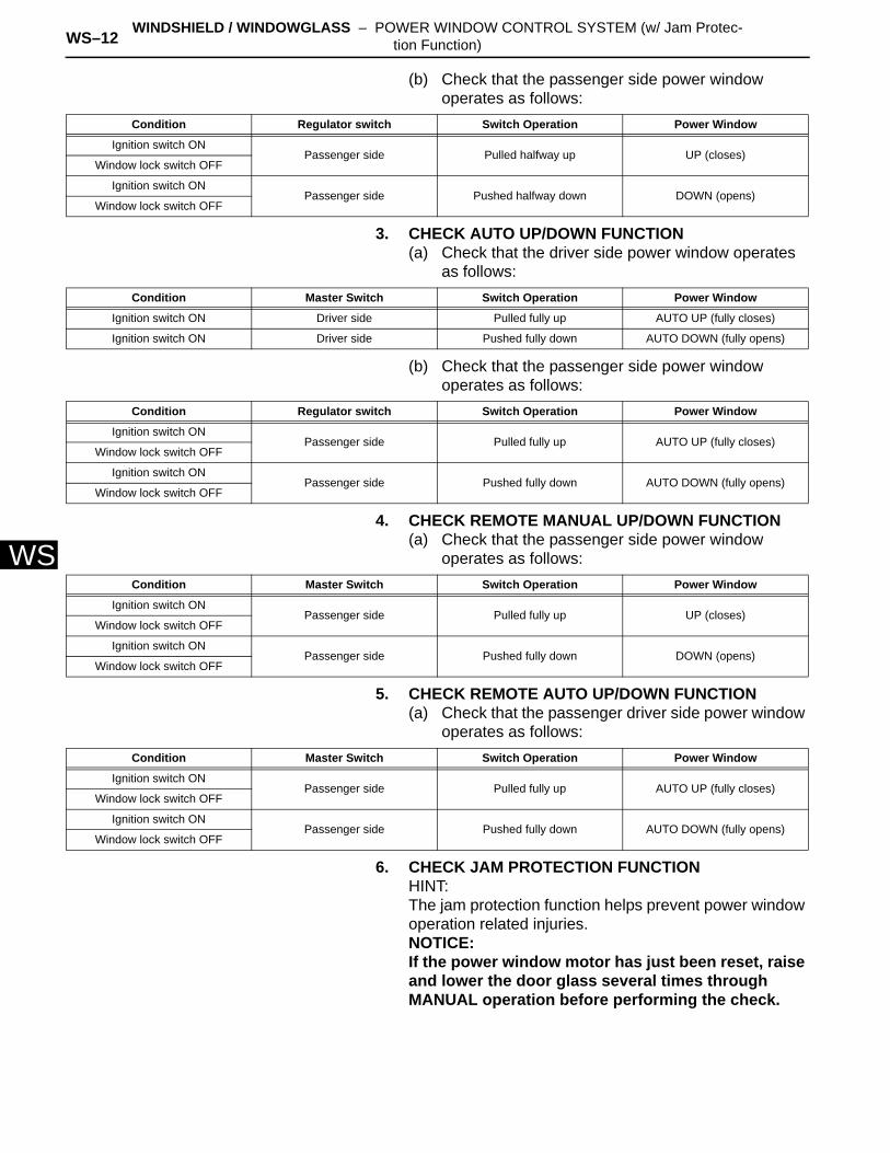
(b) Check that the passenger side power window operates as follows:
3. CHECK AUTO UP/DOWN FUNCTION(a) Check that the driver side power window operates
as follows:
(b) Check that the passenger side power window operates as follows:
4. CHECK REMOTE MANUAL UP/DOWN FUNCTION(a) Check that the passenger side power window
operates as follows:
5. CHECK REMOTE AUTO UP/DOWN FUNCTION(a) Check that the passenger driver side power window
operates as follows:
6. CHECK JAM PROTECTION FUNCTIONHINT:The jam protection function helps prevent power window operation related injuries.NOTICE:If the power window motor has just been reset, raise and lower the door glass several times through MANUAL operation before performing the check.
Condition Regulator switch Switch Operation Power Window
Ignition switch ONPassenger side Pulled halfway up UP (closes)
Window lock switch OFF
Ignition switch ONPassenger side Pushed halfway down DOWN (opens)
Window lock switch OFF
Condition Master Switch Switch Operation Power Window
Ignition switch ON Driver side Pulled fully up AUTO UP (fully closes)
Ignition switch ON Driver side Pushed fully down AUTO DOWN (fully opens)
Condition Regulator switch Switch Operation Power Window
Ignition switch ONPassenger side Pulled fully up AUTO UP (fully closes)
Window lock switch OFF
Ignition switch ONPassenger side Pushed fully down AUTO DOWN (fully opens)
Window lock switch OFF
Condition Master Switch Switch Operation Power Window
Ignition switch ONPassenger side Pulled fully up UP (closes)
Window lock switch OFF
Ignition switch ONPassenger side Pushed fully down DOWN (opens)
Window lock switch OFF
Condition Master Switch Switch Operation Power Window
Ignition switch ONPassenger side Pulled fully up AUTO UP (fully closes)
Window lock switch OFF
Ignition switch ONPassenger side Pushed fully down AUTO DOWN (fully opens)
Window lock switch OFF
WINDSHIELD / WINDOWGLASS – POWER WINDOW CONTROL SYSTEM (w/ Jam Protec-tion Function) WS–13
S
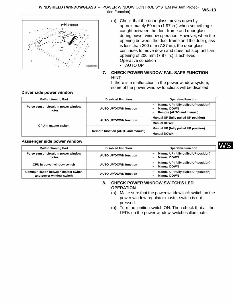
W(a) Check that the door glass moves down by approximately 50 mm (1.97 in.) when something is caught between the door frame and door glass during power window operation. However, when the opening between the door frame and the door glass is less than 200 mm (7.87 in.), the door glass continues to move down and does not stop until an opening of 200 mm (7.87 in.) is achieved.Operative condition• AUTO UP
7. CHECK POWER WINDOW FAIL-SAFE FUNCTIONHINT:If there is a malfunction in the power window system, some of the power window functions will be disabled.
Driver side power window
Passenger side power window
8. CHECK POWER WINDOW SWITCH'S LED OPERATION(a) Make sure that the power window lock switch on the
power window regulator master switch is not pressed.
(b) Turn the ignition switch ON. Then check that all the LEDs on the power window switches illuminate.
Hammer
B051853E03
Malfunctioning Part Disabled Function Operative Function
Pulse sensor circuit in power window motor AUTO UP/DOWN function
• Manual UP (fully pulled UP position)• Manual DOWN• Remote (AUTO and manual)
CPU in master switch
AUTO UP/DOWN functionManual UP (fully pulled UP position)
Manual DOWN
Remote function (AUTO and manual)Manual UP (fully pulled UP position)
Manual DOWN
Malfunctioning Part Disabled Function Operative Function
Pulse sensor circuit in power window motor AUTO UP/DOWN function • Manual UP (fully pulled UP position)
• Manual DOWN
CPU in power window switch AUTO UP/DOWN function • Manual UP (fully pulled UP position)• Manual DOWN
Communication between master switch and power window switch AUTO UP/DOWN function • Manual UP (fully pulled UP position)
• Manual DOWN
WS–14 WINDSHIELD / WINDOWGLASS – POWER WINDOW CONTROL SYSTEM (w/ Jam Protec-tion Function)
WS
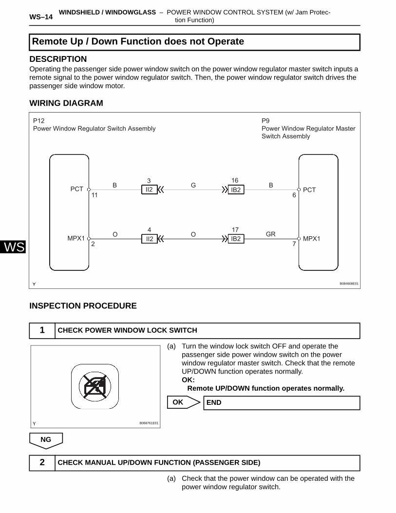
DESCRIPTIONOperating the passenger side power window switch on the power window regulator master switch inputs a remote signal to the power window regulator switch. Then, the power window regulator switch drives the passenger side window motor.
WIRING DIAGRAM
INSPECTION PROCEDURE
(a) Turn the window lock switch OFF and operate the passenger side power window switch on the power window regulator master switch. Check that the remote UP/DOWN function operates normally.OK:
Remote UP/DOWN function operates normally.
OK
NG
(a) Check that the power window can be operated with the power window regulator switch.
Remote Up / Down Function does not Operate
1 CHECK POWER WINDOW LOCK SWITCH
P12Power Window Regulator Switch Assembly
PCT PCT
MPX1 MPX1O O
G BB
GR
11
2
II2
II2
IB2
IB2
3
4 17
16
7
6
P9Power Window Regulator Master Switch Assembly
B084608E01
B066761E01
END
2 CHECK MANUAL UP/DOWN FUNCTION (PASSENGER SIDE)
WINDSHIELD / WINDOWGLASS – POWER WINDOW CONTROL SYSTEM (w/ Jam Protec-tion Function) WS–15
S
WOK:Manual UP/DOWN function operates normally.
NG
OK
(a) Check that the power window can be operated with the power window regulator switch.OK:
AUTO UP/DOWN function operates normally.
NG
OK
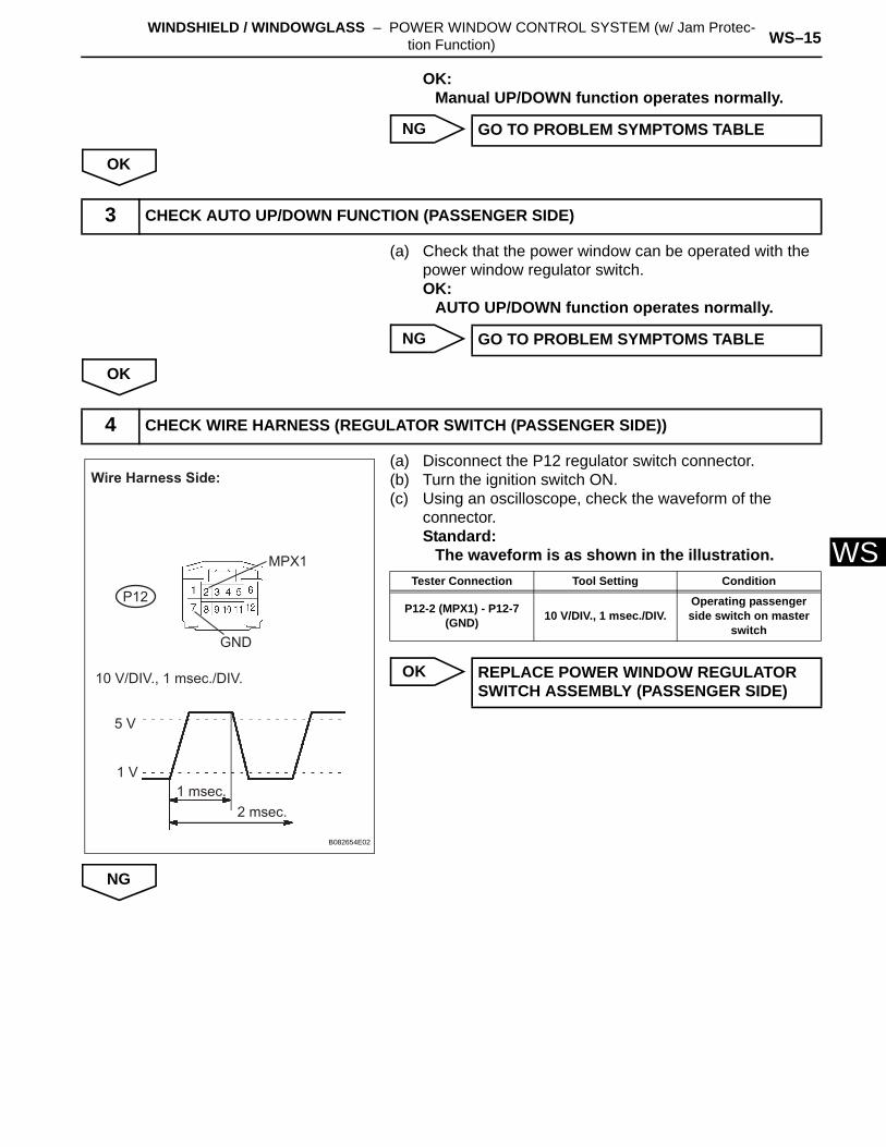
(a) Disconnect the P12 regulator switch connector.(b) Turn the ignition switch ON.(c) Using an oscilloscope, check the waveform of the
connector.Standard:
The waveform is as shown in the illustration.
OK
NG
GO TO PROBLEM SYMPTOMS TABLE
3 CHECK AUTO UP/DOWN FUNCTION (PASSENGER SIDE)
GO TO PROBLEM SYMPTOMS TABLE
4 CHECK WIRE HARNESS (REGULATOR SWITCH (PASSENGER SIDE))
P12
GND
10 V/DIV., 1 msec./DIV.
5 V
1 V1 msec.
2 msec.
Wire Harness Side:
MPX1
B082654E02
Tester Connection Tool Setting Condition
P12-2 (MPX1) - P12-7 (GND) 10 V/DIV., 1 msec./DIV.
Operating passenger side switch on master
switch
REPLACE POWER WINDOW REGULATOR SWITCH ASSEMBLY (PASSENGER SIDE)
WS–16 WINDSHIELD / WINDOWGLASS – POWER WINDOW CONTROL SYSTEM (w/ Jam Protec-tion Function)
WS
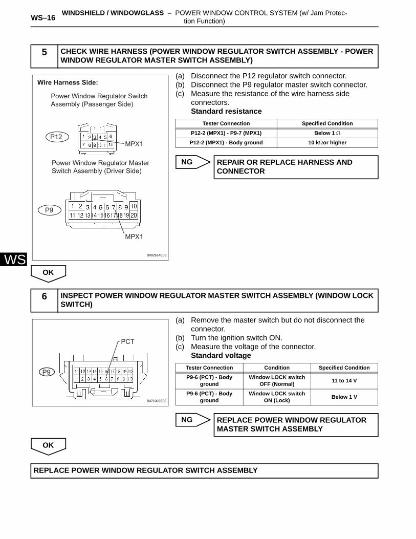
(a) Disconnect the P12 regulator switch connector.(b) Disconnect the P9 regulator master switch connector.(c) Measure the resistance of the wire harness side
connectors.Standard resistance
NG
OK
(a) Remove the master switch but do not disconnect the connector.
(b) Turn the ignition switch ON.(c) Measure the voltage of the connector.
Standard voltage
NG
OK
5 CHECK WIRE HARNESS (POWER WINDOW REGULATOR SWITCH ASSEMBLY - POWER WINDOW REGULATOR MASTER SWITCH ASSEMBLY)
Wire Harness Side:
MPX1
MPX1
P12
P9
Power Window Regulator Switch Assembly (Passenger Side)
Power Window Regulator Master Switch Assembly (Driver Side)
B082614E03
Tester Connection Specified Condition
P12-2 (MPX1) - P9-7 (MPX1) Below 1 Ω
P12-2 (MPX1) - Body ground 10 kΩor higher
REPAIR OR REPLACE HARNESS AND CONNECTOR
6 INSPECT POWER WINDOW REGULATOR MASTER SWITCH ASSEMBLY (WINDOW LOCK SWITCH)
P9
PCT
B071002E02
Tester Connection Condition Specified Condition
P9-6 (PCT) - Body ground
Window LOCK switch OFF (Normal) 11 to 14 V
P9-6 (PCT) - Body ground
Window LOCK switch ON (Lock) Below 1 V
REPLACE POWER WINDOW REGULATOR MASTER SWITCH ASSEMBLY
REPLACE POWER WINDOW REGULATOR SWITCH ASSEMBLY
WINDSHIELD / WINDOWGLASS – POWER WINDOW CONTROL SYSTEM (w/ Jam Protec-tion Function) WS–17
S
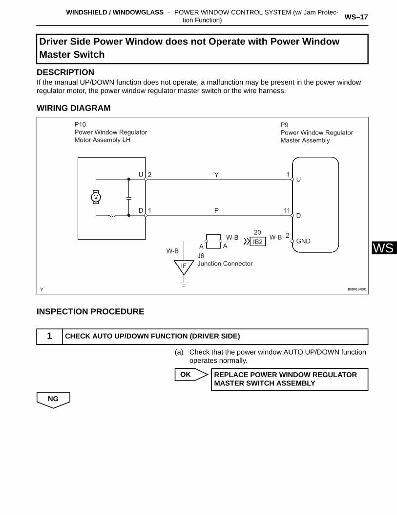
WDESCRIPTIONIf the manual UP/DOWN function does not operate, a malfunction may be present in the power window regulator motor, the power window regulator master switch or the wire harness.
WIRING DIAGRAM
INSPECTION PROCEDURE
(a) Check that the power window AUTO UP/DOWN function operates normally.
OK
NG
Driver Side Power Window does not Operate with Power Window Master Switch
1 CHECK AUTO UP/DOWN FUNCTION (DRIVER SIDE)
P10Power Window Regulator Motor Assembly LH
P9Power Window Regulator Master Assembly
U
D 1
12
2
11
20IB2
W-B
IF
A AJ6Junction Connector
W-BW-B
P
YU
D
GND
B084614E01
REPLACE POWER WINDOW REGULATOR MASTER SWITCH ASSEMBLY
WS–18 WINDSHIELD / WINDOWGLASS – POWER WINDOW CONTROL SYSTEM (w/ Jam Protec-tion Function)
WS
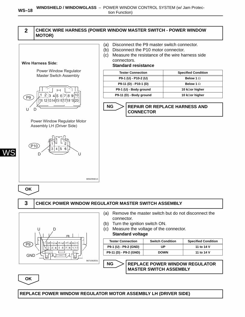
(a) Disconnect the P9 master switch connector.(b) Disconnect the P10 motor connector.(c) Measure the resistance of the wire harness side
connectors.Standard resistance
NG
OK
(a) Remove the master switch but do not disconnect the connector.
(b) Turn the ignition switch ON.(c) Measure the voltage of the connector.
Standard voltage
NG
OK
2 CHECK WIRE HARNESS (POWER WINDOW MASTER SWITCH - POWER WINDOW MOTOR)
U
U
D
D
P10
P9
Wire Harness Side:
Power Window Regulator Master Switch Assembly
Power Window Regulator Motor Assembly LH (Driver Side)
B052055E13
Tester Connection Specified Condition
P9-1 (U) - P10-2 (U) Below 1 Ω
P9-11 (D) - P10-1 (D) Below 1 Ω
P9-1 (U) - Body ground 10 kΩor higher
P9-11 (D) - Body ground 10 kΩor higher
REPAIR OR REPLACE HARNESS AND CONNECTOR
3 CHECK POWER WINDOW REGULATOR MASTER SWITCH ASSEMBLY
P9
GND
DU
B071002E01
Tester Connection Switch Condition Specified Condition
P9-1 (U) - P9-2 (GND) UP 11 to 14 V
P9-11 (D) - P9-2 (GND) DOWN 11 to 14 V
REPLACE POWER WINDOW REGULATOR MASTER SWITCH ASSEMBLY
REPLACE POWER WINDOW REGULATOR MOTOR ASSEMBLY LH (DRIVER SIDE)
WINDSHIELD / WINDOWGLASS – POWER WINDOW CONTROL SYSTEM (w/ Jam Protec-tion Function) WS–19
S
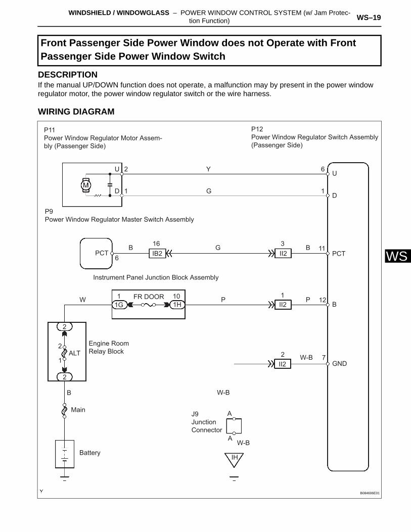
WDESCRIPTIONIf the manual UP/DOWN function does not operate, a malfunction may by present in the power window regulator motor, the power window regulator switch or the wire harness.
WIRING DIAGRAM
Front Passenger Side Power Window does not Operate with Front Passenger Side Power Window Switch
P11Power Window Regulator Motor Assem-bly (Passenger Side)
P12Power Window Regulator Switch Assembly (Passenger Side)
Y
G
GB
B
B
PPW
W-B
W-B
W-B
Main
Battery
Engine Room Relay BlockALT
2
2
2
2
1
1
1
1
6
2
1 101H1G
Instrument Panel Junction Block Assembly
II2
II2
II2
A
A
J9 Junction Connector
PCT IB2
P9Power Window Regulator Master Switch Assembly
16 311
12
7
UU
DD
PCT
B
GND
IH
FR DOOR
6
B084606E01
WS–20 WINDSHIELD / WINDOWGLASS – POWER WINDOW CONTROL SYSTEM (w/ Jam Protec-tion Function)
WS
INSPECTION PROCEDURE
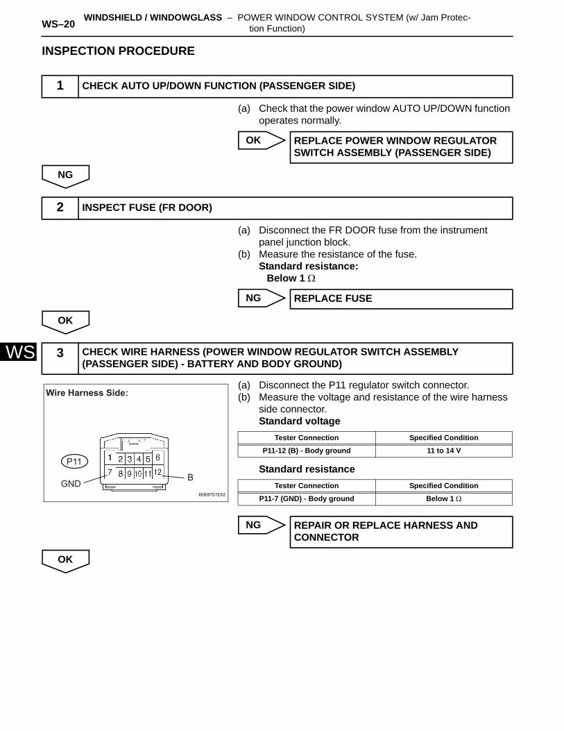
(a) Check that the power window AUTO UP/DOWN function operates normally.
OK
NG
(a) Disconnect the FR DOOR fuse from the instrument panel junction block.
(b) Measure the resistance of the fuse.Standard resistance:
Below 1 Ω
NG
OK
(a) Disconnect the P11 regulator switch connector.(b) Measure the voltage and resistance of the wire harness
side connector.Standard voltage
Standard resistance
NG
OK
1 CHECK AUTO UP/DOWN FUNCTION (PASSENGER SIDE)
REPLACE POWER WINDOW REGULATOR SWITCH ASSEMBLY (PASSENGER SIDE)
2 INSPECT FUSE (FR DOOR)
REPLACE FUSE
3 CHECK WIRE HARNESS (POWER WINDOW REGULATOR SWITCH ASSEMBLY (PASSENGER SIDE) - BATTERY AND BODY GROUND)
Wire Harness Side:
GNDB
P11
B069757E02
Tester Connection Specified Condition
P11-12 (B) - Body ground 11 to 14 V
Tester Connection Specified Condition
P11-7 (GND) - Body ground Below 1 Ω
REPAIR OR REPLACE HARNESS AND CONNECTOR
WINDSHIELD / WINDOWGLASS – POWER WINDOW CONTROL SYSTEM (w/ Jam Protec-tion Function) WS–21
S
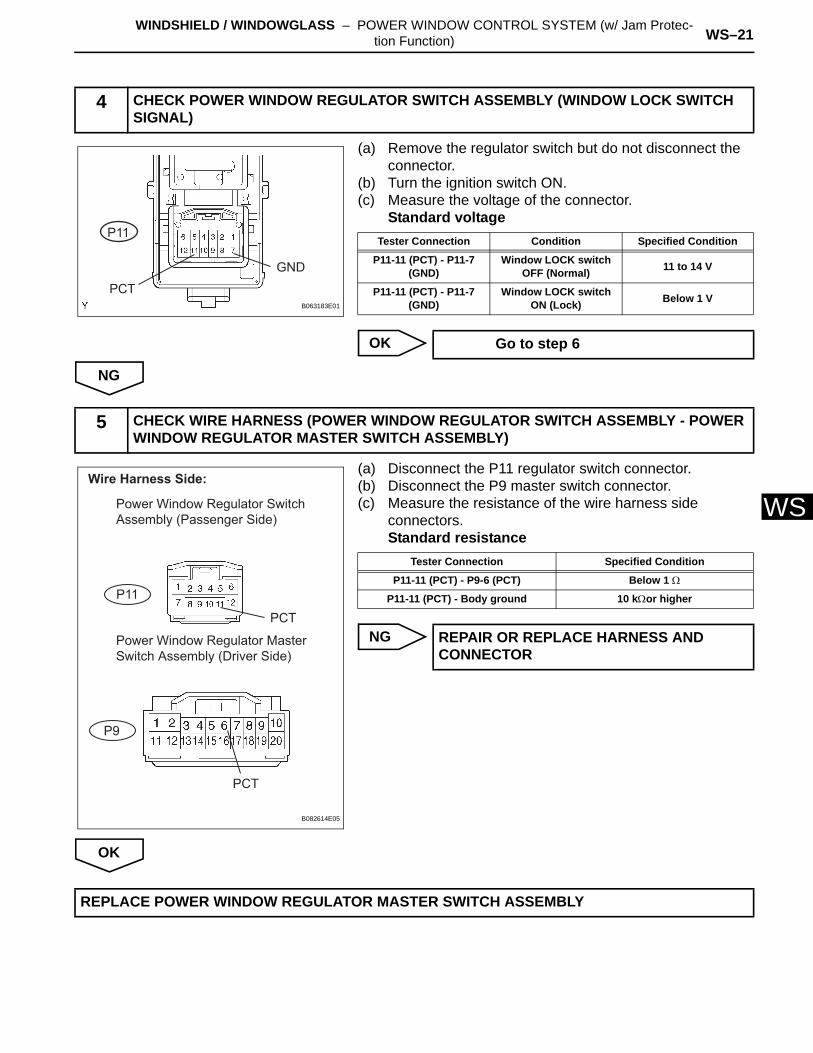
W(a) Remove the regulator switch but do not disconnect the connector.
(b) Turn the ignition switch ON.(c) Measure the voltage of the connector.
Standard voltage
OK
NG
(a) Disconnect the P11 regulator switch connector.(b) Disconnect the P9 master switch connector.(c) Measure the resistance of the wire harness side
connectors.Standard resistance
NG
OK
4 CHECK POWER WINDOW REGULATOR SWITCH ASSEMBLY (WINDOW LOCK SWITCH SIGNAL)
P11
PCT
GND
B063183E01
Tester Connection Condition Specified Condition
P11-11 (PCT) - P11-7 (GND)
Window LOCK switch OFF (Normal) 11 to 14 V
P11-11 (PCT) - P11-7 (GND)
Window LOCK switch ON (Lock) Below 1 V
Go to step 6
5 CHECK WIRE HARNESS (POWER WINDOW REGULATOR SWITCH ASSEMBLY - POWER WINDOW REGULATOR MASTER SWITCH ASSEMBLY)
Wire Harness Side:
P11
P9
PCT
PCT
Power Window Regulator Switch Assembly (Passenger Side)
Power Window Regulator Master Switch Assembly (Driver Side)
B082614E05
Tester Connection Specified Condition
P11-11 (PCT) - P9-6 (PCT) Below 1 Ω
P11-11 (PCT) - Body ground 10 kΩor higher
REPAIR OR REPLACE HARNESS AND CONNECTOR
REPLACE POWER WINDOW REGULATOR MASTER SWITCH ASSEMBLY
WS–22 WINDSHIELD / WINDOWGLASS – POWER WINDOW CONTROL SYSTEM (w/ Jam Protec-tion Function)
WS
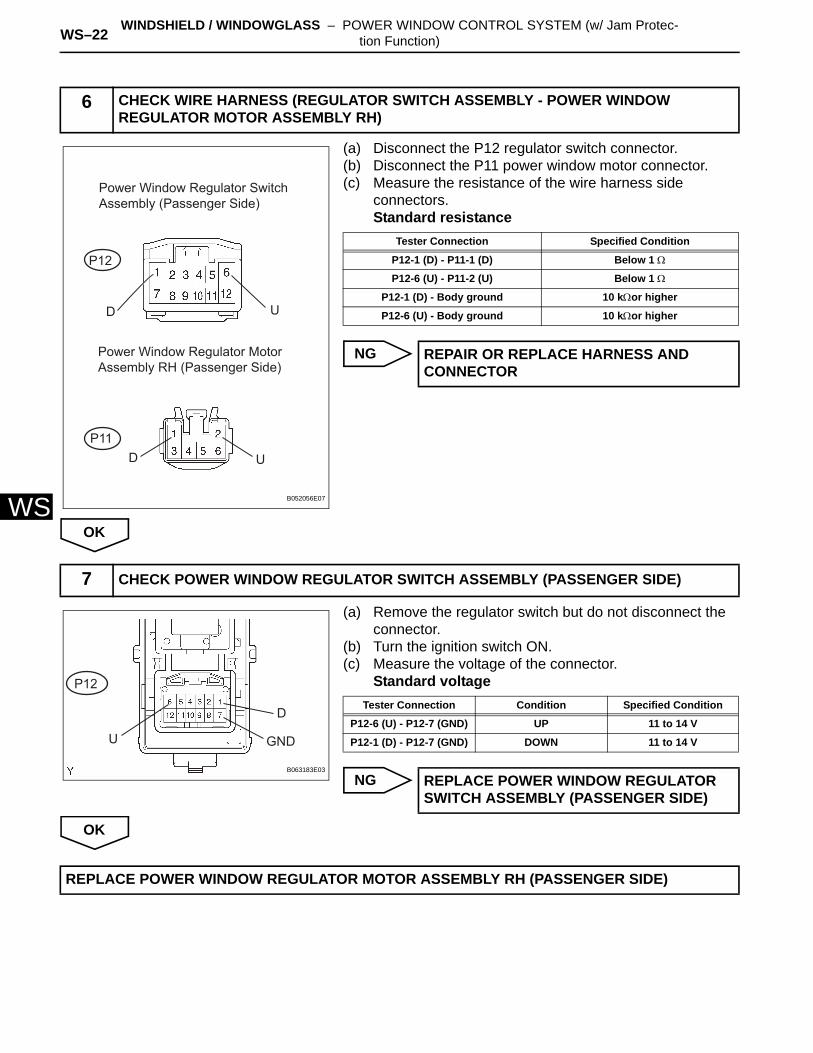
(a) Disconnect the P12 regulator switch connector.(b) Disconnect the P11 power window motor connector.(c) Measure the resistance of the wire harness side
connectors.Standard resistance
NG
OK
(a) Remove the regulator switch but do not disconnect the connector.
(b) Turn the ignition switch ON.(c) Measure the voltage of the connector.
Standard voltage
NG
OK
6 CHECK WIRE HARNESS (REGULATOR SWITCH ASSEMBLY - POWER WINDOW REGULATOR MOTOR ASSEMBLY RH)
D
D
U
U
Power Window Regulator Switch Assembly (Passenger Side)
Power Window Regulator Motor Assembly RH (Passenger Side)
P12
P11
B052056E07
Tester Connection Specified Condition
P12-1 (D) - P11-1 (D) Below 1 Ω
P12-6 (U) - P11-2 (U) Below 1 Ω
P12-1 (D) - Body ground 10 kΩor higher
P12-6 (U) - Body ground 10 kΩor higher
REPAIR OR REPLACE HARNESS AND CONNECTOR
7 CHECK POWER WINDOW REGULATOR SWITCH ASSEMBLY (PASSENGER SIDE)
P12
U
D
GND
B063183E03
Tester Connection Condition Specified Condition
P12-6 (U) - P12-7 (GND) UP 11 to 14 V
P12-1 (D) - P12-7 (GND) DOWN 11 to 14 V
REPLACE POWER WINDOW REGULATOR SWITCH ASSEMBLY (PASSENGER SIDE)
REPLACE POWER WINDOW REGULATOR MOTOR ASSEMBLY RH (PASSENGER SIDE)
WINDSHIELD / WINDOWGLASS – POWER WINDOW CONTROL SYSTEM (w/ Jam Protec-tion Function) WS–23
S
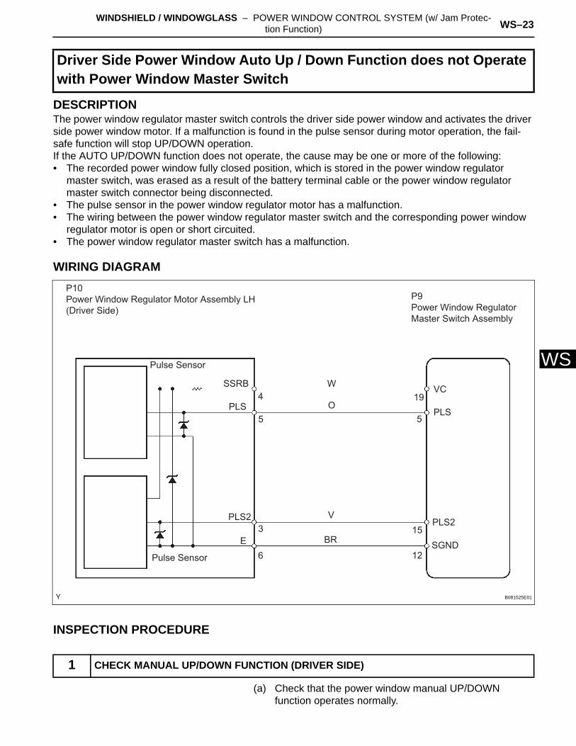
WDESCRIPTIONThe power window regulator master switch controls the driver side power window and activates the driver side power window motor. If a malfunction is found in the pulse sensor during motor operation, the fail-safe function will stop UP/DOWN operation.If the AUTO UP/DOWN function does not operate, the cause may be one or more of the following:• The recorded power window fully closed position, which is stored in the power window regulator
master switch, was erased as a result of the battery terminal cable or the power window regulator master switch connector being disconnected.
• The pulse sensor in the power window regulator motor has a malfunction.• The wiring between the power window regulator master switch and the corresponding power window
regulator motor is open or short circuited.• The power window regulator master switch has a malfunction.
WIRING DIAGRAM
INSPECTION PROCEDURE
(a) Check that the power window manual UP/DOWN function operates normally.
Driver Side Power Window Auto Up / Down Function does not Operate with Power Window Master Switch
1 CHECK MANUAL UP/DOWN FUNCTION (DRIVER SIDE)
P10Power Window Regulator Motor Assembly LH (Driver Side)
Pulse Sensor
SSRB
PLS
PLS2 PLS2
E
Pulse Sensor
3
5
4
6
W
O
V
BR15
12
19
5
VC
PLS
SGND
P9Power Window Regulator Master Switch Assembly
B081525E01
WS–24 WINDSHIELD / WINDOWGLASS – POWER WINDOW CONTROL SYSTEM (w/ Jam Protec-tion Function)
WS
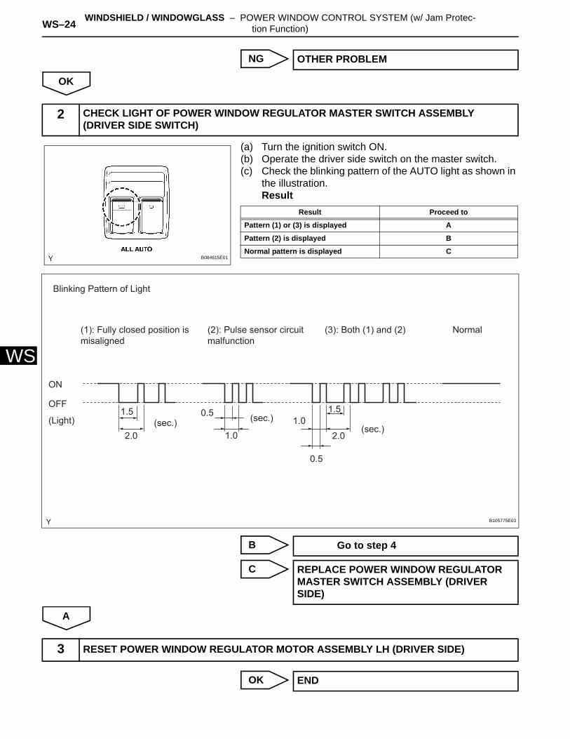
NG
OK
(a) Turn the ignition switch ON.(b) Operate the driver side switch on the master switch.(c) Check the blinking pattern of the AUTO light as shown in
the illustration.Result
B
C
A
OK
OTHER PROBLEM
2 CHECK LIGHT OF POWER WINDOW REGULATOR MASTER SWITCH ASSEMBLY (DRIVER SIDE SWITCH)
B084615E01
Result Proceed to
Pattern (1) or (3) is displayed A
Pattern (2) is displayed B
Normal pattern is displayed C
ON
OFF
(Light) (sec.) (sec.)(sec.)
Blinking Pattern of Light
(1): Fully closed position is misaligned
(2): Pulse sensor circuit malfunction
(3): Both (1) and (2) Normal
1.5 1.5
2.0 2.01.0
1.0
0.5
0.5
B105775E03
Go to step 4
REPLACE POWER WINDOW REGULATOR MASTER SWITCH ASSEMBLY (DRIVER SIDE)
3 RESET POWER WINDOW REGULATOR MOTOR ASSEMBLY LH (DRIVER SIDE)
END
WINDSHIELD / WINDOWGLASS – POWER WINDOW CONTROL SYSTEM (w/ Jam Protec-tion Function) WS–25
S
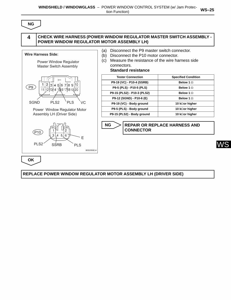
WNG
(a) Disconnect the P9 master switch connector.(b) Disconnect the P10 motor connector.(c) Measure the resistance of the wire harness side
connectors.Standard resistance
NG
OK
4 CHECK WIRE HARNESS (POWER WINDOW REGULATOR MASTER SWITCH ASSEMBLY - POWER WINDOW REGULATOR MOTOR ASSEMBLY LH)
P10
P9
VCPLS
E
PLSSSRBPLS2
PLS2SGND
Wire Harness Side:
Power Window Regulator Master Switch Assembly
Power Window Regulator Motor Assembly LH (Driver Side)
B052055E14
Tester Connection Specified Condition
P9-19 (VC) - P10-4 (SSRB) Below 1 Ω
P9-5 (PLS) - P10-5 (PLS) Below 1 Ω
P9-15 (PLS2) - P10-3 (PLS2) Below 1 Ω
P9-12 (SGND) - P10-6 (E) Below 1 Ω
P9-19 (VC) - Body ground 10 kΩor higher
P9-5 (PLS) - Body ground 10 kΩor higher
P9-15 (PLS2) - Body ground 10 kΩor higher
REPAIR OR REPLACE HARNESS AND CONNECTOR
REPLACE POWER WINDOW REGULATOR MOTOR ASSEMBLY LH (DRIVER SIDE)
WS–26 WINDSHIELD / WINDOWGLASS – POWER WINDOW CONTROL SYSTEM (w/ Jam Protec-tion Function)
WS
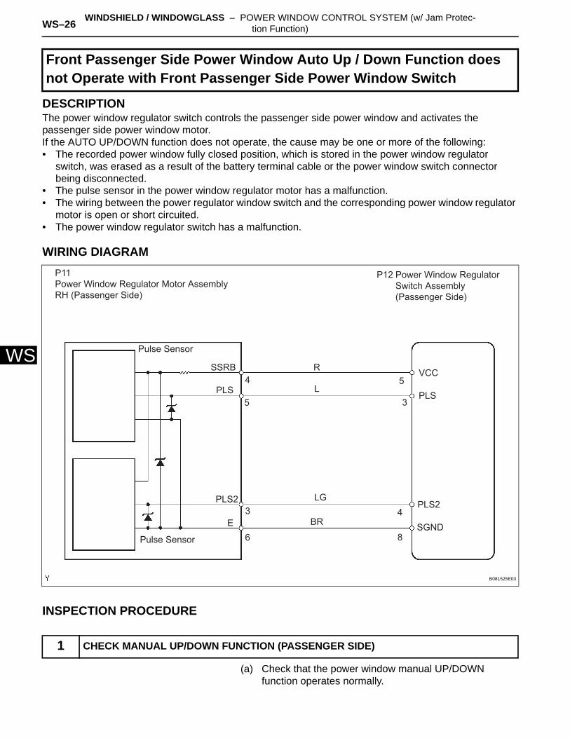
DESCRIPTIONThe power window regulator switch controls the passenger side power window and activates the passenger side power window motor.If the AUTO UP/DOWN function does not operate, the cause may be one or more of the following:• The recorded power window fully closed position, which is stored in the power window regulator
switch, was erased as a result of the battery terminal cable or the power window switch connector being disconnected.
• The pulse sensor in the power window regulator motor has a malfunction.• The wiring between the power regulator window switch and the corresponding power window regulator
motor is open or short circuited.• The power window regulator switch has a malfunction.
WIRING DIAGRAM
INSPECTION PROCEDURE
(a) Check that the power window manual UP/DOWN function operates normally.
Front Passenger Side Power Window Auto Up / Down Function does not Operate with Front Passenger Side Power Window Switch
1 CHECK MANUAL UP/DOWN FUNCTION (PASSENGER SIDE)
P11Power Window Regulator Motor Assembly RH (Passenger Side)
Pulse Sensor
SSRB
PLS
PLS2 PLS2
E
Pulse Sensor
3
5
4
6
R
L
LG
BR4
8
5
3
VCC
PLS
SGND
Power Window Regulator Switch Assembly (Passenger Side)
P12
B081525E03
WINDSHIELD / WINDOWGLASS – POWER WINDOW CONTROL SYSTEM (w/ Jam Protec-tion Function) WS–27
S
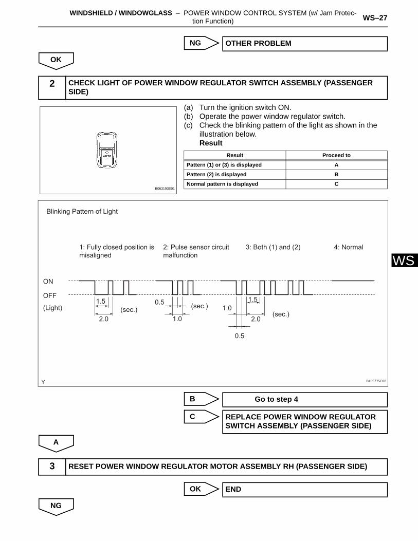
WNG
OK
(a) Turn the ignition switch ON.(b) Operate the power window regulator switch.(c) Check the blinking pattern of the light as shown in the
illustration below.Result
B
C
A
OK
NG
OTHER PROBLEM
2 CHECK LIGHT OF POWER WINDOW REGULATOR SWITCH ASSEMBLY (PASSENGER SIDE)
B063193E01
Result Proceed to
Pattern (1) or (3) is displayed A
Pattern (2) is displayed B
Normal pattern is displayed C
ON
OFF
(Light) (sec.) (sec.)(sec.)
Blinking Pattern of Light
1: Fully closed position is misaligned
2: Pulse sensor circuit malfunction
3: Both (1) and (2) 4: Normal
1.5 1.5
2.0 2.01.0
1.0
0.5
0.5
B105775E02
Go to step 4
REPLACE POWER WINDOW REGULATOR SWITCH ASSEMBLY (PASSENGER SIDE)
3 RESET POWER WINDOW REGULATOR MOTOR ASSEMBLY RH (PASSENGER SIDE)
END
WS–28 WINDSHIELD / WINDOWGLASS – POWER WINDOW CONTROL SYSTEM (w/ Jam Protec-tion Function)
WS
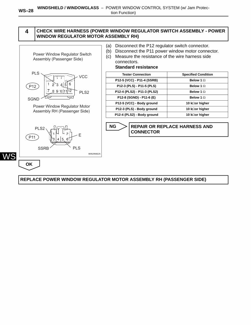
(a) Disconnect the P12 regulator switch connector.(b) Disconnect the P11 power window motor connector.(c) Measure the resistance of the wire harness side
connectors.Standard resistance
NG
OK
4 CHECK WIRE HARNESS (POWER WINDOW REGULATOR SWITCH ASSEMBLY - POWER WINDOW REGULATOR MOTOR ASSEMBLY RH)
PLSVCC
EPLS2
PLS2SGND
Power Window Regulator Switch Assembly (Passenger Side)
Power Window Regulator Motor Assembly RH (Passenger Side)
SSRB PLS
P12
P11
B052056E25
Tester Connection Specified Condition
P12-5 (VCC) - P11-4 (SSRB) Below 1 Ω
P12-3 (PLS) - P11-5 (PLS) Below 1 Ω
P12-4 (PLS2) - P11-3 (PLS2) Below 1 Ω
P12-8 (SGND) - P11-6 (E) Below 1 Ω
P12-5 (VCC) - Body ground 10 kΩor higher
P12-3 (PLS) - Body ground 10 kΩor higher
P12-4 (PLS2) - Body ground 10 kΩor higher
REPAIR OR REPLACE HARNESS AND CONNECTOR
REPLACE POWER WINDOW REGULATOR MOTOR ASSEMBLY RH (PASSENGER SIDE)
WINDSHIELD / WINDOWGLASS – POWER WINDOW CONTROL SYSTEM (w/ Jam Protec-tion Function) WS–29
S
WDESCRIPTIONIf all of the power windows do not operate, it is possible that no power is being supplied to the power window master switch, or that the power window master switch is malfunctioning.
Power Windows do not Operate at All
WS–30 WINDSHIELD / WINDOWGLASS – POWER WINDOW CONTROL SYSTEM (w/ Jam Protec-tion Function)
WS
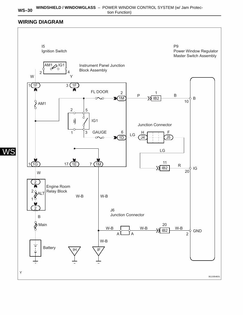
WIRING DIAGRAM
P9Power Window Regulator Master Switch Assembly
Instrument Panel Junction Block Assembly
P B12
2
2
2
2
5
1
1
1
1 3
4
3
IB2
IB2
IB2
10B
Junction Connector
LG
LG
H FJ4 J5
6GAUGE
IG1
FL DOOR
1D
1M
1M
2
IGR
11
20
20
1E
1F1F
1G 17 7
AM1
AM1 IG1
W Y
I5Ignition Switch
W-B
W-B W-B W-B
W-B
W-B
Engine Room Relay Block
AA
J6Junction Connector
IFIHBattery
B
Main
ALT
W
GND2
B113354E01
WINDSHIELD / WINDOWGLASS – POWER WINDOW CONTROL SYSTEM (w/ Jam Protec-tion Function) WS–31
S
WINSPECTION PROCEDURE
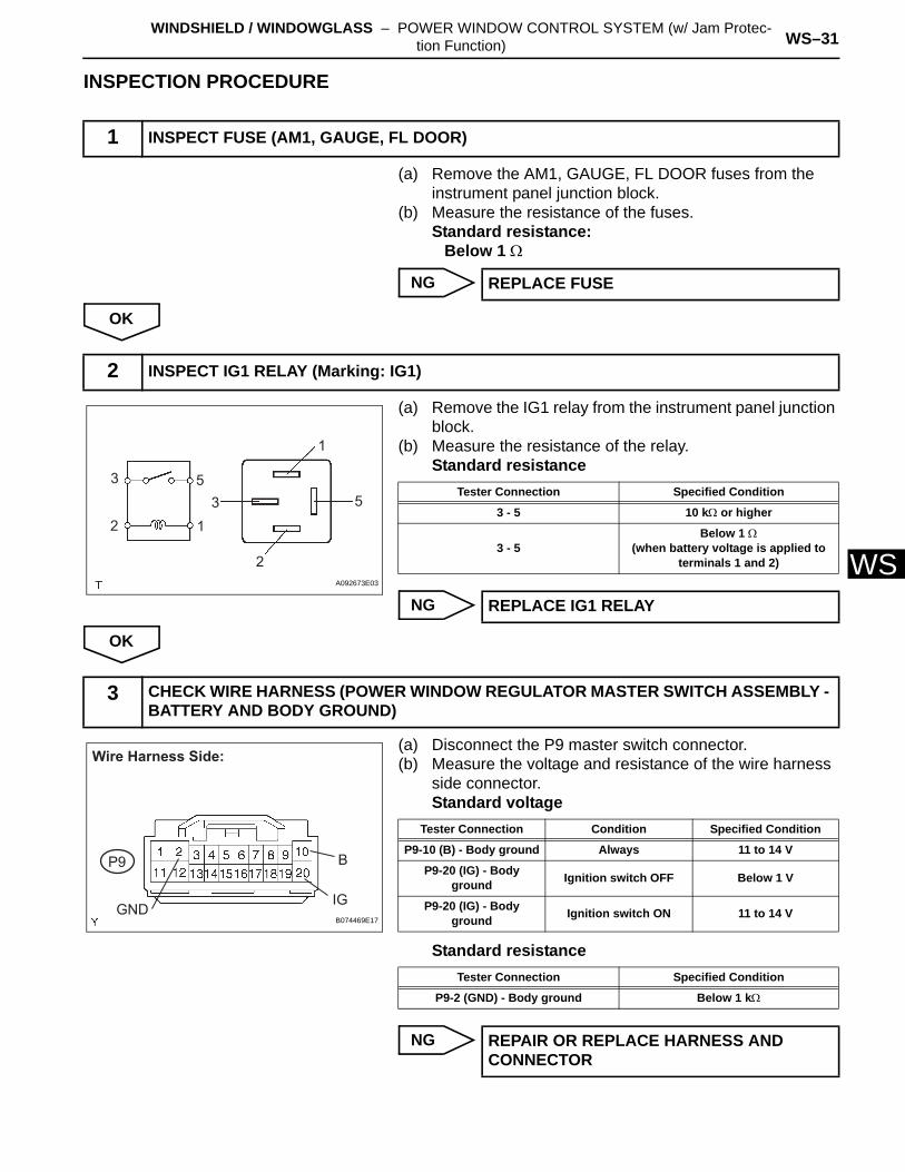
(a) Remove the AM1, GAUGE, FL DOOR fuses from the instrument panel junction block.
(b) Measure the resistance of the fuses.Standard resistance:
Below 1 Ω
NG
OK
(a) Remove the IG1 relay from the instrument panel junction block.
(b) Measure the resistance of the relay.Standard resistance
NG
OK
(a) Disconnect the P9 master switch connector.(b) Measure the voltage and resistance of the wire harness
side connector.Standard voltage
Standard resistance
NG
1 INSPECT FUSE (AM1, GAUGE, FL DOOR)
REPLACE FUSE
2 INSPECT IG1 RELAY (Marking: IG1)
3 5
123 5
1
2A092673E03
Tester Connection Specified Condition
3 - 5 10 kΩ or higher
3 - 5Below 1 Ω
(when battery voltage is applied to terminals 1 and 2)
REPLACE IG1 RELAY
3 CHECK WIRE HARNESS (POWER WINDOW REGULATOR MASTER SWITCH ASSEMBLY - BATTERY AND BODY GROUND)
Wire Harness Side:
P9
GND
B
IGB074469E17
Tester Connection Condition Specified Condition
P9-10 (B) - Body ground Always 11 to 14 V
P9-20 (IG) - Body ground Ignition switch OFF Below 1 V
P9-20 (IG) - Body ground Ignition switch ON 11 to 14 V
Tester Connection Specified Condition
P9-2 (GND) - Body ground Below 1 kΩ
REPAIR OR REPLACE HARNESS AND CONNECTOR
WS–32 WINDSHIELD / WINDOWGLASS – POWER WINDOW CONTROL SYSTEM (w/ Jam Protec-tion Function)
WS
OK
REPLACE POWER WINDOW REGULATOR MASTER SWITCH ASSEMBLY
WINDSHIELD / WINDOWGLASS – POWER WINDOW CONTROL SYSTEM (w/ Jam Protec-tion Function) WS–33
S
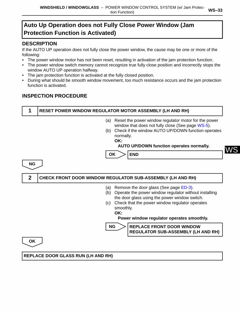
WDESCRIPTIONIf the AUTO UP operation does not fully close the power window, the cause may be one or more of the following:• The power window motor has not been reset, resulting in activation of the jam protection function.• The power window switch memory cannot recognize true fully close position and incorrectly stops the
window AUTO UP operation halfway.• The jam protection function is activated at the fully closed position.• During what should be smooth window movement, too much resistance occurs and the jam protection
function is activated.
INSPECTION PROCEDURE
(a) Reset the power window regulator motor for the power window that does not fully close (See page WS-5).
(b) Check if the window AUTO UP/DOWN function operates normally.OK:
AUTO UP/DOWN function operates normally.
OK
NG
(a) Remove the door glass (See page ED-3).(b) Operate the power window regulator without installing
the door glass using the power window switch.(c) Check that the power window regulator operates
smoothly.OK:
Power window regulator operates smoothly.
NG
OK
Auto Up Operation does not Fully Close Power Window (Jam Protection Function is Activated)
1 RESET POWER WINDOW REGULATOR MOTOR ASSEMBLY (LH AND RH)
END
2 CHECK FRONT DOOR WINDOW REGULATOR SUB-ASSEMBLY (LH AND RH)
REPLACE FRONT DOOR WINDOW REGULATOR SUB-ASSEMBLY (LH AND RH)
REPLACE DOOR GLASS RUN (LH AND RH)
WS–34 WINDSHIELD / WINDOWGLASS – POWER WINDOW CONTROL SYSTEM (w/ Jam Protec-tion Function)
WS
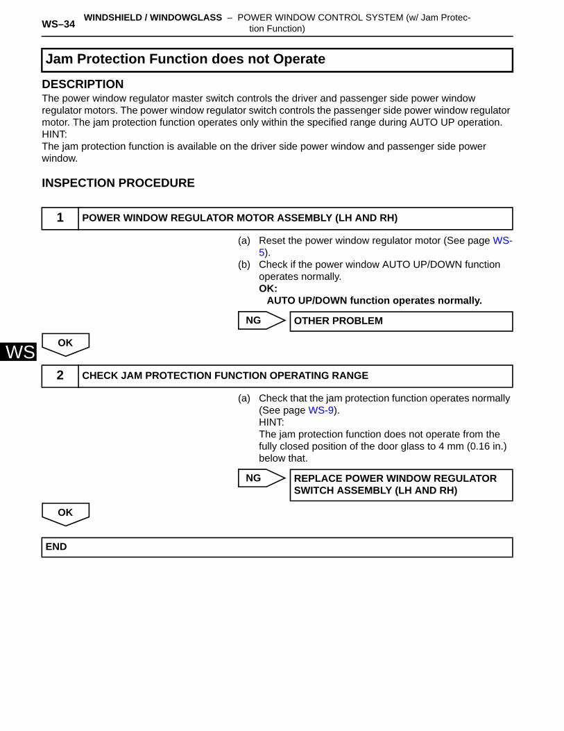
DESCRIPTIONThe power window regulator master switch controls the driver and passenger side power window regulator motors. The power window regulator switch controls the passenger side power window regulator motor. The jam protection function operates only within the specified range during AUTO UP operation.HINT:The jam protection function is available on the driver side power window and passenger side power window.
INSPECTION PROCEDURE
(a) Reset the power window regulator motor (See page WS-5).
(b) Check if the power window AUTO UP/DOWN function operates normally.OK:
AUTO UP/DOWN function operates normally.
NG
OK
(a) Check that the jam protection function operates normally (See page WS-9).HINT:The jam protection function does not operate from the fully closed position of the door glass to 4 mm (0.16 in.) below that.
NG
OK
Jam Protection Function does not Operate
1 POWER WINDOW REGULATOR MOTOR ASSEMBLY (LH AND RH)
OTHER PROBLEM
2 CHECK JAM PROTECTION FUNCTION OPERATING RANGE
REPLACE POWER WINDOW REGULATOR SWITCH ASSEMBLY (LH AND RH)
END

WINDSHIELD / WINDOWGLASS – POWER WINDOW CONTROL SYSTEM (w/o Jam Pro-tection Function) WS–33
S
WPOWER WINDOW CONTROL SYSTEM (w/o Jam Protection Function)PRECAUTIONNOTICE:When disconnecting the cable from the negative (-) battery terminal, initialize the following system after the cable is reconnected.
System Name See procedure
Power Window Control System IN-23
SFI System IN-23
WS–34 WINDSHIELD / WINDOWGLASS – POWER WINDOW CONTROL SYSTEM (w/o Jam Pro-tection Function)
WS
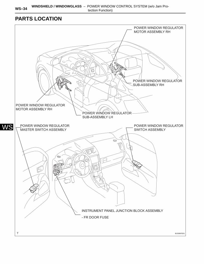
PARTS LOCATIONPOWER WINDOW REGULATOR MOTOR ASSEMBLY RH
POWER WINDOW REGULATOR MOTOR ASSEMBLY RH
POWER WINDOW REGULATOR MASTER SWITCH ASSEMBLY
POWER WINDOW REGULATOR SWITCH ASSEMBLY
INSTRUMENT PANEL JUNCTION BLOCK ASSEMBLY
- FR DOOR FUSE
POWER WINDOW REGULATOR SUB-ASSEMBLY RH
POWER WINDOW REGULATOR SUB-ASSEMBLY LH
B153697E01
WINDSHIELD / WINDOWGLASS – POWER WINDOW CONTROL SYSTEM (w/o Jam Pro-tection Function) WS–35
S
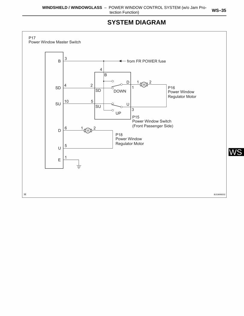
WSYSTEM DIAGRAM
B
SD
SU
SD
SU
DOWN
UP
D
U
E
3
4
10
2
4B
5
6
5
1
1
21
3
D
U
2
1
Power Window Master Switch
from FR POWER fuse
P17
Power Window Regulator Motor
P16
Power Window Regulator Motor
P18
Power Window Switch (Front Passenger Side)
P15
B153695E02
WS–36 WINDSHIELD / WINDOWGLASS – POWER WINDOW CONTROL SYSTEM (w/o Jam Pro-tection Function)
WS
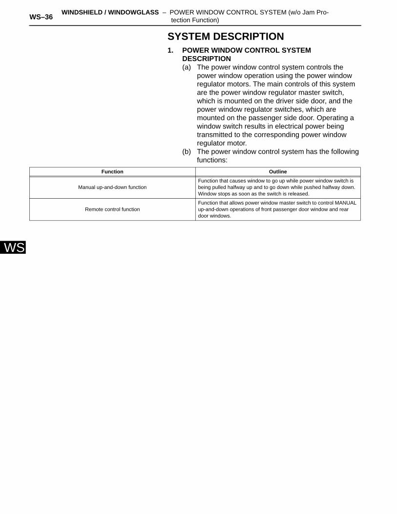
SYSTEM DESCRIPTION1. POWER WINDOW CONTROL SYSTEM
DESCRIPTION(a) The power window control system controls the
power window operation using the power window regulator motors. The main controls of this system are the power window regulator master switch, which is mounted on the driver side door, and the power window regulator switches, which are mounted on the passenger side door. Operating a window switch results in electrical power being transmitted to the corresponding power window regulator motor.
(b) The power window control system has the following functions:
Function Outline
Manual up-and-down functionFunction that causes window to go up while power window switch is being pulled halfway up and to go down while pushed halfway down. Window stops as soon as the switch is released.
Remote control functionFunction that allows power window master switch to control MANUAL up-and-down operations of front passenger door window and rear door windows.
WINDSHIELD / WINDOWGLASS – POWER WINDOW CONTROL SYSTEM (w/o Jam Pro-tection Function) WS–37
S
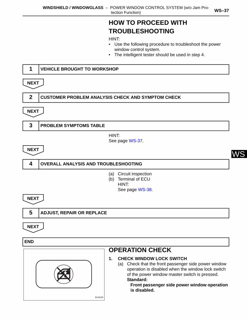
WHOW TO PROCEED WITH TROUBLESHOOTINGHINT:• Use the following procedure to troubleshoot the power
window control system.• The intelligent tester should be used in step 4.
NEXT
NEXT
HINT:See page WS-37.
NEXT
(a) Circuit inspection(b) Terminal of ECU
HINT:See page WS-38.
NEXT
NEXT
OPERATION CHECK1. CHECK WINDOW LOCK SWITCH
(a) Check that the front passenger side power window operation is disabled when the window lock switch of the power window master switch is pressed.Standard:
Front passenger side power window operation is disabled.
1 VEHICLE BROUGHT TO WORKSHOP
2 CUSTOMER PROBLEM ANALYSIS CHECK AND SYMPTOM CHECK
3 PROBLEM SYMPTOMS TABLE
4 OVERALL ANALYSIS AND TROUBLESHOOTING
5 ADJUST, REPAIR OR REPLACE
END
B140183
WS–38 WINDSHIELD / WINDOWGLASS – POWER WINDOW CONTROL SYSTEM (w/o Jam Pro-tection Function)
WS
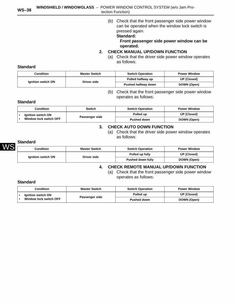
(b) Check that the front passenger side power window can be operated when the window lock switch is pressed again.Standard:
Front passenger side power window can be operated.
2. CHECK MANUAL UP/DOWN FUNCTION(a) Check that the driver side power window operates
as follows:Standard
(b) Check that the front passenger side power window operates as follows:
Standard
3. CHECK AUTO DOWN FUNCTION(a) Check that the driver side power window operates
as follows:Standard
4. CHECK REMOTE MANUAL UP/DOWN FUNCTION(a) Check that the front passenger side power window
operates as follows:Standard
Condition Master Switch Switch Operation Power Window
Ignition switch ON Driver sidePulled halfway up UP (Closed)
Pushed halfway down DOWN (Open)
Condition Switch Switch Operation Power Window
• Ignition switch ON• Window lock switch OFF Passenger side
Pulled up UP (Closed)
Pushed down DOWN (Open)
Condition Master Switch Switch Operation Power Window
Ignition switch ON Driver sidePulled up fully UP (Closed)
Pushed down fully DOWN (Open)
Condition Master Switch Switch Operation Power Window
• Ignition switch ON• Window lock switch OFF Passenger side
Pulled up UP (Closed)
Pushed down DOWN (Open)
WINDSHIELD / WINDOWGLASS – POWER WINDOW CONTROL SYSTEM (w/o Jam Pro-tection Function) WS–39
S
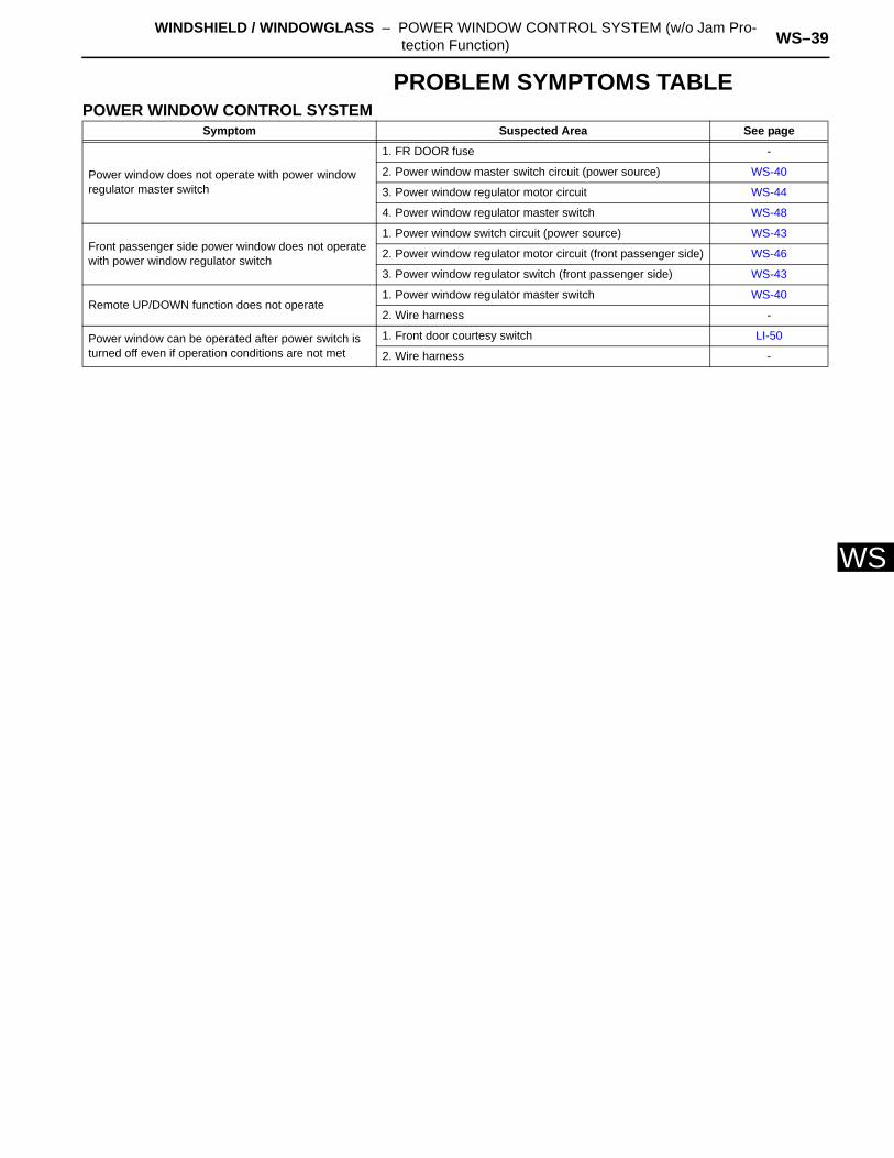
WPROBLEM SYMPTOMS TABLEPOWER WINDOW CONTROL SYSTEM
Symptom Suspected Area See page
Power window does not operate with power window regulator master switch
1. FR DOOR fuse -
2. Power window master switch circuit (power source) WS-40
3. Power window regulator motor circuit WS-44
4. Power window regulator master switch WS-48
Front passenger side power window does not operate with power window regulator switch
1. Power window switch circuit (power source) WS-43
2. Power window regulator motor circuit (front passenger side) WS-46
3. Power window regulator switch (front passenger side) WS-43
Remote UP/DOWN function does not operate1. Power window regulator master switch WS-40
2. Wire harness -
Power window can be operated after power switch is turned off even if operation conditions are not met
1. Front door courtesy switch LI-50
2. Wire harness -
WS–40 WINDSHIELD / WINDOWGLASS – POWER WINDOW CONTROL SYSTEM (w/o Jam Pro-tection Function)
WS
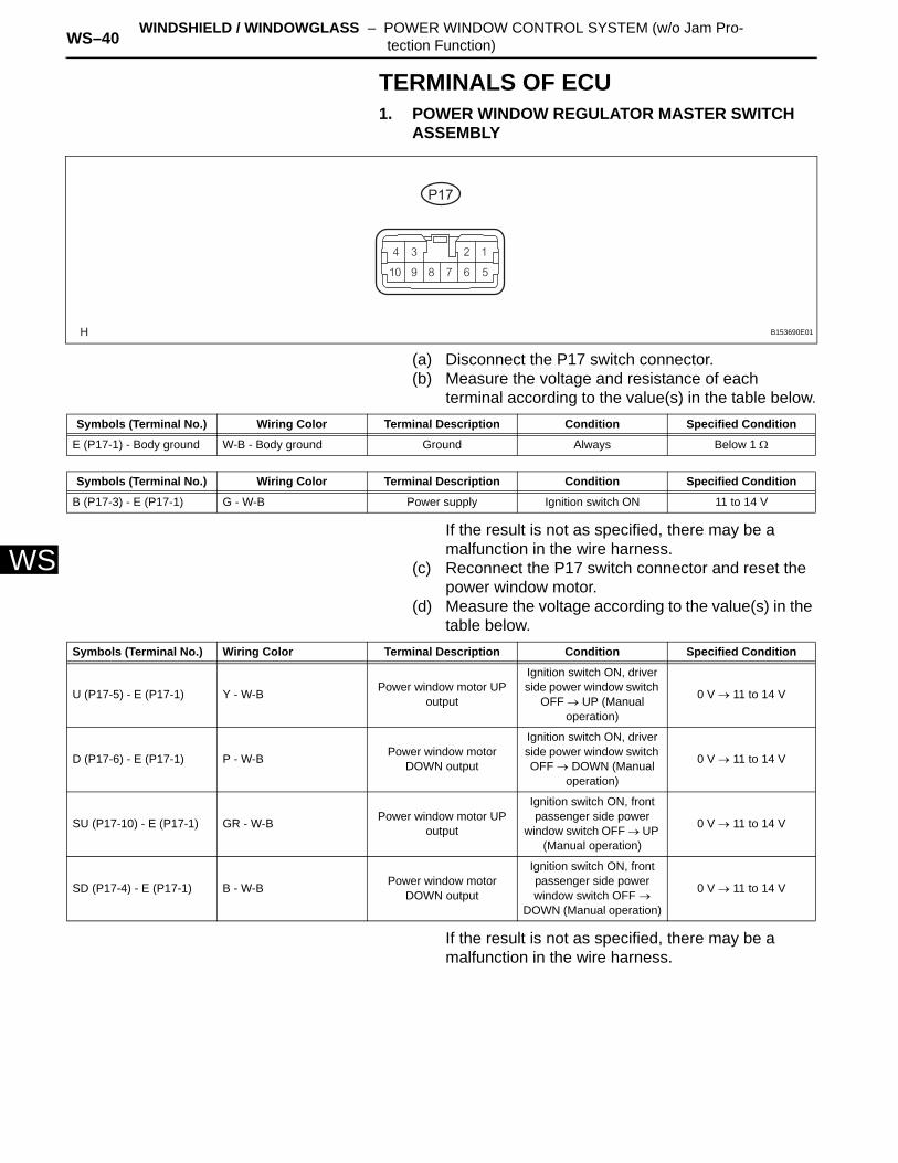
TERMINALS OF ECU1. POWER WINDOW REGULATOR MASTER SWITCH
ASSEMBLY
(a) Disconnect the P17 switch connector.(b) Measure the voltage and resistance of each
terminal according to the value(s) in the table below.
If the result is not as specified, there may be a malfunction in the wire harness.
(c) Reconnect the P17 switch connector and reset the power window motor.
(d) Measure the voltage according to the value(s) in the table below.
If the result is not as specified, there may be a malfunction in the wire harness.
P17
B153690E01
Symbols (Terminal No.) Wiring Color Terminal Description Condition Specified Condition
E (P17-1) - Body ground W-B - Body ground Ground Always Below 1 Ω
Symbols (Terminal No.) Wiring Color Terminal Description Condition Specified Condition
B (P17-3) - E (P17-1) G - W-B Power supply Ignition switch ON 11 to 14 V
Symbols (Terminal No.) Wiring Color Terminal Description Condition Specified Condition
U (P17-5) - E (P17-1) Y - W-B Power window motor UP output
Ignition switch ON, driver side power window switch
OFF → UP (Manual operation)
0 V → 11 to 14 V
D (P17-6) - E (P17-1) P - W-B Power window motor DOWN output
Ignition switch ON, driver side power window switch OFF → DOWN (Manual
operation)
0 V → 11 to 14 V
SU (P17-10) - E (P17-1) GR - W-B Power window motor UP output
Ignition switch ON, front passenger side power
window switch OFF → UP (Manual operation)
0 V → 11 to 14 V
SD (P17-4) - E (P17-1) B - W-B Power window motor DOWN output
Ignition switch ON, front passenger side power window switch OFF →
DOWN (Manual operation)
0 V → 11 to 14 V
WINDSHIELD / WINDOWGLASS – POWER WINDOW CONTROL SYSTEM (w/o Jam Pro-tection Function) WS–41
S
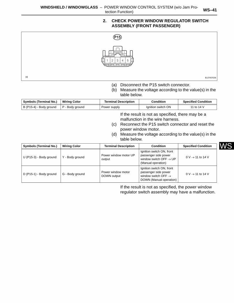
W2. CHECK POWER WINDOW REGULATOR SWITCH ASSEMBLY (FRONT PASSENGER)
(a) Disconnect the P15 switch connector.(b) Measure the voltage according to the value(s) in the
table below.
If the result is not as specified, there may be a malfunction in the wire harness.
(c) Reconnect the P15 switch connector and reset the power window motor.
(d) Measure the voltage according to the value(s) in the table below.
If the result is not as specified, the power window regulator switch assembly may have a malfunction.
P15
B137057E06
Symbols (Terminal No.) Wiring Color Terminal Description Condition Specified Condition
B (P15-4) - Body ground P - Body ground Power supply Ignition switch ON 11 to 14 V
Symbols (Terminal No.) Wiring Color Terminal Description Condition Specified Condition
U (P15-3) - Body ground Y - Body ground Power window motor UP output
Ignition switch ON, front passenger side power window switch OFF → UP (Manual operation)
0 V → 11 to 14 V
D (P15-1) - Body ground G - Body ground Power window motor DOWN output
Ignition switch ON, front passenger side power window switch OFF → DOWN (Manual operation)
0 V → 11 to 14 V
WS–42 WINDSHIELD / WINDOWGLASS – POWER WINDOW CONTROL SYSTEM (w/o Jam Pro-tection Function)
WS
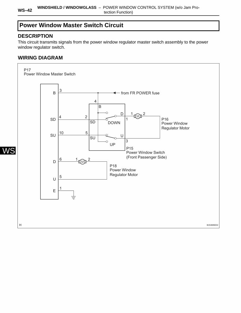
DESCRIPTIONThis circuit transmits signals from the power window regulator master switch assembly to the power window regulator switch.
WIRING DIAGRAM
Power Window Master Switch Circuit
B
SD
SU
SD
SU
DOWN
UP
D
U
E
3
4
10
2
4B
5
6
5
1
1
21
3
D
U
2
1
Power Window Master Switch
from FR POWER fuse
P17
Power Window Regulator Motor
P16
Power Window Regulator Motor
P18
Power Window Switch (Front Passenger Side)
P15
B153695E02
WINDSHIELD / WINDOWGLASS – POWER WINDOW CONTROL SYSTEM (w/o Jam Pro-tection Function) WS–43
S
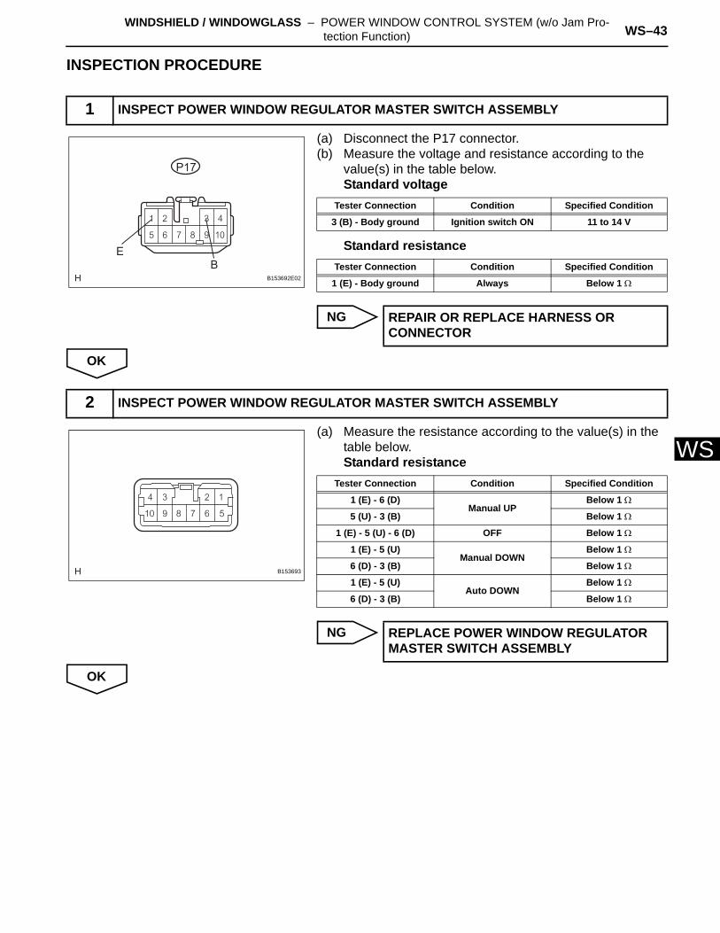
WINSPECTION PROCEDURE
(a) Disconnect the P17 connector.(b) Measure the voltage and resistance according to the
value(s) in the table below.Standard voltage
Standard resistance
NG
OK
(a) Measure the resistance according to the value(s) in the table below.Standard resistance
NG
OK
1 INSPECT POWER WINDOW REGULATOR MASTER SWITCH ASSEMBLY
P17
EB
B153692E02
Tester Connection Condition Specified Condition
3 (B) - Body ground Ignition switch ON 11 to 14 V
Tester Connection Condition Specified Condition
1 (E) - Body ground Always Below 1 Ω
REPAIR OR REPLACE HARNESS OR CONNECTOR
2 INSPECT POWER WINDOW REGULATOR MASTER SWITCH ASSEMBLY
B153693
Tester Connection Condition Specified Condition
1 (E) - 6 (D)Manual UP
Below 1 Ω
5 (U) - 3 (B) Below 1 Ω
1 (E) - 5 (U) - 6 (D) OFF Below 1 Ω
1 (E) - 5 (U)Manual DOWN
Below 1 Ω
6 (D) - 3 (B) Below 1 Ω
1 (E) - 5 (U)Auto DOWN
Below 1 Ω
6 (D) - 3 (B) Below 1 Ω
REPLACE POWER WINDOW REGULATOR MASTER SWITCH ASSEMBLY
WS–44 WINDSHIELD / WINDOWGLASS – POWER WINDOW CONTROL SYSTEM (w/o Jam Pro-tection Function)
WS
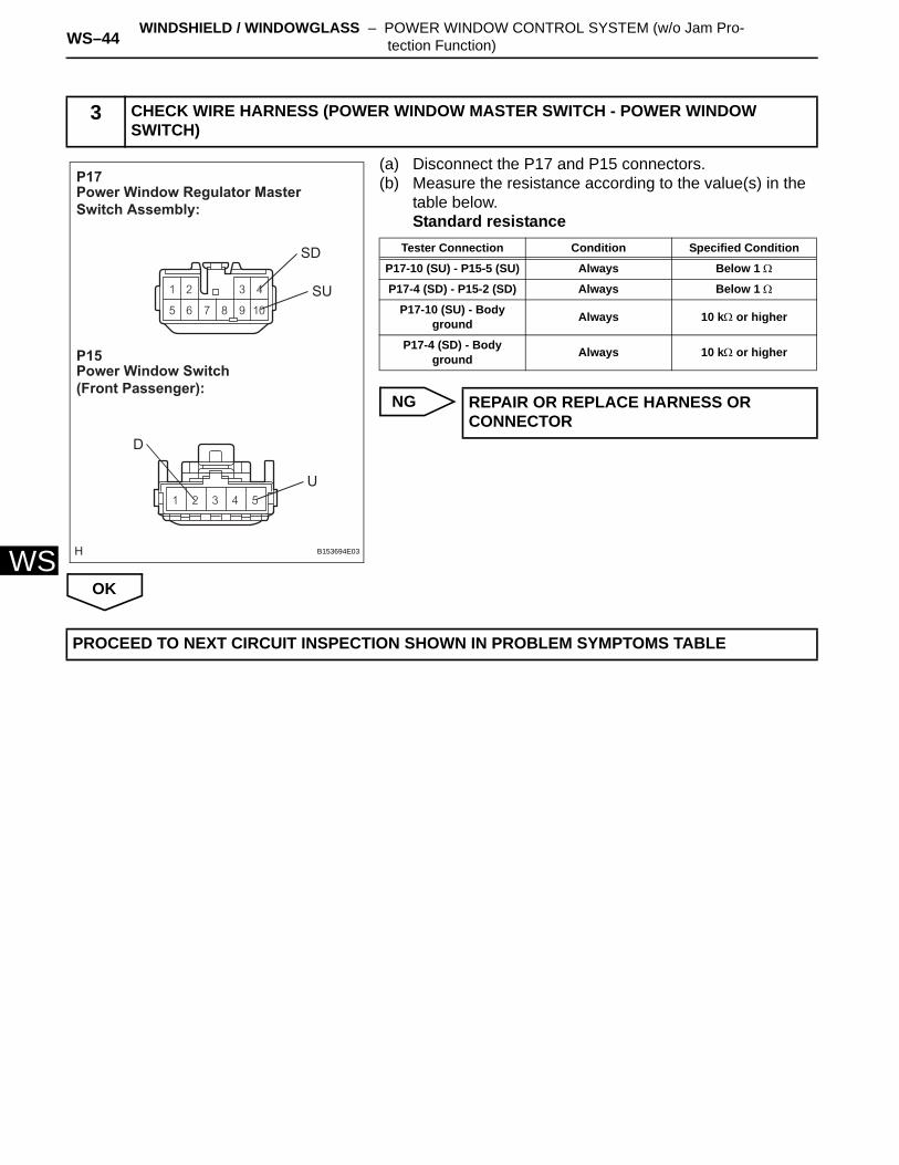
(a) Disconnect the P17 and P15 connectors.(b) Measure the resistance according to the value(s) in the
table below.Standard resistance
NG
OK
3 CHECK WIRE HARNESS (POWER WINDOW MASTER SWITCH - POWER WINDOW SWITCH)
Power Window Regulator Master Switch Assembly:
P17
Power Window Switch (Front Passenger):
P15
SU
SD
U
D
B153694E03
Tester Connection Condition Specified Condition
P17-10 (SU) - P15-5 (SU) Always Below 1 Ω
P17-4 (SD) - P15-2 (SD) Always Below 1 Ω
P17-10 (SU) - Body ground Always 10 kΩ or higher
P17-4 (SD) - Body ground Always 10 kΩ or higher
REPAIR OR REPLACE HARNESS OR CONNECTOR
PROCEED TO NEXT CIRCUIT INSPECTION SHOWN IN PROBLEM SYMPTOMS TABLE
WINDSHIELD / WINDOWGLASS – POWER WINDOW CONTROL SYSTEM (w/o Jam Pro-tection Function) WS–45
S
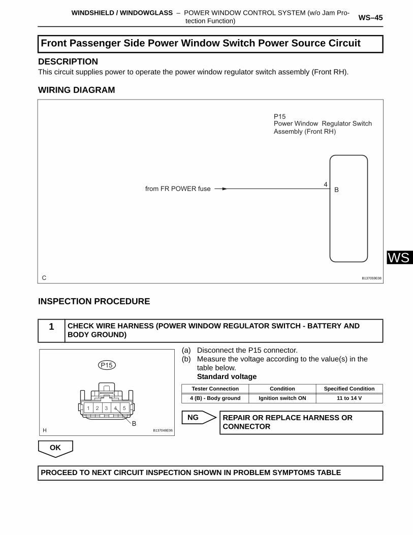
WDESCRIPTIONThis circuit supplies power to operate the power window regulator switch assembly (Front RH).
WIRING DIAGRAM
INSPECTION PROCEDURE
(a) Disconnect the P15 connector.(b) Measure the voltage according to the value(s) in the
table below.Standard voltage
NG
OK
Front Passenger Side Power Window Switch Power Source Circuit
1 CHECK WIRE HARNESS (POWER WINDOW REGULATOR SWITCH - BATTERY AND BODY GROUND)
C
P15
B4from FR POWER fuse
Power Window Regulator Switch Assembly (Front RH)
B137059E08
P15
BB137048E06
Tester Connection Condition Specified Condition
4 (B) - Body ground Ignition switch ON 11 to 14 V
REPAIR OR REPLACE HARNESS OR CONNECTOR
PROCEED TO NEXT CIRCUIT INSPECTION SHOWN IN PROBLEM SYMPTOMS TABLE
WS–46 WINDSHIELD / WINDOWGLASS – POWER WINDOW CONTROL SYSTEM (w/o Jam Pro-tection Function)
WS
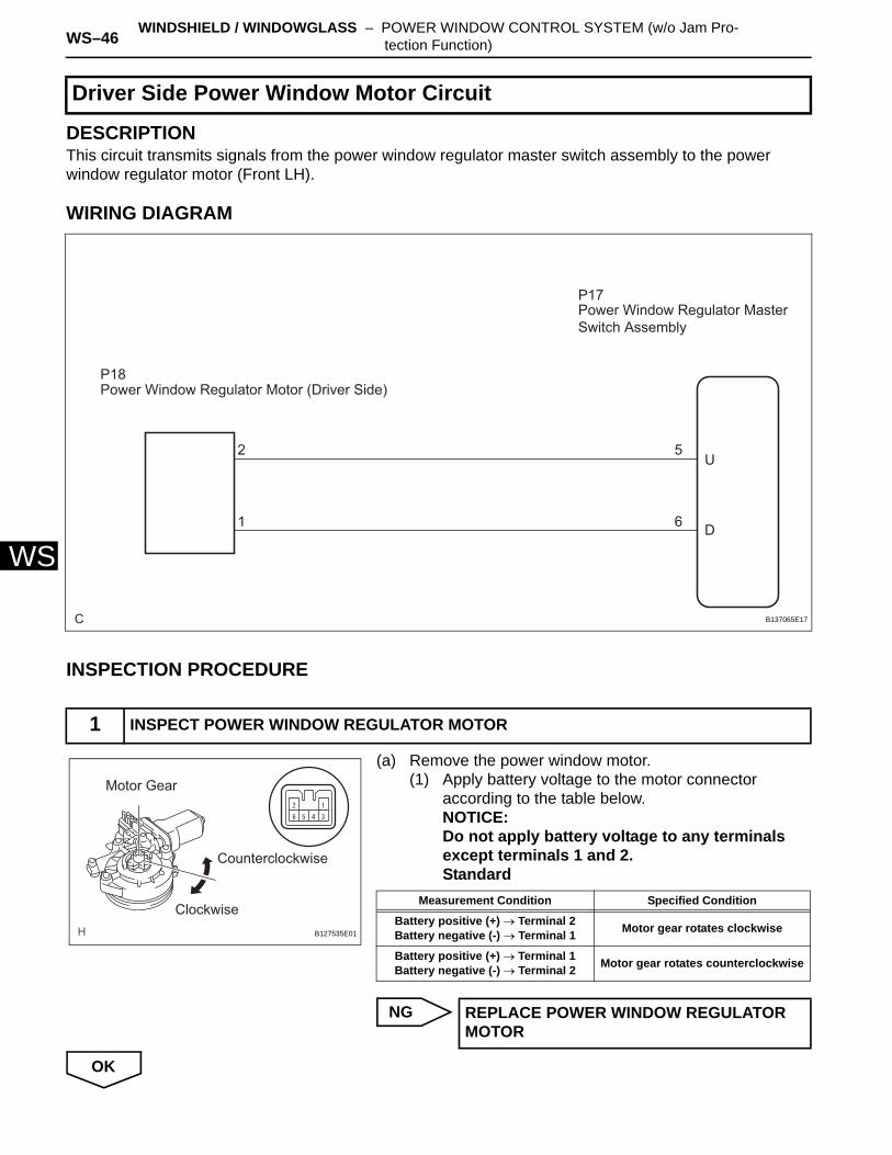
DESCRIPTIONThis circuit transmits signals from the power window regulator master switch assembly to the power window regulator motor (Front LH).
WIRING DIAGRAM
INSPECTION PROCEDURE
(a) Remove the power window motor.(1) Apply battery voltage to the motor connector
according to the table below.NOTICE:Do not apply battery voltage to any terminals except terminals 1 and 2.Standard
NG
OK
Driver Side Power Window Motor Circuit
1 INSPECT POWER WINDOW REGULATOR MOTOR
C
P17
U
D
5
6
2
1
P18Power Window Regulator Motor (Driver Side)
Power Window Regulator Master Switch Assembly
B137065E17
Motor Gear
Counterclockwise
ClockwiseB127535E01
Measurement Condition Specified Condition
Battery positive (+) → Terminal 2Battery negative (-) → Terminal 1 Motor gear rotates clockwise
Battery positive (+) → Terminal 1Battery negative (-) → Terminal 2 Motor gear rotates counterclockwise
REPLACE POWER WINDOW REGULATOR MOTOR
WINDSHIELD / WINDOWGLASS – POWER WINDOW CONTROL SYSTEM (w/o Jam Pro-tection Function) WS–47
S
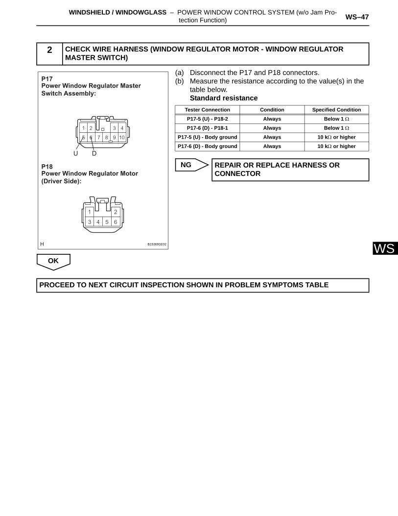
W(a) Disconnect the P17 and P18 connectors.(b) Measure the resistance according to the value(s) in the
table below.Standard resistance
NG
OK
2 CHECK WIRE HARNESS (WINDOW REGULATOR MOTOR - WINDOW REGULATOR MASTER SWITCH)
Power Window Regulator Master Switch Assembly:
P17
Power Window Regulator Motor (Driver Side):
P18
U D
B153691E02
Tester Connection Condition Specified Condition
P17-5 (U) - P18-2 Always Below 1 Ω
P17-6 (D) - P18-1 Always Below 1 Ω
P17-5 (U) - Body ground Always 10 kΩ or higher
P17-6 (D) - Body ground Always 10 kΩ or higher
REPAIR OR REPLACE HARNESS OR CONNECTOR
PROCEED TO NEXT CIRCUIT INSPECTION SHOWN IN PROBLEM SYMPTOMS TABLE
WS–48 WINDSHIELD / WINDOWGLASS – POWER WINDOW CONTROL SYSTEM (w/o Jam Pro-tection Function)
WS
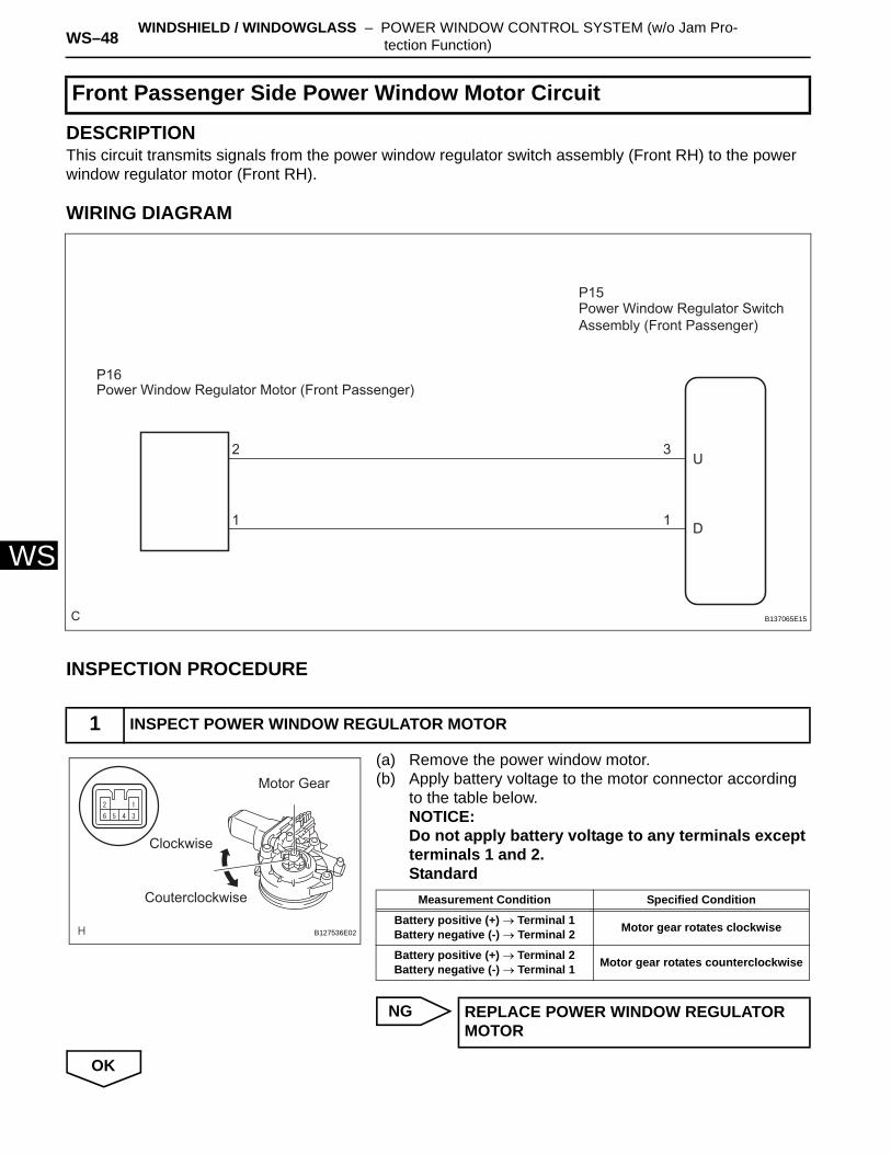
DESCRIPTIONThis circuit transmits signals from the power window regulator switch assembly (Front RH) to the power window regulator motor (Front RH).
WIRING DIAGRAM
INSPECTION PROCEDURE
(a) Remove the power window motor.(b) Apply battery voltage to the motor connector according
to the table below.NOTICE:Do not apply battery voltage to any terminals except terminals 1 and 2.Standard
NG
OK
Front Passenger Side Power Window Motor Circuit
1 INSPECT POWER WINDOW REGULATOR MOTOR
C
P15
U
D
3
1
2
1
Power Window Regulator Switch Assembly (Front Passenger)
P16Power Window Regulator Motor (Front Passenger)
B137065E15
Motor Gear
Couterclockwise
Clockwise
B127536E02
Measurement Condition Specified Condition
Battery positive (+) → Terminal 1Battery negative (-) → Terminal 2 Motor gear rotates clockwise
Battery positive (+) → Terminal 2Battery negative (-) → Terminal 1 Motor gear rotates counterclockwise
REPLACE POWER WINDOW REGULATOR MOTOR
WINDSHIELD / WINDOWGLASS – POWER WINDOW CONTROL SYSTEM (w/o Jam Pro-tection Function) WS–49
S
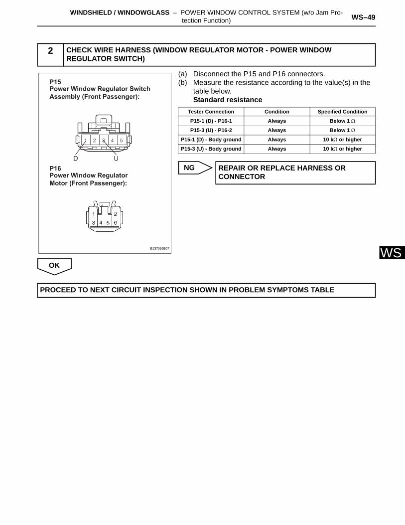
W(a) Disconnect the P15 and P16 connectors.(b) Measure the resistance according to the value(s) in the
table below.Standard resistance
NG
OK
2 CHECK WIRE HARNESS (WINDOW REGULATOR MOTOR - POWER WINDOW REGULATOR SWITCH)
Power Window Regulator Switch Assembly (Front Passenger):
P15
Power Window Regulator Motor (Front Passenger):
P16D U
B137066E07
Tester Connection Condition Specified Condition
P15-1 (D) - P16-1 Always Below 1 Ω
P15-3 (U) - P16-2 Always Below 1 Ω
P15-1 (D) - Body ground Always 10 kΩ or higher
P15-3 (U) - Body ground Always 10 kΩ or higher
REPAIR OR REPLACE HARNESS OR CONNECTOR
PROCEED TO NEXT CIRCUIT INSPECTION SHOWN IN PROBLEM SYMPTOMS TABLE
WS–48 WINDSHIELD / WINDOWGLASS – POWER WINDOW MASTER SWITCH
WS
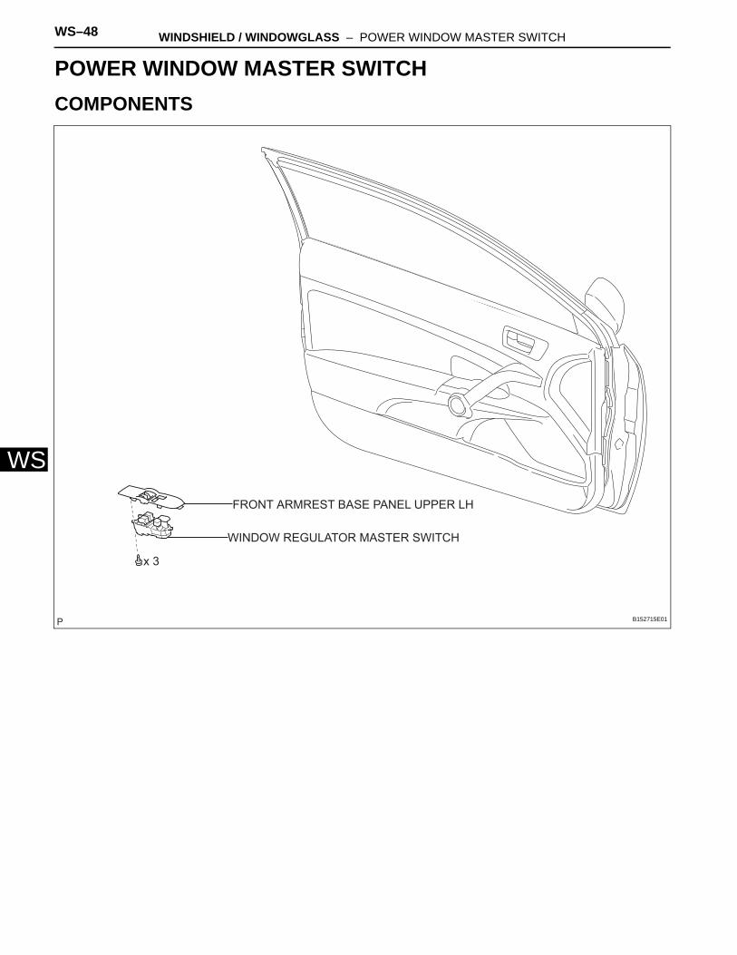
BODYWINDSHIELD / WINDOWGLASSPOWER WINDOW MASTER SWITCHCOMPONENTS
WINDOW REGULATOR MASTER SWITCH
x 3
FRONT ARMREST BASE PANEL UPPER LH
B152715E01
WINDSHIELD / WINDOWGLASS – POWER WINDOW MASTER SWITCH WS–49
S
WREMOVAL1. REMOVE FRONT ARMREST BASE PANEL UPPER
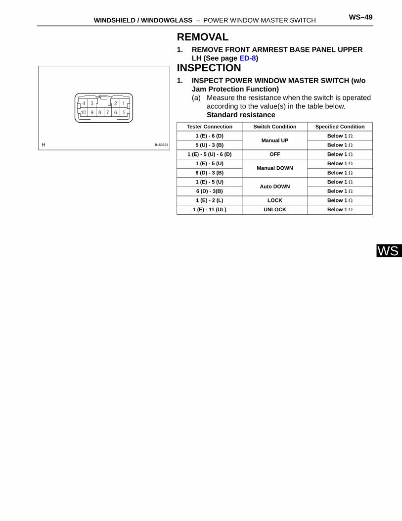
LH (See page ED-8)INSPECTION1. INSPECT POWER WINDOW MASTER SWITCH (w/o
Jam Protection Function)(a) Measure the resistance when the switch is operated
according to the value(s) in the table below.Standard resistance
B153693
Tester Connection Switch Condition Specified Condition
1 (E) - 6 (D)Manual UP
Below 1 Ω
5 (U) - 3 (B) Below 1 Ω
1 (E) - 5 (U) - 6 (D) OFF Below 1 Ω
1 (E) - 5 (U)Manual DOWN
Below 1 Ω
6 (D) - 3 (B) Below 1 Ω
1 (E) - 5 (U)Auto DOWN
Below 1 Ω
6 (D) - 3(B) Below 1 Ω
1 (E) - 2 (L) LOCK Below 1 Ω
1 (E) - 11 (UL) UNLOCK Below 1 Ω
WS–50 WINDSHIELD / WINDOWGLASS – POWER WINDOW MASTER SWITCH
WS
INSTALLATION1. INSTALL FRONT ARMREST BASE PANEL UPPER LH
(See page ED-20)
WS–50 WINDSHIELD / WINDOWGLASS – FRONT PASSENGER SIDE POWER WINDOW SWITCH
WS
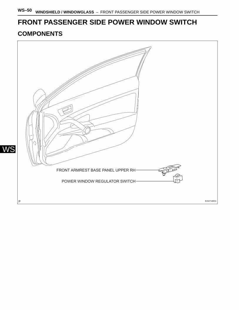
BODYWINDSHIELD / WINDOWGLASSFRONT PASSENGER SIDE POWER WINDOW SWITCHCOMPONENTS
FRONT ARMREST BASE PANEL UPPER RH
POWER WINDOW REGULATOR SWITCH
B152716E01
WINDSHIELD / WINDOWGLASS – FRONT PASSENGER SIDE POWER WINDOW SWITCH WS–51
S
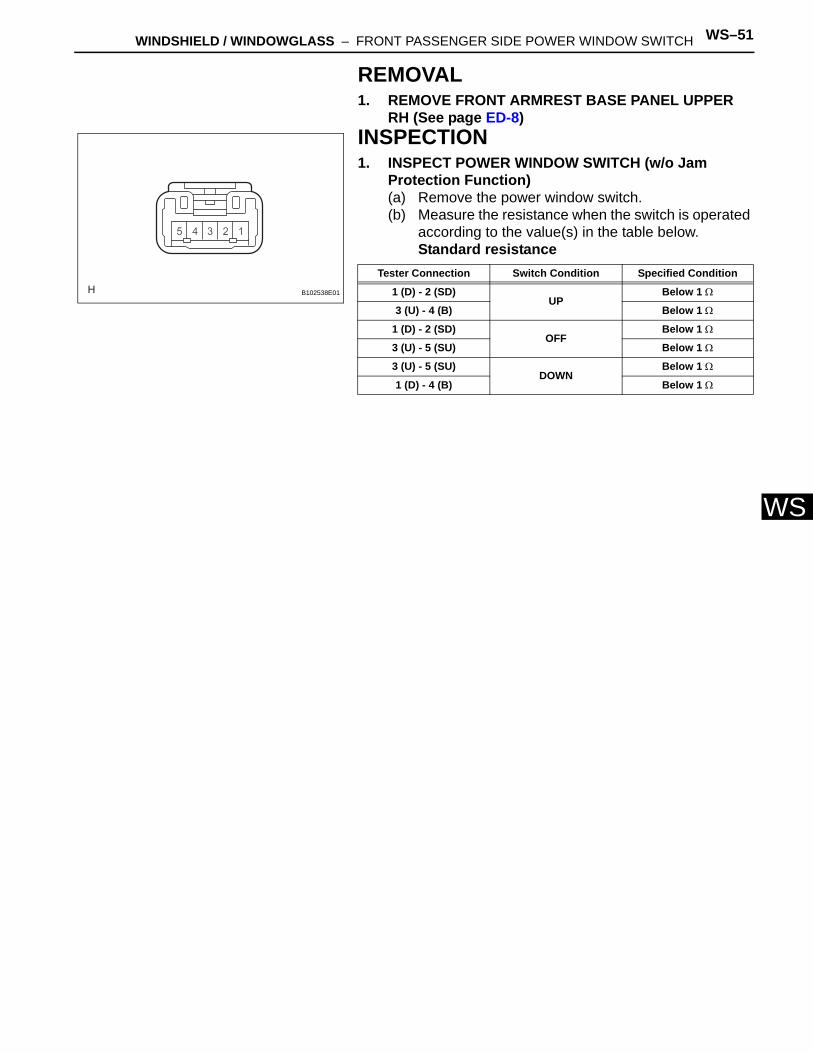
WREMOVAL1. REMOVE FRONT ARMREST BASE PANEL UPPER
RH (See page ED-8)INSPECTION1. INSPECT POWER WINDOW SWITCH (w/o Jam
Protection Function)(a) Remove the power window switch.(b) Measure the resistance when the switch is operated
according to the value(s) in the table below.Standard resistance
B102538E01
Tester Connection Switch Condition Specified Condition
1 (D) - 2 (SD)UP
Below 1 Ω
3 (U) - 4 (B) Below 1 Ω
1 (D) - 2 (SD)OFF
Below 1 Ω
3 (U) - 5 (SU) Below 1 Ω
3 (U) - 5 (SU)DOWN
Below 1 Ω
1 (D) - 4 (B) Below 1 Ω
WS–52 WINDSHIELD / WINDOWGLASS – FRONT PASSENGER SIDE POWER WINDOW SWITCH
WS
INSTALLATION1. INSTALL FRONT ARMREST BASE PANEL UPPER RH
(See page ED-20)
WS–52 WINDSHIELD / WINDOWGLASS – POWER WINDOW REGULATOR MOTOR
WS
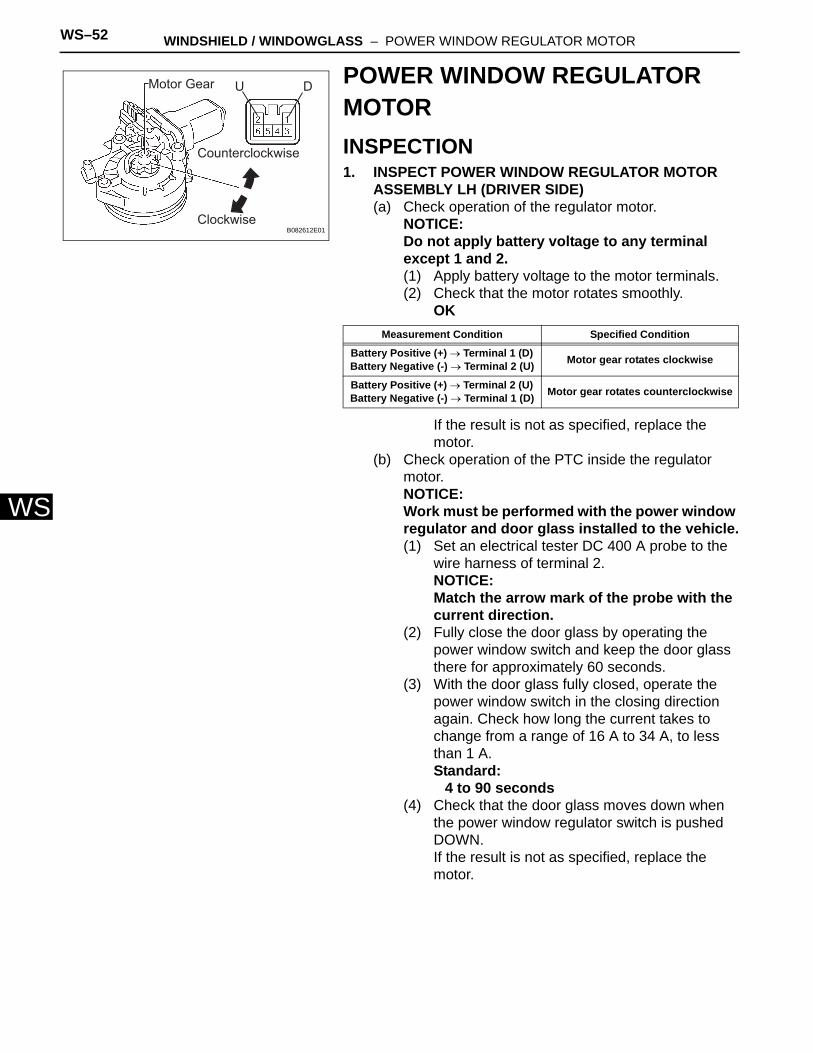
POWER WINDOW REGULATOR MOTORINSPECTION1. INSPECT POWER WINDOW REGULATOR MOTOR
ASSEMBLY LH (DRIVER SIDE)(a) Check operation of the regulator motor.
NOTICE:Do not apply battery voltage to any terminal except 1 and 2.(1) Apply battery voltage to the motor terminals.(2) Check that the motor rotates smoothly.
OK
If the result is not as specified, replace the motor.
(b) Check operation of the PTC inside the regulator motor.NOTICE:Work must be performed with the power window regulator and door glass installed to the vehicle.(1) Set an electrical tester DC 400 A probe to the
wire harness of terminal 2.NOTICE:Match the arrow mark of the probe with the current direction.
(2) Fully close the door glass by operating the power window switch and keep the door glass there for approximately 60 seconds.
(3) With the door glass fully closed, operate the power window switch in the closing direction again. Check how long the current takes to change from a range of 16 A to 34 A, to less than 1 A.Standard:
4 to 90 seconds(4) Check that the door glass moves down when
the power window regulator switch is pushed DOWN.If the result is not as specified, replace the motor.
Motor Gear
Counterclockwise
Clockwise
U D
B082612E01
Measurement Condition Specified Condition
Battery Positive (+) → Terminal 1 (D) Battery Negative (-) → Terminal 2 (U) Motor gear rotates clockwise
Battery Positive (+) → Terminal 2 (U) Battery Negative (-) → Terminal 1 (D) Motor gear rotates counterclockwise
WINDSHIELD / WINDOWGLASS – POWER WINDOW REGULATOR MOTOR WS–53
S
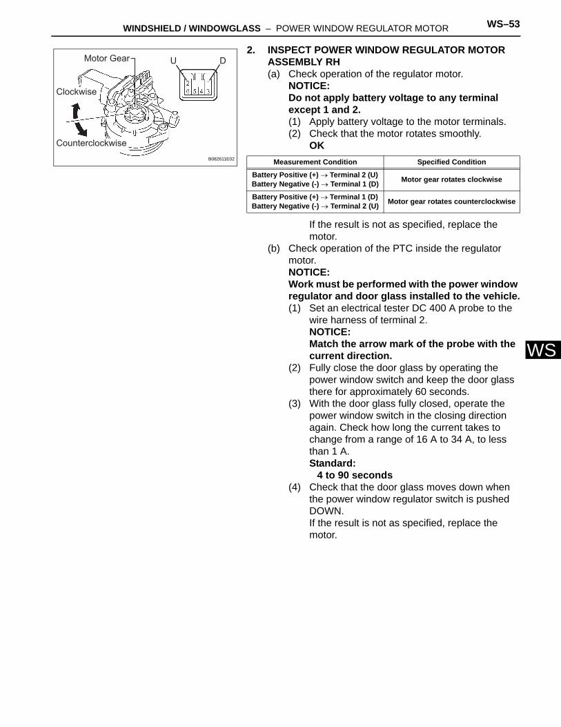
W2. INSPECT POWER WINDOW REGULATOR MOTOR ASSEMBLY RH(a) Check operation of the regulator motor.
NOTICE:Do not apply battery voltage to any terminal except 1 and 2.(1) Apply battery voltage to the motor terminals.(2) Check that the motor rotates smoothly.
OK
If the result is not as specified, replace the motor.
(b) Check operation of the PTC inside the regulator motor.NOTICE:Work must be performed with the power window regulator and door glass installed to the vehicle.(1) Set an electrical tester DC 400 A probe to the
wire harness of terminal 2.NOTICE:Match the arrow mark of the probe with the current direction.
(2) Fully close the door glass by operating the power window switch and keep the door glass there for approximately 60 seconds.
(3) With the door glass fully closed, operate the power window switch in the closing direction again. Check how long the current takes to change from a range of 16 A to 34 A, to less than 1 A.Standard:
4 to 90 seconds(4) Check that the door glass moves down when
the power window regulator switch is pushed DOWN.If the result is not as specified, replace the motor.
Counterclockwise
Clockwise
Motor Gear U D
B082611E02 Measurement Condition Specified Condition
Battery Positive (+) → Terminal 2 (U) Battery Negative (-) → Terminal 1 (D) Motor gear rotates clockwise
Battery Positive (+) → Terminal 1 (D) Battery Negative (-) → Terminal 2 (U) Motor gear rotates counterclockwise
WS–54 WINDSHIELD / WINDOWGLASS – WINDSHIELD GLASS
WS
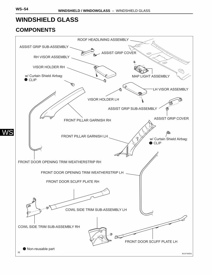
BODYWINDSHIELD / WINDOWGLASSWINDSHIELD GLASSCOMPONENTS
ASSIST GRIP COVER
ASSIST GRIP SUB-ASSEMBLY
ASSIST GRIP COVER
ASSIST GRIP SUB-ASSEMBLY
COWL SIDE TRIM SUB-ASSEMBLY LH
COWL SIDE TRIM SUB-ASSEMBLY RH
FRONT DOOR OPENING TRIM WEATHERSTRIP LH
FRONT DOOR OPENING TRIM WEATHERSTRIP RH
FRONT DOOR SCUFF PLATE LH
FRONT DOOR SCUFF PLATE RH
FRONT PILLAR GARNISH LH
FRONT PILLAR GARNISH RH
MAP LIGHT ASSEMBLY
ROOF HEADLINING ASSEMBLY
w/ Curtain Shield Airbag: CLIP
w/ Curtain Shield Airbag: CLIP
Non-reusable part
LH VISOR ASSEMBLY
RH VISOR ASSEMBLY
VISOR HOLDER LH
VISOR HOLDER RH
B115730E01
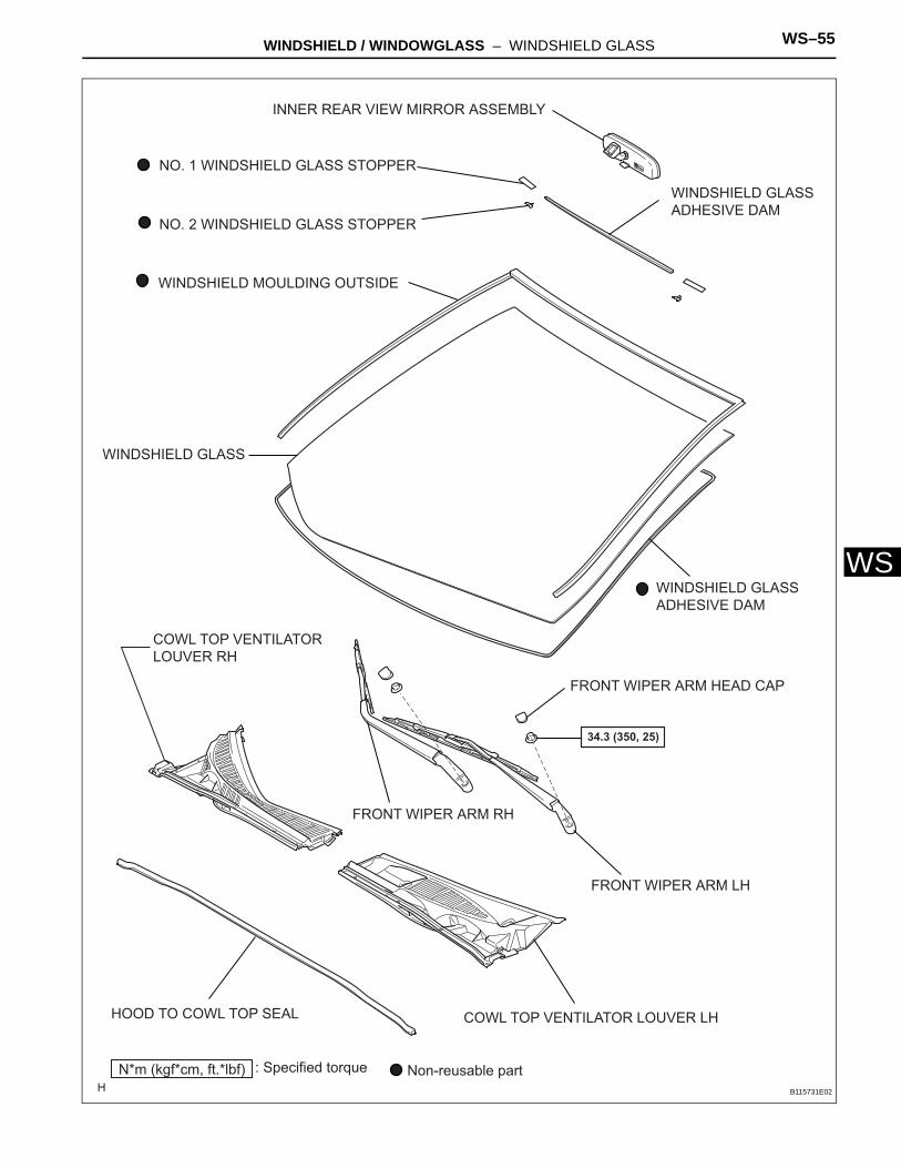
WINDSHIELD / WINDOWGLASS – WINDSHIELD GLASS WS–55
S
WCOWL TOP VENTILATOR LOUVER LH
FRONT WIPER ARM HEAD CAP
FRONT WIPER ARM LH
FRONT WIPER ARM RH
HOOD TO COWL TOP SEAL
INNER REAR VIEW MIRROR ASSEMBLY
WINDSHIELD GLASS ADHESIVE DAM
WINDSHIELD GLASS ADHESIVE DAM
WINDSHIELD MOULDING OUTSIDE
Non-reusable partN*m (kgf*cm, ft.*lbf) : Specified torque
34.3 (350, 25)
NO. 1 WINDSHIELD GLASS STOPPER
NO. 2 WINDSHIELD GLASS STOPPER
COWL TOP VENTILATOR LOUVER RH
WINDSHIELD GLASS
B115731E02
WS–56 WINDSHIELD / WINDOWGLASS – WINDSHIELD GLASS
WS
REMOVAL1. DISCONNECT CABLE FROM NEGATIVE BATTERY
TERMINALCAUTION:Wait at least 90 seconds after disconnecting the cable from the negative (-) battery terminal to prevent airbag and seat belt pretensioner activation.
2. REMOVE INNER REAR VIEW MIRROR ASSEMBLY (See page MI-6)
3. REMOVE FRONT DOOR SCUFF PLATE LH (See page IR-9)
4. REMOVE FRONT DOOR SCUFF PLATE RH (See page IR-9)
5. REMOVE COWL SIDE TRIM SUB-ASSEMBLY LH (See page IR-9)
6. REMOVE COWL SIDE TRIM SUB-ASSEMBLY RH (See page IR-9)
7. REMOVE FRONT DOOR OPENING TRIM WEATHERSTRIP LH
8. REMOVE FRONT DOOR OPENING TRIM WEATHERSTRIP RH
9. REMOVE FRONT PILLAR GARNISH LH (See page IR-12)
10. REMOVE FRONT PILLAR GARNISH RH (See page IR-12)
11. REMOVE ASSIST GRIP COVER (See page IR-13)12. REMOVE ASSIST GRIP SUB-ASSEMBLY (See page
IR-14)13. REMOVE LH VISOR ASSEMBLY (See page IR-13)14. REMOVE RH VISOR ASSEMBLY (See page IR-13)15. REMOVE VISOR HOLDER LH (See page IR-13)16. REMOVE VISOR HOLDER RH (See page IR-13)17. REMOVE MAP LIGHT ASSEMBLY (See page IR-12)18. REMOVE ROOF HEADLINING ASSEMBLY
(a) Slightly lower the front section of the roof headlining (see page IR-14).HINT:It is not necessary to completely remove the roof headlining.
19. REMOVE FRONT WIPER ARM HEAD CAP (See page WW-4)
20. REMOVE FRONT WIPER ARM LH (See page WW-4)21. REMOVE FRONT WIPER ARM RH (See page WW-4)
WINDSHIELD / WINDOWGLASS – WINDSHIELD GLASS WS–57
S
W22. REMOVE HOOD TO COWL TOP SEAL (See page WW-4)
23. REMOVE COWL TOP VENTILATOR LOUVER LH (See page WW-4)
24. REMOVE COWL TOP VENTILATOR LOUVER RH25. REMOVE WINDSHIELD MOULDING OUTSIDE
(a) Using a knife, cut off the windshield moulding outside.NOTICE:Be careful not to damage the vehicle body with the knife.
(b) Remove the remaining moulding.HINT:Make a partial cut in the moulding. Then pull and remove it by hand.
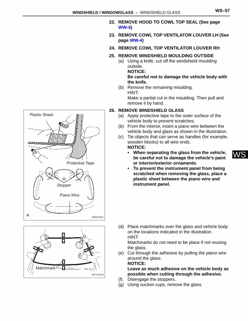
26. REMOVE WINDSHIELD GLASS(a) Apply protective tape to the outer surface of the
vehicle body to prevent scratches.(b) From the interior, insert a piano wire between the
vehicle body and glass as shown in the illustration.(c) Tie objects that can serve as handles (for example,
wooden blocks) to all wire ends.NOTICE:• When separating the glass from the vehicle,
be careful not to damage the vehicle's paint or interior/exterior ornaments.
• To prevent the instrument panel from being scratched when removing the glass, place a plastic sheet between the piano wire and instrument panel.
(d) Place matchmarks over the glass and vehicle body on the locations indicated in the illustration.HINT:Matchmarks do not need to be place if not reusing the glass.
(e) Cut through the adhesive by pulling the piano wire around the glass.NOTICE:Leave as much adhesive on the vehicle body as possible when cutting through the adhesive.
(f) Disengage the stoppers.(g) Using suction cups, remove the glass.
Plastic Sheet
Protective Tape
Stopper
Piano Wire
B084234E01
MatchmarkB073132E02
WS–58 WINDSHIELD / WINDOWGLASS – WINDSHIELD GLASS
WS
27. CLEAN WINDSHIELD GLASS(a) Using a scraper, remove the damaged stoppers,
dams and adhesive sticking to the glass.(b) Clean the outer edges of the glass with white
gasoline.NOTICE:Do not touch the glass surface after cleaning it. Even if using new glass, clean it with white gasoline.
28. CLEAN VEHICLE BODY(a) Clean and shape the contact surface of the vehicle
body.(1) On the contact surface of the vehicle body, use
a knife to cut away excess adhesive as shown in the illustration.HINT:Leave as much adhesive on the vehicle body as possible.NOTICE:Be careful not to damage the vehicle body.
(2) Clean the contact surface of the vehicle body with cleaner.HINT:Even if all the adhesive has been removed, clean the vehicle body.
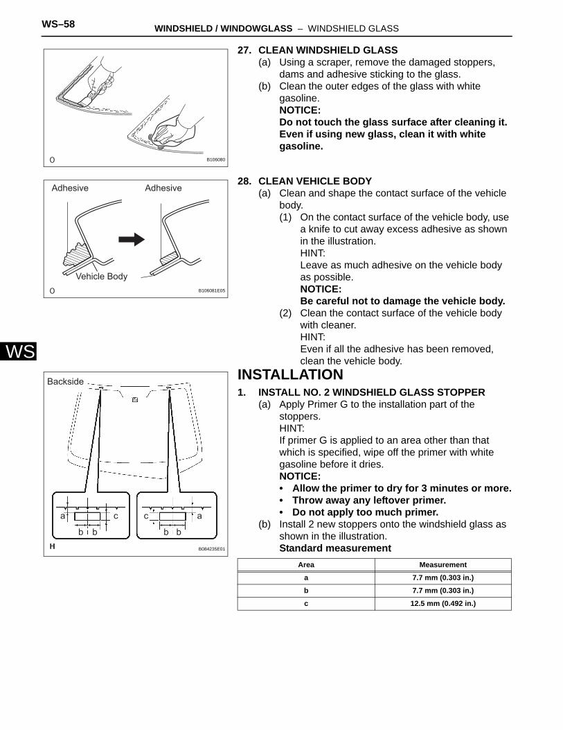
INSTALLATION1. INSTALL NO. 2 WINDSHIELD GLASS STOPPER
(a) Apply Primer G to the installation part of the stoppers.HINT:If primer G is applied to an area other than that which is specified, wipe off the primer with white gasoline before it dries.NOTICE:• Allow the primer to dry for 3 minutes or more.• Throw away any leftover primer.• Do not apply too much primer.
(b) Install 2 new stoppers onto the windshield glass as shown in the illustration.Standard measurement
B106080
Adhesive Adhesive
Vehicle BodyB106081E05
Backside
a a
b b b b
c c
B084235E01
Area Measurement
a 7.7 mm (0.303 in.)
b 7.7 mm (0.303 in.)
c 12.5 mm (0.492 in.)
WINDSHIELD / WINDOWGLASS – WINDSHIELD GLASS WS–59
S
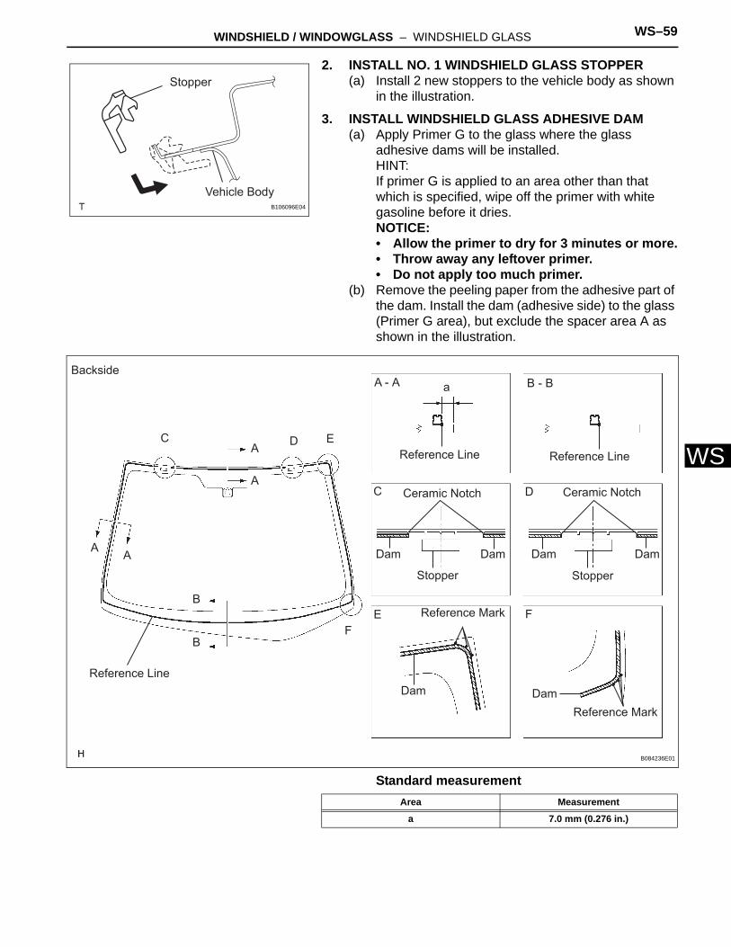
W2. INSTALL NO. 1 WINDSHIELD GLASS STOPPER(a) Install 2 new stoppers to the vehicle body as shown
in the illustration.
3. INSTALL WINDSHIELD GLASS ADHESIVE DAM(a) Apply Primer G to the glass where the glass
adhesive dams will be installed.HINT:If primer G is applied to an area other than that which is specified, wipe off the primer with white gasoline before it dries.NOTICE:• Allow the primer to dry for 3 minutes or more.• Throw away any leftover primer.• Do not apply too much primer.
(b) Remove the peeling paper from the adhesive part of the dam. Install the dam (adhesive side) to the glass (Primer G area), but exclude the spacer area A as shown in the illustration.
Standard measurement
Stopper
Vehicle BodyB106096E04
Backside
Reference Line
Reference Line Reference Line
Stopper Stopper
Reference Mark
Reference Mark
Dam Dam
DamDamDamDam
Ceramic Notch Ceramic Notch
aA - A B - B
C D
E F
C
A A
A
A D E
B
B
F
B084236E01
Area Measurement
a 7.0 mm (0.276 in.)
WS–60 WINDSHIELD / WINDOWGLASS – WINDSHIELD GLASS
WS
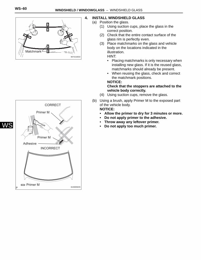
4. INSTALL WINDSHIELD GLASS(a) Position the glass.
(1) Using suction cups, place the glass in the correct position.
(2) Check that the entire contact surface of the glass rim is perfectly even.
(3) Place matchmarks on the glass and vehicle body on the locations indicated in the illustration.HINT:• Placing matchmarks is only necessary when
installing new glass. If it is the reused glass, matchmarks should already be present.
• When reusing the glass, check and correct the matchmark positions.
NOTICE:Check that the stoppers are attached to the vehicle body correctly.
(4) Using suction cups, remove the glass.(b) Using a brush, apply Primer M to the exposed part
of the vehicle body.NOTICE:• Allow the primer to dry for 3 minutes or more.• Do not apply primer to the adhesive.• Throw away any leftover primer.• Do not apply too much primer.
MatchmarkB073132E02
Primer M
Primer M
Adhesive
Primer M
CORRECT
INCORRECT
B106085E05
WINDSHIELD / WINDOWGLASS – WINDSHIELD GLASS WS–61
S
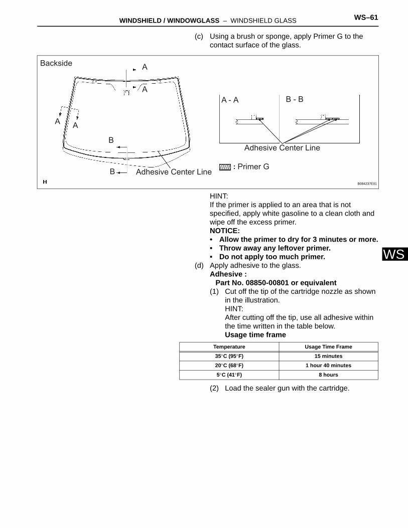
W(c) Using a brush or sponge, apply Primer G to the contact surface of the glass.
HINT:If the primer is applied to an area that is not specified, apply white gasoline to a clean cloth and wipe off the excess primer.NOTICE:• Allow the primer to dry for 3 minutes or more.• Throw away any leftover primer.• Do not apply too much primer.
(d) Apply adhesive to the glass.Adhesive :
Part No. 08850-00801 or equivalent(1) Cut off the tip of the cartridge nozzle as shown
in the illustration.HINT:After cutting off the tip, use all adhesive within the time written in the table below.Usage time frame
(2) Load the sealer gun with the cartridge.
Backside
A A
A
A
B
B
A - A B - B
Primer G
Adhesive Center Line
Adhesive Center LineB084237E01
Temperature Usage Time Frame
35°C (95°F) 15 minutes
20°C (68°F) 1 hour 40 minutes
5°C (41°F) 8 hours
WS–62 WINDSHIELD / WINDOWGLASS – WINDSHIELD GLASS
WS
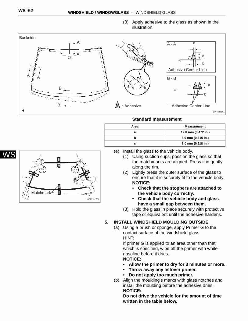
(3) Apply adhesive to the glass as shown in the illustration.
Standard measurement
(e) Install the glass to the vehicle body.(1) Using suction cups, position the glass so that
the matchmarks are aligned. Press it in gently along the rim.
(2) Lightly press the outer surface of the glass to ensure that it is securely fit to the vehicle body.NOTICE:• Check that the stoppers are attached to
the vehicle body correctly.• Check that the vehicle body and glass
have a small gap between them.(3) Hold the glass in place securely with protective
tape or equivalent until the adhesive hardens.
5. INSTALL WINDSHIELD MOULDING OUTSIDE(a) Using a brush or sponge, apply Primer G to the
contact surface of the windshield glass.HINT:If primer G is applied to an area other than that which is specified, wipe off the primer with white gasoline before it dries.NOTICE:• Allow the primer to dry for 3 minutes or more.• Throw away any leftover primer.• Do not apply too much primer.
(b) Align the moulding's marks with glass notches and install the moulding before the adhesive dries.NOTICE:Do not drive the vehicle for the amount of time written in the table below.
BacksideA
A A
A
B
B
A - A
B - B
Adhesive
a b
c
a
b
a
b
Adhesive Center Line
Adhesive Center LineB084238E01
Area Measurement
a 12.0 mm (0.472 in.)
b 8.0 mm (0.315 in.)
c 3.0 mm (0.118 in.)
MatchmarkB073132E02
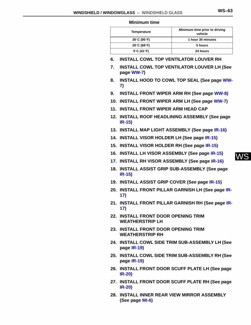
WINDSHIELD / WINDOWGLASS – WINDSHIELD GLASS WS–63
S
WMinimum time
6. INSTALL COWL TOP VENTILATOR LOUVER RH7. INSTALL COWL TOP VENTILATOR LOUVER LH (See
page WW-7)8. INSTALL HOOD TO COWL TOP SEAL (See page WW-
7)9. INSTALL FRONT WIPER ARM RH (See page WW-8)10. INSTALL FRONT WIPER ARM LH (See page WW-7)11. INSTALL FRONT WIPER ARM HEAD CAP12. INSTALL ROOF HEADLINING ASSEMBLY (See page
IR-15)13. INSTALL MAP LIGHT ASSEMBLY (See page IR-16)14. INSTALL VISOR HOLDER LH (See page IR-15)15. INSTALL VISOR HOLDER RH (See page IR-15)16. INSTALL LH VISOR ASSEMBLY (See page IR-15)17. INSTALL RH VISOR ASSEMBLY (See page IR-16)18. INSTALL ASSIST GRIP SUB-ASSEMBLY (See page
IR-15)19. INSTALL ASSIST GRIP COVER (See page IR-15)20. INSTALL FRONT PILLAR GARNISH LH (See page IR-
17)21. INSTALL FRONT PILLAR GARNISH RH (See page IR-
17)22. INSTALL FRONT DOOR OPENING TRIM
WEATHERSTRIP LH23. INSTALL FRONT DOOR OPENING TRIM
WEATHERSTRIP RH24. INSTALL COWL SIDE TRIM SUB-ASSEMBLY LH (See
page IR-19)25. INSTALL COWL SIDE TRIM SUB-ASSEMBLY RH (See
page IR-19)26. INSTALL FRONT DOOR SCUFF PLATE LH (See page
IR-20)27. INSTALL FRONT DOOR SCUFF PLATE RH (See page
IR-20)28. INSTALL INNER REAR VIEW MIRROR ASSEMBLY
(See page MI-6)
Temperature Minimum time prior to driving vehicle
35°C (95°F) 1 hour 30 minutes
20°C (68°F) 5 hours
5°C (41°F) 24 hours
WS–64 WINDSHIELD / WINDOWGLASS – WINDSHIELD GLASS
WS
29. CHECK FOR LEAKS AND REPAIR(a) Conduct a leak test after the adhesive has
completely hardened.(b) Seal any leaks with auto glass sealer.
30. CONNECT CABLE TO NEGATIVE BATTERY TERMINAL
31. PERFORM INITIALIZATION(a) Perform initialization (see page IN-23).
NOTICE:Certain systems need to be initialized after disconnecting and reconnecting the cable from the negative (-) battery terminal.
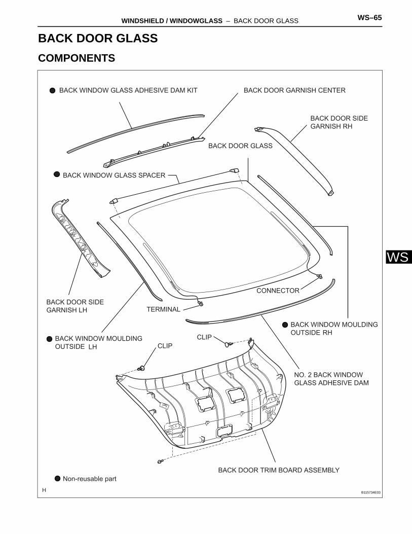
WINDSHIELD / WINDOWGLASS – BACK DOOR GLASS WS–65
S
WBODYWINDSHIELD / WINDOWGLASSBACK DOOR GLASSCOMPONENTS
BACK DOOR SIDE GARNISH LH
BACK DOOR SIDE GARNISH RH
BACK DOOR TRIM BOARD ASSEMBLY
BACK DOOR GARNISH CENTER
BACK DOOR GLASS
TERMINAL
CONNECTOR
BACK WINDOW GLASS SPACER
BACK WINDOW GLASS ADHESIVE DAM KIT
CLIPLHCLIP
RH
NO. 2 BACK WINDOW GLASS ADHESIVE DAM
Non-reusable part
BACK WINDOW MOULDING OUTSIDE
BACK WINDOW MOULDING OUTSIDE
B115734E03
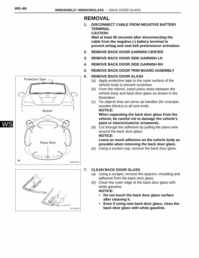
WS–66 WINDSHIELD / WINDOWGLASS – BACK DOOR GLASS
WS
REMOVAL1. DISCONNECT CABLE FROM NEGATIVE BATTERY
TERMINALCAUTION:Wait at least 90 seconds after disconnecting the cable from the negative (-) battery terminal to prevent airbag and seat belt pretensioner activation.
2. REMOVE BACK DOOR GARNISH CENTER3. REMOVE BACK DOOR SIDE GARNISH LH4. REMOVE BACK DOOR SIDE GARNISH RH5. REMOVE BACK DOOR TRIM BOARD ASSEMBLY6. REMOVE BACK DOOR GLASS
(a) Apply protective tape to the outer surface of the vehicle body to prevent scratches.
(b) From the interior, insert piano wires between the vehicle body and back door glass as shown in the illustration.
(c) Tie objects that can serve as handles (for example, wooden blocks) to all wire ends.NOTICE:When separating the back door glass from the vehicle, be careful not to damage the vehicle's paint or interior/exterior ornaments.
(d) Cut through the adhesive by pulling the piano wire around the back door glass.NOTICE:Leave as much adhesive on the vehicle body as possible when removing the back door glass.
(e) Using a suction cup, remove the back door glass.
7. CLEAN BACK DOOR GLASS(a) Using a scraper, remove the spacers, moulding and
adhesive from the back door glass.(b) Clean the outer edge of the back door glass with
white gasoline.NOTICE:• Do not touch the back door glass surface
after cleaning it.• Even if using new back door glass, clean the
back door glass with white gasoline.
Protective Tape
Spacer
Piano Wire
B084253E01
B073128E01
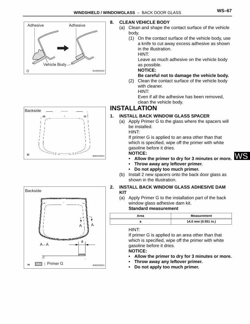
WINDSHIELD / WINDOWGLASS – BACK DOOR GLASS WS–67
S
W8. CLEAN VEHICLE BODY(a) Clean and shape the contact surface of the vehicle
body.(1) On the contact surface of the vehicle body, use
a knife to cut away excess adhesive as shown in the illustration.HINT:Leave as much adhesive on the vehicle body as possible.NOTICE:Be careful not to damage the vehicle body.
(2) Clean the contact surface of the vehicle body with cleaner.HINT:Even if all the adhesive has been removed, clean the vehicle body.
INSTALLATION1. INSTALL BACK WINDOW GLASS SPACER
(a) Apply Primer G to the glass where the spacers will be installed.HINT:If primer G is applied to an area other than that which is specified, wipe off the primer with white gasoline before it dries.NOTICE:• Allow the primer to dry for 3 minutes or more.• Throw away any leftover primer.• Do not apply too much primer.
(b) Install 2 new spacers onto the back door glass as shown in the illustration.
2. INSTALL BACK WINDOW GLASS ADHESIVE DAM KIT(a) Apply Primer G to the installation part of the back
window glass adhesive dam kit.Standard measurement
HINT:If primer G is applied to an area other than that which is specified, wipe off the primer with white gasoline before it dries.NOTICE:• Allow the primer to dry for 3 minutes or more.• Throw away any leftover primer.• Do not apply too much primer.
Adhesive Adhesive
Vehicle BodyB106081E02
Backside
B084254E01
Backside
A A
A - Aa
Primer G B084255E01
Area Measurement
a 14.0 mm (0.551 in.)
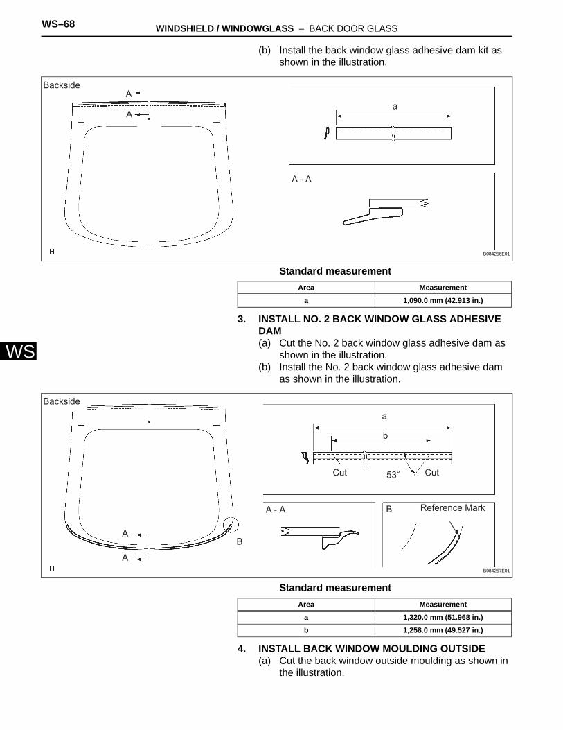
WS–68 WINDSHIELD / WINDOWGLASS – BACK DOOR GLASS
WS
(b) Install the back window glass adhesive dam kit as shown in the illustration.
Standard measurement
3. INSTALL NO. 2 BACK WINDOW GLASS ADHESIVE DAM(a) Cut the No. 2 back window glass adhesive dam as
shown in the illustration.(b) Install the No. 2 back window glass adhesive dam
as shown in the illustration.
Standard measurement
4. INSTALL BACK WINDOW MOULDING OUTSIDE(a) Cut the back window outside moulding as shown in
the illustration.
A
Aa
A - A
Backside
B084256E01
Area Measurement
a 1,090.0 mm (42.913 in.)
Backside
A
A
B
a
b
Cut Cut53
A - A B Reference Mark
B084257E01
Area Measurement
a 1,320.0 mm (51.968 in.)
b 1,258.0 mm (49.527 in.)
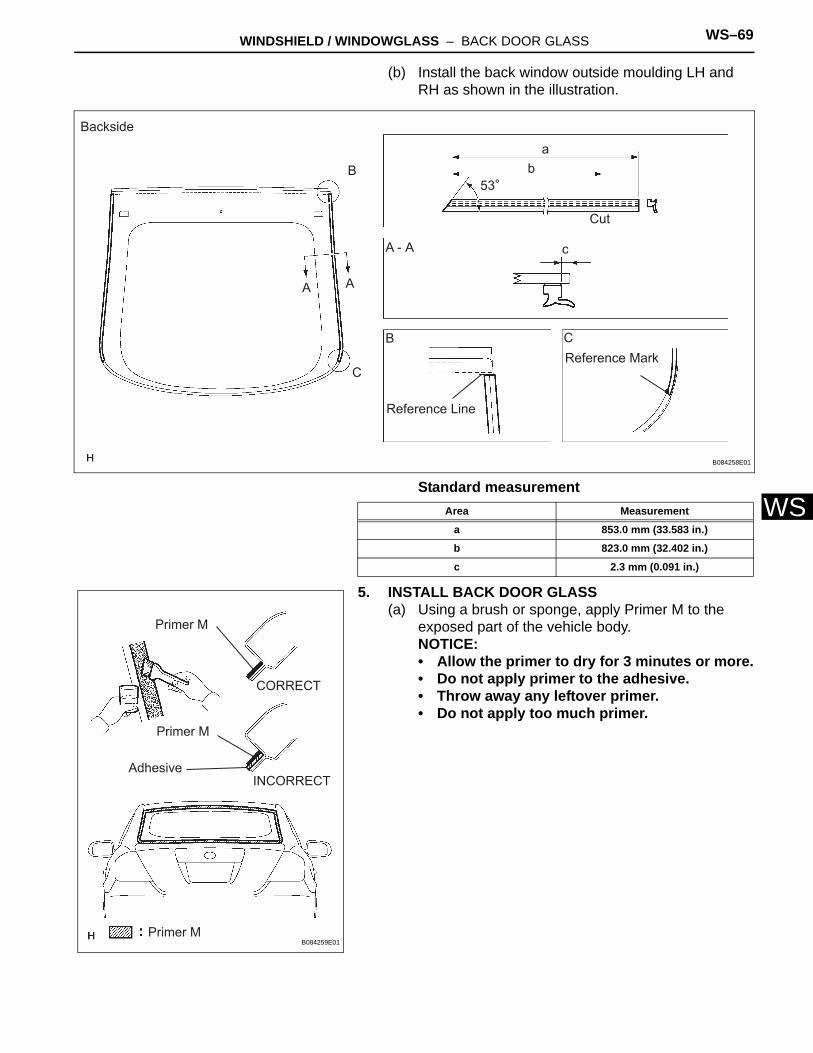
WINDSHIELD / WINDOWGLASS – BACK DOOR GLASS WS–69
S
W(b) Install the back window outside moulding LH and RH as shown in the illustration.
Standard measurement
5. INSTALL BACK DOOR GLASS(a) Using a brush or sponge, apply Primer M to the
exposed part of the vehicle body.NOTICE:• Allow the primer to dry for 3 minutes or more.• Do not apply primer to the adhesive.• Throw away any leftover primer.• Do not apply too much primer.
Backside
B
A A
C
ab
53
Cut
A - A c
B C
Reference Line
Reference Mark
B084258E01
Area Measurement
a 853.0 mm (33.583 in.)
b 823.0 mm (32.402 in.)
c 2.3 mm (0.091 in.)
Primer M
Primer M
Primer M
CORRECT
AdhesiveINCORRECT
B084259E01
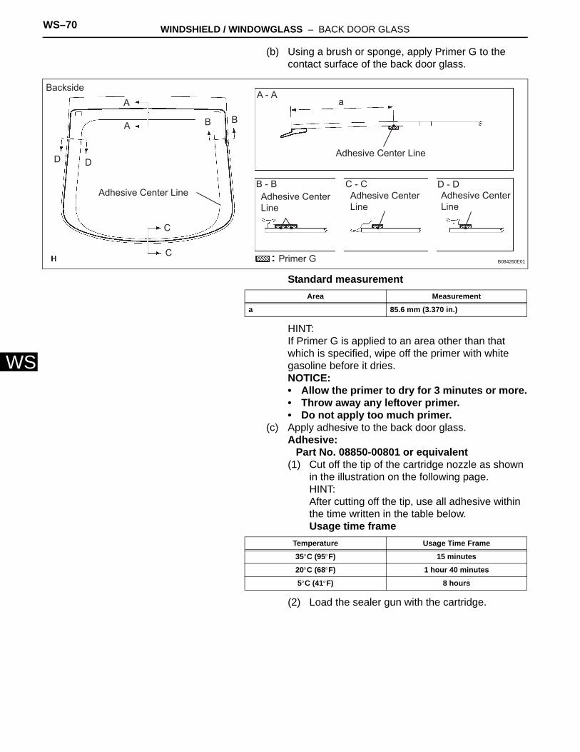
WS–70 WINDSHIELD / WINDOWGLASS – BACK DOOR GLASS
WS
(b) Using a brush or sponge, apply Primer G to the contact surface of the back door glass.
Standard measurement
HINT:If Primer G is applied to an area other than that which is specified, wipe off the primer with white gasoline before it dries.NOTICE:• Allow the primer to dry for 3 minutes or more.• Throw away any leftover primer.• Do not apply too much primer.
(c) Apply adhesive to the back door glass.Adhesive:
Part No. 08850-00801 or equivalent(1) Cut off the tip of the cartridge nozzle as shown
in the illustration on the following page.HINT:After cutting off the tip, use all adhesive within the time written in the table below.Usage time frame
(2) Load the sealer gun with the cartridge.
BacksideA - A
B - B
A
A
D D
B B
C
C
Adhesive Center Line
Adhesive Center Line
Adhesive Center Line
Adhesive Center Line
Adhesive Center Line
a
C - C D - D
Primer G B084260E01
Area Measurement
a 85.6 mm (3.370 in.)
Temperature Usage Time Frame
35°C (95°F) 15 minutes
20°C (68°F) 1 hour 40 minutes
5°C (41°F) 8 hours
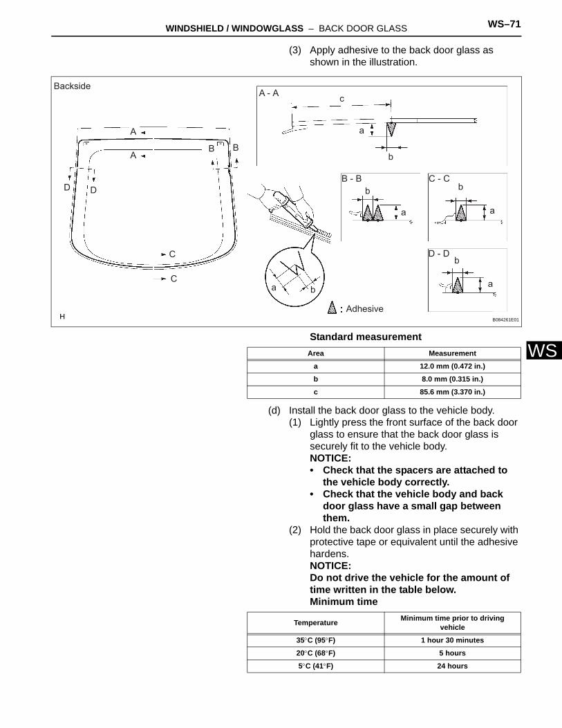
WINDSHIELD / WINDOWGLASS – BACK DOOR GLASS WS–71
S
W(3) Apply adhesive to the back door glass as shown in the illustration.
Standard measurement
(d) Install the back door glass to the vehicle body.(1) Lightly press the front surface of the back door
glass to ensure that the back door glass is securely fit to the vehicle body.NOTICE:• Check that the spacers are attached to
the vehicle body correctly.• Check that the vehicle body and back
door glass have a small gap between them.
(2) Hold the back door glass in place securely with protective tape or equivalent until the adhesive hardens.NOTICE:Do not drive the vehicle for the amount of time written in the table below.Minimum time
Backside
D D
A
A
C
C
B B
A - A
B - B C - C
D - D
c
a
a
a
a
a
b
b
b
b
b
AdhesiveB084261E01
Area Measurement
a 12.0 mm (0.472 in.)
b 8.0 mm (0.315 in.)
c 85.6 mm (3.370 in.)
Temperature Minimum time prior to driving vehicle
35°C (95°F) 1 hour 30 minutes
20°C (68°F) 5 hours
5°C (41°F) 24 hours
WS–72 WINDSHIELD / WINDOWGLASS – BACK DOOR GLASS
WS
6. CHECK FOR LEAKS AND REPAIR(a) Conduct a leak test after the adhesive has
completely hardened.(b) Seal any leaks with auto glass sealer.
7. CONNECT CABLE TO NEGATIVE BATTERY TERMINAL
8. PERFORM INITIALIZATION(a) Perform initialization (see page IN-23).
NOTICE:Certain systems need to be initialized after disconnecting and reconnecting the cable from the negative (-) battery terminal.
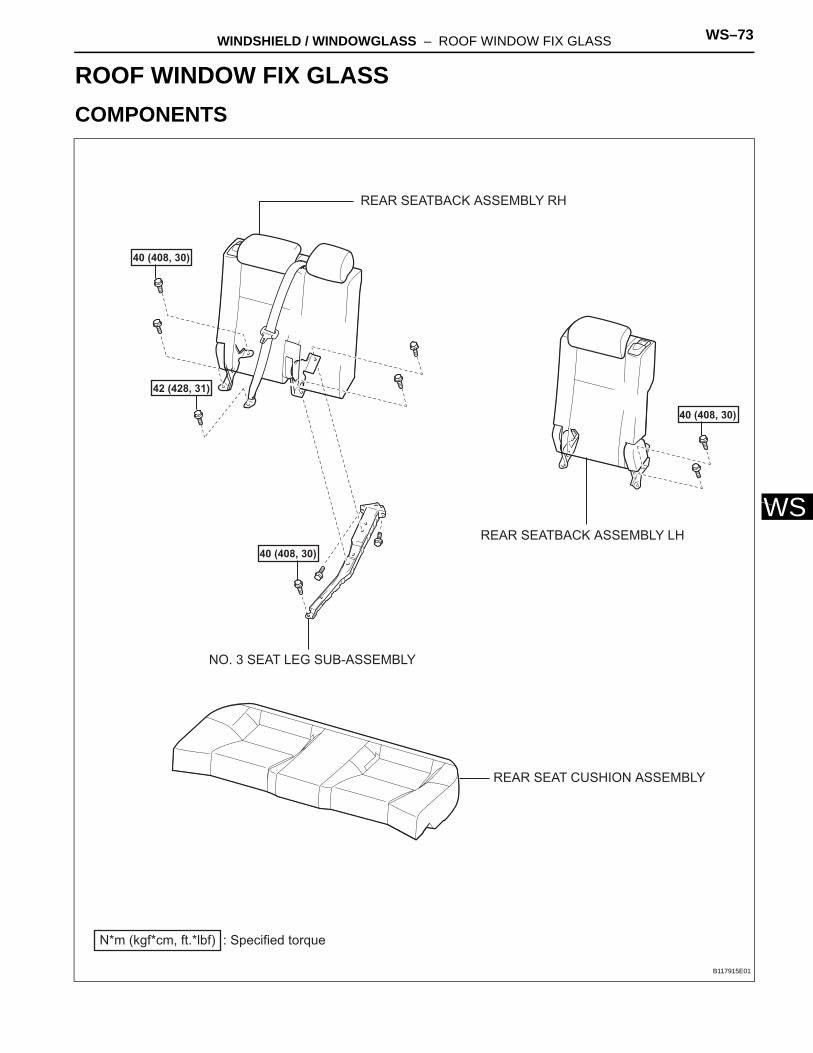
WINDSHIELD / WINDOWGLASS – ROOF WINDOW FIX GLASS WS–73
S
WBODYWINDSHIELD / WINDOWGLASSROOF WINDOW FIX GLASSCOMPONENTS
: Specified torqueN*m (kgf*cm, ft.*lbf)
40 (408, 30)
REAR SEAT CUSHION ASSEMBLY
REAR SEATBACK ASSEMBLY LH
REAR SEATBACK ASSEMBLY RH
42 (428, 31)
40 (408, 30)
40 (408, 30)
NO. 3 SEAT LEG SUB-ASSEMBLY
B117915E01
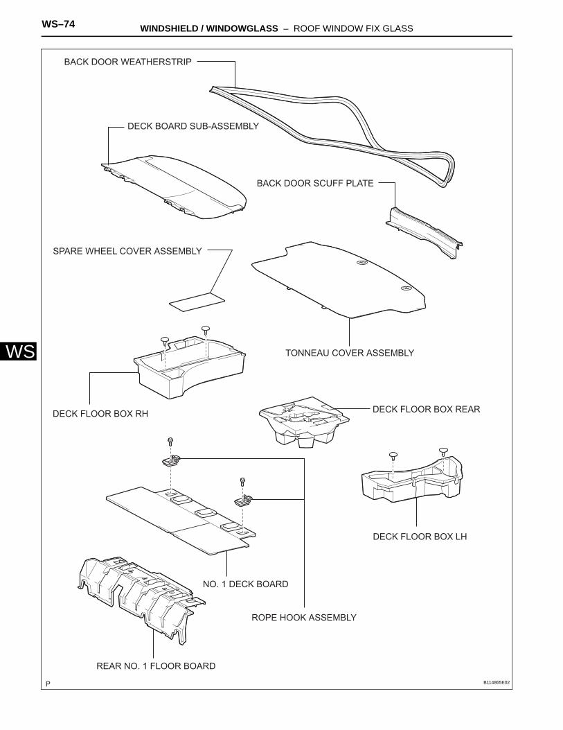
WS–74 WINDSHIELD / WINDOWGLASS – ROOF WINDOW FIX GLASS
WS
BACK DOOR SCUFF PLATE
BACK DOOR WEATHERSTRIP
DECK BOARD SUB-ASSEMBLY
DECK FLOOR BOX LH
DECK FLOOR BOX REARDECK FLOOR BOX RH
NO. 1 DECK BOARD
REAR NO. 1 FLOOR BOARD
SPARE WHEEL COVER ASSEMBLY
TONNEAU COVER ASSEMBLY
ROPE HOOK ASSEMBLY
B114865E02
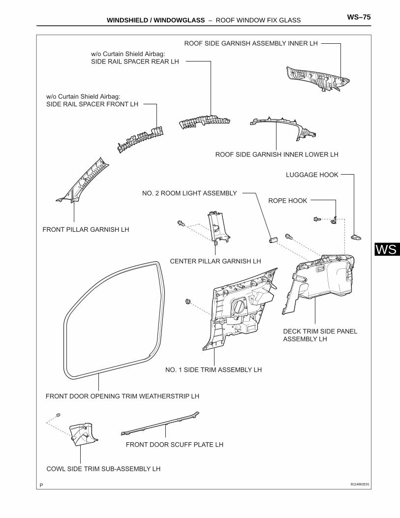
WINDSHIELD / WINDOWGLASS – ROOF WINDOW FIX GLASS WS–75
S
WCENTER PILLAR GARNISH LHCOWL SIDE TRIM SUB-ASSEMBLY LH
DECK TRIM SIDE PANEL ASSEMBLY LH
FRONT DOOR OPENING TRIM WEATHERSTRIP LH
FRONT DOOR SCUFF PLATE LH
FRONT PILLAR GARNISH LH
NO. 1 SIDE TRIM ASSEMBLY LH
NO. 2 ROOM LIGHT ASSEMBLY
ROOF SIDE GARNISH ASSEMBLY INNER LH
ROOF SIDE GARNISH INNER LOWER LH
w/o Curtain Shield Airbag:SIDE RAIL SPACER FRONT LH
w/o Curtain Shield Airbag:SIDE RAIL SPACER REAR LH
ROPE HOOK
LUGGAGE HOOK
B114862E01
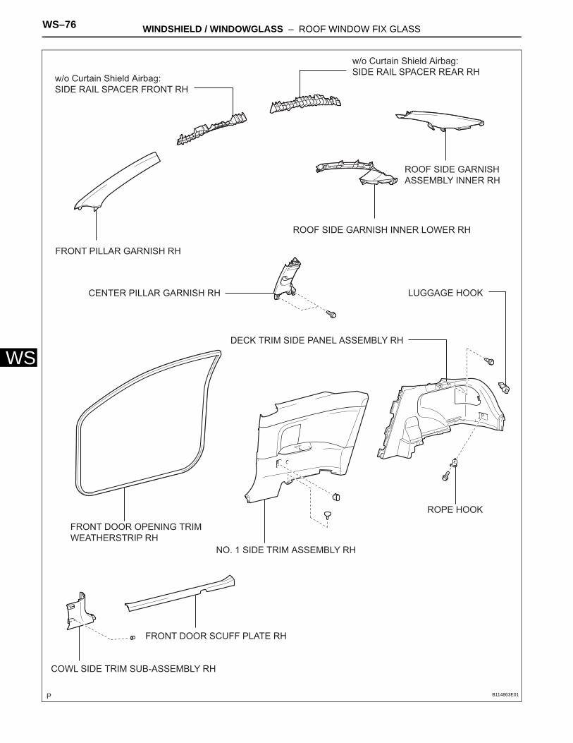
WS–76 WINDSHIELD / WINDOWGLASS – ROOF WINDOW FIX GLASS
WS
CENTER PILLAR GARNISH RH
COWL SIDE TRIM SUB-ASSEMBLY RH
DECK TRIM SIDE PANEL ASSEMBLY RH
FRONT DOOR OPENING TRIM WEATHERSTRIP RH
FRONT DOOR SCUFF PLATE RH
FRONT PILLAR GARNISH RH
NO. 1 SIDE TRIM ASSEMBLY RH
ROOF SIDE GARNISH ASSEMBLY INNER RH
ROOF SIDE GARNISH INNER LOWER RH
w/o Curtain Shield Airbag:SIDE RAIL SPACER FRONT RH
w/o Curtain Shield Airbag:SIDE RAIL SPACER REAR RH
ROPE HOOK
LUGGAGE HOOK
B114863E01
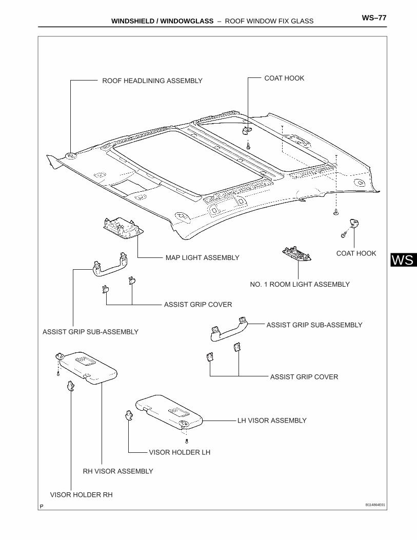
WINDSHIELD / WINDOWGLASS – ROOF WINDOW FIX GLASS WS–77
S
WASSIST GRIP COVER
ASSIST GRIP SUB-ASSEMBLY
COAT HOOK
LH VISOR ASSEMBLY
MAP LIGHT ASSEMBLY
NO. 1 ROOM LIGHT ASSEMBLY
RH VISOR ASSEMBLY
ROOF HEADLINING ASSEMBLY
VISOR HOLDER LH
VISOR HOLDER RH
COAT HOOK
ASSIST GRIP COVER
ASSIST GRIP SUB-ASSEMBLY
B114864E01
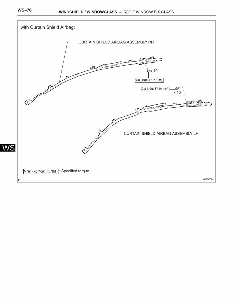
WS–78 WINDSHIELD / WINDOWGLASS – ROOF WINDOW FIX GLASS
WS
CURTAIN SHIELD AIRBAG ASSEMBLY LH
CURTAIN SHIELD AIRBAG ASSEMBLY RH
9.8 (100, 87 in.*lbf)
9.8 (100, 87 in.*lbf)
x 10
x 10
with Curtain Shield Airbag:
N*m (kgf*cm, ft.*lbf) : Specified torque
B153105E01
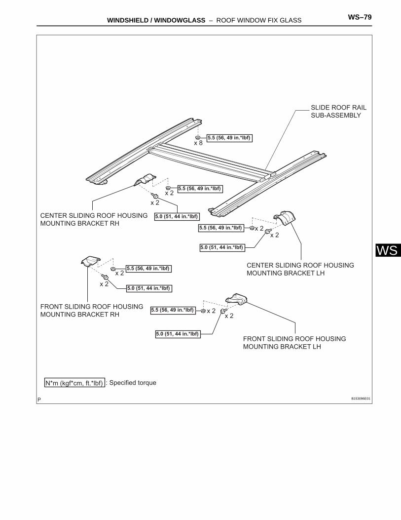
WINDSHIELD / WINDOWGLASS – ROOF WINDOW FIX GLASS WS–79
S
WCENTER SLIDING ROOF HOUSING MOUNTING BRACKET LHCENTER SLIDING ROOF HOUSING MOUNTING BRACKET RH
FRONT SLIDING ROOF HOUSING MOUNTING BRACKET LH
FRONT SLIDING ROOF HOUSING MOUNTING BRACKET RH
SLIDE ROOF RAIL SUB-ASSEMBLY
5.5 (56, 49 in.*lbf)
5.5 (56, 49 in.*lbf)
5.5 (56, 49 in.*lbf)
5.5 (56, 49 in.*lbf)
5.5 (56, 49 in.*lbf)
5.0 (51, 44 in.*lbf)
5.0 (51, 44 in.*lbf)
5.0 (51, 44 in.*lbf)
5.0 (51, 44 in.*lbf)
x 2x 2
x 2
x 2
x 2x 2
x 2x 2
x 8
N*m (kgf*cm, ft.*lbf) : Specified torque
B153096E01
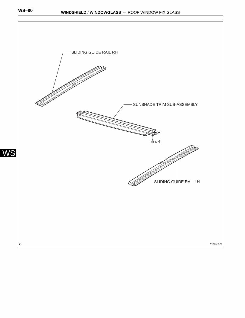
WS–80 WINDSHIELD / WINDOWGLASS – ROOF WINDOW FIX GLASS
WS
SUNSHADE TRIM SUB-ASSEMBLY
x 4
SLIDING GUIDE RAIL RH
SLIDING GUIDE RAIL LH
B153097E01
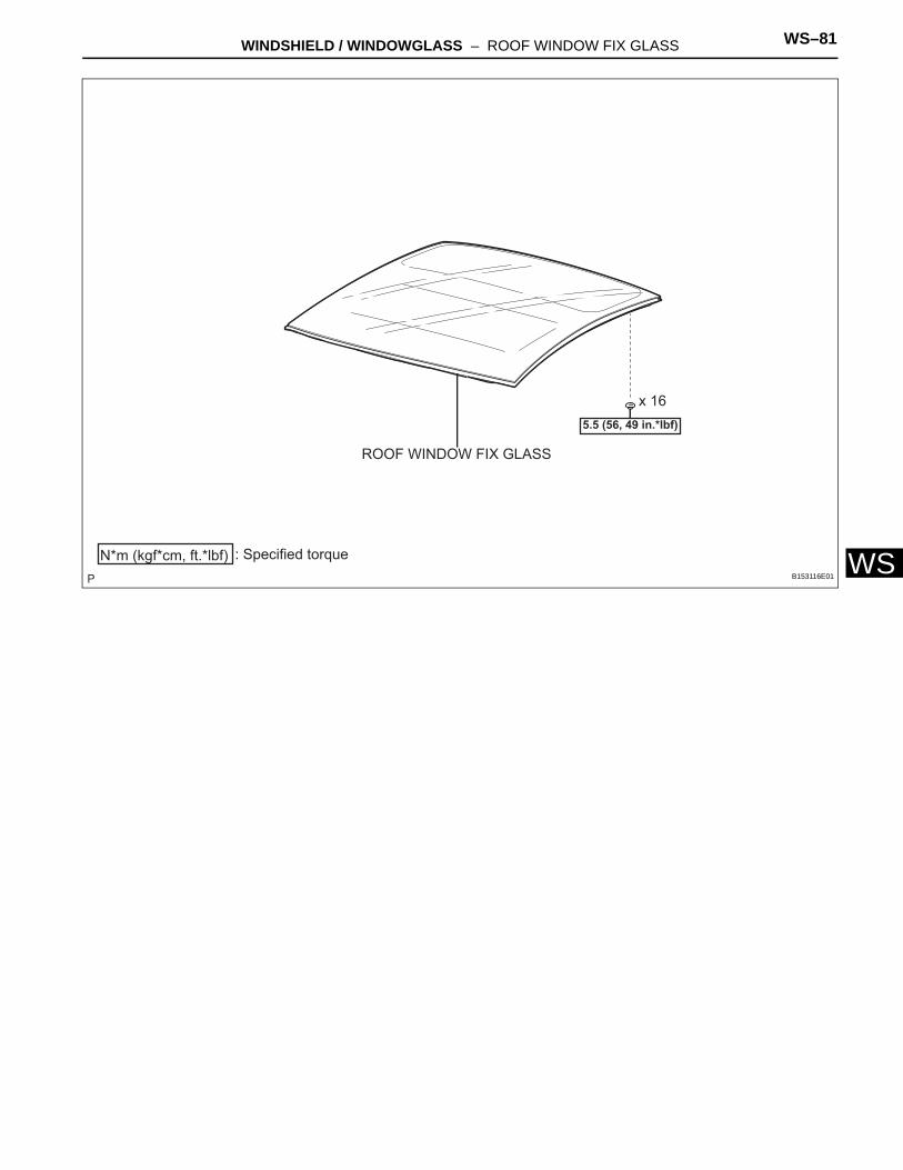
WINDSHIELD / WINDOWGLASS – ROOF WINDOW FIX GLASS WS–81
S
Wx 165.5 (56, 49 in.*lbf)
ROOF WINDOW FIX GLASS
N*m (kgf*cm, ft.*lbf) : Specified torqueB153116E01
WS–82 WINDSHIELD / WINDOWGLASS – ROOF WINDOW FIX GLASS
WS
REMOVAL1. DISCONNECT BATTERY NEGATIVE TERMINAL
NOTICE:Wait for 90 seconds after disconnecting the terminal to prevent the airbag from deploying. (See page RS-1)
2. REMOVE TONNEAU COVER ASSEMBLY3. REMOVE DECK BOARD SUB-ASSEMBLY4. REMOVE BACK DOOR SCUFF PLATE (See page IR-
8)5. REMOVE BACK DOOR WEATHERSTRIP6. REMOVE SPARE WHEEL COVER ASSEMBLY7. REMOVE DECK FLOOR BOX LH (See page IR-8)8. REMOVE DECK FLOOR BOX RH (See page IR-8)9. REMOVE DECK FLOOR BOX REAR10. REMOVE NO. 1 DECK BOARD (See page IR-8)11. REMOVE REAR NO. 1 FLOOR BOARD (See page IR-
9)12. REMOVE FRONT DOOR SCUFF PLATE OUTSIDE LH
(See page IR-9)13. REMOVE FRONT DOOR SCUFF PLATE OUTSIDE RH
(See page IR-9)14. REMOVE FRONT DOOR SCUFF PLATE LH (See page
IR-9)15. REMOVE FRONT DOOR SCUFF PLATE RH (See page
IR-9)16. REMOVE COWL SIDE TRIM SUB-ASSEMBLY LH (See
page IR-9)17. REMOVE COWL SIDE TRIM SUB-ASSEMBLY RH
(See page IR-9)18. REMOVE REAR SEAT CUSHION ASSEMBLY (See
page SE-17)19. REMOVE REAR SEATBACK ASSEMBLY LH (See
page SE-17)20. REMOVE REAR SEATBACK ASSEMBLY RH (See
page SE-18)21. REMOVE FRONT DOOR OPENING TRIM
WEATHERSTRIP LH22. REMOVE FRONT DOOR OPENING TRIM
WEATHERSTRIP RH23. REMOVE NO. 1 SIDE TRIM ASSEMBLY LH (See page
IR-10)
WINDSHIELD / WINDOWGLASS – ROOF WINDOW FIX GLASS WS–83
S
W24. REMOVE NO. 1 SIDE TRIM ASSEMBLY RH (See page IR-10)
25. REMOVE CENTER PILLAR GARNISH LH (See page IR-10)
26. REMOVE CENTER PILLAR GARNISH RH (See page IR-10)
27. REMOVE ROOF SIDE GARNISH INNER LOWER LH (See page IR-10)
28. REMOVE ROOF SIDE GARNISH INNER LOWER RH (See page IR-10)
29. REMOVE DECK TRIM SIDE PANEL ASSEMBLY LH (See page IR-11)
30. REMOVE DECK TRIM SIDE PANEL ASSEMBLY RH (See page IR-11)
31. REMOVE ROOF SIDE GARNISH ASSEMBLY INNER LH (See page IR-11)
32. REMOVE ROOF SIDE GARNISH ASSEMBLY INNER RH (See page IR-11)
33. REMOVE FRONT PILLAR GARNISH LH (See page IR-12)
34. REMOVE FRONT PILLAR GARNISH RH (See page IR-12)
35. REMOVE MAP LIGHT ASSEMBLY (See page IR-12)36. REMOVE NO. 1 ROOM LIGHT ASSEMBLY (See page
IR-13)37. REMOVE NO. 2 ROOM LIGHT ASSEMBLY (See page
IR-13)38. REMOVE LH VISOR ASSEMBLY (See page IR-13)39. REMOVE RH VISOR ASSEMBLY (See page IR-13)40. REMOVE VISOR HOLDER LH (See page IR-13)41. REMOVE VISOR HOLDER RH (See page IR-13)42. REMOVE ASSIST GRIP COVER (See page IR-13)43. REMOVE ASSIST GRIP SUB-ASSEMBLY (See page
IR-14)44. REMOVE COAT HOOK (See page IR-14)45. REMOVE ROOF HEADLINING ASSEMBLY (See page
IR-14)
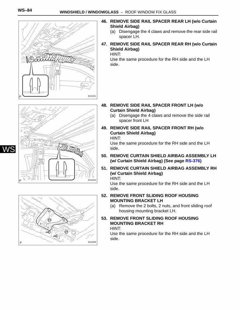
WS–84 WINDSHIELD / WINDOWGLASS – ROOF WINDOW FIX GLASS
WS
46. REMOVE SIDE RAIL SPACER REAR LH (w/o Curtain Shield Airbag)(a) Disengage the 4 claws and remove the rear side rail
spacer LH.
47. REMOVE SIDE RAIL SPACER REAR RH (w/o Curtain Shield Airbag)HINT:Use the same procedure for the RH side and the LH side.
48. REMOVE SIDE RAIL SPACER FRONT LH (w/o Curtain Shield Airbag)(a) Disengage the 4 claws and remove the side rail
spacer front LH
49. REMOVE SIDE RAIL SPACER FRONT RH (w/o Curtain Shield Airbag)HINT:Use the same procedure for the RH side and the LH side.
50. REMOVE CURTAIN SHIELD AIRBAG ASSEMBLY LH (w/ Curtain Shield Airbag) (See page RS-376)
51. REMOVE CURTAIN SHIELD AIRBAG ASSEMBLY RH (w/ Curtain Shield Airbag)HINT:Use the same procedure for the RH side and the LH side.
52. REMOVE FRONT SLIDING ROOF HOUSING MOUNTING BRACKET LH(a) Remove the 2 bolts, 2 nuts, and front sliding roof
housing mounting bracket LH.
53. REMOVE FRONT SLIDING ROOF HOUSING MOUNTING BRACKET RHHINT:Use the same procedure for the RH side and the LH side.
B153101
B153102
B153099
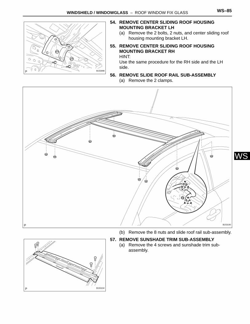
WINDSHIELD / WINDOWGLASS – ROOF WINDOW FIX GLASS WS–85
S
W54. REMOVE CENTER SLIDING ROOF HOUSING MOUNTING BRACKET LH(a) Remove the 2 bolts, 2 nuts, and center sliding roof
housing mounting bracket LH.
55. REMOVE CENTER SLIDING ROOF HOUSING MOUNTING BRACKET RHHINT:Use the same procedure for the RH side and the LH side.
56. REMOVE SLIDE ROOF RAIL SUB-ASSEMBLY(a) Remove the 2 clamps.
(b) Remove the 8 nuts and slide roof rail sub-assembly.57. REMOVE SUNSHADE TRIM SUB-ASSEMBLY
(a) Remove the 4 screws and sunshade trim sub-assembly.
B153098
B153100
B153104
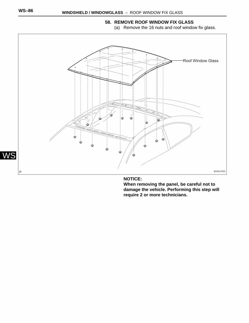
WS–86 WINDSHIELD / WINDOWGLASS – ROOF WINDOW FIX GLASS
WS
58. REMOVE ROOF WINDOW FIX GLASS(a) Remove the 16 nuts and roof window fix glass.
NOTICE:When removing the panel, be careful not to damage the vehicle. Performing this step will require 2 or more technicians.
Roof Window Glass
B153117E01
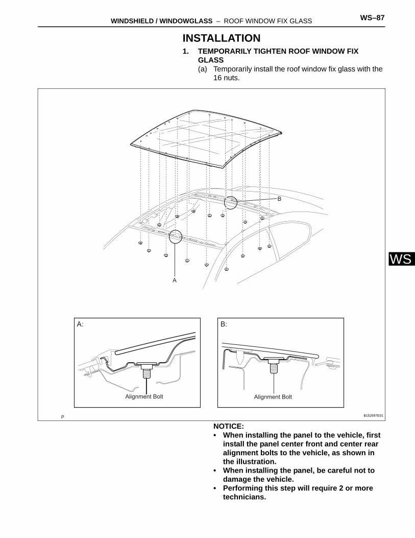
WINDSHIELD / WINDOWGLASS – ROOF WINDOW FIX GLASS WS–87
S
WINSTALLATION1. TEMPORARILY TIGHTEN ROOF WINDOW FIX
GLASS(a) Temporarily install the roof window fix glass with the
16 nuts.
NOTICE:• When installing the panel to the vehicle, first
install the panel center front and center rear alignment bolts to the vehicle, as shown in the illustration.
• When installing the panel, be careful not to damage the vehicle.
• Performing this step will require 2 or more technicians.
A
B
A: B:
Alignment Bolt Alignment Bolt
B152697E01
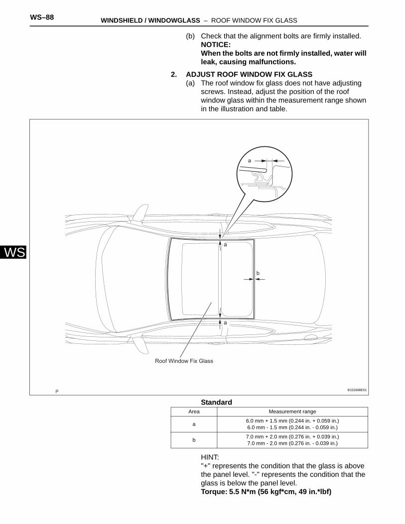
WS–88 WINDSHIELD / WINDOWGLASS – ROOF WINDOW FIX GLASS
WS
(b) Check that the alignment bolts are firmly installed.NOTICE:When the bolts are not firmly installed, water will leak, causing malfunctions.
2. ADJUST ROOF WINDOW FIX GLASS(a) The roof window fix glass does not have adjusting
screws. Instead, adjust the position of the roof window glass within the measurement range shown in the illustration and table.
Standard
HINT:"+" represents the condition that the glass is above the panel level. "-" represents the condition that the glass is below the panel level.Torque: 5.5 N*m (56 kgf*cm, 49 in.*lbf)
a
b
a
a
Roof Window Fix Glass
B152698E01
Area Measurement range
a 6.0 mm + 1.5 mm (0.244 in. + 0.059 in.)6.0 mm - 1.5 mm (0.244 in. - 0.059 in.)
b 7.0 mm + 2.0 mm (0.276 in. + 0.039 in.)7.0 mm - 2.0 mm (0.276 in. - 0.039 in.)
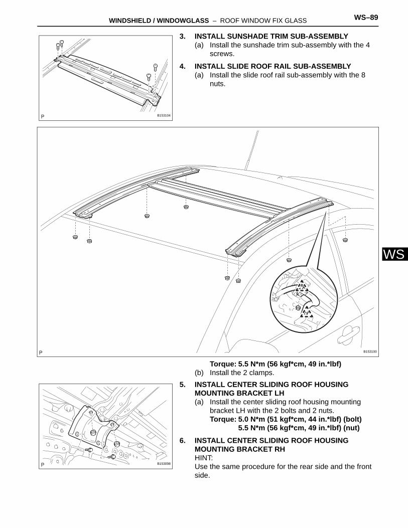
WINDSHIELD / WINDOWGLASS – ROOF WINDOW FIX GLASS WS–89
S
W3. INSTALL SUNSHADE TRIM SUB-ASSEMBLY(a) Install the sunshade trim sub-assembly with the 4
screws.
4. INSTALL SLIDE ROOF RAIL SUB-ASSEMBLY(a) Install the slide roof rail sub-assembly with the 8
nuts.
Torque: 5.5 N*m (56 kgf*cm, 49 in.*lbf)(b) Install the 2 clamps.
5. INSTALL CENTER SLIDING ROOF HOUSING MOUNTING BRACKET LH(a) Install the center sliding roof housing mounting
bracket LH with the 2 bolts and 2 nuts.Torque: 5.0 N*m (51 kgf*cm, 44 in.*lbf) (bolt)
5.5 N*m (56 kgf*cm, 49 in.*lbf) (nut)6. INSTALL CENTER SLIDING ROOF HOUSING
MOUNTING BRACKET RHHINT:Use the same procedure for the rear side and the front side.
B153104
B153100
B153098
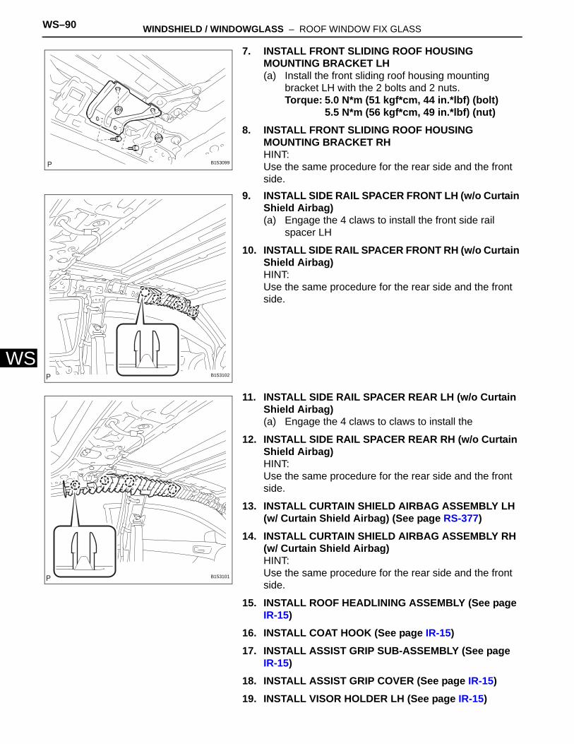
WS–90 WINDSHIELD / WINDOWGLASS – ROOF WINDOW FIX GLASS
WS
7. INSTALL FRONT SLIDING ROOF HOUSING MOUNTING BRACKET LH(a) Install the front sliding roof housing mounting
bracket LH with the 2 bolts and 2 nuts.Torque: 5.0 N*m (51 kgf*cm, 44 in.*lbf) (bolt)
5.5 N*m (56 kgf*cm, 49 in.*lbf) (nut)8. INSTALL FRONT SLIDING ROOF HOUSING
MOUNTING BRACKET RHHINT:Use the same procedure for the rear side and the front side.
9. INSTALL SIDE RAIL SPACER FRONT LH (w/o Curtain Shield Airbag)(a) Engage the 4 claws to install the front side rail
spacer LH
10. INSTALL SIDE RAIL SPACER FRONT RH (w/o Curtain Shield Airbag)HINT:Use the same procedure for the rear side and the front side.
11. INSTALL SIDE RAIL SPACER REAR LH (w/o Curtain Shield Airbag)(a) Engage the 4 claws to claws to install the
12. INSTALL SIDE RAIL SPACER REAR RH (w/o Curtain Shield Airbag)HINT:Use the same procedure for the rear side and the front side.
13. INSTALL CURTAIN SHIELD AIRBAG ASSEMBLY LH (w/ Curtain Shield Airbag) (See page RS-377)
14. INSTALL CURTAIN SHIELD AIRBAG ASSEMBLY RH (w/ Curtain Shield Airbag)HINT:Use the same procedure for the rear side and the front side.
15. INSTALL ROOF HEADLINING ASSEMBLY (See page IR-15)
16. INSTALL COAT HOOK (See page IR-15)17. INSTALL ASSIST GRIP SUB-ASSEMBLY (See page
IR-15)18. INSTALL ASSIST GRIP COVER (See page IR-15)19. INSTALL VISOR HOLDER LH (See page IR-15)
B153099
B153102
B153101
WINDSHIELD / WINDOWGLASS – ROOF WINDOW FIX GLASS WS–91
S
W20. INSTALL VISOR HOLDER RH (See page IR-15)21. INSTALL LH VISOR ASSEMBLY (See page IR-15)22. INSTALL RH VISOR ASSEMBLY (See page IR-16)23. INSTALL NO. 2 ROOM LIGHT ASSEMBLY (See page
IR-16)24. INSTALL NO. 1 ROOM LIGHT ASSEMBLY (See page
IR-16)25. INSTALL MAP LIGHT ASSEMBLY (See page IR-16)26. INSTALL FRONT PILLAR GARNISH LH (See page IR-
17)27. INSTALL FRONT PILLAR GARNISH RH (See page IR-
17)28. INSTALL ROOF SIDE GARNISH ASSEMBLY INNER
LH (See page IR-17)29. INSTALL ROOF SIDE GARNISH ASSEMBLY INNER
RH (See page IR-18)30. INSTALL DECK TRIM SIDE PANEL ASSEMBLY LH
(See page IR-18)31. INSTALL DECK TRIM SIDE PANEL ASSEMBLY RH
(See page IR-18)32. INSTALL ROOF SIDE GARNISH INNER LOWER LH
(See page IR-18)33. INSTALL ROOF SIDE GARNISH INNER LOWER RH
(See page IR-18)34. INSTALL CENTER PILLAR GARNISH LH (See page
IR-19)35. INSTALL CENTER PILLAR GARNISH RH (See page
IR-19)36. INSTALL NO. 1 SIDE TRIM ASSEMBLY LH (See page
IR-19)37. INSTALL NO. 1 SIDE TRIM ASSEMBLY RH (See page
IR-19)38. INSTALL FRONT DOOR OPENING TRIM
WEATHERSTRIP LH39. INSTALL FRONT DOOR OPENING TRIM
WEATHERSTRIP RH40. INSTALL REAR SEATBACK ASSEMBLY LH (See
page SE-28)41. INSTALL REAR SEATBACK ASSEMBLY RH (See
page SE-28)42. INSTALL REAR SEAT CUSHION ASSEMBLY (See
page SE-29)43. INSTALL COWL SIDE TRIM SUB-ASSEMBLY LH (See
page IR-19)
WS–92 WINDSHIELD / WINDOWGLASS – ROOF WINDOW FIX GLASS
WS
44. INSTALL COWL SIDE TRIM SUB-ASSEMBLY RH (See page IR-19)
45. INSTALL FRONT DOOR SCUFF PLATE LH (See page IR-20)
46. INSTALL FRONT DOOR SCUFF PLATE RH (See page IR-20)
47. INSTALL FRONT DOOR SCUFF PLATE OUTSIDE LH (See page IR-20)
48. INSTALL FRONT DOOR SCUFF PLATE OUTSIDE RH (See page IR-20)
49. INSTALL REAR NO. 1 FLOOR BOARD (See page IR-20)
50. INSTALL NO. 1 DECK BOARD (See page IR-20)51. INSTALL DECK FLOOR BOX REAR52. INSTALL DECK FLOOR BOX LH (See page IR-20)53. INSTALL DECK FLOOR BOX RH (See page IR-20)54. INSTALL SPARE WHEEL COVER ASSEMBLY55. INSTALL BACK DOOR WEATHERSTRIP56. INSTALL BACK DOOR SCUFF PLATE (See page IR-
21)57. INSTALL DECK BOARD SUB-ASSEMBLY58. INSTALL TONNEAU COVER ASSEMBLY59. CONNECT NEGATIVE BATTERY TERMINAL60. PERFORM INITIALIZATION
(See Page IN-23)
61. INSPECT SRS WARNING LIGHT
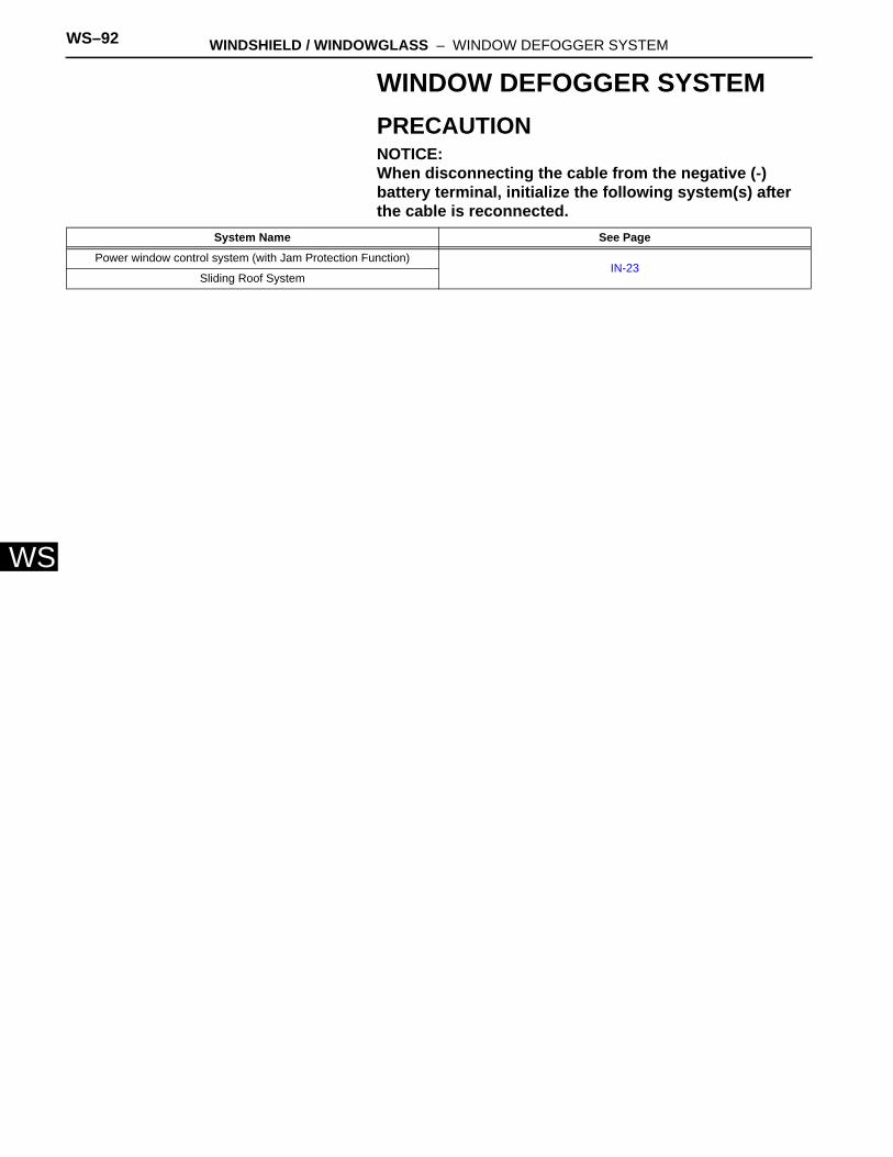
WS–92 WINDSHIELD / WINDOWGLASS – WINDOW DEFOGGER SYSTEM
WS
WINDOW DEFOGGER SYSTEMPRECAUTIONNOTICE:When disconnecting the cable from the negative (-) battery terminal, initialize the following system(s) after the cable is reconnected.
System Name See Page
Power window control system (with Jam Protection Function)IN-23
Sliding Roof System
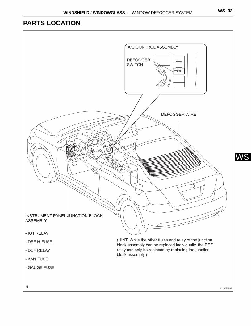
WINDSHIELD / WINDOWGLASS – WINDOW DEFOGGER SYSTEM WS–93
S
WPARTS LOCATION
A/C CONTROL ASSEMBLY
DEFOGGER SWITCH
DEFOGGER WIRE
INSTRUMENT PANEL JUNCTION BLOCK ASSEMBLY
(HINT: While the other fuses and relay of the junction block assembly can be replaced individually, the DEF relay can only be replaced by replacing the junction block assembly.)
- IG1 RELAY
- DEF H-FUSE
- DEF RELAY
- AM1 FUSE
- GAUGE FUSE
B115735E02
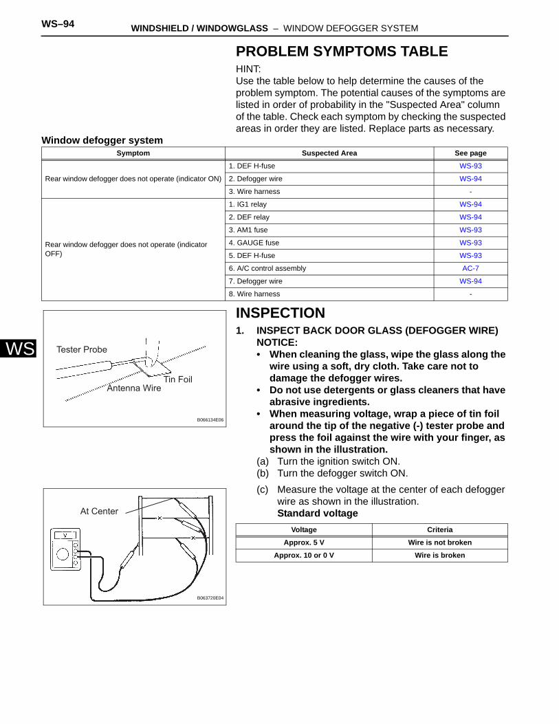
WS–94 WINDSHIELD / WINDOWGLASS – WINDOW DEFOGGER SYSTEM
WS
PROBLEM SYMPTOMS TABLEHINT:Use the table below to help determine the causes of the problem symptom. The potential causes of the symptoms are listed in order of probability in the "Suspected Area" column of the table. Check each symptom by checking the suspected areas in order they are listed. Replace parts as necessary.
Window defogger system
INSPECTION1. INSPECT BACK DOOR GLASS (DEFOGGER WIRE)
NOTICE:• When cleaning the glass, wipe the glass along the
wire using a soft, dry cloth. Take care not to damage the defogger wires.
• Do not use detergents or glass cleaners that have abrasive ingredients.
• When measuring voltage, wrap a piece of tin foil around the tip of the negative (-) tester probe and press the foil against the wire with your finger, as shown in the illustration.
(a) Turn the ignition switch ON.(b) Turn the defogger switch ON.(c) Measure the voltage at the center of each defogger
wire as shown in the illustration.Standard voltage
Symptom Suspected Area See page
Rear window defogger does not operate (indicator ON)
1. DEF H-fuse WS-93
2. Defogger wire WS-94
3. Wire harness -
Rear window defogger does not operate (indicator OFF)
1. IG1 relay WS-94
2. DEF relay WS-94
3. AM1 fuse WS-93
4. GAUGE fuse WS-93
5. DEF H-fuse WS-93
6. A/C control assembly AC-7
7. Defogger wire WS-94
8. Wire harness -
Tester Probe
Antenna WireTin Foil
B066134E06
At Center
B063720E04
Voltage Criteria
Approx. 5 V Wire is not broken
Approx. 10 or 0 V Wire is broken
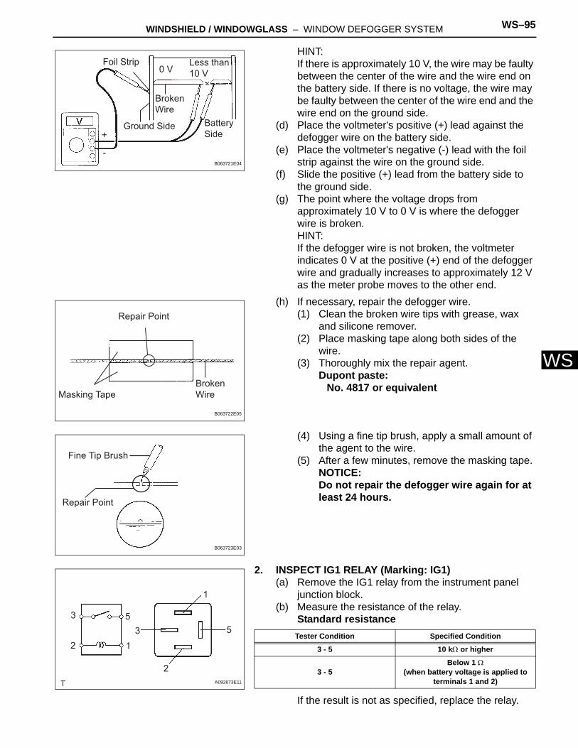
WINDSHIELD / WINDOWGLASS – WINDOW DEFOGGER SYSTEM WS–95
S
WHINT:If there is approximately 10 V, the wire may be faulty between the center of the wire and the wire end on the battery side. If there is no voltage, the wire may be faulty between the center of the wire end and the wire end on the ground side.
(d) Place the voltmeter's positive (+) lead against the defogger wire on the battery side.
(e) Place the voltmeter's negative (-) lead with the foil strip against the wire on the ground side.
(f) Slide the positive (+) lead from the battery side to the ground side.
(g) The point where the voltage drops from approximately 10 V to 0 V is where the defogger wire is broken.HINT:If the defogger wire is not broken, the voltmeter indicates 0 V at the positive (+) end of the defogger wire and gradually increases to approximately 12 V as the meter probe moves to the other end.
(h) If necessary, repair the defogger wire.(1) Clean the broken wire tips with grease, wax
and silicone remover.(2) Place masking tape along both sides of the
wire.(3) Thoroughly mix the repair agent.
Dupont paste:No. 4817 or equivalent
(4) Using a fine tip brush, apply a small amount of the agent to the wire.
(5) After a few minutes, remove the masking tape.NOTICE:Do not repair the defogger wire again for at least 24 hours.
2. INSPECT IG1 RELAY (Marking: IG1)(a) Remove the IG1 relay from the instrument panel
junction block.(b) Measure the resistance of the relay.
Standard resistance
If the result is not as specified, replace the relay.
Foil Strip
Ground Side
Broken Wire
0 VLess than 10 V
Battery Side+
-B063721E04
Repair Point
Masking TapeBroken Wire
B063722E05
Fine Tip Brush
Repair Point
B063723E03
3 5
123 5
1
2A092673E11
Tester Condition Specified Condition
3 - 5 10 kΩ or higher
3 - 5Below 1 Ω
(when battery voltage is applied to terminals 1 and 2)

WS–96 WINDSHIELD / WINDOWGLASS – WINDOW DEFOGGER SYSTEM
WS
3. INSPECT INSTRUMENT PANEL JUNCTION BLOCK ASSEMBLY (DEF RELAY)(a) Measure the voltage of the connector.
Standard
If the result is not as specified, replace the instrument panel junction block assembly.
IF
B084777E02
Tester Connection Defogger Switch Condition Specified Condition
1F-2 - Body groundOFF 0 V
ON 10 to 14 V
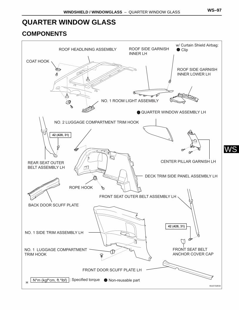
WINDSHIELD / WINDOWGLASS – QUARTER WINDOW GLASS WS–97
S
WBODYWINDSHIELD / WINDOWGLASSQUARTER WINDOW GLASSCOMPONENTS
COAT HOOK
ROOF HEADLINING ASSEMBLY ROOF SIDE GARNISH INNER LH
ROOF SIDE GARNISH INNER LOWER LH
w/ Curtain Shield Airbag: Clip
42 (428, 31)
42 (428, 31)
N*m (kgf*cm, ft.*lbf) : Specified torque
QUARTER WINDOW ASSEMBLY LH
CENTER PILLAR GARNISH LH
NO. 1 ROOM LIGHT ASSEMBLY
BACK DOOR SCUFF PLATE
ROPE HOOK
DECK TRIM SIDE PANEL ASSEMBLY LH
NO. 1 SIDE TRIM ASSEMBLY LH
FRONT DOOR SCUFF PLATE LH
NO. 1 LUGGAGE COMPARTMENT TRIM HOOK
NO. 2 LUGGAGE COMPARTMENT TRIM HOOK
REAR SEAT OUTER BELT ASSEMBLY LH
Non-reusable part
FRONT SEAT BELT ANCHOR COVER CAP
FRONT SEAT OUTER BELT ASSEMBLY LH
B115732E02
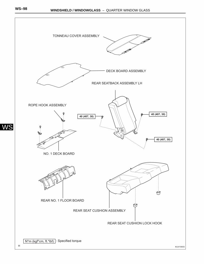
WS–98 WINDSHIELD / WINDOWGLASS – QUARTER WINDOW GLASS
WS
DECK BOARD ASSEMBLY
NO. 1 DECK BOARD
REAR NO. 1 FLOOR BOARD
REAR SEAT CUSHION ASSEMBLY
REAR SEATBACK ASSEMBLY LH
TONNEAU COVER ASSEMBLY
40 (407, 30)40 (407, 30)
40 (407, 30)
N*m (kgf*cm, ft.*lbf) : Specified torque
ROPE HOOK ASSEMBLY
REAR SEAT CUSHION LOCK HOOK
B115733E02
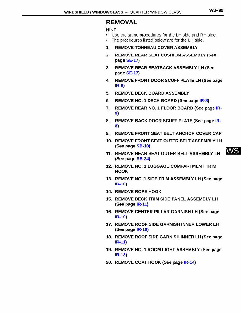
WINDSHIELD / WINDOWGLASS – QUARTER WINDOW GLASS WS–99
S
WREMOVALHINT:• Use the same procedures for the LH side and RH side.• The procedures listed below are for the LH side.
1. REMOVE TONNEAU COVER ASSEMBLY2. REMOVE REAR SEAT CUSHION ASSEMBLY (See
page SE-17)3. REMOVE REAR SEATBACK ASSEMBLY LH (See
page SE-17)4. REMOVE FRONT DOOR SCUFF PLATE LH (See page
IR-9)5. REMOVE DECK BOARD ASSEMBLY6. REMOVE NO. 1 DECK BOARD (See page IR-8)7. REMOVE REAR NO. 1 FLOOR BOARD (See page IR-
9)8. REMOVE BACK DOOR SCUFF PLATE (See page IR-
8)9. REMOVE FRONT SEAT BELT ANCHOR COVER CAP10. REMOVE FRONT SEAT OUTER BELT ASSEMBLY LH
(See page SB-10)11. REMOVE REAR SEAT OUTER BELT ASSEMBLY LH
(See page SB-24)12. REMOVE NO. 1 LUGGAGE COMPARTMENT TRIM
HOOK13. REMOVE NO. 1 SIDE TRIM ASSEMBLY LH (See page
IR-10)14. REMOVE ROPE HOOK15. REMOVE DECK TRIM SIDE PANEL ASSEMBLY LH
(See page IR-11)16. REMOVE CENTER PILLAR GARNISH LH (See page
IR-10)17. REMOVE ROOF SIDE GARNISH INNER LOWER LH
(See page IR-10)18. REMOVE ROOF SIDE GARNISH INNER LH (See page
IR-11)19. REMOVE NO. 1 ROOM LIGHT ASSEMBLY (See page
IR-13)20. REMOVE COAT HOOK (See page IR-14)
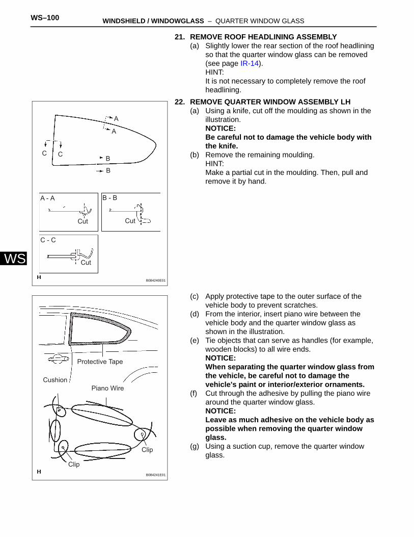
WS–100 WINDSHIELD / WINDOWGLASS – QUARTER WINDOW GLASS
WS
21. REMOVE ROOF HEADLINING ASSEMBLY(a) Slightly lower the rear section of the roof headlining
so that the quarter window glass can be removed (see page IR-14).HINT:It is not necessary to completely remove the roof headlining.
22. REMOVE QUARTER WINDOW ASSEMBLY LH(a) Using a knife, cut off the moulding as shown in the
illustration.NOTICE:Be careful not to damage the vehicle body with the knife.
(b) Remove the remaining moulding.HINT:Make a partial cut in the moulding. Then, pull and remove it by hand.
(c) Apply protective tape to the outer surface of the vehicle body to prevent scratches.
(d) From the interior, insert piano wire between the vehicle body and the quarter window glass as shown in the illustration.
(e) Tie objects that can serve as handles (for example, wooden blocks) to all wire ends.NOTICE:When separating the quarter window glass from the vehicle, be careful not to damage the vehicle's paint or interior/exterior ornaments.
(f) Cut through the adhesive by pulling the piano wire around the quarter window glass.NOTICE:Leave as much adhesive on the vehicle body as possible when removing the quarter window glass.
(g) Using a suction cup, remove the quarter window glass.
A
A
A - A
B
B
C C
B - B
C - C
Cut
Cut
Cut
B084240E01
Protective Tape
Piano WireCushion
Clip
ClipB084241E01
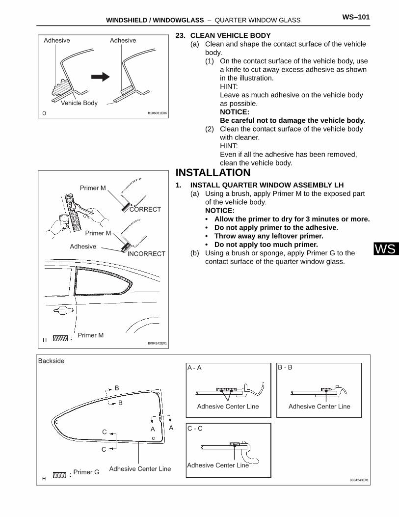
WINDSHIELD / WINDOWGLASS – QUARTER WINDOW GLASS WS–101
S
W23. CLEAN VEHICLE BODY(a) Clean and shape the contact surface of the vehicle
body.(1) On the contact surface of the vehicle body, use
a knife to cut away excess adhesive as shown in the illustration.HINT:Leave as much adhesive on the vehicle body as possible.NOTICE:Be careful not to damage the vehicle body.
(2) Clean the contact surface of the vehicle body with cleaner.HINT:Even if all the adhesive has been removed, clean the vehicle body.
INSTALLATION1. INSTALL QUARTER WINDOW ASSEMBLY LH
(a) Using a brush, apply Primer M to the exposed part of the vehicle body.NOTICE:• Allow the primer to dry for 3 minutes or more.• Do not apply primer to the adhesive.• Throw away any leftover primer.• Do not apply too much primer.
(b) Using a brush or sponge, apply Primer G to the contact surface of the quarter window glass.
Adhesive Adhesive
Vehicle BodyB106081E06
Primer M
Primer M
Primer M
CORRECT
INCORRECTAdhesive
B084242E01
Backside
Primer G Adhesive Center Line
Adhesive Center Line Adhesive Center Line
Adhesive Center Line
AA
B
B
C
C
A - A B - B
C - C
B084243E01
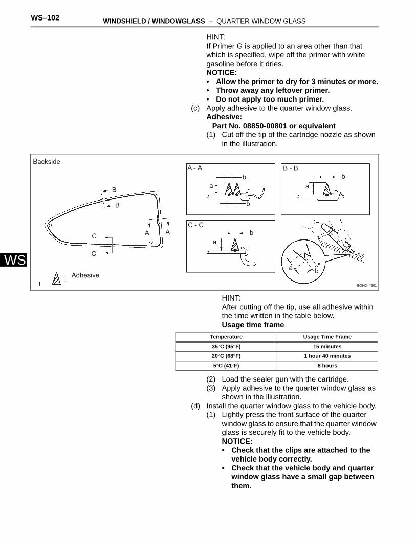
WS–102 WINDSHIELD / WINDOWGLASS – QUARTER WINDOW GLASS
WS
HINT:If Primer G is applied to an area other than that which is specified, wipe off the primer with white gasoline before it dries.NOTICE:• Allow the primer to dry for 3 minutes or more.• Throw away any leftover primer.• Do not apply too much primer.
(c) Apply adhesive to the quarter window glass.Adhesive:
Part No. 08850-00801 or equivalent(1) Cut off the tip of the cartridge nozzle as shown
in the illustration.
HINT:After cutting off the tip, use all adhesive within the time written in the table below.Usage time frame
(2) Load the sealer gun with the cartridge.(3) Apply adhesive to the quarter window glass as
shown in the illustration.(d) Install the quarter window glass to the vehicle body.
(1) Lightly press the front surface of the quarter window glass to ensure that the quarter window glass is securely fit to the vehicle body.NOTICE:• Check that the clips are attached to the
vehicle body correctly.• Check that the vehicle body and quarter
window glass have a small gap between them.
Backside
Adhesive
A A
B
B
C
C
A - A B - B
C - C
a
a
a
ab
b
b
b
b
B084244E01
Temperature Usage Time Frame
35°C (95°F) 15 minutes
20°C (68°F) 1 hour 40 minutes
5°C (41°F) 8 hours
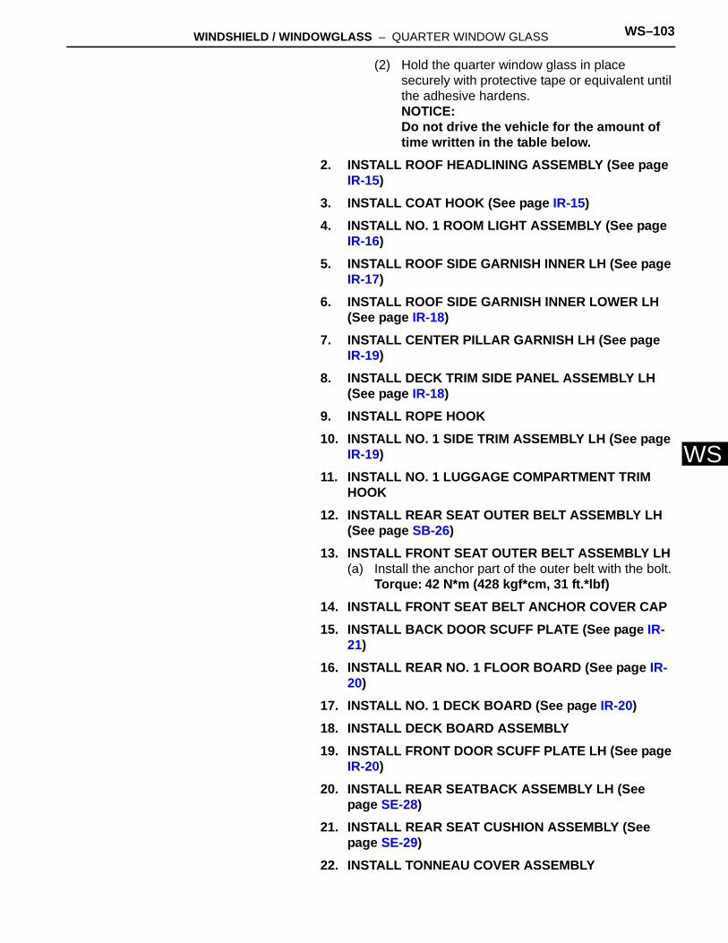
WINDSHIELD / WINDOWGLASS – QUARTER WINDOW GLASS WS–103
S
W(2) Hold the quarter window glass in place securely with protective tape or equivalent until the adhesive hardens.NOTICE:Do not drive the vehicle for the amount of time written in the table below.
2. INSTALL ROOF HEADLINING ASSEMBLY (See page IR-15)
3. INSTALL COAT HOOK (See page IR-15)4. INSTALL NO. 1 ROOM LIGHT ASSEMBLY (See page
IR-16)5. INSTALL ROOF SIDE GARNISH INNER LH (See page
IR-17)6. INSTALL ROOF SIDE GARNISH INNER LOWER LH
(See page IR-18)7. INSTALL CENTER PILLAR GARNISH LH (See page
IR-19)8. INSTALL DECK TRIM SIDE PANEL ASSEMBLY LH
(See page IR-18)9. INSTALL ROPE HOOK10. INSTALL NO. 1 SIDE TRIM ASSEMBLY LH (See page
IR-19)11. INSTALL NO. 1 LUGGAGE COMPARTMENT TRIM
HOOK12. INSTALL REAR SEAT OUTER BELT ASSEMBLY LH
(See page SB-26)13. INSTALL FRONT SEAT OUTER BELT ASSEMBLY LH
(a) Install the anchor part of the outer belt with the bolt.Torque: 42 N*m (428 kgf*cm, 31 ft.*lbf)
14. INSTALL FRONT SEAT BELT ANCHOR COVER CAP15. INSTALL BACK DOOR SCUFF PLATE (See page IR-
21)16. INSTALL REAR NO. 1 FLOOR BOARD (See page IR-
20)17. INSTALL NO. 1 DECK BOARD (See page IR-20)18. INSTALL DECK BOARD ASSEMBLY19. INSTALL FRONT DOOR SCUFF PLATE LH (See page
IR-20)20. INSTALL REAR SEATBACK ASSEMBLY LH (See
page SE-28)21. INSTALL REAR SEAT CUSHION ASSEMBLY (See
page SE-29)22. INSTALL TONNEAU COVER ASSEMBLY
WS–104 WINDSHIELD / WINDOWGLASS – QUARTER WINDOW GLASS
WS
23. CHECK FOR LEAKS AND REPAIR(a) Conduct a leak test after the adhesive has
completely hardened.(b) Seal any leaks with auto glass sealer.
24. CONNECT CABLE TO NEGATIVE BATTERY TERMINAL
25. PERFORM INITIALIZATION(a) Perform initialization (see page IN-23).
HINT:Certain systems need to be initialized after disconnecting and reconnecting the cable from the negative (-) battery terminal.
Related Documents


