DEPARTMENT OF THE ARMY TECHNICAL MANUAL DEPARTMENT OF THE AIR FORCE TECHNICAL OROER ORDNANCE MAINTENANCE DEPARTMENTS OF THE ARMY AND THE AIR FORCE AUGUST 1954

Welcome message from author
This document is posted to help you gain knowledge. Please leave a comment to let me know what you think about it! Share it to your friends and learn new things together.
Transcript
DEPARTMENT OF THE ARMY
TECHNICAL MANUAL
DEPARTMENT OF THE AIR
FORCE TECHNICAL OROER
ORDNANCE MAINTENANCE
DEPARTMENTS OF THE ARMY AND THE AIR FORCE
AUGUST 1954
TECHNICAL MANUAL) DEPARTMENTS OF THE ARMY AND
No. 9-8015-2 TECHNICAL ORDER
m-75CAJ-5
THE AIR FORCE
WASEIN~TON 25, D. C., 8
CHAPTER 1. INTRODUCTION Pllrclqrll*
Section 1. General__________________________________ l-3 II. Description and Data__________._________ 4-9
III. Cleaning, inspection, and repair procedures___ 19-15 2. PARTS, SPECIAL TOOLS, AND EQUIP-
CHAPTER 3. Section I.
II. III. IV. V.
VI. VII.
VIII. IX. X.
CEAPTER 4.
&&ion 1. II. 5.
Section I. II.
MENT FOR FIELD AND DEPOT MAINTENANCE__-__-________________ 16-29
TROUBLESHOOTING General______________________________~___ 21, 22 Transmission_______-____________________.. 23,24 Transfer__________________-______________ 25,26 Propellershafts_________________________-_ 27,28 Frontaxle_______________________-___-___ 29,30 Rearaxle__________________-_____________ 31,32 Brakes_______-_______..___--___-________ 33,34 Springs and shock absorbers________________ 35,36 Steering system__________-________________ 37,38 Wheels_-________________________________ 39,40 REMOVAL AND INSTALLATION OF
MAJOR COMPONENTS
III.
IV.
V. VI.
VII.
VIII.
IX.
Disassembly of vehicle into major components- 41-59 Assembly of vehicle from major components- 69-79 TRANSMISSION Description and data______________________ 80,81 Disassembly of transmission assembly into
subassemblies____________-_-___________ 82-87 Rebuild of transmission control lever cover
assembly___________-___________-_______ 88-90 Rebuild of transmission countershaft and
countershaft cluster gear_______________-- 91-93 Rebuild of transmission main shaft assembly- 94-96 Rebuild of input shaft assembly_____-______ 97-99 Rebuild of reverse idler shaft gear and trans-
mission case assembly_______-___- ______ 199,101 Assembly of transmission assembly from sub-
assemblies_______-__-_-_______________.. 102-106 Testa and adjustment___________________-- 107,108
J-w 4 9
15
18
25 25 28 31 32 34 35 36 37 38
40 78
99
93
199
194 166 198
109
111 113
, 1

WAFTER 6. Section I.
II.
III.
IV.
V. VI.
VII. “III.
IX. CRAPrER 7.
Section I.
II. CSM'TEB8.
Section I. II.
III. IV.
V. VI.
VII.
CHAPTERS.
Section I. II.
III. IV.
V.
CHAPTEB 10.
Section I. II.
III. CHAPTERED.
Section I.
II.
CHAPTER 12. Section I.
II. III. IV. V.
, I
TRANSFER Parapmpba Description and data______________________ 162, 116 Disassembly of transfer assembly into sub-
assemblies_____________________________ 111-116 Rebuild of transfer rear axle output shaft re-
tainer with bearing assembly_____________ 117-119 Rebuild of transfer front axle output shaft
bearing retainer_________________________ 126-122 Rebuild of transfer countershaft assembly____ 123-126 Rebuild of transfer rear axle output shaft
assembly.______________________________ 126-128 Rebuild of transfer case and covers _ _ _ __ _ __ _ 129, 130
Assembly of transfer assembly from sub-
assemblies_____________________________ 131-137
Test and adjustment______________________ 138, 139
PROPELLER SHAFTS
fioe
114
117
123
129
132
133
135
136
143
Description and data:___________._________ 140, 141
Rebuild of propeller shaft assemblies_ _ _ __ _ _ _ 142-144
FRONT AXLE
144
144
Description and data______________________ 145, 146
Disassembly of front axle assembly into sub-
151
assemblies_____________________________ 147-151
Rebuild of front axle shaft assembly_________ 152-154
Rebuild of front axle steering knuckle 6ange
assemblies__ ________ ____.______________ 155-157
Rebuild of front axle differential assembly_ _ _ 158-160
Rebuild of front axle differential drive pfnion
andhousing____________________________ 161,162
Assembly of front axle assembly from sub-
assemblies_____________________________ 163-167
REAR AXLE
153
160
165
167
172
176
Description and data______________________ 168,169
Disassembly of resr axle assembly into sub-
188
essemblies_____________________________ 170-173
Rebuild of differential assembly_____________ 174-176
Rebuild of drive pinion, axle shafts, and hous-
189
196
ingassembly___________________________ 177-179
Assembly of rear axle assembly from sub-
200
assemblies___,_________________________ 180-183
BRAKE SYSTEM
201
Description and data______________________ 184,185
Rebuildofservice brakesystem______._____ 186-189
Rebuild of hand brake system-_-___-_-_____ 190-193
SPRINGS AND SHOCK ABSORBERS
205
206
209
Description and data_________________-____ 194, 195
Rebuild of spring and shock absorber assem-
blies__________________________________ 196-199
3TEERING SYSTEM
214
216
Description and data__-___________________ 200,201 220
Rebuild of steering gear assembly___________ 202-205 224
Rebuild of drag assembly______________ 206-208 230
Rebuild of steering bellcrank assembly_______ 209-211 232
Rebuild of tie rod assemblies_______________ 212-214 233

I'uragrrrpbr
216,21f~ _.
_
_ _ . _ _ _ _ _ _
_
_ _ __. __._ .____ .
_ _ _ _
frame!____ _ _ _ _. I _
_
u _ ,_ _ _ _ . . _ _
I’ayr
236
prod& by Military hkdia Inc., wpyright 19yp
3
1. Scope
Section I. GENERAL
a. This manual is published for the use of personnel responsible for
field and depot maintenance of this materiel. It contains information
on maintenance which is beyond the scope of the tools, equipment, or
supplies normally available to using organizations. It does not con-
tain information which is intended primarily for the using organiza-
tion, since such information is available to ordnance maintenance
personnel in the pertinent operator’s technical manual or field manual.
This manual contains a description of and procedures for removal,
disassembly, inspection, repair, rebuild, and assembly of the power
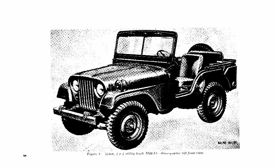
train, body, and frame of the )&ton, 4 x 4 utility truck M38Al (figs.
1, 2, and 3). The appendix contains a list of current references,
including supply manuals, technical manuals, and other available
publications applicable to the materiel.
c. This first edition is being published in advance of complete
technical review of all concerned. Any errors or omissions will be
brought to the attention of Chief of Ordnance, Washington 25, D. C.,
Attn: ORDFM-Pub.
TM g-8048 (To be renumbered TM g-8014) contains operating
and lubricating instructions for the materiel and contains all mainte-
nance operations allocated to using organizations in performing
maintenance work within their scope.
e. TM 9-8015-l contains service information on the engine.
f. TM 9-8627 contains service information on the Delco-Remy
electrical equipment.
g. TM 9-1825B (To be renumbered TM 9-8629) contains service
information on Auto-Lite electrical equipment.
h. TM g-18268 (To be renumbered TM 9-8641) contains service
information on the Carter carburetor.
i. TM 9-1827C (To be renumbered TM 9-8653) contains service
information on the hydraulic brakes.
j. TM g-18288 (To be renumbered TM 9-8655) contains service
information on the AC fuel pump.
4


Y Figure 3. s ton, 4 z 4 truck M38Al-top view.

P. Field and Depot Maintenance Allocation
Forms, Records, and Reports
a. General.
Forms.
310-20-6.
Field Report.8 of Accidents.
385-10-40

d. Report oj Unsatisfactory Equipment or Materiels.
Such
whirh indicate unsatisfactory design or
material. However, reports will always be made in the event that exceptionally
costly equipment is involved. See also SR 700-45-5 and the printed instructions
on DA Form 468.
1,
Vehicle Nomenclature.
-178654
181 MO

5. Power Train Ok -5)
b. Transmission.
Transfer.
d. Propeller Shafts.
Front Axle Assembly.
Axle Assembly.
11

Figure 6. Power of ~-ton, 4 z 4 truck MSBAI.
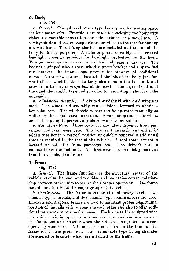
6. Body (fig. 158)
a. General. The all steel, open type body provides seating space
for four passeng&s. Provisions are made for inclosing the body with
either a removable canvas top and side curtains, or a metal top. A
towing pintle and trailer receptacle are provided at the rear for hauling
a towed load. Two lifting shackles are installed at the rear of the
body for lifting purposes. A radiator guard assembly with recessed
headlight openings provides for headlight protection on the front.
Two bumperettes on the rear protect the body against damage. The
body is equipped with a spare wheel support bracket and a spare fuel
can bracket. Footman loops provide for stowage of additional
items. A rearview mirror is located at the left of the body just for-
ward of the windshield. The body also mounts the fuel tank and
provides a battery stowage box in the cowl. The engine hood is of
the quick detachable type and provides for mounting a shovel on the
underside.
b. Windshield Assembly. A divided windshield with dual wipers is
used. The windshield assembly can be folded forward to obtain a
low silhouette. The windshield wipers can be operated manually as
well as by the engine vacuum system. A vacuum booster is provided
on the fuel pump to prevent any slowdown of wiper action,
c. Seat Assemblies. Three seats are provided; driver’s, front pas
senger, and rear passengers. The rear seat assembly can either be
folded together in a vertical position or quickly removed if additional
space is required in the rear of the vehicle. A tool compartment is
located beneath the front passenger seat. The driver’s seat is
mounted over the fuel tank. All three seats can be quickly removed
from the vehicle, if so desired.
7. Frame (fig. 178)
a. General. The frame functions as the structural center of the
vehicle, carries the load, and provides and maintains correct relation-
ship between other units to assure their proper operation. The frame
mounts practically all the major groups of the vehicle.
b. Construction. The frame is constructed of heavy steel. Two
channel-type side rails, and five channel type crossmembers are used.
Brackets and diagonal braces are used to maintain proper longitudinal
position of the rails with reference to each other and also to offer addi-
tional resistance to torsional stresses. Each side rail is equipped with
two rubber axle bumpers to prevent metal-to-metal contact between
the frame and axle housing when the vehicle is subjected to severe
operating conditions. A bumper bar is secured to the front of the
frame for vehicle protection. Four removable type lifting shackles
are secured to brackets which are attached to the frame.
13

Engine, Clutch, and Electrical System
a. Engine. The engine is an F-head, 4-cylinder, 4-cycle, water-
cooled, gasoline design developing 72 brake horsepower at 4,000 rpm,
and having a compression ratio of 6.9 to The engine is a valve-in-
head and valve-in-block type with a piston displacement of 134.2
cubic inches. Aluminum pistons, each fitted with 2 compression
rings and 1 oil ring, ar ’ used. The crank shaft is supported by three
steel backed babbitt inserts. A force feed, continuous circulation,
lubrication system is used to lubricate the moving parts of the engine.
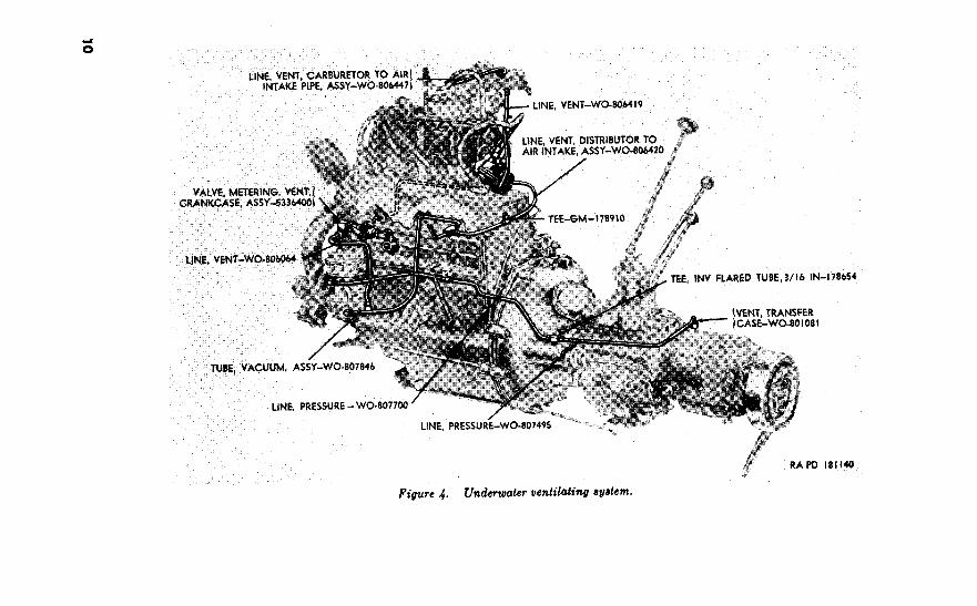
The engine is waterproofed for operation while completely submerged
in water. All mating surfaces are sealed with gaskets and plastic
type gasket cement. A design which utilizes the engine ventilating
system as a pressure seal, further insures prevention of water leakage
past mating surfaces. The engine cooling system is of the pressure
type, and the pressure, created by the expansion of the coolant as it
warms up, is not relieved until it reaches psi. The radiator filler
cap includes a relief valve which relieves the pressure when it reaches
the predetermined setting. The pressure system reduces evaporation
of the coolant and provides for more efficient engine operation by
permitting a slightly higher engine operating temperature. A bypass
tube provides for a small amount of coolant to bypass the thermostat
for fast initial warmup.
The clutch, which is located between the engine and
transmission, is of the single-plate, dry-disk type. It is comprised of
a pressure plate assembly and a clutch-driven disk. Segmented
facings on the disk provide for smooth engagement of engine power.
c. Electrical Two 12-volt lead and acid type batteries,
connected in series, supply 24 volts for operating the electrical com-
ponents of the vehicle. All components of the electrical system are
waterproofed for operation while completely submerged. Two head-
lights, a blackout driving light, and two signal blackout marker and
service parking lights are installed on the front of the vehicle. The
blackout tail and stoplight and the service tail and stoplight are
located at the rear of the vehicle. An electrical trailer receptacle at
the rear of the vehicle provides for connecting the electrical units of a
towed trailer to the vehicle electrical system.
9. Data
Refer to TM g-8048 (to be renumbered TM g-8014) for tabular
data pertaining to general characteristics and performance of the
vehicle and major components. TM 9-1804AA (to be renumbered
TM 9-8015-l) contains descriptive information and tabular data per-
taining to the engine and clutch. For detailed information and
tabular data pertaining to components covered in this manual refer
to the following paragraphs:
14
Par~~ph
Body____________________~______---_--____.____________---___ 216
Frsme___~_____________---________._-_____-___--_____--______ 245
Front axle assembly_____________________...______________-_-..__ 146
Propellershafts________________________.___-_______..___---___- 141
assembly_ ______________________________________---_._ 169
Shockabsorbers__________._--_________________________----____ 195
Springs____________________-_____________~_-___--_~____-______ 195
Steeringsystem______~____--_______-_--_-..____--__________.__ 201
Trsnsfer__________________________--_--________--_____________ 110
Trsnsmission_______________________-_-_______----______-______ 81
Universal joints___._______________-__________-__-~____-_._____ 141
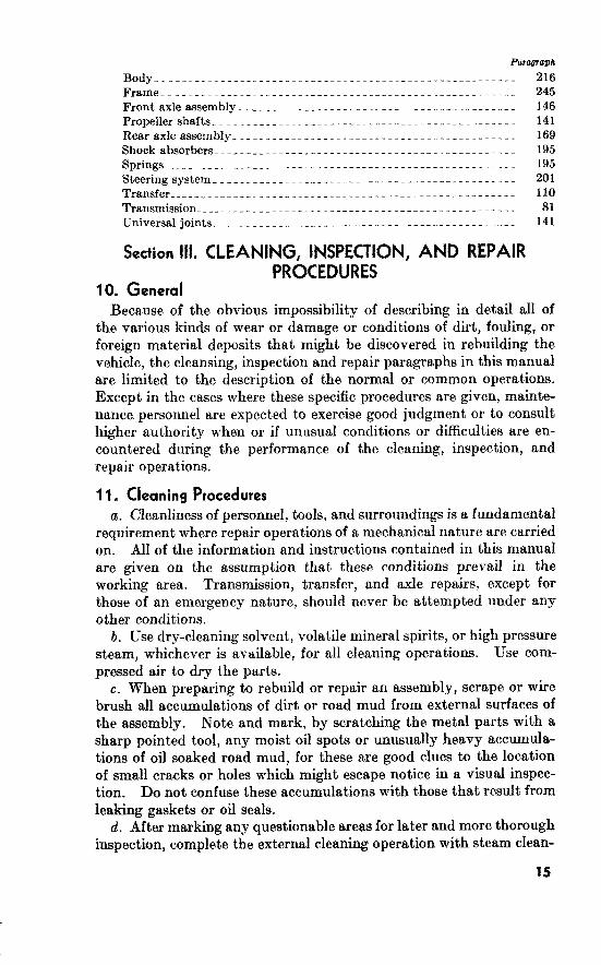
Section III. CLEANING, INSPECTION, AND REPAIR PROCEDURES
10. General Because of the obvious impossibility of describing in detail all of
the various kinds of wear or damage or conditions of dirt, fouling, or
foreign material deposits that might be discovered in rebuilding the
vehicle, the cleansing, inspection and repair paragraphs in this manual
are limited to the description of the normal or common operations.
Except in the cases where these specific procedures are given, mainte-
nance personnel are expected to exercise good judgment or to consult
higher authority when or if unusual conditions or difficulties are en-
countered during the performance of the cleaning, inspection, and
repair operations.
11. Cleaning Procedures a. Cleanliness of personnel, tools, and surroundings is a fundamental
requirement where repair operations of a mechanical nature are carried
on. All of the information and instructions contained in this manual
are given on the assumption that these conditions prevail in the
working area. Transmission, transfer, and axle repairs, except for
those of an emergency nature, should never be attempted under any
other conditions.
b. Use dry-cleaning solvent, volatile mineral spirits, or high pressure
steam, whichever is available, for all cleaning operations. Use com-
pressed air to dry the parts.
c. When preparing to rebuild or repair an assembly, scrape or wire
brush all accumulations of dirt or road mud from external surfaces of
the assembly. Note and mark, by scratching the metal parts with a
sharp pointed tool, any moist oil spots or unusually heavy accumula-
tions of oil soaked road mud, for these are good clues to the location
of small cracks or holes which might escape notice in a visual inspec-
tion. Do not confuse these accumulations with those that result from
leaking gaskets or oil seals.
d. After marking any questionable areas for later and more thorough
inspection, complete the external cleaning operation with steam clean-
15

ing equipment or by hand brushing using volatile mineral spirits as a
cleaning agent. Total immersion in a dip tank is also approved, pro-
vided the cleaning agent is dry-cleaning solvent or volatile mineral
spirits.
19. Cleaning Component Parts After Disassembly
a. If other approved facilities are not available, all parts must be
cleaned by hand using bristle brushes having the correct shape and
proper size for the job to be done; that is, round brushes for internal
bores and square or rectangular hand brushes for flat or external sur-
faces. Scrub each individual part except ball or roller bearings
Ndte. Bearings require special handling. Refer to TM 37-265 or TB 9-2830-
93 and clean, inspect, and prepare for use all ball and roller bearings used in these
assemblies according to the instructions given therein.
b. Clean all parts of hardened oil, lacquer deposits, and carbon.
Wire brushes either hand wielded or power driven may be used for
this purpose provided there is no possibility of their damaging finished
surfaces. Otherwise, the parts must be pelamitted to soak in solvent
until the foreign material is loosened.
c. Remove all gaskets or parts of gaskets from gasket surfaces,
using a putty knife or other suitable scraper. Be careful to avoid
scratching or gouging the surface metal.
d. Rinse or flush the parts in clean dry-cleaning solvent or volatile
mineral spirits. Even though the dirt or foreign matter is loosened
by the cleaning action, it must be completely washed away by a
flushing action. This is a mandatory operation on parts that have
undergone repair operations which required them to be ground,
honed, or lapped. Use solvent under pressure to force-flush repaired
parts. In the absence of such facilities, the parts may be rinsed by
immersing them in a container of clean dry-cleaning solvent or
volatile mineral spirits and then sloshing them about vigorously either
manually or by some improvised mechanical means. Dry the parts
with high pressure air.
13. Inspection Procedure
a. All parts, regardless of their application or use, must be thoroughly
examined and inspected to determine whether they are to be used
again or scrapped. The wear or damage of some parts will be evident
to the eye, whereas in others it ma,y be necessary to use tools or gages
to determine the extent of wear.
When inspecting parts, bear in mind that the inspection procedure
has two purposes. The first, to weed out any part or parts which are
unsuitable for use, or doubtful parts which could conceivably cause
the premature failure of the rebuilt unit. The second, and equally
important purpose, is to reduce the wast,eful and frequently unneces-
16

sary practice of scrapping parts which still retain a high percentage
of useful life.
e. Instructions for the performance of minor repairs, or for the
removal of minor imperfections, are given in the inspection paragraphs
wherever they facilitate the inspection procedure. Every part on
which even a minor repair is made must be washed, rinsed, and dried
upon completion of the repair.
14. Repair Procedure
a. All good workmen like repairs which are acceptable. Makeshift
or temporary repairs are not permitted, except in extreme emergencies.
b. The principal purpose of repairs is to salvage parts which would
otherwise be scrapped. The decision as to whether a part is to be
repaired or not rests upon three factors.
(1) The practicality of the repair, that is, can the part be repaired
and be thus returned to a condition approximating new. If
not, the repair should not be attempted.
(2) The cost of the repair as compared to the cost of a replacement
part. If the cost factor does not favor the repair, the part
should be discarded.
(3) The availability of replacement parts. If service parts are not
available or in short supply, every effort should be made to
salvage as many parts as possible, disregarding any of the
other governing factors.
c. Upon completion of any repairs, clean and flush the parts as
instruct~ed in paragraph 12d.
i 5. Handling After Inspection and Repair
a. All parts liable to rust, whether new or used, must be lightly
coated with medium preservative lubricating oil immediately after
inspection and/or repair, and prior ‘to their assembly. Oiling the
parts gives them a necessary rust, preventative coating and facilitates
the assembly operations.
b. Make sure that all new gaskets and replacement parts are
available to replace those scrapped.
c. Check to see that all parts are at hand so that the assembly
operations may go forward without interruption.
‘17

2
16. General
Tools and equipment and maintenance parts over and above those
available to using organization are supplied to ordnance field main-
tenance units and depot shops for maintaining, repairing, and/or
rebuilding the materiel.
17. Parts
Maintenance parts are listed in Department of the Army Supply
Manual ORD 8 SNL G-758 which is the authority for requisitioning
replacements. Parts not listed in the ORD 8 supply manual but
required by depot shops in rebuild operations may be requisitioned
from the listing in the corresponding ORD 9 supply manual and
will be supplied if available. Requisitions for ORD 9 parts will
contain a complete justification of requirements.
18. Common Tools and Equipment
Standard and commonly used tools and equipment having general
application to this materiel are listed in ORD 6 SNL J-8, Sections
7, ORD SNL J-9, Sections and ORD
SNL J-10! Sections 4, 7, 8,
by T/A and T/O&E.
and are authorized for issue
19. Special Tools and Equipment
The special tools and equipment tabulated in table I are listed in
Department of the Army Supply Manual ORD SNL J-16, Section
38. This tabulation contains only those special tools and equipment
necessary to perform the operations described in this manual, is
included for information only, and is not to be used as a basis for
requisitions.

Item
ARBOR, removing and replacing (countershaft),
0.751 in. diam, 6.850 in. long (transmission).
GAGE SET, drive pinion setting consisting of-
GAGE, checking, drive pinion setting gage- _ _ _
GAGE, drive pinion setting_ ___ ___ _ _ _ _ _ _ _ _ _ - _ _
SPACER, drive pinion setting__ _ _ ___ _ __ _-- - _-
LOCATOR, thrust washer (Intermediate shaft,
transfer case),
PULLER, rear spring bushing removing and re-
placing.
REMOVER, flange, drive pinion and bearing, dif-
ferential side.
REMOVF,R,bearingeone(front)_____ ___.___-- ---
REMOVER and replacer (bushing, spindle front
wheel).
REMOVER and replacer, bearing cup (drive pinion
inner, used with screw 41-S-1047-330).
REMOVER and replacer, bearing “up (drive pinion
outer, used with screw 41-S-1047-330).
3; REMOVER and replacer, bearing cup (spindle pin
thd jY,16NF-2 female, used with screw 41-S
1047-300).
--
-l
’ I
41-A-339-22
41-G-535-700
41-G-98-750
41-G-177-50
41-S-3868-415 4l_L-l697-375
8366660
41--R-2367-950
41-R-2368-200
41-R-2374-175
41-R-2374-660
41-R-2374-665
41-R-2374-750
-
6
50
58
6
6
116
117
6
116
6
6
81
8
147
148
7
107
8
70
8
106
6
112
6
113
6
ii0
114
- I
_-
I-
;’
83
93
163
163
181
163
197
158
174
115
156
162
162
162
_-.
1
(
/
: I
use
-
Removing and installing transmission counter-
shaft without loss of bearing rollers.
Checking differential drive pinion setting.
Removing and installing spring bushing type
eye bearings.
Removing differential case tapered roller bearing
cones.
Removing transfer front bearing cones.
Installing spindle bushing type bearing.
Removing and installing drive pinion inner
bearing cup.
Removing and installing drive pinion bearing
cup.
Removing and installing steering knuckle flange
kingpin bearing cup.
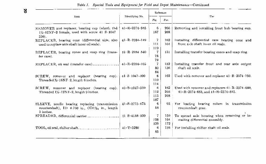
Table I. Special Tools and Equipment for Field and Depot Maintenance-Continued
s
REMOVER and replacer, bearing cup (wheel, thd
lg-12NF-2 female, used with screw 41-S-1047-
330).
REPLACER, bearing cone (differential side, also
used to replace axle shaft inner oil seals).
REPLACER, bearing cones and snap ring (trans-
fer case).
REPLACER, oil seal (transfer case)______________
SCREW, remover and replacer (bearing cup).
Threaded g-16NF-2, length 6 inches.
SCREW, remover and replacer (bearing cup).
Threaded lx-12NF-2, length 9 inches.
SLEEVE, needle bearing replacing (transmission
countershaft), ID 0.760 in., ODlgd in., length
3 inches.
SPREADER, differential carrier____________~__---
TOOL,oilseal,shiftershaft_______________________
41-R-2374-845
41-R-2384-149
41-R-2384-540
41-R-2394-105
41-s-1047-300
41-s-1047-330
41-S-3775-675
41-S-4158-500
41-T-3280
- Use
6 266
187 268
Removing and installing front hub bearing cup.
7
111
119
7
78
79
7
80
84
6
110
114
6
112
113
187
6
58
162
164
131
Installing differential case bearing cone and
front axle shaft inner oil seals.
Installing transfer bearing cones and snap ring.
132 Installing transfer front and rear axle output
136 shaft oil seals.
162 Used with remover and replacer 41-R-2374-750.
162
266
268
Used with remover and replacers 41-R-2374-660,
41-R-2374-665, and 41-R-2374-845.
93 For loading bearing rollers in transmission
countershaft gear.
7
128
129
6
85
150
164
172
136
To spread axle housing when removing or in-
stalling differential assembly.
For installing shifter shaft oil seals.
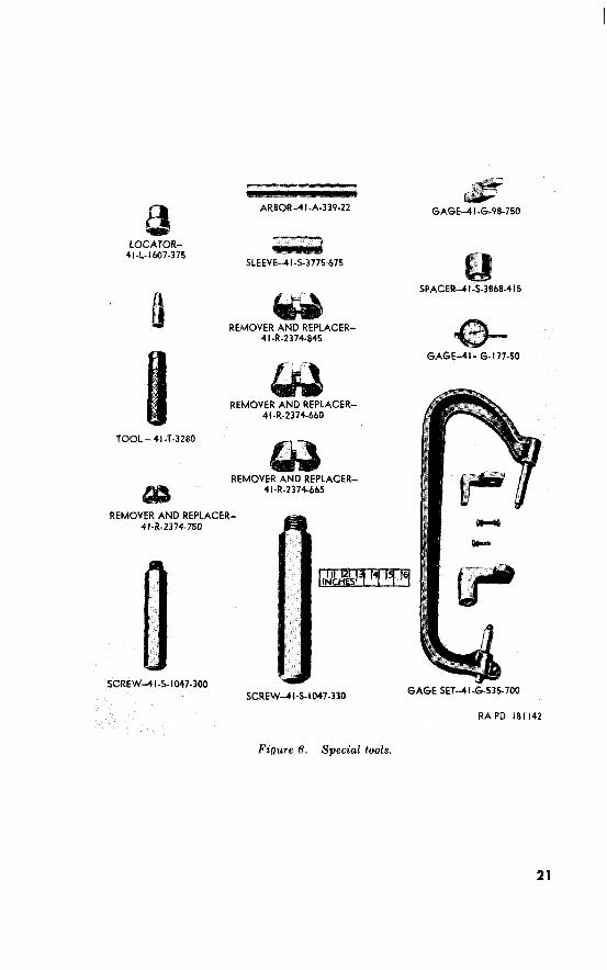
TOOL-41-T-3280
Figure 6. Special tools.
21

SPREADER-QI-S-4158.500
REMOVER-41-R-2367-950
REPLACER-41.R-2384 -540
REPLACER-+]-R-2384-149
Figure 7. Special tools.
REPLACER-II-R-2394-105
RAPD 181143
22
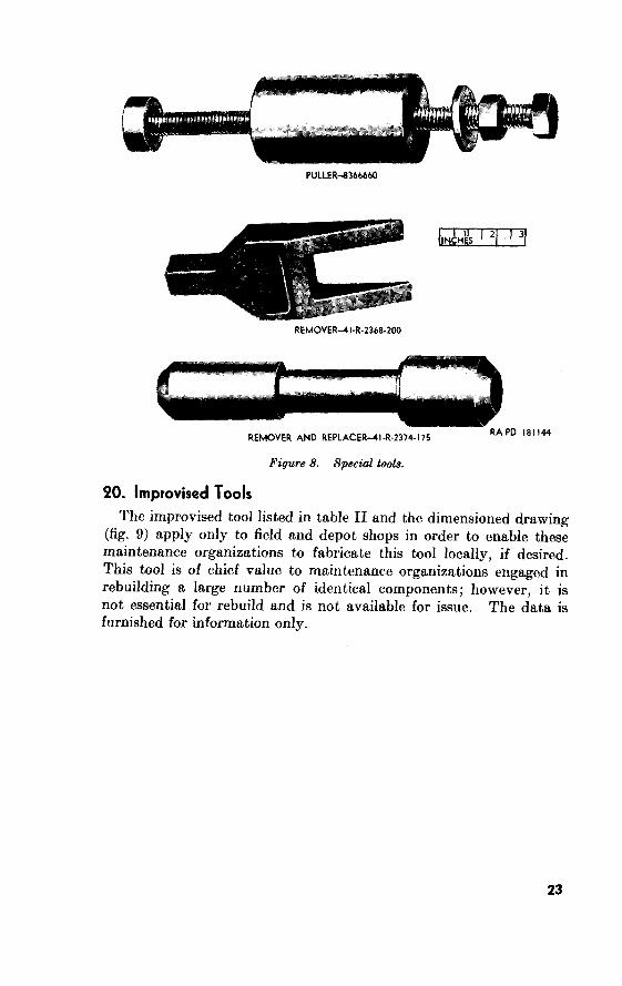
PULLER-8364W
REMOVER-41-R-2368-200
REMOVER AND REPLACER-41-R-2374-175 RA PD 181 I44
Figure 8. Special tools.
PO. Improvised Tools
The improvised tool listed in table II and the dimensioned drawing (fig. 9)
23

TOOL-WINDSHIELD GLASS RAPD 151145
for
I Item
Tool, windshield glass, weather-
strip filler.
References
Fig. PC&r. --
9 For installing windshield glass
weatherstrip filler.
I -
24
3
21. Purpose Section I. GENERAL
Information in this chapter is for use of ordnance maintenance personnel
in conjunction with and as a supplement to the troubleshooting section in the
pertinent operators manual (TM 9-804A). It provides the continuation of
instructions where a remedy in the operators manual refers to ordnance mainte-
nance personnel for corrective action.
Operation of a deadlined vehicle without a preliminary examination
can cause further damage to a disabled component and possible injury
to personnel. By careful inspection and troubleshooting such damage
and injury can be avoided and, in addition, the causes of faulty opera-
tion of a vehicle or component can often be determined without
extensive disassembly.
22. General Instructions and Procedures
This chapter contains inspection and troubleshooting procedures to
be performed while a disabled component is mounted in the vehicle.
a. The inspections made while the component is mounted in the
vehicle are, for the most part, visual and are to be performed before
attempting to operate the vehicle. The object of these inspections
is to avoid possible damage or injury and also to determine the con-
dition of, and when possible, what is wrong with the defective com-
ponent.
The troubleshooting performed while the component is mounted
in the vehicle is that which is beyond the normal scope of the using
organization. Check the troubleshooting section of TM g-8048,
then proceed as prescribed in this chapter. These troubleshooting
operations are used to determine if the fault can be remedied without
removing the component from the vehicle and also, when subsequent
removal is necessary, to indicate when repair can be made without
complete disassembly of the component.
Section II. TRANSMISSION
~3. Troubleshooting Before Removal or Operation
Do not operate the vehicle prior to completing the
procedures given in this paragraph. Refer to paragraph 22a for the
purpose of these inspections.
Removal of the lower front floor pan cover (par. 48c (9)) (if body is
still installed) will facilitate making the following inspections.
25
6. Ittspct for Oil Lrtrkn!g~.
1111
nrltl lolb(l)).
.\‘ole. t tic atmve
In<spect .for lI.atrr irr Transmissiorl. Irwpcc-t
(I’. Inspect for LOOSP Gearshift Ilnnd Lwrr. A
t
.for Trrw.smission Gearsh<ft I1an.u’ LPrwr Assembly Thnt fs
I)ificult 7’0 Shift.
Inspect .for GearAift Hard Lever That Is Jammed in First Speed
or Recerse Speed.
Inspect_for Gearshift Hand Lever That Is Jammed in Second Speed
or Third Speed. ii
24.
a. General.
X!b
b. Lubricant Check.
Transmission Slips Out of Gear.
9Bb).
d. Transmission Operates
Intermittent howl.
Intermittent knocking thudding.
High pitched howl whine.
High pitched squeal, thudding, knocking.
Transmission Sounds Noisy but Noise Caused by Outside Factors.
(1)
Section III. TRANSFER
25. Troubleshooting Before Removal or Operation
a. Generd.
Note. Removal of the lower front floor pan cover (par.
still installed) will facilitate making the following inspections.
b. Inspect Oil Leakage.
28

Inspect for Fai&ure of the High and Low Range Gearshijt Hand
Lever To Move to Direct (High) or Underdrive (Low).
6),
6)
or 6),
Inspect for Water in Transfer.
Inspect for Failure of Front Wheel Drive Lever To Move Out of
Neutral.
26. Troubleshooting Before Removal and During Operation
a.
29
Refer to paragraph 22b for the purpose and scope of these trouble-
shooting procedures.
b. Lubricant Check. Check transfer oil level before attempting to
operate vehicle. Refer to TM g-8048 for proper lubricant. If
cause of any lubricant leakage is doubtful (when operating vehicle
after fording), remove fording valve in clutch housing, wipe outer
surface of transfer, and road test. Check for lubricant. leakage.
c. Transfer Slips Out of Front Wheel Drive.
Front wheel drive gear sh<ft lever spring loose or weak. Install
gearshift lever spring correctly or replace, as necessary
(ch. 6).
(2) Bent front axle output shaft clutch gear shijter fork. Disas-
semble transfer, and replace front axle output shaft clutch
gearshifter fork (ch. 6).
(3) Shijter shaft detent ball or spring damaged. Disassemble
transfer and replace shifter shaft detent ball or spring, as
necessary (ch. 6).
(4) Front axle output shaft clutch gearshijter fork loose on shijter
shaft Disassemble transfer and tighten shifter fork screw
(ch. 6). Be sure setscrew is locked with locking wire.
(5) Gear teeth worn. Disassemble transfer and replace worn
gears (ch. 6).
d. Transfer Slips Out of High or Low Ra,nge
High and low range gearshijt lever spring loose or weak. Refer
to above.
(2) Bent rear axle output shajt sliding gearshijber fork. Dis-
assemble transfer and replace damaged rear output shaft
sliding gear shifter fork (ch. 6).
(3) Shijter shaft detent ball or spring damaged. Refer to c(3)
above.
(4) Rear axle output shaft sliding gearshijter fork loose on shijter
shaft. Refer to c(4) above.
(5) Gear teeth worn. Refer to c(5) above.
e. Transfer Gearshijt Levers Shijt Hard or Will Not Shijt.
Note. If trouble is encountered with transfer sticking in neutral (cannot be
moved to either low or high range), jack up wheel and spin to free transfer.
(1) Shijter shaft detent balls or springs damaged. Disassemble
transfer and replace faulty parts (ch. 6).
(2) Shijter shafts or shijter forks damaged. Disassemble transfer
and replace faulty parts (ch. 6).
(3) Clutch gear damaged. Disassemble transfer and replace
front axle output shaft clutch gear (ch. 6).
j. Transfer Operates Noisily Transfer noise may at times be
confused with noises actually originating in the transmission. Refer
to paragraph 24d for instructions on isolating transmission noises.

However, if noise occurs only when transfer is in operation during
vehicle travel, it is probably due to one of the following malfunctions:
(1) Improperly meshed gears in transfer. Replace faulty gears.
(2) Gear teeth damaged or missing. Replace faulty gears.
(3) Damaged countershajt gear journal roller, or rear axle output
shaft bearings. Replace faulty bearings.
Information on transmission noises will in general hold for
those caused by transfer.
Section IV. PROPELLER SHAFTS
Troubleshooting Before Removal or Operation
a. General. Do not operate the vehicle prior to completing the
procedures given in this paragraph. Refer to paragraph 22a for the
purpose of these inspections.
b. Inspect for Loose Front or Rear Propeller Shaft. If the front or
rear propeller shaft is loose when shaken by hand, make the following
inspections and apply the stated corrective actions:
(1) Inspect the universal joint journal bearing assemblies for wear
and damage. Remove and replace faulty bearing assemblies
(pars. 142b, 143d, and 1446).
(2) Inspect the universal joint bearing U-bolts for looseness and
wear. Tighten or replace damaged U-bolts, if necessary
(ch. 4).
(3) Inspect for loose mounting nuts which secure the rear pro-
peller shaft to the transfer companion flange. Tighten nuts
or replace, if stripped.
(4) Inspect for loose front propeller shaft to transfer yoke nut.
Remove front propeller shaft and tighten nut.
(5) Inspect for loose front or rear propeller shaft to front or rear
axle yoke nut. Remove propeller shaft and tighten yoke nut.
c. Inspect for Stij Operating Universal Joint-s. An excessively stiff
operating universal joint can be caused by the following malfunctions : (1) Inadequate lubrication. Lubricate universal joint and propel-
ler shaft as directed in TM 9-804A.
(2) Bent propeller shaft. Replace propeller shaft (ch. 4).
(3) Universal joint bearing assemblies seized. Replace universal
joint bearing assemblies (par. 144).
(4) Damaged propeller shaft splines. Replace propeller shaft
(par. 144).
98. Troubleshooting B e ore C Removal and During Operation
If the inspections in the preceding paragraph do not
reveal causes of failure and the vehicle is operable, then troubleshoot it.
Refer to paragraph for the purpose and scope of these trouble-
shooting procedures.
31

b. Propeller Shafts Do Not Rotate. This trouble may be caused by
one of the following:
(1) Clutch slipping. Adjust clutch as instructed in TM g-8048.
If adjusting clutch does not remedy the trouble, replace
clutch as instructed in TM g-8044.
(2) Faulty transmissaon. Troubleshoot transmission (pars. 23
and 24).
(3) Faulty transfer. Troubleshoot transfer (pars. 25 and 26).
c. Excessive Vibration. Foreign matter such as mud, paint, tar, or
other obstructions on propeller shaft may cause unbalance. Clean all
foreign materials from propeller shaft.
Section V. FRONT AXLE
29. Troubleshooting Before Removal or Operation
a. General. Do not operate the vehicle prior to completing the
procedures given in this paragraph. Refer to paragraph 22a for
purpose of these inspections.
b. Inspect for Lubricant Leakage. Visually inspect mating joints of
housing cover and housing for evidence of lubricant leakage. Leakage
at gasket joint may be caused by a damaged cover gasket or loose bolts.
Tighten all bolts. If bolts are tight and leakage continues, install a
new cover gasket. Install new gasket, if possible, without removing
front axle from vehicle. Inspect drain and filler pipe plugs for leakage.
Tighten plugs, if necessary. Inspect steering knuckle flanges at
mating surfaces for evidence of lubricant leakage. If leakage is
evident, the steering knuckle flange oil seal gasket or steering knuckle
flange oil seals may be faulty. Tighten screws which secure steering
knuckle oil seal retainers. If leakage continues after tightening,
replace gasket or oil seals, as necessary. Inspect for lubricant leakage
at axle end yoke. If leakage is evident, the drive pinion oil seal or
drive pinion oil seal gasket may be damaged. Replace as necessary.
c. Inspect for Excessive Front Wheel Play. Raise front wheels from
ground and move front wheels from side to side and up and down. If
excessive looseness exists, the trouble may be caused by one of the
following:
(1)
(2)
(3)
Wheel bearing spindle bolts loose or damaged. Remove wheel
and tighten wheel bearing spindle bolts.
Steering knuckle jlange cap bearing. Replace worn steering
knuckle flange cap bearings (par. 157).
Loose or damaged steering knuckle $ange caps. Tighten or
replace steering knuckle flange caps as necessary.
30. Troubleshooting Before Removal and During Operation
a. General. If the inspections in the preceding paragraph do not
reveal causes of failure and the vehicle is operable, then trouble-
32

shoot it. Kcfcr to paragraph 226 for th purposr and scopct of thw troul~lt~shonting proccduws.
b. Iard Sfeering. Hard stwring may 1~ caused 1)s scizrtl stwrirrg knuckle flange cap harings. Rt>plnw lwwings (par. It%).
c. Low-Speed Shimmy. Lo~~-sp~~l shimmy can h wuscd I)y 011~’ follo\ving conclitions:
Front a.& shifted. Inspect for broken spring wntw bolt, arid rcplaw, if ncwssarg (pnr. 19&~(l)). Spring rebound clips or shackles loose. Tightclrl or wplacc ns ncwwary (pars. 62 and 19&z(2)). Li’orr~ ste~rijry knuck/e_fl~,/ye CUII bearings I<t~plac~c~ 1 G(i), Improper caster. paragraph I tj7h.
(‘heck low-speed shimmy. The malfunctions c-awing low
spwtl shimmy will often lw c~nc~ountc~rd at liiglwr rout1 spds hut will not h (lasily noticctl. Sulxwquc~lit slo~5%lg tlo~vn of voliiclc \vill usually disclow shimmy.
Steering gear loose ok frame. Tiglltcn and adjust (par. Ga).
Front spr’irrgs broken or settled. Kcpair or rcpluw spring (pars. 197 and 198).
Loss of co&d bly shock absorbers. at)sortwrs (par. 57b).
&r/t steering knuckle jlange arm. Repair or wplaw (pnrs. 156 and 166).
e. Vehicle Uhnders. vc~hiclc has been in o.11 accidrnt, tllc. troublr may h clutl to a misulincd steering sgstcm. &pair or replaw tlamagd parts (~11. 12).
f. Fran t Axle Nois!y on Pull.
(1)
(2)
(3)
(4)
(5)
Ilrii~e pirli*rL and drier gear adjusted too tight. Adjust tlrivcl pinion and tlrivc grar (par. lG4b).
I)rire pitliorl roller bearings rough or damaged. clrivcb pinion rollw hwin~s (par. 163~).
Ijrive or drive gear teeth damaged or broken.
drive pinion or drivtl gcnr as nwcsswy (pars. 1 GOd and I Ci3a). Ili_flerential pinions or side gears damager1 or broken. R~~pltlw tlamagctl or broken part,s (par. lCiOa tend b).
Fran t axle unirrrsal joints damaged.
154).
g. Front Axle Noisy on (‘east.
(I) backlash at drive pnion and tirirc par. AIcljust
La&lash (par. I Mb).
(2) End play in drive yirliorl. Adjust haring (pur. 163b). h. Fran t Axle Noisy (has/ and Pull.
(1) Drice pinion drive gear adjjustutl too tight. .\djust piuion
and gear (par. 1646).
33
Adjust pinion and
gear (par.
(3) Adjust or replace
roller bearings (par. 163a and
Section VI. REAR AXLE
31. Troubleshooting Before Removal or Operation
Do not operate the vehicle prior to completing the
procedures given in this paragraph. Refer to paragraph 22a for pur-
pose of these inspections.
Visually inspect mating joints
of rear axle housing cover and housing for evidence of lubricant
leakage. Leakage at gasket joints may be caused by a damaged
housing cover gasket or loose screws. Tighten all screws. If screws
are tight and leakage continues, install a new housing cover gasket.
Install new gasket, when possible, without removing rear axle from
vehicle. Check drain and filler plugs in cover and housing for leakage.
Tighten plugs, if necessary. If lubricant leakage is evidenced at brake
drums, the inner and outer oil seals may be at fault. Replace oil seals
as necessary. Inspect for lubricant leakage at axle end yoke. If
leakage is evident, t#he drive pinion oil seal or drive pinion oil seal
gasket may be damaged. Replace gasket or oil seal, if necessary.
c. Jack up rear wheels
and spin wheels. If wheels fail to revolve, trouble may be caused by
one of the following:
(1) Replace
faulty parts (pars. 163b and 181).
(2) Replace (par. 183).
(3) drive Replace faulty
parts (pars. 161 and 163b).
(4) Replace bearing (par. 183).
32. Troubleshooting Before Removal and During Operation
a. General. If the inspections in the preceding paragraph do not
reveal causes of failure and the vehicle is operable, then troubleshoot
it. Refer to paragraph for the purpose and scope of these trouble-
shooting procedures.
Noisy. Rear axle noise is usually apparent as a hum in
moderate cases or as a growl in severe cases. Usually the tone of a
rear axle noise changes when vehicle is coasting from the tone heard
when engine is driving vehicle. Often a rear axle will be noisy when
engine is driving vehicle while no noise will be heard coasting. Often,
difficulties with rear axle shaft bearings, universal joints, or tires are
improperly diagnosed as rear axle and differential noise. The possi-
bility of an incorrect diagnosis of these troubles is great and must not
34

be disregarded when attempting a diagnosis and correction of rear
axle noise.
(1) Bearings in rear axle that support axle shaft are scored or rough.
Replace damaged bearings (par. 183).
(2) Drive pinion and drive gear not correctly adjusted to provide
proper tooth contact or backlash. Correct adjustment (par.
181).
(3) Drive pinion and drive gear not properly matched. Replace
with proper parts (pars. 180 and 181).
(4) Drive pinion or drive gear teeth worn or chipped. Replace
faulty parts (pars. 180 and 181).
(5) Improper drive gear backlash. Adjust drive gear for backlash
(par. 181).
(6) Loose or worn diferential or shaft bearings. Adjust bearings,
if possible. If bearings are worn, replace (pars. 181 and
183).
(7) Lack of lubricant. Lubricate as directed in TM g-8048.
c. Rear Axle Binds. Binding of the rear axle shaft may be caused by
damaged or seized differential gears and pinions. Replace faulty parts
(par. 181). A damaged or seized drive pinion or drive gear can also
cause the trouble. Replace faulty drive pinion and drive gear, as
necessary (pars. 180 and 181).
Section VII. BRAKES
33. Troubleshooting Before Removal or Operation
a. General. Do not operate the vehicle prior to completing the
procedures given in this paragraph. Refer to paragraph 22~ for
purpose of these inspections.
b. Inspect for Hydraulic Brake Fluid Leakage. Inspect entire
service brake system for hydraulic brake fluid leakage. Inspect for
signs of fluid leakage at master cylinder, wheel cylinder, and brake
line connections. Correct leakage and fill master cylinder. Refer to
TM g-8048 for correct procedure for filling master cylinder.
c. Inspect Brake System for Secure Mounting. Visually inspect all
brake lines to see that they are securely connected, properly supported,
and in good condition. Replace damaged lines and tighten loose
connections (par. 64).
d. Check Brake Pedal Adjustment. Brake pedal must have %- to
>&inch free travel before pressure stroke starts. Adjust brake pedal
travel, if necessary. Refer to TM g-8048 for brake pedal adjustment
procedure. If the brake pedal strikes the floor plate when pressure
is applied, adjust the brakes and bleed brake system. Refer to TM
g-8048 for brake adjustment and bleeding procedure.
35

34. Troubleshooting Before Removal and During Operation
a. General. If the inspections in the preceding paragraph do not
reveal causes of failure and the vehicle is operable, then troubleshoot
it. Refer to paragraph 22b for the purpose and scope of these trouble-
shooting procedures.
b. All Brakes Drug. If all brakes drag, and brake pedal is correctly
adjusted (pa,r. 33d), incorrect fluid is probably present in the hydraulic
brake system. Mineral oil, for instance, in the system will cause
cups to swell, and retard or prevent their action. Disassemble brake
system and replace all cups (par.
Severe Braking Action From Light Service Brake Pedal Pressure.
A loose brake backing plate is one of the principal causes of severe
braking action from light service brake pedal pressure. The brake
backing plate must be tight to provide rigid support for the brakes.
Tighten or replace brake backing plate.
Section VIII. SPRINGS AND SHOCK ABSORBERS
35. Troubleshooting Before Removal or Operation
a. General. Do not operate t’he vehicle prior to completing the
procedures given in this paragraph. Refer to paragraph 22~ for pur-
pose of these inspections.
b. Inspect the Vehicle for Sagging. See if the vehicle sags to one
side. Sagging of the vehicle may be caused by one of the following
faults:
Shifted or broken springs. Repair or replace, as necessary
(pars. 197 and 198).
(2) Shifted spring leaves. Inspect for loose U-bolts. Tighten
to torque of 50 to 55 pound-feet. Inspect for other damage
that may have been caused by leaves that have slipped.
Broken or fanned-out spring leaves may be caused by missing
or broken rebound clips. Inspect rebound clips. Correct
as required (pars. I97 and 198).
(3) Broken spring shackle. Replace shackle (ch. 4).
(4) Broken spring pivot bolt. Replace pivot bolt (ch. 4).
(5) Broken center bolt. Replace center bolt (par. 198a (1)).
c. Inspect the Vehicle -for High Setting on One Side. If the vehicle
sets high on one side, the spring assembly may have shifted on the
axle assembly. Correct as necessary. Be sure U-bolts are securely
tightened. High setting can also be caused by improper spring
installation. Check and correct as necessary (par. 62).
d. Inspect the Vehicle for Proper Shock Absorber Installation. Check
the shock absorbers for secure fastening to the spring clip plate and
frame bracket. Make sure the stop nuts are tightened securely.
36

Troubleshooting Before Removal and During Operation
a. General.
22b
b. Un,usual Spring Noise.
Section IX. STEERING SYSTEM
37. Troubleshooting Before Removal or Operation
b. Inspect for Lubricant Leakage.
Inspect for Damaged Worm Bearings or Worm Shaft.
(1)
(11))
(2)
202)
38. Troubleshooting Before Removal and During Operation
a. General.
22b
b. Hard Steering.
(1) Damaged or worn worm bearings OT worm
37
steering gear assembly (par. 202) and examine for damaged
or worn parts.
(2) Bent drag link or tie rods. Remove, repair, and/or replace
damaged parts (pars. 206-208 and 212-214).
(3) Steering knuckle$anges and related parts damaged. Refer to
paragraphs 155 through 157.
c. Loose Steering. Loose steering may be caused by improper
adjustment, worn or damaged steering gear parts, worn or damaged
steering knuckle flanges and parts, or loose steering wheel. Adjust
steering gear, or disassemble (par. 202), and replace worn or damaged
parts (par. 204). Refer to TM g-8048 for steering gear adjustment
procedure.
d. Wander or Weaving. Wander or weaving can be caused by
worn parts or improperly adjusted steering mechanism. Adjust
steering gear, or remove (par. 55b), disassemble (par. 202), and replace
worn parts. Refer to TM 9-804A for steering gear adjustment pro-
cedure.
Section X. WHEELS
39. Troubleshooting Before Removal or Operation
a. General. Do not operate the vehicle prior to completing the
procedures given in this paragraph. Refer to paragraph 22a for
purpose of these inspections.
b. Inspect Abnormal Wear of Front Tires. Excessive or abnor-
mal wear of the front tires can be caused by one of the following:
(1) Tire Tunout from sprung wheel. Remove distorted wheel
and replace. Refer to TM g-8048 for wheel replacement
procedure.
(2) Front wheel camber incorrect. Replace front axle assembly
(par. 62).
(3) Front wheels toe in out. This condition may be caused by
bent tie rod assemblies. Remove and repair, or replace tie
rod assemblies (pars. 212-214).
(4) Front springs loose, shijted, broken. Examine springs for
proper mounting and damage. Correct malfunction as
necessary (pars. 197 and 198).
c. Inspect for Abnormal Wear of Rear Tires. Abnormal wear of the
rear tires can be caused by one of the following:
(1) &storted wheel. Replace distorted wheel. Refer to TM
g-8048 for wheel replacement procedure.
(2) Rear axle assembly sprung broken. Examine rear axle
assembly and apply corrective action as necessary (ch. 9).
(3) Rear springs shijted, loose, broken. Examine springs for
proper mounting and damage. Repair or replace broken or
damaged parts (pars. 197b and 198a).
38
Worn tire tread
at edges of tires can be caused by improper front end alinement.
Refer to TM 9-8048 for procedure for checking wheel alinement.
Damaged steering knuckle flanges and related parti may be causing
the trouble. Apply corrective action as necessary (pars. 155-157).
Inspect drag link and tie rod assemblies for bent condition. Remove,
repair, and/or replace damaged parts (ch. 12).
JO. Troubleshooting Before Removal and During Operation
a. If the inspections in the preceding paragraph do not
reveal causes of failure and the vehicle is operable, then troubleshoot
it. Refer to paragraph 21 for the purpose and scope of these trouble-
shooting procedures.
Front wheel wobble may be caused by
one of the following conditions:
(1) Refer to TM 9%804A for
procedure for alining front wheels.
(2) Bent Remove, repair, and/or
replace damaged parts (ch. 12).
(3)
Replace faulty parts (ch. 8).
39

4
Section 1. DISASSEMBLY OF VEHICLE INTO MAJOR
COMPONENTS
41. General
a. This section contains information for the guidance of personnel
performing major rebuild work on the $&ton 4 x 4 utility truck
M38Al. It provides an assembly line procedure for the disassembly
of the vehicle into its major components. It designates what consti-
tutes a major component, illustrates the points of connection between
major components, and states briefly what must be done.
b. Prior to the disassembly procedures, drain the fuel tank. Refer
to TM g-8048 for drainage instructions. It is not necessary to
drain the cooling system, engine crankcase, transmission, transfer,
and axle differentials.
c. Before proceeding with the disassembly operations, steam clean
the entire vehicle. However, before cleaning or washing, inspect the
vehicle for cracks in body, and loose or shifted assemblies. Damage
of this kind is more evident when parts are dirty and dusty.
d. After cleaning, again inspect vehicle for damage, missing, loose,
or shifted assemblies and leaks. Make notes of the faulty parts or
assemblies for reference during the rebuild operations.
4% Remove Hood
a. Unhook hood catch (A) on each side of hood.
b. Raise hood until slots in hood hinges (B) (cowl halves) are
alined with flat faces of hood hinge pins (C). Lift rear of hood up,
and remove from top of engine compartment.
40
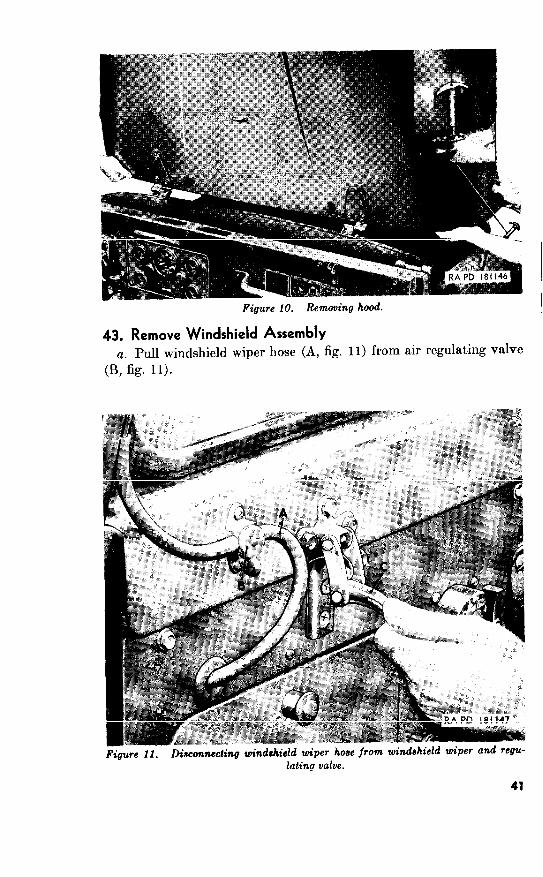
43. Remove Windshield Assembly
a. Pull windshield wiper hose (A, fig. from air regulating valve
(B, fig. 11).

b. Unhook windshield lock (C, fig. 11) at each side of windshield
assembly. Lower windshield assembly forward until slots in male
half-hinges (A, fig. 12) aline with flat faces of female half-hinges
(cowl halves) (B, fig. 12). Slip female half-hinges off pins and
remove windshield assembly from body.
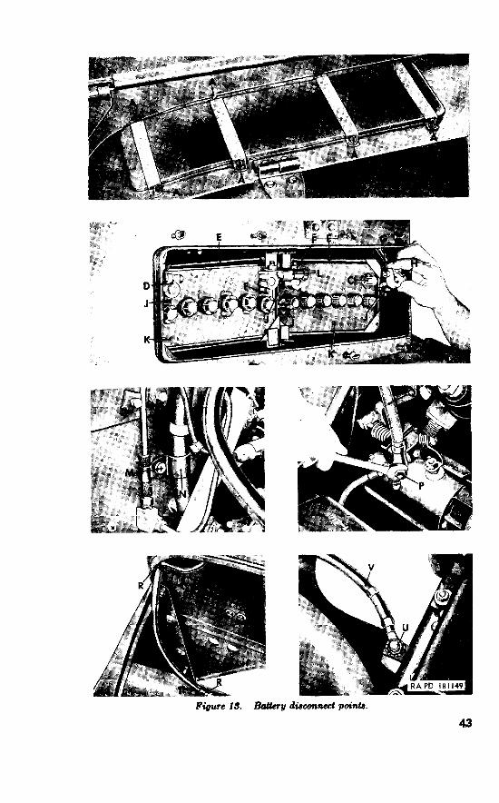
44. Remove Batteries
Ok. 13)
Caution: Exercise extreme caution while performing maintenance
operations relative to the electrical components of this vehicle.
Hand jewelry (rings, watches, etc.) should be removed to prevent
injury by burns which can be encountered from the 24-volt system.
a. Loosen eight thumb screws (A). Slip cowl battery box lid (B)
free of screws and lift lid from body.
li. Disconnect ground cable (circuit number 7) by loosening terminal
nut (G). Slip ground cable terminal off battery negative post (C).
Caution: Be sure to disconnect ground cable first.
Remove nut, and remove terminal (H) from cable
c. Disconnect battery to starter cable terminal (circuit number
82) (D) from battery positive post in same manner as given in b above.
Loosen the two battery terminal nuts (F) and remove connecting
cable (circuit number 68) (L) from battery negative and positive posta.
e. Remove four front holddown frame nuts (J). Lift the two
holddown frames (E) from batteries. Remove the two batteries (K).
42
Figwe 13. BtaUery discanncet
43

f. Remove lockwasher screw (M) and positive cable-to-dash clip
(N) from dash panel. Remove lockwasher and nut (P) and pull
battery-to-starter cable (Q) from starter switch. Pull cable from
battery box.
g. Remove two lockwasher screws (R) securing negative cable to
dash clip (S) and negative cable to splash apron clip (T). Remove
ground cable-to-frame bolt and two ground cable-to-frame lock-
washers
Note. Washers are installed on each side of cable clip.
Pull ground cable (V) from battery box.
45. Remove Spare Wheel and Tire Assembly
Vk. 14)
a. Remove three spare wheel to carrier stud nuts (A).
b. Remove spare wheel and tire assembly (B) from spare wheel
support bracket.
Figure 14. Spare wheel disconnect points.
46. Remove Fenders
Vk 15) a. Left Fender
(1) Disconnect two electrical cables (circuit number 25) (A)
from horn assembly. Disconnect electrical cable (circuit
44

45

(2)
number (B) from blackout driving light. Disconnect three electrical cables (circuit numbers and 20) (C)
from headl~ht and signal blackout marker and parking lights. Lift wiring harness from six open type clips (E). Pull fuel line (D) from push-on-type clip (F). Disconnect two electrical cables (circuit number 25) (H). Remove four lockwasher screws (G) securing rear of fender to front of body cowl.
Note.
Remove three lockwasher screws (J) which secure front of fender to radiator guard assembly.
Note.
Remove two lockwasher screws and flat washers (K) which secure fender brace (L) to frame. Lift left front fender (M) from body. Remove front fender to cowl side panel anti-squeak webbing.
b. Right Fender. The right fender is removed in the same manner as the left except thst no electrical cable disconnects must be made.
47. Remove Radiator Guard Assembly
(fig. 16) a. Remove two bolts and radiator-~-guard panel clips (A) on each
side of radiator (B). b. Swing radiator guard assembly forward until slots in radiator
guard hinges aline with flat faces of radiator guard right and lift hinge pins (frame bracket halves). Slip hinges off pins and remove radiator guard assembly from vehicle.
Figure 18. Disconnecting radiator guard assemblql.

48. Remove Body From frame
a. Make Disconnects at Right Side of Engine (fig.
Remove air cleaner. Loosen hose clamps (A) and remove
carburetor-to-air cleaner pipe hose (B). Disconnect air
cIeaner-to-dash tee vent line (C). Disconnect fuel tank-
to-air cleaner vent line (D). Remove four cap screws and
lockwashers (E) and remove air cleaner assembly (F).
(2) Disconnect distributor to generator regulator cable. Unscrew
electrical cable coupling nut (H) at distributor with coil
assembly (G) and disconnect cable to generator regulator
(circuit number from distributor with coil assembly.
(3) Disconnect generator regulator and battery to starter cables.
Remove nut and lockwasher (K). Remove the generator
regulator and battery to starter cables (J and L) from
starter switch.
Note. Removal of starter cable was described in paragraph 44.
Illustrating it in this sequence serves for location purposes.
(4) Disconnect generator regulator cable to generator regulator.
Unscrew small cable connector coupling nut (M) at front of
generator regulator assembly. Disconnect the cable con-
nection. Pull wiring harness (N) free of open clip (P).
(5) Disconnect air cleaner-to-dash tee vent line and wiring harness
from dash panel. Remove lockwasher screw and nut (Q).
Note. Nut is at rear of dash panel.
Pull closed clips (R and S) away from dash panel. Separate
the wiring harness clip (R) from vent line clip (S).
(6) Disconnect electrical cables from sending units. Disconnect
electrical cables (circuit numbers 33 and 36) (T and U) from
engine water temperature sending unit and engine oil
pressure sending unit respectively.
(7) Disconnect crankcase control vent valve. Straighten bent end
of crankcase control vent valve wire (V). Loosen bolts (W)
and (Y). Pull crankcase control vent valve wire (V) and
conduit (2) from crankcase valve control wire swivel (AA)
and-crankcase control vent valve clamp (BB).
(8) Disconnect choke control wire. Straighten bent end of choke
control wire (CC). Loosen bolts (DD and EE). Pull choke
control wire (CC) and choke control conduit (FF) from
choke control wire clamp and choke control conduit clamp.
(9) Disconnect throttle control wire. Straighten bent end of throttle
control wire (GG). Loosen bolts (HH and JJ). Pull throttle
control wire (GG) and throttle control conduit (KK) from
hand throttle control wire clamp and throttle control conduit
clamp.
47
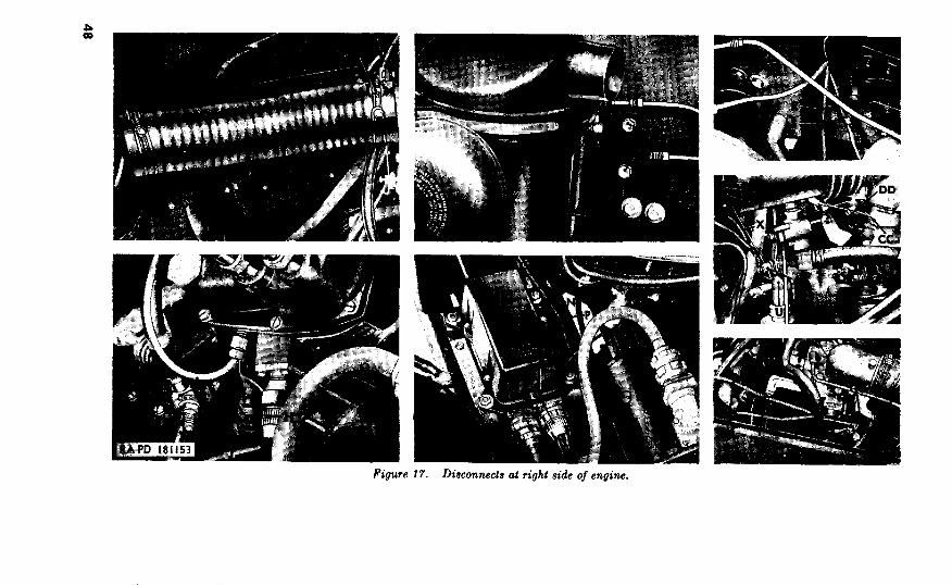
17. at right of engine.
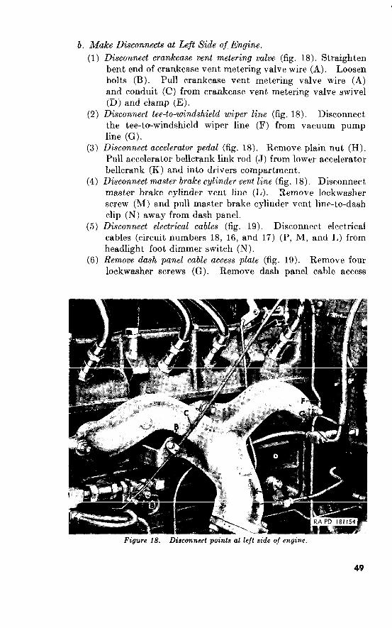
b. Make Disconnects at Left Side of Engine.
(1)
(2)
Disconnect crankcase vent metering valve (fig. Straighten
bent end of crankcase vent metering valve wire (A). Loosen
bolts (B). Pull crankcase vent metering valve wire (A)
and conduit (C) from crankcase vent metering valve swivel
(D) and clamp (E).
Disconnect tee-to-windshield wiper line (fig. 18). Disconnect
the tee-to-windshield wiper line (F) from vacuum pump
line (G).
Disconnect accelerator pedal (fig. Remove plain nut (H).
Pull accelerator bellcrank link rod (J) from lower accelerator
bellcrank (K) and into drivers compartment.
Disconnect master brake cylinder vent line (fig. 18). Disconnect
master brake cylinder vent line (L). Remove lockwasher
screw (M) and pull master brake cylinder vent line-to-dash
clip (N) away from dash panel.
Disconnect electrical cables (fig. Disconnect eIectrica1
cables (circuit numbers and (P, M, and I,) from
headlight foot dimmer switch (N).
Remove dash panel cable access plate (fig. Remove four
lockwasher screws (G). Remove dash panel cable access

(7)
(8)
Disconnect
Clip (Ii) is secured by lower right, mxess plate screw.
Disconnect brake pedal pad (fig. 19).
Discowxect clutch pedal pad (fig. 19).
c. Make Disconnects Inside of Driver’s Compartment
(1)
(2)
50
Disconnect instrument cluster from instrument panel (fig. 20).
Disconnect electrica, cables to instrument cluster and panel
(fig.
11, 15, 25,
Note. Cables 7 and 40 connect to instrument cluster. Cable 11 connects to ignition switch. Cables 15 and 25 connect to cable 10 which connects to engine circuits.
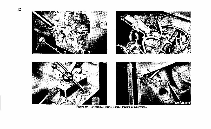
Unscrew electrical cable coupling nut (J) and disconnect
light switch wiring harness (K). Pull wiring harness out into
engine compartment by pulling it through opening presented
by removal of dash panel cable access plate (b(6) above).
(3) Disconnect speedometer Jlexible shaft assembly (fig. 20). Un-
screw coupling nut (L). Pull speedometer shaft core from
speedometer. Pull speedometer flexible shaft assembly (M)
through instrument and dash panels. Remove rubber
grommet (N) from dash panel.
(4) Remove transfer high and low range gearshift lever and front
wheel drive lever knobs (fig. 20). Unscrew the lever knobs
(P and Q) from transfer high and low range gearshift lever
(R) and front wheel drive lever (S).
(5) Remove transfer levers to jloorboard boot (fig. 20). Remove
four sheet, metal screws (T). Remove lever housing cover
boot ring (U) and transfer levers to floorboard boot (Vj.
(6) Remove shering gear jacket access plate (fig. 20). Remove four
lockwasher screws (W) Remove the two halves of the steer-
ing gear jacket access plate (X). Remove the steering jacket
access plate seal (Y).
(7) Remove master brake cylinder inspection cover (fig. 20). Re-
move four lockwasher screws (Z). Remove master brake
cylinder inspection cover (AA).
(8) Remove upper frontfloor pan cover (fig. 21). Remove 13 lock-
washer screws (A). Remove upper front floor pan cover (C)
and toe board steering gear jacket access plate (B).
(9) Remove lower jrontfEoor pan cover (fig. 21). Remove 11 lock-
washer screws (D). Remove the lower front floor pan cover
(K). (10) Disconnect handbrake rod (fig. 21). Remove cotter pin (F)
and two plain washers (G). Slip handbrake rod (J) free of
the handbrake assembly (H).
(11) Remove steering wheel. Remove rubber horn button cap
from steering wheel nut. Remove horn disk button. Re-
move steering wheel nut and remove steering wheel.
(12) Remove mounting tube jacket to instrument panel clamp (fig.
21). Remove two lockwasher bolts and plain nuts (K).
Remove mounting tube jacket to instrument panel clamp
(L). Remove liner (M).
d. Disconnect Body From Frame. Refer to figure 22 for general
lo<ation of body holddown brackets and other disconnect points at
bottom of body. Figures 23 and 24 illustrate the points in detail.
51
_

Figure $1. Disconnect point.3 inside driver’s compartment.
53

.- holddown brackets.


Figute $4. Body ho1

of body lifted from frame.

I
(4)
(5)
(circuit numbers 21, 22, 23, and 24) (G, H, J, and K) to
trailer coupling receptacle.
Make disconnects at bottom qf body (fig. 24). Remove re-
tracting spring (N). Remove cotter pin (Q) and clevis pin
(M). Pull hand brake rod (P) through hold in body. Dis-
connect fuel tank-to-air cleaner vent line (R) at flared tube
elbow (U). Disconnect fuel line (S) at flared tube elbow
(T). Pull fuel line from push-on-type clip (V).
Note.
Lift body from frame (fig. 25). Attach a suitable sling to
dash panel. Raise front end of body until opening in front
floor panel clears transmission gearshift hand lever (A),
transfer gearshift high and low range lever (B), front wheel
drive lever (C), and steering gear jacket (D). Have two
men lift rear of body while another pushes chassis out from
under body. When chassis is clear of body, lower rear of
body on floor or suitable support and then lower front end
of body. Remove the 15 body mounting bracket shims and
body mounting cushions (fig. 26).
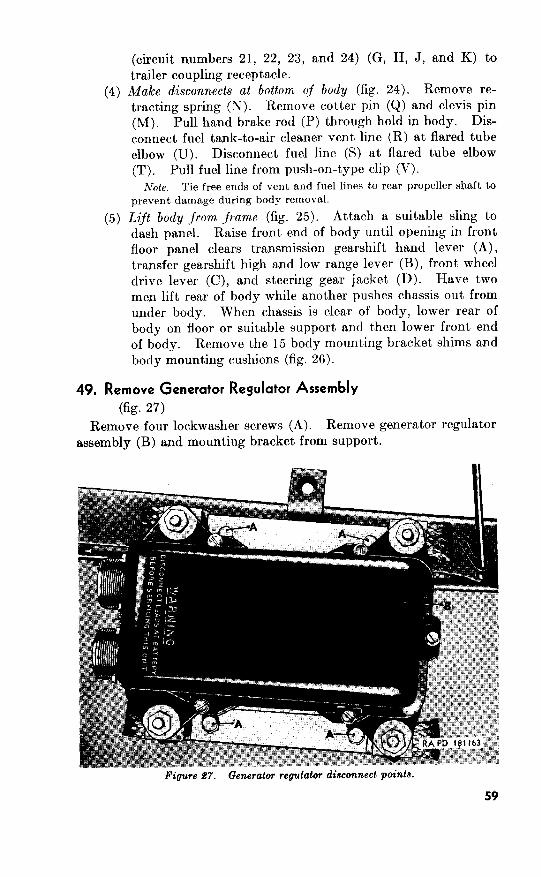
49. Remove Generator Regulator Assembly
(fig. 27)
Remove four lockwasher screws (A). Remove generator regulator
assembly (B) and mounting bracket from support.
Figure 67. Generator regulator disconnect points.
59
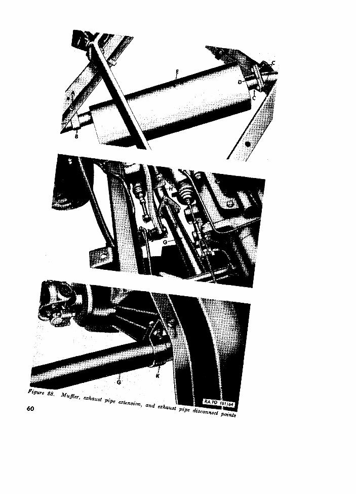
50. Remove Muffler, Exhaust Pipe, and Exhaust Pipe Extension (fig. 28)
a. Remove Exhaust Mufler.
b. Remove Exhaust Pipe Extension.
Remove Propeller Shafts
(fig. 29)
a. Front Propeller Shaft.
b. Rear Propeller Shaft.
52. Remove Power Plant (fig.
Remove Speedometer Flexible Shaft WiLh Core and Casing Assembly.
b. Attach Sling to Power Plant.
Disconnect Transfer From Engine Rear Support Crossmember.

Figure 99. Propeller shaft disconnect points.
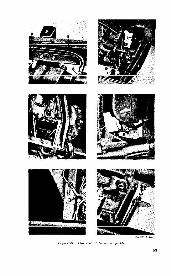
Figure SO. Power plant disconnect points.
63
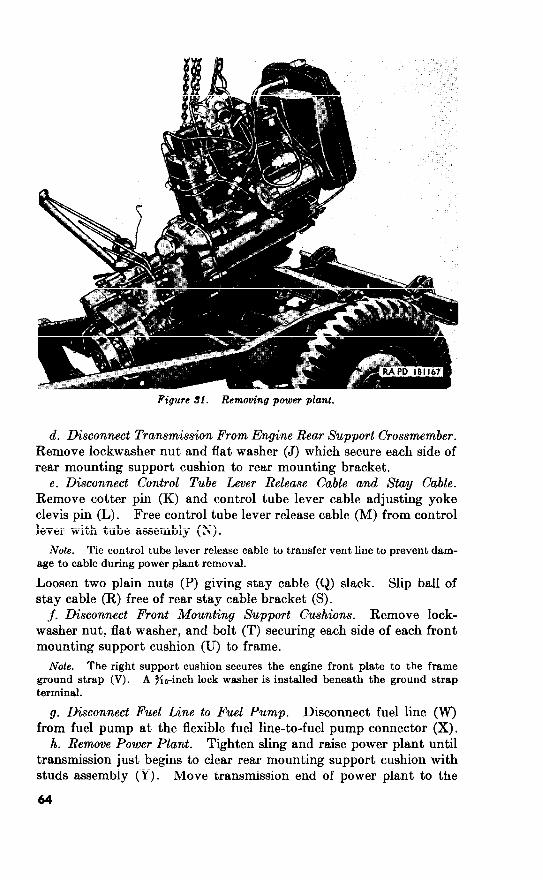
Figure 31. power plant.
d. Disconnect Transmission From Engine Rear Support Crossmember.
Remove lockwasher nut and flat washer (J) which secure each side of
rear mounting support cushion to rear mounting bracket.
e. Disconnect Control Tube Lever Release Cable and Stay Cable.
Remove cotter pin (K) and control tube lever cable adjusting yoke
clevis pin (L) . Free control tube lever release cable (M) from control
lever with tube assembly (N).
Note.
Loosen two plain nuts (P) giving stay cable (Q) slack. Slip ball of
stay cable (R) free of rear stay cable bracket (S).
j. Disconnect Front Mounting Support Cushions. Remove lock-
washer nut, flat washer, and bolt (T) securing each side of each front
mounting support cushion (U) to frame.
Note.
Disconnect Fuel Line to Fuel Pump. Disconnect fuel line (W)
from fuel pump at the flexible fuel line-to-fuel pump connector (X).
h. Remove Power Plant. Tighten sling and raise power plant until
transmission just begins to clear rear mounting support cushion with
studs assembly (Y). Move transmission end of power plant to the
64
right until the control lever with tube assembly (2) frees the control
lever tube ball stud (AA) mounted on transfer. Lift power plant
from frame as shown in figure 31.
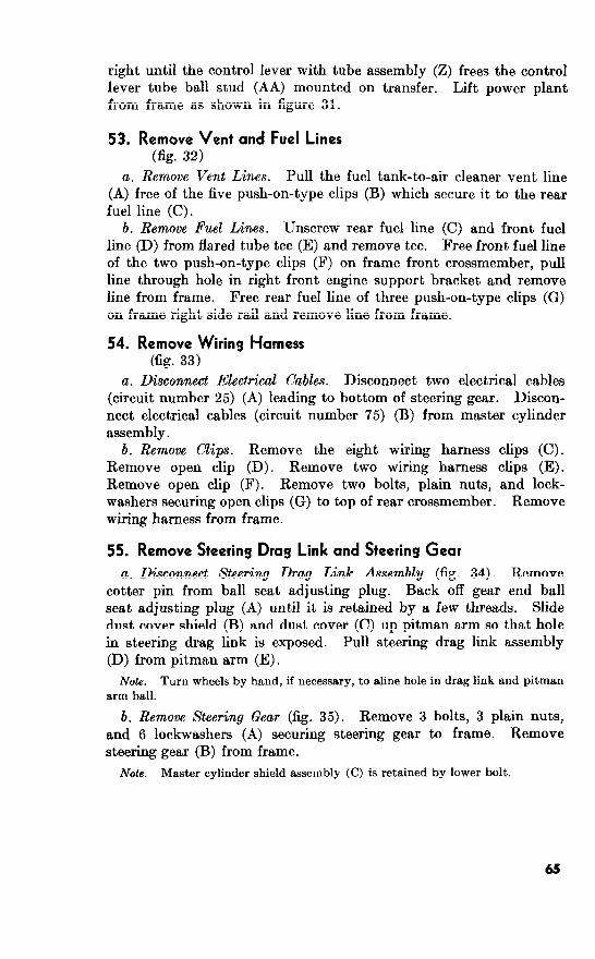
53. Remove Vent and Fuel Lines (fig. 32)
a. Remove Vent Lines. Pull the fuel tank-to-air cleaner vent line
(A) free of the five push-on-type clips (B) which secure it to the rear
fuel line (C).
b. Remove Fuel Lines. Unscrew rear fuel line (C) and front fuel
line (D) from flared tube tee (E) and remove tee. Free front fuel line
of the two push-on-type clips (F) on frame front crossmember, pull
line through hole in right front engine support bracket and remove
line from frame. Free rear fuel line of three push-on-type clips (G)
on frame right side rail and remove line from frame.
54. Remove Wiring Harness (fig. 33)
a. Disconnect Electrical Cables. Disconnect two electrical cables
(circuit number 25) (A) leading to bottom of steering gear. Discon-
nect electrical cables (circuit number 75) (B) from master cylinder
assembly.
b. Remove Clips. Remove the eight wiring harness clips (C).
Remove open clip (D). Remove two wiring harness clips (E).
Remove open clip (F). Remove two bolts, plain nuts, and lock-
washers securing open clips (G) to top of rear crossmember. Remove
wiring harness from frame.
55. Remove Steering Drag Link and Steering Gear
a. Disconnect Steering Drag Link Assembly (fig. 34). Remove
cotter pin from ball seat adjusting plug. Back off gear end ball
seat adjusting plug (A) until it is retained by a few threads. Slide
dust cover shield (B) and dust cover (C) up pitman arm so that hole
in steering drag link is exposed. Pull steering drag link assembly
(D) from pitman arm (E).
b. Remove Steering Gear (fig. 35). Remove 3 bolts, 3 plain nuts,
and 6 lockwashers (A) securing steering gear to frame. Remove
steering gear (B) from frame.
Note.

. . Figure .#?I.
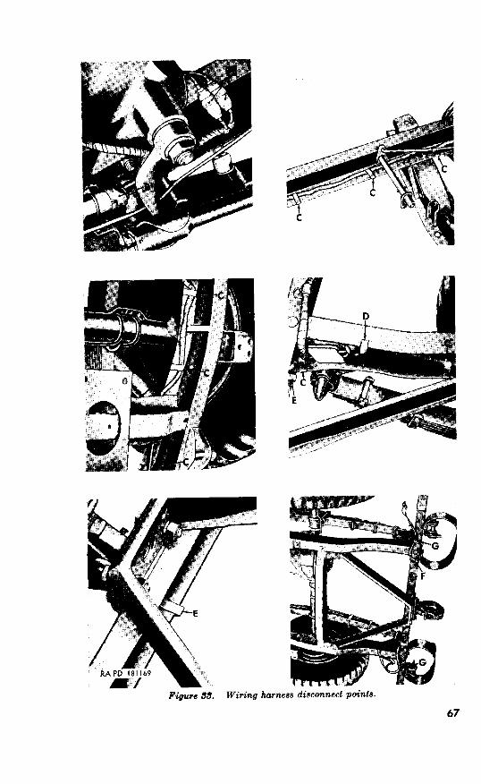
Figure 3% Wiring harness disconnect points.
67
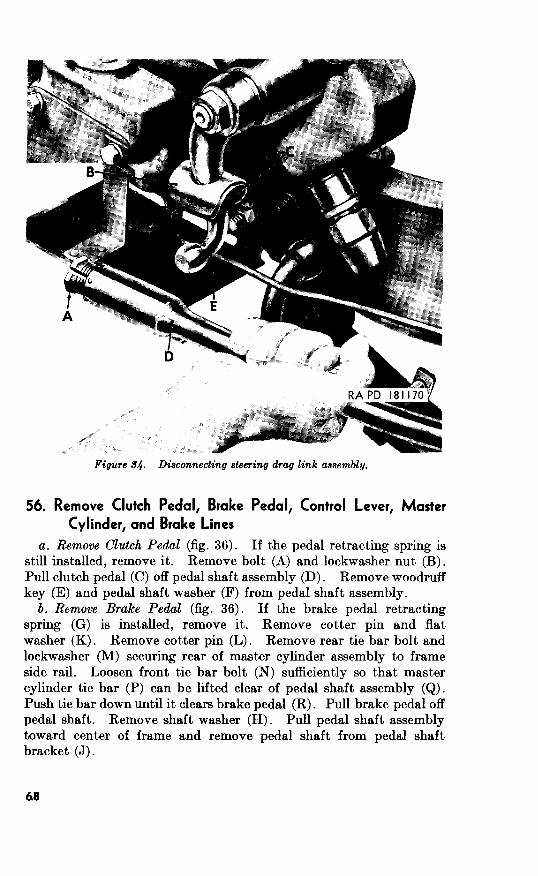
Figure 34. Disconnecting steering drag link assembly.
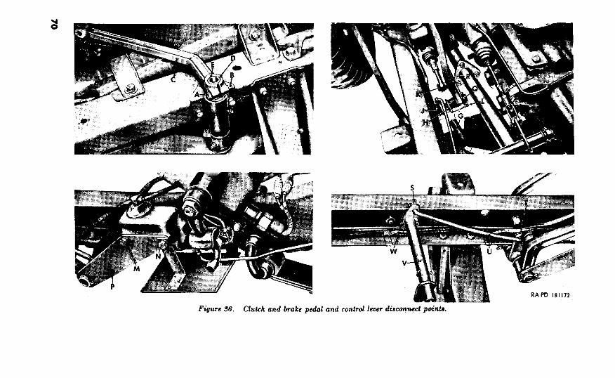
56. Remove Clutch Pedal, Brake Pedal, Control Lever, Master
Cylinder, and Brake Lines
a. Remove Clutch Pedal (fig. 36). If the pedal retracting spring is
still installed, remove it. Remove bolt (A) and lockwasher nut (B).
Pull clutch pedal (C) off pedal shaft assembly (D) . Remove woodruff
key (E) and pedal shaft washer (F) from pedal shaft assembly.
b. Remove BTake Pedal (fig. 36). If the brake pedal retracting
spring (G) is installed, remove it. Remove cotter pin and flat
washer (K). Remove cotter pin (L). Remove rear tie bar bolt and
lockwasher (M) securing rear of master cylinder assembly to frame
side rail. Loosen front tie bar bolt (N) sufficiently so that master
cylinder tie bar (P) can be lifted clear of pedal shaft assembly (Q).
Push tie bar down until it clears brake pedal (R) . Pull brake pedal off
pedal shaft. Remove shaft washer (H). Pull pedal shaft assembly
toward center of frame and remove pedal shaft from pedal shaft
bracket (J).
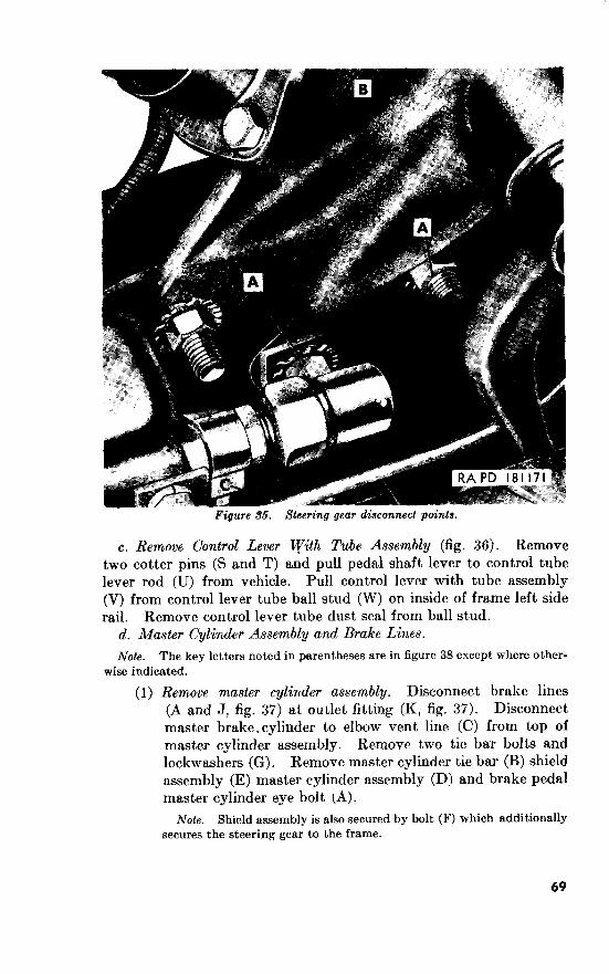
_- -. -Figure 36. Steering gear disconnect points.
c. Remove Control Lever &‘ith Tube Assembly (fig. 36). Remove
two cotter pins (S and T) and pull pedal shaft lever to control tube
lever rod (U) from vehicle. Pull control lever with tube assembly
(V) from control lever tube ball stud (W) on inside of frame left side
rail. Remove control lever tube dust seal from ball stud.
d. Master Cylinder Assembly and Brake Lines.
Note. The key letters noted in parentheses are in figure 38 except where other-
wise indicated.
(1) Remove master cylinder assembly. Disconnect brake lines
(A and J, fig. 37) at outlet fitting (K, fig. 37). Disconnect
mast,er brake.cylinder to elbow vent line (C) from top of
master cylinder assembly. Remove two tie bar bolts and
lockwashers (G). Remove master cylinder tie bar (B) shield
assembly (E) master cylinder assembly (D) and brake pedal
master cylinder eye bolt (A).
Note. Shield assembly is also secured by bolt (F) which additionally
secures the steering gear to the frame.
69
RAPD 18lIfZ
(2) Remove front master cylinder line and front axle tee to master
cylinder line Jexible line. Disconnect front master cylinder
line (K) from the flexible line to bracket spring lock clip
(M). Free front master cylinder line from line clip (B, fig. 37)
on frame left crossmember and lift front master cyIinder line
from frame. Disconnect front axle tee to master cylinder
line flexible line (P) at flexible line to bracket spring lock
clip (M) and front axle tee (S). Lift flexible line from frame.
(3) Disconnect front tee to left jlexible line. Disconnect front tee
to left flexible line (H) at left of front axle tee (S) and at the
flexible line to bracket spring lock clip (J). Lift front tee
to left flexible line (H).
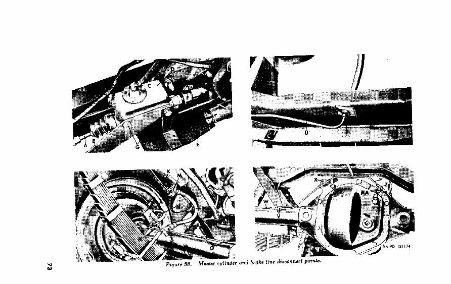
(4) Disconnect front brake left jleaible line assembly. Disconnect
front brake left flexible line assembly (N) at flexible line to
bracket spring lock clip (J) and left front wheel cylinder
(L) and lift line.
(5) Disconnect front tee to rightsexible line assembly. Disconnect
the front tee to right flexible line assembly (R) at right of
front axle tee (S) and at flexible line to bracket spring lock
clip (D, fig. 37). Remove two axle brake tube hose clamps
(Q) holding line to front axle housing. Remove two closed
clips (C, fig. 37) from front axle housing.
Note.
Lift front tee to right flexible line assembly.
(6) Disconnect front brake right JEexible line assembly. Removal
is identical to that for the front brake left flexible line
assembly ((4) above).
(7) Disconnect rear master cylinder line. Disconnect rear master
cylinder line (U) from the flexible line to bracket spring lock
clip (T). Free line from three line clips (H, fig. 37) and
remove line.
(8) Disconn,ect rear axle tee to master cylinder jlesible line and
rear tee to rear wheel cylinder lines. Disconnect rear axle tee
to master cylinder flexible line (F, fig. 37) at the flexible line
to bracket spring lock clip (T) and at rear axle tee (X).
Lift rear axle tee to master cylinder flexible line from housing.
Disconnect, the rear tee to the right and left wheel cylinder
lines (W and Y) at rear axle tee (X) and at rear wheel
cylinders (G and E, fig. 37). Free the left line from axle
brake tube hose clamp (V). Free the right line from closed
clip (Z).
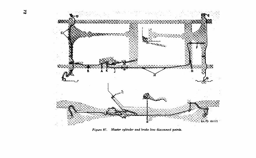
Figure 37. Master cylinder and brake line disconnect points.
Y

Figure 39. Wheel and tire assembly disconnect points.
Remove the rear tee to rear wheel cylinder lines from (rear
axle) housing.
(9) Remove front axle and rear axle tees. Remove each lockwasher
bolt securing each tee to housing assembly. Remove front
axle and rear axle tees.
57. Remove Wheel and Tire Assemblies and Shock Absorbers
a. Remove Wheel and Tire Assemblies (fig. 39). Remove five hub
nuts (A) securing each wheel to hub and brake drum assembly.
Remove wheel and tire assembly (B).
Note. Turn hub nuts on right side of vehicle counterclockwise and those on
left side of vehicle clockwise.
b. Remove Shock Absorbers (fig. 40). Remove two locknuts (A).
Remove two flat washers and mounting pin bushings (B). Remove
shock absorber (C). Remove two mounting pin bushings (D).
58. Remove Front and Rear Springs and Axle Assemblies (fig. 41).
Support the axle assemblies on jacks to take load off springs.
Remove four U-bolt nuts and washers (A). Remove two spring
U-bolts (B) from each spring assembly. Remove spring clip plate
(C) from each spring assembly. Remove bolt and elastic stop nut
(D). Unscrew two bushing type shackle bearings (G) from ends of
74

Fipre 40. Shock absorber disconnect points.
shackle (E). Remove shackle from spring eye and frame side rail.
Remove spring shackle grease seals and spring shackle grease seal
retainers.
Noti. Shackles and lower bushing type shackle bearings with left hand threads
are used on the right _cear and left front springs. The shackle is identified by a
boss (F) and the shackle bearings (G) by notches.
Remove cotter pin, slotted nut (H), and tie rods from steering bell-
crank assembly (J). Remove front spring assemblies, rear spring
assemblies, front axle assembiy, and rear axle assembly from frame.
75
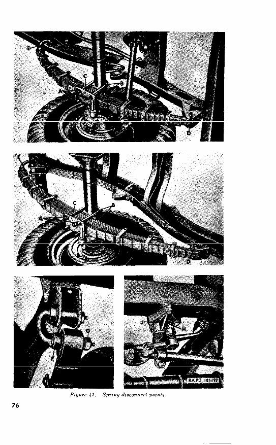
76
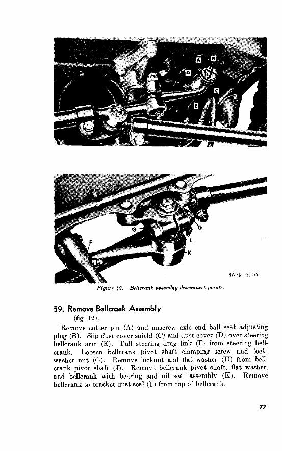
Figure .@?. Bellcrank aaaemb!y disconnect points.
59. Remove Bellcrank Assembly
(fig. 42).
Remove cotter pin (A) and unscrew axle end ball seat adjusting
plug (B). Slip dust cover shield (C) and dust cover (D) over steering
bellcrank arm (E). Pull steering drag link (F) from steering bell-
crank. Loosen bellcrank pivot shaft clamping screw and lock-
washer nut (G). Remove locknut and flat washer (H) from bell-
crank pivot shaft (J). Remove bellcrank pivot shaft, flat washer,
and bellcrank with bearing and oil seal assembly (K). Remove
bellcrank to bracket dust seal (L) from top of bellcrank.
77

Section II. ASSEMBLY OF VEHICLE FROM MAJOR
COMPONENTS 60. General
This section provides an assembly line procedure for assembling the
vehicle from its major components.
61. Install Bellcrank Assembly
(fig. 42)
Install bellcrank to bracket dust seal (L) on top of bellcrank with
bearing and oil seal assembly (K). Position bellcrank on frame steer-
ing bellcrank bracket and install bellcrank pivot shaft (J), flat washer
and %--1SNF locknut (H). Tighten Ks-20NF x 2% bellcrank pivot
shaft clamping screw and X6---20NF lockwasher hexagon nut (G).
62. Install Front and Rear Springs and Axle Assemblies
@g. 41)
Support frame at a suitable height for installation of spring and axle
assemblies. Position the front and rear axle assemblies under frame
and place them on suitable supports. Place the two front and two
rear spring assemblies in position beneath axles. Install the gr20NF-
3 x 3 bolt and X6--20NF-3 elastic stop nut (D) which secures each
spring. Install two spring shackle grease seals and two spring shackle
grease seal retainers on shackle. Install shackle (E) in frame and
spring eye. Screw two bushing type shackle bearings (G) on ends of
shackle (E).
Note. Shackles and lower bushing type shackle bearings with left hand threads
are used on the right rear and left front springs. The shackle is identified by a
boss (F) and the shackle bearings (G) by notches.
Secure each spring to axle housing with two spring U-bolts (B),
spring clip plate (C), four x8-2ONF-2 U-bolt nuts and &inch washers
(A). Tighten elastic stop nut and bolt (D) to torque of 27 to 30
pound-feet. Tighten spring U-bolts to torque of 50 to 55 pound-feet.
Install tie rods on steering bell-crank assembly (J) and secure with
x-20NF-2 slotted nut and Kt x T& cotter pin (H).
63. Install Shock Ab sor b ers and Tire and Wheel Assemblies
a. Install Shock Absorbers (fig. 40). Install mounting pin bushing
(D) on spring clip plate and on shock absorber mounting pin bracket.
Install shock absorber (C) and two mounting pin bushings (B), two
% ID, 1% OD, 0.083 thick flat washers, and two &20NF locknuts (A).
Tighten locknuts until bushings show compression behind flat washers.
6. Install Wheel and Tire Assemblies (fig. 39). Position wheel and
tire assembly (B) on hub and brake drum assembly. Secure each
wheel and tire assembly with five $20NF hub nuts (A).
Note. Hub nuts with left hand threads (identified by notches) are
side of vehicle only. Hub nuts with right hand threads are used on right side of
vehicle.
78
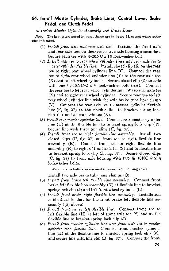
64. install Master Cylinder, Brake Lines, Control Lever, Brake
Pedal, and Clutch Pedal
a. Install Master Cylinder Assembly and Brake Lines.
The key letters noted in parentheses are in figure 38, except where other
wise indicated.
(1)
(2)
Install front axle and rear axle tees. Position the front axle
and rear axle tees on their respective axle housing assemblies.
Secure each tee with %-2ONC x 1% lockwasher bolt.
Install rear tee to rear wheel cylinder lines and rear axle tee to
master cylinder flexible line. Install closed clip (2) on the rear
tee to right rear wheel cylinder line (Y). Connect the rear
tee to right rear wheel cylinder line (Y) to the rear axle tee
(X) and to left wheel cylinder. Secure closed clip (Z) to axle
with one $&--lSNC--2 x 3$ lockwasher bolt (AA). Connect
the rear tee to left rear wheel cylinder (W) to rear axle tee
(X) and to right rear wheel cylinder. Secure rear tee to left
rear wheel cylinder line with the axle brake tube hose clamp
(V). Connect the rear axle tee to master cylinder flexible
line (F, fig. 37) at the flexible line to bracket spring lock
clip (T) and at rear axle tee (X).
(3) Install rear master cylinder line. Connect rear master cylinder
(4)
line (U) at the flexible line to bracket spring lock clip (T).
Secure line with three line clips (H, fig. 37).
Install front tee to right jlexible line assembly. Install two
closed clips (C, fig. 37) on front tee to right flexible line
assembly (R). Connect front tee to right flexible line
assembly (R) to right of front axle tee (S) and to flexible line
to bracket spring lock clip (D, fig. 37). Secure closed clips
(C, fig. 37) to front axle housing with two ,%--18NC-2 x s
lockwasher bolts.
(5)
(6)
(7)
(8)
Same bolts also are used to secure axle housing cover.
Install two axle brake tube hose clamps (Q).
Install front brake left flexible line assembly. Connect front
brake left flexible line assembly (N) at flexible line to bracket
spring lock clip (J) and left front wheel cylinder (L).
Install front brake right jlexible line assembly. Installation
is identical to that for the front brake left flexible line as-
sembly ((5) above).
Install front tee to left jlexible line. Connect front tee to
left flexible line (H) at left of front axle tee (S) and at the
flexible line to bracket spring lock clip (J).
Install front master cylinder line and front axle tee to master
cylinder line jlexible line. Connect front master cylinder
line (K) at the flexible line to bracket spring lock clip (M)
and secure line with line clip (B, fig. 37). Connect the front
79

axle tee to master cylinder line flexible line (P) at flexible
line to bracket spring lock clip (M) and front axle tee (S).
(9) Install master cylinder assembly. Position master cylinder
assembly (D), shield assembly (E), and master cylinder
tie bar (B) on frame left side rail. Install two $&24NF x 3
tie bar bolts and y&inch lockwashers (G). Install the
X6-20NF brake pedal master cylinder eyebolt (A). Connect
brake lines (A and J, fig. 37) at outlet fitting (K, fig. 37).
Note. Servicing of system is covered in paragraph 79b.
b. Install Control Lever With Tube Assembly (fig. 36). Install new
control lever tube dust seal on control lever tube ball stud (W) on
frame left side rail. Position control lever with tube assembly (V)
on ball stud.
c. Install Brake Pedal (fig. 36). Install pedal shaft in pedal shaft
bracket (J). Install shaft washer (H) and brake pedal (R) on pedal
shaft. Remove the rear tie bar bolt and lockwasher (M). Loosen
the front tie bar bolt (N) just enough so that master cylinder tie
bar (P) can be moved out sufficiently to engage end of pedal shaft
assembly (Q). Tighten front tie bar bolt (N). Install the 3/g
24NF-3 rear tie bar bolt and X-inch lockwasher (M). Install $& x 1
cotter pin (L). Install flat washer and % x 1 cotter pin (K). Install
the brake pedal retracting spring (G).
d. Install Clutch Pedal (fig. 36). Install pedal shaft washer (F)
on pedal shaft assembly. Install ?& x $$ woodruff key (E). Install
clutch pedal (C) on pedal shaft assembly (D). Install %6--24NF-3 x
1% bolt (A) and g6-24NF-3 lockwasher nut (B). Install the pedal
retracting spring. Position the pedal shaft lever to control tube
lever rod (U) on the control lever with tube assembly (V) and pedal
shaft bracket. Secure lever rod with two 352 x >h cotter pins (S and T).
65. Install Steering Drag Link and Steering Gear
a. Install Steering Gear (fig. 35). Secure steering gear (B) to
frame left side rail with three X6--20NF x 3 bolts, three X6-20NF
plain nuts, and six X6-inch lockwashers (A).
Note. Master cylinder shield assembly (C) is secured by lower bolt.
b. Install Steering Drag Link Assembly (fig. 34). Slip the dust
cover shield (B) and dust cover (C) up pitman arm. Slip dust
cover shield (C, fig. 42) and dust cover (D, fig. 42) up steering bell.
crank arm. Engage steering drag link holes with balls of pitman
arm and steering bellcrank.
Note. Correct position of steering drag link is such that the lubrication fitting
at steering bellcrank will face to the right.
Tighten the two ball seat adjusting plugs (A and B, fig. 42) tight
against the steering bellcrank ball and pitman arm ball. Back the
adjusting plug, at bellcrank, off one-half of a turn. Back adjusting
80

plug, at pitman arm, off one full turn. Install two new yB x 1% cotter
pins.
66. Install Wiring Harness @!T- 33)
a. Connect Electrical Cables. Connect two electrical cables (circuit
number 25) (A) to bottom of steering gear. Connect electrical cables
(circuit number 7.5) (B) to master cylinder assembly.
b. Install Clips. Secure wiring harness to frame with 8 wiring
harness clips (C), open clip (D), 2 wiring harness clips (E), and open
clip (F). Install two open clips (G) on wiring harness and secure to
top of rear crossmember with two No. IO-24NF-2 x 3 bolts, No. lo-
24NC-2 plain nuts, and No. 10 lockwashers.
67. Install Fuel and Vent Lines (fig. 32)
a. Install Fuel Lines. Position front fuel line (D) on frame front
crossmember. Connect front fuel line to flared tube tee (E). Secure
front fuel line by two push-on-type clips (F) to frame front cross-
member. Connect rear fuel line (C) to flared tube tee (E). Secure
rear fuel line by three push-on-type clips (G) to frame right side rail.
b. Install Vent Lines. Install five push-on-type clips (B) on clips
(B) on rear fuel line (C). Secure the fuel tank-to-air cleaner vent
line (A) to rear fuel line by the five push-on-type clips (B). Con-
nect the master brake cylinder-to-elbow vent line (C, fig. 38) to top
of master cylinder assembly.
68. Install Power Plant
(fig. 30)
a. Install Transmission znd Transfer on Engine. Refer to TM
g-8048.
b. Attach Sling to Power Plant. Attach a suitable sling to lifting
hook provided on top of engine. See that the rear mounting support
cushion with studs assembly (Y) is installed on engine rear support
cross member.
c. Install Power Plant. Carefully lower power plant onto frame as
shown in figure 31. Aline slots in rear mounting bracket (mounted
on transmission) with studs of rear mounting support cushion. En-
gage control lever with tube assembly (Z) and control lever tube ball
stud (AA) on transfer. Position the transfer case support insulator
in place on top of engine rear support cross member. Lower power
plant until it rests on rear mounting support cushion with studs
assembly (Y), case support insulator, and front of frame. Do not
remove sling.
d. Connect Transmission to Engine Rear Support Crossmember.
Install two J&, ID, 1 OD, 0.083 thick flat washers and S-24 lockwasher
81
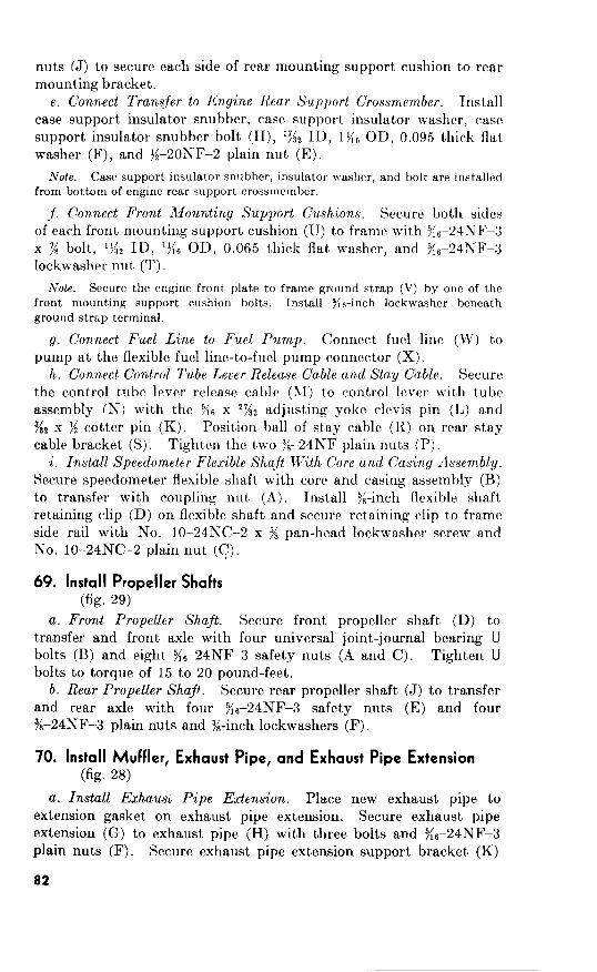
Connect Transfer to Engine Rea.r Support Crossmember.
snubber, insulator washer, and bolt are installed
from bottom of engine rear support crossmember.
.f. Connect Front Mounting Support Cushions.
Secure the to frame ground strap (V) by one of the
front mounting support cushion bolts. Install y/l&-inch lockwasher beneath
ground strap terminal.
g. Connect Fuel Line to Fuel Pump.
h. Connect Control Tube Leuer Release Cable and Stay Cable.
Install Speedometer Flexible Shaft With Core and Casing Assembly.
69. Install Propeller Shafts
(fig. 29) a. Front Propeller Shaft.
b. Rear Propeller Shaft.
70. install Muffler, Exhaust P ipe, and Exhaust Pipe Extension (fig. 2%
a. Install Exhaust Pipe Extension.
82
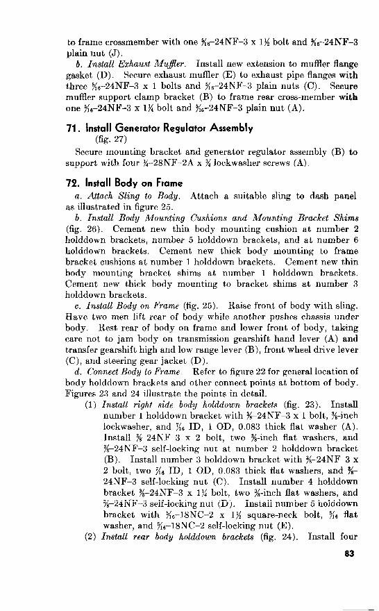
to frame crossmember with one %-24NF-3 x 1% bolt and %--24NF-3
plain nut (J).
Exhaust Mujler. Install new extension to muffler flange
gasket (D). Secure exhaust muffler (E) to exhaust pipe flanges with
three X6--24NF3 x 1 bolts and 9i6-24NF-3 plain nuts (C). Secure
muffler support clamp bracket (B) to frame rear cross-member
%&4NF-3 x 1% bolt and %-24NF-3 plain nut (A).
71. Install Generator Regulator Assembly
(fig. 27)
Secure mounting bracket and generator regulator assembly (B) to
support with four g--28NF-2A x y< lockwasher screws (A),
Install Body on Frame
a. Attach Sling to Body. Attach a suitable sling to dash panel
as illustrated in figure 25.
b. Install Body Mounting Cushions and Mounting Bracket Shims
(fig. 26). Cement new thin body mounting cushion at number 2
holddown brackets, number 5 holddown brackets, and at number 6
holddown brackets. Cement new thick body mounting to frame
bracket cushions at number 1 holddown brackets. Cement new thin
body mounting bracket shims at number holddown brackets.
Cement new thick body mounting to bracket shims at number 3
holddown brackets.
c. Install Body on Frame (fig. 25). Raise front of body with sling.
Have two men lift rear of body while another pushes chassis under
body. Rest rear of body on frame and lower front of body, taking
care not to jam body on transmission gearshift hand lever (A) and
transfer gearshift high and low range lever (B), front wheel drive lever
(C), and steering gear jacket (D).
d. Connect Body to Frame. Refer to figure 22 for general location of
body holddown brackets and other connect points at bottom of body.
Figures 23 and 24 illustrate the points in detail.
(1) Install right side body holddown brackets (fig. 23). Install
number holddown bracket with 96-24NF-3 x 1 bolt., %-inch
lockwasher, and KG ID, 1 OD, 0.083 thick flat washer (A).
Install $&24NF-3 x 2 bolt, two %-inch flat washers, and
16-24NF-3 self-locking nut at number 2 holddown bracket
(B). Install number 3 holddown bracket with T&-24NF-3 x
2 bolt, two X6 ID, 1 OD, 0.083 thick flat washers, and l/g
24NF-3 self-locking nut (C). Install number 4 holddown
bracket Y/8--24NF-3 x l>i bolt, two %-inch flat washers, and
lk-24NF-3 self-locking nut (D). Install number 5 holddown
bracket with ?{6-18NC-2 x 1>4 square-neck bolt, Y16 flat
washer, and ~i~-l8NC-2 self-locking nut (E).
(2) Install rear body holddown brackets (fig. 24). Install four
83
g6-18NC-3 x % bolts, eight % ID, GD, 0.083 thick flat
washers, and four %~-18NC--3 self-locking nuts (A) at number
6 holddown brackets. Connect electrical cables (circuit.
numbers 23 and 24) (C and B) to service as tail and stoplight.
Connect electrical cables (circuit numbers 21, 22, and 24)
(D, E, and F) to blackout tail and stop light. Connect
electrical cables (circuit numbers 21, 22, 23, and 24) (G, H,
J, and K) to the trailer coupling receptacle. Secure wiring
harness with open clip (L).
(3) Install left side body holddown brackets (fig. 23). Connect the
left side of the body to the frame at numbers 1, 2, 4, and 5
holddown brackets (F, G, H, and J) in same manner as
outlined for the right side. However, number 3 body hold-
down bracket is omitted on left side of vehicle.
(4) Make connections at bottom of body (fig. 24). Install hand
brake rod (P) through hole in body and secure it to the hand
brake operating lever with KG-inch clevis pin (M) and :g x 36
cotter pin (Q). Connect fuel tank-to-air cleaner vent line
(R) to flared tube elbow (U). Connect fuel line (S) to
flared tube elbow (T). Secure fuel line by push-on-type clip
(V).
Note. Secure skid plate to engine rear support crossmember with
four g/8-16NC-2 x 74 square-neck carriage bolts and $&16NC-2 lock
washer nuts.
e. Make Connections Inside of Driver’s Compartment.
(1) Install instrument cluster (fig. 20). Pull wiring harness
through opening presented by removal of dash panel access
plate. Connect electrical cables (circuit numbers 7, 11, 15,
25, and 40) (D, E, F, G, and H). Connect light switch
wiring harness (K) to light switch and tighten electrical cable
coupling nut (J). Insert speedometer flexible shaft assembly
(M) through dash and instrument panels. Be sure rubber
grommet (N) is installed on dash panel. Connect speed-
ometer flexible shaft. assembly (M) to speedometer by
tightening the coupling nut (L). Place instrument cluster
(B) on instrument panel (C) and secure cluster by turning
the four instrument cluster mounting plate studs (A) a
quarter of a turn clockwise.
(2) Install lower and upper frontsoor pan covers (fig. 21). Inst.all
seal on lower and upper front floor pan covers and on toe-
board steering gear jacket access plate. Secure lower front
floor pan cover (E) to floor of body with eleven %-20NC x X
lockwasher screws (D). Secure upper front floor pan cover
(C) and toe board steering gear jacket access plate (B) with
thirteen %-2ONC x 58 lockwasher screws (A).
(3) Install master brake cylinder inspection cover (fig. 20). Install
84
seal on master brake cylinder inspection cover. Secure master brake cylinder inspection cover with four
JCZONC x :$ lockwasher screws (Z).
(4) Install steering gear jacket access plate (fig. Install new
steering jacket access plate seal (Y). Position the two
halves of the steering gear jacket access plates (X) over seal
and secure plates to body with four $20NC x $&inch lock-
washer screws (W).
(5) Install transfer levers to floorboard boot (fig. 20). Install
transfer levers to floorboard boot (V) on lower front floor
pan cover. Install lever housing cover boot ring (U) with
four No. 10 x >/2 sheet metal screws (T).
(6) Install transfer high and low range gearshift lever and front
wheel drive lever knobs (fig. 20). Screw the lever knobs (P
and Q) on the transfer high and low range gearshift lever (R)
and front wheel drive lever (S).
(7) Install steering wheel. Set front wheels in straight ahead
position. Install tube jacket bearing spring. Position
steering wheel on shaft with integral worm, with one spoke of
steering wheel in vertical position above tube jacket, and
aline serrations. With mallet, tap wheel on shaft.
Install l%s-20NC-2 nut. Install horn disk button and rub-
ber horn button cap.
(8) Install mounting tube jacket to instrument panel clamp (fig. 21).
Install liner (M). Secure mounting tube jacket to instru-
ment panel clamp (L) with two Ke-24NF-2 x x lockwasher
bolts and se-24NF-2 plain nuts (K).
(9) Connect hand brake rod (fig. Connect hand brake rod
(J) to hand brake assembly (H) with two plain washers (G)
and one $& x $$ cotter pin (F).
j. Make Connections at Left Side of Engine.
Connect crankcase vent metering valve (fig. 18). Install crank-
case vent metering valve wire (A) and conduit (C) in crank-
case vent metering valve swivel (D) and clamp (E) re-
spectively. Bend over end of wire as a safety factor.
Tighten bolts (B).
(2) Connect tee-to-windshield wiper line (fig. Connect the
tee-to-windshield wiper line (F) to the vacuum pump line
(3) Connect accelerator pedal (fig. 18). Push accelerator bell-
crank link rod (J) through hole in upper floor pan cover and
into lower accelerator bellcrank (K). Secure rod to bell-
crank with plain nut (H) .
(4) Connect master brake cylinder vent line (fig. 18). Install master brake cylinder vent line to dash clip (N) on master
brake cylinder vent line. Connect master brake cylinder
85
vent line (L) . Secure clip to dash panel with No. lo-24NC-
2 x Ks lockwasher screw (M).
(5) Connect electrical cables (fig. 19). Connect electrical cables
(circuit numbers 18, and (P, M, and L) to head light
foot dimmer switch (N).
(6) Install dash panel cable access plate (fig. 19). Install wiring
harness grommet (J) in access plate. Install wiring harness
into grommet. Secure dash panel cable access plate (H)
and clip (K) to dash panel with four No. lo-24 x X lockwasher
screws (G). Secure clip fastener (U) to dash panel with
No. lo-24 x 3 lockwasher screw (V) .
(7) Connect brake pedal pad (fig. 19). Install draft pad (E),
draft pad flat washer (D), and draft pad spring (C) on brake
pedal pad (F) . Insert brake pedal pad into brake pedal (B) .
Secure brake pedal pad to brake pedal with Xs-l8NC-3 x j$ bolt and 5{6-inch lockwasher (A).
(8) Connect clutch pedal pad (fig. 19). Install pedal draft pad
(W), pedal draft pad washer (T), and pedal draft pad spring
(X) on clutch pedal pad (R) and insert clutch pedal pad into
clutch pedal (S). Connect clutch pedal pad (R) to clutch
pedal (S) with g6-18NC-3 x 1% bolt and ?i6-inch lockwasher
(Q) . g. Make Connections at Right Side of Engine (fig. 17).
(1) Connect throttle control wire. Insert throttle control wire (GG)
and throttle control conduit (KK) into throttle control wire
stop and throttle control conduit clamp respectively.
Tighten bolts (HH and JJ). Bend over end of throttle
control wire (GG).
(2) Connect choke control wire. Insert choke control wire (CC)
and choke control conduit (FF) into choke control wire
clamp and choke control conduit clamp respectively.
Tighten bolts (DD and EE). Bend over end of choke
control wire (CC).
(3) Connect crankcase control vent valve. Insert crankcase control
vent valve wire (V) and conduit (Z) into crankcase valve
control wire swivel (AA) and crankcase control vent valve
clamp (BB) respectively. Tighten bolts (W and Y). Bend
over end of wire.
(4) Connect electrical cables to sending units. Connect electrical
cables (circuit numbers 33 and 36) (T and U) to engine
water temperature sending unit and engine oil pressure
sending unit respectively.
(5) Connect air cleaner-to-dash tee vent line and wiring harness to
dash panel. Secure wiring harness clip (R) and vent line

clip (S) to dash panel with one No. lo-24NC-2 x % lock-,
washer screw and No. lo-24NC-2 nut (Q).
Note. Nut is at rear of dash panel.
(6) Connect generator regulator cable. Connect the generator
cable to generator regulator assembly and tighten small
cable connector coupling nut (M). Secure wiring harness
(N) with open clip (P).
(7) Connect disfrihutor to generator regulator cable. Connect the
generator regulator cable (circuit number 12) to distributor
with coil assembly (G). Tighten electrical cable coupling
nut (H).
(8) Install air cleaner. Secure air cleaner assembly (F) to dash
panel with four Tie--18NC x y/8 cap screws and 9i6-inch lock-
washer (E). Connect air cleaner-to-dash tee vent line (C)
and fuel tank-to-air cleaner vent line (D). Install carbure-
tor-to-air cleaner pipe hose (B), and secure with hose clamps
(A).
73.
Aline slots in radiator guard hinges with flat faces of radiator
guard right and left hinge pins (frame bracket halves) and slide slots
on pins.
b. Install two 9&-10 x 76 bolts and radiator-to-guard panel clips (A)
on each side of radiator (B)
74. 15)
a. Left .fender.
(1) Secure fender brace (L) to frame with two 3/,-24NF x 1%
lockwasher screws and KS ID, 1 OD, 0.083 thick flat washers
(K). (2) Cement new front fender to cowl side panel antisqueak
webbing on body cowl. Secure rear of fender to front of
body cowl with four gB-18NC x % lockwasher screws (G).
(3) Secure front of fender to radiator guard assembly with three
g6--18NC x % lockwasher screws (J).
(4) Connect two electrical cables (circuit, number 25) (H).
Connect three electrical cables (circuit numbers 17, 18, and
20) (C) to headlight and signal blackout marker and service
parking lights. Connect electrical cable (circuit number 19)
(B) to blackout driving light. Connect two electrical
cables (circuit number 25) (A) to horn assembly. Secure
wiring harness with six open type clips (E). Secure fuel
line (D) with push-on-type clip (F).
81

b. Right Fender. The right fender is installed in the same manner
as the left except that no electrical cable connections must be made.
75.
14)
a. Position spare wheel and tire assembly (B) on spare wheel
support bracket.
b. Secure spare wheel and tire assembly with three ji-2oNF (right-
hand thread) spare wheel-to-carrier stud nuts (A).
76. 13)
Caution: Exercise extreme caution when dealing with electrical
system. The 24-volt system can cause serious burns.
a. Insert end of ground cable (V) into battery box. Install a
y&inch ground cable to frame lockwasher on each side of ground cable
clip and install jb-24NF-3 x y& ground cable to frame bolt (U). Secure
negative cable to dash clip (S) and negative cable to splash apron clip
(T), with two No. lo-24NC x >i lockwasher screws (R).
b. Insert battery-to-starter cable (Q) into battery box. Secure
positive cable to dash clip (N) to dash panel with one No. lo-24NC
x >i lockwasher screw (M). Connect the generator regulator and
battery-to-starter cables to starter switch with g,--24NF-2 nut and
sa-inch lockwasher (P) . c. Install two batteries (K). Position two holddown frames (E)
on batteries and secure them with four 416-18NC-2 front holddown
frame nuts (J).
d. Install connecting cable (circuit number 68) (L) to battery nega-
tive and positive posts. Tighten two K,-l8NC battery terminal
nuts (F).
e. Secure battery clamps to ground cable (V) and battery-to-
starter cables (Q) with 7<,-18NC nuts.
j. Connect battery-to-starter cable (circuit number 82) (D) to
battery positive post. Connect ground cable (circuit number 7) to
battery negative post (C). Tighten 5/16-18NC negative battery
terminal nut (G) and 5/16-18NC positive battery t.erminal nut.
g. Install cowl battery box lid (B). Secure lid with eight plain
washer thumb screws (A).
77.
Aline slots in windshield hinges (A, fig. 12) with flat faces of
windshield hinges (cowl halves) (B, fig. 12). Slip hinges on pins.
Secure windshield assembly in upright position by locking the wind-
shield lock (C, fig. 11) at each side of windshield assembly.
b. Connect windshield wiper hose (A, fig. 11) to windshield wiper
air regulating valve (B).
88

78. Install Hood @g. 10)
a. Aline slots in hood hinges (B) (cowl halves) with flat faces of
hood hinge pins (C) and slip slots over pins.
b. Secure hood with hood catch (A) on each side of hood.
79. Road Test Vehicle
a. General. Visually inspect for any incomplete assembly pro-
cedures.
b. Service Brake System. Fill master cylinder assembly and brake
lines with hydraulic fluid. Adjust brake pedal free play to one-half
of an inch. Adjust service brakes and hand brake. Refer to TM
g-8048 for instructions relative to bra.ke system maintenance.
c. Clutch. Adjust clutch pedal to have at least I %-inch free pedal
travel. Refer to TM g-8048.
d. Fill Cooling System. Fill cooling system with proper coolant.
Refer to TM 9-804A.
e. Fill Fuel Tank. Refer to TM g-8048 for fuel tank filling
instructions.
j. Adjust and Focus Head Lights. Proceed as prescribed in TM
g-8048 to adjust and focus hea.d lights.
g. Adjusi Front Wheel Toe-In. Refer to TM g-8048 for instruc-
tions for adjusting toe-in.
h. Inspection. Perform a technical inspection as prescribed in AR
700-105, using DA form 461-5, Limited Technical Inspection, and
as outlined in TM 9-804A for the 6,000-mile organizational mainte-
nance services.
89
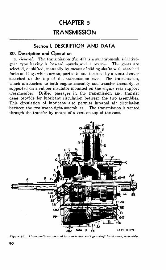
5
Section I. DESCRIPTION AND DATA
80. Description and Operation
a. General. The transmission (fig. 43) is a synchromesh, selective-
gear type having 3 forward speeds and 1 reverse. The gears are
selected, or shifted, manually by means of sliding shafts with attached
forks and lugs which are supported in and inclosed by a control cover
attached to the top of the transmission case. The transmission,
which is at’tached to both engine assembly and transfer assembly, is
supported on a rubber insulator mounted on the engine rear support
crossmember. Drilled passages in the transmission and t,ransfer
cases provide for lubricant circulation between the two assemblies.
This circulation of lubricant also permits internal air circulation
between the two water-tight assemblies. The transmission is vented
through the transfer by means of a vent on top of the case.
Figure 4s. with gearshijt hand lever, assembly.
90
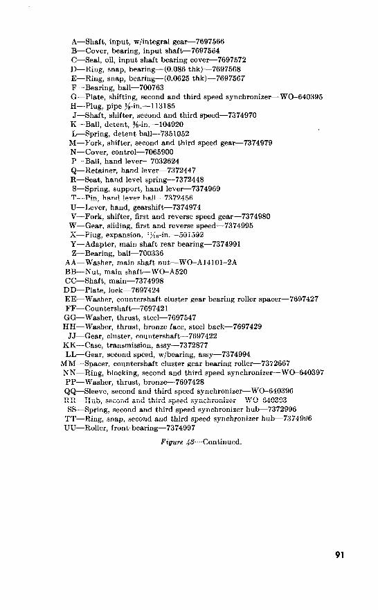
A-Shaft, input, w/integral gear-7697566
B-Cover, bearing, input shaft-7697564
C-Seal, oil, input shaft bearing cover-7697572
D-Ring, snap, bearing-(0.086 thk)-7697568
E-Ring, snap, bearing-(0.0625 thk)-7697567
F-Bearing, ball-700763
G-Plate, shifting, second and third speed synchronizer-WO-640395
H-Plug, pipe ~&in.-113185
J-Shaft, shifter, second and third speed-7374970
K-Ball, detent, 3/s-in.-104920
L-Spring, detent ball-7351052
M-Fork, shifter, second and third speed gear-7374979
N-Cover, control-7065900
P-Ball, hand lever-7032624
Q-Retainer, hand lever-7372447
R-Seat, hand level spring-7372448
S-Spring, support, hand lever-7374969
T-Pin, hand lever ball-7372456
U-Lever, hand, gearshift-
V-Fork, shifter, first and reverse speed gear-7374980
W-Gear, sliding, first and reverse speed-7374995
X-Plug, expansion, rfis-in-501592
Y-Adapter, main shaft rear bearing-7374991
Z-Bearing, ball-700336
AA-Washer, main shaft nut-WO-Al4101-2A
BB-Nut, main shaft-WO-A520
CC-Shaft, main-7374998
DD-Plate, lock-7697424
EE-Washer, countershaft cluster gear bearing roller spacer-7697427
FF-Countershaft-
GG-Washer, thrust, steel-7697547
HH-Washer, thrust, bronze face, steel back-7697429
JJ-Gear, cluster, countershaft-
KK-Case, transmission, assy-7372877
L&Gear, second speed, w/bearing, assy-7374994
MM-Spacer, countershaft cluster gear bearing roller-7372667
NN-Ring, blocking, second and third speed synchronizer-WC-640397
PP-Washer, thrust, bronze-7697428
Q&-Sleeve, second and third speed synchronizer- WC-640396
RR-Hub, second and third speed synchronizer-WC-640393
SS-Spring, second and third speed synchronizer hub-7372996
TT-Ring, snap, second and third speed synchronizer hub-7374w6
UU-Roller, front- bearing-7374997
@--Continued.
91

Figure 44. Clutch release bearing.
b. Operation (fig. 43). The movement of the gearshift hand lever
(U) is transmitted through the second and third speed shifter shafts
(J) and forks (M and V), contained in the transmission control cover
(N), to the first and reverse speed sliding gear (W) and to the second
and third speed synchronizer sleeve (QQ).
(1)
(2)
(3)
92
First speed forward. Power kow, when the gearshift hand
lever (U) is shifted into first speed forward, is from input
shaft (A) to first and reverse speed sliding gear (W), to first
speed gear of countershaft cluster gear, and to main shaft
(CC). Second speed forward. Shifting gearshift hand lever (U) into
second speed forward causes second and third speed gear
shifter fork (M) to slide second and third speed synchronizer
sleeve (QQ) rearward on the second and third speed syn-
chronizer hub (RR) and blocking ring (NN), thereby,
locking hub and ring to second speed gear (LL). Power
flow is from input shaft (A) to second speed gear of counter-
shaft cluster gear and to main shaft (CC).
Third speed .forward. Movement of gearshift hand lever (U)
to third speed forward position causes second and third
speed gear shifter fork (M) to move forward. Forward
movement, of fork, slides second and third speed synchro-
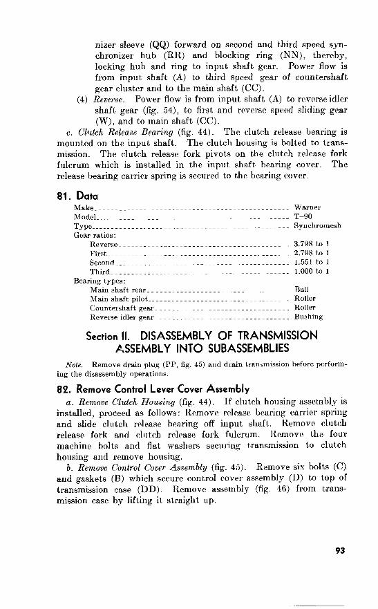
(4) Reverse.
Clutch Release Bearing (fig. 44).
81. Data
Reverse_~__~__________~----~-__.~--.__----~----~_ 3.798 to 1
First_______~~___~~_____---~_-_._---__----------~_ 2.798to 1
Second___~~____~________.---_____.___._---.__---_ 1.551to 1
Third~_____~___~~_________~-__~~.___~_.___~___~-_ l.OOOto 1
Bearing types:
Main shaft rear__~_-~.__~---.~~~..~__._~--__.~---- Ball
Main shaft pilot_____-~___----_~._______~--__-~---_ Roller
Countershaft gear________~_~~~___--___-----~---~__ Roller
Reverse idler gear___________~~____-_._~----_---~__ Bushing
Section II. DISASSEMBLY OF TRANSMISSION
ASSEMBLY INTO SUBASSEMBLIES
Note. Remove drain plug (PP, fig. 45) and drain transmission before perform-
ing the disassembly operations.
82. Remove Control Lever Cover Assembly
a. Remove Clutch Housing (fig. 44).
b. Remove Control Cover Assembly (fig. 45). (C)
46)
93

A-Gasket, top cover-7374977 B-Gasket control lever cover bolt-WO-51875U C-Bolt, &18NC-2 x g---WG-635868 D-Cover, control lever assy-7032623 E-Shaft, main., w/gear and blocking ring, assy-WG-640389 F-Collector, oil, countershaft cluster gear-7697420 G-Gear, reverse idler shaft, w/bearing, assy-7697423 H-Gear, cluster, countershaft- J-Washer, thrust, bronze face, steel back-7697429
K-Washer, thrust, steel-7697547 L-Washer, countershaft cluster gear bearing roller spacer-7697427
M-Roller, countershaft cluster gear bearing-7697545 N-Washer, countershaft cluster gear bearing roller spacer-7697427 P-Roller, countershaft cluster gear bearing-7697545 Q-Washer, countershaft cluster gear bearing roller spacer-7697427 R-Spacer, countershaft cluster gear bearing roller-7372667 S-Washer, countershaft cluster gear bearing roller spacer-7697427 T-Roller, countershaft cluster gear bearing-7697545 U-Washer, countershaft cluster gear bearing roller spacer-7697427 V-Roller, countershaft cluster gear bearing-7697545
W-Washer, countershaft cluster gear bearing roller spacer-7697427 X-Washer, thrust, bronze-7697428 Y-Cover, bearing, input shaft-7697564 Z-Gasket, input shaft bearing cover-7697565
AA-Seal, oil, input shaft bearing cover-7697572 BB-Shaft, input, w/integral gear-7697566 CC-Roller, front bearing-7374997 DD-Case, transmission, assy-7372877 EE-Spacer, main shaft rear bearing-7374992 FF-Adapter, main shaft rear bearing-7374991 GG-Bearing, ball, main shaft rear-700336 HH-Washer, plain, 2& ID, Is6 OD, sz thk-7375131
JJ-Nut, s-16NC-2-7743652 KK-Plate, lock-7697424 LL-Shaft, reverse idler-7697425
MM-Countershaft- NN-Plug, filler-7372879 PP-Plug, drain-7372879 Q&-Gasket, oil collector screw-WG-51875U RR-Bolt, socket-hd, ge-24NF-3 x s-571283
SS-Gasket, input shaft bearing cover screw-W&51875U TT-Screw, cap, socket-hd, se-18NC-3 x lj/4-571279
Figure 46. Transmission with control lever cover assembly-disassembled view.
94
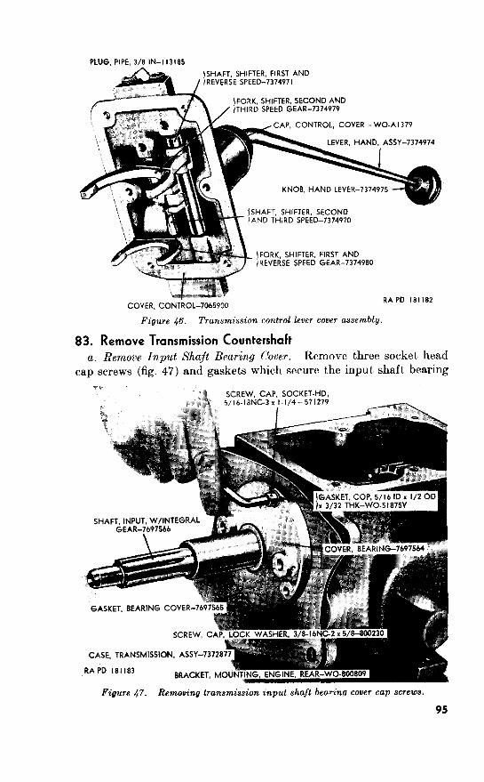
Figure 46. Transmission control lever cover assembly.
83. Remove Transmission Countershaft
a. Remove Input Shaft Bearing Cover.
RRACKFT MOU
Figure 47. Removing transmission shaft beo.ring cover cap screws.
95
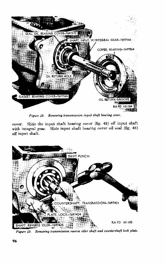
Figure 48. Removing transmission input shaft bearing cover.
Figure 49. Removing transmission reverse idler shaft and countershaft lock
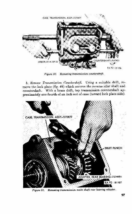
?,
IRIl8b
transmission
6. Remove Transmission Countershaft. Using a suitable drift, re-
move the lock plate (fig. 49) which secures the reverse idler shaft and
countershaft. With a brass drift, tap transmission countershaft ap-
proximately one-fourth of an inch out of case (toward lock plate side).
97

84. Remove Transmission Main Shaft Assembly
a. Remove Main Shaft Rear Bearing Adapter (fig. 51).
b. Remove Transmission A4ain Shaft Assembly (fig.
85. a.
Figure 52. Removing transmission main shaft assembly.
Remove Input Shaft With Integral Gear
Remove Input Shalt With Integral Gear (fig. 53).

Figure 63. Removing input shaft with integral gear.
transmission case assembly. Take care not to damage the counter-
shaft cluster gear oil collector.
b. Remove Countershajt Clus’er Gear Oil Collector (fig. Remove
two socket-head bolts and gaskets securing countershaft cluster gear
oil collector to transmission case. Lift the collector from the trans- mission case CO~~I~III IVY\)
7697420
Figure 64. RemotCng ttonamiwim counierahajt cltde7 gear oil colledw.
99
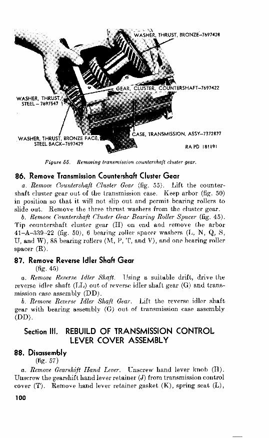
-7697428
.7697422
-7372877
191
Figure 55. Removing transmission countershaft cluster gear.
86. Remove Transmission Countershaft Cluster Gear
a. Remove Countershaft Cluster Gear (fig. 55).
b. Remove Countershaft Cluster Gear Bearing Roller Spacer (fig. 45).
6
(R) .
87. Remove Reverse Idler Shaft Gear
(fig. 45)
a. Remove Reverse Idler Shaft.
b. Remove Reverse Idler Shaft Gear.
Section Ill. REBUILD OF TRANSMISSION CONTROL
LEVER COVER ASSEMBLY
88. Disassembly (fig. 57)
a. Remove Gearshift Hand Lever.
100
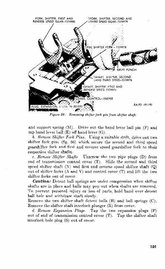
b. Remove Shifter Fork Pins.
Remove Shtfter Shqfts.
Caution:
Remove Expansion Plugs.
cover
101

89. Inspection and Repair Ok. 57)
a. Inspection.
Transmission control cover. Inspect the transmission control
cover (T) carefully for cracks, distortion, and sand holes.
Examine machined mating surface for nicks, scores, or
scratches. Inspect screw threads for damage. Replace
cover if broken, cracked, distorted, or if threads have been
damaged beyond repair.
(2) Shijter shafts. Inspect the second and third speed shifter
shaft (N) and first and reverse speed shifter shaft (Qj for
distortion, pitting, scores, cracks, ridges, or worn condition.
Replace shifter shafts, if necessary.
(3) Shijter forks. Replace the second and third speed gear shifter
fork (A) and first and reverse speed gearshifter fork (V) if
they are bent, cracked, or the ends are worn. Slip forks on
shifter shafts and check fit. Replace shifter fork if fit is
excessively loose on shifter shaft. Replace shifter fork
pin (U).
(4) Gearshift hand lever and parts. Inspect gearshift hand level
(G) for distortion, cracks, and other damage. Examine tip
of lever, which mates with shifter fork, for wear and damage.
Replace hand lever, if necessary. Inspect hand lever re-
tainer (J) for damaged threads. Replace retainer, if neces-
sary. Replace hand lever spring seat (L), if worn or dam-
aged. Replace the hand lever support spring (M), if broken,
distorted, or if it fails to operate in its intended manner.
Inspect hand lever ball (E) for wear, pitting, or out-of-
round condition. Replace ball, if necessary. Replace hand
lever retainer gasket (K) at each rebuild.
(5) Shifter shaft detent balls and springs. Inspect the shifter
shaft detent balls (B) for wear, pitting, and out-of-round
condition. Replace balls, if necessary. Check shift’er shaft
detent ball springs (C) for breaks and distortion. Replace
springs if damaged or if they fail to operate in their intended
manner.
(6) Pipe plugs and ezpawion plugs. Replace the pipe plugs (Dj
if threads are stripped or damaged. Replace the two ex-
pansion plugs (P) and shifter shaft interlock hole plug (S)
at each rebuild.
b. Repair. Slight faults, such as burs, scores, or scratches on all
parts may be removed with a hone. Clean tapped holes in trans-
mission control cover with a standard tap.
102
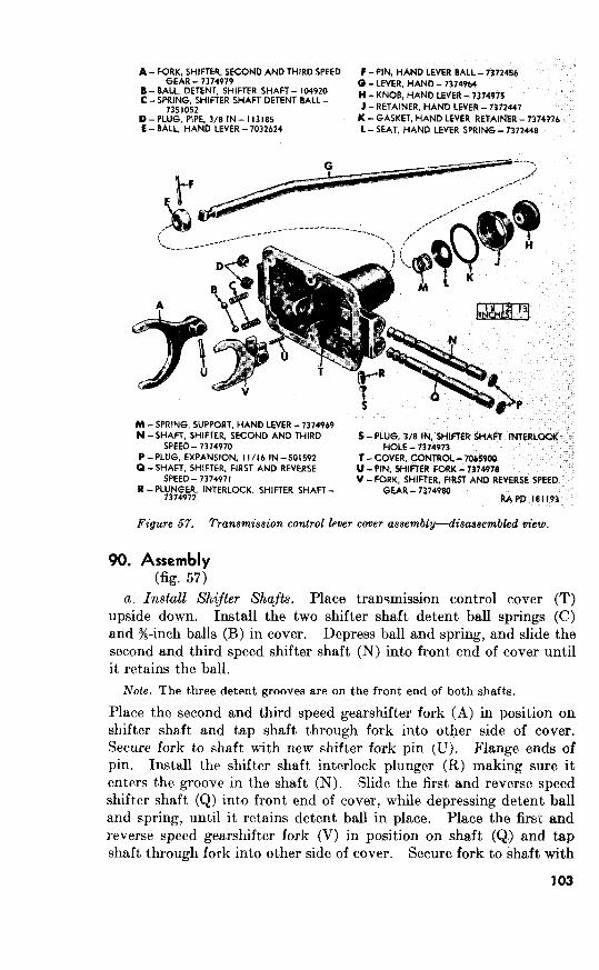
B - H - J -
K-GASKET, E -
R - V -
Figure 57. Transmission control lever cover assembly-disassembled view.
57)
a. Install Shijter Shafts.
Note. The three detent grooves are on the front end of both shafts.

new shifter fork pin (U). Flange ends of pin. Drive %-inch shifter
shaft interlock hole plug (S) into place. Install two new ‘j&-inch
expansion plugs Screw the two %-inch pipe plugs (D) into trans-
mission control cover (T).
b. Install Gearshijt Hand Lever. Tap gearshift hand lever ball (E)
into position on hand lever (G) and secure with hand lever ball pin
(F). Insert hand lever into top of transmission control cover (T).
Slide the hand lever support spring (M) and spring seat (L) over hand
lever. Coat new hand lever retainer gasket (K) with plastic type
gasket cement. Install gasket, and screw hand lever retainer (J)
into place, tightening securely. Install hand lever knob (H) on
hand lever (G). Move hand lever (G) into the various positions and
check to see that the shifter shafts are operating properly.
The transmission countershaft and countershaft cluster gear require
no disassembly except the removal of countershaft cluster gear bear-
ing rollers, spacer washers, and spacer. Refer to paragraph 86b.
9%
Inspection.
(1) Transmission countershajt. Inspect the countershaft (MM)
and replace if it is scored, pitted, ridged, or worn.
(2) Countershajt cluster gear. Examine the countershaft cluster
gear (H) teeth for damage and wear. If teeth are chipped,
broken, cracked, or worn, cluster gear must be replaced.
Inspect gear bearing rollers (M, P, T, and V) for flat spots,
chips, or discoloration due to overheating. Replace rollers
if they do not meet repair and rebuild standards (par. 270~).
Replace any broken, ridged, or distorted countershaft cluster
gear bearing roller spacer wasbers (L, N, Q, S, U, and W) or
thrust washers (J, K, and X). Replace washers if they do
not meet repair and rebuild standards (par. 270~). Replace
damaged or worn countershaft cluster gear bearing roller
spacer (R).
b. Repair. Repair slight scores, nicks and burs on countershaft
cluster gear (H) and countershaft (MM) with fine file or hone. Re-
place gear or countershaft if fault is not readily corrected.
104

Figure 68. Installing transmiseion countershaft cluster gear bearing rollers.
93.
45)
a. Install Countershaft Cluster Gear Bearing Roller Spacer, Insert
the countershaft cluster gear bearing roller spacer (R) in center of the
countershaft cluster gear (H).
b. Install Countershaft Cluster Gear Bearing Rollers. Coat arbor
41-A-339-22 (figs. 6 and 58) heavily with general purpose grease (GO)
and insert arbor through bore of countershaft cluster gear and bearing
roller spacer. Insert countershaft cluster gear bearing roller spacer
washer (S), 22 bearing rollers (T), bearing roller spacer washer (U),
22 bearing rollers (V), and bearing roller spacer washer (W) into the
front end of the countershaft cluster gear (H). Insert the bearing
roller spacer washer (Q), 22 bearing rollers (P), bearing roller spacer
washer (N), 22 bearing rollers (M), and bearing roller spacer washer
105

(L) into the rear end of the countershaft cluster gear. Seat rollers
against washers with sleeve 41-S-3775-675 (figs. 6 and 58)
Section V. REBUILD OF TRANSMISSION MAIN
SHAFT ASSEMBLY
94. Disassembly
a. Remove Synchronizer Assembly (fig. 59). Remove the second and
third speed synchronizer hub snap ring (C). Remove the synchronizer
assembly (sleeve (B), blocking rings (A and H), and hub (F)) as a unit
from main shaft (L). Slide the second speed gear (K), and first and
reverse speed sliding gear (M) off main shaft.
b. Disassemble Synchronizer Assembly (fig. 59). Slide second and
third speed synchronizer sleeve (B) from second and third speed
synchronizer hub (F). Remove the blocking rings (A and H). Re-
move the three second and third speed synchronizer shifting plates
(E) from hub. Remove the two second and third speed synchronizer
springs (D and G) from inside hub.
c. Remove Ball Bearing (fig. 45). Remove main shaft rear ball
bearing (GG) and bearing adapter (FF) from main shaft with a
suitable puller. Remove main shaft rear bearing spacer (EE).
A - RtNCi, SK;OND ANU
Figure 69. Transmission main shaft assembly-disassembled view.
95. Inspection and Repair
uk. 59) a. Inspection.
(1) Main shaft. Inspect main shaft (L) for twisted condition,
damaged splines, damaged threads, pitting, or discolored
bearing surfaces due to overheating. Check diameter of
pilot end of main shaft against repair and rebuild standards
104
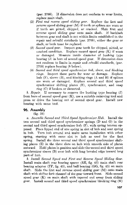
(par. 270b). If dimension does not conform to wear limits,
replace main shaft.
(2) First and rtverse speed sliding gear. Replace the first and
reverse speed sliding gear (M) if teeth or splines are worn or
if teeth are pitted, chipped, or cracked. Slide first and
reverse speed sliding gear onto main shaft. If backlash
between gear and shaft is not within limits established in the
repair and rebuild standards (par. 270b), either the gear or
shaft, or both must be replaced.
(3) Second speed gear. Inspect gear teeth for chipped, pitted, or
cracked condition. Replace second speed gear (K) if worn
or damaged. Measure inside diameter of bushing type
bearing (J) in bore of second speed gear. If dimension does
not conform to limits in repair and rebuild standards, (par.
270b) replace bearing (h below).
(41 Second and third speed synchronizer hub, sleeve, and blocking
rings. Inspect these parts for wear or damage. Replace
hub (F), sleeve (B), and blocking rings (A and H) if splines
are worn or damaged. Replace second and third speed
synchronizer shifting plates (E), synchronizer, and snap
ring (C) if broken or distorted.
b. Repair. If necessary to remove the bushing type bearing (J)
from bore of second speed gear (K), use a suitable removing tool and
press or drive the bearing out of second speed gear. Install new
bearing with same t,ool.
96.
a. Assemble Second and Third Speed Synchronizer Dub. Install the
two second and third speed synchronizer springs (D and G) in the
second and third speed synchronizer hub (F), with spring tension op-
posed. Place lipped end of one spring in slot of hub and seat spring
in hub. Turn hub around and make same installation with other
spring, starting with same slot in hub as used for the first
spring. Install the three second and third speed synchronizer shift-
ing plates (E) in the three slots on hub with smooth side of plates
outward. Hold plates in position and slide the second and third speed
synchronizer sleeve (B) over hub wit,h long beveled edge toward long
part of hub.
b. Install Second Speed and First and Reverse Speed Sliding Gear.
Install main shaft rear bearing spacer (EE, fig. 45) main shaft rear
bearing adapter (FF, fig. 45), and ball bearing (GG, fig. 45) on main
shaft. Slide the first and reverse speed sliding gear (M) onto main
shaft with shifter fork channel of the gear toward front. Slide second
speed gear (K) on main shaft with tapered end away from sliding
gear. Install second and third speed synchronizer blocking ring (H)
107
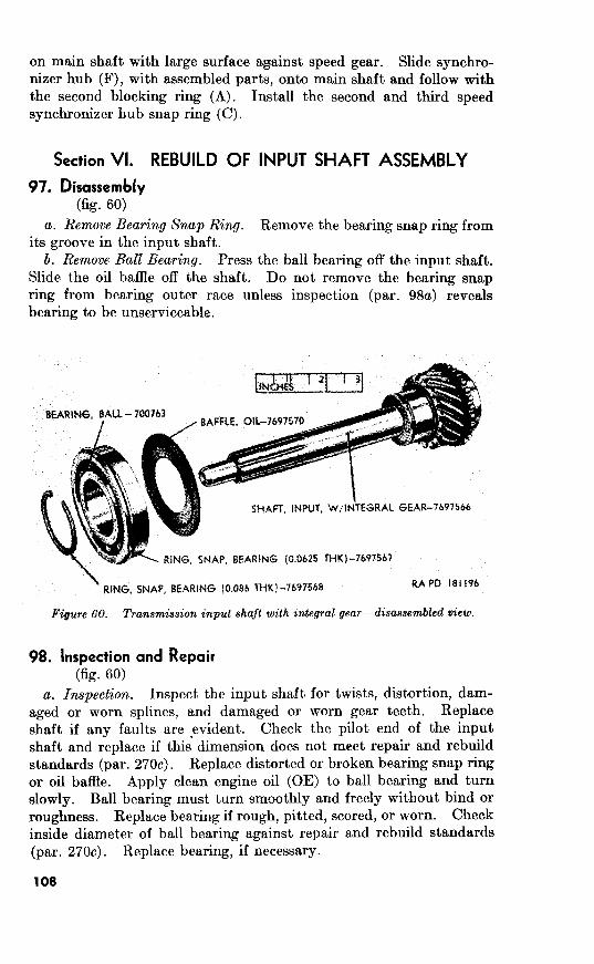
on main shaft with large surface against speed gear. Slide synchro- nizer hub (F), with assembled parts, onto main shaft and follow with
the second blocking ring (A). Install the second and third speed
synchronizer hub snap ring (C).
Section VI. REBUILD OF INPUT SHAFT ASSEMBLY
97. Disassembly
(fig. 60) a. Remove Bearing Snap Ring.
its groove in the input shaft.
b. Remove Batt Bearing. Press
Slide the oil baffle off the shaft.
Remove the bearing snap ring from
the ball bearing off the input shaft.
Do not remove the bearing snap
ring from bearing outer race unless inspection (par. 98a) reveals
bearing to be unserviceable.
Figure 60. Transmission input shaft with antegral gear--disassembled view.
98. Inspection and Repair
(fig. 60) a. Inspection. Inspect the input shaft for twists, distortion, dam-
aged or worn splines, and damaged or worn gear teeth. Replace
shaft if any faults are evident. Check the pilot end of the input
shaft and replace if this dimension does not meet repair and rebuild
standards (par. 270~). Replace distorted or broken bearing snap ring
or oil baflle. Apply clean engine oil (OE) to ball bearing and turn
slowly. Ball bearing must turn smoothly and freely without bind or
roughness. Replace bearing if rough, pitted, scored, or worn. Check
inside diameter of ball bearing against repair and rebuild standards
(par. 270~). Replace bearing, if necessary.
108

99. (fig. 60)
(1. Insfnll IMZ lkwin~. Slide oil bnflle int,o position on input shaft, with t~cvc~t~l rcccss of oil bafilc Loward intJcgrn.l gear of input shaft. l’r~~ss ball bearing on input) shaft,, using nn arbor press.
h . Ins td Ihwin,q Sqn h’i~q. I~ock bnll bcnring t.0 input shaft wit,h t,tic 0.086 tjhictlc baring snap ring. If new ball bearing is being inst’nll4, inst,nll 0.0625 t.hicli bearing snap ring in groove of bearing
a. Oisassembl~y. The ~CVCIW idlw shaft gear (fig. 61) rquircs no disasscxmbly exc>cpt t)hc removal of the bushing typr bearing. not remove the hwing unless inspection (b below) rc~cels it to be unserv- iccablc. rcmovc the bearing, press or drive baring out, of bore of q3r wiLti n suitable removing tool.
Transmission rewr.x
b. Impection ad Repair.
(1) Impection. Irqwct tc>ct,h of rcvcrsc idler shaft gear (fig. 61) for chips, pits, SCOI‘CS, or blcaks. Rcplacc gear if teeth are c~xccssivcl$ damaged or worn. hlcnsurc inside diameter of

270d).
Repair.
Assembly.
270d).
101.
a. Disassembly.
b. Inspection and Repair.
(1) Inspection.
Repair.
Assembly.
110
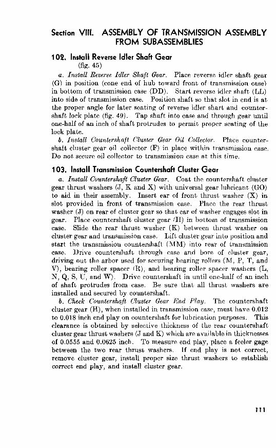
Section VIII. ASSEMBLY OF TRANSMISSION ASSEMBLY
FROM SUBASSEMBLIES
102. Install Reverse Idler Shaft Gear
(fig. 45)
a. Install Reverse Idler Shaft Gear.
Countershaft Cluster Gear Oil Collector.
103. Install Transmission Countershaft Cluster Gear
a. Install Countershajt Cluster Gear.
f R),
b. Check Countershajt Cluster Gear End Play.
0.018
0.0555 0.0625
111

Install Front Bearing Rollers. Coat front bearing rollers (CC)
with general purpose grease (GO) to aid in assembly. Install the 14
front bearing rollers in the recess at gear end of input shaft (BB).
Place input shaft in position through opening in front of transmission
case so that countershaft cluster gear oil collector (F) is engaged
behind input gear in groove provided for locking collector to gear.
Tap input shaft (BB) into bore of case until the snap ring installed
in the groove of ball bearing rests against transmission case.
b. Secure Countershaft Cluster Gear Oil Collector. Secure counter-
shaft cluster gear oil collector (F) to transmission case with two
Ka-24NF-3 x $% socket-head bolts (RR) and KG ID x % OD x 1& thick
gaskets (QQ). Tighten bolts to a torque of pound-feet.
c. Install Input Shaft Bearing Cover. Coat new input shaft bearing
cover gasket (Z) with plastic type gasket cement and place it in
position against the front of the transmission case. Slide new input
shaft bearing cover oil seal (AA) (rubber side first) and bearing cover
(Y) onto input shaft (BB). Secure input shaft bearing cover with
three sB ID x % OD x YS2 thick input shaft bearing cover screw gaskets
(SS) and x6-18NC-3 x 1% socket-head cap screws (TT).
105.
45)
a. Install Transmission Main Shaft Assembly. Insert transmission
main shaft assembly (E) into transmission case through large opening
at rear of case, making sure leading edge of main shaft rides in the
14 front bearing rollers (CC) in input shaft (BB). Tap main shaft
rear bearing adapter (FF) until it is properly seated in the trans-
mission case.
b. Install Reverse Idler Shaft and Countershajt Lock Plate. Secure
the transmission countershaft (MM) and reverse idler shaft (LL) by
tapping the reverse idler shaft and countershaft lock plate (KK) into
position in the slots in ends of the two shafts.
106.
45)
a. Install Top Cover Gasket. Make sure all old gasket material and
gasket cement is scraped off mating surface of transmission case.
Coat new top cover gasket (A) with plastic type gasket cement.
Place gasket in position on top of case.
b. Install Control Lever Cover Assembly. Place control lever cover
assembly (D) in position on top of transmission case, being careful to
observe that shifter forks engage collars on first and reverse sliding
gear and second and third speed synchronizer assembly. Secure
112

cover assembly to case with six %-lSNC-2 x y6 bolts (C) and control-
lever cover bolt gaskets (B).
c. Install Clutch Housing (fig. 44). Secure clutch housing assembly
to transmission case with four &-l4NC-3 x machine bolts and
‘5& ID, 5%4 OD, 0.065 inch thick flat washers. Install clutch release
fork fulcrum in input shaft bearing cover. Install clutch release fork,
clutch release bearing, and release bearing carrier spring.
Section IX. TESTS AND ADJUSTMENT
107. Preparation for Tests
Fill transmission with lubricant as directed in TM g-8048.
108. Tests
a. If transmission has been correctly assembled, internal gears
should rotate freely and without bind when the input shaft is turned
by hand.
b. To test transmission, turn input shaft through at least 10
complete revolutions in each gear position. Gears should turn freely
and smoothly under normal hand pressure.
c. If there is noise, binding, or looseness, the transmission must be
disassembled, inspected for damaged parts or improper assembly, and
correctly assembled.
113
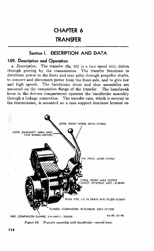
6
Section I. DESCRIPTION AND DATA
109. Description and Operation
a. Description. The transfer (fig. 62) is a two speed unit driven
through gearing by the transmission. The transfer functions to
distribute power to the front and rear axles through propeller shafts,
to connect and disconnect power from the front axle, and to give low
and high speeds. The handbrake drum and shoe assemblies are
mounted on the companion flange of the transfer. The handbreak
lever in the drivers compartment operates the handbrake assembly
through a linkage connection. The transfer case, which is secured to
the transmission, is mounted on a case support insulator located on
Figure 6.2. Transfer assembly with handbrake-overall view.
114
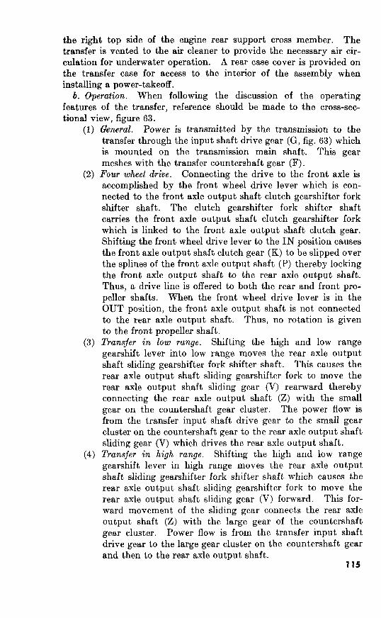
the right top side of the engine rear support cross member. The
transfer is vented to the air cleaner to provide the necessary air cir-
culation for underwater operation. A rear case cover is provided on
the transfer case for access to the interior of the assembly when
installing a power-takeoff.
b. Operation. When following the discussion of the operating
features of the transfer, reference should be made to the cross-sec-
tional view, figure 63.
(1) General. Power is transmitted by the transmission to the
transfer through the input shaft drive gear (G, fig. 63) which
is mounted on the transmission main shaft. This gear
meshes with the transfer countershaft gear (F).
(2) Four wheel drive. Connecting the drive to the front axle is
accomplished by the front wheel drive lever which is con-
nected to the front axle output shaft clutch gearshifter fork
shifter shaft. The clutch gearshifter fork shifter shaft
carries the front axle output shaft clutch gearshifter fork
which is linked to the front axle output shaft clutch gear.
Shifting the front wheel drive lever to the IN position causes
the front axle output shaft clutch gear (K) to be slipped over
the splines of the front axle output shaft (P) thereby locking
the front axle output shaft to the rear axle output shaft.
Thus, a drive line is offered to both the rear and front pro-
peller shafts. When the front wheel drive lever is in the
OUT position, the front axle output shaft is not connected
to the rear axle output shaft. Thus, no rotation is given
to the front propeller shaft.
(3) Transfer in low range. Shifting the high and low range
gearshift lever into low range moves the rear axle output
shaft sliding gearshifter fork shifter shaft. This causes the
rear axle output shaft sliding gearshifter fork to move the
rear axle output shaft sliding gear (V) rearward thereby
connecting the rear axle output shaft (Z) with the small
gear on the countershaft gear cluster. The power flow is
from the transfer input shaft drive gear to the small gear
cluster on the countershaft gear to the rear axle output shaft
sliding gear (V) which drives the rear axle output shaft.
(4) Transfer in high range. Shifting the high and low range
gearshift lever in high range moves the rear axle output
shaft sliding gearshifter fork shifter shaft which causes the
rear axle output shaft sliding gearshifter fork to move the
rear axle output shaft sliding gear (V) forward. This for-
ward movement of the sliding gear connects the rear axle
output shaft (Z) with the large gear of the countershaft
gear cluster. Power flow is from the transfer input shaft
drive gear to the large gear cluster on the countershaft gear
and then to the rear axle output shaft,. 115

A-Seal, oil, type ML, rear axle output shaft, ls/le x 2.504 x $&500068 B-Gear, driven, speedometer-WC-806718 (part of kit-8328477) C-Shim, rear axle output shaft bearing retainer-part of shim set-7371591 D-Countershaft, transfer-7375133 K-Washer, thrust, countershaft gear-7375135 F-Gear, countershaft- G-Gear! drive, input shaft-7375132 H-Bearmg, roller, journal, countershaft gear- 708234 J-Washer, thrust, countershaft gear-7375135
K-Gear! clutch, front axle output shaft-7371212 L-Bearing, bushing type, pilot, front axle output shaft-7373115
M-Seal, oil, type ML, front axle output shaft, 1%~ x 2.504 x ~-500068 N-Yoke, front axle output shaft, w/shield, assy-8328440 P-Shaft, output, front axle-8329674 Q-Bearing, ball, front axle output shaft-700079 R-Ring, snap, front axle output shaft bearing-7373185 S-Cup, bearing, rear axle output shaft, inner-706821 T-Cone, bearing, rear axle output shaft, inner-705399 U-Gear, driven, rear axle output shaft-7697467 V-Gear, sliding, rear axle output shaft-7697468
W-Cone, bearing, rear axle output shaft, outer-705399 X-Cup, bearing, rear axle output shaft, outer-706821 Y-Gear, drive, speedometer-7373166 (also part of kit-8328477) Z-Shaft, output, rear axle, w/bearing, nut and washer, assy-8328479
AA-Drum, brake-8329632

110. Data Make_____________--_-_-_-___-_-___-_-___-_-_____---_- Spicer
Model________-______-____---____----___-_-___---_____- 18
Ratios : Underdrive (low range)__________--_---_---_--_----_- 2.43 to 1
Direct (high range)-----__-----___----____--____-_-- 1.00 to 1
Bearing types:
Countershaft_______---___----_-_----_------_------_ roller
Rear axle output shaft-_------____---_____--___----_ tapered roller
Lubricant capacity___________--_-------_------___---___- 3 pt
Section II. DISASSEMBLY OF TRANSFER ASSEMBLY INTO
SUBASSEMBLIES
Note. Drain the transfer as prescribed in TM 9-8048 before proceeding with
any disassembly operations.
111. Remove Handbrake Drum and Companion Flange
a.
Figure 64. Removing transfer rear axle output shaft retainer with bearing assembly.
117
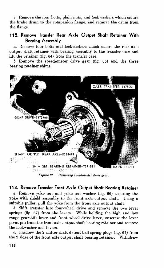
112. Remove Transfer Rear Axle Output Shaft Retainer With
Bearing Assembly
a.
113. Remove Transfer Front Axle Output Shaft Bearing Retainer
a.
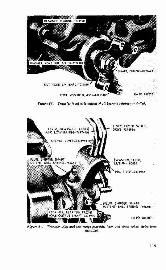
Figure 66. Transfer front a& output shaft bearing retainer installed.
i
Figure 67. Transfer high and low mnge gearshift lever and front wheel drive lever
installed.
119

Figure 68. Transfer front axle output shaft bearing partially removed.
the two shifter shaft detent ball springs and shifter shaft detent balls
from their cavities in front axle output shaft bearing retainer.
Remove the five bolts and lockwashers securing the front axle
output shaft bearing retainer to transfer case. Pull the bearing
retainer from the transfer case by sliding it off the two shifter shafts.
Note. It may require some slight movement of the bearing retainer and transfer
case in a lifting manner (right and left) to place the shifter shaft interlock in
proper position so that shifter shafts can clear it.
The front axle output shaft clutch gear, front axle output shaft, front
axle output shaft clutch gearshifter fork and shifter fork shaft, and
ball bearing will remain in the bearing retainer (fig. 68). Remove
the bearing retainer gasket.
114. Remove Transfer Countershaft
(fig. 73)
a. Remove the 10 lockwasher bolts (WW) securing the transfer
case bottom cover (XX) to the transfer case (U) and remove the
bottom cover and bottom cover gasket (YY).
n. Remove bolt (UU) and lockwasher (TT) which secure the
Aountershaft lock plate (SS) to the transfer case and remove the lock
120

plate. Using a brass drift, drive the transfer countershaft (RR) from
the transfer case.
Note. countershaft from
Lift the countershaft gear (AA) out of the transfer case. Remove
the two countershaft gear thrust washers (BB and QQ) from inside
of transfer case. Remove the two countershaft gear journal roller
bearings (PP) from within the countershaft gear bore.
115. Remove Transfer Rear Axle Output Shaft
a. Tap the rear axle output shaft (fig. 69) until the rear axle output
shaft inner and outer bearing cones (fig. 71) clear their respective
bearing cups in sides of transfer case.
Note.
Figure Tapping transfer rear axle output shaft.
b. Install remover 41-R-2368-200 between rear axle output shaft
driven gear and the imy bearing cone and tap remover (fig. 70)
until bearing cone is free of its seat on rear axle output shaft. Remove
the thrust washer snap ring (fig. 71) from its groove in rear axle
output shaft. Pull shaft out from rear of case. Lift the rear axle
output shaft, thrust washer, driven gear, sliding gear, and inner
bearing cone out of transfer case. Using a suitable puller, remove
the outer bearing cone from the rear axle output shaft. Do not
remove the front axle output shaft bushing type pilot bearing (JJ,
fig. 73), which supports the rear end of the front axle output shaft,
121
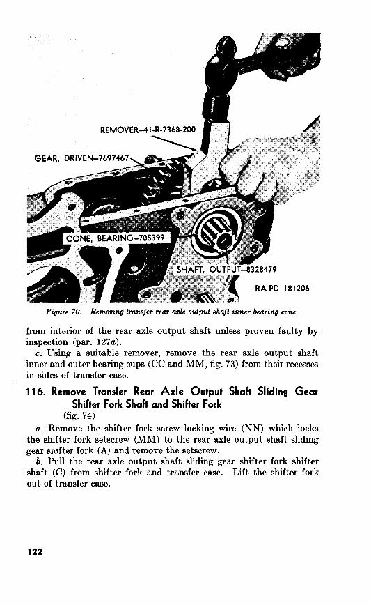
REMOVER--QI-R-2368-200
GEAR, DRIVEN-
RA PD 181206
Figure 70. Removing transfer rear azk output shaft inner bearing cone.
from interior of the rear axle output shaft, unless proven faulty by
inspection (par. 127~).
c. Using a suitable remover, remove the rear axle output shaft
inner and outer bearing cups (CC and MM, fig. 73) from their recesses
in sides of tra.nsfer case.
116. Remove Transfer Rear Axle Output Shah Sliding Gear
Shifter Fork Shah and Shiher Fork
(fig. 74)
a. Remove the shifter fork screw locking wire (NN) which locks
the shifter fork setscrew (MM) to the rear axle output shaft sliding
gear shifter fork (A) and remove the setscrew.
b. Pull the rear axle output shaft sliding gear shifter fork shifter
shaft (C) from shifter fork and transfer case. Lift the shifter fork
out of transfer case.
122

GEAR, SLIDING-
INNER - 705399
, OUTER-705399
RA I’D 181207
Figure 71. Removing thrust washer snap ring from transfer rear ode output shaft.
117.
a. Remove Handbrake Assembly (fig. 72). Remove the cotter pin,
lift the handbrake stop from handbrake anchor pin, and follow by
lifting the operating lever and inner a.nd outer shoe assemblies off
anchor pin. Remove the two cotter pins which secure the inner and
outer shoe assemblies to the operating lever and remove shoe assem-
blies from lever. Unscrew the plain nut from anchor pin, remove
lockwasher, and pull anchor pin from the rear axle output shaft
bearing retainer.
b. Remove Driven Gear (fig. 72). Unscrew the speed-
ometer driven gear sleeve from the rear axle output shaft bearing
retainer. Pull the speedometer driven gear from within retainer.
Do not remove the speedometer drive gear bearing from the bearing
retainer unless inspection (par. 118a) reveals it to be unserviceable.
To remove the speedometer drive gear bearing, it is only necessary
to pry it out of its recess with a suitable prying tool. Using a suitable
removing tool, remove the rear axle output shaft oil seal from the
bearing retainer and remove the oil seal gasket.
123

SLEfVf, SPEEDOMETER DRIVE&! (%I PART OF KIT 8328+72
\
.PlN, Atmd-1~6
MAR. DRIVEN. SPEEWMETER -
“-I *--1 HANR BRAKP - 832QhZQ
XOP, XAND AKE ; 8399630
SHOE. OUTER, W/LINING, ASSY - WO-i
-/ SHOE, INNER, W/LINING, ASSY - WO-804028
OTTER, l/8 x 3/4- 177923
RETAINER, ASSY - 8328478’
LEVER, OPERATING - 8329633
I RA PD 181208
Figure 72. Transfer rear axle output shaft retainer with bearing assembly.

118. Inspection and Repair
(fig. 72)
Note. Refer to paragraph 187 for inspection and repair procedures of handbrake
drum and shoe assemblies.
a. Inspection. Inspect the rear axle output shaft bearing retainer
for cracks, sand holes, and other damage. Replace retainer if cracks
or sand holes are found. Inspect machined surfaces of retainer for
burs, nicks, or deep scratches. Inspect the speedometer driven gear
for chipped or broken teeth. The outside diameter of pilot end of
speedometer driven gear must not be less than 0.244 inch (par. 271a).
Replace speedometer driven gear, if necessary. Check the speedom-
eter drive gear bearing, installed in rear axle output shaft bearing
retainer, for excessive wear and damage. The inside diameter of
speedometer drive gear bearing must not exceed 0.2580 inch (par.
271a). Replace bearing, if necessary. Replace the speedometer
driven gear sleeve if it is bent, cracked, or has damaged threads.
Note. The speedometer drive gear and drive gear bearing and the speedometer
driven gear and driven gear sleeve are supplied as speedometer gear set service
kit 8328477. The drive gear bearing and the drive gear are also available
separately.
Inspect companion flange with slinger assembly (C, fig. 73)) companion
flange nut (A, fig. 73), and nut washer (B, fig. 73) for damage. Replace
faulty parts, if necessary.
b. Repair. Remove all burs, abrasions, or raised metal and nicks,
on speedometer driven gear sleeve, speedometer drive gear, and rear
axle output shaft bearing retainer, with a fine mill file. Discard the
rear axle output shaft oil seal and oil seal gasket at each rebuild.
119. Assembly
a. Install Speedometer Driven Gear (fig. 72). Install new speedom-
eter drive gear bearing, if necessary, in recess of rear axle output shaft
bearing retainer using a suitable replacing tool. Insert speedometer
driven gear into retainer. Screw speedometer driven gear sleeve into
retainer.
b. Install Handbrake Assembly (fig. 72). Install inner and outer
shoes with lining assemblies on operating lever and secure with two
yS x s cotter pins. Install handbrake anchor pin, %-inch lockwasher,
and T/8--18NF-2 plain nut on rear axle output shaft bearing retainer.
Install operating lever and shoe assemblies on anchor pin. Install
handbrake stop and secure lever and shoe assemblies with 36 x 3i cotter
pin.
Note. Do not install rear axle output shaft oil seal gasket and oil seal until rear
axle output shaft end play is adjusted.
125
SSchwend
271a).
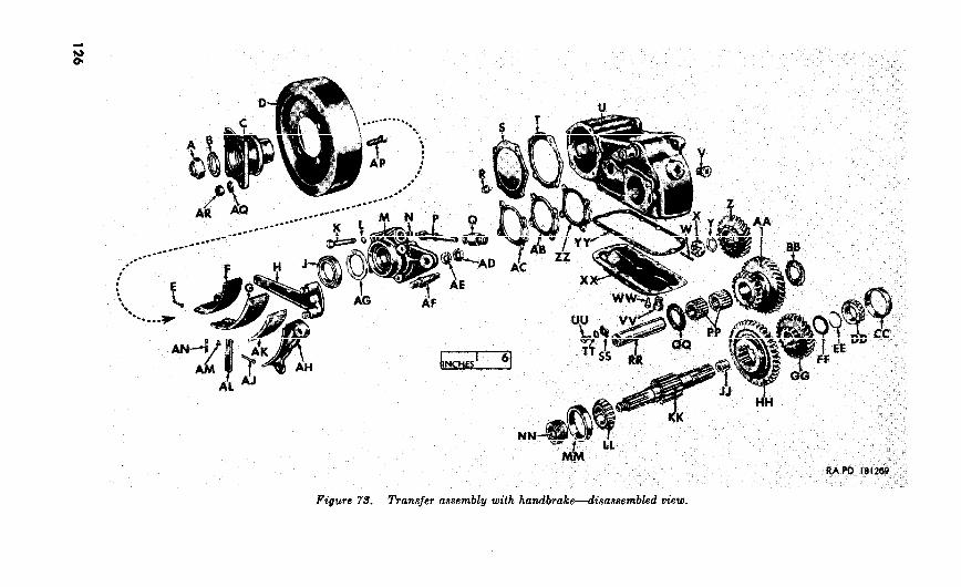

A-Nut, companion flange, 5/4-16NF-2-7032635 B-Washer, companion flange nut, %-in.-7372868 C-Flange, companion, w/slinger, assy-7371035 D-Drum, brake-8329632 E-Pin, cotter, $4 x g-177923 F-Shoe, inner, w/lining, assy-WG-806028 G-Lining, inner-WO-199476 H-Lever, operating-8329633 J-Seal, oil, type ML, rear axle output shaft, lse x 2.504 x
y2--500068 K-Bolt, “/,16NG3 x 2j/-180132 L--Washer, lock, 3/s-in.-7697469
M-Retainer, rear axle output shaft, w/bearing, assy-8328478 N-Bearing, speedometer drive gear-Al67516 (Part of kit-
8328477) P-Gear, driven, speedometer-WO-806718 (Part of kit-
8328477) Q-Sleeve, speedometer driven gear-WG-806719 (Part of kit-
8328477) R-Bolt, lockwasher, s-16N C-2 x g-443608 S-Cover, rear, case-7369850 T-Gasket, rear cover-7373162 (Part of gasket set-7375080) U-Case, transfer-7375051 V-Plug, pipe, y&in., drain and filler-7372879
W-Pin, cotter, y8 x 13/-120123 X-Nut. ctl. %16NC-2-7743652 Y-Washer,‘piain, 28/92 ID, lsa OD, 5/32 thk-7375131 Z-Gear, drive, input shaft-7375132
AA-Gear, countershaft- BB-Washer, thrust, countershaft gear-7375135 CC-Cup, bearing, rear axle output shaft, inner-706821 DD-Cone, bearing, rear axle output shaft, inner-705399 EE-Ring, snap, rear axle o*rtput shaft thrust washer-7373165 FF-Washer, thrust, rear axle output shaft-7371204 GG-Gear, driven, rear axle output shaft-7697467 HH-Gear! sliding, rear axle output shaft-7697468
JJ-Bearmg, bushing type, pilot, front axle output shaft- 7373115
AD-Nut, plain, ys-18NF-2-124944 As-Washer, lock, ?/-in.-131205 AF-Pin, anchor, brake-8329629 AG-Gasket, rear axle output shaft oil seal-WO-A1134 (Part of
AH-Shoe, outer, w/lining, assy-WO-806027 AJ-Pin! cotter, y8 x s-177923
AK-Lining, outer- WO-119475 AGStop, brake-8329630
AM-Rivet, lining-WG-119477 AN-Pin, cotter, yS x g-177923 AP-Bolt, drum, 3/8-24NF-3 x 14/8-7324918 A&-Washer, lock, S/s-in.-120382 AR-Nut, plain, yr24NF-3-121932
Figure 75-Continued.
KK-Sh;i$8miput, rear axle, w/bearing, nut and washer, assy-
LGCone, bearing, rear axle output shaft, outer-705399 MM-Cup, bearing, rear axle output shaft, outer-706821 NN-Gear! drive, speedometer-7373166 (Part of kit-8328477 PP-Bearing, roller, journal, countershaft gear-708234 Q&-Washer, thrust, countershaft gear-7375135 RR-Countershaft, transfer-7375133
SS-Plate, lock, countershaft- TT-Washer, lock, 3/8-in.7120382 UU-Bolt, 3/8-16NC-3 x 5/8-180118 VV-Plug, pipe, f/z-in., drain and filler-7372879
WW-Bolt, lockwasher, so--18NC-2 x s-217233 XX-Cover, bottom, case-7375052 YY-Gasket, bottom, cover-7375053 (Part of gasket set-
7375080) ZZ-Shim, bearing retainer, 0.003 thk-WO-A982 (Part of shim
set-7371591) AB-Shim, bearing retainer, 0.010 thk-WO-A982 (Part of shim
set-7371591)
AC-Shim, bearing retainer, 0.031 thk-WG-A984 (Part of shim set-7371591)
gasket set-7375080)

A--Fork, shifter, rear axle output shaft sIiding gear-73731 16 B-Fork, shifter, front axle output shaft clutch gear-7373117 C-Shaft, shifter, rear axle output shaft sliding gearshifter fork-7373119 D-Shaft, shifter, front axle output shaft clutch gearshifter fork-73731 18
E-Plug, shifter shaft detent ball spring-7696481 F-Spring, shifter shaft detent ball-5214784 G-Ball, detent, shifter shaft ~-in.-104920 H-Spring, lever-7374968 J-Lever, gearshift high and low range-7697470
K-Knob, lever-7696491 L--Knob, lever-7696491
M-Spring, lever-7374968 N-Lever, front wheel drive-7374966 P-Washer, lock, S/s-in.-180556
Q-Pin, pivot, lever-7374967 R-Seal, oil, type ML, shifter shaft, % x 1.128 x +500007 S-Seal, oil, type ML, % x 1.128 x ?/8, shifter shaft-500007
T-Fitting, lubr, pivot pin, $28NF-504205 U-Yoke, front axle output shaft, w/shield, assy-8328440
V-Washer, yoke nut, %-in.-7372868
Figure 7’4. Transfer front axle output shaft bearing retainer and shifter shajts- disassembled view.
128

PO.
74)
a. Remove Front Axle Output Shaft Clutch Gearshifter Fork Shi$er
Shaft. Remove shifter fork screw locking wire (PP) securing shifter
fork setscrew (QQ) to front axle output shaft clutch gearshifter fork
(B) and remove setscrew. Remove front axle output shaft clutch
gearshifter fork (B), clutch gear (LL) and front axle output shaft (KK)
from front axle output shaft bearing retainer (DD). Pull front axle
output shaft clutch gearsmfter fork shifter shaft (D) from bearing
retainer.
b. Remove Front Axle Output Shujt Ball Bearing. Remove the front
axle output shaft bearing snap ring (JJ) as shown in figure 75. Using
a suitable removing method, pressure against outer race, press or drive
the front axle output shaft ball bearing (HH) out of the front axle
output shaft bearing retainer. Bearing must be removed from inside of bearing retainer.
c. Remove Shijter Shaft Oil Seals. Using a chisel and hammer,
remove the two shifter shaft oil seals (R and S).
d. Remove Front Axle Output Shujt Oil Seal. Using a brass drift,
remove the front axle output shaft oil seal (X) from the front axle
output shaft bearing retainer (DD) and remove the oil seal gasket (Y).
W-Nut, yoke, a/4-16NF-2-7032635 X-Seal, oil, type ML, front axle output shaft 1%~ x 2.504 x ~-500068 Y-Gasket, front axle output shaft oil seal-7373157
Z-Plug, shifter shaft detent ball spring-7696481
AA-Interlock, shifter shaft-7373112 BB-Ball, detent, shifter shaft, 3/8-in.-104920 CC-Spring, shifter shaft detent ball-5214784
DD-Retainer, bearing, front axle output shaft-7374990 EE-Bolt, machine, %&16NC-3 x l-180122 FF-Washer, lock, %-in.-7697469
GG-Gasket, bearing retainer-7373156
HH-Bearing, ball, front axle output shaft-700079 JJ-Ring, snap, front axle output shaft bearing-7373185
KK-Shaft, output, front axle-8329674 LL-Gear, clutch, front axle output shaft-7371212
MM-Screw, set, shifter fork, s/,24NF x 0.72-5214776
NN-Wire, locking, shifter fork screw-22-W-1631-110 PP-Wire, locking, shifter fork screw-22-W-1631-110
&Q--Screw, set, shifter fork, a/,24NF x 0.72-5214776
?‘&-Continued.
129
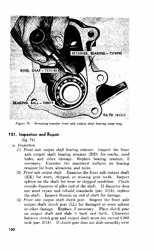
RA PO 181211.
Figure 76. Removing transfer front axle output shaft bearing snap ring.
1 Pi.
74)
a. Inspection.
(1)
(2)
(3)
130
Front axle output shaft bearing retainer.
Front axle output shaft.
271b),
Front axle output shaft clutch gear.
0.005
2716).

(4) Front axle output shaft ball bearing.
Front output shaft yoke with shield assembly
or worn
271b).
(6) Shijter shaft oil seals.
Sh(ijter shafts and forks.
(8) Lever pivot
271b),
Sh<fter shaft detent balls, springs, plugs, and interlock.
(10) Gearshijt high low range lever,.front wheel drive lever,
lever springs.
b. Repair,
131
Replace retainer if nicks or deep scratches on machined surfaces will
interfere with a good seal between the retainer and transfer case.
Correct slight damage, such as nicks, burs, or scores, on front axle
output shaft (KK) and clutch gear (LL) with a hone.
Replace shaft or gear if damage cannot be readily
corrected. Repair damaged threads on front axle output shaft, if
possible.
122. Assembly (fig. 74)
a. Install Front Axle Output Shaft Ball Bearing. Press or drive the
front axle output shaft ball bearing (HH) into place in the front axle
output shaft bearing retainer (DD). Secure bearing by installing
the front axle output shaft bearing snap ring (JJ).
b. Install Front Axle Output Shujt Clutch Gearshifter Fork Shifter
Shaft. Insert the front axle output shaft (KK), through the front axle
output shaft ball bearing, from inside the front axle output shaft bear-
ing retainer. Insert the front axle output shaft clutch gearshifter fork
shifter shaft (D) in the bearing retainer. Place the front axle output
shaft clutch gearshifter fork (B) in position on shifter shaft and slide
the shifter fork and clutch gear onto the shifter shaft together. In-
stall the $&-24NF x 0.72 shifter fork setscrew (QQ) in the shifter fork
and secure with shifter fork screw locking wire (PP).
c. Front Axle Output Shaft Oil Seal and Shifter Shaft Oil Seals. Do
not install the front axle output shaft oil seal (X) and shifter shaft
oil seals (R and S) until the front axle output shaft bearing retainer
(DD) is installed on transfer case (par.
Section V. REBUILD OF TRANSFER COUNTERSHAFT
ASSEMBLY 123. Disassembly
(fig. The transfer countershaft (RR), countershaft gear (AA), and
countershaft gearjou@qal roller bearings (PP) require no disassembly.
124. Inspection and Repair (fig.
a. Inspection.
(1) Transfer countershaft. Inspect the transfer countershaft
(RR) for scores, abrasions, and burs. Replace the transfer
countershaft if it does not conform to the repair and rebuild
standards (par.
Countershaft gear. Inspect the teeth of countershaft gear
(AA) for damage and wear. A countershaft gear with
broken, chipped, cracked, or excessively worn teeth must
be replaced. Check the inside diameter of countershaft
132
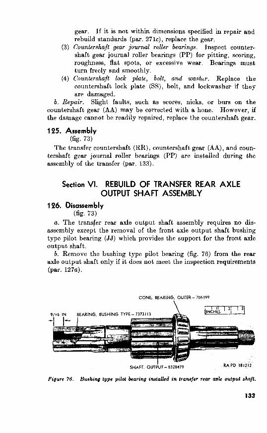
gear. If it is not within dimensions specified in repair and
rebuild standards (par. 271c), replace the gear.
(3) Countershaft gear journal roller bearings. Inspect counter-
shaft gear journal roller bearings (PP) for pitting, scoring,
roughness, flat spots, or excessive wear. Bearings must
turn freely s.nd smoothly.
(4) Cnuntershajt lock plate, bolt, and washtr. Replace the
countershaft lock plate (SS), bolt, and lockwasher if they
are damaged.
b. Repair. Slight faults, such as scores, nicks, or burs on the
countershaft gear (AA) may be corrected with a hone. However, if
the damage cannot be readily repaired, replace the countershaft gear.
125.
73)
The transfer countershaft (RR), countershaft gear (AA), and coun-
tershaft gear journal roller bearings (PP) are installed during the
assembly of the transfer (par. 133).
126. 73)
a. The transfer rear axle output shaft assembly requires no dis-
assembly except the removal of the front axle output shaft bushing
type pilot bearing (JJ) which provides the support for the front axle
output shaft.
b. Remove the bushing type pilot bearing (fig. 76) from the rear
axle output shaft only if it does not meet the inspection requirements
(par. 127a).
Bushing type pilot bearing installed in transfer rear crzk output shaft.
133

SHAFT, OUTPUT - 8328479
Figure 77. Seating bushing type pilot bearing in transfer rear azle output shaft.
1 PT. Inspection and Repair
Ok. 73)
a. Inspection.
(1)
(2)
134
kear axle output shaft. Examine the splines of the rear axle
output, shaft (KK) for scoring or twisting. Replace shaft
if cracks, twists, or scores are found. Inspect threads on
end of rear axle output shaft. If threads are damaged or
crossed, repair or replace shaft. Measure the inside diam-
eter of the .front axle output shaft bushing type pilot
bearing (JJ). Replace bearing if it does not conform to
repair and rebuild standards (par. 271d).
Rear axle output shaft sliding and driven gears. Inspect teeth
of the rear axle output shaft sliding gear (HH) and driven
gear (GG) for chipped, broken, cracked, or worn condition.
Gears with such damage must be replaced. Clearance be-

tween sliding gear and output shaft (par. 271d) must not
exceed 0.005 inch.
(3) Examine the
rear axle output shaft inner and outer bearing cups (CC and
MM) for chipped areas, cracks, or wear. Replace worn or
damaged bearing cups. Inspect rear axle output shaft inner
and outer bearing cones (DD and LL) for pitting, ‘scoring,
excessive wear, or roughness. Bes.ring cones must turn
freely and smoothly. Replace cones if worn or damaged.
Repair of the rear axle output shaft assembly is limited
to honing slight faults, such as nicke hurs, or scores.
1 P& hembly
(fig.
assembly of the rear axle output shaft is required except the
installation of the front axle output shaft bushing type pilot bearing
(JJ), if it has been removed.
If the bushing type pilot bearing is to be installed, place rear
axle output shaft in a vise (use jaw proteetors) with the pilot end up.
Place a new bearing in pilot end of shaft. Using a suitable mandrel
(46 x %), seat the bearing (fig. 77) until top of bearing is nine-sixteenths
of an inch from top of bore in the rear axle output’ shaft (fig. 76).
Section VII. REBUILD OF TRANSFER CASE AND COVERS
199. Transfer Case (fig.
Disassembly. No disassembly of the transfer case (U) is re-
quired except the removal of the control lever tube ball stud (fig. 83).
Do not remove the stud unless inspection below) reveals it unserv-
iceable. If the stud must be removed, unscrew it from transfer case
and follow by removing lockwasher.
Inspect the transfer case (U) for cracks
and sand holes. Replace transfer case if cracks and sand holes are
found. Examine the bearing cup openings and machined surface for
burs, nicks, abrasions, or deep scratches. Remove all burs, raised
metal and nicks with a fine mill file. Replace transfer case if damage
on machined surface will interfere with a good seal. Check drain and
filler pipe plugs (V and VV) for damaged or crossed threads. Replace
any plug with damaged threads. Inspect and control lever tube ball
stud for out-of-round condition. Replace stud, if necessary.
c. Install the %-inch drain and filler pipe plugs (V and
W) in transfer case. Install &-inch lockwasher on control lever tube
ball stud and screw stud into transfer case.
135

130. Transfer Case Covers
(fig. 73)
a. Disassembly. No disassembly of the transfer case bottom (XX)
and rear (S) covers is required.
b. Inspection and Repair. Inspect the transfer case bottom and
rear covers (XX and S) for warpage and cracks. Replace covers if
these faults are found. Check machined surfaces for nicks, burs, and
deep scratches. Repair all burs, nicks, and abrasions with a fine mill
file. Replace covers if damage on mating surfaces will prevent a
good seal with transfer case. Replace all damaged lockwasher bolts.
c. Assembly. No assembly of the transfer case bottom (XX) and
rear (S) covers is required.
Section VIII. ASSEMBLY OF TRANSFER ASSEMBLY FROM SUBASSEMBLIES
Note. Be sure all portions of gaskets and gasket cement have been removed from
transfer case and cover mating surfaces.
131. Install Transfer Rear Axle Output Shaft Assembly Install Rear Axle Output Sha.jt Sliding Gehrshifter Fork (fig. 74).
Insert the rear axle output shaft sliding gear shifter fork (A) in trans-
fer case and slip the rear axle output shaft sliding gearshifter fork
shifter shaft (C) through hole in transfer case and shifter fork. Secure
shifter fork to shifter shaft with $/,-24NF x 0.72 shifter fork setscrew
(MM). Secure setscrew with shifter fork screw locking wire (NN).
Figure 78. Installing thrust washer snap ring on transfer rear axle output shafl.
136

b. Install Outer Bearing Cone on Rear Axle Output Shaft (fig. 73).
Install Rear Axle Output Shaft Dricen and Sliding Gears (fig. i’s).
d. Imtall Inner Bearing Con,e on Rear Axle OutpuTt Shaft.
Figure 79. Installing
e. Install Rear Axle Output shaft Inner and Outer Bearing Cups
(fig.
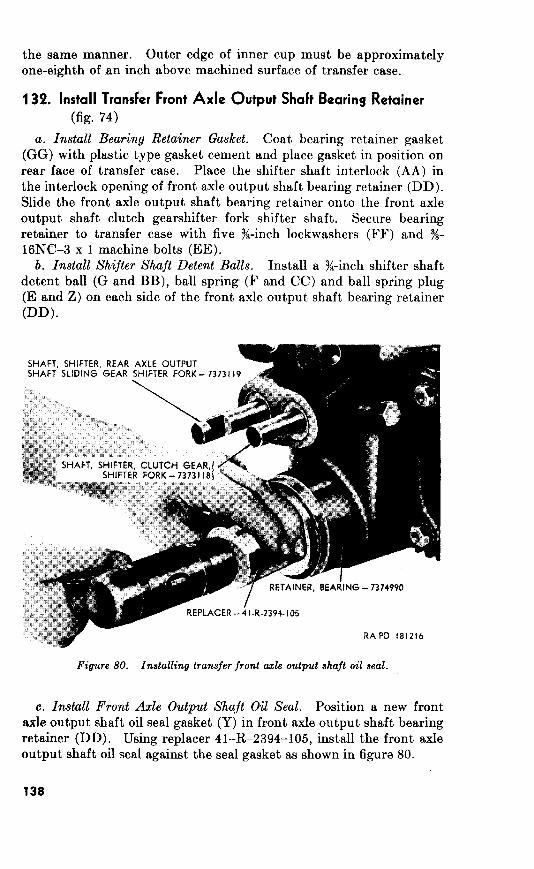
13% Install Transfer Front Axle Output Shaft Bearing Retainer
vk.
Install Bearing Retainer Gasket.
1
b. Install Shifter Shaft Detent Balls.
Figure 80. Installing transfer front axle output shaft oil seal.
e. Install Front Axle Output Shaft Oil Seal.
80.

133. Install Countenhaft Gear
(fig. 73)
a. Install Counter&aft Gear Journal Roller Bearing. Insert the two countershaft gear journal roller bearings (PP) in bore of the counter-
shaft gear (AA).
b. Install Transfer Countershaft. Apply a thick coat of universal
gear lubricant (GO) to the countershaft gear thrust washer (QQ) and
place in position inside of transfer case. Start the transfer counter-
shaft (RR) through transfer case (U) just enough to hold the thrust
washer from slipping. Apply a thick coat of universal gear lubricant
(GO) to the countershaft gear thrust washer (BB) and place in posi-
tion within transfer case. insert locator 41-L-1607-375 through
countershaft opening, in transfer case, so that countershaft gear
thrust washer is over it as shown in figure 81. Position the counter-
shaft gear, with journal roller bearings installed, between the two gear
thrust washers. Tap the transfer countershaft through countershaft
gear and opposite side of transfer case thereby removing the locator.
Figure 81. Positioning countershaft gear thrust washer with locator- 41-L-1607-376.

134. Install Transfer Rear Axle Output Shaft Retainer With Bearing Assembly
(fig.
a. Install Bearing Retainer Shim Set.
Note. This is a temporary installation at this time. Shims may have to be
removed or added, as necessary, to establish correct rear axle output shaft end
play. Install the speedometer drive gear on the rear axle output shaft in position
as illustrated in figure 65.
b. Install Rear Axle Output Shaft Bearing Retainer.
135. Adjust Transfer Rear Axle Output Shaft End Pluy
a. Install Dial Indicator.
Note. Secure transfer case so it cannot move.
b. Check Rear Axle Output Shaft End Play.
Figure 82. Dial indicator installed.

Figure 83. Checking transfer rear ax& output shaft end play.
SLEEVE, SPEEDOMETER / DRIVEN GEAR - WO-806719
REPLACER -41-R-2394-105 /
RETAINER, W/BEARING, ASSV - 8328478 9
Figure 84. Installing transfer Tear axle output shaft oil seal.
141

act as a lever and move rear axle output shaft to check end play as
illustrated in figure 83. The rear axle output shaft, must ,have from
0.004 to 0.008 inch end play. Adjustment is made by adding or
removing bearing retainer shims, as necessary. These shims are
supplied in 0.003, 0.010, and QA31 inch thickness. After establishing
correct end play, remove the rear axle output shaft bearing retainer,
coat shims with plastic type gasket cement and install retainer.
136. Install Trader Rear Axle Output
a. Install Rear Axle Output Sheft Oil Seal. Place the rear axle
output shaft oil seal gasket (AG, fig. 73) in the rear axle output shaft
bearing retainer. Using replacer 41-R-2394-105 install the rear axle
output shaft &I seal (fig. 84).
b. install Shijter Shaft Oil Seals. Using tool 41-T-3280 in the
manner illustrated in figure 85, install the two shifter shaft oil seals
(R and S, fig. 74) on the front axle output shaft clutch gearshifter
fork shifter shaft and rear axle output shaft sliding gearshifter fork
shifter shaft.
YOKE, FRONT AXLE SHAFT. W/SHIELD,
RAPD I81221 AXLE OUTPUT SHAFT - 7374990
Figure 86. Installing transfer shijler shaft oil seal.
142

137. Install Transfer Covers, Gearshift and Front Wheel Drive
Levers, and Companion Flange
a. Install Transfer Covers (fig. 73).
b. Install Gearshijt and Front Wheel Drive Levers (fig. 74).
Install Companion Flange With Slinger Assembly (fig. 73).
1 j/s
d. Install Front Axle Output Shaft Yoke With Shield Assembly
(fig.
Section IX. TEST AND ADJUSTMENT
138. Preparation for Tests
139. Tests
a.
b.
143
7
Section I. DESCRIPTION AND DATA
140. Description
a. General.
b. Universal Joints.
141, Data
Propeller Shafts.
b. Universal J&ruts.
Section II. REBUILD OF PROPELLER SHAFT ASSEMBLIES
142. Disassembly
a. Remove Slip Yoke Assembly From Propeller Shaft.

D -ROLLER, E-RETAINER,
J -WASHER. 7697613 K -CAP. 7697608
R-RING,
1 - U -
W - X -JOURNAL
76976 I t
and universal
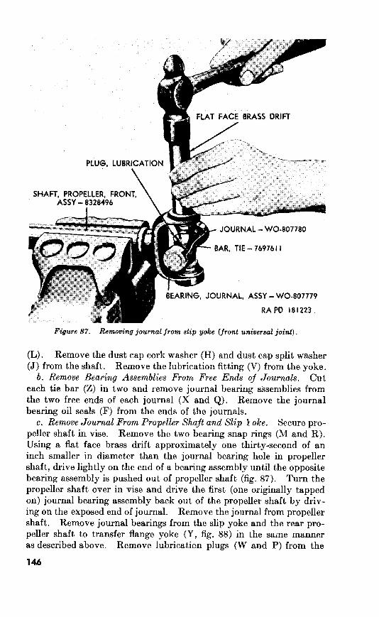
L
I
Figure 87. Removing journal from slip yoke (front universal joint).
(L). Remove the dust cap cork washer (H) and dust cap split washer
(J) from the shaft. Remove the lubrication fitting (V) from the yoke.
b. Remove Bearing Assemblies From Free Ends of Journals. Cut
each tie bar (Z) in two and remove journal bearing assemblies from
the two free ends of each journal (X and Q). Remove the journal
bearing oil seals (F) from the ends of the journals.
c. Remove Journal From Propeller Shaft and Slip I oke. Secure pro-
peller shaft in vise. Remove the two bearing snap rings (M and R).
Using a flat face brass drift approximately one thirty-second of an
inch smaller in diameter than the journal bearing hole in propeller
shaft, drive lightly on the end of bearing assembly until the opposite
bearing assembly is pushed out of propeller shaft (fig. Turn the
propeller shaft over in vise and drive the first (one originally tapped
on) journal bearing assembly back out of the propeller shaft by driv-
ing on the exposed end of journal. Remove the journal from propeller
shaft. Remove journal bearings from the slip yoke and the rear pro-
peller shaft to transfer flange yoke (Y, fig. in the same manner
as described above. Remove lubrication plugs (W and P) from the
journals. Remove the journal bearing oil seals (F) from the journals.
Do not remove journal bearing roller retainers (E) from within bear-
ing caps (B).
143. Inspection and Repair
(fig. 86)
a. Propeller Shafts. Inspect the propeller shafts (L) for cracks,
wear, broken welds, worn or damaged splines, or bent condition.
Replace propeller shaft if any of these faults are evident. Smooth off
raised metal at nicks with a fine mill file. Inspect journal bearing
surfaces for nicks, burs, and scratches. Remove any scores or burs
with a fine stone. Replace propeller shaft if any bearing surface
marks cannot be removed. Check the clearance between the propeller
shaft splines and the splines of the slip yoke (G). Replace propeller
shaft or yoke, as necessary, if clearance does not conform with repair
and rebuild standards (par. 272).
6. Slip Yokes. Inspect slip yokes for cracks, wear, broken welds,
worn or damaged splines, or bent condition. Slip yokes with any
of these faults must be replaced. Clean slight nicks or burs with a
fine stone. Check journal bearing surfaces for wear and damage.
Remove light marks with a fine stone. Replace slip yoke if marks
cannnot be removed. Inspect threads of slip yoke dust cap (K) and
threads on outer surface of slip yoke for damage. Clean threads, if
necessary, with a standard tap or die.
c. Journals. Inspect bearing surfaces of journal (Q and X) for
burs, nicks, or scratches. Smooth off light marks with a fine mill file.
Replace, if marks cannot be removed. Replace bearing assemblies
if journal is replaced.
d. Bearing Assemblies. Inspect each bearing assembly for wear,
damage, and freedom of rotation. Worn condition is indicated by
marks on journal bearing surface and by bearing rollers dropping out
of retainer. Replace all four bearing assemblies and journal if wear
is indicated. Check outside diameter of journal bearing against re-
pair and rebuild standards (par. 272). Replace bearing if not within
limits.
e. Miscellaneous Parts. Replace bearing snap rings (A, M, R and
U) if they show unnatural bends. Replace lubrication fitting (V) if
damaged. Repair damaged threads of U-bolts with a standard die.
Replace U-bolts if threads are beyond repair or if bolts are bent out
of shape. Replace slip yoke dust cap cork washer (H) at each re-
build. Replace journal bearing oil seal (F) and slip yoke dust cap
split washer (J) if they are worn or damaged sufficiently to impair
their proper operation. Inspect the rear propeller shaft to transfer
flange yoke (Y, fig. 88) for cracks, wear, or damage. Clean slight
nicks or bum with a fine stone.
147
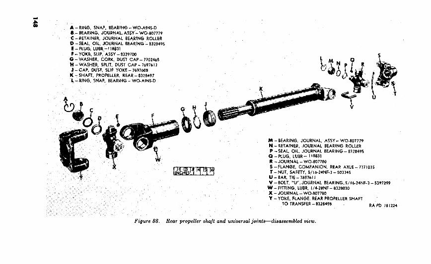
J-CAP, 7697608
K -
A
R -JOURNAL
U -
Figure 88,
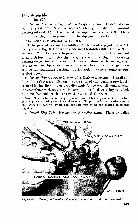
144. 86).
a. Install Journal in Slip Yoke or Propeller Shaft.
b. Install Bearing Assemblies on Free Ends of Journals.
Note. The tie bar serves only to prevent loss of bearing assemblies from free
ends of journals during shipping and storage. To prevent loss of bearing assem-
blies when not secured by tie bar, use soft wire to tie the bearing assemblies
together.
c. Install Slip Yoke Assembly on Propeller Shaft.
Figure 89. Placing universal joint journal ‘position in slip yoke assembly.
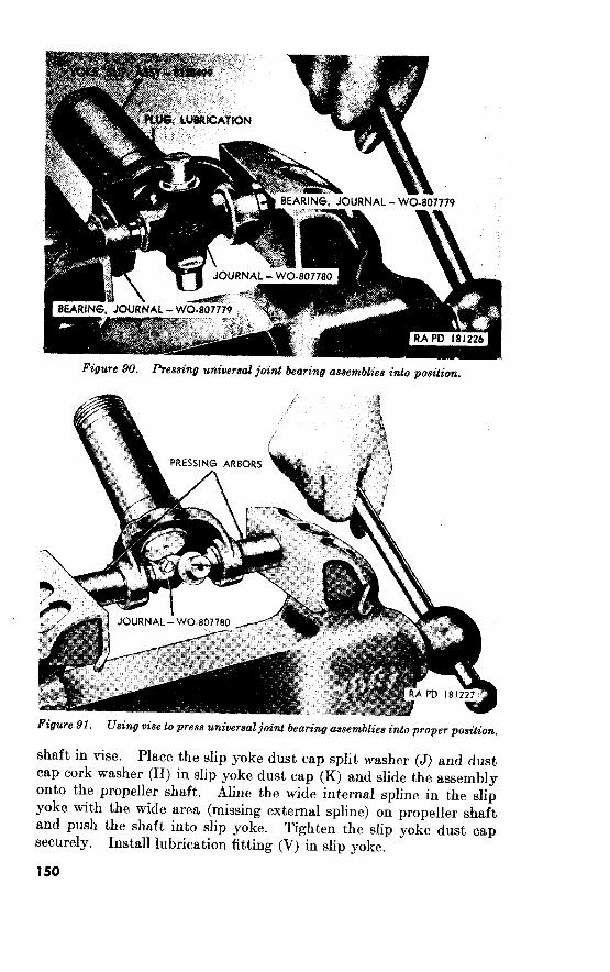
90. pressing universal joint bearing asaembliea
Using position.
shaft in vise. Place the slip yoke dust cap split washer (J) and dust
cap cork washer (H) in slip yoke dust cap (K) and slide the assembly
onto the propeller shaft. Aline the wide internal spline in the slip
yoke with the wide area (missing external spline) on propeller shaft
and push the shaft into slip yoke.
securely.
Tighten the slip yoke dust cap
Install lubrication fitting (V) in slip yoke.
150
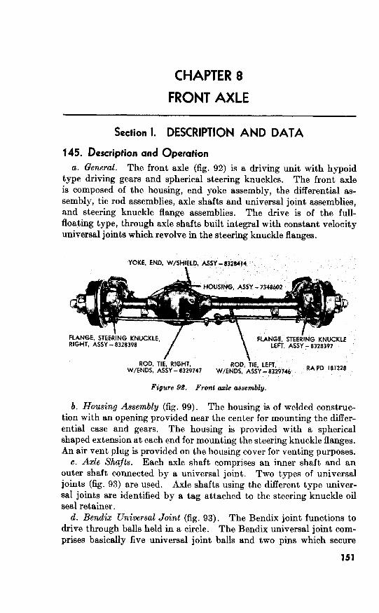
8
Section I. DESCRIPTION AND DATA
145. Description and Operation
a. General. The front axle (fig. 92) is a driving unit with hypoid
type driving gears and spherical steering knuckles. The front axle
is composed of the housing, end yoke assembly, the differential as-
sembly, tie rod assemblies, axle shafts and universal joint assemblies,
and steering knuckle flange assemblies. The drive is of the full-
floating type, through axle shafts built integral with constant velocity
universal joints which revolve in the steering knuckle flanges.
Figure 92. Front axle assembly.
b. Housing Assembly (fig. 99). The housing is of welded construc-
tion with an opening provided near the center for mounting the differ-
ential case and gears. The housing is provided with a spherical
shaped extension at each end for mounting the steering knuckle flanges.
An air vent plug is provided on the housing cover for venting purposes.
c. Axle Shafts. Each axle shaft comprises an inner shaft and an
outer shaft connected by a universal joint. Two types of universal
joints (fig. 93) are used. Axle shafts using the different type univer-
joints are identified by a tag attached to the steering knuckle oil
seal retainer.
d.. Bendix Universal Joint (fig. 93). The Bendix joint functions to
drive through balls held in a circle. The Bendix universal joint com-
prises basically five universal joint balls and two pins which secure
151

93.
the inner and outer shafts together. The end play of the Bendix uni-
versal joint and axle shaft is predetermined in manufacture by the
position and flange thickness of the bushing type spindle bearing and
the shaft to housing thrust washer. These parts, of the correct thick-
ness, ale positioned to provide satisfactory end play of the axle shaft.
They also permit rotation of the universal joint center point at the
center line of the kingpins. The bushing type spindle bearing requires
no reaming as it is so designed that when it is pressed into the wheel
spindle, it will be compressed sufficiently to provide the correct run-
ning clearance.
e. (fig. 93). The Rzeppa joint consists of a
hollow end of an axle shaft which fits over a solid member of the mating
axle shaft. The Rzeppa universal joint comprises a ball cage and race
in conjunction with four universal joint balls which are held in place
by the universal joint inner shaft retainer. The end play of the
Rzeppa universal joint is also predetermined in manufacture by the
position and thickness of the bushing type spindle bearing and shaft
to housing thrust washer in conjunction with snap ring at the outer
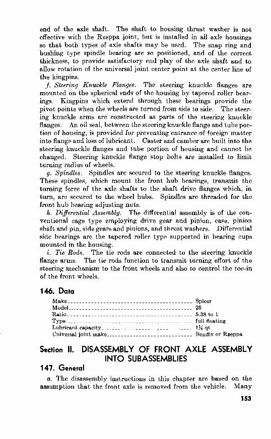
Steering Knuckle Flanges.
h. DiIerential Assembly.
Rods.
Make_------_____---_.__-_-_____---___----____- Spicer
Model_________________-----_------_-----___---- 25
Ratio_________________-----__-----__----_-_---- 5.38 to 1
Type_________________._----____----._-----_~--- full floating
Lubricant capacity_______________________._______ l>i qt
Universal joint make____-----____----__-----___-- Bendix or Raeppa
147.
153

Figure 94. Front axle bmhedrum, ad viev.

t D
D-FLANGE, STEERING
LEFT, ASSY - 8328397 E - SWIM
F-CAP,
LOCK, 3/E K
I
FLANGE
122236
U -HOUSING, V-SEAL,
ll/l6-7348605
X -CONE,
AA-CUP,
STEERING
DD -BOLT,
EE - FF - lb35
ITEMS
Figure 96. Front axle sleeting knuckle flange and spindle-dieaasembled view.
155
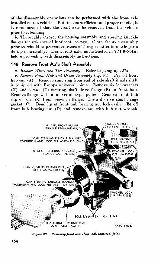
148. Remove Front Axle Shaft Assembly
a. Remove Wheel and Tire Assembly.
b. Remove Front Hub and Drum Assembly (fig. 94).
Figure 96. Removing front azk shaft with universal joint.

Remove Spindle With Bearing Assembly (fig. 95).
d. Remove Axle Shaft Assembly.
96).
e. Remove Opposite Axle Shaft.
149. Remove Front Axle Steering Knuckle Flanges
a. Remove Front Brake Flexible Line Guard.
assembly.
Figure 97. Removing tzk sieen’ng knuckk $ange cap assembly.

b. Remove Steering Knuckle Flange Cap Assemblies. Remove the
two remaining bolts and lockwashers securing the top steering knuckle
flange cap assembly to top of the flange. Lift the cap from recess in
top of steering knuckle flange (fig. 97). Remove the flange cap shim
set. Remove the lower cap assembly in the same manner.
c. Remove Steering Knuckle 02 Seal (fig. 95). Remove the 8 lock-
washer screws (Y) securing the 2 halves of the steering knuckle oil
seal retainers (T and X) to the steering knuckle flange. Remove the
two steering knuckle oil seal retainers (T and X), oil seals (R and V),
and oil seal springs (S and W). Discard the steering knuckle flange
oil seal gasket (K). Remove the steering knuckle flange from tube
end of housing (fig. 98) and remove the two steering knuckle flange
cap bearing cones.
d. Remove Opposite Steering Knuckle Flange. Remove the opposite
steering knuckle flange in the same manner as prescribed above.
150. Remove Front Axle Differential Assembly
a. Remove Housing Cover (fig. 99). Remove the 10 lockwasher cap
screws (J) securing the housing cover to the housing assembly. Re-
move housing cover (G). Discard the cover gasket (E).
b. Remove Dijerential Bearing Caps (fig. 99). Remove the 2 bolts
and lockwashers securing each of the 2 differential bearing caps (C and D) to the housing and remove the caps. Mark the caps and the
adjacent sides of housing for identification to assure proper assembly,
158

Figure 99. housing
if not already marked. Place spreader 41-S-4158-500 in position on the housing assembly.
Note. Spreader is illustrated in use in figure 128.
Spread housing enough to provide adequate clearance and remove the differential assembly. The differential assembly may have to be pried out in order to clear the differential case. Install the dif- ferential bearing caps (C and D) in housing, noting the correct bearing cap marking to assure correct location.
151. Remove Front Axle Differential Drive Pinion (fig. 108)
a. Remove Axle End Yoke With Shield Assembly. Remove the “Huglock” nut (2) and plain washer (Y) which secure the axle end yoke with shield assembly (X) to the drive pinion. Using a suitable puller, pull the end yoke assembly from end of drive pinion.
6. Remove Drive Pinion. Using a suitable block of wood, drive the drive pinion (M-2) from the housing. Remove the drive pinion
159
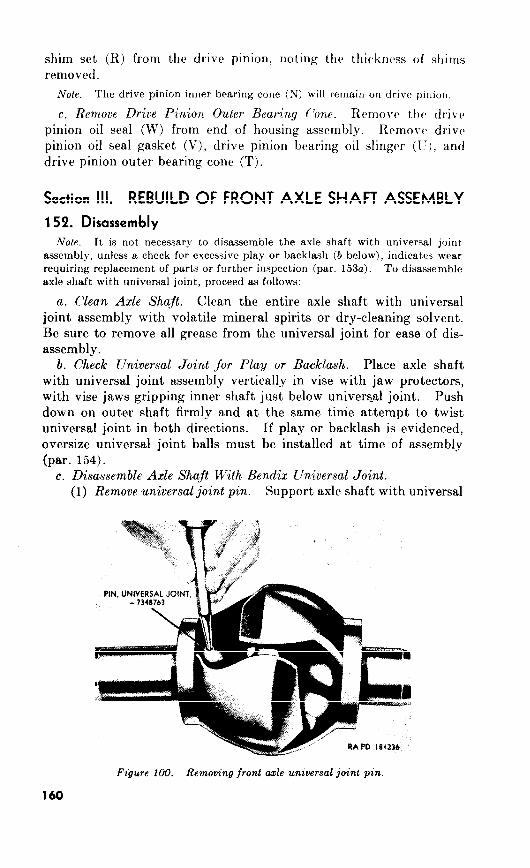
Nole. The drive pinion inner bearing cone (N) will remain on drive pillion.
c, Remove Drive Pinion Outer Bearing (‘one.
152.
Note. It is not necessary to disassemble the axle shaft with universal joint
assembly, unless a check for excessive play or backlash (b below), indicates wear
requiring replacement of parts or further inspection (par. 153~~). To disassemble
axle shaft with universal joint, proceed as follows:
a. Clean Axle Shaft.
b. Check Universal Joint for Play or Backlash.
154).
c. Disassemble Axle Shaft With Bendix Universal Joint.
(1) Remove universal joint pin.
Figure 100. Removing front axle universal joint pin.
160
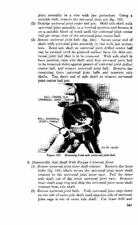
(2)
joint assembly in a vise with jaw protectors. Using a
suitable drift, remove the universal joint pin (fig. 100).
Dislodge universal joint center ball pin. Hold axle shaft with
universal joint assembly in a vertical position and bounce it
on a suitable block of wood until the universal joint center
ball pin drops clear of the universal joint center ball.
Remove universal joint balls (fig. 101). Secure outer end
shaft with universal joint assembly in vise with jaw protec-
tors. Bend axle shaft so universal joint drilled center ball
can be rotated until its grooved surface faces the first uni-
versal joint ball that is to be removed. With axle shaft in
bent position, raise axle shaft until first universal joint ball
to be removed slides against groove of universal joint drilled
center ball, and remove universal joint ball. Remove the
remaining three universal joint balls and separate axle
shafts. Tap short end of axle shaft to remove universal
joint center ball pin.
Figure 101. Removing front axle universal joint ball.
d. Disassemble Axle Shaft With Rzeppa Universal Joint.
(1)
(2)
_ _ Remove universal joint inner shaft retainer. Remove the three
bolts (fig. 102) which secure the universal joint inner shaft
retainer to the universal joint inner race. Pull the inner
axle shaft out of the inner universal joint race. Remove
inner shaft snap ring and slide the universal joint inner shaft
retainer from axle shaft.
Remove universal joint balls. Push universal joint cage down
on one side of outer axle shaft until opposite side of universal
joint cage is out of outer axle shaft. Use brass drift and
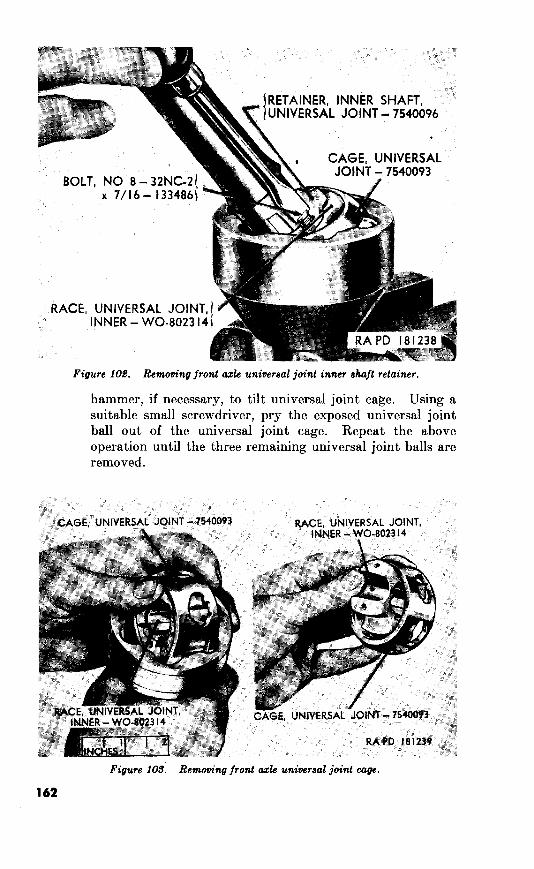
BOLT, NO 8-32NC-2
x 7/16- 133486 i
RETAINER, INNER SHAFT, UNIVERSAL JOINT - 7540096
RACE, UNIVERSAL INNER - WO-8023 141
CAGE, UNIVERSAL JOINT - 7540093
hammer, if necessary, to tilt universal joint cage. Using a suitable small screwdriver, pry the exposed universal joint
ball out of the universal joint cage. Repeat the above
operation until the three remaining universal joint balls are
removed.
162
universal joint cage.

(3) Remove universal joint cage and inner universal joint race.
Turn the universal joint cage in the outer axle shaft so that
the 2 larger elongated holes of cage are between the 2 bosses
in outer axle shaft as shown in figure 103. Lift the universal
joint cage and inner universal joint race from outer axle shaft.
(4) Remove inner universal joint race from universal joint cage.
Turn the inner universal joint race in the universal joint cage
so that 1 of the bosses on the inner universal joint race can
be dropped into 1 of the 2 elongated holes in universal joint
cage as shown in figure 103. Separate inner universal joint
race from universal joint cage.
153. Inspection and Repair
a. Inspection.
(1) Axle s-h&s. Examine the axle shafts with universal joint
assemblies for twisted, bent, or broken condition. Inspect
axle shaft splines for damage and wear. Examine universal
joint ball races in axle shaft for excessive wear. If any of
these faults are evidenced, replace the entire axle shaft with
universal joint assembly. If axle shaft is equipped with
Rzeppa joint, replace the inner and outer shaft retaining
snap rings if they are broken or distorted.
(2) Universal joint balk. Inspect the universal joint balls for
rough spots, cracks, or chipped condition. Check balls for
out-of-round condition. If balls are out-of-round, replace
them with balls of the same diameter unless backlash, (par.
152b) is excessive. If backlash is excessive, install oversize
universal joint balls.
(3) Universal joint cage and inner universal joint race. Inspect
these parts for wear and damage. Replace, if necessary.
Check screw threads in inner universal joint race for damage.
Replace the three bolts, which are used to secure the universal
joint inner shaft retainer, at each rebuild. Replace the uni-
versal joint inner shaft retainer if it is broken or bent. Re-
place the universal joint pin at each rebuild.
b. Repair. If necessary, clean threads in inner universal joint race
with a standard tap. Smooth over any slight faults such as burs,
scores, and abrasions on axle shaft splines.
154. Assembly
a. Assemble Axle Shaft With Bendix Universal Joint.
(1) Selective jit of universal joint balls. Universal joint balls are
available in various sizes. When installing new balls, keep
them within 0.001 inch of the same size, if possible. Varia-
tion should not exceed 0.002 inch. During assembly,
the two largest balls diagonally across from
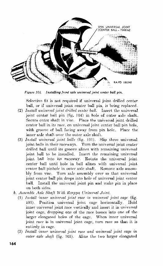
Figure 104. Installing front axle universal joint center ball pin.
In-stall universal joint drilled center ball.
Install universal joint bulls (fig. 101).
b. Assemble Axle Shaft U7th Rzeppa liniversal Joint.
(1)
(2)
164
Install inner kniversal joikt race in universal joint cage (fig.
103).
Install inner universal join,t race and universal joint cage in
outer axle shqft (fig. 103).

(3)
(4)
P
106. Znstalling front
holes in universal joint cage with bosses in outer axle shaft
and slip cage into axle shaft.
Install universal joint balls (fig. Tilt the universal joint
cage so that a universal joint ball can be inserted int,o an
elongated hole. After universal joint ball is in position, push
universal joint cage down until opposite end of cage is ex-
posed and insert another universal joint ball. Repeat the
above operation for the remaining two universal joint balls.
Install inner axle shaft. Slip the universal joint inner shaft
retainer on the inner axle shaft and secure it in place with
the inner shaft snap ring. Insert inner axle shaft in inner
universal joint race. Secure universal joint inner shaft re-
tainer with three new No. 8-32NC-2 x x6 bolts (fig. 102).
section IV. REBUILD OF FRONT AXLE STEERING KNUCKLE FLANGE ASSEMBLIES
155. Disassembly (fig. 95)
The steering knuckle flange (D) requires no disassembly.
156. Inspection and Repair
a. Inspection.
(1) Steering knuckle flanges (fig. 95). Carefully examine steering
knuckle flanges for cracks or distortion. Inspect tapped
holes for damaged threads. Inspect the steering arm for
165

cracks, distortion, and excessive out-of-round condition of
holes which engage the tie rod studs. Replace steering
knuckle flange (D) if any of the above faults are evident.
(2) 95). Examine
kingpins in steering knuckle flange cap assemblies for wear,
damage, and out-of-round condition. Inspect the caps (F
and BB) for damage, wear, out-of-round condition, and loose
fit’ in steering knuckle flanges. Replace the cap assemblies,
if necessary.
(3) Steering 95). Steering
knuckle flange cap bearing cones (N and Z) must not be
pitted, scored, rough, or excessively worn. Bearing rollers
must turn smoothly and freely.
(4) Inspect steering
knuckle oil seal retainers (T and X) for cracks, distortion,
and damage. Check the steering knuckle oil seal springs
(S and W) for breaks and other damage. Replace the steer-
ing knuckle oil seals and gasket at each overhaul.
(5) Inspect the spindle
with bearing assembly for damaged threads, out-of-round
condition, cracks, and distortion. Replace spindle assembly
if necessary. Inspect the bushing type spindle bearing (B)
for wear and damage. Replace bearing, if necessary
below).
(6)
Front hub inner and outer bearing cones
(W and U) must not be pitted, scored, rough, or excessively
worn. Bearing rollers must turn freely and smoothly.
Inspect front hub inner and outer bearing cups (H and L)
for chipped, cracked, or worn condition. Replace faulty
cones and cups. Discard the front hub oil seal (M) at each
rebuild. Replace all damaged lockwashers and nuts.
(7) Inspect shaft drive flange (B)
for distortion, cracks, and breaks. Replace, if damaged.
Discard the drive shaft flange gasket (C) and front hub cap
oil seal (Z) at each rebuild.
(8) Replace the front brake flexible
line guard (G), if broken. Replace all damaged bolts, and
pipe plugs, if necessary.
(1) If the bushing type spindle bearing must be replaced, proceed
as follows: Remove bushing type spindle bearing from spindle
with a suitable drift. Position new bushing type spindle
bearing in place in bore of spindle and drive it in position
with the remover and replacer 41-R-2374-175 (fig. 106).
(2) Clean all damaged bolt holes with standard taps.
166

Using a fine mill stone, smooth over bum, scores, or raised
metal at nicks on the kingpins of the steering knuckle flange
caps.
157. Assembly (fig. 95)
The steering knuckle flange (D) does not require any assembly prior
to installation on housing.
Section V. REBUILD OF FRONT AXLE DIFFERENTIAL ASSEMBLY
158. Disassembly (fig. 108)
a. Remove Diserential Bearing Cones. Using remover 41-R-2367-
950 (fig. remove the differential bearing cones (D and H) at each
end of the differential case. Remove the bearing shim sets (E and G),
noting the thickness of those removed at each end.
b. Remove Drive Gear. Mark drive gear and differential case to
assure assembly in identical position. Straighten bent ears of drive
gear screw lock plates (M-3) which secure the drive gear screws and
remove the 8 drive gear screws (M-4) and 4 drive gear screw lock
plates. Pull drive gear (M-l) from differential case (F). If nec-
167
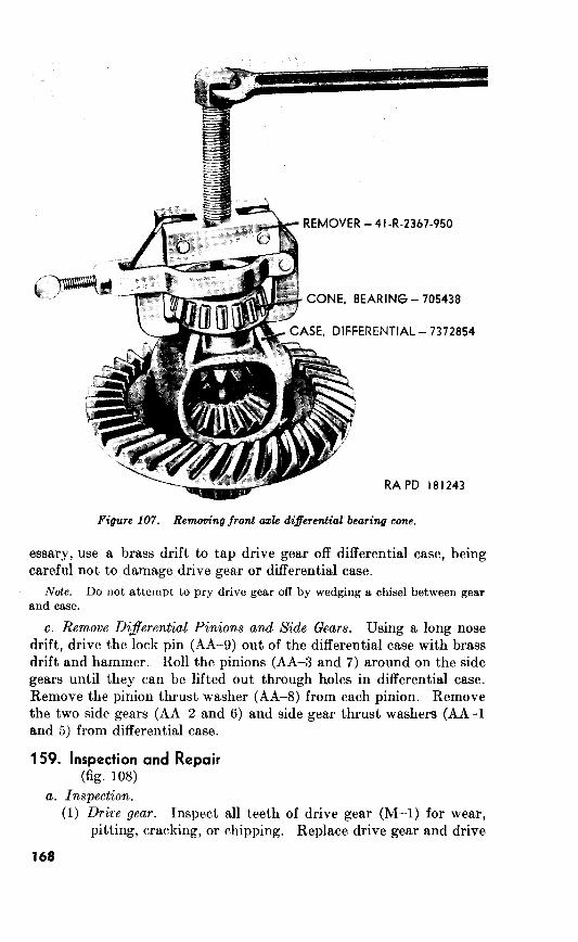
_< +a* ?
essary, use a brass drift to tap drive gear off differential case, being
careful not to damage drive gear or differential case.
not attempt to pry drive gear off by wedging a chisel between gear
and case.
e. Remove Di$erential Pinions and Side Gears. Using a long nose
drift, drive the lock pin (AA-g) out of the differential case with brass
drift and hammer. Roll the pinions (AA-3 and 7) around on the side
gears until they can be lifted out through holes in differential case.
Remove the pinion thrust washer (AA-8) from each pinion. Remove
the two side gears (AA-2 and 6) and side gear thrust washers (AA-l
and 5) from differential case.
159. (fig. 108)
a. Inspection.
(1) Drice gear. Inspect
pitting, cracking, or
168
all teeth of drive gear (M-l) for wear,
chipping. Replace drive gear and drive

(2)
pinion (M-2), as a set, if drive gear shows damage. Ex-
amine tooth contact pattern (fig. 123) to see if drive gear
has been meshing correctly with drive pinion, If tooth
pattern indicates improper mesh, it will be necessary to re-
place both the drive gear and pinion. The drive gear and
pinion are run-in and lapped together, during factory pro-
duction, as a matched set. Inspect screw threads in drive
gear for damage.
Dijerential case. Inspect differential case (F) for cracks or
distortion. Examine machined surfaces for scores or grooves.
Replace, if necessary.
Side gears. Examine side gears (AA-2 and 6) for worn,
cracked, or chipped teeth. The side gears should present
a snug fit to their respective axle shaft splines. Inspect fit
of side gears in differential case bores. This fit must not be
excessively loose. Too much play will cause excessive back-
lash in the drive line.
Note. If the side gears require replacement, the side gears and
pinions (AA-3 and 7) must be replaced as a set.
Pinions. Inspect teeth of pinions and 7) for wear,
cracks, or chipping. Install the pinion shaft (AA-lo) through
hole of each pinion. The clearance between pinion and pin-
ion shaft must not exceed 0.0069 inch. If pinion holes
exceed the wear limit (par. 273), replace the pinions and
side gears as a set.
Dijferential bearing cones. Inspect the differential bearing
cones (D and H) and cups (C and J) for excessive wear,
scoring, chipped conditions, and overheating. Replace
faulty cones or cups, if necessary.
b. Repair. Use a fine stone and smooth over any slight burs or
scratches on gear teeth and pinion shaft. Replace parts as sets (a
above) if faults on gear teeth can not be readily repaired. Clean
damaged threads of drive gear with a standard tap.
160. Assembly
(fig. 108)
a. Install Side Gears. Use new side gear thrust washers (AA-l and
5)) behind the side gears (AA-2 and 6)) and install the two side gears
in ends of differential case (F) . Lubricate side gears with lubricant
and rotate side gears to be sure they turn without binding.
b. Install Pinions. Install new pinion thrust washers (AA4 and 8)
behind pinions (AA-3 and 7). Mesh pinions with side gears so that
they are directly opposite each other in differential case. Roll pin-
ions and side gears around until holes in pinions aline with pinion
shaft holes in differential case. Install the pinion shaft (AA-lo) in
differential case and through pinions. Secure pinion shaft by install-
ing the lock pin (AA-g). Stake lock pin in place. 169
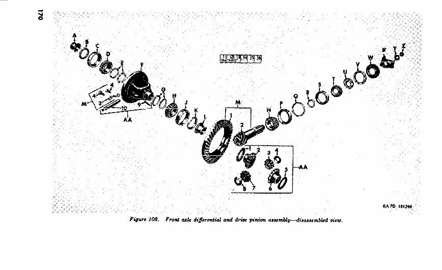
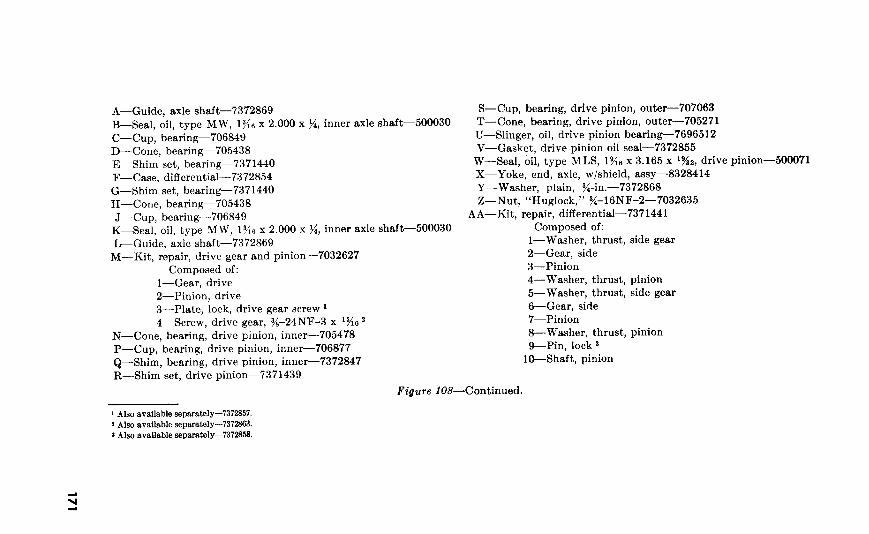
1 Also available separately-7372857. ) Also available separately-7372863. 8 Also avallable separately-7372853.
3

c. Install Di$erential Bearing Cones. Since the differential bearing
cones (D and H) may require adjustment, do not install them at
this time. Install bearing cones during installation of differential
assembly into housing (par. 164a).
d. Install Drive Gear. Place drive gear (M-1) over shoulder of
differential case (F). If using same gear as removed, aline match
marks on drive gear and differential case. Secure gear to case with
eight ?S-24NF-3 x ‘$& drive gear screws (M-4) and four drive gear
screw lock plates (M-3). Bend ears of lock plates on gear screws.
Tighten gear screws to torque of 38 to 42 pound-feet
161. 108)
a. Disassembly. Remove the drive pinion inner bearing cone (N)
from drive pinion (M-2) by a suitable removing method (arbor press).
b. Inspection and Repair.
(1) Inspect the drive pinion (M-2) for worn, chipped, or cracked
teeth. Replace the drive pinion if its teeth are faulty.
Inspect screw threads on end of drive pinion for damage.
Inspect pinion and drive gear to be sure they are matched.
Marking on drive gear and pinion must be the same.
Note. drive pinion rnclst be replaced, replace
Inspect drive pinion inner and outer bearing cones (N and T)
for wear, pitt)ing, scoring, and roughness. Bearing rollers
must turn smoothly and freely.
(2) Repair. Correct any slight faults; such as scores, bum, and
scratches: on drive pinion with a hone. Repair damaged
threads on drive pinion (M-2) with a standard thread
chaser or on lathe, if possible.
c. Assembly (fig. 109). Using a suitable arbor press, press the
drive pinion inner bearing cone in position on the drive pinion.
162.
a. Disassem,bly.
(1) Remove the inner axle shaft oil seal (B, fig. 108) by prying it
from each side of housing assembly.
(2) Do not remove the axle shaft guides (A, fig. 108) unless
inspection reveals them to be unserviceable. To remove
axle shaft guides, dl,ive them out of housing with a suitable
improvised bar.
(3) It is not necessary to remove the drive pinion inner and
outer bearing cups (P and S, fig. 108) unless inspection
172
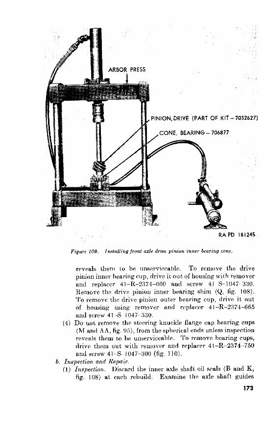
ARBOR PRESS 0
-7032627)
RAPD 181245
10.9. Installing front axle
(4)
reveals them to be unserviceable. To remove the drive
pinion inner bearing cup, drive it out of housing with remover
and replacer 41-R-2374-660 and screw 41-S-1047-330.
Remove the drive pinion inner bearing shim (Q, fig. 108).
To remove the drive pinion outer bearing cup, drive it out
of housing using remover and replacer 41-R-2374-665
and screw 41-S-1047-330.
Do not remove the steering knuckle flange cap bearing cups
(M and AA, fig. 95)) from the spherical ends unless inspection
reveals them tjo be unserviceable. To remove bearing
drive them out with remover and replacer 41-R-2374-750
and screw 41-S-1047-300 (fig. 110).
6. Inspection and Repair.
(1) Inspection. Discard the inner axle shaft oil seals (B and K,
fig. 108) at each rebuild. Examine the axle shaft guides
173

Figure 110. Removing bearing cup from front axle steering knuckle.
Figure 111. Installing front azle inner axle shaft oil seal.
108)
174

REMOVER AND REPLACER -41-R-2374-660 RA PD 181248
Figure 118. inner bearing cup.
CUP, BE
SCREW-41-S 1047-330
ARING - 70706
OVER AND REPLACER-
11.9. drive pinion outer

Figure Installing bearing cup in front ade steering knuckle.
(2) Repair.
Assembly.
(1)
(2)
(3)
(4)
(5)
163.
Install Drive Pinion Outer Bearing Cone.

(M-2) into housing until the inner bearing cone rests in bearing cup.
Slide drive pinion shim set (R) onto drive pinion.
Note. This is a temporary installation until correct shim thickness is deter-
mined during drive pinion adjustment (b below).
Using a suitable driver, drive the drive pinion outer bearing cone (T)
in place on drive pinion. Install the drive pinion bearing oil slinger
fU). Slide the axle end yoke with shield assembly (X) onto drive
pinion and secure with y&inch plain washer (Y) and gi-16NF-2
“Huglock” nut (Z).
Note. Do not install the drive pinion oil seal gasket (V) and drive pinion oil
seal (W) until pinion bearings have been adjusted.
b. Adjust Drine To compensate for manufacturing toler-
ances, drive pinions and drive gears are tested for quietness and t,ooth
contact at a standard cone setting. Since drive pinions may vary
from t,his setting, the variation is marked on the polished head of the
pinion (fig. 115). The drive pinion is marked plus or minus the
number of thousands that it is above or below standard. Plus
indicates that drive pinion is too close t)o center line of axle. Minus
indicates that drive pinion is too far from center line of axle. Refer to
figure 115 for typical inspection mark which shows t$at drive pinion is
0.003 inch too close to center line of axle. The drive pinion setting
gage set 41-G-535-700 is provided to measure the distance from
finished surface on drive pinion head to the center line of the differ-
ential case bearing bore. By establishing this distance, t#he correct
amount of drive pinion shims to be installed or removed may be
determined to correctly position drive pinion. The drive pinion
setting checking gage 41-G-98-750, a component of gage set
177
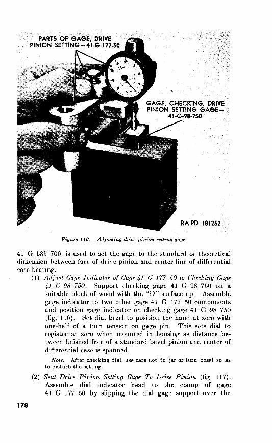
Figure 116. Adjusting drive pinion setting gage.
Adjw! Gu,ge to Checking Gage
dl-Go-98-750.
Note.
Seat Drive Pinion Setting Gage To I.!riue

I
Bll
Figure 117. Seating drive pinion setting gage /l-6-177-50.
Check drive pinion adjustment.

Figure 118. Checking j’ront axle drzve pznion setting.

turn with a slight drag and without end play. To estab-
lish correct preloading, add or subtract drive pinion inner
bearing shims.
c. Install Drive Pinion Oil Seal. After the drive pinion has been
adjusted, remove the axle end yoke with shield assembly (X, fig. 108)
and install the drive pinion oil seal gasket (V, fig. 108) and drive
pinion oil seal (W, fig. 108). Install axle end yoke with shield assem-
bly and secure with $&inch plain washer and T:-16NF-2 “Huglock”
nut.
164.
a. Install DiJerential Case in Housing. The adjustment of the
differential bearing cones (D and H, fig. 108) is maintained by bear-
ing shim sets (E and G, fig. 108) installed between differential case
and bearing cones with an O.OO%inch pinch fit when assembled in
housing. Install the differential bearing cones, without the bearing
shims, with replacer 41-R-2384-149 (fig. 119). Install the two
differential bearing cups (C and J, fig. 108) bearing cones and
Figure 119. Installing front axle differential bearing cone.

change the total thickness of shims.

GEAR,
Figure front azle
Check Drive Gear Runout.
d. Gear Tooth Contact Pattern.
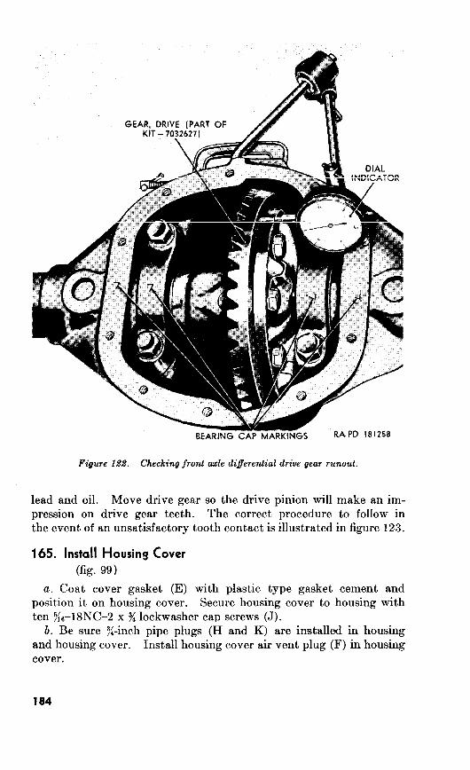
Figure 122. Checking front axle diferential drive gear runout.
165.

--I
f-y
I IX\
Figure 123. Tooth contact of front axle differential drive gear.
185
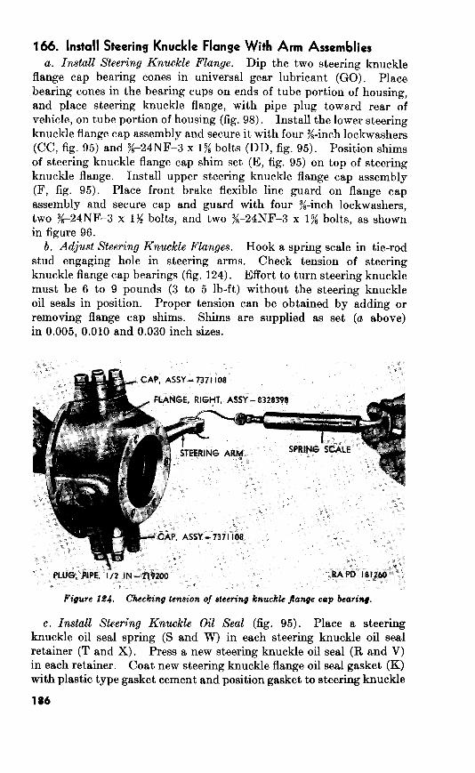
166. Install Steering Knuckle Flange With Arm Assemblies
a. Install Steering Knuckle Flange.
x
b. Adjust Steering Knuckle Flanges.
0.005, 0.030
Figure 164. Checking tension of steering knuckle jlange cep bearing.
c. Install Steering Knuckle Oil Seal (fig.
5;6-24NF-3 x 1)(6 lockwusher
scrc\vs (Yj. d. Opposite Steering Knuckle Flange.
167.
a. Install AsIr Shajt.
b. Install Spindle With Bearing Assembly (fig. 94).
c. Install Front Mub and Drum Assembly (fig. 94).
l:/,-16
Install Snap Ring.
Install Wheel and Tire Assrmbly. 63b.
_f. Install Opposite Axle Shaft ti’ith Universal Assembly.
Lubricate.
Front Wheel Alinement.
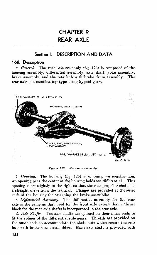
Section I. DESCRIPTION AND DATA
168. Description The rear axle assembly (fig. 125) is composed of the
housing assembly, differential assembly, axle shaft, yoke assembly,
brake assembly, and the rear hub with brake drum assembly. The
rear axle is a semifloating type using hypoid gears.
Figure 196. azle assembly.
The housing (fig. 126) is of one piece construction.
An opening near the center of the housing holds the differential. This
opening is set slightly to the right so that the rear propeller shaft has
a straight drive from the transfer. Flanges are provided at theouter
ends of the housing for attaching the brake assemblies.
e. D$erentiul The differential assembly for the rear
axle is the same as that used for the front axle except that a thrust
block for the rear axle shafts is incorporated in the rear axle.
d. The axle shafts are splined on their inner ends to
fit the splines of the differential side gears. Threads are provided on
the outer ends to accommodate the shaft nuts which secure the rear
hub with brake drum assemblies. Each axle shaft is provided with
188
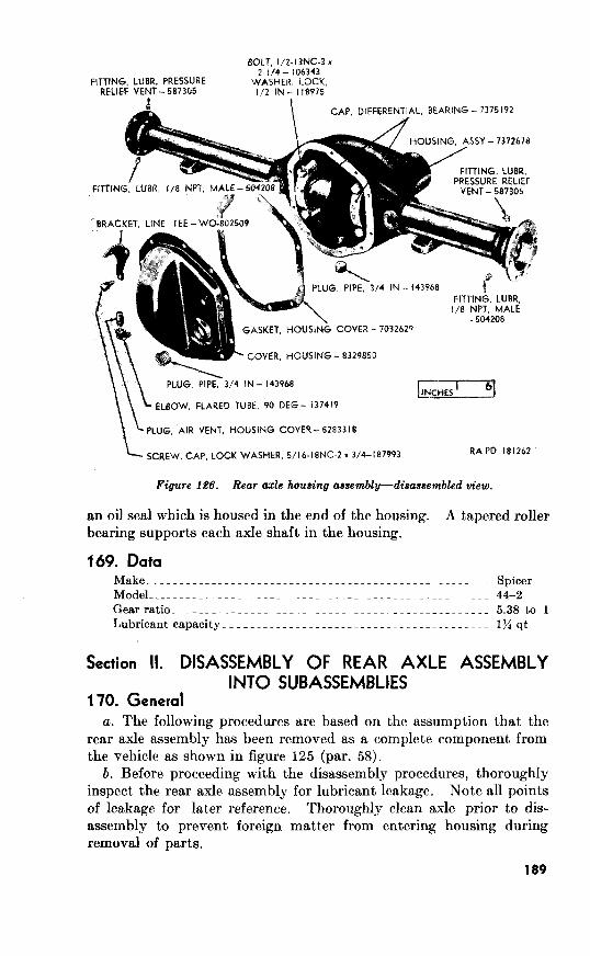
1
\
Make__~_.~..~___.______.---___--_-_.-~-_~.---~-~------_~- Spicer
Model_______._._..._~-.._-~-_._-~-_-_---___-----_---~--~-~ 44-2
Gearratio_~_____________~~____~_____~~______~_____________ 5.38to 1
Lubricant capacity_____._.___~_.-----~~----~_-----_-_--__~_ I)/4 qt
TO.


c. Drain the Rear Ade.
171. Remove Axle Shafts
a. General.
b. Remove Brake Assembly (fig. 127).
(P)
(J) ,
Remove Axle Shaft (fig. 127).
172. Remove Differential Assembly
a. Remove Housing Cover.
56d), 126) 10
Figure 1.88. Spreading rear a& housing wing spreads /I-S-41.58-&W.
191

b. Remove Dijerential Bearing Cap?.
Install Spreader.
d. Remove D$fferential Assembly.

173. Remove Drive Pinion (fig.
Remove “Huglock” nut (X) and
plain washer (W) securing end yoke (V) and dust shield (U) to drive
pinion (H-2). Using a suitable puller, pull end yoke from drive
pinion.
Note.
Remove Drive Pinion. Remove drive pinion oil seal (T), drive
pinion oil seal gasket (S), felt seal (R), and oil slinger (Q). Using a
suitable block of wood, tap the drive pinion out of housing (fig.
Remove the drive pinion outer bearing cone (P). The drive pinion
inner bearing cone (J) will remain on drive pinion.
193

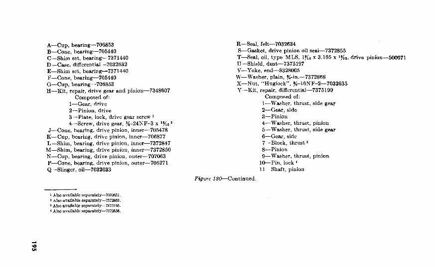
A-Cup, bearing-706853
B-Cone, bearing-705440
C-Shim set, bearing-7371440
D-Case, differential-7032632
E-Shim set, bearing-7371440
F-Cone, bearing-705440
C&-Cup, bearing-706853
H-Kit, repair, drive gear and pinion-7348607
Composed of:
l-Gear, drive
a--Pinion, drive
3-Plate, lock, drive gear screw ’ &-Screw, drive gear, y/s-24NF-3 x l%e 2
J-Cone, bearing, drive pinion, inner-705478
K-Cup, bearing, drive pinion, inner-706877
L-Shim, bearing, drive pinion, inner-7372847
M-Shim, bearing, drive pinion, inner-7372850
N-Cup, bearing, drive pinion, outer-707063
P-Cone, bearing, drive pinion, outer-705271
Q-Slinger, oil-7032633
R-Seal, felt-7032634
S-Gasket, drive pinion oil seal-7372855
T-Seal, oil, type MLS, lg/(~ x 3.165 x ‘p/Jz, drive pinion-_500071
U-Shield, dust-7375197
V-Yoke, end-8328005
W-Washer, plain, y&in.-7372868
X-Nut, “Huglock”, s-16NF-2-7032635
Y-Kit,, repair, differential-7375199
Composed of:
l-Washer, thrust, side gear
2-Gear, side
3-Pinion
4-Washer, thrust, pinion
5-Washer, thrust, side gear
6-Gear, side
‘I-Block, thrust 3 &Pinion
O-Washer, thrust, pinion
lO--Pin, lock 4
1 l-Shaft, pinion
Figure 130-Continued.
’ Also available separately-703’2631.
2 Also available separately-7372863.
3 Also available separately-7375195.
1 Also available separately-737285’3.

Figure 131.
Section III. REBUILD OF DIFFERENTIAL ASSEMBLY
174. Disassembly a. Remove Drive Gear. Straighten bent-over tabs of the 5 drive
gear screw lock plates and remove the 10 drive gear screws (fig. 132)
x15/16- 7372863
Figure 13.8. Differential assembly.
196

pinion
Note. not use chisel in an attempt to force gear from case.
b. Remove Pinion Shaft. 133)
Remove Side Gears and Pinions.
d. Remove Bearing Cones.
41-R-2367-950 as
107.

GEA OF
Figure Removing diferential pinions.
175.
b. Repair.
159b).
176.
a. Install Side Gears and Pinions (fig.
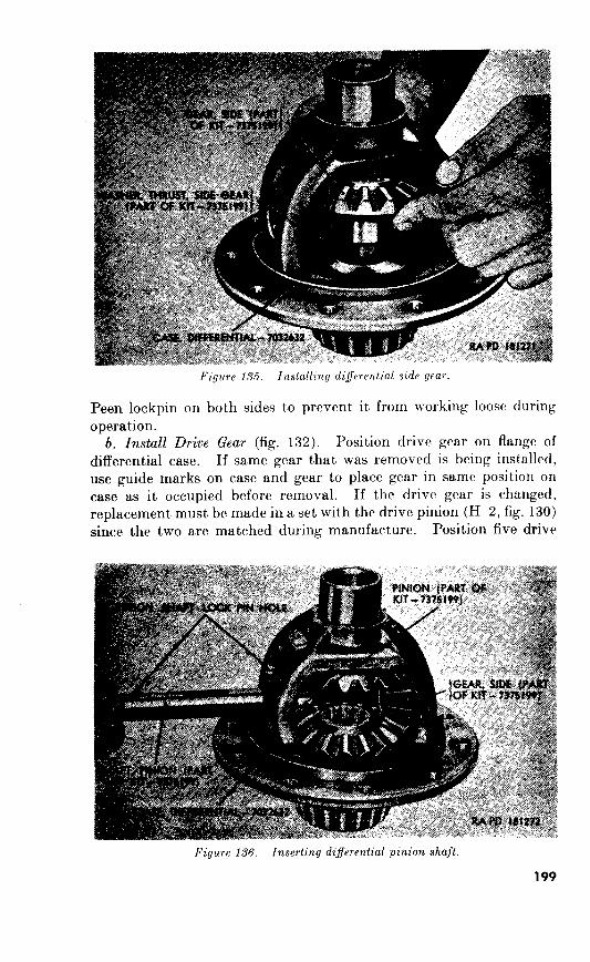
b. Install Drive Gear (fig.

lock plates on differential case and install ten T/s-24NF-3 x
l$$ drive gear screws. Tighten screws to torque of 38 to 42 pound-
feet. Lock screws by bending tabs of the lock plates against the
screws.
c. Refer to paragraph 160~ for procedures
for installing bearing cones.
177.
. Procedures for disassembly, inspection, repair, and assembly for
the drive pinion (H-2, fig. 130) of the rear axle assembly are same as
those for the drive pinion of the front axle assembly (par. 161). If
the drive pinion is changed, replacement must be made in a set.
178.
The axle shafts require no disassembly.
127).
(1) Inspect axle shafts (V) for twisted or distorted
condition. Replace, if necessary. Check splines and threads
of axle shaft for damage. Place bearing cups (D) over bear-
ing cones (C), apply clean engine oil to cones and turn slowly.
Cones must turn smoothly and freely. Replace any cones
which are scored, pitted, rough, or excessively worn. Inspect
bearing cups for chipped areas, cracks, or wear caused by
bearing cone rollers. Replace bearing cups if damaged or
200
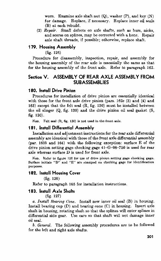
worn. Examine axle shaft nut (Q), washer (P), and key (N)
for damage. Replace, if necessary. Replace inner oil seals
(B) at each rebuild.
(2) Repair. Small defects on axle shafts, such as burs, nicks,
and scores on splines, may be corrected with a hone. Repair
axle shaft threads, if possible; otherwise, replace shaft.
179. Housing Assembly
(fig. 126)
Procedure for disassembly, inspection, repair, and assembly for
the housing assembly of the rear axle is essentially the same as that
for the housing assembly of the front axle. Refer to paragraph 162.
Section V. ASSEMBLY OF REAR AXLE ASSEMBLY FROM
SUBASSEMBLIES
180. Install Drive Pinion
Procedures for installation of drive pinion are essentially identical
with those for the front axle drive pinion (pars. 162~ (3) and (4) and
163) except that the felt seal (R, fig. 130) must be installed between
the oil slinger (Q, fig. 130) and the drive pinion oil seal gasket (S,
fig. 130).
181. Install Differential Assembly
Installation and adjustment instructions for the rear axle differential
assembly are identical with those of the front axle differential assembly
(par. 1635 and 164) with the following exception: surface E of the
drive pinion setting gage checking gage 41-G-98-750 is used for rear
axle whereas surface D is used for front axle.
18% Install Housing Cover
(fig. 126)
Refer to paragraph for installation instructions.
183. Install Axle Shafts (fig. 127)
a. Install Beating Cone. Install new inner oil seal (B) in housing.
Install bearing cup (D) and bearing cone (C) in housing. Insert axle
shaft in housing, rotating shaft so that the splines will enter splines in
differential side gear. Use care so that shaft will not damage inner
oil seal.
b. General. The following assembly procedures are to be followed
for the left and right axle shafts.

Figure 188. Bearing shims and bearing retainer in poaifion on rear azle shaft.
c. Install Brake Assembly. Install bearing shims and bearing
retainer on axle shaft (fig. 138). Install six 3/i-24NF-3 x 15 bolts in
flange of housing tube. Install new or rebuilt brake assembly.
Refer to paragraphs 184 through 193 for brake assembly rebuild
instructions. Coat grease slinger gaskets with plastic type gasket
cement. Install gaskets, one on each side of outer oil seal assembly.
Install outer oil seal assembly and rear grease slinger (fig. 139).
Install six 3/s-24NF-3 lockwasher nuts. Tighten nuts to torque of 25
to 35 pound-feet.
202

Figure 13.9. Installing grease slinger.
d. Check Axle Shaft End Play.
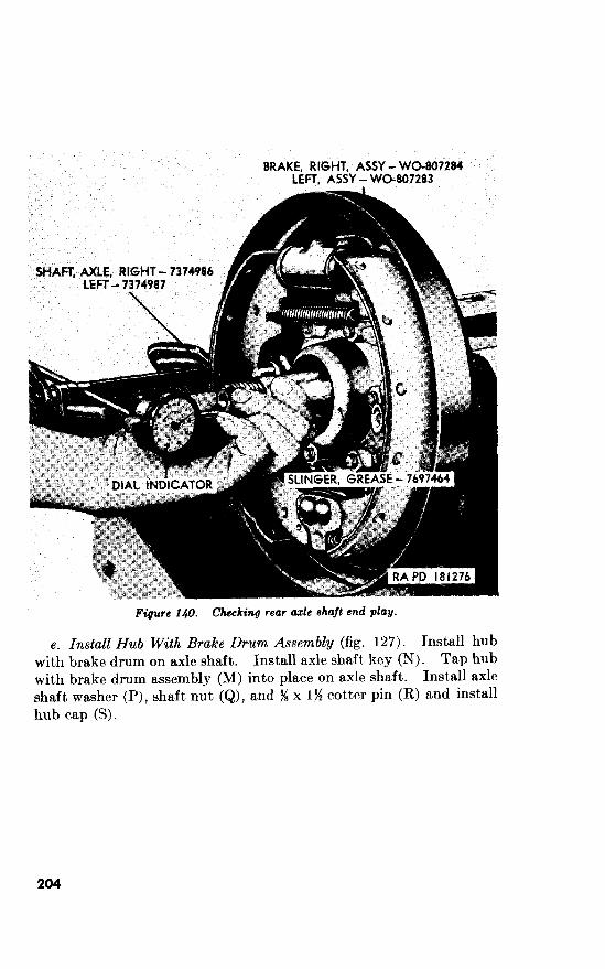
e. Install Hub With Brake Drum Assembly (fig. 127). Install hub
with brake drum on axle shaft. Install axle shaft key (N). Tap hub
with brake drum assembly (M) into place on axle shaft. Install axle
shaft washer (P), shaft nut (Q), and yS x cotter pin (R) and install
hub cap (S).
204
10
Section I. DESCRIPTION AND DATA
184. Description
a. General.
b. Service Brakes.
Handbrake (figs. 142 a
185. Data
Make of master cylinder assembIy_______ ._.__ _ _.______.___.. Wagner
Make of wheel cylinders____~__~~_________..~~ . . . . . .._._..__ Wagner

Section II. REBUILD OF SERVICE BRAKE SYSTEM
186. Disassembly
a. Remore Front Hub and Drum Assembly. Refer to paragraph 148b
for removal procedure. b. Remove Rear IIub and Drum Assembly. Refer to paragraph 171b
for removal procedure. c. Remwe Service Brake Assembly. Refer to paragraph 148~ for
removal of front service brake assemblies. Refer to paragraph 17ib for removal of rear service brake assemblies.
rl, Diwssemble Service Brake Assembly (fig. 141).
N&e. difference between brake assemblies is the length of the forward and reverse linings and the assembled position of the front and rear shoes.
(1) Remove the shoe retracting spring (P). (2) Remove anchor end shoe retainer spring (AA) from lower ends
of the front. and rear shoes (C and Q). (:3) Compress shoe holddown springs (I3 and LLI), turn the hold-
down spring shoe pins (U and Z) until flat sections of pins are alined with flat portions of shoe holddown spring seats (D, F, 1, and S) and remove seats and springs. Remove the holddown spring shoe pins (U and Z) by pulling out through rear of backing plate assembly (T).
(4) Disengage front and rear brakeshoe assemblies from front wheel cylinder assembly (H) at the top and the anchor at the bottom and lift out, shoe assemblies.
(5) Remove two plain nuts (V and Y) and lockwashers (W and X). Remove t.he two shoe adjusting eccentrics (G and K).
(6) Unscrew the lockwasher bolts (BB) and remove front wheel cylinder assembly (H) from backing plate assembly (T).
187. Inspection and Repair
a. Inspection.
(1) Master cylinder and wheel cylinders. Refrr to TM 9%1827C for inspection procedures.
(2) Brakedrums (fig. 184). Inspect brake drums for scored braking surface, cracks, or warpage. Check runout of brake- drum braking surface. Runout’ must not, exceed 0.006 inch.
(3) Shoes and lin,ings (fig. 141). Inspect front, and rear shoe linings (B and R) for wear, glazing, and evidence of brake fluid or grease leakage. In the event of brake fluid leakage, repair wheel cylinders (TM 9-1827C). If grease is leaking from rear axle, replace rear axle grease slinger (L, fig. 127) and rear axle shaft outer oil seal assembly (J, fig. 127). If front axle is leaking grease, replace the inner axle shaft oil
206
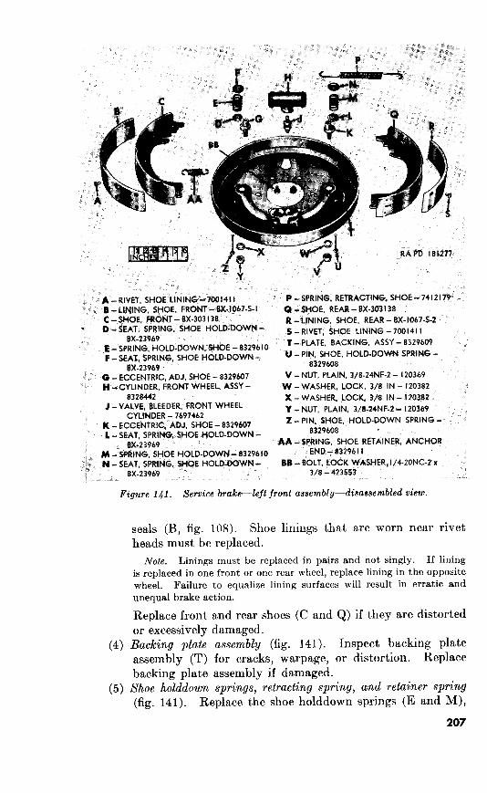
P -
E - F -SEAT, U -PIN,
8X-23969 8329608
0 -ECCENTRIC, V-NUT, W-WASHER,
J -VALVE, 76974b2
Y -NUT,
8329608
8X-23969 AA -
8329610 83296 I I
# - B6 - 8X-23969 3/8 - 423553
141. Service brake-left front assembly-disassembled
(4)
(5)
seals (B, fig. 108). Shoe linings that are worn near rivet
heads must be replaced.
Note. Linings must be replaced in pairs and not singly. If lining
is replaced in one front or one rear wheel, replace lining in the opposite
wheel. Failure to equalize lining surfaces will result in erratic and
unequal brake action.
Replace front and rear shoes (C and Q) if they are distorted
or excessively damaged.
Backing plate assembly (fig. 141). Inspect backing plate
assembly (T) for cracks, warpage, or distortion. Replace
backing plate assembly if damaged.
Shoe holddown springs, retracting spring, and retainer spring
(fig. 141). Replace the shoe holddown springs (E and M),
207

shoe retracting spring (P), and anchor end shoe retainer
spring (AA) if they are broken, distorted, or fail bo operate in
their intended manner.
Shoe adjusting eccentrics (fig. Inspect shoe adjusting
eccentrics (G and K) for wear and damage. Replace the
eccentrics, if necessary.
b. Repair.
Master cylinder and wheel cylinders. Refer to TM 9-1827C
for repair procedures.
(2) Brakedrums (fig. 184). Refinish rough or scored brakedrum
surface in a lathe. Do not remove more than 0.030 inch
thickness of metal (0.060 inch on diameter). If refinishing
requires more than dimension specified above, replace the
brakedrum.
(3) Reline front and rear shoes.
(a) Remove shoe lining rivets and strip shoe lining from shoe
(C and Q, fig. 141). Clean face of shoe thoroughly.
(b) If brakedrums have been refinished ((2) above), either in-
stall the correct oversize linings or install shims, equal in
t,hickness to metal removed from brakedrum, between the
lining and the shoe so that arc of lining will be same as
that of brakedrum.
(c) Aline end rivet holes of shoe lining with holes in shoe.
Clamp lining in place with suitable clamp or other tool.
Install end shoe lining rivets, remove clamping tool, and
install remaining shoe lining rivets and swage.
(d) Check lining and shoe contact. A O.OlO-inch feeler gage
must not enter between shoe and lining at any point.
(e) Grind shoe linings concentric with brakedrum center.
(4) Hydraulic lines and Jittings (fig. 37). To replace damaged
hydraulic line, cut tubing to required length with tubing
cutter. Blow out line to remove all foreign matter.
188. Assembly (fig. 141)
a. Position front wheel cylinder assembly (H) in backing plate as-
sembly (T). Secure wheel cylinder with two %20NC-2 x $6 lock-
washer bolts (BB).
b. Install the anchor end shoe retainer spring (AA) on the front and
rear brakeshoes. Place the front shoe (C) and the rear shoe (Q) on
the backing plate assembly (T). Install shoes so that their lower
ends engage slots behind plate anchor and their upper ends contact
wheel cylinders.
c. Install holddown spring shoe pins (U and Z) through rear of
backing plate assembly (T) and front, and rear shoes. Place shoe
holddown spring seats (D, F, L, and N) and shoe holddown springs
208

(E and M) over pins. While compressing holddown springs, turn
holddown spring shoe pin until flat section of pins are perpendicular
to flat portion of shoe holddown spring seats.
d. Install the two shoe adjusting eccentrics (G and K) in backing
plate assembly (T), with low sides of eccentrics against brake shoes.
Install y&inch lockwashers (W and X) and %-24NF-2 plain nuts (V
and Y) on eccentrics.
e. Secure the shoe retracting spring (P) on the front and rear shoes
(C and Q).
f. The front and rear service brake assemblies are installed during
rebuild of front and rear axles (pars. 167 and 183). The front and
rear hubs are installed in drums during rebuild of wheels and hubs
(par. 268).
189. Adjustment Refer to TM 9-804A for service brake adjustment.
Section III. REBUILD OF HAND BRAKE SYSTEM
190. Disassembly Remove Brake Rod Assembly. Refer to paragraph 48~ (10) for
removal procedure.
b. Remove Brake Assembly. Remove three lockwasher cap screws
(fig. 142) which secure the handbrake assembly to the body. Lift
the handbrake assembly from body.
c. Remove Brakedpum, Operating Lever, and Inner and Outer Shoe
Figure 149. Handbrake assembly--installed.
209

C -
E -
7697550
Q -
144363
8329633
x -RETAINER,
Y -NUT,
8329629
WO-806027
DD - 314 - I77923
EE - 8329630
HH -LINING, 19476
JJ -BOLT, KK -WASHER,
Refer to paragraphs and for removal
procedures.
d. It is not necessary to disassemble the brake and
brake rod assemblies unless inspection (par. 191a) reveals them to be
unserviceable.
210
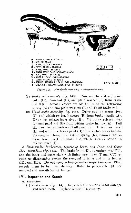
A-HANDLE, BRAKE - BT-1012-I
8 - SECTOR. BRAKE
c-RtvET. SECTOR-ET-1011-7
D -PAWL. BRAKE- 81-101 i-4
E -RIVET. PAWC - ET-IO1 1-5
F - ANTI-RATTLE, PAWL ROD- BT-102&O
O-ROD, PAWL-BT-1012-12
H-RIVET, RELEASE LEVER - BT-102O-6
J -LEVER, RELEASE- Bh1012-2
K - SPRING. RETURN, RELEASE LEVER - 8%IOZP-9A
1 -GROMMET, RELEASE LEVER RIVET - 87-1029-15 RAPD l8lZBo
Fiyure 144. Handbrake assemblll-disassembled view.
hake rod assembly (fig. 143). Unscrew the rod a.djust.ing yoke (H), plain nut (U), and plain washer (T) from brake
rod (9). Remove cot,ter pin (J) and slide th(a retracting spring (S) and two plain washers (R and T) off brake rod. Hand brake assembly (fig. 144). Drive out) the sector rivet (C) and withdraw brake sector (B) from brake handle (,4). Drive out release lever rivet (H). Withdraw rclcasc 1rve1 (J) and paw1 rod (G) from within brake handle (A). Pull the paw1 rod antirattle (F) off paw1 rod. Drive paw1 rivet (E) and withdraw brake paw1 (D) from within brnkr handle. To remove release lever return spring (I<), remove the rc-
lease lever rivet grommet (L) which secures spring to release lever (J).
e. Disassemble Brakedrum, Operating Lever, and In,ner a& Outer
Shoe Assemblies (fig. 143). The brakedrum (D), operating lever (W), and the inner and outer shoe with lining assc~mblics (F and CC) rc- quire no disassembly except t)he removal of inner and outer linings (HH and BB). Do not remove linings unless insprction (par. reveals them to be unsatisfactory. Refer to paragraph 191. fol remova! and installation of linings.
191. Inspection and Repair
a. Inspection.
(1) Brake sector (fig. 144). Inspect brake sector (B) for dnmnge and worn teeth. Replace sector, if ncoessnr~.
211
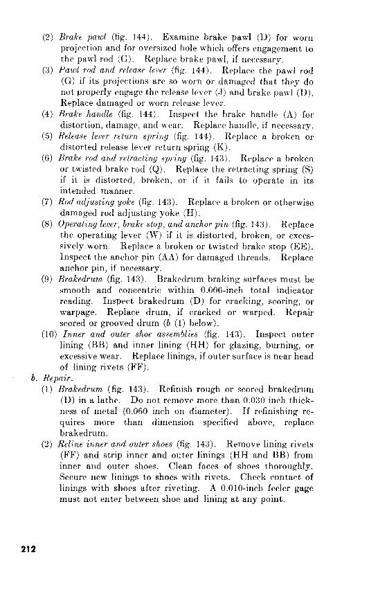
(2) Brake paw1 (fig. 144). Examine brake paw1 (D) for worn projection and for oversized hole which offers engagement to
the paw1 rod (G). Replace brake pawl, if necessary. (3) PawL rod and release lever (fig. 144). Replace the paw1 rod
(G) if its projections are so worn or damaged that, they do not properly engage the release lever (.J) and brake paw1 (D). Replace damaged or worn release lever.
(4) Brake handle (fig. 144). Inspect the brake handle (A) for
distortion, damage, and wear. Replace handle, if necessary. (5) Release lever return spring (fig. 144). Replace a broken or
distorted release lever return spring (K). (6) Brake rod a’nd retracting spring (fig. 143). Replace a broken
or twisted brake rod (Q). Replace the retracting spring (S)
if it is distorted, broken, or if it fails to operate in its intended manner.
(7) Rod adjusting yoke (fig. 143). Replace a broken or otherwise damaged rod adjusting yoke (H).
(8) Operating lever, brake stop, and anchor pin (fig. 143). Replace
the operating lever (W) if it is distorted, broken, or exces- sively worn. Replace a broken or twisted brake stop (EE). Inspect the anchor pin (AA) for damaged threads. Replace
anchor pin, if necessary. (9) Brakedrum (fig. 143). Brakedrum braking surfaces must be
smooth and concentric within 0.006-inch total indicator reading. Inspect brakedrum (D) for cracking, scoring, or
warpage. Replace drum, if cracked or warped. Repair scored or grooved drum (b (1) below).
(10) Inner and outer shoe assemblies (fig. 143). Inspect outer lining (BB) and inner lining (HH) for glazing, burning, or excessive wear. Replace linings, if outer surface is near head
of lining rivets (FF).
b. Repair.
(1) Brakedrum (fig. 143). Refinish rough or scored brakedrum
(D) in a lathe. Do not remove more than 0.030 inch thick- ness of metal (0.060 inch on diameter). If refinishing re-
quires more than dimension specified above, replace brakedrum.
(2) Reline inner and outer shoes (fig. 143). Remove lining rivets (FF) and strip inner and outer linings (HH and BB) from inner and outer shoes. Clean faces of shoes thoroughly. Secure new linings to shoes with rivets. Check contact of linings with shoes after riveting. A O.OlO-inch feeler gage
must not enter between shoe and lining at any point.
212
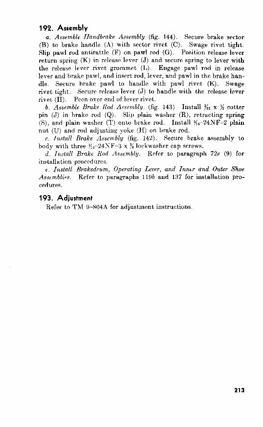
192. Assembly
a. Assemble Handbrake Assembly (fig. 144). Secure brake sector (B) to brake handle (A) with sector rivet (C). Swage rivet tight. Slip paw1 rod antirattle (F) on paw1 rod (G). Position release lever
return spring (K) in release lever (J) and secure spring to lever with the release lever rivet grommet (L). Engage paw1 rod in release lever and brake pawl, and insert rod, lever, and paw1 in the brake han- dle. Secure brake paw1 to handle with paw1 rivet (E). Swage
rivet tight. Secure release lever (J) to handle with the release lever rivet (H). Peen over end of lever rivet.
b. Assemble Brake Rod Assembly. (fig. 143) Install 352 x ): cotter pin (J) in brake rod (Q). Slip plain washer (R), retracting spring (S), and plain washer (T) onto brake rod. Install Tic-24NF-2 plain
nut (U) and rod adjusting yoke (H) on brake rod. c. Install Brake Assembly (fig. 142). Secure brake assembly to
:i6-24h’F-3 x 3: lockwasher cap screws. d. Install Brake Rod Assembly. Refer to paragraph 72e (9) for
installation procedures. e. Install Brakedrum, Operating Lever, and Inntr and Outer Shoe
Asspmblios. Refer to paragraphs 119b and 137 for installation pro-
cedures.
193. Adjustment
TM 9%804A for adjustment instructions.
213
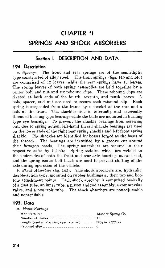
Section I. DESCRIPTION AND DATA
194. Description
a. Springs. The front and rear springs are of the semielliptic
type constructed of alloy steel. The front springs (figs. 145 and
are comprised of 12 leaves, while the rear springs have 13 leaves.
The spring leaves of both spring assemblies are held together by a.
center bolt and nut and six rebound clips. These rebound clips are
riveted at both ends of the fourth, seventh, and tenth leaves. A
bolt, spacer, and nut are used to secure each rebound clip. Each
spring is suspended from the frame by a shackel at the rear and a
bolt at the front. The shackles ride in internally and externally
threaded bushing t,ype bearings while the bolts are mounted in bushing
type eye bearings. To prevent the shackle bearings from screwing
out, due to spring action, left-hand t,hread shackle bearings are used
on the lower ends of the right rear spring shackle and left front spring
shackle. The shackles are identified by bosses forged at the bases of
the threads. The bearings are identified by a groove cut around
their hexagon heads. The spring assemblies are secured to their
respective axles by U-bolts. Spring saddles, which are welded to
the undersides of both the front and rear axle housings at each end,
and the spring center bolt heads are used to prevent shifting of the
axle during operation of the vehicle.
b. Shock Absorbers (fig. 145). The shock absorbers are, hydraulic,
double-action type, mounted on rubber bushings at their top and bot-
tom attachment points. Each shock absorber is comprised basically
of a dust tube, an inner tube, a piston and rod assembly, a compression
valve, and a reservoir tube. The shock absorbers are nonadjustable1
and nonrefillable.
195. Data
a. Front Springs.
Manufacturer____~_~___----~~~--------~~_- Mather Spring Co.
Number of leaves_______________.~--.-----~ 12
Length (center of spring eyes, arched) __~ _ _ _ 3876 in. (apprx)
Rebound clips_____~~________~__----------~ 6
214

B -WASHER,
D -
E - IN - 504208 F -
H -
J -BRACKET, K -BUMPER, 1 -
P -
U -RETAINER,
V-BOLT, W-NUT,
AA-NUT, BB -
DD -BEARING.
7b97598
FF -BUSHING,
HH -WASHER, JJ -
KK -
Figure 146. Front spring and shock absorber.
Rear Springs.
Manufacturer_.._ ____ ___________~~ . . . . . . . Mather Spring Co.
Number of leaves______________~~---------- 13
Length (center of spring eyes, arched) ___ _ _ _ _ 445 in. (apprx) Rebound clips_______~__~~__~~~~~_______..__ 6
215
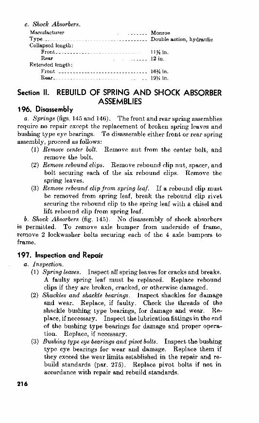
Section II. REBUILD OF SPRING AND SHOCK ABSORBER ASSEMBLIES
196. Disassembly a. 145 and 146). The front and rear spring assemblies
require no repair except the replacement of broken spring leaves and
bushing type eye bearings. To disassemble either front or rear spring
assembly, proceed as follows:
(1) Remove nut from the center bolt, and
remove the bolt.
(2) Remove rebound clip nut, spacer, and
bolt securing each of the six rebound clips. Remove the
spring leaves.
(3) clip If a rebound clip must
be removed from spring leaf, break the rebound clip rivet
securing the rebound clip to the spring leaf with a chisel and
lift rebound clip from spring leaf.
disassembly of shock absorbers
is permitted. To remove axle bumper from underside of frame,
remove 2 lockwasher bolts securing each of the 4 axle bumpers to
frame.
197. Inspection and Repair
(1) Spring leaves. Inspect all spring leaves for cracks and breaks.
A faulty spring leaf must be replaced. Replace rebound
clips if they are broken, cracked, or otherwise damaged.
(2) bearings. Inspect shackles for damage
and wear. Replace, if faulty. Check the threads of the
shackle bushing type bearings, for damage and wear. Re-
place, if necessary. Inspect the lubrication fittings in the end
of the bushing type bearings for damage and proper opera-
tion. Replace, if necessary.
(3) Inspect the bushing
type eye bearings for wear and damage. Replace them if
they exceed the wear limits established in the repair and re-
build standards (par. 275). Replace pivot bolts if not in
accordance with repair and rebuild standards.
216
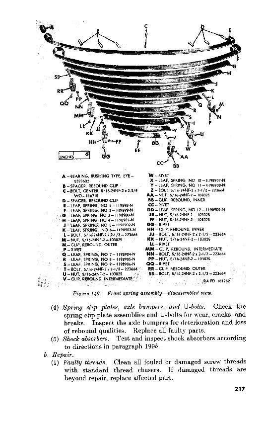
A - BEARING, BUSHING TYPE, EYE -
8329602
B-SPACER, REBOUND CLIP C - BOLT. CENTER, 51 I b-24NFe2 x Z-3/4
WO- 116715
D -SPACER, REBOUND CLIP
E-LEAF, SPRING, NO I - I 19898-N
F -LEAF, SPRING. NO 2 - J 19899-N 0 - LEAF, SPRING, NO 3 - I I9B900-N
H-LEAF, SPRING, NO 4- 1198901-N
J -LEAF, SPRING. NO 5 - I 198902-N
K - LEAF, SPRtNG. NO b - I IPB903-N
L - BOLT, 5/ lb-24NFT2 I[ 2-I /2 - 223664
M - NUT, 5/I &24NF-2 - 103025
N -CLIP. REBOUND, OUTER
P -RIVET Q -LEAF, SPRING, NO 7 - 1198904-N
R - LEAF, SPRtNG, NO 8 - I 198905-N
S - LEAF. SPRING. NO 9 - I IQB9Ob.N
T-BOLT. S/ ik24NF-2 x 2.112 - 223661
ll -NUT. 5/W-24NF.Z- IO3025
V -CLIP, REBOUND, INTERMEDlATE
W -RIVET
X - LEAF, SPRING, NO IO - 1198907-N
Y -LEAF, SPRING, NO I I - t 198908-N
2 -BOLT, 5/16-24NF-2 x 2-l/2- 223664
AA-NUT, 5/1&24NF-2 - 103025
BB -CLIP. REBOUND, tNNER
CC - RIVET DD - LEAF, SPRING. NO I2 - I 198909-N
EE - NUT, 51 I b-24NF.2 - t 03025
FF - NUT, 5/l&24NF-2 - 103025
GO -RIVET HI4 -CLIP, REBOUND, INNER
JJ - BOLT, 5/l b-24NF-2 x 2-l/2 - 223664
UK-NUT. 5/l&24NF-2- 103025
LL -RIVET
MM -CLIP, REBOUND, INTERMEDIATE NN -BOLT, 5/lb.24NF-2 x 2-l/2 - 223664
PP - NUT, 5/Jb-24NF.2 - 103025
QQ - RtVET
RR -CLIP, REBOUND. OUTER SS - BOLT. 5/t b-24NF-2 x 2-t/2 - 223664
RAFD 181282
Figure 146. Front spring assembly-disassembled view.
Spring clip plates, axle bumpers, and U-bolts.
Shock absorbers.
199b.
b. Repair.
Faulty threads.
217
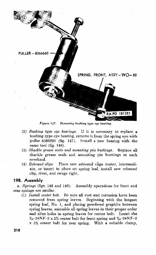
(2)
(3)
(4)
PULLER - 8366660
If it is necessary to replace a
bushing type eye bearing, remove it from the spring eye with
puller 8366660 (fig. 147). Install a new bearing with the
same tool (fig. 148).
Replace all
shackle grease seals and mounting pin bushings at each
overhaul.
Place new rebound clips (outer, intermedi-
ate, or inner) in place on spring leaf, install new rebound
clip, rivet, and swage tight.
198. Assembly 145 and 146). Assembly operations for front and
rear springs are similar.
(1) Be sure all rust and corrosion have been
removed from spring leaves. Beginning with the longest
spring leaf, No. 1, and placing powdered graphite between
spring leaves, assemble all spring leaves in their proper order
and aline holes in spring leaves for center bolt. Insert the
%-24NF-2 x 2% center bolt for front spring and X6-24NF-2
x 3% center bolt for rear spring. With a suitable clamp,
218
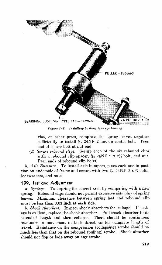
PULLER - 8366660
(2)
vise, or arbor press, compress the spring leaves together
sufficiently to install g6-24NF-2 nut on center bolt. Peen
end of center bolt at nut end.
Secure rebound clips. Secure each of the six rebound clips
with a rebound clip spacer, x6-24NF-2 x 2>4 bolt, and nut.
Peen ends of rebound clip bolts.
b. Axle Bumpers. To install axle bumpers, place each one in posi-
tion on underside of frame and secure with two x6-24NF-3 x 3$ bolts,
lockwashers, and nuts.
199. Test and Adjustment
a. Springs. Test spring for correct arch by comparing with a new
spring. Rebound clips should not permit excessive side play of spring
leaves. Minimum clearance between spring leaf and rebound clip
must be less than 0.03 inch at each side.
b. Shock Absorbers. Inspect shock absorbers for leakage. If leak-
age is evident, replace the shock absorber. Pull shock absorber to its
extended length and then collapse. There should be continuous
resistance to movement in both directions for complete length of
travel. Resistance on the compression (collapsing) stroke should be
much less than that on the rebound (pulling) stroke. Shock absorber
should not flop or fade away on any stroke.
219

12
Section I. DESCRIPTION AND DATA
200. Description and Operation
The steering system, which is of the con-
ventional design, is composed of the steering gear assembly (H), drag
link (Ii‘), bellcrank with bearing and oil seal assembly (E), tie rods
(B) and (D), and steering knuckle flanges (A) and (J). Functionally,
angular movement of the steering wheel (N, fig. 150) motivates the
shaft with integral worm (L, fig. whose screw effect causes the
pitman shaft with integral cam (JJ, fig. 150) to rotate. This in turn
causes the pitman arm (G) to swing angularly. The drag link (F),
which is connected to both the pitman arm (G) and bellcrank, is
caused to move laterally thereby pivoting the bellcrank which, in
turn, moves the tie rods (B) and (D) and steering knuckle flanges
(A) and (J).
Figure 149. Steering system.

b. Steering Gear Assembly (fig. 150).
201. Data a. Steering Gear.
Make-_-~---------._...-~----------__---_-------- Ross
Model_____~___________.~_-~--------_____.-_-_---- T12
Ratios:
Full left.___________-_--------~-_--~-~------~- 19. 1
Center_________~~_____._._.._-_--.__....._.-_ 17.1
Full right_____----_.~._.~.~.~~-~--..~.~.~~-~-- 19. 1
Dimensions.
Length from outside rim of steering wheel to center of 39.72 to 39.84 in.
pitman arm shaft.
Length of worm shaft (overall)______~_~__....-----~- 423/s in.
Length jacket (overall).___._...-_------__-.-_------ 3496 in.
c. Steering Geometry.
Kingpin inclination__~_______~.~.~.-~--_-_- 7% deg
Toe-in___________._-_------_--.------_-~-___---__ )/sr-sz-in.
Camber__~____________._.-.--_---_-_-----~-.__.-_ 1% deg
Caster__~____________-_--------_-_~.- 3deg Turning radius----- _____ ~______~____.~____~~ . . .._. 18 ft.
d. Pitman Arm Shaft.
Clearance to bushing type bearings- _ _ ~. . . . _ _ 0.0005.00025 in.
End play___.._._.-__..._.~.._~~---------_------._ 0.000

*__....“--- ________*_e--a---
Steering gear

A -Nut, +16NF-2-124949
B-Washer, lock, !&in.-103326
C-Arm, pitman-
D-Seal, oil, pitman shaft-7375341
E-Bearing, bashing type, pitman shaft-7375348
F-Bearing, bushing type, pitman shaft-7375349
G-Housing, steering gear-8329726
H-Plug pipe )&in.-219190
J-Tube, oil seal-7375337
K-Kit, repair, worm shaft bearing-7351410
Composed of:
l-Ring, snap, worm bearing
~--CUP, worm bearing ball
3-Ball , ?/le-in., worm bearing 1 4-Ball, 5/it-in., worm bearing 1 ~--CUP, worm bearing ball
B-Ring, snap, worm bearing
i-Shim set, housing upper cover 2
B-Gasket, housing side cover 3
L-Shaft, w/integral worm-8329730
M-Cover, housing, upper, w/seal, assy-7412446
N-Wheel, steering-7375336
P-Nut, ‘%r,-20NC-2-7412579
Q-Bolt, $‘&lBNC-2 x y&-214644
R-Washer, lock, 5ic-in.-120638
S-Spring, jacket bearing-WO-639191
T-Seat, jacket bearing spring-WO-801423
U-Cup, inner, jacket bearing
V-Ball, jacket bearing
W-Cup, outer, jacket bearing
X-Seal, oil, jacket-WO-804392
Y-Washer, oil seal
Z-Jacket-WO-801078
AA-Cap, horn button-WO-804623
BB-Button, horn (disk)
CC-Retainer, horn switch push rod-WO-806393
DD-Rod, push, horn switch-WO-806394
EE-Bolt, 5/;6-24NF-3 x 1$1-123798
FF-Clamp, jacket-WO-A635
GG-Washer, lock, $16-in.-138538
HH-Nut, %,j-24NF-2-120368
JJ-Shaft, pitman, w/integral cam-8329729
KK-Cover, housing side-8329723
L&Screw, adj, pitman shaft, Fe-20NF-2-8329728
MM-Nut, jam, 7$6-20NF-2-5175255
NN-Screw, cap, 5/16-18NC-2 x 1-RG-020041
PP-Washer, lock, 5/16-in.-120638
Q&-Adapter, horn switch-WO-806917
RR-Switch, horn, w/harness, assy-8329689
Figure 150-Continued.
H
Section II. REBUILD OF STEERING GEAR ASSEMBLY
PO% Disassembly (fig.
Remove Steering Whed. Refer to paragraph 48~ (11) for removal
instructions.
b. Remove Jacket. Remove bolt (EE), nut (HH), and lockwasher
(GG) which secure jacket clamp (FF), and follow by pulling jacket
(Z) off housing upper cover with seal assembly (M). Remove jacket
bearing assembly; composed of jacket bearing spring seat (T), inner
cup (U), balls (V); and outer cup (W); from upper end of jacket. To
dissassemble jacket bearing assembly, remove bearing spring seat,
inner cup, and balls from outer cup. Withdraw jacket oil seal (X)
and oil seal washer (Y) from within upper end of jack,et.
c. Remove Housing Side Cover. Remove four cap screws (NN),
lockwashers (PP) and lift housing side cover (KK) and side cover
gasket (K-8) from steering gear housing (G). Discard housing side
cover gasket.
d. Remove Pitman Arm. Unscrew the nut (A) from pitman shaft
with integral cam (JJ) and remove lockwasher (B) . Pull pitman arm
(C) from end of pitman shaft. It may be necessary to tap pitman
arm to free it from serrations on pitman shaft. If so, check pitman
shaft for burs and raised metal or nicks. Smooth as necessary.
Rough surface on pitman shaft can damage pitman shaft bearings
during removal of shaft from housing. Pull shaft (JJ) from housing.
e. Remove Shaft Wz{h Integral Worm. Remove three bolts, (Q), and
lockwashers (R), upper housing cover with seal assembly (M) and
cover shims (K-7). Pull the shaft with integral worm (L) from
housing. Withdraw steering gear oil seal tube (J) from end of shaft.
Remove the two worm bearing snap rings (K-l) and (K-6) and
remove the worm bearing balls (K-3) and (K-4) from the worm bear-
ing ball cups (K-2) and (K-5). Remove worm bearing ball cups
from shaft.
NC@. Once the worm bearing snap rings are removed, the balls will readily
fall out of cups unless pressure is exerted.
f. Remove Pitman Shaft Bearing. Do not remove the pitman shaft
bushing type bearing (E) and (F) from housing unless inspection
(par. 203a (6)) reveals them unserviceable.
g. Remove Horn Switch. Unscrew the horn switch with harness
assembly (RR) from the horn switch adapter (QQ).
h. Remove Horn Stitch Adapter. It is not necessary to remove the
horn switch adapter (QQ) f rom the steering gear housing unless
inspection (par. 203a) indicates it must be replaced.
224
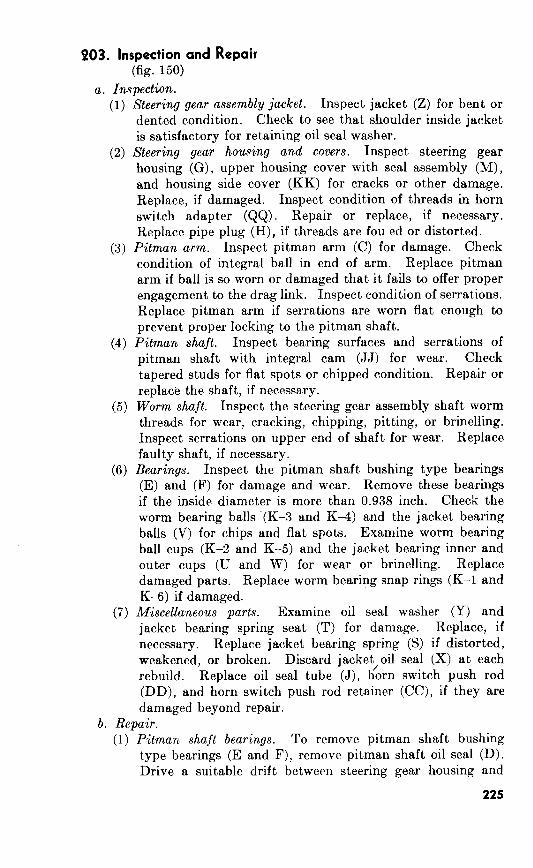
203. Inspection and Repair (fig.
Inwection.
(1) ‘Steering gear assembly jacket. Inspect jacket (Z) for bent or
dented condition. Check to see that shoulder inside jacket
is satisfactory for retaining oil seal washer.
(2) Steering gear housing and covers. Inspect steering gear
housing (G), upper housing cover with seal assembly (M),
and housing side cover (KK) for cracks or other damage.
Replace, if damaged. Inspect condition of threads in horn
switch adapter (QQ). Repair or replace, if necessary.
Replace pipe plug (H), if threads are fou ed or distorted.
Pitmun arm. Inspect pitman arm (C) for damage. Check
condition of integral ball in end of arm. Replace pitman
arm if ball is so worn or damaged that it fails to offer proper
engagement to the drag link. Inspect condition of serrations.
Replace pitman arm if serrations are worn flat enough to
prevent proper locking to the pitman shaft.
Pitman shaft. Inspect bearing surfaces and serrations of
pitman shaft with integral cam (JJ) for wear. Check
tapered studs for flat spots or chipped condition. Repair or
replace the shaft, if necessary.
Worm shaft. Inspect the steering gear assembly shaft worm
threads for wear, cracking, chipping, pitting, or brinelling.
Inspect serrations on upper end of shaft for wear. Replace
faulty shaft, if necessary.
Bearings. Inspect the pitman shaft bushing type bearings
(E) and (F) for damage and wear. Remove these bearings
if the inside diameter is more than 0.938 inch. Check the
worm bearing balls (K-3 and K-4) and the jacket bearing
balls (V) for chips and flat spots. Examine worm bearing
ball cups (K-2 and K-5) and the jacket bearing inner and
outer cups (U and W) for wear or brinelling. Replace
damaged parts. Replace worm bearing snap rings (K-l and
K-6) if damaged.
Miscellaneous parts. Examine oil seal washer (Y) and
jacket bearing spring seat (T) for damage. Replace, if
necessary. Replace jacket bearing spring (S) if distorted,
weakened, or broken. Discard jacket/oil seal (X) at each
rebuild. Replace oil seal tube (J), horn switch push rod
(DD), and horn switch push rod retainer (CC), if they are
damaged beyond repair.
b. Repair.
Pitman shaft bearings. To remove pitman shaft bushing
type bearings (E and F), remove pitman shaft oil seal (D).
Drive a suitable drift between steering gear housing and
225
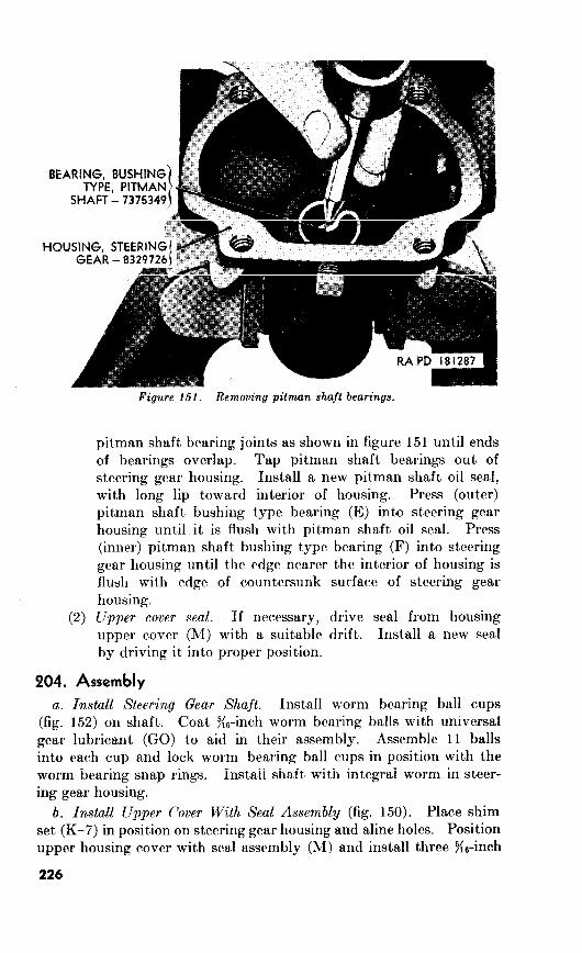
152.
Upper cover seal.
204. Assembly
a. Install Steering Gea.r Shaft.
b. Install Upper Cover With Seal Assembly (fig. 1.50).
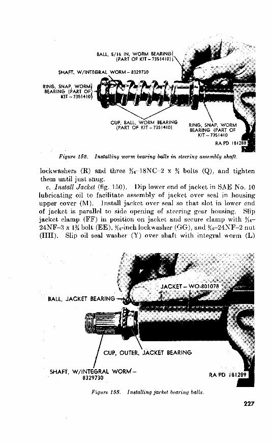
steering assembly shaft.
lockwashers (R) and three Ke-18NC-2 x % bolts (Q), and tighten
them until just snug.
c. Install Jacket (fig. 150). Dip lower end of jacket in SAE No. 10
lubricating oil to facilitate assembly of jacket over seal in housing
upper cover (M). Install jacket over seal so that slot in lower end
of jacket is parallel to side opening of steering gear housing. Slip
jacket clamp (FF) in position on jacket and secure clamp with x6-
24NF-3 x 13i bolt (EE), ?i6-inch lockwasher (GG), and i{6-24NF-2 nut
(HH). Slip oil seal washer (Y) over shaft with integral worm (L)
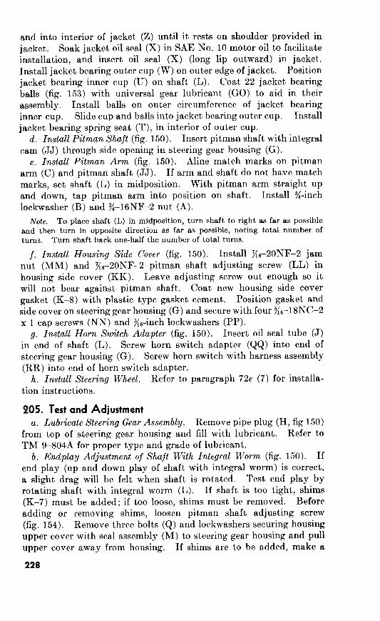
and into interior of jacket (Z) until it rests on shoulder provided in
jacket. Soak jacket oil seal (X) in SAE No. 10 motor oil to facilitate
installation, and insert oil seal (X) (long lip outward) in jacket.
Install jacket bearing outer cup (W) on outer edge of jacket. Position
jacket bearing inner cup (U) on shaft (L). Coat 22 jacket bearing
balls (fig. 153) with universal gear lubricant (GO) to aid in their
assembly. Install balls on outer circumference of jacket bearing
inner cup. Slide cup and balls into jacket bearing outer cup. Install
jacket bearing spring seat (T), in interior of outer cup.
d. Install Pitman Shaft (fig. 150). Insert pitman shaft with integral
cam (JJ) through side opening in steering gear housing (G).
e. Install Pitman Arm (fig. 150). Aline match marks on pitman
arm (C) and pitman shaft (JJ). If arm and shaft do not have match
marks, set shaft (L) in midposition. With pitman arm straight up
and down, tap pitman arm into position on shaft. Install y&inch
lockwasher (B) and 3&16NF-2 nut (A).
Note. To place shaft (L) in midposition, turn shaft to right as far as possible
and then turn in opposite direction as far as possible, noting total number of
turns. Turn shaft back one-half the number of total turns.
j. Install Housing Side Cover (fig. 150). Install y{6-20NF-2 jam
nut (MM) and X6-2ONF-2 pitman shaft adjusting screw (LL) in
housing side cover (KK). Leave adjusting screw out enough so it
will not bear against pitman shaft. Coat new housing side cover
gasket (K-8) with plastic type gasket cement. Position gasket and
side cover on steering gear housing (G) and secure with four y{6-18NC-2
x 1 cap screws (NN) and yi6-inch lockwashers (PP).
g. Install Horn Switch Adapter (fig. 150). Insert oil seal tube (J)
in end of shaft (L). Screw horn switch adapter (QQ) into end of
steering gear housing (G). Screw horn switch with harness assembly
(RR) into end of horn switch adapter.
h. Install Steering Wheel. Refer to paragraph 72e (7) for installa-
tion instructions.
205. Test and Adjustment
a. Lubricate Steering Gear Assembly. Remove pipe plug (H, fig 150)
from top of steering gear housing and fill with lubricant. Refer to
TM g-8048 for proper type and grade of lubricant.
b. Endplay Adjustment of Shaft With Integral Worm (fig. 150). If
end play (up and down play of shaft with integral worm) is correct,
a slight drag will be felt when shaft is rotated. Test end play by
rotating shaft with integral worm (L). If shaft is too tight, shims
(K-7) must be added; if too loose, shims must be removed. Before
adding or removing shims, loosen pitman shaft adjusting screw
(fig. 154). Remove three bolts (Q) and lockwashers securing housing
upper cover with seal assembly (M) to steering gear housing and pull
upper cover away from housing. If shims are to be added, make a
228
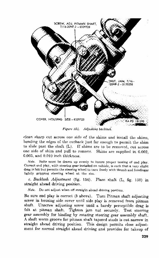
0.003, 0.010
Bolts must be drawn up evenly to insure proper testing of end play.
Correct end play, with steering gear installed on vehicle, is such that a very slight
drag is felt but permits the steering wheel to turn freely with thumb and forefinger
lightly gripping steering wheel at the rim.
c. Backlash Adjustment (fig. 154). 150)
Do not adjust when off straight ahead driving position.
229
Section III. REBUILD OF DRAG LINK ASSEMBLY
206. Disassembly
(fig.
207. Inspection and Repair
(fig.
208. Assembly
(fig.
Assemble Tie Rod End.
Note. The cotter pin (A-l) is not installed until drag link is secured to vehicle
and adjusted. Instructions for installation and adjustment of drag link assembly
are contained in TM 9-801A.
b. Assemble Pitman Arm End.
Note
Install Lubricating Fittings.
Note
SSchwend

SSchwend
Gear box end
SSchwend
Axle end
SSchwend
Axle end
SSchwend
Gear box end

d. Adjustment. Proper adjustment (a above) of the drag link
ball joints provides proper ball seat spring tension and prevents any
tightness when swinging wheels from maximum ieft to right turn.
Section IV. REBUILD OF STEERING BELLCRANK ASSEMBLY
209. Disassembly (fig.
Do not remove the needle bearing assemblies from the interior
of the steering bellcrank unless inspection (par. reveals them to
be unserviceable. To remove needle bearing assemblies, remove the
two bellcrank seals from ends of bellcrank bore, and press bearings
out of bore with a suitable remover.
b. Unscrew the lubricating fitting from the steering bellcrank
Figure 156’. Steering bellcrank assembly.
210. Inspection and Repair
157)
211. Assembly
(fig. 156)
a.
b.
Section V. REBUILT OF TIE ROD ASSEMBLIES
212. Disassembly
(fig. 157)
a. Separate Left and Right Tie Rods.
b. Loosen End Clamps.
Remove End Assemblies.
d. Remove Lubricating Fittings.
233

P A - FITTING, LURR, 90 OEG, l/8 IN - 8329748 0 -NUT. SLTD, I/2-2ONF-2 - 125250 B-END, ASSY. RH-THD -8329743 R -PIN. COllER, 3f32x7/8- 137149 C - COVER, DUST, END SND - A333908 S-PIN, COTTER. 3,‘32 I 7/S- 137169 0 -SPRING. END STUD - 73731 I I I- NUT, SLTO. l/2-20NF-2 - I25250 E - NUT, SLTO, I/2-20NF-2 - 125250 U -NUT, 5/lb24NF-2 - 120368 F - PIN, COTTER, 3/32x 7/E - I37169 V -WASHER, LOCK, 5/16 IN - 120638
0 -BOLT, 5/b24NF.2x l-l/2-214063 W -CLAMP, END - 8329741 H - CLAMP, END - 832974 I X - ROD, TIE. RIGHT - WO-642059 J -WASHER. LOCK. S/l6 IN- 120638 Y-NUT, 5/16-24NF.2 - 120368 K - NUT, 5/ 16.24NF.Z - I20368 2 -WASHER, LOCK, 5/16 IN - I20638 1 - ROD, TlE, LEFT - WO-642058 AA - CLAMP, END - 8329741
hl - END. ASSY, (H-THll - 8329744 BB - PIN, COTTER. 3/32 I 7/S - 137169 N -COVER, DUS% END STUD - A333908 CC - NUT, SLTD, l/2-20NF-2 - 125250 P -SPRING. END STUD - 73731 I I DD - SPRING. EN0 STUD - 7373 I I I
Et - COVEi, ?%t END STUD - Mf39# ff - END, ASSY. RH-THD - 8329743
FITTING, LUBR. 90 DEG. l/8 IN - 8329748 BOLT, 5/16-24NF-2 x l-1/2 - 214063
JJ-BOLT, 5/l&24NF-2x l-l/2-214063 SPRING, END STUD - 7373 I I I
Lt -COVER, DUST, Ekb STUD -A3j3@l MM -END. ASSY. U-I-THO - 8329742
LUBR, 90 DEG, l/8 IN - 8329748 Pf’ -FITTING, LUBR. 90 OEG, l/8 IN - 8329748
’ QQ -WASHER, LOCK. 5/16 IN - 120638 RR -CLAMP, END - 8329741
BOLT, 5/16_24NF2 x l-l/2- 214063 n-NUT, 5/16-24NF-2 -120368
NOTE: ITEMS 8, M. FF, AN0 MM ALSO AVAILABLE AS A REPAIR KIT-8329745
RA PD 181293 :
Figure 167.
213. Inspection and Repair (fig. 157)
a. Inspection. Inspect left and right tie rods (L) and (X) for
twisted or bent condition. Inspect tie rod threads for damage.
Replace tie rod if it cannot be repaired. Check end assemblies (B),
(M), (FF) and (MM) for damaged threads. Inspect the studs on
the end assemblies for out-of-round, twisted, or bent condition.
Replace end assemblies if they cannot be repaired. Examine end
stud spring (D), (P), (DD) and (KK) for distortion, weak condition,
or breaks. Replace end stud springs, if necessary. Inspect end
clamps (H), (W), (AA) and (RR) and their bolts, washers and nuts
for damage. Replace all damaged or worn parts. See that end
lubricating fittings (A), (GG), (NN) and (PP) are not damaged or
clogged. Replace and clean fittings, if necessary.
b. Repair. Repair all fouled or distorted threads of tie rods (L)
and (X) and end assemblies (B), (M), (FF) and (MM) with appro-
priate standard taps and thread chasers.
214. Assembly
(fig. 157)
a. Install End Assemblies. Slip end clamps (H), (W), (AA) and
(RR) over tie rods. Screw end assemblies (B) and (MM) in ends of
tie rod (L) and end assemblies (M) and (FF) in tie rod (X). Install
one s6-24NF-2 x 1% bolt, yi6-inch lockwasher, and yi6-24NF-2 nut in
each end clamp. Temporarily tighten bolts as toe-in adjustment is
made when tie rods are installed on vehicle.
b. Connect Left and Right Tie Rods. Place new end stud dust cover
(LL) and end stud spring (KK) (large end first) on stud of end as-
sembly (MM). Push or tap stud of end assembly into hole of end
assembly (M). Secure tie rods together with g-2ONF-2 slotted nut
(T) and Ks. x % cotter pin (S).
c. Install Lubricating Fittings. Screw )&inch, go-degree lubricating
fittings in each end assembly.
d. Tie Rod Adjustment. After tie rods are installed on vehicle,
correct tie rod adjustment must be maintained. Refer to TM g-8048
for toe-in adjustment.
235

13
Section I. DESCRIPTION AND DATA
915. Description (fig. 158)
a. General.
6. Windshield Assembly.
Seat Assemblies.
236
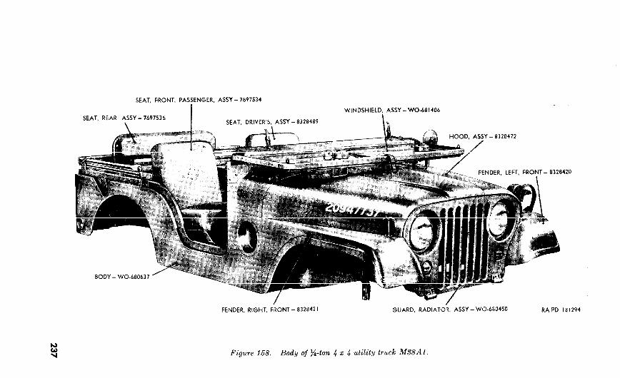
7697534
I WO-681406
7697535 I
420
WO-680450
Figure 168. Body of s-ton 4 x 4 utility truck MS8Al.
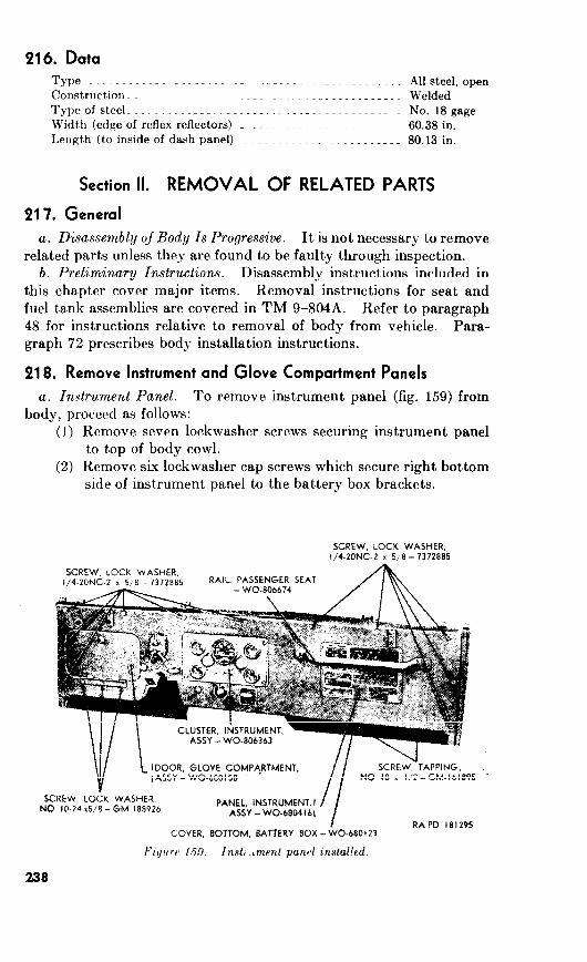
216. Data
Type-... .~~~.~_~ _. ._ ~__ _... _~____________._ Allsteel,open
.._ Welded
Typeofsteel_._. .~~___.. ._ _. _~.~_~__.~~. No.18gage
Widt,h (edgeof reflex reflectors)__~__~~~~~~~.~~ .._~__~_ 60.38in.
Length (to inside of dash panel) . _ ~. _ _ _ 80.13 in.
Section II. REMOVAL OF RELATED PARTS
217. General
a. Disassembly of Body Is Progressive. It is not necessary to remove
related parts unless they are found to be faulty through inspection.
b. Preliminary Instructions. Disassembly instructions included in
this chapter cover major items. Removal instructions for seat and
fuel tank assemblies are covered in TM g-8048. Refer to paragraph
48 for instructions relative to removal of body from vehicle. Para-
graph 72 prescribes body installation instructions.
218. Remove Instrument and Glove Compartment Panels
a. Instrument Panel. To remove instrument panel (fig. 159) from
body, proceed as follows:
(1) Remove seven lockwasher screws securing instrument panel
to top of body cowl.
(2) Remove six lockwasher cap screws which secure right bottom
side of instrument panel to the battery box brackets.
GM-189926
I WO-be0123
h’i!/trrc 1.59. lnst, .bmenl panrl
238
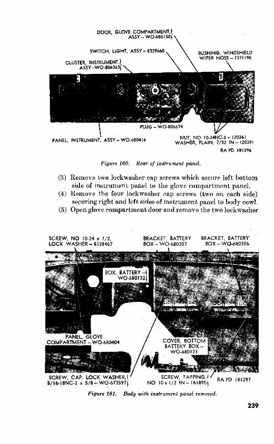
WO-b8O I50
8329660
b 120361
(3)
(4)
(5)
181296
Figure 160. Rear of instrument panel.
Remove two lockwasher cap screws which secure left bottom
side of instrument panel to the glove compartment panel.
Remove the four lockwasher cap screws (two on each side)
securing right and left sides of instrument panel to body cowl.
Open glove compartment door and remove the two lockwasher
IO-24 x l/2, WO-680306
Figure 161. Body ,with instrument panel removed.
239
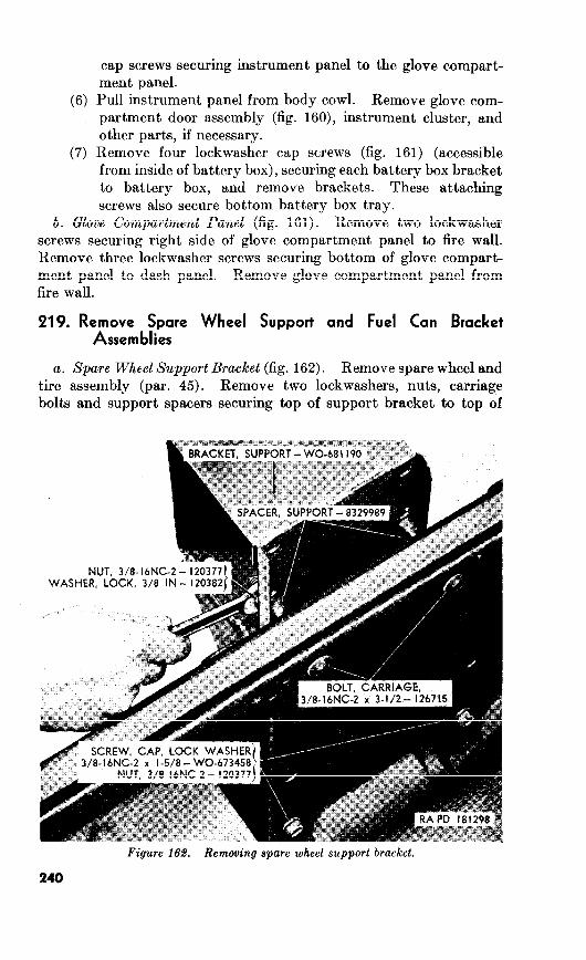
(6)
(7)
cap screws securing instrument panel to the glove compart-
ment panel.
Pull instrument panel from body cowl. Remove glove com-
partment door assembly (fig. 160), instrument cluster, and
other parts, if necessary.
Remove four lockwasher cap screws (fig. 161) (accessible
from inside of battery box), securing each battery box bracket
to battery box, and remove brackets. These attaching
screws also secure bottom battery box tray.
b. Glove Compartment Panel (fig. 161). Remove two lockwasher
screws securing right side of glove compartment panel to fire wall.
Remove three lockwasher screws securing bottom of glove compart-
ment panel to dash panel. Remove glove compartment panel from
fire wall.
219. Remove Spare Wheel Support and Fuel Can Bracket Assemblies
a. Spare Wheel Support Bracket (fig. 162). Remove spare wheel and
tire assembly (par. 45). Remove two lockwashers, nuts, carriage
bolts and support spacers securing top of support bracket to top of
NUT, 3/8-I bNC-2 -
240

Figure 169. Removing spare fuel can bracket.
body rear panel. Remove two lockwasher cap screws and nuts secur-
ing bottom of support bracket to body rear panel. Remove support
bracket from body rear panel.
b. Spare Fuel Can Bracket (fig. 163). Remove the four lockwasher
cap screws, bracket spacers, and nuts which secure the bracket
assembly to body rear panel and remove bracket assembly from body
panel.
220. Remove Battery Box Trays
a. Remove four lockwasher cap screws which secure each battery
box tray to dash panel: Remove four lockwasher cap screws securing
each tray to rear of battery box.
Note. The latter screws also attach the battery box brackets.
b. Remove four tapping screws (fig. 161) which secure rear of the
bottom battery box cOJrer to battery box. Remove four tapping
screws which secure rear of cover to fire wall and remove the cover.
Section III. REBUILD OF BODY
221. Body
a. Disassembly. It is not necessary to remove any brackets,
hinges, or any other parts unless inspection reveals them unserviceable.
If it is necessary to remove the female half-hinges (fig. 164), remove
tw9 knurled screws securing female half-hinge to side of body cowl.
241

Figure iS4.
Remove two knurled screws securing front portion of female half-
hinge to front of body cowl. Lift female half-hinge from body cowl.
b. Inspection and Repair.
(1)
(2)
Inspection. Inspect body for bent or dented sections.
Inspect brackets, footman loops, reflectors, instrument panel,
spare wheel support bracket, spare fuel can bracket, battery
box, and tool compartment for damage. Repair or replace
damaged parts. See that all tapping plat.es, access plates,
and nuts and retainers (fig. 164) are secure. Inspect the
front floor pan upper and lower covers for bent or broken
condition. Inspect left and right female half-hinges for
damaged or bent condition.
Repair. Straighten all dented or sprung sections. Repair
cracks or breaks by welding. Sandpaper and paint all
repaired sections. Weld all tapping plates and retainer
nuts in place if they are loose or missing. Replace all
damaged screws and bolts. Straighten dents on female
half-hinges of windshield assembly.
c. Assembly. To install female half-hinges (fig. 164) place each
one in position on body cowl and secure it with four SO-24 x X knurled
screws.
242

A-Screw, cap, lockwasher, >C20NC-2 x I%---WO-680580 B-Bracket, top side rail support, right-WO-680822 C-Bracket, top side rail support, left-W0680821 D-Screw, cap, lockwasher, No. 10-24 x yZ--WO680400 E-Screw, cap, lockwasher, f&20NC-2 x lj/4---WO-680580 F-Nut, +20NC-2-120375 G-Bumper. left, assv-8328464. H-Screw, cap, lockwasher, Y4-20NC-2 x s-8328466 J-Catch. lock-7375312
K-Bolt, j/4-20NC-2 x s-120697 &Loop, footman-7697591
M-Strap, holddown- N-Screw, tapping, No. 10-16 x s-162688 P-Bumper, right, assy-8328465 Q-Screw, cap, lockwasher, j/4-20NC-2 x M-8328466 R-Screw, cap, lockwasher, No. 10-24 x +-W&680400 P-Nut, f/4-20NG2-120375 T-Bolt, lockwasher, g-2ONC-2 x %-7418145 U-Lock, assy-8329653 V-Bolt, lockwasher, f/4-20NG2 x +7418145
W-Lock, assy-8329653 X-Frame, assy-8329652 Y-Bolt, lockwasher, T&-18NC-2 x l-WC-680440 Z-Hinge, half, male, right-WO-681458
AA-Washer plain, No. 10-120391 BB-Screw, No. 8-32NC-2 x g-159582 CC-Screw, cap, lockwasher, Ke-18NC-2 x g-443775 DD-Screw, tapping, No. 8-15 x Y,l61860 EE-Washer, plain, No. 10-120391 FF-Weatherstrip-WC%-680505 GG-Hinge, half! male, left-WO-681457 HH-Weatherstnp, glass-8329659
JJ-Glass-WO-680412 KK-Filler, weatherstrip, center bar- WC&-680993 LL-Filler, weatherstrip, outer-8329651
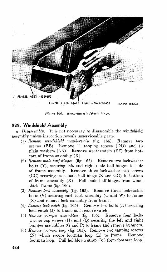
8329652 I
a. Disassembly. It is not necessary to disassemble the windshield
assembly unless inspection reveals unserviceable parts.
(1)
(2)
(3)
Remove windshield weatherstrip (fig. Remove two
screws (BB). Remove tapping screws (DD) and 13
plain washers (AA). Remove weatherstrip (FF) from bot-
tom of frame assembly (X).
Remove male half-hinges (fig. 165). Remove two lockwasher
bolts (Y), securing left and right male half-hinges to side
of frame assembly. Remove three lockwasher cap screws
(CC) securing each male half-hinge (2 and GG) to bottom
of frame assembly (X). Pull male half-hinges from wind-
shield frame (fig.
Remove lock assembly (fig. 165). Remove three lockwasher
bolts (V) securing each lock assembly (U and W) to frame
(X) and remove lock assembly from frame.
Remove lock catch (fig. 165). Remove two bolts (K) securing
lock catch (J) to frame and remove catch.
Remove bumper assemblies (fig. 165). Remove four lock-
washer cap screws (H) and (Q) securing the left and right
bumper assemblies (G and P) to frame and remove bumpers.
Remove footman loop (fig. Remove two tapping screws
(N) which secure footman loop (L) to frame. Remove
footman loop. Pull holddown strap @I) from footman loop.

TUBE -
VALVE,
(7)
(8)
(9)
and
Remove the center bar
weatherstrip filler (KK) and outer weatherstrip filler (LL)
from glass weatherstrip (HH). Remove the glass (JJ) from
the glass weatherstrip.
Remove
two lockwasher screws which secure air regulating valve
assembly to windshield frame and remove valve. Remove
the hose (at valve) from between the air regulating valve
and tube. Remove 3 tapping screws which secure the 3
clips, and pull the tube free of the hose (at connection tee).
Remove the hose from the left windshield wiper motor
assembly. Remove 2 lockwasher screws securing 2 clips
and pull the center tubing free of the connection tee and
hose connected to right windshield wiper motor. Pull
windshield wiper hoses (at connection tee) from theconnec-
tion tee.
windshield wiper Remove
blind nut (A) and pull windshield wiper adjustable arm (B)
and knurled driver (C) off shaft of the paddle assembly (S).
Remove two screws (Z), which secure windshield wiper motor

RAP0 181304
A-Nut, blind, No. 1+32NF-2-7058965 B-Arm, adjustable, windshield wiper, assy-500810 C-Driver, knurled-7372262 D-Handle, assy-WO-118568 E-Pin, set, handle-TRI-87453 F-Plate, assy-TRI-82812-41 G-Housing-WO-118550 H-Washer, felt-TRI-8741-3 J-Valve, slide-WO-118558
K-Retainer, valve-A327338 L-Yoke, valve kicker-TRI-2617
M-Spring-TRI-2620 N-Kicker, valve-TRI-2618-17 P-Gasket, valve cover-TRI-8894-3 Q-Cover, valve-TRI-8896-1 R-Seal-WO-118552 S-Paddle, assy-TRI-P86631-I-J
T-Gasket, top cover-TRI-87652 U-Cover, top-TRI-86521-3 V-Screw, top cover-TRI-1900-IR
W-Screw, top cover-TRI-1900 X-Screw, valve cover-TRI-1863-8 Y-Spacer, mounting, windshield wiper-8329997 Z-Screw, lockwasher, No. 10-32 x 76 (mounting)-TRI-1727-28
AA-Blade, windshield wiper, assy-500813
246

(10) Disassemble windshield wiper motor (fig. 168).
b. Inspection and
(1) Inspection.
(a)
(b)
sindshield assembly (fig. 165).
Windshield wiper motor (fig. 168).
(2)
Windshield assembly (fig. 165).
247

(b)
Figure 169. Installing windshield glass weatherstrip.
bumpers (G and P), remove four split rivets securing each
liner to bumper. Install new liner on bumper and secure
with four y/6., x X6 split rivets.
Remove all burs,
abrasions, and scratches from mating surfaces of housing
(G), valve cover (Q), and top cover (U) with a fine mill file.
(1)
(a)
(b)
i-cc)
Coat the left and right male half-
hinges (Z and GG) with glass cement and install hinges in
windshield frame. Secure each hinge with three %a-
18NC-2 x 3$ lockwasher cap screws (CC) and two ?i6-
18NC-2 x 1 lockwasher bolts (Y).
Place weatherstrip as-
sembly (FF) at bottom of frame assembly (X) so that
lipped portion of weatherstrip slips over rim on lower front
of frame. Secure weatherstrip with 13 No. 10 plain
washers (AA), No. 8-15 x )!! tapping screws (DD), and
2 No. 8-32NC-2 x ?d screws (BB).
Secure each lock assembly (U and W)
to windshield frame with three )$-20NC-2 x 56 lockwasher
bolts (T).
248
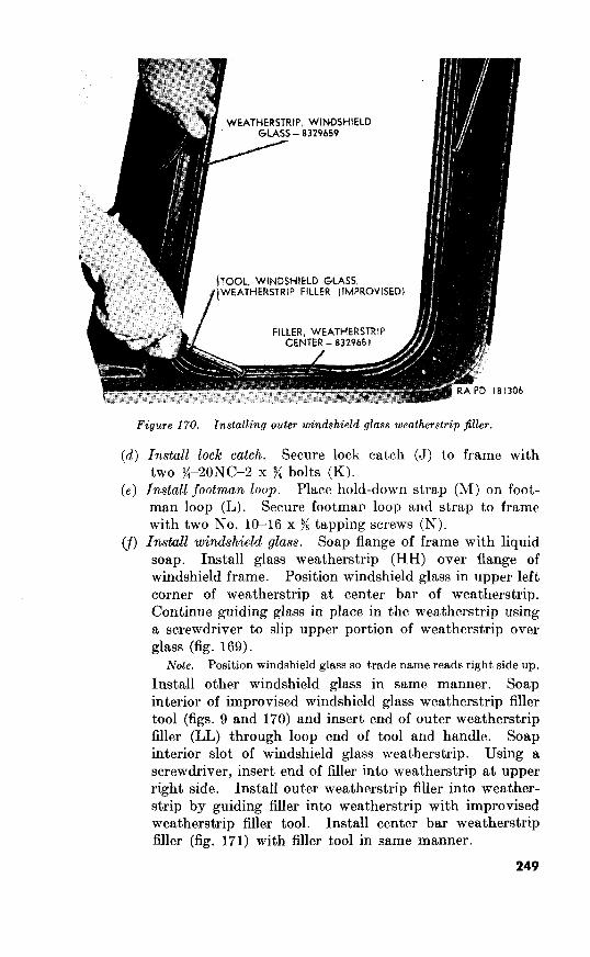
Figure 170. Installing outer
(4
(e)
W
Install lock catch. Secure lock catch (J) to frame with
two 52ONC-2 x $/4 bolts (K).
Install footman loop. Place hold-down strap (M) on foot-
man loop (L). Secure footman loop and strap to frame
with two No. lo-16 x 9/R tapping screws (N).
Install windshield glass. Soap flange of frame with liquid
soap. Install glass weatherstrip (HH) over flange of
windshield frame. Position windshield glass in upper left
corner of weatherstrip at center bar of weatherstrip.
Continue guiding glass in place in the weatherstrip using
a screwdriver to slip upper portion of weatherstrip over
glass (fig. 169).
Position windshield glass so trade name reads right side up.
Install other windshield glass in same manner. Soap
interior of improvised windshield glass weatherstrip filler
tool (figs. 9 and 170) and insert end of outer weatherstrip
filler (LL) through loop end of tool and handle. Soap
interior slot of windshield glass weatherstrip. Using a
screwdriver, insert end of filler into weatherstrip at upper
right side. Install outer weatherstrip filler into weather-
strip by guiding filler into weatherstrip with improvised
weatherstrip filler tool. Install center bar weatherstrip
filler (fig. 171) with filler tool in same manner.
249

) l-ILLCR,
WO-680993
8329659
Figure 171. Installing windshield glass center bar weatherstrip filler.
(g) Secure left and right bumper
(2)
assemblies (G and P) to windshield frame (X) with four
%--20NC-2 x % lockwasher cap screws (H and Q).
Assemble Install seal (R)
on paddle assembly (S) and position paddle assembly in
housing (G). Coat paddle assembly with general purpose
lubricating grease. Install top cover gasket (T) on top
cover (U). Secure top cover and top cover gasket to housing
(G) with two top cover screws (V) and four top cover screws
(W). Position felt washer (H) and slide valve (J) on paddle
assembly (S). Assemble valve retainer (K), valve kicker
yoke (L), spring (M), and valve kicker (N) together and insert
them by the paddle assembly (S). Secure valve cover gasket
(P) and valve cover (Q) to housing (G) with two valve cover
screws (X). Secure plate assembly (F) to housing (G) with
two windshield wiper mounting spacers (Y) and mounting
screws (Z). Secure handle assembly (D) to plate by pressing
handle set pin (E) in place.
Note. Cement valve cover gasket (P) and top cover gasket (T) to
valve cover, top cover, and windshield wiper motor housing with
plastic type gasket cement.
250

(3) Install windshield wiper motor assembly (fig. 168).
Install widshield wiper tubes and hoses (fig. 167).
10 x $
10 s ?:
lo-24 s :{
and
223. Seat Assemblies
a. Disassembly.
uulcss (b
(1) Fwnt seats. 12
ruid
(2) Rear passerlger sea,t.
b. Inspection and Repair.
(1) Inspection.
He&.
(‘OVCI’.
c. Assembly.
(1) Front seatn. on
(2)
Install pad and cover. Tighten cover loops and secure them by bending over a clip on seat frame. Secure cover by bending over the remaining 17 clips. Slip seat cushion in seat frame and secure seat cushion with two X6-24 x s/s lockwasher screws. Install seat back springs, pad, and cover. Secure cover with 12 No. 10 washers and No. 10 x >h screws. Rear passenger seat. Put springs, padding, and cover in place on bottom of seat and secure cover in place with 10 No. 10 x l$ screws and washers. Put springs, padding, and cover in place on back of seat. Secure cover to frame with 10 No. 10 x )G screws and washers, 5 in top of frame and 5 in bottom.
~94. Fuel Tank Assembly (fig. 172)
a. Disassembly. It is not necessary to disassemble fuel tank unless inspection (b below) reveals damage. Refer to TM g-8048 for removal of fuel tank from body.
(1)
(2)
(3)
Remove fuel gage sending unit assembly from fuel tank. Refer to TM g-8048. Remove fuel jilter assembly from fuel tank. Refer to TM g-8048. Disassemble fuel jilter assembly. Remove nut (K), lock- washer (L), and screw (P). Remove end plate (N) and fuel filter element (M). Disconnect the upper end plate assem- bly (J) from cover plate assembly (E) by unscrewing the upper end plate connection. Remove six bolts (A) and then remove the air vent assembly (B) and air vent gasket (C) from top of cover plate assembly (E).
b. Inspection and Repair.
(1) Inspection.
(a)
@I
(cl
252
Fuel tank. Check fuel tank (CC) for cracks or damage. Test fuel tank for leaks. Tank must withstand 3 psi air pressure without showing leaks at seams or fittings. Replace filler cap assembly (GG), filler tube strainer (EE), drain plug (AA), and mounting strap (V) if damaged or worn. Replace the filler neck grommet (DD) and cap gasket (FF) at each rebuild.
Fuel jilter assembly. Inspect air vent assembly (B), cover plate assembly (E), upper end plate assembly (J), end
plate (N), and screw (P) for damage. Replace all faulty
parts. Replacement of fuel filter element (M) is covered
in TM g-8048. Replace air vent gasket (C) and cover plate gasket (Q) at each rebuild.
Fuel gage sending unit. Replace an improperly operating fuel gage sending unit (S). Replace the fuel gage send- ing unit gasket (‘I’) at each rebuild.

I66
C-GASKET,
D -SCREW,
F-NUT,
WO-806627
K -NUT,
b
R -SCREW,
8329687
U -SCREW,
V-STRAP,
W -ANTI-SQUEAK,
Z -ANTI-SQUEAK,
AA BB -
832962 I
DD -GROMMET,
EE -STRAINER,
FF -GASKET,
t
Fuel tank assembly-disassembled view.
253

(2) Repair. Small leaks at seams and joints of fuel tank (CC)
may be repaired by soldering. Use paste flux to eliminate
spattering.
Do not attempt fuel tank repair unless tank
has been cleaned and properly treated to be free of all
explosive or inflammable fumes. Thoroughly steam tank
(or use other approved method) to completely remove all
fumes.
c. Assembly.
(1) Assemble fuel jilter assembly. Secure air vent assembly (B)
and air vent gasket (C) to top of cover plate assembly (E)
with six No. lo-24NC-2 x :h bolts (A). Place end plate (N)
at bottom of fuel filter element (M) and insert upper end
plate (J) in top of element. Install No. lo-24NC--2 x 6
screw (P), and secure end plate, element, and upper end
plate together with No. 10 lockwasher (L) and No. lo-
nut (K). Slide fuel filter element through bracket
of cover plate assembly (E) and connect vent line to bracket
of cover plate assembly and to line connector of cover plate
assembly. Secure fuel filter element to cover plate bracket
with No. IO-24NC-2 x :$ screw (H), No. 10 lockwasher (G),
and No. lo-24NC-2 nut (F).
(2) Install fueljilter assembly in fuel tank. Refer to TM g-8048.
(3) Install fuel gage sending unit (S) in fuel tank. Refer to
TM-9-804A.
(4) Install fuel tank in vehicle. Refer to TM g-8048.
Section IV. INSTALLATION OF RELATED PARTS
225. Install Instrument and Glove Compartment Panels
a. Glove Compartment Panel. Place glove compartment panel
(fig. 161) in posit,ion on fire wall. Secure panel with five No. lo-24 x >:
lockwasher screws (two securing right side of panel and three secur-
ing bottom of panel).
b. Instrument Panel. Position instrument panel on body co+.
Install eleven jt2ONC-2 x 9/s lockwasher screws at front of panel ,as
shown in figure 159. Install eight %20NC-2 x ?Q lockwasher screws
to secure panel to battery box brackets and glove compartment
panel. Open glove compartment door and install two No. lo-24 x )h
lockwasher screws which secure instrument panel to glove compart-
ment panel.
226. Inst;llsSpare Wheel Support and Fuel Can Bracket Assem-
a. spare Wheel Support Bracket (fig. 162). Position support
bracket at rear of body rear panel. Secure top of bracket with two
254
I/R--16NC-2 x 3% carriage bolts, support spacers, %-inch lock washers,
and T/,-16NC-2 nuts. Secure bottom of bracket with two 7&16NC-
2 x l:$ lockwasher cap screws and %16NC-2 nuts.
b. Spare Fuel Can Bracket (fig. 163). Secure bracket to body
rear panel with four $S-16NC x 2)/8 lockwasher screws, bracket spacers,
and lh-16NC-2 hex nuts.
227. Install Battery Box Trays
a. Secure each battery box tray to fire wall with four s{~lS x %
lockdasher cap screws. Secure each tray to rear of battery box with
s6-18 x 7: lockwasher screws.
8. Secure bottom battery box cover (fig. 161) to battery box with
eight No. 10 x j4 tapping screws.
255

14
Section I. DESCRIPTION AND DATA
228. Description
a. Hood (fig.
SCREW, CAP, LOCK WASHER. I/C20NC-2 x l/2-8328412
RAPD 181309
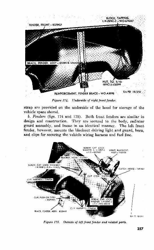
Underside of front fender.
strap are provided on the underside of the hood for storage of the
vehicle spare shovel.
b. Fenders (figs. 174 and 175). Both front fenders are similar in
design and construction. They are secured to the body, radiator
guard assembly, and frame in an identical manner. The left front
fender, however, mounts the bIackout driving light and guard, horn,
and clips for securing the vehicle wiring harness and fuel line.
HOOO- c,
7691481
18131,
257
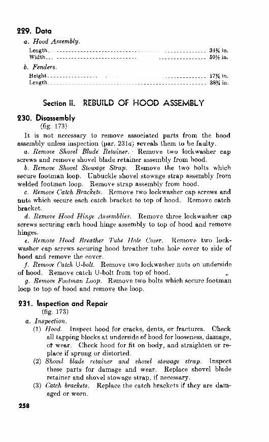
PP9. Data
a. Hood Assembly.
Length___........_._._..._......._...~-------_......_...... 34yiin. Width_____..........._..__......._._------_.._......_.~.... 59sin.
b. Fenders.
Height__...........____--_-_-_-------------~............... 17sin.
Length...................~~~~-~~~~~------------~~_~..~....~ 38yiiin.
Section II. REBUILD OF HOOD ASSEMBLY
230. Disassembly (fig. 173)
It is not necessary to remove associated parts from the hood
assembly unless inspection (par. 231a) Feveals them to be faulty.
a. Remove Shovel Blade Retainer. Remove two lockwasher cap
screws and remove shovel blade retainer assembly from hood.
b. Remove Shovel Stowage Strap. Remove the two bolts which
secure footman loop. Unbuckle shovel stowage strap assembly from
welded footman loop. Remove strap assembly from hood.
c. Remove Catch Brackets. Remove two lockwasher cap screws and
nuts which secure each catch bracket to top of hood. Remove catch
bracket.
d. Remove Hood Hinge Assemblies. Remove three lockwasher cap
screws securing each hood hinge assembly to top of hood and remove
hinges.
e. Remove Hood Breather Tube Hole Cover. Remove two lock-
washer cap screws securing hood breather tube hole cover to side of
hood and remove the cover.
j. Remove Catch U-bolt. Remove two lockwasher nuts on underside
of hood. Remove catch U-bolt from top of hood.
g. Remove Footman Loop. Remove two bolts which secure footman
loop to top of hood and remove the loop.
931. Inspection and Repair (fig. 173)
a. Inspection.
(1) Hood. Inspect hood for cracks, dents, or fractures. Check
all tapping blocks at underside of hood for looseness, damage,
of wear. Check hood for fit on body, and straighten or re-
place if sprung or distorted.
(2) Shovel blade retainer and shovel stowage strap. Inspect
these parts for damage and wear. Replace shovel blade
retainer and shovel stowage strap, if necessary.
(3) Catch brackets. Replace the catch brackets if they are dam-
aged or worn.
258

(4) Hood hinge assemblies. Inspect hood hinge assemblies for
cracks, damage, and wear, and replace, if necessary.
(5) Hood breather tube hole cover. Inspect hood breather tube
hole cover for dents, distortion, or other damage. Replace
cover if it cannot be repaired by straightening.
(6) Catch U-bolt and footman loops. Replace broken or dis-
torted catch U-bolt and footman loops.
(7) Beds, cap screws, and nuts. Replace all damaged bolts,
screws, and nuts.
b. Repair.
(1) General. NO established procedures are set forth for repair
of components in this paragraph since there can be consid-
erable variation to damage of sheet metal parts.
(2) Hood. Tack weld any loose tapping blocks to underside of
hood. Clean all tapped holes in tapping blocks with stand-
ard taps. Straighten bent or sprung hood, if necessary.
Remove dents and repair cracks by welding.
232. Assembly (fig. 173)
a. Install Shovel Blade Retainer. Secure shovel blade retainer to
underside of hood with two $-2ONC-2 x s lockwasher cap screws.
b. Install Shovel Stowage Strap. Slip shovel stowage strap assembly
over footman loop. Secure footman loop and shovel stowage strap
assembly to underside of hood with two No. lo-24NC-2 x ji bolts.
c. Install Catch Brackets. Secure each catch bracket to top of hood
with two j$-2ONC-2 x )i lockwasher cap screws.
d. Install Hood Hinge Assemblies. Position each hood hinge as-
sembly on top of hood. Install three yi6-18NC-2 x $i lockwasher
cap screws in each hinge assembly.
e. Install Hood Breather Tube Hole Cover. Place hood breather
tube hole cover in position on right side of hood and secure cover
with two No. lo-24NC-2 x X internal-teeth lockwasher cap screws.
j. Install Catch U-Bolt. Insert catch U-bolt through top of hood.
Secure catch U-bolt with two ji-2ONC-2 lockwasher nuts at under-
side of hood.
g. Install Footman Loop. Secure footman loop to top of hood with
two No. lo-24NC-2 x yZ bolts.
Section III. REBUILD OF FENDERS
233. Disassembly
a. Right Front Fender. The right front fender (fig. 174) requires
no disassembly except for removal of the hood catch. Do not remove
hood catch unIess inspection (par. 234a) reveals it to be unserviceable.
To remove hood catch (fig. 175), remove two lockwasher cap screws.
b. Left Front Fender (fig. 175 and 176). Do not remove the horn
259

_... ___, _. -- .,
17’6. Underside of left front fender.
bracket, blackout driving light assembly, hood catch, push-on type
clip, and wiring harness clips unless inspection (par. 234~) reveals
them unserviceable.
(1)
(2)
(3)
(4)
Remove horn bracket. Remove two lockwasher cap screws
securing horn bracket to side of fender and remove horn
bracket.
Remove blackout light assembly. Remove cap screw secur-
ing open clip to fender and remove clip. Remove three
lockwasher cap screws and remove blackout light assembly.
Remove hood catch. Refer to a above.
Remove wiring harness and push-on type clip. Pull the
six wiring harness clips and the one push-on type clip (se-
cures fuel line) from their retaining holes in left front fender.
934. 174, 175, and 176)
a. Inspection. Inspect front fenders for dents, cracks, and sprung
condition. Inspect the fender brace reinforcements and replace them,
if necessary. Replace hood catches if they operate improperly.
Check all tapping blocks on underside of fenders for damage and
looseness. See that square nuts are in good condition and securely
held by their retainers. Replace all damaged wiring harness and
260

b. Repair. No
Right Front Fender. 175)
Left Front Fender (figs.
Install horn bracket.
Install blackout light assembly.
Install hood catch.
Install wiring harness and push-on type clips.
15
Section I. DESCRIPTION AND DATA
Description (fig.
Radiator.
(E)
Radiator Guard With Hinges and Hood Liner.
237. Data
a. Radiator
Radiator Guard With Hinges And Hood Liner.
262

Section II. REBUILD OF RADIATOR ASSEMBLY
238. Disassembly
(fig. 177)
a. Remove Radiator Assembly From Power Plant. Remove the
radiator filler neck cap (D) and gasket (E) and open drain cock (P)
to drain cooling system. Disconnect radiator hose clamps (G and J)
which secure radiator water inlet hose (H), to radiator and to engine.
Disconnect radiator hose clamps (M and R) which secure water outlet
hose (N) to radiator and to engine. Pull radiator assembly free of
hoses and lift it free of the left and right radiator to engine support
rods (S and V).
b. Remove Radiator Shroud Box. Remove six tapping screws (K)
which secure the radiator shroud box (L) to radiator (F). Pull radi-
ator shroud box from radiator.
c. Remove Radiator to Engine Support Rods. Remove two cotter
pins (U) and plain washers (T) which secure both the left and right
radiator to engine support rods (S and V) to the engine front mounting
support cushions. Pull the rods from the support cushions.
d. Remove Drain Cock. Unscrew the drain cock (P) from the
radiator (F) .
239. Inspection and Repair
(fig. 177)
a. Inspection.
(1) Check to see that all radiator fins are parallel and that the
tubes are not bent. Check all soldered seams.
(2) Jnspect the radiator (F) for leakage. Examine the drain
cock (P) for leakage.
(3) Install filler neck cap gasket (E) and filler neck cap (D).
Close free end of radiator overflow tube. Close either radi-
ator water outlet or water inlet tube with suitable cap. At-
tach an air hose to outlet or inlet tube (not capped). Sub-
merge radiator assembly in water and admit air. Observe
radiator assembly for leakage. Mark any leaks for repair.
Caution: Air pressure must be below 10 psi.
(4) Inspect filler neck cap (D) for proper operation. Replace
filler cap if it indicates improper operation.
Note. Vacuum in radiator is relieved by valve built into the cap
which opens at one-half to one pound vacuum. Replace cap if valve
fails to open.
263
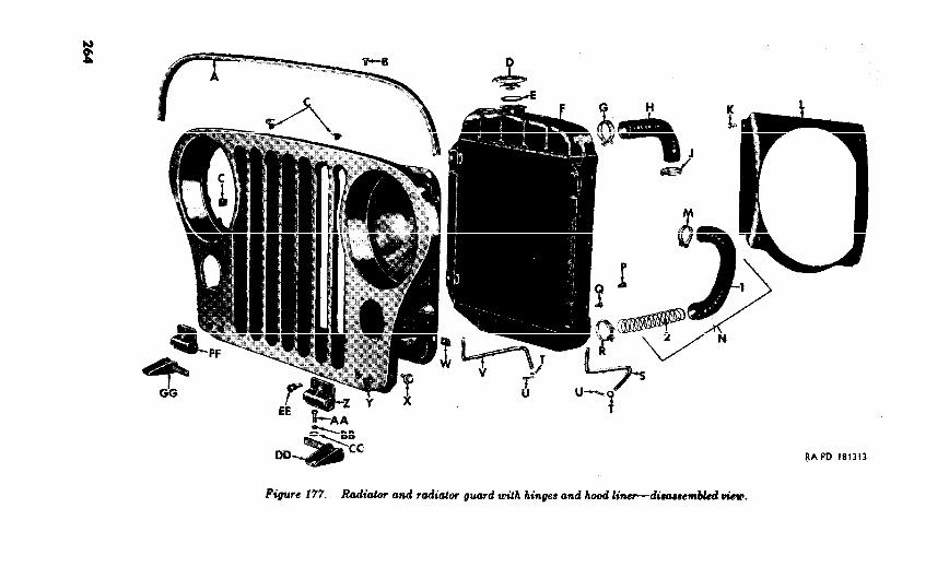
P
radiator

A-Liner, hood-WO-680420
B-Rivet, split, %4 x &-I13454
C-Clip, wiring, harness-7346934
D-Cap, filler neck-7375030
E-Gasket, filler nech cap-A262210
F-Radiator-WO-805825
G-Clamp, hose, radiator-8328455
H-Hose, water inlet, radiator-WO-805820
J-Clamp, hose, radiator-8328455
K-Screw, tapping, pan-hd No. 8 (0.165) x s-128270
&Box, shroud, radiator-WO-806322
M-Clamp, hose, radiator-8328455
N-Hose, water outlet, radiator-8328458
l-Hose, water outlet radiator-WO-805821
2-Reinforcement, hose water outlet-WO-645905
P-Cock, drain, >&in.--103647
Q-Bolt, se-10 x 5/8-7369880
R-Clamp, hose, radiator-8328455
S-Rod, support, radiator to
T-Washer, plain, i>/32 ID, 5%4 OD, 0.065 thk-120395
U-Pin, cotter, $/32 x 3/4-121222
V-Rod, support, radiator to engine, right-8328491
W-Clip, :16--10, radiator to guard panel-8328493
%--Screw, cap, lockwasher, se-18NC-2 x &-WC)-673468
Y-Guard, radiator, assy-WC-680450
Z-Hinge, radiator guard-WC-673621
AA-Screw, cap, %e-24NF-3 x g-120213
BB-Washer, lock, >(:6-in.-120214
CC-Washer, plain, 3’8 ID, y/8 OD, 0.083 thk-446363
DD-Pin, hinge, radiator guard, left-WO-680395
EE-Screw, cap, lockwasher, y~l6NF-3 x l-WO-673501
FF-Hinge, radiator guard-WO-673621
GG-Pin, hinge. radiator guard right-WC-680396
Fiquae 177-Continued.

Test filler neck cap as follows: Attach air hose to radiator
assembly as described in (3) above. Secure a suitable rubber
hose to free end of radiator overflow tube and insert hose in
a container of water. Force air under low pressure into
radiator assembly. Bubbles in water will indicate leakage
of air past filler neck cap. Filler neck cap must hold a min-
imum pressure of 3% psi and a maximum pressure of 4% psi.
(5) Inspect radiator shroud box (L) for dents, damage, and sprung
condition.
(6) Check the radiator to engine support rods (S and V) for
twists, breaks, and other damage.
(7) Replace radiator water outlet and inlet hoses if they are
collapsed, cracked, or deteriorated.
b. Repair.
(1) Solder all loose connections.
(2) Close all leaks by soldering.
(3) Straighten bent tubes and misalined fins.
(4) Repair leaks in flat parts of top and lower tanks of radiator
(F) by sweating sheet metal over damaged areas.
(5) Straighten bent or distorted radiator to engine support rods
(S and V).
(6) Straighten bent radiator shroud box (L). Remove dents
from box.
MO.
177)
a. Install Drain Cock. Screw the +$-inch drain cock (P) in the lower
tank of the radiator (F).
b. Install Radiator to Engine Support Rods. Place the left radiator
to engine support rod (S) and the right radiator to engine support rod
(V) in the engine front mounting support cushions. Secure support
rods with two ‘% ID, 5% OD, 0.065 thick plain washers (T) and
162 x 3: cotter pins (U).
c. Install Radiator Shroud Boz. Secure the radiator shroud box
(L) to the radiator (F) with six No. 8 (0.165) x X pan-head tapping
screws
d. Install Radiator Assembly on Power Plant. Position radiator
assembly (F) on the radiator to engine support rods (S and V) . Con-
nect the radiator water inlet hose (H) and secure in place with hose
clamps (G and J) . Connect radiator water outlet hose with reinforce-
ment assembly (N) to radiator and secure hoses with the hose clamps
(M and R). Fill cooling system with proper coolant as directed in
TM g-8048.
e. Install Filler Neck Cap. Install new filler neck cap gasket (E)
in filler neck cap (D) and install the cap on the radiator.
266

241.
242.
metal at nicks on the radiator guard hinge pins (DD and
GG) and in the slots of the radiator guard hinges (Z and FF)
to assure their proper engagement.
243. Assembly (fig. 177)
a. Install Wiring Harness Clips. Insert the three wiring harness
clips (C) in their retaining holes in the radiator guard (Y).
b. Install Radiator Guard Hood Liner. Secure new hood liner (A)
to top of radiator guard (Y) with thirteen 9/64 x R6 split rivets (B).
c. Install Radiator Guard Hinges. Position radiator guard hinges
(Z and FF) on radiator guard (Y). Secure each hinge with two
T/8--lSNF-3 x 1 lockwasher cap screws (EE).
d. Radiator CTard Hinge Pins. Secure the left radiator guard
hinge pin (DD) and the right radiator guard hinge pin (GG) to the
frame side rails with four y/s ID, g OD, 0.083 thick plain washers (CC).
g6-inch lockwashers (BB), and Kc-24NF-3 x 36 cap screws (AA).
e. Install Headlights and Signal Blackout Markef and Service Parking
Lights. Refer to TM g-8048 for installation instructions,
268

Section I. DESCRIPTION AND DATA
244. Description
a. Frame (fig. 178). The frame, which is the structural center of
the vehicle, is constructed of two heavy channel steel side rails (d and
x) and five cross members (A, W, V, Q, and K). All crossmembers,
except the engine rear support crossmember (Q), are welded to the
two side rails. The engine rear support cross member (Q) is bolted
to the two side rails. A bumper bar (J) is bolted to the front ends of
the side rails. Two rear reinforcements (Y) are welded to the side
rails and rear crossmember. Four shock absorber brackets (C, G,
AA, and CC) are riveted and welded to the top portions of the side
rails. Two rear spring shackle brackets (Z) and four spring pivot
brackets (S, H, DD, and BB) are riveted and welded to the underside
of the side rails. Holddown brackets (E, P, and R) for securing the
body to the frame are riveted and welded to the sides of the side rails.
b. Towing Pintle (fig. 179). The towing pintle is mounted on the
rear crossmember and secured in place with four bolts and lockwasher
nuts. A rotating type towing pintle, somewhat different from the
one illustrated, is used on a few vehicles.
c. Lijtting Shackles (figs. 179 and 180). Two lifting shackIes are
bolted to the front of the frame. Two lifting shackles are bolted to
the rear of the frame. Two bumperettes are also bolted to the rear
of the frame.
245. Data Material____~~___.____-----~~~--~-~-------~~_-----~~_- Steel,SAE950
Length (overall)_________~~_____~~~.___~~~~..____~~..._ 128.44in.
Width (outside edges of side rails)__~~_____~~~~___~~~~_._ 29.25 in.
Number of cross members______~______~~______~______.~ 5
Weight______________--~~_.----~~~~-----~~~._-.~~...~- 140 lb. (aprx.)
Distance between right and left front holddown brackets_ _ _ 31.50 in.
Distance from center line of frame to center line of hold-down
bracket_____~~~______~~-__..__~--_..~~-------~~~~..- 16.063in.
269
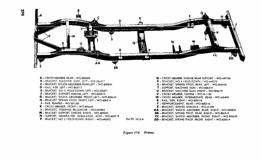
r:
9
--WO-805643
L -BRACKET,
I9

Section II. REMOVAL OF ASSOCIATED PARTS FROM
FRAME 246. Remove Towing Pintle
(fig. 179)
Remove four bolts and lockwasher nuts which towing pintle
to rear of frame. Remove towing pintle from frame.
Figure lY9. Towin.g pintle and rear lifting shackle installed.
247. Remove Rear Lifting Shackles and Rear Bumperettes (fig. 179)
Remove two bolts and lockwasher nuts which secure inner end of
each rear bumperette to frame. Remove two bolts, plain washers,
and lockwasher nuts which secure lifting shackle bracket and the
outer end of each bumperette to frame. Remove bumperettes and
lifting shackles. Remove lifting shackle spacer which is installed
between each lifting shackle and bumperette.
248. Remove Front Lifting Shackles (fig. 180)
Remove bolt, nut, and lockwasher which secure front of each lifting
shackle bracket to top of bumper bar. Remove bolt and lockwasher
which secure rear of each front lifting shackle bracket to the side rail.
Remove shackle bracket and shackle spacer.
271

Figure 180. Front lifting shackle installed.
Section III. REBUILD OF FRAME
249. Disassembly
(fig. 178)
a. General. The extent of frame disassembly can only be deter-
mined by inspection. It is not necessary to remove the bumper bar
(J) and engine rear support crossmember (Q) unless inspection (par.
250a) proves these components faulty.
Remove two bolts,
lockwashers, and lockwasher nuts which secure each side of the engine
rear support crossmember (Q) to side rails and remove crossmember
from frame.
c. Remove bolt, lockwasher, and nut which secure
front of bumper bar (J) to each side rail of frame. Remove two bolts,
lockwashers, and nuts securing bottom of bumper bar to bottom
portion of each side rail and remove bumper bar.
950. Inspection and Repair
181).
272
(1) Inspection of the frame should be made before
removal from the vehicle and after removal. Since improper
steering geometry or axle alinement may offer similar
symptoms of improper vehicle operation as those caused by a
distorted frame (due to accident), it is recommended that

frame inspection be performed prior to disassembly of vehicle
in. order to prevent unnecessary labor.
Note. Reference should be made to a good frame (if one is available)
for comparative purposes during procedures described in this paragraph.
(2) Inspection of frame prior to removal. Check frame for mis-
alinement. If a frame alining fixture is not available, use
the “X” or diagonal method (fig. of checking frame
alinement. The most convenient method of checking
alinement while the frame is still installed on the vehicle is by
marking on the floor all points from which measurements
should be taken. Figure illustrates check points that
should be used for making plumb bob marks.
(a) Position vehicle on a clean level floor or other suitable
place. Hang a plumb bob from each point (A through H)
as indicated in figure 181. Mark spots on floor beneath
plumb bob points.
Note Practice utmost care to mark plumb bob points accurately
in relation to frame in order to obtain a satisfactory alinement check.
Move vehicle off markings.
(1) Measure frame width at front and rear. Draw a center
line through the full length of the frame using the mid-
points of the frame widths if they are equal. However, if
frame widths vary, use mid-points of any two pair of equal
diagonals. Measure distance from center line to opposite
sides of frame over entire frame length. Measurements
should not vary if frame is in proper alinement.
(c) To locate point at which frame is sprung, measure diagonal
distance between points A and G, G and C, C and E, D and
F, F and B, and B and H. The comparative diagonal
distance on opposite sides of frame must not vary by more
than one-eighth of an inch. If any pair of diagonal lines
vary by more than one-eighth of an inch, part of frame
included between measurement points is sprung. Diag-
onals should also intersect at center line. If measurements
do not agree within one-eighth of an inch, corrective action,
(b below) must be applied to those points that are not
equal. Approximate comparable diagonal measurements
are as follows: 46% inches (A to G) and (B to H), 47%
inches (B to F) and (C to G), and 51% inches (C to E) and
(D to F).
(d) Due to the kick-up of the frame at both ends, the center
of the front spring pivot bracket hole should be 0.51 inch
(distance E) higher than center of front spring shackle
bushing hole. The center of the rear spring shackle
273
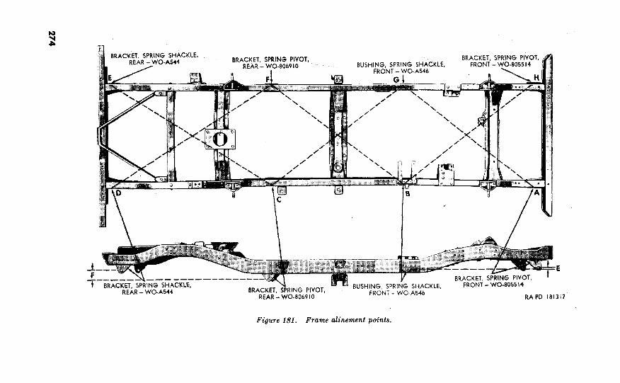
Figure 181. Frame alinement points.
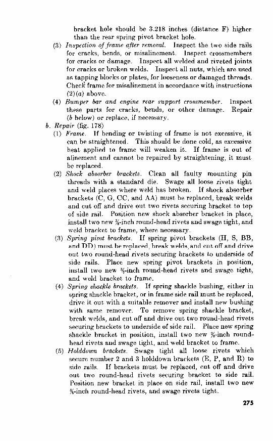
3.218
above.
engine rear

251. Assembly (fig. 178)
a. Install Engine Rear Support C9ossmembc.r. Secure engine rear
support crossmember (Q) to each frame side rail (D and X) with two
%-24NF-3 x % bolts, $&inch lockwashers, and SS-24NF-3 hex nuts.
b. Install Bumper Bar. Position bumper bar (J) at front of frame.
Secure front of bumper bar to each side rail with one Qb-24NF-3 x T&
bolt, $&inch lockwasher, and 3/s--24NF-3 hex nut. Secure bottom of
bumper bar to bottom portion of each side rail with two y/8-24NF-3 x
36 bolts, $6- inch lockwashers, and “/,-24NF-3 hex nuts.
Section IV. REBUILD OF TOWING PINTLE ASSEMBLY
252. Disassembly (fig 182)
a. Remove Lock. Remove two snap rings from ends of latch pin.
Drive out latch pin and lift lock from towing pintle.
r
Figure 18.2. Towing pi&e assembly--disassembled view.
276

b. Disassemble Lock. Remove two snap rings from ends of lockpin.
Drive out lockpin and remove latch from lock. Withdraw latch
spring from within lock.
c. Remove Lubrication Fittings. Unscrew lubrication fittings from
ends of lock and latch pins, if necessary.
253. Inspection and Repair (fig. 182)
a. Inspection.
(1) Towing pintle, lock, and latch. Inspect towing pintle, lock,
and latch for cracks, wear, and damage. Check projections
on latch to see that they are not broken. Replace a faulty
towing pintle, lock, or latch, if necessary.
(2) Latch and lockpins. Inspect the latch and lockpins for wear,
damage, and out-of-round condition. Replace a faulty
latch pin or lockpin.
(3) Latch spring. Replace the latch spring if it is broken,
distorted, or if it fails to operate in its intended manner.
(4) Snap rings. Replace all distorted or broken snap rings.
(5) Lubrication jittings. Replace lubrication fittings if they are
damaged or if they do not open.
(6) Bolts. Replace bolts and lockwasher nut if they are dam-
aged.
b. Repair. Repair of towing pintle assembly is limited to removing
burs, abrasions, and raised metal at nicks from lockpin and latch pin.
Use a fine mill file.
254. Assembly (fig. 182)
a. Assemble Latch. Place the latch spring in the lock. Place latch
in position over latch spring and secure latch to lock with the lockpin.
Secure lockpin with two snap rings.
b. Install Lock. Position lock (with latch assembled) on towing
pintle and secure lock to towing pintle with the latch pin. Secure
latch pin in place with two snap rings.
c. In&all Lubrication Fittings. Install a )/4--28NF lubrication
fitting in end of lockpin and latch pin.
Section V. REBUILD OF LIFTING SHACKLE ASSEMBLIES
255. Disassembly
a. Front Lifting Shackles (fig. 180). Remove lifting shackle snap
clip from hole in lifting shackle pin. Remove pin and lift shackle from
bracket. Remove chain to towing shackle bracket drive screw and
remove chain from lifting shackle bracket.
b. Rear Lifting Shackles (fig. 179). Proceed as directed in a above.
277

256. Inspection and Repair
a. Inspection. Inspect all front and rear lifting shackle parts for
damage and wear. Inspect the lifting shackle pin for out-of-round
condition. Replace all faulty parts.
b. Repair, Remove all burs, abrasions, and raised metal at nicks
from lifting shackle pins with a fine mill file.
257. Assembly
a. Front Lifting Shackles (fig. 180). Position lifting shackle within
lifting shackle bracket and secure shackle to bracket with the lifting
shackle pin. Secure 0.072-inch lifting shackle clip chain to bracket
with a No. 2 x 3: lifting shackle bracket drive screw. Lock shackle
pin with the lifting shackle snap clip.
b. Rear Lifting Shackles (fig. 179). Proceed as directed in a above.
Section VI. REBUILD OF BUMPERETTES
258. Disassembly (fig. 179)
The rear bumperettes require no disassembly.
259. Inspection and Repair
a. Inspection. Inspect rear bumperettes tor cracKs and alstortion.
b. Repair. Straighten a bent or sprung bumperette. Repair all
breaks or fractures by welding.
260. Assembly
The rear bumperettes require no assembly.
Section VII. INSTALLATION OF ASSOCIATED PARTS ON
FRAME
261. Install Towing PintIe (fig. 179)
Position towing pintle at rear of frame. Secure towing pintle to
frame with four )4-20NF-3 x 2 bolts and $--20NF-3 lockwasher nuts.
262. Install Rear Lifting Shackles and Bumperettes (fig. 179)
Position rear lifting shackle spacer between bumperette and rear
lifting shackle. Secure outer end of bumperette and rear lifting
shackle to rear of frame with two g-20NF-3 x 1% bolts and %-20NF-3
278
263. Install Front Lifting Shackles (fig.
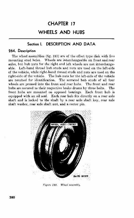
17
Section I. DESCRIPTION AND DATA
264. Description
The wheel assemblies (fig. are of the offset type disk with five
mounting stud holes. Wheels are interchangeable on front and rear
axles, but hub nuts for the right and left wheels are not interchange-
able. Left-hand thread hub studs and nuts are used on the left-side
of the vehicle, while right-hand thread studs and nuts are used on the
right-side of the vehicle. The hub nuts for the left-side of the vehicle
are notched for identification. The serrated hub studs of all four
wheels are pressed into the front and rear hubs. The front and rear
hubs are secured to their respective brake drums by three bolts. The
front hubs are mounted on opposed bearings. Each front hub is
equipped with an oil seal. Each rear hub fits directly on a rear axle
shaft and is locked to the shaft by a rear axle shaft key, rear axle
shaft washer, rear axle shaft nut, and a cotter pin.
280
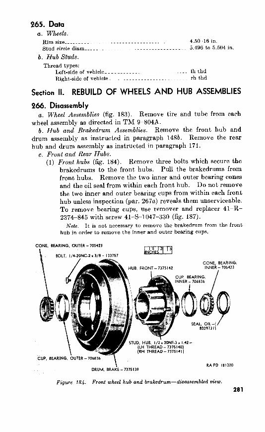
265. Data a. Wheels.
Hub Studs.
Section II. REBUILD OF WHEELS AND HUB ASSEMBLIES
266. Disassembly a. Wheel Assemblies (fig. 183). Remove tire and tube from each
wheel assembly as directed in TM g-8048.
b. Hub and Brakedrum Assemblies. Remove the front hub and
drum assembly as instructed in paragraph 148b. Remove the rear
hub and drum assembly as instructed in paragraph 171.
c. Front and Rear Hubs.
(1) Front hubs (fig. 184). Remove three bolts which secure the
brakedrums to the front hubs. Pull the brakedrums from
front hubs. Remove the two inner and outer bearing cones
and the oil seal from within each front hub. Do not remove
the two inner and outer bearing cups from within each front
hub unless inspection (par. 267a) reveals them unserviceable.
To remove bearing cups, use remover and replacer 41-R-
2374-845 with screw 41-E-1047-330 (fig. 187).
CONE, BEARING, OUTER - 705423
NC.2 x 3/8 - I33757
CONE BEARING. UB, FRONT - 7375142
ZONF-3 x I .42 -
(RH THREAD-7375141)
DRUM, BRA&-7375139 RAPD 181320
281
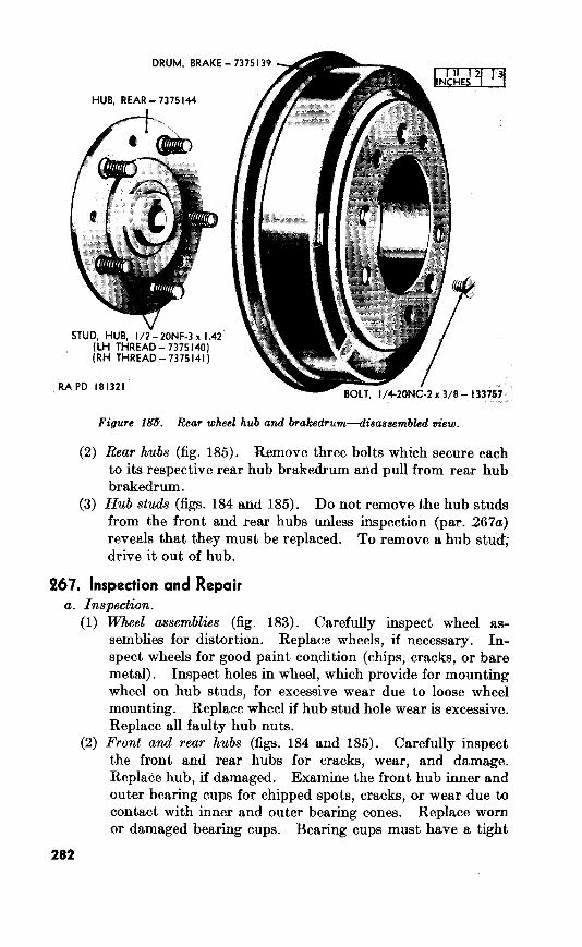
(2)
Figure l&T. Rear wheel hub and brakedrum-disassembled view.
185). Remove three bolts which secure each
to its respective rear hub brakedrum and pull from rear hub
brakedrum.
184 and 185). Do not remove-the hub studs
from the front and rear hubs unless inspection (par. 267a)
reveals that they must be replaced. To remove a hub stud;
drive it out of hub.
267. Inspection and Repair
(1) Wheel 183). Carefully inspect wheel as-
semblies for distortion. Replace wheels, if necessary. In-
spect wheels for good paint condition (chips, cracks, or bare
metal). Inspect holes in wheel, which provide for mounting
wheel on hub studs, for excessive wear due to loose wheel
mounting. Replace wheel if hub stud hole wear is excessive.
Replace all faulty hub nuts.
(2) 184 and 185). Carefully inspect
the front and rear hubs for cracks, wear, and damage.
Replace hub, if damaged. Examine the front hub inner and
outer bearing cups for chipped spots, cracks, or wear due to
contact with inner and outer bearing cones. Replace worn
or damaged bearing cups. Bearing cups must have a tight
282

fit in front hub. Test front hub bearing cones for tightness
and freedom of rotation. Replace bearing cones if scoring,
pitting, wear, or other damage is evident.
Inspect hub studs for damaged threads, wear, or looseness.
Replace hub studs, if necessary.
(3) Tubes and tires. Refer to TM 9-804A for tube and tire
inspection procedures.
b. Repair.
(1) Wheel assemblies (fig. 183). Paint wheel assemblies, if
necessary.
(2) Front and rear hv.bs (figs. and Remove all raised
metal at nicks with a fine mill file. Replace front hub oil
seals at each rebuild.
Note.
268. Assembly a. Hub Studs. If hub studs were removed from rear hub, drive
new t/2--2ONF-3 x 1.42 hub studs into place in hub (fig. 186).
Note.
I --. -- - --
Figure 186. Instulling rear wheel hub stud.
b. Front Hubs (fig. 184). If the inner and outer bearing cups were
removed from front hub, use remover and replacer 41-R-2374-845
with screw to drive the two bearing cups into proper
position in hub (fig. 187). Lubricate interior of front hub with layer
of proper lubricant. Lubricate the inner roller bearing cones with
283

SCREW-41-S-1047-330
HUE, FRONT - 7375 142
RA PD 181323
Figure 187. Installing wheel hub bearing cup.
proper lubricant, as directed in TM g-8048, and place it in position
against the inner bearing cup.
Note.
Install new oil seal (lip toward bearing cone) in the front hub. Seal
must be flush with surface of front hub. Position front hub in brake-
drum and secure with three bolts.
c. 185). Position rear hub in brakedrum and
secure hub to drum with three %--20NC-2 x x bolts.
d. Install tire and tube assemblies on
each wheel assembly as instructed in TM g-8048.
284

269. General
The repair and rebuild standards included herein give the minimum,
maximum and key clearances of new or rebuilt parts. They also give
wear limits which indicate that point to which a part or parts may be
worn before replacement, in order to receive maximum service with
minimum replacement. Normally, all parts, which have not been
worn beyond the dimensions shown in the wear limits column, or
damaged from corrosion, will be approved for service. An asterisk (*)
in the wear limits column indicates that the part or parts should be
replaced when worn beyond the limits given in the sizes and fits of new
parts column.
270. Transmission (ch. 5)
a. Transmission Countershaft and Countershajt Cluster Gear (par. 92).
p; Ref. zetter Point Of measurement
188 E Diameter of countershaft cluster gear
bearing rollers.
G Countershaft cluster gear end play_.-
D Thickness of countershaft cluster gear
thrust washers.
b. Main Shaft Assembly (par. 95). Fig. NO.
RCTJ. letter Point ~Jmeasurement
188 A Diameter of pilot end of main shaft._
C Backlash between first and reverse
speed sliding gear and main shaft.
B Inside diameter bushing type bearing
second speed gear.
c. Input Shaft Assembly (par. 98).
;ll: ReJ. zetter Point OJ measurement
188 K Diameter of pilot end of input shaft__
J Inside diameter of ball bearing_ _ _ _ . _
H Diameter of input shaft front bearing
rollers.
Sires and fits o/new parts
0.1248-0.1250_
0.012-0.018__. _
0.0535-0.0595L
Sizes and fits of new parts
0.7627-0.7632-m
0.003-0.016~_~~
1.4925-1.4935__
and fits ofnew parts
0.627-0.628_ _
1.5743-1.5748L
0.218&0.2182__
Wear limits
(*I
0.022
(*)
W&Z7 limits
(*)
0. 018
1. 4955
W@Xr limits
0. 622
(*I
(*I
285
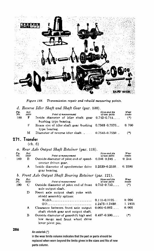
measuring
d. Reverse Idler Shaft and Shaft Gear (par. 100). Fig. Ref. WtZr NO. Poinl o/mcaaLremcnt
Sizea and fits l.?llLl ojnew parta limifs
F Inside diameter of idler shaft gear 0.742-0.744___ _ (*)
bushing type bearing.
F Ream size of idler shaft gear bushing 0.7563-0.7570__ 0. 760
type bearing.
M Diameter of reverse idler shaft- _ __ _ _ 0.7545-0.7550__ (*)
271. Tronsfer (ch. 6)
a. Rear Axle Output Shaft Retainer (par. 118).
j-0: Rej. Sizes and fifr W.Xr letter Point 01 measurement o/new parts limits
189 B Outside diameter of pilot end of speed- 0.2460.248__ _ _ 0. 244
ometer driven gear.
A Inside diameter of speedometer drive 0.2530-0.2550.. 0. 2580
gear bearing.
b. Front Axle Output Shajt Bearing Retainer (par. 121).
190 c Outside diameter of pilot end of front
axle output shaft.
D Front axle output shaft yoke with
shield assembly splines:
Width---_---_-__-------------
OD~~~~__________________---~
A Clearance between front axle output
shaft clutch gear and output shaft.
B Outside diameter of gearshift high and
low range and front wheel drive
lever pivot pin.
Size8 and fits Wear o/new parfa limits
0.752-0.753_. . (*)
O.lll-0.1125__. 0. 096
1.2475-l .2480_. 1. 2455
O.OOl-0.002__. . 0. 005
0.497-0.500._. _ (*)
286
SSchwend
An asterisk (*) in the wear limits column indicates that the part or parts should be replaced when worn beyond the limits given in the sizes and fits of new parts column.
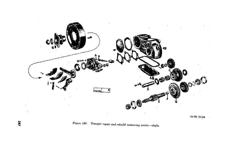
RA I’D lel~25
189.
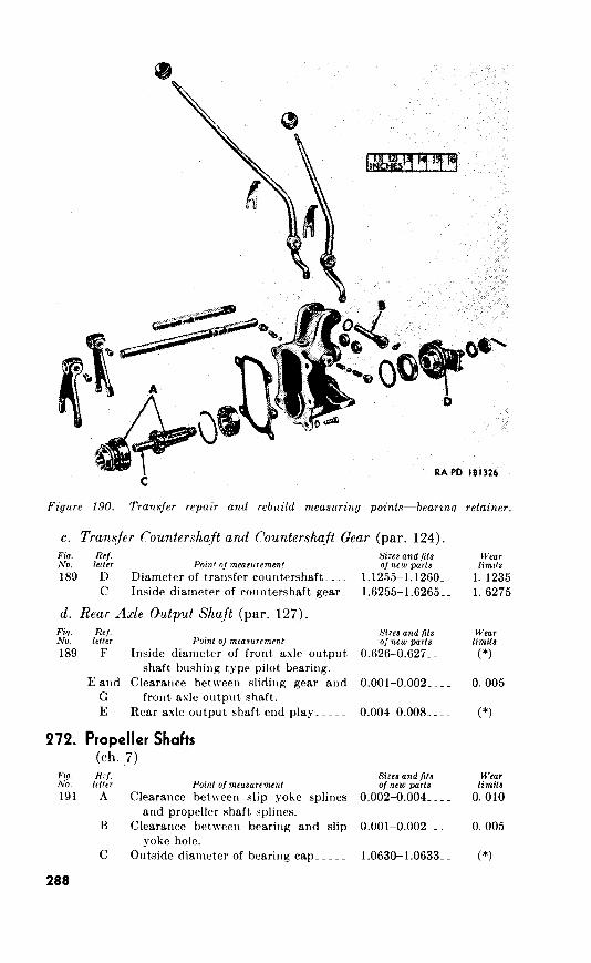
RA PD I81326
c. Transfer Countershaft and Countershaft Gear (par.
Fiq. ReJ.
NO. Sizes and fits
/e//t7 Pain’ ~Jmea~urement oJnew parts
d. Rear Axle Output Shaft
Fiq.
NO.
272.
Fig. No.
288
ReJ.
k/It7 Poinl o/mrosur~ment
Propeller Shafts
(ch. 7) RZj.
ltt1er Point OJ measurement
Sizes andfits
o;new par/s
Sizes and fits
OJ new parts
Wear huts
W&V

rebuild
273. Front Axle
Fig. Ref. NO. letter
192 C and Clearance
D shaft.
A Clearance
Point 01 measurement
between pinion and pinion
Sizer and fits of new parts
0.0024-0.0039__
between bearing cups and O.OOS_________
housing.
B Drive and drive pinion backlash..
E Drive gear runout_____- __._.____ ~~
274. Rear Axle
Ref. NO. letter
193 C and Clearance between pinion and pinion
D shaft.
A Clearance between bearing cups and
housing.
B Drive gear and drive pinion lash_ _ _ _
F Drive gear runout_________________
E Diameter of differential thrust block_
275. Springs
Ref. letter
A Diameter of shackle bushing type
bearing.
C Diameter of bushing type eye bearing-
B Diameter of pivot bolts__________._
A Spring shackle bushing type bearing
to shackle (threaded type).
0.005-0.007__ _ _
Excess of 0.003_
Sizes and fits o/new
O.OOS_______._
0.0050.007____
Excess of 0.003_
1.0661.071____
Sizes and fits Of new parts
0.845-0.855_ _ _ _
0.860-0.875-m. _
0.4355-0.4375__
0.015_________
Wear
0069
(*I
I:;
Wl?Ur
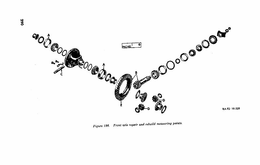
0
Figure 198. measuring points.

and

RA PD 181330
276. Steering System
Fig. ReJ. NO. letter Point of measurement
Sizes and fits oJnew parts
195 A Inside diameter of pitman shaft bush- 0.937-0.938__ _ _
ing type bearings.
WtXr
limit.9
(*)
and

277. Torque Wrench Specifications
Localion
Brake backing plate bolts_______~_~~-----..._.~_-----.._._.__.__--
Differential bearing cap bolts_____~~~~________~_-----.......__.__-
Drive gear screws______-~--...__~-------------
Handbrakedrumbolts___~~~~......-----._.__---_---....._.~~~---
Pitman arm plain nut____~_~~~~------~~.~----------_.------------
Propeller shaft universal joint journal bearing U-bolts-_- _ _ _ _ _ _ _ _
Spring front and rear U-bolts_____________._._-------...._....~~--
Spring bolts___~~______~~~~-------___---------__--_------~~
Steering gear to frame bolts_____~~_~______~~~~-------_.....~~-----
Steering tierod bolts___ ____ ~~ _____ _~~~_________~_~~~_ ______ __~___
Wheel spindle bolt___~~______-_--------__----------__----------_.
in Zb-ft
25-35
39-42
3&42
20-30
150-175
15-20
50-55
27-30
3&40
lo-15
45-55
293

Spc’cial Rrgulstious in tllcl :{lO-20 swics; SR 1 10-1-l ; ORD 1; SIZ :Jl1 O-20-29 ; and F;Ll 2 I--X sl~orrltl IX: consulted frequently
revisions of rt~f~cnc:c~s given in this appendix and for new pul)lications rrlsting to malrricl covered in this manual.
2.
following Dcpartmclnt of tllc Army Supply Manuals pertain to this mat.cricll:
a.. T)Pstructior~ To Praoctl.t &wrn~y Cise.
Land Minces and Components, D(~moli- ORD 3 SNL R-7 t ion Explosives and Rclat~cd 1 t,c‘ms ; antl Ammmlition for Simulatcttl hlil- lrry Booby Trap, Hand Grana(lC, ant1 I~a.nd Llirlc Fire. b. Rqjair arr,d Rebuild.
Antifriction Bcbarings and Rclatcd lt)c>ms ORD 5 SNL H-12 Clcanrrs, I’r(Lservatives, Lubricants, Rc- ORD 3 SNL K-l
coil Fluids, Special Oils, md Relattld 1~n.intc~nnncc Materials.
El(~(~t~rica.1 Fit.tings_ _ _ _ _ _ _ _ _ _ _ ORD 5 SNL H-4 Ttcbms of Soldering, bletallizing, Brazing ORD :i SlNL K-2
and Welding Materials: Gases and
Rclatcd It,cms. Lubricaiing Equipment, Accessories am1 ORD (‘) SNL K-3
RrJated Dispensers. Lubricating Fittings, Oil Filters, and Oil ORD 5 SNL H-16
Filt (‘1’ Elements. Jlajor Jtclms and Major Combinat,ions of ORD z SNL G-l
Group G. Miscellaneous Hardware- _ _ _ _ _ _ _ ~. ORD 5 SNL H-2
Oil Seals_____~___~___~_~~.~_~_~~-~~ ORD 5 SNL H-13 Pipe and H&e Fittings____________~.~ ORD 5 SNL H-6
Standard Hardware__~_~___~_~___~_~~~ ORD 5 SNL H-l
c. L$h,iclr.
Truck, )&ton, 4 x 4, Utility, iWSAl_ _ _ ORD (‘) SNI, G-758
1 See SR 310-20-29 for published Manuals of the Ordnance section of the
Department of the Army Supply Manual.
294
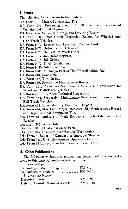
3. Forms
The following forms pertain to this materiel:
DA Form 9-1, Materiel Inspection Tag.
DA Form 9-3, Processing Record for Shipment and Storage of
Vehicles and Boxed Engines.
DA Form 94, Vehicular Storage and Servicing Record.
DA Form 9-68, Spot Check Inspection Report for Wheeled and
Half-Track Vehicles.
DA Form 9-71, Locator and Inventory Control Card.
DA Form 9-72, Ordnance Stock Record.
DA Form 9-76, Request for Work Order.
DA Form 9-77, Job Order Register.
DA Form 9-78, Job Order.
DA Form 9-79, Parts Requisition.
DA Form 9-80, Job Order File.
DA Form 9-81, Exchange Part or Unit Identification Tag.
DA Form 446, Issue Slip.
DA Form 447, Turn-In Slip.
DA Form 460, Preventive Maintenance Roster.
DA Form 461, Preventive Maintenance Service and Inspection for
Wheel and Half-Track Vehicles.
DA Form 461-5, Limited Technical Inspection.
DA Form 462, Preventive Maintenance Service and Inspection for
Full-Track Vehicles.
DA Form 468, Unsatisfactory Equipment Report.
DA Form 478, MWO and Major Unit Assembly Replacement Record
and Organizational Equipment File.
DA Form 811 and 811-1, Work Request and Job Order and Hand
Receipt.
DA Form 865, Work Order.
DA Form 866, Condolidation of Parts.
DA Form 867, Stabus of Modification Work Order.
6, Report of Damaged or Improper Shipment.
DD Form 313, U. S. Government Operator’s Permit.
DD Form 315, Preventive Maintenance Service Due.
4. Other Publications
The following explanatory publications contain information perti-
nent to this mat.eriel and associated equipment:
a. Camoujlage.
Camouflage, Basic Principles_ _ _ _ _ _ _ _ _ _ FM 5-20
Camouflage of Vehicles____________-_- FM 5-20B
b. Decontamination.
Decontamination_________ __________ TM 3-220
Defense Against Chemical Attack_ _ _ _ _ FM 2140
295
c. Destruction To Prevent Enemy Use.
Explosives and Demolitions_ _ __ _ _ _ _ _ _ _ FM 5-25
Ordnance Service in the Field. _ _ _ _ _ _ _ _ FM 9-5
d. General.
Cooling Systems: Vehicles and Pow- TM 9-2858
ered Ground Equipment.
Inspection of Ordnance Materiel in the TM 9-l 100
Hands of Troops.
Military Vchicles_~_~~~__~___~_____-- TM 9-2800
Precautions in Handling Gasoline- _ _ _ _ AR 850-20
Safety: Prevention of Motor Vehicle SR 385-155-1
Accidents.
Principles of Automotive Vehicles_ _ _ _ _ TM 9-2700
Safety: Reports of Accident Experience_ SR 385-1040
Storage Batteries, Lead-Acid Type- _ _ _ TM 9-2857
e. Repair and Rebuild.
Abrasives, Cleaning, Preserving, Seal- TM 9-850
ing, Adhesive and Related Materials
Issued for Ordnance Materiel.
Disposal of Supplies and Equipment: SR 755-105-5
Uneconomically R e p a i r a b 1 e Ord-
nance Vehicles.
Hand, Measuring, and Power Tools ___ TM 10-590
Instruction Guide: Care and Mainte- TM 37-265
nance of Ball and Roller Bearings.
Lubrication_________________________ TM 9-2835
Maintenance and Care of Hand Tools__ TM 9-867
Maintenance and Care of Pneumatic TM 31-200
Tires and Rubber Treads.
Maintenance of Supplies and Equip- AR 750-5
ment: Maintenance Responsibilities
and Shop Operation.
Maintenance of Supplies and Equip- SR 750-130-5
ment: Ordnance Expenditure Limits
for Repair of Transport Vehicles.
Modification of Ordnance Materiel- _ _ _ SB 9-38
Ordnance Field Maintenance _ _ _ _ _ _ _ _ _ FM 9-10
Ordnance Maintenance: Hydraulic TM 9-8653 (TM 9-1827C)
Brakes (Wagner-Lockheed).
Ordnance Maintenance: Carburetors TM 9-8641 (TM g-18268)
(Carter).
Ordnance Maintenance: Electrical TM 9-8629 (TM 9-1825B)
Equipment (Auto-lite).
Ordnance Maintenance: Electrical TM 9-8627 (TM 9-1825A)
Equipment (Delco-Remy).
Ordnance Maintenance: Fuel Pumps__ TM 9-8655 (TM g-18288)
296

Painting Instructions for Field Use _ _ _ _ TM 9-2851
Preparation of Ordnance Materiel for TM 9-2853
Deep Water Fording.
Preventive Maintenance of Electric TM 55-405
Motors and Generators.
Supplies and Equipment: Unsatisfac- SR 700-45-5
tory Equipment Report.
Wheeled and Half-Track Vehicles, TB 9-2835-12
Trailers, and Towed Artillery: LU-
brication of Wheel Bearings.
f. Operation
%-ton 4 x 4 Utility Truck M38Al_ ____ _ TM g-8048
8. Shipment and Stand4y or Long-Term Storage.
Army Shipping Document_ _ _ _ _ _ _ _ _ _
Instruction Guide: Ordnance Packag-
ing and Shipping (Posts, Camps, and
Stations).
Marking and Packaging of Supplies
and Equipment: Marking of Over-
sea Supply.
Military Standard -Marking of Ship-
ments.
Ordnance Storage and Shipment
Chart -Group G.
Preparation of Supplies and Equip-
ment: Processing of Unboxed and
Uncrated Equipment for Oversea
Shipment.
Preservation, Packaging, and Packing
of Military Supplies and Equipment.
Processing of Motor Vehicles and Re-
lated Unboxed Materiel for Ship-
ment and Storage.
Protection of Ordnance General Sup-
plies in Open Storage.
Shipment of Supplies and Equipment:
Report of Damaged or Improper
Shipment.
Standards for Oversea Shipment and
Domestic Issue of Ordnance Mate-
riel Other than Ammunition and
Army Aircraft .
TM 38-705
TM 9-2854
SR 746- 30-5
MIL-STD-129 2
TB 9-OSSC-G
AR 747-30
TM 38-230
SB 94
TB ORD 379
SR 745-45-5
Navy Shipping Guide
Article 18504
AFR 71-4.
TB ORD 385
297

THIS CD PRODUCED BY
MILITARY MEDIA, TNC.
COPYRJGHT 1999
Absorber, ahock (See Shock sbaorbera) PaWmti Accidenta, report__________________________-. _______________ Adjustment:
Diffewntial: Casebecklseh_______________________-_____________ Drivepinion___,______.___________________________
Handbrsk~___________________________________________ Rear axle:
Differential sesembly___________________._._________ Output shaft end play______________________________
Servieebr~eg____________________________________-__~_ Steeringgenr_________________________-____---...-____-- Steering knuckle flange_________________________________ Tierod_______________________________________._______
Alinement, wheela__________________________________..__-__-_ Axle:
Front (See Front axle) Rear (See Rear axle)
Batteries: Inatsllation___________________________,_______________ Removsl______________________________________________
Battery box traye: Instsllstion___________________________________________
Bellcrank: Ins~lation___________________________________________ Removel______________________________________________
Body: Aesembly___________________________________--_-__---_ Data________________________________________________- Desoription_________________________________________-_ Dieeeeembly______________-_____________________-_____- General______________________________________---..-__-- Inepection__________________-_________________________ Instsll~tion____.__________________________________---- Removal_______.__________________-___________________ Repair________________________________________--____--
Brake, hand: Adjustment____________________________________-____-- Aesembly_____________________________________________ Diaaseembly_____,_____________________________________ Inepection____________________________-_____----__-_-- Inetollstion________________________________._--___---_ Removal______________________________________-___-_-- 4n~ir______________________________________-_--------
3 PW
8
164 181 163 176 193 213
181 201 135 140 189 209 ti5 228 166 186 214 235 167 187
76 88 44 42
227 255 220 241
61 78 59 77
221 216 215 221 217 221
72 48
221
241 238 236 241
241 83 47
241
193 213 192 213 190 209 191 211 119 125 117 123 191 211
299

Brake lines: Paragraph
Instsllstion_____________..._.___._____._______-_-_-___ 64
Removal________________._____._.__________--_-_______ 56
Brake master cylinder (See Master cylinder)
Brake pedal:
Installation___________________________________________ 64
Removal__________.~ .____ ._._. _ _______ _____________~~ 56
Brake system:
Data___________._..._~______________.__._-------_____ 185
Description_________----__--------_-_----------~.._._. 184
Troubleshooting_~~_~___~~~~~-~-~~~~~~~-~~.~.._....~~_. 33, 34
Brakes, service:
Adjustment__________-------------------------_.___.__ 189
Assembly_______.____-_~__~-~~_~_-_~.--_-~--~------~-- 188
Disassembly_______~__---~~--------~---------_-----_.__ 186
Inspection__________________._____.________-_--------- 187
PQW 79
68
79
68
205
205
35,36
209
206
206
Installation_______________--_-___---___------------- 167,183 187,201
Removal____________________________________________ 148,171 156,191
Repair_______________-_-_---_-_-_-----_---------------
Bumperettes:
Assembly_______~_______________._____________________
Disassembly_________--_-~-_-----------------_---------
Inspection____________________________________________
Installation________________________.__________________
Removal_____________---_-.-------_------------------
Repair_______________________._______________________
Cleaning, mspection, and repair:
After disassembly procedures_________~_-_-_- .___._._..__
Cleaning procedures_________________________._________
General______________-_-_----------------_---_-_-_-_-
Handling after inspection______~____--------------------
Handling repair_______________-_-.-.-_-_-_-___-._
Inspection procedure___________------_-----_-_---_-_-_-
Repair procedure_._.____-_------------------_. ___.____
Clutch pedal:
Installation_____________________~_~_~___~~_~___~_~.___
Removal__________________________.________._____.__.
Commontoolsandequipment______.________-_.__.._ _____.
Data:
Body________________-_--------------------_-_-_-_-_-
Brakesystem_____________.______._____.__.__.________
Fenders_____________------------------_----_-_-____._
Frame______________.----------------------_-_-.-_-__
Frontaxle________________._____._______.___._________
Hood_________________-_-_-_-_-_-___-_-___-__________
Propeller shafts--___---_---------..------------_-_-_-_-
Radiator___________.-_-_-_-_________-___.__.___.._._.
Rearaxle._____________________.___-_-_-__._______.__.
Shockabsorbers_______________________________________
Springs______.______-_---_----_-_-_--------.__________
Steering system___-_-_-___-._.-_-_-_____-_-_----_-_-__
Transfer_------ .____________________-_-_-_------_____.
Transmission________---_---_-_------------_-_-.____._.
Universal joints_______________-----___------_-________
Wheelsandhubs________________--------_-_-_-_-______
300
187 206
260 278
258 278
259 278
262 278
247 271
259 278
12 16
11 15
10 15
15 17
15 17
13 16
14 17
64 79
56 68
18 18
216 238
185 205
229 258
245 269
146 153
229 258
141 144
237 262
169 189
195 214
195 214
201 221
110 117
81 93
141 144
265 281
Description : Paragraph PW
Body_____~____~~_._.-_----_-.____--------_-_-_.-_ 6,215 13,236
Brakesystem___~~-.__-~--_-_-______--_-_-_-__________ 184 205
Clutch___.______.._.___--_--------_----~-~---------_---_ 8 14
hlectricalsystem___..._.._.-_-.------~.-~-~---~-----_-- 8 14
Engine___~__~...._~..-.-----------_--------..-.-.-~ 8 14
Fenders______._..._.~_.~.-~------_-__-_-~-_---------- 228 256
Frame___._____.______---__------------_-----.__ 7,244 13,269
145 151
4 9
228 256
5 11
140 144
236 262
168 188
194 214
194 214
200 220
109 114
80 90
264 280
70 82
50 61
70 82
50 61
235 261
229 258
228 256
233 259
234 260
74 8’7
46 44
234 260
2 8
3 8
251 276
245 269
244 269
249 272
250 272
250 272
154 163
152 160
153 163
167 187
148 156
153 163
146 153
145 151
301

Front axle-Continued
Differential assembly:
Assembly________----_-____----_-_-_-_-____--_____
Disassembly___-_____.._---_--________._._____._._
Inspection_____.____----..___-_-_._------__-_--_--
Installation_____.---~__.---------.---.~____--_____
Removal____________.-______-_-____-----__-------
Repair__________---__-____-- ._________________~_~
Differential drive pinion:
Assembly______._-------___------_-------____----_
Disassembly_____.._._._--------__-___.._._---____
Inspection________.____._-~-~______...._.._~-_._._
Installation______--_----_--------_----------------
Removal_______-.___._._-------___.___..._---_.__
Repair_._-___-______.___--------____._._._---_~-_
Differential housing assembly:
Assembly______..----_-___.~_----_--------_____---
Disassembly_____________--------____________----_
Inspection_______-~--___~__-.__--_--------_____---
Repair__________----___~_____---_--------____--~-.
Housing cover:
Installation______------___.._____________-________
Removal________________--------_-_-_-_____------
Installation_________-----_-________-___-_-__--__.___._
Operation__________-_-________-_---__--------________
Removal____________-_-_--___.____-_______________.._
Repair and rebuild standards_______~___--------~.._____
Steering knuckle flange:
Assembly___.___-________--------_--------_____-_-
Dis~sembly____-_._._.__--------_----_--~_-------
Inspection_______----____--------_--------__.__.__
Installation___~_~~~~_~~__--------_--------__._____
Removal___.___-._._._._--_---___-________-_-----
Repair__________----_-_____.___________________._
160
158
159
164
150
159
papc 169
167
168
181
158
168
161 172
161 172
161 172
163 176
151 159
161 172
162 172
162 172
162 172
162 172
165 184
150 158
62 78
145 151
58 74
273 289
157
155
156
166
149
156
167
165
165
186
157
165
32 Troubleshooting_~____----____--------_---------_-__--- 29,30
Fuel can bracket:
Installation_________-----________________-_-__________
Removal___-_____________.._-------__---------______-
Fuel lines : Installation_-------_------~_-_------__---------_._____
Removal___-________._____._---- ____________________
Fuel tank:
Assembly____________________----_______-_____________
Disassembly__________________________________________
Inspection___________________-__----__---_____-_______
Insta~ation__________________-_--_--__________________
Removal_____________-______----_--__--_------_______
Repair______________________--_----____.----_-_______
Generator regulator:
Installation_________-----_-__-_-____-________._-------
Removal___________-_-_-______________________--_-_-_
Glove compartment panel:
Installation________________.__---_--__-------_-_______
Removal____________________-------__---------_______
Handbrake (See Brake, hand)
302
226 254
219 240
67 81
53 65
224 252
224 252
224 252
224 252
224 252
224 252
71 83
49 59
225 254
218 238
Assembly_-_________-__________--_____-_-_____________
Data_____-_____________________-_____-----______-_---
Description________---_________--____.-____---.__--- _
Disassembly____-__---_.__.____--_________________-___
Inspection______-__-_____--_-----__--._____--_________
Installation________--__________________----__-__---_-_
Removal_______________---_-______-_______--________-
Repair________--__--___.____-_--______-__-______-____
Hood liner:
Assembly______________-__-_--_--_____________--___---
Data______.-----_____-----_-----____-_________-_____-
Description________--__---__----_____-________________
Disassembly-----.____---_-______--___~-~-____---_____
Inspection____________-__________-_-__-----___-______-
Repair_____-----______----____________________--_____
Hubs:
Assembly__-________--______-----______-_--___--______
Data_______-----__--____--________-__-----______-----
Description________---______-_-_-________-____-_____--
Disassembly_______---___--_-----__-__-----______---__
Inspection_________--_____-_----_-____-----______--___
Installation_________________-----________--___--____-_
Removal___________--______---_-___________________--
Repair________--_____---________---_______--____-____
Improvisedtools_____-----________---_________-___--_-----
Instrument panel:
Installation________---_______----_____-----______---__
Removal___________-_________---___-------__-_~_-----
Maintenance, field and depot allocation____-_________--____--
Master cylinder:
Installation_______---___-____----_____-----______---__
Removal__________---________-_-_______---______-----
Muffler:
Installation__-_-__---___-_------__--__---___-____-____
Removal___________--____-_-----_-___----~_-_.__-____
Nomenclature, vehicle_________._-_.______--____-_.---___---
Parts, special tools, and equipment:
Common tools and equipment_-_-___--_______--_________
General_____-_-__----.__--------______-___--_________
Improvised tools_____-______-----___-__----_____---___
Parts___--_________________________--__---_____------
Special tools
Pintle, towing:
Assembly___________--______---_-_______--__-_______._
Disassembly_______---____-_-----_____---- ___________
Inspection________-_--________---_____----_--._.______
Installation___-_-_--_-__--------__-________--___-_____
Removal__________---________---_____----__-_________
Repair_________________________-____-__--____________
Power plant:
Installation________-___-_-__-_____--__________---____-
Removal______________________-______----____________
232
229
228
230
231
78
42
231
PW
259 258
256
258
258
89
40
258
243 268
237 262
236 262
241 267
242 267
242 267
268 283
265 281
264 280
266 281
267 282
268 283
266 281
267 282
20 23
225 254
218 238
2 8
64 79
56 68
70 82
50 61
4 9
18 18
16 18
20 23
17 18
19 18
254 277
252 276
253 277
261 278
246 271
253 277
68 81
52 61
303

Propeller shafts: Paragraph PW Assenlbly_____________________________________________ 144 149 Data_________________________________________________ 141 144 Description_________-_______________-_--______________ 140 144 Disassembly____________ _______ _______________________ 142 144 Inspection________________________---__-______________ 143 147 Installation_______________________________-_-____-____ 69 82 Removal_____________________________________________ 51 61
Repair_____________________________---_-_-_-____---__ 143 147
Repair and standards-__-______-________________ 272 288
Troubleshooting_______________________-_-----_----_-_- 27,28 31
Radiator: Assembly_____________________________________________
Data__________________________-___-_-_---____________
Description________-______________-___-_-___-_-_______
Disrtssembly_______-__--______________________________
Inspection_________-___-__________________________-___
Installation___________________________________________
Removal_________________-_____-______--_-___-_______
Repair_______________________________________________
Radiator guard: As~mbly__--_-_-_____________-_______-_-_______-_-___
Data___-_________________________-_______________-___
Description___________________-_-_____-_-_____________
Disassembly__________________________________________
Inspection___-___-_-_-_______-________________________
Installation__________________________________________-
~moval_____________________________________________
Repair_---_____-_-___-___________-_____-__-__-____-__
Rear axle: Data_________________________________________________
Description______________________________________-_-__
Differential assembly:
Assembly________________-________________________
Disassembly______________________________________
Inspection______________________________________-_
Installation_____________._________-_-_-___________
Removal_________________________________________
Repair___________________________________-_-_-_-_
Drive pinion:
Assembly_________________________________________
Disassembly______________________________________
Inspection________________________________________
Installation_______________________________________
Removal__________-__-__--_-_-___-__--_____-_____
Repair___________________________________________
Housing assembly : Assembly_________________________________________
Disassembly_______________________ ______ _________
Inspection___________--___________________________
Repair________________-_--_-__--_-_-_____________
Housing cover:
Installation_______________________________________
Removal______________________________________-_-
304
240 266
237 262
236 262
238 263
239 263
249 266
238 263
239 263
243 268
237 262
236 262
241 267
242 267
73 87
47 46
242 267
169 189
168 188
176 198
174 196
175 198
181 201
172 191
175 198
177
177
177
180
173
177
200
200
200
201
193
200
179 201
179 201
162 172
179 201
182 201
172 191

Rear axle-Continued Paragraph
Installation_________-______________________-__________ 62
Removal______________--__----_-__----_-_-___________ 58
Repair and rebuild standards_____-__-__._-_-_-_-___-_-_- 274
Shafts: Assembly______________--____--__-_-_-_-_-________ 179
Disassembly_____----_-___---____~-______--_-_-_- 178
Inspection_________________-______---_-_~_-----_-- 178
Installation_____________-______-_-___-_---_-----_- 183
Repair_________________--_-----__-_-_-___-_______ 178
Removal_______-______-_-________________-_______ 171
Troubleshooting_____---_-____-__-___-____________---__ 31.32
Records______________-____--_-____--__-_______-___--__-__
Repair and rebuild standards: Frontaxle_______________-_____-______________________
General_________--_-_____________-____--_-__----____-
Propeller shafts______----___-_-__-_______________-_-_-
Rearaxle_______-_______-_-_____-__--__-__-____--__-__
Springs__________-___---_____-___-____-_________-_____
Steerin’gsystem______-____-______-____-____--_________
Torque wrench specifications____--_--___________________
Transmission_______-_________________-_____________-_-
Transfer__________________-_____________-__--_________
Reports_________________________________________________-
SCze, general________-___--_____-____-____-_______________
Assembly________________--__-____-_-___-__--_-_______
Disassembly___--___-__-___-__________________________
Inspection_____--__--__--_____________-_______________
Repair______________-__-_____________-____--_________
Service brakes (See Brakes, service)
Shackles, front lifting: Assembly_________________-_-_-__-_--_-_-__-__-__--_-_
Disas~mbly_____________________-_--__--__-__-_______
Inspection___________-_______-____-_____-__-_-___-_--_
Installation_______________--_--_____-______-_-___-_--_
Removal____________-___-___-________-_-___-_________
Repair__________________--________-____-__-_-________
Shackles, rear lifting: Assembly_________________________-___________________
Di~ssembly_________-_-__________-___________________
Inspection______________________-____-__-_______-_____
Installation_________-___-_____-_______________________
Removal______________________-__-___________________
Repair_____________-__-_______________________-______
Shaft, propeller (See Propeller shaft)
Shock absorbers: Assembly____________________--__-_____________-______
Data____________________-___-_______-_________-_____-
Description______________-____-___-________--_________
Disassembly___________-_--_-________-_________--__-_-
Inspection____________________-_-_-___-______________-
Inste~ation__________-_--_-_-___________________-__---
Removal_____________________-______________________-
3
201
200
200
201
200
191
34
8
273 289
269 285
272 288
274 289
275 289
276 292
277 293
270 285
271 286
3 8
1 4
223 251
223 251
223 251
223 251
257 278
255 277
256 278
263 279
247 271
256 278
257 278
255 277
256 278
262 278
248 271
256 278
198 218
195 214
194 214
196 216
197 216
63 78
57 74
PWC
78
74
289
305

Shock absorbers-Continued Parwraph papc Repsir____-____--_________________________________-__ 197 216 Test and adjustment______________________--_-_________ 199 219
Troubleshooting______________-__________-___-_____-___ 35,36 36,37
Spare wheel : Installation______________________________---__________
Removal_____________--____--__________-____---______
Spare wheel support: Installation_______.__---____--___-_-_-______-____--___
Removal____________---____--__________-____---_-_-__
Specialtools______________________________________________
Speedometer driven gear: Installation__________________-_____-_-________________
Removal_________________-_______-______--_--_-___-__
Springs: Assembly____________-_-_____-_-___---________________
Data_____________________-__-_____---__-___-_-_-___-_
Descriptian___-___-_____________-_-___-___-_______--_-
Dis~sembly_-____--_______________-____--__--___-____
Inspection________________-_______-_______________--__
Installation________-____________________-__--_-_-_-___
Removal___________________-_-____---___-_____-______
Repair__________________-_________________-______-___
Repairandrebuildstandards________--_________________
Test and adjustment______________________-_-_--_-_____
75
45
88
44
226 254
219 240
19 18
119 125
117 123
198
195
194
196
197
62
58
197
275
199
218
214
214
216
216
78
74
216
289
219
36,37 Troublqshooting______ ____ ___ _________ _________________ 35.36
Steering system: Data___-_-____-_---_____-___--_-___________-_____-___
Description______________________-_____--__-____-_____
Drag link:
Assembly____________--________-_____-____________
Dissssembly___________________-__________________
Inspection_____________________--_____________-___
Installation_________---________--_________________
Removal_______________-__-_-_________-_-_-______
Repair_~____________--________-_____-__-_____-_-_
Operation____________________._______________________
Repair and rebuild standards_____--___-_____-_-________
Steering bellcran k.
Assembly_____________________________________-___
Disassembly______________________________________
Inspection__________--_______-____________________
Repair__________________-_-_______-_-_______-____
Steering gear:
Assembly_______________________-_______-_____-_--
Disassembly_________-___-_-_-________________-_-_
Inspection__________________-_-____-_-____________
Installation___________________________________----
Removal_____________-__-____-______-__________-_
Repair_________________________________________-_
Test and adjustment__________________-__________-_
Tie rod:
Adjustment____________________________________--_
Assembly_______________________________-_-_-_----
201
200
221
220
208 230
206 230
207 230
65 80
55 65
207 230
200 220
276 292
211 233
209 232
210 233
210 233
204 226
202 224
203 225
65 80
55 65
203 225
205 228
214 235
214 235
306

Steering system-Continued
Tie rod-Continued Paragraph
Disassembly __.. _________~___________.~.-.--_-_ 212
Inspection.__.---.___-_-_____-_--_--_-_~__~--_~--~- 213
Repair___._~.---.~.--_----_-_--_--_-_~-___------- 213
Troubleshooting_._..---_-_~-------_----~------- .___ 37, 38
Tabulated data______--_-__--_-__._-_--_-.-------~-~.-~----
Torque wrench specificat~ions_..~___._-__-__._-_---_- .__._____
Towing pintle (See Pintle, towing)
Transfer:
Companion flange:
Installation___--..~~----~.~~----_--_----_--_____-_
Removal ____ ____ __.. _.__.~_______~_~__~____.____
Countershaft:
Assembly___________-_-----___-_--__-_-_--._..._..
Disassembly.-_-___-_-~-_-----_-__--_-_-_--_-___-_
Inspection__-__-_._.-_---_-_----~--_---_-~_~______
Installation_-_-~-_.__.---_-_---___-_-_-_--______-_
Removal_________----.~.-_-_----__-___-_-__-_-_-_
Repair______._.-__._.---_-_-_----_--_-_-_____.__.
Data_____-_--__-_--_-__--_-_-_-_---__.-----_-..___.--
Description_-_---_--_-_---_-_-_---_-_-__-_-_-_________
Front axle output shaft bearing retainer:
Assembly_________---__-__----_-__-----__.-_--
Disassembly~___._------__----_-__--_-_-__-_-_----
Inspection_._.-_-. ____________________-..-___-_--
Installation_______._._-_-__--_----_.------....-_--
Removal_________-_-_--__-_--____---_----~-__
Repair_________-.~.--_-__--_-_____-__---_-_--_-_-
Handbrake drum:
Installation_____-___-------_-_--_--_------..__-_--
Removals_____.__-_--_-__-------_----_--_----__
Operation___----.-_----------_--_--.-__-_--.-__-_--_-
Preparation for tests_-_--__-----._.-__-_.-_--_-_______-
Rear axle output shaft:
Assembly__~__~~__-__-__._----------.~_-..------_~
Disassembly ___.. _~____________.______.-__-.._._.--
Inspection.___._-_.__.-.-___~_-_--__-_-_--__-______
Installation________.-_--__-_----__----~-.--_----_-
Removal_..._..-______.-_.___-__-._-_-_--..-.-_.-
Repair_________-_-_--_----_--____--_-____-_-__-__
Rear axle output shaft oil seal:
Installation_____-___-_--__-_-----...--.-_~..
Removal__________._.__-___----____--_-._----.-__
Rear axle output shaft retainer with bearing assembly:
Assembly_______-_..__-_-_-_--_____-____.__-__.__.
Disassembly__.________.-_____----__----_-__-_____
Inspection____-_-.._-_--..-__-_____-_______-____-_
Installation________.__------_-___._-._.__.______._
Removal _____ ________________~_.__---~-._--_- .__.
Repa~r.._____._..._._..-..._.-_--_-_--_~-_--_--_-__
Rear axle output shaft sliding gearshifter fork shaft:
Installation.__-_-___-_--__---- .._. __._ .___ _.______
Removal __________ _____________________.__-____.-
9 14
277 293
137
111
143
117
125 133
123 132
124 132
133 139
114 120
124 132
110 117
109 114
122 132
120 129
121 130
132 138
113 118
121 130
137
111 117
109 114
138 143
128 135
126 13.3
127 134
131 136
115 121
127 134
136 142
115 121
119 125
117 123
118 125
134 140
112 118
118 125
131 136
116 122
Pnge 233
235
235
3;
307

135
135
135
135
130
130
130
137
130
114
136
136
136
143
138
120
101
101
101
101
110
110
110
110
00 103
88 100
89 102
106 112
82 93
80 102
93 105
91 104
02 104
105 112
83 95
92 104
93 105
91 104
02 104
103 111
86 100
92 104
81 93
80 00
99 109
97 108
98 108
Pngc 286
142
12!)
143
28, 29
308

Transmission-Continued
Innut shaft with integral gear-Continued Paz ovaph
Instsllation____~----~..-..---__-_-------_-..._._._
Removal_____~--.---.------_------------__-_-
Repair_____.._-_.---_------------------_-----
Installation_----..---_--_---_----..---.....--_..-.~.~
Main shaft assembly:
Assembly.__...-__---_----~_-~-~--~_~-_--~-__-_--_
Disassembly__- __.__ ________~_~_~__~____~_~~.__---
Inspection..~~..~~.--._----_-_----_-------_-.-._
Installation____...~~---_---------_----__---_
Removal_____._..-.-.------------------_----
Repair___-_.~.-_.---_-------_-----------_~---~_
Operation ____ ~_~~_____~__._______.___-._-.--._..---._
Preparation for tests_....-~-~--____~_----_----_-___.----_
Removal___.._.._.--_---_--_--~-__---~__-_~--__.-~-__
Repair and standards___---__---______--__.-_-__
Reverse idler shaft gear:
Assembly_____.-._~~-_---_~_-~-~---_--_---___-_-__
Disassembly_._-_.---__-_---__----_-_~_~~-__.~_~_.
Inspection_____-..~~-_---_-___----___-__--_._-.-..
Installation_____..~.-_------------__-_--__..-_-..
Removal______.~...._~_---__-_--_-_-----__-..--..
Repair_____.~_-..---_--__--__----_-_-__--._.-_~_~
Testing after assembly.....----___--~---_--_--____---~_
Troubleshooting_____.~..~_~.-~.._-_------_.-._---.
Tires:
Installation___-_.._-..-.-_--_--___--------.---...-.-..
Removal___~~~~.._--.---_--__-___----_-_-_---..--.-.
Troubleshooting:
Before removal and during operation:
Brakes_....___-__~_-_------_-------_ .___....__..
Frontaxle...._.____-_-~-___-----_-_------___----.
Propeliershafts.___.._-_-____--_-_-------____---~_
Rearaxle___.._-..~~_---~_~___--_-_-____--___-____
Springs._..._._-..~._----_~__~----------------_-._
Shockabsorbers__~___._.-_..---_-_---------_---~.
Steeringsystem___.- ____ __________________~_..-_-.
Transfer______--..-..------------.-.-..--_..-._..
Transmission___ ______ ~______~_________.___...-~-..
Wheels_______--....__-_-___---_-_----~--_____~-__
Before removal or operation:
Brakes_._._........_-----------_-_-----_.-.~---.
Frontaxle__._- .____ ~____ . . ____.__~_.___..._.__.
Propellershafts.____.___-___--__-_-~----~__~_---__
Rearaxle_____--..-.----__-_..--_-._....-_.~...._.
Springs__.__~_--...._~---____-----__--..-_...-.-_.
~hockabsorbers_....-.---___---_--__--_~--___-___.
bteeringsystem___ ______ _~_________________~._--_.
Transfer__________.._..__-__----____----.___.---__
Transmission__._..___ ._____ ___ ____ ________________
Wheels_____________________--____-_----_____---__
General instructions______....____---______--_____---_.
Procedures________._...____--___-___-_..__._--_____.
Purpose__________-_...._.______---_-_-------~-...____.
i
104
85
98
68
PWC
112
98
108
81
96 107
94 106
95 106
105 112
84 98
95 106
80 90
107 113
52 61
270 285
100 109
100 109
100 109
102 111
87 100
100 109
108 113
!3, 24 25, 27
75
45
88
44
34 36
30 32
28 31
32 34
36 37
36 37
38 37
26 29
24 27
40 39
33 35
29 32
27 31
31 34
35 36
35 36
37 37
25 28
23 25
39 38
22 25
22 25
21 25
309
Uncatiefacwy equipment, report____________________________
Vehicle nomenclature_ _ ____________________________________ Vehiclerorrdtest_____-____________________________________ Vent linee:
Removal______________-___--_________-_______________ Ins~tion___________________________________________
Ventilation system, dencrlption______________________________
Wheel alinement _ _ .___________________-___________________ Wheels:
Aseembly_____________________________________________ DBfs____________________________________~____________ Description_______ _________-_________--_______________ Diseeeembly__________________________________________ Inapection____________________________________________ Inetrrllstion_______________-_________--________________ Removd___-____~____________________________________ Repsir_______________________________________________ - ._
3
4 79
Plr 3
9 89
63 07 4
86 81 9
167 187
208 266 264 266 267
6’ 67
267
283 231 280 281 282
78 74
282 38,39 Troubleshooting- ________ ______________________________ 39.40
Windshield: Assembly__,_______ _____ ____________ ____________ ______ Dkamembly__________________________________________ Inepection____________________________________________ Inetallation__________-________________________________ Removal_____________________________________________ Re~ir____________----_____________--________________
Wiring harnewx Inetallation_________________________________________-_ Removal_____________________________________________
[AG 461.2 (30 Mu S4)]
222 222 222
77 43
222
66 64
244 244 244
88 41
244
81 66
310

THIS CD PKODUCED BY
MILITARY MEDIA, INC. COPY RIGHT 1999
AND TEB Am
FORCE:
M.
&l'7CIAL:
United Btatee Army, 6%&f of Staf.
United States Amy, The Adjutant Gr,ral.
N. Chief of &a#, United State8 ANT Force,
United Statee Air Force,
Active Army:
’ Sp
. _ c0 (1 j
None.
(1)
311
Related Documents