POWER SYSTEM STABILIZER : ANALYSIS & SIMULATIONS Technical Report By Vihang M. Dholakiya (10MEEE05) Devendra P. Parmar (10MEEE07) Under the Guidance of Dr. S. C. Vora DEPARTMENT OF ELECTRICAL ENGINEERING INSTITUTE OF TECHNOLOGY NIRMA UNIVERSITY AHMEDABAD 382 481 MAY 2012

Welcome message from author
This document is posted to help you gain knowledge. Please leave a comment to let me know what you think about it! Share it to your friends and learn new things together.
Transcript
POWER SYSTEM STABILIZER : ANALYSIS &
SIMULATIONS
Technical Report
By
Vihang M. Dholakiya (10MEEE05)
Devendra P. Parmar (10MEEE07)
Under the Guidance of
Dr. S. C. Vora
DEPARTMENT OF ELECTRICAL ENGINEERING
INSTITUTE OF TECHNOLOGY
NIRMA UNIVERSITY
AHMEDABAD 382 481
MAY 2012

Dedicated To
Mentor
Dr. S. C. Vora

CERTIFICATE
This is to certify that the Technical Report entitled “POWER SYSTEM STA-
BILIZER : ANALYSIS & SIMULATIONS” submitted by Mr. Vihang M.
Dholakiya (10MEEE05) and Mr. Devendra P. Parmar (10MEEE07), is the
record of work carried out by them under my supervision and guidance. The work
submitted has in my opinion reached a level required for being accepted. The results
embodied in this project work to the best of my knowledge are satisfactory.
Date:
Project Guide
Dr. S. C. Vora
Professor
Department of Electrical Engineering
Institute of Technology
Nirma University
Ahmedabad

Acknowledgements
We take this opportunity to express our sincere gratitude to our honorable guide
Dr.S.C.Vora for his invaluable guidance. It would have never been possible for
us to wok on this project without his technical support and continuous encourage-
ment. We consider ourself, extremely fortunate for having chance to work under his
guidance. In spite of his hectic schedule, he was always approachable and spent his
precious time to discuss problems. It has been a very learning and enjoyable experi-
ence to work under him.
We would like to acknowledge Mr. A. Ragaveniran et.al., authors of technical
paper titled as “MATLAB/Simulik-Based Modeling and Operation of Power System
Stabilizer” which provides us initial motivation for doing work in the area of imple-
mentation of power system stabilizer.
We would also like to thank all faculty members of Department of Electrical Engi-
neering, who have helped us during this project work. I wish to express my thanks
to other staff members of Electrical Department as well for their regular help and
co-operation during the project work. We heartily thankful staff member of library
for providing technical recourses for project work.
We would be specially thankful to our dear friend Narendra C. Mahavadia for
providing continuous help and motivational support during entire project work. We
never forget the time that we have spent with him during this tenure.
We are thankfull to our classmates for their invaluable help, suggestions and support
during the project work. We would like to thank all who have directly or indirectly
contributed to this project work.
Finally, We would like to thank The Almighty and express my deep sense of rever-
ence gratitude to our Parents and Family Members who have provided support and
blessings without which we wouldn’t have reached at this stage.
- Vihang M. Dholakiya
- Devendra P. Parmar
i
Abstract
The extensive interconnection of power networks by weak tie-lines can restrict the
steady-state power transfer limits due to low frequency electromechanical oscillations.
The low frequency oscillations may result in interruptions in energy supply due to loss
of synchronism among the system generators and affect operational system economics
and security. Further, in order to maintain steady state and transient stability of syn-
chronous generators, high performance excitation systems are essential. The static
exciters with thyristor controllers are generally used for both hydraulic and thermal
units. Such exciters are characterized by high initial response and increased reliabil-
ity due to advances in thyristor controllers and hence have become one of the major
problems in the power system stability area. As a solution to this, the generators are
equipped with Power System Stabilizers(PSSs) that provide supplementary feedback
stabilizing signals which is added to the Automatic Voltage Regulator (AVR). PSSs
augment the power system stability limit and extend the power transfer capability
by enhancing the system damping of low-frequency oscillations in the order of 0.2 to
3.0 Hz.
The report focuses on small signal performance analysis of Single Machine Infinite
Bus(SMIB) as well as of multimachine power system. The dynamic behaviour of
Haffron-Phillips model of excitation system with typical data is evaluated by devel-
oping MATLAB code for eigenvalue tracking analysis. The effect of implementation
of power system stabilizer to SMIB system has been realized by time domain sim-
ulations. In the later part optimal placement of PSS is decided, because from the
economic point of view and to avoid redundancy, it is desired, not to employ PSS
on individual generators to overcome the problem of power system oscillations. The
eigenvalue analysis of the power system for various areas is used to determine the
inter-area and local mode frequencies and participation of the generators. It is also
important to identify the generator that shall be installed with PSS. A simulation
study on well-adopted test system is carried out, with various possibilities, to deter-
mine the optimal placement of the PSS. The observations of the certain analysis are
helpful in determining the PSS placement and are presented in the report.
ii

List of Figures
2.1 Classification of Power System Stability . . . . . . . . . . . . . . . . . 62.2 Phasor Representation of Electrical Torque . . . . . . . . . . . . . . 132.3 Synchronizing & Damping Torque Stability Analysis . . . . . . . . . . 14
3.1 Haffron- Phillips Model of Excitation System . . . . . . . . . . . . . . 183.2 Linearized SMIB Model . . . . . . . . . . . . . . . . . . . . . . . . . 193.3 Block Diagram of Linearized SMIB Model . . . . . . . . . . . . . . . 203.4 Eigenvalue Loci for Variation in AVR Gain . . . . . . . . . . . . . . . 233.5 Basic Arrangement of PSS . . . . . . . . . . . . . . . . . . . . . . . . 243.6 Haffron- Phillips Model of Excitation System with PSS . . . . . . . . 253.7 Operating Principle of PSS . . . . . . . . . . . . . . . . . . . . . . . . 253.8 General Structure of PSS . . . . . . . . . . . . . . . . . . . . . . . . . 263.9 SMIB Model in MATLAB/SIMULINK . . . . . . . . . . . . . . . . . 283.10 Rotor Angle Deviation Before Introducing PSS . . . . . . . . . . . . . 293.11 Speed Deviation Before Introducing PSS . . . . . . . . . . . . . . . . 293.12 Rotor Angle Deviation After Introducing PSS . . . . . . . . . . . . . 303.13 Speed Deviation After Introducing PSS . . . . . . . . . . . . . . . . . 30
4.1 Single Line Diagram of Test System . . . . . . . . . . . . . . . . . . . 334.2 Speed Participation Factor v/s Generator No. For Inter-Area Mode-
0.54 Hz . . . . . . . . . . . . . . . . . . . . . . . . . . . . . . . . . . 384.3 Participation Factor v/s Generator No. For Local Mode-1.05 Hz . . . 394.4 Eigenvalues of Two Area Test System without PSS . . . . . . . . . . 394.5 Eigenvalues of Two Area Test System with PSS in Area-2 . . . . . . 404.6 Eigenvalues of Two Area Test System with PSS in Both Areas . . . . 404.7 MATLAB/SIMULINK Model of Test System . . . . . . . . . . . . . 414.8 Block Diagram of PSS . . . . . . . . . . . . . . . . . . . . . . . . . . 414.9 Power Flow from Area-1 to Area-2 . . . . . . . . . . . . . . . . . . . 424.10 Per Unit Speed Deviation for Case-1 . . . . . . . . . . . . . . . . . . 434.11 Per Unit Speed Deviation for Case-2 . . . . . . . . . . . . . . . . . . 444.12 Per Unit Speed Deviation for Case-3 . . . . . . . . . . . . . . . . . . 444.13 Per Unit Speed Deviation for Case-4 . . . . . . . . . . . . . . . . . . 45
iii

List of Tables
2.1 Types of Swing Mode of Oscillations . . . . . . . . . . . . . . . . . . 8
4.1 Network Statastics . . . . . . . . . . . . . . . . . . . . . . . . . . . . 344.2 Power Flow Results . . . . . . . . . . . . . . . . . . . . . . . . . . . . 344.3 Line Flow Results . . . . . . . . . . . . . . . . . . . . . . . . . . . . . 354.4 Summerized Power Flow Analysis . . . . . . . . . . . . . . . . . . . . 354.5 Summerized Power Flow Results . . . . . . . . . . . . . . . . . . . . . 364.6 Effects of PSS with Different Arrangement Scheme . . . . . . . . . . 37
B.1 Machine Data of Two Area Test System . . . . . . . . . . . . . . . . 50B.2 Line Data of Two Area Test System . . . . . . . . . . . . . . . . . . . 51B.3 Load Data of Two Area Test System . . . . . . . . . . . . . . . . . . 51B.4 Exciter & PSS Data of Two Area Test System . . . . . . . . . . . . . 51
iv
Abbreviations
AVR . . . . . . . . . . . . . . . . . . . . . . . . . . . . . . . . . . . . . . . . . . . . . . . . .Automatic Voltage RegulatorCPF . . . . . . . . . . . . . . . . . . . . . . . . . . . . . . . . . . . . . . . . . . . . . . . . . . . . . . Continuous Power FlowGUI . . . . . . . . . . . . . . . . . . . . . . . . . . . . . . . . . . . . . . . . . . . . . . . . . . . . . . Graphical User InterfaceHVDC . . . . . . . . . . . . . . . . . . . . . . . . . . . . . . . . . . . . . . . . . . . . . . . High Voltage Direct CurrentOPF . . . . . . . . . . . . . . . . . . . . . . . . . . . . . . . . . . . . . . . . . . . . . . . . . . . . . . . . . Optimal Power FlowPSAT . . . . . . . . . . . . . . . . . . . . . . . . . . . . . . . . . . . . . . . . . . . . Power System Analysis Tool BoxPSS . . . . . . . . . . . . . . . . . . . . . . . . . . . . . . . . . . . . . . . . . . . . . . . . . . . . . . .Power System StabilizerSMIB . . . . . . . . . . . . . . . . . . . . . . . . . . . . . . . . . . . . . . . . . Single Machine Infinite Bus System
Nomenclature
Gex(s) . . . . . . . . . . . . . . . . . . . . . . . . . . . . . . . . . . . . . . . . . . . . . . . . . . .Exciter Transfer FunctionH . . . . . . . . . . . . . . . . . . . . . . . . . . . . . . . . . . . . . . . . . . . . . . . . . . . . . . . . . . . . . . .Moment of InertiaKD . . . . . . . . . . . . . . . . . . . . . . . . . . . . . . . . . . . . . . . . . . . . . . . . . . . . . . . . . . Damping Co-efficientKE . . . . . . . . . . . . . . . . . . . . . . . . . . . . . . . . . . . . . . . . . . . . . . . . . . . . . . . . . . . . . . . . . . .Exciter GainKS . . . . . . . . . . . . . . . . . . . . . . . . . . . . . . . . . . . . . . . . . . . . . . . . . . . . . .Synchronizing Co-efficientKPSS . . . . . . . . . . . . . . . . . . . . . . . . . . . . . . . . . . . . . . . . . . . . . . . . . . . . . . . . . . . . . . . . . . . PSS Gains . . . . . . . . . . . . . . . . . . . . . . . . . . . . . . . . . . . . . . . . . . . . . . . . . . . . . . . . . . . . . . . . .Laplace FunctionTw . . . . . . . . . . . . . . . . . . . . . . . . . . . . . . . . . . . . . . . . . . . . . . . . . . . . . . .Wash out Time Constantωn . . . . . . . . . . . . . . . . . . . . . . . . . . . . . . . . . . . . . . . . . . . . . . . . . . . . . . . . . . . . . .Natural Frequency∆ωr . . . . . . . . . . . . . . . . . . . . . . . . . . . . . . . . . . . . . . . . . . . . . . . . . . . . . . . . . . . . . . Speed Deviation∆P . . . . . . . . . . . . . . . . . . . . . . . . . . . . . . . . . . . . . . . . . . . . . . . . . . . . . Change in Power Transfer∆δ . . . . . . . . . . . . . . . . . . . . . . . . . . . . . . . . . . . . . . . . . . . . . . . . . . . . . . . . .Change in Rotor Angleζ . . . . . . . . . . . . . . . . . . . . . . . . . . . . . . . . . . . . . . . . . . . . . . . . . . . . . . . . . . . . . . . . . . Damping Ratioφ . . . . . . . . . . . . . . . . . . . . . . . . . . . . . . . . . . . . . . . . . . . . . . . . . . . . . . . . . . . . . . . . . . . . . . . . . . . Phase
v
Contents
Acknowledgements i
Abstract ii
List of Figures iii
List of Tables iv
Nomenclature/Abbreviations v
Contents vi
1 Introduction 11.1 Problem Identification . . . . . . . . . . . . . . . . . . . . . . . . . . 11.2 Objective of The Work . . . . . . . . . . . . . . . . . . . . . . . . . . 11.3 Project Planning . . . . . . . . . . . . . . . . . . . . . . . . . . . . . 21.4 Scope of Work . . . . . . . . . . . . . . . . . . . . . . . . . . . . . . . 21.5 Outline of Thesis . . . . . . . . . . . . . . . . . . . . . . . . . . . . . 3
2 Power System Stability 42.1 Background . . . . . . . . . . . . . . . . . . . . . . . . . . . . . . . . 42.2 Small Signal Stability . . . . . . . . . . . . . . . . . . . . . . . . . . . 72.3 Small Signal Stability Analysis . . . . . . . . . . . . . . . . . . . . . . 9
2.3.1 Eigenvalue Analysis . . . . . . . . . . . . . . . . . . . . . . . . 92.3.2 Synchronizing and Damping Torque Analysis . . . . . . . . . . 122.3.3 Frequency Response and Residue Analysis . . . . . . . . . . . 152.3.4 Time Domain Solutions . . . . . . . . . . . . . . . . . . . . . 15
2.4 Summary . . . . . . . . . . . . . . . . . . . . . . . . . . . . . . . . . 16
3 SMIB & PSS: Physical Aspects, Implementation & Analysis 173.1 Small Signal Performance of Single Machine Infinite Bus System . . . 17
3.1.1 Formulation of Heffron-Phillips Model of Excitation System forStability Studies . . . . . . . . . . . . . . . . . . . . . . . . . 17
3.1.2 Linearized Model of Single Machine Infinite Bus System . . . 193.1.3 Oscillatory Stability Assessment of SMIB . . . . . . . . . . . . 213.1.4 Introducing PSS in AVR loop of SMIB . . . . . . . . . . . . . 23
3.2 Summary . . . . . . . . . . . . . . . . . . . . . . . . . . . . . . . . . 31
vi

vii
4 Optimal Placement of PSS in Multimachine Power System 324.1 Background . . . . . . . . . . . . . . . . . . . . . . . . . . . . . . . . 324.2 Test System Description . . . . . . . . . . . . . . . . . . . . . . . . . 324.3 Load Flow Analysis . . . . . . . . . . . . . . . . . . . . . . . . . . . . 334.4 Linear Analysis . . . . . . . . . . . . . . . . . . . . . . . . . . . . . . 36
4.4.1 System Behavior in Different Arrangement of PSS . . . . . . . 364.4.2 Mode Identification and Participation Analysis . . . . . . . . . 374.4.3 S-Domain Plots . . . . . . . . . . . . . . . . . . . . . . . . . . 394.4.4 Time Domain Simulations . . . . . . . . . . . . . . . . . . . . 40
4.5 Summary . . . . . . . . . . . . . . . . . . . . . . . . . . . . . . . . . 45
5 Conclusions & Future Work 465.1 Conclusions . . . . . . . . . . . . . . . . . . . . . . . . . . . . . . . . 465.2 Future Work . . . . . . . . . . . . . . . . . . . . . . . . . . . . . . . . 47
References 48
A IEEE Proceeding 49
B System Data 50
C Introduction to PSAT 2.1.6 52C.1 Overview . . . . . . . . . . . . . . . . . . . . . . . . . . . . . . . . . . 52
C.1.1 Useful Features . . . . . . . . . . . . . . . . . . . . . . . . . . 53C.1.2 PSAT Utilities . . . . . . . . . . . . . . . . . . . . . . . . . . 53
C.2 Starting Process of PSAT . . . . . . . . . . . . . . . . . . . . . . . . 53C.3 Useful Links . . . . . . . . . . . . . . . . . . . . . . . . . . . . . . . . 57
Index 58

Chapter 1
Introduction
1.1 Problem Identification
Power transactions are increasing day by day in restructured power systems. Re-
structured power system is therefore, expected to be operated at a greater variety of
operating points and closer to their operating constraints. The “low frequency os-
cillations” is one of the operational constraints which limit bulk power transmission
through power network. In such scenario, power system controls plays significant role.
Power system controls can contribute either positive or negative damping. Generation
control and particularly the generator voltage regulation can be significant sources of
negative damping. High gain in the generator voltage regulation can lead to poor or
negative damping of the oscillation. This problem has lead to the implementation of
Power System Stabilizer (PSS) to damp out the oscillations.
1.2 Objective of The Work
The project work is aimed at the implementation of power system stabilizer with
appropriate parameters in single machine infinite bus system. Effect of power system
stabilizer implementation on system damping is also targeted. Further, for multi
machine power system, it is aimed that, the damping of power system oscillations
can be achieved with minimum No.of power system stabilizers located at optimal
locations.
1

CHAPTER 1. INTRODUCTION 2
1.3 Project Planning
• Formation & analysis of Haffron-Phillips model of excitation system.
• Development of program in MATLAB for sweep analysis of exciter gain and its
effect on system response.
• Formation of SMIB in MATLAB c©/SIMULINK.
• Effect of PSS on response of SMIB system.
• Formation of Kundur’s Two Area System in MATLAB c©/SIMULINK.
• S-domain analysis of Kundur’s Two Area System using Power System Analysis
Toolbox(PSAT).
• Primary screening of generators for placement of PSS through participation
factors.
• Time domain simulations of developed Kundur’s Two Area System.
1.4 Scope of Work
The scope of the project work can be broadly outlined as below:
• Realization of Haffron-Philips Model of Excitation System.
• Effect of PSS implementation on behavior of SMIB.
• Eigenvalue analysis of Kundur’s Two Area System in various PSS arrangement.
• Participation factor analysis.
• Response analysis in time domain for Kundur’s Two Area System with typical
different cases.
• Choice of optimal location of PSS based on observations of S-domain analysis
and time-domain simulations.
CHAPTER 1. INTRODUCTION 3
1.5 Outline of Thesis
• Chapter 1 introduces the main problem associated with the low frequency
oscillation damping by optimally placed PSS and the same is considered as the
objective of this work. The project planning and scope of work is also included.
• Chapter 2 gives general background of power system stability. The detail
description of eigenvalue analysis method used for evaluating small signal per-
formance of power system is focused and the other methods are discussed briefly.
• Chapter 3 includes the dynamic analysis of Hafron-Phillips model of excitation
system through eigenvalue tracking method. The effect of implementation of
PSS in SMIB has also been analyzed by performing time domain simulations.
• Chapter 4 discusses about optimal placement of PSS in multimachine power
system. The eigenvalue analysis of for Kundur’s two area system is used to de-
termine the mode of oscillation and participation of the generators. A simulation
study on considered test system is carried out, with various PSS arrangement,
the optimal placement of the PSS is decided.
• Chapter 5 comprises of conclusion and future work.
Chapter 2
Power System Stability
2.1 Background
Modern power system can be characterized by widespread system interconnections.
The interconnected power system is comprised of multiple machines connected by the
transmission network. The supply of reliable and economic electric energy is a major
determinant of industrial progress and consequent rise in the standard of living. In
practical terms this means that both voltage and frequency must be held within allow-
able tolerances so that the consumer’s equipment can operate satisfactorily. Further,
with deregulation of power supply utilities, the power network has become a highway
for transmitting electric power from wherever it is available to places where required,
depending on the pricing that varies with time of the day. In such scenario, the anal-
ysis of dynamic performance and stability of power system has great importance.
The stability problem is concerned with the behavior of the synchronous machines
under perturbed conditions. If the perturbation does not involve any net change in
power, the machines should return to their original state and if an unbalance between
the supply and demand is created by perturbation, a new operating state should be
achieved. When the system changes its operating point from one stable point to the
other,it is mandatory that all interconnected synchronous machines should remain in
synchronism. i.e., they should all remain operating in parallel and at the same speed.
4
CHAPTER 2. POWER SYSTEM STABILITY 5
Thus, Power System Stability may be broadly defined as that property of power
system that enables it to remain in a state of operating equilibrium under normal
operating condition and to regain an acceptable state of equilibrium after being sub-
jected to disturbance[1].
Although, stability of a system is an integral property of the system, for purposes of
the system analysis, it is mainly divided into following categories:
• Steady State Stability relates to ability of synchronous machine to maintain
synchronism followed by small disturbances. e.g. gradually changing load.
• Dynamic or Small Signal Stability concerns with the response of syn-
chronous machine to small perturbations that are oscillating in nature. If these
oscillations are of small amplitude, the system may be considered as small signal
stable, but if the amplitude of oscillations is of growing nature, with the passage
of time the system may lose its stability. Usually, heavy power flow in trans-
mission line or interaction of controller with system frequency is responsible for
small signal instabilities. The phenomenon is concerning with few seconds to
10s of seconds of time period.
• Transient Stability involves response of synchronous machine to large dis-
turbances such as application and clearing of faults, sudden load changes and
inadvertent tripping of transmission lines or generators. Such large disturbances
can create large changes in rotor speeds, power angles and power transfer. The
phenomenon is concerns with time period of 1 second or less.
The detailed classification of power system stability is depicted in the following Fig.2.1
[1].The report focuses on the Small Signal Stability of power system.

CHAPTER 2. POWER SYSTEM STABILITY 6
Figure 2.1: Classification of Power System Stability

CHAPTER 2. POWER SYSTEM STABILITY 7
2.2 Small Signal Stability
Small Signal Stability is the ability of the power system to maintain synchronism
when subjected to small disturbances. A power system at a particular operating
state may be large disturbance unstable and still such a system may be operated with
insecurity with proper control and protective actions. But, if the system is small-signal
unstable at a given operating condition, it cannot be operated at all, because small
signal instability may result in steady increase in generator rotor angle due to lack of
synchronizing torque or in rotor oscillations of increasing amplitude due to insufficient
damping torque. Thus, small-signal stability is a fundamental requirement for the
satisfactory operation of power systems.The reasons for the system can become small
signal unstable are enlisted hereunder[3]:
• Use of high gain fast acting exciters
• Heavy power transfer over long transmission lines from remote generating plants
• Power transfer over weak ties between systems which may result due to line
outages.
• Inadequate tuning of controls of equipment such as generator excitation systems,
HVDC-converters and static var compensators.
• Adverse interaction of electrical and mechanical systems causing instabilities of
torsional mode oscillations.
The issue of small signal instability in current scenario is generally because of insuffi-
cient damping of oscillations. In practical power system, the main types of oscillations
associated with small signal stability are as follows:
1) Swing Mode
2) Control Mode
3) Torsional Mode

CHAPTER 2. POWER SYSTEM STABILITY 8
• Swing Mode of Oscillation
This mode is also referred to as electromechanical oscillations. For an n gen-
erator system, there are (n-1) swing (oscillatory) modes associated with the
generator rotors.The location of generators in the system determines the type
of swing mode.Hence, the swing mode of oscillation can be further sub classified
as shown in following Table 2.1 [3].
Table 2.1: Types of Swing Mode of Oscillations
Local Mode Inter-Unit(Intra-plant) Mode Inter-AreaThese oscillations generally These oscillations These oscillations usuallyinvolve one or more typically involve two or involve combinations of manysynchronous machines at a more synchronous synchronous machines onpower station swinging machines at a power one part of a power systemtogether against a plant swing against each swinging against machinescomparatively large power other. on another part of the system.system or load center.Freqency Range: 0.7 to 2 Hz Freqency Range: 1.5 to 3 Hz Freqency Range: 0.1 to 0.5 Hz
• Control Modes of Oscillations
Control modes are associated with generating units and other controls. Poorly
tuned exciters, speed governors, HVDC converters and static var compensators
are the usual causes of instability of these modes.
• Torsional Mode of Oscillations
These oscillations involve relative angular motion between the rotating elements
(synchronous machine rotor, turbine, and exciter) of a unit, with frequencies
ranging from 4Hz and above. Instability of torsional mode may be caused
by interaction with excitation controls, speed governors and series capacitor
compensated transmission lines.
Of these oscillations, local mode, intra-plant mode, control mode and torsional mode
are generally categorized as local problems as it involves a small part of the system.
Further, inter-area mode oscillations are categorized as global problems and have
widespread effects.

CHAPTER 2. POWER SYSTEM STABILITY 9
2.3 Small Signal Stability Analysis
There are mainly four techniques which are used to analyze the small signal stability
of power system:
a. Eigenvalue Analysis
b. Synchronizing and Damping Torque Analysis
c. Frequency Response and Residue Based Analysis
d. Time domain Simulations
2.3.1 Eigenvalue Analysis
In this report ,of the above methods, Eigenvalue Analysis is used to study oscillatory
behavior of power systems and hence has been described in detail. The system is
linearized about an operating point and typically involves computation of eigenvalues,
eigenvectors, participation factors and system modes from state-space representation
of power system model. This can also be termed as “Small Signal Stability Analysis”
or “Modal Analysis”. Technique employed in this report for studying oscillatory
modes is also based on eigenvalue analysis. Initially, eigenvalues and eigenvectors
are derived. From this, modes of oscillations and participation factor of particular
generator are found out. It gives preliminary idea about possible location of PSS. The
derivation of eigenvalues and participation factor can be found in [1] and can be briefly
explained as follows: Linear approximation of power systems can be characterized by
the following state-space equations:
∆x = A∆x+B∆u (2.1)
∆y = C∆x+D∆u (2.2)
Where,
∆ x is the state vector of length equal to the number of states n

CHAPTER 2. POWER SYSTEM STABILITY 10
∆ y is the output vector of length m
∆ u is the input vector of length r
A is the (n × n) state matrix
B is the input matrix of (n × r)
C is the output matrix of (m × n)
D is the feed forward matrix of (m × r)
Eigenvalues of the system state matrix is available from the characteristic equation
of the state matrix A. It can be expressed as
det(A− λI) = 0 (2.3)
For each of the eigenvalues, there are two sets of orthogonal eigenvectors, namely the
left and right eigenvectors, satisfying the following equations:
AΦi = λiΦi (2.4)
ΨiA = λiΨi (2.5)
Where,
λi, is the ith eigenvalue Φi is the right eigenvector corresponding to λi Ψi is the left
eigenvector corresponding to λi
Eigenvalue & Stability of Power System
The time-dependent characteristic of a mode corresponding to an eigenvalue λi is
given by eλit. Therefore, the stability of the system is determined by the eigenvalues
analysis. Real eigenvalues are associated with non-oscillatory modes, whereas the
complex ones, appearing in conjugate pairs, correspond to oscillatory modes - one
mode for each pair. If the eigenvalue of an oscillatory mode is expressed as,
λi = σ ± jω (2.6)

CHAPTER 2. POWER SYSTEM STABILITY 11
The damping coefficient which gives the rate of decay of amplitude of the oscillation
is given by,
ζ =−σ√σ2 + ω2
(2.7)
and the frequency of oscillation in Hz is determined by,
f =ω
2π(2.8)
A negative real part of the eigenvalue represents positive damping coefficient that
is, decaying oscillation, and the positive real part indicates negative damping, i.e.,
increasing oscillation. The right eigenvector of a mode gives an idea about how this
mode is distributed among different states of the system and hence known as Mode
Shape. Based on this idea, if a mode is found to be distributed among specific state
variable of generating units in different areas, then that mode can be identified as a
local mode or inter-area mode. Typically, rotor speed is used as the test state variable
for mode shape analysis in inter-area oscillation study[1] , [4].
Participation Factor is a measurement of relative participation of any state variable
in any specific mode. It is mathematically expressed as the multiplication of left and
right eigenvectors. For example, participation factor pki of any kth state variable in
any ith mode can be measured as[1],
pki = Φki ×Ψik (2.9)
Where,
Φki is the kth entry of the right eigenvector of ith mode
Ψik is the kth entry of the left eigenvector of ith mode
Thus, participation factors are the sensitivities of the eigenvalues to changes in the
diagonal elements of the state matrix. They indicate possible locations where a
stabilizer may effectively control the mode of concern[8]. Eigenvalue or modal analysis
describes the small-signal behavior of the system about an operating point, and does
not take into account the nonlinear behavior of components such as controller’s limits
at large system perturbations. Further, design and analysis carried out using various
CHAPTER 2. POWER SYSTEM STABILITY 12
indices such as participation factors, may lead to many alternate options. These
options need to be verified by time-domain simulations.
Advantages of Eigenvalue Analysis
i) Separate identification of modes of oscillations
ii) Root loci plotted with variations in system parameters or operating conditions
provide valuable insight into the dynamic characteristics of the system.
iii) Using eigenvectors coherent groups of generators which participate in a given
swing mode can be identified.
2.3.2 Synchronizing and Damping Torque Analysis
The synchronous operation of generators is generally dealing with balance between the
input mechanical torque and output electrical torque of each machine. The change in
electrical torque of alternator following small perturbation can be illustrated through
following equation:
∆Te = Ts∆δ + TD∆ω (2.10)
Where,
• Ts∆δ is the component of torque change in phase with the rotor angle pertur-
bation and is referred to as the synchronizing torque component.
• Ts is the synchronizing torque coefficient.
• TD∆ω is the component of torque in phase with the speed deviation and is
referred to as the damping torque component.
• TD is the damping torque coefficient.
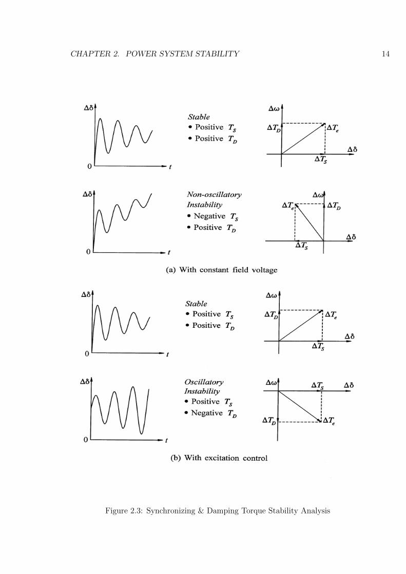
The nature of system oscillations to small perturbation depends on both the com-
ponents of electrical torque. The response of generator without automatic voltage
regulator (constant field) can result into instability due to lack of sufficient synchro-
nizing torque. Such instability is known as non-oscillatory instability. Further, the

CHAPTER 2. POWER SYSTEM STABILITY 13
presence of automatic voltage regulator can also result in instability with oscillations
having nature of continuously growing amplitude. Such instability is known as oscilla-
tory instability. Both types of instabilities are illustrated in following Fig.3.1 [1]. This
analysis assumes that the rotor angle and the speed deviations oscillate sinusoidally.
Hence this can be represented by phasors as depicted in Fig.2.2
Figure 2.2: Phasor Representation of Electrical Torque
From the above figure the damping torque component can be written as
∆TeD = ∆Te cosφ (2.11)
And synchronizing torque component can be written as
∆TeS = ∆Te sinφ (2.12)
If either or both damping and synchronizing torques are negative, i.e., if ∆TeD <
0 and/or ∆TeS < 0, then the system is unstable. A negative damping torque im-
plies that the response will be in the form of growing oscillations, and a negative
synchronizing torque implies monotonic instability.
CHAPTER 2. POWER SYSTEM STABILITY 14
Figure 2.3: Synchronizing & Damping Torque Stability Analysis

CHAPTER 2. POWER SYSTEM STABILITY 15
2.3.3 Frequency Response and Residue Analysis
Frequency response is characterization of a systems transfer function between a given
input and output. Frequency response methods allow a deeper insight into small-
signal dynamics and have widespread use in the design of power system controllers.
Frequency response can also be measured directly, even in a power system. Residues
give the contribution of a mode to a transfer function. They also give the sensitivity
of the corresponding eigenvalue to a positive feedback between the output of the
transfer function and its input. Thus, residues are useful to get an idea of which
modes will be affected most by feedback. An advantage of using residues in such
analysis is that it takes into account the transfer function structure of the excitation
system unlike participation factors. However, evaluation of residues dependent on the
specific input/output combinations and may be computationally intensive for large
systems.
2.3.4 Time Domain Solutions
Time domain techniques provide an exact determination of stability of non-linear
systems both for small and large disturbances. The choice of disturbance and selection
of variables to be observed in time response are critical. If the input is not chosen
properly, there is possibility that the substantial excitation of the important modes
may not be achieved. The observed response may contain many modes and the
poorly damped modes may not be so dominant. The solution is highly affected by the
modeling of the components. Larger systems may have a number of inter-area modes
of similar frequencies, and it is quite difficult to separate them from a response in
which more than one is excited. Therefore, for a large power system it is not possible
to identify any desired mode and study their characteristics.
Of all these methods, eigenvalue or modal analysis is widely used for analyzing
the small-signal stability of power system due to advantages described earlier in this
section.

CHAPTER 2. POWER SYSTEM STABILITY 16
2.4 Summary
The chapter provides general introduction to basic concepts of power system stability
including a discussion of classification,definitions of related terms in brief. The details
regarding small signal stability analysis includes eigenvalue analysis along with other
methods to evaluate small signal performance of power system in simplified manner.
Chapter 3
SMIB & PSS: Physical Aspects,
Implementation & Analysis
3.1 Small Signal Performance of Single Machine
Infinite Bus System
In order to analyze the small signal stability of SMIB, following methodology has
been adopted:
A) Formulation of Heffron-Phillips Model of Excitation System for Stability Studies
B) Linearized Model of Single Machine Infinite Bus System
C) Oscillatory Stability Assessment of SMIB
D) Introducing PSS in AVR loop of SMIB
3.1.1 Formulation of Heffron-Phillips Model of Excitation
System for Stability Studies
The third-order model of the synchronous machine can be represented as a block dia-
gram shown in Fig.3.1. The basis for the model presented here, which was originally
proposed by Heffron and Phillips, is the “Single Machine Infinite Bus” (SMIB) setup.
By introducing a number of new constants, a very compact notation is achieved. The
17

CHAPTER 3. SMIB & PSS: PHYSICAL ASPECTS, IMPLEMENTATION &ANALYSIS18
model is useful to directly implement a simplified representation of an SMIB system,
including the mechanical dynamics, field winding, and excitation system. This im-
plementation can be used directly for stability studies. In the present case, a generic
simplified representation of the excitation system is used. Detailed descriptions and
common variants of these systems can be found in [1]. All quantities presented
Figure 3.1: Haffron- Phillips Model of Excitation System
are in per unit. The mechanical system is represented by the system inertia and the
damping constant, where the torque balances ∆Tm −∆Te is considered as an input
and the incremental torque angle ∆δ as an output. The electrical part of the system
consists of three main parts:
a. The composition of the electrical torque (influenced by ∆δ over constant K1
and the internal incremental voltage ∆eq over constant K2),
b. The effect of the field winding (determined by the field winding constant K3
and influenced by ∆δ over constant K4),
c. The effect of the excitation system (influenced by ∆δ over constant K5 and ∆eq
over constant K6).

CHAPTER 3. SMIB & PSS: PHYSICAL ASPECTS, IMPLEMENTATION &ANALYSIS19
The excitation system itself is modeled by a first-order transfer function including
the amplification factor KA and the time constant TA.
Interpretation of K-constants
The constants K1 to K6 shown in block diagram describe internal influence factors
within the system and can be found by a comparison of coefficients with the equations
governing the synchronous machine dynamics. While K1 and K2 are derived from the
computation of the electric torque, K3 and K4 have their origin in the field voltage
equation. K5 and K6 come from the equation governing the terminal voltage magni-
tude. The detailed derivation of K-constants is given in chapter 12 of P. Kundur.
K1 - Influence of torque angle on electric torque
K2-Influence of internal Voltage on electric torque
K3- field winding constant
K4-Influence of torque angle on field voltage
K5-Influence of torque angle on terminal voltage
K6-Influence of internal voltage on terminal voltage
3.1.2 Linearized Model of Single Machine Infinite Bus Sys-
tem
Figure 3.2: Linearized SMIB Model
Fig.3.2 shown above is representation of single machine connected to large power
system through transmission line. For any condition, the magnitude of infinite bus
voltage EB remains constant when machine is perturbed. Considering classical model
of synchronous generator and neglecting stator resistance, linearization of system
CHAPTER 3. SMIB & PSS: PHYSICAL ASPECTS, IMPLEMENTATION &ANALYSIS20
equations gives state space equation as follows:
d
dt
∆ωr
∆δ
=
KD
2HKS
2H
ω0 0
∆ωr
∆δ
+
12H
0
∆Tm (3.1)
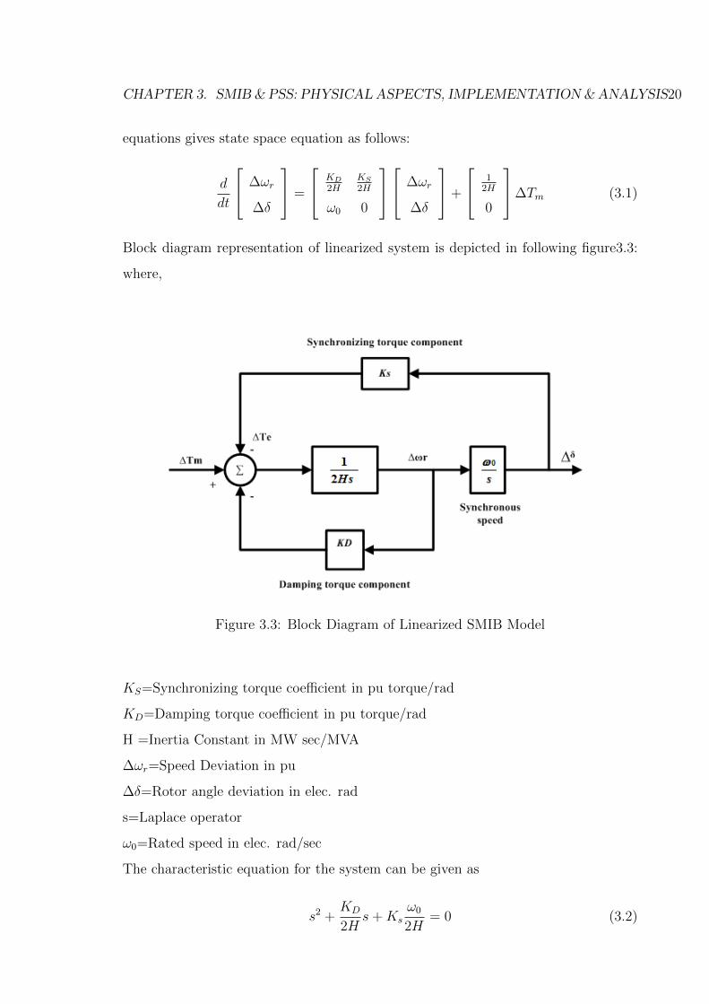
Block diagram representation of linearized system is depicted in following figure3.3:
where,
Figure 3.3: Block Diagram of Linearized SMIB Model
KS=Synchronizing torque coefficient in pu torque/rad
KD=Damping torque coefficient in pu torque/rad
H =Inertia Constant in MW sec/MVA
∆ωr=Speed Deviation in pu
∆δ=Rotor angle deviation in elec. rad
s=Laplace operator
ω0=Rated speed in elec. rad/sec
The characteristic equation for the system can be given as
s2 +KD
2Hs+Ks
ω0
2H= 0 (3.2)

CHAPTER 3. SMIB & PSS: PHYSICAL ASPECTS, IMPLEMENTATION &ANALYSIS21
Comparing this with general characteristic equation
s2 + 2ζωns+ ωn2 = 0 (3.3)
Natural frequency of oscillation is
ωn =
√ksω0
2H(3.4)
and damping ratio is
ζ =12KD√
Ks2Hω0
(3.5)
a. As the synchronizing torque coefficient Ks increases, the natural frequency in-
creases and the damping ratio decreases.
b. An increase in damping torque coefficient KD increases the damping ratio
c. An Increase in inertia constant decreases both natural frequency and damping
ratio.
3.1.3 Oscillatory Stability Assessment of SMIB
Dynamic Performance Evaluation of AVR Loop and Stability of SMIB
System
Under heavy loading condition, the modern regulator-exciter system introduces neg-
ative damping and may lead to oscillatory instability. For the sake of small signal
stability analysis, a typical single machine infinite bus bar system given as example
in book titled as “ Power System Dynamics-Stability and Control” by K.R. Padiar
has been considered [2]. The system data considered are as follows:
Pg =1.1 Vt = Eb =1.0 KD=0 T3=6.0 sec KE=200 TE=0.05 sec
K1 = 0.0345 K2 = 2.2571 K3 = 0.4490 K4 = 0.1826 K5 =-0.0649 K6 =1.0613

CHAPTER 3. SMIB & PSS: PHYSICAL ASPECTS, IMPLEMENTATION &ANALYSIS22
In order to evaluate dynamic performance of SMIB in small signal instable condition,
Eigenvalue Tracking approach has been adopted.
Eigenvalue Tracking Analysis
As discussed in chapter 1 that the eigenvalues computed from the system state matrix
can be helpful to predict the system stability.From the data shown in the above table,
a MATLAB code has been developed to analyze the behaviour of system against gain
variation from KE=0 to KE=400. It is possible to express the system equations in
the state space form. From the block diagram, shown in Fig.3.1, the following system
equations and state matrix are derived.
x = [A]x+ [B]Vref (3.6)
x = [∆δ ∆ωr ∆ψfd ∆Efd]T (3.7)
[A] =
0 ω0 0 0
−K1
2H−KD
2H−K2
2H0
−K4
T30 −1
T3K3
1T3
−KEK5
T50 −KEK6
TE
−1TE
(3.8)
B = [0 0 0KE
TE]T (3.9)
The damping term KD, is included in the swing equation. The eigenvalues of the
matrix should lie in left half plane in the‘s’ plane for the system to be stable. The effect
of various parameters for example, here effect of variation in KE is examined from
eigenvalue analysis. It is to be noted that the elements of matrix [A] are dependent
on the operating condition.
The loci of the complex critical eigenvalues for the considered case is shown in Fig.3.4.
It is observed that, when K5 < 0, the increase in AVR gain beyond KE=4 results in
oscillatory instability. Although the locus turns around as KE is further increased,but
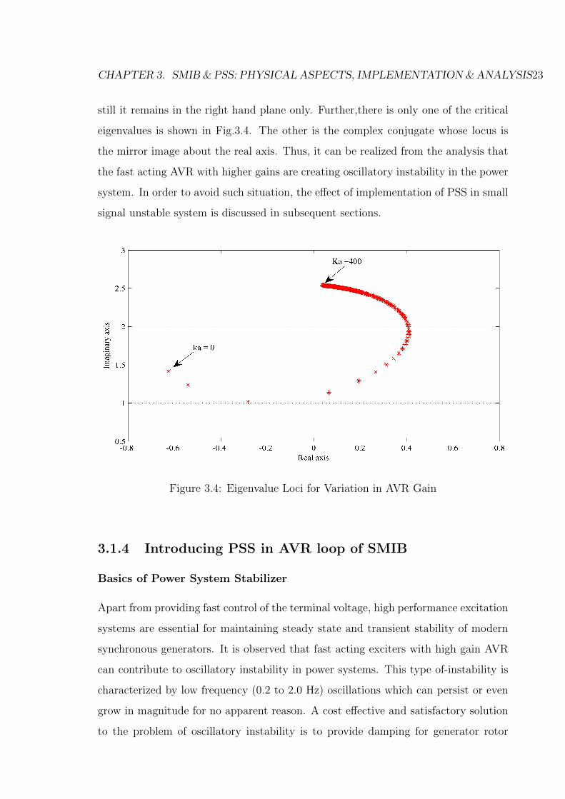
CHAPTER 3. SMIB & PSS: PHYSICAL ASPECTS, IMPLEMENTATION &ANALYSIS23
still it remains in the right hand plane only. Further,there is only one of the critical
eigenvalues is shown in Fig.3.4. The other is the complex conjugate whose locus is
the mirror image about the real axis. Thus, it can be realized from the analysis that
the fast acting AVR with higher gains are creating oscillatory instability in the power
system. In order to avoid such situation, the effect of implementation of PSS in small
signal unstable system is discussed in subsequent sections.
Figure 3.4: Eigenvalue Loci for Variation in AVR Gain
3.1.4 Introducing PSS in AVR loop of SMIB
Basics of Power System Stabilizer
Apart from providing fast control of the terminal voltage, high performance excitation
systems are essential for maintaining steady state and transient stability of modern
synchronous generators. It is observed that fast acting exciters with high gain AVR
can contribute to oscillatory instability in power systems. This type of-instability is
characterized by low frequency (0.2 to 2.0 Hz) oscillations which can persist or even
grow in magnitude for no apparent reason. A cost effective and satisfactory solution
to the problem of oscillatory instability is to provide damping for generator rotor

CHAPTER 3. SMIB & PSS: PHYSICAL ASPECTS, IMPLEMENTATION &ANALYSIS24
oscillations. This is conveniently done by providing Power System Stabilizers (PSS)
which are supplementary controllers in the excitation systems. The basic function of
PSS is to add damping to the generator rotor oscillations by controlling its excitation
using auxiliary stabilizing signal.
The basic arrangement of PSS along with the generator controls is depicted in Fig.3.5.
In this arrangement, speed change of generator is taken as input to PSS and its out-
put is added to the reference input of AVR to change the excitation voltage.
Figure 3.5: Basic Arrangement of PSS
The theoretical basis for PSS can be illustrated by extended block diagram of Heffron-
Phillips model of excitation system as depicted in 3.6 As the purpose of PSS is to
introduce damping torque component, a logical signal to use for controlling generator
excitation is the speed deviation ∆ωr.

CHAPTER 3. SMIB & PSS: PHYSICAL ASPECTS, IMPLEMENTATION &ANALYSIS25
Figure 3.6: Haffron- Phillips Model of Excitation System with PSS
Power System Stabilizer adds damping to generator rotor oscillations by controlling
its excitation using an auxiliary stabilizing signal. The stabilizer does so by producing
component of electrical torque in phase with the rotor speed deviation. Fig. 3.7 shows
the operating principle of PSS.
Figure 3.7: Operating Principle of PSS
CHAPTER 3. SMIB & PSS: PHYSICAL ASPECTS, IMPLEMENTATION &ANALYSIS26
From the above figure it can be clearly visualize that due to stabilizing signal provided
by PSS in phase with speed deviation, the electrical torque is shifted from third to
first quadrant, means becomes positive from negative in magnitude.
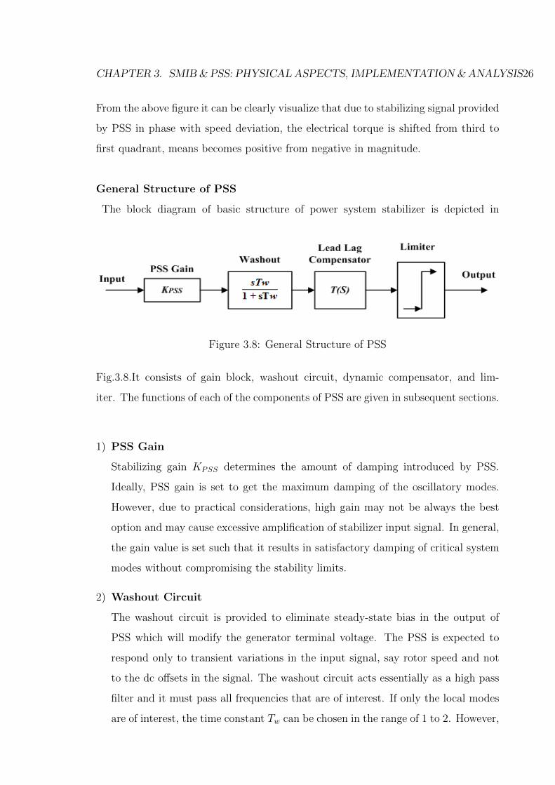
General Structure of PSS
The block diagram of basic structure of power system stabilizer is depicted in
Figure 3.8: General Structure of PSS
Fig.3.8.It consists of gain block, washout circuit, dynamic compensator, and lim-
iter. The functions of each of the components of PSS are given in subsequent sections.
1) PSS Gain
Stabilizing gain KPSS determines the amount of damping introduced by PSS.
Ideally, PSS gain is set to get the maximum damping of the oscillatory modes.
However, due to practical considerations, high gain may not be always the best
option and may cause excessive amplification of stabilizer input signal. In general,
the gain value is set such that it results in satisfactory damping of critical system
modes without compromising the stability limits.
2) Washout Circuit
The washout circuit is provided to eliminate steady-state bias in the output of
PSS which will modify the generator terminal voltage. The PSS is expected to
respond only to transient variations in the input signal, say rotor speed and not
to the dc offsets in the signal. The washout circuit acts essentially as a high pass
filter and it must pass all frequencies that are of interest. If only the local modes
are of interest, the time constant Tw can be chosen in the range of 1 to 2. However,

CHAPTER 3. SMIB & PSS: PHYSICAL ASPECTS, IMPLEMENTATION &ANALYSIS27
if inter area modes are also to be damped, then Tw must be chosen in the range of
10 to 20. The value of Tw = 10 is necessary to improve damping of the inter area
modes[1]. There is also a noticeable improvement in the first swing stability when
Tw is increased from 1.5 to 10. The higher value of Tw also improved the overall
terminal voltage response during system islanding conditions.
3) Lead-Lag Compensator
Lead-Lag compensator block provides the suitable phase lead to compensate for
the phase lag between the exciter input and generator electrical torque.The dy-
namic compensator, used in practice, is made up of several multiple stages of
lead-lag compensators depending upon the requirement of phase compensation to
be provided.
4) PSS Output Limits
Stabilizer output voltage is limited between typical maximum and minimum val-
ues to restrict the level of generator terminal voltage fluctuation during transient
conditions. Large output limits ensure maximum contribution of stabilizers but
generator terminal voltage may face large fluctuation.The main objective in select-
ing the output limits of PSS is to allow maximum forcing capability of stabilizer,
while maintaining the terminal voltage within desired limits. Most commonly used
value of the maximum limit is between 0.1 to 0.2 p.u. , while minimum limit is
taken between -0.05 and -0.1 p.u.
5) Input of PSS
Many signals, like rotor speed deviation, frequency deviation, change in load angle,
change in electrical power etc are possible to use as input signal to PSS. However,
from practical point of view, the following three types of input signals are most
commonly used as input to power system stabilizer:
• Rotor Speed Deviation (∆ ω)
• Frequency Deviation (∆ f)
• Electrical Power Deviation (∆ P)

CHAPTER 3. SMIB & PSS: PHYSICAL ASPECTS, IMPLEMENTATION &ANALYSIS28
Though in practice, the speed deviation signal is used as input to PSS, it is in-
herently sensitive to torsional modes of oscillations in the frequency range of 8
to 20 Hz, which can lead to negative damping for torsional mode. Hence, It also
advisable to use torsional filter-typically a low pass filter- for avoiding interaction
of PSS with torsional mode of oscillations.
Time Domain Simulations of SMIB with PSS
The test system discussed in the previous section has also been used to realize the
impact of PSS installation in SMIB.The SIMULINK model of the test system is
depicted in Fig.3.9. From the Fig3.10. and Fig.3.11 of rotor angle deviation and
speed deviation respectively, it can be inferred that, in absence of sufficient stabilizing
control the system has become oscillatory instable. The oscillations of growing nature
has been found that leads the test system to be small signal instable.
After introducing properly tuned PSS in AVR loop, it can be visualize from Fig.3.12
and Fig.3.13 of rotor angle deviation and speed deviation respectively, that the system
oscillations have been sufficiently damped out in short period of time.
Figure 3.9: SMIB Model in MATLAB/SIMULINK

CHAPTER 3. SMIB & PSS: PHYSICAL ASPECTS, IMPLEMENTATION &ANALYSIS29
Figure 3.10: Rotor Angle Deviation Before Introducing PSS
Figure 3.11: Speed Deviation Before Introducing PSS
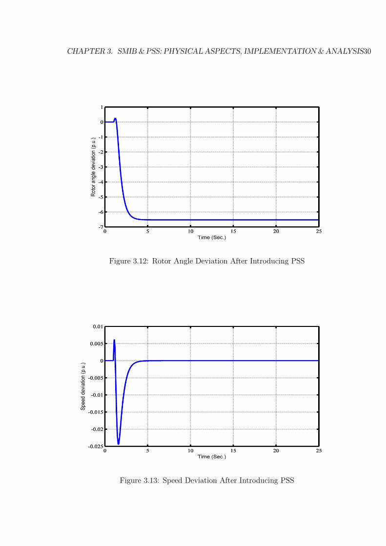
CHAPTER 3. SMIB & PSS: PHYSICAL ASPECTS, IMPLEMENTATION &ANALYSIS30
Figure 3.12: Rotor Angle Deviation After Introducing PSS
Figure 3.13: Speed Deviation After Introducing PSS
CHAPTER 3. SMIB & PSS: PHYSICAL ASPECTS, IMPLEMENTATION &ANALYSIS31
3.2 Summary
The chapter provides basic analysis on effect of AVR gain on power system stability
that produces power system oscillations of increasing amplitude.For the purpose of
analysis, typical SMIB system has been linearized to get the eigenvalues for different
values of AVR gain. Further, the damping of low frequency oscillations is achieved
by properly tuned PSS. The chapter provide s platform for implementation of power
system stabilizer in multimachine power system which is discussed in subsequent
chapter.
Chapter 4
Optimal Placement of PSS in
Multimachine Power System
4.1 Background
The enhancement of damping of low frequency oscillations in multimachine power
systems by the application of a PSS has become a matter of great attention. It
is much more significant in current scenario where many large and complex power
systems frequently operate close to their stability limits. Though, there is common
perception that the application of PSS is almost a mandatory requirement on all
generators, the use of high price PSS with each and every generator is constrained by
economical limits. In view of the potentially high cost of using a PSS and to assess its
effectiveness in damping poorly damped oscillatory modes to achieve better stability,
identification of the optimum site of PSS is an important task.
4.2 Test System Description
Fig.4.1 shows the two-area benchmark power system which is developed by P.Kundur
considered for choosing optimal location of PSS.
The system contains eleven buses and two areas, connected by a weak tie between
bus 7 and 9. Each area consists of two generators, each having a rating of 900 MVA
and 20 kV. Inertia constant of area-1 generators is 6.5sec and of area-2 generators is
32

CHAPTER 4. OPTIMAL PLACEMENTOF PSS INMULTIMACHINE POWER SYSTEM33
6.17 5sec. Totally two loads are applied to the system at bus 7 and 9. Two shunt
capacitors are also connected to bus 7 and 9 as shown in the figure below. For the
comparisons of the obtained results with that available in literature, the frequency of
operation is chosen as 60 Hz.
Figure 4.1: Single Line Diagram of Test System
The three step methodology adopted for deciding optimal location of PSS is as
follows. Power System Analysis Toolbox-PSAT is used to carry out the following
analysis:
(i) Load Flow Analysis
(ii) Linear (S-Domain) Analysis
(iii) Time Domain Simulations
4.3 Load Flow Analysis
Power flow analysis provides information regarding active and reactive power along
with other pertinent information such as bus bar voltage levels, effect of inphase
and quadrature boost voltages on system loading, reactive power compensation. The
stability of the power system is related to the deficiency or redundancy in generation
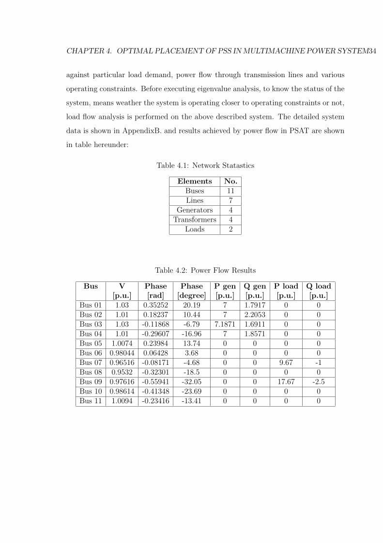
CHAPTER 4. OPTIMAL PLACEMENTOF PSS INMULTIMACHINE POWER SYSTEM34
against particular load demand, power flow through transmission lines and various
operating constraints. Before executing eigenvalue analysis, to know the status of the
system, means weather the system is operating closer to operating constraints or not,
load flow analysis is performed on the above described system. The detailed system
data is shown in AppendixB. and results achieved by power flow in PSAT are shown
in table hereunder:
Table 4.1: Network Statastics
Elements No.Buses 11Lines 7
Generators 4Transformers 4
Loads 2
Table 4.2: Power Flow Results
Bus V Phase Phase P gen Q gen P load Q load[p.u.] [rad] [degree] [p.u.] [p.u.] [p.u.] [p.u.]
Bus 01 1.03 0.35252 20.19 7 1.7917 0 0Bus 02 1.01 0.18237 10.44 7 2.2053 0 0Bus 03 1.03 -0.11868 -6.79 7.1871 1.6911 0 0Bus 04 1.01 -0.29607 -16.96 7 1.8571 0 0Bus 05 1.0074 0.23984 13.74 0 0 0 0Bus 06 0.98044 0.06428 3.68 0 0 0 0Bus 07 0.96516 -0.08171 -4.68 0 0 9.67 -1Bus 08 0.9532 -0.32301 -18.5 0 0 0 0Bus 09 0.97616 -0.55941 -32.05 0 0 17.67 -2.5Bus 10 0.98614 -0.41348 -23.69 0 0 0 0Bus 11 1.0094 -0.23416 -13.41 0 0 0 0
CHAPTER 4. OPTIMAL PLACEMENTOF PSS INMULTIMACHINE POWER SYSTEM35
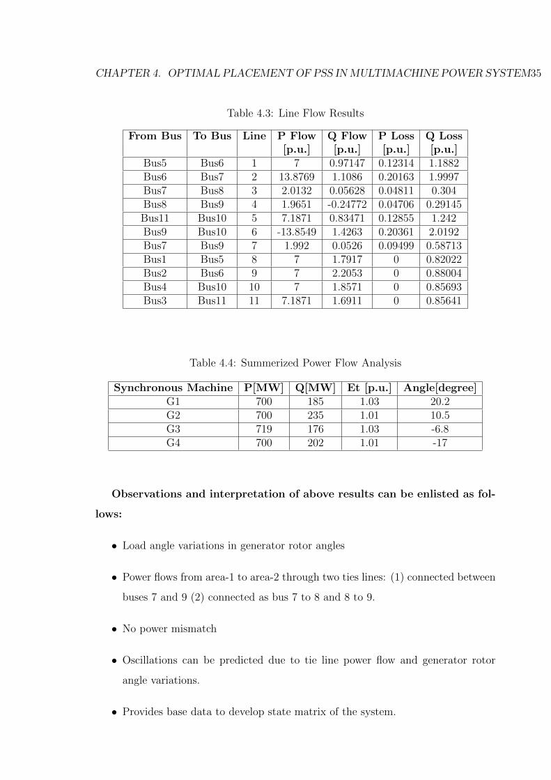
Table 4.3: Line Flow Results
From Bus To Bus Line P Flow Q Flow P Loss Q Loss[p.u.] [p.u.] [p.u.] [p.u.]
Bus5 Bus6 1 7 0.97147 0.12314 1.1882Bus6 Bus7 2 13.8769 1.1086 0.20163 1.9997Bus7 Bus8 3 2.0132 0.05628 0.04811 0.304Bus8 Bus9 4 1.9651 -0.24772 0.04706 0.29145Bus11 Bus10 5 7.1871 0.83471 0.12855 1.242Bus9 Bus10 6 -13.8549 1.4263 0.20361 2.0192Bus7 Bus9 7 1.992 0.0526 0.09499 0.58713Bus1 Bus5 8 7 1.7917 0 0.82022Bus2 Bus6 9 7 2.2053 0 0.88004Bus4 Bus10 10 7 1.8571 0 0.85693Bus3 Bus11 11 7.1871 1.6911 0 0.85641
Table 4.4: Summerized Power Flow Analysis
Synchronous Machine P[MW] Q[MW] Et [p.u.] Angle[degree]G1 700 185 1.03 20.2G2 700 235 1.01 10.5G3 719 176 1.03 -6.8G4 700 202 1.01 -17
Observations and interpretation of above results can be enlisted as fol-
lows:
• Load angle variations in generator rotor angles
• Power flows from area-1 to area-2 through two ties lines: (1) connected between
buses 7 and 9 (2) connected as bus 7 to 8 and 8 to 9.
• No power mismatch
• Oscillations can be predicted due to tie line power flow and generator rotor
angle variations.
• Provides base data to develop state matrix of the system.
CHAPTER 4. OPTIMAL PLACEMENTOF PSS INMULTIMACHINE POWER SYSTEM36
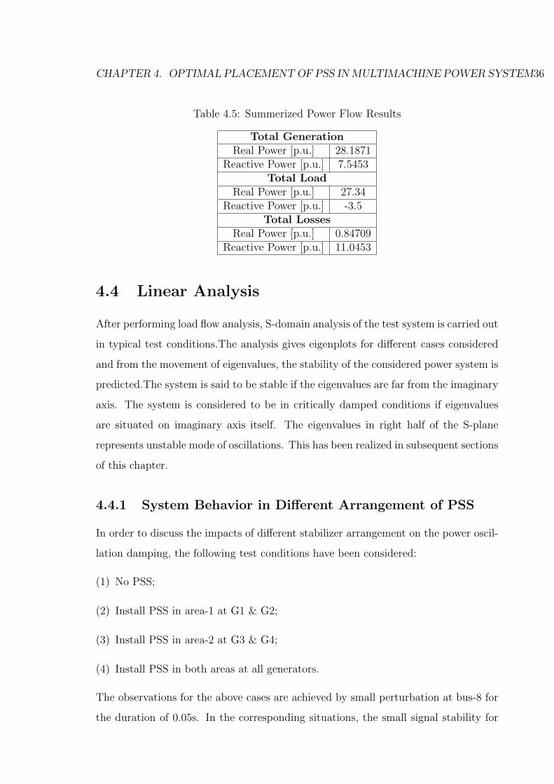
Table 4.5: Summerized Power Flow Results
Total GenerationReal Power [p.u.] 28.1871
Reactive Power [p.u.] 7.5453Total Load
Real Power [p.u.] 27.34Reactive Power [p.u.] -3.5
Total LossesReal Power [p.u.] 0.84709
Reactive Power [p.u.] 11.0453
4.4 Linear Analysis
After performing load flow analysis, S-domain analysis of the test system is carried out
in typical test conditions.The analysis gives eigenplots for different cases considered
and from the movement of eigenvalues, the stability of the considered power system is
predicted.The system is said to be stable if the eigenvalues are far from the imaginary
axis. The system is considered to be in critically damped conditions if eigenvalues
are situated on imaginary axis itself. The eigenvalues in right half of the S-plane
represents unstable mode of oscillations. This has been realized in subsequent sections
of this chapter.
4.4.1 System Behavior in Different Arrangement of PSS
In order to discuss the impacts of different stabilizer arrangement on the power oscil-
lation damping, the following test conditions have been considered:
(1) No PSS;
(2) Install PSS in area-1 at G1 & G2;
(3) Install PSS in area-2 at G3 & G4;
(4) Install PSS in both areas at all generators.
The observations for the above cases are achieved by small perturbation at bus-8 for
the duration of 0.05s. In the corresponding situations, the small signal stability for
CHAPTER 4. OPTIMAL PLACEMENTOF PSS INMULTIMACHINE POWER SYSTEM37
the inter-area oscillation has been analyzed in detail with the eigenvalues analysis
method using PSAT Toolbox. PSAT is an add-on MATLAB toolbox for electric
power system analysis and control. PSAT includes power flow, continuation power
flow, optimal power flow, small-signal stability analysis and time domain simulation.
All operations can be assessed by means of Graphical User Interfaces (GUIs) and a
Simulink-based library provides a user friendly tool for network design[9].The details
of PSAT is given in AppendixC.
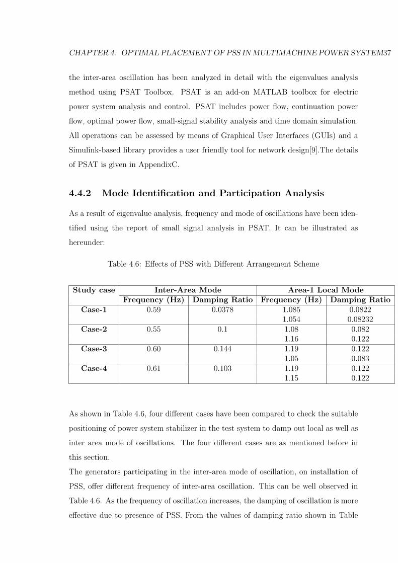
4.4.2 Mode Identification and Participation Analysis
As a result of eigenvalue analysis, frequency and mode of oscillations have been iden-
tified using the report of small signal analysis in PSAT. It can be illustrated as
hereunder:
Table 4.6: Effects of PSS with Different Arrangement Scheme
Study case Inter-Area Mode Area-1 Local ModeFrequency (Hz) Damping Ratio Frequency (Hz) Damping Ratio
Case-1 0.59 0.0378 1.085 0.08221.054 0.08232
Case-2 0.55 0.1 1.08 0.0821.16 0.122
Case-3 0.60 0.144 1.19 0.1221.05 0.083
Case-4 0.61 0.103 1.19 0.1221.15 0.122
As shown in Table 4.6, four different cases have been compared to check the suitable
positioning of power system stabilizer in the test system to damp out local as well as
inter area mode of oscillations. The four different cases are as mentioned before in
this section.
The generators participating in the inter-area mode of oscillation, on installation of
PSS, offer different frequency of inter-area oscillation. This can be well observed in
Table 4.6. As the frequency of oscillation increases, the damping of oscillation is more
effective due to presence of PSS. From the values of damping ratio shown in Table

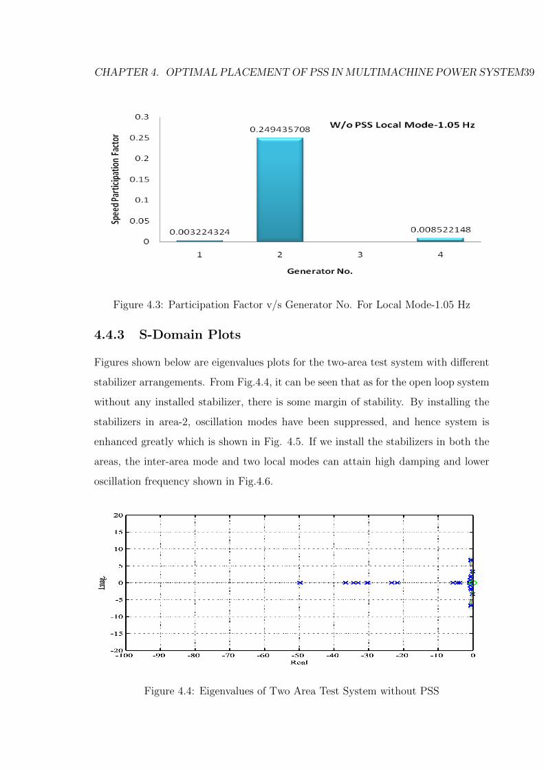
CHAPTER 4. OPTIMAL PLACEMENTOF PSS INMULTIMACHINE POWER SYSTEM38
4.6, it can be inferred that, the local & inter area both the modes of oscillations
can be damped definitely by placing PSS in both the areas. For damping of local
mode oscillations, there are three choices. One can follow the either of choice from
case no. 2, 3 and 4. The value of damping ratio that we get for local as well as
inter area mode, in case 1, is comparatively smaller than the other cases. Hence it
is not considered as a suitable choice for installation of PSS. In case no. 4 PSS is
installed at all generators. Although it gives best damping effect, but it will result in
redundancy of no. of PSS used. So, in this report case no. 3 has been considered as
suitable choice for placement of PSS, because it provides sufficient damping to local
as well as inter area mode of oscillations. It is being worth noted that the generators
of Area-2 are participating significantly only in inter area mode for considered cases.
They have negligible contribution to local mode oscillations. Hence, not depicted in
Table 4.6. Further this can also be realized from the plot of speed participation factor
v/s generator no. shown in Fig.4.2 and 4.3.Resembling plots can be possible for other
modes of frequency for various cases.
Figure 4.2: Speed Participation Factor v/s Generator No. For Inter-Area Mode-0.54Hz
CHAPTER 4. OPTIMAL PLACEMENTOF PSS INMULTIMACHINE POWER SYSTEM39
Figure 4.3: Participation Factor v/s Generator No. For Local Mode-1.05 Hz
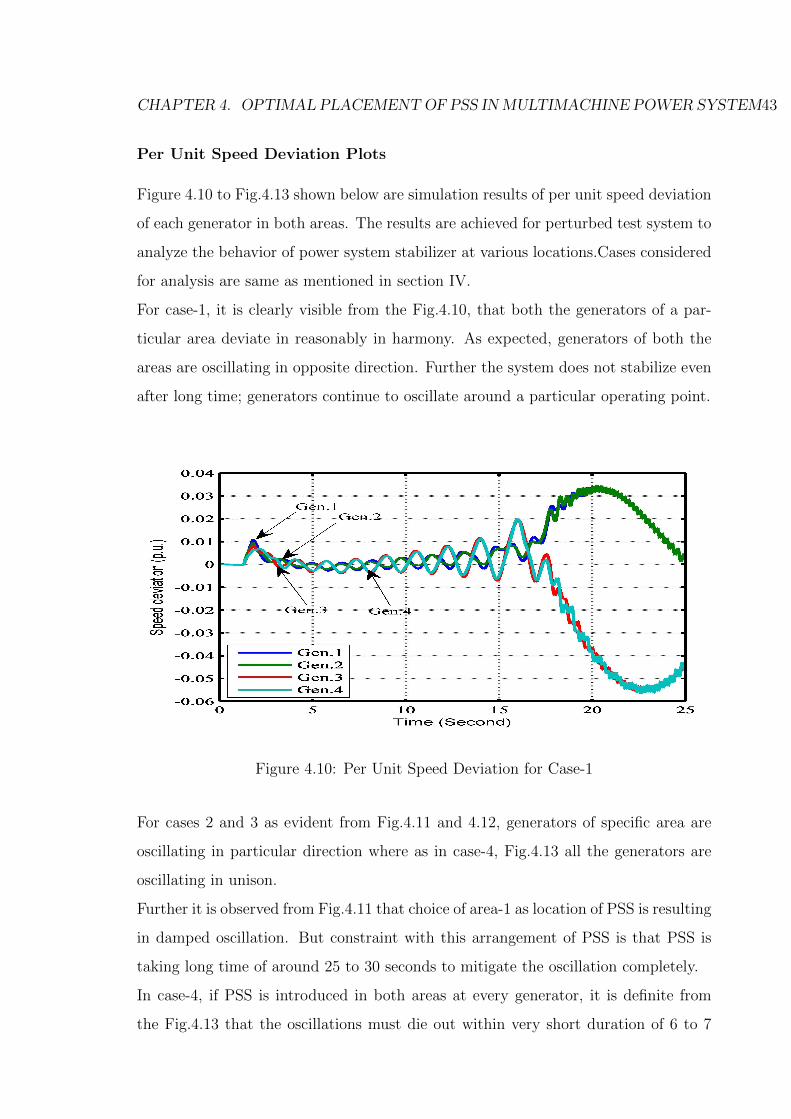
4.4.3 S-Domain Plots
Figures shown below are eigenvalues plots for the two-area test system with different
stabilizer arrangements. From Fig.4.4, it can be seen that as for the open loop system
without any installed stabilizer, there is some margin of stability. By installing the
stabilizers in area-2, oscillation modes have been suppressed, and hence system is
enhanced greatly which is shown in Fig. 4.5. If we install the stabilizers in both the
areas, the inter-area mode and two local modes can attain high damping and lower
oscillation frequency shown in Fig.4.6.
Figure 4.4: Eigenvalues of Two Area Test System without PSS

CHAPTER 4. OPTIMAL PLACEMENTOF PSS INMULTIMACHINE POWER SYSTEM40
Figure 4.5: Eigenvalues of Two Area Test System with PSS in Area-2
Figure 4.6: Eigenvalues of Two Area Test System with PSS in Both Areas
4.4.4 Time Domain Simulations
For the verification and realization of concept of small signal oscillations, a two area
model described earlier has been developed using MATLAB c©/SIMULINK software
as shown in 4.7. In this model, standard p.u. model of generator is considered. The
generator parameters in per unit on the rated MVA and kV base and the details of

CHAPTER 4. OPTIMAL PLACEMENTOF PSS INMULTIMACHINE POWER SYSTEM41
exciter parameter, Step-up transformer, transmission line & load are as per Kundur’s
Two Area test system .
Figure 4.7: MATLAB/SIMULINK Model of Test System
Details of power system stabilizers employed are as in block diagram in Fig.4.8. The
simulations were carried out and various analysis results are depicted pictorially for
clarity.
Figure 4.8: Block Diagram of PSS
The power system stabilizer model is with single input of the rotor speed deviation.
The damping is mostly determined by the gain KS=20, and the following sub-block
of wash out circuit has the high-pass filtering function to ensure the stabilizer has the
relative better response on the speed deviation. There are also lead-lag transfer func-
tions to compensate the phase lag between the excitation model and the synchronous
machine.

CHAPTER 4. OPTIMAL PLACEMENTOF PSS INMULTIMACHINE POWER SYSTEM42
Power Flow Plots
In order to represent the concerned oscillation effects, the time domain analysis for
the test system has been performed. Fig.4.9 shows the simulation results on the line
power flow from area 1 to area 2.
It can be observed that the arrangement on stabilizer installation for every machine
in both areas has the best damping effects on inter-area oscillation, which is in unison
with the dominant eigenvalues analysis results discussed in earlier section.
If there is no stabilizer for machines in both areas, the inter-area oscillation is un-
avoidable. The power transfer for such a case would reach to 800 MW with significant
oscillations. This leads to stresses in a weakly coupled tie line. System will be highly
oscillatory and hence may result into instability.
Figure 4.9: Power Flow from Area-1 to Area-2
Comparative analysis of the oscillations between areas indicate that installing the
stabilizers for G3 and G4 in area-2 is a relative optimal solution to damp the inter-
area oscillations. For this particular location of PSS, the constant active power flow
is identified as 413 MW from area-1 to area-2. Thus by proper placement of PSS and
tuning, constant power flow and damped inter area oscillations is achieved.
CHAPTER 4. OPTIMAL PLACEMENTOF PSS INMULTIMACHINE POWER SYSTEM43
Per Unit Speed Deviation Plots
Figure 4.10 to Fig.4.13 shown below are simulation results of per unit speed deviation
of each generator in both areas. The results are achieved for perturbed test system to
analyze the behavior of power system stabilizer at various locations.Cases considered
for analysis are same as mentioned in section IV.
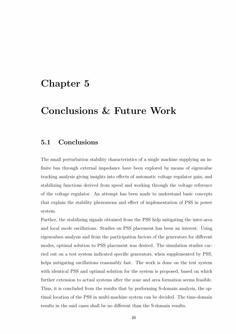
For case-1, it is clearly visible from the Fig.4.10, that both the generators of a par-
ticular area deviate in reasonably in harmony. As expected, generators of both the
areas are oscillating in opposite direction. Further the system does not stabilize even
after long time; generators continue to oscillate around a particular operating point.
Figure 4.10: Per Unit Speed Deviation for Case-1
For cases 2 and 3 as evident from Fig.4.11 and 4.12, generators of specific area are
oscillating in particular direction where as in case-4, Fig.4.13 all the generators are
oscillating in unison.
Further it is observed from Fig.4.11 that choice of area-1 as location of PSS is resulting
in damped oscillation. But constraint with this arrangement of PSS is that PSS is
taking long time of around 25 to 30 seconds to mitigate the oscillation completely.
In case-4, if PSS is introduced in both areas at every generator, it is definite from
the Fig.4.13 that the oscillations must die out within very short duration of 6 to 7

CHAPTER 4. OPTIMAL PLACEMENTOF PSS INMULTIMACHINE POWER SYSTEM44
Figure 4.11: Per Unit Speed Deviation for Case-2
seconds. But at the same time it is not favorable situation because placing PSS at
every generator has a redundancy in the solution.
Figure 4.12: Per Unit Speed Deviation for Case-3
For better choice which is optimized one is case-3. In this case PSS are installed at
both the generators of area-2. As shown in Fig. 4.12, the oscillations are mitigated
in about 10 sec.

CHAPTER 4. OPTIMAL PLACEMENTOF PSS INMULTIMACHINE POWER SYSTEM45
Figure 4.13: Per Unit Speed Deviation for Case-4
4.5 Summary
This chapter presents the power system stabilizer with the consideration of local
and inter-area mode of oscillations, to damp the potential power oscillation. Based
on this, the eigenvalues analysis method has been adopted to analyze the damping
effects of various arrangement schemes of such stabilizer. The case study on the
typical 4-machines 2-area test system shows that although the best arrangement
scheme that install the stabilizer for every machine and area can obtain the best
oscillation damping effect, it is not the economical solution scheme especial to the
large power networks, and the scheme that arrange stabilizer for one area is the
optimal arrangement with the consideration of economical factor.
Chapter 5
Conclusions & Future Work
5.1 Conclusions
The small perturbation stability characteristics of a single machine supplying an in-
finite bus through external impedance have been explored by means of eigenvalue
tracking analysis giving insights into effects of automatic voltage regulator gain, and
stabilizing functions derived from speed and working through the voltage reference
of the voltage regulator. An attempt has been made to understand basic concepts
that explain the stability phenomena and effect of implementation of PSS in power
system.
Further, the stabilizing signals obtained from the PSS help mitigating the inter-area
and local mode oscillations. Studies on PSS placement has been an interest. Using
eigenvalues analysis and from the participation factors of the generators for different
modes, optimal solution to PSS placement was desired. The simulation studies car-
ried out on a test system indicated specific generators, when supplemented by PSS,
helps mitigating oscillations reasonably fast. The work is done on the test system
with identical PSS and optimal solution for the system is proposed, based on which
further extension to actual systems after the zone and area formation seems feasible.
Thus, it is concluded from the results that by performing S-domain analysis, the op-
timal location of the PSS in multi-machine system can be decided. The time-domain
results in the said cases shall be no different than the S-domain results.
46

CHAPTER 5. CONCLUSIONS & FUTURE WORK 47
5.2 Future Work
• As an extension to the presented work, it is suggested to observe results of
employing PSS with various gains and design to achieve quicker oscillation mit-
igation, avoid speed deviations, which may give better insight.
• The future researches on the arrangement rules with evolutionary algorithm and
the coordinated FACTS device to obtain the better power oscillation damping
effects can be concerned and performed.

References
[1] ] Prabha Kundur, “Power System Stability and Control,” The EPRI Power Sys-
tem Engineering Series, 1994, McGraw-Hill, ISBN 0-07-063515-3.
[2] K.R.Padiyar, “Power System Dynamics Stability and Control,” B.S Publications,
2002, ISBN: 81-7800-024-5.
[3] K.N.Shubhanga, “Manual for a Multimachine Transient Stability Programme,”
Version 1.0.
[4] M. Klein, G.J.Rogers, and P.Kundur, “A Fundamental Study of Inter-Area Os-
cillations,” IEEE Trans. on Power Systems, Vol.6, no-3, Aug. 1991, pp. 914-921.
[5] Liao Quingfin, Liudichen, Zeng Cong, Ying Liming, Cui Xue. “Eigen value sen-
sitivities of excitation system, model and parameters,” 3rd IEEE Conf. On In-
dustrial Electronics and Applications, June-2008, pp. 2239-2243.
[6] F.P.DeMello and C.Concordia, “Concepts of Synchronous Machine Stability as
Affected by Excitation Control,” IEEE Trans. on Power Apparatus and Systems,
PAS-88, Apr. 1969, pp.316-329.
[7] Gurunath Gurrala, “Power System Stabilizer Design for Interconnected power
System,” IEEE Trans. on Power Systems, vol.25, no.2, May 2010, pp. 1042-1051.
[8] M.Klein, G.J.Rogers, S.Moorty, P.Kundur, “Analytical Investigation of Factors
Influencing Power System Stabilizer Performance,” IEEE Trans. on Energy Con-
version , vol.7, no.3, Sept. 1992, pp. 382 - 390.
[9] Federico Milano, “Documentation for Power System Analysis Toolbox (PSAT),”
2004.
48

Appendix A
IEEE Proceeding
[1] Devendra P.Parmar, Vihang M.Dholakiya, and Santosh C.Vora, “Optimal Place-
ments of Power System stabilizers: Simulation studies on Test System”, Presented
at 2nd International conference of Current Trends in Technology (NUiCONE’11) at
Nirma University, Ahmedabad , ISBN No.: 978-1-4577-2169-4 .
49

Appendix B
System Data
The system consist of two similar area connected by a weak tie line. Each area con-
sists of two coupled units, The parameters of system as depicted in below tables.
Machines Data:
Table B.1: Machine Data of Two Area Test SystemGen. MVA Xd Xd’ Xd” Tdo’ Tdo” Xq Xq’ Xq” Tqo’ Tqo”No Rating (p.u.) (p.u.) (p.u.) Sec. Sec. (p.u.) (p.u.) (p.u.) Sec. Sec.1 900 1.8 0.3 0.25 8.0 0.03 1.7 0.55 0.25 0.4 0.052 900 1.8 0.3 0.25 8.0 0.03 1.7 0.55 0.25 0.4 0.053 900 1.8 0.3 0.25 8.0 0.03 1.7 0.55 0.25 0.4 0.054 900 1.8 0.3 0.25 8.0 0.03 1.7 0.55 0.25 0.4 0.05
Inertia constant of Area-1 machines are 6.5 (for G1 & G2), Area-2 machines are 6.125
(for G3 & G4). Each step up transformer has an impedance of 0 + j0.15 p.u. on 900
MVA and 20/230 kV base, and has an off-nominal ratio of 1.0.
Line Data:
The Transmission system nominal voltage is 230 kV. The parameters of the lines in
per unit on 100 MVA, 230 kV base are shown in below Table:
50

APPENDIX B. SYSTEM DATA 51
Table B.2: Line Data of Two Area Test SystemFrom Bus To Bus Length km r pu/km xl pu/km bc pu/km
5 6 25 0.0001 0.001 0.001756 7 10 0.0001 0.001 0.001757 8 110 0.0001 0.001 0.001758 9 110 0.0001 0.001 0.001757 9 220 0.0001 0.001 0.001759 10 10 0.0001 0.001 0.0017510 11 25 0.0001 0.001 0.00175
Load Data:
The load and reactive power supplied by the shunt capacitors at buses 7 and 9 are as
follows:
Table B.3: Load Data of Two Area Test SystemBus No. PL (MW) QL (MVAr) QC (MVAr)
7 967 100 2009 1767 100 350
Exciter and PSS Data:
Table B.4: Exciter & PSS Data of Two Area Test SystemKA = 200 TR = 0.01 KSTAB = 20.0 TW = 10.0T1 = 0.05 T2 = 0.02 T3 = 3.0 T4 = 5.4

Appendix C
Introduction to PSAT 2.1.6
PSAT is free and open Source software particularly suited for analysis of Power Sys-
tems Stability and Control. The PSAT is a MATLAB toolbox for electric power
systems analysis and Simulation. All the operation can be accessed by means of
graphical user interfaces (GUIs) and Simulink based library provides an user friendly
tool for network design.
C.1 Overview
PSAT core is powerflow routines, once the powerflow has been solved, further static
and/or dynamic analysis can be performed.Following analysis performed in PSAT
tool box.
• Optimal Power flow (OPF)
• Continuous Power Flow (CPF) / Voltage Stability Analysis
• Small Signal Stability analysis
• Time domain Simulations
• PMU Placement
• Graphical user Interface (GUIs)
• Graphical Network Construction (CAD)
52

APPENDIX C. INTRODUCTION TO PSAT 2.1.6 53
C.1.1 Useful Features
• Mathematical model & utilities
• Bridges to other Programs
• Data format conversion capability
C.1.2 PSAT Utilities
• Simulink library for drawing network.
• GUIs For settings system and routine parameters.
• GUI for plotting results.
• Filters for converting data to and from other formats.
C.2 Starting Process of PSAT
Prilimary steps of PSAT applications in analysis of Power Systems Problems:
a. PSAT Installation
b. Launching PSAT
c. Loading data
d. Running Power flow program
e. Displaying results
f. Saving results
g. Setting

APPENDIX C. INTRODUCTION TO PSAT 2.1.6 54
F PSAT Installation
a. Download PSAT version from site :
http://www.uclm.es/area/gsee/Web/Federico/psat.htm
b. Requirements : >> Matlab 6.5
c. Installation
• Extract Zip file in a good location
• Open Matlab
• Add PSAT’s path to Matlab default path
Launching of PSAT
• Type psat.m in MATLAB command window: >> psat.m
This will create all the structures required by the toolbox , then opens psat GUI.
Loading data
Almost all operations require that a data file is loaded. To load a file, Load only a
data file:
• Menu File/Open/Data File
• Short cut <Ctr-d>
Load a saved system:
• File/Open/Saved System
• Short cut <Ctr-y>

APPENDIX C. INTRODUCTION TO PSAT 2.1.6 55
The data file can be either a .m file in PSAT format or a .mdl Simulink model created
with the PSAT library. If the source is in a different format supported by the PSAT
format conversion utility, first perform the conversion in order to create the PSAT
data file.
Running Power flow Program
To run the power flow routine:
• Menu Run/Power Flow
• Short cut <Ctr-p>
It is not necessary to load again the data file every time it is modify, because the last
version of the data file is read each time the power flow is performed. The data are
updated also in case of changes in the Simulink model originally loaded.
Other Analysis
• After solving the first power flow, the program is ready for further analysis,
such as CPF , OPF , ...
• Each of these procedures can be launched from the tool-bar or the menu-bar of
the main window.
Displaying Results
Results can be generally displayed in more than one way, either by means of a graph-
ical user interface in MATLAB or as a ASCII text file.
These routines only create a text report:
• Standard Power flow (in a .txt , .xls or .tex file)

APPENDIX C. INTRODUCTION TO PSAT 2.1.6 56
• PMU placement (in a .eig file)
• SSSA (Small Signal Stability analysis) (in a .pmu file)
Saving Results
To save actual System status in a .mat file :
• Menu File/Save/Current System
• Shortcut <Ctrl-a>
All global structures used by PSAT are stored in this file which is placed in the folder
of the current data file. all static computations allow to create a report in a text file
that can be stored and used later.
Settings
The main settings of the system are directly included in the main window:
• Base frequency
• Base Power
• Start & End Simulation Time
• static and dynamic tolerance
• Maximum number of iterations
Other general settings
• Menu Edit/General Settings or <Ctr-k>
Network Design
PSAT allows drawing electrical schemes by means of pictorial blocks. To launch
PSAT library
APPENDIX C. INTRODUCTION TO PSAT 2.1.6 57
• click on Simulink icon in the menu-bar,
• the menu Edit/Network/Edit Network or
• the short cut <Ctr-s>.
PSAT comes with variety of procedures for static and dynamic analysis, several mod-
els of standard and unconventional devices, a complete GUI, and a Simulink-based
network editor. These features make PSAT suited for both educational and research
purposes.
C.3 Useful Links
Following links related to power systems:
a. http://www.engin.umich.edu/group/ctm/ : Control Tutorial for MATLAB
b. http://www.dmoz.org/Science/Technology/Software for Engineering/
Electrical Engineering/Power Distribution/ : Open Software for Power Systems
c. http://www.uclm.edu/area/gsee/Web/Federico/psat.htm :PSAT software down-
load
d. http://www.ece.mtu.edu/faculty/ljbohman/peec/Dig Rsor.htm : Opensource
Educational Software (Power Engineer Education Committee)
e. http://www.animations.physics.unsw.edu.au/jw/electricmotors.html : Electri-
cal Motor and Generator Fundamental Tutorial
f. http://www.ee.iitb.ac.in/trivedi/latex.htm : Help on Latex Software
g. http://www.latex-project.org
Index
Classification of Power System Stability, 5
Eigenvalue Analysis Method, 9
Eigenvalue Tracking Analysis, 22
General Structure of PSS, 26
Haffron-Phillips Model of Excitation System,
18
Interpretation of K-constants, 19
Small Signal Stability, 7
Synchronizing and Damping Torque Analy-
sis, 12
58
Related Documents


