Lab Assignment No.1 Title:- “Introduction to Analog Power Network Simulator.” Theory:- Power network simulator is defined as replication of original power system on which various normal and abnormal conditions/phenomenon can be performed. Normal Conditions:- Following are the normal conditions for power system. 1. Rated Voltage (system voltage should be in permissible range ) 2. Rated Frequency 3. Balanced Load 4. Maintain stability 5. Power generation should be greater than demand Abnormal Conditions:- Following are the abnormal conditions for power system. 1. Short circuits 2. Switching Surges 3. Lightning over Voltages 4. Ferranti effect 5. Mal Synchronization Ferranti Effect:-

Welcome message from author
This document is posted to help you gain knowledge. Please leave a comment to let me know what you think about it! Share it to your friends and learn new things together.
Transcript
Lab Assignment No.1
Title:-
“Introduction to Analog Power Network Simulator.”
Theory:-
Power network simulator is defined asreplication of original power system on which various normal and abnormal conditions/phenomenon can be performed.
Normal Conditions:-
Followingare the normal conditions for power system.
1. Rated Voltage (system voltage should be in permissible range)
2. Rated Frequency3. Balanced Load4. Maintain stability 5. Power generation should be greater than demand
Abnormal Conditions:-
Following are theabnormal conditions for power system.
1. Short circuits2. Switching Surges 3. Lightning over Voltages4. Ferranti effect5. Mal Synchronization
Ferranti Effect:-
Ferranti effect is anincrease in voltage occurring at the receiving end of a longtransmission line, above the voltage at the sending end. Thisoccurs when the line is energized, but there is a very light loador the load is disconnected. The capacitive line charging currentproduces a voltage drop across the line inductance that is in-phase with the sending end voltages considering the lineresistance as negligible. Therefore both line inductance andcapacitance are responsible for this phenomenon.
Conditions For Ferranti Effect:-
Ferranti Effect has 2 main conditions
1. No Load2. Large/medium transmission line
0-----80 Km----------- Short
80--240Km----------- Medium
Greater than 240------ Large
Synchronization:-
Process ofconnection two different sources through synchronizing breakersfor the given conditions (same voltage, same frequency, samephase angle & same phase sequence) is called Synchronization.
The sequence of events is similar for manual or automaticsynchronization. The generator is brought up to approximatesynchronous speed by supplying more energy to its shaft - forexample, opening the valves on a steam turbine, opening the gates
on a hydraulic turbine, or increasing the fuel rack setting on adiesel engine. The field of the generator is energized and thevoltage at the terminals of the generator is observed andcompared with the system. The voltage magnitude must be the sameas the system voltage.
If one machine is slightly out of phase it will pull into stepwith the others but, if the phase difference is large, there willbe heavy cross-currents which can cause voltage fluctuations and,in extreme cases, damage to the machines.
Synchroscope:-
The manual method of synchronization relies on observing aninstrument called a "synchroscope", which displays the relativefrequencies of system and generator. The pointer of thesynchroscope will indicate "fast" or "slow" speed of thegenerator with respect to the system. To minimize the transientcurrent when the generator circuit breaker is closed, usualpractice is to initiate the close as the needle slowly approachesthe in-phase point. An error of a few electrical degrees betweensystem and generator will result in a momentary inrush and abruptspeed change of the generator.
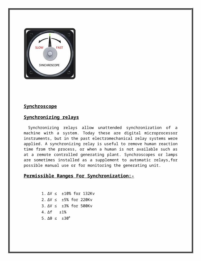
Synchroscope
Synchronizing relays
Synchronizing relays allow unattended synchronization of amachine with a system. Today these are digital microprocessorinstruments, but in the past electromechanical relay systems wereapplied. A synchronizing relay is useful to remove human reactiontime from the process, or when a human is not available such asat a remote controlled generating plant. Synchroscopes or lampsare sometimes installed as a supplement to automatic relays,forpossible manual use or for monitoring the generating unit.
Permissible Ranges For Synchronization:-
1. ∆V ≤ ±10% for 132Kv2. ∆V ≤ ±5% for 220Kv3. ∆V ≤ ±3% for 500Kv4. ∆f ±1%5. ∆Ɵ ≤ ±300
Components of Analog Simulator :-
Components of analog simulators are
1. Power Station 1: Representing gas Turbine Power Station (Turbine, Generator, stepup Transformer).
2. Power Station 2: Representing Steam Power Station.3. Synchronizing Panel4. Two Further Inputs5. Four Substations of single bus bar single breaker scheme.6. Four Substations of double bus bar single breaker scheme.7. Artificial transmission lines.8. Fault Simulation Switches.9. Main Panel/Annunciation Panel.10. Load11. Protective Relays.
Major types of Relays according to working principle:-
1. Electromagnetic Relays (1st Generation Relays).2. Solid State Relays (2nd Generation
Relays).3. Microprocessor Based Relays (3rd Generation Relays).
Relays Installed On Generators:-
1. Generator Differential Relay.2. Over current / over load Relay.3. Unbalanced load Relay4. Under frequency Relay.5. Stator earth fault Relay.6. Under excitation Relay7. Reverse Power Relay.8. Rotor earth fault Relay.9. Voltage drop Relay.10. Voltage rise Relay.
Relay Installed On System:-
1. Impedance Relay.2. Differential Relay.3. Over current/earth Fault Relay.
Lab Assignment No.2
Title:-
“Switching Practice / Energization Techniques.”
Objective:-
Combination of Circuit Breakers, line
isolator and earth switch for opening and closing of double bas
bar single bus bar scheme.
Theory:-
Circuit breaker always trip the circuit but open contacts of
breaker cannot be visible physically from outside of the breaker
and that is why it is recommended not to touch any electrical
circuit just by switching off the circuit breaker. So for better
safety there must be some arrangement so that one can see open
condition of the section of the circuit before touching it.
Isolator is a mechanical switch which isolates a part of circuit
from system as when required. Electrical isolators separate a
part of the system from rest for safe maintenance works.
So definition of isolator can be rewritten as Isolator is a
manually operated mechanical switch which separates a part of the
electrical power system normally at off load condition.
Types of Electrical Isolators:-
There are different types of isolators available depending uponsystem requirement such as
1) Double Break Isolator
2) Single Break Isolator
3) Pantograph type Isolator
Depending upon the position in power system, the isolators can becategorized as
1) Bus side isolator–the isolator is directly connected with mainbus
2) Line side isolator–the isolator is situated at line side ofany feeder
3) Transfer bus side isolator – the isolator is directlyconnected with transfer bus.
Constructional Features of Double Break Isolators:-
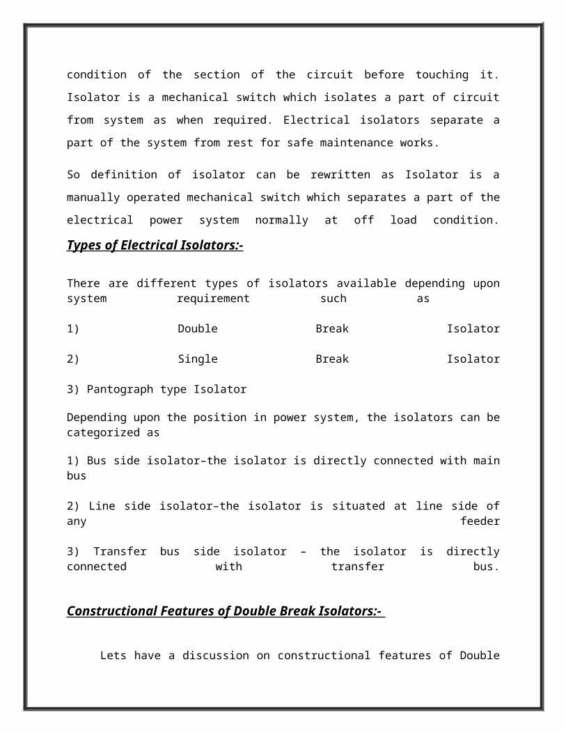
Lets have a discussion on constructional features of Double
Break Isolators. These have three stacks of post insulatorsas shown in the figure. The central post insulator carries atubular or flat male contact which can be rotatedhorizontally with rotation of central post insulator. Thisrod type contact is also called moving contact.
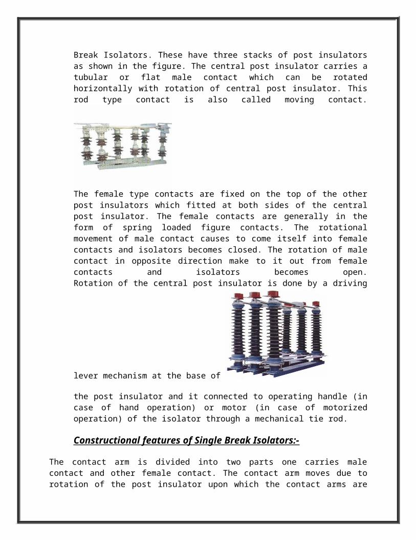
The female type contacts are fixed on the top of the otherpost insulators which fitted at both sides of the centralpost insulator. The female contacts are generally in theform of spring loaded figure contacts. The rotationalmovement of male contact causes to come itself into femalecontacts and isolators becomes closed. The rotation of malecontact in opposite direction make to it out from femalecontacts and isolators becomes open.Rotation of the central post insulator is done by a driving
lever mechanism at the base of
the post insulator and it connected to operating handle (incase of hand operation) or motor (in case of motorizedoperation) of the isolator through a mechanical tie rod.
Constructional features of Single Break Isolators:-
The contact arm is divided into two parts one carries malecontact and other female contact. The contact arm moves due torotation of the post insulator upon which the contact arms are
fitted. Rotation of both post insulators stacks in opposite toeach other causes to close the isolator by closing the contactarm. Counter rotation of both post insulators stacks open thecontact arm and isolator becomes in off condition. This motorizedform of this type of isolators is generally used but emergencyhand driven mechanism is also provided.
Earthing Switches:-
Earthing switches are mounted on the base of mainly line sideisolator. Earthing switches are normally vertically breakswitches. Earthing arms (contact arm of earthing switch) arenormally aligned horizontally at off condition. during switchingon operation, these earthing arms rotate and move to verticalposition and make contact with earth female contacts fitted atthe top of the post insulator stack of isolator at its outgoingside. The erarthing arms are so interlocked with main isolatormoving contacts that it can be closed only when the main contactsof isolator are in open position. Similarly the main isolatorcontacts can be closed only when the earthing arms are in openposition.
Operation of Electrical Isolator:-
As no arc quenching technique is provided in isolator it must beoperated when there is no chance current flowing through thecircuit. No live circuit should be closed or open by isolatoroperation. A complete live closed circuit must not be opened byisolator operation and also a live circuit must not be closed andcompleted by isolator operation to avoid huge arcing in betweenisolator contacts. That is why isolators must be open aftercircuit breaker is open and these must be closed before circuitbreaker is closed. Isolator can be operated by hand locally aswell as by motorized mechanism from remote position. Motorizedoperation arrangement costs more compared to hand operation;hence decision must be taken before choosing an isolator forsystem whether hand operated or motor operated economicallyoptimum for the system. For voltages up to 145KV system hand
operated isolators are used whereas for higher voltage systemslike 245 KV or 420 KV and above motorized isolators are used.
To Energize a line bay steps are :-
1. Open earth switch connected with line isolator.2. Close line isolator.3. Close bus isolator.4. Close circuit Breaker.
To Deenergize a line bay steps are:-
1. Open the Breaker.2. Open bus isolator.3. Open line isolator.4. Close earth switch with line isolator.
Lab Assignment No.3
Title:-
Power Factor Correction
Theory:
Power factor is the ratio between the KW (Kilo-Watts) and the KVA(Kilo-Volt Amperes) drawn by an electrical load where the KW isthe actual load power and the KVA is the apparent load power. Itis a measure of how effectively the current is being convertedinto useful work output and more particularly is a good indicatorof the effect of the load current on the efficiency of the supplysystem.
All current flow will causes losses in the supply anddistribution system. A load with a power factor of 1.0 results inthe most efficient loading of the supply and a load with a powerfactor of 0.5 will result in much higher losses in the supplysystem.
A poor power factor can be the result of either a significantphase difference between the voltage and current at the loadterminals, or it can be due to a high harmonic content ordistorted/discontinuous current waveform.
Poor load current phase angle is generally the result of aninductive load such as an i nduction motor, power transformer,lighting ballasts, welder or induction furnace.
Power Factor Correction:
Capacitive Power Factor correction is applied to circuitswhich include induction motors as a means of reducing theinductive component of the current and thereby reduce the lossesin the supply. There should be no effect on the operation of themotor itself.
An induction motor draws current from the supply, that is madeup of resistive components and inductive components.
The resistive components are:
Load current. Loss current.
The inductive components are:
Leakage reactance. Magnetizing current.
The current due to the leakage reactance is dependant on thetotal current drawn by the motor, but the magnetizing current isindependent of the load on the motor. The magnetizing current
will typically be between 20% and 60% of the rated full loadcurrent of the motor. The magnetizing current is the current thatestablishes the flux in the iron and is very necessary if themotor is going to operate.
The magnetizing current does not actually contribute to theactual work output of the motor. It is the catalyst that allowsthe motor to work properly. The magnetizing current and theleakage reactance can be considered passenger components ofcurrent that will not affect the power drawn by the motor, butwill contribute to the power dissipated in the supply anddistribution system.
Take for example a motor with a current draw of 100 Amps anda power factor of 0.75 The resistive component of the current is75 Amps and this is what the KWh meter measures. The highercurrent will result in an increase in the distribution losses of(100 x 100) /(75 x 75) = 1.777 or a 78% increase in the supplylosses.
Methods of Power Factor Correction:
Capacitors connected at each starter and controlled by eachstarter is known as "Static Power Factor Correction" whilecapacitors connected at a distribution board and controlledindependently from the individual starters is known as "BulkCorrection".
Bulk Correction:
The Power factor of the total current supplied to thedistribution board is monitored by a controller which thenswitches capacitor banks In a fashion to maintain a power factorbetter than a preset limit. (Typically 0.95)
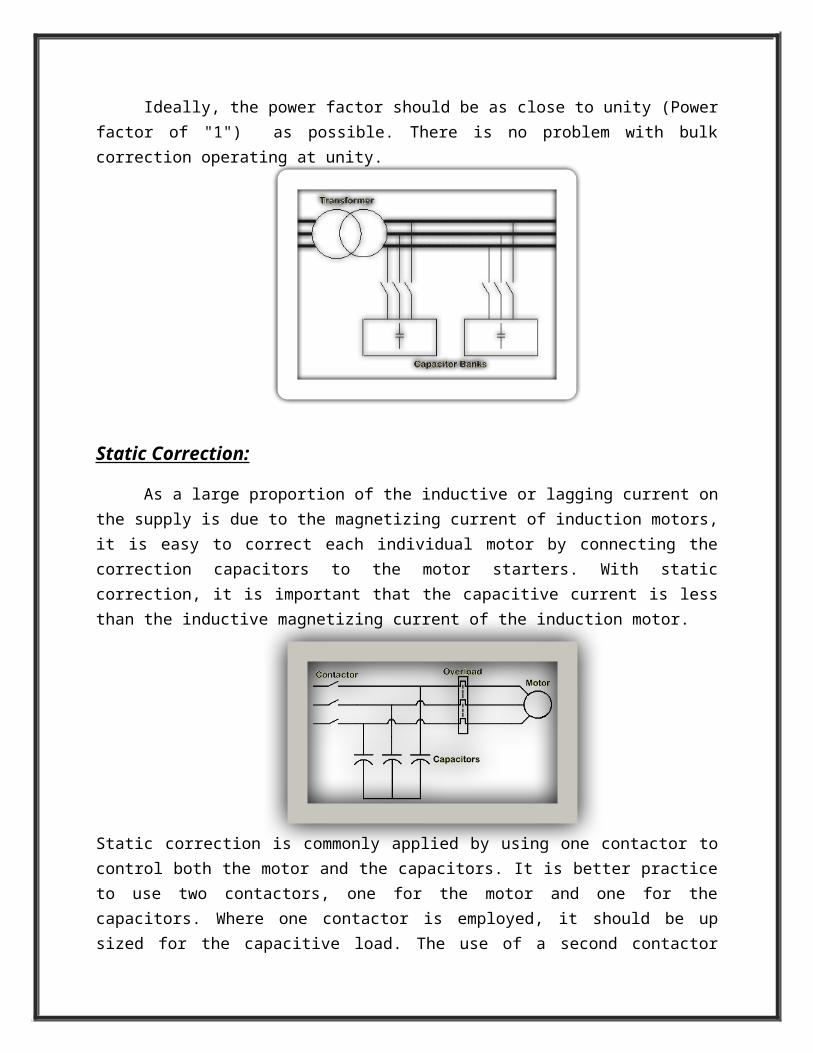
Ideally, the power factor should be as close to unity (Powerfactor of "1") as possible. There is no problem with bulkcorrection operating at unity.
Static Correction:
As a large proportion of the inductive or lagging current onthe supply is due to the magnetizing current of induction motors,it is easy to correct each individual motor by connecting thecorrection capacitors to the motor starters. With staticcorrection, it is important that the capacitive current is lessthan the inductive magnetizing current of the induction motor.
Static correction is commonly applied by using one contactor tocontrol both the motor and the capacitors. It is better practiceto use two contactors, one for the motor and one for thecapacitors. Where one contactor is employed, it should be upsized for the capacitive load. The use of a second contactor
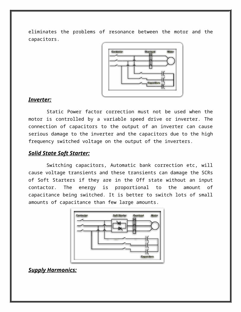
eliminates the problems of resonance between the motor and thecapacitors.
Inverter:
Static Power factor correction must not be used when themotor is controlled by a variable speed drive or inverter. Theconnection of capacitors to the output of an inverter can causeserious damage to the inverter and the capacitors due to the highfrequency switched voltage on the output of the inverters.
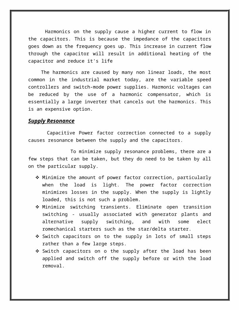
Solid State Soft Starter:
Switching capacitors, Automatic bank correction etc, willcause voltage transients and these transients can damage the SCRsof Soft Starters if they are in the Off state without an inputcontactor. The energy is proportional to the amount ofcapacitance being switched. It is better to switch lots of smallamounts of capacitance than few large amounts.
Supply Harmonics:
Harmonics on the supply cause a higher current to flow inthe capacitors. This is because the impedance of the capacitorsgoes down as the frequency goes up. This increase in current flowthrough the capacitor will result in additional heating of thecapacitor and reduce it's life
The harmonics are caused by many non linear loads, the mostcommon in the industrial market today, are the variable speedcontrollers and switch-mode power supplies. Harmonic voltages canbe reduced by the use of a harmonic compensator, which isessentially a large inverter that cancels out the harmonics. Thisis an expensive option.
Supply Resonance
Capacitive Power factor correction connected to a supplycauses resonance between the supply and the capacitors.
To minimize supply resonance problems, there are afew steps that can be taken, but they do need to be taken by allon the particular supply.
Minimize the amount of power factor correction, particularlywhen the load is light. The power factor correctionminimizes losses in the supply. When the supply is lightlyloaded, this is not such a problem.
Minimize switching transients. Eliminate open transitionswitching - usually associated with generator plants andalternative supply switching, and with some electromechanical starters such as the star/delta starter.
Switch capacitors on to the supply in lots of small stepsrather than a few large steps.
Switch capacitors on o the supply after the load has beenapplied and switch off the supply before or with the loadremoval.
Lab Assignment No.4
Title:-
Synchronization and Mal synchronization
Theory:
In an alternating current electric powersystem, synchronization is the process of matching the speed andfrequency of a generator or other source to a running network. AnAC generator cannot deliver power to an electrical grid unless itis running at the same frequency as the network. If two segmentsof a grid are disconnected, they cannot exchange AC power againuntil they are brought back into exact synchronization.A DC generator can be connected to a power network by adjustingits open-circuit terminal voltage to match the network voltage byeither adjusting its speed or its field excitation; the exactengine speed is not critical. However, an AC machine must matchboth the amplitude and the timing of the network voltage, whichrequires both speed and excitation to be systematicallycontrolled for synchronization.
Conditions:
Phase Sequence Voltage Magnitude Frequency Phase Angle
Waveform and phase sequence are fixed by the construction of thegenerator and its connections to the system. During installationof a generator, careful checks are made to ensure the generatorterminals and all control wiring are correct so that the order ofphases (phase sequence) matches the system. Connecting agenerator with the wrong phase sequence will result in a shortcircuit as the system voltages are opposite to those of thegenerator terminal voltages. The voltage, frequency and phase
angle must be controlled each time a generator is to be connectedto a grid.
Phase Sequence:The phase sequence (or phase rotation) of the three phases of thegenerator must be the same as the phase sequence of the threephases of the electrical system (Grid). The only time that thephase sequence could be wrong is at initial installation or aftermaintenance. There are two possible problem sources. Thegenerator or transformer power leads could actually beinterchanged during maintenance or the potential transformerleads could be interchanged during maintenance.
Voltage Magnitude:The magnitude of the sinusoidal voltage produced by the generatormust be equal to the magnitude of the sinusoidal voltage of thegrid.If all other conditions are met but the two voltages are not thesame, that is there is a voltage differential, closing of the ACgenerator output breaker will cause a potentially large MVARflow.Before a generator is synchronized to the grid, there is nocurrent flow, no armature reaction and therefore the internalvoltage of the generator is the same as the terminal voltage ofthe generator.
Frequency:The frequency of the sinusoidal voltage produced by the generatormust be equal to the frequency of the sinusoidal voltage producedby the grid.
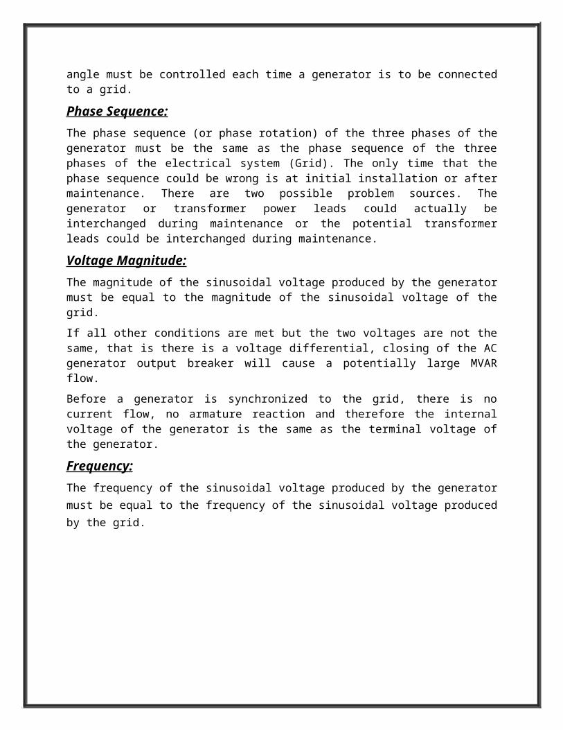
In Figure above the generator is slower than the grid.
The synchroscope would be rotating rapidly counter clockwise. Ifthe generator breaker were to be accidentally closed, thegenerator would be out of step with the external electricalsystem. It would behave like motor and the grid would try tobring it up to speed.
The grid would try to slow it down, again resulting in slippingof poles.
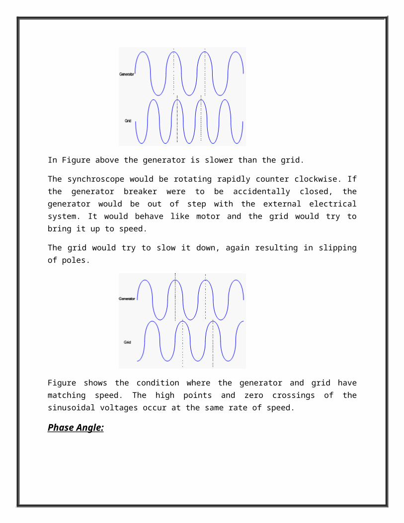
Figure shows the condition where the generator and grid havematching speed. The high points and zero crossings of thesinusoidal voltages occur at the same rate of speed.
Phase Angle:
As previously mentioned, the phase angle between the voltageproduced by the generator and the voltage produced by the gridmust be zero.
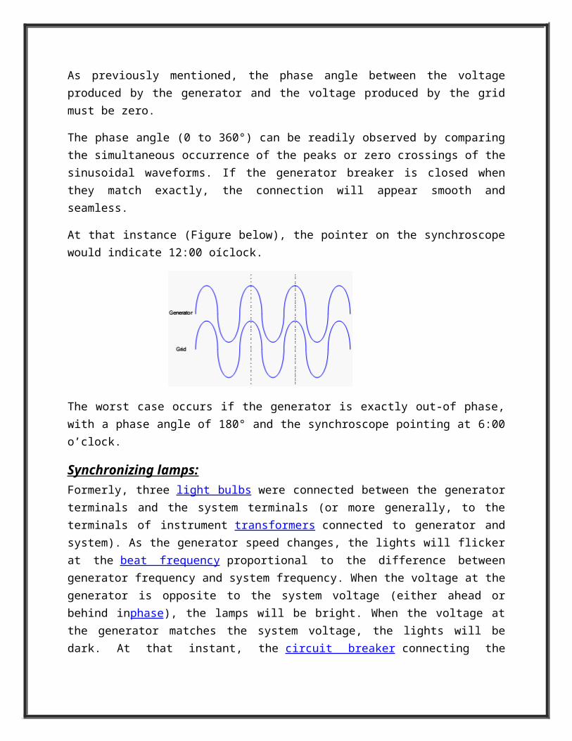
The phase angle (0 to 360°) can be readily observed by comparingthe simultaneous occurrence of the peaks or zero crossings of thesinusoidal waveforms. If the generator breaker is closed whenthey match exactly, the connection will appear smooth andseamless.
At that instance (Figure below), the pointer on the synchroscopewould indicate 12:00 oíclock.
The worst case occurs if the generator is exactly out-of phase,with a phase angle of 180° and the synchroscope pointing at 6:00o’clock.
Synchronizing lamps:Formerly, three light bulbs were connected between the generatorterminals and the system terminals (or more generally, to theterminals of instrument transformers connected to generator andsystem). As the generator speed changes, the lights will flickerat the beat frequency proportional to the difference betweengenerator frequency and system frequency. When the voltage at thegenerator is opposite to the system voltage (either ahead orbehind inphase), the lamps will be bright. When the voltage atthe generator matches the system voltage, the lights will bedark. At that instant, the circuit breaker connecting the
generator to the system may be closed and the generator will thenstay in synchronism with the system.
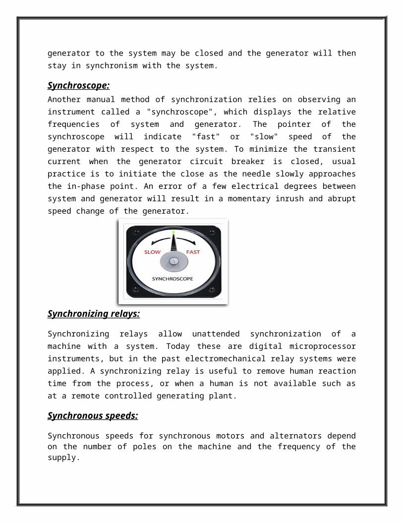
Synchroscope:Another manual method of synchronization relies on observing aninstrument called a "synchroscope", which displays the relativefrequencies of system and generator. The pointer of thesynchroscope will indicate "fast" or "slow" speed of thegenerator with respect to the system. To minimize the transientcurrent when the generator circuit breaker is closed, usualpractice is to initiate the close as the needle slowly approachesthe in-phase point. An error of a few electrical degrees betweensystem and generator will result in a momentary inrush and abruptspeed change of the generator.
Synchronizing relays:
Synchronizing relays allow unattended synchronization of amachine with a system. Today these are digital microprocessorinstruments, but in the past electromechanical relay systems wereapplied. A synchronizing relay is useful to remove human reactiontime from the process, or when a human is not available such asat a remote controlled generating plant.
Synchronous speeds:
Synchronous speeds for synchronous motors and alternators dependon the number of poles on the machine and the frequency of thesupply.
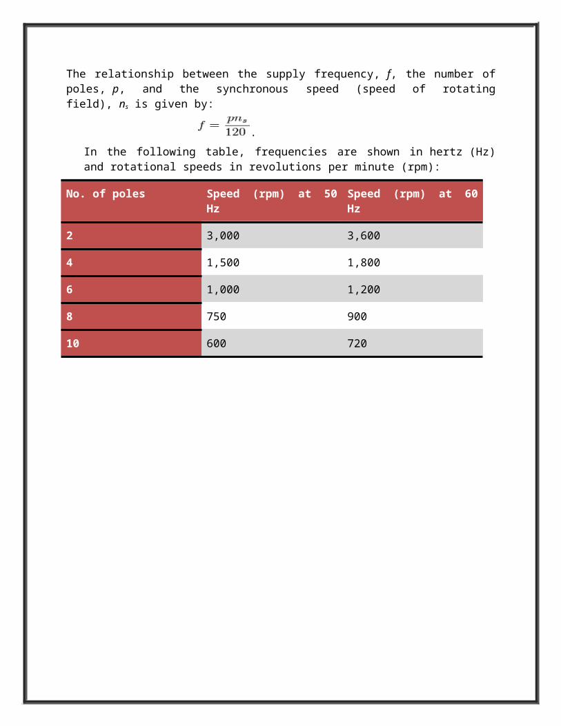
The relationship between the supply frequency, f, the number ofpoles, p, and the synchronous speed (speed of rotatingfield), ns is given by:
.In the following table, frequencies are shown in hertz (Hz)and rotational speeds in revolutions per minute (rpm):
No. of poles Speed (rpm) at 50Hz
Speed (rpm) at 60Hz
2 3,000 3,600
4 1,500 1,800
6 1,000 1,200
8 750 900
10 600 720
Related Documents


