POWER SUPPLY PROTECTION

Welcome message from author
This document is posted to help you gain knowledge. Please leave a comment to let me know what you think about it! Share it to your friends and learn new things together.
Transcript
POWER SUPPLYPROTECTION
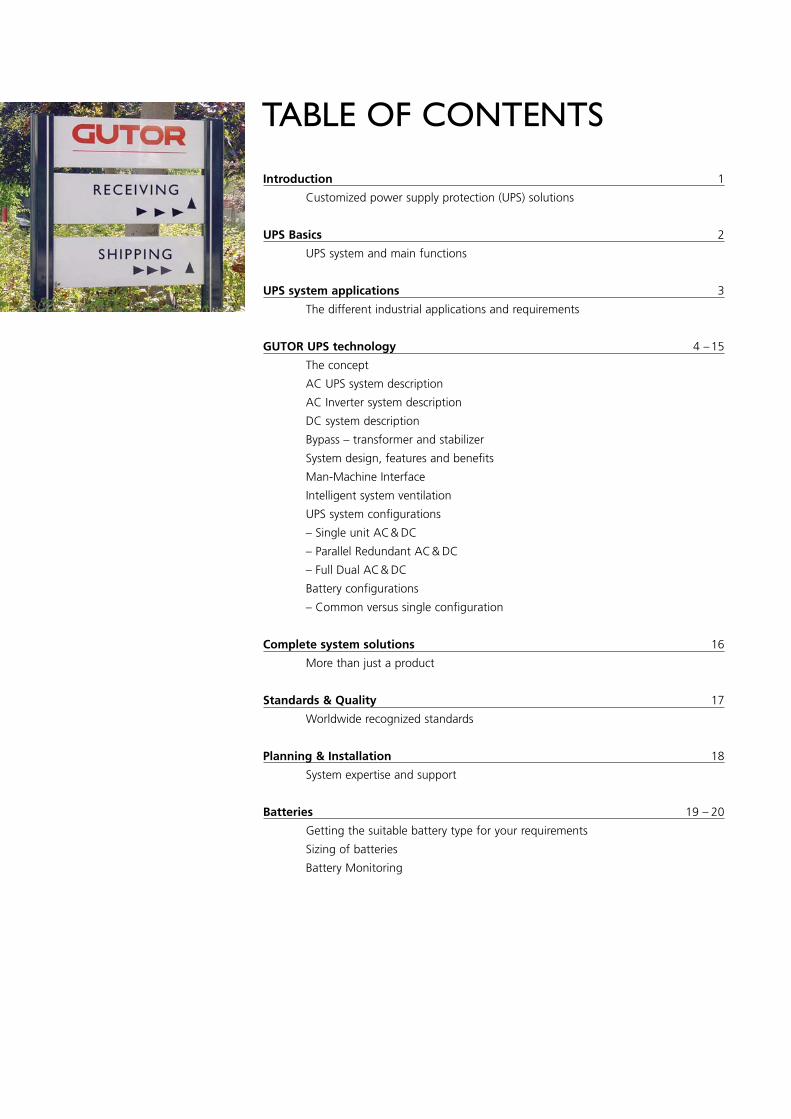
TABLE OF CONTENTS
Introduction 1
Customized power supply protection (UPS) solutions
UPS Basics 2
UPS system and main functions
UPS system applications 3
The different industrial applications and requirements
GUTOR UPS technology 4 –15
The concept
AC UPS system description
AC Inverter system description
DC system description
Bypass – transformer and stabilizer
System design, features and benefits
Man-Machine Interface
Intelligent system ventilation
UPS system configurations
– Single unit AC& DC
– Parallel Redundant AC& DC
– Full Dual AC& DC
Battery configurations
– Common versus single configuration
Complete system solutions 16
More than just a product
Standards & Quality 17
Worldwide recognized standards
Planning & Installation 18
System expertise and support
Batteries 19 – 20
Getting the suitable battery type for your requirements
Sizing of batteries
Battery Monitoring
INTRODUCTION
The objective of this brochure is to guide youthrough the world ofGUTOR UPS technology. Inaddition to a general over-view of the main functionsand important aspects ofUPS systems, this brochurehighlights some of thebasic GUTOR UPS featuresand benefits.
We are pleased to discussyour power supply protec-tion needs and evaluate thebest possible solution. Ourultimate goal is to provide afull range of comprehensiveservices for as long as yourequire.
GUTOR is a leading world-class industrial UPS company. The depth of ourtechnical understanding,combined with the experi-ence gained by workingclosely with customers fromvarious industrial sectors,qualifies us to providecustomized solutions foruninterruptible power sup-ply protection (UPS) ofsuperior technical qualitystandards.
CUSTOMIZEDPOWER SUPPLYPROTECTION(UPS) SOLUTIONS
1

UPS BASICS
UPS SYSTEM AND MAIN FUNCTIONS
The continuous supply ofquality power is critical tocommercial and industrialprocess installations. A power failure, or evenminor disturbances in thepower supply, will interruptthe process chain andeventually result in systemshutdown. This could causesubstantial financial lossesor even jeopardize thesafety of human lives.
Additionally, UPS systemsare often installed to support the safe shutdownand reboot of critical process installations.
Modern UPS systems provide auxiliary functionssuch as automatic monito-ring, system performancetesting and alarm displays.
Custom single line diagram
The key function of UPSsystems is therefore theprotection of electricalpower supplies to installa-tions (also called consumersor loads), which cannottolerate even the slightestvoltage interruption orinconsistencies. Unfilteredelectrical power suppliedby utilities may containharmonics, sags, spikes orother noise. Introducingone or more UPS systemsalong the power supplychain will effectively eliminate these kinds ofdisturbances.
Most importantly, duringpower failure conditions,the UPS will bridge the critical power supply gap.In these instances, thesystem automatically switches to large batterybanks to draw the requiredelectrical power until mainsis again available. Thisoccurs without affectingthe load performance. Thesize of the battery banksand eventual alternativepower source (bypass, diesel power generator),depend on system and battery configurations.
2
UPS SYSTEM APPLICATIONS
THE DIFFERENT INDUSTRIAL APPLICATIONS AND REQUIREMENTS
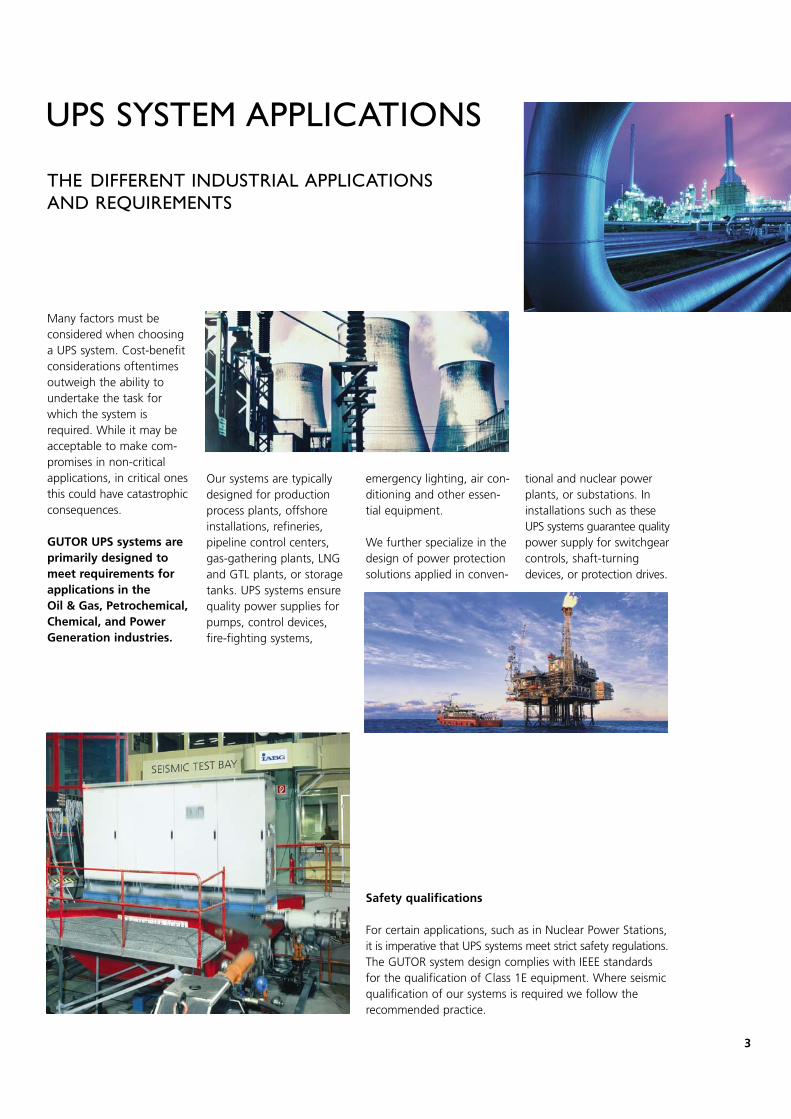
Many factors must be considered when choosinga UPS system. Cost-benefitconsiderations oftentimesoutweigh the ability toundertake the task forwhich the system is required. While it may beacceptable to make com-promises in non-criticalapplications, in critical onesthis could have catastrophicconsequences.
GUTOR UPS systems areprimarily designed tomeet requirements forapplications in the Oil & Gas, Petrochemical,Chemical, and PowerGeneration industries.
Our systems are typicallydesigned for productionprocess plants, offshoreinstallations, refineries,pipeline control centers,gas-gathering plants, LNGand GTL plants, or storagetanks. UPS systems ensurequality power supplies forpumps, control devices,fire-fighting systems,
emergency lighting, air con-ditioning and other essen-tial equipment.
We further specialize in thedesign of power protectionsolutions applied in conven-
For certain applications, such as in Nuclear Power Stations, it is imperative that UPS systems meet strict safety regulations.The GUTOR system design complies with IEEE standardsfor the qualification of Class 1E equipment. Where seismicqualification of our systems is required we follow therecommended practice.
tional and nuclear powerplants, or substations. Ininstallations such as theseUPS systems guarantee qualitypower supply for switchgearcontrols, shaft-turning devices, or protection drives.
Safety qualifications
3
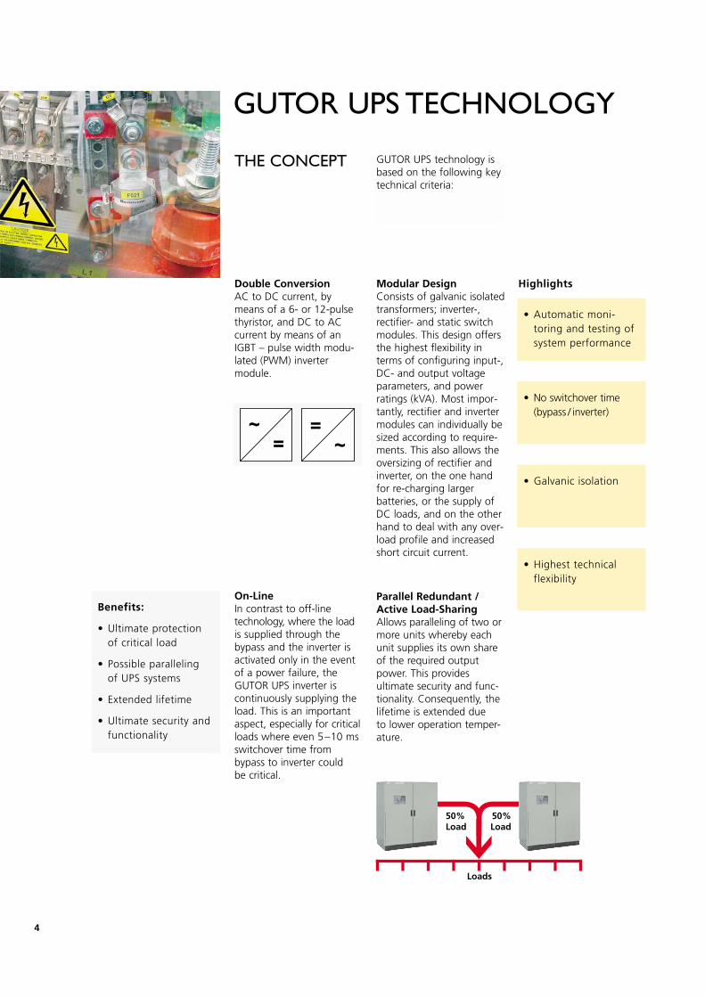
Parallel Redundant /Active Load-SharingAllows paralleling of two ormore units whereby eachunit supplies its own shareof the required outputpower. This provides ultimate security and func-tionality. Consequently, thelifetime is extended due to lower operation temper-ature.
Loads
50%Load
50%Load
GUTOR UPS TECHNOLOGY
THE CONCEPT
Double ConversionAC to DC current, bymeans of a 6- or 12-pulsethyristor, and DC to ACcurrent by means of anIGBT – pulse width modu-lated (PWM) invertermodule.
On-LineIn contrast to off-line technology, where the loadis supplied through thebypass and the inverter isactivated only in the eventof a power failure, theGUTOR UPS inverter is continuously supplying theload. This is an importantaspect, especially for criticalloads where even 5–10 msswitchover time frombypass to inverter could be critical.
GUTOR UPS technology isbased on the following keytechnical criteria:
• Automatic moni-toring and testing ofsystem performance
• No switchover time(bypass / inverter)
• Galvanic isolation
• Highest technical flexibility
Benefits:
• Ultimate protection of critical load
• Possible paralleling of UPS systems
• Extended lifetime
• Ultimate security andfunctionality
HighlightsModular Design Consists of galvanic isolatedtransformers; inverter-, rectifier- and static switchmodules. This design offersthe highest flexibility interms of configuring input-,DC- and output voltageparameters, and powerratings (kVA). Most impor-tantly, rectifier and invertermodules can individually besized according to require-ments. This also allows theoversizing of rectifier andinverter, on the one handfor re-charging larger batteries, or the supply ofDC loads, and on the otherhand to deal with any over-load profile and increasedshort circuit current.
4
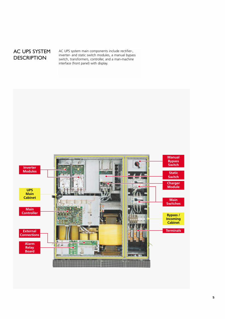
AC UPS SYSTEMDESCRIPTION
AC UPS system main components include rectifier-,inverter- and static switch modules, a manual bypassswitch, transformers, controller, and a man-machineinterface (front panel) with display.
MainSwitches
StaticSwitch
ChargerModule
Terminals
ManualBypassSwitch
Bypass / IncomingCabinet
AlarmRelayBoard
MainController
UPSMain
Cabinet
InverterModules
External Connections
5
6
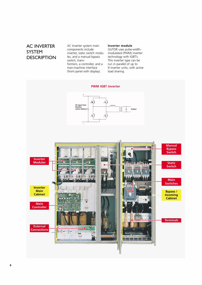
AC Inverter system maincomponents include inverter, static switch modu-les, and a manual bypassswitch, trans-formers, a controller, and aman-machine interface(front panel with display).
AC INVERTERSYSTEMDESCRIPTION
MainSwitches
ManualBypassSwitch
Bypass / IncomingCabinet
External Connections
MainController
InverterMain
Cabinet
InverterModules Static
Switch
+
Output+
DC Input fromRectifierand/or Battery
PWM IGBT Inverter
Inverter moduleGUTOR uses pulse-width-modulated (PWM) invertertechnology with IGBT’s.This inverter type can berun in parallel of up to 9 inverter units, with activeload sharing.
Terminals
7
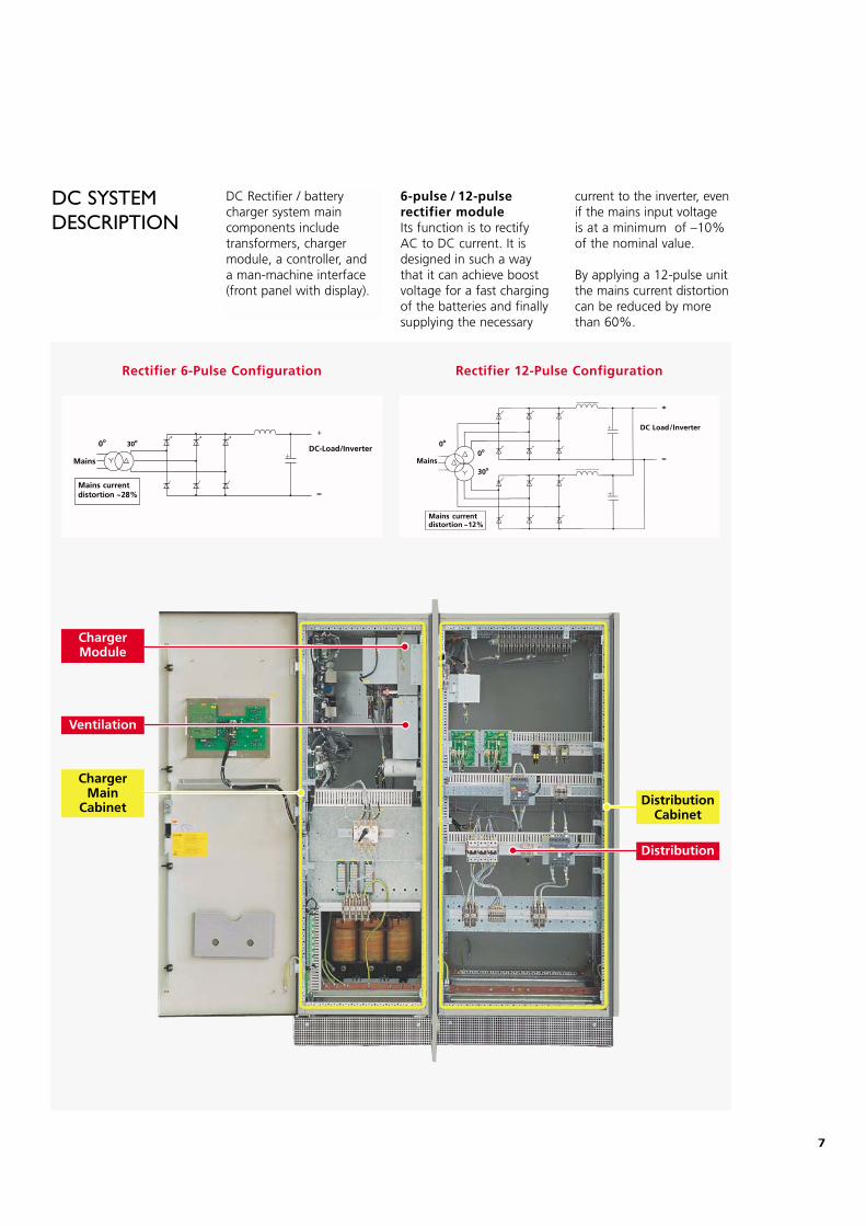
DC SYSTEMDESCRIPTION
DC Rectifier / battery charger system main components include transformers, chargermodule, a controller, and a man-machine interface(front panel with display).
Distribution
DistributionCabinet
ChargerMain
Cabinet
Ventilation
ChargerModule
+Mains
30o0o
Mains currentdistortion ~28%
DC-Load/Inverter
+
Rectifier 6-Pulse Configuration Rectifier 12-Pulse Configuration
6-pulse / 12-pulse rectifier moduleIts function is to rectify AC to DC current. It isdesigned in such a waythat it can achieve boostvoltage for a fast chargingof the batteries and finallysupplying the necessary
current to the inverter, evenif the mains input voltageis at a minimum of –10%of the nominal value.
By applying a 12-pulse unitthe mains current distortioncan be reduced by morethan 60%.
8
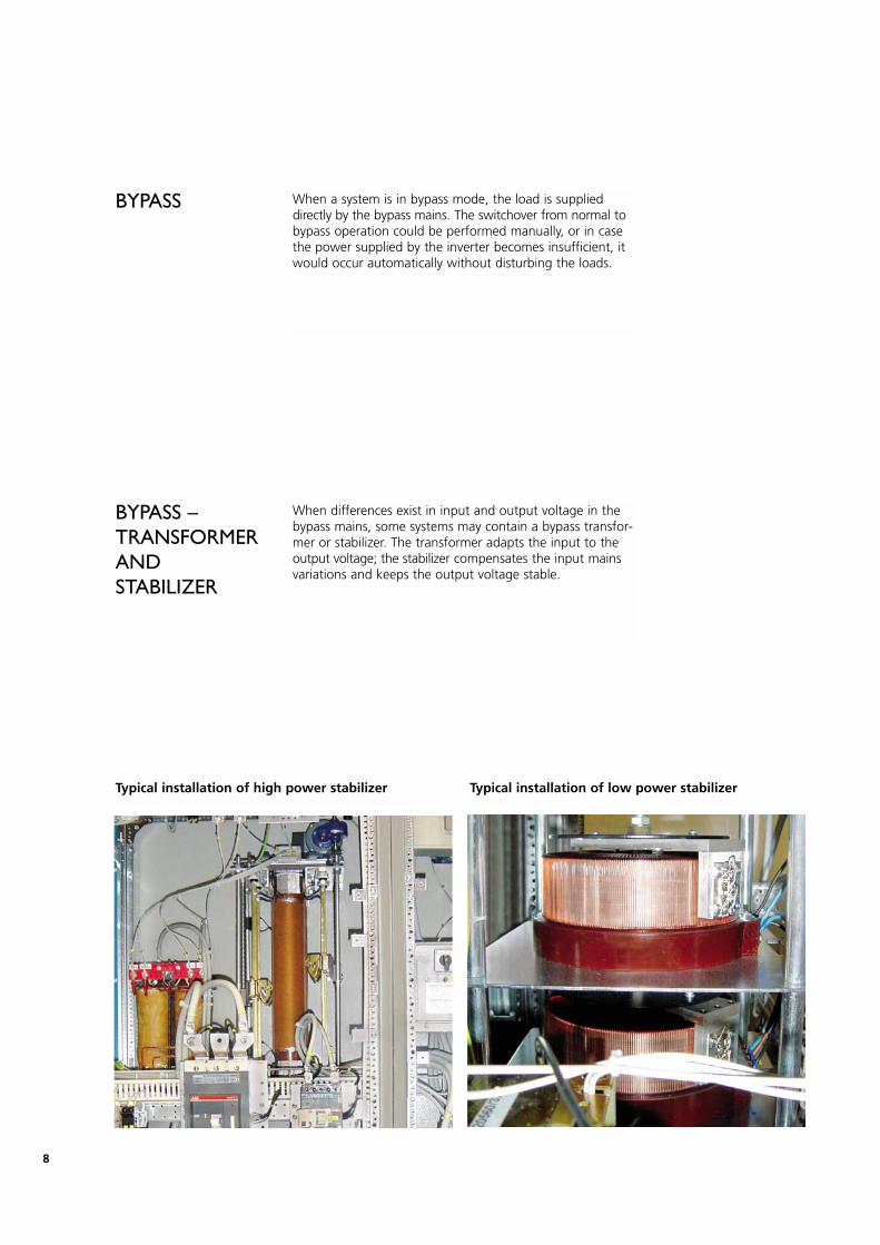
BYPASS
BYPASS – TRANSFORMERANDSTABILIZER
When a system is in bypass mode, the load is supplieddirectly by the bypass mains. The switchover from normal tobypass operation could be performed manually, or in casethe power supplied by the inverter becomes insufficient, itwould occur automatically without disturbing the loads.
When differences exist in input and output voltage in thebypass mains, some systems may contain a bypass transfor-mer or stabilizer. The transformer adapts the input to theoutput voltage; the stabilizer compensates the input mainsvariations and keeps the output voltage stable.
Typical installation of high power stabilizer Typical installation of low power stabilizer
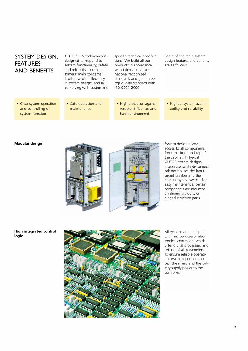
SYSTEM DESIGN,FEATURES AND BENEFITS
GUTOR UPS technology isdesigned to respond tosystem functionality, safetyand reliability – our cus-tomers’ main concerns. It offers a lot of flexibility in system designs and incomplying with customer’s
specific technical specifica-tions. We build all our products in accordancewith international andnational recognized standards and guaranteetop quality standard withISO 9001:2000.
Some of the main systemdesign features and benefitsare as follows:
System design allowsaccess to all componentsfrom the front and top ofthe cabinet. In typicalGUTOR system designs, a separate safety disconnectcabinet houses the inputcircuit breaker and themanual bypass switch. Foreasy maintenance, certaincomponents are mountedon sliding drawers, or hinged structure parts.
All systems are equippedwith microprocessor elec-tronics (controller), whichoffer digital processing andsetting of all parameters.To ensure reliable operati-on, two independent sour-ces, the mains and the bat-tery supply power to thecontroller.
Modular design
High integrated controllogic
• Safe operation andmaintenance
• Clear system operationand controlling ofsystem function
• High protection againstweather influences andharsh environment
• Highest system avail-ability and reliability
9
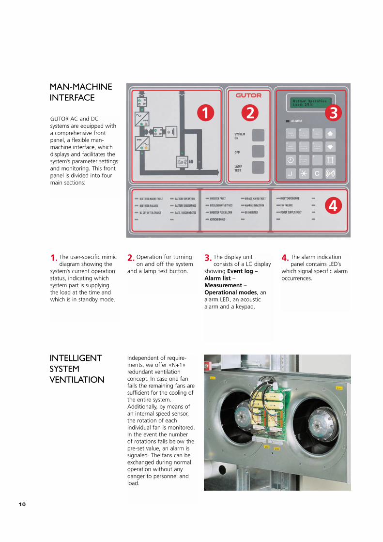
GUTOR AC and DCsystems are equipped witha comprehensive frontpanel, a flexible man-machine interface, whichdisplays and facilitates thesystem’s parameter settingsand monitoring. This frontpanel is divided into fourmain sections:
Independent of require-ments, we offer «N+1»redundant ventilation concept. In case one fanfails the remaining fans aresufficient for the cooling ofthe entire system.Additionally, by means ofan internal speed sensor,the rotation of each individual fan is monitored.In the event the number of rotations falls below thepre-set value, an alarm issignaled. The fans can beexchanged during normaloperation without any danger to personnel andload.
1 2 3
4
1. The user-specific mimic diagram showing the
system’s current operationstatus, indicating whichsystem part is supplyingthe load at the time andwhich is in standby mode.
2. Operation for turning on and off the system
and a lamp test button.
3. The display unit consists of a LC display
showing Event log –Alarm list –Measurement –Operational modes, analarm LED, an acousticalarm and a keypad.
4. The alarm indicationpanel contains LED’s
which signal specific alarmoccurrences.
MAN-MACHINEINTERFACE
INTELLIGENTSYSTEM VENTILATION
10
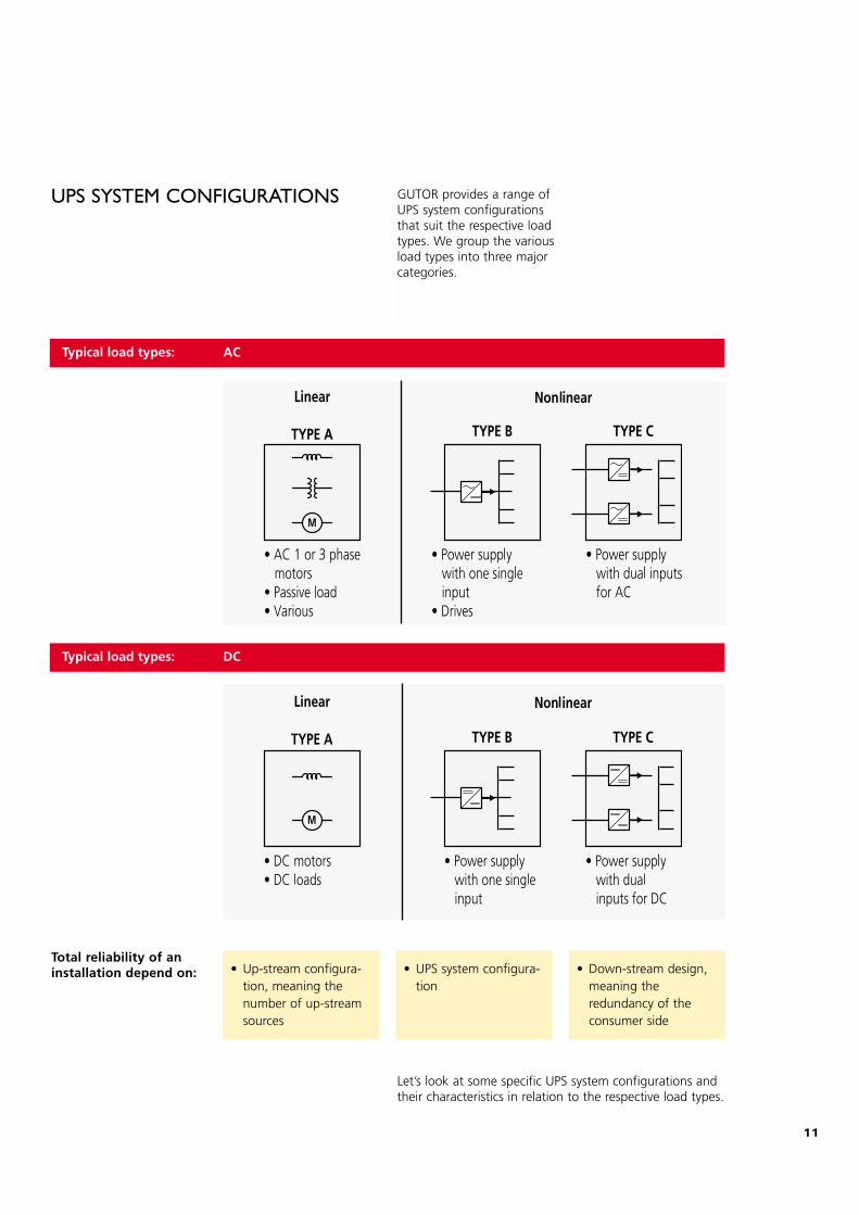
GUTOR provides a range ofUPS system configurationsthat suit the respective loadtypes. We group the variousload types into three majorcategories.
UPS SYSTEM CONFIGURATIONS
• UPS system configura-tion
• Up-stream configura-tion, meaning thenumber of up-streamsources
• Down-stream design,meaning the redundancy of theconsumer side
Total reliability of aninstallation depend on:
Let’s look at some specific UPS system configurations andtheir characteristics in relation to the respective load types.
Typical load types: AC
Typical load types: DC
11
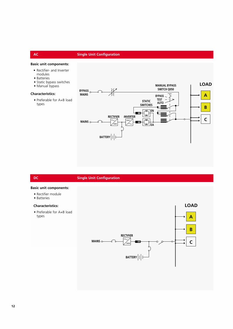
DC Single Unit Configuration
Basic unit components:
• Rectifier module• Batteries
Characteristics:
• Preferable for A+B load types
AC Single Unit Configuration
Basic unit components:
• Rectifier- and Inverter modules
• Batteries• Static bypass switches• Manual bypass
Characteristics:
• Preferable for A+B load types
12
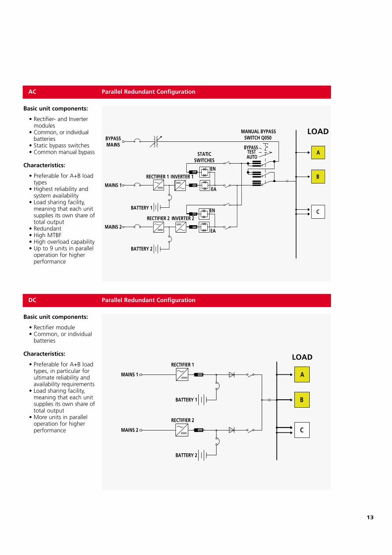
AC Parallel Redundant Configuration
Basic unit components:
• Rectifier- and Inverter modules
• Common, or individual batteries
• Static bypass switches• Common manual bypass
Characteristics:
• Preferable for A+B load types
• Highest reliability and system availability
• Load sharing facility, meaning that each unit supplies its own share of total output
• Redundant• High MTBF• High overload capability• Up to 9 units in parallel
operation for higher performance
DC Parallel Redundant Configuration
Basic unit components:
• Rectifier module• Common, or individual
batteries
Characteristics:
• Preferable for A+B load types, in particular for ultimate reliability and availability requirements
• Load sharing facility, meaning that each unit supplies its own share oftotal output
• More units in parallel operation for higher performance
13
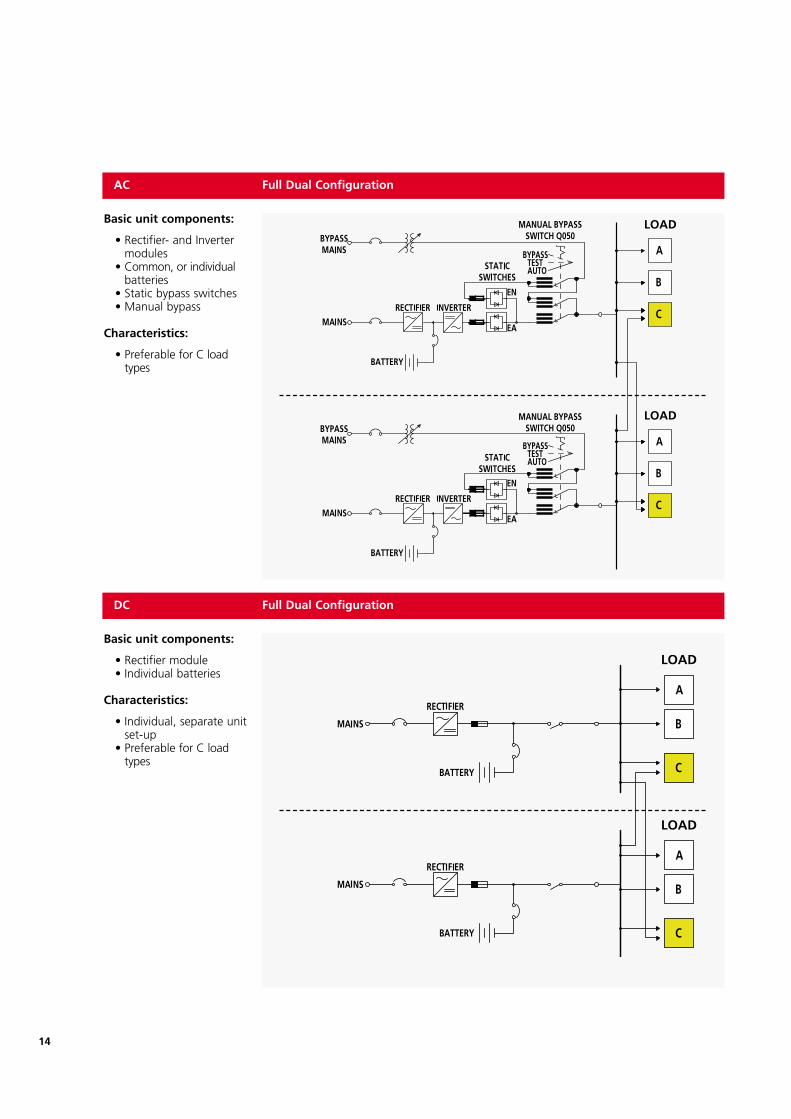
Basic unit components:
• Rectifier module• Individual batteries
Characteristics:
• Individual, separate unit set-up
• Preferable for C load types
14
AC Full Dual Configuration
Basic unit components:
• Rectifier- and Inverter modules
• Common, or individualbatteries
• Static bypass switches• Manual bypass
Characteristics:
• Preferable for C load types
DC Full Dual Configuration
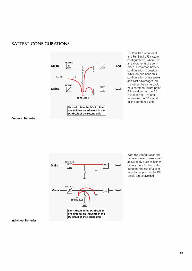
BATTERY CONFIGURATIONS
For Parallel / Redundant and Full Dual UPS systemconfigurations, where twoand more units are com-bined, a common batteryconfiguration is possible.While on one hand thisconfiguration offers spaceand cost advantages, onthe other, the same couldbe a common failure point.A breakdown of the DCcircuit in one UPS unitinfluences the DC circuit of the combined unit.
Common Batteries
Individual Batteries
With this configuration thesame arguments mentionedabove apply, such as higherbattery costs. In this confi-guration, the risk of a com-mon failure point in the DCcircuit can be avoided.
15
Mains
Mains
Load
Load
Short-circuit in the DC-circuit inone unit has an influence in theDC-circuit of the second unit.
Mains
Mains
Load
Load
Short-circuit in the DC-circuit inone unit has no influence in theDC-circuit of the second unit.
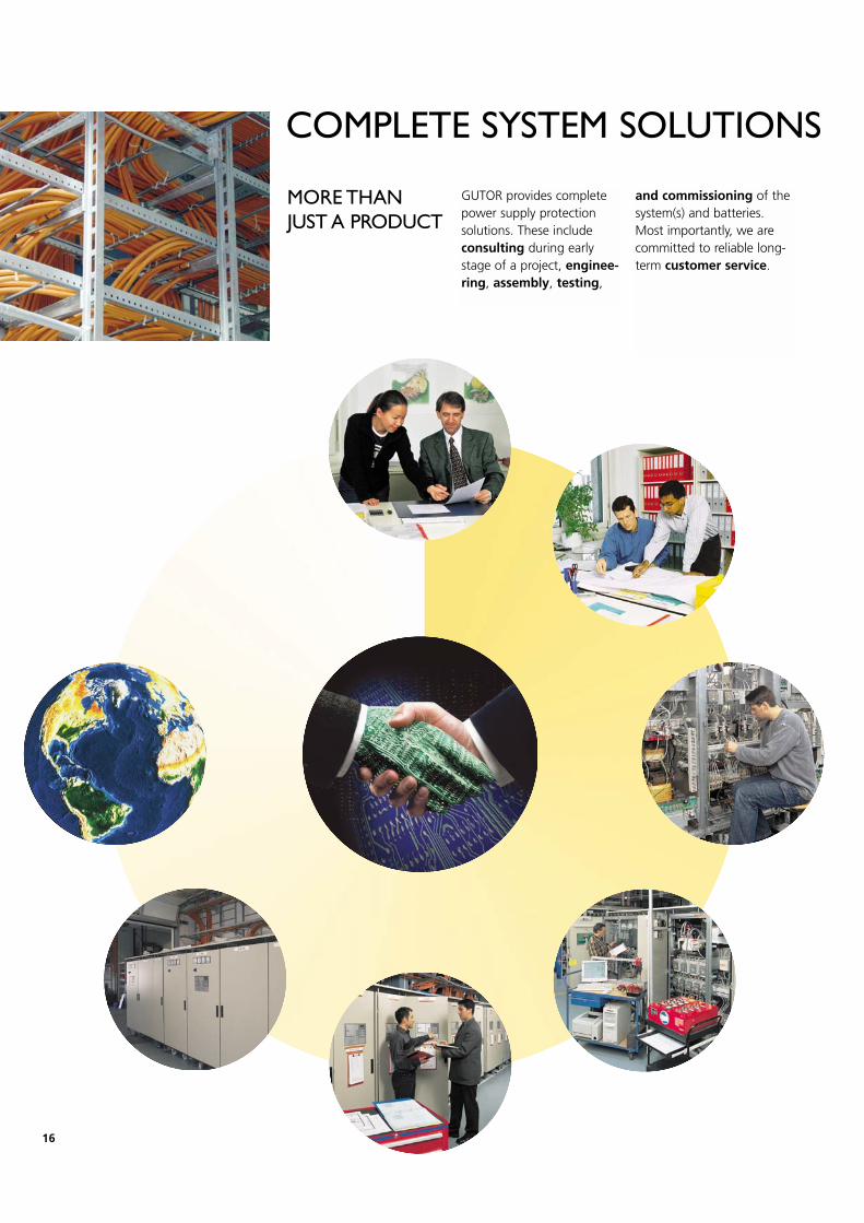
MORE THAN JUST A PRODUCT
GUTOR provides completepower supply protectionsolutions. These includeconsulting during earlystage of a project, enginee-ring, assembly, testing,
and commissioning of thesystem(s) and batteries.Most importantly, we arecommitted to reliable long-term customer service.
COMPLETE SYSTEM SOLUTIONS
16

STANDARDS & QUALITY
GUTOR supplies productsthat are designed andmanufactured based onrecognized worldwidetechnical and safety stand-ards, such as EN, IEC, IEEE,VDE, SEV, NEMA, ANSI,CSA, UL, FCC.
We guarantee quality assu-rance by means of internaland external controls con-ducted by our qualitymanagement and BureauVeritas, our external audi-tor. In addition, oursystems and processeshave undergone customerassurance programs toassure qualification for spe-cial applications. Reportsare available to our custo-mers and inspectors.
WORLDWIDERECOGNIZEDSTANDARDS
17
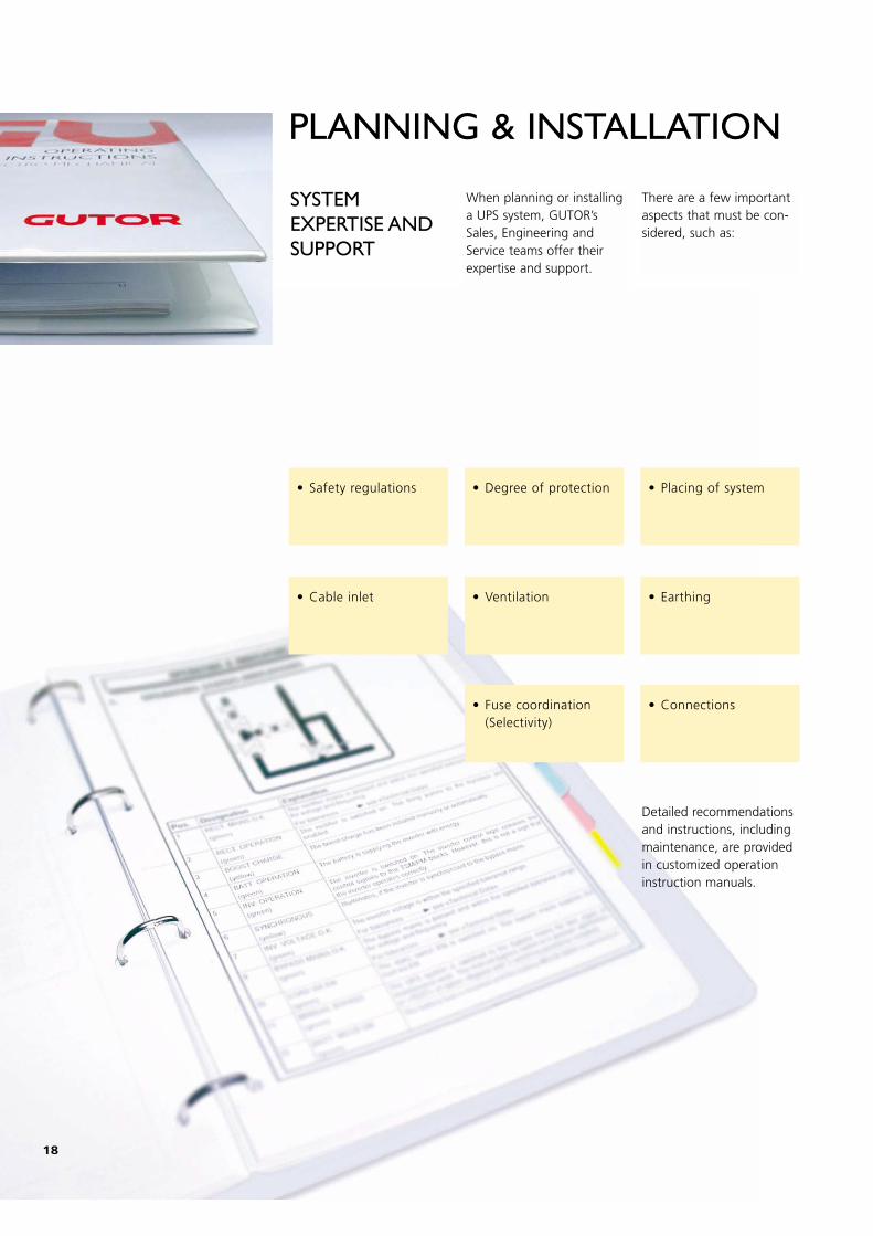
SYSTEMEXPERTISE ANDSUPPORT
When planning or installinga UPS system, GUTOR’sSales, Engineering andService teams offer theirexpertise and support.
There are a few importantaspects that must be con-sidered, such as:
Detailed recommendationsand instructions, includingmaintenance, are providedin customized operationinstruction manuals.
PLANNING & INSTALLATION
• Safety regulations • Degree of protection • Placing of system
• Cable inlet • Ventilation • Earthing
• Connections• Fuse coordination(Selectivity)
18
BATTERIES
GETTING THESUITABLE BATTERY TYPEFOR YOURREQUIREMENTS
Batteries are a key elementin the concept of the UPSpower protection solutionpackage. They are used tostore the energy requiredto feed the load (Inverter)during a mains failure. Thechoice of battery type istherefore critical.
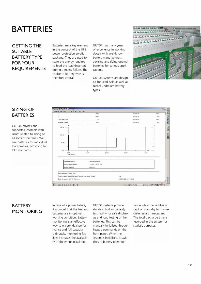
GUTOR advises and supports customers withissues related to sizing ofall sorts of batteries. Wesize batteries for individualload profiles, according toIEEE standards.
GUTOR has many years of experience in workingclosely with well-knownbattery manufacturers,advising and sizing optimalbatteries for various appli-cations.
GUTOR systems are design-ed for Lead Acid as well asNickel-Cadmium batterytypes.
SIZING OF BATTERIES
BATTERY MONITORING
In case of a power failure,it is crucial that the back-upbatteries are in optimalworking condition. Batterymonitoring is an effectiveway to ensure ideal perfor-mance and full capacity.Ultimately, monitoring faci-lities increases the availabili-ty of the entire installation.
GUTOR systems providestandard built-in capacitytest facility for safe dischar-ge and load testing of thebatteries. This can bemanually initialized throughkeypad commands on thefront panel. When thesystem is initialized, it swit-ches to battery operation
mode while the rectifier iskept on stand-by for imme-diate restart if necessary.The total discharge time isrecorded in the system forstatistic purposes.
19
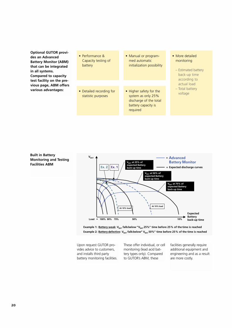
Optional GUTOR provi-des an AdvancedBattery Monitor (ABM)that can be integratedin all systems.Compared to capacitytest facility on the pre-vious page, ABM offersvarious advantages:
Built in BatteryMonitoring and TestingFacilities ABM
Advanced Battery Monitor
VBAT
ExpectedBatteryback-up time
VBAT at 25% ofexpected Batteryback-up time
VBAT at 50% ofexpected Batteryback-up time
VBAT at 75% ofexpected Batteryback-up time
Example 1: Battery weak: VBAT falls below „VBAT 25%“ time before 25% of the time is reached
Example 2: Battery defective: VBAT falls below „ VBAT 50%“ time before 25% of the time is reached
Ex. 1Ex. 2
100%Load = 90% 75% 50% 10%
At 10% loadAt 10% load
=
=
Expected discharge curves
Upon request GUTOR pro-vides advice to customers,and installs third party battery monitoring facilities.
These offer individual, or cellmonitoring (lead acid bat-tery types only). Comparedto GUTOR’s ABM, these
facilities generally requireadditional equipment andengineering and as a resultare more costly.
• Manual or program-med automatic initialization possibility
• Performance &Capacity testing ofbattery
• More detailed monitoring
– Estimated batteryback-up timeaccording toactual load
– Total battery voltage
• Detailed recording forstatistic purposes
• Higher safety for thesystem as only 25%discharge of the totalbattery capacity isrequired
20
GUTOR offices:
HeadquartersGUTOR Electronic Ltd Hardstrasse 72 – 74 CH-5430 Wettingen Switzerland
Phone: +41 (0)56 437 34 34 Fax: +41 (0)56 437 34 44 e-mail: [email protected] www.gutor.com
Asia-PacificGUTOR Electronic Asia Pacific Sdn. Bhd. 6th Floor, Wisma Genting Jalan Sultan Ismail 50250 Kuala Lumpur Malaysia
Phone: +603 2161 3440 Fax: +603 2161 3441 e-mail: [email protected] www.gutor.com
North America GUTOR North America 40 Catamore Blvd. 02914 East Providence RI USA
Phone: +1 (888) 994 8867, ext 6638 Fax: +1 (401) 435 2580 e-mail: [email protected] www.gutor.com
Representative offices in Brazil, China, Emirates, Germany, India, Russia, Saudi Arabia
996-2767A
410.
126G
B1
Related Documents