POWER SUPPLY FOR A METRO SYSTEM Mahendra Kumar CEE/DMRC 9.8.12

Power Supply for a Metro 9.8.12 System
Nov 30, 2015
Power system for metro system
Welcome message from author
This document is posted to help you gain knowledge. Please leave a comment to let me know what you think about it! Share it to your friends and learn new things together.
Transcript

POWER SUPPLY FOR A METRO SYSTEM
Mahendra KumarCEE/DMRC
9.8.12

MAP OF THE PRESENTATION
• IEC 61850• ADOPTION 61850 in DMRC• Reliability of Power supply• Arrangements adopted in DMRC

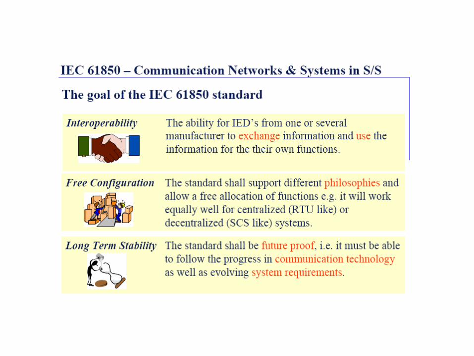
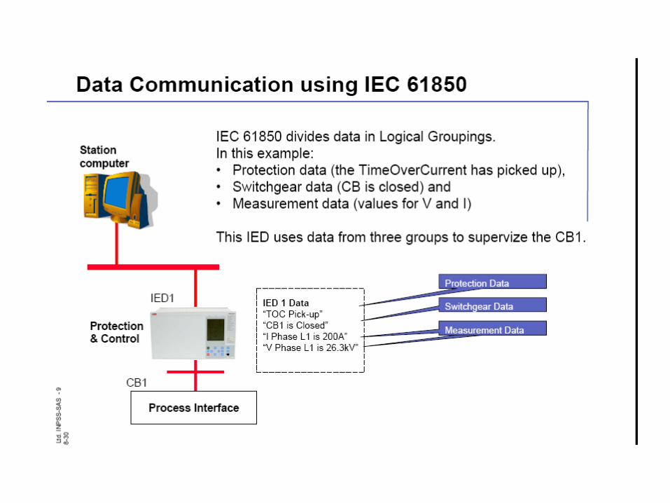
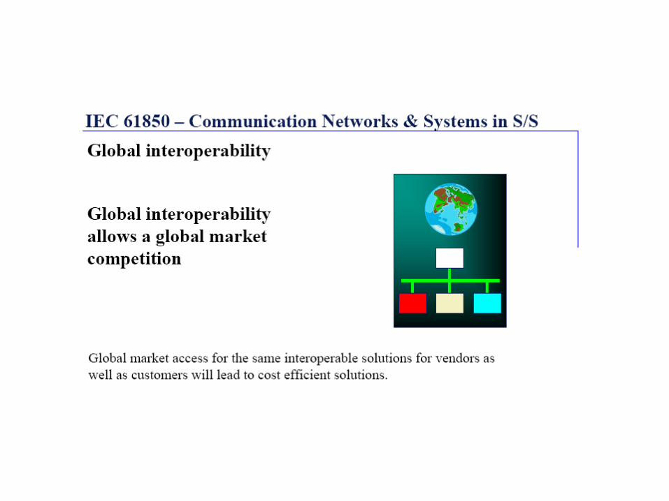
IEC 61850


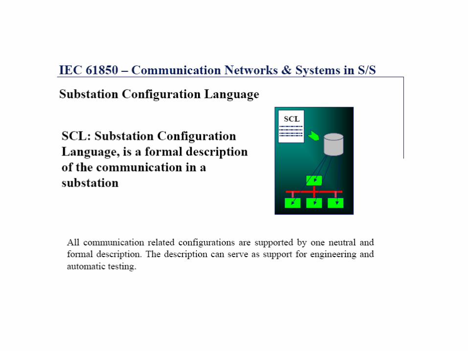


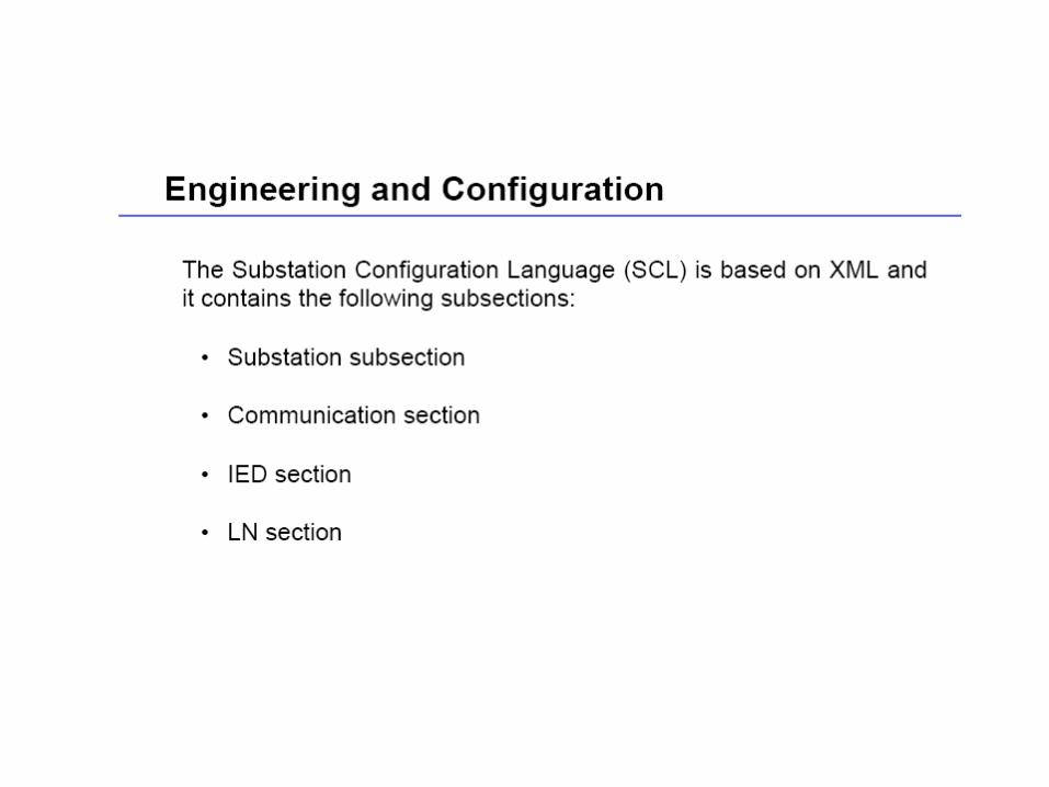


FUNCTIONAL DESIGN SPECIFICATION

SUBSTATION AUTOMATION SYSTEM BE-8A

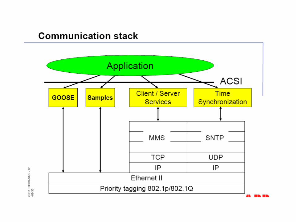
FUNCTIONAL PARTS OF SAS BE-8A• SAS comprises of• Bay Control IED Unit (BCU)• Bay Protection IED Unit (BPU) • Station Human Machine Interface (Main and Stand by) • Gateway for Remote Control Centre• Communication through fibre optic medium• Ethernet switch• Peripheral devices like printer, display unit, keyboards etc• DR workstation• GPS for Time Synchronising• UPS• Standard Functionality and communication as per IEC 61850
standard.

BAY CONTROL UNIT • Bay Control IED Unit has• Fully Complaint to IEC 61850 standard• Control and Monitoring function • Synchro-check function• Voltage selection function• In built back up o/c protection function• Displays status of bay oriented equipments• Peer-Peer communication using GOOSE message for interlocking
function• Communication through fibre optic medium• Interoperable with third party IEC 61850 compliant devices• Directly Connected to the inter bay bus on IEC 61850

STATION LEVEL HMI FUNCTIONS• Station level HMI functions• Displays status of all equipments of each bays in single
line diagram format• Controlling of all equipments of each bays• Measurements• Event and Alarm Handling• System supervision• Event and Alarm list generation• User authority levels• Reports handling• Disturbance analysis• IED parameter setting

COMMUNICATION DEVICES• Gateways• Communication interface medium for Remote
OCC.• Two ports for simultaneous reporting to two
masters i.e. at shastripark and Metrobhavan• One spare port for future use.• Fibre optic medium• Data exchange between IED on bay level and
Station level through fibre optic cables• Disturbance free communication

COMMUNICATION DEVICES
• Ethernet switch• Interface device between IED at bay level and
Station level for data exchange• One switch for two bays• Data exchange as per IEC 61850 standard• Operates on 110V dc

SYSTEM HARDWARE• Station Hardware• Main and Standby station HMI workstation• DR workstation for disturbance handling• Plasma screen for display of overall SLD of
the station• Printers (one Laser and one DoT matrix type)• GPS receiver for time synchronizing

FUNCTIONAL REQUIREMENTSFour level of operations• Operation Control Centers(OCC)• Station HMI (Station level)• Local Bay Controller IED (Bay level)• Apparatus levelOperations shall be possible
by only one operator at a time subject to interlocking, synchrocheck and other functions etc

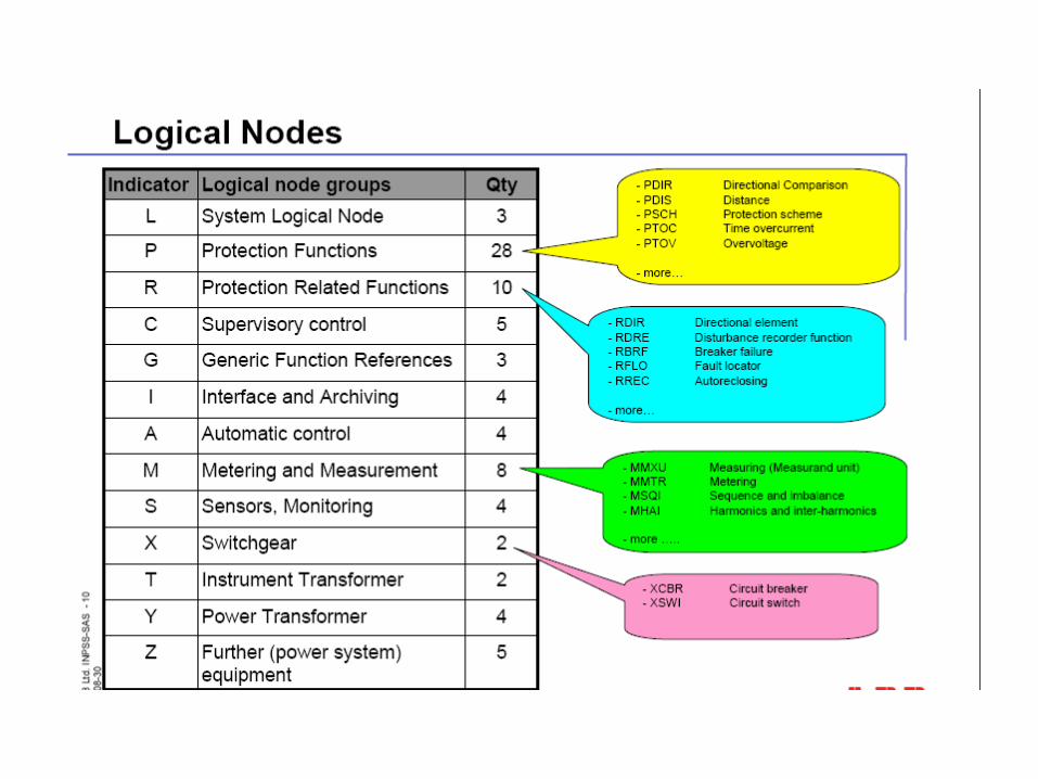
LIST OF IED• BCU• REC 670 IED dedicated for controlling, monitoring and back up o/c
protection function for each and every bay of 66/33/25kV level• BPU• RED 670 IED dedicated for Line or cable differential protection
with backup distance protection function for 66kV incomer bays• RET 670 IED dedicated for Transformer diff. protection with
integrated REF and standby E/F protection function for Transformer bays.
• REB 670 IED dedicated for BusbarProtection function for 66kV busbar
• REO 517 dedicated for 25kV Traction feeder protection

ADVANTAGES OVER CONVENTIONAL SYSTEM
• Highly reliable• Less maintenance• Reduced hardwiring• Conventional RTU’snot required.• Modification or Extension of components does
not require shutdown of whole SAS• Safety for operating staff• Minimum basic training is required for operating
staff.


SHASTRI PARK DEPOT
(RSS 220kV)
(RSS 66kV GIS)
(RSS 66kV)
(RSS 66kV)
DWARKA
NJF DEPOT
(RSS 66kV)
INDRAPRASTHA
(RSS 66kV)
SUSHANT LOK
KHYBER PASS
Red LineYellow Line
Blue Line
SYMBOLSInterchange Station (Existing)
Future Interchange Station
GTB NAGAR
JEHANGIRPURI
VISHWA VIDYALAYA
DILSHADGARDEN
VAISHALIANAND VIHAR
BOTANICAL
NOIDA S-32CITY CENTRE
GARDEN
SARITA
BADARPUR
SHUSHANT
CHATARPUR
SAKET LAJPAT NAGAR
CENTRALSECRETIAT
IP
RAJIV CHOWK
KIRTI
SUBHASH NAGAR
MU
ND
KA
ASHOK PARK
NAGAR
U/G Line
YAMUNA BANK DEPOT
RSS
GHITORNI DEPOT
VIHAR
DEPOT
MUNDKA
(RSS 220kV)
(RSS 132kV)
(RSS 66kV)
(RSS 66kV GIS)
GATE
AMBEDKAR COLONY
(RSS 66kV GIS)
(RSS 66kV GIS)
RITHALA
NEW DELHI
KASHMERE
LOK
(RSS 66kV GIS)AIRPORT
(RSS 66kV GIS)PARK STREET
SHAHDRA

The Delhi Metro Rail Corporation (DMRC) has successfully completed the Phase I & Phase II of construction of Metro Corridors, namely
• Line 1 (Shahdara-Rithala),
• Line 2 (Vishwa Vidyalaya-Central Secretariat)
• Line 3 (Barakhamba Road-Dwarka, including extension Dwarka-Dwarka Subcity and Barakhamba Road-Indraprastha).
• Line 4
• Line 5
• Line 6
As part of Phase I & II Projects, 6 & 8 Receiving Substations have also been installed respectively

POWER SUPPLY ARRANGEMENT FOR PHASE-I

Line No.
Name of DMRC RSS
Abbre-viation
Incoming Voltage
Source of Supply
Grid Substation
RemarksLocation Agency
1
Kashmere Gate KG 220 kV Mandaula Kashmere Gate NDPL
Rithala RL 66 kV Bawana Rohini I NDPL
2 New Delhi ND 66 kV GTPS GTPS BYPL
3
Dwarka DW 66 kV Bamnauli Pappankalan II BRPL
Subhash Nagar SN 66 kV Bamnauli Pappankalan I BRPL
Indraprastha IP 66 kV GTPS GTPS BYPL

DMRC is building the following Corridors as part of DMRC-Phase II Project.
Sr. No. Corridor Ref. Name of Corridor Remarks
RO Shahdara-Dilshad Garden
IN Indraprastha-New Ashok Nagar via Yamuna Bank
YA Yamuna Bank-Anand Vihar
MO Vishwa Vidyalaya-Jehangir Puri
IM Inderlok-Mundka
M3 Central Secretariat-Green Park
M4 Green Park-Ambedkar Colony
GE Ambedkar Colony-Sushant Lok (Gurgaon)
NE New Ashok Nagar-Noida

POWER SUPPLY ARRANGEMENT FOR PHASE-II

Line No.
Name of DMRC RSS
Abbre-viation
Incoming Voltage
EHV Feeder
Grid Substation Source of Supply
RemarksLocation Agency
Line2 Ext.
Jehangirpuri JP 220 kV
1 Shalimar Bagh NDPL Bawana GSS for 2nd Feeder yet to be decided2 None at present
Ambedkar Colony
AC
66 kV 1 Mehrauli BRPL
Bamnauli / Badapur
2 Mehrauli BRPL
Sushant Lok SL 66 kV
1Sushant Lok Sector 52A
HVPNLBadshah-
pur2nd Feeder yet to be provided
2Sushant Lok Sec.
57HVPNL
Line 3 Ext.
Botanical Garden
BG 132 kV
1Noida
Sector 45UPPCL
Sector 20 Noida * (220 kV)
2Noida
Sector 45UPPCL
Line 5 Mundka MK 66 kV
1 Kanjhawla BRPL Bawana2nd Feeder yet to be provided
2 Mundka DTLBamnauli/ Bawana

Integrating Phase I & Phase II Power Supply Systems


TRACTION POWER SUPPLY
1. NORMAL POWER SUPPLY ARRANGEMENTS
2. ESTIMATED POWER REQUIREMENT
3. PROJECTED POWER DEMANDS AT DMRC SUBSTATIONS

NORMAL POWER SUPPLY ARRANGEMENTS
Assuming that all DMRC Traction Substations are healthy and feeding, the zone of feed of every Traction Substation extends upto the Neutral Section (Sectioning Post) on either side of the Substation. A schematic traction power supply diagram, showing the locations of Traction Substations and their zone of feed, under normal conditions of power supply is as below.

NORMAL POWER SUPPLY ARRANGEMENTS

Lengths of Feed• The following table indicates the approximate Lengths of feed
from various TSS, under normal conditions of feed.• These lengths are made use of for projecting the Power
requirements now. These lengths may be different from the lengths adopted at the time of making Simulation Studies. The lengths of feeding zones adopted at the time of making Simulation Studies, are made use of for calculating the average power requirement per km based on Simulation Studies.]

Length of Feed from various Substations, under Normal conditions of feed
Name of Substation
Length of Feed (km)
RemarksTowards Direction
ATowards Direction
BTotal
Kashmere Gate 7.103 9.102 16.205
Rithala 1.410 7.894 8.664
Jehangirpuri 0.070 3.788 3.858
Dwarka 5.625 5.925 11.550
Subhash Nagar 3.584 9.129 12.713
Indraprastha 7.082 15.300 22.382
Botanical Garden 3.285 4.271 7.556
Mundka 0.106 17.499 17.605

ESTIMATED POWER REQUIREMENTS
The Power demand at the various Traction Substations, depends upon a number of factors, such as
– Lengths of feeding zone
– No of trains in the feeding zones
– Power drawn by each train, based on its state (whether starting, accelerating, coasting, braking etc)
– The profile of track in the zone which is being fed by the TSS.

• A precise estimation of power demand can be made only with the help of a suitable computer software, which can simulate the train running, determine the current drawn by each train in the feeding zone, add up the power demands to arrive at the total Instantaneous demand at the Substation and also integrate the power demand over a specified time interval (say 15-minutes). Based on past data records and on thumb-rule calculations, the max power demand per km, can be interpolated for various combinations of train running (8-car, 6-car, 4-car trains at say, 3-min, 4-min, 6-min etc headway).

Figures adopted by RITES in the DPR
RITES, in their “Detailed Project Report for Phase II Corridors of Delhi Metro”, had adopted the following figures for Peak hour power demand per km of the route, for different train operation plans.
Peak Hour Trains and Hourly Traction Power Demand per Km
YearTrains per
hour
Average Hourly Power Demand (MW/Km)
Number of Cars per Train
4-Car 6-Car 8-Car
2011 & 2021
10 0.36 0.54 0.72
12 0.43 0.65 0.86
20 0.72 1.08 1.43
Designed 24 0.86 1.30 1.73

AUXILIARY POWER SUPPLY

GENERAL DESCRIPTION
• The various electrical and electro-mechanical installations in passenger stations are required to be provided with electrical power at 415 V 3 phase.
• AMS
• 33 kv network
• ASS

INTERCONNECTION STUDY

•GENERAL
The object of the interlink between various DMRC Lines is to ensure an emergency supply between the
lines, both at 25 kV and 33 kV. Under normal power supply arrangements, the different DMRC Lines are
deriving power supply from the following RSS/TSS/AMS, situated in the respective lines.
Line 1 DescriptionPower Supply from
25 kV 33 kV
1 Rithala - Dilshad GardenKGRithala
KGRithala
2
Jehangirpuri –Viswavidyalaya - Central Sectt. - Qutub Minar - Sushant Lok (Gurgaon)
JehangirpuriNew DelhiAmbedkar ColonySushant Lok
JehangirpuriNew DelhiAmbedkar ColonySushant Lok
3
Dwarka Sector 9 – Dwarka Barakhamba Road – Indraprastha – New Ashok Nagar – Noida (including Yamuna Bank – Vaishali)
DwarkaSubhash NagarIndraprasthaBotanical Garden
DwarkaSubhash NagarIndraprasthaBotanical Garden
4 Inderlok - Mundka Mundka Mundka

• The Lines 1, 2 and 3 have more than one Substation and hence, under an Emergency condition, when one of the Substations in the Line, is totally out-of-service, one of the remaining healthy Substations in the Line, will be able to provide the back-up power, both at 25 kV and 33 kV. However, in the case of Line 5, which has only one Substation and is not track-linked with any of the other Lines, Interconnection Links at 25 kV and 33 kV, with other Line/s, are essential and hence provided at detailed below.

• Traction Power LINKS
– Interconnection Links between Lines 1, 2 and 3
– 25 kV Link between Line 1 and Line 2
– Two additional 25 kV Outgoing bays were established in the KG TSS, to enable two 25 kV Link feeders to be taken off the 25 kV bus bars at KG TSS. These Link feeders were taken to ISBT FP of Line 2 and can be used, if required, to feed 25 kV traction power to Line 2, if New Delhi TSS fails. As a long term measure, it may also be worthwhile to consider adding one more 66 kV / 27.5 kV Traction transformer at KG TSS along with a 66 kV feeder from the GTPS.

• 25 kV Link between Line 2 and Line 3
A 25 kV Link had been established between New Delhi TSS (of Line 2) and the R.K. Ashram Marg FP (of Line 3). The Link is made up of a 240 sq mm copper cable, which will be able to safely transfer a power upto 7.5 MVA, from New Delhi TSS of R.K. Ashram Marg FP.

•25 kV Link between Line 3 and Line 1
The Link between Line 1 and Line 3, originally envisaged between Rithala TSS (Line 1) and Dwarka TSS (Line 3), was given up and at present an indirect link exists between Line 1 and Line 3, from KG TSS (Line1) to R.K. Ashram Marg FP (Line 3), via the 25 kV Bus bars at New Delhi TSS. However this Link is not useful from technical, as well as, logistical points of view.

2. INTERCONNECTION LINKS WITH LINE 5
– 25 kV Link between Line 5 and Line 3
A Feeding Post at Kirti Nagar II (in IM Corridor) has been established and this FP derives 25 kV single phase power supply from Subshah Nagar TSS (Line 3), via a 25 kV Link consisting of duplicate 25 kV feeders (each feeder consisting of a phase cable 2x240 sq mm copper and a return cable 2x240 sq mm (3.3 kV) copper).

•Provisions made in the Design
Sr. No.
Item Availability of Redundancy
1Incoming HV Feeders from the Grid Substation to the DMRC Receiving Substation
2 Incoming Feeders provided (except in KG and Jehangirpuri RSS)
2 Traction Transformers
2 Traction Transformers are provided at every Substation. Each transformer is rated fore 100% load at the Substation, one supplying the load and the other remaining as hot-standby.
3 25 kV Outgoing Traction Feeders 4 Outgoing feeders provided at every Substation, each feeder designed to carry the full traction load.
Failure of Traction Transformer
• Every Substation has 2 traction transformers, each rated for the 100% maximum power demand at the Substation. One transformer supplies the entire load and the other remains as ‘hot-standby’. Hence, failure of one traction transformer at one Substation, does not affect the 25 kV traction power supply to the Traction Overhead Equipment.

Failure of 25 kV Feeder/ Equipment
• Failure of one 25 kV Traction outgoing feeder or failure of one 25 kV power supply equipment, does not affect the 25 kV traction power supply to the equipment.


Emergency Power Supply Plan1. Line 1 (Rithala-Shahdara-Dilshad Garden)
Sr. No. Emergency
Conditions
Standby Power
Supply
Remarks
1st Standby
2nd Standby
1A Rithala Fails Kashmere
Gate
Mundka KG Supply is from KGE GSS (NDPL)
RL Supply is from ROH GSS (NDPL) MK Supply is from MK GSS (NDPL)
1B Kashmere Gate Fails
Rithala Mundka As a 3rd standby, power can be drawn from New Delhi TSS.

2. Line 2 (Jehangirpuri – Viswavidyalaya-Central Secretariat – Qutub Minar – Sushant Lok)
Sr. No. Emergency
Conditions
Standby Power
Supply
Remarks
1st Standby
2nd
Standby
2A Jehangirpuri Fails
New Delhi - If JP fails and at the same time ND is also off, then power can be drawn from KG.
2B New Delhi Fails
Ambedkar Colony
Jehangirpuri As a 3rd standby, power can be drawn from Kashmere Gate TSS
2C Ambedkar Colony Fails
New Delhi Sushant Lok
2D Sushant Lok Fails
Ambedkar Colony
-

3. Line 3 & 4 (Dwarka-Indraprastha-New Ashok Magar-Noida, Yamuna Bank-Vaishali)
Sr. No. Emergency
Conditions
Standby Power
Supply
Remarks
1st Standby
2nd
Standby
3A Dwarka Fails
Subhash Nagar
-
3B Subhash Nagar Fails
Dwarka Indraprastha As a 3rd standby, power can be drawn from New Delhi TSS.
3C Indraprastha Fails
Botanical Garden
Subhash Nagar
As a 3rd standby, power can be drawn from New Delhi TSS.
3D Botanical Garden Fails
Indraprastha
-

4.Line 5 (Mundka-Kirti Nagar-Inderlok)
Sr. No. Emergency
Conditions
Standby Power
Supply
Remarks
1st Standby
2nd
Standby
4 Mundka Fails
Subhash Nagar
Kashmere Gate

AUXILIARY POWER SUPPLY
GENERALAs already described above, the normal auxiliary power supply arrangement includes
• Two independent 33 kV feeders to feed the ASS’s• Division of the feeders into separate loops deriving feed from
different AMS’s.
The Schematic Auxiliary Power Supply Diagram as below, shows the division of feeders into separate loops in the various
Corridors.


THANK YOU

POWER SUPPLY INSTALLATIONS OF DMRC
Related Documents