Power Series Linkage Tools SAFETY & OPERATOR’S MANUAL GLS, GRS, GCC, GMP Mechanical Pulverizer (GMP) Linkage Shear (GLS) Rebar Shear (GRS) Concrete Cracker (GCC)

Welcome message from author
This document is posted to help you gain knowledge. Please leave a comment to let me know what you think about it! Share it to your friends and learn new things together.
Transcript
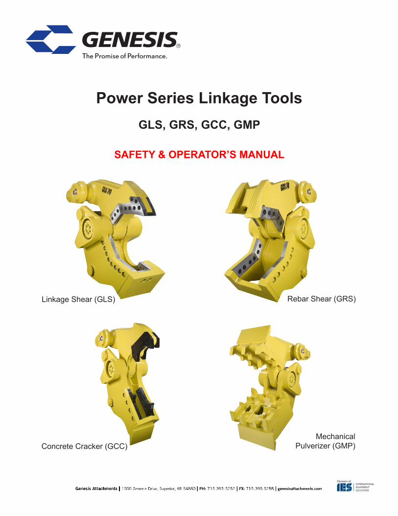
Power Series Linkage Tools
SAFETY & OPERATOR’S MANUAL
GLS, GRS, GCC, GMP
MechanicalPulverizer (GMP)
Linkage Shear (GLS) Rebar Shear (GRS)
Concrete Cracker (GCC)
© 2017 Genesis Attachments, LLCGenesis Power Series Linkage Tools2
CONTACT INFORMATION
View and download all manuals at genesisattachments.com/manuals.aspPatents: genesisattachments.com/patents
Asia Pacific Representative Office
24 Upper Serangoon View #12-28 Singapore 534205
Phone: +65 9673 9730
E-mail:[email protected]
Brazil
Avenida Araça, 1677Campinas - São Paulo
Phone: +55 19 9 9989-8803
E-mail:[email protected]
Europe/Africa/Middle EastGenesis GmbH
Teramostrasse 2387700 Memmingen, Germany
Phone: +49 83 31 9 25 98 0Fax: +49 83 31 9 25 98 80
genesis-europe.com
E-mail:[email protected]
Central & South America, The Caribbean
Cra 13A #89-38 / Ofi 613Bogota, Colombia
Phone: +57 1 610 8160 / 795 8747
E-mail: [email protected]
World HeadquartersGenesis Attachments
1000 Genesis DriveSuperior, WI 54880 USA
Toll Free: 888-SHEAR-IT(888-743-2748)
Phone: 715.395.5252Fax: 715.395.5255
E-mail:[email protected]
© 2017 Genesis Attachments, LLC Genesis Power Series Linkage Tools 3
PREFACETo ensure years of safe, dependable service, only trained and authorized persons should operate and service your Genesis attachment. It is the responsibility of the product’s owner to ensure the operator is trained in the safe operation of the product and has available this manual for review. It is the responsibility of the operator and maintenance personnel to read, fully understand and follow all operational and safety-related instructions in this manual. The attachment should not be operated until you have read and fully understand these instructions. Always use good safety practices to protect yourself and those around you.
ImportantThis operator’s manual must accompany the attachment at all times and be readily available to the operator.
Manual ReplacementShould this manual become damaged or lost or if additional copies are required, immediately con-tact any authorized Genesis dealer or the Genesis Service Department at 888-743-2748 or 715-395-5252 for a replacement.
Registration FormThe Warranty Registration Form must be filled out by the dealer or customer and returned to Gen-esis indicating the date the attachment went into service.
Possible VariationsGenesis cannot anticipate every possible circumstance that might involve a potential hazard as the owner’s requirements and equipment may vary. Therefore, the warnings in this publication and on the product may not be all-inclusive, and you must satisfy yourself that the procedure, applica-tion, work method or operating technique is safe for you and others before operating.
Public NoticeGenesis reserves the right to make changes and improvements to its products and technical litera-ture at any time without public notice or obligation. Genesis also reserves the right to discontinue manufacturing any product at its discretion at any time.
WarrantyAll work or repairs to be considered for warranty reimbursement must be pre-authorized by the Genesis Service Department. Any alterations, modifications or repairs performed before authoriza-tion by the Genesis Service Department will render all warranty reimbursement consideration null and void without exception. See page 46 for Warranty Claim Procedures.
Improper operation or improperly performed maintenance may render any warranty null and void.

© 2017 Genesis Attachments, LLCGenesis Power Series Linkage Tools4
TABLE OF CONTENTSCONTACT INFORMATION 2PREFACE 3
Important 3Manual Replacement 3Registration Form 3Possible Variations 3Public Notice 3Warranty 3
SAFETY STATEMENTS 7OPERATIONAL SAFETY 8
Read Manual Before Operating or Maintaining the Attachment 8Personal Protection 8Know Your Equipment 8Before Operating 8Check the Equipment 9Stability 9Know the Work Area 10Starting Procedure 10Place the Load Safely 10Safely Operate Equipment 11Transporting the Attachment 12Equipment Condition 12Working Overhead 12Power Lines 12Prioritized Oil Flow 13Emergency Situations 13Unsafe Conditions 13Crystalline Silica Dust 13Process Material Safely 14Lift the Load Safely 14Place the Load Safely 14
ATTACHMENT MARKINGS 15PAD INSTALLATION 16ATTACHMENT INSTALLATION 17
Removal 17MAINTENANCE SAFETY 18MAINTENANCE SCHEDULE 19
Eight-Hour Checklist 19Grease 19
BOLT TORQUE SPECIFICATIONS 20Visual Reference for GLS Bolt Torque 21Visual Reference for GRS Bolt Torque 22Visual Reference for GCC Bolt Torque 23Visual Reference for GMP Bolt Torque 24
© 2017 Genesis Attachments, LLC Genesis Power Series Linkage Tools 5
TABLE OF CONTENTSLINKAGE SHEAR MAINTENANCE 25
Blade Bolts 25Piercing Blades 26Piercing Blade Replacement 28Guide Blade 29Guide Blade Shimming 29Guide Blade Rotation 29Guide Blade Replacement 29Primary and Secondary Blades 30Primary and Secondary Blade Removal 30Adjustment Plates 31Primary and Secondary Blade Rotation 31Primary and Secondary Blade Gap 32Blade Gap Measuring Procedure 32Blade Shimming 32Razor Blade 33Jaw Stop 33
REBAR SHEAR MAINTENANCE 34Blade Bolts 34Piercing Tips 34Primary and Secondary Blades 35Primary and Secondary Blade Removal 35Primary and Secondary Blade Rotation 36Primary and Secondary Blade Gap 36Blade Gap Measuring Procedure 36Blade Shimming 37Jaw Stop 37
CONCRETE CRACKER MAINTENANCE 38Concrete Cracking Blades 38Blade Removal 38Blade Rotation 39Jaw Stop 39Pulverizing Teeth 40
GENERAL WELDING GUIDELINES 41Welding Ground Clamp 41Welding Rules 41
BUILD-UP 42HARD-SURFACING 43HARD-SURFACING PATTERNS 44TROUBLE-SHOOTING GUIDE 45WARRANTY 46
Claim Procedure 46Blade Warranty 46
© 2017 Genesis Attachments, LLCGenesis Power Series Linkage Tools6
TABLE OF CONTENTSPARTS ORDER POLICY AND PROCEDURE 47
Parts Orders Should Include 47Placing Orders 47Part Numbers 47Shipping 47Invoices 47Returns 47Return Goods Authorization 47
PARTS ORDER FORM 48PARTS 49
GLS Blades and Wear Parts 50GRS Blades and Wear Parts 51GCC Blades and Wear Parts 52GMP Blades and Wear Parts 53Power Series Pivot Group 54
TOOL LIST 55CONTACT INFORMATION 56

© 2017 Genesis Attachments, LLC Genesis Power Series Linkage Tools 7
SAFETY STATEMENTSThis symbol by itself or used with a safety signal word throughout this manual is used to call attention to instruc-tions involving your personal safety or the safety of oth-ers. Failure to follow these instructions can result in injury or death.
This statement is used where serious injury or death could result if the instructions are not followed properly.! WARNING
This statement is used where minor or moderate injury could result if the instructions are not followed properly.! CAUTION
This statement is used where property damage could result if the instructions are not followed properly.NOTICE
! DANGER This statement is used where serious injury or death will result if the instructions are not followed properly.
© 2017 Genesis Attachments, LLCGenesis Power Series Linkage Tools8
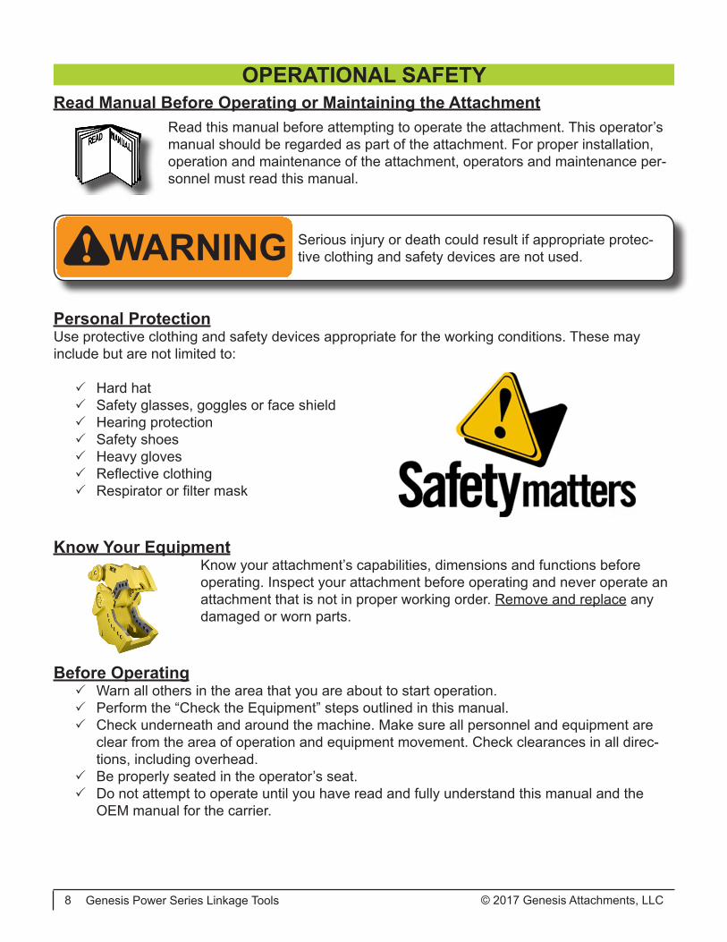
! WARNING Serious injury or death could result if appropriate protec-tive clothing and safety devices are not used.
Personal ProtectionUse protective clothing and safety devices appropriate for the working conditions. These may include but are not limited to:
3 Hard hat 3 Safety glasses, goggles or face shield 3 Hearing protection 3 Safety shoes 3 Heavy gloves 3 Reflective clothing 3 Respirator or filter mask
Know Your EquipmentKnow your attachment’s capabilities, dimensions and functions before operating. Inspect your attachment before operating and never operate an attachment that is not in proper working order. Remove and replace any damaged or worn parts.
Before Operating 3 Warn all others in the area that you are about to start operation. 3 Perform the “Check the Equipment” steps outlined in this manual. 3 Check underneath and around the machine. Make sure all personnel and equipment are
clear from the area of operation and equipment movement. Check clearances in all direc-tions, including overhead.
3 Be properly seated in the operator’s seat. 3 Do not attempt to operate until you have read and fully understand this manual and the
OEM manual for the carrier.
OPERATIONAL SAFETYRead Manual Before Operating or Maintaining the Attachment
Read this manual before attempting to operate the attachment. This operator’s manual should be regarded as part of the attachment. For proper installation, operation and maintenance of the attachment, operators and maintenance per-sonnel must read this manual.

© 2017 Genesis Attachments, LLC Genesis Power Series Linkage Tools 9
Check the EquipmentBefore use, check the equipment to ensure it is in good operating condition.
Check the following: 3 Grease fittings. Pump grease at all fitting locations, see page 19. 3 Blades and wear surfaces for wear or damage. 3 Hydraulic fluid level. Add hydraulic fluid as required. 3 Hydraulic hoses and hose connections for wear or leaks. Repair or
replace any damaged hoses or connections. 3 All control levers for proper operation.
GOODCONDITION
3
! WARNING Serious injury or death could result if warnings or instruc-tions regarding carrier stability and the work area are not followed properly.
StabilityYour Genesis attachment is sized for carrier stability. However, improper operation, faulty mainte-nance or unauthorized modifications may cause instability.
3 Know the working ranges and capacities of the carrier to avoid tipping. 3 Use the recommended carrier counter weight.
The following conditions affect stability:• Ground conditions• Grade • Weight of attachment• Contents of attachment• Operator judgement
For greater stability, knuckle the attachment to bring the load closer to the center of rotation (cen-ter of gravity) while lifting. Use extra caution during reaching to avoid tipping.
OPERATIONAL SAFETY

© 2017 Genesis Attachments, LLCGenesis Power Series Linkage Tools10
Know the Work AreaCheck clearances in the work area. Keep all bystanders at a safe distance. Do not work under obstacles. Always check your location for overhead and buried power lines or other utilities before operation.
Check ground conditions. Avoid unstable or slippery areas. Position the carrier on firm level ground. If level ground is not possible, position the carrier to use the attachment to the front or back of the carrier. Avoid working over the side of the carrier.
To reduce the risk of tipping and slipping, never park on a grade exceeding 10% (one-foot rise over the span of a ten-foot run).
Starting ProcedureBefore operating, walk completely around the equipment to make certain no one is under it, on it or close to it. Keep all bystanders at least 75 feet away from the area of operation and equipment movement. Let all other workers and bystanders know you are preparing to start. DO NOT operate until everyone is clear.
Always be properly seated in the operator’s seat before operating any carrier controls.
To start: 3 Make sure all controls are in the center (neutral) position. 3 Be properly seated. 3 Slowly operate all functions to check for proper operation and to bleed air from the hydrau-
lic system.
To shut down: 3 Return your Genesis attachment to a rest position on the ground. 3 Shut off the carrier engine. 3 Work controls in all directions to relieve hydraulic pressure, per excavator manufacturer’s
instructions.
! WARNING Serious injury or death could result if warnings or instructions regarding safe operation are not followed properly.
Place the Load SafelyDo not move the attachment, or anything held in the jaws, over people, equipment or buildings. Do not throw or drop the contents. Operate the controls smoothly and gradually.
OPERATIONAL SAFETY

© 2017 Genesis Attachments, LLC Genesis Power Series Linkage Tools 11
Safely Operate EquipmentDo not operate equipment until you are trained by a qualified operator in its use and capabilities.
See your carrier’s manual for these instructions. 3 Operate only from the operator’s seat. Check the seat belt daily and replace if frayed or
damaged. 3 Do not operate this or any other equipment under the influence of drugs or alcohol. If you
are taking prescription medication or over-the-counter drugs ask your medical provider whether you can safely operate equipment.
3 Never leave equipment unattended with the engine running or with the attachment in a raised position. Apply the brakes before exiting the equipment.
3 Do not exceed the lifting capacity of your carrier. 3 Avoid conditions that can lead to tipping. The carrier can tip when operated on hills, ridges,
banks and slopes. Avoid operating across a slope which could cause the carrier to overturn. 3 Reduce speed when driving over rough terrain, on a slope, or when
turning to avoid overturning the carrier. 3 Never use the attachment as a work platform or personnel carrier. 3 Keep all step plates, grab bars, pedals and controls free of dirt, grease,
debris and oil. 3 Never allow anyone to be around the equipment when it is operating. 3 Do not operate poorly maintained or otherwise faulty equipment. Inform the proper authority
and DO NOT resume operation until the problem has been fixed. 3 Do not alter or remove any safety features. 3 Know your work site safety rules as well as traffic rules and flow. When
in doubt on any safety issue, contact your supervisor or safety coordi-nator for an explanation.
3 A heavy load can cause equipment instability. Use extreme care during travel. Slow down on turns and watch out for bumps. The equipment may need additional counter-weights to counterbalance the weight of the attachment.
OPERATIONAL SAFETY

© 2017 Genesis Attachments, LLCGenesis Power Series Linkage Tools12
Power LinesDo not operate the machine near energized power lines. All local, state/provincial and federal regulations must be met before approaching power lines, overhead or under-ground cables, or power sources of any kind with any part of the carrier or attachment. Always contact the appropriate utility when operating near power lines. The lines should be moved, insulated, disconnected or de-energized and grounded before operating in the area.
Current in high voltage lines may arc some distance from the wire to a nearby ground. Keep all parts of the machine at least 50 feet (16m) away from power lines.
Working OverheadAvoid handling material overhead whenever possible. Safety glass and wire mesh cab guarding must be installed to protect the operator from flying debris that may be created during handling. Falling Object Protection Structures, or FOPS, are neces-sary for any application where material is to be handled overhead.
Transporting the Attachment 3 Travel only with the attachment in a safe transport position to prevent uncontrolled move-
ment. Drive slowly over rough ground and on slopes. 3 When driving on public roads use safety lights, reflectors, Slow Moving Vehicle signs, etc.,
to prevent accidents. Check local government regulations that may affect you. 3 Do not drive close to ditches, excavations, etc., as cave-in could result. 3 Do not smoke when refueling the prime mover. Allow room in the fuel tank for expansion.
Wipe up any spilled fuel. Secure cap tightly when done.
Equipment ConditionNever operate poorly maintained equipment. When maintenance is required, repair or replace parts immediately.
! WARNING Serious injury or death could result if warnings or instruc-tions regarding working overhead are not followed prop-erly.
! DANGER Serious injury or death will result if warnings or instructions regarding power lines are not followed properly.
OPERATIONAL SAFETY

© 2017 Genesis Attachments, LLC Genesis Power Series Linkage Tools 13
OPERATIONAL SAFETY
IMPORTANT: Concrete and masonry products contain silica sand. Quartz, which is a form of silica and the most common mineral in the Earth’s crust, is associated with many types of rock.
Some activities that may have silica dust present in the air include demolition, sweeping, loading, sawing, hammering, drilling or planing of rock, concrete or masonry.
It is recommended to use dust suppression (such as water) or dust col-lection (such as a vacuum) along with personal protective equipment if necessary during the operation of any attachment that may cause high levels of silica dust.
Prioritized Oil FlowEquipment operators must ensure there is prioritized oil flow to the main valves in overhead op-erations or high reach conditions.
Emergency SituationsAlways be prepared for emergencies. Make sure a fire extinguisher is available. Be familiar with its operation. Make sure to inspect and service the fire extinguisher regularly. Make sure a first aid kit is readily available.
Unsafe ConditionsDo not operate if an unsafe condition exists. Stop operation immediately, shut down the machine and report the unsafe condition to the proper authority. Equipment operation and maintenance practices directly affect your safety and the safety of those around you. Always use common sense while operating and be alert to unsafe conditions.
Crystalline Silica DustIt is recommended to use dust suppression, dust collection and if necessary, personal protective equipment during the operation of any attachment that may cause high levels of dust.
! DANGERExposure to respirable crystalline silica dust along with other hazardous dusts may cause serious or fatal respira-tory disease.
© 2017 Genesis Attachments, LLCGenesis Power Series Linkage Tools14
! WARNING Using your Genesis attachment in unauthorized applica-tions may create an unsafe situation and will void the war-ranty.
Process Material Safely• Do not process hardened steel material such as tool steel, railroad rail, axles or machined
parts. Hardened material breaks, rather than shears, which may cause flying debris.
• Do not operate any functions of the carrier while cutting or crushing with your Genesis attach-ment, including boom and drive functions.
• Do not pull down structures with your Genesis attachment. Doing so may cause falling debris or material may break free and exceed the capacities of the carrier, causing a tipping hazard.
Lift the Load Safely• Make sure the load is held securely in the jaws. Do not move a loaded attachment if load is
loose or dangling. Make sure the load is pinched between the jaws – never cradle a load.
• Use extra caution during reaching to avoid tipping.
Place the Load Safely• Do not move the attachment, or anything held in the jaws, over people, equipment or build-
ings. Place the load gently. Do not throw or drop the contents.
• Operate the controls smoothly and gradually. Jerky controls are hazardous and may cause damage to the carrier.
• Avoid fire hazards. Keep the area clean. Remove all flammable materials from the area during any welding or heating process. Have a fire extinguisher nearby and know how to use it.
• Never substitute pins or bolts. Use factory supplied pins. Replace all bolts with the same size and grade. Failure to do so may cause serious injury or death.
• Use your Genesis attachment only as directed in this manual. Do not use the attachment to lift and move other objects. Doing so may cause instability and tipping.
OPERATIONAL SAFETY
© 2017 Genesis Attachments, LLC Genesis Power Series Linkage Tools 15
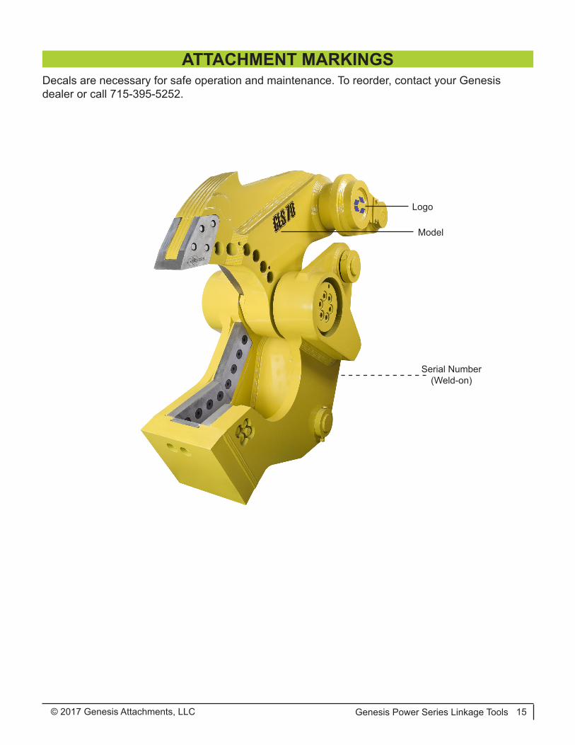
Decals are necessary for safe operation and maintenance. To reorder, contact your Genesis dealer or call 715-395-5252.
Logo
Model
Serial Number(Weld-on)
ATTACHMENT MARKINGS
© 2017 Genesis Attachments, LLCGenesis Power Series Linkage Tools16
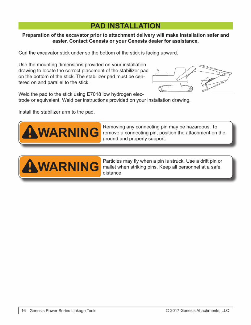
PAD INSTALLATIONPreparation of the excavator prior to attachment delivery will make installation safer and
easier. Contact Genesis or your Genesis dealer for assistance.
Curl the excavator stick under so the bottom of the stick is facing upward.
Use the mounting dimensions provided on your installation drawing to locate the correct placement of the stabilizer pad on the bottom of the stick. The stabilizer pad must be cen-tered on and parallel to the stick.
Weld the pad to the stick using E7018 low hydrogen elec-trode or equivalent. Weld per instructions provided on your installation drawing.
Install the stabilizer arm to the pad.
! WARNING Removing any connecting pin may be hazardous. To remove a connecting pin, position the attachment on the ground and properly support.
! WARNING Particles may fly when a pin is struck. Use a drift pin or mallet when striking pins. Keep all personnel at a safe distance.

© 2017 Genesis Attachments, LLC Genesis Power Series Linkage Tools 17
Remove the bucket or other attachment following the manufacturer’s procedure. Retract the bucket cylinder and associated linkage. All Power Series Linkage Tools are designed to sit flat on the ground. The attachment must be on a firm, level surface with the jaws closed.
Position the excavator behind the attachment and care-fully line up the stick connection of the excavator and attachment. Install pin.
Raise the tool slightly off the ground and extend the bucket cylinder.
Connect excavator power link to upper jaw.
Align the stabilizer arm with the stationary jaw by moving the stick and operating the bucket cylinder. Pin the arm to the jaw.
Check all connections to ensure mounting pins are prop-erly retained.
RemovalTo remove tool with stiff arm, set arm on heavy object. Remove pin from pad. Move tool to storage position with arm hanging.
Lower tool to ground. Close jaws to prevent tool move-ment after link pin is removed.
Remove pins.
ATTACHMENT INSTALLATION
! WARNING Make sure all personnel stand clear. Lifting the attachment will cause the jaw to close and the stabilizer bar to swing.

© 2017 Genesis Attachments, LLCGenesis Power Series Linkage Tools18
Only trained and authorized persons should perform maintenance on the attachment. To be quali-fied, you must understand the instructions in this manual, have training, and know the safety rules and regulations of the job site.
Do not alter the physical or mechanical operation of the attachment. Doing so may cause a dan-gerous situation for yourself and those around you and will void the warranty.
Do not attempt repairs you do not understand. If any questions arise regarding a safety or mainte-nance procedure, contact Genesis or your Genesis dealer.
Read this entire manual. All personnel must understand the maintenance and safety procedures.
Use factory authorized parts. The use of unauthorized parts may compromise safety, performance and durability of the attachment and may void the warranty.
Follow the daily checklist and maintenance schedules in this manual. Extreme conditions may dictate shorter maintenance intervals.
Do not exceed bolt torque specifications.
Do not weld on structural components without consulting Genesis. Doing so may cause structural failure and void the warranty.
Do not work on the attachment before ensuring it will not move. Completely lower the boom to the ground or a rest position and relieve hydraulic pressure.
Never operate poorly maintained equipment. When maintenance is required, repair or replace parts immediately.
Do not operate under unsafe conditions. If an unsafe condition arises during operation, immedi-ately shut down the equipment and report the situation to the proper authority.
MAINTENANCE SAFETY
© 2017 Genesis Attachments, LLC Genesis Power Series Linkage Tools 19
Performing scheduled maintenance will ensure safe, reliable operation of your linkage attachment. Inspect and grease components every eight hours of operation, as indicated below. Use the main-tenance procedures described in this manual. If you are not able to safely and competently per-form these procedures, have a Genesis dealer perform them.
Extreme operating conditions may require shortened maintenance intervals.
Eight-Hour ChecklistInspect:
• Bolts - replace loose or damaged• Bracket pivot for wear and pin retainers• Entire attachment for cracks (visual check)• Jaw stop for cracking or damaged welds (GLS, GRS, GCC)
Grease:• Bracket pivot• Main shaft/pivot (both sides)• Stick tip and linkage joints per excavator OEM instructions
Jaws:• Check blade tolerance*• Check blade edge radius*• Check for loose or damaged bolts• Check teeth or tines for wear• Build-up and hard-surface as required
*See model-specific maintenance information in this manual for maximum tolerance and radius.
GreaseUse a lithium-based premium EP #2 in normal conditions above 32° F (0° C). Use Grade 0 in tem-peratures below freezing.
Grease all fittings every eight hours of operation. Grease until extrusion is visible.
MAINTENANCE SCHEDULE

© 2017 Genesis Attachments, LLCGenesis Power Series Linkage Tools20
BOLT TORQUE SPECIFICATIONSGenesis typically uses dry torque measurements.
Prior to using the chart below, clean all bolt holes, bolts and nuts to remove dirt, grease and oil. See the Visual Reference below or Part Lists to identify bolt type.
Never re-torque bolts that use Loctite. If a bolt becomes loose or damaged after the initial use when Locite was applied and the bolt was torqued, the bolt must be replaced.
Never break tightened bolts loose with a torque wrench. Doing so may break the torque wrench or take it out of calibration.
Torque wrenches should be calibrated on an annual basis.
When using a torque multiplier with a torque wrench, incorrect settings will be multiplied by the ratio of the torque wrench.
Never use an air wrench on a torque multiplier.
Visual Reference
Dry Torque ValuesHex Head Flat Head
FastenerGrade
Size x Pitch Nm Ft-lb Nm Ft-lb
CL 10.9
M8 x 1.25 36 27 29 22
M10 x 1.50 72 53 58 42
M12 x 1.75 125 92 100 74
M14 x 1.50 210 154 168 123
M14 x 2.00 200 148 160 118
M16 x 2.00 313 230 250 184
M20 x 1.50 640 472 512 378
M20 x 2.50 610 450 488 360
M24 x 3.00 1055 778 844 622
M27 x 3.00 1543 1138 1234 910
M30 x 3.50 2095 1545 1676 1236
8
1/2-13 145 107 116 86
1/2-20 163 120 130 96
5/8-11 286 211 229 169
3/4-10 510 376 408 301
7/8-9 822 606 658 485
1.00-8 1220 900 976 720
1.00-14 1345 992 1076 794
1.50-6 4280 3160 3424 2528
L9 1.00-8 1152 850 922 680
9 1.25-7 2464 1817 1971 1454
Wet Torque ValuesHex Head Flat Head
FastenerGrade
Size x Pitch Nm Ft-lb Nm Ft-lb
CL 10.9
M20 x 2.50 458 338 366 270
M24 x 3.00 790 583 632 466
M27 x 3.00 1157 850 926 680
M30 x 3.50 1572 1160 1258 928
8
3/4-10 383 282 306 226
7/8-9 617 455 494 364
1.00-8 916 675 733 540
1.25-7 1847 1362 1478 1090
9 1.50-12 4067 3000 3254 2400
Apply grease or anti-seize on threads and under bolt heads
© 2017 Genesis Attachments, LLC Genesis Power Series Linkage Tools 21
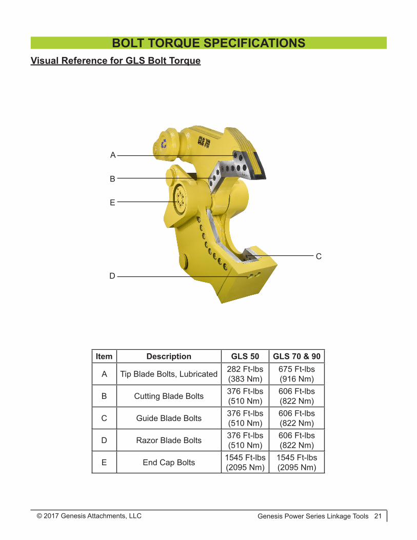
Item Description GLS 50 GLS 70 & 90
A Tip Blade Bolts, Lubricated 282 Ft-lbs(383 Nm)
675 Ft-lbs(916 Nm)
B Cutting Blade Bolts 376 Ft-lbs(510 Nm)
606 Ft-lbs(822 Nm)
C Guide Blade Bolts 376 Ft-lbs(510 Nm)
606 Ft-lbs(822 Nm)
D Razor Blade Bolts 376 Ft-lbs(510 Nm)
606 Ft-lbs(822 Nm)
E End Cap Bolts 1545 Ft-lbs(2095 Nm)
1545 Ft-lbs(2095 Nm)
Visual Reference for GLS Bolt Torque
A
D
B
C
E
BOLT TORQUE SPECIFICATIONS
© 2017 Genesis Attachments, LLCGenesis Power Series Linkage Tools22
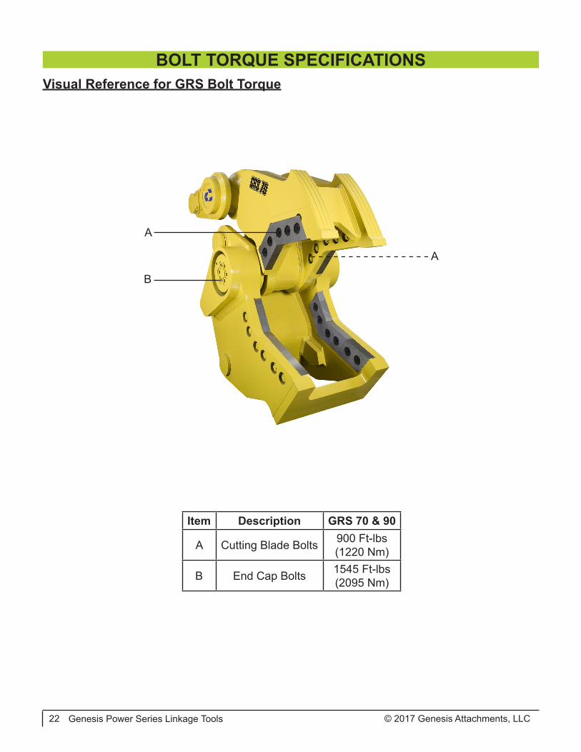
Item Description GRS 70 & 90
A Cutting Blade Bolts 900 Ft-lbs(1220 Nm)
B End Cap Bolts 1545 Ft-lbs(2095 Nm)
Visual Reference for GRS Bolt Torque
A
A
B
BOLT TORQUE SPECIFICATIONS

© 2017 Genesis Attachments, LLC Genesis Power Series Linkage Tools 23
Item Description GCC 50 GCC 70 & 90
A Blade Bolts 606 Ft-lbs(822 Nm)
900 Ft-lbs(1220 Nm)
B End Cap Bolts 1545 Ft-lbs(2095 Nm)
1545 Ft-lbs(2095 Nm)
Visual Reference for GCC Bolt Torque
A
A
B
BOLT TORQUE SPECIFICATIONS
© 2017 Genesis Attachments, LLCGenesis Power Series Linkage Tools24
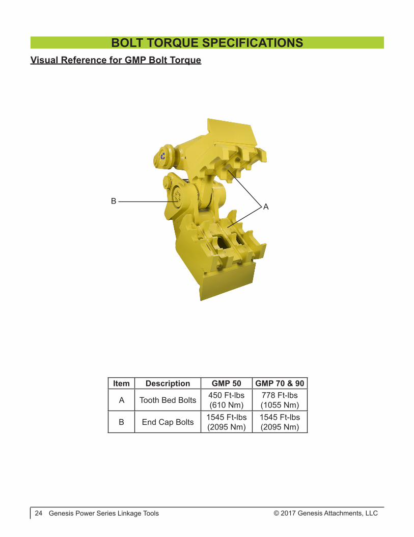
Item Description GMP 50 GMP 70 & 90
A Tooth Bed Bolts 450 Ft-lbs(610 Nm)
778 Ft-lbs(1055 Nm)
B End Cap Bolts 1545 Ft-lbs(2095 Nm)
1545 Ft-lbs(2095 Nm)
Visual Reference for GMP Bolt Torque
AB
BOLT TORQUE SPECIFICATIONS
© 2017 Genesis Attachments, LLC Genesis Power Series Linkage Tools 25
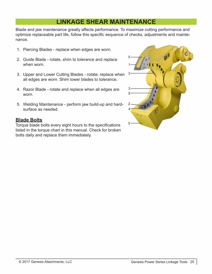
Blade and jaw maintenance greatly affects performance. To maximize cutting performance and optimize replaceable part life, follow this specific sequence of checks, adjustments and mainte-nance.
1. Piercing Blades - replace when edges are worn.
2. Guide Blade - rotate, shim to tolerance and replace when worn.
3. Upper and Lower Cutting Blades - rotate; replace when all edges are worn. Shim lower blades to tolerance.
4. Razor Blade - rotate and replace when all edges are worn.
5. Welding Maintenance - perform jaw build-up and hard-surface as needed.
Blade BoltsTorque blade bolts every eight hours to the specifications listed in the torque chart in this manual. Check for broken bolts daily and replace them immediately.
2
1
3
4
5
5
35
LINKAGE SHEAR MAINTENANCE
© 2017 Genesis Attachments, LLCGenesis Power Series Linkage Tools26
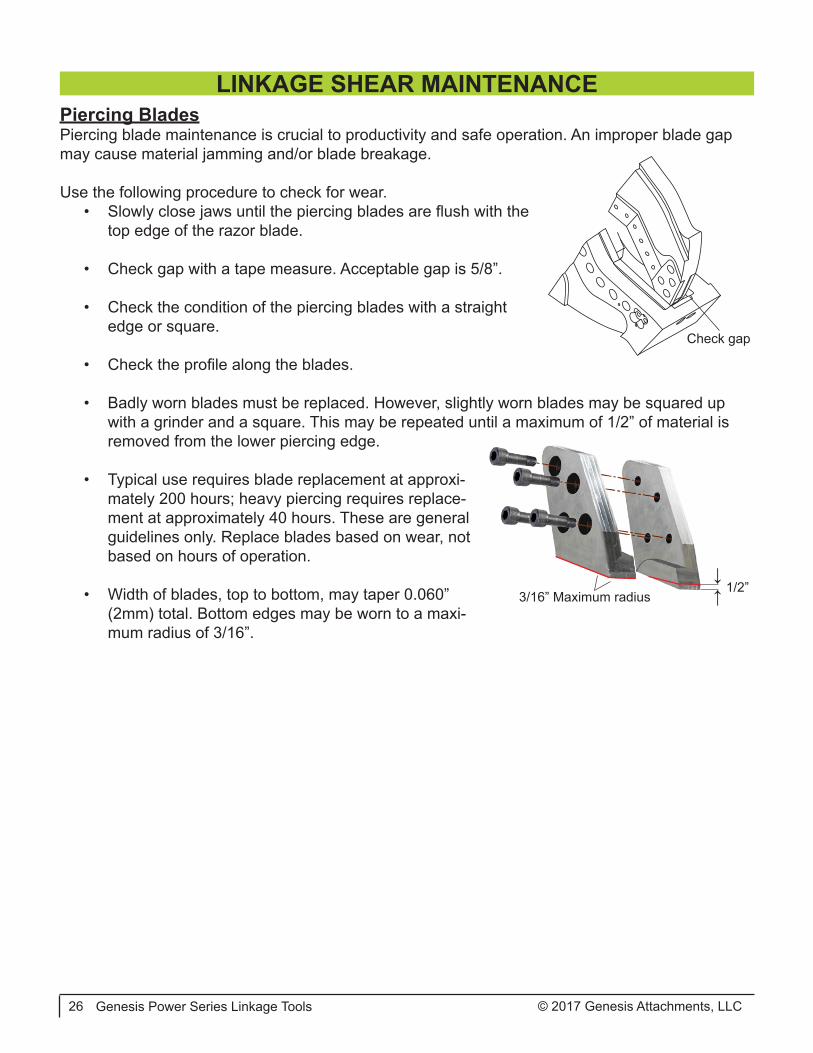
Piercing BladesPiercing blade maintenance is crucial to productivity and safe operation. An improper blade gap may cause material jamming and/or blade breakage.
Use the following procedure to check for wear.• Slowly close jaws until the piercing blades are flush with the
top edge of the razor blade.
• Check gap with a tape measure. Acceptable gap is 5/8”.
• Check the condition of the piercing blades with a straight edge or square.
• Check the profile along the blades.
• Badly worn blades must be replaced. However, slightly worn blades may be squared up with a grinder and a square. This may be repeated until a maximum of 1/2” of material is removed from the lower piercing edge.
• Typical use requires blade replacement at approxi-mately 200 hours; heavy piercing requires replace-ment at approximately 40 hours. These are general guidelines only. Replace blades based on wear, not based on hours of operation.
• Width of blades, top to bottom, may taper 0.060” (2mm) total. Bottom edges may be worn to a maxi-mum radius of 3/16”.
↓↓3/16” Maximum radius
1/2”
Check gap
LINKAGE SHEAR MAINTENANCE
© 2017 Genesis Attachments, LLC Genesis Power Series Linkage Tools 27
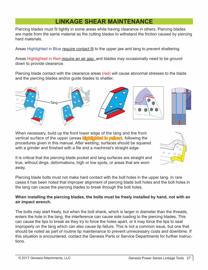
Piercing blades must fit tightly in some areas while having clearance in others. Piercing blades are made from the same material as the cutting blades to withstand the friction caused by piercing hard materials.
Areas Highlighted in Blue require contact fit to the upper jaw and tang to prevent shattering.
Areas Highlighted in Red require an air gap, and blades may occasionally need to be ground down to provide clearance.
Piercing blade contact with the clearance areas (red) will cause abnormal stresses to the blade and the piercing blades and/or guide blades to shatter.
When necessary, build up the front lower edge of the tang and the front vertical surface of the upper (areas highlighted in yellow), following the procedures given in this manual. After welding, surfaces should be squared with a grinder and finished with a file and a machinist’s straight edge.
It is critical that the piercing blade pocket and tang surfaces are straight and true, without dings, deformations, high or low spots, or areas that are worn away.
Piercing blade bolts must not make hard contact with the bolt holes in the upper tang. In rare cases it has been noted that improper alignment of piercing blade bolt holes and the bolt holes in the tang can cause the piercing blades to break through the bolt holes.
When installing the piercing blades, the bolts must be freely installed by hand, not with an air impact wrench.
The bolts may start freely, but when the bolt shank, which is larger in diameter than the threads, enters the hole in the tang, the interference can cause side loading to the piercing blades. This can cause the tips to break as they try to force the holes apart, or it may force the tips to seat improperly on the tang which can also cause tip failure. This is not a common issue, but one that should be noted as part of routine tip maintenance to prevent unnecessary costs and downtime. If this situation is encountered, contact the Genesis Parts or Service Departments for further instruc-tions.
Tang
LINKAGE SHEAR MAINTENANCE

© 2017 Genesis Attachments, LLCGenesis Power Series Linkage Tools28
Piercing Blade Replacement1. Remove blades using an air-impact wrench or breaker bar and multiplier.
2. Remove dust and debris from blade seats; wipe down with a rag and solvent.
3. Lightly file deformities from blade seat edges. Do not sand or grind face of blade seats.
4. Install new, clean blades. Lubricate the threaded holes in the blade and on the bottom of the bolt head where it will contact the blade.
5. Snug lubricated blade bolts by hand to hold them in place; push blades up and into the up-per and rear surfaces of the seats.
6. Torque bolts to 1/3 of the final torque value.
7. Check for firm contact against blade seats.
8. With a feeler gauge, confirm gap of 0.002” to 0.010” where blades meet at piercing surface. A very narrow gap may be confirmed by shining a flashlight from below the blades and seeing light pass through. If gap exceeds 0.010”, call the Genesis Service Department. If no gap exists, remove blades, lightly grind facing surfaces and repeat steps 5-8.
9. Torque bolts to 2/3 final value, and then to final value, using a cross bolt pattern.
Correct clamping force is required to keep tips from moving on their seats. Over-tightening can cause bolt shanks to stretch, losing their clamping force. Loose bolts will cause the seating areas to erode.
Piercing blade bolts must be lubricated and torqued as specified below.NOTICE
Description GLS 50 GLS 70 & 90
Blade Bolts, Lub. 282 Ft-lbs(382 Nm)
675 Ft-lbs(915 Nm)
Check gap
LINKAGE SHEAR MAINTENANCE
© 2017 Genesis Attachments, LLC Genesis Power Series Linkage Tools 29
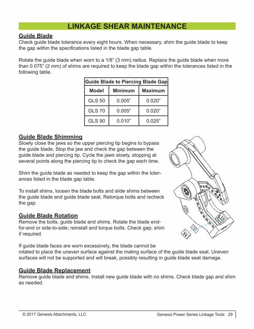
Guide BladeCheck guide blade tolerance every eight hours. When necessary, shim the guide blade to keep the gap within the specifications listed in the blade gap table.
Rotate the guide blade when worn to a 1/8” (3 mm) radius. Replace the guide blade when more than 0.075” (2 mm) of shims are required to keep the blade gap within the tolerances listed in the following table.
Guide Blade ShimmingSlowly close the jaws so the upper piercing tip begins to bypass the guide blade. Stop the jaw and check the gap between the guide blade and piercing tip. Cycle the jaws slowly, stopping at several points along the piercing tip to check the gap each time.
Shim the guide blade as needed to keep the gap within the toler-ances listed in the blade gap table.
To install shims, loosen the blade bolts and slide shims between the guide blade and guide blade seat. Retorque bolts and recheck the gap.
Guide Blade RotationRemove the bolts, guide blade and shims. Rotate the blade end-for-end or side-to-side; reinstall and torque bolts. Check gap; shim if required.
If guide blade faces are worn excessively, the blade cannot be rotated to place the uneven surface against the mating surface of the guide blade seat. Uneven surfaces will not be supported and will break, possibly resulting in guide blade seat damage.
Guide Blade ReplacementRemove guide blade and shims. Install new guide blade with no shims. Check blade gap and shim as needed.
Guide Blade to Piercing Blade Gap
Model Minimum Maximum
GLS 50 0.005” 0.020”
GLS 70 0.005” 0.020”
GLS 90 0.010” 0.025”
LINKAGE SHEAR MAINTENANCE

© 2017 Genesis Attachments, LLCGenesis Power Series Linkage Tools30
Primary and Secondary BladesProper maintenance of the primary and secondary blades, or cutting blades, is required for opti-mal performance. Blade rotation extends blade life and improves cutting performance. Shimming to maintain blade tolerances helps prevent jamming. Dull blades make the excavator hydraulic system work harder and may cause structural damage to the attachment.
Inspect blades every eight hours of operation. Re-torque loose bolts and replace broken bolts. Grind away dents or mushrooming of blade edges at the end of each day to prevent upper jaw deflection, excessive blade wear and undue stress to upper and lower jaws.
Rotate blades to use all four cutting edges. Always use Genesis-approved blades. Blades that do not meet Genesis specifications can cause major problems, and using them may void the war-ranty.
Before performing any blade maintenance, read, fully understand and follow these safety rules.
• Wear personal safety equipment including gloves, safety glasses, safety boots and proper clothing.
• Safe blade maintenance requires two people - one to steady the blade while the other loosens the bolts.
• Blades are heavy and may fall out of the blade seat if not adequately supported. Bystanders must stand clear.
• Never strike a blade with a hardened steel tool. The blade may fragment, creat-ing sharp flying debris.
Primary and Secondary Blade RemovalLoosen the bolts on one blade at a time, enough to loosen the blades.
If blades remain tight, insert a 7/16” brass drift pin into the through-hole on the lower jaw. Tap the drift pin with a hammer until the blade is loose.
Carefully remove bolts and blades.
LINKAGE SHEAR MAINTENANCE
Insert drift pin
© 2017 Genesis Attachments, LLC Genesis Power Series Linkage Tools 31
Adjustment PlatesDo not remove the adjustment plates from the lower jaw during routine blade rotation or replace-ment. These plates are custom-machined for each attachment and need only be replaced when lost, damaged or extremely worn.
Inspect the top of each adjustment plate and seat for burrs, nicks or other imperfections that may prevent proper seating of the blades and cause errant blade gap readings. Clean the adjustment plates as necessary.
Replacement plates can be ordered from your Genesis dealer or the Genesis Parts Department with the serial number of your attachment.
Offset dowel or fastener holes are located in each adjustment plate. When replacing adjustment plates, make sure these holes are aligned with the corresponding holes in the blade seat.
Do not grind blade seat areas.
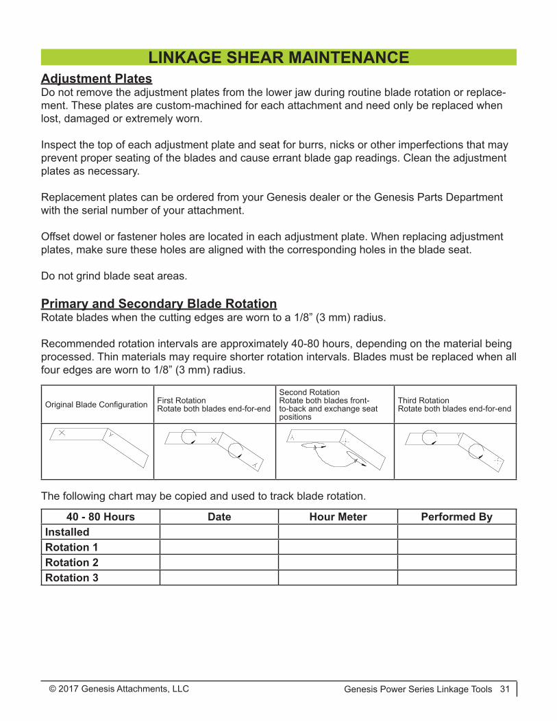
Primary and Secondary Blade RotationRotate blades when the cutting edges are worn to a 1/8” (3 mm) radius.
Recommended rotation intervals are approximately 40-80 hours, depending on the material being processed. Thin materials may require shorter rotation intervals. Blades must be replaced when all four edges are worn to 1/8” (3 mm) radius.
The following chart may be copied and used to track blade rotation.
Original Blade Configuration First RotationRotate both blades end-for-end
Second RotationRotate both blades front-to-back and exchange seat positions
Third RotationRotate both blades end-for-end
40 - 80 Hours Date Hour Meter Performed ByInstalledRotation 1Rotation 2Rotation 3
LINKAGE SHEAR MAINTENANCE
© 2017 Genesis Attachments, LLCGenesis Power Series Linkage Tools32
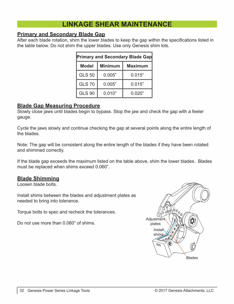
Primary and Secondary Blade GapAfter each blade rotation, shim the lower blades to keep the gap within the specifications listed in the table below. Do not shim the upper blades. Use only Genesis shim kits.
LINKAGE SHEAR MAINTENANCE
Primary and Secondary Blade Gap
Model Minimum Maximum
GLS 50 0.005” 0.015”
GLS 70 0.005” 0.015”
GLS 90 0.010” 0.020”
Blade Gap Measuring ProcedureSlowly close jaws until blades begin to bypass. Stop the jaw and check the gap with a feeler gauge.
Cycle the jaws slowly and continue checking the gap at several points along the entire length of the blades.
Note: The gap will be consistent along the entire length of the blades if they have been rotated and shimmed correctly.
If the blade gap exceeds the maximum listed on the table above, shim the lower blades. Blades must be replaced when shims exceed 0.060”.
Blade ShimmingLoosen blade bolts.
Install shims between the blades and adjustment plates as needed to bring into tolerance.
Torque bolts to spec and recheck the tolerances.
Do not use more than 0.060” of shims.Install shims
Adjustment plates
Blades

© 2017 Genesis Attachments, LLC Genesis Power Series Linkage Tools 33
Razor BladeCheck the razor blade for wear every eight hours of op-eration. Rotate when worn, using the edges in the se-quence indicated by the illustration.
After rotation, check the gap between the razor blade and piercing blades. If the gap exceeds the maximum tolerance after new piercing blades have been installed, the razor blade must be replaced. Do not shim the razor blade.
Set screws should be installed in unused bolt holes to prevent thread and hole damage. Replace set screws when lost or damaged.
Jaw StopThe Linkage Shear features a jaw stop welded in the lower jaw.
The jaw stop is positioned well beyond blade bypass and designed to prevent the excavator bucket linkage from toggling over. Toggling over can jam the linkage and bend the bucket cylinder rod.
To extend the life of the jaw stop and reduce mainte-nance, avoid extending the bucket cylinder beyond the point where material is cut.
Inspect the jaw stop every eight hours of operation, checking for cracked or damaged welds.
1
4
3
2
LINKAGE SHEAR MAINTENANCE
To prevent serious excavator damage, replace the stop immediately if cracked or damaged welds are found.! CAUTION
© 2017 Genesis Attachments, LLCGenesis Power Series Linkage Tools34
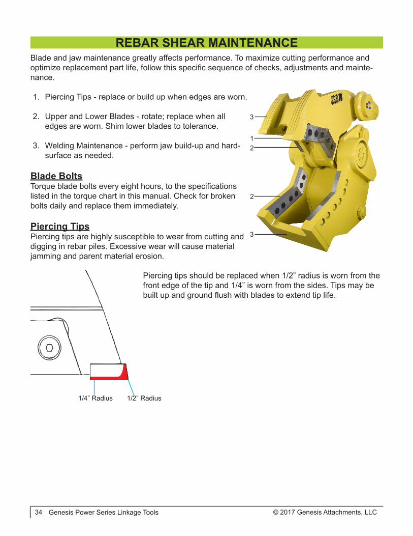
Blade and jaw maintenance greatly affects performance. To maximize cutting performance and optimize replacement part life, follow this specific sequence of checks, adjustments and mainte-nance.
1. Piercing Tips - replace or build up when edges are worn.
2. Upper and Lower Blades - rotate; replace when all edges are worn. Shim lower blades to tolerance.
3. Welding Maintenance - perform jaw build-up and hard-surface as needed.
Blade BoltsTorque blade bolts every eight hours, to the specifications listed in the torque chart in this manual. Check for broken bolts daily and replace them immediately.
Piercing TipsPiercing tips are highly susceptible to wear from cutting and digging in rebar piles. Excessive wear will cause material jamming and parent material erosion.
Piercing tips should be replaced when 1/2” radius is worn from the front edge of the tip and 1/4” is worn from the sides. Tips may be built up and ground flush with blades to extend tip life.
2
1
3
3
2
1/2” Radius1/4” Radius
REBAR SHEAR MAINTENANCE
© 2017 Genesis Attachments, LLC Genesis Power Series Linkage Tools 35
Primary and Secondary BladesProper maintenance of the primary and secondary blades, or cutting blades, is required for opti-mal performance. Blade rotation extends blade life and improves cutting performance. Shimming to maintain blade tolerances helps prevent jamming. Dull blades make the excavator hydraulic system work harder and may cause structural damage to the attachment.
Inspect blades every eight hours of operation. Re-torque loose bolts and replace broken bolts. Grind away dents or mushrooming of blade edges at the end of each day to prevent upper jaw deflection, excessive blade wear and undue stress to upper and lower jaws.
Rotate blades to use all four cutting edges. Always use Genesis-approved blades. Blades that do not meet Genesis specifications can cause major problems, and using them may void the war-ranty.
Before performing any blade maintenance, read, fully understand and follow these safety rules.
• Wear personal safety equipment including gloves, safety glasses, safety boots and proper clothing.
• Safe blade maintenance requires two people - one to steady the blade while the other loosens the bolts.
• Blades are heavy and may fall out of the blade seat if not adequately supported. Bystanders must stand clear.
• Never strike a blade with a hardened steel tool. The blade may fragment, creat-ing sharp flying debris.
Primary and Secondary Blade RemovalLoosen the bolts on one blade at a time, enough to loosen the blades.
Carefully remove bolts and blades.
REBAR SHEAR MAINTENANCE

© 2017 Genesis Attachments, LLCGenesis Power Series Linkage Tools36
Primary and Secondary Blade RotationRotate blades when the cutting edges are worn to a 1/8” (3 mm) radius.
Recommended rotation intervals are approximately 40-80 hours, depending on the material being processed. Thin materials may require shorter rotation intervals. Blades must be replaced when all four edges are worn to 1/8” (3 mm) radius.
Original Blade Configuration First RotationRotate both blades end-for-end
Second RotationRotate both blades front-to-back and exchange seat positions
Third RotationRotate both blades end-for-end
The following chart may be copied and used to track blade rotation.40 - 80 Hours Date Hour Meter Performed By
InstalledRotation 1Rotation 2Rotation 3
Primary and Secondary Blade GapAfter each blade rotation, shim lower blades to keep the gap within the range of 0.031” to 0.062”. Do not shim the upper blades. Use only Genesis shim kits.
Blade Gap Measuring ProcedureSlowly close jaws until blades begin to bypass. Stop the jaw and check the gap with a feeler gauge.
Cycle the jaws slowly and continue checking the gap at several points along the entire length of the blades.
Note: The gap will be consistent along the entire length of the blades if they have been rotated and shimmed correctly.
If the blade gap exceeds 0.062”, shim the lower blades. Blades must be replaced when shims exceed 0.060”.
REBAR SHEAR MAINTENANCE
© 2017 Genesis Attachments, LLC Genesis Power Series Linkage Tools 37
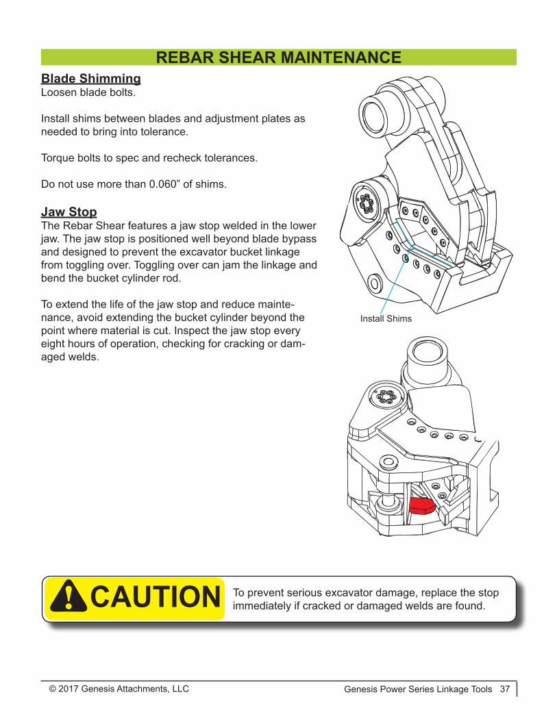
Blade ShimmingLoosen blade bolts.
Install shims between blades and adjustment plates as needed to bring into tolerance.
Torque bolts to spec and recheck tolerances.
Do not use more than 0.060” of shims.
Jaw StopThe Rebar Shear features a jaw stop welded in the lower jaw. The jaw stop is positioned well beyond blade bypass and designed to prevent the excavator bucket linkage from toggling over. Toggling over can jam the linkage and bend the bucket cylinder rod.
To extend the life of the jaw stop and reduce mainte-nance, avoid extending the bucket cylinder beyond the point where material is cut. Inspect the jaw stop every eight hours of operation, checking for cracking or dam-aged welds.
Install Shims
REBAR SHEAR MAINTENANCE
To prevent serious excavator damage, replace the stop immediately if cracked or damaged welds are found.! CAUTION
© 2017 Genesis Attachments, LLCGenesis Power Series Linkage Tools38
Blade and jaw maintenance greatly affects performance. To maximize performance and optimize replaceable part life, follow all instructions for checks, adjustments and maintenance described in this section, at the intervals listed in the maintenance schedule in this manual.
Before performing maintenance, read, fully understand and follow these safety rules.
• Wear personal safety equipment including gloves, safety glasses, safety boots and proper clothing.
• Safe blade maintenance requires two people - one to steady the blade while the other loosens the bolts.
• Blades are heavy and may fall out of the blade seat if not adequately supported. Bystanders must stand clear.
• Never strike a blade with a hardened steel tool. The blade may fragment, creat-ing sharp flying debris.
Concrete Cracking BladesProper maintenance of the blades is required for optimal performance. Blade rotation extends blade life and improves performance.
At the end of each eight-hour shift, inspect blades and check the condition of concrete cracking points on the blades. Replace any broken bolts, and retorque loose bolts when cool. Grind away dents or mushrooming of blade edges at the end of each day to prevent upper jaw deflection, ex-cessive blade wear and undue stress to jaws.
Rotate blades to use both cutting edges. Always use Genesis-approved blades. Blades that do not meet Genesis specifications can cause major problems, and using them may void the warranty.
Replace blades when cracking points become severely rounded or flat. A more pointed blade will process concrete more efficiently. Cracking points may be build up and re-used if desired to ex-tend blade life.
Blade RemovalLoosen the bolts on one blade at a time, enough to loosen the blades.
Carefully remove bolts and blades.
CONCRETE CRACKER MAINTENANCE
© 2017 Genesis Attachments, LLC Genesis Power Series Linkage Tools 39
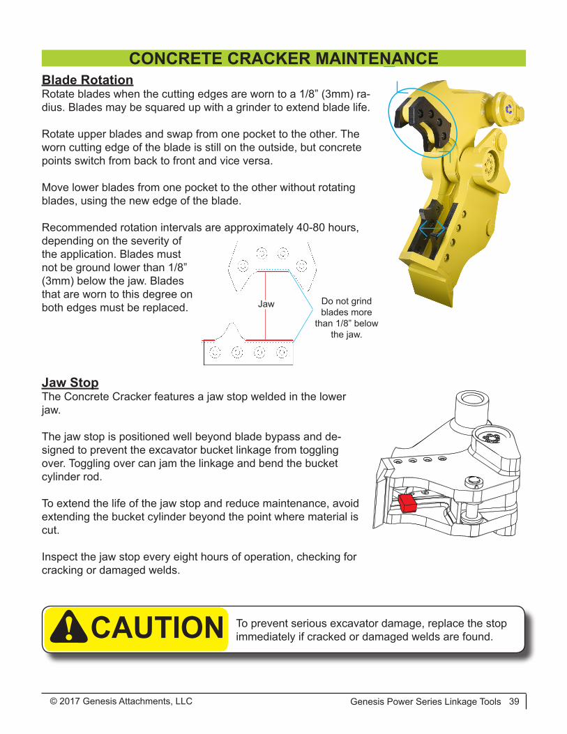
Blade RotationRotate blades when the cutting edges are worn to a 1/8” (3mm) ra-dius. Blades may be squared up with a grinder to extend blade life.
Rotate upper blades and swap from one pocket to the other. The worn cutting edge of the blade is still on the outside, but concrete points switch from back to front and vice versa.
Move lower blades from one pocket to the other without rotating blades, using the new edge of the blade.
Recommended rotation intervals are approximately 40-80 hours, depending on the severity of the application. Blades must not be ground lower than 1/8” (3mm) below the jaw. Blades that are worn to this degree on both edges must be replaced.
Jaw StopThe Concrete Cracker features a jaw stop welded in the lower jaw.
The jaw stop is positioned well beyond blade bypass and de-signed to prevent the excavator bucket linkage from toggling over. Toggling over can jam the linkage and bend the bucket cylinder rod.
To extend the life of the jaw stop and reduce maintenance, avoid extending the bucket cylinder beyond the point where material is cut.
Inspect the jaw stop every eight hours of operation, checking for cracking or damaged welds.
Jaw Do not grind blades more
than 1/8” below the jaw.
CONCRETE CRACKER MAINTENANCE
To prevent serious excavator damage, replace the stop immediately if cracked or damaged welds are found.! CAUTION
© 2017 Genesis Attachments, LLCGenesis Power Series Linkage Tools40
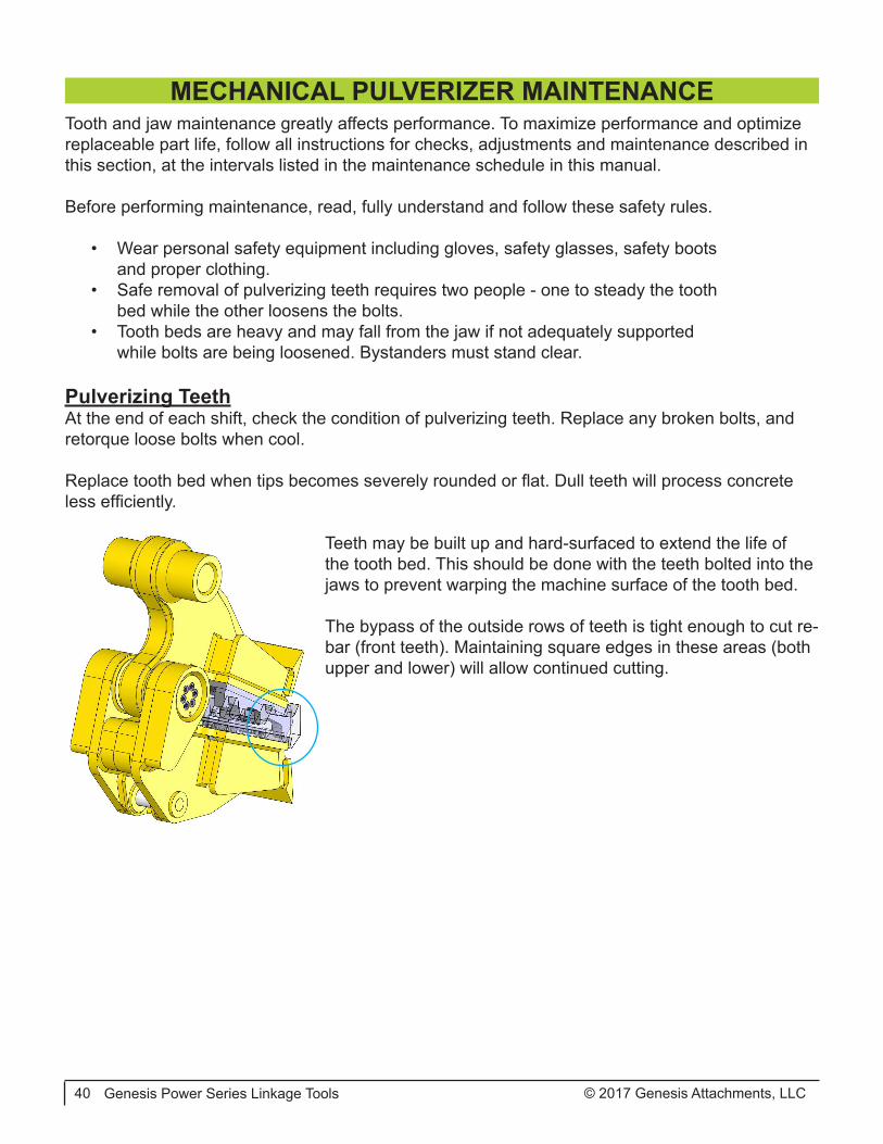
Tooth and jaw maintenance greatly affects performance. To maximize performance and optimize replaceable part life, follow all instructions for checks, adjustments and maintenance described in this section, at the intervals listed in the maintenance schedule in this manual.
Before performing maintenance, read, fully understand and follow these safety rules.
• Wear personal safety equipment including gloves, safety glasses, safety boots and proper clothing.
• Safe removal of pulverizing teeth requires two people - one to steady the tooth bed while the other loosens the bolts.
• Tooth beds are heavy and may fall from the jaw if not adequately supported while bolts are being loosened. Bystanders must stand clear.
Pulverizing TeethAt the end of each shift, check the condition of pulverizing teeth. Replace any broken bolts, and retorque loose bolts when cool.
Replace tooth bed when tips becomes severely rounded or flat. Dull teeth will process concrete less efficiently.
Teeth may be built up and hard-surfaced to extend the life of the tooth bed. This should be done with the teeth bolted into the jaws to prevent warping the machine surface of the tooth bed.
The bypass of the outside rows of teeth is tight enough to cut re-bar (front teeth). Maintaining square edges in these areas (both upper and lower) will allow continued cutting.
MECHANICAL PULVERIZER MAINTENANCE
© 2017 Genesis Attachments, LLC Genesis Power Series Linkage Tools 41
GENERAL WELDING GUIDELINESBuild-up and hard-surfacing are welding procedures that protect the parent material of the jaws and keep the blades in good adjustment. Build-up is the welding procedure that restores the jaws to their original shape. Building up the jaws helps protect the blades and increases attachment life. Hard-surfacing is the welding material added over the parent material (or build-up material) to cre-ate a wear-resistant surface.
Welding should not be performed until the jaws are work-hardened. Work-hardening can take up to 80 hours. On attachments with blades, jaws must not wear lower than the height of a new blade. If either jaw wears down lower than blade height, immediately stop operating the attach-ment and perform build-up and hard-surfacing as described in the following pages of this manual.
When welding around blade seats or the piercing tip tang area (GLS only), maintain the fac-tory machined seat radius. If the rounded grooves are welded up, use a die grinder with a carbide tool to recut these areas to their original profile. Leaving a squared edge will even-tually cause structural cracking. The radius provides a broader area to absorb structural stress.
Welding Ground ClampDisconnect all battery ground cables or shut off master battery switch, if equipped. Failure to do so may cause excavator electrical problems, including permanent damage to on-board computer systems.
Connect ground clamp as close as possible to the area being welded without allowing cur-rent to pass through the pivot group or cylinder pin.
If you are welding on the lower jaw, connect weld clamp to the lower. If you are welding on the upper jaw, connect to the upper but not to the power link. If needed, weld a piece of steel to the area for the grounding clamp and cut the piece off when welding is completed.
Welding RulesBefore you begin:
• Remove adjacent blades, as preheating and welding may cause blade damage.• Wearing an approved respirator, grind the area to clean it, removing all existing hard-sur-
facing.• Preheat area to 350˚ F (177˚ C). Maintain this temperature throughout the procedure. Do
not exceed 450˚ F (232˚ C) interpass temperature.
During welding:• Always grind and weld with the grain of the material.• Peen each weld pass to relieve stress and harden the welds.• Do not undercut the ends of the welds.• Do not start or stop welds directly above a bolt hole or in the apex of the jaw.
After welding maintenance is complete:• Cover the area with a heat blanket and allow it to cool slowly, approximately eight hours.• Do not put the attachment into operation until the welds have been allowed to cool.
© 2017 Genesis Attachments, LLCGenesis Power Series Linkage Tools42
Procedure:
Follow the General Welding Guidelines and Rules.
Determine the area to build up, using a straight-edge or square. On tools with blades, jaws must not wear lower than the height of a new blade. Use a new blade to help determine build-up height for the jaw.
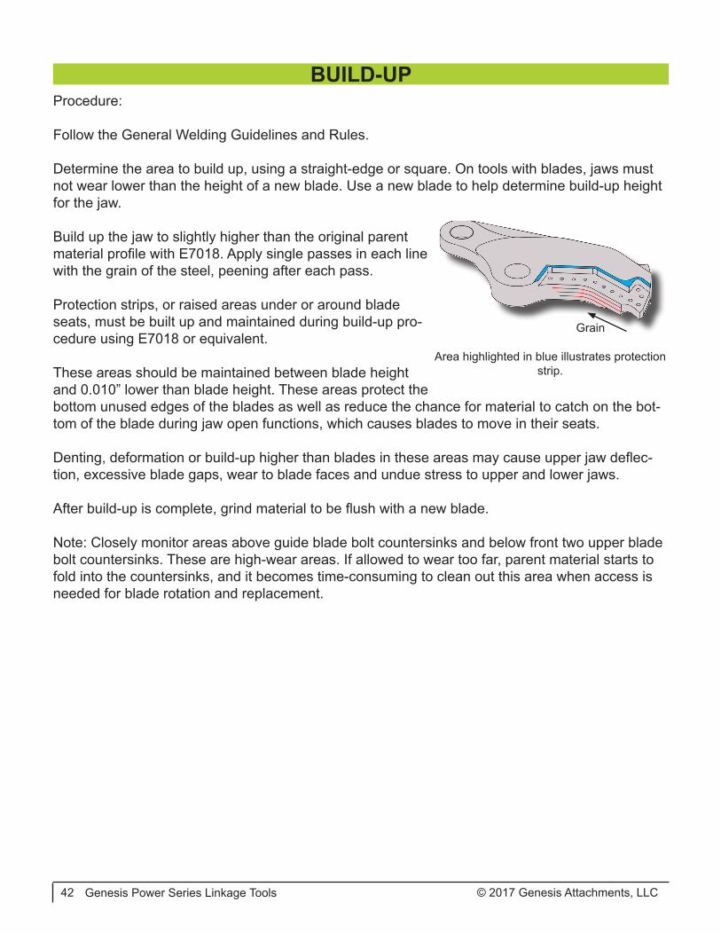
Build up the jaw to slightly higher than the original parent material profile with E7018. Apply single passes in each line with the grain of the steel, peening after each pass.
Protection strips, or raised areas under or around blade seats, must be built up and maintained during build-up pro-cedure using E7018 or equivalent.
These areas should be maintained between blade height and 0.010” lower than blade height. These areas protect the bottom unused edges of the blades as well as reduce the chance for material to catch on the bot-tom of the blade during jaw open functions, which causes blades to move in their seats.
Denting, deformation or build-up higher than blades in these areas may cause upper jaw deflec-tion, excessive blade gaps, wear to blade faces and undue stress to upper and lower jaws.
After build-up is complete, grind material to be flush with a new blade.
Note: Closely monitor areas above guide blade bolt countersinks and below front two upper blade bolt countersinks. These are high-wear areas. If allowed to wear too far, parent material starts to fold into the countersinks, and it becomes time-consuming to clean out this area when access is needed for blade rotation and replacement.
BUILD-UP
Area highlighted in blue illustrates protection strip.
Grain
© 2017 Genesis Attachments, LLC Genesis Power Series Linkage Tools 43
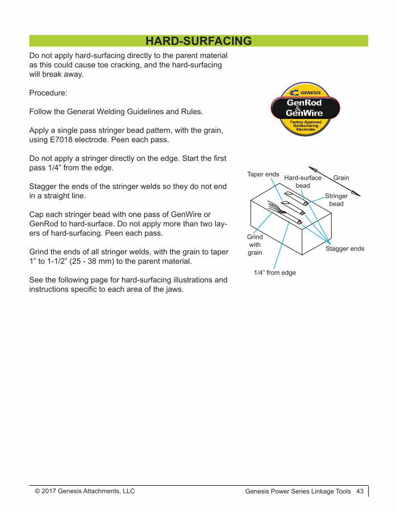
Grain
Stagger ends
Taper ends
Grind with grain
1/4” from edge
Stringer bead
Hard-surface bead
Do not apply hard-surfacing directly to the parent material as this could cause toe cracking, and the hard-surfacing will break away.
Procedure:
Follow the General Welding Guidelines and Rules.
Apply a single pass stringer bead pattern, with the grain, using E7018 electrode. Peen each pass.
Do not apply a stringer directly on the edge. Start the first pass 1/4” from the edge.
Stagger the ends of the stringer welds so they do not end in a straight line.
Cap each stringer bead with one pass of GenWire or GenRod to hard-surface. Do not apply more than two lay-ers of hard-surfacing. Peen each pass.
Grind the ends of all stringer welds, with the grain to taper 1” to 1-1/2” (25 - 38 mm) to the parent material.
See the following page for hard-surfacing illustrations and instructions specific to each area of the jaws.
HARD-SURFACING
© 2017 Genesis Attachments, LLCGenesis Power Series Linkage Tools44
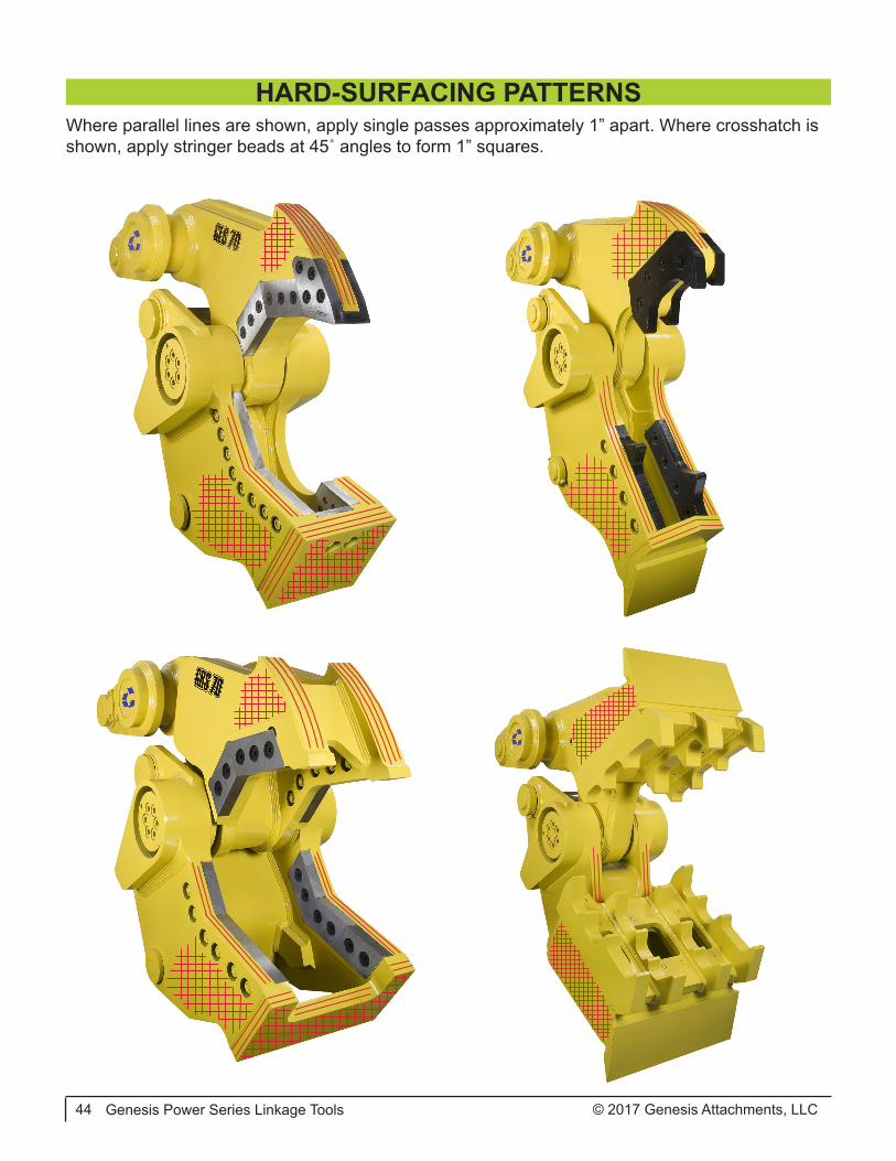
Where parallel lines are shown, apply single passes approximately 1” apart. Where crosshatch is shown, apply stringer beads at 45˚ angles to form 1” squares.
HARD-SURFACING PATTERNS
© 2017 Genesis Attachments, LLC Genesis Power Series Linkage Tools 45
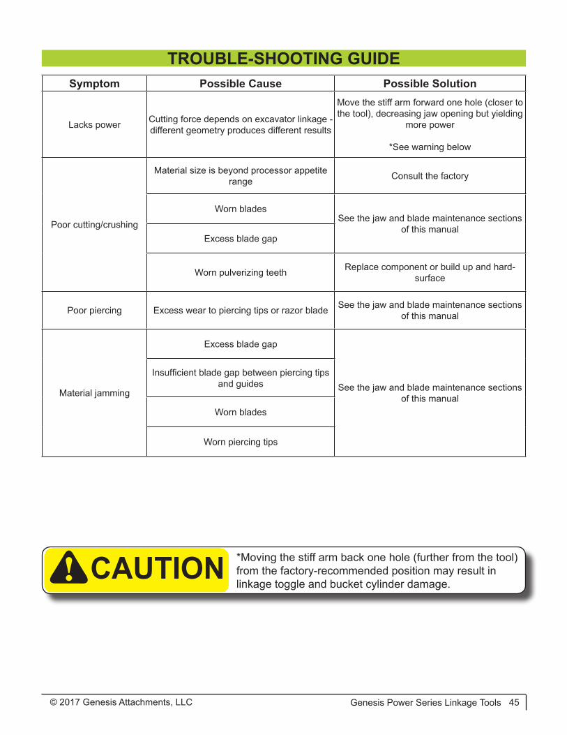
Symptom Possible Cause Possible Solution
Lacks power Cutting force depends on excavator linkage - different geometry produces different results
Move the stiff arm forward one hole (closer to the tool), decreasing jaw opening but yielding
more power
*See warning below
Poor cutting/crushing
Material size is beyond processor appetite range Consult the factory
Worn bladesSee the jaw and blade maintenance sections
of this manualExcess blade gap
Worn pulverizing teeth Replace component or build up and hard-surface
Poor piercing Excess wear to piercing tips or razor blade See the jaw and blade maintenance sections of this manual
Material jamming
Excess blade gap
See the jaw and blade maintenance sections of this manual
Insufficient blade gap between piercing tips and guides
Worn blades
Worn piercing tips
TROUBLE-SHOOTING GUIDE
*Moving the stiff arm back one hole (further from the tool) from the factory-recommended position may result in linkage toggle and bucket cylinder damage.! CAUTION

© 2017 Genesis Attachments, LLCGenesis Power Series Linkage Tools46
WARRANTYClaim ProcedureNotify the Genesis Service Department of the potential warranty claim prior to making the repair. Digital pictures are very helpful for diagnosing problems and recommending repairs.
Contact the Genesis Service Department before making alterations, changes or repairs to any component that is going to be considered for warranty. Not doing so will void all Genesis warranty consideration.
The Genesis Service Department will issue an authorization number to track the repair costs, out-going parts, and/or defective parts returning to the factory.
Replacement parts must be ordered using a purchase order number. Shipping is standard ground. Overnight shipping is available by request, and Genesis will not cover the shipping charge.
When the repair is complete, submit an invoice to the Genesis Service Department within 30 days. Include itemized internal labor reporting, parts lists and invoices for outside contractors. Reference the authorization number on all invoices.
When returning parts for warranty consideration, include a copy of any related Genesis paperwork along with any other necessary documentation to ensure proper processing and credit. The Gen-esis Service Department will provide the necessary forms.
Your account will be credited when the warranty claim is accepted.
Blade WarrantyStandard warranty on blades will only be considered on the first edge, and wear on the edge must be 1/8” radius or less. Genesis does not warranty cutting blades that are cracked or broken from top to bottom (perpendicular to the long edge of the blade). Genesis also does not cover fasten-ers, the labor to replace wear components or collateral damage, such as blade seats, from broken blades, the piercing blade tang or adjustment plates.
Please direct any questions to the Genesis Service Department: 715-395-5252

© 2017 Genesis Attachments, LLC Genesis Power Series Linkage Tools 47
PARTS ORDER POLICY AND PROCEDUREParts Orders Should Include
• Purchase order number• Model and serial number of attachment• Part number and quantity needed• Shipping and billing address• Method of shipment or required delivery date
Placing OrdersOrders may be placed by phone, e-mail or fax. To fax an order, use the form on the following page. Contact information is located at the front of this manual.
Part NumbersPart numbers are listed in a separate Parts Manual or, if included, the Parts section of this manu-al. Contact the Genesis Parts Department with questions regarding part numbers, availability and pricing.
ShippingAll orders will be shipped best way surface unless an alternate shipping method is requested. Shipping charges are not included in the purchase price of parts.
InvoicesAll invoices are due upon receipt. Any accounts with invoices open beyond 60 days are subject to review and may be placed on C.O.D. status without further notice.
ReturnsUnused Genesis parts may be returned with proper documentation. Return shipping is the respon-sibility of the purchaser. Credit will be issued upon return, less a 20% restocking fee. Documen-tation is required for credit of returned parts. Contact the Genesis Parts Department at 715-395-5252 for a RGA (Return Goods Authorization) number and form.
Return Goods AuthorizationAll parts returned to Genesis for warranty consideration must be returned with a completed RGA (Return Goods Authorization) provided by the Genesis Parts Department. The form needs to be completed in its entirety, including any additional information requested by the Parts or Service Department. Return freight is the responsibility of the shipper and will be credited upon claim ap-proval. A determination to accept or deny the claim will be made based on the information avail-able to Genesis. Warranty on purchased parts other than wear components is 6 months. There is no warranty period on wear parts or components.

© 2017 Genesis Attachments, LLCGenesis Power Series Linkage Tools48
PARTS ORDER FORM
Fax to the Genesis Parts Department at 715-395-3411For assistance, call 715-395-5252 or e-mail [email protected]
Customer:
Phone:
Shipping Address:
Purchase Order:
Model:
Date:
Contact:
Fax:
Billing Address:
Shipping Method:
Serial Number:
Quantity Part Number Description Price

© 2017 Genesis Attachments, LLC Genesis Power Series Linkage Tools 49
The following pages contain illustrations and part lists for Power Series Linkage Tools. These pho-tos and generalized drawings identify major components and may not be identical in fine detail to a particular attachment.
The part lists included here are intended to aid in operation and maintenance. Part numbers listed are those currently used. These may differ from the part numbers of the components originally in-stalled in your attachment. To ensure use of the correct internal components, always indicate your attachment model and serial number when ordering parts.
If further information is required, contact the Genesis Parts Department for a breakdown and parts list specific to your attachment model and serial number.
PARTS
© 2017 Genesis Attachments, LLCGenesis Power Series Linkage Tools50
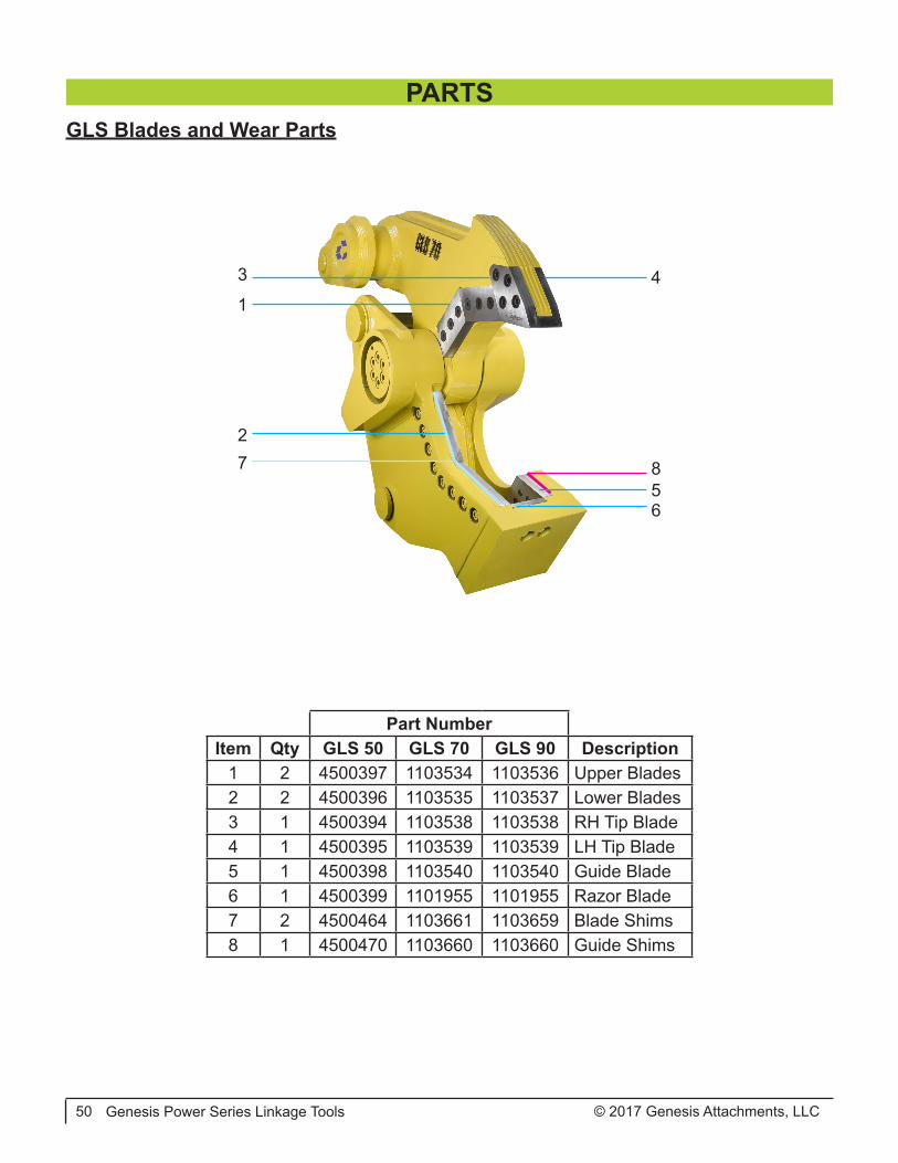
GLS Blades and Wear Parts
1
3
2
4
65
7 8
PARTS
Part NumberItem Qty GLS 50 GLS 70 GLS 90 Description
1 2 4500397 1103534 1103536 Upper Blades2 2 4500396 1103535 1103537 Lower Blades3 1 4500394 1103538 1103538 RH Tip Blade4 1 4500395 1103539 1103539 LH Tip Blade5 1 4500398 1103540 1103540 Guide Blade6 1 4500399 1101955 1101955 Razor Blade7 2 4500464 1103661 1103659 Blade Shims8 1 4500470 1103660 1103660 Guide Shims

© 2017 Genesis Attachments, LLC Genesis Power Series Linkage Tools 51
GRS Blades and Wear Parts
1
6,7,8
3
1
5,7,8
4
2
PARTS
Part NumberItem Qty GRS 70 GRS 90 Description
1 8 4500705 4500709 Lower Blades & Upper Primary Blades2 2 4501319 4501318 Upper Secondary Blades3 2 4501330 4501330 Weld-on Piercing Tips4 2 sets 4501006 4501607 Lower Blade Shims5 10 F0510350 F0510350 Upper Blade Bolts6 12 F0510350 F0510450 Lower Blade Bolts7 22 F0910008 F0910008 Hex Nuts8 22 F1300100 F1300100 Flat Washers

© 2017 Genesis Attachments, LLCGenesis Power Series Linkage Tools52
GCC Blades and Wear Parts
4,6,7
5,6,73
1
2
3
PARTS
Part NumberItem Qty GCC 50 GCC 70 GCC 90 Description
1 1 4500063 4500119 4500276 Upper RH Blade2 1 4500062 4500121 4500278 Upper LH Blade3 2 4500061 4500117 4500274 Lower Blades4 See Model F0588550 (4) F0510600 (4) F0510600 (5) Upper Blade Bolts5 See Model F0588300 (8) F0510350 (8) F0510350 (10) Lower Blade Bolts6 See Model F0908809 (12) F0910008 (12) F0910008 (15) Hex Nuts7 See Model F300088 (12) F1300100 (12) F1300100 (15) Flat Washers
© 2017 Genesis Attachments, LLC Genesis Power Series Linkage Tools 53
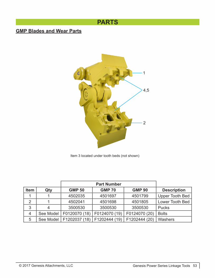
GMP Blades and Wear Parts
1
4,5
2
Item 3 located under tooth beds (not shown)
PARTS
Part NumberItem Qty GMP 50 GMP 70 GMP 90 Description
1 1 4502035 4501697 4501799 Upper Tooth Bed2 1 4502041 4501698 4501805 Lower Tooth Bed3 4 3500530 3500530 3500530 Pucks4 See Model F0120070 (18) F0124070 (19) F0124070 (20) Bolts5 See Model F1202037 (18) F1202444 (19) F1202444 (20) Washers
© 2017 Genesis Attachments, LLCGenesis Power Series Linkage Tools54
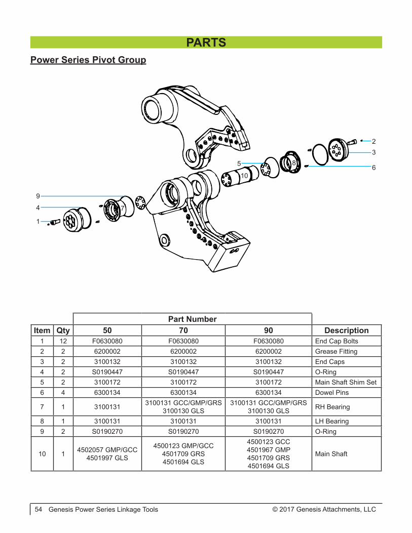
Power Series Pivot Group
1
10
9
8
7
65
4
32
PARTS
Part NumberItem Qty 50 70 90 Description
1 12 F0630080 F0630080 F0630080 End Cap Bolts2 2 6200002 6200002 6200002 Grease Fitting3 2 3100132 3100132 3100132 End Caps4 2 S0190447 S0190447 S0190447 O-Ring5 2 3100172 3100172 3100172 Main Shaft Shim Set6 4 6300134 6300134 6300134 Dowel Pins
7 1 3100131 3100131 GCC/GMP/GRS3100130 GLS
3100131 GCC/GMP/GRS3100130 GLS RH Bearing
8 1 3100131 3100131 3100131 LH Bearing9 2 S0190270 S0190270 S0190270 O-Ring
10 1 4502057 GMP/GCC4501997 GLS
4500123 GMP/GCC4501709 GRS4501694 GLS
4500123 GCC4501967 GMP4501709 GRS4501694 GLS
Main Shaft
© 2017 Genesis Attachments, LLC Genesis Power Series Linkage Tools 55
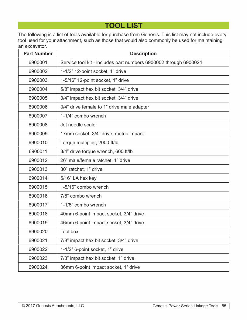
The following is a list of tools available for purchase from Genesis. This list may not include every tool used for your attachment, such as those that would also commonly be used for maintaining an excavator.
Part Number Description
6900001 Service tool kit - includes part numbers 6900002 through 6900024
6900002 1-1/2” 12-point socket, 1” drive
6900003 1-5/16” 12-point socket, 1” drive
6900004 5/8” impact hex bit socket, 3/4” drive
6900005 3/4” impact hex bit socket, 3/4” drive
6900006 3/4” drive female to 1” drive male adapter
6900007 1-1/4” combo wrench
6900008 Jet needle scaler
6900009 17mm socket, 3/4” drive, metric impact
6900010 Torque multiplier, 2000 ft/lb
6900011 3/4” drive torque wrench, 600 ft/lb
6900012 26” male/female ratchet, 1” drive
6900013 30” ratchet, 1” drive
6900014 5/16” LA hex key
6900015 1-5/16” combo wrench
6900016 7/8” combo wrench
6900017 1-1/8” combo wrench
6900018 40mm 6-point impact socket, 3/4” drive
6900019 46mm 6-point impact socket, 3/4” drive
6900020 Tool box
6900021 7/8” impact hex bit socket, 3/4” drive
6900022 1-1/2” 6-point socket, 1” drive
6900023 7/8” impact hex bit socket, 1” drive
6900024 36mm 6-point impact socket, 1” drive
TOOL LIST

Asia Pacific Representative Office
24 Upper Serangoon View #12-28 Singapore 534205
Phone: +65 9673 9730
E-mail:[email protected]
Brazil
Avenida Araça, 1677Campinas - São Paulo
Phone: +55 19 9 9989-8803
E-mail:[email protected]
Europe/Africa/Middle EastGenesis GmbH
Teramostrasse 2387700 Memmingen, Germany
Phone: +49 83 31 9 25 98 0Fax: +49 83 31 9 25 98 80
genesis-europe.com
E-mail:[email protected]
Central & South America, The Caribbean
Cra 13A #89-38 / Ofi 613Bogota, Colombia
Phone: +57 1 610 8160 / 795 8747
E-mail: [email protected]
World HeadquartersGenesis Attachments
1000 Genesis DriveSuperior, WI 54880 USA
Toll Free: 888-SHEAR-IT(888-743-2748)
Phone: 715.395.5252Fax: 715.395.5255
E-mail:[email protected]
CONTACT INFORMATION
View and download all manuals at genesisattachments.com/manuals.aspPatents: genesisattachments.com/patents
Rev. G - 7-7-17
Related Documents