GAS TURBINE POWER PLANT Working Principle of a close cycle Gas Turbine: A closed cycle gas turbine, in its simplest form consists of a compressor heating chamber, gas turbine which drives the generator and compressor and a cooling chamber. The schematic arrangement of a closed cycle gas turbine is shown in Fig (s). In this Turbine, the air is compressed isentropically and then passed into the heating chamber. The compressed air is heated at constant pressure with the help of some external source and made to flow over the turbine blades. The gas while flowing over the blades, gets expanded , from the turbine, the gas is

Welcome message from author
This document is posted to help you gain knowledge. Please leave a comment to let me know what you think about it! Share it to your friends and learn new things together.
Transcript
GAS TURBINE POWER PLANT
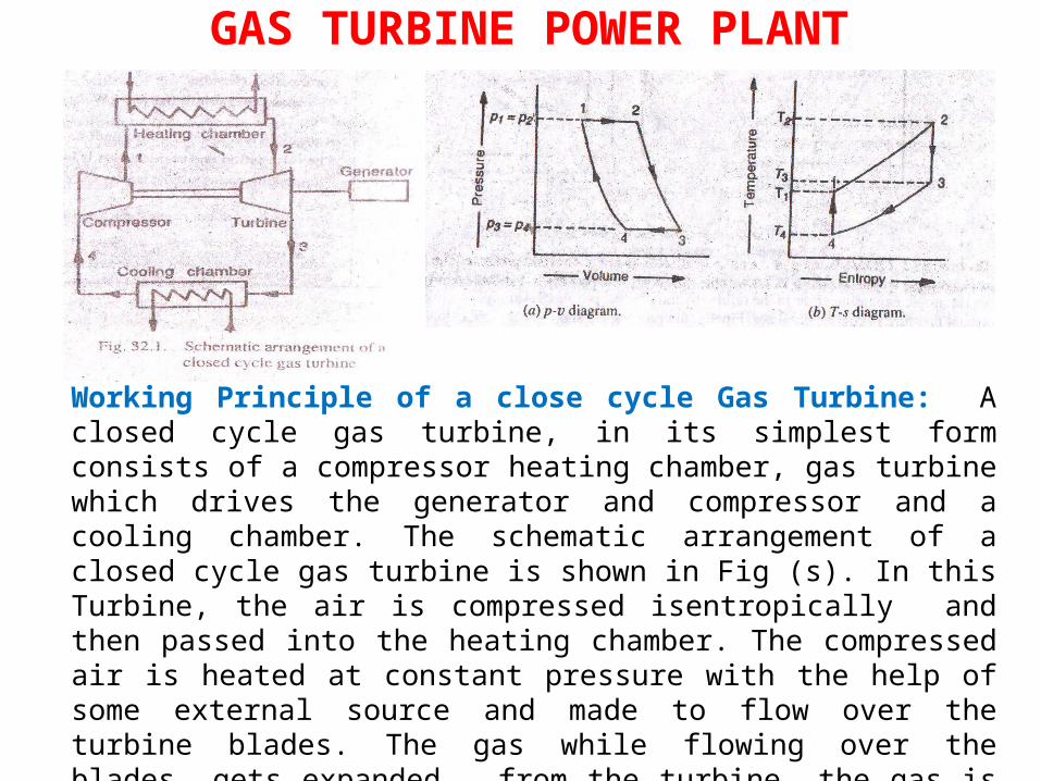
Working Principle of a close cycle Gas Turbine: A closed cycle gas turbine, in its simplest form consists of a compressor heating chamber, gas turbine which drives the generator and compressor and a cooling chamber. The schematic arrangement of a closed cycle gas turbine is shown in Fig (s). In this Turbine, the air is compressed isentropically and then passed into the heating chamber. The compressed air is heated at constant pressure with the help of some external source and made to flow over the turbine blades. The gas while flowing over the blades, gets expanded , from the turbine, the gas is passed to the cooling chamber where it is cooled at constant pressure with the help of circulating water to its original temperature. Now the air is made to flow into the compressor again. It is the obvious , that in a closed cycle gas turbine, the
GAS TURBINE POWER PLANT
air is continuously circulated within the turbine. A closed cycle gas turbine
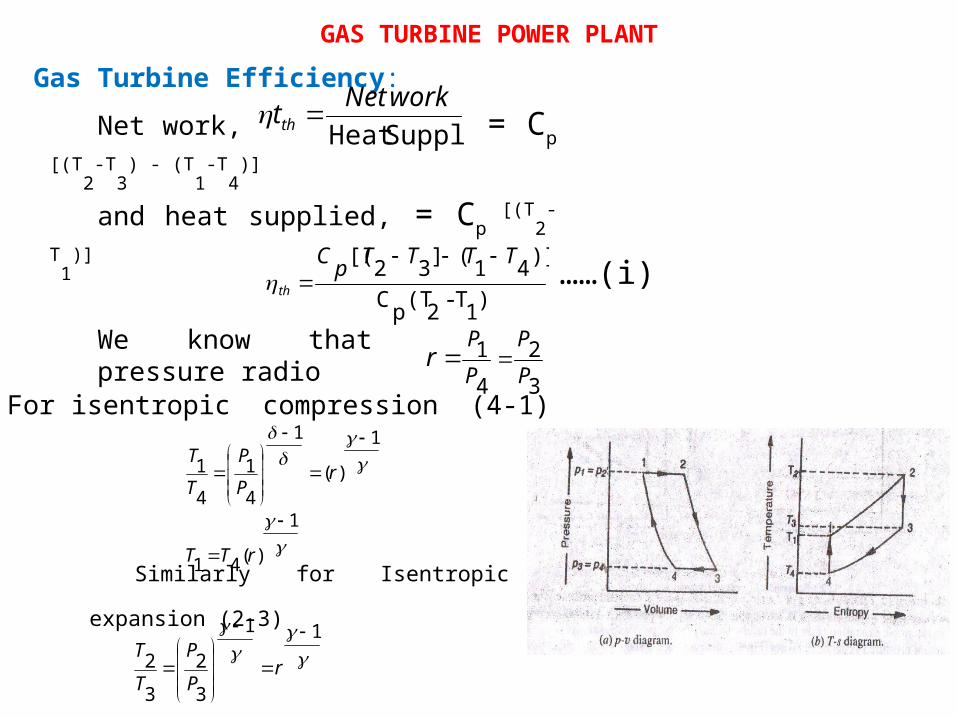
works on joules or Brayton’s Cycle as shown in Fig (b).
The process 1-2 shows heating of the air in heating chamber at constant pressure.
The process 2-3 shows isentropic expansion of air in the turbine.
Similarly, the process 3-4 shows cooling of the air at constant pressure in cooling chamber.
Finally, the process 4-1 shows isentropic Compression of the air in the Compressor.
Work done by the turbine per kg of air, WT = CP (T2 - T3)and work required by the compressor per Kg of air WC = Cp (T1 - T4)Now the net work available W = WT - WC
Gas Turbine Efficiency:
SupplyHeat workNettth Net work, = Cp
[(T2-T
3) - (T
1-T
4)]
and heat supplied, = Cp [(T
2-
T1)]
)1T-2(TpC)]41(]32[( TTTTpC
th
……(i)
We know that pressure radio 3
241
PP
PP
r
For isentropic compression (4-1)
Similarly for Isentropic
expansion (2-3)
11
32
32
r
PP
TT
1)(41
1)(
1
41
41
rTT
rPP
TT
GAS TURBINE POWER PLANT
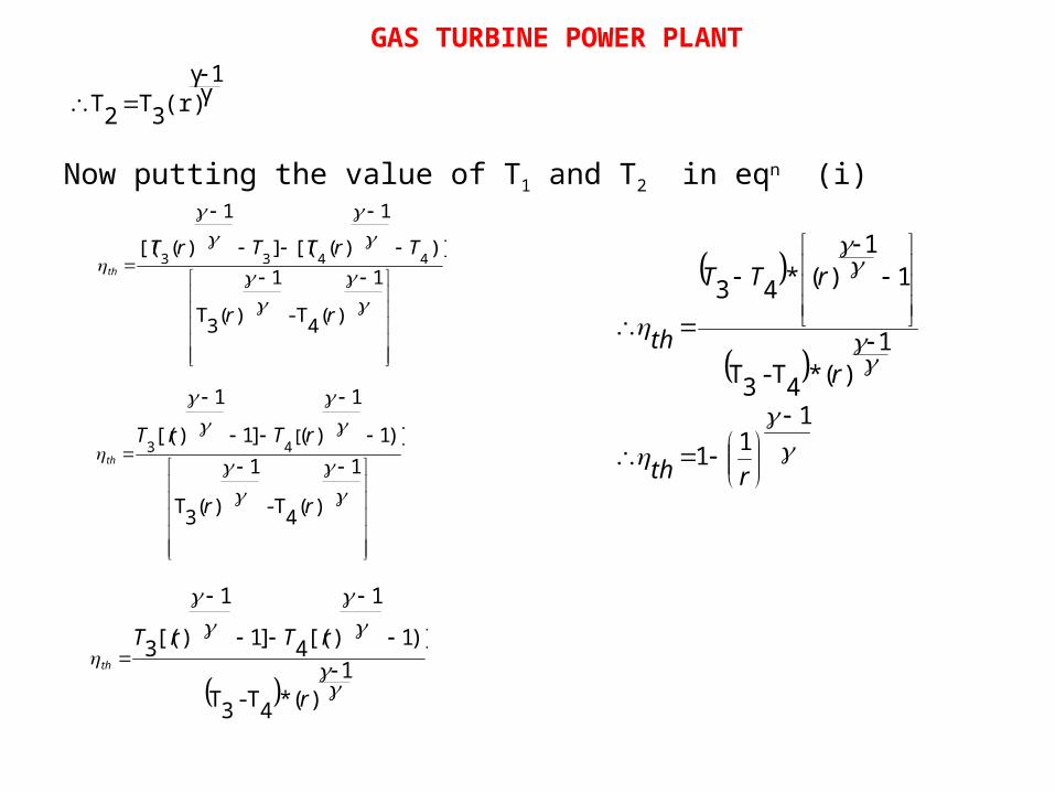
Now putting the value of T1 and T2 in eqn (i)
1)(4T-
1)(3T
)]11
)(]11
)[( [43
rr
rTrTth
1)(*4T-3T
)]11
)[(4]11
)[(3
r
rTrTth
111
1)(*4T-3T
11
)(*43
rth
r
rTT
th
γ1γ
(r)3T2T
1)(4T-
1)(3T
)]1
)([(]1
)([( 4433
rr
TrTTrTth
GAS TURBINE POWER PLANT
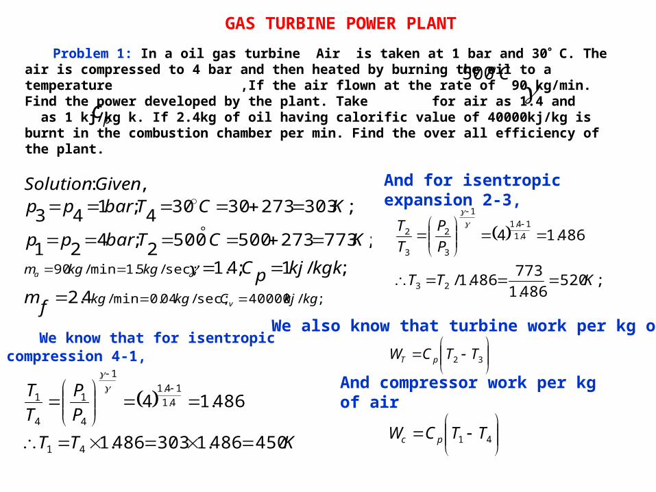
Problem 1: In a oil gas turbine Air is taken at 1 bar and 30 C. The air is compressed to 4 bar and then heated by burning the oil to a temperature ,If the air flown at the rate of 90 kg/min. Find the power developed by the plant. Take for air as 1.4 and as 1 kj/kg k. If 2.4kg of oil having calorific value of 40000kj/kg is burnt in the combustion chamber per min. Find the over all efficiency of the plant.
We know that for isentropic compression 4-1,
KTTPP
TT
450486.1303486.1
486.14
41
4.114.1
1
4
1
4
1
And for isentropic expansion 2-3,
;520486.1773486.1/
486.14
23
4.114.1
1
3
2
3
2
KTT
PP
TT
32 TTCW pT
We also know that turbine work per kg of air
41 TTCW pc
And compressor work per kg of air
;/40000sec;/04.0min/
sec;/5.1min/90
4.2;/1;4.1
;7732735005002;421
;30327330304;143,:
kgkjCkgkg
kgkgm
v
a
fmkgkkjpC
KCTbarpp
KCTbarppGivenSolution
C500
pc
GAS TURBINE POWER PLANT
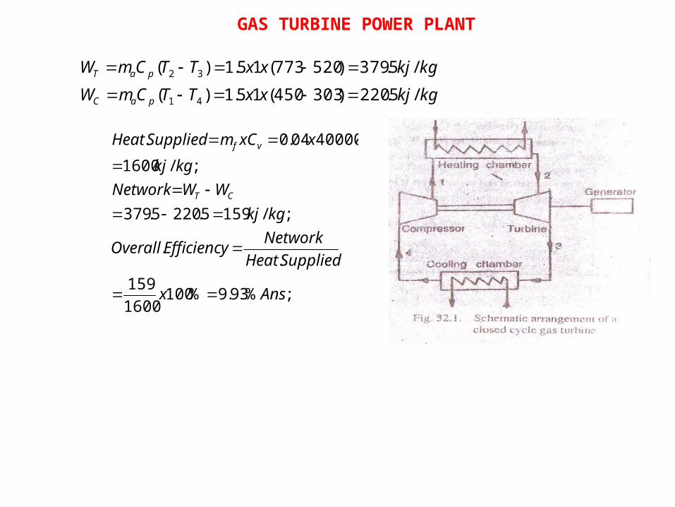
;%93.9%1001600159
..
;/1595.2205.379
;/16004000004.0.
Ansx
SuppliedHeatNetworkEfficiencyOverall
kgkjWWNetwork
kgkjxxCmSuppliedHeat
CT
vf
kgkjxxTTCmWkgkjxxTTCmW
paC
paT
/5.220)303450(15.1)(/5.379)520773(15.1)(
41
32
GAS TURBINE POWER PLANT
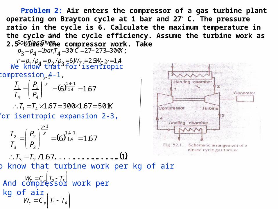
Problem 2: Air enters the compressor of a gas turbine plant operating on Brayton cycle at 1 bar and 27 C. The pressure ratio in the cycle is 6. Calculate the maximum temperature in the cycle and the cycle efficiency. Assume the turbine work as 2.5 times the compressor work. Take
4.1;5.2;63/24/1
;30027327304;143,:
cWTWpppprKCTbarpp
GivenSolution
KTTPP
TT
50167.130067.1
67.16
41
4.114.1
1
4
1
4
1
1...................................67.1/
67.16
23
4.114.1
1
3
2
3
2
TTPP
TT
.4.1
32 TTCW pT
We also know that turbine work per kg of air
41 TTCW pc
And compressor work per kg of air
We know that for isentropic compression 4-1,
And for isentropic expansion 2-3,
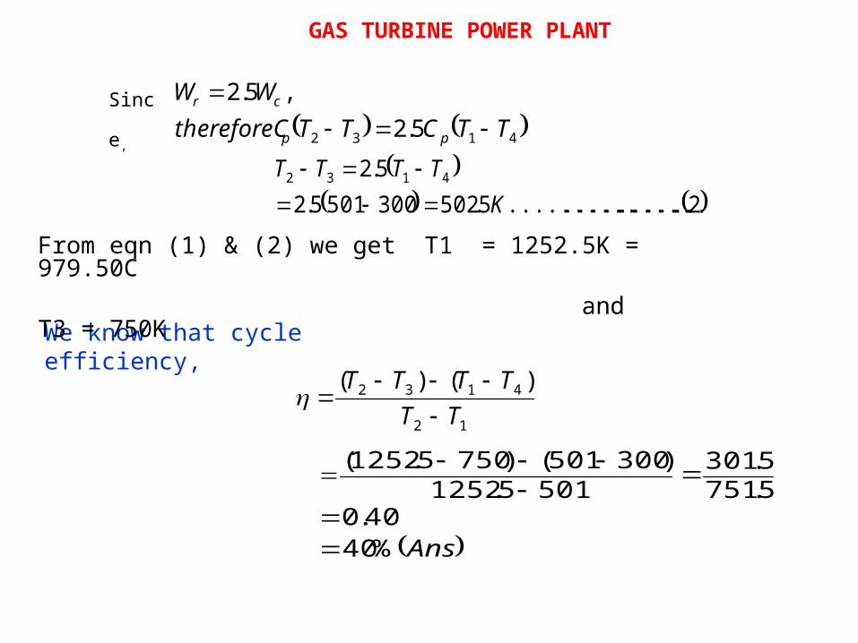
4132 5.2,5.2
TTCTTthereforeCWW
pp
cr
2................................5.5023005015.2
5.2 4132
KTTTT
Sinc
e,
12
4132 )()(TT
TTTT
Ans%4040.0
5.7515.301
5015.1252)300501()7505.1252(
We know that cycle efficiency,
From eqn (1) & (2) we get T1 = 1252.5K = 979.50C and T3 = 750K
GAS TURBINE POWER PLANT
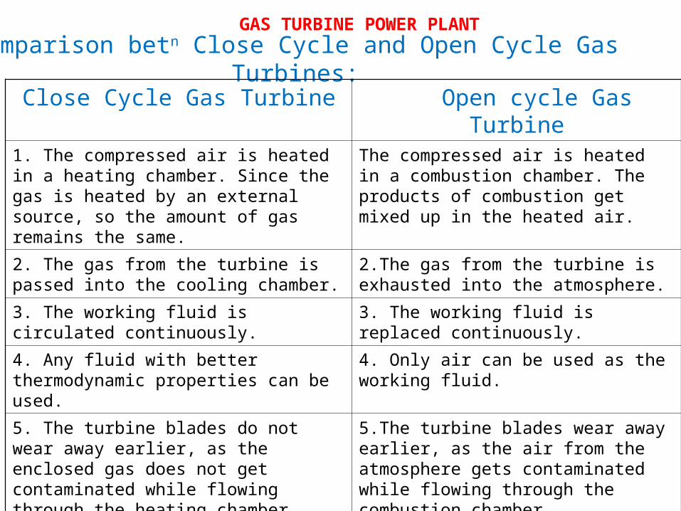
Comparison betn Close Cycle and Open Cycle Gas Turbines:
Close Cycle Gas Turbine Open cycle Gas Turbine
1. The compressed air is heated in a heating chamber. Since the gas is heated by an external source, so the amount of gas remains the same.
The compressed air is heated in a combustion chamber. The products of combustion get mixed up in the heated air.
2. The gas from the turbine is passed into the cooling chamber.
2.The gas from the turbine is exhausted into the atmosphere.
3. The working fluid is circulated continuously.
3. The working fluid is replaced continuously.
4. Any fluid with better thermodynamic properties can be used.
4. Only air can be used as the working fluid.
5. The turbine blades do not wear away earlier, as the enclosed gas does not get contaminated while flowing through the heating chamber.
5.The turbine blades wear away earlier, as the air from the atmosphere gets contaminated while flowing through the combustion chamber.
6. It is best suited for stationary installation or marine uses.
6. It is best suited for moving vehicle.
7. Its maintenance cost is high. 7. Its maintenance cost is low.
GAS TURBINE POWER PLANT
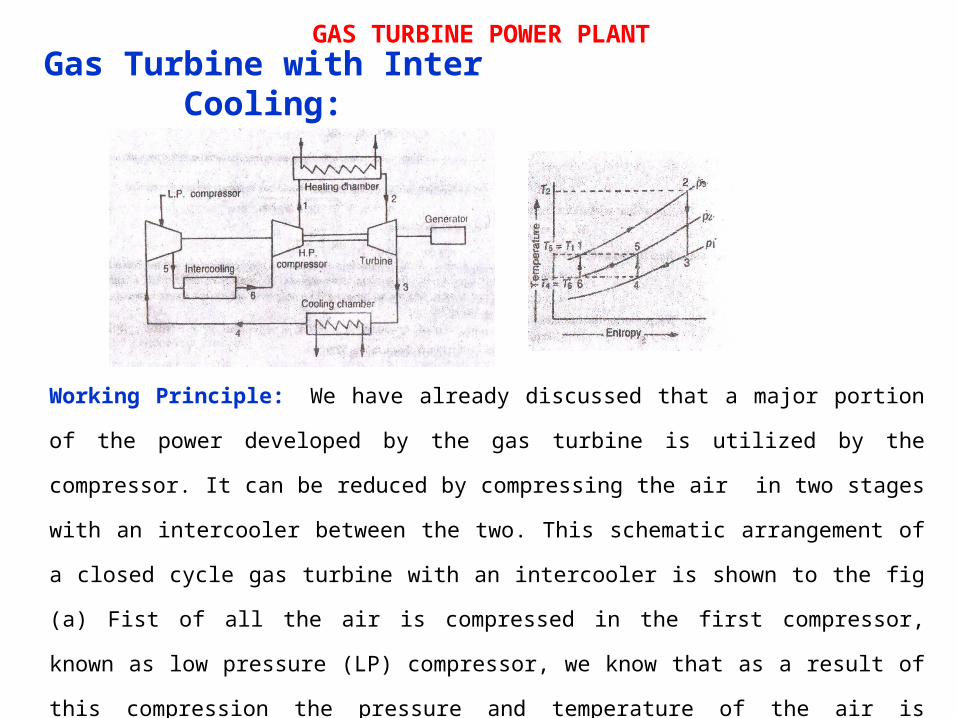
Gas Turbine with Inter Cooling:
Working Principle: We have already discussed that a major portion
of the power developed by the gas turbine is utilized by the
compressor. It can be reduced by compressing the air in two stages
with an intercooler between the two. This schematic arrangement of
a closed cycle gas turbine with an intercooler is shown to the fig
(a) Fist of all the air is compressed in the first compressor,
known as low pressure (LP) compressor, we know that as a result of
this compression the pressure and temperature of the air is
increased. Now the air is passed to air intercooler which reduces
the temperature of the compressed air to its original temperature,
but keeping the pressure constant. After that, the compressed air
is once again compressed in the second compressor known as high
pressure (H.P) compressor, Now the compressed air passed through
the heating chamber and then through the turbine.
GAS TURBINE POWER PLANT
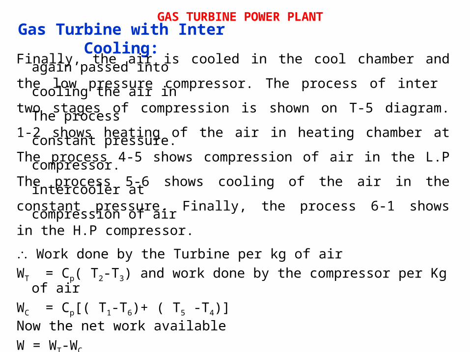
Gas Turbine with Inter Cooling:Finally, the air is cooled in the cool chamber and again passed into
the low pressure compressor. The process of inter cooling the air in two stages of compression is shown on T-5 diagram. The process 1-2 shows heating of the air in heating chamber at constant pressure. The process 4-5 shows compression of air in the L.P compressor. The process 5-6 shows cooling of the air in the intercooler at constant pressure. Finally, the process 6-1 shows compression of air in the H.P compressor. Work done by the Turbine per kg of airWT = Cp( T2-T3) and work done by the compressor per Kg of air
WC = Cp[( T1-T6)+ ( T5 -T4)]Now the net work availableW = WT-WC
GAS TURBINE POWER PLANT
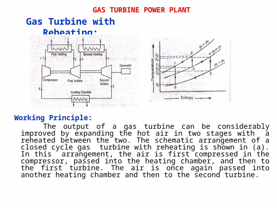
Gas Turbine with Reheating:
Working Principle: The output of a gas turbine can be considerably improved by expanding the hot air in two stages with a reheated between the two. The schematic arrangement of a closed cycle gas turbine with reheating is shown in (a). In this arrangement, the air is first compressed in the compressor, passed into the heating chamber, and then to the first turbine. The air is once again passed into another heating chamber and then to the second turbine.
GAS TURBINE POWER PLANT
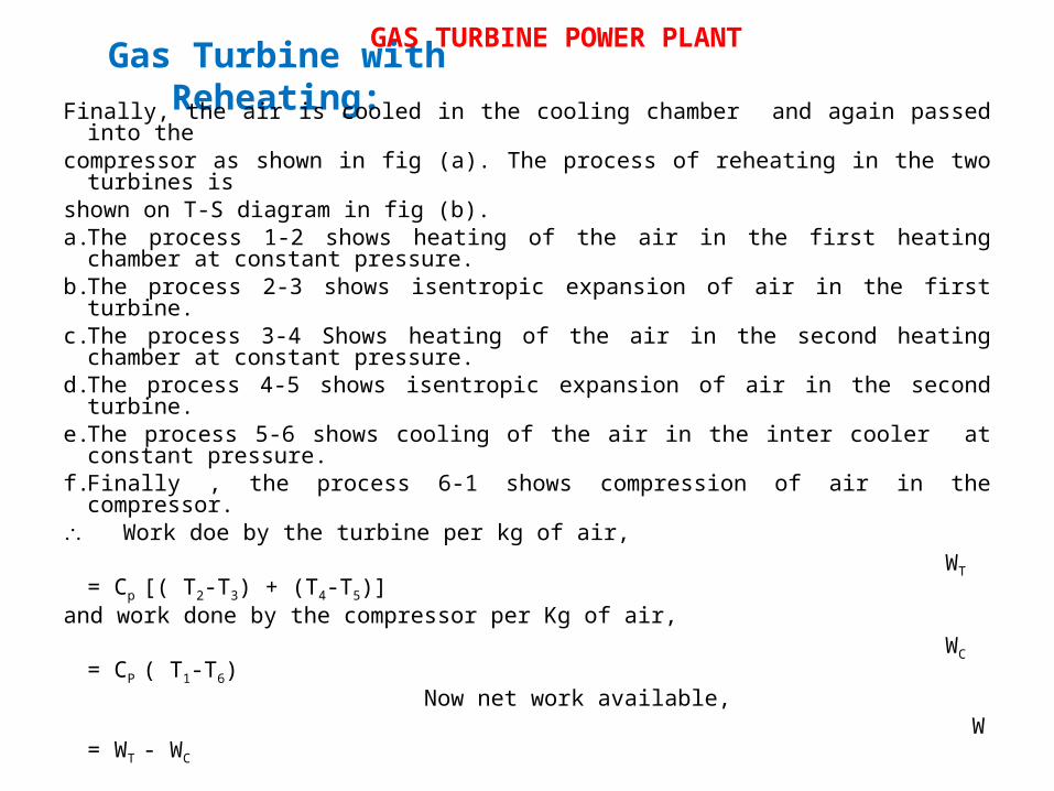
Gas Turbine with Reheating:Finally, the air is cooled in the cooling chamber and again passed
into the compressor as shown in fig (a). The process of reheating in the two turbines is
shown on T-S diagram in fig (b). a.The process 1-2 shows heating of the air in the first heating chamber at constant pressure.
b.The process 2-3 shows isentropic expansion of air in the first turbine.
c.The process 3-4 Shows heating of the air in the second heating chamber at constant pressure.
d.The process 4-5 shows isentropic expansion of air in the second turbine.
e.The process 5-6 shows cooling of the air in the inter cooler at constant pressure.
f.Finally , the process 6-1 shows compression of air in the compressor.
Work doe by the turbine per kg of air, WT = Cp [( T2-T3) + (T4-T5)]
and work done by the compressor per Kg of air, WC = CP ( T1-T6)
Now net work available, W = WT - WC
GAS TURBINE POWER PLANT
Related Documents