AN50009 Power MOSFET applications in automotive BLDC and PMSM drives Rev. 1.0 — 19 October 2021 application note Document information Information Content Keywords BLDC, PMSM, motor drive, simulation Abstract This application note provides an overview of electrical machine use in vehicles. PMSM and BLDC operating principles are detailed. A simple switch selection and switch loss estimation is provided along with simulation results to verify the calculations. An accompanying interactive version of this application note, including embedded simulations can be found on Nexperia.com

Welcome message from author
This document is posted to help you gain knowledge. Please leave a comment to let me know what you think about it! Share it to your friends and learn new things together.
Transcript
AN50009Power MOSFET applications in automotive BLDC and PMSMdrivesRev. 1.0 — 19 October 2021 application note
Document informationInformation Content
Keywords BLDC, PMSM, motor drive, simulation
Abstract This application note provides an overview of electrical machine use in vehicles. PMSM and BLDCoperating principles are detailed. A simple switch selection and switch loss estimation is providedalong with simulation results to verify the calculations. An accompanying interactive version of thisapplication note, including embedded simulations can be found on Nexperia.com

Nexperia AN50009Power MOSFET applications in automotive BLDC and PMSM drives
1. IntroductionWith today’s top of the range cars having more than 40 electrical machines, the global demand formotor drives rapidly rises. This is especially true for Brushless DC (BLDC) and Permanent MagnetSynchronous Motor (PMSM) drives. BLDC and PMSM are essential parts of Hybrid Electric Vehicle(HEV) and Electric Vehicle (EV) propulsion systems towards which priorities globally seem to bedirected. BLDC and PMSM drives are also employed where higher power and better regulationis needed in internal combustion vehicles. Some of the key automotive applications for electricalmachines and drives are depicted in Fig. 1. Motor applications can be implemented in any of thethree main categories shown:
1. Powertrain – Energy related – key aspect is Performance.2. Chassis and Safety – Safety and Comfort – key aspect is Reliability.3. Body control – Ease of use and Lighting – key aspect is Cost.
Body Control• Window lifter (DC Motor)• Wiper (DC Motor / BLDC )
• Seat control (DC Motor)• Sunroof (DC Motor / BLDC )
• Power tailgate (DC Motor / BLDC )
Chassis & Safety• Steering (BLDC / PMSM)
Powertrain• Transmission (BLDC/ PMSM)• Cooling system (BLDC)• Start-Stop (BSG & ISG – BLDC / PMSM)• Hybrid drive (BLDC / PMSM (higher power
than Start-Stop))
aaa-033950
Fig. 1. Key automotive applications for electrical machines and drives
2. Electrical machines in automotive applicationsMost of the electrical machines in vehicles are volume produced Brushed DC motors that do nothave complex speed and torque control requirements. They can be employed in applications suchas door locks, mirror folding, electrical seat adjustment and window motors.
The unidirectional and bidirectional Brushed DC motor drives are shown in Fig. 2. More informationabout these drives can be found in application notes AN50004 and IAN50004.
M
aaa-033951b) bidirectionala) unidirectional
M
Fig. 2. MOSFET driven Brushed DC motor drive: a) unidirectional and b) bidirectional
AN50009 All information provided in this document is subject to legal disclaimers. © Nexperia B.V. 2021. All rights reserved
application note Rev. 1.0 — 19 October 2021 2 / 21
Nexperia AN50009Power MOSFET applications in automotive BLDC and PMSM drives
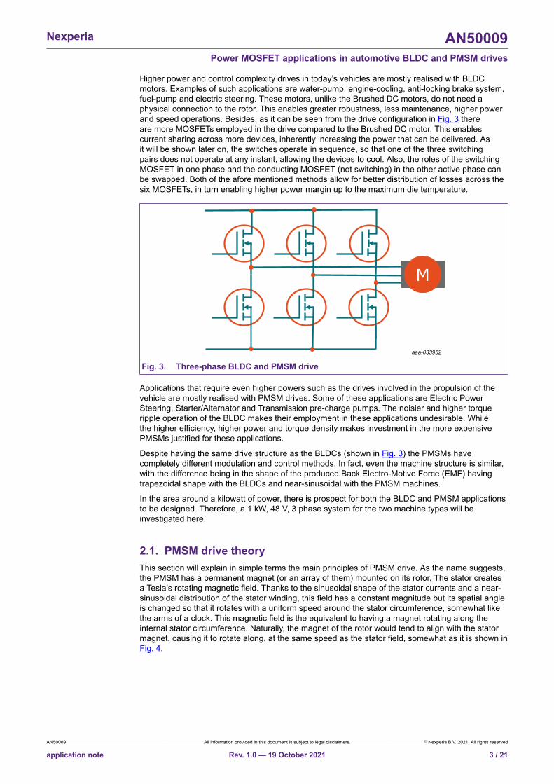
Higher power and control complexity drives in today’s vehicles are mostly realised with BLDCmotors. Examples of such applications are water-pump, engine-cooling, anti-locking brake system,fuel-pump and electric steering. These motors, unlike the Brushed DC motors, do not need aphysical connection to the rotor. This enables greater robustness, less maintenance, higher powerand speed operations. Besides, as it can be seen from the drive configuration in Fig. 3 thereare more MOSFETs employed in the drive compared to the Brushed DC motor. This enablescurrent sharing across more devices, inherently increasing the power that can be delivered. Asit will be shown later on, the switches operate in sequence, so that one of the three switchingpairs does not operate at any instant, allowing the devices to cool. Also, the roles of the switchingMOSFET in one phase and the conducting MOSFET (not switching) in the other active phase canbe swapped. Both of the afore mentioned methods allow for better distribution of losses across thesix MOSFETs, in turn enabling higher power margin up to the maximum die temperature.
M
aaa-033952
Fig. 3. Three-phase BLDC and PMSM drive
Applications that require even higher powers such as the drives involved in the propulsion of thevehicle are mostly realised with PMSM drives. Some of these applications are Electric PowerSteering, Starter/Alternator and Transmission pre-charge pumps. The noisier and higher torqueripple operation of the BLDC makes their employment in these applications undesirable. Whilethe higher efficiency, higher power and torque density makes investment in the more expensivePMSMs justified for these applications.
Despite having the same drive structure as the BLDCs (shown in Fig. 3) the PMSMs havecompletely different modulation and control methods. In fact, even the machine structure is similar,with the difference being in the shape of the produced Back Electro-Motive Force (EMF) havingtrapezoidal shape with the BLDCs and near-sinusoidal with the PMSM machines.
In the area around a kilowatt of power, there is prospect for both the BLDC and PMSM applicationsto be designed. Therefore, a 1 kW, 48 V, 3 phase system for the two machine types will beinvestigated here.
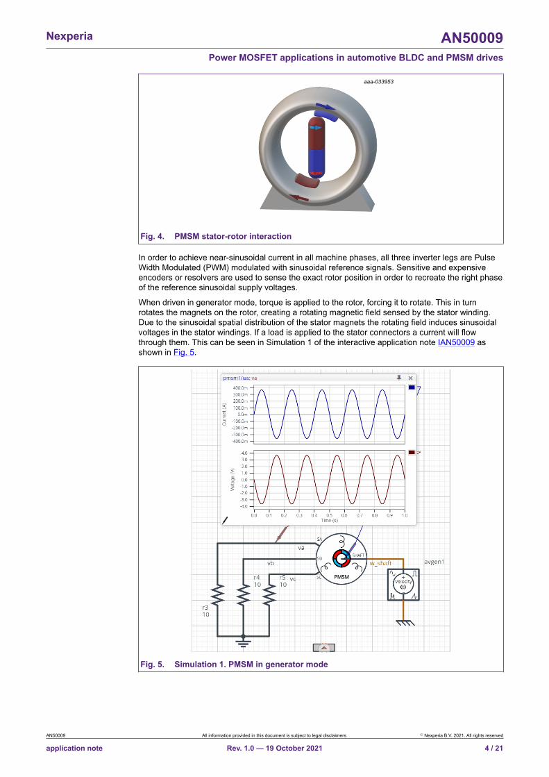
2.1. PMSM drive theoryThis section will explain in simple terms the main principles of PMSM drive. As the name suggests,the PMSM has a permanent magnet (or an array of them) mounted on its rotor. The stator createsa Tesla’s rotating magnetic field. Thanks to the sinusoidal shape of the stator currents and a near-sinusoidal distribution of the stator winding, this field has a constant magnitude but its spatial angleis changed so that it rotates with a uniform speed around the stator circumference, somewhat likethe arms of a clock. This magnetic field is the equivalent to having a magnet rotating along theinternal stator circumference. Naturally, the magnet of the rotor would tend to align with the statormagnet, causing it to rotate along, at the same speed as the stator field, somewhat as it is shown inFig. 4.
AN50009 All information provided in this document is subject to legal disclaimers. © Nexperia B.V. 2021. All rights reserved
application note Rev. 1.0 — 19 October 2021 3 / 21
Nexperia AN50009Power MOSFET applications in automotive BLDC and PMSM drives
aaa-033953
Fig. 4. PMSM stator-rotor interaction
In order to achieve near-sinusoidal current in all machine phases, all three inverter legs are PulseWidth Modulated (PWM) modulated with sinusoidal reference signals. Sensitive and expensiveencoders or resolvers are used to sense the exact rotor position in order to recreate the right phaseof the reference sinusoidal supply voltages.
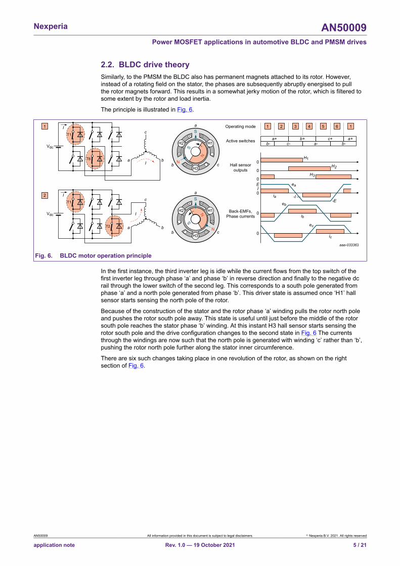
When driven in generator mode, torque is applied to the rotor, forcing it to rotate. This in turnrotates the magnets on the rotor, creating a rotating magnetic field sensed by the stator winding.Due to the sinusoidal spatial distribution of the stator magnets the rotating field induces sinusoidalvoltages in the stator windings. If a load is applied to the stator connectors a current will flowthrough them. This can be seen in Simulation 1 of the interactive application note IAN50009 asshown in Fig. 5.
Fig. 5. Simulation 1. PMSM in generator mode
AN50009 All information provided in this document is subject to legal disclaimers. © Nexperia B.V. 2021. All rights reserved
application note Rev. 1.0 — 19 October 2021 4 / 21
Nexperia AN50009Power MOSFET applications in automotive BLDC and PMSM drives
2.2. BLDC drive theorySimilarly, to the PMSM the BLDC also has permanent magnets attached to its rotor. However,instead of a rotating field on the stator, the phases are subsequently abruptly energised to pullthe rotor magnets forward. This results in a somewhat jerky motion of the rotor, which is filtered tosome extent by the rotor and load inertia.
The principle is illustrated in Fig. 6.
aaa-033363
Sa
aT6 b
c
I
I
Vdc
Vdc
b cN
S
N
H2 H1
H3
Sa
b cN
S
N
H3
H2 H1
T1
aT2 b
c
I
IT1
0
0
0
Hall sensoroutputs
Active switches a+c-b- a- b-
b+
H1
ea
eb
ec
ia
H2
H3
c+ a+
Operating mode 11
2
Back-EMFs,Phase currents ib
0IE
ic
0
0
2 3 4 5 6 1
-E-I
Fig. 6. BLDC motor operation principle
In the first instance, the third inverter leg is idle while the current flows from the top switch of thefirst inverter leg through phase ‘a’ and phase ‘b’ in reverse direction and finally to the negative dcrail through the lower switch of the second leg. This corresponds to a south pole generated fromphase ‘a’ and a north pole generated from phase ‘b’. This driver state is assumed once ‘H1’ hallsensor starts sensing the north pole of the rotor.
Because of the construction of the stator and the rotor phase ‘a’ winding pulls the rotor north poleand pushes the rotor south pole away. This state is useful until just before the middle of the rotorsouth pole reaches the stator phase ‘b’ winding. At this instant H3 hall sensor starts sensing therotor south pole and the drive configuration changes to the second state in Fig. 6 The currentsthrough the windings are now such that the north pole is generated with winding ‘c’ rather than ‘b’,pushing the rotor north pole further along the stator inner circumference.
There are six such changes taking place in one revolution of the rotor, as shown on the rightsection of Fig. 6.
AN50009 All information provided in this document is subject to legal disclaimers. © Nexperia B.V. 2021. All rights reserved
application note Rev. 1.0 — 19 October 2021 5 / 21
Nexperia AN50009Power MOSFET applications in automotive BLDC and PMSM drives
2.3. PMSM switch ratingWhen talking about a machine of certain power rating, it is assumed that we are talking aboutthe mechanical power that the machine is capable of delivering on its shaft. For determining theswitch rating of the drive, the input electrical power is needed. The difference between the input,electrical and the output, mechanical power are the losses incurring within the machine and drive.Throughout the machine, various losses appear due to magnetization, flow of electric current andmechanical movement of the rotor. These losses can be accounted for by the machine efficiency(η). Therefore, the electrical input power can be expressed as:
=PinPout (1)
The efficiency of the machine depends on the machine type and design quality. For inductionmachines of several hundred Watts it can go below 50%, while for high-power PMSMs it can reach95%.
The input power is then expressed as the product of the phase voltage and current root meansquare (rms) value:
=Pin Pf3V rms I rms (2)
The number 3 signifies that the drive is three-phase, while the power factor (Pf) is a measure ofdisplacement in time of the voltage and current sinusoidal waveforms. The power factor, a measureinversely indicating the proportion of energy needed for magnetisation of the machine, can alsotake a broad range of values. PMSM have lower magnetisation requirement and therefore higherpower factor values compared to induction machines. They can be driven from unity down to 0.85power factor.
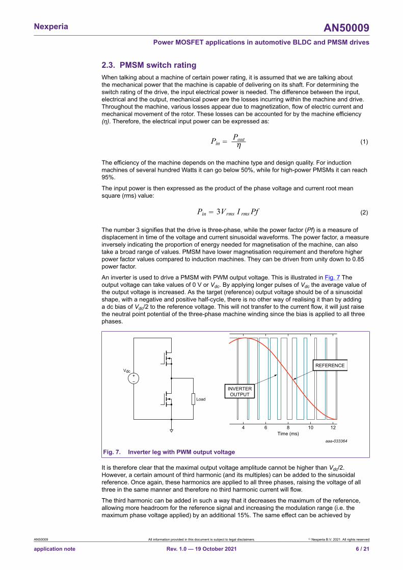
An inverter is used to drive a PMSM with PWM output voltage. This is illustrated in Fig. 7 Theoutput voltage can take values of 0 V or Vdc. By applying longer pulses of Vdc the average value ofthe output voltage is increased. As the target (reference) output voltage should be of a sinusoidalshape, with a negative and positive half-cycle, there is no other way of realising it than by addinga dc bias of Vdc/2 to the reference voltage. This will not transfer to the current flow, it will just raisethe neutral point potential of the three-phase machine winding since the bias is applied to all threephases.
Load
VdcREFERENCE
INVERTEROUTPUT
4 6 8Time (ms)
10 12
aaa-033364
Fig. 7. Inverter leg with PWM output voltage
It is therefore clear that the maximal output voltage amplitude cannot be higher than Vdc/2.However, a certain amount of third harmonic (and its multiples) can be added to the sinusoidalreference. Once again, these harmonics are applied to all three phases, raising the voltage of allthree in the same manner and therefore no third harmonic current will flow.
The third harmonic can be added in such a way that it decreases the maximum of the reference,allowing more headroom for the reference signal and increasing the modulation range (i.e. themaximum phase voltage applied) by an additional 15%. The same effect can be achieved by
AN50009 All information provided in this document is subject to legal disclaimers. © Nexperia B.V. 2021. All rights reserved
application note Rev. 1.0 — 19 October 2021 6 / 21

Nexperia AN50009Power MOSFET applications in automotive BLDC and PMSM drives
calculating the average between the minimum and maximum references (out of the three available)and adding it to all three reference signals. The described method can be studied within Simulation2 of the interactive application note IAN50009 as shown in Fig. 8. If such reference signals areapplied, the performance will be equivalent to space vector modulation.
Fig. 8. Simulation 2. Min-max injection modulation method
As the rms voltage is √2 times smaller than the maximum voltage in sinusoidal waveforms, it canbe obtained from the Vdc value as:
= V 1.15 Vrms1 =2 2
V20.813dc dc (3)
Next, from Eq 2 the current rms value can be expressed. Finally, the maximal value of the current is√2 higher than the rms value:
= I m 2 I rms (4)
The chosen switch should have at least this current rating. In practise an overload factor of atleast 20% is added as well as a safety factor of another 100%. The highest voltage the switchis expected to block is the supply voltage, in cases when the other switch in the same leg isconducting.
AN50009 All information provided in this document is subject to legal disclaimers. © Nexperia B.V. 2021. All rights reserved
application note Rev. 1.0 — 19 October 2021 7 / 21
Nexperia AN50009Power MOSFET applications in automotive BLDC and PMSM drives
2.4. BLDC switch ratingBLDCs are mostly aimed at mid-power range applications where machine construction costs arereduced, sacrificing some of the machine efficiency.
As it is shown in Fig. 6 and its description, one of the three inverter legs is dormant while two areconducting. This means that the machine current along with a voltage up to Vdc/2 is applied to asingle phase of the drive 2/3rd of the reference period. As there are three phases the input electricpower can be expressed as:
= I3Pin =2 V23
V Idcdc (5)
Considering that the current is not as uniform as seen in Fig. 6 a waveform derating factor (wf) of20% is used to obtain the maximum current the switch shall bear.
= I m 1.2 I (6)
The maximum voltage that the switch should block is maintained at Vdc, as with the PMSM.
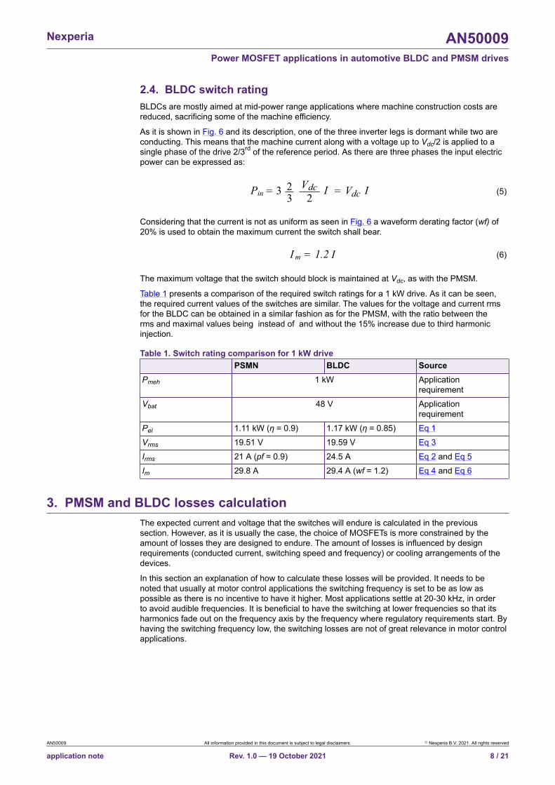
Table 1 presents a comparison of the required switch ratings for a 1 kW drive. As it can be seen,the required current values of the switches are similar. The values for the voltage and current rmsfor the BLDC can be obtained in a similar fashion as for the PMSM, with the ratio between therms and maximal values being instead of and without the 15% increase due to third harmonicinjection.
Table 1. Switch rating comparison for 1 kW drivePSMN BLDC Source
Pmeh 1 kW Applicationrequirement
Vbat 48 V Applicationrequirement
Pel 1.11 kW (η = 0.9) 1.17 kW (η = 0.85) Eq 1Vrms 19.51 V 19.59 V Eq 3Irms 21 A (pf = 0.9) 24.5 A Eq 2 and Eq 5Im 29.8 A 29.4 A (wf = 1.2) Eq 4 and Eq 6
3. PMSM and BLDC losses calculationThe expected current and voltage that the switches will endure is calculated in the previoussection. However, as it is usually the case, the choice of MOSFETs is more constrained by theamount of losses they are designed to endure. The amount of losses is influenced by designrequirements (conducted current, switching speed and frequency) or cooling arrangements of thedevices.
In this section an explanation of how to calculate these losses will be provided. It needs to benoted that usually at motor control applications the switching frequency is set to be as low aspossible as there is no incentive to have it higher. Most applications settle at 20-30 kHz, in orderto avoid audible frequencies. It is beneficial to have the switching at lower frequencies so that itsharmonics fade out on the frequency axis by the frequency where regulatory requirements start. Byhaving the switching frequency low, the switching losses are not of great relevance in motor controlapplications.
AN50009 All information provided in this document is subject to legal disclaimers. © Nexperia B.V. 2021. All rights reserved
application note Rev. 1.0 — 19 October 2021 8 / 21

Nexperia AN50009Power MOSFET applications in automotive BLDC and PMSM drives
3.1. PMSM conduction lossesThe PMSM motor current is sinusoidal, with a certain switching frequency ripple superimposed. Letthe period of the sinusoidal control signal be noted with Tc, while the switching period with Ts.
The current in positive direction will flow through the top MOSFET in the positive control half-cycle(Tc /2) during the duty cycle δ in each switching interval Ts. In the negative control half-cycle (Tc /2)for a period (1-δ) Ts negative current will pass through the same switch. Since the top and bottomswitches swap roles between control half-cycles (Tc /2) it can be concluded that during a wholecontrol cycle (Tc) one control half-cycle worth of current passes through the switch. This discussionis illustrated in Simulation 3 of the interactive application note IAN50009, see Fig. 9.
Fig. 9. Simulation 3. PMSM drive switch current conduction
The current direction is not relevant because the square of the current is sought. The overallconduction losses can be calculated as:
=Pcond R 2rmsIDSon (7)
Where the rms current value is of a half cycle, averaged over the whole cycle period:
= I rms12 )∫0 i 2 d( (8)
This is valid if the reverse voltage drop of the device is below the internal diode conductionthreshold and dead-time is not accounted for. For a sinusoidal current with an amplitude Im, theconduction losses come to [1]:
=Pcond R2mI
DSon 4(9)
AN50009 All information provided in this document is subject to legal disclaimers. © Nexperia B.V. 2021. All rights reserved
application note Rev. 1.0 — 19 October 2021 9 / 21

Nexperia AN50009Power MOSFET applications in automotive BLDC and PMSM drives
3.2. BLDC conduction lossesIn BLDC drives the current flows through two inverter legs. In order to regulate the current flowingthrough the machine windings, at least one of the inverter legs needs to be modulated in order tomaintain a desired current magnitude. When only one inverter leg commutates and the other isconstantly conducting, the switching method is unipolar, when two legs commutate the switchingmethod is bipolar, as shown in Fig. 10. The unipolar switching shown in Fig. 10 distributes theswitching losses between the two FETs of an inverter leg. In both cases the upper and lower switchare being turned on in an alternating manner, to avoid diode loses in the synchronous FET.
aaa-033365
A+
2Operating mode
Bipolar switching Unipolar switching
Phase a
1 43 65 21 43 65
Phase b
B-
Phase c
A+
C+
B-
C+
B+ B-
A+ A-
C+C- C- C+
B+ B-
A+ A-
Fig. 10. Bipolar and unipolar switching of devices
For the conduction losses, the switching mode does not seem to have much influence. Therequired rms current through the individual switches is the same in both cases. In the bipolarswitching mode, looking at the A+, switching at a certain duty cycle δ, a current of value I passesthrough it for a time δTs (Ts being the switching period) in the first half cycle. In the second halfcycle A- is switched with duty cycle δ, while A+ is then switched on for (1 - δ)Ts. Therefore, duringthe hole control cycle a single switch conducts the current equivalent of half a control cycle. Similaris the case with the unipolar switch mode, with the difference that half of the switching cycle thesame switch conducts inherently.
Applying Eq 8 for a constant current I passing through the switch for one third of the switchingperiod, the resulting conduction losses come to:
=Pcond R2I
DSon 3(10)
This conclusion applies when dead-times are very short and the current through the BLDCwindings is well controlled to be close to DC with small ripples.
The unipolar method can be simplified, having only the top switches driven with PWM, while thebottom switch is turned on inversely for freewheeling. The respective bottom switches, belongingto the other conducting phase, are held constantly on during the time the current needs to flowthrough them. In this case uneven distribution of power losses is achieved in the top and bottomswitches. The top switch is on for δTs. The bottom switch conducts when it is freewheeling for(1 - δ) Ts and for an additional third of the control period when it is held completely on. In this casethe integral from Eq 8 results in:
=Pcond_up R2I
DSon 3(11)
=Pcond_dn R2I
DSon 3( )1+ -1 (12)
AN50009 All information provided in this document is subject to legal disclaimers. © Nexperia B.V. 2021. All rights reserved
application note Rev. 1.0 — 19 October 2021 10 / 21

Nexperia AN50009Power MOSFET applications in automotive BLDC and PMSM drives
In all the switching methods, the diode of the MOSFETs will need to demagnetise the motorphase that stops conducting. The energy accumulated in the phase inductance will therefore bedissipated in each MOSFET diode in each control cycle:
=E L 2I21 (13)
Where L is the machine phase inductance.
3.3. Switching lossesThe switching energy losses can be estimated as:
=Eon V 2
onIdc
t
Eoff =
dc
V
Ion
2t
sw(on)
sw(off )(14)
Where tsw can be approximated by:
=QGD R
gdt
=
GV
t
sw(on)
sw(off)
- pl(Ion)V
QGD RGpl(Ion)V
sf
sf(15)
Where tsw is the switching time, Ion is the on-state current, Vgd is the gate drive voltage, and RG isthe gate resistance. QGD – gate to drain charge and Vpl(Ion) – gate plateau voltage at current Ion,can be read from the data sheet: QGD from tables and Vpl(Ion) from the transfer characteristic graph(Fig. 11).
0
80
160
240
0 4 6 8VGS (V)
ID(A)
Tj = 25 ° C
Tj = 175 ° C
Ion
2pl(Ion)V
Fig. 11. Reading Ion and Vpl(Ion) from the transfer characteristic
In itself, QGD accounts for the voltage transient during the Miller plateau. The current transientthat occurs before (turn on) or after (turn off) the Miller plateau is determined by part of QGS. It isaccounted for by an approximated increase of the voltage transient by an additional 20 to 30%,represented by the scaling factor sf (sf takes value from 1.2 to 1.3). This percentage is dependenton technology used. The approximation is sufficient here as the switching losses are not expectedto dominate because of the low switching frequency.
AN50009 All information provided in this document is subject to legal disclaimers. © Nexperia B.V. 2021. All rights reserved
application note Rev. 1.0 — 19 October 2021 11 / 21
Nexperia AN50009Power MOSFET applications in automotive BLDC and PMSM drives
The on-state current is the average current in the case of the switching losses. For PMSM theaverage is calculated for half of the control cycle:
= Iavg 1 (∫0 i d) = (∫0 sin d)Im = I m
(16)
This value can therefore be substituted in Eq 14 instead of Ion to obtain the switching energies. It isconsidered that the current ripple is negligible compared to the base value.
= EoffP +swfsw )(Eon2 fcc
(17)
In case of the BLDC the switching occurs around I, which needs to be placed in Eq 14:
=I avg I (18)
he obtained energy levels then need to be multiplied once again with the number of switchingoccurring in one half of the control period. Due to the device switching only 1/3rd of the half-cycle(Fig. 10 – Unipolar switching) this is expressed as 1/3 × 0.5 × fsw/fcc.
= EoffP +swfsw )(Eon6 fcc
(19)
The switching at the negative half cycle is not accounted for in both cases as it is governed bydiode switching and it can be omitted. The reason for this is that by the nature of the diode thevoltage across it needs to decrease to nearly zero before it can take on any current, achievingnearly zero voltage switching. The diode also cannot start increasing the voltage across itsconnectors until the current has stopped flowing through it.
4. Switch selectionAs noted, MOSFETs are usually chosen according to the amount of loss they are intended todissipate.
Based on low switching frequency – 20 kHz is chosen – the conduction losses are expected tobe dominant. At this point switching losses are estimated as 50% of conduction losses in PMSMsand 20% in BLDCs. With an allowance of 1.5% losses in the six switches the required RDSon canbe calculated from Eq 9 and Eq 10 as shown in Eq 20 and Eq 21, respectively. The maximumexpected current amplitude can be read from Table 1:
= PcondR 2mI
DSon4 ,Pcond = 1 0.015
6 1.5Pin
(20)
= PcondR 2mI
DSon3 ,Pcond =
1 0.0156 1.2
Pin(21)
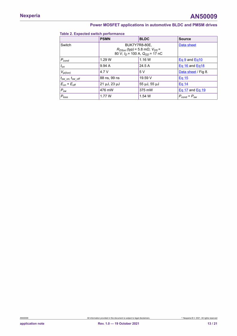
This results in a RDSon of 8.3 mΩ for PMSM and 8.5 mΩ for the BLDC. To allow for some headroomthe BUK7Y7R8-80E is chosen. This is an automotive, 7.8 mΩ, 80 V, trench 6 technology MOSFET.The drain current of this MOSFET is given as 100 A, roughly 3 times higher than the maximumcurrent needed for the application. This is usual and expected, as the ID rating of the MOSFETsis measured with its mounting base temperature held at 25 °C. Table 2 gives an overview of theexpected switch performance for a gate drive voltage of 10 V and a gate resistance of 22 Ω.
AN50009 All information provided in this document is subject to legal disclaimers. © Nexperia B.V. 2021. All rights reserved
application note Rev. 1.0 — 19 October 2021 12 / 21
Nexperia AN50009Power MOSFET applications in automotive BLDC and PMSM drives
Table 2. Expected switch performancePSMN BLDC Source
Switch BUK7Y7R8-80E,RDSon (typ) = 5.8 mΩ; VDS =
80 V; ID = 100 A, QGD = 17 nC
Data sheet
Pcond 1.29 W 1.16 W Eq 9 and Eq10Ion 9.94 A 24.5 A Eq 16 and Eq18Vpl(Ion) 4.7 V 5 V Data sheet / Fig 8.tsw_on, tsw_off 88 ns, 99 ns 19.59 V Eq 15Eon + Eoff 21 µJ, 23 µJ 55 µJ, 55 µJ Eq 14Psw 476 mW 375 mW Eq 17 and Eq 19Ploss 1.77 W 1.54 W Pcond + Psw
AN50009 All information provided in this document is subject to legal disclaimers. © Nexperia B.V. 2021. All rights reserved
application note Rev. 1.0 — 19 October 2021 13 / 21
Nexperia AN50009Power MOSFET applications in automotive BLDC and PMSM drives
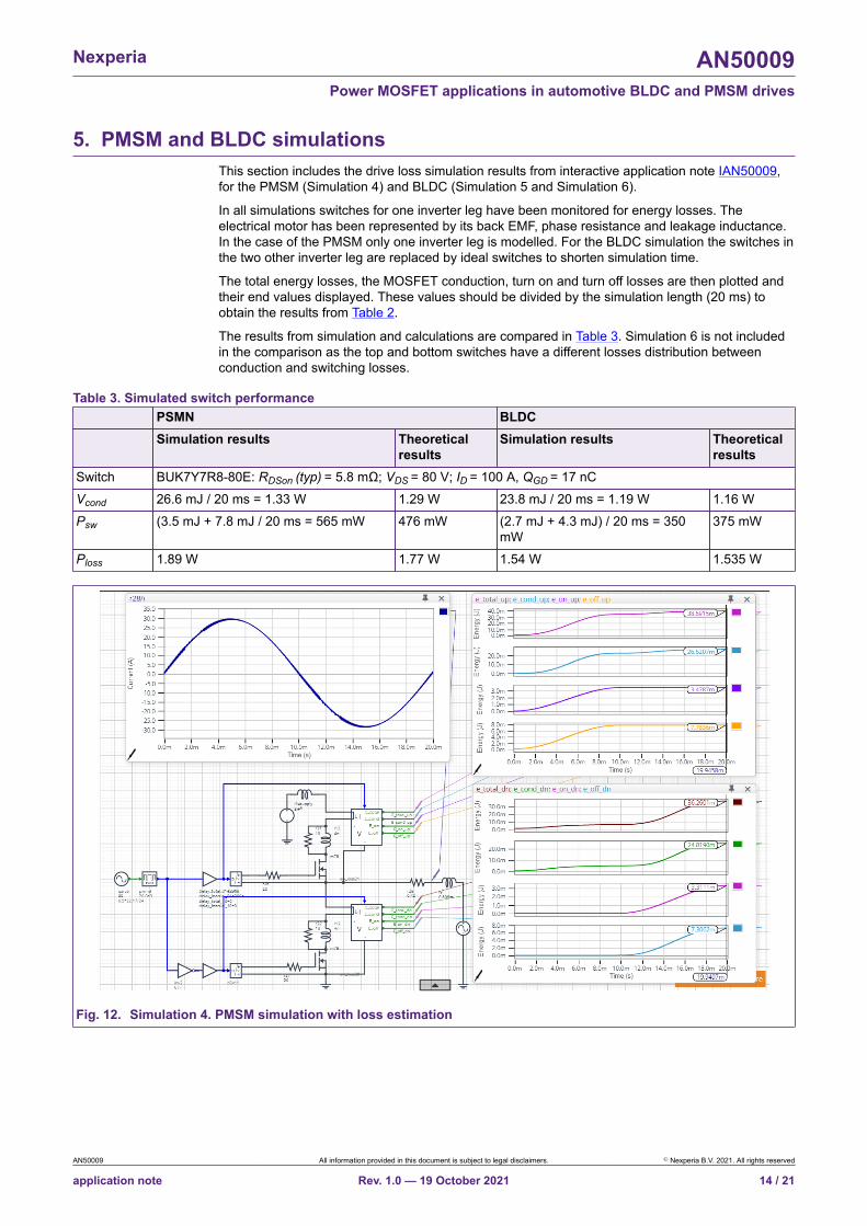
5. PMSM and BLDC simulationsThis section includes the drive loss simulation results from interactive application note IAN50009,for the PMSM (Simulation 4) and BLDC (Simulation 5 and Simulation 6).
In all simulations switches for one inverter leg have been monitored for energy losses. Theelectrical motor has been represented by its back EMF, phase resistance and leakage inductance.In the case of the PMSM only one inverter leg is modelled. For the BLDC simulation the switches inthe two other inverter leg are replaced by ideal switches to shorten simulation time.
The total energy losses, the MOSFET conduction, turn on and turn off losses are then plotted andtheir end values displayed. These values should be divided by the simulation length (20 ms) toobtain the results from Table 2.
The results from simulation and calculations are compared in Table 3. Simulation 6 is not includedin the comparison as the top and bottom switches have a different losses distribution betweenconduction and switching losses.
Table 3. Simulated switch performancePSMN BLDCSimulation results Theoretical
resultsSimulation results Theoretical
resultsSwitch BUK7Y7R8-80E: RDSon (typ) = 5.8 mΩ; VDS = 80 V; ID = 100 A, QGD = 17 nCVcond 26.6 mJ / 20 ms = 1.33 W 1.29 W 23.8 mJ / 20 ms = 1.19 W 1.16 WPsw (3.5 mJ + 7.8 mJ / 20 ms = 565 mW 476 mW (2.7 mJ + 4.3 mJ) / 20 ms = 350
mW375 mW
Ploss 1.89 W 1.77 W 1.54 W 1.535 W
Fig. 12. Simulation 4. PMSM simulation with loss estimation
AN50009 All information provided in this document is subject to legal disclaimers. © Nexperia B.V. 2021. All rights reserved
application note Rev. 1.0 — 19 October 2021 14 / 21

Nexperia AN50009Power MOSFET applications in automotive BLDC and PMSM drives
Fig. 13. Simulation 5. BLDC simulation with loss estimation; unipolar modulation; all switches PWM modulated
AN50009 All information provided in this document is subject to legal disclaimers. © Nexperia B.V. 2021. All rights reserved
application note Rev. 1.0 — 19 October 2021 15 / 21
Nexperia AN50009Power MOSFET applications in automotive BLDC and PMSM drives
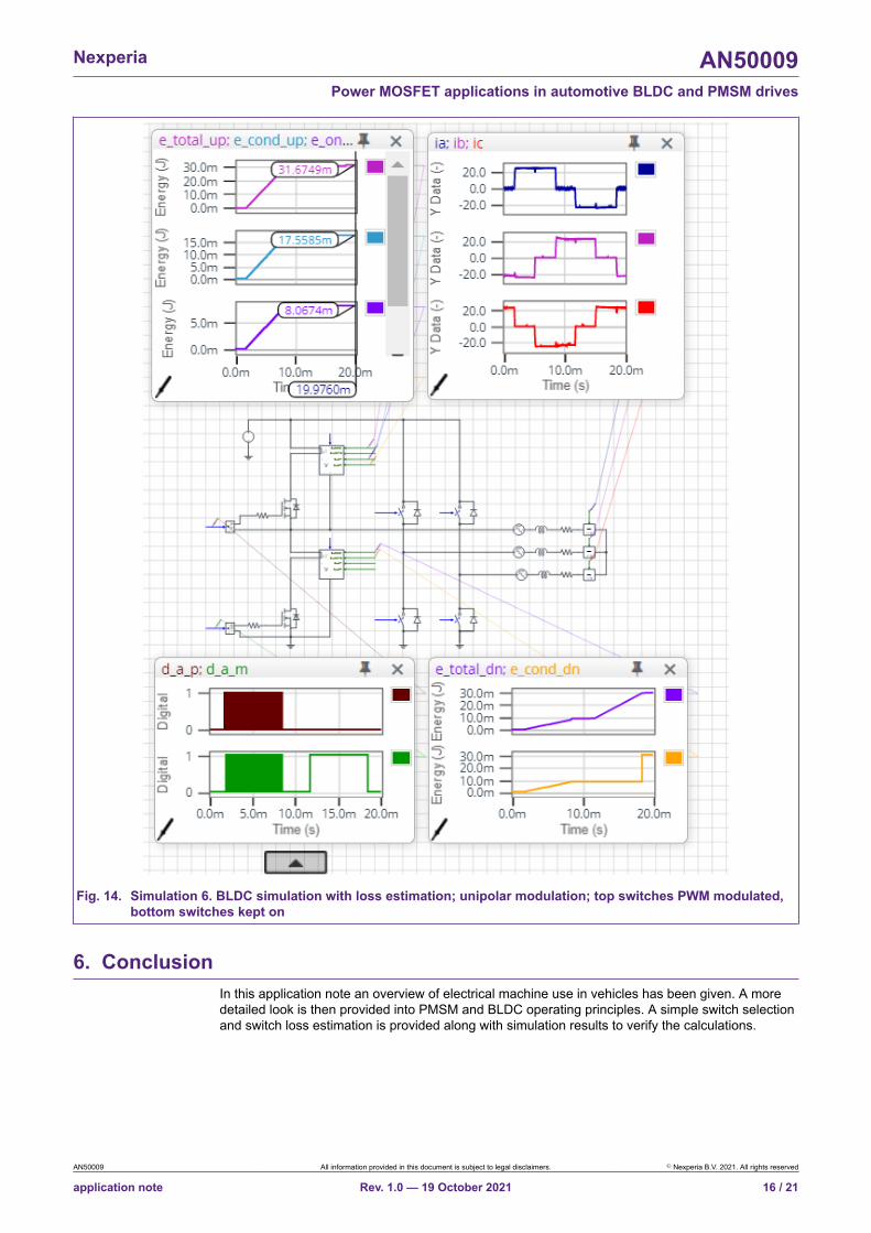
Fig. 14. Simulation 6. BLDC simulation with loss estimation; unipolar modulation; top switches PWM modulated,bottom switches kept on
6. ConclusionIn this application note an overview of electrical machine use in vehicles has been given. A moredetailed look is then provided into PMSM and BLDC operating principles. A simple switch selectionand switch loss estimation is provided along with simulation results to verify the calculations.
AN50009 All information provided in this document is subject to legal disclaimers. © Nexperia B.V. 2021. All rights reserved
application note Rev. 1.0 — 19 October 2021 16 / 21
Nexperia AN50009Power MOSFET applications in automotive BLDC and PMSM drives
7. References1. J. W. Kolar, H. Ertl and F. C. Zach, "Influence of the modulation method on the conduction and
switching losses of a PWM converter system," in IEEE Transactions on Industry Applications,vol. 27, no. 6, pp. 1063-1075, Nov.-Dec. 1991, doi: 10.1109/28.108456.
2. Nexperia interactive application note IAN50009.
8. Revision historyTable 4. Revision historyRevisionnumber
Date Description
1.0 2021-10-19 Initial version.
AN50009 All information provided in this document is subject to legal disclaimers. © Nexperia B.V. 2021. All rights reserved
application note Rev. 1.0 — 19 October 2021 17 / 21

Nexperia AN50009Power MOSFET applications in automotive BLDC and PMSM drives
9. Legal information
DefinitionsDraft — The document is a draft version only. The content is still underinternal review and subject to formal approval, which may result inmodifications or additions. Nexperia does not give any representations orwarranties as to the accuracy or completeness of information included hereinand shall have no liability for the consequences of use of such information.
DisclaimersLimited warranty and liability — Information in this document is believedto be accurate and reliable. However, Nexperia does not give anyrepresentations or warranties, expressed or implied, as to the accuracyor completeness of such information and shall have no liability for theconsequences of use of such information. Nexperia takes no responsibilityfor the content in this document if provided by an information source outsideof Nexperia.
In no event shall Nexperia be liable for any indirect, incidental, punitive,special or consequential damages (including - without limitation - lostprofits, lost savings, business interruption, costs related to the removalor replacement of any products or rework charges) whether or not suchdamages are based on tort (including negligence), warranty, breach ofcontract or any other legal theory.
Notwithstanding any damages that customer might incur for any reasonwhatsoever, Nexperia’s aggregate and cumulative liability towards customerfor the products described herein shall be limited in accordance with theTerms and conditions of commercial sale of Nexperia.
Right to make changes — Nexperia reserves the right to make changesto information published in this document, including without limitationspecifications and product descriptions, at any time and without notice. Thisdocument supersedes and replaces all information supplied prior to thepublication hereof.
Suitability for use — Nexperia products are not designed, authorized orwarranted to be suitable for use in life support, life-critical or safety-criticalsystems or equipment, nor in applications where failure or malfunctionof an Nexperia product can reasonably be expected to result in personalinjury, death or severe property or environmental damage. Nexperia and itssuppliers accept no liability for inclusion and/or use of Nexperia products insuch equipment or applications and therefore such inclusion and/or use is atthe customer’s own risk.
Applications — Applications that are described herein for any of theseproducts are for illustrative purposes only. Nexperia makes no representationor warranty that such applications will be suitable for the specified usewithout further testing or modification.
Customers are responsible for the design and operation of their applicationsand products using Nexperia products, and Nexperia accepts no liability forany assistance with applications or customer product design. It is customer’ssole responsibility to determine whether the Nexperia product is suitableand fit for the customer’s applications and products planned, as well asfor the planned application and use of customer’s third party customer(s).Customers should provide appropriate design and operating safeguards tominimize the risks associated with their applications and products.
Nexperia does not accept any liability related to any default, damage, costsor problem which is based on any weakness or default in the customer’sapplications or products, or the application or use by customer’s third partycustomer(s). Customer is responsible for doing all necessary testing for thecustomer’s applications and products using Nexperia products in order toavoid a default of the applications and the products or of the application oruse by customer’s third party customer(s). Nexperia does not accept anyliability in this respect.
Export control — This document as well as the item(s) described hereinmay be subject to export control regulations. Export might require a priorauthorization from competent authorities.
Translations — A non-English (translated) version of a document is forreference only. The English version shall prevail in case of any discrepancybetween the translated and English versions.
TrademarksNotice: All referenced brands, product names, service names andtrademarks are the property of their respective owners.
AN50009 All information provided in this document is subject to legal disclaimers. © Nexperia B.V. 2021. All rights reserved
application note Rev. 1.0 — 19 October 2021 18 / 21
Nexperia AN50009Power MOSFET applications in automotive BLDC and PMSM drives
List of TablesTable 1. Switch rating comparison for 1 kW drive................8Table 2. Expected switch performance.............................. 13Table 3. Simulated switch performance............................. 14Table 4. Revision history....................................................17
AN50009 All information provided in this document is subject to legal disclaimers. © Nexperia B.V. 2021. All rights reserved
application note Rev. 1.0 — 19 October 2021 19 / 21
Nexperia AN50009Power MOSFET applications in automotive BLDC and PMSM drives
List of FiguresFig. 1. Key automotive applications for electricalmachines and drives............................................................2Fig. 2. MOSFET driven Brushed DC motor drive: a)unidirectional and b) bidirectional........................................ 2Fig. 3. Three-phase BLDC and PMSM drive....................... 3Fig. 4. PMSM stator-rotor interaction................................... 4Fig. 5. Simulation 1. PMSM in generator mode................... 4Fig. 6. BLDC motor operation principle................................5Fig. 7. Inverter leg with PWM output voltage....................... 6Fig. 8. Simulation 2. Min-max injection modulation method. 7Fig. 9. Simulation 3. PMSM drive switch currentconduction............................................................................ 9Fig. 10. Bipolar and unipolar switching of devices............. 10Fig. 11. Reading Ion and Vpl(Ion) from the transfercharacteristic...................................................................... 11Fig. 12. Simulation 4. PMSM simulation with lossestimation........................................................................... 14Fig. 13. Simulation 5. BLDC simulation with lossestimation; unipolar modulation; all switches PWMmodulated...........................................................................15Fig. 14. Simulation 6. BLDC simulation with lossestimation; unipolar modulation; top switches PWMmodulated, bottom switches kept on................................. 16
AN50009 All information provided in this document is subject to legal disclaimers. © Nexperia B.V. 2021. All rights reserved
application note Rev. 1.0 — 19 October 2021 20 / 21
Nexperia AN50009Power MOSFET applications in automotive BLDC and PMSM drives
Contents1. Introduction...................................................................22. Electrical machines in automotive applications........ 22.1. PMSM drive theory......................................................32.2. BLDC drive theory....................................................... 52.3. PMSM switch rating.....................................................62.4. BLDC switch rating......................................................83. PMSM and BLDC losses calculation...........................83.1. PMSM conduction losses............................................ 93.2. BLDC conduction losses........................................... 103.3. Switching losses........................................................ 114. Switch selection......................................................... 125. PMSM and BLDC simulations................................... 146. Conclusion.................................................................. 167. References.................................................................. 178. Revision history..........................................................179. Legal information........................................................18
© Nexperia B.V. 2021. All rights reservedFor more information, please visit: http://www.nexperia.comFor sales office addresses, please send an email to: [email protected] of release: 19 October 2021
AN50009 All information provided in this document is subject to legal disclaimers. © Nexperia B.V. 2021. All rights reserved
application note Rev. 1.0 — 19 October 2021 21 / 21
Related Documents