947 Power Monitoring Product EcoMonitor Pro PLC MELSEC-Q Series EcoMonitor Light EcoMonitor Plus Eco WebServer 3 EcoMonitor Plus Energy Measuring Unit Basic Unit * 1: 110V and 220V can be connected directly. Externally mounted voltage transformer (VT) for instrument is needed for voltages greater than those (primary voltage can be set to up to 11,000V, and secondary voltage can be set between 1 and 220V). For details, see the instruction manual. * 2: 110V, 220V and 440V can be connected directly. Externally mounted voltage transformer (VT) for instrument is needed for voltages greater than those (primary voltage can be set to up to 6,600V, and secondary voltage can be set between 1 and 220V). For details, see the instruction manual. * 3: 63.5V/110V – 277V/480V can be connected directly. An externally mounted voltage transformer (VT) for instrument is needed for voltages greater than those (primary voltage can be set to up to 6,600V, and secondary voltage can be set between 1 and 220V). For details, see the instruction manual. * 4: The settable primary current when using the 5A current sensor is as follows: 5A, 6A, 7.5A, 8A, 10A, 12A, 15A, 20A, 25A, 30A, 40A, 50A, 60A, 75A, 80A, 100A, 120A, 150A, 200A, 250A, 300A, 400A, 500A, 600A, 750A, 800A, 1000A, 1200A, 1500A, 1600A, 2000A, 2500A, 3000A, 4000A, 5000A, 6000A, 7500A, 8000A, 10000A, 12000A, 20000A, 25000A, 30000A(CT primary side can be set freely up to 30,000A. However, CT secondary side is fixed at 5A.) * 5: Refer to the specifications of options (split-type current sensor, 5A current sensor) on page 939 for the current sensor error rates. * 6: Refer to the instruction manual for the detail on the setting of pulse unit. * 7: Measurements are conducted based on a setting other than 2-circuit measurement mode with single-phase 2-wire setting. * 8: It measures only in the case of Single-phase 2-wire, Single-phase 3-wire, 3-phase 3-wire. * 9: Recommended bar terminal: Nichihu TGV TC-1.25-11T. *10: Connected with optional units, it increases AC110V:4.5VA, AC220V:5.0VA. Connected with display units, it increases AC110V:1.5VA, AC220V:2.0VA. Setting values Number of alarm occurrences Maximum value (Stored in the nonuvolatile memory) Operating environment Compatible wire Between all terminals (excluding communication circuit and frame GND terminal) and external casing: 2,000VAC for 1min Between all current/voltage inputs and all auxiliary power terminals: 2,000VAC for 1min Leakage current, demanded leakage current, resistance leakage current ( * 8) , demanded resistance leakage current ( * 8) , resistance leakage current difference conversion value ( * 8) Current, demanded current, voltage, power, demanded power, reactive power, power factor, frequency, electric energy (regenerative, consumption), reactive electric energy ( * 7) , current imbalance rate, voltage imbalance rate, operating time Low sensitivity mode Leakage current Io, resistive leakage current Ior: ±2.5% (relative to 10 to 100% of rating) Leakage current Io, resistive leakage current Ior: ±2.5mA (relative to 10% of rating or lower) High sensitivity mode Leakage current Io, resistive leakage current Ior: ±2.5mA Current, voltage, power, reactive power, apparent power, frequency: ±1.0% (relative to rated input) Power factor: ±3.0% Electric energy: ±2.0%(in 5 to 100% range of rated values; power factor = 1) Reactive electric energy: ±2.5% (in 10 to 100% range of rated values; power factor = 0) Harmonic current, harmonic voltage: ±2.5% Current, voltage, power, reactive power, apparent power, frequency: ±1.0% (relative to rated input) Power factor: ±3.0% Electric energy: ±2.0%(in 5 to 100% range of rated values; power factor = 1) Reactive electric energy: ±2.5% (in 10 to 100% range of rated values; power factor = 0) Auxiliary power circuit ( * 10) Voltage circuit Current circuit For each phase: 0.1VA (110VAC), 0.2VA (220VAC) 1circuit For each phase: 0.1VA (110VAC), 0.2VA (220VAC), 0.4VA (440VAC) For each phase: 0.1VA (current sensor primary side) 1circuit For each phase: 0.1VA (110VAC), 0.2VA (220VAC), 0.4VA (440VAC) 1circuit 100V – 240VAC (+10%, -15%) 50/60Hz 50/60Hz (automatic frequency selection) 110VAC (between wires 1 and 2, and wires 2 and 3), 220VAC (between wires 1 and 3) 220VAC (between wires 1 and 2, and wires 2 and 3), 440VAC (between wires 1 and 3) 110VAC (between wires 1 and 2, and wires 2 and 3), 220VAC (between wires 1 and 3) 1A (Mitsubishi ZCT is used. Primary current value of ZCT is indicated.) 50A, 100A, 250A, 400A, 600A (Dedicated split-type current sensor is used. All values indicate primary current values of current sensor.) 5A (Dedicated 5A current sensor is used. Current transformer (CT) is used in two-step configuration together with the 5A current sensor in order to allow a maximum primary current value setting of 30,000A) ( * 4) Minimum: 63.5V/110VAC, Maximum: 277V/480VAC ( * 3) Energy Measuring High Performance Model EMU4-HM1-MB 110V, 220V, 440VAC common ( * 2) Single-phase 2-wire/single-phase 3-wire, 3-phase 3-wire/ three-phase 4-wire common Energy Measuring Standard Model EMU4-BM1-MB 110V, 220VAC common ( * 1) Single-phase 2-wire/single-phase 3-wire, 3-phase 3-wire common AWG26-16 (single wire/stranded wires) (Single wire: f0.41 to f1.29mm, Stranded wires: 0.13 to 1.3mm 2 ) 0.2kg 37.5 (W) x 90 (H) x 94 (D) mm (excluding protruding parts) External dimensions (unit: mm) Weight Single wire: AWG24-17, Stranded wires: AWG20-26 ( * 9) (Single wire: f0.5 to f1.2mm, Stranded wires: 0.5 to 1.3mm 2 ) AWG26-14 (single wire/stranded wires) (Single wire: f0.41 to f1.62mm, Stranded wires: 0.13 to 2.0mm 2 ) Between all current/voltage inputs, auxiliary power terminals and all contact/pulse inputs, pulse/alarm outputs, communication terminals: 2,000VAC for 1min Measurement items Specification Insulation Monitor Model EMU4-LG1-MB Function Function Pulse output of electric energy Select pulse unit from below. 0.001/0.01/0.1/1/10/100/1000/10000/100000(kWh/pulse) ( * 6) Current input Input/output terminal Auxiliary power/voltage input terminal At the same locations as above: 10 MΩ or more (500VDC) Insulation resistance 2,000 m or lower Commercial-frequency withstand voltage Altitude -10°C to +60°C (ave. daily temp. of 35°C or lower) Storage temperature range 30% to 85%RH (no condensation) Operating humidity range -5°Cto +55°C (ave. daily temp. of 35°C or lower) Operating temperature range EMC: EN-61326-1:2013, Safety: EN-61010-1:2010 Compatible standard Setting values, electric energy (consumption, regenerative), reactive electric energy, periodic electric energy, operating time, pulse count value, pulse conversion value, electric energy conversion value, maximum value, minimum value (Stored in the nonvolatile memory) Plus output Recorded item Rated switching voltage/current Pulse input Contact input Alarm output 110VAC:2.0VA AC220V:3.0VA 3-phase 4-wire Consumption VA No. of measurement circuits Main unit tolerances ( * 5) Non-voltage a contact, 1 output (Select function from below) 35VDC 75mA, 24VAC 75mA (Power factor = 1) Alarm Contact output of alarm generating status Select monitoring target from below Leakage current first stage alarm Leakage current second stage alarm Resistance leakage current first stage alarm Resistance leakage current second stage alarm Limit alarm of number of first stage alarm occurrences of leakage current Limit alarm of number of second stage alarm occurrences of leakage current Limit alarm of number of first stage alarm occurrences of resistance leakage current Limit alarm of number of second stage alarm occurrences of resistance leakage current Alarm/pulse output 5VDC, 7mA Counting of input pulse (count: 0 to 999,999) Monitoring of contact and measurement of electric energy during operation (when contact is ON) Contact/pulse input Non-voltage a contact, 1 input (Select function from below) 100msec Contact output of alarm generating status Select monitoring target from below. Monitoring of current demand upper limit, monitoring of current demand lower limit Monitoring of N-phase current demand upper limit Monitoring of line voltage upper limit Monitoring of line voltage lower limit Monitoring of phase voltage upper limit Monitoring of phase voltage lower limit Monitoring of power demand upper limit, monitoring of power demand lower limit Monitoring of power factor upper limit, monitoring of power factor lower limit Monitoring of pulse conversion value upper limit Monitoring of current imbalance rate upper limit Monitoring of voltage imbalance rate upper limit Leakage current: 2sec, resistive leakage current: 2sec Data update cycle Auxiliary power rating Output signal format Rated input voltage/current Input signal format 110VAC (between wires 1 and 2, and wires 2 and 3), 220VAC (between wires 1 and 3) 220VAC (between wires 1 and 2, and wires 2 and 3), 440VAC (between wires 1 and 3) 110V, 220V, 440VAC common ( * 2) Single-phase 3-wire Single-phase 2-wire/ 3-phase 3-wire Single-phase 2-wire/single-phase 3-wire, 3-phase 3-wire/ three-phase 4-wire common Phase wire system Model Power interruption backup External output specification External input specification Frequency Current circuit Voltage circuit Item Instrument ratings Apparent power, periodic electric energy, harmonic current, harmonic voltage, pulse count value, pulse conversion value, electric energy conversion value - - - - - - - - - - - - - - - - - - - - Specifications Power Management Equipment P.910 Energy Saving Supporting Devices P.920

Welcome message from author
This document is posted to help you gain knowledge. Please leave a comment to let me know what you think about it! Share it to your friends and learn new things together.
Transcript

947P
ow
er Mo
nitoring
Pro
duct
EcoM
onitorP
roP
LCM
ELSEC-Q SeriesE
coMonitor
LightE
coMonitor
Plus
Eco
WebS
erver3E
coM
on
itor
Plu
s
Energy Measuring UnitBasic Unit
* 1: 110V and 220V can be connected directly. Externally mounted voltage transformer (VT) for instrument is needed for voltages greater than those (primary voltage can be set to up to 11,000V, and secondary voltage can be set between 1 and 220V). For details, see the instruction manual.
* 2: 110V, 220V and 440V can be connected directly. Externally mounted voltage transformer (VT) for instrument is needed for voltages greater than those (primary voltage can be set to up to 6,600V, and secondary voltage can be set between 1 and 220V). For details, see the instruction manual.
* 3: 63.5V/110V – 277V/480V can be connected directly. An externally mounted voltage transformer (VT) for instrument is needed for voltages greater than those (primary voltage can be set to up to 6,600V, and secondary voltage can be set between 1 and 220V). For details, see the instruction manual.
* 4: The settable primary current when using the 5A current sensor is as follows:5A, 6A, 7.5A, 8A, 10A, 12A, 15A, 20A, 25A, 30A, 40A, 50A, 60A, 75A, 80A, 100A, 120A, 150A, 200A, 250A, 300A, 400A, 500A, 600A, 750A, 800A, 1000A, 1200A, 1500A, 1600A, 2000A, 2500A, 3000A, 4000A, 5000A, 6000A, 7500A, 8000A, 10000A, 12000A, 20000A, 25000A, 30000A(CT primary side can be set freely up to 30,000A. However, CT secondary side is fixed at 5A.)
* 5: Refer to the specifications of options (split-type current sensor, 5A current sensor) on page 939 for the current sensor error rates.
* 6: Refer to the instruction manual for the detail on the setting of pulse unit.* 7: Measurements are conducted based on a setting other than 2-circuit measurement mode with
single-phase 2-wire setting.* 8: It measures only in the case of Single-phase 2-wire, Single-phase 3-wire, 3-phase 3-wire. * 9: Recommended bar terminal: Nichihu TGV TC-1.25-11T.*10: Connected with optional units, it increases AC110V:4.5VA, AC220V:5.0VA.
Connected with display units, it increases AC110V:1.5VA, AC220V:2.0VA.
Setting valuesNumber of alarm occurrencesMaximum value(Stored in the nonuvolatile memory)
Operating environment
Compatible wire
Between all terminals (excluding communication circuit and frame GND terminal) and external casing: 2,000VAC for 1minBetween all current/voltage inputs and all auxiliary power terminals: 2,000VAC for 1min
Leakage current, demanded leakage current, resistance leakage current (*8), demanded resistance leakage current (*8), resistance leakage current difference conversion value (*8)
Current, demanded current, voltage, power, demanded power, reactive power, power factor, frequency, electric energy (regenerative, consumption), reactive electric energy (*7), current imbalance rate, voltage imbalance rate, operating time
Low sensitivity modeLeakage current Io, resistive leakage current Ior: ±2.5% (relative to 10 to 100% of rating)Leakage current Io, resistive leakage current Ior: ±2.5mA (relative to 10% of rating or lower)High sensitivity modeLeakage current Io, resistive leakage current Ior: ±2.5mA
Current, voltage, power, reactive power, apparent power, frequency: ±1.0% (relative to rated input)Power factor: ±3.0%Electric energy: ±2.0%(in 5 to 100% range of rated values; power factor = 1)Reactive electric energy: ±2.5% (in 10 to 100% range of rated values; power factor = 0)Harmonic current, harmonic voltage: ±2.5%
Current, voltage, power, reactive power, apparent power, frequency: ±1.0% (relative to rated input)Power factor: ±3.0%Electric energy: ±2.0%(in 5 to 100% range of rated values; power factor = 1)Reactive electric energy: ±2.5% (in 10 to 100% range of rated values; power factor = 0)
Auxiliary power circuit (*10)
Voltage circuit
Current circuit
For each phase: 0.1VA (110VAC), 0.2VA (220VAC)
1circuit
For each phase: 0.1VA (110VAC), 0.2VA (220VAC), 0.4VA (440VAC)
For each phase: 0.1VA (current sensor primary side)
1circuit
For each phase: 0.1VA (110VAC), 0.2VA (220VAC), 0.4VA (440VAC)
1circuit
100V – 240VAC (+10%, -15%) 50/60Hz
50/60Hz (automatic frequency selection)
110VAC (between wires 1 and 2, and wires 2 and 3), 220VAC (between wires 1 and 3)220VAC (between wires 1 and 2, and wires 2 and 3), 440VAC (between wires 1 and 3)
110VAC (between wires 1 and 2, and wires 2 and 3), 220VAC (between wires 1 and 3)
1A(Mitsubishi ZCT is used. Primary current value of ZCT is indicated.)
50A, 100A, 250A, 400A, 600A(Dedicated split-type current sensor is used. All values indicate primary current values of current sensor.)5A(Dedicated 5A current sensor is used. Current transformer (CT) is used in two-step configuration together with the 5A current sensor in order to allow a maximum primary current value setting of 30,000A) (*4)
Minimum: 63.5V/110VAC, Maximum: 277V/480VAC (*3)
Energy Measuring High Performance ModelEMU4-HM1-MB
110V, 220V, 440VAC common (*2)
Single-phase 2-wire/single-phase 3-wire, 3-phase 3-wire/ three-phase 4-wire common
Energy Measuring Standard ModelEMU4-BM1-MB
110V, 220VAC common (*1)
Single-phase 2-wire/single-phase 3-wire, 3-phase 3-wire common
AWG26-16 (single wire/stranded wires)(Single wire: f0.41 to f1.29mm, Stranded wires: 0.13 to 1.3mm2)
0.2kg
37.5 (W) x 90 (H) x 94 (D) mm (excluding protruding parts)External dimensions (unit: mm)Weight
Single wire: AWG24-17, Stranded wires: AWG20-26 (*9)
(Single wire: f0.5 to f1.2mm, Stranded wires: 0.5 to 1.3mm2)
AWG26-14 (single wire/stranded wires)(Single wire: f0.41 to f1.62mm, Stranded wires: 0.13 to 2.0mm2)
Between all current/voltage inputs, auxiliary power terminals and all contact/pulse inputs, pulse/alarm outputs, communication terminals: 2,000VAC for 1min
Measurement items
SpecificationInsulation Monitor ModelEMU4-LG1-MB
Function
Function
Pulse output of electric energySelect pulse unit from below.0.001/0.01/0.1/1/10/100/1000/10000/100000(kWh/pulse) (*6)
Current input
Input/output terminal
Auxiliary power/voltage input terminal
At the same locations as above: 10 MΩ or more (500VDC)Insulation resistance
2,000 m or lower
Commercial-frequency withstand voltage
Altitude-10°C to +60°C (ave. daily temp. of 35°C or lower)Storage temperature range30% to 85%RH (no condensation)Operating humidity range-5°Cto +55°C (ave. daily temp. of 35°C or lower)Operating temperature range
EMC: EN-61326-1:2013, Safety: EN-61010-1:2010Compatible standard
Setting values, electric energy (consumption, regenerative), reactive electric energy, periodic electric energy, operating time, pulse count value, pulse conversion value, electric energy conversion value, maximum value, minimum value (Stored in the nonvolatile memory)
Plus output
Recorded item
Rated switching voltage/current
Pulse input
Contact input
Alarm output
110VAC:2.0VA AC220V:3.0VA
3-phase 4-wire
Consumption VA
No. of measurement circuits
Main unit tolerances (*5)
Non-voltage a contact, 1 output (Select function from below)
35VDC 75mA, 24VAC 75mA (Power factor = 1)
Alarm
Contact output of alarm generating statusSelect monitoring target from belowLeakage current first stage alarmLeakage current second stage alarmResistance leakage current first stage alarmResistance leakage current second stage alarmLimit alarm of number of first stage alarm occurrences of leakage currentLimit alarm of number of second stage alarm occurrences of leakage currentLimit alarm of number of first stage alarm occurrences of resistance leakage currentLimit alarm of number of second stage alarm occurrences of resistance leakage current
Alarm/pulse output
5VDC, 7mA
Counting of input pulse (count: 0 to 999,999)
Monitoring of contact and measurement of electric energy during operation (when contact is ON)
Contact/pulse input
Non-voltage a contact, 1 input (Select function from below)
100msec
Contact output of alarm generating statusSelect monitoring target from below.Monitoring of current demand upper limit, monitoring of current demand lower limitMonitoring of N-phase current demand upper limitMonitoring of line voltage upper limitMonitoring of line voltage lower limitMonitoring of phase voltage upper limitMonitoring of phase voltage lower limitMonitoring of power demand upper limit, monitoring of power demand lower limitMonitoring of power factor upper limit, monitoring of power factor lower limitMonitoring of pulse conversion value upper limitMonitoring of current imbalance rate upper limitMonitoring of voltage imbalance rate upper limit
Leakage current: 2sec, resistive leakage current: 2secData update cycle
Auxiliary power rating
Output signal format
Rated input voltage/current
Input signal format
110VAC (between wires 1 and 2, and wires 2 and 3), 220VAC (between wires 1 and 3)220VAC (between wires 1 and 2, and wires 2 and 3), 440VAC (between wires 1 and 3)
110V, 220V, 440VAC common (*2)
Single-phase 3-wire
Single-phase 2-wire/3-phase 3-wire
Single-phase 2-wire/single-phase 3-wire, 3-phase 3-wire/ three-phase 4-wire commonPhase wire system
Model
Power interruption
backup
Ext
erna
l out
put s
peci
ficat
ion
Ext
erna
l inp
ut
spec
ifica
tion
Frequency
Current circuit
Voltage circuit
Item
Instrument ratings
Apparent power, periodic electric energy, harmonic current, harmonic voltage, pulse count value, pulse conversion value, electric energy conversion value
−
−−
−
−
−
−
−
−
−
−
−
−
−
−
−
−
−
−
−
Specifications
Power Management Equipment
P.910
Energy Saving Supporting Devices
P.920

948 Energy Saving Supporting Device EcoMonitorPlusP
ow
er M
oni
tori
ng P
rod
uct
Eco
Mon
itor
Pro
PLC
MEL
SEC-
Q Se
ries
Eco
Mon
itor
Ligh
tE
coM
onito
rP
lus
Eco
Web
Ser
ver 3
Eco
Mo
nit
or
Plu
s
Extension Unit
Apparent power, harmonic current, harmonic voltage, electric energy conversion value
*1: 110V and 220V can be connected directly. Externally mounted voltage transformer (VT) for instrument is needed for voltages greater than those (primary voltage can be set to up to 11,000V, and secondary voltage can be set between 1 and 220V). For details, see the instruction manual.
*2: 110V, 220V and 440V can be connected directly. Externally mounted voltage transformer (VT) for instrument is needed for voltages greater than those (primary voltage can be set to up to 6,600V, and secondary voltage can be set between 1 and 220V). For details, see the instruction manual.
*3: 63.5V/110V – 277V/480V can be connected directly. An externally mounted voltage transformer (VT) for instrument is needed for voltages greater than those (primary voltage can be set to up to 6,600V, and secondary voltage can be set between 1 and 220V). For details, see the instruction manual.
*4: The settable primary current when using the 5A current sensor is as follows:5A, 6A, 7.5A, 8A, 10A, 12A, 15A, 20A, 25A, 30A, 40A, 50A, 60A, 75A, 80A, 100A, 120A, 150A, 200A, 250A, 300A, 400A, 500A, 600A, 750A, 800A, 1000A, 1200A, 1500A, 1600A, 2000A, 2500A, 3000A, 4000A, 5000A, 6000A, 7500A, 8000A, 10000A, 12000A, 20000A, 25000A, 30000A(CT primary side can be set freely up to 30,000A. However, CT secondary side is fixed at 5A.)
*5: Refer to the specifications of options (split-type current sensor, 5A current sensor) on page 939 for the current sensor error rates.*6: Refer to the instruction manual for the detail on the setting of pulse unit.*7: Measurements are conducted based on a setting other than 2-circuit measurement mode with single-phase 2-wire setting.*8: It measures only in the case of Single-phase 2-wire, Single-phase 3-wire, 3-phase 3-wire. *9: Recommended bar terminal: Nichihu TGV TC-1.25-11T.
Current, voltage, power, reactive power, apparent power, frequency: ±1.0% (relative to rated input)Power factor: ±3.0%Electric energy: ±2.0%(in 5 to 100% range of rated values; power factor = 1)Reactive electric energy: ±2.5% (in 10 to 100% range of rated values; power factor = 0)Harmonic current, harmonic voltage: ±2.5%
(Same as basic unit)
Between all terminals (excluding communication circuit and frame GND terminal) and external casing: 2,000VAC for 1min
Current, demanded current, voltage, power, demanded power, reactive power, power factor, frequency, electric energy (regenerative, consumption), reactive electric energy (*7), current imbalance rate, voltage imbalance rate, operating time
For each phase: 0.1VA (110VAC), 0.2VA (220VAC), 0.4VA (440VAC)
2circuits
For each phase: 0.1VA (current sensor primary side)
2circuits
50/60Hz (automatic frequency selection)
110VAC (between wires 1 and 2, and wires 2 and 3), 220VAC (between wires 1 and 3)220VAC (between wires 1 and 2, and wires 2 and 3), 440VAC (between wires 1 and 3)
50A, 100A, 250A, 400A, 600A(Dedicated split-type current sensor is used. All values indicate primary current values of current sensor.)5A(Dedicated 5A current sensor is used. Current transformer (CT) is used in two-step configuration together with the 5A current sensor in order to allow a maximum primary current value setting of 30,000A) (*4)
Minimum: 63.5V/110VAC, Max.: 277V/480VAC (*3)
Energy Measuring Extension Unit for Different voltage system EMU4-VA2
110V, 220V, 440VAC common (*2)
Single-phase 2-wire/single-phase 3-wire, 3-phase 3-wire/ 3-phase 4-wire common
AWG26-16 (single wire/stranded wires)(Single wire: f0.41 to f1.29mm, Stranded wires: 0.13 to 1.3mm2)
0.2kg
37.5 (W) x 90 (H) x 94 (D) mm (excluding protruding parts)
Single wire: AWG24-17, Stranded wires: AWG20-26 (*9)
(Single wire: f0.5 to f1.2mm, Stranded wires: 0.5 to 1.3mm2)
AWG26-14 (single wire/stranded wires)(Single wire: f0.41 to f1.62mm, Stranded wires: 0.13 to 2.0mm2)
Between all current/voltage inputs, auxiliary power terminals and all contact/pulse inputs, pulse/alarm outputs, communication terminals: 2,000VAC for 1min
SpecificationEnergy Measuring Extension Unit for Same Voltage System EMU4-A2
Pulse output of electric energySelect pulse unit from below.0.001/0.01/0.1/1/10/100/1000/10000/100000(kWh/pulse) (*6)
Between all current/voltage inputs and all auxiliary power terminals: 2,000VAC for 1min
At the same locations as above: 10 MΩ or more (500VDC)
2,000 m or lower
-10°C to +60°C (ave. daily temp. of 35°C or lower)30% to 85%RH (no condensation)
-5°Cto +55°C (ave. daily temp. of 35°C or lower)
EMC: EN-61326-1:2013, Safety: EN-61010-1:2010
Setting values, electric energy (consumption, regenerative), reactive electric energy, periodic electric energy, operating time, pulse count value, pulse conversion value, electric energy conversion value, maximum value, minimum value (Stored in the nonvolatile memory)
AC110V:1.0VA AC220VA:1.5VA
Non-voltage a contact, 1 output (Select function from below)
35VDC 75mA, 24VAC 75mA (Power factor = 1)
Alarm/pulse output
100msec
Contact output of alarm generating statusSelect monitoring target from below.Monitoring of current demand upper limit, monitoring of current demand lower limitMonitoring of N-phase current demand upper limitMonitoring of line voltage upper limitMonitoring of line voltage lower limitMonitoring of phase voltage upper limitMonitoring of phase voltage lower limitMonitoring of power demand upper limit, monitoring of power demand lower limitMonitoring of power factor upper limit, monitoring of power factor lower limitMonitoring of current imbalance rate upper limitMonitoring of voltage imbalance rate upper limit
(Same as the unit connected on the left side)
Item
Operating environment
Compatible wire
Auxiliary power circuit (*10)
Voltage circuit
Current circuit
External dimensions (unit: mm)Weight
Measurement items
Function
Function
Current input
Input/output terminal
Auxiliary power/voltage input terminal
Insulation resistance
Commercial-frequency withstand voltage
Altitude
Storage temperature rangeOperating humidity range
Operating temperature rangeCompatible standard
Plus output
Recorded item
Rated switching voltage/current
Pulse input
Contact input
Alarm output
3-phase 4-wire
Consumption VA
No. of measurement circuits
Main unit tolerances (*5)
Data update cycle
Auxiliary power rating
Output signal format
Rated input voltage/current
Input signal format
Single-phase 3-wire
Single-phase 2-wire/3-phase 3-wire
Phase wire system
Model
Power interruption
backup
Ext
erna
l out
put s
peci
ficat
ion
Ext
erna
l inp
ut
spec
ifica
tion
Frequency
Current circuit
Voltage circuit
Instrument ratings
−
−
−
−
−
−
−
−
−
−
−
−
Zero-phase Current transformer (ZCT) inside Diameter, Maximum Through-wire Diameter and Allowable CurrentZero-phase Current transformer (ZCT) inside Diameter, Maximum Through-wire Diameter and Allowable Current
Wiring
Maximum through-wire diameter (mm2)(Allowable current (A) of wire)
Phase wire Wire type
Split type Through type
Single-phase 2-wire 2
3
Split-type Zero-phase Current TransformerSplit-type Zero-phase Current TransformerItem Specification
Model
Hole diameter (mm)
Allowable current (A)Weight (kg) 0.5
Rated short-time current 50kA (peak-to-peak value: 100kA)
CZ-22S
22
50
0.6
CZ-30S
30
100
1.8
CZ-55S
55
300
2.8
CZ-77S
77
600
2.8
CZ-112S
112
1.000
Through-type Zero-phase Current TransformerThrough-type Zero-phase Current TransformerItem SpecificationModel
Hole diameter (mm)
Allowable current
Weight (kg) 0.2
Rated short-time current 50kA (peak-to-peak value: 100kA)
ZT15B
15
0.4
ZT30B
CZ-22S
22(115)
22(130)
22(115)
14(100)
CZ-30S
60(217)
38(190)
38(162)
22(135)
CZ-55S
250(556)
200(545)
200(496)
150(455)
CZ-77S
500(842)
500(920)
500(842)
325(760)
ZT15B
14(88)
2(33)
8(61)
2(33)
ZT30B
60(217)
38(190)
38(162)
22(135)
ZT40B
150(395)
60(260)
100(298)
60(260)
ZT60B
325(650)
250(655)
250(556)
200(560)
ZT80B
600(992)
400(870)
500(842)
325(760)
ZT100B
800(1185)
600(1140)
725(1095)
600(1140)
CZ-112S
−
−
1000(1465)
800(1285)
30
0.6
ZT40B
40
2.0
ZT60B
60
2.6
ZT80B
80
3.3
ZT100B
100
Zero-phase Current Transformer with Primary ConductorZero-phase Current Transformer with Primary ConductorItem Specification
Model
Allowable current (A)Weight (kg)
Rated burden 3
Number of polarities AC600V
ZTA600A
600
6.5
ZTA1200A
1200
11
ZTA2000A
2000
27
Rated short-time current 100kA (peak value)
*1: Note that the wire thickness may vary slightly depending on the manufacturer.*2: The IV wire applies to cases where insulators are used.*3: The IV wire applies to cases where insulation in a covered conduit in air. (Cables of 600mm2 or more have various structures. The values are shown for reference. )
Refer to the following table, “Zero-phase Current transformer (ZCT) inside Diameter, Maximum Through-wire Diameter and Allowable Current.”
Single-phase 3-wire 3-phase 3-wire 600V cross-linked
polyethylene-insulated wireSingle-core wire (CV wire)
600Vpolyvinyl-insulated wire
(IV)
600V cross-linked polyethylene-insulated wireSingle-core wire (CV wire)
600Vpolyvinyl-insulated wire
(IV)
No. of wires
949P
ow
er Mo
nitoring
Pro
duct
EcoM
onitorP
roP
LCM
ELSEC-Q SeriesE
coMonitor
LightE
coMonitor
Plus
Eco
WebS
erver3E
coM
on
itor
Plu
s
Extension Unit
Apparent power, harmonic current, harmonic voltage, electric energy conversion value
*1: 110V and 220V can be connected directly. Externally mounted voltage transformer (VT) for instrument is needed for voltages greater than those (primary voltage can be set to up to 11,000V, and secondary voltage can be set between 1 and 220V). For details, see the instruction manual.
*2: 110V, 220V and 440V can be connected directly. Externally mounted voltage transformer (VT) for instrument is needed for voltages greater than those (primary voltage can be set to up to 6,600V, and secondary voltage can be set between 1 and 220V). For details, see the instruction manual.
*3: 63.5V/110V – 277V/480V can be connected directly. An externally mounted voltage transformer (VT) for instrument is needed for voltages greater than those (primary voltage can be set to up to 6,600V, and secondary voltage can be set between 1 and 220V). For details, see the instruction manual.
*4: The settable primary current when using the 5A current sensor is as follows:5A, 6A, 7.5A, 8A, 10A, 12A, 15A, 20A, 25A, 30A, 40A, 50A, 60A, 75A, 80A, 100A, 120A, 150A, 200A, 250A, 300A, 400A, 500A, 600A, 750A, 800A, 1000A, 1200A, 1500A, 1600A, 2000A, 2500A, 3000A, 4000A, 5000A, 6000A, 7500A, 8000A, 10000A, 12000A, 20000A, 25000A, 30000A(CT primary side can be set freely up to 30,000A. However, CT secondary side is fixed at 5A.)
*5: Refer to the specifications of options (split-type current sensor, 5A current sensor) on page 939 for the current sensor error rates.*6: Refer to the instruction manual for the detail on the setting of pulse unit.*7: Measurements are conducted based on a setting other than 2-circuit measurement mode with single-phase 2-wire setting.*8: It measures only in the case of Single-phase 2-wire, Single-phase 3-wire, 3-phase 3-wire. *9: Recommended bar terminal: Nichihu TGV TC-1.25-11T.
Current, voltage, power, reactive power, apparent power, frequency: ±1.0% (relative to rated input)Power factor: ±3.0%Electric energy: ±2.0%(in 5 to 100% range of rated values; power factor = 1)Reactive electric energy: ±2.5% (in 10 to 100% range of rated values; power factor = 0)Harmonic current, harmonic voltage: ±2.5%
(Same as basic unit)
Between all terminals (excluding communication circuit and frame GND terminal) and external casing: 2,000VAC for 1min
Current, demanded current, voltage, power, demanded power, reactive power, power factor, frequency, electric energy (regenerative, consumption), reactive electric energy (*7), current imbalance rate, voltage imbalance rate, operating time
For each phase: 0.1VA (110VAC), 0.2VA (220VAC), 0.4VA (440VAC)
2circuits
For each phase: 0.1VA (current sensor primary side)
2circuits
50/60Hz (automatic frequency selection)
110VAC (between wires 1 and 2, and wires 2 and 3), 220VAC (between wires 1 and 3)220VAC (between wires 1 and 2, and wires 2 and 3), 440VAC (between wires 1 and 3)
50A, 100A, 250A, 400A, 600A(Dedicated split-type current sensor is used. All values indicate primary current values of current sensor.)5A(Dedicated 5A current sensor is used. Current transformer (CT) is used in two-step configuration together with the 5A current sensor in order to allow a maximum primary current value setting of 30,000A) (*4)
Minimum: 63.5V/110VAC, Max.: 277V/480VAC (*3)
Energy Measuring Extension Unit for Different voltage system EMU4-VA2
110V, 220V, 440VAC common (*2)
Single-phase 2-wire/single-phase 3-wire, 3-phase 3-wire/ 3-phase 4-wire common
AWG26-16 (single wire/stranded wires)(Single wire: f0.41 to f1.29mm, Stranded wires: 0.13 to 1.3mm2)
0.2kg
37.5 (W) x 90 (H) x 94 (D) mm (excluding protruding parts)
Single wire: AWG24-17, Stranded wires: AWG20-26 (*9)
(Single wire: f0.5 to f1.2mm, Stranded wires: 0.5 to 1.3mm2)
AWG26-14 (single wire/stranded wires)(Single wire: f0.41 to f1.62mm, Stranded wires: 0.13 to 2.0mm2)
Between all current/voltage inputs, auxiliary power terminals and all contact/pulse inputs, pulse/alarm outputs, communication terminals: 2,000VAC for 1min
SpecificationEnergy Measuring Extension Unit for Same Voltage System EMU4-A2
Pulse output of electric energySelect pulse unit from below.0.001/0.01/0.1/1/10/100/1000/10000/100000(kWh/pulse) (*6)
Between all current/voltage inputs and all auxiliary power terminals: 2,000VAC for 1min
At the same locations as above: 10 MΩ or more (500VDC)
2,000 m or lower
-10°C to +60°C (ave. daily temp. of 35°C or lower)30% to 85%RH (no condensation)
-5°Cto +55°C (ave. daily temp. of 35°C or lower)
EMC: EN-61326-1:2013, Safety: EN-61010-1:2010
Setting values, electric energy (consumption, regenerative), reactive electric energy, periodic electric energy, operating time, pulse count value, pulse conversion value, electric energy conversion value, maximum value, minimum value (Stored in the nonvolatile memory)
AC110V:1.0VA AC220VA:1.5VA
Non-voltage a contact, 1 output (Select function from below)
35VDC 75mA, 24VAC 75mA (Power factor = 1)
Alarm/pulse output
100msec
Contact output of alarm generating statusSelect monitoring target from below.Monitoring of current demand upper limit, monitoring of current demand lower limitMonitoring of N-phase current demand upper limitMonitoring of line voltage upper limitMonitoring of line voltage lower limitMonitoring of phase voltage upper limitMonitoring of phase voltage lower limitMonitoring of power demand upper limit, monitoring of power demand lower limitMonitoring of power factor upper limit, monitoring of power factor lower limitMonitoring of current imbalance rate upper limitMonitoring of voltage imbalance rate upper limit
(Same as the unit connected on the left side)
Item
Operating environment
Compatible wire
Auxiliary power circuit (*10)
Voltage circuit
Current circuit
External dimensions (unit: mm)Weight
Measurement items
Function
Function
Current input
Input/output terminal
Auxiliary power/voltage input terminal
Insulation resistance
Commercial-frequency withstand voltage
Altitude
Storage temperature rangeOperating humidity range
Operating temperature rangeCompatible standard
Plus output
Recorded item
Rated switching voltage/current
Pulse input
Contact input
Alarm output
3-phase 4-wire
Consumption VA
No. of measurement circuits
Main unit tolerances (*5)
Data update cycle
Auxiliary power rating
Output signal format
Rated input voltage/current
Input signal format
Single-phase 3-wire
Single-phase 2-wire/3-phase 3-wire
Phase wire system
Model
Power interruption
backup
Ext
erna
l out
put s
peci
ficat
ion
Ext
erna
l inp
ut
spec
ifica
tion
Frequency
Current circuit
Voltage circuit
Instrument ratings
−
−
−
−
−
−
−
−
−
−
−
−
Zero-phase Current transformer (ZCT) inside Diameter, Maximum Through-wire Diameter and Allowable CurrentZero-phase Current transformer (ZCT) inside Diameter, Maximum Through-wire Diameter and Allowable Current
Wiring
Maximum through-wire diameter (mm2)(Allowable current (A) of wire)
Phase wire Wire type
Split type Through type
Single-phase 2-wire 2
3
Split-type Zero-phase Current TransformerSplit-type Zero-phase Current TransformerItem Specification
Model
Hole diameter (mm)
Allowable current (A)Weight (kg) 0.5
Rated short-time current 50kA (peak-to-peak value: 100kA)
CZ-22S
22
50
0.6
CZ-30S
30
100
1.8
CZ-55S
55
300
2.8
CZ-77S
77
600
2.8
CZ-112S
112
1.000
Through-type Zero-phase Current TransformerThrough-type Zero-phase Current TransformerItem SpecificationModel
Hole diameter (mm)
Allowable current
Weight (kg) 0.2
Rated short-time current 50kA (peak-to-peak value: 100kA)
ZT15B
15
0.4
ZT30B
CZ-22S
22(115)
22(130)
22(115)
14(100)
CZ-30S
60(217)
38(190)
38(162)
22(135)
CZ-55S
250(556)
200(545)
200(496)
150(455)
CZ-77S
500(842)
500(920)
500(842)
325(760)
ZT15B
14(88)
2(33)
8(61)
2(33)
ZT30B
60(217)
38(190)
38(162)
22(135)
ZT40B
150(395)
60(260)
100(298)
60(260)
ZT60B
325(650)
250(655)
250(556)
200(560)
ZT80B
600(992)
400(870)
500(842)
325(760)
ZT100B
800(1185)
600(1140)
725(1095)
600(1140)
CZ-112S
−
−
1000(1465)
800(1285)
30
0.6
ZT40B
40
2.0
ZT60B
60
2.6
ZT80B
80
3.3
ZT100B
100
Zero-phase Current Transformer with Primary ConductorZero-phase Current Transformer with Primary ConductorItem Specification
Model
Allowable current (A)Weight (kg)
Rated burden 3
Number of polarities AC600V
ZTA600A
600
6.5
ZTA1200A
1200
11
ZTA2000A
2000
27
Rated short-time current 100kA (peak value)
*1: Note that the wire thickness may vary slightly depending on the manufacturer.*2: The IV wire applies to cases where insulators are used.*3: The IV wire applies to cases where insulation in a covered conduit in air. (Cables of 600mm2 or more have various structures. The values are shown for reference. )
Refer to the following table, “Zero-phase Current transformer (ZCT) inside Diameter, Maximum Through-wire Diameter and Allowable Current.”
Single-phase 3-wire 3-phase 3-wire 600V cross-linked
polyethylene-insulated wireSingle-core wire (CV wire)
600Vpolyvinyl-insulated wire
(IV)
600V cross-linked polyethylene-insulated wireSingle-core wire (CV wire)
600Vpolyvinyl-insulated wire
(IV)
No. of wires
Power Management Equipment
P.910
Energy Saving Supporting Devices
P.920
950 Energy Saving Supporting Device EcoMonitorPlusP
ow
er M
oni
tori
ng P
rod
uct
Eco
Mon
itor
Pro
PLC
MEL
SEC-
Q Se
ries
Eco
Mon
itor
Ligh
tE
coM
onito
rP
lus
Eco
Web
Ser
ver 3
Eco
Mo
nit
or
Plu
s
External View
92.91.1
35.4
27
90.6
74.4
37.54
904.
54.
5
EMU4-BM1-MBMODEL
37.54
904.
54.
5
EMU4-LG1-MBMODEL
* This side view also applies to other basic unit models (EMU4-BM1-MB, EMU4-HM1-MB, EMU4-LG1-MB).
[Energy Measuring Standard Model] EMU4-HM1-MB [Insulation Monitor Model] EMU4-LG1-MB
92.9
35.4
27
59.8
74.4
37.54
904.
54.
5
EMU4-A2MODEL
37.54
904.
54.
5
92.9
90.6
35.4
27
74.4
MODEL EMU4-VA2
[Energy Measuring Extension Unit for Different Voltage System] EMU4-VA2 [Energy Measuring Extension Unit for Same Voltage System] EMU4-A2
Units (mm)Units (mm)
37.44
904.
54.
5
EMU4-HM1-MBMODEL
[Energy Measuring High Performance Model] EMU4-HM1-MB
MODBUS® Communication TerminalConnect the MODBUS communication cable.
Voltage Input TerminalConnect the voltage input wire from the measuring circuit.
LEDDisplays the operating status of the unit.
Current Input TerminalConnect the secondary output of the dedicated current sensor connected to the current wire of the measurement circuit.
Frame GND TerminalConnect to ground. (D type ground)
Auxiliary Power TerminalConnect the auxiliary power supply.
External Input TerminalConnect the pulse/ contact output line.
Reset ButtonPress to reset the unit.
Connector (compact display unit)Connect the connector of the compact display unit.
951P
ow
er Mo
nitoring
Pro
duct
EcoM
onitorP
roP
LCM
ELSEC-Q SeriesE
coMonitor
LightE
coMonitor
Plus
Eco
WebS
erver3E
coM
on
itor
Plu
s
92.91.1
35.4
27
90.6
74.4
37.54
904.
54.
5
EMU4-BM1-MBMODEL
37.54
904.
54.
5
EMU4-LG1-MBMODEL
* This side view also applies to other basic unit models (EMU4-BM1-MB, EMU4-HM1-MB, EMU4-LG1-MB).
[Energy Measuring Standard Model] EMU4-HM1-MB [Insulation Monitor Model] EMU4-LG1-MB
92.9
35.4
27
59.8
74.4
37.54
904.
54.
5
EMU4-A2MODEL
37.54
904.
54.
5
92.9
90.6
35.4
27
74.4
MODEL EMU4-VA2
[Energy Measuring Extension Unit for Different Voltage System] EMU4-VA2 [Energy Measuring Extension Unit for Same Voltage System] EMU4-A2
Units (mm)Units (mm)
37.44
904.
54.
5
EMU4-HM1-MBMODEL
[Energy Measuring High Performance Model] EMU4-HM1-MB
MODBUS® Communication TerminalConnect the MODBUS communication cable.
Voltage Input TerminalConnect the voltage input wire from the measuring circuit.
LEDDisplays the operating status of the unit.
Current Input TerminalConnect the secondary output of the dedicated current sensor connected to the current wire of the measurement circuit.
Frame GND TerminalConnect to ground. (D type ground)
Auxiliary Power TerminalConnect the auxiliary power supply.
External Input TerminalConnect the pulse/ contact output line.
Reset ButtonPress to reset the unit.
Connector (compact display unit)Connect the connector of the compact display unit.
Power Management Equipment
P.910
Energy Saving Supporting Devices
P.920
MEMO

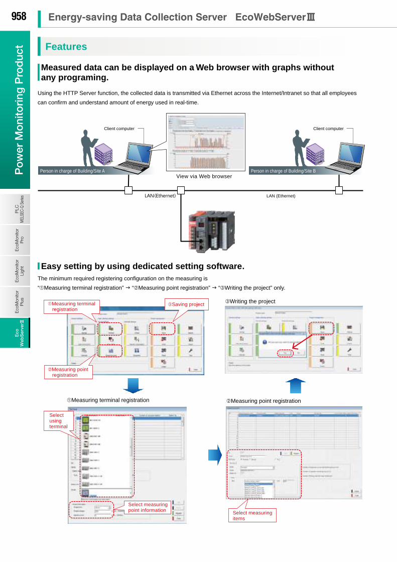
MDU breakerEnergy MeasuringUnit
(EcoMonitorLight)
Energy MeasuringUnit
(EcoMonitorPlus) Air circuit breaker (AE-SW Series)
Electronic multi-measuring instrument (ME96SS Ver.A)
EnergyMeasuringUnit(EcoMonitorLight)
Electronic multi-measuring instrument (ME96SS Ver.A)
Electronic multi-measuring instrument (ME96SS Ver.A)
EnergyMeasuringUnit (EcoMonitorLight)
EnergyMeasuringUnit (EcoMonitorPlus)
Electronic multi-measuring instrument (ME96SS Ver.A)
RS-485 (MODBUS® RTU)
Ethernet (MODBUS® TCP)
LAN(Ethernet)
Receving point
MITSUBISHI GOT
Network monitoring lamp
Target-based management
Specific consumption management
Demand measurement
Pulse signal
Demand control
Collects energy data
Up to 32 units
Collects production data
Alarm activated
I see…
Production line
1. Monitor/Manage energy by department
2. Specific consumption-based management of energy-saving activities
3. Monthly/Annual target-based management
4. Monitor equipment operating status
5. Manage/Record energy data
Entire factoryPlant manager
I see…
Employee A Employee B For monitor equipment status For managing objectives For improvement activities
E-mail notification Transfers files in CSV format
Air conditioning
QE81WH QE82LG
Mitsubishi Electric AE-200J Web-compatible integrated air-conditioning controller
Support energy-saving activities using “Visible Management”
Oh no! Consumption has
increased compared
to last year.
*F Series requires serial converter
MELSEC programmable controller
Q Series, QnA Series, A Series, L Series, F Series*
MELSEC-Q Series Energy measuring module /
Insulation monitoring module
Check demand information and alarm records onsite
( )
Analog input Temperature input
Contact outputEnables remote control of load at locations far from EcoWebServer #
Ethernet (MELSEC communication protocol)
Data collection inside inner register
Measurement data written to inner register
zoom (1 or 5 min), daily, monthly, annual, facility (daily), specific consumption,
demand (daily, monthly, annual), demand alarm, control,
operation history, system log file
abnormal upper/lower limits, operating status,
target value over specific consumption,
over planned energy value, error information
SMTP server (Mail server)
SNTP server (Time server)
FTP server (File server)
EcoWebServer # (with demand control function)
Oh, an e-mail
warning of an alarm
in production line A. Alarm activated
Did we achieve our target this month?
We can reduce waste even further here.
Acquire time information Adjust EcoWebServer #
clock
We need to use air- conditioning less this month.
MODBUS® TCP ⇔ MODBUS® RTU Protocol converter
Comparatively high specific consumption (waste of energy, negative influence on productivity) Ex) kWh of electricity per day can be saved with improvement.
Compare data before and after implementing countermeasure (kWh reduced per day)
Implement similar countermeasures for other facilities
• Facilities start-up too fast• After investigation and deciding appropriate
start-up time, implement countermeasure
Energy-saving Data Collection Server
System Configuration Example
Support factory, building and school
energy-saving activities.
Build visualized environments and
manage energy effectively.
Support to energy conditions at all times
and quickly resolve energy loss problems.
Finaly reduce energy loss, increase
productivity and cut production costs.
Energy-saving method
Energy Management System
952 省省省省省省省Energy-saving Data Collection Server EcoWebServer3P
ow
er M
oni
tori
ng P
rod
uct
Eco
Mon
itor
Pro
PLC
MEL
SEC-
Q Se
ries
Eco
Mon
itor
Ligh
tE
coM
onito
rP
lus
Eco
Web
Ser
ver 3
Eco
Web
Ser
ver #
MDU breakerEnergy MeasuringUnit
(EcoMonitorLight)
Energy MeasuringUnit
(EcoMonitorPlus) Air circuit breaker (AE-SW Series)
Electronic multi-measuring instrument (ME96SS Ver.A)
EnergyMeasuringUnit(EcoMonitorLight)
Electronic multi-measuring instrument (ME96SS Ver.A)
Electronic multi-measuring instrument (ME96SS Ver.A)
EnergyMeasuringUnit (EcoMonitorLight)
EnergyMeasuringUnit (EcoMonitorPlus)
Electronic multi-measuring instrument (ME96SS Ver.A)
RS-485 (MODBUS® RTU)
Ethernet (MODBUS® TCP)
LAN(Ethernet)
Receving point
MITSUBISHI GOT
Network monitoring lamp
Target-based management
Specific consumption management
Demand measurement
Pulse signal
Demand control
Collects energy data
Up to 32 units
Collects production data
Alarm activated
I see…
Production line
1. Monitor/Manage energy by department
2. Specific consumption-based management of energy-saving activities
3. Monthly/Annual target-based management
4. Monitor equipment operating status
5. Manage/Record energy data
Entire factoryPlant manager
I see…
Employee A Employee B For monitor equipment status For managing objectives For improvement activities
E-mail notification Transfers files in CSV format
Air conditioning
QE81WH QE82LG
Mitsubishi Electric AE-200J Web-compatible integrated air-conditioning controller
Support energy-saving activities using “Visible Management”
Oh no! Consumption has
increased compared
to last year.
*F Series requires serial converter
MELSEC programmable controller
Q Series, QnA Series, A Series, L Series, F Series*
MELSEC-Q Series Energy measuring module /
Insulation monitoring module
Check demand information and alarm records onsite
( )
Analog input Temperature input
Contact outputEnables remote control of load at locations far from EcoWebServer #
Ethernet (MELSEC communication protocol)
Data collection inside inner register
Measurement data written to inner register
zoom (1 or 5 min), daily, monthly, annual, facility (daily), specific consumption,
demand (daily, monthly, annual), demand alarm, control,
operation history, system log file
abnormal upper/lower limits, operating status,
target value over specific consumption,
over planned energy value, error information
SMTP server (Mail server)
SNTP server (Time server)
FTP server (File server)
EcoWebServer # (with demand control function)
Oh, an e-mail
warning of an alarm
in production line A. Alarm activated
Did we achieve our target this month?
We can reduce waste even further here.
Acquire time information Adjust EcoWebServer #
clock
We need to use air- conditioning less this month.
MODBUS® TCP ⇔ MODBUS® RTU Protocol converter
Comparatively high specific consumption (waste of energy, negative influence on productivity) Ex) kWh of electricity per day can be saved with improvement.
Compare data before and after implementing countermeasure (kWh reduced per day)
Implement similar countermeasures for other facilities
• Facilities start-up too fast• After investigation and deciding appropriate
start-up time, implement countermeasure
Energy-saving Data Collection Server
System Configuration Example
Support factory, building and school
energy-saving activities.
Build visualized environments and
manage energy effectively.
Support to energy conditions at all times
and quickly resolve energy loss problems.
Finaly reduce energy loss, increase
productivity and cut production costs.
Energy-saving method
Energy Management System
953P
ow
er Mo
nitoring
Pro
duct
EcoM
onitorP
roP
LCM
ELSEC-Q SeriesE
coMonitor
LightE
coMonitor
Plus
Eco
WebS
erver3E
coW
ebS
erver#
Power Management Equipment
P.910
Energy Saving Supporting Devices
P.920

Target Value Management
The ideal condition is efficient use of the necessary amount of energy, at the necessary place and necessary time.
EM (Energy loss Minimum) activities
• No-load power is consumed when there is no production.• Lights are on in areas where there are no people.• There are no inverters, so an unnecessary amount of energy is being used.
Actual
• Necessary time (year, month, day, hour, minute, second...)• Necessary place (all, building, department, production line, equipment)• Necessary amount (technical standards, use/operation standards)
Energy required for production:
Ideal
Improve productivity ( Save energy)
Improvements Discover waste
Monthly
Managing objectives is a very important issue when practicing energy savings.
“Target value management” is the process of transforming actual conditions into ideal conditions, and thereby requires
understanding the actual situation and how much “unseen” waste there is. For this reason, target value management involves
performing detailed management of operations, moving from months to days and lines to equipment, and evolving from “seeing”
waste to “understanding” it.
Additionally, when using target value management, it is necessary to construct and put into practice an organization that values
“people who set objectives (manage),” “people who find things” and “people capable of thinking of improvements and
implementing them.”
Specific consumption management
In lines where there is a large difference in production volume, it is difficult to save energy and improve productivity using energy
management alone.
By understanding specific consumption —energy consumed per product— waste in energy and production processes can be
clarified, and it becomes easier to implement countermeasures.
Rather than simply not using energy, it’s important to use energy efficiently when, where and how much needed.
Daily
What is “Demand”....?
Rolling block demand management methodEx) Interval:15min, Sub interval 5min
Fixed block demand managementEx) Interval:30min
Demand is average electric power at a specified period. This period for demand differs for each country and the way of
management method.
Electric fee is basically determined based on the highest demand in one year(contract demand).
The highter the contract demand is, the more expensive the electric basic charge is.
There are two types of basic demand management method as below.
(1) Fixed block demand management method
The demand period consists of only an interval.
(2) Rolling block demand management method
The demand period consists of interval and sub interval.
Interval is the period for caluclation of average electric.
Sub interval is the period for updata the calculation.
Realize visualization of energy and demand management with one EcoWebServer #.
Subtotal Volume
Estimation
Warning
Load interruption
This is specific consumption management
EcoWebServer# with demand monitoring function comply with the Fixed block demand management method. Interval can be selected from 15min or 30min.
• Based on the results of the estimation, an alarm is output and a notification sent when the objective demand has been exceeded.
• The alarm notification can be a buzzer, display lamp, etc., which is sent through the contact output.
• The value at the end of the 30-minute time limit is estimated from the measured demand (power demand).
• Load interruption may be necessary depending on power use.• A control output signal can be used to automatically interrupt
the load.
• Demand (power demand) is computed and calculated by taking pulses from the multi-measuring meter
(transaction meter) for power demand.
Reduce basic free
Reduce demand
Importance of Visualizing Energy Importance of Demand Monitoring
Essentials Issues for Saving Energy Energy Saving by visualizing demand
954 省省省省省省省Energy-saving Data Collection Server EcoWebServer3P
ow
er M
oni
tori
ng P
rod
uct
Eco
Mon
itor
Pro
PLC
MEL
SEC-
Q Se
ries
Eco
Mon
itor
Ligh
tE
coM
onito
rP
lus
Eco
Web
Ser
ver 3
Eco
Web
Ser
ver #

Target Value Management
The ideal condition is efficient use of the necessary amount of energy, at the necessary place and necessary time.
EM (Energy loss Minimum) activities
• No-load power is consumed when there is no production.• Lights are on in areas where there are no people.• There are no inverters, so an unnecessary amount of energy is being used.
Actual
• Necessary time (year, month, day, hour, minute, second...)• Necessary place (all, building, department, production line, equipment)• Necessary amount (technical standards, use/operation standards)
Energy required for production:
Ideal
Improve productivity ( Save energy)
Improvements Discover waste
Monthly
Managing objectives is a very important issue when practicing energy savings.
“Target value management” is the process of transforming actual conditions into ideal conditions, and thereby requires
understanding the actual situation and how much “unseen” waste there is. For this reason, target value management involves
performing detailed management of operations, moving from months to days and lines to equipment, and evolving from “seeing”
waste to “understanding” it.
Additionally, when using target value management, it is necessary to construct and put into practice an organization that values
“people who set objectives (manage),” “people who find things” and “people capable of thinking of improvements and
implementing them.”
Specific consumption management
In lines where there is a large difference in production volume, it is difficult to save energy and improve productivity using energy
management alone.
By understanding specific consumption —energy consumed per product— waste in energy and production processes can be
clarified, and it becomes easier to implement countermeasures.
Rather than simply not using energy, it’s important to use energy efficiently when, where and how much needed.
Daily
What is “Demand”....?
Rolling block demand management methodEx) Interval:15min, Sub interval 5min
Fixed block demand managementEx) Interval:30min
Demand is average electric power at a specified period. This period for demand differs for each country and the way of
management method.
Electric fee is basically determined based on the highest demand in one year(contract demand).
The highter the contract demand is, the more expensive the electric basic charge is.
There are two types of basic demand management method as below.
(1) Fixed block demand management method
The demand period consists of only an interval.
(2) Rolling block demand management method
The demand period consists of interval and sub interval.
Interval is the period for caluclation of average electric.
Sub interval is the period for updata the calculation.
Realize visualization of energy and demand management with one EcoWebServer #.
Subtotal Volume
Estimation
Warning
Load interruption
This is specific consumption management
EcoWebServer# with demand monitoring function comply with the Fixed block demand management method. Interval can be selected from 15min or 30min.
• Based on the results of the estimation, an alarm is output and a notification sent when the objective demand has been exceeded.
• The alarm notification can be a buzzer, display lamp, etc., which is sent through the contact output.
• The value at the end of the 30-minute time limit is estimated from the measured demand (power demand).
• Load interruption may be necessary depending on power use.• A control output signal can be used to automatically interrupt
the load.
• Demand (power demand) is computed and calculated by taking pulses from the multi-measuring meter
(transaction meter) for power demand.
Reduce basic free
Reduce demand
Importance of Visualizing Energy Importance of Demand Monitoring
Essentials Issues for Saving Energy Energy Saving by visualizing demand
955P
ow
er Mo
nitoring
Pro
duct
EcoM
onitorP
roP
LCM
ELSEC-Q SeriesE
coMonitor
LightE
coMonitor
Plus
Eco
WebS
erver3E
coW
ebS
erver#
Power Management Equipment
P.910
Energy Saving Supporting Devices
P.920

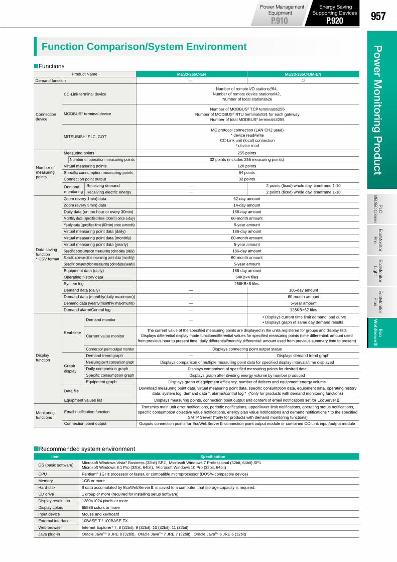
CC-Link, MODBUS® (TCP, RTU*)CommunicationCC-Link, MODBUS® (TCP, RTU*)Communication
Product name Energy-saving Data Collection Server
MES3-255C-ENModel no.
Product name
MES3-255C-DM-ENModel no.
Transmission speed
Maximum total cable length(maximum transmission distance)
Maximum number of connected units
Communication methodSynchronization methodEncoding methodTransmission route formatTransmission formatError control methodConnecting cable
CC
-Lin
k co
mm
unic
atio
ns s
ectio
n
156kbps / 625kbps / 2.5Mbps / 5Mbps / 10Mbps
Broadcast polling methodFrame synchronization methodNRZI methodBus (RS-485)HDLC compatibleCRC (x16+x12+x15)CC-Link Ver1.10-compatible dedicated cable
Transmission speed156kbps625kbps2.5Mbps5Mbps10Mbps
SpecificationsItem
Cable length between stations
20cm or more
Maximum total cable length1200m900m400m160m100m
1. Total number of stations a+b×2+c×3+d×4q64 a: 1 station occupied, b: 2 stations occupied, c: 3 stations occupied, d: 4 stations occupied2. Number of units connected 16× (A+D) +54×B+88×Cq2304 A: Number of remote I/O stations …64 max B: Number of remote device stations …42 max C: Number of local stations, intelligent device stations …26 max D: Number of reserve stations *
* Unregistered station numbers from station 1 to the maximum number of stations are counted as reserve stations.
Network Specifications (CC-Link)
Functions
64 units However, conditions on the right must be met
Energy-saving Data Collection Server (with demand control function)
*MODBUS® TCP ⇔ RTU converter is required for MODBUS® RTU communication.MODBUS® TCP ⇔ RTU converter (SI-485 MB) is produced by LINEEYE CO.,LTD.
Lineup Function Comparison/System Environment
Energy-saving Data Collection Server EcoWebServer #
Recommended system environment
MODBUS® terminal device
MITSUBISHI PLC, GOT
Measuring points
Virtual measuring points
Specific consumption measuring points
Connection point output
Zoom (every 1min) data
Zoom (every 5min) data
Daily data (on the hour or every 30min)
Monthly data (specified time (00min) once a day)
Yearly data (specified time (00min) once a month)
Virtual measuring point data (daily)
Virtual measuring point data (monthly)
Virtual measuring point data (yearly)
Specific consumption measuring point data (daily)
Specific consumption measuring point data (monthly)
Specific consumption measuring point data (yearly)
Equipment data (daily)
Operating history data
System log
Demand data (daily)
Demand data (monthly(daily maximum))
Demand data (yearly(monthly maximum))
Demand alarm/Control log
Real-time
CC-Link terminal device
Displays current time limit demand load curve Displays graph of same day demand results
MC protocol connection (LAN CH2 used)* device read/write
CC-Link unit (local) connection* device read
Number of MODBUS® TCP terminalsq255Number of MODBUS® RTU terminalsq31 for each gateway
Number of total MODBUS® terminalsq255
Number of remote I/O stationsq64, Number of remote device stationsq42,
Number of local stationsq26
255 points
32 points (includes 255 measuring points)
128 points
64 points
32 points
62-day amount
14-day amount
186-day amount
60-month amount
5-year amount
186-day amount
60-month amount
5-year amount
186-day amount
60-month amount
5-year amount
186-day amount
64KB×4 files
256KB×8 files
—
—
2 points (fixed) whole day, timeframe 1-10
2 points (fixed) whole day, timeframe 1-10
—
—
—
—
—
186-day amount
60-month amount
5-year amount
128KB×62 files
Displays connecting point output status
— Displays demand trend graph
Product Name MES3-255C-DM-ENMES3-255C-EN
Demand function —
Item Specification
OS (basic software)
CPU
Memory
Hard-disk
CD drive
Display resolution
Display colors
Input device
External interface
Web browser
Java plug-in
Microsoft Windows Vista® Business (32bit) SP2, Microsoft Windows 7 Professional (32bit, 64bit) SP1Microsoft Windows 8.1 Pro (32bit, 64bit), Microsoft Windows 10 Pro (32bit, 64bit)
Pentium® 1GHz processor or faster, or compatible microprocessor (DOS/V-compatible device)
1GB or more
If data accumulated by EcoWebServer# is saved to a computer, that storage capacity is required.
1 group or more (required for installing setup software)
1280×1024 pixels or more
65536 colors or more
Mouse and keyboard
10BASE-T / 100BASE-TX
Internet Explorer® 7, 8 (32bit), 9 (32bit), 10 (32bit), 11 (32bit)
Oracle JaveTM 8 JRE 8 (32bit), Oracle JavaTM 7 JRE 7 (32bit), Oracle JavaTM 6 JRE 6 (32bit)
Number of operation measuring points
Receiving demand
Receiving electric energy
Demand monitor
Current value monitor
Connection point output monitor
Demand trend graph
Measuring point comparison graph
Daily comparison graph
Specific consumption graph
Equipment graph
Data file
Equipment values list
Email notification function
Connection point output
Connection device
Number of measuring points
Data saving function * CSV format
Display function
Monitoring functions
Demand monitoring
Graph display
The current value of the specified measuring points are displayed in the units registered for groups and display listsDisplays differential display mode function/differential values for specified measuring points (time differential: amount used
from previous hour to present time, daily differential/monthly differential: amount used from previous summary time to present)
Transmits main unit error notifications, periodic notifications, upper/lower limit notifications, operating status notifications, specific consumption objective value notifications, energy plan value notifications and demand notifications * to the specified
SMTP Server (*only for products with demand monitoring functions)
Download measuring point data, virtual measuring point data, specific consumption data, equipment data, operating history data, system log, demand data *, alarms/control log * (*only for products with demand monitoring functions)
Displays comparison of multiple measuring point data for specified display intervals/time displayed
Displays comparison of specified measuring points for desired date
Displays graph after dividing energy volume by number produced
Displays graph of equipment efficiency, number of defects and equipment energy volume
Displays measuring points, connection point output and content of email notifications set for EcoServer#
Outputs connection points for EcoWebServer# connection point output module or combined CC-Link input/output module
956 省省省省省省省Energy-saving Data Collection Server EcoWebServer3P
ow
er M
oni
tori
ng P
rod
uct
Eco
Mon
itor
Pro
PLC
MEL
SEC-
Q Se
ries
Eco
Mon
itor
Ligh
tE
coM
onito
rP
lus
Eco
Web
Ser
ver 3
Eco
Web
Ser
ver #
CC-Link, MODBUS® (TCP, RTU*)CommunicationCC-Link, MODBUS® (TCP, RTU*)Communication
Product name Energy-saving Data Collection Server
MES3-255C-ENModel no.
Product name
MES3-255C-DM-ENModel no.
Transmission speed
Maximum total cable length(maximum transmission distance)
Maximum number of connected units
Communication methodSynchronization methodEncoding methodTransmission route formatTransmission formatError control methodConnecting cable
CC
-Lin
k co
mm
unic
atio
ns s
ectio
n
156kbps / 625kbps / 2.5Mbps / 5Mbps / 10Mbps
Broadcast polling methodFrame synchronization methodNRZI methodBus (RS-485)HDLC compatibleCRC (x16+x12+x15)CC-Link Ver1.10-compatible dedicated cable
Transmission speed156kbps625kbps2.5Mbps5Mbps10Mbps
SpecificationsItem
Cable length between stations
20cm or more
Maximum total cable length1200m900m400m160m100m
1. Total number of stations a+b×2+c×3+d×4q64 a: 1 station occupied, b: 2 stations occupied, c: 3 stations occupied, d: 4 stations occupied2. Number of units connected 16× (A+D) +54×B+88×Cq2304 A: Number of remote I/O stations …64 max B: Number of remote device stations …42 max C: Number of local stations, intelligent device stations …26 max D: Number of reserve stations *
* Unregistered station numbers from station 1 to the maximum number of stations are counted as reserve stations.
Network Specifications (CC-Link)
Functions
64 units However, conditions on the right must be met
Energy-saving Data Collection Server (with demand control function)
*MODBUS® TCP ⇔ RTU converter is required for MODBUS® RTU communication.MODBUS® TCP ⇔ RTU converter (SI-485 MB) is produced by LINEEYE CO.,LTD.
Lineup Function Comparison/System Environment
Energy-saving Data Collection Server EcoWebServer #
Recommended system environment
MODBUS® terminal device
MITSUBISHI PLC, GOT
Measuring points
Virtual measuring points
Specific consumption measuring points
Connection point output
Zoom (every 1min) data
Zoom (every 5min) data
Daily data (on the hour or every 30min)
Monthly data (specified time (00min) once a day)
Yearly data (specified time (00min) once a month)
Virtual measuring point data (daily)
Virtual measuring point data (monthly)
Virtual measuring point data (yearly)
Specific consumption measuring point data (daily)
Specific consumption measuring point data (monthly)
Specific consumption measuring point data (yearly)
Equipment data (daily)
Operating history data
System log
Demand data (daily)
Demand data (monthly(daily maximum))
Demand data (yearly(monthly maximum))
Demand alarm/Control log
Real-time
CC-Link terminal device
Displays current time limit demand load curve Displays graph of same day demand results
MC protocol connection (LAN CH2 used)* device read/write
CC-Link unit (local) connection* device read
Number of MODBUS® TCP terminalsq255Number of MODBUS® RTU terminalsq31 for each gateway
Number of total MODBUS® terminalsq255
Number of remote I/O stationsq64, Number of remote device stationsq42,
Number of local stationsq26
255 points
32 points (includes 255 measuring points)
128 points
64 points
32 points
62-day amount
14-day amount
186-day amount
60-month amount
5-year amount
186-day amount
60-month amount
5-year amount
186-day amount
60-month amount
5-year amount
186-day amount
64KB×4 files
256KB×8 files
—
—
2 points (fixed) whole day, timeframe 1-10
2 points (fixed) whole day, timeframe 1-10
—
—
—
—
—
186-day amount
60-month amount
5-year amount
128KB×62 files
Displays connecting point output status
— Displays demand trend graph
Product Name MES3-255C-DM-ENMES3-255C-EN
Demand function —
Item Specification
OS (basic software)
CPU
Memory
Hard-disk
CD drive
Display resolution
Display colors
Input device
External interface
Web browser
Java plug-in
Microsoft Windows Vista® Business (32bit) SP2, Microsoft Windows 7 Professional (32bit, 64bit) SP1Microsoft Windows 8.1 Pro (32bit, 64bit), Microsoft Windows 10 Pro (32bit, 64bit)
Pentium® 1GHz processor or faster, or compatible microprocessor (DOS/V-compatible device)
1GB or more
If data accumulated by EcoWebServer# is saved to a computer, that storage capacity is required.
1 group or more (required for installing setup software)
1280×1024 pixels or more
65536 colors or more
Mouse and keyboard
10BASE-T / 100BASE-TX
Internet Explorer® 7, 8 (32bit), 9 (32bit), 10 (32bit), 11 (32bit)
Oracle JaveTM 8 JRE 8 (32bit), Oracle JavaTM 7 JRE 7 (32bit), Oracle JavaTM 6 JRE 6 (32bit)
Number of operation measuring points
Receiving demand
Receiving electric energy
Demand monitor
Current value monitor
Connection point output monitor
Demand trend graph
Measuring point comparison graph
Daily comparison graph
Specific consumption graph
Equipment graph
Data file
Equipment values list
Email notification function
Connection point output
Connection device
Number of measuring points
Data saving function * CSV format
Display function
Monitoring functions
Demand monitoring
Graph display
The current value of the specified measuring points are displayed in the units registered for groups and display listsDisplays differential display mode function/differential values for specified measuring points (time differential: amount used
from previous hour to present time, daily differential/monthly differential: amount used from previous summary time to present)
Transmits main unit error notifications, periodic notifications, upper/lower limit notifications, operating status notifications, specific consumption objective value notifications, energy plan value notifications and demand notifications * to the specified
SMTP Server (*only for products with demand monitoring functions)
Download measuring point data, virtual measuring point data, specific consumption data, equipment data, operating history data, system log, demand data *, alarms/control log * (*only for products with demand monitoring functions)
Displays comparison of multiple measuring point data for specified display intervals/time displayed
Displays comparison of specified measuring points for desired date
Displays graph after dividing energy volume by number produced
Displays graph of equipment efficiency, number of defects and equipment energy volume
Displays measuring points, connection point output and content of email notifications set for EcoServer#
Outputs connection points for EcoWebServer# connection point output module or combined CC-Link input/output module
957P
ow
er Mo
nitoring
Pro
duct
EcoM
onitorP
roP
LCM
ELSEC-Q SeriesE
coMonitor
LightE
coMonitor
Plus
Eco
WebS
erver3E
coW
ebS
erver#
Power Management Equipment
P.910
Energy Saving Supporting Devices
P.920
View via Web browser
LAN (Ethernet)
Person in charge of Building/Site A Person in charge of Building/Site B
Saving project
Client computer Client computer
Writing the project
Measuring terminal registration Measuring point registration
Using the HTTP Server function, the collected data is transmitted via Ethernet across the Internet/Intranet so that all employees
can confirm and understand amount of energy used in real-time.
The display procedure is select “Measuring point group/name Graph display date” and select “Display” only.
A comparison of the specified date and items can be displayed.
Correlation analysis (graph overlapping)
Select the graph display date
Select the display and display the screen
Analysis by department
Sales
General affairs
Designing
Purchasing
Accounting
Electrical outlet
Lightning
Air conditioning
Office automation
Analysis by application
Select using terminal
Measuring point registration
Measuring terminal registration
Select measuring items
Select measuring point information
Select the measuring point group/ measuring point name you want to display
Select the number of the graph to be displayed.
(When displaying the same graph in a cascade, select the same number.)
Select the graph display interval/ date/automatic update (optional)
Select the graph display format (Bar graph/Line graph/Stacked bar graph)
Select the display button to display the screen
Display screen
Selection screen
The display procedure is to select “Measuring point group/name Graph display format Graph No.
Graph display intervals etc.” and select “Display” only.
It’s possible to select graphs and display various graphs in the format of your choice. It’s also possible to display the same
graph, making it easy to understand graph correlations.
Select the measuring point group/measuring point name you want to display
The minimum required registering configuration on the measuring is
“Measuring terminal registration” “Measuring point registration” “Writing the project” only.
LAN(Ethernet)
Features
Easy setting by using dedicated setting software.
Date comparison graphDate comparison graph1
Measuring point comparison graphMeasuring point comparison graph2
Measured data can be displayed on a Web browser with graphs without any programing.
Add new comparison screens according to the scenario. Strong support provided for analyzing activities.
958 省省省省省省省Energy-saving Data Collection Server EcoWebServer3P
ow
er M
oni
tori
ng P
rod
uct
Eco
Mon
itor
Pro
PLC
MEL
SEC-
Q Se
ries
Eco
Mon
itor
Ligh
tE
coM
onito
rP
lus
Eco
Web
Ser
ver 3
Eco
Web
Ser
ver #
View via Web browser
LAN (Ethernet)
Person in charge of Building/Site A Person in charge of Building/Site B
Saving project
Client computer Client computer
Writing the project
Measuring terminal registration Measuring point registration
Using the HTTP Server function, the collected data is transmitted via Ethernet across the Internet/Intranet so that all employees
can confirm and understand amount of energy used in real-time.
The display procedure is select “Measuring point group/name Graph display date” and select “Display” only.
A comparison of the specified date and items can be displayed.
Correlation analysis (graph overlapping)
Select the graph display date
Select the display and display the screen
Analysis by department
Sales
General affairs
Designing
Purchasing
Accounting
Electrical outlet
Lightning
Air conditioning
Office automation
Analysis by application
Select using terminal
Measuring point registration
Measuring terminal registration
Select measuring items
Select measuring point information
Select the measuring point group/ measuring point name you want to display
Select the number of the graph to be displayed.
(When displaying the same graph in a cascade, select the same number.)
Select the graph display interval/ date/automatic update (optional)
Select the graph display format (Bar graph/Line graph/Stacked bar graph)
Select the display button to display the screen
Display screen
Selection screen
The display procedure is to select “Measuring point group/name Graph display format Graph No.
Graph display intervals etc.” and select “Display” only.
It’s possible to select graphs and display various graphs in the format of your choice. It’s also possible to display the same
graph, making it easy to understand graph correlations.
Select the measuring point group/measuring point name you want to display
The minimum required registering configuration on the measuring is
“Measuring terminal registration” “Measuring point registration” “Writing the project” only.
LAN(Ethernet)
Features
Easy setting by using dedicated setting software.
Date comparison graphDate comparison graph1
Measuring point comparison graphMeasuring point comparison graph2
Measured data can be displayed on a Web browser with graphs without any programing.
Add new comparison screens according to the scenario. Strong support provided for analyzing activities.
959P
ow
er Mo
nitoring
Pro
duct
EcoM
onitorP
roP
LCM
ELSEC-Q SeriesE
coMonitor
LightE
coMonitor
Plus
Eco
WebS
erver3E
coW
ebS
erver#
Power Management Equipment
P.910
Energy Saving Supporting Devices
P.920
Power receiving facilities
Receiving electricity power demand(line graph)
Selected power volume (stacked bar display)
Load installed in a location separated from the EcoWebServer # can also by controlled by CC-Link transmission.(CC-Link: total cable length up to 1.2km)
Demand monitor screen
Current day demand trend graph
Target Value
Fixed Value
Alarm output Email notificationSMTP Server<Items monitored>
over the set target value
MITSUBISHI GOT MITSUBISHI PLC
LAN (Ethernet)
Ethernet(Melsec comunication protocol)
EcoWebServer #
Displays demand information and alarm information
Display date selection menu
Specific consumption amount (=a÷b)
Production amount (b)
Energy used (a)
Specific consumption target value
By integrating the production volumes from the measuring terminal and PLC, the specific consumption graph can be easily
displayed and points related to the drop in specific consumption can be easily understood.
Additionally, by comparing two specific consumption graphs at the same line, it is possible to confirm the benefits at the time the
countermeasure was implemented.
Information collected on the EcoWebServer # can be displayed on the GOT.
By displaying the alarm state/measuring value for energy information/demand, real-time monitoring at the
site and urgent countermeasures are possible.
Objective values (upper/lower) and error information can be transmitted through email notifications/alarm output, and changes in
status can be recognized immediately. The result of the careful target value management and monitoring the status monitoring
ensure that problems occurring at the site are not overlooked.
* The password is set so that it can only be changed by the administrator.
Objective values can be set for each measuring point from the specific consumption screen.
A password is required to change objective value settings.
Objective value setting window button
Use the checkbox to select whether or not to display the vertical scale of the graph with the specific consumption objective value in the center.
Objective value scale fixed display box
Yearly/monthly graph: 1hr cycleDaily/zoom data: 1min cycle
Automatic update fixed display box
Select the specific consumption measuring point from the pulldown menu.
Specific consumption measuring point selection menu
Select the date of the data from the pulldown menu.
Alarm lamps
Network monitor display lights(PATLITE)
Cumulative amount of energy used
Energy plan value Specific consumption objective value
Upper/lower irregularity Change in operating state Error information Demand alarm
Person in charge of Building/Site C
Person in charge of Building/Site B
Control status display area
Demand information display area
Demand load curve
Current demand display area
Alarm status display area
Person in charge of Building/Site A
Graph screen example
Alarms displayed via the LAN (with demand control function)
Compatible model: MES3-255C-DM-EN only
As the breakdown of power demand (load balance) can be easily understood from the power demand trends and stacked bar
graphs for each regional substation and operating equipment can be reviewed, and operations can be planned and proposed
based on the analysis results, which enable peak shift/peak cut.
Easily understand productivity by confirming the specific consumption graph
Connection with Mitsubishi Electric GOT display device.
Alarm output/email notification through a variety of monitoring functions.
Simultaneously visualize demand trends and energy consumption per building/load
960 省省省省省省省Energy-saving Data Collection Server EcoWebServer3P
ow
er M
oni
tori
ng P
rod
uct
Eco
Mon
itor
Pro
PLC
MEL
SEC-
Q Se
ries
Eco
Mon
itor
Ligh
tE
coM
onito
rP
lus
Eco
Web
Ser
ver 3
Eco
Web
Ser
ver #

Power receiving facilities
Receiving electricity power demand(line graph)
Selected power volume (stacked bar display)
Load installed in a location separated from the EcoWebServer # can also by controlled by CC-Link transmission.(CC-Link: total cable length up to 1.2km)
Demand monitor screen
Current day demand trend graph
Target Value
Fixed Value
Alarm output Email notificationSMTP Server<Items monitored>
over the set target value
MITSUBISHI GOT MITSUBISHI PLC
LAN (Ethernet)
Ethernet(Melsec comunication protocol)
EcoWebServer #
Displays demand information and alarm information
Display date selection menu
Specific consumption amount (=a÷b)
Production amount (b)
Energy used (a)
Specific consumption target value
By integrating the production volumes from the measuring terminal and PLC, the specific consumption graph can be easily
displayed and points related to the drop in specific consumption can be easily understood.
Additionally, by comparing two specific consumption graphs at the same line, it is possible to confirm the benefits at the time the
countermeasure was implemented.
Information collected on the EcoWebServer # can be displayed on the GOT.
By displaying the alarm state/measuring value for energy information/demand, real-time monitoring at the
site and urgent countermeasures are possible.
Objective values (upper/lower) and error information can be transmitted through email notifications/alarm output, and changes in
status can be recognized immediately. The result of the careful target value management and monitoring the status monitoring
ensure that problems occurring at the site are not overlooked.
* The password is set so that it can only be changed by the administrator.
Objective values can be set for each measuring point from the specific consumption screen.
A password is required to change objective value settings.
Objective value setting window button
Use the checkbox to select whether or not to display the vertical scale of the graph with the specific consumption objective value in the center.
Objective value scale fixed display box
Yearly/monthly graph: 1hr cycleDaily/zoom data: 1min cycle
Automatic update fixed display box
Select the specific consumption measuring point from the pulldown menu.
Specific consumption measuring point selection menu
Select the date of the data from the pulldown menu.
Alarm lamps
Network monitor display lights(PATLITE)
Cumulative amount of energy used
Energy plan value Specific consumption objective value
Upper/lower irregularity Change in operating state Error information Demand alarm
Person in charge of Building/Site C
Person in charge of Building/Site B
Control status display area
Demand information display area
Demand load curve
Current demand display area
Alarm status display area
Person in charge of Building/Site A
Graph screen example
Alarms displayed via the LAN (with demand control function)
Compatible model: MES3-255C-DM-EN only
As the breakdown of power demand (load balance) can be easily understood from the power demand trends and stacked bar
graphs for each regional substation and operating equipment can be reviewed, and operations can be planned and proposed
based on the analysis results, which enable peak shift/peak cut.
Easily understand productivity by confirming the specific consumption graph
Connection with Mitsubishi Electric GOT display device.
Alarm output/email notification through a variety of monitoring functions.
Simultaneously visualize demand trends and energy consumption per building/load
961P
ow
er Mo
nitoring
Pro
duct
EcoM
onitorP
roP
LCM
ELSEC-Q SeriesE
coMonitor
LightE
coMonitor
Plus
Eco
WebS
erver3E
coW
ebS
erver#
Power Management Equipment
P.910
Energy Saving Supporting Devices
P.920

Equipment (Motor)
Lighting equipment
Multi-unit air conditioner
CC-Link
Demand level signal LAN (Ethernet)Demand power
Pulse output
Compatible model: MES3-255C-DM-EN only
Demand control possible by interconnecting with Mitsubishi Electric Web-compatible integrated controller—AE-200J, G-150AD, etc.
Additionally, automatic control of load possible through contact point output via main unit of EcoWebServer # and CC-Link.
Using the LAN interface (CH2) of EcoWebServer #, realize MODBUS® TCP communication.
(As with the case of MC protocol communication)
Using the LAN CH2 of EcoWebServer #, via MODBUS® TCP ⇔ MODBUS® RTU converter,
realize MODBUS® RTU communication.
Energy MeasuringUnit (EcoMonitorPlus)
Receving point
Mitsubishi Electric AE-200J Web-compatible integrated air-conditioning controller
Transmission terminal for digital output
Contact point output signal
Contact point output signal
EcoWebServer # equipped with demand monitor function
Capacity-saving control combined with energy-saving monitor level (60/70/80/90%)
MODBUS® TCP ⇔ RTU converter is required for MODBUS® RTU communication. MODBUS® TCP ⇔ RTU converter (SI-485 MB) is produced by LINEEYE CO.,LTD.
EcoWebServer # (with demand control function)
EnergyMeasuringUnit(EcoMonitorLight) *1
Ethernet MODBUS® TCP
*1 It needs the optional module for MODBUS® TCP communication
RS-485 MODBUS® RTU
CH2
HUB
Electronic multi-measuring instrument (ME96SS Ver.A)
Main Unit Specifications
MES3-255C-EN front
MES3-255C-DM-EN front
Front surface (cover of Server section opened)/bottom surface (CC-Link transmission device)
Energy-saving air conditioning operation realized by interconnecting with integrated air-conditioning controller.
It can be connected at MODBUS® RTU/TCP communication
Bottom surfaceFront surface (cover of Server section opened)
(Note 1) Connect to AC100-240V(+10%, -15%) 50/60Hz(±5%). Do not connect to a power supply other than that specified as this may cause an accident.(Note 2) A separate power supply is required for the demand monitor section when using. When using the main device, AC100-240V(+10%, -15%) 50/60Hz power is required for the demand monitor connector
terminals V1, V2. It is possible to connect power from the power-supply module.(Note 3) • CompactFlashTM memory cards are used in a constantly attached state. If they are removed while the power is on or the memory card is being accessed, this product will malfunction. • When removing the card from the memory card slot, be sure to place the RESET/SELECT switch in the SELECT position and remove it only after turning off the power supply and the CF CARD LED has turned off.
• Do not use the CompactFlashTM memory card with any other product. This could corrupt the internal data.• Do not insert a CompactFlashTM memory card other than the one included in the package in this device. If a different card is inserted, the system will not operate correctly.
(Note 4) Be sure to exchange the battery within three minutes after turning off the power. If more than three minutes passes after the battery is removed, the final one hour of data may be lost or the clock may initialize. (Data or configuration settings from more than one hour before will not be initialized). If the clock initializes, please set again after backing up the data. Refer to the operating manual (hardware edition) for the battery replacement procedure.
LED display
Set CC-Link station number.
CC-Link station number setting switch
Set CC-Link transmission speed.
CC-Link transmission speed setting switch
Closed when conditions monitoring function conditions are met.Connect external equipment such as buzzers and lamps.
Contact output terminal block
Displays an error code when an error is detected.In addition, in IP address display mode, the preset IP address is displayed at start-up.
7-segment LED display
Not used.
USB interface
Use connected to a computer network.
LAN interface CH1
Use when connected to a programmable controller network, MITSUBISHI GOT, MODBUS® communication.
LAN interface CH2
Connect power supply. (Note 1)
Power-supply terminal block
Connect CC-Link communication cable.
CC-Link terminal block
Server section
Server section
Push the button and remove the CompactFlashTM memory card.
Stores programs for collecting and displaying data. Data collected is also saved to it. (Note 3)
CompactFlash™ memory card
Used when resetting the main unit.
RESET/SELECT switch
Normally, used in RUN state.
MODE/STOP/RUN switch
Displays an error code when an error is detected.In addition, in IP address display mode, the preset IP address is displayed at start-up.
7-segment LED display
Not used.
USB interface
When you open the panel, you will see the power-supply connection terminal. (Note 1)
Power-supply panel
Display each status.
LED display
Use connected to a computer network.
LAN interface CH1
Connect cable to pulse input, alarm output and control output for demand monitoring. (Note 2)
Demand monitor section connection terminal
Closed when conditions monitoring function conditions are met.Connect external equipment such as buzzers and lamps.
Contact output terminal blockUse when connected to a programmable controller network, MITSUBISHI GOT, MODBUS® communication.
LAN interface CH2
Set CC-Link station number.
CC-Link station number setting switch
Set CC-Link transmission speed.
CC-Link transmission speed setting switch
Display each status.
LED display
Connect CC-Link communication cable.
CC-Link terminal block
LED display
Display each status.
Display each status.
Store the battery.Remove the cover and connect the connector. (Note 4)
Battery storage compartment
Not used.
RS-232 interface
Demand monitor section
Contact output section
CC-Link communication
section
Power-supply section
Contact output section
CC-Link communication
section
Power-supply section
CompactFlash™ memory card EJECT button
Electronic multi-measuring instrument (ME96SS Ver.A) *1
EnergyMeasuringUnit(EcoMonitorLight)
EnergyMeasuringUnit(EcoMonitorPlus)
Electronic multi-measuring instrument (ME96SS Ver.A)
MODBUS® TCP ⇔ MODBUS® RTU Protocol converter
962 省省省省省省省Energy-saving Data Collection Server EcoWebServer3P
ow
er M
oni
tori
ng P
rod
uct
Eco
Mon
itor
Pro
PLC
MEL
SEC-
Q Se
ries
Eco
Mon
itor
Ligh
tE
coM
onito
rP
lus
Eco
Web
Ser
ver 3
Eco
Web
Ser
ver #

Equipment (Motor)
Lighting equipment
Multi-unit air conditioner
CC-Link
Demand level signal LAN (Ethernet)Demand power
Pulse output
Compatible model: MES3-255C-DM-EN only
Demand control possible by interconnecting with Mitsubishi Electric Web-compatible integrated controller—AE-200J, G-150AD, etc.
Additionally, automatic control of load possible through contact point output via main unit of EcoWebServer # and CC-Link.
Using the LAN interface (CH2) of EcoWebServer #, realize MODBUS® TCP communication.
(As with the case of MC protocol communication)
Using the LAN CH2 of EcoWebServer #, via MODBUS® TCP ⇔ MODBUS® RTU converter,
realize MODBUS® RTU communication.
Energy MeasuringUnit (EcoMonitorPlus)
Receving point
Mitsubishi Electric AE-200J Web-compatible integrated air-conditioning controller
Transmission terminal for digital output
Contact point output signal
Contact point output signal
EcoWebServer # equipped with demand monitor function
Capacity-saving control combined with energy-saving monitor level (60/70/80/90%)
MODBUS® TCP ⇔ RTU converter is required for MODBUS® RTU communication. MODBUS® TCP ⇔ RTU converter (SI-485 MB) is produced by LINEEYE CO.,LTD.
EcoWebServer # (with demand control function)
EnergyMeasuringUnit(EcoMonitorLight) *1
Ethernet MODBUS® TCP
*1 It needs the optional module for MODBUS® TCP communication
RS-485 MODBUS® RTU
CH2
HUB
Electronic multi-measuring instrument (ME96SS Ver.A)
Main Unit Specifications
MES3-255C-EN front
MES3-255C-DM-EN front
Front surface (cover of Server section opened)/bottom surface (CC-Link transmission device)
Energy-saving air conditioning operation realized by interconnecting with integrated air-conditioning controller.
It can be connected at MODBUS® RTU/TCP communication
Bottom surfaceFront surface (cover of Server section opened)
(Note 1) Connect to AC100-240V(+10%, -15%) 50/60Hz(±5%). Do not connect to a power supply other than that specified as this may cause an accident.(Note 2) A separate power supply is required for the demand monitor section when using. When using the main device, AC100-240V(+10%, -15%) 50/60Hz power is required for the demand monitor connector
terminals V1, V2. It is possible to connect power from the power-supply module.(Note 3) • CompactFlashTM memory cards are used in a constantly attached state. If they are removed while the power is on or the memory card is being accessed, this product will malfunction. • When removing the card from the memory card slot, be sure to place the RESET/SELECT switch in the SELECT position and remove it only after turning off the power supply and the CF CARD LED has turned off.
• Do not use the CompactFlashTM memory card with any other product. This could corrupt the internal data.• Do not insert a CompactFlashTM memory card other than the one included in the package in this device. If a different card is inserted, the system will not operate correctly.
(Note 4) Be sure to exchange the battery within three minutes after turning off the power. If more than three minutes passes after the battery is removed, the final one hour of data may be lost or the clock may initialize. (Data or configuration settings from more than one hour before will not be initialized). If the clock initializes, please set again after backing up the data. Refer to the operating manual (hardware edition) for the battery replacement procedure.
LED display
Set CC-Link station number.
CC-Link station number setting switch
Set CC-Link transmission speed.
CC-Link transmission speed setting switch
Closed when conditions monitoring function conditions are met.Connect external equipment such as buzzers and lamps.
Contact output terminal block
Displays an error code when an error is detected.In addition, in IP address display mode, the preset IP address is displayed at start-up.
7-segment LED display
Not used.
USB interface
Use connected to a computer network.
LAN interface CH1
Use when connected to a programmable controller network, MITSUBISHI GOT, MODBUS® communication.
LAN interface CH2
Connect power supply. (Note 1)
Power-supply terminal block
Connect CC-Link communication cable.
CC-Link terminal block
Server section
Server section
Push the button and remove the CompactFlashTM memory card.
Stores programs for collecting and displaying data. Data collected is also saved to it. (Note 3)
CompactFlash™ memory card
Used when resetting the main unit.
RESET/SELECT switch
Normally, used in RUN state.
MODE/STOP/RUN switch
Displays an error code when an error is detected.In addition, in IP address display mode, the preset IP address is displayed at start-up.
7-segment LED display
Not used.
USB interface
When you open the panel, you will see the power-supply connection terminal. (Note 1)
Power-supply panel
Display each status.
LED display
Use connected to a computer network.
LAN interface CH1
Connect cable to pulse input, alarm output and control output for demand monitoring. (Note 2)
Demand monitor section connection terminal
Closed when conditions monitoring function conditions are met.Connect external equipment such as buzzers and lamps.
Contact output terminal blockUse when connected to a programmable controller network, MITSUBISHI GOT, MODBUS® communication.
LAN interface CH2
Set CC-Link station number.
CC-Link station number setting switch
Set CC-Link transmission speed.
CC-Link transmission speed setting switch
Display each status.
LED display
Connect CC-Link communication cable.
CC-Link terminal block
LED display
Display each status.
Display each status.
Store the battery.Remove the cover and connect the connector. (Note 4)
Battery storage compartment
Not used.
RS-232 interface
Demand monitor section
Contact output section
CC-Link communication
section
Power-supply section
Contact output section
CC-Link communication
section
Power-supply section
CompactFlash™ memory card EJECT button
Electronic multi-measuring instrument (ME96SS Ver.A) *1
EnergyMeasuringUnit(EcoMonitorLight)
EnergyMeasuringUnit(EcoMonitorPlus)
Electronic multi-measuring instrument (ME96SS Ver.A)
MODBUS® TCP ⇔ MODBUS® RTU Protocol converter
963P
ow
er Mo
nitoring
Pro
duct
EcoM
onitorP
roP
LCM
ELSEC-Q SeriesE
coMonitor
LightE
coMonitor
Plus
Eco
WebS
erver3E
coW
ebS
erver#
Power Management Equipment
P.910
Energy Saving Supporting Devices
P.920

When setting (CH1) When connecting the PLC (CH2)
Power-supply section
Connecting point output section
Server communications section (LAN interface)
CC-Link communication section
When displaying graphsWhen displaying graphs
External dimensions
MES3-255C-ENMES3-255C-EN
Peripheral installation conditions
MES3-255C-ENMES3-255C-EN MES3-255C-DM-ENMES3-255C-DM-EN
MES3-255C-DM-ENMES3-255C-DM-EN
Connection Diagram External Diagram/Bundled Products List
Where the transaction meter of the multi-measuring power demand meter is 10,000pulse/kWh
Model: MES3-255C-EN, MES3-255C-DM-EN
Demand monitor section
Local station
CC-Link dedicated cable
Local station
(B)
(W)
(Y)
(B)
(W)
(Y)
(B)
(W)
(Y)
(B)
(W)
(Y)
DA
DB
DG
SLD
FG
DA
DB
DG
SLD
FG
DA
DB
DG
SLD
FG
0 1 2 3 4 5 6 78 9 A B C D E F
1
3
5
7
9
B
D
F
0
2
4
6
8
A
C
E
COM
CH1
LAN cable(straight or cross)
Computer
Attached CD(setting window)
CH2 LAN cable(straight or cross)
LAN cable(straight or cross)
LAN cable(straight)
Hub Hub
CH1
CH2
Client computer
Hub Hub
CH1
CH2
LAN cable(straight or cross)
D-type ground
ERR+
ERR–
FG
LG
N
L
AC100 to 240V
* MES3-255C-DM* MES3-255C D-type groundAC100 to 240V
Electricity Meter
Demand Unit
LOADLOADLOADLOADLOADLOADLOADLOADLOADLOADLOADLOADLOADLOADLOADLOAD
<Side surface>
122.5
104
4.5
<Front surface>
114
<Bottom surface>
111.
5
122.
5
97.5
30mm or more *2
17mm or more
5mm or more
Shows frame roof or wiring duct, part position
80mm or more
Doors
Unit : mm
Peripheral installation conditions *1 Peripheral installation conditions
189
<Front view>
122.
5
<Bottom surface>122.5
4.5
97.5
104
<Side surface>
MES3-255C-EN MES3-255C-DM-ENProduct Name
CC-Link communication product
Energy-saving Data Collection Server (main unit)
CompactFlashTM memory card (software)
Setup software (CD-R)/operating manual collection
Battery (installed in lower surface of main unit battery section) *1
Frame attachment screw
CC-Link terminal resistance (black: 110Ω/2W) (white: 130Ω1/2W)
IEC rail attachment adapter
IEC rail attachment screw (M5 × 10)
IEC rail attachment corner washer
IEC rail attachment stop metal clamp
Operating manual hardware edition
*1 To purchase a replacement battery (model name: Q6BAT), inquire at the dealership where you purchased the main product.
1
1
1
1
Small 2 Large 2
2
2
2
1
Black: 2 White: 2
Shows frame roof or wiring duct, part position
30mm or more
30mm or more *1
5mm or more
30mm or more 80mm or more10mm or more
Doors
*1 When height of the wiring duct is 50mm or less. Others are 40mm or more.
4 (M4 × 12) 4 (M4 × 14)
D
N
S
97.5
44.0
Bundled Products List
AC100V
VT
CT
LAN network onsite
Production equipment,
LAN network
Ethernet/Serialconverter
To PLC calculator link
unit
To PLC Ethernet port/ Ethernet unit
Operation of Ethernet/serial converter can be confirmed using the following product.Line Eye SI-65
100/200VAC or 24VDC
CC-Link dedicated cable
Energy-saving data collection server (master station)
Terminating resistance
(110Ω, 1/2W)
Terminating resistance
(110Ω, 1/2W)
*1 These are the conditions when considering radiation. At the same time, please secure enough space to replace the battery in the lower layer of the main unit.
*2 When height of the wiring duct is 50mm or less. Others are 40mm or more.
964 省省省省省省省Energy-saving Data Collection Server EcoWebServer3P
ow
er M
oni
tori
ng P
rod
uct
Eco
Mon
itor
Pro
PLC
MEL
SEC-
Q Se
ries
Eco
Mon
itor
Ligh
tE
coM
onito
rP
lus
Eco
Web
Ser
ver 3
Eco
Web
Ser
ver #
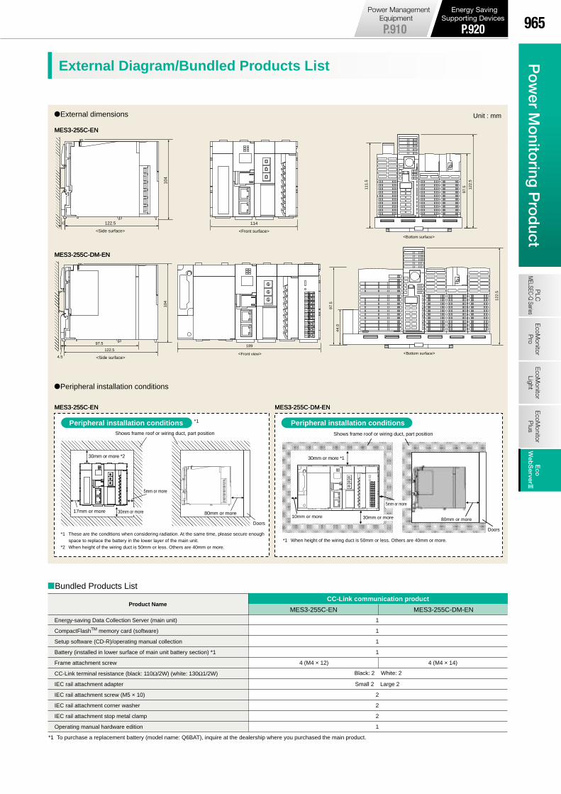
When setting (CH1) When connecting the PLC (CH2)
Power-supply section
Connecting point output section
Server communications section (LAN interface)
CC-Link communication section
When displaying graphsWhen displaying graphs
External dimensions
MES3-255C-ENMES3-255C-EN
Peripheral installation conditions
MES3-255C-ENMES3-255C-EN MES3-255C-DM-ENMES3-255C-DM-EN
MES3-255C-DM-ENMES3-255C-DM-EN
Connection Diagram External Diagram/Bundled Products List
Where the transaction meter of the multi-measuring power demand meter is 10,000pulse/kWh
Model: MES3-255C-EN, MES3-255C-DM-EN
Demand monitor section
Local station
CC-Link dedicated cable
Local station
(B)
(W)
(Y)
(B)
(W)
(Y)
(B)
(W)
(Y)
(B)
(W)
(Y)
DA
DB
DG
SLD
FG
DA
DB
DG
SLD
FG
DA
DB
DG
SLD
FG
0 1 2 3 4 5 6 78 9 A B C D E F
1
3
5
7
9
B
D
F
0
2
4
6
8
A
C
E
COM
CH1
LAN cable(straight or cross)
Computer
Attached CD(setting window)
CH2 LAN cable(straight or cross)
LAN cable(straight or cross)
LAN cable(straight)
Hub Hub
CH1
CH2
Client computer
Hub Hub
CH1
CH2
LAN cable(straight or cross)
D-type ground
ERR+
ERR–
FG
LG
N
L
AC100 to 240V
* MES3-255C-DM* MES3-255C D-type groundAC100 to 240V
Electricity Meter
Demand Unit
LOADLOADLOADLOADLOADLOADLOADLOADLOADLOADLOADLOADLOADLOADLOADLOAD
<Side surface>
122.5
104
4.5
<Front surface>
114
<Bottom surface>
111.
5
122.
5
97.5
30mm or more *2
17mm or more
5mm or more
Shows frame roof or wiring duct, part position
80mm or more
Doors
Unit : mm
Peripheral installation conditions *1 Peripheral installation conditions
189
<Front view>
122.
5
<Bottom surface>122.5
4.5
97.5
104
<Side surface>
MES3-255C-EN MES3-255C-DM-ENProduct Name
CC-Link communication product
Energy-saving Data Collection Server (main unit)
CompactFlashTM memory card (software)
Setup software (CD-R)/operating manual collection
Battery (installed in lower surface of main unit battery section) *1
Frame attachment screw
CC-Link terminal resistance (black: 110Ω/2W) (white: 130Ω1/2W)
IEC rail attachment adapter
IEC rail attachment screw (M5 × 10)
IEC rail attachment corner washer
IEC rail attachment stop metal clamp
Operating manual hardware edition
*1 To purchase a replacement battery (model name: Q6BAT), inquire at the dealership where you purchased the main product.
1
1
1
1
Small 2 Large 2
2
2
2
1
Black: 2 White: 2
Shows frame roof or wiring duct, part position
30mm or more
30mm or more *1
5mm or more
30mm or more 80mm or more10mm or more
Doors
*1 When height of the wiring duct is 50mm or less. Others are 40mm or more.
4 (M4 × 12) 4 (M4 × 14)
D
N
S
97.5
44.0
Bundled Products List
AC100V
VT
CT
LAN network onsite
Production equipment,
LAN network
Ethernet/Serialconverter
To PLC calculator link
unit
To PLC Ethernet port/ Ethernet unit
Operation of Ethernet/serial converter can be confirmed using the following product.Line Eye SI-65
100/200VAC or 24VDC
CC-Link dedicated cable
Energy-saving data collection server (master station)
Terminating resistance
(110Ω, 1/2W)
Terminating resistance
(110Ω, 1/2W)
*1 These are the conditions when considering radiation. At the same time, please secure enough space to replace the battery in the lower layer of the main unit.
*2 When height of the wiring duct is 50mm or less. Others are 40mm or more.
965P
ow
er Mo
nitoring
Pro
duct
EcoM
onitorP
roP
LCM
ELSEC-Q SeriesE
coMonitor
LightE
coMonitor
Plus
Eco
WebS
erver3E
coW
ebS
erver#
Power Management Equipment
P.910
Energy Saving Supporting Devices
P.920

(1) Easily create daily, monthly and annual reports.
• Ledger prepared ledger is saved as an Excel file in user-designated place.
(2) Easily perform specific consumption management as the index of energy-saving activities.
• Possible to manually input production volume and perform specific consumption
management of energy information from EcoWebServer3 and E-Energy.
• Possible to prepare each specific consumption graph (zoom, daily, weekly and monthly).
(3) Easily collect data.
• CSV files stored in EcoWebServer3 and E-Energy can be downloaded with simple
operations.
This software supports the specific consumption analysis graph and ledger preparation of daily reports, monthly reports and annual
reports from CSV files collected and output by the Mitsubishi Electric EcoWebServer3 Energy-saving Data Collection Server.
* The supporting product version, EcoWebServer3 with demand monitoring function, for EcoMeasure3, will be released soon.
Number of licenses ( number of computers installed in )
*1 It needs to start in the Chinese version of Microsoft operating system (OS).*2 If virtual measurement points for input or measurement points for E-Energy are included, no zoom specific consumption is displayed.*3 Note that the required memory and available hard-disk space may vary depending on the system environment.*4 Shows the capacity required when used with maximum eight subsystems connected.
• 1 license per 1 client• Hardware key attached (USB) (1 unit)
SpecificationsItemModel name
Number of units
Target devices
Number of virtual measurement points
Number of virtual measurement point groups
Maximum 95 points (Total of 95 points including virtual measurement points for calculating measurement management points and virtual measurement points for input.)* Four arithmetic operations of up to 64 measurement management points (including constants) can be registered in the virtual measurement points for calculation.
Maximum five groups *Addition/Subtraction calculations for up to 32 virtual measurement points can be registered in the virtual measurement point groups.
Daily report creation, monthly report creation, annual report creation
The daily, monthly and annual reports can have up to 2,250 output items.
Analog (including specific consumption) Maximum, minimum, average
Pulse Total, maximum, minimum, average
Demand Maximum
Daily specific consumption, weekly specific consumption, monthly specific consumption and zoom specific consumption *2
Maximum 100 points
Can set by each specific consumption
Specific consumption, target value, production volume, power used (kWh), accumulated power volume (kWh)* The specific consumption/target value/production volume units can be set freely.
Auto-scale function
Daily/weekly/ monthly specific consumption Power volume (kWh), production volume, specific consumption, accumulated power volume (kWh), accumulated production amount, specific consumption target value
Zoom specific consumption Power volume (kWh), production volume, specific consumption, power use/hour
Daily/weekly/ zoom specific consumption Contents of display newly updated at designated time once per hour each hour
Monthly specific consumption Contents of display newly updated at designated time once per day each day
Microsoft Windows Vista® (32bit) (SP2) Home Basic / Home Premium / Business / Enterprise / UltimateMicrosoft Windows Server 2003(32bit) (SP2) StandardMicrosoft Windows 7(32bit/64bit)(SP1) ProfessionalMicrosoft Windows 8.1 Pro(32bit/64bit)Microsoft Windows 10 Pro(32bit/64bit)Microsoft Excel 2003(SP3) / 2007(SP3) / 2010(32bit/64bit)(SP1)
If using Windows XP : Pentium processor of 400MHz or higher or a compatible microprocessor (DOS/V- compatible)If using Windows Vista® or Windows 7 : As recommended for the operating system
OS
(basic software)
Required software
As recommended for the operating system
Software: Approx. 100MB or more Data: 8GB or more *4
1 drive (for installing software)
10/100/1000BASE-T ×1
1 connector (for connecting hardware key)
800×600 pixels or more
256 colors or more
CPU
Memory *3
Hard-disk *3
CD-ROM drive
LAN
USB connector (Type A)
Display resolution
Display color
EcoWebServer3
MES3-SW1-DR-FR
Language English, Chinese *1
8 units maximum (combination of following target devices)
Ledger creation
Maximum number of items
Calculation items
Specific consumption display
Number of specific consumption
Specific consumption target value
Graph display
List display
Automatic updating
[Daily Report] [Monthly Report] [Annual Report]
Connection devices
Ledger creation function
Operation environment
Specific consumption management
function
Support Terminal Related Products
EcoMeasure# daily/monthly report specific consumption analysis software
Features Product Appearance
Specifications
MES3-255C-EN, MES3-255C-DM-EN (CC-Link)Product Name Icon/type name Station type Number of occupying stations
EnergyMeasuringUnit (1P2W, 1P3W, 3P3W) EMU4-BD1-MB Remote device station 1 station occupied
EnergyMeasuringUnit (1P2W, 1P3W, 3P3W, 3P4W) EMU4-HD1-MB Remote device station 1 station occupied
EnergyMeasuringUnit (1P2W, 1P3W, 3P3W, 3P4W) EMU4-FD1-MB Remote device station 1 station occupied
Energy measuring standard model *1 EMU4-BM1-MB Remote device station 1 station occupied
Energy measuring high performance model *1 EMU4-HM1-MB Remote device station 1 station occupied
Insulation Monitoring model *1 EMU4-LG1-MB Remote device station 1 station occupied
Energy measuring extension model for same voltage system *2 EMU4-A2 Remote device station *3
Energy measuring extension model for different voltage system *2 EMU4-VA2 Remote device station *3
Energy measuring extension model for analog input *2 EMU4-AX4 Remote device station *3
Energy measuring extension model for pulse/digital input *2 EMU4-PX4 Remote device station *3
EnergyMeasuringUnit (Power reception and distribution monitoring (standard product 3 circuits)) EMU2-RD3-C Remote device station 1 station occupied
EnergyMeasuringUnit (Power reception and distribution monitoring (standard product 5 circuits)) EMU2-RD5-C Remote device station 1 station occupied
EnergyMeasuringUnit (Power reception and distribution monitoring (standard product 7 circuits)) EMU2-RD7-C Remote device station 1 station occupied
EnergyMeasuringUnit (Power reception and distribution monitoring (3P4W 2 circuits)) EMU2-RD2-C-4W Remote device station 1 station occupied
EnergyMeasuringUnit (Power reception and distribution monitoring (3P4W 4 circuits)) EMU2-RD4-C-4W Remote device station 1 station occupied
EnergyMeasuringUnit EMU3-DP1-C Remote device station 1 station occupied
MDU breaker (WS-V) MDU(WS-V) NF250-SEV/HEV with MDU Remote device station 1 station occupied
MDU breaker (WS) MDU(WS)NF400-SEP/HEP with MDUNF600-SEP/HEP with MDUNF800-SEP/HEP with MDU
Remote device station 1 station occupied
Low-voltage air circuit breaker (AE-SW with CC-Link interface unit) AE-SW(BIF-CC) Remote device station 1 station occupied
Electronic multi-measuring instrument ME96SSHA-MB Remote device station 1 station occupied
Electronic multi-measuring instrument ME96SSRA-MB Remote device station 1 station occupied
Electronic multi-measuring instrument ME96SSH-MB Remote device station 1 station occupied
Electronic multi-measuring instrument ME96SSR-MB Remote device station 1 station occupied
Electronic multi-measuring instrument ME96NSR Remote device station 1 station occupied
Electronic multi-measuring instrument with transmission function ME110SSR-C(H) Remote device station 1 station occupied
Electronic multi-measuring instrument with transmission function ME110NSR-C Remote device station 1 station occupied
Thermocouple temperature input unit AJ65BT-68TD Remote device station 4 station occupied
Platinum resistance temperature sensor Pt 100 temperature input unit AJ65BT-64RD3 Remote device station 4 station occupied
Analog-digital conversion unit AJ65BT-64AD Remote device station 2 station occupied
Terminal block type 24 VDC input unit (8 points) AJ65SBTB1-8D Remote I/O station 1 station occupied
Terminal block type 24 VDC input unit (16 points) AJ65SBTB1-16D Remote I/O station 1 station occupied
Terminal block type 24 VDC input unit (32 points) AJ65SBTB1-32D Remote I/O station 1 station occupied
Terminal block type DC input transistor output combined unit (Input 8 points, Output 8 points) AJ65SBTB1-16DT Remote I/O station 1 station occupied
Terminal block type DC input transistor output combined unit (Input 16 points, Output 16 points) AJ65SBTB1-32DT Remote I/O station 1 station occupied
CC-Link master/local unit (Local station) QJ61BT11N Intelligent device station 1 station occupied
CC-Link master/local unit (Local station) LCPU/LJ61BT11 Intelligent device station 1 station occupied
*1 EMU4-BM1-MB, EMU4-HM1-MB, EMU4-LG1-MB are main units of EcoMonitorPlus.*2 EMU4-A2, EMU4-VA2, EMU4-AX4, EMU4-PX4 are extension units of EcoMonitorPlus.*3 Conbination of main unit and extension unit occupied 1 station.
MES3-255C-EN, MES3-255C-DM-EN (MODBUS®)Product Name Icon/type name
Electronic multi-measuring instrument ME96SSHA-MB
Electronic multi-measuring instrument ME96SSRA-MB
Electronic multi-measuring instrument ME96SSEA-MB
Electronic multi-measuring instrument ME96SSH-MB
Electronic multi-measuring instrument ME96SSR-MB
Electronic multi-measuring instrument ME96SSE-MB
EnergyMeasuringUnit (1P2W, 1P3W, 3P3W) EMU4-BD1-MB
EnergyMeasuringUnit (1P2W, 1P3W, 3P3W, 3P4W) EMU4-HD1-MB
EnergyMeasuringUnit (1P2W, 1P3W, 3P3W, 3P4W) EMU4-FD1-MB
Energy measuring standard model *1 EMU4-BM1-MB
Energy measuring high performance model *1 EMU4-HM1-MB
Insulation Monitoring model *1 EMU4-LG1-MB
Energy measuring extension model for same voltage system *2 EMU4-A2
Energy measuring extension model for different voltage system *2 EMU4-VA2
Energy measuring extension model for analog input *2 EMU4-AX4
Energy measuring extension model for pulse/digital input *2 EMU4-PX4
*1 EMU4-BM1-MB, EMU4-HM1-MB, EMU4-LG1-MB are main units of EcoMonitorPlus.*2 EMU4-A2, EMU4-VA2, EMU4-AX4, EMU4-PX4 are extension units of EcoMonitorPlus.
966 省省省省省省省Energy-saving Data Collection Server EcoWebServer3P
ow
er M
oni
tori
ng P
rod
uct
Eco
Mon
itor
Pro
PLC
MEL
SEC-
Q Se
ries
Eco
Mon
itor
Ligh
tE
coM
onito
rP
lus
Eco
Web
Ser
ver 3
Eco
Web
Ser
ver #
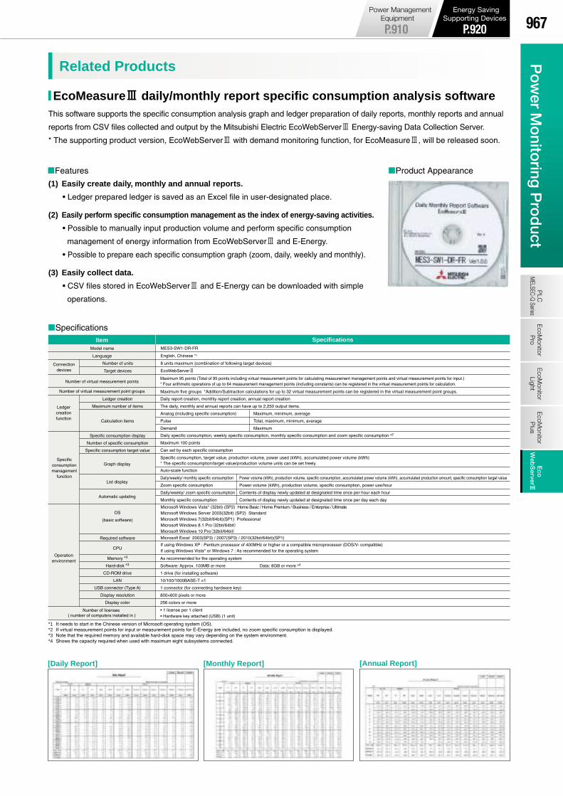
(1) Easily create daily, monthly and annual reports.
• Ledger prepared ledger is saved as an Excel file in user-designated place.
(2) Easily perform specific consumption management as the index of energy-saving activities.
• Possible to manually input production volume and perform specific consumption
management of energy information from EcoWebServer3 and E-Energy.
• Possible to prepare each specific consumption graph (zoom, daily, weekly and monthly).
(3) Easily collect data.
• CSV files stored in EcoWebServer3 and E-Energy can be downloaded with simple
operations.
This software supports the specific consumption analysis graph and ledger preparation of daily reports, monthly reports and annual
reports from CSV files collected and output by the Mitsubishi Electric EcoWebServer3 Energy-saving Data Collection Server.
* The supporting product version, EcoWebServer3 with demand monitoring function, for EcoMeasure3, will be released soon.
Number of licenses ( number of computers installed in )
*1 It needs to start in the Chinese version of Microsoft operating system (OS).*2 If virtual measurement points for input or measurement points for E-Energy are included, no zoom specific consumption is displayed.*3 Note that the required memory and available hard-disk space may vary depending on the system environment.*4 Shows the capacity required when used with maximum eight subsystems connected.
• 1 license per 1 client• Hardware key attached (USB) (1 unit)
SpecificationsItemModel name
Number of units
Target devices
Number of virtual measurement points
Number of virtual measurement point groups
Maximum 95 points (Total of 95 points including virtual measurement points for calculating measurement management points and virtual measurement points for input.)* Four arithmetic operations of up to 64 measurement management points (including constants) can be registered in the virtual measurement points for calculation.
Maximum five groups *Addition/Subtraction calculations for up to 32 virtual measurement points can be registered in the virtual measurement point groups.
Daily report creation, monthly report creation, annual report creation
The daily, monthly and annual reports can have up to 2,250 output items.
Analog (including specific consumption) Maximum, minimum, average
Pulse Total, maximum, minimum, average
Demand Maximum
Daily specific consumption, weekly specific consumption, monthly specific consumption and zoom specific consumption *2
Maximum 100 points
Can set by each specific consumption
Specific consumption, target value, production volume, power used (kWh), accumulated power volume (kWh)* The specific consumption/target value/production volume units can be set freely.
Auto-scale function
Daily/weekly/ monthly specific consumption Power volume (kWh), production volume, specific consumption, accumulated power volume (kWh), accumulated production amount, specific consumption target value
Zoom specific consumption Power volume (kWh), production volume, specific consumption, power use/hour
Daily/weekly/ zoom specific consumption Contents of display newly updated at designated time once per hour each hour
Monthly specific consumption Contents of display newly updated at designated time once per day each day
Microsoft Windows Vista® (32bit) (SP2) Home Basic / Home Premium / Business / Enterprise / UltimateMicrosoft Windows Server 2003(32bit) (SP2) StandardMicrosoft Windows 7(32bit/64bit)(SP1) ProfessionalMicrosoft Windows 8.1 Pro(32bit/64bit)Microsoft Windows 10 Pro(32bit/64bit)Microsoft Excel 2003(SP3) / 2007(SP3) / 2010(32bit/64bit)(SP1)
If using Windows XP : Pentium processor of 400MHz or higher or a compatible microprocessor (DOS/V- compatible)If using Windows Vista® or Windows 7 : As recommended for the operating system
OS
(basic software)
Required software
As recommended for the operating system
Software: Approx. 100MB or more Data: 8GB or more *4
1 drive (for installing software)
10/100/1000BASE-T ×1
1 connector (for connecting hardware key)
800×600 pixels or more
256 colors or more
CPU
Memory *3
Hard-disk *3
CD-ROM drive
LAN
USB connector (Type A)
Display resolution
Display color
EcoWebServer3
MES3-SW1-DR-FR
Language English, Chinese *1
8 units maximum (combination of following target devices)
Ledger creation
Maximum number of items
Calculation items
Specific consumption display
Number of specific consumption
Specific consumption target value
Graph display
List display
Automatic updating
[Daily Report] [Monthly Report] [Annual Report]
Connection devices
Ledger creation function
Operation environment
Specific consumption management
function
Support Terminal Related Products
EcoMeasure# daily/monthly report specific consumption analysis software
Features Product Appearance
Specifications
967P
ow
er Mo
nitoring
Pro
duct
EcoM
onitorP
roP
LCM
ELSEC-Q SeriesE
coMonitor
LightE
coMonitor
Plus
Eco
WebS
erver3E
coW
ebS
erver#
Power Management Equipment
P.910
Energy Saving Supporting Devices
P.920

Customer
Mitsubishi Electric will support migration of equipment for the customer in cooperation with the sales representative.
[Quality improvement][Promotion of energy saving]
[Visualization] [Automation][Safety and security measures]
Mitsubishi PLCs Mitsubishi micro PLCs Mitsubishi inverters
Mitsubishi AC servos
Mitsubishi industrial robots
Control equipmentNot only various functions, high speed, large capacity and extensive networking but also top class reliability are proved by long-term actual achievements.
Selecting the proper latest modelDownsizing and space savingReplacing existing products manufactured by
other companies with Mitsubishi productsImproving the maintainability
High-speed, high-accuracy controlSmart wiringHigh-speed, large-capacity communicationNetworking
Standardizing the maintenance toolUtilizing the GOTQuick recovery from machine alarmsSupporting and implementing energy saving
Utilizing the software assets and resourcesImproving the operabilityStep-by-step migrationPreventive maintenance realized by
migration
Acquiring, judging and analyzing dataImage recognition inspectionAutomating inspections and judgmentsSafety control equipment
Automation and labor saving by robotsDuplicating the CPUConstructing the MES (manufacturing execution system)
1Step
2Step
Drive equipment
Product life
Even if a unit is operating normally, the failure rate is high because each part is worn out and damages (related to the power ON time, surge, etc.) are accumulated.
Random failure period
Used yearsta tb
Fai
lure
rat
e
*Aluminum electrolytic capacitors, fuses, relays, etc.
Maintenance of electrical equipmentAmbient environmentChecking stored programs
Service life
10years
3Step
Mitsubishi Electric will propose a variety of products and functions based on various keywords to eliminate concerns of customers.
5years
Equipment System Migration in 3 Steps
Data can be acquired and analyzed quickly!
Migration requires only small cost!
Migration has realized energy-saving and
environment friendly.
We would like to preventive maintenance.
We would like to acquire and analyze
data quickly.
We do not have enough workers engaged in examination for
improvements and migration.
We cannot afford large cost required for new equipment or
modifying the existing equipment.
We would like to improve the productivity and quality without
changing the existing equipment.
Automated production expanded, and the
efficiency improved.
The productivity and quality are improved
using the existing equipment!
We would like to save energy, and be environmentally
friendly.
Mitsubishi Electric supports stable supply of electric power with its wide variety of products in the distribution control field, and proposes aggressive energy saving achieved by migration.
Sales representative
Replacing a unit whose service life is expired
[Productivity improvement]
Mitsubishi low-voltage distribution control equipment
Distribution control equipment
Preventive maintenance of equipment and devices is required to use FA equipment for a long time.
Preventive maintenance and product life
[Stable operation] [Extension of equipment service life] [Preventive maintenance]
Periodic maintenance and inspection (Visual inspection)
Daily maintenance and inspection (Visual inspection)
Mitsubishi Electric’s motor control technology is advancing everyday. Mitsubishi drive equipment contribute to the realization of not only high functions and high performance but also energy saving.
Losses in the maintenance work reduced by
adopting one manufacturer for various equipment!
There are two concepts of preventive maintenance.
Mitsubishi Electric recommends overhaul maintenance of FA equipment in 5 years since the start of operation.
Mitsubishi Electric recommends 10 years as the service life of FA equipment.
Maintenance of units (to prevent short-circuit by removing dust and adhering substances)
Replacement of parts requiring periodic replacement (such as fuses, batteries and memory cards)
Overhaul of units incorporating parts having limited service life*
Mitsubishi
Electric
Indicator lamps (in the equipment main body, devices and units)
Equipment mounting statusCable connection status
Overhaul maintenance
Wear-out failure period
Initial failureperiod
MS-Tseries
Mitsubishi graphic operation terminals
B-01
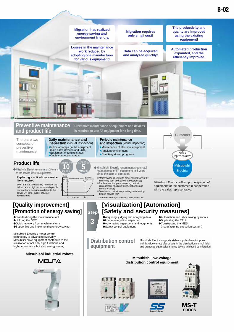
Customer
Mitsubishi Electric will support migration of equipment for the customer in cooperation with the sales representative.
[Quality improvement][Promotion of energy saving]
[Visualization] [Automation][Safety and security measures]
Mitsubishi PLCs Mitsubishi micro PLCs Mitsubishi inverters
Mitsubishi AC servos
Mitsubishi industrial robots
Control equipmentNot only various functions, high speed, large capacity and extensive networking but also top class reliability are proved by long-term actual achievements.
Selecting the proper latest modelDownsizing and space savingReplacing existing products manufactured by
other companies with Mitsubishi productsImproving the maintainability
High-speed, high-accuracy controlSmart wiringHigh-speed, large-capacity communicationNetworking
Standardizing the maintenance toolUtilizing the GOTQuick recovery from machine alarmsSupporting and implementing energy saving
Utilizing the software assets and resourcesImproving the operabilityStep-by-step migrationPreventive maintenance realized by
migration
Acquiring, judging and analyzing dataImage recognition inspectionAutomating inspections and judgmentsSafety control equipment
Automation and labor saving by robotsDuplicating the CPUConstructing the MES (manufacturing execution system)
1Step
2Step
Drive equipment
Product life
Even if a unit is operating normally, the failure rate is high because each part is worn out and damages (related to the power ON time, surge, etc.) are accumulated.
Random failure period
Used yearsta tb
Fai
lure
rat
e
*Aluminum electrolytic capacitors, fuses, relays, etc.
Maintenance of electrical equipmentAmbient environmentChecking stored programs
Service life
10years
3Step
Mitsubishi Electric will propose a variety of products and functions based on various keywords to eliminate concerns of customers.
5years
Equipment System Migration in 3 Steps
Data can be acquired and analyzed quickly!
Migration requires only small cost!
Migration has realized energy-saving and
environment friendly.
We would like to preventive maintenance.
We would like to acquire and analyze
data quickly.
We do not have enough workers engaged in examination for
improvements and migration.
We cannot afford large cost required for new equipment or
modifying the existing equipment.
We would like to improve the productivity and quality without
changing the existing equipment.
Automated production expanded, and the
efficiency improved.
The productivity and quality are improved
using the existing equipment!
We would like to save energy, and be environmentally
friendly.
Mitsubishi Electric supports stable supply of electric power with its wide variety of products in the distribution control field, and proposes aggressive energy saving achieved by migration.
Sales representative
Replacing a unit whose service life is expired
[Productivity improvement]
Mitsubishi low-voltage distribution control equipment
Distribution control equipment
Preventive maintenance of equipment and devices is required to use FA equipment for a long time.
Preventive maintenance and product life
[Stable operation] [Extension of equipment service life] [Preventive maintenance]
Periodic maintenance and inspection (Visual inspection)
Daily maintenance and inspection (Visual inspection)
Mitsubishi Electric’s motor control technology is advancing everyday. Mitsubishi drive equipment contribute to the realization of not only high functions and high performance but also energy saving.
Losses in the maintenance work reduced by
adopting one manufacturer for various equipment!
There are two concepts of preventive maintenance.
Mitsubishi Electric recommends overhaul maintenance of FA equipment in 5 years since the start of operation.
Mitsubishi Electric recommends 10 years as the service life of FA equipment.
Maintenance of units (to prevent short-circuit by removing dust and adhering substances)
Replacement of parts requiring periodic replacement (such as fuses, batteries and memory cards)
Overhaul of units incorporating parts having limited service life*
Mitsubishi
Electric
Indicator lamps (in the equipment main body, devices and units)
Equipment mounting statusCable connection status
Overhaul maintenance
Wear-out failure period
Initial failureperiod
MS-Tseries
Mitsubishi graphic operation terminals
B-02
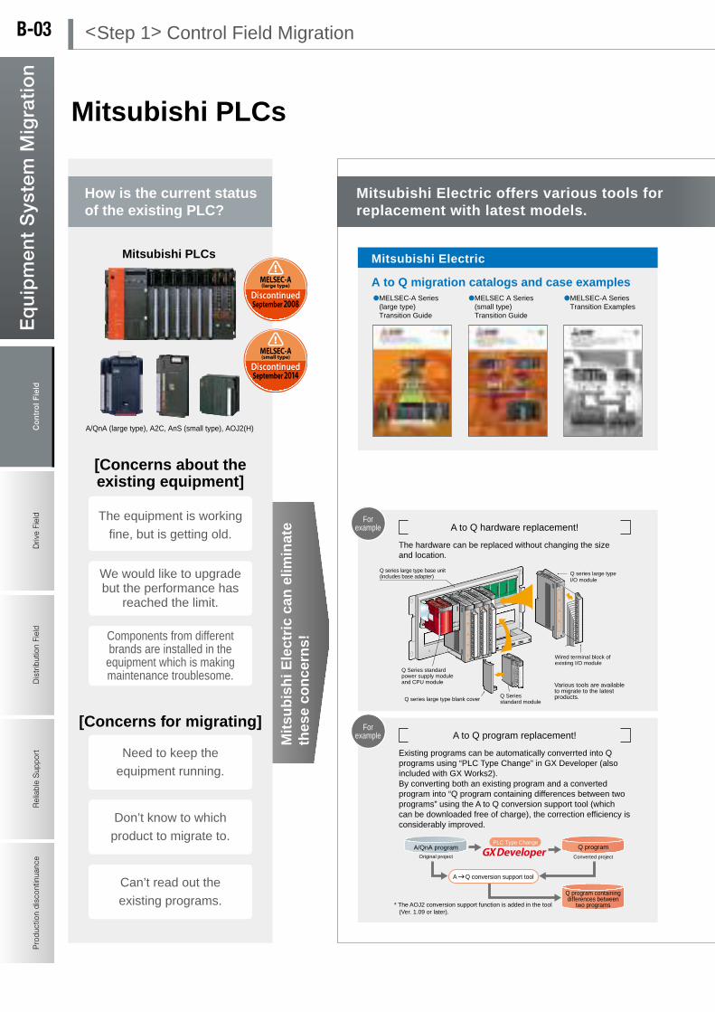
Con
trol
Fie
ldD
rive
Fiel
dD
istr
ibut
ion
Fiel
dR
elia
ble
Sup
port
Pro
duct
ion
disc
ontin
uanc
eE
qu
ipm
ent
Sys
tem
Mig
rati
on
Control F
ieldD
rive FieldD
istribution FieldR
eliable Support
Production discontinuance
Eq
uip
men
t System
Mig
ration
Mitsubishi PLCs
A/QnA (large type), A2C, AnS (small type), AOJ2(H)
A to Q migration catalogs and case examples
Mitsubishi Electric
MELSEC-A Series (large type) Transition Guide
A to Q hardware replacement!
Partner manufacturers
Mitsubishi ElectricEngineering Co., Ltd.
Mitsubishi ElectricSystem & Service Co., Ltd.
Network replacement!
[Benefits of migration]
[Concerns for migrating]
Mitsubishi PLCs
MELSEC A Series (small type) Transition Guide
A to Q migration tool catalogsMigration tool catalogsMELSEC-A Series
Transition Examples
Q series large type blank cover
Q series large type base unit(includes base adapter) Q series large type
I/O module
A to Q program replacement!
Existing programs can be automatically converrted into Q programs using “PLC Type Change” in GX Developer (also included with GX Works2).By converting both an existing program and a converted program into “Q program containing differences between two programs” using the A to Q conversion support tool (which can be downloaded free of charge), the correction efficiency is considerably improved.
A/QnA programOriginal project
PLC Type Change
Converted project
Q program
* The AOJ2 conversion support function is added in the tool (Ver. 1.09 or later).
MELSECNET(@)/B
MELSECNET/H(10)
MELSECNET/H(10)
MELSECNET(@)/B
Existing system
System being transferred
System in which replacement is completed
Gateway(Relay station)
3 year warranty!
DiscontinuedSeptember 2008
MELSEC-A(large type)
September 2014
MELSEC-A(small type)
Discontinued
A Q conversion support tool
P.118P.88
Mitsubishi PLCs
P.10
Mitsubishi data link system “MELSECNET”
can be replaced in various methods.
Various tools are available to migrate to the latest products.
How is the current status of the existing PLC?
Mitsubishi Electric offers various tools for replacement with latest models.
Enhanced program security function!
The control panel can be downsized.
Abundant lineup enables selection of product
suitable for the required specifications.
Improve efficiency with various convenient
instructions!
High speed and large capacity CPU!
Q Series standard power supply module and CPU module
Q Series standard module
Wired terminal block of existing I/O module
Can’t read out the
existing programs.
Don’t know to which
product to migrate to.
Need to keep the
equipment running.
Components from different brands are installed in the equipment which is making maintenance troublesome.
We would like to upgrade but the performance has
reached the limit.
The equipment is working
fine, but is getting old.
[Concerns about the existing equipment]
For example
For example
For example
Q program containing differences between
two programs
Mit
sub
ish
i Ele
ctri
c ca
n e
limin
ate
thes
e co
nce
rns!
Easy connection with multiple
communication ports!
Mitsubishi supports migration with various
tools and accumulated know-how.
The hardware can be replaced without changing the size and location.
Tools to easily migrate from A series to Q series available.
Migrate to the latest Mitsubishi PLCs!!
< Step 1 > Control Field MigrationB-03

Con
trol
Fie
ldD
rive
Fiel
dD
istr
ibut
ion
Fiel
dR
elia
ble
Sup
port
Pro
duct
ion
disc
ontin
uanc
eE
qu
ipm
ent
Sys
tem
Mig
rati
on
Control F
ieldD
rive FieldD
istribution FieldR
eliable Support
Production discontinuance
Eq
uip
men
t System
Mig
ration
Mitsubishi PLCs
A/QnA (large type), A2C, AnS (small type), AOJ2(H)
A to Q migration catalogs and case examples
Mitsubishi Electric
MELSEC-A Series (large type) Transition Guide
A to Q hardware replacement!
Partner manufacturers
Mitsubishi ElectricEngineering Co., Ltd.
Mitsubishi ElectricSystem & Service Co., Ltd.
Network replacement!
[Benefits of migration]
[Concerns for migrating]
Mitsubishi PLCs
MELSEC A Series (small type) Transition Guide
A to Q migration tool catalogsMigration tool catalogsMELSEC-A Series
Transition Examples
Q series large type blank cover
Q series large type base unit(includes base adapter) Q series large type
I/O module
A to Q program replacement!
Existing programs can be automatically converrted into Q programs using “PLC Type Change” in GX Developer (also included with GX Works2).By converting both an existing program and a converted program into “Q program containing differences between two programs” using the A to Q conversion support tool (which can be downloaded free of charge), the correction efficiency is considerably improved.
A/QnA programOriginal project
PLC Type Change
Converted project
Q program
* The AOJ2 conversion support function is added in the tool (Ver. 1.09 or later).
MELSECNET(@)/B
MELSECNET/H(10)
MELSECNET/H(10)
MELSECNET(@)/B
Existing system
System being transferred
System in which replacement is completed
Gateway(Relay station)
3 year warranty!
DiscontinuedSeptember 2008
MELSEC-A(large type)
September 2014
MELSEC-A(small type)
Discontinued
A Q conversion support tool
P.118P.88
Mitsubishi PLCs
P.10
Mitsubishi data link system “MELSECNET”
can be replaced in various methods.
Various tools are available to migrate to the latest products.
How is the current status of the existing PLC?
Mitsubishi Electric offers various tools for replacement with latest models.
Enhanced program security function!
The control panel can be downsized.
Abundant lineup enables selection of product
suitable for the required specifications.
Improve efficiency with various convenient
instructions!
High speed and large capacity CPU!
Q Series standard power supply module and CPU module
Q Series standard module
Wired terminal block of existing I/O module
Can’t read out the
existing programs.
Don’t know to which
product to migrate to.
Need to keep the
equipment running.
Components from different brands are installed in the equipment which is making maintenance troublesome.
We would like to upgrade but the performance has
reached the limit.
The equipment is working
fine, but is getting old.
[Concerns about the existing equipment]
For example
For example
For example
Q program containing differences between
two programs
Mit
sub
ish
i Ele
ctri
c ca
n e
limin
ate
thes
e co
nce
rns!
Easy connection with multiple
communication ports!
Mitsubishi supports migration with various
tools and accumulated know-how.
The hardware can be replaced without changing the size and location.
Tools to easily migrate from A series to Q series available.
Migrate to the latest Mitsubishi PLCs!!
B-04

Con
trol
Fie
ldD
rive
Fiel
dD
istr
ibut
ion
Fiel
dR
elia
ble
Sup
port
Pro
duct
ion
disc
ontin
uanc
eE
qu
ipm
ent
Sys
tem
Mig
rati
on
Control F
ieldD
rive FieldD
istribution FieldR
eliable Support
Production discontinuance
Eq
uip
men
t System
Mig
ration
Mitsubishi Micro PLCs
F1, F1J, F2, FX1, FX2, FX2C,
FX0, FX0S, FX0N, FX1S, FX1N, FX1NC,
FX2N, FX2NC
Migration catalog
FX Migration Guide
F (F1, F1J, F2) series replacement! Legacy FX series replacement!
Programming software
Mitsubishi micro PLCs
Migration Guide from FX2N/FX2NC to FX3
Migration Guide from FX1N/FX1NC to FX3
The F (F1, F1J, F2) series can be replaced by the FX series while reading out existing programs using the combination “FX-20P + FX-20P-FKIT”.After existing programs are transferred to the FX series, they can be corrected and debugged using GX Works2.
Legacy FX series program can be
transferred to the latest product by using
PC type change function of GX Works2.
Replacing wiring!
Large size legacy product can be replaced easily
with connector type FX series PLC and terminal
block product of partner vendors.(Connector type requires 24 V DC power supply)
3 year warranty!
The combination “FX-20P + FX-20P-FKIT” is available.
FX-20P-FKIT
* Contact your local dealer.
F1/F1J/F2 PLC
FX-20P
GX Works2
Legacy MELSEC-F product
Migrate
FX2N/FX2NC
DiscontinuedSeptember 2012
DiscontinuedDecember 2012
FX-20P
FX1S/FX1N/FX1NCTo be discontinuedDecember 2015
[Concerns for migrating]
GX Works2
Mitsubishi micro PLCs
P.134
P.48
Mitsubishi micro PLCs
[Benefits of migration]
Micro PLCs are downsized compared to legacy models, and
can fit into the existing space. Programs can be replaced with
FX-20P-FKIT for F series or with GX Works2 for FX series.
For example
Mitsubishi Electric offers various tools for replacement with latest models.
How is the current status of the existing PLC?
[Concerns about the existing equipment]
Output terminal block
Input terminal block
In case the product size is large and the wiring is short
High-function and compact extension
modules are available!
Enhanced program security function!
Improve efficiency with various convenient
instructions!
Abundant lineup enables selection of product
suitable for the required specifications.
Convenient built-in functions enable system configuration at low cost!
Expansion boards enable expansion
at low cost!
Can’t read out the existing programs.
Don’t know to which
product to migrate to.
Need to keep the
equipment running.
Components from different brands are installed in the equipment which is making maintenance troublesome.
The equipment is working
fine, but is getting old.
For example
For example
Mit
sub
ish
i Ele
ctri
c ca
n e
limin
ate
thes
e co
nce
rns!
We would like to upgrade but the performance
has reached the limit.
Easy connection with multiple
communication ports!
Migrate to the latest Mitsubishi PLCs!!
< Step 1 > Control Field MigrationB-05

Con
trol
Fie
ldD
rive
Fiel
dD
istr
ibut
ion
Fiel
dR
elia
ble
Sup
port
Pro
duct
ion
disc
ontin
uanc
eE
qu
ipm
ent
Sys
tem
Mig
rati
on
Control F
ieldD
rive FieldD
istribution FieldR
eliable Support
Production discontinuance
Eq
uip
men
t System
Mig
ration
Mitsubishi Micro PLCs
F1, F1J, F2, FX1, FX2, FX2C,
FX0, FX0S, FX0N, FX1S, FX1N, FX1NC,
FX2N, FX2NC
Migration catalog
FX Migration Guide
F (F1, F1J, F2) series replacement! Legacy FX series replacement!
Programming software
Mitsubishi micro PLCs
Migration Guide from FX2N/FX2NC to FX3
Migration Guide from FX1N/FX1NC to FX3
The F (F1, F1J, F2) series can be replaced by the FX series while reading out existing programs using the combination “FX-20P + FX-20P-FKIT”.After existing programs are transferred to the FX series, they can be corrected and debugged using GX Works2.
Legacy FX series program can be
transferred to the latest product by using
PC type change function of GX Works2.
Replacing wiring!
Large size legacy product can be replaced easily
with connector type FX series PLC and terminal
block product of partner vendors.(Connector type requires 24 V DC power supply)
3 year warranty!
The combination “FX-20P + FX-20P-FKIT” is available.
FX-20P-FKIT
* Contact your local dealer.
F1/F1J/F2 PLC
FX-20P
GX Works2
Legacy MELSEC-F product
Migrate
FX2N/FX2NC
DiscontinuedSeptember 2012
DiscontinuedDecember 2012
FX-20P
FX1S/FX1N/FX1NCTo be discontinuedDecember 2015
[Concerns for migrating]
GX Works2
Mitsubishi micro PLCs
P.134
P.48
Mitsubishi micro PLCs
[Benefits of migration]
Micro PLCs are downsized compared to legacy models, and
can fit into the existing space. Programs can be replaced with
FX-20P-FKIT for F series or with GX Works2 for FX series.
For example
Mitsubishi Electric offers various tools for replacement with latest models.
How is the current status of the existing PLC?
[Concerns about the existing equipment]
Output terminal block
Input terminal block
In case the product size is large and the wiring is short
High-function and compact extension
modules are available!
Enhanced program security function!
Improve efficiency with various convenient
instructions!
Abundant lineup enables selection of product
suitable for the required specifications.
Convenient built-in functions enable system configuration at low cost!
Expansion boards enable expansion
at low cost!
Can’t read out the existing programs.
Don’t know to which
product to migrate to.
Need to keep the
equipment running.
Components from different brands are installed in the equipment which is making maintenance troublesome.
The equipment is working
fine, but is getting old.
For example
For example
Mit
sub
ish
i Ele
ctri
c ca
n e
limin
ate
thes
e co
nce
rns!
We would like to upgrade but the performance
has reached the limit.
Easy connection with multiple
communication ports!
Migrate to the latest Mitsubishi PLCs!!
B-06

Con
trol
Fie
ldD
rive
Fiel
dD
istr
ibut
ion
Fiel
dR
elia
ble
Sup
port
Pro
duct
ion
disc
ontin
uanc
eE
qu
ipm
ent
Sys
tem
Mig
rati
on
Control F
ieldD
rive FieldD
istribution FieldR
eliable Support
Production discontinuance
Eq
uip
men
t System
Mig
ration
Mitsubishi graphic operation terminals
GOT-A900 series
GOT-F900 series
Migration documents
Migration tool
[Benefits of migration]
[Concerns for migrating]
Mitsubishi graphic operation terminals
GOT-F900 Migration Guide
Documents for migrating GOT-F900 series
Replacement Guide
Mitsubishi Graphic Operation Terminals
GOT2000 seriesGOT1000 series
3 year warranty!
GT Designer2 classic
GT Designer3
* Excluding some models
GT Works3
GT Convertor2
P.566
Screen design software
DiscontinuedMarch 2009
GOT-A900
DiscontinuedMarch 2011
GOT-F900
GT Works3
GT Works3
Mitsubishi Graphic Operation Terminals
Check the equipment status using a web browser.Monitor your worksite anytime, anywhere.
For example
For example
For example
comes with the following software to
convert screen data from GOT-900 series
to GOT1000, GOT2000 series.
Optional attachment is
available for replacing
GOT-900 to GOT1000 series
with different screen size.
Screen data created in
the GOT-A800 series
SW3NIW-A8GOTP
Screen data created in
the GP-PRO/PB-III series
manufactured by Digital
Electronics Corporation
GT Works3 comes with GT Converter2 to convert screen data of legacy models and other brand HMI to GOT1000/GOT2000 series.
Mitsubishi Electric offers various tools for replacement with latest models.
How is the current status of the existing GOT?
[Concerns about the existing equipment]
Migrate to the latest Mitsubishi Graphic Operation Terminals!!
Abundant lineup enables selection of product
suitable for the required specifications.
Logging function to improve quality!
Decentralize control to GOT to assure stable
operation!
Improves visibility with brilliant color LCD!
Can be connected to various networks!
Front side USB port enables easy
maintenance*
Can we replace other brand HMI with
GOT1000 or GOT2000 series products?
Can the screen data be
replaced?
Do we have to drill holes
to replace?
Components from different brands are installed in the equipment which is making maintenance troublesome.
Screen datas are not
backed up.
The product is getting old
and is not well maintained.
Mit
sub
ish
i Ele
ctri
c ca
n e
limin
ate
thes
e co
nce
rns!
Easy connection with multiple
communication ports!
GOT series has same panel-cut dimensions when the screen size
is the same. Screen data can easily be replaced using GT Works3.
GOT with the latest functions can reduce loads on the PLC,
and can back up data.
Replacing of a Mitsubishi legacy product or other brand HMI!
Technical Bulletin for replacement of GOT-A900 with GOT1000
Technical Bulletin for replacement of GOT-1000 with GOT2000
< Step 1 > Control Field MigrationB-07
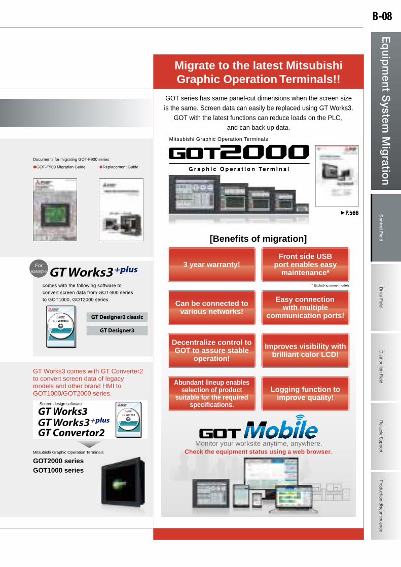
Con
trol
Fie
ldD
rive
Fiel
dD
istr
ibut
ion
Fiel
dR
elia
ble
Sup
port
Pro
duct
ion
disc
ontin
uanc
eE
qu
ipm
ent
Sys
tem
Mig
rati
on
Control F
ieldD
rive FieldD
istribution FieldR
eliable Support
Production discontinuance
Eq
uip
men
t System
Mig
ration
Mitsubishi graphic operation terminals
GOT-A900 series
GOT-F900 series
Migration documents
Migration tool
[Benefits of migration]
[Concerns for migrating]
Mitsubishi graphic operation terminals
GOT-F900 Migration Guide
Documents for migrating GOT-F900 series
Replacement Guide
Mitsubishi Graphic Operation Terminals
GOT2000 seriesGOT1000 series
3 year warranty!
GT Designer2 classic
GT Designer3
* Excluding some models
GT Works3
GT Convertor2
P.566
Screen design software
DiscontinuedMarch 2009
GOT-A900
DiscontinuedMarch 2011
GOT-F900
GT Works3
GT Works3
Mitsubishi Graphic Operation Terminals
Check the equipment status using a web browser.Monitor your worksite anytime, anywhere.
For example
For example
For example
comes with the following software to
convert screen data from GOT-900 series
to GOT1000, GOT2000 series.
Optional attachment is
available for replacing
GOT-900 to GOT1000 series
with different screen size.
Screen data created in
the GOT-A800 series
SW3NIW-A8GOTP
Screen data created in
the GP-PRO/PB-III series
manufactured by Digital
Electronics Corporation
GT Works3 comes with GT Converter2 to convert screen data of legacy models and other brand HMI to GOT1000/GOT2000 series.
Mitsubishi Electric offers various tools for replacement with latest models.
How is the current status of the existing GOT?
[Concerns about the existing equipment]
Migrate to the latest Mitsubishi Graphic Operation Terminals!!
Abundant lineup enables selection of product
suitable for the required specifications.
Logging function to improve quality!
Decentralize control to GOT to assure stable
operation!
Improves visibility with brilliant color LCD!
Can be connected to various networks!
Front side USB port enables easy
maintenance*
Can we replace other brand HMI with
GOT1000 or GOT2000 series products?
Can the screen data be
replaced?
Do we have to drill holes
to replace?
Components from different brands are installed in the equipment which is making maintenance troublesome.
Screen datas are not
backed up.
The product is getting old
and is not well maintained.
Mit
sub
ish
i Ele
ctri
c ca
n e
limin
ate
thes
e co
nce
rns!
Easy connection with multiple
communication ports!
GOT series has same panel-cut dimensions when the screen size
is the same. Screen data can easily be replaced using GT Works3.
GOT with the latest functions can reduce loads on the PLC,
and can back up data.
Replacing of a Mitsubishi legacy product or other brand HMI!
Technical Bulletin for replacement of GOT-A900 with GOT1000
Technical Bulletin for replacement of GOT-1000 with GOT2000
B-08

Con
trol
Fie
ldD
rive
Fie
ldD
istr
ibut
ion
Fiel
dR
elia
ble
Sup
port
Pro
duct
ion
disc
ontin
uanc
eE
qu
ipm
ent
Sys
tem
Mig
rati
on
Control Field
Drive F
ieldD
istribution FieldR
eliable Support
Production discontinuance
Eq
uip
men
t System
Mig
ration
Mitsubishi inverters
E500 S500
Migration documents
Convenient compatibility
Inverter migration proposal
[Benefits of migration]
[Concerns for migrating]
Mitsubishi inverters
Advantages of migration to the 800 series
The mounting compatibility with conventional models is secured.Mitsubishi Electric offers the (optional) mounting compatibility
attachment though the compatibility may be different in some models.
A500 F500
FR Configurator2
* Supports conversion from A500 to A800.
Convert function
FR-A700 FR-A800
Energy saving
Improved ease of maintenance
The FREQROL-F800 series is compatible with the IPM motor.
Replacement is easy due to frame number being the same as that of the standard three-phase motor.
Latest series use long service-life components and most advanced life diagnosis which improves ease of maintenance.
IPM motor with permanent magnet is more efficient than the high-performance energy-saving motors.
Efficiency level meets “IE4 (super premium efficiency)” of international standard IEC 60034-30. (As of March 2013)
Deterioration degree of main circuit capacitors, control circuit capacitors and rush current suppression circuits can be monitored.
Self-diagnosis function sounds alarm for components having limited service life to prevent failures.
[Efficiency comparison]
Ove
rall
effic
ienc
y
Approximate life of limited service life components
Part name
Cooling fan 10 years
10 years
10 years
2 to 3 years
5 years
5 years
A800 F800 E700 D700 P.556P.522P.490P.438
FR-A500
65
70
75
80
85
90
95
100
Motor capacity
Comparison in Mitsubishi Electric
0.75 1.
52.
23.
75.
57.
5 11 1518
.5 22 30 37 45 55 75 90 110
132
160
MM-EFS/MM-THE4
SF-JR/SF-TH
SF-PR/SF-THE3
SF-HR/SF-THE
A700
FR-A800FR-A700
The trace data stored in the built-in RAM is erased when the power is turned OFF or the inverter is reset.
In the FR-A800 and F800 series, the trace function can store the operation status (such as the output frequency) just before activation of the protection function in the RAM built in the inverter. The stored data (trace data) can be copied to the USB memory. Troubleshooting can be performed easily even in distant places when the trace data is captured by the software (FR Configurator2) set up in the inverter.
For example
Mit
sub
ish
i Ele
ctri
c ca
n e
limin
ate
thes
e co
nce
rns!
It is economical to use Mitsubishi inverters for drive when Mitsubishi PLCs are used for control. CC-Link and RS-485 communication enable precise control of multiple inverters.
Parameters can be converted easily using the convert function of “FR Configurator2” (optional) parameter setting software.
Abundant tools and documents to support migration are available. Parameters can be converted easily using FR Configurator2.
Mitsubishi inverters with the latest functions considerably improves energy saving and ease of maintenance!
Replace with high-efficiency IPM motor (MM-EFS series)
How is the current status of the existing inverter?
Mitsubishi Electric offers various tools for replacement with latest models.
The magnet motor is also available (A800 and F800).
Easy replacement of cooling fan
Abundant lineup enables selection of product
suitable for the required specifications!
Parameters can be copied using the USB memory
(A800 and F800).
Easy operation with M dial
Improved ease of maintenance with long
service life components.
Easy control with abundant network
connections!
Life diagnosis function notifies remaining service
life of components!
“Close contact” installation design saves installation space (E700 and D700).Service life
specified by JEMA
Smoothing capacitor on PC Board
Capacitor for smoothing main circuit
Approximateservice life
Migrate to the latest Mitsubishi inverters!!
We are using coil type motor, eddy current joint type motor (AS), direct current (DC) motor, and
have difficulty in daily and preventive maintenances.
How can we replace the parameters?
Are there compatible products to the existing
obsolete products?
Need to improve energy efficiency.
Need to manage and control many units.
Replacement of service life limited components may be needed soon.
[Concerns about the existing equipment]
Easy wiring (A800, F800
E700SC and D700).
< Step 2 > Drive Field MigrationB-09
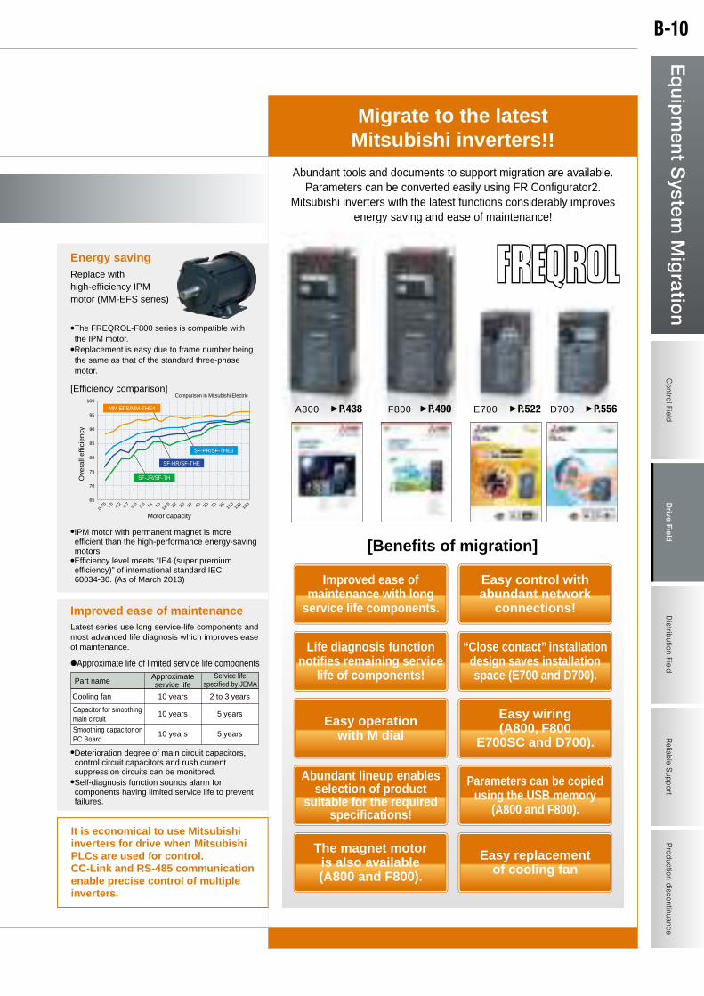
Con
trol
Fie
ldD
rive
Fie
ldD
istr
ibut
ion
Fiel
dR
elia
ble
Sup
port
Pro
duct
ion
disc
ontin
uanc
eE
qu
ipm
ent
Sys
tem
Mig
rati
on
Control Field
Drive F
ieldD
istribution FieldR
eliable Support
Production discontinuance
Eq
uip
men
t System
Mig
ration
Mitsubishi inverters
E500 S500
Migration documents
Convenient compatibility
Inverter migration proposal
[Benefits of migration]
[Concerns for migrating]
Mitsubishi inverters
Advantages of migration to the 800 series
The mounting compatibility with conventional models is secured.Mitsubishi Electric offers the (optional) mounting compatibility
attachment though the compatibility may be different in some models.
A500 F500
FR Configurator2
* Supports conversion from A500 to A800.
Convert function
FR-A700 FR-A800
Energy saving
Improved ease of maintenance
The FREQROL-F800 series is compatible with the IPM motor.
Replacement is easy due to frame number being the same as that of the standard three-phase motor.
Latest series use long service-life components and most advanced life diagnosis which improves ease of maintenance.
IPM motor with permanent magnet is more efficient than the high-performance energy-saving motors.
Efficiency level meets “IE4 (super premium efficiency)” of international standard IEC 60034-30. (As of March 2013)
Deterioration degree of main circuit capacitors, control circuit capacitors and rush current suppression circuits can be monitored.
Self-diagnosis function sounds alarm for components having limited service life to prevent failures.
[Efficiency comparison]
Ove
rall
effic
ienc
y
Approximate life of limited service life components
Part name
Cooling fan 10 years
10 years
10 years
2 to 3 years
5 years
5 years
A800 F800 E700 D700 P.556P.522P.490P.438
FR-A500
65
70
75
80
85
90
95
100
Motor capacity
Comparison in Mitsubishi Electric
0.75 1.
52.
23.
75.
57.
5 11 1518
.5 22 30 37 45 55 75 90 110
132
160
MM-EFS/MM-THE4
SF-JR/SF-TH
SF-PR/SF-THE3
SF-HR/SF-THE
A700
FR-A800FR-A700
The trace data stored in the built-in RAM is erased when the power is turned OFF or the inverter is reset.
In the FR-A800 and F800 series, the trace function can store the operation status (such as the output frequency) just before activation of the protection function in the RAM built in the inverter. The stored data (trace data) can be copied to the USB memory. Troubleshooting can be performed easily even in distant places when the trace data is captured by the software (FR Configurator2) set up in the inverter.
For example
Mit
sub
ish
i Ele
ctri
c ca
n e
limin
ate
thes
e co
nce
rns!
It is economical to use Mitsubishi inverters for drive when Mitsubishi PLCs are used for control. CC-Link and RS-485 communication enable precise control of multiple inverters.
Parameters can be converted easily using the convert function of “FR Configurator2” (optional) parameter setting software.
Abundant tools and documents to support migration are available. Parameters can be converted easily using FR Configurator2.
Mitsubishi inverters with the latest functions considerably improves energy saving and ease of maintenance!
Replace with high-efficiency IPM motor (MM-EFS series)
How is the current status of the existing inverter?
Mitsubishi Electric offers various tools for replacement with latest models.
The magnet motor is also available (A800 and F800).
Easy replacement of cooling fan
Abundant lineup enables selection of product
suitable for the required specifications!
Parameters can be copied using the USB memory
(A800 and F800).
Easy operation with M dial
Improved ease of maintenance with long
service life components.
Easy control with abundant network
connections!
Life diagnosis function notifies remaining service
life of components!
“Close contact” installation design saves installation space (E700 and D700).Service life
specified by JEMA
Smoothing capacitor on PC Board
Capacitor for smoothing main circuit
Approximateservice life
Migrate to the latest Mitsubishi inverters!!
We are using coil type motor, eddy current joint type motor (AS), direct current (DC) motor, and
have difficulty in daily and preventive maintenances.
How can we replace the parameters?
Are there compatible products to the existing
obsolete products?
Need to improve energy efficiency.
Need to manage and control many units.
Replacement of service life limited components may be needed soon.
[Concerns about the existing equipment]
Easy wiring (A800, F800
E700SC and D700).
B-10
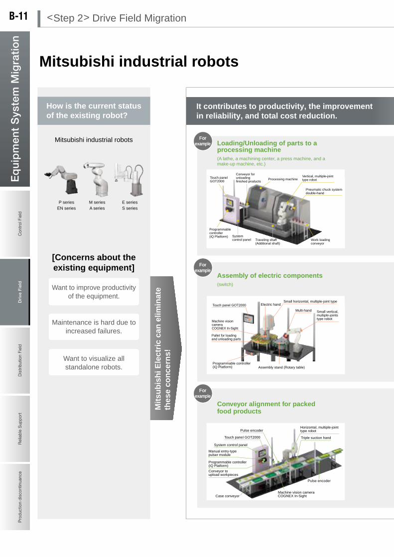
Con
trol
Fie
ldD
rive
Fie
ldD
istr
ibut
ion
Fiel
dR
elia
ble
Sup
port
Pro
duct
ion
disc
ontin
uanc
eE
qu
ipm
ent
Sys
tem
Mig
rati
on
Control Field
Drive F
ieldD
istribution FieldR
eliable Support
Production discontinuance
Eq
uip
men
t System
Mig
ration
SQ series supports iQ Platform and enables higher speed control.
Mitsubishi industrial robots
RV-F seriesRH-F series
Mitsubishi industrial robots
P series M series E seriesEN series A series S series
Forexample
Forexample
Forexample
[Benefits of migration]
Mitsubishi industrial robotsPoints for the employment of robots
AdvantagesImprovement of environmental resistanceSmooth hand-over of products with various
processing machinesHigher operating rate of robotShorter cycle time
Points for the employment of robots
AdvantagesHigh-speed kittingCapable of handling a wide variety of
workpieces using only a small spaceNo need to change hands to switch a kind of
workComplicated assembly processReduction of cycle time
Points for the employment of robots
AdvantagesHigh-speed trackingNo need of alignment deviceReduction of cycle timeStable quality due to automated process
Processing machine
Conveyor for unloading finished products
System control panel Work loading
conveyor
Pneumatic chuck system double-hand
Vertical, multiple-joint type robot
Traveling shaft (Additional shaft)
Touch panel GOT2000
Programmablecontroller (iQ Platform)
Touch panel GOT2000Small horizontal, multiple-joint type
Assembly stand (Rotary table)
Electric hand
Multi-hand Small vertical, multiple-joints type robot
Pallet for loading and unloading parts
Programmable controller (iQ Platform)
Machine vision camera COGNEX In-Sight
Case conveyor
Pulse encoder
Pulse encoder
Triple suction handTouch panel GOT2000
System control panel
Horizontal, multiple-joint type robot
Machine vision camera COGNEX In-Sight
Conveyor to upload workpieces
Manual entry-type pulser module
Programmable controller (iQ Platform)
Assembly of electric components (switch)
F-SERIES
Q series PLCGOT(HMI)
P.636
Mit
sub
ish
i Ele
ctri
c ca
n e
limin
ate
thes
e co
nce
rns!
For example
For example
For example
A vertical, multiple-joint type robot realizes high-speed loading and unloading of parts to a processing machine. (Oil mist proof) Additional traveling shaft improves the operating rate of a robot and efficiently utilizes the facility.
High-speed parts kitting with a horizontal, multiple-joint type robot, fine assembly with a vertical, multiple-joint type robot, and the ability to handle a variety of workpieces with a high-functioning hand (a multi-hand and an electric hand)
High-speed vision-tracking of horizontal, multiple-joint type robot realizes non-stopping alignment process. It also processes simultaneous tracking for multiple conveyors.
It contributes to productivity, the improvement in reliability, and total cost reduction.
How is the current status of the existing robot?
Conveyor alignment for packed food products
Loading/Unloading of parts to a processing machine
Migrate to the latest Mitsubishi robots!!
Want to visualize all standalone robots.
Maintenance is hard due to increased failures.
Want to improve productivity of the equipment.
[Concerns about the existing equipment]
Improved operability with easy connection
of GOT
Downsized robot saves installation
space.
Robot can be controlled using PLC language!
Multiple robots can be controlled
together.
Robot CPU in iQ Platform
saves wiring
High-speed control improves
tact time!
(A lathe, a machining center, a press machine, and a make-up machine, etc.)
< Step 2 > Drive Field MigrationB-11
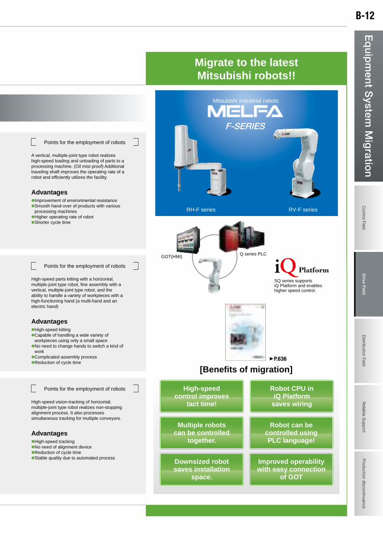
Con
trol
Fie
ldD
rive
Fie
ldD
istr
ibut
ion
Fiel
dR
elia
ble
Sup
port
Pro
duct
ion
disc
ontin
uanc
eE
qu
ipm
ent
Sys
tem
Mig
rati
on
Control Field
Drive F
ieldD
istribution FieldR
eliable Support
Production discontinuance
Eq
uip
men
t System
Mig
ration
SQ series supports iQ Platform and enables higher speed control.
Mitsubishi industrial robots
RV-F seriesRH-F series
Mitsubishi industrial robots
P series M series E seriesEN series A series S series
Forexample
Forexample
Forexample
[Benefits of migration]
Mitsubishi industrial robotsPoints for the employment of robots
AdvantagesImprovement of environmental resistanceSmooth hand-over of products with various
processing machinesHigher operating rate of robotShorter cycle time
Points for the employment of robots
AdvantagesHigh-speed kittingCapable of handling a wide variety of
workpieces using only a small spaceNo need to change hands to switch a kind of
workComplicated assembly processReduction of cycle time
Points for the employment of robots
AdvantagesHigh-speed trackingNo need of alignment deviceReduction of cycle timeStable quality due to automated process
Processing machine
Conveyor for unloading finished products
System control panel Work loading
conveyor
Pneumatic chuck system double-hand
Vertical, multiple-joint type robot
Traveling shaft (Additional shaft)
Touch panel GOT2000
Programmablecontroller (iQ Platform)
Touch panel GOT2000Small horizontal, multiple-joint type
Assembly stand (Rotary table)
Electric hand
Multi-hand Small vertical, multiple-joints type robot
Pallet for loading and unloading parts
Programmable controller (iQ Platform)
Machine vision camera COGNEX In-Sight
Case conveyor
Pulse encoder
Pulse encoder
Triple suction handTouch panel GOT2000
System control panel
Horizontal, multiple-joint type robot
Machine vision camera COGNEX In-Sight
Conveyor to upload workpieces
Manual entry-type pulser module
Programmable controller (iQ Platform)
Assembly of electric components (switch)
F-SERIES
Q series PLCGOT(HMI)
P.636
Mit
sub
ish
i Ele
ctri
c ca
n e
limin
ate
thes
e co
nce
rns!
For example
For example
For example
A vertical, multiple-joint type robot realizes high-speed loading and unloading of parts to a processing machine. (Oil mist proof) Additional traveling shaft improves the operating rate of a robot and efficiently utilizes the facility.
High-speed parts kitting with a horizontal, multiple-joint type robot, fine assembly with a vertical, multiple-joint type robot, and the ability to handle a variety of workpieces with a high-functioning hand (a multi-hand and an electric hand)
High-speed vision-tracking of horizontal, multiple-joint type robot realizes non-stopping alignment process. It also processes simultaneous tracking for multiple conveyors.
It contributes to productivity, the improvement in reliability, and total cost reduction.
How is the current status of the existing robot?
Conveyor alignment for packed food products
Loading/Unloading of parts to a processing machine
Migrate to the latest Mitsubishi robots!!
Want to visualize all standalone robots.
Maintenance is hard due to increased failures.
Want to improve productivity of the equipment.
[Concerns about the existing equipment]
Improved operability with easy connection
of GOT
Downsized robot saves installation
space.
Robot can be controlled using PLC language!
Multiple robots can be controlled
together.
Robot CPU in iQ Platform
saves wiring
High-speed control improves
tact time!
(A lathe, a machining center, a press machine, and a make-up machine, etc.)
B-12
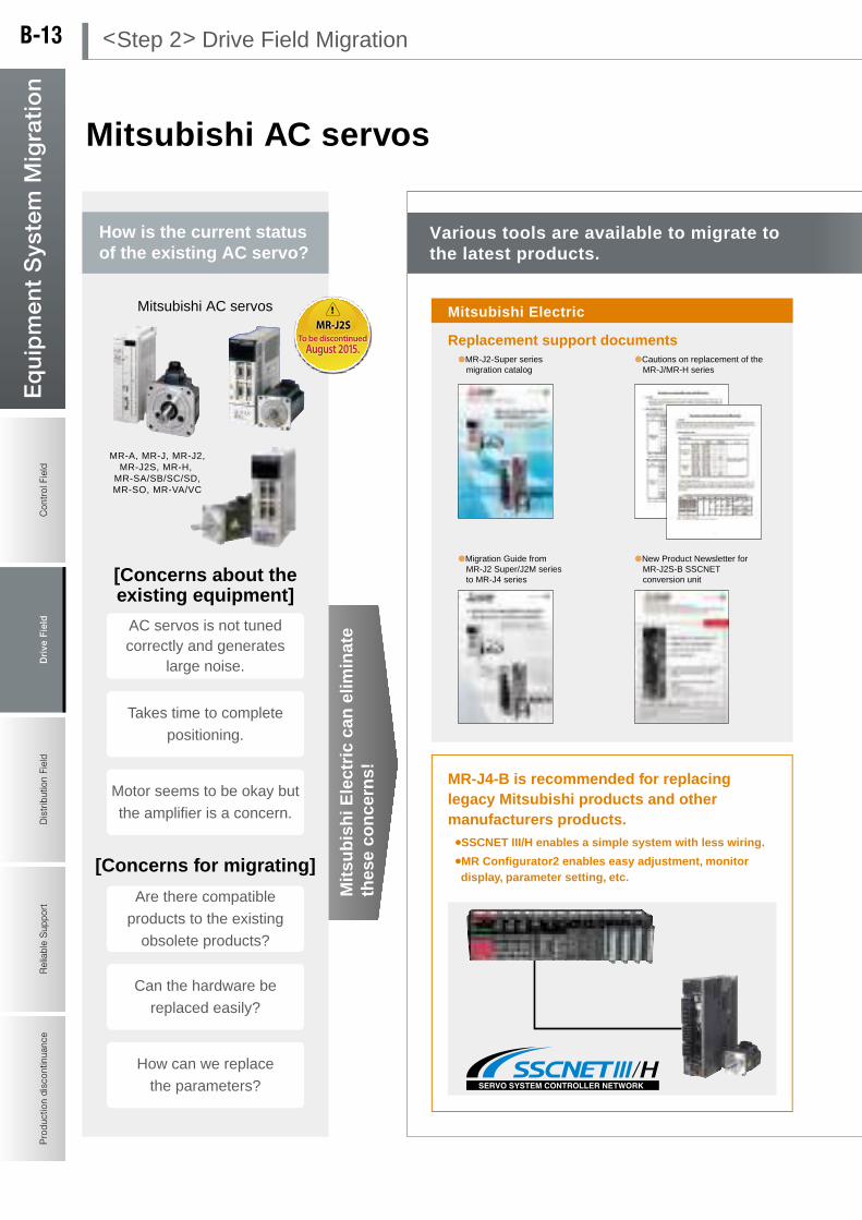
Con
trol
Fie
ldD
rive
Fie
ldD
istr
ibut
ion
Fiel
dR
elia
ble
Sup
port
Pro
duct
ion
disc
ontin
uanc
eE
qu
ipm
ent
Sys
tem
Mig
rati
on
Control Field
Drive F
ieldD
istribution FieldR
eliable Support
Production discontinuance
Eq
uip
men
t System
Mig
ration
Mitsubishi AC servos
MR-A, MR-J, MR-J2,MR-J2S, MR-H,
MR-SA/SB/SC/SD,MR-SO, MR-VA/VC
Mitsubishi AC servos
MR-J4-B is recommended for replacing legacy Mitsubishi products and other manufacturers products.¡SSCNET III/H enables a simple system with less wiring.
¡MR Configurator2 enables easy adjustment, monitor display, parameter setting, etc.
[Concerns for migrating]
Replacement support documents
Mitsubishi Electric Partner manufacturer
P.270
Servo can be
replaced with
MR-J3A type using
the migration tool.
For replacing MR-J series For replacing MR-J2S series
For replacing MR-H series For replacing MR-SA series
MR-J2STo be discontinued
August 2015.
[Benefits of migration]In case of MR-J2S series
0.05kW to 22kW
Mit
sub
ish
i Ele
ctri
c ca
n e
limin
ate
thes
e co
nce
rns!
For example
How is the current status of the existing AC servo?
Various tools are available to migrate to the latest products.
How can we replace
the parameters?
Can the hardware be
replaced easily?
Are there compatible
products to the existing
obsolete products?
Motor seems to be okay but
the amplifier is a concern.
Takes time to complete
positioning.
AC servos is not tuned correctly and generates
large noise.
[Concerns about the existing equipment]
Migrate to the latest Mitsubishi AC servos!!
High-response control improves
tact time!
Space saving design allows close contact
installation
Easy tuning function
Smooth operation due to reduced cogging torque
Easy servo adjustment to fit the equipment!
Easy wiring with SSCNET III/H or
SSCNET III.
Easy setting of electronic gear.
Abundant lineup enables selection of product suitable for
the required specifications!
Abundant tools to support easy migration are available. In multi-axis control, combining the motion controller contributes to
function upgrade and space saving!
Migration Guide from MR-J2 Super/J2M series to MR-J4 series
New Product Newsletter for MR-J2S-B SSCNET conversion unit
MR-J2-Super series migration catalog
Cautions on replacement of the MR-J/MR-H series
Migratoin tools available from Mitsubishi Electric System & Service Co. Ltd.
< Step 2 > Drive Field MigrationB-13

Con
trol
Fie
ldD
rive
Fie
ldD
istr
ibut
ion
Fiel
dR
elia
ble
Sup
port
Pro
duct
ion
disc
ontin
uanc
eE
qu
ipm
ent
Sys
tem
Mig
rati
on
Control Field
Drive F
ieldD
istribution FieldR
eliable Support
Production discontinuance
Eq
uip
men
t System
Mig
ration
Mitsubishi AC servos
MR-A, MR-J, MR-J2,MR-J2S, MR-H,
MR-SA/SB/SC/SD,MR-SO, MR-VA/VC
Mitsubishi AC servos
MR-J4-B is recommended for replacing legacy Mitsubishi products and other manufacturers products.¡SSCNET III/H enables a simple system with less wiring.
¡MR Configurator2 enables easy adjustment, monitor display, parameter setting, etc.
[Concerns for migrating]
Replacement support documents
Mitsubishi Electric Partner manufacturer
P.270
Servo can be
replaced with
MR-J3A type using
the migration tool.
For replacing MR-J series For replacing MR-J2S series
For replacing MR-H series For replacing MR-SA series
MR-J2STo be discontinued
August 2015.
[Benefits of migration]In case of MR-J2S series
0.05kW to 22kW
Mit
sub
ish
i Ele
ctri
c ca
n e
limin
ate
thes
e co
nce
rns!
For example
How is the current status of the existing AC servo?
Various tools are available to migrate to the latest products.
How can we replace
the parameters?
Can the hardware be
replaced easily?
Are there compatible
products to the existing
obsolete products?
Motor seems to be okay but
the amplifier is a concern.
Takes time to complete
positioning.
AC servos is not tuned correctly and generates
large noise.
[Concerns about the existing equipment]
Migrate to the latest Mitsubishi AC servos!!
High-response control improves
tact time!
Space saving design allows close contact
installation
Easy tuning function
Smooth operation due to reduced cogging torque
Easy servo adjustment to fit the equipment!
Easy wiring with SSCNET III/H or
SSCNET III.
Easy setting of electronic gear.
Abundant lineup enables selection of product suitable for
the required specifications!
Abundant tools to support easy migration are available. In multi-axis control, combining the motion controller contributes to
function upgrade and space saving!
Migration Guide from MR-J2 Super/J2M series to MR-J4 series
New Product Newsletter for MR-J2S-B SSCNET conversion unit
MR-J2-Super series migration catalog
Cautions on replacement of the MR-J/MR-H series
Migratoin tools available from Mitsubishi Electric System & Service Co. Ltd.
B-14
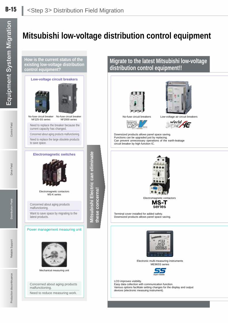
Con
trol
Fie
ldD
rive
Fiel
dD
istr
ibut
ion
Fie
ldR
elia
ble
Sup
port
Reliable S
upportD
rive Field
Pro
duct
ion
disc
ontin
uanc
eE
qu
ipm
ent
Sys
tem
Mig
rati
on
Control Field
Production discontinuance
Eq
uip
men
t System
Mig
ration
Distrib
ution Field
Mitsubishi low-voltage distribution control equipment
No-fuse circuit breakerNF225-SS series
No-fuse circuit breakerNF2000 series
[Benefits of migration]
Low-voltage circuit breakersProduct catalogs
Electromagnetic contactorsMS-K series
Electromagnetic switches
Mechanical measuring unit
Power management measuring unit
Electronic multi-measuring instrument
Electromagnetic switches
Low-voltage circuit breakers
Downsized products allows panel space saving.Functions can be upgraded just by replacing.Can prevent unnecessary operations of the earth-leakage circuit breaker by high function IC.
Electric power measuring unit [QE84WH]PLC measures power information up to 4 channels which enables standard data control and state monitoring in each production equipment.
Insulation monitoring unit[QE821LG]PLC continuously monitors the insulation status and supports preventive maintenance of the production equipment.
Mitsubishi FA products can “visualize” power management equipment and of production equipment.
Directly connected to Q series PLC.
Product catalogs
Terminal cover installed for added safety.Downsized products allows panel space saving.
Electromagnetic contactors
Product catalogs
Electronic multi-measuring instrumentsME96SS series
In addition to circuit breaker function, this product continuously monitors the electric circuit information (power amount, load current, leakage current, etc.) and enables centralized monitoring through communication.
MDU breaker*
These products monitors leakage current data and investigate causes of electric leakage.
Need to reduce measuring work.
Concerned about aging products malfunctioning.
* These equipment are not sold in the USA.
Mitsubishi Super-S Series Electronic Multi-measuring Instrument ME96SS
Mitsubishi MS-T Series Electromagnetic switches
Mitsubishi WS-AE Series Low Voltage Air Circuit Breakers
Mitsubishi WS-V Series Molded Case Circuit Breakers and Earth-leakage Circuit Breakers
No-fuse circuit breakers Low-voltage air circuit breakers
Mit
sub
ish
i Ele
ctri
c ca
n e
limin
ate
thes
e co
nce
rns!
LCD improves visibility.Easy data collection with communication function.Various options facilitate setting changes for the display and output devices (electronic measuing instrument).
How is the current status of the existing low-voltage distribution control equipment?
No-fuse circuit breaker/ earth-leakage circuit
breaker equipped with leakage current indication*
Want to save space by migrating to the latest products.
Concerned about aging products malfunctioning.
Concerned about aging products malfunctioning.
Need to replace the breaker because the current capacity has changed.
Energy measuring unit EcoMonitorLight
Downsized to save panel
space.
New circuit breaking technology allows
higher performance.
Contribute to energy saving and preventive maintenance through
monitoring of the electric circuit information using
the MDU breaker and others.
Safe and easy wiring with
CAN terminal.
Detachable arc cover makes
inspection easy.
Wide viewing angle LCD improves
visibility.
Set data transceiver allows easy setting and management.
Furthermore,Mitsubishi's migration can:
Need to replace the large obsolete products to save space.
Migrate to the latest Mitsubishi low-voltage distribution control equipment!!
Migrations
by Mitsubishi
Electric
Save energy with low power
consumption coil.
Single-circuit measuring unit, display unit, and setting unit integrated into a single measuring unit. Allows easy and low cost energy “visualization”. Built-in MODBUS® communication allows system upgrade.
< Step 3> Distribution Field MigrationB-15
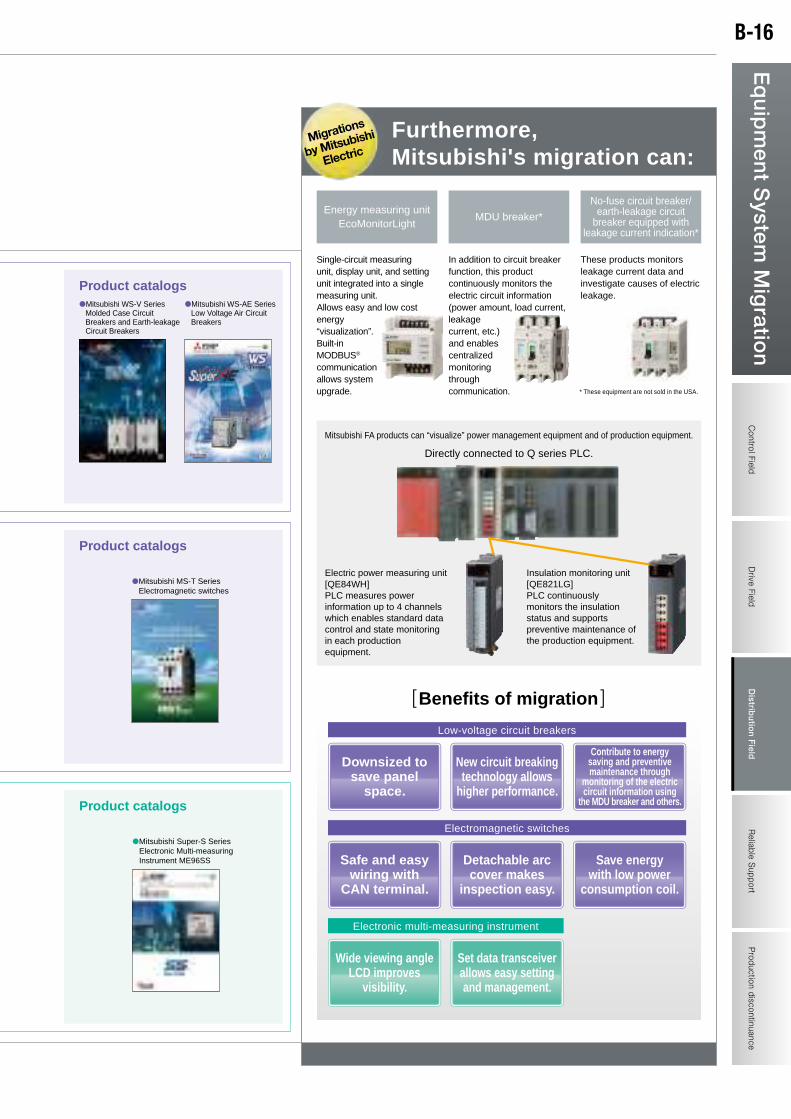
Con
trol
Fie
ldD
rive
Fiel
dD
istr
ibut
ion
Fie
ldR
elia
ble
Sup
port
Reliable S
upportD
rive Field
Pro
duct
ion
disc
ontin
uanc
eE
qu
ipm
ent
Sys
tem
Mig
rati
on
Control Field
Production discontinuance
Eq
uip
men
t System
Mig
ration
Distrib
ution Field
Mitsubishi low-voltage distribution control equipment
No-fuse circuit breakerNF225-SS series
No-fuse circuit breakerNF2000 series
[Benefits of migration]
Low-voltage circuit breakersProduct catalogs
Electromagnetic contactorsMS-K series
Electromagnetic switches
Mechanical measuring unit
Power management measuring unit
Electronic multi-measuring instrument
Electromagnetic switches
Low-voltage circuit breakers
Downsized products allows panel space saving.Functions can be upgraded just by replacing.Can prevent unnecessary operations of the earth-leakage circuit breaker by high function IC.
Electric power measuring unit [QE84WH]PLC measures power information up to 4 channels which enables standard data control and state monitoring in each production equipment.
Insulation monitoring unit[QE821LG]PLC continuously monitors the insulation status and supports preventive maintenance of the production equipment.
Mitsubishi FA products can “visualize” power management equipment and of production equipment.
Directly connected to Q series PLC.
Product catalogs
Terminal cover installed for added safety.Downsized products allows panel space saving.
Electromagnetic contactors
Product catalogs
Electronic multi-measuring instrumentsME96SS series
In addition to circuit breaker function, this product continuously monitors the electric circuit information (power amount, load current, leakage current, etc.) and enables centralized monitoring through communication.
MDU breaker*
These products monitors leakage current data and investigate causes of electric leakage.
Need to reduce measuring work.
Concerned about aging products malfunctioning.
* These equipment are not sold in the USA.
Mitsubishi Super-S Series Electronic Multi-measuring Instrument ME96SS
Mitsubishi MS-T Series Electromagnetic switches
Mitsubishi WS-AE Series Low Voltage Air Circuit Breakers
Mitsubishi WS-V Series Molded Case Circuit Breakers and Earth-leakage Circuit Breakers
No-fuse circuit breakers Low-voltage air circuit breakers
Mit
sub
ish
i Ele
ctri
c ca
n e
limin
ate
thes
e co
nce
rns!
LCD improves visibility.Easy data collection with communication function.Various options facilitate setting changes for the display and output devices (electronic measuing instrument).
How is the current status of the existing low-voltage distribution control equipment?
No-fuse circuit breaker/ earth-leakage circuit
breaker equipped with leakage current indication*
Want to save space by migrating to the latest products.
Concerned about aging products malfunctioning.
Concerned about aging products malfunctioning.
Need to replace the breaker because the current capacity has changed.
Energy measuring unit EcoMonitorLight
Downsized to save panel
space.
New circuit breaking technology allows
higher performance.
Contribute to energy saving and preventive maintenance through
monitoring of the electric circuit information using
the MDU breaker and others.
Safe and easy wiring with
CAN terminal.
Detachable arc cover makes
inspection easy.
Wide viewing angle LCD improves
visibility.
Set data transceiver allows easy setting and management.
Furthermore,Mitsubishi's migration can:
Need to replace the large obsolete products to save space.
Migrate to the latest Mitsubishi low-voltage distribution control equipment!!
Migrations
by Mitsubishi
Electric
Save energy with low power
consumption coil.
Single-circuit measuring unit, display unit, and setting unit integrated into a single measuring unit. Allows easy and low cost energy “visualization”. Built-in MODBUS® communication allows system upgrade.
B-16
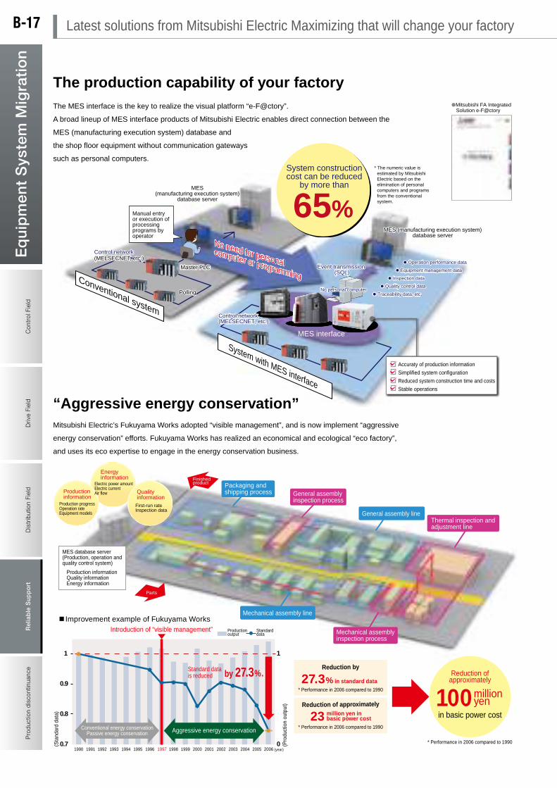
Con
trol
Fie
ldD
rive
Fiel
dD
istr
ibut
ion
Fiel
dR
elia
ble
Sup
por
t
Drive Field
Reliab
le Sup
port
Pro
duct
ion
disc
ontin
uanc
eE
qu
ipm
ent
Sys
tem
Mig
rati
on
Control Field
Distribution Field
Production discontinuance
Eq
uip
men
t System
Mig
ration
Factory
Office
LAN
MELSEC PLC
EcoWebServer
Client server
Production sectionProduction section
Alarm lamp
Alarm output
information
Collection of
Electronic
instrument
Contact input EcoMonitorPro
65%
* The numeric value is estimated by Mitsubishi Electric based on the elimination of personal computers and programs from the conventional system.
Operation performance data
Equipment management data
Inspection data
Quality control data
Traceability data, etc.
Accuraty of production information
Simplified system configuration
Reduced system construction time and costs
Stable operations
No personal computer
MES interface
Event transmission (SQL)
System with MES interface
Conventional system
Control network(MELSECNET, etc.)
Manual entry or execution of processing programs by operator
Master PLC
Control network(MELSECNET, etc.)
Polling
System construction cost can be reduced
by more than
MES (manufacturing execution system) database server
No need for personal computer or programming
No need for personal computer or programming
No need for personal computer or programming
MES (manufacturing execution system)
database server
The production capability of your factory
“Aggressive energy conservation”
1
0.9
0.8
0.7
1
01990 1991 1992 1993 1994 1995 1996 1997 1998 1999 2000 2001 2002 2003 2004 2005 2006
Introduction of “visible management”
(year)
by 27.3%.
(Pro
duct
ion
outp
ut)
(Sta
ndar
d da
ta)
Aggressive energy conservation
Improvement example of Fukuyama Works
Reduction by
* Performance in 2006 compared to 1990
Parts
Mechanical assembly line
General assembly line
27.3% in standard data
Reduction of approximately
* Performance in 2006 compared to 1990
23
100in basic power cost
* Performance in 2006 compared to 1990
Conventional energy conservation Passive energy conservation
million yen
Reduction of approximately
Thermal inspection and adjustment line
Mechanical assembly inspection process
Standard data
Production output
Finished product
General assembly inspection process
Packaging and shipping process
Production information Quality information Energy information
Production progress Operation rate Equipment models
Productioninformation
First-run rate Inspection data
Quality information
Energy information
MES database server(Production, operation and quality control system)
million yen in basic power cost
Standard data is reduced
Electric power amount Electric current Air flow
What is EcoWebServer?
CC-Link connection type B-NET connection type
Remain available! Inherited functions
Graph display
Powered up! Improved performance
New functions added! Additional functions
The setting software is provided as an accessory.There is no necessity to create programs.
The newly adopted universal design makes graphs easier to see.
Virtual measurement and production quantity are incorporated in the standard data control.
The daily data saving period has been extended from 2 months to 6 months. Extended saving period
The number of virtual measurement points and standard data measurement points have been increased.
The zoom data collection period has been reduced.
Alarm outputs have been enabled to enhance the monitoring function.
The temperature and humidity data are collected for each section and application.
The energy loss in the equipment has been made visible.
The measured data are processed and saved easily.
Mitsubishi FA Integrated Solution e-F@ctory
Mitsubishi Energy-saving Data Collection Server EcoWebServerIII
Extended saving period
Enhanced calculation function
1 minute minimum
Equipment monitoring
Multiple comparison
Up to 16 contact outputs
Various graph displays are available to construct the “mechanism to let workers be aware” of status changes.
Calculation function
Mitsubishi Electric’s simple, convenient and compact EcoWebServerIII is advanced to support visible management of energy.
Mitsubishi Electric’s Fukuyama Works adopted “visible management”, and is now implement “aggressive
energy conservation” efforts. Fukuyama Works has realized an economical and ecological “eco factory”,
and uses its eco expertise to engage in the energy conservation business.
The MES interface is the key to realize the visual platform “e-F@ctory”.
A broad lineup of MES interface products of Mitsubishi Electric enables direct connection between the
MES (manufacturing execution system) database and
the shop floor equipment without communication gateways
such as personal computers.
EcoWebServer is an all-in-one type data collection server having excellent functions
essential in energy-saving management of alarm units and machines.
Two types selectable
CSV format Compatible with FTP
Simple setting Simple extension
Latest solutions from Mitsubishi Electric Maximizing that will change your factoryB-17

Con
trol
Fie
ldD
rive
Fiel
dD
istr
ibut
ion
Fiel
dR
elia
ble
Sup
por
t
Drive Field
Reliab
le Sup
port
Pro
duct
ion
disc
ontin
uanc
eE
qu
ipm
ent
Sys
tem
Mig
rati
on
Control Field
Distribution Field
Production discontinuance
Eq
uip
men
t System
Mig
ration
Factory
Office
LAN
MELSEC PLC
EcoWebServer
Client server
Production sectionProduction section
Alarm lamp
Alarm output
information
Collection of
Electronic
instrument
Contact input EcoMonitorPro
65%
* The numeric value is estimated by Mitsubishi Electric based on the elimination of personal computers and programs from the conventional system.
Operation performance data
Equipment management data
Inspection data
Quality control data
Traceability data, etc.
Accuraty of production information
Simplified system configuration
Reduced system construction time and costs
Stable operations
No personal computer
MES interface
Event transmission (SQL)
System with MES interface
Conventional system
Control network(MELSECNET, etc.)
Manual entry or execution of processing programs by operator
Master PLC
Control network(MELSECNET, etc.)
Polling
System construction cost can be reduced
by more than
MES (manufacturing execution system) database server
No need for personal computer or programming
No need for personal computer or programming
No need for personal computer or programming
MES (manufacturing execution system)
database server
The production capability of your factory
“Aggressive energy conservation”
1
0.9
0.8
0.7
1
01990 1991 1992 1993 1994 1995 1996 1997 1998 1999 2000 2001 2002 2003 2004 2005 2006
Introduction of “visible management”
(year)
by 27.3%.
(Pro
duct
ion
outp
ut)
(Sta
ndar
d da
ta)
Aggressive energy conservation
Improvement example of Fukuyama Works
Reduction by
* Performance in 2006 compared to 1990
Parts
Mechanical assembly line
General assembly line
27.3% in standard data
Reduction of approximately
* Performance in 2006 compared to 1990
23
100in basic power cost
* Performance in 2006 compared to 1990
Conventional energy conservation Passive energy conservation
million yen
Reduction of approximately
Thermal inspection and adjustment line
Mechanical assembly inspection process
Standard data
Production output
Finished product
General assembly inspection process
Packaging and shipping process
Production information Quality information Energy information
Production progress Operation rate Equipment models
Productioninformation
First-run rate Inspection data
Quality information
Energy information
MES database server(Production, operation and quality control system)
million yen in basic power cost
Standard data is reduced
Electric power amount Electric current Air flow
What is EcoWebServer?
CC-Link connection type B-NET connection type
Remain available! Inherited functions
Graph display
Powered up! Improved performance
New functions added! Additional functions
The setting software is provided as an accessory.There is no necessity to create programs.
The newly adopted universal design makes graphs easier to see.
Virtual measurement and production quantity are incorporated in the standard data control.
The daily data saving period has been extended from 2 months to 6 months. Extended saving period
The number of virtual measurement points and standard data measurement points have been increased.
The zoom data collection period has been reduced.
Alarm outputs have been enabled to enhance the monitoring function.
The temperature and humidity data are collected for each section and application.
The energy loss in the equipment has been made visible.
The measured data are processed and saved easily.
Mitsubishi FA Integrated Solution e-F@ctory
Mitsubishi Energy-saving Data Collection Server EcoWebServerIII
Extended saving period
Enhanced calculation function
1 minute minimum
Equipment monitoring
Multiple comparison
Up to 16 contact outputs
Various graph displays are available to construct the “mechanism to let workers be aware” of status changes.
Calculation function
Mitsubishi Electric’s simple, convenient and compact EcoWebServerIII is advanced to support visible management of energy.
Mitsubishi Electric’s Fukuyama Works adopted “visible management”, and is now implement “aggressive
energy conservation” efforts. Fukuyama Works has realized an economical and ecological “eco factory”,
and uses its eco expertise to engage in the energy conservation business.
The MES interface is the key to realize the visual platform “e-F@ctory”.
A broad lineup of MES interface products of Mitsubishi Electric enables direct connection between the
MES (manufacturing execution system) database and
the shop floor equipment without communication gateways
such as personal computers.
EcoWebServer is an all-in-one type data collection server having excellent functions
essential in energy-saving management of alarm units and machines.
Two types selectable
CSV format Compatible with FTP
Simple setting Simple extension
B-18

Con
trol
Fie
ldD
rive
Fiel
dD
istr
ibut
ion
Fiel
dR
elia
ble
Sup
por
t
Drive Field
Reliab
le Sup
port
Pro
duct
ion
disc
ontin
uanc
eE
qu
ipm
ent
Sys
tem
Mig
rati
on
Control Field
Distribution Field
Production discontinuance
Eq
uip
men
t System
Mig
ration
Latest solutions from Mitsubishi Electric Maximizing that will change your factory
Before
MotorControl panel Error
Promoting energy saving in existing production equipment…
While minimizing the chance of failure of existing production equipment...
In control panel
Leakage current ZCT
VoltageAlarm
On-site HMI
Motor
Process 1
Process 2
Process 3Whole process Process 4
Inverter
Motor
Alarm
Time
Electrical current
Alarm
Constant monitoring of the current value
Point3
Constant measurement of the electrical current
Preventive maintenance measures are taken before equipment stoppage. Point1
Point2 Timing of production line control can be synchronized based on energy.
Energy Saving Item or process, synchronizing the control timing
Maintenance man-hours can be reduced by improving the efficiency of periodic inspection work.
Specific energy consumption can be managed in detail according to individual items or processes to assist in reducing the power consumption of production equipment and realize energy savings.
Constantly measuring current (or power) consumption can help prevent serious faults and equipment failure, ultimately resulting in reduced production losses.
The resistive-component leakage current (Ior) can be measured so that a leakage current caused by insulation deterioration can be identified.
The module can be installed directly in the Q base unit.
The module can be installed directly in the Q base unit.
Insulation monitoring module
Insulation Monitoring Module Installation Example
Energy Measuring Module Installation Example
Production stoppage
Preventive Maintenance
Preventive Maintenance
Alarm monitoring value
Repair, maintenance and overhaul before fault occurs
Control panel
Constant measurement of the Leakage current value, and constant monitoring for insulation deterioration for each unit/load
Prevention of sudden failure of machines and lines / Detection of insulation deterioration (earth leakage) at early stage
Energy measuring module
Power measurement and insulation monitoring together with PLC migration realize energy saving and preventive maintenance!
B-19

Con
trol
Fie
ldD
rive
Fiel
dD
istr
ibut
ion
Fiel
dR
elia
ble
Sup
por
t
Drive Field
Reliab
le Sup
port
Pro
duct
ion
disc
ontin
uanc
eE
qu
ipm
ent
Sys
tem
Mig
rati
on
Control Field
Distribution Field
Production discontinuance
Eq
uip
men
t System
Mig
ration
Global web site
Easily accessibility to the FA information of Mitsubishi Electric all over the world!
From “Worldwide” provided at the upper right corner of the top page, you can easily access to the FA web sites all over the world.On the pages for each country, you can check not only products purchasable all over the world but also the information on products developed specially for the region, catalogs and manuals in each language and various regional services.Please utilize “Worldwide” for expanding your business overseas.
u GlossariesThese glossaries contain more than 750 specialized technical terms associated with the use and operation of FA products helping to improve understanding and communication between businesses and local staff.
u On-site lexiconThese lexicon's are designed to support the on-site communication between Japanese engineers and local staff. For each word a relevant FA explanation and example sentence are provided.
u PhrasebookThese phrasebooks can be used to support communication between local staff and Japanese enginners. The phrasebooks contain many everyday phrases as well as numerous examples related to the manufacturing environment.
u DictionariesThese dictionaries contain references to more than 4000 words related to the world of FA. Use them to support and improve the communication between colleagues and local staff.
www.MitsubishiElectric.com/faGlobal FA web site
Business support
B-20
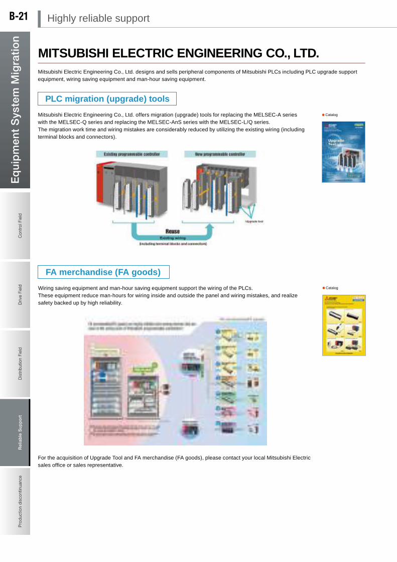
Con
trol
Fie
ldD
rive
Fiel
dD
istr
ibut
ion
Fiel
dR
elia
ble
Sup
por
t
Drive Field
Reliab
le Sup
port
Pro
duct
ion
disc
ontin
uanc
eE
qu
ipm
ent
Sys
tem
Mig
rati
on
Control Field
Distribution Field
Production discontinuance
Eq
uip
men
t System
Mig
ration
MITSUBISHI ELECTRIC ENGINEERING CO., LTD.Mitsubishi Electric Engineering Co., Ltd. designs and sells peripheral components of Mitsubishi PLCs including PLC upgrade support equipment, wiring saving equipment and man-hour saving equipment.
For the acquisition of Upgrade Tool and FA merchandise (FA goods), please contact your local Mitsubishi Electric sales office or sales representative.
PLC migration (upgrade) tools
FA merchandise (FA goods)
Mitsubishi Electric Engineering Co., Ltd. offers migration (upgrade) tools for replacing the MELSEC-A series with the MELSEC-Q series and replacing the MELSEC-AnS series with the MELSEC-L/Q series.The migration work time and wiring mistakes are considerably reduced by utilizing the existing wiring (including terminal blocks and connectors).
Wiring saving equipment and man-hour saving equipment support the wiring of the PLCs.These equipment reduce man-hours for wiring inside and outside the panel and wiring mistakes, and realize safety backed up by high reliability.
Catalog
Catalog
Highly reliable supportB-21
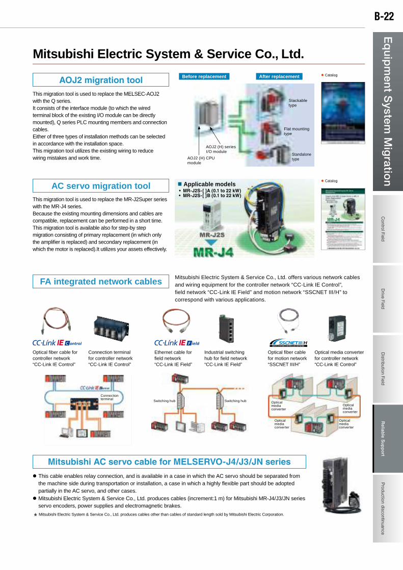
Con
trol
Fie
ldD
rive
Fiel
dD
istr
ibut
ion
Fiel
dR
elia
ble
Sup
por
t
Drive Field
Reliab
le Sup
port
Pro
duct
ion
disc
ontin
uanc
eE
qu
ipm
ent
Sys
tem
Mig
rati
on
Control Field
Distribution Field
Production discontinuance
Eq
uip
men
t System
Mig
ration
Mitsubishi Electric System & Service Co., Ltd.
This migration tool is used to replace the MELSEC-AOJ2 with the Q series.It consists of the interface module (to which the wired terminal block of the existing I/O module can be directly mounted), Q series PLC mounting members and connection cables.Either of three types of installation methods can be selected in accordance with the installation space. This migration tool utilizes the existing wiring to reduce wiring mistakes and work time.
This migration tool is used to replace the MR-J2Super series with the MR-J4 series.Because the existing mounting dimensions and cables are compatible, replacement can be performed in a short time.This migration tool is available also for step-by step migration consisting of primary replacement (in which only the amplifier is replaced) and secondary replacement (in which the motor is replaced).It utilizes your assets effectively.
Mitsubishi Electric System & Service Co., Ltd. offers various network cables and wiring equipment for the controller network “CC-Link IE Control”, field network “CC-Link IE Field” and motion network “SSCNET III/H” to correspond with various applications.
l This cable enables relay connection, and is available in a case in which the AC servo should be separated from the machine side during transportation or installation, a case in which a highly flexible part should be adopted partially in the AC servo, and other cases.
l Mitsubishi Electric System & Service Co., Ltd. produces cables (increment:1 m) for Mitsubishi MR-J4/J3/JN series servo encoders, power supplies and electromagnetic brakes.
* Mitsubishi Electric System & Service Co., Ltd. produces cables other than cables of standard length sold by Mitsubishi Electric Corporation.
Optical fiber cable for controller network “CC-Link IE Control”
Connection terminal for controller network “CC-Link IE Control”
Industrial switching hub for field network “CC-Link IE Field”
Optical fiber cable for motion network “SSCNET III/H”
Optical media converter for controller network “CC-Link IE Control”
Ethernet cable for field network “CC-Link IE Field”
l Catalogn Applicable models • MR-J2S-[]A(0.1to22kW)• MR-J2S-[]B(0.1to22kW)
Before replacement After replacement
AOJ2 (H) CPU module
AOJ2 (H) series I/O module
Stackable type
Flat mounting type
Standalone type
Switching hub Switching hubOptical media converter
Optical media converter
Optical media converter
Optical media converter
Connection terminal
AOJ2migrationtool
FA integrated network cables
MitsubishiACservocableforMELSERVO-J4/J3/JNseries
AC servo migration tool
l Catalog
B-22
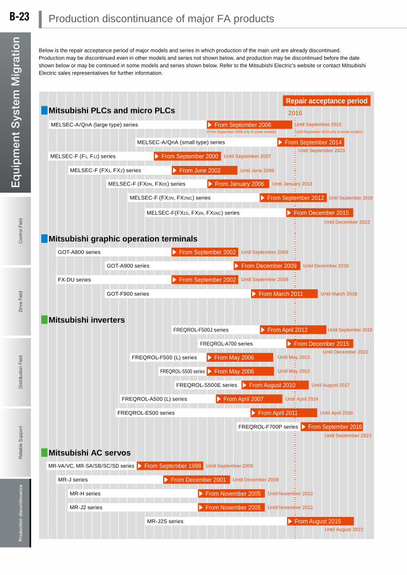
Con
trol
Fie
ldD
rive
Fiel
dD
istr
ibut
ion
Fiel
dR
elia
ble
Sup
port
Drive Field
Pro
duc
tion
dis
cont
inua
nce
Reliable S
upportP
rod
uction discontinuance
Eq
uip
men
t S
yste
m M
igra
tio
n
Control Field
Distribution Field
Eq
uip
men
t System
Mig
ration
Below is the repair acceptance period of major models and series in which production of the main unit are already discontinued.Production may be discontinued even in other models and series not shown below, and production may be discontinued before the date shown below or may be continued in some models and series shown below. Refer to the Mitsubishi Electric’s website or contact Mitsubishi Electric sales representatives for further information.
Mitsubishi PLCs and micro PLCs
Mitsubishi graphic operation terminals
Mitsubishi inverters
Mitsubishi AC servos
Repair acceptance period
Until September 2013
Until September 2021
2016
Until August 2022
MELSEC-A/QnA (large type) series
MELSEC-A/QnA (small type) series s From September 2014
Until September 2007MELSEC-F (F1, F1J) series s From September 2000
GOT-A800 series Until September 2009s From September 2002
Until September 2009FX-DU series s From September 2002
MR-J series Until December 2008s From December 2001
Until November 2012MR-H series s From November 2005
Until November 2012MR-J2 series s From November 2005
MR-J2S series s From August 2015
Until December 2016GOT-A900 series s From December 2009
Until April 2018FREQROL-E500 series s From April 2011
Until September 2023
FREQROL-F700P series s From September 2016
GOT-F900 series Until March 2018s From March 2011
Until May 2013FREQROL-F500 (L) series s From May 2006
Until September 2005MR-VA/VC, MR-SA/SB/SC/SD series s From September 1998
Until May 2013FREQROL-S500 series s From May 2006
Until August 2017FREQROL-S500E series s From August 2010
FREQROL-A500 (L) series Until April 2014s From April 2007
Until June 2009MELSEC-F (FX1, FX2) series s From June 2002
Until January 2013MELSEC-F (FX0N, FX0S) series s From January 2006
Until September 2019MELSEC-F (FX2N, FX2NC) series s From September 2012
s From September 2006(From September 2008 only in some models) (Until September 2015 only in some models)
Until December 2022
Until September 2019FREQROL-F500J series s From April 2012
Until December 2022
FREQROL-A700 series s From December 2015
MELSEC-F(FX1S, FX1N, FX1NC) series s From December 2015
Production discontinuance of major FA productsB-23
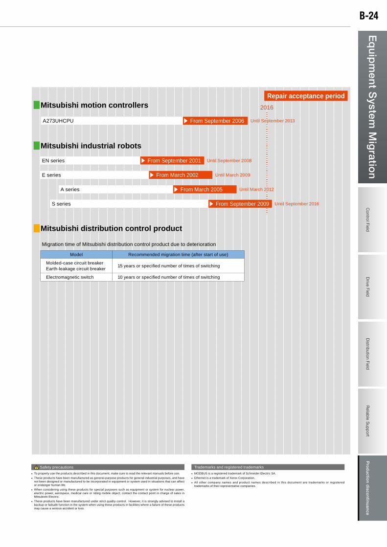
Con
trol
Fie
ldD
rive
Fiel
dD
istr
ibut
ion
Fiel
dR
elia
ble
Sup
port
Drive Field
Pro
duc
tion
dis
cont
inua
nce
Reliable S
upportP
rod
uction discontinuance
Eq
uip
men
t S
yste
m M
igra
tio
n
Control Field
Distribution Field
Eq
uip
men
t System
Mig
ration
• MODBUS is a registered trademark of Schneider Electric SA.
• Ethernet is a trademark of Xerox Corporation.
• All other company names and product names described in this document are trademarks or registered trademarks of their representative companies.
Trademarks and registered trademarks Safety precautions
• To properly use the products described in this document, make sure to read the relevant manuals before use.
• These products have been manufactured as general-purpose products for general industrial purposes, and have not been designed or manufactured to be incorporated in equipment or system used in situations that can affect or endanger human life.
• When considering using these products for special purposes such as equipment or system for nuclear power, electric power, aerospace, medical care or riding mobile object, contact the contact point in charge of sales in Mitsubishi Electric.
• These products have been manufactured under strict quality control. However, it is strongly advised to install a backup or failsafe function in the system when using these products in facilities where a failure of these products may cause a serious accident or loss.
Repair acceptance period
2016
Mitsubishi industrial robots
Until September 2008EN series s From September 2001
Until March 2009E series s From March 2002
Until March 2012A series s From March 2005
S series Until September 2016s From September 2009
Mitsubishi motion controllers
Until September 2013A273UHCPU s From September 2006
Mitsubishi distribution control product
Model Recommended migration time (after start of use)
Molded-case circuit breakerEarth-leakage circuit breaker
15 years or specified number of times of switching
Electromagnetic switch 10 years or specified number of times of switching
Migration time of Mitsubishi distribution control product due to deterioration
B-24
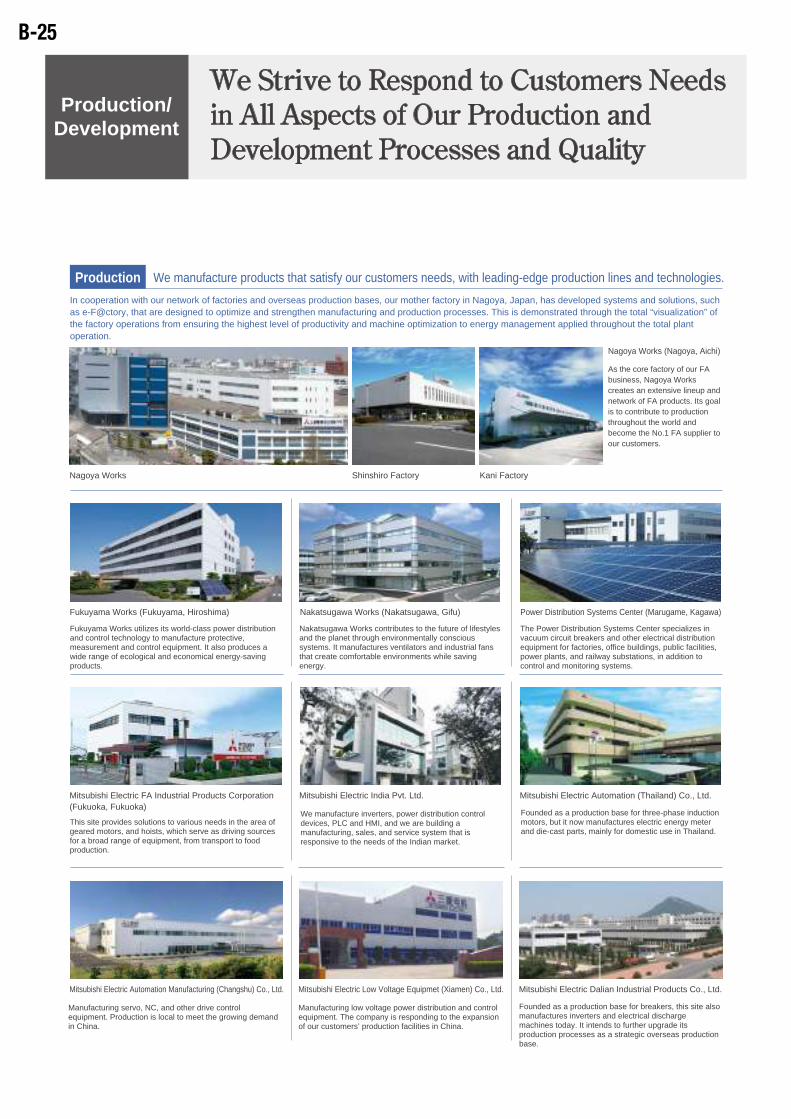
Nagoya Works (Nagoya, Aichi)
As the core factory of our FA business, Nagoya Works creates an extensive lineup and network of FA products. Its goal is to contribute to production throughout the world and become the No.1 FA supplier to our customers.
Fukuyama Works (Fukuyama, Hiroshima)
Fukuyama Works utilizes its world-class power distribution and control technology to manufacture protective, measurement and control equipment. It also produces a wide range of ecological and economical energy-saving products.
Nakatsugawa Works (Nakatsugawa, Gifu)
Nakatsugawa Works contributes to the future of lifestyles and the planet through environmentally conscious systems. It manufactures ventilators and industrial fans that create comfortable environments while saving energy.
Power Distribution Systems Center (Marugame, Kagawa)
The Power Distribution Systems Center specializes in vacuum circuit breakers and other electrical distribution equipment for factories, office buildings, public facilities, power plants, and railway substations, in addition to control and monitoring systems.
This site provides solutions to various needs in the area of geared motors, and hoists, which serve as driving sources for a broad range of equipment, from transport to food production.
Mitsubishi Electric Automation (Thailand) Co., Ltd.
Founded as a production base for three-phase induction motors, but it now manufactures electric energy meter and die-cast parts, mainly for domestic use in Thailand.
Manufacturing servo, NC, and other drive control equipment. Production is local to meet the growing demand in China.
Manufacturing low voltage power distribution and control equipment. The company is responding to the expansion of our customers’ production facilities in China.
Nagoya Works
Manufacturing low voltage power distribution and control equipment. The company is responding to the expansion of our customers’ production facilities in China.
Manufacturing servo, NC, and other drive control equipment. Production is local to meet the growing demand in China.
Comprehensive strength To promote the development of competitive
products and create technologies for the future
we foster world-leading R&D activities whilst
utilizing our network of overseas and domestic
research institutes.
Advanced Technology R&D Center (Amagasaki, Hyogo)
As an advanced technology base for all of Mitsubishi Electric’s business areas, the R&D Center has many responsibilities: from the development of common infrastructure technologies and new products to the research and development of potential new businesses for the future.
Information and Technology R&D Center (Kamakura, Kanagawa)
The R&D Center plays an important role in creating new businesses and innovating existing ones through basic research and development in the areas of information, communications, and optical and electromagnetic technologies.
Core Development ProcessesTo develop products in response to diversifying
needs, two core development centers have been
created integrating the related departments of FA
and Industrial Automation Machinery. These
state-of-the-art centers maximise the technology
synergies to produce world-class products. FA Development Center (within Nagoya Works)
The FA Development Center pursues solutions for our customers’ diverse and advanced needs in the areas of control technology, networking, HMIs, complex software, drives etc.
Industrial Automation Development Center (within Nagoya Works)
The state-of-the-art development environment is capable of responding to trends for more compact features, higher precision, and higher speeds. The design, processing technology and service domains have been brought together to strengthen Mitsubishi Electric’s total development power.
Shinshiro Factory Kani Factory
Mitsubishi Electric Automation Manufacturing (Changshu) Co., Ltd. Mitsubishi Electric Low Voltage Equipmet (Xiamen) Co., Ltd.
Development at the global levelWe develop products that satisfy the needs of
our overseas customers, propose new
global-scale FA business plans, adopt
cutting-edge technologies from overseas and
promote other development activities, all from a
global perspective. European Development Center (Düsseldorf, Germany)
In addition to investigating and researching cutting-edge technologies, the European Development Center develops products for the European market, in the languages of the European countries, as well as working to obtain various EU standards and certifications.
North American Development Center (Chicago, Boston) USA
As a planning and development base for new products and new business creation in North America, the North American Development Center aims to incubate new FA businesses and investigate advanced technologies.
China Design (Dalian, China)
Based on close cooperation between sales departments and our mother factory, we are expanding our product lineup and developing new specifications for the Chinese market.
Indian Development Center (Pune, India)
The company develops for the Indian market. Also, as a development base for the global market, it partners with other development bases to develop common technologies for FA equipment.
Mitsubishi Electric Dalian Industrial Products Co., Ltd.
Founded as a production base for breakers, this site also manufactures inverters and electrical discharge machines today. It intends to further upgrade its production processes as a strategic overseas production base.
We manufacture inverters, power distribution control devices, PLC and HMI, and we are building a manufacturing, sales, and service system that is responsive to the needs of the Indian market.
Mitsubishi Electric India Pvt. Ltd.
LSI evaluation facilityAnechoic room Inspecting machining equipment performance
We exhaustively inspect the drive control and machining performance of machining equipment, testing to ensure continuing precision machining after delivery.
We manufacture products that satisfy our customers needs, with leading-edge production lines and technologies.ProductionIn cooperation with our network of factories and overseas production bases, our mother factory in Nagoya, Japan, has developed systems and solutions, such as e-F@ctory, that are designed to optimize and strengthen manufacturing and production processes. This is demonstrated through the total “visualization” of the factory operations from ensuring the highest level of productivity and machine optimization to energy management applied throughout the total plant operation.
We identify new customer needs promptly and accelerate our R&D cycle to respond to those needs.Development
In response to our customers’ trust and confidence, we constantly review and reinforce our quality management system.Quality
We Strive to Respond to Customers Needs in All Aspects of Our Production and Development Processes and Quality
Production/Development
Mitsubishi Electric FA Industrial Products Corporation (Fukuoka, Fukuoka)
B-25

Nagoya Works (Nagoya, Aichi)
As the core factory of our FA business, Nagoya Works creates an extensive lineup and network of FA products. Its goal is to contribute to production throughout the world and become the No.1 FA supplier to our customers.
Fukuyama Works (Fukuyama, Hiroshima)
Fukuyama Works utilizes its world-class power distribution and control technology to manufacture protective, measurement and control equipment. It also produces a wide range of ecological and economical energy-saving products.
Nakatsugawa Works (Nakatsugawa, Gifu)
Nakatsugawa Works contributes to the future of lifestyles and the planet through environmentally conscious systems. It manufactures ventilators and industrial fans that create comfortable environments while saving energy.
Power Distribution Systems Center (Marugame, Kagawa)
The Power Distribution Systems Center specializes in vacuum circuit breakers and other electrical distribution equipment for factories, office buildings, public facilities, power plants, and railway substations, in addition to control and monitoring systems.
This site provides solutions to various needs in the area of geared motors, and hoists, which serve as driving sources for a broad range of equipment, from transport to food production.
Mitsubishi Electric Automation (Thailand) Co., Ltd.
Founded as a production base for three-phase induction motors, but it now manufactures electric energy meter and die-cast parts, mainly for domestic use in Thailand.
Manufacturing servo, NC, and other drive control equipment. Production is local to meet the growing demand in China.
Manufacturing low voltage power distribution and control equipment. The company is responding to the expansion of our customers’ production facilities in China.
Nagoya Works
Manufacturing low voltage power distribution and control equipment. The company is responding to the expansion of our customers’ production facilities in China.
Manufacturing servo, NC, and other drive control equipment. Production is local to meet the growing demand in China.
Comprehensive strength To promote the development of competitive
products and create technologies for the future
we foster world-leading R&D activities whilst
utilizing our network of overseas and domestic
research institutes.
Advanced Technology R&D Center (Amagasaki, Hyogo)
As an advanced technology base for all of Mitsubishi Electric’s business areas, the R&D Center has many responsibilities: from the development of common infrastructure technologies and new products to the research and development of potential new businesses for the future.
Information and Technology R&D Center (Kamakura, Kanagawa)
The R&D Center plays an important role in creating new businesses and innovating existing ones through basic research and development in the areas of information, communications, and optical and electromagnetic technologies.
Core Development ProcessesTo develop products in response to diversifying
needs, two core development centers have been
created integrating the related departments of FA
and Industrial Automation Machinery. These
state-of-the-art centers maximise the technology
synergies to produce world-class products. FA Development Center (within Nagoya Works)
The FA Development Center pursues solutions for our customers’ diverse and advanced needs in the areas of control technology, networking, HMIs, complex software, drives etc.
Industrial Automation Development Center (within Nagoya Works)
The state-of-the-art development environment is capable of responding to trends for more compact features, higher precision, and higher speeds. The design, processing technology and service domains have been brought together to strengthen Mitsubishi Electric’s total development power.
Shinshiro Factory Kani Factory
Mitsubishi Electric Automation Manufacturing (Changshu) Co., Ltd. Mitsubishi Electric Low Voltage Equipmet (Xiamen) Co., Ltd.
Development at the global levelWe develop products that satisfy the needs of
our overseas customers, propose new
global-scale FA business plans, adopt
cutting-edge technologies from overseas and
promote other development activities, all from a
global perspective. European Development Center (Düsseldorf, Germany)
In addition to investigating and researching cutting-edge technologies, the European Development Center develops products for the European market, in the languages of the European countries, as well as working to obtain various EU standards and certifications.
North American Development Center (Chicago, Boston) USA
As a planning and development base for new products and new business creation in North America, the North American Development Center aims to incubate new FA businesses and investigate advanced technologies.
China Design (Dalian, China)
Based on close cooperation between sales departments and our mother factory, we are expanding our product lineup and developing new specifications for the Chinese market.
Indian Development Center (Pune, India)
The company develops for the Indian market. Also, as a development base for the global market, it partners with other development bases to develop common technologies for FA equipment.
Mitsubishi Electric Dalian Industrial Products Co., Ltd.
Founded as a production base for breakers, this site also manufactures inverters and electrical discharge machines today. It intends to further upgrade its production processes as a strategic overseas production base.
We manufacture inverters, power distribution control devices, PLC and HMI, and we are building a manufacturing, sales, and service system that is responsive to the needs of the Indian market.
Mitsubishi Electric India Pvt. Ltd.
LSI evaluation facilityAnechoic room Inspecting machining equipment performance
We exhaustively inspect the drive control and machining performance of machining equipment, testing to ensure continuing precision machining after delivery.
We manufacture products that satisfy our customers needs, with leading-edge production lines and technologies.ProductionIn cooperation with our network of factories and overseas production bases, our mother factory in Nagoya, Japan, has developed systems and solutions, such as e-F@ctory, that are designed to optimize and strengthen manufacturing and production processes. This is demonstrated through the total “visualization” of the factory operations from ensuring the highest level of productivity and machine optimization to energy management applied throughout the total plant operation.
We identify new customer needs promptly and accelerate our R&D cycle to respond to those needs.Development
In response to our customers’ trust and confidence, we constantly review and reinforce our quality management system.Quality
We Strive to Respond to Customers Needs in All Aspects of Our Production and Development Processes and Quality
Production/Development
Mitsubishi Electric FA Industrial Products Corporation (Fukuoka, Fukuoka)
B-26
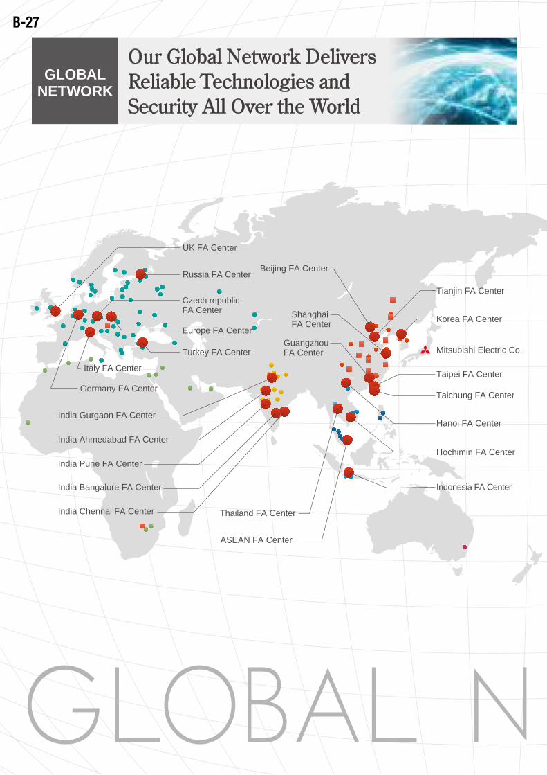
Offices
FA Center SatelliteMitsubishi Electric FA Centers
Tianjin FA Center
Beijing FA Center
ASEAN FA Center
Thailand FA Center
Taichung FA Center
Taipei FA Center
Korea FA Center
Mitsubishi Electric Co.
North America FA Center
Mexico FA Center
India Gurgaon FA Center
India Bangalore FA Center
India Pune FA Center
India Ahmedabad FA Center
India Chennai FA Center
UK FA Center
Czech republicFA Center
Europe FA Center
Russia FA Center
Germany FA Center
Italy FA Center
Hanoi FA Center
Hochimin FA Center
Indonesia FA Center
Turkey FA Center
Our Global Network Delivers Reliable Technologies and Security All Over the World
GLOBAL NETWORK
Shanghai FA Center
Guangzhou FA Center
Brazil FA Center
Brazil Votorantim FA Center
China Mainland B-29
Korea B-31
Taiwan B-32
ASEAN B-33
Indonesia B-34
Vietnam B-35
Thailand/India B-36
Oceania B-37
Americas/Mexico B-38
Brazil B-39
Europe B-40
Turkey B-43
Middle East/Africa B-44
Index
B-27
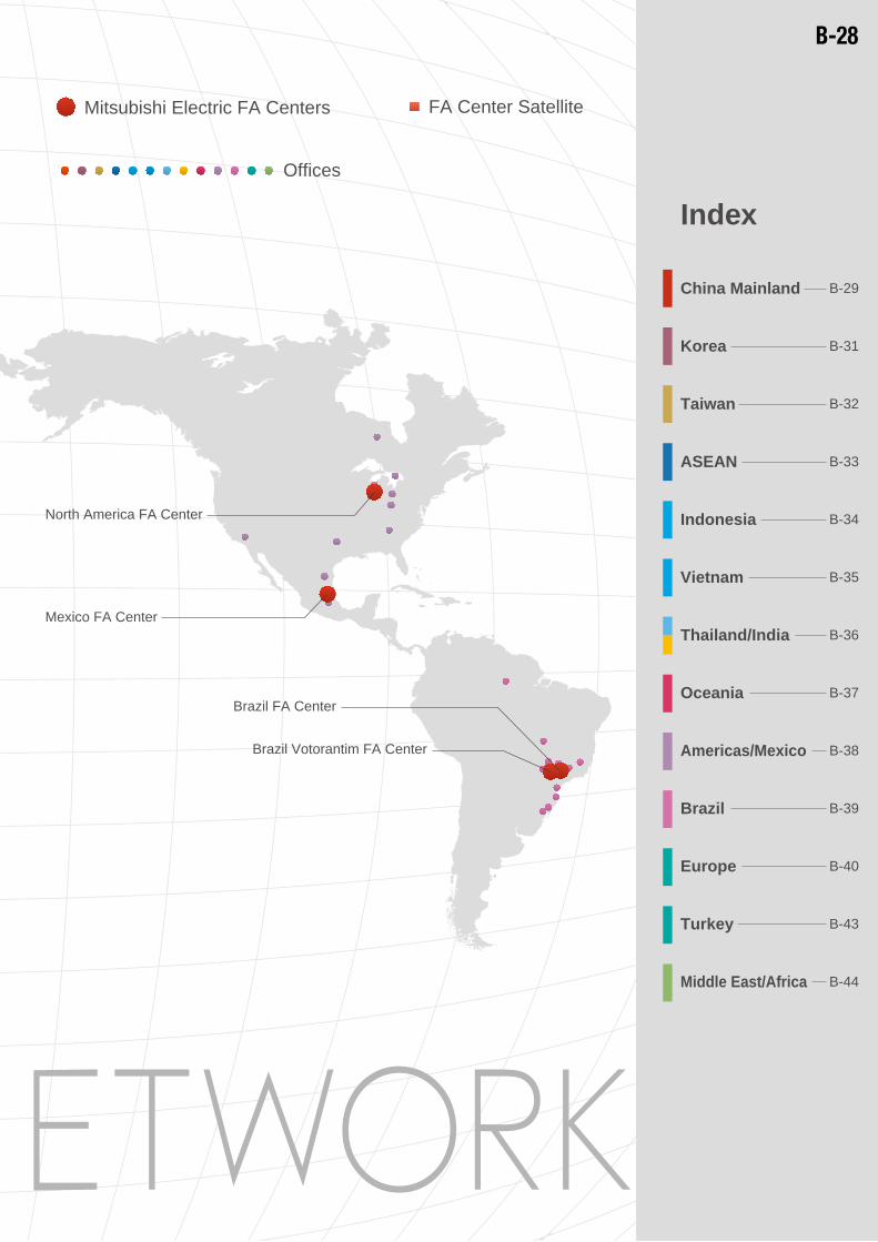
Offices
FA Center SatelliteMitsubishi Electric FA Centers
Tianjin FA Center
Beijing FA Center
ASEAN FA Center
Thailand FA Center
Taichung FA Center
Taipei FA Center
Korea FA Center
Mitsubishi Electric Co.
North America FA Center
Mexico FA Center
India Gurgaon FA Center
India Bangalore FA Center
India Pune FA Center
India Ahmedabad FA Center
India Chennai FA Center
UK FA Center
Czech republicFA Center
Europe FA Center
Russia FA Center
Germany FA Center
Italy FA Center
Hanoi FA Center
Hochimin FA Center
Indonesia FA Center
Turkey FA Center
Our Global Network Delivers Reliable Technologies and Security All Over the World
GLOBAL NETWORK
Shanghai FA Center
Guangzhou FA Center
Brazil FA Center
Brazil Votorantim FA Center
China Mainland B-29
Korea B-31
Taiwan B-32
ASEAN B-33
Indonesia B-34
Vietnam B-35
Thailand/India B-36
Oceania B-37
Americas/Mexico B-38
Brazil B-39
Europe B-40
Turkey B-43
Middle East/Africa B-44
Index
B-28
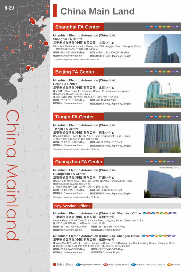
FA Center Satellite
CNC
CNC
Mitsubishi Electric Automation (China) Ltd. Beijing Office三菱电机自动化(中国)有限公司 北京分公司9F, Office Tower 1, Henderson Centre, 18 Jianguomennei Avenue, Dongcheng District, Beijing, China北京市东城区建国门内大街18号 恒基中心办公楼第一座9层
+86-10-6518-8830(Rep)TEL
http://www.meach.cnHP Chinese, EnglishLANGUAGE+86-10-6518-8030(Rep)FAX
Mitsubishi Electric Automation (China) Ltd. Tianjin Office三菱电机自动化(中国)有限公司 天津分公司Room 2003 City Tower, No.35, Youyi Road, Hexi District, Tianjin, China天津市河西区友谊路35号 城市大厦2003室
+86-22-2813-1015(Rep)TEL
http://www.meach.cnHP Chinese, Japanese, EnglishLANGUAGE+86-22-2813-1017(Rep)FAX
Mitsubishi Electric Automation (China) Ltd. Guanzhou Office三菱电机自动化(中国)有限公司 广州分公司Rm.1609, North Tower, The Hub Center, No.1068, Xin Gang East Road, Haizhu District, Guangzhou, China广州市海珠区新港东路1068号 中洲中心北塔1609室
+86-20-8923-6730(Rep)TEL
http://www.meach.cnHP Chinese, Japanese, EnglishLANGUAGE+86-20-8923-6715(Rep)FAX
MITSUBISHI ELECTRIC QINGDAO FA Center Satellite55-1, Liaoning Road, Qingdao, China青岛市辽宁路55号-1
+86-532-8384-3891(Rep)TEL
ChineseLANGUAGE
+86-532-8384-1357(Rep)FAX
MITSUBISHI ELECTRIC WUHAN FA Center SatelliteUnit 1609, Jiangtian Mansion, No.586, Wuluo Road, Wuchang District, Wuhan, China武汉市武昌区武珞路586号 江天大厦 16F 1609室
+86-27-8765-5025(Rep)TEL
ChineseLANGUAGE
+86-27-8765-5247(Rep)FAX
MITSUBISHI ELECTRIC XIANGYANG FA Center SatelliteRoom 1318, Financial Building, Dongfeng Qiche Street, Xiangyang Qiche Products Development Zone, Xiangyang, China襄阳汽车产业开发区东风汽车大道金融大楼工行1318室
+86-710-339-8821(Rep)TEL
ChineseLANGUAGE
+86-710-339-2859(Rep)FAX
MITSUBISHI ELECTRIC SHENZHEN FA Center Satellite27F, Daqing Building, Chegong Miao, Futian District, Shenzhen, China深圳市福田区车公庙路大庆大厦27楼
+86-755-8298-4361(Rep)TEL
ChineseLANGUAGE
+86-755-8298-4880(Rep)FAX
MITSUBISHI ELECTRIC GUANGZHOU FA Center SatelliteUnit C, 8F, Chengjian Building, 189, Tiyu Road(West), Tianhe District, Guangzhou, China广州市天河区体育西路189号 城建大厦8楼C单元
MITSUBISHI ELECTRIC FUZHOU FA Center Satellite
+86-20-3879-7100(Rep)TEL
ChineseLANGUAGE
+86-20-3879-7106(Rep)FAX
Room 810, Times Square, 89, Fuxin Road(Central), Fuzhou, China福州市福新中路89号 时代国际广场810室
+86-591-8395-4128(Rep)TEL
ChineseLANGUAGE
+86-591-8399-5476(Rep)FAX
MITSUBISHI ELECTRIC CHONGQING FA Center Satellite5-5, Yugao Square D Tower, Keyuan Yi Road, Gaoxin District, Chongqing, China重庆市高新区科园一路210号 渝高广场D座 科技发展大厦5-5
+86-23-6862-2098(Rep)TEL
ChineseLANGUAGE
+86-23-8908-9306(Rep)FAX
MITSUBISHI ELECTRIC ZHENGZHOU FA Center Satellite109B, Kejishichangsumagang, Wenhualu 68, Zhengzhou, China郑州市文化路68号科技市场数码港109B室
+86-371-6396-5378(Rep)TEL
ChineseLANGUAGE
+86-371-6396-5398(Rep)FAX
Sales Offices
Mitsubishi Electric Automation (China) Ltd. Dalian Office三菱电机自动化(中国)有限公司 大连分公司Dongbei 3-5, Dailan Economic & Technical Development Zone, Liaoning Province, China大连经济技术开发区东北三街5号(三菱电机大连机器有限公司内)
+86-411-8765-5951(Rep)TEL
http://www.meach.cnHP Chinese, EnglishLANGUAGE+86-411-8765-5952(Rep)FAX
Mitsubishi Electric Automation (China) Ltd. Nanijing Office三菱电机自动化(中国)有限公司 南京分公司Unit S1, 18F, Huatai Building, 90, Zhongshan Road(East), Nanjing, China南京市中山东路90号华泰大厦18楼S1座
+86-25-8445-3228(Rep)TEL
http://www.meach.cnHP Chinese, EnglishLANGUAGE+86-25-8445-3808(Rep)FAX
Mitsubishi Electric Automation (China) Ltd. Wuhan Office三菱电机自动化(中国)有限公司 武汉分公司Room 4618, 46F, New World International Trader Tower No.568 Jianshe Avenue, Hankou, Wuhan, 430022, China武汉市汉口建设大道568号新世界国贸大厦1座46层18号
+86-27-8555-8043TEL
http://www.meach.cnHP ChineseLANGUAGE+86-27-8555-7883FAX
Mitsubishi Electric Automation (China) Ltd.三菱电机自动化(中国)有限公司Mitsubishi Electric Automation Center, No.1386 Hongqiao Road, Shanghai, China上海市虹桥路1386号 三菱电机自动化中心
+86-21-2322-3030TEL
http://cn.mitsubishielectric.com/fa/zhHP Chinese, Japanese, EnglishLANGUAGE+86-21-2322-3000(9611#)FAX
http://www.mitsubishi-qd.comHP
http://www.whxingdong.comHP
http://www.szxingdong.comHP http://www.hnbf.cnHP
RB CNC LVS MC
RB CNC LVS MC
RB CNC LVS MC
Mitsubishi Electric Automation (China) Ltd. Shenzhen Office三菱电机自动化(中国)有限公司 深圳分公司Level 8, Galaxy World Tower B, 1 Yabao Road, Longgang District, Shenzhen, China深圳市龙岗区雅宝路1号 星河WORLD B栋大厦8层
+86-755-2399-8272(Rep)TEL
http://www.meach.cnHP Chinese, EnglishLANGUAGE+86-755-8218-4776(Rep)FAX
RB CNC LVS MC
Mitsubishi Electric Automation (China) Ltd. Chengdu Office三菱电机自动化(中国)有限公司 成都分公司Room 401A-407B-408, 4F, Unit B, Shangri-La Center, No. 9 Binjiang East Road, Jinjiang District, Chengdu, China成都市滨江东路9号B座成都香格里拉中心办公楼4层401A, 407B, 408单元
+86-28-8446-8030(Rep)TEL
http://www.meach.cnHP Chinese, EnglishLANGUAGE+86-28-8446-8630(Rep)FAX
RB CNC LVS MC
CNC
LVS MC
MITSUBISHI ELECTRIC SHENYANG FA Center SatelliteRoom 1122, Buynow Technology Building, NO.90-5, Sanhao Street, Heping District, Shenyang, China沈阳市和平区三好街90甲5号 百脑汇科技大厦1122室
+86-24-8399-3929(Rep)TEL
ChineseLANGUAGE
+86-24-8399-3949(Rep)FAX
http://highskill30.comHP
MITSUBISHI ELECTRIC CHANGCHUN FA Center Satellite1798, Ruipeng Road, Chaoyang Industrial Economy Development District, Changchun, China长春市朝阳工业经济开发区瑞鹏路1798号
+86-431-8502-1546TEL
ChineseLANGUAGE
+86-431-8502-1690FAX
http://www.cckw.com.cnHP
http://www.szxingdong.comHP
http://www.szxingdong.comHP
* PLC,HMI,SV,INV:吉林省地区受付窓口CNC
Beijing FA Center
Mitsubishi Electric Automation (China) Ltd. Beijin FA Center三菱电机自动化(中国)有限公司 北京FA中心Unit 901, Office Tower 1, Henderson Centre, 18 Jianguomennei Avenue, Dongcheng District, Beijing, China北京市东城区建国门内大街18号 恒基中心办公楼第一座901室
+86-10-6518-8830(Rep)TEL
LANGUAGE
+86-10-6518-2938FAX
http://www.meach.cnHP
Shanghai FA Center
Mitsubishi Electric Automation (China) Ltd. Shanghai FA Center三菱电机自动化(中国)有限公司 上海FA中心Mitsubishi Electric Automation Center, No.1386 Hongqiao Road, Shanghai, China上海市虹桥路1386号 三菱电机自动化中心
+86-21-2322-3030(Rep)TEL
Chinese, Japanese, EnglishLANGUAGE
+86-21-2322-3000(9611#)(Rep)FAX
http://www.meach.cnHP
* Japanese engineers are stationed in the FA Center.
Guangzhou FA Center
Mitsubishi Electric Automation (China) Ltd. Guangzhou FA Center三菱电机自动化(中国)有限公司 广州FA中心Room 1609, North Tower, The Hub Center, No.1068, Xingang East Road, Haizhu District, Guangzhou, China广州市海珠区新港东路1068号 中洲中心北塔1609室
+86-20-8923-6730(Rep)TEL
Chinese, Japanese, EnglishLANGUAGE
+86-20-8923-6715(Rep)FAX
http://www.meach.cnHP
* Japanese engineers are stationed in the FA Center.
* Robot:華南地区受付窓口
Tianjin FA Center
Mitsubishi Electric Automation (China) Ltd. Tianjin FA Center三菱电机自动化(中国)有限公司 天津FA中心Room 2003 City Tower, No.35, Youyi Road, Hexi District, Tianjin, China天津市河西区友谊路35号 城市大厦2003室
+86-22-2813-1015(Rep)TEL
Chinese, Japanese, English
Chinese, Japanese, English
LANGUAGE
+86-22-2813-1017(Rep)FAX
http://www.meach.cnHP
* Japanese engineers are stationed in the FA Center.
Key Service Offices
Mitsubishi Electric Automation (China) Ltd. Shenzhen Office三菱电机自动化(中国)有限公司 深圳分公司Level 8, Galaxy World Tower B, 1 Yabao Road, Longgang District, Shenzhen, China深圳市龙岗区雅宝路1号 星河WORLD B栋大厦8层
+86-755-2399-8272(Rep)TEL
Chinese, EnglishLANGUAGE
+86-755-8218-4776(Rep)FAX
http://www.meach.cnHP
Mitsubishi Electric Automation (China) Ltd. Chengdu Office三菱电机自动化(中国)有限公司 成都分公司Room 401A-407B-408, 4F, Unit B, Shangri-La Center, No. 9 Binjiang East Road, Jinjiang District, Chengdu, China成都市滨江东路9号B座成都香格里拉中心办公楼4层401A, 407B, 408单元
+86-28-8446-8030(Rep)TEL
Chinese, EnglishLANGUAGE
+86-28-8446-8630(Rep)FAX
http://www.meach.cnHP
RB CNC LVS MC
RB CNC LVS MC
RB CNC LVS MC
RB LVS* MC
China Main Land
RB CNC LVS MC
RB CNC LVS MC
Sales offices Programmable Controllers InvertersAC Servos, Servo System ControllersHuman-Machine Interfaces Industrial RobotsRB Computerized Numerical ControllersCNC Low-voltage Circuit BreakersLVS Contactors and Motor Starters * For repairing or after-sales technical support, please contact your nearest FA Center.MC
B-29
FA Center Satellite
CNC
CNC
Mitsubishi Electric Automation (China) Ltd. Beijing Office三菱电机自动化(中国)有限公司 北京分公司9F, Office Tower 1, Henderson Centre, 18 Jianguomennei Avenue, Dongcheng District, Beijing, China北京市东城区建国门内大街18号 恒基中心办公楼第一座9层
+86-10-6518-8830(Rep)TEL
http://www.meach.cnHP Chinese, EnglishLANGUAGE+86-10-6518-8030(Rep)FAX
Mitsubishi Electric Automation (China) Ltd. Tianjin Office三菱电机自动化(中国)有限公司 天津分公司Room 2003 City Tower, No.35, Youyi Road, Hexi District, Tianjin, China天津市河西区友谊路35号 城市大厦2003室
+86-22-2813-1015(Rep)TEL
http://www.meach.cnHP Chinese, Japanese, EnglishLANGUAGE+86-22-2813-1017(Rep)FAX
Mitsubishi Electric Automation (China) Ltd. Guanzhou Office三菱电机自动化(中国)有限公司 广州分公司Rm.1609, North Tower, The Hub Center, No.1068, Xin Gang East Road, Haizhu District, Guangzhou, China广州市海珠区新港东路1068号 中洲中心北塔1609室
+86-20-8923-6730(Rep)TEL
http://www.meach.cnHP Chinese, Japanese, EnglishLANGUAGE+86-20-8923-6715(Rep)FAX
MITSUBISHI ELECTRIC QINGDAO FA Center Satellite55-1, Liaoning Road, Qingdao, China青岛市辽宁路55号-1
+86-532-8384-3891(Rep)TEL
ChineseLANGUAGE
+86-532-8384-1357(Rep)FAX
MITSUBISHI ELECTRIC WUHAN FA Center SatelliteUnit 1609, Jiangtian Mansion, No.586, Wuluo Road, Wuchang District, Wuhan, China武汉市武昌区武珞路586号 江天大厦 16F 1609室
+86-27-8765-5025(Rep)TEL
ChineseLANGUAGE
+86-27-8765-5247(Rep)FAX
MITSUBISHI ELECTRIC XIANGYANG FA Center SatelliteRoom 1318, Financial Building, Dongfeng Qiche Street, Xiangyang Qiche Products Development Zone, Xiangyang, China襄阳汽车产业开发区东风汽车大道金融大楼工行1318室
+86-710-339-8821(Rep)TEL
ChineseLANGUAGE
+86-710-339-2859(Rep)FAX
MITSUBISHI ELECTRIC SHENZHEN FA Center Satellite27F, Daqing Building, Chegong Miao, Futian District, Shenzhen, China深圳市福田区车公庙路大庆大厦27楼
+86-755-8298-4361(Rep)TEL
ChineseLANGUAGE
+86-755-8298-4880(Rep)FAX
MITSUBISHI ELECTRIC GUANGZHOU FA Center SatelliteUnit C, 8F, Chengjian Building, 189, Tiyu Road(West), Tianhe District, Guangzhou, China广州市天河区体育西路189号 城建大厦8楼C单元
MITSUBISHI ELECTRIC FUZHOU FA Center Satellite
+86-20-3879-7100(Rep)TEL
ChineseLANGUAGE
+86-20-3879-7106(Rep)FAX
Room 810, Times Square, 89, Fuxin Road(Central), Fuzhou, China福州市福新中路89号 时代国际广场810室
+86-591-8395-4128(Rep)TEL
ChineseLANGUAGE
+86-591-8399-5476(Rep)FAX
MITSUBISHI ELECTRIC CHONGQING FA Center Satellite5-5, Yugao Square D Tower, Keyuan Yi Road, Gaoxin District, Chongqing, China重庆市高新区科园一路210号 渝高广场D座 科技发展大厦5-5
+86-23-6862-2098(Rep)TEL
ChineseLANGUAGE
+86-23-8908-9306(Rep)FAX
MITSUBISHI ELECTRIC ZHENGZHOU FA Center Satellite109B, Kejishichangsumagang, Wenhualu 68, Zhengzhou, China郑州市文化路68号科技市场数码港109B室
+86-371-6396-5378(Rep)TEL
ChineseLANGUAGE
+86-371-6396-5398(Rep)FAX
Sales Offices
Mitsubishi Electric Automation (China) Ltd. Dalian Office三菱电机自动化(中国)有限公司 大连分公司Dongbei 3-5, Dailan Economic & Technical Development Zone, Liaoning Province, China大连经济技术开发区东北三街5号(三菱电机大连机器有限公司内)
+86-411-8765-5951(Rep)TEL
http://www.meach.cnHP Chinese, EnglishLANGUAGE+86-411-8765-5952(Rep)FAX
Mitsubishi Electric Automation (China) Ltd. Nanijing Office三菱电机自动化(中国)有限公司 南京分公司Unit S1, 18F, Huatai Building, 90, Zhongshan Road(East), Nanjing, China南京市中山东路90号华泰大厦18楼S1座
+86-25-8445-3228(Rep)TEL
http://www.meach.cnHP Chinese, EnglishLANGUAGE+86-25-8445-3808(Rep)FAX
Mitsubishi Electric Automation (China) Ltd. Wuhan Office三菱电机自动化(中国)有限公司 武汉分公司Room 4618, 46F, New World International Trader Tower No.568 Jianshe Avenue, Hankou, Wuhan, 430022, China武汉市汉口建设大道568号新世界国贸大厦1座46层18号
+86-27-8555-8043TEL
http://www.meach.cnHP ChineseLANGUAGE+86-27-8555-7883FAX
Mitsubishi Electric Automation (China) Ltd.三菱电机自动化(中国)有限公司Mitsubishi Electric Automation Center, No.1386 Hongqiao Road, Shanghai, China上海市虹桥路1386号 三菱电机自动化中心
+86-21-2322-3030TEL
http://cn.mitsubishielectric.com/fa/zhHP Chinese, Japanese, EnglishLANGUAGE+86-21-2322-3000(9611#)FAX
http://www.mitsubishi-qd.comHP
http://www.whxingdong.comHP
http://www.szxingdong.comHP http://www.hnbf.cnHP
RB CNC LVS MC
RB CNC LVS MC
RB CNC LVS MC
Mitsubishi Electric Automation (China) Ltd. Shenzhen Office三菱电机自动化(中国)有限公司 深圳分公司Level 8, Galaxy World Tower B, 1 Yabao Road, Longgang District, Shenzhen, China深圳市龙岗区雅宝路1号 星河WORLD B栋大厦8层
+86-755-2399-8272(Rep)TEL
http://www.meach.cnHP Chinese, EnglishLANGUAGE+86-755-8218-4776(Rep)FAX
RB CNC LVS MC
Mitsubishi Electric Automation (China) Ltd. Chengdu Office三菱电机自动化(中国)有限公司 成都分公司Room 401A-407B-408, 4F, Unit B, Shangri-La Center, No. 9 Binjiang East Road, Jinjiang District, Chengdu, China成都市滨江东路9号B座成都香格里拉中心办公楼4层401A, 407B, 408单元
+86-28-8446-8030(Rep)TEL
http://www.meach.cnHP Chinese, EnglishLANGUAGE+86-28-8446-8630(Rep)FAX
RB CNC LVS MC
CNC
LVS MC
MITSUBISHI ELECTRIC SHENYANG FA Center SatelliteRoom 1122, Buynow Technology Building, NO.90-5, Sanhao Street, Heping District, Shenyang, China沈阳市和平区三好街90甲5号 百脑汇科技大厦1122室
+86-24-8399-3929(Rep)TEL
ChineseLANGUAGE
+86-24-8399-3949(Rep)FAX
http://highskill30.comHP
MITSUBISHI ELECTRIC CHANGCHUN FA Center Satellite1798, Ruipeng Road, Chaoyang Industrial Economy Development District, Changchun, China长春市朝阳工业经济开发区瑞鹏路1798号
+86-431-8502-1546TEL
ChineseLANGUAGE
+86-431-8502-1690FAX
http://www.cckw.com.cnHP
http://www.szxingdong.comHP
http://www.szxingdong.comHP
* PLC,HMI,SV,INV:吉林省地区受付窓口CNC
Beijing FA Center
Mitsubishi Electric Automation (China) Ltd. Beijin FA Center三菱电机自动化(中国)有限公司 北京FA中心Unit 901, Office Tower 1, Henderson Centre, 18 Jianguomennei Avenue, Dongcheng District, Beijing, China北京市东城区建国门内大街18号 恒基中心办公楼第一座901室
+86-10-6518-8830(Rep)TEL
LANGUAGE
+86-10-6518-2938FAX
http://www.meach.cnHP
Shanghai FA Center
Mitsubishi Electric Automation (China) Ltd. Shanghai FA Center三菱电机自动化(中国)有限公司 上海FA中心Mitsubishi Electric Automation Center, No.1386 Hongqiao Road, Shanghai, China上海市虹桥路1386号 三菱电机自动化中心
+86-21-2322-3030(Rep)TEL
Chinese, Japanese, EnglishLANGUAGE
+86-21-2322-3000(9611#)(Rep)FAX
http://www.meach.cnHP
* Japanese engineers are stationed in the FA Center.
Guangzhou FA Center
Mitsubishi Electric Automation (China) Ltd. Guangzhou FA Center三菱电机自动化(中国)有限公司 广州FA中心Room 1609, North Tower, The Hub Center, No.1068, Xingang East Road, Haizhu District, Guangzhou, China广州市海珠区新港东路1068号 中洲中心北塔1609室
+86-20-8923-6730(Rep)TEL
Chinese, Japanese, EnglishLANGUAGE
+86-20-8923-6715(Rep)FAX
http://www.meach.cnHP
* Japanese engineers are stationed in the FA Center.
* Robot:華南地区受付窓口
Tianjin FA Center
Mitsubishi Electric Automation (China) Ltd. Tianjin FA Center三菱电机自动化(中国)有限公司 天津FA中心Room 2003 City Tower, No.35, Youyi Road, Hexi District, Tianjin, China天津市河西区友谊路35号 城市大厦2003室
+86-22-2813-1015(Rep)TEL
Chinese, Japanese, English
Chinese, Japanese, English
LANGUAGE
+86-22-2813-1017(Rep)FAX
http://www.meach.cnHP
* Japanese engineers are stationed in the FA Center.
Key Service Offices
Mitsubishi Electric Automation (China) Ltd. Shenzhen Office三菱电机自动化(中国)有限公司 深圳分公司Level 8, Galaxy World Tower B, 1 Yabao Road, Longgang District, Shenzhen, China深圳市龙岗区雅宝路1号 星河WORLD B栋大厦8层
+86-755-2399-8272(Rep)TEL
Chinese, EnglishLANGUAGE
+86-755-8218-4776(Rep)FAX
http://www.meach.cnHP
Mitsubishi Electric Automation (China) Ltd. Chengdu Office三菱电机自动化(中国)有限公司 成都分公司Room 401A-407B-408, 4F, Unit B, Shangri-La Center, No. 9 Binjiang East Road, Jinjiang District, Chengdu, China成都市滨江东路9号B座成都香格里拉中心办公楼4层401A, 407B, 408单元
+86-28-8446-8030(Rep)TEL
Chinese, EnglishLANGUAGE
+86-28-8446-8630(Rep)FAX
http://www.meach.cnHP
RB CNC LVS MC
RB CNC LVS MC
RB CNC LVS MC
RB LVS* MC
China Main Land
RB CNC LVS MC
RB CNC LVS MC
Sales offices Programmable Controllers InvertersAC Servos, Servo System ControllersHuman-Machine Interfaces Industrial RobotsRB Computerized Numerical ControllersCNC Low-voltage Circuit BreakersLVS Contactors and Motor Starters * For repairing or after-sales technical support, please contact your nearest FA Center.MC
B-30
Taiwan
Korea
Mitsubishi Electric Automation (China) Ltd. Xi'an Office三菱电机自动化(中国)有限公司 西安分公司Room D-E, 24F, millenium Star Mansion, NO.88 Nan'er Huan Xiduan, Xi'an, Shanxi province, China西安市二环南路88号老三届世纪星大厦24层DE室
+86-29-8730-5236(Rep)TEL
http://www.meach.cnHP
ChineseLANGUAGE
+86-29-8730-5235(Rep)FAX
Sales Offices
RB
Mitsubishi Electric Automation (China) Ltd. Shenyang Office三菱电机自动化(中国)有限公司 沈阳分公司Tower C, President Building, No.69 Heping North Street, Heping District, Shenyang, China沈阳市和平区和平北大街69号总统大厦C座
+86-24-2259-8830(Rep)TEL
http://cn.mitsubishielectric.com/fa/zhHP
ChineseLANGUAGE
+86-24-2259-8030(Rep)FAX
Mitsubishi Electric Automation (HONG KONG) Ltd.三菱电机自动化(香港)有限公司20th Floor, Cityplaza One, 1111 King's Road, Taikoo Shing, Hong Kong, China香港太古城英皇道1111号太古城中心一座20F
+852-2510-0555(Rep)TEL +852-2887-7984(Rep)FAX
Chinese, EnglishLANGUAGE
* Please contact Shanghai FA Center for Japanese support.
LVS MC
Mitsubishi Electric Automation Korea Co., Ltd.7F to 9F, Gangseo Hangang Xi-tower A, 401, Yangcheon-ro, Gangseo-Gu, Seoul,07528, Korea
+82-2-3660-9629/9606/9607+82-2-3660-9630+82-2-3660-9632+82-2-3660-9631
TEL
Korean, JapaneseLANGUAGE
+82-2-6224-0475FAX
http://www.mitsubishi-automation.co.kr/HP
* Japanese engineers are stationed in the FA Center.
Mitsubishi Electric Automation Korea Co., Ltd.7F to 9F, Gangseo Hangang Xi-tower A, 401, Yangcheon-ro, Gangseo-Gu, Seoul 07528, Korea
+82-2-3660-9530+82-2-3660-9510+82-2-3660-9550
TEL
http://www.mitsubishi-automation.co.kr/HP
Korean, JapaneseLANGUAGE
+82-2-3664-8372/8335+82-2-3664-8668
FAX
Mitsubishi Electric Automation Korea Co., Ltd. Busan Office3F Haejeong Bldg. 233, Jungang-Daero, Dong-Gu, Busan, 48815, Korea
+82-51-464-3747 to 9TEL
http://www.mitsubishi-automation.co.kr/HP
Korean, JapaneseLANGUAGE
+82-51-464-3768FAX
Mitsubishi Electric Automation Korea Co., Ltd. Daegu Office4F KT Bldg. 8, Hoguk-ro, Buk-Gu, Daegu 41518, Korea
+82-53-382-7400+82-53-382-7401
TEL
http://www.mitsubishi-automation.co.kr/HP
Korean, English, JapaneseLANGUAGE
+82-53-382-7411FAX
Sales Offices
CNC
CNC
CNCRB
RB LVS MC
Korea FA Center RB CNC
Taichung FA Center
Taipei FA Center
Mitsubishi Electric Taiwan Co., Ltd.台灣三菱電機股份有限公司No.8-1, Industrial 16th Road, Taichung Industrial Park, Taichung City 40768 Taiwan40768 台中市西屯區工業十六路8之1號
+886-4-2359-0688(Rep)TEL
Chinese, Japanese, EnglishLANGUAGE
+886-4-2359-0689(Rep)FAX
http://www.MitsubishiElectric.com.twHP
* Japanese engineers are stationed in the FA Center.
Mitsubishi Electric Taiwan Co., Ltd. (Central area)台灣三菱電機股份有限公司(台中地區)No.8-1, Industrial 16th Road, Taichung Industrial Park, Taichung City 40768, Taiwan40768 台中市西屯區工業十六路8之1號
+886-4-2359-0688(Rep)TEL
http://www.mitsubishielectric.com.twHP
Chinese, English, JapaneseLANGUAGE
+886-4-2359-0689(Rep)FAX
RB CNC
RB CNC
RB CNC
SETSUYO ENTERPRISE CO., LTD.攝陽企業股份有限公司6F, No.105, Wugong 3rd Road, Wugu District, New Taipei City 24889, Taiwan24889 新北市五股區五工三路105號6樓
+886-2-2299-2499TEL
http://www.setsuyo.com.twHP
Japanese, ChineseLANGUAGE
+886-2-2299-2509FAX
Mitsubishi Electric Taiwan Co., Ltd. (South area)台灣三菱電機股份有限公司(台南地區)11F-1., No.30, Zhongzheng S. Road, Yongkang District, Tainan City 71067, Taiwan71067 台南市永康區中正南路30號11樓之1
+886-6-252-5030TEL
http://www.mitsubishielectric.com.twHP
ChineseLANGUAGE
+886-6-252-5031FAX
SETSUYO ENTERPRISE CO., LTD. Tainan Branch攝陽企業股份有限公司 台南支店2, 12F, No.30, Zhongzheng S. Road, Yongkang District, Tainan City 71067, Taiwan71067 台南市永康區中正南路30號12樓之2
+886-6-282-1713TEL
http://www.setsuyo.com.twHP Chinese, JapaneseLANGUAGE+886-6-282-1714FAX
SETSUYO ENTERPRISE CO., LTD. Kaohsiung Branch攝陽企業股份有限公司 高雄支店Room 6 16F, No.3, Ziqiang 3rd Road, Lingya District, Kaohsiung City 80245, Taiwan80245 高雄市苓雅區自強三路3號16樓之6
+886-7-332-0489TEL
http://www.setsuyo.com.twHP Chinese, JapaneseLANGUAGE+886-7-332-0495FAX
SETSUYO ENTERPRISE CO., LTD. Taichung Branch攝陽企業股份有限公司 台中支店Room 7, 7F, No.77, Shizheng N.1st Road, Xitun District, Taichung City 40756, Taiwan40756 台中市市政北一路77號7樓之7
+886-4-2258-1027TEL
http://www.setsuyo.com.twHP ChineseLANGUAGE+886-4-2252-0967FAX
Mitsubishi Electric Taiwan Co., Ltd. (North area)台灣三菱電機股份有限公司(台北地區)10F, No.88 Sec. 6, Chung Shan North Road, Shi Lin District, Taipei City 11155, Taiwan11155 台北市士林區中山北路六段88號10樓
+886-2-2833-5430TEL
http://www.mitsubishielectric.com.twHP
Chinese, JapaneseLANGUAGE
+886-2-2833-5433FAX
Sales Offices
SHIHLIN ELECTRIC & ENGINEERING CORPORATION(AUTOMATION DIVISION)士林電機廠股份有限公司No.234, Zhonglun, Xinfeng Township, Hsinchu County 30473, Taiwan30473 新竹縣新豊鄉中崙村七鄰234號
+886-3-599-5111TEL
http://www.seec.com.twHP Chinese, JapaneseLANGUAGE+886-3-590-7173FAX
FAPRO ENTERPRISE CO., Ltd.能麒企業股份有限公司7F, No.22, Wuquan 7th Rd., Wugu District, New Taipei City 24890, Taiwan24890 新北市五股區五權七路22號7樓
+886-2-2298-1399TEL
http://www.fapro.com.twHP Chinese, JapaneseLANGUAGE+886-2-2298-1319FAX
TWO-WAY TRADING CORPORATION双象貿易股份有限公司12F, No.61, Nanjing W. Road, Datong District, Taipei City 10352, Taiwan10352 台北市大同區南京西路61號12樓
+886-2-2558-9169TEL
http://www.two-way.com.twHP ChineseLANGUAGE+886-2-2559-0983FAX
HAN WAY TECHNOLOGY INC.COMPANY.瀚衛科技有限公司Room 3, 11F, No.37, Sec. 2, Sanmin Road, Banqiao District, New Taipei City 22069, Taiwan22069 新北市板橋區三民路2段37號11樓之3
+886-2-2963-4180TEL
http://www.han-way.com.twHP ChineseLANGUAGE+886-2-2963-4182FAX
FACON Engineering Co., Ltd.惠控機電股份有限公司9F, No.120-11, Sec.3, Jhongshan Road, Jhonghe District, New Taipei City, 23544 Taiwan23544 新北市中和區中山路三段120-11號9樓
+886-2-8221-3180TEL
http://www.facon.com.cnHP ChineseLANGUAGE+886-2-8221-3183FAX
EVERTAK TECHNOLOGY CO.,Ltd.日遠科技股份有限公司8F, No.23, Ji Lin Road, Chung Li City, Taoyuan Hsien 32062, Taiwan32062 桃園縣中壢市吉林路23號8樓
+886-3-4617999TEL
http://www.evertak.com.twHP ChineseLANGUAGE+886-3-4617688FAX
CHIANG LY TRADING CO., Ltd.強力貿易股份有限公司No.228, Yanping S. Road, Zhongzheng District, Taipei City 10065, Taiwan10065 台北市中正區延平南路228號
+886-2-2381-5195TEL
ChineseLANGUAGE+886-2-2311-1792FAX
METOP FUNCTIONS Co., Ltd.上菱機電股份有限公司Room 8, 4F, No.4, Ln. 609, Sec. 5, Chongxin Road., Sanchong District, New Taipei City 24159, Taiwan24159 新北市三重區重新路五段609巷6號7樓之5
+886-2-2999-1689TEL
http://www.metop.com.twHP ChineseLANGUAGE+886-2-2999-1655FAX
Distributors
SETSUYO ENTERPRISE CO., LTD.攝陽企業股份有限公司3F, No.105, Wugong 3rd Road, Wugu District, New Taipei City 24889, Taiwan24889 新北市五股區五工三路105號3樓
+886-2-2299-9917TEL
Japanese, ChineseLANGUAGE
+886-2-2299-9963FAX
http://www.setsuyo.com.twHP
* Japanese engineers are stationed in the FA Center.
China Main Land
RB
RB CNC
Sales offices Programmable Controllers InvertersAC Servos, Servo System ControllersHuman-Machine Interfaces Industrial RobotsRB Computerized Numerical ControllersCNC Low-voltage Circuit BreakersLVS Contactors and Motor Starters * For repairing or after-sales technical support, please contact your nearest FA Center.MC
B-31
Taiwan
Korea
Mitsubishi Electric Automation (China) Ltd. Xi'an Office三菱电机自动化(中国)有限公司 西安分公司Room D-E, 24F, millenium Star Mansion, NO.88 Nan'er Huan Xiduan, Xi'an, Shanxi province, China西安市二环南路88号老三届世纪星大厦24层DE室
+86-29-8730-5236(Rep)TEL
http://www.meach.cnHP
ChineseLANGUAGE
+86-29-8730-5235(Rep)FAX
Sales Offices
RB
Mitsubishi Electric Automation (China) Ltd. Shenyang Office三菱电机自动化(中国)有限公司 沈阳分公司Tower C, President Building, No.69 Heping North Street, Heping District, Shenyang, China沈阳市和平区和平北大街69号总统大厦C座
+86-24-2259-8830(Rep)TEL
http://cn.mitsubishielectric.com/fa/zhHP
ChineseLANGUAGE
+86-24-2259-8030(Rep)FAX
Mitsubishi Electric Automation (HONG KONG) Ltd.三菱电机自动化(香港)有限公司20th Floor, Cityplaza One, 1111 King's Road, Taikoo Shing, Hong Kong, China香港太古城英皇道1111号太古城中心一座20F
+852-2510-0555(Rep)TEL +852-2887-7984(Rep)FAX
Chinese, EnglishLANGUAGE
* Please contact Shanghai FA Center for Japanese support.
LVS MC
Mitsubishi Electric Automation Korea Co., Ltd.7F to 9F, Gangseo Hangang Xi-tower A, 401, Yangcheon-ro, Gangseo-Gu, Seoul,07528, Korea
+82-2-3660-9629/9606/9607+82-2-3660-9630+82-2-3660-9632+82-2-3660-9631
TEL
Korean, JapaneseLANGUAGE
+82-2-6224-0475FAX
http://www.mitsubishi-automation.co.kr/HP
* Japanese engineers are stationed in the FA Center.
Mitsubishi Electric Automation Korea Co., Ltd.7F to 9F, Gangseo Hangang Xi-tower A, 401, Yangcheon-ro, Gangseo-Gu, Seoul 07528, Korea
+82-2-3660-9530+82-2-3660-9510+82-2-3660-9550
TEL
http://www.mitsubishi-automation.co.kr/HP
Korean, JapaneseLANGUAGE
+82-2-3664-8372/8335+82-2-3664-8668
FAX
Mitsubishi Electric Automation Korea Co., Ltd. Busan Office3F Haejeong Bldg. 233, Jungang-Daero, Dong-Gu, Busan, 48815, Korea
+82-51-464-3747 to 9TEL
http://www.mitsubishi-automation.co.kr/HP
Korean, JapaneseLANGUAGE
+82-51-464-3768FAX
Mitsubishi Electric Automation Korea Co., Ltd. Daegu Office4F KT Bldg. 8, Hoguk-ro, Buk-Gu, Daegu 41518, Korea
+82-53-382-7400+82-53-382-7401
TEL
http://www.mitsubishi-automation.co.kr/HP
Korean, English, JapaneseLANGUAGE
+82-53-382-7411FAX
Sales Offices
CNC
CNC
CNCRB
RB LVS MC
Korea FA Center RB CNC
Taichung FA Center
Taipei FA Center
Mitsubishi Electric Taiwan Co., Ltd.台灣三菱電機股份有限公司No.8-1, Industrial 16th Road, Taichung Industrial Park, Taichung City 40768 Taiwan40768 台中市西屯區工業十六路8之1號
+886-4-2359-0688(Rep)TEL
Chinese, Japanese, EnglishLANGUAGE
+886-4-2359-0689(Rep)FAX
http://www.MitsubishiElectric.com.twHP
* Japanese engineers are stationed in the FA Center.
Mitsubishi Electric Taiwan Co., Ltd. (Central area)台灣三菱電機股份有限公司(台中地區)No.8-1, Industrial 16th Road, Taichung Industrial Park, Taichung City 40768, Taiwan40768 台中市西屯區工業十六路8之1號
+886-4-2359-0688(Rep)TEL
http://www.mitsubishielectric.com.twHP
Chinese, English, JapaneseLANGUAGE
+886-4-2359-0689(Rep)FAX
RB CNC
RB CNC
RB CNC
SETSUYO ENTERPRISE CO., LTD.攝陽企業股份有限公司6F, No.105, Wugong 3rd Road, Wugu District, New Taipei City 24889, Taiwan24889 新北市五股區五工三路105號6樓
+886-2-2299-2499TEL
http://www.setsuyo.com.twHP
Japanese, ChineseLANGUAGE
+886-2-2299-2509FAX
Mitsubishi Electric Taiwan Co., Ltd. (South area)台灣三菱電機股份有限公司(台南地區)11F-1., No.30, Zhongzheng S. Road, Yongkang District, Tainan City 71067, Taiwan71067 台南市永康區中正南路30號11樓之1
+886-6-252-5030TEL
http://www.mitsubishielectric.com.twHP
ChineseLANGUAGE
+886-6-252-5031FAX
SETSUYO ENTERPRISE CO., LTD. Tainan Branch攝陽企業股份有限公司 台南支店2, 12F, No.30, Zhongzheng S. Road, Yongkang District, Tainan City 71067, Taiwan71067 台南市永康區中正南路30號12樓之2
+886-6-282-1713TEL
http://www.setsuyo.com.twHP Chinese, JapaneseLANGUAGE+886-6-282-1714FAX
SETSUYO ENTERPRISE CO., LTD. Kaohsiung Branch攝陽企業股份有限公司 高雄支店Room 6 16F, No.3, Ziqiang 3rd Road, Lingya District, Kaohsiung City 80245, Taiwan80245 高雄市苓雅區自強三路3號16樓之6
+886-7-332-0489TEL
http://www.setsuyo.com.twHP Chinese, JapaneseLANGUAGE+886-7-332-0495FAX
SETSUYO ENTERPRISE CO., LTD. Taichung Branch攝陽企業股份有限公司 台中支店Room 7, 7F, No.77, Shizheng N.1st Road, Xitun District, Taichung City 40756, Taiwan40756 台中市市政北一路77號7樓之7
+886-4-2258-1027TEL
http://www.setsuyo.com.twHP ChineseLANGUAGE+886-4-2252-0967FAX
Mitsubishi Electric Taiwan Co., Ltd. (North area)台灣三菱電機股份有限公司(台北地區)10F, No.88 Sec. 6, Chung Shan North Road, Shi Lin District, Taipei City 11155, Taiwan11155 台北市士林區中山北路六段88號10樓
+886-2-2833-5430TEL
http://www.mitsubishielectric.com.twHP
Chinese, JapaneseLANGUAGE
+886-2-2833-5433FAX
Sales Offices
SHIHLIN ELECTRIC & ENGINEERING CORPORATION(AUTOMATION DIVISION)士林電機廠股份有限公司No.234, Zhonglun, Xinfeng Township, Hsinchu County 30473, Taiwan30473 新竹縣新豊鄉中崙村七鄰234號
+886-3-599-5111TEL
http://www.seec.com.twHP Chinese, JapaneseLANGUAGE+886-3-590-7173FAX
FAPRO ENTERPRISE CO., Ltd.能麒企業股份有限公司7F, No.22, Wuquan 7th Rd., Wugu District, New Taipei City 24890, Taiwan24890 新北市五股區五權七路22號7樓
+886-2-2298-1399TEL
http://www.fapro.com.twHP Chinese, JapaneseLANGUAGE+886-2-2298-1319FAX
TWO-WAY TRADING CORPORATION双象貿易股份有限公司12F, No.61, Nanjing W. Road, Datong District, Taipei City 10352, Taiwan10352 台北市大同區南京西路61號12樓
+886-2-2558-9169TEL
http://www.two-way.com.twHP ChineseLANGUAGE+886-2-2559-0983FAX
HAN WAY TECHNOLOGY INC.COMPANY.瀚衛科技有限公司Room 3, 11F, No.37, Sec. 2, Sanmin Road, Banqiao District, New Taipei City 22069, Taiwan22069 新北市板橋區三民路2段37號11樓之3
+886-2-2963-4180TEL
http://www.han-way.com.twHP ChineseLANGUAGE+886-2-2963-4182FAX
FACON Engineering Co., Ltd.惠控機電股份有限公司9F, No.120-11, Sec.3, Jhongshan Road, Jhonghe District, New Taipei City, 23544 Taiwan23544 新北市中和區中山路三段120-11號9樓
+886-2-8221-3180TEL
http://www.facon.com.cnHP ChineseLANGUAGE+886-2-8221-3183FAX
EVERTAK TECHNOLOGY CO.,Ltd.日遠科技股份有限公司8F, No.23, Ji Lin Road, Chung Li City, Taoyuan Hsien 32062, Taiwan32062 桃園縣中壢市吉林路23號8樓
+886-3-4617999TEL
http://www.evertak.com.twHP ChineseLANGUAGE+886-3-4617688FAX
CHIANG LY TRADING CO., Ltd.強力貿易股份有限公司No.228, Yanping S. Road, Zhongzheng District, Taipei City 10065, Taiwan10065 台北市中正區延平南路228號
+886-2-2381-5195TEL
ChineseLANGUAGE+886-2-2311-1792FAX
METOP FUNCTIONS Co., Ltd.上菱機電股份有限公司Room 8, 4F, No.4, Ln. 609, Sec. 5, Chongxin Road., Sanchong District, New Taipei City 24159, Taiwan24159 新北市三重區重新路五段609巷6號7樓之5
+886-2-2999-1689TEL
http://www.metop.com.twHP ChineseLANGUAGE+886-2-2999-1655FAX
Distributors
SETSUYO ENTERPRISE CO., LTD.攝陽企業股份有限公司3F, No.105, Wugong 3rd Road, Wugu District, New Taipei City 24889, Taiwan24889 新北市五股區五工三路105號3樓
+886-2-2299-9917TEL
Japanese, ChineseLANGUAGE
+886-2-2299-9963FAX
http://www.setsuyo.com.twHP
* Japanese engineers are stationed in the FA Center.
China Main Land
RB
RB CNC
Sales offices Programmable Controllers InvertersAC Servos, Servo System ControllersHuman-Machine Interfaces Industrial RobotsRB Computerized Numerical ControllersCNC Low-voltage Circuit BreakersLVS Contactors and Motor Starters * For repairing or after-sales technical support, please contact your nearest FA Center.MC
B-32

ASEAN
ASEAN FA Center Indonesia FA Center
Mitsubishi Electric Asia Pte. Ltd.307 Alexandra Road, Mitsubishi Electric Building, Singapore 159943
+65-6473-2308+65-6470-2413+65-6470-2462
TEL
http://www.mitsubishielectric.com.sgHP
English, Chinese, JapaneseLANGUAGE
+65-6476-7439FAX
Regional Sales Office in ASEAN
Mitsubishi Electric Asia Pte. Ltd.307 Alexandra Road, Mitsubishi Electric Building, Singapore 159943
+65-6470-2480, +65-6470-2475+65-6470-2413+65-6470-2462
TEL
Chinese, Malay, English, JapaneseLANGUAGE
+65-6476-7439FAX
http://www.mitsubishielectric.com.sgHP
MALAYSIA
Flexible Automation System Sdn. Bhd.
60, Jalan USJ 10/1B, 47620, UEP Subang Jaya, Selangor, Darul, Ehsan, Malaysia
+60-3-5633-1280TEL
http://www.flexible.com.myHP
http://www.hikari.com.sgHP
Malay, English, ChineseLANGUAGE
+60-3-5633-6613FAX
TDS Technology (S) Pte. Ltd.64 Sungei Kadut Loop, HOCEN Building Level3, Singapore 729493
+65-6366-1661TEL
http://www.tdstech.comHP
English, ChineseLANGUAGE
+65-6362-1661FAX
FA-Tech Robotic & Controls Pte. Ltd.No.1 Ubi View #01-03, Focus One, Singapore 408555
+65-6747-6316TEL
English, ChineseLANGUAGE
+65-6747-6516FAX
Flexible Automation System Sdn. Bhd. Penang Branch27, Jalan Pesara Mahsuri 5, Sg. Nibong Kechil, 11900, P. Penang, Malaysia
+60-4-643-3898TEL
http://www.flexible.com.myHP
Malay, English, ChineseLANGUAGE
+60-4-643-3308FAX
Distributors
PHILIPPINES
Integrated Factory Automation Inc.128 Lopez Rizal St., Brgy. Highway Hills, Mandaluyong City, Philippines
+63-2-532-5876 to 80TEL
Tagalog, EnglishLANGUAGE+63-2-571-8979FAX
http://www.ifa.com.phHP
SINGAPOREPumas Automation & Robotics Pte. Ltd.209 Henderson Road # 03-07 Henderson Industrial Park, Singapore 159551
+65-6278-3289TEL
http://sg.pumasautomation.com/index.php/en/HP
English, ChineseLANGUAGE
+65-6278-8372FAX
i-Linear Automation Sdn. Bhd.38-40, Persiaran Tembok, Taman Tawas Gemilang 30010, Ipoh, Perak, Malaysia
+60-5-546-6331TEL
Malay, English, ChineseLANGUAGE
+60-5-547-7331FAX
http://www.ilinear.com.my/HP
i-Linear Automation Sdn. Bhd. Penang Branch1018 (1st Floor), Jalan Dato Ismail Hashim, 11900, Penang, Malaysia
+60-4-646-8382TEL
Malay, English, ChineseLANGUAGE
+60-4-646-8157FAX
http://www.ilinear.com.my/HP
RB
i-Linear Automation Sdn. Bhd.Johor Bahru BranchNo. 31A, Jalan Impian Emas 3, Taman Impian Emas, 81300 Skudai, Johor, Malaysia
+60-7-558-5331TEL
Malay, English, ChineseLANGUAGE
+60-7-558-7331FAX
http://www.ilinear.com.my/HP
RB
i-Linear Automation Sdn. Bhd.Kuala Lumpur Branch17A, Jalan SS18/1B, 47500 Subang Jaya, Selangor, Malaysia.
+60-3-5637-6268TEL
Malay, English, ChineseLANGUAGE
+60-3-5635-7168FAX
http://www.ilinear.com.my/HP
RB
RB CNC LVS MC
RB
RB
RB
RB
RB
LVS MC
LVS MC
Flexible Automation System Sdn. Bhd. Johor Bahru Branch17 & 17A, Jalan Impian Emas 5/5, Taman Impian Emas, 81300 Skudai, Johor, Malaysia
+60-7-557-8218TEL
http://www.flexible.com.myHP
Malay, English, ChineseLANGUAGE
+60-7-557-3404FAX
Flexible Automation System Sdn. Bhd. Ipoh Branch84C-1, Jalan Kuala kangsar, 30010, Ipoh, Perak, Malaysia
+60-5-506-0323/2528TEL
http://www.flexible.com.myHP
Malay, English, ChineseLANGUAGE
+60-5-506-0127FAX
Flexible Automation System Sdn. Bhd. Melaka BranchNo 20, Jalan PB 1, Taman Padang Balang, Batu Berendam, 75350, Melaka, Malaysia
+60-6-317-5090TEL
http://www.flexible.com.myHP
Malay, English, ChineseLANGUAGE
+60-6-317-5092FAX
LVS MC
LVS MC
LVS MC
Mittric Sdn, Bhd.5, Jalan Pemberita U1/49, Temasya Indstrial Park, Glenmarie, 40150 Shah Alam, Selangor, Malaysia
+60-3-5569-3748TEL
http://mittric.com/HP
Malay, English, ChineseLANGUAGE
+60-3-5569-3749FAX
LVS MC
RB
Indonesia
Sales Offices
Distributors
PT. Mitsubishi Electric Indonesia Cikarang OfficeJl. Kenari Raya Blok G2-07A Delta Silicon 5, Lippo Cikarang - Bekasi 17550, Indonesia
+62-21 2961 7797TEL
Indonesian, English, JapaneseLANGUAGE
+62-21 2961 7794FAX
RB CNC
* Japanese engineers are stationed in the FA Center.
PT. Sahabat IndonesiaMuara Karang Selatan Blok A Utara No. 1.Kawasan Industri Pergudangan, Jakarta Utara 14440, Jakarta, Indonesia
+62-21 661 0651TEL
Indonesian, EnglishLANGUAGE
+62-21 660 3700FAX
LVS MC
PT. Mitsubishi Electric IndonesiaGedung Jaya 8th Floor, JL. MH. Thamrin No.12, Jakarta Pusat 10340, Indonesia
+62-21 3192 6461TEL
http://www.mitsubishielectric.com/fa/id_en/index.htmlHP
Indonesian, English, JapaneseLANGUAGE
+62-21 3192 3942FAX
RB
PT. Autoteknindo Sumber MakmurMuara Karang Selatan, Block A Utara No. 1 Kav. No. 11, Kawasan Industri Pergudangan, Jakarta-Utara 14440 P.O.Box 5045, Jakarta 11050, Indonesia
+62-21 663 0833TEL
Indonesian, EnglishLANGUAGE+62-21 663 0832FAX
PT. Autoflex GlobalindoJl. MT. Haryono 141 Semarang Central Java 50123, Indonesia
+62-24 358 5577TEL
Indonesian, EnglishLANGUAGE
+62-24 355 9798FAX
http://www.autoflexindo.comHP
PT. FlexindomasKomplek Ruko Latumenten Jl. Prof. Dr. Latumenten No. 17B Jakarta Barat 11330, Indonesia
+62-21 6313 1151,+62-21 630 1980
TEL
Indonesian, EnglishLANGUAGEhttp://www.id.pumasautomation.comHP
+62-21 631 3154FAX
PT. Mitsol Teknik IndonesiaJl. Jemur Sari 76 D20, Surabaya 60237, Indonesia
+62-31 847 6488TEL
Indonesian, EnglishLANGUAGE
+62-31 847 5462FAX
http://www.mistol.co.idHP
PT. Setsuyo Astec - Semarang OfficeJalan MT Haryono No.525 Semarang, Jawa Tengah, Indonesia
+62-24 844 7899TEL
Indonesian, EnglishLANGUAGE
+62-24 841 7666FAX
http://www.stcid.setsuyo.asiaHP
PT. Abadi Bangun BersamaKomplek Kopo Mas Regency Ruko C-8B JL. KH. Wahid Hasyim, Bandung, Indonesia
+62-22 543 6852TEL
Indonesian, EnglishLANGUAGE+62-22 543 6696FAX
PT. Noble ElectrindoJl. Raya Gading Batavia Blok LC 11/06 Kelapa Gading, Jakarta Utara 14240, Indonesia
+62-21 4585 3422, +62-822 9880 1898,+62-812 8559 1138, +62-877 8216 5691
TEL
Indonesian, EnglishLANGUAGEhttp://noble-indo.com/home/HP
RB
PT. Mitsubishi Electric Indonesia Cikarang OfficeJl. Kenari Raya Blok G2-07A Delta Silicon 5, Lippo Cikarang - Bekasi 17550, Indonesia
+62-21 2961 7797TEL
http://www.mitsubishielectric.com/fa/id_en/index.htmlHP
Indonesian, English, JapaneseLANGUAGE
+62-21 2961 7794FAX
RB CNC
CNC
LVS
CNC
LVS
RB MC
CNCFlexible Automation System CorporationUnit 411, Alabang Corporate Center Km25, West Service Road South Superhighway, Alabang, Muntinlupa City, 1771 Philippines
+63-2-807-2416TEL
Tagalog, EnglishLANGUAGE
+63-2-807-2417FAX
http://ph.pumasautomation.com/index.php/en/HP
Flexible Automation System Corporation
Unit 411. Alabang Corporate Center Km25. West Service Road South Super Highway Alabang Muntinlupa Metro Manila, Philippines
+63-2-807-2416TEL
Tagalog, EnglishLANGUAGE
+63-2-807-2417FAX
http://ph.pumasautomation.com/index.php/en/HP
Flexible Automation System Corporation
Unit 217, M.G.A. Arcade, A.C. Cortes Avenue, Mandaue City, Cebu, 6014 Philippines
+63-2-344-0181TEL
Tagalog, EnglishLANGUAGE
+63-2-345-0319FAX
http://ph.pumasautomation.com/index.php/en/HP
Edison Electric Integrated, Inc.24th Fl. Galleria Corporate Center, Robinson's Commercial Complex EDSA cor. Ortigas Ave., Quezon City, Metro Manila, Philippines
+63-2-634-86-91TEL
Tagalog, EnglishLANGUAGE+63-2-634-58-99FAX
LVS MC
PT. Setsuyo AstecThe Plaza Office Tower, 28th Floor JL. MH. Thamrin Kav 28-30, Jakarta, 10350, Indonesia
+62-21 2992 3322TEL
Indonesian, English, JapaneseLANGUAGE
+62-21 2992 3323FAX
http://stcid.setsuyo.asiaHP
RB CNC LVS
http://sahabatindo.com/HP
PT. Setsuyo Astec - Surabaya OfficeJl. Raya Meganti Karangan No.411, Wiyung, Surabaya, Jawa Timur 60228 Indonesia
+62-31 752 7351TEL
Indonesian, EnglishLANGUAGEhttp://www.stcid.setsuyo.asiaHP
Sales offices Industrial RobotsRB Computerized Numerical ControllersCNC Low-voltage Circuit BreakersLVS Contactors and Motor Starters * For repairing or after-sales technical support, please contact your nearest FA Center.MCProgrammable Controllers InvertersAC Servos, Servo System ControllersHuman-Machine Interfaces
B-33
ASEAN
ASEAN FA Center Indonesia FA Center
Mitsubishi Electric Asia Pte. Ltd.307 Alexandra Road, Mitsubishi Electric Building, Singapore 159943
+65-6473-2308+65-6470-2413+65-6470-2462
TEL
http://www.mitsubishielectric.com.sgHP
English, Chinese, JapaneseLANGUAGE
+65-6476-7439FAX
Regional Sales Office in ASEAN
Mitsubishi Electric Asia Pte. Ltd.307 Alexandra Road, Mitsubishi Electric Building, Singapore 159943
+65-6470-2480, +65-6470-2475+65-6470-2413+65-6470-2462
TEL
Chinese, Malay, English, JapaneseLANGUAGE
+65-6476-7439FAX
http://www.mitsubishielectric.com.sgHP
MALAYSIA
Flexible Automation System Sdn. Bhd.
60, Jalan USJ 10/1B, 47620, UEP Subang Jaya, Selangor, Darul, Ehsan, Malaysia
+60-3-5633-1280TEL
http://www.flexible.com.myHP
http://www.hikari.com.sgHP
Malay, English, ChineseLANGUAGE
+60-3-5633-6613FAX
TDS Technology (S) Pte. Ltd.64 Sungei Kadut Loop, HOCEN Building Level3, Singapore 729493
+65-6366-1661TEL
http://www.tdstech.comHP
English, ChineseLANGUAGE
+65-6362-1661FAX
FA-Tech Robotic & Controls Pte. Ltd.No.1 Ubi View #01-03, Focus One, Singapore 408555
+65-6747-6316TEL
English, ChineseLANGUAGE
+65-6747-6516FAX
Flexible Automation System Sdn. Bhd. Penang Branch27, Jalan Pesara Mahsuri 5, Sg. Nibong Kechil, 11900, P. Penang, Malaysia
+60-4-643-3898TEL
http://www.flexible.com.myHP
Malay, English, ChineseLANGUAGE
+60-4-643-3308FAX
Distributors
PHILIPPINES
Integrated Factory Automation Inc.128 Lopez Rizal St., Brgy. Highway Hills, Mandaluyong City, Philippines
+63-2-532-5876 to 80TEL
Tagalog, EnglishLANGUAGE+63-2-571-8979FAX
http://www.ifa.com.phHP
SINGAPOREPumas Automation & Robotics Pte. Ltd.209 Henderson Road # 03-07 Henderson Industrial Park, Singapore 159551
+65-6278-3289TEL
http://sg.pumasautomation.com/index.php/en/HP
English, ChineseLANGUAGE
+65-6278-8372FAX
i-Linear Automation Sdn. Bhd.38-40, Persiaran Tembok, Taman Tawas Gemilang 30010, Ipoh, Perak, Malaysia
+60-5-546-6331TEL
Malay, English, ChineseLANGUAGE
+60-5-547-7331FAX
http://www.ilinear.com.my/HP
i-Linear Automation Sdn. Bhd. Penang Branch1018 (1st Floor), Jalan Dato Ismail Hashim, 11900, Penang, Malaysia
+60-4-646-8382TEL
Malay, English, ChineseLANGUAGE
+60-4-646-8157FAX
http://www.ilinear.com.my/HP
RB
i-Linear Automation Sdn. Bhd.Johor Bahru BranchNo. 31A, Jalan Impian Emas 3, Taman Impian Emas, 81300 Skudai, Johor, Malaysia
+60-7-558-5331TEL
Malay, English, ChineseLANGUAGE
+60-7-558-7331FAX
http://www.ilinear.com.my/HP
RB
i-Linear Automation Sdn. Bhd.Kuala Lumpur Branch17A, Jalan SS18/1B, 47500 Subang Jaya, Selangor, Malaysia.
+60-3-5637-6268TEL
Malay, English, ChineseLANGUAGE
+60-3-5635-7168FAX
http://www.ilinear.com.my/HP
RB
RB CNC LVS MC
RB
RB
RB
RB
RB
LVS MC
LVS MC
Flexible Automation System Sdn. Bhd. Johor Bahru Branch17 & 17A, Jalan Impian Emas 5/5, Taman Impian Emas, 81300 Skudai, Johor, Malaysia
+60-7-557-8218TEL
http://www.flexible.com.myHP
Malay, English, ChineseLANGUAGE
+60-7-557-3404FAX
Flexible Automation System Sdn. Bhd. Ipoh Branch84C-1, Jalan Kuala kangsar, 30010, Ipoh, Perak, Malaysia
+60-5-506-0323/2528TEL
http://www.flexible.com.myHP
Malay, English, ChineseLANGUAGE
+60-5-506-0127FAX
Flexible Automation System Sdn. Bhd. Melaka BranchNo 20, Jalan PB 1, Taman Padang Balang, Batu Berendam, 75350, Melaka, Malaysia
+60-6-317-5090TEL
http://www.flexible.com.myHP
Malay, English, ChineseLANGUAGE
+60-6-317-5092FAX
LVS MC
LVS MC
LVS MC
Mittric Sdn, Bhd.5, Jalan Pemberita U1/49, Temasya Indstrial Park, Glenmarie, 40150 Shah Alam, Selangor, Malaysia
+60-3-5569-3748TEL
http://mittric.com/HP
Malay, English, ChineseLANGUAGE
+60-3-5569-3749FAX
LVS MC
RB
Indonesia
Sales Offices
Distributors
PT. Mitsubishi Electric Indonesia Cikarang OfficeJl. Kenari Raya Blok G2-07A Delta Silicon 5, Lippo Cikarang - Bekasi 17550, Indonesia
+62-21 2961 7797TEL
Indonesian, English, JapaneseLANGUAGE
+62-21 2961 7794FAX
RB CNC
* Japanese engineers are stationed in the FA Center.
PT. Sahabat IndonesiaMuara Karang Selatan Blok A Utara No. 1.Kawasan Industri Pergudangan, Jakarta Utara 14440, Jakarta, Indonesia
+62-21 661 0651TEL
Indonesian, EnglishLANGUAGE
+62-21 660 3700FAX
LVS MC
PT. Mitsubishi Electric IndonesiaGedung Jaya 8th Floor, JL. MH. Thamrin No.12, Jakarta Pusat 10340, Indonesia
+62-21 3192 6461TEL
http://www.mitsubishielectric.com/fa/id_en/index.htmlHP
Indonesian, English, JapaneseLANGUAGE
+62-21 3192 3942FAX
RB
PT. Autoteknindo Sumber MakmurMuara Karang Selatan, Block A Utara No. 1 Kav. No. 11, Kawasan Industri Pergudangan, Jakarta-Utara 14440 P.O.Box 5045, Jakarta 11050, Indonesia
+62-21 663 0833TEL
Indonesian, EnglishLANGUAGE+62-21 663 0832FAX
PT. Autoflex GlobalindoJl. MT. Haryono 141 Semarang Central Java 50123, Indonesia
+62-24 358 5577TEL
Indonesian, EnglishLANGUAGE
+62-24 355 9798FAX
http://www.autoflexindo.comHP
PT. FlexindomasKomplek Ruko Latumenten Jl. Prof. Dr. Latumenten No. 17B Jakarta Barat 11330, Indonesia
+62-21 6313 1151,+62-21 630 1980
TEL
Indonesian, EnglishLANGUAGEhttp://www.id.pumasautomation.comHP
+62-21 631 3154FAX
PT. Mitsol Teknik IndonesiaJl. Jemur Sari 76 D20, Surabaya 60237, Indonesia
+62-31 847 6488TEL
Indonesian, EnglishLANGUAGE
+62-31 847 5462FAX
http://www.mistol.co.idHP
PT. Setsuyo Astec - Semarang OfficeJalan MT Haryono No.525 Semarang, Jawa Tengah, Indonesia
+62-24 844 7899TEL
Indonesian, EnglishLANGUAGE
+62-24 841 7666FAX
http://www.stcid.setsuyo.asiaHP
PT. Abadi Bangun BersamaKomplek Kopo Mas Regency Ruko C-8B JL. KH. Wahid Hasyim, Bandung, Indonesia
+62-22 543 6852TEL
Indonesian, EnglishLANGUAGE+62-22 543 6696FAX
PT. Noble ElectrindoJl. Raya Gading Batavia Blok LC 11/06 Kelapa Gading, Jakarta Utara 14240, Indonesia
+62-21 4585 3422, +62-822 9880 1898,+62-812 8559 1138, +62-877 8216 5691
TEL
Indonesian, EnglishLANGUAGEhttp://noble-indo.com/home/HP
RB
PT. Mitsubishi Electric Indonesia Cikarang OfficeJl. Kenari Raya Blok G2-07A Delta Silicon 5, Lippo Cikarang - Bekasi 17550, Indonesia
+62-21 2961 7797TEL
http://www.mitsubishielectric.com/fa/id_en/index.htmlHP
Indonesian, English, JapaneseLANGUAGE
+62-21 2961 7794FAX
RB CNC
CNC
LVS
CNC
LVS
RB MC
CNCFlexible Automation System CorporationUnit 411, Alabang Corporate Center Km25, West Service Road South Superhighway, Alabang, Muntinlupa City, 1771 Philippines
+63-2-807-2416TEL
Tagalog, EnglishLANGUAGE
+63-2-807-2417FAX
http://ph.pumasautomation.com/index.php/en/HP
Flexible Automation System Corporation
Unit 411. Alabang Corporate Center Km25. West Service Road South Super Highway Alabang Muntinlupa Metro Manila, Philippines
+63-2-807-2416TEL
Tagalog, EnglishLANGUAGE
+63-2-807-2417FAX
http://ph.pumasautomation.com/index.php/en/HP
Flexible Automation System Corporation
Unit 217, M.G.A. Arcade, A.C. Cortes Avenue, Mandaue City, Cebu, 6014 Philippines
+63-2-344-0181TEL
Tagalog, EnglishLANGUAGE
+63-2-345-0319FAX
http://ph.pumasautomation.com/index.php/en/HP
Edison Electric Integrated, Inc.24th Fl. Galleria Corporate Center, Robinson's Commercial Complex EDSA cor. Ortigas Ave., Quezon City, Metro Manila, Philippines
+63-2-634-86-91TEL
Tagalog, EnglishLANGUAGE+63-2-634-58-99FAX
LVS MC
PT. Setsuyo AstecThe Plaza Office Tower, 28th Floor JL. MH. Thamrin Kav 28-30, Jakarta, 10350, Indonesia
+62-21 2992 3322TEL
Indonesian, English, JapaneseLANGUAGE
+62-21 2992 3323FAX
http://stcid.setsuyo.asiaHP
RB CNC LVS
http://sahabatindo.com/HP
PT. Setsuyo Astec - Surabaya OfficeJl. Raya Meganti Karangan No.411, Wiyung, Surabaya, Jawa Timur 60228 Indonesia
+62-31 752 7351TEL
Indonesian, EnglishLANGUAGEhttp://www.stcid.setsuyo.asiaHP
Sales offices Industrial RobotsRB Computerized Numerical ControllersCNC Low-voltage Circuit BreakersLVS Contactors and Motor Starters * For repairing or after-sales technical support, please contact your nearest FA Center.MCProgrammable Controllers InvertersAC Servos, Servo System ControllersHuman-Machine Interfaces
B-34

Thailand FA Center
Thailand
India
RB CNC
India Pune FA Center
India Gurgaon FA Center
Mitsubishi Electric India Pvt. Ltd. Pune BranchEmerald House, EL-3, J Block, M.I.D.C., Bhosari, Pune - 411026, Maharashtra, India
+91-20-2710-2000TEL
Japanese, English, Hindi, MarathiLANGUAGE
+91-20-2710-2100FAX
http://www.mitsubishielectric.in/HP
Mitsubishi Electric India Pvt. Ltd. Gurgaon Head Office2nd Floor, Tower A & B, Cyber Greens, DLF Cyber City, DLF Phase - III, Gurgaon - 122002, Haryana, India
+91-124-463-0300TEL
Japanese, English, HindiLANGUAGE
+91-124-463-0399FAX
http://www.mitsubishielectric.inHP
* Japanese engineers are stationed in the FA Center.
* Japanese engineers are stationed in the FA Center.
Mitsubishi Electric Factory Automation (Thailand) Co., Ltd.12th Floor, SV.City Building, Office Tower 1, No. 896/19 and 20 Rama 3 Road, Kwaeng Bangpongpang, Knet Yannawa, Bangkok 10120, Thailand
+66-2682-6522 to 31TEL
Thai, English, JapaneseLANGUAGE
+66-2682-6020FAX http://www.mitsubishifa.co.th/HP
* Japanese engineers are stationed in the FA Center.
Mitsubishi Electric Factory Automation (Thailand) Co., Ltd.12th Floor, SV.City Building, Office Tower 1, No. 896/19 and 20 Rama 3 Road, Kwaeng Bangpongpang, Khet Yannawa, Bangkok 10120, Thailand
+66-2682-6522 to 31TEL
http://www.MitsubishiFA.co.thHP
Thai, English, JapaneseLANGUAGE
+66-2682-6020FAX
+66-2224-5960FAX
Sales Offices
RB CNC
Mitsubishi Electric Factory Automaition (Thailand) Co.,Ltd. Bowin Branch333/122, 123 Moo.3, Tumbol Bowin Amphur Sriracha, Chonburi 20230, Thailand
+66-2682-6522TEL
http://www.MitsubishiFA.co.thHP
Thai, EnglishLANGUAGE
+66-3819-5873FAX
RB CNC
Mitsubishi Electric Automation (Thailand) Co., Ltd.Bang-Chan Industrial Estate No.111 Moo 4, Serithai Rd, T.Kannayao, A.Kannayao, Bangkok 10230 Thailand
+66-2517-1326TEL
http://www.meath-co.comHP
Thai, English, JapaneseLANGUAGE
+66-2919-9885FAX
* This IM (Induction Motor) is different from the one sold in Japan. For further information, please contact MITSUBISHI ELECTRIC AUTOMATION (THAILAND) CO., LTD.
Distributors
United Trading & Import Co., Ltd.77/12 Bamrungmuang Road, Klong Mahanak Pomprab Bangkok Thailand
+66-2223-4220 to 23TEL
Thai, EnglishLANGUAGEhttp://www.utic.co.thHP
LVS MC
Mitsubishi Electric India Pvt. Ltd. Bangalore BranchPrestige Emerald, 6th Floor, Municipal No.2, Madras Bank Road, Bangalore - 560001, Karnataka, India
+91-80-4020-1600TEL
Kannad, Hindi, EnglishLANGUAGE
+91-80-4020-1699FAX
http://www.mitsubishielectric.inHP
* Induction Motor
IM *
India Bangalore FA Center
RB CNC LVS MC
RB CNC LVS MC
RB CNC LVS MC
Vietnam
Mitsubishi Electric Vietnam Company LimitedUnit 01-04, 10th Floor, Vincom Center, 72 Le Thanh Ton Street, District 1, Ho Chi Minh City, Vietnam
+84-8-3910-5945TEL
Vietnamiese, EnglishLANGUAGE
+84-8-3910-5947FAX
http://www.MitsubishiElectric.asia/VietnamHP
Sales Offices
Hanoi FA Center
Mitsubishi Electric Vietnam Company Limited Hanoi Branch Office6th Floor, Detech Tower, 8 Ton That Thuyet Street, My Dinh2 Ward, Nam Tu Liem District, Hanoi, Vietnam
+84-4-3937-8075TEL
Vietnamiese, English, JapaneseLANGUAGE
+84-4-3937-8076FAX
http://www.MitsubishiElectric.asia/VietnamHP
RB
Ho Chi Minh FA Center RB
Mitsubishi Electric Vietnam Company Limited
Unit 01-04, 10th Floor, Vincom Center, 72 Le Thanh Ton Street, District 1, Ho Chi Minh City, Vietnam
+84-8-3910-5945TEL
http://www.mitsubishielectric.asia/vietnam/HP
Vietnamiese, English, JapaneseLANGUAGE
+84-8-3910-5947FAX
Mitsubishi Electric Vietnam Company Limited Hanoi Branch6th Floor, Detech Tower, 8 Ton That Thuyet Street, My Dinh2 Ward, Nam Tu Liem District, Hanoi, Vietnam
+84-4-3937-8075TEL
http://www.mitsubishielectric.asia/vietnam/HP
Vietnamiese, English, JapaneseLANGUAGE
+84-4-3937-8076FAX
Distributors
http://www.duyhung.vn/HP
http://www.sagiangvn.comHP
SA GIANG TRADING CO., Ltd.
Room 11.3B , 11th Floor, Ree Tower, 09 Doan Van Bo St., Ward 12, Dist.4, HCMC, Vietnam
+84-8-3943-1568/69/70TEL
Vietnamese, English, JapaneseLANGUAGE
+84-8-3943-1571FAX
* Japanese engineers are stationed in the FA Center.
RB LVS MCCNC
RB LVS MC
APC INDUSTRY CORPORATION
No10 21 Road, Linh Chieu Ward, Thu Duc District,Ho Chi Minh, Vietnam
+84-8-3722-3605TEL
Vietnamese, EnglishLANGUAGE+84-8-3722-5120FAX
RB LVS MC
SA GIANG TRADING CO., Ltd. Hanoi office
6 Floor, Bac Ha - C14 Building, To Huu Street, TrungVan Ward, Nam Tu Liem District, Ha Noi, Viet Nam.
+84-4-3573-7646(Rep)TEL
http://www.sagiangvn.comHP
Vietnamese, EnglishLANGUAGE
+84-4-3573-7650(Rep)FAX
RB LVS MC
DUY HUNG TECHCOM CO., LTD.
Villa 2A-20, 16B1 str, Village of European Vietnamese Resident, Mo Lao ward, Ha Dong dist, Hanoi, Vietnam.
+84-4-3540-9046TEL
Vietamese, EnglishLANGUAGE
+84-4-3540-9049FAX
NARASAKI SANGYO CO., LTD. HANOI REPRESENTATIVE OFFICE
R.308, HITC Building, 239 Xuan Thuy Str., Dich Vong Hau Ward, Cau Giay Dist, Hanoi, Vietnam
+84-4-3724-7063TEL
Vietnamese, English, JapaneseLANGUAGE+84-4-3724-7065FAX
RB LVS MC
RB LVS MC
http://www.duyhung.vn/HP
DUY HUNG TECHCOM CO., LTD. HCM Branch
3rd Floor, No.32 D5 str, Ward 25, Binh Thanh dist, Ho Chi Minh, Vietnam
+84-4 354 09046TEL
Vietamese, EnglishLANGUAGE
+84-4 354 09049FAX
RB LVS MC
RB LVS MCCNC
Sales offices Industrial RobotsRB Computerized Numerical ControllersCNC Low-voltage Circuit BreakersLVS Contactors and Motor Starters * For repairing or after-sales technical support, please contact your nearest FA Center.MCProgrammable Controllers InvertersAC Servos, Servo System ControllersHuman-Machine Interfaces
B-35
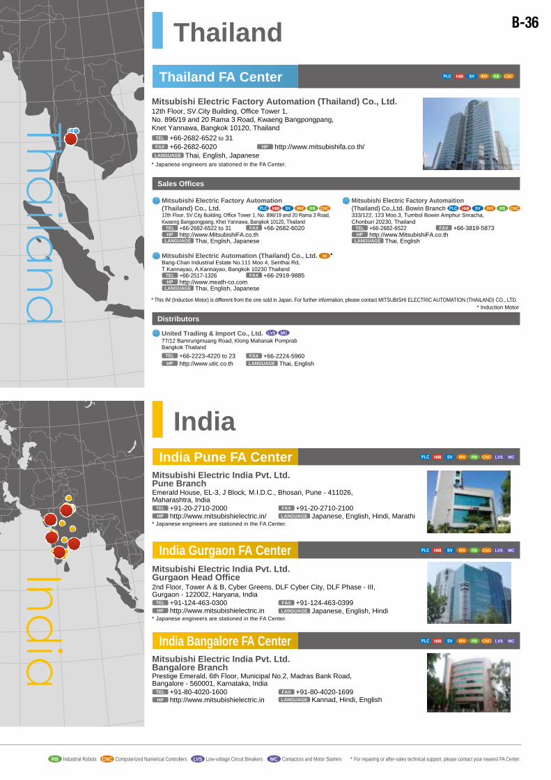
Thailand FA Center
Thailand
India
RB CNC
India Pune FA Center
India Gurgaon FA Center
Mitsubishi Electric India Pvt. Ltd. Pune BranchEmerald House, EL-3, J Block, M.I.D.C., Bhosari, Pune - 411026, Maharashtra, India
+91-20-2710-2000TEL
Japanese, English, Hindi, MarathiLANGUAGE
+91-20-2710-2100FAX
http://www.mitsubishielectric.in/HP
Mitsubishi Electric India Pvt. Ltd. Gurgaon Head Office2nd Floor, Tower A & B, Cyber Greens, DLF Cyber City, DLF Phase - III, Gurgaon - 122002, Haryana, India
+91-124-463-0300TEL
Japanese, English, HindiLANGUAGE
+91-124-463-0399FAX
http://www.mitsubishielectric.inHP
* Japanese engineers are stationed in the FA Center.
* Japanese engineers are stationed in the FA Center.
Mitsubishi Electric Factory Automation (Thailand) Co., Ltd.12th Floor, SV.City Building, Office Tower 1, No. 896/19 and 20 Rama 3 Road, Kwaeng Bangpongpang, Knet Yannawa, Bangkok 10120, Thailand
+66-2682-6522 to 31TEL
Thai, English, JapaneseLANGUAGE
+66-2682-6020FAX http://www.mitsubishifa.co.th/HP
* Japanese engineers are stationed in the FA Center.
Mitsubishi Electric Factory Automation (Thailand) Co., Ltd.12th Floor, SV.City Building, Office Tower 1, No. 896/19 and 20 Rama 3 Road, Kwaeng Bangpongpang, Khet Yannawa, Bangkok 10120, Thailand
+66-2682-6522 to 31TEL
http://www.MitsubishiFA.co.thHP
Thai, English, JapaneseLANGUAGE
+66-2682-6020FAX
+66-2224-5960FAX
Sales Offices
RB CNC
Mitsubishi Electric Factory Automaition (Thailand) Co.,Ltd. Bowin Branch333/122, 123 Moo.3, Tumbol Bowin Amphur Sriracha, Chonburi 20230, Thailand
+66-2682-6522TEL
http://www.MitsubishiFA.co.thHP
Thai, EnglishLANGUAGE
+66-3819-5873FAX
RB CNC
Mitsubishi Electric Automation (Thailand) Co., Ltd.Bang-Chan Industrial Estate No.111 Moo 4, Serithai Rd, T.Kannayao, A.Kannayao, Bangkok 10230 Thailand
+66-2517-1326TEL
http://www.meath-co.comHP
Thai, English, JapaneseLANGUAGE
+66-2919-9885FAX
* This IM (Induction Motor) is different from the one sold in Japan. For further information, please contact MITSUBISHI ELECTRIC AUTOMATION (THAILAND) CO., LTD.
Distributors
United Trading & Import Co., Ltd.77/12 Bamrungmuang Road, Klong Mahanak Pomprab Bangkok Thailand
+66-2223-4220 to 23TEL
Thai, EnglishLANGUAGEhttp://www.utic.co.thHP
LVS MC
Mitsubishi Electric India Pvt. Ltd. Bangalore BranchPrestige Emerald, 6th Floor, Municipal No.2, Madras Bank Road, Bangalore - 560001, Karnataka, India
+91-80-4020-1600TEL
Kannad, Hindi, EnglishLANGUAGE
+91-80-4020-1699FAX
http://www.mitsubishielectric.inHP
* Induction Motor
IM *
India Bangalore FA Center
RB CNC LVS MC
RB CNC LVS MC
RB CNC LVS MC
Vietnam
Mitsubishi Electric Vietnam Company LimitedUnit 01-04, 10th Floor, Vincom Center, 72 Le Thanh Ton Street, District 1, Ho Chi Minh City, Vietnam
+84-8-3910-5945TEL
Vietnamiese, EnglishLANGUAGE
+84-8-3910-5947FAX
http://www.MitsubishiElectric.asia/VietnamHP
Sales Offices
Hanoi FA Center
Mitsubishi Electric Vietnam Company Limited Hanoi Branch Office6th Floor, Detech Tower, 8 Ton That Thuyet Street, My Dinh2 Ward, Nam Tu Liem District, Hanoi, Vietnam
+84-4-3937-8075TEL
Vietnamiese, English, JapaneseLANGUAGE
+84-4-3937-8076FAX
http://www.MitsubishiElectric.asia/VietnamHP
RB
Ho Chi Minh FA Center RB
Mitsubishi Electric Vietnam Company Limited
Unit 01-04, 10th Floor, Vincom Center, 72 Le Thanh Ton Street, District 1, Ho Chi Minh City, Vietnam
+84-8-3910-5945TEL
http://www.mitsubishielectric.asia/vietnam/HP
Vietnamiese, English, JapaneseLANGUAGE
+84-8-3910-5947FAX
Mitsubishi Electric Vietnam Company Limited Hanoi Branch6th Floor, Detech Tower, 8 Ton That Thuyet Street, My Dinh2 Ward, Nam Tu Liem District, Hanoi, Vietnam
+84-4-3937-8075TEL
http://www.mitsubishielectric.asia/vietnam/HP
Vietnamiese, English, JapaneseLANGUAGE
+84-4-3937-8076FAX
Distributors
http://www.duyhung.vn/HP
http://www.sagiangvn.comHP
SA GIANG TRADING CO., Ltd.
Room 11.3B , 11th Floor, Ree Tower, 09 Doan Van Bo St., Ward 12, Dist.4, HCMC, Vietnam
+84-8-3943-1568/69/70TEL
Vietnamese, English, JapaneseLANGUAGE
+84-8-3943-1571FAX
* Japanese engineers are stationed in the FA Center.
RB LVS MCCNC
RB LVS MC
APC INDUSTRY CORPORATION
No10 21 Road, Linh Chieu Ward, Thu Duc District,Ho Chi Minh, Vietnam
+84-8-3722-3605TEL
Vietnamese, EnglishLANGUAGE+84-8-3722-5120FAX
RB LVS MC
SA GIANG TRADING CO., Ltd. Hanoi office
6 Floor, Bac Ha - C14 Building, To Huu Street, TrungVan Ward, Nam Tu Liem District, Ha Noi, Viet Nam.
+84-4-3573-7646(Rep)TEL
http://www.sagiangvn.comHP
Vietnamese, EnglishLANGUAGE
+84-4-3573-7650(Rep)FAX
RB LVS MC
DUY HUNG TECHCOM CO., LTD.
Villa 2A-20, 16B1 str, Village of European Vietnamese Resident, Mo Lao ward, Ha Dong dist, Hanoi, Vietnam.
+84-4-3540-9046TEL
Vietamese, EnglishLANGUAGE
+84-4-3540-9049FAX
NARASAKI SANGYO CO., LTD. HANOI REPRESENTATIVE OFFICE
R.308, HITC Building, 239 Xuan Thuy Str., Dich Vong Hau Ward, Cau Giay Dist, Hanoi, Vietnam
+84-4-3724-7063TEL
Vietnamese, English, JapaneseLANGUAGE+84-4-3724-7065FAX
RB LVS MC
RB LVS MC
http://www.duyhung.vn/HP
DUY HUNG TECHCOM CO., LTD. HCM Branch
3rd Floor, No.32 D5 str, Ward 25, Binh Thanh dist, Ho Chi Minh, Vietnam
+84-4 354 09046TEL
Vietamese, EnglishLANGUAGE
+84-4 354 09049FAX
RB LVS MC
RB LVS MCCNC
Sales offices Industrial RobotsRB Computerized Numerical ControllersCNC Low-voltage Circuit BreakersLVS Contactors and Motor Starters * For repairing or after-sales technical support, please contact your nearest FA Center.MCProgrammable Controllers InvertersAC Servos, Servo System ControllersHuman-Machine Interfaces
B-36

North America FA Center
Americas /Mexico
Mitsubishi Electric Automation, Inc.500 Corporate Woods Parkway, Vernon Hills, IL 60061, U.S.A.
+1-847-478-2100, +1-847-478-2500TEL
TEL TEL
English, JpaneseLANGUAGE
EnglishLANGUAGE
JapaneseLANGUAGE
+1-847-478-2253, +1-847-478-2650 , +1-847-478-2396FAX
https://us.mitsubishielectric.com/fa/enHP
* Japanese engineers are stationed in the FA Center.
Mitsubishi Electric Automation, Inc. Western Region Headquarters5900-B Katella Ave, Cypress, CA 90630, U.S.A
+1-714-699-2626TEL
https://us.mitsubishielectric.com/fa/enHP
EnglishLANGUAGE
+1-714-699-2620FAX
Mitsubishi Electric Automation, Inc. Western Region Grapevine - Texas1000 Nolen Drive, Suite 200, Grapevine, TX 76051, U.S.A.
+1-817-416-9767, +1-817-251-7468TEL
https://us.mitsubishielectric.com/fa/enHP
English, SpanishLANGUAGE
+1-817-416-5000FAX
Mitsubishi Electric Automation, Inc.500 Corporate Woods Parkway, Vernon Hills, IL 60061, U.S.A.
+1-847-478-2100(Rep), +1-847-478-2500TEL
https://us.mitsubishielectric.com/fa/enHP English, Spanish, JapaneseLANGUAGE+1-847-478-2253, +1-847-478-2650 , +1-847-478-2396FAX
Mitsubishi Electric Automation, Inc. Canadian Region
4299 14th Avenue, Markham, Ontario L3R OJ2, Canada+1-905-754-3805TEL
https://us.mitsubishielectric.com/fa/enHP
EnglishLANGUAGE
+1-905-475-7935FAX
Regional Sales Office in America
Sales Offices
RB LVS MCCNC
Mexico FA CenterMitsubishi Electric Automation, Inc. Mexico BranchMariano Escobedo #69, Col. Zona Industrial, Tlalnepantla Edo. México, C.P. 54030
+52-55-3067-7500TEL
Spanish, English, JpaneseLANGUAGE
https://mx.mitsubishielectric.com/fa/enHP
RB LVS MCCNC
Mitsubishi Electric Automation, Inc. Eastern Region Headquarters1845 Satellite Boulevard Suite 450, Duluth, GA 30097, U.S.A.
+1-678-258-4500TEL
https://us.mitsubishielectric.com/fa/enHP
EnglishLANGUAGE
+1-847-876-6684FAX
Mitsubishi Electric Automation, Inc. Mexico BranchMariano Escobedo #69, Col. Zona Industrial, Tlalnepantla Edo. Mexico, C.P. 54030
+52-55-3067-7511(Rep) +52-55-3067-7500(Technical Support)
TEL
https://us.mitsubishielectric.com/fa/enHP
Sales Offices
Mitsubishi Electric Automation, Inc. Monterrey OfficePlaza Mirage, AV. Gonzalitos 460 Sur, Local 28, Col. San Jeronimo, Monterrey, Nuevo Leon, C.P. 64640, Mexico
+52-55-3067-7521TEL
https://us.mitsubishielectric.com/fa/enHP
English, SpanishLANGUAGE
RB LVS MC
* Japanese engineers are stationed in the FA Center.
English, Spanish, JapaneseLANGUAGE
India
Oceania
India Ahmedabad FA Center
Regional Sales Office in India
Mitsubishi Electric India Pvt. Ltd. Pune BranchEmerald House, EL-3, J Block, M.I.D.C., Bhosari, Pune - 411026, Maharashtra, India
+91-20-2710-2000TEL
Marathi, Hindi, English, JapaneseLANGUAGE
+91-20-2710-2100FAX
http://www.mitsubishielectric.inHP
Sales Offices
Mitsubishi Electric India Pvt. Ltd. Gurgaon Head Office2nd Floor, Tower A & B, Cyber Greens, DLF Cyber City, DLF Phase - III, Gurgaon - 122002, Haryana, India
+91-124-4630300TEL
Hindi, English, JapaneseLANGUAGE
+91-124-4630399FAX
http://www.mitsubishielectric.inHP
Mitsubishi Electric India Pvt. Ltd. Bangalore BranchPrestige Emerald, 6th Floor, Municipal No.2, Madras Bank Road, (Lavelle Road), Bangalore 560001, Karnataka, India
+91-80-4020-1600TEL
Kannad, Hindi, EnglishLANGUAGE
+91-80-4020-1699FAX
http://www.mitsubishielectric.inHP
LVS MC
Mitsubishi Electric India Pvt. Ltd. Vadodara Branch A-1/2, 2nd Floor, Status Plaza, Opp Relish Resort, Akshar Square, O.P Road, Vadodara, 390020, Gujarat, India
+91-26-5231-4699TEL
Gujarati, Hindi, EnglishLANGUAGE
+91-26-5233-3307FAX
http://www.mitsubishielectric.inHP
LVS MC
Mitsubishi Electric India Pvt. Ltd. Mumbai Branch106 MAGNUM OPUS, (E), Santacruz West, Mumbai, 400055, Maharashtra, India
+91-22-2667-4308TEL
Marathi, Hindi, EnglishLANGUAGE
+91-22-2667-4309FAX
http://www.mitsubishielectric.inHP
LVS MC
Mitsubishi Electric India Pvt. Ltd. Hyderabad Branch4th Floor, Unit No. 407, Ashoka Bhoopal Chamber, S.P. Road, Secunderabad, Hyderabad-500003, Andhra Pradesh, India
+91-40-2772-2519TEL
Telugu, Hindi, EnglishLANGUAGE
+91-40-2772-2519FAX
http://www.mitsubishielectric.inHP
LVS MC
Mitsubishi Electric India Pvt. Ltd. Chennai BranchCitilights Corporate Centre No. 1, Vivekananda Road, Srinivasa Nagar, Chetpet, Chennai-600031, Tamil Nadu, India
+91-44-4554-8772TEL
Tamil, Hindi, EnglishLANGUAGE
+91-44-4554-8773FAX
http://www.mitsubishielectric.inHP
LVS MC
Mitsubishi Electric India Pvt. Ltd. Ahmedabad BranchB/4, 3rd Floor, SAFAL Profitaire, Corporate Road, Prahaladnagar, Satellite, Ahmedabad - 380015, Gujarat, India
+91-79-6512-0063TEL
Gujarati, Hindi, EnglishLANGUAGEhttp://www.mitsubishielectric.inHP
LVS MC
Mitsubishi Electric India Pvt. Ltd. Coimbatore Branch2nd Floor, Door No.1604, Trichy Road, Near ICICI Bank, Coimbatore - 641018, Tamil Nadu, India
+91-81- 2944-5670TEL
Malayalam, Tamil, Hindi, EnglishLANGUAGE
http://www.mitsubishielectric.inHP
Mitsubishi Electric India Pvt. Ltd. Ahmedabad BranchB/4, 3rd Floor, SAFAL Profitaire, Corporate Road, Prahaladnagar, Satellite, Ahmedabad - 380015, Gujarat, India
+91-7965120063TEL
Gujarati, Hindi, EnglishLANGUAGEhttp://www.mitsubishielectric.inHP
LVS MC
AUSTRALIAMITSUBISHI ELECTRIC AUSTRALIA PTY. LTD.348 Victoria Road, P.O. Box 11, Rydalmere, N.S.W 2116, Australia
+61-2-9684-7777TEL
EnglishLANGUAGE
+61-2-9684-7245FAX
http://www.mitsubishielectric.com.auHP
Sales Offices
RB CNC LVS MC
RB CNC LVS MC
RB CNC LVS MC
LVS MC
Mitsubishi Electric India Pvt. Ltd. Rudrapur Branch181/6, Awas Vikas Ring Road, Rudrapur, Dist-USN - 263153, Uttarakhand, India
+91-5944-246899TEL
Hindi, EnglishLANGUAGE
http://www.mitsubishielectric.inHP
LVS MC
Mitsubishi Electric India Pvt. Ltd. Nagpur BranchPlot No.8, NIIT Layout, Ravindra Nagar, Ring Road, Nagpur, Maharashtra, India
+91-712-2284020TEL
Marathi, Hindi, EnglishLANGUAGE
http://www.mitsubishielectric.inHP
LVS MC
Mitsubishi Electric India Pvt. Ltd. Indore Branch110 1st Floor, Shagun Commercial Complex, Plot No.7/PU-4, Scheme No.54, Vijay Nagar, Indore - 452010, Madhya Pradesh, India
+91-731-6050013TEL
Hindi, EnglishLANGUAGE
http://www.mitsubishielectric.inHP
CNC
CNC
CNC LVS MC
CNC CNC LVS MC
RB LVS MCCNC
LVS MC
Mitsubishi Electric Automation, Inc. Central Region Branch Office (Cincinati office - South Ohio)
World Park 5 10166 International Blvd. Cincinnati, Ohio 45246, U.S.A.+1-513-785-0530TEL
https://us.mitsubishielectric.com/fa/enHP
EnglishLANGUAGE
LVS MC
Mitsubishi Electric Automation, Inc. Western Region Branch Office-California48511 Warm Springs Blvd, Suite 209 Fremont, CA 94539, U.S.A.
+1-510-344-8020TEL
https://us.mitsubishielectric.com/fa/enHP
English, JapaneseLANGUAGELVS MC
Mitsubishi Electric Automation, Inc. Central Region Branch Office (Sidney office - North Ohio)
670 Vandermark Rd Sidney, Ohio 45365, U.S.A+1-937-492-3058TELTEL +1-937-492-3058TELFAX
https://us.mitsubishielectric.com/fa/enHP
English, JapaneseLANGUAGE
LVS MC
Mitsubishi Electric Automation, Inc. Central Region Branch Office (Northville - Michigan)
15603 Centennial Drive, Northville, MI 48168, U.S.A.TEL +1-734-453-6200 +1-734-455-4299TELFAX
https://us.mitsubishielectric.com/fa/enHP
EnglishLANGUAGE
RB LVS MCCNC
RB LVS MCCNC
CNC
RB LVS MCCNC RB LVS MCCNC
WESTERN REGION
TEXAS
CANADIAN REGION EASTERN REGION
SOUTH OHIO
NORTH OHIO
MICHIGAN
RB LVS MCCNC
Mitsubishi Electric India Pvt. Ltd. Chennai BranchCitilights Corporate Centre No. 1, Vivekananda Road, Srinivasa Nagar, Chetpet, Chennai - 600031, Tamil Nadu, India
+91-4445548772TEL
Tamil, Hindi, EnglishLANGUAGE
+91-4445548773FAX
http://www.mitsubishielectric.inHP
India Chennai FA Center LVS MC
+1-847-478-2469+1-847-478-2334
TEL Technical Consulting(Support hours: 7:00 to 19:00 (CST))
1-800-950-7781
Sales offices Programmable Controllers InvertersAC Servos, Servo System ControllersHuman-Machine Interfaces Industrial RobotsRB Computerized Numerical ControllersCNC Low-voltage Circuit BreakersLVS Contactors and Motor Starters * For repairing or after-sales technical support, please contact your nearest FA Center.MC
B-37
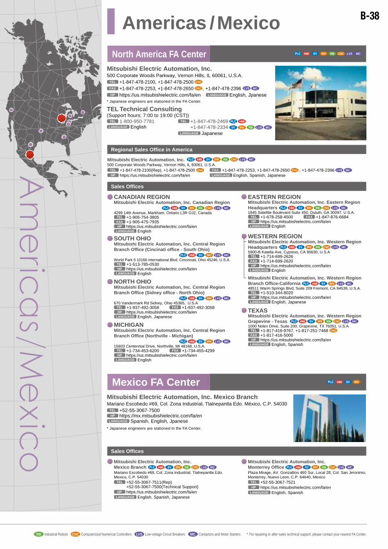
North America FA Center
Americas /Mexico
Mitsubishi Electric Automation, Inc.500 Corporate Woods Parkway, Vernon Hills, IL 60061, U.S.A.
+1-847-478-2100, +1-847-478-2500TEL
TEL TEL
English, JpaneseLANGUAGE
EnglishLANGUAGE
JapaneseLANGUAGE
+1-847-478-2253, +1-847-478-2650 , +1-847-478-2396FAX
https://us.mitsubishielectric.com/fa/enHP
* Japanese engineers are stationed in the FA Center.
Mitsubishi Electric Automation, Inc. Western Region Headquarters5900-B Katella Ave, Cypress, CA 90630, U.S.A
+1-714-699-2626TEL
https://us.mitsubishielectric.com/fa/enHP
EnglishLANGUAGE
+1-714-699-2620FAX
Mitsubishi Electric Automation, Inc. Western Region Grapevine - Texas1000 Nolen Drive, Suite 200, Grapevine, TX 76051, U.S.A.
+1-817-416-9767, +1-817-251-7468TEL
https://us.mitsubishielectric.com/fa/enHP
English, SpanishLANGUAGE
+1-817-416-5000FAX
Mitsubishi Electric Automation, Inc.500 Corporate Woods Parkway, Vernon Hills, IL 60061, U.S.A.
+1-847-478-2100(Rep), +1-847-478-2500TEL
https://us.mitsubishielectric.com/fa/enHP English, Spanish, JapaneseLANGUAGE+1-847-478-2253, +1-847-478-2650 , +1-847-478-2396FAX
Mitsubishi Electric Automation, Inc. Canadian Region
4299 14th Avenue, Markham, Ontario L3R OJ2, Canada+1-905-754-3805TEL
https://us.mitsubishielectric.com/fa/enHP
EnglishLANGUAGE
+1-905-475-7935FAX
Regional Sales Office in America
Sales Offices
RB LVS MCCNC
Mexico FA CenterMitsubishi Electric Automation, Inc. Mexico BranchMariano Escobedo #69, Col. Zona Industrial, Tlalnepantla Edo. México, C.P. 54030
+52-55-3067-7500TEL
Spanish, English, JpaneseLANGUAGE
https://mx.mitsubishielectric.com/fa/enHP
RB LVS MCCNC
Mitsubishi Electric Automation, Inc. Eastern Region Headquarters1845 Satellite Boulevard Suite 450, Duluth, GA 30097, U.S.A.
+1-678-258-4500TEL
https://us.mitsubishielectric.com/fa/enHP
EnglishLANGUAGE
+1-847-876-6684FAX
Mitsubishi Electric Automation, Inc. Mexico BranchMariano Escobedo #69, Col. Zona Industrial, Tlalnepantla Edo. Mexico, C.P. 54030
+52-55-3067-7511(Rep) +52-55-3067-7500(Technical Support)
TEL
https://us.mitsubishielectric.com/fa/enHP
Sales Offices
Mitsubishi Electric Automation, Inc. Monterrey OfficePlaza Mirage, AV. Gonzalitos 460 Sur, Local 28, Col. San Jeronimo, Monterrey, Nuevo Leon, C.P. 64640, Mexico
+52-55-3067-7521TEL
https://us.mitsubishielectric.com/fa/enHP
English, SpanishLANGUAGE
RB LVS MC
* Japanese engineers are stationed in the FA Center.
English, Spanish, JapaneseLANGUAGE
India
Oceania
India Ahmedabad FA Center
Regional Sales Office in India
Mitsubishi Electric India Pvt. Ltd. Pune BranchEmerald House, EL-3, J Block, M.I.D.C., Bhosari, Pune - 411026, Maharashtra, India
+91-20-2710-2000TEL
Marathi, Hindi, English, JapaneseLANGUAGE
+91-20-2710-2100FAX
http://www.mitsubishielectric.inHP
Sales Offices
Mitsubishi Electric India Pvt. Ltd. Gurgaon Head Office2nd Floor, Tower A & B, Cyber Greens, DLF Cyber City, DLF Phase - III, Gurgaon - 122002, Haryana, India
+91-124-4630300TEL
Hindi, English, JapaneseLANGUAGE
+91-124-4630399FAX
http://www.mitsubishielectric.inHP
Mitsubishi Electric India Pvt. Ltd. Bangalore BranchPrestige Emerald, 6th Floor, Municipal No.2, Madras Bank Road, (Lavelle Road), Bangalore 560001, Karnataka, India
+91-80-4020-1600TEL
Kannad, Hindi, EnglishLANGUAGE
+91-80-4020-1699FAX
http://www.mitsubishielectric.inHP
LVS MC
Mitsubishi Electric India Pvt. Ltd. Vadodara Branch A-1/2, 2nd Floor, Status Plaza, Opp Relish Resort, Akshar Square, O.P Road, Vadodara, 390020, Gujarat, India
+91-26-5231-4699TEL
Gujarati, Hindi, EnglishLANGUAGE
+91-26-5233-3307FAX
http://www.mitsubishielectric.inHP
LVS MC
Mitsubishi Electric India Pvt. Ltd. Mumbai Branch106 MAGNUM OPUS, (E), Santacruz West, Mumbai, 400055, Maharashtra, India
+91-22-2667-4308TEL
Marathi, Hindi, EnglishLANGUAGE
+91-22-2667-4309FAX
http://www.mitsubishielectric.inHP
LVS MC
Mitsubishi Electric India Pvt. Ltd. Hyderabad Branch4th Floor, Unit No. 407, Ashoka Bhoopal Chamber, S.P. Road, Secunderabad, Hyderabad-500003, Andhra Pradesh, India
+91-40-2772-2519TEL
Telugu, Hindi, EnglishLANGUAGE
+91-40-2772-2519FAX
http://www.mitsubishielectric.inHP
LVS MC
Mitsubishi Electric India Pvt. Ltd. Chennai BranchCitilights Corporate Centre No. 1, Vivekananda Road, Srinivasa Nagar, Chetpet, Chennai-600031, Tamil Nadu, India
+91-44-4554-8772TEL
Tamil, Hindi, EnglishLANGUAGE
+91-44-4554-8773FAX
http://www.mitsubishielectric.inHP
LVS MC
Mitsubishi Electric India Pvt. Ltd. Ahmedabad BranchB/4, 3rd Floor, SAFAL Profitaire, Corporate Road, Prahaladnagar, Satellite, Ahmedabad - 380015, Gujarat, India
+91-79-6512-0063TEL
Gujarati, Hindi, EnglishLANGUAGEhttp://www.mitsubishielectric.inHP
LVS MC
Mitsubishi Electric India Pvt. Ltd. Coimbatore Branch2nd Floor, Door No.1604, Trichy Road, Near ICICI Bank, Coimbatore - 641018, Tamil Nadu, India
+91-81- 2944-5670TEL
Malayalam, Tamil, Hindi, EnglishLANGUAGE
http://www.mitsubishielectric.inHP
Mitsubishi Electric India Pvt. Ltd. Ahmedabad BranchB/4, 3rd Floor, SAFAL Profitaire, Corporate Road, Prahaladnagar, Satellite, Ahmedabad - 380015, Gujarat, India
+91-7965120063TEL
Gujarati, Hindi, EnglishLANGUAGEhttp://www.mitsubishielectric.inHP
LVS MC
AUSTRALIAMITSUBISHI ELECTRIC AUSTRALIA PTY. LTD.348 Victoria Road, P.O. Box 11, Rydalmere, N.S.W 2116, Australia
+61-2-9684-7777TEL
EnglishLANGUAGE
+61-2-9684-7245FAX
http://www.mitsubishielectric.com.auHP
Sales Offices
RB CNC LVS MC
RB CNC LVS MC
RB CNC LVS MC
LVS MC
Mitsubishi Electric India Pvt. Ltd. Rudrapur Branch181/6, Awas Vikas Ring Road, Rudrapur, Dist-USN - 263153, Uttarakhand, India
+91-5944-246899TEL
Hindi, EnglishLANGUAGE
http://www.mitsubishielectric.inHP
LVS MC
Mitsubishi Electric India Pvt. Ltd. Nagpur BranchPlot No.8, NIIT Layout, Ravindra Nagar, Ring Road, Nagpur, Maharashtra, India
+91-712-2284020TEL
Marathi, Hindi, EnglishLANGUAGE
http://www.mitsubishielectric.inHP
LVS MC
Mitsubishi Electric India Pvt. Ltd. Indore Branch110 1st Floor, Shagun Commercial Complex, Plot No.7/PU-4, Scheme No.54, Vijay Nagar, Indore - 452010, Madhya Pradesh, India
+91-731-6050013TEL
Hindi, EnglishLANGUAGE
http://www.mitsubishielectric.inHP
CNC
CNC
CNC LVS MC
CNC CNC LVS MC
RB LVS MCCNC
LVS MC
Mitsubishi Electric Automation, Inc. Central Region Branch Office (Cincinati office - South Ohio)
World Park 5 10166 International Blvd. Cincinnati, Ohio 45246, U.S.A.+1-513-785-0530TEL
https://us.mitsubishielectric.com/fa/enHP
EnglishLANGUAGE
LVS MC
Mitsubishi Electric Automation, Inc. Western Region Branch Office-California48511 Warm Springs Blvd, Suite 209 Fremont, CA 94539, U.S.A.
+1-510-344-8020TEL
https://us.mitsubishielectric.com/fa/enHP
English, JapaneseLANGUAGELVS MC
Mitsubishi Electric Automation, Inc. Central Region Branch Office (Sidney office - North Ohio)
670 Vandermark Rd Sidney, Ohio 45365, U.S.A+1-937-492-3058TELTEL +1-937-492-3058TELFAX
https://us.mitsubishielectric.com/fa/enHP
English, JapaneseLANGUAGE
LVS MC
Mitsubishi Electric Automation, Inc. Central Region Branch Office (Northville - Michigan)
15603 Centennial Drive, Northville, MI 48168, U.S.A.TEL +1-734-453-6200 +1-734-455-4299TELFAX
https://us.mitsubishielectric.com/fa/enHP
EnglishLANGUAGE
RB LVS MCCNC
RB LVS MCCNC
CNC
RB LVS MCCNC RB LVS MCCNC
WESTERN REGION
TEXAS
CANADIAN REGION EASTERN REGION
SOUTH OHIO
NORTH OHIO
MICHIGAN
RB LVS MCCNC
Mitsubishi Electric India Pvt. Ltd. Chennai BranchCitilights Corporate Centre No. 1, Vivekananda Road, Srinivasa Nagar, Chetpet, Chennai - 600031, Tamil Nadu, India
+91-4445548772TEL
Tamil, Hindi, EnglishLANGUAGE
+91-4445548773FAX
http://www.mitsubishielectric.inHP
India Chennai FA Center LVS MC
+1-847-478-2469+1-847-478-2334
TEL Technical Consulting(Support hours: 7:00 to 19:00 (CST))
1-800-950-7781
Sales offices Programmable Controllers InvertersAC Servos, Servo System ControllersHuman-Machine Interfaces Industrial RobotsRB Computerized Numerical ControllersCNC Low-voltage Circuit BreakersLVS Contactors and Motor Starters * For repairing or after-sales technical support, please contact your nearest FA Center.MC
B-38

Europe FA Center RB LVS MCCNC
Europe
Mitsubishi Electric Europe B.V. Polish Branchul. Krakowska 50, 32-083 Balice, Poland
+48-12-347-65-00TEL
Polish, English, JapaneseLANGUAGE
+48-12-630-47-01FAX
https://pl3a.mitsubishielectric.comHP
* Japanese engineers are stationed in the FA Center.
UK FA Center
Mitsubishi Electric Europe B.V. UK BranchTravellers Lane, Hatfield, Hertfordshire, AL10 8XB, U.K.
+44-1707-27-8780TEL
EnglishLANGUAGE
+44-1707-27-8695FAX
https://gb3a.mitsubishielectric.comHP
RB LVS MC
Mitsubishi Electric (Russia) LLC St. Petersburg BranchPiskarevsky pr. 2, bld 2, lit "Sch", BC "Benua", office 709; 195027, St. Petersburg, Russia
+7-812-633-3497TEL
Russian, English, JapaneseLANGUAGE
+7-812-633-3499FAX
https://ru3a.mitsubishielectric.comHP
Russia FA Center RB LVS MC
Mitsubishi Electric Europe B.V. Italian BranchCentro Direzionale Colleoni - Palazzo Sirio, Viale Colleoni 7, 20864 Agrate Brianza (MB), Italy
+39-039-60531TEL
Italian, French, EnglishLANGUAGE
+39-039-6053312FAX
https://it3a.mitsubishielectric.comHP
Italy FA Center RB LVS
Brazil FA Center
Brazil
Mitsubishi Electric do Brasil Comércio e Serviços Ltda.Avenida Adelino Cardana, 293, 21 andar, Bethaville, Barueri SP, Brasil
+55-11-4689-3000TEL
Portuguese, English, JapaneseLANGUAGE
+55-11-4689-3016FAX
Distributors
ARTCOM COM. E DISTRIBUICAO DE MAQ. E EQUIPAMENTOS INDUSTRIAIS LTDA.Av. Getulio Vargas, 943, Bairro Niteroi, CEP 92480-000, Canoas - RS, Brasil
+55-51-3031-7677TEL
http://www.artcom-rs.com.br/HP
http://www.mitsubishielectric.com/fa/br_pt/HP
PortugueseLANGUAGE
Automotion Ind. Com. Imp. e Exp. Ltda.Acesso Jose Sartorelli, KM 2.1 - CEP 18550-000, Boituva - SP, Brazil
+55-15-3363-9900TEL
http://www.automotion.com.br/HP
Portuguese, EnglishLANGUAGE
+55-15-3363-9911FAX
MELCO CNC do Brasil Comercio e Servicos S.A.Avenida Gisele Constantino, 1578, Parque Bela Vista - Votorantim-SP, Brazil
+55-15-3023-9000TEL
Portuguese, English, JapaneseLANGUAGE
+55-15-3363-9911FAX
Mitsubishi Electric do Brasil Comércio e Serviços Ltda.
Avenida Adelino Cardana, 293, 21 andar, Bethaville, Barueri SP, Brasil
+55-11-4689-3000TEL
Portuguese, English, JapaneseLANGUAGE
+55-11-4689-3016FAX
Sales Offices
RBMELCO CNC do Brasil Comercio e Servicos S.A.Avenida Gisele Constantino,1578, Parque Bela Vista - Votorantim-SP, Brazil
+55-15-3023-9000TEL
Portuguese, English, JapaneseLANGUAGE
CNC
Brazil Votorantim FA Center CNC
http://www.mitsubishielectric.com/fa/br_pt/HP
CETEM Automacao Industrial LTDA.Rua Candido Benicio, 1381, Bairro Praca Seca, CEP 21321-802, Rio de Janeiro - RJ, Brasil
+55-21-3350-8833TEL
http://www.cetemrj.com.br/HP
Portuguese, EnglishLANGUAGE
MPA Automacao LTDA.Av. ENG. EURICO VIANA - SETOR LESTE, Bairro VILA NOVA, CEP 74740-170, GOIANIA - GO, Brasil
+55-62-3541-0015TEL
http://www.mpaautomacao.com.brHP
PortugueseLANGUAGE
CIM Automacao LTDA.Rua Minas Gerais, 409, Diadema - CEP 09941-760, Sao Paulo - SP, Brasil
+55-11-3389-1118TEL
http://www.cimautomacao.com.br/HP
Portuguese, EnglishLANGUAGE
RB
LARATEC COM DE FERRAMENTAS LTDA.
Rua Albano Reis, 1058, Bom Retiro, CEP 80520-530, Curitiba - PR, Brasil
+55-41-3022-1666TEL
http://www.laratec.com.brHP
PortugueseLANGUAGE
SEMATEX AUTOMACAO INDUSTRIAL LTDA.
Rua Buenos Aires, 459 - Sala 101, Ponta Aguda, CEP 89051-050, Blumenau - SC, Brasil
+55-47-3323-8000TEL
http://www.sematex.com.br/HP
PortugueseLANGUAGE
SUNXTRONIC DA AMAZ IMP E EXP LTDA.
Rua Jose Paranagua, 470C - Centro, CEP 69005-130, Manaus - AM, Brasil
+55-92-3233-5497TEL
http://www.sunxtronic.com.br/HP
Portuguese, EnglishLANGUAGE
RGO COMERCIO MANUTENCAO E IMP DE EQUIP ELETRONICOS LTDA.Rua Sergio Cardoso, 72, Jardim Paraiso, CEP 13211-374, Jundiai - SP, Brasil
+55-11-3963-6020TEL
http://www.rgoeletronica.com.brHP
PortugueseLANGUAGE
RB
+55-92-3233-9723FAX
RB LVS MC
+55-11-3389-1110FAX
Mitsubishi Electric Europe B.V. Czech BranchAvenir Business Park, Radlicka 751/113e, 158 00 Praha5, Czech Republic
+420-255-719-200TEL
Czech, EnglishLANGUAGE
+420-251-551-471FAX
https://cz3a.mitsubishielectric.comHP
* Japanese engineers are stationed in the FA Center.
Czech Republic FA Center RB LVS MCCNC
Germany FA Center
Mitsubishi Electric Europe B.V. German BranchMitsubishi-Electric-Platz 1, 40882 Ratingen, Germany
+49-2102-486-0TEL
German, EnglishLANGUAGE
+49-2102-486-1120FAX
https://de3a.mitsubishielectric.comHP
RB LVS MC
Sales offices Industrial RobotsRB Computerized Numerical ControllersCNC Low-voltage Circuit BreakersLVS Contactors and Motor Starters * For repairing or after-sales technical support, please contact your nearest FA Center.MCProgrammable Controllers InvertersAC Servos, Servo System ControllersHuman-Machine Interfaces
B-39
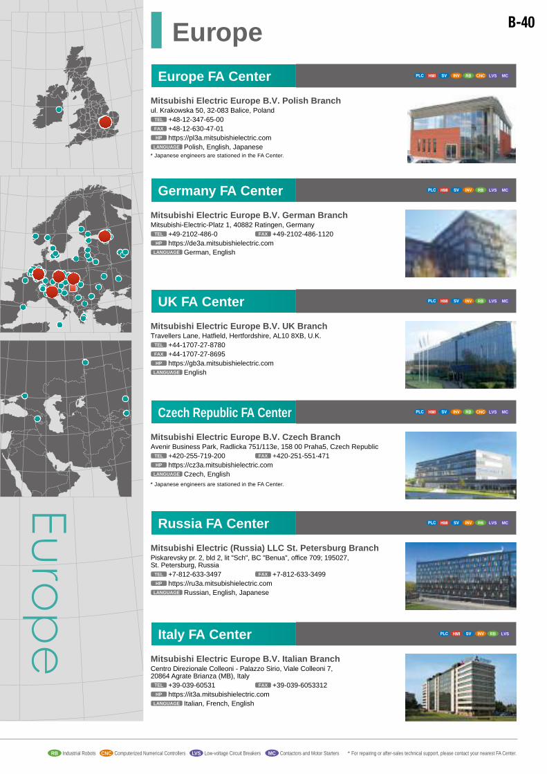
Europe FA Center RB LVS MCCNC
Europe
Mitsubishi Electric Europe B.V. Polish Branchul. Krakowska 50, 32-083 Balice, Poland
+48-12-347-65-00TEL
Polish, English, JapaneseLANGUAGE
+48-12-630-47-01FAX
https://pl3a.mitsubishielectric.comHP
* Japanese engineers are stationed in the FA Center.
UK FA Center
Mitsubishi Electric Europe B.V. UK BranchTravellers Lane, Hatfield, Hertfordshire, AL10 8XB, U.K.
+44-1707-27-8780TEL
EnglishLANGUAGE
+44-1707-27-8695FAX
https://gb3a.mitsubishielectric.comHP
RB LVS MC
Mitsubishi Electric (Russia) LLC St. Petersburg BranchPiskarevsky pr. 2, bld 2, lit "Sch", BC "Benua", office 709; 195027, St. Petersburg, Russia
+7-812-633-3497TEL
Russian, English, JapaneseLANGUAGE
+7-812-633-3499FAX
https://ru3a.mitsubishielectric.comHP
Russia FA Center RB LVS MC
Mitsubishi Electric Europe B.V. Italian BranchCentro Direzionale Colleoni - Palazzo Sirio, Viale Colleoni 7, 20864 Agrate Brianza (MB), Italy
+39-039-60531TEL
Italian, French, EnglishLANGUAGE
+39-039-6053312FAX
https://it3a.mitsubishielectric.comHP
Italy FA Center RB LVS
Brazil FA Center
Brazil
Mitsubishi Electric do Brasil Comércio e Serviços Ltda.Avenida Adelino Cardana, 293, 21 andar, Bethaville, Barueri SP, Brasil
+55-11-4689-3000TEL
Portuguese, English, JapaneseLANGUAGE
+55-11-4689-3016FAX
Distributors
ARTCOM COM. E DISTRIBUICAO DE MAQ. E EQUIPAMENTOS INDUSTRIAIS LTDA.Av. Getulio Vargas, 943, Bairro Niteroi, CEP 92480-000, Canoas - RS, Brasil
+55-51-3031-7677TEL
http://www.artcom-rs.com.br/HP
http://www.mitsubishielectric.com/fa/br_pt/HP
PortugueseLANGUAGE
Automotion Ind. Com. Imp. e Exp. Ltda.Acesso Jose Sartorelli, KM 2.1 - CEP 18550-000, Boituva - SP, Brazil
+55-15-3363-9900TEL
http://www.automotion.com.br/HP
Portuguese, EnglishLANGUAGE
+55-15-3363-9911FAX
MELCO CNC do Brasil Comercio e Servicos S.A.Avenida Gisele Constantino, 1578, Parque Bela Vista - Votorantim-SP, Brazil
+55-15-3023-9000TEL
Portuguese, English, JapaneseLANGUAGE
+55-15-3363-9911FAX
Mitsubishi Electric do Brasil Comércio e Serviços Ltda.
Avenida Adelino Cardana, 293, 21 andar, Bethaville, Barueri SP, Brasil
+55-11-4689-3000TEL
Portuguese, English, JapaneseLANGUAGE
+55-11-4689-3016FAX
Sales Offices
RBMELCO CNC do Brasil Comercio e Servicos S.A.Avenida Gisele Constantino,1578, Parque Bela Vista - Votorantim-SP, Brazil
+55-15-3023-9000TEL
Portuguese, English, JapaneseLANGUAGE
CNC
Brazil Votorantim FA Center CNC
http://www.mitsubishielectric.com/fa/br_pt/HP
CETEM Automacao Industrial LTDA.Rua Candido Benicio, 1381, Bairro Praca Seca, CEP 21321-802, Rio de Janeiro - RJ, Brasil
+55-21-3350-8833TEL
http://www.cetemrj.com.br/HP
Portuguese, EnglishLANGUAGE
MPA Automacao LTDA.Av. ENG. EURICO VIANA - SETOR LESTE, Bairro VILA NOVA, CEP 74740-170, GOIANIA - GO, Brasil
+55-62-3541-0015TEL
http://www.mpaautomacao.com.brHP
PortugueseLANGUAGE
CIM Automacao LTDA.Rua Minas Gerais, 409, Diadema - CEP 09941-760, Sao Paulo - SP, Brasil
+55-11-3389-1118TEL
http://www.cimautomacao.com.br/HP
Portuguese, EnglishLANGUAGE
RB
LARATEC COM DE FERRAMENTAS LTDA.
Rua Albano Reis, 1058, Bom Retiro, CEP 80520-530, Curitiba - PR, Brasil
+55-41-3022-1666TEL
http://www.laratec.com.brHP
PortugueseLANGUAGE
SEMATEX AUTOMACAO INDUSTRIAL LTDA.
Rua Buenos Aires, 459 - Sala 101, Ponta Aguda, CEP 89051-050, Blumenau - SC, Brasil
+55-47-3323-8000TEL
http://www.sematex.com.br/HP
PortugueseLANGUAGE
SUNXTRONIC DA AMAZ IMP E EXP LTDA.
Rua Jose Paranagua, 470C - Centro, CEP 69005-130, Manaus - AM, Brasil
+55-92-3233-5497TEL
http://www.sunxtronic.com.br/HP
Portuguese, EnglishLANGUAGE
RGO COMERCIO MANUTENCAO E IMP DE EQUIP ELETRONICOS LTDA.Rua Sergio Cardoso, 72, Jardim Paraiso, CEP 13211-374, Jundiai - SP, Brasil
+55-11-3963-6020TEL
http://www.rgoeletronica.com.brHP
PortugueseLANGUAGE
RB
+55-92-3233-9723FAX
RB LVS MC
+55-11-3389-1110FAX
Mitsubishi Electric Europe B.V. Czech BranchAvenir Business Park, Radlicka 751/113e, 158 00 Praha5, Czech Republic
+420-255-719-200TEL
Czech, EnglishLANGUAGE
+420-251-551-471FAX
https://cz3a.mitsubishielectric.comHP
* Japanese engineers are stationed in the FA Center.
Czech Republic FA Center RB LVS MCCNC
Germany FA Center
Mitsubishi Electric Europe B.V. German BranchMitsubishi-Electric-Platz 1, 40882 Ratingen, Germany
+49-2102-486-0TEL
German, EnglishLANGUAGE
+49-2102-486-1120FAX
https://de3a.mitsubishielectric.comHP
RB LVS MC
Sales offices Industrial RobotsRB Computerized Numerical ControllersCNC Low-voltage Circuit BreakersLVS Contactors and Motor Starters * For repairing or after-sales technical support, please contact your nearest FA Center.MCProgrammable Controllers InvertersAC Servos, Servo System ControllersHuman-Machine Interfaces
B-40

* English is available at each local distributors. If you require Japanese correspondence, please contact our Europe FA Center.
ROMANIASirius Trading & Services srlAleea Lacul Morii Nr. 3, Sector 6, 060841 Bucuresti, Romania
+40-21-430-40-06TEL
Romanian, EnglishLANGUAGE+40-21-430-40-02FAX
http://www.siriustrading.roHP
RB LVS MC
NORWAYScanelec ASLeirvikåsen 43B, NO-5179 Godvik, Norway
+47-55-506000TEL
Norwegianm, EnglishLANGUAGE+47-55-506001FAX
http://www.scanelec.noHP
LVS MC
RB
THE NETHERLANDS
Koning & Hartman B.V.Haarlerbergweg 21e-23e, NL-1101 CH, Amsterdam, Netherlands
+31-20-587-76-00TEL
German, English, DutchLANGUAGE+31-20-587-76-05FAX
http://www.koningenhartman.comHP
RB
Imtech Marine & Offshore B.V.Sluisjesdijk 155, NL-3087 AG Rotterdam, Netherlands
Hiflex Automatiseringstechniek B.V.Wolweverstraat 22, NL-2984 CD Ridderkerk, Netherlands
+31-180-46-60-04TEL
English, DutchLANGUAGE+31-180-44-23-55FAX
http://www.hiflex.nlHP
+31-10-487-19-11TEL
English, Dutch
ES Elektro B.V.Steurweg 2, 4941 VR Raamsdonksveer, Netherlands
+31-765782800TEL
Dutch, EnglishLANGUAGE+31-765782800FAX
LANGUAGE+31-10-487-16-92FAX
LVS MC
Provendor OyTeljänkatu 8 A3, FIN-28130 Pori, Finland
+358-2-522-3300TEL
http://www.provendor.fiHP Finnish, EnglishLANGUAGE+358-2-522-3322FAX
RB LVS MCFINLAND
Hans Følsgaard A/STheilgaards Torv 1, DK-4600 Køge, Denmark
+45-4320-8600TEL
http://www.hf.netHP Danish, English, GermanLANGUAGE+45-4396-8855FAX
DENMARKRB LVS MC
GREECE
UTECO5, M. Mavrogenous Str., 185 42 Piraeus, Greece
+30-211-1206-900TEL
http://www.uteco.grHP Greek, EnglishLANGUAGE+30-211-1206-999FAXTEL
RB LVS MC
Kalamarakis - SapounasIonas & Neromilou str., 136 78 Chamomilos-Acharnes, Athens, Greece
+30-2102-406000TEL
Greek, EnglishLANGUAGE+30-2102-406007FAX
LVS MC
HUNGARYMeltrade Automatika Kft.Ferto Utca 14, HU-1107 Budapest, Hungary
+36-1-431-9726TEL
http://www.meltrade.huHP Hungarian, EnglishLANGUAGE+36-1-431-9727FAX
RB LVS MC
MALTAAlfatrade Ltd.99, Paola Hill, MT-Paola PLA 1702, Malta
+356-21-697816TEL
EnglishLANGUAGE+356-21-697817FAX
RB LVS MC
Rifas UABTinklų g. 35R, LT-35115 Panevėžys, Lithuania
+370-45-582-728TEL
Lithuanian, Russian, EnglishLANGUAGE+370-45-582-729FAX
LITHUANIA
http://www.rifas.ltHP
LVS MC
MOLDOVAIntehsis srlBoulevard Traian 23/1, MD-2060 Chisinau, Moldova
+373-22-66-4242TEL
Russian, EnglishLANGUAGE+373-22-66-4280FAX
LVS MC
KYRGYZSTANBishkek Equipment Maintenance Centre ZTOTOZhukeeva Budovkina str. 122, 720064 Bishkek, Kyrgyzstan
+996-312-56-6340TEL
Russsian, EnglishLANGUAGE+996-312-56-6340FAX
KAZAKHSTANTOO "KAZPROMAVTOMATIKA"Zhambyla str. 28, KZ-100012, Karaganda, Kazakhstan
+7-7212-50-11-50TEL
Kazakh, Russian, EnglishLANGUAGE
+7-7212-50-10-00FAX
http://www.kpakz.comHP
RB CNC LVS MC
SLOVAKIASIMAP SK, s.r.o.Jána Derku 1671/1A, 911 01 Trenčín, Slovakia
+421-32-743-0472TEL
Slovak, EnglishLANGUAGE+421-32-743-7520FAX
http://www.simap.skHP
RB LVS MC
SLOVENIAINEA RBT d.o.o.Stegne 11, SI-1000 Ljubljana, Slovenia
+386-1-5138-116TEL
Slovenian, EnglishLANGUAGE+386-1-5138-170FAX
http://www.inea-rbt.siHP
RB LVS MC
SERBIAINEA SR d.o.o.Ul. Karadjordjeva 12/217, SER-113000 Smederevo, Serbia
+381-64-68-55-187TEL
RB LVS MC
Serbian, EnglishLANGUAGEhttp://www.inea.rsHP
Regional Sales Office in Europe
Sales Offices
Distributors
Mitsubishi Electric Europe B.V. - Factory Automation European Business GroupMitsubishi-Electric-Platz 1, 40882 Ratingen, Germany
+49-2102-486-0TEL
https://eu3a.mitsubishielectric.comHP
German, EnglishLANGUAGE
+49-2102-486-7170, +49-2102-486-9880FAX
RB CNC LVS MC
RB CNC LVS MC
RB CNC LVS MC
RUSSIAMitsubishi Electric (Russia) LLC St. Petersburg BranchPiskarevsky pr. 2, bld 2, lit “Sch”, BC “Benua”, office 720; 195027 St. Petersburg, Russia
+7-812-633-3497TEL
https://ru3a.mitsubishielectric.comHP Russian, English, JapaneseLANGUAGE+7-812-633-3499FAX
Mitsubishi Electric (Russia) LLC52, bld. 1, Kosmodamianskaya emb., 115054 Moscow, Russia
+7-495-721-2070TEL
https://ru3a.mitsubishielectric.comHP Russian, English, GermanLANGUAGE+7-495-721-2071FAX
Office in Poznanul. Krzemowa 1, Złotniki k. Poznania 62-002 Suchy Las, Poland
+48-61-66-72-100TEL
Polish, EnglishLANGUAGE+48-61-65-85-522FAX
RB CNC LVS MC
Office in Warsawul. Łopuszańska 38C, 02-232 Warszawa, Poland
+48-22-468-27-00TEL
Polish, EnglishLANGUAGE+48-22-468-27-00FAX
RB CNC LVS MC
Office in Wroclawul. Muchoborska 18, 54-424 Wrocław, Poland
+48-71-339-40-26TEL
Polish, EnglishLANGUAGE+48-71-333-77-53FAX
RB CNC LVS MC
POLANDMitsubishi Electric Europe B.V. Polish Branchul. Krakowska 50, 32-083 Balice, Poland
+48-12-347-65-00TEL
https://pl3a.mitsubishielectric.comHP Polish, EnglishLANGUAGE+48-12-630-47-01FAX
RB CNC LVS MC
MITSUBISHI ELECTRIC Hungary FA Center SatelliteFerto Utca 14, HU-1107 Budapest, Hungary
+36-1-431-9726TEL
Hungarian, EnglishLANGUAGE
+36-1-431-9727FAX
https://hu3a.mitsubishielectric.comHP
RB LVS MC
ARMENIAIndustrial Technologies LLCFourth str., 17, Microrajon, 2302 Razdan, Armenia
+374-10-94-005-675TEL
Russsian, EnglishLANGUAGE
LVS MCAUSTRIAGEVA Elektronik-Handelsgesellschaft mbHWiener Str. 89, A-2500 Baden, Austria
+43-2252-85552-0TEL
http://www.geva.atHP German, EnglishLANGUAGE+43-2252-48860FAX
RB
BELARUSTechnikon Ltd.177-9, Nezavisimosti pr. 220125 Minsk, Belarus
+375-17-393-1177TEL
http://www.technikon.byHP Belarussian, Russian, EnglishLANGUAGE+375-17-393-0081FAX
RB CNC LVS MC
BULGARIAAkhnaton Ltd4, Andrei Ljapchev Blvd., PO Box 21, BG-1756 Sofia, Bulgaria
+359-2-817-6000TEL
Bulgarian, EnglishLANGUAGE+359-2-817-69-99FAX
RB CNC
http://www.akhnaton.bizHP
CROATIAINEA CR d.o.o.Lošinjska 4a, 10000 Zagreb, Croatia
+385-1-3694-001TEL
http://www.inea.hrHP Croatian, EnglishLANGUAGE+385-1-3694-003FAX
FA Center Satellite
Europe
CNC
SPAINMitsubishi Electric Europe B.V. Spanish BranchCarretera de Rubí, 76-80-Apdo. 420, 08190 Sant Cugat del Vallés (Barcelona), Spain
+34-935-65-3131, +34-935-65-2236TEL
https://es3a.mitsubishielectric.comHP English, Spanish, PortugueseLANGUAGE+34-935-89-1579FAX
RB CNC LVS MC
CNC
Customer Technology Center NorthRevierstraße 21, 44379 Dortmund, Germany
+49-231-967041-0TEL
https://de3a.mitsubishielectric.comHP German, EnglishLANGUAGE+49-231-967041-41FAX
GERMANYMitsubishi Electric Europe B.V. German BranchMitsubishi-Electric-Platz 1, 40882 Ratingen, Germany
+49-2102-486-0TEL
https://de3a.mitsubishielectric.comHP German, EnglishLANGUAGE+49-2102-486-1120, +49-2102-486-9880FAX
Customer Technology Center South-WestKurze Straße 40, 70794 Filderstadt, Germany
+49-711-770598-0, +49-711-770598-123TEL
https://de3a.mitsubishielectric.comHP German, EnglishLANGUAGE+49-711-770598-79, +49-711-770598-141FAX
Customer Technology Center South-EastLilienthalstr. 2a, 85399 Hallbergmoos, Germany
+49-811-99874-0TEL
https://de3a.mitsubishielectric.comHP German, EnglishLANGUAGE+49-811-99874-10FAX
RB CNC LVS MC
RB CNC LVS MC
RB CNC LVS
RB CNC LVS MC
MC
CNC
CNCCNC
UNITED KINGDOMMitsubishi Electric Europe B.V. UK BranchTravellers Lane, UK-Hatfield, Hertfordshire, AL10 8XB, U.K.
+44-1707-28-8780, +49-2102-486-0TEL
https://gb3a.mitsubishielectric.comHP EnglishLANGUAGE+44-1707-27-8695FAX
RB CNC LVS MC
CNC
FRANCEMitsubishi Electric Europe B.V. French Branch25, Boulevard des Bouvets, 92741 Nanterre Cedex, France
+33-1-55-68-55-68, +33-1-41-02-83-13TEL
+33-1-55-68-57-57FAX
https://fr3a.mitsubishielectric.comHP French, EnglishLANGUAGE
RB CNC LVS MC
CNC
ITALYMitsubishi Electric Europe B.V. Italian BranchCentro Direzionale Colleoni - Palazzo Sirio, Viale Colleoni 7, 20864 Agrate Brianza (MB), Italy
+39-039-60531, +39-039-6053-342TEL
https://it3a.mitsubishielectric.comhttp://mechatronics.mitsubishielectric.it/it/
HP
Italian, EnglishLANGUAGE
+39-039-6053-312FAX
RB CNC LVS MC
CNC
CNC
BELGIUM
Koning & Hartman B.V., Industrial SolutionsWoluwelaan 31, BE-1800 Vilvoorde, Belgium
+32-2-257-02-40TEL
http://www.koningenhartman.be/nlHP
German, English, Dutch, FrenchLANGUAGE
+32-2-257-02-49FAX
RBESCO DrivesKouterveld - Culliganlaan 3, BE-1831 Diegem, Belgium
+32-2-717-6460TEL
http://www.esco-da.beHP English, French, DutchLANGUAGE+32-2-717-6461FAX
RB LVS MC
CZECH REPUBLICAutoCont Control Systems, s.r.o.Kafkova 1853/3, 702 00 Ostrava 2, Czech Republic
+420-59-5691-150TEL
http://www.autocontcontrol.czHP
Czech, EnglishLANGUAGE
RB CNC LVS MC
+420-59-5691-199+420-59-5691-185
FAXCNC
POLAND
ELAUTEC S.C.ul. Makuszyńskiego 22A, 31-752 Kraków, Poland
+48-12-413-00-77TEL PolishLANGUAGE+48-12-638-31-89FAX
PG SYSTEMSul. Rataja 12, 05-070 Sulejówek, Poland
MPL Techma Sp. z o.o.al. Zwycięstwa 96/98, 81-451 Gdynia, Poland
+48-58-698-21-04TEL PolishLANGUAGE+48-58-698-21-07FAX
+48-22-499-57-26TEL PolishLANGUAGE+48-22-499-57-27FAX
RB CNC LVS MC
RB CNC LVS MC
RB CNC LVS MC
RB CNC LVS MC
STC Privodnaya Technika42/13, Volgogradskiy Avenue, 109316, Moscow, Russia
+7-495-786-2100TEL
Russian, English, GermanLANGUAGE+7-495-786-2101FAX
http://www.privod.ruHP
RUSSIA
NC-TECH213, B.Novodmitrovskaya str. 14/2, 127015 Moscow, Russia
+7-495-748-0191TEL +7-495-748-0192FAX
CNC
PTF ConSysVozrozhdeniya, 20A, 198188 St. Petersburg, Russia
+7-812-325-3653TEL
Russian, EnglishLANGUAGE+7-812-334-0890FAX
http://www.consys.ruHP
RB LVS MC
Avtomatika SeverLva Tolstogo str. 7, office 311, 197376 St. Petersburg, Russia
+7-812-303-9648TEL
Russian, EnglishLANGUAGE+7-812-718-3239FAX
http://www.avtomatika.infoHP
Russian, EnglishLANGUAGEhttp://www.nc-tech.ruHP
LVS MC
Electrotechnical Systems Siberia Ltd.62, office 450A, Sibiryakov-Gvardeitcev str., 630088, Novosibirsk, Russia
+7-383-3-150-150TEL
Russian, EnglishLANGUAGE+7-383-3-150-150FAX
http://www.es-electro.ruHP
RB LVS MC
Intellectualny DomKaslinskaya str.44, office 454084 Chelyabinsk, Russia
+7-351-790-55-16TEL
Russian, EnglishLANGUAGE+7-351-790-93-32FAX
hhtp://www.idom.ruHP
RPS-AvtomatikaNagibina str. 40a, office 105, 344018 Rostov-na-Donu, Russia
+7-863-226-35-72TEL
Russian, EnglishLANGUAGE+7-863-231-23-52FAX
hhtp://www.rps-a.ruHP
LVS MC
Rivkora11A, Babelya str., 620034, Ekaterinburg, Russia
+7-343-235-89-19TEL
Russian, EnglishLANGUAGE+7-343-235-89-19FAX
http://www.rivkora.ruHP
TDA-Electro135A, Chaadaeva str., 440067, Penza, Russia
+7-8412-45-88-88TEL
Russian, EnglishLANGUAGE+7-8412-90-00-33FAX
http://www.tda-group.ruHP
TechpriborDnepropetrovskaya str. 13, office 1, 236004 Kaliningrad, Russia
+7-4012-65-03-22TEL
Russian, EnglishLANGUAGE+7-4012-65-38-33FAX
http://www.techpribor-kaliningrad.ruHP
LVS MC
RB
RB LVS MC
RB LVS
RB LVS
SWEDENMitsubishi Electric Europe B.V. (Scandinavia)Fjelievägen 8, SE-22736 Lund, Sweden
+46-8-625-10-00TEL
https://se3a.mitsubishielectric.com/fa/svHP Swedish, EnglishLANGUAGE
Dutch, EnglishLANGUAGE
Slovakian, EnglishLANGUAGE
+46-46-39-70-18FAX
RB CNC LVS MC
NetherlandsMitsubishi Electric Europe B.V. Benelux BranchNijverheidsweg 23C, 3641 RP Mijdrecht
+31-297250350TEL
https://nl3a.mitsubishielectric.com/fa/nlHP
RB CNC LVS MC
SlovakiaMitsubishi Electric Europe B.V. Slovakian BranchLevicka 7, 949 01 Nitra, Slovakia
+421-917 624036TEL
https://sk3a.mitsubishielectric.comHP
RB LVS MC
IRELANDMitsubishi Electric Europe B.V. Irish BranchWestgate Business Park, Ballymount, Dublin 24, Ireland
+353-1-4198800TEL
https://ie3a.mitsubishielectric.comHP EnglishLANGUAGE+353-1-4198890FAX
RB LVS MC
Sales offices Industrial RobotsRB Computerized Numerical ControllersCNC Low-voltage Circuit BreakersLVS Contactors and Motor Starters * For repairing or after-sales technical support, please contact your nearest FA Center.MCProgrammable Controllers InvertersAC Servos, Servo System ControllersHuman-Machine Interfaces
CZECH REPUBLICMitsubishi Electric Europe B.V. - odšt pný závodCzech BranchAvenir Business Park, Radlická 751/113e, 158 00 Praha 5, Czech Republic
+420-251-551-470TEL
https://cz3a.mitsubishielectric.comHP Czech, EnglishLANGUAGE+420-251-551-471FAX
RB LVS MC
B-41

* English is available at each local distributors. If you require Japanese correspondence, please contact our Europe FA Center.
ROMANIASirius Trading & Services srlAleea Lacul Morii Nr. 3, Sector 6, 060841 Bucuresti, Romania
+40-21-430-40-06TEL
Romanian, EnglishLANGUAGE+40-21-430-40-02FAX
http://www.siriustrading.roHP
RB LVS MC
NORWAYScanelec ASLeirvikåsen 43B, NO-5179 Godvik, Norway
+47-55-506000TEL
Norwegianm, EnglishLANGUAGE+47-55-506001FAX
http://www.scanelec.noHP
LVS MC
RB
THE NETHERLANDS
Koning & Hartman B.V.Haarlerbergweg 21e-23e, NL-1101 CH, Amsterdam, Netherlands
+31-20-587-76-00TEL
German, English, DutchLANGUAGE+31-20-587-76-05FAX
http://www.koningenhartman.comHP
RB
Imtech Marine & Offshore B.V.Sluisjesdijk 155, NL-3087 AG Rotterdam, Netherlands
Hiflex Automatiseringstechniek B.V.Wolweverstraat 22, NL-2984 CD Ridderkerk, Netherlands
+31-180-46-60-04TEL
English, DutchLANGUAGE+31-180-44-23-55FAX
http://www.hiflex.nlHP
+31-10-487-19-11TEL
English, Dutch
ES Elektro B.V.Steurweg 2, 4941 VR Raamsdonksveer, Netherlands
+31-765782800TEL
Dutch, EnglishLANGUAGE+31-765782800FAX
LANGUAGE+31-10-487-16-92FAX
LVS MC
Provendor OyTeljänkatu 8 A3, FIN-28130 Pori, Finland
+358-2-522-3300TEL
http://www.provendor.fiHP Finnish, EnglishLANGUAGE+358-2-522-3322FAX
RB LVS MCFINLAND
Hans Følsgaard A/STheilgaards Torv 1, DK-4600 Køge, Denmark
+45-4320-8600TEL
http://www.hf.netHP Danish, English, GermanLANGUAGE+45-4396-8855FAX
DENMARKRB LVS MC
GREECE
UTECO5, M. Mavrogenous Str., 185 42 Piraeus, Greece
+30-211-1206-900TEL
http://www.uteco.grHP Greek, EnglishLANGUAGE+30-211-1206-999FAXTEL
RB LVS MC
Kalamarakis - SapounasIonas & Neromilou str., 136 78 Chamomilos-Acharnes, Athens, Greece
+30-2102-406000TEL
Greek, EnglishLANGUAGE+30-2102-406007FAX
LVS MC
HUNGARYMeltrade Automatika Kft.Ferto Utca 14, HU-1107 Budapest, Hungary
+36-1-431-9726TEL
http://www.meltrade.huHP Hungarian, EnglishLANGUAGE+36-1-431-9727FAX
RB LVS MC
MALTAAlfatrade Ltd.99, Paola Hill, MT-Paola PLA 1702, Malta
+356-21-697816TEL
EnglishLANGUAGE+356-21-697817FAX
RB LVS MC
Rifas UABTinklų g. 35R, LT-35115 Panevėžys, Lithuania
+370-45-582-728TEL
Lithuanian, Russian, EnglishLANGUAGE+370-45-582-729FAX
LITHUANIA
http://www.rifas.ltHP
LVS MC
MOLDOVAIntehsis srlBoulevard Traian 23/1, MD-2060 Chisinau, Moldova
+373-22-66-4242TEL
Russian, EnglishLANGUAGE+373-22-66-4280FAX
LVS MC
KYRGYZSTANBishkek Equipment Maintenance Centre ZTOTOZhukeeva Budovkina str. 122, 720064 Bishkek, Kyrgyzstan
+996-312-56-6340TEL
Russsian, EnglishLANGUAGE+996-312-56-6340FAX
KAZAKHSTANTOO "KAZPROMAVTOMATIKA"Zhambyla str. 28, KZ-100012, Karaganda, Kazakhstan
+7-7212-50-11-50TEL
Kazakh, Russian, EnglishLANGUAGE
+7-7212-50-10-00FAX
http://www.kpakz.comHP
RB CNC LVS MC
SLOVAKIASIMAP SK, s.r.o.Jána Derku 1671/1A, 911 01 Trenčín, Slovakia
+421-32-743-0472TEL
Slovak, EnglishLANGUAGE+421-32-743-7520FAX
http://www.simap.skHP
RB LVS MC
SLOVENIAINEA RBT d.o.o.Stegne 11, SI-1000 Ljubljana, Slovenia
+386-1-5138-116TEL
Slovenian, EnglishLANGUAGE+386-1-5138-170FAX
http://www.inea-rbt.siHP
RB LVS MC
SERBIAINEA SR d.o.o.Ul. Karadjordjeva 12/217, SER-113000 Smederevo, Serbia
+381-64-68-55-187TEL
RB LVS MC
Serbian, EnglishLANGUAGEhttp://www.inea.rsHP
Regional Sales Office in Europe
Sales Offices
Distributors
Mitsubishi Electric Europe B.V. - Factory Automation European Business GroupMitsubishi-Electric-Platz 1, 40882 Ratingen, Germany
+49-2102-486-0TEL
https://eu3a.mitsubishielectric.comHP
German, EnglishLANGUAGE
+49-2102-486-7170, +49-2102-486-9880FAX
RB CNC LVS MC
RB CNC LVS MC
RB CNC LVS MC
RUSSIAMitsubishi Electric (Russia) LLC St. Petersburg BranchPiskarevsky pr. 2, bld 2, lit “Sch”, BC “Benua”, office 720; 195027 St. Petersburg, Russia
+7-812-633-3497TEL
https://ru3a.mitsubishielectric.comHP Russian, English, JapaneseLANGUAGE+7-812-633-3499FAX
Mitsubishi Electric (Russia) LLC52, bld. 1, Kosmodamianskaya emb., 115054 Moscow, Russia
+7-495-721-2070TEL
https://ru3a.mitsubishielectric.comHP Russian, English, GermanLANGUAGE+7-495-721-2071FAX
Office in Poznanul. Krzemowa 1, Złotniki k. Poznania 62-002 Suchy Las, Poland
+48-61-66-72-100TEL
Polish, EnglishLANGUAGE+48-61-65-85-522FAX
RB CNC LVS MC
Office in Warsawul. Łopuszańska 38C, 02-232 Warszawa, Poland
+48-22-468-27-00TEL
Polish, EnglishLANGUAGE+48-22-468-27-00FAX
RB CNC LVS MC
Office in Wroclawul. Muchoborska 18, 54-424 Wrocław, Poland
+48-71-339-40-26TEL
Polish, EnglishLANGUAGE+48-71-333-77-53FAX
RB CNC LVS MC
POLANDMitsubishi Electric Europe B.V. Polish Branchul. Krakowska 50, 32-083 Balice, Poland
+48-12-347-65-00TEL
https://pl3a.mitsubishielectric.comHP Polish, EnglishLANGUAGE+48-12-630-47-01FAX
RB CNC LVS MC
MITSUBISHI ELECTRIC Hungary FA Center SatelliteFerto Utca 14, HU-1107 Budapest, Hungary
+36-1-431-9726TEL
Hungarian, EnglishLANGUAGE
+36-1-431-9727FAX
https://hu3a.mitsubishielectric.comHP
RB LVS MC
ARMENIAIndustrial Technologies LLCFourth str., 17, Microrajon, 2302 Razdan, Armenia
+374-10-94-005-675TEL
Russsian, EnglishLANGUAGE
LVS MCAUSTRIAGEVA Elektronik-Handelsgesellschaft mbHWiener Str. 89, A-2500 Baden, Austria
+43-2252-85552-0TEL
http://www.geva.atHP German, EnglishLANGUAGE+43-2252-48860FAX
RB
BELARUSTechnikon Ltd.177-9, Nezavisimosti pr. 220125 Minsk, Belarus
+375-17-393-1177TEL
http://www.technikon.byHP Belarussian, Russian, EnglishLANGUAGE+375-17-393-0081FAX
RB CNC LVS MC
BULGARIAAkhnaton Ltd4, Andrei Ljapchev Blvd., PO Box 21, BG-1756 Sofia, Bulgaria
+359-2-817-6000TEL
Bulgarian, EnglishLANGUAGE+359-2-817-69-99FAX
RB CNC
http://www.akhnaton.bizHP
CROATIAINEA CR d.o.o.Lošinjska 4a, 10000 Zagreb, Croatia
+385-1-3694-001TEL
http://www.inea.hrHP Croatian, EnglishLANGUAGE+385-1-3694-003FAX
FA Center Satellite
Europe
CNC
SPAINMitsubishi Electric Europe B.V. Spanish BranchCarretera de Rubí, 76-80-Apdo. 420, 08190 Sant Cugat del Vallés (Barcelona), Spain
+34-935-65-3131, +34-935-65-2236TEL
https://es3a.mitsubishielectric.comHP English, Spanish, PortugueseLANGUAGE+34-935-89-1579FAX
RB CNC LVS MC
CNC
Customer Technology Center NorthRevierstraße 21, 44379 Dortmund, Germany
+49-231-967041-0TEL
https://de3a.mitsubishielectric.comHP German, EnglishLANGUAGE+49-231-967041-41FAX
GERMANYMitsubishi Electric Europe B.V. German BranchMitsubishi-Electric-Platz 1, 40882 Ratingen, Germany
+49-2102-486-0TEL
https://de3a.mitsubishielectric.comHP German, EnglishLANGUAGE+49-2102-486-1120, +49-2102-486-9880FAX
Customer Technology Center South-WestKurze Straße 40, 70794 Filderstadt, Germany
+49-711-770598-0, +49-711-770598-123TEL
https://de3a.mitsubishielectric.comHP German, EnglishLANGUAGE+49-711-770598-79, +49-711-770598-141FAX
Customer Technology Center South-EastLilienthalstr. 2a, 85399 Hallbergmoos, Germany
+49-811-99874-0TEL
https://de3a.mitsubishielectric.comHP German, EnglishLANGUAGE+49-811-99874-10FAX
RB CNC LVS MC
RB CNC LVS MC
RB CNC LVS
RB CNC LVS MC
MC
CNC
CNCCNC
UNITED KINGDOMMitsubishi Electric Europe B.V. UK BranchTravellers Lane, UK-Hatfield, Hertfordshire, AL10 8XB, U.K.
+44-1707-28-8780, +49-2102-486-0TEL
https://gb3a.mitsubishielectric.comHP EnglishLANGUAGE+44-1707-27-8695FAX
RB CNC LVS MC
CNC
FRANCEMitsubishi Electric Europe B.V. French Branch25, Boulevard des Bouvets, 92741 Nanterre Cedex, France
+33-1-55-68-55-68, +33-1-41-02-83-13TEL
+33-1-55-68-57-57FAX
https://fr3a.mitsubishielectric.comHP French, EnglishLANGUAGE
RB CNC LVS MC
CNC
ITALYMitsubishi Electric Europe B.V. Italian BranchCentro Direzionale Colleoni - Palazzo Sirio, Viale Colleoni 7, 20864 Agrate Brianza (MB), Italy
+39-039-60531, +39-039-6053-342TEL
https://it3a.mitsubishielectric.comhttp://mechatronics.mitsubishielectric.it/it/
HP
Italian, EnglishLANGUAGE
+39-039-6053-312FAX
RB CNC LVS MC
CNC
CNC
BELGIUM
Koning & Hartman B.V., Industrial SolutionsWoluwelaan 31, BE-1800 Vilvoorde, Belgium
+32-2-257-02-40TEL
http://www.koningenhartman.be/nlHP
German, English, Dutch, FrenchLANGUAGE
+32-2-257-02-49FAX
RBESCO DrivesKouterveld - Culliganlaan 3, BE-1831 Diegem, Belgium
+32-2-717-6460TEL
http://www.esco-da.beHP English, French, DutchLANGUAGE+32-2-717-6461FAX
RB LVS MC
CZECH REPUBLICAutoCont Control Systems, s.r.o.Kafkova 1853/3, 702 00 Ostrava 2, Czech Republic
+420-59-5691-150TEL
http://www.autocontcontrol.czHP
Czech, EnglishLANGUAGE
RB CNC LVS MC
+420-59-5691-199+420-59-5691-185
FAXCNC
POLAND
ELAUTEC S.C.ul. Makuszyńskiego 22A, 31-752 Kraków, Poland
+48-12-413-00-77TEL PolishLANGUAGE+48-12-638-31-89FAX
PG SYSTEMSul. Rataja 12, 05-070 Sulejówek, Poland
MPL Techma Sp. z o.o.al. Zwycięstwa 96/98, 81-451 Gdynia, Poland
+48-58-698-21-04TEL PolishLANGUAGE+48-58-698-21-07FAX
+48-22-499-57-26TEL PolishLANGUAGE+48-22-499-57-27FAX
RB CNC LVS MC
RB CNC LVS MC
RB CNC LVS MC
RB CNC LVS MC
STC Privodnaya Technika42/13, Volgogradskiy Avenue, 109316, Moscow, Russia
+7-495-786-2100TEL
Russian, English, GermanLANGUAGE+7-495-786-2101FAX
http://www.privod.ruHP
RUSSIA
NC-TECH213, B.Novodmitrovskaya str. 14/2, 127015 Moscow, Russia
+7-495-748-0191TEL +7-495-748-0192FAX
CNC
PTF ConSysVozrozhdeniya, 20A, 198188 St. Petersburg, Russia
+7-812-325-3653TEL
Russian, EnglishLANGUAGE+7-812-334-0890FAX
http://www.consys.ruHP
RB LVS MC
Avtomatika SeverLva Tolstogo str. 7, office 311, 197376 St. Petersburg, Russia
+7-812-303-9648TEL
Russian, EnglishLANGUAGE+7-812-718-3239FAX
http://www.avtomatika.infoHP
Russian, EnglishLANGUAGEhttp://www.nc-tech.ruHP
LVS MC
Electrotechnical Systems Siberia Ltd.62, office 450A, Sibiryakov-Gvardeitcev str., 630088, Novosibirsk, Russia
+7-383-3-150-150TEL
Russian, EnglishLANGUAGE+7-383-3-150-150FAX
http://www.es-electro.ruHP
RB LVS MC
Intellectualny DomKaslinskaya str.44, office 454084 Chelyabinsk, Russia
+7-351-790-55-16TEL
Russian, EnglishLANGUAGE+7-351-790-93-32FAX
hhtp://www.idom.ruHP
RPS-AvtomatikaNagibina str. 40a, office 105, 344018 Rostov-na-Donu, Russia
+7-863-226-35-72TEL
Russian, EnglishLANGUAGE+7-863-231-23-52FAX
hhtp://www.rps-a.ruHP
LVS MC
Rivkora11A, Babelya str., 620034, Ekaterinburg, Russia
+7-343-235-89-19TEL
Russian, EnglishLANGUAGE+7-343-235-89-19FAX
http://www.rivkora.ruHP
TDA-Electro135A, Chaadaeva str., 440067, Penza, Russia
+7-8412-45-88-88TEL
Russian, EnglishLANGUAGE+7-8412-90-00-33FAX
http://www.tda-group.ruHP
TechpriborDnepropetrovskaya str. 13, office 1, 236004 Kaliningrad, Russia
+7-4012-65-03-22TEL
Russian, EnglishLANGUAGE+7-4012-65-38-33FAX
http://www.techpribor-kaliningrad.ruHP
LVS MC
RB
RB LVS MC
RB LVS
RB LVS
SWEDENMitsubishi Electric Europe B.V. (Scandinavia)Fjelievägen 8, SE-22736 Lund, Sweden
+46-8-625-10-00TEL
https://se3a.mitsubishielectric.com/fa/svHP Swedish, EnglishLANGUAGE
Dutch, EnglishLANGUAGE
Slovakian, EnglishLANGUAGE
+46-46-39-70-18FAX
RB CNC LVS MC
NetherlandsMitsubishi Electric Europe B.V. Benelux BranchNijverheidsweg 23C, 3641 RP Mijdrecht
+31-297250350TEL
https://nl3a.mitsubishielectric.com/fa/nlHP
RB CNC LVS MC
SlovakiaMitsubishi Electric Europe B.V. Slovakian BranchLevicka 7, 949 01 Nitra, Slovakia
+421-917 624036TEL
https://sk3a.mitsubishielectric.comHP
RB LVS MC
IRELANDMitsubishi Electric Europe B.V. Irish BranchWestgate Business Park, Ballymount, Dublin 24, Ireland
+353-1-4198800TEL
https://ie3a.mitsubishielectric.comHP EnglishLANGUAGE+353-1-4198890FAX
RB LVS MC
Sales offices Industrial RobotsRB Computerized Numerical ControllersCNC Low-voltage Circuit BreakersLVS Contactors and Motor Starters * For repairing or after-sales technical support, please contact your nearest FA Center.MCProgrammable Controllers InvertersAC Servos, Servo System ControllersHuman-Machine Interfaces
CZECH REPUBLICMitsubishi Electric Europe B.V. - odšt pný závodCzech BranchAvenir Business Park, Radlická 751/113e, 158 00 Praha 5, Czech Republic
+420-251-551-470TEL
https://cz3a.mitsubishielectric.comHP Czech, EnglishLANGUAGE+420-251-551-471FAX
RB LVS MC
B-42
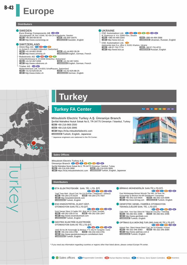
Middle East /Africa
LEBANONCEG Liban - Comptoir d'Electricité Générale Liban
Cebaco Center - Block A, Autostrade Dora, Beirut, Lebanon+961-1-240-445TEL
Arabic, English, FrenchLANGUAGE+961-1-240-193FAX
Other Middle East Arab Countries/CyprusComptoir d'Electricité Générale - International - S.A.L. (Off Shore)Cebaco Center - Block A, Autostrade DoraP.O. Box 11-1314 Beirut, Beirut, Lebanon
+961-1-240-430TEL
Arabic, French, EnglishLANGUAGE+961-1-240-438FAX
SAUDI ARABIA
ISRAELSherf Motion Technologies Ltd.Rehov Hamerkava 19, IL-58851 Holon, Israel
+972-3-5595462TEL
Hebrew, EnglishLANGUAGE
+972-3-5560182FAX
GIRIT CELADON LTD.12 H'aomanut Street, IL-42505 Netanya, Israel
+972-9-8633980TEL
Hebrew, English
Hebrew, English
LANGUAGE
+972-3-7537802FAX
RB
ELECTRO TECHNIQUE8 Markaz Almaaloumat St., Sheraton, Cairo, Egypt
+2-2-226-98-576TEL
Arabic, EnglishLANGUAGE+2-2-226-98-579FAX
ILAN&GAVISH Automation24 Shenkar St., Kiryat Arie, IL-49001 Petah-Tikva, Israel
+972-3-9221824TEL
LANGUAGE
+972-3-9240761FAX
http://www.ilan-gavish.co.ilHP
http://www.girit.co.ilHP
http://www.sherfmotion.co.ilHP
MOROCCOSCHIELE MAROC Km 7,2 Nouvelle Route de Rabat. Aîn Sebaâ. 20600 Casablanca, Maroc
+212-5-22-66-01-51/52/53/54TEL
French, EnglishLANGUAGE+212-5-22-66-01-56FAX
http://www.schielemaroc.comHP
TUNISIAMOTRA Electric3, Résidence Imen, Avenue des Martyrs Mourouj III, 2074 - El Mourouj III Ben Arous, Tunisia
+216-71-474-599TEL
French, EnglishLANGUAGE+216-71-474-671FAX
http://www.motra-electric.comHP
ALGERIAMEC-CASA Complete Automation Solutions Algeria
Cité Alghazel N° 01, 02000 Chlef, Algeria+213-27722867TEL
Arabic, French, EnglishLANGUAGE
+213-27722867FAX
http://www.mec-casa.comHP
CNC
Distributors
EGYPTCairo Electrical Group9 Rostoum Str. Garden City 8th Floor, Apt. 37P.O. Box 165-11516 Maglis El-Shaab, Cairo - Egypt
+20-2-279-23-203TEL
Arabic, English, FrenchLANGUAGE+20-2-279-62-719FAX
RB
RB
Center of Electrical GoodsAl-Shuwayer Street Side way of Salahudin Al-Ayoubi Str. (Known as Sitteen Str.) Behind Bank Al-Bilad, P.O. Box 15955, Riyadh 11454, Saudi Arabia
+966-1-477-0149TEL
Arabic, English, FrenchLANGUAGE+961-1-477-6043FAX
CBI-electricPrivate Bag 2016, 1600 Isando, South Africa
+27-11-977-0770TEL
EnglishLANGUAGE+27-11-977-0761FAX
http://www.cbi-electric.comHP
Adroit Technologies20 Waterford Office Park, 189 Witkoppen Road, Fourways, South Africa
+27-11-658-8100TEL
EnglishLANGUAGE+27-11-658-8101FAX
http://www.adroit.co.zaHP
LVS MC
LVS MC
LVS MC
LVS MC
LVS MC
The Integrated Control for Trading Est. (TIC)
Ash Shaikh Abdullah Al Anqari St., Al Wurud, Riyadh, Saudi Arabia+966-11 2051240TEL
Arabic, EnglishLANGUAGE+966-11 2051967FAX
LVS MC
Africa
Middle East
RB
SOUTH AFRICAMOTIONTRONIXNo. 5 Albatross Street, Rhodesfield, Kempton Park 1619, South Africa
+27-11-394-8512TEL
EnglishLANGUAGE+27-11-394-8513FAX
http://www.motiontronix.co.zaHP
SENEGALAvangreen SenegalRue B x Birago Diop nr. 27, Point E Dakar (Senegal)
+221-33-825-74-20TEL
French, EnglishLANGUAGE+221-33-825-74-30FAX
http://www.avangreen.comHP
RB LVS MC
Dubai BranchMitsubishi Electric Europe B.V. Dubai BranchDubai Silicon Oasis, P.O.BOX 341241, Dubai, U.A.E.
+971-4-3724716TEL
Arabic, EnglishLANGUAGE
+971-4-3724721FAX
https://eu3a.mitsubishielectric.comHP
Sales Offices
EuropeDistributors
* If you need any information regarding countries or regions other than listed above, please contact Europe FA center.
UKRAINECSC Automation Ltd.M. Raskovoyi st. 4-b, 02660 Kiev, Ukraine
+380-44-494-3344TEL
Ukrainian, Russian, EnglishLANGUAGE+380-44-494-3366FAX
http://www.kck.uaHP
CNCCSC Automation Ltd.Aptekarskiy lane 9-a, office 3, 61001 Kharkov, Ukraine
+38-57-732-7774TEL
Russian, EnglishLANGUAGE+38-57-731-8721FAX
http://www.kck.uaHP
RB CNC LVS MC
ETA ELEKTROTEKNİK SAN. TİC. LTD. ŞTİ.
Yeşil Tepe Mah. Uluyol Cad. No:114 Erenler / Adapazari / Sakarya+90-264-275-8104TEL
Turkish, EnglishLANGUAGE
+90-264-275-7507FAX
http://etaelektroteknik.comHP
ESO ENDÜSTRİYEL ELEKT.SİST.OTOMASYON SAN.TİC.LTD.ŞTİ.
İzmit Sanayi Sitesi 3.Cadde 202. Blok No:27 İzmit / Kocaeli +90-262-335-0716TEL
Turkish, EnglishLANGUAGE
+90-262-335-1947FAX
http://www.esoendustriyel.comHP
GEOTEK ELEKTRİK ELEKTRONİK OTOMASYON SAN.VE TİC.LTD.ŞTİ.
1443 Sk.No:3K Keremoğlu İş Merkezi P.K 35170 Yenişehir / İzmir+90-232-433-4780TEL
Turkish, EnglishLANGUAGE
+90-232-433-4781FAX
http://www.geotekotomasyon.com/iletisim.htmlHP
BİRMAG MÜHENDİSLİK SAN.TİC.LTD.ŞTİ.
Gazi Muhtarpaşa Bulvari Mücahi Tler MH. 54 Nolu SK. Güneydoğu İş Merkezi No:8/6 Şehitkamil / Gaziantep
+90-342-215-0504TEL
Turkish, EnglishLANGUAGE+90-342-215-0599FAX
http://www.birmag.comHP
GENFOTEK GENEL FABRİKA OTOMASYON TEKNOLOJİLERİ SAN. TİC. LTD.ŞTİ.
Zafer Mah. Yeni San.Sitesi M-7 Blok No:21Çorlu / Tekirdağ+90-282-651-3486TEL
Turkish, EnglishLANGUAGE
+90-282-651-3496FAX
http://www.genfotek.comHP
OPTİMAS ELK.MÜH.İNŞ.TUR.ORG.SAN.VE TİC.LTD.ŞTİ.
Aykent San. Sitesi Hasan Basri Cad. No:10 Karatay / Konya+90-332-346-3083TEL
Turkish, EnglishLANGUAGE
+90-332-346-3084FAX
http://www.optimas.com.trHP
LVS MC
LVS MC
LVS MC
LVS MC
LVS MC
LVS MC
SWITZERLANDOmni Ray AGIm Schörli 5, CH-8600 Dübendorf, Switzerland
+41-44-802-28-80TEL
English, German, FrenchLANGUAGE+41-44-802-28-28FAX
http://www.omniray.chHP
Robotronic AGSchlachthofstrasse 8, CH-8406 Winterthur, Switzerland
+41-52-267-0200TEL
English, German, FrenchLANGUAGE+41-52-267-0201FAX
http://www.robotronic.chHP
Trielec AGMühlentalstrasse 136, CH-8201 Schaffhausen, Switzerland
+41-52-625-84-25TEL
German, EnglishLANGUAGE+41-52-625-88-25FAX
http://www.trielec.chHP
LVS MC
RB
* Japanese engineers are stationed in the FA Center.
Mitsubishi Electric Turkey A.Ş. Ümraniye BranchŞerifali Mahallesi Nutuk Sokak No:5, TR-34775 Ümraniye / İstanbul, Turkey
+90-216-969-2500TEL
Turkish, English, JapaneseLANGUAGE
+90-216-526-3995FAX
https://tr3a.mitsubishielectric.comHP
Distributors
Sales Offices
RB CNC LVS MC
Mitsubishi Electric Turkey A.Ş. Ümraniye BranchŞerifali Mahallesi Nutuk Sokak No:5, TR-34775 Ümraniye / İstanbul, Turkey
+90-216-526-3990TEL
https://tr3a.mitsubishielectric.comHP Turkish, English, JapaneseLANGUAGE+90-216-526-3995FAX
TurkeyTurkey FA Center RB CNC LVS MC
Euro Energy Components ABJärnvägsgatan 36, Box 10348, SE-434 24 Kungsbacka, Sweden
+46-300-69-00-40TEL +46-300-16475FAX
SWEDEN
Swedish, EnglishLANGUAGEhttp://www.euroenergy.seHP
LVS MC
LVS MCRB
LVS MCLVS MCRB
MITSUBISHI ELECTRIC EUROPE South Africa FA Center Satellite20 Waterford Office Park Waterford Drive cnr of Witkoppen Road Fourways Johannesburg South Africa
+27-11-658-8100TEL
EnglishLANGUAGE
https://za3a.mitsubishielectric.comHP
FA Center Satellite
Sales offices Industrial RobotsRB Computerized Numerical ControllersCNC Low-voltage Circuit BreakersLVS Contactors and Motor Starters * For repairing or after-sales technical support, please contact your nearest FA Center.MCProgrammable Controllers InvertersAC Servos, Servo System ControllersHuman-Machine Interfaces
B-43
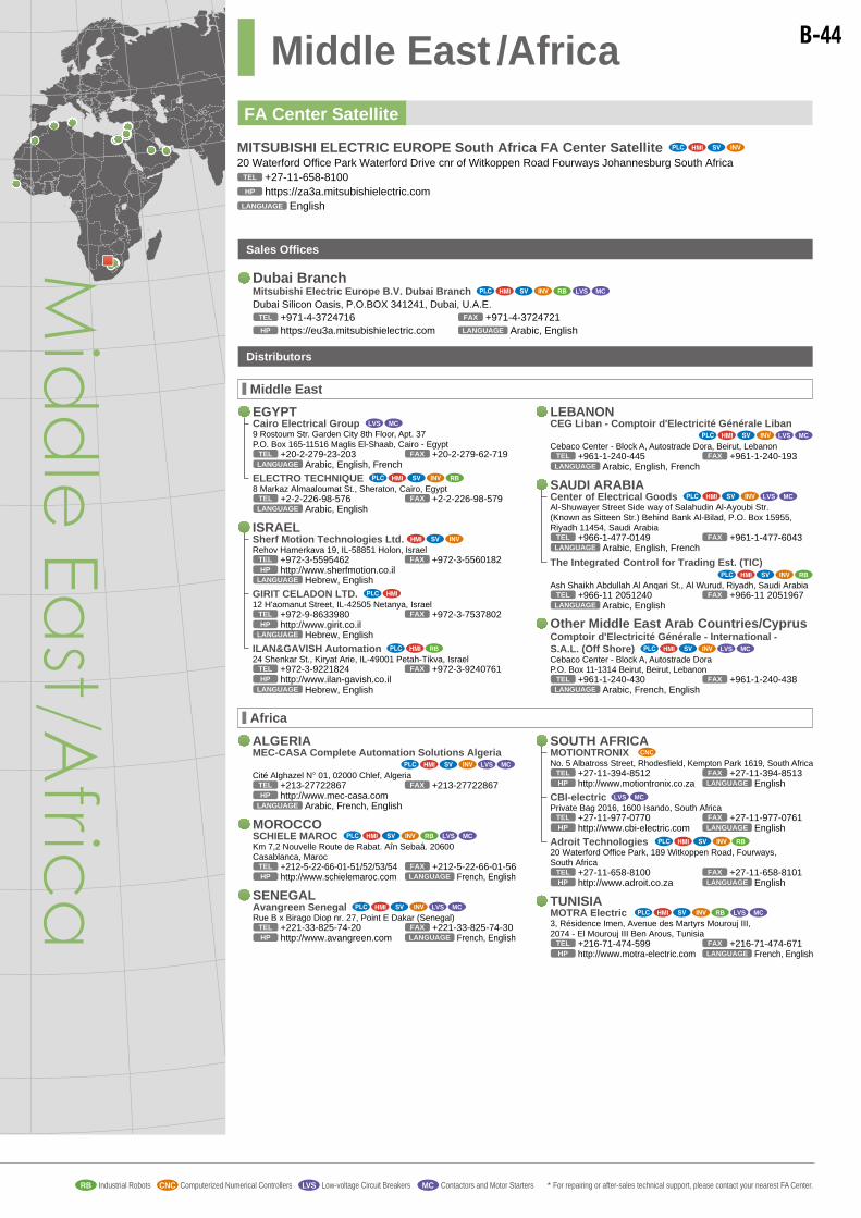
Middle East /Africa
LEBANONCEG Liban - Comptoir d'Electricité Générale Liban
Cebaco Center - Block A, Autostrade Dora, Beirut, Lebanon+961-1-240-445TEL
Arabic, English, FrenchLANGUAGE+961-1-240-193FAX
Other Middle East Arab Countries/CyprusComptoir d'Electricité Générale - International - S.A.L. (Off Shore)Cebaco Center - Block A, Autostrade DoraP.O. Box 11-1314 Beirut, Beirut, Lebanon
+961-1-240-430TEL
Arabic, French, EnglishLANGUAGE+961-1-240-438FAX
SAUDI ARABIA
ISRAELSherf Motion Technologies Ltd.Rehov Hamerkava 19, IL-58851 Holon, Israel
+972-3-5595462TEL
Hebrew, EnglishLANGUAGE
+972-3-5560182FAX
GIRIT CELADON LTD.12 H'aomanut Street, IL-42505 Netanya, Israel
+972-9-8633980TEL
Hebrew, English
Hebrew, English
LANGUAGE
+972-3-7537802FAX
RB
ELECTRO TECHNIQUE8 Markaz Almaaloumat St., Sheraton, Cairo, Egypt
+2-2-226-98-576TEL
Arabic, EnglishLANGUAGE+2-2-226-98-579FAX
ILAN&GAVISH Automation24 Shenkar St., Kiryat Arie, IL-49001 Petah-Tikva, Israel
+972-3-9221824TEL
LANGUAGE
+972-3-9240761FAX
http://www.ilan-gavish.co.ilHP
http://www.girit.co.ilHP
http://www.sherfmotion.co.ilHP
MOROCCOSCHIELE MAROC Km 7,2 Nouvelle Route de Rabat. Aîn Sebaâ. 20600 Casablanca, Maroc
+212-5-22-66-01-51/52/53/54TEL
French, EnglishLANGUAGE+212-5-22-66-01-56FAX
http://www.schielemaroc.comHP
TUNISIAMOTRA Electric3, Résidence Imen, Avenue des Martyrs Mourouj III, 2074 - El Mourouj III Ben Arous, Tunisia
+216-71-474-599TEL
French, EnglishLANGUAGE+216-71-474-671FAX
http://www.motra-electric.comHP
ALGERIAMEC-CASA Complete Automation Solutions Algeria
Cité Alghazel N° 01, 02000 Chlef, Algeria+213-27722867TEL
Arabic, French, EnglishLANGUAGE
+213-27722867FAX
http://www.mec-casa.comHP
CNC
Distributors
EGYPTCairo Electrical Group9 Rostoum Str. Garden City 8th Floor, Apt. 37P.O. Box 165-11516 Maglis El-Shaab, Cairo - Egypt
+20-2-279-23-203TEL
Arabic, English, FrenchLANGUAGE+20-2-279-62-719FAX
RB
RB
Center of Electrical GoodsAl-Shuwayer Street Side way of Salahudin Al-Ayoubi Str. (Known as Sitteen Str.) Behind Bank Al-Bilad, P.O. Box 15955, Riyadh 11454, Saudi Arabia
+966-1-477-0149TEL
Arabic, English, FrenchLANGUAGE+961-1-477-6043FAX
CBI-electricPrivate Bag 2016, 1600 Isando, South Africa
+27-11-977-0770TEL
EnglishLANGUAGE+27-11-977-0761FAX
http://www.cbi-electric.comHP
Adroit Technologies20 Waterford Office Park, 189 Witkoppen Road, Fourways, South Africa
+27-11-658-8100TEL
EnglishLANGUAGE+27-11-658-8101FAX
http://www.adroit.co.zaHP
LVS MC
LVS MC
LVS MC
LVS MC
LVS MC
The Integrated Control for Trading Est. (TIC)
Ash Shaikh Abdullah Al Anqari St., Al Wurud, Riyadh, Saudi Arabia+966-11 2051240TEL
Arabic, EnglishLANGUAGE+966-11 2051967FAX
LVS MC
Africa
Middle East
RB
SOUTH AFRICAMOTIONTRONIXNo. 5 Albatross Street, Rhodesfield, Kempton Park 1619, South Africa
+27-11-394-8512TEL
EnglishLANGUAGE+27-11-394-8513FAX
http://www.motiontronix.co.zaHP
SENEGALAvangreen SenegalRue B x Birago Diop nr. 27, Point E Dakar (Senegal)
+221-33-825-74-20TEL
French, EnglishLANGUAGE+221-33-825-74-30FAX
http://www.avangreen.comHP
RB LVS MC
Dubai BranchMitsubishi Electric Europe B.V. Dubai BranchDubai Silicon Oasis, P.O.BOX 341241, Dubai, U.A.E.
+971-4-3724716TEL
Arabic, EnglishLANGUAGE
+971-4-3724721FAX
https://eu3a.mitsubishielectric.comHP
Sales Offices
EuropeDistributors
* If you need any information regarding countries or regions other than listed above, please contact Europe FA center.
UKRAINECSC Automation Ltd.M. Raskovoyi st. 4-b, 02660 Kiev, Ukraine
+380-44-494-3344TEL
Ukrainian, Russian, EnglishLANGUAGE+380-44-494-3366FAX
http://www.kck.uaHP
CNCCSC Automation Ltd.Aptekarskiy lane 9-a, office 3, 61001 Kharkov, Ukraine
+38-57-732-7774TEL
Russian, EnglishLANGUAGE+38-57-731-8721FAX
http://www.kck.uaHP
RB CNC LVS MC
ETA ELEKTROTEKNİK SAN. TİC. LTD. ŞTİ.
Yeşil Tepe Mah. Uluyol Cad. No:114 Erenler / Adapazari / Sakarya+90-264-275-8104TEL
Turkish, EnglishLANGUAGE
+90-264-275-7507FAX
http://etaelektroteknik.comHP
ESO ENDÜSTRİYEL ELEKT.SİST.OTOMASYON SAN.TİC.LTD.ŞTİ.
İzmit Sanayi Sitesi 3.Cadde 202. Blok No:27 İzmit / Kocaeli +90-262-335-0716TEL
Turkish, EnglishLANGUAGE
+90-262-335-1947FAX
http://www.esoendustriyel.comHP
GEOTEK ELEKTRİK ELEKTRONİK OTOMASYON SAN.VE TİC.LTD.ŞTİ.
1443 Sk.No:3K Keremoğlu İş Merkezi P.K 35170 Yenişehir / İzmir+90-232-433-4780TEL
Turkish, EnglishLANGUAGE
+90-232-433-4781FAX
http://www.geotekotomasyon.com/iletisim.htmlHP
BİRMAG MÜHENDİSLİK SAN.TİC.LTD.ŞTİ.
Gazi Muhtarpaşa Bulvari Mücahi Tler MH. 54 Nolu SK. Güneydoğu İş Merkezi No:8/6 Şehitkamil / Gaziantep
+90-342-215-0504TEL
Turkish, EnglishLANGUAGE+90-342-215-0599FAX
http://www.birmag.comHP
GENFOTEK GENEL FABRİKA OTOMASYON TEKNOLOJİLERİ SAN. TİC. LTD.ŞTİ.
Zafer Mah. Yeni San.Sitesi M-7 Blok No:21Çorlu / Tekirdağ+90-282-651-3486TEL
Turkish, EnglishLANGUAGE
+90-282-651-3496FAX
http://www.genfotek.comHP
OPTİMAS ELK.MÜH.İNŞ.TUR.ORG.SAN.VE TİC.LTD.ŞTİ.
Aykent San. Sitesi Hasan Basri Cad. No:10 Karatay / Konya+90-332-346-3083TEL
Turkish, EnglishLANGUAGE
+90-332-346-3084FAX
http://www.optimas.com.trHP
LVS MC
LVS MC
LVS MC
LVS MC
LVS MC
LVS MC
SWITZERLANDOmni Ray AGIm Schörli 5, CH-8600 Dübendorf, Switzerland
+41-44-802-28-80TEL
English, German, FrenchLANGUAGE+41-44-802-28-28FAX
http://www.omniray.chHP
Robotronic AGSchlachthofstrasse 8, CH-8406 Winterthur, Switzerland
+41-52-267-0200TEL
English, German, FrenchLANGUAGE+41-52-267-0201FAX
http://www.robotronic.chHP
Trielec AGMühlentalstrasse 136, CH-8201 Schaffhausen, Switzerland
+41-52-625-84-25TEL
German, EnglishLANGUAGE+41-52-625-88-25FAX
http://www.trielec.chHP
LVS MC
RB
* Japanese engineers are stationed in the FA Center.
Mitsubishi Electric Turkey A.Ş. Ümraniye BranchŞerifali Mahallesi Nutuk Sokak No:5, TR-34775 Ümraniye / İstanbul, Turkey
+90-216-969-2500TEL
Turkish, English, JapaneseLANGUAGE
+90-216-526-3995FAX
https://tr3a.mitsubishielectric.comHP
Distributors
Sales Offices
RB CNC LVS MC
Mitsubishi Electric Turkey A.Ş. Ümraniye BranchŞerifali Mahallesi Nutuk Sokak No:5, TR-34775 Ümraniye / İstanbul, Turkey
+90-216-526-3990TEL
https://tr3a.mitsubishielectric.comHP Turkish, English, JapaneseLANGUAGE+90-216-526-3995FAX
TurkeyTurkey FA Center RB CNC LVS MC
Euro Energy Components ABJärnvägsgatan 36, Box 10348, SE-434 24 Kungsbacka, Sweden
+46-300-69-00-40TEL +46-300-16475FAX
SWEDEN
Swedish, EnglishLANGUAGEhttp://www.euroenergy.seHP
LVS MC
LVS MCRB
LVS MCLVS MCRB
MITSUBISHI ELECTRIC EUROPE South Africa FA Center Satellite20 Waterford Office Park Waterford Drive cnr of Witkoppen Road Fourways Johannesburg South Africa
+27-11-658-8100TEL
EnglishLANGUAGE
https://za3a.mitsubishielectric.comHP
FA Center Satellite
Sales offices Industrial RobotsRB Computerized Numerical ControllersCNC Low-voltage Circuit BreakersLVS Contactors and Motor Starters * For repairing or after-sales technical support, please contact your nearest FA Center.MCProgrammable Controllers InvertersAC Servos, Servo System ControllersHuman-Machine Interfaces
B-44

Warranty
1. Gratis Warranty Term and Gratis Warranty Range
If any faults or defects (hereinafter “Failure”) found to be the responsibility of Mitsubishi occur during use of the product within the
gratis warranty term, the product shall be repaired at no cost via the sales representative. However, if repairs are required onsite,
actual expenses to send an engineer will be borne by the customer. Mitsubishi shall not be held responsible for any
re-commissioning, maintenance, or testing on-site that involves replacement of the failed module.
[Gratis Warranty Term]
The gratis warranty term of the product shall be between 12 months*1 and 36 months*2 after the date of purchase or delivery to a
designated place.
Note that the product shall be distributed for a maximum period of 6 months after shipment, and the longest gratis warranty term after
manufacturing shall be between 18 months*1 and 42 months*2. In addition, the gratis warranty term of the product repaired shall not
exceed the gratis warranty term before repairs.
[Gratis Warranty Range]
(1) The customer shall be responsible for the primary failure diagnosis unless otherwise specified.
If requested by the customer, Mitsubishi Electric Corporation or its representative firm may carry out the primary failure diagnosis
at the customer’s expense.
The primary failure diagnosis will, however, be free of charge should the cause of failure be attributable to Mitsubishi Electric
Corporation.
(2) The warranty shall apply only to the product used under normal situations such as when the usage state, method and/or
environment conform to the conditions / precautions stated in the instruction manual, the user’s manual, the caution labels on
the product, etc. The range shall be limited to normal use within the usage state, usage methods, usage environment, etc. which
follow the conditions, precautions, etc. given in the instruction manual, user’s manual, caution labels on the product, etc.
(3) Even within the gratis warranty term, repairs shall be charged in the following cases.
Any failure occurring from inappropriate storage or handling of the product, carelessness or negligence of the customer. Failure
caused by the customer’s hardware or software design.
Any failure caused by unapproved modifications, etc., to the product by the customer.
When the Mitsubishi product is assembled into the customer’s device, any failure that could have been avoided if functions or
structures, judged as necessary in the legal safety measures the customer’s device is subject to or judged as necessary by
industry standards, had been provided.
Any failure that could have been avoided if consumable parts designated in the user’s manual etc. had been correctly serviced
or replaced.
Replacement of consumable parts.
Any failure caused by external irresistible forces such as fires or abnormal voltages, and any failure caused by force majeure
such as earthquakes, lightning, wind and water damage.
Any failure caused by reasons unpredictable by scientific technology standards at time of shipment from Mitsubishi.
Any other failure found not to be the responsibility of Mitsubishi or admitted not to be so by the customer.
2. Onerous repair term after discontinuation of production
(1) Mitsubishi shall accept onerous product repairs for 7 years (4 years for the safety controller) after production of the product is
discontinued.
Discontinuation of production shall be notified with Mitsubishi Technical Bulletins, etc.
(2) Product supply (including repair parts) is not available after production is discontinued.
3. Overseas service
Overseas, repairs shall be accepted by Mitsubishi’s local overseas FA Center. Note that the repair conditions at each FA Center may
differ.
Warranty Information
B-45
4. Exclusion of loss in opportunity and secondary loss from warranty liability
Regardless of the gratis warranty term, Mitsubishi shall not be liable for compensation to damages caused by any cause
found not to be the responsibility of Mitsubishi, loss in opportunity, lost profits incurred to the customer by failures of
Mitsubishi products, special damages and secondary damages, whether foreseeable or not, compensation for accidents, and
compensation for damages to products other than Mitsubishi products, replacement by the customer, maintenance of on-site
equipment, start-up test run and other tasks.
5. Changes in product specifications
The specifications given in the catalogs, manuals or technical documents are subject to change without prior notice.
6. Product application
(1) In using the Mitsubishi product, the usage conditions shall be that the application will not lead to a major accident even if any
problem or fault should occur in the product, and that backup and fail-safe functions are systematically provided outside of
the device for any problem or fault.
(2) The Mitsubishi product has been designed and manufactured for applications in general industries, etc.
Thus, the product should not be used in applications that could affect the public, such as use in nuclear power plants or other
power plants operated by respective power companies, and that require a special quality assurance system, such as use for
railway companies or public sectors.
Also, the product should not be used in applications that could have significant impact on human life or property, such as use
in aircraft, medical or railway services, incineration / fuel devices, manned transportation equipment, equipment for recreation /
amusement, or safety devices.
However, Mitsubishi Electric Corporation may consider the possibility of using the product even in these fore-mentioned
applications, if the customer acknowledges that the product has only limited application and that any special quality is not
required.
(3) Depending on the product, because there shall be other terms defined that are not included in this context, please confirm
when you place an order.
*1: The products (Safety controller / Inverter / Low-voltage circuit breaker / Magnetic contactors and starters / Power management measuring devices) whose
gratis warranty term is either 12 months after delivery or 18 months after manufacturing.
*2: The products (Programmable controller (including C language controller) / Servo system controller / GOT / Energy-saving support device) whose gratis
warranty term is either 36 months after delivery or 42 months after manufacturing.
*3: The gratis warranty term of the industrial robot shall be for either 12 months after delivery or 2000 operating hours (possible operating hours of 8 hours per day
5 250 days).
*4: Oil mist environment for industrial robots
As a result of tests conducted using cutting oils
shown in the table on the right, Mitsubishi confirms
that the product satisfies IP (Ingress Protection)
specifications. Using the product in an environment
where any cutting oils other than those shown in
the table on the right may cause the product to
decrease in IP performance. Also, the warranty
does not apply if a failure occurs in the product
used in an atmosphere where any cutting oil other
than those shown in the table on the right is used
or where a robot is directly exposed to water, oil
or dust beyond IP specs limits. If the customer wants to use a type of cutting oil, other than the applicable oils confirmed, Mitsubishi is ready to conduct a
verification test of the oil on the behalf of the customer. For the latest information about any types of cutting oils, other than those listed in the table on the right,
which have been confirmed as applicable, visit the website “Mitsubishi FA Site” (URL<http://www.mitsubishielectric.co.jp/fa>).
*5: Usage environment for Magnetic contactors and starters
Do not use the product in the following locations, as it may cause the product to malfunction or shorten its operation life.
Where the ambient temperature exceeds the range of -5 to +40°C.
Where the average daily temperature exceeds 35°C.
Where the altitude exceeds 1000m.
Where abnormal vibration or shock happens.
Where there is the excessive amount of dust.
Where hazardous gases such as explosive, corrosive and flammable gases are generated.
Where there is the excessive amount of moisture or oil mist.
Where there is too much snow and ice.
Where it is always wet.
Where it is directly exposed to sea breeze.
Cutting oils for oil mist environmental test
No. Oil name Manufacturer Property Operating condition
1 Castrol hysol X Castrol Water soluble 20 fold dilution
2 Castrol Syntilo 9954 Castrol Water soluble 20 fold dilution
3 Yushiro oil CE Yushiro Chemical Industry Water-insoluble –
4 Yushiroken E10 Yushiro Chemical Industry Water soluble 20 fold dilution
5 Yushiroken synthetic 770TG Yushiro Chemical Industry Water soluble 20 fold dilution
6 Yushiroken FX90 Yushiro Chemical Industry Water soluble 20 fold dilution
7 SUNCUT ES-50N Nippon Grease Water-insoluble –
8 Searching cut SG555 Kyowa Oil Lubricants Water-insoluble –
9 Emul cut FA-800 Kyodo Yushi Water soluble –
B-46

B-47
IndexModel Product name Page Model Product name Page
1
1E-GR35S Hand output cable 657
1E-ST040hC Hand (curl) tube 657
1E-ST0408C-300 Hand (curl) tube 657
1E-VD0h Solenoid valve set 657
1E-VD0hE Solenoid valve set 657
1F-hhLUCBL-02 Machine cable, for extension/flexible CR-751 657
1F-hhLUCBL-11 Machine cable, for extension/flexible CR-751 657
1F-hhUCBL-02 Machine cable, for extension/fixed CR-751 657
1F-hhUCBL-11 Machine cable, for extension/fixed CR-751 657
1F-02UCBL-02Machine cable (replacement for shorter 2m type)
657
1F-DH-hhStopper for changing the J1-axis operating range
657
1F-DH-05J1Stopper for changing the J1-axis operating range
657
1F-GR35S-02 Hand output cable 657
1F-GR60S-01 Hand output cable 657
1F-HA01S-01 External wiring set 1 for the base 657
1F-HA02S-01 External wiring set 2 for the base 657
1F-HB01S-01 External wiring set 1 for the forearm 657
1F-HB02S-01 External wiring set 2 for the forearm 657
1F-HC35C-01 Hand input cable 657
1F-HC35C-02 Hand input cable 657
1F-HC35S-02 Hand input cable 657
1F-HS304S-01 Internal wiring and piping set for hand 657
1F-HS408S-01 Internal wiring and piping set for hand 657
1F-HS408S-02 Internal wiring and piping set for hand 657
1F-HS604S-01 Internal wiring and piping set for hand 657
1F-HS604S-02 Internal wiring and piping set for hand 657
1F-UT-BOX External user wiring and piping box 657
1F-UT-BOX-01 External user wiring and piping box 657
1F-VD0h-hh Solenoid valve set 657
1F-VD0hE-hh Solenoid valve set 657
1N-ST060hC Hand (curl) tube 657
1N-ST0608C-01 Hand (curl) tube 657
1S-hhCBL-01 Machine cable, for extension/fixed CR-750 657
1S-hhCBL-03 Machine cable, for extension/fixed CR-750 657
1S-hhCBL-11 Machine cable, for extension/fixed CR-750 657
1S-hhLCBL-01 Machine cable, for extension/flexible CR-750 657
1S-hhLCBL-03 Machine cable, for extension/flexible CR-750 657
1S-hhLCBL-11 Machine cable, for extension/flexible CR-750 657
1S-02UCBL-01Machine cable (replacement for shorter 2m type)
657
1S-DH-01Stopper for changing the J1-axis operating range
657
1S-DH-05J1Stopper for changing the J1-axis operating range
657
1S-DH-05J2Stopper for changing the J2-axis operating range
657
1S-DH-11J1Stopper for changing the J1-axis operating range
657
1S-DH-11J2Stopper for changing the J2-axis operating range
657
1S-DH-11J3Stopper for changing the J3-axis operating range
657
1S-GR35S-02 Hand output cable 657
1S-HC00S-01 Hand input cable 657
1S-HC30C-11 Hand input cable 657
1S-ST0304S Hand tube 657
1S-VD0h-hh Solenoid valve set 657
1S-VD0hE-hh Solenoid valve set 657
2
2A-CBL Remote Parallel I/O cable (5m, 15m) 658
2A-RZ361 On-board Parallel I/O interface (Sink type) 658
2A-RZ371 On-board Parallel I/O interface (Source type) 658
2D-CBL Remote Parallel I/O cable (5m, 15m) 658
2D-TZ368On-board Parallel I/O interface (Installed internally)
658
2D-TZ378On-board Parallel I/O interface (Installed internally)
658
2D-TZ454 Extension memory 658
2D-TZ535 Network base card 658
2D-TZ576 CC-Link interface 658
2F-32CON03M Conversion cable for the teaching box 658
2F-CNUSR01MTerminal block replacement tool for the user wiring
658
2F-YZ581 Encoder distribution unit 658
3
3D-11C-WINE MELSOFT iQ Works 236
3D-11C-WINJ Personal computer support software 658
3D-12C-WINE MELSOFT iQ Works 236
3D-12C-WINJ Personal computer support software-mini 658
3F-21D-WINJ Simulator (MELFA-Works) 658
4
4F-3DVS2-PKG1 MELFA- 3D Vision 658
4F-FS001-W200 Force sensor set 658
A
A1SADP-Q-SET1 AnS-Q module conversion adapter 239
B-48
Model Product name Page Model Product name Page
A1SADP-Q-SET2 AnS-Q module conversion adapter 239
A1SJ71AP23QMELSECNET(II) local station data link module
239
A1SJ71AT23BQMELSECNET/B local station data link module
239
A6CAP-WP2Network Related Products Protective cap for unused connector
235
A6CON1 MELSEC-Q Series Connector 216, 235
A6CON1E MELSEC-Q Series Connector 216, 235
A6CON2 MELSEC-Q Series Connector 216, 235
A6CON2E MELSEC-Q Series Connector 216, 235
A6CON3 MELSEC-Q Series Connector 216, 235
A6CON3E MELSEC-Q Series Connector 216, 235
A6CON4 MELSEC-Q Series Connector 216, 235
A6CON-L5P (35505-6000-B0M GF)
Network Related Products One-touch connector plug for communication (10pcs)
235
A6CON-LJ5P (35720-L200-B00 AK)
Network Related Products Online connector 235
A6CON-P214 (33104-6000FL)
Network Related Products One-touch connector plug (20pcs)
235
A6CON-P220 (33104-6100FL)
Network Related Products One-touch connector plug (20pcs)
235
A6CON-P514 (33104-6200FL)
Network Related Products One-touch connector plug (20pcs)
235
A6CON-P520 (33104-6300FL)
Network Related Products One-touch connector plug (20pcs)
235
A6CON-PW5P (35505-6080-A00 GF)
Network Related Products One-touch connector plug for power supply and FG (10pcs)
235
A6CON-PW5P-SOD (35505-6180-A00 GF)
Network Related Products One-touch connector plug for power supply and FG (10pcs)
235
A6CON-PWJ5P (35720-L200-A00 AK)
Network Related Products Online connector 235
A6CON-TR11NNetwork Related Products One-touch connector plug with teminating resitor (1pc)
235
A6CVR-16Network Related Products Protective cover for remote I/O module
235
A6CVR-32Network Related Products Protective cover for remote I/O module
235
A6CVR-8Network Related Products Protective cover for remote I/O module
235
A6CVR-VCE16Network Related Products Protective cover for remote I/O module
235
A6CVR-VCE8Network Related Products Protective cover for remote I/O module
235
A6GA-CCMFP1NN300FNetwork Related Products CC-Link Related Products
232
A6GA-CCMFP1NN60FNetwork Related Products CC-Link Related Products
232
A6GA-CCMFP2ANN 300FNetwork Related Products CC-Link Related Products
232
A6GA-CCMFP2ANN 60FNetwork Related Products CC-Link Related Products
232
A6GA-CCMFP2NN 300FNetwork Related Products CC-Link Related Products
232
A6GA-CCMFP2NN 60FNetwork Related Products CC-Link Related Products
232
A6GA-CCMFP3NN 300FNetwork Related Products CC-Link Related Products
232
A6GA-CCMFP3NN 60FNetwork Related Products CC-Link Related Products
232
A6TBX36-EMELSEC-Q Series Connector/terminal block conversion module
217, 235
A6TBX54-EMELSEC-Q Series Connector/terminal block conversion module
217, 235
A6TBX70MELSEC-Q Series Connector/terminal block conversion module
217, 235
A6TBX70-EMELSEC-Q Series Connector/terminal block conversion module
217, 235
A6TBXY36MELSEC-Q Series Connector/terminal block conversion module
217, 235
A6TBXY54MELSEC-Q Series Connector/terminal block conversion module
217, 235
A6TBY36-EMELSEC-Q Series Connector/terminal block conversion module
217, 235
A6TBY54-EMELSEC-Q Series Connector/terminal block conversion module
217, 235
A6TE2-16SRN MELSEC-Q Series Relay terminal module 217, 235
A7GT-CNB Bus connector conversion box 629
A9GT-QCNB Bus extension connector box 624, 629
AC05TBMELSEC-Q Series Connector/terminal block conversion module
217, 235
AC05TB-EMELSEC-Q Series Connector/terminal block conversion module
217, 235
AC06TE MELSEC-Q Series Relay terminal module 217, 235
AC100TBMELSEC-Q Series Connector/terminal block conversion module
217, 235
AC100TE MELSEC-Q Series Relay terminal module 217, 235
AC10TBMELSEC-Q Series Connector/terminal block conversion module
217, 235
AC10TB-EMELSEC-Q Series Connector/terminal block conversion module
217, 235
AC10TE MELSEC-Q Series Relay terminal module 217, 235
AC20TBMELSEC-Q Series Connector/terminal block conversion module
217, 235
AC20TB-EMELSEC-Q Series Connector/terminal block conversion module
217, 235
AC30TBMELSEC-Q Series Connector/terminal block conversion module
217, 235
AC30TB-EMELSEC-Q Series Connector/terminal block conversion module
217, 235
AC30TE MELSEC-Q Series Relay terminal module 217, 235
AC50TBMELSEC-Q Series Connector/terminal block conversion module
217, 235
AC50TB-EMELSEC-Q Series Connector/terminal block conversion module
217, 235
AC50TE MELSEC-Q Series Relay terminal module 217, 235
AC80TBMELSEC-Q Series Connector/terminal block conversion module
217, 235
AE1000-SWLow Voltage Air Circuit Breakers(AE-SW Series)
710
AE1250-SWLow Voltage Air Circuit Breakers(AE-SW Series)
710
AE1600-SWLow Voltage Air Circuit Breakers (AE-SW Series)
710
AE2000-SWLow Voltage Air Circuit Breakers (AE-SW Series)
710
AE2000-SWALow Voltage Air Circuit Breakers (AE-SW Series)
710
AE2500-SWLow Voltage Air Circuit Breakers(AE-SW Series)
710
AE3200-SWLow Voltage Air Circuit Breakers (AE-SW Series)
710
AE4000-SWLow Voltage Air Circuit Breakers (AE-SW Series)
711
AE4000-SWALow Voltage Air Circuit Breakers (AE-SW Series)
710
AE5000-SWLow Voltage Air Circuit Breakers (AE-SW Series)
711
AE6300-SWLow Voltage Air Circuit Breakers (AE-SW Series)
711
AE630-SWLow Voltage Air Circuit Breakers (AE-SW Series)
710
AJ65ABTP3-16DNetwork Related Products Remote I/O Module Input modules with diagnostic function
171, 231
AJ65ABTP3-16DENetwork Related Products Remote I/O Module Input modules with diagnostic function
171, 231

B-49
IndexModel Product name Page Model Product name Page
AJ65BT-64ADNetwork Related Products Analog Module Voltage/current input
175, 232
AJ65BT-64DAINetwork Related Products Analog Module Current output
175, 232
AJ65BT-64DAVNetwork Related Products Analog Module Voltage output
175, 232
AJ65BT-64RD3Network Related Products Analog Module Temperature input module
175, 232
AJ65BT-64RD4Network Related Products Analog Module Temperature input module
175, 232
AJ65BT-68TDNetwork Related Products Analog Module Temperature input module
175, 232
AJ65BTB1-16DNetwork Related Products Remote I/O Module Input module
170, 231
AJ65BTB1-16DTNetwork Related Products Remote I/O Module I/O composite module
170, 231
AJ65BTB1-16TNetwork Related Products Remote I/O Module Output module
170, 231
AJ65BTB2-16DNetwork Related Products Remote I/O Module Input module
170, 231
AJ65BTB2-16DRNetwork Related Products Remote I/O Module I/O composite module
170, 231
AJ65BTB2-16DTNetwork Related Products Remote I/O Module I/O composite module
170, 231
AJ65BTB2-16RNetwork Related Products Remote I/O Module Output module
170, 231
AJ65BTB2-16TNetwork Related Products Remote I/O Module Output module
170, 231
AJ65BTC1-32DNetwork Related Products Remote I/O Module Input module
174, 231
AJ65BTC1-32TNetwork Related Products Remote I/O Module Output module
174, 231
AJ65BT-D62Network Related Products High-Speed Counter Module
176, 232
AJ65BT-D62DNetwork Related Products High-Speed Counter Module
176, 232
AJ65BT-D62D-S1Network Related Products High-Speed Counter Module
176, 232
AJ65BT-D75P2-S3Network Related Products Positioning Module
176, 232
AJ65BT-R2NNetwork Related Products RS-232 Interface Module
176, 232
AJ65BT-RPI-10ANetwork Related Products Repeater Module
176, 232
AJ65BT-RPI-10BNetwork Related Products Repeater Module
176, 232
AJ65BTS-RPHNetwork Related Products Repeater Module
176, 232
AJ65DBTB1-32DNetwork Related Products Remote I/O Module Input module
170, 231
AJ65DBTB1-32DRNetwork Related Products Remote I/O Module I/O composite module
170, 231
AJ65DBTB1-32DT1Network Related Products Remote I/O Module I/O composite module
170, 231
AJ65DBTB1-32RNetwork Related Products Remote I/O Module Output module
170, 231
AJ65DBTB1-32T1Network Related Products Remote I/O Module Output module
170, 231
AJ65FBTA2-16TNetwork Related Products Remote I/O Module Output module
174, 232
AJ65FBTA2-16TENetwork Related Products Remote I/O Module Output module
174, 232
AJ65FBTA4-16DNetwork Related Products Remote I/O Module Input module
174, 232
AJ65FBTA4-16DENetwork Related Products Remote I/O Module Input module
174, 232
AJ65FBTA42-16DTNetwork Related Products Remote I/O Module I/O composite module
174, 232
AJ65FBTA42-16DTENetwork Related Products Remote I/O Module I/O composite module
174, 232
AJ65FBTA-RPH Network Related Products Repeater Module 176, 232
AJ65MBTL1N-16DNetwork Related Products CC-Link Related Products
232
AJ65MBTL1N-16DTNetwork Related Products CC-Link Related Products
232
AJ65MBTL1N-16TNetwork Related Products CC-Link Related Products
232
AJ65MBTL1N-32DNetwork Related Products CC-Link Related Products
232
AJ65MBTL1N-32TNetwork Related Products CC-Link Related Products
232
AJ65SBT2B-64ADNetwork Related Products Analog Module Voltage/current input
175, 232
AJ65SBT2B-64DANetwork Related Products Analog Module Voltage/current output
175, 232
AJ65SBT2B-64RD3Network Related Products Analog Module Temperature input module
175, 232
AJ65SBT2B-64TDNetwork Related Products Analog Module Temperature input module
175, 232
AJ65SBT-62DANetwork Related Products Analog Module Voltage/current output
175, 232
AJ65SBT-64ADNetwork Related Products Analog Module Voltage/current input
175, 232
AJ65SBTB1-16DNetwork Related Products Remote I/O Module Input module
168, 230
AJ65SBTB1-16D1Network Related Products Remote I/O Module Input module
168, 230
AJ65SBTB1-16DTNetwork Related Products Remote I/O Module I/O composite module
168, 230
AJ65SBTB1-16DT1Network Related Products Remote I/O Module I/O composite module
169, 230
AJ65SBTB1-16DT2Network Related Products Remote I/O Module I/O composite module
169, 230
AJ65SBTB1-16DT3Network Related Products Remote I/O Module I/O composite module
169, 230
AJ65SBTB1-16TNetwork Related Products Remote I/O Module Output module
168, 230
AJ65SBTB1-16T1Network Related Products Remote I/O Module Output module
168, 230
AJ65SBTB1-16TENetwork Related Products Remote I/O Module Output module
168, 230
AJ65SBTB1-32DNetwork Related Products Remote I/O Module Input module
168, 230
AJ65SBTB1-32D1Network Related Products Remote I/O Module Input module
168, 230
AJ65SBTB1-32D5Network Related Products Remote I/O Module Input module
168, 230
AJ65SBTB1-32DTNetwork Related Products Remote I/O Module I/O composite module
169, 230
AJ65SBTB1-32DT1Network Related Products Remote I/O Module I/O composite module
169, 230
AJ65SBTB1-32DT2Network Related Products Remote I/O Module I/O composite module
169, 230
AJ65SBTB1-32DT3Network Related Products Remote I/O Module I/O composite module
169, 230
AJ65SBTB1-32DTE1Network Related Products Remote I/O Module I/O composite module
169, 230
AJ65SBTB1-32KDNetwork Related Products Remote I/O Module Input module
168, 230
AJ65SBTB1-32KDT2Network Related Products Remote I/O Module I/O composite module
169, 230
AJ65SBTB1-32KDT8Network Related Products Remote I/O Module I/O composite module
169, 230
AJ65SBTB1-32TNetwork Related Products Remote I/O Module Output module
168, 230
AJ65SBTB1-32T1Network Related Products Remote I/O Module Output module
168, 230
AJ65SBTB1-32TE1Network Related Products Remote I/O Module Output module
168, 230
AJ65SBTB1-8DNetwork Related Products Remote I/O Module Input module
168, 230
AJ65SBTB1-8TNetwork Related Products Remote I/O Module Output module
168, 230
AJ65SBTB1-8T1Network Related Products Remote I/O Module Output module
168, 230
AJ65SBTB1-8TENetwork Related Products Remote I/O Module Output module
168, 230
AJ65SBTB1B-16TE1Network Related Products Remote I/O Module Output module
168, 230
AJ65SBTB2-16TNetwork Related Products Remote I/O Module Output module
168, 230
B-50
Model Product name Page Model Product name Page
AJ65SBTB2-16T1Network Related Products Remote I/O Module Output module
168, 230
AJ65SBTB2-8TNetwork Related Products Remote I/O Module Output module
168, 230
AJ65SBTB2-8T1Network Related Products Remote I/O Module Output module
168, 230
AJ65SBTB2N-16ANetwork Related Products Remote I/O Module Input module
168, 230
AJ65SBTB2N-16RNetwork Related Products Remote I/O Module Output module
168, 230
AJ65SBTB2N-16SNetwork Related Products Remote I/O Module Output module
168, 230
AJ65SBTB2N-8ANetwork Related Products Remote I/O Module Input module
168, 230
AJ65SBTB2N-8RNetwork Related Products Remote I/O Module Output module
168, 230
AJ65SBTB2N-8SNetwork Related Products Remote I/O Module Output module
168, 230
AJ65SBTB3-16DNetwork Related Products Remote I/O Module Input module
168, 230
AJ65SBTB3-16D5Network Related Products Remote I/O Module Input module
168, 230
AJ65SBTB3-16KDNetwork Related Products Remote I/O Module Input module
168, 230
AJ65SBTB32-16DRNetwork Related Products Remote I/O Module I/O composite module
169, 230
AJ65SBTB32-16DTNetwork Related Products Remote I/O Module I/O composite module
169, 230
AJ65SBTB32-16DT2Network Related Products Remote I/O Module I/O composite module
169, 230
AJ65SBTB32-16KDRNetwork Related Products Remote I/O Module I/O composite module
169, 230
AJ65SBTB32-16KDT2Network Related Products Remote I/O Module I/O composite module
169, 230
AJ65SBTB32-16KDT8Network Related Products Remote I/O Module I/O composite module
169, 230
AJ65SBTB32-8DTNetwork Related Products Remote I/O Module I/O composite module
169, 230
AJ65SBTB32-8DT2Network Related Products Remote I/O Module I/O composite module
169, 230
AJ65SBTB3-8DNetwork Related Products Remote I/O Module Input module
168, 230
AJ65SBTC1-32DNetwork Related Products Remote I/O Module Input module
173, 231
AJ65SBTC1-32D1Network Related Products Remote I/O Module Input module
173, 231
AJ65SBTC1-32DTNetwork Related Products Remote I/O Module I/O composite module
173, 231
AJ65SBTC1-32DT1Network Related Products Remote I/O Module I/O composite module
173, 231
AJ65SBTC1-32DT2Network Related Products Remote I/O Module I/O composite module
173, 231
AJ65SBTC1-32DT3Network Related Products Remote I/O Module I/O composite module
173, 231
AJ65SBTC1-32TNetwork Related Products Remote I/O Module Output module
173, 231
AJ65SBTC1-32T1Network Related Products Remote I/O Module Output module
173, 231
AJ65SBTC4-16DENetwork Related Products Remote I/O Module Input module
173, 231
AJ65SBTC4-16DNNetwork Related Products Remote I/O Module Input module
173, 231
AJ65SBTC4-16DTNetwork Related Products Remote I/O Module I/O composite module
173, 231
AJ65SBTC4-16DT2Network Related Products Remote I/O Module I/O composite module
173, 231
AJ65SBTCF1-32DNetwork Related Products Remote I/O Module Input module
174, 231
AJ65SBTCF1-32DTNetwork Related ProductsRemote I/O Module I/O composite module
174, 231
AJ65SBTCF1-32TNetwork Related Products Remote I/O Module Output module
174, 231
AJ65SBT-CLB Network Related Products Bridge Module 177, 233
AJ65SBT-RPG Network Related Products Repeater Module 176, 232
AJ65SBT-RPS Network Related Products Repeater Module 176, 232
AJ65SBT-RPT Network Related Products Repeater Module 176, 232
AJ65VBTCE2-16TNetwork Related Products Remote I/O Module Output module
172, 231
AJ65VBTCE2-8TNetwork Related Products Remote I/O Module Output module
172, 231
AJ65VBTCE3-16DNetwork Related Products Remote I/O Module Input module
172, 231
AJ65VBTCE3-16DENetwork Related Products Remote I/O Module Input module
172, 231
AJ65VBTCE3-16DTENetwork Related Products Remote I/O Module I/O composite module
172, 231
AJ65VBTCE3-16TENetwork Related Products Remote I/O Module Output module
172, 231
AJ65VBTCE32-16DTNetwork Related Products Remote I/O Module I/O composite module
172, 231
AJ65VBTCE32-32DTNetwork Related Products Remote I/O Module I/O composite module
172, 231
AJ65VBTCE3-32DNetwork Related Products Remote I/O Module Input module
172, 231
AJ65VBTCE3-32DENetwork Related Products Remote I/O Module Input module
172, 231
AJ65VBTCE3-32DTENetwork Related Products Remote I/O Module I/O composite module
172, 231
AJ65VBTCE3-8DNetwork Related Products Remote I/O Module Input module
172, 231
AJ65VBTCF1-32DT1Network Related Products Remote I/O Module I/O composite module
174, 231
AJ65VBTCFJ1-32DT1Network Related Products Remote I/O Module I/O composite module
174, 231
AJ65VBTCU2-16TNetwork Related Products Remote I/O Module Output module
173, 231
AJ65VBTCU2-8TNetwork Related Products Remote I/O Module Output module
173, 231
AJ65VBTCU3-16D1Network Related Products Remote I/O Module Input module
173, 231
AJ65VBTCU3-8D1Network Related Products Remote I/O Module Input module
173, 231
AJ65VBTCU-68ADINNetwork Related Products Analog Module Current input
175, 232
AJ65VBTCU-68ADVNNetwork Related Products Analog Module Voltage input
175, 232
AJ65VBTCU-68DAVNNetwork Related Products Analog Module Voltage output
175, 232
AJ65VBTS2-16TNetwork Related Products Remote I/O Module Output module
171, 231
AJ65VBTS2-32TNetwork Related Products Remote I/O Module Output module
171, 231
AJ65VBTS3-16DNetwork Related Products Remote I/O Module Input module
171, 231
AJ65VBTS32-16DTNetwork Related Products Remote I/O Module I/O composite module
171, 231
AJ65VBTS32-32DTNetwork Related Products Remote I/O Module I/O composite module
171, 231
AJ65VBTS3-32DNetwork Related Products Remote I/O Module Input module
171, 231
AL-05DLS Circuit Protector 705, 706
AL2-10MR-A MELSEC-F Series α2 Main Units 225
AL2-10MR-D MELSEC-F Series α2 Main Units 225
AL2-14MR-A MELSEC-F Series α2 Main Units 225
AL2-14MR-D MELSEC-F Series α2 Main Units 225
AL2-24MR-A MELSEC-F Series α2 Main Units 225
AL2-24MR-D MELSEC-F Series α2 Main Units 225
AL2-2DA MELSEC-F Series α Extension Modules 225
AL2-2PT-ADP MELSEC-F Series α Extension Modules 225
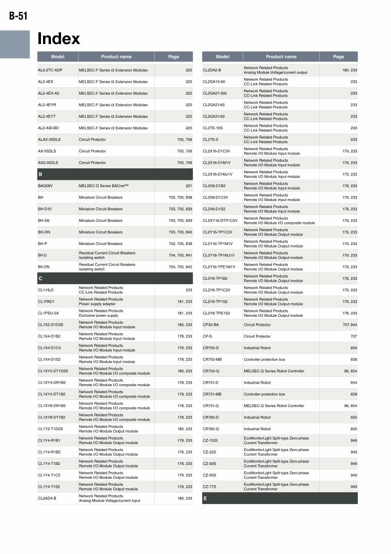
B-51
IndexModel Product name Page Model Product name Page
AL2-2TC-ADP MELSEC-F Series α Extension Modules 225
AL2-4EX MELSEC-F Series α Extension Modules 225
AL2-4EX-A2 MELSEC-F Series α Extension Modules 225
AL2-4EYR MELSEC-F Series α Extension Modules 225
AL2-4EYT MELSEC-F Series α Extension Modules 225
AL2-ASI-BD MELSEC-F Series α Extension Modules 225
ALAX-05DLS Circuit Protector 705, 706
AX-05DLS Circuit Protector 705, 706
AX2-05DLS Circuit Protector 705, 706
B
BAQ08V MELSEC-Q Series BACnet™ 221
BH Miniature Circuit Breakers 702, 705, 838
BH-D10 Miniature Circuit Breakers 703, 705, 839
BH-D6 Miniature Circuit Breakers 703, 705, 839
BH-DN Miniature Circuit Breakers 703, 705, 840
BH-P Miniature Circuit Breakers 702, 705, 838
BV-DResidual Current Circuit Breakers Isolating switch
704, 705, 841
BV-DNResidual Current Circuit Breakers Isolating switch
704, 705, 842
C
CL1-HLDNetwork Related Products CC-Link Related Products
233
CL1PAD1Network Related Products Power supply adapter
181, 233
CL1PSU-2ANetwork Related Products Exclusive power supply
181, 233
CL1X2-D1D3SNetwork Related Products Remote I/O Module Input module
180, 233
CL1X4-D1B2Network Related Products Remote I/O Module Input module
178, 233
CL1X4-D1C3Network Related Products Remote I/O Module Input module
179, 233
CL1X4-D1S2Network Related Products Remote I/O Module Input module
178, 233
CL1XY2-DT1D5SNetwork Related Products Remote I/O Module I/O composite module
180, 233
CL1XY4-DR1B2Network Related Products Remote I/O Module I/O composite module
178, 233
CL1XY4-DT1B2Network Related Products Remote I/O Module I/O composite module
178, 233
CL1XY8-DR1B2Network Related Products Remote I/O Module I/O composite module
178, 233
CL1XY8-DT1B2Network Related Products Remote I/O Module I/O composite module
178, 233
CL1Y2-T1D2SNetwork Related Products Remote I/O Module Output module
180, 233
CL1Y4-R1B1Network Related Products Remote I/O Module Output module
178, 233
CL1Y4-R1B2Network Related Products Remote I/O Module Output module
178, 233
CL1Y4-T1B2Network Related Products Remote I/O Module Output module
178, 233
CL1Y4-T1C2Network Related Products Remote I/O Module Output module
179, 233
CL1Y4-T1S2Network Related Products Remote I/O Module Output module
178, 233
CL2AD4-BNetwork Related Products Analog Module Voltage/current input
180, 233
CL2DA2-BNetwork Related Products Analog Module Voltage/current output
180, 233
CL2GA13-60Network Related Products CC-Link Related Products
233
CL2GA21-300Network Related Products CC-Link Related Products
233
CL2GA21-60Network Related Products CC-Link Related Products
233
CL2GA31-60Network Related Products CC-Link Related Products
233
CL2TE-10SNetwork Related Products CC-Link Related Products
233
CL2TE-5Network Related Products CC-Link Related Products
233
CL2X16-D1C3VNetwork Related Products Remote I/O Module Input module
179, 233
CL2X16-D1M1VNetwork Related Products Remote I/O Module Input module
179, 233
CL2X16-D1MJ1VNetwork Related Products Remote I/O Module Input module
179, 233
CL2X8-D1B2Network Related Products Remote I/O Module Input module
178, 233
CL2X8-D1C3VNetwork Related Products Remote I/O Module Input module
179, 233
CL2X8-D1S2Network Related Products Remote I/O Module Input module
178, 233
CL2XY16-DTP1C5VNetwork Related Products Remote I/O Module I/O composite module
179, 233
CL2Y16-TP1C2VNetwork Related Products Remote I/O Module Output module
179, 233
CL2Y16-TP1M1VNetwork Related Products Remote I/O Module Output module
179, 233
CL2Y16-TP1MJ1VNetwork Related Products Remote I/O Module Output module
179, 233
CL2Y16-TPE1M1VNetwork Related Products Remote I/O Module Output module
179, 233
CL2Y8-TP1B2Network Related Products Remote I/O Module Output module
178, 233
CL2Y8-TP1C2VNetwork Related Products Remote I/O Module Output module
179, 233
CL2Y8-TP1S2Network Related Products Remote I/O Module Output module
178, 233
CL2Y8-TPE1S2Network Related Products Remote I/O Module Output module
178, 233
CP30-BA Circuit Protector 707, 844
CP-S Circuit Protector 707
CR750-D Industrial Robot 654
CR750-MB Controller protection box 658
CR750-Q MELSEC-Q Series Robot Controller 96, 654
CR751-D Industrial Robot 654
CR751-MB Controller protection box 658
CR751-Q MELSEC-Q Series Robot Controller 96, 654
CR760-D Industrial Robot 655
CR760-Q Industrial Robot 655
CZ-112SEcoMonitorLight Split-type Zero-phase Current Transformer
949
CZ-22SEcoMonitorLight Split-type Zero-phase Current Transformer
949
CZ-30SEcoMonitorLight Split-type Zero-phase Current Transformer
949
CZ-55SEcoMonitorLight Split-type Zero-phase Current Transformer
949
CZ-77SEcoMonitorLight Split-type Zero-phase Current Transformer
949
E
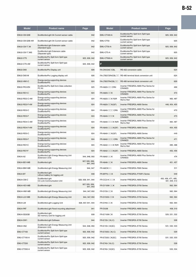
B-52
Model Product name Page Model Product name Page
EMU2-CB-Q5B EcoMonitorLight 5A Current sensor cable 942
EMU2-CB-Q5B-4W EcoMonitorLight 5A Current sensor cable 942
EMU2-CB-ThMEcoMonitorLight Extension cable(Standard type)
942
EMU2-CB-ThMSEcoMonitorLight Extension cable(Separate type)
942
EMU2-CT5EcoMonitorPro Split form Split type current sensor
925, 939, 942
EMU2-CT5-4WEcoMonitorPro Split form Split type current sensor
925, 939, 942
EMU2-D65 EcoMonitorPro Display unit 926
EMU2-D65-M EcoMonitorPro Logging display unit 926
EMU2-HM1-CEnergy-saving supporting devices EcoMonitorPro
924
EMU2-PK3-ENEcoMonitorPro Split form Data collection PC Kit
925
EMU2-RD1-CEnergy-saving supporting devices EcoMonitorPro
924
EMU2-RD2-C-4WEnergy-saving supporting devices EcoMonitorPro
924
EMU2-RD2-F-4WEnergy-saving supporting devices EcoMonitorPro
924
EMU2-RD3-CEnergy-saving supporting devices EcoMonitorPro
924
EMU2-RD3-FEnergy-saving supporting devices EcoMonitorPro
924
EMU2-RD4-C-4WEnergy-saving supporting devices EcoMonitorPro
924
EMU2-RD4-F-4WEnergy-saving supporting devices EcoMonitorPro
924
EMU2-RD5-CEnergy-saving supporting devices EcoMonitorPro
924
EMU2-RD5-FEnergy-saving supporting devices EcoMonitorPro
924
EMU2-RD7-CEnergy-saving supporting devices EcoMonitorPro
924
EMU2-RD7-FEnergy-saving supporting devices EcoMonitorPro
924
EMU4-A2EcoMonitorLight Energy Measuring Unit (Extension Unit)
944, 948, 950
EMU4-BD1-MB EcoMonitorLight927, 935, 936,
941, 943
EMU4-BM1-MB EcoMonitorLight Energy Measuring Unit 944, 947
EMU4-BTEcoMonitorLight Lithium battery for logging unit
939
EMU4-CM-CEcoMonitorLight CC-Link Communication Unit
928, 938, 941, 944
EMU4-HD1-MB EcoMonitorLight927, 935, 936,
941, 943
EMU4-HM1-MB EcoMonitorLight Energy Measuring Unit 944, 947, 950
EMU4-LG1-MB EcoMonitorLight Energy Measuring Unit 944, 947, 950
EMU4-LM EcoMonitorLight Logging Unit 928, 937, 941, 944
EMU4-PAT EcoMonitorLight Panel mounting attachment 941
EMU4-SD2GBEcoMonitorLight SD memory card for logging unit
939
EMU4-SW1 EcoMonitorLight Software 944
EMU4-VA2EcoMonitorLight Energy Measuring Unit (Extension Unit)
944, 948, 950
EMU-CT100EcoMonitorPro Split form Split type current sensor
925, 939, 942
EMU-CT100-AEcoMonitorPro Split form Split type current sensor
925, 939, 942
EMU-CT250EcoMonitorPro Split form Split type current sensor
925, 939, 942
EMU-CT250-AEcoMonitorPro Split form Split type current sensor
925, 939, 942
EMU-CT400-AEcoMonitorPro Split form Split type current sensor
925, 939, 942
EMU-CT50EcoMonitorPro Split form Split type current sensor
925
EMU-CT50-AEcoMonitorPro Split form Split type current sensor
925, 939, 942
EMU-CT5-AEcoMonitorPro Split form Split type current sensor
925
EMU-CT600-AEcoMonitorPro Split form Split type current sensor
925, 939, 942
F
FA-CNV240hCBL RS-422 conversion cable 624
FA-LTBGT2R4CBLhh RS-485 terminal block conversion unit 624
FA-LTBGTR4CBLhh RS-485 terminal block conversion unit 629
FR-A820-hh CRNInverter FREQROL-A800 Plus Series for CRANES
469
FR-A820-hhKInverter FREQROL-A800 Plus Series for CRANES
473
FR-A820-hhK R2RInverter FREQROL-A800 Plus Series for Roll to Roll
483, 487
FR-A820-hhK(GF) Inverter FREQROL-A800 Series 448, 454, 455
FR-A840-hhh CRNInverter FREQROL-A800 Plus Series for CRANES
470
FR-A840-hhhKInverter FREQROL-A800 Plus Series for CRANES
473
FR-A840-hhhK R2RInverter FREQROL-A800 Plus Series for Roll to Roll
484, 487
FR-A840-hhhK(GF) Inverter FREQROL-A800 Series 454, 455
FR-A840-hhK(GF) Inverter FREQROL-A800 Series 449
FR-A842-hhh CRNInverter FREQROL-A800 Plus Series for CRANES
471
FR-A842-hhhK R2RInverter FREQROL-A800 Plus Series for Roll to Roll
485, 488
FR-A842-hhhK(GF) Inverter FREQROL-A800 Series 450, 456
FR-A842-hhKInverter FREQROL-A800 Plus Series for CRANES
474
FR-A846-hhK Inverter FREQROL-A800 Series 451, 457
FR-A8CNhh Inverter FREQROL-F800 Series 511
FR-BFP2-hhK Inverter FREQROL-F700PJ Series 549
FR-CC2-HhhhK Inverter FREQROL-A800 Series450, 456, 471, 485,
501, 509, 512
FR-D710W-hhK Inverter FREQROL-D700 Series 562, 564
FR-D720-hhK Inverter FREQROL-D700 Series 562, 564
FR-D720S-hhK Inverter FREQROL-D700 Series 562, 564
FR-D740-hhK Inverter FREQROL-D700 Series 562, 564
FR-DU08 Inverter FREQROL-A800 Series 458, 510
FR-E710W-hK Inverter FREQROL-E700 Series 529, 531, 532
FR-E720-hK(-C) Inverter FREQROL-E700 Series 528
FR-E720-hK(SC) Inverter FREQROL-E700 Series 531, 532, 533
FR-E720S-hK(-C) Inverter FREQROL-E700 Series 529
FR-E720S-hK(SC) Inverter FREQROL-E700 Series 531, 532, 533
FR-E740-hK(-C) Inverter FREQROL-E700 Series 528
FR-E740-hK(SC) Inverter FREQROL-E700 Series 533, 534
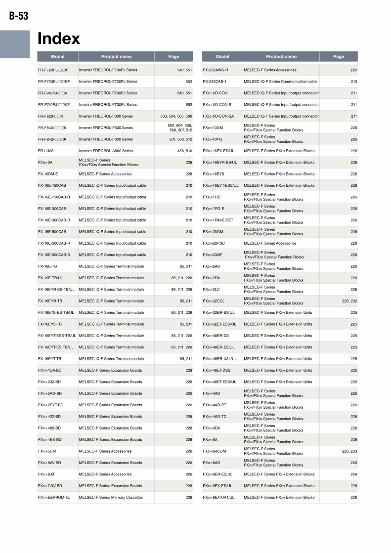
B-53
IndexModel Product name Page Model Product name Page
FR-F720PJ-hhK Inverter FREQROL-F700PJ Series 549, 551
FR-F720PJ-hhKF Inverter FREQROL-F700PJ Series 552
FR-F740PJ-hhK Inverter FREQROL-F700PJ Series 549, 551
FR-F740PJ-hhKF Inverter FREQROL-F700PJ Series 552
FR-F820-hhK Inverter FREQROL-F800 Series 500, 504, 505, 506
FR-F840-hhhK Inverter FREQROL-F800 Series500, 504, 505, 506, 507, 512
FR-F842-hhhK Inverter FREQROL-F800 Series 501, 508, 512
FR-LU08 Inverter FREQROL-A800 Series 458, 510
FX0N-3AMELSEC-F Series FX0N/FX2N Special Function Blocks
226
FX-10DM-E MELSEC-F Series Accessories 226
FX-16E-150CAB MELSEC iQ-F Series Input/output cable 210
FX-16E-150CAB-R MELSEC iQ-F Series Input/output cable 210
FX-16E-300CAB MELSEC iQ-F Series Input/output cable 210
FX-16E-300CAB-R MELSEC iQ-F Series Input/output cable 210
FX-16E-500CAB MELSEC iQ-F Series Input/output cable 210
FX-16E-500CAB-R MELSEC iQ-F Series Input/output cable 210
FX-16E-500CAB-S MELSEC iQ-F Series Input/output cable 210
FX-16E-TB MELSEC iQ-F Series Terminal module 85, 211
FX-16E-TB/UL MELSEC iQ-F Series Terminal module 85, 211, 226
FX-16EYR-ES-TB/UL MELSEC iQ-F Series Terminal module 85, 211, 226
FX-16EYR-TB MELSEC iQ-F Series Terminal module 85, 211
FX-16EYS-ES-TB/UL MELSEC iQ-F Series Terminal module 85, 211, 226
FX-16EYS-TB MELSEC iQ-F Series Terminal module 85, 211
FX-16EYT-ESS-TB/UL MELSEC iQ-F Series Terminal module 85, 211, 226
FX-16EYT-ES-TB/UL MELSEC iQ-F Series Terminal module 85, 211, 226
FX-16EYT-TB MELSEC iQ-F Series Terminal module 85, 211
FX1N-1DA-BD MELSEC-F Series Expansion Boards 226
FX1N-232-BD MELSEC-F Series Expansion Boards 226
FX1N-2AD-BD MELSEC-F Series Expansion Boards 226
FX1N-2EYT-BD MELSEC-F Series Expansion Boards 226
FX1N-422-BD MELSEC-F Series Expansion Boards 226
FX1N-485-BD MELSEC-F Series Expansion Boards 226
FX1N-4EX-BD MELSEC-F Series Expansion Boards 226
FX1N-5DM MELSEC-F Series Accessories 226
FX1N-8AV-BD MELSEC-F Series Expansion Boards 226
FX1N-BAT MELSEC-F Series Accessories 226
FX1N-CNV-BD MELSEC-F Series Expansion Boards 226
FX1N-EEPROM-8L MELSEC-F Series Memory Cassettes 226
FX-232AWC-H MELSEC-F Series Accessories 226
FX-232CAB-1 MELSEC iQ-F Series Communication cable 210
FX2C-I/O-CON MELSEC iQ-F Series Input/output connector 211
FX2C-I/O-CON-S MELSEC iQ-F Series Input/output connector 211
FX2C-I/O-CON-SA MELSEC iQ-F Series Input/output connector 211
FX2N-10GMMELSEC-F Series FX0N/FX2N Special Function Blocks
226
FX2N-10PGMELSEC-F Series FX0N/FX2N Special Function Blocks
226
FX2N-16EX-ES/UL MELSEC-F Series FX2N Extension Blocks 226
FX2N-16EYR-ES/UL MELSEC-F Series FX2N Extension Blocks 226
FX2N-16EYS MELSEC-F Series FX2N Extension Blocks 226
FX2N-16EYT-ESS/UL MELSEC-F Series FX2N Extension Blocks 226
FX2N-1HCMELSEC-F Series FX0N/FX2N Special Function Blocks
226
FX2N-1PG-EMELSEC-F Series FX0N/FX2N Special Function Blocks
226
FX2N-1RM-E-SETMELSEC-F Series FX0N/FX2N Special Function Blocks
226
FX2N-20GMMELSEC-F Series FX0N/FX2N Special Function Blocks
226
FX2N-20PSU MELSEC-F Series Accessories 226
FX2N-232IFMELSEC-F Series FX0N/FX2N Special Function Blocks
226
FX2N-2ADMELSEC-F Series FX0N/FX2N Special Function Blocks
226
FX2N-2DAMELSEC-F Series FX0N/FX2N Special Function Blocks
226
FX2N-2LCMELSEC-F Series FX0N/FX2N Special Function Blocks
226
FX2N-32CCLMELSEC-F Series FX0N/FX2N Special Function Blocks
226, 232
FX2N-32ER-ES/UL MELSEC-F Series FX2N Extension Units 225
FX2N-32ET-ESS/UL MELSEC-F Series FX2N Extension Units 225
FX2N-48ER-DS MELSEC-F Series FX2N Extension Units 225
FX2N-48ER-ES/UL MELSEC-F Series FX2N Extension Units 225
FX2N-48ER-UA1/UL MELSEC-F Series FX2N Extension Units 225
FX2N-48ET-DSS MELSEC-F Series FX2N Extension Units 225
FX2N-48ET-ESS/UL MELSEC-F Series FX2N Extension Units 225
FX2N-4ADMELSEC-F Series FX0N/FX2N Special Function Blocks
226
FX2N-4AD-PTMELSEC-F Series FX0N/FX2N Special Function Blocks
226
FX2N-4AD-TCMELSEC-F Series FX0N/FX2N Special Function Blocks
226
FX2N-4DAMELSEC-F Series FX0N/FX2N Special Function Blocks
226
FX2N-5AMELSEC-F Series FX0N/FX2N Special Function Blocks
226
FX2N-64CL-MMELSEC-F Series FX0N/FX2N Special Function Blocks
226, 233
FX2N-8ADMELSEC-F Series FX0N/FX2N Special Function Blocks
226
FX2N-8ER-ES/UL MELSEC-F Series FX2N Extension Blocks 226
FX2N-8EX-ES/UL MELSEC-F Series FX2N Extension Blocks 226
FX2N-8EX-UA1/UL MELSEC-F Series FX2N Extension Blocks 226
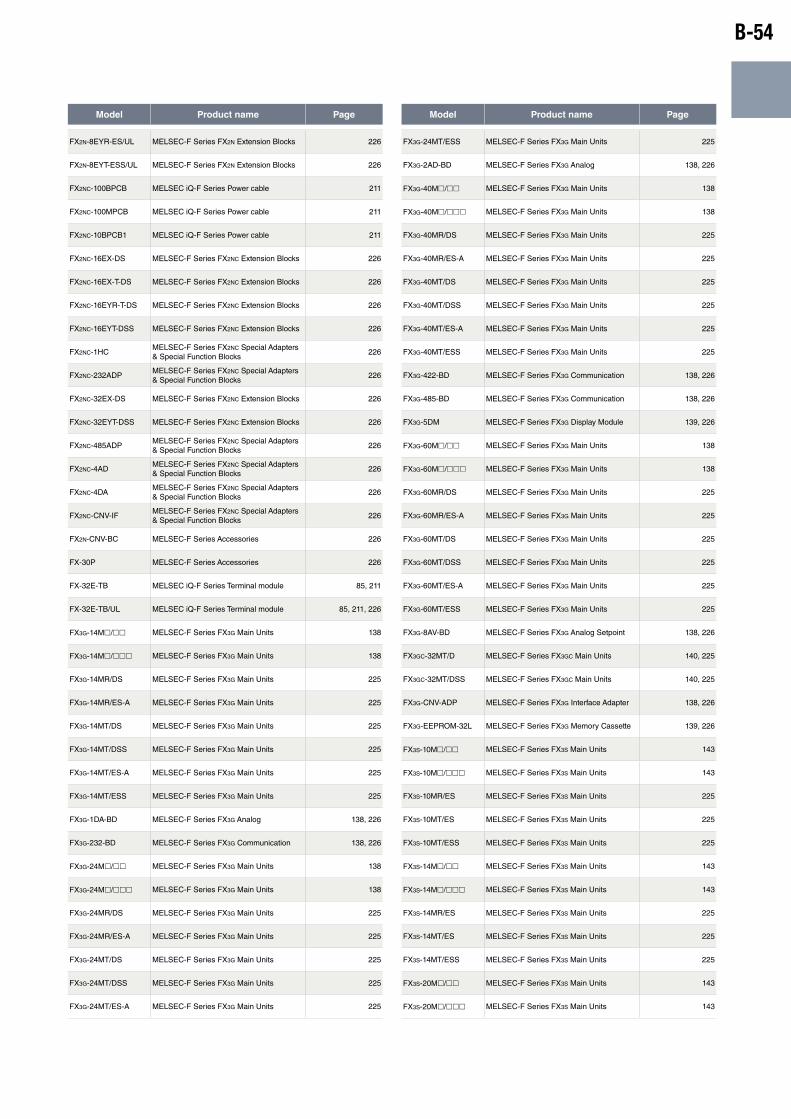
B-54
Model Product name Page Model Product name Page
FX2N-8EYR-ES/UL MELSEC-F Series FX2N Extension Blocks 226
FX2N-8EYT-ESS/UL MELSEC-F Series FX2N Extension Blocks 226
FX2NC-100BPCB MELSEC iQ-F Series Power cable 211
FX2NC-100MPCB MELSEC iQ-F Series Power cable 211
FX2NC-10BPCB1 MELSEC iQ-F Series Power cable 211
FX2NC-16EX-DS MELSEC-F Series FX2NC Extension Blocks 226
FX2NC-16EX-T-DS MELSEC-F Series FX2NC Extension Blocks 226
FX2NC-16EYR-T-DS MELSEC-F Series FX2NC Extension Blocks 226
FX2NC-16EYT-DSS MELSEC-F Series FX2NC Extension Blocks 226
FX2NC-1HCMELSEC-F Series FX2NC Special Adapters & Special Function Blocks
226
FX2NC-232ADPMELSEC-F Series FX2NC Special Adapters & Special Function Blocks
226
FX2NC-32EX-DS MELSEC-F Series FX2NC Extension Blocks 226
FX2NC-32EYT-DSS MELSEC-F Series FX2NC Extension Blocks 226
FX2NC-485ADPMELSEC-F Series FX2NC Special Adapters & Special Function Blocks
226
FX2NC-4ADMELSEC-F Series FX2NC Special Adapters & Special Function Blocks
226
FX2NC-4DAMELSEC-F Series FX2NC Special Adapters & Special Function Blocks
226
FX2NC-CNV-IFMELSEC-F Series FX2NC Special Adapters & Special Function Blocks
226
FX2N-CNV-BC MELSEC-F Series Accessories 226
FX-30P MELSEC-F Series Accessories 226
FX-32E-TB MELSEC iQ-F Series Terminal module 85, 211
FX-32E-TB/UL MELSEC iQ-F Series Terminal module 85, 211, 226
FX3G-14Mh/hh MELSEC-F Series FX3G Main Units 138
FX3G-14Mh/hhh MELSEC-F Series FX3G Main Units 138
FX3G-14MR/DS MELSEC-F Series FX3G Main Units 225
FX3G-14MR/ES-A MELSEC-F Series FX3G Main Units 225
FX3G-14MT/DS MELSEC-F Series FX3G Main Units 225
FX3G-14MT/DSS MELSEC-F Series FX3G Main Units 225
FX3G-14MT/ES-A MELSEC-F Series FX3G Main Units 225
FX3G-14MT/ESS MELSEC-F Series FX3G Main Units 225
FX3G-1DA-BD MELSEC-F Series FX3G Analog 138, 226
FX3G-232-BD MELSEC-F Series FX3G Communication 138, 226
FX3G-24Mh/hh MELSEC-F Series FX3G Main Units 138
FX3G-24Mh/hhh MELSEC-F Series FX3G Main Units 138
FX3G-24MR/DS MELSEC-F Series FX3G Main Units 225
FX3G-24MR/ES-A MELSEC-F Series FX3G Main Units 225
FX3G-24MT/DS MELSEC-F Series FX3G Main Units 225
FX3G-24MT/DSS MELSEC-F Series FX3G Main Units 225
FX3G-24MT/ES-A MELSEC-F Series FX3G Main Units 225
FX3G-24MT/ESS MELSEC-F Series FX3G Main Units 225
FX3G-2AD-BD MELSEC-F Series FX3G Analog 138, 226
FX3G-40Mh/hh MELSEC-F Series FX3G Main Units 138
FX3G-40Mh/hhh MELSEC-F Series FX3G Main Units 138
FX3G-40MR/DS MELSEC-F Series FX3G Main Units 225
FX3G-40MR/ES-A MELSEC-F Series FX3G Main Units 225
FX3G-40MT/DS MELSEC-F Series FX3G Main Units 225
FX3G-40MT/DSS MELSEC-F Series FX3G Main Units 225
FX3G-40MT/ES-A MELSEC-F Series FX3G Main Units 225
FX3G-40MT/ESS MELSEC-F Series FX3G Main Units 225
FX3G-422-BD MELSEC-F Series FX3G Communication 138, 226
FX3G-485-BD MELSEC-F Series FX3G Communication 138, 226
FX3G-5DM MELSEC-F Series FX3G Display Module 139, 226
FX3G-60Mh/hh MELSEC-F Series FX3G Main Units 138
FX3G-60Mh/hhh MELSEC-F Series FX3G Main Units 138
FX3G-60MR/DS MELSEC-F Series FX3G Main Units 225
FX3G-60MR/ES-A MELSEC-F Series FX3G Main Units 225
FX3G-60MT/DS MELSEC-F Series FX3G Main Units 225
FX3G-60MT/DSS MELSEC-F Series FX3G Main Units 225
FX3G-60MT/ES-A MELSEC-F Series FX3G Main Units 225
FX3G-60MT/ESS MELSEC-F Series FX3G Main Units 225
FX3G-8AV-BD MELSEC-F Series FX3G Analog Setpoint 138, 226
FX3GC-32MT/D MELSEC-F Series FX3GC Main Units 140, 225
FX3GC-32MT/DSS MELSEC-F Series FX3GC Main Units 140, 225
FX3G-CNV-ADP MELSEC-F Series FX3G Interface Adapter 138, 226
FX3G-EEPROM-32L MELSEC-F Series FX3G Memory Cassette 139, 226
FX3S-10Mh/hh MELSEC-F Series FX3S Main Units 143
FX3S-10Mh/hhh MELSEC-F Series FX3S Main Units 143
FX3S-10MR/ES MELSEC-F Series FX3S Main Units 225
FX3S-10MT/ES MELSEC-F Series FX3S Main Units 225
FX3S-10MT/ESS MELSEC-F Series FX3S Main Units 225
FX3S-14Mh/hh MELSEC-F Series FX3S Main Units 143
FX3S-14Mh/hhh MELSEC-F Series FX3S Main Units 143
FX3S-14MR/ES MELSEC-F Series FX3S Main Units 225
FX3S-14MT/ES MELSEC-F Series FX3S Main Units 225
FX3S-14MT/ESS MELSEC-F Series FX3S Main Units 225
FX3S-20Mh/hh MELSEC-F Series FX3S Main Units 143
FX3S-20Mh/hhh MELSEC-F Series FX3S Main Units 143
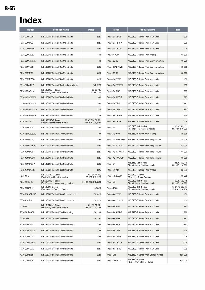
B-55
IndexModel Product name Page Model Product name Page
FX3S-20MR/ES MELSEC-F Series FX3S Main Units 225
FX3S-20MT/ES MELSEC-F Series FX3S Main Units 225
FX3S-20MT/ESS MELSEC-F Series FX3S Main Units 225
FX3S-30Mh/hh MELSEC-F Series FX3S Main Units 143
FX3S-30Mh/hhh MELSEC-F Series FX3S Main Units 143
FX3S-30MR/ES MELSEC-F Series FX3S Main Units 225
FX3S-30MT/ES MELSEC-F Series FX3S Main Units 225
FX3S-30MT/ESS MELSEC-F Series FX3S Main Units 225
FX3S-CNV-ADP MELSEC-F Series FX3S Interface Adapter 142, 226
FX3U-128ASL-MMELSEC iQ-F Series FX3 intelligent function module
65, 67, 70, 72, 85, 210
FX3U-128Mh/hh MELSEC-F Series FX3U Main Units 136
FX3U-128Mh/hhh MELSEC-F Series FX3U Main Units 136
FX3U-128MR/ES-A MELSEC-F Series FX3U Main Units 225
FX3U-128MT/ESS MELSEC-F Series FX3U Main Units 225
FX3U-16CCL-MMELSEC iQ-F Series FX3 intelligent function module
65, 67, 70, 72, 85, 137, 210, 226, 230
FX3U-16Mh/hh MELSEC-F Series FX3U Main Units 136
FX3U-16Mh/hhh MELSEC-F Series FX3U Main Units 136
FX3U-16MR/DS MELSEC-F Series FX3U Main Units 225
FX3U-16MR/ES-A MELSEC-F Series FX3U Main Units 225
FX3U-16MT/DS MELSEC-F Series FX3U Main Units 225
FX3U-16MT/DSS MELSEC-F Series FX3U Main Units 225
FX3U-16MT/ES-A MELSEC-F Series FX3U Main Units 225
FX3U-16MT/ESS MELSEC-F Series FX3U Main Units 225
FX3U-1PGMELSEC iQ-F Series FX3 intelligent function module
65, 67, 70, 72, 85, 137, 210, 226
FX3U-1PSU-5VMELSEC iQ-F Series FX3 Extension power supply module
64, 85, 137, 210, 226
FX3U-20SSC-HMELSEC-F Series FX3U Special Function Blocks
137, 226
FX3U-232ADP-MB MELSEC-F Series FX3U Communication 136, 226
FX3U-232-BD MELSEC-F Series FX3U Communication 136, 226
FX3U-2HCMELSEC iQ-F Series FX3 intelligent function module
65, 67, 70, 72, 85, 137, 210, 226
FX3U-2HSY-ADP MELSEC-F Series FX3U Positioning 136, 226
FX3U-32BL MELSEC-F Series FX3U Battery 137, 211
FX3U-32Mh/hh MELSEC-F Series FX3U Main Units 136
FX3U-32Mh/hhh MELSEC-F Series FX3U Main Units 136
FX3U-32MR/DS MELSEC-F Series FX3U Main Units 225
FX3U-32MR/ES-A MELSEC-F Series FX3U Main Units 225
FX3U-32MR/UA1 MELSEC-F Series FX3U Main Units 225
FX3U-32MS/ES MELSEC-F Series FX3U Main Units 225
FX3U-32MT/DS MELSEC-F Series FX3U Main Units 225
FX3U-32MT/DSS MELSEC-F Series FX3U Main Units 225
FX3U-32MT/ES-A MELSEC-F Series FX3U Main Units 225
FX3U-32MT/ESS MELSEC-F Series FX3U Main Units 225
FX3U-3A-ADP MELSEC-F Series FX3U Analog 136, 226
FX3U-422-BD MELSEC-F Series FX3U Communication 136, 226
FX3U-485ADP-MB MELSEC-F Series FX3U Communication 136, 226
FX3U-485-BD MELSEC-F Series FX3U Communication 136, 226
FX3U-48Mh/hh MELSEC-F Series FX3U Main Units 136
FX3U-48Mh/hhh MELSEC-F Series FX3U Main Units 136
FX3U-48MR/DS MELSEC-F Series FX3U Main Units 225
FX3U-48MR/ES-A MELSEC-F Series FX3U Main Units 225
FX3U-48MT/DS MELSEC-F Series FX3U Main Units 225
FX3U-48MT/DSS MELSEC-F Series FX3U Main Units 225
FX3U-48MT/ES-A MELSEC-F Series FX3U Main Units 225
FX3U-48MT/ESS MELSEC-F Series FX3U Main Units 225
FX3U-4ADMELSEC iQ-F Series FX3 intelligent function module
65, 67, 70, 72, 85, 137, 210, 226
FX3U-4AD-ADP MELSEC-F Series FX3U Analog 136, 226
FX3U-4AD-PNK-ADP MELSEC-F Series FX3U Temperature 136, 226
FX3U-4AD-PT-ADP MELSEC-F Series FX3U Temperature 136, 226
FX3U-4AD-PTW-ADP MELSEC-F Series FX3U Temperature 136, 226
FX3U-4AD-TC-ADP MELSEC-F Series FX3U Temperature 136, 226
FX3U-4DAMELSEC iQ-F Series FX3 intelligent function module
65, 67, 70, 72, 85, 137, 210, 226
FX3U-4DA-ADP MELSEC-F Series FX3U Analog 136, 226
FX3U-4HSX-ADPMELSEC-F Series FX3U High Speed Counter
136, 226
FX3U-4LCMELSEC iQ-F Series FX3 intelligent function module
65, 67, 70, 72, 85, 137, 210, 226
FX3U-64CCLMELSEC iQ-F Series FX3 intelligent function module
65, 67, 70, 72, 85, 137, 210, 226, 232
FX3U-64Mh/hh MELSEC-F Series FX3U Main Units 136
FX3U-64Mh/hhh MELSEC-F Series FX3U Main Units 136
FX3U-64MR/DS MELSEC-F Series FX3U Main Units 225
FX3U-64MR/ES-A MELSEC-F Series FX3U Main Units 225
FX3U-64MR/UA1 MELSEC-F Series FX3U Main Units 225
FX3U-64MS/ES MELSEC-F Series FX3U Main Units 225
FX3U-64MT/DS MELSEC-F Series FX3U Main Units 225
FX3U-64MT/DSS MELSEC-F Series FX3U Main Units 225
FX3U-64MT/ES-A MELSEC-F Series FX3U Main Units 225
FX3U-64MT/ESS MELSEC-F Series FX3U Main Units 225
FX3U-7DM MELSEC-F Series FX3U Display Module 137, 226
FX3U-7DM-HLDMELSEC-F Series FX3U Display Module Holder
137, 226
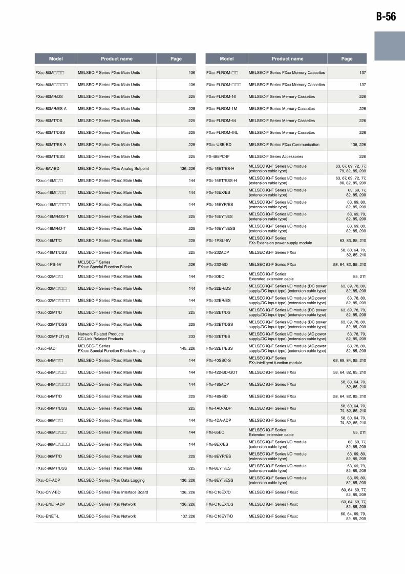
B-56
Model Product name Page Model Product name Page
FX3U-80Mh/hh MELSEC-F Series FX3U Main Units 136
FX3U-80Mh/hhh MELSEC-F Series FX3U Main Units 136
FX3U-80MR/DS MELSEC-F Series FX3U Main Units 225
FX3U-80MR/ES-A MELSEC-F Series FX3U Main Units 225
FX3U-80MT/DS MELSEC-F Series FX3U Main Units 225
FX3U-80MT/DSS MELSEC-F Series FX3U Main Units 225
FX3U-80MT/ES-A MELSEC-F Series FX3U Main Units 225
FX3U-80MT/ESS MELSEC-F Series FX3U Main Units 225
FX3U-8AV-BD MELSEC-F Series FX3U Analog Setpoint 136, 226
FX3UC-16Mh/h MELSEC-F Series FX3UC Main Units 144
FX3UC-16Mh/hh MELSEC-F Series FX3UC Main Units 144
FX3UC-16Mh/hhh MELSEC-F Series FX3UC Main Units 144
FX3UC-16MR/DS-T MELSEC-F Series FX3UC Main Units 225
FX3UC-16MR/D-T MELSEC-F Series FX3UC Main Units 225
FX3UC-16MT/D MELSEC-F Series FX3UC Main Units 225
FX3UC-16MT/DSS MELSEC-F Series FX3UC Main Units 225
FX3UC-1PS-5VMELSEC-F Series FX3UC Special Function Blocks
226
FX3UC-32Mh/h MELSEC-F Series FX3UC Main Units 144
FX3UC-32Mh/hh MELSEC-F Series FX3UC Main Units 144
FX3UC-32Mh/hhh MELSEC-F Series FX3UC Main Units 144
FX3UC-32MT/D MELSEC-F Series FX3UC Main Units 225
FX3UC-32MT/DSS MELSEC-F Series FX3UC Main Units 225
FX3UC-32MT-LT(-2)Network Related Products CC-Link Related Products
233
FX3UC-4ADMELSEC-F Series FX3UC Special Function Blocks Analog
145, 226
FX3UC-64Mh/h MELSEC-F Series FX3UC Main Units 144
FX3UC-64Mh/hh MELSEC-F Series FX3UC Main Units 144
FX3UC-64Mh/hhh MELSEC-F Series FX3UC Main Units 144
FX3UC-64MT/D MELSEC-F Series FX3UC Main Units 225
FX3UC-64MT/DSS MELSEC-F Series FX3UC Main Units 225
FX3UC-96Mh/h MELSEC-F Series FX3UC Main Units 144
FX3UC-96Mh/hh MELSEC-F Series FX3UC Main Units 144
FX3UC-96Mh/hhh MELSEC-F Series FX3UC Main Units 144
FX3UC-96MT/D MELSEC-F Series FX3UC Main Units 225
FX3UC-96MT/DSS MELSEC-F Series FX3UC Main Units 225
FX3U-CF-ADP MELSEC-F Series FX3U Data Logging 136, 226
FX3U-CNV-BD MELSEC-F Series FX3U Interface Board 136, 226
FX3U-ENET-ADP MELSEC-F Series FX3U Network 136, 226
FX3U-ENET-L MELSEC-F Series FX3U Network 137, 226
FX3U-FLROM-hh MELSEC-F Series FX3U Memory Cassettes 137
FX3U-FLROM-hhh MELSEC-F Series FX3U Memory Cassettes 137
FX3U-FLROM-16 MELSEC-F Series Memory Cassettes 226
FX3U-FLROM-1M MELSEC-F Series Memory Cassettes 226
FX3U-FLROM-64 MELSEC-F Series Memory Cassettes 226
FX3U-FLROM-64L MELSEC-F Series Memory Cassettes 226
FX3U-USB-BD MELSEC-F Series FX3U Communication 136, 226
FX-485PC-IF MELSEC-F Series Accessories 226
FX5-16ET/ES-HMELSEC iQ-F Series I/O module (extension cable type)
63, 67, 69, 72, 77, 79, 82, 85, 209
FX5-16ET/ESS-HMELSEC iQ-F Series I/O module (extension cable type)
63, 67, 69, 72, 77, 80, 82, 85, 209
FX5-16EX/ESMELSEC iQ-F Series I/O module (extension cable type)
63, 69, 77, 82, 85, 209
FX5-16EYR/ESMELSEC iQ-F Series I/O module (extension cable type)
63, 69, 80, 82, 85, 209
FX5-16EYT/ESMELSEC iQ-F Series I/O module (extension cable type)
63, 69, 79, 82, 85, 209
FX5-16EYT/ESSMELSEC iQ-F Series I/O module (extension cable type)
63, 69, 80, 82, 85, 209
FX5-1PSU-5VMELSEC iQ-F Series FX5 Extension power supply module
63, 83, 85, 210
FX5-232ADP MELSEC iQ-F Series FX5U58, 60, 64, 70,
82, 85, 210
FX5-232-BD MELSEC iQ-F Series FX5U 58, 64, 82, 85, 210
FX5-30ECMELSEC iQ-F Series Extended extension cable
85, 211
FX5-32ER/DSMELSEC iQ-F Series I/O module (DC power supply/DC input type) (extension cable type)
63, 69, 78, 80, 82, 85, 209
FX5-32ER/ESMELSEC iQ-F Series I/O module (AC power supply/DC input type) (extension cable type)
63, 78, 80, 82, 85, 209
FX5-32ET/DSMELSEC iQ-F Series I/O module (DC power supply/DC input type) (extension cable type)
63, 69, 78, 79, 82, 85, 209
FX5-32ET/DSSMELSEC iQ-F Series I/O module (DC power supply/DC input type) (extension cable type)
63, 69, 78, 80, 82, 85, 209
FX5-32ET/ESMELSEC iQ-F Series I/O module (AC power supply/DC input type) (extension cable type)
63, 78, 79, 82, 85, 209
FX5-32ET/ESSMELSEC iQ-F Series I/O module (AC power supply/DC input type) (extension cable type)
63, 78, 80, 82, 85, 209
FX5-40SSC-SMELSEC iQ-F Series FX5 intelligent function module
63, 69, 84, 85, 210
FX5-422-BD-GOT MELSEC iQ-F Series FX5U 58, 64, 82, 85, 210
FX5-485ADP MELSEC iQ-F Series FX5U58, 60, 64, 70,
82, 85, 210
FX5-485-BD MELSEC iQ-F Series FX5U 58, 64, 82, 85, 210
FX5-4AD-ADP MELSEC iQ-F Series FX5U58, 60, 64, 70, 74, 82, 85, 210
FX5-4DA-ADP MELSEC iQ-F Series FX5U58, 60, 64, 70, 74, 82, 85, 210
FX5-65ECMELSEC iQ-F Series Extended extension cable
85, 211
FX5-8EX/ESMELSEC iQ-F Series I/O module (extension cable type)
63, 69, 77, 82, 85, 209
FX5-8EYR/ESMELSEC iQ-F Series I/O module (extension cable type)
63, 69, 80, 82, 85, 209
FX5-8EYT/ESMELSEC iQ-F Series I/O module (extension cable type)
63, 69, 79, 82, 85, 209
FX5-8EYT/ESSMELSEC iQ-F Series I/O module (extension cable type)
63, 69, 80, 82, 85, 209
FX5-C16EX/D MELSEC iQ-F Series FX5UC60, 64, 69, 77,
82, 85, 209
FX5-C16EX/DS MELSEC iQ-F Series FX5UC60, 64, 69, 77,
82, 85, 209
FX5-C16EYT/D MELSEC iQ-F Series FX5UC60, 64, 69, 79,
82, 85, 209
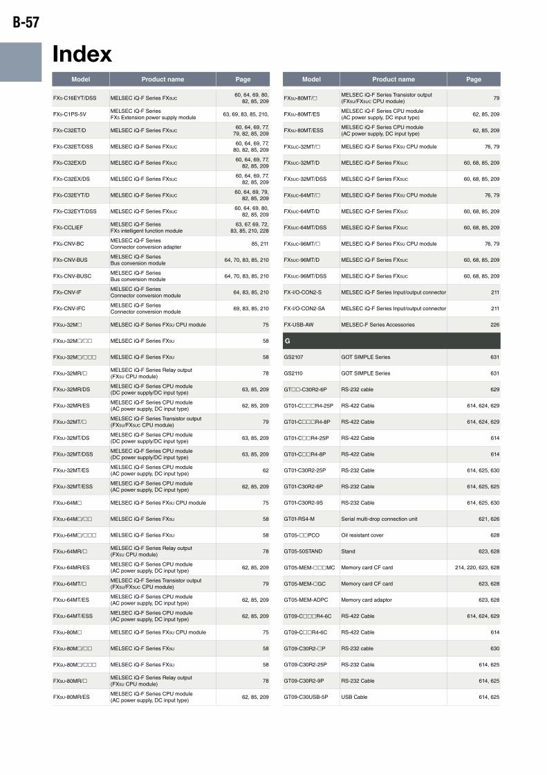
B-57
IndexModel Product name Page Model Product name Page
FX5-C16EYT/DSS MELSEC iQ-F Series FX5UC60, 64, 69, 80,
82, 85, 209
FX5-C1PS-5VMELSEC iQ-F Series FX5 Extension power supply module
63, 69, 83, 85, 210,
FX5-C32ET/D MELSEC iQ-F Series FX5UC60, 64, 69, 77,
79, 82, 85, 209
FX5-C32ET/DSS MELSEC iQ-F Series FX5UC60, 64, 69, 77,
80, 82, 85, 209
FX5-C32EX/D MELSEC iQ-F Series FX5UC60, 64, 69, 77,
82, 85, 209
FX5-C32EX/DS MELSEC iQ-F Series FX5UC60, 64, 69, 77,
82, 85, 209
FX5-C32EYT/D MELSEC iQ-F Series FX5UC60, 64, 69, 79,
82, 85, 209
FX5-C32EYT/DSS MELSEC iQ-F Series FX5UC60, 64, 69, 80,
82, 85, 209
FX5-CCLIEFMELSEC iQ-F Series FX5 intelligent function module
63, 67, 69, 72, 83, 85, 210, 228
FX5-CNV-BCMELSEC iQ-F Series Connector conversion adapter
85, 211
FX5-CNV-BUSMELSEC iQ-F Series Bus conversion module
64, 70, 83, 85, 210
FX5-CNV-BUSCMELSEC iQ-F Series Bus conversion module
64, 70, 83, 85, 210
FX5-CNV-IFMELSEC iQ-F Series Connector conversion module
64, 83, 85, 210
FX5-CNV-IFCMELSEC iQ-F Series Connector conversion module
69, 83, 85, 210
FX5U-32Mh MELSEC iQ-F Series FX5U CPU module 75
FX5U-32Mh/hh MELSEC iQ-F Series FX5U 58
FX5U-32Mh/hhh MELSEC iQ-F Series FX5U 58
FX5U-32MR/hMELSEC iQ-F Series Relay output (FX5U CPU module)
78
FX5U-32MR/DSMELSEC iQ-F Series CPU module (DC power supply/DC input type)
63, 85, 209
FX5U-32MR/ESMELSEC iQ-F Series CPU module (AC power supply, DC input type)
62, 85, 209
FX5U-32MT/hMELSEC iQ-F Series Transistor output (FX5U/FX5UC CPU module)
79
FX5U-32MT/DSMELSEC iQ-F Series CPU module (DC power supply/DC input type)
63, 85, 209
FX5U-32MT/DSSMELSEC iQ-F Series CPU module (DC power supply/DC input type)
63, 85, 209
FX5U-32MT/ESMELSEC iQ-F Series CPU module (AC power supply, DC input type)
62
FX5U-32MT/ESSMELSEC iQ-F Series CPU module (AC power supply, DC input type)
62, 85, 209
FX5U-64Mh MELSEC iQ-F Series FX5U CPU module 75
FX5U-64Mh/hh MELSEC iQ-F Series FX5U 58
FX5U-64Mh/hhh MELSEC iQ-F Series FX5U 58
FX5U-64MR/hMELSEC iQ-F Series Relay output (FX5U CPU module)
78
FX5U-64MR/ESMELSEC iQ-F Series CPU module (AC power supply, DC input type)
62, 85, 209
FX5U-64MT/hMELSEC iQ-F Series Transistor output (FX5U/FX5UC CPU module)
79
FX5U-64MT/ESMELSEC iQ-F Series CPU module (AC power supply, DC input type)
62, 85, 209
FX5U-64MT/ESSMELSEC iQ-F Series CPU module (AC power supply, DC input type)
62, 85, 209
FX5U-80Mh MELSEC iQ-F Series FX5U CPU module 75
FX5U-80Mh/hh MELSEC iQ-F Series FX5U 58
FX5U-80Mh/hhh MELSEC iQ-F Series FX5U 58
FX5U-80MR/hMELSEC iQ-F Series Relay output (FX5U CPU module)
78
FX5U-80MR/ESMELSEC iQ-F Series CPU module (AC power supply, DC input type)
62, 85, 209
FX5U-80MT/hMELSEC iQ-F Series Transistor output (FX5U/FX5UC CPU module)
79
FX5U-80MT/ESMELSEC iQ-F Series CPU module (AC power supply, DC input type)
62, 85, 209
FX5U-80MT/ESSMELSEC iQ-F Series CPU module (AC power supply, DC input type)
62, 85, 209
FX5UC-32MT/h MELSEC iQ-F Series FX5U CPU module 76, 79
FX5UC-32MT/D MELSEC iQ-F Series FX5UC 60, 68, 85, 209
FX5UC-32MT/DSS MELSEC iQ-F Series FX5UC 60, 68, 85, 209
FX5UC-64MT/h MELSEC iQ-F Series FX5U CPU module 76, 79
FX5UC-64MT/D MELSEC iQ-F Series FX5UC 60, 68, 85, 209
FX5UC-64MT/DSS MELSEC iQ-F Series FX5UC 60, 68, 85, 209
FX5UC-96MT/h MELSEC iQ-F Series FX5U CPU module 76, 79
FX5UC-96MT/D MELSEC iQ-F Series FX5UC 60, 68, 85, 209
FX5UC-96MT/DSS MELSEC iQ-F Series FX5UC 60, 68, 85, 209
FX-I/O-CON2-S MELSEC iQ-F Series Input/output connector 211
FX-I/O-CON2-SA MELSEC iQ-F Series Input/output connector 211
FX-USB-AW MELSEC-F Series Accessories 226
G
GS2107 GOT SIMPLE Series 631
GS2110 GOT SIMPLE Series 631
GThh-C30R2-6P RS-232 cable 629
GT01-ChhhR4-25P RS-422 Cable 614, 624, 629
GT01-ChhhR4-8P RS-422 Cable 614, 624, 629
GT01-ChhR4-25P RS-422 Cable 614
GT01-ChhR4-8P RS-422 Cable 614
GT01-C30R2-25P RS-232 Cable 614, 625, 630
GT01-C30R2-6P RS-232 Cable 614, 625, 625
GT01-C30R2-9S RS-232 Cable 614, 625, 630
GT01-RS4-M Serial multi-drop connection unit 621, 626
GT05-hhPCO Oil resistant cover 628
GT05-50STAND Stand 623, 628
GT05-MEM-hhhMC Memory card CF card 214, 220, 623, 628
GT05-MEM-hGC Memory card CF card 623, 628
GT05-MEM-ADPC Memory card adaptor 623, 628
GT09-ChhhR4-6C RS-422 Cable 614, 624, 629
GT09-ChhR4-6C RS-422 Cable 614
GT09-C30R2-hP RS-232 cable 630
GT09-C30R2-25P RS-232 Cable 614, 625
GT09-C30R2-9P RS-232 Cable 614, 625
GT09-C30USB-5P USB Cable 614, 625

B-58
Model Product name Page Model Product name Page
GT10-hhPSCB Protective sheet 628
GT10-hhPSCW Protective sheet 628
GT10-hhPSGB Protective sheet 628
GT10-hhPSGW Protective sheet 628
GT10-20PCO Protective cover for oil 623
GT1030 GOT1000 GT10 model596, 601, 602,
603, 626
GT1030-HBh(W)(2) GOT1000 GT10 model 605, 607
GT10-30PCO Oil resistant cover 628
GT105h GOT1000 GT10 model 600, 602, 603, 626
GT105h-QhBD GOT1000 GT10 model 605, 607
GT1050 GOT1000 GT10 model 596, 600, 626
GT10-50FMB GT10 memory board 627
GT1055 GOT1000 GT10 model 596, 600, 626
GT10-9PT5S Connector conversion adapter 626
GT10-ChhhR4-25P RS-422 cable 624, 629
GT10-ChhhR4-8P RS-422 cable 624, 629
GT10-ChhhR4-8PC RS-422 cable 624, 629
GT10-C02H-6PT9PBarcode reader connection cable RS-232 cable
625, 630
GT10-C02H-9SC RS-422 cable 624, 629
GT10-C10EXUSB-5S Extended USB waterproof cable 625, 630
GT10-C10R4-8PL RS-422 cable 624, 629
GT10-C30R2-6P RS-232 cable 625
GT10-LDR GT10 memory loader 627
GT10-RS2TUSB-5S USB cable 630
GT11-50BAT Battery 623, 628
GT11-50UCOV USB protective cover 628
GT11H-Chhh External connection cable 630
GT11H-Chhh-32P External connection cable 630
GT11H-Chhh-37P External connection cable 630
GT11H-C15R2-6P FA device connection relay cable 630
GT11H-C15R4-hP FA device connection relay cable 630
GT11H-C30R2-6P RS-232 cable 629
GT11H-CCL CC-Link interface unit 626
GT11H-CNB-37S Connector conversion box for Handy GOT 630
GT11HS-CCL CC-Link interface unit 626
GT145h GOT1000 GT14 model 602, 626
GT145h-QhBDE GOT1000 GT14 model 605, 607
GT1450 GOT1000 GT14 model 596, 603, 626
GT14-50UCOV USB protective cover 628
GT1455 GOT1000 GT14 model 596, 599, 603, 626
GT14-C10EXUSB-4S Extension USB waterproof cable 630
GT14H-50ATT Handy GOT wall-mounting fixture 628
GT14-RS2T4-9P RS-232/485 Signal Conversion Adapter 626
GT14-VNCSKEY VNC® server function license 627
GT15-hhSTAND Stand 623, 628
GT15-50ATT-hh Attachment 623
GT15-50ATT-85 Attachment 628
GT15-50ATT-95W Attachment 628
GT15-60ATT-hh Attachment 623
GT15-60ATT-77 Attachment 628
GT15-60ATT-87 Attachment 628
GT15-60ATT-96 Attachment 628
GT15-60ATT-97 Attachment 628
GT15-70ATT-hh Attachment 623
GT15-70ATT-87 Attachment 628
GT15-70ATT-98 Attachment 628
GT15-75QBUS2L Q bus connection unit 621
GT15-75QBUSL Q bus connection unit 621
GT15-A1SChhBBus connection cable for QnA/ACPU/motion controller CPU (A series)
629
GT15-A1SChhNBBus connection cable for QnA/ACPU/motion controller CPU (A series)
629
GT15-A370ChhBBus connection cable for QnA/ACPU/motion controller CPU (A series)
629
GT15-A370ChhB-S1Bus connection cable for QnA/ACPU/motion controller CPU (A series)
629
GT15-AChhBBus connection cable for QnA/ACPU/motion controller CPU (A series)
629
GT15-AFC Ferrite core set for A bus cable (two-pack) 629
GT15-BAT Battery 628
GT15-ChhhBSBus connection cable for QnA/ACPU/motion controller CPU (A series)
629
GT15-ChhhEXSS-1Bus connection cable for QnA/ACPU/motion controller CPU (A series)
629
GT15-ChhBSBus connection cable for QnA/ACPU/motion controller CPU (A series)
629
GT15-ChhNBBus connection cable for QnA/ACPU/motion controller CPU (A series)
629
GT15-C03HTBConversion cable for connecting external I/O unit
625, 630
GT15-C50VG Analog RGB cable 625, 630
GT15-CFCD CF card unit 627
GT15-CFEX-C08SET CF card extension unit 603, 627
GT15-DIO External I/O unit 622, 627
GT15-DIOR External I/O unit 622, 627
GT15-EXCNB Buffer circuit cable 629

B-59
IndexModel Product name Page Model Product name Page
GT15-J2C10BBus connection cable for QnA/ACPU/motion controller CPU (A series)
629
GT15-J61BT13 CC-Link communication unit 621, 626
GT15-J71BR13 MELSECNET/H communication unit 621, 626
GT15-J71GF13-T2CC-Link IE Field Network communication unit
621, 626
GT15-J71GP23-SXCC-Link IE Controller Network communication unit
621, 626
GT15-J71LP23-25 MELSECNET/H communication unit 621, 626
GT15-PRN Printer unit 622, 627
GT15-QBUS Q bus connection unit 621, 626
GT15-QBUS2 Q bus connection unit 621, 626
GT15-QChhhB QCPU bus connection cable 624
GT15-QChhhBS QCPU bus connection cable 624, 629
GT15-QChhB Bus connection cable for QCPU (Q mode) 629
GT15-QFC Ferrite core set for Q bus cable (two-pack) 624, 629
GT15-RS2-9P Serial communication unit 621, 626
GT15-RS2T4-25P RS-422 conversion unit 626
GT15-RS2T4-9P RS-422 conversion unit 626
GT15-RS4-9S Serial communication unit 621, 626
GT15-RS4-TE Serial communication unit 621, 626
GT15-SGTKEY-U License key for GT SoftGOT1000 627
GT15-SOUT Sound output unit 622, 627
GT16-hhPSCB Protective sheet 627
GT16-hhPSCB-012 Protective sheet 627
GT16-hhPSCW Protective sheet 627
GT16-hhPSGB Protective sheet 627
GT16-hhPSGW Protective sheet 627
GT16-hhSLTT Backlight 627
GT16-hhVLTN Backlight 627
GT16-hhVLTT Backlight 627
GT16-50PCO Oil resistant cover 628
GT16-50UCOV USB protective cover 628
GT1655 GOT1000 GT16 model596, 598, 602,
603, 626
GT1655-VTBD GOT1000 GT16 model 604, 606
GT166h GOT1000 GT16 model 598, 602, 603, 626
GT1662 GOT1000 GT16 model 596, 598, 626
GT1662-VNBh GOT1000 GT16 model 604, 606
GT1665HS GOT1000 GT16 model 596, 598, 626
GT1665HS-VTBD GOT1000 GT16 model 604, 606
GT1665M GOT1000 GT16 model 596, 597, 598, 626
GT1665M-STBh GOT1000 GT16 model 604, 606
GT167h GOT1000 GT16 model 598, 602, 603, 626
GT167h-VNBh GOT1000 GT16 model 604, 606
GT16-70VLTTA Backlight 627
GT1672 GOT1000 GT16 model 596, 597, 598, 627
GT1675 GOT1000 GT16 model 596, 597, 598, 626
GT1675M GOT1000 GT16 model 596, 597, 598, 626
GT1675M-STBh GOT1000 GT16 model 604, 606
GT1675M-VTBh GOT1000 GT16 model 604, 606
GT1685 GOT1000 GT16 model 598, 602, 603, 626
GT1685M GOT1000 GT16 model 596, 597, 598, 626
GT1685M-STBh GOT1000 GT16 model 604, 606
GT16-90XLTT Backlight 627
GT1695 GOT1000 GT16 model 598, 602, 603, 626
GT1695M GOT1000 GT16 model 596, 597, 598, 626
GT1695M-XTBh GOT1000 GT16 model 604, 606
GT16-C02R4-hS RS-422 conversion cable 629
GT16H-60ESCOV Emergency stop switch guard 628
GT16H-60PSC Protective sheet 627
GT16H-Chhh-32P External connection cable 630
GT16H-Chhh-42P External connection cable 630
GT16H-CNB-42S Connector conversion box for Handy GOT 630
GT16-MESB Optional function board 627
GT16M-MMR Multimedia unit 627
GT16M-R2 RGB input unit 627
GT16M-ROUT RGB output unit 627
GT16M-V4 Video input unit 627
GT16M-V4R1 Video/RGB input unit 627
GT16-PCRAKEYPersonal computer remote operation function (Ethernet) license
627
GT16-UCOV USB protective cover 628
GT16-VNCSKEY VNC® server function license 627
GT20-hhPCO Protective cover for oil 623
GT21hh GOT2000 GT21 model 580
GT2103 GOT2000 GT21model569, 588, 589, 592, 595, 620
GT21-03PSCC-UC Protective sheet 623, 623
GT21-03SDCD SD memory card unit 622
GT2104 GOT2000 GT21model569, 588, 589, 592, 595, 620
GT21-04RATT-40 Attachment 623

B-60
Model Product name Page Model Product name Page
GT21-04RPCO Protective cover for oil 623
GT21-04RPSCC-UC Protective sheet 623
GT21-ChhhR4-25P5 RS-422 cable 624
GT21-ChhhR4-8P5 RS-422 cable 624
GT23hh GOT2000 GT23 model 580
GT2308 GOT2000 GT23model568, 586, 587, 592, 595, 620
GT2310 GOT2000 GT23model568, 586, 587, 592, 595, 620
GT25hh GOT2000 GT25 model 580
GT25-hhFIT-EXS Special fitting 623
GT25-hhPSCC Protective sheet 623
GT25-hhPSCC-UC Protective sheet 623
GT25-hhPSGC Protective sheet 623
GT25-05PCO Protective cover for oil 623
GT25-05UCOV USB environmental protection cover 623
GT2508 GOT2000 GT25model569, 585, 590, 594, 620, 621
GT2508F GOT2000 GT25model569, 585, 591,
594, 620
GT2510 GOT2000 GT25model569, 584, 585, 590,
594, 620, 621
GT2510F GOT2000 GT25model569, 584, 585, 591, 594, 620
GT2512 GOT2000 GT25model568, 584, 585, 590,
594, 620, 621
GT2512F GOT2000 GT25model568, 584, 585, 591, 594, 620
GT25F-hhESGS Environmental protection sheet 623
GT25-FNADP Field network adapter unit 621
GT25-J71E71-100 Ethernet communication unit 621
GT25-MESIFKEY-h MES I/F Function License 622
GT25-PCRAKEY-hRemote Personal Computer Operation Function (Ethernet) License
622
GT25-UCOV USB environmental protection cover 623
GT25-VNCSKEY-h VNC Server Function License 622
GT25-WEBSKEY-h GOT Mobile Function License 622
GT25-WLAN Wireless LAN communication unit 621
GT27hh GOT2000 GT27 model 580
GT2705 GOT2000 GT27model569, 583, 590, 593, 620, 621
GT2708 GOT2000 GT27model569, 583, 590, 593, 620, 621
GT2710 GOT2000 GT27model569, 582, 583, 590,
593, 620, 621
GT2712 GOT2000 GT27model568, 582, 583, 590,
593, 620, 621
GT2715 GOT2000 GT27model568, 582, 583, 590,
593, 620, 621
GT27-15PSCC Protective sheet 623
GT27-15PSGC Protective sheet 623
GT27-MMR-Z Multimedia unit 622
GT27-R2 RGB input unit 622
GT27-R2-Z RGB input unit 622
GT27-ROUT RGB output unit 622
GT27-ROUT-Z RGB output unit 622
GT27-SGTKEY-U License key for GT SoftGOT2000 622
GT27-V4R1-Z Video/RGB input unit 622
GT27-V4-Z Video input unit 622
H
H-6FH45XX/M/C Industrial Robot 652
HG-AKhh36 HG-AK Series servo motor 366, 367, 377
HG-AKhh36B HG-AK Series servo motor 366, 367, 377
HG-AKhh36B-S100 HG-AK Series servo motor 377
HG-AKhh36-S100 HG-AK Series servo motor 377
HG-JRhhh1 HG-JR Series servo motor 354, 355, 373, 374
HG-JRhhh14 HG-JR Series servo motor 356, 357, 373, 374
HG-JRhhh14B HG-JR Series servo motor 356, 357, 373
HG-JRhhh14MB HG-JR Series servo motor 361
HG-JRhhh1B HG-JR Series servo motor 354, 355, 373
HG-JRhhh1M HG-JR Series servo motor 358, 359, 373, 374
HG-JRhhh1M4 HG-JR Series servo motor 360, 361, 373, 374
HG-JRhhh1M4B HG-JR Series servo motor 360, 373
HG-JRhhh1MB HG-JR Series servo motor 358, 359, 373
HG-JRhh1 HG-JR Series servo motor 354, 355, 373
HG-JRhh14 HG-JR Series servo motor 356, 357, 373
HG-JRhh14B HG-JR Series servo motor 356, 357, 373
HG-JRhh14MB HG-JR Series servo motor 361
HG-JRhh1B HG-JR Series servo motor 354, 355, 373
HG-JRhh1M HG-JR Series servo motor 358, 359, 373
HG-JRhh1M4 HG-JR Series servo motor 360, 361, 373
HG-JRhh1M4B HG-JR Series servo motor 360, 373
HG-JRhh1MB HG-JR Series servo motor 358, 359, 373
HG-JRhh3 HG-JR Series servo motor 350, 351, 371, 372
HG-JRhh34 HG-JR Series servo motor 352, 353, 371, 372
HG-JRhh34B HG-JR Series servo motor 352, 353, 371, 372
HG-JRhh3B HG-JR Series servo motor 350, 351, 371, 372
HG-JRh3 HG-JR Series servo motor 350, 351
HG-JRh34 HG-JR Series servo motor 352, 353
HG-JRh34B HG-JR Series servo motor 352, 353

B-61
IndexModel Product name Page Model Product name Page
HG-JRh3B HG-JR Series servo motor 350, 351
HG-KNh3 HG-SN Series Servo motor 432, 433
HG-KNh3B HG-SN Series Servo motor 432, 433
HG-KNh3BJ HG-KN Series Servo motor427, 428, 432,
433, 434
HG-KNh3J HG-KN Series Servo motor427, 428, 432,
433, 434
HG-KRhh3 HG-KR Series servo motor 340, 341, 369
HG-KRhh3B HG-KR Series servo motor 340, 341, 369
HG-MRhh3 HG-MR Series servo motor 342, 343, 369
HG-MRhh3B HG-MR Series servo motor 342, 343, 369
HG-RRhh3 HG-RR Series servo motor 362, 363, 375
HG-RRhh3B HG-RR Series servo motor 362, 363, 375
HG-SNhh2BJ HG-SN Series Servo motor 429, 430, 435
HG-SNhh2J HG-SN Series Servo motor 429, 430, 435
HG-SNh2BJ HG-SN Series Servo motor 429, 430, 435
HG-SNh2J HG-SN Series Servo motor 429, 430, 435
HG-SRhh1 HG-SR Series servo motor 344, 345, 370
HG-SRhh1B HG-SR Series servo motor 344, 345, 370
HG-SRhh2 HG-SR Series servo motor 346, 347, 370
HG-SRhh24 HG-SR Series servo motor 348, 349, 370
HG-SRhh24B HG-SR Series servo motor 348, 349, 370
HG-SRhh2B HG-SR Series servo motor 346, 347, 370
HG-URhh2 HG-UR Series servo motor 364, 365, 376
HG-URhh2B HG-UR Series servo motor 364, 365, 376
HG-URh2 HG-UR Series servo motor 364, 365, 376
HG-URh2B HG-UR Series servo motor 384, 365, 376
K
KB-DResidual Current Circuit Breakers Isolating switch
704, 705, 843
L
L02CPU MELSEC-L Series CPU Module 122, 132, 133, 222
L02CPU-P MELSEC-L Series CPU Module 122, 132, 133, 222
L02CPU-P-SET MELSEC-L Series CPU packages 222
L02CPU-SET MELSEC-L Series CPU packages 222
L02SCPU MELSEC-L Series CPU Module 122, 132, 133, 222
L02SCPU-P MELSEC-L Series CPU Module 122, 132, 133, 222
L06CPU MELSEC-L Series CPU Module 122, 132, 133, 222
L06CPU-P MELSEC-L Series CPU Module 122, 132, 133, 222
L06CPU-P-SET MELSEC-L Series CPU packages 222
L06CPU-SET MELSEC-L Series CPU packages 222
L1MEM-hGBSD Memory card SD card 628
L26CPU MELSEC-L Series CPU Module 122, 132, 133, 222
L26CPU-BT MELSEC-L Series CPU Module122, 132, 133,
222, 230
L26CPU-BT-SET MELSEC-L Series CPU packages 222
L26CPU-P MELSEC-L Series CPU Module 122, 132, 133, 222
L26CPU-PBT MELSEC-L Series CPU Module122, 132, 133,
222, 230
L26CPU-PBT-SET MELSEC-L Series CPU packages 222
L26CPU-P-SET MELSEC-L Series CPU packages 222
L26CPU-SET MELSEC-L Series CPU packages 222
L60AD2DA2 MELSEC-L Series Voltage, current I/O 126, 224
L60AD4 MELSEC-L Series Voltage, current input 126, 224
L60AD4-2GH MELSEC-L Series Voltage, current input 126, 224
L60ADIL8 MELSEC-L Series Current input 126, 224
L60ADVL8 MELSEC-L Series Voltage input 126, 224
L60DA4 MELSEC-L Series Voltage, current output 126, 224
L60DAIL8 MELSEC-L Series Current input 126, 224
L60DAVL8 MELSEC-L Series Voltage input 126, 224
L60MD4-GMELSEC-L Series Multiple Input (voltage/current/temperature) Module
126, 224
L60RD8 MELSEC-L Series Temperature input 127, 224
L60TCRT4 MELSEC-L Series Temperature control 127, 224
L60TCRT4BW MELSEC-L Series Temperature control 127, 224
L60TCTT4 MELSEC-L Series Temperature control 127, 224
L60TCTT4BW MELSEC-L Series Temperature control 127, 224
L61P MELSEC-L Series Power Supply Module 123, 223
L63P MELSEC-L Series Power Supply Module 123, 223
L63SP MELSEC-L Series Power Supply Module 123, 223
L6ADP-R2 MELSEC-L Series RS-232 adapter 123, 222
L6ADP-R4 MELSEC-L Series RS-422/485 adapter 123, 222
L6DSPU MELSEC-L Series CPU options 222
L6EC-ETMELSEC-L Series END cover with error terminal
222
L6EXB MELSEC-L Series Branch module 123, 223
L6EXE MELSEC-L Series Extension module 123, 223
L6TE-18SMELSEC-L Series Spring clamp terminal block
223
LC06EMELSEC-L Series Branch/Extension module
223
LC10EMELSEC-L Series Branch/Extension module
223
LC30EMELSEC-L Series Branch/Extension module
223
LD40PD01MELSEC-L Series Flexible High-Speed I/O Control Module
128, 224
LD62MELSEC-L Series High-Speed Counter Module
128, 224

B-62
Model Product name Page Model Product name Page
LD62DMELSEC-L Series High-Speed Counter Module
128, 224
LD75D1 MELSEC-L Series Positioning Module 127, 224
LD75D2 MELSEC-L Series Positioning Module 127, 224
LD75D4 MELSEC-L Series Positioning Module 127, 224
LD75P1 MELSEC-L Series Positioning Module 127, 224
LD75P2 MELSEC-L Series Positioning Module 127, 224
LD75P4 MELSEC-L Series Positioning Module 127, 224
LD77MS16 MELSEC-L Series Simple Motion Module127, 224, 241,
256, 258 to 261
LD77MS2 MELSEC-L Series Simple Motion Module127, 224, 241,
256, 258 to 261
LD77MS4 MELSEC-L Series Simple Motion Module127, 224, 241,
256, 258 to 261
LG69 MELSEC-L Series Space module 223, 239
LH42C4NT1P MELSEC-L Series I/O Combined Module 125, 223, 125, 223
LJ51AW12ALMELSEC-L Series AnyWireASLINK Master Module
130, 224
LJ61BT11MELSEC-L Series CC-Link Master/Local Module
129, 224, 230
LJ61CL12MELSEC-L Series CC-Link/LT Master Module
130, 224, 233
LJ71C24MELSEC-L Series Serial Communication Module
131, 224
LJ71C24-R2MELSEC-L Series Serial Communication Module
131, 224
LJ71E71-100MELSEC-L Series Ethernet Interface Module
129, 224
LJ71GF11-T2MELSEC-L Series CC-Link IE Field Network Module
129, 224, 228
LJ72GF15-T2MELSEC-L Series CC-Link IE Field Network Module
129, 224, 228
LJ72MS15MELSEC-L Series SSCNET III/H Head Module
131, 224
LM-FP2B-06M-1SS0LM-F Series Linear servo motor Primary side
384, 385, 392
LM-FP2D-12M-1SS0LM-F Series Linear servo motor Primary side
384, 385, 392
LM-FP2F-18M-1SS0LM-F Series Linear servo motor Primary side
384, 385, 392
LM-FP4B-12M-1SS0LM-F Series Linear servo motor Primary side
384, 385, 392
LM-FP4D-24M-1SS0LM-F Series Linear servo motor Primary side
384, 385, 392
LM-FP4F-36M-1SS0LM-F Series Linear servo motor Primary side
384, 385, 392
LM-FP4H-48M-1SS0LM-F Series Linear servo motor Primary side
384, 385, 392
LM-FP5H-60M-1SS0LM-F Series Linear servo motor Primary side
384, 385, 392
LM-FS20-480-1SS0LM-F Series Linear servo motor Secondary side
384, 393
LM-FS20-576-1SS0LM-F Series Linear servo motor Secondary side
384, 393
LM-FS40-480-1SS0LM-F Series Linear servo motor Secondary side
384, 393
LM-FS40-576-1SS0LM-F Series Linear servo motor Secondary side
384, 393
LM-FS50-480-1SS0LM-F Series Linear servo motor Secondary side
384, 393
LM-FS50-576-1SS0LM-F Series Linear servo motor Secondary side
384, 393
LM-H3P2A-07P-BSS0LM-H3 Series Linear servo motor Primary side
382, 383, 390
LM-H3P3A-12P-CSS0LM-H3 Series Linear servo motor Primary side
382, 383, 390
LM-H3P3B-24P-CSS0LM-H3 Series Linear servo motor Primary side
382, 383, 390
LM-H3P3C-36P-CSS0LM-H3 Series Linear servo motor Primary side
382, 383, 390
LM-H3P3D-48P-CSS0LM-H3 Series Linear servo motor Primary side
382, 383, 390
LM-H3P7A-24P-ASS0LM-H3 Series Linear servo motor Primary side
382, 383, 390
LM-H3P7B-48P-ASS0LM-H3 Series Linear servo motor Primary side
382, 383, 390
LM-H3P7C-72P-ASS0LM-H3 Series Linear servo motor Primary side
382, 383, 390
LM-H3P7D-96P-ASS0LM-H3 Series Linear servo motor Primary side
382, 383, 390
LM-H3S20-288-BSS0LM-H3 Series Linear servo motor Secondary side
382, 391
LM-H3S20-384-BSS0LM-H3 Series Linear servo motor Secondary side
382, 391
LM-H3S20-480-BSS0LM-H3 Series Linear servo motor Secondary side
382, 391
LM-H3S20-768-BSS0LM-H3 Series Linear servo motor Secondary side
382, 391
LM-H3S30-288-CSS0LM-H3 Series Linear servo motor Secondary side
382, 391
LM-H3S30-384-CSS0LM-H3 Series Linear servo motor Secondary side
382, 391
LM-H3S30-480-CSS0LM-H3 Series Linear servo motor Secondary side
382, 391
LM-H3S30-768-CSS0LM-H3 Series Linear servo motor Secondary side
382, 391
LM-H3S70-288-ASS0LM-H3 Series Linear servo motor Secondary side
382, 391
LM-H3S70-384-ASS0LM-H3 Series Linear servo motor Secondary side
382, 391
LM-H3S70-480-ASS0LM-H3 Series Linear servo motor Secondary side
382, 391
LM-H3S70-768-ASS0LM-H3 Series Linear servo motor Secondary side
382, 391
LM-K2P1A-01M-2SS1LM-K2 Series Linear servo motor Primary side
386, 387, 394
LM-K2P1C-03M-2SS1LM-K2 Series Linear servo motor Primary side
386, 387, 394
LM-K2P2A-02M-1SS1LM-K2 Series Linear servo motor Primary side
386, 387, 394
LM-K2P2C-07M-1SS1LM-K2 Series Linear servo motor Primary side
386, 387, 394
LM-K2P2E-12M-1SS1LM-K2 Series Linear servo motor Primary side
386, 387, 394
LM-K2P3C-14M-1SS1LM-K2 Series Linear servo motor Primary side
386, 387, 394
LM-K2P3E-24M-1SS1LM-K2 Series Linear servo motor Primary side
386, 387, 394
LM-K2S10-288-2SS1LM-K2 Series Linear servo motor Secondary side
386, 395
LM-K2S10-384-2SS1LM-K2 Series Linear servo motor Secondary side
386, 395
LM-K2S10-480-2SS1LM-K2 Series Linear servo motor Secondary side
386, 395
LM-K2S10-768-2SS1LM-K2 Series Linear servo motor Secondary side
386, 395
LM-K2S20-288-1SS1LM-K2 Series Linear servo motor Secondary side
386, 395
LM-K2S20-384-1SS1LM-K2 Series Linear servo motor Secondary side
386, 395
LM-K2S20-480-1SS1LM-K2 Series Linear servo motor Secondary side
386, 395
LM-K2S20-768-1SS1LM-K2 Series Linear servo motor Secondary side
386, 395
LM-K2S30-288-1SS1LM-K2 Series Linear servo motor Secondary side
386, 395
LM-K2S30-384-1SS1LM-K2 Series Linear servo motor Secondary side
386, 395
LM-K2S30-480-1SS1LM-K2 Series Linear servo motor Secondary side
386, 395
LM-K2S30-768-1SS1LM-K2 Series Linear servo motor Secondary side
386, 395
LM-U2P2B-40M-2SS0LM-U2 Series Linear servo motor Primary side
388, 389, 396
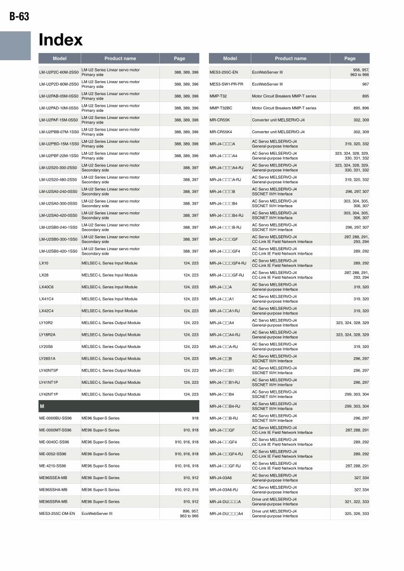
B-63
IndexModel Product name Page Model Product name Page
LM-U2P2C-60M-2SS0LM-U2 Series Linear servo motor Primary side
388, 389, 396
LM-U2P2D-80M-2SS0LM-U2 Series Linear servo motor Primary side
388, 389, 396
LM-U2PAB-05M-0SS0LM-U2 Series Linear servo motor Primary side
388, 389, 396
LM-U2PAD-10M-0SS0LM-U2 Series Linear servo motor Primary side
388, 389, 396
LM-U2PAF-15M-0SS0LM-U2 Series Linear servo motor Primary side
388, 389, 396
LM-U2PBB-07M-1SS0LM-U2 Series Linear servo motor Primary side
388, 389, 396
LM-U2PBD-15M-1SS0LM-U2 Series Linear servo motor Primary side
388, 389, 396
LM-U2PBF-22M-1SS0LM-U2 Series Linear servo motor Primary side
388, 389, 396
LM-U2S20-300-2SS0LM-U2 Series Linear servo motor Secondary side
388, 397
LM-U2S20-480-2SS0LM-U2 Series Linear servo motor Secondary side
388, 397
LM-U2SA0-240-0SS0LM-U2 Series Linear servo motor Secondary side
388, 397
LM-U2SA0-300-0SS0LM-U2 Series Linear servo motor Secondary side
388, 397
LM-U2SA0-420-0SS0LM-U2 Series Linear servo motor Secondary side
388, 397
LM-U2SB0-240-1SS0LM-U2 Series Linear servo motor Secondary side
388, 397
LM-U2SB0-300-1SS0LM-U2 Series Linear servo motor Secondary side
388, 397
LM-U2SB0-420-1SS0LM-U2 Series Linear servo motor Secondary side
388, 397
LX10 MELSEC-L Series Input Module 124, 223
LX28 MELSEC-L Series Input Module 124, 223
LX40C6 MELSEC-L Series Input Module 124, 223
LX41C4 MELSEC-L Series Input Module 124, 223
LX42C4 MELSEC-L Series Input Module 124, 223
LY10R2 MELSEC-L Series Output Module 124, 223
LY18R2A MELSEC-L Series Output Module 124, 223
LY20S6 MELSEC-L Series Output Module 124, 223
LY28S1A MELSEC-L Series Output Module 124, 223
LY40NT5P MELSEC-L Series Output Module 124, 223
LY41NT1P MELSEC-L Series Output Module 124, 223
LY42NT1P MELSEC-L Series Output Module 124, 223
M
ME-0000BU-SS96 ME96 Super-S Series 918
ME-0000MT-SS96 ME96 Super-S Series 910, 918
ME-0040C-SS96 ME96 Super-S Series 910, 916, 918
ME-0052-SS96 ME96 Super-S Series 910, 916, 918
ME-4210-SS96 ME96 Super-S Series 910, 916, 918
ME96SSEA-MB ME96 Super-S Series 910, 912
ME96SSHA-MB ME96 Super-S Series 910, 912, 916
ME96SSRA-MB ME96 Super-S Series 910, 912
MES3-255C-DM-EN EcoWebServer III896, 957,
963 to 966
MES3-255C-EN EcoWebServer III956, 957,
963 to 966
MES3-SW1-PR-FR EcoWebServer III 967
MMP-T32 Motor Circuit Breakers MMP-T series 895
MMP-T32BC Motor Circuit Breakers MMP-T series 895, 896
MR-CR55K Converter unit MELSERVO-J4 302, 309
MR-CR55K4 Converter unit MELSERVO-J4 302, 309
MR-J4-hhhAAC Servo MELSERVO-J4 General-purpose Interface
319, 320, 332
MR-J4-hhhA4AC Servo MELSERVO-J4 General-purpose Interface
323, 324, 328, 329, 330, 331, 332
MR-J4-hhhA4-RJAC Servo MELSERVO-J4 General-purpose Interface
323, 324, 328, 329, 330, 331, 332
MR-J4-hhhA-RJAC Servo MELSERVO-J4 General-purpose Interface
319, 320, 332
MR-J4-hhhBAC Servo MELSERVO-J4 SSCNET III/H Interface
296, 297, 307
MR-J4-hhhB4AC Servo MELSERVO-J4 SSCNET III/H Interface
303, 304, 305, 306, 307
MR-J4-hhhB4-RJAC Servo MELSERVO-J4 SSCNET III/H Interface
303, 304, 305, 306, 307
MR-J4-hhhB-RJAC Servo MELSERVO-J4 SSCNET III/H Interface
296, 297, 307
MR-J4-hhhGFAC Servo MELSERVO-J4 CC-Link IE Field Network Interface
287, 288, 291, 293, 294
MR-J4-hhhGF4AC Servo MELSERVO-J4 CC-Link IE Field Network Interface
289, 292
MR-J4-hhhGF4-RJAC Servo MELSERVO-J4 CC-Link IE Field Network Interface
289, 292
MR-J4-hhhGF-RJAC Servo MELSERVO-J4 CC-Link IE Field Network Interface
287, 288, 291, 293, 294
MR-J4-hhAAC Servo MELSERVO-J4 General-purpose Interface
319, 320
MR-J4-hhA1AC Servo MELSERVO-J4 General-purpose Interface
319, 320
MR-J4-hhA1-RJAC Servo MELSERVO-J4 General-purpose Interface
319, 320
MR-J4-hhA4AC Servo MELSERVO-J4 General-purpose Interface
323, 324, 328, 329
MR-J4-hhA4-RJAC Servo MELSERVO-J4 General-purpose Interface
323, 324, 328, 329
MR-J4-hhA-RJAC Servo MELSERVO-J4 General-purpose Interface
319, 320
MR-J4-hhBAC Servo MELSERVO-J4 SSCNET III/H Interface
296, 297
MR-J4-hhB1AC Servo MELSERVO-J4 SSCNET III/H Interface
296, 297
MR-J4-hhB1-RJAC Servo MELSERVO-J4 SSCNET III/H Interface
296, 297
MR-J4-hhB4AC Servo MELSERVO-J4 SSCNET III/H Interface
299, 303, 304
MR-J4-hhB4-RJAC Servo MELSERVO-J4 SSCNET III/H Interface
299, 303, 304
MR-J4-hhB-RJAC Servo MELSERVO-J4 SSCNET III/H Interface
296, 297
MR-J4-hhGFAC Servo MELSERVO-J4 CC-Link IE Field Network Interface
287, 288, 291
MR-J4-hhGF4AC Servo MELSERVO-J4 CC-Link IE Field Network Interface
289, 292
MR-J4-hhGF4-RJAC Servo MELSERVO-J4 CC-Link IE Field Network Interface
289, 292
MR-J4-hhGF-RJAC Servo MELSERVO-J4 CC-Link IE Field Network Interface
287, 288, 291
MR-J4-03A6AC Servo MELSERVO-J4 General-purpose Interface
327, 334
MR-J4-03A6-RJAC Servo MELSERVO-J4 General-purpose Interface
327, 334
MR-J4-DUhhhADrive unit MELSERVO-J4 General-purpose Interface
321, 322, 333
MR-J4-DUhhhA4Drive unit MELSERVO-J4 General-purpose Interface
325, 326, 333
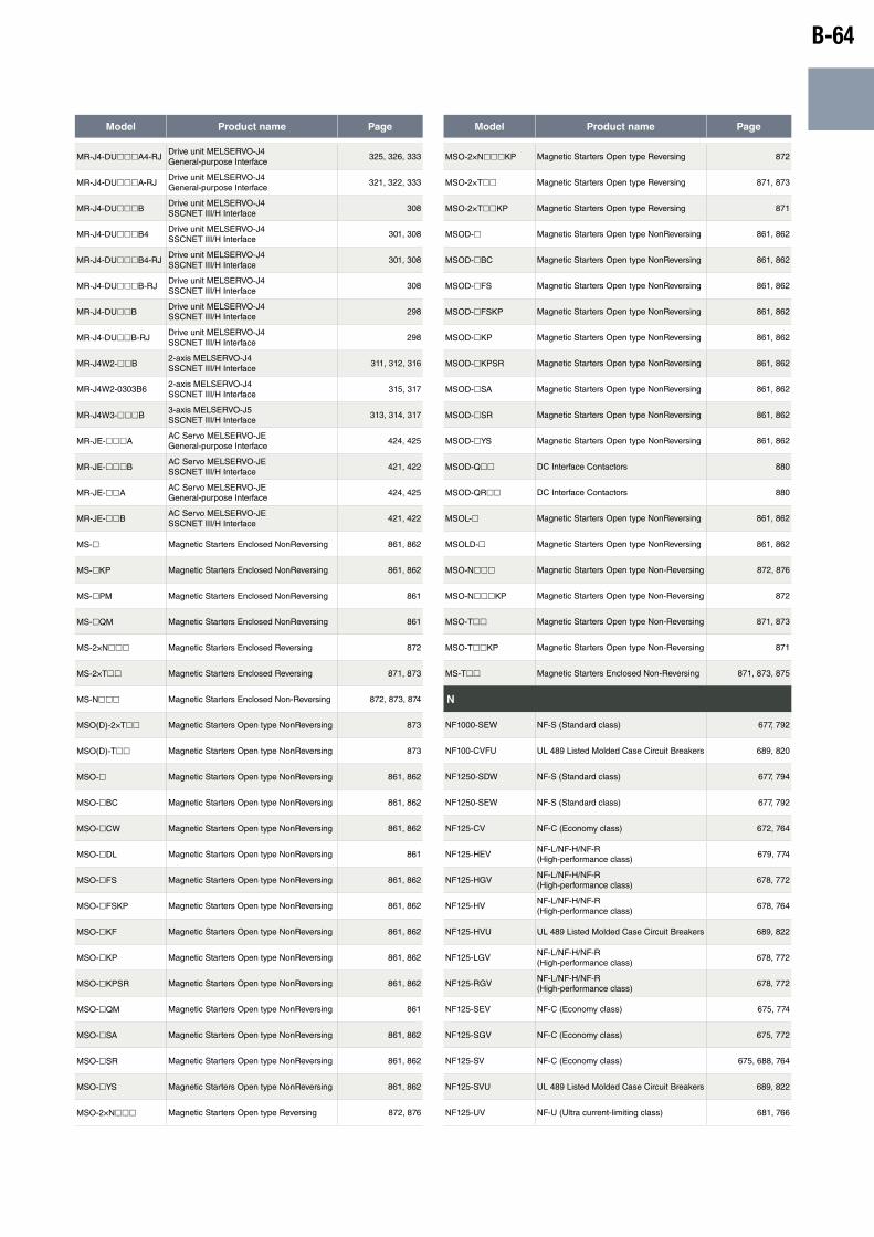
B-64
Model Product name Page Model Product name Page
MR-J4-DUhhhA4-RJDrive unit MELSERVO-J4 General-purpose Interface
325, 326, 333
MR-J4-DUhhhA-RJDrive unit MELSERVO-J4 General-purpose Interface
321, 322, 333
MR-J4-DUhhhBDrive unit MELSERVO-J4 SSCNET III/H Interface
308
MR-J4-DUhhhB4Drive unit MELSERVO-J4 SSCNET III/H Interface
301, 308
MR-J4-DUhhhB4-RJDrive unit MELSERVO-J4 SSCNET III/H Interface
301, 308
MR-J4-DUhhhB-RJDrive unit MELSERVO-J4 SSCNET III/H Interface
308
MR-J4-DUhhBDrive unit MELSERVO-J4 SSCNET III/H Interface
298
MR-J4-DUhhB-RJDrive unit MELSERVO-J4 SSCNET III/H Interface
298
MR-J4W2-hhB2-axis MELSERVO-J4 SSCNET III/H Interface
311, 312, 316
MR-J4W2-0303B62-axis MELSERVO-J4 SSCNET III/H Interface
315, 317
MR-J4W3-hhhB3-axis MELSERVO-J5 SSCNET III/H Interface
313, 314, 317
MR-JE-hhhAAC Servo MELSERVO-JE General-purpose Interface
424, 425
MR-JE-hhhBAC Servo MELSERVO-JE SSCNET III/H Interface
421, 422
MR-JE-hhAAC Servo MELSERVO-JE General-purpose Interface
424, 425
MR-JE-hhBAC Servo MELSERVO-JE SSCNET III/H Interface
421, 422
MS-h Magnetic Starters Enclosed NonReversing 861, 862
MS-hKP Magnetic Starters Enclosed NonReversing 861, 862
MS-hPM Magnetic Starters Enclosed NonReversing 861
MS-hQM Magnetic Starters Enclosed NonReversing 861
MS-2×Nhhh Magnetic Starters Enclosed Reversing 872
MS-2×Thh Magnetic Starters Enclosed Reversing 871, 873
MS-Nhhh Magnetic Starters Enclosed Non-Reversing 872, 873, 874
MSO(D)-2×Thh Magnetic Starters Open type NonReversing 873
MSO(D)-Thh Magnetic Starters Open type NonReversing 873
MSO-h Magnetic Starters Open type NonReversing 861, 862
MSO-hBC Magnetic Starters Open type NonReversing 861, 862
MSO-hCW Magnetic Starters Open type NonReversing 861, 862
MSO-hDL Magnetic Starters Open type NonReversing 861
MSO-hFS Magnetic Starters Open type NonReversing 861, 862
MSO-hFSKP Magnetic Starters Open type NonReversing 861, 862
MSO-hKF Magnetic Starters Open type NonReversing 861, 862
MSO-hKP Magnetic Starters Open type NonReversing 861, 862
MSO-hKPSR Magnetic Starters Open type NonReversing 861, 862
MSO-hQM Magnetic Starters Open type NonReversing 861
MSO-hSA Magnetic Starters Open type NonReversing 861, 862
MSO-hSR Magnetic Starters Open type NonReversing 861, 862
MSO-hYS Magnetic Starters Open type NonReversing 861, 862
MSO-2×Nhhh Magnetic Starters Open type Reversing 872, 876
MSO-2×NhhhKP Magnetic Starters Open type Reversing 872
MSO-2×Thh Magnetic Starters Open type Reversing 871, 873
MSO-2×ThhKP Magnetic Starters Open type Reversing 871
MSOD-h Magnetic Starters Open type NonReversing 861, 862
MSOD-hBC Magnetic Starters Open type NonReversing 861, 862
MSOD-hFS Magnetic Starters Open type NonReversing 861, 862
MSOD-hFSKP Magnetic Starters Open type NonReversing 861, 862
MSOD-hKP Magnetic Starters Open type NonReversing 861, 862
MSOD-hKPSR Magnetic Starters Open type NonReversing 861, 862
MSOD-hSA Magnetic Starters Open type NonReversing 861, 862
MSOD-hSR Magnetic Starters Open type NonReversing 861, 862
MSOD-hYS Magnetic Starters Open type NonReversing 861, 862
MSOD-Qhh DC Interface Contactors 880
MSOD-QRhh DC Interface Contactors 880
MSOL-h Magnetic Starters Open type NonReversing 861, 862
MSOLD-h Magnetic Starters Open type NonReversing 861, 862
MSO-Nhhh Magnetic Starters Open type Non-Reversing 872, 876
MSO-NhhhKP Magnetic Starters Open type Non-Reversing 872
MSO-Thh Magnetic Starters Open type Non-Reversing 871, 873
MSO-ThhKP Magnetic Starters Open type Non-Reversing 871
MS-Thh Magnetic Starters Enclosed Non-Reversing 871, 873, 875
N
NF1000-SEW NF-S (Standard class) 677, 792
NF100-CVFU UL 489 Listed Molded Case Circuit Breakers 689, 820
NF1250-SDW NF-S (Standard class) 677, 794
NF1250-SEW NF-S (Standard class) 677, 792
NF125-CV NF-C (Economy class) 672, 764
NF125-HEVNF-L/NF-H/NF-R (High-performance class)
679, 774
NF125-HGVNF-L/NF-H/NF-R (High-performance class)
678, 772
NF125-HVNF-L/NF-H/NF-R (High-performance class)
678, 764
NF125-HVU UL 489 Listed Molded Case Circuit Breakers 689, 822
NF125-LGVNF-L/NF-H/NF-R (High-performance class)
678, 772
NF125-RGVNF-L/NF-H/NF-R (High-performance class)
678, 772
NF125-SEV NF-C (Economy class) 675, 774
NF125-SGV NF-C (Economy class) 675, 772
NF125-SV NF-C (Economy class) 675, 688, 764
NF125-SVU UL 489 Listed Molded Case Circuit Breakers 689, 822
NF125-UV NF-U (Ultra current-limiting class) 681, 766
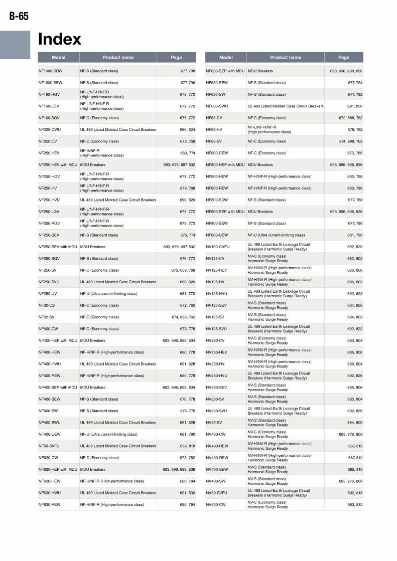
B-65
IndexModel Product name Page Model Product name Page
NF1600-SDW NF-S (Standard class) 677, 798
NF1600-SEW NF-S (Standard class) 677, 796
NF160-HGVNF-L/NF-H/NF-R (High-performance class)
679, 772
NF160-LGVNF-L/NF-H/NF-R (High-performance class)
679, 772
NF160-SGV NF-C (Economy class) 675, 772
NF225-CWU UL 489 Listed Molded Case Circuit Breakers 690, 824
NF250-CV NF-C (Economy class) 673, 768
NF250-HEVNF-H/NF-R (High-performance class)
680, 774
NF250-HEV with MDU MDU Breakers 693, 695, 697, 832
NF250-HGVNF-L/NF-H/NF-R (High-performance class)
679, 772
NF250-HVNF-L/NF-H/NF-R (High-performance class)
679, 768
NF250-HVU UL 489 Listed Molded Case Circuit Breakers 690, 826
NF250-LGVNF-L/NF-H/NF-R (High-performance class)
679, 772
NF250-RGVNF-L/NF-H/NF-R (High-performance class)
679, 772
NF250-SEV NF-S (Standard class) 676, 774
NF250-SEV with MDU MDU Breakers 693, 695, 697, 832
NF250-SGV NF-S (Standard class) 676, 772
NF250-SV NF-C (Economy class) 675, 688, 768
NF250-SVU UL 489 Listed Molded Case Circuit Breakers 690, 826
NF250-UV NF-U (Ultra current-limiting class) 681, 770
NF30-CS NF-C (Economy class) 672, 760
NF32-SV NF-C (Economy class) 674, 688, 762
NF400-CW NF-C (Economy class) 673, 776
NF400-HEP with MDU MDU Breakers 693, 696, 698, 834
NF400-HEW NF-H/NF-R (High-performance class) 680, 778
NF400-HWU UL 489 Listed Molded Case Circuit Breakers 691, 828
NF400-REW NF-H/NF-R (High-performance class) 680, 778
NF400-SEP with MDU MDU Breakers 693, 696, 698, 834
NF400-SEW NF-S (Standard class) 676, 778
NF400-SW NF-S (Standard class) 676, 776
NF400-SWU UL 489 Listed Molded Case Circuit Breakers 691, 828
NF400-UEW NF-U (Ultra current-limiting class) 681, 780
NF50-SVFU UL 489 Listed Molded Case Circuit Breakers 689, 818
NF630-CW NF-C (Economy class) 673, 782
NF630-HEP with MDU MDU Breakers 693, 696, 698, 836
NF630-HEW NF-H/NF-R (High-performance class) 680, 784
NF630-HWU UL 489 Listed Molded Case Circuit Breakers 691, 830
NF630-REW NF-H/NF-R (High-performance class) 680, 784
NF630-SEP with MDU MDU Breakers 693, 696, 698, 836
NF630-SEW NF-S (Standard class) 677, 784
NF630-SW NF-S (Standard class) 677, 782
NF630-SWU UL 489 Listed Molded Case Circuit Breakers 691, 830
NF63-CV NF-C (Economy class) 672, 688, 762
NF63-HVNF-L/NF-H/NF-R (High-performance class)
678, 762
NF63-SV NF-C (Economy class) 674, 688, 762
NF800-CEW NF-C (Economy class) 673, 786
NF800-HEP with MDU MDU Breakers 693, 696, 698, 836
NF800-HEW NF-H/NF-R (High-performance class) 680, 786
NF800-REW NF-H/NF-R (High-performance class) 680, 786
NF800-SDW NF-S (Standard class) 677, 788
NF800-SEP with MDU MDU Breakers 693, 696, 698, 836
NF800-SEW NF-S (Standard class) 677, 786
NF800-UEW NF-U (Ultra current-limiting class) 681, 790
NV100-CVFUUL 489 Listed Earth Leakage Circuit Breakers (Harmonic Surge Ready)
692, 820
NV125-CVNV-C (Economy class) Harmonic Surge Ready
682, 802
NV125-HEVNV-H/NV-R (High-performance class) Harmonic Surge Ready
686, 806
NV125-HVNV-H/NV-R (High-performance class) Harmonic Surge Ready
686, 802
NV125-HVUUL 489 Listed Earth Leakage Circuit Breakers (Harmonic Surge Ready)
692, 822
NV125-SEVNV-S (Standard class) Harmonic Surge Ready
684, 806
NV125-SVNV-S (Standard class) Harmonic Surge Ready
684, 802
NV125-SVUUL 489 Listed Earth Leakage Circuit Breakers (Harmonic Surge Ready)
692, 822
NV250-CVNV-C (Economy class) Harmonic Surge Ready
683, 804
NV250-HEVNV-H/NV-R (High-performance class) Harmonic Surge Ready
686, 806
NV250-HVNV-H/NV-R (High-performance class) Harmonic Surge Ready
686, 804
NV250-HVUUL 489 Listed Earth Leakage Circuit Breakers (Harmonic Surge Ready)
692, 826
NV250-SEVNV-S (Standard class) Harmonic Surge Ready
685, 806
NV250-SVNV-S (Standard class) Harmonic Surge Ready
685, 804
NV250-SVUUL 489 Listed Earth Leakage Circuit Breakers (Harmonic Surge Ready)
692, 826
NV32-SVNV-S (Standard class) Harmonic Surge Ready
684, 800
NV400-CWNV-C (Economy class) Harmonic Surge Ready
683, 776, 808
NV400-HEWNV-H/NV-R (High-performance class) Harmonic Surge Ready
687, 810
NV400-REWNV-H/NV-R (High-performance class) Harmonic Surge Ready
687, 810
NV400-SEWNV-S (Standard class) Harmonic Surge Ready
685, 810
NV400-SWNV-S (Standard class) Harmonic Surge Ready
685, 776, 808
NV50-SVFUUL 489 Listed Earth Leakage Circuit Breakers (Harmonic Surge Ready)
692, 818
NV630-CWNV-C (Economy class) Harmonic Surge Ready
683, 812
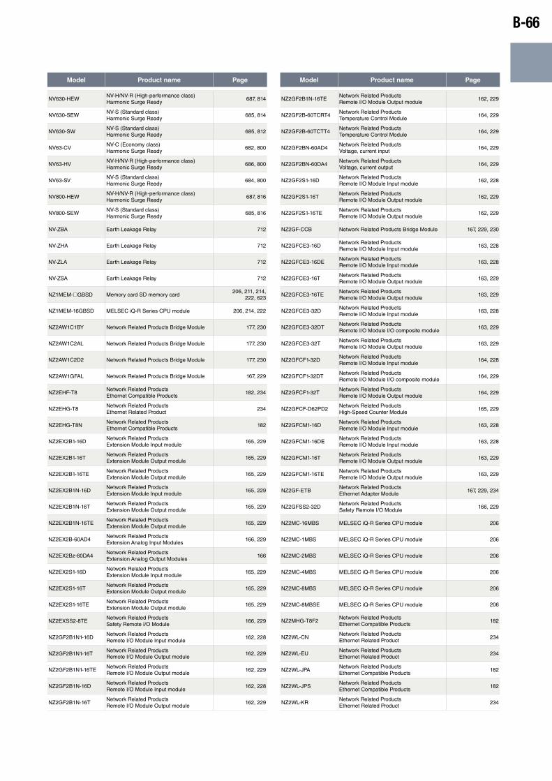
B-66
Model Product name Page Model Product name Page
NV630-HEWNV-H/NV-R (High-performance class) Harmonic Surge Ready
687, 814
NV630-SEWNV-S (Standard class) Harmonic Surge Ready
685, 814
NV630-SWNV-S (Standard class) Harmonic Surge Ready
685, 812
NV63-CVNV-C (Economy class) Harmonic Surge Ready
682, 800
NV63-HVNV-H/NV-R (High-performance class) Harmonic Surge Ready
686, 800
NV63-SVNV-S (Standard class) Harmonic Surge Ready
684, 800
NV800-HEWNV-H/NV-R (High-performance class) Harmonic Surge Ready
687, 816
NV800-SEWNV-S (Standard class) Harmonic Surge Ready
685, 816
NV-ZBA Earth Leakage Relay 712
NV-ZHA Earth Leakage Relay 712
NV-ZLA Earth Leakage Relay 712
NV-ZSA Earth Leakage Relay 712
NZ1MEM-hGBSD Memory card SD memory card206, 211, 214,
222, 623
NZ1MEM-16GBSD MELSEC iQ-R Series CPU module 206, 214, 222
NZ2AW1C1BY Network Related Products Bridge Module 177, 230
NZ2AW1C2AL Network Related Products Bridge Module 177, 230
NZ2AW1C2D2 Network Related Products Bridge Module 177, 230
NZ2AW1GFAL Network Related Products Bridge Module 167, 229
NZ2EHF-T8Network Related Products Ethernet Compatible Products
182, 234
NZ2EHG-T8Network Related Products Ethernet Related Product
234
NZ2EHG-T8NNetwork Related Products Ethernet Compatible Products
182
NZ2EX2B1-16DNetwork Related Products Extension Module Input module
165, 229
NZ2EX2B1-16TNetwork Related Products Extension Module Output module
165, 229
NZ2EX2B1-16TENetwork Related Products Extension Module Output module
165, 229
NZ2EX2B1N-16DNetwork Related Products Extension Module Input module
165, 229
NZ2EX2B1N-16TNetwork Related Products Extension Module Output module
165, 229
NZ2EX2B1N-16TENetwork Related Products Extension Module Output module
165, 229
NZ2EX2B-60AD4Network Related Products Extension Analog Input Modules
166, 229
NZ2EX2Bz-60DA4Network Related Products Extension Analog Output Modules
166
NZ2EX2S1-16DNetwork Related Products Extension Module Input module
165, 229
NZ2EX2S1-16TNetwork Related Products Extension Module Output module
165, 229
NZ2EX2S1-16TENetwork Related Products Extension Module Output module
165, 229
NZ2EXSS2-8TENetwork Related Products Safety Remote I/O Module
166, 229
NZ2GF2B1N1-16DNetwork Related Products Remote I/O Module Input module
162, 228
NZ2GF2B1N1-16TNetwork Related Products Remote I/O Module Output module
162, 229
NZ2GF2B1N1-16TENetwork Related Products Remote I/O Module Output module
162, 229
NZ2GF2B1N-16DNetwork Related Products Remote I/O Module Input module
162, 228
NZ2GF2B1N-16TNetwork Related Products Remote I/O Module Output module
162, 229
NZ2GF2B1N-16TENetwork Related Products Remote I/O Module Output module
162, 229
NZ2GF2B-60TCRT4Network Related Products Temperature Control Module
164, 229
NZ2GF2B-60TCTT4Network Related Products Temperature Control Module
164, 229
NZ2GF2BN-60AD4Network Related Products Voltage, current input
164, 229
NZ2GF2BN-60DA4Network Related Products Voltage, current output
164, 229
NZ2GF2S1-16DNetwork Related Products Remote I/O Module Input module
162, 228
NZ2GF2S1-16TNetwork Related Products Remote I/O Module Output module
162, 229
NZ2GF2S1-16TENetwork Related Products Remote I/O Module Output module
162, 229
NZ2GF-CCB Network Related Products Bridge Module 167, 229, 230
NZ2GFCE3-16DNetwork Related Products Remote I/O Module Input module
163, 228
NZ2GFCE3-16DENetwork Related Products Remote I/O Module Input module
163, 228
NZ2GFCE3-16TNetwork Related Products Remote I/O Module Output module
163, 229
NZ2GFCE3-16TENetwork Related Products Remote I/O Module Output module
163, 229
NZ2GFCE3-32DNetwork Related Products Remote I/O Module Input module
163, 228
NZ2GFCE3-32DTNetwork Related Products Remote I/O Module I/O composite module
163, 229
NZ2GFCE3-32TNetwork Related Products Remote I/O Module Output module
163, 229
NZ2GFCF1-32DNetwork Related Products Remote I/O Module Input module
164, 228
NZ2GFCF1-32DTNetwork Related Products Remote I/O Module I/O composite module
164, 229
NZ2GFCF1-32TNetwork Related Products Remote I/O Module Output module
164, 229
NZ2GFCF-D62PD2Network Related Products High-Speed Counter Module
165, 229
NZ2GFCM1-16DNetwork Related Products Remote I/O Module Input module
163, 228
NZ2GFCM1-16DENetwork Related Products Remote I/O Module Input module
163, 228
NZ2GFCM1-16TNetwork Related Products Remote I/O Module Output module
163, 229
NZ2GFCM1-16TENetwork Related Products Remote I/O Module Output module
163, 229
NZ2GF-ETBNetwork Related Products Ethernet Adapter Module
167, 229, 234
NZ2GFSS2-32DNetwork Related Products Safety Remote I/O Module
166, 229
NZ2MC-16MBS MELSEC iQ-R Series CPU module 206
NZ2MC-1MBS MELSEC iQ-R Series CPU module 206
NZ2MC-2MBS MELSEC iQ-R Series CPU module 206
NZ2MC-4MBS MELSEC iQ-R Series CPU module 206
NZ2MC-8MBS MELSEC iQ-R Series CPU module 206
NZ2MC-8MBSE MELSEC iQ-R Series CPU module 206
NZ2MHG-T8F2Network Related Products Ethernet Compatible Products
182
NZ2WL-CNNetwork Related Products Ethernet Related Product
234
NZ2WL-EUNetwork Related Products Ethernet Related Product
234
NZ2WL-JPANetwork Related Products Ethernet Compatible Products
182
NZ2WL-JPSNetwork Related Products Ethernet Compatible Products
182
NZ2WL-KRNetwork Related Products Ethernet Related Product
234

B-67
IndexModel Product name Page Model Product name Page
NZ2WL-TWNetwork Related Products Ethernet Related Product
234
NZ2WL-USNetwork Related Products Ethernet Related Product
234
Q
Q00CPU MELSEC-Q Series CPU Module 114, 213
Q00JCPU MELSEC-Q Series CPU Module 114, 213
Q00UCPUMELSEC-Q Series Programmable Controller CPU
92, 112, 212
Q00UJCPUMELSEC-Q Series Programmable Controller CPU
92, 112, 212
Q01CPU MELSEC-Q Series CPU Module 114, 213
Q01UCPUMELSEC-Q Series Programmable Controller CPU
92, 112, 212
Q02CPU MELSEC-Q Series CPU Module 115, 213
Q02HCPU MELSEC-Q Series CPU Module 115, 213
Q02PHCPU MELSEC-Q Series Process CPU 93, 116, 213
Q02UCPUMELSEC-Q Series Programmable Controller CPU
92, 113
Q03UDCPUMELSEC-Q Series Programmable Controller CPU
92, 113, 212
Q03UDECPUMELSEC-Q Series Programmable Controller CPU
92, 113, 212
Q03UDVCPUMELSEC-Q Series Programmable Controller CPU
92, 112, 212
Q04UDEHCPUMELSEC-Q Series Programmable Controller CPU
92, 113, 212
Q04UDHCPUMELSEC-Q Series Programmable Controller CPU
92, 113, 212
Q04UDVCPUMELSEC-Q Series Programmable Controller CPU
92, 112, 212
Q06CCPU-V MELSEC-Q Series CPU module 213
Q06HCPU MELSEC-Q Series CPU Module 115, 213
Q06PHCPU MELSEC-Q Series Process CPU 93, 116, 213
Q06UDEHCPUMELSEC-Q Series Programmable Controller CPU
92, 113, 212
Q06UDHCPUMELSEC-Q Series Programmable Controller CPU
92, 113, 212
Q06UDVCPUMELSEC-Q Series Programmable Controller CPU
92, 112, 212
Q100UDEHCPUMELSEC-Q Series Programmable Controller CPU
92, 113, 212
Q10UDEHCPUMELSEC-Q Series Programmable Controller CPU
92, 113, 212
Q10UDHCPUMELSEC-Q Series Programmable Controller CPU
92, 113, 212
Q12DCCPU-CBL MELSEC-Q Series CPU module 213
Q12DCCPU-V MELSEC-Q Series C Controller 95, 213
Q12DCCPU-V-B011 MELSEC-Q Series CPU module 213
Q12DCCPU-V-B013 MELSEC-Q Series CPU module 213
Q12DCCPU-V-B015 MELSEC-Q Series CPU module 213
Q12DCCPU-V-B019 MELSEC-Q Series CPU module 213
Q12DCCPU-V-B01B MELSEC-Q Series CPU module 213
Q12DCCPU-V-B01D MELSEC-Q Series CPU module 213
Q12HCPU MELSEC-Q Series CPU Module 115, 213
Q12PHCPU MELSEC-Q Series Process CPU 93, 116, 213
Q12PRHCPU MELSEC-Q Series Redundant CPU 94, 117, 213
Q13UDEHCPUMELSEC-Q Series Programmable Controller CPU
92, 113, 212
Q13UDHCPUMELSEC-Q Series Programmable Controller CPU
92, 113, 212
Q13UDVCPUMELSEC-Q Series Programmable Controller CPU
92, 112, 212
Q170MSCPU Motion controller 240, 245 to 250, 254
Q170MSCPU-S1 Motion controller 240, 245 to 250, 254
Q171ENC-W8 Serial absolute synchronous encoder 251, 254
Q172DEX Synchronous encoder interface module 250, 251, 254
Q172DLX Servo external signals interface module 250, 251, 254
Q172DRCPU MELSEC-Q Series Robot Controller 96
Q172DSCPU Motion CPU module240, 244, 246, 247, 248, 250, 253, 254
Q173DPX Manual pulse generator interface module 250, 251, 254
Q173DSCPU MELSEC-Q Series Motion CPU96, 240, 244, 246, 247,
248, 250, 253, 254
Q173DSXY Safety signal module 250, 252, 253, 254
Q173NCCPU-S01 MELSEC-Q Series CNC CPU 96
Q20UDEHCPUMELSEC-Q Series Programmable Controller CPU
92, 113, 212
Q20UDHCPUMELSEC-Q Series Programmable Controller CPU
92, 113, 212
Q24DHCCPU-LS MELSEC-Q Series C Controller 95, 213
Q24DHCCPU-LS-B030 MELSEC-Q Series CPU module 213
Q24DHCCPU-V MELSEC-Q Series C Controller 95, 213
Q24DHCCPU-V-B019 MELSEC-Q Series CPU module 213
Q24DHCCPU-V-B01D MELSEC-Q Series CPU module 213
Q24DHCCPU-VG-h MELSEC-Q Series C Controller 95
Q24DHCCPU-VG-B000
MELSEC-Q Series CPU module 213
Q24DHCCPU-VG-B002
MELSEC-Q Series CPU module 213
Q25HCPU MELSEC-Q Series CPU Module 115, 213
Q25PHCPU MELSEC-Q Series Process CPU 93, 116, 213
Q25PRHCPU MELSEC-Q Series Redundant CPU 94, 117, 213
Q26DHCCPU-LS MELSEC-Q Series C Controller 95
Q26UDEHCPUMELSEC-Q Series Programmable Controller CPU
92, 113, 212
Q26UDHCPUMELSEC-Q Series Programmable Controller CPU
92, 113, 212
Q26UDVCPUMELSEC-Q Series Programmable Controller CPU
92, 112, 212
Q2MEM-16MBA MELSEC-Q Series CPU module 214
Q2MEM-1MBS MELSEC-Q Series CPU module 214
Q2MEM-2MBS MELSEC-Q Series CPU module 214
Q2MEM-32MBA MELSEC-Q Series CPU module 214
Q2MEM-8MBA MELSEC-Q Series CPU module 214
Q2MEM-ADP MELSEC-Q Series CPU module 214

B-68
Model Product name Page Model Product name Page
Q2MEM-BAT MELSEC-Q Series CPU module 214
Q312B MELSEC-Q Series Base Unit 97, 215
Q312DB MELSEC-Q Series Base Unit 97, 215
Q32SB MELSEC-Q Series Base Unit 97, 215
Q33B MELSEC-Q Series Base Unit 97, 215
Q33SB MELSEC-Q Series Base Unit 97, 215
Q35B MELSEC-Q Series Base Unit 97, 215
Q35BL Q Series large type base unit 239
Q35BLSQ Series large type base unit (AnS Series size)
239
Q35BLS-DQ Series large type base unit (AnS Series size)
239
Q35DB MELSEC-Q Series Base Unit 97, 215
Q35SB MELSEC-Q Series Base Unit 97, 215
Q38B MELSEC-Q Series Base Unit 97, 215
Q38BL Q Series large type base unit 239
Q38BLSQ Series large type base unit (AnS Series size)
239
Q38BLS-DQ Series large type base unit (AnS Series size)
239
Q38DB MELSEC-Q Series Base Unit 97, 215
Q3MEM-4MBS MELSEC-Q Series CPU module 214
Q3MEM-4MBS-SET MELSEC-Q Series CPU module 214
Q3MEM-8MBS MELSEC-Q Series CPU module 214
Q3MEM-8MBS-SET MELSEC-Q Series CPU module 214
Q3MEM-BAT MELSEC-Q Series CPU module 214
Q3MEM-CV MELSEC-Q Series CPU module 214
Q3MEM-CV-H MELSEC-Q Series CPU module 214
Q4MCA-1MBS MELSEC-Q Series CPU module 214
Q4MCA-2MBS MELSEC-Q Series CPU module 214
Q4MCA-4MBS MELSEC-Q Series CPU module 214
Q4MCA-8MBS MELSEC-Q Series CPU module 214
Q50BD-CCV2Network Related Products CC-Link Related Products
232
Q50UDEHCPUMELSEC-Q Series Programmable Controller CPU
92, 113, 212
Q52B MELSEC-Q Series Base Unit 97, 215
Q55B MELSEC-Q Series Base Unit 97, 215
Q55BL Q Series large type base unit 239
Q55BLSQ Series large type base unit (AnS Series size)
239
Q55BLS-DQ Series large type base unit (AnS Series size)
239
Q612B MELSEC-Q Series Base Unit 97, 215
Q61LD MELSEC-Q Series Load cell input 100, 218
Q61P MELSEC-Q Series Power Supply Module 97, 215
Q61P-D MELSEC-Q Series Power Supply Module 97, 215
Q61SP MELSEC-Q Series Power Supply Module 97, 215
Q62AD-DGH MELSEC-Q Series Current input 100, 218
Q62DA-FG MELSEC-Q Series Voltage/current output 100, 218
Q62DAN MELSEC-Q Series Voltage/current output 100, 218
Q62HLC MELSEC-Q Series Loop control 101, 218
Q62P MELSEC-Q Series Power Supply Module 97, 215
Q63B MELSEC-Q Series Base Unit 97, 215
Q63P MELSEC-Q Series Power Supply Module 97, 215
Q63RP MELSEC-Q Series Power Supply Module 97, 215
Q64AD MELSEC-Q Series Voltage/current input 100, 218
Q64AD2DAMELSEC-Q Series Voltage and current input/output
100, 218
Q64AD-GH MELSEC-Q Series Voltage/current input 100, 218
Q64ADH MELSEC-Q Series Voltage/current input 100, 218
Q64DAH MELSEC-Q Series Voltage/current output 100, 218
Q64DAN MELSEC-Q Series Voltage/current output 100, 218
Q64PN MELSEC-Q Series Power Supply Module 97, 215
Q64RD MELSEC-Q Series Temperature input 101, 218
Q64RD-G MELSEC-Q Series Temperature input 101, 218
Q64RP MELSEC-Q Series Power Supply Module 97
Q64RPN MELSEC-Q Series Power supply module 215
Q64TCRTBWN MELSEC-Q Series Temperature control 101, 218
Q64TCRTN MELSEC-Q Series Temperature control 101, 218
Q64TCTTBWN MELSEC-Q Series Temperature control 101, 218
Q64TCTTN MELSEC-Q Series Temperature control 101, 218
Q64TD MELSEC-Q Series Temperature input 101, 218
Q64TDV-GH MELSEC-Q Series Temperature input 101, 218
Q65B MELSEC-Q Series Base Unit 97, 215
Q65BL Q Series large type base unit 239
Q65BLSQ Series large type base unit (AnS Series size)
239
Q65BLS-DQ Series large type base unit (AnS Series size)
239
Q65WRB MELSEC-Q Series Base Unit 97, 215
Q66AD-DG MELSEC-Q Series Current input 100, 218
Q66DA-G MELSEC-Q Series Voltage/current output 100, 218
Q68AD-G MELSEC-Q Series Voltage/current input 100, 218
Q68ADI MELSEC-Q Series Current input 100, 218
Q68ADV MELSEC-Q Series Voltage input 100, 218
Q68B MELSEC-Q Series Base Unit 97, 215
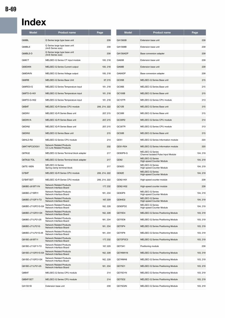
B-69
IndexModel Product name Page Model Product name Page
Q68BL Q Series large type base unit 239
Q68BLSQ Series large type base unit (AnS Series size)
239
Q68BLS-DQ Series large type base unit (AnS Series size)
239
Q68CT MELSEC-Q Series CT input module 100, 218
Q68DAIN MELSEC-Q Series Current output 100, 218
Q68DAVN MELSEC-Q Series Voltage output 100, 218
Q68RB MELSEC-Q Series Base Unit 97, 215
Q68RD3-G MELSEC-Q Series Temperature input 101, 218
Q68TD-G-H01 MELSEC-Q Series Temperature input 101, 218
Q68TD-G-H02 MELSEC-Q Series Temperature input 101, 218
Q6BAT MELSEC iQ-R Series CPU module 206, 214, 222
Q6DIN1 MELSEC iQ-R Series Base unit 207, 215
Q6DIN1A MELSEC iQ-R Series Base unit 207, 215
Q6DIN2 MELSEC iQ-R Series Base unit 207, 215
Q6DIN3 MELSEC-Q Series Base unit 215
Q6HLD-R2 MELSEC-Q Series CPU module 214
Q6KT-NPC2OG51Network Related Products CC-Link Related Products
232
Q6TA32 MELSEC-Q Series Terminal block adapter 217
Q6TA32-TOL MELSEC-Q Series Terminal block adapter 217
Q6TE-18SNMELSEC-Q Series Spring clamp terminal block
217
Q7BAT MELSEC iQ-R Series CPU module 206, 214, 222
Q7BAT-SET MELSEC iQ-R Series CPU module 206, 214, 222
Q80BD-J61BT11NNetwork Related Products Network Interface Board
177, 232
Q80BD-J71BR11Network Related Products Network Interface Board
181, 234
Q80BD-J71GF11-T2Network Related Products Network Interface Board
167, 229
Q80BD-J71GP21S-SXNetwork Related Products Network Interface Board
162, 228
Q80BD-J71GP21-SXNetwork Related Products Network Interface Board
162, 228
Q80BD-J71LP21-25Network Related Products Network Interface Board
181, 234
Q80BD-J71LP21GNetwork Related Products Network Interface Board
181, 234
Q80BD-J71LP21S-25Network Related Products Network Interface Board
181, 234
Q81BD-J61BT11Network Related Products Network Interface Board
177, 232
Q81BD-J71GF11-T2Network Related Products Network Interface Board
167, 229
Q81BD-J71GP21S-SXNetwork Related Products Network Interface Board
162, 228
Q81BD-J71GP21-SXNetwork Related Products Network Interface Board
162, 228
Q81BD-J71LP21-25Network Related Products Network Interface Board
181, 234
Q8BAT MELSEC-Q Series CPU module 214
Q8BAT-SET MELSEC-Q Series CPU module 214
QA1S51B Extension base unit 239
QA1S65B Extension base unit 239
QA1S68B Extension base unit 239
QA1S6ADP Base conversion adapter 239
QA65B Extension base unit 239
QA68B Extension base unit 239
QA6ADP Base conversion adapter 239
QC05B MELSEC-Q Series Base unit 215
QC06B MELSEC-Q Series Base unit 215
QC100B MELSEC-Q Series Base unit 215
QC10TR MELSEC-Q Series CPU module 213
QC12B MELSEC-Q Series Base unit 215
QC30B MELSEC-Q Series Base unit 215
QC30R2 MELSEC-Q Series CPU module 214
QC30TR MELSEC-Q Series CPU module 213
QC50B MELSEC-Q Series Base unit 215
QD51 MELSEC-Q Series Information module 220
QD51-R24 MELSEC-Q Series Information module 220
QD60P8-GMELSEC-Q Series Channel Isolated Pulse Input Module
104, 219
QD62MELSEC-Q Series High-speed Counter Module
104, 219
QD62DMELSEC-Q Series High-speed Counter Module
104, 219
QD62EMELSEC-Q Series High-speed Counter Module
104, 219
QD62-H01 High-speed counter module 239
QD62-H02 High-speed counter module 239
QD63P6MELSEC-Q Series High-speed Counter Module
104, 219
QD64D2MELSEC-Q Series High-speed Counter Module
104, 219
QD65PD2MELSEC-Q Series High-speed Counter Module
104, 219
QD70D4 MELSEC-Q Series Positioning Module 103, 219
QD70D8 MELSEC-Q Series Positioning Module 103, 219
QD70P4 MELSEC-Q Series Positioning Module 103, 219
QD70P8 MELSEC-Q Series Positioning Module 103, 219
QD72P3C3 MELSEC-Q Series Positioning Module 103, 219
QD73A1 Positioning module 239
QD74MH16 MELSEC-Q Series Positioning Module 103, 219
QD74MH8 MELSEC-Q Series Positioning Module 103, 219
QD75D1 MELSEC-Q Series Positioning Module 103, 219
QD75D1N MELSEC-Q Series Positioning Module 103, 219
QD75D2 MELSEC-Q Series Positioning Module 103, 219
QD75D2N MELSEC-Q Series Positioning Module 103, 219
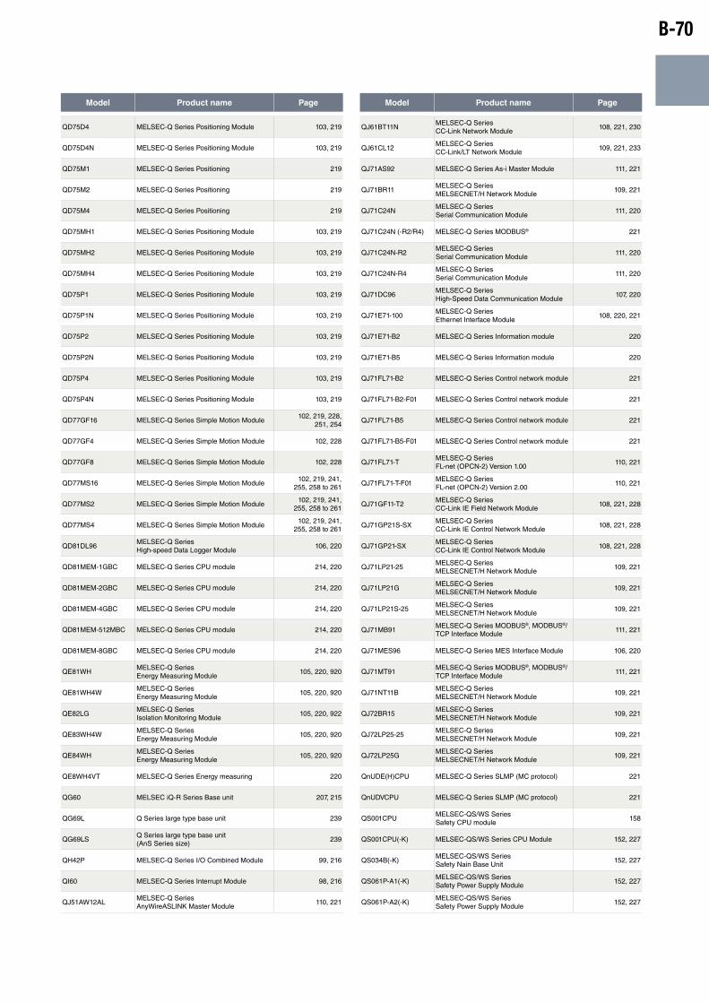
B-70
Model Product name Page Model Product name Page
QD75D4 MELSEC-Q Series Positioning Module 103, 219
QD75D4N MELSEC-Q Series Positioning Module 103, 219
QD75M1 MELSEC-Q Series Positioning 219
QD75M2 MELSEC-Q Series Positioning 219
QD75M4 MELSEC-Q Series Positioning 219
QD75MH1 MELSEC-Q Series Positioning Module 103, 219
QD75MH2 MELSEC-Q Series Positioning Module 103, 219
QD75MH4 MELSEC-Q Series Positioning Module 103, 219
QD75P1 MELSEC-Q Series Positioning Module 103, 219
QD75P1N MELSEC-Q Series Positioning Module 103, 219
QD75P2 MELSEC-Q Series Positioning Module 103, 219
QD75P2N MELSEC-Q Series Positioning Module 103, 219
QD75P4 MELSEC-Q Series Positioning Module 103, 219
QD75P4N MELSEC-Q Series Positioning Module 103, 219
QD77GF16 MELSEC-Q Series Simple Motion Module102, 219, 228,
251, 254
QD77GF4 MELSEC-Q Series Simple Motion Module 102, 228
QD77GF8 MELSEC-Q Series Simple Motion Module 102, 228
QD77MS16 MELSEC-Q Series Simple Motion Module102, 219, 241,
255, 258 to 261
QD77MS2 MELSEC-Q Series Simple Motion Module102, 219, 241,
255, 258 to 261
QD77MS4 MELSEC-Q Series Simple Motion Module102, 219, 241,
255, 258 to 261
QD81DL96MELSEC-Q Series High-speed Data Logger Module
106, 220
QD81MEM-1GBC MELSEC-Q Series CPU module 214, 220
QD81MEM-2GBC MELSEC-Q Series CPU module 214, 220
QD81MEM-4GBC MELSEC-Q Series CPU module 214, 220
QD81MEM-512MBC MELSEC-Q Series CPU module 214, 220
QD81MEM-8GBC MELSEC-Q Series CPU module 214, 220
QE81WHMELSEC-Q Series Energy Measuring Module
105, 220, 920
QE81WH4WMELSEC-Q Series Energy Measuring Module
105, 220, 920
QE82LGMELSEC-Q Series Isolation Monitoring Module
105, 220, 922
QE83WH4WMELSEC-Q Series Energy Measuring Module
105, 220, 920
QE84WHMELSEC-Q Series Energy Measuring Module
105, 220, 920
QE8WH4VT MELSEC-Q Series Energy measuring 220
QG60 MELSEC iQ-R Series Base unit 207, 215
QG69L Q Series large type base unit 239
QG69LSQ Series large type base unit (AnS Series size)
239
QH42P MELSEC-Q Series I/O Combined Module 99, 216
QI60 MELSEC-Q Series Interrupt Module 98, 216
QJ51AW12ALMELSEC-Q Series AnyWireASLINK Master Module
110, 221
QJ61BT11NMELSEC-Q Series CC-Link Network Module
108, 221, 230
QJ61CL12MELSEC-Q Series CC-Link/LT Network Module
109, 221, 233
QJ71AS92 MELSEC-Q Series As-i Master Module 111, 221
QJ71BR11MELSEC-Q Series MELSECNET/H Network Module
109, 221
QJ71C24NMELSEC-Q Series Serial Communication Module
111, 220
QJ71C24N (-R2/R4) MELSEC-Q Series MODBUS® 221
QJ71C24N-R2MELSEC-Q Series Serial Communication Module
111, 220
QJ71C24N-R4MELSEC-Q Series Serial Communication Module
111, 220
QJ71DC96MELSEC-Q Series High-Speed Data Communication Module
107, 220
QJ71E71-100MELSEC-Q Series Ethernet Interface Module
108, 220, 221
QJ71E71-B2 MELSEC-Q Series Information module 220
QJ71E71-B5 MELSEC-Q Series Information module 220
QJ71FL71-B2 MELSEC-Q Series Control network module 221
QJ71FL71-B2-F01 MELSEC-Q Series Control network module 221
QJ71FL71-B5 MELSEC-Q Series Control network module 221
QJ71FL71-B5-F01 MELSEC-Q Series Control network module 221
QJ71FL71-TMELSEC-Q Series FL-net (OPCN-2) Version 1.00
110, 221
QJ71FL71-T-F01MELSEC-Q Series FL-net (OPCN-2) Version 2.00
110, 221
QJ71GF11-T2MELSEC-Q Series CC-Link IE Field Network Module
108, 221, 228
QJ71GP21S-SXMELSEC-Q Series CC-Link IE Control Network Module
108, 221, 228
QJ71GP21-SXMELSEC-Q Series CC-Link IE Control Network Module
108, 221, 228
QJ71LP21-25MELSEC-Q Series MELSECNET/H Network Module
109, 221
QJ71LP21GMELSEC-Q Series MELSECNET/H Network Module
109, 221
QJ71LP21S-25MELSEC-Q Series MELSECNET/H Network Module
109, 221
QJ71MB91MELSEC-Q Series MODBUS®, MODBUS®/TCP Interface Module
111, 221
QJ71MES96 MELSEC-Q Series MES Interface Module 106, 220
QJ71MT91MELSEC-Q Series MODBUS®, MODBUS®/TCP Interface Module
111, 221
QJ71NT11BMELSEC-Q Series MELSECNET/H Network Module
109, 221
QJ72BR15MELSEC-Q Series MELSECNET/H Network Module
109, 221
QJ72LP25-25MELSEC-Q Series MELSECNET/H Network Module
109, 221
QJ72LP25GMELSEC-Q Series MELSECNET/H Network Module
109, 221
QnUDE(H)CPU MELSEC-Q Series SLMP (MC protocol) 221
QnUDVCPU MELSEC-Q Series SLMP (MC protocol) 221
QS001CPUMELSEC-QS/WS Series Safety CPU module
158
QS001CPU(-K) MELSEC-QS/WS Series CPU Module 152, 227
QS034B(-K)MELSEC-QS/WS Series Safety Nain Base Unit
152, 227
QS061P-A1(-K)MELSEC-QS/WS Series Safety Power Supply Module
152, 227
QS061P-A2(-K)MELSEC-QS/WS Series Safety Power Supply Module
152, 227
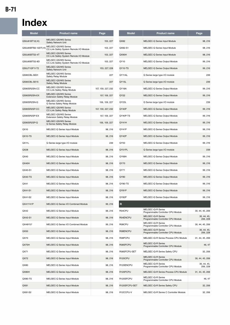
B-71
IndexModel Product name Page Model Product name Page
QS0J61BT12(-K)MELSEC-QS/WS Series Safety Network Unit
153, 227
QS0J65BTB2-12DT(-K)MELSEC-QS/WS Series CC-Link Safety System Remote I/O Module
153, 227
QS0J65BTS2-4TMELSEC-QS/WS Series CC-Link Safety System Remote I/O Module
153, 227
QS0J65BTS2-8DMELSEC-QS/WS Series CC-Link Safety System Remote I/O Module
153, 227
QS0J71GF11-T2MELSEC-QS/WS Series Safety Network Unit
153, 227, 228
QS90CBL-SE01MELSEC-QS/WS Series Safety Relay Module
227
QS90CBL-SE15MELSEC-QS/WS Series Safety Relay Module
227
QS90SR2SN-CCMELSEC-QS/WS Series CC-Link Safety Relay Module
157, 159, 227, 232
QS90SR2SN-EXMELSEC-QS/WS Series Extension Safety Relay Module
157, 159, 227
QS90SR2SN-QMELSEC-QS/WS Series Q Series Safety Relay Module
156, 159, 227
QS90SR2SP-CCMELSEC-QS/WS Series CC-Link Safety Relay Module
157, 159, 227, 232
QS90SR2SP-EXMELSEC-QS/WS Series Extension Safety Relay Module
157, 159, 227
QS90SR2SP-QMELSEC-QS/WS Series Q Series Safety Relay Module
156, 159, 227
QX10 MELSEC-Q Series Input Module 98, 216
QX10-TS MELSEC-Q Series Input Module 98, 216
QX11L Q Series large type I/O module 239
QX28 MELSEC-Q Series Input Module 98, 216
QX40 MELSEC-Q Series Input Module 98, 216
QX40H MELSEC-Q Series Input Module 98, 216
QX40-S1 MELSEC-Q Series Input Module 98, 216
QX40-TS MELSEC-Q Series Input Module 98, 216
QX41 MELSEC-Q Series Input Module 98, 216
QX41-S1 MELSEC-Q Series Input Module 98, 216
QX41-S2 MELSEC-Q Series Input Module 98, 216
QX41Y41P MELSEC-Q Series I/O Combined Module 99, 216
QX42 MELSEC-Q Series Input Module 98, 216
QX42-S1 MELSEC-Q Series Input Module 98, 216
QX48Y57 MELSEC-Q Series I/O Combined Module 99, 216
QX50 MELSEC-Q Series Input Module 98, 216
QX70 MELSEC-Q Series Input Module 98, 216
QX70H MELSEC-Q Series Input Module 98, 216
QX71 MELSEC-Q Series Input Module 98, 216
QX72 MELSEC-Q Series Input Module 98, 216
QX80 MELSEC-Q Series Input Module 98, 216
QX80H MELSEC-Q Series Input Module 98, 216
QX80-TS MELSEC-Q Series Input Module 98, 216
QX81 MELSEC-Q Series Input Module 98, 216
QX81-S2 MELSEC-Q Series Input Module 98, 216
QX82 MELSEC-Q Series Input Module 98, 216
QX82-S1 MELSEC-Q Series Input Module 98, 216
QX90H MELSEC-Q Series Input Module 98, 216
QY10 MELSEC-Q Series Output Module 99, 216
QY10-TS MELSEC-Q Series Output Module 99, 216
QY11AL Q Series large type I/O module 239
QY13L Q Series large type I/O module 239
QY18A MELSEC-Q Series Output Module 99, 216
QY22 MELSEC-Q Series Output Module 99, 216
QY23L Q Series large type I/O module 239
QY40P MELSEC-Q Series Output Module 99, 216
QY40P-TS MELSEC-Q Series Output Module 99, 216
QY41H MELSEC-Q Series Output Module 99, 216
QY41P MELSEC-Q Series Output Module 99, 216
QY42P MELSEC-Q Series Output Module 99, 216
QY50 MELSEC-Q Series Output Module 99, 216
QY51PL Q Series large type I/O module 239
QY68A MELSEC-Q Series Output Module 99, 216
QY70 MELSEC-Q Series Output Module 99, 216
QY71 MELSEC-Q Series Output Module 99, 216
QY80 MELSEC-Q Series Output Module 99, 216
QY80-TS MELSEC-Q Series Output Module 99, 216
QY81P MELSEC-Q Series Output Module 99, 216
QY82P MELSEC-Q Series Output Module 99, 216
R
R04CPUMELSEC iQ-R Series Programmable Controller CPU Module
30, 44, 45, 206
R04ENCPUMELSEC iQ-R Series Programmable Controller CPU Module
30, 44, 45, 206, 228
R08CPUMELSEC iQ-R Series Programmable Controller CPU Module
30, 44, 45, 206
R08ENCPUMELSEC iQ-R Series Programmable Controller CPU Module
30, 44, 45, 206, 228
R08PCPU MELSEC iQ-R Series Process CPU Module 31, 44, 45, 206
R08SFCPUMELSEC iQ-R Series Programmable Controller CPU Module
46, 47
R08SFCPU-SET MELSEC iQ-R Series Safety CPU 32, 206
R120CPUMELSEC iQ-R Series Programmable Controller CPU Module
30, 44, 45, 206
R120ENCPUMELSEC iQ-R Series Programmable Controller CPU Module
30, 44, 45, 206, 228
R120PCPU MELSEC iQ-R Series Process CPU Module 31, 44, 45, 206
R120SFCPUMELSEC iQ-R Series Programmable Controller CPU Module
46, 47
R120SFCPU-SET MELSEC iQ-R Series Safety CPU 32, 206
R12CCPU-V MELSEC iQ-R Series C Controller Module 32, 206
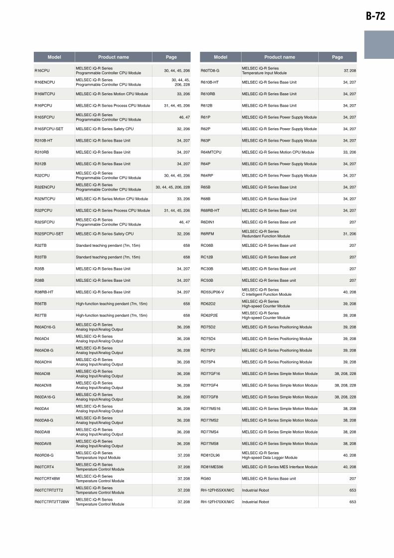
B-72
Model Product name Page Model Product name Page
R16CPUMELSEC iQ-R Series Programmable Controller CPU Module
30, 44, 45, 206
R16ENCPUMELSEC iQ-R Series Programmable Controller CPU Module
30, 44, 45, 206, 228
R16MTCPU MELSEC iQ-R Series Motion CPU Module 33, 206
R16PCPU MELSEC iQ-R Series Process CPU Module 31, 44, 45, 206
R16SFCPUMELSEC iQ-R Series Programmable Controller CPU Module
46, 47
R16SFCPU-SET MELSEC iQ-R Series Safety CPU 32, 206
R310B-HT MELSEC iQ-R Series Base Unit 34, 207
R310RB MELSEC iQ-R Series Base Unit 34, 207
R312B MELSEC iQ-R Series Base Unit 34, 207
R32CPUMELSEC iQ-R Series Programmable Controller CPU Module
30, 44, 45, 206
R32ENCPUMELSEC iQ-R Series Programmable Controller CPU Module
30, 44, 45, 206, 228
R32MTCPU MELSEC iQ-R Series Motion CPU Module 33, 206
R32PCPU MELSEC iQ-R Series Process CPU Module 31, 44, 45, 206
R32SFCPUMELSEC iQ-R Series Programmable Controller CPU Module
46, 47
R32SFCPU-SET MELSEC iQ-R Series Safety CPU 32, 206
R32TB Standard teaching pendant (7m, 15m) 658
R33TB Standard teaching pendant (7m, 15m) 658
R35B MELSEC iQ-R Series Base Unit 34, 207
R38B MELSEC iQ-R Series Base Unit 34, 207
R38RB-HT MELSEC iQ-R Series Base Unit 34, 207
R56TB High-function teaching pendant (7m, 15m) 658
R57TB High-function teaching pendant (7m, 15m) 658
R60AD16-GMELSEC iQ-R Series Analog Input/Analog Output
36, 208
R60AD4MELSEC iQ-R Series Analog Input/Analog Output
36, 208
R60AD8-GMELSEC iQ-R Series Analog Input/Analog Output
36, 208
R60ADH4MELSEC iQ-R Series Analog Input/Analog Output
36, 208
R60ADI8MELSEC iQ-R Series Analog Input/Analog Output
36, 208
R60ADV8MELSEC iQ-R Series Analog Input/Analog Output
36, 208
R60DA16-GMELSEC iQ-R Series Analog Input/Analog Output
36, 208
R60DA4MELSEC iQ-R Series Analog Input/Analog Output
36, 208
R60DA8-GMELSEC iQ-R Series Analog Input/Analog Output
36, 208
R60DAI8MELSEC iQ-R Series Analog Input/Analog Output
36, 208
R60DAV8MELSEC iQ-R Series Analog Input/Analog Output
36, 208
R60RD8-GMELSEC iQ-R Series Temperature Input Module
37, 208
R60TCRT4MELSEC iQ-R Series Temperature Control Module
37, 208
R60TCRT4BWMELSEC iQ-R Series Temperature Control Module
37, 208
R60TCTRT2TT2MELSEC iQ-R Series Temperature Control Module
37, 208
R60TCTRT2TT2BWMELSEC iQ-R Series Temperature Control Module
37, 208
R60TD8-GMELSEC iQ-R Series Temperature Input Module
37, 208
R610B-HT MELSEC iQ-R Series Base Unit 34, 207
R610RB MELSEC iQ-R Series Base Unit 34, 207
R612B MELSEC iQ-R Series Base Unit 34, 207
R61P MELSEC iQ-R Series Power Supply Module 34, 207
R62P MELSEC iQ-R Series Power Supply Module 34, 207
R63P MELSEC iQ-R Series Power Supply Module 34, 207
R64MTCPU MELSEC iQ-R Series Motion CPU Module 33, 206
R64P MELSEC iQ-R Series Power Supply Module 34, 207
R64RP MELSEC iQ-R Series Power Supply Module 34, 207
R65B MELSEC iQ-R Series Base Unit 34, 207
R68B MELSEC iQ-R Series Base Unit 34, 207
R68RB-HT MELSEC iQ-R Series Base Unit 34, 207
R6DIN1 MELSEC iQ-R Series Base unit 207
R6RFMMELSEC iQ-R Series Redundant Function Module
31, 206
RC06B MELSEC iQ-R Series Base unit 207
RC12B MELSEC iQ-R Series Base unit 207
RC30B MELSEC iQ-R Series Base unit 207
RC50B MELSEC iQ-R Series Base unit 207
RD55UP06-VMELSEC iQ-R Series C Intelligent Function Module
40, 208
RD62D2MELSEC iQ-R Series High-speed Counter Module
39, 208
RD62P2EMELSEC iQ-R Series High-speed Counter Module
39, 208
RD75D2 MELSEC iQ-R Series Positioning Module 39, 208
RD75D4 MELSEC iQ-R Series Positioning Module 39, 208
RD75P2 MELSEC iQ-R Series Positioning Module 39, 208
RD75P4 MELSEC iQ-R Series Positioning Module 39, 208
RD77GF16 MELSEC iQ-R Series Simple Motion Module 38, 208, 228
RD77GF4 MELSEC iQ-R Series Simple Motion Module 38, 208, 228
RD77GF8 MELSEC iQ-R Series Simple Motion Module 38, 208, 228
RD77MS16 MELSEC iQ-R Series Simple Motion Module 38, 208
RD77MS2 MELSEC iQ-R Series Simple Motion Module 38, 208
RD77MS4 MELSEC iQ-R Series Simple Motion Module 38, 208
RD77MS8 MELSEC iQ-R Series Simple Motion Module 38, 208
RD81DL96MELSEC iQ-R Series High-speed Data Logger Module
40, 208
RD81MES96 MELSEC iQ-R Series MES Interface Module 40, 208
RG60 MELSEC iQ-R Series Base unit 207
RH-12FH55XX/M/C Industrial Robot 653
RH-12FH70XX/M/C Industrial Robot 653

B-73
IndexModel Product name Page Model Product name Page
RH-12FH85XX/M/C Industrial Robot 653
RH-20FH100XX/M/C Industrial Robot 653
RH-20FH85XX/M/C Industrial Robot 653
RH-3FH3515/12C Industrial Robot 652
RH-3FH4515/12C Industrial Robot 652
RH-3FH5515/12C Industrial Robot 652
RH42C4NT2P MELSEC iQ-R Series I/O Combined Module 35, 207
RH-6FH35XX/M/C Industrial Robot 652
RH-6FH55XX/M/C Industrial Robot 652
RJ51AW12ALMELSEC iQ-R Series AnyWireASLINK Master Module
43, 208
RJ61BT11MELSEC iQ-R Series CC-Link System Master/Local Module
42, 208, 230
RJ71C24MELSEC iQ-R Series Serial Communication Module
43, 208
RJ71C24-R2MELSEC iQ-R Series Serial Communication Module
43, 208
RJ71C24-R4MELSEC iQ-R Series Serial Communication Module
43, 208
RJ71EN71MELSEC iQ-R Series Ethernet Interface Module
41, 42, 208, 228
RJ71GF11-T2MELSEC iQ-R Series CC-Link IE Field Network Master/Local Module
42, 208, 228
RJ71GP21-SXMELSEC iQ-R Series CC-Link IE Control Network Module
41, 208, 228
RJ72GF15-T2MELSEC iQ-R SeriesCC-Link IE Field Network Remote Head Module
42, 208, 228
RnENCPUMELSEC iQ-R Series Ethernet Interface Module
41, 42
RQ612B MELSEC iQ-R Series Base Unit 34, 207
RQ65B MELSEC iQ-R Series Base Unit 34, 207
RV-13F(M)(C) Industrial Robot 648
RV-13FL(M)(C) Industrial Robot 648
RV-20F(M)(C) Industrial Robot 648
RV-2F(B) Industrial Robot 644
RV-2FL(B) Industrial Robot 644
RV-35F(M) Industrial Robot 650
RV-4F(M)(C) Industrial Robot 644
RV-4FL(M)(C) Industrial Robot 644
RV-50F(M) Industrial Robot 650
RV-70F(M) Industrial Robot 650
RV-7F(M)(C) Industrial Robot 646
RV-7FL(M)(C) Industrial Robot 646
RV-7FLL(M)(C) Industrial Robot 646
RX10 MELSEC iQ-R Series Input Module 35, 207
RX40C7 MELSEC iQ-R Series Input Module 35, 207
RX40NC6B MELSEC iQ-R Series Input Module 35, 207
RX40NC6H MELSEC iQ-R Series Input Module 35, 207
RX41C4 MELSEC iQ-R Series Input Module 35, 207
RX41C6HS MELSEC iQ-R Series Input Module 35, 207
RX42C4 MELSEC iQ-R Series Input Module 35, 207
RX61C6HS MELSEC iQ-R Series Input Module 35, 207
RY10R2 MELSEC iQ-R Series Output Module 35, 207
RY40NT5P MELSEC iQ-R Series Output Module 35, 207
RY40PT5B MELSEC iQ-R Series Output Module 35, 207
RY40PT5P MELSEC iQ-R Series Output Module 35, 207
RY41NT2H MELSEC iQ-R Series Output Module 35, 207
RY41NT2P MELSEC iQ-R Series Output Module 35, 207
RY41PT1P MELSEC iQ-R Series Output Module 35, 207
RY41PT2H MELSEC iQ-R Series Output Module 35, 207
RY42NT2P MELSEC iQ-R Series Output Module 35, 207
RY42PT1P MELSEC iQ-R Series Output Module 35, 207
S
S(D)-2×ThhMagnetic Contactors Open type NonReversing
875
S(D)-ThhMagnetic Contactors Open type NonReversing
875
S-hMagnetic Contactors Open type NonReversing
861, 862
S-hBCMagnetic Contactors Open type NonReversing
861, 862
S-hCWMagnetic Contactors Open type NonReversing
861, 862
S-hDLMagnetic Contactors Open type NonReversing
861
S-hFNMagnetic Contactors Open type NonReversing
861, 862
S-hQMMagnetic Contactors Open type NonReversing
861
S-hSAMagnetic Contactors Open type NonReversing
861, 862
S-hSDMagnetic Contactors Open type Reversing
862
S-hSFMagnetic Contactors Open type Reversing
862
S-hSGMagnetic Contactors Open type Reversing
862
S-hSXMagnetic Contactors Open type Reversing
862
S-hYSMagnetic Contactors Open type NonReversing
861, 862
S-2×NhhhMagnetic Contactors Open type Reversing
872, 877
S-2×ThhMagnetic Contactors Open type Reversing
871, 875
SD-hMagnetic Contactors Open type NonReversing
861, 862
SD-hBCMagnetic Contactors Open type NonReversing
861, 862
SD-hSAMagnetic Contactors Open type NonReversing
861, 862
SD-hSDMagnetic Contactors Open type Reversing
862
SD-hSFMagnetic Contactors Open type Reversing
862
SD-hSGMagnetic Contactors Open type Reversing
862
SD-hSXMagnetic Contactors Open type Reversing
862

B-74
Model Product name Page Model Product name Page
SD-2×Nhhh DC Operate magnetic Contactors 878
SD-Nhhh DC Operate magnetic Contactors 878
SD-Qhh DC Interface Contactors 880
SD-QRhh DC Interface Contactors 880
SHTA400-05DLS Circuit Protector 705, 706
SHTD048-05DLS Circuit Protector 705, 706
SL-hMagnetic Contactors Open type NonReversing
861, 862
SL-2×NhhhMagnetic Contactor AC closing coil reversing
879
SLD-hMagnetic Contactors Open type NonReversing
861, 862
SLD-2×NhhhMagnetic Contactor DC closing coil reversing
879
SLD-NhhhMagnetic Contactor DC closing coil non-reversing
879
SLD-ThFNMagnetic Contactors Open type NonReversing
861
SL-NhhhMagnetic Contactor AC closing coil non-reversing
879
SL-ThhMagnetic Contactor AC closing coil non-reversing
879
SL-ThFNMagnetic Contactors Open type NonReversing
861
S-NhhhMagnetic Contactors Open type Non-Reversing
872, 877
SR-Kh Contactor Relays Specification 888
SR-Th Contactor Relays Specification 887
S-ThhMagnetic Contactors Open type Non-Reversing
871, 875
SW0D5C-CNVW-E MELSOFT iQ Works 236
SW0D5C-QCTU-E MELSOFT iQ Works 236
SW0D5C-QFLU-E MELSOFT iQ Works 236
SW0D5C-QTCU-E MELSOFT iQ Works 236
SW1D5C-FBDQ-EEngineering and Programming Software PX Developer
200, 237
SW1D5C-FBDQ-JEngineering and Programming Software PX Developer
200
SW1D5C-FXSSC-EEngineering and Programming Software FX Configurator-FP
200
SW1D5C-FXSSC-JEngineering and Programming Software FX Configurator-FP
200
SW1D5C-QASU-E MELSOFT iQ Works 236
SW1D5C-QMBU-E MELSOFT iQ Works 236
SW1D5C-QPTU-E MELSOFT iQ Works 236
SW1D5C-QTIU-E MELSOFT iQ Works 236
SW1D5-FXENETL-EEngineering and Programming Software FX3U-ENET-L setup tool
200
SW1D5-FXENETL-JEngineering and Programming Software FX3U-ENET-L setup tool
200
SW1DNC-ACTAND-BEngineering and Programming Software MX Component for Android™
200
SW1DNC-CWSIM-E CW-Sim 238
SW1DNC-CWSIM-EZ CW-Sim 238
SW1DNC-CWSIMSA-E CW-Sim 238
SW1DNC-FBDQMON-EEngineering and Programming Software PX Developer monitoring tool
200, 237
SW1DNC-FBDQMON-JEngineering and Programming Software PX Developer monitoring tool
200, 236
SW1DNC-GTWK3-E MELSOFT iQ Works 236
SW1DNC-GXW2-EEngineering and Programming Software GX Works2
200, 236
SW1DNC-GXW2-JEngineering and Programming Software GX Works2
200, 236
SW1DNC-IQWK-E MELSOFT iQ Works 263
SW1DNC-MESIF-EEngineering and Programming Software MX MESInterface
200, 237
SW1DNC-MESIF-JEngineering and Programming Software MX MESInterface
200
SW1DNC-MTW2-E MELSOFT iQ Works 236
SW1DND-CWWLQ12-E CW Workbench 238
SW1DND-CWWLQ12-EVZ CW Workbench 238
SW1DND-CWWLQ12-EZ CW Workbench 238
SW1DND-CWWLQ24-E CW Workbench 238
SW1DND-CWWLQ24-EVZ CW Workbench 238
SW1DND-CWWLQ24-EZ CW Workbench 238
SW1DND-GTWK3-hHMI/GOT Screen Design Software MELSOFT GT Works3
622, 627
SW1DND-GXW2-EMotion controller software MELSOFT GX Works2
263
SW1DND-GXW3-EEngineering and Programming Software GX Works3
200, 210, 236
SW1DND-GXW3-JEngineering and Programming Software GX Works3
200
SW1DND-IQWK-E MELSOFT iQ Works 236, 627
SW1DND-MTW2-EMotion controller software MELSOFT MT Works2
263
SW1DND-RCCPU-EEngineering and Programming Software CW Configurator
200
SW1DND-RCCPU-JEngineering and Programming Software CW Configurator
200
SW1DND-RMESIF-EEngineering and Programming Software MX MESInterface-R
200
SW1DND-RMESIF-JEngineering and Programming Software MX MESInterface-R
200
SW1DNN-DCUTL-EEngineering and Programming Software High-speed data communication unit tool
200
SW1DNN-DCUTL-JEngineering and Programming Software High-speed data communication unit tool
200
SW1DNN-DLUTL-EEngineering and Programming Software Tool for high-speed data logger unit
200
SW1DNN-DLUTL-JEngineering and Programming Software Tool for high-speed data logger unit
200
SW1DNN-LLUTL-MEngineering and Programming Software CPU unit logging setup tool
200
SW1DNN-NLUTL-EEngineering and Programming Software BOX data logger setup tool
200
SW1DNN-NLUTL-JEngineering and Programming Software BOX data logger setup tool
200
SW1DNN-RDLUTL-EEngineering and Programming Software Tool for high-speed data logger unit
200
SW1DNN-RDLUTL-JEngineering and Programming Software Tool for high-speed data logger unit
200
SW1DNN-VIEWER-MEngineering and Programming Software GX LogViewer
200
SW1DNN-WS0ADR-BEngineering and Programming Software Safety controller setup and monitoring tools
200, 227
SW1IVD-AD51HP MELSEC-Q Series Information module 220
SW1MIC-ACTIOS-BEngineering and Programming Software MX Component for iOS
200
SW2D5C-EXP-E MELSOFT iQ Works 237
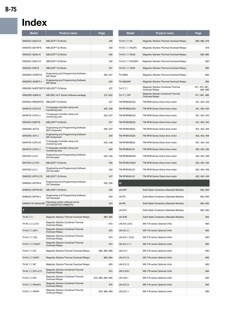
B-75
IndexModel Product name Page Model Product name Page
SW2D5C-QADU-E MELSOFT iQ Works 236
SW2D5C-QD75P-E MELSOFT iQ Works 236
SW2D5C-QDAU-E MELSOFT iQ Works 236
SW2D5C-QSCU-E MELSOFT iQ Works 236
SW2D5C-RAS-E MELSOFT iQ Works 237
SW2DNC-SHEET-EEngineering and Programming Software MX Sheet
200, 237
SW2DNC-SHEET-JEngineering and Programming Software MX Sheet
200
SW2DNC-SHEETSET-E MELSOFT iQ Works 237
SW2DND-IQWK-E MELSEC iQ-F Series Software package 210, 622
SW3D5C-FBDGPP-E MELSOFT iQ Works 237
SW3PVC-CCPU-EC-language controller setup and monitoring tools
200, 238
SW3PVC-CCPU-JC-language controller setup and monitoring tools
200, 237
SW4D5C-QSET-E MELSOFT iQ Works 237
SW4DNC-ACT-EEngineering and Programming Software MX Component
200, 237
SW4DNC-ACT-JEngineering and Programming Software MX Component
200
SW4PVC-CCPU-EC-language controller setup and monitoring tools
200, 238
SW4PVC-CCPU-JC-language controller setup and monitoring tools
200
SW7D5C-LLT-EEngineering and Programming Software GX Simulator
200, 236
SW7D5C-LLT-EV MELSOFT iQ Works 236
SW7D5C-LLT-JEngineering and Programming Software GX Simulator
200
SW8D5C-GPPLLT-E MELSOFT iQ Works 237
SW8D5C-GPPW-EEngineering and Programming Software GX Developer
200, 236
SW8D5C-GPPW-EV MELSOFT iQ Works 236
SW8D5C-GPPW-JEngineering and Programming Software GX Developer
200
SW8DNC-SV1322QJLSETOperating system software set for Q17nDSCPU/Q170MSCPU
254
T
TH-Nhhh Magnetic Starters Thermal Overload Relays 883, 885
TH-Nhhh(+CT)Magnetic Starters Combined Thermal Overload Relays
872
TH-Nhhh(KP)Magnetic Starters Combined Thermal Overload Relays
876
TH-Nhhh(TA)Magnetic Starters Combined Thermal Overload Relays
872
TH-Nhhh(TA)KPMagnetic Starters Combined Thermal Overload Relays
872
TH-NhhhHZ Magnetic Starters Thermal Overload Relays 883, 884, 885
TH-NhhhHZKP Magnetic Starters Thermal Overload Relays 883, 884
TH-NhhhKP Magnetic Starters Thermal Overload Relays 883
TH-NhhhKP(+CT)Magnetic Starters Combined Thermal Overload Relays
872
TH-NhhhRHMagnetic Starters Combined Thermal Overload Relays
872, 883, 884, 885
TH-NhhhRH(KP)Magnetic Starters Combined Thermal Overload Relays
876
TH-NhhhRHKPMagnetic Starters Combined Thermal Overload Relays
872, 883, 884
TH-NhhhTA Magnetic Starters Thermal Overload Relays 883, 885, 876
TH-NhhhTA(KP) Magnetic Starters Thermal Overload Relays 876
TH-NhhhTAHZ Magnetic Starters Thermal Overload Relays 883, 885
TH-NhhhTAHZKP Magnetic Starters Thermal Overload Relays 883
TH-NhhhTAKP Magnetic Starters Thermal Overload Relays 883
TH-N600 Magnetic Starters Thermal Overload Relays 884
TH-N600KP Magnetic Starters Thermal Overload Relays 884
TH-ThhMagnetic Starters Combined Thermal Overload Relays
871, 874, 881, 882, 885
TH-ThhKPMagnetic Starters Combined Thermal Overload Relays
871, 881, 882
TM-RFM002C20 TM-RFM Series Direct drive motor 401, 403, 405
TM-RFM004C20 TM-RFM Series Direct drive motor 401, 403, 405
TM-RFM006C20 TM-RFM Series Direct drive motor 401, 403, 405
TM-RFM006E20 TM-RFM Series Direct drive motor 401, 403, 405
TM-RFM012E20 TM-RFM Series Direct drive motor 401, 403, 405
TM-RFM012G20 TM-RFM Series Direct drive motor 402, 403, 406
TM-RFM018E20 TM-RFM Series Direct drive motor 401, 403, 405
TM-RFM040J10 TM-RFM Series Direct drive motor 402, 403, 406
TM-RFM048G20 TM-RFM Series Direct drive motor 402, 403, 406
TM-RFM072G20 TM-RFM Series Direct drive motor 402, 403, 406
TM-RFM120J10 TM-RFM Series Direct drive motor 402, 403, 406
TM-RFM240J10 TM-RFM Series Direct drive motor 402, 403, 406
U
UA-DR1 Solid State Contactors (Standard Models) 892, 893
UA-PC Solid State Contactors (Standard Models) 892, 893
UA-RE Solid State Contactors (Standard Models) 892, 893
UA-SH1 Solid State Contactors (Standard Models) 892, 893
UA-SH8 Solid State Contactors (Standard Models) 892
UN-AXh(CX) MS-T/N series Optional Units 890
UN-AXhh MS-T/N series Optional Units 890
UN-AXhh(CX) MS-T/N series Optional Units 890
UN-AXhhh MS-T/N series Optional Units 890
UN-CVh MS-T/N series Optional Units 890
UN-CVh0 MS-T/N series Optional Units 890
UN-CVh2 MS-T/N series Optional Units 890
UN-CV251 MS-T/N series Optional Units 890
UN-CWh MS-T/N series Optional Units 890
UN-CZh0 MS-T/N series Optional Units 890
UN-CZh1 MS-T/N series Optional Units 890
B-76
Model Product name Page Model Product name Page
UN-CZh2 MS-T/N series Optional Units 890
UN-CZh4 MS-T/N series Optional Units 890
UN-CZ605 MS-T/N series Optional Units 890
UN-FD Solid State Contactors (Standard Models) 892, 893
UN-FDh(CX) MS-T/N series Optional Units 891
UN-LLhh(CX) MS-T/N series Optional Units 890
UN-MLh MS-T/N series Optional Units 891
UN-RM20 MS-T/N series Optional Units 891
UN-RRh MS-T/N series Optional Units 891
UN-SAhh MS-T/N series Optional Units 891
UN-SAhhh MS-T/N series Optional Units 891
UN-SAh3 MS-T/N series Optional Units 891
UN-SA33 MS-T/N series Optional Units 891
UN-SDh MS-T/N series Optional Units 891
UN-SGh MS-T/N series Optional Units 891
UN-SYhh MS-T/N series Optional Units 890
UN-SYhh(CX) MS-T/N series Optional Units 890
UN-THh MS-T/N series Optional Units 891
UN-TLh MS-T/N series Optional Units 891
UN-YDh MS-T/N series Optional Units 891
UN-YGh MS-T/N series Optional Units 891
UN-YYh MS-T/N series Optional Units 891
US-Hhh Solid State Contactor 893
US-HhhDD Solid State Contactor 893
US-Khhh Solid State Contactors (Standard Models) 893
US-KhhhTE Solid State Contactors (Standard Models) 893
US-K70 Solid State Contactors (Standard Models) 892
US-KD8Solid State Contactor (For Direct Current Load)
893
US-KHhhh Solid State Contactors (Standard Models) 893
US-KHhhhTE Solid State Contactors (Standard Models) 893
US-KH70 Solid State Contactors (Standard Models) 892
US-Nhh Solid State Contactors (Standard Models) 892
US-NhhNS Solid State Contactors (Standard Models) 892
US-NhhNSTE Solid State Contactors (Standard Models) 892
US-NhhTE Solid State Contactors (Standard Models) 892
US-NhSS Solid State Contactors (Standard Models) 892
US-NhSSTE Solid State Contactors (Standard Models) 892
US-NHhhNS Solid State Contactors (Standard Models) 892
US-NHhhNSTE Solid State Contactors (Standard Models) 892
UT-2B4 Motor Circuit Breakers Bus bar 900
UT-2B5 Motor Circuit Breakers Bus bar 900
UT-3B4 Motor Circuit Breakers Bus bar 900
UT-3B5 Motor Circuit Breakers Bus bar 900
UT-AXh MS-T series Optional Units 889
UT-AXh(BC) MS-T/N series Optional Units 890
UT-AXhh MS-T series Optional Units 889
UT-AXhh(BC) MS-T/N series Optional Units 890
UT-BT20 Motor Circuit Breakers Mounting base unit 900
UT-BT32 Motor Circuit Breakers Mounting base unit 900
UT-BT32D Motor Circuit Breakers Mounting base unit 900
UT-CVh MS-T/N series Optional Units 890
UT-CV3Motor Circuit Breakers Line side terminal adapter kit
900
UT-CWh MS-T/N series Optional Units 890
UT-EP3Motor Circuit Breakers 3 phase feed-in terminal
900
UT-HZ18(BC) MS-T/N series Optional Units 891
UT-MAL Motor Circuit Breakers 898, 900
UT-MALLL Motor Circuit Breakers 898, 900
UT-MAX Motor Circuit Breakers 898, 900
UT-MAXLL Motor Circuit Breakers 898, 900
UT-MLhh MS-T series Optional Units 889
UT-MLhh(BC) MS-T/N series Optional Units 891
UT-MQ12Motor Circuit Breakers Connection conductor unit
900
UT-MT20Motor Circuit Breakers Connection conductor unit
900
UT-MT20DMotor Circuit Breakers Connection conductor unit
900
UT-MT32Motor Circuit Breakers Connection conductor unit
900
UT-MT32DMotor Circuit Breakers Connection conductor unit
900
UT-RRh MS-T/N series Optional Units 891
UT-RT10 Motor Circuit Breakers Jointing block unit 900
UT-RT20 Motor Circuit Breakers Jointing block unit 900
UT-RT32 Motor Circuit Breakers Jointing block unit 900
UT-SAhh MS-T series Optional Units 889, 891
UT-SAh3 MS-T/N series Optional Units 891
UT-SA33h MS-T/N series Optional Units 891
UT-SDh MS-T/N series Optional Units 891
UT-SGh MS-T/N series Optional Units 891
UT-SYhh(BC) MS-T/N series Optional Units 890

B-77
IndexModel Product name Page Model Product name Page
UT-TH50 MS-T/N series Optional Units 891
UT-TUMotor Circuit Breakers Short-circuit indicator unit
900
UT-YD20 MS-T/N series Optional Units 891
W
WS0-4RO4002 MELSEC-QS/WS Series Relay output 155
WS0-4RO4002 (WS0-4RO)
MELSEC-QS/WS Series Safety Controller 227
WS0-C20R2 MELSEC-QS/WS Series Safety Controller 227
WS0-CPU0 MELSEC-QS/WS Series CPU module 159
WS0-CPU000200MELSEC-QS/WS Series Safety Controller CPU Module
154
WS0-CPU000200 (WS0-CPU0)
MELSEC-QS/WS Series Safety Controller 227
WS0-CPU1 MELSEC-QS/WS Series CPU module 159
WS0-CPU130202MELSEC-QS/WS Series Safety Controller CPU Module
154
WS0-CPU130202 (WS0-CPU1)
MELSEC-QS/WS Series Safety Controller 227
WS0-CPU3 MELSEC-QS/WS Series CPU module 159
WS0-CPU320202MELSEC-QS/WS Series Safety Controller CPU Module
154
WS0-GCC100202 MELSEC-QS/WS Series Network Module 155, 232
WS0-GCC100202 (WS0-GCC1)
MELSEC-QS/WS Series Safety Controller 227
WS0-GETH00200 MELSEC-QS/WS Series Network Module 155
WS0-GETH00200 (WS0-GETH)
MELSEC-QS/WS Series Safety Controller 227
WS0-MPL00201 (WS0-MPL)
MELSEC-QS/WS Series Safety Controller 227
WS0-TBC4 MELSEC-QS/WS Series Safety Controller 227
WS0-TBS4 MELSEC-QS/WS Series Safety Controller 227
WS0-UC-232A MELSEC-QS/WS Series Safety Controller 227
WS0-XTDI80202 MELSEC-QS/WS Series DC input 155
WS0-XTDI80202 (WS0-XTDI)
MELSEC-QS/WS Series Safety Controller 227
WS0-XTIO84202MELSEC-QS/WS Series DC input/Transistor output
155
WS0-XTIO84202 (WS0-XTIO)
MELSEC-QS/WS Series Safety Controller 227
Z
ZThhB Interchangeable ZCT 713
ZT100BEcoMonitorLight Through-type Zero-phase Current Transformer
949
ZT1200AEcoMonitorLight Zero-phase Current Transformer with Primary Conductor
949
ZT15BEcoMonitorLight Through-type Zero-phase Current Transformer
949
ZT2000AEcoMonitorLight Zero-phase Current Transformer with Primary Conductor
949
ZT30BEcoMonitorLight Through-type Zero-phase Current Transformer
949
ZT40BEcoMonitorLight Through-type Zero-phase Current Transformer
949
ZT600AEcoMonitorLight Zero-phase Current Transformer with Primary Conductor
949
ZT60BEcoMonitorLight Through-type Zero-phase Current Transformer
949
ZT80BEcoMonitorLight Through-type Zero-phase Current Transformer
949
ZTAhhhAInterchangeable ZCTs with primary conductor
713

FA PRODUCTCATALOG
FA
PR
OD
UC
T C
AT
ALO
G
K-K06-5-C9564-C HQ 1701 Printed in Japan (IP)
Revised publication effective Jan. 2017.Superseding publication of K-K06-5-C9564-B May 2015.
Specifications are subject to change without notice.
Related Documents


