POWER LINE COMMUNICATION A dissertation submitted to Istanbul Arel University in partial fulfillment of the requirements for the Bachelor's Degree Submitted by Egemen Recep Çalışkan 2013

Welcome message from author
This document is posted to help you gain knowledge. Please leave a comment to let me know what you think about it! Share it to your friends and learn new things together.
Transcript

POWER LINE COMMUNICATION
A dissertation submitted
to Istanbul Arel University in partial
fulfillment of the requirements for the
Bachelor's Degree
Submitted by
Egemen Recep Çalışkan
2013

ii
Title in all caps
Dissertation written by
Egemen Recep Çalışkan
Approved by
___________________________________ , Chair, Dissertation Committee
___________________________________ , Members, Dissertation Committee
___________________________________
___________________________________
___________________________________
iii
TABLE OF CONTENTS
LIST OF FIGURES ........................................................................................................ V
LIST OF TABLES ......................................................................................................... VI
ACKNOWLEDGEMENTS ........................................................................................ VII
CHAPTER 1 ..................................................................................................................... 8
1.1 Introduction .............................................................................................................. 8
CHAPTER 2 ..................................................................................................................... 9
2.1 Power Lines .............................................................................................................. 9
2.2 General Modulation Techniques for Communication ............................................ 90
2.2.1 Amplitude Shift keying (ASK) .................................................................... 10
2.2.2 Frequency Shift keying (FSK) .................................................................... 11
2.2.3 Phase shift keying (PSK) .............................................................................. 11
2.3 Directions of Data Transmission ............................................................................ 92
2.4 Synchronous, Asynchronous Communication ....................................................... 93
CHAPTER 3 ................................................................................................................... 14
3.1 Fundamentals of the Power Line Communication ................................................. 14
3.2 History of PLC ....................................................................................................... 14
3.3 Application Areas ................................................................................................... 15
3.4 The standards of PLC ............................................................................................. 15

iv
CHAPTER 4 ................................................................................................................... 16
4.1 Coupling with Power Line ..................................................................................... 16
4.2 Generating FSK Signal ........................................................................................... 16
4.3 Demodulating FSK Signal ..................................................................................... 17
4.4 Hardware Designs and Calculations ...................................................................... 17
4.4.1 Transmitter ................................................................................................... 17
4.4.2 Receiver ........................................................................................................ 21
4.5 Printed Circuit Board (PCB) Designs .................................................................... 23
CHAPTER 5 ................................................................................................................... 25
5.1 Tests and Results .................................................................................................... 25
5.2 Conclusion .............................................................................................................. 26
5.3 Recommendations for Future Designs ................................................................... 26
REFERENCES ............................................................................................................... 27

v
LIST OF FIGURES
Figure 2.1 Countries Nominal Power Network Voltage and Frequency . ......................... 9
Figure 2.2 Digital Communication Techniques and Their Expressions ......................... 12
Figure 2.3 Directions of Data Transmission ................................................................... 13
Figure 2.4 Synchronous Communication ....................................................................... 13
Figure 2.5 Asynchronous Communication ..................................................................... 14
Figure 4.1 Coupling with Power Line ............................................................................. 16
Figure 4.2 Sinusoidal FSK Generator . ............................................................................ 18
Figure 4.3 TL082 Operational Amplifier ........................................................................ 19
Figure 4.4 PLC Transmitter Circuit Schematic ............................................................... 20
Figure 4.5 Frequency Response of the Third Order High Pass RC Filter ...................... 21
Figure 4.6 PLC Receiver Circuit Schematic ................................................................... 22
Figure 4.7 Frequency Response of the Band Pass LC Filter .......................................... 23
Figure 4.8 PLC Transmitter Circuit PCB Layout ............................................................ 24
Figure 4.9 PLC Receiver Circuit PCB Layout................................................................. 24
Figure 5.1 Transmitter Output @ 80khz ......................................................................... 25
Figure 5.2 Transmitter Output @ 70khz ......................................................................... 25
Figure 5.3 Receiver Input @ 80khz ................................................................................ 25
Figure 5.4 Receiver Input @ 70khz ................................................................................. 25
vi
LIST OF TABLES
Table 3.1 Frequency ranges for PLC according to CENELEC EN 50065-1…….…….15

vii
ACKNOWLEDGEMENTS
I would like to thank my supervisor, Doç. Dr. Hasan Hüseyin Balık for the patient
guidance and advice. I would also like to thank all my family and friends who supported
me for this study.
Egemen Recep Çalışkan
2013
Istanbul Arel University, Istanbul

8
CHAPTER 1
1.1 Introduction
Power line communication (also known PLC) is the voice or data communication
between two points over power lines. The system uses power lines that are already
installed in our buildings. At first PLC used for voice communication in American Army
in1918 [7]. Today, we are using PLC for narrow and broadband data communications.
At this study, PLC receiver and transmitter has been designed for controlling a
high voltage power line. A button used for input in transmitter and a led used for output
instead of a relay in receiver circuit.
9
CHAPTER 2
2.1 Power Lines
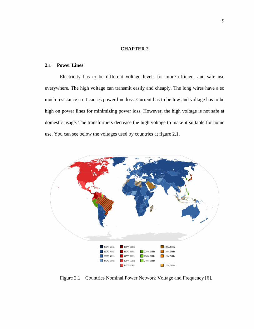
Electricity has to be different voltage levels for more efficient and safe use
everywhere. The high voltage can transmit easily and cheaply. The long wires have a so
much resistance so it causes power line loss. Current has to be low and voltage has to be
high on power lines for minimizing power loss. However, the high voltage is not safe at
domestic usage. The transformers decrease the high voltage to make it suitable for home
use. You can see below the voltages used by countries at figure 2.1.
Figure 2.1 Countries Nominal Power Network Voltage and Frequency [6].
10
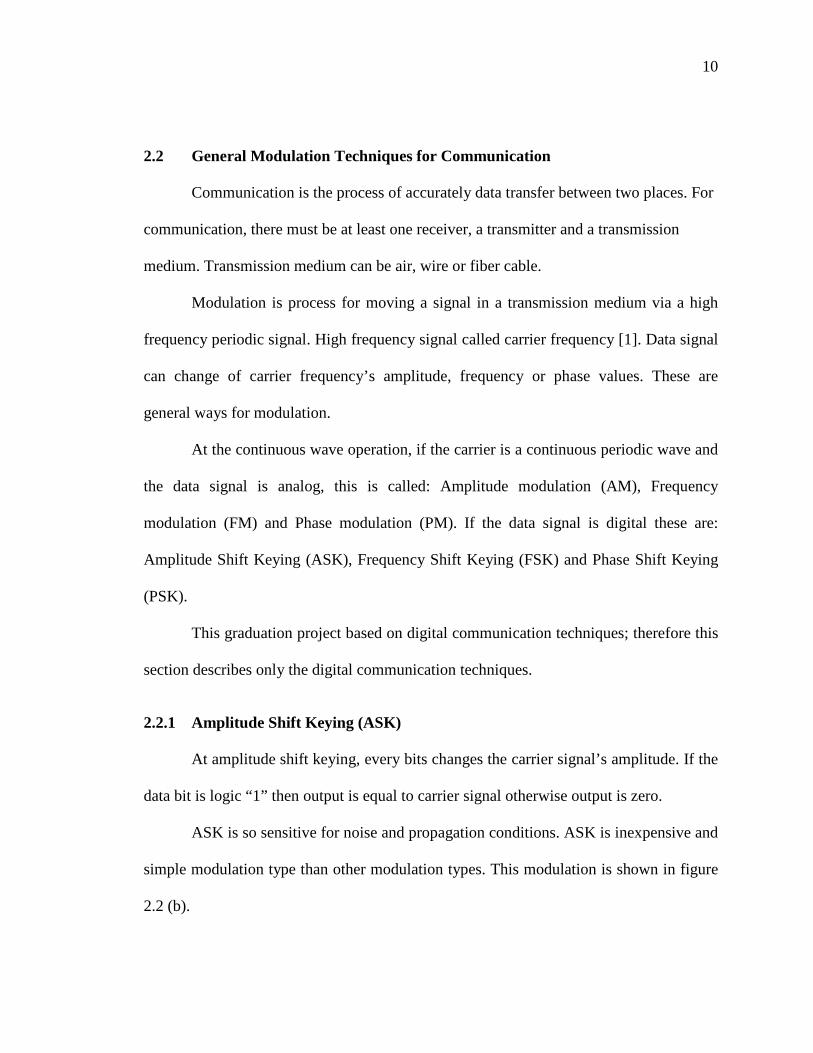
2.2 General Modulation Techniques for Communication
Communication is the process of accurately data transfer between two places. For
communication, there must be at least one receiver, a transmitter and a transmission
medium. Transmission medium can be air, wire or fiber cable.
Modulation is process for moving a signal in a transmission medium via a high
frequency periodic signal. High frequency signal called carrier frequency [1]. Data signal
can change of carrier frequency’s amplitude, frequency or phase values. These are
general ways for modulation.
At the continuous wave operation, if the carrier is a continuous periodic wave and
the data signal is analog, this is called: Amplitude modulation (AM), Frequency
modulation (FM) and Phase modulation (PM). If the data signal is digital these are:
Amplitude Shift Keying (ASK), Frequency Shift Keying (FSK) and Phase Shift Keying
(PSK).
This graduation project based on digital communication techniques; therefore this
section describes only the digital communication techniques.
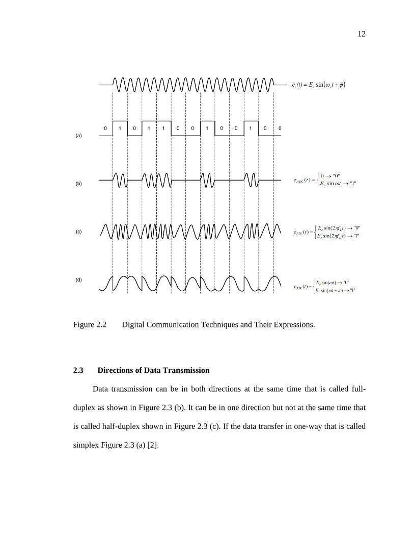
2.2.1 Amplitude Shift Keying (ASK)
At amplitude shift keying, every bits changes the carrier signal’s amplitude. If the
data bit is logic “1” then output is equal to carrier signal otherwise output is zero.
ASK is so sensitive for noise and propagation conditions. ASK is inexpensive and
simple modulation type than other modulation types. This modulation is shown in figure
2.2 (b).

11
2.2.2 Frequency Shift Keying (FSK)
At frequency shift keying, the data signal’s every bits change the carrier signal’s
frequency. For instance, if the data bit is logic “1” then output gives 80 kHz sinusoidal
wave and for logic “0” gives 70 kHz sinusoidal wave.
FSK has many application areas in our daily-life (e.g. radio, modem , fax). FSK is
very immune to noise. Because noise can change the signals amplitude but it can’t
change the signals frequency easily. This modulation is shown in figure 2.2 (c).
2.2.3 Phase Shift Keying (PSK)
At phase shift keying, the data bits change the carrier signal’s phase. Generally
PSK uses two different angles for communication. For instance, if the data signal’s bit
digital “0” output sinusoidal wave’s phase angle 0º and for digital “1” phase angle 180º.
So two different angles can transmit 1 bit and four or more angle can transmit 2 or more
bit at 1-cycle. Quadrature Phase-Shift Keying (QPSK) uses four phase and QPSK is the
most known PSK type.
Bluetooth, wireless modems, satellite TV receivers and RFID cards uses advanced
PSK types. This modulation is shown in Figure 2.2 (d).
12
Figure 2.2 Digital Communication Techniques and Their Expressions.
2.3 Directions of Data Transmission
Data transmission can be in both directions at the same time that is called full-
duplex as shown in Figure 2.3 (b). It can be in one direction but not at the same time that
is called half-duplex shown in Figure 2.3 (c). If the data transfer in one-way that is called
simplex Figure 2.3 (a) [2].

13
Figure 2.3 Directions of Data Transmission [2].
2.4 Synchronous, Asynchronous Communication
Synchronous transfer is when data is generated at a constant rate using a shared
periodic clock. The data and control signals are generated relative to the clock edge. The
transmitting device sends the clock signal to the receiving device [3].
Figure 2.4 Synchronous Communication

14
Asynchronous transfer is when data is sent using handshaking signals. There is no
shared clock. Start and stop bits synchronize communication between the two devices.
Figure 2.5 Asynchronous Communication
Chapter 3
3.1 Fundamentals of the Power Line Communication
Power line communication (also known PLC) is the voice or data communication
between two points over power lines. The system uses power lines that are already
installed in our house. There is no need to lay cable for PLC. It does not create the clutter
of cables at home automation applications. For this reason PLC is the best home
automation solution.
3.2 History of PLC
Power line communication is not a brand new invention. At first PLC used for
voice communication in American Army in 1918. Then Germany and Europe used for
control high voltage lines. PLC started with simplex but later times duplex
communication is used for PLC. Today, we are using PLC for narrow and broadband data
communications.

15
3.3 Application Areas
Even today, PLC is using for home automation systems, internet distribution,
automatic meter reading by energy providers, and low-quality voice transmission.
3.4 The standards of PLC
All devices are connected to the same line for plc. The standards were established
to avoid interference with communication. The European Committee for Electrotechnical
Standardization in Brussels (CENELEC) published the standard EN 50065-1. That is
determine bands and power limits between 3Khz -148Khz @116 dB (µV). These
standards also apply to Europe and Germany. There are basically four different bands for
PLC.
• A-band (3 kHz - 95 kHz)
• B-band (95 kHz - 125 kHz)
• C-band (125 kHz - 140 kHz)
• D-band (140 kHz - 148.5 kHz)
We can see frequency ranges and maximum transmission levels for power line
communication according to CENELEC 50065-1 standard.
Table 3.1 Frequency ranges for PLC communication according to EN 50065-1 [5]
Band Frequency Range Maximum Transmission Level Usage AreasA 3khz - 95khz 134db (μV) Available for electric distribution companies use only B 95khz - 125khz 116db (μV) - 134db (μV) Available for consumers with no restrictionC 125khz - 140khz 116db (μV) - 134db (μV) Available for consumes only with media access protocolD 140khz - 148.5khz 116db (μV) - 134db (μV) Available for consumers with no restriction
16
Chapter 4
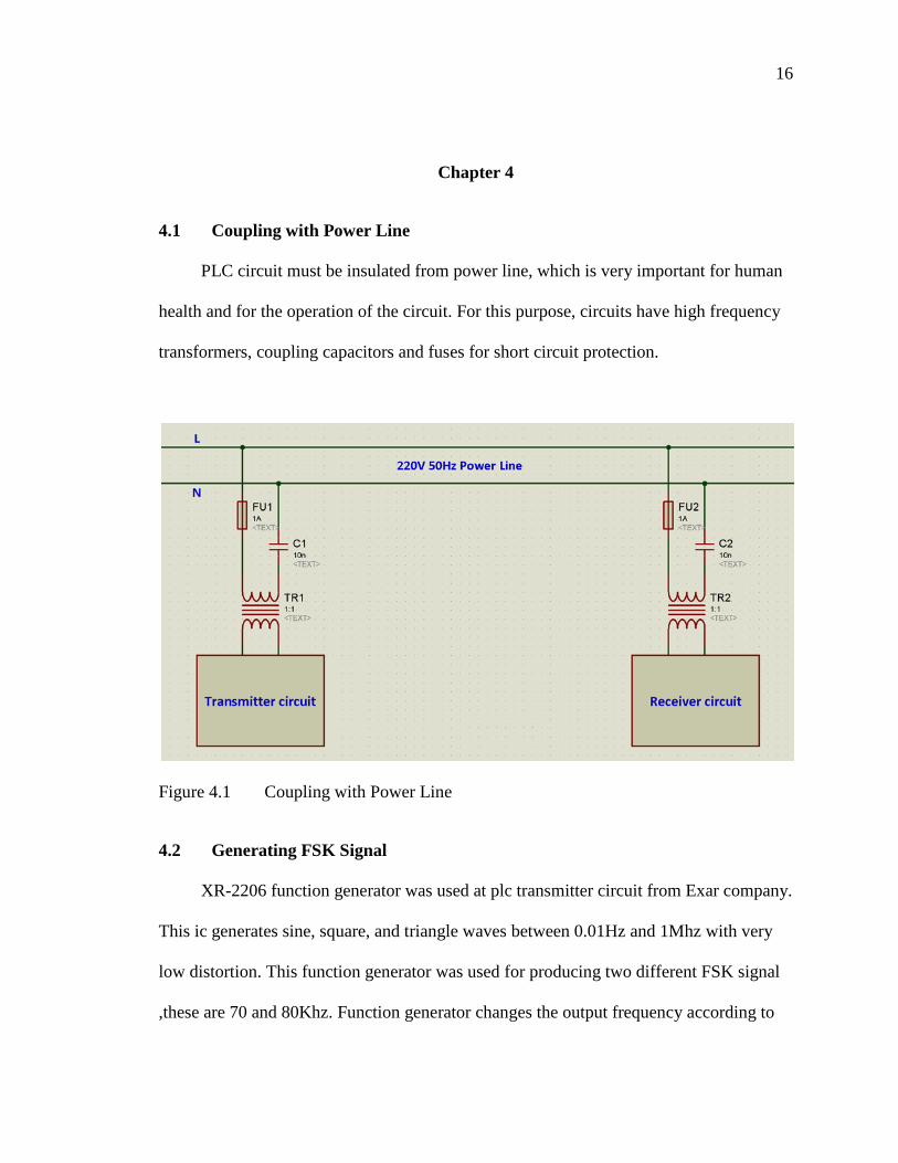
4.1 Coupling with Power Line
PLC circuit must be insulated from power line, which is very important for human
health and for the operation of the circuit. For this purpose, circuits have high frequency
transformers, coupling capacitors and fuses for short circuit protection.
Figure 4.1 Coupling with Power Line
4.2 Generating FSK Signal
XR-2206 function generator was used at plc transmitter circuit from Exar company.
This ic generates sine, square, and triangle waves between 0.01Hz and 1Mhz with very
low distortion. This function generator was used for producing two different FSK signal
,these are 70 and 80Khz. Function generator changes the output frequency according to
17
input’s state 1 or 0. The function generator output gives very limited power so this
output not enough for driving a transformer. For this reason it uses a opamp for driving
transformer.
4.3 Demodulating FSK Signal
The power lines have noise at every frequencies. All electrical devices are produces
noises on power lines. Also long and un-insulated cables acting as TV, radio or a GSM
antenna. We have to filter all these unwanted noises to obtain our carrier signal. In the
receiver circuit was used three order high pass RC filter and a LC filter for that. And we
apply the filtered input signal to PLL to obtain demodulated data output.
4.4 Hardware Designs and Calculations
In this project, we are going to design power line communication transmitter and
receiver for an electric company to control remotely high voltage lines away. We’re
going to use a simple button for input, and a led instead of a relay that controls the high-
voltage line. We choose the working frequency range between 70khz and 80khz. When
the button pressed led going to light up. When the button is not pressed led will be off
state. Our project is an experimental so high-speed data transfer is not the case. But it
may be performed with lower communication speeds 100 or 300 baudrate.
4.4.1 Transmitter
The XR-2206 is our FSK modulator. It modulates the data signal to carrier signal.
FSK modulation has two different frequencies.

18
These frequencies are adjust by timing capacitor between 5-6 pins and timing
resistors 7-8 pins to ground. You can see typical FSK modulator circuit for XR-2206
below.
Figure 4.2 Sinusoidal FSK Generator [8]
You can see FSK input voltage levels for Frequency 1 and Frequency 2 in figure
4.2. For this project FSK frequencies were selected 70 khz and 80khz. Frequencies can be
calculated with
19
We cannot find the exact that resistor values. Resistors are producing at certain
fixed values. We can adjust these exact resistor values with a 2.2kΩ resistor and a serial
connected 5kΩ potentiometer.
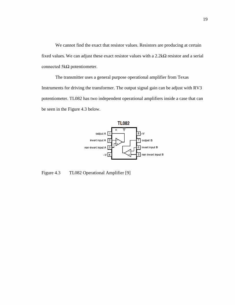
The transmitter uses a general purpose operational amplifier from Texas
Instruments for driving the transformer. The output signal gain can be adjust with RV3
potentiometer. TL082 has two independent operational amplifiers inside a case that can
be seen in the Figure 4.3 below.
Figure 4.3 TL082 Operational Amplifier [9]
20
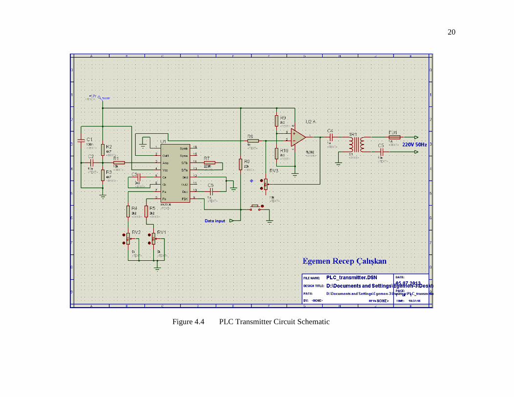
Figure 4.4 PLC Transmitter Circuit Schematic
21
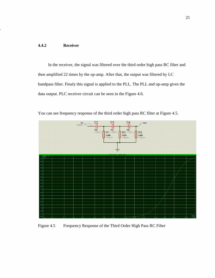
4.4.2 Receiver
In the receiver, the signal was filtered over the third order high pass RC filter and
then amplified 22 times by the op-amp. After that, the output was filtered by LC
bandpass filter. Finaly this signal is applied to the PLL. The PLL and op-amp gives the
data output. PLC receiver circuit can be seen in the Figure 4.6.
You can see frequency response of the third order high pass RC filter at Figure 4.5.
Figure 4.5 Frequency Response of the Third Order High Pass RC Filter

22
Figure 4.6 PLC Receiver Circuit Schematic

23
And you can see frequency response of band pass filter at Figure 4.7
Figure 4.7 Frequency Response of the Band Pass LC Filter
We can find center frequency of the LC band pass filter with

24
Figure 4.8 PLC Transmitter Circuit PCB Layout
Figure 4.9 PLC Receiver Circuit PCB Layout

25
Chapter 5
5.1 Tests and Results
Many times measurements were made during circuit design with oscilloscope.
The transmitter output signal 80 kHz in figure 5.1 and 70 kHz can be seen in figure 5.2.
Figure 5.1 Transmitter Output @ 80khz Figure 5.2 Transmitter Output @ 70khz
You can see the receiver’s filtered transformer outputs when the circuits connected the
noisy power line in figure 5.3 and 5.4.
Figure 5.3 Receiver Input @ 80khz Figure 5.4 Receiver Input @ 70khz

26
5.2 Conclusions
Power Line Communication can be used for home automation systems with slow
baud rates. There is limited usage area. PLC is very sensitive to noise and high-quality
communication is not possible all the time. The filters weaken carrier signal too much on
the same power line, that situation makes communication very difficult. Electric motors,
switches make too much noise on power line. Another factor that makes it hard to
communicate in long lines.
5.3 Recommendations for Future Designs
PLC can be used to slow data transfer where there is a very critical
communications with a very narrow-band filter. Power saving lamps and line filters
decrease the communication speed. Automatic gain control should be added to the
receiver input to work properly with the short and long distance. If the received signal is
processed by a DSP with FFT algorithms, we will get better results. Speed can be
increased by using multiple narrow bands. Nowadays, Wi-fi, GPRS modems and RF
transceivers may be preferred instead of PLC after evaluating the conditions.

27
REFERENCES
[1] Communication Systems Engineering (2nd Edition), John G. Proakis ,Masoud Salehi
,2002,ISBN 0-13-061793-8
[2] http://www.dcs.bbk.ac.uk/~ptw/teaching/IWT/data-comms/slide18.html
[3] http://www.ni.com/white-paper/6552/en
[4] http://www.domologic.de/download/pdf/konnex_pl132_en.pdf
[5] EN50065-1, “Signaling on low-voltage electrical installations in the frequency range
3 kHz to 148.5kHz”, CENELEC; Genevre, July 1993
[6] http://en.wikipedia.org/wiki/File:Weltkarte_der_Netzspannungen_und_Netzfreq
uenzen.svg
[7] http://www.ieeeghn.org/wiki/index.php/Telephony_over_Power_Lines_(Early_
History)
[8] http://www.jaycar.com.au/images_uploaded/XR2206V1.PDF
[9] http://www.ti.com/lit/ds/symlink/tl082-n.pdf
[10] http://www.ti.com/lit/ds/snosbu1b/snosbu1b.pdf (LM565 PLL datasheet)
Related Documents


