PRESENTED BY:- MD IFTEKHAR ALAM REGD. NO. - 1101224145 MITS, RAYAGADA GUIDED BY :- Asst.Prof. T.CHAUDHARY MITS, RAYAGADA

power generation by speed breaker
Jul 16, 2015
Welcome message from author
This document is posted to help you gain knowledge. Please leave a comment to let me know what you think about it! Share it to your friends and learn new things together.
Transcript

PRESENTED BY:-
MD IFTEKHAR ALAM
REGD. NO. - 1101224145
MITS, RAYAGADA
GUIDED BY :-
Asst.Prof. T.CHAUDHARY
MITS, RAYAGADA

CONTENTS
INTRODUCTION
BASIC PRINCIPLE
BLOCK DIAGRAM
RACK AND PINION MECHANISM
CONSTRUCTION OF SPEED BREAKER
VOLTAGE GENERATED VS SPEED OF VEHICLE
VOLTAGE GENERATED VS LOAD OF VEHICLE
ADVANTAGES & DISADVANTAGES
FUTURE SCOPE AND CONCLUSION
INTRODUCTION
In the present scenario power has becomes major need for humanlife. Due to day-to-day increase in population and lack of theconventional sources, it becomes necessary that we must dependon non-conventional sources for power generation. While moving,the vehicles posses some kinetic energy and it is being wasted. Thiskinetic energy can be utilized to produce power by using a specialarrangement called “POWER HUMP”.
Contd….
The Kinetic energy of moving vehicles can be converted into mechanical
energy through rack and pinion mechanism.
The rotating shaft is connected to the electric dynamo and it produces
electrical energy proportional to traffic density. This generated power can
be regulated by using zener diode for continuous supply.
All this mechanism can be housed under the dome like speed breaker,
which is called hump.
The generated power can be used for general purpose like street lights,
traffic signals. The electrical output can be improved by arranging these
power humps in series, this generated power can be amplified and stored
by using different electric devices. The maintenance cost of hump is
almost nullified. By adopting this arrangement, we can satisfy the future
demands to some extent.
BASIC PRINCIPLE
The kinetic energy of moving vehicle can be utilized to produce power by using
a special arrangement called POWER HUMP.
It is an Electro-Mechanical unit. It utilizes both mechanical technologies and
electrical techniques for the power generation and its storage.
POWER HUMP is a dome like device likely to be speed breaker.
Whenever the vehicle is allowed to pass over the dome it gets pressed
downwards then the springs attached to the dome is compressed and the rack
which is attached to the bottom of the dome moves downward in reciprocating
motion. Since the rack has teeth connected to gears, there exists conversion of
reciprocating motion of rack into rotary motion of gears.

A flywheel is mounted on the shaft whose function is to regulate the fluctuation
in the energy and to make the energy uniform so that the shafts will rotate with
certain R.P.M. these shafts are connected through a gear drive to the dynamos,
which converts the mechanical energy into electrical energy. The conversion will
be proportional to traffic density.
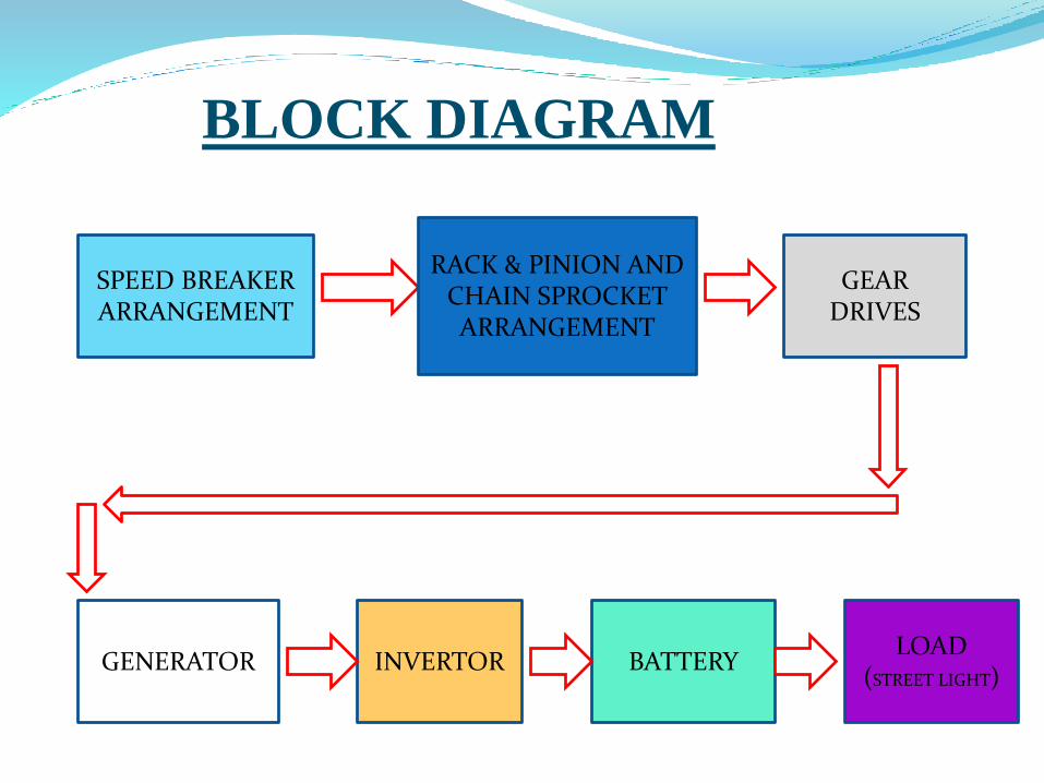
SPEED BREAKERARRANGEMENT
RACK & PINION ANDCHAIN SPROCKET ARRANGEMENT
GEARDRIVES
GENERATOR INVERTOR BATTERYLOAD
(STREET LIGHT)
BLOCK DIAGRAM
RACK AND PINION MECHANISM
This machine member converts reciprocating motion into rotary motion. The
rotational power is stored in flywheel & flywheel rotates dynamo, which
generates electricity.
When vehicle moves on the speed breaker, the rack will be pushed down. The
rack is attached with free wheel type pinion which rotates in one direction only.
The rack & pinion arrangement convert reciprocating motion into rotary motion.
This rotary motion is further magnified by using chain & sprocket drive. The
output of pulley is attached with flywheel which stores kinetic energy and
transfer to dynamo which generate electricity with zero cost.

SCHEMATIC DIAGRAM OF RACK & PINION ARRENGEMENT
CONSTRUCTION OF SPEED BREAKER
Here we are constructing the speed breaker of vibrating type.
When a vehicle crosses the speed breaker, it gets pressed and
then it gets back to its original position.
Dimensions of speed breaker:-
Height : 0.2m
Width : 0.4m
Length : 4m
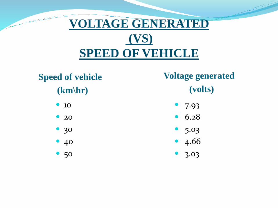
VOLTAGE GENERATED
(VS)
SPEED OF VEHICLE
Speed of vehicle
(km\hr)
Voltage generated
(volts)
10
20
30
40
50
7.93
6.28
5.03
4.66
3.03
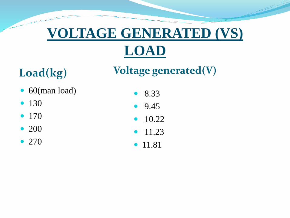
VOLTAGE GENERATED (VS)
LOAD
Load(kg) Voltage generated(V)
60(man load)
130
170
200
270
8.33
9.45
10.22
11.23
11.81

ADVANTAGES DISADVANTAGES
Low Budget electricity
production
No obstruction to traffic
Suitable for parking at
multiplexes, malls, toll
booths, signals, etc
Suitable for all season
We have to check
mechanism from time to
time
It can get rusted in rainy
season
May not work with light
weight vehicles
Not work properly in
rainy season
FUTURES COPE AND CONCLUSION
FUTURE SCOPE :-
Suitable for parking at multiplexes, malls, toll booths, signals, etc.
Uses: Charging batteries and using them to light up the streets, etc.
Such speed breakers can be designed for heavy vehicles, thus increasing input
torque and ultimately output of generator.
More suitable and compact mechanisms to enhance efficiency.

CONCLUSION :-
It can be implemented at metropolitan cities.
So that more electric power is produced.
Arrangement of whole setup is easier.
The stored electricity could satisfy the daily requirement of electric power


THANK YOU
Related Documents