POWER FACTOR CORRECTION OF MACHINE LABORATORY AND CNC MACHINE BY USING IPFC CONTROLLER Submitted by:- DEEPAK KUMAR BAGHAR 110301EER101 PRAVAT KUMAR PATRA 110301EER076 DEVIPRASAD SINGHDEO 110301EER014 SARTHAK PATI 110301EER036 ASHIS PANDA 110301EER044 ANUP MANGARAJ 110301EER109 GUIDED BY Shri Surya Narayan Sahu

Welcome message from author
This document is posted to help you gain knowledge. Please leave a comment to let me know what you think about it! Share it to your friends and learn new things together.
Transcript
POWER FACTOR CORRECTION OF
MACHINE LABORATORY AND CNC
MACHINE BY USING IPFC CONTROLLER
Submitted by:-
DEEPAK KUMAR BAGHAR 110301EER101
PRAVAT KUMAR PATRA 110301EER076
DEVIPRASAD SINGHDEO 110301EER014
SARTHAK PATI 110301EER036
ASHIS PANDA 110301EER044
ANUP MANGARAJ 110301EER109
GUIDED BY
Shri Surya Narayan Sahu
INTRODUCTION
Power factor is the ratio of true power or watts toapparent power or volt amps. They are identical onlywhen current and voltage are in phase then the powerfactor is1.0.
The cosine of angle between voltage and current in accircuit is known as power factor. In ac circuit there isgenerally a phase difference φ between voltage andcurrent. The term cosφ is called the power factor ofcircuit
VI cosφ represent the active power in Watt or KW
VIsin φ represent the reactive power in VAR or KVAR
VI represents apparent power in VA or KVA
Power factor cosφ= (active power / apparent power)=(KW/KVA)
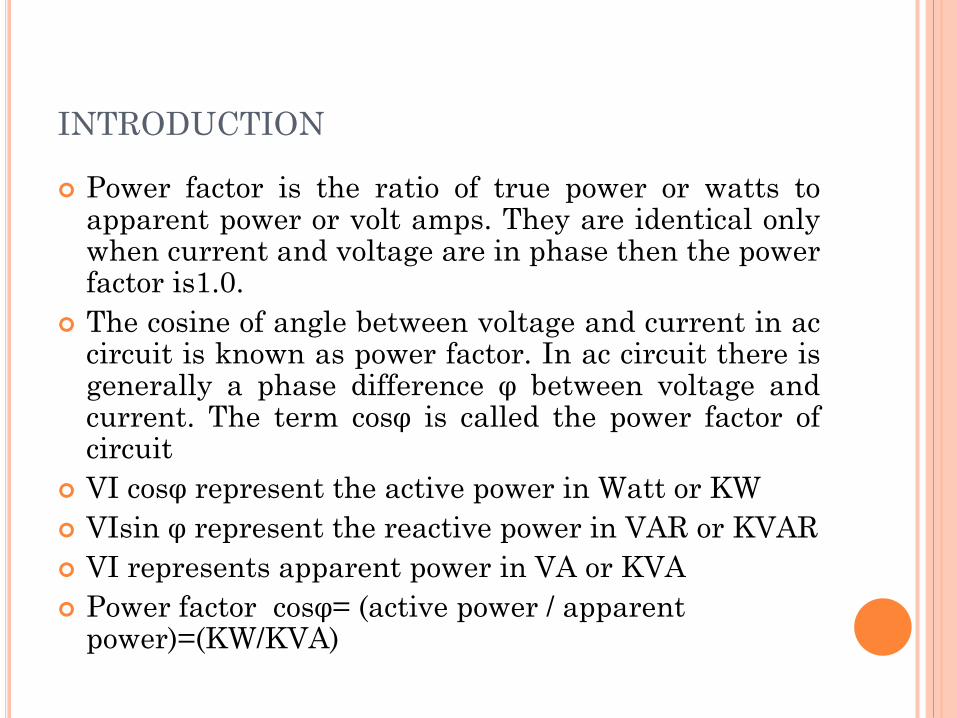
The lagging reactive power is responsible for the
low power factor. It is clear from the power
triangle that smaller the reactive power
component higher is the power factor of the
circuit.
KVAR=KVA sniφ=(KW/ cosφ)* sinφ
KVAR=KW tanφ
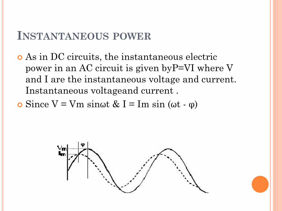
INSTANTANEOUS POWER
As in DC circuits, the instantaneous electric
power in an AC circuit is given byP=VI where V
and I are the instantaneous voltage and current.
Instantaneous voltageand current .
Since V = Vm sinωt & I = Im sin (ωt - φ)
Then the instantaneous power at any time t can
be expressed as
Pinstanteneous = Vm Im sinωt sin (ωt-φ)
After using trigonometric identity:sin (t-φ) =
sinωt cosφ- cosωt sinφ
The power becomes: instantaneous = Vm Im sin
2ωt cosφ - Vm Im sinωt sinφ cos ωt
NEEDS OF POWER FACTOR CONTROLLER
Power factor correction (PFC) is a technique of
counteracting the undesirable effects of electric
loads that create a power factor that is less than
one.
Power factor correction may be applied either by
an electrical power transmission utility to
improve the stability and efficiency of the
transmission network or correction may be
installed by individual electrical customers to
reduce the costs charged to them by their
electricity supplier.

TYPES OF POWER FACTOR CONTROLLER
Passive PFC
This is a simple way of correcting the
nonlinearity of a load by using capacitor banks.
Active PFC
An active power factor corrector (active
PFC) is a power electronic system that controls
the amount of power drawn by a load in order to
obtain a Power factor as close as possible to
unity.
CAPACITIVE POWER FACTOR CORRECTION
(CPFC)
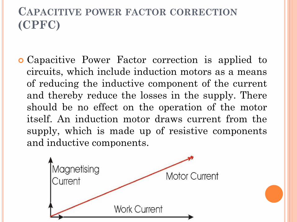
Capacitive Power Factor correction is applied to
circuits, which include induction motors as a means
of reducing the inductive component of the current
and thereby reduce the losses in the supply. There
should be no effect on the operation of the motor
itself. An induction motor draws current from the
supply, which is made up of resistive components
and inductive components.

DIFFERENT TYPES OF CAPACITIVE
POWER FACTOR CORRECTION
Bulk correction
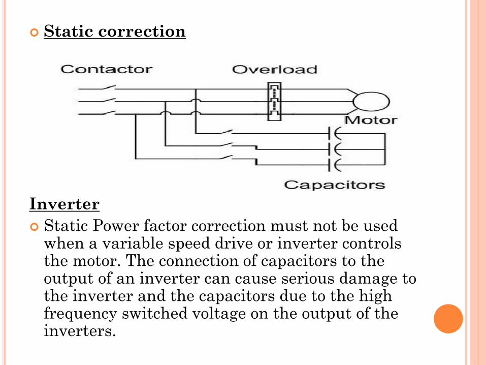
Static correction
Inverter
Solid-state soft starter
Bulk correction
Static correction
Inverter
Static Power factor correction must not be used when a variable speed drive or inverter controls the motor. The connection of capacitors to the output of an inverter can cause serious damage to the inverter and the capacitors due to the high frequency switched voltage on the output of the inverters.
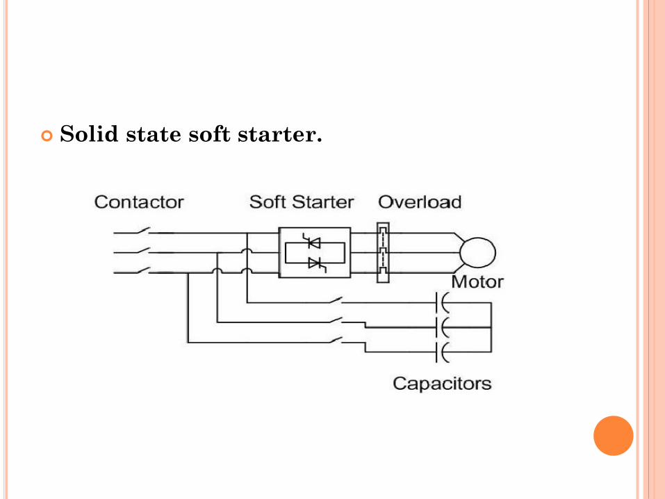
Solid state soft starter.
HARDWARE AND ITS CONFIGURATION
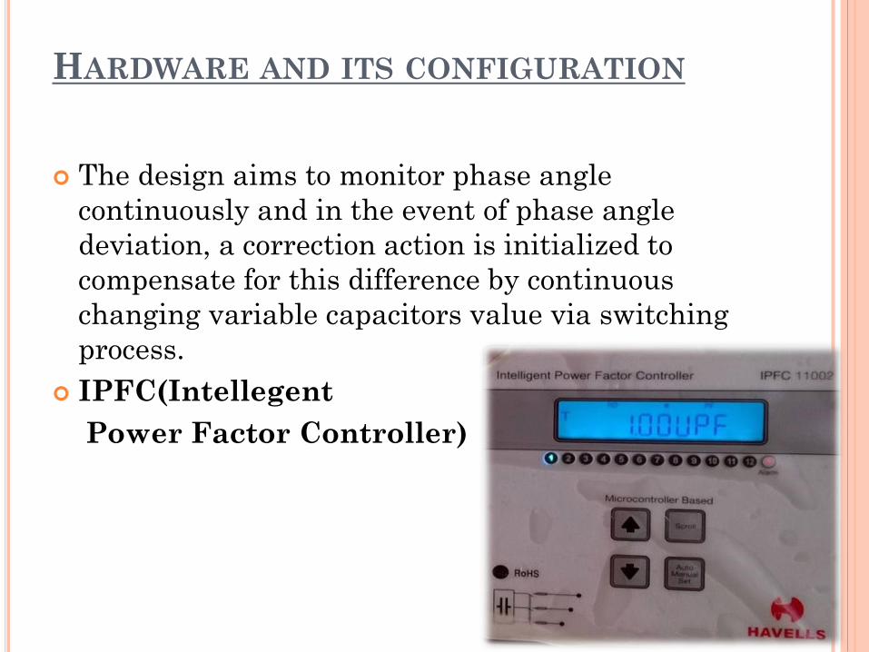
The design aims to monitor phase angle
continuously and in the event of phase angle
deviation, a correction action is initialized to
compensate for this difference by continuous
changing variable capacitors value via switching
process.
IPFC(Intellegent
Power Factor Controller)
BENEFITS
Three Phase Sensing - Accurate measurement of
PF
Fault Detection (Over Compensation, Under
Compensation, Over Voltage, Over Current,
Under Voltage, over harmonics voltage and
current)
Automatic or Manual Control (manual control
with power backup option)
Intelligent operation
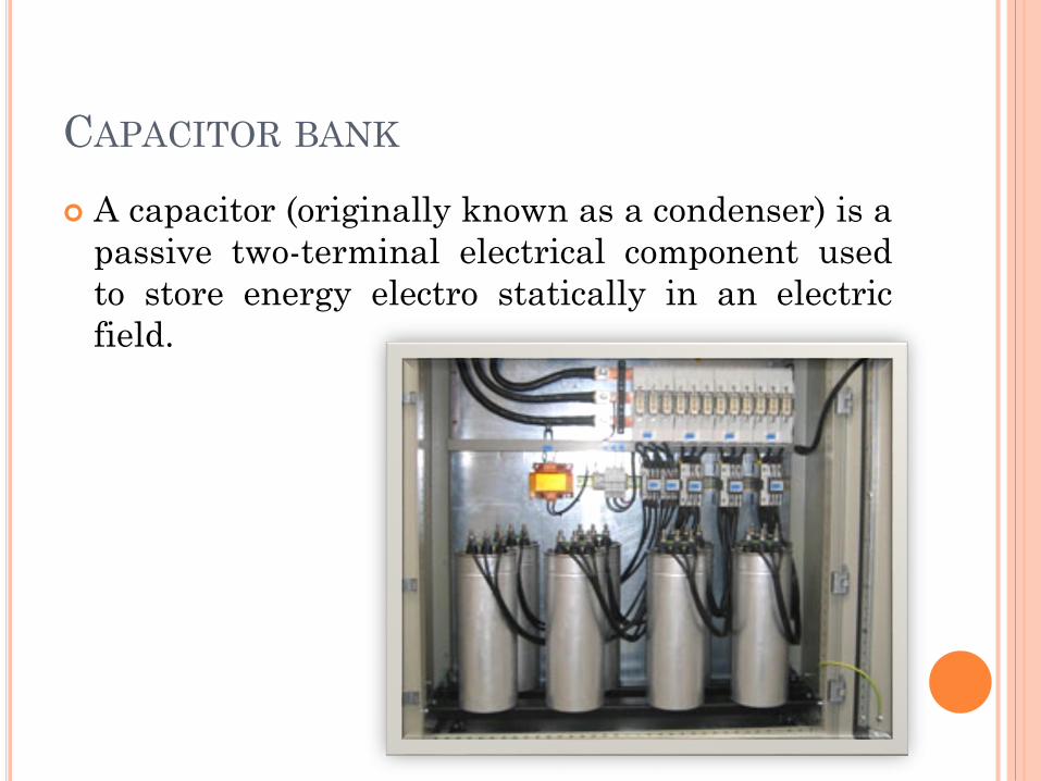
CAPACITOR BANK
A capacitor (originally known as a condenser) is a
passive two-terminal electrical component used
to store energy electro statically in an electric
field.

CONTROLE SCHEME
Circuit Diagram
Over voltage
For all these above there is a threshold set through
RS-232communication.When ever it crosses above
that threshold particular alarm status will display on
LCD.
Under voltage
For all these above there is a threshold set
through RS-232communication.When ever it
crosses above that threshold particular alarm
status will display on LCD.
Over Compensation
When all capacitor bank steps (max) gets
OFF and IPFC still don’t achieve required Target
PF this alarm will display.
Under Compensation
When all capacitor bank steps(max) gets ON
and IPFC still don’t achieve required Target
Power factor this alarm will display.
Under Current
Condition until current is restored above
50mA and all capacitor steps get disconnected.
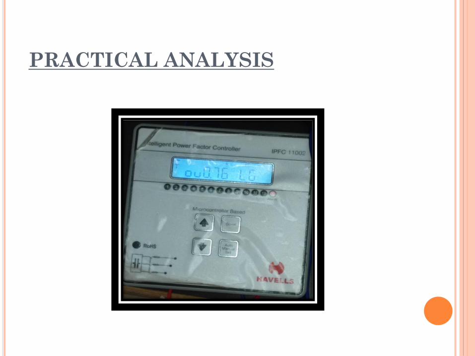
PRACTICAL ANALYSIS
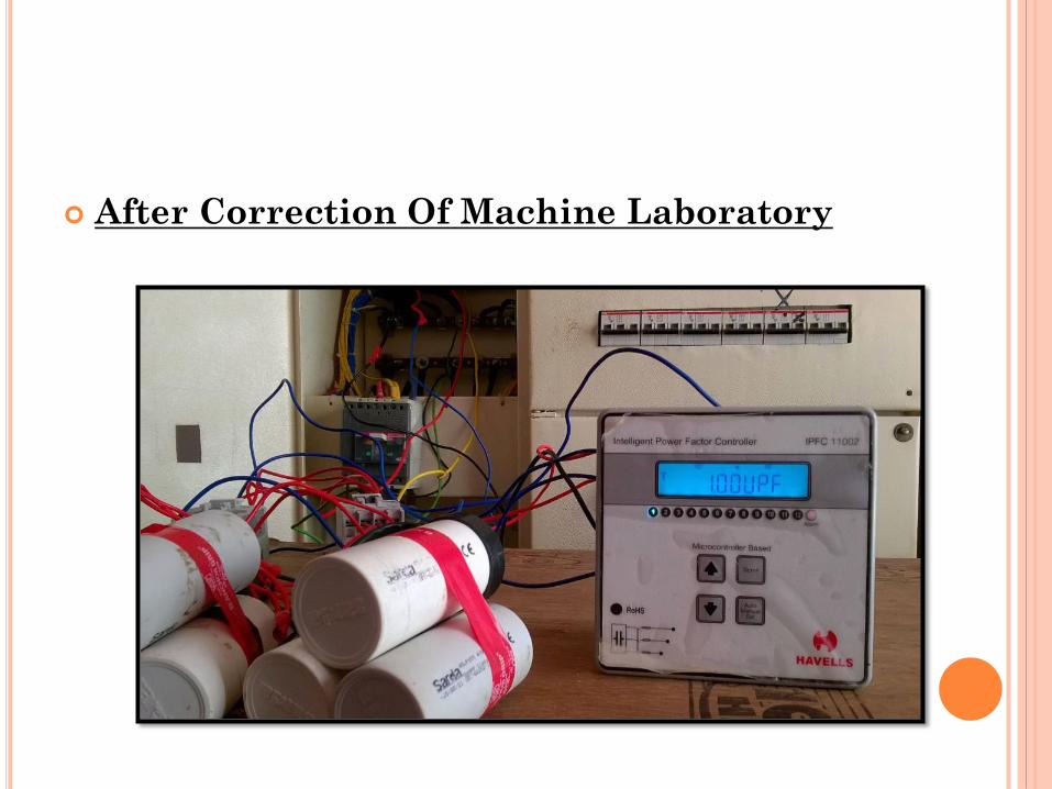
After Correction Of Machine Laboratory
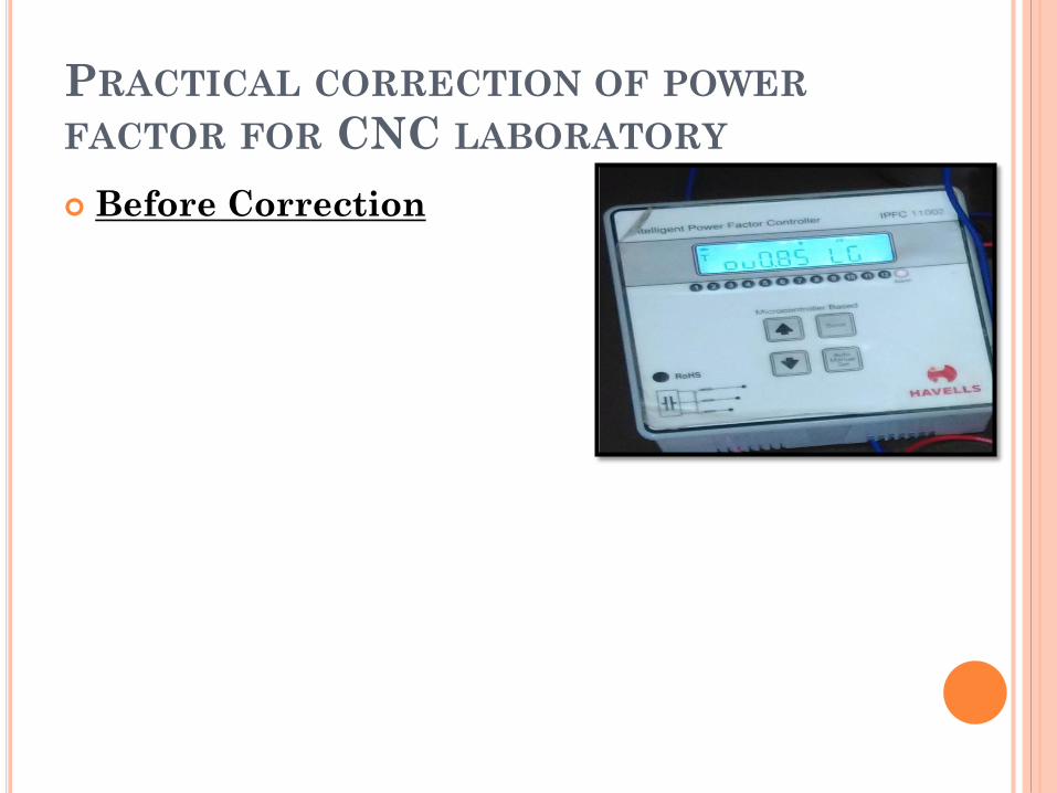
PRACTICAL CORRECTION OF POWER
FACTOR FOR CNC LABORATORY
Before Correction
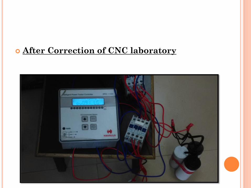
After Correction of CNC laboratory

Related Documents