POWER ENGINEERING CATALOGUE

Welcome message from author
This document is posted to help you gain knowledge. Please leave a comment to let me know what you think about it! Share it to your friends and learn new things together.
Transcript
POWER ENGINEERINGCATALOGUE

Safe and efficient delivery of
electricity needs networks to be
built with products that provide
protection, performance and
reliability over the long run.
That’s why we partner with leading
manufacturers of quality products
and work with you to deliver safe
and lasting solutions for your
network.
At Hamer Power Engineering we
deliver certainty, reliability and
long-term value based on the
products that we supply and on the
technical support that we provide.
Solutions and Value Engineering
Supply Partners
Pillars, Cabinets and Frames
LV Network Monitoring
Underground Network and Service Boxes
Disconnects and Fuses
Cable Joints and Terminations
Network Fittings and Accessories
MV and HV Switchgear and Cable Link Boxes
Tools, Measurement and Test Equipment
End-To-End Service and Technical Support
Contents2
3
5
15
25
35
51
91
111
131
140
2
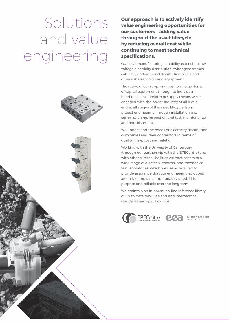
Our approach is to actively identify value engineering opportunities for our customers – adding value throughout the asset lifecycle by reducing overall cost while continuing to meet technical specifications.Our local manufacturing capability extends to low
voltage electricity distribution switchgear frames,
cabinets, underground distribution pillars and
other subassemblies and equipment.
The scope of our supply ranges from large items
of capital equipment through to individual
hand tools. This breadth of supply means we’re
engaged with the power industry at all levels
and at all stages of the asset lifecycle: from
project engineering, through installation and
commissioning, inspection and test, maintenance
and refurbishment.
We understand the needs of electricity distribution
companies and their contractors in terms of
quality, time, cost and safety.
Working with the University of Canterbury
(through our partnership with the EPECentre) and
with other external facilities we have access to a
wide range of electrical, thermal and mechanical
test laboratories, which we use as required to
provide assurance that our engineering solutions
are fully compliant, appropriately rated, fit for
purpose and reliable over the long term.
We maintain an in-house, on-line reference library
of up-to-date New Zealand and international
standards and specifications.
Solutions and value
engineering

3HAMER POWER ENGINEERING CATALOGUE
Bowthorpe Line Taps are the industry standard split bolt system for connecting conductors. With
more than 70 plus years of service and greater than 16 million connections, Bowthorpe Line Taps
have proven their design, have an indefinite life and are simple to install.
EFEN makes energy distribution systems safe, whether you are active in the field of infrastructure
or in the power supply sector, EFEN offers optimised safety systems and components for power
distribution – tailored to the respective field of application.
GridKey is a Low Voltage multi-feeder monitoring system that remotely monitors substation
feeders. Increased insight of the low voltage network data via real time warnings, status alerts and
loading information helps improve network planning, reduce network maintenance costs and
prevent unplanned outages.
Insulect manufacturers a range of tough, modular, reliable network switchgear for overhead,
substation and underground applications. Designed and engineered in Australia and requiring
minimal maintenance for long-lasting performance, Insulect has been helping electricity
transmission and distribution customers strengthen their networks for over twenty years
Langmatz develops and manufactures innovative, high quality cabinets and underground systems
for the power supply, telecommunications and traffic engineering sectors. Langmatz cabinets and
modular, structural pits employ extremely durable and environmentally benign polycarbonate.
NKT is a global supplier to the energy sector and is the joined forces of Kabeldon and nkt cables
under the new common brand NKT. NKT develops and manufactures high quality cables,
accessories and solutions for electricity transmission and distribution, construction and railway
applications. NKT's manufacturing plants are among the most modern, flexible and cost-effective
in the world.
Pfisterer can be found wherever electrical current flows for the supply of energy. Pfisterer
manufactures high-quality products, which find reliable, long-term and virtually maintenance-free
service in the sensitive interfaces of energy supply networks.
We are proud to partner with specialist international component and equipment suppliers, as well as trusted New Zealand contract manufacturing partners, to deliver solutions, peace of mind and long term reliability for electricity distribution companies.
Supply partners
4
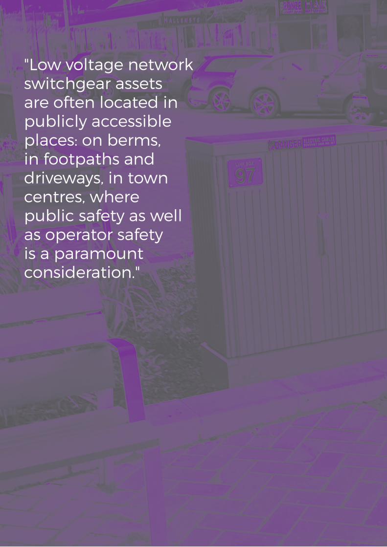
"Low voltage network switchgear assets are often located in publicly accessible places: on berms, in footpaths and driveways, in town centres, where public safety as well as operator safety is a paramount consideration."

5
Pillars, Cabinets, Frames and LV Data MonitoringDistribution Pillars and Link Pillars
Langmatz Polycarbonate Equipment Cabinets
Low Voltage Distribution/Transformer Frames
6
8
10
6
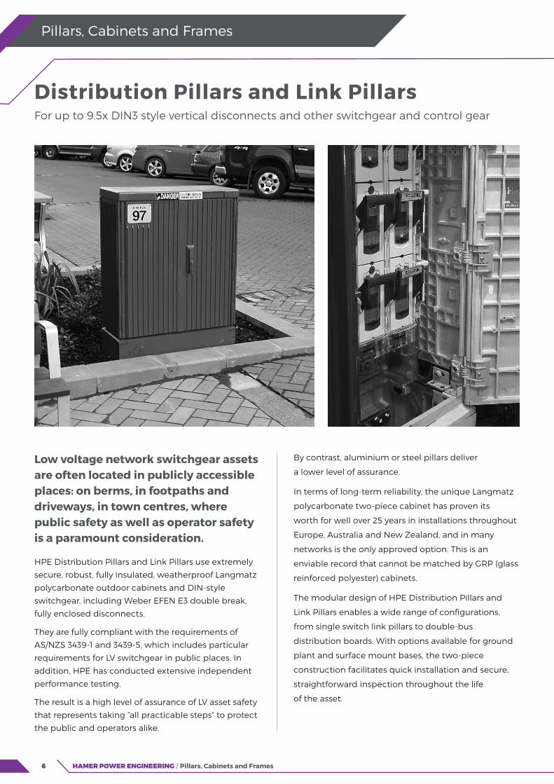
Low voltage network switchgear assets are often located in publicly accessible places: on berms, in footpaths and driveways, in town centres, where public safety as well as operator safety is a paramount consideration.
HPE Distribution Pillars and Link Pillars use extremely
secure, robust, fully insulated, weatherproof Langmatz
polycarbonate outdoor cabinets and DIN-style
switchgear, including Weber EFEN E3 double break,
fully enclosed disconnects.
They are fully compliant with the requirements of
AS/NZS 3439-1 and 3439-5, which includes particular
requirements for LV switchgear in public places. In
addition, HPE has conducted extensive independent
performance testing.
The result is a high level of assurance of LV asset safety
that represents taking “all practicable steps” to protect
the public and operators alike.
HAMER POWER ENGINEERING / Pillars, Cabinets and Frames
Pillars, Cabinets and Frames
By contrast, aluminium or steel pillars deliver
a lower level of assurance.
In terms of long-term reliability, the unique Langmatz
polycarbonate two-piece cabinet has proven its
worth for well over 25 years in installations throughout
Europe, Australia and New Zealand, and in many
networks is the only approved option. This is an
enviable record that cannot be matched by GRP (glass
reinforced polyester) cabinets.
The modular design of HPE Distribution Pillars and
Link Pillars enables a wide range of configurations,
from single switch link pillars to double-bus
distribution boards. With options available for ground
plant and surface mount bases, the two-piece
construction facilitates quick installation and secure,
straightforward inspection throughout the life
of the asset.
Distribution Pillars and Link Pillars For up to 9.5x DIN3 style vertical disconnects and other switchgear and control gear
7HAMER POWER ENGINEERING / Pillars, Cabinets and Frames
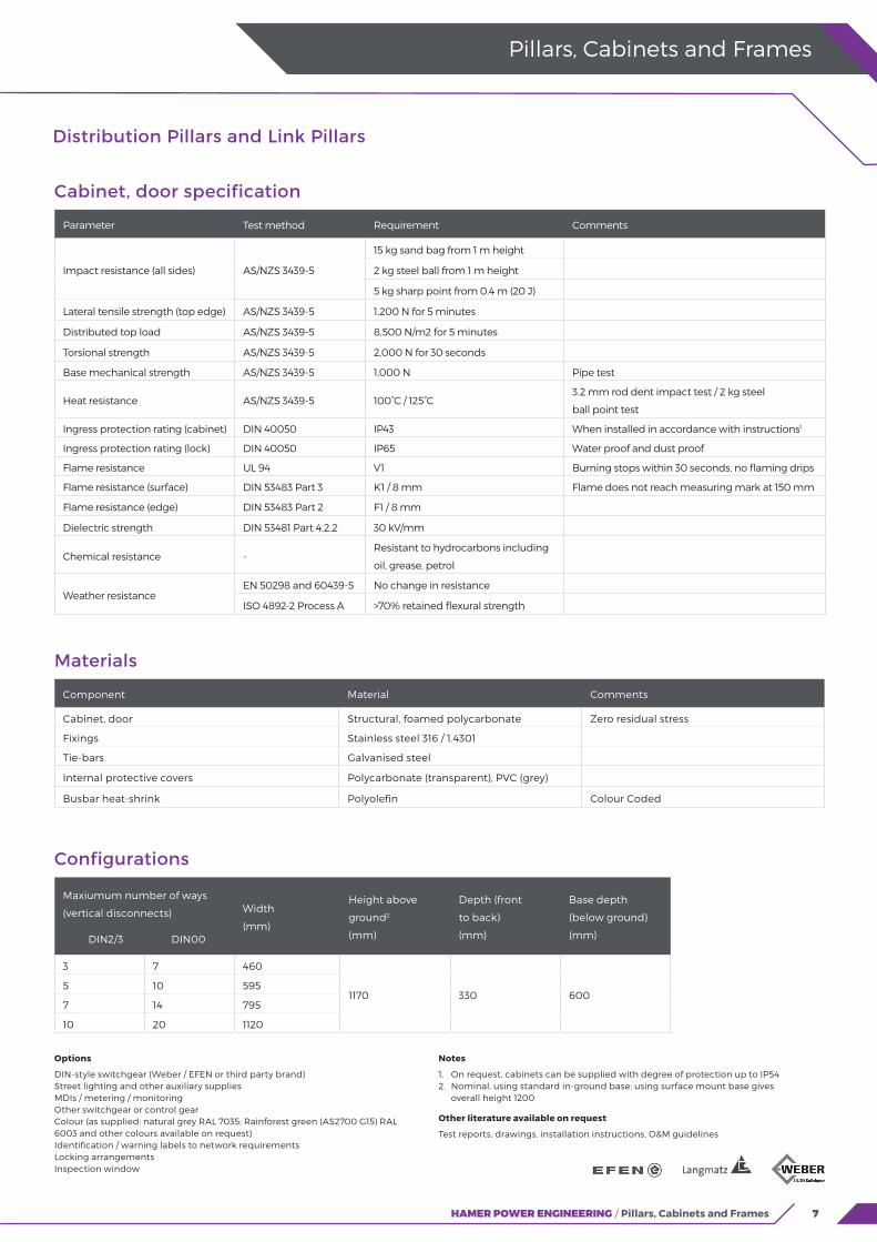
Distribution Pillars and Link Pillars
Pillars, Cabinets and Frames
Options
DIN-style switchgear (Weber / EFEN or third party brand) Street lighting and other auxiliary supplies MDIs / metering / monitoring Other switchgear or control gear Colour (as supplied: natural grey RAL 7035; Rainforest green (AS2700 G15) RAL 6003 and other colours available on request) Identification / warning labels to network requirements Locking arrangements Inspection window
Notes
1. On request, cabinets can be supplied with degree of protection up to IP54 2. Nominal, using standard in-ground base; using surface mount base gives overall height 1200
Other literature available on request
Test reports, drawings, installation instructions, O&M guidelines
Cabinet, door specification
Parameter Test method Requirement Comments
Impact resistance (all sides) AS/NZS 3439-5
15 kg sand bag from 1 m height
2 kg steel ball from 1 m height
5 kg sharp point from 0.4 m (20 J)
Lateral tensile strength (top edge) AS/NZS 3439-5 1,200 N for 5 minutes
Distributed top load AS/NZS 3439-5 8,500 N/m2 for 5 minutes
Torsional strength AS/NZS 3439-5 2,000 N for 30 seconds
Base mechanical strength AS/NZS 3439-5 1,000 N Pipe test
Heat resistance AS/NZS 3439-5 100°C / 125°C3.2 mm rod dent impact test / 2 kg steel
ball point test
Ingress protection rating (cabinet) DIN 40050 IP43 When installed in accordance with instructions1
Ingress protection rating (lock) DIN 40050 IP65 Water proof and dust proof
Flame resistance UL 94 V1 Burning stops within 30 seconds, no flaming drips
Flame resistance (surface) DIN 53483 Part 3 K1 / 8 mm Flame does not reach measuring mark at 150 mm
Flame resistance (edge) DIN 53483 Part 2 F1 / 8 mm
Dielectric strength DIN 53481 Part 4.2.2 30 kV/mm
Chemical resistance -Resistant to hydrocarbons including
oil, grease, petrol
Weather resistanceEN 50298 and 60439-5 No change in resistance
ISO 4892-2 Process A >70% retained flexural strength
Materials
Component Material Comments
Cabinet, door Structural, foamed polycarbonate Zero residual stress
Fixings Stainless steel 316 / 1.4301
Tie-bars Galvanised steel
Internal protective covers Polycarbonate (transparent), PVC (grey)
Busbar heat-shrink Polyolefin Colour Coded
Configurations
Maxiumum number of ways
(vertical disconnects)
DIN2/3 DIN00
Width
(mm)
Height above
ground2
(mm)
Depth (front
to back)
(mm)
Base depth
(below ground)
(mm)
3 7 460
1170 330 6005 10 595
7 14 795
10 20 1120
8
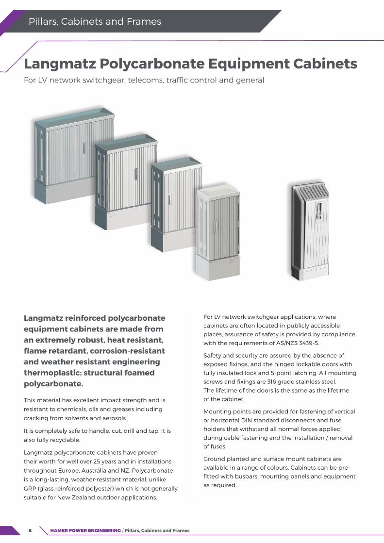
Langmatz reinforced polycarbonate equipment cabinets are made from an extremely robust, heat resistant, flame retardant, corrosion-resistant and weather resistant engineering thermoplastic: structural foamed polycarbonate.
This material has excellent impact strength and is
resistant to chemicals, oils and greases including
cracking from solvents and aerosols.
It is completely safe to handle, cut, drill and tap. It is
also fully recyclable.
Langmatz polycarbonate cabinets have proven
their worth for well over 25 years and in installations
throughout Europe, Australia and NZ. Polycarbonate
is a long-lasting, weather-resistant material, unlike
GRP (glass reinforced polyester) which is not generally
suitable for New Zealand outdoor applications.
HAMER POWER ENGINEERING / Pillars, Cabinets and Frames
Pillars, Cabinets and Frames
For LV network switchgear applications, where
cabinets are often located in publicly accessible
places, assurance of safety is provided by compliance
with the requirements of AS/NZS 3439-5.
Safety and security are assured by the absence of
exposed fixings, and the hinged lockable doors with
fully insulated lock and 5-point latching. All mounting
screws and fixings are 316 grade stainless steel.
The lifetime of the doors is the same as the lifetime
of the cabinet.
Mounting points are provided for fastening of vertical
or horizontal DIN standard disconnects and fuse
holders that withstand all normal forces applied
during cable fastening and the installation / removal
of fuses.
Ground planted and surface mount cabinets are
available in a range of colours. Cabinets can be pre-
fitted with busbars, mounting panels and equipment
as required.
Langmatz Polycarbonate Equipment Cabinets For LV network switchgear, telecoms, traffic control and general
9HAMER POWER ENGINEERING / Pillars, Cabinets and Frames
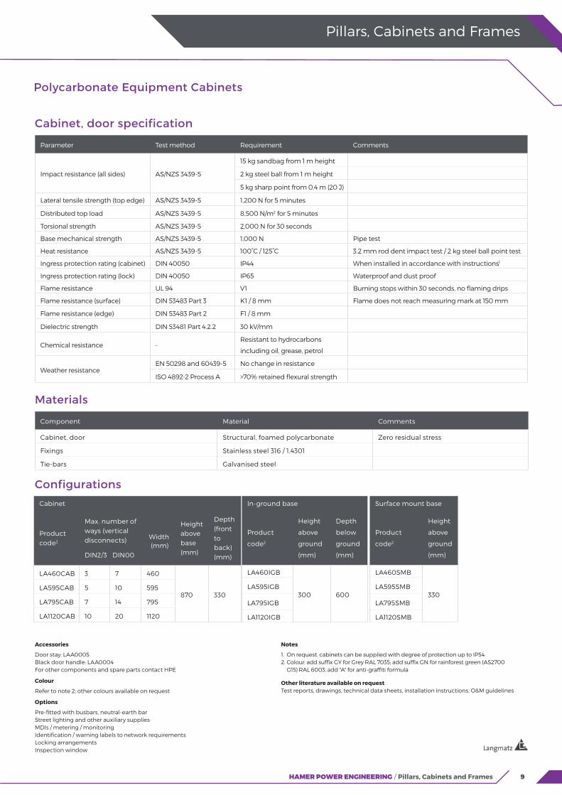
Polycarbonate Equipment Cabinets
Pillars, Cabinets and Frames
Accessories
Door stay: LAA0005 Black door handle: LAA0004For other components and spare parts contact HPE
Colour
Refer to note 2; other colours available on request
Options
Pre-fitted with busbars, neutral-earth bar Street lighting and other auxiliary supplies MDIs / metering / monitoring Identification / warning labels to network requirements Locking arrangements Inspection window
Notes
1. On request, cabinets can be supplied with degree of protection up to IP54 2. Colour: add suffix GY for Grey RAL 7035; add suffix GN for rainforest green (AS2700 G15) RAL 6003; add "A" for anti-graffiti formula
Other literature available on request Test reports, drawings, technical data sheets, installation instructions, O&M guidelines
Cabinet, door specification
Parameter Test method Requirement Comments
Impact resistance (all sides) AS/NZS 3439-5
15 kg sandbag from 1 m height
2 kg steel ball from 1 m height
5 kg sharp point from 0.4 m (20 J)
Lateral tensile strength (top edge) AS/NZS 3439-5 1,200 N for 5 minutes
Distributed top load AS/NZS 3439-5 8,500 N/m2 for 5 minutes
Torsional strength AS/NZS 3439-5 2,000 N for 30 seconds
Base mechanical strength AS/NZS 3439-5 1,000 N Pipe test
Heat resistance AS/NZS 3439-5 100°C / 125°C 3.2 mm rod dent impact test / 2 kg steel ball point test
Ingress protection rating (cabinet) DIN 40050 IP44 When installed in accordance with instructions1
Ingress protection rating (lock) DIN 40050 IP65 Waterproof and dust proof
Flame resistance UL 94 V1 Burning stops within 30 seconds, no flaming drips
Flame resistance (surface) DIN 53483 Part 3 K1 / 8 mm Flame does not reach measuring mark at 150 mm
Flame resistance (edge) DIN 53483 Part 2 F1 / 8 mm
Dielectric strength DIN 53481 Part 4.2.2 30 kV/mm
Chemical resistance -Resistant to hydrocarbons
including oil, grease, petrol
Weather resistanceEN 50298 and 60439-5 No change in resistance
ISO 4892-2 Process A >70% retained flexural strength
Materials
Component Material Comments
Cabinet, door Structural, foamed polycarbonate Zero residual stress
Fixings Stainless steel 316 / 1.4301
Tie-bars Galvanised steel
In-ground base
Product
code2
Height
above
ground
(mm)
Depth
below
ground
(mm)
LA460IGB
300 600LA595IGB
LA795IGB
LA1120IGB
Surface mount base
Product
code2
Height
above
ground
(mm)
LA460SMB
330LA595SMB
LA795SMB
LA1120SMB
Cabinet
Product code2
Max. number of ways (vertical disconnects)
DIN2/3 DIN00
(mm)
Height above base (mm)
Depth (front to back) (mm)
LA460CAB 3 7 460
870 330LA595CAB 5 10 595
LA795CAB 7 14 795
LA1120CAB 10 20 1120
Configurations
Width
10
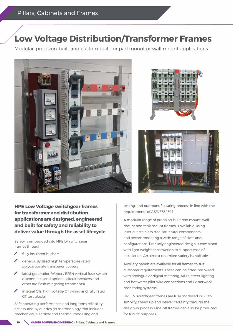
HPE Low Voltage switchgear frames for transformer and distribution applications are designed, engineered and built for safety and reliability to deliver value through the asset lifecycle.
Safety is embedded into HPE LV switchgear frames through:
fully insulated busbars
generously sized high temperature rated polycarbonate transparent covers
latest generation Weber / EFEN vertical fuse-switch disconnects (and optional circuit breakers and other arc-flash mitigating treatments)
integral CTs, high voltage CT wiring and fully rated CT test blocks.
Safe operating performance and long-term reliability are assured by our design methodology that includes mechanical, electrical and thermal modelling and
HAMER POWER ENGINEERING / Pillars, Cabinets and Frames
Pillars, Cabinets and Frames
testing, and our manufacturing process in line with the
requirements of AS/NZS3439.1
A modular range of precision-built pad mount, wall
mount and tank mount frames is available, using
laser-cut stainless steel structural components
and accommodating a wide range of sizes and
configurations. Precisely engineered design is combined
with light weight construction to support ease of
installation. An almost unlimited variety is available.
Auxiliary panels are available for all frames to suit
customer requirements. These can be fitted pre-wired
with analogue or digital metering, MDIs, street-lighting
and hot water pilot wire connections and LV network
monitoring systems.
HPE LV switchgear frames are fully modelled in 3D to
simplify, speed up and deliver certainty through the
design-in process. One-off frames can also be produced
for trial-fit purposes.
Low Voltage Distribution/Transformer Frames Modular, precision-built and custom built for pad mount or wall mount applications

11HAMER POWER ENGINEERING / Pillars, Cabinets and Frames
LV Switchgear Frames
Pillars, Cabinets and Frames
Standard dimensions: pad mounted, bolted frames, Type LVF
Frame width
(mm)
Service
panel width
(mm)
Max number of feeders2
With service panel Without service panel
Height
(mm)
600
195
4 6
985 / 1135 / 1500
700 5 7
800 6 8
900 7 9
1000 8 10
1200 10 12
Contact Hamer Power Engineering for more information
Options
DIN-style switchgear (Weber / EFEN or third-party brand) Street lighting and other auxiliary supplies MDIs / metering / monitoring Other switchgear or controlgear
Notes
1. Other cross sections available on request 2. DIN2/3 fuse-switch-disconnects (max 630 A), pitch 100 mm; alternatively 2x DIN00 (max 160 A), pitch 50 mm
Other literature available on request
Test reports, drawings, installation instructions, O&M guidelines
Materials
Component Material Comments
Frame Stainless steel 304 or 316
Fixings Stainless steel 304
Protective covers Polycarbonate (transparent), PVC (grey) For accidental flashover protection
Busbar heat-shrink Polyolefin For accidental flashover protection
Standard configurations: pad mounted, bolted frames, Type LVF
Rating (kVA)Busbar size
(mm)
N/E bar size1
(mm)
Bushing cable
cross section1
(mm2)
Earth cable
cross-section1
(mm2)
Incoming
isolator
(A)
100-300 30 x 1038.1 x 6.35
185 95 630
500 50 x 10 2x 150 185 1000
750 80 x 10 50 x 10 2x 240 240 1600
1000 100 x 10 80 x 10 3x 240 2x 240 2000

12
"Low voltage net
13
Low Voltage Network Monitoring Gridkey MCU318 Metrology and Comms Unit
GridKey SlimSensor
GridKey Data Centre
14
16
18

14
Why Choose the GridKey MCU318?
GridKey is a custom designed continuous monitoring solution for low voltage (LV) networks. It consists of a number of current sensors on each feeder together with voltage taps, connected to a Metrology and Communications Unit (MCU) which processes the sensor data and generates and logs substation loading and condition parameters.
This information is relayed to a remote data centre where the data is securely stored. Substation performance and feeder cable condition can be analysed, enabling access graphically via our customer web portal.
The GridKey MCU318 LV monitoring system is designed for purpose, offering a flexible and highly configurable information system with the following benefits:
Safe and easy retrofit solution for installations indoors and out – lightweight and compact with no interruption of customer supply
Built to be weather resistant– IP54 rated, meeting relevant electrical standards for external and internal substation use
When used with SlimSensor modified Rogowski sensors the system provides class 2 metering accuracy – on three phases of up to 6 feeders
HAMER POWER ENGINEERING / Pillars, Cabinets and Frames
Low Voltage Network Monitoring
Comprehensive reporting of substation feeder and calculated busbar parameters, giving better information to drive evidence-based decision making for grid management
Compact design allows the system to be fitted internally within LV cabinets reducing the risk of theft or vandalism. A built-in GPRS modem and antenna provides reliable communications
A secure Wi-Fi connection to the unit is provided to allow configuration and testing whilst installing
For some countries GridKey are able to supply a cost effective roaming SIM card, however any SIM card can be fitted during manufacture for the customer’s chosen mobile network(s). These can be soldered directly onto the PCB to improve security and reliability.
The customer can choose to configure and generate alert messages that would be sent via the data network system for multiple grid measurement states, for example to provide indications and warnings of any over voltage or power phase imbalance conditions.
The information and alerts provided enable network managers to make evidence-based decisions and plan effectively for future preventive maintenance and capital expenditure.
GridKey MCU318 Metrology and Comms Unit Unlocking the smart grid - A collaboration between Lucy Electric and Sentec
Dimensions (mm)
15HAMER POWER ENGINEERING / Pillars, Cabinets and Frames
Low Voltage Network Monitoring
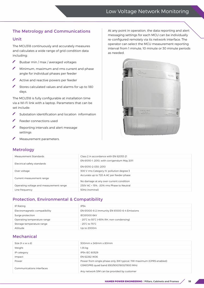
The Metrology and Communications
Unit
The MCU318 continuously and accurately measures
and calculates a wide range of grid condition data
including:
Busbar min / max / averaged voltages
Minimum, maximum and rms current and phase
angle for individual phases per feeder
Active and reactive powers per feeder
Stores calculated values and alarms for up to 180
days.
The MCU318 is fully configurable at installation time
via a Wi-Fi link with a laptop. Parameters that can be
set include:
Substation identification and location information
Feeder connections used
Reporting intervals and alert message
settings
Measurement parameters.
At any point in operation, the data reporting and alert messaging settings for each MCU can be individually re-configured remotely via its network interface. The operator can select the MCU measurement reporting interval from 1 minute, 10 minute or 30 minute periods as needed.
MetrologyMeasurement Standards Class 2 in accordance with EN 62053-21
Electrical safety standardsEN 61010-1: 2010, with corrigendum May 2011
EN 61010-2-030: 2010
Over voltage 300 V rms Category IV. pollution degree 3
Current measurement rangeAccurate up to 720 A AC per feeder phase
No damage at any over-current condition
Operating voltage and measurement range 230V AC + 15%. -20% rms Phase to Neutral
Line frequency 50Hz (nominal)
Protection, Environmental & CompatibilityIP Rating IP54
Electromagnetic compatibility EN 61000-6-2 immunity EN 61000-6-4 Emissions
Surge protection IEC61000 6kV
Operating temperature range - 20°C to 55°C (<93% RH, non-condensing)
Storage temperature range - 25°C to 70°C
Altitude Up to 2000m
MechanicalSize (h x w x d) 300mm x 245mm x 80mm
Weight 1.35 kg
IP category IP54 IEC 60529
Impact EN 62262 IK06
Power Power from single phase only, 6W typical, 11W maximum (GPRS enabled)
Communications interfacesGSM/GPRS quad band 850/900/1800/1900 MHz
Any network SIM can be provided by customer
16
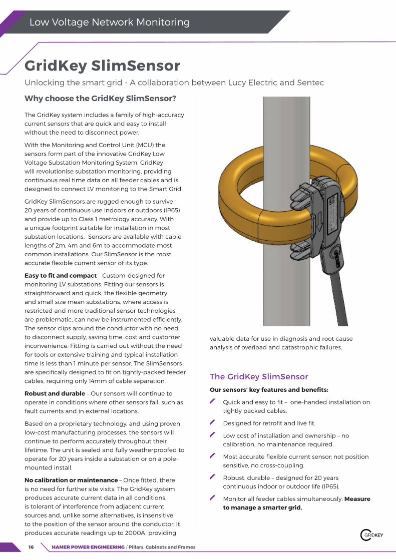
Why choose the GridKey SlimSensor?
The GridKey system includes a family of high-accuracy current sensors that are quick and easy to install without the need to disconnect power.
With the Monitoring and Control Unit (MCU) the sensors form part of the innovative GridKey Low Voltage Substation Monitoring System. GridKey will revolutionise substation monitoring, providing continuous real time data on all feeder cables and is designed to connect LV monitoring to the Smart Grid.
GridKey SlimSensors are rugged enough to survive 20 years of continuous use indoors or outdoors (IP65) and provide up to Class 1 metrology accuracy. With a unique footprint suitable for installation in most substation locations, Sensors are available with cable lengths of 2m, 4m and 6m to accommodate most common installations. Our SlimSensor is the most accurate flexible current sensor of its type.
Easy to fit and compact – Custom-designed for monitoring LV substations. Fitting our sensors is straightforward and quick; the flexible geometry and small size mean substations, where access is restricted and more traditional sensor technologies are problematic, can now be instrumented efficiently. The sensor clips around the conductor with no need to disconnect supply, saving time, cost and customer inconvenience. Fitting is carried out without the need for tools or extensive training and typical installation time is less than 1 minute per sensor. The SlimSensors are specifically designed to fit on tightly-packed feeder cables, requiring only 14mm of cable separation.
Robust and durable – Our sensors will continue to operate in conditions where other sensors fail, such as fault currents and in external locations.
Based on a proprietary technology, and using proven low-cost manufacturing processes, the sensors will continue to perform accurately throughout their lifetime. The unit is sealed and fully weatherproofed to operate for 20 years inside a substation or on a pole-mounted install.
No calibration or maintenance – Once fitted, there is no need for further site visits. The GridKey system produces accurate current data in all conditions, is tolerant of interference from adjacent current sources and, unlike some alternatives, is insensitive to the position of the sensor around the conductor. It produces accurate readings up to 2000A, providing
HAMER POWER ENGINEERING / Pillars, Cabinets and Frames
Low Voltage Network Monitoring
valuable data for use in diagnosis and root cause analysis of overload and catastrophic failures.
The GridKey SlimSensor
Our sensors' key features and benefits:
Quick and easy to fit – one-handed installation on tightly packed cables.
Designed for retrofit and live fit.
Low cost of installation and ownership – no calibration, no maintenance required.
Most accurate flexible current sensor; not position sensitive, no cross-coupling.
Robust, durable – designed for 20 years continuous indoor or outdoor life (IP65).
Monitor all feeder cables simultaneously: Measure to manage a smarter grid.
GridKey SlimSensor Unlocking the smart grid - A collaboration between Lucy Electric and Sentec

17HAMER POWER ENGINEERING / Pillars, Cabinets and Frames
Low Voltage Network Monitoring
MetrologyMeasurement Standards IEC Standard 60044-8
Electrical Safety Standards BS EN 61010-1: 2001, BS EN 61010-2-032: 2002
Sensor type Type B sensor as defined in BS EN 61010-2-032:2002, Category IV, Pollution degree 3
Accuracy class Class 1 (calibrated), Class 2 (uncalibrated)
Rated current 600 A
Maximum current 2000 A
Output strength 150 mV ac at rated current
Line frequency 50 Hz
Protection, Environmental & CompatibilitySurge protection IEC61000 6 kV
Operating temperature range - 20°C to 55°C (<93% RH, non-condensing)
Storage temperature range - 25°C to 70°C
Altitude Up to 2000 m
MechanicalMinimum required clearance between conductors 14 mm
Cable Length 2 m, 4 m, 6 m
Aperture 50 mm maximum conductor diameter
Weight N/A
IP category IP65 IEC 60529
Dimensions (mm)
18
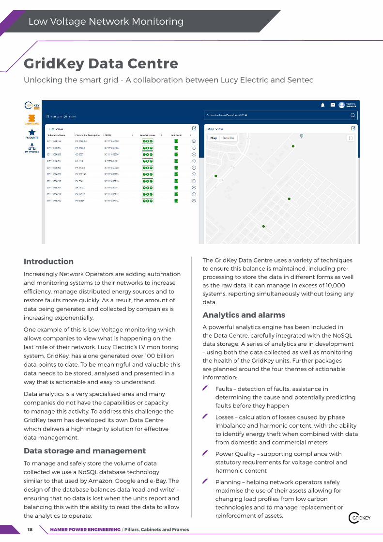
Introduction Increasingly Network Operators are adding automation
and monitoring systems to their networks to increase
efficiency, manage distributed energy sources and to
restore faults more quickly. As a result, the amount of
data being generated and collected by companies is
increasing exponentially.
One example of this is Low Voltage monitoring which
allows companies to view what is happening on the
last mile of their network. Lucy Electric’s LV monitoring
system, GridKey, has alone generated over 100 billion
data points to date. To be meaningful and valuable this
data needs to be stored, analysed and presented in a
way that is actionable and easy to understand.
Data analytics is a very specialised area and many
companies do not have the capabilities or capacity
to manage this activity. To address this challenge the
GridKey team has developed its own Data Centre
which delivers a high integrity solution for effective
data management.
Data storage and managementTo manage and safely store the volume of data
collected we use a NoSQL database technology
similar to that used by Amazon, Google and e-Bay. The
design of the database balances data ‘read and write’ –
ensuring that no data is lost when the units report and
balancing this with the ability to read the data to allow
the analytics to operate.
HAMER POWER ENGINEERING / Pillars, Cabinets and Frames
Low Voltage Network Monitoring
The GridKey Data Centre uses a variety of techniques to ensure this balance is maintained, including pre-processing to store the data in different forms as well as the raw data. It can manage in excess of 10,000 systems, reporting simultaneously without losing any data.
Analytics and alarmsA powerful analytics engine has been included in the Data Centre, carefully integrated with the NoSQL data storage. A series of analytics are in development – using both the data collected as well as monitoring the health of the GridKey units. Further packages are planned around the four themes of actionable information:
Faults – detection of faults, assistance in determining the cause and potentially predicting faults before they happen
Losses – calculation of losses caused by phase imbalance and harmonic content, with the ability to identify energy theft when combined with data from domestic and commercial meters
Power Quality – supporting compliance with statutory requirements for voltage control and harmonic content
Planning – helping network operators safely maximise the use of their assets allowing for changing load profiles from low carbon technologies and to manage replacement or reinforcement of assets.
GridKey Data Centre Unlocking the smart grid - A collaboration between Lucy Electric and Sentec
19HAMER POWER ENGINEERING / Pillars, Cabinets and Frames
Low Voltage Network Monitoring
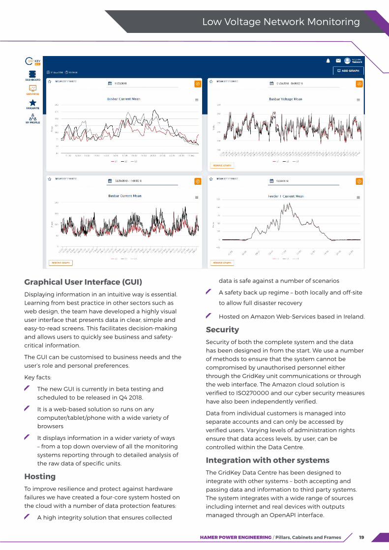
Graphical User Interface (GUI)Displaying information in an intuitive way is essential. Learning from best practice in other sectors such as web design, the team have developed a highly visual user interface that presents data in clear, simple and easy-to-read screens. This facilitates decision-making and allows users to quickly see business and safety-critical information.
The GUI can be customised to business needs and the user’s role and personal preferences.
Key facts:
The new GUI is currently in beta testing and scheduled to be released in Q4 2018.
It is a web-based solution so runs on any computer/tablet/phone with a wide variety of browsers
It displays information in a wider variety of ways – from a top down overview of all the monitoring systems reporting through to detailed analysis of the raw data of specific units.
HostingTo improve resilience and protect against hardware failures we have created a four-core system hosted on the cloud with a number of data protection features:
A high integrity solution that ensures collected
data is safe against a number of scenarios
A safety back up regime – both locally and off-site
to allow full disaster recovery
Hosted on Amazon Web-Services based in Ireland.
SecuritySecurity of both the complete system and the data has been designed in from the start. We use a number of methods to ensure that the system cannot be compromised by unauthorised personnel either through the GridKey unit communications or through the web interface. The Amazon cloud solution is verified to ISO270000 and our cyber security measures have also been independently verified.
Data from individual customers is managed into separate accounts and can only be accessed by verified users. Varying levels of administration rights ensure that data access levels, by user, can be controlled within the Data Centre.
Integration with other systemsThe GridKey Data Centre has been designed to integrate with other systems – both accepting and passing data and information to third party systems. The system integrates with a wide range of sources including internet and real devices with outputs managed through an OpenAPI interface.
20
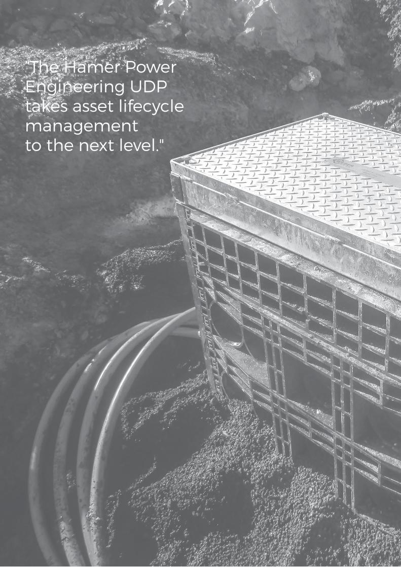
“The Hamer Power Engineering UDP takes asset lifecycle management to the next level."
21
Underground Network and Service Boxes UDP In-Ground Distribution Boxes
U-Pillar Underground Service Connection Boxes
Langmatz Modular Structural Pits and Equipment Vaults
22
24
26
22
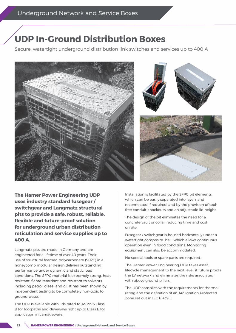
The Hamer Power Engineering UDP uses industry standard fusegear / switchgear and Langmatz structural pits to provide a safe, robust, reliable, flexible and future-proof solution for underground urban distribution reticulation and service supplies up to 400 A.
Langmatz pits are made in Germany and are engineered for a lifetime of over 40 years. Their use of structural foamed polycarbonate (SFPC) in a honeycomb modular design delivers outstanding performance under dynamic and static load conditions. The SFPC material is extremely strong, heat resistant, flame retardant and resistant to solvents including petrol, diesel and oil. It has been shown by independent testing to be completely non-toxic to ground water.
The UDP is available with lids rated to AS3996 Class B for footpaths and driveways right up to Class E for application in carriageways.
HAMER POWER ENGINEERING / Underground Network and Service Boxes
Underground Network and Service Boxes
Installation is facilitated by the SFPC pit elements, which can be easily separated into layers and reconnected if required, and by the provision of tool-free conduit knockouts and an adjustable lid height.
The design of the pit eliminates the need for a concrete vault or collar, reducing time and cost on site.
Fusegear / switchgear is housed horizontally under a watertight composite “bell” which allows continuous operation even in flood conditions. Monitoring equipment can also be accommodated.
No special tools or spare parts are required.
The Hamer Power Engineering UDP takes asset lifecycle management to the next level: it future proofs the LV network and eliminates the risks associated with above ground pillars.
The UDP complies with the requirements for thermal rating and the definition of an Arc Ignition Protected Zone set out in IEC 61439.1.
UDP In-Ground Distribution Boxes Secure, watertight underground distribution link switches and services up to 400 A
23HAMER POWER ENGINEERING / Underground Network and Service Boxes
UDP In-Ground Distribution Boxes
Underground Network and Service Boxes
Mechanical specifications
Specification Test method Requirement
Lid load class AS 3996 Up to Class E400 (40 tonnes)
Transfer of vertical loads to ground base DIN 1054:2005-01 min 200 kN/m2
Transfer of adjacent static and dynamic
loads to ground baseDIN FB 101
Load class 2 (96 kN with area 40x40 cm using set up RStO
road class)
Active ground pressure (transfer of
vertical loads to pit elements)DIN 4085 Ground types V1 to V3 acc to ATV-DVWK-A 127
Materials
Component Material
Lid Cast iron, galvanised steel or composite
Bell Composite
Frame Hot dip galvanised steel (≥ 70 μm)
Fixings Stainless steel 304 (1.4301)
Structural pit elements Structural foamed polycarbonate (PC/PBT blend with 6% GRP)
Structural pit element material properties
Specification Test method Requirement
Density ISO 1183 0.95 – 1.25 g/cm3
Water absorption DIN 53495 < 0.5 %
Hardness ISO 2039/1 90 MPa
Tensile strain at break ISO 527 38 MPa
Elongation at break ISO 527 12 %
Elastic modulus ISO 527 2,000 MPa
Notched impact strength DIN 53453 6 kJ/m2 (20°C), 4 kJ/m2 (-20°C)
Vicat softening temperature ISO 306 110°C (B50 method)
Flammability (Surface flame) Self-extinguishing after flame is withdrawn
Groundwater compatibility (Independent Test)Non-toxic (no leaching of heavy metals, phenol, polycyclic
aromatic hydrocarbons or BTEX)
Configurations and Dimensions (mm)
Product Code
Typical Configurations
Internal
Length
(mm)
Internal
Width
(mm)
Nominal
Depth
(mm)
Typical Weights (kg)
Cable Tails
(mm2)63 / 100 A 160 A 250 A 400 A
Total
(exc
cable
tails)
Head
FrameLid(s)
Switchgear
Assembly
UDP03xx 2x 3P or 6x 1P 1x 3P 550 250 600 62 18 10 5 25-70
UDP04xx 2x 3P or 6x 1P 2x 3P 1x 3P 800 250 600 80 22 12 8 25-95UDP05xx 1x 3P 400 400 700 110 18 15 30 150-240UDP07xx 3x 3P 3x 3P 800 400 700 160 25 15 50 95-240UDP10xx 6x 3P 800 800 700 300 40 2x 50 150 150-240
Notes
Network link box configurations, with optional bus coupler, are also available
Options
Service fuses up to 100 A or Weber-EFEN DIN-type horizontal disconnectors 160 A or 250 A Lid type (composite, steel, steel with concrete fill / paveable) Locking and latching arrangements. Other literature available on request. Type test reports, drawings, technical data sheets, installation instructions, O&M guidelines
24 HAMER POWER ENGINEERING / Underground Network and Service Boxes
Underground Network and Service Boxes
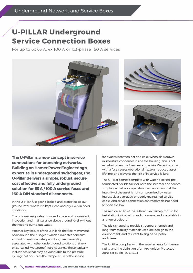
The U-Pillar is a new concept in service connections for branching networks. Building on Hamer Power Engineering’s expertise in underground switchgear, the U-Pillar delivers a simple, robust, secure, cost effective and fully underground solution for 63 A / 100 A service fuses and 160 A DIN standard disconnects.
In the U-Pillar, fusegear is locked and protected below ground level, where it is kept clean and dry, even in flood conditions.
The unique design also provides for safe and convenient inspection and maintenance above ground level, without the need to pump out water.
Another key feature of the U-Pillar is the free movement of air around the fusegear, which eliminates concerns around operational safety and long-term reliability associated with other underground solutions that rely on so-called “waterproof” fuse housings. These typically include seals that may be vulnerable to the pressure cycling that occurs as the temperature of the service
fuse varies between hot and cold. When air is drawn in, moisture condenses inside the housing, and is not expelled when the fuse heats up again. Water in contact with a fuse causes operational hazards, reduced asset lifetime, and elevates the risk of in-service failure.
The U-Pillar comes complete with water-blocked, pre-terminated flexible tails for both the incomer and service supplies, so network operators can be certain that the integrity of the asset is not compromised by water ingress via a damaged or poorly maintained service cable. And service connection contractors do not need to open the box.
The reinforced lid of the U-Pillar is extremely robust, for installation in footpaths and driveways, and is available in a range of colours.
The pit is shaped to provide structural strength and long-term stability. Materials used are benign to the environment, and resistant to engine oil, petrol and diesel.
The U-Pillar complies with the requirements for thermal rating and the definition of an Arc Ignition Protected Zone set out in IEC 61439.1.
U-PILLAR Underground Service Connection Boxes For up to 6x 63 A, 4x 100 A or 1x3-phase 160 A services
25HAMER POWER ENGINEERING / Underground Network and Service Boxes
Underground Network and Service Boxes
U-PILLAR Underground Service Connection Boxes
Mechanical specifications
Parameter Test method Requirement Comments
Lid load class AS3996 Class B080 (8 tonnes)Suitable for footpaths and driveways (nominal wheel loading
2,670 kg)
Lid slip resistance AS/NZS4586 Classification V (P5) Represents a very low risk of slipping when wet
Colour - Black Other colours available on request
Weather resistanceASTM D2565 / ISO
4892-2Greater than UV8 Long term UV stable
Chemical resistance - Engine oil, petrol, dieselMaintains structural integrity after exposure to small and
occasional spills
Flammability UL94 HB Very difficult to ignite without a sustained source of ignition
Thermal stability AS/NZS4766 Pass Melt flow index remains within ±20% after 100 days at 100°C
Temperature range - -40 to +60°C Hot tarseal can be used around pit headframe
Options Security bolts / internal padlock Identification (on lid and bell) Incomer and service cable tail lengths (0.2 m and 0.3 m as standard)1
Branch joint2 Service fuses Street lighting and other auxiliary supplies
Notes 1. Capped incomer and water-blocked service connectors included as standard
2. Product code KP8033 (Pfisterer ISICOMPACT single-shear-bolt connector and resin joint kit) for main 50-240 / branch 10-70 mm2.
Other literature available on request Test reports, drawings, technical data sheets, installation instructions, O&M guidelines, FMEA
Materials Parameter Test method Comments
Lid, pit Polyolefin UV stabilised grade
Bell Composite -
Stand Polycarbonate -
Fusegear holders ABS, various -
Fixtures and fittings Stainless steel 304, (1.4301)
Cable insulationThermoset elastomeric
PVCSubmersible, splash resistant to petrol and oil, ozone resistant, abrasion resistant
Configurations and dimensionsProduct Code Number of services Dimensions Approx
weight
(kg)
Cable tail sections In-line connectors
63 A
1-phase 3-phase
100 A
1-phase 3-phase
160 A
1-phase 3-phase
Width
(mm)
Depth
(mm)
Incomers
(mm2)
Services
(mm2)
Incomers
(mm2)
Services
(mm2)
UDP02B0630011 6 19.0
25 16 10-50 10-50
UDP02B0630012 2 17.6
UDP02B1000013 1 14.4
UDP02B1000014 2 15.3
UDP02B1000015 3 16.2
UDP02B1000016 4 17.1
UDP02B1000017 1 16.4
UDP02B1600020 3 25.070 70 35-120 35-120
UDP02B1600021 1 21.8
26 HAMER POWER ENGINEERING / Underground Network and Service Boxes
Underground Network and Service Boxes
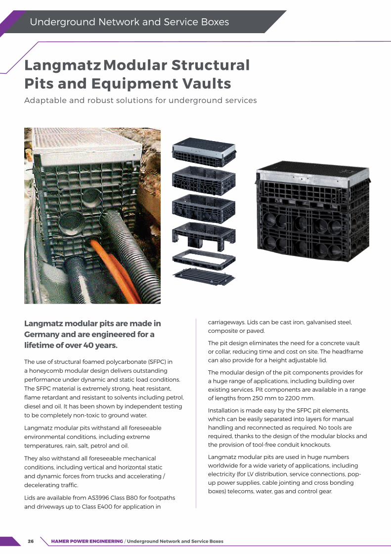
Langmatz modular pits are made in Germany and are engineered for a lifetime of over 40 years.
The use of structural foamed polycarbonate (SFPC) in
a honeycomb modular design delivers outstanding
performance under dynamic and static load conditions.
The SFPC material is extremely strong, heat resistant,
flame retardant and resistant to solvents including petrol,
diesel and oil. It has been shown by independent testing
to be completely non-toxic to ground water.
Langmatz modular pits withstand all foreseeable
environmental conditions, including extreme
temperatures, rain, salt, petrol and oil.
They also withstand all foreseeable mechanical
conditions, including vertical and horizontal static
and dynamic forces from trucks and accelerating /
decelerating traffic.
Lids are available from AS3996 Class B80 for footpaths
and driveways up to Class E400 for application in
carriageways. Lids can be cast iron, galvanised steel, composite or paved.
The pit design eliminates the need for a concrete vault or collar, reducing time and cost on site. The headframe can also provide for a height adjustable lid.
The modular design of the pit components provides for a huge range of applications, including building over existing services. Pit components are available in a range of lengths from 250 mm to 2200 mm.
Installation is made easy by the SFPC pit elements, which can be easily separated into layers for manual handling and reconnected as required. No tools are required, thanks to the design of the modular blocks and the provision of tool-free conduit knockouts.
Langmatz modular pits are used in huge numbers worldwide for a wide variety of applications, including electricity (for LV distribution, service connections, pop-up power supplies, cable jointing and cross bonding boxes) telecoms, water, gas and control gear.
Langmatz Modular Structural Pits and Equipment Vaults Adaptable and robust solutions for underground services

27HAMER POWER ENGINEERING / Underground Network and Service Boxes
Underground Network and Service Boxes
Modular Structural Pits and Equipment Vaults
Materials Component Material Comments
Pit components Structural foamed polycarbonate
Pit component connectors (dowel pins) Polypropylene
Headframe Hot-dip galvanised >70 μm
Fixings Stainless steel 304 grade
Lid Composite / cast iron / galvanised steel / paved
Available sizes
Length1,2
(Internal)Height (layers)
Height
(headframe
support layer)
Height (headframe) for lid type
Composite
Cast iron,
galvanised
steel
Paved
250
70
151 250 66
140
105
95 As required
400
220
580
-
650
800
-1165-
1400
Notes 1. Other sizes available on request up to 2,200 mm length 2. External length add 100 mm (nom)
Other literature available on request Test reports, drawings, installation instructions, O&M guidelines For ordering codes and for more information contact your Hamer Power Engineering representative
28
“We are proud to partner with specialist international suppliers to deliver solutions, peace of mind and long term reliability.”
29
Disconnects and Fuses EFEN LV Vertical Fuse Switch Disconnects
EFEN LV Horizontal Fuse Switch Disconnects
Fuse Switch Disconnects for LV Overhead Lines
EFEN NH Low Voltage High Rupturing
Capacity Fuses and Solid Links
Connections, Spare Covers, CTs and Other Accessories
31
34
38
40
42

30 HAMER POWER ENGINEERING / Disconnects and Fuses
“The new E3 disconnector keeps live terminals fully shrouded from touch at all times.”

31HAMER POWER ENGINEERING / Disconnects and Fuses
Disconnects and Fuses
Isolating electricity supply at distribution substations can be made safer with the latest generation of EFEN disconnectors.
The new E3 disconnector keeps live terminals fully
shrouded from touch at all times.
In the open position the E3 disconnector holds the
disconnected fuse under its cover, which maintains an
IP2x barrier preventing finger touch of either source
or load terminal. With distributed generation on the
rise and more connected solar feeding into the LV
network from residential and commercial premises, a
fully shrouded approach better protects operators by
eliminating the risk of exposed live fuse terminals.
In the E3 disconnector the whole fuse is withdrawn
in a parallel direction by levering the manually
dependent switch in a way that opens both terminals
of each fuse blade at the same time. This halves the
arc voltage by creating two smaller arcs – one at each terminal.
E3 disconnectors also manage heat more effectively, reducing the risk of over-heating. Heat build-up is minimised by improved housing ventilation and busbar design.
The improved design also delivers improved switching capacity with non-resistive loads, and higher short-circuit rating for improved performance in fault conditions.
The versatile range includes both simultaneous three phase switching as well as individual single phase switching from 100 A to 630 A. E3 disconnectors are available as either 1000 A or 2000 A isolators with knife links in place of fuses.
Other ratings are available on request, including parallel arrangements. Rear-connect and side-connect configurations are also available.
EFEN LV Vertical Fuse Switch Disconnects EFEN E3 Disconnector is the next practicable step in LV network safety
Closed Open Visual Break
32 HAMER POWER ENGINEERING / Disconnects and Fuses
Disconnects and Fuses
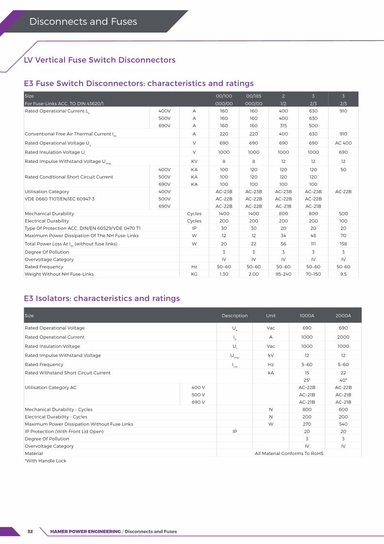
LV Vertical Fuse Switch Disconnectors
E3 Fuse Switch Disconnectors: characteristics and ratingsSize 00/100 00/185 2 3 3
For Fuse-Links ACC. TO DIN 43620/1 000/00 000/00 1/2 2/3 2/3
Rated Operational Current Le 400V A 160 160 400 630 910
500V A 160 160 400 630
690V A 160 160 315 500
Conventional Free Air Thermal Current Ith A 220 220 400 630 910
Rated Operational Voltage Ue V 690 690 690 690 AC 400
Rated Insulation Voltage Ui V 1000 1000 1000 1000 690
Rated Impulse Withstand Voltage Uimp KV 8 8 12 12 12
Rated Conditional Short Circuit Current
400V KA 100 120 120 120 50
500V KA 100 120 120 120
690V KA 100 100 100 100
Utilisation Category 400V AC–23B AC–23B AC–23B AC–23B AC-22B
VDE 0660 T107/EN/IEC 60947-3 500V AC–22B AC–22B AC–22B AC–22B
690V AC–22B AC–22B AC–21B AC–21B
Mechanical Durability Cycles 1400 1400 800 800 500
Electrical Durability Cycles 200 200 200 200 100
Type Of Protection ACC. DIN/EN 60529/VDE 0470 T1 IP 30 30 20 20 20
Maximum Power Dissipation Of The NH Fuse-Links W 12 12 34 48 70
Total Power Loss At Ith (without fuse links) W 20 22 56 111 158
Degree Of Pollution 3 3 3 3 3
Overvoltage Category IV IV IV IV IV
Rated Frequency Hz 50–60 50–60 50–60 50–60 50-60
Weight Without NH Fuse-Links KG 1.30 2.00 95–240 70–150 9,5
E3 Isolators: characteristics and ratings
Size Description Unit 1000A 2000A
Rated Operational Voltage Ue Vac 690 690
Rated Operational Current Ie A 1000 2000
Rated Insulation Voltage Ui Vac 1000 1000
Rated Impulse Withstand Voltage Uimp kV 12 12
Rated Frequency Icw Hz 5–60 5–60
Rated Withstand Short Circuit Current kA 15 22
25* 40*
Utilisation Category AC 400 V AC–22B AC–22B
500 V AC–21B AC–21B
690 V AC–21B AC–21B
Mechanical Durability – Cycles N 800 600
Electrical Durability - Cycles N 200 200
Maximum Power Dissipation Without Fuse Links W 270 540
IP Protection (With Front Lid Open) IP 20 20
Degree Of Pollution 3 3
Overvoltage Category IV IV
Material All Material Conforms To RoHS
*With Handle Lock
33HAMER POWER ENGINEERING / Disconnects and Fuses
Disconnects and Fuses
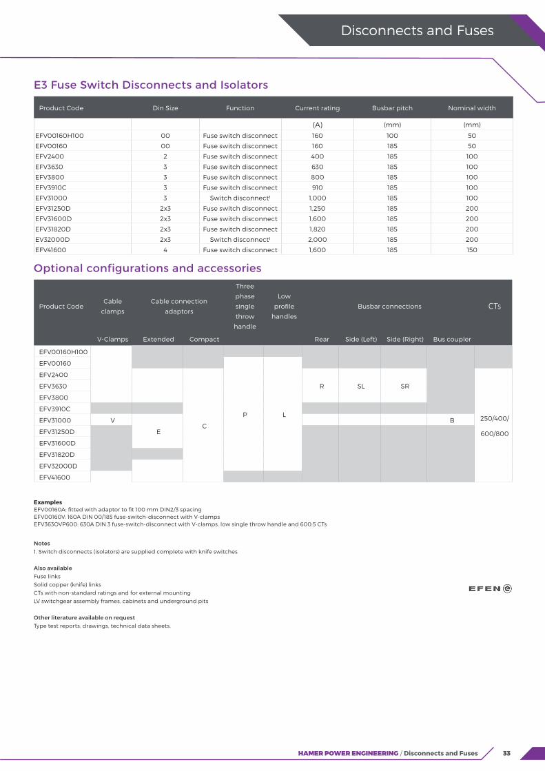
E3 Fuse Switch Disconnects and Isolators
Product Code Din Size Function Current rating Busbar pitch Nominal width
(A) (mm) (mm)
EFV00160H100 00 Fuse switch disconnect 160 100 50
EFV00160 00 Fuse switch disconnect 160 185 50
EFV2400 2 Fuse switch disconnect 400 185 100
EFV3630 3 Fuse switch disconnect 630 185 100
EFV3800 3 Fuse switch disconnect 800 185 100
EFV3910C 3 Fuse switch disconnect 910 185 100
EFV31000 3 Switch disconnect1 1,000 185 100
EFV31250D 2x3 Fuse switch disconnect 1,250 185 200
EFV31600D 2x3 Fuse switch disconnect 1,600 185 200
EFV31820D 2x3 Fuse switch disconnect 1,820 185 200
EV32000D 2x3 Switch disconnect1 2,000 185 200
EFV41600 4 Fuse switch disconnect 1,600 185 150
Notes1. Switch disconnects (isolators) are supplied complete with knife switches
Also availableFuse links
Solid copper (knife) links
CTs with non-standard ratings and for external mounting
LV switchgear assembly frames, cabinets and underground pits
Other literature available on requestType test reports, drawings, technical data sheets.
ExamplesEFV00160A: fitted with adaptor to fit 100 mm DIN2/3 spacing EFV00160V: 160A DIN 00/185 fuse-switch-disconnect with V-clamps EFV363OVP600: 630A DIN 3 fuse-switch-disconnect with V-clamps, low single throw handle and 600:5 CTs
Optional configurations and accessories
Product CodeCable
clamps
Cable connection
adaptors
Three
phase
single
throw
handle
Low
profile
handles
Busbar connections CTs
V-Clamps Extended Compact Rear Side (Left) Side (Right) Bus coupler
EFV00160H100
EFV00160
P L
EFV2400
C
R SL SR
250/400/
600/800
EFV3630
EFV3800
EFV3910C
EFV31000 V
E
B
EFV31250D
EFV31600D
EFV31820D
EFV32000D
EFV41600

34
Horizontal fuse switch disconnects provide an alternative mounting and connection method to vertical disconnects, for example for single circuit supplies and for the safe and cost effective upgrade or replacement of earlier generations of fuse switches.
The EFEN SILAS range has been used successfully in New Zealand for 30+ years and is now complemented by the EFEN IN series.
Both the SILAS and IN series use the widely available and economic DIN blade fuse cartridges, and offer an excellent level of operator safety thanks to their AC22B switching capacity.
Both may be used in AC or DC applications, as specified by their ratings.
The SILAS range is designed for independent mounting for single switch protection applications by virtue of its terminal covers. These features are ideally suited to solar applications or wherever battery protection is required in an internal installation.
HAMER POWER ENGINEERING / Disconnects and Fuses
Disconnects and Fuses
SILAS is also suitable for multiple feeder mounting on busbars with ratings from 160 A to 630 A.
The EFEN IN series of switches is available from 160 to 1,600 A and is a more compact design. Cable covers are supplied: these can be removed for use in applications where a protective enclosure is used. Its compact size makes the IN ideal for network pillar applications.
Sizes 00, 1, 2 and 3 of the IN series and sizes 1, 2 and 3 of the SILAS series have the added advantage of phase protection barriers moulded into the base.
EFEN LV Horizontal Fuse Switch Disconnects The best of both worlds with EFEN SILAS and IN Series
35HAMER POWER ENGINEERING / Disconnects and Fuses
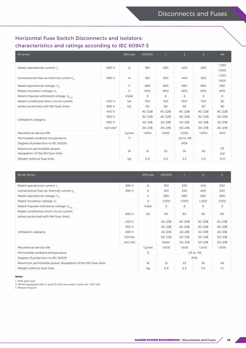
Horizontal Fuse Switch Disconnects and Isolators: characteristics and ratings according to IEC 60947-3
IN series DIN size 000/00 1 2 3 4A
Rated operational current, Ie 690 V A 160 250 400 6301,250
1.600
Conventional free-air thermal current Ith 690 V A 160 250 400 6301,250
1,600
Rated operational voltage, Ue V 690 690 690 690 690
Rated insulation voltage, Ui V 800 800 800 800 800
Rated impulse withstand voltage, Uimp kVpk 8 8 8 8 8
Rated conditional short circuit current 400 V kA 100 100 1001 100 50
(when protected with NH fuse-links) 690 V kA 50 50 50 50 50
Utilisation category
400 V AC-22B AC-22B AC-22B AC-22B AC-22B
500 V AC-22B AC-22B AC-22B AC-22B AC-22B
690 V AC-21B AC-21B AC-21B AC-21B AC-21B
440 Vdc2 DC-21B DC-21B DC-21B DC-21B DC-21B
Mechanical service life Cycles 1,600 1,600 1,000 1,000 600
Permissible ambient temperature °C ‘-25 to +55
Degree of protection to IEC 60529 IP3X
Maximum permissible power
dissipation of the NH fuse-linksW 12 23 34 48
115
140
Weight without fuse links kg 0.5 2.0 3.3 5.3 14.0
Disconnects and Fuses
SILAS Series DIN size 000/00 1 2 3
Rated operational current, Ie 690 V A 160 250 400 630
Conventional free-air thermal current Ith 690 V A 160 250 400 630
Rated operational voltage, Ue V 690 690 690 690
Rated insulation voltage, Ui V 1,000 1,000 1,000 1,000
Rated impulse withstand voltage, Uimp kVpk 8 8 8 8
Rated conditional short circuit current 690 V kA 80 80 50 80
(when protected with NH fuse-links)
Utilisation category
400 V AC-23B AC-23B AC-23B AC-23B
500 V AC-22B AC-22B AC-22B AC-22B
690 V AC-21B AC-21B AC-21B AC-21B
220Vdc DC-22B DC-21B DC-21B DC-21B
440 Vdc Note3 DC-21B DC-21B DC-21B
Mechanical service life Cycles 1,600 1,600 1,000 1,000
Permissible ambient temperature °C ‘-25 to +55
Degree of protection to IEC 60529 IP3X
Maximum permissible power dissipation of the NH fuse-links W 12 23 34 48
Weight without fuse links kg 0.8 2.2 3.6 4.1
Notes 1. With pilot tool2. When equipped with L1 and L3 with two poles; 1-pole Ue = 220 Vdc 3. Please enquire

36 HAMER POWER ENGINEERING / Disconnects and Fuses
Conductor application ranges
IN series Conductor type Cross section 000/00 1 2 3 4A
Multiple use screw terminal - - - M8 M10 M10 M10 M12/M16
Pressure plates with bolts CURE
mm2
1.5-16 1.5-16 - - -
RM/SM 2-25 6-50 6-70 6-70
Pressure plates with bolts and prism clamps CU/ALRE/RM/
SE/SM2.5-70 70-150 70-240 70-240 -
Flat conductor (max W x H) - - mm 10x6 16x15 21x15 21x15 -
SILAS series Conductor type Cross section 000/00 1 2 3
Multiple use screw terminal - - - M8 M10 M10 M10
Pressure plates with bolts CURE
mm2
6-50 70-150 - -
RM/SM 6-25 6-50 6-70 6-70
Pressure plates with bolts and prism clamps CU/ALRE/RM/
SE/SM6-70 70-150 120-240 150-300
Box clamps CURE/RM 2.5-95 35-150 95-300 95-300
RE/RM - 50-150 120-300 120-300
ALRE/RM - 35-150 95-300 95-300
RE/RM - 50-150 120-300 120-300
Flat conductor (max W x H) - - mm - 15x20 20 x 32 20 x 32
Tightening torques for terminals and busbar mounting
IN series DIN size 000/00 1 2 3 4A
Multiple use screw terminal
Nm
14 32 32 32 32/56
Pressure plates with bolts / prism clamps 4 8 14 14 -
Busbar mounting 6 10 10 14 -
SILAS Series DIN size 000/00 1 2 3
Multiple use screw terminal
Nm
12 20 20 20
Pressure plates with bolts / prism clamps 3 6 8 8
Busbar mounting 3 6 8 8
Box clamps 5 12 20 20
Disconnects and Fuses
37HAMER POWER ENGINEERING / Disconnects and Fuses
Disconnects and Fuses
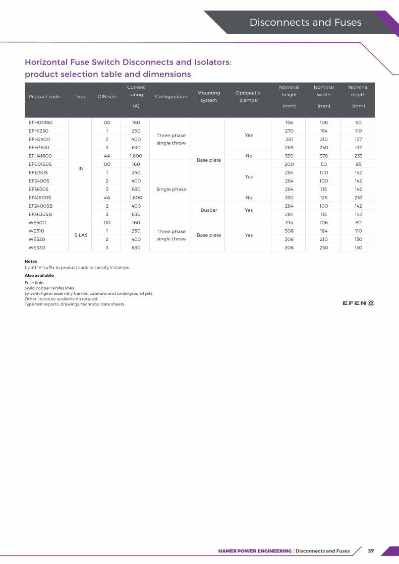
Notes 1. add “V” suffix to product code to specify V-clamps.
Also available
Fuse linksSolid copper (knife) links LV switchgear assembly frames, cabinets and underground pitsOther literature available on requestType test reports, drawings, technical data sheets
Horizontal Fuse Switch Disconnects and Isolators: product selection table and dimensions
Product code Type DIN size
Current
rating
(A)
ConfigurationMounting
system
Optional V-
clamps1
Nominal
height
(mm)
Nominal
width
(mm)
Nominal
depth
(mm)
EFH00160
IN
00 160
Three phase
single throw
Base plate
Yes
156 106 90
EFH1250 1 250 270 184 110
EFH2400 2 400 281 210 127
EFH3630 3 630 289 250 132
EFH41600 4A 1,600 No 330 378 233
EF00160S 00 160
Single phase
Yes
200 50 95
EF1250S 1 250 284 100 142
EF2400S 2 400 284 100 142
EF3630S 3 630 284 115 142
EF41600S 4A 1,600 No 330 126 233
EF2400SB 2 400Busbar Yes
284 100 142
EF3630SB 3 630 284 115 142
WE500
SILAS
00 160
Three phase
single throwBase plate Yes
194 106 80
WE510 1 250 306 184 110
WE520 2 400 306 210 130
WE530 3 630 306 250 130
38 HAMER POWER ENGINEERING / Disconnects and Fuses
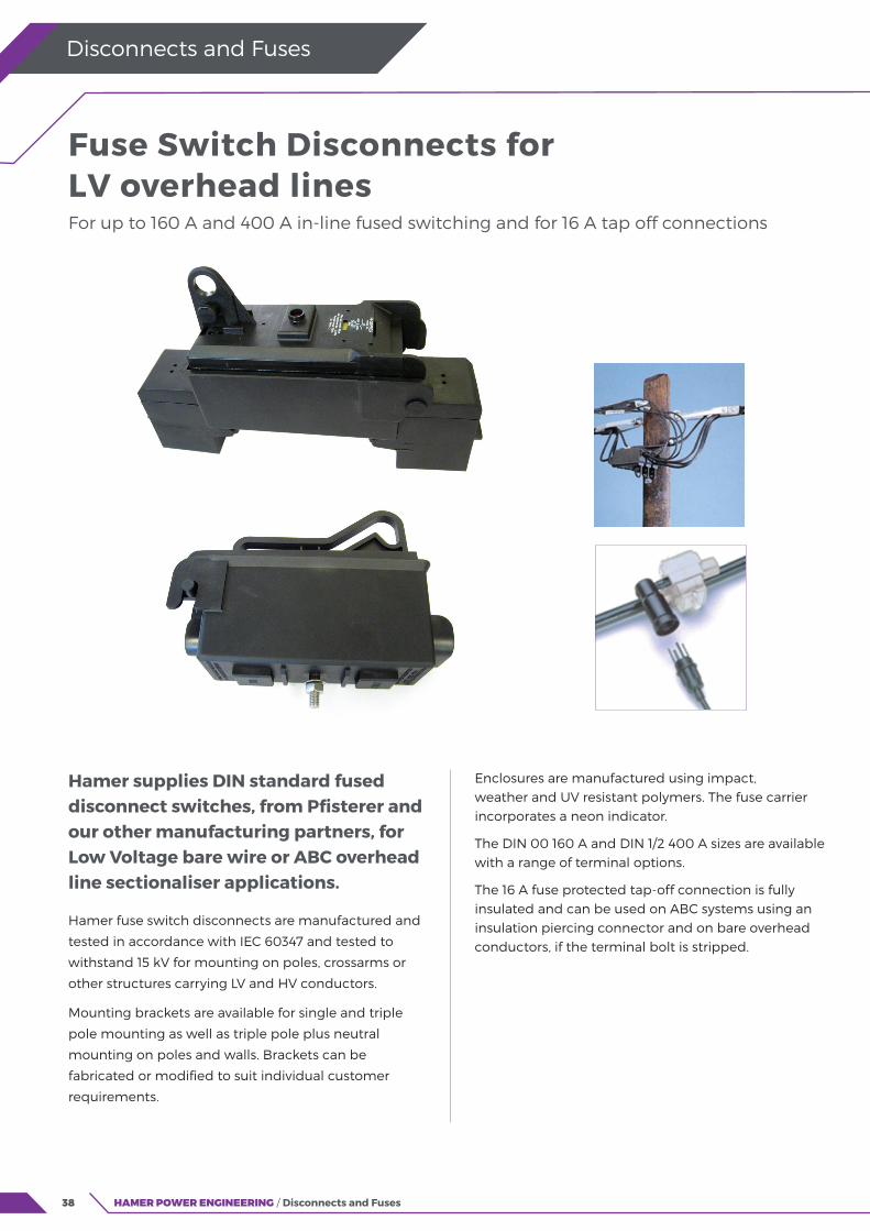
Hamer supplies DIN standard fused disconnect switches, from Pfisterer and our other manufacturing partners, for Low Voltage bare wire or ABC overhead line sectionaliser applications.
Hamer fuse switch disconnects are manufactured and
tested in accordance with IEC 60347 and tested to
withstand 15 kV for mounting on poles, crossarms or
other structures carrying LV and HV conductors.
Mounting brackets are available for single and triple
pole mounting as well as triple pole plus neutral
mounting on poles and walls. Brackets can be
fabricated or modified to suit individual customer
requirements.
Enclosures are manufactured using impact, weather and UV resistant polymers. The fuse carrier incorporates a neon indicator.
The DIN 00 160 A and DIN 1/2 400 A sizes are available with a range of terminal options.
The 16 A fuse protected tap-off connection is fully insulated and can be used on ABC systems using an insulation piercing connector and on bare overhead conductors, if the terminal bolt is stripped.
Disconnects and Fuses
Fuse Switch Disconnects for LV overhead linesFor up to 160 A and 400 A in-line fused switching and for 16 A tap off connections
39HAMER POWER ENGINEERING / Disconnects and Fuses
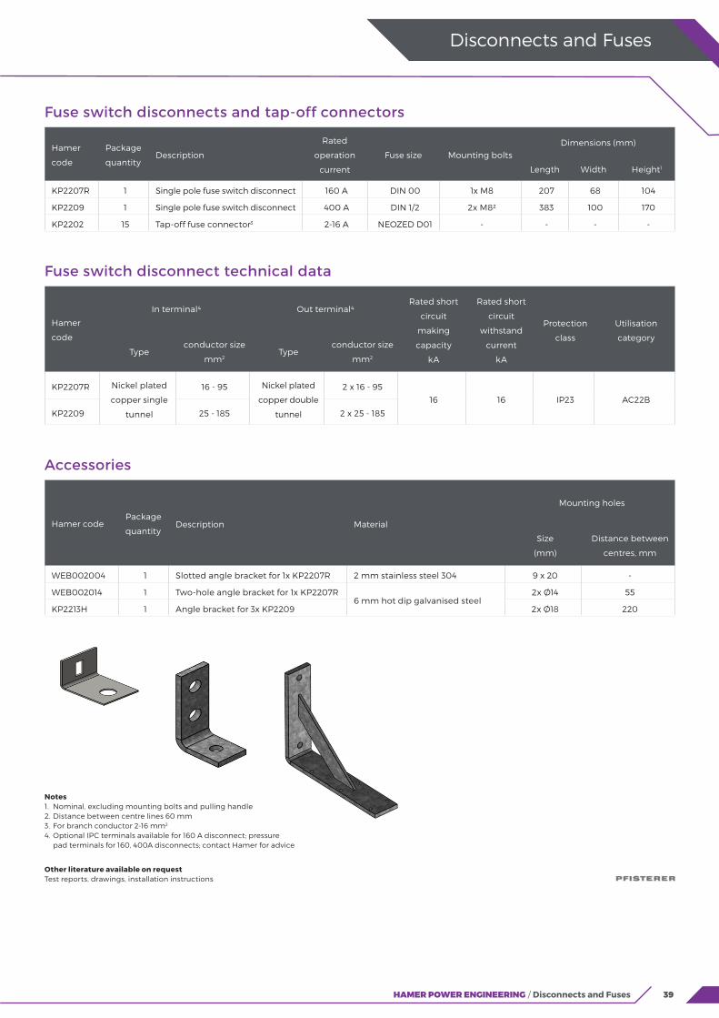
Notes 1. Nominal, excluding mounting bolts and pulling handle 2. Distance between centre lines 60 mm 3. For branch conductor 2-16 mm2 4. Optional IPC terminals available for 160 A disconnect; pressure pad terminals for 160, 400A disconnects; contact Hamer for advice
Other literature available on request Test reports, drawings, installation instructions
Fuse switch disconnects and tap-off connectors
Hamer
code
Package
quantityDescription
Rated
operation
current
Fuse size Mounting boltsDimensions (mm)
Length Width Height1
KP2207R 1 Single pole fuse switch disconnect 160 A DIN 00 1x M8 207 68 104
KP2209 1 Single pole fuse switch disconnect 400 A DIN 1/2 2x M82 383 100 170
KP2202 15 Tap-off fuse connector3 2-16 A NEOZED D01 - - - -
Accessories
Hamer codePackage
quantityDescription Material
Mounting holes
Size
(mm)
Distance between
centres, mm
WEB002004 1 Slotted angle bracket for 1x KP2207R 2 mm stainless steel 304 9 x 20 -
WEB002014 1 Two-hole angle bracket for 1x KP2207R6 mm hot dip galvanised steel
2x Ø14 55
KP2213H 1 Angle bracket for 3x KP2209 2x Ø18 220
Fuse switch disconnect technical data
Hamer
code
In terminal4 Out terminal4Rated short
circuit
making
capacity
kA
Rated short
circuit
withstand
current
kA
Protection
class
Utilisation
category
Typeconductor size
mm2Type
conductor size
mm2
KP2207R Nickel plated
copper single
tunnel
16 - 95 Nickel plated
copper double
tunnel
2 x 16 - 95
16 16 IP23 AC22B
KP2209 25 - 185 2 x 25 - 185
Disconnects and Fuses

40 HAMER POWER ENGINEERING / Disconnects and Fuses
Disconnects and Fuses
NH stands for “low voltage high rupturing capacity” (from the German: Niederspannungs Hochleistungs Sicherungen). NH fuses have a breaking capacity generally exceeding 100 kA, which covers virtually all the short-circuit currents expected to be encountered in low voltage systems.
The NH fuse system is used worldwide, and comprises fuses, solid links, fuse bases and fuse switch disconnects. NH fuses are designed to be used by authorised persons, and as such their design does not provide inherent protection against electric shock; instead, the fuse switch disconnect provides this protection. EFEN SILAS and IN series horizontal disconnects are fully compliant in this regard and
EFEN E3 vertical disconnects deliver best practice, with fully shrouded source and load contacts, even in the open position.
NH fuses and links sizes 00, 1, 2, 3 and 4a for which fully standardised bases are available.
There is no minimum operating voltage that must be observed for NH fuses, and they are designed to operate with AC systems from 45-62 Hz.
For most distribution line and cable applications, NH fuses with utilisation category gG are specified. These have full-range breaking capacity for general application, and have a time-current characteristic aligned to meet the current carrying capacity of insulated conductors. Hamer Power Engineering stocks a range of the most commonly used sizes of gG fuses. Other specialised fuses with different operating characteristics are also available.
EFEN NH Low Voltage High Rupturing Capacity Fuses and Solid Links For horizontal and vertical disconnects
41HAMER POWER ENGINEERING / Disconnects and Fuses
Disconnects and Fuses
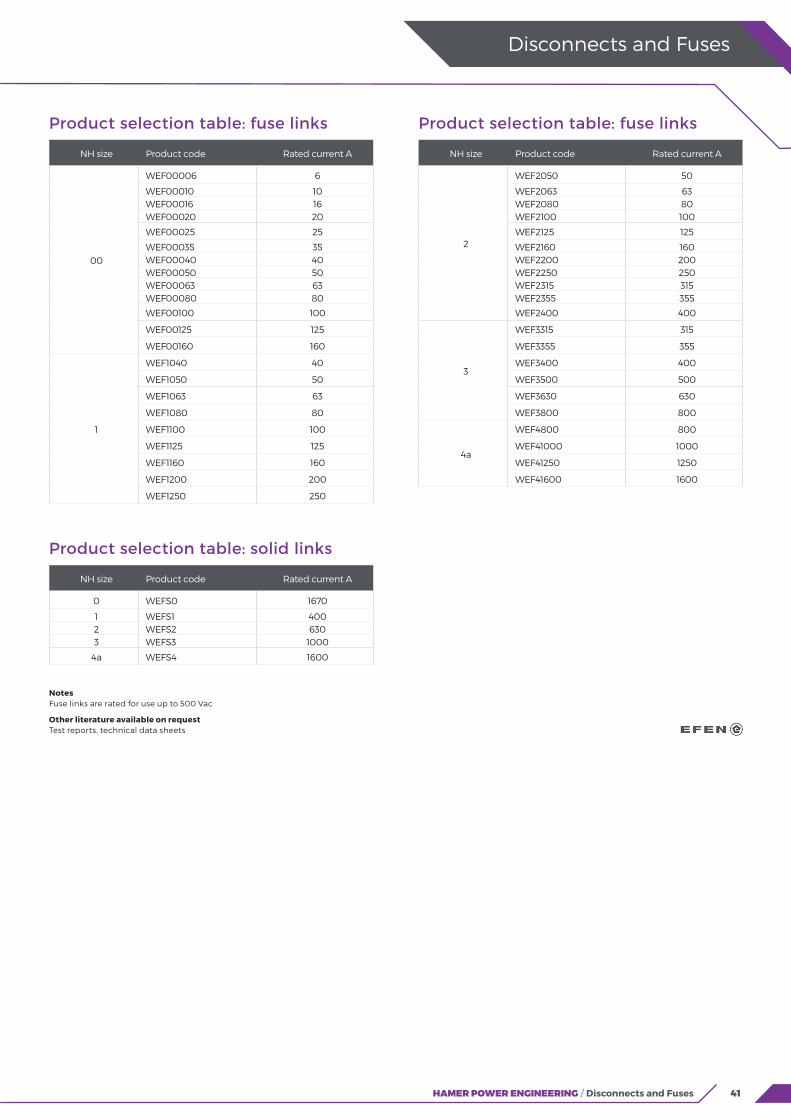
Product selection table: fuse links
NH size Product code Rated current A
00
WEF00006 6
WEF00010 10WEF00016 16WEF00020 20
WEF00025 25
WEF00035 35WEF00040 40WEF00050 50WEF00063 63WEF00080 80
WEF00100 100
WEF00125 125
WEF00160 160
1
WEF1040 40
WEF1050 50
WEF1063 63
WEF1080 80
WEF1100 100
WEF1125 125
WEF1160 160
WEF1200 200
WEF1250 250
Product selection table: fuse links
NH size Product code Rated current A
2
WEF2050 50
WEF2063 63WEF2080 80WEF2100 100
WEF2125 125
WEF2160 160WEF2200 200WEF2250 250WEF2315 315WEF2355 355
WEF2400 400
3
WEF3315 315
WEF3355 355
WEF3400 400
WEF3500 500
WEF3630 630
WEF3800 800
4a
WEF4800 800
WEF41000 1000
WEF41250 1250
WEF41600 1600
Notes Fuse links are rated for use up to 500 Vac
Other literature available on request Test reports, technical data sheets
Product selection table: solid links
NH size Product code Rated current A
0 WEFS0 1670
1 WEFS1 4002 WEFS2 6303 WEFS3 1000
4a WEFS4 1600

42 HAMER POWER ENGINEERING / Disconnects and Fuses
Disconnects and Fuses
Hamer Power Engineering provides a range of accessories to make the latest generation of EFEN E3 vertical fuse switch disconnectors even more versatile.
Connections
Connection plates have been specially designed to enable the connection of large cross section cables and multiple cables. These are typically ordered with the EFEN E3 disconnector as a complete assembly. The “compact single” connection is available as a retrofit kit.
Side entry tags are available for either the left or the right-hand side of the EFEN E3 disconnector.
Hamer Power Engineering also engineers bespoke connection solutions for individual customer requirements.
Spare covers
Connection plates are provided complete with covers; spare covers are available if required.
Current transformers
The EFEN E3 disconnector product line includes a specially designed range of Class 1 CTs that fit neatly onto the busbar connection tags, without increasing external dimensions.
Other accessories
The range of accessories available also includes: V-clamps, for cable connection without compression crimping; mounting brackets to provide attachment points on the side of the EFEN E3 disconnector; handle clips to identify a particular circuit such as the incomer; and CT cable covers, to protect the special CT wiring behind the disconnector.
Connections, Spare Covers, CTs and Other Accessories For EFEN E3 vertical disconnects

43HAMER POWER ENGINEERING / Disconnects and Fuses
Disconnects and Fuses
Disconnect connection variants (pre-assembled)
Image Disconnect types Suffix1 DescriptionMax
conductor size (mm2)
Extended length to bottom
connection centre line
(mm)
EFV31000 C
Compact single
Also available as an accessory Hamer code EFA0005
2x 300 103
EFV32000 CD Compact dual 3x 630 114
EFV31000 E Extended single1x 630 or
2x 300158
EFV32000 ED Extended dual 3x 630 169
EFV32000D FD Four-way compact dual 4x 300 114
EFV31000
SL Side entry tags (left) - -
SR Side entry tags (right) - -
Disconnect accessories
Image For use with Product code Description
EFV2400
EFV3630
EFV3800
EFV31000
EFA0014 V-clamp Connector set
EFA0005 Compact connection kit (set of 3x modified covers, brackets and bolts)
EFV2400
EFV3630
EFV3800
EFV31000
EFV31250
EFV31600
EFV32000
EFA0013 Angle bracket (set of 4x for attachment points in the side of disconnects)
EFA0006 Red handle clips (for identifying incomer)
EFA0001 CT cable holder (clips on to the back of the disconnect)
44 HAMER POWER ENGINEERING / Disconnects and Fuses
Disconnects and Fuses
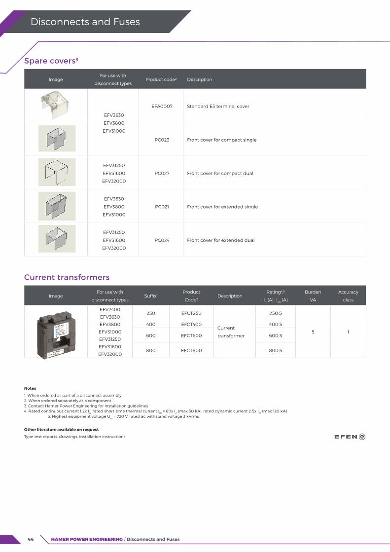
Spare covers3
ImageFor use with
disconnect typesProduct code2 Description
EFV3630
EFV3800
EFV31000
EFA0007 Standard E3 terminal cover
PC023 Front cover for compact single
EFV31250
EFV31600
EFV32000
PC027 Front cover for compact dual
EFV3630
EFV3800
EFV31000
PC021 Front cover for extended single
EFV31250
EFV31600
EFV32000
PC024 Front cover for extended dual
Notes
1. When ordered as part of a disconnect assembly 2. When ordered separately as a component 3. Contact Hamer Power Engineering for installation guidelines 4. Rated continuous current 1.2x In; rated short-time thermal current Ith = 60x In (max 50 kA); rated dynamic current 2.5x Ith (max 120 kA) 5. Highest equipment voltage Um = 720 V; rated ac withstand voltage 3 kVrms
Other literature available on request
Type test reports, drawings, installation instructions
Current transformers
ImageFor use with
disconnect typesSuffix1
Product
Code2Description
Rating4,5
In (A) : I2n (A)
Burden
VA
Accuracy
class
EFV2400250 EFCT250
Current
transformer
250:5
5 1
EFV3630
EFV3800 400 EFCT400 400:5
EFV31000600 EFCT600 600:5
EFV31250
EFV31600800 EFCT800 800:5
EFV32000
45
Cable Joints and Terminations Pfisterer ISICOMPACT LV Branch Joints
NKT CB/CC Screened T-Connectors
NKT CPI Inner Cone Connectors
NKT Fluid-Filled MV/HV Cable Accessories
NKT MV Cable Joints and Terminations
44
46
50
54
58
46
Cable Joints and Terminations
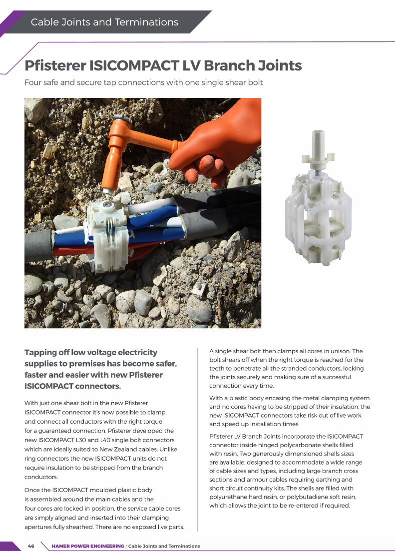
Tapping off low voltage electricity supplies to premises has become safer, faster and easier with new Pfisterer ISICOMPACT connectors.
With just one shear bolt in the new Pfisterer
ISICOMPACT connector it’s now possible to clamp
and connect all conductors with the right torque
for a guaranteed connection. Pfisterer developed the
new ISICOMPACT L30 and L40 single bolt connectors
which are ideally suited to New Zealand cables. Unlike
ring connectors the new ISICOMPACT units do not
require insulation to be stripped from the branch
conductors.
Once the ISICOMPACT moulded plastic body
is assembled around the main cables and the
four cores are locked in position, the service cable cores
are simply aligned and inserted into their clamping
apertures fully sheathed. There are no exposed live parts.
A single shear bolt then clamps all cores in unison. The bolt shears off when the right torque is reached for the teeth to penetrate all the stranded conductors, locking the joints securely and making sure of a successful connection every time.
With a plastic body encasing the metal clamping system and no cores having to be stripped of their insulation, the new ISICOMPACT connectors take risk out of live work and speed up installation times.
Pfisterer LV Branch Joints incorporate the ISICOMPACT connector inside hinged polycarbonate shells filled with resin. Two generously dimensioned shells sizes are available, designed to accommodate a wide range of cable sizes and types, including large branch cross sections and armour cables requiring earthing and short circuit continuity kits. The shells are filled with polyurethane hard resin, or polybutadiene soft resin, which allows the joint to be re-entered if required.
Pfisterer ISICOMPACT LV Branch Joints Four safe and secure tap connections with one single shear bolt
HAMER POWER ENGINEERING / Cable Joints and Terminations
47HAMER POWER ENGINEERING / Cable Joints and Terminations
Cable Joints and Terminations
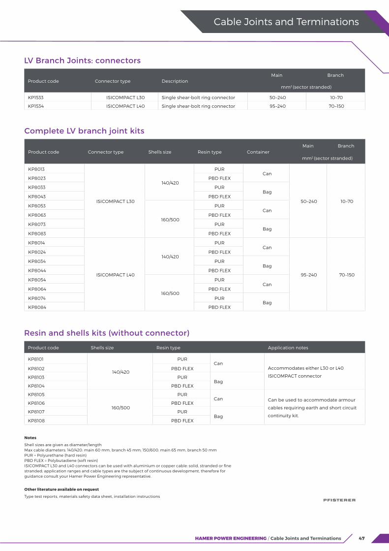
LV Branch Joints: connectors
Product code Connector type DescriptionMain Branch
mm2 (sector stranded)
KP1533 ISICOMPACT L30 Single shear-bolt ring connector 50–240 10–70
KP1534 ISICOMPACT L40 Single shear-bolt ring connector 95–240 70–150
Notes
Shell sizes are given as diameter/lengthMax cable diameters: 140/420: main 60 mm, branch 45 mm; 150/600: main 65 mm, branch 50 mmPUR = Polyurethane (hard resin)PBD FLEX = Polybutadiene (soft resin)ISICOMPACT L30 and L40 connectors can be used with aluminium or copper cable: solid, stranded or fine stranded; application ranges and cable types are the subject of continuous development, therefore for guidance consult your Hamer Power Engineering representative.
Other literature available on request
Type test reports, materials safety data sheet, installation instructions
Resin and shells kits (without connector)
Product code Shells size Resin type Application notes
KP8101
140/420
PURCan
Accommodates either L30 or L40
ISICOMPACT connector
KP8102 PBD FLEX
KP8103 PURBag
KP8104 PBD FLEX
KP8105
160/500
PURCan Can be used to accommodate armour
cables requiring earth and short circuit
continuity kit.
KP8106 PBD FLEX
KP8107 PURBag
KP8108 PBD FLEX
Complete LV branch joint kits
Product code Connector type Shells size Resin type ContainerMain Branch
mm2 (sector stranded)
KP8013
ISICOMPACT L30
140/420
PURCan
50–240 10–70
KP8023 PBD FLEX
KP8033 PURBag
KP8043 PBD FLEX
KP8053
160/500
PURCan
KP8063 PBD FLEX
KP8073 PURBag
KP8083 PBD FLEX
KP8014
ISICOMPACT L40
140/420
PURCan
95–240 70–150
KP8024 PBD FLEX
KP8034 PURBag
KP8044 PBD FLEX
KP8054
160/500
PURCan
KP8064 PBD FLEX
KP8074 PURBag
KP8084 PBD FLEX
48 HAMER POWER ENGINEERING / Cable Joints and Terminations
Cable Joints and Terminations
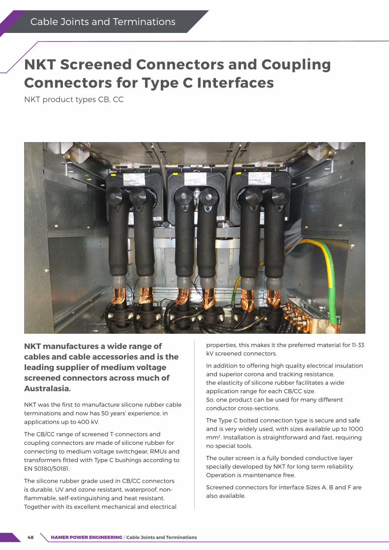
NKT manufactures a wide range of cables and cable accessories and is the leading supplier of medium voltage screened connectors across much of Australasia.
NKT was the first to manufacture silicone rubber cable terminations and now has 50 years’ experience, in applications up to 400 kV.
The CB/CC range of screened T-connectors and coupling connectors are made of silicone rubber for connecting to medium voltage switchgear, RMUs and transformers fitted with Type C bushings according to EN 50180/50181.
The silicone rubber grade used in CB/CC connectors is durable, UV and ozone resistant, waterproof, non-flammable, self-extinguishing and heat resistant. Together with its excellent mechanical and electrical
properties, this makes it the preferred material for 11-33 kV screened connectors.
In addition to offering high quality electrical insulation and superior corona and tracking resistance, the elasticity of silicone rubber facilitates a wide application range for each CB/CC size. So, one product can be used for many different conductor cross-sections.
The Type C bolted connection type is secure and safe and is very widely used, with sizes available up to 1000 mm2. Installation is straightforward and fast, requiring no special tools.
The outer screen is a fully bonded conductive layer specially developed by NKT for long term reliability. Operation is maintenance free.
Screened connectors for interface Sizes A, B and F are also available.
NKT Screened Connectors and Coupling Connectors for Type C Interfaces NKT product types CB, CC
49HAMER POWER ENGINEERING / Cable Joints and Terminations
Cable Joints and Terminations
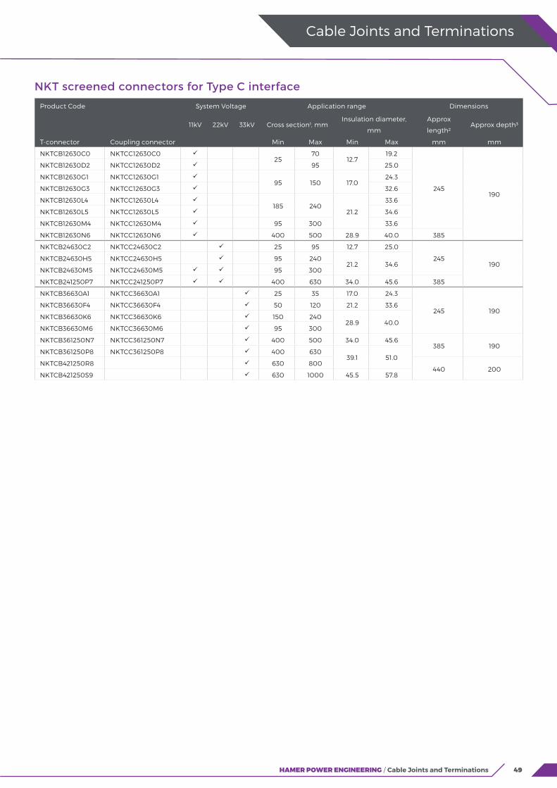
NKT screened connectors for Type C interface
Product Code System Voltage Application range Dimensions
11kV 22kV 33kV Cross section¹, mmInsulation diameter,
mm
Approx
length²Approx depth³
T-connector Coupling connector Min Max Min Max mm mm
NKTCB12630C0 NKTCC12630C0 25
7012.7
19.2
245190
NKTCB12630D2 NKTCC12630D2 95 25.0
NKTCB12630G1 NKTCC12630G1 95 150 17.0
24.3
NKTCB12630G3 NKTCC12630G3 32.6
NKTCB12630L4 NKTCC12630L4 185 240
21.2
33.6
NKTCB12630L5 NKTCC12630L5 34.6
NKTCB12630M4 NKTCC12630M4 95 300 33.6
NKTCB12630N6 NKTCC12630N6 400 500 28.9 40.0 385
NKTCB24630C2 NKTCC24630C2 25 95 12.7 25.0
245190
NKTCB24630H5 NKTCC24630H5 95 24021.2 34.6
NKTCB24630M5 NKTCC24630M5 95 300
NKTCB241250P7 NKTCC241250P7 400 630 34.0 45.6 385
NKTCB36630A1 NKTCC36630A1 25 35 17.0 24.3
245 190NKTCB36630F4 NKTCC36630F4 50 120 21.2 33.6
NKTCB36630K6 NKTCC36630K6 150 24028.9 40.0
NKTCB36630M6 NKTCC36630M6 95 300
NKTCB361250N7 NKTCC361250N7 400 500 34.0 45.6385 190
NKTCB361250P8 NKTCC361250P8 400 63039.1 51.0
NKTCB421250R8 630 800440 200
NKTCB421250S9 630 1000 45.5 57.8
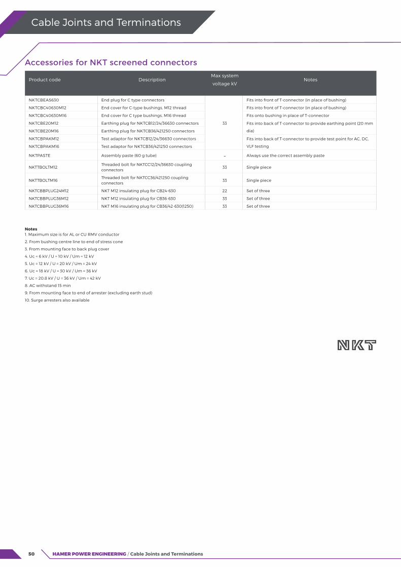
50 HAMER POWER ENGINEERING / Cable Joints and Terminations
Cable Joints and Terminations
Accessories for NKT screened connectors
Product code DescriptionMax system
voltage kVNotes
NKTCBEAS630 End plug for C type connectors
33
Fits into front of T-connector (in place of bushing)
NKTCBC40630M12 End cover for C-type bushings, M12 thread Fits into front of T-connector (in place of bushing)
NKTCBC40630M16 End cover for C type bushings, M16 thread Fits onto bushing in place of T-connector
NKTCBE20M12 Earthing plug for NKTCB12/24/36630 connectors Fits into back of T-connector to provide earthing point (20 mm
dia)NKTCBE20M16 Earthing plug for NKTCB36/421250 connectors
NKTCBPAKM12 Test adaptor for NKTCB12/24/36630 connectors Fits into back of T-connector to provide test point for AC, DC,
VLF testingNKTCBPAKM16 Test adaptor for NKTCB36/421250 connectors
NKTPASTE Assembly paste (60 g tube) - Always use the correct assembly paste
NKTTBOLTM12Threaded bolt for NKTCC12/24/36630 coupling connectors
33 Single piece
NKTTBOLTM16Threaded bolt for NKTCC36/421250 coupling connectors
33 Single piece
NKTCBBPLUG24M12 NKT M12 insulating plug for CB24-630 22 Set of three
NKTCBBPLUG36M12 NKT M12 insulating plug for CB36-630 33 Set of three
NKTCBBPLUG36M16 NKT M16 insulating plug for CB36/42-630(1250) 33 Set of three
Notes 1. Maximum size is for AL or CU RMV conductor
2. From bushing centre line to end of stress cone
3. From mounting face to back plug cover
4. Uc = 6 kV / U = 10 kV / Um = 12 kV
5. Uc = 12 kV / U = 20 kV / Um = 24 kV
6. Uc = 18 kV / U = 30 kV / Um = 36 kV
7. Uc = 20.8 kV / U = 36 kV / Um = 42 kV
8. AC withstand 15 min
9. From mounting face to end of arrester (excluding earth stud)
10. Surge arresters also available
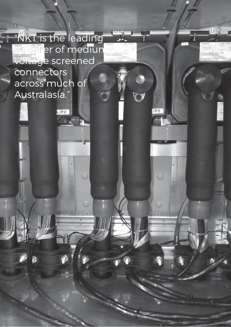
51
“NKT is the leading supplier of medium voltage screened connectors across much of Australasia.”
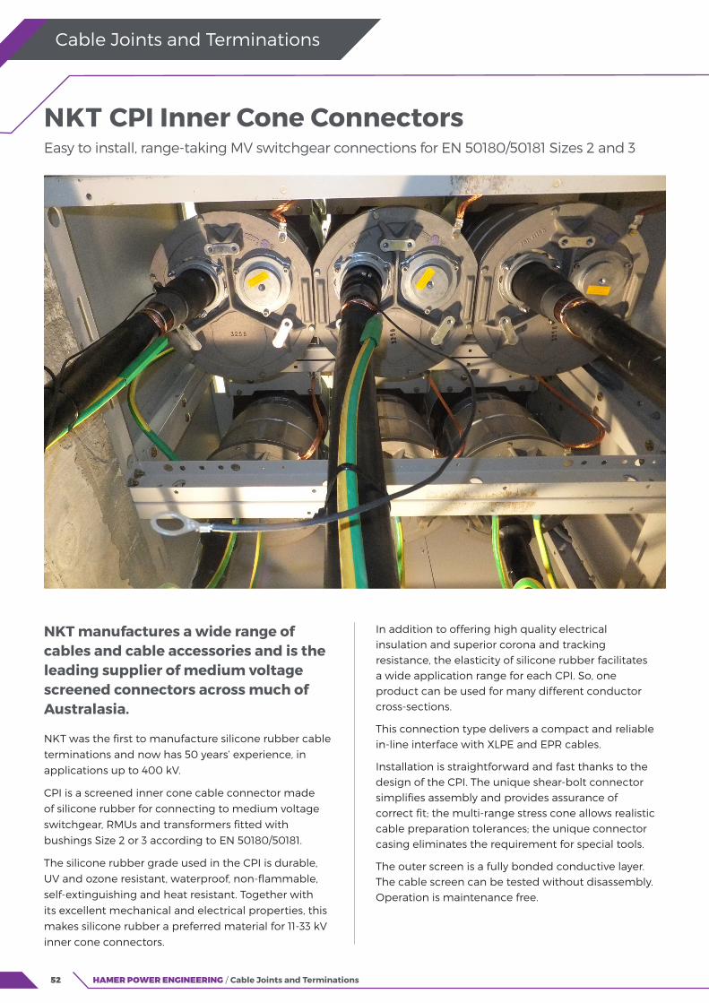
52
NKT manufactures a wide range of cables and cable accessories and is the leading supplier of medium voltage screened connectors across much of Australasia.
NKT was the first to manufacture silicone rubber cable terminations and now has 50 years’ experience, in applications up to 400 kV.
CPI is a screened inner cone cable connector made of silicone rubber for connecting to medium voltage switchgear, RMUs and transformers fitted with bushings Size 2 or 3 according to EN 50180/50181.
The silicone rubber grade used in the CPI is durable, UV and ozone resistant, waterproof, non-flammable, self-extinguishing and heat resistant. Together with its excellent mechanical and electrical properties, this makes silicone rubber a preferred material for 11-33 kV inner cone connectors.
HAMER POWER ENGINEERING / Cable Joints and Terminations
Cable Joints and Terminations
In addition to offering high quality electrical insulation and superior corona and tracking resistance, the elasticity of silicone rubber facilitates a wide application range for each CPI. So, one product can be used for many different conductor cross-sections.
This connection type delivers a compact and reliable in-line interface with XLPE and EPR cables.
Installation is straightforward and fast thanks to the design of the CPI. The unique shear-bolt connector simplifies assembly and provides assurance of correct fit; the multi-range stress cone allows realistic cable preparation tolerances; the unique connector casing eliminates the requirement for special tools.
The outer screen is a fully bonded conductive layer. The cable screen can be tested without disassembly. Operation is maintenance free.
NKT CPI Inner Cone Connectors Easy to install, range-taking MV switchgear connections for EN 50180/50181 Sizes 2 and 3
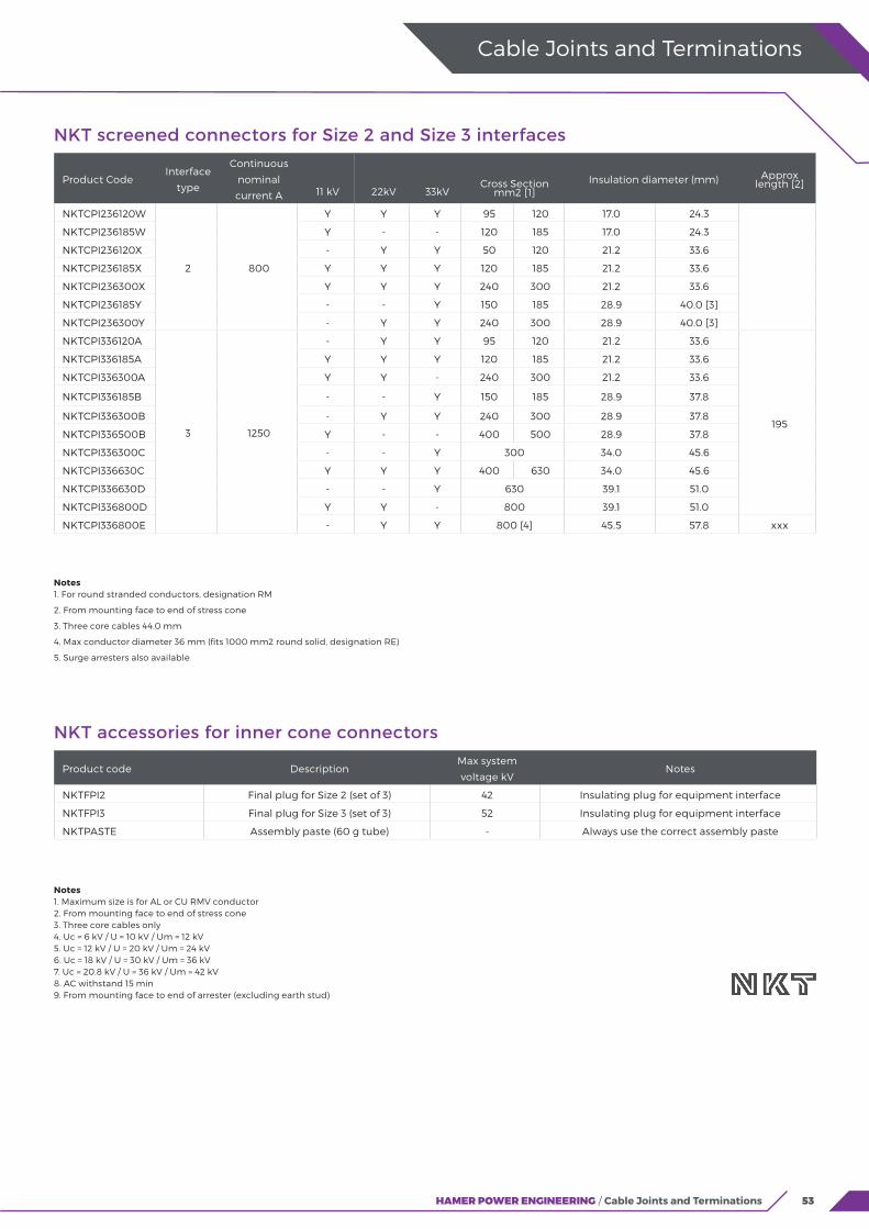
53HAMER POWER ENGINEERING / Cable Joints and Terminations
NKT screened connectors for Size 2 and Size 3 interfaces
Product CodeInterface
type
Continuous
nominal
current A 11 kV 22kV 33kVCross Section
mm2 [1]Insulation diameter (mm) Approx
length [2]
NKTCPI236120W
2 800
Y Y Y 95 120 17.0 24.3
NKTCPI236185W Y - - 120 185 17.0 24.3
NKTCPI236120X - Y Y 50 120 21.2 33.6
NKTCPI236185X Y Y Y 120 185 21.2 33.6
NKTCPI236300X Y Y Y 240 300 21.2 33.6
NKTCPI236185Y - - Y 150 185 28.9 40.0 [3]
NKTCPI236300Y - Y Y 240 300 28.9 40.0 [3]
NKTCPI336120A
3 1250
- Y Y 95 120 21.2 33.6
195
NKTCPI336185A Y Y Y 120 185 21.2 33.6
NKTCPI336300A Y Y - 240 300 21.2 33.6
NKTCPI336185B - - Y 150 185 28.9 37.8
NKTCPI336300B - Y Y 240 300 28.9 37.8
NKTCPI336500B Y - - 400 500 28.9 37.8
NKTCPI336300C - - Y 300 34.0 45.6
NKTCPI336630C Y Y Y 400 630 34.0 45.6
NKTCPI336630D - - Y 630 39.1 51.0
NKTCPI336800D Y Y - 800 39.1 51.0
NKTCPI336800E - Y Y 800 [4] 45.5 57.8 xxx
Cable Joints and Terminations
Notes 1. For round stranded conductors, designation RM
2. From mounting face to end of stress cone
3. Three core cables 44.0 mm
4. Max conductor diameter 36 mm (fits 1000 mm2 round solid, designation RE)
5. Surge arresters also available
NKT accessories for inner cone connectors
Product code DescriptionMax system
voltage kVNotes
NKTFPI2 Final plug for Size 2 (set of 3) 42 Insulating plug for equipment interface
NKTFPI3 Final plug for Size 3 (set of 3) 52 Insulating plug for equipment interface
NKTPASTE Assembly paste (60 g tube) - Always use the correct assembly paste
Notes 1. Maximum size is for AL or CU RMV conductor 2. From mounting face to end of stress cone 3. Three core cables only 4. Uc = 6 kV / U = 10 kV / Um = 12 kV 5. Uc = 12 kV / U = 20 kV / Um = 24 kV 6. Uc = 18 kV / U = 30 kV / Um = 36 kV 7. Uc = 20.8 kV / U = 36 kV / Um = 42 kV 8. AC withstand 15 min 9. From mounting face to end of arrester (excluding earth stud)

54 HAMER POWER ENGINEERING / Cable Joints and Terminations
Cable Joints and Terminations
55
“Safe and efficient delivery of electricity needs networks to be built with products that provide assurance of reliability.”
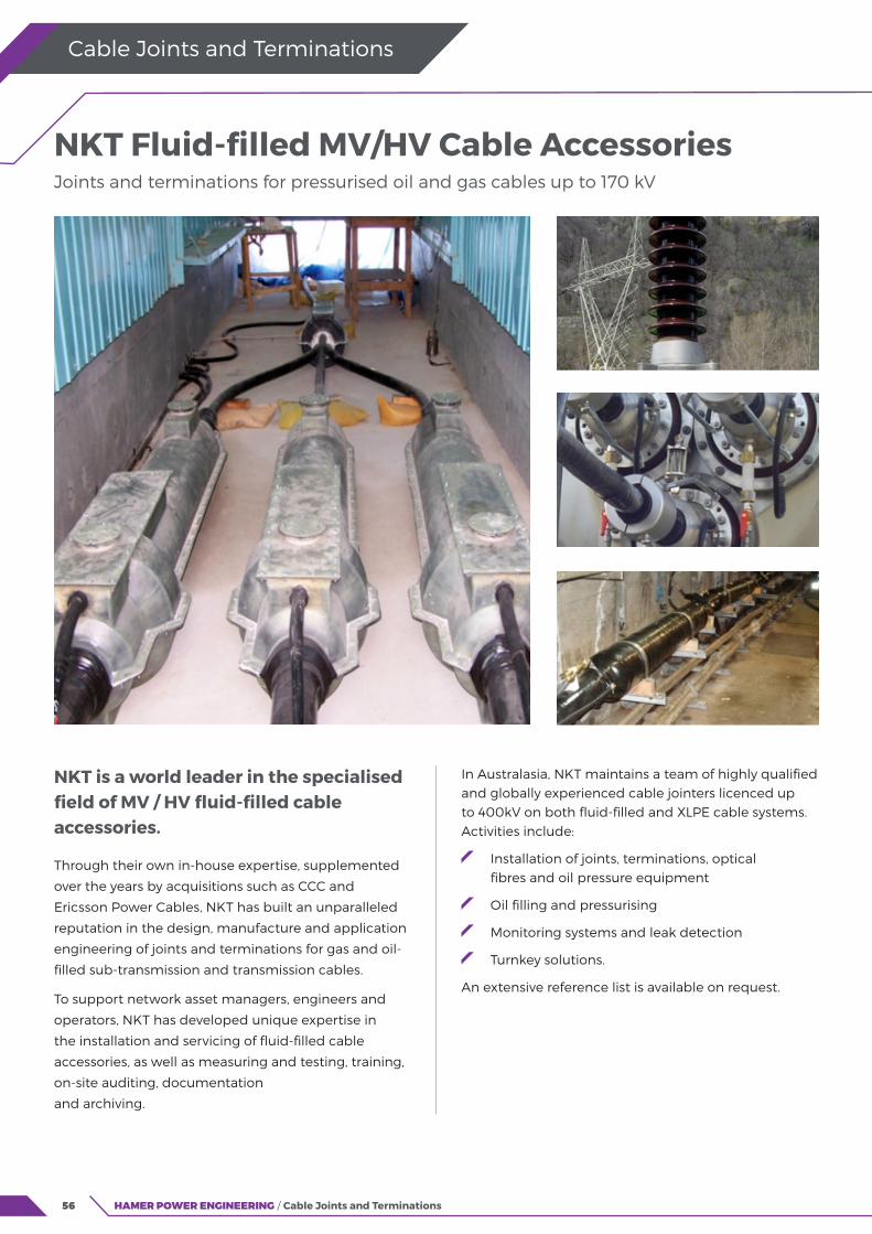
56
NKT is a world leader in the specialised field of MV / HV fluid-filled cable accessories.
Through their own in-house expertise, supplemented
over the years by acquisitions such as CCC and
Ericsson Power Cables, NKT has built an unparalleled
reputation in the design, manufacture and application
engineering of joints and terminations for gas and oil-
filled sub-transmission and transmission cables.
To support network asset managers, engineers and
operators, NKT has developed unique expertise in
the installation and servicing of fluid-filled cable
accessories, as well as measuring and testing, training,
on-site auditing, documentation
and archiving.
HAMER POWER ENGINEERING / Cable Joints and Terminations
Cable Joints and Terminations
In Australasia, NKT maintains a team of highly qualified and globally experienced cable jointers licenced up to 400kV on both fluid-filled and XLPE cable systems. Activities include:
Installation of joints, terminations, optical fibres and oil pressure equipment
Oil filling and pressurising
Monitoring systems and leak detection
Turnkey solutions.
An extensive reference list is available on request.
NKT Fluid-filled MV/HV Cable Accessories Joints and terminations for pressurised oil and gas cables up to 170 kV
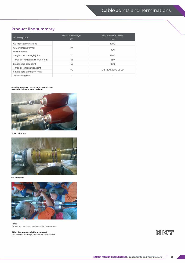
57HAMER POWER ENGINEERING / Cable Joints and Terminations
Cable Joints and Terminations
Product line summary
Accessory typeMaximum voltage
kV
Maximum cable size
mm2
Outdoor terminations
145
1200
GIS and transformer
terminations800
Single core through joint 170 1200
Three core straight through joint 145 630
Single core stop joint 145 800
Three core transition joint170 Oil: 1200 XLPE: 2500
Single core transition joint
Trifurcating box - -
Notes Other cross sections may be available on request
Other literature available on request Test reports, drawings, installation instructions
Installation of NKT 33 kV sub-transmission transition joints in New Zealand:
XLPE cable end
Oil cable end
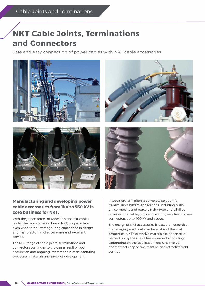
58
Cable Joints and Terminations
HAMER POWER ENGINEERING / Cable Joints and Terminations
Manufacturing and developing power cable accessories from 1kV to 550 kV is core business for NKT.With the joined forces of Kabeldon and nkt cables under the new common brand NKT, we provide an even wider product range, long experience in design and manufacturing of accessories and excellent service.
The NKT range of cable joints, terminations and connectors continues to grow as a result of both acquisition and ongoing investment in manufacturing processes, materials and product development.
NKT Cable Joints, Terminations and Connectors Safe and easy connection of power cables with NKT cable accessories
In addition, NKT offers a complete solution for transmission system applications, including push-on, composite and porcelain dry-type and oil-filled terminations, cable joints and switchgear / transformer connectors up to 400 kV and above.
The design of NKT accessories is based on expertise in managing electrical, mechanical and thermal properties. NKT’s extensive materials experience is backed up by the use of finite element modelling. Depending on the application, designs involve geometrical / capacitive, resistive and refractive field control.
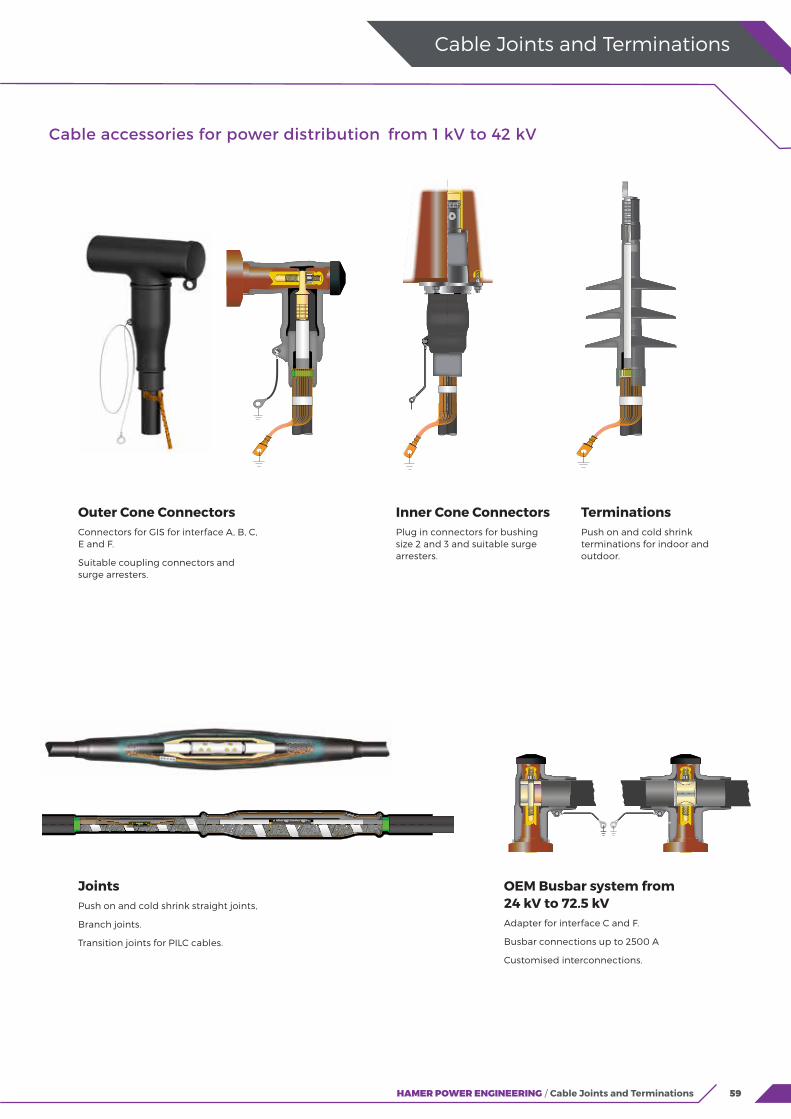
NKT Cable Joints, Terminations and Connectors Safe and easy connection of power cables with NKT cable accessories
59HAMER POWER ENGINEERING / Cable Joints and Terminations
Cable Joints and Terminations
Outer Cone ConnectorsConnectors for GIS for interface A, B, C, E and F.
Suitable coupling connectors and surge arresters.
Inner Cone ConnectorsPlug in connectors for bushing size 2 and 3 and suitable surge arresters.
TerminationsPush on and cold shrink terminations for indoor and outdoor.
JointsPush on and cold shrink straight joints,
Branch joints.
Transition joints for PILC cables.
OEM Busbar system from 24 kV to 72.5 kVAdapter for interface C and F.
Busbar connections up to 2500 A
Customised interconnections.
Cable accessories for power distribution from 1 kV to 42 kV

60
Cable Joints and Terminations
Cable accessories for power distribution from 52 kV to 550 kV
GIS/Transformer TerminationsDry plug-in cable terminations.
Oil filled plug-in cable terminations.
Outdoor TerminationsFlexible cable terminations.
Oil filled cable terminations.
Termination with porcelain or composite insulator.
JointsOne or three pieces straight joints with or without cross bonding.
Low Pressure Oil filled AccessoriesJoints and terminations.
61
Network Fittings and Accessories Bowthorpe HD Series Line Taps
REBAr Earth Bonding Anchor
Pfisterer SICON Stepless Shear Bolt Connectors
Polaris PTLIH Ground Mounted Transformer Connectors
Polaris PSMTL Transformer Connectors
LV Protective Caps
IPCs, PG Clamps and Other Clamps for Overhead Lines
60
62
64
66
68
70
72
Cable accessories for power distribution from 52 kV to 550 kV
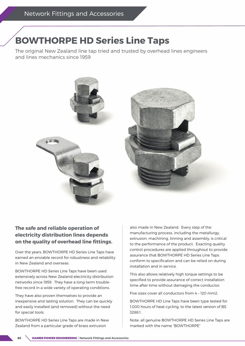
62 HAMER POWER ENGINEERING / Network Fittings and Accessories
Network Fittings and Accessories
The safe and reliable operation of electricity distribution lines depends on the quality of overhead line fittings.
Over the years, BOWTHORPE HD Series Line Taps have
earned an enviable record for robustness and reliability
in New Zealand and overseas.
BOWTHORPE HD Series Line Taps have been used
extensively across New Zealand electricity distribution
networks since 1959. They have a long-term trouble-
free record in a wide variety of operating conditions.
They have also proven themselves to provide an
inexpensive and lasting solution. They can be quickly
and easily installed (and removed) without the need
for special tools.
BOWTHORPE HD Series Line Taps are made in New
Zealand from a particular grade of brass extrusion
BOWTHORPE HD Series Line Taps
The original New Zealand line tap tried and trusted by overhead lines engineers and lines mechanics since 1959
also made in New Zealand. Every step of the
manufacturing process, including the metallurgy,
extrusion, machining, tinning and assembly, is critical
to the performance of the product. Exacting quality
control procedures are applied throughout to provide
assurance that BOWTHORPE HD Series Line Taps
conform to specification and can be relied on during
installation and in service.
This also allows relatively high torque settings to be
specified to provide assurance of correct installation
time after time without damaging the conductor.
Five sizes cover all conductors from 4 – 120 mm2.
BOWTHORPE HD Line Taps have been type tested for
1,000 hours of heat-cycling, to the latest version of BS
3288.1.
Note: all genuine BOWTHORPE HD Series Line Taps are
marked with the name “BOWTHORPE”
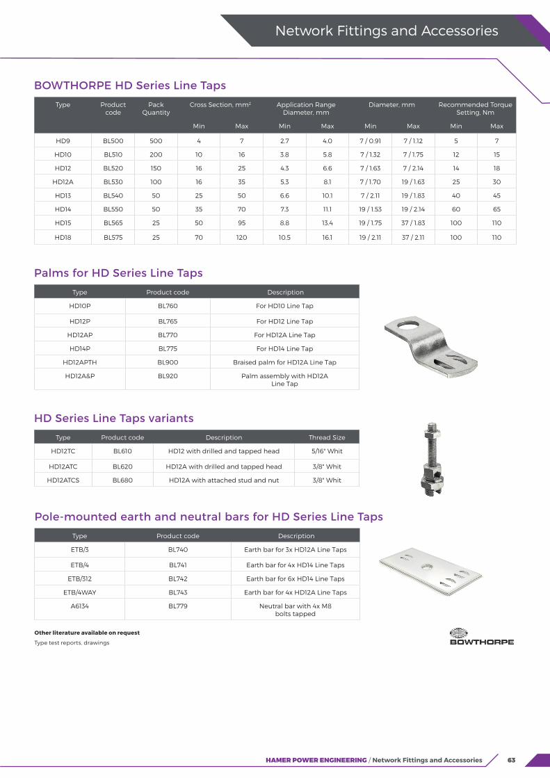
63HAMER POWER ENGINEERING / Network Fittings and Accessories
Network Fittings and Accessories
BOWTHORPE HD Series Line Taps
Type Product code
Pack Quantity
Cross Section, mm2 Application Range Diameter, mm
Diameter, mm Recommended Torque Setting, Nm
Min Max Min Max Min Max Min Max
HD9 BL500 500 4 7 2.7 4.0 7 / 0.91 7 / 1.12 5 7
HD10 BL510 200 10 16 3.8 5.8 7 / 1.32 7 / 1.75 12 15
HD12 BL520 150 16 25 4.3 6.6 7 / 1.63 7 / 2.14 14 18
HD12A BL530 100 16 35 5.3 8.1 7 / 1.70 19 / 1.63 25 30
HD13 BL540 50 25 50 6.6 10.1 7 / 2.11 19 / 1.83 40 45
HD14 BL550 50 35 70 7.3 11.1 19 / 1.53 19 / 2.14 60 65
HD15 BL565 25 50 95 8.8 13.4 19 / 1.75 37 / 1.83 100 110
HD18 BL575 25 70 120 10.5 16.1 19 / 2.11 37 / 2.11 100 110
Palms for HD Series Line Taps
Type Product code Description
HD10P BL760 For HD10 Line Tap
HD12P BL765 For HD12 Line Tap
HD12AP BL770 For HD12A Line Tap
HD14P BL775 For HD14 Line Tap
HD12APTH BL900 Braised palm for HD12A Line Tap
HD12A&P BL920 Palm assembly with HD12A Line Tap
HD Series Line Taps variants
Type Product code Description Thread Size
HD12TC BL610 HD12 with drilled and tapped head 5/16" Whit
HD12ATC BL620 HD12A with drilled and tapped head 3/8" Whit
HD12ATCS BL680 HD12A with attached stud and nut 3/8" Whit
Pole-mounted earth and neutral bars for HD Series Line Taps
Type Product code Description
ETB/3 BL740 Earth bar for 3x HD12A Line Taps
ETB/4 BL741 Earth bar for 4x HD14 Line Taps
ETB/312 BL742 Earth bar for 6x HD14 Line Taps
ETB/4WAY BL743 Earth bar for 4x HD12A Line Taps
A6134 BL779 Neutral bar with 4x M8 bolts tapped
Other literature available on request
Type test reports, drawings
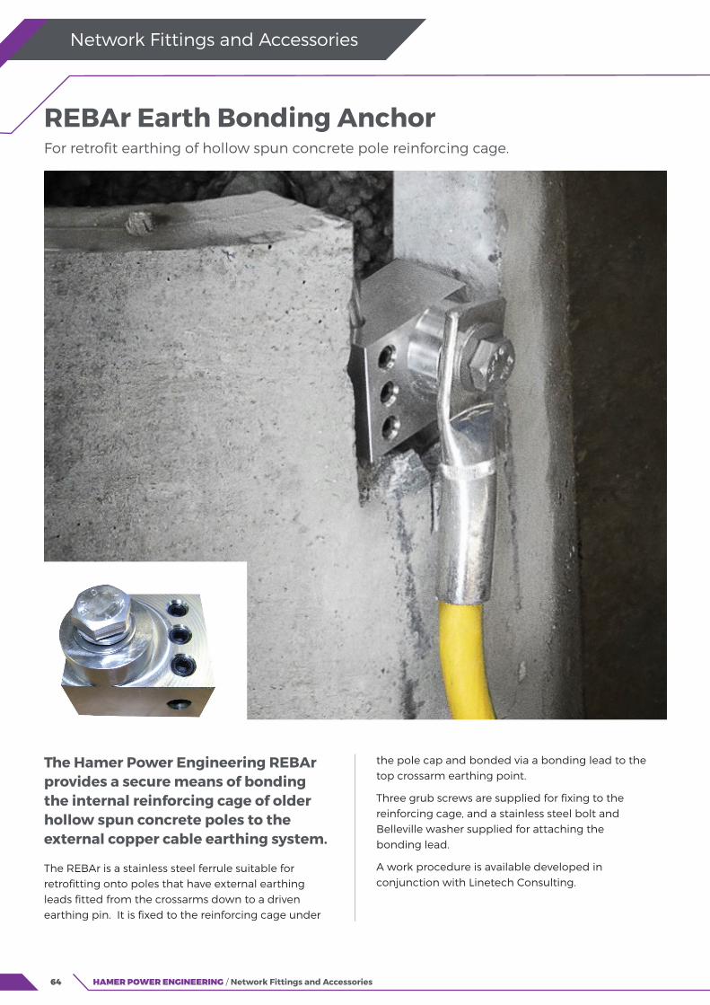
64
The Hamer Power Engineering REBAr provides a secure means of bonding the internal reinforcing cage of older hollow spun concrete poles to the external copper cable earthing system.
The REBAr is a stainless steel ferrule suitable for retrofitting onto poles that have external earthing leads fitted from the crossarms down to a driven earthing pin. It is fixed to the reinforcing cage under
HAMER POWER ENGINEERING / Network Fittings and Accessories
Network Fittings and Accessories
REBAr Earth Bonding Anchor For retrofit earthing of hollow spun concrete pole reinforcing cage.
the pole cap and bonded via a bonding lead to the top crossarm earthing point.
Three grub screws are supplied for fixing to the reinforcing cage, and a stainless steel bolt and Belleville washer supplied for attaching the bonding lead.
A work procedure is available developed in conjunction with Linetech Consulting.
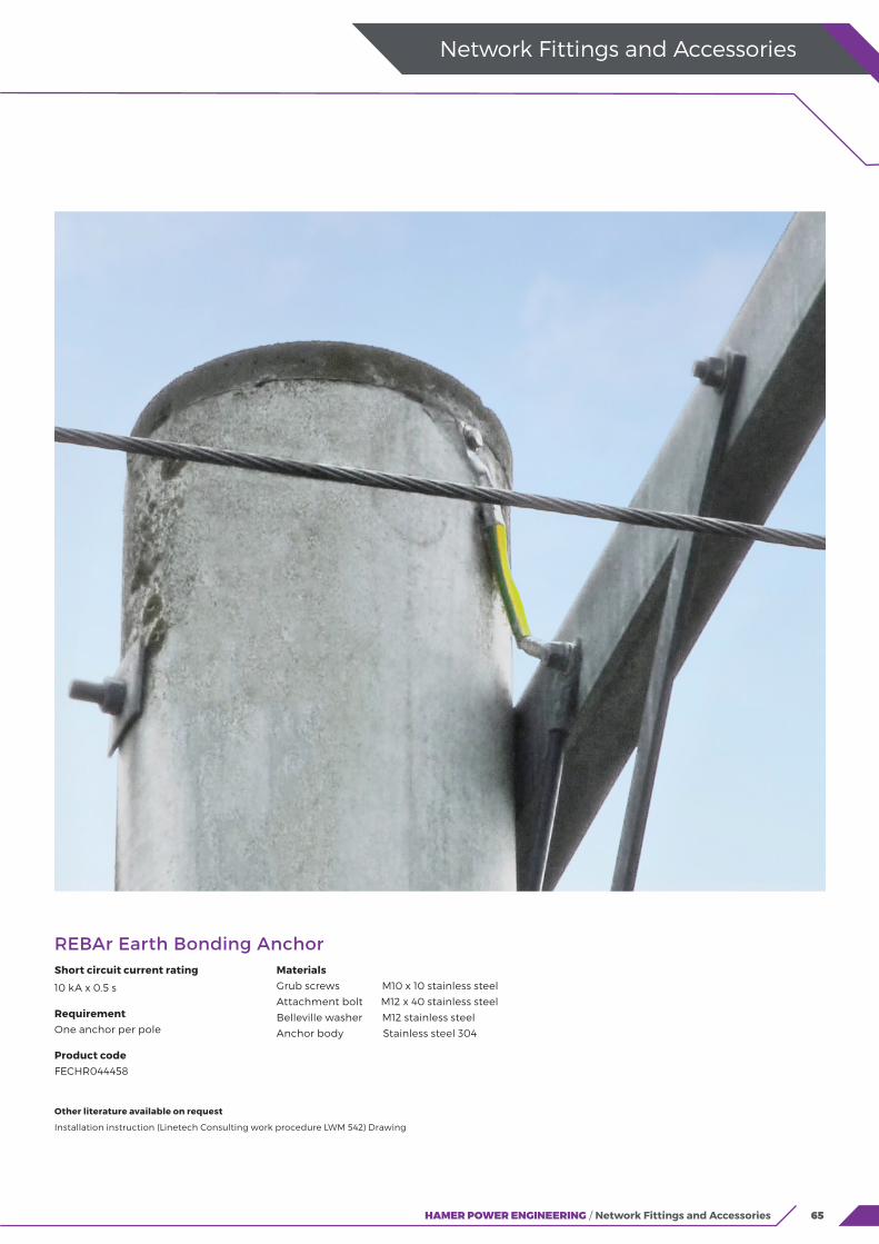
65HAMER POWER ENGINEERING / Network Fittings and Accessories
Network Fittings and Accessories
REBAr Earth Bonding Anchor
Other literature available on request
Installation instruction (Linetech Consulting work procedure LWM 542) Drawing
Short circuit current rating
10 kA x 0.5 s
RequirementOne anchor per pole
Product codeFECHR044458
MaterialsGrub screws M10 x 10 stainless steel
Attachment bolt M12 x 40 stainless steel
Belleville washer M12 stainless steel
Anchor body Stainless steel 304

66 HAMER POWER ENGINEERING / Network Fittings and Accessories
Network Fittings and Accessories
Terminals, connectors and cable lugs using screw technology have been on the advance for years, and with good reason.
The special design feature of the SICON shear bolt connectors is that there are no predetermined break points in the thread. This provides for optimal load-bearing capacity for each range of cross sections. The bolt always breaks at the surface of the clamp body, so there are no protrusions and nothing has to be filed down to make the sleeve fit. Fitting requires a simple tool – literally with a flick of the wrist.
Offering a large clamping range, SICON shear bolt connectors feature a compact design with rounded edges and flat transitions suitable for slide-on and shrink sleeves.
They are contact technology type-tested to IEC 61238-1 and proven in joint tests to HD 629 and in 18-month endurance test.
Pfisterer SICON Stepless Shear Bolt Connectors The cable connector system for voltages up to 36 kV
The SICON system features aluminium alloy connectors, steel threaded studs, brass shear bolts and plastic centring sleeves and the family includes branch connectors, inline connectors and cable lugs.
An overview of SICON system benefits:
Nothing protrudes, and nothing has to be filed down.
Full utilisation of the thread loading for any size of conductor.
No special tools needed.
Smooth breakage of the shear bolt simplifies tightening.
The remains of the bolt stay with the tool and can be disposed of safely.

67HAMER POWER ENGINEERING / Network Fittings and Accessories
Network Fittings and Accessories
Notes All SICON connectors listed have oil-stopsCable sections in accordance with EN 60228 (VDE 0295)Central screw-type cable lugs and other versions on request.
Selection table for SICON stepless shear bolt connectors
Product code
Application range, mm2
Palm bore
diameter
mm
Wrench size (A/F)
mmNumber of bolts
Dimensions
Length
mm
Outer
Diameter
mm
Inner
Diameter
mmmin max
Branch connectors
KP1165 50 185 - 6 6 162 68/33 20
In-line connectors
KP1185 10 95 -
52
65 24 13
KP1160 25 150 - 6828 16.3
KP1200 25 150 -
4
102
KP1205 50 185 -
6 126
33 20
KP1210 50 240+ -35
21
KP1215 95 300 - 22
KP1236 70 240 -
8
140 38 24
KP1240 185 400 - 170 42 26
KP1220 300 630 - 230 52 33.3
Lugs
KP1225 10 9513
5
1 70 24 13
KP1180 25 15091 28 16.3
KP1181 25 150 16.5
KP1190 50 185 136 2 115 33 20
KP1191 50 185 16.5
KP1155 95 300 13
8
120 38 24KP1156 95 300 16.5
KP1231 185 400 13
3
138 42 26KP1233 185 400 16.5
KP1194 300 630 13180 52 33.3
KP1195 300 630 16.5
Centre palm lugs
KPxxxx 16 50 17.55
tbc tbc
24 13
KPxxxx 50 240 17.5 35 20
KPxxxx 95 300 17.5 6 or 8
tbc
38 24
KPxxxx 185 400 17.5 42 26.4
KPxxxx 300 630 17.58
45 or 52 tbc 33.5
KPxxxx 800 800 17.5 tbc tbc
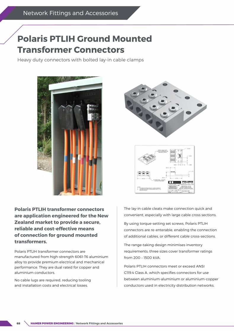
68 HAMER POWER ENGINEERING / Network Fittings and Accessories
Network Fittings and Accessories
Polaris PTLIH transformer connectors are application engineered for the New Zealand market to provide a secure, reliable and cost-effective means of connection for ground mounted transformers.
Polaris PTLIH transformer connectors are
manufactured from high-strength 6061-T6 aluminium
alloy to provide premium electrical and mechanical
performance. They are dual rated for copper and
aluminium conductors.
No cable lugs are required, reducing tooling
and installation costs and electrical losses.
Polaris PTLIH Ground Mounted Transformer Connectors
Heavy duty connectors with bolted lay-in cable clamps
The lay-in cable cleats make connection quick and
convenient, especially with large cable cross sections.
By using torque-setting set screws, Polaris PTLIH
connectors are re-enterable, enabling the connection
of additional cables, or different cable cross-sections.
The range-taking design minimises inventory
requirements; three sizes cover transformer ratings
from 200 – 1500 kVA.
Polaris PTLIH connectors meet or exceed ANSI
C119.4 Class A, which specifies connectors for use
between aluminium-aluminium or aluminium-copper
conductors used in electricity distribution networks.
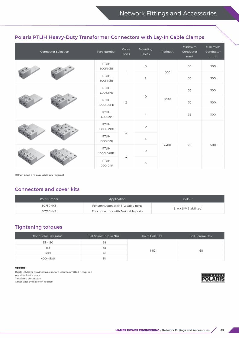
69HAMER POWER ENGINEERING / Network Fittings and Accessories
Polaris PTLIH Heavy-Duty Transformer Connectors with Lay-In Cable Clamps
Connector Selection Part NumberCable
Ports
Mounting
HolesRating A
Minimum
Conductor
mm²
Maximum
Conductor
mm²
PTLIH
600PNZB1
0
600
35 300
PTLIH
600PNZB2 35 300
PTLIH
60052PB
2
01200
35 300
PTLIH
1000102PB70 500
PTLIH
60052P4 35 300
PTLIH
1000103PB3
0
2400 70 500
PTLIH
1000103P8
PTLIH
1000104PB4
0
PTLIH
1000104P8
Other sizes are available on request
Network Fittings and Accessories
Options
Oxide inhibitor provided as standard, can be omitted if requiredAnodised set screwsTin plated connectorsOther sizes available on request
Connectors and cover kits
Part Number Application Colour
50750HK5 For connectors with 1—2 cable portsBlack (UV Stabilised)
50750HK9 For connectors with 3—4 cable ports
Tightening torques
Conductor Size mm² Set Screw Torque Nm Palm Bolt Size Bolt Torque Nm
35 – 120 28
M12 68185 38
300 41
400 – 500 51
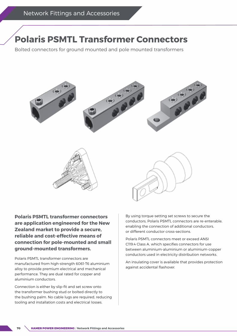
70
Polaris PSMTL transformer connectors are application engineered for the New Zealand market to provide a secure, reliable and cost-effective means of connection for pole-mounted and small ground-mounted transformers.
Polaris PSMTL transformer connectors are manufactured from high-strength 6061-T6 aluminium alloy to provide premium electrical and mechanical performance. They are dual rated for copper and aluminium conductors.
Connection is either by slip-fit and set screw onto the transformer bushing stud or bolted directly to the bushing palm. No cable lugs are required, reducing tooling and installation costs and electrical losses.
HAMER POWER ENGINEERING / Network Fittings and Accessories
Network Fittings and Accessories
Polaris PSMTL Transformer Connectors Bolted connectors for ground mounted and pole mounted transformers
By using torque-setting set screws to secure the conductors, Polaris PSMTL connectors are re-enterable, enabling the connection of additional conductors, or different conductor cross-sections.
Polaris PSMTL connectors meet or exceed ANSI C119.4 Class A, which specifies connectors for use between aluminium-aluminium or aluminium-copper conductors used in electricity distribution networks.
An insulating cover is available that provides protection against accidental flashover.

71HAMER POWER ENGINEERING / Network Fittings and Accessories
Network Fittings and Accessories
Polaris PSMTL Transformer Connectors
Connector Selection Part NumberCable
Ports
Mounting
HolesRating A
Minimum
Conductor
mm²
Maximum
Conductor
mm²
POL82 2 2 200
16 120
PSMTL
3504PH
4 4 400PSMTL
SC3504P
Other sizes are available on request
Insulating cover
Part Number Application Colour
613504H
For connectors with 2—4
cable portsBlack (UV Stabilised)
Tightening torques
Conductor Size mm² Set Screw Torque Nm Connection Type Bolt Torque Nm
16—25 14Threaded Stud
(Slip-fit 5/8” 11)42
35—120 28 Bushing Palm (M10 bolt) 35
Options
Oxide inhibitor provided as standard, can be omitted if requiredAnodised set screwsTin plated connectorsTransparent covers to facilitate inspection / audit (not UV-stabilised)Other sizes available on request
Other literature available on request
Type test reports, drawings
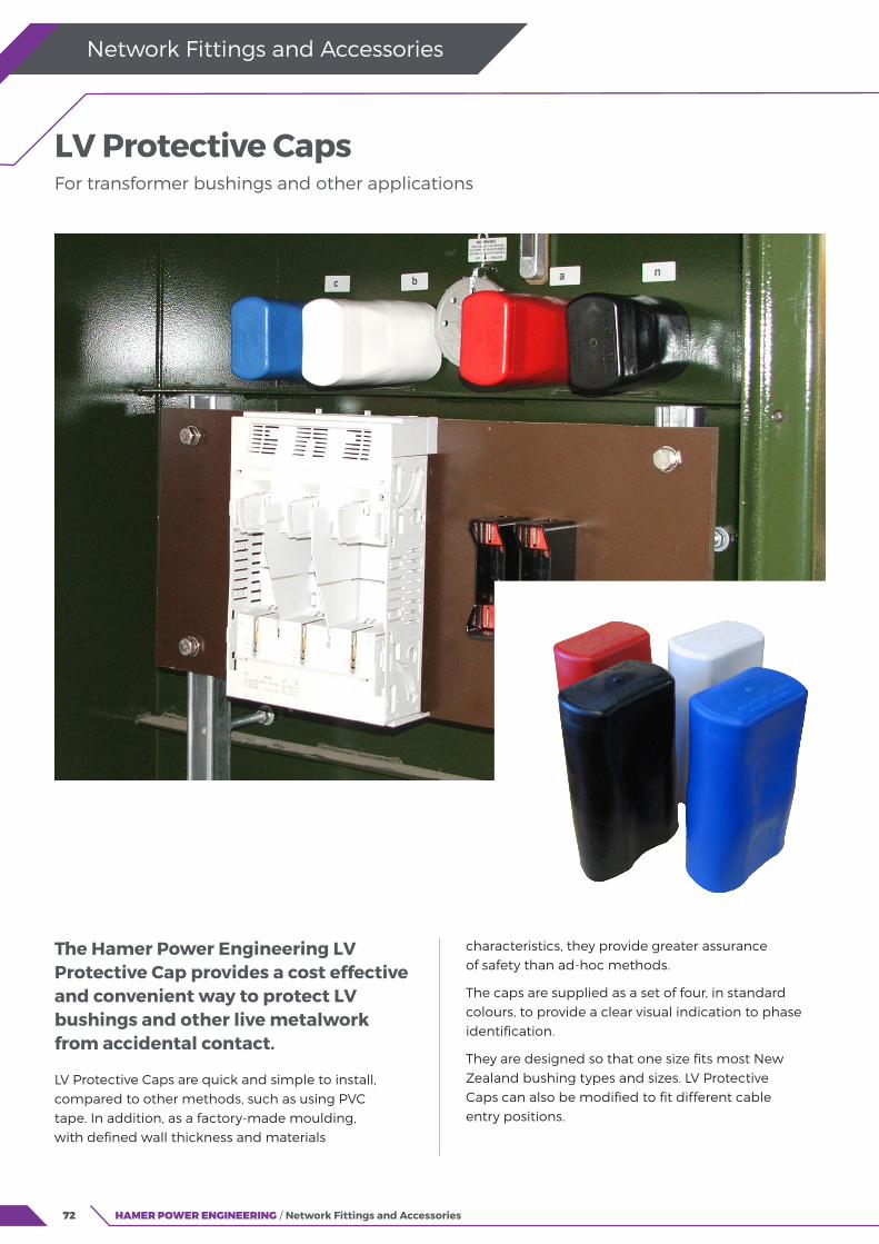
72 HAMER POWER ENGINEERING / Network Fittings and Accessories
Network Fittings and Accessories
The Hamer Power Engineering LV Protective Cap provides a cost effective and convenient way to protect LV bushings and other live metalwork from accidental contact.
LV Protective Caps are quick and simple to install, compared to other methods, such as using PVC tape. In addition, as a factory-made moulding, with defined wall thickness and materials
LV Protective CapsFor transformer bushings and other applications
characteristics, they provide greater assurance of safety than ad-hoc methods.
The caps are supplied as a set of four, in standard colours, to provide a clear visual indication to phase identification.
They are designed so that one size fits most New Zealand bushing types and sizes. LV Protective Caps can also be modified to fit different cable entry positions.
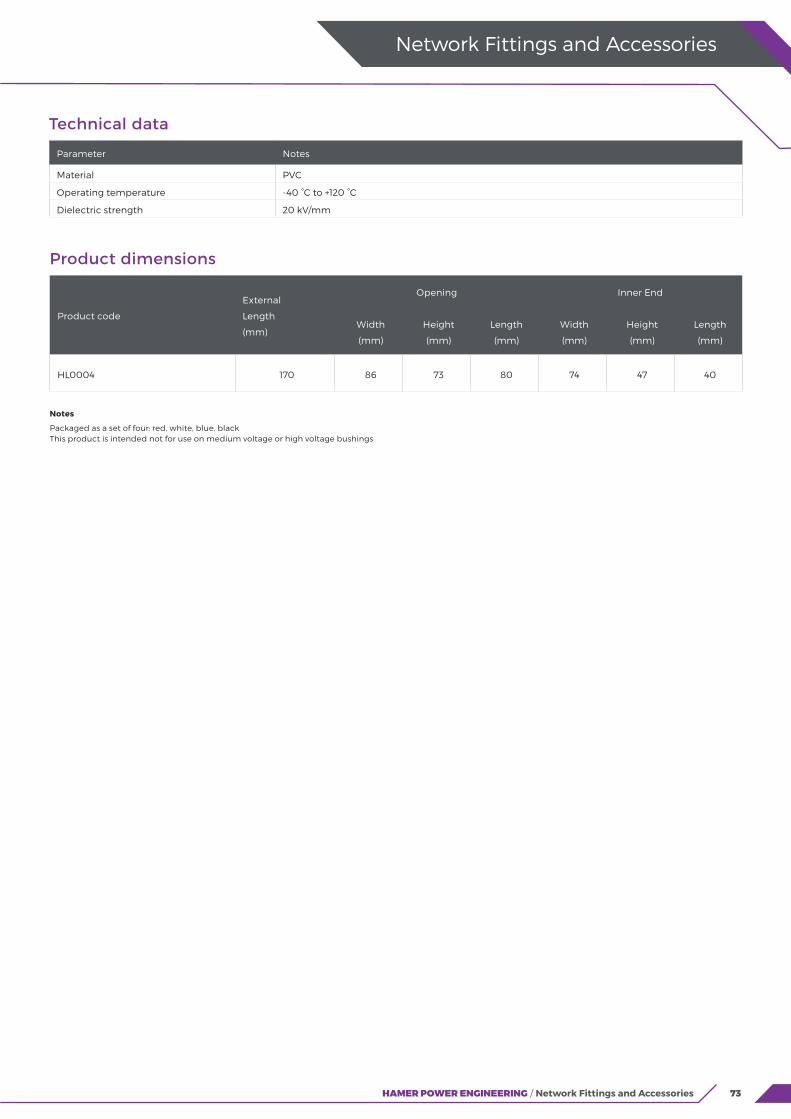
73HAMER POWER ENGINEERING / Network Fittings and Accessories
Technical data
Parameter Notes
Material PVC
Operating temperature -40 °C to +120 °C
Dielectric strength 20 kV/mm
Notes
Packaged as a set of four: red, white, blue, black This product is intended not for use on medium voltage or high voltage bushings
Product dimensions
Product code
External
Length
(mm)
Opening Inner End
Width
(mm)
Height
(mm)
Length
(mm)
Width
(mm)
Height
(mm)
Length
(mm)
HL0004 170 86 73 80 74 47 40
Network Fittings and Accessories
74 HAMER POWER ENGINEERING / Network Fittings and Accessories
Network Fittings and Accessories
75
“We partner with leading manufacturers of quality products and work with you to deliver safe and lasting solutions for your network.”
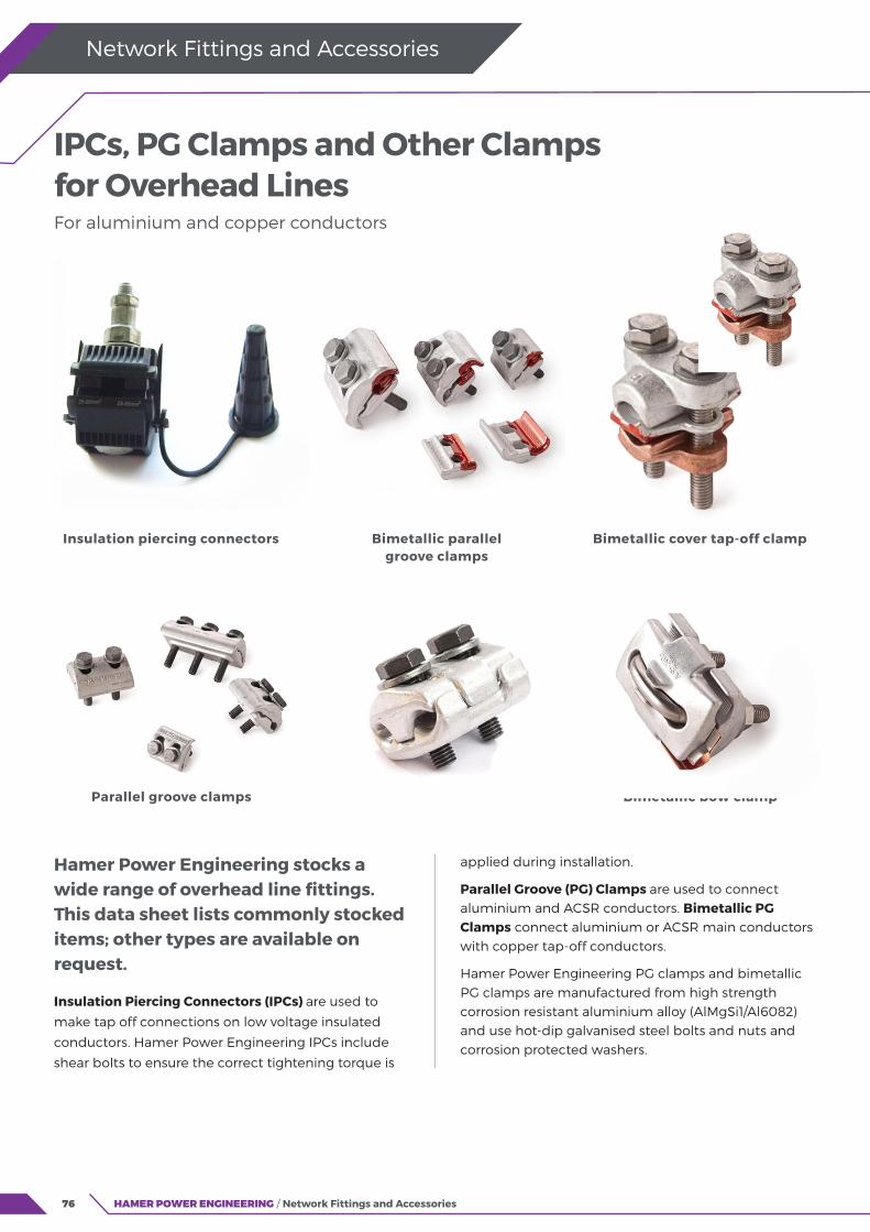
76 HAMER POWER ENGINEERING / Network Fittings and Accessories
Network Fittings and Accessories
Hamer Power Engineering stocks a wide range of overhead line fittings. This data sheet lists commonly stocked items; other types are available on request.
Insulation Piercing Connectors (IPCs) are used to
make tap off connections on low voltage insulated
conductors. Hamer Power Engineering IPCs include
shear bolts to ensure the correct tightening torque is
IPCs, PG Clamps and Other Clamps for Overhead Lines For aluminium and copper conductors
applied during installation.
Parallel Groove (PG) Clamps are used to connect aluminium and ACSR conductors. Bimetallic PG Clamps connect aluminium or ACSR main conductors with copper tap-off conductors.
Hamer Power Engineering PG clamps and bimetallic PG clamps are manufactured from high strength corrosion resistant aluminium alloy (AlMgSi1/Al6082) and use hot-dip galvanised steel bolts and nuts and corrosion protected washers.
Insulation piercing connectors Bimetallic parallel groove clamps
Bimetallic cover tap-off clamp
Parallel groove clamps Bimetallic bow clamp

77HAMER POWER ENGINEERING / Network Fittings and Accessories
Product selection table: application ranges
Product code Description
Main conductor
AL CU ACSR
Cross section,
(mm2)
Diameter
(mm)
ACSR size
Min Max Min Max Min Max
BIZ1695
Insulation piercing connector
16
95KP2190 25
KP2197 50
BIZ2595 25
BIZ50150 (35)50 150
KP1928 Bimetallic parallel groove clamp (two bolts)
16 70 5.1 11.7 16/2.5 70/12
KP1930 25 150 7.5 14 35/6 95/15
KP1927 35 120 6.3 15.7 25/4 120/20
KP1926Bimetallic parallel groove clamp (single bolt)
35 120
KP1935 Bimetallic cover
tap-off clamp
25 70 25/4 70/12
KP1937 50 150 50/8 120/20
KP2111 Bimetallic bow clamp 95 240 12.5 21.9 95/15 240/40
KP1950
Parallel groove clamp
16 70 5.1 11.7 16/2.5 70/12
KP1942 25 150 6.3 15.7 25/4 120/20
KP1960 50 150 9 16 50/8 120/20
Product code Description
Branch conductor
AL CU
Cross section,
(mm2)
Diameter
(mm)Min Max Min Max
BIZ1695
Insulation piercing
connector
4 35(50)
KP2190 6 50
KP2197 50 95
BIZ2595 25 95
BIZ50150 (35)50 150
KP1928 Bimetallic parallel groove clamp (two bolts)
6
50
2.7 9
KP193010
3.5 9
KP1927 3.5 12.5
KP1926Bimetallic parallel groove clamp (single bolt)
10 50
KP1935 Bimetallic cover
tap-off clamp
10 70
KP1937 25 120
KP2111 Bimetallic bow clamp 95 240
1 70 185
KP1950
Parallel groove clamp
16 70
KP1942 25 150
KP1960 50 150
Bimetallic Cover Tap-Off Clamps connect aluminium or ACSR main conductors with copper tap-off conductors. Hamer Power Engineering cover tap-off clamps are manufactured from high strength corrosion resistant aluminium alloy, hot-forged metallic sheet and high strength copper alloy (CuNi2Si) and use hot-dip galvanised steel bolts and corrosion protected washers.
Bimetallic Bow Clamps connect aluminium or ACSR conductors with copper conductors. The body is made of high strength aluminium alloy with bimetallic sheet for copper tap-off; the U-bolt and nuts are hot-dip galvanised with corrosion protected washers.
Network Fittings and Accessories
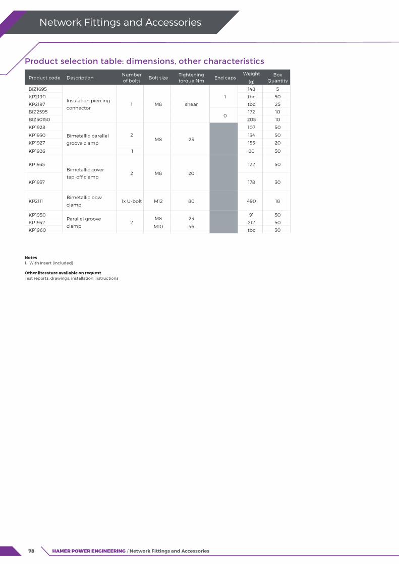
78
Product selection table: dimensions, other characteristics
Product code DescriptionNumber of bolts
Bolt sizeTightening torque Nm
End capsWeight
(g)
Box Quantity
BIZ1695
Insulation piercing
connector1 M8 shear
1
148 5
KP2190 tbc 50
KP2197 tbc 25
BIZ25950
172 10
BIZ50150 205 10
KP1928
Bimetallic parallel
groove clamp
2M8 23
107 50
KP1930 134 50
KP1927 155 20
KP1926 1 80 50
KP1935Bimetallic cover
tap-off clamp2 M8 20
122 50
KP1937 178 30
KP2111Bimetallic bow
clamp1x U-bolt M12 80 490 18
KP1950Parallel groove
clamp2
M8
M10
23
46
91 50
KP1942 212 50
KP1960 tbc 30
Notes 1. With insert (included)
Other literature available on request Test reports, drawings, installation instructions
Network Fittings and Accessories
HAMER POWER ENGINEERING / Network Fittings and Accessories

79
MV and HV Switchgear and Cable Link BoxesAir Insulated Load Break Switches
Gas Insulated Load Break Switches
Electronic Sectionalisers
Isolating Links
Substation Disconnectors
Cable Link Boxes
Insulect SVLs
80
82
84
86
88
91
92

80 HAMER POWER ENGINEERING / Switchgear and Cable Link Boxes
Switchgear and Cable Link Boxes
FeaturesModular Design
We readily provide custom design changes to suit individual customer requirements, as well as modular or unitised factory assembly for more rapid installation.
Manual or Motorised
Available with conventional operating rod and handle, with patented hook stick actuator. Able to be fitted with motorised operation as well as remote control facilities.
Insulators
Choose from Porcelain, Silicon or Cycloaliphatic insulators.
Options
Associated earthing switch available. Load interrupter to break up to 630 amps.
Air Insulated Load Break Switches Side break and vertical break
12kV, 24kV, 36kV
Ordering Information
Side Break or Vertical Break
2/24 kV or 36 kV
Current Rating
Pole top or mid pole designs
Unitised or Modular
Operating Mechanism: manual handle, hook stick actuator, motor operation (local/remote or SCADA)
Load Break option.
Insulect Air Break Switches (ABS) are designed, assembled and tested in Australia. Our range is widely installed throughout distribution networks for isolation or switching applications.
12, 24, 36kV voltage rating
We have two sizes: 12/24kV and 36kV with current ratings from 630A up to 1250A.
Vertical or side break
Each variant can be configured in a side break or vertical break arrangement.
Horizontal or vertical install
The switches can
be mounted in
horizontal or vertical
(pole top or mid pole)
configurations.
Local design and testing
Designed and tested in
Australia in accordance
with AS 62271.102 / IEC
62271.102.

81HAMER POWER ENGINEERING / Switchgear and Cable Link Boxes
Switchgear and Cable Link Boxes
Technical specifications
Rated VoltagekV (rms)
LIWV (BIL)kVp
Power FrequencyWithstand Voltage
kV
ContinuousCurrent
A
Load Breaking CapacityA
Short CircuitWithstandAir Break
SwitchLoad Break
Switch
Side Break
12/24 150 50 Up to 1250 15 630 25 kA / 1s
36 170 70 Up to 1250 15 630 25 kA / 1s
Vertical Break
12/24 150 50 Up to 1250 15 630 25 kA / 3s
36 170 70 Up to 1250 15 630 25 kA / 3s
Technical configurations
Pole Top, Side Break Switchwith manual operating handle.
Pole Top, Side Break Switchwith hook stick actuator.
Mid Pole, Side Break Switchwith manual operating handle and associated Earth Switch.
Mid Pole, Vertical Break Switch with manual operating handle.
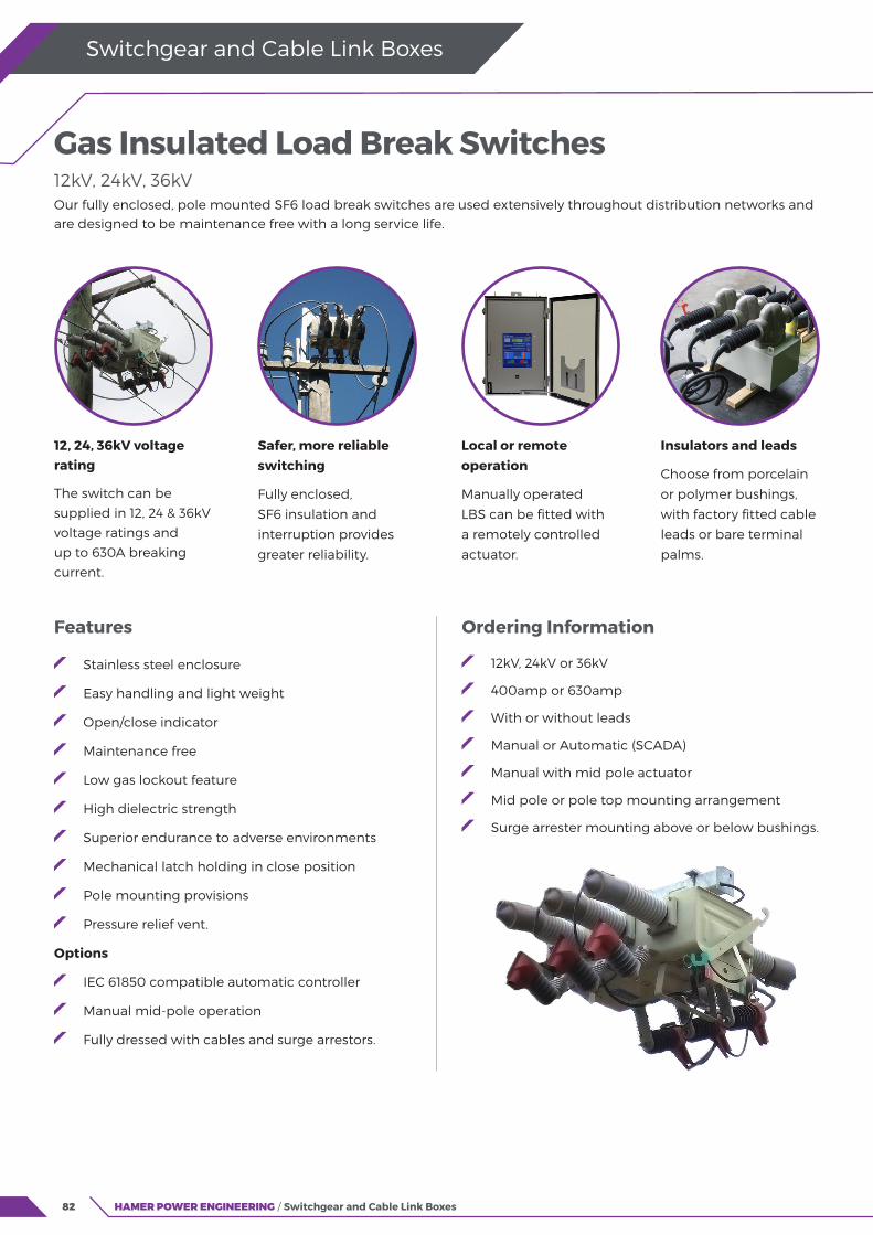
82 HAMER POWER ENGINEERING / Switchgear and Cable Link Boxes
Switchgear and Cable Link Boxes
Features
Stainless steel enclosure
Easy handling and light weight
Open/close indicator
Maintenance free
Low gas lockout feature
High dielectric strength
Superior endurance to adverse environments
Mechanical latch holding in close position
Pole mounting provisions
Pressure relief vent.
Options
IEC 61850 compatible automatic controller
Manual mid-pole operation
Fully dressed with cables and surge arrestors.
Gas Insulated Load Break Switches 12kV, 24kV, 36kV
Ordering Information
12kV, 24kV or 36kV
400amp or 630amp
With or without leads
Manual or Automatic (SCADA)
Manual with mid pole actuator
Mid pole or pole top mounting arrangement
Surge arrester mounting above or below bushings.
Our fully enclosed, pole mounted SF6 load break switches are used extensively throughout distribution networks and are designed to be maintenance free with a long service life.
12, 24, 36kV voltage rating
The switch can be
supplied in 12, 24 & 36kV
voltage ratings and
up to 630A breaking
current.
Safer, more reliable switching
Fully enclosed,
SF6 insulation and
interruption provides
greater reliability.
Local or remote operation
Manually operated
LBS can be fitted with
a remotely controlled
actuator.
Insulators and leads
Choose from porcelain
or polymer bushings,
with factory fitted cable
leads or bare terminal
palms.
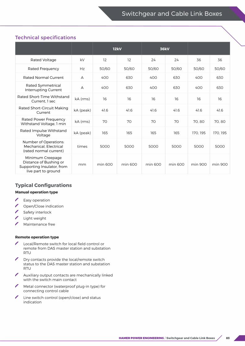
83HAMER POWER ENGINEERING / Switchgear and Cable Link Boxes
Switchgear and Cable Link Boxes
Technical specifications
12kV 36kV
Rated Voltage kV 12 12 24 24 36 36
Rated Frequency Hz 50/60 50/60 50/60 50/60 50/60 50/60
Rated Normal Current A 400 630 400 630 400 630
Rated Symmetrical Interrupting Current
A 400 630 400 630 400 630
Rated Short-Time Withstand Current, 1 sec
kA (rms) 16 16 16 16 16 16
Rated Short-Circuit Making Current
kA (peak) 41.6 41.6 41.6 41.6 41.6 41.6
Rated Power Frequency Withstand Voltage, 1 min
kA (rms) 70 70 70 70 70, 80 70, 80
Rated Impulse Withstand Voltage
kA (peak) 165 165 165 165 170, 195 170, 195
Number of Operations: Mechanical, Electrical(rated normal current)
times 5000 5000 5000 5000 5000 5000
Minimum Creepage Distance of Bushing or
Supporting Insulator, from live part to ground
mm min 600 min 600 min 600 min 600 min 900 min 900
Typical ConfigurationsManual operation type
Easy operation
Open/Close indication
Safety interlock
Light weight
Maintenance free
Remote operation type
Local/Remote switch for local field control or remote from DAS master station and substation RTU
Dry contacts provide the local/remote switch status to the DAS master station and substation RTU
Auxiliary output contacts are mechanically linked with the switch main contact
Metal connector (waterproof plug-in type) for connecting control cable
Line switch control (open/close) and status indication
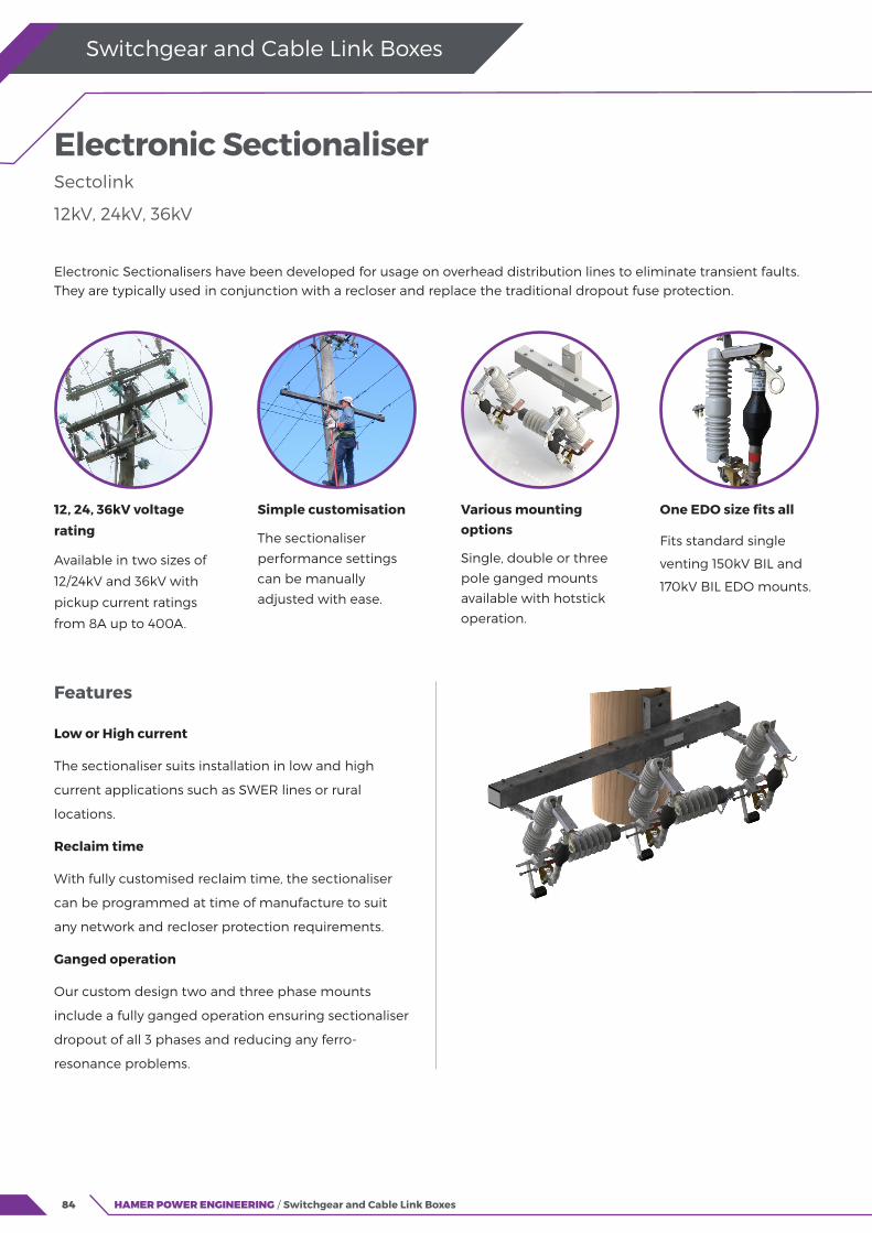
84 HAMER POWER ENGINEERING / Switchgear and Cable Link Boxes
Switchgear and Cable Link Boxes
Features
Low or High current
The sectionaliser suits installation in low and high
current applications such as SWER lines or rural
locations.
Reclaim time
With fully customised reclaim time, the sectionaliser
can be programmed at time of manufacture to suit
any network and recloser protection requirements.
Ganged operation
Our custom design two and three phase mounts
include a fully ganged operation ensuring sectionaliser
dropout of all 3 phases and reducing any ferro-
resonance problems.
Electronic Sectionaliser Sectolink
12kV, 24kV, 36kV
Electronic Sectionalisers have been developed for usage on overhead distribution lines to eliminate transient faults. They are typically used in conjunction with a recloser and replace the traditional dropout fuse protection.
12, 24, 36kV voltage
rating
Available in two sizes of
12/24kV and 36kV with
pickup current ratings
from 8A up to 400A.
Simple customisation
The sectionaliser
performance settings
can be manually
adjusted with ease.
Various mounting options
Single, double or three
pole ganged mounts
available with hotstick
operation.
One EDO size fits all
Fits standard single
venting 150kV BIL and
170kV BIL EDO mounts.
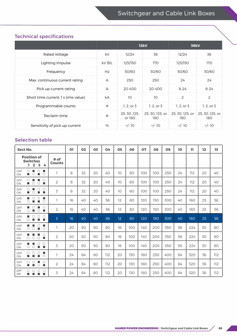
85HAMER POWER ENGINEERING / Switchgear and Cable Link Boxes
Switchgear and Cable Link Boxes
Technical specifications
12kV 36kV
Rated Voltage kV 12/24 36 12/24 36
Lighting Impulse kV BIL 125/150 170 125/150 170
Frequency Hz 50/60 50/60 50/60 50/60
Max. continuous current rating A 250 250 24 24
Pick up current rating A 20-400 20-400 8-24 8-24
Short time current, 1 s (rms value) kA 10 10 2 2
Programmable counts # 1, 2, or 3 1, 2, or 3 1, 2, or 3 1, 2, or 3
Reclaim time #25, 30, 125,
or 18025, 30, 125, or
18025, 30, 125, or
18025, 30, 125, or
180
Sensitivity of pick up current % +/- 10 +/- 10 +/- 10 +/- 10
Selection table
Sect No. 01 02 03 04 05 06 07 08 09 10 11 12 13
Position of Switches
1 2 3 4
# of Counts
OFF ON
1 8 32 20 40 10 60 100 100 250 24 112 20 40
OFF ON
2 8 32 20 40 10 60 100 100 250 24 112 20 40
OFF ON
3 8 32 20 40 10 60 100 100 250 24 112 20 40
OFF ON
1 16 40 40 56 12 80 120 150 300 40 160 25 56
OFF ON
2 16 40 40 56 12 80 120 150 300 40 160 25 56
OFF ON
3 16 40 40 56 12 80 120 150 300 40 160 25 56
OFF ON
1 20 50 50 80 16 100 140 200 350 56 224 30 80
OFF ON
2 20 50 50 80 16 100 140 200 350 56 224 30 80
OFF ON
3 20 50 50 80 16 100 140 200 350 56 224 30 80
OFF ON
1 24 64 60 112 20 130 160 250 400 64 320 36 112
OFF ON
2 24 64 60 112 20 130 160 250 400 64 320 36 112
OFF ON
3 24 64 60 112 20 130 160 250 400 64 320 36 112

86 HAMER POWER ENGINEERING / Switchgear and Cable Link Boxes
Switchgear and Cable Link Boxes
Features
Modular Design
We readily provide custom design changes to suit
individual customer requirements and applications.
Insulators
Choose from Porcelain, Silicon or Cycloaliphatic
insulators.
Options
Latching mechanism
Load break plus fuse holder
Flicker horns
Earthing stirrup.
Isolating Links Single phase
12kV to 72.5kV
Insulect HV Links are installed throughout distribution networks and in substations as isolation points between HV apparatus.
Wide voltage rating
The HV links range
covers all voltage ratings
between 12kV and
72.5kV, with current
rating up to 1600A.
Three mounting configurations
The links can be mounted at 30 degrees, vertically or underslung orientations.
Load break capability
Isolating links can be
fitted with Flicker blades
or 630A load breaking
devices.
Local design and testing
Designed and tested in Australia in accordance with AS 62271.102 / IEC 62271.102.
Ordering Information
Vertical, horizontal or angled 30 degrees
mounting configuration
12/24 kV, 36kV or 72.5 kV
Porcelain, Cyclo or Polymer
Current Rating
With or without Earthing Stirrup
Short Circuit withstand requirement.

87HAMER POWER ENGINEERING / Switchgear and Cable Link Boxes
Switchgear and Cable Link Boxes
Technical specifications
Voltage (kV) Rated Current (A) BIL (kV) STWC (kA) Duration (s)
12 / 24 Up to 1250 150 / 170 20 / 25 3 / 1
24 Up to 1250 200 20 3
36 Up to 1250 200 20 / 25 3 / 1
72.5 Up to 1250 325 20 / 25 3 / 1
Typical configuration

88 HAMER POWER ENGINEERING / Switchgear and Cable Link Boxes
Switchgear and Cable Link Boxes
Features & Options
Contacts
All contact surfaces are silver plated copper. Copper components other than the contact surfaces are tin plated as standard.
Flickers
The moving blades are supplied with a spring-loaded flicker to quickly extinguish residual current arcing when the switch is opened live.
Custom footprint
Insulect disconnectors can be customised to suit specific substation layouts, configurations and structure types.
Insulators
A variety of insulator types can be accommodated for each voltage level, including electrical and mechanical ratings and pollution levels.
Substation Disconnectors and earthing switches
12kV to 145kV
Insulect Disconnectors are designed to accommodate each customer’s needs and the layout of each substation. For over two decades, our disconnector and earthing switches have been 100% locally designed, built and serviced to ensure the best possible solution tailored to the needs of our customers.
Standard Design
Our disconnector
range is based on a
rotary double break
design, with or without
integrated Earthing
Switch.
Horizontal or Vertical
Designed for horizontal
or vertical applications
and may be mounted
on steel structures or
pole mounted.
Manual or Motor Operated
Disconnectors are built for either manual operation or with a motor operated mechanism, for local or remote operation.
Earthing Switches
Independent single or double earthing switches can be supplied with the disconnectors.
Earthing Switches
Each disconnector can be fitted with independent earth switches where required.
Earth switches can be supplied for one or both sides of the switch.
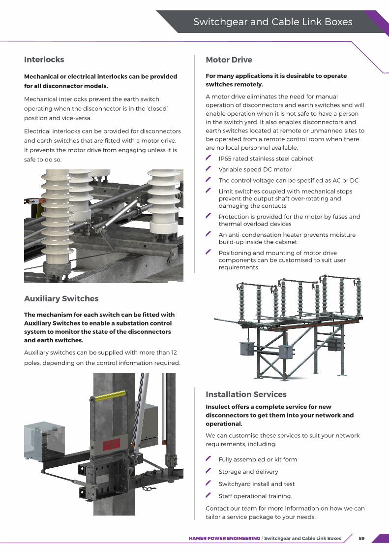
89HAMER POWER ENGINEERING / Switchgear and Cable Link Boxes
Switchgear and Cable Link Boxes
Interlocks
Mechanical or electrical interlocks can be provided
for all disconnector models.
Mechanical interlocks prevent the earth switch
operating when the disconnector is in the ‘closed’
position and vice-versa.
Electrical interlocks can be provided for disconnectors
and earth switches that are fitted with a motor drive.
It prevents the motor drive from engaging unless it is
safe to do so.
Motor Drive
For many applications it is desirable to operate switches remotely.
A motor drive eliminates the need for manual operation of disconnectors and earth switches and will enable operation when it is not safe to have a person in the switch yard. It also enables disconnectors and earth switches located at remote or unmanned sites to be operated from a remote control room when there are no local personnel available.
IP65 rated stainless steel cabinet
Variable speed DC motor
The control voltage can be specified as AC or DC
Limit switches coupled with mechanical stops prevent the output shaft over-rotating and damaging the contacts
Protection is provided for the motor by fuses and thermal overload devices
An anti-condensation heater prevents moisture build-up inside the cabinet
Positioning and mounting of motor drive components can be customised to suit user requirements.
Auxiliary Switches
The mechanism for each switch can be fitted with Auxiliary Switches to enable a substation control system to monitor the state of the disconnectors and earth switches.
Auxiliary switches can be supplied with more than 12
poles, depending on the control information required.
Installation ServicesInsulect offers a complete service for new disconnectors to get them into your network and operational.
We can customise these services to suit your network requirements, including:
Fully assembled or kit form
Storage and delivery
Switchyard install and test
Staff operational training.
Contact our team for more information on how we can tailor a service package to your needs.
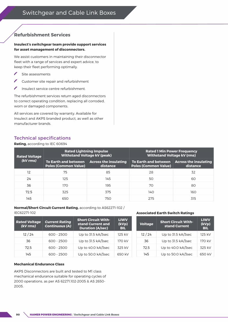
90 HAMER POWER ENGINEERING / Switchgear and Cable Link Boxes
Switchgear and Cable Link Boxes
Refurbishment Services
Insulect’s switchgear team provide support services for asset management of disconnectors.
We assist customers in maintaining their disconnector fleet with a range of services and expert advice, to keep their fleet performing optimally.
Site assessments
Customer site repair and refurbishment
Insulect service centre refurbishment.
The refurbishment services return aged disconnectors to correct operating condition, replacing all corroded, worn or damaged components.
All services are covered by warranty. Available for Insulect and AKPS branded product, as well as other manufacturer brands.
Technical specificationsRating, according to IEC 60694
Rated Voltage (kV rms)
Current Rating Continuous (A)
Short Circuit With-stand Current and
Duration (A/sec)
LIWV (kVp)
BIL
12 / 24 600 - 2500 Up to 31.5 kA/3sec 125 kV
36 600 - 2500 Up to 31.5 kA/3sec 170 kV
72.5 600 - 2500 Up to 40.0 kA/3sec 325 kV
145 600 - 2500 Up to 50.0 kA/3sec 650 kV
Voltage Short Circuit With-stand Current
LIWV (kVp)
BIL
12 / 24 Up to 31.5 kA/3sec 125 kV
36 Up to 31.5 kA/3sec 170 kV
72.5 Up to 40.0 kA/3sec 325 kV
145 Up to 50.0 kA/3sec 650 kV
Rated Voltage (kV rms)
Rated Lightning ImpulseWithstand Voltage kV (peak)
Rated 1 Min Power Frequency Withstand Voltage kV (rms)
To Earth and betweenPoles (Common Value)
Across the insulating distance
To Earth and betweenPoles (Common Value)
Across the insulatingdistance
12 75 85 28 32
24 125 145 50 60
36 170 195 70 80
72.5 325 375 140 160
145 650 750 275 315
Normal/Short Circuit Current Rating, according to AS62271-102 / IEC62271-102 Associated Earth Switch Ratings
Mechanical Endurance Class
AKPS Disconnectors are built and tested to M1 class mechanical endurance suitable for operating cycles of 2000 operations, as per AS 62271.102-2005 & AS 2650-2005.
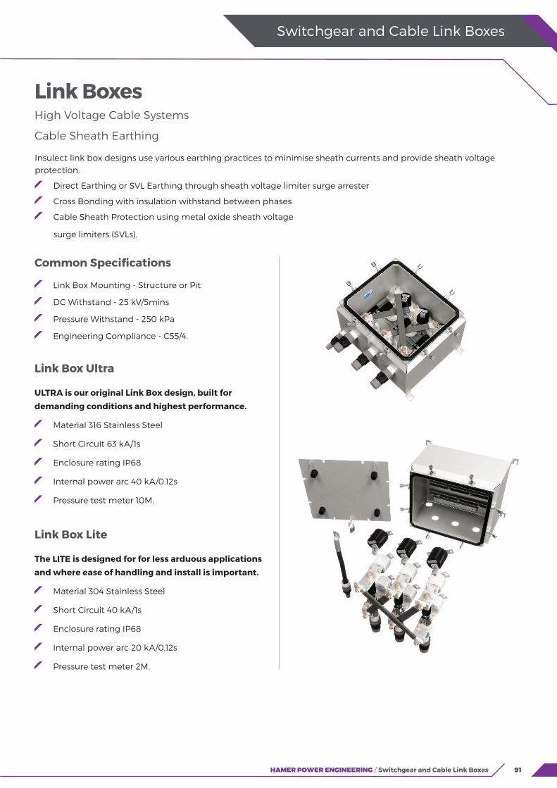
91HAMER POWER ENGINEERING / Switchgear and Cable Link Boxes
Switchgear and Cable Link Boxes
Common Specifications
Link Box Mounting - Structure or Pit
DC Withstand - 25 kV/5mins
Pressure Withstand - 250 kPa
Engineering Compliance - C55/4.
Link Box Ultra
ULTRA is our original Link Box design, built for
demanding conditions and highest performance.
Material 316 Stainless Steel
Short Circuit 63 kA/1s
Enclosure rating IP68
Internal power arc 40 kA/0.12s
Pressure test meter 10M.
Link Box Lite
The LITE is designed for for less arduous applications
and where ease of handling and install is important.
Material 304 Stainless Steel
Short Circuit 40 kA/1s
Enclosure rating IP68
Internal power arc 20 kA/0.12s
Pressure test meter 2M.
Insulect link box designs use various earthing practices to minimise sheath currents and provide sheath voltage protection.
Direct Earthing or SVL Earthing through sheath voltage limiter surge arrester
Cross Bonding with insulation withstand between phases
Cable Sheath Protection using metal oxide sheath voltage
surge limiters (SVLs).
Link Boxes High Voltage Cable Systems
Cable Sheath Earthing
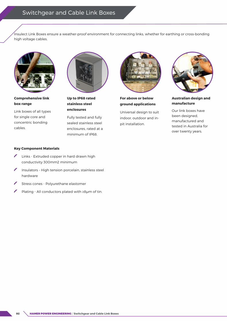
92 HAMER POWER ENGINEERING / Switchgear and Cable Link Boxes
Switchgear and Cable Link Boxes
Key Component Materials
Links - Extruded copper in hard drawn high
conductivity 300mm2 minimum
Insulators - High tension porcelain, stainless steel
hardware
Stress cones - Polyurethane elastomer
Plating - All conductors plated with ≥8μm of tin.
Insulect Link Boxes ensure a weather-proof environment for connecting links, whether for earthing or cross-bonding high voltage cables.
Comprehensive link
box range
Link boxes of all types
for single core and
concentric bonding
cables.
Up to IP68 rated
stainless steel
enclosures
Fully tested and fully
sealed stainless steel
enclosures, rated at a
minimum of IP68.
For above or below
ground applications
Universal design to suit
indoor, outdoor and in-
pit installation.
Australian design and manufacture
Our link boxes have
been designed,
manufactured and
tested in Australia for
over twenty years.

93HAMER POWER ENGINEERING / Switchgear and Cable Link Boxes
Switchgear and Cable Link Boxes
SVL Sheath Voltage Limiters (SVL) are an economic solution for safeguarding expensive cable
installations.
Ordering information
Use the table to build your specification and confirm your link box 5-digit Part Number. Use the diagram on the right as a guide or call us for assistance.
1. Select the model type - ULTRA or LITE
2. Choose the application
3. Choose single or concentric cables
4. And the number of cables
5. Choose the mounting type.
Along with your 5-digit Part Number, you will need to confirm the following:
Confirm the cable size of the bonding and earth cables
Advise of any special requirements or modifications in detail.
They are highly reliable and effective at managing cable sheath voltage rises and the associated power flows that can result under fault conditions.
Insulect manufacture an extensive range of quality 20kA zinc oxide sheath voltage limiters (SVL’s).
Voltages: 1.5kV to 9.0kV
Technical Specifications
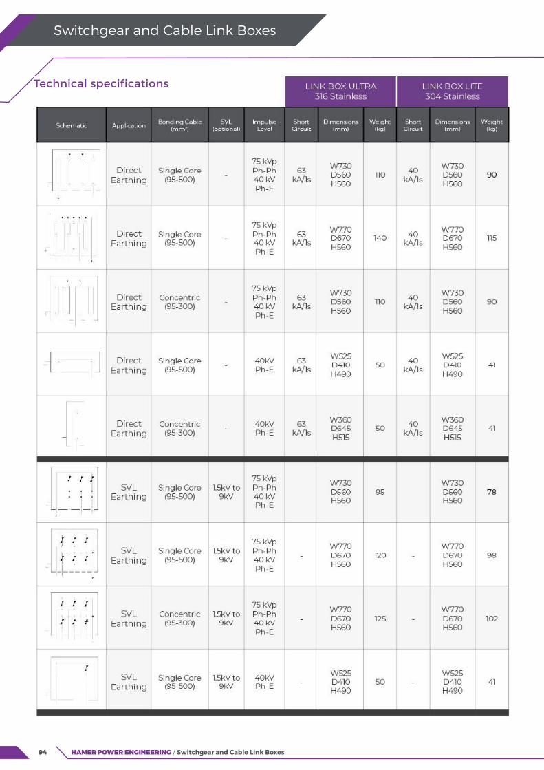
94 HAMER POWER ENGINEERING / Switchgear and Cable Link Boxes
Switchgear and Cable Link Boxes
Technical specifications
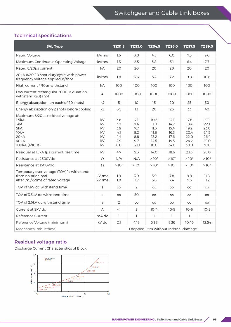
95HAMER POWER ENGINEERING / Switchgear and Cable Link Boxes
Switchgear and Cable Link Boxes
Technical specifications
SVL Type TZS1.5 TZS3.0 TZS4.5 TZS6.0 TZS7.5 TZS9.0
Rated Voltage kVrms 1.5 3.0 4.5 6.0 7.5 9.0
Maximum Continuous Operating Voltage kVrms 1.3 2.5 3.8 5.1 6.4 7.7
Rated 8/20μs current kA 20 20 20 20 20 20
20kA 8/20 20 shot duty cycle with power frequency voltage applied 1s/shot
kVrms 1.8 3.6 5.4 7.2 9.0 10.8
High current 4/10μs withstand kA 100 100 100 100 100 100
Low current rectangular 2000μs duration withstand (20) shot
A 1000 1000 1000 1000 1000 1000
Energy absorption (on each of 20 shots) kJ 5 10 15 20 25 30
Energy absorption on 2 shots before cooling kJ 6.5 13 20 26 33 40
Maximum 8/20μs residual voltage at:1.5kA3kA5kA10kA20kA40kA 100kA (4/10μs)
kVkVkVkVkVkVkV
3.63.73.94.14.44.96.0
7.17.47.78.28.89.712.0
10.511.011.511.813.214.518.0
14.114.715.416.317.619.324.0
17.618.419.220.422.024.230.0
21.122.123.024.526.429.036.0
Residual at 15kA 1μs current rise time kV 4.7 9.3 14.0 18.6 23.3 28.0
Resistance at 2500Vdc Ω N/A N/A > 107 > 107 > 108 > 108
Resistance at 1500Vdc Ω > 107 > 107 > 107 > 107 > 108 > 108
Temporary over-voltage (TOV) 1s withstand:from no prior loadafter 7kJ/kVrms of rated voltage
kV rmskV rms
1.91.8
3.93.7
5.95.6
7.87.4
9.89.3
11.811.2
TOV of 5kV dc withstand time s ∞ 2 ∞ ∞ ∞ ∞
TOV of 3.5kV dc withstand time s ∞ 50 ∞ ∞ ∞ ∞
TOV of 2.5kV dc withstand time s 2 ∞ ∞ ∞ ∞ ∞Current at 5kV dc A ∞ 3 10-4 10-5 10-5 10-5
Reference Current mA dc 1 1 1 1 1 1
Reference Voltage (minimum) kV dc 2.1 4.18 6.28 8.36 10.46 12.54
Mechanical robustness - Dropped 1.5m without internal damage
Residual voltage ratioDischarge Current Characteristics of Block
96
Switchgear and Cable Link Boxes
HAMER POWER ENGINEERING / Switchgear and Cable Link Boxes
97
Tools, Measurement and Test Equipment1000V Insulated Tools
LV and MV Insulated Mats and Shrouds
Hand Tools, Tool Bags and Belts
Battery Powered Hydraulic Compression Tools
Grips, Ratchet Hoists, Cable Pullers and Accessories
Equipment Testing, Measurement and Analysis
Proximity and Touch Detection
98
99
100
102
103
104
105

98 HAMER POWER ENGINEERING / Tools, Measurement and Test Equipment
1000V insulated tools compliant with the current international standards provide practicable safety for users by protecting them from hazardous voltages.
Boddingtons Electrical has established a global reputation for high quality, reliability and flexibility. Boddingtons Electrical use high quality base tools with strong, precise blades and jaws, insulated with bright orange, soft PVC for comfort, ergonomics and durability. They are impact and abrasion resistant from -25°C to +70°C, and flame retardant to IEC 60900:2012. The manufacturing process allows for fast prototyping and tool development.
For maximum assurance, all Boddingtons Electrical insulated tools are permanently laser marked with the batch number. A lifetime warranty is available for both the tool and insulation.
As New Zealand’s leading supplier of insulated tools, Hamer Power Engineering provides an extensive range of tools and kits from Klein Tools and Boddingtons Electrical for cable jointers, line mechanics and technicians. These are available to customers’ requirements.
Hamer Power Engineering’s range of insulated tools includes:
Allen keys
Connector holding tools
Cable cutters
Insulated hammers
Link extractors
Measuring tapes and rules
Pliers
Ratchet cable cutters
Spanners
Screwdrivers
Saws
Reversible ratchets
Sockets and ratchets
Tools cases
Tool kits
Torque wrenches
Wedges
Other tools available on request.
1000V Insulated Tools Practicable safety for cable jointers, line mechanics and technicians. Compliant
with the latest revision of IEC/EN 60900
Tools, Measurement and Test Equipment
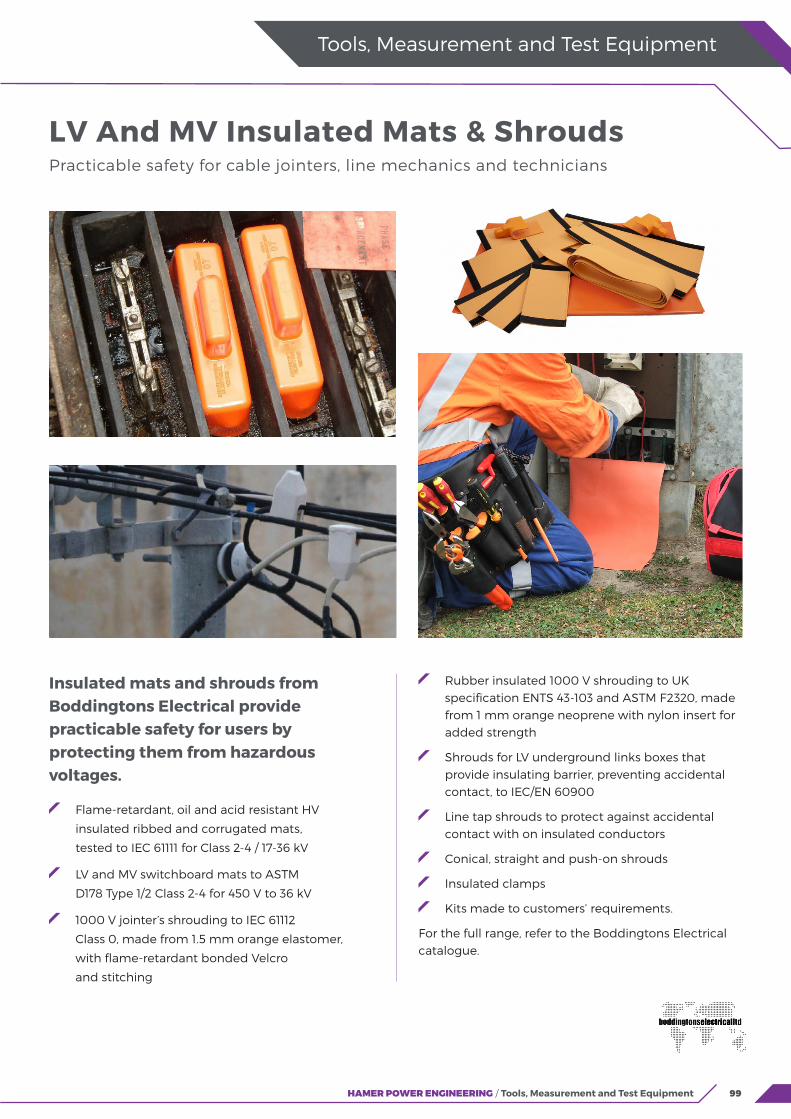
99HAMER POWER ENGINEERING / Tools, Measurement and Test Equipment
Tools, Measurement and Test Equipment
Insulated mats and shrouds from Boddingtons Electrical provide practicable safety for users by protecting them from hazardous voltages.
Flame-retardant, oil and acid resistant HV
insulated ribbed and corrugated mats,
tested to IEC 61111 for Class 2-4 / 17-36 kV
LV and MV switchboard mats to ASTM
D178 Type 1/2 Class 2-4 for 450 V to 36 kV
1000 V jointer’s shrouding to IEC 61112
Class 0, made from 1.5 mm orange elastomer,
with flame-retardant bonded Velcro
and stitching
Rubber insulated 1000 V shrouding to UK specification ENTS 43-103 and ASTM F2320, made from 1 mm orange neoprene with nylon insert for added strength
Shrouds for LV underground links boxes that provide insulating barrier, preventing accidental contact, to IEC/EN 60900
Line tap shrouds to protect against accidental contact with on insulated conductors
Conical, straight and push-on shrouds
Insulated clamps
Kits made to customers’ requirements.
For the full range, refer to the Boddingtons Electrical catalogue.
LV And MV Insulated Mats & Shrouds Practicable safety for cable jointers, line mechanics and technicians

100 HAMER POWER ENGINEERING / Tools, Measurement and Test Equipment
Tools, Measurement and Test Equipment
Klein Tools, established in 1857, manufactures virtually every type of hand tool used in the electrical and electricity industries. Hamer Power Engineering has for many years supplied Klein Tools to New Zealand electricity industry professionals, with whom they have a reputation for safety, quality, and durability.
HPE’s range of insulated tools includes:
Allen keys
Cable cutters
Hammers
Knives
Measuring tapes
Pliers
Ratchet cable cutters
Spanners
Screwdrivers
Saws
Reversible ratchets
Sockets and ratchets
Torches, LED lamps and head lights
Torque wrenches
Wrenches.
Hamer Power Engineering also supplies a wide variety of top-quality tool bags, belts and pouches, from Klein Tools and the Taurus Leather Company, including a range designed in New Zealand for cable jointers, line mechanics and technicians.
Reinforced backpacks and shoulder bags
Canvas buckets
Leather tool pouches and belts
Tool cases (optionally laser marked)
Tote bags.
Hand Tools, Tool Bags & Belts Quality hand tools for electricity industry professionals

101HAMER POWER ENGINEERING / Tools, Measurement and Test Equipment
Tools, Measurement and Test Equipment
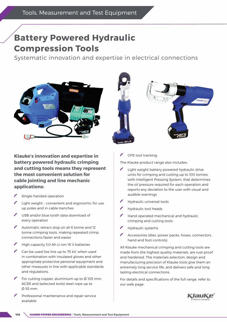
102 HAMER POWER ENGINEERING / Tools, Measurement and Test Equipment
Klauke’s innovation and expertise in battery powered hydraulic crimping and cutting tools means they represent the most convenient solution for cable jointing and line mechanic applications:
Single-handed operation
Light weight – convenient and ergonomic for use up poles and in cable trenches
USB and/or blue tooth data download of every operation
Automatic retract stop on all 6 tonne and 12 tonne crimping tools, making repeated crimp connections faster and easier
High capacity 3.0 Ah Li-Ion 18 V batteries
Can be used live line up to 75 kV, when used in combination with insulated gloves and other appropriate protective personal equipment and other measures in line with applicable standards and regulations.
For cutting copper, aluminium up to Ø 105 mm, ACSR and (selected tools) steel rope up to Ø 55 mm
Professional maintenance and repair service available
GPS tool tracking.
The Klauke product range also includes:
Light weight battery powered hydraulic drive units for crimping and cutting up to 100 tonnes, with Intelligent Pressing System, that determines the oil pressure required for each operation and reports any deviation to the user with visual and audible warnings
Hydraulic universal tools
Hydraulic tool heads
Hand operated mechanical and hydraulic crimping and cutting tools
Hydraulic systems
Accessories (dies, power packs, hoses, connectors, hand and foot controls).
All Klauke mechanical crimping and cutting tools are made from the highest quality materials, are rust-proof and hardened. The materials selection, design and manufacturing precision of Klauke tools give them an extremely long service life, and delivers safe and long lasting electrical connections.
For details and specifications of the full range, refer to our web page.
Battery Powered Hydraulic Compression Tools Systematic innovation and expertise in electrical connections
Tools, Measurement and Test Equipment

103HAMER POWER ENGINEERING / Tools, Measurement and Test Equipment
Tools, Measurement and Test Equipment
Klein ChicagoTM Grips, Parallel Jaw Grips and Haven’sTM Grips are used to maintain temporary tension until a conductor or cable can be permanently terminated.They are available with different designs of jaw contours to eliminate or minimise deformation and maximise grip on aluminium, copper and ACSR conductor, covered conductor or stay wires, with maximum safe load up to 11.3 tonnes. Different locking / latching features are used to accommodate a wide variety of hooks, winches and tackle blocks, and to facilitate placement, including with a hot stick.
The Klein web strap ratchet hoist has a large, non-conductive adjuster that allows the web slack to be adjusted easily. The ratcheting mechanism and 360° rotating handle allows precise tensioning for up to 675 kg (single conductor) and 1350 kg (double conductor).
Also available from Klein: Howe Wire Tool and block and tackle packages.
Greenlee mains powered cable pullers are fast and safe to use, allowing one-person set-up and operation, delivering savings on site time and costs. A wide range
of models is available, with maximum pulling force of up to 4,500 kg.
Cable pulling accessories from Greenlee include:
Hook sheaves, base mounted sheaves
Cable drum rollers
Low-stretch, rot-resistant composite rope (with double braided inner core and outer jacket and green tracer)
Swivel and rope connectors
Grips and pulling socks
Duct cleaning brushes and mandrels
Cable pulling lubricant.
For details of the full range, refer to our web page.
Grips, Ratchet Hoists, Cable Pullers and Accessories For overhead lines and underground cable installation
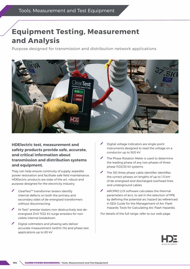
104 HAMER POWER ENGINEERING / Tools, Measurement and Test Equipment
HDElectric test, measurement and safety products provide safe, accurate, and critical information about transmission and distribution systems and equipment. They can help ensure continuity of supply, expedite power restoration and facilitate safe field maintenance. HDElectric products are state of the art, robust and purpose designed for the electricity industry.
ClearTestTM transformer testers identify internal defects on both the primary and secondary sides of de-energised transformers without disconnecting
Hi-Test® arrester testers non-destructively test de- energised ZnO 11/22 kV surge arresters for non- visible internal breakdown
Digital voltmeters and phasing sets deliver accurate measurement (within 1%) and phase test applications up to 80 kV
Digital voltage indicators are single point instruments designed to read the voltage on a conductor up to 500 kV
The Phase Rotation Meter is used to determine the leading phase of any two phases of three- phase 11/22/33 kV systems
The 3ID three phase cable identifier identifies the correct phases on lengths of up to 1.5 km of de-energised and discharged overhead lines and underground cables
ARCPRO 2.01 software calculates the thermal parameters of arcs, to aid in the selection of PPE by defining the potential arc hazard (as referenced in EEA Guide for the Management of Arc Flash Hazards: Tools for Calculating Arc Flash Hazards).
For details of the full range, refer to our web page.
Equipment Testing, Measurement and Analysis Purpose designed for transmission and distribution network applications
Tools, Measurement and Test Equipment

105HAMER POWER ENGINEERING / Tools, Measurement and Test Equipment
Tools, Measurement and Test Equipment
The Modiewark is a non-contact voltage tester which detects the presence of an alternating electric or electromagnetic field as both a proximity and touch device. Its unique switching action allows for the identification of alternating currents at a distance between 200 mm and 300 mm from a voltage source from 110 V to 220 kV.
The Modiewark has been trusted by electricity industry professionals for over 40 years. Firstly, as a proximity device to determine live or dead situations and secondly as a touch device to verify the tester has physically reached the field around designated mains under test.
The Modiewark can also be used indoors, tracing voltage sources from power distribution boards and cable fault detection.
The unique Modiewark sensor allows for directional checks such as checking LV when HV is nearby. Induced voltages on isolated conductors can also be checked by adjusting the sensitivity.
Detecting distance of a 240 V single live wire is approximately 100 mm and with a bunched neutral and earth, as a flexible cable, the distance is 50 mm.
Typical uses include:
Identifying live conductors
Fault finding in flexible cables
Checking equipment grounding
Neon lighting servicing
Tracking live wires above and below ground at URD test points
Phasing conductors
High frequency radiation detection.
Contact Hamer Power Engineering for ordering information.
Proximity and Touch Detection Of live or dead overhead and underground power lines
106
For over 75 years Hamer Power Engineering has supplied the power industry with electrical equipment, components and tools. We work closely with our customers and our
international supply partners to develop and supply
quality products and solutions for New Zealand’s
electricity networks.
Our diverse and capable team includes degree
qualified electrical engineering and operations
management, as well as registered electrician and
test technician skills. Technical, logistical and customer
management specialists are located in Auckland
and Christchurch.
Our technical team’s engineering expertise and
experience with our applications is well known
and allows us to provide robust and responsive
technical support.
By working with our customers and with respected
industry partners we deliver comprehensive training,
installation and certification to ensure that the most
current information and techniques are delivered
to the end user. This approach also allows us to offer
manufacturer-backed extended warranties.
At Hamer Power Engineering we deliver certainty,
reliability and long-term value based on the products
that we supply and on the technical support that
we provide.
End-to-end service
andtechnical
support

Hamer Power Engineering Limited85a Falsgrave StreetPhillipstownChristchurch 8011
For further information on our products and services
contact Hamer Power Engineering on 0800 473 999
or email [email protected]
www.hamerpower.co.nz
Hamer Power Engineering Limited reserve the right to amend product details without notice.
HPE053 1019

Related Documents