Power Electronic Capacitors PEC MKP DC Series/Type: MKP DC (Resin Top) Ordering code: B25690 Date: Aug. 2019 Version: 1 TDK Electronics AG 2019. Reproduction, publication and dissemination of this publication, enclosures hereto and the information contained therein without TDK Electronics' prior express consent is prohibited. Content of header bars 1 and 2 of data sheet will be automatically entered in headers and footers! Please fill in the table and then change the color to "white". This ensures that the table disappears (invisible) for the customer PDF. Don't change formatting when entering or pasting text in the table and don't add any cell or line in and to it! Identification/Classification 1 (header 1 + top left bar): Power Electronic Capacitors Identification/Classification 2 (header 2 + bottom left header bar): PEC MKP DC Ordering code: (top right header bar) B25690 Series/Type: (bottom right header bar) MKP DC (Resin Top) Preliminary data (optional): Department: CAP PW PD Date: Aug. 2019 Version: 1

Welcome message from author
This document is posted to help you gain knowledge. Please leave a comment to let me know what you think about it! Share it to your friends and learn new things together.
Transcript
Power Electronic Capacitors
PEC MKP DC
Series/Type: MKP DC (Resin Top) Ordering code: B25690
Date: Aug. 2019 Version: 1
TDK Electronics AG 2019. Reproduction, publication and dissemination of this publication, enclosures hereto and the information contained therein without TDK Electronics' prior express consent is prohibited.
Content of header bars 1 and 2 of data sheet will be automatically entered in headers and footers! Please fill in the table and then change the color to "white". This ensures that the table disappears (invisible) for the customer PDF. Don't change formatting when entering or pasting text in the table and don't add any cell or line in and to it! Identification/Classification 1 (header 1 + top left bar):
Power Electronic Capacitors
Identification/Classification 2 (header 2 + bottom left header bar):
PEC MKP DC
Ordering code: (top right header bar) B25690 Series/Type: (bottom right header bar) MKP DC (Resin Top) Preliminary data (optional): Department: CAP PW PD Date: Aug. 2019 Version: 1

Power Electronic Capacitors B25690
PEC MKP DC MKP DC (Resin Top)
CAP PW PD Aug. 2019
Please read Cautions and warnings and Page 2 of 31 Important notes at the end of this document.
1. Construction and general data
Characteristics Standard capacitance tolerance K: ±10%
Dielectric dissipation factor (tan δo) 2 • 10-4
Service life expectancy tLD (co) (refer to section 3)
100 000 h at Ths +75 °C and VRDC for D≤116 mm 100 000 h at Ths +70 °C and VRDC for D=136 mm up to 200 000 h (considering de-ratings in voltage and/or temperature)
Expected failure rate αFQ (co) 50 fit at VRDC and +70 °C (refer to section 4)
Minimum temperature Top,min. –40 °C
Maximum temperature Top,max. +85 °C for diameter 75 ≤ ØD ≤100 mm +75 °C for diameter 116≤ ØD ≤136 mm
Storage temperature Tstg –40 ... +85 °C
Maximum hotspot temperature Ths (refer to section 1)
+85 °C for diameter 75 ≤ ØD ≤100 mm +75 °C for diameter 116≤ ØD ≤136 mm
Climatic category 40/85/56 for 75 ≤ ØD ≤100 mm diameter 40/75/56 for 116≤ ØD ≤136 mm diameter
Maximum altitude 2 000 m above sea level (derating curves available upon request)
Partial discharge extinction voltage (typical) >1.6 kVac (10 pC) (higher value upon request)
Test data
Voltage test between terminals VTT 1.5 VRDC, 10 s
Voltage test between terminals and case VTC (√2VRDC + 1 000) V AC or 4 000 V AC whichever is the highest value, 10 s
Design data
Resin filling Non PCB, hard polyurethane (dry type)
Mounting and grounding M12 threaded bolt on bottom of the aluminum case
Max. torque (case) M12 stud 10 Nm
Max. torque terminal Female M6: 5 Nm Female M8: 6 Nm
Cooling Natural or forced air cooling
Degree of protection IP00
Reference standards IEC 61071 - 2017
UL 810 5th edition - certification file No.E502394
RoHS compliance

Power Electronic Capacitors B25690
PEC MKP DC MKP DC (Resin Top)
CAP PW PD Aug. 2019
Please read Cautions and warnings and Page 3 of 31 Important notes at the end of this document.
1.1 Structure of ordering code
1.2 Label information
The label explanation are following:
25 Z 2019: Production by TDK Electronics
Zhuhai factory 2019 year, calendar week 25;
Bar code consists of lot number and serial
number:
Lot number: 9 digits (ex.: 905887304)
Serial number: 3 digits (ex.: 001)
Terminal type: 0 = Female M6 2 = Female M8 9 = special
B2569 0 A 1 427 K 1 0 1
MKP DC Series
Version: A: plastic ring L = 10mm B: to be defined C: plastic ring L = 55mm S: special
Voltage: 110 • 10 = 1100 V
Rated capacitance: 107 = 10 ꞏ 107 pF = 100 µF 427 = 42 ꞏ 107 pF = 420 µF 108 = 10 ꞏ 108 pF = 1 mF
Distance between terminals: 1 = 32 mm 3 = 50 mm 9 = special
Capacitance tolerance J = ± 5% K = ± 10% A = special
Internal use code

Power Electronic Capacitors B25690
PEC MKP DC MKP DC (Resin Top)
CAP PW PD Aug. 2019
Please read Cautions and warnings and Page 4 of 31 Important notes at the end of this document.
1.3 Standard types
Distance between terminals (mm)
OC ending
Diameter (Ø)
Terminal type
32 ± 0.5
-**1
50 ± 0.5
-**3
75/85 mm Female M6 standard
100 mm Female M6 standard
116/136 mm Female M6 standard
Other terminal configurations available upon request.
1.4 Drawings
Figure 1: - B25690A – ØD=75/85 mm Figure 2: - B25690A – ØD=100 mm
- Female terminals (M6) - Female terminals (M6)
- Between terminals 32 ±0.5 mm - Between terminals 32 ±0.5 mm
Power Electronic Capacitors B25690
PEC MKP DC MKP DC (Resin Top)
CAP PW PD Aug. 2019
Please read Cautions and warnings and Page 5 of 31 Important notes at the end of this document.
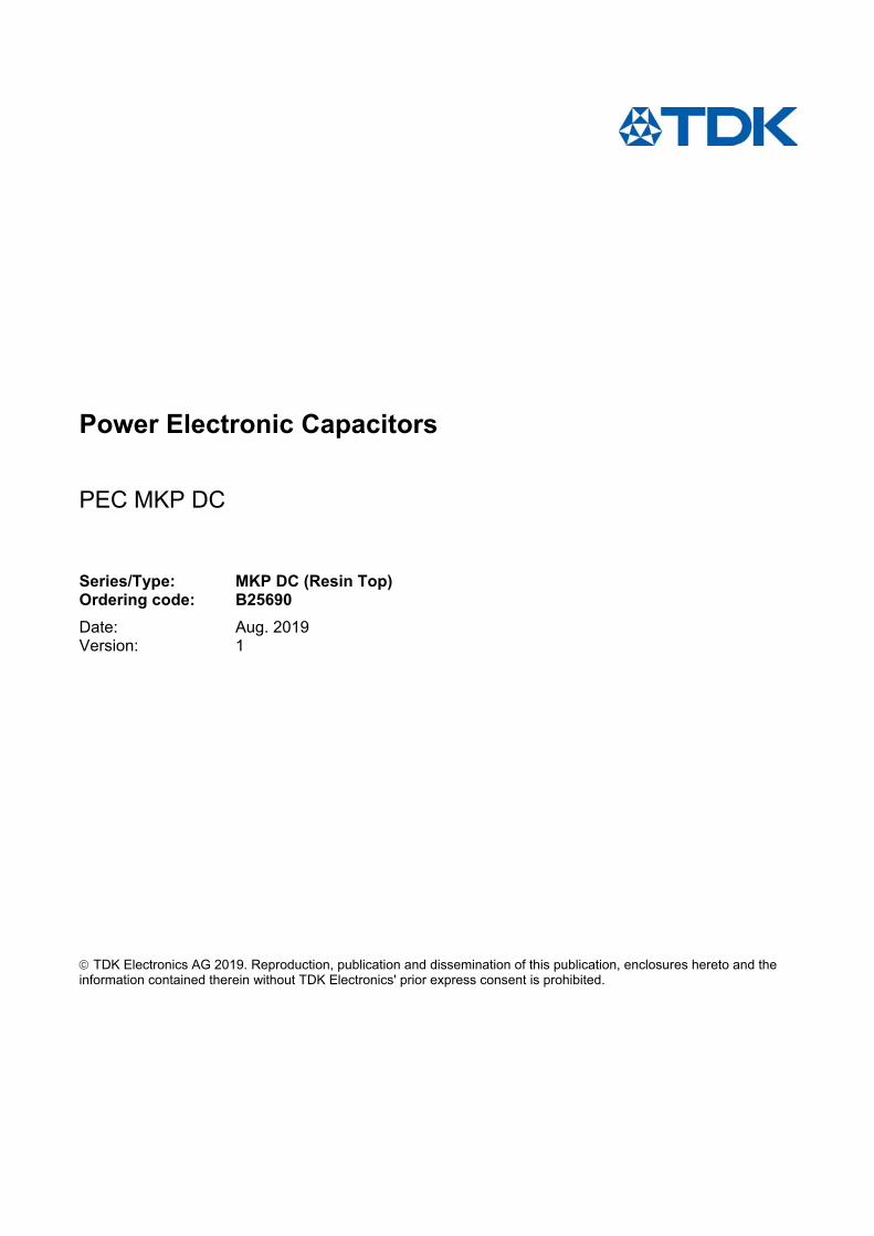
Figure 3: - B25690A - ØD=116 mm Figure 4: - B25690C - ØD=136 mm
- Female terminals (M6) - Female terminals (M6)
- Between terminals 50 ±0.5 mm - Between terminals 50 ±0.5 mm

Power Electronic Capacitors B25690
PEC MKP DC MKP DC (Resin Top)
CAP PW PD Aug. 2019
Please read Cautions and warnings and Page 6 of 31 Important notes at the end of this document.
Terms and characteristics
The following definitions apply to power capacitors according to IEC 61071.
Rated capacitance CR Nominal value of the capacitance at 20 °C and measuring frequency of 100 Hz. Rated DC voltage VRDC Maximum operating peak voltage of either polarity but of a non-reversing type wave form, for which the
capacitor has been designed, for continuous operation. Ripple voltage Vripple Peak-to-peak alternating component of the unidirectional voltage.
This value must not exceed 0.28 ∙ VRDC
Maximum surge voltage Vs Peak voltage induced by a switching or any other disturbance of the system which is allowed for a limited
number of times and short period.
Insulation voltage Vi Rms rated value of the insulation voltage of capacitive elements and terminals to case or earth. When it is not
specified in the product data sheet, the insulation voltage is at least:
Vi = 2
VRDC
AC voltage test between terminals and case VTC Units having all terminals insulated from the container shall be subjected for 10 s to a voltage applied between the terminals (joined together) and the container. Maximum rate of voltage rise (dv/dt)max
Maximum permissible repetitive rate of voltage rise of the operational voltage.
Maximum current Imax
Maximum rms current for continuous operation for the given frequency range and for the maximum ripple
voltage. Please provide Frequency Spectrum of rms current to your sales contact.
Maximum peak current Î Maximum permissible repetitive current amplitude during continuous operation.
Maximum peak current (Î) and maximum rate of voltage rise (dV/dt)max on a capacitor are related as follows:
Î = C ∙ (dv/dt)max Maximum surge current Î s
Admissible peak current induced by a switching or any other disturbance of the system which is allowed for a
limited number of times and short period.
Îs = C ∙ (dv/dt)s
Ambient temperature TA
Temperature of the surrounding air, measured at 10 cm distance and 2/3 of the case height of the capacitor.

Power Electronic Capacitors B25690
PEC MKP DC MKP DC (Resin Top)
CAP PW PD Aug. 2019
Please read Cautions and warnings and Page 7 of 31 Important notes at the end of this document.
Lowest operating temperature Top,min
Lowest permitted ambient temperature at which a capacitor may be energized.
Maximum operating temperature Top,max
Highest permitted capacitor temperature during operation, i.e. temperature at the hottest point of the case.
Hot-spot temperature Ths
Temperature zone inside of the capacitor at hottest spot.
Ths =TA+ IRMS2 ∙ ESR ∙ Rth
Tangent of the loss angle of a capacitor tan
Ratio between the equivalent series resistance and the capacitive reactance of a capacitor at a specified
sinusoidal alternating voltage, frequency and temperature.
Series resistance Rs
The sum of all Ohmic resistances occurring inside the capacitor.
ESR Effective resistance which, if connected in series with an ideal capacitor of capacitance value equal to that of the capacitor in question, would have a power loss equal to active power dissipated in that capacitor under specified operating conditions.
ESR = Ctan
= C
Rs
0tan
Thermal resistance Rth
The thermal resistance indicates by how many degrees the capacitor temperature at the hot spot rises in
relation to the dissipation losses.
Maximum power loss Pmax
Maximum permissible power dissipation for the capacitor’s operation.
Pmax = thR
Ahs T T
Self inductance Lself
The sum of all inductive elements which are contained in a capacitor.
Resonance frequency fr
The lowest frequency at which the impedance of the capacitor becomes minimum.
fr = Rself CL2
1

Power Electronic Capacitors B25690
PEC MKP DC MKP DC (Resin Top)
CAP PW PD Aug. 2019
Please read Cautions and warnings and Page 8 of 31 Important notes at the end of this document.
VRDC = 700 VDC / VTT = 1050 VDC, 10s / VTC = 4000 VAC, 10s
CR IMAX1 Is Î ESR2 Lself RTH D HC HT Weight Fig.
Ordering code
µF A kA kA mΩ nH K/W mm mm mm kg
360 70 6.6 2.2 1.6 ≤40 5.5 75 95 101 0.5 1 B25690A0367K701
480 65 6.5 2.2 2.1 ≤40 4.6 75 120 126 0.6 1 B25690A0487K701
500 70 8.9 3.0 1.6 ≤40 5.0 85 95 101 0.6 1 B25690A0507K701
560 70 13.0 4.3 1.5 ≤40 4.2 75 155 161 0.8 1 B25690A0567K701
570 65 6.5 2.2 2.4 ≤40 4.5 75 140 146 0.7 1 B25690A0577K701
650 70 8.9 3.0 2.0 ≤40 4.7 85 120 126 0.8 1 B25690A0657K701
660 70 12.2 4.1 1.4 ≤40 4.6 100 95 101 0.9 2 B25690A0667K701
680 70 13.1 4.4 1.7 ≤60 4.2 75 176 182 0.9 1 B25690A0687K701
750 70 8.9 3.0 2.2 ≤40 4.6 85 135 141 0.9 1 B25690A0757K701
780 70 8.9 3.0 2.0 ≤40 4.5 85 140 146 1.0 1 B25690A0787K701
780 70 17.8 5.9 1.5 ≤40 4.3 85 155 161 1.1 1 B25690A0787K721
900 70 12.4 4.1 1.5 ≤40 4.2 100 120 126 1.2 2 B25690A0907K701
920 80 17.3 5.8 0.7 ≤40 5.3 116 96 102 1.0 3 B25690A0927K703
950 70 17.8 5.9 1.5 ≤60 4.2 85 176 182 1.2 1 B25690A0957K701
1000 70 12.2 4.1 1.9 ≤40 3.9 100 135 141 1.4 2 B25690A0108K701
1100 70 12.5 4.2 1.9 ≤40 3.8 100 140 146 1.5 2 B25690A0118K701
1100 70 25.2 8.4 1.0 ≤40 3.4 100 155 161 1.6 2 B25690A0118K721
1200 80 16.6 5.5 1.0 ≤40 4.9 116 121 127 1.4 3 B25690A0128K703
1300 70 24.4 8.1 1.1 ≤60 3.1 100 176 182 2.0 2 B25690A0138K701
1400 70 18.0 6.0 1.4 ≤90 3.2 85 252 258 1.6 1 B25690A0148K701
1500 80 17.1 5.7 1.1 ≤40 4.8 116 141 147 1.6 3 B25690A0158K703
1500 100 34.3 11.4 1.0 ≤60 3.5 116 155 161 1.8 3 B25690A0158K723
1800 100 33.8 11.3 1.0 ≤60 3.3 116 176 182 2.0 3 B25690A0188K703
2500 100 34.5 11.5 0.9 ≤90 2.6 116 230 236 2.5 3 B25690A0258K703
4400 100 56.8 18.9 0.8 ≤90 2.0 136 304 310 4.5 4 B25690C0448K703
5000 100 55.7 18.6 0.7 ≤90 1.8 136 345 351 5.0 4 B25690C0508K703
5500 100 58.6 19.5 0.7 ≤90 1.6 136 370 376 5.5 4 B25690C0558K703 1 Please refer to current derating section for more details 2 ESR at 1 kHz (typical value)
Other configurations and capacitance tolerances available upon request

Power Electronic Capacitors B25690
PEC MKP DC MKP DC (Resin Top)
CAP PW PD Aug. 2019
Please read Cautions and warnings and Page 9 of 31 Important notes at the end of this document.
VRDC = 900 VDC / VTT = 1350 VDC, 10s / VTC = 4000 VAC, 10s
CR IMAX1 Is Î ESR2 Lself RTH D HC HT Weight Fig.
Ordering code µF A kA kA mΩ nH K/W mm mm mm kg
280 65 5.8 1.9 2.1 ≤40 5.5 75 95 101 0.5 1 B25690A0287K901
370 60 5.8 1.9 2.7 ≤40 4.6 75 120 126 0.6 1 B25690A0377K901
380 70 7.9 2.6 1.7 ≤40 5.0 85 95 101 0.6 1 B25690A0387K901
420 70 11.5 3.8 1.8 ≤40 4.2 75 155 161 0.8 1 B25690A0427K901
460 60 5.7 1.9 3.0 ≤40 4.5 75 140 146 0.7 1 B25690A0467K901
500 70 10.7 3.6 1.5 ≤40 4.6 100 95 101 0.9 2 B25690A0507K901
510 70 7.8 2.6 2.2 ≤40 4.7 85 120 126 0.8 1 B25690A0517K901
520 70 11.6 3.9 1.9 ≤60 4.2 75 176 182 0.9 1 B25690A0527K901
570 65 7.9 2.7 2.3 ≤40 4.6 85 135 141 0.9 1 B25690A0577K901
580 70 15.7 5.2 1.5 ≤40 4.3 85 155 161 1.1 1 B25690A0587K901
600 65 7.8 2.6 2.5 ≤40 4.5 85 140 146 1.0 1 B25690A0607K901
700 70 11.0 3.7 1.7 ≤40 4.2 100 120 126 1.2 2 B25690A0707K901
720 70 15.7 5.2 1.6 ≤60 4.2 85 176 182 1.2 1 B25690A0737K901
720 80 15.4 5.1 1.0 ≤40 5.3 116 96 102 1.0 3 B25690A0727K903
780 70 11.1 3.7 1.9 ≤40 3.9 100 135 141 1.4 2 B25690A0787K901
850 70 11.1 3.7 2.1 ≤40 3.8 100 140 146 1.5 2 B25690A0857K901
850 70 22.2 7.4 1.2 ≤40 3.4 100 155 161 1.6 2 B25690A0857K921
980 80 15.3 5.1 1.3 ≤40 4.9 116 121 127 1.4 3 B25690A0987K903
1000 70 21.4 7.1 1.2 ≤60 3.1 100 176 182 2.0 2 B25690A0108K901
1100 70 15.3 5.1 1.4 ≤90 3.2 85 252 258 1.6 1 B25690A0118K901
1150 100 30.8 10.3 1.0 ≤60 3.5 116 155 161 1.8 3 B25690A0118K903
1200 80 15.4 5.1 1.5 ≤40 4.8 116 141 147 1.6 3 B25690A0128K903
1400 100 31.1 10.4 1.3 ≤60 3.3 116 176 182 2.0 3 B25690A0148K903
1900 100 30.8 10.3 1.2 ≤90 2.6 116 230 236 2.5 3 B25690A0198K903
3400 100 49.5 16.5 1.2 ≤90 2.0 136 304 310 4.5 4 B25690C0348K903
3800 100 50.6 16.9 1.1 ≤90 1.8 136 345 351 5.0 4 B25690C0388K903
4300 100 52.3 17.4 1.0 ≤90 1.6 136 370 376 5.5 4 B25690C0438K903 1 Please refer to current derating section for more details 2 ESR at 1 kHz (typical value)
Other configurations and capacitance tolerances available upon request

Power Electronic Capacitors B25690
PEC MKP DC MKP DC (Resin Top)
CAP PW PD Aug. 2019
Please read Cautions and warnings and Page 10 of 31 Important notes at the end of this document.
VRDC = 1000 VDC / VTT = 1500 VDC, 10s / VTC = 4000 VAC, 10s
CR IMAX1 Is Î ESR2 Lself RTH D HC HT Weight Fig.
Ordering code µF A kA kA mΩ nH K/W mm mm mm kg
220 60 5.1 1.7 2.2 ≤40 5.5 75 95 101 0.5 1 B25690A1227K001
290 70 7.0 2.3 1.8 ≤40 5.0 85 95 101 0.6 1 B25690A1297K001
300 55 5.0 1.7 2.9 ≤40 4.6 75 120 126 0.6 1 B25690A1307K001
330 70 10.0 3.3 1.9 ≤40 4.2 75 155 161 0.8 1 B25690A1337K001
360 55 5.0 1.7 3.3 ≤40 4.5 75 140 146 0.7 1 B25690A1367K001
400 65 7.1 2.4 2.3 ≤40 4.7 85 120 126 0.8 1 B25690A1407K001
400 70 9.6 3.2 1.5 ≤40 4.6 100 95 101 0.9 2 B25690A1407K011
410 70 10.1 3.4 2.0 ≤60 4.2 75 176 182 0.9 1 B25690A1417K001
450 65 7.0 2.4 2.2 ≤40 4.6 85 135 141 0.9 1 B25690A1457K001
460 70 13.8 4.6 1.6 ≤40 4.3 85 155 161 1.1 1 B25690A1467K001
470 60 6.9 2.3 2.6 ≤40 4.5 85 140 146 1.0 1 B25690A1477K001
530 70 9.8 3.3 1.8 ≤40 4.2 100 120 126 1.2 2 B25690A1537K001
550 80 13.5 4.5 1.0 ≤40 5.3 116 96 102 1.0 3 B25690A1557K003
570 70 13.7 4.6 1.7 ≤60 4.2 85 176 182 1.2 1 B25690A1577K001
600 70 9.5 3.2 1.9 ≤40 3.9 100 135 141 1.4 2 B25690A1607K001
650 70 9.7 3.2 1.9 ≤40 3.8 100 140 146 1.5 2 B25690A1657K001
650 70 19.1 6.4 1.1 ≤40 3.4 100 155 161 1.6 2 B25690A1657K021
750 80 13.6 4.5 1.4 ≤40 4.9 116 121 127 1.4 3 B25690A1757K003
780 70 19.3 6.4 1.1 ≤60 3.1 100 176 182 2.0 2 B25690A1787K001
860 70 13.8 4.6 1.3 ≤90 3.2 85 252 258 1.6 1 B25690A1867K001
920 80 13.5 4.5 1.5 ≤40 4.8 116 141 147 1.6 3 B25690A1927K003
920 100 27.0 9.0 1.0 ≤60 3.5 116 155 161 1.8 3 B25690A1927K023
1100 100 26.5 8.8 1.2 ≤60 3.3 116 176 182 2.0 3 B25690A1108K003
1500 100 26.6 8.9 0.9 ≤90 2.6 116 230 236 2.5 3 B25690A1158K003
2700 100 44.7 14.9 0.9 ≤90 2.0 136 304 310 4.5 4 B25690C1278K003
3100 100 45.1 15.0 0.8 ≤90 1.8 136 345 351 5.0 4 B25690C1318K003
3500 100 46.5 15.5 0.8 ≤90 1.6 136 370 376 5.5 4 B25690C1358K003 1 Please refer to current derating section for more details 2 ESR at 1 kHz (typical value)
Other configurations and capacitance tolerances available upon request

Power Electronic Capacitors B25690
PEC MKP DC MKP DC (Resin Top)
CAP PW PD Aug. 2019
Please read Cautions and warnings and Page 11 of 31 Important notes at the end of this document.
VRDC = 1100 VDC / VTT = 1650 VDC, 10s / VTC = 4000 VAC, 10s
CR IMAX1 Is Î ESR2 Lself RTH D HC HT Weight Fig.
Ordering code µF A kA kA mΩ nH K/W mm mm mm kg
180 60 6.1 2.0 2.3 ≤40 5.5 75 95 101 0.5 1 B25690A1187K101
240 70 8.5 2.8 1.9 ≤40 5.0 85 95 101 0.6 1 B25690A1247K101
250 55 6.0 2.0 3.0 ≤40 4.6 75 120 126 0.6 1 B25690A1257K101
280 70 12.2 4.1 2.0 ≤40 4.2 75 155 161 0.8 1 B25690A1287K101
300 55 6.1 2.0 3.4 ≤40 4.5 75 140 146 0.7 1 B25690A1307K101
320 65 8.4 2.8 2.4 ≤40 4.7 85 120 126 0.8 1 B25690A1327K101
330 70 11.8 3.9 1.7 ≤40 4.6 100 95 101 0.9 1 B25690A1337K101
340 70 12.2 4.1 2.1 ≤60 4.2 75 176 182 0.9 1 B25690A1347K101
420 65 9.0 3.0 2.4 ≤40 4.6 85 135 141 0.9 1 B25690A1427K101
420 70 17.5 5.8 1.8 ≤40 4.3 85 155 161 1.1 1 B25690A1427K121
450 70 11.8 3.9 2.1 ≤40 4.2 100 120 126 1.2 2 B25690A1457K101
470 80 16.1 5.4 1.1 ≤40 5.3 116 96 102 1.0 2 B25690A1477K103
480 70 16.8 5.6 1.9 ≤60 4.2 85 176 182 1.2 1 B25690A1487K101
500 70 11.6 3.9 2.0 ≤40 3.9 100 135 141 1.4 2 B25690A1507K101
540 70 11.7 3.9 2.0 ≤40 3.8 100 140 146 1.5 2 B25690A1547K101
550 70 24.0 8.0 1.2 ≤40 3.4 100 155 161 1.6 2 B25690A1557K101
620 80 16.3 5.4 1.5 ≤40 4.9 116 121 127 1.4 3 B25690A1627K103
660 70 23.6 7.9 1.2 ≤60 3.1 100 176 182 2.0 2 B25690A1667K101
720 70 16.7 5.6 1.4 ≤90 3.2 85 252 258 1.6 1 B25690A1727K101
760 75 16.3 5.4 1.6 ≤40 4.8 116 141 147 1.6 3 B25690A1767K103
770 100 32.7 10.9 1.1 ≤60 3.5 116 155 161 1.8 3 B25690A1777K103
900 100 32.2 10.7 1.3 ≤60 3.3 116 176 182 2.0 3 B25690A1907K103
1200 100 31.6 10.5 1.2 ≤90 2.6 116 230 236 2.5 3 B25690A1128K103
2200 100 54.0 18.0 1.2 ≤90 2.0 136 304 310 4.5 4 B25690C1228K103
2600 100 54.3 18.1 1.1 ≤90 1.8 136 345 351 5.0 4 B25690C1268K103
3000 100 58.1 19.4 1.0 ≤90 1.6 136 370 376 5.5 4 B25690C1308K103 1 Please refer to current derating section for more details 2 ESR at 1 kHz (typical value)
Other configurations and capacitance tolerances available upon request

Power Electronic Capacitors B25690
PEC MKP DC MKP DC (Resin Top)
CAP PW PD Aug. 2019
Please read Cautions and warnings and Page 12 of 31 Important notes at the end of this document.
VRDC = 1200 VDC / VTT = 1800 VDC, 10s / VTC = 4000 VAC, 10s
CR IMAX Is Î ESR2 Lself RTH D HC HT Weight Fig.
Ordering code µF A kA kA mΩ nH K/W mm mm mm kg
140 55 5.5 1.8 2.8 ≤40 5.5 75 95 101 0.5 1 B25690A1147K201
190 55 5.5 1.8 3.5 ≤40 4.6 75 120 126 0.6 1 B25690A1197K201
200 65 7.6 2.5 2.2 ≤40 5.0 85 95 101 0.6 1 B25690A1207K201
220 50 5.3 1.8 4.0 ≤40 4.5 75 140 146 0.7 1 B25690A1227K201
220 70 11.0 3.7 2.1 ≤40 4.2 75 155 161 0.8 1 B25690A1227K221
260 60 7.5 2.5 2.7 ≤40 4.7 85 120 126 0.8 1 B25690A1267K201
270 70 11.0 3.7 2.2 ≤60 4.2 75 176 182 0.9 1 B25690A1277K201
270 70 10.6 3.5 2.0 ≤40 4.6 100 95 101 0.9 2 B25690A1277K211
300 65 7.7 2.6 2.6 ≤40 4.6 85 135 141 0.9 1 B25690A1307K201
310 70 15.3 5.1 1.9 ≤40 4.3 85 155 161 1.1 1 B25690A1317K201
320 60 7.6 2.5 3.1 ≤40 4.5 85 140 146 1.0 1 B25690A1327K201
360 70 10.4 3.5 2.1 ≤40 4.2 100 120 126 1.2 2 B25690A1367K201
370 80 14.5 4.8 1.2 ≤40 5.3 116 96 102 1.0 3 B25690A1377K203
380 70 14.9 5.0 2.0 ≤60 4.2 85 176 182 1.2 1 B25690A1387K201
400 70 10.7 3.6 2.3 ≤40 3.9 100 135 141 1.4 2 B25690A1407K201
430 70 10.7 3.6 2.3 ≤40 3.8 100 140 146 1.5 2 B25690A1437K201
450 70 21.6 7.2 1.3 ≤40 3.4 100 155 161 1.6 2 B25690A1457K201
500 70 21.2 7.1 1.3 ≤60 3.1 100 176 182 2.0 2 B25690A1507K201
500 75 14.5 4.8 1.7 ≤40 4.9 116 121 127 1.4 3 B25690A1507K203
580 70 14.8 4.9 1.6 ≤90 3.2 85 252 258 1.6 1 B25690A1587K201
600 70 14.3 4.8 1.9 ≤40 4.8 116 141 147 1.6 3 B25690A1607K203
620 100 29.7 9.9 1.0 ≤60 3.5 116 155 161 1.8 3 B25690A1627K203
720 100 29.5 9.8 1.3 ≤60 3.3 116 176 182 2.0 3 B25690A1727K203
1000 100 28.9 9.6 1.2 ≤90 2.6 116 230 236 2.5 3 B25690A1108K203
1800 100 19.4 6.5 1.2 ≤90 2.0 136 304 310 4.5 4 B25690C1188K203
2100 100 48.1 16.0 1.1 ≤90 1.8 136 345 351 5.0 4 B25690C1218K203
2400 100 51.1 17.0 1.0 ≤90 1.6 136 370 376 5.5 4 B25690C1248K203 1 Please refer to current derating section for more details 2 ESR at 1 kHz (typical value)
Other configurations and capacitance tolerances available upon request
Power Electronic Capacitors B25690
PEC MKP DC MKP DC (Resin Top)
CAP PW PD Aug. 2019
Please read Cautions and warnings and Page 13 of 31 Important notes at the end of this document.
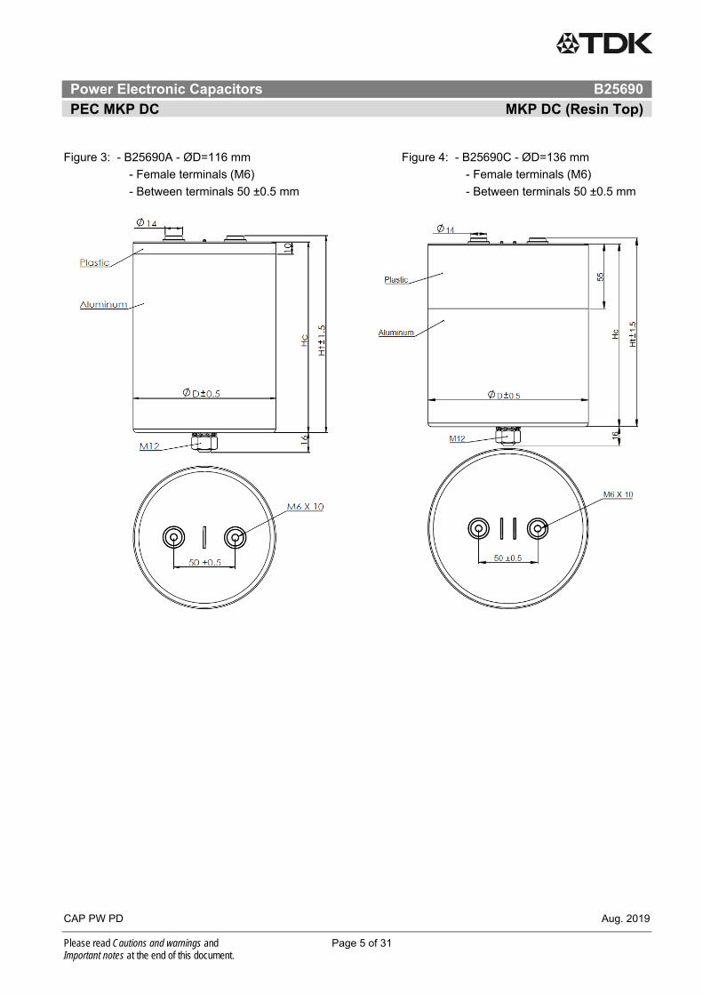
VRDC = 1300 VDC / VTT = 1950 VDC, 10s / VTC = 4000 VAC, 10s
CR IMAX1 Is Î ESR2 Lself RTH D HC HT Weight Fig.
Ordering code µF A kA kA mΩ nH K/W mm mm mm kg
120 55 5.0 1.7 3.0 ≤40 5.5 75 95 101 0.5 1 B25690A1127K301
160 50 4.9 1.6 3.8 ≤40 4.6 75 120 126 0.6 1 B25690A1167K301
160 65 7.1 2.4 2.3 ≤40 5.0 85 95 101 0.6 1 B25690A1167K311
180 70 9.9 3.3 2.2 ≤40 4.2 75 155 161 0.8 1 B25690A1187K301
200 50 5.1 1.7 4.2 ≤40 4.5 75 140 146 0.8 1 B25690A1207K301
210 70 9.4 3.1 1.9 ≤40 4.6 100 95 101 0.9 2 B25690A1217K301
220 70 9.9 3.3 2.4 ≤60 4.2 75 176 182 0.9 1 B25690A1227K301
230 60 6.9 2.3 2.9 ≤40 4.7 85 120 126 0.8 1 B25690A1237K301
240 70 13.8 4.6 1.9 ≤40 4.3 85 155 161 1.1 1 B25690A1247K301
250 60 7.0 2.3 2.9 ≤40 4.6 85 135 141 0.9 1 B25690A1257K301
260 55 6.9 2.3 3.4 ≤40 4.5 85 140 146 1.0 1 B25690A1267K301
280 65 9.8 3.3 2.2 ≤40 4.2 100 120 126 1.2 2 B25690A1287K301
300 70 13.4 4.5 2.0 ≤60 4.2 85 176 182 1.2 1 B25690A1307K301
300 80 13.4 4.5 1.3 ≤40 5.3 116 96 102 1.0 3 B25690A1307K303
330 65 9.7 3.2 2.4 ≤40 3.9 100 135 141 1.4 2 B25690A1337K301
350 70 19.9 6.6 1.3 ≤40 3.4 100 155 161 1.6 2 B25690A1357K301
360 65 9.6 3.2 2.4 ≤40 3.8 100 140 146 1.5 2 B25690A1367K301
420 70 19.7 6.6 1.4 ≤60 3.1 100 176 182 2.0 2 B25690A1427K301
420 75 13.7 4.6 1.7 ≤40 4.9 116 121 127 1.4 3 B25690A1427K303
480 70 13.8 4.6 1.6 ≤90 3.2 85 252 258 1.6 1 B25690A1487K301
500 100 27.6 9.2 1.1 ≤60 3.5 116 155 161 1.8 3 B25690A1507K303
520 70 13.9 4.6 1.9 ≤40 4.8 116 141 147 1.6 3 B25690A1527K303
600 100 27.8 9.3 1.3 ≤60 3.3 116 176 182 2.0 3 B25690A1607K303
830 100 27.7 9.2 1.2 ≤90 2.6 116 230 236 2.5 3 B25690A1837K303
1500 100 45.7 15.2 1.2 ≤90 2.0 136 304 310 4.5 4 B25690C1158K303
1700 100 46.3 15.4 1.1 ≤90 1.8 136 345 351 5.0 4 B25690C1178K303
1900 100 47.8 15.9 1.0 ≤90 1.6 136 370 376 5.5 4 B25690C1198K303 1 Please refer to current derating section for more details 2 ESR at 1 kHz (typical value)
Other configurations and capacitance tolerances available upon request

Power Electronic Capacitors B25690
PEC MKP DC MKP DC (Resin Top)
CAP PW PD Aug. 2019
Please read Cautions and warnings and Page 14 of 31 Important notes at the end of this document.
VRDC = 1500 VDC / VTT = 2550 VDC, 10s / VTC = 4000 VAC, 10s
CR IMAX1 Is Î ESR2 Lself RTH D HC HT Weight Fig.
Ordering code µF A kA kA mΩ nH K/W mm mm mm kg
100 50 4.4 1.5 3.4 ≤40 5.5 75 95 101 0.5 1 B25690A1107K501
120 50 4.2 1.4 4.5 ≤40 4.6 75 120 126 0.6 1 B25690A1127K501
130 60 6.5 2.2 2.7 ≤40 5.0 85 95 101 0.6 1 B25690A1137K501
150 45 4.3 1.4 5.0 ≤40 4.5 75 140 146 0.8 1 B25690A1157K501
150 65 9.0 3.0 2.5 ≤40 4.2 75 155 161 0.8 1 B25690A1157K521
170 70 8.3 2.8 2.0 ≤40 4.6 100 95 101 0.9 2 B25690A1177K501
180 65 8.7 2.9 2.6 ≤60 4.2 75 176 182 0.9 1 B25690A1187K521
180 55 6.5 2.2 3.4 ≤40 4.7 85 120 126 0.8 1 B25690A1187K501
210 60 6.6 2.2 2.7 ≤40 4.6 85 135 141 0.9 1 B25690A1217K501
210 70 13.0 4.3 2.1 ≤40 4.3 85 155 161 1.1 1 B25690A1217K521
230 60 6.5 2.2 3.1 ≤40 4.5 85 140 146 1.0 1 B25690A1237K501
240 65 8.5 2.8 2.4 ≤40 4.2 100 120 126 1.2 2 B25690A1247K501
250 70 12.5 4.2 2.2 ≤60 4.2 85 176 182 1.2 1 B25690A1257K501
250 80 12.1 4.0 1.5 ≤40 5.3 116 96 102 1.0 3 B25690A1257K503
270 65 8.4 2.8 2.6 ≤40 3.9 100 135 141 1.4 2 B25690A1277K501
280 70 16.1 5.4 1.4 ≤40 3.4 100 155 161 1.6 2 B25690A1287K501
330 70 11.6 3.9 2.0 ≤40 4.9 116 121 127 1.4 3 B25690A1337K503
340 70 16.0 5.3 1.4 ≤60 3.1 100 176 182 2.0 2 B25690A1347K501
380 70 12.1 4.0 1.6 ≤90 3.2 85 252 258 1.6 1 B25690A1387K501
400 100 25.1 8.4 1.2 ≤60 3.5 116 155 161 1.8 3 B25690A1407K503
420 70 12.4 4.1 2.2 ≤40 4.8 116 141 147 1.6 3 B25690A1427K503
500 90 24.3 8.1 1.4 ≤60 3.3 116 176 182 2.0 3 B25690A1507K503
680 100 24.0 8.0 1.1 ≤90 2.6 116 230 236 2.5 3 B25690A1687K503
1200 100 39.6 13.2 1.2 ≤90 2.0 136 304 310 4.5 4 B25690C1128K503
1400 100 41.8 13.9 1.2 ≤90 1.8 136 345 351 5.0 4 B25690C1148K503
1600 100 45.0 15.0 1.0 ≤90 1.6 136 370 376 5.5 4 B25690C1168K503 1 Please refer to current derating section for more details 2 ESR at 1 kHz (typical value)
Other configurations and capacitance tolerances available upon request

Power Electronic Capacitors B25690
PEC MKP DC MKP DC (Resin Top)
CAP PW PD Aug. 2019
Please read Cautions and warnings and Page 15 of 31 Important notes at the end of this document.
VRDC = 1700 VDC / VTT = 2550 VDC, 10s / VTC = 4000 VAC, 10s
CR IMAX1 Is Î ESR2 Lself RTH D HC HT Weight Fig.
Ordering code µF A kA kA mΩ nH K/W mm mm mm kg
170 50 5.7 1.9 3.3 ≤40 4.5 85 140 146 1.0 1 B25690A1177K701
260 80 10.6 3.5 1.8 ≤60 3.8 85 230 236 1.4 1 B25690A1267K701
270 70 10.6 3.5 2.1 ≤40 4.9 116 121 127 1.4 3 B25690A1277K703
320 70 10.7 3.6 2.2 ≤40 4.8 116 141 147 1.6 3 B25690A1327K703
360 80 14.3 4.8 1.8 ≤40 3.0 136 121 127 1.9 4 B25690C1367K703
380 100 21.3 7.1 1.2 ≤60 3.3 116 176 182 2.0 3 B25690A1387K703
440 80 14.0 4.7 2.0 ≤40 2.8 136 141 147 2.2 4 B25690C1447K703
500 100 28.0 9.3 1.1 ≤60 2.5 136 176 182 2.8 4 B25690C1507K703
520 100 21.2 7.1 1.3 ≤90 2.6 116 230 236 2.5 3 B25690A1527K703
700 100 28.5 9.5 1.2 ≤90 2.2 136 230 236 3.5 4 B25690C1707K703
850 100 28.4 9.5 1.3 ≤90 2.0 136 268 274 3.9 4 B25690C1857K703
1100 100 35.4 11.8 1.1 ≤90 1.8 136 345 351 5.0 4 B25690C1118K703
1200 100 38.8 12.9 1.0 ≤90 1.6 136 370 376 5.5 4 B25690C1128K703 1 Please refer to current derating section for more details 2 ESR at 1 kHz (typical value)
Other configurations and capacitance tolerances available upon request

Power Electronic Capacitors B25690
PEC MKP DC MKP DC (Resin Top)
CAP PW PD Aug. 2019
Please read Cautions and warnings and Page 16 of 31 Important notes at the end of this document.
VRDC = 2000 VDC / VTT = 3000 VDC, 10s / VTC = 4000 VAC, 10s
CR IMAX1 Is Î ESR2 Lself RTH D HC HT Weight Fig.
Ordering code µF A kA kA mΩ nH K/W mm mm mm kg
110 50 4.4 1.5 3.6 ≤40 4.5 85 140 146 1.0 1 B25690A2117K001
170 80 8.8 2.9 1.9 ≤60 3.8 85 230 236 1.4 1 B25690A2177K001
180 70 8.8 2.9 2.2 ≤40 4.9 116 121 127 1.4 3 B25690A2187K003
220 70 8.8 2.9 2.4 ≤40 4.8 116 141 147 1.6 3 B25690A2227K003
250 80 12.2 4.1 1.9 ≤40 3.0 136 121 127 1.9 4 B25690C2257K003
260 100 18.1 6.0 1.2 ≤60 3.3 116 176 182 2.0 3 B25690A2267K003
300 80 12.0 4.0 2.1 ≤40 2.8 136 141 147 2.2 4 B25690C2307K003
360 100 17.6 5.9 1.4 ≤90 2.6 116 230 236 2.8 3 B25690A2367K003
360 100 24.2 8.1 1.1 ≤60 2.5 136 176 182 2.5 4 B25690C2367K003
480 100 24.4 8.1 1.3 ≤90 2.2 136 230 236 3.5 4 B25690C2487K003
600 100 24.1 8.0 1.4 ≤90 2.0 136 268 274 3.9 4 B25690C2607K003
750 100 30.9 10.3 1.1 ≤90 1.8 136 345 351 5.0 4 B25690C2757K003
800 100 32.3 10.8 1.0 ≤90 1.6 136 370 376 5.5 4 B25690C2807K003 1 Please refer to current derating section for more details 2 ESR at 1 kHz (typical value)
Other configurations and capacitance tolerances available upon request

Power Electronic Capacitors B25690
PEC MKP DC MKP DC (Resin Top)
CAP PW PD Aug. 2019
Please read Cautions and warnings and Page 17 of 31 Important notes at the end of this document.
VRDC = 2200 VDC / VTT = 3300 VDC, 10s / VTC = 4000 VAC, 10s
CR IMAX1 Is Î ESR2 Lself RTH D HC HT Weight Fig.
Ordering code µF A kA kA mΩ nH K/W mm mm mm kg
90 45 4.0 1.3 3.8 ≤40 4.5 85 140 146 1.0 1 B25690A2906K201
140 80 8.1 2.7 2.0 ≤60 3.8 85 230 236 1.4 1 B25690A2147K201
150 70 8.1 2.7 2.3 ≤40 4.9 116 121 127 1.4 3 B25690A2157K203
180 65 8.0 2.7 2.6 ≤40 4.8 116 141 147 1.6 3 B25690A2187K203
210 100 15.7 5.2 1.2 ≤60 3.3 116 176 182 2.0 3 B25690A2217K203
210 75 10.9 3.6 2.0 ≤40 3.0 136 121 127 1.9 4 B25690C2217K203
250 75 11.1 3.7 2.2 ≤40 2.8 136 141 147 2.2 4 B25690C2257K203
280 100 16.3 5.4 1.5 ≤90 2.6 116 230 236 2.8 3 B25690A2287K203
280 100 22.4 7.5 1.1 ≤60 2.5 136 176 182 2.5 4 B25690C2287K203
400 100 21.7 7.2 1.3 ≤90 2.2 136 230 236 3.5 4 B25690C2407K203
480 100 22.3 7.4 1.5 ≤90 2.0 136 268 274 3.9 4 B25690C2507K203
630 100 27.0 9.0 1.2 ≤90 1.8 136 345 351 5.0 4 B25690C2637K203
680 100 28.7 9.6 1.1 ≤90 1.6 136 370 376 5.5 4 B25690C2687K203 1 Please refer to current derating section for more details 2 ESR at 1 kHz (typical value)
Other configurations and capacitance tolerances available upon request

Power Electronic Capacitors B25690
PEC MKP DC MKP DC (Resin Top)
CAP PW PD Aug. 2019
Please read Cautions and warnings and Page 18 of 31 Important notes at the end of this document.
VRDC = 2400 VDC / VTT = 3600 VDC, 10s / VTC = 4000 VAC, 10s
CR IMAX1 Is Î ESR2 Lself RTH D HC HT Weight Fig.
Ordering code µF A kA kA mΩ nH K/W mm mm mm kg
75 45 7.8 2.6 4.0 ≤40 4.5 85 140 146 1.0 1 B25690A2756K401
120 75 7.9 2.6 2.1 ≤60 3.8 85 230 236 1.4 1 B25690A2127K401
120 65 15.2 5.1 2.4 ≤40 4.9 116 121 127 1.4 3 B25690A2127K403
140 65 15.4 5.1 2.7 ≤40 4.8 116 141 147 1.6 3 B25690A2147K403
160 75 20.8 6.9 2.1 ≤40 3.0 136 121 127 1.9 4 B25690C2167K403
170 100 14.9 5.0 1.3 ≤60 3.3 116 176 182 2.0 3 B25690A2177K403
200 75 20.5 6.8 2.3 ≤40 2.8 136 141 147 2.2 4 B25690C2207K403
230 100 20.6 6.9 1.2 ≤60 2.5 136 176 182 2.5 4 B25690C2237K403
240 100 14.9 5.0 1.5 ≤90 2.6 116 230 236 2.8 3 B25690A2247K403
320 100 20.5 6.8 1.4 ≤90 2.2 136 230 236 3.5 4 B25690C2327K403
400 100 50.5 16.8 1.5 ≤90 2.0 136 268 274 3.9 4 B25690C2407K403
500 100 49.9 16.6 1.3 ≤90 1.8 136 345 351 5.0 4 B25690C2507K403
550 100 52.3 17.4 1.1 ≤90 1.6 136 370 376 5.5 4 B25690C2557K403 1 Please refer to current derating section for more details 2 ESR at 1 kHz (typical value)
Other configurations and capacitance tolerances available upon request

Power Electronic Capacitors B25690
PEC MKP DC MKP DC (Resin Top)
CAP PW PD Aug. 2019
Please read Cautions and warnings and Page 19 of 31 Important notes at the end of this document.
VRDC = 2600 VDC / VTT = 3900 VDC, 10s / VTC = 4000 VAC, 10s
CR IMAX1 Is Î ESR2 Lself RTH D HC HT Weight Fig.
Ordering code µF A kA kA mΩ nH K/W mm mm mm kg
60 40 7.5 2.5 4.2 ≤40 4.5 85 140 146 1.0 1 B25690A2606K601
100 70 7.3 2.4 2.2 ≤60 3.8 85 230 236 1.4 1 B25690A2107K601
100 65 13.8 4.6 2.5 ≤40 4.9 116 121 127 1.4 3 B25690A2107K603
120 65 14.3 4.8 2.8 ≤40 4.8 116 141 147 1.6 3 B25690A2127K603
140 100 13.6 4.5 1.3 ≤60 3.3 116 176 182 1.9 3 B25690A2147K603
140 75 19.3 6.4 2.1 ≤40 3.0 136 121 127 2.0 4 B25690C2147K603
170 70 18.6 6.2 2.4 ≤40 2.8 136 141 147 2.2 4 B25690C2177K603
200 100 13.8 4.6 1.6 ≤90 2.6 116 230 236 2.8 3 B25690A2207K603
200 100 19.1 6.4 1.2 ≤60 2.5 136 176 182 2.5 4 B25690C2207K603
270 100 19.0 6.3 1.4 ≤90 2.2 136 230 236 3.5 4 B25690C2277K603
330 100 46.9 15.6 1.6 ≤90 2.0 136 268 274 3.9 4 B25690C2337K603
420 100 47.9 16.0 1.3 ≤90 1.8 136 345 351 5.0 4 B25690C2427K603
460 100 48.0 16.0 1.1 ≤90 1.6 136 370 376 5.5 4 B25690C2467K603 1 Please refer to current derating section for more details 2 ESR at 1 kHz (typical value)
Other configurations and capacitance tolerances available upon request
Power Electronic Capacitors B25690
PEC MKP DC MKP DC (Resin Top)
CAP PW PD Aug. 2019
Please read Cautions and warnings and Page 20 of 31 Important notes at the end of this document.
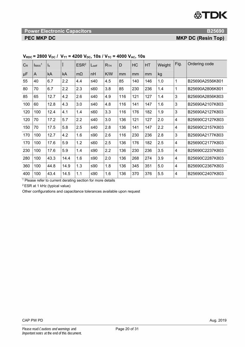
VRDC = 2800 VDC / VTT = 4200 VDC, 10s / VTC = 4000 VAC, 10s
CR IMAX1 Is Î ESR2 Lself RTH D HC HT Weight Fig.
Ordering code µF A kA kA mΩ nH K/W mm mm mm kg
55 40 6.7 2.2 4.4 ≤40 4.5 85 140 146 1.0 1 B25690A2556K801
80 70 6.7 2.2 2.3 ≤60 3.8 85 230 236 1.4 1 B25690A2806K801
85 65 12.7 4.2 2.6 ≤40 4.9 116 121 127 1.4 3 B25690A2856K803
100 60 12.8 4.3 3.0 ≤40 4.8 116 141 147 1.6 3 B25690A2107K803
120 100 12.4 4.1 1.4 ≤60 3.3 116 176 182 1.9 3 B25690A2127K803
120 70 17.2 5.7 2.2 ≤40 3.0 136 121 127 2.0 4 B25690C2127K803
150 70 17.5 5.8 2.5 ≤40 2.8 136 141 147 2.2 4 B25690C2157K803
170 100 12.7 4.2 1.6 ≤90 2.6 116 230 236 2.8 3 B25690A2177K803
170 100 17.6 5.9 1.2 ≤60 2.5 136 176 182 2.5 4 B25690C2177K803
230 100 17.6 5.9 1.4 ≤90 2.2 136 230 236 3.5 4 B25690C2237K803
280 100 43.3 14.4 1.6 ≤90 2.0 136 268 274 3.9 4 B25690C2287K803
360 100 44.8 14.9 1.3 ≤90 1.8 136 345 351 5.0 4 B25690C2367K803
400 100 43.4 14.5 1.1 ≤90 1.6 136 370 376 5.5 4 B25690C2407K803 1 Please refer to current derating section for more details 2 ESR at 1 kHz (typical value)
Other configurations and capacitance tolerances available upon request

Power Electronic Capacitors B25690
PEC MKP DC MKP DC (Resin Top)
CAP PW PD Aug. 2019
Please read Cautions and warnings and Page 21 of 31 Important notes at the end of this document.
VRDC = 3000 VDC / VTT = 4500 VDC, 10s / VTC = 4000 VAC, 10s
CR IMAX1 Is Î ESR2 Lself RTH D HC HT Weight Fig.
Ordering code µF A kA kA mΩ nH K/W mm mm mm kg
45 40 6.2 2.1 4.7 ≤40 4.5 85 140 146 1.0 1 B25690A3456K001
70 70 6.3 2.1 2.4 ≤60 3.8 85 230 236 1.4 1 B25690A3706K001
75 60 11.9 4.0 2.7 ≤40 4.9 116 121 127 1.4 3 B25690A3756K003
90 60 11.6 3.9 3.0 ≤40 4.8 116 141 147 1.6 3 B25690A3906K003
100 95 11.7 3.9 1.4 ≤60 3.3 116 176 182 1.9 3 B25690A3107K003
100 70 16.1 5.4 2.3 ≤40 3.0 136 121 127 2.0 4 B25690C3107K003
120 70 15.9 5.3 2.6 ≤40 2.8 136 141 147 2.2 4 B25690C3127K003
140 95 11.7 3.9 1.7 ≤90 2.6 116 230 236 2.8 3 B25690A3147K003
140 100 16.2 5.4 1.3 ≤60 2.5 136 176 182 2.5 4 B25690C3147K003
200 100 16.1 5.4 1.5 ≤90 2.2 136 230 236 3.5 4 B25690C3207K003
240 100 40.2 13.4 1.7 ≤90 2.0 136 268 274 3.9 4 B25690C3247K003
320 100 40.7 13.6 1.3 ≤90 1.8 136 345 351 5.0 4 B25690C3327K003
330 100 41.2 13.7 1.1 ≤90 1.6 136 370 376 5.5 4 B25690C3337K003 1 Please refer to current derating section for more details 2 ESR at 1 kHz (typical value)
Other configurations and capacitance tolerances available upon request
Power Electronic Capacitors B25690
PEC MKP DC MKP DC (Resin Top)
CAP PW PD Aug. 2019
Please read Cautions and warnings and Page 22 of 31 Important notes at the end of this document.
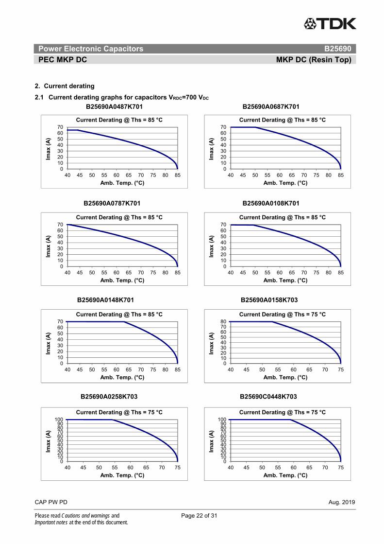
2. Current derating
2.1 Current derating graphs for capacitors VRDC=700 VDC
B25690A0487K701 B25690A0687K701
B25690A0787K701 B25690A0108K701
B25690A0148K701 B25690A0158K703
B25690A0258K703 B25690C0448K703
010203040506070
40 45 50 55 60 65 70 75 80 85
Imax
(A
)
Amb. Temp. (°C)
Current Derating @ Ths = 85 °C
010203040506070
40 45 50 55 60 65 70 75 80 85
Imax
(A
)
Amb. Temp. (°C)
Current Derating @ Ths = 85 °C
010203040506070
40 45 50 55 60 65 70 75 80 85
Imax
(A
)
Amb. Temp. (°C)
Current Derating @ Ths = 85 °C
010203040506070
40 45 50 55 60 65 70 75 80 85
Imax
(A
)
Amb. Temp. (°C)
Current Derating @ Ths = 85 °C
010203040506070
40 45 50 55 60 65 70 75 80 85
Imax
(A
)
Amb. Temp. (°C)
Current Derating @ Ths = 85 °C
01020304050607080
40 45 50 55 60 65 70 75
Imax
(A
)
Amb. Temp. (°C)
Current Derating @ Ths = 75 °C
0102030405060708090
100
40 45 50 55 60 65 70 75
Imax
(A
)
Amb. Temp. (°C)
Current Derating @ Ths = 75 °C
0102030405060708090
100
40 45 50 55 60 65 70 75
Imax
(A
)
Amb. Temp. (°C)
Current Derating @ Ths = 75 °C

Power Electronic Capacitors B25690
PEC MKP DC MKP DC (Resin Top)
CAP PW PD Aug. 2019
Please read Cautions and warnings and Page 23 of 31 Important notes at the end of this document.
2.2 Current derating graphs for capacitors VRDC=900 VDC
B25690A0387K901 B25690A0577K901
B25690A0607K901 B25690A0727K903
B25690A0737K901 B25690A0857K901
B25690A0128K903 B25690A0148K903
010203040506070
40 45 50 55 60 65 70 75 80 85
Imax
(A
)
Amb. Temp. (°C)
Current Derating @ Ths = 85 °C
010203040506070
40 45 50 55 60 65 70 75 80 85
Imax
(A
)
Amb. Temp. (°C)
Current Derating @ Ths = 85 °C
010203040506070
40 45 50 55 60 65 70 75 80 85
Imax
(A
)
Amb. Temp. (°C)
Current Derating @ Ths = 85 °C
01020304050607080
40 45 50 55 60 65 70 75
Imax
(A
)
Amb. Temp. (°C)
Current Derating @ Ths = 75 °C
010203040506070
40 45 50 55 60 65 70 75 80 85
Imax
(A
)
Amb. Temp. (°C)
Current Derating @ Ths = 85 °C
010203040506070
40 45 50 55 60 65 70 75 80 85
Imax
(A
)
Amb. Temp. (°C)
Current Derating @ Ths = 85 °C
01020304050607080
40 45 50 55 60 65 70 75
Imax
(A
)
Amb. Temp. (°C)
Current Derating @ Ths = 75 °C
0102030405060708090
100
40 45 50 55 60 65 70 75
Imax
(A
)
Amb. Temp. (°C)
Current Derating @ Ths = 75 °C
Power Electronic Capacitors B25690
PEC MKP DC MKP DC (Resin Top)
CAP PW PD Aug. 2019
Please read Cautions and warnings and Page 24 of 31 Important notes at the end of this document.
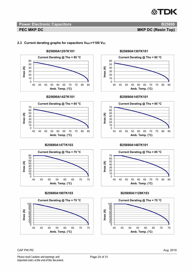
2.3 Current derating graphs for capacitors VRDC=1100 VDC
B25690A1257K101 B25690A1307K101
B25690A1427K101 B25690A1457K101
B25690A1477K103 B25690A1487K101
B25690A1907K103 B25690A1128K103
0102030405060
40 45 50 55 60 65 70 75 80 85
Imax
(A
)
Amb. Temp. (°C)
Current Derating @ Ths = 85 °C
0102030405060
40 45 50 55 60 65 70 75 80 85
Imax
(A
)
Amb. Temp. (°C)
Current Derating @ Ths = 85 °C
010203040506070
40 45 50 55 60 65 70 75 80 85
Imax
(A
)
Amb. Temp. (°C)
Current Derating @ Ths = 85 °C
010203040506070
40 45 50 55 60 65 70 75 80 85
Imax
(A
)
Amb. Temp. (°C)
Current Derating @ Ths = 85 °C
01020304050607080
40 45 50 55 60 65 70 75
Imax
(A
)
Amb. Temp. (°C)
Current Derating @ Ths = 75 °C
010203040506070
40 45 50 55 60 65 70 75 80 85
Imax
(A
)
Amb. Temp. (°C)
Current Derating @ Ths = 85 °C
0102030405060708090
100
40 45 50 55 60 65 70 75
Imax
(A
)
Amb. Temp. (°C)
Current Derating @ Ths = 75 °C
0102030405060708090
100
40 45 50 55 60 65 70 75
Imax
(A
)
Amb. Temp. (°C)
Current Derating @ Ths = 75 °C

Power Electronic Capacitors B25690
PEC MKP DC MKP DC (Resin Top)
CAP PW PD Aug. 2019
Please read Cautions and warnings and Page 25 of 31 Important notes at the end of this document.
2.4 Current derating graphs for capacitors VRDC=1200 VDC
B25690A1197K201 B25690A1267K201 B25690A1277K211 B25690A1507K203
B25690A1627K203 B25690A1108K203
0102030405060
40 45 50 55 60 65 70 75 80 85
Imax
(A
)
Amb. Temp. (°C)
Current Derating @ Ths = 85 °C
0102030405060
40 45 50 55 60 65 70 75 80 85
Imax
(A
)
Amb. Temp. (°C)
Current Derating @ Ths = 85 °C
010203040506070
40 45 50 55 60 65 70 75 80 85
Imax
(A
)
Amb. Temp. (°C)
Current Derating @ Ths = 85 °C
01020304050607080
40 45 50 55 60 65 70 75
Imax
(A
)
Amb. Temp. (°C)
Current Derating @ Ths = 75 °C
0102030405060708090
100
40 45 50 55 60 65 70 75
Imax
(A
)
Amb. Temp. (°C)
Current Derating @ Ths = 75 °C
0102030405060708090
100
40 45 50 55 60 65 70 75
Imax
(A
)
Amb. Temp. (°C)
Current Derating @ Ths = 75 °C

Power Electronic Capacitors B25690
PEC MKP DC MKP DC (Resin Top)
CAP PW PD Aug. 2019
Please read Cautions and warnings and Page 26 of 31 Important notes at the end of this document.
3. Service life expectancy
Service life tLD at different hotspot temperature (hs) and voltage V
For capacitors with diameter 116mm a maximum hot spot temperature of 85°C or capacitor with diameter 136mm a maximum hot spot temperature of 80°C is allowed during short term operation (maximum 10% of the total load duration) without further reduction of the service life.
The expected lifetime is a calculated value based on real application data and life endurance test for this capacitor series. The lifetime calculation correlates the time of test, voltage and temperature always comparing testing conditions to real application data and its own ageing factors. In order to determine the ageing factor used for this capacitor design it was performed life endurance tests with different stress is voltage and temperature.
Failure criteria is capacitance drop higher than 3%.
0,9
0,95
1
1,05
1,1
0,0 0,2 0,4 0,6 0,8 1,0 1,2 1,4 1,6 1,8 2,0
VO
P/
VR
DC
tLD / tLD(co)
Expected L i fe t ime @ T HS
70℃ 75℃ 80℃ 85℃

Power Electronic Capacitors B25690
PEC MKP DC MKP DC (Resin Top)
CAP PW PD Aug. 2019
Please read Cautions and warnings and Page 27 of 31 Important notes at the end of this document.
4. Expected failure rate
The FIT (Failure In Time) of a component is defined as the number of expected failures in 109 hours of operation. The FIT rate is calculated on the basis of the number of components operating in the field and the estimated hours of operation. All the reports of failures are taken into consideration for this calculation, which is updated every year. The other values in the graph are given as indication and calculated based on acceleration factors.
1
10
100
1000
0,7 0,8 0,9 1 1,1 1,2
FIT
Voltage x Un
FIT Rate - PEC MKP DC
Ths: 60°C 65°C 70°C 75°C 80°C 85°C

Power Electronic Capacitors B25690
PEC MKP DC MKP DC (Resin Top)
CAP PW PD Aug. 2019
Please read Cautions and warnings and Page 28 of 31 Important notes at the end of this document.
Cautions and warnings
In case of dents of more than 1 mm depth or any other mechanical damage, capacitors must not be used at all.
Check tightness of the connections/terminals periodically.
The energy stored in capacitors may be lethal. To prevent any chance of shock, discharge and short-circuit the capacitor before handling.
Failure to follow cautions may result, worst case, in premature failures, bursting and fire.
Protect the capacitor properly against over current and short circuit.
TDK Electronics is not responsible for any kind of possible damages to persons or things due to improper installation and application of capacitors for power electronics.
Safety
Electrical or mechanical misapplication of capacitors may be hazardous. Personal injury or property damage may result from bursting of the capacitor or from expulsion melted material due to mechanical disruption of the capacitor.
Ensure good, effective grounding for capacitor enclosures.
Observe appropriate safety precautions during operation (self-recharging phenomena and the high energy contained in capacitors).
Handle capacitors carefully, because they may still be charged even after disconnection.
The terminals of capacitors, connected bus bars and cables as well as other devices may also be energized.
Follow good engineering practice.
Thermal load
After installation of the capacitor it is necessary to verify that maximum hot-spot temperature is not exceeded at extreme service conditions.
Mechanical protection
The capacitor has to be installed in a way that mechanical damages and dents in the aluminum can are avoided.
Storage and operating conditions
Do not use or store capacitors in corrosive atmosphere, especially where chloride gas, sulfide gas, acid, alkali, salt or the like are present. In dusty environments regular maintenance and cleaning especially of the terminals is required to avoid conductive path between phases and/or phases and ground.

Power Electronic Capacitors B25690
PEC MKP DC MKP DC (Resin Top)
CAP PW PD Aug. 2019
Please read Cautions and warnings and Page 29 of 31 Important notes at the end of this document.
Service life expectancy
Electrical components do not have an unlimited service life expectancy; this applies to self-healing capacitors, too. The maximum service life expectancy may vary depending on the application the capacitor is used in.
Display of ordering codes for TDK Electronics products
The ordering code for one and the same TDK Electronics product can be represented differently in data sheets, data books, other publications, on the TDK Electronics website, or in order-related documents such as shipping notes, order confirmations and product labels. The varying representations of the ordering codes are due to different processes employed and do not affect the specifications of the respective products. Detailed information can be found on the Internet under www.tdk-electronics.tdk.com.

Important notes
Page 30 of 31
The following applies to all products named in this publication:
1. Some parts of this publication contain statements about the suitability of our products for certain areas of application. These statements are based on our knowledge of typical requirements that are often placed on our products in the areas of application concerned. We nevertheless expressly point out that such statements cannot be regarded as binding statements about the suitability of our products for a particular customer application. As a rule we are either unfamiliar with individual customer applications or less familiar with them than the customers themselves. For these reasons, it is always ultimately incumbent on the customer to check and decide whether a product with the properties described in the product specification is suitable for use in a particular customer application.
2. We also point out that in individual cases, a malfunction of electronic components or failure before the end of their usual service life cannot be completely ruled out in the current state of the art, even if they are operated as specified. In customer applications requiring a very high level of operational safety and especially in customer applications in which the malfunction or failure of an electronic component could endanger human life or health (e.g. in accident prevention or life-saving systems), it must therefore be ensured by means of suitable design of the customer application or other action taken by the customer (e.g. installation of protective circuitry or redundancy) that no injury or damage is sustained by third parties in the event of malfunction or failure of an electronic component.
3. The warnings, cautions and product-specific notes must be observed.
4. In order to satisfy certain technical requirements, some of the products described in this publication may contain substances subject to restrictions in certain jurisdictions (e.g. because they are classed as hazardous). Useful information on this will be found in our Material Data Sheets on the Internet (www.tdk-electronics.tdk.com/material). Should you have any more detailed questions, please contact our sales offices.
5. We constantly strive to improve our products. Consequently, the products described in this publication may change from time to time. The same is true of the corresponding product specifications. Please check therefore to what extent product descriptions and specifications contained in this publication are still applicable before or when you place an order.
We also reserve the right to discontinue production and delivery of products. Consequently, we cannot guarantee that all products named in this publication will always be available. The aforementioned does not apply in the case of individual agreements deviating from the foregoing for customer-specific products.
6. Unless otherwise agreed in individual contracts, all orders are subject to our General Terms and Conditions of Supply.
7. Our manufacturing sites serving the automotive business apply the IATF 16949 standard. The IATF certifications confirm our compliance with requirements regarding the quality management system in the automotive industry. Referring to customer requirements and customer specific requirements (“CSR”) TDK always has and will continue to have the policy of respecting individual agreements. Even if IATF 16949 may appear to support the acceptance of unilateral requirements, we hereby like to emphasize that only requirements mutually agreed upon can and will be implemented in our Quality Management System. For clarification purposes we like to point out that obligations from IATF 16949 shall only become legally binding if individually agreed upon.

Important notes
Page 31 of 31
8. The trade names EPCOS, CeraCharge, CeraDiode, CeraLink, CeraPad, CeraPlas, CSMP, CTVS, DeltaCap, DigiSiMic, ExoCore, FilterCap, FormFit, LeaXield, MiniBlue, MiniCell, MKD, MKK, MotorCap, PCC, PhaseCap, PhaseCube, PhaseMod, PhiCap, PowerHap, PQSine, PQvar, SIFERRIT, SIFI, SIKOREL, SilverCap, SIMDAD, SiMic, SIMID, SineFormer, SIOV, ThermoFuse, WindCap are trademarks registered or pending in Europe and in other countries. Further information will be found on the Internet at www.tdk-electronics.tdk.com/trademarks.
Release 2018-10
Related Documents