Power Conversion Systems Power Supplies Converters Inverters Chargers Systems s tems verters Chargers Systems P Po we e r r C C o o n nv v v ve e e e r r r s s s i i i o o o o o n n n n n S S S S S S S S y y y y y y y s Power Supplies Converters Inv Power Conversion Systems Power Supplies Converters Inverters Chargers Systems

Welcome message from author
This document is posted to help you gain knowledge. Please leave a comment to let me know what you think about it! Share it to your friends and learn new things together.
Transcript

Power Conversion SystemsPower Supplies Converters Inverters Chargers Systems
stemsverters Chargers Systems
PPoweerr CCoonnvvvveeeerrrsssiiiooooonnnnn SSSSSSSSyyyyyyysPower Supplies Converters Inv
Power Conversion SystemsPower Supplies Converters Inverters Chargers Systems

www.schaeferpower.dewww.schaeferpower.deTable of Contents
The manufacturer reserves the right to deviate from technical details given.
Page
COMPANY PROFILE 3
LOW POWER CONVERTERS 9
FROM 100W TO 7.5KW, SWITCHMODE
DC/DC Converters, AC/DC Power Supplies & Battery Chargers
Step-Up Converters 47
HIGH POWER CONVERTERS 49
FROM 5 TO 40KW, SWITCHMODE
DC/DC Converters, AC/DC Power Supplies & Battery Chargers
Step-Up Converters 83
INVERTERS FROM 200VA TO 45KVA 85
DC/AC Inverters & AC/AC Frequency Converters
Static Switches 97
UPS Systems from 1000 to 2500VA 99
ACTIVE HARMONIC FILTERS 101
ELECTRONIC LOADS 105
THYRISTOR-CONTROLLED UNITS 109
FROM 500W TO 500KW
AC/DC Power Supplies & Battery Chargers
OPTIONS & ACCESSORIES 115
TECHNICAL NOTES 125
DESIGN SOLUTIONS 135

www.schaeferpower.deCompany Profile SCHAEFER worldwide
SCHAEFER being a wholly owned, privately run and assisted by a qualified, and experienced team of experts. SCHAEFER has grown in a controlled and sustainable manner to a dedicated work-force of over 200 people, who oversee the entireconcept, design and manufacture of all of the SCHAEFER Product Portfolio. Stemming from more than 40 years experience, SCHAEFER Person-nel can tap into a rich resource which can only be gained after detailed and in-depth consultation with Clients.
In his position as CEO, Dipl.-Ing. Hansjürgen Schäfer pursues this approved course of business management of continuously developing client relations and assistance. “Assisting our clients in the field of engineering, product utilization as well as in the area of flexible development of customized power supplies, we are pursuing a sustainable growth strategy. At the same time we are committing ourselves to our headquarter in Germany and are proud of our products “made in Germany”.”
Dipl.-Ing. Hansjürgen Schäfer CEO
3 | 4
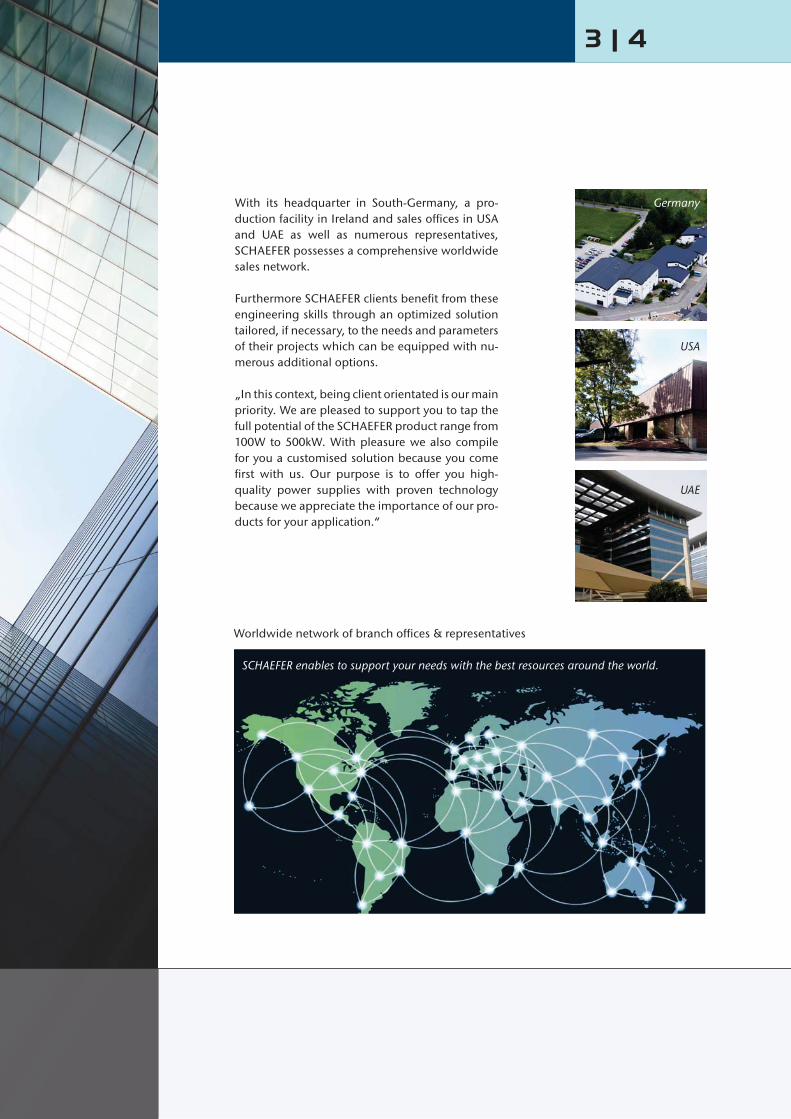
With its headquarter in South-Germany, a pro-duction facility in Ireland and sales offices in USA and UAE as well as numerous representatives,SCHAEFER possesses a comprehensive worldwide sales network.
Furthermore SCHAEFER clients benefit from these engineering skills through an optimized solution tailored, if necessary, to the needs and parameters of their projects which can be equipped with nu-merous additional options.
„In this context, being client orientated is our main priority. We are pleased to support you to tap the full potential of the SCHAEFER product range from 100W to 500kW. With pleasure we also compile for you a customised solution because you come first with us. Our purpose is to offer you high-quality power supplies with proven technology because we appreciate the importance of our pro-ducts for your application.“
Worldwide network of branch offices & representatives
SCHAEFER enables to support your needs with the best resources around the world.
Germany
USA
UAE

www.schaeferpower.deCompany Profile Design & Manufacture
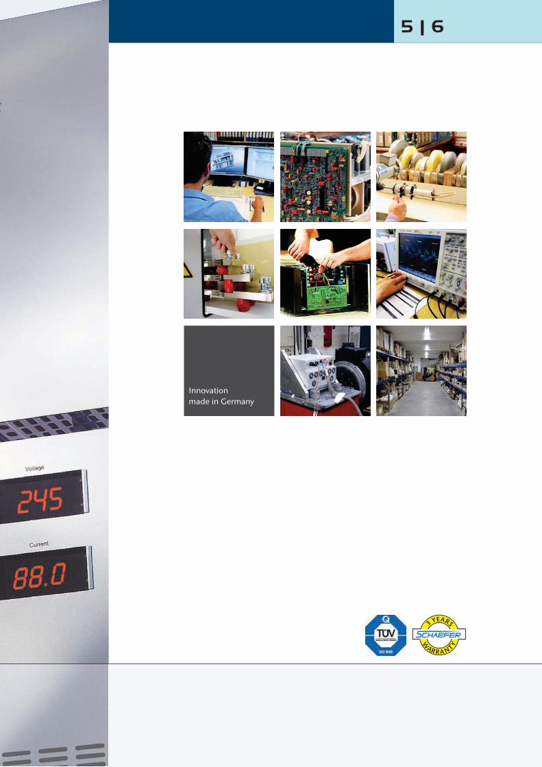
Maintaining the ability to design & manufacturein house generates a large degree of flexibility.The SCHAEFER Client profits from these engineeringskills through an optimised solution tailored to the needs and parameters of the Project.
Immediate proximity also generates the free flow-ing information path, which is the production and development area, along with the testing and cus-tomer support area being all under the same roof. This enhances the SCHAEFER Teams ability to react to exacting demands with ease. Fruits of this labour are to be seen throughout the world in a variety of fields such as:
n Rail & Automotive Industryn Power Generation Plantsn Oil & Gas Industryn Chemical Industry n Industrial Automation n Military Industryn Building Securityn Integrated Airport Solutions
Development guidelines, arduous selection of in-dustrial components regarding their load criteria and temperature performance as well as many test procedures during all steps of production ensure the highest product quality. In addition, Schaefer pur-sues a full supplier management according to ISO 9001 which guarantees permanent improvement of the products especially within the turbulent market of electronic components.
On demand, SCHAEFER can also provide additional customer specified tests in cooperation with exter-nal test laboratories.
5 | 6
Innovationmade in Germany
www.schaeferpower.deCompany Profile Products & Applications
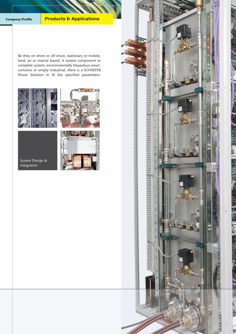
Be they on shore or off shore, stationary or mobile, land, air or marine based. A system component or complete system, environmentally Hazardous area1,corrosive or simply Industrial, there is a SCHAEFERPower Solution to fit the specified parameters.
System Design &integration

Installation of a 360kW expandable power supply system within a container for mineral exploration on vessel
Container ready for shipment
On board installation
7 | 87 | 8
Container ready for shipment

www.schaeferpower.deLow Power Converters from 100W to 7.5kW, switchmode
DC / DC Converters, AC / DC Power Supplies & Battery ChargersAC or
DCDC
Input / Output isolation Continuous short circuit protection Overvoltage protection with auto restart Operational from – 40 to +75 °C Industrial grade components Compact and robust design Natural convection (except for series C56xx and C57xx)
DC Input voltage: 10 - 800V DC AC Input voltage: 115 / 230V AC, single phase (with or without PFC) or 200 / 400 / 480V AC, three phases AC Input frequency: with PFC 47 - 65Hz, without PFC 47 - 400Hz Output voltage: 5 / ... / 400V DC Output current: up to 500A Output power: 100W - 7.5kW
Features
upplies & Battery Chargers
Input
Voltage range unit switches off at under- and overvoltage
No-load input power 5 - 6W typicalexcept for series 4800, 5600/5700
Inrush current AC input: limited by thermistor Hold-up time AC input: 10ms typical
@ nom. input voltage(for series 4800: 5ms typical)
Immunity acc. to EN 61000-6-2
Output
DC output voltages 5 9 12 15 24 2848 60 110 200 220 400
Line regulation (±10%) 0.1% Load regulation (10-90%) 0.2% Load transient (10-90-10%) 6 % typical Response time to ±1 % 2 - 3 ms Turn-on rise time Soft-start, 100 ms typical Ripple ≤ 1% + 30 mV p-p Overload protection current limited to 105-110% of Inom
Overvoltage protection OVP switches off module withautomatic return to operation
Remote sense standard for all series except for B / BP series; up to 10% of Unom for output < 60V DC,up to 6V for output > 60V DC
General
Efficiency 80 - 92% typical Operating temperature -20 to +75°C
(optional: -40 to +75°C) Load derating 2.5%/°C above + 55°C Storage temperature -40 to + 85°C Cooling (details see page 131)
= natural convection = increased air flow recommended = incl. temperature controlled fans
Humidity up to 95 % RH, non-condensing Temperature coefficient 0.02 % / °C typical Safety / Construction acc. to EN 60950-1 / EN 50178 Protection category IP20 acc. to EN 60529,
NEMA or others upon request EMI acc. to EN 61000-6-4,
class A, optionally class B MTBF 100,000 - 140,000h @ 40°C
acc. to MIL - HDBK - 217E (notice 1) Connectors (details see page 132)
H15 acc. to DIN 41612and high current connectors for I > 50 A,or terminals / bolts / bars
Specifications

9 | 10
Options (details see page 115)
Input Inrush current limiting Reverse polarity protection for DC input Autoranging for 115 / 230 VAC input
Output Decoupling diode for redundant / parallel operation Active current sharing for parallel operation Remote on / off (inhibit)
Signalsvia relay contacts Power ok (input) DC ok (output)
Monitoringof input / output voltage or current via analog signal interface card RS232 or CAN Bus (external)
Programmingof output voltage or current via potentiometer analog signal interface card RS232 or CAN Bus (external)
Programming of battery chargers Temperature compensated charging voltage Automatic / manual selection of charging characteristic
(external)
Mechanics / environment: 19” sub-rack for eurocassette, refer to page 121 Wall mount Chassis mount DIN rail mount Increased mechanical strength Tropical protection Extended temperature range to –40 °C
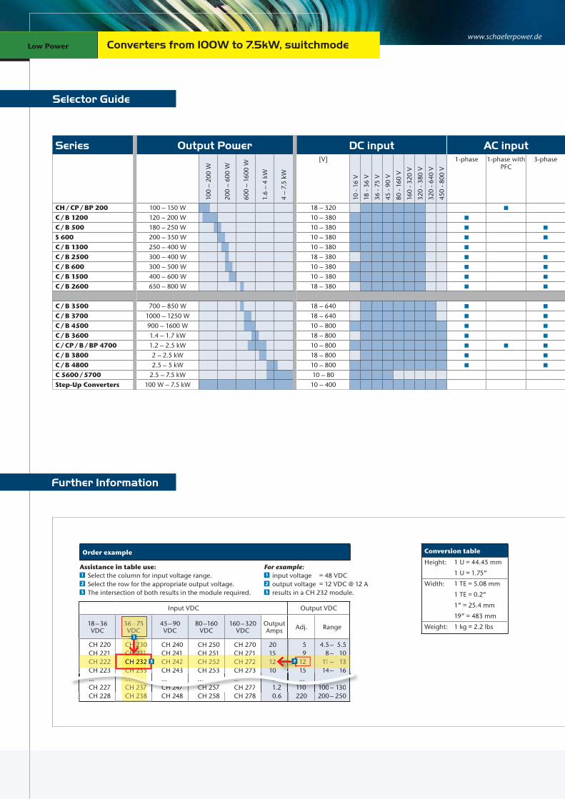
www.schaeferpower.deConverters from 100W to 7.5kW, switchmodeLow Power
Selector Guide
Series Output Power DC input AC input
100
– 20
0 W
200
– 60
0 W
600
– 16
00 W
1.6
– 4
kW
4 –
7.5
kW
[V]
10 -
16 V
18 -
36 V
36 -
75 V
45 -
90 V
80 -
160
V
160
- 320
V
320
- 380
V
320
- 640
V
450
- 800
V
1-phase 1-phase with PFC
3-phase
CH / CP / BP 200 100 – 150 W 18 – 320C / B 1200 120 – 200 W 10 – 380C / B 500 180 – 250 W 10 – 380S 600 200 – 350 W 10 – 380C / B 1300 250 – 400 W 10 – 380C / B 2500 300 – 400 W 18 – 380C / B 600 300 – 500 W 10 – 380C / B 1500 400 – 600 W 10 – 380C / B 2600 650 – 800 W 18 – 380
C / B 3500 700 – 850 W 18 – 640C / B 3700 1000 – 1250 W 18 – 640C / B 4500 900 – 1600 W 10 – 800C / B 3600 1.4 – 1.7 kW 18 – 800C / CP / B / BP 4700 1.2 – 2.5 kW 10 – 800C / B 3800 2 – 2.5 kW 18 – 800C / B 4800 2.5 – 5 kW 10 – 800C 5600 / 5700 2.5 – 7.5 kW 10 – 80Step-Up Converters 100 W – 7.5 kW 10 – 400
Further Information
For example:1 input voltage = 48 VDC2 output voltage = 12 VDC @ 12 A 3 results in a CH 232 module.
Assistance in table use:1 Select the column for input voltage range.2 Select the row for the appropriate output voltage.3 The intersection of both results in the module required.
Input VDC Output VDC
18 – 36 VDC
36 – 75 VDC
45 – 90 VDC
80 –160 VDC
160 – 320 VDC
Output Amps Adj. Range
CH 220CH 221CH 222CH 223...CH 227CH 228
CH 230CH 231CH 232CH 233...CH 237CH 238
CH 240CH 241CH 242CH 243...CH 247CH 248
CH 250CH 251CH 252CH 253...CH 257CH 258
CH 270CH 271CH 272CH 273...CH 277CH 278
20151210 ... 1.2 0.6
5 9 12 15 ...110220
4.5 – 5.5 8 – 10 11 – 13 14 – 16 ... 100 – 130 200 – 250
7 CH 247 CH 257...CH 277
..1.2 110
...CH 227 100– 130
... ... ...
CH 238
CH 233...CH 23737
36–75 VDC
CH 230CH 231
23
CH 241CH 242CH 243
CH 251CH 252CH 253
CH 271CH 272CH 273
151210
9
15
8 1011– 1314 16
CH 221CH 222CH 223
12CH 231CH 232CH 233
CHH 23230CHHH 2323131CHH 22331
23
1
CH 232 222
Order example Conversion table
Height: 1 U = 44.45 mm
1 U = 1.75“
Width: 1 TE = 5.08 mm
1 TE = 0.2“
1” = 25.4 mm
19” = 483 mm
Weight: 1 kg = 2.2 lbs

11 | 12
Nominal DC output voltage Package Cooling Page[V]
5 V
9 V
12 V
15 V
24 V
28 V
48 V
60 V
110
V
200
V
220
V
400
V
Euro- cassette for 19” Rack
mountHeight [U]
19” Plug-in module
Height [U]
Wall mount
Chassis mount
DIN rail
mount
Nat
ural
co
nvec
tion
Fan
cool
ed
5 / 9 / ... / 60 3 135 / 9 / ... / 220 6 155 / 9 / ... / 220 3 175 / 9 / ... / 220 3 195 / 9 / ... / 220 6 215 / 9 / ... / 220 3 235 / 9 / ... / 220 3 255 / 9 / ... / 400 6 275 / 9 / ... / 220 3 29
5 / 9 / ... / 400 6 315 / 9 / ... / 400 6 339 / 12 / ... / 400 6 355 / 9 / ... / 400 6 375 / 9 / ... / 400 6 39
12 / 15 / ... / 400 6 4112 / 15 / ... / 400 6 435 / 9 / ... / 400 6 4510 / ... / 400 3 / 6 depending on module 47
Conversion diagram °C °F
˚F - 40 C - 20 C 55 C 75 C 85 C
20018016014012010080604020
0– 20– 40– 60
– 40 – 30 – 20 – 10 0 10 20 30 40 50 60 70 80 90 ˚C
185˚F167˚F
131˚F
– 4˚F
– 40˚F
www.schaeferpower.deLow Power Low Power
DC / DC ConvertersDC
inDCout
Battery ChargersACin
DCout
Battery
Series specific information
AC / DC Power SuppliesACin
DCout
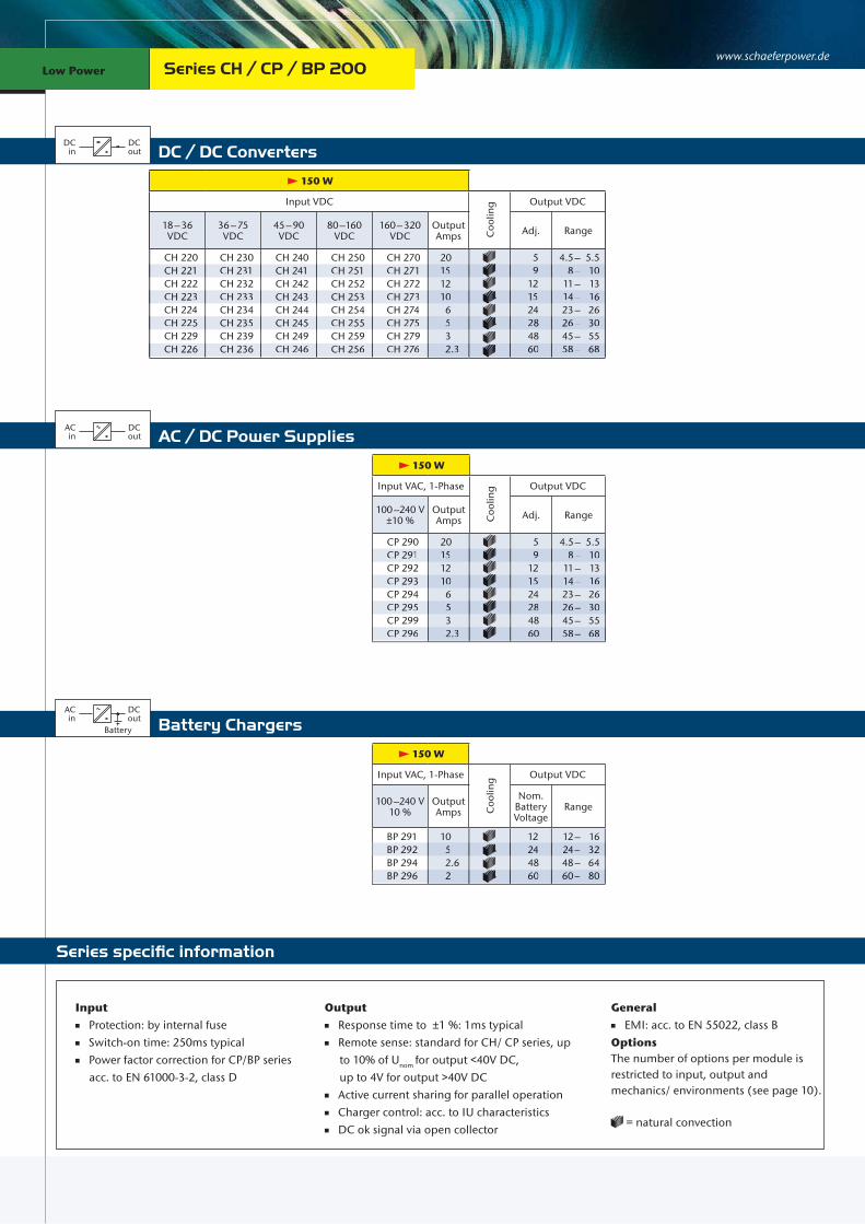
Series CH / CP / BP 200
150 W
Input VDC
Coo
ling Output VDC
18 – 36 VDC
36 – 75 VDC
45 – 90 VDC
80 –160 VDC
160 – 320 VDC
Output Amps Adj. Range
CH 220CH 221CH 222CH 223CH 224CH 225CH 229CH 226
CH 230CH 231CH 232CH 233CH 234CH 235CH 239CH 236
CH 240CH 241CH 242CH 243CH 244CH 245CH 249CH 246
CH 250CH 251CH 252CH 253CH 254CH 255CH 259CH 256
CH 270CH 271CH 272CH 273CH 274CH 275CH 279CH 276
20151210 6 5 3 2.3
5 9 12 15 24 28 48 60
4.5 – 5.5 8 – 10 11 – 13 14 – 16 23 – 26 26 – 30 45 – 55 58 – 68
150 W
Input VAC, 1-PhaseC
oolin
g Output VDC
100 –240 V ±10 %
Output Amps Adj. Range
CP 290CP 291CP 292CP 293CP 294CP 295CP 299CP 296
20151210 6 5 3 2.3
5 9 12 15 24 28 48 60
4.5 – 5.5 8 – 10 11 – 13 14 – 16 23 – 26 26 – 30 45 – 55 58 – 68
150 W
Input VAC, 1-Phase
Coo
ling Output VDC
100 –240 V 10 %
Output Amps
Nom. Battery Voltage
Range
BP 291BP 292BP 294BP 296
10 5 2.6 2
12 24 48 60
12 – 16 24 – 32 48 – 64 60 – 80
CH 221 CH 231 CH 241 CH 251 CH 271 15 9 8– 10
CH 223 CH 233 CH 243 CH 253 CH 273 10 15 14– 16
CH 225 CH 235 CH 245 CH 255 CH 275 5 28 26– 30
CH 226 CH 236 CH 246 CH 256 CH 276 2.3 60 58– 68
CP 291 15 9 8– 10
CP 293 10 15 14– 16
CP 295 5 28 26– 30
CP 296 2.3 60 58– 68
BP 292 5 24 24– 32
BP 296 2 60 60– 80
Input Protection: by internal fuse Switch-on time: 250ms typical Power factor correction for CP/BP series acc. to EN 61000-3-2, class D
Output Response time to ±1 %: 1ms typical Remote sense: standard for CH/ CP series, up to 10% of Unom for output <40V DC, up to 4V for output >40V DC Active current sharing for parallel operation Charger control: acc. to IU characteristics DC ok signal via open collector
General EMI: acc. to EN 55022, class BOptionsThe number of options per module is restricted to input, output andmechanics/ environments (see page 10).
= natural convection
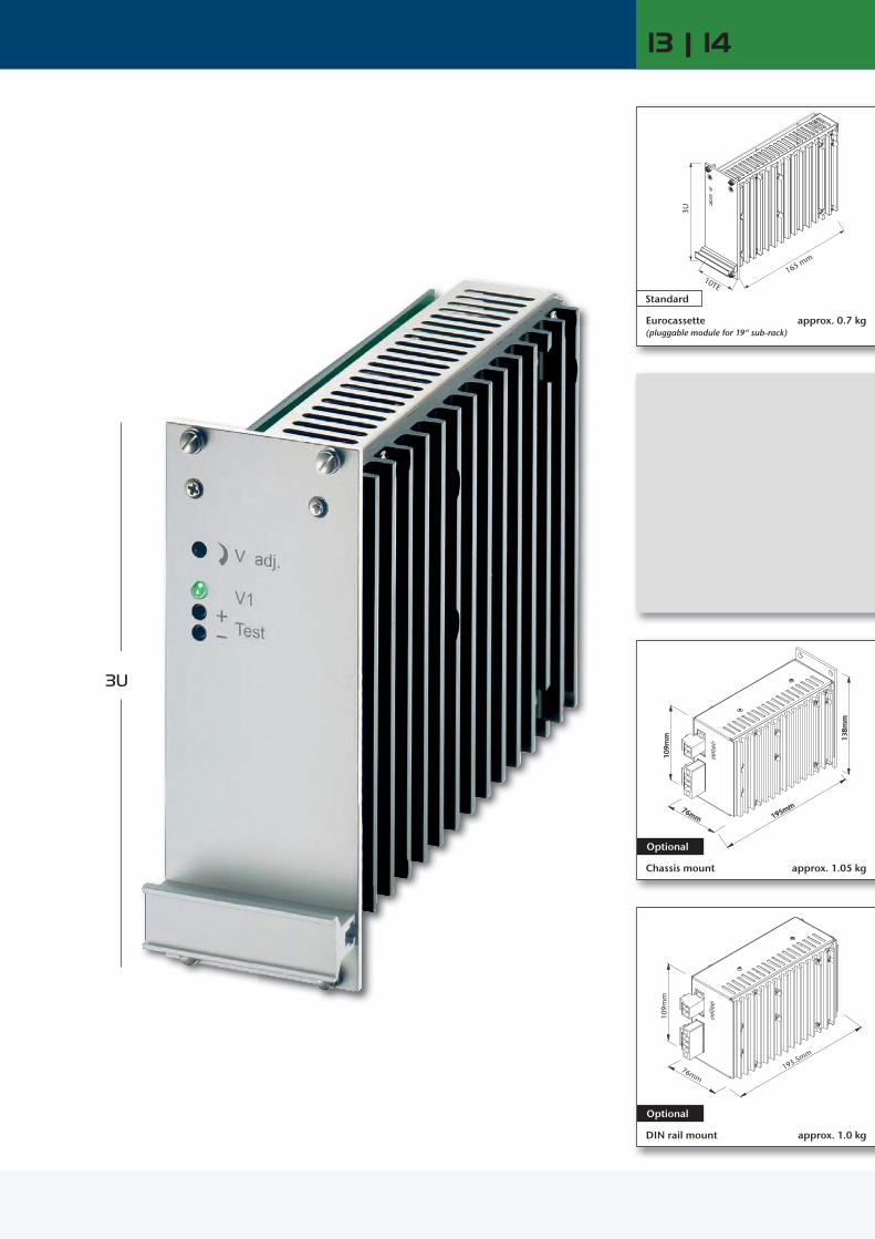
13 | 14
3U
10TE
3U
165 mm
Standard
Eurocassette (pluggable module for 19“ sub-rack)
approx. 0.7 kg
76mm 195mm
138m
m
109m
m
approx. 1.05 kg
Optional
Chassis mount
109m
m
76mm193.5mm
Optional
DIN rail mount approx. 1.0 kg
www.schaeferpower.deLow Power Low Power
DC / DC ConvertersDC
inDCout
Battery ChargersACin
DCout
Battery
Series specific information
AC / DC Power SuppliesACin
DCout
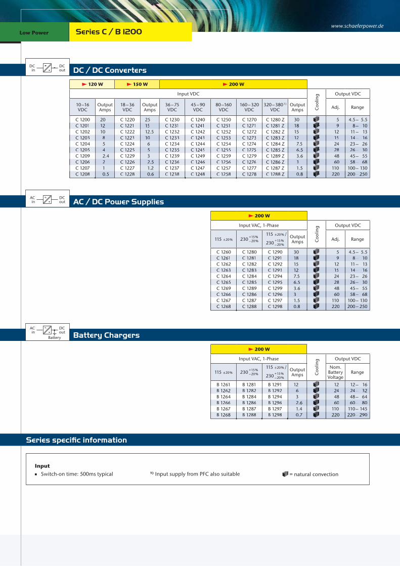
Series C / B 1200
120 W 150 W 200 W
Input VDC
Coo
ling Output VDC
10 –16 VDC
Output Amps
18 – 36 VDC
Output Amps
36 – 75 VDC
45 – 90 VDC
80 –160 VDC
160 – 320 VDC
320 – 380 1) VDC
Output Amps Adj. Range
C 1200C 1201C 1202C 1203C 1204C 1205C 1209C 1206C 1207C 1208
201210 8 5 4 2.4 2 1 0.5
C 1220C 1221C 1222C 1223C 1224C 1225C 1229C 1226C 1227C 1228
251512.510 6 5 3 2.5 1.2 0.6
C 1230C 1231C 1232C 1233C 1234C 1235C 1239C 1236C 1237C 1238
C 1240C 1241C 1242C 1243C 1244C 1245C 1249C 1246C 1247C 1248
C 1250C 1251C 1252C 1253C 1254C 1255C 1259C 1256C 1257C 1258
C 1270C 1271C 1272C 1273C 1274C 1275C 1279C 1276C 1277C 1278
C 1280 ZC 1281 ZC 1282 ZC 1283 ZC 1284 ZC 1285 ZC 1289 ZC 1286 ZC 1287 ZC 1288 Z
30 18 15 12 7.5 6.5 3.6 3 1.5 0.8
5 9 12 15 24 28 48 60110220
4.5 – 5.5 8 – 10 11 – 13 14 – 16 23 – 26 26 – 30 45 – 55 58 – 68 100 – 130 200 – 250
C 1201 12 C 1221 15 C 1231 C 1241 C 1251 C 1271 C 1281 Z 18 9 8– 10
C 1203 8 C 1223 10 C 1233 C 1243 C 1253 C 1273 C 1283 Z 12 15 14– 16
C 1205 4 C 1225 5 C 1235 C 1245 C 1255 C 1275 C 1285 Z 6.5 28 26– 30
C 1206 2 C 1226 2.5 C 1236 C 1246 C 1256 C 1276 C 1286 Z 3 60 58– 68
C 1208 0.5 C 1228 0.6 C 1238 C 1248 C 1258 C 1278 C 1288 Z 0.8 220 200– 250
200 W
Input VAC, 1-Phase
Coo
ling Output VDC
115 ± 20 % 230 + 15 % – 20 %
115 ± 20 % /
230 + 15 % – 20 %
Output Amps Adj. Range
C 1260C 1261C 1262C 1263C 1264C 1265C 1269C 1266C 1267C 1268
C 1280C 1281C 1282C 1283C 1284C 1285C 1289C 1286C 1287C 1288
C 1290C 1291C 1292C 1293C 1294C 1295C 1299C 1296C 1297C 1298
301815127.56.53.631.50.8
5 9 12 15 24 28 48 60110220
4.5 – 5.5 8 – 10 11 – 13 14 – 16 23 – 26 26 – 30 45 – 55 58 – 68 100 – 130 200 – 250
C 1261 C 1281 C 1291 18 9 8– 10
C 1263 C 1283 C 1293 12 15 14– 16
C 1265 C 1285 C 1295 6.5 28 26– 30
C 1266 C 1286 C 1296 3 60 58– 68
C 1268 C 1288 C 1298 0.8 220 200– 250
200 W
Input VAC, 1-Phase
Coo
ling Output VDC
115 ± 20 % 230 + 15 % – 20 %
115 ± 20 % /
230 + 15 % – 20 %
Output Amps
Nom. Battery Voltage
Range
B 1261B 1262B 1264B 1266B 1267B 1268
B 1281B 1282B 1284B 1286B 1287B 1288
B 1291B 1292B 1294B 1296B 1297B 1298
12 6 3 2.6 1.4 0.7
12 24 48 60110220
12 – 16 24 – 32 48 – 64 60 – 80 110 – 145 220 – 290
B 1262 B 1282 B 1292 6 24 24– 32
B 1266 B 1286 B 1296 2.6 60 60– 80
B 1268 B 1288 B 1298 0.7 220 220– 290
Input Switch-on time: 500ms typical 1) Input supply from PFC also suitable = natural convection

15 | 16
3U6U6U6UU
10TE164 mm
6U
Eurocassette (pluggable module for 19“ sub-rack)
Standard
approx. 1.7 kg
140 mm
360
mm
260 mm
Wall mount
Optional
approx. 4.7 kg
65 mm
240
mm 29
5 m
m
172.5 mm
Chassis mount
Optional
approx. 2.1 kg

www.schaeferpower.deLow Power Low Power
DC / DC ConvertersDC
inDCout
Battery ChargersACin
DCout
Battery
Series specific information
AC / DC Power SuppliesACin
DCout
Series C / B 500
180 W 200 W 250 W
Input VDC
Coo
ling Output VDC
10 –16 VDC
Output Amps
18 – 36 VDC
Output Amps
36 – 75 VDC
45 – 90 VDC
80 –160 VDC
160 – 320 VDC
320 – 380 1) VDC
Output Amps Adj. Range
C 500C 501C 502C 503C 504C 505C 509C 506C 507C 508
25171411 7 6 3.5 3 1.5 0.8
C 520C 521C 522C 523C 524C 525C 529C 526C 527C 528
30201613 8 7 4 3.5 1.8 0.9
C 530C 531C 532C 533C 534C 535C 539C 536C 537C 538
C 540C 541C 542C 543C 544C 545C 549C 546C 547C 548
C 550C 551C 552C 553C 554C 555C 559C 556C 557C 558
C 570C 571C 572C 573C 574C 575C 579C 576C 577C 578
C 580 ZC 581 ZC 582 ZC 583 ZC 584 ZC 585 ZC 589 ZC 586 ZC 587 ZC 588 Z
35 25 20 16 10 8.5 4.5 3.7 2 1
5 9 12 15 24 28 48 60110220
4.5 – 5.5 8 – 10 11 – 13 14 – 16 23 – 26 26 – 30 45 – 55 58 – 68 100 – 130 200 – 250
250 W
Input VAC, 1-Phase Input VAC, 3-Phase
Output Amps
Coo
ling Output VDC
115 ± 20 % 230 + 15 % – 20 %
115 ± 20 % /
230 + 15 % – 20 %
3x200 + 15 % – 20 % Adj. Range
C 560C 561C 562C 563C 564C 565C 569C 566C 567C 568
C 580C 581C 582C 583C 584C 585C 589C 586C 587C 588
C 590C 591C 592C 593C 594C 595C 599C 596C 597C 598
C 560 VC 561 VC 562 VC 563 VC 564 VC 565 VC 569 VC 566 VC 567 VC 568 V
35 25 20 16 10 8.5 4.5 3.7 2 1
5 9 12 15 24 28 48 60110220
4.5 – 5.5 8 – 10 11 – 13 14 – 16 23 – 26 26 – 30 45 – 55 58 – 68 100 – 130 200 – 250
250 W
Input VAC, 1-Phase Input VAC, 3-Phase
Output Amps
Coo
ling Output VDC
115 ± 20 % 230 + 15 % – 20 %
115 ± 20 % /
230 + 15 % – 20 %
3x200 + 15 % – 20 %
Nom. Battery Voltage
Range
B 561B 562B 564B 566B 567B 568
B 581B 582B 584B 586B 587B 588
B 591B 592B 594B 596B 597B 598
B 561 VB 562 VB 564 VB 566 VB 567 VB 568 V
16 8 4 3.2 2 1
12 24 48 60110220
12 – 16 24 – 32 48 – 64 60 – 80 110 – 145 220 – 290
C 501 17 C 521 20 C 531 C 541 C 551 C 571 C 581 Z 25 9 8– 10
C 503 11 C 523 13 C 533 C 543 C 553 C 573 C 583 Z 16 15 14– 16
C 505 6 C 525 7 C 535 C 545 C 555 C 575 C 585 Z 8.5 28 26– 30
C 506 3 C 526 3.5 C 536 C 546 C 556 C 576 C 586 Z 3.7 60 58– 68
C 508 0.8 C 528 0.9 C 538 C 548 C 558 C 578 C 588 Z 1 220 200– 250
C 561 C 581 C 591 C 561 V 25
C 563 C 583 C 593 C 563 V 16 15
C 565 C 585 C 595 C 565 V 8.5 2
C 566 C 586 C 596 C 566 V 3.7 60
C 568 C 588 C 598 C 568 V 1 220
B 562 B 582 B 592 B 562 V 8 24 24
B 566 B 586 B 596 B 566 V 3.2 60 60–
B 568 B 588 B 598 B 568 V 1 220 220– 290
Input Switch-on time: 1-2s 1) Input supply from PFC also suitable = natural convection
5
12
24
8
0
4.5– 5.5
11– 13
23– 26
45– 55
100– 130
t VDC
Range
2– 16
– 64
14
9 8– 10
5 14– 16
28 26– 30
0 58– 68
200– 250
– 32
– 80

17 | 18
3U3U3U3U
166.5 mm21TE24TE*
Standard approx. 1.7 kg
(pluggable module for 19“ sub-rack)*) applicable to 5 V output models
Eurocassette
140 mm
220
mm
180 mm
Optional
106
mm
205 mm
125 mm
135
mm
Wall mount approx. 3.2 kg
Chassis mount
Optional
approx. 2.1 kg
106
mm
200 mm125 mm
DIN rail mount
Optional
approx. 2.05 kg
DC / DC ConvertersDC
inDCout
Series specific information
www.schaeferpower.de
AC / DC Power Supplies
Low Power Low Power
ACin
DCout
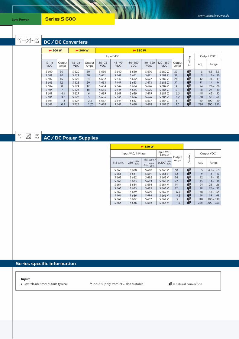
200 W 300 W 350 W
Input VDC
Coo
ling Output VDC
10 –16 VDC
Output Amps
18 – 36 VDC
Output Amps
36 – 75 VDC
45 – 90 VDC
80 –160 VDC
160 – 320 VDC
320 – 380 1) VDC
Output Amps Adj. Range
S 600S 601S 602S 603S 604S 605S 609S 606S 607S 608
30201512 8 7 4.4 3.6 1.8 0.9
S 620S 621S 622S 623S 624S 625S 629S 626S 627S 628
503024201210 6 5 2.5 1.25
S 630S 631S 632S 633S 634S 635S 639S 636S 637S 638
S 640S 641S 642S 643S 644S 645S 649S 646S 647S 648
S 650S 651S 652S 653S 654S 655S 659S 656S 657S 658
S 670S 671S 672S 673S 674S 675S 679S 676S 677S 678
S 680 ZS 681 ZS 682 ZS 683 ZS 684 ZS 685 ZS 689 ZS 686 ZS 687 ZS 688 Z
503226221412 6.5 5.2 3 1.5
5 9 12 15 24 28 48 60110220
4.5 – 5.5 8 – 10 11 – 13 14 – 16 23 – 26 26 – 30 45 – 55 58 – 68 100 – 130 200 – 250
S 601 20 S 621 30 S 631 S 641 S 651 S 671 S 681 Z 32 9 8– 10
S 603 12 S 623 20 S 633 S 643 S 653 S 673 S 683 Z 22 15 14– 16
S 605 7 S 625 10 S 635 S 645 S 655 S 675 S 685 Z 12 28 26– 30
S 606 3.6 S 626 5 S 636 S 646 S 656 S 676 S 686 Z 5.2 60 58– 68
S 608 0.9 S 628 1.25 S 638 S 648 S 658 S 678 S 688 Z 1.5 220 200– 250
Series S 600
350 W
Input VAC, 1-Phase Input VAC, 3-Phase
Output Amps
Coo
ling Output VDC
115 ± 20 % 230 + 15 % – 20 %
115 ± 20 % /
230 + 15 % – 20 %
3x200 + 15 % – 20 % Adj. Range
S 660S 661S 662S 663S 664S 665S 669S 666S 667S 668
S 680S 681S 682S 683S 684S 685S 689S 686S 687S 688
S 690S 691S 692S 693S 694S 695S 699S 696S 697S 698
S 660 VS 661 VS 662 VS 663 VS 664 VS 665 VS 669 VS 666 VS 667 VS 668 V
503226221412 6.5 5.2 3 1.5
5 9 12 15 24 28 48 60110220
4.5 – 5.5 8 – 10 11 – 13 14 – 16 23 – 26 26 – 30 45 – 55 58 – 68 100 – 130 200 – 250
S 661 S 681 S 691 S 661 V 32 9 8– 10
S 663 S 683 S 693 S 663 V 22 15 14– 16
S 665 S 685 S 695 S 665 V 12 28 26– 30
S 666 S 686 S 696 S 666 V 5.2 60 58– 68
S 668 S 688 S 698 S 668 V 1.5 220 200– 250
Input Switch-on time: 500ms typical 1) Input supply from PFC also suitable = natural convection

3U
19 | 20
42TE
3U
166.5 mm
180.6 mm
170
mm
130
mm
171 mm
220 mm
220
mm
167 mm
180.6 mm
130
mm
175 mm
Eurocassette (pluggable module for 19“ sub-rack)
Standard
approx. 2.6 kg
Wall mount
Optional
approx. 3.6 kg
Chassis mount
Optional
approx. 3.1 kg
DIN rail mount
Optional
approx. 3.0 kg

www.schaeferpower.deLow Power Low Power
DC / DC ConvertersDC
inDCout
Battery ChargersACin
DCout
Battery
Series specific information
AC / DC Power SuppliesACin
DCout
400 W
Input VAC, 1-Phase
Coo
ling Output VDC
115 ± 20 % 230 + 15 % – 20 %
115 ± 20 % /
230 + 15 % – 20 %
Output Amps Adj. Range
C 1360C 1361C 1362C 1363C 1364C 1365C 1369C 1366C 1367C 1368
C 1380C 1381C 1382C 1383C 1384C 1385C 1389C 1386C 1387C 1388
C 1390C 1391C 1392C 1393C 1394C 1395C 1399C 1396C 1397C 1398
503530251513 7.3 6 3 1.5
5 9 12 15 24 28 48 60110220
4.5 – 5.5 8 – 10 11 – 13 14 – 16 23 – 26 26 – 30 45 – 55 58 – 68 100 – 130 200 – 250
400 W
Input VAC, 1-Phase
Coo
ling Output VDC
115 ± 20 % 230 + 15 % – 20 %
115 ± 20 % /
230 + 15 % – 20 %
Output Amps
Nom. Battery Voltage
Range
B 1361B 1362B 1364B 1366B 1367B 1368
B 1381B 1382B 1384B 1386B 1387B 1388
B 1391B 1392B 1394B 1396B 1397B 1398
2512 6 4.5 2.7 1.4
12 24 48 60110220
12 – 16 24 – 32 48 – 64 60 – 80 110 – 145 220 – 290
250 W 300 W 400 W
Input VDC
Coo
ling Output VDC
10 –16 VDC
Output Amps
18 – 36 VDC
Output Amps
36 – 75 VDC
45 – 90 VDC
80 –160 VDC
160 – 320 VDC
320 – 380 1) VDC
Output Amps Adj. Range
C 1300C 1301C 1302C 1303C 1304C 1305C 1309C 1306C 1307C 1308
3524201610 8.5 5 4 2 1
C 1320C 1321C 1322C 1323C 1324C 1325C 1329C 1326C 1327C 1328
453025211311 6 5 2.5 1.25
C 1330C 1331C 1332C 1333C 1334C 1335C 1339C 1336C 1337C 1338
C 1340C 1341C 1342C 1343C 1344C 1345C 1349C 1346C 1347C 1348
C 1350C 1351C 1352C 1353C 1354C 1355C 1359C 1356C 1357C 1358
C 1370C 1371C 1372C 1373C 1374C 1375C 1379C 1376C 1377C 1378
C 1380 ZC 1381 ZC 1382 ZC 1383 ZC 1384 ZC 1385 ZC 1389 ZC 1386 ZC 1387 ZC 1388 Z
503530251513 7.3 6 3 1.5
5 9 12 15 24 28 48 60110220
4.5 – 5.5 8 – 10 11 – 13 14 – 16 23 – 26 26 – 30 45 – 55 58 – 68 100 – 130 200 – 250
C 1301 24 C 1321 30 C 1331 C 1341 C 1351 C 1371 C 1381 Z 35 9 8– 10
C 1303 16 C 1323 21 C 1333 C 1343 C 1353 C 1373 C 1383 Z 25 15 14– 16
C 1305 8.5 C 1325 11 C 1335 C 1345 C 1355 C 1375 C 1385 Z 13 28 26– 30
C 1306 4 C 1326 5 C 1336 C 1346 C 1356 C 1376 C 1386 Z 6 60 58– 68
C 1308 1 C 1328 1.25 C 1338 C 1348 C 1358 C 1378 C 1388 Z 1.5 220 200– 250
C 1361 C 1381 C 1391 35 9 8– 10
C 1363 C 1383 C 1393 25 15 14– 16
C 1365 C 1385 C 1395 13 28 26– 30
C 1366 C 1386 C 1396 6 60 58– 68
C 1368 C 1388 C 1398 1.5 220 200– 250
B 1362 B 1382 B 1392 12 24 24– 32
B 1366 B 1386 B 1396 4.5 60 60– 80
B 1368 B 1388 B 1398 1.4 220 220– 290
Series C / B 1300
Input Switch-on time: 500ms typical 1) Input supply from PFC also suitable = natural convection

21 | 22
6U
164 mm14TE
6U
295
mm
240
mm
88 mm200 mm
360
mm
260 mm
140 mm
Eurocassette (pluggable module for 19“ sub-rack)
Standard
approx. 2.0 kg
Wall mount
Optional
approx. 5.0 kg
Chassis mount
Optional
approx. 2.4 kg
www.schaeferpower.deLow Power Low Power
DC / DC ConvertersDC
inDCout
Battery ChargersACin
DCout
Battery
Series specific information
AC / DC Power SuppliesACin
DCout
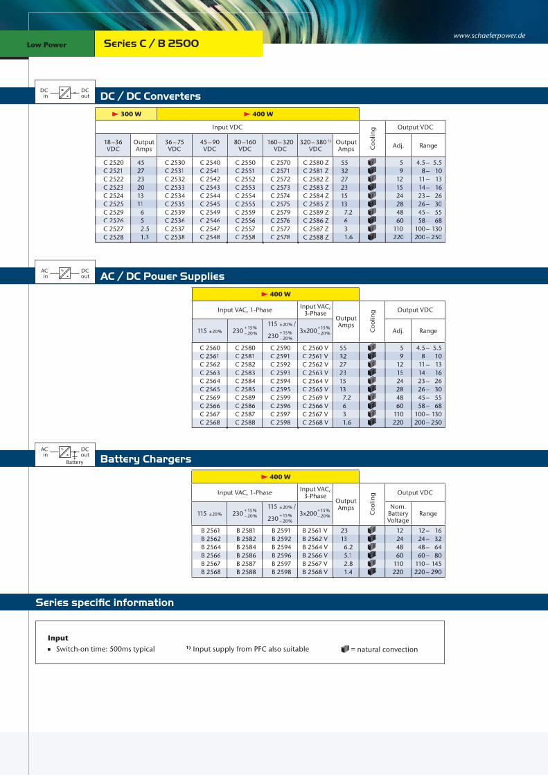
300 W 400 W
Input VDC
Coo
ling Output VDC
18 –36 VDC
Output Amps
36 – 75 VDC
45 – 90 VDC
80 –160 VDC
160 – 320 VDC
320 – 380 1) VDC
Output Amps Adj. Range
C 2520C 2521C 2522C 2523C 2524C 2525C 2529C 2526C 2527C 2528
452723201311 6 5 2.5 1.3
C 2530C 2531C 2532C 2533C 2534C 2535C 2539C 2536C 2537C 2538
C 2540C 2541C 2542C 2543C 2544C 2545C 2549C 2546C 2547C 2548
C 2550C 2551C 2552C 2553C 2554C 2555C 2559C 2556C 2557C 2558
C 2570C 2571C 2572C 2573C 2574C 2575C 2579C 2576C 2577C 2578
C 2580 ZC 2581 ZC 2582 ZC 2583 ZC 2584 ZC 2585 ZC 2589 ZC 2586 ZC 2587 ZC 2588 Z
553227231513 7.2 6 3 1.6
5 9 12 15 24 28 48 60110220
4.5 – 5.5 8 – 10 11 – 13 14 – 16 23 – 26 26 – 30 45 – 55 58 – 68 100 – 130 200 – 250
400 W
Input VAC, 1-Phase Input VAC, 3-Phase
Output Amps
Coo
ling Output VDC
115 ± 20 % 230 + 15 % – 20 %
115 ± 20 % /
230 + 15 % – 20 %
3x200 + 15 % – 20 % Adj. Range
C 2560C 2561C 2562C 2563C 2564C 2565C 2569C 2566C 2567C 2568
C 2580C 2581C 2582C 2583C 2584C 2585C 2589C 2586C 2587C 2588
C 2590C 2591C 2592C 2593C 2594C 2595C 2599C 2596C 2597C 2598
C 2560 VC 2561 VC 2562 VC 2563 VC 2564 VC 2565 VC 2569 VC 2566 VC 2567 VC 2568 V
553227231513 7.2 6 3 1.6
5 9 12 15 24 28 48 60110220
4.5 – 5.5 8 – 10 11 – 13 14 – 16 23 – 26 26 – 30 45 – 55 58 – 68 100 – 130 200 – 250
400 W
Input VAC, 1-Phase Input VAC, 3-Phase
Output Amps
Coo
ling Output VDC
115 ± 20 % 230 + 15 % – 20 %
115 ± 20 % /
230 + 15 % – 20 %
3x200 + 15 % – 20 %
Nom. Battery Voltage
Range
B 2561B 2562B 2564B 2566B 2567B 2568
B 2581B 2582B 2584B 2586B 2587B 2588
B 2591B 2592B 2594B 2596B 2597B 2598
B 2561 VB 2562 VB 2564 VB 2566 VB 2567 VB 2568 V
2313 6.2 5.1 2.8 1.4
12 24 48 60110220
12 – 16 24 – 32 48 – 64 60 – 80 110 – 145 220 – 290
C 2521 27 C 2531 C 2541 C 2551 C 2571 C 2581 Z 32 9 8– 10
C 2523 20 C 2533 C 2543 C 2553 C 2573 C 2583 Z 23 15 14– 16
C 2525 11 C 2535 C 2545 C 2555 C 2575 C 2585 Z 13 28 26– 30
C 2526 5 C 2536 C 2546 C 2556 C 2576 C 2586 Z 6 60 58– 68
C 2528 1.3 C 2538 C 2548 C 2558 C 2578 C 2588 Z 1.6 220 200– 250
C 2561 C 2581 C 2591 C 2561 V 32 9 8– 10
C 2563 C 2583 C 2593 C 2563 V 23 15 14– 16
C 2565 C 2585 C 2595 C 2565 V 13 28 26– 30
C 2566 C 2586 C 2596 C 2566 V 6 60 58– 68
C 2568 C 2588 C 2598 C 2568 V 1.6 220 200– 250
B 2562 B 2582 B 2592 B 2562 V 13 24 24– 32
B 2566 B 2586 B 2596 B 2566 V 5.1 60 60– 80
B 2568 B 2588 B 2598 B 2568 V 1.4 220 220– 290
Series C / B 2500
Input Switch-on time: 500ms typical 1) Input supply from PFC also suitable = natural convection

23 | 24
3U3U
226 mm21TE24TE*
117.5 mm
106
mm
232.5 mm
135
mm
300
mm
260 mm
140 mm
approx. 2.5 kg
Standard
(pluggable module for 19“ sub-rack)*) applicable to 5 V output models
Eurocassette
Wall mount
Optional
approx. 5.0 kg
Chassis mount
Optional
approx. 3.0 kg
www.schaeferpower.deLow Power Low Power
DC / DC ConvertersDC
inDCout
Battery ChargersACin
DCout
Battery
Series specific information
AC / DC Power SuppliesACin
DCout
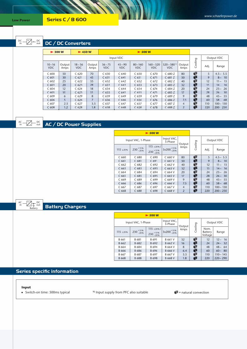
300 W 450 W 500 W
Input VDC
Coo
ling Output VDC
10 –16 VDC
Output Amps
18 – 36 VDC
Output Amps
36 – 75 VDC
45 – 90 VDC
80 –160 VDC
160 – 320 VDC
320 – 380 1) VDC
Output Amps Adj. Range
C 600C 601C 602C 603C 604C 605C 609C 606C 607C 608
503025201210 6 5 2.5 1.2
C 620C 621C 622C 623C 624C 625C 629C 626C 627C 628
704535281815 8 7 3.5 1.8
C 630C 631C 632C 633C 634C 635C 639C 636C 637C 638
C 640C 641C 642C 643C 644C 645C 649C 646C 647C 648
C 650C 651C 652C 653C 654C 655C 659C 656C 657C 658
C 670C 671C 672C 673C 674C 675C 679C 676C 677C 678
C 680 ZC 681 ZC 682 ZC 683 ZC 684 ZC 685 ZC 689 ZC 686 ZC 687 ZC 688 Z
805040322017 9 7.5 4 2
5 9 12 15 24 28 48 60110220
4.5 – 5.5 8 – 10 11 – 13 14 – 16 23 – 26 26 – 30 45 – 55 58 – 68 100 – 130 200 – 250
500 W
Input VAC, 1-Phase Input VAC, 3-Phase
Output Amps
Coo
ling Output VDC
115 ± 20 % 230 + 15 % – 20 %
115 ± 20 % /
230 + 15 % – 20 %
3x200 + 15 % – 20 % Adj. Range
C 660C 661C 662C 663C 664C 665C 669C 666C 667C 668
C 680C 681C 682C 683C 684C 685C 689C 686C 687C 688
C 690C 691C 692C 693C 694C 695C 699C 696C 697C 698
C 660 VC 661 VC 662 VC 663 VC 664 VC 665 VC 669 VC 666 VC 667 VC 668 V
805040322017 9 7.5 4 2
5 9 12 15 24 28 48 60110220
4.5 – 5.5 8 – 10 11 – 13 14 – 16 23 – 26 26 – 30 45 – 55 58 – 68 100 – 130 200 – 250
500 W
Input VAC, 1-Phase Input VAC, 3-Phase
Output Amps
Coo
ling Output VDC
115 ± 20 % 230 + 15 % – 20 %
115 ± 20 % /
230 + 15 % – 20 %
3x200 + 15 % – 20 %
Nom. Battery Voltage
Range
B 661B 662B 664B 666B 667B 668
B 681B 682B 684B 686B 687B 688
B 691B 692B 694B 696B 697B 698
B 661 VB 662 VB 664 VB 666 VB 667 VB 668 V
3216 8 6.4 3.5 1.8
12 24 48 60110220
12 – 16 24 – 32 48 – 64 60 – 80 110 – 145 220 – 290
C 601 30 C 621 45 C 631 C 641 C 651 C 671 C 681 Z 50 9 8– 10
C 603 20 C 623 28 C 633 C 643 C 653 C 673 C 683 Z 32 15 14– 16
C 605 10 C 625 15 C 635 C 645 C 655 C 675 C 685 Z 17 28 26– 30
C 606 5 C 626 7 C 636 C 646 C 656 C 676 C 686 Z 7.5 60 58– 68
C 608 1.2 C 628 1.8 C 638 C 648 C 658 C 678 C 688 Z 2 220 200– 250
C 661 C 681 C 691 C 661 V 50 9 8– 10
C 663 C 683 C 693 C 663 V 32 15 14– 16
C 665 C 685 C 695 C 665 V 17 28 26– 30
C 666 C 686 C 696 C 666 V 7.5 60 58– 68
C 668 C 688 C 698 C 668 V 2 220 200– 250
B 662 B 682 B 692 B 662 V 16 24 24– 32
B 666 B 686 B 696 B 666 V 6.4 60 60– 80
B 668 B 688 B 698 B 668 V 1.8 220 220– 290
Series C / B 600
Input Switch-on time: 500ms typical 1) Input supply from PFC also suitable = natural convection
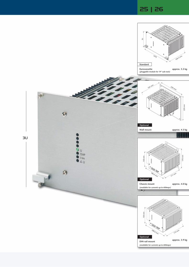
25 | 26
3U
42TE
3U
166.5 mm
180.6 mm
170
mm
130
mm
171 mm
220 mm
220
mm
167 mm
180.6 mm
130
mm
175 mm
Eurocassette (pluggable module for 19“ sub-rack)
Standard
approx. 3.5 kg
Wall mount
Optional
approx. 4.5 kg
Chassis mount
(available for currents up to 60Amps)
Optional
approx. 4.0 kg
DIN rail mount
(available for currents up to 60Amps)
Optional approx. 3.9 kg

www.schaeferpower.deLow Power Low Power
DC / DC ConvertersDC
inDCout
Battery ChargersACin
DCout
Battery
Series specific information
AC / DC Power SuppliesACin
DCout
400 W 500 W 600 W
Input VDC
Coo
ling Output VDC
10 –16 VDC
Output Amps
18 – 36 VDC
Output Amps
36 – 75 VDC
45 – 90 VDC
80 –160 VDC
160 – 320 VDC
320 – 380 1) VDC
Output Amps Adj. Range
C 1500C 1501C 1502C 1503C 1504C 1505C 1509C 1506C 1507C 1507 JC 1508C 1508 J
402524201513 7 5.5 3 2 1.4 1
C 1520C 1521C 1522C 1523C 1524C 1525C 1529C 1526C 1527C 1527 JC 1528C 1528 J
603833251815 8 6.5 3.3 2.5 1.6 1.3
C 1530C 1531C 1532C 1533C 1534C 1535C 1539C 1536C 1537C 1537 JC 1538C 1538 J
C 1540C 1541C 1542C 1543C 1544C 1545C 1549C 1546C 1547C 1547 JC 1548C 1548 J
C 1550C 1551C 1552C 1553C 1554C 1555C 1559C 1556C 1557C 1557 JC 1558C 1558 J
C 1570C 1571C 1572C 1573C 1574C 1575C 1579C 1576C 1577C 1577 JC 1578C 1578 J
C 1580 ZC 1581 ZC 1582 ZC 1583 ZC 1584 ZC 1585 ZC 1589 ZC 1586 ZC 1587 ZC 1587 ZJC 1588 ZC 1588 ZJ
80504234232011 9 4.5 3 2.4 1.5
5 9 12 15 24 28 48 60110200220400
4.5 – 5.5 8 – 10 11 – 13 14 – 16 23 – 26 26 – 30 45 – 55 58 – 68 100 – 130 190 – 200 200 – 250 380 – 400
600 W
Input VAC, 1-Phase Input VAC, 3-Phase
Output Amps
Coo
ling Output VDC
115 ± 20 % 230 + 15 % – 20 %
115 ± 20 % /
230 + 15 % – 20 %
3x200 + 15 % – 20 % Adj. Range
C 1560C 1561C 1562C 1563C 1564C 1565C 1569C 1566C 1567C 1567 JC 1568C 1568 J
C 1580C 1581C 1582C 1583C 1584C 1585C 1589C 1586C 1587C 1587 JC 1588C 1588 J
C 1590C 1591C 1592C 1593C 1594C 1595C 1599C 1596C 1597C 1597 JC 1598C 1598 J
C 1560 VC 1561 VC 1562 VC 1563 VC 1564 VC 1565 VC 1569 VC 1566 VC 1567 VC 1567 VJC 1568 VC 1568 VJ
80504234232011 9 4.5 3 2.4 1.5
5 9 12 15 24 28 48 60110200220400
4.5 – 5.5 8 – 10 11 – 13 14 – 16 23 – 26 26 – 30 45 – 55 58 – 68 100 – 130 190 – 200 200 – 250 380 – 400
600 W
Input VAC, 1-Phase Input VAC, 3-Phase
Output Amps
Coo
ling Output VDC
115 ± 20 % 230 + 15 % – 20 %
115 ± 20 % /
230 + 15 % – 20 %
3x200 + 15 % – 20 %
Nom. Battery Voltage
Range
B 1561B 1562B 1564B 1566B 1567B 1568
B 1581B 1582B 1584B 1586B 1587B 1588
B 1591B 1592B 1594B 1596B 1597B 1598
B 1561 VB 1562 VB 1564 VB 1566 VB 1567 VB 1568 V
3418 9 7.5 4 2
12 24 48 60110220
12 – 16 24 – 32 48 – 64 60 – 80 110 – 145 220 – 290
C 1501 25 C 1521 38 C 1531 C 1541 C 1551 C 1571 C 1581 Z 50 9 8– 10
C 1503 20 C 1523 25 C 1533 C 1543 C 1553 C 1573 C 1583 Z 34 15 14– 16
C 1505 13 C 1525 15 C 1535 C 1545 C 1555 C 1575 C 1585 Z 20 28 26– 30
C 1506 5.5 C 1526 6.5 C 1536 C 1546 C 1556 C 1576 C 1586 Z 9 60 58– 68
C 1507 J 2 C 1527 J 2.5 C 1537 J C 1547 J C 1557 J C 1577 J C 1587 ZJ 3 200 190– 200
C 1508 J 1 C 1528 J 1.3 C 1538 J C 1548 J C 1558 J C 1578 J C 1588 ZJ 1.5 400 380– 400
B 1562 B 1582 B 1592 B 1562 V 18 24 24– 32
B 1566 B 1586 B 1596 B 1566 V 7.5 60 60– 80
B 1568 B 1588 B 1598 B 1568 V 2 220 220– 290
C 1561 C 1581 C 1591 C 1561 V 50 9 8– 10
C 1563 C 1583 C 1593 C 1563 V 34 15 14– 16
C 1565 C 1585 C 1595 C 1565 V 20 28 26– 30
C 1566 C 1586 C 1596 C 1566 V 9 60 58– 68
C 1567 J C 1587 J C 1597 J C 1567 VJ 3 200 190– 200
C 1568 J C 1588 J C 1598 J C 1568 VJ 1.5 400 380– 400
Series C / B 1500
Input Switch-on time: 500ms typical 1) Input supply from PFC also suitable = natural convection
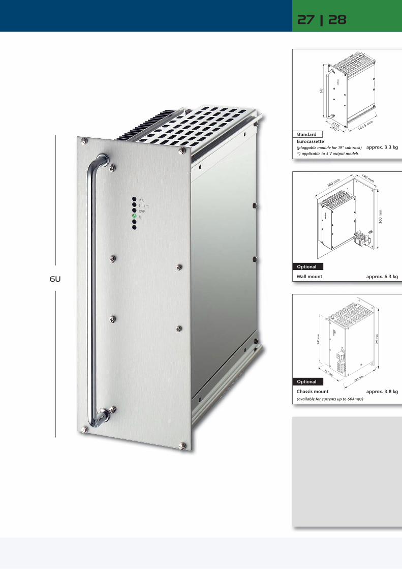
27 | 28
6U
6U
21TE24TE* 166.5 mm
295
mm
125 mm
200 mm
240
mm
140 mm
260 mm
360
mm
approx. 3.3 kg (pluggable module for 19“ sub-rack)*) applicable to 5 V output models
Eurocassette Standard
Wall mount
Optional
approx. 6.3 kg
Chassis mount
(available for currents up to 60Amps)
Optional
approx. 3.8 kg

www.schaeferpower.deLow Power Low Power
DC / DC ConvertersDC
inDCout
Battery ChargersACin
DCout
Battery
Series specific information
AC / DC Power SuppliesACin
DCout
650 W 800 W
Input VDC
Coo
ling Output VDC
18 –36 VDC
Output Amps
36 – 75 VDC
45 – 90 VDC
80 –160 VDC
160 – 320 VDC
320 – 380 1) VDC
Output Amps Adj. Range
C 2620C 2621C 2622C 2623C 2624C 2625C 2629C 2626C 2627C 2628
85 65504225221210 5 2.5
C 2630C 2631C 2632C 2633C 2634C 2635C 2639C 2636C 2637C 2638
C 2640C 2641C 2642C 2643C 2644C 2645C 2649C 2646C 2647C 2648
C 2650C 2651C 2652C 2653C 2654C 2655C 2659C 2656C 2657C 2658
C 2670C 2671C 2672C 2673C 2674C 2675C 2679C 2676C 2677C 2678
C 2680 ZC 2681 ZC 2682 ZC 2683 ZC 2684 ZC 2685 ZC 2689 ZC 2686 ZC 2687 ZC 2688 Z
100 75 60 50 30 27 15 12 6.5 3.2
5 9 12 15 24 28 48 60110220
4.5 – 5.5 8 – 10 11 – 13 14 – 16 23 – 26 26 – 30 45 – 55 58 – 68 100 – 130 200 – 250
800 W
Input VAC, 1-Phase Input VAC, 3-Phase
Output Amps
Coo
ling Output VDC
115 ± 20 % 230 + 15 % – 20 %
115 ± 20 % /
230 + 15 % – 20 %
3x200 + 15 % – 20 % Adj. Range
C 2660C 2661C 2662C 2663C 2664C 2665C 2669C 2666C 2667C 2668
C 2680C 2681C 2682C 2683C 2684C 2685C 2689C 2686C 2687C 2688
C 2690C 2691C 2692C 2693C 2694C 2695C 2699C 2696C 2697C 2698
C 2660 VC 2661 VC 2662 VC 2663 VC 2664 VC 2665 VC 2669 VC 2666 VC 2667 VC 2668 V
100 75 60 50 30 27 15 12 6.5 3.2
5 9 12 15 24 28 48 60110220
4.5 – 5.5 8 – 10 11 – 13 14 – 16 23 – 26 26 – 30 45 – 55 58 – 68 100 – 130 200 – 250
800 W
Input VAC, 1-Phase Input VAC, 3-Phase
Output Amps
Coo
ling Output VDC
115 ± 20 % 230 + 15 % – 20 %
115 ± 20 % /
230 + 15 % – 20 %
3x200 + 15 % – 20 %
Nom. Battery Voltage
Range
B 2661B 2662B 2664B 2666B 2667B 2668
B 2681B 2682B 2684B 2686B 2687B 2688
B 2691B 2692B 2694B 2696B 2697B 2698
B 2661 VB 2662 VB 2664 VB 2666 VB 2667 VB 2668 V
50251310 6 3
12 24 48 60110220
12 – 16 24 – 32 48 – 64 60 – 80 110 – 145 220 – 290
C 2621 65 C 2631 C 2641 C 2651 C 2671 C 2681 Z 75 9 8– 10
C 2623 42 C 2633 C 2643 C 2653 C 2673 C 2683 Z 50 15 14– 16
C 2625 22 C 2635 C 2645 C 2655 C 2675 C 2685 Z 27 28 26– 30
C 2626 10 C 2636 C 2646 C 2656 C 2676 C 2686 Z 12 60 58– 68
C 2628 2.5 C 2638 C 2648 C 2658 C 2678 C 2688 Z 3.2 220 200– 250
C 2661 C 2681 C 2691 C 2661 V 75 9 8– 10
C 2663 C 2683 C 2693 C 2663 V 50 15 14– 16
C 2665 C 2685 C 2695 C 2665 V 27 28 26– 30
C 2666 C 2686 C 2696 C 2666 V 12 60 58– 68
C 2668 C 2688 C 2698 C 2668 V 3.2 220 200– 250
B 2662 B 2682 B 2692 B 2662 V 25 24 24– 32
B 2666 B 2686 B 2696 B 2666 V 10 60 60– 80
B 2668 B 2688 B 2698 B 2668 V 3 220 220– 290
Series C / B 2600
Input Switch-on time: 500ms typical 1) Input supply from PFC also suitable = natural convection
= increased air flow recommended

170
mm
130
mm
180.6 mm
260 mm
3U
29 | 30
3U
42TE 226 mm
229 mm 220 mm
220
mm
170
mm
130
mm
180.6 mm
260 mm
220
mm
Eurocassette (pluggable module for 19“ sub-rack)
Standard
approx. 4.0 kg
Wall mount
Optional
approx. 6.0 kg
Chassis mount
(available for currents up to 60Amps)
Optional
approx. 4.6 kg
www.schaeferpower.deLow Power Low Power
DC / DC ConvertersDC
inDCout
Battery ChargersACin
DCout
Battery
Series specific information
AC / DC Power SuppliesACin
DCout
850 W
Input VAC, 1-Phase Input VAC, 3-PhaseOutput Amps
Coo
ling Output VDC
115 ± 20 % 230 + 15 % – 20 %
115 ± 20 % /
230 + 15 % – 20 %
3x200 + 15 % – 20 % 3x400 + 15 %
– 20 % 3x480 + 10 % – 15 % Adj. Range
C 3560C 3561C 3562C 3563C 3564C 3565C 3569C 3566C 3567C 3567 JC 3568C 3568 J
C 3580C 3581C 3582C 3583C 3584C 3585C 3589C 3586C 3587C 3587 JC 3588C 3588 J
C 3590C 3591C 3592C 3593C 3594C 3595C 3599C 3596C 3597C 3597 JC 3598C 3598 J
C 3560 VC 3561 VC 3562 VC 3563 VC 3564 VC 3565 VC 3569 VC 3566 VC 3567 VC 3567 VJC 3568 VC 3568 VJ
C 3580 VC 3581 VC 3582 VC 3583 VC 3584 VC 3585 VC 3589 VC 3586 VC 3587 VC 3587 VJC 3588 VC 3588 VJ
C 3590 VC 3591 VC 3592 VC 3593 VC 3594 VC 3595 VC 3599 VC 3596 VC 3597 VC 3597 VJC 3598 VC 3598 VJ
100 65 56 45 30 27 14 12 6.5 4 3.5 2
5 9 12 15 24 28 48 60110200220400
4.5 – 5.5 8 – 10 11 – 13 14 – 16 23 – 26 26 – 30 45 – 55 58 – 68 100 – 130 190 – 200 200 – 250 380 – 400
700 W 850 W
Input VDC
Coo
ling Output VDC
18 –36 VDC
Output Amps
36 – 75 VDC
45 – 90 VDC
80 –160 VDC
160 – 320 VDC
320 – 380 1) VDC
320 – 640 2) VDC
Output Amps
Adj. Range
C 3520C 3521C 3522C 3523C 3524C 3525C 3529C 3526C 3527C 3527 JC 3528C 3528 J
80 55504027231210 5.3 3.5 2.8 1.7
C 3530C 3531C 3532C 3533C 3534C 3535C 3539C 3536C 3537C 3537 JC 3538C 3538 J
C 3540C 3541C 3542C 3543C 3544C 3545C 3549C 3546C 3547C 3547 JC 3548C 3548 J
C 3550C 3551C 3552C 3553C 3554C 3555C 3559C 3556C 3557C 3557 JC 3558C 3558 J
C 3570C 3571C 3572C 3573C 3574C 3575C 3579C 3576C 3577C 3577 JC 3578C 3578 J
C 3580 ZC 3581 ZC 3582 ZC 3583 ZC 3584 ZC 3585 ZC 3589 ZC 3586 ZC 3587 ZC 3587 ZJC 3588 ZC 3588 ZJ
C 3570 GC 3571 GC 3572 GC 3573 GC 3574 GC 3575 GC 3579 GC 3576 GC 3577 GC 3577 GJC 3578 GC 3578 GJ
100 65 56 45 30 27 14 12 6.5 4 3.5 2
5 9 12 15 24 28 48 60110200220400
4.5 – 5.5 8 – 10 11 – 13 14 – 16 23 – 26 26 – 30 45 – 55 58 – 68 100 – 130 190 – 200 200 – 250 380 – 400
850 W
Input VAC, 1-Phase Input VAC, 3-PhaseOutput Amps
Coo
ling Output VDC
115 ± 20 % 230 + 15 % – 20 %
115 ± 20 % /
230 + 15 % – 20 %
3x200 + 15 % – 20 % 3x400 + 15 %
– 20 % 3x480 + 10 % – 15 %
Nom. Battery Voltage
Range
B 3561B 3562B 3564B 3566B 3567B 3568
B 3581B 3582B 3584B 3586B 3587B 3588
B 3591B 3592B 3594B 3596B 3597B 3598
B 3561 VB 3562 VB 3564 VB 3566 VB 3567 VB 3568 V
B 3581 VB 3582 VB 3584 VB 3586 VB 3587 VB 3588 V
B 3591 VB 3592 VB 3594 VB 3596 VB 3597 VB 3598 V
50281512 7 3.5
12 24 48 60110220
12 – 16 24 – 32 48 – 64 60 – 80 110 – 145 220 – 290
C 3521 55 C 3531 C 3541 C 3551 C 3571 C 3581 Z C 3571 G 65 9 8– 10
C 3523 40 C 3533 C 3543 C 3553 C 3573 C 3583 Z C 3573 G 45 15 14– 16
C 3525 23 C 3535 C 3545 C 3555 C 3575 C 3585 Z C 3575 G 27 28 26– 30
C 3526 10 C 3536 C 3546 C 3556 C 3576 C 3586 Z C 3576 G 12 60 58– 68
C 3527 J 3.5 C 3537 J C 3547 J C 3557 J C 3577 J C 3587 ZJ C 3577 GJ 4 200 190– 200
C 3528 J 1.7 C 3538 J C 3548 J C 3558 J C 3578 J C 3588 ZJ C 3578 GJ 2 400 380– 400
C 3561 C 3581 C 3591 C 3561 V C 3581 V C 3591 V 65 9 8– 10
C 3563 C 3583 C 3593 C 3563 V C 3583 V C 3593 V 45 15 14– 16
C 3565 C 3585 C 3595 C 3565 V C 3585 V C 3595 V 27 28 26– 30
C 3566 C 3586 C 3596 C 3566 V C 3586 V C 3596 V 12 60 58– 68
C 3567 J C 3587 J C 3597 J C 3567 VJ C 3587 VJ C 3597 VJ 4 200 190– 200
C 3568 J C 3588 J C 3598 J C 3568 VJ C 3588 VJ C 3598 VJ 2 400 380– 400
B 3562 B 3582 B 3592 B 3562 V B 3582 V B 3592 V 28 24 24– 32
B 3566 B 3586 B 3596 B 3566 V B 3586 V B 3596 V 12 60 60– 80
B 3568 B 3588 B 3598 B 3568 V B 3588 V B 3598 V 3.5 220 220– 290
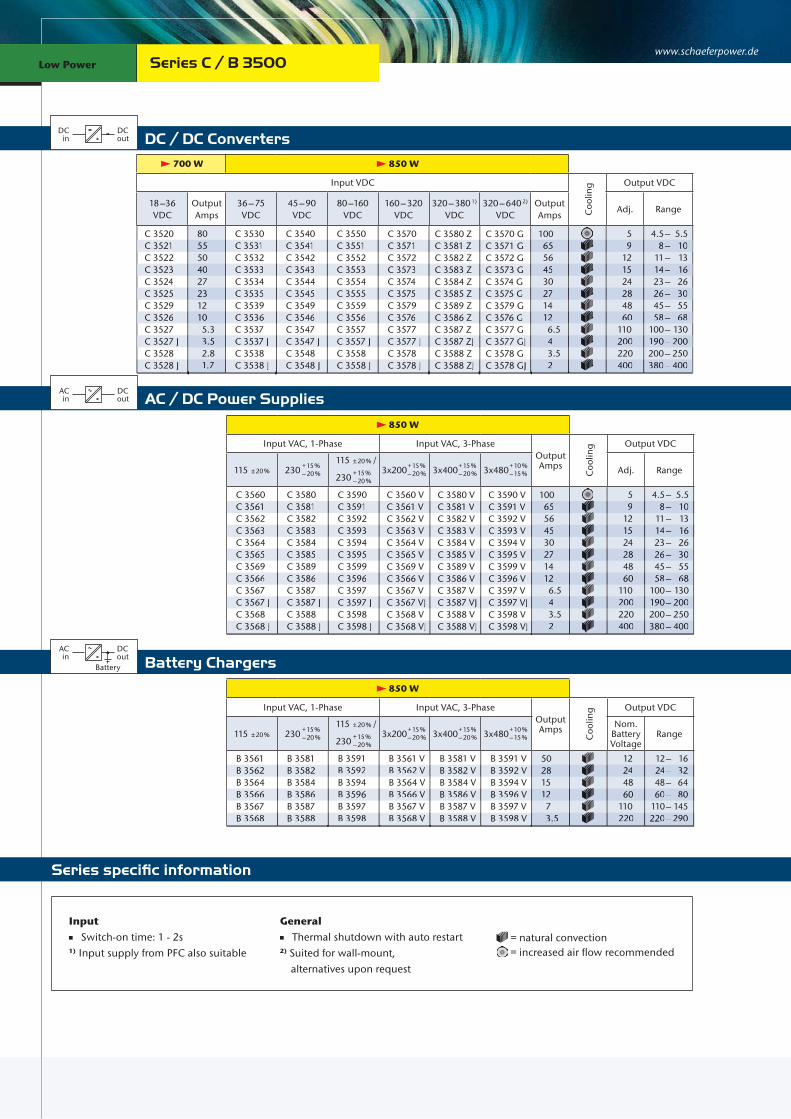
Series C / B 3500
Input Switch-on time: 1 - 2s
General Thermal shutdown with auto restart
Input Switch-on time: 1 - 2s1) Input supply from PFC also suitable
General Thermal shutdown with auto restart2) Suited for wall-mount, alternatives upon request
= natural convection = increased air flow recommended
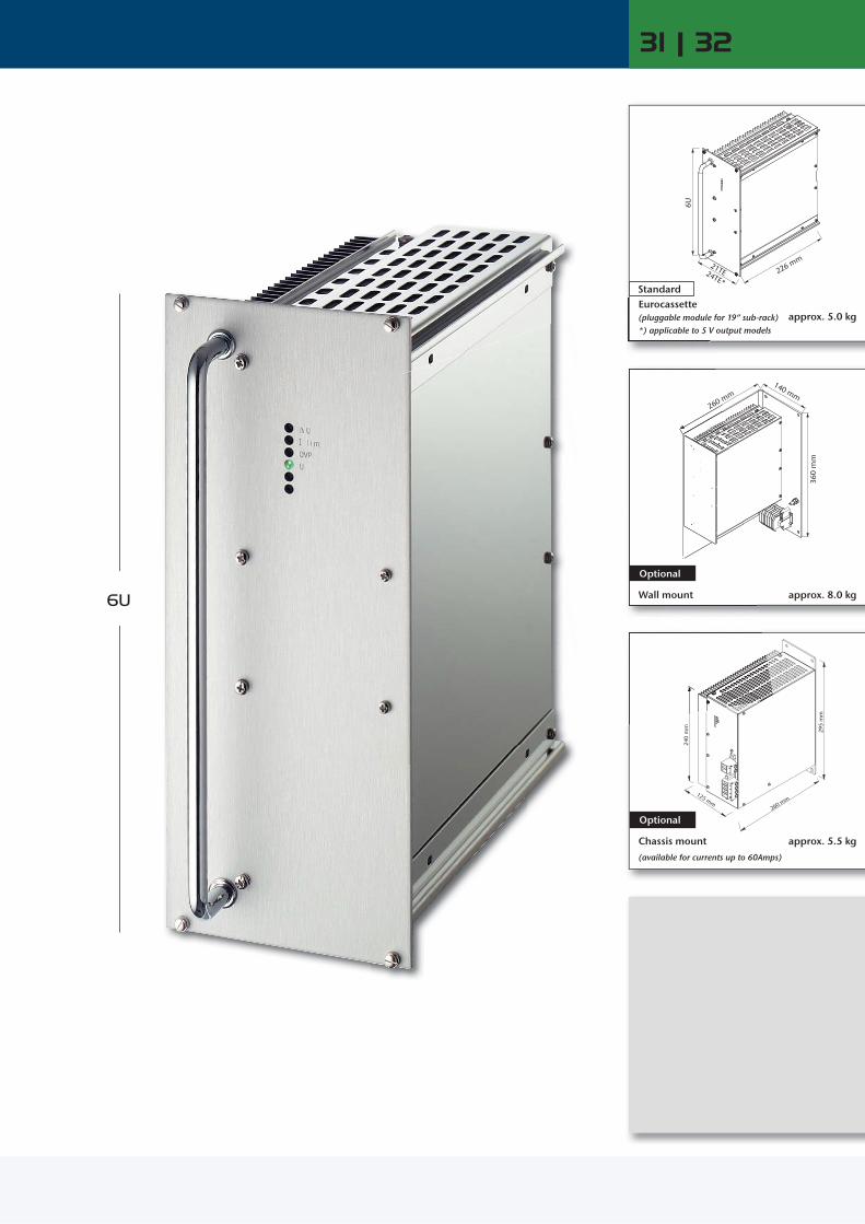
31 | 32
6U
226 mm
6U
21TE24TE*
295
mm
125 mm
240
mm
260 mm
140 mm260 mm
360
mm
260 m
approx. 5.0 kg
Optional
Standard
(pluggable module for 19“ sub-rack)*) applicable to 5 V output models
Eurocassette
Wall mount approx. 8.0 kg
Chassis mount
(available for currents up to 60Amps)
Optional
approx. 5.5 kg

www.schaeferpower.deLow Power Low Power
DC / DC ConvertersDC
inDCout
Battery ChargersACin
DCout
Battery
Series specific information
AC / DC Power SuppliesACin
DCout
1000 W 1250 W
Input VDC
Coo
ling Output VDC
18 –36 VDC
Output Amps
36 – 75 VDC
45 – 90 VDC
80 –160 VDC
160 – 320 VDC
320 – 380 1) VDC
320 – 640 2) VDC
Output Amps Adj. Range
C 3720C 3721C 3722C 3723C 3724C 3725C 3729C 3726C 3727C 3727 JC 3728C 3728 J
120 80 70 56 40 35 19 15 8 5 4 2.5
C 3730C 3731C 3732C 3733C 3734C 3735C 3739C 3736C 3737C 3737 JC 3738C 3738 J
C 3740C 3741C 3742C 3743C 3744C 3745C 3749C 3746C 3747C 3747 JC 3748C 3748 J
C 3750C 3751C 3752C 3753C 3754C 3755C 3759C 3756C 3757C 3757 JC 3758C 3758 J
C 3770C 3771C 3772C 3773C 3774C 3775C 3779C 3776C 3777C 3777 JC 3778C 3778 J
C 3780 ZC 3781 ZC 3782 ZC 3783 ZC 3784 ZC 3785 ZC 3789 ZC 3786 ZC 3787 ZC 3787 ZJC 3788 ZC 3788 ZJ
C 3770 GC 3771 GC 3772 GC 3773 GC 3774 GC 3775 GC 3779 GC 3776 GC 3777 GC 3777 GJC 3778 GC 3778 GJ
150 100 85 70 50 42 23 18 10 6 5 3
5 9 12 15 24 28 48 60110200220400
4.5 – 5.5 8 – 10 11 – 13 14 – 16 23 – 26 26 – 30 45 – 55 58 – 68 100 – 130 190 – 200 200 – 250 380 – 400
1250 W
Input VAC, 1-Phase Input VAC, 3-PhaseOutput Amps
Coo
ling Output VDC
115 ± 20 % 230 + 15 % – 20 %
115 ± 20 % /
230 + 15 % – 20 %
3x200 + 15 % – 20 % 3x400 + 15 %
– 20 % 3x480 + 10 % – 15 % Adj. Range
C 3760C 3761C 3762C 3763C 3764C 3765C 3769C 3766C 3767C 3767 JC 3768C 3768 J
C 3780C 3781C 3782C 3783C 3784C 3785C 3789C 3786C 3787C 3787 JC 3788C 3788 J
C 3790C 3791C 3792C 3793C 3794C 3795C 3799C 3796C 3797C 3797 JC 3798C 3798 J
C 3760 VC 3761 VC 3762 VC 3763 VC 3764 VC 3765 VC 3769 VC 3766 VC 3767 VC 3767 VJC 3768 VC 3768 VJ
C 3780 VC 3781 VC 3782 VC 3783 VC 3784 VC 3785 VC 3789 VC 3786 VC 3787 VC 3787 VJC 3788 VC 3788 VJ
C 3790 VC 3791 VC 3792 VC 3793 VC 3794 VC 3795 VC 3799 VC 3796 VC 3797 VC 3797 VJC 3798 VC 3798 VJ
150 100 85 70 50 42 23 18 10 6 5 3
5 9 12 15 24 28 48 60110200220400
4.5 – 5.5 8 – 10 11 – 13 14 – 16 23 – 26 26 – 30 45 – 55 58 – 68 100 – 130 190 – 200 200 – 250 380 – 400
C 3721 80 C 3731 C 3741 C 3751 C 3771 C 3781 Z C 3771 G 100 9 8– 10
C 3723 56 C 3733 C 3743 C 3753 C 3773 C 3783 Z C 3773 G 70 15 14– 16
C 3725 35 C 3735 C 3745 C 3755 C 3775 C 3785 Z C 3775 G 42 28 26– 30
C 3726 15 C 3736 C 3746 C 3756 C 3776 C 3786 Z C 3776 G 18 60 58– 68
C 3727 J 5 C 3737 J C 3747 J C 3757 J C 3777 J C 3787 ZJ C 3777 GJ 6 200 190– 200
C 3728 J 2.5 C 3738 J C 3748 J C 3758 J C 3778 J C 3788 ZJ C 3778 GJ 3 400 380– 400
C 3761 C 3781 C 3791 C 3761 V C 3781 V C 3791 V 100 9 8– 10
C 3763 C 3783 C 3793 C 3763 V C 3783 V C 3793 V 70 15 14– 16
C 3765 C 3785 C 3795 C 3765 V C 3785 V C 3795 V 42 28 26– 30
C 3766 C 3786 C 3796 C 3766 V C 3786 V C 3796 V 18 60 58– 68
C 3767 J C 3787 J C 3797 J C 3767 VJ C 3787 VJ C 3797 VJ 6 200 190– 200
C 3768 J C 3788 J C 3798 J C 3768 VJ C 3788 VJ C 3798 VJ 3 400 380– 400
Series C / B 3700
1250 W
Input VAC, 1-Phase Input VAC, 3-PhaseOutput Amps
Coo
ling Output VDC
115 ± 20 % 230 + 15 % – 20 %
115 ± 20 % /
230 + 15 % – 20 %
3x200 + 15 % – 20 % 3x400 + 15 %
– 20 % 3x480 + 10 % – 15 %
Nom. Battery Voltage
Range
B 3761B 3762B 3764B 3766B 3767B 3768
B 3781B 3782B 3784B 3786B 3787B 3788
B 3791B 3792B 3794B 3796B 3797B 3798
B 3761 VB 3762 VB 3764 VB 3766 VB 3767 VB 3768 V
B 3781 VB 3782 VB 3784 VB 3786 VB 3787 VB 3788 V
B 3791 VB 3792 VB 3794 VB 3796 VB 3797 VB 3798 V
7540221810 5
12 24 48 60110220
12 – 16 24 – 32 48 – 64 60 – 80 110 – 145 220 – 290
B 3762 B 3782 B 3792 B 3762 V B 3782 V B 3792 V 40 24 24– 32
B 3766 B 3786 B 3796 B 3766 V B 3786 V B 3796 V 18 60 60– 80
B 3768 B 3788 B 3798 B 3768 V B 3788 V B 3798 V 5 220 220– 290
Input Switch-on time: 1 - 2s
General Thermal shutdown with auto restart
Input Switch-on time: 1 - 2s1) Input supply from PFC also suitable
General Thermal shutdown with auto restart2) Suited for wall-mount, alternatives upon request
= natural convection = increased air flow recommended

28TE
6U
226 mm
295
mm
155 mm
262 mm
241
mm
140 mm
360
mm
260 mm
33 | 34
6U
241
mm
260 mm
Eurocassette (pluggable module for 19“ sub-rack)
Standard
approx. 6.5 kg
Optional
approx. 9.5 kg Wall mount
approx. 7.5 kg Chassis mount
(available for currents up to 60Amps)
Optional

www.schaeferpower.deLow Power Low Power
DC / DC ConvertersDC
inDCout
Battery ChargersACin
DCout
Battery
Series specific information
AC / DC Power SuppliesACin
DCout
900 W 1200 W 1600 W
Input VDC
Coo
ling Output VDC
10 –16 VDC
Output Amps
20 – 32 VDC
Output Amps
40 – 64 VDC
50 – 80 VDC
80 –160 VDC
160 – 320 VDC
320 – 380 1) VDC
320 – 640 2) VDC
450 – 800 2) VDC
Output Amps Adj. Range
C 4501C 4502C 4503C 4504C 4505C 4509C 4506C 4507C 4507 JC 4508C 4508 J
60 50 42 32 28 16 14 7.2 4.4 3.6 2.2
C 4521C 4522C 4523C 4524C 4525C 4529C 4526C 4527C 4527 JC 4528C 4528 J
90 80 65 45 40 22 18 10 6 5 3
C 4531C 4532C 4533C 4534C 4535C 4539C 4536C 4537C 4537 JC 4538C 4538 J
C 4541C 4542C 4543C 4544C 4545C 4549C 4546C 4547C 4547 JC 4548C 4548 J
C 4551C 4552C 4553C 4554C 4555C 4559C 4556C 4557C 4557 JC 4558C 4558 J
C 4571C 4572C 4573C 4574C 4575C 4579C 4576C 4577C 4577 JC 4578C 4578 J
C 4581 ZC 4582 ZC 4583 ZC 4584 ZC 4585 ZC 4589 ZC 4586 ZC 4587 ZC 4587 ZJC 4588 ZC 4588 ZJ
C 4571 GC 4572 GC 4573 GC 4574 GC 4575 GC 4579 GC 4576 GC 4577 GC 4577 GJC 4578 GC 4578 GJ
C 4571 KC 4572 KC 4573 KC 4574 KC 4575 KC 4579 KC 4576 KC 4577 KC 4577 KJC 4578 KC 4578 KJ
110 96 80 56 50 30 24 13 8 6.5 4
9 12 15 24 28 48 60110200220400
8 – 10 11 – 13 14 – 16 23 – 26 26 – 30 45 – 55 58 – 68 100 – 130 190 – 200 200 – 250 380 – 400
C 4502 50 C 4522 80 C 4532 C 4542 C 4552 C 4572 C 4582 Z C 4572 G C 4572 K 96 12 11– 13
C 4504 32 C 4524 45 C 4534 C 4544 C 4554 C 4574 C 4584 Z C 4574 G C 4574 K 56 24 23– 26
C 4509 16 C 4529 22 C 4539 C 4549 C 4559 C 4579 C 4589 Z C 4579 G C 4579 K 30 48 45– 55
C 4507 7.2 C 4527 10 C 4537 C 4547 C 4557 C 4577 C 4587 Z C 4577 G C 4577 K 13 110 100– 130
C 4508 3.6 C 4528 5 C 4538 C 4548 C 4558 C 4578 C 4588 Z C 4578 G C 4578 K 6.5 220 200– 250
1600 W
Input VAC, 1-Phase Input VAC, 3-PhaseOutput Amps
Coo
ling Output VDC
115 ± 20 % 230 + 15 % – 20 %
115 ± 20 % /
230 + 15 % – 20 %
3x200 + 15 % – 20 % 3x400 + 15 %
– 20 % 3x480 + 10 % – 15 % Adj. Range
C 4561C 4562C 4563C 4564C 4565C 4569C 4566C 4567C 4567 JC 4568C 4568 J
C 4581C 4582C 4583C 4584C 4585C 4589C 4586C 4587C 4587 JC 4588C 4588 J
C 4591C 4592C 4593C 4594C 4595C 4599C 4596C 4597C 4597 JC 4598C 4598 J
C 4561 VC 4562 VC 4563 VC 4564 VC 4565 VC 4569 VC 4566 VC 4567 VC 4567 VJC 4568 VC 4568 VJ
C 4581 VC 4582 VC 4583 VC 4584 VC 4585 VC 4589 VC 4586 VC 4587 VC 4587 VJC 4588 VC 4588 VJ
C 4591 VC 4592 VC 4593 VC 4594 VC 4595 VC 4599 VC 4596 VC 4597 VC 4597 VJC 4598 VC 4598 VJ
110 96 80 56 50 30 24 13 8 6.5 4
9 12 15 24 28 48 60110200220400
8 – 10 11 – 13 14 – 16 23 – 26 26 – 30 45 – 55 58 – 68 100 – 130 190 – 200 200 – 250 380 – 400
1600 W
Input VAC, 1-Phase Input VAC, 3-PhaseOutput Amps
Coo
ling Output VDC
115 ± 20 % 230 + 15 % – 20 %
115 ± 20 % /
230 + 15 % – 20 %
3x200 + 15 % – 20 % 3x400 + 15 %
– 20 % 3x480 + 10 % – 15 %
Nom. Battery Voltage
Range
B 4561B 4562B 4564B 4566B 4567B 4568
B 4581B 4582B 4584B 4586B 4587B 4588
B 4591B 4592B 4594B 4596B 4597B 4598
B 4561 VB 4562 VB 4564 VB 4566 VB 4567 VB 4568 V
B 4581 VB 4582 VB 4584 VB 4586 VB 4587 VB 4588 V
B 4591 VB 4592 VB 4594 VB 4596 VB 4597 VB 4598 V
80 46 25 20 12 6
12 24 48 60110220
12 – 16 24 – 32 48 – 64 60 – 80 110 – 145 220 – 290
C 4562 C 4582 C 4592 C 4562 V C 4582 V C 4592 V 96 12 11– 13
C 4564 C 4584 C 4594 C 4564 V C 4584 V C 4594 V 56 24 23– 26
C 4569 C 4589 C 4599 C 4569 V C 4589 V C 4599 V 30 48 45– 55
C 4567 C 4587 C 4597 C 4567 V C 4587 V C 4597 V 13 110 100– 130
C 4568 C 4588 C 4598 C 4568 V C 4588 V C 4598 V 6.5 220 200– 250
B 4562 B 4582 B 4592 B 4562 V B 4582 V B 4592 V 46 24 24– 32
B 4566 B 4586 B 4596 B 4566 V B 4586 V B 4596 V 20 60 60– 80
B 4568 B 4588 B 4598 B 4568 V B 4588 V B 4598 V 6 220 220– 290
Series C / B 4500
Input Switch-on time: 1 - 2s1) Input supply from PFC also suitable
General Thermal shutdown with auto restart2) Suited for wall-mount, alternatives upon request
= increased air flow recommended
21TE
6U
306 mm
295
mm
125 mm
240
mm
340 mm
140 mm
360
mm
340 mm
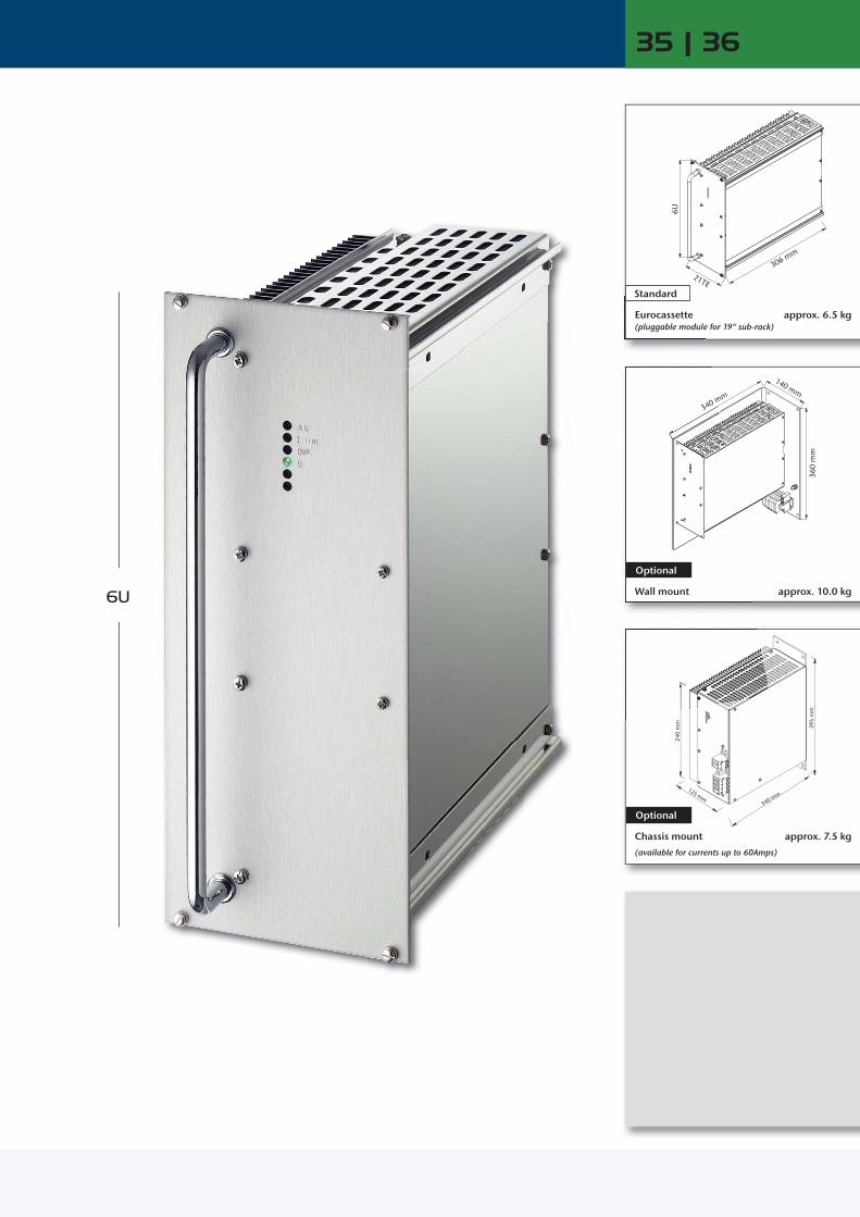
35 | 36
6U
2
340 m
Eurocassette (pluggable module for 19“ sub-rack)
Standard
approx. 6.5 kg
Wall mount
Optional
approx. 10.0 kg
Chassis mount
(available for currents up to 60Amps)
Optional
approx. 7.5 kg

www.schaeferpower.deLow Power Low Power
DC / DC ConvertersDC
inDCout
Battery ChargersACin
DCout
Battery
Series specific information
AC / DC Power SuppliesACin
DCout
1400 W 1700 W
Input VDC
Coo
ling Output VDC
18 –32 VDC
Output Amps
36 – 75 VDC
45 – 90 VDC
80 –160 VDC
160 – 320 VDC
320 – 380 1) VDC
320 – 640 2) VDC
450 – 800 2) VDC
Output Amps Adj. Range
C 3620C 3621C 3622C 3623C 3624C 3625C 3629C 3626C 3627C 3627 JC 3628C 3628 J
180 2)
120100 80 55 48 26 21 11 7 5.5 3.5
C 3630C 3631C 3632C 3633C 3634C 3635C 3639C 3636C 3637C 3637 JC 3638C 3638 J
C 3640C 3641C 3642C 3643C 3644C 3645C 3649C 3646C 3647C 3647 JC 3648C 3648 J
C 3650C 3651C 3652C 3653C 3654C 3655C 3659C 3656C 3657C 3657 JC 3658C 3658 J
C 3670C 3671C 3672C 3673C 3674C 3675C 3679C 3676C 3677C 3677 JC 3678C 3678 J
C 3680 ZC 3681 ZC 3682 ZC 3683 ZC 3684 ZC 3685 ZC 3689 ZC 3686 ZC 3687 ZC 3687 ZJC 3688 ZC 3688 ZJ
C 3670 GC 3671 GC 3672 GC 3673 GC 3674 GC 3675 GC 3679 GC 3676 GC 3677 GC 3677 GJC 3678 GC 3678 GJ
C 3670 KC 3671 KC 3672 KC 3673 KC 3674 KC 3675 KC 3679 KC 3676 KC 3677 KC 3677 KJC 3678 KC 3678 KJ
200 2) 130115 90 65 55 30 25 14 8.5 7 4.3
5 9 12 15 24 28 48 60110200220400
4.5 – 5.5 8 – 10 11 – 13 14 – 16 23 – 26 26 – 30 45 – 55 58 – 68 100 – 130 190 – 200 200 – 250 380 – 400C 3628 J 3.5 C 3638 J C 3648 J C 3658 J C 3678 J C 3688 ZJ C 3678 GJ C 3678 KJ 4.3 400 380– 400
1700 W
Input VAC, 1-Phase Input VAC, 3-PhaseOutput Amps
Coo
ling Output VDC
115 ± 20 % 230 + 15 % – 20 %
115 ± 20 % /
230 + 15 % – 20 %
3x200 + 15 % – 20 % 3x400 + 15 %
– 20 % 3x480 + 10 % – 15 % Adj. Range
C 3660C 3661C 3662C 3663C 3664C 3665C 3669C 3666C 3667C 3667 JC 3668C 3668 J
C 3680C 3681C 3682C 3683C 3684C 3685C 3689C 3686C 3687C 3687 JC 3688C 3688 J
C 3690C 3691C 3692C 3693C 3694C 3695C 3699C 3696C 3697C 3697 JC 3698C 3698 J
C 3660 VC 3661 VC 3662 VC 3663 VC 3664 VC 3665 VC 3669 VC 3666 VC 3667 VC 3667 VJC 3668 VC 3668 VJ
C 3680 VC 3681 VC 3682 VC 3683 VC 3684 VC 3685 VC 3689 VC 3686 VC 3687 VC 3687 VJC 3688 VC 3688 VJ
C 3690 VC 3691 VC 3692 VC 3693 VC 3694 VC 3695 VC 3699 VC 3696 VC 3697 VC 3697 VJC 3698 VC 3698 VJ
200 2) 130115 90 65 55 30 25 14 8.5 7 4.3
5 9 12 15 24 28 48 60110200220400
4.5 – 5.5 8 – 10 11 – 13 14 – 16 23 – 26 26 – 30 45 – 55 58 – 68 100 – 130 190 – 200 200 – 250 380 – 400
1700 W
Input VAC, 1-Phase Input VAC, 3-PhaseOutput Amps
Coo
ling Output VDC
115 ± 20 % 230 + 15 % – 20 %
115 ± 20 % /
230 + 15 % – 20 %
3x200 + 15 % – 20 % 3x400 + 15 %
– 20 % 3x480 + 10 % – 15 %
Nom. Battery Voltage
Range
B 3661B 3662B 3664B 3666B 3667B 3668
B 3681B 3682B 3684B 3686B 3687B 3688
B 3691B 3692B 3694B 3696B 3697B 3698
B 3661 VB 3662 VB 3664 VB 3666 VB 3667 VB 3668 V
B 3681 VB 3682 VB 3684 VB 3686 VB 3687 VB 3688 V
B 3691 VB 3692 VB 3694 VB 3696 VB 3697 VB 3698 V
100 55 30 24 14 7
12 24 48 60110220
12 – 16 24 – 32 48 – 64 60 – 80 110 – 145 220 – 290
C 3661 C 3681 C 3691 C 3661 V C 3681 V C 3691 V 130 9 8– 10
C 3663 C 3683 C 3693 C 3663 V C 3683 V C 3693 V 90 15 14– 16
C 3665 C 3685 C 3695 C 3665 V C 3685 V C 3695 V 55 28 26– 30
C 3666 C 3686 C 3696 C 3666 V C 3686 V C 3696 V 25 60 58– 68
C 3667 J C 3687 J C 3697 J C 3667 VJ C 3687 VJ C 3697 VJ 8.5 200 190– 200
C 3668 J C 3688 J C 3698 J C 3668 VJ C 3688 VJ C 3698 VJ 4.3 400 380– 400
B 3662 B 3682 B 3692 B 3662 V B 3682 V B 3692 V 55 24 24– 32
B 3666 B 3686 B 3696 B 3666 V B 3686 V B 3696 V 24 60 60– 80
B 3668 B 3688 B 3698 B 3668 V B 3688 V B 3698 V 7 220 220– 290
Series C / B 3600
Input Switch-on time: 1 - 2s1) Input supply from PFC also suitable
General Thermal shutdown with auto restart2) Suited for wall-mount, alternatives upon request
= natural convection = increased air flow recommended
C 3621 120 C 3631 C 3641 C 3651 C 3671 C 3681 Z C 3671 G C 3671 K 130 9 8– 10
C 3623 80 C 3633 C 3643 C 3653 C 3673 C 3683 Z C 3673 G C 3673 K 90 15 14– 16
C 3625 48 C 3635 C 3645 C 3655 C 3675 C 3685 Z C 3675 G C 3675 K 55 28 26– 30
C 3626 21 C 3636 C 3646 C 3656 C 3676 C 3686 Z C 3676 G C 3676 K 25 60 58– 68
C 3627 J 7 C 3637 J C 3647 J C 3657 J C 3677 J C 3687 ZJ C 3677 GJ C 3677 KJ 8.5 200 190– 200
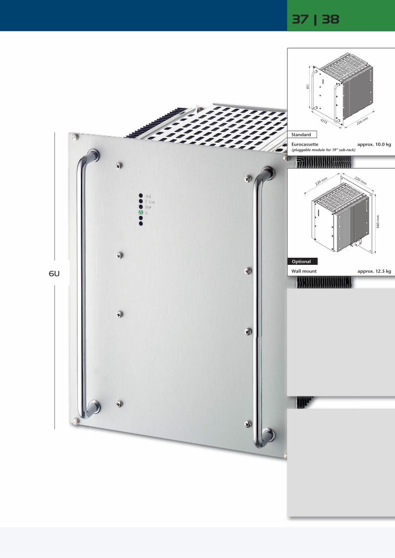
42TE
6U
226 mm
220 mm
360
mm
229 mm
37 | 38
Eurocassette (pluggable module for 19“ sub-rack)
Standard
approx. 10.0 kg
Wall mount
Optional
approx. 12.5 kg 6U

www.schaeferpower.deLow Power Low Power
DC / DC ConvertersDC
inDCout
Battery ChargersACin
DCout
Battery
Series specific information
AC / DC Power SuppliesACin
DCout
1200 W 1700 W 2500 W 2500 W
Input VDC
Coo
ling Output VDC
10 –16 VDC
Output Amps
20 – 32 VDC
Output Amps
40 – 64 VDC
50 – 80 VDC
Output Amps
80 –160 VDC
160 – 320 VDC
320 – 380 1) VDC
320 – 640 2) VDC
450 – 800 2) VDC
Output Amps Adj. Range
C 4700C 4701C 4702C 4703C 4704C 4705C 4709C 4706C 4707C 4707 JC 4708C 4708 J
100 80 68 58 46 40 22 18 10 6 5 3
C 4720C 4721C 4722C 4723C 4724C 4725C 4729C 4726C 4727C 4727 JC 4728C 4728 J
160 2)
110 95 80 60 50 30 25 13 7 7 3.5
C 4730C 4731C 4732C 4733C 4734C 4735C 4739C 4736C 4737C 4737 JC 4738C 4738 J
C 4740C 4741C 4742C 4743C 4744C 4745C 4749C 4746C 4747C 4747 JC 4748C 4748 J
180 2)
140 120 100 75 65 38 31 18 10 10 5
C 4750C 4751C 4752C 4753C 4754C 4755C 4759C 4756C 4757C 4757 JC 4758C 4758 J
C 4770C 4771C 4772C 4773C 4774C 4775C 4779C 4776C 4777C 4777 JC 4778C 4778 J
C 4780 ZC 4781 ZC 4782 ZC 4783 ZC 4784 ZC 4785 ZC 4789 ZC 4786 ZC 4787 ZC 4787 ZJC 4788 ZC 4788 ZJ
C 4770 GC 4771 GC 4772 GC 4773 GC 4774 GC 4775 GC 4779 GC 4776 GC 4777 GC 4777 GJC 4778 GC 4778 GJ
C 4770 KC 4771 KC 4772 KC 4773 KC 4774 KC 4775 KC 4779 KC 4776 KC 4777 KC 4777 KJC 4778 KC 4778 KJ
180 2)
150 130 110 80 70 40 33 20 10 10 5
5 9 12 15 24 28 48 60110200220400
4.5 – 5.5 8 – 10 11 – 13 14 – 16 23 – 26 26 – 30 45 – 55 58 – 68 100 – 130 190 – 200 200 – 250 380 – 400
1700 W 2500 W
Input VAC, 1-Phase Input VAC, 3-PhaseOutput Amps
Coo
ling Output VDC
100 –240 ± 10 %
with PFC
Output Amps 115 ± 20 % 230 + 15 %
– 20 %
115 ± 20 % /
230 + 15 % – 20 %
3x200 + 15 % – 20 % 3x400 + 15 %
– 20 % 3x480 + 10 % – 15 % Adj. Range
CP 4790CP 4791CP 4792CP 4793CP 4794CP 4795CP 4799CP 4796CP 4797CP 4797 JCP 4798CP 4798 J
180 2)
150120100 70 60 35 25 14 7 7 3.5
C 4760C 4761C 4762C 4763C 4764C 4765C 4769C 4766C 4767C 4767 JC 4768C 4768 J
C 4780C 4781C 4782C 4783C 4784C 4785C 4789C 4786C 4787C 4787 JC 4788C 4788 J
C 4790C 4791C 4792C 4793C 4794C 4795C 4799C 4796C 4797C 4797 JC 4798C 4798 J
C 4760 VC 4761 VC 4762 VC 4763 VC 4764 VC 4765 VC 4769 VC 4766 VC 4767 VC 4767 VJC 4768 VC 4768 VJ
C 4780 VC 4781 VC 4782 VC 4783 VC 4784 VC 4785 VC 4789 VC 4786 VC 4787 VC 4787 VJC 4788 VC 4788 VJ
C 4790 VC 4791 VC 4792 VC 4793 VC 4794 VC 4795 VC 4799 VC 4796 VC 4797 VC 4797 VJC 4798 VC 4798 VJ
180 2)
150 130 110 80 70 40 33 20 10 10 5
5 9 12 15 24 28 48 60110200220400
4.5 – 5.5 8 – 10 11 – 13 14 – 16 23 – 26 26 – 30 45 – 55 58 – 68 100 – 130 190 – 200 200 – 250 380 – 400
1700 W 2500 W
Input VAC, 1-Phase Input VAC, 3-PhaseOutput Amps
Coo
ling Output VDC
100 –240 ± 10 %
with PFC
Output Amps 115 ± 20 % 230 + 15 %
– 20 %
115 ± 20 % /
230 + 15 % – 20 %
3x200 + 15 % – 20 % 3x400 + 15 %
– 20 % 3x480 + 10 % – 15 %
Nom. Battery Voltage
Range
BP 4791BP 4792BP 4794BP 4796BP 4797BP 4798
100 56 28 22 12 6
B 4761B 4762B 4764B 4766B 4767B 4768
B 4781B 4782B 4784B 4786B 4787B 4788
B 4791B 4792B 4794B 4796B 4797B 4798
B 4761 VB 4762 VB 4764 VB 4766 VB 4767 VB 4768 V
B 4781 VB 4782 VB 4784 VB 4786 VB 4787 VB 4788 V
B 4791 VB 4792 VB 4794 VB 4796 VB 4797 VB 4798 V
110 70 35 30 18 9
12 24 48 60110220
12 – 16 24 – 32 48 – 64 60 – 80 110 – 145 220 – 290
C 4701 80 C 4721 110 C 4731 C 4741 140 C 4751 C 4771 C 4781 Z C 4771 G C 4771 K 150 9 8– 10
C 4703 58 C 4723 80 C 4733 C 4743 100 C 4753 C 4773 C 4783 Z C 4773 G C 4773 K 110 15 14– 16
C 4705 40 C 4725 50 C 4735 C 4745 65 C 4755 C 4775 C 4785 Z C 4775 G C 4775 K 70 28 26– 30
C 4706 18 C 4726 25 C 4736 C 4746 31 C 4756 C 4776 C 4786 Z C 4776 G C 4776 K 33 60 58– 68
C 4707 J 6 C 4727 J 7 C 4737 J C 4747 J 10 C 4757 J C 4777 J C 4787 ZJ C 4777 GJ C 4777 KJ 10 200 190– 200
C 4708 J 3 C 4728 J 3.5 C 4738 J C 4748 J 5 C 4758 J C 4778 J C 4788 ZJ C 4778 GJ C 4778 KJ 5 400 380– 400
CP 4791 150 C 4761 C 4781 C 4791 C 4761 V C 4781 V C 4791 V 150 9 8– 10
CP 4793 100 C 4763 C 4783 C 4793 C 4763 V C 4783 V C 4793 V 110 15 14– 16
CP 4795 60 C 4765 C 4785 C 4795 C 4765 V C 4785 V C 4795 V 70 28 26– 30
CP 4796 25 C 4766 C 4786 C 4796 C 4766 V C 4786 V C 4796 V 33 60 58– 68
CP 4797 J 7 C 4767 J C 4787 J C 4797 J C 4767 VJ C 4787 VJ C 4797 VJ 10 200 190– 200
CP 4798 J 3.5 C 4768 J C 4788 J C 4798 J C 4768 VJ C 4788 VJ C 4798 VJ 5 400 380– 400
BP 4792 56 B 4762 B 4782 B 4792 B 4762 V B 4782 V B 4792 V 70 24 24– 32
BP 4796 22 B 4766 B 4786 B 4796 B 4766 V B 4786 V B 4796 V 30 60 60– 80
BP 4798 6 B 4768 B 4788 B 4798 B 4768 V B 4788 V B 4798 V 9 220 220– 290
Input Switch-on time: 1 - 2s Power factor correction for CP/ BP series, acc. to EN 61000-3-2, class D1) Input supply from external PFC also suitable
General Thermal shutdown with auto restart2) Suited for wall-mount, alternatives upon request
= increased air flow recommended
Series C / CP / B / BP 4700
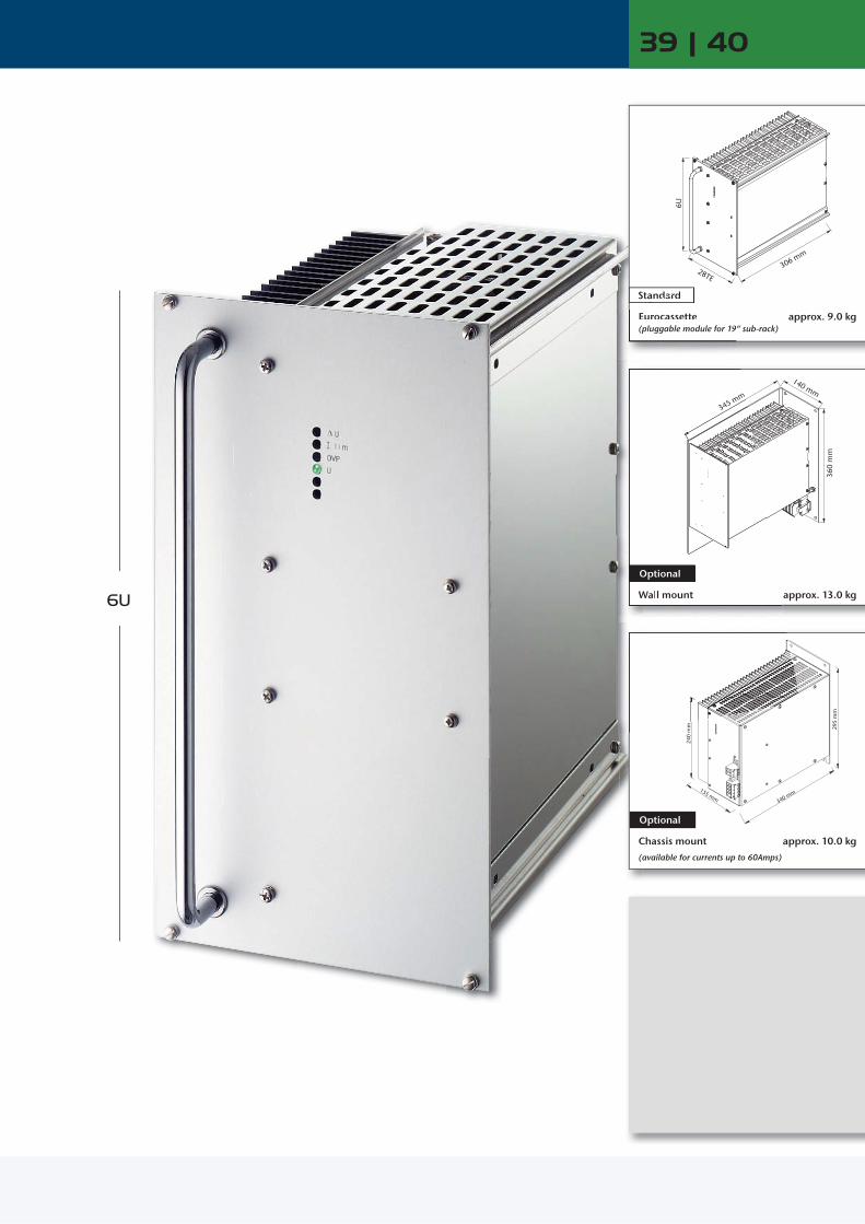
28TE
6U
306 mm
295
mm
340 mm155 mm
240
mm
140 mm
360
mm
345 mm
39 | 40
6U
Eurocassette (pluggable module for 19“ sub-rack)
Standard
approx. 9.0 kg
Wall mount
Optional
approx. 13.0 kg
Chassis mount
(available for currents up to 60Amps)
Optional
approx. 10.0 kg
345 mm
Eurocassette (pluggable module for 19
dard
Wall mount
Optional

www.schaeferpower.deLow Power Low Power
DC / DC ConvertersDC
inDCout
Battery ChargersACin
DCout
Battery
Series specific information
AC / DC Power SuppliesACin
DCout
2000 W 2500 W
Input VDC
Coo
ling Output VDC
18 –32 VDC
Output Amps
36 – 75 VDC
45 – 90 VDC
80 –160 VDC
160 – 320 VDC
320 – 380 1) VDC
320 – 640 2) VDC
450 – 800 2) VDC
Output Amps Adj. Range
C 3822C 3823C 3824C 3825C 3829C 3826C 3827C 3827 JC 3828C 3828 J
120 100 75 65 38 30 15 10 8 5
C 3832C 3833C 3834C 3835C 3839C 3836C 3837C 3837 JC 3838C 3838 J
C 3842C 3843C 3844C 3845C 3849C 3846C 3847C 3847 JC 3848C 3848 J
C 3852C 3853C 3854C 3855C 3859C 3856C 3857C 3857 JC 3858C 3858 J
C 3872C 3873C 3874C 3875C 3879C 3876C 3877C 3877 JC 3878C 3878 J
C 3882 ZC 3883 ZC 3884 ZC 3885 ZC 3889 ZC 3886 ZC 3887 ZC 3887 ZJC 3888 ZC 3888 ZJ
C 3872 GC 3873 GC 3874 GC 3875 GC 3879 GC 3876 GC 3877 GC 3877 GJC 3878 GC 3878 GJ
C 3872 KC 3873 KC 3874 KC 3875 KC 3879 KC 3876 KC 3877 KC 3877 KJC 3878 KC 3878 KJ
160 2)
130 100 85 45 36 20 12 10 6
12 15 24 28 48 60110200220400
11 – 13 14 – 16 23 – 26 26 – 30 45 – 55 58 – 68 100 – 130 190 – 200 200 – 250 380 – 400
2500 W
Input VAC, 1-Phase Input VAC, 3-PhaseOutput Amps
Coo
ling Output VDC
115 ± 20 % 230 + 15 % – 20 %
115 ± 20 % /
230 + 15 % – 20 %
3x200 + 15 % – 20 % 3x400 + 15 %
– 20 % 3x480 + 10 % – 15 % Adj. Range
C 3862C 3863C 3864C 3865C 3869C 3866C 3867C 3867 JC 3868C 3868 J
C 3882C 3883C 3884C 3885C 3889C 3886C 3887C 3887 JC 3888C 3888 J
C 3892C 3893C 3894C 3895C 3899C 3896C 3897C 3897 JC 3898C 3898 J
C 3862 VC 3863 VC 3864 VC 3865 VC 3869 VC 3866 VC 3867 VC 3867 VJC 3868 VC 3868 VJ
C 3882 VC 3883 VC 3884 VC 3885 VC 3889 VC 3886 VC 3887 VC 3887 VJC 3888 VC 3888 VJ
C 3892 VC 3893 VC 3894 VC 3895 VC 3899 VC 3896 VC 3897 VC 3897 VJC 3898 VC 3898 VJ
160 2)
130 100 85 45 36 20 12 10 6
12 15 24 28 48 60110200220400
11 – 13 14 – 16 23 – 26 26 – 30 45 – 55 58 – 68 100 – 130 190 – 200 200 – 250 380 – 400
2500 W
Input VAC, 1-Phase Input VAC, 3-PhaseOutput Amps
Coo
ling Output VDC
115 ± 20 % 230 + 15 % – 20 %
115 ± 20 % /
230 + 15 % – 20 %
3x200 + 15 % – 20 % 3x400 + 15 %
– 20 % 3x480 + 10 % – 15 %
Nom. Battery Voltage
Range
B 3861B 3862B 3864B 3866B 3867B 3868
B 3881B 3882B 3884B 3886B 3887B 3888
B 3891B 3892B 3894B 3896B 3897B 3898
B 3861 VB 3862 VB 3864 VB 3866 VB 3867 VB 3868 V
B 3881 VB 3882 VB 3884 VB 3886 VB 3887 VB 3888 V
B 3891 VB 3892 VB 3894 VB 3896 VB 3897 VB 3898 V
150 80 45 35 20 10
12 24 48 60110220
12 – 16 24 – 32 48 – 64 60 – 80 110 – 145 220 – 290
C 3823 100 C 3833 C 3843 C 3853 C 3873 C 3883 Z C 3873 G C 3873 K 130 15 14– 16
C 3825 65 C 3835 C 3845 C 3855 C 3875 C 3885 Z C 3875 G C 3875 K 85 28 26– 30
C 3826 30 C 3836 C 3846 C 3856 C 3876 C 3886 Z C 3876 G C 3876 K 36 60 58– 68
C 3827 J 10 C 3837 J C 3847 J C 3857 J C 3877 J C 3887 ZJ C 3877 GJ C 3877 KJ 12 200 190– 200
C 3828 J 5 C 3838 J C 3848 J C 3858 J C 3878 J C 3888 ZJ C 3878 GJ C 3878 KJ 6 400 380– 400
C 3863 C 3883 C 3893 C 3863 V C 3883 V C 3893 V 130 15 14– 16
C 3865 C 3885 C 3895 C 3865 V C 3885 V C 3895 V 85 28 26– 30
C 3866 C 3886 C 3896 C 3866 V C 3886 V C 3896 V 36 60 58– 68
C 3867 J C 3887 J C 3897 J C 3867 VJ C 3887 VJ C 3897 VJ 12 200 190– 200
C 3868 J C 3888 J C 3898 J C 3868 VJ C 3888 VJ C 3898 VJ 6 400 380– 400
B 3862 B 3882 B 3892 B 3862 V B 3882 V B 3892 V 80 24 24– 32
B 3866 B 3886 B 3896 B 3866 V B 3886 V B 3896 V 35 60 60– 80
B 3868 B 3888 B 3898 B 3868 V B 3888 V B 3898 V 10 220 220– 290
Series C / B 3800
Input Switch-on time: 1 - 2s1) Input supply from PFC also suitable
General Thermal shutdown with auto restart2) Suited for wall-mount, alternatives upon request
= natural convection = increased air flow recommended
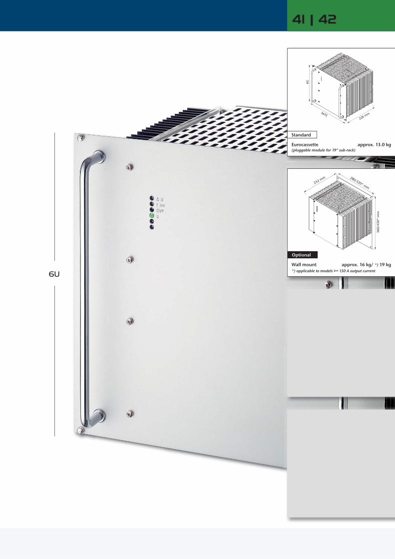
6U
280/320* mm
360/
450*
mm
232 mm
41 | 42
56TE
6U
226 mm
Eurocassette (pluggable module for 19“ sub-rack)
Standard
approx. 13.0 kg
Optional
approx. 16 kg/ *) 19 kg *) applicable to models >= 150 A output current
Wall mount

www.schaeferpower.deLow Power Low Power
DC / DC ConvertersDC
inDCout
Battery ChargersACin
DCout
Battery
Series specific information
AC / DC Power SuppliesACin
DCout
Series C / B 4800
2.5 kW 3.5 kW 5 kW 5 kW
Input VDC
Coo
ling Output VDC
10 –16 2) VDC
Output Amps
20 – 32 2) VDC
Output Amps
40 – 64 VDC
50 – 80 VDC
Output Amps
80 –160 VDC
160 – 320 VDC
320 – 380 1) VDC
320 – 640 2) VDC
450 – 800 2) VDC
Output Amps Adj. Range
C 4802C 4803C 4804C 4805C 4809C 4806C 4807C 4807 JC 4808C 4808 J
136116 92 80 44 36 20 12 10 6
C 4822C 4823C 4824C 4825C 4829C 4826C 4827C 4827 JC 4828C 4828 J
190160120100 60 50 26 14 14 7
C 4832C 4833C 4834C 4835C 4839C 4836C 4837C 4837 JC 4838C 4838 J
C 4842C 4843C 4844C 4845C 4849C 4846C 4847C 4847 JC 4848C 4848 J
240 2)
200 2)
150130 76 62 36 20 20 10
C 4852C 4853C 4854C 4855C 4859C 4856C 4857C 4857 JC 4858C 4858 J
C 4872C 4873C 4874C 4875C 4879C 4876C 4877C 4877 JC 4878C 4878 J
C 4882 ZC 4883 ZC 4884 ZC 4885 ZC 4889 ZC 4886 ZC 4887 ZC 4887 ZJC 4888 ZC 4888 ZJ
C 4872 GC 4873 GC 4874 GC 4875 GC 4879 GC 4876 GC 4877 GC 4877 GJC 4878 GC 4878 GJ
C 4872 KC 4873 KC 4874 KC 4875 KC 4879 KC 4876 KC 4877 KC 4877 KJC 4878 KC 4878 KJ
260 2)
220 2)
160 2)
140 80 66 40 20 20 10
12 15 24 28 48 60110200220400
11 – 13 14 – 16 23 – 26 26 – 30 45 – 55 58 – 68 100 – 130 190 – 200 200 – 250 380 – 400
4 kW 5 kW
Input VAC, 1-Phase Input VAC, 3-Phase
Output Amps
Coo
ling Output VDC
115 2) ± 20 %
Output Amps 230 + 15 %
– 20 % 3x200 + 15 % – 20 % 3x400 + 15 %
– 20 % 3x480 + 10 % – 15 % Adj. Range
C 4862C 4863C 4864C 4865C 4869C 4866C 4867C 4867 JC 4868C 4868 J
260220150130 72 60 30 16 16 8
C 4882C 4883C 4884C 4885C 4889C 4886C 4887C 4887 JC 4888C 4888 J
C 4862 VC 4863 VC 4864 VC 4865 V C 4869 V C 4866 V C 4867 V C 4867 VJ C 4868 V C 4868 VJ
C 4882 VC 4883 VC 4884 VC 4885 VC 4889 VC 4886 VC 4887 VC 4887 VJC 4888 VC 4888 VJ
C 4892 VC 4893 VC 4894 VC 4895 VC 4899 VC 4896 VC 4897 VC 4897 VJC 4898 VC 4898 VJ
260 2)
220 2)
160 2)
140 80 66 40 20 20 10
12 15 24 28 48 60110200220400
11 – 13 14 – 16 23 – 26 26 – 30 45 – 55 58 – 68 100 – 130 190 – 200 200 – 250 380 – 400
4 kW 5 kW
Input VAC, 1-Phase Input VAC, 3-Phase
Output Amps
Coo
ling Output VDC
115 2)
± 20 %
Output Amps 230 + 15 %
– 20 % 3x200 + 15 % – 20 % 3x400 + 15 %
– 20 % 3x480 + 10 % – 15 %
Nom. Battery Voltage
Range
B 4861B 4862B 4864B 4866B 4867B 4868
220122 62 50 28 14
B 4881B 4882B 4884B 4886B 4887B 4888
B 4861 VB 4862 V B 4864 V B 4866 V B 4867 V B 4868 V
B 4881 VB 4882 VB 4884 VB 4886 VB 4887 VB 4888 V
B 4891 VB 4892 VB 4894 VB 4896 VB 4897 VB 4898 V
220 2)
140 70 60 34 18
12 24 48 60110220
12 – 16 24 – 32 48 – 64 60 – 80 110 – 145 220 – 290
C 4803 116 C 4823 160 C 4833 C 4843 200 2) C 4853 C 4873 C 4883 Z C 4873 G C 4873 K 220 2) 15 14– 16
C 4805 80 C 4825 100 C 4835 C 4845 130 C 4855 C 4875 C 4885 Z C 4875 G C 4875 K 140 28 26– 30
C 4806 36 C 4826 50 C 4836 C 4846 62 C 4856 C 4876 C 4886 Z C 4876 G C 4876 K 66 60 58– 68
C 4807 J 12 C 4827 J 14 C 4837 J C 4847 J 20 C 4857 J C 4877 J C 4887 ZJ C 4877 GJ C 4877 KJ 20 200 190– 200
C 4808 J 6 C 4828 J 7 C 4838 J C 4848 J 10 C 4858 J C 4878 J C 4888 ZJ C 4878 GJ C 4878 KJ 10 400 380– 400
C 4863 220 C 4883 C 4863 V C 4883 V C 4893 V 220 2) 15 14– 16
C 4865 130 C 4885 C 4865 V C 4885 V C 4895 V 140 28 26– 30
C 4866 60 C 4886 C 4866 V C 4886 V C 4896 V 66 60 58– 68
C 4867 J 16 C 4887 J C 4867 VJ C 4887 VJ C 4897 VJ 20 200 190– 200
C 4868 J 8 C 4888 J C 4868 VJ C 4888 VJ C 4898 VJ 10 400 380– 400
B 4862 122 B 4882 B 4862 V B 4882 V B 4892 V 140 24 24– 32
B 4866 50 B 4886 B 4866 V B 4886 V B 4896 V 60 60 60– 80
B 4868 14 B 4888 B 4868 V B 4888 V B 4898 V 18 220 220– 290
ZVS topology
ZVS topology
ZVS topology
General Thermal shutdown with auto restart Option “rco” for ZVS-modules available (see p.118)1) Input supply from PFC also suitable2) Suited for wall-mount, alternatives upon request
= increased air flow recommended
Input No-load input power: 15W typical Switch-on time: 1 - 2s Inrush current: 230V AC and 3-phase input: limited by thermistor Hold-up time for AC input: 5ms typical @ nominal input voltage
Output Response time to ±1 %: 5 - 10ms Turn-on rise time: Soft-start, 100-300ms typical OVP without restart for ZVS
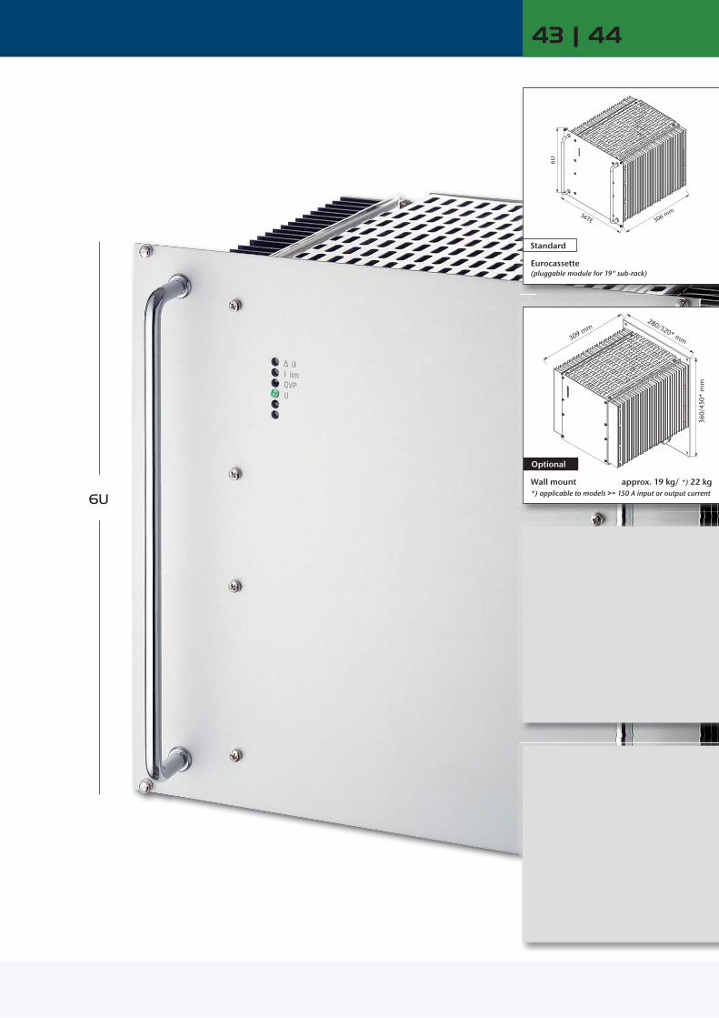
6U
56TE
6U
306 mm
280/320* mm
360/
450*
mm
309 mm
43 | 44
Eurocassette (pluggable module for 19“ sub-rack)
Standard
Optional
*) applicable to models >= 150 A input or output current
Wall mount approx. 19 kg/ *) 22 kg

DC / DC ConvertersDC
inDCout
Series specific information
www.schaeferpower.de
DC / DC ConvertersDC
inDCout
Low Power Low Power
2.5 kW 3.5 kW 5 kW
Input VDC
Coo
ling Output VDC
10 –16 VDC
Output Amps
20 – 32 VDC
Output Amps
40 – 64 VDC
50 – 80 VDC
Output Amps Adj. Range
C 5600C 5601C 5602C 5603C 5604C 5605C 5609C 5606C 5607C 5607 JC 5608C 5608 J
200160136116 92 80 44 36 20 12 10 6
C 5620C 5621C 5622C 5623C 5624C 5625C 5629C 5626C 5627C 5627 JC 5628C 5628 J
320220190160120100 60 50 26 14 14 7
C 5630C 5631C 5632C 5633C 5634C 5635C 5639C 5636C 5637C 5637 JC 5638C 5638 J
C 5640C 5641C 5642C 5643C 5644C 5645C 5649C 5646C 5647C 5647 JC 5648C 5648 J
360280240200150130 76 62 36 20 20 10
5 9 12 15 24 28 48 60110200220400
4.5 – 5.5 8 – 10 11 – 13 14 – 16 23 – 26 26 – 30 45 – 55 58 – 68 100 – 130 190 – 200 200 – 250 380 – 400
3.6 kW 5.1 kW 7.5 kW
Input VDC
Coo
ling Output VDC
10 –16 VDC
Output Amps
20 – 32 VDC
Output Amps
40 – 64 VDC
50 – 80 VDC
Output Amps Adj. Range
C 5700C 5701C 5702C 5703C 5704C 5705C 5709C 5706C 5707C 5707 JC 5708C 5708 J
300240204174138120 66 54 30 18 15 9
C 5720C 5721C 5722C 5723C 5724C 5725C 5729C 5726C 5727C 5727 JC 5728C 5728 J
450330285240180150 90 75 39 21 21 10.5
C 5730C 5731C 5732C 5733C 5734C 5735C 5739C 5736C 5737C 5737 JC 5738C 5738 J
C 5740C 5741C 5742C 5743C 5744C 5745C 5749C 5746C 5747C 5747 JC 5748C 5748 J
500400360300225195114 93 54 30 30 15
5 9 12 15 24 28 48 60110200220400
4.5 – 5.5 8 – 10 11 – 13 14 – 16 23 – 26 26 – 30 45 – 55 58 – 68 100 – 130 190 – 200 200 – 250 380 – 400
Series C 5600 and C 4800 are electrically identical up to 80 VDC input.
C 5601 160 C 5621 220 C 5631 C 5641 280 9 8– 10
C 5603 116 C 5623 160 C 5633 C 5643 200 15 14– 16
C 5605 80 C 5625 100 C 5635 C 5645 130 28 26– 30
C 5606 36 C 5626 50 C 5636 C 5646 62 60 58– 68
C 5607 J 12 C 5627 J 14 C 5637 J C 5647 J 20 200 190– 200
C 5608 J 6 C 5628 J 7 C 5638 J C 5648 J 10 400 380– 400
C 5701 240 C 5721 330 C 5731 C 5741 400 9 8– 10
C 5703 174 C 5723 240 C 5733 C 5743 300 15 14– 16
C 5705 120 C 5725 150 C 5735 C 5745 195 28 26– 30
C 5706 54 C 5726 75 C 5736 C 5746 93 60 58– 68
C 5707 J 18 C 5727 J 21 C 5737 J C 5747 J 30 200 190– 200
C 5708 J 9 C 5728 J 10.5 C 5738 J C 5748 J 15 400 380– 400
Series C 5600 / 5700
series C 5600
series C 5700
Input No-load input power: 15 - 20W Switch-on time: 1 - 2s
Output Manual adjustment of output voltage only via external potentiometer
General Thermal shutdown with auto restart MTBF: approx. 70,000h @ 40°C acc. to MIL - HDBK - 217E (notice 1)
= incl. temperature controlled fans
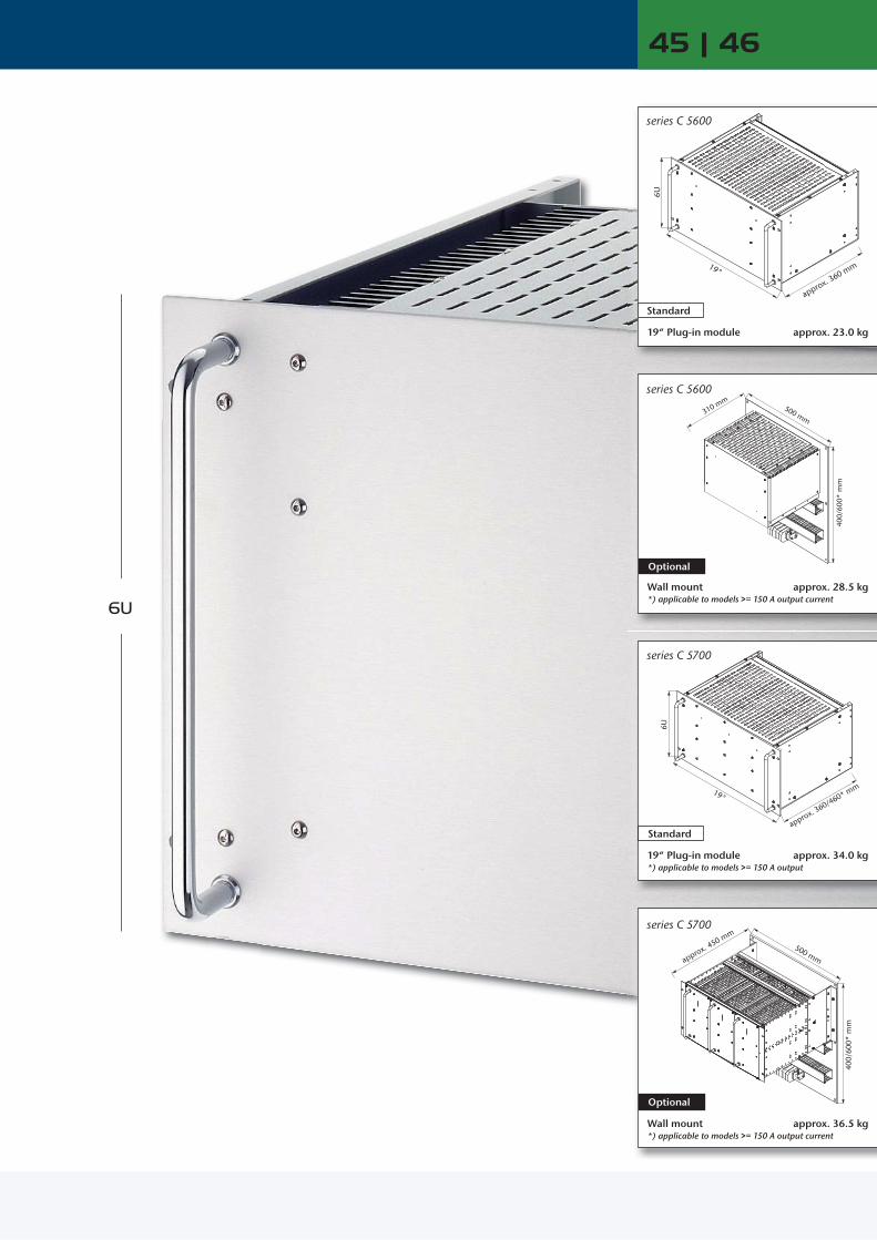
6U
19"
6U
approx. 360 mm
500 mm
400/
600*
mm
310 mm
45 | 46
19"
6U
approx. 360/460* mm
500 mm
400/
600*
mm
approx. 450 mm
19“ Plug-in module
Standard
approx. 23.0 kg
Optional
Wall mount *) applicable to models >= 150 A output current
series C 5600
series C 5600
approx. 28.5 kg
19“ Plug-in module *) applicable to models >= 150 A output
approx. 34.0 kg
series C 5700
Standard
Wall mount *) applicable to models >= 150 A output current
Optional
approx. 36.5 kg
series C 5700

www.schaeferpower.deSeries ELow Power
The step-up converters are very similar to the DC/DC conver-step-up converters are very similar to the DC/DC conver-ters of series “C”, except that the step-up converters sense the voltage across the load which is the total of the battery voltage and the voltage added by the step-up converter. The step-up converter can not reduce the voltage being applied to its input. Therefore, the load should be specified for the maximum battery voltage.
For output voltage stabilizationThe output voltage of an e.g. battery charger with parallel connected battery varies substantially with the charging con-dition of the battery. For many applications, however, the load circuit requires a better stabilized voltage. Frequently used methods for reducing the voltage variation are e.g. “voltage dropping diodes”. A more economical solution is given by switch mode step-up converters. These are DC/DC converters supplied from the battery with the output con-nected in series to the battery. Due to the circuit configura-tion, the output of a step-up converter is not isolated from the input supply (battery).
Step-up converters
Circuit diagrams
Step-up converter with common positive line Step-up converter with common negative line
The following circuit diagram shows a step-up converter which can be grounded on the positive side. The voltage will be added at the negative side and the positive line is common for input and output.
The following circuit diagram shows a step-up converter which can be grounded on the negative side. The voltage will be added at the positive side and the negative line is common for input and output.
Parallel operation of step-up converters Individual load supply
For more power or redundancy step-up converters may be connected in parallel with active current sharing, individually protected by fuses at the input and decoupling diodes or fuses at the output. Such systems have already been realized for 2,000 Amps.
For applications that require individually stabilized voltages across the loads, the step-converters will be connected as shown in the following diagram and may be of different power ratings.
stan
dard
ver
sion
optio
nal v
ersi
on
batterycharger
+
-
step-up converter (long) cable to load
+
-
sense leadsload
+
-
step-up converter
-+
sense leads
load
=
=
=
batterycharger
batterycharger
=
+
-
=
=
=
=
step-up converters
load
sense leadscurrentsharing signal
batterycharger
=
+
-
= =
==
step-up converters
sense leads sense leads
loads

Operation diagram
During normal operation no voltage needs to be added and the converter runs with a minimum of power losses. The voltage at the load is slightly reduced as the current flows through the bypass diode. The bypass diode also allows for replacement of the step-up converter and should therefore be installed externally.
During battery discharge the converter adds the voltage that is needed to maintain the required output voltage level.
The maximum voltage to be added is normally less than 20 % of the total voltage. Therefore, the step-up converter needs to be designed for 20 % of the through-power, only.
battery voltagevoltage at load
discharge
time
volta
ge
voltage added bystep-up converter
normaloperation, no voltageadded of battery
Example: Input: 40 – 56 VDC (battery) Output: 0 – 10 VDC (step-up voltage) output voltage regulated to 50 V during discharge of battery
Create your step-up converter
Step-up Converters
1000 W 1250 W
Input VDC Output VDC
18 –36 VDC
Output Amps
36 – 75 VDC
45 – 90 VDC
80 –160 VDC
160 – 320 VDC
320 – 380 1) VDC
320 – 640 3) VDC
Output Amps
Adj. Range
C 3720C 3721C 3726C 3727C 3727 JC 3728C 3728 J
120 2)
80 15 8 5 4 2.5
C 3730C 3731C 3736C 3737C 3737 JC 3738C 3738 J
C 3740C 3741C 3746C 3747C 3747 JC 3748C 3748 J
C 3750C 3751C 3756C 3757C 3757 JC 3758C 3758 J
C 3770C 3771C 3776C 3777C 3777 JC 3778C 3778 J
C 3780 ZC 3781 ZC 3786 ZC 3787 ZC 3787 ZJC 3788 ZC 3788 ZJ
C 3770 GC 3771 GC 3776 GC 3777 GC 3777 GJC 3778 GC 3778 GJ
150 2) 100 18 10 6 5 3
5 9
60110200220400
4.5 – 5.5 8 – 10 58 – 68 100 – 130 190 – 200 200 – 250 380 – 400
1000 W 1250 W
Input VDC (battery voltage) Output VDC
18 –36 VDC
Output Amps
36 – 75 VDC
45 – 90 VDC
80 –160 VDC
160 – 320 VDC
320 – 380 1) VDC
320 – 640 3) VDC
Output Amps
Voltage at load
regulated to
Step-up voltage
E 3720E 3721E 3726E 3727E 3727 JE 3728E 3728 J
120 2)
80 15 8 5 4 2.5
E 3730E 3731E 3736E 3737E 3737 JE 3738E 3738 J
E 3740E 3741E 3746E 3747E 3747 JE 3748E 3748 J
E 3750E 3751E 3756E 3757E 3757 JE 3758E 3758 J
E 3770E 3771E 3776E 3777E 3777 JE 3778E 3778 J
E 3780 ZE 3781 ZE 3786 ZE 3787 ZE 3787 ZJE 3788 ZE 3788 ZJ
E 3770 GE 3771 GE 3776 GE 3777 GE 3777 GJE 3778 GE 3778 GJ
150 2) 100 18 10 6 5 3
dependingon input voltage
0 – 5.5 0 – 10 0 – 68 0 – 130 0 – 200 0 – 250 0 – 400
Each DC/DC converter can be modified to be a step-up converter: calculate the output power of the step-up converter: max. voltage to be added x max. load current choose the suitable “C” series re-name the model as “E” …
Example:
47 | 48
C 3720 120 2) C 3730 C 3740 C 3750 C 3770 C 3780 Z C 3770 G 150 2) 5 4.5– 5.5
C 3726 15 C 3736 C 3746 C 3756 C 3776 C 3786 Z C 3776 G 18 60 58– 68
C 3727 J 5 C 3737 J C 3747 J C 3757 J C 3777 J C 3787 ZJ C 3777 GJ 6 200 190– 200
C 3728 J 2.5 C 3738 J C 3748 J C 3758 J C 3778 J C 3788 ZJ C 3778 GJ 3 400 380– 400
E 3720 120 2) E 3730 E 3740 E 3750 E 3770 E 3780 Z E 3770 G 150 2)
E 3726 15 E 3736 E 3746 E 3756 E 3776 E 3786 Z E 3776 G 18
E 3727 J 5 E 3737 J E 3747 J E 3757 J E 3777 J E 3787 ZJ E 3777 GJ 6
E 3728 J 2.5 E 3738 J E 3748 J E 3758 J E 3778 J E 3788 ZJ E 3778 GJ 3
0– 5.5
0– 68
0– 200
0– 400
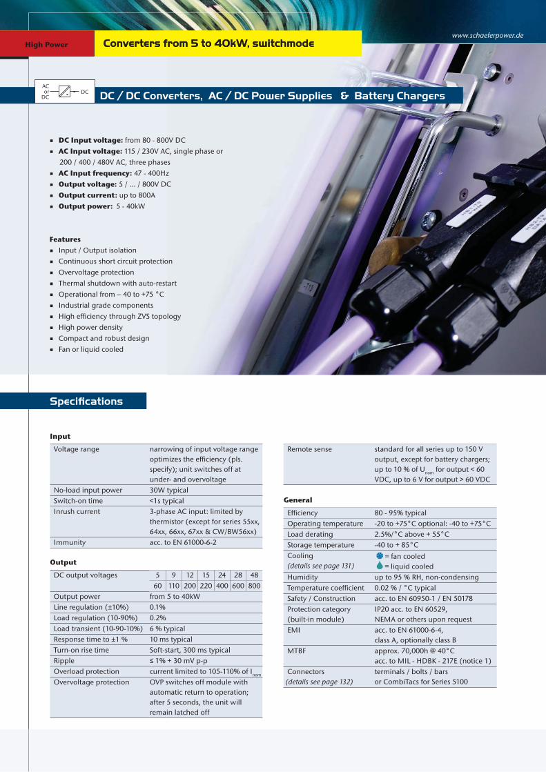
www.schaeferpower.deConverters from 5 to 40kW, switchmodeConverters from 5 to 40kW, switchmodeHigh Power
DC / DC Converters, AC / DC Power Supplies & Battery Chargers
DC Input voltage: from 80 - 800V DC AC Input voltage: 115 / 230V AC, single phase or 200 / 400 / 480V AC, three phases AC Input frequency: 47 - 400Hz Output voltage: 5 / ... / 800V DC Output current: up to 800A Output power: 5 - 40kW
Specifications
AC or
DCDC
Input / Output isolation Continuous short circuit protection Overvoltage protection Thermal shutdown with auto-restart Operational from – 40 to +75 °C Industrial grade components High efficiency through ZVS topology High power density Compact and robust design Fan or liquid cooled
Features
Input
Voltage range narrowing of input voltage rangeoptimizes the efficiency (pls. specify); unit switches off at under- and overvoltage
No-load input power 30W typical Switch-on time <1s typical Inrush current 3-phase AC input: limited by
thermistor (except for series 55xx,64xx, 66xx, 67xx & CW/BW56xx)
Immunity acc. to EN 61000-6-2
Output
DC output voltages 5 9 12 15 24 28 4860 110 200 220 400 600 800
Output power from 5 to 40kW Line regulation (±10%) 0.1% Load regulation (10-90%) 0.2% Load transient (10-90-10%) 6 % typical Response time to ±1 % 10 ms typical Turn-on rise time Soft-start, 300 ms typical Ripple ≤ 1% + 30 mV p-p Overload protection current limited to 105-110% of Inom
Overvoltage protection OVP switches off module withautomatic return to operation; after 5 seconds, the unit will remain latched off
Remote sense standard for all series up to 150 Voutput, except for battery chargers;up to 10 % of Unom for output < 60 VDC, up to 6 V for output > 60 VDC
General
Efficiency 80 - 95% typical Operating temperature -20 to +75°C optional: -40 to +75°C Load derating 2.5%/°C above + 55°C Storage temperature -40 to + 85°C Cooling (details see page 131)
= fan cooled = liquid cooled
Humidity up to 95 % RH, non-condensing Temperature coefficient 0.02 % / °C typical Safety / Construction acc. to EN 60950-1 / EN 50178 Protection category (built-in module)
IP20 acc. to EN 60529, NEMA or others upon request
EMI acc. to EN 61000-6-4, class A, optionally class B
MTBF approx. 70,000h @ 40°Cacc. to MIL - HDBK - 217E (notice 1)
Connectors (details see page 132)
terminals / bolts / barsor CombiTacs for Series 5100
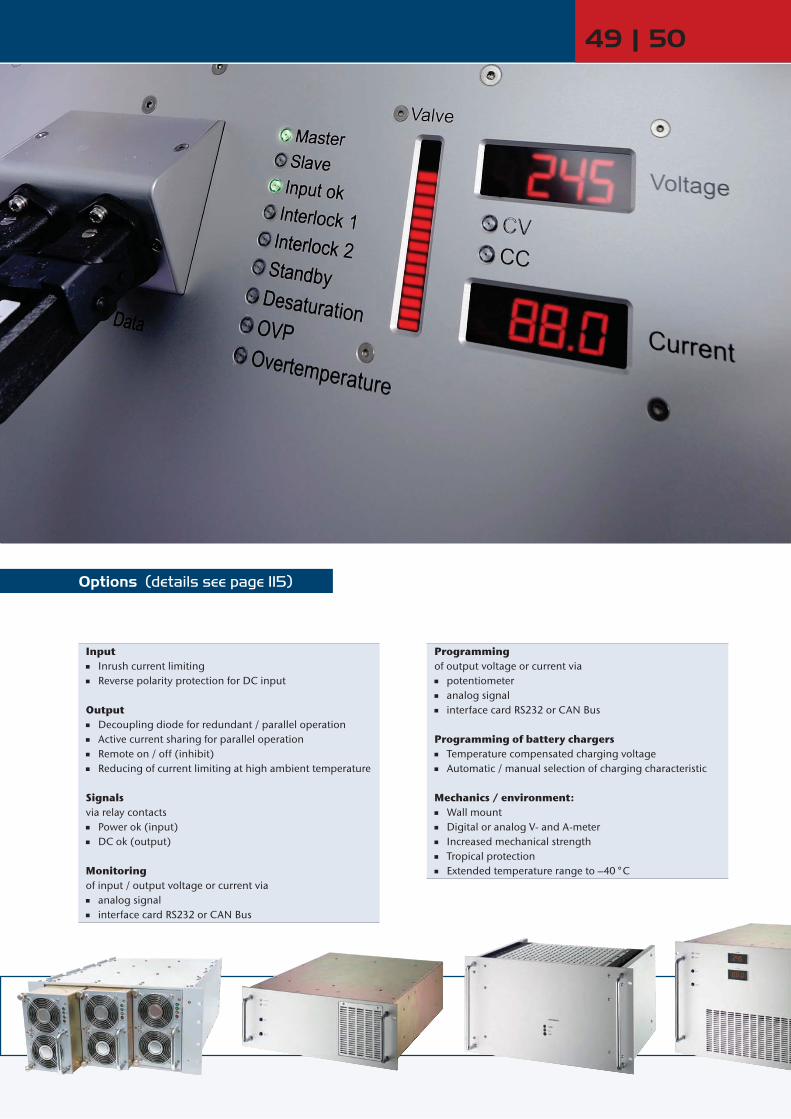
Options (details see page 115)
49 | 50
Input Inrush current limiting Reverse polarity protection for DC input
Output Decoupling diode for redundant / parallel operation Active current sharing for parallel operation Remote on / off (inhibit) Reducing of current limiting at high ambient temperature
Signalsvia relay contacts Power ok (input) DC ok (output)
Monitoringof input / output voltage or current via analog signal interface card RS232 or CAN Bus
Programmingof output voltage or current via potentiometer analog signal interface card RS232 or CAN Bus
Programming of battery chargers Temperature compensated charging voltage Automatic / manual selection of charging characteristic
Mechanics / environment: Wall mount Digital or analog V- and A-meter Increased mechanical strength Tropical protection Extended temperature range to –40 °C

www.schaeferpower.deHigh Power Converters from 5 to 40kW, switchmodeConverters from 5 to 40kW, switchmode
Selector Guide
High Power
Series Output Power DC input AC input[kW]
2 –
6 kW
6 –
8 kW
8 –
10 k
W
10 –
15
kW
15 –
30
kW
30 –
40
kW
[V]
80 -
160
V
160
- 320
V
320
- 380
V
320
- 640
V
450
- 800
V
1-phase 3-phase
C / B 5100 2.4 – 5 320 – 800C / B 5200 4 – 5 80 – 800C / B 5600 4.5 – 6 80 – 800C / B 5300 5.6 – 7.5 80 – 800C / B 5700 6.5 – 8 80 – 800C / B 5400 7.5 – 10 80 – 800C / B 5800 8.5 – 12 80 – 800C / B 6400 20 – 22 320 – 800C / B 6600 20 – 30 320 – 800
CW / BW 5300 5.6 – 8 80 – 800CW / BW 5400 5.6 – 10 320 – 800CW / BW 5500 7.5 – 15 80 – 800CW / BW 5600 9.1 – 20 320 – 800CW / BW 6600 24 – 30 320 – 800CW / BW 6700 20 – 40 320 – 800
Step-Up Converters 2.4 – 40 80 – 8001) value (adjustable) to be advised
Further Information
For example:1 input voltage = 160 - 320 VDC2 output voltage = 60 VDC @ 110 A 3 results in a C 5376 module.
Assistance in table use:1 Select the column for input voltage range.2 Select the row for the appropriate output voltage.3 The intersection of both results in the module required.
Order example Conversion table
Height: 1 U = 44.45 mm
1 U = 1.75“
Width: 1 TE = 5.08 mm
1 TE = 0.2“
1” = 25.4 mm
19” = 483 mm
Weight: 1 kg = 2.2 lbs 5.6 kW 7.5 kW
Input VDC Output VDC
80 –160 VDC
Output Amps
160 –320 VDC
320 – 380 1) VDC
320 – 640 VDC
450 – 800 VDC
Output Amps Adj. Range
C 5353C 5354C 5355C 5359C 5356C 5357C 5357 JC 5358C 5358 J
350216187102 83 43 28 22.5 14
C 5373C 5374C 5375C 5379C 5376C 5377C 5377 JC 5378C 5378 J
C 5383 ZC 5384 ZC 5385 ZC 5389 ZC 5386 ZC 5387 ZC 5387 ZJC 5388 ZC 5388 ZJ
C 5373 GC 5374 GC 5375 GC 5379 GC 5376 GC 5377 GC 5377 GJC 5378 GC 5378 GJ
C 5373 K C 5374 KC 5375 KC 5379 KC 5376 KC 5377 KC 5377 KJC 5378 KC 5378 KJ
350288250136110 58 38 30 19
15 24 28 48 60110200220400
14 – 16 23 – 26 26 – 30 45 – 55 58 – 68 100 – 130 190 – 200 200 – 250 380 – 400
C 5384 Z C 5374 G C 5374 K 288 24 23– 26C 5354 216
C 5389 Z C 5379 G C 5379 K 136 48 45– 55C 5359 102
C 5387 Z C 5377 G C 5377 K 58 110 100– 130C 5357 43
C 5388 Z C 5378 G C 5378 K 30 220 200– 250C 5358 22.5C 5378 J
C 5377 J
C
160–320 VDC
C 5373C 5374
9C
C 5377
C 5378
53755374
5379
1
C 5376 60 58– 68C 5386 Z C 5376 G C 5376 K 11C 5356 83 C 5376C 5376C 5376C 537658
3603 2
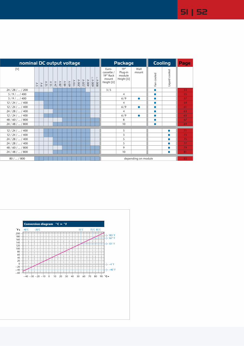
51 | 52
nominal DC output voltage Package Cooling Page[V]
5 V
9 V
12 V
15 V
24 V
28 V
48 V
60 V
110
V
200
V
220
V
400
V
600
V 1)
800
V 1)
Euro- cassette / 19” Rack mount
Height [U]
19” Plug-in module
Height [U]
Wall mount
Fan
cool
ed
Liq
uid
coo
led
24 / 28 / ... / 200 3 / 5 535 / 9 / ... / 400 4 555 / 9 / ... / 400 6 / 9 57
12 / 24 / ... / 400 4 5912 / 24 / ... / 400 6 / 9 6124 / 28 / ... / 400 4 6312 / 24 / ... / 400 6 / 9 6548 / 60 / ... / 800 8 6724 / 48 / ... / 800 10 69
12 / 24 / ... / 400 5 7112 / 24 / ... / 400 3 7324 / 28 / ... / 400 5 7524 / 28 / ... / 400 5 7748 / 60 / ... / 800 9 7924 / 48 / ... / 800 10 81
80 / ... / 800 depending on module 83
Conversion diagram °C °F
˚F - 40 C - 20 C 55 C 75 C 85 C
20018016014012010080604020
0– 20– 40– 60
– 40 – 30 – 20 – 10 0 10 20 30 40 50 60 70 80 90 ˚C
185˚F167˚F
131˚F
– 4˚F
– 40˚F

DC / DC ConvertersDC
inDCout
Battery ChargersACin
DCout
Battery
Series specific information
www.schaeferpower.de
AC / DC Power SuppliesACin
DCout
High Power
Battery ChargersACin
DCout
Battery
5 kW
Input VDCOutput Amps
Coo
ling Output VDC
320 – 380 1) VDC
320 – 640 VDC
450 – 800 VDC Adj. Range
C 5184 ZC 5185 ZC 5189 ZC 5186 ZC 5187 ZC 5187 ZJ
C 5174 GC 5175 GC 5179 GC 5176 GC 5177 GC 5177 GJ
C 5174 KC 5175 KC 5179 KC 5176 KC 5177 KC 5177 KJ
100100 91 74 39 25
24 28 48 60110200
23 – 26 26 – 30 45 – 55 58 – 68 100 – 130 190 – 200
5 kW
Input VAC, 3-PhaseOutput Amps
Coo
ling Output VDC
3x400 + 15 % – 20 % 3x480 + 10 %
– 15 % Adj. Range
C 5184 VC 5185 VC 5189 VC 5186 VC 5187 VC 5187 VJ
C 5194 VC 5195 VC 5199 VC 5196 VC 5197 VC 5197 VJ
100100 91 74 39 25
24 28 48 60110200
23 – 26 26 – 30 45 – 55 58 – 68 100 – 130 190 – 200
5 kW
Input VAC, 3-PhaseOutput Amps
Coo
ling Output VDC
3x400 + 15 % – 20 % 3x480 + 10 %
– 15 %
Nom. Battery Voltage
Range
B 5182 VB 5184 VB 5186 VB 5187 V
B 5192 VB 5194 VB 5196 VB 5197 V
100 80 62 34
24 48 60110
24 – 32 48 – 64 60 – 80 110 – 145
B 5184 V B 5194 V 80 48 48– 64
B 5187 V B 5197 V 34 110 110– 145
Series C / B 5100
C 5185 Z C 5175 G C 5175 K 100 28 26– 30
C 5186 Z C 5176 G C 5176 K 74 60 58– 68
C 5187 ZJ C 5177 GJ C 5177 KJ 25 200 190– 200
C 5185 V C 5195 V 100 28 26– 30
C 5186 V C 5196 V 74 60 58– 68
C 5187 VJ C 5197 VJ 25 200 190– 200
Input Hold-up time for AC input: 5ms typical @ nom. input voltage1) input supply from PFC also suitable
General optional: Cooling via speed-controlled fans (depending on temperature) optional: 19” sub-rack (3U or 5U) with terminals / bolts / bars
= incl. fans
High Power

5U
53 | 54
204 mm(40TE)
(3U
)12
7 m
m
538 mm
127 mm(25TE)
(5U
)20
4 m
m
538 mm
Pluggable module (for 3U sub-rack)
Standard
approx. 17 kg
3U, 19“ sub-rack with 2 modules
Pluggable module (for 5U sub-rack)
Standard
approx. 17 kg
5U, 19“ sub-rack with 3 modules
Optional
Optional


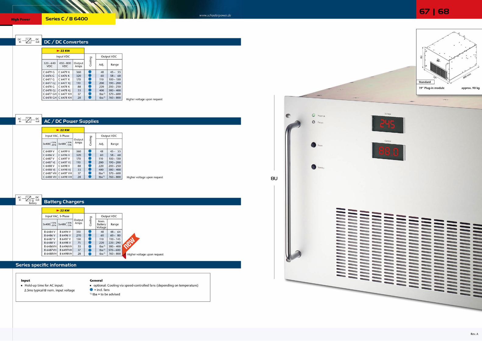


www.schaeferpower.deHigh Power Series E
Step-up converters
The step-up converters are very similar to the DC/DC converters of series “C”, except that the step-up converters sense the voltage across the load which is the total of the battery voltage and the voltage added by the step-up converter. The step-up converter can not reduce the voltage being applied to its input. Therefore, the load should be specified for the maximum battery voltage.
For output voltage stabilizationThe output voltage of an e.g. battery charger with parallel con-nected battery varies substantially with the charging condition of the battery. For many applications, however, the load circuit requires a better stabilized voltage. Frequently used methods for reducing the voltage variation are e.g. “voltage dropping diodes”. A more economical solution is given by switch mode step-up converters. These are DC/DC converters supplied from the battery with the output connected in series to the battery. Due to the circuit configuration, the output of a step-up converter is not isolated from the input supply (battery).
Circuit diagrams
Step-up converter with common positive line Step-up converter with common negative line
The following circuit diagram shows a step-up converter which can be grounded on the positive side. The voltage will be added at the negative side and the positive line is common for input and output.
The following circuit diagram shows a step-up converter which can be grounded on the negative side. The voltage will be added at the positive side and the negative line is common for input and output.
Parallel operation of step-up converters Individual load supply
For more power or redundancy step-up converters may be connected in parallel with active current sharing, individually protected by fuses at the input and decoupling diodes or fuses at the output. Such systems have already been realized for 2,000 Amps.
For applications that require individually stabilized voltages across the loads, the step-converters will be connected as shown in the following diagram and may be of different power ratings.
stan
dard
ver
sion
optio
nal v
ersi
on
batterycharger
+
-
step-up converter (long) cable to load
+
-
sense leadsload
+
-
step-up converter
-+
sense leads
load
=
=
=
batterycharger
batterycharger
=
+
-
=
=
=
=
step-up converters
load
sense leadscurrentsharing signal
batterycharger
=
+
-
= =
==
step-up converters
sense leads sense leads
loads
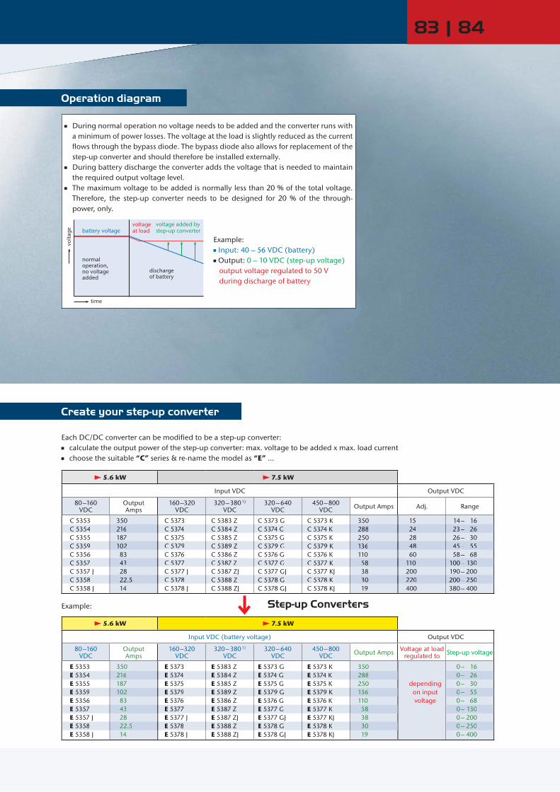
Operation diagram
During normal operation no voltage needs to be added and the converter runs with a minimum of power losses. The voltage at the load is slightly reduced as the current flows through the bypass diode. The bypass diode also allows for replacement of the step-up converter and should therefore be installed externally.
During battery discharge the converter adds the voltage that is needed to maintain the required output voltage level.
The maximum voltage to be added is normally less than 20 % of the total voltage. Therefore, the step-up converter needs to be designed for 20 % of the through-power, only.
battery voltagevoltage at load
discharge
time
volta
ge
voltage added bystep-up converter
normaloperation, no voltageadded of battery
Example: Input: 40 – 56 VDC (battery) Output: 0 – 10 VDC (step-up voltage) output voltage regulated to 50 V during discharge of battery
83 | 84
Create your step-up converter
Step-up Converters
Each DC/DC converter can be modified to be a step-up converter: calculate the output power of the step-up converter: max. voltage to be added x max. load current choose the suitable “C” series & re-name the model as “E” …
5.6 kW 7.5 kW
Input VDC Output VDC
80 –160 VDC
Output Amps
160 –320 VDC
320 – 380 1) VDC
320 – 640 VDC
450 – 800 VDC Output Amps Adj. Range
C 5353C 5354C 5355C 5359C 5356C 5357C 5357 JC 5358C 5358 J
350216187102 83 43 28 22.5 14
C 5373C 5374C 5375C 5379C 5376C 5377C 5377 JC 5378C 5378 J
C 5383 ZC 5384 ZC 5385 ZC 5389 ZC 5386 ZC 5387 ZC 5387 ZJC 5388 ZC 5388 ZJ
C 5373 GC 5374 GC 5375 GC 5379 GC 5376 GC 5377 GC 5377 GJC 5378 GC 5378 GJ
C 5373 K C 5374 KC 5375 KC 5379 KC 5376 KC 5377 KC 5377 KJC 5378 KC 5378 KJ
350288250136110 58 38 30 19
15 24 28 48 60110200220400
14 – 16 23 – 26 26 – 30 45 – 55 58 – 68 100 – 130 190 – 200 200 – 250 380 – 400
5.6 kW 7.5 kW
Input VDC (battery voltage) Output VDC
80 –160 VDC
Output Amps
160 –320 VDC
320 – 380 1) VDC
320 – 640 VDC
450 – 800 VDC Output Amps Voltage at load
regulated to Step-up voltage
E 5353E 5354E 5355E 5359E 5356E 5357E 5357 JE 5358E 5358 J
350216187102 83 43 28 22.5 14
E 5373E 5374E 5375E 5379E 5376E 5377E 5377 JE 5378E 5378 J
E 5383 ZE 5384 ZE 5385 ZE 5389 ZE 5386 ZE 5387 ZE 5387 ZJE 5388 ZE 5388 ZJ
E 5373 GE 5374 GE 5375 GE 5379 GE 5376 GE 5377 GE 5377 GJE 5378 GE 5378 GJ
E 5373 K E 5374 KE 5375 KE 5379 KE 5376 KE 5377 KE 5377 KJE 5378 KE 5378 KJ
350288250136110 58 38 30 19
depending on input voltage
0 – 16 0 – 26 0 – 30 0 – 55 0 – 68 0 – 130 0 – 200 0 – 250 0 – 400
C 5354 216 C 5374 C 5384 Z C 5374 G C 5374 K 288 24 23– 26
C 5359 102 C 5379 C 5389 Z C 5379 G C 5379 K 136 48 45– 55
C 5357 43 C 5377 C 5387 Z C 5377 G C 5377 K 58 110 100– 130
C 5358 22.5 C 5378 C 5388 Z C 5378 G C 5378 K 30 220 200– 250
E 5354 216 E 5374 E 5384 Z E 5374 G E 5374 K 288
E 5359 102 E 5379 E 5389 Z E 5379 G E 5379 K 136
E 5357 43 E 5377 E 5387 Z E 5377 G E 5377 K 58
E 5358 22.5 E 5378 E 5388 Z E 5378 G E 5378 K 30
0– 26
0– 55
0– 130
0– 250
Example:

www.schaeferpower.de Inverters 1 or 3-Phase Output from 200VA to 45kVA, switchmode
DC / AC Inverters, AC / AC Frequency Converters & Static Switches
Sine Wave Continuous short circuit protection Thermal shutdown with auto-restart for 1-phase inverters >1.2kVA 3-phase inverters >3.6kVA Suitable for complex load Surge power capability Industrial grade components Compact and robust design 3-phase output: Unsymmetrical load permissible, modular system with interchangeable inverters
Input voltage: 10-800V DC or 115/ 230V AC, single phase, 47-400Hz or 200/ 400/ 480V AC, three phase, 47-400Hz Output voltage: 115/ 230 V AC, single phase or 200/ 400/ 480V AC, three phases Output frequency: 50/ 60/ 400/ 800Hz (crystal stabilized) or programmable within 40-400Hz or 400-800Hz Output power: 200VA - 45kVA
Features
Specifications
ACor
DCAC
Input
Voltage range unit switches off at under- and overvoltage
No-load input power 10 – 30 W Inrush current for AC input and DC input >160V:
limited by thermistor Hold-up time AC input: 10 ms typical
Series CI: 20ms typical Immunity acc. to EN 61000-6-2
General
Efficiency 80 – 92 % Operating temperature – 20 to + 75°C
optional: -40 to +75°C Load derating 2.5%/°C above + 55°C
Storage temperature -40 to + 85°C Cooling (details see page 131)
= natural convection = incl. temperature controlled fans
Humidity up to 95 % RH, non-condensing Safety / Construction acc. to EN 60950-1 / EN 50178 Protection category IP20 acc. to EN 60529,
NEMA or others upon request EMI acc. to EN 61000-6-4,
class A, optionally class B MTBF @40°C acc. to MIL -HDBK-217E (notice1)
series IT: 120.000h
series CI: 70.000h
series IV: 50.000h
Output
Output voltages
115V AC 230V AC3x200VAC 3x400VAC 3x480VAC
or any other Output power from 200 VA up to 45k VA Line regulation (±10%) 0.1 % for series CI,
2 % for series IT and IV3 % for series IT and IV @ 400Hz
Load regulation (10-90%) 1 % typical, 3 % max.(400 Hz: 3 % typical, 5 % max.)
Turn-on rise time soft-start, 100ms typical Waveform sine wave or any wave shape pro-
grammable by external signal
Frequency 40 – 800 Hz: adjustable orprogrammable or any fixed frequency (crystal stabilized)
Distortion 3 % typical, 5 % @ 400 Hz,7 % @ 40 – 400 Hz, 800Hz
Overload protection (steady state)
current limited to approx. 1.05 x nominal current
Surge power 2 x nominal power for 1 s Short circuit protection electronically limited to 3 x no-
minal current, unit switches off after 1 s
Crest factor approx. 3 Power factor cos 0.7 inductive / capacitive
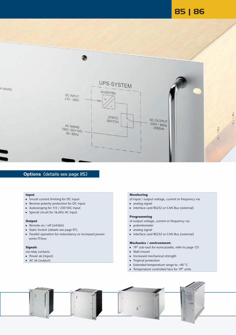
85 | 86
Options (details see page 115)
Input Inrush current limiting for DC input Reverse polarity protection for DC input Autoranging for 115 / 230 VAC input Special circuit for 16.6Hz AC input
Output Remote on / off (inhibit) Static Switch (details see page 97) Parallel operation for redundancy or increased power: series IT5xxx
Signalsvia relay contacts Power ok (input) AC ok (output)
Monitoringof input / output voltage, current or frequency via analog signal interface card RS232 or CAN Bus (external)
Programming of output voltage, current or frequency via potentiometer analog signal interface card RS232 or CAN Bus (external)
Mechanics / environment: 19” sub-rack for eurocassette, refer to page 121 Wall mount Increased mechanical strength Tropical protection Extended temperature range to –40 °C Temperature controlled fans for 19” units

www.schaeferpower.de1 or 3-Phase Output from 200VA to 45kVA, switchmode Inverters
Series IT - Inverters with 1-phase output from 200 VA to 15 kVA Page 89
DC/AC Invertersis a combination of a switch mode Inverter and a Transformer at the output. The transformer provides the isolation between input and output and transforms the voltage to the required level.
AC outputDC input
Inverter Transformer
AC/AC Frequency Converters
is a combination of a switch mode Inverter with a rectifier at the input and a Transformer at the output. The transformer provides the isolation between input and output and transforms the voltage to the required level.
AC outputAC input
Inverter Transformer
For lower input voltages the CI version is more compact than the IT version.
Series CI - Inverters with 1-phase output from 400 VA to 3.5 kVA Page 91
DC/AC Invertersis a combination of a switch mode Converter and Inverter. The converter provides the isolation between input and output and transforms the voltage to the level needed by the inverter for supplying the specified AC output voltage.
AC outputDC input
Converter Inverter
AC/AC Frequency Convertersis a combination of a switch mode Converter and Inverter. The converter provides the isolation between input and output and transforms the voltage to the level needed by the inverter for supplying the specified AC output voltage.
AC outputAC input
Converter Inverter
Series IV - Inverters with 3-phase output from 600VA to 45 kVA Page 93
DC/AC or AC/AC
AC output
DC orAC input
3 x Inverter
3-phase
3 x Transformer
is a combination of 3 individual switch mode inverters with output transformers synchronized for a symmetrical 3-phase output. The transformers provide the isolation between input and output and transform the voltages to the required levels.
Series SS from 800 VA to 10 kVA Page 97
Static SwitchesThe Static Switch has two inputs for load supply, a priority and a non-priority input, and synchronizes the frequency of one supply to the other. Typically, but not exclusively, supplied by Mains & an Inverter, there are 3 modes of operation:1. Service mode Mains - mains is selected as the load provider.2. Service mode Inverter - inverter is selected as the load provider.3. Automated function with priority selection.
AC output
AC supply 1
AC supply 2 static switch
1-phase
Series U from 1 to 2.5 kVA Page 99
UPS Systems with Static Switchprovides uninterrupted AC power to a critical load by connecting the load to AC supply 1 which can be the inverter output or to AC supply 2 which can be the mains. Series U does not include the batteries. The batteries can be specified and both, batteries and charger can be added to the system. =
AC mainsStatic Switch Bypass Switch
AC output
(Load)
Inverter
Battery
Connectors for Series CI, IT, IV & SS Page 132
Mechanics Series CI Series IT Series IV Series SS Series UEurocassette H15 & high currrent connector for I >50 A H15 and F24H7 -- H15 and F48 --Wall mount or 19“ unit Terminals Terminals Terminals Terminals Terminals

87 | 88

www.schaeferpower.de
Frequency Designation
DC / AC Inverters with 1-phase output from 200VA to 15kVAAC outputDC input
Inverter Transformer
AC / AC Frequency Converters with 1-phase output from 500VA to 15kVA
Inverters Inverters
AC outputAC input
Inverter Transformer
Series IT Switch mode inverter and transformer
.1
.2
.3
.4
.41
.5
.51
.6
.61
.7
.8
40 - 400 Hz adjustable / programmable45 - 65 Hz adjustable / programmableany fixed frequency between 40 - 400 Hz400 Hzsynchronized with 400 Hz mains50 Hzsynchronized with 50 Hz mains60 Hzsynchronized with 60 Hz mains50/60 Hz switchable800 Hz
Input VDC
Coo
ling
OutputVAC20 –32
VDCOutput
kVA Size 40 – 64 VDC
50 –80 VDC
Output kVA Size 80 – 160
VDCOutput
kVA Size 160 – 320 VDC
340 –400 VDC
340 – 640 1) VDC
450 –800 1) VDC
Output kVA Size
IT 1626 0.2 A IT 1636IT 3636
IT 4836
IT 5636IT 5736
IT 1646IT 3646
IT 4846
IT 5646IT 5746
0.40.5
1.2
23
AB
D
EE
IT 1656IT 3656IT 3856IT 4856
IT 5656IT 5756
0.511.22
35
ABCD
EF + T1
IT 1676IT 3676IT 3876IT 4876
IT 5676IT 5776 IT 5876IT 5976
IT 1686 ZIT 3686 ZIT 3886 ZIT 4886 Z
IT 5686 ZIT 5786 ZIT 5886 ZIT 5986 Z
IT 3676 GIT 3876 G
IT 4876 GIT 5676 GIT 5776 GIT 5876 GIT 5976 G
IT 3876 K
IT 4876 KIT 5676 KIT 5776 KIT 5876 KIT 5976 K
0.5 1 1.6 2.5 2.5 5 81015
ABCDD
F + T1F + T2F + T3F + T4
115
IT 1628 0.2 A IT 1638IT 3638
IT 4838
IT 5638IT 5738
IT 1648IT 3648
IT 4848
IT 5648IT 5748
0.40.5
1.2
23
AB
D
EE
IT 1658IT 3658IT 3858IT 4858
IT 5658IT 5758
0.511.22
35
ABCD
EF + T1
IT 1678IT 3678IT 3878IT 4878
IT 5678IT 5778IT 5878IT 5978
IT 1688 ZIT 3688 ZIT 3888 ZIT 4888 Z
IT 5688 ZIT 5788 ZIT 5888 ZIT 5988 Z
IT 3678 GIT 3878 G
IT 4878 GIT 5678 GIT 5778 GIT 5878 GIT 5978 G
IT 3878 K
IT 4878 KIT 5678 KIT 5778 KIT 5878 KIT 5978 K
0.5 1 1.6 2.5 2.5 5 81015
ABCDD
F + T1F + T2F + T3F + T4
230
= natural convection = incl. temperature controlled fans 1) standard version: wall mount
IT 3636 IT 3646 0.5 B IT 3656 1 B IT 3676 IT 3686 Z IT 3676 G 1 B
IT 4836 IT 4846 1.2 D IT 4856 2 D IT 4876 IT 4886 Z 2.5 D
IT 5636 IT 5646 2 E IT 5656 3 E IT 5676 IT 5686 Z IT 5676 G IT 5676 K 5 F+T1
IT 5876 IT 5886 Z IT 5876 G IT 5876 K 10 F+T3
IT 1638 IT 1648 0.4 A IT 1658 0.5 A IT 1678 IT 1688 Z 0.5 A
IT 3858 1.2 C IT 3878 IT 3888 Z IT 3878 G IT 3878 K 1.6 C
IT 4878 G IT 4878 K 2.5 D
IT 5738 IT 5748 3 E IT 5758 5 F+T1 IT 5778 IT 5788 Z IT 5778 G IT 5778 K 8 F+T2
IT 5978 IT 5988 Z IT 5978 G IT 5978 K 15 F+T4
Input VAC1-Phase Output
kVA Size
Input VAC1-Phase
Input VAC3-Phase Output
kVA Size
Coo
ling
OutputVAC
115 ± 20 % 230 + 15 % – 20 % 3x200 + 15 %
– 20 % 3x400 + 15 % – 20 % 3x480 + 10 %
– 15 %
IT 1666IT 3666IT 3866IT 4866IT 5666IT 5766
0.511.2235
ABCDE
F + T1
IT 1686IT 3686IT 3886IT 4886IT 5686IT 5786
IT 1666 VIT 3666 VIT 3866 VIT 4866 VIT 5666 VIT 5766 V
IT 3686 VIT 3886 VIT 4886 VIT 5686 VIT 5786 VIT 5886 VIT 5986 V
IT 3896 VIT 4896 VIT 5696 VIT 5796 VIT 5896 VIT 5996 V
0.5 1 1.6 2.5 5 81215
ABCD
F + T1F + T2F + T3F + T4
115
IT 1668IT 3668IT 3868IT 4868IT 5668IT 5768
0.511.2235
ABCDE
F + T1
IT 1688IT 3688IT 3888IT 4888IT 5688IT 5788
IT 1668 VIT 3668 VIT 3868 VIT 4868 VIT 5668 VIT 5768 V
IT 3688 VIT 3888 VIT 4888 VIT 5688 VIT 5788 VIT 5888 VIT 5988 V
IT 3898 VIT 4898 VIT 5698 VIT 5798 VIT 5898 VIT 5998 V
0.5 1 1.6 2.5 5 81215
ABCD
F + T1F + T2F + T3F + T4
230
IT 3666 1 B IT 3686 IT 3666 V IT 3686 V 1 B
IT 4866 2 D IT 4886 IT 4866 V IT 4886 V IT 4896 V 2.5 D
IT 5766 5 F+T1 IT 5786 IT 5766 V IT 5786 V IT 5796 V 8 F+T2
IT 5986 V IT 5996 V 15 F+T4
IT 3668 1 B IT 3688 IT 3668 V IT 3688 V 1 B
IT 4868 2 D IT 4888 IT 4868 V IT 4888 V IT 4898 V 2.5 D
IT 5768 5 F+T1 IT 5788 IT 5768 V IT 5788 V IT 5798 V 8 F+T2
IT 5988 V IT 5998 V 15 F+T4
= natural convection
= incl. temperature controlled fans

89 | 90
Eurocassette / approx. 9 kg Wall mount / approx. 11 kg Eurocassette / approx. 11 - 13 kg Wall mount / approx. 13 - 15 kg
42TE
6U
166.5 mm
220 mm
360
mm
168 mm
42TE
6U
226 mm
220 mm
360
mm
229 mm
Eurocassette / approx. 16 - 18 kg Wall mount / approx. 19 - 21 kg Eurocassette / approx. 18 - 24 kg Wall mount / approx. 21 - 27 kg
56TE
6U
306 mm
280 mm
360
mm
309 mm
19“ Plug-in module / approx. 46 - 50 kg Wall mount / approx. 54 - 58 kg 19“ Plug-in module / approx. 32 kg Wall mount / approx. 36 kg
19"
6U
460 mm
500 mm
600
mm
310 mm
19"
6U
360 mm
500 mm
400
mm
310 mm
Wall mount version
W
H
D
Trans - former
H W D Weightin kgin mm
T1T2T3T4
390450450500
240280280320
233253283280
335066110
Trans - former
H W D Weightin kgin mm
T1 335 230 210 33
Size A Size B
Size C Size D
Size E Size F
Transformers refer to 50/60 Hz.Other frequencies or tropical insulation may change size and weight.
Transformers refer to 50/60 Hz.Other frequencies or tropical insulation may change size and weight.
56TE
6U
306 mm
280 mm
360
mm
309 mm
Standing version
W
H
D Size T1 - T4 Size T1
19“, 3U Plug-in module
3HE
19"
362mm
19“, 3U high packages: available for series IT16xx up to IT36xx.
= incl. temperature controlled fans
Optional
Standard Optional Standard Optional
Standard Optional Standard Optional
Standard Optional Standard Optional
Size L
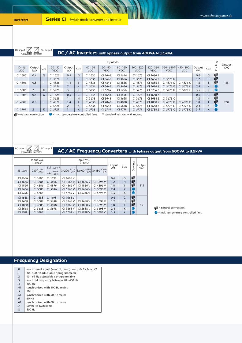
www.schaeferpower.de
Frequency Designation
Inverters Inverters Series CI Switch mode converter and inverter
DC / AC Inverters with 1-phase output from 400VA to 3.5kVA
AC / AC Frequency Converters with 1-phase output from 600VA to 3.5kVAAC outputAC input
Converter Inverter
AC outputDC input
Converter Inverter
Input VDC
Coo
ling
OutputVAC10 –16
VDCOutput
kVA Size 20 – 32 VDC
Output kVA Size 40 – 64
VDC50 – 80 VDC
80 –160 VDC
160 – 320 VDC
320 –380 VDC
320 –640 1) VDC
450 –800 1) VDC
Output kVA Size
CI 1606
CI 4806
CI 5706
0.4
0.8
2
G
I
K
CI 1626CI 3626CI 4826 CI 5626CI 5726
0.511.423
GHIKK
CI 1636CI 3636CI 4836 CI 5636CI 5736
CI 1646CI 3646CI 4846 CI 5646CI 5746
CI 1656CI 3656CI 4856 CI 5656CI 5756
CI 1676CI 3676CI 4876 CI 5676CI 5776
CI 1686 ZCI 3686 ZCI 4886 Z CI 5686 ZCI 5786 Z
CI 3676 GCI 4876 G CI 5676 GCI 5776 G
CI 4876 K CI 5676 KCI 5776 K
0.6 1.2 1.8 2.4 3.5
GHIKK
115
CI 1608
CI 4808
CI 5708
0.4
0.8
2
G
I
K
CI 1628CI 3628CI 4828 CI 5628CI 5728
0.511.423
GHIKK
CI 1638CI 3638CI 4838 CI 5638CI 5738
CI 1648CI 3648CI 4848 CI 5648CI 5748
CI 1658CI 3658CI 4858 CI 5658CI 5758
CI 1678CI 3678CI 4878 CI 5678CI 5778
CI 1688 ZCI 3688 ZCI 4888 Z CI 5688 ZCI 5788 Z
CI 3678 GCI 4878 G CI 5678 GCI 5778 G
CI 4878 K CI 5678 KCI 5778 K
0.6 1.2 1.8 2.4 3.5
GHIKK
230
= natural convection = incl. temperature controlled fans 1) standard version: wall mount
CI 3626 1 H CI 3636 CI 3646 CI 3656 CI 3676 CI 3686 Z CI 3676 G 1.2 H
CI 5626 2 K CI 5636 CI 5646 CI 5656 CI 5676 CI 5686 Z CI 5676 G CI 5676 K 2.4 K
CI 4808 0.8 I CI 4828 1.4 I CI 4838 CI 4848 CI 4858 CI 4878 CI 4888 Z CI 4878 G CI 4878 K 1.8 I
CI 5708 2 K CI 5728 3 K CI 5738 CI 5748 CI 5758 CI 5778 CI 5788 Z CI 5778 G CI 5778 K 3.5 K
Input VAC1-Phase
Input VAC3-Phase
Output kVA Size
Coo
ling
OutputVAC
115 ± 20 % 230 + 15 % – 20 %
115 ± 20 % /
230 + 15 % – 20 %
3x200 + 15 % – 20 % 3x400 + 15 %
– 20 % 3x480 + 10 % – 15 %
CI 1666CI 3666CI 4866CI 5666CI 5766
CI 1686CI 3686CI 4886CI 5686CI 5786
CI 1696CI 3696CI 4896CI 5696
CI 1666 VCI 3666 VCI 4866 VCI 5666 VCI 5766 V
CI 3686 VCI 4886 VCI 5686 VCI 5786 V
CI 3696 VCI 4896 VCI 5696 VCI 5796 V
0.6 1.2 1.8 2.4 3.5
GHIKK
115
CI 1668CI 3668CI 4868CI 5668CI 5768
CI 1688CI 3688CI 4888CI 5688CI 5788
CI 1698CI 3698CI 4898CI 5698
CI 1668 VCI 3668 VCI 4868 VCI 5668 VCI 5768 V
CI 3688 VCI 4888 VCI 5688 VCI 5788 V
CI 3698 VCI 4898 VCI 5698 VCI 5798 V
0.6 1.2 1.8 2.4 3.5
GHIKK
230
CI 3666 CI 3686 CI 3696 CI 3666 V CI 3686 V CI 3696 V 1.2 H
CI 5666 CI 5686 CI 5696 CI 5666 V CI 5686 V CI 5696 V 2.4 K
CI 1668 CI 1688 CI 1698 CI 1668 V 0.6 G
CI 4868 CI 4888 CI 4898 CI 4868 V CI 4888 V CI 4898 V 1.8 I
CI 5768 CI 5788 CI 5768 V CI 5788 V CI 5798 V 3.5 K
= natural convection
= incl. temperature controlled fans
.0
.1
.2
.3
.4
.41
.5
.51
.6
.61
.7
.8
any external signal (control, ramp) ––> only for Series CI40 - 400 Hz adjustable / programmable45 - 65 Hz adjustable / programmableany fixed frequency between 40 - 400 Hz400 Hzsynchronized with 400 Hz mains50 Hzsynchronized with 50 Hz mains60 Hzsynchronized with 60 Hz mains50/60 Hz switchable800 Hz
CI 1608 0.4 G CI 1628 0.5 G CI 1638 CI 1648 CI 1658 CI 1678 CI 1688 Z 0.6 G

Eurocassette / approx. 6 kg Wall mount / approx. 8 kg Eurocassette / approx. 10 kg Wall mount / approx. 12 kg
Eurocassette / approx. 18 kg Wall mount / approx. 21 kg 19“ Plug-in module / approx. 28-32 kg*) less depth upon request
Wall mount / approx. 34-38 kg**) applicable for CI 5706, 5708 5726 and 5728
42TE
6U
166.5 mm
220 mm
360
mm
168 mm
42TE
6U
226 mm
220 mm
360
mm
229 mm
56TE
6U
306 mm
280 mm
360
mm
309 mm
19"
6U
460 mm*
500 mm
400
mm
600
mm
**
310 mm
Size G Size H
Size I Size K
91 | 92
Size M
19“, 2U Plug-in module
2HE
19"
362mm
Optional
Standard Optional Standard Optional
Standard Optional Standard Optional
19“, 2U high packages: available for series CI16xx.
= incl. temperature controlled fans
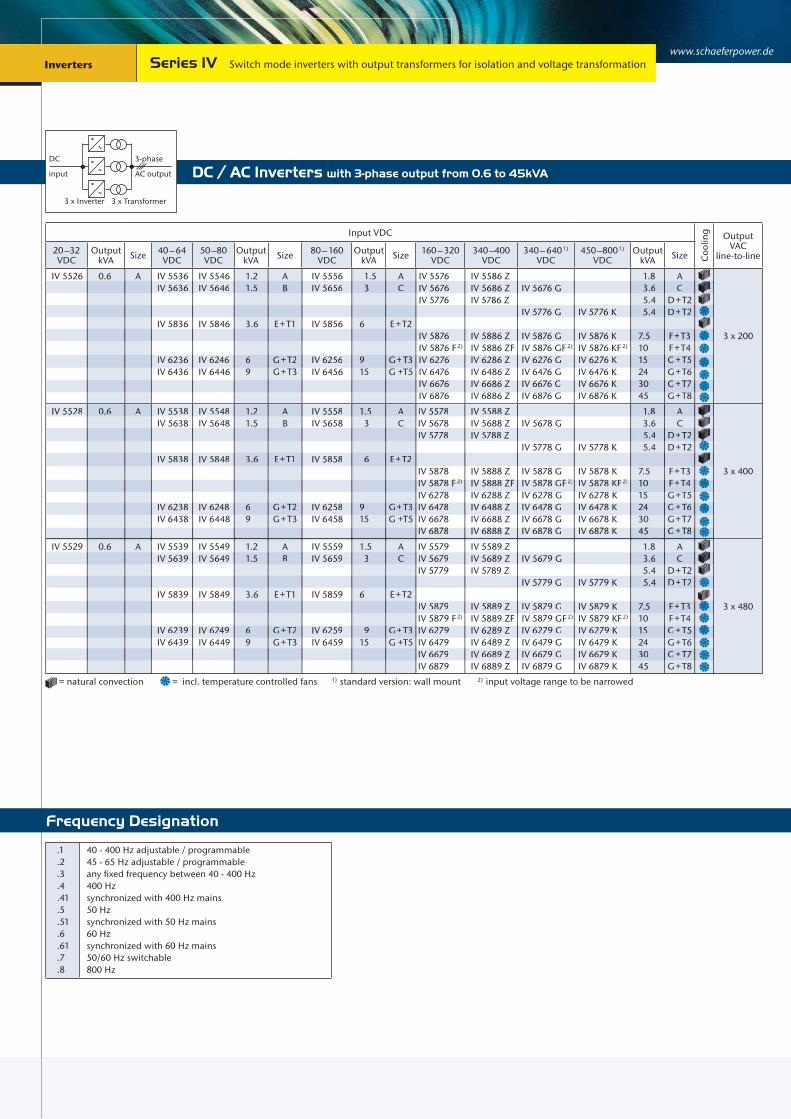
www.schaeferpower.de Inverters
Frequency Designation
Inverters
.1
.2
.3
.4
.41
.5
.51
.6
.61
.7
.8
40 - 400 Hz adjustable / programmable45 - 65 Hz adjustable / programmableany fixed frequency between 40 - 400 Hz400 Hzsynchronized with 400 Hz mains50 Hzsynchronized with 50 Hz mains60 Hzsynchronized with 60 Hz mains50/60 Hz switchable800 Hz
Series IV Switch mode inverters with output transformers for isolation and voltage transformation
Input VDC
Coo
ling Output
VACline-to-line20 –32
VDCOutput
kVA Size 40 – 64 VDC
50 –80 VDC
Output kVA Size 80 – 160
VDCOutput
kVA Size 160 – 320 VDC
340 –400 VDC
340 – 640 1) VDC
450 –800 1) VDC
Output kVA Size
IV 5526 0.6 A IV 5536IV 5636
IV 5836
IV 6236IV 6436
IV 5546IV 5646
IV 5846
IV 6246IV 6446
1.21.5
3.6
69
AB
E + T1
G + T2G + T3
IV 5556IV 5656
IV 5856
IV 6256IV 6456
1.5 3
6
915
AC
E + T2
G + T3G +T5
IV 5576IV 5676IV 5776
IV 5876IV 5876 F 2)
IV 6276IV 6476IV 6676IV 6876
IV 5586 ZIV 5686 ZIV 5786 Z
IV 5886 ZIV 5886 ZFIV 6286 ZIV 6486 ZIV 6686 ZIV 6886 Z
IV 5676 G
IV 5776 G
IV 5876 GIV 5876 GF 2)
IV 6276 GIV 6476 GIV 6676 GIV 6876 G
IV 5776 K
IV 5876 KIV 5876 KF 2)
IV 6276 KIV 6476 KIV 6676 KIV 6876 K
1.8 3.6 5.4 5.4
7.51015243045
AC
D + T2D + T2
F + T3 F + T4G + T5G + T6G + T7G + T8
3 x 200
IV 5528 0.6 A IV 5538IV 5638
IV 5838
IV 6238IV 6438
IV 5548IV 5648
IV 5848
IV 6248IV 6448
1.21.5
3.6
69
AB
E + T1
G + T2G + T3
IV 5558IV 5658
IV 5858
IV 6258IV 6458
1.5 3
6
915
AC
E + T2
G + T3G +T5
IV 5578IV 5678IV 5778
IV 5878IV 5878 F 2)
IV 6278IV 6478IV 6678IV 6878
IV 5588 ZIV 5688 ZIV 5788 Z
IV 5888 ZIV 5888 ZFIV 6288 ZIV 6488 ZIV 6688 ZIV 6888 Z
IV 5678 G
IV 5778 G
IV 5878 GIV 5878 GF 2)
IV 6278 GIV 6478 GIV 6678 GIV 6878 G
IV 5778 K
IV 5878 KIV 5878 KF 2)
IV 6278 KIV 6478 KIV 6678 KIV 6878 K
1.8 3.6 5.4 5.4
7.51015243045
AC
D + T2D + T2
F + T3F + T4G + T5G + T6G + T7G + T8
3 x 400
IV 5529 0.6 A IV 5539IV 5639
IV 5839
IV 6239IV 6439
IV 5549IV 5649
IV 5849
IV 6249IV 6449
1.21.5
3.6
69
AB
E + T1
G + T2G + T3
IV 5559IV 5659
IV 5859
IV 6259IV 6459
1.5 3
6
915
AC
E + T2
G + T3G +T5
IV 5579IV 5679IV 5779
IV 5879IV 5879 F 2)
IV 6279IV 6479IV 6679IV 6879
IV 5589 ZIV 5689 ZIV 5789 Z
IV 5889 ZIV 5889 ZFIV 6289 ZIV 6489 ZIV 6689 ZIV 6889 Z
IV 5679 G
IV 5779 G
IV 5879 GIV 5879 GF 2)
IV 6279 GIV 6479 GIV 6679 GIV 6879 G
IV 5779 K
IV 5879 KIV 5879 KF 2)
IV 6279 KIV 6479 KIV 6679 KIV 6879 K
1.8 3.6 5.4 5.4
7.51015243045
AC
D + T2D + T2
F + T3F + T4G + T5G + T6G + T7G + T8
3 x 480
= natural convection = incl. temperature controlled fans 1) standard version: wall mount 2) input voltage range to be narrowed
IV 5636 IV 5646 1.5 B IV 5656 3 C IV 5676 IV 5686 Z IV 5676 G 3.6 C
IV 5776 G IV 5776 K 5.4 D+T2
IV 5876 IV 5886 Z IV 5876 G IV 5876 K 7.5 F+T3
IV 6236 IV 6246 6 G+T2 IV 6256 9 G+T3 IV 6276 IV 6286 Z IV 6276 G IV 6276 K 15 G+T5
IV 6676 IV 6686 Z IV 6676 G IV 6676 K 30 G+T7
IV 5528 0.6 A IV 5538 IV 5548 1.2 A IV 5558 1.5 A IV 5578 IV 5588 Z 1.8 A
IV 5778 IV 5788 Z 5.4 D+T2
IV 5838 IV 5848 3.6 E+T1 IV 5858 6 E+T2
IV 5878 F 2)
IV 6278IV 5888 ZFIV 6288 Z
IV 5878 GF 2)
IV 6278 GIV 5878 KF 2)
IV 6278 K1015
F+T4G T5
IV 6878 IV 6888 Z IV 6878 G IV 6878 K 45 G+T8
IV 5779 G IV 5779 K 5.4 D+T2
IV 5879 IV 5889 Z IV 5879 G IV 5879 K 7.5 F+T3
IV 6239 IV 6249 6 G+T2 IV 6259 9 G+T3 IV 6279 IV 6289 Z IV 6279 G IV 6279 K 15 G+T5
IV 6679 IV 6689 Z IV 6679 G IV 6679 K 30 G+T7
IV 5639 IV 5649 1.5 B IV 5659 3 C IV 5679 IV 5689 Z IV 5679 G 3.6 C
AC output
DC
3 x Inverter
3-phase
3 x Transformer
input DC / AC Inverters with 3-phase output from 0.6 to 45kVA
IV 6238 IV 6248 6 G+T2 IV 6258 9 G+T3 IV 6478 IV 6488 Z IV 6478 G IV 6478 K 24 G+T6

93 | 94
19“ sub-rack / approx. 22-27 kg *) with wall plate / approx. 26-31 kg *) 19“ sub-rack / approx. 33 kg *) with wall plate / approx. 38 kg *)
19"
6U
350 mm
500 mm
400
mm
310 mm
19"
6U
406 mm
500 mm
600
mm
330 mm
19“ Plug-in module / approx. 32 kg with wall plate / approx. 36 kg
19"
6U
360 mm
500 mm
400
mm
310 mm
approx. 23 kg / 3.4 kVA
Size A Size B
Size G
Size T1 - T3 Size T4
19"
6U
360 mm
500 mm
600
mm
330 mm
Size C Size D
19"
6U
510 mm
500 mm
600
mm
330 mm
19“ sub-rack / approx. 40 kg *) with wall plate / approx. 45 kg *) 19“ sub-rack / approx. 24 kg **) with wall plate / approx. 65 kg *)
W
H
D Size T5 - T8
Trans - former
H W D Weightin kg
Powerin kVAin mm
T5T6T7T8
390450450500
240280280320
233253283280
335066110
5 81215
Transformers refer to 50/60 Hz at the output.Other frequencies or tropical insulation may change size and weight.Attention: For 3-phase system 3 transformers are required.
Wall mount version
W
H
D
Size T5
Trans - former
H W D Weightin kg
Powerin kVAin mm
T5 335 230 210 33 5
Transformers refer to 50/60 Hz at the output.Other frequencies or tropical insulation may change size and weight.Attention: For 3-phase system 3 transformers are required.
standing version
Trans - former
Ø H Weightin kg
Powerin kVAin mm
T1T2T3
190205243
758585
8.61215
1.423
Transformers refer to 50/60 Hz at the output.Other frequencies or tropical insulation may change size and weight.Attention: For 3-phase system 3 transformers are required.
19"
7U
460 mm
500 mm
800
mm
370 mm
Size E Size F
19"
6U
460 mm
500 mm
600
/ 80
0 m
m
370 mm
19“ sub-rack / approx. 27 kg **) with wall plate / 58/ 70/ 80kg *) 19“ sub-rack / approx. 28 kg **) with wall plate / approx. 104 kg *)
Attention: For 3-phase system 3 modules are required.
192 mm
200
mm
176 mm
H
Ø
Standard Optional Standard Optional
Standard Optional Standard Optional
Standard Optional Standard Optional
Standard Optional
93 | 94
*) transformers internal **) transformers external
Transformer refers to 50/60 Hz at the output.Other frequencies or tropical insulation may change size and weight. Attention: For 3-phase system 3 transformersare required.

www.schaeferpower.de Inverters
Frequency Designation
Inverters
AC / AC Inverters with 3-phase output from 1.5kVA to 45kVA
Series IV Switch mode inverters with output transformers for isolation and voltage transformation
AC output
AC input
3 x Inverterwith input
rectifier
3-phase
3 x Transformer
1 or 3-ph.
.1
.2
.3
.4
.41
.5
.51
.6
.61
.7
.8
40 - 400 Hz adjustable / programmable45 - 65 Hz adjustable / programmableany fixed frequency between 40 - 400 Hz400 Hzsynchronized with 400 Hz mains50 Hzsynchronized with 50 Hz mains60 Hzsynchronized with 60 Hz mains50/60 Hz switchable800 Hz
Input VAC1-Phase Output
kVA Size
Input VAC1-Phase
Input VAC3-Phase Output
kVA Size
Coo
ling Output
VACline-to-line 115 ± 20 % 230 + 15 %
– 20 % 3x200 + 15 % – 20 % 3x400 + 15 %
– 20 % 3x480 + 10 % – 15 %
IV 5566IV 5666IV 5766IV 5866
IV 6266IV 6466
1.5 3 3.6 6
915
AC
D+T1E + T2
G+T3G+T5
IV 5586IV 5686IV 5786IV 5886
IV 6286IV 6486
IV 5566 VIV 5666 VIV 5766 VIV 5866 V
IV 6266 VIV 6466 V
IV 5686 VIV 5786 VIV 5886 VIV 5886 VFIV 6286 VIV 6486 VIV 6686 VIV 6886 V
IV 5796 VIV 5896 VIV 5896 VFIV 6296 VIV 6496 VIV 6696 VIV 6896 V
1.8 3.6 5.4 7.51015243645
AC
D + T2E + T3F + T4G + T5G + T6G + T7G + T8
3 x 200
IV 5568IV 5668IV 5768IV 5868
IV 6268IV 6468
1.5 3 3.6 6
915
AC
D+T1E + T2
G+T3G+T5
IV 5588IV 5688IV 5788IV 5888
IV 6288IV 6488
IV 5568 VIV 5668 VIV 5768 VIV 5868 V
IV 6268 VIV 6468 V
IV 5688 VIV 5788 VIV 5888 VIV 5888 VFIV 6288 VIV 6488 VIV 6688 VIV 6888 V
IV 5798 VIV 5898 VIV 5898 VFIV 6298 VIV 6498 VIV 6698 VIV 6898 V
1.8 3.6 5.4 7.51015243645
AC
D + T2E + T3F + T4G + T5G + T6G + T7G + T8
3 x 400
IV 5569IV 5669IV 5769IV 5869
IV 6269IV 6469
1.5 3 3.6 6
915
AC
D+T1E + T2
G+T3G+T5
IV 5589IV 5689IV 5789IV 5889
IV 6289IV 6489
IV 5569 VIV 5669 VIV 5769 VIV 5869 V
IV 6269 VIV 6469 V
IV 5689 VIV 5789 VIV 5889 VIV 5889 VFIV 6289 VIV 6489 VIV 6689 VIV 6889 V
IV 5799 VIV 5899 VIV 5899 VFIV 6299 VIV 6499 VIV 6699 VIV 6899 V
1.8 3.6 5.4 7.51015243645
AC
D + T2E + T3F + T4G + T5G + T6G + T7G + T8
3 x 480
= natural convection = incl. temperature controlled fans
IV 5666 3 C IV 5686 IV 5666 V IV 5686 V 3.6 C
IV 6266 9 G+T3 IV 6286 IV 6266 V IV 6286 V IV 6296 V 15 G+T5
IV 6686 VIV 6886 V
IV 6696 VIV 6896 V
3645
G+T7G T8
IV 5568 1.5 A IV 5588 IV 5568 V 1.8 A
IV 5888 VF IV 5898 VF 10 F+T4
IV 6468 15 G+T5 IV 6488 IV 6468 V IV 6488 V IV 6498 V 24 G+T6
IV 6888 V IV 6898 V 45 G+T8
IV 5869 6 E+T2 IV 5889 IV 5869 V IV 5889 V IV 5899 V 7.5 E+T3
IV 6269 9 G+T3 IV 6289 IV 6269 V IV 6289 V IV 6299 V 15 G+T5
IV 5866 6 E+T2 IV 5886 IV 5866 V IV 5886 V IV 5896 V 7.5 E+T3
IV 5768 3.6 D+T1 IV 5788 IV 5768 V IV 5788 V IV 5798 V 5.4 D+T2
IV 5669 3 C IV 5689 IV 5669 V IV 5689 V 3.6 C
IV 6689 V IV 6699 V 36 G+T7

19“ sub-rack / approx. 27 kg *) with wall plate / approx. 31 kg *)
19"
6U
350 mm
500 mm
400
mm
310 mm
19“ Plug-in module / approx. 32 kg with wall plate / approx. 36 kg
19"
6U
360 mm
500 mm
400
mm
310 mm
approx. 23 kg / 3.4 kVA
Size A
Size G
Size T1 - T3 Size T4
19"
6U
360 mm
500 mm
600
mm
330 mm
Size C Size D
19"
6U
510 mm
500 mm
600
mm
330 mm
19“ sub-rack / approx. 40 kg *) with wall plate / approx. 45 kg *) 19“ sub-rack / approx. 24 kg **) with wall plate / 55/65 kg *)
Trans - former
Ø H Weightin kg
Powerin kVAin mm
T1T2T3
190205243
758585
8.61215
1.423
Transformers refer to 50/60 Hz at the output.Other frequencies or tropical insulation may change size and weight.Attention: For 3-phase system 3 transformers are required.
19"
7U
460 mm
500 mm
800
mm
370 mm
Size E Size F
19"
6U
460 mm
500 mm
800
mm
370 mm
19“ sub-rack / approx. 27 kg **) with wall plate / approx. 70/80kg*) 19“ sub-rack / approx. 28 kg **) with wall plate / approx. 104 kg *)
Attention: For 3-phase system 3 modules are required.
192 mm
200
mm
176 mm
H
Ø
Standard Optional
Standard Optional Standard Optional
Standard Optional Standard Optional
Standard Optional
W
H
D Size T5 - T8
Trans - former
H W D Weightin kg
Powerin kVAin mm
T5T6T7T8
390450450500
240280280320
233253283280
335066110
5 81215
Transformers refer to 50/60 Hz at the output.Other frequencies or tropical insulation may change size and weight.Attention: For 3-phase system 3 transformers are required.
Wall mount version
W
H
D
Size T5
Trans - former
H W D Weightin kg
Powerin kVAin mm
T5 335 230 210 33 5
Transformers refer to 50/60 Hz at the output.Other frequencies or tropical insulation may change size and weight.Attention: For 3-phase system 3 transformers are required.
standing version
Transformer refers to 50/60 Hz at the output.Other frequencies or tropical insulation may change size and weight. Attention: For 3-phase system 3 transformersare required.
95 | 96
*) transformers internal **) transformers external

www.schaeferpower.de Inverters
Static Switches with 1-phase output from 0.8 to 10kVAAC output
AC supply 1
AC supply 2 static switch
1-phase
Inverters
Frequency Designation
.4
.5
.6
.8
400 Hz50 Hz60 Hz800Hz
= natural convection
Model Output Power [kVA] Cooling Input / Output [V]
SS 1506SS 3506SS 3516SS 3526SS 3536
0.81.63510
115
SS 1508SS 3508SS 3518SS 3528SS 3538
0.81.63.2510
230
Series SS Static Switches
Series specific information
Function
The Static Switch has two inputs for load supply, a priority and a non-
priority input, and synchronizes the frequency of one supply to the
other. Typically, but not exclusively, supplied by Mains and an Inverter,
there are 3 modes of operation:
1. Service mode Mains - mains is selected as the load provider.
2. Service mode Inverter - inverter is selected as the load provider.
3. Automated function with priority selection.
In the automated function the supply of the priority input is connected
to the load. If the static switch detects deviation from tolerance through
monitoring, it will transfer the load to the non-priority input. When the
supply of the priority input has returned to be within parameters of
voltage and frequency, the static switch reverses this selection.
For adapting the static switch to different requirements, the priority
for mains or inverter operation can be selected externally via an opto-
coupler. The static switch can also be inhibited via another opto-coupler
for disconnecting the load. LEDs and potential-free relay contacts
indicate the mode of operation and / or the status of alarms.
Indication of operation mode
Input / Output
Surge current 5 x Inom for 1 s
Overload protection For models with Inom ≤ 15 A: short circuit
protected: unit switches off at output
current above 15 A;
For models with Inom > 15 A: an external
fuse with slow characteristic is required
Inhibit (remote on / off) logic low = 0 – 5 V;
logic high = 12 – 30 V
via opto-coupler
Priority selection logic low = 0 – 5 V;
logic high = 12 – 30 V
via opto-coupler
Transfer trigger 0.8 x Unom < voltage < 1.15 x Unom
Transfer time
- mains to inverter (mains
priority) or inverter to
mains (inverter priority)
For models with Inom ≤ 15 A:
≤ ½ period, typically ¼ period
(including failure detection time)
For models with Inom > 15 A:
one period, typically ½ period
(including failure detection time)
- return to mains (mains
priority) or return to
inverter (inverter priority)
For models with Inom ≤ 15 A:
practically no interruption
For models with Inom > 15 A:
typically ½ period
Options
Mechanics / environment 19” sub-rack for eurocassette,
refer to page 121 Wall mount Increased mechanical strength Tropical protection Extended temperature range to
–40 °C
Green LED
RedLED
potential free contacts *)
Mains operation
Inverter operation
Inverter synchronous with mains
Mains over voltage Mains under voltage
Inverter over voltage Inverter under voltage
Common alarm
Service mode
*) Umax = 250 VAC, Imax = 3 A
SS 3506 1.6
SS 3526 5
SS 3508 1.6
SS 3528 5

97 | 98
6U
Eurocassette(pluggable module for 19“ sub-rack)
Wall mount
21TE
6U
166.5 mm
140 mm
360
mm
260 mm
approx. 3.3 kg
approx. 6.3 kg
series SS 15xx
series SS 15xx
Standard
Optional
Eurocassette(pluggable module for 19“ sub-rack)
Standard
21TE
6U
226 mm
approx. 5.0 kg
series SS 35xx
Optional
Wall mount
140 mm
360
mm
260 mm
approx. 8.0 kg
series SS 35xx

www.schaeferpower.de Inverters Series U Uninterruptible Power Supply Systems
Input VDC
Coo
ling Input /
OutputVAC40 – 64
VDC50 –80 VDC
Output kVA
80 – 160 VDC
Output kVA
160 – 320 VDC
Output kVA
U 5436 U 5446 1.2
U 5256U 5356U 5456
11.22
U 5276U 5376U 5476
1 1.6 2.5
115
U 5438 U 5448 1.2
U 5258U 5358U 5458
11.22
U 5278U 5378U 5478
1 1.6 2.5
230
U 5356 1.2 U 5376 1.6
UPS with 1-phase output from 1 to 2.5kVA
U 5358 1.2 U 5378 1.6
Series specific information
Function
The UPS provides uninterrupted power to a critical load, being supplied
either by mains or by batteries via the internal inverter.
In the automated function the supply of the priority input (mains) is
connected to the load. If the internal static switch detects deviation from
tolerance, it will transfer the load to the non-priority input (inverter).
When the supply of the priority input has returned to be within
parameters of voltage and frequency, the static switch reverses this
selection.
For adapting the UPS to different requirements, the priority for mains
or inverter operation can be selected externally via switch on the rear
side of the UPS. The UPS can also be inhibited either via opto-coupler or
via external relay contact for disconnecting the load. LEDs indicate the
mode of operation and / or the status of alarms. A potential-free relay
contact is given for common alarm.
Optionally, a manual bypass switch can be provided for connecting the
load directly to the mains while disconnecting the UPS or the batteries
in case of maintenance. For maximum flexibility the batteries (external)
can be specified according to the requirements on site and a suitable
battery charger (external) can be chosen from the Schaefer product
range.
UPS System
Input / Output
Transfer time
- mains to inverter (mains
priority) or inverter to
mains (inverter priority)
≤ ½ period, typically ¼ period
(including failure detection
time)
- return to mains (mains
priority) or return to
inverter (inverter priority)
practically no interruption
Transfer trigger 0.8 x Unom < voltage < 1.15 x Unom
Indication of operation mode
=
AC mainsStatic Switch Bypass Switch
AC output
(Load)
Inverter
Battery
Frequency Designation
.4
.5
.6
400 Hz50 Hz60 Hz
= incl. temperature
controlled fans
Green LED Red LED
Mains operation
Inverter operation
Inverter synchronous with mains
Mains over voltage
Mains under voltage
Inverter over voltage
Inverter under voltage
Common alarm
incl. potential free contact*)
*) Umax = 250 VAC, Imax = 3 A

99 | 100
4U
4U
19" 535 mm
Standard
approx. 20-28 kg 19“ Plug-in module

www.schaeferpower.deActive Harmonic Filters from 60 to 300AmpsHarmonic Filters
Modular system 60 A to 300 A extendable Harmonic compensation for 3-wire and 4-wire technology Up to 50th harmonic each individually selectable Ultrafast reactive power compensation Flicker compensation Load balancing between phases and unload neutral wire Grid resonancy detection Ethernet and Ethercat system for interconnection Subsystems Display control unit, Active sensor unit, ModBus, PQ Analyzer …
Features
Power Balance Series
Specifications
Input & Output Parameters
Connectivity 3-wire: 3 phase 4-wire: 3 phase + neutral lead
Phase compensation current 60A 120A 180A 240A 300A Neutral lead compensation current
180A 360A 540A 720A 900A
Input voltage 3-wire: 200 V - 480 V ± 10%4-wire: 200 V - 400 V ± 10%
Frequency 50/60 Hz ± 3 Hz Reaction time 21μs
(immediate load change reaction) Staedy state response time < 300μs
(steady state response time to full steady state compensation)
Switching frequency 24 kHz Control frequency 48 kHz Digital control algorithm Selective Direct Control algorithm
Compensation up to 49th harmonic Individually selectable degree of compensation
Control functions Harmonic compensation Reactice power compensation, adjustable power factor Reactive power injection (overcompensation) Load balancing
Power factor correction Fully inductive and reactive current compensation from 0 to 100%
Overload current 150A @cf2.5
300A @cf2.5
450A @cf2.5
600A @cf2.5
750A @cf2.5
Current transformer Source or Load side selectable, Primary current range 100 A – 10000 A, secondary current 1 A
Maximum power losses (W) 530 1100 1700 2000 2800 Weight single unit 60 kg Weight including cabinett 90kg 150kg 210kg 270kg 330kg Dimensions single unit 19” x 678 x 5U (W x D x H) Dimensions including cabinett (mm)
570 x 815 x808
570 x 815 x 1035
570 x 815 x 1260
570 x 815 x 1485
570 x 815 x 1710
Air flow rate 470 cfm
940 cfm
1410 cfm
1880 cfm
2350 cfm
Interface Ethercat 100 Mbit/s, USB, Active sensor bus, Display bus
Ambient temperature -10°C to + 40°C full performance, up to +55°C derating 2% / K
Cooling = incl. temperature controlled fans
Humidity 95% non condensing

101 | 102
Options
TFT 07 7“ TFT control unit
Input: 5 key navigation Operating system: embedded Linux Communication: Ethercat Master, Ethernet TCP/IP Interface: USB, Digital I/O, Display bus Dimensions (W x D x H): 308 x 45 x 135 mm Basic functionality: parameter setting, status indication,
alarming, monitoring, event logging
TFT 12 12.1“ TFT control unit
Input: touchscreen Operating system: embedded Linux Communication: Ethercat Master, Ethernet TCP/IP Interface: USB, Digital I/O, Display bus Dimensions (W x D x H): 308 x 50 x 240 mm Basic functionality: parameter setting, status indication alarming, monitoring, event logging Extended functionality: power quality analyzer
SU Active sensor unit
Interface: Active sensor bus Dimensions (W x D x H): 186 x 90 x 35 mm Basic functionality: Source or Load side selectable, primary
current range 100 A – 10000 A, secondary current 1A

www.schaeferpower.deHarmonic Filters Series PB 10000
Modular System
PB 10060 60 Amps Module
consisting of one module 1 sensor unit 1 display
PB 10120 120 Amps Moduleconsisting of two modules 1 sensor unit 1 display
PB 10180 180 Amps Moduleconsisting of three modules 1 sensor unit 1 display
PB 10240 240 Amps Module
consisting of four modules 1 sensor unit 1 display
PB 10300 300 Amps Module
consisting of five modules 1 sensor unit 1 display
The PB-SERIES is an active harmonic filter system for tower buildings as well as automation, windturbine and various other industrial ap-plications eliminating harmonic oscillations and consequently costs for reactive energy. The filter monitors the current signal & compen-
General Information
sates for the unwanted elements of the measured current. Thus, the filter ensures a harmonic suppression independently of the number of loads. Furthermore the filter corrects the power factor, improving the systems’ efficiency while reducing harmonic pollution.
PB Active Harmonic Filter
Without POWER BALANCE:Harmonic disturbances caused by e.g. non-linear loads.
With POWER BALANCE:Reactive power & harmonic oscillations are actively compensated.

103 | 104
5U
5 U
19”678 mm
approx. 60 kg 19“ Plug-in module
Standard

www.schaeferpower.deElectronic Loads liquid cooledElectronic Loads
Regulation of voltage, current, power and resistance Wide operating range up to 400V / up to 750A with one module Paralleling of up to 4 modules for higher load capacity Reduced water consumption depending on load power and water inlet temperature CAN Bus interface for control and monitoring Protected against thermal overheating Determination of the capacity of batteries in Ah (battery tester) / “In service” test of batteries considering actual load currents by an additional current probe input Programmable switch off limits to avoid total discharge of the battery
Features
LW 5100 SeriesP
WATER INLET
WATER OUTLET
Input
Voltage range 12 ... 400V DC Load current 1 ... 750A Load power max. 10kW Auxiliary input voltage 100 - 240V AC/ 2A, 50/60Hz Master-Slave configuration Expandable up to 40kW Interface CAN Bus
General
Operating temperature 0... + 50°Coptional: -20 to +50°C
Cooling liquid temperature up to +35°C Cooling liquid pressure up to 6 bar Cooling liquid flow rate Depending on load power and
cooling liquid temperature at the liquid inlet, up to 30l/min
Storage temperature -20 to +70°Coptional: -30 to +80°C
Humidity up to 95% RH, non-condensing Safety / Construction acc. to EN 60950-1 / EN 50178 Protection category IP20 acc. to EN 60529 Connectors terminal, bolts, bars
Options remote control unit extended temperature range
Specifications
Control
Regulation Constant voltage (CV), constant current (CC), constant resistance (CR), constant power (CP)
Adjustment / Control - CV, CC, CR, CP programmable by potentiometers on the front plate, external control unit (remote control) and CAN - Inhibit selectable by push-button on the front plate, external control unit (remote control) and CAN
Modulation Modulation of voltage, current, power by using internal stored waveforms. Offset, amplitude and frequency adjustable.
Display Indication of actual values like voltage, current, resistance, power, temperature; status by LCD display
Monitoring Monitoring of actual values like voltage, current and power by 0...10V, 4...20mA or 0...20mA signal and CAN
Control of external linear valves for liquid cooling
0...10V / 10mA max.
Parallel operation Power increase by paralleling up to 4 units (40kW)
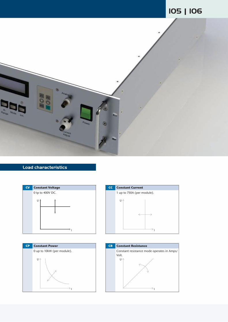
105 | 106
Load characteristics
CV Constant Voltage CC Constant Current
0 tp to 400V DC.
U
I
1 up to 750A (per module).
U
I
CP Constant Power CR Constant Resistance
0 up to 10kW (per module).
U
I
Constant resistance mode operates in Amps/Volt.
U
I

www.schaeferpower.deElectronic Loads Series LW 5100
P
WATER INLET
WATER OUTLETModular System
1 x LW 5100 1 Module
consisting of cabinet one module
2 x LW 5100 2 Modulesconsisting of cabinet two modules
3 x LW 5100 3 Modulesconsisting of cabinet three modules
4 x LW 5100 4 Modules
consisting of cabinet four modules
WATER OUTLETModular System
1 x LW 5100 1 Moduleconsisting of cabinet one module
2 x LW 5100 2 Modulesconsisting of cabinet two modules
3 x LW 5100 3 Modulesconsisting of cabinet three modules
4 x LW 5100 4 Modulesconsisting of cabinet four modules
This liquid cooled load allows a wide range of operation up to 400V / 750A. The small size provides high power density combined with high ease of use. Wherever heat and noise of fans is unacceptable, this load offers a per-fect solution, e.g. laboratory or test rooms.Due to its capability to connect modules in paral-lel, the power rating can be increased up to 40kW, controllable by one interface.
P
WATER INLET
WATER OUTLETGeneral Information

107 | 108
3U
Standard
approx. 40 kg 19“ Plug-in module
3U
19"
591 m
m

www.schaeferpower.de Thyristor Controlled Thyristor Controlled 1 or 3-Phase Input from 500W to 500kW Thyristor Controlled
AC input voltage: 115 / 230V AC, single phase, 50 / 60Hz or 200/ 400/ 480/ 690V AC, 3-phase, 50 / 60Hz Output voltage: 12 / 24 / 48 / 60 / 72 / 110 / 220 / 360V Output current: up to 3250A Output power: 500W - 500kW
AC / DC Power Supplies & Battery Chargers
Robust design High reliable 6-pulse performance Optional: 10% input current distortion for 12-pulse charger Turn Key solution Constant current & voltage operation Industrial grade components High level of humidity protection Concise & clear indication panel
Features
ACin
DCout
Specifications
Input
Voltage range nominal voltage ±10%(other voltage upon request)
Frequency 50 or 60Hz ±5% Protection by fuse
General
Efficiency - Series QE - Series QD
80 – 90%82– 92% for models <48V DC 85– 95% for models ≥48V DC
Operating temperature –10 to +40°C, optional up to +65°C
Humidity up to 95 % RH, non-condensing Altitude up to 1000 m asl Cooling natural convection or internal fans Audible noise 50-70dB (A) depending on power Safety / Construction acc. to EN 60950-1 / EN 50178 EMI acc. to EN 61000-6-4, class A Enclosure - Protection category
- Color
IP20 acc. to EN 60529, optional up to IP55 RAL7035, others upon request
Transformer acc. to IEC 76 / IEC14 /EN 60591 / DIN VDE 0532
Output
Voltage adjustable from 90 – 120% of Unom
(other voltage upon request) Line regulation (±10%) ± 0.5% Load regulation (10-90%) ± 1% Dynamic load (10 - 90 -10%) ± 10% typical Ripple ≤ 5% rms without battery,
optional: < 2% rms or 2mV frequency weighted
Current electronic current limitation adjustable from 60 – 105% of Inom
Overload protection short circuit protected by fuse and electronic current limitation
Charging characteristic IU acc. to DIN 41773 for Pb batteries DIN 41774 for NiCd batteries
Charging voltage - float
- equalize
- boost (manual activated)
2.23 – 2.27V/ cell for Pb batteries / 1.4V / cell for NiCd batteries2.35 – 2.4V / cell for Pb batteries / 1.55V / cell for NiCd batteries2.7V / cell for Pb batteries / 1.7V 7 cell for NiCd batteries

109 | 110
Options
Input MCB, MCCB or isolator inrush current limiting 690V AC input
Output parallel or redundant operation
12-pulse performance
filtering up to 0.1% pp (corresponding to 0.035% rms) or 2mV frequency weighted voltage stabilization
Control (details see page 123)
IU characteristic acc. to DIN 41773 and 41774 manual selection of charging characteristic
(float / equalize / boost) automatic selection of charging characteristic with timer
temperature compensated charging voltage
Battery MCB, MCCB or isolator deep discharge protection
Monitoring (details see page 123)analogue or micro-processor-controlled input/ output voltage battery circuit ground insulation failure over temperature
Interface Card CAN Bus MOD Bus
Mechanics / environment: enclosures, IP20 up to IP55, for charger and / or batteries analogue or digital meters operating temperature
up to +65°C tropical protection earthquake-proof vermin-proof
Converters / Inverters switchmode DC / DC converters from 100W to 40kW switchmode DC / AC inverters, frequency converters and
static switches from 200 VA to 45k VA

www.schaeferpower.de Thyristor Controlled Thyristor Controlled
Q1
V3V4
V1V2
T1
R5 A
L++ BATTERY
L1
- BATTERY1L- 1L+
F31 F32
L1
DC-LOAD
THYRISTOR CONTROL
F1
F6
C1
L-
V
N
R7
Model designation (example): QE 24 / 20
single phase inputnominal output voltage [V]
max. output current [A]
Series QE with single phase input, 500W-5kW
enclosure size 1)
nominal output voltage approx. line current 2)
[A]
approx. weight 3)
[kg]12 V 24 V 48 V 60 V 110 V 220 V
max. output current [A]
R3 30 20 10 8 5 2.5 4 28 36 25 12.5 10 6 3 5 31
R4 50 32 16 14 8 4 6.5 40 60 40 20 18 10 5 8 46
R5 80 55 30 25 14 7 11 60110 75 40 35 18 9 15 73
R5+– 100 55 45 25 12.5 20 88– 130 70 60 32 16 26 98
1) Larger size may be required for optional equipment.2) Line current is referred to nominal input voltage of 230 VAC.3) Weight is referred to thyristor-controlled rectifier on a mounting plate without enclosure.
wall-mountedenclosure
designation
weight (empty)
[kg]
height width depth
dimensions [mm]
R2 9 300 380
210R3 12
380R4 17
600
R4+ 26 600
R4T 22 380
350R5 31 600
R5+ 38 760
floor-mountedenclosure
designation
weight (empty)
[kg]
height* width depth
dimensions [mm]
R6 661200
600
400R6+ 80 800
R7 1271800
600
R7+ 150 800
R8 147
2000
600500
R8+ 175 800
R9 250 1200 600
*) The height of the base frame, elevated roof and suspension eyes is to be added, if needed.
QE - Series
1-phase thyristor-controlled rectifiers, 500W-5kW
nominal output voltage
12V 24V 48V 60V 110V 220V 360V
max. output current
from 0 to 130A
Enclosures
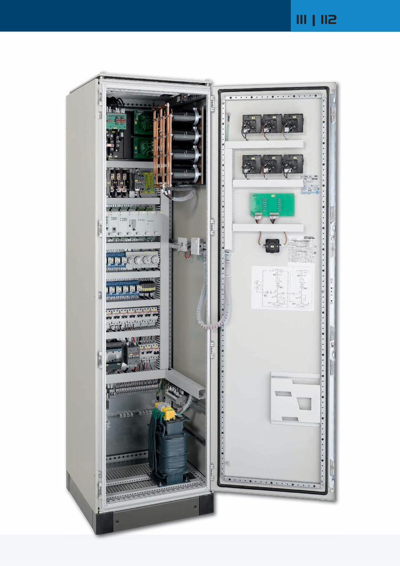
111 | 112

www.schaeferpower.de Thyristor Controlled Thyristor Controlled Series QD with 3-phase input, 1 - 500kW
Q1
V4V5V6
V1V2V3
T1
R5 A
L++ BATTERY
L1
- BATTERY1L- 1L+
F31 F32
L1 L2 L3
DC-LOAD
6-pulseTHYRISTOR CONTROL
F1-F3
F6
C1
L-
V
R7
Model designation (example): QD 60 / 32
three phases inputnominal output voltage [V]
max. output current [A]
enclosure size 1)
nominal output voltage approx. line current 2)
[A]
approx. weight 3)
[kg]24 V 48 V 60 V 110 V 220 V
max. output current [A]
R4 25 12 10 5 2.5 1.1 48 40 20 16 8 4 2 62
R5 60 30 25 12 6 3 74 80 40 32 16 8 4 78 100 50 40 20 10 5 85
R5+ 125 60 50 25 12 6 95
R6 160 80 65 32 16 8 130 200 100 80 40 20 10 150
R6+ 240 120 100 50 25 11 180 300 150 120 60 30 14 260
R7 350 170 140 70 35 16 310 400 200 160 80 40 19 340
R7+ 500 250 200 100 50 24 390 600 300 240 120 60 28 420
R8 700 350 280 140 70 33 450R8+ 800 400 320 160 80 38 510R9 1000 500 400 200 100 48 620
2 x R8+
1200 600 500 250 120 57 6801600 800 600 300 150 76 7402000 1000 800 400 200 95 7802250 1125 900 500 250 120 9202750 1375 1100 600 300 142 10003250 1625 1300 700 350 166 1180
2 x R9– 1800 1450 800 400 190 1300– 2250 1800 1000 500 238 1450– – 2750 1500 750 356 1630
3 x R9 – – – 2000 1000 475 18754 x R9 – – – – 2000 950 2390
1) Larger size may be required for optional equipment. Enclosures see page 111.2) Line current is referred to nominal input voltage of 3 x 400 VAC.3) Weight is referred to thyristor-controlled rectifier on a mounting plate without enclosure.
QD - Series
3-phase thyristor-controlled rectifiers, 1-500kW
nominal output voltage
24V 48V 60V 110V 220V 360V
max. output current
from 0 to 3250A
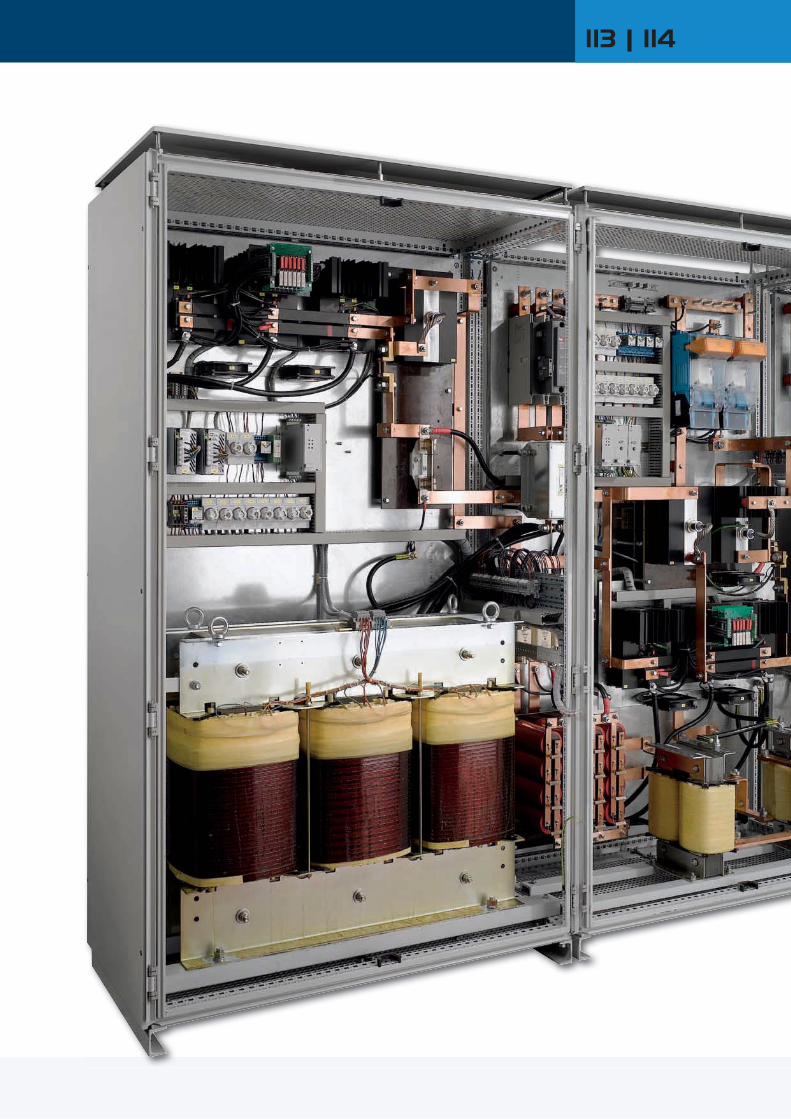
113 | 114
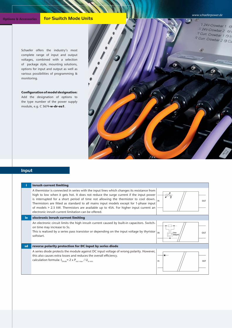
www.schaeferpower.deOptions & Accessories Options & Accessories for Switch Mode UnitsOptions & Accessories
Schaefer offers the industry’s most complete range of input and output voltages, combined with a selection of package style, mounting solutions, options for input and output as well as various possibilities of programming & monitoring.
Configuration of model designation:Add the designation of options to the type number of the power supply module, e.g. C 3674-w-dr-eu1.
Input
i inrush current limiting
A thermistor is connected in series with the input lines which changes its resistance from high to low when it gets hot. It does not reduce the surge current if the input power is interrupted for a short period of time not allowing the thermistor to cool down. Thermistors are fitted as standard to all mains input models except for 1-phase input of models > 2.5 kW. Thermistors are available up to 45A. For higher input current an electronic inrush current limitation can be offered.
ie electronic inrush current limiting
An electronic circuit limits the high inrush current caused by built-in capacitors. Switch- on time may increase to 5s.This is realized by a series pass transistor or depending on the input voltage by thyristor softstart.
sd reverse polarity protection for DC input by series diode
A series diode protects the module against DC input voltage of wrong polarity. However, this also causes extra losses and reduces the overall efficiency.calculation formula: IDiode= 2 x Pout max / Uin min OUTIN
OUTIN timedelayed
IN OUT

115 | 116
ad reverse polarity protection for DC input by anti parallel diode
To avoid the power losses a diode is provided with opposite polarity in parallel to the input blowing an internal or external fuse if the module is connected to a supply of wrong polarity.calculation formula: IDiode= 2 x Pout max / Uin min
au auto-ranging
For standard dual AC input models the range of 115 / 230 V AC is to be selected by connecting the input line to different pins on the connector. With auto-ranging the unit senses the input voltage and provides automatically the correct connection. OUT
L
N
115V ACor230V AC
OUTIN

www.schaeferpower.deOptions & Accessories Options & Accessories for Switch Mode Units
Output
The number of options per module may be restricted due to limitation of space inside the module or due to a limited number of connector pins. Potentiometers or interface cards may be supplied separately for installation outside of the module.
General information
Parallel / redundant operation for DC output (details see page 125/126)
dd decoupling diode
A series diode built into the units output allows paralleling of 2 or more units for redundancy or higher power or battery charging. For control purposes the anode of the diode is also available at the output connector. It cannot be loaded ≥ 0.5A. The sense signal is taken partially from the anode and partially from the load/cathode of the decoupling diode. This guarantees starting and operating under all conditions, but it also effects the regulation accuracy of 2%. In this way it gives a load sharing of 15-30% between the paralleled units.
cs active current sharing
An additional control circuit provides active current sharing via an interconnecting wire between converters that operate in parallel. The output lines of the converters have to be in “star point” connection.
csi current sharing interrupt (“cs” included)
“csi” will effect the removal of the “cs” signal from the load voltage common connection. Should there be an instance where a unit is not supplying the load, then the effect of its current sharing signal is removed, and the load voltage is unaffected by this condition. In terms of calibration the same criteria follow as for parallel operation.
icsi current sharing interrupt (“csi” included), galvanically isolated
The inclusion of “csi” (current sharing interrupt) and the galvanic isolation is the optimum set up for systems with high power or high currents, were the voltage drop on the power wiring could influence the cs signal.
ma master / slave operation (avalaible for series 6xxx)
Master / Slave interface permits the parallel function of identical modules to increase the output power capapcity, shared by current control without any dynamic reduction in performance.
Parallel / redundant operation for AC output
red inverter parallel operation: for series IT5xxx
For redundant operation or for increased output power, two inverters of the IT5xxx series can be switched together. If one inverter fails, the internal contactor will be switched off and the output power of one inverter is still available.
IN
IN
CS
CS
+-OUT
IN
+
-
OUT
OUT
L
N
currentsharing
OUT
currentsharing
IN
IN
currentsharing
currentsharing
+-
IN
IN
CSI
CSI
OUT
MS
SL
currentregulation
currentregulation
IN
IN
OUT
currentregulation
currentregulation
CSI
CSI
IV
IV
IN
OUT
IN

117 | 118
Inhibit
h1 inhibit by external closing contact, signal referred to input
The operation of the unit is inhibited when a voltage signal is applied in reference to the negative line of the input. This can also be used in combination with a thermal trip, which shuts the unit down.
h2 inhibit by voltage signal, signal referred to output
Operation of the unit is inhibited if a voltage signal (5V / 10mA) is applied in reference to the negative line of the output.
h3 inhibit by closing contact, signal referred to output
The operation of the unit is inhibited when a voltage signal is applied in reference to the negative line of the output. This can also be used in combination with a thermal trip, which shuts the unit down.Please note: Only relevant solution for inverters.
Automatic reduction of current limiting
rco reducing current limiting at over temperature
A circuit reduces the current limiting level at higher temperature (to be specified).
Please note: Option is avalaible for series 48xx with ZVS topology and for high power converter modules (see page 49).
DC output protection
rd reverse polarity protection for DC output
by reverse diode with external fuse
IN OUT
IN RCO OUTsec.
controlsecondarycontrol
IN INH
sec.control
secondarycontrol
IN INH
sec.control
secondarycontrol
IN INH
primarycontrol OUT
primarycontrol

www.schaeferpower.deOptions & Accessories Options & Accessories
Signals
for Switch Mode Units
The number of options per module may be restricted due to limitation of space inside the module or due to a limited number of connector pins. Potentiometers or interface cards may be supplied separately for installation outside of the module.
General information
pr input voltage supervision (power ok) incl. relay contacts
A logic signal is given if the input voltage (AC or DC) drops below the specified limit. In AC input models the rectified input voltage is sensed so that a power fail alarm can be avoided if at light load mains power returns before the input capacitors are substantially discharged. A relay contact is provided for failure indication.
dr output voltage supervision (DC ok) incl. relay contacts
A logic signal is given if the output voltage is below the specified limit. A relay contact is provided for failure indication.DC ok level: 5V output: 4,75V all other voltages: 90% of adjusted voltage
cf charger / converter fail supervision incl. relay contacts
A logic signal is given if the input voltage, the auxiliary voltage of the primary side and the current of the primary side exceed or go below a specified range. A relay contact is provided for failure indication.
ac AC ok for inverter including relay contacts
A logic signal is given if the output voltage of an inverter is below the specified limit. A relay contact is provided for failure indication.
IN
L
N
+
-
IN OUT
IN OUT
IN OUT
primarycontrolcircuit
supervision
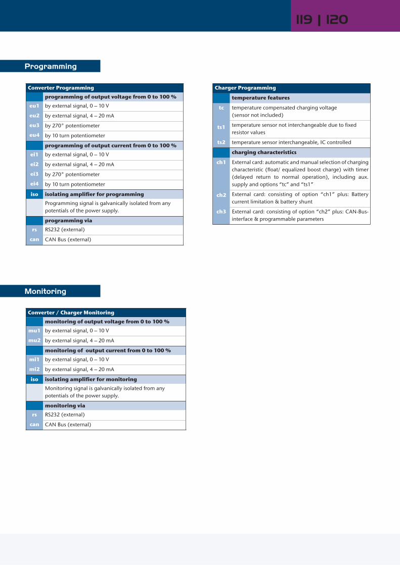
119 | 120
Programming
Converter Programming
programming of output voltage from 0 to 100 %
eu1
eu2
eu3
eu4
by external signal, 0 – 10 V
by external signal, 4 – 20 mA
by 270° potentiometer
by 10 turn potentiometer
programming of output current from 0 to 100 %
ei1
ei2
ei3
ei4
by external signal, 0 – 10 V
by external signal, 4 – 20 mA
by 270° potentiometer
by 10 turn potentiometer
iso isolating amplifier for programming
Programming signal is galvanically isolated from any potentials of the power supply.
programming via
rs
can
RS232 (external)
CAN Bus (external)
Converter / Charger Monitoring
monitoring of output voltage from 0 to 100 %
mu1
mu2
by external signal, 0 – 10 V
by external signal, 4 – 20 mA
monitoring of output current from 0 to 100 %
mi1
mi2
by external signal, 0 – 10 V
by external signal, 4 – 20 mA
iso isolating amplifier for monitoring
Monitoring signal is galvanically isolated from any potentials of the power supply.
monitoring via
rs
can
RS232 (external)
CAN Bus (external)
Charger Programming
temperature features
tc
ts1
ts2
temperature compensated charging voltage (sensor not included)
temperature sensor not interchangeable due to fixed resistor values
temperature sensor interchangeable, IC controlled
charging characteristics
ch1
ch2
ch3
External card: automatic and manual selection of charging characteristic (float/ equalized boost charge) with timer (delayed return to normal operation), including aux. supply and options “tc” and “ts1”
External card: consisting of option “ch1” plus: Battery current limitation & battery shunt
External card: consisting of option “ch2” plus: CAN-Bus-interface & programmable parameters
Monitoring

www.schaeferpower.deOptions & Accessories Options & Accessories for Switch Mode Units
Mechanics
As standard, all of the modules are designed and manufactured for insertion into 19” sub-racks. Higher power modules are already constructed in 19” format.
Optionally, 19” sub-racks are available and can be configured as 3U or 6U allowing any mix of units and can be upgraded in accordance to the customers’ requirements, e.g.
mating connectors wired to a terminal block fuses or circuit breakers hot swappable configuration upon request analog or digital meters switches fans filters decoupling diodes provisions for keying the modules to ensure module / slot designation
19“ Sub-Racks
6U =
266
mm
19" = 483 mm
84TE = 426.7 mm
19" = 483 mm
6U =
266
mm
2TE = 10 mm
3U =
132
.5 m
m3U
= 1
32.5
mm
84TE = 426.7 mm
3U =
132
.5 m
m
19" = 483 mm
84TE = 426.7 mm
w wall mount
Modules, which have the wall mount option, are typically fixed to a structure or within a cabinet. Depending on the size of the module, this may be done with a flat or angled plate (see pho-to). The load connections are typically through a terminal block. Should the application not require a pluggable module / rack solution, wall mounting presents an alternative option for the customer to choose from.
cha chassis mount
Module is designed for installation to a structure or within a cabi-net. Screw type mating connectors are supplied with the module. Due to the limited number of connector pins this option is not available for modules with dual AC input. Option is avalaible for currents up to 60Amps.
din DIN rail mount
Module is designed for DIN rail mounting to a structure or within a cabinet. Screw type mating connectors are supplied with the module. Due to the limited number of connector pins this option is not available for modules with dual AC input. Option is avalai-ble for currents up to 60Amps.

121 | 122
t tropical protection
The unit is given additional protection by a heavy coat of varnish on the printed circuit board(s) and on components to achieve 99% RH, non condensing.
c extended temperature range
The circuit is designed and tested for operation at an ambient temperature as low as – 40°C.
ms increased mechanical strength
Screws are secured with Loctite and heavy components are fastened by ties and / or glue. Modules with the „ms“ are build acc. to EN 61373 regarding shock and vibration.
Environment
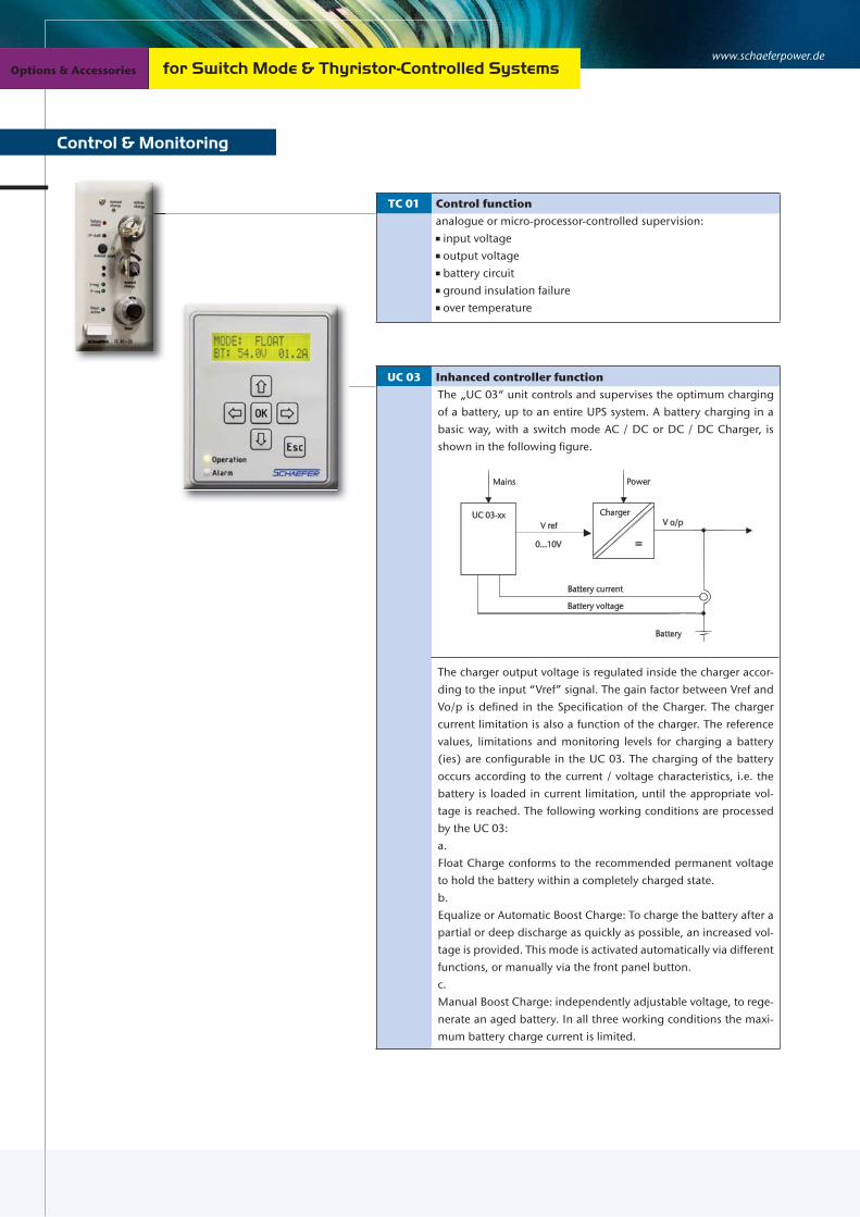
www.schaeferpower.deOptions & Accessories Options & Accessories
TC 01 Control function
analogue or micro-processor-controlled supervision: input voltage output voltage battery circuit ground insulation failure over temperature
UC 03 Inhanced controller function
The „UC 03“ unit controls and supervises the optimum charging of a battery, up to an entire UPS system. A battery charging in a basic way, with a switch mode AC / DC or DC / DC Charger, is shown in the following figure.
The charger output voltage is regulated inside the charger accor-ding to the input “Vref” signal. The gain factor between Vref and Vo/p is defined in the Specification of the Charger. The charger current limitation is also a function of the charger. The reference values, limitations and monitoring levels for charging a battery (ies) are configurable in the UC 03. The charging of the battery occurs according to the current / voltage characteristics, i.e. the battery is loaded in current limitation, until the appropriate vol-tage is reached. The following working conditions are processed by the UC 03: a.Float Charge conforms to the recommended permanent voltage to hold the battery within a completely charged state.b. Equalize or Automatic Boost Charge: To charge the battery after a partial or deep discharge as quickly as possible, an increased vol-tage is provided. This mode is activated automatically via different functions, or manually via the front panel button.c. Manual Boost Charge: independently adjustable voltage, to rege-nerate an aged battery. In all three working conditions the maxi-mum battery charge current is limited.
Control & Monitoring
for Switch Mode & Thyristor-Controlled Systems
Mains Power
UC 03-xx ChargerV ref
0...10V
Battery current
Battery voltage
Battery
V o/p
=

123 | 124
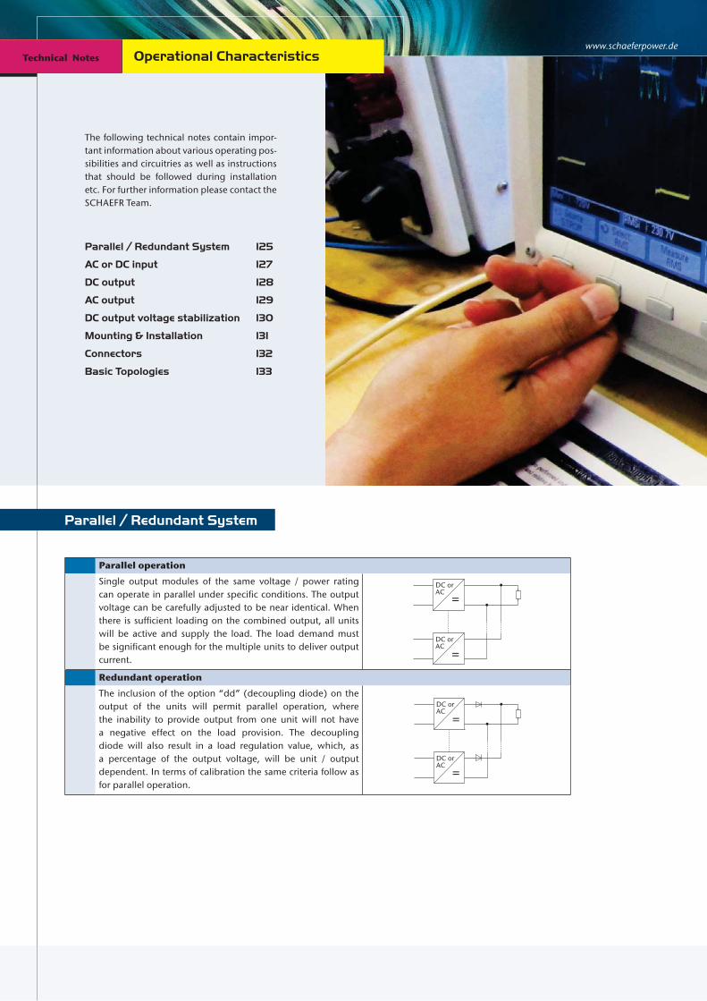
www.schaeferpower.deTechnical Notes Technical Notes Operational Characteristics
Parallel operation
Single output modules of the same voltage / power rating can operate in parallel under specific conditions. The output voltage can be carefully adjusted to be near identical. When there is sufficient loading on the combined output, all units will be active and supply the load. The load demand must be significant enough for the multiple units to deliver output current.
Redundant operation
The inclusion of the option “dd” (decoupling diode) on the output of the units will permit parallel operation, where the inability to provide output from one unit will not have a negative effect on the load provision. The decoupling diode will also result in a load regulation value, which, as a percentage of the output voltage, will be unit / output dependent. In terms of calibration the same criteria follow as for parallel operation.
DC orAC
=
=DC orAC
=
=
DC orAC
DC orAC
The following technical notes contain impor-tant information about various operating pos-sibilities and circuitries as well as instructions that should be followed during installation etc. For further information please contact the SCHAEFR Team.
Parallel / Redundant System 125
AC or DC input 127
DC output 128
AC output 129
DC output voltage stabilization 130
Mounting & Installation 131
Connectors 132
Basic Topologies 133
Parallel / Redundant System
Technical Notes

125 | 126
Balanced current operation
The inclusion of the option “cs” (current sharing) allows for parallel operation with a significant degree of current balancing. The communication between the units allows for a voltage setting correction, which in turn shall equate to an automatic current sharing (balancing) on the outputs. The tolerance of such balancing is module dependent. In terms of calibration the same criteria follow as for parallel operation.
Redundant balanced operation
The inclusion of both, the “cs” and “dd” option results in an optimized balanced current provision while being de-coupled from each other. A connected module, who is not supplying an output voltage, will influence the load voltage. The voltage may be reduced by up to 7 %. In terms of calibration the same criteria follow as for parallel operation.
Fault tolerant operation
The inclusion of “csi” (current sharing interrupt), “cs” and “dd” is the optimum set up for a fault tolerant application. “csi” will effect the removal of the “cs” signal from the load voltage common connection. Should there be an instance where a unit is not supplying the load, then the effect of its current sharing signal is removed, and the load voltage is unaffected by this condition. In terms of calibration the same criteria follow as for parallel operation.
CS
DC orAC =
CS
DC orAC =
CS
CS
DC orAC =
CS
DC orAC =
CS
DC orAC
= CSCSi
DC orAC
= CSCSi
CS
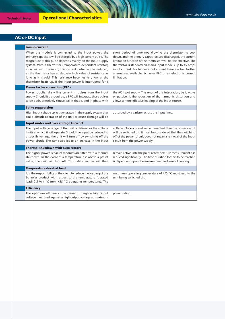
www.schaeferpower.deTechnical Notes Technical Notes Operational Characteristics
AC or DC input
inrush current
Power factor correction (PFC)
Power supplies draw line current in pulses from the input supply. Should it be required, a PFC will integrate these pulses to be both, effectively sinusoidal in shape, and in phase with
the AC input supply. The result of this integration, be it active or passive, is the reduction of the harmonic distortion and allows a more effective loading of the input source.
Spike suppression
High input voltage spikes generated in the supply system that could disturb operation of the unit or cause damage will be
absorbed by a varistor across the input lines.
Input under and over voltage turn off
The input voltage range of the unit is defined as the voltage limits at which it will operate. Should the input be reduced to a specific voltage, the unit will turn off by switching off the power circuit. The same applies to an increase in the input
voltage. Once a preset value is reached then the power circuit will be switched off. It must be considered that the switching off of the power circuit does not mean a removal of the input circuit from the power supply.
Thermal shutdown with auto restart
The higher power Schaefer modules are fitted with a thermal shutdown. In the event of a temperature rise above a preset value, the unit will turn off. This safety feature will then
remain active until the point of temperature measurement has reduced significantly. The time duration for this to be reached is dependent upon the environment and level of cooling.
Temperature derated load
It is the responsibility of the client to reduce the loading of the Schaefer product with respect to the temperature (derated load: 2.5 % / °C from +55 °C operating temperature). The
maximum operating temperature of +75 °C must lead to the unit being switched off.
Efficiency
The optimum efficiency is obtained through a high input voltage measured against a high output voltage at maximum
power rating.
When the module is connected to the input power, the primary capacitors will be charged by a high current pulse. The magnitude of this pulse depends mainly on the input supply system. With a thermistor (temperature dependent resistor) in series with the input, this current pulse can be reduced, as the thermistor has a relatively high value of resistance as long as it is cold. This resistance becomes very low as the thermistor heats up. If the input power is interrupted for a
short period of time not allowing the thermistor to cool down, and the primary capacitors are discharged, the current limitation function of the thermistor will not be effective. The thermistor is standard on mains input models up to 45 Amps input current. For higher input current there are two further alternatives available: Schaefer PFC or an electronic current limitation.

DC output
127 | 128
Soft start
The application of the input power permits the unit to generate a secondary output. The switching on of the primary power circuit is controlled and gradually increased to allow
a controlled charging of the secondary capacitors. The time duration for the secondary capacitors to be charged is defined as the soft start.
No load operation
Single output converters require no minimum load for operation within tolerance. Multi output converters require
the main output be loaded. Semi-regulated auxiliary outputs may also require a minimum load to be applied.
Short circuit protection
The main output of a converter will be immune against a momentary or continuous short circuit. The secondary current limitation will not permit the sustained output current to be higher than the calibrated setting, and it will actively reduce the output voltage in accordance to the overload. The
removal of the overload / short circuit will result in the output voltage being increased to the calibrated value. Regulated auxiliary outputs will also reduce the output voltage / current in accordance to their overloading. The characteristic may vary according to the circuit employed.
Over voltage protection (OVP)
The main output voltage is measured, either internally or through sense leads. This measured value is compared against a calibrated value. When the calibrated value has been reached, this circuit turns off the primary power circuit. Once the measured value has reduced below the calibrated
value, the primary power circuit is permitted, once again, to be activated. The high power units have an additional feature, which will shut down the primary power circuit after a continued OVP operation. The input power must be re-cycled in order to remove the unit from shut down.
voltage adjustment [V] 5 9 12 15 24 28 48 60 110 200 220 400
Over voltage protection [V] 6.5 12 15 18 30 35 60 70 140 220 280 440
Sense leads
Through the use of sense leads, an output voltage may be regulated to a point outside of the unit. The sense leads should be connected to the power connection at the point of load under regard of polarity. There should be a non-interruptible connection between sense and load points. Interruption may lead to damage or the activation of the OVP circuit. The units, which have sense leads, have the ability to regulate to a higher voltage at the output connection. This increase is largely dependent upon the unit. The details may be found in the respective unit specification. Parallel operation with sense leads allows a common point for the units to regulate their
voltages to. Units whose output voltage has been calibrated to be near identical will now be able to supply a common load.De-coupled outputs will be sensed both, before and after thedecoupling diodes, which in turn will lead to an output voltage regulation, specifi c to load and unit. Sense leads are typically employed with a decoupled output voltage of less than 40 VDC. The current sharing option will effectively override the sense lead output voltage setting, but the point at which the output voltage is regulated, will be the point of sense lead connection.
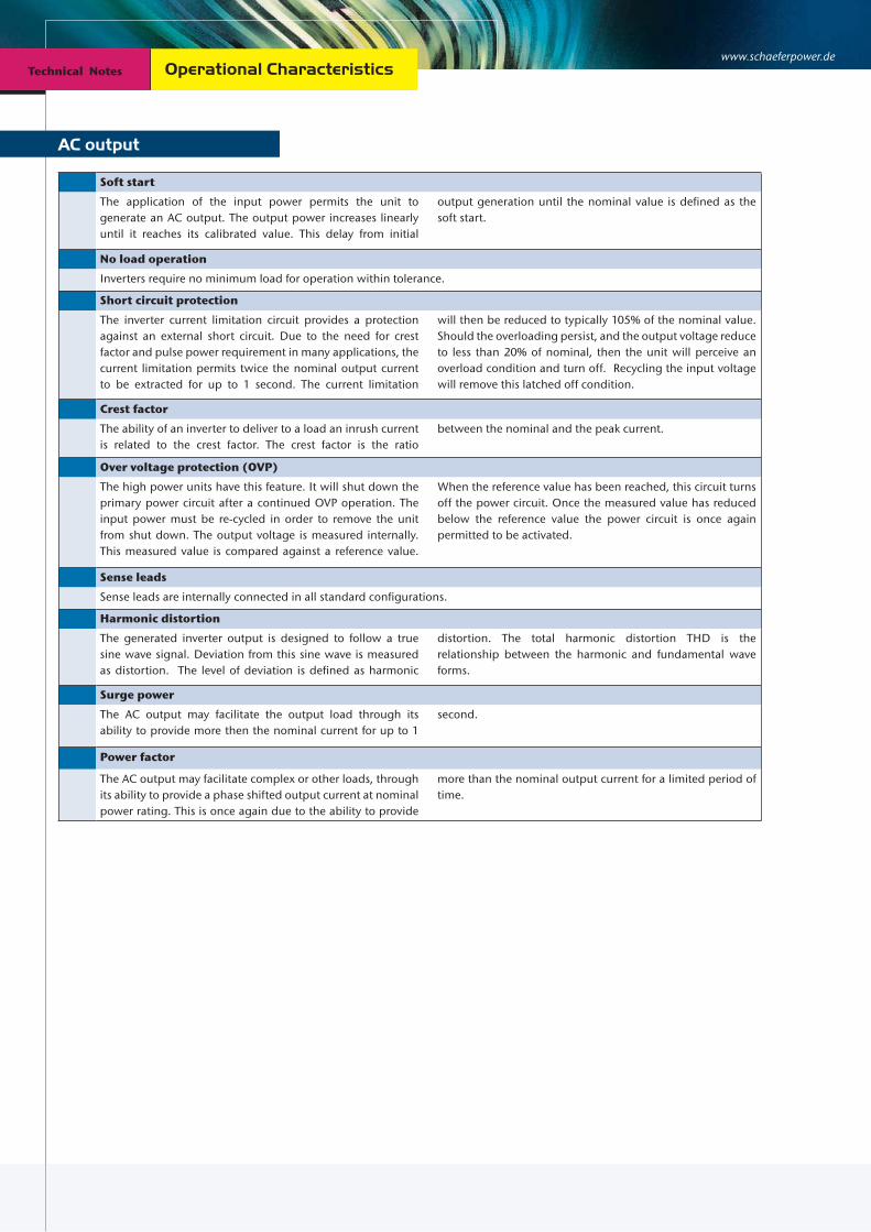
www.schaeferpower.deTechnical Notes Technical Notes
AC output
Operational Characteristics
Soft start
The application of the input power permits the unit to generate an AC output. The output power increases linearly until it reaches its calibrated value. This delay from initial
output generation until the nominal value is defined as the soft start.
No load operation
Inverters require no minimum load for operation within tolerance.
Short circuit protection
The inverter current limitation circuit provides a protection against an external short circuit. Due to the need for crest factor and pulse power requirement in many applications, the current limitation permits twice the nominal output current to be extracted for up to 1 second. The current limitation
will then be reduced to typically 105% of the nominal value. Should the overloading persist, and the output voltage reduce to less than 20% of nominal, then the unit will perceive an overload condition and turn off. Recycling the input voltage will remove this latched off condition.
Crest factor
The ability of an inverter to deliver to a load an inrush current is related to the crest factor. The crest factor is the ratio
between the nominal and the peak current.
Over voltage protection (OVP)
The high power units have this feature. It will shut down the primary power circuit after a continued OVP operation. The input power must be re-cycled in order to remove the unit from shut down. The output voltage is measured internally. This measured value is compared against a reference value.
When the reference value has been reached, this circuit turns off the power circuit. Once the measured value has reduced below the reference value the power circuit is once again permitted to be activated.
Sense leads
Sense leads are internally connected in all standard configurations.
Harmonic distortion
The generated inverter output is designed to follow a true sine wave signal. Deviation from this sine wave is measured as distortion. The level of deviation is defined as harmonic
distortion. The total harmonic distortion THD is the relationship between the harmonic and fundamental wave forms.
Surge power
The AC output may facilitate the output load through its ability to provide more then the nominal current for up to 1
second.
Power factor
The AC output may facilitate complex or other loads, through its ability to provide a phase shifted output current at nominal power rating. This is once again due to the ability to provide
more than the nominal output current for a limited period of time.

DC output voltage stabilization
129 | 130
The output voltage of a battery charger with parallel connected batteries varies substantially with the charging condition of the battery. For many applications, however, the load circuit requires a more stabilized voltage which can be accomplished by:
Voltage dropping diodes
being interconnected between battery and load, reduce the voltage to a value suitable for the load. They are short-circuited by one or more contactors only if a partial reduction or no voltage reduction is required. A control circuit senses the battery voltage and energizes the contactors. Voltage dropping diodes cause substantial power losses as the excess voltage is absorbed by the diodes. However, due to simplicity, this method is frequently used, especially if the voltage reduction is needed only during the short periods of high-rate charging.
AC input
battery
- +
batterycharger
DC-load
K1
K2 controlcircuit
K1 and K2for
Switchmode step-up converters
are DC/DC converters supplied from the battery with the output connected in series to the battery. They present a very economical solution as they only add voltage when the battery is discharged. Details see page 47/ 83.
batterycharger
+
-
step-up converter (long) cable to load
+
-
sense leadsload
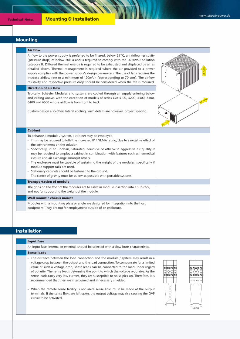
www.schaeferpower.deTechnical Notes Technical Notes Mounting & Installation
Mounting
Air flow
Airflow to the power supply is preferred to be filtered, below 55°C, an airflow resistivity(pressure drop) of below 20kPa and is required to comply with the EN60950 pollutioncategory II. Diffused thermal energy is required to be exhausted and displaced by air asdetailed above. Thermal management is required where the air provided to a powersupply complies with the power supply’s design parameters. The use of fans requires theincrease airflow rate to a minimum of 120m3/h (corresponding to 70 cfm). The airflowresistivity and respective pressure drop should be considered when the fan is required.
Direction of air flow
Typically, Schaefer Modules and systems are cooled through air supply entering below and exiting above, with the exception of models of series C/B 5100, 5200, 5300, 5400, 6400 and 6600 whose airflow is from front to back.
Custom design also offers lateral cooling. Such details are however, project specific.
Cabinet
To enhance a module / system, a cabinet may be employed.- This may be required to fulfil the increased IP / NEMA rating, due to a negative effect of
the environment on the solution.- Specifically, in an unclean, saturated, corrosive or otherwise aggressive air quality it
may be required to employ a cabinet in combination with features such as hermetical closure and air exchange amongst others.
- The enclosure must be capable of sustaining the weight of the modules, specifically if module support rails are used.
- Stationary cabinets should be fastened to the ground.- The centre of gravity must be as low as possible with portable systems.
Transportation of module
The grips on the front of the modules are to assist in module insertion into a sub-rack, and not for supporting the weight of the module.
Wall mount / chassis mount
Modules with a mounting plate or angle are designed for integration into the host equipment. They are not for employment outside of an enclosure.
AIR
FLO
W
AIR FLOW
AIR FLOW
Input fuse
An input fuse, internal or external, should be selected with a slow burn characteristic.
Sense leads
- The distance between the load connection and the module / system may result in a voltage drop between the output and the load connection. To compensate for a limited value of such a voltage drop, sense leads can be connected to the load under regard of polarity. The sense leads determine the point to which the voltage regulates. As the sense leads carry very low current, they are susceptible to noise pick up. Therefore, it is recommended that they are intertwined and if necessary shielded.
- When the remote sense facility is not used, sense links must be made at the output terminals. If the sense links are left open, the output voltage may rise causing the OVP circuit to be activated.
- +-S +S
LOAD+-
Installation

131 | 132
H15 Female Connector
Number of contacts: 15Contacts: Fastons or screw terminalsOperating current at +20 °C: 15 AOperating temperature: – 55 to +125 °CTest voltage (contact to contact): 3100 Vrms
Test voltage (contact to ground): 3100 Vrms
Contact resistance: 8 mΩPerformance according to: IEC 60603-2 / DIN 41612
High Current Female Connector
Number of contacts: 2Contacts: Bolts with 8 mm diameter for terminal lugs M8Operating current at +20°C: 170 AOperating temperature: –55 to +125 °CTest voltage (contact to contact): 500 Vrms
Test voltage (contact to ground): 2500 Vrms
Contact resistance: 0.06 mΩDimensions (H x W x D): 118 x 35 x 85 mmPerformance according to: IEC 60603-2 / DIN 41612
F24H7 Female Connector
Number of contacts: 24 / 7Contacts: solder pins / fastonsOperating current at +20°C: 6 / 15 AOperating temperature: – 55 to +125 °CTest voltage (contact to contact): 1550 / 3100 VrmsTest voltage (contact to ground): 2500 / 3100 VrmsContact resistance: 15 / 8 mΩPerformance according to: IEC 60603-2 / DIN 41612
F48 Female Connector
Number of contacts: 48Contacts: solder pinsOperating current at +20 °C: 6 AOperating temperature: – 55 to +125 °CTest voltage (contact to contact): 1550 Vrms
Test voltage (contact to ground): 2500 Vrms
Contact resistance: 15 mΩPerformance according to: IEC 60603-2 / DIN 41612
Connectors

www.schaeferpower.deTechnical Notes Technical Notes Basic Topologies
There are various circuit topologies and the selection depends on the requirements, such as low or high input voltage, low or high output voltage, single or multi output, power rating. The following circuits present our common concepts of power conversion.
Push Pull Converter
The push pull converter is often used for applications with low input voltage. The switching transistors are alternately conducting with variable pulse-width. At the secondary side, after rectification and filtering, the output voltage is sensed and compared with a reference. The error signal controls via an opto-coupler the primary circuit.
Half Bridge Converter
The following circuit shows, as an example, a converter with dual AC input in a half bridge connection. With the input voltage supplied to the 230 V terminal, the rectifier circuit is a standard bridge connection; supplied to the 115 V terminal the rectifier circuit functions as a voltage doubler circuit.
DC/AC Inverter
The diagram beside shows the circuit of an inverter. The DC input voltage is transformed by the power transistors T1-T4 with the parallel connected inverse diodes D1-D4 in a pulse-width modulated square wave voltage. The choke with the windings LI and LII integrates this voltage, and at the capacitor C a sinusoidal output voltage is available. The power transistors are controlled via opto-coupler in such a way that not both transistors of one branch are conducting at the same time. The output voltage is sensed and compared with a reference signal generating the firing pulses for the power transistors. The output current is measured via shunt R1 and limited through the control circuit. Isolation between input and output and voltage transformation can either be provided by a converter connected to the input of an inverter or by a transformer connected to the output of an inverter.
output
sense
ripple
I-lim.
I-lim.
sec.controlprim.control
opto-
couplers
DC
filter
input
-
-
+
+
+
-
RFIfilter
OVP
mainoutput
sense
ripple
I-lim.
sec.control
filter
-
+
+
-prim.control
opto-
couplers
RFIfilter
115V AC
230V AC
0V
AC input OVP- rect.
I-lim.
D1
D2
D3
D4
T1
T2 T4
T3
R2 LI LII
R1
C
control + PWM
current
voltage
sense
sense
opto-coupler
opto-coupler
Inverter AC output
InverterDC input
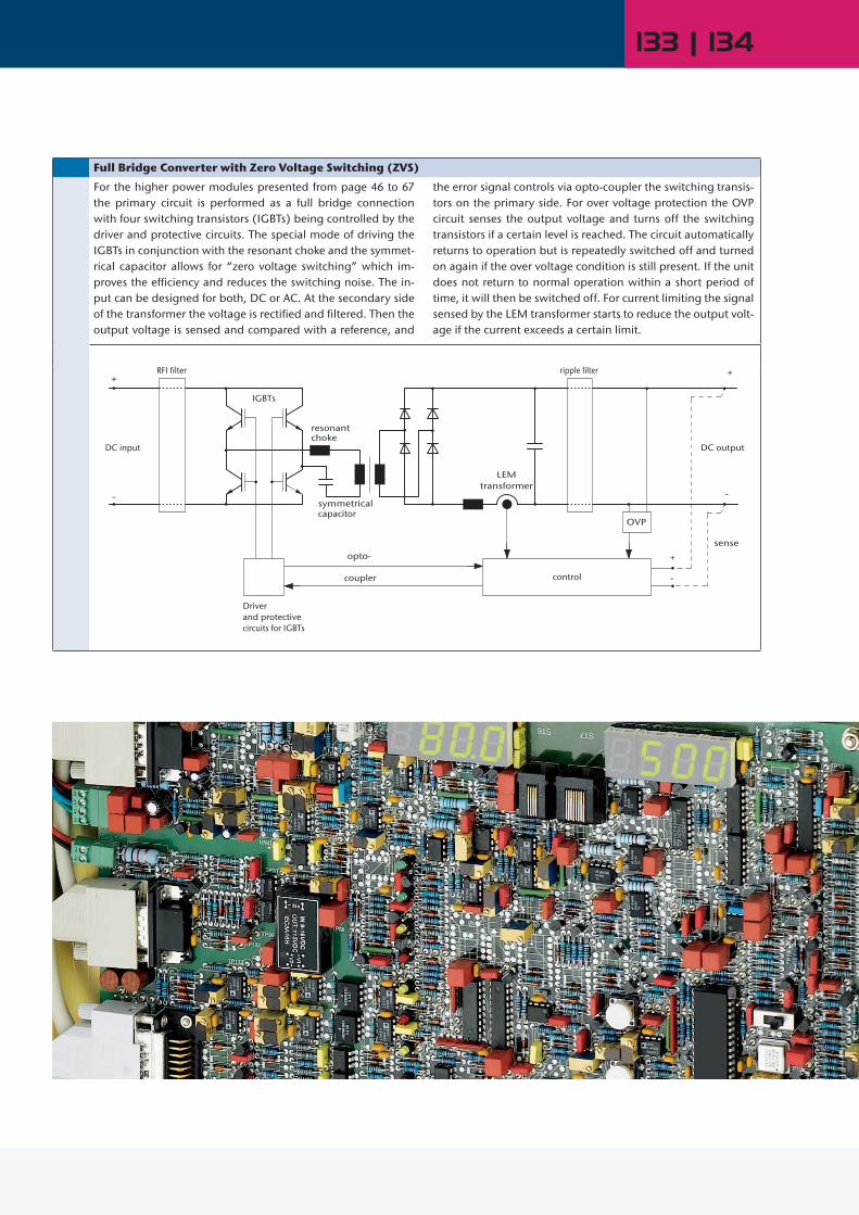
133 | 134
Full Bridge Converter with Zero Voltage Switching (ZVS)
For the higher power modules presented from page 46 to 67 the primary circuit is performed as a full bridge connection with four switching transistors (IGBTs) being controlled by the driver and protective circuits. The special mode of driving the IGBTs in conjunction with the resonant choke and the symmet-rical capacitor allows for “zero voltage switching” which im-proves the efficiency and reduces the switching noise. The in-put can be designed for both, DC or AC. At the secondary side of the transformer the voltage is rectified and filtered. Then the output voltage is sensed and compared with a reference, and
the error signal controls via opto-coupler the switching transis-tors on the primary side. For over voltage protection the OVP circuit senses the output voltage and turns off the switching transistors if a certain level is reached. The circuit automatically returns to operation but is repeatedly switched off and turned on again if the over voltage condition is still present. If the unit does not return to normal operation within a short period of time, it will then be switched off. For current limiting the signal sensed by the LEM transformer starts to reduce the output volt-age if the current exceeds a certain limit.
IGBTs
Driverand protectivecircuits for IGBTs
resonant
control
symmetrical
LEMtransformer
capacitor
ripple filter
opto-
coupler
OVP
+
-
sense
RFI filter+
-
DC input DC output
+
-
choke

www.schaeferpower.deCustomized Systems Design Solutions
The distinction in the market of power supplies is achie-ved by being customer ori-entated, the unique variety of products available and the high level of flexibility to customer specific requirements as well as the modification of standard equipment for small and large quantities.
Be they on shore or off shore, stationary or mobile, land, air or marine based. A system component or complete system, environmentally Hazardous area 1,corrosive or simply Industrial, there is a SCHAEFER Power Solution to fit the parameters.
Welcoming the challenge, the SCHAEFER Team offers the highest quality engineering designed and manu-factured in Germany.
Immediate proximity also generates the free flowing information path, which is the production and deve-lopment areas, along with the testing and customer support areas being all under the same roof. This en-hances the SCHAEFER Teams ability to react to exac-ting demands with ease. Fruits of this labour are to be seen throughout the World, in a variety of fields such as:
Rail & Automotive Industry Power Generation Plants Oil & Gas Industry Chemical Industry Industrial Automation Military Industry Building Security Integrated Airport Solutions
Customization

135 | 136
made in Germany
Interested in new projects?Just scan this QR-Code!

www.schaeferpower.de Design Solutions Design Solutions
Modular and expandable power capability
N+1 redundancy concept fully redundant and fault tolerant
Easy system expandability up to 1MW by adding additional fully wired
100kW enclosures Output voltages available up to 1000 V Control and adjustability of electrical
parameter Additional customised options CAN/
Modbus Interface
8kVA Rolling Stock Mounted Inverter, IP66
300kW ultra fast charging station for E-Busses
Client specific interface connection Anchored to the RAIL Car floor 600mm × 600mm foot print Impervious to both impulses and spikes across the input, this module
delivers the full output range with a crest factor of 3, up to +75°C environmental temperature
Full power ability, across a phase shifted load, capacitive & inductive load tolerant of ± 0.7cos
Multi input/ Multi output system Hermetically sealed enclosure Controlled air management Battery charger & DC Bus supply Challenging environmental specifications Engineered for high degree of shock & vibration Self-protecting, autonomous assessment of thermal and electrical
parameters
40kW On-board Power Supply System
Rail & Automotive
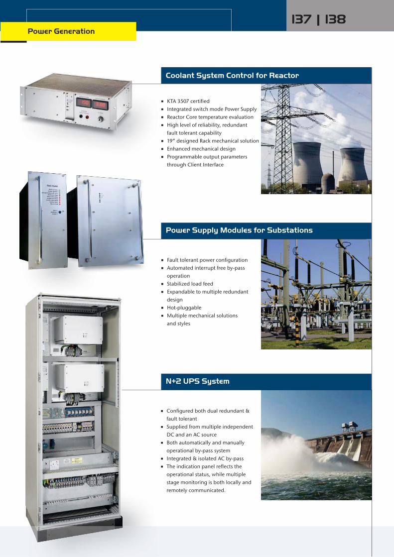
Configured both dual redundant & fault tolerant
Supplied from multiple independent DC and an AC source
Both automatically and manually operational by-pass system
Integrated & isolated AC by-pass The indication panel reflects the
operational status, while multiple stage monitoring is both locally and
remotely communicated.
KTA 3507 certified Integrated switch mode Power Supply Reactor Core temperature evaluation High level of reliability, redundant fault tolerant capability 19” designed Rack mechanical solution Enhanced mechanical design Programmable output parameters
through Client Interface
Fault tolerant power configuration Automated interrupt free by-pass
operation Stabilized load feed Expandable to multiple redundant
design Hot-pluggable Multiple mechanical solutions and styles
Power Supply Modules for Substations
N+2 UPS System
Coolant System Control for Reactor
Power Generation137 | 138
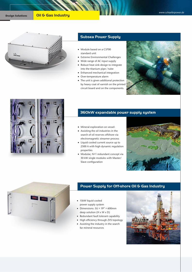
www.schaeferpower.de Design Solutions Design Solutions
Subsea Power Supply
Module based on a C3700 standard unit Extreme Environmental Challenges Wide range of AC input supply Robust heat sink design to integrate into the titanium pipe / tube Enhanced mechanical integration Over-temperature alarm The unit is given additional protection
by heavy coat of varnish on the printed circuit board and on the components.
15kW liquid cooled power supply system Dimensions: 5U × 19“ × 600mm deep solution (H x W x D) Redundant fault tolerant capability High efficiency through ZVS topology Assisting the industry in the search for mineral resources
Power Supply for Off-shore Oil & Gas Industry
360kW expandable power supply system
Mineral exploration on vessel: Assisting the oil industries in the
search of oil reserves offshore via electromagnetic streamer process
Liquid cooled current source up to 2500 A with high dynamic regulation properties
Modular, N+1 redundant concept via 30 kW single modules with Master/Slave configuration
15kWpowe
Dimedeep
Redu High Assist
for m
Oil & Gas Industry

On-board 3-D Radar Power Supply
Integrated combined solution
On-board Military UPS
5kW Modules ensuring a high power density Flexible orientation Capable of populating a 5U RACK with three units Capable of populating a 3U RACK with two units Engineered for high degree of shock & vibration
Integrated Inverter, Static Switch and Battery Charger Dimensions: 6U × 19“ × 500mm deep solution (H x W x D) Robust and reliable design Digital voltmeter display for DC input
(battery voltage) on front plate Push button for “Latch Reset” Common alarm with relay contact Digital voltmeter display for DC input
(battery voltage) on front plate
AC/DC converter with fan cooling High level of reliability, Redundant fault tolerant capability Environmental adapted to 97% non
condensing humidity Power Factor correction for three-phase input minimizing the load requirement of generator Client specific mechanical & electrical
design with special heat sinks
139 | 140Military Industry
On
AC/D High
fault Envir
cond Powe
threeload
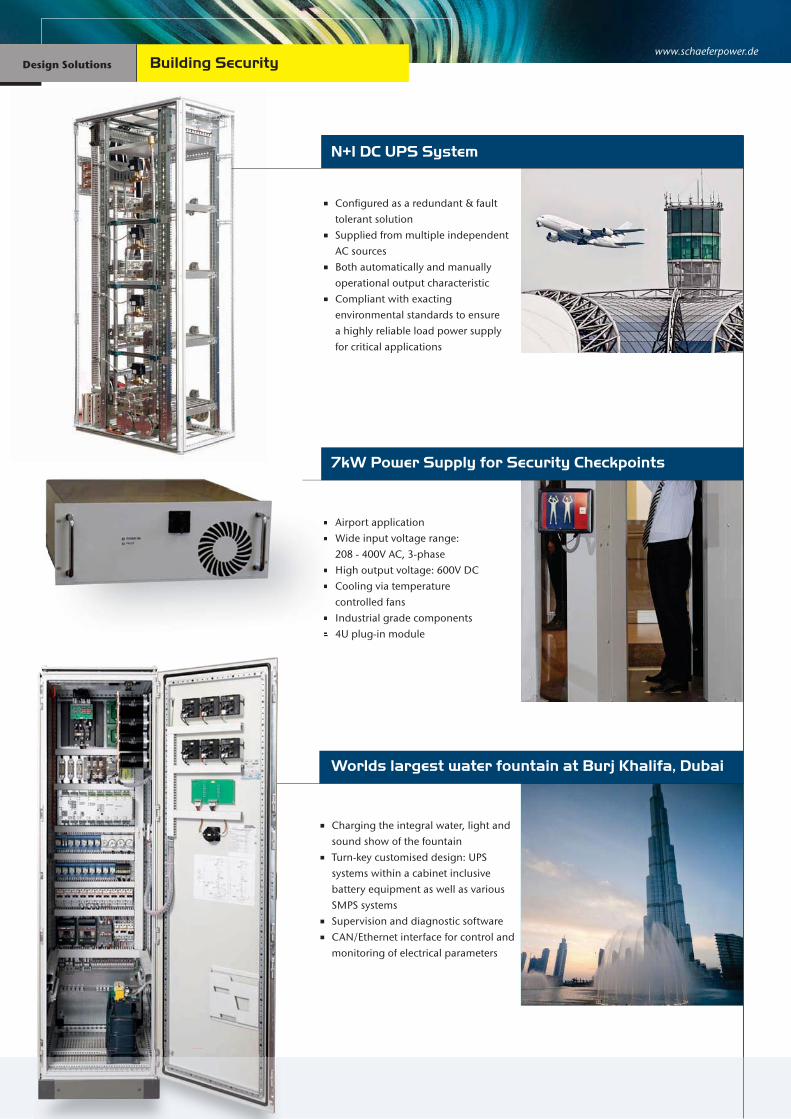
www.schaeferpower.de Design Solutions Design Solutions
N+1 DC UPS System
Configured as a redundant & fault tolerant solution
Supplied from multiple independent AC sources
Both automatically and manually operational output characteristic
Compliant with exacting environmental standards to ensure a highly reliable load power supply for critical applications
Charging the integral water, light and sound show of the fountain Turn-key customised design: UPS
systems within a cabinet inclusive battery equipment as well as various SMPS systems
Supervision and diagnostic software CAN/Ethernet interface for control and
monitoring of electrical parameters
Worlds largest water fountain at Burj Khalifa, Dubai
7kW Power Supply for Security Checkpoints
Airport application Wide input voltage range: 208 - 400V AC, 3-phase High output voltage: 600V DC Cooling via temperature controlled fans Industrial grade components 4U plug-in module
Building Security

DC/DC Converter for Robotics Power Supply
Digital controlled generator for Eroding Steel Rolls
40kW Liquid cooled Power Supply
Electrical Discharge Generator with adjustable power source: 0-30A
Synchronized output at Uout=300V with adjustable frequency in the range of 200Hz to 300KHz Pluggable system, installation on water heat sinks via pressure rails Communication via EtherCat (PC-generator)
For semiconductor manufacturing industry
Highly demanding environment Extreme load variations Transfer of thermal energy into a fluid for heat exchange re-capture Programmable output parameters through Client Interface
Wide input voltage range: 450 - 800V DC Multi output parameters Natural convection Remote on / off (inhibit) CAN-Bus interface High level of reliability, redundant fault tolerant capability
Trfo
Prth
141 | 142Industrial Automation
W4
M N R C H
re

www.schaeferpower.de Design Solutions Design Solutions
4kW Inverter System for Aircraft Mains Simulation
Ground equipment for mains simulation on the Eurofighter
Converter for 400Hz mains simulation Output selection, 3-phase AC or 3
individual DC voltages Each output is individually
programmable via RS232 interface in voltage and frequency
400Hz Input Frequency
For installation in explosive environments (hazardous area 1)
Allowing the failure of a single power supply, not affecting the controlled output
The overall power supply unit is housed within a certified Exd enclosure
An Exe enclosure being attached to the Exd enclosure contains all terminations, operator indications and switches
Safety Valve
1kW N+1 Tsunami Warning System
Sub sea power supply Input voltage 1200V DC up to 2450V DC (nominal) Output voltage required, 380V DC (300 – 400V DC calibration range) Galvanic isolation High level of reliability
S
2 O
G
Demanding Markets

143 | 144
If you are lost on the moon, marooned in the ocean or just dealing
with pollution, Schaefer has the POWER to find the solution.

www.schaeferpower.de
. . . . . . . . . . . . . . . . . . . . . . . . . . . . . . . . . . . . .
. . . . . . . . . . . . . . . . . . . . . . . . . . . . . . . . . . . . .
. . . . . . . . . . . . . . . . . . . . . . . . . . . . . . . . . . . . .
. . . . . . . . . . . . . . . . . . . . . . . . . . . . . . . . . . . . .
. . . . . . . . . . . . . . . . . . . . . . . . . . . . . . . . . . . . .
. . . . . . . . . . . . . . . . . . . . . . . . . . . . . . . . . . . . .
. . . . . . . . . . . . . . . . . . . . . . . . . . . . . . . . . . . . .
. . . . . . . . . . . . . . . . . . . . . . . . . . . . . . . . . . . . .
. . . . . . . . . . . . . . . . . . . . . . . . . . . . . . . . . . . . .
. . . . . . . . . . . . . . . . . . . . . . . . . . . . . . . . . . . . .
. . . . . . . . . . . . . . . . . . . . . . . . . . . . . . . . . . . . .
. . . . . . . . . . . . . . . . . . . . . . . . . . . . . . . . . . . . .
. . . . . . . . . . . . . . . . . . . . . . . . . . . . . . . . . . . . .
. . . . . . . . . . . . . . . . . . . . . . . . . . . . . . . . . . . . .
. . . . . . . . . . . . . . . . . . . . . . . . . . . . . . . . . . . . .
. . . . . . . . . . . . . . . . . . . . . . . . . . . . . . . . . . . . .
. . . . . . . . . . . . . . . . . . . . . . . . . . . . . . . . . . . . .
. . . . . . . . . . . . . . . . . . . . . . . . . . . . . . . . . . . . .
. . . . . . . . . . . . . . . . . . . . . . . . . . . . . . . . . . . . .
. . . . . . . . . . . . . . . . . . . . . . . . . . . . . . . . . . . . .
. . . . . . . . . . . . . . . . . . . . . . . . . . . . . . . . . . . . .
. . . . . . . . . . . . . . . . . . . . . . . . . . . . . . . . . . . . .
. . . . . . . . . . . . . . . . . . . . . . . . . . . . . . . . . . . . .
. . . . . . . . . . . . . . . . . . . . . . . . . . . . . . . . . . . . .
. . . . . . . . . . . . . . . . . . . . . . . . . . . . . . . . . . . . .
. . . . . . . . . . . . . . . . . . . . . . . . . . . . . . . . . . . . .
. . . . . . . . . . . . . . . . . . . . . . . . . . . . . . . . . . . . .
. . . . . . . . . . . . . . . . . . . . . . . . . . . . . . . . . . . . .
. . . . . . . . . . . . . . . . . . . . . . . . . . . . . . . . . . . . .
. . . . . . . . . . . . . . . . . . . . . . . . . . . . . . . . . . . . .
. . . . . . . . . . . . . . . . . . . . . . . . . . . . . . . . . . . . .
. . . . . . . . . . . . . . . . . . . . . . . . . . . . . . . . . . . . .
. . . . . . . . . . . . . . . . . . . . . . . . . . . . . . . . . . . . .
. . . . . . . . . . . . . . . . . . . . . . . . . . . . . . . . . . . . .
. . . . . . . . . . . . . . . . . . . . . . . . . . . . . . . . . . . . .
. . . . . . . . . . . . . . . . . . . . . . . . . . . . . . . . . . . . .
. . . . . . . . . . . . . . . . . . . . . . . . . . . . . . . . . . . . .
. . . . . . . . . . . . . . . . . . . . . . . . . . . . . . . . . . . . .
. . . . . . . . . . . . . . . . . . . . . . . . . . . . . . . . . . . . .
. . . . . . . . . . . . . . . . . . . . . . . . . . . . . . . . . . . . .
. . . . . . . . . . . . . . . . . . . . . . . . . . . . . . . . . . . . .
. . . . . . . . . . . . . . . . . . . . . . . . . . . . . . . . . . . . .
. . . . . . . . . . . . . . . . . . . . . . . . . . . . . . . . . . . . .
. . . . . . . . . . . . . . . . . . . . . . . . . . . . . . . . . . . . .
. . . . . . . . . . . . . . . . . . . . . . . . . . . . . . . . . . . . .
. . . . . . . . . . . . . . . . . . . . . . . . . . . . . . . . . . . . .
. . . . . . . . . . . . . . . . . . . . . . . . . . . . . . . . . . . . .
Notes

. . . . . . . . . . . . . . . . . . . . . . . . . . . . . . . . . . . . .
. . . . . . . . . . . . . . . . . . . . . . . . . . . . . . . . . . . . .
. . . . . . . . . . . . . . . . . . . . . . . . . . . . . . . . . . . . .
. . . . . . . . . . . . . . . . . . . . . . . . . . . . . . . . . . . . .
. . . . . . . . . . . . . . . . . . . . . . . . . . . . . . . . . . . . .
. . . . . . . . . . . . . . . . . . . . . . . . . . . . . . . . . . . . .
. . . . . . . . . . . . . . . . . . . . . . . . . . . . . . . . . . . . .
. . . . . . . . . . . . . . . . . . . . . . . . . . . . . . . . . . . . .
. . . . . . . . . . . . . . . . . . . . . . . . . . . . . . . . . . . . .
. . . . . . . . . . . . . . . . . . . . . . . . . . . . . . . . . . . . .
. . . . . . . . . . . . . . . . . . . . . . . . . . . . . . . . . . . . .
. . . . . . . . . . . . . . . . . . . . . . . . . . . . . . . . . . . . .
. . . . . . . . . . . . . . . . . . . . . . . . . . . . . . . . . . . . .
. . . . . . . . . . . . . . . . . . . . . . . . . . . . . . . . . . . . .
. . . . . . . . . . . . . . . . . . . . . . . . . . . . . . . . . . . . .
. . . . . . . . . . . . . . . . . . . . . . . . . . . . . . . . . . . . .
. . . . . . . . . . . . . . . . . . . . . . . . . . . . . . . . . . . . .
. . . . . . . . . . . . . . . . . . . . . . . . . . . . . . . . . . . . .
. . . . . . . . . . . . . . . . . . . . . . . . . . . . . . . . . . . . .
. . . . . . . . . . . . . . . . . . . . . . . . . . . . . . . . . . . . .
. . . . . . . . . . . . . . . . . . . . . . . . . . . . . . . . . . . . .
. . . . . . . . . . . . . . . . . . . . . . . . . . . . . . . . . . . . .
. . . . . . . . . . . . . . . . . . . . . . . . . . . . . . . . . . . . .
. . . . . . . . . . . . . . . . . . . . . . . . . . . . . . . . . . . . .
. . . . . . . . . . . . . . . . . . . . . . . . . . . . . . . . . . . . .
. . . . . . . . . . . . . . . . . . . . . . . . . . . . . . . . . . . . .
. . . . . . . . . . . . . . . . . . . . . . . . . . . . . . . . . . . . .
. . . . . . . . . . . . . . . . . . . . . . . . . . . . . . . . . . . . .
. . . . . . . . . . . . . . . . . . . . . . . . . . . . . . . . . . . . .
. . . . . . . . . . . . . . . . . . . . . . . . . . . . . . . . . . . . .
. . . . . . . . . . . . . . . . . . . . . . . . . . . . . . . . . . . . .
. . . . . . . . . . . . . . . . . . . . . . . . . . . . . . . . . . . . .
. . . . . . . . . . . . . . . . . . . . . . . . . . . . . . . . . . . . .
. . . . . . . . . . . . . . . . . . . . . . . . . . . . . . . . . . . . .
. . . . . . . . . . . . . . . . . . . . . . . . . . . . . . . . . . . . .
. . . . . . . . . . . . . . . . . . . . . . . . . . . . . . . . . . . . .
. . . . . . . . . . . . . . . . . . . . . . . . . . . . . . . . . . . . .
. . . . . . . . . . . . . . . . . . . . . . . . . . . . . . . . . . . . .
. . . . . . . . . . . . . . . . . . . . . . . . . . . . . . . . . . . . .
. . . . . . . . . . . . . . . . . . . . . . . . . . . . . . . . . . . . .
. . . . . . . . . . . . . . . . . . . . . . . . . . . . . . . . . . . . .
. . . . . . . . . . . . . . . . . . . . . . . . . . . . . . . . . . . . .
. . . . . . . . . . . . . . . . . . . . . . . . . . . . . . . . . . . . .
. . . . . . . . . . . . . . . . . . . . . . . . . . . . . . . . . . . . .
. . . . . . . . . . . . . . . . . . . . . . . . . . . . . . . . . . . . .
. . . . . . . . . . . . . . . . . . . . . . . . . . . . . . . . . . . . .
. . . . . . . . . . . . . . . . . . . . . . . . . . . . . . . . . . . . .

edit
ion
ME1
3
www.schaeferpower.de
SCHÄFER Elektronik GmbH
Oststrasse 17, Gamshurst77855 AchernGermanyPhone +49 (0)7841-2052-0Fax +49 (0)[email protected]
SCHAEFER Inc.
45 South StreetHopkinton, MA 01748USAPhone +1 508-435-6400Fax +1 [email protected]
SCHAEFER GmbH Middle East
5EA-528, Dubai Airport Free ZoneP.O.Box: 293539, DubaiUAEPhone (+971) 4 - 204 5831Fax (+971) 4 - 204 [email protected]
For more informationjust scan this QR-Code!
wwwwwwwwwwwwwwwwwwwwwwwwwwwwwwwwwwwwwwwwwwwwwwwwwwwwwwwwwwwwwwwwwwwwwwwwwwwwwwwwwwwwwwwwwwwwwwwwwwwwwwwwwwwwwwwwwwwwwwwwwwwwwwwwwwwwwwwwwwwwwwwwwwwwwwwwwwwwwwwwwwwwwwwwwwwwwwwwwwwwwwwwwwww..............ssssssssssssssssssssssssssssssssssssssssssssssssssssssssssssscccccccccccccccccccccccccccccccccccccccccccccccccccccccccchhhhhhhhhhhhhhhhhhhhhhhhhhhhhhhhhhhhhhhhhhhhhhhhhhhhhhhhhhhhhhhhhaaaaaaaaaaaaaaaaaaaaaaaaaaaaaaaaaaaaaaaaaaaaaaaaaaaaaaaaaaaaaaaaaeeeeeeeeeeeeeeeeeeeeeeeeeeeeeeeeeeeeeeeeeeeeeeeeeeeeeffffffffffffffffffffffffffffffffffffffffffffffffffffffffffeeeeeeeeeeeeeeeeeeeeeeeeeeeeeeeeeeeeeeeeeeeeeeeeeeeeeeeeeeeeeeeeeeeeeeeeeeeeeeeeeeeeeeeeeeerrrrrrrrrrrrrrrrrrrrrrrrrrrrrrrrrrrrrrrrrrrrrpppppppppppppppppppppppppppppppppppppppppppppppppppppppppppppppppppppppppppppppppppoooooooooooooooooooooooooooooooooooooooooooooooooooowwwwwwwwwwwwwwwwwwwwwwwwwwwwwwwwwwwwwwwwwwwwwwweeeeeeeeeeeeeeeeeeeeeeeeeeeeeeeeeeeeeeeeeeeeeerrrrrrrrrrrrrrrrrrrrrrrrrrrrrrrrrrrrrrrrrrrrrrrrrrrrrrrrrrrrrrrrrrrrrrrrrrrrrrrrrr........................ddddddddddddddddddddddddddddddddddddddddddddddddddddddddddddddddddddeeeeeeeeeeeeeeeeeeeeeeeeeeeeeeeeeeeeeeeeeeeeeeeeeeeeeeeeeeeeeewww.schaeferpower.de
SCHÄFER Elektronik GmbH
OsOsOsOOOOOO tststststttssttsttt trtrtrtrtrrtrrasasasasasasasasasasasasssasaa seseseeeeseseseseseeeeseseesesesesee 11 1 1111 111117,7,7,777,777,7,77, GG GGG GG G GGGGGamammmamammamshshshshsshsshss urururuururrruuu ststststststststttttttt77777777777777778585858858585885858858 5 5555 5 55 AcAcAcAcAccccAccAccccccccAcccccccheheheheheheheheheheeeh rnrnrnrnrnrnrnrnrnnrnnrnnnrnrGeGeGGGGeGeeG rmrmrrmrmrmrmrmrrrmrmmmmanananaaaana yyyyyyyyyyyyyyyyyyyyyPhPhPhPhPhPhPhhPhhhhPhPhPhPhhPhPhhononoonononononoooonononoo eeeeee +4+++++4+44+4+4+4+++++ 999 9 9 99 9 (0(0(0(0(00(00(00(0(000(0(0(000000000000)7)7)7)7)7)7)7)7)7)7)7)7777)7)))) 888888888888884141414141414141414141141414444 -2-2--2-2-2-22-2-2-2-22222222-- 050505050505050505050505055052-2-2-2-2-2-2-2 00000000000000000000FaFaFaFaFaFaFaaFaFaaFaFaaFaaFaFaxxxxxxxxxxxxxxxx +4++++4+4+4+4+4++4++++++++4+ 99 9 9 99 99 (0(0(0(0(0(0(00(0((0000000)7)7)7)7)7)7)7)7))7)7)77))))))) 888888888888414141414141441414111441144 -2-2--2-2-2-2-2-2-2--2-2-2-2-2---22220505050505050505505055055555005500 2-2-2-2-2-2-22-2-22222222 5252525255255252525252552222252555525555555555555mamamamamammamammmamamamamaaamamaamm iiliilllilililliliililliiiiiiilll@s@s@s@s@s@@@s@s@s@s@s@s@@@@s@s@ss@ssss@@sss@@s@s@sss@s@ssssssssssssschcchchchhhhchchchchchhhhhchchcchcchcchchchchchchcchccchhhhhhhchchhchcchhchchhcccccchccccchhaeaaeaeaeaeaeaeaeeefefffefefefefeeeeeeefeerprppprppprppprpppprpppprppppppppprpppppppppppooooooowowowowwoooooooooowowowowoooowwoooooooooooooooooooooooowwwwwwwoowwowwooowwoowowooowwererereeeeeeeeeere .d.ddd.ddd.ddddddddddddeeeeeee
OsOOsOOOO tststststttsststt tttrtrtrasasasaasseseseeeeeee 1111111111177777777777777 GGGGGGGGGGGGGGGGGamammmmmmmshshshshshss uruuruururrststststssOststrasse 17, Gamshurst77855 AchernGermanyPhone +49 (0)7841-2052-0Fax +49 (0)[email protected]
SCHAEFER Inc.
45545454545444 S S SS Sououououuo thththth SS SSStrtrtrtrreeeeeeeeeettttHHHHoHoHoHoHH pkpkpkpkinininntototon,n,n,n, MM MMA AA AAA 0101010117474747474488888888888USUSUSUUSUU AAAAAAPhhPhPhPhPhPhhPhPhPhPhPhhPhhPhPPhhhhPhPhhonoonononoonononononononoononononno eeeeeeeeeeeeeeeee +1+1+1+1++1+1+11+1+1+1+111+1+11+11+11+11++1++1+++ 5050505050505050550500050505005050005500050550055005008-88-8-8--8-8-8-8-8-8-8-8--8-8-8-8-888-888-8-888888 434343434343434434343434344434333443333333434333333433334344333333334355555-5-5-55-5-5-5-5-5-5--5-5-5555-5--5-5-55-555-555-55555 666646464646464646466464464666464646646466644646646666666644464666446440000000000000000000000000000000000000000000000000000000000FaFaFaFaFaFaFaFaaFaaxxxxxxxxxxxxxx +1+1+1+1+1+1+1+1+1+1+11+1+1+1+1++1+1+1+11++1+1+1 50505050505505555055050505050050500505 8-8-8-8-8-8-8-8-8-88----88-8-88--8-888-8-8-888888 434343434343343434343334343434343434343434343434333343343334343343333334335-5-55-5-5--5-55-5-55-5-55-5-5-5-5555-555-5---5555555555 6666646646646646464466666464666646464466666466464666646664666464664466646 000000000000000000000000001111111111111111sasasasasasaasaleleleleleeleeesss@s@s@@@@s@s@@sss@s@s@@@s@@s@s scscscscscscscscscscscs hhahhhahhahahhhhahahhahaaahhhahhhaaefefefefefefefefefefeffeffffffffefererererererererererereee popopopopopoooooopopopopopoopopopopoooopopopppoooooopooppopopopppooooooowwewewewewweweweweewewewewewewewewweewewwwwewwwwwwewwwewewewewweeeeerrr.rrrrrr.rrrrr.rrrrrrr.rrrrr.rr.r.r.rr.rrr.rr.r.r.rrrr.rr.cocccocococococococcccccococococccoccococcoccccccccocoommmmmmmmm
45454545455 SSSSSououoouuo ththhth SSStrtrtreeeeeetttt45 South StreetHopkinton, MA 01748USAPhone +1 508-435-6400Fax +1 [email protected]
SCHAEFER GmbH Middle East
5E5E55E5E55E5EE5EEEA-AA-AA-A-A-A-AA-AAA-AA-AA 52525225228,8,,8,8,8, D DDD DD DDubububbbbbbubb iaiaiaiiaiaii A A A AAirirririrpopopopooooooopooooopopoooooooortrtrtrrtrtrrrtrtrtrrtrr F F F F FFFFFFFFFFrererereererrerererereererererrererreeeeeeeeeeeeeeeeeeeeeeee eeee eeeeeee eeeeeeee ZoZoZoZooooooZoooZooZooooZoZooooooZoooooooZooooZoZoZZooooZonnnnnenenenenennnnnnnnnnnennennenenenPPPP.P.PP.P.O.OO.O.OOO.O.OO BoBoBoBoooooBox:x:x:x:x:x:x:xx: 2 2 2222222222222229939399393939393939333535353535335353553535355333333553399,9,9,9,9,9999,99,999,99 D DD DD DD DDDDDDDDDDDDDDDububububububbubububbubbububububbbbbaiaiaiaiaaiaiaaiaaaiaiaaaiaiUAUAUAUAUAUAUAUAUAAAAAEEEEEEEEEEEEEEEEEPhPhPhPhPhhPhPhhhonononononononoonoonoo eeeee (((+(+(+(+(+(+((+(((((+(((+(+((++(++(( 979797979797979779797979779979797771)1)1)1)1)1)1)))1)))1)111)111))))))) 4 44 4 44 4 44 - - - - -- 2 2 2 22 2 2 2204040404000404040040 5 5 5 5 5 5 583838383833838331111111111111FaFaFaFaFaFaaFaaxxxxx ((+(+(+(+(+(+(+(+(+((+((+(((((+(+(+(((+( 9797979797979797979797999797971)1)1)1)1)))1)1))))1)))1)) 4 4 444 4 44 - - - -- 2 2 2 2 2 2 22040404040404004040004400 5 5 5555555 5 5 5 583838383838338383838388383322222222222222222222222222222mamamamamamamamaamam iililiiililililililiiliiilililii @s@s@s@s@s@s@s@s@s@s@s@@@s@@s@s@ssschchchchchchhhchhchhhchcchchcchcccchhhhhaeaeaeaeaeaeaeaeaaeaeaaaa fefefefefefefeferprprprprppprprppprppppowowowowowwowowerereeeerer-m-m-m-mmmm-mm-m-mmmmmmmme.e.e.ee.ee.e.eeeeee cocococococococococococococoooooommmmmmmmmmmmmmmmmmmmmmmm
5E5E5E55EEE55EE5EEAAAAAAAAAAAAAAA 525255525255288 DDDDDubububbbbbbbaiaaiiaiaiiiaai AAAAAAAAAAAAAirirriiiiiiii popopopoppopopoppooooopoorttrtrtrtrtrttrr FFFFFFFFFFFFrererererrerreeeerer eeeeee ZoZoooZoooooonennenenennnnenn5EA-528, Dubai Airport Free ZoneP.O.Box: 293539, DubaiUAEPhone (+971) 4 - 204 5831Fax (+971) 4 - 204 [email protected]
Related Documents


