Power control - Hydraulic Equipments - Sales & Service - Line Up ● Pumps ● Pressure Control Valves ● Flow Control Valves ● Directional Valves ● Check Valves ● Cartridge Valves ● Proportional & Servo Valves ● Digital Valves ● Motors ● Power Packages ● Manifold Systems ● Sensors ● Model Code Index CAUTION - NOTICE - TOKIMEC is one of Japan's leading manufacturers of hydraulic equipment. We provide a full range of hydraulic components such as pumps, valves, actuators, and related electronics and sensors, as well as standard and custom power units to customers worldwide. Many of our products are tailored for specific applications, such as plastics injection molding, diecast machinery, and machine tools and we have gained a reputation for products which provide superior value in terms of performance and quality. TOKIMEC INC. - Fluid Power Phone:+81-3-3737-8631 Fax:+81-3-3737-8666

Welcome message from author
This document is posted to help you gain knowledge. Please leave a comment to let me know what you think about it! Share it to your friends and learn new things together.
Transcript
Power control - Hydraulic Equipments
- Sales & Service -
Line Up
Pumps Pressure Control Valves Flow Control Valves Directional Valves Check Valves Cartridge Valves Proportional & Servo Valves Digital Valves Motors
Power Packages Manifold Systems Sensors
Model Code Index
CAUTION - NOTICE -
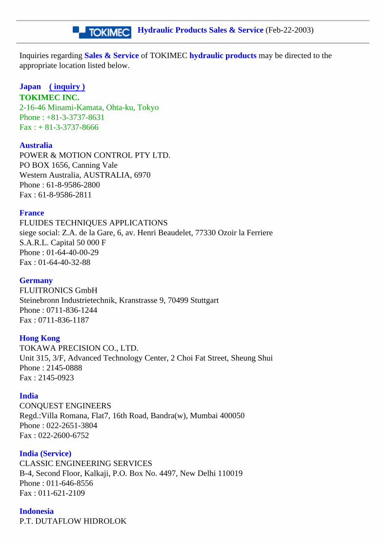
TOKIMEC is one of Japan's leading manufacturers of hydraulic equipment. We provide a full range of hydraulic components such as pumps, valves, actuators, and related electronics and sensors, as well as standard and custom power units to customers worldwide. Many of our products are tailored for specific applications, such as plastics injection molding, diecast machinery, and machine tools and we have gained a reputation for products which provide superior value in terms of performance and quality.
TOKIMEC INC. - Fluid Power Phone:+81-3-3737-8631 Fax:+81-3-3737-8666
Hydraulic Products Sales & Service (Feb-22-2003)
Inquiries regarding Sales & Service of TOKIMEC hydraulic products may be directed to the appropriate location listed below.
Japan ( inquiry )TOKIMEC INC.2-16-46 Minami-Kamata, Ohta-ku, TokyoPhone : +81-3-3737-8631Fax : + 81-3-3737-8666
AustraliaPOWER & MOTION CONTROL PTY LTD.PO BOX 1656, Canning ValeWestern Australia, AUSTRALIA, 6970Phone : 61-8-9586-2800Fax : 61-8-9586-2811
FranceFLUIDES TECHNIQUES APPLICATIONSsiege social: Z.A. de la Gare, 6, av. Henri Beaudelet, 77330 Ozoir la FerriereS.A.R.L. Capital 50 000 FPhone : 01-64-40-00-29Fax : 01-64-40-32-88
GermanyFLUITRONICS GmbHSteinebronn Industrietechnik, Kranstrasse 9, 70499 StuttgartPhone : 0711-836-1244Fax : 0711-836-1187
Hong KongTOKAWA PRECISION CO., LTD.Unit 315, 3/F, Advanced Technology Center, 2 Choi Fat Street, Sheung ShuiPhone : 2145-0888Fax : 2145-0923
IndiaCONQUEST ENGINEERSRegd.:Villa Romana, Flat7, 16th Road, Bandra(w), Mumbai 400050Phone : 022-2651-3804Fax : 022-2600-6752
India (Service)CLASSIC ENGINEERING SERVICESB-4, Second Floor, Kalkaji, P.O. Box No. 4497, New Delhi 110019Phone : 011-646-8556Fax : 011-621-2109
IndonesiaP.T. DUTAFLOW HIDROLOK
Rukan Green Garden, Blok Z2-68JI. Daan Mogot Km 3. Jakarta 11520Phone : 021-581-4173Fax : 021-552-9023
MalaysiaPOWER & MOTION SDN.BHDNo.15, Jalan PJS 11/2, Taman Subang Indah, 46000 Petaling Jaya, Selangor Darul Ehsan, MalaysiaPhone : 03-733-1500Fax : 03-738-0266
The NetherlandsACTION-HYDRO B.V.Kabelstraat 7, Industrieterrein "Gooise Kant", 1322 AD AlmerePhone : 036-53-60-204Fax : 036-53-60-324
People's Republic of ChinaTOKAWA PRECISION CO., LTD.Room 605, Chunshengjiang Building, 400 Zhejiang Road, Shanghai 200001Phone : +86-21-6351-9041, +86-21-6351-9042Fax : +86-21-6351-9040
People's Republic of ChinaTOKAWA PRECISION CO., LTD.Room 808, Yin Xin Building, 787 Bai Zhang Road, East, Ningbo, Zip 315040Phone : +86-574-8770-6936Fax : +86-574-8770-1777
PhilippinesMORGAN TRADING INC.3 Country Club, Cityland Houses, Valle Verde, Pasig, M.M.Phone : 02-631-3607Fax : 02-631-4028
SingaporePOWER & MOTION CONTROL PTE LTD.30, Tuas South Street 5, Singapore 637826Phone : 6261-6606Fax : 6265-7789
South KoreaTOKIMEC KOREA HYDRAULICS CO., LTD.HEAD OFFICELG Bldg.6F, #588, Guro-Dong, Guro-Gu, Seoul 152-050Phone : 02-2630-5851Fax : 02-2630-5858
GURO BRANCHA-108, Ansung Machinery Store, 410-13Shindorim-Dong, Guro-Gu, Seoul, KoreaPhone : 02-676-7132Fax : 02-676-7133
BUSAN BRANCH28-107, Busan Industry Supplies StoreKaebub-Dong, Sasang-ku, Busan-Si, KoreaPhone : 051-319-2128Fax : 051-319-2186
SpainHIDRAVICK S.A.Pol. Ind. Centro de ViladecansC/de la Forja, n. 37, 08840 - Viladecans, BarcelonaPhone : 936-37-66-44Fax : 936-37-75-10
SwedenHYDRO NOVA ABFagerstagatan 19A, Box 65, S-163 91 SpangaPhone : 0-8-795-22-00Fax : 0-8-795-22-26
TaiwanSSOMAX INDUSTRY INC.9F, No.196, Sec. 2, Chung Shing Rd., Hsin Tien City, TaipeiPhone : 02-2910-0258Fax : 02-2913-1188
ThailandTHAI AGENCY ENGINEERING CO., LTD.2nd - 3rd Floor, Vorasin Building, 9 Soi Yasoop 2, Vipavadi Rangsit Rd., Ladyao, Chatujak, Bangkok 10900Phone : 02-691-5900Fax : 02-691-5820
U.K.WYKO INDUSTRIAL DISTRIBUTIONAmbar Way, Halesowen B62 8WG, West MidlandsPhone : 0121-508-6286Fax : 0121-508-6221
U.S.A.TOKIMEC U.S.A. INC.445 S. Figueroa St., Suite 3770, Los Angeles, CA 90071Phone : 213-689-4747Fax : 213-689-0303
U.S.A.AIR HYDRO POWER CO.3405 Robards Court, PO Box 34170, Louisville, KY 40233Phone : 502-451-1000 (800-292-1672)Fax : 502-456-2837
U.S.A.HYDRADYNE, INC.
1000 Muirfield Dr., Hanover Park, IL 60103Phone : 630-563-3600Fax : 630-563-3850
U.S.A.SENTINEL FLUID CONTROLS5702 Opportunity Dr., Toledo, OH 43612Phone : 419-478-9086 (800-686-8700)Fax : 419-478-4839
U.S.A.PABCO FLUID POWER CO.5750 Hillside Ave., Cincinnati, OH 45233Phone : 513-941-6200 (800-727-2226)Fax : 513-941-6452
Hydraulic Equipment Model Code Index Back
Model Code Index
Please click desired model code for further infomation.
2520VQ25M25VQ3520VQ3525VQ35M35VQ4520VQ4525VQ4535VQ45M45VQ4CG4CT4SL-350MBLGBRC-175C-552C-572C2C2GC2PGC5GC5PGCBCFCGCGLCGRCOMCRCTCVCCVICVSHD-CGD-DF(R)GD-F(R)GDC-A1/4
DC-AEDC-AT1/2DC-AX4DC-B*B/CDE-XDEFFGDEFRGDF1OP1DG15S2DG17VDG20SDG2MDG2S4DG3S-10DG3VDG4LDG4M4DG4S-4DG4SMDG4V-3DG4V-5DG4VC-3DG4VC-5DG4VS-3DG4VS-5DG5S-10DG5VDGMCRDGMSLDT8P1EC-4SEC-XEPAEPADEPCG2-01EPCG2-03/06/10EPDG1EPFG-03/06/10EPFG-O1EPFRGESMESP
ETPF11-SQP*F11-SQP**F11-SQP***F11-SQPS*F11-SQPS**FCG/FGFCGT-02FN(1)-4FN1GFNGGR(2)HGR-MLFCGMHT(multi)MHTP-X/ZP100VP130VP16VP21VP31VP40VP70VPB-X/ZPCGPH80/100/130PVB(Q)Q****(Q-PAC)RFRG-3FRGRG2-3FRTSQP*SQP**SQP***SQPS*SQPS**ST3STC-YTCG20
TCG50-80TCGETFGTTFN(C)GTGMHRTGMHXTGMSHTHPCGTU(TU-PAC)U-D35U-D37URG1URG2URMCV-104/105V-108/109V-124/125V-128/129V-134/135V-138/139V-144/145V-148/149V20V30VVJXCGXCTXFXGXG1XGLXT(L)
Sales & Service Hydraulic Equipment Back
Design and specifications are subject to change without prior notice, and without any obligation on the part of the manufacturer.

VQ Series (Double) - Vane Pumps
MODEL CODE
(F3-) 3525VQ 38 A 17 (F) - 86 C C 20 (L) - JA
1 2 3 4 5 6 7 8 9 10 11
1. Fluid
Omit for mineral oil
F3: phosphate ester
2. Double vane pump
2520VQ Series
3520, 3525VQ Series
4520, 4525, 4535VQ Series
3. Pump displacement code
Series Displacement
25**VQ 12, 14, 17, 21
35**VQ 25, 30, 35, 38
45**VQ 42, 50, 60
4. Port connection
A: SAE4 bolt flange connection
5. Pump displacement code
Series Displacement
**20VQ 5, 8, 11, 12, 14
**25VQ 12, 14, 17, 21
**35VQ 25, 30, 35, 38
6. Pump mounting
Omit for flange mounting
F: foot mounting
7. Shaft
1: parallel sq. key (2520VQ only)
86: parallel sq. key
11: spline
8. Outlet position (viewed from cover end)
A: opposite inlet
B: 90º CCW from inlet
C: inline with inlet
D: 90º CW from inlet
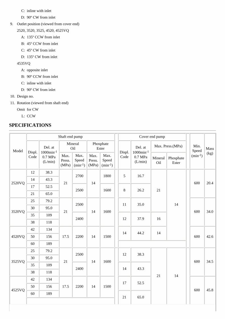
9. Outlet position (viewed from cover end)
2520, 3520, 3525, 4520, 4525VQ
A: 135º CCW from inlet
B: 45º CCW from inlet
C: 45º CW from inlet
D: 135º CW from inlet
4535VQ
A: opposite inlet
B: 90º CCW from inlet
C: inline with inlet
D: 90º CW from inlet
10. Design no.
11. Rotation (viewed from shaft end)
Omit for CW
L: CCW
SPECIFICATIONS
Model
Shaft end pump
Cover end pump
Min.
Speed(min-1)
Mass(kg)Displ.
Code
Del. at1000min-1
0.7 MPa(L/min)
MineralOil
PhosphateEster
Displ.Code
Del. at1000min-1
0.7 MPa(L/min)
Max. Press.(MPa)
Max.Press.(MPa)
Max.Speed(min-1)
Max.Press.(MPa)
Max.Speed(min-1)
MineralOil
PhosphateEster
2520VQ
12 38.3
21
2700
14
1800
5 16.7
21
14
600 20.414 43.3
17 52.52500 1600 8 26.2
21 65.0
3520VQ
25 79.2
21
2500
14 1600
11 35.0
600 34.030 95.0
35 1092400 12 37.9 16
38 118
4520VQ
42 134
17.5 2200 14 150014 44.2 14
600 42.650 156
60 189
3525VQ
25 79.2
21
2500
14 1600
12 38.3
21 14
600 34.530 95.0
35 1092400 14 43.3
38 118
4525VQ
42 134
17.5 2200 14 150017 52.5
600 45.850 156
60 18921 65.0
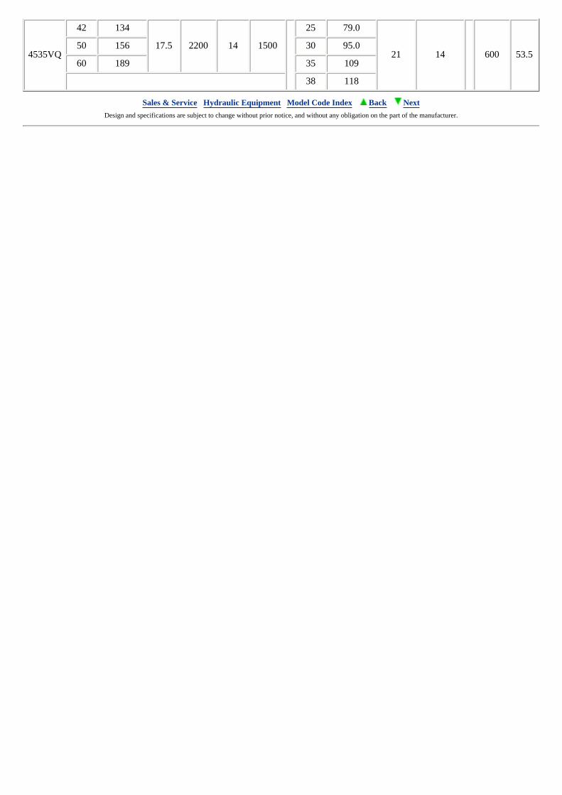
4535VQ
42 134
17.5 2200 14 1500
25 79.0
21 14 600 53.550 156 30 95.0
60 189 35 109
38 118
Sales & Service Hydraulic Equipment Model Code Index Back Next Design and specifications are subject to change without prior notice, and without any obligation on the part of the manufacturer.
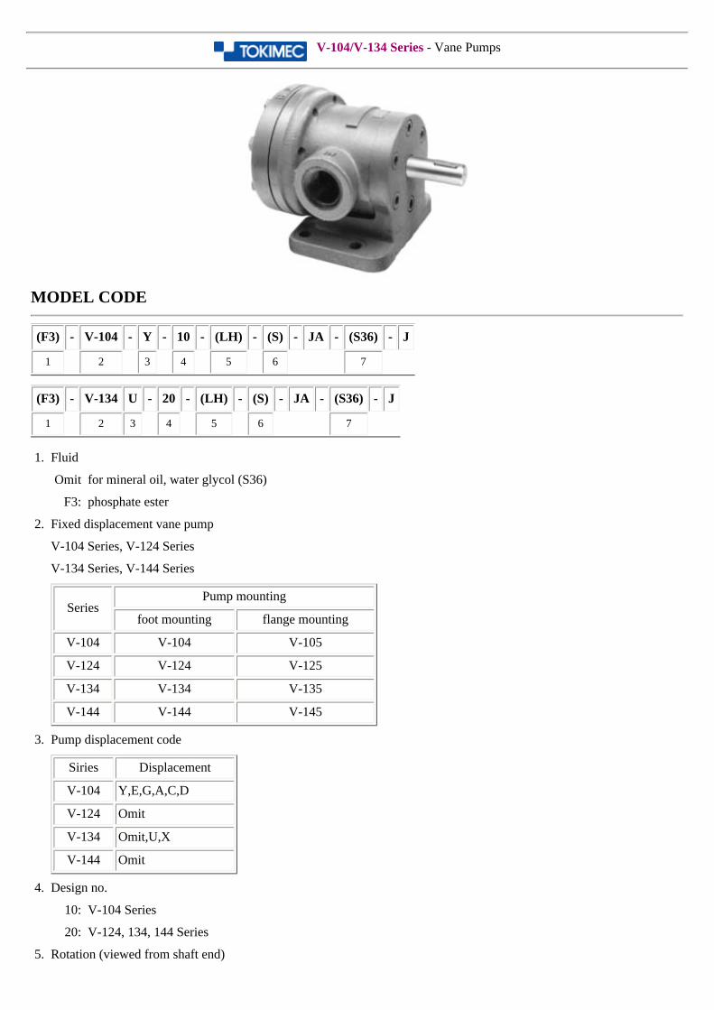
V-104/V-134 Series - Vane Pumps
MODEL CODE
(F3) - V-104 - Y - 10 - (LH) - (S) - JA - (S36) - J
1 2 3 4 5 6 7
(F3) - V-134 U - 20 - (LH) - (S) - JA - (S36) - J
1 2 3 4 5 6 7
1. Fluid
Omit for mineral oil, water glycol (S36)
F3: phosphate ester
2. Fixed displacement vane pump
V-104 Series, V-124 Series
V-134 Series, V-144 Series
SeriesPump mounting
foot mounting flange mounting
V-104 V-104 V-105
V-124 V-124 V-125
V-134 V-134 V-135
V-144 V-144 V-145
3. Pump displacement code
Siries Displacement
V-104 Y,E,G,A,C,D
V-124 Omit
V-134 Omit,U,X
V-144 Omit
4. Design no.
10: V-104 Series
20: V-124, 134, 144 Series
5. Rotation (viewed from shaft end)
Omit for CW
LH: CCW
6. Connect port position (foot mounting, viewed from shaft end)
Omit: inlet is left side, outlet is right side(standard)
S: inlet is right side, outlet is left side
7. Special feature
S36: water glycol
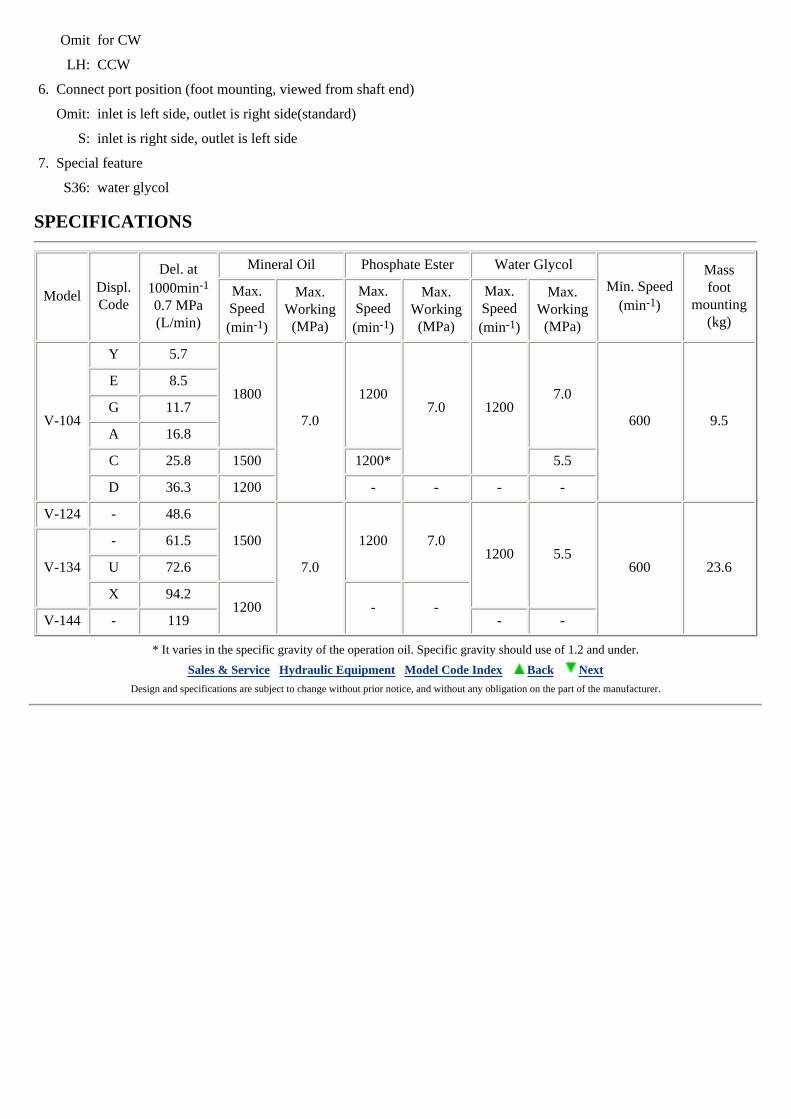
SPECIFICATIONS
ModelDispl.Code
Del. at1000min-1
0.7 MPa(L/min)
Mineral Oil Phosphate Ester Water Glycol
Min. Speed(min-1)
Massfoot
mounting(kg)
Max.Speed(min-1)
Max.Working
(MPa)
Max.Speed(min-1)
Max.Working
(MPa)
Max.Speed(min-1)
Max.Working
(MPa)
V-104
Y 5.7
1800
7.0
12007.0 1200
7.0
600 9.5
E 8.5
G 11.7
A 16.8
C 25.8 1500 1200* 5.5
D 36.3 1200 - - - -
V-124 - 48.6
1500
7.0
1200 7.01200 5.5
600 23.6V-134
- 61.5
U 72.6
X 94.21200 - -
V-144 - 119 - -
* It varies in the specific gravity of the operation oil. Specific gravity should use of 1.2 and under.
Sales & Service Hydraulic Equipment Model Code Index Back Next Design and specifications are subject to change without prior notice, and without any obligation on the part of the manufacturer.
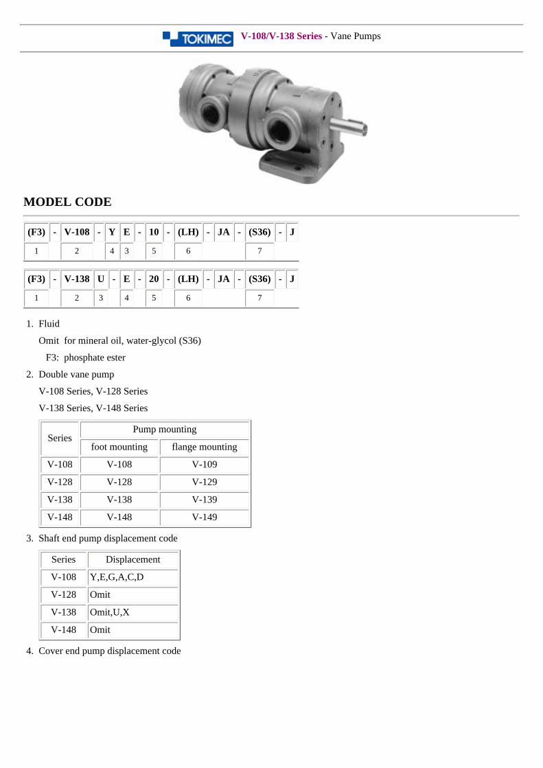
V-108/V-138 Series - Vane Pumps
MODEL CODE
(F3) - V-108 - Y E - 10 - (LH) - JA - (S36) - J
1 2 4 3 5 6 7
(F3) - V-138 U - E - 20 - (LH) - JA - (S36) - J
1 2 3 4 5 6 7
1. Fluid
Omit for mineral oil, water-glycol (S36)
F3: phosphate ester
2. Double vane pump
V-108 Series, V-128 Series
V-138 Series, V-148 Series
SeriesPump mounting
foot mounting flange mounting
V-108 V-108 V-109
V-128 V-128 V-129
V-138 V-138 V-139
V-148 V-148 V-149
3. Shaft end pump displacement code
Series Displacement
V-108 Y,E,G,A,C,D
V-128 Omit
V-138 Omit,U,X
V-148 Omit
4. Cover end pump displacement code
Series Displacement
V-108
Y,E,G,A,C,DV-128
V-138
V-148
5. Design no.
10: V-108 Series
20: V-128, 138, 148 Series
6. Rotation (viewed from shaft end)
Omit for CW
LH: CCW
7. Special feature
S36: Water glycol
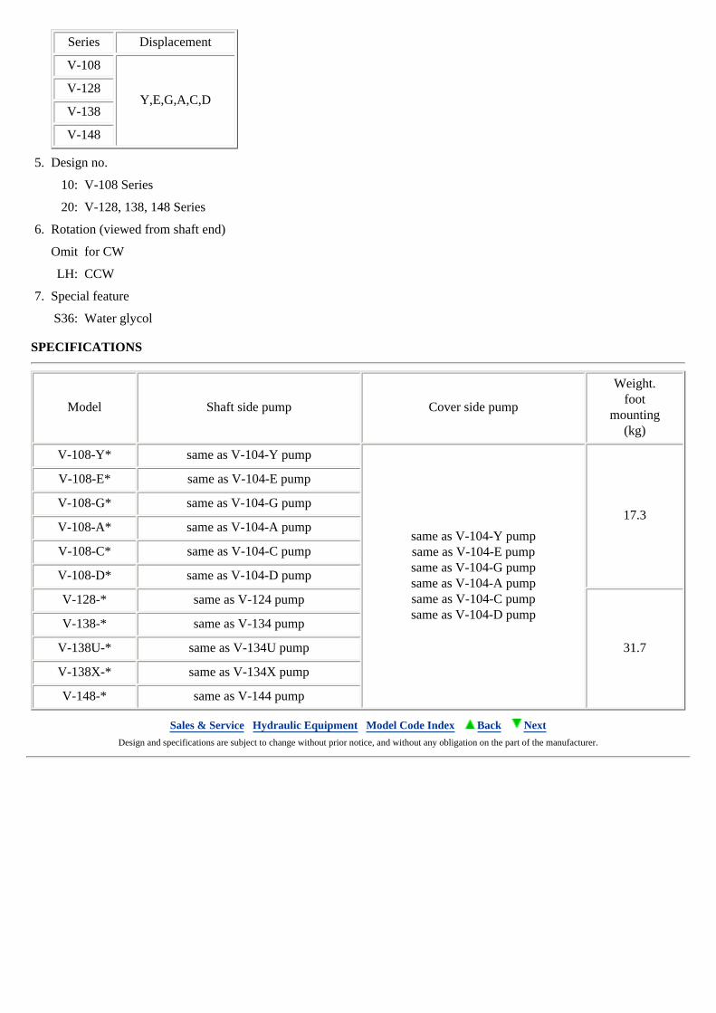
SPECIFICATIONS
Model Shaft side pump Cover side pump
Weight.foot
mounting(kg)
V-108-Y* same as V-104-Y pump
same as V-104-Y pumpsame as V-104-E pumpsame as V-104-G pumpsame as V-104-A pumpsame as V-104-C pumpsame as V-104-D pump
17.3
V-108-E* same as V-104-E pump
V-108-G* same as V-104-G pump
V-108-A* same as V-104-A pump
V-108-C* same as V-104-C pump
V-108-D* same as V-104-D pump
V-128-* same as V-124 pump
31.7
V-138-* same as V-134 pump
V-138U-* same as V-134U pump
V-138X-* same as V-134X pump
V-148-* same as V-144 pump
Sales & Service Hydraulic Equipment Model Code Index Back Next Design and specifications are subject to change without prior notice, and without any obligation on the part of the manufacturer.
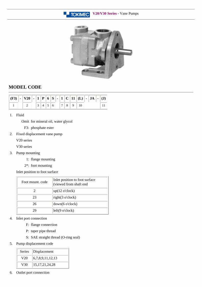
V20/V30 Series - Vane Pumps
MODEL CODE
(F3) - V20 - 1 P 6 S - 1 C 11 (L) - JA - (J)
1 2 3 4 5 6 7 8 9 10 11
1. Fluid
Omit for mineral oil, water glycol
F3: phosphate ester
2. Fixed displacement vane pump
V20 series
V30 series
3. Pump mounting
1: flange mounting
2*: foot mounting
Inlet position to foot surface
Foot mount. codeInlet position to foot surface(viewed from shaft end
2 up(12 o'clock)
23 right(3 o'clock)
26 down(6 o'clock)
29 left(9 o'clock)
4. Inlet port connection
F: flange connection
P: taper pipe thread
S: SAE straight thread (O-ring seal)
5. Pump displacement code
Series Displacement
V20 6,7,8,9,11,12,13
V30 15,17,21,24,28
6. Outlet port connection
F: flange connection
P: taper pipe thread
S: SAE straight thread (O-ring seal)
7. Shaft
1: parallel sq. key
3: woodruff key
11: involute spline
8. Outlet position(viewed from cover end)
A: opposite inlet
B: 90º CCW from inlet
C: inline with inlet
D: 90º CW from inlet
9. Design no.
10. Rotation (viewed from shaft end)
Omit for CW
L: CCW
11. J:JIS taper thread for P type port connection
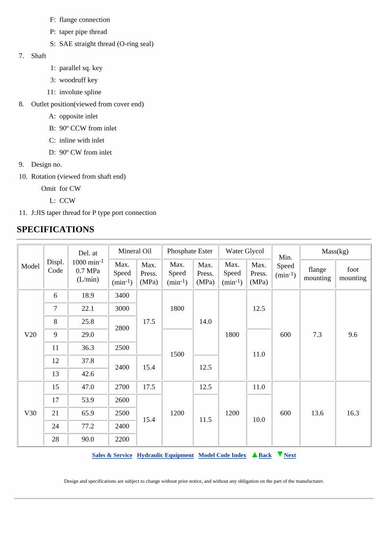
SPECIFICATIONS
ModelDispl.Code
Del. at1000 min-1
0.7 MPa(L/min)
Mineral Oil Phosphate Ester Water GlycolMin.
Speed(min-1)
Mass(kg)
Max.Speed(min-1)
Max.Press.(MPa)
Max.Speed(min-1)
Max.Press.(MPa)
Max.Speed(min-1)
Max.Press.(MPa)
flangemounting
footmounting
V20
6 18.9 3400
17.5
1800
14.0
1800
12.5
600 7.3 9.6
7 22.1 3000
8 25.82800
9 29.0
1500 11.011 36.3 2500
12 37.82400 15.4 12.5
13 42.6
V30
15 47.0 2700 17.5
1200
12.5
1200
11.0
600 13.6 16.3
17 53.9 2600
15.4 11.5 10.021 65.9 2500
24 77.2 2400
28 90.0 2200
Sales & Service Hydraulic Equipment Model Code Index Back Next
Design and specifications are subject to change without prior notice, and without any obligation on the part of the manufacturer.
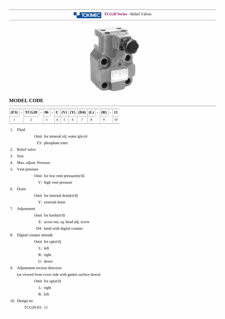
TCG20 Series - Relief Valves
MODEL CODE
(F3) - TCG20 - 06 - C (V) (Y) (D4) (L) - (R) - 11
1 2 3 4 5 6 7 8 9 10
1. Fluid
Omit for mineral oil, water glycol
F3: phosphate ester
2. Relief valve
3. Size
4. Max. adjust. Pressure
5. Vent pressure
Omit for low vent pressure(st'd)
V: high vent pressure
6. Drain
Omit for internal drain(st'd)
Y: external drain
7. Adjustment
Omit for knob(st'd)
E: acorn nut, sq. head adj. screw
D4: knob with digital counter
8. Digital counter attitude
Omit for up(st'd)
L: left
R: right
U: down
9. Adjustment section direction
(as viewed from cover side with gasket surface down)
Omit for up(st'd)
L: right
R: left
10. Design no.
TCG20-03: 11
TCG20-06: 11
TCG20-10: 11
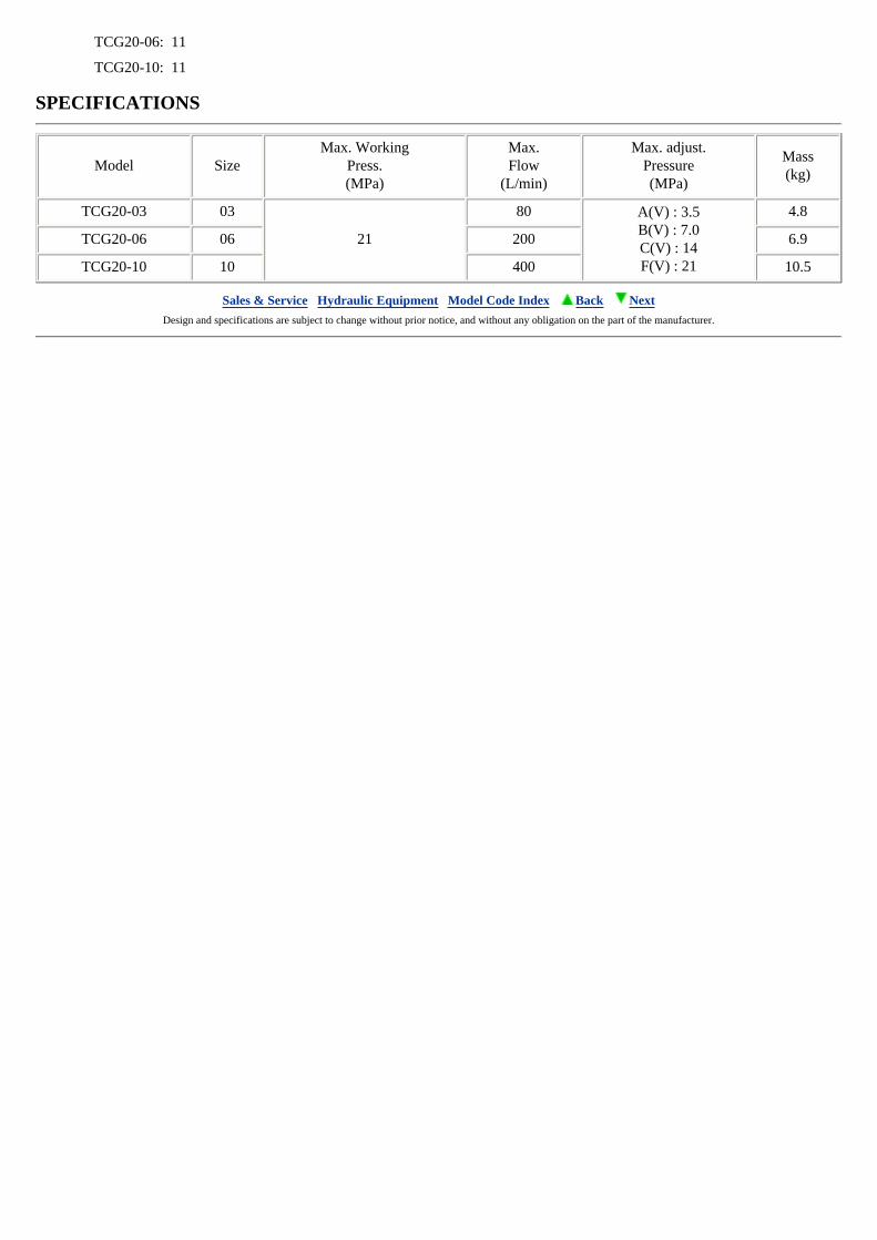
SPECIFICATIONS
Model SizeMax. Working
Press.(MPa)
Max.Flow
(L/min)
Max. adjust.Pressure(MPa)
Mass(kg)
TCG20-03 03
21
80 A(V) : 3.5B(V) : 7.0C(V) : 14F(V) : 21
4.8
TCG20-06 06 200 6.9
TCG20-10 10 400 10.5
Sales & Service Hydraulic Equipment Model Code Index Back Next Design and specifications are subject to change without prior notice, and without any obligation on the part of the manufacturer.
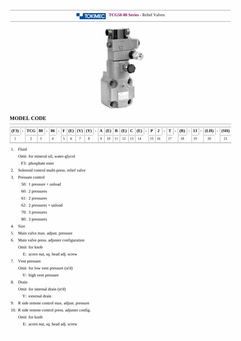
TCG50-80 Series - Relief Valves
MODEL CODE
(F3) - TCG 80 - 06 - F (E) (V) (Y) - A (E) B (E) C (E) - P 2 - T - (R) - 13 - (LH) - (SH)
1 2 3 4 5 6 7 8 9 10 11 12 13 14 15 16 17 18 19 20 21
1. Fluid
Omit for mineral oil, water-glycol
F3: phosphate ester
2. Solenoid control multi-press. relief valve
3. Pressure control
50: 1 pressure + unload
60: 2 pressures
61: 2 pressures
62: 2 pressures + unload
70: 3 pressures
80: 3 pressures
4. Size
5. Main valve max. adjust. pressure
6. Main valve press. adjuster configuration
Omit for knob
E: acorn nut, sq. head adj. screw
7. Vent pressure
Omit for low vent pressure (st'd)
V: high vent pressure
8. Drain
Omit for internal drain (st'd)
Y: external drain
9. R side remote control max. adjust. pressure
10. R side remote control press. adjuster config.
Omit for konb
E: acorn nut, sq. head adj. screw
11. C side remote control max. adjust. pressure
12. C side remote control press. adjuster config.
Omit for knob
E: acorn nut, sq. head adj. screw (st'd)
13. L side remote control max. adjust. pressure
14. L side remote control press. adjuster config.
Omit for knob
E: acorn nut, sq. head adj. screw (st'd)
15. Electrical wiring (see DG4V-3)
16. Solenoid valve accessories (see DG4V-3)
17. Solenoid valve power supply (see DG4V-3)
18. Pressure adj. section attitude
(as viewed from sol. valve with gasket surface down)
Omit for up
L: right
R: left
19. Design no.
20. Solenoid attitude (TCG50,60,61)
Omit for right side(st'd)as viewed from adj. knob side
LH: left side as viewed from adj. knob side
21. Shockless function
Omit for no shockless function
SH: vent unload shockless valve (DGMSL-3)
(for TCG50,62,80)
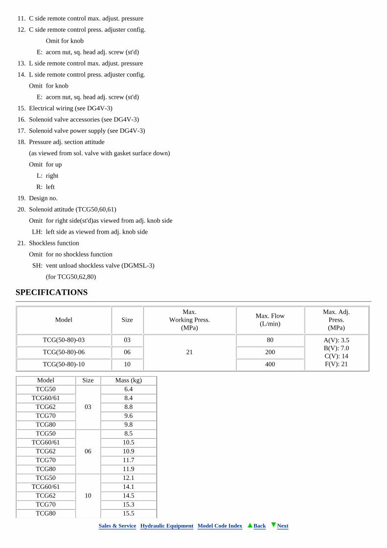
SPECIFICATIONS
Model SizeMax.
Working Press.(MPa)
Max. Flow(L/min)
Max. Adj.Press.(MPa)
TCG(50-80)-03 03
21
80 A(V): 3.5B(V): 7.0C(V): 14F(V): 21
TCG(50-80)-06 06 200
TCG(50-80)-10 10 400
Model Size Mass (kg)TCG50
03
6.4TCG60/61 8.4
TCG62 8.8TCG70 9.6TCG80 9.8TCG50
06
8.5TCG60/61 10.5
TCG62 10.9TCG70 11.7TCG80 11.9TCG50
10
12.1TCG60/61 14.1
TCG62 14.5TCG70 15.3TCG80 15.5
Sales & Service Hydraulic Equipment Model Code Index Back Next

CG, CT, CF Series - Relief Valves
MODEL CODE
(F3) - CG - 03 - B (V) (Y) - 15 - (S81) - JA - J
1 2 3 4 5 6 7 8
1. Fluid
Omit for mineral oil, water-glycol
F3: phosphate ester
2. Relief valve
CG: gasket mount
CT: thread connection
CF: flange connection
3. Size
4. Max. adjust. pressure
5. Vent pressure
Omit for low vent pressure (st'd)
V: high vent pressure
6. Drain
Omit for internal drain (st'd)
Y: external drain
7. Design no.
10: CT-03, CF-16, CF-24
15: CG-03
20: CT-10
40: CT-06
8. Adjuster section configuration (CG/CT-03 only)
Omit for sq. head adj. screw
S81: knob
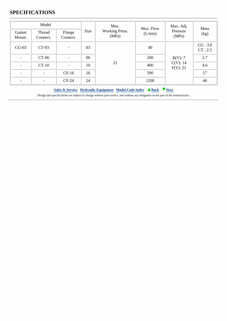
SPECIFICATIONS
Model
SizeMax.
Working Press.(MPa)
Max. Flow(L/min)
Max. Adj.Pressure(MPa)
Mass(kg)Gasket
Mount.Thread
Connect.Flange
Connect.
CG-03 CT-03 - 03
21
40
B(V): 7C(V): 14F(V): 21
CG : 3.0CT : 2.5
- CT-06 - 06 200 2.7
- CT-10 - 10 400 4.6
- - CF-16 16 500 17
- - CF-24 24 1200 46
Sales & Service Hydraulic Equipment Model Code Index Back Next Design and specifications are subject to change without prior notice, and without any obligation on the part of the manufacturer.
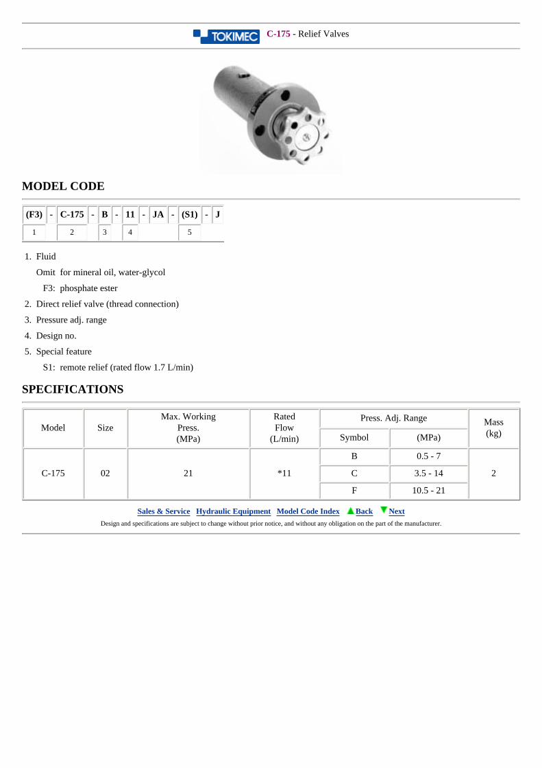
C-175 - Relief Valves
MODEL CODE
(F3) - C-175 - B - 11 - JA - (S1) - J
1 2 3 4 5
1. Fluid
Omit for mineral oil, water-glycol
F3: phosphate ester
2. Direct relief valve (thread connection)
3. Pressure adj. range
4. Design no.
5. Special feature
S1: remote relief (rated flow 1.7 L/min)
SPECIFICATIONS
Model SizeMax. Working
Press.(MPa)
RatedFlow
(L/min)
Press. Adj. Range Mass(kg)Symbol (MPa)
C-175 02 21 *11
B 0.5 - 7
2C 3.5 - 14
F 10.5 - 21
Sales & Service Hydraulic Equipment Model Code Index Back Next Design and specifications are subject to change without prior notice, and without any obligation on the part of the manufacturer.
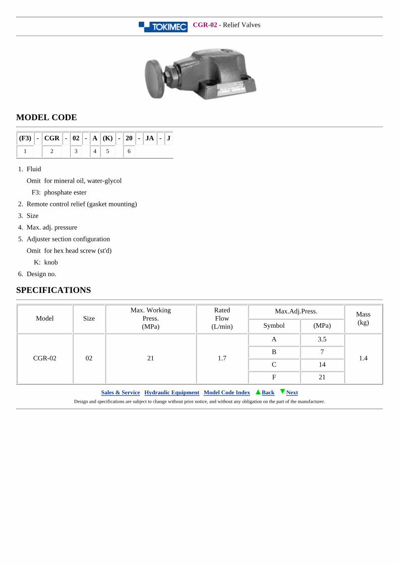
CGR-02 - Relief Valves
MODEL CODE
(F3) - CGR - 02 - A (K) - 20 - JA - J
1 2 3 4 5 6
1. Fluid
Omit for mineral oil, water-glycol
F3: phosphate ester
2. Remote control relief (gasket mounting)
3. Size
4. Max. adj. pressure
5. Adjuster section configuration
Omit for hex head screw (st'd)
K: knob
6. Design no.
SPECIFICATIONS
Model SizeMax. Working
Press.(MPa)
RatedFlow
(L/min)
Max.Adj.Press. Mass(kg)Symbol (MPa)
CGR-02 02 21 1.7
A 3.5
1.4B 7
C 14
F 21
Sales & Service Hydraulic Equipment Model Code Index Back Next Design and specifications are subject to change without prior notice, and without any obligation on the part of the manufacturer.
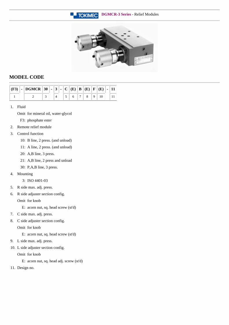
DGMCR-3 Series - Relief Modules
MODEL CODE
(F3) - DGMCR 30 - 3 - C (E) B (E) F (E) - 11
1 2 3 4 5 6 7 8 9 10 11
1. Fluid
Omit for mineral oil, water-glycol
F3: phosphate ester
2. Remote relief module
3. Control function
10: B line, 2 press. (and unload)
11: A line, 2 press. (and unload)
20: A,B line, 3 press.
21: A,B line, 2 press and unload
30: P,A,B line, 3 press.
4. Mounting
3: ISO 4401-03
5. R side max. adj. press.
6. R side adjuster section config.
Omit for knob
E: acorn nut, sq. head screw (st'd)
7. C side max. adj. press.
8. C side adjuster section config.
Omit for knob
E: acorn nut, sq. head screw (st'd)
9. L side max. adj. press.
10. L side adjuster section config.
Omit for knob
E: acorn nut, sq. head adj. screw (st'd)
11. Design no.
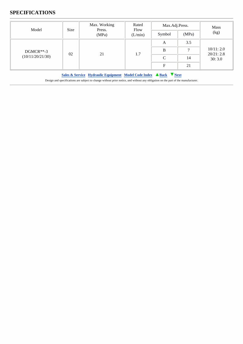
SPECIFICATIONS
Model SizeMax. Working
Press.(MPa)
RatedFlow
(L/min)
Max.Adj.Press. Mass(kg)Symbol (MPa)
DGMCR**-3(10/11/20/21/30)
02 21 1.7
A 3.5
10/11: 2.020/21: 2.8
30: 3.0
B 7
C 14
F 21
Sales & Service Hydraulic Equipment Model Code Index Back Next Design and specifications are subject to change without prior notice, and without any obligation on the part of the manufacturer.
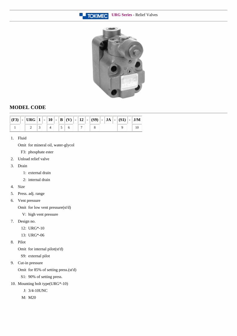
URG Series - Relief Valves
MODEL CODE
(F3) - URG 1 - 10 - B (V) - 12 - (S9) - JA - (S1) - J/M
1 2 3 4 5 6 7 8 9 10
1. Fluid
Omit for mineral oil, water-glycol
F3: phosphate ester
2. Unload relief valve
3. Drain
1: external drain
2: internal drain
4. Size
5. Press. adj. range
6. Vent pressure
Omit for low vent pressure(st'd)
V: high vent pressure
7. Design no.
12: URG*-10
13: URG*-06
8. Pilot
Omit for internal pilot(st'd)
S9: external pilot
9. Cut-in pressure
Omit for 85% of setting press.(st'd)
S1: 90% of setting press.
10. Mounting bolt type(URG*-10)
J: 3/4-10UNC
M: M20
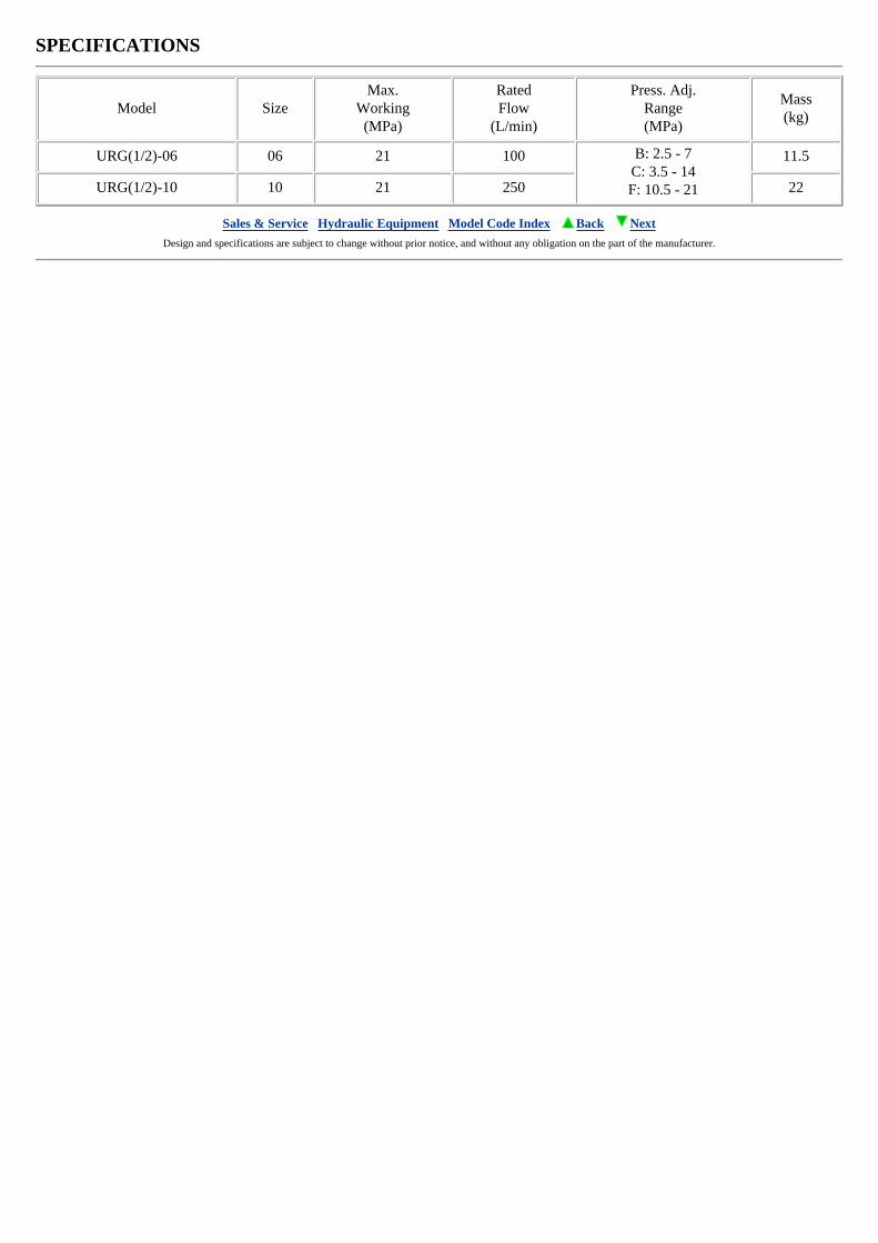
SPECIFICATIONS
Model SizeMax.
Working(MPa)
RatedFlow
(L/min)
Press. Adj.Range(MPa)
Mass(kg)
URG(1/2)-06 06 21 100 B: 2.5 - 7C: 3.5 - 14F: 10.5 - 21
11.5
URG(1/2)-10 10 21 250 22
Sales & Service Hydraulic Equipment Model Code Index Back Next Design and specifications are subject to change without prior notice, and without any obligation on the part of the manufacturer.
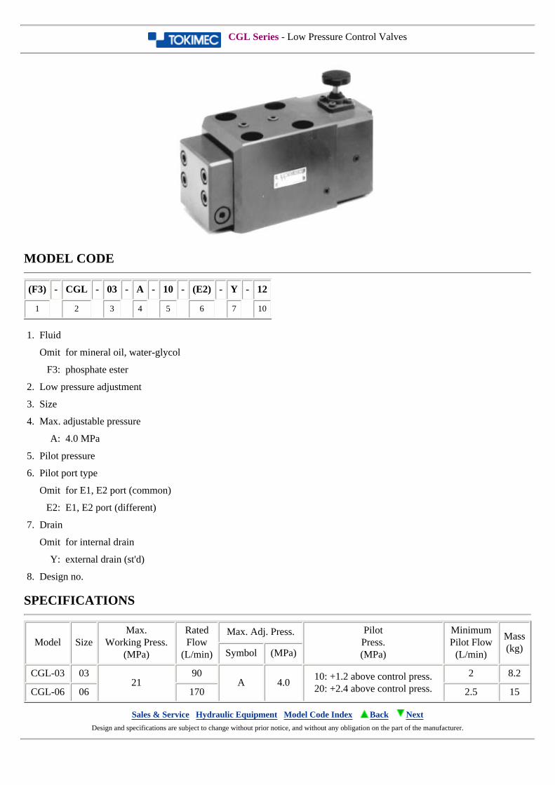
CGL Series - Low Pressure Control Valves
MODEL CODE
(F3) - CGL - 03 - A - 10 - (E2) - Y - 12
1 2 3 4 5 6 7 10
1. Fluid
Omit for mineral oil, water-glycol
F3: phosphate ester
2. Low pressure adjustment
3. Size
4. Max. adjustable pressure
A: 4.0 MPa
5. Pilot pressure
6. Pilot port type
Omit for E1, E2 port (common)
E2: E1, E2 port (different)
7. Drain
Omit for internal drain
Y: external drain (st'd)
8. Design no.
SPECIFICATIONS
Model SizeMax.
Working Press.(MPa)
RatedFlow
(L/min)
Max. Adj. Press. PilotPress.(MPa)
MinimumPilot Flow
(L/min)
Mass(kg)Symbol (MPa)
CGL-03 0321
90A 4.0
10: +1.2 above control press.20: +2.4 above control press.
2 8.2
CGL-06 06 170 2.5 15
Sales & Service Hydraulic Equipment Model Code Index Back Next Design and specifications are subject to change without prior notice, and without any obligation on the part of the manufacturer.
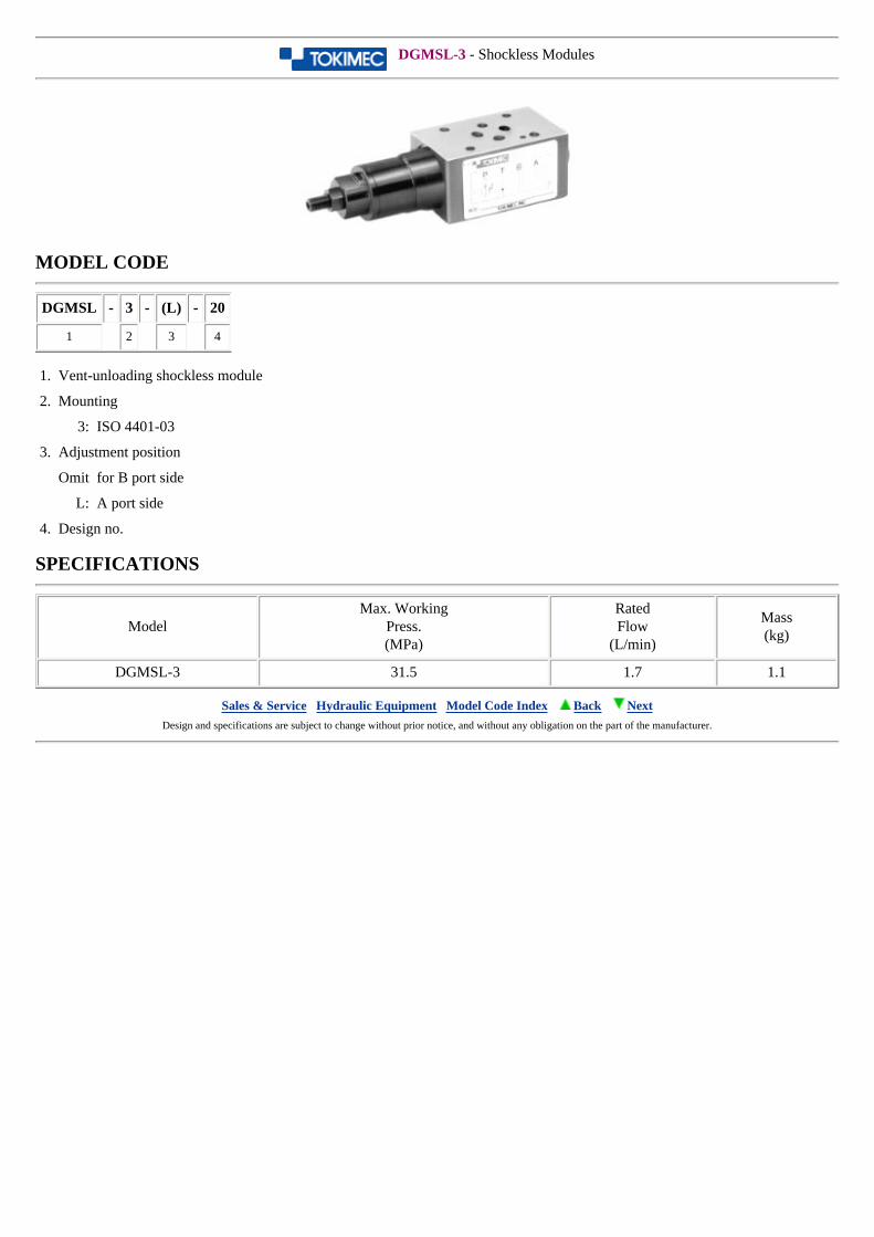
DGMSL-3 - Shockless Modules
MODEL CODE
DGMSL - 3 - (L) - 20
1 2 3 4
1. Vent-unloading shockless module
2. Mounting
3: ISO 4401-03
3. Adjustment position
Omit for B port side
L: A port side
4. Design no.
SPECIFICATIONS
ModelMax. Working
Press.(MPa)
RatedFlow
(L/min)
Mass(kg)
DGMSL-3 31.5 1.7 1.1
Sales & Service Hydraulic Equipment Model Code Index Back Next Design and specifications are subject to change without prior notice, and without any obligation on the part of the manufacturer.
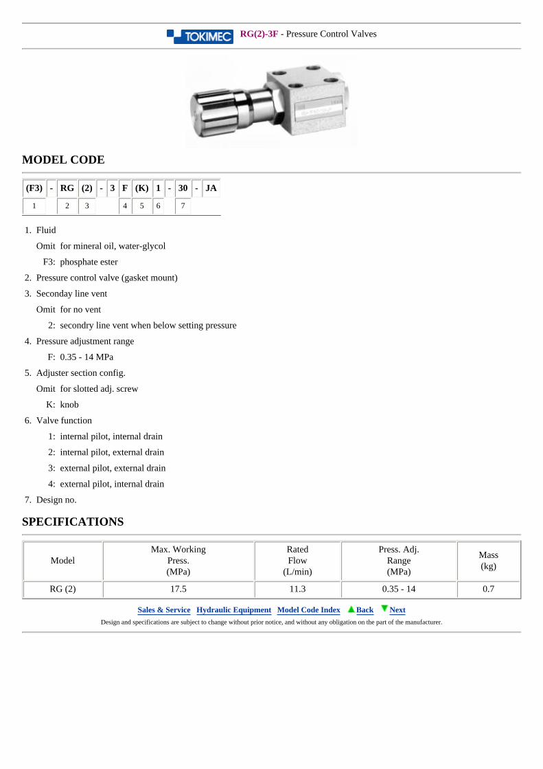
RG(2)-3F - Pressure Control Valves
MODEL CODE
(F3) - RG (2) - 3 F (K) 1 - 30 - JA
1 2 3 4 5 6 7
1. Fluid
Omit for mineral oil, water-glycol
F3: phosphate ester
2. Pressure control valve (gasket mount)
3. Seconday line vent
Omit for no vent
2: secondry line vent when below setting pressure
4. Pressure adjustment range
F: 0.35 - 14 MPa
5. Adjuster section config.
Omit for slotted adj. screw
K: knob
6. Valve function
1: internal pilot, internal drain
2: internal pilot, external drain
3: external pilot, external drain
4: external pilot, internal drain
7. Design no.
SPECIFICATIONS
ModelMax. Working
Press.(MPa)
RatedFlow
(L/min)
Press. Adj.Range(MPa)
Mass(kg)
RG (2) 17.5 11.3 0.35 - 14 0.7
Sales & Service Hydraulic Equipment Model Code Index Back Next Design and specifications are subject to change without prior notice, and without any obligation on the part of the manufacturer.
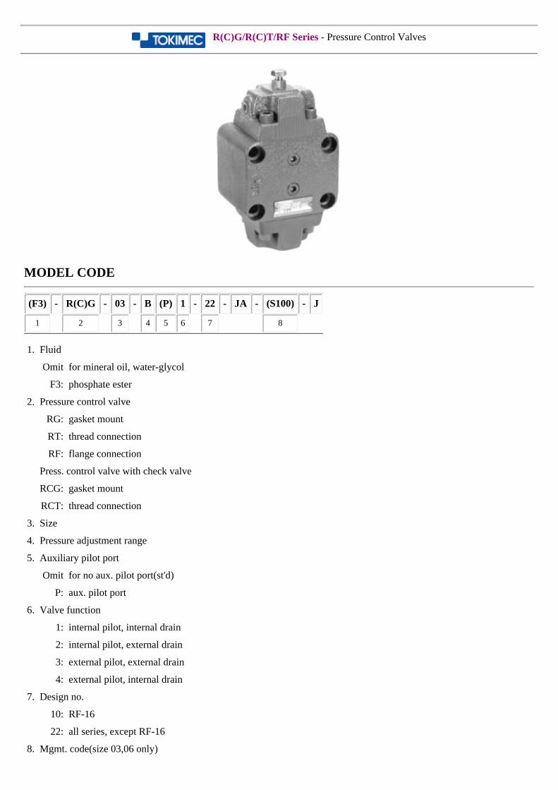
R(C)G/R(C)T/RF Series - Pressure Control Valves
MODEL CODE
(F3) - R(C)G - 03 - B (P) 1 - 22 - JA - (S100) - J
1 2 3 4 5 6 7 8
1. Fluid
Omit for mineral oil, water-glycol
F3: phosphate ester
2. Pressure control valve
RG: gasket mount
RT: thread connection
RF: flange connection
Press. control valve with check valve
RCG: gasket mount
RCT: thread connection
3. Size
4. Pressure adjustment range
5. Auxiliary pilot port
Omit for no aux. pilot port(st'd)
P: aux. pilot port
6. Valve function
1: internal pilot, internal drain
2: internal pilot, external drain
3: external pilot, external drain
4: external pilot, internal drain
7. Design no.
10: RF-16
22: all series, except RF-16
8. Mgmt. code(size 03,06 only)
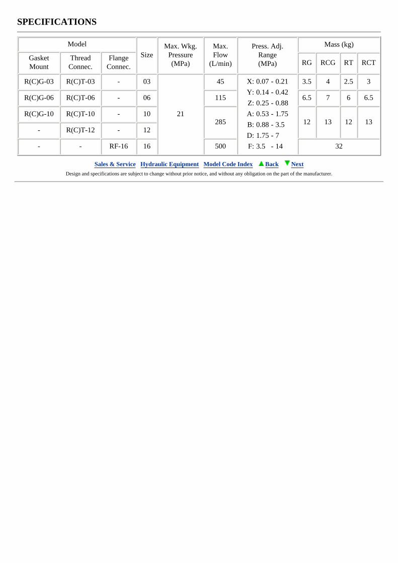
SPECIFICATIONS
Model
SizeMax. Wkg.
Pressure(MPa)
Max.Flow
(L/min)
Press. Adj.Range(MPa)
Mass (kg)
GasketMount
ThreadConnec.
FlangeConnec.
RG RCG RT RCT
R(C)G-03 R(C)T-03 - 03
21
45 X: 0.07 - 0.21
Y: 0.14 - 0.42
Z: 0.25 - 0.88
A: 0.53 - 1.75
B: 0.88 - 3.5
D: 1.75 - 7
F: 3.5 - 14
3.5 4 2.5 3
R(C)G-06 R(C)T-06 - 06 115 6.5 7 6 6.5
R(C)G-10 R(C)T-10 - 10285 12 13 12 13
- R(C)T-12 - 12
- - RF-16 16 500 32
Sales & Service Hydraulic Equipment Model Code Index Back Next Design and specifications are subject to change without prior notice, and without any obligation on the part of the manufacturer.
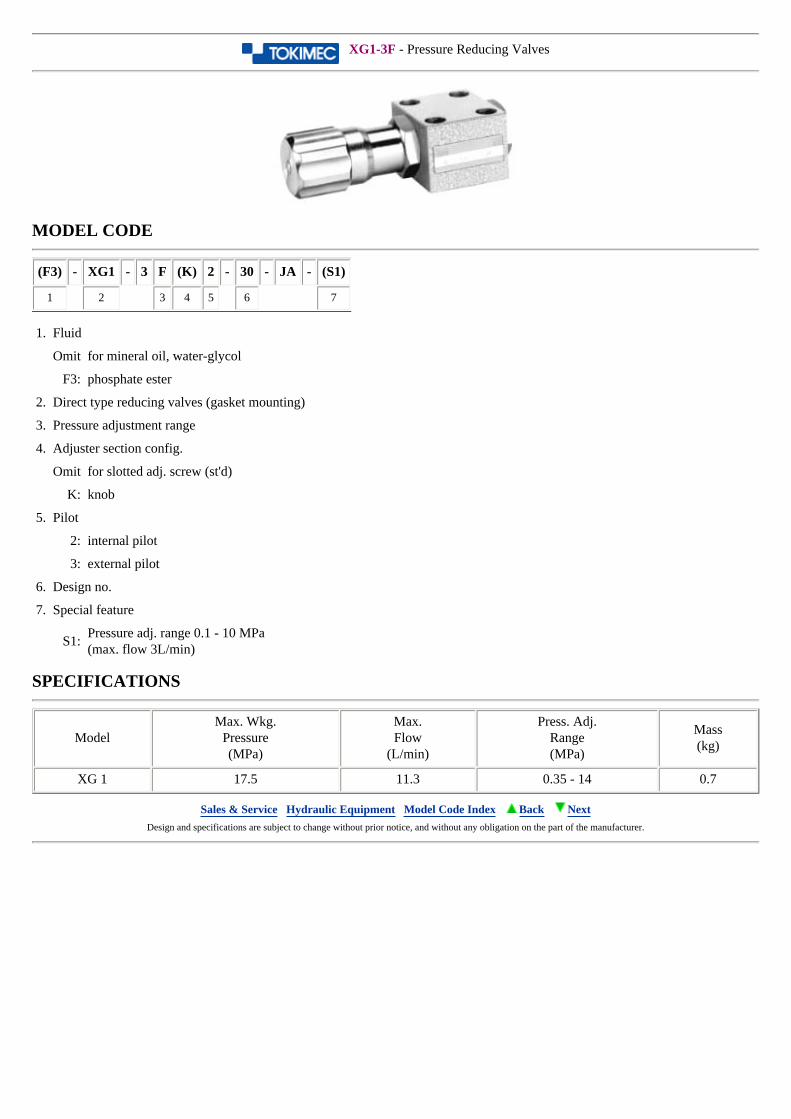
XG1-3F - Pressure Reducing Valves
MODEL CODE
(F3) - XG1 - 3 F (K) 2 - 30 - JA - (S1)
1 2 3 4 5 6 7
1. Fluid
Omit for mineral oil, water-glycol
F3: phosphate ester
2. Direct type reducing valves (gasket mounting)
3. Pressure adjustment range
4. Adjuster section config.
Omit for slotted adj. screw (st'd)
K: knob
5. Pilot
2: internal pilot
3: external pilot
6. Design no.
7. Special feature
S1:Pressure adj. range 0.1 - 10 MPa(max. flow 3L/min)
SPECIFICATIONS
ModelMax. Wkg.
Pressure(MPa)
Max.Flow
(L/min)
Press. Adj.Range(MPa)
Mass(kg)
XG 1 17.5 11.3 0.35 - 14 0.7
Sales & Service Hydraulic Equipment Model Code Index Back Next Design and specifications are subject to change without prior notice, and without any obligation on the part of the manufacturer.
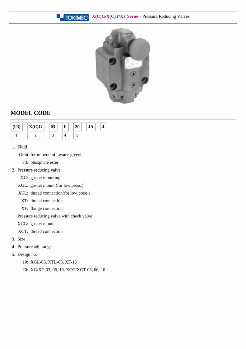
X(C)G/X(C)T/XF Series - Pressure Reducing Valves
MODEL CODE
(F3) - X(C)G - 03 - F - 20 - JA - J
1 2 3 4 5
1. Fluid
Omit for mineral oil, water-glycol
F3: phosphate ester
2. Pressure reducing valve
XG: gasket mounting
XGL: gasket mount.(for low press.)
XTL: thread connection(for low press.)
XT: thread connection
XF: flange connection
Pressure reducing valve with check valve
XCG: gasket mount.
XCT: thread connection
3. Size
4. Pressure adj. range
5. Design no.
10: XGL-03, XTL-03, XF-16
20: XG/XT-03, 06, 10, XCG/XCT-03, 06, 10
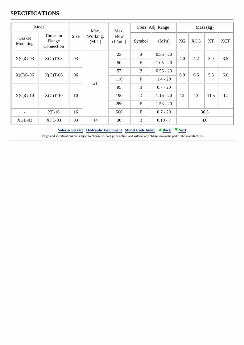
SPECIFICATIONS
Model
SizeMax.
Working.(MPa)
Max.Flow
(L/min)
Press. Adj. Range Mass (kg)
GasketMounting
Thread orFlange
ConnectionSymbol (MPa) XG XCG XT XCT
X(C)G-03 X(C)T-03 03
21
23 B 0.56 - 204.0 4.2 3.0 3.5
50 F 1.05 - 20
X(C)G-06 X(C)T-06 0657 B 0.56 - 20
6.0 6.5 5.5 6.0110 F 1.4 - 20
X(C)G-10 X(C)T-10 10
95 B 0.7 - 20
12 13 11.5 12190 D 1.16 - 20
280 F 1.58 - 20
- XF-16 16 500 F 0.7 - 20 36.5
XGL-03 XTL-03 03 14 30 B 0.18 - 7 4.0
Sales & Service Hydraulic Equipment Model Code Index Back Next Design and specifications are subject to change without prior notice, and without any obligation on the part of the manufacturer.

BLG Series - Balancer Valves
MODEL CODE
(F3) - BLG-02 - B - 12 (-S20)
1 2 3 4 5
1. Fluid
Omit for mineral oil, water-glycol
F3: phosphate ester
2. Balancer valve(gasket mounting)
3. Press. adj. range
B: 1 - 7 MPa
4. Design no.
10: BLG-3
12: BLG-02
5. Pressure gauge port
Omit for gauge port
S20: no gauge port(BLG-03 only)
SPECIFICATIONS
ModelMax. Working
Press.(MPa)
Max.Flow
(L/min)
Press. Adj.Range(MPa)
Mass(kg)
BLG-3 10.5 201 - 7
1.8
BLG-02 10.5 30 2.9
Sales & Service Hydraulic Equipment Model Code Index Back Next Design and specifications are subject to change without prior notice, and without any obligation on the part of the manufacturer.
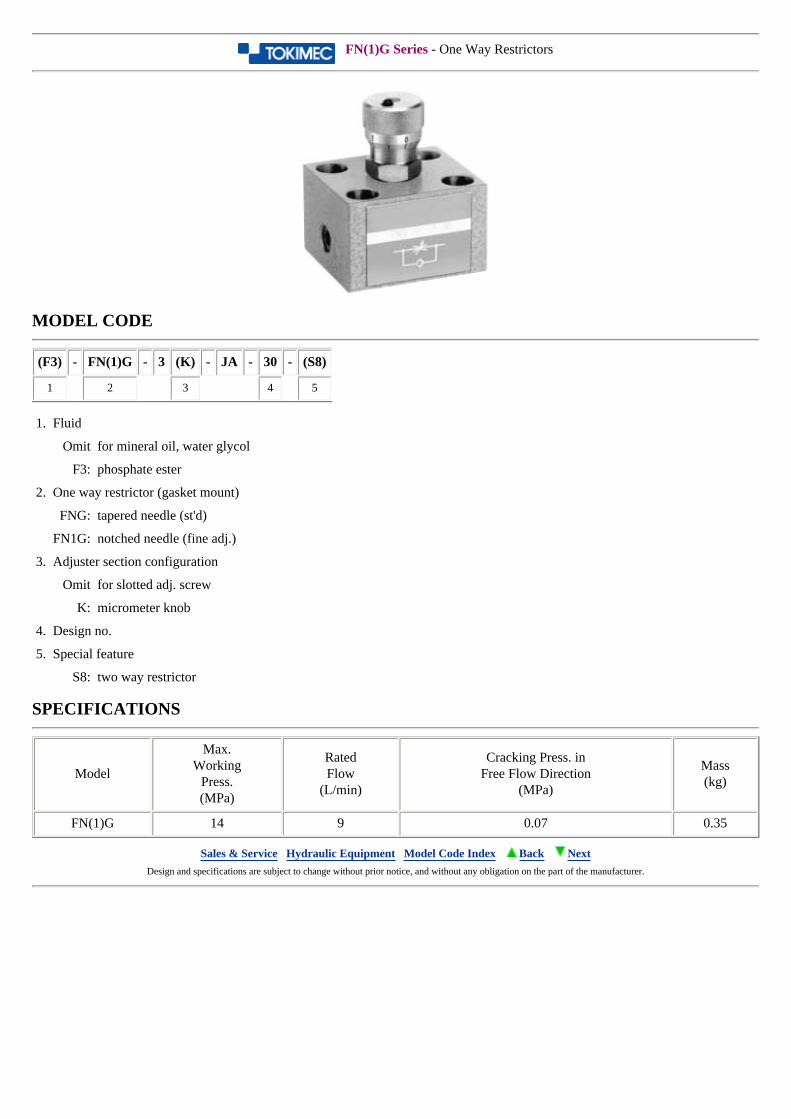
FN(1)G Series - One Way Restrictors
MODEL CODE
(F3) - FN(1)G - 3 (K) - JA - 30 - (S8)
1 2 3 4 5
1. Fluid
Omit for mineral oil, water glycol
F3: phosphate ester
2. One way restrictor (gasket mount)
FNG: tapered needle (st'd)
FN1G: notched needle (fine adj.)
3. Adjuster section configuration
Omit for slotted adj. screw
K: micrometer knob
4. Design no.
5. Special feature
S8: two way restrictor
SPECIFICATIONS
Model
Max.Working
Press.(MPa)
RatedFlow
(L/min)
Cracking Press. inFree Flow Direction
(MPa)
Mass(kg)
FN(1)G 14 9 0.07 0.35
Sales & Service Hydraulic Equipment Model Code Index Back Next Design and specifications are subject to change without prior notice, and without any obligation on the part of the manufacturer.
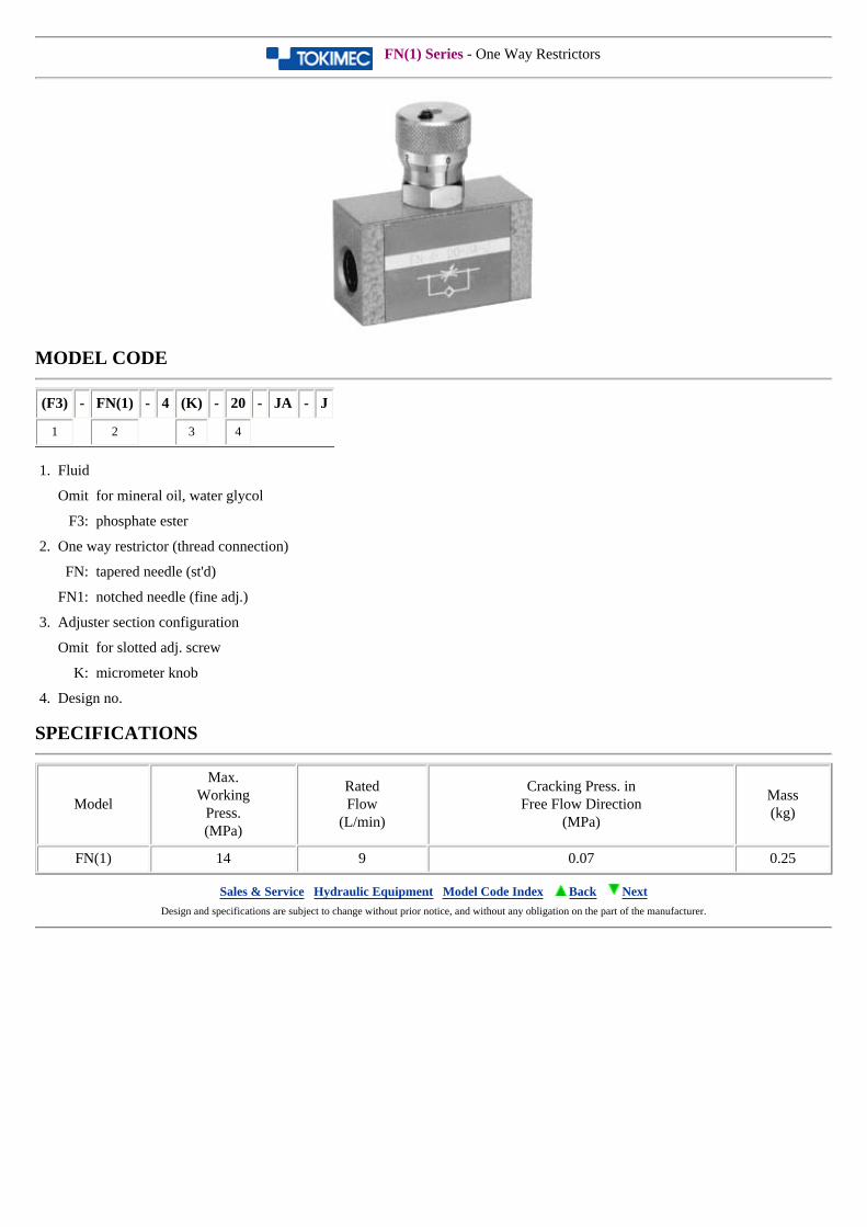
FN(1) Series - One Way Restrictors
MODEL CODE
(F3) - FN(1) - 4 (K) - 20 - JA - J
1 2 3 4
1. Fluid
Omit for mineral oil, water glycol
F3: phosphate ester
2. One way restrictor (thread connection)
FN: tapered needle (st'd)
FN1: notched needle (fine adj.)
3. Adjuster section configuration
Omit for slotted adj. screw
K: micrometer knob
4. Design no.
SPECIFICATIONS
Model
Max.Working
Press.(MPa)
RatedFlow
(L/min)
Cracking Press. inFree Flow Direction
(MPa)
Mass(kg)
FN(1) 14 9 0.07 0.25
Sales & Service Hydraulic Equipment Model Code Index Back Next Design and specifications are subject to change without prior notice, and without any obligation on the part of the manufacturer.
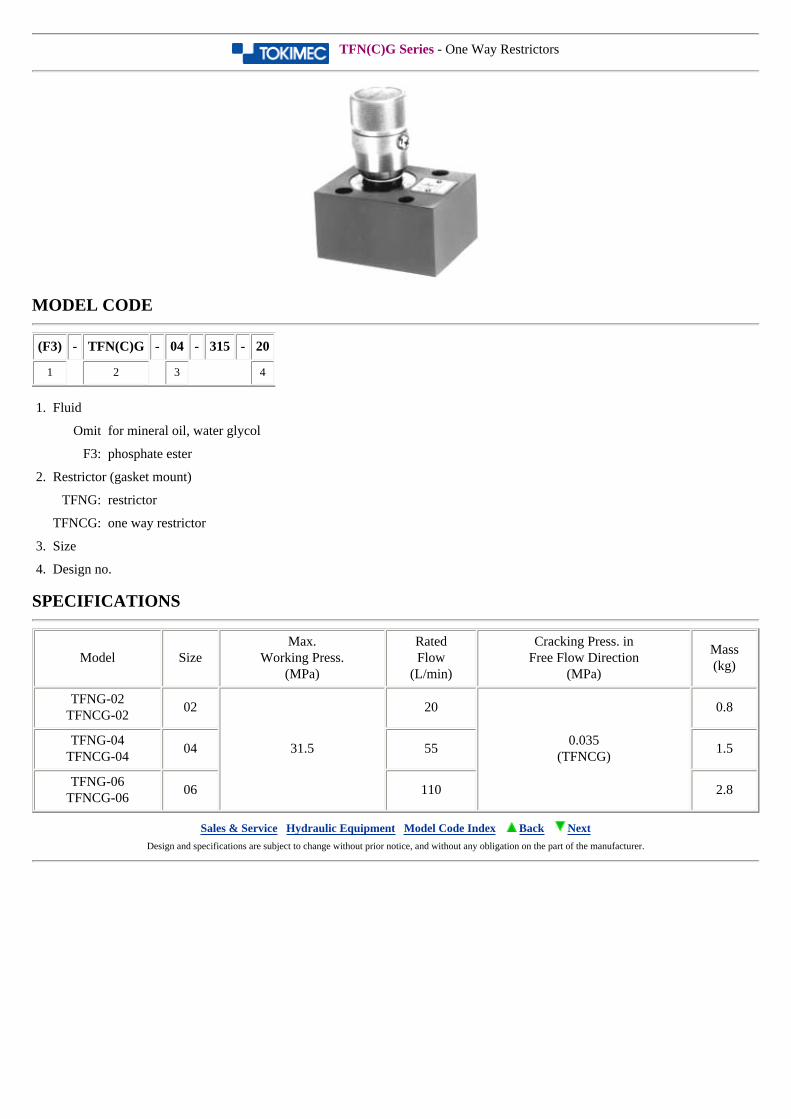
TFN(C)G Series - One Way Restrictors
MODEL CODE
(F3) - TFN(C)G - 04 - 315 - 20
1 2 3 4
1. Fluid
Omit for mineral oil, water glycol
F3: phosphate ester
2. Restrictor (gasket mount)
TFNG: restrictor
TFNCG: one way restrictor
3. Size
4. Design no.
SPECIFICATIONS
Model SizeMax.
Working Press.(MPa)
RatedFlow
(L/min)
Cracking Press. inFree Flow Direction
(MPa)
Mass(kg)
TFNG-02TFNCG-02
02
31.5
20
0.035(TFNCG)
0.8
TFNG-04TFNCG-04
04 55 1.5
TFNG-06TFNCG-06
06 110 2.8
Sales & Service Hydraulic Equipment Model Code Index Back Next Design and specifications are subject to change without prior notice, and without any obligation on the part of the manufacturer.
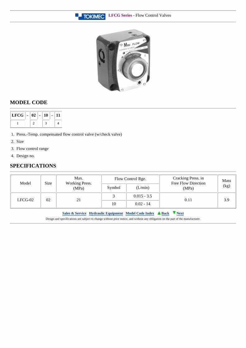
LFCG Series - Flow Control Valves
MODEL CODE
LFCG - 02 - 10 - 11
1 2 3 4
1. Press.-Temp. compensated flow control valve (w/check valve)
2. Size
3. Flow control range
4. Design no.
SPECIFICATIONS
Model SizeMax.
Working Press.(MPa)
Flow Control Rge. Cracking Press. inFree Flow Direction
(MPa)
Mass(kg)Symbol (L/min)
LFCG-02 02 213 0.015 - 3.5
0.11 3.910 0.02 - 14
Sales & Service Hydraulic Equipment Model Code Index Back Next Design and specifications are subject to change without prior notice, and without any obligation on the part of the manufacturer.
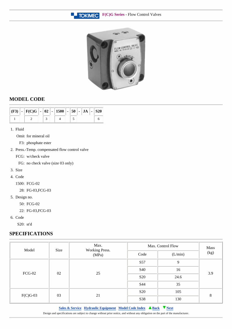
F(C)G Series - Flow Control Valves
MODEL CODE
(F3) - F(C)G - 02 - 1500 - 50 - JA - S20
1 2 3 4 5 6
1. Fluid
Omit for mineral oil
F3: phosphate ester
2. Press.-Temp. compensated flow control valve
FCG: w/check valve
FG: no check valve (size 03 only)
3. Size
4. Code
1500: FCG-02
28: FG-03,FCG-03
5. Design no.
50: FCG-02
22: FG-03,FCG-03
6. Code
S20: st'd
SPECIFICATIONS
Model SizeMax.
Working Press.(MPa)
Max. Control Flow Mass(kg)Code (L/min)
FCG-02 02 25
S57 9
3.9S40 16
S20 24.6
S44 35
F(C)G-03 03 21S20 105
8S38 130
Sales & Service Hydraulic Equipment Model Code Index Back Next Design and specifications are subject to change without prior notice, and without any obligation on the part of the manufacturer.
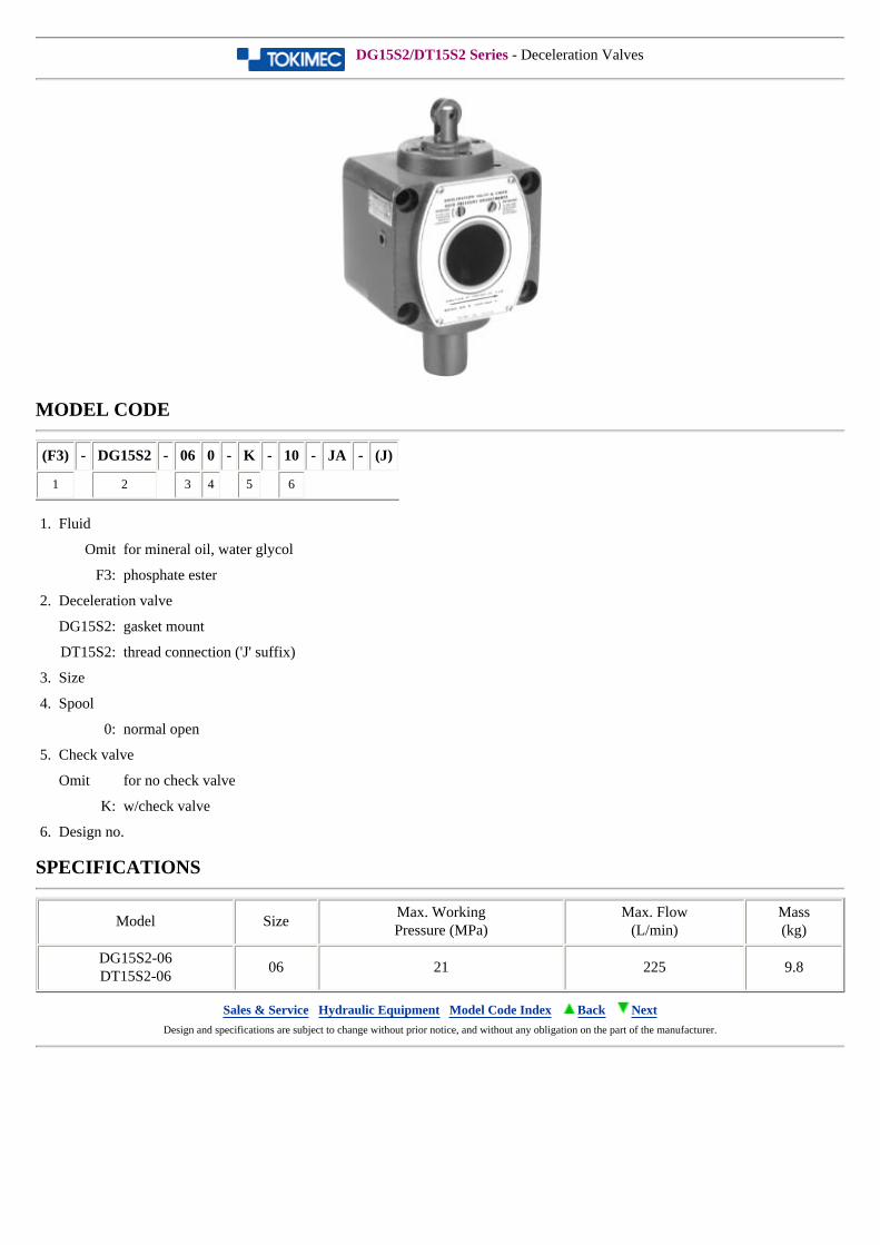
DG15S2/DT15S2 Series - Deceleration Valves
MODEL CODE
(F3) - DG15S2 - 06 0 - K - 10 - JA - (J)
1 2 3 4 5 6
1. Fluid
Omit for mineral oil, water glycol
F3: phosphate ester
2. Deceleration valve
DG15S2: gasket mount
DT15S2: thread connection ('J' suffix)
3. Size
4. Spool
0: normal open
5. Check valve
Omit for no check valve
K: w/check valve
6. Design no.
SPECIFICATIONS
Model SizeMax. WorkingPressure (MPa)
Max. Flow(L/min)
Mass(kg)
DG15S2-06DT15S2-06
06 21 225 9.8
Sales & Service Hydraulic Equipment Model Code Index Back Next Design and specifications are subject to change without prior notice, and without any obligation on the part of the manufacturer.
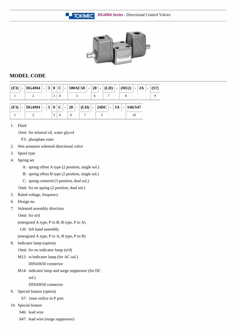
DG4M4 Series - Directional Control Valves
MODEL CODE
(F3) - DG4M4 - 3 0 C - 100AC50 - 20 - (LH) - (M12) - JA - (S7)
1 2 3 4 5 6 7 8 9
(F3) - DG4M4 - 3 0 C - 20 - (LH) - 24DC - JA - S46/S47
1 2 3 4 6 7 5 10
1. Fluid
Omit for mineral oil, water glycol
F3: phosphate ester
2. Wet armature solenoid directional valve
3. Spool type
4. Spring set
A: spring offset A type (2 position, single sol.)
B: spring offset B type (2 position, single sol.)
C: spring centered (3 position, dual sol.)
Omit for no spring (2 position, dual sol.)
5. Rated voltage, frequency
6. Design no.
7. Solenoid assembly direction
Omit for st'd
(energized A type, P to B; B type, P to A)
LH: left hand assembly
(energized A type, P to A; B type, P to B)
8. Indicator lamp (option)
Omit for no indicator lamp (st'd)
M12: w/indicator lamp (for AC sol.)
DIN43650 connector
M14: indicator lamp and surge suppressor (for DC
sol.)
DIN43650 connector
9. Special feature (option)
S7: 1mm orifice in P port
10. Special feature
S46: lead wire
S47: lead wire (surge suppressor)
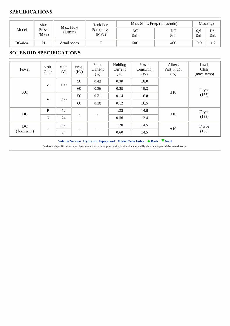
SPECIFICATIONS
ModelMax.Press.(MPa)
Max. Flow(L/min)
Tank PortBackpress.
(MPa)
Max. Shift. Freq. (times/min) Mass(kg)
ACSol.
DCSol.
Sgl.Sol.
Dbl.Sol.
DG4M4 21 detail specs 7 500 400 0.9 1.2
SOLENOID SPECIFICATIONS
PowerVolt.Code
Volt.(V)
Freq.(Hz)
Start.Current
(A)
HoldingCurrent
(A)
PowerConsump.
(W)
Allow.Volt. Fluct.
(%)
Insul.Class
(max. temp)
AC
Z 10050 0.42 0.30 18.0
±10F type(155)
60 0.36 0.25 15.3
V 20050 0.21 0.14 18.8
60 0.18 0.12 16.5
DCP 12
- -1.23 14.8
±10F type(155)N 24 0.56 13.4
DC( lead wire)
-12
- -1.20 14.5
±10F type(155)24 0.60 14.5
Sales & Service Hydraulic Equipment Model Code Index Back Next Design and specifications are subject to change without prior notice, and without any obligation on the part of the manufacturer.
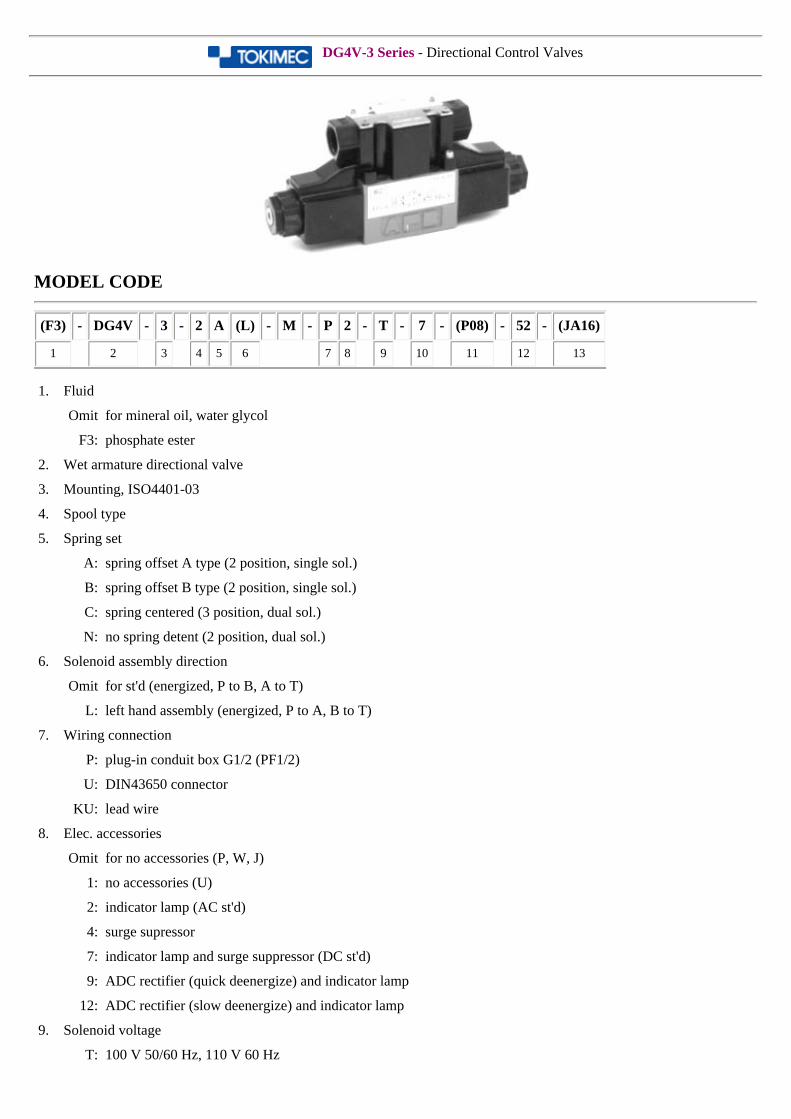
DG4V-3 Series - Directional Control Valves
MODEL CODE
(F3) - DG4V - 3 - 2 A (L) - M - P 2 - T - 7 - (P08) - 52 - (JA16)
1 2 3 4 5 6 7 8 9 10 11 12 13
1. Fluid
Omit for mineral oil, water glycol
F3: phosphate ester
2. Wet armature directional valve
3. Mounting, ISO4401-03
4. Spool type
5. Spring set
A: spring offset A type (2 position, single sol.)
B: spring offset B type (2 position, single sol.)
C: spring centered (3 position, dual sol.)
N: no spring detent (2 position, dual sol.)
6. Solenoid assembly direction
Omit for st'd (energized, P to B, A to T)
L: left hand assembly (energized, P to A, B to T)
7. Wiring connection
P: plug-in conduit box G1/2 (PF1/2)
U: DIN43650 connector
KU: lead wire
8. Elec. accessories
Omit for no accessories (P, W, J)
1: no accessories (U)
2: indicator lamp (AC st'd)
4: surge supressor
7: indicator lamp and surge suppressor (DC st'd)
9: ADC rectifier (quick deenergize) and indicator lamp
12: ADC rectifier (slow deenergize) and indicator lamp
9. Solenoid voltage
T: 100 V 50/60 Hz, 110 V 60 Hz
V: 200 V 50/60 Hz, 220 V 60 Hz
G: DC12 V
H: DC24 V
TR: 100 V 50/60 Hz (ADC rectifier)
VR: 200 V 50/60 Hz (ADC rectifier)
10. T port allowable back pressure
7: 20.6 MPa
11. Port orifice
Omit for no port orifice (st'd)
12. Design no.
13. Special feature
JA16: man. operated knob
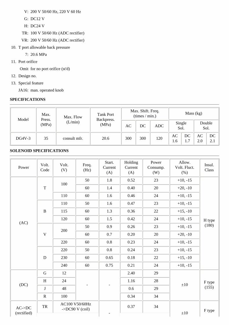
SPECIFICATIONS
ModelMax.Press.(MPa)
Max. Flow(L/min)
Tank PortBackpress.
(MPa)
Max. Shift. Freq.(times / min.)
Mass (kg)
SingleSol.
DoubleSol.AC DC ADC
DG4V-3 35 consult mfr. 20.6 300 300 120AC1.6
DC1.7
AC2.0
DC2.1
SOLENOID SPECIFICATIONS
PowerVolt.Code
Volt.(V)
Freq.(Hz)
Start.Current
(A)
HoldingCurrent
(A)
PowerConsump.
(W)
Allow.Volt. Fluct.
(%)
Insul.Class
(AC)
T100
50 1.8 0.52 23 +10, -15
H type(180)
60 1.4 0.40 20 +20, -10
110 60 1.6 0.46 24 +10, -15
B
110 50 1.6 0.47 23 +10, -15
115 60 1.3 0.36 22 +15, -10
120 60 1.5 0.42 24 +10, -15
V200
50 0.9 0.26 23 +10, -15
60 0.7 0.20 20 +20, -10
220 60 0.8 0.23 24 +10, -15
D
220 50 0.8 0.24 23 +10, -15
230 60 0.65 0.18 22 +15, -10
240 60 0.75 0.21 24 +10, -15
(DC)
G 12
- -
2.40 29
±10F type(155)
H 24 1.16 28
J 48 0.6 29
R 100 0.34 34
AC->DC(rectified)
TRAC100 V50/60Hz->DC90 V (coil)
-
0.37 34
±10F type
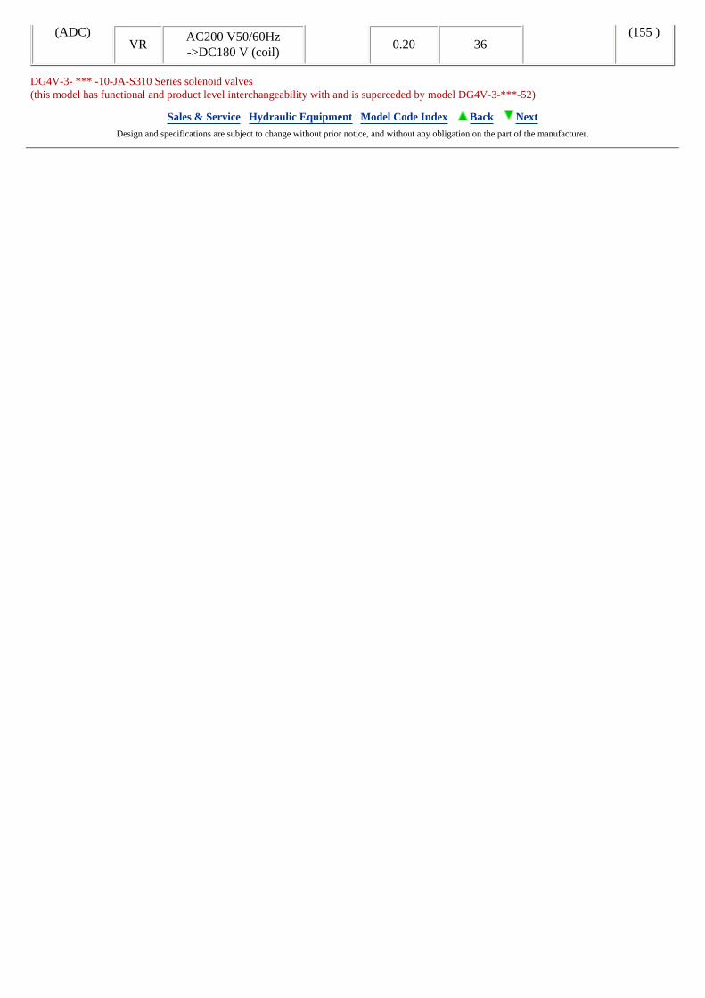
(ADC) (155 )VR
AC200 V50/60Hz->DC180 V (coil)
0.20 36
DG4V-3- *** -10-JA-S310 Series solenoid valves(this model has functional and product level interchangeability with and is superceded by model DG4V-3-***-52)
Sales & Service Hydraulic Equipment Model Code Index Back Next Design and specifications are subject to change without prior notice, and without any obligation on the part of the manufacturer.
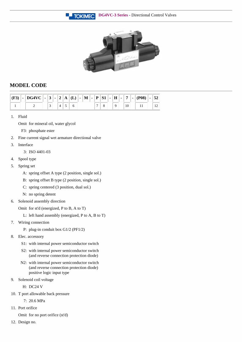
DG4VC-3 Series - Directional Control Valves
MODEL CODE
(F3) - DG4VC - 3 - 2 A (L) - M - P S1 - H - 7 - (P08) - 52
1 2 3 4 5 6 7 8 9 10 11 12
1. Fluid
Omit for mineral oil, water glycol
F3: phosphate ester
2. Fine current signal wet armature directional valve
3. Interface
3: ISO 4401-03
4. Spool type
5. Spring set
A: spring offset A type (2 position, single sol.)
B: spring offset B type (2 position, single sol.)
C: spring centered (3 position, dual sol.)
N: no spring detent
6. Solenoid assembly direction
Omit for st'd (energized, P to B, A to T)
L: left hand assembly (energized, P to A, B to T)
7. Wiring connection
P: plug-in conduit box G1/2 (PF1/2)
8. Elec. accessory
S1: with internal power semiconductor switch
S2: with internal power semiconductor switch(and reverse connection protection diode)
N2: with internal power semiconductor switch (and reverse connection protection diode) positive logic input type
9. Solenoid coil voltage
H: DC24 V
10. T port allowable back pressure
7: 20.6 MPa
11. Port orifice
Omit for no port orifice (st'd)
12. Design no.
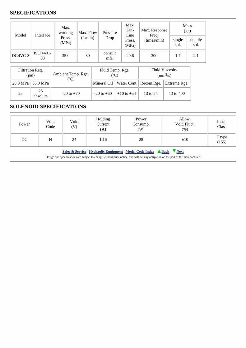
SPECIFICATIONS
Model Interface
Max. working Press.(MPa)
Max. Flow(L/min)
Pressure Drop
Max. Tank Line
Press.(MPa)
Max. Response Freq.
(times/min)
Mass(kg)
single sol.
double sol.
DG4VC-3ISO 4401-
0335.0 80
consult mfr.
20.6 300 1.7 2.1
Filtration Req.(µm) Ambient Temp. Rge.
(ºC)
Fluid Temp. Rge.(ºC)
Fluid Viscosity(mm2/s)
25.0 MPa 35.0 MPa Mineral Oil Water Cont Recom.Rge. Extreme Rge.
2525
absolute-20 to +70 -20 to +60 +10 to +54 13 to 54 13 to 400
SOLENOID SPECIFICATIONS
PowerVolt.Code
Volt.(V)
HoldingCurrent
(A)
PowerConsump.
(W)
Allow.Volt. Fluct.
(%)
Insul.Class
DC H 24 1.16 28 ±10F type(155)
Sales & Service Hydraulic Equipment Model Code Index Back Next Design and specifications are subject to change without prior notice, and without any obligation on the part of the manufacturer.
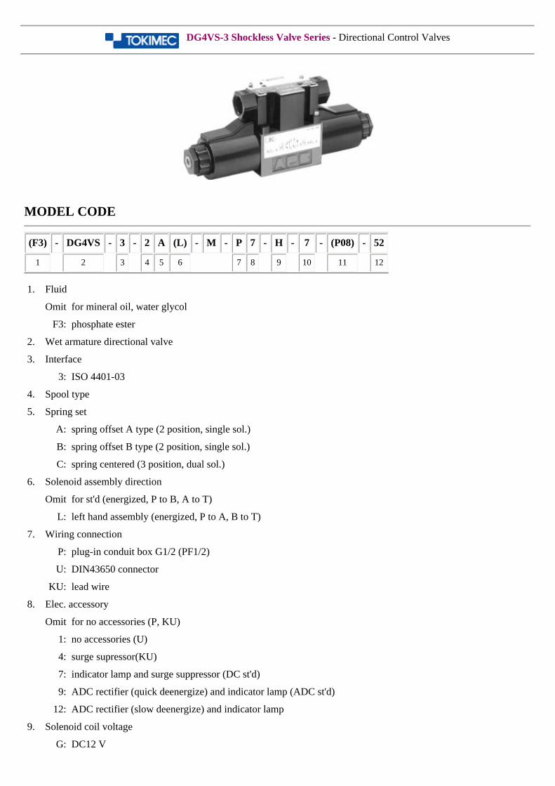
DG4VS-3 Shockless Valve Series - Directional Control Valves
MODEL CODE
(F3) - DG4VS - 3 - 2 A (L) - M - P 7 - H - 7 - (P08) - 52
1 2 3 4 5 6 7 8 9 10 11 12
1. Fluid
Omit for mineral oil, water glycol
F3: phosphate ester
2. Wet armature directional valve
3. Interface
3: ISO 4401-03
4. Spool type
5. Spring set
A: spring offset A type (2 position, single sol.)
B: spring offset B type (2 position, single sol.)
C: spring centered (3 position, dual sol.)
6. Solenoid assembly direction
Omit for st'd (energized, P to B, A to T)
L: left hand assembly (energized, P to A, B to T)
7. Wiring connection
P: plug-in conduit box G1/2 (PF1/2)
U: DIN43650 connector
KU: lead wire
8. Elec. accessory
Omit for no accessories (P, KU)
1: no accessories (U)
4: surge supressor(KU)
7: indicator lamp and surge suppressor (DC st'd)
9: ADC rectifier (quick deenergize) and indicator lamp (ADC st'd)
12: ADC rectifier (slow deenergize) and indicator lamp
9. Solenoid coil voltage
G: DC12 V
H: DC24 V
TR: 100 V 50/60 Hz (ADC rectifier)
VR: 200 V 50/60 Hz (ADC rectifier)
10. T port allowable back pressure
7: 20.6 MPa
11. Port orifice
Omit for no port orifice (st'd)
12. Design no.
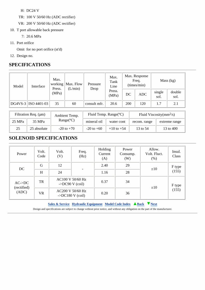
SPECIFICATIONS
Model Interface
Max.workingPress.(MPa)
Max. Flow(L/min)
Pressure Drop
Max. Tank Line
Press.(MPa)
Max. Response Freq.
(times/min) Mass (kg)
DC ADCsingle sol.
double sol.
DG4VS-3 ISO 4401-03 35 60 consult mfr. 20.6 200 120 1.7 2.1
Filtration Req. (µm) Ambient Temp. Range(ºC)
Fluid Temp. Range(ºC) Fluid Viscosity(mm2/s)
25 MPa 35 MPa mineral oil water cont recom. range extreme range
25 25 absolute -20 to +70 -20 to +60 +10 to +54 13 to 54 13 to 400
SOLENOID SPECIFICATIONS
PowerVolt.Code
Volt.(V)
Freq.(Hz)
HoldingCurrent
(A)
PowerConsump.
(W)
Allow.Volt. Fluct.
(%)
Insul.Class
DCG 12
-2.40 29
±10F type(155)H 24 1.16 28
AC->DC(rectified)
(ADC)
TRAC100 V 50/60 Hz
->DC90 V (coil)0.37 34
±10F type(155)
VRAC200 V 50/60 Hz->DC180 V (coil)
0.20 36
Sales & Service Hydraulic Equipment Model Code Index Back Next Design and specifications are subject to change without prior notice, and without any obligation on the part of the manufacturer.
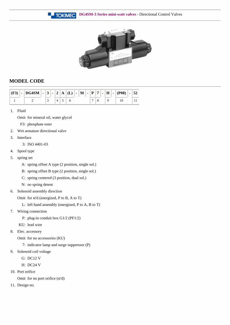
DG4SM-3 Series mini-watt valves - Directional Control Valves
MODEL CODE
(F3) - DG4SM - 3 - 2 A (L) - M - P 7 - H - (P08) - 52
1 2 3 4 5 6 7 8 9 10 11
1. Fluid
Omit for mineral oil, water glycol
F3: phosphate ester
2. Wet armature directional valve
3. Interface
3: ISO 4401-03
4. Spool type
5. spring set
A: spring offset A type (2 position, single sol.)
B: spring offset B type (2 position, single sol.)
C: spring centered (3 position, dual sol.)
N: no spring detent
6. Solenoid assembly direction
Omit for st'd (energized, P to B, A to T)
L: left hand assembly (energized, P to A, B to T)
7. Wiring connection
P: plug-in conduit box G1/2 (PF1/2)
KU: lead wire
8. Elec. accessory
Omit for no accessories (KU)
7: indicator lamp and surge suppressor (P)
9. Solenoid coil voltage
G: DC12 V
H: DC24 V
10. Port orifice
Omit for no port orifice (st'd)
11. Design no.
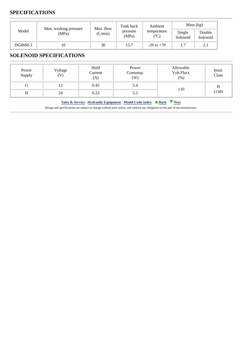
SPECIFICATIONS
ModelMax. working pressure
(MPa)Max. flow
(L/min)
Tank backpressure(MPa)
Ambienttemperature
(ºC)
Mass (kg)
SingleSolenoid
DoubleSolenoid
DG4SM-3 16 30 15.7 -20 to +70 1.7 2.1
SOLENOID SPECIFICATIONS
PowerSupply
Voltage(V)
HoldCurrent
(A)
PowerConsump.
(W)
Allowable.Volt.Fluct.
(%)
Insul.Class
G 12 0.45 5.4±10
B(130)H 24 0.23 5.5
Sales & Service Hydraulic Equipment Model Code Index Back Next Design and specifications are subject to change without prior notice, and without any obligation on the part of the manufacturer.
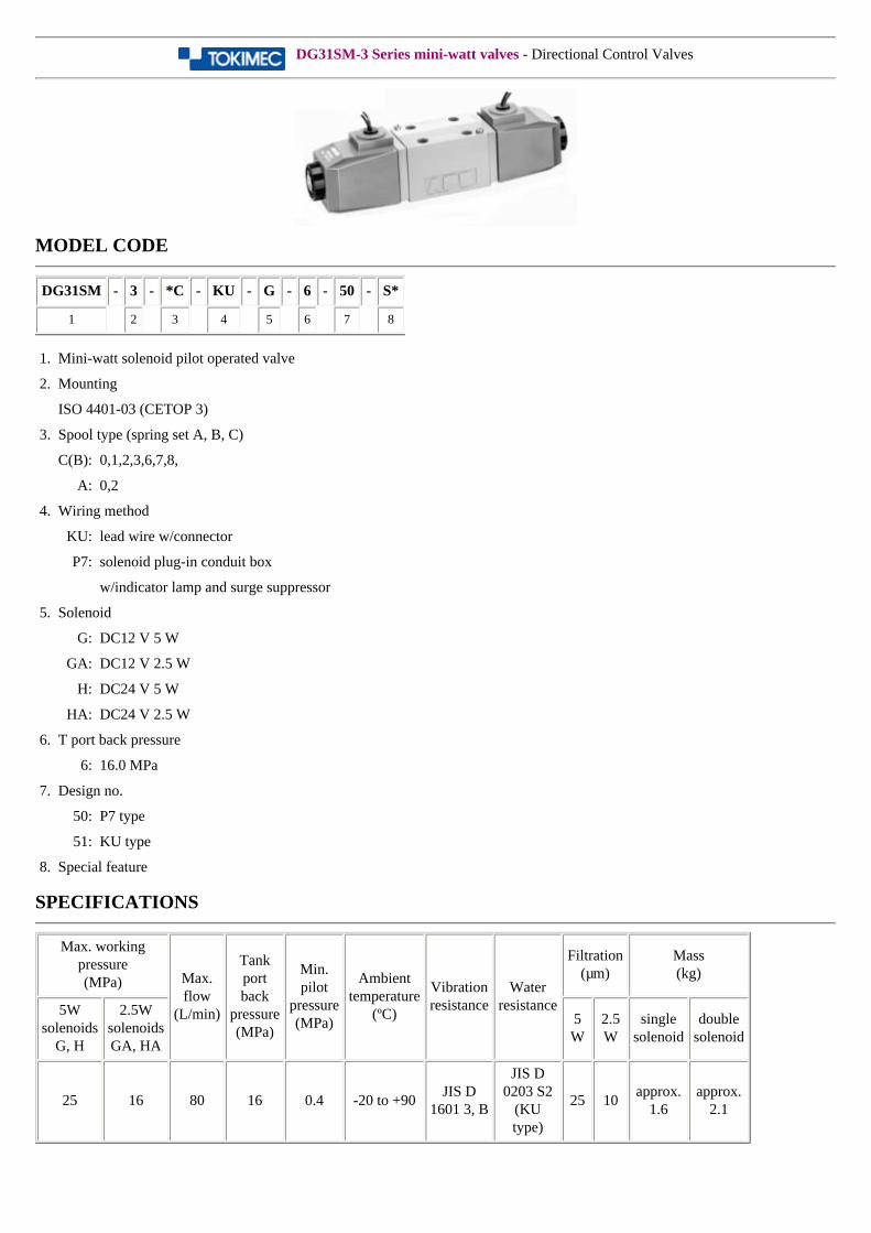
DG31SM-3 Series mini-watt valves - Directional Control Valves
MODEL CODE
DG31SM - 3 - *C - KU - G - 6 - 50 - S*
1 2 3 4 5 6 7 8
1. Mini-watt solenoid pilot operated valve
2. Mounting
ISO 4401-03 (CETOP 3)
3. Spool type (spring set A, B, C)
C(B): 0,1,2,3,6,7,8,
A: 0,2
4. Wiring method
KU: lead wire w/connector
P7: solenoid plug-in conduit box
w/indicator lamp and surge suppressor
5. Solenoid
G: DC12 V 5 W
GA: DC12 V 2.5 W
H: DC24 V 5 W
HA: DC24 V 2.5 W
6. T port back pressure
6: 16.0 MPa
7. Design no.
50: P7 type
51: KU type
8. Special feature
SPECIFICATIONS
Max. working pressure(MPa) Max.
flow(L/min)
Tank portback
pressure(MPa)
Min. pilot
pressure(MPa)
Ambienttemperature
(ºC)
Vibrationresistance
Waterresistance
Filtration(µm)
Mass(kg)
5W solenoids
G, H
2.5W solenoidsGA, HA
5 W
2.5 W
singlesolenoid
doublesolenoid
25 16 80 16 0.4 -20 to +90JIS D
1601 3, B
JIS D 0203 S2
(KU type)
25 10approx.
1.6approx.
2.1
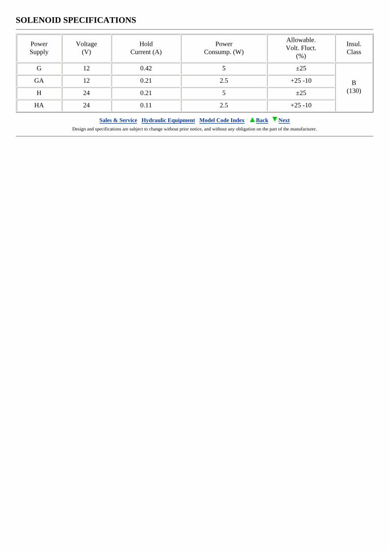
SOLENOID SPECIFICATIONS
PowerSupply
Voltage(V)
HoldCurrent (A)
PowerConsump. (W)
Allowable.Volt. Fluct.
(%)
Insul.Class
G 12 0.42 5 ±25
B(130)
GA 12 0.21 2.5 +25 -10
H 24 0.21 5 ±25
HA 24 0.11 2.5 +25 -10
Sales & Service Hydraulic Equipment Model Code Index Back Next Design and specifications are subject to change without prior notice, and without any obligation on the part of the manufacturer.
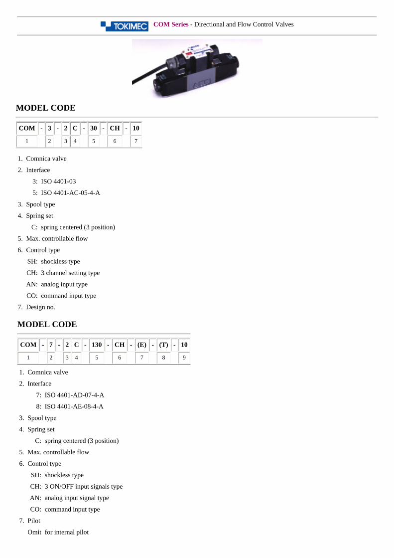
COM Series - Directional and Flow Control Valves
MODEL CODE
COM - 3 - 2 C - 30 - CH - 10
1 2 3 4 5 6 7
1. Comnica valve
2. Interface
3: ISO 4401-03
5: ISO 4401-AC-05-4-A
3. Spool type
4. Spring set
C: spring centered (3 position)
5. Max. controllable flow
6. Control type
SH: shockless type
CH: 3 channel setting type
AN: analog input type
CO: command input type
7. Design no.
MODEL CODE
COM - 7 - 2 C - 130 - CH - (E) - (T) - 10
1 2 3 4 5 6 7 8 9
1. Comnica valve
2. Interface
7: ISO 4401-AD-07-4-A
8: ISO 4401-AE-08-4-A
3. Spool type
4. Spring set
C: spring centered (3 position)
5. Max. controllable flow
6. Control type
SH: shockless type
CH: 3 ON/OFF input signals type
AN: analog input signal type
CO: command input type
7. Pilot
Omit for internal pilot
E: external pilot
8. Drain
Omit for external drain
T: internal drain
9. Design no.
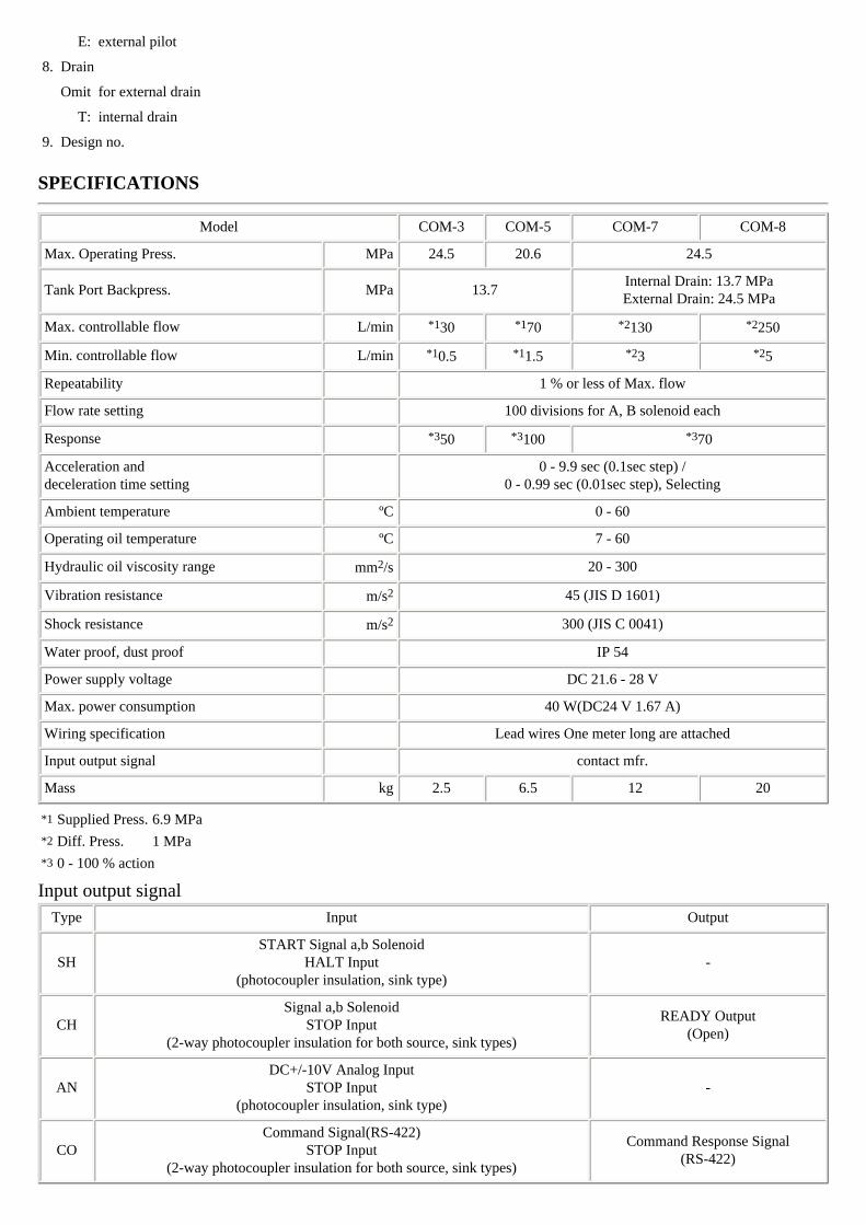
SPECIFICATIONS
Model COM-3 COM-5 COM-7 COM-8
Max. Operating Press. MPa 24.5 20.6 24.5
Tank Port Backpress. MPa 13.7Internal Drain: 13.7 MPaExternal Drain: 24.5 MPa
Max. controllable flow L/min *130 *170 *2130 *2250
Min. controllable flow L/min *10.5 *11.5 *23 *25
Repeatability 1 % or less of Max. flow
Flow rate setting 100 divisions for A, B solenoid each
Response *350 *3100 *370
Acceleration anddeceleration time setting
0 - 9.9 sec (0.1sec step) /
0 - 0.99 sec (0.01sec step), Selecting
Ambient temperature ºC 0 - 60
Operating oil temperature ºC 7 - 60
Hydraulic oil viscosity range mm2/s 20 - 300
Vibration resistance m/s2 45 (JIS D 1601)
Shock resistance m/s2 300 (JIS C 0041)
Water proof, dust proof IP 54
Power supply voltage DC 21.6 - 28 V
Max. power consumption 40 W(DC24 V 1.67 A)
Wiring specification Lead wires One meter long are attached
Input output signal contact mfr.
Mass kg 2.5 6.5 12 20
*1 Supplied Press. 6.9 MPa
*2 Diff. Press. 1 MPa
*3 0 - 100 % action
Input output signal Type Input Output
SHSTART Signal a,b Solenoid
HALT Input(photocoupler insulation, sink type)
-
CHSignal a,b Solenoid
STOP Input(2-way photocoupler insulation for both source, sink types)
READY Output(Open)
ANDC+/-10V Analog Input
STOP Input(photocoupler insulation, sink type)
-
COCommand Signal(RS-422)
STOP Input(2-way photocoupler insulation for both source, sink types)
Command Response Signal(RS-422)

Sales & Service Hydraulic Equipment Model Code Index Back Next Design and specifications are subject to change without prior notice, and without any obligation on the part of the manufacturer.
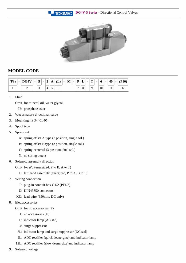
DG4V-5 Series - Directional Control Valves
MODEL CODE
(F3) - DG4V - 5 - 2 A (L) - M - P L - T - 6 - 40 - (P10)
1 2 3 4 5 6 7 8 9 10 11 12
1. Fluid
Omit for mineral oil, water glycol
F3: phosphate ester
2. Wet armature directional valve
3. Mounting, ISO4401-05
4. Spool type
5. Spring set
A: spring offset A type (2 position, single sol.)
B: spring offset B type (2 position, single sol.)
C: spring centered (3 position, dual sol.)
N: no spring detent
6. Solenoid assembly direction
Omit for st'd (energized, P to B, A to T)
L: left hand assembly (energized, P to A, B to T)
7. Wiring connection
P: plug-in conduit box G1/2 (PF1/2)
U: DIN43650 connector
KU: lead wire (350mm, DC only)
8. Elec.accessories
Omit for no accessories (P)
1: no accessories (U)
L: indicator lamp (AC st'd)
4: surge suppressor
7L: indicator lamp and surge suppressor (DC st'd)
9L: ADC rectifier (quick deenergize) and indicator lamp
12L: ADC rectifier (slow deenergize)and indicator lamp
9. Solenoid voltage

T: 100 V 50/60 Hz, 110 V 60 Hz
OV: 200 V 50/60 Hz, 220 V 60 Hz
G: DC12 V
H: DC24 V
TR: 100 V 50/60 Hz (ADC rectifier)
VR: 200 V 50/60 Hz (ADC rectifier)
10. T port allowable back pressure
6: 15.7 MPa (AC sol.)
7: 20.6 MPa (DC sol.)
11. Design no.
12. Port orifice (option)
Omit for no port orifice (st'd)
SPECIFICATIONS
Model
Max.Working
Press.(MPa)
Max. Flow(L/min)
Tank PortBackpress.
(MPa)
Max. Shift. Freq.(times/min.)
Mass (kg)
SingleSol.
DoubleSol.AC DC ADC
DG4V-5 31.5 consult mfr.15.7 (AC)
240 180 120AC DC AC DC
20.6 (DC) 3.6 4.4 4.6 6.1
SOLENOID SPECIFICATIONS
PowerVolt.Code
Volt.(V)
Freq.(Hz)
Start.Current
(A)
HoldingCurrent
(A)
PowerConsump.
(W)
PowerVolt. Fluct.
(%)
Insul.Class
(AC)
T100
50 6.8 0.69 - +10, -15
H type(180 ºC)
60 5.9 0.49 - +20, -10
110 60 6.5 0.59 - +10, -15
B
110 50 6.2 0.63 - +10, -15
115 60 5.8 0.52 - +15, -10
120 60 6.0 0.54 - +10, -15
OV200
50 3.4 0.35 - +10, -15
60 3.0 0.25 - +20, -10
220 60 3.3 0.30 - +10, -15
D
220 50 3.1 0.32 - +10, -15
230 60 2.9 0.26 - +15, -10
240 60 3.0 0.27 - +10, -15
(DC)
G 12
- -
3.17
38 ±10H type
(180 ºC)
H 24 1.58
OJ 48 0.79
R 100 0.38

AC->DC
(rectified)(ADC)
TRAC100V 50/60Hz
->DC90V(coil)-
0.42 38
±10H type
(180 ºC)VR
AC200V 50/60Hz->DC180V(coil)
0.21 38
Sales & Service Hydraulic Equipment Model Code Index Back Next Design and specifications are subject to change without prior notice, and without any obligation on the part of the manufacturer.
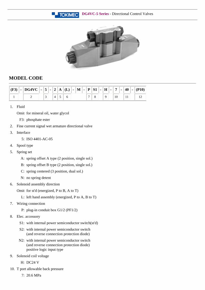
DG4VC-5 Series - Directional Control Valves
MODEL CODE
(F3) - DG4VC - 5 - 2 A (L) - M - P S1 - H - 7 - 40 - (P10)
1 2 3 4 5 6 7 8 9 10 11 12
1. Fluid
Omit for mineral oil, water glycol
F3: phosphate ester
2. Fine current signal wet armature directional valve
3. Interface
5: ISO 4401-AC-05
4. Spool type
5. Spring set
A: spring offset A type (2 position, single sol.)
B: spring offset B type (2 position, single sol.)
C: spring centered (3 position, dual sol.)
N: no spring detent
6. Solenoid assembly direction
Omit for st'd (energized, P to B, A to T)
L: left hand assembly (energized, P to A, B to T)
7. Wiring connection
P: plug-in conduit box G1/2 (PF1/2)
8. Elec. accessory
S1: with internal power semiconductor switch(st'd)
S2: with internal power semiconductor switch(and reverse connection protection diode)
N2: with internal power semiconductor switch (and reverse connection protection diode) positive logic input type
9. Solenoid coil voltage
H: DC24 V
10. T port allowable back pressure
7: 20.6 MPa
11. Design no.
12. Port orifice
Omit for no port orifice (st'd)
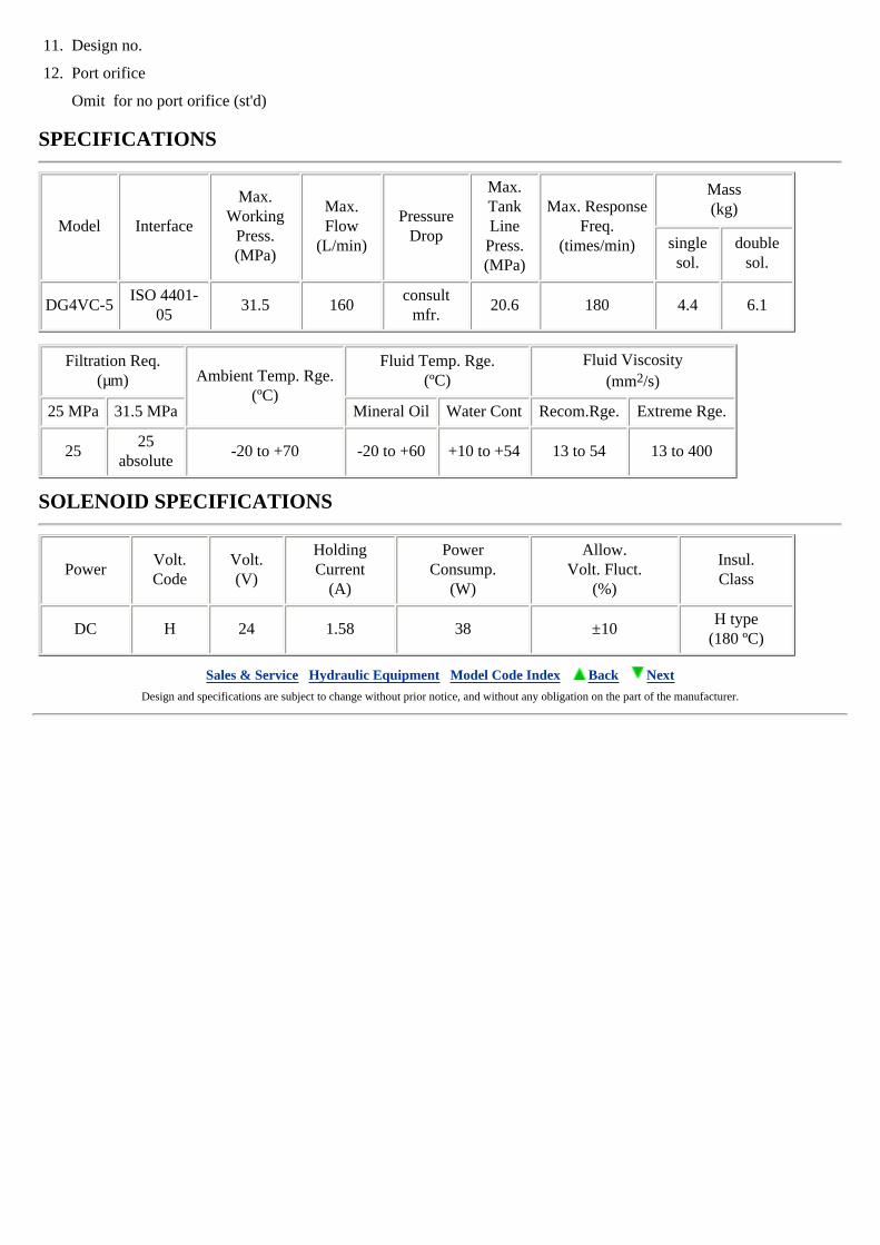
SPECIFICATIONS
Model Interface
Max. Working
Press.(MPa)
Max. Flow
(L/min)
Pressure Drop
Max. Tank Line
Press.(MPa)
Max. Response Freq.
(times/min)
Mass(kg)
single sol.
double sol.
DG4VC-5ISO 4401-
0531.5 160
consult mfr.
20.6 180 4.4 6.1
Filtration Req.(µm) Ambient Temp. Rge.
(ºC)
Fluid Temp. Rge.(ºC)
Fluid Viscosity(mm2/s)
25 MPa 31.5 MPa Mineral Oil Water Cont Recom.Rge. Extreme Rge.
2525
absolute-20 to +70 -20 to +60 +10 to +54 13 to 54 13 to 400
SOLENOID SPECIFICATIONS
PowerVolt.Code
Volt.(V)
HoldingCurrent
(A)
PowerConsump.
(W)
Allow.Volt. Fluct.
(%)
Insul.Class
DC H 24 1.58 38 ±10H type
(180 ºC)
Sales & Service Hydraulic Equipment Model Code Index Back Next Design and specifications are subject to change without prior notice, and without any obligation on the part of the manufacturer.
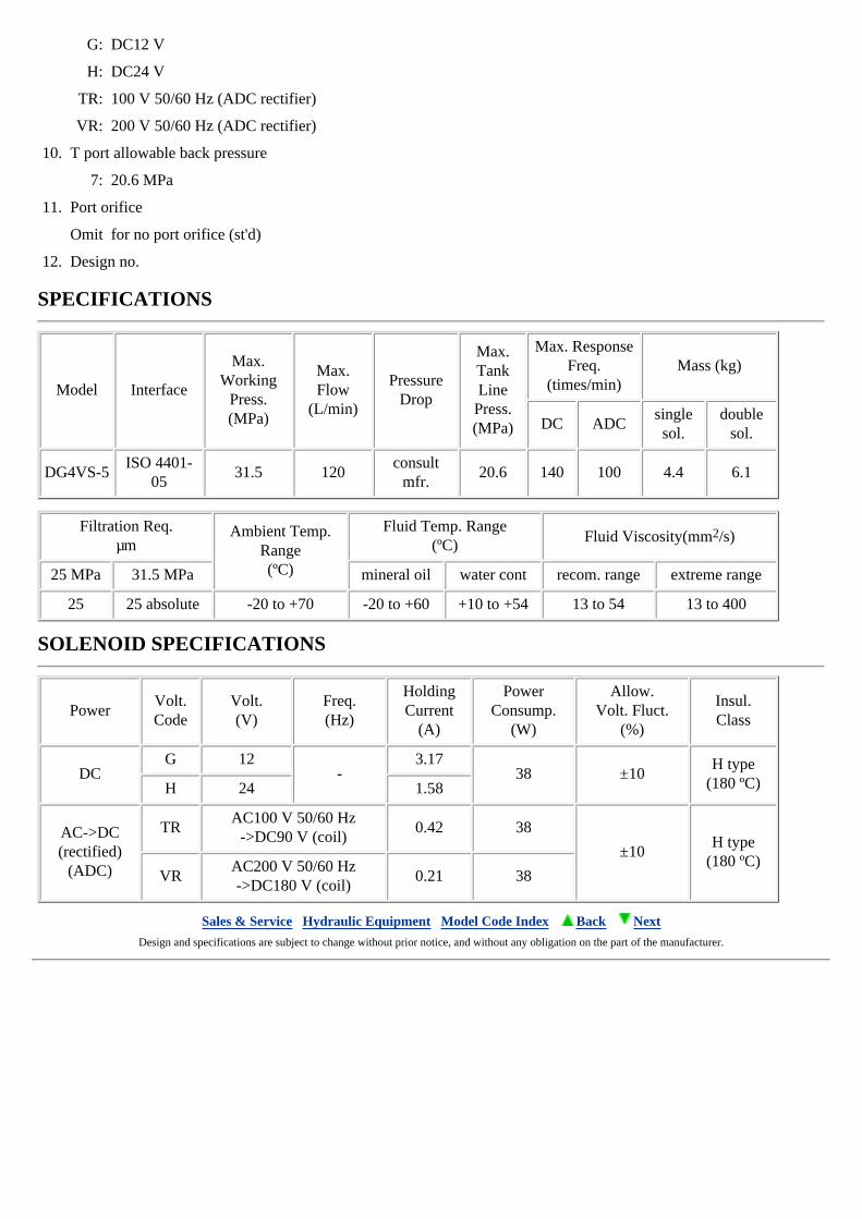
DG4VS-5 shockless valve series - Directional Control Valves
MODEL CODE
(F3) - DG4VS - 5 - 2 A (L) - M - P 7L - H - 7 - 40 - (P10)
1 2 3 4 5 6 7 8 9 10 11 12
1. Fluid
Omit for mineral oil, water glycol
F3: phosphate ester
2. Wet armature directional valve
3. Interface
5: ISO 4401-05
4. Spool type
5. Spring set
A: spring offset A type (2 position, single sol.)
B: spring offset B type (2 position, single sol.)
C: spring centered (3 position, dual sol.)
N: no spring detent
6. Solenoid assembly direction
Omit for st'd (energized, P to B, A to T)
L: left hand assembly (energized, P to A, B to T)
7. Wiring connection
P: plug-in conduit box G1/2 (PF1/2)
U: DIN43650 connector
KU: lead wire
8. Elec. accessory
Omit for no accessories (P, KU)
1: no accessories (U)
4: surge supressor(KU)
7L: indicator lamp and surge suppressor (DC st'd)
9L: ADC rectifier (quick deenergize) and indicator lamp (ADC st'd)
12L: ADC rectifier (slow deenergize) and indicator lamp
9. Solenoid coil voltage
G: DC12 V
H: DC24 V
TR: 100 V 50/60 Hz (ADC rectifier)
VR: 200 V 50/60 Hz (ADC rectifier)
10. T port allowable back pressure
7: 20.6 MPa
11. Port orifice
Omit for no port orifice (st'd)
12. Design no.
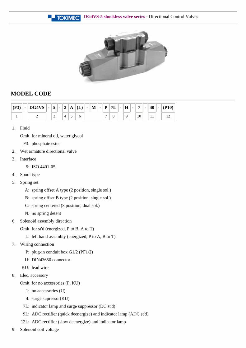
SPECIFICATIONS
Model Interface
Max. Working
Press.(MPa)
Max. Flow
(L/min)
Pressure Drop
Max. Tank Line
Press.(MPa)
Max. Response Freq.
(times/min) Mass (kg)
DC ADCsingle sol.
double sol.
DG4VS-5ISO 4401-
0531.5 120
consult mfr.
20.6 140 100 4.4 6.1
Filtration Req.µm
Ambient Temp. Range(ºC)
Fluid Temp. Range(ºC) Fluid Viscosity(mm2/s)
25 MPa 31.5 MPa mineral oil water cont recom. range extreme range
25 25 absolute -20 to +70 -20 to +60 +10 to +54 13 to 54 13 to 400
SOLENOID SPECIFICATIONS
PowerVolt.Code
Volt.(V)
Freq.(Hz)
HoldingCurrent
(A)
PowerConsump.
(W)
Allow.Volt. Fluct.
(%)
Insul.Class
DCG 12
-3.17
38 ±10H type
(180 ºC)H 24 1.58
AC->DC(rectified)
(ADC)
TRAC100 V 50/60 Hz
->DC90 V (coil)0.42 38
±10H type
(180 ºC)VR
AC200 V 50/60 Hz->DC180 V (coil)
0.21 38
Sales & Service Hydraulic Equipment Model Code Index Back Next Design and specifications are subject to change without prior notice, and without any obligation on the part of the manufacturer.
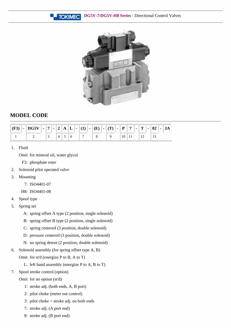
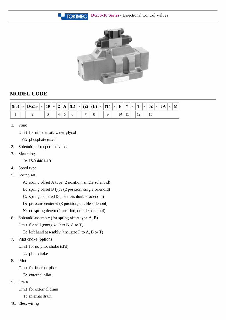
DG5V-7/DG5V-H8 Series - Directional Control Valves
MODEL CODE
(F3) - DG5V - 7 - 2 A L - (1) - (E) - (T) - P 7 - T - 82 - JA
1 2 3 4 5 6 7 8 9 10 11 12 13
1. Fluid
Omit for mineral oil, water glycol
F3: phosphate ester
2. Solenoid pilot operated valve
3. Mounting
7: ISO4401-07
H8: ISO4401-08
4. Spool type
5. Spring set
A: spring offset A type (2 position, single solenoid)
B: spring offset B type (2 position, single solenoid)
C: spring centered (3 position, double solenoid)
D: pressure centered (3 position, double solenoid)
N: no spring detent (2 position, double solenoid)
6. Solenoid assembly (for spring offset type A, B)
Omit for st'd (energize P to B, A to T)
L: left hand assembly (energize P to A, B to T)
7. Spool stroke control (option)
Omit for no option (st'd)
1: stroke adj. (both ends, A, B port)
2: pilot choke (meter out control)
3: pilot choke + stroke adj. on both ends
7: stroke adj. (A port end)
8: stroke adj. (B port end)
27: pilot choke + stroke adj. (A port end)
28: pilot choke + stroke adj. (B port end)
8. Pilot
Omit for internal pilot
E: external pilot
9. Drain
Omit for external drain
T: internal drain
10. Elec. wiring
P: plug-in conduit box G1/2 (PF1/2)
U: DIN43650 connector
11. Elec. accessories
Omit for no accessories (for types P)
1: no accessories (for type U)
2: indicator lamp (AC st'd)
7: indicator lamp and surge suppressor (DC st'd)
9: ADC solenoid rectifier (quick deenergize) and
indicator lamp
12: ADC solenoid rectifier (slow deenergize) and
indicator lamp
12. Solenoids
T: 100 V 50/60Hz, 110 V 60 Hz
V: 200 V 50/60Hz, 220 V 60 Hz
G: DC12 V
H: DC24 V
TR: 100 V 50/60Hz (ADC rectifier)
VR: 200 V 50/60Hz (ADC rectifier)
13. Design no.
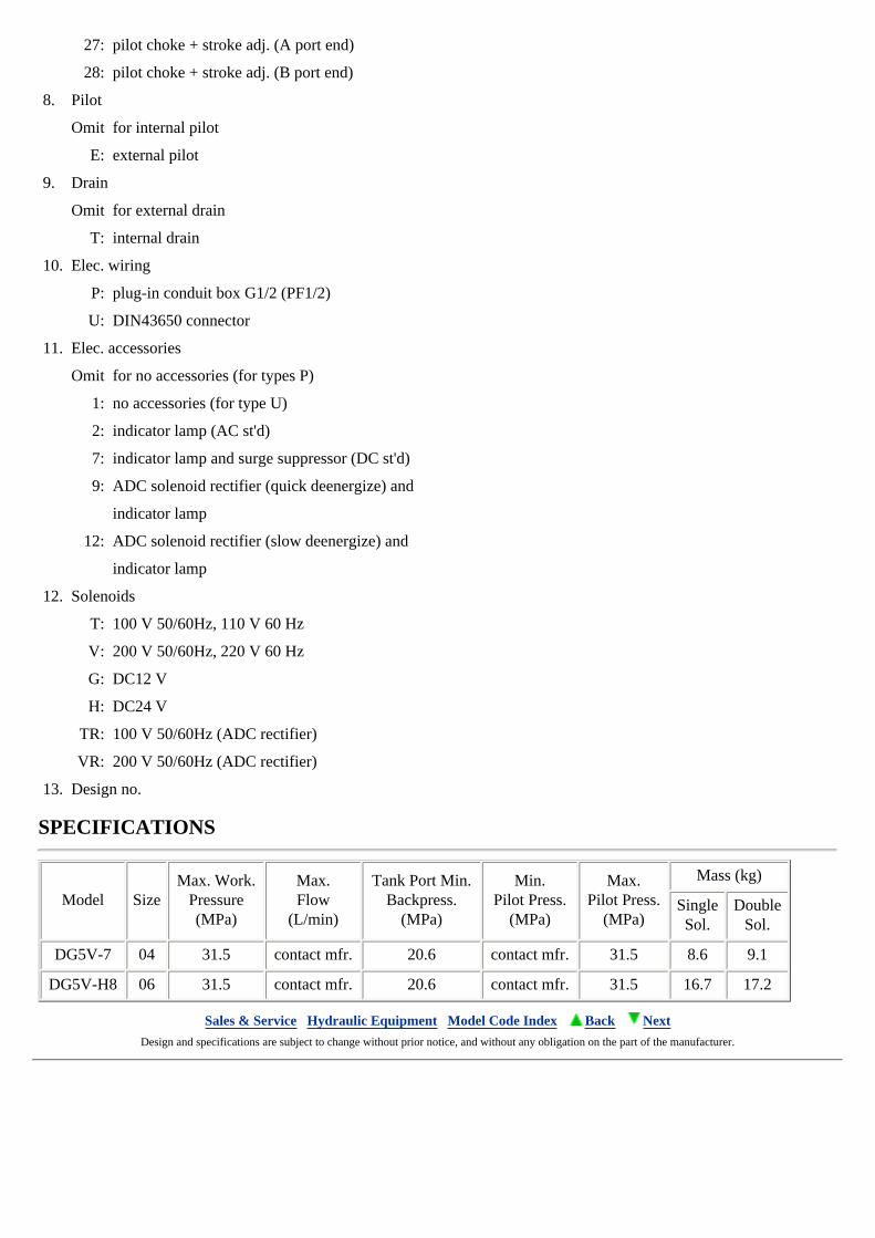
SPECIFICATIONS
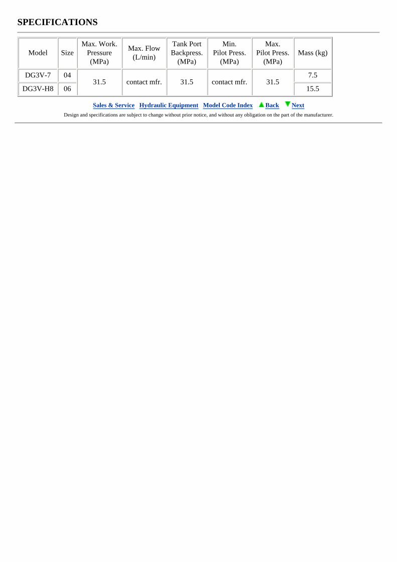
Model SizeMax. Work.
Pressure(MPa)
Max.Flow
(L/min)
Tank Port Min.Backpress.
(MPa)
Min.Pilot Press.
(MPa)
Max.Pilot Press.
(MPa)
Mass (kg)
SingleSol.
DoubleSol.
DG5V-7 04 31.5 contact mfr. 20.6 contact mfr. 31.5 8.6 9.1
DG5V-H8 06 31.5 contact mfr. 20.6 contact mfr. 31.5 16.7 17.2
Sales & Service Hydraulic Equipment Model Code Index Back Next Design and specifications are subject to change without prior notice, and without any obligation on the part of the manufacturer.
DG5S-10 Series - Directional Control Valves
MODEL CODE
(F3) - DG5S - 10 - 2 A (L) - (2) (E) - (T) - P 7 - T - 82 - JA - M
1 2 3 4 5 6 7 8 9 10 11 12 13
1. Fluid
Omit for mineral oil, water glycol
F3: phosphate ester
2. Solenoid pilot operated valve
3. Mounting
10: ISO 4401-10
4. Spool type
5. Spring set
A: spring offset A type (2 position, single solenoid)
B: spring offset B type (2 position, single solenoid)
C: spring centered (3 position, double solenoid)
D: pressure centered (3 position, double solenoid)
N: no spring detent (2 position, double solenoid)
6. Solenoid assembly (for spring offset type A, B)
Omit for st'd (energize P to B, A to T)
L: left hand assembly (energize P to A, B to T)
7. Pilot choke (option)
Omit for no pilot choke (st'd)
2: pilot choke
8. Pilot
Omit for internal pilot
E: external pilot
9. Drain
Omit for external drain
T: internal drain
10. Elec. wiring
P: plug-in conduit box G1/2 (PF1/2)
U: DIN43650 connector
11. Elec. accessories
Omit for no accessories (type P)
1: no accessories (type U)
2: indicator lamp (AC st'd)
7: indicator lamp and surge suppressor (DC st'd)
9: ADC solenoid rectifier (quick deenergize) and indicator lamp
12: ADC solenoid rectifier (slow deenergize) and indicator lamp
12. Solenoids
T: 100 V 50/60 Hz 110 V 60 Hz
V: 200 V 50/60 Hz 220 V 60 Hz
G: DC12 V
H: DC24 V
TR: 100 V 50/60 Hz (ADC)
VR: 200 V 50/60 Hz (ADC)
13. Design no.
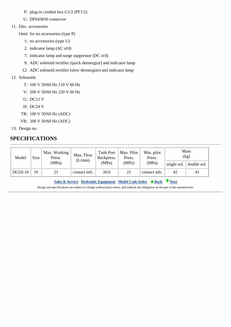
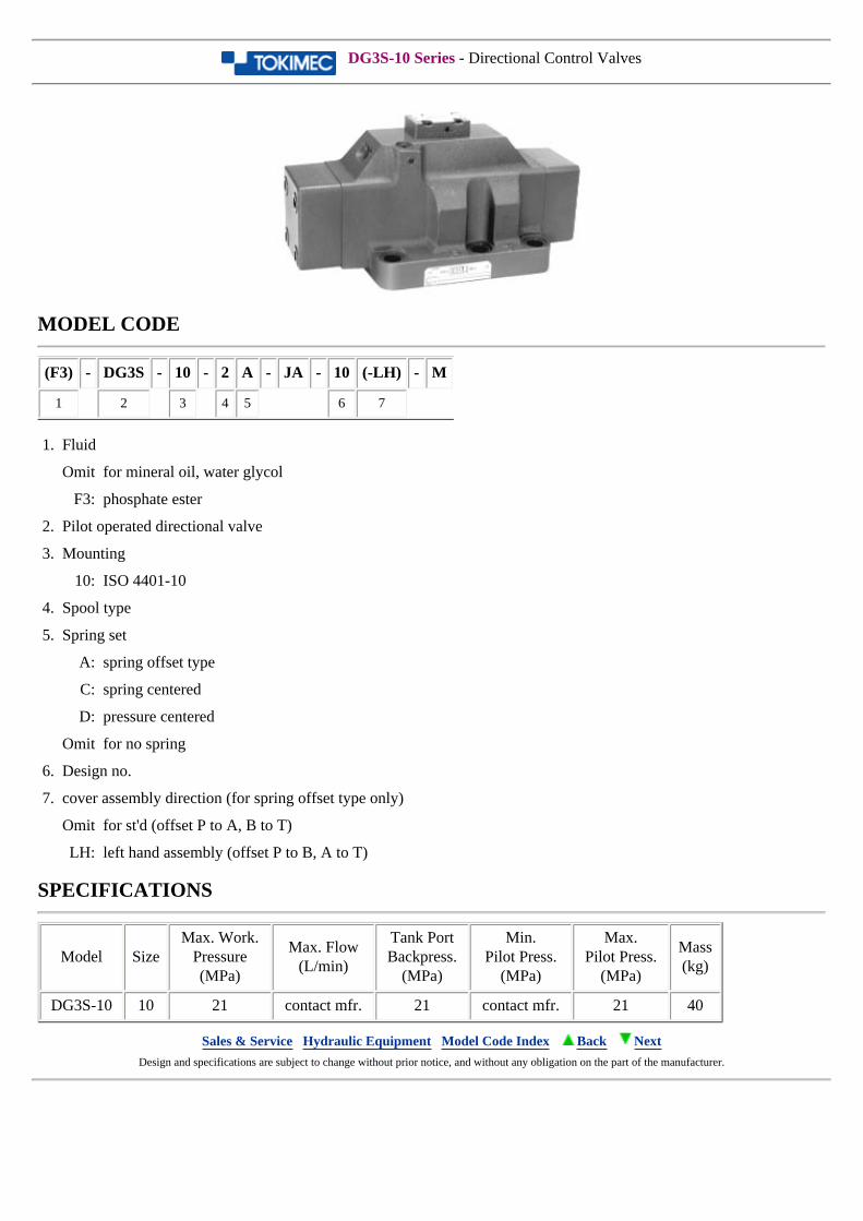
SPECIFICATIONS
Model SizeMax. Working
Press.(MPa)
Max. Flow(L/min)
Tank PortBackpress.
(MPa)
Max. PilotPress.(MPa)
Min. pilotPress.(MPa)
Mass(kg)
single sol. double sol.
DG5S-10 10 21 contact mfr. 20.6 21 contact mfr. 42 43
Sales & Service Hydraulic Equipment Model Code Index Back Next Design and specifications are subject to change without prior notice, and without any obligation on the part of the manufacturer.
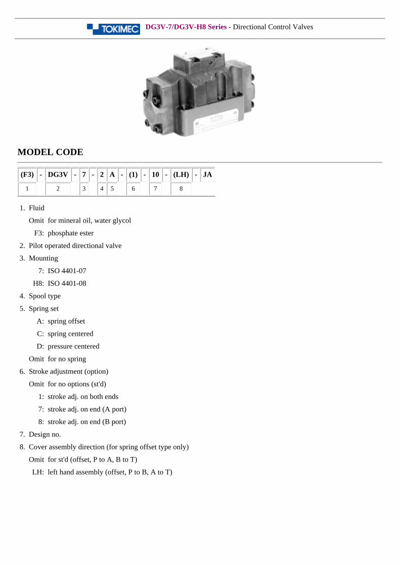
DG3V-7/DG3V-H8 Series - Directional Control Valves
MODEL CODE
(F3) - DG3V - 7 - 2 A - (1) - 10 - (LH) - JA
1 2 3 4 5 6 7 8
1. Fluid
Omit for mineral oil, water glycol
F3: phosphate ester
2. Pilot operated directional valve
3. Mounting
7: ISO 4401-07
H8: ISO 4401-08
4. Spool type
5. Spring set
A: spring offset
C: spring centered
D: pressure centered
Omit for no spring
6. Stroke adjustment (option)
Omit for no options (st'd)
1: stroke adj. on both ends
7: stroke adj. on end (A port)
8: stroke adj. on end (B port)
7. Design no.
8. Cover assembly direction (for spring offset type only)
Omit for st'd (offset, P to A, B to T)
LH: left hand assembly (offset, P to B, A to T)
SPECIFICATIONS
Model SizeMax. Work.
Pressure(MPa)
Max. Flow(L/min)
Tank PortBackpress.
(MPa)
Min.Pilot Press.
(MPa)
Max.Pilot Press.
(MPa)Mass (kg)
DG3V-7 0431.5 contact mfr. 31.5 contact mfr. 31.5
7.5
DG3V-H8 06 15.5
Sales & Service Hydraulic Equipment Model Code Index Back Next Design and specifications are subject to change without prior notice, and without any obligation on the part of the manufacturer.
DG3S-10 Series - Directional Control Valves
MODEL CODE
(F3) - DG3S - 10 - 2 A - JA - 10 (-LH) - M
1 2 3 4 5 6 7
1. Fluid
Omit for mineral oil, water glycol
F3: phosphate ester
2. Pilot operated directional valve
3. Mounting
10: ISO 4401-10
4. Spool type
5. Spring set
A: spring offset type
C: spring centered
D: pressure centered
Omit for no spring
6. Design no.
7. cover assembly direction (for spring offset type only)
Omit for st'd (offset P to A, B to T)
LH: left hand assembly (offset P to B, A to T)
SPECIFICATIONS
Model SizeMax. Work.
Pressure(MPa)
Max. Flow(L/min)
Tank PortBackpress.
(MPa)
Min.Pilot Press.
(MPa)
Max.Pilot Press.
(MPa)
Mass(kg)
DG3S-10 10 21 contact mfr. 21 contact mfr. 21 40
Sales & Service Hydraulic Equipment Model Code Index Back Next Design and specifications are subject to change without prior notice, and without any obligation on the part of the manufacturer.
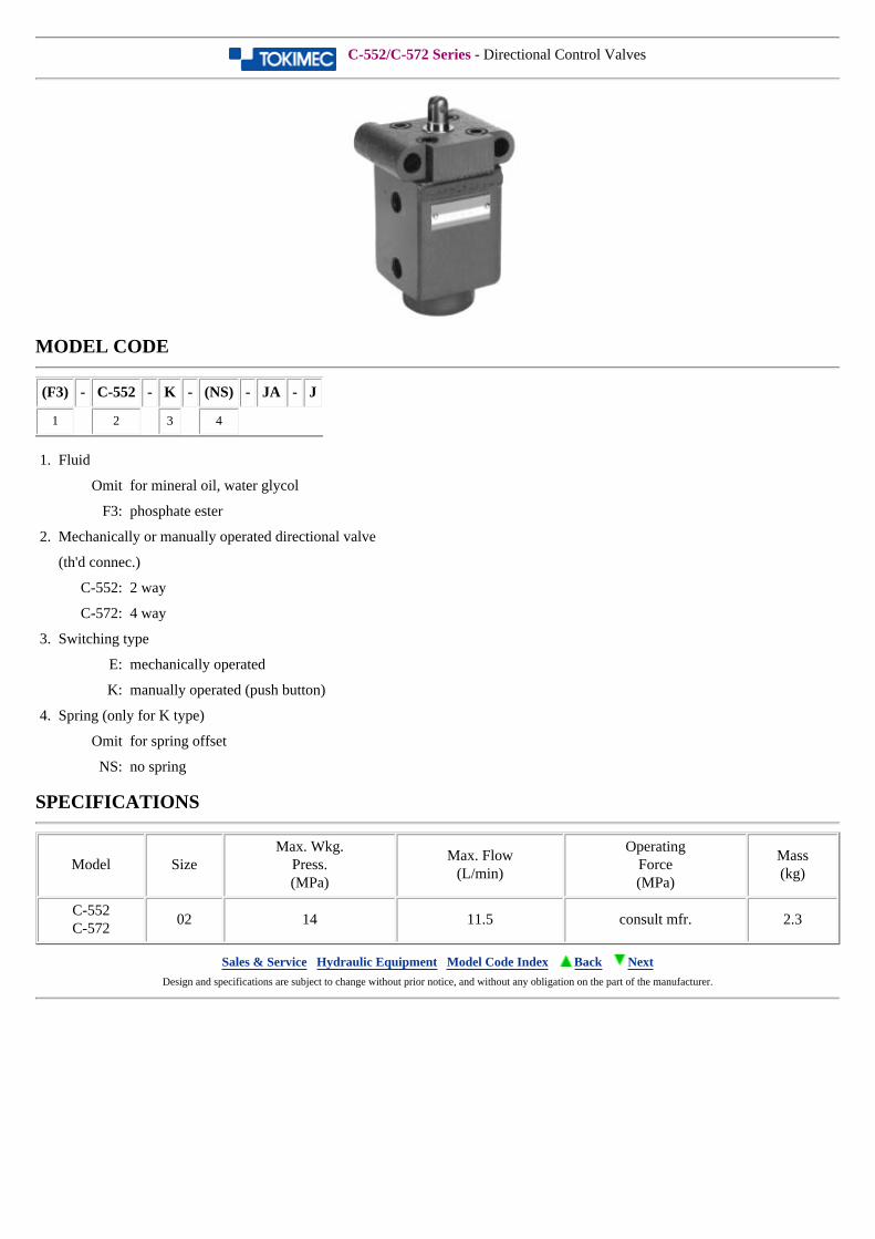
C-552/C-572 Series - Directional Control Valves
MODEL CODE
(F3) - C-552 - K - (NS) - JA - J
1 2 3 4
1. Fluid
Omit for mineral oil, water glycol
F3: phosphate ester
2. Mechanically or manually operated directional valve
(th'd connec.)
C-552: 2 way
C-572: 4 way
3. Switching type
E: mechanically operated
K: manually operated (push button)
4. Spring (only for K type)
Omit for spring offset
NS: no spring
SPECIFICATIONS
Model SizeMax. Wkg.
Press.(MPa)
Max. Flow(L/min)
OperatingForce(MPa)
Mass(kg)
C-552C-572
02 14 11.5 consult mfr. 2.3
Sales & Service Hydraulic Equipment Model Code Index Back Next Design and specifications are subject to change without prior notice, and without any obligation on the part of the manufacturer.
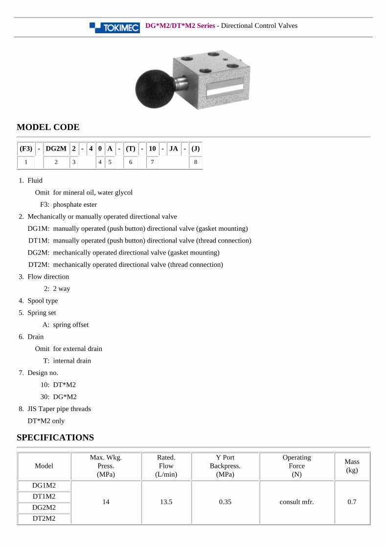
DG*M2/DT*M2 Series - Directional Control Valves
MODEL CODE
(F3) - DG2M 2 - 4 0 A - (T) - 10 - JA - (J)
1 2 3 4 5 6 7 8
1. Fluid
Omit for mineral oil, water glycol
F3: phosphate ester
2. Mechanically or manually operated directional valve
DG1M: manually operated (push button) directional valve (gasket mounting)
DT1M: manually operated (push button) directional valve (thread connection)
DG2M: mechanically operated directional valve (gasket mounting)
DT2M: mechanically operated directional valve (thread connection)
3. Flow direction
2: 2 way
4. Spool type
5. Spring set
A: spring offset
6. Drain
Omit for external drain
T: internal drain
7. Design no.
10: DT*M2
30: DG*M2
8. JIS Taper pipe threads
DT*M2 only
SPECIFICATIONS
ModelMax. Wkg.
Press.(MPa)
Rated.Flow
(L/min)
Y PortBackpress.
(MPa)
OperatingForce(N)
Mass(kg)
DG1M2
14 13.5 0.35 consult mfr. 0.7DT1M2
DG2M2
DT2M2

Sales & Service Hydraulic Equipment Model Code Index Back Next Design and specifications are subject to change without prior notice, and without any obligation on the part of the manufacturer.
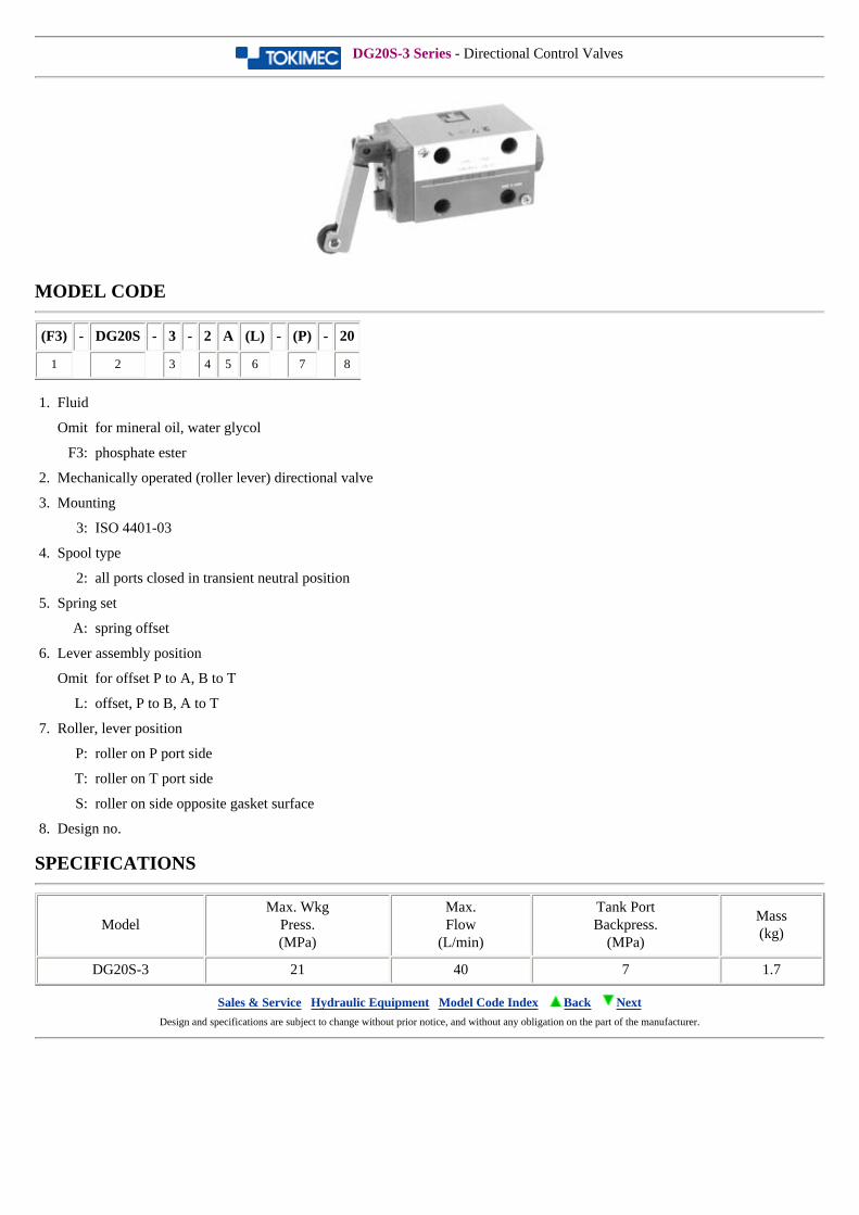
DG20S-3 Series - Directional Control Valves
MODEL CODE
(F3) - DG20S - 3 - 2 A (L) - (P) - 20
1 2 3 4 5 6 7 8
1. Fluid
Omit for mineral oil, water glycol
F3: phosphate ester
2. Mechanically operated (roller lever) directional valve
3. Mounting
3: ISO 4401-03
4. Spool type
2: all ports closed in transient neutral position
5. Spring set
A: spring offset
6. Lever assembly position
Omit for offset P to A, B to T
L: offset, P to B, A to T
7. Roller, lever position
P: roller on P port side
T: roller on T port side
S: roller on side opposite gasket surface
8. Design no.
SPECIFICATIONS
ModelMax. Wkg
Press.(MPa)
Max.Flow
(L/min)
Tank PortBackpress.
(MPa)
Mass(kg)
DG20S-3 21 40 7 1.7
Sales & Service Hydraulic Equipment Model Code Index Back Next Design and specifications are subject to change without prior notice, and without any obligation on the part of the manufacturer.

DG20S-5 Series - Directional Control Valves
MODEL CODE
(F3) - DG20S - 5 - 2 A (L) - (P) - 10
1 2 3 4 5 6 7 8
1. Fluid
Omit for mineral oil, water glycol
F3: phosphate ester
2. Mechanically operated (roller lever) directional valve
3. Mounting
5: ISO 4401-05
4. Spool type
2: all ports closed in transient neutral position
5. Spring set
A: spring offset
6. Lever assembly position
Omit for offset P to A, B to T
L: offset, P to B, A to T
7. Roller, lever position
P: roller on P port side
T: roller on T port side
S: roller on side opposite gasket surface
8. Design no.
SPECIFICATIONS
ModelMax. Wkg
Press.(MPa)
Max.Flow
(L/min)
Tank PortBackpress.
(MPa)
Mass(kg)
DG20S-5 21 100 7 2.8
Sales & Service Hydraulic Equipment Model Code Index Back Next Design and specifications are subject to change without prior notice, and without any obligation on the part of the manufacturer.
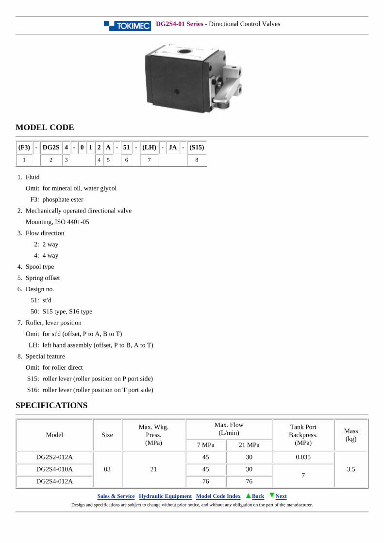
DG2S4-01 Series - Directional Control Valves
MODEL CODE
(F3) - DG2S 4 - 0 1 2 A - 51 - (LH) - JA - (S15)
1 2 3 4 5 6 7 8
1. Fluid
Omit for mineral oil, water glycol
F3: phosphate ester
2. Mechanically operated directional valve
Mounting, ISO 4401-05
3. Flow direction
2: 2 way
4: 4 way
4. Spool type
5. Spring offset
6. Design no.
51: st'd
50: S15 type, S16 type
7. Roller, lever position
Omit for st'd (offset, P to A, B to T)
LH: left hand assembly (offset, P to B, A to T)
8. Special feature
Omit for roller direct
S15: roller lever (roller position on P port side)
S16: roller lever (roller position on T port side)
SPECIFICATIONS
Model SizeMax. Wkg.
Press.(MPa)
Max. Flow(L/min)
Tank PortBackpress.
(MPa)
Mass(kg)
7 MPa 21 MPa
DG2S2-012A
03 21
45 30 0.035
3.5DG2S4-010A 45 307
DG2S4-012A 76 76
Sales & Service Hydraulic Equipment Model Code Index Back Next Design and specifications are subject to change without prior notice, and without any obligation on the part of the manufacturer.
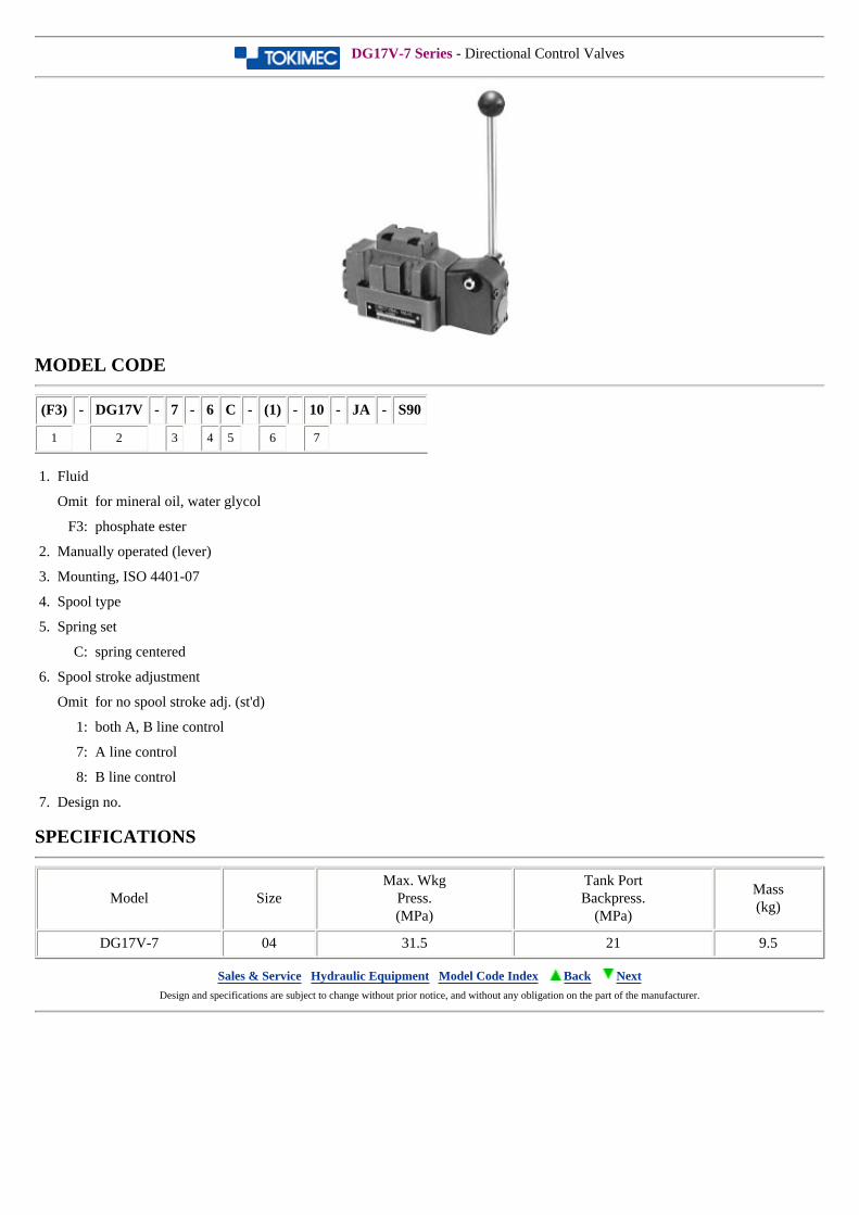
DG17V-7 Series - Directional Control Valves
MODEL CODE
(F3) - DG17V - 7 - 6 C - (1) - 10 - JA - S90
1 2 3 4 5 6 7
1. Fluid
Omit for mineral oil, water glycol
F3: phosphate ester
2. Manually operated (lever)
3. Mounting, ISO 4401-07
4. Spool type
5. Spring set
C: spring centered
6. Spool stroke adjustment
Omit for no spool stroke adj. (st'd)
1: both A, B line control
7: A line control
8: B line control
7. Design no.
SPECIFICATIONS
Model SizeMax. Wkg
Press.(MPa)
Tank PortBackpress.
(MPa)
Mass(kg)
DG17V-7 04 31.5 21 9.5
Sales & Service Hydraulic Equipment Model Code Index Back Next Design and specifications are subject to change without prior notice, and without any obligation on the part of the manufacturer.
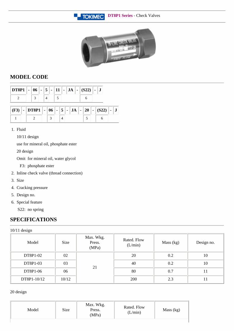
DT8P1 Series - Check Valves
MODEL CODE
DT8P1 - 06 - 5 - 11 - JA - (S22) - J
2 3 4 5 6
(F3) - DT8P1 - 06 - 5 - JA - 20 - (S22) - J
1 2 3 4 5 6
1. Fluid
10/11 design
use for mineral oil, phosphate ester
20 design
Omit for mineral oil, water glycol
F3: phosphate ester
2. Inline check valve (thread connection)
3. Size
4. Cracking pressure
5. Design no.
6. Special feature
S22: no spring
SPECIFICATIONS
10/11 design
Model SizeMax. Wkg.
Press.(MPa)
Rated. Flow(L/min)
Mass (kg) Design no.
DT8P1-02 02
21
20 0.2 10
DT8P1-03 03 40 0.2 10
DT8P1-06 06 80 0.7 11
DT8P1-10/12 10/12 200 2.3 11
20 design
Model SizeMax. Wkg.
Press.(MPa)
Rated. Flow(L/min)
Mass (kg)
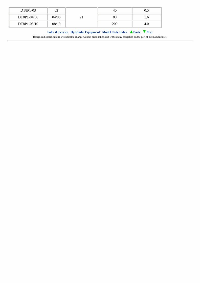
DT8P1-03 02
21
40 0.5
DT8P1-04/06 04/06 80 1.6
DT8P1-08/10 08/10 200 4.0
Sales & Service Hydraulic Equipment Model Code Index Back Next Design and specifications are subject to change without prior notice, and without any obligation on the part of the manufacturer.
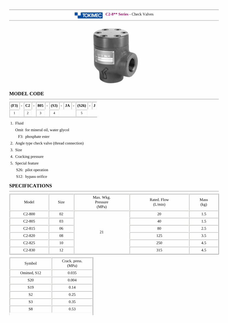
C2-8** Series - Check Valves
MODEL CODE
(F3) - C2 - 805 - (S3) - JA - (S26) - J
1 2 3 4 5
1. Fluid
Omit for mineral oil, water glycol
F3: phosphate ester
2. Angle type check valve (thread connection)
3. Size
4. Cracking pressure
5. Special feature
S26: pilot operation
S12: bypass orifice
SPECIFICATIONS
Model SizeMax. Wkg.
Pressure(MPa)
Rated. Flow(L/min)
Mass(kg)
C2-800 02
21
20 1.5
C2-805 03 40 1.5
C2-815 06 80 2.5
C2-820 08 125 3.5
C2-825 10 250 4.5
C2-830 12 315 4.5
SymbolCrack. press.
(MPa)
Omitted, S12 0.035
S20 0.004
S19 0.14
S2 0.25
S3 0.35
S8 0.53

S17 0.88
S34 1.05
S22 no spring
Sales & Service Hydraulic Equipment Model Code Index Back Next Design and specifications are subject to change without prior notice, and without any obligation on the part of the manufacturer.
C2G/C5G Series - Check Valves
MODEL CODE
(F3) - C5G - 825 - (S3) - JA - (11) - (S160) - (M)
1 2 3 4 5 6 7
1. Fluid
Omit for mineral oil, water glycol
F3: phosphate ester
2. Angle type check valve (gasket mount)
3. Size
4. Cracking pressure
5. Design no.
Use only for C2G-805
6. Special feature
S51: adj. opening (for C2G-805)
S160: adj. opening (for C2G-815, C5G-825)
7. Mounting bolt type (Only for C5G-825, others omit)
Omit for 3/4-10UNC
M: metric bolts (M20)
SPECIFICATIONS
Model SizeMax. Wkg.
Pressure(MPa)
RatedFlow
(L/min)
Mass(kg)
C2G-805 03
21
40 1.5
C5G-815 06 80 3.0
C5G-825 10 380 6.0
SPECIFICATIONS
SymbolCrack. press.
(MPa)
Omitted, S12 0.035
S20 0.004
S19 0.14
S2 0.25
S3 0.35

S8 0.53
S17 0.88
S34 1.05
S22 no spring
Sales & Service Hydraulic Equipment Model Code Index Back Next Design and specifications are subject to change without prior notice, and without any obligation on the part of the manufacturer.

DF10P1 Series - Check Valves
MODEL CODE
(F3) - DF10P1 - 16 - 5 - 20 - JA - (S22)
1 2 3 4 5 6
1. Fluid
Omit for mineral oil, water glycol
F3: phosphate ester
2. Angle type check valve (flange connection)
3. Size
4. Cracking pressure
5. Design no.
6. Special feature
S12: bypass orifice(ø 1.2)
S22: no spring
SPECIFICATIONS
Model SizeMax. Wkg.
Pressure(MPa)
RatedFlow
(L/min)
Mass(kg)
DF10P1-16 1621
500 13
DF10P1-24 24 1200 65.5
SymbolCrack. press.
(MPa)
5 (st'd) 0.035
7 0.05
10 0.07
20 0.14
25 0.18
30 0.21
50 0.35
65 0.46
80 0.56

100 0.70
Sales & Service Hydraulic Equipment Model Code Index Back Next Design and specifications are subject to change without prior notice, and without any obligation on the part of the manufacturer.
4CG/4CT Series - Check Valves
MODEL CODE
(F3) - 4CG - 03 - (D) A - 20 - (GE5) - JA - (S100) - J
1 2 3 4 5 6 7 8
1. Fluid
Omit for mineral oil, water glycol
F3: phosphate ester
2. Pilot operated check valve (normal closed)
4CG: gasket mount
4CT: thread connection
3. Size
4. Decompression function
Omit for st'd
D: decompression
5. Cracking pressure
6. Design no.
7. Drain
Omit for internal drain
GE5: external drain
8. Code
Model Code
4CG/4CT-03 S100
4CG/4CT-03-D S100
4CG/4CT-03-GE5 S2
4CG/4CT-03-D-GE5 S2
4CG/4CT-06 S100
4CG/4CT-06-D S100
4CG/4CT-06-GE5 Omit
4CG/4CT-06-D-GE5 S2
4CG/4CT-10 Omit
4CG/4CT-10-D Omit
4CG-10-GE5 Omit
4CT-10-GE5 S2
4CG/4CT-10-D-GE5 S2
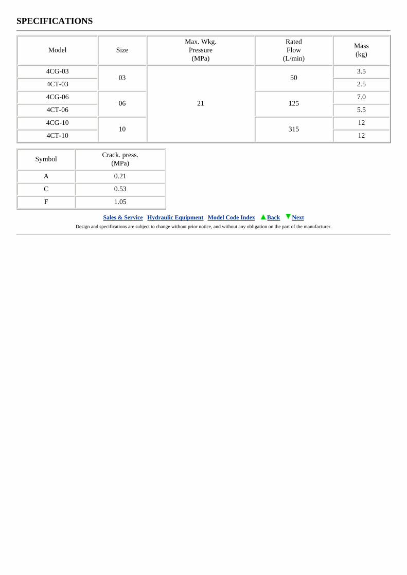
SPECIFICATIONS
Model SizeMax. Wkg.
Pressure(MPa)
RatedFlow
(L/min)
Mass(kg)
4CG-0303
21
503.5
4CT-03 2.5
4CG-0606 125
7.0
4CT-06 5.5
4CG-1010 315
12
4CT-10 12
SymbolCrack. press.
(MPa)
A 0.21
C 0.53
F 1.05
Sales & Service Hydraulic Equipment Model Code Index Back Next Design and specifications are subject to change without prior notice, and without any obligation on the part of the manufacturer.
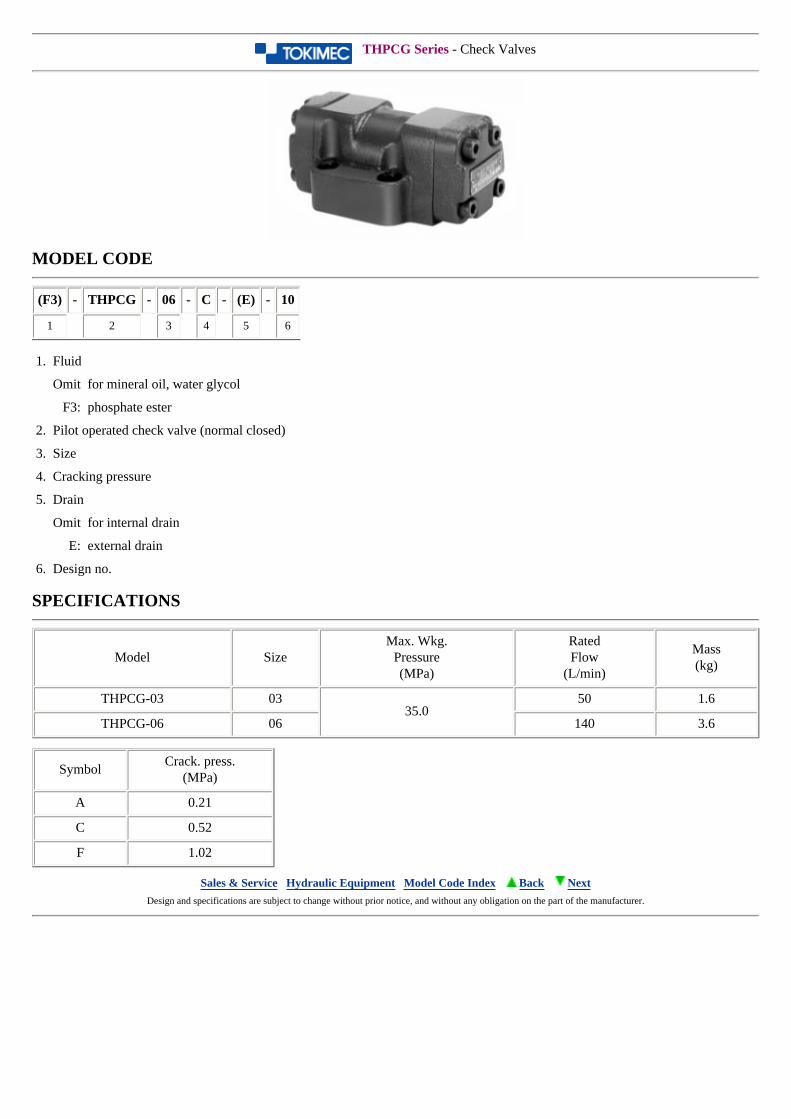
THPCG Series - Check Valves
MODEL CODE
(F3) - THPCG - 06 - C - (E) - 10
1 2 3 4 5 6
1. Fluid
Omit for mineral oil, water glycol
F3: phosphate ester
2. Pilot operated check valve (normal closed)
3. Size
4. Cracking pressure
5. Drain
Omit for internal drain
E: external drain
6. Design no.
SPECIFICATIONS
Model SizeMax. Wkg.
Pressure(MPa)
RatedFlow
(L/min)
Mass(kg)
THPCG-03 0335.0
50 1.6
THPCG-06 06 140 3.6
SymbolCrack. press.
(MPa)
A 0.21
C 0.52
F 1.02
Sales & Service Hydraulic Equipment Model Code Index Back Next Design and specifications are subject to change without prior notice, and without any obligation on the part of the manufacturer.
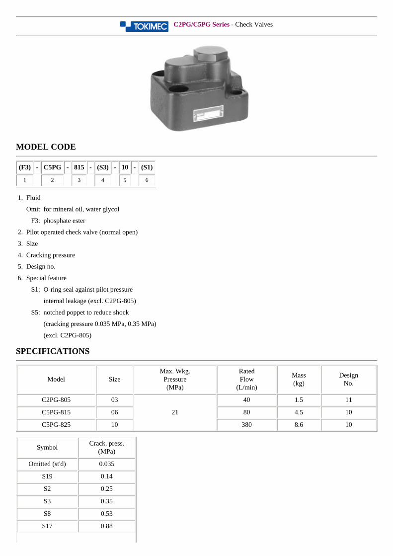
C2PG/C5PG Series - Check Valves
MODEL CODE
(F3) - C5PG - 815 - (S3) - 10 - (S1)
1 2 3 4 5 6
1. Fluid
Omit for mineral oil, water glycol
F3: phosphate ester
2. Pilot operated check valve (normal open)
3. Size
4. Cracking pressure
5. Design no.
6. Special feature
S1: O-ring seal against pilot pressure
internal leakage (excl. C2PG-805)
S5: notched poppet to reduce shock
(cracking pressure 0.035 MPa, 0.35 MPa)
(excl. C2PG-805)
SPECIFICATIONS
Model SizeMax. Wkg.
Pressure(MPa)
RatedFlow
(L/min)
Mass(kg)
DesignNo.
C2PG-805 03
21
40 1.5 11
C5PG-815 06 80 4.5 10
C5PG-825 10 380 8.6 10
SymbolCrack. press.
(MPa)
Omitted (st'd) 0.035
S19 0.14
S2 0.25
S3 0.35
S8 0.53
S17 0.88

S34 1.05
S22 no spring
Sales & Service Hydraulic Equipment Model Code Index Back Next Design and specifications are subject to change without prior notice, and without any obligation on the part of the manufacturer.
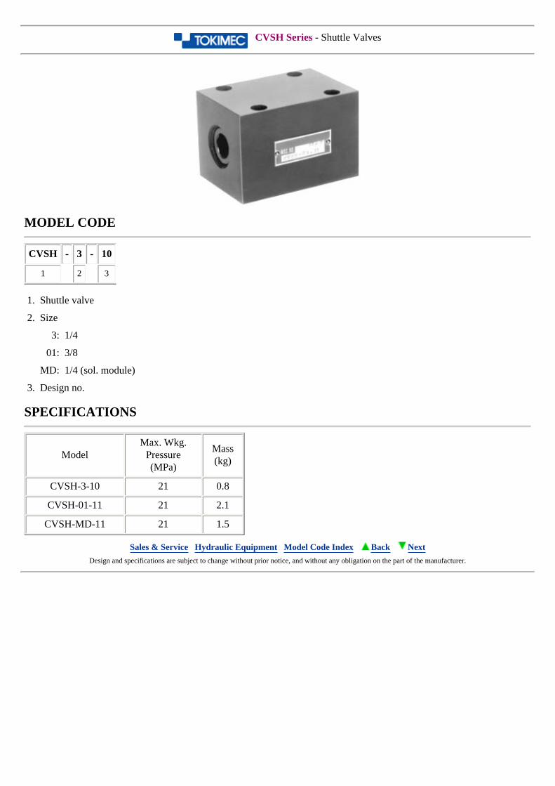
CVSH Series - Shuttle Valves
MODEL CODE
CVSH - 3 - 10
1 2 3
1. Shuttle valve
2. Size
3: 1/4
01: 3/8
MD: 1/4 (sol. module)
3. Design no.
SPECIFICATIONS
ModelMax. Wkg.
Pressure(MPa)
Mass(kg)
CVSH-3-10 21 0.8
CVSH-01-11 21 2.1
CVSH-MD-11 21 1.5
Sales & Service Hydraulic Equipment Model Code Index Back Next Design and specifications are subject to change without prior notice, and without any obligation on the part of the manufacturer.
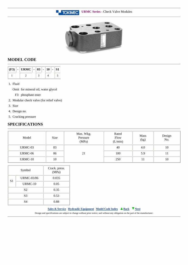
URMC Series - Check Valve Modules
MODEL CODE
(F3) - URMC - 03 - 10 - S1
1 2 3 4 5
1. Fluid
Omit for mineral oil, water glycol
F3: phosphate ester
2. Modular check valve (for relief valve)
3. Size
4. Design no.
5. Cracking pressure
SPECIFICATIONS
Model SizeMax. Wkg.
Pressure(MPa)
RatedFlow
(L/min)
Mass(kg)
DesignNo.
URMC-03 03
21
40 4.0 10
URMC-06 06 100 5.9 11
URMC-10 10 250 11 10
SymbolCrack. press.
(MPa)
S1URMC-03/06 0.035
URMC-10 0.05
S2 0.35
S3 0.53
S4 0.88
Sales & Service Hydraulic Equipment Model Code Index Back Next Design and specifications are subject to change without prior notice, and without any obligation on the part of the manufacturer.
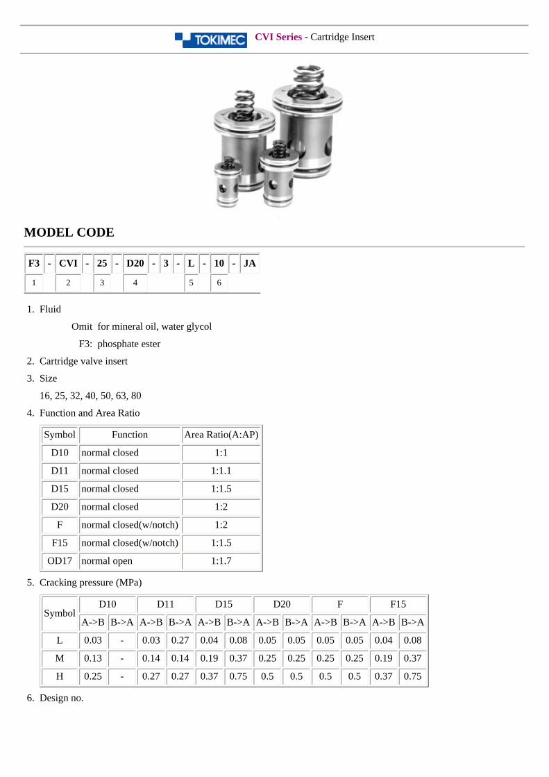
CVI Series - Cartridge Insert
MODEL CODE
F3 - CVI - 25 - D20 - 3 - L - 10 - JA
1 2 3 4 5 6
1. Fluid
Omit for mineral oil, water glycol
F3: phosphate ester
2. Cartridge valve insert
3. Size
16, 25, 32, 40, 50, 63, 80
4. Function and Area Ratio
Symbol Function Area Ratio(A:AP)
D10 normal closed 1:1
D11 normal closed 1:1.1
D15 normal closed 1:1.5
D20 normal closed 1:2
F normal closed(w/notch) 1:2
F15 normal closed(w/notch) 1:1.5
OD17 normal open 1:1.7
5. Cracking pressure (MPa)
SymbolD10 D11 D15 D20 F F15
A->B B->A A->B B->A A->B B->A A->B B->A A->B B->A A->B B->A
L 0.03 - 0.03 0.27 0.04 0.08 0.05 0.05 0.05 0.05 0.04 0.08
M 0.13 - 0.14 0.14 0.19 0.37 0.25 0.25 0.25 0.25 0.19 0.37
H 0.25 - 0.27 0.27 0.37 0.75 0.5 0.5 0.5 0.5 0.37 0.75
6. Design no.
SPECIFICATIONS
Model SizeMax. Wkg.
Pressure(MPa)
Rated Flow(∆P, 0.5 MPa)
(L/min)
Mass(kg)
CVI
16
35
200 0.15
25 450 0.35
32 650 0.75
40 1100 1.4
50 1700 2.2
63 2800 5.4
80 4200 9.8
Sales & Service Hydraulic Equipment Model Code Index Back Next Design and specifications are subject to change without prior notice, and without any obligation on the part of the manufacturer.
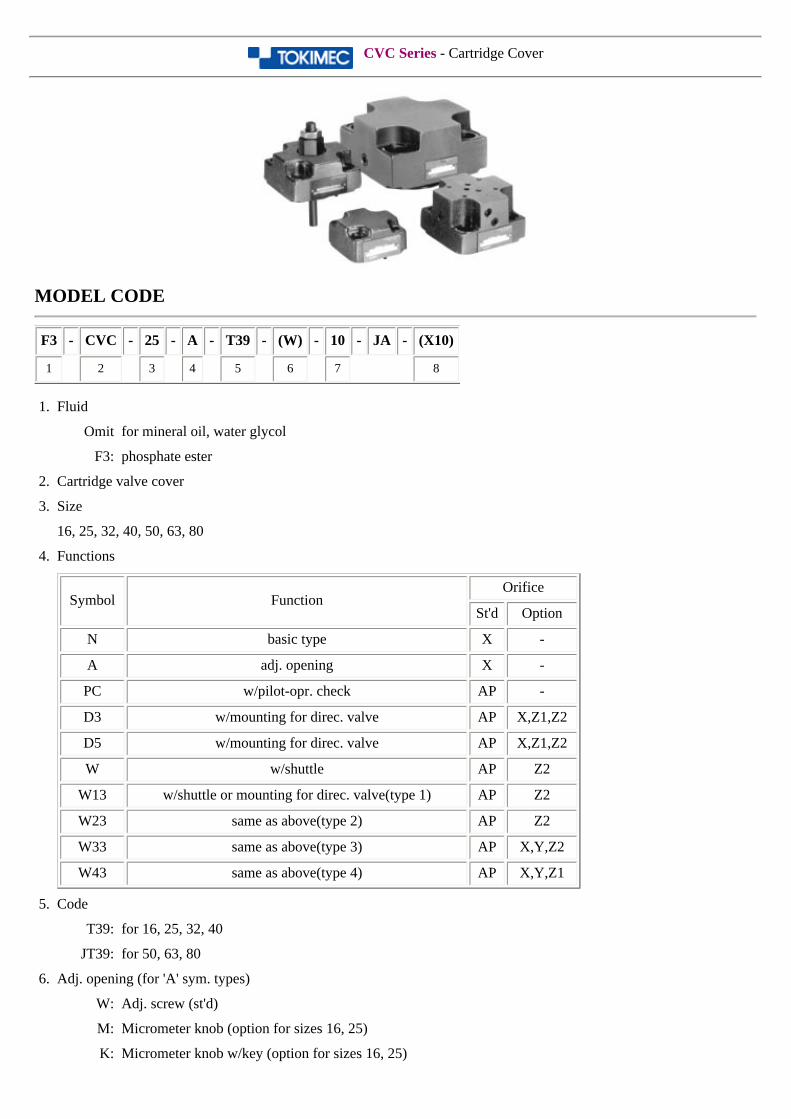
CVC Series - Cartridge Cover
MODEL CODE
F3 - CVC - 25 - A - T39 - (W) - 10 - JA - (X10)
1 2 3 4 5 6 7 8
1. Fluid
Omit for mineral oil, water glycol
F3: phosphate ester
2. Cartridge valve cover
3. Size
16, 25, 32, 40, 50, 63, 80
4. Functions
Symbol FunctionOrifice
St'd Option
N basic type X -
A adj. opening X -
PC w/pilot-opr. check AP -
D3 w/mounting for direc. valve AP X,Z1,Z2
D5 w/mounting for direc. valve AP X,Z1,Z2
W w/shuttle AP Z2
W13 w/shuttle or mounting for direc. valve(type 1) AP Z2
W23 same as above(type 2) AP Z2
W33 same as above(type 3) AP X,Y,Z2
W43 same as above(type 4) AP X,Y,Z1
5. Code
T39: for 16, 25, 32, 40
JT39: for 50, 63, 80
6. Adj. opening (for 'A' sym. types)
W: Adj. screw (st'd)
M: Micrometer knob (option for sizes 16, 25)
K: Micrometer knob w/key (option for sizes 16, 25)
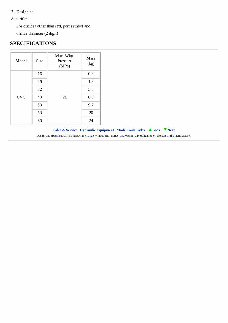
7. Design no.
8. Orifice
For orifices other than st'd, port symbol and
orifice diameter (2 digit)
SPECIFICATIONS
Model SizeMax. Wkg.
Pressure(MPa)
Mass(kg)
CVC
16
21
0.8
25 1.8
32 3.8
40 6.0
50 9.7
63 20
80 24
Sales & Service Hydraulic Equipment Model Code Index Back Next Design and specifications are subject to change without prior notice, and without any obligation on the part of the manufacturer.
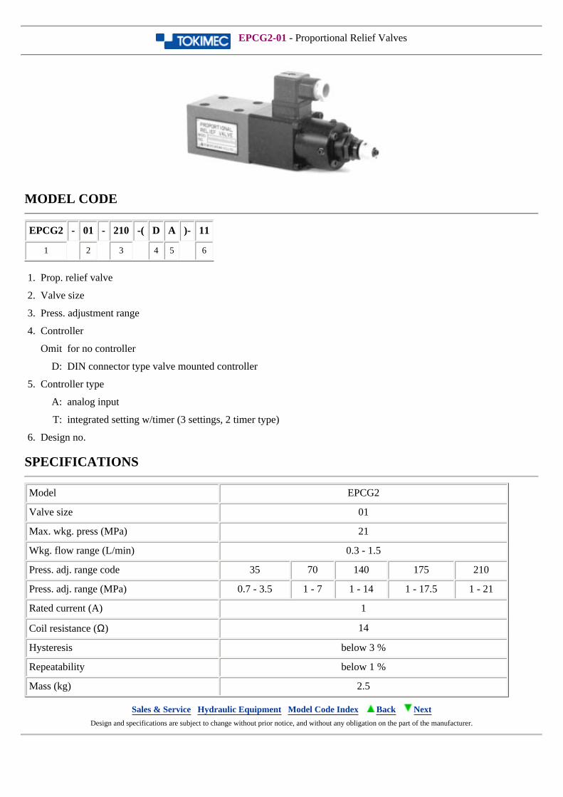
EPCG2-01 - Proportional Relief Valves
MODEL CODE
EPCG2 - 01 - 210 -( D A )- 11
1 2 3 4 5 6
1. Prop. relief valve
2. Valve size
3. Press. adjustment range
4. Controller
Omit for no controller
D: DIN connector type valve mounted controller
5. Controller type
A: analog input
T: integrated setting w/timer (3 settings, 2 timer type)
6. Design no.
SPECIFICATIONS
Model EPCG2
Valve size 01
Max. wkg. press (MPa) 21
Wkg. flow range (L/min) 0.3 - 1.5
Press. adj. range code 35 70 140 175 210
Press. adj. range (MPa) 0.7 - 3.5 1 - 7 1 - 14 1 - 17.5 1 - 21
Rated current (A) 1
Coil resistance (Ω) 14
Hysteresis below 3 %
Repeatability below 1 %
Mass (kg) 2.5
Sales & Service Hydraulic Equipment Model Code Index Back Next Design and specifications are subject to change without prior notice, and without any obligation on the part of the manufacturer.
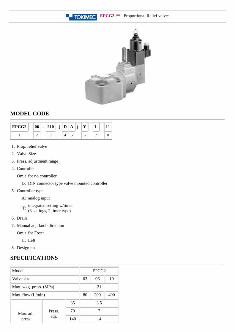
EPCG2-** - Proportional Relief valves
MODEL CODE
EPCG2 - 06 - 210 -( D A )- Y - L - 11
1 2 3 4 5 6 7 8
1. Prop. relief valve
2. Valve Size
3. Press. adjustment range
4. Controller
Omit for no controller
D: DIN connector type valve mounted controller
5. Controller type
A: analog input
T:integrated setting w/timer(3 settings, 2 timer type)
6. Drain
7. Manual adj. knob direction
Omit for Front
L: Left
8. Design no.
SPECIFICATIONS
Model EPCG2
Valve size 03 06 10
Max. wkg. press. (MPa) 21
Max. flow (L/min) 80 200 400
Max. adj.press.
Press.adj.
35 3.5
70 7
140 14
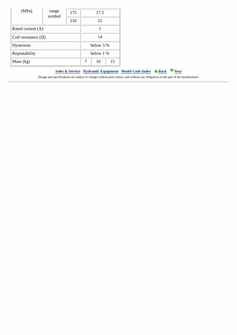
(MPa) rangesymbol
175 17.5
210 21
Rated current (A) 1
Coil resistance (Ω) 14
Hysteresis below 3 %
Repeatability below 1 %
Mass (kg) 7 10 15
Sales & Service Hydraulic Equipment Model Code Index Back Next Design and specifications are subject to change without prior notice, and without any obligation on the part of the manufacturer.
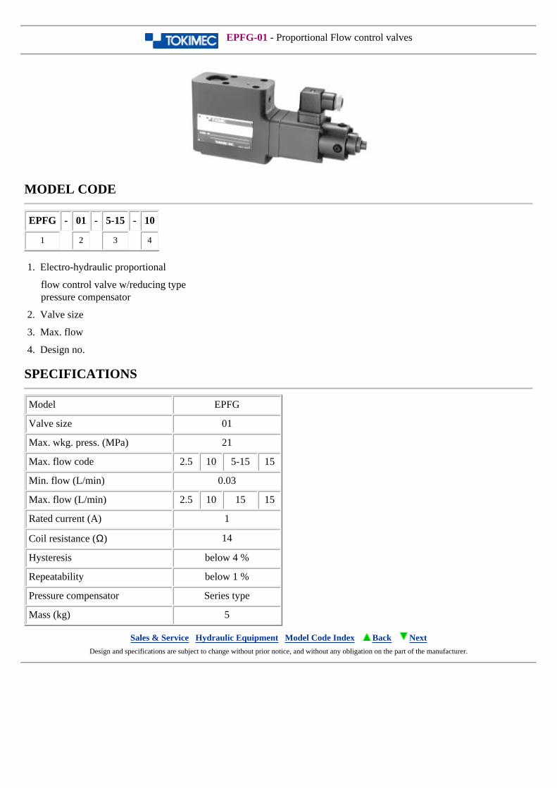
EPFG-01 - Proportional Flow control valves
MODEL CODE
EPFG - 01 - 5-15 - 10
1 2 3 4
1. Electro-hydraulic proportional
flow control valve w/reducing typepressure compensator
2. Valve size
3. Max. flow
4. Design no.
SPECIFICATIONS
Model EPFG
Valve size 01
Max. wkg. press. (MPa) 21
Max. flow code 2.5 10 5-15 15
Min. flow (L/min) 0.03
Max. flow (L/min) 2.5 10 15 15
Rated current (A) 1
Coil resistance (Ω) 14
Hysteresis below 4 %
Repeatability below 1 %
Pressure compensator Series type
Mass (kg) 5
Sales & Service Hydraulic Equipment Model Code Index Back Next Design and specifications are subject to change without prior notice, and without any obligation on the part of the manufacturer.
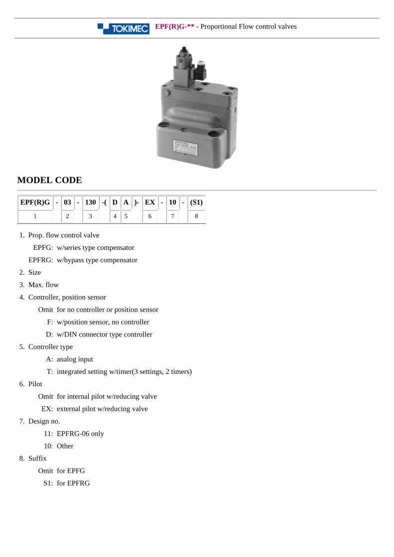
EPF(R)G-** - Proportional Flow control valves
MODEL CODE
EPF(R)G - 03 - 130 -( D A )- EX - 10 - (S1)
1 2 3 4 5 6 7 8
1. Prop. flow control valve
EPFG: w/series type compensator
EPFRG: w/bypass type compensator
2. Size
3. Max. flow
4. Controller, position sensor
Omit for no controller or position sensor
F: w/position sensor, no controller
D: w/DIN connector type controller
5. Controller type
A: analog input
T: integrated setting w/timer(3 settings, 2 timers)
6. Pilot
Omit for internal pilot w/reducing valve
EX: external pilot w/reducing valve
7. Design no.
11: EPFRG-06 only
10: Other
8. Suffix
Omit for EPFG
S1: for EPFRG
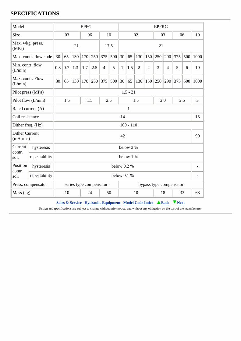
SPECIFICATIONS
Model EPFG EPFRG
Size 03 06 10 02 03 06 10
Max. wkg. press. (MPa)
21 17.5 21
Max. contr. flow code 30 65 130 170 250 375 500 30 65 130 150 250 290 375 500 1000
Min. contr. flow (L/min)
0.3 0.7 1.3 1.7 2.5 4 5 1 1.5 2 2 3 4 5 6 10
Max. contr. Flow (L/min)
30 65 130 170 250 375 500 30 65 130 150 250 290 375 500 1000
Pilot press (MPa) 1.5 - 21
Pilot flow (L/min) 1.5 1.5 2.5 1.5 2.0 2.5 3
Rated current (A) 1
Coil resistance 14 15
Dither freq. (Hz) 100 - 110
Dither Current(mA rms)
42 90
Currentcontr. sol.
hysteresis below 3 %
repeatability below 1 %
Positioncontr. sol.
hysteresis below 0.2 % -
repeatability below 0.1 % -
Press. compensator series type compensator bypass type compensator
Mass (kg) 10 24 50 10 18 33 68
Sales & Service Hydraulic Equipment Model Code Index Back Next Design and specifications are subject to change without prior notice, and without any obligation on the part of the manufacturer.
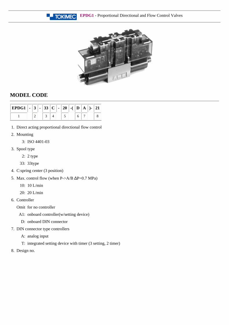
EPDG1 - Proportional Directional and Flow Control Valves
MODEL CODE
EPDG1 - 3 - 33 C - 20 -( D A )- 21
1 2 3 4 5 6 7 8
1. Direct acting proportional directional flow control
2. Mounting
3: ISO 4401-03
3. Spool type
2: 2 type
33: 33type
4. C:spring center (3 position)
5. Max. control flow (when P->A/B ∆P=0.7 MPa)
10: 10 L/min
20: 20 L/min
6. Controller
Omit for no controller
A1: onboard controller(w/setting device)
D: onboard DIN connector
7. DIN connector type controllers
A: analog input
T: integrated setting device with timer (3 setting, 2 timer)
8. Design no.
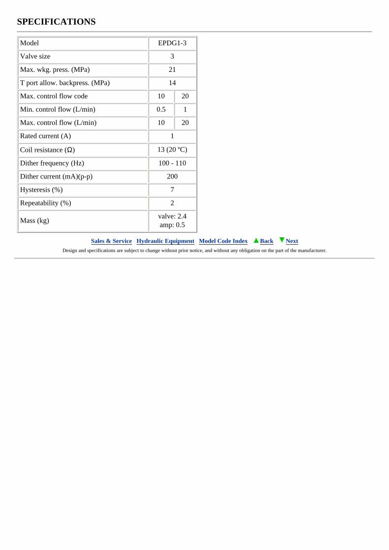
SPECIFICATIONS
Model EPDG1-3
Valve size 3
Max. wkg. press. (MPa) 21
T port allow. backpress. (MPa) 14
Max. control flow code 10 20
Min. control flow (L/min) 0.5 1
Max. control flow (L/min) 10 20
Rated current (A) 1
Coil resistance (Ω) 13 (20 ºC)
Dither frequency (Hz) 100 - 110
Dither current (mA)(p-p) 200
Hysteresis (%) 7
Repeatability (%) 2
Mass (kg)valve: 2.4amp: 0.5
Sales & Service Hydraulic Equipment Model Code Index Back Next Design and specifications are subject to change without prior notice, and without any obligation on the part of the manufacturer.
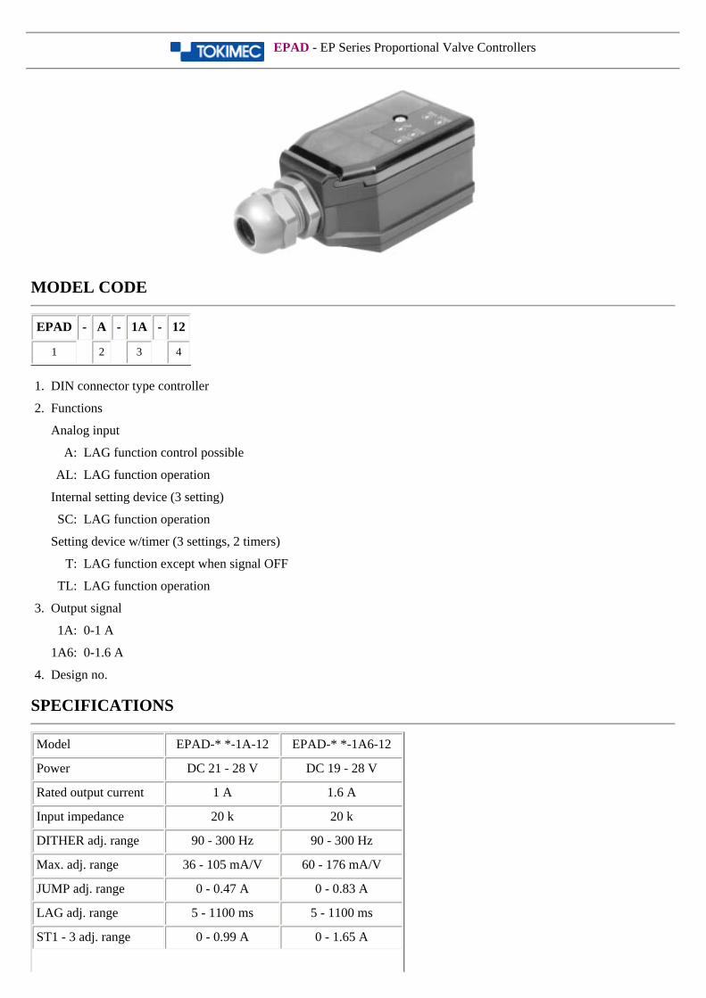
EPAD - EP Series Proportional Valve Controllers
MODEL CODE
EPAD - A - 1A - 12
1 2 3 4
1. DIN connector type controller
2. Functions
Analog input
A: LAG function control possible
AL: LAG function operation
Internal setting device (3 setting)
SC: LAG function operation
Setting device w/timer (3 settings, 2 timers)
T: LAG function except when signal OFF
TL: LAG function operation
3. Output signal
1A: 0-1 A
1A6: 0-1.6 A
4. Design no.
SPECIFICATIONS
Model EPAD-* *-1A-12 EPAD-* *-1A6-12
Power DC 21 - 28 V DC 19 - 28 V
Rated output current 1 A 1.6 A
Input impedance 20 k 20 k
DITHER adj. range 90 - 300 Hz 90 - 300 Hz
Max. adj. range 36 - 105 mA/V 60 - 176 mA/V
JUMP adj. range 0 - 0.47 A 0 - 0.83 A
LAG adj. range 5 - 1100 ms 5 - 1100 ms
ST1 - 3 adj. range 0 - 0.99 A 0 - 1.65 A
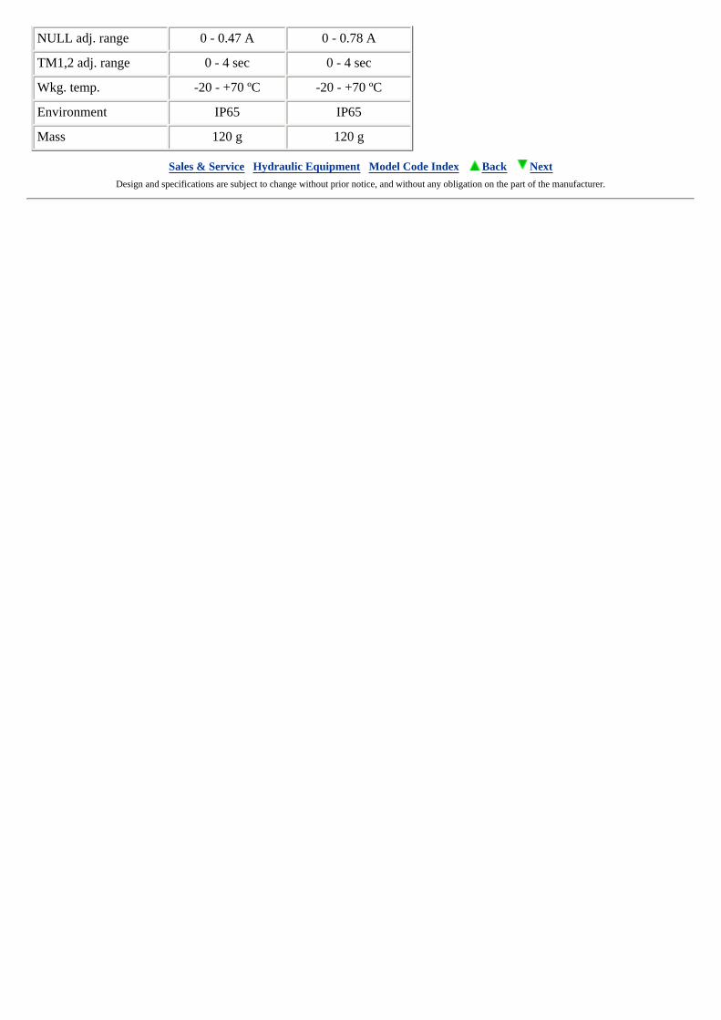
NULL adj. range 0 - 0.47 A 0 - 0.78 A
TM1,2 adj. range 0 - 4 sec 0 - 4 sec
Wkg. temp. -20 - +70 ºC -20 - +70 ºC
Environment IP65 IP65
Mass 120 g 120 g
Sales & Service Hydraulic Equipment Model Code Index Back Next Design and specifications are subject to change without prior notice, and without any obligation on the part of the manufacturer.
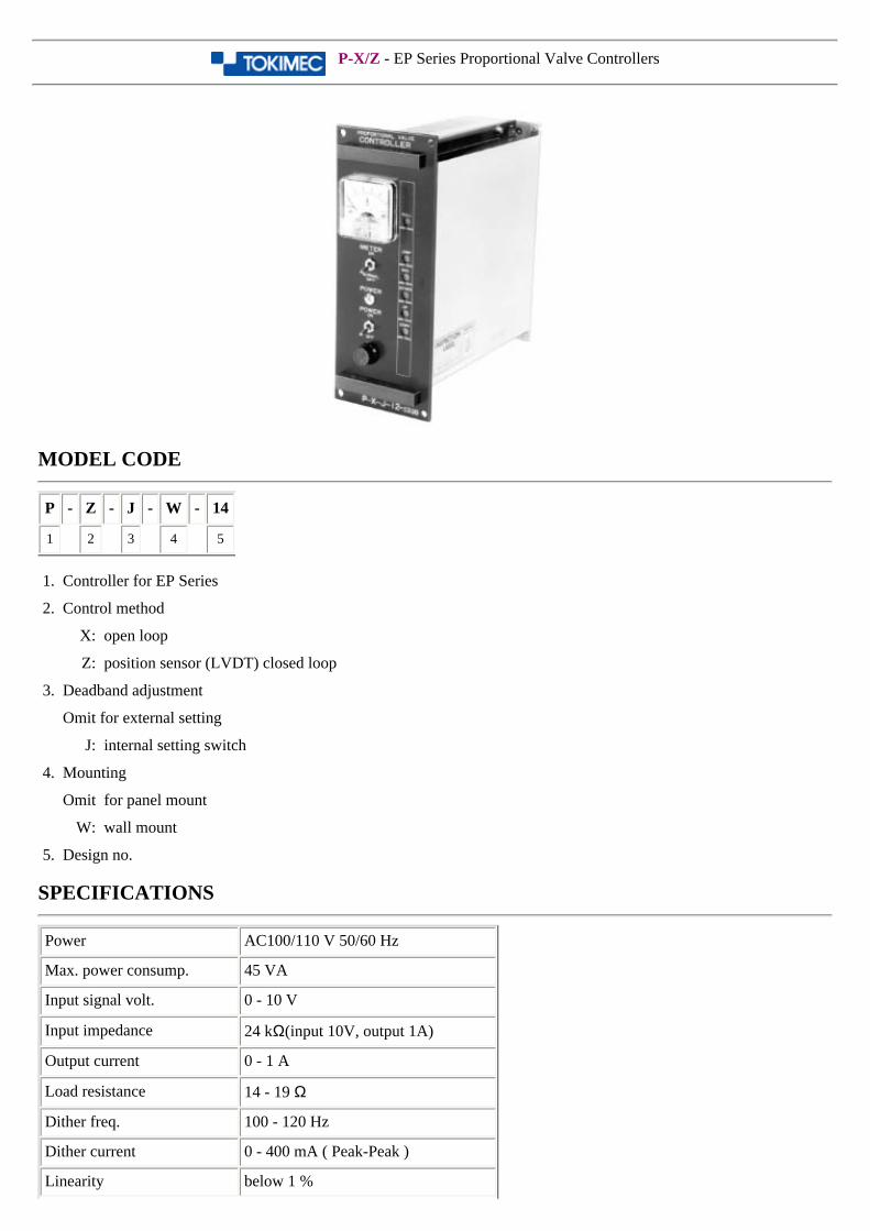
P-X/Z - EP Series Proportional Valve Controllers
MODEL CODE
P - Z - J - W - 14
1 2 3 4 5
1. Controller for EP Series
2. Control method
X: open loop
Z: position sensor (LVDT) closed loop
3. Deadband adjustment
Omit for external setting
J: internal setting switch
4. Mounting
Omit for panel mount
W: wall mount
5. Design no.
SPECIFICATIONS
Power AC100/110 V 50/60 Hz
Max. power consump. 45 VA
Input signal volt. 0 - 10 V
Input impedance 24 kΩ(input 10V, output 1A)
Output current 0 - 1 A
Load resistance 14 - 19 Ω
Dither freq. 100 - 120 Hz
Dither current 0 - 400 mA ( Peak-Peak )
Linearity below 1 %
Wkg. temp. range 0 - 50 ºC
Storage temp. range -10 - +75 ºC
Relative humidity 30 - 90 %
Sales & Service Hydraulic Equipment Model Code Index Back Next Design and specifications are subject to change without prior notice, and without any obligation on the part of the manufacturer.
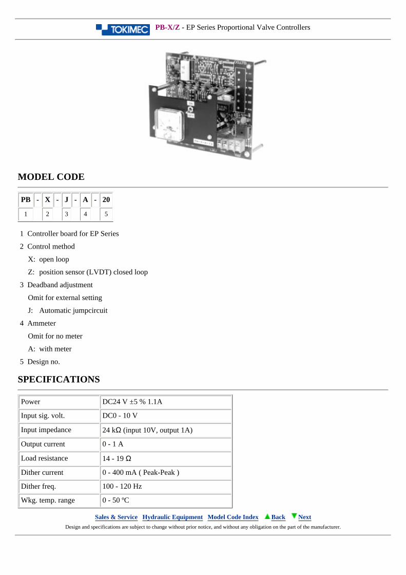
PB-X/Z - EP Series Proportional Valve Controllers
MODEL CODE
PB - X - J - A - 20
1 2 3 4 5
1 Controller board for EP Series
2 Control method
X: open loop
Z: position sensor (LVDT) closed loop
3 Deadband adjustment
Omit for external setting
J: Automatic jumpcircuit
4 Ammeter
Omit for no meter
A: with meter
5 Design no.
SPECIFICATIONS
Power DC24 V ±5 % 1.1A
Input sig. volt. DC0 - 10 V
Input impedance 24 kΩ (input 10V, output 1A)
Output current 0 - 1 A
Load resistance 14 - 19 Ω
Dither current 0 - 400 mA ( Peak-Peak )
Dither freq. 100 - 120 Hz
Wkg. temp. range 0 - 50 ºC
Sales & Service Hydraulic Equipment Model Code Index Back Next Design and specifications are subject to change without prior notice, and without any obligation on the part of the manufacturer.
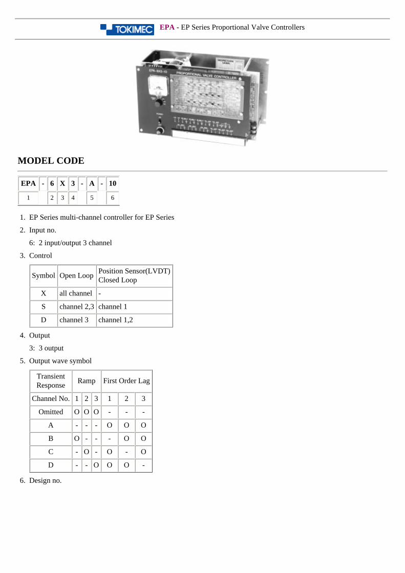
EPA - EP Series Proportional Valve Controllers
MODEL CODE
EPA - 6 X 3 - A - 10
1 2 3 4 5 6
1. EP Series multi-channel controller for EP Series
2. Input no.
6: 2 input/output 3 channel
3. Control
Symbol Open LoopPosition Sensor(LVDT)Closed Loop
X all channel -
S channel 2,3 channel 1
D channel 3 channel 1,2
4. Output
3: 3 output
5. Output wave symbol
TransientResponse
Ramp First Order Lag
Channel No. 1 2 3 1 2 3
Omitted O O O - - -
A - - - O O O
B O - - - O O
C - O - O - O
D - - O O O -
6. Design no.
SPECIFICATIONS
Power AC100/110 V 50/60 Hz
Max. power consump. 80 VA
Input signal volt. DC 0 - 10 V
Input impedance 22 kΩ
Output current 0 - 1 A/1ch
Load resistance 14 Ω(at20 ºC)
Dither freq. 110 - 140 Hz
Dither current 0 - 100 mAp-p (triangle wave)
Linearity below 1 % (command volt. vs. current)
Wkg. temp. range 0 - 50 ºC
Storage temp. -10 - +75 ºC
Rel. Humidity 30 - 90 %
Mass 4 kg
Sales & Service Hydraulic Equipment Model Code Index Back Next Design and specifications are subject to change without prior notice, and without any obligation on the part of the manufacturer.
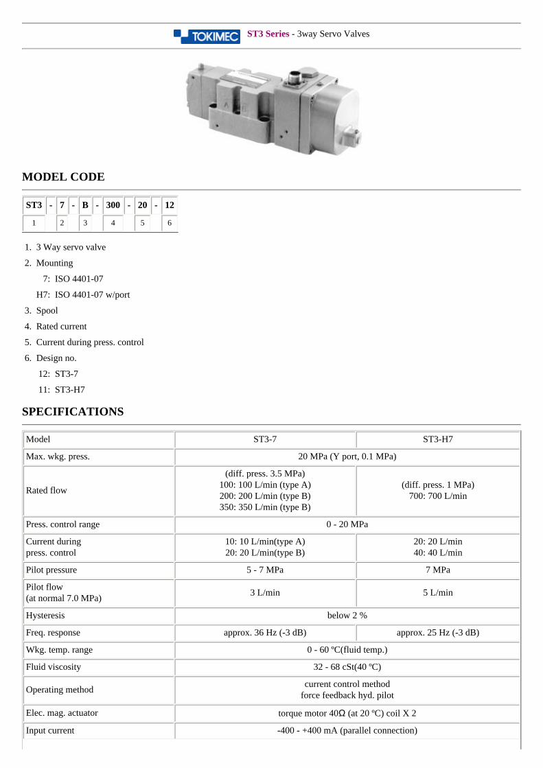
ST3 Series - 3way Servo Valves
MODEL CODE
ST3 - 7 - B - 300 - 20 - 12
1 2 3 4 5 6
1. 3 Way servo valve
2. Mounting
7: ISO 4401-07
H7: ISO 4401-07 w/port
3. Spool
4. Rated current
5. Current during press. control
6. Design no.
12: ST3-7
11: ST3-H7
SPECIFICATIONS
Model ST3-7 ST3-H7
Max. wkg. press. 20 MPa (Y port, 0.1 MPa)
Rated flow
(diff. press. 3.5 MPa) 100: 100 L/min (type A)200: 200 L/min (type B)350: 350 L/min (type B)
(diff. press. 1 MPa)700: 700 L/min
Press. control range 0 - 20 MPa
Current duringpress. control
10: 10 L/min(type A)20: 20 L/min(type B)
20: 20 L/min40: 40 L/min
Pilot pressure 5 - 7 MPa 7 MPa
Pilot flow(at normal 7.0 MPa)
3 L/min 5 L/min
Hysteresis below 2 %
Freq. response approx. 36 Hz (-3 dB) approx. 25 Hz (-3 dB)
Wkg. temp. range 0 - 60 ºC(fluid temp.)
Fluid viscosity 32 - 68 cSt(40 ºC)
Operating methodcurrent control method
force feedback hyd. pilot
Elec. mag. actuator torque motor 40Ω (at 20 ºC) coil X 2
Input current -400 - +400 mA (parallel connection)
Dither input approx. 50 - 70mA rms/coil, approx. 350 Hz
Power consumption 3.2 W (1.6W/coil) at 20 ºC
FiltrationP,A,B,T port: 25 µmX(pilot port): 10 µm
Mass approx. 12.5 kg approx. 21 kg
Sales & Service Hydraulic Equipment Model Code Index Back Next Design and specifications are subject to change without prior notice, and without any obligation on the part of the manufacturer.
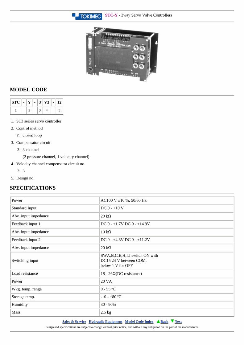
STC-Y - 3way Servo Valve Controllers
MODEL CODE
STC - Y - 3 V3 - 12
1 2 3 4 5
1. ST3 series servo controller
2. Control method
Y: closed loop
3. Compensator circuit
3: 3 channel
(2 pressure channel, 1 velocity channel)
4. Velocity channel compensator circuit no.
3: 3
5. Design no.
SPECIFICATIONS
Power AC100 V ±10 %, 50/60 Hz
Standard Input DC 0 - +10 V
Abv. input impedance 20 kΩ
Feedback input 1 DC 0 - +1.7V DC 0 - +14.9V
Abv. input impedance 10 kΩ
Feedback input 2 DC 0 - +4.8V DC 0 - +11.2V
Abv. input impedance 20 kΩ
Switching inputSWA,B,C,E,H,I,J switch ON withDC15 24 V between COM,below 1 V for OFF
Load resistance 18 - 26Ω(DC resistance)
Power 20 VA
Wkg. temp. range 0 - 55 ºC
Storage temp. -10 - +80 ºC
Humidity 30 - 90%
Mass 2.5 kg
Sales & Service Hydraulic Equipment Model Code Index Back Next Design and specifications are subject to change without prior notice, and without any obligation on the part of the manufacturer.
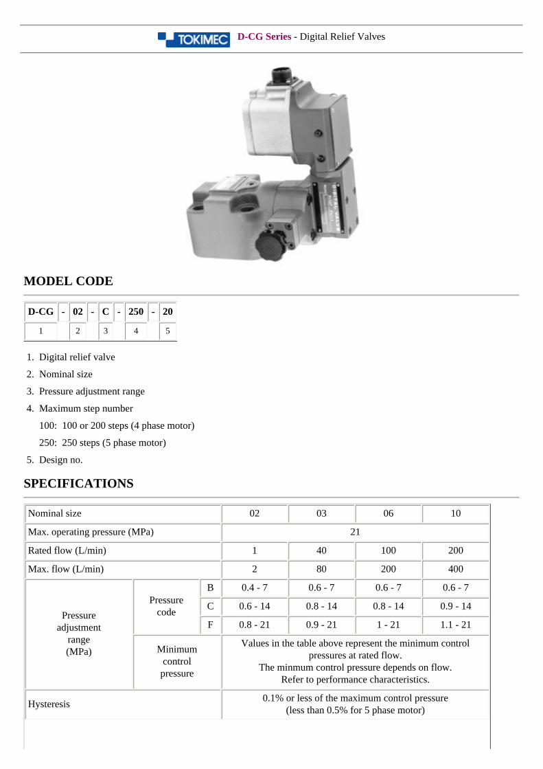
D-CG Series - Digital Relief Valves
MODEL CODE
D-CG - 02 - C - 250 - 20
1 2 3 4 5
1. Digital relief valve
2. Nominal size
3. Pressure adjustment range
4. Maximum step number
100: 100 or 200 steps (4 phase motor)
250: 250 steps (5 phase motor)
5. Design no.
SPECIFICATIONS
Nominal size 02 03 06 10
Max. operating pressure (MPa) 21
Rated flow (L/min) 1 40 100 200
Max. flow (L/min) 2 80 200 400
Pressureadjustment
range(MPa)
Pressurecode
B 0.4 - 7 0.6 - 7 0.6 - 7 0.6 - 7
C 0.6 - 14 0.8 - 14 0.8 - 14 0.9 - 14
F 0.8 - 21 0.9 - 21 1 - 21 1.1 - 21
Minimumcontrolpressure
Values in the table above represent the minimum control pressures at rated flow.
The minmum control pressure depends on flow.Refer to performance characteristics.
Hysteresis0.1% or less of the maximum control pressure
(less than 0.5% for 5 phase motor)
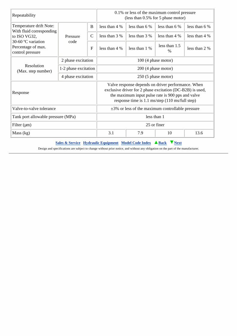
Repeatability0.1% or less of the maximum control pressure
(less than 0.5% for 5 phase motor)
Temperature drift Note:With fluid correspondingto ISO VG32, 30-60 ºC variationPercentage of max.control pressure
Pressurecode
B less than 4 % less than 6 % less than 6 % less than 6 %
C less than 3 % less than 3 % less than 4 % less than 4 %
F less than 4 % less than 1 %less than 1.5
%less than 2 %
Resolution(Max. step number)
2 phase excitation 100 (4 phase motor)
1-2 phase excitation 200 (4 phase motor)
4 phase excitation 250 (5 phase motor)
Response
Valve response depends on driver performance. Whenexclusive driver for 2 phase excitation (DC-B2B) is used,
the maximum input pulse rate is 900 pps and valveresponse time is 1.1 ms/step (110 ms/full step)
Valve-to-valve tolerance ±3% or less of the maximum controllable pressure
Tank port allowable pressure (MPa) less than 1
Filter (µm) 25 or finer
Mass (kg) 3.1 7.9 10 13.6
Sales & Service Hydraulic Equipment Model Code Index Back Next Design and specifications are subject to change without prior notice, and without any obligation on the part of the manufacturer.
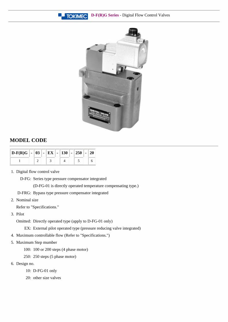
D-F(R)G Series - Digital Flow Control Valves
MODEL CODE
D-F(R)G - 03 - EX - 130 - 250 - 20
1 2 3 4 5 6
1. Digital flow control valve
D-FG: Series type pressure compensator integrated
(D-FG-01 is directly operated temperature compensating type.)
D-FRG: Bypass type pressure compensator integrated
2. Nominal size
Refer to "Specifications."
3. Pilot
Omitted: Directly operated type (apply to D-FG-01 only)
EX: External pilot operated type (pressure reducing valve integrated)
4. Maximum controllable flow (Refer to "Specifications.")
5. Maximum Step mumber
100: 100 or 200 steps (4 phase motor)
250: 250 steps (5 phase motor)
6. Design no.
10: D-FG-01 only
20: other size valves
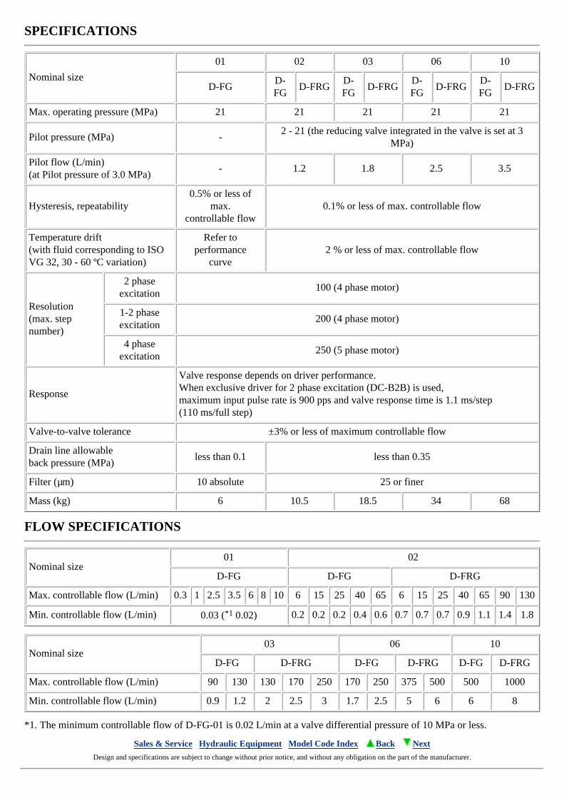
SPECIFICATIONS
Nominal size
01 02 03 06 10
D-FGD-FG
D-FRGD-FG
D-FRGD-FG
D-FRGD-FG
D-FRG
Max. operating pressure (MPa) 21 21 21 21 21
Pilot pressure (MPa) -2 - 21 (the reducing valve integrated in the valve is set at 3
MPa)
Pilot flow (L/min)(at Pilot pressure of 3.0 MPa)
- 1.2 1.8 2.5 3.5
Hysteresis, repeatability0.5% or less of
max.controllable flow
0.1% or less of max. controllable flow
Temperature drift(with fluid corresponding to ISOVG 32, 30 - 60 ºC variation)
Refer toperformance
curve2 % or less of max. controllable flow
Resolution(max. step number)
2 phase excitation
100 (4 phase motor)
1-2 phase excitation
200 (4 phase motor)
4 phase excitation
250 (5 phase motor)
Response
Valve response depends on driver performance.When exclusive driver for 2 phase excitation (DC-B2B) is used,maximum input pulse rate is 900 pps and valve response time is 1.1 ms/step(110 ms/full step)
Valve-to-valve tolerance ±3% or less of maximum controllable flow
Drain line allowableback pressure (MPa)
less than 0.1 less than 0.35
Filter (µm) 10 absolute 25 or finer
Mass (kg) 6 10.5 18.5 34 68
FLOW SPECIFICATIONS
Nominal size01 02
D-FG D-FG D-FRG
Max. controllable flow (L/min) 0.3 1 2.5 3.5 6 8 10 6 15 25 40 65 6 15 25 40 65 90 130
Min. controllable flow (L/min) 0.03 (*1 0.02) 0.2 0.2 0.2 0.4 0.6 0.7 0.7 0.7 0.9 1.1 1.4 1.8
Nominal size03 06 10
D-FG D-FRG D-FG D-FRG D-FG D-FRG
Max. controllable flow (L/min) 90 130 130 170 250 170 250 375 500 500 1000
Min. controllable flow (L/min) 0.9 1.2 2 2.5 3 1.7 2.5 5 6 6 8
*1. The minimum controllable flow of D-FG-01 is 0.02 L/min at a valve differential pressure of 10 MPa or less.
Sales & Service Hydraulic Equipment Model Code Index Back Next Design and specifications are subject to change without prior notice, and without any obligation on the part of the manufacturer.
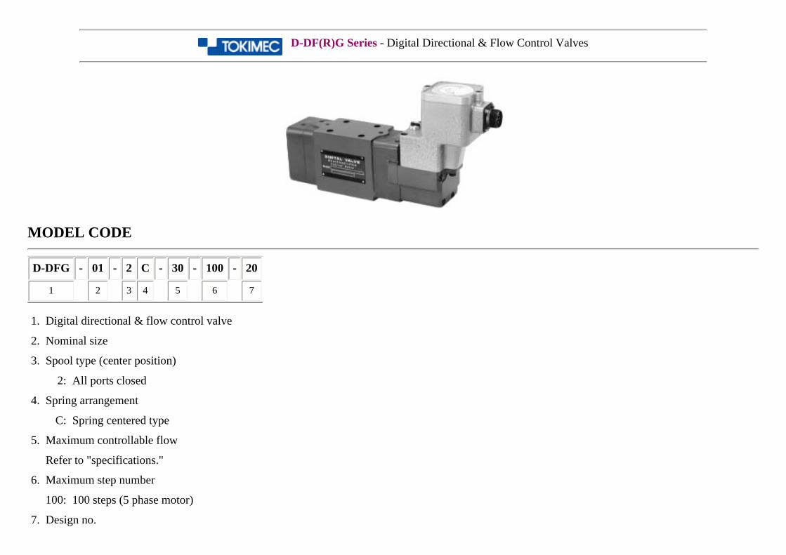
D-DF(R)G Series - Digital Directional & Flow Control Valves
MODEL CODE
D-DFG - 01 - 2 C - 30 - 100 - 20
1 2 3 4 5 6 7
1. Digital directional & flow control valve
2. Nominal size
3. Spool type (center position)
2: All ports closed
4. Spring arrangement
C: Spring centered type
5. Maximum controllable flow
Refer to "specifications."
6. Maximum step number
100: 100 steps (5 phase motor)
7. Design no.
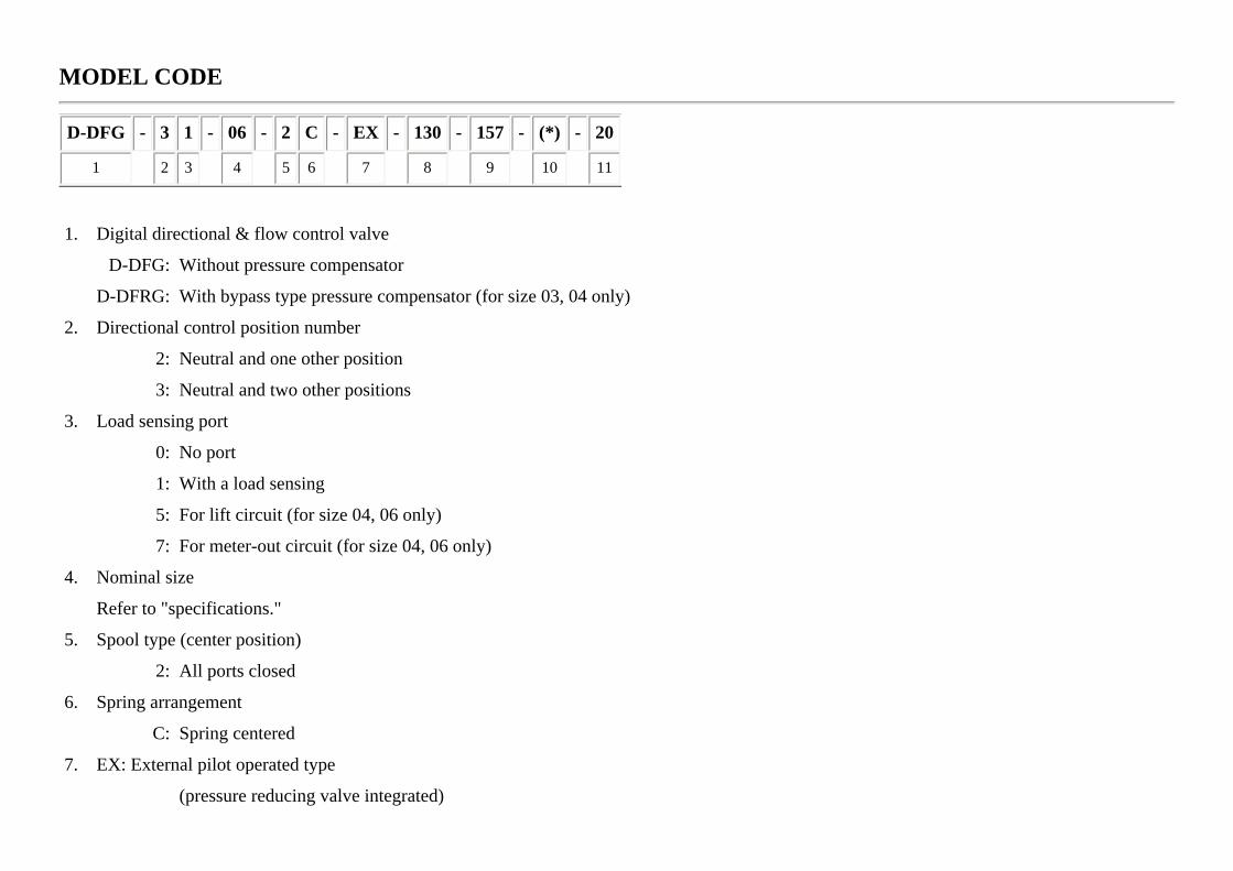
MODEL CODE
D-DFG - 3 1 - 06 - 2 C - EX - 130 - 157 - (*) - 20
1 2 3 4 5 6 7 8 9 10 11
1. Digital directional & flow control valve
D-DFG: Without pressure compensator
D-DFRG: With bypass type pressure compensator (for size 03, 04 only)
2. Directional control position number
2: Neutral and one other position
3: Neutral and two other positions
3. Load sensing port
0: No port
1: With a load sensing
5: For lift circuit (for size 04, 06 only)
7: For meter-out circuit (for size 04, 06 only)
4. Nominal size
Refer to "specifications."
5. Spool type (center position)
2: All ports closed
6. Spring arrangement
C: Spring centered
7. EX: External pilot operated type
(pressure reducing valve integrated)
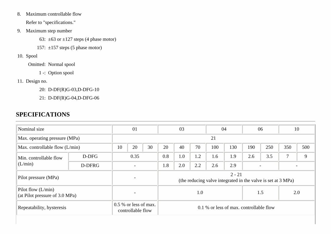
8. Maximum controllable flow
Refer to "specifications."
9. Maximum step number
63: ±63 or ±127 steps (4 phase motor)
157: ±157 steps (5 phase motor)
10. Spool
Omitted: Normal spool
1 -: Option spool
11. Design no.
20: D-DF(R)G-03,D-DFG-10
21: D-DF(R)G-04,D-DFG-06
SPECIFICATIONS
Nominal size 01 03 04 06 10
Max. operating pressure (MPa) 21
Max. controllable flow (L/min) 10 20 30 20 40 70 100 130 190 250 350 500
Min. controllable flow(L/min)
D-DFG 0.35 0.8 1.0 1.2 1.6 1.9 2.6 3.5 7 9
D-DFRG - 1.8 2.0 2.2 2.6 2.9 - -
Pilot pressure (MPa) -2 - 21
(the reducing valve integrated in the valve is set at 3 MPa)
Pilot flow (L/min)(at Pilot pressure of 3.0 MPa)
- 1.0 1.5 2.0
Repeatability, hysteresis0.5 % or less of max.
controllable flow0.1 % or less of max. controllable flow

Temperature drift(with fluid corresponding to ISO VG32, 30 - 60 ºC variation)
2 % or less of max. controllable flow
Resolution (max. step number)
2 phase excitation - both direction ±63 (P -> A and P -> B) (4 phase motor)
1-2 phase excitation - both direction ±127 (P -> A and P -> B) (4 phase motor)
4 phase excitationboth direction ±100(P -> A and P -> B)
both direction ±157 (P -> A and P -> B) (5 phase motor)
Response 2000 PPS
Valve response depends on driver performance.When exclusive driver for 2 phase excitation (DC-B2B) is used,
maximum input pulse rate is 900 pps and valve response time is 1.1 ms/step.(70 ms/ 63 full step)
Valve-to-valve tolerance ±3% or less of maximum controllable flow
Y port (Drain line) allowableback pressure (MPa)
less than 1.0 less than 0.35
Filter (µm) 10 absolute 25 or finer
Mass (kg)D-DFG 2.5 10.7 10.8 18.2 45
D-DFRG - 12.7 12.8 - -
Sales & Service Hydraulic Equipment Model Code Index Back Next Design and specifications are subject to change without prior notice, and without any obligation on the part of the manufacturer.
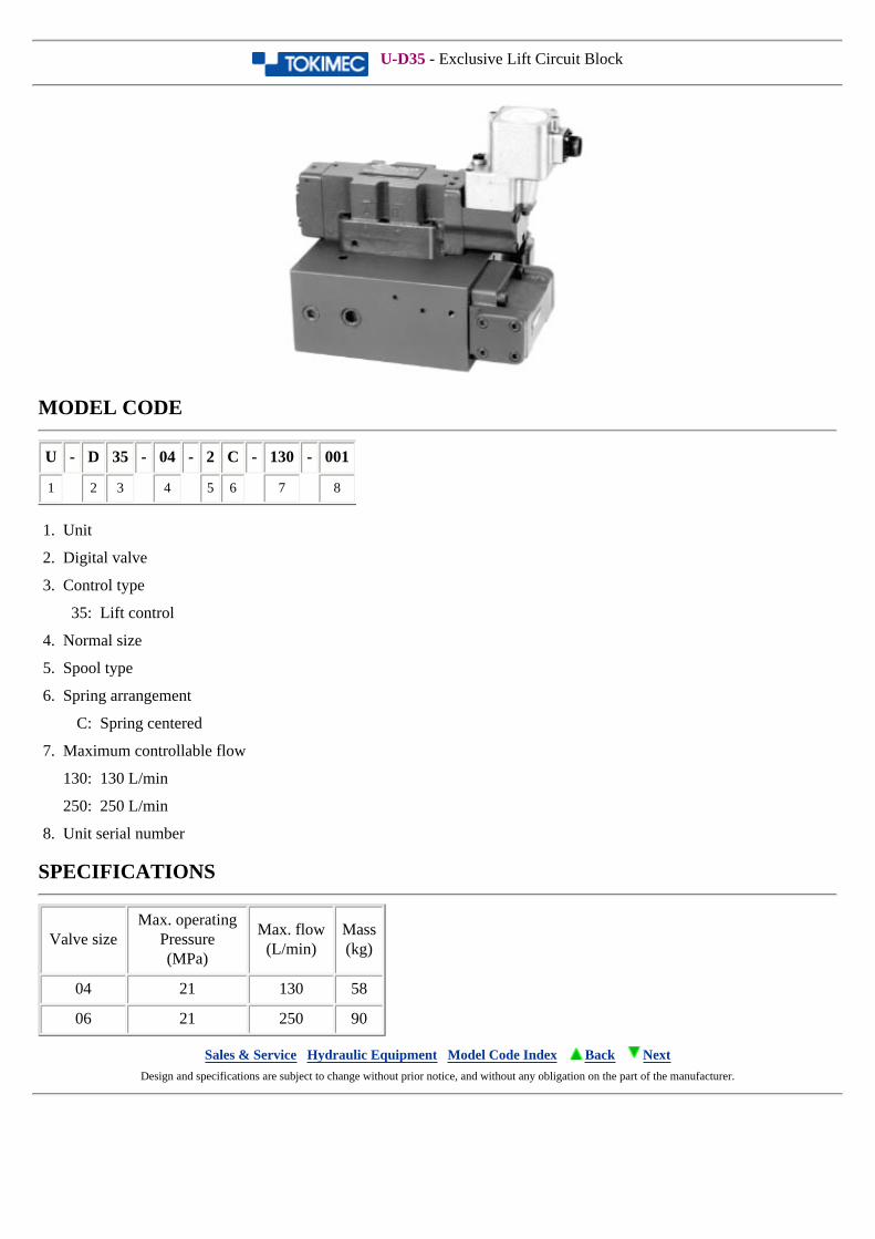
U-D35 - Exclusive Lift Circuit Block
MODEL CODE
U - D 35 - 04 - 2 C - 130 - 001
1 2 3 4 5 6 7 8
1. Unit
2. Digital valve
3. Control type
35: Lift control
4. Normal size
5. Spool type
6. Spring arrangement
C: Spring centered
7. Maximum controllable flow
130: 130 L/min
250: 250 L/min
8. Unit serial number
SPECIFICATIONS
Valve sizeMax. operating
Pressure(MPa)
Max. flow(L/min)
Mass(kg)
04 21 130 58
06 21 250 90
Sales & Service Hydraulic Equipment Model Code Index Back Next Design and specifications are subject to change without prior notice, and without any obligation on the part of the manufacturer.
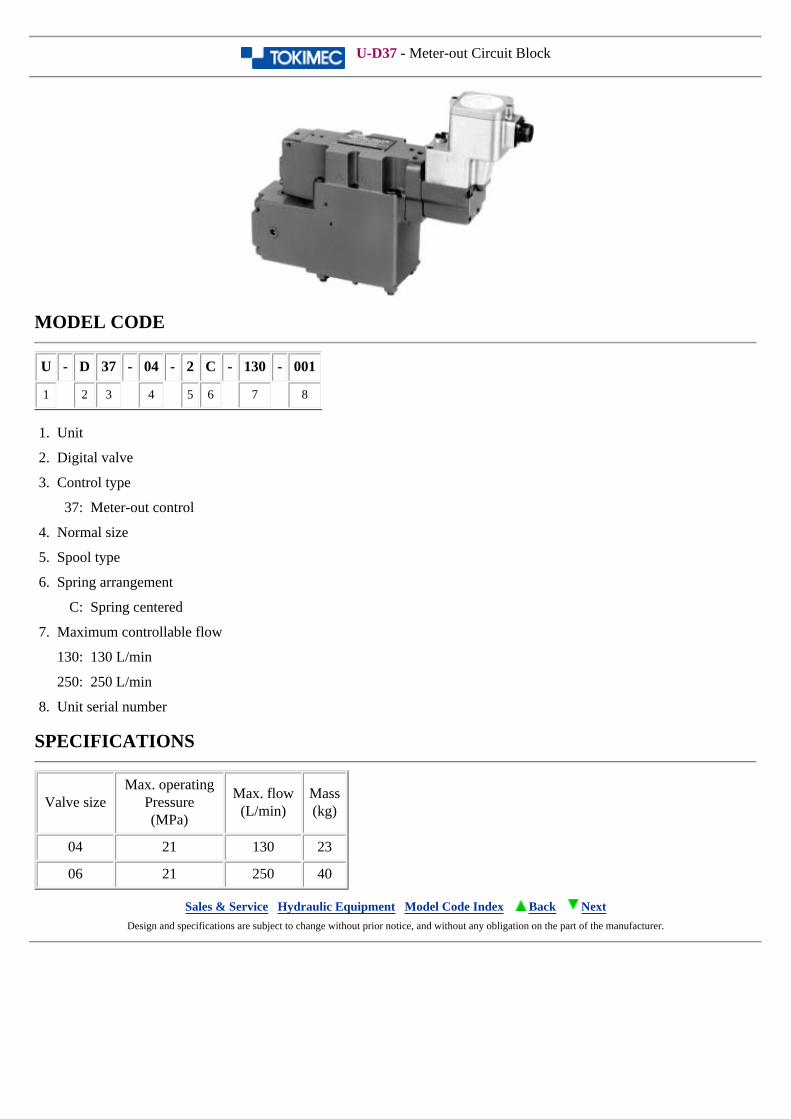
U-D37 - Meter-out Circuit Block
MODEL CODE
U - D 37 - 04 - 2 C - 130 - 001
1 2 3 4 5 6 7 8
1. Unit
2. Digital valve
3. Control type
37: Meter-out control
4. Normal size
5. Spool type
6. Spring arrangement
C: Spring centered
7. Maximum controllable flow
130: 130 L/min
250: 250 L/min
8. Unit serial number
SPECIFICATIONS
Valve sizeMax. operating
Pressure(MPa)
Max. flow(L/min)
Mass(kg)
04 21 130 23
06 21 250 40
Sales & Service Hydraulic Equipment Model Code Index Back Next Design and specifications are subject to change without prior notice, and without any obligation on the part of the manufacturer.
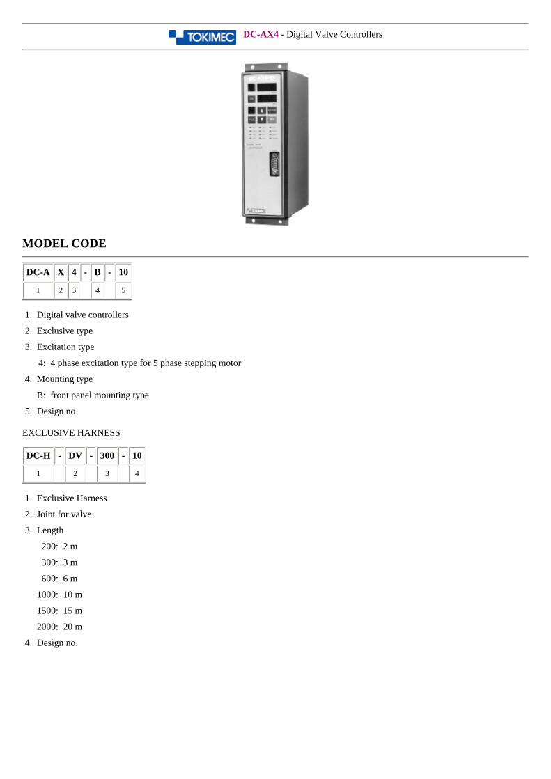
DC-AX4 - Digital Valve Controllers
MODEL CODE
DC-A X 4 - B - 10
1 2 3 4 5
1. Digital valve controllers
2. Exclusive type
3. Excitation type
4: 4 phase excitation type for 5 phase stepping motor
4. Mounting type
B: front panel mounting type
5. Design no.
EXCLUSIVE HARNESS
DC-H - DV - 300 - 10
1 2 3 4
1. Exclusive Harness
2. Joint for valve
3. Length
200: 2 m
300: 3 m
600: 6 m
1000: 10 m
1500: 15 m
2000: 20 m
4. Design no.
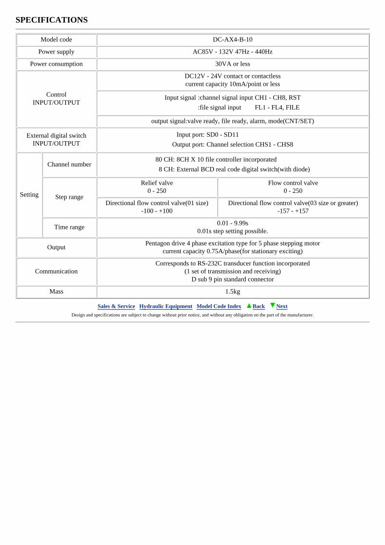
SPECIFICATIONS
Model code DC-AX4-B-10
Power supply AC85V - 132V 47Hz - 440Hz
Power consumption 30VA or less
ControlINPUT/OUTPUT
DC12V - 24V contact or contactlesscurrent capacity 10mA/point or less
Input signal :channel signal input CH1 - CH8, RST
:file signal input FL1 - FL4, FILE
output signal:valve ready, file ready, alarm, mode(CNT/SET)
External digital switchINPUT/OUTPUT
Input port: SD0 - SD11
Output port: Channel selection CHS1 - CHS8
Setting
Channel number80 CH: 8CH X 10 file controller incorporated
8 CH: External BCD real code digital switch(with diode)
Step range
Relief valve0 - 250
Flow control valve0 - 250
Directional flow control valve(01 size)-100 - +100
Directional flow control valve(03 size or greater)-157 - +157
Time range0.01 - 9.99s
0.01s step setting possible.
OutputPentagon drive 4 phase excitation type for 5 phase stepping motor
current capacity 0.75A/phase(for stationary exciting)
CommunicationCorresponds to RS-232C transducer function incorporated
(1 set of transmission and receiving)D sub 9 pin standard connector
Mass 1.5kg
Sales & Service Hydraulic Equipment Model Code Index Back Next Design and specifications are subject to change without prior notice, and without any obligation on the part of the manufacturer.
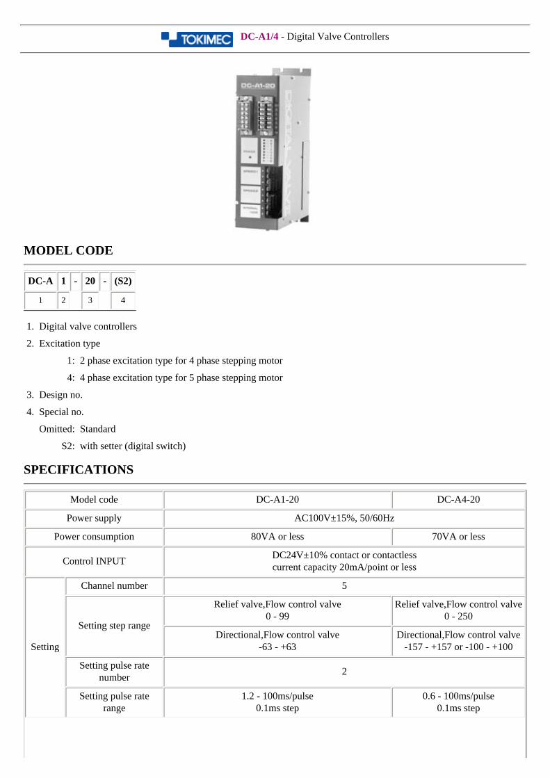
DC-A1/4 - Digital Valve Controllers
MODEL CODE
DC-A 1 - 20 - (S2)
1 2 3 4
1. Digital valve controllers
2. Excitation type
1: 2 phase excitation type for 4 phase stepping motor
4: 4 phase excitation type for 5 phase stepping motor
3. Design no.
4. Special no.
Omitted: Standard
S2: with setter (digital switch)
SPECIFICATIONS
Model code DC-A1-20 DC-A4-20
Power supply AC100V±15%, 50/60Hz
Power consumption 80VA or less 70VA or less
Control INPUTDC24V±10% contact or contactlesscurrent capacity 20mA/point or less
Setting
Channel number 5
Setting step range
Relief valve,Flow control valve0 - 99
Relief valve,Flow control valve0 - 250
Directional,Flow control valve-63 - +63
Directional,Flow control valve-157 - +157 or -100 - +100
Setting pulse rate number
2
Setting pulse rate range
1.2 - 100ms/pulse0.1ms step
0.6 - 100ms/pulse0.1ms step
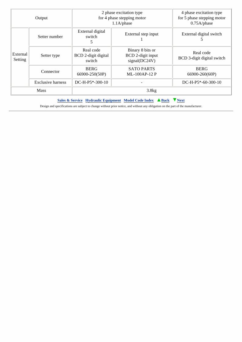
Output2 phase excitation type
for 4 phase stepping motor1.1A/phase
4 phase excitation typefor 5 phase stepping motor
0.75A/phase
ExternalSetting
Setter numberExternal digital
switch5
External step input1
External digital switch5
Setter typeReal code
BCD 2-digit digital switch
Binary 8 bits orBCD 2-digit input
signal(DC24V)
Real codeBCD 3-digit digital switch
ConnectorBERG
66900-250(50P)SATO PARTS
ML-100AP-12 PBERG
66900-260(60P)
Exclusive harness DC-H-P5*-300-10 - DC-H-P5*-60-300-10
Mass 3.8kg
Sales & Service Hydraulic Equipment Model Code Index Back Next Design and specifications are subject to change without prior notice, and without any obligation on the part of the manufacturer.
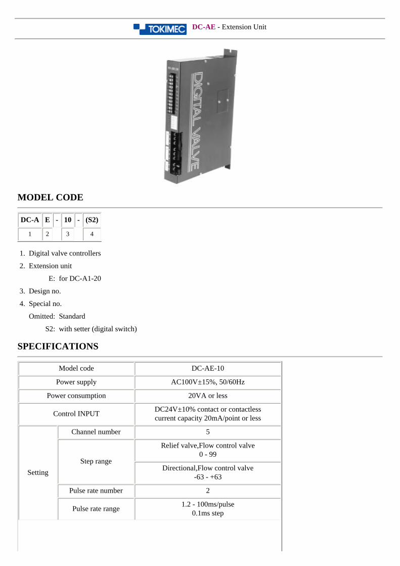
DC-AE - Extension Unit
MODEL CODE
DC-A E - 10 - (S2)
1 2 3 4
1. Digital valve controllers
2. Extension unit
E: for DC-A1-20
3. Design no.
4. Special no.
Omitted: Standard
S2: with setter (digital switch)
SPECIFICATIONS
Model code DC-AE-10
Power supply AC100V±15%, 50/60Hz
Power consumption 20VA or less
Control INPUTDC24V±10% contact or contactlesscurrent capacity 20mA/point or less
Setting
Channel number 5
Step range
Relief valve,Flow control valve0 - 99
Directional,Flow control valve-63 - +63
Pulse rate number 2
Pulse rate range1.2 - 100ms/pulse
0.1ms step
Output2 phase excitation type
for 4 phase stepping motor1.1A/phase
ExternalSetting
Setter number External digital switch 5
Setter typeReal code
BCD 2-digit digital switch
ConnectorBERG
66900-250(50P)
Exclusive harness DC-H-P5*-300-10
Mass 2.1kg
Sales & Service Hydraulic Equipment Model Code Index Back Next Design and specifications are subject to change without prior notice, and without any obligation on the part of the manufacturer.

DC-AT1/2 - Digital Valve Controllers
MODEL CODE
DC-A T 1 - 20
1 2 3 4
1. Digital valve controllers
2. Transient shape
3. Excitation type
1: 1-2 phase excitation type for 4 phase stepping motor
2: 2 phase excitation type for 4 phase stepping motor
4. Design no.
SPECIFICATIONS
Model code DC-AT1-20 DC-AT2-20
Power supply AC85 - 132V, 50/60Hz
Power consumption 80VA or less
Control INPUTDC24V±10% contact or contactlesscurrent capacity 20mA/point or less
Setting
Channel number 8CH + RESET
Transient shape 32
Step range
Relief valveFlow control valve
0 - 199 0 - 99
DirectionalFlow control valve
-216 - +126 -63 - +63
Data Use the setter (DC-PT) for setting.
Output1-2 phase excitation type
for 4 phase stepping motor1.1A/phase
2 phase excitation typefor 4 phase stepping motor
1.1A/phase
Sales & Service Hydraulic Equipment Model Code Index Back Next
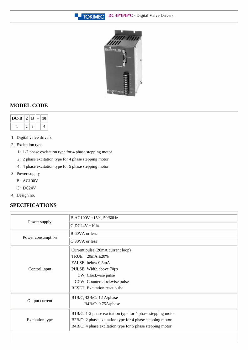
DC-B*B/B*C - Digital Valve Drivers
MODEL CODE
DC-B 2 B - 10
1 2 3 4
1. Digital valve drivers
2. Excitation type
1: 1-2 phase excitation type for 4 phase stepping motor
2: 2 phase excitation type for 4 phase stepping motor
4: 4 phase excitation type for 5 phase stepping motor
3. Power supply
B: AC100V
C: DC24V
4. Design no.
SPECIFICATIONS
Power supplyB:AC100V ±15%, 50/60Hz
C:DC24V ±10%
Power consumptionB:60VA or less
C:30VA or less
Control input
Current pulse (20mA current loop)
TRUE 20mA ±20%
FALSE below 0.5mA
PULSE Width above 70µs
CW: Clockwise pulse
CCW: Counter clockwise pulse
RESET: Excitation reset pulse
Output currentB1B/C,B2B/C: 1.1A/phase
B4B/C: 0.75A/phase
Excitation type
B1B/C: 1-2 phase excitation type for 4 phase stepping motor
B2B/C: 2 phase excitation type for 4 phase stepping motor
B4B/C: 4 phase excitation type for 5 phase stepping motor

Adaptable pulse rate
B1B/C: 1800 pps
B2B/C: 900 pps
B4B/C: 2200 pps
MassDC-B*C: 0.8 kg
DC-B*B: 3.2 kg
Sales & Service Hydraulic Equipment Model Code Index Back Next Design and specifications are subject to change without prior notice, and without any obligation on the part of the manufacturer.
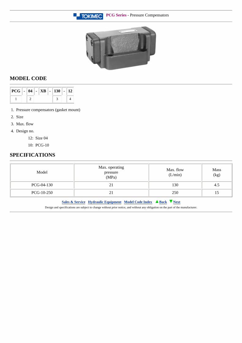
PCG Series - Pressure Compensators
MODEL CODE
PCG - 04 - XB - 130 - 12
1 2 3 4
1. Pressure compensators (gasket mount)
2. Size
3. Max. flow
4. Design no.
12: Size 04
10: PCG-10
SPECIFICATIONS
ModelMax. operating
pressure(MPa)
Max. flow(L/min)
Mass(kg)
PCG-04-130 21 130 4.5
PCG-10-250 21 250 15
Sales & Service Hydraulic Equipment Model Code Index Back Next Design and specifications are subject to change without prior notice, and without any obligation on the part of the manufacturer.
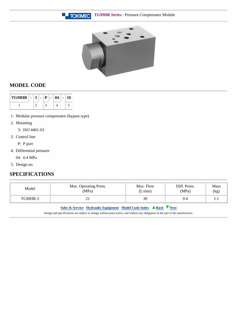
TGMHR Series - Pressure Compensator Module
MODEL CODE
TGMHR - 3 - P - 04 - 10
1 2 3 4 5
1. Modular pressure compensator (bypass type)
2. Mounting
3: ISO 4401-03
3. Control line
P: P port
4. Differential pressure
04: 0.4 MPa
5. Design no.
SPECIFICATIONS
ModelMax. Operating Press.
(MPa)Max. Flow
(L/min)Diff. Press.
(MPa)Mass(kg)
TGMHR-3 21 30 0.4 1.1
Sales & Service Hydraulic Equipment Model Code Index Back Next Design and specifications are subject to change without prior notice, and without any obligation on the part of the manufacturer.
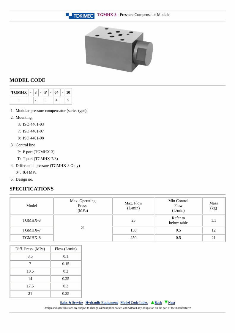
TGMHX-3 - Pressure Compensator Module
MODEL CODE
TGMHX - 3 - P - 04 - 10
1 2 3 4 5
1. Modular pressure compensator (series type)
2. Mounting
3: ISO 4401-03
7: ISO 4401-07
8: ISO 4401-08
3. Control line
P: P port (TGMHX-3)
T: T port (TGMHX-7/8)
4. Differential pressure (TGMHX-3 Only)
04: 0.4 MPa
5. Design no.
SPECIFICATIONS
ModelMax. Operating
Press.(MPa)
Max. Flow(L/min)
Min ControlFlow
(L/min)
Mass(kg)
TGMHX-3
21
25Refer to
below table1.1
TGMHX-7 130 0.5 12
TGMHX-8 250 0.5 21
Diff. Press. (MPa) Flow (L/min)
3.5 0.1
7 0.15
10.5 0.2
14 0.25
17.5 0.3
21 0.35
Sales & Service Hydraulic Equipment Model Code Index Back Next Design and specifications are subject to change without prior notice, and without any obligation on the part of the manufacturer.
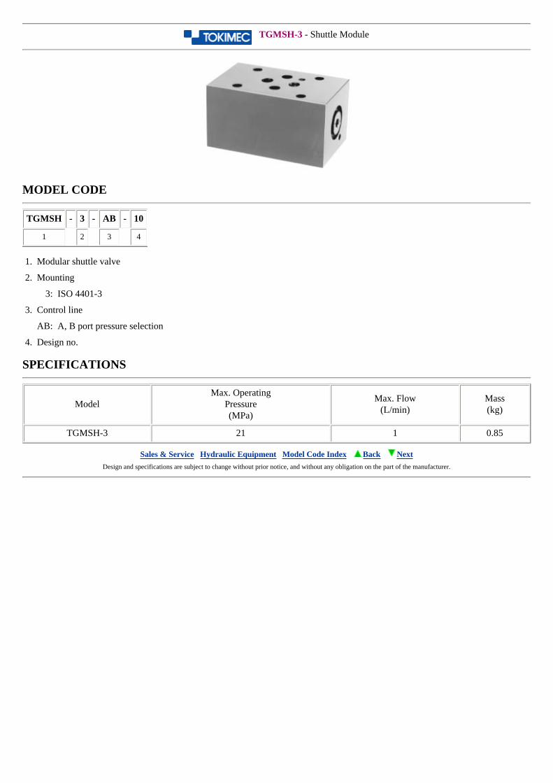
TGMSH-3 - Shuttle Module
MODEL CODE
TGMSH - 3 - AB - 10
1 2 3 4
1. Modular shuttle valve
2. Mounting
3: ISO 4401-3
3. Control line
AB: A, B port pressure selection
4. Design no.
SPECIFICATIONS
ModelMax. Operating
Pressure(MPa)
Max. Flow(L/min)
Mass(kg)
TGMSH-3 21 1 0.85
Sales & Service Hydraulic Equipment Model Code Index Back Next Design and specifications are subject to change without prior notice, and without any obligation on the part of the manufacturer.
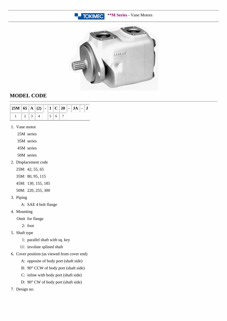
**M Series - Vane Motors
MODEL CODE
25M 65 A (2) - 1 C 20 - JA - J
1 2 3 4 5 6 7
1. Vane motor
25M series
35M series
45M series
50M series
2. Displacement code
25M: 42, 55, 65
35M: 80, 95, 115
45M: 130, 155, 185
50M: 220, 255, 300
3. Piping
A: SAE 4 bolt flange
4. Mounting
Omit for flange
2: foot
5. Shaft type
1: parallel shaft with sq. key
11: involute splined shaft
6. Cover position (as viewed from cover end)
A: opposite of body port (shaft side)
B: 90° CCW of body port (shaft side)
C: inline with body port (shaft side)
D: 90° CW of body port (shaft side)
7. Design no.
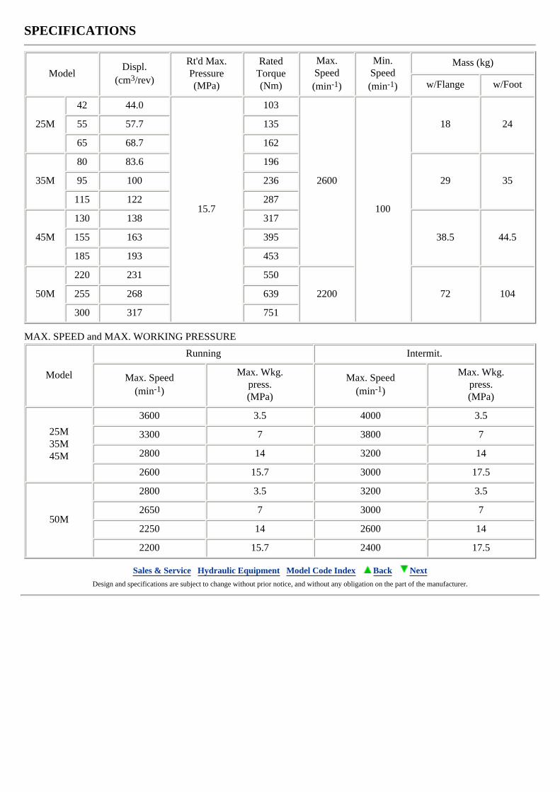
SPECIFICATIONS
ModelDispl.
(cm3/rev)
Rt'd Max.Pressure(MPa)
RatedTorque(Nm)
Max.Speed(min-1)
Min.Speed(min-1)
Mass (kg)
w/Flange w/Foot
25M
42 44.0
15.7
103
2600
100
18 2455 57.7 135
65 68.7 162
35M
80 83.6 196
29 3595 100 236
115 122 287
45M
130 138 317
38.5 44.5155 163 395
185 193 453
50M
220 231 550
2200 72 104255 268 639
300 317 751
MAX. SPEED and MAX. WORKING PRESSURE
Model
Running Intermit.
Max. Speed(min-1)
Max. Wkg.press.(MPa)
Max. Speed(min-1)
Max. Wkg.press.(MPa)
25M35M45M
3600 3.5 4000 3.5
3300 7 3800 7
2800 14 3200 14
2600 15.7 3000 17.5
50M
2800 3.5 3200 3.5
2650 7 3000 7
2250 14 2600 14
2200 15.7 2400 17.5
Sales & Service Hydraulic Equipment Model Code Index Back Next Design and specifications are subject to change without prior notice, and without any obligation on the part of the manufacturer.
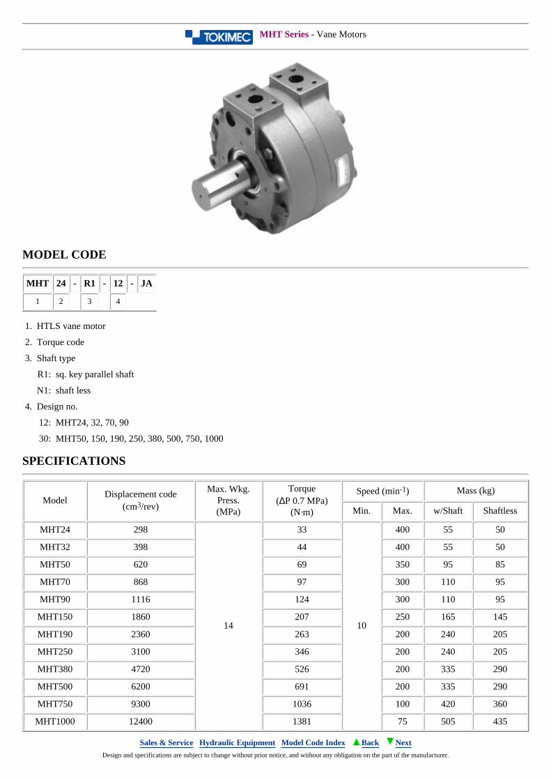
MHT Series - Vane Motors
MODEL CODE
MHT 24 - R1 - 12 - JA
1 2 3 4
1. HTLS vane motor
2. Torque code
3. Shaft type
R1: sq. key parallel shaft
N1: shaft less
4. Design no.
12: MHT24, 32, 70, 90
30: MHT50, 150, 190, 250, 380, 500, 750, 1000
SPECIFICATIONS
ModelDisplacement code
(cm3/rev)
Max. Wkg.Press.(MPa)
Torque(∆P 0.7 MPa)
(N·m)
Speed (min-1) Mass (kg)
Min. Max. w/Shaft Shaftless
MHT24 298
14
33
10
400 55 50
MHT32 398 44 400 55 50
MHT50 620 69 350 95 85
MHT70 868 97 300 110 95
MHT90 1116 124 300 110 95
MHT150 1860 207 250 165 145
MHT190 2360 263 200 240 205
MHT250 3100 346 200 240 205
MHT380 4720 526 200 335 290
MHT500 6200 691 200 335 290
MHT750 9300 1036 100 420 360
MHT1000 12400 1381 75 505 435
Sales & Service Hydraulic Equipment Model Code Index Back Next Design and specifications are subject to change without prior notice, and without any obligation on the part of the manufacturer.
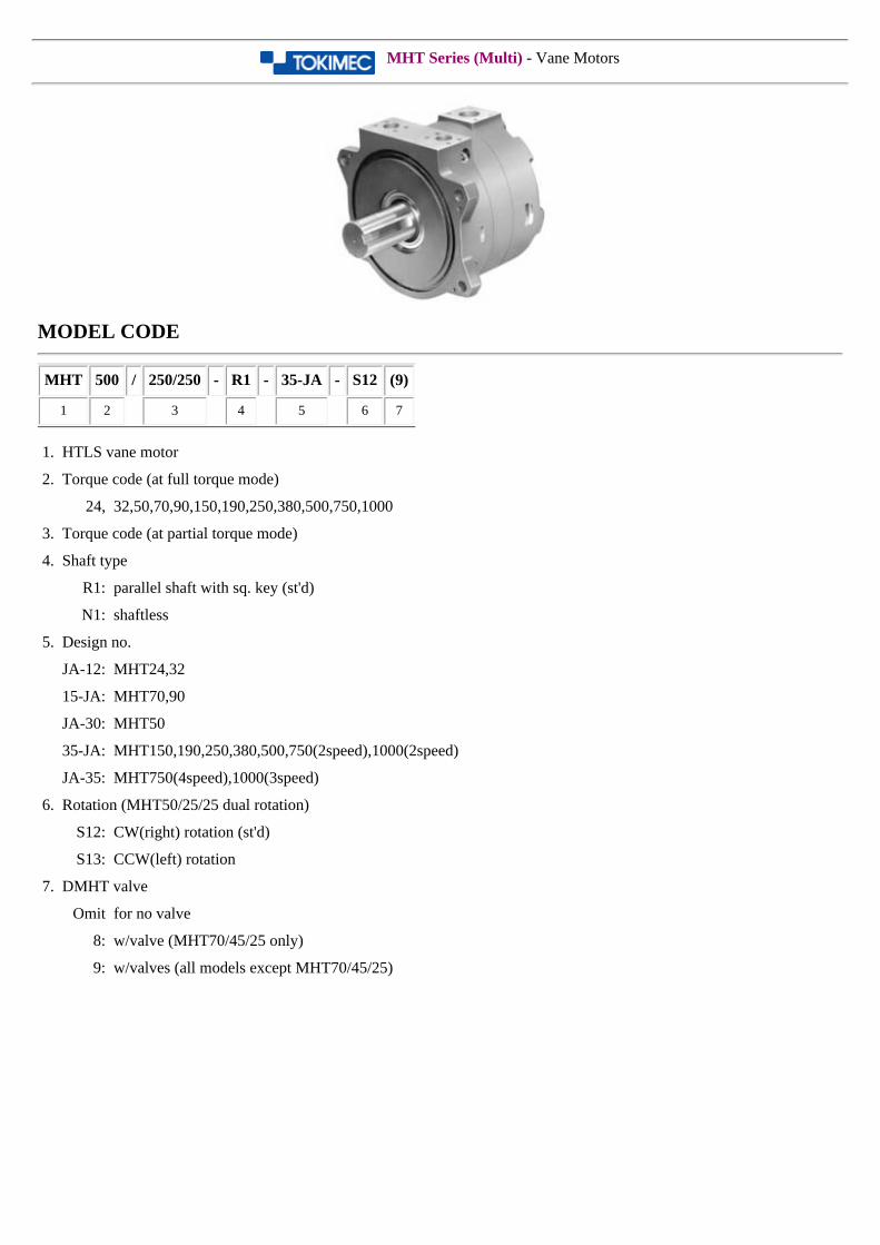
MHT Series (Multi) - Vane Motors
MODEL CODE
MHT 500 / 250/250 - R1 - 35-JA - S12 (9)
1 2 3 4 5 6 7
1. HTLS vane motor
2. Torque code (at full torque mode)
24, 32,50,70,90,150,190,250,380,500,750,1000
3. Torque code (at partial torque mode)
4. Shaft type
R1: parallel shaft with sq. key (st'd)
N1: shaftless
5. Design no.
JA-12: MHT24,32
15-JA: MHT70,90
JA-30: MHT50
35-JA: MHT150,190,250,380,500,750(2speed),1000(2speed)
JA-35: MHT750(4speed),1000(3speed)
6. Rotation (MHT50/25/25 dual rotation)
S12: CW(right) rotation (st'd)
S13: CCW(left) rotation
7. DMHT valve
Omit for no valve
8: w/valve (MHT70/45/25 only)
9: w/valves (all models except MHT70/45/25)
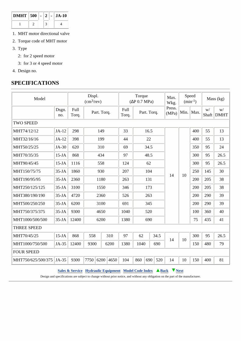
DMHT 500 - 2 - JA-10
1 2 3 4
1. MHT motor directional valve
2. Torque code of MHT motor
3. Type
2: for 2 speed motor
3: for 3 or 4 speed motor
4. Design no.
SPECIFICATIONS
ModelDispl.
(cm3/rev)Torque
(∆P 0.7 MPa)Max.Wkg.Press.(MPa)
Speed(min-1)
Mass (kg)
Dsgn.
no.Full
Torq.Part. Torq.
Full Torq.
Part. Torq. Min. Max.w/
Shaftw/
DMHT
TWO SPEED
MHT74/12/12 JA-12 298 149 33 16.5
14 10
400 55 13
MHT32/16/16 JA-12 398 199 44 22 400 55 13
MHT50/25/25 JA-30 620 310 69 34.5 350 95 24
MHT70/35/35 15-JA 868 434 97 48.5 300 95 26.5
MHT90/45/45 15-JA 1116 558 124 62 300 95 26.5
MHT150/75/75 35-JA 1860 930 207 104 250 145 30
MHT190/95/95 35-JA 2360 1180 263 131 200 205 38
MHT250/125/125 35-JA 3100 1550 346 173 200 205 38
MHT380/190/190 35-JA 4720 2360 526 263 200 290 39
MHT500/250/250 35-JA 6200 3100 691 345 200 290 39
MHT750/375/375 35-JA 9300 4650 1040 520 100 360 40
MHT1000/500/500 35-JA 12400 6200 1380 690 75 435 41
THREE SPEED
MHT70/45/25 15-JA 868 558 310 97 62 34.514 10
300 95 26.5
MHT1000/750/500 JA-35 12400 9300 6200 1380 1040 690 150 480 79
FOUR SPEED
MHT750/625/500/375 JA-35 9300 7750 6200 4650 104 860 690 520 14 10 150 400 81
Sales & Service Hydraulic Equipment Model Code Index Back Next Design and specifications are subject to change without prior notice, and without any obligation on the part of the manufacturer.
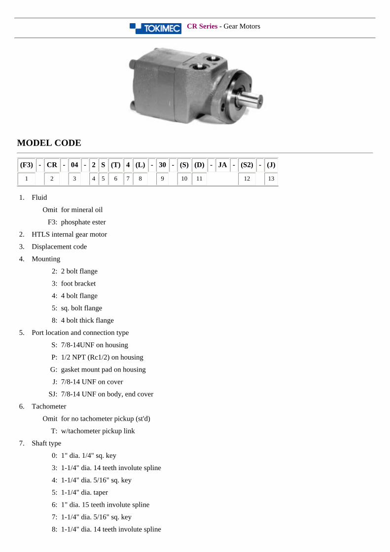
CR Series - Gear Motors
MODEL CODE
(F3) - CR - 04 - 2 S (T) 4 (L) - 30 - (S) (D) - JA - (S2) - (J)
1 2 3 4 5 6 7 8 9 10 11 12 13
1. Fluid
Omit for mineral oil
F3: phosphate ester
2. HTLS internal gear motor
3. Displacement code
4. Mounting
2: 2 bolt flange
3: foot bracket
4: 4 bolt flange
5: sq. bolt flange
8: 4 bolt thick flange
5. Port location and connection type
S: 7/8-14UNF on housing
P: 1/2 NPT (Rc1/2) on housing
G: gasket mount pad on housing
J: 7/8-14 UNF on cover
SJ: 7/8-14 UNF on body, end cover
6. Tachometer
Omit for no tachometer pickup (st'd)
T: w/tachometer pickup link
7. Shaft type
0: 1" dia. 1/4" sq. key
3: 1-1/4" dia. 14 teeth involute spline
4: 1-1/4" dia. 5/16" sq. key
5: 1-1/4" dia. taper
6: 1" dia. 15 teeth involute spline
7: 1-1/4" dia. 5/16" sq. key
8: 1-1/4" dia. 14 teeth involute spline
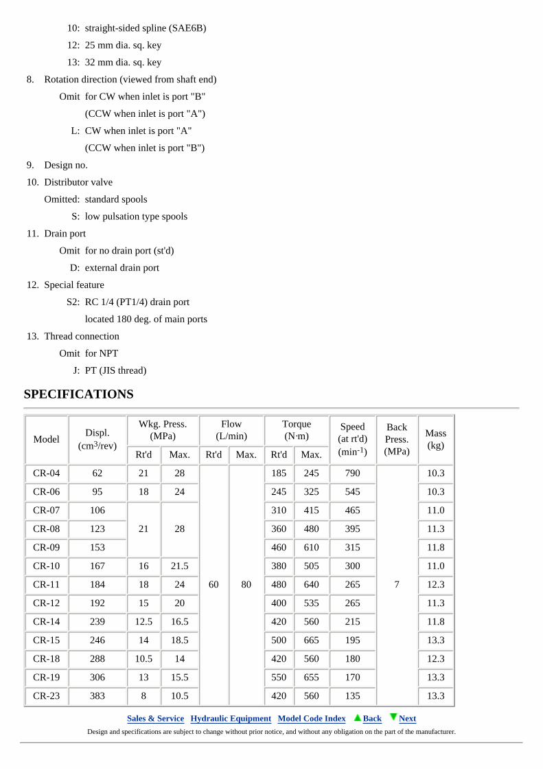
10: straight-sided spline (SAE6B)
12: 25 mm dia. sq. key
13: 32 mm dia. sq. key
8. Rotation direction (viewed from shaft end)
Omit for CW when inlet is port "B"
(CCW when inlet is port "A")
L: CW when inlet is port "A"
(CCW when inlet is port "B")
9. Design no.
10. Distributor valve
Omitted: standard spools
S: low pulsation type spools
11. Drain port
Omit for no drain port (st'd)
D: external drain port
12. Special feature
S2: RC 1/4 (PT1/4) drain port
located 180 deg. of main ports
13. Thread connection
Omit for NPT
J: PT (JIS thread)
SPECIFICATIONS
ModelDispl.
(cm3/rev)
Wkg. Press.(MPa)
Flow(L/min)
Torque(N·m)
Speed(at rt'd)(min-1)
BackPress.(MPa)
Mass(kg)
Rt'd Max. Rt'd Max. Rt'd Max.
CR-04 62 21 28
60 80
185 245 790
7
10.3
CR-06 95 18 24 245 325 545 10.3
CR-07 106
21 28
310 415 465 11.0
CR-08 123 360 480 395 11.3
CR-09 153 460 610 315 11.8
CR-10 167 16 21.5 380 505 300 11.0
CR-11 184 18 24 480 640 265 12.3
CR-12 192 15 20 400 535 265 11.3
CR-14 239 12.5 16.5 420 560 215 11.8
CR-15 246 14 18.5 500 665 195 13.3
CR-18 288 10.5 14 420 560 180 12.3
CR-19 306 13 15.5 550 655 170 13.3
CR-23 383 8 10.5 420 560 135 13.3
Sales & Service Hydraulic Equipment Model Code Index Back Next Design and specifications are subject to change without prior notice, and without any obligation on the part of the manufacturer.
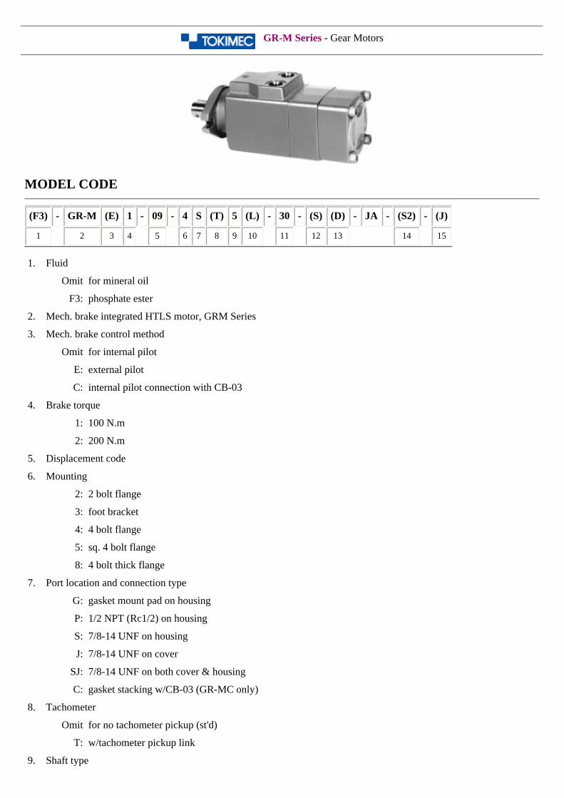
GR-M Series - Gear Motors
MODEL CODE
(F3) - GR-M (E) 1 - 09 - 4 S (T) 5 (L) - 30 - (S) (D) - JA - (S2) - (J)
1 2 3 4 5 6 7 8 9 10 11 12 13 14 15
1. Fluid
Omit for mineral oil
F3: phosphate ester
2. Mech. brake integrated HTLS motor, GRM Series
3. Mech. brake control method
Omit for internal pilot
E: external pilot
C: internal pilot connection with CB-03
4. Brake torque
1: 100 N.m
2: 200 N.m
5. Displacement code
6. Mounting
2: 2 bolt flange
3: foot bracket
4: 4 bolt flange
5: sq. 4 bolt flange
8: 4 bolt thick flange
7. Port location and connection type
G: gasket mount pad on housing
P: 1/2 NPT (Rc1/2) on housing
S: 7/8-14 UNF on housing
J: 7/8-14 UNF on cover
SJ: 7/8-14 UNF on both cover & housing
C: gasket stacking w/CB-03 (GR-MC only)
8. Tachometer
Omit for no tachometer pickup (st'd)
T: w/tachometer pickup link
9. Shaft type
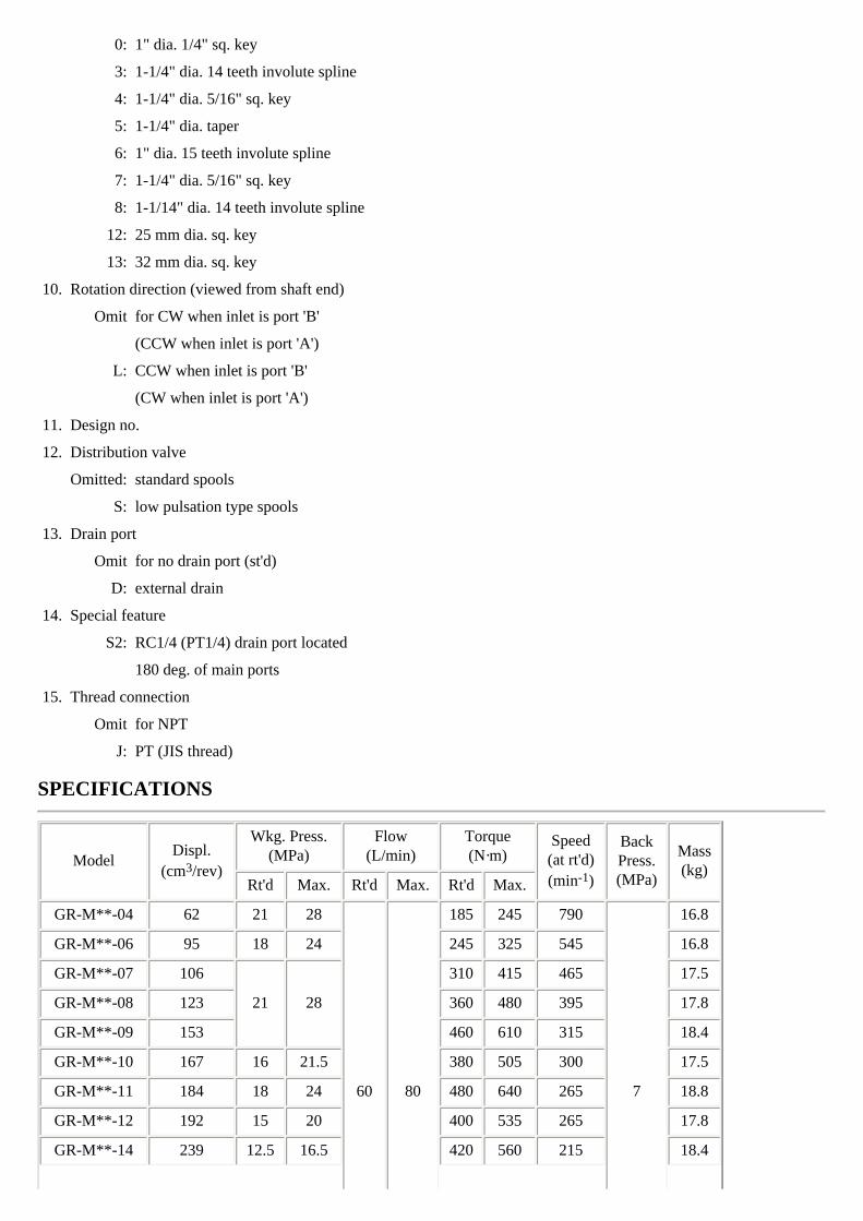
0: 1" dia. 1/4" sq. key
3: 1-1/4" dia. 14 teeth involute spline
4: 1-1/4" dia. 5/16" sq. key
5: 1-1/4" dia. taper
6: 1" dia. 15 teeth involute spline
7: 1-1/4" dia. 5/16" sq. key
8: 1-1/14" dia. 14 teeth involute spline
12: 25 mm dia. sq. key
13: 32 mm dia. sq. key
10. Rotation direction (viewed from shaft end)
Omit for CW when inlet is port 'B'
(CCW when inlet is port 'A')
L: CCW when inlet is port 'B'
(CW when inlet is port 'A')
11. Design no.
12. Distribution valve
Omitted: standard spools
S: low pulsation type spools
13. Drain port
Omit for no drain port (st'd)
D: external drain
14. Special feature
S2: RC1/4 (PT1/4) drain port located
180 deg. of main ports
15. Thread connection
Omit for NPT
J: PT (JIS thread)
SPECIFICATIONS
ModelDispl.
(cm3/rev)
Wkg. Press.(MPa)
Flow(L/min)
Torque(N·m)
Speed(at rt'd)(min-1)
BackPress.(MPa)
Mass(kg)
Rt'd Max. Rt'd Max. Rt'd Max.
GR-M**-04 62 21 28
60 80
185 245 790
7
16.8
GR-M**-06 95 18 24 245 325 545 16.8
GR-M**-07 106
21 28
310 415 465 17.5
GR-M**-08 123 360 480 395 17.8
GR-M**-09 153 460 610 315 18.4
GR-M**-10 167 16 21.5 380 505 300 17.5
GR-M**-11 184 18 24 480 640 265 18.8
GR-M**-12 192 15 20 400 535 265 17.8
GR-M**-14 239 12.5 16.5 420 560 215 18.4
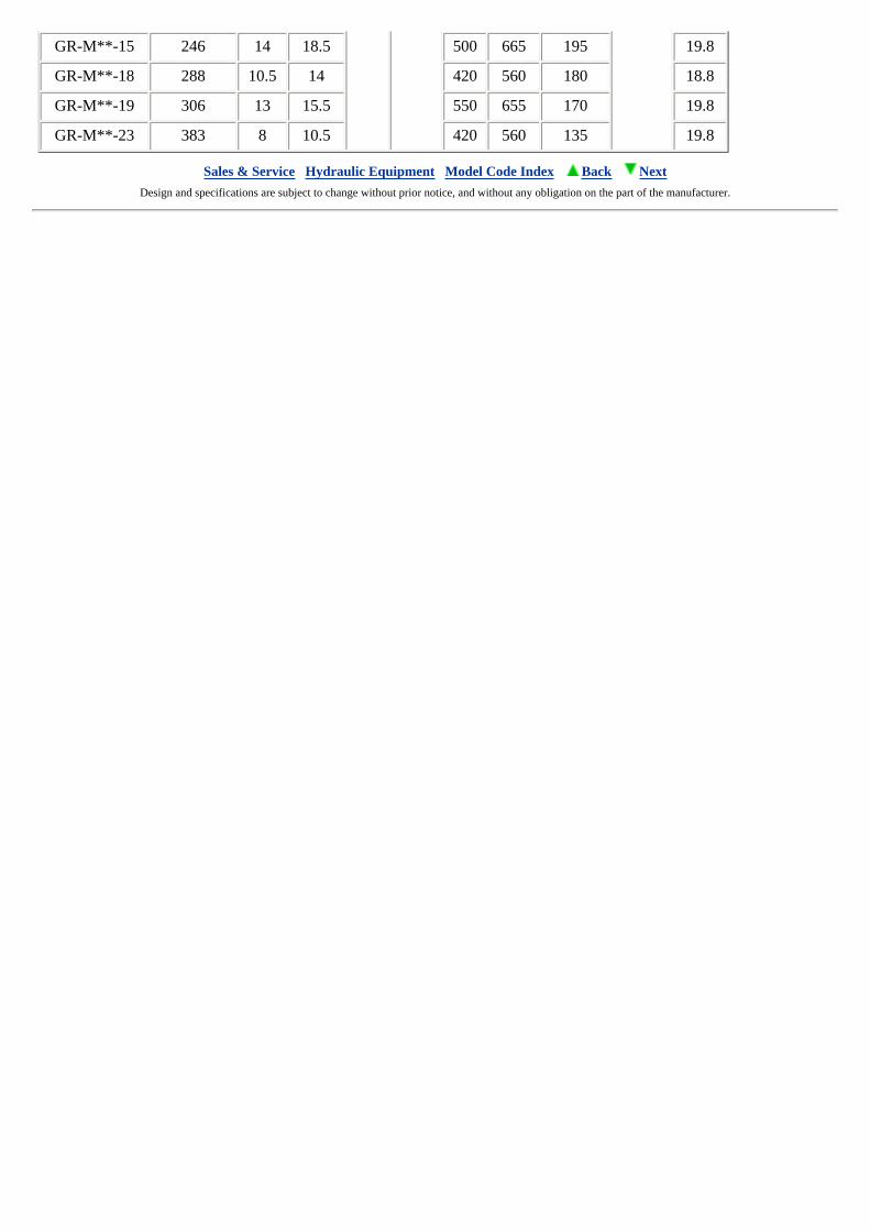
GR-M**-15 246 14 18.5 500 665 195 19.8
GR-M**-18 288 10.5 14 420 560 180 18.8
GR-M**-19 306 13 15.5 550 655 170 19.8
GR-M**-23 383 8 10.5 420 560 135 19.8
Sales & Service Hydraulic Equipment Model Code Index Back Next Design and specifications are subject to change without prior notice, and without any obligation on the part of the manufacturer.
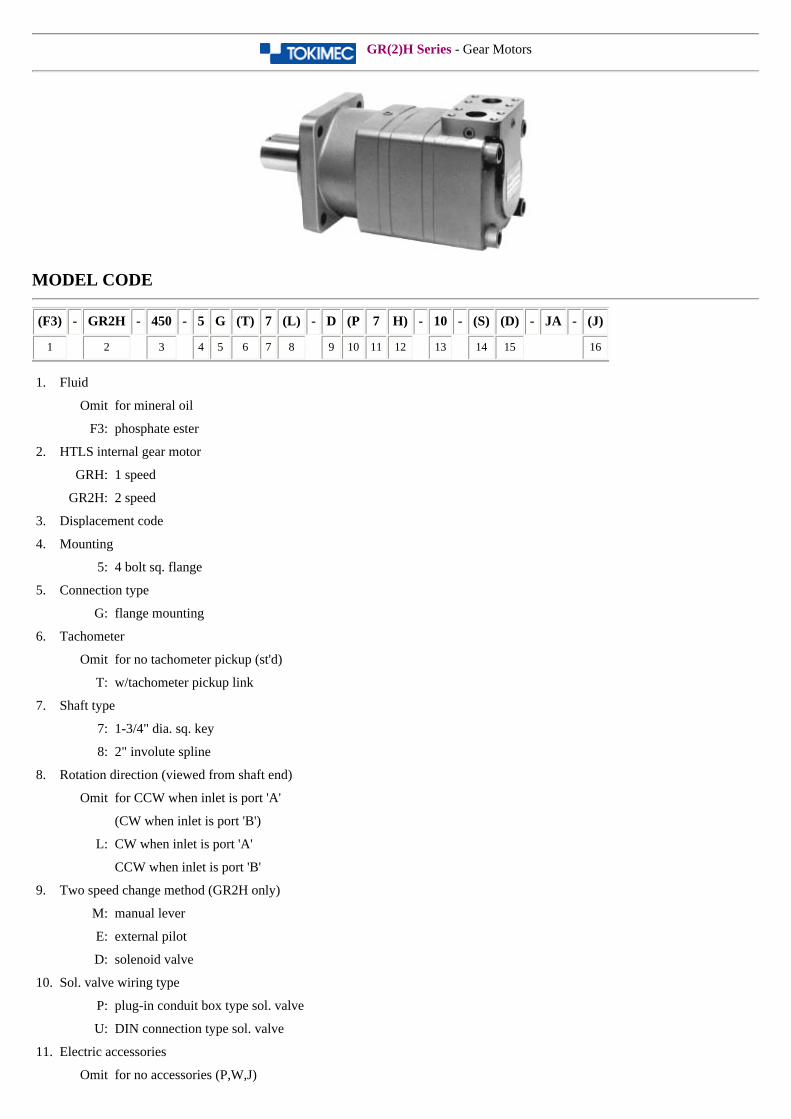
GR(2)H Series - Gear Motors
MODEL CODE
(F3) - GR2H - 450 - 5 G (T) 7 (L) - D (P 7 H) - 10 - (S) (D) - JA - (J)
1 2 3 4 5 6 7 8 9 10 11 12 13 14 15 16
1. Fluid
Omit for mineral oil
F3: phosphate ester
2. HTLS internal gear motor
GRH: 1 speed
GR2H: 2 speed
3. Displacement code
4. Mounting
5: 4 bolt sq. flange
5. Connection type
G: flange mounting
6. Tachometer
Omit for no tachometer pickup (st'd)
T: w/tachometer pickup link
7. Shaft type
7: 1-3/4" dia. sq. key
8: 2" involute spline
8. Rotation direction (viewed from shaft end)
Omit for CCW when inlet is port 'A'
(CW when inlet is port 'B')
L: CW when inlet is port 'A'
CCW when inlet is port 'B'
9. Two speed change method (GR2H only)
M: manual lever
E: external pilot
D: solenoid valve
10. Sol. valve wiring type
P: plug-in conduit box type sol. valve
U: DIN connection type sol. valve
11. Electric accessories
Omit for no accessories (P,W,J)
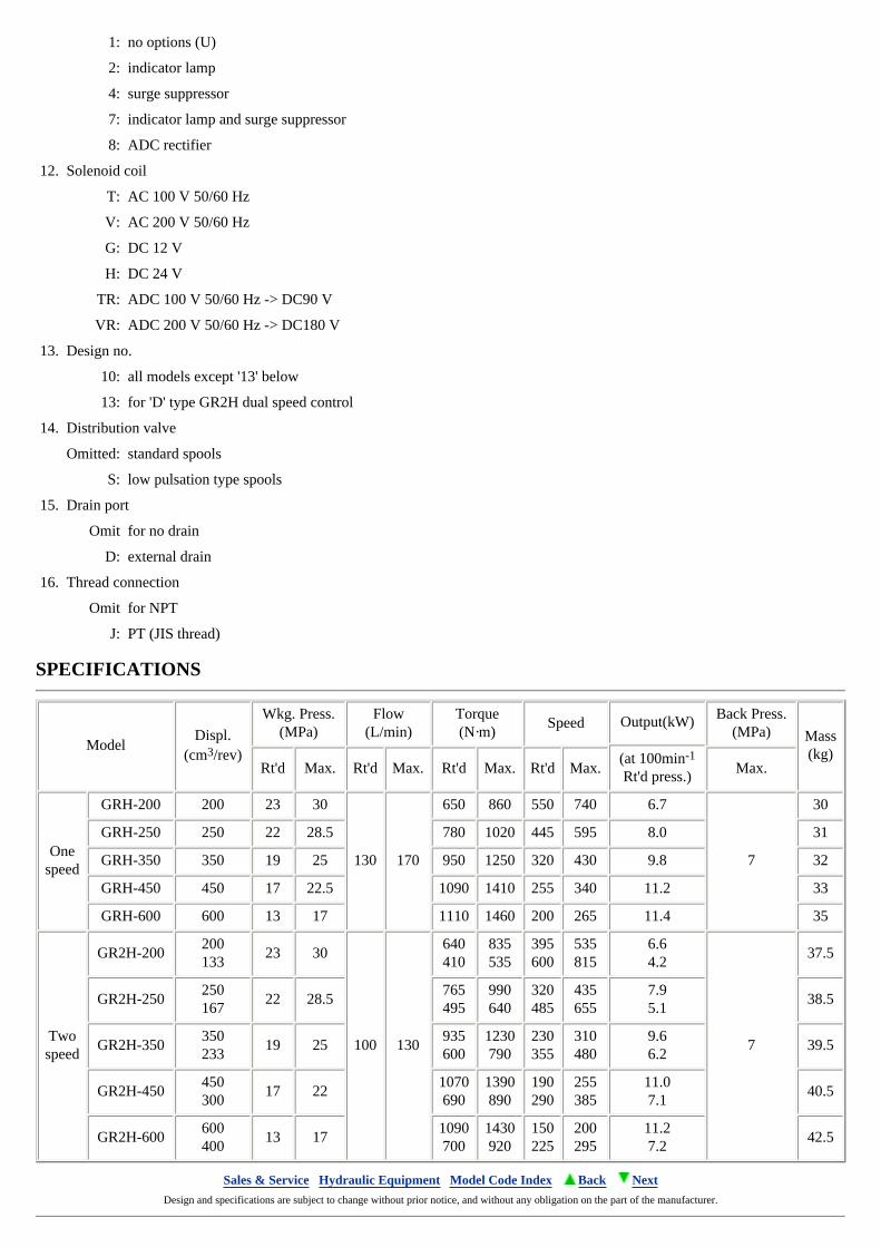
1: no options (U)
2: indicator lamp
4: surge suppressor
7: indicator lamp and surge suppressor
8: ADC rectifier
12. Solenoid coil
T: AC 100 V 50/60 Hz
V: AC 200 V 50/60 Hz
G: DC 12 V
H: DC 24 V
TR: ADC 100 V 50/60 Hz -> DC90 V
VR: ADC 200 V 50/60 Hz -> DC180 V
13. Design no.
10: all models except '13' below
13: for 'D' type GR2H dual speed control
14. Distribution valve
Omitted: standard spools
S: low pulsation type spools
15. Drain port
Omit for no drain
D: external drain
16. Thread connection
Omit for NPT
J: PT (JIS thread)
SPECIFICATIONS
ModelDispl.
(cm3/rev)
Wkg. Press.(MPa)
Flow(L/min)
Torque(N·m)
Speed Output(kW) Back Press.(MPa) Mass
(kg)(at 100min-1
Rt'd press.)Rt'd Max. Rt'd Max. Rt'd Max. Rt'd Max. Max.
Onespeed
GRH-200 200 23 30
130 170
650 860 550 740 6.7
7
30
GRH-250 250 22 28.5 780 1020 445 595 8.0 31
GRH-350 350 19 25 950 1250 320 430 9.8 32
GRH-450 450 17 22.5 1090 1410 255 340 11.2 33
GRH-600 600 13 17 1110 1460 200 265 11.4 35
Twospeed
GR2H-200200133
23 30
100 130
640410
835535
395600
535815
6.64.2
7
37.5
GR2H-250250167
22 28.5765495
990640
320485
435655
7.95.1
38.5
GR2H-350350233
19 25935600
1230790
230355
310480
9.66.2
39.5
GR2H-450450300
17 221070690
1390890
190290
255385
11.07.1
40.5
GR2H-600600400
13 171090700
1430920
150225
200295
11.27.2
42.5
Sales & Service Hydraulic Equipment Model Code Index Back Next Design and specifications are subject to change without prior notice, and without any obligation on the part of the manufacturer.
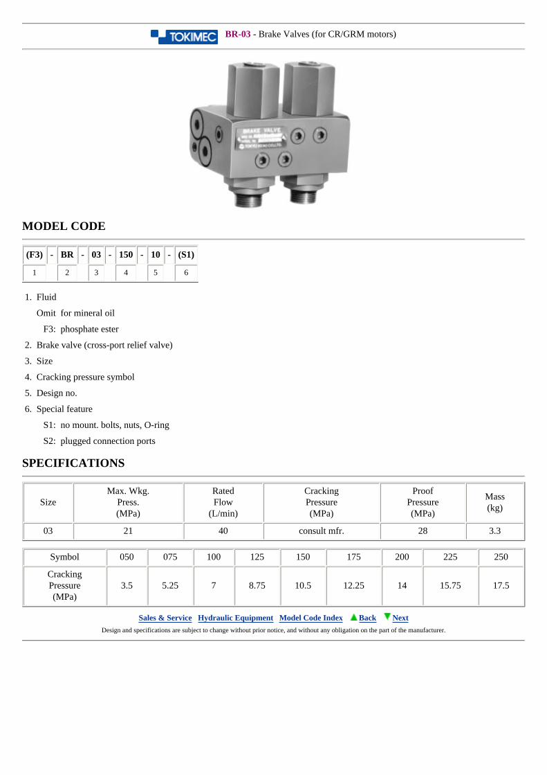
BR-03 - Brake Valves (for CR/GRM motors)
MODEL CODE
(F3) - BR - 03 - 150 - 10 - (S1)
1 2 3 4 5 6
1. Fluid
Omit for mineral oil
F3: phosphate ester
2. Brake valve (cross-port relief valve)
3. Size
4. Cracking pressure symbol
5. Design no.
6. Special feature
S1: no mount. bolts, nuts, O-ring
S2: plugged connection ports
SPECIFICATIONS
SizeMax. Wkg.
Press.(MPa)
RatedFlow
(L/min)
CrackingPressure(MPa)
ProofPressure(MPa)
Mass(kg)
03 21 40 consult mfr. 28 3.3
Symbol 050 075 100 125 150 175 200 225 250
CrackingPressure(MPa)
3.5 5.25 7 8.75 10.5 12.25 14 15.75 17.5
Sales & Service Hydraulic Equipment Model Code Index Back Next Design and specifications are subject to change without prior notice, and without any obligation on the part of the manufacturer.
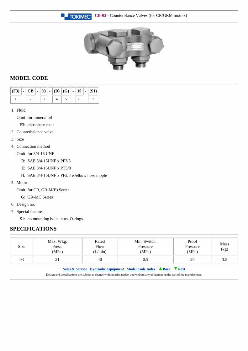
CB-03 - Counterblance Valves (for CR/GRM motors)
MODEL CODE
(F3) - CB - 03 - (B) (G) - 10 - (S1)
1 2 3 4 5 6 7
1. Fluid
Omit for mineral oil
F3: phosphate ester
2. Counterbalance valve
3. Size
4. Connection method
Omit for 3/4-16 UNF
B: SAE 3/4-16UNF x PF3/8
E: SAE 3/4-16UNF x PT3/8
H: SAE 3/4-16UNF x PF3/8 w/elbow hose nipple
5. Motor
Omit for CR, GR-M(E) Series
G: GR-MC Series
6. Design no.
7. Special feature
S1: no mounting bolts, nuts, O-rings
SPECIFICATIONS
SizeMax. Wkg.
Press.(MPa)
RatedFlow
(L/min)
Min. Switch.Pressure(MPa)
ProofPressure(MPa)
Mass(kg)
03 21 40 0.5 28 3.5
Sales & Service Hydraulic Equipment Model Code Index Back Next Design and specifications are subject to change without prior notice, and without any obligation on the part of the manufacturer.
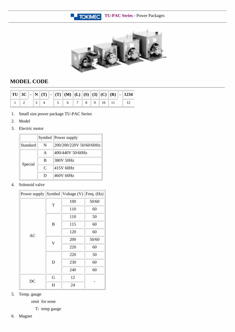
TU-PAC Series - Power Packages
MODEL CODE
TU 3C - N (T) - (T) (M) (L) (S) (3) (C) (R) - 1234
1 2 3 4 5 6 7 8 9 10 11 12
1. Small size power package TU-PAC Series
2. Model
3. Electric motor
Symbol Power supply
Standard N 200/200/220V 50/60/60Hz
Special
A 400/440V 50/60Hz
B 380V 50Hz
C 415V 60Hz
D 460V 60Hz
4. Solenoid valve
Power supply Symbol Voltage (V) Freq. (Hz)
AC
T100 50/60
110 60
B
110 50
115 60
120 60
V200 50/60
220 60
D
220 50
230 60
240 60
DCG 12
-H 24
5. Temp. gauge
omit for none
T: temp gauge
6. Magnet
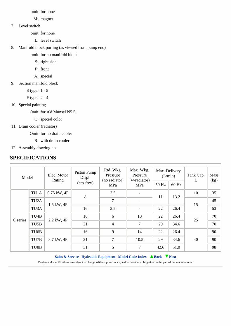
omit for none
M: magnet
7. Level switch
omit for none
L: level switch
8. Manifold block porting (as viewed from pump end)
omit for no manifold block
S: right side
F: front
A: special
9. Section manifold block
S type: 1 - 5
F type: 2 - 4
10. Special painting
Omit for st'd Munsel N5.5
C: special color
11. Drain cooler (radiator)
Omit for no drain cooler
R: with drain cooler
12. Assembly drawing no.
SPECIFICATIONS
ModelElec. Motor
Rating
Piston PumpDispl.
(cm3/rev)
Rtd. Wkg.Pressure
(no radiator)MPa
Max. Wkg.Pressure
(w/radiator)MPa
Max. Delivery(L/min) Tank Cap.
LMass(kg)
50 Hz 60 Hz
C series
TU1A 0.75 kW, 4P8
3.5 -11 13.2
10 35
TU2A1.5 kW, 4P
7 -15
45
TU3A 16 3.5 - 22 26.4 53
TU4B2.2 kW, 4P
16 6 10 22 26.425
70
TU5B 21 4 7 29 34.6 70
TU6B
3.7 kW, 4P
16 9 14 22 26.4
40
90
TU7B 21 7 10.5 29 34.6 90
TU8B 31 5 7 42.6 51.0 98
Sales & Service Hydraulic Equipment Model Code Index Back Next Design and specifications are subject to change without prior notice, and without any obligation on the part of the manufacturer.
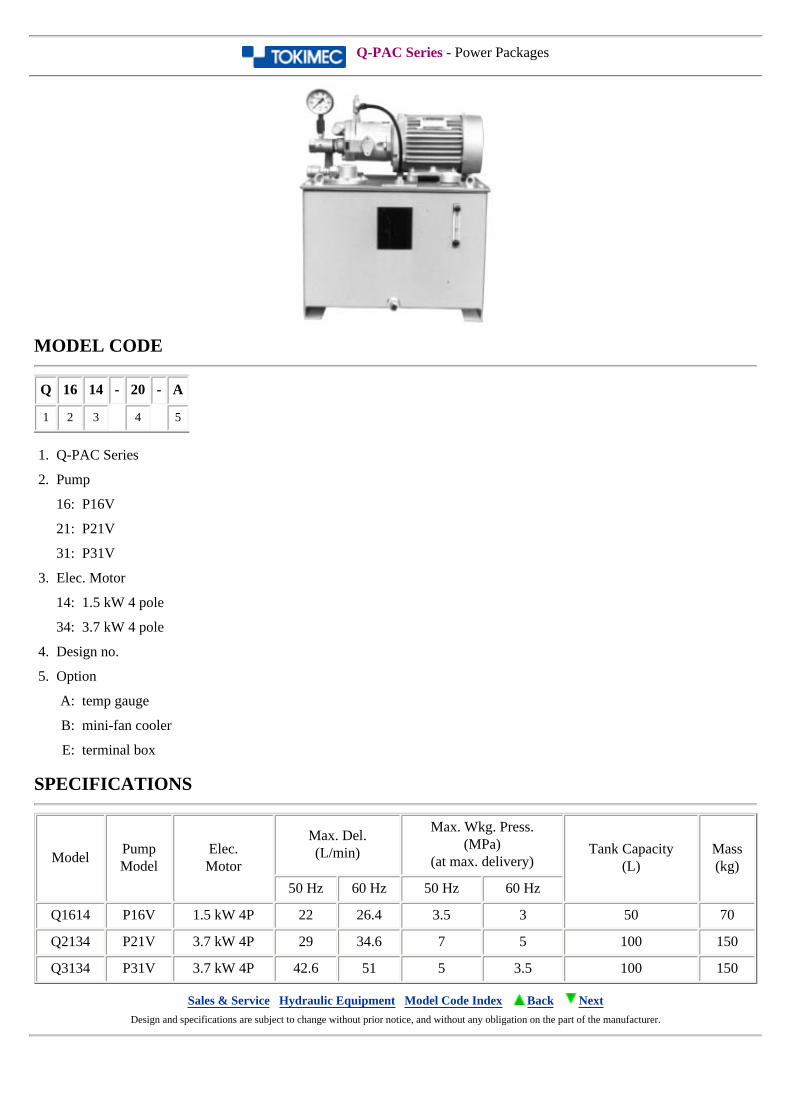
Q-PAC Series - Power Packages
MODEL CODE
Q 16 14 - 20 - A
1 2 3 4 5
1. Q-PAC Series
2. Pump
16: P16V
21: P21V
31: P31V
3. Elec. Motor
14: 1.5 kW 4 pole
34: 3.7 kW 4 pole
4. Design no.
5. Option
A: temp gauge
B: mini-fan cooler
E: terminal box
SPECIFICATIONS
ModelPumpModel
Elec.Motor
Max. Del.(L/min)
Max. Wkg. Press.(MPa)
(at max. delivery)Tank Capacity
(L)Mass(kg)
50 Hz 60 Hz 50 Hz 60 Hz
Q1614 P16V 1.5 kW 4P 22 26.4 3.5 3 50 70
Q2134 P21V 3.7 kW 4P 29 34.6 7 5 100 150
Q3134 P31V 3.7 kW 4P 42.6 51 5 3.5 100 150
Sales & Service Hydraulic Equipment Model Code Index Back Next Design and specifications are subject to change without prior notice, and without any obligation on the part of the manufacturer.
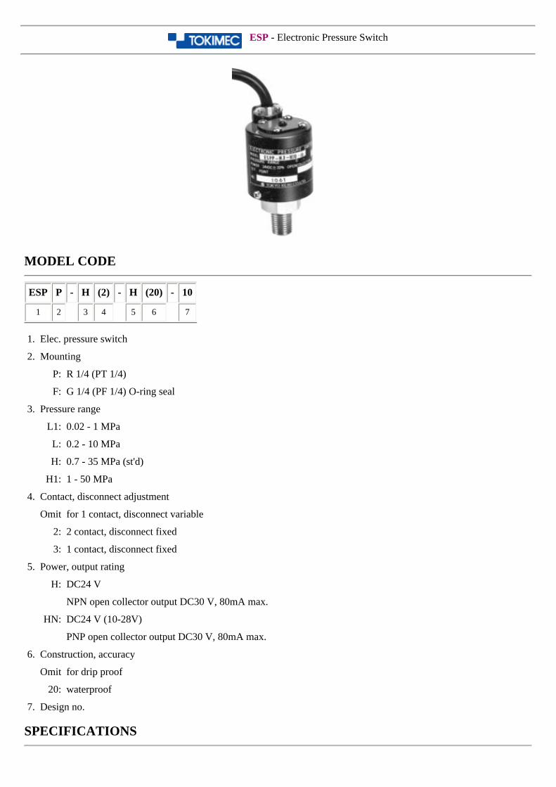
ESP - Electronic Pressure Switch
MODEL CODE
ESP P - H (2) - H (20) - 10
1 2 3 4 5 6 7
1. Elec. pressure switch
2. Mounting
P: R 1/4 (PT 1/4)
F: G 1/4 (PF 1/4) O-ring seal
3. Pressure range
L1: 0.02 - 1 MPa
L: 0.2 - 10 MPa
H: 0.7 - 35 MPa (st'd)
H1: 1 - 50 MPa
4. Contact, disconnect adjustment
Omit for 1 contact, disconnect variable
2: 2 contact, disconnect fixed
3: 1 contact, disconnect fixed
5. Power, output rating
H: DC24 V
NPN open collector output DC30 V, 80mA max.
HN: DC24 V (10-28V)
PNP open collector output DC30 V, 80mA max.
6. Construction, accuracy
Omit for drip proof
20: waterproof
7. Design no.
SPECIFICATIONS
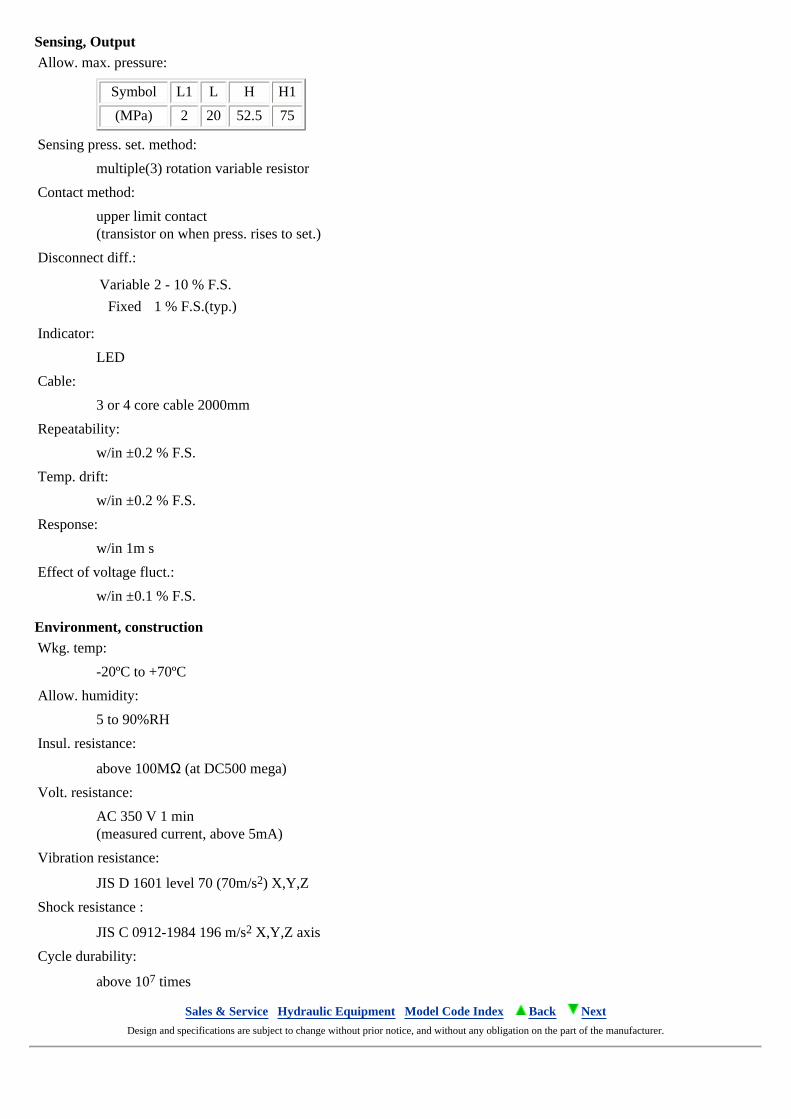
Sensing, OutputAllow. max. pressure:
Symbol L1 L H H1
(MPa) 2 20 52.5 75
Sensing press. set. method:
multiple(3) rotation variable resistor
Contact method:
upper limit contact(transistor on when press. rises to set.)
Disconnect diff.:
Variable 2 - 10 % F.S.
Fixed 1 % F.S.(typ.)
Indicator:
LED
Cable:
3 or 4 core cable 2000mm
Repeatability:
w/in ±0.2 % F.S.
Temp. drift:
w/in ±0.2 % F.S.
Response:
w/in 1m s
Effect of voltage fluct.:
w/in ±0.1 % F.S.
Environment, constructionWkg. temp:
-20ºC to +70ºC
Allow. humidity:
5 to 90%RH
Insul. resistance:
above 100MΩ (at DC500 mega)
Volt. resistance:
AC 350 V 1 min(measured current, above 5mA)
Vibration resistance:
JIS D 1601 level 70 (70m/s2) X,Y,Z
Shock resistance :
JIS C 0912-1984 196 m/s2 X,Y,Z axis
Cycle durability:
above 107 times
Sales & Service Hydraulic Equipment Model Code Index Back Next Design and specifications are subject to change without prior notice, and without any obligation on the part of the manufacturer.
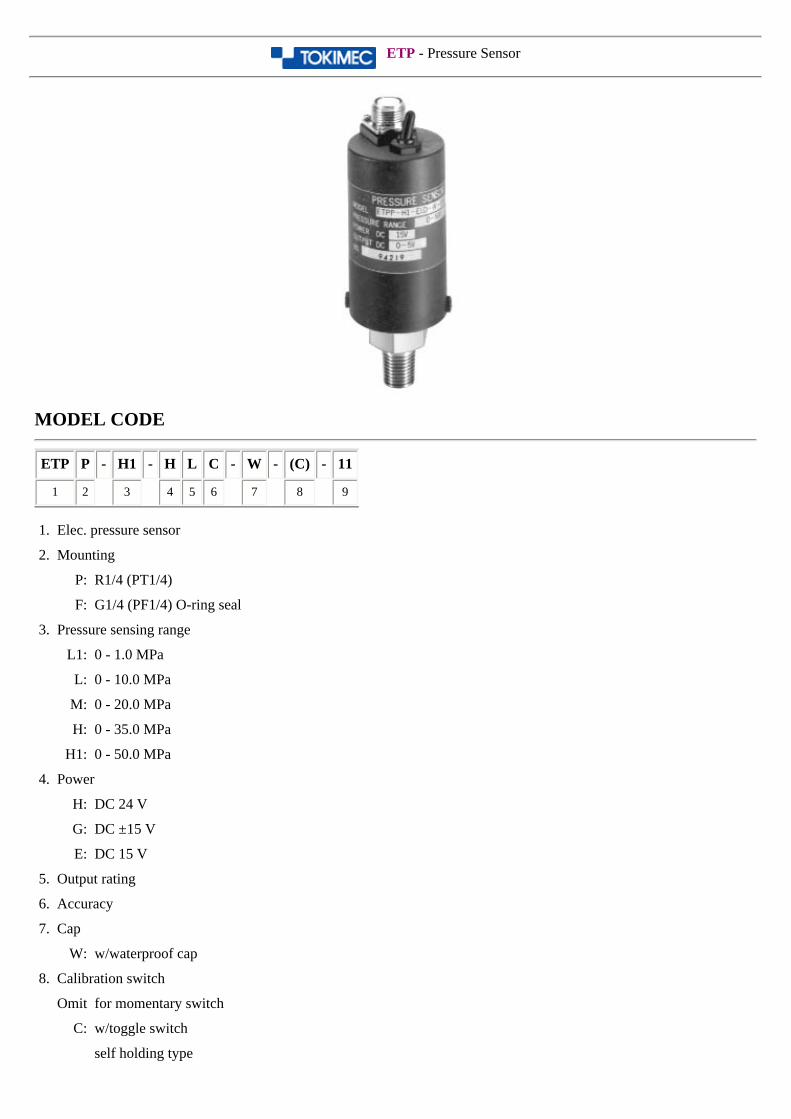
ETP - Pressure Sensor
MODEL CODE
ETP P - H1 - H L C - W - (C) - 11
1 2 3 4 5 6 7 8 9
1. Elec. pressure sensor
2. Mounting
P: R1/4 (PT1/4)
F: G1/4 (PF1/4) O-ring seal
3. Pressure sensing range
L1: 0 - 1.0 MPa
L: 0 - 10.0 MPa
M: 0 - 20.0 MPa
H: 0 - 35.0 MPa
H1: 0 - 50.0 MPa
4. Power
H: DC 24 V
G: DC ±15 V
E: DC 15 V
5. Output rating
6. Accuracy
7. Cap
W: w/waterproof cap
8. Calibration switch
Omit for momentary switch
C: w/toggle switch
self holding type
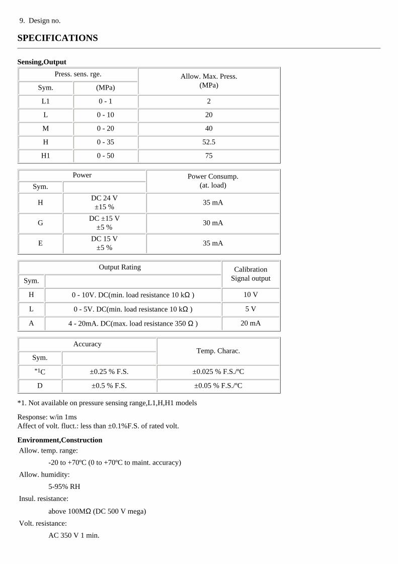
9. Design no.
SPECIFICATIONS
Sensing,Output
Press. sens. rge. Allow. Max. Press.(MPa)Sym. (MPa)
L1 0 - 1 2
L 0 - 10 20
M 0 - 20 40
H 0 - 35 52.5
H1 0 - 50 75
Power Power Consump.(at. load)Sym.
HDC 24 V±15 %
35 mA
GDC ±15 V
±5 %30 mA
EDC 15 V
±5 %35 mA
Output Rating CalibrationSignal outputSym.
H 0 - 10V. DC(min. load resistance 10 kΩ ) 10 V
L 0 - 5V. DC(min. load resistance 10 kΩ ) 5 V
A 4 - 20mA. DC(max. load resistance 350 Ω ) 20 mA
AccuracyTemp. Charac.
Sym.
*1C ±0.25 % F.S. ±0.025 % F.S./ºC
D ±0.5 % F.S. ±0.05 % F.S./ºC
*1. Not available on pressure sensing range,L1,H,H1 models
Response: w/in 1msAffect of volt. fluct.: less than ±0.1%F.S. of rated volt.
Environment,Construction
Allow. temp. range:
-20 to +70ºC (0 to +70ºC to maint. accuracy)
Allow. humidity:
5-95% RH
Insul. resistance:
above 100MΩ (DC 500 V mega)
Volt. resistance:
AC 350 V 1 min.
Vibration resistance:
JISD 1601 level 70 (70m/s2) X,Y,Z axis 4H
Shock resistance:
JIS C 0921-1984 196m/s2 X, Y, Z axis
Cycle durability:
more than 107 times
Water resistance:
splash proof (JIS C 0920)
Contact mat'l:
SUS 630 or SUS 316
Mass
320 g
Sales & Service Hydraulic Equipment Model Code Index Back Next Design and specifications are subject to change without prior notice, and without any obligation on the part of the manufacturer.
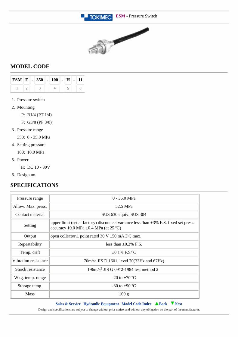
ESM - Pressure Switch
MODEL CODE
ESM F - 350 - 100 - H - 11
1 2 3 4 5 6
1. Pressure switch
2. Mounting
P: R1/4 (PT 1/4)
F: G3/8 (PF 3/8)
3. Pressure range
350: 0 - 35.0 MPa
4. Setting pressure
100: 10.0 MPa
5. Power
H: DC 10 - 30V
6. Design no.
SPECIFICATIONS
Pressure range 0 - 35.0 MPa
Allow. Max. press. 52.5 MPa
Contact material SUS 630 equiv. SUS 304
Settingupper limit (set at factory) disconnect variance less than ±3% F.S. fixed set press. accuracy 10.0 MPa ±0.4 MPa (at 25 ºC)
Output open collector,1 point rated 30 V 150 mA DC max.
Repeatability less than ±0.2% F.S.
Temp. drift ±0.1% F.S/ºC
Vibration resistance 70m/s2 JIS D 1601, level 70(33Hz and 67Hz)
Shock resistance 196m/s2 JIS G 0912-1984 test method 2
Wkg. temp. range -20 to +70 ºC
Storage temp. -30 to +90 ºC
Mass 100 g
Sales & Service Hydraulic Equipment Model Code Index Back Next Design and specifications are subject to change without prior notice, and without any obligation on the part of the manufacturer.
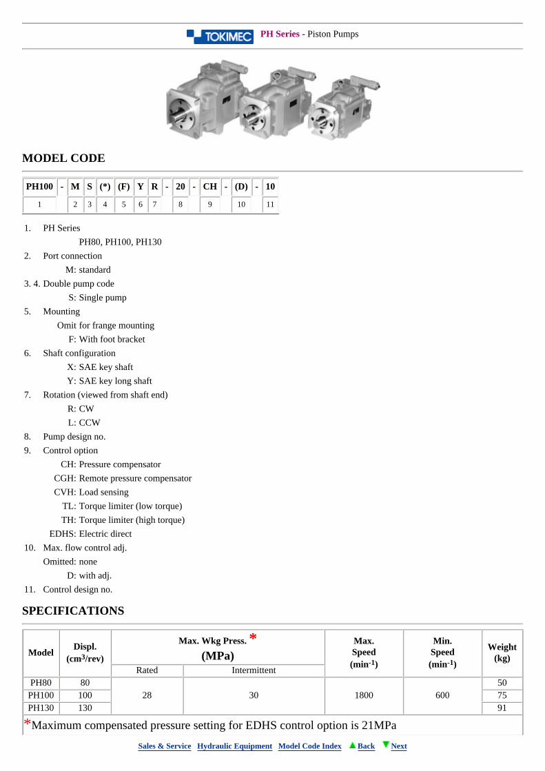
PH Series - Piston Pumps
MODEL CODE
PH100 - M S (*) (F) Y R - 20 - CH - (D) - 10
1 2 3 4 5 6 7 8 9 10 11
1. PH Series
PH80, PH100, PH130
2. Port connection
M: standard
3. 4. Double pump code
S: Single pump
5. Mounting
Omit for frange mounting
F: With foot bracket
6. Shaft configuration
X: SAE key shaft
Y: SAE key long shaft
7. Rotation (viewed from shaft end)
R: CW
L: CCW
8. Pump design no.
9. Control option
CH: Pressure compensator
CGH: Remote pressure compensator
CVH: Load sensing
TL: Torque limiter (low torque)
TH: Torque limiter (high torque)
EDHS: Electric direct
10. Max. flow control adj.
Omitted: none
D: with adj.
11. Control design no.
SPECIFICATIONS
Model Displ.
(cm3/rev)
Max. Wkg Press. *(MPa)
Max.Speed(min-1)
Min.Speed(min-1)
Weight(kg)
Rated IntermittentPH80 80
28 30 1800 60050
PH100 100 75PH130 130 91
*Maximum compensated pressure setting for EDHS control option is 21MPa
Sales & Service Hydraulic Equipment Model Code Index Back Next
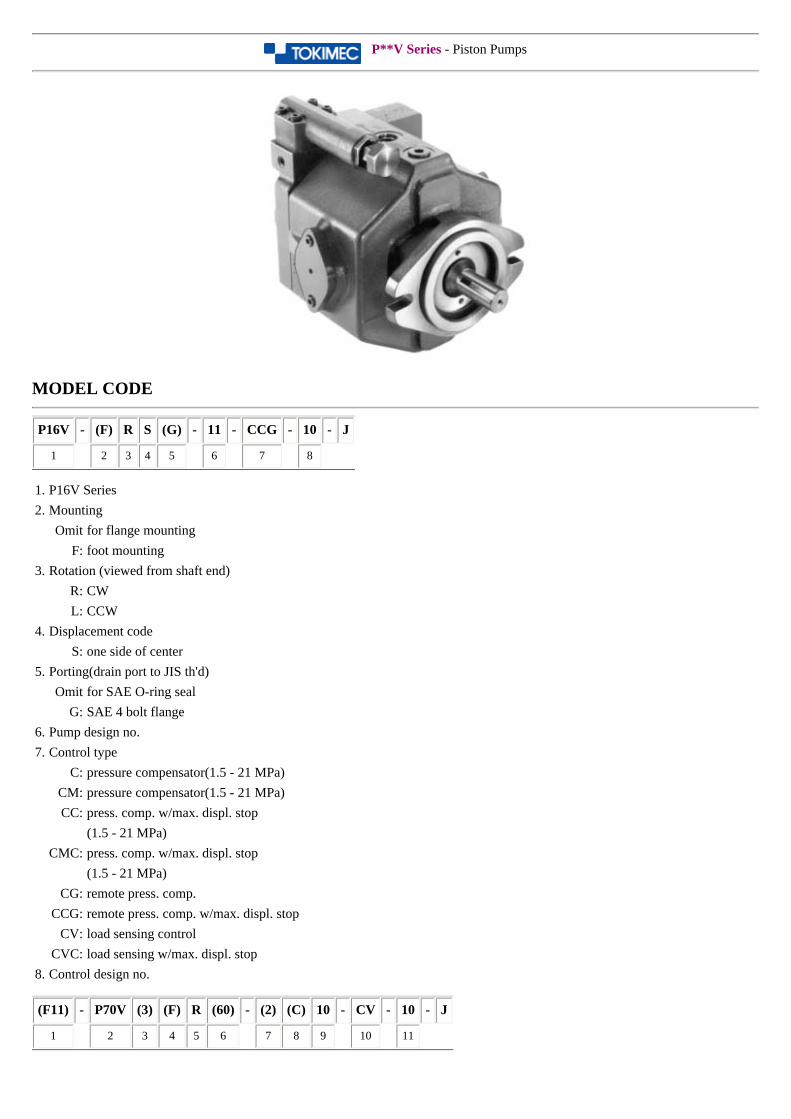
P**V Series - Piston Pumps
MODEL CODE
P16V - (F) R S (G) - 11 - CCG - 10 - J
1 2 3 4 5 6 7 8
1. P16V Series
2. Mounting
Omit for flange mounting
F: foot mounting
3. Rotation (viewed from shaft end)
R: CW
L: CCW
4. Displacement code
S: one side of center
5. Porting(drain port to JIS th'd)
Omit for SAE O-ring seal
G: SAE 4 bolt flange
6. Pump design no.
7. Control type
C: pressure compensator(1.5 - 21 MPa)
CM: pressure compensator(1.5 - 21 MPa)
CC: press. comp. w/max. displ. stop
(1.5 - 21 MPa)
CMC: press. comp. w/max. displ. stop
(1.5 - 21 MPa)
CG: remote press. comp.
CCG: remote press. comp. w/max. displ. stop
CV: load sensing control
CVC: load sensing w/max. displ. stop
8. Control design no.
(F11) - P70V (3) (F) R (60) - (2) (C) 10 - CV - 10 - J
1 2 3 4 5 6 7 8 9 10 11
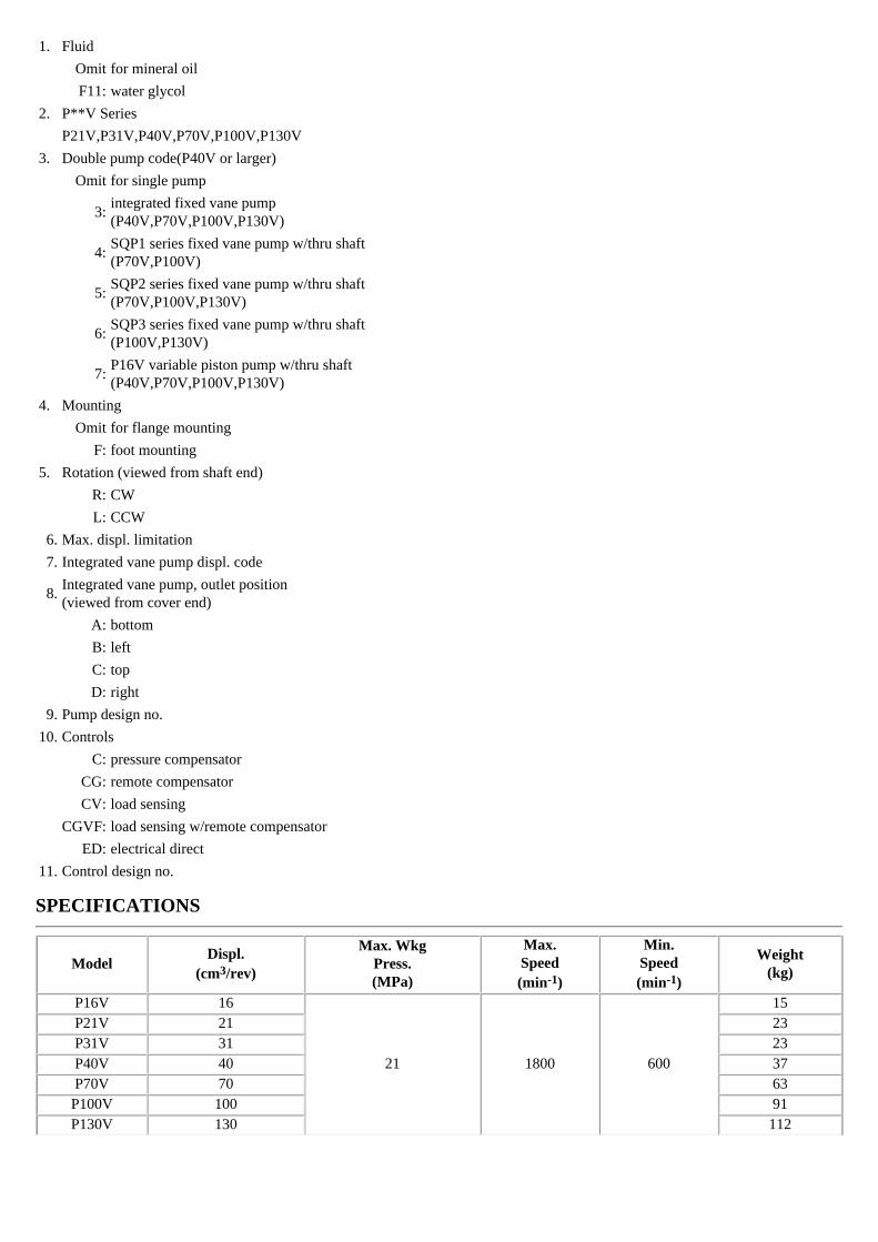
1. Fluid
Omit for mineral oil
F11: water glycol
2. P**V Series
P21V,P31V,P40V,P70V,P100V,P130V
3. Double pump code(P40V or larger)
Omit for single pump
3:integrated fixed vane pump(P40V,P70V,P100V,P130V)
4:SQP1 series fixed vane pump w/thru shaft(P70V,P100V)
5:SQP2 series fixed vane pump w/thru shaft(P70V,P100V,P130V)
6:SQP3 series fixed vane pump w/thru shaft(P100V,P130V)
7:P16V variable piston pump w/thru shaft(P40V,P70V,P100V,P130V)
4. Mounting
Omit for flange mounting
F: foot mounting
5. Rotation (viewed from shaft end)
R: CW
L: CCW
6. Max. displ. limitation
7. Integrated vane pump displ. code
8.Integrated vane pump, outlet position(viewed from cover end)
A: bottom
B: left
C: top
D: right
9. Pump design no.
10. Controls
C: pressure compensator
CG: remote compensator
CV: load sensing
CGVF: load sensing w/remote compensator
ED: electrical direct
11. Control design no.
SPECIFICATIONS
Model Displ.
(cm3/rev)
Max. WkgPress.(MPa)
Max.Speed(min-1)
Min.Speed(min-1)
Weight(kg)
P16V 16
21 1800 600
15P21V 21 23P31V 31 23P40V 40 37P70V 70 63P100V 100 91P130V 130 112
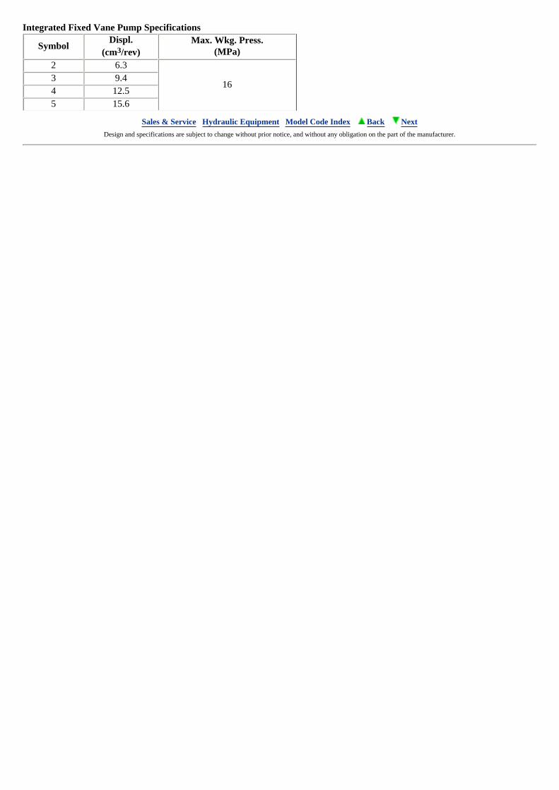
Integrated Fixed Vane Pump Specifications
SymbolDispl.
(cm3/rev)Max. Wkg. Press.
(MPa)2 6.3
163 9.44 12.55 15.6
Sales & Service Hydraulic Equipment Model Code Index Back Next Design and specifications are subject to change without prior notice, and without any obligation on the part of the manufacturer.
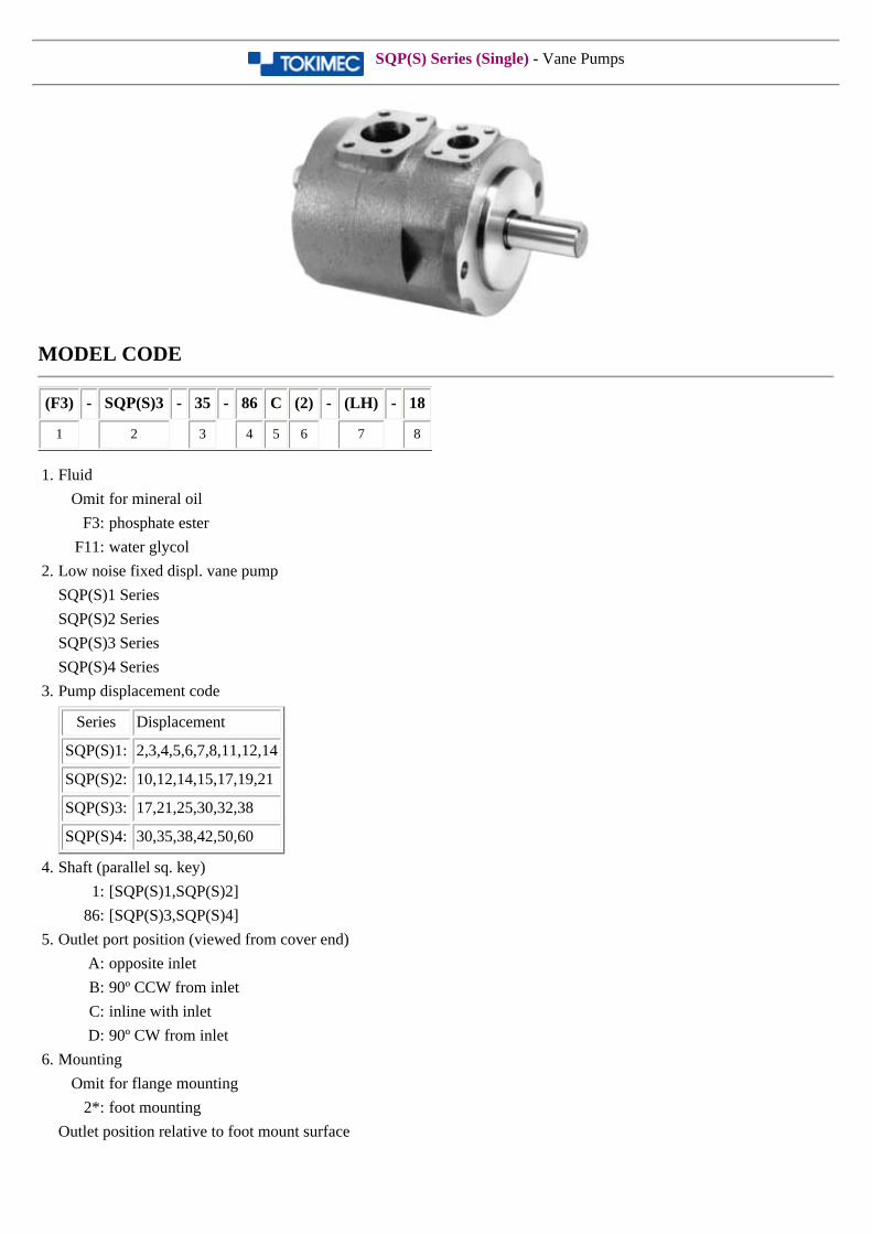
SQP(S) Series (Single) - Vane Pumps
MODEL CODE
(F3) - SQP(S)3 - 35 - 86 C (2) - (LH) - 18
1 2 3 4 5 6 7 8
1. Fluid
Omit for mineral oil
F3: phosphate ester
F11: water glycol
2. Low noise fixed displ. vane pump
SQP(S)1 Series
SQP(S)2 Series
SQP(S)3 Series
SQP(S)4 Series
3. Pump displacement code
Series Displacement
SQP(S)1: 2,3,4,5,6,7,8,11,12,14
SQP(S)2: 10,12,14,15,17,19,21
SQP(S)3: 17,21,25,30,32,38
SQP(S)4: 30,35,38,42,50,60
4. Shaft (parallel sq. key)
1: [SQP(S)1,SQP(S)2]
86: [SQP(S)3,SQP(S)4]
5. Outlet port position (viewed from cover end)
A: opposite inlet
B: 90º CCW from inlet
C: inline with inlet
D: 90º CW from inlet
6. Mounting
Omit for flange mounting
2*: foot mounting
Outlet position relative to foot mount surface
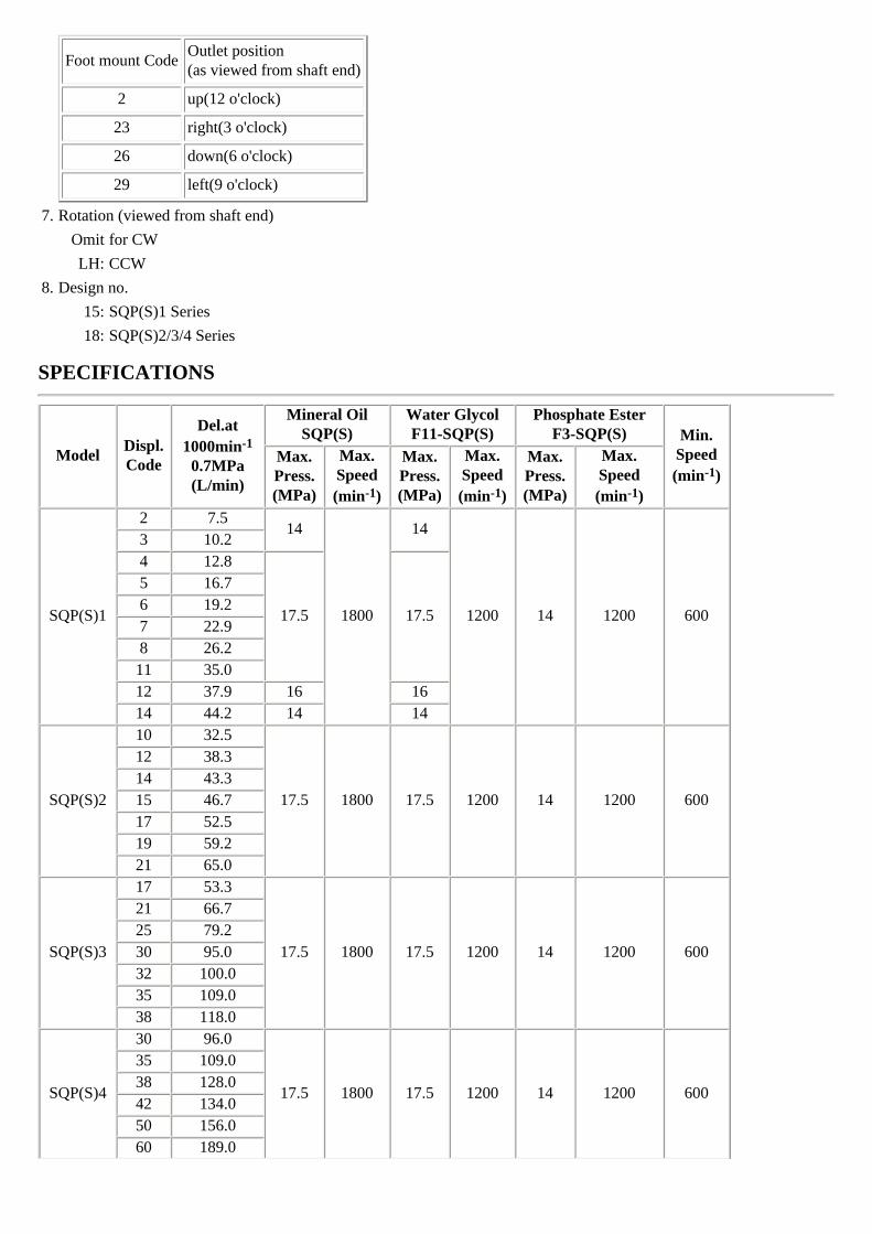
Foot mount CodeOutlet position(as viewed from shaft end)
2 up(12 o'clock)
23 right(3 o'clock)
26 down(6 o'clock)
29 left(9 o'clock)
7. Rotation (viewed from shaft end)
Omit for CW
LH: CCW
8. Design no.
15: SQP(S)1 Series
18: SQP(S)2/3/4 Series
SPECIFICATIONS
Model Displ.Code
Del.at1000min-1
0.7MPa(L/min)
Mineral OilSQP(S)
Water GlycolF11-SQP(S)
Phosphate EsterF3-SQP(S) Min.
Speed(min-1)
Max.Press.(MPa)
Max.Speed(min-1)
Max.Press.(MPa)
Max.Speed(min-1)
Max.Press.(MPa)
Max.Speed(min-1)
SQP(S)1
2 7.514
1800
14
1200 14 1200 600
3 10.24 12.8
17.5 17.5
5 16.76 19.27 22.98 26.211 35.012 37.9 16 1614 44.2 14 14
SQP(S)2
10 32.5
17.5 1800 17.5 1200 14 1200 600
12 38.314 43.315 46.717 52.519 59.221 65.0
SQP(S)3
17 53.3
17.5 1800 17.5 1200 14 1200 600
21 66.725 79.230 95.032 100.035 109.038 118.0
SQP(S)4
30 96.0
17.5 1800 17.5 1200 14 1200 600
35 109.038 128.042 134.050 156.060 189.0

MASS (kg)
ModelSQP SQPS
Flange mounting Foot mounting Flange mounting Foot mountingSQP(S)1 16 19 18.5 21.5SQP(S)2 25 34.5 29.5 39SQP(S)3 35 44.5 43 52.5SQP(S)4 59.5 84.5 71 96
Sales & Service Hydraulic Equipment Model Code Index Back Next Design and specifications are subject to change without prior notice, and without any obligation on the part of the manufacturer.
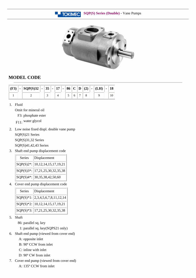
SQP(S) Series (Double) - Vane Pumps
MODEL CODE
(F3) - SQP(S)32 - 35 - 17 - 86 C D (2) - (LH) - 18
1 2 3 4 5 6 7 8 9 10
1. Fluid
Omit for mineral oil
F3: phosphate ester
F11: water glycol
2. Low noise fixed displ. double vane pump
SQP(S)21 Series
SQP(S)31,32 Series
SQP(S)41,42,43 Series
3. Shaft end pump displacement code
Series Displacement
SQP(S)2*: 10,12,14,15,17,19,21
SQP(S)3*: 17,21,25,30,32,35,38
SQP(S)4*: 30,35,38,42,50,60
4. Cover end pump displacement code
Series Displacement
SQP(S)*1: 2,3,4,5,6,7,8,11,12,14
SQP(S)*2: 10,12,14,15,17,19,21
SQP(S)*3: 17,21,25,30,32,35,38
5. Shaft
86: parallel sq. key
1: parallel sq. key(SQPS21 only)
6. Shaft end pump (viewed from cover end)
A: opposite inlet
B: 90º CCW from inlet
C: inline with inlet
D: 90º CW from inlet
7. Cover end pump (viewed from cover end)
A: 135º CCW from inlet
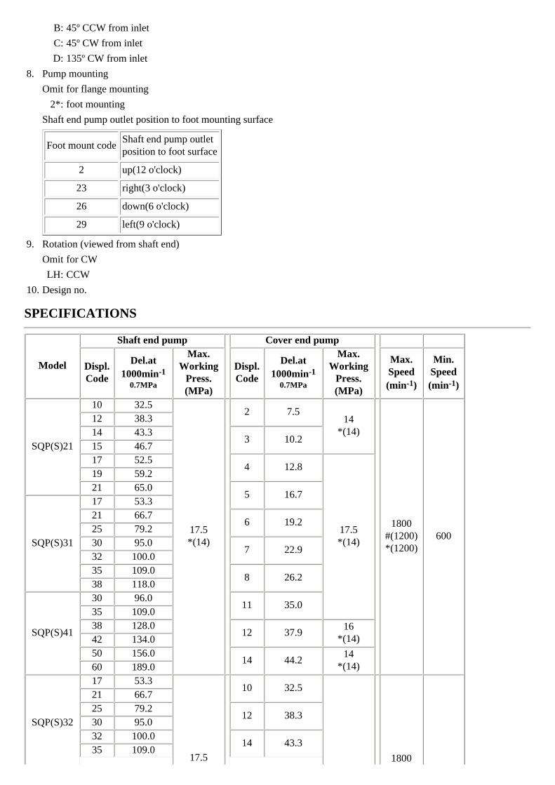
B: 45º CCW from inlet
C: 45º CW from inlet
D: 135º CW from inlet
8. Pump mounting
Omit for flange mounting
2*: foot mounting
Shaft end pump outlet position to foot mounting surface
Foot mount codeShaft end pump outletposition to foot surface
2 up(12 o'clock)
23 right(3 o'clock)
26 down(6 o'clock)
29 left(9 o'clock)
9. Rotation (viewed from shaft end)
Omit for CW
LH: CCW
10. Design no.
SPECIFICATIONS
Model
Shaft end pump
Cover end pump
Displ.Code
Del.at1000min-1
0.7MPa
Max.Working
Press.(MPa)
Displ.Code
Del.at1000min-1
0.7MPa
Max.Working
Press.(MPa)
Max.Speed(min-1)
Min.Speed(min-1)
SQP(S)21
10 32.5
17.5*(14)
2 7.514
*(14)
1800
#(1200)*(1200)
600
12 38.314 43.3
3 10.215 46.717 52.5
4 12.8
17.5*(14)
19 59.221 65.0
5 16.7
SQP(S)31
17 53.321 66.7
6 19.225 79.230 95.0
7 22.932 100.035 109.0
8 26.238 118.0
SQP(S)41
30 96.011 35.0
35 109.038 128.0
12 37.916
*(14)42 134.050 156.0
14 44.214
*(14)60 189.0
SQP(S)32
17 53.3
17.5
10 32.5
1800
21 66.725 79.2
12 38.330 95.032 100.0
14 43.335 109.0
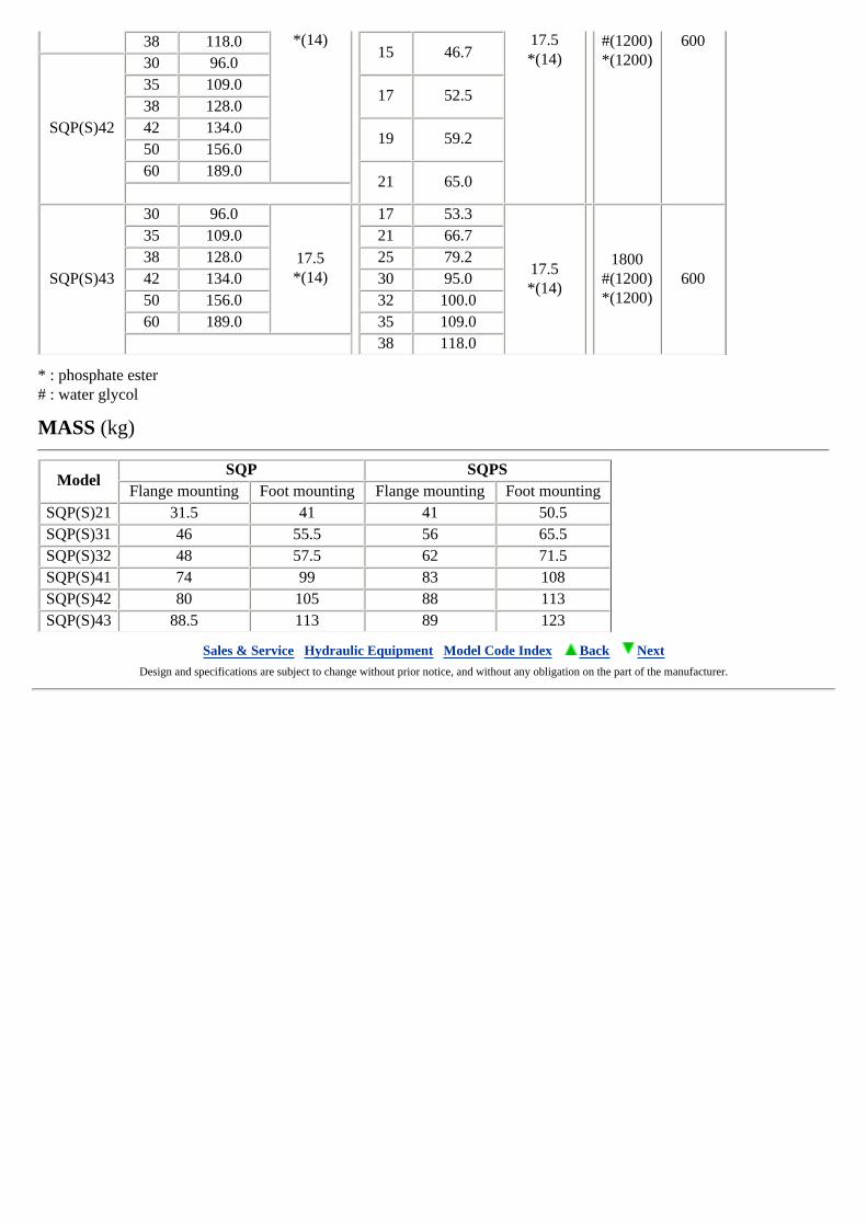
*(14) 17.5*(14)
#(1200)*(1200)
60038 118.015 46.7
SQP(S)42
30 96.035 109.0
17 52.538 128.042 134.0
19 59.250 156.060 189.0
21 65.0
SQP(S)43
30 96.0
17.5*(14)
17 53.3
17.5*(14)
1800
#(1200)*(1200)
600
35 109.0 21 66.738 128.0 25 79.242 134.0 30 95.050 156.0 32 100.060 189.0 35 109.0
38 118.0
* : phosphate ester# : water glycol
MASS (kg)
ModelSQP SQPS
Flange mounting Foot mounting Flange mounting Foot mountingSQP(S)21 31.5 41 41 50.5SQP(S)31 46 55.5 56 65.5SQP(S)32 48 57.5 62 71.5SQP(S)41 74 99 83 108SQP(S)42 80 105 88 113SQP(S)43 88.5 113 89 123
Sales & Service Hydraulic Equipment Model Code Index Back Next Design and specifications are subject to change without prior notice, and without any obligation on the part of the manufacturer.
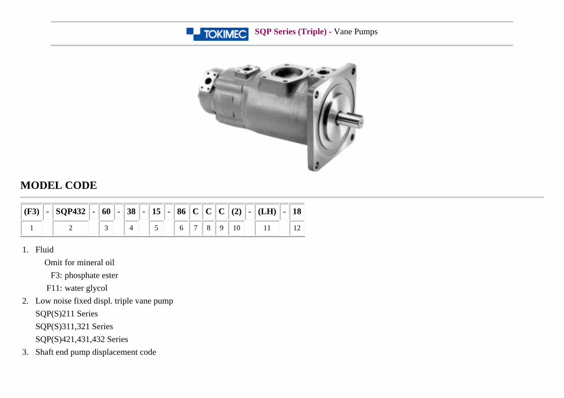
SQP Series (Triple) - Vane Pumps
MODEL CODE
(F3) - SQP432 - 60 - 38 - 15 - 86 C C C (2) - (LH) - 18
1 2 3 4 5 6 7 8 9 10 11 12
1. Fluid
Omit for mineral oil
F3: phosphate ester
F11: water glycol
2. Low noise fixed displ. triple vane pump
SQP(S)211 Series
SQP(S)311,321 Series
SQP(S)421,431,432 Series
3. Shaft end pump displacement code
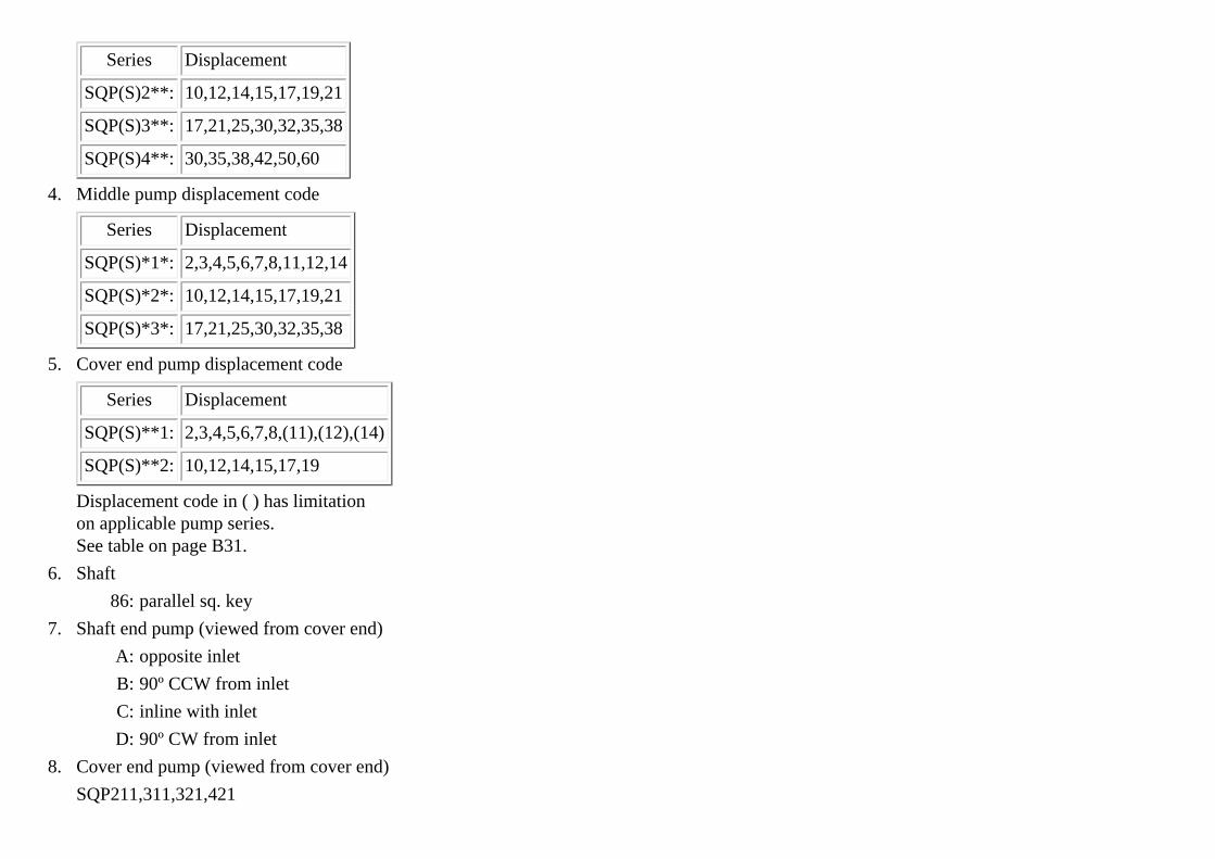
Series Displacement
SQP(S)2**: 10,12,14,15,17,19,21
SQP(S)3**: 17,21,25,30,32,35,38
SQP(S)4**: 30,35,38,42,50,60
4. Middle pump displacement code
Series Displacement
SQP(S)*1*: 2,3,4,5,6,7,8,11,12,14
SQP(S)*2*: 10,12,14,15,17,19,21
SQP(S)*3*: 17,21,25,30,32,35,38
5. Cover end pump displacement code
Series Displacement
SQP(S)**1: 2,3,4,5,6,7,8,(11),(12),(14)
SQP(S)**2: 10,12,14,15,17,19
Displacement code in ( ) has limitationon applicable pump series.See table on page B31.
6. Shaft
86: parallel sq. key
7. Shaft end pump (viewed from cover end)
A: opposite inlet
B: 90º CCW from inlet
C: inline with inlet
D: 90º CW from inlet
8. Cover end pump (viewed from cover end)
SQP211,311,321,421
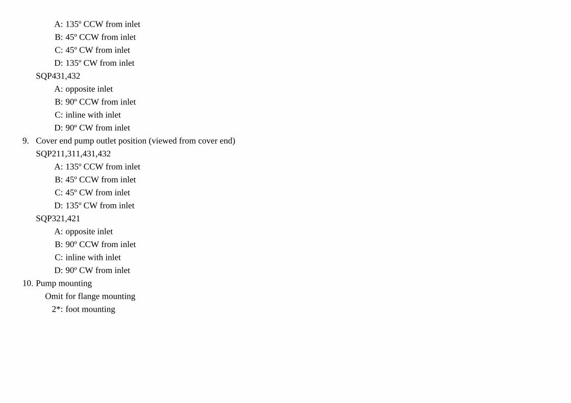
A: 135º CCW from inlet
B: 45º CCW from inlet
C: 45º CW from inlet
D: 135º CW from inlet
SQP431,432
A: opposite inlet
B: 90º CCW from inlet
C: inline with inlet
D: 90º CW from inlet
9. Cover end pump outlet position (viewed from cover end)
SQP211,311,431,432
A: 135º CCW from inlet
B: 45º CCW from inlet
C: 45º CW from inlet
D: 135º CW from inlet
SQP321,421
A: opposite inlet
B: 90º CCW from inlet
C: inline with inlet
D: 90º CW from inlet
10. Pump mounting
Omit for flange mounting
2*: foot mounting
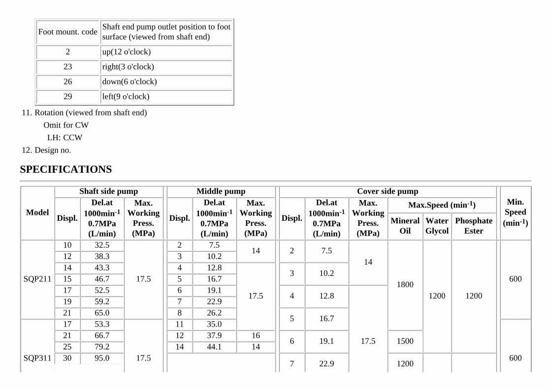
Foot mount. codeShaft end pump outlet position to footsurface (viewed from shaft end)
2 up(12 o'clock)
23 right(3 o'clock)
26 down(6 o'clock)
29 left(9 o'clock)
11. Rotation (viewed from shaft end)
Omit for CW
LH: CCW
12. Design no.
SPECIFICATIONS
Model
Shaft side pump
Middle pump
Cover side pump
Min.
Speed(min-1)
Displ.
Del.at1000min-1
0.7MPa(L/min)
Max.Working
Press.(MPa)
Displ.
Del.at1000min-1
0.7MPa(L/min)
Max.Working
Press.(MPa)
Displ.
Del.at1000min-1
0.7MPa(L/min)
Max.Working
Press.(MPa)
Max.Speed (min-1)
MineralOil
WaterGlycol
PhosphateEster
SQP211
10 32.5
17.5
2 7.514
2 7.514
18001200 1200
600
12 38.3 3 10.214 43.3 4 12.8
17.5
3 10.215 46.7 5 16.717 52.5 6 19.1
4 12.8
17.5
19 59.2 7 22.921 65.0 8 26.2
5 16.7
SQP311
17 53.3
17.5
11 35.0
600
21 66.7 12 37.9 166 19.1 1500
25 79.2 14 44.1 1430 95.0
7 22.9 1200
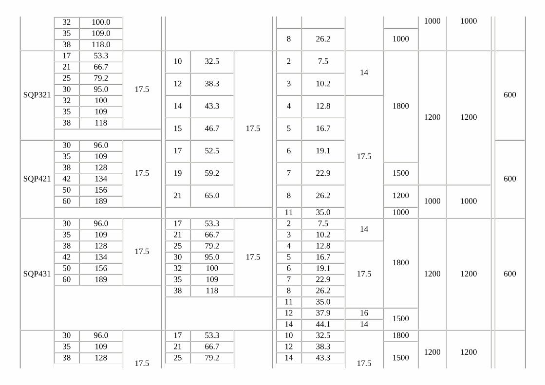
1000 100032 100.035 109.0
8 26.2 100038 118.0
SQP321
17 53.3
17.5
10 32.5
17.5
2 7.514
18001200 1200
600
21 66.725 79.2
12 38.3 3 10.230 95.032 100
14 43.3 4 12.8
17.5
35 10938 118
15 46.7 5 16.7
SQP421
30 96.0
17.5
17 52.5 6 19.1
600
35 10938 128
19 59.2 7 22.9 150042 13450 156
21 65.0 8 26.2 12001000 100060 189
11 35.0 1000
SQP431
30 96.0
17.5
17 53.3
17.5
2 7.514
18001200 1200 600
35 109 21 66.7 3 10.238 128 25 79.2 4 12.8
17.5
42 134 30 95.0 5 16.750 156 32 100 6 19.160 189 35 109 7 22.9
38 118 8 26.2
11 35.012 37.9 16
150014 44.1 14
30 96.0
17.5
17 53.3 10 32.5
17.5
1800
1200 120035 109 21 66.7 12 38.3
150038 128 25 79.2 14 43.3
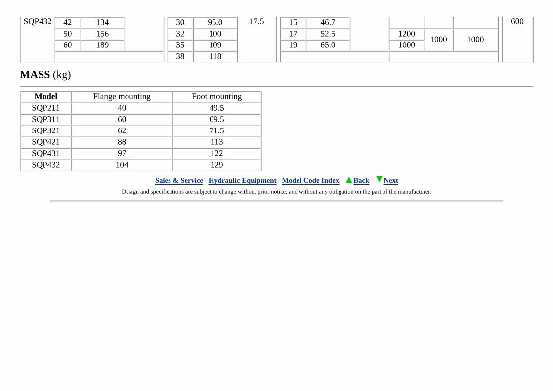
SQP432 17.5 60042 134 30 95.0 15 46.750 156 32 100 17 52.5 1200
1000 100060 189 35 109 19 65.0 1000
38 118
MASS (kg)
Model Flange mounting Foot mountingSQP211 40 49.5SQP311 60 69.5SQP321 62 71.5SQP421 88 113SQP431 97 122SQP432 104 129
Sales & Service Hydraulic Equipment Model Code Index Back Next Design and specifications are subject to change without prior notice, and without any obligation on the part of the manufacturer.
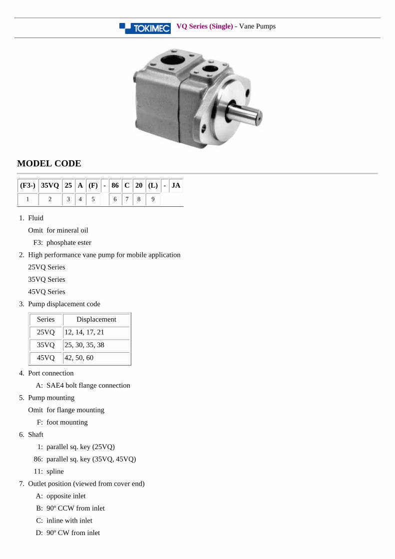
VQ Series (Single) - Vane Pumps
MODEL CODE
(F3-) 35VQ 25 A (F) - 86 C 20 (L) - JA
1 2 3 4 5 6 7 8 9
1. Fluid
Omit for mineral oil
F3: phosphate ester
2. High performance vane pump for mobile application
25VQ Series
35VQ Series
45VQ Series
3. Pump displacement code
Series Displacement
25VQ 12, 14, 17, 21
35VQ 25, 30, 35, 38
45VQ 42, 50, 60
4. Port connection
A: SAE4 bolt flange connection
5. Pump mounting
Omit for flange mounting
F: foot mounting
6. Shaft
1: parallel sq. key (25VQ)
86: parallel sq. key (35VQ, 45VQ)
11: spline
7. Outlet position (viewed from cover end)
A: opposite inlet
B: 90º CCW from inlet
C: inline with inlet
D: 90º CW from inlet
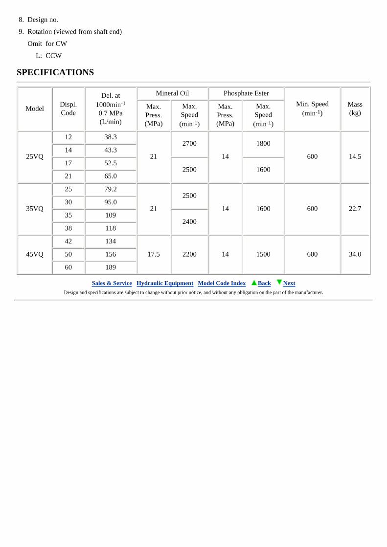
8. Design no.
9. Rotation (viewed from shaft end)
Omit for CW
L: CCW
SPECIFICATIONS
ModelDispl.Code
Del. at1000min-1
0.7 MPa(L/min)
Mineral Oil Phosphate Ester
Min. Speed(min-1)
Mass(kg)
Max.Press.(MPa)
Max.Speed(min-1)
Max.Press.(MPa)
Max.Speed(min-1)
25VQ
12 38.3
21
2700
14
1800
600 14.514 43.3
17 52.52500 1600
21 65.0
35VQ
25 79.2
21
2500
14 1600 600 22.730 95.0
35 1092400
38 118
45VQ
42 134
17.5 2200 14 1500 600 34.050 156
60 189
Sales & Service Hydraulic Equipment Model Code Index Back Next Design and specifications are subject to change without prior notice, and without any obligation on the part of the manufacturer.
Directional Valves -Phased out models-
The following models have been discontinued and are no longer in production. Most of these products are interchangeable with and/or have been superceded by models listed above. Please contact TOKIMEC regarding any questions you may have on these products.
DG4V-3- *** -10-JA-S310 Series solenoid valves(this model has functional and product level interchangeability with and is superceded by model DG4V-3-***-52)
4SL-3 Series solenoid valves DG4L Series solenoid valves DG4S-4 Series solenoid valves
Sales & Service Hydraulic Equipment Model Code Index Back
Design and specifications are subject to change without prior notice, and without any obligation on the part of the manufacturer.
Proportional Valves -Phased out models-
The following models have been discontinued and are no longer in production. Most of these products are interchangeable with and/or have been superceded by models listed above. Please contact TOKIMEC regarding any questions you may have on these products.
DEF(R)G Series proportional valves TCGE Series proportional valves TFGT Series proportional valves FCGT-02 Series proportional valves DE-X Series controllers EC-X Series controllers EC-4S Series controllers
Sales & Service Hydraulic Equipment Model Code Index Back
Design and specifications are subject to change without prior notice, and without any obligation on the part of the manufacturer.
Pumps -Discontinued models-
The following models have been discontinued and are no longer in production. Most of these products are interchangeable with and/or have been superceded by models listed above. Please contact TOKIMEC regarding any questions you may have on these products.
VVJ50/80/125 Series variable vane pump PVB(Q) Series variable piston pump
Sales & Service Hydraulic Equipment Model Code Index Back
Design and specifications are subject to change without prior notice, and without any obligation on the part of the manufacturer.
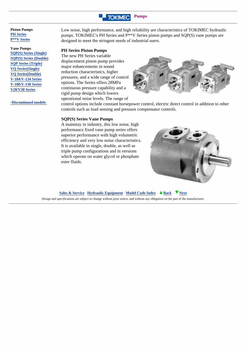
Pumps
Piston PumpsPH SeriesP**V Series
Vane PumpsSQP(S) Series (Single)SQP(S) Series (Double)SQP Series (Triple)VQ Series(Single)VQ Series(Double)V-104/V-134 SeriesV-108/V-138 SeriesV20/V30 Series
-Discontinued models-
Low noise, high performance, and high reliability are characteristics of TOKIMEC hydraulic pumps. TOKIMEC's PH Series and P**V Series piston pumps and SQP(S) vane pumps are designed to meet the stringent needs of industrial users.
PH Series Piston Pumps The new PH Series variable displacement piston pump provides major enhancements in sound reduction characteristics, higher pressures, and a wide range of control options. The Series offers 28MPa continuous pressure capability and a rigid pump design which lowers operational noise levels. The range of control options include constant horsepower control, electric direct control in addition to other controls such as load sensing and pressure compensator controls.
SQP(S) Series Vane Pumps A mainstay in industry, this low noise, high performance fixed vane pump series offers superior performance with high volumetric efficiency and very low noise characteristics. It is available in single, double, as well as triple pump configurations and in versions which operate on water glycol or phosphate ester fluids.
Sales & Service Hydraulic Equipment Model Code Index Back Next Design and specifications are subject to change without prior notice, and without any obligation on the part of the manufacturer.
Pressure Control Valves
Relief ValvesTCG20 SeriesTCG50--80 SeriesCG/CT/CF Series
Remote Control Relief ValvesC-175CGR-02DGMCR-3 Series
Unloading Relief ValvesURG Series
Low Pressure Control ValvesCGL Series
Shockless ValvesDGMSL-3
Pressure Control ValvesRG(2)-3FR(C)G/R(C)T/RF Series
Pressure Reducing ValvesXG1-3FX(C)G/X(C)T Series
Balancer ValvesBLG Series
Sales & Service Hydraulic Equipment Model Code Index Back Next Design and specifications are subject to change without prior notice, and without any obligation on the part of the manufacturer.
Flow Control Valves
Restrictors
FN(1)G SeriesFN(1) SeriesTFN(C)G Series
Pressure-Temperature Compensated Flow Control Valves
LFCG SeriesF(C)G Series
Deceleration Valves
DG15S2/DT15S2 Series
Sales & Service Hydraulic Equipment Model Code Index Back Next Design and specifications are subject to change without prior notice, and without any obligation on the part of the
manufacturer.
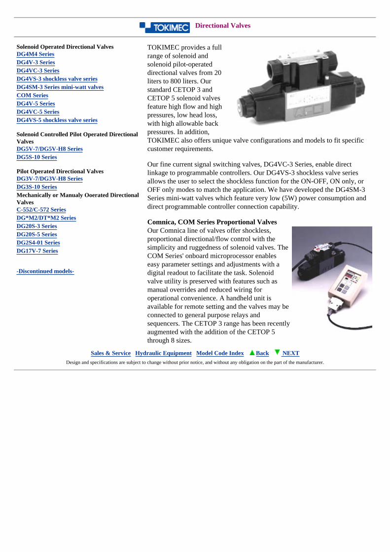
Directional Valves
Solenoid Operated Directional ValvesDG4M4 SeriesDG4V-3 SeriesDG4VC-3 SeriesDG4VS-3 shockless valve seriesDG4SM-3 Series mini-watt valvesCOM SeriesDG4V-5 SeriesDG4VC-5 SeriesDG4VS-5 shockless valve series
Solenoid Controlled Pilot Operated Directional ValvesDG5V-7/DG5V-H8 SeriesDG5S-10 Series
Pilot Operated Directional ValvesDG3V-7/DG3V-H8 SeriesDG3S-10 SeriesMechanically or Manualy Ooerated Directional ValvesC-552/C-572 SeriesDG*M2/DT*M2 SeriesDG20S-3 SeriesDG20S-5 SeriesDG2S4-01 SeriesDG17V-7 Series
-Discontinued models-
TOKIMEC provides a full range of solenoid and solenoid pilot-operated directional valves from 20 liters to 800 liters. Our standard CETOP 3 and CETOP 5 solenoid valves feature high flow and high pressures, low head loss, with high allowable back pressures. In addition, TOKIMEC also offers unique valve configurations and models to fit specific customer requirements.
Our fine current signal switching valves, DG4VC-3 Series, enable direct linkage to programmable controllers. Our DG4VS-3 shockless valve series allows the user to select the shockless function for the ON-OFF, ON only, or OFF only modes to match the application. We have developed the DG4SM-3 Series mini-watt valves which feature very low (5W) power consumption and direct programmable controller connection capability.
Comnica, COM Series Proportional Valves Our Comnica line of valves offer shockless, proportional directional/flow control with the simplicity and ruggedness of solenoid valves. The COM Series' onboard microprocessor enables easy parameter settings and adjustments with a digital readout to facilitate the task. Solenoid valve utility is preserved with features such as manual overrides and reduced wiring for operational convenience. A handheld unit is available for remote setting and the valves may be connected to general purpose relays and sequencers. The CETOP 3 range has been recently augmented with the addition of the CETOP 5 through 8 sizes.
Sales & Service Hydraulic Equipment Model Code Index Back NEXT Design and specifications are subject to change without prior notice, and without any obligation on the part of the manufacturer.
Check Valves
Check ValvesDT8P1 SeriesC2-8** SeriesC2G/C5G SeriesDF10P1 Series
Pilot Operated Check Valves4CG/4CT SeriesTHPCG SeriesC2PG/C5PG Series
Shuttle ValvesCVSH Series
Check Valve ModulesURMC Series
Sales & Service Hydraulic Equipment Model Code Index Back Next Design and specifications are subject to change without prior notice, and without any obligation on the part of the manufacturer.

Cartridge Valves
Cartridge InsertCVI Series
Cartridge CoverCVC Series
Sales & Service Hydraulic Equipment Model Code Index Back Next Design and specifications are subject to change without prior notice, and without any obligation on the part of the manufacturer.
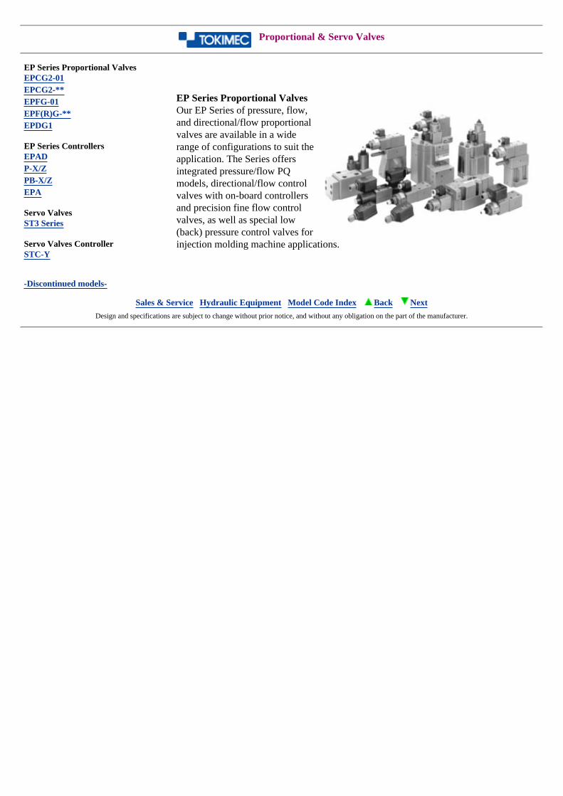
Proportional & Servo Valves
EP Series Proportional ValvesEPCG2-01EPCG2-**EPFG-01EPF(R)G-**EPDG1
EP Series ControllersEPADP-X/ZPB-X/ZEPA
Servo ValvesST3 Series
Servo Valves ControllerSTC-Y
-Discontinued models-
EP Series Proportional Valves Our EP Series of pressure, flow, and directional/flow proportional valves are available in a wide range of configurations to suit the application. The Series offers integrated pressure/flow PQ models, directional/flow control valves with on-board controllers and precision fine flow control valves, as well as special low (back) pressure control valves for injection molding machine applications.
Sales & Service Hydraulic Equipment Model Code Index Back Next Design and specifications are subject to change without prior notice, and without any obligation on the part of the manufacturer.
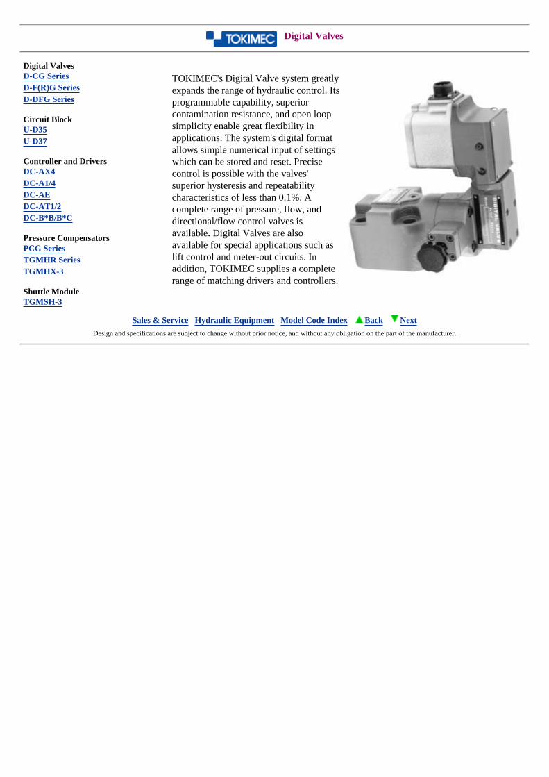
Digital Valves
Digital ValvesD-CG SeriesD-F(R)G SeriesD-DFG Series
Circuit BlockU-D35U-D37
Controller and DriversDC-AX4DC-A1/4DC-AEDC-AT1/2DC-B*B/B*C
Pressure CompensatorsPCG SeriesTGMHR SeriesTGMHX-3
Shuttle ModuleTGMSH-3
TOKIMEC's Digital Valve system greatly expands the range of hydraulic control. Its programmable capability, superior contamination resistance, and open loop simplicity enable great flexibility in applications. The system's digital format allows simple numerical input of settings which can be stored and reset. Precise control is possible with the valves' superior hysteresis and repeatability characteristics of less than 0.1%. A complete range of pressure, flow, and directional/flow control valves is available. Digital Valves are also available for special applications such as lift control and meter-out circuits. In addition, TOKIMEC supplies a complete range of matching drivers and controllers.
Sales & Service Hydraulic Equipment Model Code Index Back Next Design and specifications are subject to change without prior notice, and without any obligation on the part of the manufacturer.
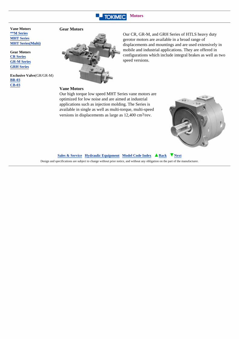
Motors
Vane Motors**M SeriesMHT SeriesMHT Series(Multi)
Gear MotorsCR SeriesGR-M SeriesGRH Series
Exclusive Valve(GR/GR-M)BR-03CB-03
Gear Motors Our CR, GR-M, and GRH Series of HTLS heavy duty gerotor motors are available in a broad range of displacements and mountings and are used extensively in mobile and industrial applications. They are offered in configurations which include integral brakes as well as two speed versions.
Vane Motors Our high torque low speed MHT Series vane motors are optimized for low noise and are aimed at industrial applications such as injection molding. The Series is available in single as well as multi-torque, multi-speed versions in displacements as large as 12,400 cm3/rev.
Sales & Service Hydraulic Equipment Model Code Index Back Next Design and specifications are subject to change without prior notice, and without any obligation on the part of the manufacturer.

Power Packages
Standard Power PackagesTU-PAC SeriesQ-PAC Series
Standard Power Packages TOKIMEC's TU-PAC and Q-PAC Series of standard power units are designed to meet the needs of users in the stationary market. The unique design of the TU-PAC Series maximizes heat transference and aeration in a low profile, space-saving package. A direct pump-mount manifold block option enables configuration of hydraulic
circuits to meet specific customer requirements in a space-saving, piping-reduced design. The TU-PAC Series is offered in ten basic models with tank capacities of 10 to 60 liters. Our Q-PAC Series of power packages with direct-coupled piston pumps is offered in tank capacities up to 100 liters.
Sales & Service Hydraulic Equipment Model Code Index Back Next Design and specifications are subject to change without prior notice, and without any obligation on the part of the manufacturer.
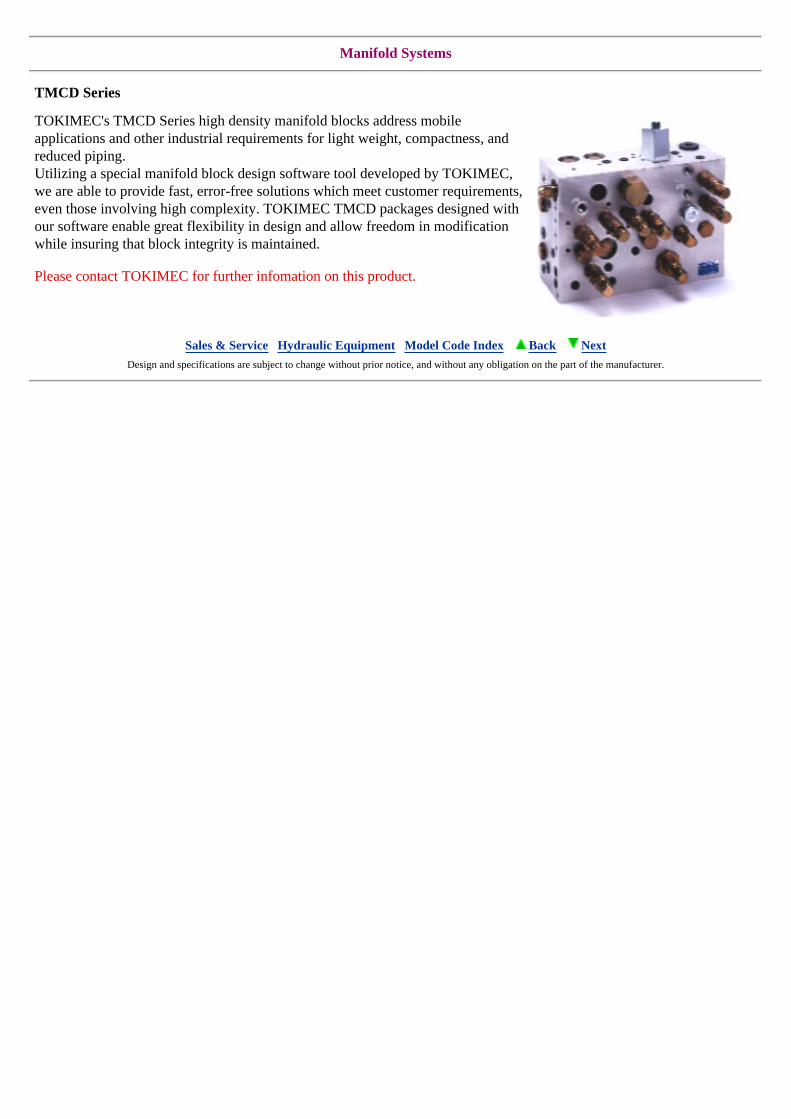
Manifold Systems
TMCD Series
TOKIMEC's TMCD Series high density manifold blocks address mobile applications and other industrial requirements for light weight, compactness, and reduced piping. Utilizing a special manifold block design software tool developed by TOKIMEC, we are able to provide fast, error-free solutions which meet customer requirements, even those involving high complexity. TOKIMEC TMCD packages designed with our software enable great flexibility in design and allow freedom in modification while insuring that block integrity is maintained.
Please contact TOKIMEC for further infomation on this product.
Sales & Service Hydraulic Equipment Model Code Index Back Next Design and specifications are subject to change without prior notice, and without any obligation on the part of the manufacturer.
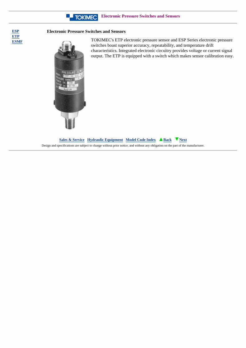
Electronic Pressure Switches and Sensors
ESPETPESMF
Electronic Pressure Switches and Sensors
TOKIMEC's ETP electronic pressure sensor and ESP Series electronic pressure switches boast superior accuracy, repeatability, and temperature drift characteristics. Integrated electronic circuitry provides voltage or current signal output. The ETP is equipped with a switch which makes sensor calibration easy.
Sales & Service Hydraulic Equipment Model Code Index Back Next Design and specifications are subject to change without prior notice, and without any obligation on the part of the manufacturer.

CAUTION
This digest of TOKIMEC hydraulic components is intended to serve as a guide and a source of basic information. However; it does not include, for the most part, detailed information on product performance, dimensions, etc., which may be essential in particular applications. ln addition there may exist changes which have occurred since the issuance of this webpage and or inadvertent errors or omissions which may be material. As such it is strongly recommended that TOKIMEC or our authorized representatives be consulted prior to application of the products and for further information on these or other TOKIMEC hydraulic components.
Sales & Service Hydraulic Equipment Back
NOTICE
TOKIMEC INC. complies with UN regulation and the Export Trade Control Order of Japanese Government. Therefore, we will decline the following transactions :
Resale /sales of goods to the countries against which UN has resolved economic sanctions and / or Countries listed in Attachment 4 to the Export Trade Control Order of Japanese Government (i.e. Iran, Iraq, Libya and North Korea).
Resale / sale of goods to military forces (including terrorist groups) as the end user.
Resale / sale of goods for mass destruction weapons (nuclear, biological, and chemical weapons as well as missiles) and for their development.
TOKIMEC INC. [email protected]
Related Documents