High-voltage direct current From Wikipedia, the free encyclope dia Long distance HVDC lines carrying hydroelectricity from Canada's Nelson river to this station where it is converted to AC for use in Winnipeg's local grid A high-voltage , direct current (HVDC) electric power transmission system uses direct current for the bulk transmission of electrical power, in contrast with the more common alternating current systems. For long- distance transmission, HVDC systems may be less expensive and suffer lower electrical losses. For underwater power cables, HVDC avoids the heavy currents required by the cable capacitance. For shorter distances, the higher cost of DC conversion equipment compared to an AC system may still be warranted, due to other benefits of direct current links. HVDC allows power transmission between unsynchronized AC distribution systems, and can increase s ystem stability by preventing cascading failures from propagating from one part of a wider power transmission grid to another. The modern form of HVDC transmission uses technology developed extensively in the 1930s in Sweden at ASEA. Early commercial installations included one in the Soviet Union in 1951 between Moscow and Kashira, and a 10 –20 MW system between Gotland and mainlandSweden in 1954. [1] The longest HVDC link in the world is currently the Xiangjiaba-Shanghai 2,071 km (1,287 mi) 6400 MW link connecting theXiangjiaba Dam to Shanghai , in the People's Republic of China. [2] In 2012, the longest HVDC link will be the Rio Madeira link connecting the Amazonas to the São Paulo area where the length of the DC line is over 2,500 km (1,600 mi). [3]

Welcome message from author
This document is posted to help you gain knowledge. Please leave a comment to let me know what you think about it! Share it to your friends and learn new things together.
Transcript

8/3/2019 Power at Hv Wiki
http://slidepdf.com/reader/full/power-at-hv-wiki 1/17
High-voltage direct currentFrom Wikipedia, the free encyclopedia
Long distance HVDC lines carrying hydroelectricity from Canada's Nelson river to this station where
it is converted to AC for use in Winnipeg's local grid
A high-voltage, direct current (HVDC) electric power transmission system uses direct current for the bulk
transmission of electrical power, in contrast with the more common alternating current systems. For long-
distance transmission, HVDC systems may be less expensive and suffer lower electrical losses.
For underwater power cables, HVDC avoids the heavy currents required by the cable capacitance. For shorter
distances, the higher cost of DC conversion equipment compared to an AC system may still be warranted, due
to other benefits of direct current links. HVDC allows power transmission between unsynchronized AC
distribution systems, and can increase system stability by preventing cascading failures from propagating from
one part of a wider power transmission grid to another.
The modern form of HVDC transmission uses technology developed extensively in the 1930s
in Sweden at ASEA. Early commercial installations included one in the Soviet Union in 1951
between Moscow and Kashira, and a 10 –20 MW system between Gotland and mainlandSweden in 1954.[1]
The
longest HVDC link in the world is currently the Xiangjiaba-Shanghai 2,071 km (1,287 mi) 6400 MW link
connecting theXiangjiaba Dam to Shanghai, in the People's Republic of China.[2]
In 2012, the longest HVDC
link will be the Rio Madeira link connecting theAmazonas to the São Paulo area where the length of the DC line
is over 2,500 km (1,600 mi).[3]

8/3/2019 Power at Hv Wiki
http://slidepdf.com/reader/full/power-at-hv-wiki 2/17
Existing links
Under construction
ProposedMany of these transfer power from renewable sources such as hydro and wind. For names, see also
the annotated version.
Contents
[hide]
1 High voltage transmission
2 History of HVDC transmission
3 Advantages of HVDC over AC transmission
4 Disadvantages
5 Costs of high voltage DC transmission
6 Rectifying and inverting
o 6.1 Components

8/3/2019 Power at Hv Wiki
http://slidepdf.com/reader/full/power-at-hv-wiki 3/17
o 6.2 Rectifying and inverting systems
7 Configurations
o 7.1 Monopole and earth return
o 7.2 Bipolar o 7.3 Back to back
o 7.4 Systems with transmission lines
o 7.5 Tripole: current-modulating control
8 Corona discharge
9 Applications
o 9.1 Overview
o 9.2 AC network interconnections
o 9.3 Renewable electricity superhighways
o 9.4 Voltage Sourced Converters (VSC)
10 See also
11 References
12 External links
[edit]High voltage transmission
High voltage (in either AC or DC electrical power transmission applications) is used for electric power
transmission to reduce the energy lost in the resistance of the wires. For a given quantity of power transmitted
and size of conductor, doubling the voltage will deliver the same power at only half the current. Since the power
lost as heat in the wires is proportional to the square of the current, but does not depend in any major way on
the voltage delivered by the power line, doubling the voltage in a power system reduces the line-loss loss per
unit of electrical power delivered by a factor of 4. Power loss in transmission lines can also be reduced by
reducing resistance, for example by increasing the diameter of the conductor; but larger conductors are heavier
and more expensive.
High voltages cannot easily be used for lighting and motors, and so transmission-level voltages must be
reduced to values compatible with end-use equipment. Transformers are used to change the voltage levelin alternating current (AC) transmission circuits. The competition between the direct current (DC) of Thomas
Edison and the AC of Nikola Tesla and George Westinghouse was known as the War of Currents, with AC
becoming dominant.
Practical manipulation of high power high voltage DC became possible with the development of high power
electronic rectifier devices such as mercury arc valves and, more recently starting in the 1970s, high power

8/3/2019 Power at Hv Wiki
http://slidepdf.com/reader/full/power-at-hv-wiki 4/17
semiconductor devices such as high power thyristors and 21st century high power variants such as integrated
gate-commutated thyristors (IGCTs), MOS controlled thyristors (MCTs) and gate turn-off thyristors (GTOs). A
similar high power transistor device called the insulated-gate bipolar transistors (IGBT) has recently been used
in these applications.[4]
[edit]History of HVDC transmission
Schematic diagram of a Thury HVDC transmission system

8/3/2019 Power at Hv Wiki
http://slidepdf.com/reader/full/power-at-hv-wiki 5/17
HVDC in 1971: this 150 kV mercury arc valve converted AC hydropowervoltage for transmission to
distant cities from Manitoba Hydro generators.
Bipolar system pylons of the Baltic-Cable-HVDC in Sweden
The first long-distance transmission of electric power was demonstrated using direct current in 1882 at
the Miesbach-Munich Power Transmission, but only 2.5 kW was transmitted. An early method of high-voltage
DC transmission was developed by the Swiss engineer René Thury[5]
and his method was put into practice by
1889 in Italy by the Acquedotto De Ferrari-Galliera company. This system used series-connected motor-
generator sets to increase voltage. Each set was insulated from ground and driven by insulated shafts from
a prime mover. The line was operated in constant current mode, with up to 5,000 volts on each machine, some
machines having double commutators to reduce the voltage on each commutator. This system transmitted
630 kW at 14 kV DC over a distance of 120 km.[6][7]
The Moutiers-Lyon system transmitted 8,600 kW of
hydroelectric power a distance of 124 miles, including 6 miles of underground cable. The system used eight
series-connected generators with dual commutators for a total voltage of 150,000 volts between the poles, and
ran from about 1906 until 1936. Fifteen Thury systems were in operation by 1913[8]
Other Thury systems
operating at up to 100 kV DC operated up to the 1930s, but the rotating machinery required high maintenance
and had high energy loss. Various other electromechanical devices were tested during the first half of the 20th
century with little commercial success.[9]
One conversion technique attempted for conversion of direct current from a high transmission voltage to lower
utilization voltage was to charge series-connected batteries, then connect the batteries in parallel to serve
distribution loads.[10]
While at least two commercial installations were tried around the turn of the 20th century,
the technique was not generally useful owing to the limited capacity of batteries, difficulties in switching
between series and parallel connections, and the inherent energy inefficiency of a battery charge/discharge
cycle.
The grid controlled mercury arc valve became available for power transmission during the period 1920 to 1940.
Starting in 1932, General Electric tested mercury-vapor valves and a 12 kV DC transmission line, which also
served to convert 40 Hz generation to serve 60 Hz loads, at Mechanicville, New York. In 1941, a 60 MW, +/-

8/3/2019 Power at Hv Wiki
http://slidepdf.com/reader/full/power-at-hv-wiki 6/17
200 kV, 115 km buried cable link was designed for the city of Berlin using mercury arc valves (Elbe-Project),
but owing to the collapse of the German government in 1945 the project was never completed.[11]
The nominal
justification for the project was that, during wartime, a buried cable would be less conspicuous as a bombing
target. The equipment was moved to the Soviet Union and was put into service there.[12]
Introduction of the fully
static mercury arc valve to commercial service in 1954 marked the beginning of the modern era of HVDC
transmission. A HVDC-connection was constructed byASEA between the mainland of Sweden and the island
Gotland.
Mercury arc valves require an external circuit to force the current to zero and thus turn off the valve. In HVDC
applications, the AC power system itself provides the means of "commutating" the current to another valve in
the converter. Consequently, converters built with mercury arc valves are known as line-commutated
converters (LCC). Line-commutated converters require rotating synchronous machines in the AC systems to
which they are connected, making power transmission into a passive load impossible.
Mercury arc valves were common in systems designed up to 1975, the last mercury arc HVDC system (the
Nelson River Bipole 1) having been put into service in 1976. As of 2011 the Inter-Island HVDC (high voltage
direct current) link between the North and South Islands of New Zealand is the last major operating mercury arc
HVDC not yet replaced with a solid state system (this is being planned for 2012).
Since 1976, new HVDC systems have used only solid-state devices, in most cases thyristor valves. Like
mercury arc valves, thyristors require an external circuit (in HVDC applications, the AC power system itself
does this) to turn them off, and HVDC using thyristor valves is therefore also known as line-commutated
converter (LCC) HVDC and has the same restrictions.
On March 15, 1979, a thyristor based direct current connection between Cabora Bassa and Johannesburg
(1410 km, ±533 kV, 1920 MW) was turned on. Though the electronics were built in 1974 by AEG,
and BBC (Brown Boveri Company) and Siemens were partners in the project, the late turn on was a result of
the civil war.[citation needed ]
According to Sood,[13]
the next 25 years may well be dominated by "force commutated converters" (i.e.,
thyristor or thyristor-like semiconductors with gates that are actively controlled by separate switching circuitry,
for smoother switching response). This era has already begun with "capacitor commutated converters" (CCC),
which are simple thyristor networks with gates operated from an external capacitive circuit, drawn from the AC
line.
Such externally-controlled thyristor-based circuits are expected to eventually be replaced by "self-commutated
converters" based around more complex semiconductor switching devices. These "self-commutating
converters" will finally largely supplant today's externally-commutated systems entirely, after self-commutating
solid-state devices in the required power ranges become economically viable.[13]
Such self-commutated devices
include the insulated gate bipolar transistors (IGBT) and variant thyristors called integrated gate-commutated

8/3/2019 Power at Hv Wiki
http://slidepdf.com/reader/full/power-at-hv-wiki 7/17
thyristors (IGCT), and gate turn-off thyristors (GTO). All these devices are used now in medium power high-
voltage DC systems, and are capable of being scaled-up in power to the point that they (or other similar
variants of multilayer solid-state high-power devices) will probably eventually replace all simple thyristor-based
systems now in use, even for very highest power transmission DC applications.[4]
Since thyristor-based switches (i.e., solid-state rectifiers) were incorporated into them, hundreds of HVDC sea
cables have been laid, and have worked with high reliability, usually better than 96% of the time.
[edit]Advantages of HVDC over AC transmission
The advantage of HVDC is the ability to transmit large amounts of power over long distances with lower capital
costs and with lower losses than AC. Depending on voltage level and construction details, losses are quoted as
about 3% per 1,000 km.[14]
High-voltage direct current transmission allows efficient use of energy sources,
remote from load centers.
In a number of applications HVDC is more effective than AC transmission. Examples include:
Undersea cables, where high capacitance causes additional AC losses. (e.g., 250 km Baltic
Cable between Sweden and Germany,[15]
the 600 km NorNed cable between Norway and the Netherlands,
and 290 km Basslink between the Australian mainland and Tasmania[16]
)
Endpoint-to-endpoint long-haul bulk power transmission without intermediate 'taps', for example, in remote
areas
Increasing the capacity of an existing power grid in situations where additional wires are difficult or
expensive to install
Power transmission and stabilization between unsynchronised AC distribution systems
Connecting a remote generating plant to the distribution grid, for example Nelson River Bipole
Stabilizing a predominantly AC power-grid, without increasing prospective short circuit current
Reducing line cost. HVDC needs fewer conductors as there is no need to support multiple phases. Also,
thinner conductors can be used since HVDC does not suffer from the skin effect
Facilitate power transmission between different countries that use AC at differing voltages and/or
frequencies
Synchronize AC produced by renewable energy sources
Long undersea / underground high voltage cables have a high electrical capacitance, since the conductors are
surrounded by a relatively thin layer of insulation and a metal sheath while the extensive length of the cable
multiplies the area between the conductors. The geometry is that of a long co-axial capacitor. Where
alternating current is used for cable transmission, this capacitance appears in parallel with load. Additional
current must flow in the cable to charge the cable capacitance, which generates additional losses in the

8/3/2019 Power at Hv Wiki
http://slidepdf.com/reader/full/power-at-hv-wiki 8/17
conductors of the cable. Additionally, there is a dielectric loss component in the material of the cable insulation,
which consumes power.
However, when direct current is used, the cable capacitance is charged only when the cable is first energized
or when the voltage is changed; there is no steady-state additional current required. For a long AC undersea
cable, the entire current-carrying capacity of the conductor could be used to supply the charging current alone.
The cable capacitance issue limits the length and power carrying capacity of AC cables. DC cables have no
such limitation, and are essentially bound by only Ohm's Law. Although some DC leakage current continues to
flow through the dielectric insulators, this is very small compared to the cable rating and much less than with
AC transmission cables.
HVDC can carry more power per conductor because, for a given power rating, the constant voltage in a DC line
is the same as the peak voltage in an AC line. The power delivered in an AC system is defined by the root
mean square (RMS) of an AC voltage, but RMS is only about 71% of the peak voltage. The peak voltage of AC
determines the actual insulation thickness and conductor spacing. Because DC operates at a constant
maximum voltage, this allows existing transmission line corridors with equally sized conductors and insulation
to carry more power into an area of high power consumption than AC, which can lower costs.
Because HVDC allows power transmission between unsynchronized AC distribution systems, it can help
increase system stability, by preventing cascading failures from propagating from one part of a wider power
transmission grid to another. Changes in load that would cause portions of an AC network to become
unsynchronized and separate would not similarly affect a DC link, and the power flow through the DC link
would tend to stabilize the AC network. The magnitude and direction of power flow through a DC link can be
directly commanded, and changed as needed to support the AC networks at either end of the DC link. This has
caused many power system operators to contemplate wider use of HVDC technology for its stability benefits
alone.
[edit]Disadvantages
The disadvantages of HVDC are in conversion, switching, control, availability and maintenance.
HVDC is less reliable and has lower availability than alternating current (AC) systems, mainly due to the extra
conversion equipment. Single-pole systems have availability of about 98.5%, with about a third of the downtime
unscheduled due to faults. Fault-tolerant bipole systems provide high availability for 50% of the link capacity,
but availability of the full capacity is about 97% to 98%.[17]
The required static inverters are expensive and have limited overload capacity. At smaller transmission
distances, the losses in the static inverters may be bigger than in an AC transmission line. The cost of the
inverters may not be offset by reductions in line construction cost and lower line loss.

8/3/2019 Power at Hv Wiki
http://slidepdf.com/reader/full/power-at-hv-wiki 9/17
In contrast to AC systems, realizing multiterminal systems is complex, as is expanding existing schemes to
multiterminal systems. Controlling power flow in a multiterminal DC system requires good communication
between all the terminals; power flow must be actively regulated by the inverter control system instead of the
inherent impedance and phase angle properties of the transmission line.[18]
Multi-terminal lines are rare. One is
in operation at the Hydro Québec – New England transmission from Radisson to Sandy Pond.[19] Another
example is the Sardinia-mainland Italy link which was modified in 1989 to also provide power to the island of
Corsica.[20]
HVDC circuit breakers are difficult to build because some mechanism must be included in the circuit breaker to
force current to zero, otherwise arcing and contact wear would be too great to allow reliable switching.
Operating a HVDC scheme requires many spare parts to be kept, often exclusively for one system, as HVDC
systems are less standardized than AC systems and technology changes faster.
[edit]Costs of high voltage DC transmissionNormally manufacturers such as Alstom, Siemens and ABB do not state specific cost information of a particular
project since this is a commercial matter between the manufacturer and the client.
Costs vary widely depending on the specifics of the project such as power rating, circuit length, overhead vs.
underwater route, land costs, and AC network improvements required at either terminal. A detailed evaluation
of DC vs. AC cost may be required where there is no clear technical advantage to DC alone and only
economics drives the selection.
However some practitioners have given out some information that can be reasonably well relied upon:
For an 8 GW 40 km link laid under the English Channel, the following are approximate primary equipment costs
for a 2000 MW 500 kV bipolar conventional HVDC link (exclude way-leaving, on-shore reinforcement works,
consenting, engineering, insurance, etc.)
Converter stations ~£110M
Subsea cable + installation ~£1M/km
So for an 8 GW capacity between England and France in four links, little is left over from £750M for the
installed works. Add another £200 –300M for the other works depending on additional onshore works
required.[21]
An April, 2010 announcement for a 2,000 MW line, 64 km, between Spain and France, is 700 million euros; this
includes the cost of a tunnel through the Pyrenees.[22]
[edit]Rectifying and inverting
[edit]Components
8/3/2019 Power at Hv Wiki
http://slidepdf.com/reader/full/power-at-hv-wiki 10/17
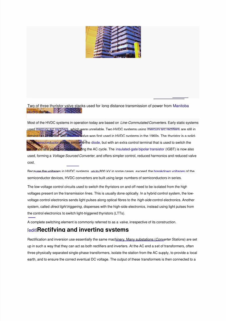
Two of three thyristor valve stacks used for long distance transmission of power from Manitoba
Hydro dams
Most of the HVDC systems in operation today are based on Line-Commutated Converters . Early static systems
used mercury arc rectifiers, which were unreliable. Two HVDC systems using mercury arc rectifiers are still in
service (as of 2008). The thyristor valve was first used in HVDC systems in the 1960s. The thyristor is a solid-
state semiconductor device similar to the diode, but with an extra control terminal that is used to switch the
device on at a particular instant during the AC cycle. The insulated-gate bipolar transistor (IGBT) is now also
used, forming a Voltage Sourced Converter , and offers simpler control, reduced harmonics and reduced valve
cost.
Because the voltages in HVDC systems, up to 800 kV in some cases, exceed the breakdown voltages of the
semiconductor devices, HVDC converters are built using large numbers of semiconductors in series.
The low-voltage control circuits used to switch the thyristors on and off need to be isolated from the high
voltages present on the transmission lines. This is usually done optically. In a hybrid control system, the low-
voltage control electronics sends light pulses along optical fibres to the high-side control electronics. Another
system, called direct light triggering , dispenses with the high-side electronics, instead using light pulses from
the control electronics to switch light-triggered thyristors (LTTs).
A complete switching element is commonly referred to as a valve , irrespective of its construction.
[edit]Rectifying and inverting systems
Rectification and inversion use essentially the same machinery. Many substations (Converter Stations ) are set
up in such a way that they can act as both rectifiers and inverters. At the AC end a set of transformers, often
three physically separated single-phase transformers, isolate the station from the AC supply, to provide a local
earth, and to ensure the correct eventual DC voltage. The output of these transformers is then connected to a

8/3/2019 Power at Hv Wiki
http://slidepdf.com/reader/full/power-at-hv-wiki 11/17
bridge rectifier formed by a number of valves. The basic configuration uses six valves, connecting each of the
three phases to each of the two DC rails. However, with a phase change only every sixty degrees, considerable
harmonics remain on the DC rails.
An enhancement of this configuration uses 12 valves (often known as a twelve-pulse system). The AC is split
into two separate three phase supplies before transformation. One of the sets of supplies is then configured to
have a star (wye) secondary, the other a delta secondary, establishing a thirty degree phase difference
between the two sets of three phases. With twelve valves connecting each of the two sets of three phases to
the two DC rails, there is a phase change every 30 degrees, and harmonics are considerably reduced.
In addition to the conversion transformers and valve-sets, various passive resistive and reactive components
help filter harmonics out of the DC rails.
[edit]Configurations
[edit]Monopole and earth return
Block diagram of a monopole system with earth return
In a common configuration, called monopole, one of the terminals of the rectifier is connected to earth ground.
The other terminal, at a potential high above or below ground, is connected to a transmission line.
The earthed terminal may be connected to the corresponding connection at the inverting station by means of a
second conductor.
If no metallic conductor is installed, current flows in the earth between the earth electrodes at the two stations.
Therefore it is a type of single wire earth return. The issues surrounding earth-return current include:
Electrochemical corrosion of long buried metal objects such as pipelines
Underwater earth-return electrodes in seawater may produce chlorine or otherwise affect water chemistry.
An unbalanced current path may result in a net magnetic field, which can affect
magnetic navigational compasses for ships passing over an underwater cable.
These effects can be eliminated with installation of a metallic return conductor between the two ends of the
monopolar transmission line. Since one terminal of the converters is connected to earth, the return conductor
need not be insulated for the full transmission voltage which makes it less costly than the high-voltage

8/3/2019 Power at Hv Wiki
http://slidepdf.com/reader/full/power-at-hv-wiki 12/17

8/3/2019 Power at Hv Wiki
http://slidepdf.com/reader/full/power-at-hv-wiki 13/17
Bipolar systems may carry as much as 3,200 MW at voltages of +/-600 kV. Submarine cable installations
initially commissioned as a monopole may be upgraded with additional cables and operated as a bipole.
A block diagram of a bipolar HVDC transmission system, between two stations designated A and B.
AC – represents an alternating current network CON – represents a converter valve,
eitherrectifier or inverter, TR represents a powertransformer, DCTL is the direct-current transmission
line conductor, DCL is a direct-current filter inductor, BP represents a bypass switch, and PMrepresent power factor correctionand harmonic filter networks required at both ends of the link. The
DC transmission line may be very short in a back-to-back link, or extend hundreds of miles (km)
overhead, underground or underwater. One conductor of the DC line may be replaced by
connections to earth ground.
A bipolar scheme can be implemented so that the polarity of one or both poles can be changed. This allows the
operation as two parallel monopoles. If one conductor fails, transmission can still continue at reduced capacity.
Losses may increase if ground electrodes and lines are not designed for the extra current in this mode. To
reduce losses in this case, intermediate switching stations may be installed, at which line segments can beswitched off or parallelized. This was done at Inga –Shaba HVDC.
[edit]Back to back
A back-to-back station (or B2B for short) is a plant in which both static inverters and rectifiers are in the same
area, usually in the same building. The length of the direct current line is kept as short as possible. HVDC back-
to-back stations are used for
coupling of electricity mains of different frequency (as in Japan; and the GCC interconnection between
UAE [50 Hz] and Saudi Arabia [60 Hz] under construction in ±2009 –2011)
coupling two networks of the same nominal frequency but no fixed phase relationship (as until 1995/96
in Etzenricht, Dürnrohr, Vienna, and theVyborg HVDC scheme).
different frequency and phase number (for example, as a replacement for traction current converter plants)
The DC voltage in the intermediate circuit can be selected freely at HVDC back-to-back stations because of the
short conductor length. The DC voltage is as low as possible, in order to build a small valve hall and to avoid

8/3/2019 Power at Hv Wiki
http://slidepdf.com/reader/full/power-at-hv-wiki 14/17
series connections of valves. For this reason at HVDC back-to-back stations valves with the highest available
current rating are used.
[edit]Systems with transmission lines
The most common configuration of an HVDC link is two inverter / rectifier stations connected by an overheadpower line. This is also a configuration commonly used in connecting unsynchronised grids, in long-haul power
transmission, and in undersea cables.
Multi-terminal HVDC links, connecting more than two points, are rare. The configuration of multiple terminals
can be series, parallel, or hybrid (a mixture of series and parallel). Parallel configuration tends to be used for
large capacity stations, and series for lower capacity stations. An example is the 2,000 MW Quebec - New
England Transmissionsystem opened in 1992, which is currently the largest multi-terminal HVDC system in the
world.[25]
[edit]Tripole: current-modulating controlA scheme patented in 2004 (Current modulation of direct current transmission lines) is intended for conversion
of existing AC transmission lines to HVDC. Two of the three circuit conductors are operated as a bipole. The
third conductor is used as a parallel monopole, equipped with reversing valves (or parallel valves connected in
reverse polarity). The parallel monopole periodically relieves current from one pole or the other, switching
polarity over a span of several minutes. The bipole conductors would be loaded to either 1.37 or 0.37 of their
thermal limit, with the parallel monopole always carrying +/- 1 times its thermal limit current. The
combined RMS heating effect is as if each of the conductors is always carrying 1.0 of its rated current. This
allows heavier currents to be carried by the bipole conductors, and full use of the installed third conductor forenergy transmission. High currents can be circulated through the line conductors even when load demand is
low, for removal of ice.
As of 2005, no tri-pole conversions are in operation, although a transmission line in India has been converted to
bipole HVDC.
Cross-Skagerrak consists of 3 poles, from which 2 are switched in parallel and the third uses an opposite
polarity with a higher transmission voltage. A similar arrangement is HVDC Inter-Island, but it consists of 2
parallel-switched inverters feeding in the same pole and a third one with opposite polarity and higher operation
voltage.
[edit]Corona discharge
Corona discharge is the creation of ions in a fluid (such as air) by the presence of a strong electric
field. Electrons are torn from neutral air, and either the positive ions or the electrons are attracted to the
conductor, while the charged particles drift. This effect can cause considerable power loss, create audible and
8/3/2019 Power at Hv Wiki
http://slidepdf.com/reader/full/power-at-hv-wiki 15/17
radio-frequency interference, generate toxic compounds such as oxides of nitrogen and ozone, and bring forth
arcing.
Both AC and DC transmission lines can generate coronas, in the former case in the form of oscillating particles,
in the latter a constant wind. Due to the space charge formed around the conductors, an HVDC system may
have about half the loss per unit length of a high voltage AC system carrying the same amount of power. With
monopolar transmission the choice of polarity of the energized conductor leads to a degree of control over the
corona discharge. In particular, the polarity of the ions emitted can be controlled, which may have an
environmental impact on particulate condensation. (particles of different polarities have a different mean-free
path.) Negative coronas generate considerably more ozone than positive coronas, and generate it
further downwind of the power line, creating the potential for health effects. The use of a positive voltage will
reduce the ozone impacts of monopole HVDC power lines.
[edit]Applications
[edit]Overview
The controllability of current-flow through HVDC rectifiers and inverters, their application in connecting
unsynchronized networks, and their applications in efficient submarine cables mean that HVDC cables are
often used at national boundaries for the exchange of power (in North America, HVDC connections divide
much of Canada and the United States into several electrical regions that cross national borders, although the
purpose of these connections is still to connect unsynchronized AC grids to each other). Offshore windfarms
also require undersea cables, and their turbines are unsynchronized. In very long-distance connections
between just two points, for example around the remote communities of Siberia, Canada, and
the Scandinavian North, the decreased line-costs of HVDC also makes it the usual choice. Other applications
have been noted throughout this article.
[edit]AC network interconnections
AC transmission lines can interconnect only synchronized AC networks that oscillate at the same frequency
and in phase. Many areas that wish to share power have unsynchronized networks. The power grids of the UK,
Northern Europe and continental Europe are not united into a single synchronized network. Japan has 50 Hz
and 60 Hz networks. Continental North America, while operating at 60 Hz throughout, is divided into regions
which are unsynchronised: East, West, Texas, Quebec, and Alaska. Brazil and Paraguay, which share the
enormous Itaipu Dam hydroelectric plant, operate on 60 Hz and 50 Hz respectively. However, HVDC systems
make it possible to interconnect unsynchronized AC networks, and also add the possibility of controlling AC
voltage and reactive power flow.
A generator connected to a long AC transmission line may become unstable and fall out of synchronization with
a distant AC power system. An HVDC transmission link may make it economically feasible to use remote

8/3/2019 Power at Hv Wiki
http://slidepdf.com/reader/full/power-at-hv-wiki 16/17
generation sites. Wind farms located off-shore may use HVDC systems to collect power from multiple
unsynchronized generators for transmission to the shore by an underwater cable.
In general, however, an HVDC power line will interconnect two AC regions of the power-distribution grid.
Machinery to convert between AC and DC power adds a considerable cost in power transmission. The
conversion from AC to DC is known as rectification, and from DC to AC as inversion. Above a certain break-
even distance (about 50 km for submarine cables, and perhaps 600 –800 km for overhead cables), the lower
cost of the HVDC electrical conductors outweighs the cost of the electronics.
The conversion electronics also present an opportunity to effectively manage the power grid by means of
controlling the magnitude and direction of power flow. An additional advantage of the existence of HVDC links,
therefore, is potential increased stability in the transmission grid.
[edit]Renewable electricity superhighways
Two HVDC lines cross near Wing, North Dakota.
A number of studies have highlighted the potential benefits of very wide area super grids based on HVDC since
they can mitigate the effects of intermittency by averaging and smoothing the outputs of large numbers of
geographically dispersed wind farms or solar farms.[26]
Czisch's study concludes that a grid covering the fringes
of Europe could bring 100% renewable power (70% wind, 30% biomass) at close to today's prices. There has
been debate over the technical feasibility of this proposal[27]
and the political risks involved in energy
transmission across a large number of international borders.[28]
The construction of such green power superhighways is advocated in a white paper that was released by
the American Wind Energy Association and theSolar Energy Industries Association[29]
In January 2009, the European Commission proposed €300 million to subsidize the development of HVDC
links between Ireland, Britain, the Netherlands, Germany, Denmark, and Sweden, as part of a wider €1.2 billion
package supporting links to offshore wind farms and cross-border interconnectors throughout Europe.
Meanwhile the recently founded Union of the Mediterranean has embraced a Mediterranean Solar Plan to
import large amounts of concentrating solar power into Europe from North Africa and the Middle East.[30]

8/3/2019 Power at Hv Wiki
http://slidepdf.com/reader/full/power-at-hv-wiki 17/17
[edit]Voltage Sourced Converters (VSC)
The development of insulated gate bipolar transistors (IGBT) and gate turn-off thyristors (GTO) has made
smaller HVDC systems economical. These may be installed in existing AC grids for their role in stabilizing
power flow without the additional short-circuit current that would be produced by an additional AC transmission
line. The manufacturer ABB calls this concept "HVDC Light", while Siemens calls a similar concept "HVDC
PLUS" (Power Link Universal System). They have extended the use of HVDC down to blocks as small as a few
tens of megawatts and lines as short as a few score kilometres of overhead line. There are several different
variants of Voltage-Sourced Converter (VSC) technology: most "HVDC Light" installations use pulse width
modulation but the most recent installations, along with "HVDC PLUS", are based on multilevel switching. The
latter is a promising concept as it allows reducing the filtering efforts to a minimum. At the moment, the line
filters of typical converter stations cover nearly half of the area of the whole station.
Related Documents


![Wiki Power Point For Comm 110[1]](https://static.cupdf.com/doc/110x72/55985da11a28ab65768b4846/wiki-power-point-for-comm-1101.jpg)