Power and Energy Power and Energy Measurements Measurements Chapters: 39 and 42 Chapters: 39 and 42 Juha Kallunki, 5.4.2006 Juha Kallunki, 5.4.2006

Power and Energy Measurements Chapters: 39 and 42 Juha Kallunki, 5.4.2006.
Dec 22, 2015
Welcome message from author
This document is posted to help you gain knowledge. Please leave a comment to let me know what you think about it! Share it to your friends and learn new things together.
Transcript

Power and Energy Power and Energy MeasurementsMeasurementsChapters: 39 and 42Chapters: 39 and 42
Juha Kallunki, 5.4.2006Juha Kallunki, 5.4.2006

ContestContest
Power measurementsPower measurements– DC circuitsDC circuits– AC circuitsAC circuits
Three-phase systemsThree-phase systems High-frequency power High-frequency power
measurementsmeasurements Energy Energy
measurementsmeasurements– DC circuitsDC circuits– AC circuitsAC circuits
Example: Power and Example: Power and energy measurements energy measurements in motor drivesin motor drives

Power in DC circuitsPower in DC circuits
Power Power Can be carried out using a voltmeter Can be carried out using a voltmeter
and an ammeter (generally)and an ammeter (generally) Two measurement arrangementsTwo measurement arrangements Wattmeters:Wattmeters:
– DynamometerDynamometer– Digital wattmeterDigital wattmeter– Thermal wattmeterThermal wattmeter– Hall-power meterHall-power meter
LLVIP

DC circuitsDC circuits
a)a) Ammeter measures Ammeter measures current which flow current which flow into the voltmeter into the voltmeter and load and load
b)b) Voltmeter Voltmeter measures voltage measures voltage drop across the drop across the ammeter in ammeter in addition to that addition to that dropping across dropping across the load the load

DynamometerDynamometer
Power (direct) Power (direct) measurement device measurement device for DC and AC for DC and AC systemssystems
Accuracy better than Accuracy better than 0,25 %0,25 %
Two coils: static and Two coils: static and movablemovable
Torque is proportional Torque is proportional product of current in product of current in current coil and current coil and current in voltage coilcurrent in voltage coil

Digital wattmeter (up Digital wattmeter (up to 100 kHz)to 100 kHz) Advantages:Advantages:
– High-resolutionHigh-resolution– AccuracyAccuracy
Several techniques Several techniques (multiplication of (multiplication of signals)signals)
Electronic multiplier is Electronic multiplier is an analog system which an analog system which gives as its output a gives as its output a voltage proportional to voltage proportional to the power indication the power indication required required A/D A/D conversionconversion

Hall-power meterHall-power meter
Coil generates Coil generates magnetic field which magnetic field which is proportional to load is proportional to load currentcurrent
The sensor excitation The sensor excitation current passes current passes through R1 and is through R1 and is proportional to the proportional to the load voltageload voltage Hall voltage is Hall voltage is proportional to load proportional to load powerpower
Problems: offset and Problems: offset and linearitylinearity

Power in AC circuitsPower in AC circuits
Instantaneous power Instantaneous power (time dependence)(time dependence)
Mean power (usually Mean power (usually the most interesting)the most interesting)
Real power (active Real power (active work), reactive power, work), reactive power, apparent powerapparent power
Measures can be done Measures can be done same way as DC same way as DC circuit (single-phase)circuit (single-phase)
)()()( titvtp
T
dttpT
P0
)(1

AC circuitsAC circuits
cosLLIVP sinLLIVQ 22 QPS

Low- and Medium-Low- and Medium-Frequency Power Frequency Power MeasurementsMeasurements Three-Voltmeter Three-Voltmeter
MethodMethod– Single-phase Single-phase
arrangementsarrangements– Power in load can Power in load can
be measured be measured using a non-using a non-inductive resistor inductive resistor and measuring and measuring the three voltagethe three voltage
– Also in DC circuitsAlso in DC circuits
R
VVVP BCABACL 2
222

Line-Frequency Power Line-Frequency Power MeasurementsMeasurements Polyphase Power MeasurementsPolyphase Power Measurements
– Three-phase systems areThree-phase systems are most most commonly usedcommonly used in in industrial applicationsindustrial applications
– Energy and power generation and Energy and power generation and distributiondistribution
– ““Real power for consumer”Real power for consumer”– Reactive power also important (loading) Reactive power also important (loading) – Power can measured several waysPower can measured several ways– Power factorPower factor

Line-Frequency Power Line-Frequency Power Measurements (2)Measurements (2) Four (main) different cases which Four (main) different cases which
affects to the measurement affects to the measurement arrangements:arrangements:
1.1. Symmetrical load with neutral conductorSymmetrical load with neutral conductor
2.2. Symmetrical load without neutral Symmetrical load without neutral conductorconductor
3.3. Unsymmetrical load with neutral Unsymmetrical load with neutral conductorconductor
4.4. Unsymmetrical load without neutral Unsymmetrical load without neutral conductorconductor

Line-Frequency Power Line-Frequency Power Measurements (3)Measurements (3) Measurements can be done Measurements can be done
several ways (needed several ways (needed arrangements):arrangements):– One-wattmeter arrangementsOne-wattmeter arrangements– Two-wattmeter arrangementsTwo-wattmeter arrangements– Three-wattmeter arrangementsThree-wattmeter arrangements

Symmetrical and Symmetrical and Balanced systemsBalanced systems
The supply system is symmetrical and the The supply system is symmetrical and the three-phase load is balanced when phase three-phase load is balanced when phase currents and voltages are equalcurrents and voltages are equal
““Normal situation”Normal situation”
321
321
III
VVV

Symmetrical load with Symmetrical load with neutral conductorneutral conductor
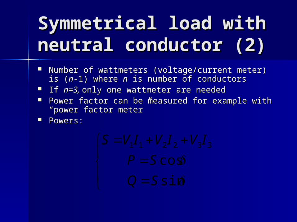
Symmetrical load with Symmetrical load with neutral conductor (2)neutral conductor (2) Number of wattmeters (voltage/current meter) is (Number of wattmeters (voltage/current meter) is (nn-1) -1)
where where nn is number of conductors is number of conductors If If n=3, n=3, only one wattmeter are neededonly one wattmeter are needed Power factor can be measured for example with Power factor can be measured for example with
“power factor meter” “power factor meter” Powers:Powers:
sin
cos332211
SQ
SP
IVIVIVS

Symmetrical load with Symmetrical load with neutral conductor (3)neutral conductor (3) One wattmeter One wattmeter
arrangements for arrangements for real and reactive real and reactive power power measurementsmeasurements
cos3 TT IUP

Symmetrical load Symmetrical load without neutral without neutral conductorconductor Active and reactive Active and reactive
power can be measured power can be measured with two power meter with two power meter (in three-wire system), (in three-wire system), case of symmetrical case of symmetrical load and without neutral load and without neutral conductor (motors), conductor (motors), Aron’s theoremAron’s theorem
Possible to use also in Possible to use also in case of unsymmetrical case of unsymmetrical loadload
If power factor is <0,5 If power factor is <0,5 then three wattmeter then three wattmeter arrangementarrangement
CDAB PPP
CDAB PPQ *3
A
A
V
V
W
W
Phase A
Phase B
Phase C
VAB = VA - VB
VCB = VC - VB
IA
IC
PAB
PCB

Symmetrical Power Symmetrical Power Systems Supplying Systems Supplying Unbalanced LoadsUnbalanced Loads Current amplitudes are different, Current amplitudes are different,
and their relative phase is not and their relative phase is not equal 120°equal 120°
Usually it is caused by some fault Usually it is caused by some fault (short circuit)(short circuit)
Three- or two wattmeter Three- or two wattmeter arrangements (depends on arrangements (depends on neutral point)neutral point)

Symmetrical Power Symmetrical Power Systems Supplying Systems Supplying Unbalanced LoadsUnbalanced Loads Four possible arrangements:Four possible arrangements:
– Three-wattmeter arrangementThree-wattmeter arrangement– Two-wattmeter arrangementTwo-wattmeter arrangement– Barbagelata arrangementBarbagelata arrangement– Righi arrangementRighi arrangement

Two-wattmeter Two-wattmeter arrangementsarrangements Measurements Measurements
arrangements for arrangements for reactive power reactive power measurementsmeasurements
wherewhere
)10(3)30(13 PPQ
1310)30(1 PPP

Barbagelata Barbagelata arrangementsarrangements Measurement Measurement
arrangements for arrangements for active and active and reactive power reactive power measurementsmeasurements
““Two-wattmeter Two-wattmeter method”method”
12323113
3212
23
1PPPPQ
PPP

Righi arrangementsRighi arrangements
Measurement Measurement arrangements for arrangements for reactive power reactive power measurementsmeasurements
)31(21232 23
1PPPQ

Conclusion about Conclusion about Three-Wire SystemsThree-Wire Systems

High-frequency power High-frequency power measurementsmeasurements Radio (< 300 MHz) or microwave (> Radio (< 300 MHz) or microwave (>
1 GHz) frequencies1 GHz) frequencies Measurement devices are classified Measurement devices are classified
by absorption type and transmitted by absorption type and transmitted or throughline typeor throughline type
Based on thermistors, Based on thermistors, thermocouples, diodes or radiation thermocouples, diodes or radiation sensorssensors
Should be calibrated very carefullyShould be calibrated very carefully

Thermistor-Based Thermistor-Based Power MetersPower Meters A thermistor is A thermistor is
resistor made of a resistor made of a compound of compound of highly highly temperature temperature metallic oxidesmetallic oxides
Resistance is a Resistance is a function of the function of the temperature rise temperature rise produced by produced by applied powerapplied power

Calorimetric methodCalorimetric method
Accurate methodAccurate method Technique based Technique based
on direct on direct determination of determination of the heat the heat produced by the produced by the input power input power
““Laboratory Laboratory method”method”

EnergyEnergy measurementsmeasurements
Simplest way is to measure current, voltage and Simplest way is to measure current, voltage and observation interval and compute the product:observation interval and compute the product:
Observation interval measures by a chronometer or a Observation interval measures by a chronometer or a time countertime counter
Electricity/energy meters:Electricity/energy meters:– Electrodynamic measurement deviceElectrodynamic measurement device– Induction meter (AC)Induction meter (AC)– Digital energy meter (AC/DC)Digital energy meter (AC/DC)
Two main parts:Two main parts:– Transducer (Converts power to mechanical or electrical Transducer (Converts power to mechanical or electrical
signal)signal)– Counter (Integrates the “energy”)Counter (Integrates the “energy”)
1
2
)(t
t
dttptVIE

DC Energy DC Energy MeasurementsMeasurements Electrodynamic Electrodynamic
measurement device measurement device (integrating wattmeter)(integrating wattmeter)
Based on DC motor (no iron)Based on DC motor (no iron) Magnetic field is generating Magnetic field is generating
by line currentby line current Torque Torque
Aluminum disk and Aluminum disk and permanent magnet gives permanent magnet gives linear dependence of linear dependence of ΓΓ and and power power
Mechanical counter transfers Mechanical counter transfers the rotating motion into a the rotating motion into a digital or mechanical displaydigital or mechanical display
Vm IkR
kIVC 2

AC AC EnergyEnergy MeasurementsMeasurements Induction energy Induction energy
meter (every meter (every household)household)
Accuracy about 2 %Accuracy about 2 % Current and voltage Current and voltage
coilcoil AC current (coil) AC current (coil)
Eddy currents (disk) Eddy currents (disk) Force to diskForce to disk
Variable powers cause Variable powers cause variable rotating variable rotating speedspeed
Day and night Day and night electricityelectricity
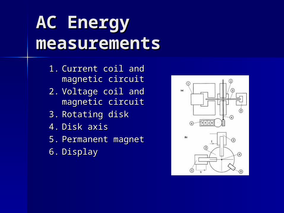
AC Energy AC Energy measurementsmeasurements
1.1. Current coil and Current coil and magnetic circuitmagnetic circuit
2.2. Voltage coil and Voltage coil and magnetic circuitmagnetic circuit
3.3. Rotating diskRotating disk
4.4. Disk axisDisk axis
5.5. Permanent Permanent magnetmagnet
6.6. DisplayDisplay

Electronic Energy Electronic Energy MetersMeters Product of current and voltage. Product of current and voltage.
The result is integrated over the The result is integrated over the observation timeobservation time
The most used technique is the The most used technique is the time-division multiplier in which time-division multiplier in which pulses are modulated in duration pulses are modulated in duration and amplitude of voltage and and amplitude of voltage and currentcurrent
Accuracy: 0,005 %Accuracy: 0,005 %

Energy measurementsEnergy measurements
Automatic remote reading in future Automatic remote reading in future – PricingPricing– Controlling generation/loadsControlling generation/loads
Several system under development Several system under development (GSM, radio link, phone line…)(GSM, radio link, phone line…)
Energy meters also in var (reactive Energy meters also in var (reactive power) hours and volt-ampere power) hours and volt-ampere (apparent power) hours(apparent power) hours

Some StandardsSome Standards
General distribution networkGeneral distribution network SFS 2537SFS 2537
– AC energy measurementsAC energy measurements Measurement arrangementsMeasurement arrangements
SFS 3381SFS 3381– AC energy measurementsAC energy measurements
Measurement devicesMeasurement devices

Case: Elevators power Case: Elevators power and energy consumption and energy consumption measurementsmeasurements ””Two-wattmeter method”Two-wattmeter method”
– Voltages: UVoltages: Ul1l1->U->Ul2l2 and U and Ul2l2 U Ul3l3
– Currents: ICurrents: I11 and I and I22
– Sample frequency: 20 kHz Sample frequency: 20 kHz – Dasylab™Dasylab™– P = 16 kW, n = 2780 rpm, I = 36 A / 47 A, I = 115 A P = 16 kW, n = 2780 rpm, I = 36 A / 47 A, I = 115 A
(start), cosphi = 0,86, height of the shaft = 3,9 m(start), cosphi = 0,86, height of the shaft = 3,9 m

Elevator power Elevator power consumptionconsumption
s
2 . 5 5 . 0 7 . 5 1 0 . 0 1 2 . 5 1 5 . 0 1 7 . 5 2 0 . 0 2 2 . 5 2 5 . 0 2 7 . 5 3 0 . 0 3 2 . 5 3 5 . 0 3 7 . 5 4 0 . 0 4 2 . 5L i n e P o w e r M o t o r P o w e r
8 0 . 0 0
6 0 . 0 0
4 0 . 0 0
2 0 . 0 0
0 . 0 08 0 . 0 0
6 0 . 0 0
4 0 . 0 0
2 0 . 0 0
0 . 0 0
1 9 , 9 k W *
L i n e a c t i v e p o w e r
M o t o r a c t i v e p o w e r
1 9 . 7 k W *
0 . 1 7 0 k W *
0 . 0 0 0 k W *
0 . 0 2 1 k W
6 7 . 4 k W m a x
6 6 . 8 k W m a x
Net (green) and motor Net (green) and motor (blue) power(blue) power

Elevator energy Elevator energy consumptionconsumption
s
2 . 5 5 . 0 7 . 5 1 0 . 0 1 2 . 5 1 5 . 0 1 7 . 5 2 0 . 0 2 2 . 5 2 5 . 0 2 7 . 5 3 0 . 0 3 2 . 5 3 5 . 0 3 7 . 5 4 0 . 0 4 2 . 5S p e e d M o t o r A c c e l e r a t i o n E n e r g y D i s t a n c e
8 0
7 0
6 0
5 0
4 0
3 0
2 0
1 0
0
A c c e l e r a t i o n 2 1 . 9 4 2 W h ( 1 . 1 7 6 m )
F u l l s p e e d 2 8 . 4 6 3 W h ( 2 . 4 6 4 m )
D e c e l e r a t i o n 2 0 . 2 0 2 W h ( 0 . 3 4 4 m )
7 1 . 8 5 1 W h 7 2 . 0 2 3 W h
A c c e l e r a t i o n 0 . 1 1 6 W h ( 0 . 8 1 6 m )
F u l l s p e e d 0 . 3 1 3 W h ( 2 . 6 6 4 m )
D e c e l e r a t i o n 0 . 1 4 9 W h ( 0 . 4 7 2 m )
7 2 . 6 0 2 W hd t = 1 2 . 1 0 2 s
Total (net) power Total (net) power energyenergy consumptionconsumption

The The EndEnd
Related Documents