UNIVERSIDADE FEDERAL DO RIO GRANDE DO SUL GRADUATE PROGRAM IN MINING, METALS AND MATERIALS ENGINEERING (PPGE3M) TECHNISCHE UNIVERSITÄT DRESDEN FAKULTÄT MASCHINENWESEN (bi‐national doctorate) POTENTIALITIES OF THE USE OF INCREMENTAL FORMING IN COMPUTER AIDED DESIGN AND MANUFACTURE OF CUSTOMIZED CRANIOFACIAL IMPLANTS PhD Thesis To attain the academic degree of Doutor em Engenharia (Dr.) and Doktor‐Ingenieur (Dr. ‐Ing.) Submitted by Engenheira de Materiais Liciane Sabadin Bertol Born in December, 6 th 1982 in Passo Fundo, Brasil Comitee Members: Supervisors: Co‐supervisor: Prof. Dr. Wilson Kindlein Júnior – PPGE3M/UFRGS Prof. Dr. Ralph Stelzer – KTC/TUD Prof. Dr. Luis Alberto dos Santos – PPGE3M/UFRGS Reviewers: Prof. Dr. Jorge Vicente Lopes da Silva – CTI Prof. Dr. Claiton Heitz – PUC‐RS Prof. Dr. Guilherme Fritscher – PUC‐RS Prof. Dr. Lirio Schaeffer – PPGE3M/UFRGS Date of the award: September, 10 th 2012

Welcome message from author
This document is posted to help you gain knowledge. Please leave a comment to let me know what you think about it! Share it to your friends and learn new things together.
Transcript

UNIVERSIDADE FEDERAL DO RIO GRANDE DO SUL GRADUATE PROGRAM IN MINING, METALS AND MATERIALS ENGINEERING (PPGE3M)
TECHNISCHE UNIVERSITÄT DRESDEN FAKULTÄT MASCHINENWESEN
(bi‐national doctorate)
POTENTIALITIES OF THE USE OF INCREMENTAL FORMING IN COMPUTER AIDED DESIGN AND
MANUFACTURE OF CUSTOMIZED CRANIOFACIAL IMPLANTS
PhD Thesis
To attain the academic degree of Doutor em Engenharia
(Dr.) and
Doktor‐Ingenieur (Dr. ‐Ing.)
Submitted by
Engenheira de Materiais Liciane Sabadin Bertol Born in December, 6th 1982 in Passo Fundo, Brasil
Comitee Members: Supervisors: Co‐supervisor:
Prof. Dr. Wilson Kindlein Júnior – PPGE3M/UFRGS Prof. Dr. Ralph Stelzer – KTC/TUD Prof. Dr. Luis Alberto dos Santos – PPGE3M/UFRGS
Reviewers:
Prof. Dr. Jorge Vicente Lopes da Silva – CTI Prof. Dr. Claiton Heitz – PUC‐RS Prof. Dr. Guilherme Fritscher – PUC‐RS Prof. Dr. Lirio Schaeffer – PPGE3M/UFRGS
Date of the award: September, 10th 2012

2
You can have any color as long as it’s black.
Henry Ford (1863 – 1947)

3
ACKNOWLEDGEMENTS
To my supervisor, Professor Wilson Kindlein Junior, for teaching me to believe
in my ideas. Still, for believing in me, and for the encouragement and advice he has
provided throughout my time as his student.
To Professor Luis Alberto dos Santos, co‐supervisor of this project, for his
valuable contribution in the choice of topics to be addressed and discussions to be
held.
To all the members of the Konstruktionstechnik team, from Dresden University
of Technology, for receiving me during the period of one year. Special thanks to
Professor Ralph Stelzer, also supervisor of this project, conducted under the co‐
supervising scheme. My sincere thanks to Christine Schöne, for her collaboration and
encouragement.
To the National Council for Scientific and Technological Development, CNPq, for
providing the founding which allowed me to undertake this research.
To PPGE3M/UFRGS, that welcomed the research project and provided the
conditions for my academic development. To the teachers from PPGE3M, for their
excellence in research and for being always open for discussions and exchange of
experiences.
To my colleagues from Laboratory of Design and Materials Selection
(LdSM/UFRGS), for being responsible for the knowledge obtained during the Master's
and PhD period. My special thanks also for making this period more enjoyable.
To the team from Metal Forming Laboratory (LDTM/UFRGS), for the tests
performed and for valuable discussions about the incremental forming processes.
To my family, especially to my mother Clédia, for support and example of life,
and to my sister Franciele, for teaching me to enjoy life.
To my friends, for making me happy.

4
SUMMARY
LIST OF FIGURES ....................................................................................................................... 6
LIST DE TABLES ....................................................................................................................... 11
LIST OF ABBREVIATIONS......................................................................................................... 13
ABSTRACT .............................................................................................................................. 15
RESUMO................................................................................................................................. 16
ZUSAMMENFASSUNG............................................................................................................. 17
1. INTRODUCTION .................................................................................................................. 18
2. OBJECTIVES ........................................................................................................................ 21
3. BIBLIOGRAPHIC REVIEW ..................................................................................................... 22
3.1 The craniofacial skeleton .................................................................................................. 22
3.1.2 Cranioplasty ............................................................................................................... 22
3.2 The materials and craniofacial reconstruction .................................................................. 23
3.2.1 Allografts (homologous) ............................................................................................. 26
3.2.2 Alloplastic grafts......................................................................................................... 26
3.3 Anatomical biomodels and craniofacial reconstruction .................................................... 31
3.4 Biomodels and design of custom prosthesis ..................................................................... 35
3.4.1 Manufacture of prosthesis through manual modeling ................................................ 35
3.4.2 Manufacture of prostheses through virtual modeling................................................. 37
3.4.3 Manufacture of prosthesis through incremental forming ........................................... 41
3.4.4 Manufacture of prosthesis though additive manufacturing ........................................ 46
3.4.5 Manufacture of prosthesis through three‐dimensional laser scanning ....................... 47
3.5 Quality in orthopedic implants ......................................................................................... 50
4. MATERIALS AND METHODS................................................................................................ 52
4.1 Design of implants ............................................................................................................ 53
4.1.1 Characterization of the type of implant ...................................................................... 53
4.1.2 Acquisition of anatomical data of patients ................................................................. 54
4.1.3 Manipulation of tomographic data ............................................................................. 54
4.1.4 Manufacture of biomodels ......................................................................................... 54

5
4.1.5 Modeling of the implants ........................................................................................... 54
4.1.6 Selection of materials and manufacturing processes .................................................. 55
4.1.7 Characterization of the material ................................................................................. 55
4.2 Manufacture of implants .................................................................................................. 58
4.2.1 Determination of the parameters of SPIF ................................................................... 58
4.2.2 Dimensional inspection .............................................................................................. 61
5. RESULTS AND DISCUSSION ................................................................................................. 63
5.1 Characterization of the types of implants ......................................................................... 63
5.2 Determination of parameters of the SPIF ......................................................................... 68
5.3 Dimensional inspection .................................................................................................... 71
5.4 Thermography .................................................................................................................. 76
5.5 Design and manufacture of implants ................................................................................ 78
5.5.1 Frontal region............................................................................................................. 78
5.5.2 Frontal and supra‐orbital region ................................................................................. 87
5.5.3 Zygomatic bone region ............................................................................................... 95
5.5.4 Mandible ramus ....................................................................................................... 101
5.5.5 Temporomandibular joint (TMJ) ............................................................................... 109
5.5.6 Summary of the proposed methods ......................................................................... 112
6. CONCLUSIONS .................................................................................................................. 119
7. REFERENCES..................................................................................................................... 122
6
LIST OF FIGURES
Figure 1: Schematic representation of the cranium bones............................................ 22
Figure 2: Virtual biomodel obtained from CT images, used to visualize the bone
structure, surgical planning and implants design........................................................... 32
Figure 3: Physical biomodel, produced through additive manufacturing and used for
the project of a mandibular prosthesis. ......................................................................... 33
Figure 4: Interface of the software of three‐dimensional reconstruction of medical
images. a) Three‐dimensional reconstruction of the skull, showing all tissues. b) Three‐
dimensional reconstruction of the same skull, but allowing the exhibition of bone
tissues only. .................................................................................................................... 34
Figure 5: Figure 5: Manufacture of custom implant to repair defect in the region of the
zygomatic bone. a) Biomodel used for making a model (resin) of the implant.
b) Replicated model in calcium phosphate cement, adapted to biomodel................... 36
Figure 6: Biomodel of the patient used as template for the conformation of a titanium
plate to fit the defect. Source: Meurer (2003)............................................................... 36
Figure 7: Prototype of the cranial implant manually modeled in wax. Source: Maji et al.
(2008).............................................................................................................................. 37
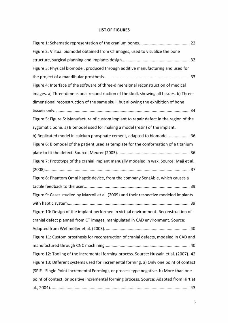
Figure 8: Phantom Omni haptic device, from the company SensAble, which causes a
tactile feedback to the user............................................................................................ 39
Figure 9: Cases studied by Mazzoli et al. (2009) and their respective modeled implants
with haptic system.......................................................................................................... 39
Figure 10: Design of the implant performed in virtual environment. Reconstruction of
cranial defect planned from CT images, manipulated in CAD environment. Source:
Adapted from Wehmöller et al. (2003). ......................................................................... 40
Figure 11: Custom prosthesis for reconstruction of cranial defects, modeled in CAD and
manufactured through CNC machining.......................................................................... 40
Figure 12: Tooling of the incremental forming process. Source: Hussain et al. (2007). 42
Figure 13: Different systems used for incremental forming. a) Only one point of contact
(SPIF ‐ Single Point Incremental Forming), or process type negative. b) More than one
point of contact, or positive incremental forming process. Source: Adapted from Hirt et
al., 2004). ........................................................................................................................ 43
7
Figure 14: Titanium cranial implant projected in CAD environment and produced
through SPIF. Source: Duflou et al. (2008b). .................................................................. 45
Figure 15: Examples of prosthesis manufactured through additive manufacturing. a)
Mandible implant, zygoma and intervertebral discs with reticular structure. Source:
Rapidtech, 2011. b) Implant for repair of cranial defect in poly‐lactic acid (PLA). Source:
Fraunhofer Institu für Lasertechnik (ILT). c) Mandible Implant with optimized internal
structure and topology. Source: Fraunhofer Geselschaft. d) Prosthesis for repair of
cranial defect, in titanium. Source: University Maastricht, Netherlands. e) Replacement
implant of knee joint in Co‐Cr, with reticular structure. Source: Arcam AB, Sweden.
f) Prosthesis for replacement of hip joint in titanium, with a gradient of porosity.
Source: Neuner (2008). .................................................................................................. 47
Figure 16: Process of manufacture of dental crowns and bridges based on Reverse
Engineering. a) Scanning of the patient's dental mold. b) Part design. c) Visualization of
the model projected on the patient's dental arch. d) CNC milling of zirconia parts. .... 48
Figure 17: Manufacture of custom TMJ prosthesis. a) CT scan of the patient.
b) Anatomical biomodel showing the removal of region to be replaced. c) Prosthesis
prototype. d) Scanning of the components of the prototype. e) Virtual model. f) Final
prosthesis, manufactured through CNC milling. ............................................................ 50
Figure 18: Steps involved in the project and manufacture of custom craniofacial
implants covered in this study........................................................................................ 53
Figure 19: Schematic figure of the device mounting used for the bending test............ 56
Figure 20: Testing specimens submitted to a forming test to determine the Forming
Limit Curve of the material............................................................................................. 57
Figure 21: Example of forming limit curve (FLC). ........................................................... 57
Figure 22: Tooling of the single point incremental forming process. ............................ 60
Figure 23: Device used for electrochemical etching of the circles grid on the metal
plate................................................................................................................................ 61
Figure 24: Graduated scale used for the measurement of deformations. .................... 61
Figure 25: Different studied implant geometries........................................................... 64
Figure 26: Metallographic analysis of titanium samples, showing equiaxed
microstructure. ............................................................................................................... 65
Figure 27: Forming Limit Curve of the titanium plates. ................................................. 66

8
Figure 28: Forming limit diagram of the titanium plates used and strain values obtained
for the SPIF tests............................................................................................................. 68
Figure 29: SPIF in titanium cone forming an angle of 45° with the plane of the plate.. 70
Figure 30: SPIF in titanium cone forming an angle of 50° with the plane of the plate,
with disruption. .............................................................................................................. 70
Figure 31: Fracture of the material presented in SPIF of cone with angle of 45°. ......... 71
Figure 32: Three‐dimensional laser scanning of the testing specimens in the cones of
30 and 40° manufactured through SPIF in plate of 1mm............................................... 71
Figure 33: Variation of the thickness of the formed plate into the conformation of the
30° cone. a) Top view. b) Cross section view. ................................................................ 72
Figure 34: Variation of the thickness of the formed plate into the conformation of the
30° cone. a) Top view. b) Cross section view. ................................................................ 73
Figure 35: Variation of the thickness of the formed plate into the conformation of the
50° cone. a) Top view. b) Cross section view. ................................................................ 74
Figure 36: Three‐dimensional comparison of CAD designed model and the model
formed through SPIF....................................................................................................... 75
Figure 37: Thermography performed during the SPIF of cones with different angles. a)
30 degrees. b) 40 degrees. c) 50 degrees....................................................................... 77
Figure 38: Three‐dimensional image obtained from CT data. Defect in the frontal
region of the skull. .......................................................................................................... 79
Figure 39: Figure 39: Procedure for manual modeling of implant to repair the bone
defect in the frontal region. a) Biomodel showing the defect. b) Implant model, molded
in epoxy resin in a silicon mold. c) Implant cast in calcium phosphate cement with
titanium mesh inside. d) Implant positioned in the biomodel....................................... 80
Figure 40: Virtual model of the implant (in blue) for repair of cranial defect. .............. 81
Figure 41: SPIF of implant for repair of cranial defect. .................................................. 82
Figure 42: Three‐dimensional comparison between the designed and produced model.
........................................................................................................................................ 83
Figure 43: Bone structure of the case of bone defect studied. a) Virtual biomodel,
showing the defect in the frontal and supra‐orbital region. b) Physical biomodel used
for the manual modeling. ............................................................................................... 87
Figure 44: Resulting cranial implant produced through manual shaping. ..................... 88

9
Figure 45: Three‐dimensional model of the cranium of the patient, (a) showing the
bone defect to be reconstructed, (b) modeling and (c) bone defect repaired with the
shaped implant (green). ................................................................................................. 89
Figure 46: Virtual implant model, with adjacent polygons with a maximum angle of 40°
to the plane of the plate................................................................................................. 90
Figure 47: Forming strategy defined in CAM software. a) Toolpath. b) Process
simulation. ...................................................................................................................... 91
Figure 48: SPIF of the implant. ....................................................................................... 91
Figure 49: Implant manufactured of titanium, showing the etched grid used for the
measurement of the deformation. ................................................................................ 92
Figure 50: Differences, in millimeters, between the designed implant and the implant
produced through SPIF. .................................................................................................. 92
Figure 51: Bone defects in the zygomatic bone region. a) Physical biomodel used for
modeling of the implant to the first case. b) Virtual biomodel used in the second case.
........................................................................................................................................ 95
Figure 52: Manufacture of custom implant to repair defects in the region of the
zygomatic bone. a) Biomodel used to make a model (resin) of the implant. b) Model
replicated in calcium phosphate cement in silicone mold. c) Implant removed from the
mold. d) Checking of the fitting of the implant to biomodel. ........................................ 96
Figure 53: Modeling of the zygomatic implant. a) Mirroring operation. b) Final model
(in blue)........................................................................................................................... 98
Figure 54: Single point incremental forming of the zygomatic Implant. ...................... 99
Figure 55: Dimensional comparison between the CAD designed implant and the
implant produced through SPIF...................................................................................... 99
Figure 56: Design of the implant performed in a virtual environment. Mandibular
reconstruction planned from CT images using mirroring operations. Source: Adapted
from Bertol et al. (2010). .............................................................................................. 101
Figure 57: Implant to repair the mandibular defect. a) Model produced in Ti‐6Al‐4V
through selective laser sintering. b) Differences (in millimeters) between the CAD
model and the produced model................................................................................... 102
Figure 58: Internal structure. a) Unitary element of the reticular pattern. b) Reticular
structure. c) 3D shape filled with the developed pattern............................................ 104

10
Figure 59: Operations performed in the surface files for the insertion of network
structure in the 3D shape of the implant. a) Positioning and overlapping.
b) Intersection and exclusion of the rest of the reticular block. c) Union of the implant
surface and its respective internal structure. .............................................................. 106
Figure 60: Mandible implant modeled in two parts..................................................... 107
Figure 61: Component of the mandibular implant produced through single point
incremental forming..................................................................................................... 107
Figure 62: Variation in dimensions (in mm) presented by the formed parts in relation to
the CAD model. a) Front part. b) Back part. ................................................................. 108
Figure 63: Titanium implants for different craniofacial regions produced through single
point incremental forming. (a)Frontal; (b) frontal and supraorbital; (c) zygomatic bone;
(d) mandible…………………………………………………………………………………………………………….113
Figure 64: Deformations presented in implants shaped through SPIF and comparison
with the material FLC.................................................................................................... 114

11
LIST DE TABLES
Table 1: Classification of implants and grafts................................................................. 24
Table 2: Requirements used to obtain tomographic data. ............................................ 54
Table 3: Forming parameters used for the tests. ........................................................... 59
Table 4: Results of tensile and bending tests. ................................................................ 65
Table 5: Chemical composition of the plates. ................................................................ 66
Table 6: Influence of different parameters on the forming limit curve (FLC). ............... 67
Table 7: Time required to manufacture the cranium implant with calcium phosphate
cement............................................................................................................................ 80
Table 8: Costs associated in manufacturing the cranium implant with calcium
phosphate cement.......................................................................................................... 81
Table 9: Time required to manufacture the titanium cranial implant through SPIF. .... 83
Table 10: Costs associated with the manufacture of titanium cranial implant through
SPIF. ................................................................................................................................ 84
Table 11: Comparison between the costs of making cranial titanium implants through
CNC machining and additive manufacturing (laser melting). Source: Adapted from
Wirtz, 2005. .................................................................................................................... 86
Table 12: Time required for the manual manufacture of the cranium implant in
titanium plate. ................................................................................................................ 88
Table 13: Costs associated with the manual manufacture of cranial implant in titanium
plate................................................................................................................................ 88
Table 14: Time required to manufacture the implant to repair front and supraorbital
defects in titanium through SPIF. ................................................................................... 93
Table 15: Costs associated with the manufacture of the implant to repair frontal and
supra‐orbital defects in titanium through SPIF. ............................................................. 93
Table 16: Time required to manufacture the zygomatic bone implant in calcium
phosphate cement.......................................................................................................... 97
Table 17: Costs associated with the manufacture of the zygomatic bone implant in
calcium phosphate cement. ........................................................................................... 97
Table 18: Time required to manufacture the zygomatic bone implant through SPIF. 100

12
Table 19: Costs associated with the manufacture of the implant to repair the zygomatic
bone in titanium through SPIF...................................................................................... 100
Table 20: Time required to manufacture the mandibular implant through laser
sintering Ti‐6Al‐4V. ....................................................................................................... 102
Table 21: Costs associated with the laser sintering of the mandibular implant.......... 102
Table 22: Possibility to block modeling with reticular structure in the CAD system. .. 105
Table 23: Time required to manufacture the mandibular implant through SPIF. ....... 108
Table 24: Costs associated with the SPIF of the the mandibular implant ................... 109
Table 25: Time required to manufacture the custom system for TMJ replacement... 111
Table 26: Costs associated with the manufacture of custom system to replace the TMJ.
...................................................................................................................................... 111
Table 27: Possibility of manufacturing through single point incremental forming and
meeting of the formal requirements for the reconstruction of the different regions of
the craniofacial complex. ............................................................................................. 117
Table 28: Summary of the processes studied for the manufacture of custom implants
for craniofacial reconstruction. .................................................................................... 118

13
LIST OF ABBREVIATIONS
ABNT Associação Brasileira de Normas Técnicas (Brazilian Association of Technical
Norms)
AM Additive Manufacturing
ANVISA Agência Nacional de Vigilância Sanitária (National Sanitary Surveillance Agency)
ASTM American Society for Testing and Materials
3D Three‐dimensional
CAD Computer‐Aided Design
CAE Computer‐Aided Engineering
CAM Computer‐Aided Manufacturing
CFC Calcium Phosphate Cement
CNC Computerized Numerical Control
CP Commercially pure
DICOM Digital Imaging and Communications in Medicine
DMLS Direct Metal Laser Sintering
EAS Engineering Assisted Surgery
FLC Forming Limit Curve
FLD Forming Limit Diagram
IE Incremental Forming
LACER Laboratory of Ceramic Materials
LAMEF Laboratory of Physical Metallurgy
LdSM Laboratory of Design and Materials Selection
LDTM Metal Forming Laboratory
MRI Magnetic Resonance Imaging
PEEK Poly‐ether‐ether‐ketone
PMMA Polymethylmethacriate
RP Rapid Prototyping
SFF Solid Freeform Fabrication
SLS Selective Laser Sintering
SLM Selective Laser Melting
SPIF Single Point Incremental Forming
SPM Specific Patient Modeling
STL Stereolithography

14
TC Computed Tomography
TMJ Temporomandibular Joint
TUD Technische Universität Dresden (Dresden Univeristy of Technology)
UFRGS Universidade Federal do Rio Grande do Sul

15
ABSTRACT
Currently, craniofacial reconstruction surgeries are still a challenge for surgical
teams due to the difficulty to define and repair bone defects. Defining the geometry of
the implant is the first challenge, since each patient has an individual anatomy and, in
case of bone defects due to trauma or tumors, each defect has a specific shape. The
implant should then have a geometry that permits the replacement of the original
structure and should consist of a material suitable for implantation. Moreover, the
selected manufacturing process must be flexible enough to enable the production of a
single piece, not requiring excessive cost with dyes and tooling. In the current scenario
of flexible manufacturing processes, the process of incremental forming, which
permits forming metal sheets to manufacture small batches, receives special emphasis.
Thus, this study evaluates the feasibility of preoperative manufacturing of customized
implants to repair defects in different regions of the craniofacial complex through the
process of incremental forming. Different procedures were used for modeling implants
obtained from CT data of patients and the parameters for forming different
geometries of titanium implants were developed. Alternative techniques capable of
producing such implants are also presented. The study shows that, although it has
limited dimensional accuracy and restrictions regarding the geometric complexity of
the implants that can be shaped, the single point incremental forming (SPIF) process
represents a suitable alternative for the preoperative manufacturing of customized
implants for the reconstruction of craniofacial defects.

16
RESUMO
Atualmente, cirurgias de reconstrução craniofacial ainda são um desafio à
equipe cirúrgica devido às dificuldades em definir e reparar o defeito ósseo. A
definição da geometria do implante é o primeiro desafio, uma vez que cada paciente
possui uma anatomia individual e, em caso de defeitos ósseos devido a traumas ou
tumores, cada defeito possui uma forma específica. O implante deve, então, possuir
geometria tal que o possibilite substituir a estrutura original e ser constituído de
material apto para a implantação. Além disso, o processo de fabricação selecionado
deve ser flexível a fim de possibilitar a produção de uma peça única, dispensando
custos excessivos com ferramental. No cenário atual de processos de manufatura
flexível, um destaque especial recebe o processo de estampagem incremental, que
permite a conformação de chapas metálicas para a fabricação de pequenos lotes.
Neste sentido, este estudo ocorre no âmbito da fabricação pré‐operatória de
implantes personalizados para reparo de defeitos em diferentes regiões do complexo
craniofacial através do processo de estampagem incremental. Foram utilizados
diferentes procedimentos para modelagem dos implantes a partir de dados
tomográficos e foram desenvolvidos parâmetros para a conformação de diferentes
geometrias em titânio. São apresentadas, ainda, técnicas alternativas capazes de
produzir tais implantes. O estudo mostra que, embora possua precisão dimensional
limitada e restrições com relação à complexidade geométrica dos implantes que
podem ser conformados, o processo de estampagem incremental apresenta‐se como
uma alternativa viável à fabricação pré‐operatória de implantes personalizados para a
reconstrução de defeitos craniofaciais.

17
ZUSAMMENFASSUNG
Operationen im Schädel‐ und Gesichtsbereich stellen nach wie vor eine große
Herausforderung für die behandelnden Ärzte dar, weil sich oftmals die Abgrenzung des
Knochendefekts und die Wiederherstellung der ursprünglichen Knochenstruktur als
schwierig erweisen. Die erste Herausforderung dabei ist die Definition der
Implantatgeometrie, da jeder Patient eine individuelle Anatomie und, im Falle eines
Knochendefekts durch Traumata oder Tumore, jeder Defekt eine spezifische Form
aufweist. Das Implantat sollte somit eine der originalen Knochenstruktur
entsprechenden Geometrie besitzen und aus einem für die Implantation geeigneten
Material bestehen. Weiterhin muss das für die Herstellung des Implantats gewählte
Verfahren derart anpassungsfähig sein, dass auch die Erzeugung eines einzelnen
individuellen Produktes möglich ist und keine übermäßigen Kosten im Werkzeug‐ und
Formenbau verursacht werden. Im gegenwärtigen Szenario flexibler
Herstellungsprozesse, die eine effiziente Blechumformung auch in kleineren
Stückzahlen erlauben, liegt ein besonderer Schwerpunkt auf dem Verfahren der
inkrementellen Umformung. In dieser Arbeit wird daher die Durchführbarkeit der
präoperativen Herstellung individueller Implantate zur Wiederherstellung knöcherner
Strukturen verschiedener Regionen im Schädel‐ und Gesichtsbereich mit dem
Verfahren der inkrementellen Blechumformung untersucht. Dabei wurden
unterschiedliche Methoden zur Modellierung von Implantaten aus
patientenspezifischen CT‐Daten angewendet und Prozessparameter für die Herstellung
verschiedener Formen von Titanimplantaten entwickelt. Ferner werden alternative
Techniken vorgestellt, mit denen es ebenfalls möglich ist, solche Implantate
herzustellen. Gleichwohl es Einschränkungen hinsichtlich der Formgenauigkeit und
Komplexität der zu formenden Geometrie des Implantates gibt, zeigt diese Arbeit, dass
das Verfahren der inkrementellen Blechumformung eine geeignete Alternative für die
präoperative Herstellung von individuellen Implantaten für den Schädel‐ und
Gesichtsbereich darstellt.

18
1. INTRODUCTION
In order to develop new manufacturing technologies and new products, the
combination of engineering and design in medical and biological sciences along with
the cooperation of different areas of technical‐scientific community has been pursuing
the feasibility of working with quality in the segment of craniofacial implants. This
interdisciplinary character brings solutions that target people's access to a better
health care system coupled with quality and technology, providing thus, a better
quality of life and social welfare.
The repair of cranial defects is necessary to provide brain protection and is
aesthetically desirable. Tumors, trauma, diseases and birth defects generate the need
for bone reconstruction. The treatment of craniofacial defects is a challenge to the
surgical team, and often involves multiple surgeries, some of high cost, and yet, in
some cases, the results are not satisfactory. In this sense, there is a continuous
concern in the improvement and development of new treatment methodologies.
The rapid technological development of engineering and product design from
the last half century has brought changes of great importance in Medicine regarding
the treatment of bone fractures and rehabilitation. The use of CAD (computer‐aided
design), CAM (computer‐aided manufacturing) and CAE (computer‐aided engineering)
enables the project, manufacturing and evaluation of specific prosthesis according to
the needs of each individual patient. The additive manufacturing (AM), or rapid
prototyping (RP) systems, which enable the manufacturing of medical implants in a
fast, accurate and totally automated way, occupy a prominent role in this
context. Therefore, it is possible to obtain, in short time, a 3D model that can be tested
in practical situations.
The manufacturing of custom prosthesis has become a field of great interest in
Biomedical Engineering. In fact, even when several products can be classified as similar,
the natural difference among them in terms of anthropometric features of each
individual leads research towards high customization in order to ensure the best
performance possible for the product. The main arguments raised by proponents of
the manufacturing of customized implants include the reduction of surgical time,

19
better aesthetic results, reduced risk of infection and better outcomes. Furthermore,
the incorporation of functionality to the implant is also possible, as in the case of
osteoconductive implants or controlled drug delivery. However, the manufacturing of
prosthesis, according to the patient’s needs, is costly and requires the domain of a still
incipient technology, when compared to traditional methods such as in situ molding
and standardized prostheses. The manufacturing technology for the production of
customized prostheses comprises image processing and medicine, the use of CAD
three‐dimensional reconstruction, CAM systems, flexible manufacturing processes,
CNC (Computerized Numerical Command) machinery, biomaterial processing
technology, among others.
Thus, this study evaluates the main techniques currently available for the
project and manufacturing of customized bone implants in craniofacial complex. CT
images serve as the basis for the project of implants, manipulated in CAD software and
transferred to CAM software, where strategies and parameters for the manufacture of
the implant in the desired geometry are defined. In other words, a reverse engineering
approach is used to produce a specific implant for the needs of each patient, also
known as Specific Patient Modeling (SPM). The potential and limitations of each
technique are assessed, as well as appropriate materials for each manufacturing
process and anatomical function that the implant should perform.
Several techniques have been proposed and used for manufacturing
customized implants ‐ including incremental forming, rapid manufacturing, CNC
machining, and manual conformation with the aid of physical biomodels (Goldsmit,
Horowitz and Orentlicher, 2012; Staffa et al., 2012; Goh et al., 2010; abergmann et al.,
2010; Mustafa et al., 2011; Neovius and Engstrand, 2009) . Specifically, using the single
point incremental forming (SPIF) technique to form the implants to repair cranial
defects has shown great potential. The possibility of extending the application of the
technique for other more complex defects of the face, however, still remains
unexplored. In this sense, the main issue to be investigated in this study is: which of
the various flexible manufacturing processes available today can be used for the
production of various types of implants needed for the repair of defects in the
craniofacial region? The produced implants must fulfill geometrical and functional

20
requirements in order to be considered suitable for its use. Additionally, as an
objective of this study, is to investigate whether single point incremental forming can
effectively represent a suitable alternative to stamping of custom medical products.
This study aims to contribute to the advance of Biomedical Engineering,
particularly that which relates to the design and manufacturing of craniofacial
implants. The study was developed within the Graduate Program in Mining,
Metallurgical and Materials Engineering in the Federal University of Rio Grande do Sul,
and the Department of Mechanical Engineering in Dresden University of Technology.

21
2. OBJECTIVES
General objective: To evaluate the feasibility of preoperative manufacturing of
customized implants for the repair of defects in different regions of the craniofacial
complex through different manufacturing processes.
Specific Objectives:
1. Evaluate software currently available that allow the medical
manipulation of implants.
2. Evaluate the materials and manufacturing processes available for the
production of craniofacial implants with different geometries,
functions and mechanical requirements.
3. Evaluate the technique of single point incremental forming as an
alternative to the manufacturing of custom craniofacial
implants, parameters, potentials and limitations.
4. Develop a technological route of manufacturing and evaluation of
custom craniofacial implants, taking into consideration the structural,
aesthetic and functional requirements of the implants, in addition to
the prevailing relevant norms.

22
3. BIBLIOGRAPHIC REVIEW
3.1 The craniofacial skeleton
The anatomy of the cranio‐maxillofacial skeleton is designed to give protection
to soft tissue structures of vital importance and to allow the jaw movement, among
other functions. Important systems that are protected include the central nervous
system, eyes and respiratory system. A schematic representation of the bone structure
of the skull is shown in Figure 1.
Figure 1: Schematic representation of the cranium bones.
Source: Adapted from Salgado (2010).
3.1.2 Cranioplasty
Cranioplasty is a procedure used in the totality of craniofacial surgeries of
malformations and in surgeries of cancer and trauma, resulting in loss of substance of
the cranium. The aesthetic‐functional changes of the face and cranium require surgical
specialties involving increasing technical and scientific improvement. The current trend,
according to Rettore et al. (2000), is that patients are seen from a multidisciplinary
perspective.
The fractures of the craniofacial skeleton are just one component of a spectrum
of "maxillofacial injuries" and are associated with varying degrees of involvement of
soft tissues and adjacent structures such as the eyes and nasal passages, paranasal
sinuses and tongue. They can range in severity from a simple crack in the top alveolus
to a major rupture in the internal facial skeleton. Important structural diseases in the
Occipital
Jaw
Mandible
Parietl
Frontal
Zigomatic
Sphenoid
Temporal

23
head form the basis of many medical, dental, and surgical specialties, such as oral‐
maxillofacial surgery, neurology, neuro‐radiology, neurosurgery, ophthalmology,
otology, rhinology, and psychiatry (Moore and Dalley, 2001).
Currently, craniofacial reconstruction surgeries are still a challenge for surgical
teams due to difficulties in defining and repairing bone defects. The definition of the
geometry of the implant is the first challenge, since each patient has an individual
bone anatomy and in the event of bone defects due to trauma or tumors, each defect
has a specific shape. The implant should then have such a geometry that allows for
replacement of the original structure. The definition of the material of which the
implant is made is another factor to be defined and generates divergent views among
the various researchers of this subject (Quatela and Chow, 2008; Staffa et al., 2012;
Goh et al., 2010; Neovius and Erik, 2010; Okazaki et al., 2014; Niinomi, 1998).
According to Hench (2006), the challenge of the biomaterials field is that implant
devices replace living tissues whose physical properties are the result of millions of
years of evolutionary optimization, and have the capacity for growth, regeneration and
repair. Thus, all materials used for repair or restoration of the body must have a
specific set of characteristics and properties. The relative success or failure of a
biomaterial reflects the scientific and engineering trial used in the evaluation of this
adjustment.
The goals of modern bone surgery are rapid recovery of form and function. This
must be the goal of every surgeon treating fractures and tumors causing craniofacial
bone defects or performing osteotomies for correction of craniofacial deformities.
When selecting the appropriate implant it is necessary to estimate the magnitude and
expected duration of the charges for each specific case.
3.2 The materials and craniofacial reconstruction
Numerous implants, orthoses and prosthesis have been developed since the
initial use of gold and silver as biomaterial. Most of them were used for a period of
time and then discarded when their limitations became known and or new materials
were provided. The use of implants to repair or replace parts of the human body has

24
grown tremendously in recent years, mainly due to increased life expectancy of the
population, but also due to the increase of accidents related to transportation means ,
work and sports, and also wars and violence. According to Pereira et al. (2006), the
demand for biomaterials grows 5‐15% each year.
Historically, gold plates were used for cranioplasty by pre‐Columbian Inca
surgeons. In the sixteenth century, canine bone was used to repair a cranial defect in a
human. In the early twentieth century, the use of autografts was quite popular.
However, due to the devastation caused by war, the search for alternative metals to
cover large craniofacial defects increased. Modern plastic and ceramic materials have
replaced the metals in many cases for decades (Sanan and Haynes, 1997).
An implant according to Ernst, Herzog and Seidl (2009) describes any tissue or
synthetic material that can be placed in a living organism. A graft describes a vital
tissue or a body part which at least fulfills its function in the host tissue. Table 1
summarizes the classification of implants and grafts.
Table 1: Classification of implants and grafts.
Source: Adapted from Ernst, Herzog and Seidl (2009).
A material, ideal to be used as an implant, must meet the following
requirements (Ernst, Herzog and Seidl, 2009): good compatibility, no local or systemic
toxicity, no reabsorption (early) of the implant material, readily available in adequate

25
quantity, sterilizable, must be pliable and conformable, have elasticity coefficient and
Poison’s ratio which corresponds to the tissue where it will be placed.
The main purpose of cranioplasty is to repair loss of substance and reconstruct
the cranium, with a view to shelter and protect the brain and restore the aesthetics of
the head. Tumors, trauma, disease, and birth defects generate the need for bone
reconstruction. According to Neto and Zanini (2000), bone loss smaller than 2 cm in
diameter, provided they do not compromise the aesthetics, will not usually be repaired
because the ability of osteogenesis of the dura mater, pericranium, and bone edges is
large. However, in cases where cranioplasty is required, there are alloplastic methods
and bone transplant methods. Among the arguments used by teams who prefer bone
transplants is the fact that they integrate into the recipient location by osteogenesis,
osteoinduction and osteoconduction, and, apart from undergoing remodeling to
restore the form, resist better to infections and stimulate vascularization of devitalized
areas (Lee, Antonyshyn and Forrest , 1995). On the other hand, some critics say that
the method, apart from being limited, always has some degree of reabsorption and
always results in a lesser or greater morbidity for the patient, depending on the donor
area. The donor most popular areas for removing material for bone grafts in
cranioplasty are the skull cap, ribs and the iliac crest.
Ideally, in the cranioplastias in which it is necessary to have access to the brain,
the cranial region that is removed is stored for later insertion. A bone cap, however,
may not be available for the repair of defects where the fracture is composed of
several fragments, tumors, congenital abnormalities, osteomyelitis or reabsorption of
the bone fragment. Repairs using autogenous bones (rib or iliac) are often made, but
sometimes do not provide adequate brain protection and may be associated with
morbidity (Stoodley, Abbot and Simpson, 1996).
Authors that employ alloplastic materials defend their inexhaustible capacity to
meet even the largest repairs without morbidity to the patient, in obtaining the
material and ease of application and modeling. Quatela and Chow (2008) point out
other advantages of alloplastic implants: lack of allergenicity and carcinogenesis; not
corrosive nor toxic; not absorbable, are durable, resistant and lightweight,
biocompatible and malleable. On the other hand, Neto and Zanini (2000) point out

26
that it is undeniable that the alloplastic inclusions, for being foreign bodies, have
functional limitations and interfere with the diagnosis by image (especially metallic
inclusions in magnetic resonance imaging).
3.2.1 Allografts (homologous)
The removal of bone from another part of the patient's own body for
subsequent grafting (autogenous material) is still a widely used technique, especially in
cases of small bone defects. Autogenous bone is usually the first choice, particularly
for grafts. Its use is contraindicated for very large extent of the defect, patient in
advanced age, previous failures in cranial reconstruction. Also, when autogenous
implants are used, other considerations must be taken: risk of postoperative infection
and resorption of the graft with loss of their physical properties and the need for
another surgical procedure at the donor site. While xenografts (decalcified and dried
animal bones) can pose immunological risks, allografts (obtained from cadavers and
stored in bone banks) may be responsible for transmission of infections such as
hepatitis B, hepatitis C and HIV. For xenografts, in particular bovine material, there is
also concern about the possibility of disease transmission.
3.2.2 Alloplastic grafts
In the case of major defects, however, implants with alloplastic materials are
preferred. A major advantage of the use of alloplastic materials is the possibility of
manufacturing the prosthesis before surgery, thus reducing the time and complexity of
the surgery. The use of alloplastic implants for reconstruction of damaged or missing
parts of the human body has a long history, with different types of materials being
used, some more successful, some less. Currently there are various materials (metals,
polymers, ceramics and composites) suitable for use as an implant. Among these
alternatives, three noteworthy materials that are widely used for craniofacial surgery:
methylmethacrylate, calcium cement and phosphate (hydroxyapatite) and
titanium. Each of these materials has its potential advantages, disadvantages and
indications in contemporary craniofacial surgery. When used with good surgical
technique and in the appropriate patient, each material can enable good clinical

27
response. The main materials used for craniofacial bone reconstruction are reviewed
below.
‐ Polymers
Represent materials also often used as grafts. These are manufactured in the
form of woven yarn and powders that, when mixed with proper liquids become mass
serving to fill spaces from loss of tissues. In general, they produce a significant tissue
reaction. Prominent polymeric materials currently used for alloplastic cranioplasty are
polyethylene (PE) and polymethylmethacrylate (PMMA).
Polyethylene (PE)
Ultra high molecular weight polyethylene is also a polymer used to reconstruct
the floor of the orbit and nasal cavity due to its hardness and strength. However,
according to Rettore et al. (2000), the main contraindications to its use are: infected
areas, regions with low blood flow, patients with systemic disease that hinder the
healing process; regions that have undergone radiotherapy; areas where there is
excessive pressure on the implanted material.
One of the main representatives of the polyethylene is Medpor® (Porex), which
has high density linear polyethylene in its constitution. Its porous structure of
interconnection stimulates bone cells to penetrate through these pores.
Polymethylmethacrylate (PMMA)
With a complex range of possibilities, the ideal synthetic material according to
Chiarini (2004) must be biocompatible, inert, have low thermal conductivity, be
radiotransparent, non‐magnetic, light, rigid, simple to prepare, easily applicable and
low cost. In this sense, the polymethylmethacrylate (PMMA) is among the inert
materials that meet these requirements.
PMMA, commonly known as acrylics, is produced from esters of acrylic or
methacrylic acids and has a long history of use in orthopedic surgery as bone cement
for joint prosthesis. It has been adapted for cranioplasty procedures through a powder
mixture of methylmethacrylate polymer and methylmethacrylate‐styrene copolymer
and a monomer benzyl peroxide. PMMA is polymerized in surgery by a mix of the
liquid monomer to powder polymer. As a result of this mixture there is an exothermic

28
reaction, in which the temperature may reach 80°C in the curing time of the polymer
(8‐10 min). It forms a rigid and almost translucent polymer. As described by Eppley
(2003), due to the fact that the liquid monomer is highly allergenic and cytotoxic, the
mixture of the components and the beginning of the polymerization process occur
outside the implantation local. Once hardened, the PMMA is inert, not resorbable and
induces the formation of a fibrous capsule, which means that there is biological
tolerance, but there is no capacity of tissue incorporation. The formation of capsules of
fibrous tissue is usually attributed to surgical trauma, thermal shock caused by in
situ polymerization, the exothermic reaction that may necrose the bone if its
temperature reaches 56°C (Hench and Ethridge, 1082), and by the high toxicity of the
unpolymerized monomers, a fact confirmed in cell culture (Pedersen, 1987).
PMMA also has several advantages. The material easily adapts to the contour
of the defect in surgery (due to its pre‐hardening moldability) and is quite durable,
with high impact resistance. Because PMMA is rigid, it may have its tenacity to
fractures increased by the joint use of wire mesh reinforcement, approaching the
strength of the implant to the resistance of human cranial bone (Eppley,
2003). However, there are some disadvantages to the use of PMMA. The material
releases volatile gasses when it is mixed (due to monomer), from which allergic
reactions have already been reported in patients who were in the same place where
the mixing was performed. Furthermore, the high temperatures reached during
polymerization of the material require refrigeration to prevent the implant tissue from
being damaged. Furthermore, as stated by Eppley (2003), the material exhibits ease of
bacteria adhesion, which makes it poorly tolerated by the body once infected, or when
in contact with tissues with recent infection. Still, thinning of the skin over the implant,
implant exposure and infection may occur with a long period of implantation in
pediatric cranioplasty.
‐ Metals
Metals were always used to reconstruct bone structures, as in the case of bone
fractures or bone loss. The metals used are researched and approved by international
organizations before their use is cleared (FDA, Anvisa, ISO, etc). As advantagesof
metals it is worth to mention their inertia and structural stability, which allows them to

29
perform the functions for which they are indicated. The metallic materials of greater
emphasis to craniofacial surgery are the stainless steels and titanium and its alloys.
Stainless steel
Stainless steel is used as wires of various diameters and plates and screws for
rigid fixation in traumatology and orthognathic surgery. They cause mild foreign body
reaction and small resorption in places where they are placed.
Despite its widespread use, its stability is being questioned by researchers, who
claim all stainless steels to be susceptible to degradation by tissue fluids, causing, then,
surface corrosion, and affecting the electrical neutrality (Rettore et al., 2000).
Titanium
Titanium has been available as an engineering material since 1950 and it is used
for applications which require moderate resistance combined with good formability
and corrosion resistance (Welsch, Boyer and Collins, 1994). Its production has greatly
developed due to aerospace industry demands of a material lighter than steel and
more resistant to high temperatures than the aluminum alloys. Commercially pure
titanium is widely used when high corrosion resistance is required.
Commercially pure titanium is available in several grades that have varying
amounts of impurities such as carbon, hydrogen, iron, nitrogen and oxygen. Some
modified degrees may also contain small amounts of palladium (Ti‐0, 2Pd), nickel and
molybdenum (Ti‐0,3Mo‐0,8Ni). These additions occur when attempting to increase
corrosion resistance and/or deformation.
Metallic materials are the source of success stories involving cranioplasty and
alloplastic materials. Titanium is currently the most used material for craniofacial
fixation, because, according to Rettore et al. (2000), it is considered the most
acceptable metal in the body. The way its insertion in the body is recommended
promotes the phenomenon of osseointegration, which, in studies of implants and
bone grafts, is regarded as the best type of interface achieved between bone and
implant material. Titanium is a material that has high corrosion resistance by forming a
thin adherent layer of titanium oxide on its surface. As a result, it is highly
biocompatible, with virtually no risk of hypersensitivity or allergic reactions. To

30
increase its resistance, it is usually manufactured as an alloy with small amounts of
other metals (eg Ti‐6Al‐4V, 6% aluminum and 4% vanadium). This resistance, combined
with the possibility of the material to be shaped and bent manually, makes it easy to
adapt to the bone. Furthermore, the low density of titanium and its alloys allows for a
minimum attenuation of the X‐ray CT images.
Titanium wire meshes have been used for a long time and have a history of
good results in cranioplasty, as a rapid method for restoring the external cranial
shape. They are recommended for the support of materials of autogenous or
alloplastic bone grafts. It can be used as surgical technique for rapid cranioplasty by
intraoperative modeling of meshes or canvas of titanium (with a thickness that can
vary from 0.15 to 2.0 mm). The mesh is placed over the defect and manually formed
according to the anatomy of the patient. When the mesh is flat, it must be shaped so
as to obtain a curvilinear surface, similar to the skull. The edges of the canvas are set
to the bone next to the defect in with screws. Currently large pieces of titanium mesh
are available already curved, which simplifies the process of adaptation to the shape of
the cranium. When implanted in the outer surface of the cranium, it generates an
excellent head contour, even in cases of large bone defects. The perforated nature of
mesh and canvas allows for vascularization of the region.
‐ Ceramics
Calcium phosphate cements
Materials for implantation of calcium phosphate compounds (CFCs) have been
commercially available for nearly 20 years as an alternative for bone replacement or
augmentation. Unlike most other alloplastic biomaterials, which are inert, these
materials are bioactive (enable osteoconduction) and have the potential to promote
growth and osseous integration after implantation. As a result, these materials are
very well tolerated, with minimum fibrous encapsulation and without negative effects
on local bone mineralization. According to Santos (2002), due to its chemical similarity
with human bone, calcium phosphate cements are osteoinductive themselves. They
provide a physical substrate on which new bone tissue, from adjacent surfaces, can be
deposited and potentially guided to areas occupied by the material.

31
The use of calcium phosphate cements has been increasing for applications in
craniofacial surgery. Such material is available as a composition of a powder and liquid,
which are mixed in surgery. The mixture is poured and formed in the cranial defect and
subsequently converted in vivo to hydroxyapatite by direct crystallization, without
generating heat. Various forms of these compositions are currently available, including
various types of calcium phosphates.
3.3 Anatomical biomodels and craniofacial reconstruction
In many areas of applied science, there is great interest in reconstructing three‐
dimensional images (3D) from their cross sections, such as medical imaging, geological
modeling, paleontology, and industrial manufacturing systems. In the case of medical
images, special emphasis deserve Computed Tomography (CT) and Magnetic
Resonance Imaging (MRI), which are two common techniques for capturing
information of anatomical details of patients, stored as two‐dimensional images. The
data obtained from these medical imaging are in general a set of evenly spaced parallel
slices representing cross sections of the object under investigation.
Developments occurring in computer graphics and manufacturing processes
have allowed the patient data obtained from CT and MRI to be edited and processed
to obtain from them, physical anatomical models, called biomodels. For the
manufacturing of biomodels, an automated and flexible process is required, capable of
producing organic complex forms. Nowadays, additive manufacturing has emerged in
response to the need for designers to produce prototypes faster and more accurate
than the manual method, and it is the most widely used technology. This process uses
CAD (Computer‐Aided Design) and CAM (Computer‐Aided Manufacturing) software to
manufacture parts directly from a virtual three‐dimensional model. The key of the
processes of additive manufacturing is the construction of the part by depositing
material layer by layer, which enables the manufacture of single parts and complex
geometries (Carvalho and Volpato, 2007).
The medical field has experienced different uses of additive manufacturing,
initially as a mean to guide surgical procedures using anatomical models derived from

32
CT scans. In a classic application of additive manufacturing, James et al. (1998) used
models produced through stereolithography for planning the surgical correction of a
facial defect. Holle et al. (1996) discuss the use of stereolithography models to plan the
shape and setting of autografts. Erickson et al. (1997) produced through casting
custom titanium orbital implants from models of wax using anatomical models
obtained from information of CT scans. Studies point to the potential of biomodels to
reduce the overall cost of treatment, and lead to better results (Meurer et al., 2003).
According to D'Urso et al. (1998), biomodeling is a generic term that has been
used to describe the ability to replicate the morphology of biological structures in solid
material. Based on this concept, and extending the scope to include computational
biomodels, Lohfeld et al. (2005) provides the following definition: "A biomodel is an
entity that reproduces the geometry or morphology of a biological structure, which
can be accomplished through both physical and computational models." From this
definition, it is possible to define physical biomodels and computing information‐based
biomodels (this, in particular, may also have different settings according to its use).
A virtual biomodel can be defined as a prototype that is generated based on
computer information, created to enable the visualization of biological structures. An
example for this case is a three‐dimensional image of the human skeleton, generated
from CT data and used for surgical planning (Figure 2). This definition also includes
models able to be handled in a CAD environment, as occurs, for example, in
the design of prostheses and implants.
Figure 2: Virtual biomodel obtained from CT images, used to visualize the bone structure, surgical
planning and implants design.

33
A computer biomodel is a prototype that is generated based on computer
information in order to perform biomechanical analysis in biological structures and
finite element models of bone structures used to simulate the distribution of tensions
and strains. Within this definition, the material properties of the biological structure
are extremely important for the generation of the model and its geometry.
A physical biomodel (Figure 3) is a biomodel materialized in a solid physical
form that can be produced through technologies such as CNC (computer numerical
control) or additive manufacturing. In general, physical biomodels are generated from
virtual biomodels. They can be made in real size or scaled to obtain benefits in certain
situations. In clinical practice, physical biomodels, in particular, have proven to be
useful tools for the diagnosis and surgical reconstruction.
Figure 3: Physical biomodel, produced through additive manufacturing and used to the project of a
mandibular prosthesis.
Currently, many softwares allow for the conversion of the series of CT slices of
3D volumetric models (MIMICS®, of Belgium Materialise, InVesalius®, from the
Brazilian Institute Center of Information Technology Renato Archer ‐ CTI). Shading
tools and rendering of volumes have enhanced the visual realism of such
images. In Figure 4 , three‐dimensional models generated with InVesalius
reconstruction software, version 2.1 are illustrated. In (a), the image from the three‐
dimensional computerized tomography, without restriction of the tissue densities, in

34
(b), the three‐dimensional image generated from the same tomography selecting
density thresholds, covering only the denser tissues as the bone
tissues. Some software also allow simulating the kinetics of bone and muscle and their
behavior in various situations, as well as modeling and simulation of customized
implants, such as the software Anybody®, of the Danish company Anybody Technology
A/S.
Figure 4: Interface of the software of three‐dimensional reconstruction of medical images. a) Three‐dimensional reconstruction of the skull, showing all tissues. b) Three‐dimensional reconstruction of
the same skull, but allowing the exhibition of bone tissues only.
Some advantages described by D'Urso (1998) regarding the use of biomodels
are listed below:
• CT and MRI conventional images, in the form of slices, are complex and
require a subjective 3D reconstruction. The accuracy of such
reconstruction is dependent of experience and three‐dimensional sense
aptitude of the observer. Biomodels readily provide replicas of the
anatomy of the patient.
• Biomodels optimize surgery planning because they allow for a realistic
and interactive simulation to surgery.
• In surgery, biomodels may be used simply to guide the surgical
approach and verify anatomic relations without the need to use
complex equipment.
(a) (b)

35
• Biomodels can be used as templates for the manufacturing of
customized prostheses and implants, leading to improvements in the
design and fitting of the implant, reducing risks and surgery time.
• Biomodels provide patients with an understanding of their pathology
and the goals and limitations of surgery preoperatively.
3.4 Biomodels and design of custom prosthesis
The need for prosthesis that fit precisely lead to the development of various
methods of implants manufacturing for computer‐aided cranioplasty. The design and
manufacture of anatomical prostheses require complete integration of all elements
involved. However, custom prosthesis manufactured for specific patients are
structures with complex geometry. The design and manufacture of such structures in a
computer system require several steps. There are different methods for manufacturing
custom implant, also the target of research work.
3.4.1 Manufacture of prosthesis through manual modeling
Manual modeling can be understood as the method of using biomodels
manufactured through additive manufacturing to serve as the basis for the surgeon to
manually sculpt or shape the prosthesis for reconstruction of the defect.
Traditionally, the clinical use of additive manufacturing relates to models that
copy the structures original unchanged. In situations where the models require
changes to perform the reconstruction, manual modeling technique is used. This
method starts with the manufacture of a biomodel of the patient from the CT
scan. The surgeon plans the surgical procedure, removing defective parts when
necessary. To create the model of the implant, the biomodel is used as template and
manual modeling is performed in the defect region, as shown in Figure 5. From this
model of the implant, a mold is made, allowing that biomaterials are poured directly
into the mold (calcium phosphate cements or PMMA, for example) or metal plates are
shaped to fit the mold. The implant is then positioned over the biomodel for
verification of the adjustment between the parts.

36
Figure 5: Figure 5: Manufacture of custom implant to repair defect in the region of the zygomatic bone. a) Biomodel used for making a model (resin) of the implant. b) Replicated model in calcium
phosphate cement, adapted to biomodel.
Alternatively to the production of a molding defect, metal plates may be
formed directly on the biomodel. Stoodley, Abbot, and Simpson (1996) use a skull
biomodel that was manufactured in nylon using the technology of selective laser
sintering (SLS). The model accurately reproduces the prominence in the left supra‐
orbital region, resulting from the healing of a frontal fracture outside the right
position. The flare was removed from the biomodel and a titanium plate is shaped to
fit the defect. Patients with fractures in the frontal region also underwent the same
technique, succeeding. The positioning of the drain holes and screws and the exact
length of the screws can be judged from the biomodel. Figure 6 illustrates a case of
using a biomodel as a reference for the formation of a titanium plate for the correction
of front bone defects. There are also reports of the use of manual modeling method
for shaping wax prototypes of cranial implants ( Figure 7 ), for further manufacture
through casting (Maji et al., 2008).
Figure 6: Biomodel of the patient used as template for the conformation of a titanium plate to fit the
defect. Source: Meurer (2003).
(a) (b)

37
Figure 7: Prototype of the cranial implant manually modeled in wax. Source: Maji et al. (2008).
Although the method using manual modeling looks easy and proves suitable for
many clinical situations, it has several limitations. Any change in the model can be
permanent, which leaves little margin for error. The final result of manually altered
model is highly dependent on manual skills of the professional, and might not be
reliable.
Another approach is the use of acrylic or similar material, preoperatively, to
create a model implant to serve as a guide so that, during surgery, the surgeon uses it
to adjust the bone graft. This is especially appropriate when the graft requires a
complex geometry. The surgeon can minimize the surgical time by preoperative
molding of acrylic, in the exact form, using the biomodel as a guide (D'Urso, 2005).
3.4.2 Manufacture of prostheses through virtual modeling
In the traditional method, the biomodel is produced is then manually modified,
cut, and sculptured to become symmetrical. However, a method has recently been
developed, which uses virtual modeling and also, in which reconstruction precedes
prototyping. Computational techniques are used to reconstruct the desired
structures. In this method, the design of customized implants is developed in a virtual
environment to eliminate frequent errors caused by the combined use of physical and
virtual models. Moreover, a computer analysis of the implant can be designed to check
the mechanical stability and a quality control system can also be established.
Engineering Assisted Surgery, as described by Lohfeld et al. (2007), is a new
area of research now accepted internationally for healthcare institutions and defined
as "application of engineering and manufacturing technologies in the delivery of
healthcare." The EAS processes include conversion of CT scans and potentially MRI,

38
additive manufacturing, 3D CAD, robotics, reverse engineering, and finite element
analysis (FEA), with the goal of improving surgical procedures. For medical applications,
the use of EAS provided an improvement in services offered to patients through
developments in areas such as 3D visualization of anatomical parts, surgical planning,
design, and manufacturing of prosthetic implants (D'Urso and Redmond, 2000; Chelule,
Coole, and Cheshire, 2000 Lethaus et al., 2011).
The design of custom implants for repair of defects in the region of the face
and skull can also be accomplished through use of virtual reality environment and
haptic devices (Figure 8), which assist the design of complex shapes. This technology
allows the designer to have a sense of touch through tactile feedback provided by the
haptic interface, allowing the user to have a sense of where the virtual 3D models that
are being manipulated are. . Such feedback is in the form of a force in the opposite
direction to the force exerted by the user along the axes x, y and z. Haptic interfaces
can be used to simulate operations and actions as deformations and cuts. The three‐
dimensional haptic devices can be used in applications such as simulation of complex
surgical procedures and the training of inexperienced surgeons. Furthermore, using
haptic devices, designers can freehand model, using tools to cut, carve and deform a
virtual simulated block of clay on the mesh, exploring the feedback, both tactile and
visual. Thus, some stages of design of custom implants are facilitated by reducing the
time required for modeling the implants bypassing some limitations in handling
complex shapes experienced in CAD systems. This molding process is based on voxels,
the 3D equivalent of pixels. The depiction of the geometry can be seen as a 3D
extrapolation of binary images in space. In such a design process, as reported by
Mazzoli et al. (2009), the designer models a virtual implant that fits precisely to the
bone defect, stemmed from CT scans of the patient (Figure 9). Moreover, the force
feedback adds tactile sensitivity, allowing the "sculptor" to feel virtual surfaces of both
the defect and the implant model, key features in 3D modeling.
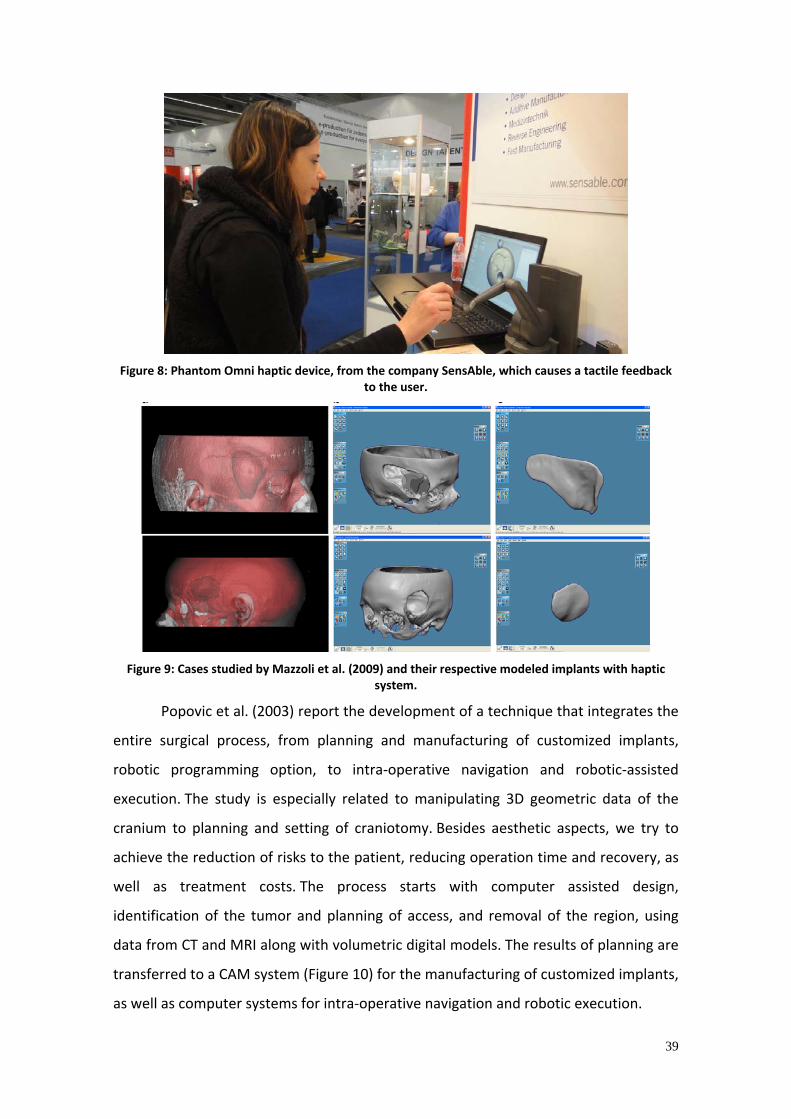
39
Figure 8: Phantom Omni haptic device, from the company SensAble, which causes a tactile feedback
to the user.
Figure 9: Cases studied by Mazzoli et al. (2009) and their respective modeled implants with haptic
system.
Popovic et al. (2003) report the development of a technique that integrates the
entire surgical process, from planning and manufacturing of customized implants,
robotic programming option, to intra‐operative navigation and robotic‐assisted
execution. The study is especially related to manipulating 3D geometric data of the
cranium to planning and setting of craniotomy. Besides aesthetic aspects, we try to
achieve the reduction of risks to the patient, reducing operation time and recovery, as
well as treatment costs. The process starts with computer assisted design,
identification of the tumor and planning of access, and removal of the region, using
data from CT and MRI along with volumetric digital models. The results of planning are
transferred to a CAM system (Figure 10) for the manufacturing of customized implants,
as well as computer systems for intra‐operative navigation and robotic execution.

40
Figure 10: Design of the implant performed in virtual environment. Reconstruction of cranial defect planned from CT images, manipulated in CAD environment. Source: Adapted from Wehmöller et al.
(2003).
Lethaus et al. (2011) report the design and manufacture of implants for large
skull defects using virtual biomodels in CAD/CAM environment. The skull bone defects
were repaired in this study using custom prosthesis in titanium or polyether‐ether‐
ketone (PEEK), produced through CNC machining (Figure 11).
Figure 11: Custom prosthesis for reconstruction of cranial defects, modeled in CAD and manufactured
through CNC machining.
New applications and prospects are seen in the areas of biomechanics for the
implantation of bone structures. Using the direct manufacturing process such as laser
sintering, titanium implants may be produced in unusual geometry, as described by
Wehmöller (2005). Complex geometries and structures demonstrate the possibilities
of this new technology, which in the close future will help in the revolution not only
the geometric configuration, but also reduce the cost and time of manufacture of
permanent metallic implants.
Wong et al. (2005) report a comparison between methods using manual and

41
virtual modeling. Both methods proved effective in surgical reconstruction of facial
asymmetry for selected cases. The manual modeling method is preferred where
backbones are already deformed, or when the reconstruction involves also soft
tissues. In technical aspects, the virtual method was superior because of its versatility,
predictability, accuracy, objectivity and convenience for data storage and
documentation.
The virtual method, however, has some limitations. To be widely used, some
requirements must be met. There is need for powerful image processing software and
qualified professionals, good communication between surgeons and designers should
be established, and a database with normal facial structures should be established.
An immediate advantage of the technique it the possibility of manufacturing
the prosthesis or implant through an automated process, such as CNC machining,
additive manufacturing and incremental forming. Thus, the component is
manufactured directly in the material suitable for implantation.
3.4.3 Manufacture of prosthesis through incremental forming
In recent decades, the metal forming industry has been faced with new
demands. Among them there is the production of small batches of components of
metal sheets, the increasing demand for flexibility of the process and the need to
reduce the time to bring the product to the market (Petek et al., 2009). The medical
field is certainly one of these cases. The requirements listed are incompatible with the
traditional processes of sheet metal forming. As a result, new forming processes,
which have no intrinsic costs to traditional equipment has been recently proposed,
usually classified as incremental forming processes, which have been developed and
optimized in several research groups (Hirt et al, 2004; Jeswiet et al., 2005; Micari,
Ambroglio and Filice, 2007; Duflou et al., 2010; Malhotra et al., 2011; Hussain et al.,
2009; Hamilton and Jeswiet, 2011; Palumbo and Brandizzi, 2012; Robert et al., 2012).
Single point incremental forming (SPIF) is a process in which a simple geometry
tool moves along an arbitrary trajectory over a sheet metal workpiece, fixed in a blank
holder (Figure 12). In this way, locally controlled plastic deformations are inserted until

42
the target geometry is achieved. Unlike other processes, molds and dies are not
necessary. It is also known as negative incremental forming process and is illustrated
in Figure 13. Therefore, a CNC milling machine can be used to strain the plate
plastically, placing the tool into specific path controlled by computer.
Figure 12: Tooling of the single point incremental forming process (SPIF). Source: Hussain et al. (2007).
Among the different types of incremental forming processes, the one which
uses only one contact point is shown as the most advantageous from an economic
standpoint because of its simplicity of tooling. Other types of incremental forming
processes have been proposed by researchers in recent years. The most widely used
can be classified into two categories: the first includes all processes in which a support
is used below the plate to guide the deformation inhibiting some degrees of freedom
(Figure 13 b). Traditionally, wood structures as well as layers of rubber of high strength
were used in different research centers. The second class of processes uses different
system deformation. Using more than one punch, for example, it may provide a local
deformation with greater control over the rigid movements. Other studies are
interested in using a different tool concept, replaced by water jet or pellets by making
a kind of mix process between incremental forming and shot peening (Petek et al.,
2009).

43
(a) (b)
Figure 13: Different systems used for incremental forming. a) Only one point of contact (SPIF ‐ Single Point Incremental Forming), or process type negative. b) More than one point of contact, or positive
incremental forming process. Source: Adapted from Hirt et al., 2004).
A simple tool is used for the product in a continuous movement of the
trajectory usually automatically generated in a CAD/CAM system. In this analysis, the
tool path starts on the outside of the form and will be moving towards the center and
down incrementally in the Z direction, in a kind of spiral. Thus, the tangential motion of
the tool forms the plate in accordance with the desired profile. The action of the punch
is located in a small region located close to the point of contact. Indeed, a large
numerical analysis of the process has shown that due to the progressive action of the
punch, the path of deformation of a reference volume of material is characterized for a
tendency of steps: each increment of deformation is only caused for the action of the
punch during its action. In turn, increase in deformation does not occur when the tool
moves back along the same lap, but spaced from the position of interest. This result
confirms the idea of "localized deformation", in that any point of the material is not
affected for the imposed deformation in the adjacent regions. In other words, the
material exhibits its great deformation in small progressive increments.
This aspect results in a strong increase in formability [Kim and Yang (2000),
Ambrogio et al. (2003), Shim and Park (2001), Hussain et al. (2009)]. Forming limit
curves are higher compared to the curves obtained through traditional sheet metal
processes, reaching values 2‐3 times greater. Furthermore, the forming limit diagram
does not have a curve with the same characteristic shape, but is represented for a
straight line with a negative slope in the positive quadrant.
However, at the same time, the particular mechanics of the process introduce

44
certain disadvantages. Indeed, the zones of the plate where the punch does not act are
subject to the presence of rigid motion that, when the force is released, generates
undesired elastic return. This can negatively influence the final result in terms of
dimensional accuracy and surface roughness. In other words, a large part of the plate
is free to bend and therefore the final geometry may be different from what is desired.
Discrepancies of a few millimeters are sometimes presented (Bambach, Hirt and Ames,
2004), making the process of incremental forming not so appropriate when aiming to
produce very accurate parts. This undesired effect can be reduced using different
strategies. For example, properly selecting the process parameters, among them the
tool diameter and speed, the tool path and increase vertical, and lubrication highlight.
In summary, it is possible to list some relevant advantages offered through SPIF
process as said by Micari et al. (2007):
• Set‐up costs are virtually null [Jeswiet et al. (2005)];
• The movement of the tool is controlled by a CNC machine;
• High flexibility of the process to produce a new product. The minimum
number of pieces to be considered for a batch is practically one;
• The process can be used for a rapid prototyping of new products, but it
is also suitable to produce parts that need to be the reconstructed, for
example, automotive components, whose matrices are currently out of
service [Amino et al. (2002)];
• The forming limits are greater than typical processes of sheet metal
forming. This is due to the favorable state of tensions punch‐induced
during deformation located.
On the other hand, some drawbacks can be mentioned:
• Incremental forming is a slow process. Indeed, deformation is locally
imposed by the punch, which go a long trajectory to form complex
geometries. Despite the most modern equipment allows high speed
rate, the manufacturing time can reach several minutes;
• The accuracy obtained in the parts is low. Indeed, the plate is simply set

45
on a blank holder, and is free to bend during the process. However,
when the force exerted by the punch is released, the elastic return can
be significant.
Considering its great flexibility, the single point incremental forming process
appears as a possibility for the manufacture of customized implants for craniofacial
reconstruction. Strategic toolpaths are drawn to shape the implant in the desired
geometry. In other words, a reverse engineering approach is used to produce a specific
implant for the needs of each patient (Figure 14).
Figure 14: Titanium cranial implant projected in CAD environment and produced through incremental
forming. Source: Duflou et al. (2008b).
Important advances for the use of incremental forming applications in the
manufactuting of products for the medical field are described by many authors
today. Such products have as features to require a high degree of customization
without the need of low cost. Ambroglio et al. (2005) describes the fabrication of a
customized an ankle support. The "round design", as described by the author, begins
and ends in the patient's own body. The ankle of the patient is scanned, and from the
scanner output information (point cloud), a virtual model is generated, for subsequent
manufacture of an ankle support in the exact dimensions of the patient through
incremental forming. Duflou et al. (2008) also shows the possibility of manufacturing
customized to cranial implants through incremental forming.

46
3.4.4 Manufacture of prosthesis through additive manufacturing
Scientific studies of the applications of CAD/CAM systems in medicine and
dentistry have been developed over the past 25 years, whose application is frequently
associated with CNC machining or additive manufacturing (Bernard and Fischer, 2002;
Schöne and Stelzer, 2005). In this case, in most approaches since 2006, it is focused on
stents in Co‐Cr and titanium alloys.
Additive manufacturing (AM), also commonly called rapid prototyping (RP),
rapid manufacturing (RM) or solid freeform fabrication (SFF), allows for the fabrication
of complex shapes, such as the forms found in the craniofacial region. Several SFF
techniques are currently available, allowing the use of various materials, including
metals and ceramics. Specifically for the manufacture of implants, additive
manufacturing processes enable the manufacture of components in material suitable
for implantation, as already experienced by several researchers (Singare et al., 2004,
He et al., 2006; Lohfeld et al., 2007 ; Bertol et al., 2010, Zhou et al., 2010; Mazzoli et al.,
2009)
The additive manufacturing processes are characterized for the generation of
the component, previously designed in CAD environment, by material deposition, layer
by layer. The physical principle that makes the layers overlapping and solidified to form
the 3D object varies in additive manufacturing techniques, and is commonly
characterized by the action of a laser beam that the melt the particles of powder (SLS,
SLM), addition of a liquid which binds the powder particles (3D printing), incidence of
light which solidifies a photopolymerizable resin (PolyJet). Among the advantages
offered by the additive manufacturing systems compared to conventional methods are
a wide variety of materials that can be used, including metals, ceramics and resorbable
polymers can be mentioned; flexibility in shapes that can be produced; the potential of
producing components of low weight, with optimized geometry and controlled
roughness, the biocompatibility and the fact that it is a one‐step process, which means
no tools or additional steps in the process are required. Additive Manufacturing
techniques for the production of implants in the material for suitable for implantation
have been proposed to produce different anatomical structures, such as hip, cranium,

47
zygomatic bone, mandible, etc., illustrated in Figure 15.
Figure 15: Examples of prosthesis manufactured through additive manufacturing. a) Mandible implant, zygoma and intervertebral discs with reticular structure. Source: Rapidtech, 2011. b) Implant for repair of cranial defect in poly‐lactic acid (PLA). Source: Fraunhofer Institu für Lasertechnik (ILT). c) Mandible Implant with optimized internal structure and topology. Source: Fraunhofer Geselschaft. d) Prosthesis for repair of cranial defect, in titanium. Source: University Maastricht, Netherlands. e) Replacement implant of knee joint in Co‐Cr, with reticular structure. Source: Arcam AB, Sweden. f) Prosthesis for replacement of hip joint in titanium, with a gradient of porosity. Source: Neuner (2008).
3.4.5 Manufacture of prosthesis through three‐dimensional laser scanning
Currently, aesthetic, ergonomic quality and product customization aspects are
assuming a growing importance in manufacturing industries: a wide variety of products
is designed and produced using these concepts. In this scenario, reverse engineering
(RE) plays a key role since there is often a need to acquire important information for
f

48
existing products. RE potentially allows us to reconstruct, in a short process time, the
complex geometric shapes known as free forms. Using the approach of reverse
engineering, it is possible to create reliable three‐dimensional models representing
various objects, components, environments, animals and even human parts.
Several applications of reverse engineering techniques are disseminated
worldwide in the areas of fine arts (to acquire virtual replicas of unique models),
archeology (to rebuild old objects and even manufacture them again), in the industry,
to provide models and craft products whose unique designs have been lost. Dentistry,
specifically the area dedicated to the manufacture of dental prostheses, currently uses
CAD/CAM systems based on three‐dimensional laser scanning models. Dental crowns
and bridges can be produced in a personalized and automated way from the dental
arch molds of the patient and with the aid of a specific CAD/CAM system (Figure
16). The applications of three‐dimensional laser scanning are also reported for the
areas of health, assistive technology, archeology, jewelry, digital games, among
others. Similar systems for the development of personalized products based on data of
the digitized patient's body are also being developed, such as the development of
custom seats [Smith (2011), Beretta (2011), Batista (2009)].
Figure 16: Process of manufacture of dental crowns and bridges based on Reverse Engineering.
a) Scanning of the patient's dental mold. b) Part design. c) Visualization of the model projected on the patient's dental arch. d) CNC milling of zirconia parts.
a b c
d

49
In an analogous way to the manufacture of prosthesis using manual modeling,
the method that uses the technique of dimensional laser scanning uses a physical
model of a patient's skull, which acts as a template for manual modeling. A
representative model of the prosthesis to be formed using a material suitable for
shaping. Dental waxes, resins and polymeric plastic masses are among these materials.
After determining the area to be reconstructed and the geometry of the
implant, the three‐dimensional laser scanning of the part to be shaped is held. It
should be noted that the model formed using physical biomodels must fit perfectly to
the patient's bone structure, since it will be replicated in the material suitable for
implantation.
The three‐dimensional scan captures information from an existing physical
model, generating three‐dimensional information that can be exported to a CAD
program, or directly to a prototyping device. This digital file that corresponds to a
three‐dimensional model to be manufactured implant is manipulable in a CAD
environment and can easily communicate with CAM systems, allowing for manufacture
of an automated manner. Different processes of manufacturing can be used such as
CNC or additive manufacturing. Both processes can be performed directly with the
material suitable for implantation.
The production of prosthesis for replacement of the temporomandibular joint
(TMJ) has used the technique of three‐dimensional laser scanning to capture data for
the design and manufacture of custom components, as shown in Figure 17. The
process consists basically of the CT scan of the patient, making an anatomical model of
the bones of the patient through rapid prototyping. The model represents exactly the
patient's bone structure, which allows for simulation of the regions of the mandible
and/or joint that should be modified. The prototype of the prosthesis is manually
patterned with the aid of resin or plastic masses and is subjected to three‐dimensional
scanning. This process allows the geometric data of the prosthesis to be saved in
digital format, which allows its manufacturing through automated techniques such as
CNC machining or additive manufacturing. As a result a prosthesis which fits precisely
to the patient's bone structure is created.

50
Figure 17: Manufacture of custom TMJ prosthesis. a) CT scan of the patient. b) Anatomical biomodel showing the removal of region to be replaced. c) Prosthesis prototype. d) Scanning of the components of the prototype. e) Virtual model. f) Final prosthesis, manufactured through CNC milling.
3.5 Quality in orthopedic implants
Orthopedic implants and their quality are evaluated, in general, by factors such
as the concept of the implant (function to be performed, patient characteristics,
fixation technique to be used) design (dynamic evolutionary process, anatomical
studies, distribution of load characteristics of the materials used, such as ductility,
toughness, fatigue resistance, etc.). sterilization technique, the component
characteristics and instrumentation (anatomical references, accuracy, testing,
reliability, ergonomics, care and cleaning agents); control quality (raw materials,
manufacturing processes, production processes, recording, packaging, sterilization,
labeling, storage, transport) and R&D (accumulated knowledge, clinical
experience/publications, records, risk analysis, study of failures, investments).
There are some causes that can lead to failure in orthopedic implants. Such
failures may come from three different origins: the surgical technique, the patient or
the implant itself. The wrong choice of technique, as well as its inadequate
implementation are factors that can lead to implant failure and treatment
failure. Factors such as osteoporosis, obesity, excess or lack of physical activity and
incompatibility of the implant materials are assigned to the patient as possible causes
of failure. The implant itself fails mainly due to the mechanical aspects, design errors,

51
fixing problems or sterilization.
Orthopedic implants are regulated by agencies and institutions that are
responsible nationally and internationally. Internationally accepted standards are
especially dictated by the Foods and Drug Administration (FDA), International
Standards Organization (ISO), ASTM (American Society for Testing Materials (ASTM),
Deutsches Institut für Normung (DIN), American National Standards Institute (ANSI),
among others. In Brazil, orthopedic implants and their necessary quality requirements
are regulated by Agência Nacional de Vigilância Sanitária (Anvisa).
Some important standards that deal with quality in orthopedic implants may be
cited: ASTM F1440 (mechanical testing), ASTM F380 (passivation), ASTM F967.01
(passivation after laser recording), ASTM 138 (stainless steel), ASTM F74 (Co‐Cr cast
alloys), ASTM F67 (pure titanium), ASTM F136, F620 and F1108 (Ti‐6Al‐4V alloys),
ASTM F648 (polyethylene, ultra high molecular weight), ASTM F799 (Co‐Cr forged
alloys), ASTM F603 (alumina heads for joints), ASTM F1185 (hydroxyapatite), ASTM
D4169 (tests for packaging and transport), ASTM D4329 (UV packaging
exposure). Besides these, other rules also regulate aspects such as sterilization,
biocompatibility, aging tests, validity tests, standards for project design, environment,
etc.

52
4. MATERIALS AND METHODS
The basic idea of this PhD study was to guide the process of design and
manufacture of implants to repair defects in the craniofacial complex, avoiding the use
of standardized plates and using implants designed and manufactured according to the
needs of each patient, with geometry, accuracy and mechanical properties suitable for
each case. The implants were produced using different design and manufacturing
processes.
Reverse engineering was used in order to produce such custom implants for
the reconstruction of human craniofacial bone structures. These products were chosen
for two main reasons:
• require a high degree of customization
• the manufacturing process used is flexible
Initially it is necessary to make a distinction of different types of craniofacial
implants that may be required to repair the craniofacial defects. These implants are
located in different regions of the craniofacial complex and differ among themselves in
terms of functions and geometric complexity. These characteristics guide and delimit
the systematic selection of materials and manufacturing processes, since they require
or dispense certain formal and mechanical requirements, and in turn, limit the
selection to a few materials and manufacturing processes.
This study addressed five types of craniofacial defects with indication for
customized implants, which might have different geometry and mechanical
characteristics. The studied bone defects are located in distinct regions of the
craniofacial complex with indication for alloplastic replacement.
The process involved the following steps, illustrated in Figure 18: acquisition of
anatomical data through computed tomography, tomographic data manipulation;
generation of a virtual or physical biomodel; modeling of the missing surface – implant;
characterization of the implant to be produced in terms of geometric and mechanical
requirements; selection of materials and manufacturing processes; manufacture of the
implant; evaluation of produced implant.

53
Figure 18: Steps involved in the project and manufacture of custom craniofacial implants covered in
this study.
4.1 Design of implants
4.1.1 Characterization of the type of implant
The implant types selected for evaluation in this study are different from one
another in terms of geometrical, mechanical and functional characteristics. For the
design and manufacture of implants, five different regions of the craniofacial complex
that are typically subjected to bone reconstruction surgeries were selected. There
were selected regions with different degrees geometrical complexity and pronounced
curvature, volumetric and articular regions, changing between each one, the degree of
difficulty and complexity to the production of implants.

54
4.1.2 Acquisition of anatomical data of patients
The acquisition of anatomical data of cases of surgical indication for craniofacial
reconstruction was performed using CT scans. The output files are images in DICOM
format, corresponding to the transversal slices of the examined region. For the results
of CT to be used in subsequent steps of the design and manufacturing of implants,
some parameters were followed, according to Table 2.
Table 2: Requirements used to obtain tomographic data.
Matrix 512x512
Field of view Between 140 and 170mm
Slice distance 1.0mm
4.1.3 Manipulation of tomographic data
Using InVesalius software version 3.0, DICOM images from CT scans were
transformed into three‐dimensional models. Thresholds were defined to exclude soft
tissues and selection of densities corresponding to bone tissue. Next, the surfaces
corresponding to the bone structure were generated and converted into STL format.
The objective of converting the file to STL mesh format is the possibility to manipulate
the file in other CAD, CAM and CAE commercial softwares, allowing the design of
implants in the virtual environment and making a physical replica of the model through
additive manufacturing.
4.1.4 Manufacture of biomodels
Physical anatomical models corresponding to the bone structure of patients
were built using additive manufacturing processes. The STL files were converted into
files corresponding to a series of transverse slices of the model, allowing the physical
reconstruction of the models, layer by layer.
4.1.5 Modeling of the implants
The modeling of the implants was performed using computer

55
modeling software widely used in Product Design and Reverse Engineering. Among
them there are the 3D Studio Max®, Rhinoceros®, Solidworks® and Raindrop Geomagic
Studio®. The implants were designed in order to reconstruct the region of the skull
and/or the patient's face that presented a bone defect.
The modeling of three‐dimensional structures and patterns that add
functionality to the implant was also assessed. The possibility of building internal
structures of regular pattern in order to provide weight reduction and to stimulate the
adjustment of the implant to the bone structure, as well as osteointegration, has been
investigated.
4.1.6 Selection of materials and manufacturing processes
For each type of implant studied, materials and manufacturing processes were
selected so that the produced implant could adequately meet the project
requirements, whether they were formal, mechanical, or functional. Single point
incremental forming (SPIF), CNC machining, additive manufacturing and modeling
guide were evaluate as possible manufacturing processes. Each of the processes
enables or restricts the use of certain materials which have, therefore, been selected.
The requirement of biocompatibility of the material to be used to manufacture the
implant was observed in all cases.
4.1.7 Characterization of the material
The implants were produced using commercially pure titanium sheets grade 2,
1mm thick. Prior to the production of implants, the characterization of the material
was performed in terms of chemical composition and mechanical properties. For
metallographic analysis, samples were taken in the transverse and longitudinal
direction of the sheet. The analysis was used to evaluate the grain size and phases
present in the material.
The analysis of the chemical composition was also carried out, verifying
compliance with the standard 5832‐2. The element Fe was determined by optical
emission spectrometry with inductively coupled plasma, Vista model, Varian
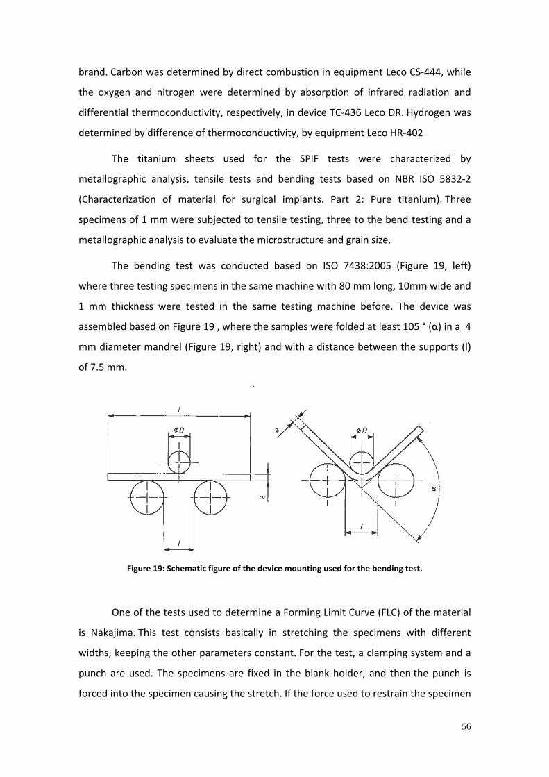
56
brand. Carbon was determined by direct combustion in equipment Leco CS‐444, while
the oxygen and nitrogen were determined by absorption of infrared radiation and
differential thermoconductivity, respectively, in device TC‐436 Leco DR. Hydrogen was
determined by difference of thermoconductivity, by equipment Leco HR‐402
The titanium sheets used for the SPIF tests were characterized by
metallographic analysis, tensile tests and bending tests based on NBR ISO 5832‐2
(Characterization of material for surgical implants. Part 2: Pure titanium). Three
specimens of 1 mm were subjected to tensile testing, three to the bend testing and a
metallographic analysis to evaluate the microstructure and grain size.
The bending test was conducted based on ISO 7438:2005 (Figure 19, left)
where three testing specimens in the same machine with 80 mm long, 10mm wide and
1 mm thickness were tested in the same testing machine before. The device was
assembled based on Figure 19 , where the samples were folded at least 105 ° (α) in a 4
mm diameter mandrel (Figure 19, right) and with a distance between the supports (l)
of 7.5 mm.
Figure 19: Schematic figure of the device mounting used for the bending test.
One of the tests used to determine a Forming Limit Curve (FLC) of the material
is Nakajima. This test consists basically in stretching the specimens with different
widths, keeping the other parameters constant. For the test, a clamping system and a
punch are used. The specimens are fixed in the blank holder, and then the punch is
forced into the specimen causing the stretch. If the force used to restrain the specimen

57
is insufficient, it seeps into the die, if it exceeds, it breaks. Eight test specimens were
subjected to deformation by a punch to their rupture (Figure 20). The deformations
were measured to the generation of FLC of the material.
Figure 20: Testing specimens submitted to a forming test to determine the Forming Limit Curve of the
material.
FLC is a graph of the main deformation greater at the beginning of necking
plotted for all values of the minimum main strain that can be supported. A typical
curve for the steel can be seen in Figure 21.
Figure 21: Example of forming limit curve (FLC).
Assuming that the curve represents the values of possible combinations of
deformation of the specimen that indicate signs of early rupture, the curve can be
interpreted as a boundary between regions of failure and safety. The region above the

58
curve is the region of failure or breakage. The region below the curve represents the
safe region.
Furthermore, tests were performed on standard test specimens for
determination of parameters which determine the limits for shaping the implant
through SPIF. For this, a CNC machining equipment Tecnodrill Digimill 3D was used,
belonging to the Laboratory of Design and Materials Selection (LdSM) from the Federal
University of Rio Grande do Sul (UFRGS).
Besides titanium, implants were also produced using calcium phosphate
cement. The bone cement used (α‐TCP) was obtained using calcium carbonate as
precursors (CaCO 3) ‐ average particle size of 3.4 µm ‐ and calcium pyrophosphate
(Ca 2 P2O 7‐γ) ‐ average particle size of 9.54 µm ‐ that passed through stages of thermal
treatment (calcination at 1300°C for approximately 15 hours and quenching of
precursors), grinding (to obtain an average particle size of 850 µm) and dried (oven at
90° C for 72 hours). The solid part was mixed with the liquid part, which is an aqueous
solution of Na2HPO4 to 2.5%.
4.2 Manufacture of implants
The designed implants were manufactured through one or more manufacturing
processes that were considered appropriate. For all implants studied, the possibility of
using the SPIF process for each case was evaluated and discussed. Parameters
necessary for the process used to allow the manufacturing of every particular type of
implant were studied and discussed.
4.2.1 Determination of the parameters of single point incremental forming
In this study, the process parameters were investigated in a systematic way for
single point incremental forming of titanium sheets, aiming their application as
implants for craniofacial reconstruction. SPIF tests with varied parameters were
conducted in commercially pure titanium grade 2, 1mm thick plates. The tests
intended to simulate different conditions and material stress for each mode, detect
the various deformations which lead to fracture. For the lubrication system
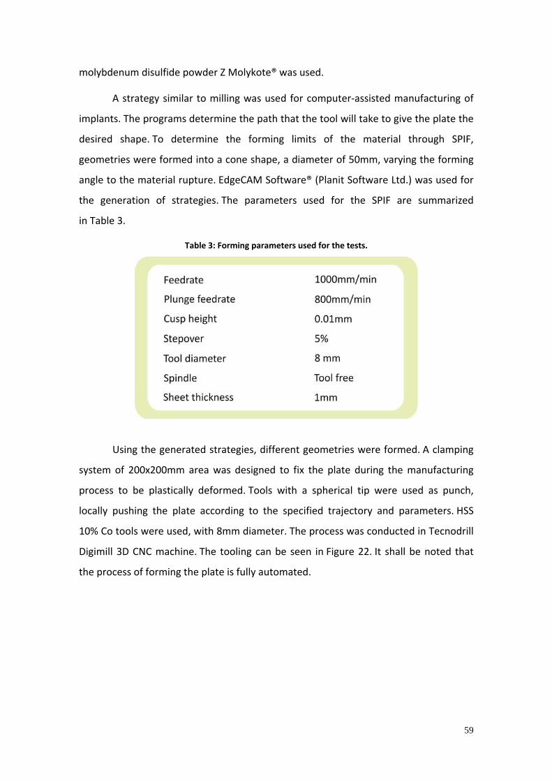
59
molybdenum disulfide powder Z Molykote® was used.
A strategy similar to milling was used for computer‐assisted manufacturing of
implants. The programs determine the path that the tool will take to give the plate the
desired shape. To determine the forming limits of the material through SPIF,
geometries were formed into a cone shape, a diameter of 50mm, varying the forming
angle to the material rupture. EdgeCAM Software® (Planit Software Ltd.) was used for
the generation of strategies. The parameters used for the SPIF are summarized
in Table 3.
Table 3: Forming parameters used for the tests.
Using the generated strategies, different geometries were formed. A clamping
system of 200x200mm area was designed to fix the plate during the manufacturing
process to be plastically deformed. Tools with a spherical tip were used as punch,
locally pushing the plate according to the specified trajectory and parameters. HSS
10% Co tools were used, with 8mm diameter. The process was conducted in Tecnodrill
Digimill 3D CNC machine. The tooling can be seen in Figure 22. It shall be noted that
the process of forming the plate is fully automated.

60
Figure 22: Tooling of the single point incremental forming process.
To enable the measurement of the deformation caused by the process, the
plates were previously marked with circles of diameter defined by the electrochemical
etching (Figure 23), performed with equipment belonging to the Metal Forming
Laboratory (LdTM/UFRGS). To measure the deformations generated in the SPIF of the
different specimens, a particular, flexible, transparent and graduated scale with
deformations for the circular grating of 2.5 mm in diameter (Figure 24) was used. Thus,
the strain values were read directly from the scale. Such scale, for being flexible,
follows the shape of the testing specimen and its transparency allows the visualization
of the mesh lines. For the measurement, the scale was overlaid on the ellipse to be
measured and a reading was taken when the degree of transverse lines was over the
axis that was being measured and the longitudinal lines of graduation were overlapped
on the contour lines as the ellipse. The points were plotted on the measured strain
limit graph, where φ 1 (major strain) corresponds to the axis of ordinates and
φ 2 (minor strain) corresponds to the axis of abscissas.
Tool Part
Blank holder

61
Figure 23: Device used for electrochemical etching of the circles grid on the metal plate.
Figure 24: Graduated scale used for the measurement of deformations.
Furthermore, the temperature reached was monitored by the tool and by the
plate during the SPIF, using the technique of thermography. The equipment used for
the analysis was the Infrared thermography SAT, SAT‐PHY6800, belonging to the
Laboratory of Ceramic Materials (Lacer/UFRGS).
4.2.2 Dimensional inspection
In the case of production of customized implants, as well as in applications in
which the fitting to other parts is necessary, the dimensional inspection gives a
significant response over the performance of the process. To analyze the dimensional
accuracy of the process the technique of three‐dimensional laser scanner was used
(Tecnodrill Digimill 3D). A comparison between the dimensions of manufactured parts
and the designed parts, developed in a CAD environment was made. To this purpose,

62
the files resulting from scanning of formed parts and the virtual representations of the
designed parts are overlapped, and the differences between them are measured. .
Using the three‐dimensional laser scanning the change in thickness experienced by the
sheet during the forming process was also assessed.
The implants produced were evaluated according to the attendance or absence
of formal, mechanical and functional requirements. The manufacturing process used
was evaluated in terms of:
• precision, evaluated through the three dimensional laser scanning
and/or adaptation of the implant to the patient’s biomodel;
• time required to the execution of the various steps involved (set up of
the equipment, manufacture, post‐processing);
• difficulties encountered in the various steps involved (set up of the
equipment, manufacture, post‐processing);
• cost, also considering the level of technical skills of the operators
involved and equipment needed.
In this sense, with the evaluation of the strengths and limitations of
manufacturing processes studied, appropriate conditions for the development of
criteria for the choice of manufacturing process (and, consequently, of the materials)
for each case of manufacturing of customized implants in the craniofacial complex are
created.

63
5. RESULTS AND DISCUSSION
5.1 Characterization of the types of implants
For the design and manufacture of implants, regions with different geometrical
characteristics and different functional requirements were selected. As shown
in Figure 25, they are located in distinct regions of the craniofacial complex:
• Defect in the parietal or frontal region (a);
• Defect in the frontal region of the skull, including the supra‐orbital
region (b);
• Defect in the region of the zygomatic bone (c);
• Defect in the region of mandible ramus (d);
• Defect in the temporomandibular joint (e).

64
Figure 25: Different studied implant geometries.
5.1 Characterization of the material
Through the tensile and bending tests performed, the properties shown
in Table 4 were determined and compared with the properties specified by the
standard NBR ISO 5832‐2.

65
Table 4: Results of tensile and bending tests.
Grade Condition
Tensile strength (1)
min. MPa
Yield strength min. MPa
Elongation (2)
min. %
Mandrel diameter for bending test of
strips (3)
mm
2 Annealed 345 275 20
Sample 1 1 mm
467 356 42 Did not crack
Sample 2 1 mm
470 347 40 Did not crack
Sample 3 1 mm
468 352 38 Did not crack
R E S U L T S
Average 468 352 40 Did not crack
1) requirements for tesile, yielding and bending strength that plates shall apply to materials obtained longitudinally and transversely to the rolling direction. 2) Length of calibration = 5.65 mm or 50 √ S0, where S0 is the original area of cross section in square millimeters. 3) t = the thickness of the sheet or strip ≤ 2 mm
Findings through metallographic analysis demonstrate that the sample showed
typical microstructure of pure titanium, with the average grain size ASTM 9, as shown
in Figure 26. The tensile properties are in accordance with those specified in the
standard for titanium grade 2.
Figure 26: Metallographic analysis of titanium samples, showing equiaxed microstructure.
Table 5 shows the results obtained and the comparison to the requirement of
the standard ISO 5832‐2 to evaluate the chemical composition.

66
0
0,1
0,2
0,3
0,4
0,5
0,6
‐0,6 ‐0,4 ‐0,2 0 0,2 0,4 0,6
Minor Strain (φ2)
Major strain (φ1)
φ1=‐φ2
φ1=φ2
FLC
CLC (l inha detendência)
Table 5: Chemical composition of the plates.
Element Pure titanium sheet grade 2 Thickness: 1mm
% (m/m)
Specification Norma NBR ISO 5832‐2 Grade 2
% (m/m)
Fe 0.08 0,30 max.
C 0.023 0,10 max.
O 0.104 0,25 max.
N 0.008 0,03 max.
H 0.0014 0,0125 max
A test was also performed to determine the forming limit curve (FLC) of the
used plates of titanium. Using the markings etched on the plates, transverse and
longitudinal strains to determine the FLC (Figure 27) were measured.
Figure 27: Forming Limit Curve of the titanium plates.
The FLC is particularly important because it determines, for conventional sheet
metal forming processes, safe levels of deformation which can be imposed on the
material. According to Folle et al. (2008), the factors that affect the forming limit curve
for a given metal sheet are the thickness, the friction, the rolling direction, the
anisotropy, the pre‐deformation, grain size, the strain hardening and the punch
speed. The effects on the curve, caused by each of these factors, are shown in Table 6.
FLC (trend)

67
Table 6: Influence of different parameters on the forming limit curve (FLC).

68
0
0,1
0,2
0,3
0,4
0,5
0,6
‐0,25 ‐0,2 ‐0,15 ‐0,1 ‐0,05 0 0,05 0,1 0,15
Minor strain(φ2)
Major
strain (φ
1)
Incremental
FLC
CLC (l inha detendência)
5.2 Determination of parameters of the single point incremental forming
The single point incremental forming of cone specimens allowed the
measurement of permitted and critic levels of deformation, where material fracture
might occur.
Figure 28 shows the forming limit diagram (FLD) of the titanium sheets. The
measures of the strain obtained from different samples and the FLC material are
plotted on the graph.
Figure 28: Forming limit diagram of the titanium plates used and strain values obtained for the SPIF tests.
For the SPIF process, however, it is observed that some strain values obtained
are above the FLC. This can be explained by the fact that, in SPIF, the material is
occasionally pushed in the direction of deformation. Each portion of the material is
individually deformed, however, at the end of the process; the tension is applied in the
entire area of the plate uniformly. In a conventional sheet metal forming process, the
fracture mechanism occurs due to crack propagation, since the force is eventually
concentrated in preferential regions, usually in parts of material that are defective or
have micro‐cracks. For the generated graph, the points that lie below the trend line
correspond to deformations of the sheet in regions that were not in their maximum
state of deformation. It is noted further that for forming through SPIF the points are in
the region of the graph corresponding to positive deformations, which indicates an
FLC (trend)

69
increase in area in both the vertical and transversal direction of the deformed
region. The increase in area in one direction and consequent reduction of the cross‐
sectional area, which occurs to the conventional forming process, indicates that there
is a necking in the material, so the points are represented in the corresponding
negative deformation area in the graph. Such behavior is not observed for the SPIF
process.
For the determination of maximum angles that define the forming limits of the
material, tests were conducted in specimens in the form of a cone with a diameter of
50mm, with angles of 30, 40, 45, and 50 degrees.
For different measured angles, it was found that the maximum angle to the
conformation of titanium through SPIF was 45°. At this angle, the plate has undergone
deformation, without showing cracks or micro‐cracks (Figure 29). Above this value, the
plate has an excessive deformation and decrease in thickness and consequently fails
(Figure 30).
Once again using the angle 45°, SPIF was carried out in a larger cone, the apex
plane with 120 mm diameter and 55mm height. The maximum amount of deformation
measured in this test was 60%. It was observed the breaking of the plate during SPIF
(Figure 31); however, the process was continued until its end. The fracture of the
material occurred in a region that had 50% elongation, below the maximum shown in
other regions of the material. This leads to the need to consider other important
factors that affect the formability of the material in the process of SPIF. It is observed
that fracture occurs in an intermediate region formed in the profile geometry. In this
case, a conical geometry was used, with a flat basis and not pointed, as seen in Figure
29 . Considering that on the upper ends of the cone the plate thickness has its
maximum, it decreases along the profile geometry. Upon arriving at the base of the
cone, the plate thickness is again at a maximum. This event leads to the conclusion
that the material is broken due to excessive reduction of sheet thickness and not due
to deformation of the material above the limit. To prevent this type of breakdown, the
use of a safety factor could be foreseen, forming only parts requiring lower levels of
deformation or limit angles.

70
Figure 29: SPIF in titanium cone forming an angle of 45° with the plane of the plate.
Figure 30: SPIF in titanium cone forming an angle of 50° with the plane of the plate, with disruption.

71
Figure 31: Fracture of the material presented in SPIF of cone with angle of 45°.
5.3 Dimensional inspection
The measurement of the variation of thickness of the sheets was performed
using the technique of three‐dimensional laser scanning, and after the capture of the
point clouds, they were manipulated in the software Geomagic Qualify® (Figure
32). The plates were scanned in the two main faces with the aid of spheres for fixing
the plate. The thickness variation was evaluated for the samples in the form of cone
angles of 30° (Figure 33), 40° (Figure 34) and 50° (Figure 35). It is worth to remember
that the initial thickness of the plates was 1 mm.
Figure 32: Three‐dimensional laser scanning of the testing specimens in the cones of 30 and 40°
manufactured through SPIF in plate of 1mm.
72
(a)
(b)
Figure 33: Variation of the thickness of the formed plate into the conformation of the 30° cone. a) Top view. b) Cross section view.

73
(a)
(b)
Figure 34: Variation of the thickness of the formed plate into the conformation of the 30° cone. a) Top view. b) Cross section view.

74
(a)
(b)
Figure 35: Variation of the thickness of the formed plate into the conformation of the 50° cone. a) Top view. b) Cross section view.

75
The variation of thickness of the sheets can be understood considering the law
of conservation of volume: since the plate is attached to the blank holder and the
material is plastically deformed, the increased surface area which occurs in the region
of the plane of the plate is offset by decreasing the thickness. Through these tests a
significant variation of thickness for the cones of 40 and 50 degrees can be observed,
as a consequence of this fact. The region of the material to fracture would
theoretically be attained when the thickness of zero was reached, as in the case
of Figure 35. However, other factors end up affecting the formability of the metal
sheet, such as material defects or cracks and lubrication failures.
The accuracy of the SPIF process of the test specimens was also evaluated by
means of three‐dimensional laser scanning. The formed geometries were compared
with their original models, designed in CAD. The result can be seen in Figure 36.
Figure 36: Three‐dimensional comparison of CAD designed model and the model formed through SPIF.
Poor accuracy of the process is observed, especially in regions near the edges
of the plate and regions experiencing geometric variations over abrupt or sharp edges,
such as the bottom end of the figure illustrated in Figure 36. This difference can also be
seen in the cross section of the cones with 30 and 40 degrees shown in Figure
33 , Figure 34 and Figure 35. The region of contact between the edges of the sheets
and formed parts are rounded, as well as their bottom extremities.

76
5.4 Thermography
The temperature experienced by the material and the tool during the SPIF is
shown at different angles in the thermography of Figure 37 . The formed cones of 30,
40 and 50 degrees were evaluated.
(a)

77
(b)
(c)
Figure 37: Thermography performed during the SPIF of cones with different angles. a) 30 degrees. b) 40 degrees. c) 50 degrees.

78
The titanium plate and the tool, in turn, had heating, evidenced in the
thermography, especially the cone angle of 50 degrees, experiencing temperatures
around 70oC. The heating of the titanium plate can be attributed to several factors,
such as the release of energy due to plastic deformation and friction. However, it is not
possible to consider the temperature rise a cause of the fracture of the material which
occurs in the cone of 50 degrees. In this case, it can be inferred that the fracture has
occurred due to deficiencies of the process, such as the deficiency in lubrication, as
evidenced by elevated temperature, or by local defects in the material.
5.5 Design and manufacture of implants
As proposed, cases of reconstruction of craniofacial bone defects in five
different regions of the craniofacial complex were studied: the frontal or parietal
region, the frontal region, including the supra‐orbital, the zygomatic bone region, the
temporomandibular joint; the mandible ramus. For each case, one or more modeling
possibilities were investigated, whether manual or virtual. All cases involved the use of
biomodels, whether physical or virtual, derived from CT images. The ability to
manufacture implants through SPIF and other alternative processes was evaluated.
5.5.1 Frontal region
A typical case of defect repair in the frontal region of the cranium was selected
(Figure 38). To this purpose, two strategies of modeling and manufacturing were
used. The first approach (method 1) was based on manual modeling of the prototype
of the implant. The second (method 2) was performed using virtual modeling and
single point incremental forming.

79
Figure 38: Three‐dimensional image obtained from CT data. Defect in the frontal region of the skull.
METHOD 1
An anatomical biomodel containing the cranial defect to be repaired was
produced though CNC machining process. The defect was filled manually with epoxy
resin, and from this template, a silicone rubber mold was generated and a suspension
of calcium phosphate cement was poured into it. Furthermore, inside the mold, a
titanium mesh grade 2 cp thickness 0.7 mm was positioned, to ensure structural
stability of the cement and allow its attachment to the cranium of the patient with the
use of screws. After pouring into the mold, the calcium phosphate cement remained in
the oven for 24 hours until it has acquired the necessary rigidity to be demolded. Figure
39 illustrates the steps involved in this procedure. For the evaluation of costs involved
to produce the implant, however, the cost of commercial bone cement was considered.

80
Figure 39: Figure 39: Procedure for manual modeling of implant to repair the bone defect in the
frontal region. a) Biomodel showing the defect. b) Implant model, molded in epoxy resin in a silicon mold. c) Implant cast in calcium phosphate cement with titanium mesh inside. d) Implant positioned
in the biomodel.
The process time to obtain the implant considering the steps described above is
shown in Table 7.
Table 7: Time required to manufacture the cranium implant with calcium phosphate cement.
Step Used time (h)
Manufacturing biomodel 10 Modeling the plastic mass (including the cure time) 10 Manufacture of silicone mold (including curing time) 25 Cutting and shaping the titanium mesh 1 Filling with calcium phosphate cement (including curing time) 25 TOTAL TIME 71
The handling time of the materials for making the mold and the implant
(excluding the curing time) was estimated at 5 hours. Among the manufacturing costs
of the implant, the manufacture of biomodel, the materials for making the model of
the implant and template, the implant materials (cement of calcium phosphate and
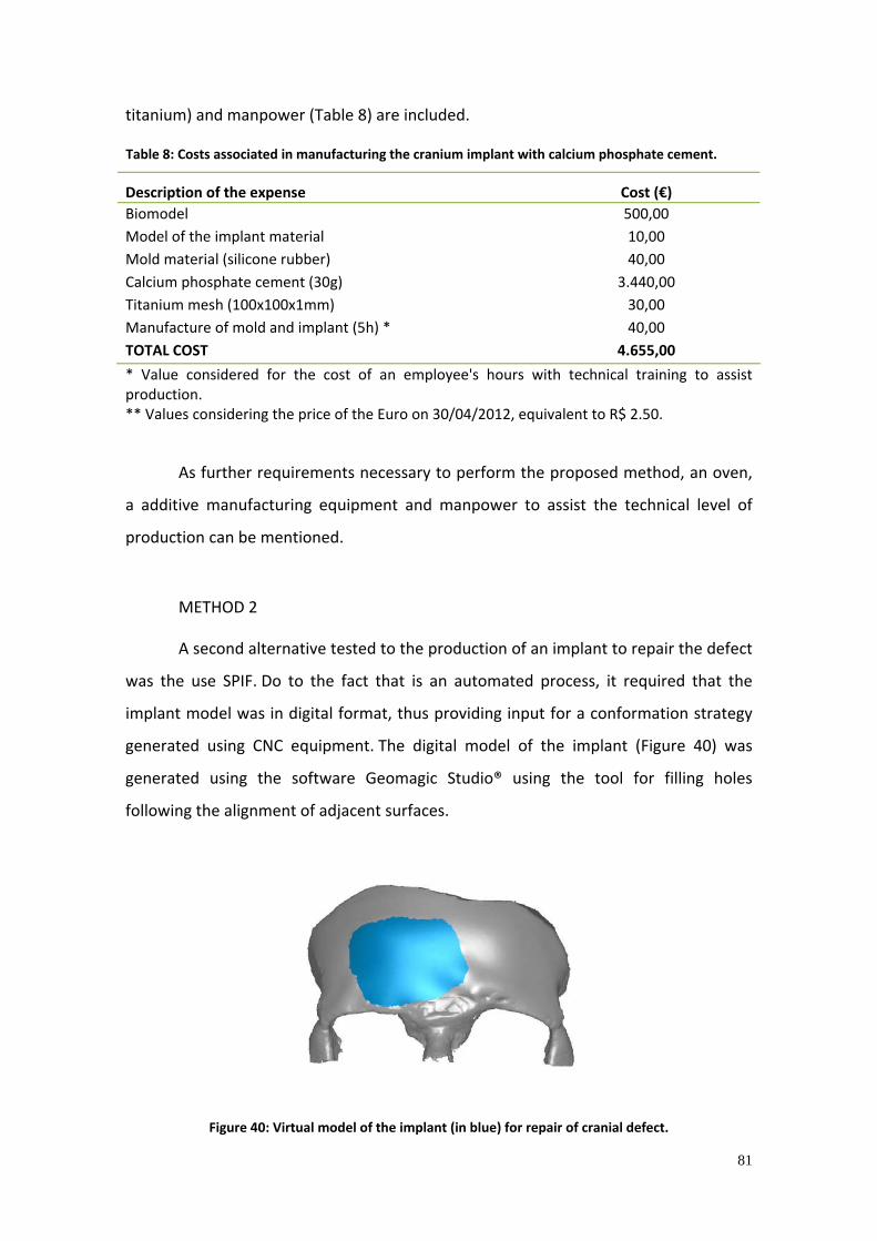
81
titanium) and manpower (Table 8) are included.
Table 8: Costs associated in manufacturing the cranium implant with calcium phosphate cement.
Description of the expense Cost (€) Biomodel 500,00 Model of the implant material 10,00 Mold material (silicone rubber) 40,00 Calcium phosphate cement (30g) 3.440,00 Titanium mesh (100x100x1mm) 30,00 Manufacture of mold and implant (5h) * 40,00 TOTAL COST 4.655,00
* Value considered for the cost of an employee's hours with technical training to assist production. ** Values considering the price of the Euro on 30/04/2012, equivalent to R$ 2.50.
As further requirements necessary to perform the proposed method, an oven,
a additive manufacturing equipment and manpower to assist the technical level of
production can be mentioned.
METHOD 2
A second alternative tested to the production of an implant to repair the defect
was the use SPIF. Do to the fact that is an automated process, it required that the
implant model was in digital format, thus providing input for a conformation strategy
generated using CNC equipment. The digital model of the implant (Figure 40) was
generated using the software Geomagic Studio® using the tool for filling holes
following the alignment of adjacent surfaces.
Figure 40: Virtual model of the implant (in blue) for repair of cranial defect.

82
For the virtual model of the implant it was possible to use the feature of filling
holes of Geomagic Studio® software, since the area to be repaired is an extension of
the adjacent surfaces, without complex curvatures. Thus, the mathematical approach
provided by the software proved to be visually suitable. Such tool is limited, however,
to the case of implants modeling in non‐complex regions of the cranium, such as the
parietal or frontal region; in the case of complex geometries, however, it is necessary
to design it in CAD environment.
Using EdgeCAM® software, a strategy to form the implant through SPIF of cp
titanium sheet was generated. A strategy that defines a constant cusp of 0.01 mm
and step over (horizontal advancement) of 5% was selected. The result of the
conformation of the implant, prior to cutting the implant from the sheet is shown
in Figure 41.
.
Figure 41: Incremental forming of implant for repair of cranial defect.
After the SPIF, the part was scanned in order to verify the accuracy of the
process. The comparative result between the virtual designed model and the formed
model can be seen in Figure 42 . The deviations are shown in millimeters.

83
Figure 42: Three‐dimensional comparison between the designed and produced model (in mm).
It must be noted that the low accuracy of the process in some specific regions
such as regions near the edges of the implant and in the central region. This can be
attributed to the return due to elastic properties of the material and the geometry
itself, where it is observed a greater springback effect at approximately the center of
the part. The elongation was calculated and showed values ranging from 10 to 20%.
According to Table 8 and Table 9, the time and costs associated with the
manufacture of the implant through SPIF can be listed.
Table 9: Time required to manufacture the titanium cranial implant through single point incremental forming.
Step Used time (h)
Biomodel Manufacture 3 Programming in CAM 1 Set up of the equipment 1 SPIF 2 Cutting plate according to the contour of the implant 3 Deburring, cleaning 2 TOTAL TIME 12

84
Table 10: Costs associated with the manufacture of titanium cranial implant through single point incremental forming.
Description of the expense Cost (€)*** CAD modeling (3 hours) * 48,00 CAM Programming (1 hour) 16,00 Time machine CNC machining center (3 hours) 120,00 Cutting plate and finishing (5 hours) ** 40,00 Titanium sheet cp grade 2 (200x200x1mm) 42,00 Lubricant (MoS2) 40,00 TOTAL COST 306,00
* Values considered for the cost of an employee's hours with technical training in design and programming. ** Values considered for the cost of time for an employee with technical training to assist production. *** Values considering the price of the Euro on 30/04/2012, equivalent to R$ 2.50
As operational requirements, the demand of this process are also a 3‐axis CNC
machining, CAD and CAM softwares. As manpower, a professional with aptitude for
CAD modeling and CNC programming is necessary.
EVALUATION OF PROPOSED METHODS
Both procedures used for modeling and manufacturing of the implants were
suitable for the studied cranial defect. The implant manufactured through manual
modeling, and the one which was virtually designed and manufactured through SPIF
adapted well to the bone structure. If necessary, dimensional changes (such as
removal of excess material, shaping external titanium mesh) could still be done in the
manually modeled implant to allow adaptation to the biomodel. The implant
manufactured through SPIF also proved to be capable of use, although some
springback has been experimented by the sheet, decreasing the implant
accuracy. However, as the geometry of the implant is simple and follows the cranial
curvature, there is no impediment to the use of the technique. In the case of complex
geometries, however, the elastic return, and therefore, the inaccuracy of the process
may prevent its use.
The time required for manufacturing the implant through manual modeling is
mostly derived from the cure time of the materials. The material for the construction

85
of the prototype of the implant requires about 10 hours to achieve the stiffness
required to be molded. The mold material (silicone rubber) and the implant material
(calcium phosphate cement), in turn, require about 24 hours. The lack of precision
which may perchance be associated with this method arises from the fact that it is
manually performed and, for this reason, depends on motor skills and practice of the
operator.
The calcium phosphate cements (hydroxyapatite) present different
characteristics for use as a biomaterial. They are biocompatible and, in addition,
bioactive, inducing formation of bone tissue in regions where it is located, causing its
regeneration. It is therefore bioassimilable. This feature comes against what was
thought until recently about biomaterials: that they should remain inert when
implanted in the human body. The calcium phosphate cement may be cured "in situ",
allowing greater ease of handling. However, its "caught" reaction does not present
elevation of temperature, being favorable for intraoperative manipulation, excluding
possible complications that can occur from exposure to implant tissue at high
temperatures. Although being suitable for intraoperative handling, manufacture of the
implants of calcium phosphate before the surgery appears to be very
advantageous. Due to the limitations that the metallic and polymeric materials present,
the production of custom craniofacial implants using calcium phosphate cements show
significant advantages. Unlike most other alloplastic biomaterials, which are inert,
these materials are bioactive (enable osteoconduction) and have the potential to
promote osseous growth and integration after implantation. As a result, these
materials are very well tolerated, with virtually no inflammation, minimum fibrous
encapsulation and without negative effects on bone mineralization site. According to
Santos (2002), calcium phosphate cements provide a physical substrate on which new
bone tissue, with adjacent surfaces, can potentially be deposited and guided to areas
occupied for the material.
The time required to manufacture the implant through SPIF is, in turn,
significantly lower. This is due to the fact that the SPIF process allows the direct
manufacture of the implant in the suitable material and in its final geometry, without
the prior manufacture of prototypes. The advantage provided by this method to the

86
manufacture of skull defects is evident from these data, regarding the time necessary
to complete the process. Some manual finishing operations such as cutting of the plate,
removal of burrs and cleaning are necessary, however.
The SPIF process also showed a reduced cost to manufacture skull implants
when compared to manual shaping. This fact can be explained analyzing the
composition of the cost of the manual modeling process, which is mostly derived from
the cost of biomodel and the implant material. Eliminating the need for a prototype of
the cranium to provide a basis for the modeling, the cost of the process is significantly
reduced. The material used for manual modeling (calcium phosphate cement) has also
a higher market value, being eliminated from the SPIF method. In turn, it provides the
advantage that, being initially fluid, it can be used to fill bone holes and has also
properties of osteoconduction.
Other authors also suggest the manufacture of cranial implants using other
procedures. Wirtz (2005) evaluates the manufacture of a cranial implant in titanium by
means of additive manufacturing and compares process variables with CNC milling, in
the case of the same implant. Table 11 shows the comparative costs involved for both
processes. Furthermore, the production of such a custom implant is currently
commercially available. The time required for the manufacture (excluding the steps of
pre‐and post‐processing) is estimated at 12 hours, using laser melting equipment. The
division Cranial Construct®, from the German company Digital Medical Design GmbH,
designs and manufactures customized implants for cranial defects using additive
manufacturing and deliveries it to the applicant in approximately one week.
Table 11: Comparison between the costs of making cranial titanium implants through CNC machining and additive manufacturing (laser melting). Source: Adapted from Wirtz, 2005.
Step CNC Machining Additive manufacturing Programation in CAM
300€ CNC Programation 50€ Positioning of support structures, division of the 3D file in layers
Manufacture 3000€ 200€
CNC machining Deep drawing
1200€ Laser sintering
Post‐processing 200€ Deburring, cleaning 250€ Removal of supports, Deburring, cleaning
Total cost 3700€ 1500€
In the costs raised by Wirtz (2005), a significant difference appeared compared

87
to the costs involved in the studied processes. This difference is particularly significant
regarding the costs arising of steps that involve the direct interference of the operator,
as it is the case of manual operations to remove burrs and cleaning. This difference is
mainly due to the comparison of labor costs of resident employees in Germany and
Brazil, among other costs involving taxes and fees. The costs of raw materials can also
be strongly influenced by the geographical region where it will be used.
5.5.2 Frontal and supra‐orbital region
One case of typical defect in the frontal and supra‐orbital region of the skull
with indication of bone reconstruction was investigated. For the design and
manufacture of the implant, two different approaches were used. For the first method,
a physical biomodel of the skull was used for the direct manual modeling of the
implant (method 1). For the second method, a virtual modeling approach was chosen,
in which a virtual flat editable mesh has been distorted according to the 3D model of
the skull. The part was formed through single point incremental forming (method 2).
METHOD 1
In the first case of front and supra‐orbital bone defect (Figure 43 a), a physical
biomodel was used to shape the implant manually (Figure 43 b). The implant was
made manually using the biomodel manufactured through additive manufacturing. To
this purpose, a predrilled titanium plate was formed with the aid of pliers. The result is
shown in Figure 44 .
Figure 43: Bone structure of the case of bone defect studied. a) Virtual biomodel, showing the defect
in the frontal and supra‐orbital region. b) Physical biomodel used for the manual modeling.
(a) (b)

88
Figure 44: Resulting cranial implant produced through manual shaping.
The implant fitted well to the bone structure, as evidenced by its proper
adaptation to the biomodel. The bone defect was completely hidden by the implant,
which thus enables the resumption of aesthetic functions and neural protection. Time
data and cost required for the manual shaping of the implant are presented in Table
12 and Table 13.
Table 12: Time required for the manual manufacture of the cranium implant in titanium plate.
Step Used time (h) Biomodel manufacture 10 Drilling titanium plate 1 Cutting and shaping titanium plate 4 Deburring, cleaning 2 TOTAL TIME 17
Table 13: Costs associated with the manual manufacture of cranial implant in titanium plate.
Description of expense Cost (€)** Biomodel manufacture 500,00 Titanium sheet cp degree 2 (100x100x1mm) 30,00 Drilling, forming, shaping and finishing of the plate (6 hours) * 48,00 TOTAL COST 578,00 * Value considered for the cost of an employee's hours with technical training to assist production. ** Values considering the price of the Euro on 30/04/2012, equivalent to R$ 2.50.
METHOD 2
The second variant of bone defect in the frontal and supra‐orbital is shown in

89
Figure 45a. An implant was virtually designed in order to restore the shape of the
cranium and the orbit. The process started from a surface that was virtually distorted
and shaped to adapt to the anatomy of the cranium and fill the area with missing bone
material. The modeling was performed in 3ds Max® software and is shown in Figure
45b. The final virtual implant model is illustrated in Figure 45c.
Figure 45: Three‐dimensional model of the cranium of the patient, (a) showing the bone defect to be
reconstructed, (b) modeling and (c) bone defect repaired with the shaped implant (green).
The designed implant model was manufactured from titanium sheet cp 1mm
thick, through SPIF. For shaping the implant, a strategy was used so that the defined
toolpath in the CAM software did not exceed the limits of angle and maximum
deflection determined in preliminary tests with cone geometries. A reference plane
was constructed (representing the plate) and polygons were modeled joining the lower
regions of the implant to the reference plane. A maximum angle of 40° between the
polygon and track the reference plane was established, in order to ensure that the
plate does not exceed the limits and the material fails (Figure 46).
(a)
(c)
(b)

90
Figure 46: Virtual implant model, with adjacent polygons with a maximum angle of 40° to the plane of
the plate.
The need for further shaping of surfaces adjacent to the ends of the implant is
evident. With the exception of the hypothetical situation in which all the implant edges
coincide with the plane of the plate at low angles (below 45°), certain regions to be
shaped are positioned at distances above the deformation limit of the material. Thus,
if the tool goes down directly to this position, the plate would break due to the
extrapolation of the limit angle. In this regard, the forming is sought in deeper regions
by gradual material forming at an allowed angle, until it reaches regions of the edges
which lie below the plane of the plate. The modeling of the implant, due to the need of
the inclusion of adjacent areas to follow the curvature of the implant and allow its
conformation, required a longer time compared to the modeling of the cranial implant
from the previous case (item 5.5.1).
With the area to be shaped defined in compliance of the limit angles of forming,
a conformation strategy was generated in a CAM software (Figure 47). In this case, also
a strategy defining a cusp constant of 0.01 mm and stepover of 5% was used. Care
should be taken so that the increase is small enough to ensure that only a small point
of the tool finds the surface of the metal to be shaped, to maximize the pressure. The
process for forming titanium implant to repair the front and supra‐orbital defect is
illustrated in Figure 47.

91
Figure 47: Forming strategy defined in CAM software. a) Toolpath. b) Process simulation.
The implant was then produced in titanium. Using the etched grid in the plate it
was possible to measure the deformation experienced by the material. The highest
value found of elongation, measured using the graduated scale (Figure 24), was 72%
and can be seen in Figure 49.
Figure 48: SPIF of the implant.
(a) (b)

92
Figure 49: Implant manufactured of titanium, showing the etched grid used for the measurement of
the deformation.
The difference between the designed and the final part, formed through SPIF,
can be seen in Figure 50 . This analysis was carried out using three dimensional laser
scanning, and provides important information about the accuracy of the process. For
the fabrication of customized implants, as it is the case studied, such precision is
particularly important, since the implant must be exactly adapted to the patient's bone
structure. As seen in the dimensional analysis of deviations, the region corresponding
to the orbit has not been properly reproduced.
Figure 50: Differences, in millimeters, between the designed implant and the implant produced
through SPIF.

93
The differences found between the designed part and the effectively
performed implant range from zero to a maximum of 5.9 mm. This difference can be
explained for the elastic return experienced by the material, after releasing the
pressure exerted by the punch. For the application of this methodology, considering
the material, process parameters and tooling, the accuracy should give better results,
since the implant must fit exactly to the patient's bone anatomy. Dimensional
deviations would be aesthetically viable for up to 2 mm for the region. The use a scale
factor can be shown as an alternative, giving the desired part larger dimensions than it
really should have. It may be possible to compensate the springback effect
experienced by the material. The quantification of the exact amount to be increased in
the model, however, should be determined.
The time consumed and cost associated with manufacture of the implant
through SPIF is listed in Table 14 and Table 15.
Table 14: Time required to manufacture the implant to repair front and supraorbital defects in titanium through single point incremental forming.
Step Used time (h) Modeling of implant in CAD 5 Programming in CAM 1 Set up of the equipment 1 SPIF 2 Cutting plate according to the contour of the implant 3 Deburring, cleaning 2 TOTAL TIME 14
Table 15: Costs associated with the manufacture of the implant to repair frontal and supra‐orbital defects in titanium through single point incremental forming.
Description of the expense Cost (€)*** CAD modeling (5 hours) * 80,00 Programming in CAM (1 hour) 16,00 Time machine CNC machining center (3 hours) 120,00 Cutting and finishing plate (5 hours) ** 40,00 Titanium sheet cp grade 2 (200x200x1mm) 42,00 Lubricant (MoS2) 40,00 TOTAL COST 338,00 * Values considered for the cost of an employee's hours with technical training in design and programming. ** Values considered for the cost of time for an employee with technical training to assist production. *** Values considering the price of the Euro on 30/04/2012, equivalent to R$ 2.50.

94
As operational requirements for this process, a 3‐axis CNC machine, a
workstation, CAD and CAM softwares are also required. As manpower, able
professionals are necessary for CAD modeling and CNC programming.
EVALUATION OF PROPOSED METHODS
The methods for the manufacture of custom implant to repair cranial defects
which also involve the supra‐orbital region proved to be suitable, albeit with some
limitations.
For applications requiring very complex form, the SPIF process could be
considered impractical because of the limited angle conformation (45° in this
case). The craniofacial skeleton in turn, has regions, especially in the face, that present
a complex geometry which would require the conformation of the plate at an angle
exceeding the material limits, which would make the process unfeasible. The skull, on
the other hand, has a smooth curvature, which can be manufactured through SPIF. In
this case, the orbit, for presenting a complex geometry and high forming angle, was
partially formed through SPIF, however it showed deviations from the desired
shape. The region of the frontal bone defect, nevertheless, was entirely made up
through SPIF.
The implant formed through manual modeling showed suitable accuracy, fitting
well to biomodel of the patient. The manual forming process requires, however, some
manual skill of the operator and the geometry of the implant is defined
visually. Furthermore, the extent of this application to other cases of cranial defects
must be carefully evaluated. As the area of the defect increases, it becomes more
difficult to form the plate in order to follow the spherical curvature of the
head. Assuming that a hypothetic defect covers one entire side of the skull, it is
difficult to imagine manual shaping of the plate without difficulty.
The implant generated through the method of SPIF had its main demand of
time in the virtual modeling stage, while for the other process, the main demand is the
manufacture of the the biomodel. With regard to costs for the material, although both
implants are made of titanium and presumably have the same dimensions, for SPIF, a
sheet dimension corresponding to the area provided to be attached to the blank

95
holder must always be considered. For the system used in this study it was
200x200mm.
5.5.3 Zygomatic bone region
To evaluate the modeling of implants for bone reconstruction in the region of
the zygomatic bone, two methods were also used, seeking the restoration of function
in two typical cases of trauma to the zygomatic bone region. The approach used for
the implant modeling of the first case involved manual modeling through the use of
physical biomodel (method 1), using titanium mesh and calcium phosphate
cement. For the second case, the CT image was transformed into a virtual three‐
dimensional model, serving as a basis for performing mirroring operation. The implant
was then formed using SPIF (method 2).
(a) (b)
Figure 51: Bone defects in the zygomatic bone region. a) Physical biomodel used for modeling of the implant to the first case. b) Virtual biomodel used in the second case.
METHOD 1
The implant of calcium phosphate cement and titanium was developed using a
replica of the cranium base (biomodel), produced through additive manufacturing
from CT data. To define the implant geometry, a deformable plastic material was
manually shaped on the biomodel. Thus, the defect was filled with material to obtain a
replica of the implant. From this prototype, a silicon rubber mold was made aiming to

96
reproduce the region of the defect and allow the manufacture of the implant, suitable
in size and curvature. A titanium mesh was cut according to the edges of the defect
and then shaped following the anatomy using the biomodel manufactured as
template. The implant design also predicted the hypothetical region where it must be
fixed with screws. The shaped titanium mesh was inserted into the mold. Next, the
calcium phosphate cement, initially fluid, was poured into the mold cavity containing
the titanium mesh.
The mold filled with cement was placed in an oven for a period of 24 hours, so
the material can acquire mechanical strength and dry. Then, the implant was removed
from the mold. The Figure 52 illustrates the manufacturing steps of the implant.
Figure 52: Manufacture of custom implant to repair defects in the region of the zygomatic bone.
a) Biomodel used to make a model (resin) of the implant. b) Model replicated in calcium phosphate cement in silicone mold. c) Implant removed from the mold. d) Checking of the fitting of the implant
to biomodel.
Part of the titanium mesh that is intentionally out of the cemented structure
has been bended according to the biomodel. The mesh, with holes, allows the fixing
with screws, with no need of drilling the implant during surgery. Moreover, the
97
surgeon can predict how and where the fixing is performed.
Summarized in Table 16 is the description of steps to manufacture the implant
to repair a defect in the zygomatic bone region and the associated time. Table
17 shows the costs involved for this procedure. The time required to prototype the
model of the implant with a plastic resin, excluding the hardening time, was 5 hours.
Table 16: Time required to manufacture the zygomatic bone implant in calcium phosphate cement.
Step Used time (h) Biomodel manufacturing 10 Modeling of the plastic mass (including the cure time) 10 Manufacture of silicone mold (including curing time) 25 Cutting and shaping the titanium mesh 1 Filling with calcium phosphate cement (including curing time) 25 TOTAL TIME 71
Table 17: Costs associated with the manufacture of the zygomatic bone implant in calcium phosphate cement.
Description of the expense Cost (€)** Biomodel 500,00 Implant model material 10,00 Mold material (silicone rubber) 40,00 Calcium phosphate cement (30g) 3.440,00 Titanium mesh (100x100x1mm) 30,00 Confection of mold and implant (5h) 40,00 TOTAL COST 4.060,00 * Value considered for the cost of an employee's hours with technical training to assist production. ** Values considering the price of the Euro on 30/04/2012, equivalent to $ 2.50.
As other requirements necessary to perform the proposed method, an oven, a
additive manufacturing equipment and manpower to assist the technical level of
production can be mentioned.
METHOD 2
The three‐dimensional model obtained from computed tomography was saved
in STL format, a standard file that represents a three‐dimensional surface composed of
a triangle mesh. A mirroring operation in relation to the vertical axis (YZ plane) of the
cranium of the patient was performed using the software Geomagic Studio® (Figure

98
53 a). After the mirroring operation and the generation of a new virtual biomodel (this
time with a symmetrically mirrored model and using the software features which
allows the boolean operations) there was an intersection between the two models,
with a subtraction of the regions in common. It results, as remaining structure, the
region corresponding to the missing defect located in the zygomatic bone, which is
exactly the implant model that fits to the patient's bone defect (Figure 53 b). Also,
adjustments were made to keep only the outer surface to enable sheet metal forming,
and adjacent shaped surfaces were designed to predict how the implant would be
fixed.
The virtual model was then formed through SPIF. The strategy was generated
with the software EdgeCAM®. In Figure 54, the implant after forming through SPIF is
observed. After the forming, the implant must be cut from the sheet along its contour.
The strain experienced by the formed implants was measured with the aid of a
graduated scale (Figure 24). The dimensional deviations produced between the formed
implant and its respective CAD are shown in millimeters, in Figure 55.
(a) (b)
Figure 53: Modeling of the zygomatic implant. a) Mirroring operation. b) Final model (in blue).

99
Figure 54: Single point incremental forming of the zygomatic Implant.
Figure 55: Dimensional comparison between the CAD designed implant and the implant produced
through single point incremental forming (in mm).
Some regions of the implant whose dimensional deviations deserve highlight
are the regions that have more pronounced deformations, such as the case in the
region along the contours of the orbit, with values close to 4mm.
Below are presented values in terms of time (Table 18) and costs (Table 19)
associated with the manufacture of the implant for the reconstruction of the
zygomatic bone through incremental forming.

100
Table 18: Time required to manufacture the zygomatic bone implant through single point incremental forming.
Step Used time (h) Modeling of implant in CAD 5 Programming in CAM 1 Set up of the equipment 1 SPIF 2 Cutting plate according to the contour of the implant 3 Deburring, cleaning 2 TOTAL TIME 14
Table 19: Costs associated with the manufacture of the implant to repair the zygomatic bone in titanium through single point incremental forming.
Description of the expense Cost (€)*** CAD modeling (5 hours) * 80,00 Programming CAM (1 hour) 16,00 Time machine CNC machining center (3 hours) 120,00 Cutting and finishing plate (5 hours) ** 40,00 Titanium sheet cp grade 2 (200x200x1mm) 42,00 Lubricant (MoS2) 40,00 TOTAL COST 338,00 * Values considered for the cost of an employee's hours with technical training in design and programming. ** Values considered for the cost of time for an employee with technical training to assist production. *** Values considering the price of the Euro on 30/04/2012, equivalent to R$ 2.50.
EVALUATION OF PROPOSED METHODS
The manual modeling technique proposed enabled the construction of a
custom implant for the reconstruction of the zygomatic bone, including the region of
the orbit floor, with good adaptation to biomodel. As initially fluid, the calcium
phosphate cement allows the filling of holes and small defects and provides great
freedom with respect to the geometries that can be molded. It should be noted that
due to the fact that craniofacial defects present a very individual geometry, varying
significantly from case to case, some forms of implant would be impossible to be
obtained directly during the surgery with the aid of standardized plates.
Through SPIF it is also possible to obtain an implant to repair a defect in the
zygomatic bone with good adaption to the anatomical bone structure. The application
of SPIF for the reconstruction of defects in the zygomatic bone would be limited,
however, if it should also involve the reconstruction of the orbit floor area. Due to the

101
fact that they include regions of complex geometry, they would require the
conformation of the plate above the allowed limit angles (45˚, for the used system
parameters). For forming the outer surface of the zygomatic bone, however, the SPIF
technique proves to be appropriate, despite its significant elastic return.
5.5.4 Mandible ramus
For the modeling of implants for the reconstruction of mandibular bone defects,
two typical cases were studied. One corresponds to a patient with need of complete
removal of the mandible. The second is a case of resection of part of the mandible. To
obtain implants to repair these defects, two different modeling and manufacturing
methods were investigated: laser sintering (method 1) and SPIF (method 2).
METHOD 1
The first studied case is illustrated in Figure 56. The implant design was made
using mirroring operations in relation to a symmetry plane of the face. The softwares
Geomagic Studio® and Solidworks® were used for such operation.
Figure 56: Design of the implant performed in a virtual environment. Mandibular reconstruction
planned from CT images using mirroring operations. Source: Adapted from Bertol et al. (2010).
The implant to repair the mandibular defect generated in CAD was

102
manufactured through selective laser sintering (Direct Metal Laser Sintering, DMLS),
EOS equipment M250X, using powder Ti‐6Al‐4V, 50μ particle size. The values of time
and cost for such implants are summarized in Table 20 and 21. The produced implant,
as well as the dimensional comparison between the designed and the manufactured
model, are shown in Figure 57. The model was manufactured at the Fraunhofer
Institute IFAM in Bremen, Germany.
Figure 57: Implant to repair the mandibular defect. a) Model produced in Ti‐6Al‐4V through selective laser sintering. b) Differences (in millimeters) between the CAD model and the produced model.
Table 20: Time required to manufacture the mandibular implant through laser sintering Ti‐6Al‐4V.
Step Used time (h) Modeling of implant in CAD 2 Mechanical simulation of the implant via FEM, optimization of the internal structure
10
Positioning support structures, converting the 3D file into slices 1 Laser sintering 36 Removal of support structures 6 Deburring, cleaning 4 TOTAL TIME 59
Table 21: Costs associated with the laser sintering of the mandibular implant.
Description of the expense Cost (€)*** Preparation of the implant in CAD, CAE and CAM (13 hours) * 208,00 Laser sintering (36 hours), material included 3.600,00 Removal of supports and burrs, cleaning (10 hours) ** 80,00 TOTAL COST 3.888,00 * Values considered for the cost of an employee's hours with technical training in design and programming. ** Values considered for the cost of time for an employee with technical training to assist production. *** Values considering the price of the Euro on 30/04/2012, equivalent to R$ 2.50.
(a) (b)

103
The time required for the sintering of such implant (36h) is considerably longer
compared to the manufacture of implants previously discussed. An implant for cranial
reconstruction, as described by Wirtz (2005), can be produced in titanium through
laser sintering in approximately 12h. This difference in time is due to the implant
volume of the manufactured model in question.
The time required to obtain the laser sintering implant is also dependent on the
orientation of the model. It is possible to rotate the geometry in order to reduce the Z
height, which would reduce the process time. However, the reorientation of model
means, in some cases, the need to insert extra amount of structures for supporting the
part to allow its manufacture. As a result, increased complexity in supports removal is
added to the process, a step manually performed with the aid of a cutting tool.
The long time required to complete the process (59h) also causes an increase in
cost, due to the high time of use of the equipment and the need for skilled labor to
perform the simulation and optimization of the geometry. The proposed method also
requires a additive manufacturing equipment capable to sinter titanium powder with a
controlled atmosphere (in this case, the EOS DMLS equipment M250X with argon), a
workstation, software CAD, CAE and CAM. In addition, trained manpower to perform
such functions is also required.
The model produced through the described method has high accuracy, meeting
the necessary geometrical requirements. The regions of lower precision, shown
in Figure 57 b, refer mainly to the regions on which support structures were removed,
requiring some kind of manual finishing.
To add functionality to the implant, internal structures were also included. The
insertion of internal reticular patterns in the implant is performed to reduce the
weight of the implant and allows, if the case of the surface be open in any of the
extremities, vascularization and bone tissue growth within the implant. These patterns,
this time designed in a CAD environment, can be combined with complex 3D shapes, to
permit to fill the 3D model with certain internal structure. Different pattern
geometries, and also size and spacing of repetition patterns can be configured. For the
generation of the internal structures, different elements that were later replicated in
the form of patterns for subsequent insertion into a 3D shape (Figure 58) were

104
modeled in Solidworks® software (Dassault Systems). There are some currently
available commercial softwares capable of inserting internal repeating structures
automatically to the desired 3D geometry, such as the software VisCam® (Marcam
Engineering GmbH).
As described by Lohfeld (2007), prosthesis with pores in its interior not only
brings benefits to provide a reduction in weight, but can also make the production
faster, in the case of using a rapid manufacturing process. The manufacturing time of
this process is strongly dependent on the area to be scanned for the laser in each
layer. The disadvantage of manufacturing an internal structure lies in the way the dust
is removed from the interior of the part, which must be previously designed.
Figure 58: Internal structure. a) Unitary element of the reticular pattern. b) Reticular structure. c) 3D
shape filled with the developed pattern.
The difficulty for modeling the patterns in CAD environment is the size that the
files can achieve. In this way, one is limited to the hardware processing capacity. As the
unitary elements are being replicated in order to create an internal structure large
enough to fill a 3D structure corresponding to a mandibular bone defect, for example,
the file size will also increase significantly. Thus, it is sometimes impossible to save the
patterns developed as STL files, precluding its combination with the 3D shape to be
filled. Table 22 describes the size of network structures that were modeled with their
respective values of surface area, volume and size of the generated file. A symmetrical
unit element of length 1 mm and wall thickness of 0.3 mm was used as reference. To
this element, it was found that the designing in CAD environment of a block with
dimensions 12x15x45 mm was not possible due to hardware restrictions. The
processing capacity prevents even the file corresponding to half this size be saved as a

105
triangle mesh file. Thus, it was not possible to design and save in STL the internal
structure able to completely fill the proposed 3D shape (25x45x30mm). The tests were
performed with the software Solidworks® 2010 on a DualCore processor with 64‐bit
operating system.
Table 22: Possibility to block modeling with reticular structure in the CAD system.
Block size
(mm)
Surface area
(mm2)
Volume
(mm3)
CAD file size
(KB)
Possibility to save in
STL
12x15x12 3952 560 7077 Yes
12x15x24 7864 1120 13559 Yes
12x15x27 8842 1260 15029 No
12x15x30 9820 1400 16913 No
12x15x33 10798 1540 18590 No
12x15x36 11776 1680 20215 No
12x15x39 12754 1820 21598 No
12x15x42 13732 1960 23381 No
12x15x45 14710 2100 24809 No
The limitation found in the process of repeating unit elements for the
generation of reticular structures in the CAD system was circumvented using unitary
elements modeled in CAD, that have already been saved as triangle mesh file (surface
file, STL). Thus, the file size was significantly smaller, making possible the building
blocks of reticular structure of sufficient size to fill the 3D shapes present in the
craniofacial complex. For such, mirroring operations using the software Geomagic
Studio® were carried out with the same hardware configuration.
With the reticular block structure as STL and the 3D shape to be filled, features
of the Geomagic Studio® software, which allows Boolean operations (addition,
subtraction, intersection) were used. Thus, the first block of the network structure and
the 3D shape of the implant were appropriately positioned and overlapped (Figure
59a). So, the block is cut in the following the 3D form of the implant (Figure 59b) and
the 3D surface of the implant and the resulting reticular structure were attached
(Figure 59 c), resulting in an implant completely filled with the designed pattern. An
implant with such reticular internal structure, although it has not been manufactured,
could be produced in the material suitable for implantation using rapid manufacturing

106
processes such as selective laser melting.
Figure 59: Operations performed in the surface files for the insertion of network structure in the 3D shape of the implant. a) Positioning and overlapping. b) Intersection and exclusion of the rest of the
reticular block. c) Union of the implant surface and its respective internal structure.
METHOD 2
The implant for reconstruction of mandibular defect, proposed in the second
method, was designed to be divided into two components and enable its manufacture
from a metal sheet (in the case of SPIF). In this way, the interior is not massive,
generating a low weight implant. The result of this modeling is shown in Figure 60 . The
software Geomagic Studio® was used to select the region of interest in the structure
(obtained from CT data) and Solidworks® for modeling the surface corresponding to
the implant. In the designing process, additional surfaces are also provided for fixation
of the implant by means of screws.

107
Figure 60: Mandible implant modeled in two parts.
Each of the parts of the implant was formed though SPIF. The result of the
forming of the back part of the implant is shown in Figure 61 . The deviations found in
the formed geometry in relation to the designed CAD model are shown in Figure 62 for
each of the parts of the implant (front and back).
Figure 61: Component of the mandibular implant produced through single point incremental forming.
Back part
Front part
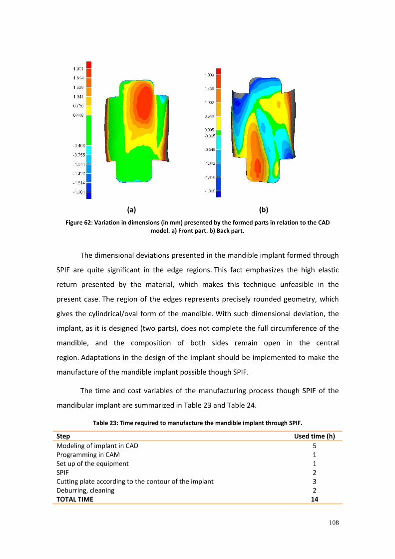
108
(a) (b)
Figure 62: Variation in dimensions (in mm) presented by the formed parts in relation to the CAD model. a) Front part. b) Back part.
The dimensional deviations presented in the mandible implant formed through
SPIF are quite significant in the edge regions. This fact emphasizes the high elastic
return presented by the material, which makes this technique unfeasible in the
present case. The region of the edges represents precisely rounded geometry, which
gives the cylindrical/oval form of the mandible. With such dimensional deviation, the
implant, as it is designed (two parts), does not complete the full circumference of the
mandible, and the composition of both sides remain open in the central
region. Adaptations in the design of the implant should be implemented to make the
manufacture of the mandible implant possible though SPIF.
The time and cost variables of the manufacturing process though SPIF of the
mandibular implant are summarized in Table 23 and Table 24.
Table 23: Time required to manufacture the mandible implant through SPIF.
Step Used time (h) Modeling of implant in CAD 5 Programming in CAM 1 Set up of the equipment 1 SPIF 2 Cutting plate according to the contour of the implant 3 Deburring, cleaning 2 TOTAL TIME 14

109
Table 24: Costs associated to the SPIF of the mandibular implant.
Description of the expense Cost (€)*** CAD modeling (5 hours) * 80,00 Programming CAM (1 hour) 16,00 Time machine CNC machining center (3 hours) 120,00 Cutting and finishing plate (5 hours) ** 40,00 Titanium sheet cp grade 2 (200x200x1mm) ‐ 2 sheets 84,00 Lubricant (MoS2) 40,00 TOTAL COST 380,00 * Values considered for the cost of an employee's hours with technical training in design and programming. ** Values considered for the cost of time for an employee with technical training to assist production. *** Values considering the price of the Euro on 30/04/2012, equivalent to R$ 2.50.
EVALUATION OF PROPOSED METHODS
The implants produced by means of rapid manufacturing showed good
adaptation to biomodel, given the necessary geometrical requirements. The rapid
manufacturing also allows internal structures of high geometric complexity to be
inserted into the implant, adding functionality. Such formal freedom is not observed in
SPIF, in which limits the geometry only to an outer surface shaped according to the
virtual three‐dimensional model. The laser sintering process, however, although
flexible to create complex geometries, still uses equipment often restricted to a few
companies, universities and research centers. Antagonistically, SPIF uses CNC
machining centers, 3‐axis and simple tooling, which are easily found. The time required
to manufacture the implant is also significantly lower (14 hours, compared to the laser
sintering, which requires 59 hours). However, it has limited dimensional accuracy, that
in the case of the implant in question, makes its manufacture unfeasible. Other
strategies for improving the accuracy and/or increasing the forming limits of the
material should be used.
5.5.5 Temporomandibular joint (TMJ)
Three basic requirements for a system for full reconstruction of ATM can be
listed, which are: to reproduce the movements of the original system function, to

110
provide adequate adjustment to the cranium and to achieve sufficient service life. Such
requirements may still develop into others, such as the reproduction of condylar
translation during opening of the mouth, unrestricted mandible movements; correct fit
to the skull; correct fit to the mandible; stable fixation of bone structures, life
expectancy of more than 20 years, low wear rate, particles tolerated for the body,
biocompatible materials, adequate mechanical strength, simple and achievable
deployment procedures.
Due to the foregoing requirements, prosthesis for replacement of TMJ should
copy the movement of the joint. Therefore, two surfaces in contact are needed (one
attached to the skull, another attached to the mandible) and that permit relative
movement. Thus, it would not be feasible the use this prosthesis with two components
titanium, due to the imminence of excessive wear between the surfaces. Still, the
standard ISO 7206‐2: 2012 (Implants for surgery ‐ Partial and total prosthesis hip joint,
part 2: articulating surfaces made of metallic materials, ceramic and plastic) provides a
list of materials which may be articulated against each other, in which titanium is not
included. Therefore, SPIF was not performed for the manufacture of prosthesis for
replacement of TMJ. It has been considered only the manufacture through CNC
machining, described in Section 3.4.5, in which the mandible component is made of
titanium and the cranial component, ultra‐ high‐ molecular‐ weight‐ polyethylene.
Commercially available and approved for implantation systems can be
mentioned, such as Promm (Brazil), called Arthroplasty System Promm, TMJ Concepts
(USA) called TMJ Patient‐Fitted TMJ Reconstruction Prosthesis System and the system
W. Lorenz Surgical Inc. (USA) called Biomet Microfixation TMJ Replacement
System. Both manufacturers use the CNC machining process for the production of
custom TMJ prosthesis. The time spent on each step for the manufacture of a custom
system for TMJ replacement TMJ through manual modeling, laser scanning and CNC‐
machining are summarized in Table 25.

111
Table 25: Time required to manufacture the custom system for TMJ replacement.
Step Used time (h) Biomodel manufacturing 10 Modeling the plastic mass for implant prototyping (including curing time) 10 Scanning of the prototypes (cranial and mandibular components) 4 STL file generation 4 CNC Programming 4 Set up of the equipment 1 Machining of the jaw component (titanium) 12 Machining of the cranial component (in UHMWPE) 4 Deburring, cleaning 4 TOTAL TIME 53
The material handling time for prototyping the implant (excluding the curing
time) is estimated at 5 hours. The estimated costs associated with manufacturing of
the implant are presented in Table 26.
Table 26: Costs associated with the manufacture of custom system to replace the TMJ.
Description of expenses Cost (€)*** Biomodel 500,00 Modeling of the prototypes of the implant (5 hours) ** 40,00 Material of the implant model 10,00 Scanning of the prototypes 320,00 STL file generation (4 hours) * 64,00 CNC Programming (4 hours) * 64,00 Titanium sheet cp grade 2 (120x80x12mm) 100,00 Ultra high molecular weight polyethylene block (40x40x25mm) 50,00 CNC Machining (17 hours) 680,00 Deburring, cleaning (4 hours) ** 32,00 TOTAL COST 1.860,00 * Values considered for the cost of an employee's hours with technical training in design and programming. ** Values considered for the cost of time for an employee with technical training to assist production. *** Values considering the price of the Euro on 30/04/2012, equivalent to R$ 2.50.
The implant produced using this process is well adapted to the biomodel, and
its precision is limited by factors related to the multiple steps of the process, such as
the resolution used for scanning and the machining strategy. The geometric complexity
that can be achieved for customized TMJ implants manufactured through this method
is, however, limited by the intrinsic characteristics of the CNC machining process,
where the material is removed only from the regions where the tool can reach. The
112
indexing of the extra axis to the CNC equipment tends to enable the manufacture of
parts with more complex geometry.
5.5.6 Summary of the proposed methods
Several processes that allow the manufacturing of customized implants to
repair defects in the craniofacial complex are available today. Methods based on
manual modeling with the use of anatomical biomodel of the patient, single point
incremental forming, additive manufacturing and CNC machining highlight among
them. As it has been noted, each process has its more or less limited extent regarding
the potential for the manufacture of craniofacial implants. Limitations for the
application of each process reside in aspects such as the desired accuracy, geometric
complexity, availability of equipment and tooling, automation, process time. The
processes studied in each typical case craniofacial reconstruction are summarized
in Table 28, with the variables of materials, time, cost, advantages, limitations and
operational requirements.
Methods based on manual modeling are already being used in craniofacial
surgery. Osteosynthesis plates for reconstruction are commercially available and can
be shaped in the desired geometry intraoperactively or previously to the surgery, with
the aid of biomodels, as performed in this study for reconstruction of defects in frontal
and supra‐orbital regions. The freedom that the surgeon has, considering the
geometry that can be formed, is, however, limited. Furthermore, the conformation
depends on manual skills of the operator and cannot be performed in defects covering
large areas. Furthermore, when performed intraoperactively, the conformation of
osteosynthesis plates can increase the time of surgery, increasing patient risk and costs
to the health system. The use of an initially fluid material (as is the case of calcium
phosphate cements) appear as an alternative for the reconstruction of complex
defects, since small bone holes can be filled. For those cases assessed using the
calcium phosphate cement (reconstruction of frontal defect and zygomatic bone), the
aesthetic effect obtained was satisfactory. Additionally, the calcium phosphate
cements have properties of osteoconduction, guiding the bone growth and providing a
stable interface between implant and bone.

113
The rapid manufacturing processes able to produce implants directly using the
material suitable for implantation, such as those based on laser melting, allow the
reproduction of the designed models with high accuracy, and unlimited geometric
flexibility. As discussed herein, for the case of manufacture of the mandible implant,
organic geometries, reticular structures, or even internal optimized geometries can be
produced. However, although very versatile and flexible in terms of geometries to be
manufactured and capable of generating implants directly into the material suitable
for implantation, additive manufacturing processes based on laser sintering of metals
is not yet widely available. Notably, there is a rapidly growing market worldwide,
improvement and diffusion of technical innovations in hardware and software and
increasing of the range of materials suitable for the process. However, most of the
equipment currently in operation is still restricted to large companies, universities and
research centers. Thus, using the technique for manufacturing custom implant is still
limited and expensive.
Single point incremental forming, in turn, although it has limitations
considering the accuracy of the process, uses simple tooling and widely available
equipment. CNC machining centers are easily found and can be easily adapted to the
SPIF process for implant manufacturing. The titanium implants manufactured through
SPIF can be seen in Figure 63.
Figure 63: Titanium implants for different craniofacial regions produced through single point
incremental forming. (a)Frontal; (b) frontal and supraorbital; (c) zygomatic bone; (d) mandible.
SPIF has proposed, as one of its strengths, the possibility to achieve degrees of
deformation not achievable through conventional sheet metal forming methods. This
statement can be confirmed when comparing the strains obtained through SPIF with
the forming limit curve of the material (shown in Figure 28 ). To the formed implants of
this study, the analysis of deformation is shown in Figure 64.

114
0
0,1
0,2
0,3
0,4
0,5
0,6
‐0,3 ‐0,2 ‐0,1 0 0,1 0,2 0,3
Minor strain (φ2)
Major Strain(φ1)
FLC
Frontal
Frontal+órbit
Zygomatic
Mandíble
CLC (l inha detendência)
Figure 64: Deformations presented in implants produced through SPIF and comparison with the material FLC.
For implants, analogously to the specimens formed into a cone shape, the
points on the graph are found above the FLC of the material. This means that the
degree of deformation reached in SPIF is greater than the degree of deformation
obtained through conventional sheet metal forming. The points that appear below the
FLC correspond to the implant to repair a defect in the frontal region, which due to its
simple geometry, required low degrees of deformation. Special attention must be
given to frontal defect implants + orbital and zygomatic, which experienced high
degrees of deformation without rupture.
However, due to the low accuracy presented by SPIF, some authors have
investigated some strategies that can circumvent, or at least lessen the negative
springback effects of the plate. In this sense, Ambrogio et al. (2004) showed that it is
possible to improve the accuracy of the final product, reducing the gap by 70% through
proper selection of these parameters. A very promising concept for reducing
inaccuracy of the parts is based on the design of "addicted trajectories" of the tool and,
thereby, create an intermediate form which approach the desired shape only when the
motion of the plate is relaxed. These paths should be designed before the start of the
process, using both numerical simulation and sensors that detect the actual shape of
the plate and introduce the appropriate correction to the part program taking into
FLC (trend)

115
account the springback effect. According to Ambrogio et al. (2005), this area of
research will probably be the challenge of coming years.
Mohammadi et al. (2012) and Duflou et al. (2008a) have developed a system
capable to generate heat dynamically directly in the vicinity of the tool by means of a
laser beam, creating a ductile area of low elastic modulus. Effects obtained with this
strategy are the reduction of the forces applied by the tool, greater localized
deformation and, thus, an increase in the accuracy of the process. It was also
demonstrated that the incremental forming using multiple passes (Duflou et al.,
2008b), or mixed strategies (Malhotra et al., 2011) enhance the formability of the
sheet, also generating positive effects on the accuracy of the process. Further, the use
of counter parts under the plate to be shaped can also be used for such purpose
(Ambrogio et al., 2004). Other studies indicate, as a strategy to increase the accuracy,
the reduction in diameter of the tool and reducing the vertical increment. Another
factor that affects the accuracy of the process is the distance between the location on
the plate where the part is being formed and where it is fixed (clamping system). The
distance must be minimized in order to reduce unwanted effects of elastic
deformation of the plate (Micari et al., 2007). Behera et al (2011) reported also an
increase in the accuracy of the process by means of optimized toolpaths and
compensated trajectories, anticipating the deformation that the material would suffer
and making up for it.
Besides the aspects discussed about the accuracy, when a strategy for
incremental forming is utilized, according to the conservation of volume, the thinning
of the sheet is another important problem (Hussain and Gao, 2007). The thinning is
generally governed by geometric thickness that leads to zero on the vertical walls. As a
result, this type of surface must be carefully avoided. Sometimes, the problem can be
solved performing a rotation in the model to be formed by positioning the walls, first
vertical, aligned with the horizontal plane as much as possible. From a purely industrial
point of view, the thickening phenomenon is usually avoided with use of thicker
plates. Anyway, when the weight of the component is a variable to be optimized, a
specific study should be performed.
The increase in formability of the material itself, and the resultant viability of

116
forming parts exceeding the limit forming angles (45 degrees, for the material used for
this study) are aspects that are currently being discussed. Strategies are proposed,
such as localized heating of the material in regions where the deformation occurs
[Duflou et al. (2008a), Palunbo and Brandizzi (2012)] and the use of multiple steps or
intermediate geometries in order to increase the formability of the material [Duflou et
al. (2008b), Malhora et al. (2011)].
For the various cases of patients requiring craniofacial reconstruction
addressed in this study, the possibility of manufacturing the implant through SPIF was
evaluated. The result is summarized in Table 27.

117
Table 27: Possibility of manufacturing through single point incremental forming and meeting of the formal requirements for the reconstruction of the different regions of the craniofacial complex.
Region of the craniofacial complex to be reconstructed
Possibility of
establishing the desired geometry
Accuracy (reproduction of the desired geometry)
Potential of application of the technique in the craniofacial complex
region
Frontal or parietal
Yes Suitable Can be applied
Frontal and supra‐orbital
Yes Good for the frontal region, does not satisfactorily
reproduce the orbital area.
Inadequate for supra‐orbital reconstruction
Zygomatic bone
Yes Suitable It can be applied, except for the reconstruction
of orbital floor.
Mandible ramus
No Inadequate It can not be applied for geometrical constraints
Temporomandibular joint
No Inadequate It can not be applied for regulatory requirements

118
Table 28: Summary of the processes studied for the manufacture of customized implants for craniofacial reconstruction.

119
6. CONCLUSIONS
This study examined methods of manufacture of customized implants currently
used with potential for craniofacial reconstruction surgery. The anatomical information
and, consequently, the regions to be reconstructed were obtained from CT
scans. Methods were evaluated based on manual modeling using different materials,
such as titanium meshes and calcium phosphate cements, and automated methods,
such as CNC machining, additive manufacturing and single point incremental forming.
For all cases investigated in this study, implants were designed based on CT
images. The softwares used are commercially available and offer various resources for
the virtual three‐dimensional reconstruction and visualization of the anatomical
structure of the patients. For the design of the implants, commercially available CAD
software can also be used to manipulate the files.
The methodology presented and discussed for the manufacture of craniofacial
customized implants using calcium phosphate cement meets the requirements for use
in bone reconstruction. The implants manufactured through the manual modeling
method with the aid of rapid prototyping biomodels have formal and functional
characteristics suitable for specific types of fractures investigated in this study.
Likewise, the manual sheet conformation for the reconstruction of front and orbital
defect, although being dependent on motor skills of the operator, provided a suitable
reproduction of the desired geometry.
The mandibular implant produced through rapid manufacturing (the laser
sintering, more specifically) on Ti‐6Al‐4V presented appropriate geometric
precision. The manufacture of complex shapes with high dimensional accuracy
demonstrated the high flexibility of the process. However, the high cost of the
materials and equipment restricts the access to this technology to few end users that
have appropriate resources.
Implants of titanium grade 2, 1mm thickness, whose geometries were designed
in advance in a CAD, were produced through single point incremental forming. The
manufacture of implants to repair complex craniofacial defects introduced restrictions
due to the accuracy limitations of the technique and the geometries that could be

120
formed. Through trials in cone specimens, the forming limit angle of the material was
determined to be 45˚. This finding limited the achievable cranial and facial geometries
using this process, so only implants with curvature below this angle can be successfully
formed. The implants produced for the correction of defects in the frontal, parietal and
zygomatic regions clearly show satisfactory geometry. The implant to repair frontal
and supra‐orbital defects was satisfactorily fitted to the frontal region; the
characteristic curve of the orbit was, however, not adequately reproduced. The
implant produced to repair the mandibular defect has not fitted to the anatomical
structure and may be considered inappropriate. The increase in the formability of the
material itself, and the consequent feasibility of parts with angles higher than 45
degrees are aspects that are being currently discussed. Strategies are being proposed
for the localized heating of the material in regions where the deformation occurs as
well as the use of multiple steps and/or intermediate geometries for incremental
forming.
A relevant characteristic of SPIF, which was observed in the produced implants,
was the low precision. The elastic recovery presented by the plate is substantial and
may, as in the case of the mandible implant, destabilize the process. As it has been
demonstrated, strategies such as the use of more than one point of contact or backing
plates for incremental forming, as well as multi step incremental forming, may help to
improve the precision of the process. It is also possible to improve the dimensional
accuracy of parts produced through incremental forming through the development
and use of optimized forming strategies, which undertake compensation in regions
that are slightly warped or deformed in excess.
The analysis of deformation on the implants produced through SPIF
demonstrates an increase in the capacity of elongation of the material when compared
to a conventional sheet metal forming. For the implants to repair the frontal and
parietal orbital and the zygomatic regions, the strain values are found above the
forming limit curve of the material.
Despite its limitations in geometric and dimensional accuracy, the single point
incremental forming process enabled the production of a preoperactively
manufactured custom implants with a simple automated set up. As system

121
requirements, there are CAD and CAM software and widely used equipments such as
3‐axis CNC milling machines, clamping systems, backing plates and spherical tools. The
processing time is also low compared to other investigated processes (such as additive
manufacturing and manual modeling using calcium phosphate cement), and is mainly
due to the design steps in CAD and CAM programming. Likewise, the costs of
manufacture of implants through SPIF are also significantly lower.
Considering the flexibility and potential provided by the SPIF process, it can be
stated that the process presents itself as a viable alternative for the manufacture of
customized titanium craniofacial implants. They are, however, subjected to the
intrinsic limitations of the process and the material once the geometry to be formed is
defined.
Implants intended for the reconstruction of complex craniofacial defects have,
as fundamental requirements for the most part, the protection and restoration of
form. Thus, this study contributes to the systematic knowledge of design tools,
materials and manufacturing processes that allow the flexible production of
craniofacial implants that meet its formal, functional and aesthetic requirements.

122
7. REFERENCES
ABNT NBR ISSO 6892‐02: Materiais metálicos – Ensaio de tração à temperatura
ambiente. International Standards Organization, 2002.
ASTM F1440‐92: Standard Practice for Cyclic Fatigue Testing of Metallic Stemmed Hip
Arthroplasty Femoral Components Without Torsion. Pennsylvania: ASTM International,
2008.
ASTM F380‐77: Test Method for Effective Fluorescent Lifetime of Neodymium‐Doped
Laser Materials. Pennsylvania: ASTM International, 1989.
ASTM F967‐03(2011) Standard Practice for Security Engineering Symbols. Pennsylvania:
ASTM International, 2011.
ASTM F 138‐08: Standard Specification for Wrought 18 Chromium ‐14Nickel ‐
2.5Molybdenum Stainless Steel Bar and Wire for Surgical Implants. Pennsylvania:
ASTM International, 2008.
ASTM F74‐73: Practice for Determining Hydrolytic Stability of Plastic Encapsulants for
Electronic Devices. Pennsylvania: ASTM International, 1989.
ASTM F67‐06: Standard Specification for Unalloyed Titanium, for Surgical Implant
Applications. Pennsylvania: ASTM International, 2006.
ASTM F136‐11: Standard Specification for Wrought Titanium ‐6Aluminum ‐4Vanadium
ELI (Extra Low Interstitial) Alloy for Surgical Implant Applications. Pennsylvania: ASTM
International, 2011.
ASTM F799‐11: Standard Specification for Cobalt‐28Chromium‐6Molybdenum Alloy
Forgings for Surgical Implants. Pennsylvania: ASTM International, 2011.
F620‐11 Standard Specification for Titanium Alloy Forgings for Surgical Implants in the
Alpha Plus Beta Condition. Pennsylvania: ASTM International, 2011.
ASTM F1108‐04: Standard Specification for Titanium‐6Aluminum‐4Vanadium Alloy
Castings for Surgical Implants. Pennsylvania: ASTM International, 2009.

123
ASTM 648‐10a: Standard Specification for Ultra‐High‐Molecular‐Weight Polyethylene
Powder and Fabricated Form for Surgical Implants. Pennsylvania: ASTM International,
2010.
ASTM F603‐12: Standard Specification for High‐Purity Dense Aluminum Oxide for
Medical Application. Pennsylvania: ASTM International, 2012.
ASTM F1185‐03: Standard Specification for Composition of Hydroxylapatite for Surgical
Implants. Pennsylvania: ASTM International, 2009.
ASTM D 4169‐09: Standard Practice for Performance Testing of Shipping Containers
and Systems. Pennsylvania: ASTM International, 2009.
ASTM D4329‐05 Standard Practice for Fluorescent UV Exposure of Plastics.
Pennsylvania: ASTM International, 2005.
ALLWOOD, J. M.; SHOULER, D. R. Paddle forming: a novel class of sheet metal forming
processes. Cirp Annals‐Manufacturing Technology, v.56, n.1, p.257‐260, 2007.
AMBROGIO, G.; CONSTANTINO, I.; DE NAPOLI, L.; FILICE, L.; MUZZUPAPPA, M.
Influence of some relevant process parameters on the dimensional accuracy in
incremental forming: a numerical and experimental investigation. Journal of Materials
Processing Technology, v.153‐154C, p.501‐507, 2004.
AMBROGIO, G.; COZZA, V.; FILICE, F.; MICARI, F. An analitical model for inproving
precision in single point incremental forming, AMPT 2006, Conference, Las Vegas, J.
Mater. Process. Tech., (2007).
AMBROGIO, G.; DE NAPOLI, L.; FILICE, L.; GAGLIARDI, F.; MUZZUPAPPA, M. Application
of IF process for high customized medical product manufacturing. International Journal
of Materials Processing Technology, v.162‐163, p.156‐162, 2005.
AMBROGIO, G.; FILICE, L. A simple strategy for improving geometry precision in single
point incremental forming, in: Proceedings of the Eight International Conference of
Technology of Plasticity, Verona, 2005, pp.357‐358.
AMBROGIO, G.; FILICE, L.; FRATINI, F.; MICARI, F. Some relevant correlations between
process parameters and process performance in incremental forming of metal sheets,
in: Proceedings of VI ESAFORM Conference, Salerno, Italy, 2003, pp.175‐178.

124
AMINO, H; LU, Y.; MAKI, T.; OSAWA, S.; FUKUDA, K. Dieless NC forming, prototype of
automotive service parts, in: Proceedings of the Second International Conference of
Rapid Prorotyping and Manufacturing (ICRPM), Beijim, 2002.
ARRUDA, R. Estampagem incremental na conformação de chapas para a fabricação de
coletores solares planos. PhD Thesis. Universidade Federal do Rio Grande do Sul,
Programa de Pós‐graduação em Engenharia de Minas, Metalúrgica e de Materiais.
Porto Alegre, 2010.
ATKINS, A. G. Fracture in forming. Journal of Materials Processing Technology, v.56,
n.1‐4, p.609‐618, 1996.
BAMBACH, M; HIRT, G.; AMES, J. Modeling of optimized strategies in the incremental
CNC sheet metal forming process, in: Proceedings of Numiform 2004 Conference,
Columbus, Ohio, 2004, p.1960‐1974.
BANKS, P.; BROWN, A. Fraturas do esqueleto facial. Livraria Santos Editora, 2005.
BATISTA, V.B.; SILVA, F.P.; KINDLEIN JUNIOR, W.; MORAES, H.S.; BERSCH, R.C.R.
Fabricação de assentos personalizados via modelagem em gesso, digitalização 3D e
usinagem CNC. In: Proceedings of Congresso Brasileiro de Engenharia de Fabricação,
Rio de Janeiro, RJ: ABCM, 2009.
BEHERA, A.K.; VANHOVE, H.; LAUWERS, B.; DUFLOU, J. Accuracy improvement in single
point incremental forming though systematic study of feature interactions. Key
Engineering Materials, v. 473, pp 881‐888, 2011.
BERETTA, E.M. Tecnologia Assistiva: Personalização em massa através do Design e
fabricação de assentos customizados para cadeira de rodas. Master Thesis.
Universidade Federal do Rio Grande do Sul, Programa de Pós‐Graduação em Design.
Porto Alegre, 2011.
BERMANN, C.; LINDER, M.; ZHANG.; KOCZUR, K.; KIRSTEN, A.; TELLE, R.; FISCHER, H. 3D
printing of bone substitute implants using calcium phosphate and bioactive glasses.
Journal of European Ceramic Society, v. 30, p. 2563‐2567, 2010.
BERTOL, L. S.; KINDLEIN JÚNIOR, W.; SILVA, F. P.; AUMUND‐KOPP, C. Medical design:
Direct metal laser sintering of Ti 6Al 4V. Materials and Design, v.31, p.3982‐3988, 2010.

125
BERTOL, LS; CANDIDO, LA, ROLDO, L; KINDLEIN JÚNIOR, W. Fabricação de implantes
médicos via digitalização tridimensional e usinagem CNC. Revista Tecnologia e
Tendências, vol. 8, n.1, pp. 21‐27, Editora Feevale, 2009a.
BERTOL, LS; SILVA, FP; KINDLEIN JUNIOR, W. Design and Health Care: a study of virtual
design and direct metal laser sintering of titanium alloy for the production of
customized implants. Australasian Medical Journal, v. 1, p. 136‐141, 2009b.
BREME, J. Titanlegierungen in der Medizintechnik. In: Titan und Titanlegierungen;
Wiley‐VCH‐Verlag 2002, p. 416‐460
BRESSAN, J. D. Conformação de chapas anisotrópicas e superplásticas. In: I Conferência
Nacional de Conformação de Chapas, 1993, Porto Alegre, RS. Anais da I Conferência
Nacional de Conformação de Chapas. Porto Alegre: Editor Lírio Schaeffer, v.1, pp.151‐
160, 1998.
CARVALHO, J.; VOLPATO, N. Prototipagem rápida como processo de fabricação, in:
VOLPATO, N. Prototipagem rápida: tecnologias e aplicações. São Paulo: Edgar Blücher,
2007, cap. 1, p. 1‐15.
CENPRA – Centro de Pesquisas Renato Archer. Available at: <www.cti.gov.br> Accessed
in 20.02.2010.
CHELULE, K.L.; COOLE, T.J.; CHESHIRE, D.G. Fabrication of medical models from scan
data through additive manufacturing techniques, in: Proceedings of the TCT (Time‐
Compression Technologies) Conference & Exhibition 2000, Cardiff, UK, 2000, p. 45–50.
CHEN, F.K.; CHIU, K.H. Stamping formability of pure titanium sheets. Journal of
Materials Processing Technology, v.170, p.181–186, 2005.
CHOI, S.H.; SAMAVEDAN, S. Modelling and optimization of rapid prototyping.
Computers in Industry, v. 47, I. 1pp. 39‐53, 2002.
CRANIO CONSTRUCT, DMD GmbH Digital Medical Design. Available at:
<www.cranioconstruct.de>. Accessed in 28.04.2012.
D’URSO, P.S.; ATKINSIN, R.L.; WEIDMANN, M.J.; REDMOND, M.J.; HALL, B.I.;
EARWAKER, W.J.S., THOMPDON, R.G.; EFFENEY, D.J. Biomodelling of cranium base
tumors. Journal of Clinical Neuroscience, 6(1), p.31‐35, 1998.
126
D’URSO, P.S.; REDMOND, M.J. A method for the resection of cranial tumours and skull
reconstruction, Br. J. Neurosurg. 14, p.555–559, 2000.
DUFLOU, J.R.; CALLEBAUT, B.; VERBERT, J.; DE BAERDEMAEKER, H. Improved SPIF
performance through dymanic local heating. International Journal of Machine Tools &
Manufacture 48 (2008a) 543‐549.
DUFLOU, J.R.; VANHOVE, H.; VERBERT, J.; GU, J.; VASILAKOS, I.; EYCKENS, P. Twist
revisited: twist phenomena in single point incremental forming. CIRP Annals –
Manufacturing Technology, v.59, p.307‐310, 2010.
DUFLOU, J.R.; VERBERT, J.; BELKASSEM,B.; GUB, J.; SOL, H.; HENRARD, C.; HABRAKEN,
A.M. Process Window enhancement for single point incremental forming through
multi‐steps toolpaths. CIRP Annals ‐ Manufacturing Technology 57 (2008b) 253–256.
EPPLEY, B.L. Craniofacial reconstruction with computer‐generated HTR patient‐
matched implants: use in primary bone tumor excision. J Craniofac Surg 13:650, 2002.
ERICKSON, D. MS MacKnown Dental Laboratory. Lackland Air Force Base, San Antonio,
Texas, Personal Communication, 1997.
FILICE, L.; FRATINI, L.; MICARI, F. Analysis of material formability in incremental
forming. Annals of the CIRP 2002, v.5, pp.199‐202.
FOLLE, L.; ARRUDA, R.P.; MARCA, D.; SCHAEFFER, L. Escolha do lubrificante correto
torna mais precisa a curva limite de conformação. Corte e Conformação de Metais, v.3,
p.64‐76, 2008.
FUJII, H.; TAKAHASHI, K.; YAMASHITA, Y. Application of titanium and its alloys for
automibile parts. Nippon Steel Technical Report, n.88, July 2003.
GOH, R.C.W.; CHANG, C.N.; LIN, C.H.; LO, L.J. Customised fabricated implants after
previous failed cranioplasty. Journal of Plastic, Reconstructive and Aesthetic Surgery, v.
63, p. 1479‐1484, 2010.
GOLDSMIT, D.; HOROWITZ, A.; ORENTLICHER, G. Facial skeletal augmentation using
custom facial implants. Atlas of Oral and Maxillofacial Surgery Clinics, v.20, p. 119‐134,
2012.
HAM, M.; JESWIET, J. Forming limit curves in Single Point Incremental Forming. CIRP

127
Annals‐Manufacturing Technology, v.56, n.1, pp.277‐280, 2007.
HE, Y.; YE, M.; WANG, C. A method in the design and fabrication of exact‐fit
customized implant based on sectional medical images and rapid prototyping
technology. Int J Adv manuf Technol (2006) 28: 504‐508.
HENCH, L.L. Biomateriais: uma introdução. In: ORÉFICE, R.A.; PEREIRA, M.M.; MANSUR,
H.S. Biomateriais: fundamentos e aplicações. Rio de Janeiro: Cultura Médica, 2006.
HIRT, G.; AMES, J.; BAMBACH, M.; Kopp, R.. Forming strategies and Process Modelling
for CNC Incremental Sheet Forming. CIRP Annals – Manufacturing Technology. Vol. 53.
2004, pp 203‐206.
HUSSAIN, G.; GAO, L. A novel method to test the thinning limits of sheet metals in
negative incremental forming. International Journal of Machine Tools and
Manufacture, v.47, p.419‐435, 2007.
HUSSAIN, G.; GAO, L.; DAR, N.U. An experimental study on some formability evaluation
methods in negative incremental forming. Journal of Materials Processing Technology
186, pp. 45‐53, 2007.
HUSSAIN, G.; GAO, L.; HAYAT, N.; ZIRAN, X. A new formability indicator in single point
incremental forming. Journal of Materials Processing Technology, v.209, p.4237‐4242,
2009.
ISEKI, J. An approximate deformation analysis and FEM analysis for the incremental
bulging of sheet metal using a spherical roller. International Journal of Materials
Processing Technology, v.111, p.150‐154, 2001.
JAMES, W.J.; SLABBEKOORN, M.A.; EDGIN W.A.; HARDIN, C.K. Correction of congenital
malar hypoplasia using stereolithography for presurgical planning. J Oral Maxilofac
Surg, v.56, p. 512‐517, 1998.
JESWIET, J.; MICARI, F.; HIRT, G.; BRAMLEY, A.; DUFLOU, J.; ALLWOOD, J. Assymetric
single point incremental forming of sheet metal. Annals of CIRP 2005, v.54, n.1.
JORGENSEN, T.H.; MOOS, N. Applications of RP techniques for sheet metal forming,
State‐of‐the‐art. RAPTIA Thematic Network report, Available at: www.raptia.org.
Accessed in 20.06.2010.

128
KIM, T.K.; YANG, D.Y. Improvement of formability for the incremental sheet metal
forming process. Int. J. Mech. Sci., v.42, p.1271‐1286, 2000.
KITAZAWA, K.; NAKAJIMA, A. Cylindrical incremental drawing of sheet metals by CNC
incremental forming process. Advanced Technology of Plasticity, v.2, p.1495‐1500,
1999.
KOOP, R; SCHMITZ, A. Plastic working in Germany and related environmental issues.
International Journal of Materials Processing Technology, v.59, p.186‐198, 1996.
LANG, L.H.; WANG, Z.R.; KANG, D.C.; YUAN, S.J.; ZHANG, S.H.; DANKERT, J,; NIELSEN,
K.B. Hydroforming highlights: sheet hydroforming and tube hydroforming.
International Journal of Materials Processing Technology, v.151, p.165‐177, 2004.
LEE, C.; ANTONYSHYN, A.M.; FORREST, C.R. Cranioplasty indications, Technique and
early results of autogenous split‐skull cranial vault reconstruction. J. Cranio Max. Fac
Surg, v. 23, p.133‐142, 1995.
LESZAK, E. Patent US334205A1, published in 19/09/1967. Apparatus and Process for
Incremental Dieless Forming.
LETHAUS, B.; POORT TER LAAK, M.; LAEVEN, P.; BEERENS, M.; KOPER, D.; POUKENS, J.;
KESSLER, P. A treatment algorithm for patients with large skull bone defects and first
results. Journal of Cranio‐Maxillo‐Facial Surgery, v.6, p.435‐440, 2011.
LOHFELD, S.; MCHUGH, P.; SERBAN, D.; BOYLE, D.; O´DONNELL, G.; PECKITT, N.
Engineering Assisted Surgery: a route for digital design and manufacturing of
customised maxillofacial implants. Journal of Materials Processing Technology, 183,
p.333–338, 2007.
LONGAGRE, J.J.; DE STEFANO, G.A. Further observations of the behavior of aitogenous
split‐rib grafts in reconstruction of large defects of the cranium and the face. Plast
Reconstr Surg, v. 20, p.281, 1957.
MAJI, P.K.; BANERJEE, P.S.; SINHA, A. Application of rapid prototyping and rapid tooling
for development of patient‐specific craniofacial implant: an investigative study. Int J
Adv Manuf Tecnol (2008) 36: 510‐515.
MALHOTRA, R.; BHATTACHARYA, A.; KUMAR, A.; REDDY, N.V.; CAO, J. A new

129
methodology for multi‐pass single point incremental forming with mixed toolpaths.
CIRP Annals – Manufacturing Technology 60 (2011) 323‐326.
MATSUBARA, S. Incremental backward forming of sheet metal with a hemispherical
head tool. J. JSTP, v. 35, p.1311‐1321, 1994.
MAZZOLI, M.; GERMANI, M.; RAFFAELI, R. Direct fabrication through electron beam
melting technology of custom cranial implants designed in a PHANToM‐based haptic
environment. Materials and Design 30 (2009) 3186–3192.
MEURER, E. As tecnologias CAD/CAM em cirurgia bucomaxilofacial. PhD Thesis.
Pontifícia Universidade Católica do Rio Grande do Sul, Porto Alegre,2003.
MICARI, F; AMBROGLIO, G.; FILICE, L. Shape and dimensional accuracy in Single Point
Incremental Forming: State of the art and future trends. Journal of Materials
Processing Technology, v.191, p.390‐395, 2007.
MOHAMADI, A.; VANHOVE H.; BEHERA, A.K.; VAN BAEL, K.; DUFLOU, J. In‐process
hardening in laser supported sheet metal forming. Key Engineering Materials, V. 504‐
506, pp. 827‐832, 2012.
MOORE, K.L.; DALLEY, A.F. Anatomia orientada para a clínica. Rio de Janeiro:
Guanabara Koogan, 4. ed, 2001.
MÜLLER, D; MÜLLER, H. Experiences using rapid prototyping techniques to
manufacture sheet metal forming tools. Proc. ISATA Conferencem Dublin, 2000, p9.
MÜLLER, H.; HENZMANN, H. Potentials of rapid prototyping techniques for the
manufacture of prototype sheet metal forming tools. Proc. European Conf. on Rapid
Prototyping and Manufacturing, Aachen, 1998, pp 337‐350.
MUSTAFA, S.F.; EVANS, P.L.; BOCCA, A.; PATTON, D.W.; SUGAR, A.W.; BAXTER, P.W.
Customized titanium reconstruction of post‐traumatic orbital wall defects: a review of
22 cases. International Journal of Oral and Maxillofacial Surgery, v.40, p. 1357‐1362,
2011.
NEOVIUS, E.; ENGSTRAND, T. Craniofacial reconstruction with bone and biomaterials:
review over the last 11 years. Journal of Plastic, Reconstructive and Aesthetic Surgery,
v. 63, p. 1615‐1623, 2010.

130
NETO, A.P.; ZANINI, S.A. Cranioplastias. In: Cirurgia Craniofacial: Malformações.
Revinter, 2000, p. 185‐191.
NEUNER, M. Implantat mit Orangenhaut. Fraunhofer Magazin v. 4, p.30‐31, 2008.
NIINOMI, M. Mechanical properties of biomedical titanium alloys. Materials Science
and Engineering, v. 243, p. 231‐236, 1998.
NOVOTNY, J,; HEIM, P. Hydroforming of sheet metal parts from aluminium alloys.
International Journal of Materials Processing Technology, v.115, p.65‐69, 2001.
OKAZAKI, Y.; GOTOH, E.; MANABE, T.; KOBAYASHI, K. Comparison of metal
concentrations in rat tibia tissues with various metallic implants. Biomaterials, v.25, p.
5913‐5920, 2004.
PALUMBO, G.; BRANDIZZI, M. Experimental investigations on the single point
incremental forming of a titanium alloy component combining static heating with high
tool rotation speed. Materials and Design, v.40, p. 43‐51, 2012.
PARK, J.J.; KIM, Y.H. Fundamental studies on the incremental sheet metal forming
technique. International Journal of Materials Processing Technology, v.140, p.447‐453,
2003.
PEREIRA, M.M.; BUONO, V.T.L.; ZAVAGLIA, C.A.C. Materiais metálicos: ciência e
aplicação como biomateriais. In: ORÉFICE, R.A.; PEREIRA, M.M.; MANSUR, H.S.
Biomateriais: fundamentos e aplicações. Rio de Janeiro: Cultura Médica, 2006, cap. 2,
p. 39‐58.
PERKINS, C.S.; LAYTON, S.A. The aetiology of the maxillofacial injuries and the seat belt
law. Br. J. Oral Surg., v.26, p.353, 1988.
PETEK, A.; JURISEVIC, B.; KUZMAN, K.; JUNKAR, M. Comparison of alternative
approaches of single point incremental forming processes. Journal of Materials
Processing Technology, v.209, p. 1810‐1815, 2009.
POPOVIC, A.; ENGELARDT, M.; WU, T.; PORTHEINE, F.; SCHMIEDER, K.; RADERMACHER,
K. CRANIO – computer‐assisted planning for navigated and robot‐assisted surgery on
the skull. International Congress Series 1256, p. 1269‐1275, 2003.
QUATELA, V.C.; CHOW, J. Synthetic facial implants. Facial Plastics Surgery Clinics of

131
North America, v.16, p.01‐10, 2008.
RAPIDTECH 2011. Promotional material. Available at <www.rapidtech.de>. Accessed in
20.06.2011.
RETTORE JR, R.; COMUNIAN, C.R.; CUSTÓDIO, A.L.N.; COSTA, S.M. Implantes
Aloplásticos. In: irurgia Craniofacial: Malformações. Revinter, 2000, p. 65‐71.
ROBERT, C.; DELAMÉZIÈRE, A.; DAL SANTO, P.; BATOZ, J.L. Comparison between
incremental deformation theory and flow rule to simulate sheet‐metal forming
processes. Journal of Materials Processing Technology, v.212, p.1123‐1131, 2012.
ROWE, N.L.; KILLEY, H.C. Fractures of the facial skeleton. Edinburgh, Livingstone, 1968.
SAKAWADA, T.; MATSUBARA, S.; SAKAMOTO, M.; FUKUHARA, G. Deformation analysis
for stretch forming of sheet metal with CNC machine tool. Advanced Technology of
Plasticity 2 (1999) 1501‐1504.
SALGADO. Saúde Integral e Reabilitação. Terapia crânio‐sacra. Available at
<http://www.salgadosaude.com.br/tratamentos/terapia‐cranio‐sacra>. Accessed in
12.08.2010.
SANAN, A.; Haines, S.J. Repairing holes in the head: a history of cranioplasty.
Neurosurgery, v. 40, n. 3, p. 588‐603, 1997.
SANTOS, L.A. Desenvolvimento de fosfato de cálcio reforçado por fibras para uso na
área médico‐odontológica. PhD Thesis, Comissão de Pós‐Graduação em Engenharia
Mecânica/UNICAMP, Campinas, 2002.
SCHAEFFER, L. Conformação de chapas metálicas. Porto Alegre: Imprensa Livre, 2004.
SCHMOECKEL, D. Developments in automation, flexibilization and control of forming
machinery. Annals of CIRP vol.40/2/1992; 615.
SCHOENE, C.; STELZER, R. 3D‐Digitising and Reverse Engineering, Aspects of Production
Engineering in dental industry. Darmstadt: PACE‐Forum Digital Manufacturing, 2005.
SHIM, M.S.; PARK, J.J. The formability of aluminum sheet in Incremental forming,
International Journal of Materials Processing Technology, v.113, p.654‐658, 2001.
SILVA, F.P. Usinagem de espumas de poliuretano e digitalização tridimensional para a

132
fabricação de assentos personalizados para pessoas com deficiência. PhD Thesis.
Universidade Federal do Rio Grande do Sul. Programa de Pós‐Graduação em
Engenharia de Minas, Metalúrgica e de Materiais. Porto Alegre, 2011.
SILVA, M. B. et al. Revisiting the fundamentals of single point incremental forming by
means of membrane analysis. International Journal of Machine Tools & Manufacture, v.
48, n. 1, p. 73‐83, 2008.
SINGARE, S.; DICHEN, L.; BINGHENG, L.; YANPU, L.; ZHENYU, G.; YAXIONG, L. Design
and fabrication of custom mandible titanium tray based on rapid prototyping. Medical
Engineering & Physics, v. 26, p. 671–676, 2004.
STAFFA, G.; BARBANERA, A.; FAIOLA, A.; FRICIA, M.; LIMONI, P.; MOTTORAN, R.;
ZANOTTI, B.; STEFINI, R. Custom‐made bioceramic implants in complex and large
cranial reconstruction: a two year follow‐up. Journal of Cranio‐Maxillofacial Surgery,
v.40, p. 65‐67, 2012.
STOODLEY, M.A.; ABBOTT, J.R.; SIMPSON, D.A. Titanium cranioplasty using 3‐D
computer modeling of skull defects. Journal of Clinical Neuroscience, v.3, n.2, p. 149‐
155, 1996.
TANAKA, S.; NAKAMURA, T.; HAYAKAWA, K. Incremental sheet metal forming using
elastic tools. Advanced Technology of Plasticity, v.2, p.1477‐1482, 2000.
VINCENT‐TOWNEND, J.R.L.; SHEPHERD, J.P. Appendix in Rowe and Williams
Maxillofacial Injuries (J.L. Williams ed.), pp. 1053‐67. Edinburgh: Churchill Livingstone,
1994.
WEHMÖLLER, M.; WEICHE, S.; RASCHE, C.; EUFINGER, H. Experiments for examination
of precision. International Congress Series 1256 (2003) 720‐725.
WELSCH, G.; BOYER, R.; COLLINS, E.W. Materials properties Handbook: titanium alloys.
ASM International, 1994.
WIRTZ, T. Herstellung von Knochenimplantaten aus Titanwerkstoffen durch
Laserformen. PhD Thesis. Rheinisch‐Westfälischen Technischen Hochschule Aachen,
2005.
WONG, T.Y.; FANG, J.J.; CHUNG, C.H.; HUANG, J.S.; LEE, J.W. Comparison of 2 methods

133
of making surgical models for correction of facial asymmetry. Journal of Oral
maxillofacial Surgery 63, p.200‐208, 2005.
YOON, S.J.; YANG, D.Y. Finite element simulation of an incremental forming process
using a roll set for the manufacture of a doubly curved sheet metal, in: Proceedings of
Numisheet, 2002, pp. 423‐428.
ZHOU, L.; HE, L.; LIU, G.; ZHAO, J. Accurate reconstruction of discontinuous mandible
using a reverse engineering/ computer‐aided design/ rapid prototyping technique:
preliminary clinical study. J Oral Maxillofac Surg 68: 2115‐2121, 2010.
Related Documents