Potential order-of-magnitude enhancement of wind farm power density via counter-rotating vertical-axis wind turbine arrays John O. Dabiri Citation: J. Renewable Sustainable Energy 3, 043104 (2011); doi: 10.1063/1.3608170 View online: http://dx.doi.org/10.1063/1.3608170 View Table of Contents: http://jrse.aip.org/resource/1/JRSEBH/v3/i4 Published by the American Institute of Physics. Related Articles A hybrid identification scheme combining singular entropy with ERA for wind turbine systems J. Renewable Sustainable Energy 3, 033107 (2011) Decentralized robust static synchronous compensator control for wind farms to augment dynamic transfer capability J. Renewable Sustainable Energy 2, 022701 (2010) Integration of space vector pulse width modulation controlled STATCOM with wind farm connected to multimachine power system J. Renewable Sustainable Energy 1, 013103 (2009) Additional information on J. Renewable Sustainable Energy Journal Homepage: http://jrse.aip.org/ Journal Information: http://jrse.aip.org/about/about_the_journal Top downloads: http://jrse.aip.org/features/most_downloaded Information for Authors: http://jrse.aip.org/authors Downloaded 21 Oct 2011 to 131.215.220.186. Redistribution subject to AIP license or copyright; see http://jrse.aip.org/about/rights_and_permissions

Welcome message from author
This document is posted to help you gain knowledge. Please leave a comment to let me know what you think about it! Share it to your friends and learn new things together.
Transcript

Potential order-of-magnitude enhancement of wind farm powerdensity via counter-rotating vertical-axis wind turbine arraysJohn O. Dabiri Citation: J. Renewable Sustainable Energy 3, 043104 (2011); doi: 10.1063/1.3608170 View online: http://dx.doi.org/10.1063/1.3608170 View Table of Contents: http://jrse.aip.org/resource/1/JRSEBH/v3/i4 Published by the American Institute of Physics. Related ArticlesA hybrid identification scheme combining singular entropy with ERA for wind turbine systems J. Renewable Sustainable Energy 3, 033107 (2011) Decentralized robust static synchronous compensator control for wind farms to augment dynamic transfercapability J. Renewable Sustainable Energy 2, 022701 (2010) Integration of space vector pulse width modulation controlled STATCOM with wind farm connected tomultimachine power system J. Renewable Sustainable Energy 1, 013103 (2009) Additional information on J. Renewable Sustainable EnergyJournal Homepage: http://jrse.aip.org/ Journal Information: http://jrse.aip.org/about/about_the_journal Top downloads: http://jrse.aip.org/features/most_downloaded Information for Authors: http://jrse.aip.org/authors
Downloaded 21 Oct 2011 to 131.215.220.186. Redistribution subject to AIP license or copyright; see http://jrse.aip.org/about/rights_and_permissions

Potential order-of-magnitude enhancement of wind farmpower density via counter-rotating vertical-axis windturbine arrays
John O. Dabiria)
Graduate Aeronautical Laboratories and Bioengineering, California Institute of Technology,Pasadena, California 91125, USA
(Received 7 February 2011; accepted 14 June 2011; published online 19 July 2011)
Modern wind farms comprised of horizontal-axis wind turbines (HAWTs) require
significant land resources to separate each wind turbine from the adjacent turbine
wakes. This aerodynamic constraint limits the amount of power that can be
extracted from a given wind farm footprint. The resulting inefficiency of HAWT
farms is currently compensated by using taller wind turbines to access greater wind
resources at high altitudes, but this solution comes at the expense of higher
engineering costs and greater visual, acoustic, radar, and environmental impacts.
We investigated the use of counter-rotating vertical-axis wind turbines (VAWTs)
in order to achieve higher power output per unit land area than existing wind farms
consisting of HAWTs. Full-scale field tests of 10-m tall VAWTs in various
counter-rotating configurations were conducted under natural wind conditions
during summer 2010. Whereas modern wind farms consisting of HAWTs produce
2–3 W of power per square meter of land area, these field tests indicate that power
densities an order of magnitude greater can potentially be achieved by arranging
VAWTs in layouts that enable them to extract energy from adjacent wakes and
from above the wind farm. Moreover, this improved performance does not require
higher individual wind turbine efficiency, only closer wind turbine spacing and a
sufficient vertical flux of turbulence kinetic energy from the atmospheric surface
layer. The results suggest an alternative approach to wind farming that has the
potential to concurrently reduce the cost, size, and environmental impacts of wind
farms. VC 2011 American Institute of Physics. [doi:10.1063/1.3608170]
I. INTRODUCTION
A principal challenge for all forms of renewable energy is that their sources—solar radia-
tion or wind, for example—are more diffuse than fossil fuels. As a consequence, existing
renewable energy technologies require substantial land resources in order to extract appreciable
quantities of energy. This limitation of land use is especially acute in the case of wind energy,
which currently faces an additional constraint in that conventional propeller-style wind turbines
(i.e., horizontal-axis wind turbines; henceforth, HAWTs) must be spaced far apart in order to
avoid aerodynamic interference caused by interactions with the wakes of adjacent turbines. This
requirement has forced wind energy systems away from high energy demand population centers
and toward remote locations including, more recently, offshore sites. It has also necessitated the
implementation of very large wind turbines, so that the inefficiency of the wind farm as a
whole can be compensated by accessing the greater wind resources available at high altitudes.
However, this solution comes at the expense of higher engineering costs and greater visual,
acoustic, radar, and environmental impacts. These issues represent a principal barrier to the
a)Author to whom correspondence should be addressed. Electronic mail: [email protected]. Tel.: 1-626-395-6294.
Fax: 1-626-577-5258.
1941-7012/2011/3(4)/043104/12/$30.00 VC 2011 American Institute of Physics3, 043104-1
JOURNAL OF RENEWABLE AND SUSTAINABLE ENERGY 3, 043104 (2011)
Downloaded 21 Oct 2011 to 131.215.220.186. Redistribution subject to AIP license or copyright; see http://jrse.aip.org/about/rights_and_permissions

realization of wind energy technology that is both economically viable and socially
acceptable.1,2
To maintain 90% of the performance of isolated HAWTs, the turbines in a HAWT farm
must be spaced 3–5 turbine diameters apart in the cross-wind direction and 6–10 diameters
apart in the downwind direction.1,2 The power density of such wind farms, defined as the power
extracted per unit land area, is between 2 and 3 W m�2.3
Wind turbines whose airfoil blades rotate around a vertical axis (i.e., vertical-axis wind tur-
bines; henceforth, VAWTs) have the potential to achieve higher power densities than HAWTs.
This possibility arises in part because the swept area of a VAWT rotor (i.e., the cross-sectional
area that interacts with the wind) need not be equally apportioned between its breadth—which
determines the size of its footprint—and its height. By contrast, the circular sweep of HAWT
blades dictates that the breadth and height of the rotor swept area are identical. Therefore,
whereas increasing HAWT rotor swept area necessarily increases the turbine footprint, it is pos-
sible to increase the swept area of a VAWT independent of its footprint, by increasing the rotor
blade height. Table I compares the power density of a commercially-available VAWT with two
common HAWT models. The power density of the VAWT design is more than three times that
of the HAWTs, suggesting that VAWTs may be a more effective starting point than HAWTs
for the design of wind farms with high power density.
The turbine power densities indicated in Table I are not achieved in practice due to the
aforementioned spacing requirements between the turbines in a wind farm. However, we
hypothesized that counter-rotating arrangements of VAWTs can benefit from constructive aero-
dynamic interactions between adjacent turbines, thereby mitigating reductions in the perform-
ance of the turbines when in close proximity. By accommodating a larger number of VAWTs
within a given wind farm footprint, the power density of the wind farm is increased. Further-
more, by capturing a greater proportion of the wind energy incident on the wind farm footprint,
it becomes unnecessary to use wind turbines as large as those commonly found in modern
HAWT farms. In turn, the use of smaller turbines can reduce the complexity and cost of the
individual wind turbines, since the smaller wind turbines do not experience the high gravita-
tional, centrifugal, and wind loading that must be withstood by large HAWTs. The less severe
design requirements can enable the implementation of less expensive materials and manufactur-
ing processes.
Here, we present an initial study of this concept of counter-rotating VAWT farms, by
measuring wind turbine performance at full scale and in naturally-occurring wind conditions.
Although field measurements lack the controllable environment of scale model experiments in a
wind tunnel or numerical simulations, they do provide the most direct support of the validity of
the proposed wind farm concept. The data set presented here can also be used as a baseline for
comparison with future scale model experiments and numerical simulations.
II. MATERIALS AND METHODS
A. Field site summary
Experiments were conducted at a field site in the Antelope Valley of northern Los Angeles
County, California, USA. The site is vacant desert and the topography is flat for approximately
1.5 km in all directions (Figure 1(A)). Over the duration of these experiments, from June to
September 2010, the mean wind speed was approximately 7.8 m=s at 10 m with mean
TABLE I. Comparison of VAWT and HAWT power density. The power density is calculated as the turbine rated power
divided by the area of the circular footprint swept by the turbine rotor blades when rotated in yaw by 360�.
Turbine type Rated power (MW) Rotor diameter (m) Power density (W=m2)
VAWT 0.0012 1.2 1061
HAWT 2.5 100 318
HAWT 3.0 112 304
043104-2 John O. Dabiri J. Renewable Sustainable Energy 3, 043104 (2011)
Downloaded 21 Oct 2011 to 131.215.220.186. Redistribution subject to AIP license or copyright; see http://jrse.aip.org/about/rights_and_permissions

turbulence fluctuations (i.e., standard deviation) of 2.6 m=s. Figure 2 plots the daily average
wind speed and turbulence fluctuations during the course of the experiments. Figure 3 plots the
distribution of wind direction at the site; the prevailing wind is from the southwest. The natural
variability of the wind direction enabled the sensitivity of turbine performance to wind direction
to be studied without requiring a large number of discrete turbine configurations to be tested
(see VAWT positioning and protocols below).
B. Wind turbine design
The field tests utilized six 10-m tall� 1.2-m diameter VAWTs. The turbines were a modi-
fied version of a commercially available model (Windspire Energy Inc.) with 4.1-m span airfoil
blades and a 1200-W generator connected to the base of the turbine shaft. Three of the turbines
rotated around their central shaft in a clockwise direction (e.g., from a top view) in the winds
above 3.8 m s�1; the other three rotated in a counter-clockwise direction when the wind speed
exceeded the same threshold (henceforth, the cut-in wind speed).
FIG. 1. VAWT configurations. (A) View of field site toward southwest (approximately upwind). Each turbine is 10 m tall
to the top of the rotor blades. Three-turbine array is at left, two-turbine array is in center. Inset at right indicates height of
the turbines relative to a 1.9-m tall person. (B) Schematic top view of two-VAWT configurations. Top of panel is due north.
Circles indicate 1.2-m turbine diameter, arrows indicate the direction of turbine rotation. Turbine spacing (i.e., 1.65 turbine
diameters) is indicated by the length of the single grey lines and is drawn to scale. Red circle, turbine CCW1; blue circle,
turbine CW1; and black circles, additional positions of turbine CW1 tested during measurements of wind direction sensitiv-
ity. Black arrow at lower left indicates prevailing wind direction in panels (B)-(D) (see Figures 2 and 3 for full distributions
of wind speed and direction, respectively). (C) Schematic top view of three-VAWT configurations. Blue circles (i.e., clock-
wise-rotating turbines) are spaced 1.65 turbine diameters from red turbine (i.e., counter-clockwise-rotating turbine), as indi-
cated by the length of the single grey lines. Black circle, alternate position of upper blue circle at 4 turbine diameters
downwind, as indicated by the length of the double grey lines. (D) Schematic top view of six-VAWT configuration. Red
and blue circles indicate the positions of six VAWTs during measurements. Length of double grey lines indicates 4 turbine
diameter spacing. Grey circles indicate additional turbine positions in a hypothetical larger-scale array.
043104-3 Vertical-axis wind turbine arrays J. Renewable Sustainable Energy 3, 043104 (2011)
Downloaded 21 Oct 2011 to 131.215.220.186. Redistribution subject to AIP license or copyright; see http://jrse.aip.org/about/rights_and_permissions

C. VAWT positioning and protocols
Each of the experiments was conducted with the turbines positioned within the same 75
m� 75 m tract of land. One of the six turbines remained fixed in the same location for all of
the experiments. The remaining turbines were manually repositioned on portable footings in
order to create the various configurations studied. The schedule of turbine positions is listed in
Table II, along with the number of hours that each turbine configuration was measured.
FIG. 2. Measured daily average wind speed (solid line) and standard deviation turbulence fluctuations (dashed band) over
the duration of field tests.
FIG. 3. Histogram of measured wind direction. Angle coordinate is measured in degrees from north. Radial coordinate is
the number of hours observed for each wind direction.
043104-4 John O. Dabiri J. Renewable Sustainable Energy 3, 043104 (2011)
Downloaded 21 Oct 2011 to 131.215.220.186. Redistribution subject to AIP license or copyright; see http://jrse.aip.org/about/rights_and_permissions

D. Turbine measurements
The rotational speed and electrical power generated by each turbine were monitored in
real-time and recorded at 1 Hz using custom software designed to interface with the turbines
(WindSync, Windspire Energy Inc.). Measurement accuracy was 65% for both parameters.
Each measurement was assigned a time stamp that was synchronized with separately collected
meteorological data (see the Meteorological measurements section below) and was manually
uploaded via a satellite uplink (HughesNet) from the field site to a computer at the California
Institute of Technology, where the data were analyzed.
E. Meteorological measurements
A 10-m meteorological tower was erected at the northwest corner of the field site in order
to measure the wind speed and direction at a height comparable to the mid-span height of the
VAWT blades (8 m). The tower was located 15 turbine diameters northwest (i.e., approximately
cross-wind) of the nearest VAWT to ensure that it did not affect the wind conditions near the
turbines. Although the need to avoid aerodynamic interference between the meteorological
tower and the VAWTs precluded wind measurements using the tower closer to the turbines, the
difference in their position was significantly smaller than the length scale over which mean
flow in the atmospheric surface layer changes.4,5 To be sure, the turbulence fluctuations, which
were typically 30%–40% of the mean wind speed, likely overwhelm the differences between
the instantaneous wind speed at the location of the meteorological tower and at the turbines.
The accuracy of the wind speed sensor (Thies First Class) and wind direction sensor (Met
One) measurements was 63% and 65�, respectively. Data from the meteorological tower were
recorded at 1 Hz using a datalogger (Campbell Scientific). The data were assigned a timestamp
synchronized with the turbine measurement data before transmission via the satellite uplink.
F. Power coefficient calculation
The turbine power coefficient is defined as the fraction of incident kinetic energy passing
through the swept area of the turbine rotor that is converted to electrical energy.2 In terms of
the generated electrical power P, air density q, turbine rotor swept area A (equal to the product
of the turbine rotor diameter and height), and wind speed U, the power coefficient is
Cp ¼P
1=2ð ÞqAU3; (1)
TABLE II. Field test schedule. See text and Figure 1 for definitions of abbreviations.
Test dates Turbine configuration Measurement duration
(continuous h)
12 June–23 June CW1 south of CCW1, 1.65-dia. separation 252
25 June–7 July CW1 north of CCW1, 1.65-dia. separation 312
9 July–23 July CW1 south of CCW1, 10-dia. separation 360
30 July–11 August CW1 west of CCW1, 1.65-dia. separation 312
13 August–15 August CW2 south of CCW2, 1.65-dia. separation 72
CW3 northeast of CCW2, 1.65-dia. separation
13 August–17 August CW1 east of CCW1, 1.65-dia. separation, CW1 rotor stationary 120
19 August–29 August CW2 south of CCW2, 1.65-dia. separation 264
CW3 northeast of CCW2, 4-dia. separation
30 August–1 September CW3 northwest of CCW2, 14-dia. separation 58
3 September–5 September Fig. 1(D), last downwind CW turbine absent 48
10 September–20 Septembera Fig. 1(D) 251
aCW turbine in right column of Fig. 1(D) measured 10–11 September and 18–20 September only. CCW turbine in middle
column of Fig. 1(D) measured 10–13 September only.
043104-5 Vertical-axis wind turbine arrays J. Renewable Sustainable Energy 3, 043104 (2011)
Downloaded 21 Oct 2011 to 131.215.220.186. Redistribution subject to AIP license or copyright; see http://jrse.aip.org/about/rights_and_permissions

where the air density was estimated to be 1.2 kg m�3 and the turbine rotor swept area is
5.02 m2.
G. Wind farm power density calculation
The wind farm power density is defined as the electrical power generated by the wind farm
divided by the area of its footprint.3 In terms of the turbine rated power P, capacity factor C,
wind farm aerodynamic loss factor L, wind turbine spacing S, and wind turbine diameter D, the
wind farm power density is
WPD ¼ PC 1� Lð Þp=4ð Þ SDð Þ2
; (2)
where the factor p=4 arises due to the assumption that each turbine has a circular footprint with
diameter (S�D) inside which no other turbines can be located.
III. RESULTS
In the first set of experiments, we measured the performance of two counter-rotating
VAWTs whose axes of rotation were separated by 1.65 turbine diameters (Figure 1(B)). The
clockwise-rotating turbine (denoted CW1) was measured at multiple positions around the azi-
muth of the counter-clockwise-rotating turbine (denoted CCW1) in order to determine the de-
pendence of turbine performance on the relative direction of the incident wind. In addition, the
performance of turbine CCW1 was measured while it was isolated (i.e., separated by 10 turbine
diameters from turbine CW1) in order to evaluate the effect of the close proximity of the tur-
bines on the power coefficient (i.e., the fraction incident wind energy that is converted to elec-
trical energy, denoted Cp). A normalized power coefficient, Cnormp , defined as the ratio of the
turbine power coefficient in the counter-rotating configuration to the power coefficient of the
isolated turbine, was used to evaluate the performance of each configuration.
The normalized power coefficient of turbine CCW1 (and, by spatial symmetry, the normal-
ized power coefficient of turbine CW1) was nearly insensitive to the incident wind direction
over the 315� of wind direction variation that was observed (Figure 4(A)). Averaged over all
FIG. 4. Measurement of two-VAWT configuration with 1.65 turbine diameter separation (see Fig. 1(B)). (A) Plot of nor-
malized power coefficient Cnormp (radial coordinate) versus incident wind direction (angle coordinate in degrees from north).
Inset turbine schematic indicates the position of VAWTs relative to incident wind. Length of grey line indicates 1.65 tur-
bine diameter spacing. Wind directions observed for less than 900 s are omitted (i.e., incident wind from the north). Values
of Cnormp ¼ 1 indicate turbine performance equal to that of the isolated turbine. (B) Solid line, plot of normalized power
coefficient Cnormp versus tip speed ratio for all incident wind directions. The tip speed ratio is given by (pDX)U�1, where D
is the wind turbine rotor diameter, X is the turbine rotation rate, and U is the wind speed. Vertical dotted line indicates
designed operating tip speed ratio of turbines.
043104-6 John O. Dabiri J. Renewable Sustainable Energy 3, 043104 (2011)
Downloaded 21 Oct 2011 to 131.215.220.186. Redistribution subject to AIP license or copyright; see http://jrse.aip.org/about/rights_and_permissions

incident wind directions, the close proximity of the turbines slightly improved their perform-
ance relative to the turbines in isolation (Figure 4(B)). This is in contrast to typical performance
reductions between 20% and 50% for HAWTs at a similar turbine spacing.6–9 The result is
qualitatively consistent with the predictions of previous simplified numerical models, which
anticipated that closely-spaced VAWTs can reciprocally enhance the wind field of the adjacent
turbines.10,11
In a second set of experiments, we studied the performance of a third VAWT placed 1.65-
diameters downwind from two counter-rotating VAWTs with the same spacing (Figure 1(C)).
These experiments explored the effect of downwind blockage caused by the two closely-spaced
upwind turbines. We observed a significant decrease in the performance of the downwind
turbine, especially at higher ratios of rotor blade tip speed to wind speed (henceforth, tip speed
ratio12). However, when the spacing of the downwind turbine was increased to four diameters,
its performance was recovered to within 5% of the isolated turbine performance across the
range of observed tip speed ratios (Figure 5). This rapid recovery of the downwind flow field is
in marked contrast to the 15–20 diameters of downwind spacing found to be required for a sim-
ilar level of wake recovery in a recent numerical simulation of a large HAWT.13
Based on the preceding experiments, we hypothesized that by increasing the mean spacing
of all turbines in an array to four diameters, upstream blockage effects would be significantly
reduced. Figure 1(D) illustrates the wind farm configuration implemented in field tests. Nearest-
neighbor turbines were counter-rotating in order to take advantage of the lesser aerodynamic in-
terference between counter-rotating VAWTs as compared to co-rotating VAWTs.10,11 The field
tests confirmed that each of the downwind turbines in the array achieved performance compara-
ble to the VAWT at the front of the array (Figure 6(A)). The performance of the turbine
located five positions downwind from the front of the array was reduced by less than 5% rela-
tive to the farthest upwind turbine, which is within the measurement uncertainty.
Averaged over the 48.6-m2 footprint of the six-turbine VAWT array, the daily mean
power density produced by the array varied from 21 to 47 W m�2 at wind speeds above cut-in and
6–30 W m�2 overall (Figure 6(B)). This performance significantly exceeded the 2–3 W m�2
power density of modern HAWT farms, despite the relatively low mean wind speed during this
set of field tests (5.7 m s�1).
FIG. 5. Normalized power coefficient Cnormp of turbine CW3 (upper clockwise turbines in Fig. 1(C)) versus turbine tip
speed ratio. Prevailing wind direction is indicated by black arrow at lower left of Fig. 1(B). Blue curve, 1.65-diameter
downwind spacing from counter-rotating upwind turbine pair (i.e., upper blue circle in Fig. 1(C)); black curve, 4-diameter
downwind spacing (i.e., upper black circle in Fig. 1(C)). Values of Cnormp ¼ 1 indicate turbine performance equal to that of
the isolated turbine. Vertical dotted line indicates designed operating tip speed ratio of turbines.
043104-7 Vertical-axis wind turbine arrays J. Renewable Sustainable Energy 3, 043104 (2011)
Downloaded 21 Oct 2011 to 131.215.220.186. Redistribution subject to AIP license or copyright; see http://jrse.aip.org/about/rights_and_permissions

To be sure, practical limitations on the number of VAWTs in the field tests precluded a
direct evaluation of turbines surrounded on all sides by neighboring VAWTs, as would be the
case for the majority of turbines in a wind farm. To extrapolate the present measurements to
larger VAWT farms, we considered the present VAWT diameter (1.2 m) and inter-turbine spac-
ing (4 diameters), and we made conservative estimates for both the total aerodynamic loss in
the array (10%) and the capacity factor (i.e., the ratio of actual power output to the maximum
generator power output; 30%). The calculated power density for a VAWT farm with these pa-
rameters is approximately 18 W m�2 (cf. Eq. (2)). This performance is 6–9 times the power
density of modern wind farms that utilize HAWTs.14
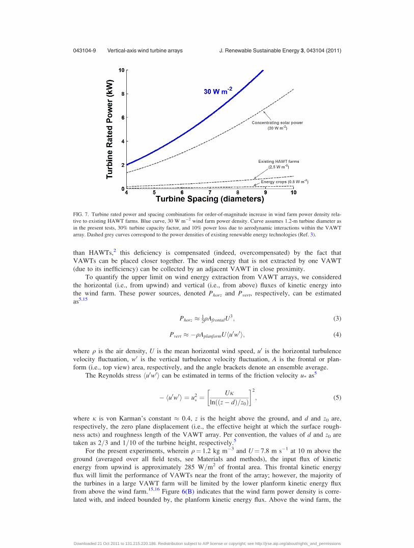
Furthermore, it is straightforward to compute the combinations of VAWT rated power out-
put and turbine spacing that can achieve 30 W m�2 (i.e., 10 times modern HAWT farms) by
using 1.2-m diameter VAWTs like those studied here (Figure 7). Higher VAWT rated power
outputs can be achieved by using taller turbine rotors than the 4.1-m structures used in these
experiments, and by connecting the turbine shaft to larger generators. Indeed, in initial field
tests with 6.1-m tall rotors, the captured wind power exceeded the capacity of the 1200 W gen-
erator on each turbine.
IV. DISCUSSION
The large increases in wind farm power density demonstrated here may be surprising when
one considers that the efficiency (i.e., power coefficient) of modern HAWTs approaches the the-
oretical upper limit of 59.2% aerodynamic efficiency for isolated HAWTs.2 The present results
suggest that the physical limit on wind energy extraction using the VAWT array approach is
not the individual turbine efficiency, as is the case for well-spaced HAWTs that essentially op-
erate in isolation within a wind farm. Instead, wind energy extraction is limited by the wind
resource itself, especially the horizontal wind speed and the vertical flux of turbulence kinetic
energy required to transport wind energy to turbines downwind from the front of the wind
farm. This upper limit, which is based on properties of the atmospheric surface layer and the
surface roughness created by the wind turbines themselves,4,5,15,16 supersedes the theoretical
limit on isolated HAWT efficiency as the primary determinant of maximum VAWT farm per-
formance. Stated differently, although individual VAWTs often exhibit lower power coefficients
FIG. 6. Performance of counter-rotating six-VAWT configuration. (A) Plot of normalized power coefficient Cnormp versus
tip speed ratio for all incident wind directions. Data are normalized by the power coefficient of the farthest upwind turbine
(i.e., CW turbine in left column of Fig. 1(D)). Dotted red curve, CCW turbine in left column of Fig. 1(D); dashed red curve,
CCW turbine in middle column; solid red curve, CCW turbine in right column; dash-dot red curve, CCW turbine in right
column with adjacent CW turbine removed; dashed blue curve, CW turbine in middle column; and solid blue curve, CW tur-
bine in right column. Vertical dotted line indicates designed operating tip speed ratio of turbines. (B) Measured array power
density versus planform kinetic energy flux (see text for definition). Data points are labeled according to the measurement
date. Closed circles, 24-h average (except 10 September, which is an average from 13:00 to 24:00); open circles, average
above cut-in wind speed.
043104-8 John O. Dabiri J. Renewable Sustainable Energy 3, 043104 (2011)
Downloaded 21 Oct 2011 to 131.215.220.186. Redistribution subject to AIP license or copyright; see http://jrse.aip.org/about/rights_and_permissions
than HAWTs,2 this deficiency is compensated (indeed, overcompensated) by the fact that
VAWTs can be placed closer together. The wind energy that is not extracted by one VAWT
(due to its inefficiency) can be collected by an adjacent VAWT in close proximity.
To quantify the upper limit on wind energy extraction from VAWT arrays, we considered
the horizontal (i.e., from upwind) and vertical (i.e., from above) fluxes of kinetic energy into
the wind farm. These power sources, denoted Phorz and Pvert, respectively, can be estimated
as5,15
Phorz � 12qAfrontalU
3; (3)
Pvert � �qAplanformU u0w0h i; (4)
where q is the air density, U is the mean horizontal wind speed, u0 is the horizontal turbulence
velocity fluctuation, w0 is the vertical turbulence velocity fluctuation, A is the frontal or plan-
form (i.e., top view) area, respectively, and the angle brackets denote an ensemble average.
The Reynolds stress u0w0h i can be estimated in terms of the friction velocity u* as5
� u0w0h i ¼ u2� ¼
Ujln z� dð Þ=z0ð Þ
� �2
; (5)
where j is von Karman’s constant � 0.4, z is the height above the ground, and d and z0 are,
respectively, the zero plane displacement (i.e., the effective height at which the surface rough-
ness acts) and roughness length of the VAWT array. Per convention, the values of d and z0 are
taken as 2=3 and 1=10 of the turbine height, respectively.5
For the present experiments, wherein q¼ 1.2 kg m�3 and U¼ 7.8 m s�1 at 10 m above the
ground (averaged over all field tests, see Materials and methods), the input flux of kinetic
energy from upwind is approximately 285 W=m2 of frontal area. This frontal kinetic energy
flux will limit the performance of VAWTs near the front of the array; however, the majority of
the turbines in a large VAWT farm will be limited by the lower planform kinetic energy flux
from above the wind farm.15,16 Figure 6(B) indicates that the wind farm power density is corre-
lated with, and indeed bounded by, the planform kinetic energy flux. Above the wind farm, the
FIG. 7. Turbine rated power and spacing combinations for order-of-magnitude increase in wind farm power density rela-
tive to existing HAWT farms. Blue curve, 30 W m�2 wind farm power density. Curve assumes 1.2-m turbine diameter as
in the present tests, 30% turbine capacity factor, and 10% power loss due to aerodynamic interactions within the VAWT
array. Dashed grey curves correspond to the power densities of existing renewable energy technologies (Ref. 3).
043104-9 Vertical-axis wind turbine arrays J. Renewable Sustainable Energy 3, 043104 (2011)
Downloaded 21 Oct 2011 to 131.215.220.186. Redistribution subject to AIP license or copyright; see http://jrse.aip.org/about/rights_and_permissions

mean wind speed will be reduced from its upwind value due to the elevated surface friction
caused by the presence of the wind turbines. Figure 8 plots the planform kinetic energy flux
model from Eqs. (4) and (5) as a function of the ratio of the reduced mean wind speed Ur to
the unperturbed wind speed U (i.e., in the absence of the wind farm). For comparison, the nom-
inal performance of modern HAWT farms is also shown. The results suggest that as long as the
wind speed above the wind farm remains greater than 1=3 of the unperturbed wind, the VAWT
farm performance upper bound dictated by the planform kinetic energy flux exceeds the per-
formance of current HAWT farms. For Ur=U> 0.75, the VAWT farm planform kinetic flux is
an order of magnitude greater than the performance of modern HAWT farms.
The present measurements are insufficient to determine the range of Ur=U that can be
achieved in practice for large-scale VAWT farms. The value will depend on the local stability
of the atmospheric surface layer, the spatial density and height profile of the VAWTs, and their
effective drag properties. Further study of the interplay among these parameters is essential and
is a focus of ongoing and future research.
By including periodic gaps of larger downwind spacing and=or turbine height variations
between clusters of downwind VAWTs, it may also be possible to prevent saturation of the
frontal kinetic energy flux without significantly compromising the gains in wind farm power
density. With regard to the former strategy of downwind spacing, we verified that by removing
the turbine immediately upwind of the rearmost VAWT in the present array, its performance
was further improved (Figure 6(A), red dash-dot curve).
Counter-rotation of adjacent VAWTs is important because it ensures that the airflow
induced by each of the turbines in the region between them is oriented in the same direction
(Refs. 17 and 18, see also Figure 9). Hence, the creation of horizontal wind shear (i.e., velocity
gradients), which leads to turbulence and energy dissipation in the region between the turbines,
is reduced relative to adjacent turbines that rotate in the same direction.19,20 Since the remain-
ing wind energy between the turbines is not dissipated by turbulence, it can be subsequently
extracted by VAWTs located further downwind. This process is most effective for VAWTs
operating at higher tip speed ratios (i.e., greater than 2), since in this regime the turbine rotation
can suppress vortex shedding and turbulence in the wake in a manner similar to that observed
in previous studies of spinning cylinders.21–23 At lower tip speed ratios, the VAWTs likely
FIG. 8. Planform kinetic energy flux versus the ratio of mean wind speed above the wind farm Ur to the unperturbed mean
wind speed U (i.e., in the absence of the wind farm). The planform kinetic energy flux is correspondingly reduced with Ur
replacing U in Eqs. (4) and (5). For mean wind speeds that are greater than approximately 1=3 of the unperturbed wind
speed, the planform kinetic energy flux exceeds the performance of current HAWT farms (black dashed line). For
Ur=U> 0.75, the VAWT farm planform kinetic flux is an order of magnitude greater than the performance of modern
HAWT farms.
043104-10 John O. Dabiri J. Renewable Sustainable Energy 3, 043104 (2011)
Downloaded 21 Oct 2011 to 131.215.220.186. Redistribution subject to AIP license or copyright; see http://jrse.aip.org/about/rights_and_permissions

create a larger wake akin to that of a stationary cylinder; we observed correspondingly reduced
performance in the present field tests.
The overall approach described presently is fundamentally different from current practices
in wind energy harvesting: here, a large number of smaller VAWTs are implemented instead of
fewer, large HAWTs. The higher levels of turbulence near the ground—both naturally occurring
and induced by the VAWT configuration—enhance the vertical flux of kinetic energy delivered
to the turbines, thereby facilitating their close spacing. This approach has the potential to con-
currently alleviate many of the practical challenges associated with large HAWTs, such as the
cost and logistics of their manufacture, transportation, and installation (e.g., by using less ex-
pensive materials and manufacturing processes and by exploiting greater opportunities for mass
production); environmental impacts (e.g., bird and bat strikes); acoustic and radar signatures
(e.g., lower tip speed ratios than HAWTs (Ref. 2)); visual signature (Figure 10); and general ac-
ceptance by local communities. These issues, although not strictly scientific, limit the further
expansion of existing wind energy technology.
The present results encourage a search for optimal configurations of counter-rotating
VAWTs that can improve upon the power density achieved here. Such optimal solutions may
FIG. 9. Schematic of induced airflow between co-rotating VAWTs (panel (A)) and counter-rotating VAWTs (panel (B)).
Co-rotating VAWTs (circles) induce airflow (hollow arrows) in opposite directions, whereas counter-rotating VAWTs
(circles) induce airflow (hollow arrows) in the same direction.
FIG. 10. Visual signature of VAWT array. Image taken approximately 1 km from test facility (indicated by white arrow).
10 m height of VAWTs is labeled at right, in addition to approximate 100 m height of a typical large HAWT. Photo credit:
R. W. Whittlesey.
043104-11 Vertical-axis wind turbine arrays J. Renewable Sustainable Energy 3, 043104 (2011)
Downloaded 21 Oct 2011 to 131.215.220.186. Redistribution subject to AIP license or copyright; see http://jrse.aip.org/about/rights_and_permissions

achieve enhanced turbine performance in close proximity (e.g., Figure 4) while minimizing
downwind blockage effects and enhancing the vertical flux of kinetic energy via manipulation
of the zero plane displacement and roughness length of the VAWT array. Finally, we note that
the energy harvesting principles developed here are equally applicable to underwater turbines in
the ocean.
ACKNOWLEDGMENTS
The author gratefully acknowledges funding from the National Science Foundation Energy for
Sustainability program (Grant No. CBET-0725164) and the Gordon and Betty Moore Foundation.
The author also thanks R. W. Whittlesey for providing assistance in establishing the satellite data
connection to the field site.
1B. Sørensen, Renewable Energy: Its Physics, Engineering, Use, Environmental Impacts, Economy, and Planning Aspects(Elsevier, London, 2004).
2E. Hau, Wind Turbines: Fundamentals, Technologies, Application, Economics (Springer, Berlin, 2005).3D. J. C. MacKay, Sustainable Energy—Without the Hot Air (UIT Cambridge Ltd., Cambridge, UK, 2009).4H. Tennekes and J. L. Lumley, A First Course in Turbulence (MIT, Cambridge, MA, 1972).5J. R. Garratt, The Atmospheric Boundary Layer (Cambridge University Press, Cambridge, England, 1994).6M. Liu, M. Yocke, and T. Myers, J. Energy 7, 73 (1983).7N. O. Jensen, “A note on wind generator interaction,” Technical Report Risø-M-2411, Risø National Laboratory,Roskilde, Denmark, 1984.
8C. T. Kiranoudis and Z. B. Maroulis, Renewable Energy 11, 439 (1997).9S. Ivanell, J. Sørensen, and D. Henningson, Wind Energy (Springer, Berlin, 2007).
10R. Rajagopalan, P. Klimas, T. Rickerl, J. Propul. Power 6, 645 (1990).11R. W. Whittlesey, S. Liska, and J. O. Dabiri, Bioinsp Biomim 5, 035005 (2010).12The tip speed ratio is given by (pDX)U�1, where D is the wind turbine rotor diameter, X is the turbine rotation rate, and
U is the wind speed.13R. Linn and E. Koo, “WindBlade: Coupled turbine=atmosphere modeling,” in Los Alamos National Laboratory Turbine-
Turbine Interaction Workshop, Los Alamos, NM, 2–3 March, 2011.14Note that even if the total aerodynamic losses in the wind farm are increased to 25 percent, the capacity factor is reduced
to 15 percent, and the spacing between VAWTs is increased to six diameters, the VAWT farm still achieves a power den-sity of 3.3 W m�2, which exceeds the performance of most modern wind farms. This illustrates the robustness of theVAWT array concept.
15M. Calaf, C. Meneveau, and J. Myers, Phys. Fluids 22, 015110 (2010).16R. B. Cal, J. Lebron, L. Castillo, H. S. Kang, and C. Meneveau, J. Renewable Sustainable Energy 2, 013106 (2010).17When the turbine tip speed ratio is greater than 1, as is the case for lift-based VAWTs such as those tested presently, the
direction of induced airflow is dictated by the direction of turbine rotation (Ref. 2).18D. Weihs, in Swimming and Flying in Nature, edited by T. Wu, C. Brokaw, and C. Brennen (Plenum, New York, 1975).19To be sure, the second-nearest-neighbor turbines in the array are co-rotating. However, their separation is a factor 21=2
greater than the separation of nearest-neighbor counter-rotating turbines. Since the effect of induced flow decays with ra-dial distance as r�2 or faster (Ref. 18), the magnitude of the co-rotating interactions is at most 1=2 of the interactionsbetween counter-rotating turbines.
20P. R. Schatzle, P. C. Klimas, and H. R. Spahr, “Aerodynamic interference between two Darrieus wind turbines,” SandiaNational Laboratories Report No. SAND8l-0896, 1981.
21F. Diaz, J. Gavalda, J. G. Kawall, J. F. Keller, and F. Giralt, Phys. Fluids 26, 3454 (1983).22S. Mittal and B. Kumar, J. Fluid Mech. 476, 303 (2003).23A. S. Chan, P. A. Dewey, A. Jameson, C. Liang, and A. J. Smits, J. Fluid Mech. 679, 343 (2011).
043104-12 John O. Dabiri J. Renewable Sustainable Energy 3, 043104 (2011)
Downloaded 21 Oct 2011 to 131.215.220.186. Redistribution subject to AIP license or copyright; see http://jrse.aip.org/about/rights_and_permissions
Related Documents


