Potential and prospective implementation of carbon nanotubes on next generation aircraft and space vehicles: A review of current and expected applications in aerospace sciences Omid Gohardani a,n , Maialen Chapartegui Elola b , Cristina Elizetxea b a Springs of Dreams Corporation, 340 East 1st Street, No. 8, Tustin, California 92781, United States of America b Tecnalia, Parque Tecnológico de San Sebastián, Mikeletegi Pasealekua 2, E-20009 Donostia-San Sebastián, Spain article info Article history: Received 2 January 2014 Received in revised form 21 May 2014 Accepted 22 May 2014 Available online 9 July 2014 Keywords: Aerospace nanotechnology Next generation aircraft/spacecraft Future aerospace materials Aerospace nanomaterials Carbon nanotube aircraft Space elevator abstract Carbon nanotubes have instigated the interest of many different scientific fields since their authenticated introduction, more than two decades ago. Particularly in aerospace applications, the potential implemen- tations of these advanced materials have been predicted to have a large impact on future aircraft and space vehicles, mainly due to their distinct features, which include superior mechanical, thermal and electrical properties. This article provides the very first consolidated review of the imminent prospects of utilizing carbon nanotubes and nanoparticles in aerospace sciences, based on their recent implementations and predicted future applications. Explicitly, expected carbon nanotube employment in aeronautics and astronautics are identified for commercial aircraft, military aircraft, rotorcraft, unmanned aerial vehicles, satellites, and space launch vehicles. Attention is devoted to future utilization of carbon nanotubes, which may comprise hydrogen storage encapsulation, composite material implementation, lightning protection for aircraft, aircraft icing mitigation, reduced weight of airframes/satellites, and alleviation of challenges related to future space launch. This study further sheds light onto recent actualized implementations of carbon nanotubes in aerospace applications, as well as current and prospective challenges related to their usage in aerospace sciences, encompassing health and safety hazards, large scale manufacturing, achievement of optimum properties, recycling, and environmental impacts. & 2014 Elsevier Ltd. All rights reserved. Contents 1. Introduction ......................................................................................................... 43 2. A brief introduction to CNTs ............................................................................................ 44 2.1. Classification .................................................................................................. 44 2.2. Synthesis of CNTs .............................................................................................. 46 2.3. Manufacturing ................................................................................................. 46 2.4. Properties ..................................................................................................... 46 2.5. Modeling of CNTs .............................................................................................. 46 3. Timeline of CNT milestones in aerospace applications ....................................................................... 46 4. Potential roles of CNTs in aeronautics .................................................................................... 46 4.1. Introduction ................................................................................................... 46 4.2. CNTs and commercial aircraft ..................................................................................... 47 4.2.1. Airframe ............................................................................................... 47 4.2.2. Wiring ................................................................................................ 48 4.2.3. Aircraft icing ........................................................................................... 49 4.2.4. Propulsion ............................................................................................. 50 4.2.5. Lightning protection ..................................................................................... 50 4.2.6. Electromagnetic interference shielding....................................................................... 51 4.2.7. Sensing ................................................................................................ 51 Contents lists available at ScienceDirect journal homepage: www.elsevier.com/locate/paerosci Progress in Aerospace Sciences http://dx.doi.org/10.1016/j.paerosci.2014.05.002 0376-0421/& 2014 Elsevier Ltd. All rights reserved. n Corresponding author. E-mail address: [email protected] (O. Gohardani). Progress in Aerospace Sciences 70 (2014) 42–68

Welcome message from author
This document is posted to help you gain knowledge. Please leave a comment to let me know what you think about it! Share it to your friends and learn new things together.
Transcript
Potential and prospective implementation of carbon nanotubes onnext generation aircraft and space vehicles: A review of current andexpected applications in aerospace sciences
Omid Gohardani a,n, Maialen Chapartegui Elola b, Cristina Elizetxea b
a Springs of Dreams Corporation, 340 East 1st Street, No. 8, Tustin, California 92781, United States of Americab Tecnalia, Parque Tecnológico de San Sebastián, Mikeletegi Pasealekua 2, E-20009 Donostia-San Sebastián, Spain
a r t i c l e i n f o
Article history:Received 2 January 2014Received in revised form21 May 2014Accepted 22 May 2014Available online 9 July 2014
Keywords:Aerospace nanotechnologyNext generation aircraft/spacecraftFuture aerospace materialsAerospace nanomaterialsCarbon nanotube aircraftSpace elevator
a b s t r a c t
Carbon nanotubes have instigated the interest of many different scientific fields since their authenticatedintroduction, more than two decades ago. Particularly in aerospace applications, the potential implemen-tations of these advanced materials have been predicted to have a large impact on future aircraft and spacevehicles, mainly due to their distinct features, which include superior mechanical, thermal and electricalproperties. This article provides the very first consolidated review of the imminent prospects of utilizingcarbon nanotubes and nanoparticles in aerospace sciences, based on their recent implementations andpredicted future applications. Explicitly, expected carbon nanotube employment in aeronautics andastronautics are identified for commercial aircraft, military aircraft, rotorcraft, unmanned aerial vehicles,satellites, and space launch vehicles. Attention is devoted to future utilization of carbon nanotubes, whichmay comprise hydrogen storage encapsulation, composite material implementation, lightning protectionfor aircraft, aircraft icing mitigation, reduced weight of airframes/satellites, and alleviation of challengesrelated to future space launch. This study further sheds light onto recent actualized implementations ofcarbon nanotubes in aerospace applications, as well as current and prospective challenges related to theirusage in aerospace sciences, encompassing health and safety hazards, large scale manufacturing,achievement of optimum properties, recycling, and environmental impacts.
& 2014 Elsevier Ltd. All rights reserved.
Contents
1. Introduction . . . . . . . . . . . . . . . . . . . . . . . . . . . . . . . . . . . . . . . . . . . . . . . . . . . . . . . . . . . . . . . . . . . . . . . . . . . . . . . . . . . . . . . . . . . . . . . . . . . . . . . . . 432. A brief introduction to CNTs . . . . . . . . . . . . . . . . . . . . . . . . . . . . . . . . . . . . . . . . . . . . . . . . . . . . . . . . . . . . . . . . . . . . . . . . . . . . . . . . . . . . . . . . . . . . 44
2.1. Classification . . . . . . . . . . . . . . . . . . . . . . . . . . . . . . . . . . . . . . . . . . . . . . . . . . . . . . . . . . . . . . . . . . . . . . . . . . . . . . . . . . . . . . . . . . . . . . . . . . 442.2. Synthesis of CNTs . . . . . . . . . . . . . . . . . . . . . . . . . . . . . . . . . . . . . . . . . . . . . . . . . . . . . . . . . . . . . . . . . . . . . . . . . . . . . . . . . . . . . . . . . . . . . . 462.3. Manufacturing . . . . . . . . . . . . . . . . . . . . . . . . . . . . . . . . . . . . . . . . . . . . . . . . . . . . . . . . . . . . . . . . . . . . . . . . . . . . . . . . . . . . . . . . . . . . . . . . . 462.4. Properties. . . . . . . . . . . . . . . . . . . . . . . . . . . . . . . . . . . . . . . . . . . . . . . . . . . . . . . . . . . . . . . . . . . . . . . . . . . . . . . . . . . . . . . . . . . . . . . . . . . . . 462.5. Modeling of CNTs . . . . . . . . . . . . . . . . . . . . . . . . . . . . . . . . . . . . . . . . . . . . . . . . . . . . . . . . . . . . . . . . . . . . . . . . . . . . . . . . . . . . . . . . . . . . . . 46
3. Timeline of CNT milestones in aerospace applications . . . . . . . . . . . . . . . . . . . . . . . . . . . . . . . . . . . . . . . . . . . . . . . . . . . . . . . . . . . . . . . . . . . . . . . 464. Potential roles of CNTs in aeronautics . . . . . . . . . . . . . . . . . . . . . . . . . . . . . . . . . . . . . . . . . . . . . . . . . . . . . . . . . . . . . . . . . . . . . . . . . . . . . . . . . . . . 46
4.1. Introduction . . . . . . . . . . . . . . . . . . . . . . . . . . . . . . . . . . . . . . . . . . . . . . . . . . . . . . . . . . . . . . . . . . . . . . . . . . . . . . . . . . . . . . . . . . . . . . . . . . . 464.2. CNTs and commercial aircraft . . . . . . . . . . . . . . . . . . . . . . . . . . . . . . . . . . . . . . . . . . . . . . . . . . . . . . . . . . . . . . . . . . . . . . . . . . . . . . . . . . . . . 47
4.2.1. Airframe . . . . . . . . . . . . . . . . . . . . . . . . . . . . . . . . . . . . . . . . . . . . . . . . . . . . . . . . . . . . . . . . . . . . . . . . . . . . . . . . . . . . . . . . . . . . . . . 474.2.2. Wiring . . . . . . . . . . . . . . . . . . . . . . . . . . . . . . . . . . . . . . . . . . . . . . . . . . . . . . . . . . . . . . . . . . . . . . . . . . . . . . . . . . . . . . . . . . . . . . . . 484.2.3. Aircraft icing . . . . . . . . . . . . . . . . . . . . . . . . . . . . . . . . . . . . . . . . . . . . . . . . . . . . . . . . . . . . . . . . . . . . . . . . . . . . . . . . . . . . . . . . . . . 494.2.4. Propulsion . . . . . . . . . . . . . . . . . . . . . . . . . . . . . . . . . . . . . . . . . . . . . . . . . . . . . . . . . . . . . . . . . . . . . . . . . . . . . . . . . . . . . . . . . . . . . 504.2.5. Lightning protection . . . . . . . . . . . . . . . . . . . . . . . . . . . . . . . . . . . . . . . . . . . . . . . . . . . . . . . . . . . . . . . . . . . . . . . . . . . . . . . . . . . . . 504.2.6. Electromagnetic interference shielding. . . . . . . . . . . . . . . . . . . . . . . . . . . . . . . . . . . . . . . . . . . . . . . . . . . . . . . . . . . . . . . . . . . . . . . 514.2.7. Sensing . . . . . . . . . . . . . . . . . . . . . . . . . . . . . . . . . . . . . . . . . . . . . . . . . . . . . . . . . . . . . . . . . . . . . . . . . . . . . . . . . . . . . . . . . . . . . . . . 51
Contents lists available at ScienceDirect
journal homepage: www.elsevier.com/locate/paerosci
Progress in Aerospace Sciences
http://dx.doi.org/10.1016/j.paerosci.2014.05.0020376-0421/& 2014 Elsevier Ltd. All rights reserved.
n Corresponding author.E-mail address: [email protected] (O. Gohardani).
Progress in Aerospace Sciences 70 (2014) 42–68
4.2.8. Safety . . . . . . . . . . . . . . . . . . . . . . . . . . . . . . . . . . . . . . . . . . . . . . . . . . . . . . . . . . . . . . . . . . . . . . . . . . . . . . . . . . . . . . . . . . . . . . . . . 514.3. CNTs and military aircraft . . . . . . . . . . . . . . . . . . . . . . . . . . . . . . . . . . . . . . . . . . . . . . . . . . . . . . . . . . . . . . . . . . . . . . . . . . . . . . . . . . . . . . . . 52
4.3.1. Stealth . . . . . . . . . . . . . . . . . . . . . . . . . . . . . . . . . . . . . . . . . . . . . . . . . . . . . . . . . . . . . . . . . . . . . . . . . . . . . . . . . . . . . . . . . . . . . . . . 524.3.2. Aircraft icing . . . . . . . . . . . . . . . . . . . . . . . . . . . . . . . . . . . . . . . . . . . . . . . . . . . . . . . . . . . . . . . . . . . . . . . . . . . . . . . . . . . . . . . . . . . 53
4.4. Morphing aircraft. . . . . . . . . . . . . . . . . . . . . . . . . . . . . . . . . . . . . . . . . . . . . . . . . . . . . . . . . . . . . . . . . . . . . . . . . . . . . . . . . . . . . . . . . . . . . . . 534.5. CNTs and rotorcraft . . . . . . . . . . . . . . . . . . . . . . . . . . . . . . . . . . . . . . . . . . . . . . . . . . . . . . . . . . . . . . . . . . . . . . . . . . . . . . . . . . . . . . . . . . . . . 53
4.5.1. Structural damping . . . . . . . . . . . . . . . . . . . . . . . . . . . . . . . . . . . . . . . . . . . . . . . . . . . . . . . . . . . . . . . . . . . . . . . . . . . . . . . . . . . . . . 534.5.2. Structural monitoring . . . . . . . . . . . . . . . . . . . . . . . . . . . . . . . . . . . . . . . . . . . . . . . . . . . . . . . . . . . . . . . . . . . . . . . . . . . . . . . . . . . . 534.5.3. Icing on rotorcraft . . . . . . . . . . . . . . . . . . . . . . . . . . . . . . . . . . . . . . . . . . . . . . . . . . . . . . . . . . . . . . . . . . . . . . . . . . . . . . . . . . . . . . . 53
4.6. CNTs in UAV and MAV applications . . . . . . . . . . . . . . . . . . . . . . . . . . . . . . . . . . . . . . . . . . . . . . . . . . . . . . . . . . . . . . . . . . . . . . . . . . . . . . . . 534.6.1. Electric UAVs and CNTs . . . . . . . . . . . . . . . . . . . . . . . . . . . . . . . . . . . . . . . . . . . . . . . . . . . . . . . . . . . . . . . . . . . . . . . . . . . . . . . . . . . 544.6.2. Mitigation of aircraft icing related to UAVs . . . . . . . . . . . . . . . . . . . . . . . . . . . . . . . . . . . . . . . . . . . . . . . . . . . . . . . . . . . . . . . . . . . 54
5. Potential roles of CNTs in astronautics . . . . . . . . . . . . . . . . . . . . . . . . . . . . . . . . . . . . . . . . . . . . . . . . . . . . . . . . . . . . . . . . . . . . . . . . . . . . . . . . . . . . 545.1. The space elevator . . . . . . . . . . . . . . . . . . . . . . . . . . . . . . . . . . . . . . . . . . . . . . . . . . . . . . . . . . . . . . . . . . . . . . . . . . . . . . . . . . . . . . . . . . . . . . 55
5.1.1. Motivation . . . . . . . . . . . . . . . . . . . . . . . . . . . . . . . . . . . . . . . . . . . . . . . . . . . . . . . . . . . . . . . . . . . . . . . . . . . . . . . . . . . . . . . . . . . . . 555.1.2. Concept . . . . . . . . . . . . . . . . . . . . . . . . . . . . . . . . . . . . . . . . . . . . . . . . . . . . . . . . . . . . . . . . . . . . . . . . . . . . . . . . . . . . . . . . . . . . . . . 55
5.2. Space propulsion . . . . . . . . . . . . . . . . . . . . . . . . . . . . . . . . . . . . . . . . . . . . . . . . . . . . . . . . . . . . . . . . . . . . . . . . . . . . . . . . . . . . . . . . . . . . . . . 555.3. Satellites and spacecraft . . . . . . . . . . . . . . . . . . . . . . . . . . . . . . . . . . . . . . . . . . . . . . . . . . . . . . . . . . . . . . . . . . . . . . . . . . . . . . . . . . . . . . . . . 56
6. Recent developments of CNT implementation in aerospace applications. . . . . . . . . . . . . . . . . . . . . . . . . . . . . . . . . . . . . . . . . . . . . . . . . . . . . . . . . 566.1. A glimpse of actualized CNT implementation in aerospace applications . . . . . . . . . . . . . . . . . . . . . . . . . . . . . . . . . . . . . . . . . . . . . . . . . . . 566.2. A selection of patents featuring CNT implementation in aerospace applications. . . . . . . . . . . . . . . . . . . . . . . . . . . . . . . . . . . . . . . . . . . . . 57
7. Challenges related to CNT implementation in aerospace applications . . . . . . . . . . . . . . . . . . . . . . . . . . . . . . . . . . . . . . . . . . . . . . . . . . . . . . . . . . . 577.1. Large scale production. . . . . . . . . . . . . . . . . . . . . . . . . . . . . . . . . . . . . . . . . . . . . . . . . . . . . . . . . . . . . . . . . . . . . . . . . . . . . . . . . . . . . . . . . . . 597.2. Adequate quality at a low cost . . . . . . . . . . . . . . . . . . . . . . . . . . . . . . . . . . . . . . . . . . . . . . . . . . . . . . . . . . . . . . . . . . . . . . . . . . . . . . . . . . . . 597.3. Achievement of optimized properties upon CNT implementation . . . . . . . . . . . . . . . . . . . . . . . . . . . . . . . . . . . . . . . . . . . . . . . . . . . . . . . . 597.4. Health and safety concerns . . . . . . . . . . . . . . . . . . . . . . . . . . . . . . . . . . . . . . . . . . . . . . . . . . . . . . . . . . . . . . . . . . . . . . . . . . . . . . . . . . . . . . . 597.5. Recycling and environmental inputs. . . . . . . . . . . . . . . . . . . . . . . . . . . . . . . . . . . . . . . . . . . . . . . . . . . . . . . . . . . . . . . . . . . . . . . . . . . . . . . . 60
8. Discussion . . . . . . . . . . . . . . . . . . . . . . . . . . . . . . . . . . . . . . . . . . . . . . . . . . . . . . . . . . . . . . . . . . . . . . . . . . . . . . . . . . . . . . . . . . . . . . . . . . . . . . . . . . 619. Future outlooks . . . . . . . . . . . . . . . . . . . . . . . . . . . . . . . . . . . . . . . . . . . . . . . . . . . . . . . . . . . . . . . . . . . . . . . . . . . . . . . . . . . . . . . . . . . . . . . . . . . . . . 61
10. Conclusions . . . . . . . . . . . . . . . . . . . . . . . . . . . . . . . . . . . . . . . . . . . . . . . . . . . . . . . . . . . . . . . . . . . . . . . . . . . . . . . . . . . . . . . . . . . . . . . . . . . . . . . . . 62Acknowledgments . . . . . . . . . . . . . . . . . . . . . . . . . . . . . . . . . . . . . . . . . . . . . . . . . . . . . . . . . . . . . . . . . . . . . . . . . . . . . . . . . . . . . . . . . . . . . . . . . . . . . . . . 62References . . . . . . . . . . . . . . . . . . . . . . . . . . . . . . . . . . . . . . . . . . . . . . . . . . . . . . . . . . . . . . . . . . . . . . . . . . . . . . . . . . . . . . . . . . . . . . . . . . . . . . . . . . . . . . 62
1. Introduction
The interest for applications of carbon nanotubes (CNTs) hassince their scientific introduction progressively increased due tothe superior features that these materials exhibit. The potentialapplications of CNTs have augmented by a manifold in differentscientific disciplines, such as in energy storage [1,2], mechanicalsystems [3], sensing [4], biological applications [5–7], and fieldemission [8–10]. As aerospace engineering is considered to be onethe forefront disciplines of the future, it is natural that thesematerials will play a game-changing role for this specific industry.With the retirement of the Space Shuttle [11,12] and introductionof composite materials to a larger extent on current and futurecommercial aircraft such as Boeing 787 [13] and Airbus A380 [14],the potential implementations of CNTs and benefits thereof, forboth the aeronautical and the aerospace industry are evident. Forthis purpose, this article seeks to identify the potential usage ofCNTs in aerospace applications and identify their prospectiveimplementations. In 1950s, the need for composite materials withsuperior mechanical properties was a driving stimulus into carbonfiber research [15], which eventually led to progress in carbonwhisker and single crystal graphite research [16,17]. The emergingchallenges of crack propagation and encountered fiber defectshowever called for alternative solutions for obtaining ultra-highmodulus fibers. One approach towards this goal was the employ-ment of controlled synthesis of carbon fibers by utilizing acatalytic chemical vapor deposition (CVD) [18]. The progress inpolymer-based carbon fiber research was initially carried out onmicroscale filaments [19] and consequently led to experimentalidentification of CNTs using transmission electron microscopy [20].In the present study, a literature excursion on CNTs clearlyindicates that the number of scientific publications on this topic
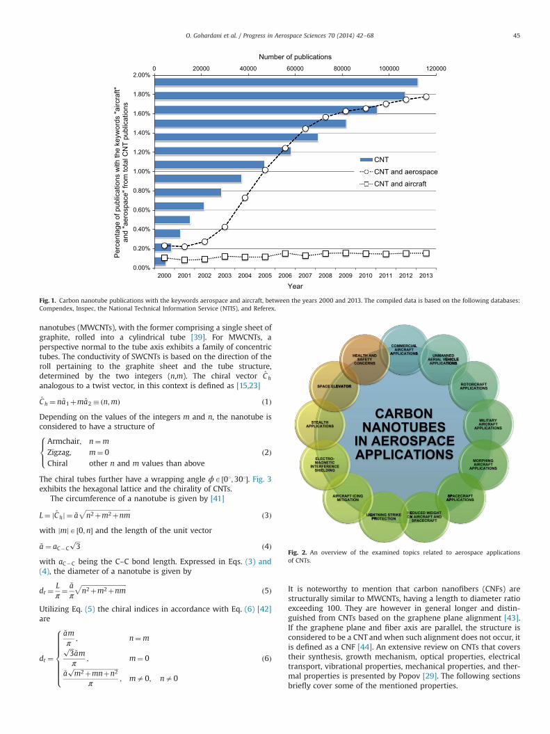
has increased considerably since the year 2000, as shown in Fig. 1.This trend is likely to continue to increase as scientists unravel theapplications and characteristics of CNTs in different scientificfields. In this context, an interesting remark is that the numberof articles containing the keyword aerospace has increased fromless than 0.25% to 1.8% in 2013. These figures are hence indicativeof a continued bright prospect of CNT usage in aerospace sciences,while also accounting for their relative limited current implemen-tations. Equally, it is apparent that there is a distinct difference inthe number of publications pertaining to CNTs solely with thekeyword “aircraft” versus “aerospace”, as shown in Fig. 1.
More detailed historical insight into carbon fibers and CNTs hasbeen outlined by other researchers [21–23], where in-depthspecifications are presented related to these materials. Due tothe extremely large number of research efforts carried out in thefield of nanotechnology and particularly related to CNTs, it isbeyond the scope of this article to cover all studies with potentialapplications of these materials. A literature excursion related toapplications of CNTs in aerospace engineering often results inscientific articles where profound research studies in the field ofmaterial sciences are presented. In light of this statement, alimited number of articles are identified that focus solely on thepotential applications of CNTs in aeronautics and astronautics.Granted, the multi-disciplinary aspect of this topic has renderedauthoring of a multi-faceted review of this topic, a challengingtask. The purpose of this article is therefore to explore theaforementioned realms and provide identified prospects of CNTapplications within aerospace sciences departing from solely amaterial science perspective. Hence, this review article endeavorsto provide an overview of the topics necessary for understandingthe concepts associated with CNT implementation in aerospacesciences, in conjunction with references where more detailed
O. Gohardani et al. / Progress in Aerospace Sciences 70 (2014) 42–68 43
descriptions from a material science perspective are presented.Fig. 2 outlines the covered topics in this review article.
2. A brief introduction to CNTs
Due to the numerous beneficial applications of CNTs in variousscientific fields, the spectrum of the published literature regardingthese materials has examined many of their characteristics in
terms of atomic structure and morphology, processing, character-ization, mechanics, and other chemical/physical properties inseveral books and review articles [24–38]. In this section, a briefoverview is provided related to the characteristics of CNTs.
2.1. Classification
CNTs are commonly classified into two categories, termedsingle-walled carbon nanotubes (SWCNTs) and multi-walled carbon
Nomenclature
ηB battery efficiencytE flight endurance timeξðdÞ probability distribution of nanotubesϕ wrapping angleρ densityϱ electrical resistivityψ ðdÞ arbitrary nanotube volume distributions electrical conductivitysB tensile strengthC h chiral vectorℓ length�a length of the unit vectoraC�C C–C bond lengthd diameter of nanotubedt diameter of nanotubedr detected distance by radark thermal conductivityℓ integerm integern integert nanotube outer layer thicknessAR aspect ratioCD drag coefficientCL lift coefficientE, ~E Young's modulusE11 elastic modulus in the principal material directionEm matrix modulusEB nominal stored battery energyENT nanotube modulusLNT circumference of a nanotubeP1 received power with the material presentP2 received power with the material absentS wingplan form areaSE shielding effectivenessT temperatureVNT total volume fraction of tubes in the compositeWB battery weightWS structure weightWTotal total weightAFRL Air Force Material LaboratoryAO atomic oxygenBADA base of aircraft dataBWB blended wing bodyCFRP carbon fiber reinforced polymerCGE CNP/glassfiber/epoxyCNFs carbon nanofibersCNFP carbon nanofiber paperCNP carbon nanotube paperCNS carbon nanostructuresCNTs carbon nanotubesCNRP carbon nanotube reinforced polymer
CVD chemical vapor depositionDARPA Defense Advanced Research Projects AgencyDoD US Department of DefenseDSWSAM dynamic and static wettability scheme for advanced
materialsEEDS electroexpulsive deicing systemsEHS environmental health and safetyEFM embedded fiber methodEME electromagnetic energyEMI electromagnetic interferenceETMS enhanced traffic management systemEP electric propulsionERA environmentally responsible aviationEU European UnionFAA Federal Aviation AdministrationFEA finite element analysisGEO geostationary earth orbitICT information and communication technologyILS interlaminar shear strengthLEO low earth orbitLGG light gas gunLNG liquid natural gasMAV micro air/aerial vehicleMGS Mars global surveyorMHD magneto-hydrodynamicsMMOD micrometeoroid/orbital debrisnanoFET nanoparticle field extraction thrusterNASA National Aeronautics and Space AdministrationNAV nano aerial vehiclesNIOSH National Institute for Occupational Safety and HealthNTIS National Technical Information ServiceMMOD micrometeoroids and orbital debrisMWCNT multi-walled carbon nanotubeOEW operating empty weightPMCs polymer matrix compositesPSC preferred system conceptRAM radar absorbing materialRCS radar cross sectionRHC resistive heating coatingRLV reusable launch vehicleROA remotely operated aircraftRPV remoted piloted vehicleSFC specific fuel consumptionSWCNT single-walled carbon nanotubeTRIPS thermal, radiation and impact protective shieldsUAV uninhabited aerial vehicle/unmanned aerial vehicleUAS unmanned air systemsUHMWPE epoxy and ultra-high molecular weight
polyethyleneUV ultravioletVGCNF vapor grown carbon nanofiberVUV vacuum ultraviolet
O. Gohardani et al. / Progress in Aerospace Sciences 70 (2014) 42–6844
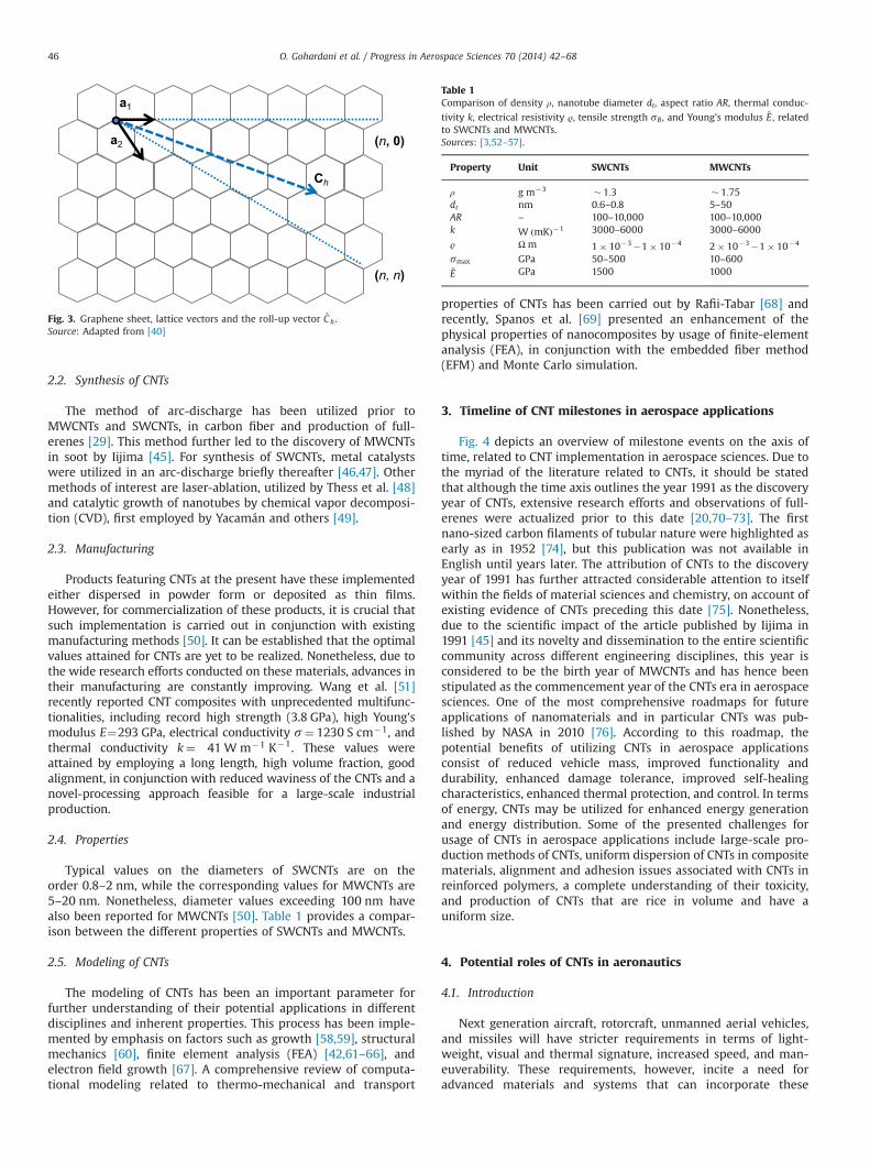
nanotubes (MWCNTs), with the former comprising a single sheet ofgraphite, rolled into a cylindrical tube [39]. For MWCNTs, aperspective normal to the tube axis exhibits a family of concentrictubes. The conductivity of SWCNTs is based on the direction of theroll pertaining to the graphite sheet and the tube structure,determined by the two integers (n,m). The chiral vector C h
analogous to a twist vector, in this context is defined as [15,23]
C h ¼ na1þma2 � ðn;mÞ ð1ÞDepending on the values of the integers m and n, the nanotube isconsidered to have a structure of
Armchair; n¼m
Zigzag; m¼ 0Chiral other n and m values than above
8><>: ð2Þ
The chiral tubes further have a wrapping angle ϕA ½01;301�. Fig. 3exhibits the hexagonal lattice and the chirality of CNTs.
The circumference of a nanotube is given by [41]
L¼ jC hj ¼ �affiffiffiffiffiffiffiffiffiffiffiffiffiffiffiffiffiffiffiffiffiffiffiffiffiffiffiffin2þm2þnm
pð3Þ
with jmjA ½0;n� and the length of the unit vector
�a ¼ aC�C
ffiffiffi3
pð4Þ
with aC�C being the C–C bond length. Expressed in Eqs. (3) and(4), the diameter of a nanotube is given by
dt ¼Lπ¼ �aπ
ffiffiffiffiffiffiffiffiffiffiffiffiffiffiffiffiffiffiffiffiffiffiffiffiffiffiffiffin2þm2þnm
pð5Þ
Utilizing Eq. (5) the chiral indices in accordance with Eq. (6) [42]are
dt ¼
�amπ
; n¼mffiffiffi3
p�amπ
; m¼ 0
�affiffiffiffiffiffiffiffiffiffiffiffiffiffiffiffiffiffiffiffiffiffiffiffiffiffiffiffim2þmnþn2
p
π; ma0; na0
8>>>>>>><>>>>>>>:
ð6Þ
It is noteworthy to mention that carbon nanofibers (CNFs) arestructurally similar to MWCNTs, having a length to diameter ratioexceeding 100. They are however in general longer and distin-guished from CNTs based on the graphene plane alignment [43].If the graphene plane and fiber axis are parallel, the structure isconsidered to be a CNT and when such alignment does not occur, itis defined as a CNF [44]. An extensive review on CNTs that coverstheir synthesis, growth mechanism, optical properties, electricaltransport, vibrational properties, mechanical properties, and ther-mal properties is presented by Popov [29]. The following sectionsbriefly cover some of the mentioned properties.
0 20000 40000 60000 80000 100000 120000
0.00%
0.20%
0.40%
0.60%
0.80%
1.00%
1.20%
1.40%
1.60%
1.80%
2.00%
2000 2001 2002 2003 2004 2005 2006 2007 2008 2009 2010 2011 2012 2013
Number of publications
Per
cent
age
of p
ublic
atio
ns w
ith th
e ke
ywor
ds "a
ircra
ft"
and
"aer
ospa
ce" f
rom
tota
l CN
T pu
blic
atio
ns
Year
CNT
CNT and aerospace
CNT and aircraft
Fig. 1. Carbon nanotube publications with the keywords aerospace and aircraft, between the years 2000 and 2013. The compiled data is based on the following databases:Compendex, Inspec, the National Technical Information Service (NTIS), and Referex.
Fig. 2. An overview of the examined topics related to aerospace applicationsof CNTs.
O. Gohardani et al. / Progress in Aerospace Sciences 70 (2014) 42–68 45
2.2. Synthesis of CNTs
The method of arc-discharge has been utilized prior toMWCNTs and SWCNTs, in carbon fiber and production of full-erenes [29]. This method further led to the discovery of MWCNTsin soot by Iijima [45]. For synthesis of SWCNTs, metal catalystswere utilized in an arc-discharge briefly thereafter [46,47]. Othermethods of interest are laser-ablation, utilized by Thess et al. [48]and catalytic growth of nanotubes by chemical vapor decomposi-tion (CVD), first employed by Yacamán and others [49].
2.3. Manufacturing
Products featuring CNTs at the present have these implementedeither dispersed in powder form or deposited as thin films.However, for commercialization of these products, it is crucial thatsuch implementation is carried out in conjunction with existingmanufacturing methods [50]. It can be established that the optimalvalues attained for CNTs are yet to be realized. Nonetheless, due tothe wide research efforts conducted on these materials, advances intheir manufacturing are constantly improving. Wang et al. [51]recently reported CNT composites with unprecedented multifunc-tionalities, including record high strength (3.8 GPa), high Young'smodulus E¼293 GPa, electrical conductivity s¼ 1230 S cm�1, andthermal conductivity k¼ 41 W m�1 K�1. These values wereattained by employing a long length, high volume fraction, goodalignment, in conjunction with reduced waviness of the CNTs and anovel-processing approach feasible for a large-scale industrialproduction.
2.4. Properties
Typical values on the diameters of SWCNTs are on theorder 0.8–2 nm, while the corresponding values for MWCNTs are5–20 nm. Nonetheless, diameter values exceeding 100 nm havealso been reported for MWCNTs [50]. Table 1 provides a compar-ison between the different properties of SWCNTs and MWCNTs.
2.5. Modeling of CNTs
The modeling of CNTs has been an important parameter forfurther understanding of their potential applications in differentdisciplines and inherent properties. This process has been imple-mented by emphasis on factors such as growth [58,59], structuralmechanics [60], finite element analysis (FEA) [42,61–66], andelectron field growth [67]. A comprehensive review of computa-tional modeling related to thermo-mechanical and transport
properties of CNTs has been carried out by Rafii-Tabar [68] andrecently, Spanos et al. [69] presented an enhancement of thephysical properties of nanocomposites by usage of finite-elementanalysis (FEA), in conjunction with the embedded fiber method(EFM) and Monte Carlo simulation.
3. Timeline of CNT milestones in aerospace applications
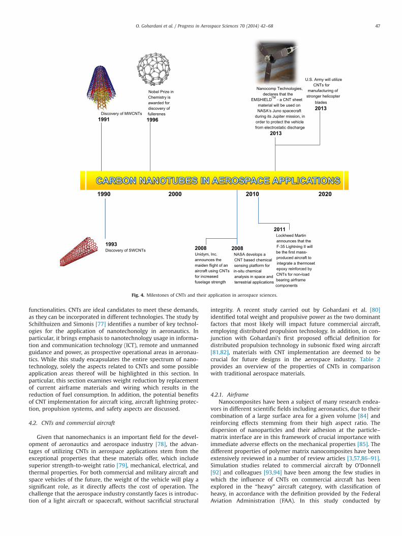
Fig. 4 depicts an overview of milestone events on the axis oftime, related to CNT implementation in aerospace sciences. Due tothe myriad of the literature related to CNTs, it should be statedthat although the time axis outlines the year 1991 as the discoveryyear of CNTs, extensive research efforts and observations of full-erenes were actualized prior to this date [20,70–73]. The firstnano-sized carbon filaments of tubular nature were highlighted asearly as in 1952 [74], but this publication was not available inEnglish until years later. The attribution of CNTs to the discoveryyear of 1991 has further attracted considerable attention to itselfwithin the fields of material sciences and chemistry, on account ofexisting evidence of CNTs preceding this date [75]. Nonetheless,due to the scientific impact of the article published by Iijima in1991 [45] and its novelty and dissemination to the entire scientificcommunity across different engineering disciplines, this year isconsidered to be the birth year of MWCNTs and has hence beenstipulated as the commencement year of the CNTs era in aerospacesciences. One of the most comprehensive roadmaps for futureapplications of nanomaterials and in particular CNTs was pub-lished by NASA in 2010 [76]. According to this roadmap, thepotential benefits of utilizing CNTs in aerospace applicationsconsist of reduced vehicle mass, improved functionality anddurability, enhanced damage tolerance, improved self-healingcharacteristics, enhanced thermal protection, and control. In termsof energy, CNTs may be utilized for enhanced energy generationand energy distribution. Some of the presented challenges forusage of CNTs in aerospace applications include large-scale pro-duction methods of CNTs, uniform dispersion of CNTs in compositematerials, alignment and adhesion issues associated with CNTs inreinforced polymers, a complete understanding of their toxicity,and production of CNTs that are rice in volume and have auniform size.
4. Potential roles of CNTs in aeronautics
4.1. Introduction
Next generation aircraft, rotorcraft, unmanned aerial vehicles,and missiles will have stricter requirements in terms of light-weight, visual and thermal signature, increased speed, and man-euverability. These requirements, however, incite a need foradvanced materials and systems that can incorporate these
a1
a2 (n, 0)
(n, n)
Ch
Fig. 3. Graphene sheet, lattice vectors and the roll-up vector C h .Source: Adapted from [40]
Table 1Comparison of density ρ, nanotube diameter dt, aspect ratio AR, thermal conduc-
tivity k, electrical resistivity ϱ, tensile strength sB , and Young's modulus ~E , relatedto SWCNTs and MWCNTs.Sources: [3,52–57].
Property Unit SWCNTs MWCNTs
ρ g m�3 � 1:3 � 1:75dt nm 0.6–0.8 5–50AR – 100–10,000 100–10,000k W ðmKÞ�1 3000–6000 3000–6000
ϱ Ω m 1� 10�3�1� 10�4 2� 10�3�1� 10�4
smax GPa 50–500 10–600~E GPa 1500 1000
O. Gohardani et al. / Progress in Aerospace Sciences 70 (2014) 42–6846
functionalities. CNTs are ideal candidates to meet these demands,as they can be incorporated in different technologies. The study bySchilthuizen and Simonis [77] identifies a number of key technol-ogies for the application of nanotechonolgy in aeronautics. Inparticular, it brings emphasis to nanotechnology usage in informa-tion and communication technology (ICT), remote and unmannedguidance and power, as prospective operational areas in aeronau-tics. While this study encapsulates the entire spectrum of nano-technology, solely the aspects related to CNTs and some possibleapplication areas thereof will be highlighted in this section. Inparticular, this section examines weight reduction by replacementof current airframe materials and wiring which results in thereduction of fuel consumption. In addition, the potential benefitsof CNT implementation for aircraft icing, aircraft lightning protec-tion, propulsion systems, and safety aspects are discussed.
4.2. CNTs and commercial aircraft
Given that nanomechanics is an important field for the devel-opment of aeronautics and aerospace industry [78], the advan-tages of utilizing CNTs in aerospace applications stem from theexceptional properties that these materials offer, which includesuperior strength-to-weight ratio [79], mechanical, electrical, andthermal properties. For both commercial and military aircraft andspace vehicles of the future, the weight of the vehicle will play asignificant role, as it directly affects the cost of operation. Thechallenge that the aerospace industry constantly faces is introduc-tion of a light aircraft or spacecraft, without sacrificial structural
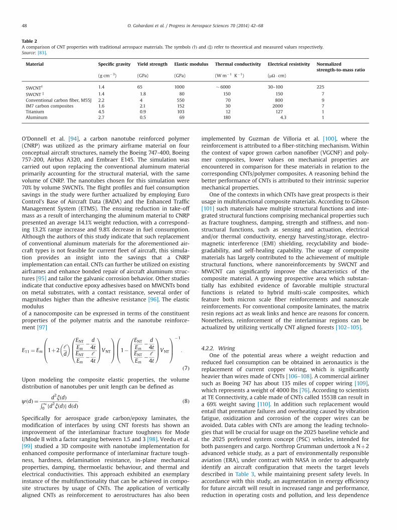
integrity. A recent study carried out by Gohardani et al. [80]identified total weight and propulsive power as the two dominantfactors that most likely will impact future commercial aircraft,employing distributed propulsion technology. In addition, in con-junction with Gohardani's first proposed official definition fordistributed propulsion technology in subsonic fixed wing aircraft[81,82], materials with CNT implementation are deemed to becrucial for future designs in the aerospace industry. Table 2provides an overview of the properties of CNTs in comparisonwith traditional aerospace materials.
4.2.1. AirframeNanocomposites have been a subject of many research endea-
vors in different scientific fields including aeronautics, due to theircombination of a large surface area for a given volume [84] andreinforcing effects stemming from their high aspect ratio. Thedispersion of nanoparticles and their adhesion at the particle–matrix interface are in this framework of crucial importance withimmediate adverse effects on the mechanical properties [85]. Thedifferent properties of polymer matrix nanocomposites have beenextensively reviewed in a number of review articles [3,57,86–91].Simulation studies related to commercial aircraft by O'Donnell[92] and colleagues [93,94] have been among the few studies inwhich the influence of CNTs on commercial aircraft has beenexplored in the “heavy” aircraft category, with classification ofheavy, in accordance with the definition provided by the FederalAviation Administration (FAA). In this study conducted by
Discovery of MWCNTs 1991
1993 Discovery of SWCNTs
Nanocomp Technologies, declares that the
EMSHIELDTM - a CNT sheet material will be used on NASA’s Juno spacecraft
during its Jupiter mission, in order to protect the vehicle from electrostatic discharge
2013
2000 20201990
Nobel Prize in Chemistry is awarded for discovery of fullerenes 1996
U.S. Army will utilize CNTs for
manufacturing of stronger helicopter
blades2013
2008 Unidym, Inc. announces the maiden flight of an aircraft using CNTs for increased fuselage strength
2008 NASA develops a CNT based chemical sensing platform for in-situ chemical analysis in space and terrestrial applications
2011 Lockheed Martin announces that the F-35 Lightning II will be the first mass-produced aircraft to integrate a thermoset epoxy reinforced by CNTs for non-load bearing airframe components
2010
Fig. 4. Milestones of CNTs and their application in aerospace sciences.
O. Gohardani et al. / Progress in Aerospace Sciences 70 (2014) 42–68 47
O'Donnell et al. [94], a carbon nanotube reinforced polymer(CNRP) was utilized as the primary airframe material on fourconceptual aircraft structures, namely the Boeing 747-400, Boeing757-200, Airbus A320, and Embraer E145. The simulation wascarried out upon replacing the conventional aluminum materialprimarily accounting for the structural material, with the samevolume of CNRP. The nanotubes chosen for this simulation were70% by volume SWCNTs. The flight profiles and fuel consumptionsavings in the study were further actualized by employing EuroControl's Base of Aircraft Data (BADA) and the Enhanced TrafficManagement System (ETMS). The ensuing reduction in take-offmass as a result of interchanging the aluminum material to CNRPpresented an average 14.1% weight reduction, with a correspond-ing 13.2% range increase and 9.8% decrease in fuel consumption.Although the authors of this study indicate that such replacementof conventional aluminum materials for the aforementioned air-craft types is not feasible for current fleet of aircraft, this simula-tion provides an insight into the savings that a CNRPimplementation can entail. CNTs can further be utilized on existingairframes and enhance bonded repair of aircraft aluminum struc-tures [95] and tailor the galvanic corrosion behavior. Other studiesindicate that conductive epoxy adhesives based on MWCNTs bondon metal substrates, with a contact resistance, several order ofmagnitudes higher than the adhesive resistance [96]. The elasticmodulusof a nanocomposite can be expressed in terms of the constituentproperties of the polymer matrix and the nanotube reinforce-ment [97]
E11 ¼ Em 1þ2ℓd
� � ENTEm
� d4t
ENTEm
� ℓ4t
0BB@
1CCAVNT
0BB@
1CCA 1�
ENTEm
� d4t
ENTEm
� ℓ4t
0BB@
1CCAVNT
0BB@
1CCA
�1
:
ð7Þ
Upon modeling the composite elastic properties, the volumedistribution of nanotubes per unit length can be defined as
ψ ðdÞ ¼ d2ξðdÞR10 fd2ξðdÞg dðdÞ
ð8Þ
Specifically for aerospace grade carbon/epoxy laminates, themodification of interfaces by using CNT forests has shown animprovement of the interlaminar fracture toughness for ModeI/Mode II with a factor ranging between 1.5 and 3 [98]. Veedu et al.[99] studied a 3D composite with nanotube implementation forenhanced composite performance of interlaminar fracture tough-ness, hardness, delamination resistance, in-plane mechanicalproperties, damping, thermoelastic behaviour, and thermal andelectrical conductivities. This approach exhibited an exemplaryinstance of the multifunctionality that can be achieved in compo-site structures by usage of CNTs. The application of verticallyaligned CNTs as reinforcement to aerostructures has also been
implemented by Guzman de Villoria et al. [100], where thereinforcement is attributed to a fiber-stitching mechanism. Withinthe context of vapor grown carbon nanofiber (VGCNF) and poly-mer composites, lower values on mechanical properties areencountered in comparison for these materials in relation to thecorresponding CNTs/polymer composites. A reasoning behind thebetter performance of CNTs is attributed to their intrinsic superiormechanical properties.
One of the contexts in which CNTs have great prospects is theirusage in multifunctional composite materials. According to Gibson[101] such materials have multiple structural functions and inte-grated structural functions comprising mechanical properties suchas fracture toughness, damping, strength and stiffness, and non-structural functions, such as sensing and actuation, electricaland/or thermal conductivity, energy harvesting/storage, electro-magnetic interference (EMI) shielding, recyclability and biode-gradability, and self-healing capability. The usage of compositematerials has largely contributed to the achievement of multiplestructural functions, where nanoreinforcements by SWCNT andMWCNT can significantly improve the characteristics of thecomposite material. A growing prospective area which substan-tially has exhibited evidence of favorable multiple structuralfunctions is related to hybrid multi-scale composites, whichfeature both micron scale fiber reinforcements and nanoscalereinforcements. For conventional composite laminates, the matrixresin regions act as weak links and hence are reasons for concern.Nonetheless, reinforcement of the interlaminar regions can beactualized by utilizing vertically CNT aligned forests [102–105].
4.2.2. WiringOne of the potential areas where a weight reduction and
reduced fuel consumption can be obtained in aeronautics is thereplacement of current copper wiring, which is significantlyheavier than wires made of CNTs [106–108]. A commercial airlinersuch as Boeing 747 has about 135 miles of copper wiring [109],which represents a weight of 4000 lbs [76]. According to scientistsat TE Connectivity, a cable made of CNTs called 1553B can result ina 69% weight saving [110]. In addition such replacement wouldentail that premature failures and overheating caused by vibrationfatigue, oxidization and corrosion of the copper wires can beavoided. Data cables with CNTs are among the leading technolo-gies that will be crucial for usage on the 2025 baseline vehicle andthe 2025 preferred system concept (PSC) vehicles, intended forboth passengers and cargo. Northrop Grumman undertook a Nþ2advanced vehicle study, as a part of environmentally responsibleaviation (ERA), under contract with NASA in order to adequatelyidentify an aircraft configuration that meets the target levelsdescribed in Table 3, while maintaining present safety levels. Inaccordance with this study, an augmentation in energy efficiencyfor future aircraft will result in increased range and performance,reduction in operating costs and pollution, and less dependence
Table 2A comparison of CNT properties with traditional aerospace materials. The symbols ð†Þ and ð‡Þ refer to theoretical and measured values respectively.Source: [83].
Material Specific gravity Yield strength Elastic modulus Thermal conductivity Electrical resistivity Normalizedstrength-to-mass ratio
(g cm�3) (GPa) (GPa) (W m�1 K�1) (μΩ � cm)
SWCNT† 1.4 65 1000 � 6000 30–100 225
SWCNT ‡ 1.4 1.8 80 150 150 7Conventional carbon fiber, M55J 2.2 4 550 70 800 9IM7 carbon composites 1.6 2.1 152 30 2000 7Titanium 4.5 0.9 103 12 127 1Aluminum 2.7 0.5 69 180 4.3 1
O. Gohardani et al. / Progress in Aerospace Sciences 70 (2014) 42–6848
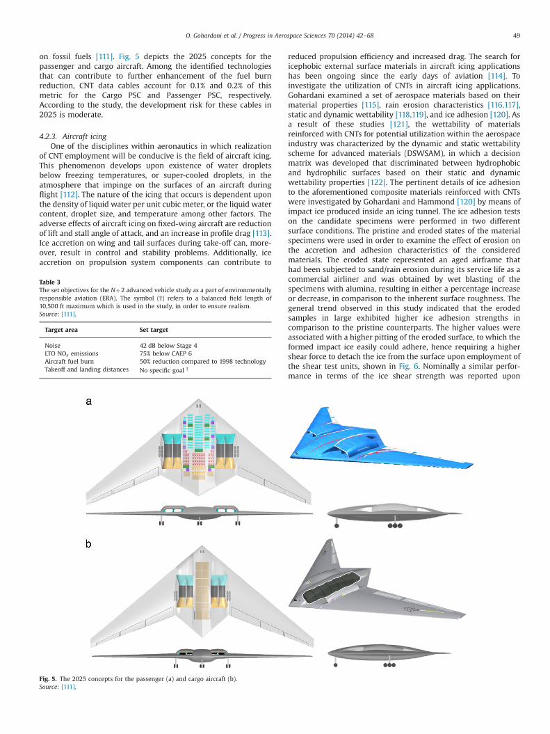
on fossil fuels [111]. Fig. 5 depicts the 2025 concepts for thepassenger and cargo aircraft. Among the identified technologiesthat can contribute to further enhancement of the fuel burnreduction, CNT data cables account for 0.1% and 0.2% of thismetric for the Cargo PSC and Passenger PSC, respectively.According to the study, the development risk for these cables in2025 is moderate.
4.2.3. Aircraft icingOne of the disciplines within aeronautics in which realization
of CNT employment will be conducive is the field of aircraft icing.This phenomenon develops upon existence of water dropletsbelow freezing temperatures, or super-cooled droplets, in theatmosphere that impinge on the surfaces of an aircraft duringflight [112]. The nature of the icing that occurs is dependent uponthe density of liquid water per unit cubic meter, or the liquid watercontent, droplet size, and temperature among other factors. Theadverse effects of aircraft icing on fixed-wing aircraft are reductionof lift and stall angle of attack, and an increase in profile drag [113].Ice accretion on wing and tail surfaces during take-off can, more-over, result in control and stability problems. Additionally, iceaccretion on propulsion system components can contribute to
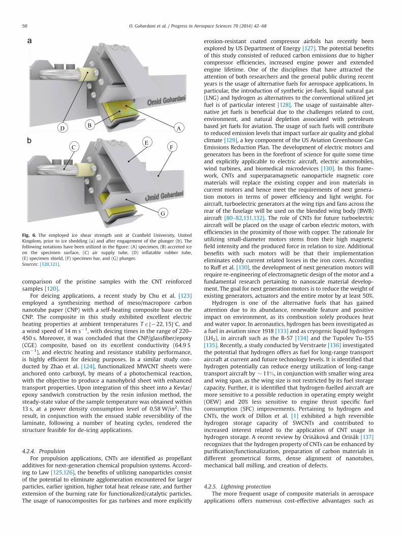
reduced propulsion efficiency and increased drag. The search foricephobic external surface materials in aircraft icing applicationshas been ongoing since the early days of aviation [114]. Toinvestigate the utilization of CNTs in aircraft icing applications,Gohardani examined a set of aerospace materials based on theirmaterial properties [115], rain erosion characteristics [116,117],static and dynamic wettability [118,119], and ice adhesion [120]. Asa result of these studies [121], the wettability of materialsreinforced with CNTs for potential utilization within the aerospaceindustry was characterized by the dynamic and static wettabilityscheme for advanced materials (DSWSAM), in which a decisionmatrix was developed that discriminated between hydrophobicand hydrophilic surfaces based on their static and dynamicwettability properties [122]. The pertinent details of ice adhesionto the aforementioned composite materials reinforced with CNTswere investigated by Gohardani and Hammond [120] by means ofimpact ice produced inside an icing tunnel. The ice adhesion testson the candidate specimens were performed in two differentsurface conditions. The pristine and eroded states of the materialspecimens were used in order to examine the effect of erosion onthe accretion and adhesion characteristics of the consideredmaterials. The eroded state represented an aged airframe thathad been subjected to sand/rain erosion during its service life as acommercial airliner and was obtained by wet blasting of thespecimens with alumina, resulting in either a percentage increaseor decrease, in comparison to the inherent surface roughness. Thegeneral trend observed in this study indicated that the erodedsamples in large exhibited higher ice adhesion strengths incomparison to the pristine counterparts. The higher values wereassociated with a higher pitting of the eroded surface, to which theformed impact ice easily could adhere, hence requiring a highershear force to detach the ice from the surface upon employment ofthe shear test units, shown in Fig. 6. Nominally a similar perfor-mance in terms of the ice shear strength was reported upon
Table 3The set objectives for the Nþ2 advanced vehicle study as a part of environmentallyresponsible aviation (ERA). The symbol (†) refers to a balanced field length of10,500 ft maximum which is used in the study, in order to ensure realism.Source: [111].
Target area Set target
Noise 42 dB below Stage 4LTO NOx emissions 75% below CAEP 6Aircraft fuel burn 50% reduction compared to 1998 technologyTakeoff and landing distances No specific goal †
Fig. 5. The 2025 concepts for the passenger (a) and cargo aircraft (b).Source: [111].
O. Gohardani et al. / Progress in Aerospace Sciences 70 (2014) 42–68 49
comparison of the pristine samples with the CNT reinforcedsamples [120].
For deicing applications, a recent study by Chu et al. [123]employed a synthesizing method of meso/macropore carbonnanotube paper (CNP) with a self-heating composite base on theCNP. The composite in this study exhibited excellent electricheating properties at ambient temperatures TA ½�22;15�1C, anda wind speed of 14 m s�1, with deicing times in the range of 220–450 s. Moreover, it was concluded that the CNP/glassfiber/epoxy(CGE) composite, based on its excellent conductivity (64.9 Scm�1), and electric heating and resistance stability performance,is highly efficient for deicing purposes. In a similar study con-ducted by Zhao et al. [124], functionalized MWCNT sheets wereanchored onto carboxyl, by means of a photochemical reaction,with the objective to produce a nanohybrid sheet with enhancedtransport properties. Upon integration of this sheet into a Kevlar/epoxy sandwich construction by the resin infusion method, thesteady-state value of the sample temperature was obtained within13 s, at a power density consumption level of 0.58 W/in2. Thisresult, in conjunction with the ensued stable reversibility of thelaminate, following a number of heating cycles, rendered thestructure feasible for de-icing applications.
4.2.4. PropulsionFor propulsion applications, CNTs are identified as propellant
additives for next-generation chemical propulsion systems. Accord-ing to Law [125,126], the benefits of utilizing nanoparticles consistof the potential to eliminate agglomeration encountered for largerparticles, earlier ignition, higher total heat release rate, and furtherextension of the burning rate for functionalized/catalytic particles.The usage of nanocomposites for gas turbines and more explicitly
erosion-resistant coated compressor airfoils has recently beenexplored by US Department of Energy [127]. The potential benefitsof this study consisted of reduced carbon emissions due to highercompressor efficiencies, increased engine power and extendedengine lifetime. One of the disciplines that have attracted theattention of both researchers and the general public during recentyears is the usage of alternative fuels for aerospace applications. Inparticular, the introduction of synthetic jet-fuels, liquid natural gas(LNG) and hydrogen as alternatives to the conventional utilized jetfuel is of particular interest [128]. The usage of sustainable alter-native jet fuels is beneficial due to the challenges related to cost,environment, and natural depletion associated with petroleumbased jet fuels for aviation. The usage of such fuels will contributeto reduced emission levels that impact surface air quality and globalclimate [129], a key component of the US Aviation Greenhouse GasEmissions Reduction Plan. The development of electric motors andgenerators has been in the forefront of science for quite some timeand explicitly applicable to electric aircraft, electric automobiles,wind turbines, and biomedical microdevices [130]. In this frame-work, CNTs and superparamagnetic nanoparticle magnetic corematerials will replace the existing copper and iron materials incurrent motors and hence meet the requirements of next genera-tion motors in terms of power efficiency and light weight. Foraircraft, turboelectric generators at the wing tips and fans across therear of the fuselage will be used on the blended wing body (BWB)aircraft [80–82,131,132]. The role of CNTs for future turboelectricaircraft will be placed on the usage of carbon electric motors, withefficiencies in the proximity of those with copper. The rationale forutilizing small-diameter motors stems from their high magneticfield intensity and the produced force in relation to size. Additionalbenefits with such motors will be that their implementationeliminates eddy current related losses in the iron cores. Accordingto Ruff et al. [130], the development of next generation motors willrequire re-engineering of electromagnetic design of the motor and afundamental research pertaining to nanoscale material develop-ment. The goal for next generation motors is to reduce the weight ofexisting generators, actuators and the entire motor by at least 50%.
Hydrogen is one of the alternative fuels that has gainedattention due to its abundance, renewable feature and positiveimpact on environment, as its combustion solely produces heatand water vapor. In aeronautics, hydrogen has been investigated asa fuel in aviation since 1918 [133] and as cryogenic liquid hydrogen(LH2), in aircraft such as the B-57 [134] and the Tupolev Tu-155[135]. Recently, a study conducted by Verstraete [136] investigatedthe potential that hydrogen offers as fuel for long-range transportaircraft at current and future technology levels. It is identified thathydrogen potentially can reduce energy utilization of long-rangetransport aircraft by � 11%, in conjunction with smaller wing areaand wing span, as the wing size is not restricted by its fuel storagecapacity. Further, it is identified that hydrogen-fuelled aircraft aremore sensitive to a possible reduction in operating empty weight(OEW) and 20% less sensitive to engine thrust specific fuelconsumption (SFC) improvements. Pertaining to hydrogen andCNTs, the work of Dillon et al. [1] exhibited a high reversiblehydrogen storage capacity of SWCNTs and contributed toincreased interest related to the application of CNT usage inhydrogen storage. A recent review by Oriňáková and Oriňák [137]recognizes that the hydrogen property of CNTs can be enhanced bypurification/functionalization, preparation of carbon materials indifferent geometrical forms, dense alignment of nanotubes,mechanical ball milling, and creation of defects.
4.2.5. Lightning protectionThe more frequent usage of composite materials in aerospace
applications offers numerous cost-effective advantages such as
ABD
FCE
G
Fig. 6. The employed ice shear strength unit at Cranfield University, UnitedKingdom, prior to ice shedding (a) and after engagement of the plunger (b). Thefollowing notations have been utilized in the figure: (A) specimen, (B) accreted iceon the specimen surface, (C) air supply tube, (D) inflatable rubber tube,(E) specimen shield, (F) specimen bar, and (G) plunger.Sources: [120,121].
O. Gohardani et al. / Progress in Aerospace Sciences 70 (2014) 42–6850
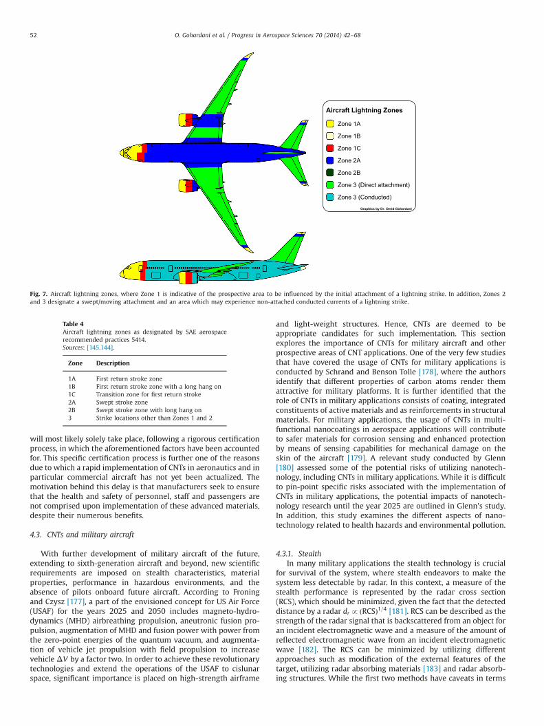
increased fuel efficiency, reduction of acoustic emissions andpollutants [138]. Equally, such alterations present new challengesdue to the change of material characteristics. One of the areassusceptible to such challenge is the lightning strike threat toaircraft. For commercial airliners, the statistical in-flight analysisindicates that an aircraft is subject to a lightning strike in the rangeof 1000–10,000 flight hours, which can be approximated to onelightning annually [139,140]. Upon lightning strike on an unpro-tected surface, electricity with current levels up to 200,000 Atraverses the path of least resistance [141]. The potential inflicteddamage on an aircraft structure may comprise resistive-heating,acoustic shock, ignition of vapors in the fuel tanks, arcing andsparking at joints, and melting or burning at the lightningattachment points [142,143]. In this context, conventional metallicairframes, such as those made with aluminum, are highly con-ductive, but current composite material airframes such as thosefeaturing carbon fiber reinforced polymers (CFRPs) exhibit lowerelectrical conductivity. The dielectric feature of the polymermatrix composite implies that the overall conductivity of thecomposite laminate is greatly reduced, despite the presence ofcarbon fibers which are highly conductive [138]. Fig. 7 and Table 4exhibit an aircraft's lightning zones as defined by SAE AerospaceRecommended Practices 5414 [144,145]. The article by Sweerset al. [144] identifies that despite the prevalent lightning activity atthe altitude of 5000–15,000 feet (1524–4572 m), most lightningstrikes occur on jet aircraft while in clouds during the climb anddescent flight phases. In addition the authors identify that aircrafttraversing high incidence lightning activity areas are more suscep-tible to lightning strikes in comparison to long-haul aircraft whichoperate in more benign lightning environments. The potential useof CNTs and CNFs in particular related to aircraft lightningapplications has been evident as these nano-fillers are able toalter non-conducting polymers into conductive materials. Despiteapplications of the identified materials, in photovoltaic devices[146,147] and electromagnetic interference shielding (EMI) [148],Gou and coworkers [141] identified a lack of adequate level ofattained electrical conductivity for lightning strike protection,heavy re-agglomeration levels of CNTs and CNFs at high viscosityof the polymer resin, and a limitation in increased conductivitybeyond the percolation threshold, originating in the absence ofeffecting connection between the nano-fillers. To address theseissues, Gou et al. introduced nickel nanostrands for bridgingindividual CNFs and for modifying the electrical pathway withinthe carbon nanofiber papers (CNFPs). Studies have also beenundertaken by other researchers where CNTs have been utilizedfor lightning strike protection [149]. A recent review conducted byGagné and Therriault provides a more detailed insight into aircraftlightning strike protection measures related to composite materi-als [150]. Apart from CNTs, buckypaper which is generally definedas a macroscopic assembly of entangled CNTs [151] can be utilizedfor purposes of high-current carrying capacity upon lightningstrikes on an aircraft and for protection of electric circuits anddevices onboard aircraft [152].
4.2.6. Electromagnetic interference shieldingThe demand for electromagnetic interference shielding (EMI) is
an important factor specifically related to radio frequency radia-tion sources and electronics of reliable nature [153]. Equally, theshielding of electronics should be carried out at an adequate level,since under-shielding can result in product failure and over-shielding ensues in increased weight and complexity, in additionto an increased material cost [154]. Polymer matrix composites(PMCs) are common materials which have been well established inmany diverse applications, including electronics of aircraft.Hitherto, light weight, simple processability and manufacturing
has motivated the usage of these materials. To date, numerousmaterials have been utilized as fillers of PMCs [52]. Subsequent tothe introduction of CNTs, the latter have attracted considerableattention due to their high level of conductivity. The differentapproaches utilized for EMI shielding consist of reflection, absorp-tion and internal reflections [153,155]. In this context a material'sability to attenuate EMI is given by its corresponding shieldingeffectiveness SE [156]
SE ¼ �10 logP1
P2
� �ð9Þ
where P1 denotes the received power with the material presentand P2 represents the received power with the material absent.A higher value on SE is indicative of an enhanced attenuation.Studies conducted by Yang et al. [157,158] indicate that EMI SEvalues of MWCNTs and polystyrene were considerably higher thanthose of VGCNFs. For aerospace applications, a study carried out byMehdipour et al. [159] identified that high SE values can beattained despite a moderate ðo10%Þ loading of MWCNTs in anepoxy resin. More recently, Kumar et al. [160] carried out a studyin the X-band (8.2-GHz) frequency region, reporting a value of163 dB cm3 g�1 for MWCNTs decorated carbon foam of thickness2.75 mm. Such EMI shielding materials are crucial in the afore-mentioned frequency band, in order to mitigate hazards of spaceradiation to humans and space vehicles [161]. Immediate applica-tions of CNTs in space applications can be beneficial for onboardcomputer screens operating close to other electronic equipment atthe International Space Station and in forthcoming space explora-tion missions [162]. Future missions will require that computerscreens onboard the space vehicles have coatings with at least 90%transmittance and a SE � 40 dB.
4.2.7. SensingOne of the future applications of CNTs is to passively collect
component diagnostic data and to supply signals that prevent andcontrol component failures. In addition, these signals can be usedfor optimization of the operating configurations of the component[163]. Self-sensing is hence an important feature that will beimportant for future aircraft and spacecraft [164,165]. In thiscontext, sensing refers to the measurement of electrical resistanceat the surface under flexure [166]. In aviation, condition monitor-ing of fastened joints can be achieved by utilizing through-thickness stress sensing [167]. For damage detection purposes,several studies [168,169] have been conducted based on theassumption that inflicted damage increases the resistivity result-ing from the fiber direction and causes the conduction pathgeometry to be changed. Sensing is in this framework exploredthrough the ability of CNTs to mechanically deform, real-timestrain monitoring by means of changes in conductivity [170],employment of ordered CNTs for aerospace materials [171], CNTdispersion [172–174], modeling, and response [175].
4.2.8. SafetyThe prospective benefits of CNT usage with their superior
mechanical, electrical and thermal properties often overshadowthe potential health hazards that should be considered in parti-cular due to the industrial scale manufacturing of these materials.In the context of this discussion, the similarity to carcinogenicforms of asbestos can be identified, based on the shape anddimension of the carbon fibers and the fact that iron is retainedin the nanofibers during the manufacturing process [176]. It isnoteworthy that future implementation of CNTs in particular formanned air and space vehicles should be considered solely on thebasis that full health impact assessment and studies are conductedon the possible implications that such implementation might haveon the health of the passengers and crew. Such implementation
O. Gohardani et al. / Progress in Aerospace Sciences 70 (2014) 42–68 51
will most likely solely take place, following a rigorous certificationprocess, in which the aforementioned factors have been accountedfor. This specific certification process is further one of the reasonsdue to which a rapid implementation of CNTs in aeronautics and inparticular commercial aircraft has not yet been actualized. Themotivation behind this delay is that manufacturers seek to ensurethat the health and safety of personnel, staff and passengers arenot comprised upon implementation of these advanced materials,despite their numerous benefits.
4.3. CNTs and military aircraft
With further development of military aircraft of the future,extending to sixth-generation aircraft and beyond, new scientificrequirements are imposed on stealth characteristics, materialproperties, performance in hazardous environments, and theabsence of pilots onboard future aircraft. According to Froningand Czysz [177], a part of the envisioned concept for US Air Force(USAF) for the years 2025 and 2050 includes magneto-hydro-dynamics (MHD) airbreathing propulsion, aneutronic fusion pro-pulsion, augmentation of MHD and fusion power with power fromthe zero-point energies of the quantum vacuum, and augmenta-tion of vehicle jet propulsion with field propulsion to increasevehicle ΔV by a factor two. In order to achieve these revolutionarytechnologies and extend the operations of the USAF to cislunarspace, significant importance is placed on high-strength airframe
and light-weight structures. Hence, CNTs are deemed to beappropriate candidates for such implementation. This sectionexplores the importance of CNTs for military aircraft and otherprospective areas of CNT applications. One of the very few studiesthat have covered the usage of CNTs for military applications isconducted by Schrand and Benson Tolle [178], where the authorsidentify that different properties of carbon atoms render themattractive for military platforms. It is further identified that therole of CNTs in military applications consists of coating, integratedconstituents of active materials and as reinforcements in structuralmaterials. For military applications, the usage of CNTs in multi-functional nanocoatings in aerospace applications will contributeto safer materials for corrosion sensing and enhanced protectionby means of sensing capabilities for mechanical damage on theskin of the aircraft [179]. A relevant study conducted by Glenn[180] assessed some of the potential risks of utilizing nanotech-nology, including CNTs in military applications. While it is difficultto pin-point specific risks associated with the implementation ofCNTs in military applications, the potential impacts of nanotech-nology research until the year 2025 are outlined in Glenn's study.In addition, this study examines the different aspects of nano-technology related to health hazards and environmental pollution.
4.3.1. StealthIn many military applications the stealth technology is crucial
for survival of the system, where stealth endeavors to make thesystem less detectable by radar. In this context, a measure of thestealth performance is represented by the radar cross section(RCS), which should be minimized, given the fact that the detecteddistance by a radar drp ðRCSÞ1=4 [181]. RCS can be described as thestrength of the radar signal that is backscattered from an object foran incident electromagnetic wave and a measure of the amount ofreflected electromagnetic wave from an incident electromagneticwave [182]. The RCS can be minimized by utilizing differentapproaches such as modification of the external features of thetarget, utilizing radar absorbing materials [183] and radar absorb-ing structures. While the first two methods have caveats in terms
Aircraft Lightning Zones
Zone 1A
Zone 1B
Zone 1C
Zone 2A
Zone 2B
Zone 3 (Direct attachment)
Zone 3 (Conducted)
Fig. 7. Aircraft lightning zones, where Zone 1 is indicative of the prospective area to be influenced by the initial attachment of a lightning strike. In addition, Zones 2and 3 designate a swept/moving attachment and an area which may experience non-attached conducted currents of a lightning strike.
Table 4Aircraft lightning zones as designated by SAE aerospacerecommended practices 5414.Sources: [145,144].
Zone Description
1A First return stroke zone1B First return stroke zone with a long hang on1C Transition zone for first return stroke2A Swept stroke zone2B Swept stroke zone with long hang on3 Strike locations other than Zones 1 and 2
O. Gohardani et al. / Progress in Aerospace Sciences 70 (2014) 42–6852
of increased RCS in other regions of the target and increasedweight and thickness, CNTs can be utilized as constituents in radarabsorbing structures, in order to achieve stealth characteristics. Anexample of such radar absorbing structure with CNTs was inves-tigated by Kim and Lee [182], in which a nanocomposite composedof E-glass fabric, epoxy resin and CNTs was adhesively bonded tothe external surface of a sandwich construction in order to absorbelectromagnetic waves. In this study, the utilized compositesandwich construction exhibited absorption of incident electro-magnetic waves up to 90% in the X-band frequency and furtherprovided approximately three times the peel strength in compar-ison to the corresponding aluminum foil.
4.3.2. Aircraft icingFor military aircraft, the problem of icing ensues in a number of
challenges which may hinder safe flight operations, such asobscuring the view of the pilot during missions and contributingto unreliable instrument readings. In addition, the aerodynamicpenalties due to ice accumulation on the control surfaces result inincreased drag and a reduction of lift which consequently affectsthe increase in fuel consumption. Similar to the case of commercialaircraft, the usage of CNTs will be beneficial in order to remedy iceadhesion on military aircraft.
4.4. Morphing aircraft
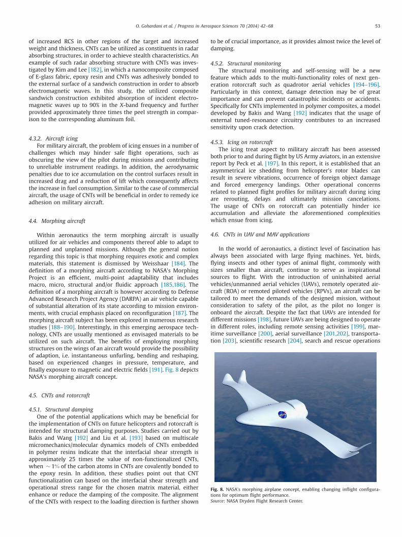
Within aeronautics the term morphing aircraft is usuallyutilized for air vehicles and components thereof able to adapt toplanned and unplanned missions. Although the general notionregarding this topic is that morphing requires exotic and complexmaterials, this statement is dismissed by Weisshaar [184]. Thedefinition of a morphing aircraft according to NASA's MorphingProject is an efficient, multi-point adaptability that includesmacro, micro, structural and/or fluidic approach [185,186]. Thedefinition of a morphing aircraft is however according to DefenseAdvanced Research Project Agency (DARPA) an air vehicle capableof substantial alteration of its state according to mission environ-ments, with crucial emphasis placed on reconfiguration [187]. Themorphing aircraft subject has been explored in numerous researchstudies [188–190]. Interestingly, in this emerging aerospace tech-nology, CNTs are usually mentioned as envisaged materials to beutilized on such aircraft. The benefits of employing morphingstructures on the wings of an aircraft would provide the possibilityof adaption, i.e. instantaneous unfurling, bending and reshaping,based on experienced changes in pressure, temperature, andfinally exposure to magnetic and electric fields [191]. Fig. 8 depictsNASA's morphing aircraft concept.
4.5. CNTs and rotorcraft
4.5.1. Structural dampingOne of the potential applications which may be beneficial for
the implementation of CNTs on future helicopters and rotorcraft isintended for structural damping purposes. Studies carried out byBakis and Wang [192] and Liu et al. [193] based on multiscalemicromechanics/molecular dynamics models of CNTs embeddedin polymer resins indicate that the interfacial shear strength isapproximately 25 times the value of non-functionalized CNTs,when � 1% of the carbon atoms in CNTs are covalently bonded tothe epoxy resin. In addition, these studies point out that CNTfunctionalization can based on the interfacial shear strength andoperational stress range for the chosen matrix material, eitherenhance or reduce the damping of the composite. The alignmentof the CNTs with respect to the loading direction is further shown
to be of crucial importance, as it provides almost twice the level ofdamping.
4.5.2. Structural monitoringThe structural monitoring and self-sensing will be a new
feature which adds to the multi-functionality roles of next gen-eration rotorcraft such as quadrotor aerial vehicles [194–196].Particularly in this context, damage detection may be of greatimportance and can prevent catastrophic incidents or accidents.Specifically for CNTs implemented in polymer composites, a modeldeveloped by Bakis and Wang [192] indicates that the usage ofexternal tuned-resonance circuitry contributes to an increasedsensitivity upon crack detection.
4.5.3. Icing on rotorcraftThe icing treat aspect to military aircraft has been assessed
both prior to and during flight by US Army aviators, in an extensivereport by Peck et al. [197]. In this report, it is established that anasymmetrical ice shedding from helicopter's rotor blades canresult in severe vibrations, occurrence of foreign object damageand forced emergency landings. Other operational concernsrelated to planned flight profiles for military aircraft during icingare rerouting, delays and ultimately mission cancelations.The usage of CNTs on rotorcraft can potentially hinder iceaccumulation and alleviate the aforementioned complexitieswhich ensue from icing.
4.6. CNTs in UAV and MAV applications
In the world of aeronautics, a distinct level of fascination hasalways been associated with large flying machines. Yet, birds,flying insects and other types of animal flight, commonly withsizes smaller than aircraft, continue to serve as inspirationalsources to flight. With the introduction of uninhabited aerialvehicles/unmanned aerial vehicles (UAVs), remotely operated air-craft (ROA) or remoted piloted vehicles (RPVs), an aircraft can betailored to meet the demands of the designed mission, withoutconsideration to safety of the pilot, as the pilot no longer isonboard the aircraft. Despite the fact that UAVs are intended fordifferent missions [198], future UAVs are being designed to operatein different roles, including remote sensing activities [199], mar-itime surveillance [200], aerial surveillance [201,202], transporta-tion [203], scientific research [204], search and rescue operations
Fig. 8. NASA's morphing airplane concept, enabling changing inflight configura-tions for optimum flight performance.Source: NASA Dryden Flight Research Center.
O. Gohardani et al. / Progress in Aerospace Sciences 70 (2014) 42–68 53
[205], military applications [82,206–209], conservation of nature[210,211], and fire detection [212–214]. Recent advancements inelectronics have also sparked the interest for smaller unmannedvehicles, namely micro air/aerial vehicles (MAVs). UAVs and MAVsare suitable platforms for the implementation of CNTs, as they donot compromise the safety of the pilot. Until now UAVs have notbeen designed for prolonged flight hours and hence many aspectssuch as ice protection systems are often not featured on thesevehicles. The implementation of CNTs on UAVs will therefore be agame changing strategy and alter the usage platforms of thesevehicles. Some of the benefits that CNT implementation may bringfor UAVs include reduced weight, longer operational hours, andsustainability to icing conditions during flight. In a recent reportproduced for the United States Air Force (USAF) AerospaceManagement Systems Division by US Department of Transporta-tion [215], the Department of Defense (DoD) expects its inventoryof unmanned air systems (UAS) to grow to 14,000 by the year2035. The number of UAS for the federal agency is by this timepredicted to increase to 10,000 from the current number of a fewhundreds. These nano, micro and small UAVs are all in need offurther optimization related to reduced weight and enhancedperformance, exhibiting the future prospects of CNTimplementation.
4.6.1. Electric UAVs and CNTsSpecifically for electric UAVs, the implementation of CNTs
contributes to a longer endurance time for the vehicle due to alower weight and extended battery energy. The flight endurancetime of such vehicle is described by [216,217]
tE ¼ηBEB
ðWSþWBþWPRþWPLÞ3=2
( )ρSC3
L
2C2D
" #1=2
ηp: ð10Þ
In Eq. (10), EB denotes the nominal stored battery energy and ηB isan efficiency factor which incorporates the influence of factorssuch as current draw rate, temperature and auxiliary parameterson the available energy, which can be extracted from the battery.The parameters WS, WB, WPR, and WPL denote the weight of theaircraft structure, battery, propulsion system, and payload system,respectively. In addition, the aerodynamic parameters of theequation are the following: ρ denoting the air density, S is thewingplan form area, lift and drag coefficients are CL and CD, andultimately ηP is the propeller efficiency. The ηBEB product, inEq. (10), denotes the available energy. In order to obtain acomparison basis for a multifunctional structure-battery material,Thomas and Qidwai [218] considered the normalized changes inendurance with changes in energy, structure and battery weight,shown in the following equation:
ΔtEtE
¼ΔηBEBηBEB
�32ΔWSþΔWB
WTotal
� �ð11Þ
This equation indicates that the flight endurance time is increasedby 1.5 times more, if the weight of the vehicle is reduced contra ifthe battery energy is increased [218]. Hence, the implementationof CNTs can address both of these parameters, i.e. reduction of theweight of the vehicle while increasing the battery energy, con-tributing to an extended flight duration time. Granted, suchimplementation in both the structure of the aircraft and its batterywill considerably increase the flight endurance time. As reportedby Fu et al. [219], the usage of aligned CNT sheets can also facilitatea stable cycling performance for the battery construction.
4.6.2. Mitigation of aircraft icing related to UAVsSimilar to the case for manned aircraft, icing is a hazard to UAVs
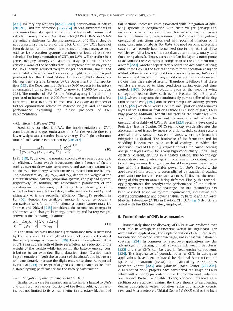
and can occur on various locations of the flying vehicle, compris-ing but not limited to its wings, engine inlets, rotary blades, and
tail sections. Increased costs associated with integration of anti-icing systems in conjunction with their weight penalty andincreased power consumption have thus far served as motivatorsfor not implementing these systems in UAV applications, yieldingoperational restrictions associated with potential missions or inmany cases mission aborts. For UAVs, the need for icing protectionsystems has recently been recognized due to the fact that thesevehicles exhibit a lower climb rate than other military, rotary- andfixed-wing aircraft. Hence, accretion of an ice layer is more proneto destabilize these vehicles in comparison to the aforementionedaircraft [220]. Another aspect that renders the avoidance of icingdifficult for UAVs is the fact that despite their operation at higheraltitudes than where icing conditions commonly occur, UAVs needto ascend and descend in icing conditions with a rate of descendslower than their rate of ascend. Therefore, it follows that thesevehicles are exposed to icing conditions during extended timeperiods [197]. Despite innovations such as the weeping wingconcept utilized on UAVs such as the Predator RQ 1-B aircraft[221], which is a system that continuously pumps a film of deicingfluid onto the wing [197], and the electroexpulsive deicing systems(EEDS) [222] which pulverizes ice into small particles and removeslayers of ice as thin as frost or as thick as an inch of glaze, CNTsmay provide additional benefits for tackling the challenges withaircraft icing. In order to expand the mission envelope and theoperational usability of UAVs, Battelle [223] recently developed aResistive Heating Coating (RHC) technology which alleviates theaforementioned issues by means of a lightweight coating systemapplicable as a spray-on system to areas where ice formationmitigation is desired. The hindrance of ice formation and itsshedding is actualized by a stack of coatings, in which thedispersion level of CNTs in juxtaposition with the barrier coatingand paint layers allows for a very high conductivity, upon usingelectrical current, ensuing in a heated surface. This technologydemonstrates many advantages in comparison to existing tradi-tional icing systems. Firstly, it operates at lower power densities inline with the limited available power for UAVs. Secondly, theappliance of this coating is accomplished by traditional coatingapplication methods in aerospace sciences, facilitating the retro-fitting of this system onto existing airframes. Finally, this technol-ogy perpetuates the aerodynamic performance of the surface,which often is a convoluted challenge. The RHC technology hasbeen assessed based on system requirements, integration andcoating compatibility, and power analysis by Battelle and Air ForceMaterial Laboratory (AFRL) in Dayton, OH, USA. Fig. 9 depicts anairfoil with the RHS technology employed.
5. Potential roles of CNTs in astronautics
Immediately since the discovery of CNTs, it was predicted thattheir role in aerospace engineering would be significant. Forastronautical applications, the implementation of CNRP can servefor radiation protection, static discharge, and in heat dissipation oncoatings [224]. In common for aerospace applications are theadvantages of utilizing a high strength lightweight structures[225] and that CNTs can be used in heat engine components[224]. The importance of potential roles of CNTs in aerospaceapplications have been embraced by National Aeronautics andSpace Administration (NASA), and particularly NASA AmesResearch Center [226] and Johnson Space Center [227,228].A number of NASA projects have considered the usage of CNTswhich will be briefly presented herein. For the Thermal, Radiationand Impact Protective Shields (TRIPS) concept, intended as amultipurpose approach against the triple threats of aeroheatingduring atmospheric entry, radiation (solar and galactic cosmicrays) and Micrometeoroid/Orbital Debris (MMOD) strikes, the high
O. Gohardani et al. / Progress in Aerospace Sciences 70 (2014) 42–6854
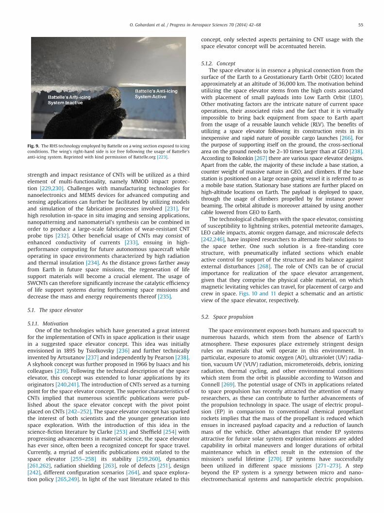
strength and impact resistance of CNTs will be utilized as a thirdelement of multi-functionality, namely MMOD impact protec-tion [229,230]. Challenges with manufacturing technologies fornanoelectronics and MEMS devices for advanced computing andsensing applications can further be facilitated by utilizing modelsand simulation of the fabrication processes involved [231]. Forhigh resolution in-space in situ imaging and sensing applications,nanopatterning and nanomaterial's synthesis can be combined inorder to produce a large-scale fabrication of wear-resistant CNTprobe tips [232]. Other beneficial usage of CNTs may consist ofenhanced conductivity of currents [233], ensuing in high-performance computing for future autonomous spacecraft whileoperating in space environments characterized by high radiationand thermal insulation [234]. As the distance grows farther awayfrom Earth in future space missions, the regeneration of lifesupport materials will become a crucial element. The usage ofSWCNTs can therefore significantly increase the catalytic efficiencyof life support systems during forthcoming space missions anddecrease the mass and energy requirements thereof [235].
5.1. The space elevator
5.1.1. MotivationOne of the technologies which have generated a great interest
for the implementation of CNTs in space application is their usagein a suggested space elevator concept. This idea was initiallyenvisioned in 1895 by Tsiolkovsky [236] and further technicallyinvented by Artsutanov [237] and independently by Pearson [238].A skyhook concept was further proposed in 1966 by Isaacs and hiscolleagues [239]. Following the technical description of the spaceelevator, this concept was extended to lunar applications by itsoriginators [240,241]. The introduction of CNTs served as a turningpoint for the space elevator concept. The superior characteristics ofCNTs implied that numerous scientific publications were pub-lished about the space elevator concept with the pivot pointplaced on CNTs [242–252]. The space elevator concept has sparkedthe interest of both scientists and the younger generation intospace exploration. With the introduction of this idea in thescience-fiction literature by Clarke [253] and Sheffield [254] withprogressing advancements in material science, the space elevatorhas ever since, often been a recognized concept for space travel.Currently, a myriad of scientific publications exist related to thespace elevator [255–258] its stability [259,260], dynamics[261,262], radiation shielding [263], role of defects [251], design[242], different configuration scenarios [264], and space explora-tion policy [265,249]. In light of the vast literature related to this
concept, only selected aspects pertaining to CNT usage with thespace elevator concept will be accentuated herein.
5.1.2. ConceptThe space elevator is in essence a physical connection from the
surface of the Earth to a Geostationary Earth Orbit (GEO) locatedapproximately at an altitude of 36,000 km. The motivation behindutilizing the space elevator stems from the high costs associatedwith placement of small payloads into Low Earth Orbit (LEO).Other motivating factors are the intricate nature of current spaceoperations, their associated risks and the fact that it is virtuallyimpossible to bring back equipment from space to Earth apartfrom the usage of a reusable launch vehicle (RLV). The benefits ofutilizing a space elevator following its construction rests in itsinexpensive and rapid nature of possible cargo launches [266]. Forthe purpose of supporting itself on the ground, the cross-sectionalarea on the ground needs to be 2–10 times larger than at GEO [238].According to Bolonkin [267] there are various space elevator designs.Apart from the cable, the majority of these include a base station, acounter weight of massive nature in GEO, and climbers. If the basestation is positioned on a large ocean-going vessel it is referred to asa mobile base station. Stationary base stations are further placed onhigh-altitude locations on Earth. The payload is deployed to space,through the usage of climbers propelled by for instance powerbeaming. The orbital altitude is moreover attained by using anothercable lowered from GEO to Earth.
The technological challenges with the space elevator, consistingof susceptibility to lightning strikes, potential meteorite damages,LEO cable impacts, atomic oxygen damage, and microscale defects[242,246], have inspired researchers to alternate their solutions tothe space tether. One such solution is a free-standing corestructure, with pneumatically inflated sections which enableactive control for support of the structure and its balance againstexternal disturbances [268]. The role of CNTs can be of crucialimportance for realization of the space elevator arrangement,given that they comprise the physical cable material, on whichmagnetic levitating vehicles can travel, for placement of cargo andcrew in space. Figs. 10 and 11 depict a schematic and an artisticview of the space elevator, respectively.
5.2. Space propulsion
The space environment exposes both humans and spacecraft tonumerous hazards, which stem from the absence of Earth'satmosphere. These exposures place extremely stringent designrules on materials that will operate in this environment. Inparticular, exposure to atomic oxygen (AO), ultraviolet (UV) radia-tion, vacuum UV (VUV) radiation, micrometeroids, debris, ionizingradiation, thermal cycling, and other environmental conditionswhich stem from the orbit is plausible according to Watson andConnell [269]. The potential usage of CNTs in applications relatedto space propulsion has recently attracted the attention of manyresearchers, as these can contribute to further advancements ofthe propulsion technology in space. The usage of electric propul-sion (EP) in comparison to conventional chemical propellantrockets implies that the mass of the propellant is reduced whichensues in increased payload capacity and a reduction of launchmass of the vehicle. Other advantages that render EP systemsattractive for future solar system exploration missions are addedcapability in orbital maneuvers and longer durations of orbitalmaintenance which in effect result in the extension of themission's useful lifetime [270]. EP systems have successfullybeen utilized in different space missions [271–273]. A stepbeyond the EP system is a synergy between micro and nano-electromechanical systems and nanoparticle electric propulsion.
Fig. 9. The RHS technology employed by Battelle on a wing section exposed to icingconditions. The wing's right-hand side is ice free following the usage of Battelle'santi-icing system. Reprinted with kind permission of Battelle.org [223].
O. Gohardani et al. / Progress in Aerospace Sciences 70 (2014) 42–68 55
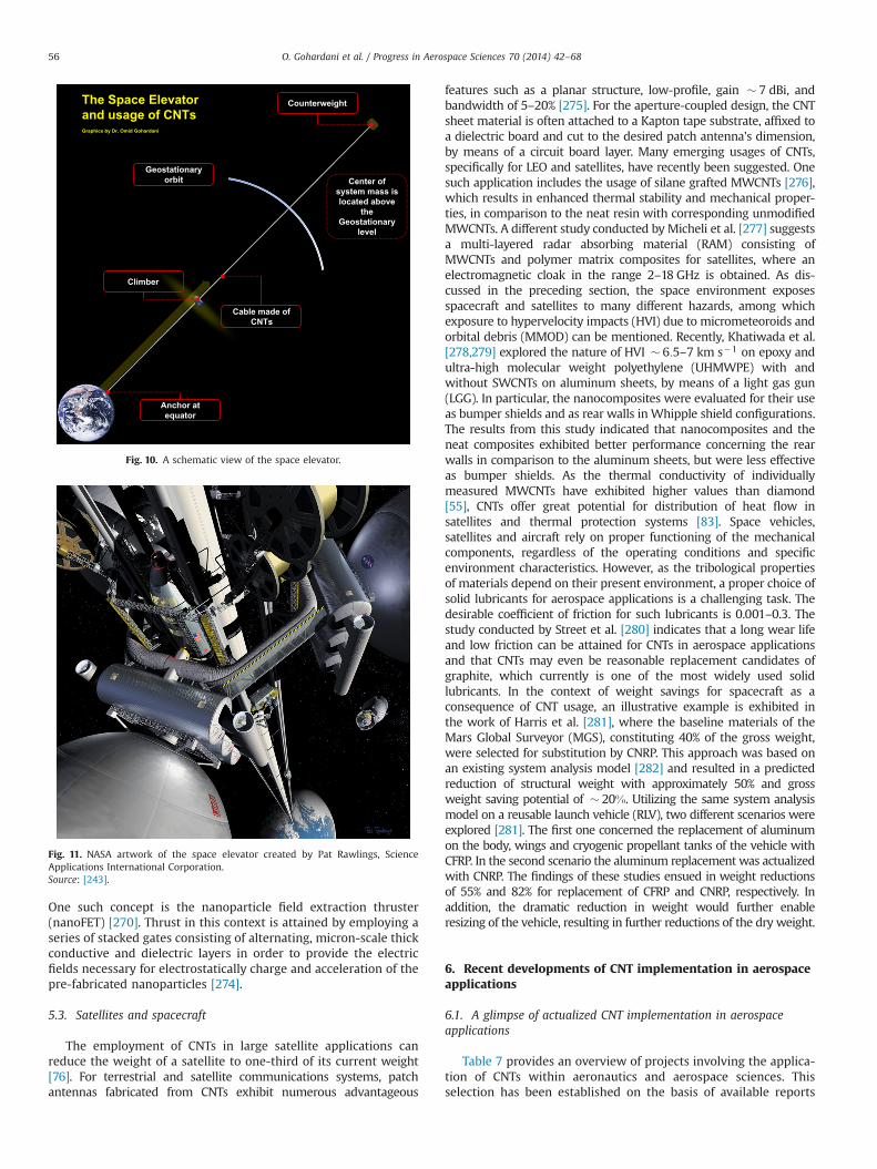
One such concept is the nanoparticle field extraction thruster(nanoFET) [270]. Thrust in this context is attained by employing aseries of stacked gates consisting of alternating, micron-scale thickconductive and dielectric layers in order to provide the electricfields necessary for electrostatically charge and acceleration of thepre-fabricated nanoparticles [274].
5.3. Satellites and spacecraft
The employment of CNTs in large satellite applications canreduce the weight of a satellite to one-third of its current weight[76]. For terrestrial and satellite communications systems, patchantennas fabricated from CNTs exhibit numerous advantageous
features such as a planar structure, low-profile, gain � 7 dBi, andbandwidth of 5–20% [275]. For the aperture-coupled design, the CNTsheet material is often attached to a Kapton tape substrate, affixed toa dielectric board and cut to the desired patch antenna's dimension,by means of a circuit board layer. Many emerging usages of CNTs,specifically for LEO and satellites, have recently been suggested. Onesuch application includes the usage of silane grafted MWCNTs [276],which results in enhanced thermal stability and mechanical proper-ties, in comparison to the neat resin with corresponding unmodifiedMWCNTs. A different study conducted by Micheli et al. [277] suggestsa multi-layered radar absorbing material (RAM) consisting ofMWCNTs and polymer matrix composites for satellites, where anelectromagnetic cloak in the range 2–18 GHz is obtained. As dis-cussed in the preceding section, the space environment exposesspacecraft and satellites to many different hazards, among whichexposure to hypervelocity impacts (HVI) due to micrometeoroids andorbital debris (MMOD) can be mentioned. Recently, Khatiwada et al.[278,279] explored the nature of HVI � 6:5–7 km s�1 on epoxy andultra-high molecular weight polyethylene (UHMWPE) with andwithout SWCNTs on aluminum sheets, by means of a light gas gun(LGG). In particular, the nanocomposites were evaluated for their useas bumper shields and as rear walls inWhipple shield configurations.The results from this study indicated that nanocomposites and theneat composites exhibited better performance concerning the rearwalls in comparison to the aluminum sheets, but were less effectiveas bumper shields. As the thermal conductivity of individuallymeasured MWCNTs have exhibited higher values than diamond[55], CNTs offer great potential for distribution of heat flow insatellites and thermal protection systems [83]. Space vehicles,satellites and aircraft rely on proper functioning of the mechanicalcomponents, regardless of the operating conditions and specificenvironment characteristics. However, as the tribological propertiesof materials depend on their present environment, a proper choice ofsolid lubricants for aerospace applications is a challenging task. Thedesirable coefficient of friction for such lubricants is 0.001–0.3. Thestudy conducted by Street et al. [280] indicates that a long wear lifeand low friction can be attained for CNTs in aerospace applicationsand that CNTs may even be reasonable replacement candidates ofgraphite, which currently is one of the most widely used solidlubricants. In the context of weight savings for spacecraft as aconsequence of CNT usage, an illustrative example is exhibited inthe work of Harris et al. [281], where the baseline materials of theMars Global Surveyor (MGS), constituting 40% of the gross weight,were selected for substitution by CNRP. This approach was based onan existing system analysis model [282] and resulted in a predictedreduction of structural weight with approximately 50% and grossweight saving potential of � 20%. Utilizing the same system analysismodel on a reusable launch vehicle (RLV), two different scenarios wereexplored [281]. The first one concerned the replacement of aluminumon the body, wings and cryogenic propellant tanks of the vehicle withCFRP. In the second scenario the aluminum replacement was actualizedwith CNRP. The findings of these studies ensued in weight reductionsof 55% and 82% for replacement of CFRP and CNRP, respectively. Inaddition, the dramatic reduction in weight would further enableresizing of the vehicle, resulting in further reductions of the dry weight.
6. Recent developments of CNT implementation in aerospaceapplications
6.1. A glimpse of actualized CNT implementation in aerospaceapplications
Table 7 provides an overview of projects involving the applica-tion of CNTs within aeronautics and aerospace sciences. Thisselection has been established on the basis of available reports
Geostationary orbit
Anchor at equator
Climber
Cable made of CNTs
Counterweight
Center of system mass is located above
the Geostationary
level
The Space Elevator and usage of CNTs
Fig. 10. A schematic view of the space elevator.
Fig. 11. NASA artwork of the space elevator created by Pat Rawlings, ScienceApplications International Corporation.Source: [243].
O. Gohardani et al. / Progress in Aerospace Sciences 70 (2014) 42–6856
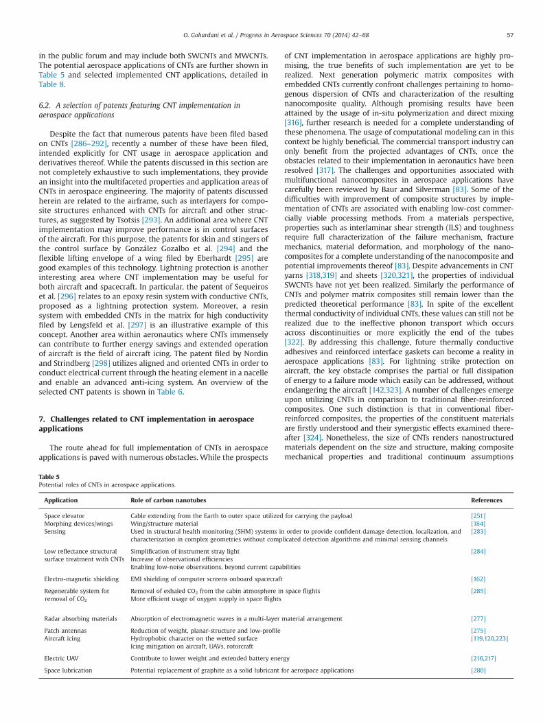
in the public forum and may include both SWCNTs and MWCNTs.The potential aerospace applications of CNTs are further shown inTable 5 and selected implemented CNT applications, detailed inTable 8.
6.2. A selection of patents featuring CNT implementation inaerospace applications
Despite the fact that numerous patents have been filed basedon CNTs [286–292], recently a number of these have been filed,intended explicitly for CNT usage in aerospace application andderivatives thereof. While the patents discussed in this section arenot completely exhaustive to such implementations, they providean insight into the multifaceted properties and application areas ofCNTs in aerospace engineering. The majority of patents discussedherein are related to the airframe, such as interlayers for compo-site structures enhanced with CNTs for aircraft and other struc-tures, as suggested by Tsotsis [293]. An additional area where CNTimplementation may improve performance is in control surfacesof the aircraft. For this purpose, the patents for skin and stingers ofthe control surface by González Gozalbo et al. [294] and theflexible lifting envelope of a wing filed by Eberhardt [295] aregood examples of this technology. Lightning protection is anotherinteresting area where CNT implementation may be useful forboth aircraft and spacecraft. In particular, the patent of Sequeiroset al. [296] relates to an epoxy resin system with conductive CNTs,proposed as a lightning protection system. Moreover, a resinsystem with embedded CNTs in the matrix for high conductivityfiled by Lengsfeld et al. [297] is an illustrative example of thisconcept. Another area within aeronautics where CNTs immenselycan contribute to further energy savings and extended operationof aircraft is the field of aircraft icing. The patent filed by Nordinand Strindberg [298] utilizes aligned and oriented CNTs in order toconduct electrical current through the heating element in a nacelleand enable an advanced anti-icing system. An overview of theselected CNT patents is shown in Table 6.
7. Challenges related to CNT implementation in aerospaceapplications
The route ahead for full implementation of CNTs in aerospaceapplications is paved with numerous obstacles. While the prospects
of CNT implementation in aerospace applications are highly pro-mising, the true benefits of such implementation are yet to berealized. Next generation polymeric matrix composites withembedded CNTs currently confront challenges pertaining to homo-genous dispersion of CNTs and characterization of the resultingnanocomposite quality. Although promising results have beenattained by the usage of in-situ polymerization and direct mixing[316], further research is needed for a complete understanding ofthese phenomena. The usage of computational modeling can in thiscontext be highly beneficial. The commercial transport industry canonly benefit from the projected advantages of CNTs, once theobstacles related to their implementation in aeronautics have beenresolved [317]. The challenges and opportunities associated withmultifunctional nanocomposites in aerospace applications havecarefully been reviewed by Baur and Silverman [83]. Some of thedifficulties with improvement of composite structures by imple-mentation of CNTs are associated with enabling low-cost commer-cially viable processing methods. From a materials perspective,properties such as interlaminar shear strength (ILS) and toughnessrequire full characterization of the failure mechanism, fracturemechanics, material deformation, and morphology of the nano-composites for a complete understanding of the nanocomposite andpotential improvements thereof [83]. Despite advancements in CNTyarns [318,319] and sheets [320,321], the properties of individualSWCNTs have not yet been realized. Similarly the performance ofCNTs and polymer matrix composites still remain lower than thepredicted theoretical performance [83]. In spite of the excellentthermal conductivity of individual CNTs, these values can still not berealized due to the ineffective phonon transport which occursacross discontinuities or more explicitly the end of the tubes[322]. By addressing this challenge, future thermally conductiveadhesives and reinforced interface gaskets can become a reality inaerospace applications [83]. For lightning strike protection onaircraft, the key obstacle comprises the partial or full dissipationof energy to a failure mode which easily can be addressed, withoutendangering the aircraft [142,323]. A number of challenges emergeupon utilizing CNTs in comparison to traditional fiber-reinforcedcomposites. One such distinction is that in conventional fiber-reinforced composites, the properties of the constituent materialsare firstly understood and their synergistic effects examined there-after [324]. Nonetheless, the size of CNTs renders nanostructuredmaterials dependent on the size and structure, making compositemechanical properties and traditional continuum assumptions
Table 5Potential roles of CNTs in aerospace applications.
Application Role of carbon nanotubes References
Space elevator Cable extending from the Earth to outer space utilized for carrying the payload [251]Morphing devices/wings Wing/structure material [184]Sensing Used in structural health monitoring (SHM) systems in order to provide confident damage detection, localization, and
characterization in complex geometries without complicated detection algorithms and minimal sensing channels[283]
Low reflectance structural Simplification of instrument stray light [284]surface treatment with CNTs Increase of observational efficiencies
Enabling low-noise observations, beyond current capabilities
Electro-magnetic shielding EMI shielding of computer screens onboard spacecraft [162]
Regenerable system forremoval of CO2
Removal of exhaled CO2 from the cabin atmosphere in space flightsMore efficient usage of oxygen supply in space flights
[285]
Radar absorbing materials Absorption of electromagnetic waves in a multi-layer material arrangement [277]
Patch antennas Reduction of weight, planar-structure and low-profile [275]Aircraft icing Hydrophobic character on the wetted surface [119,120,223]
Icing mitigation on aircraft, UAVs, rotorcraft
Electric UAV Contribute to lower weight and extended battery energy [216,217]
Space lubrication Potential replacement of graphite as a solid lubricant for aerospace applications [280]
O. Gohardani et al. / Progress in Aerospace Sciences 70 (2014) 42–68 57
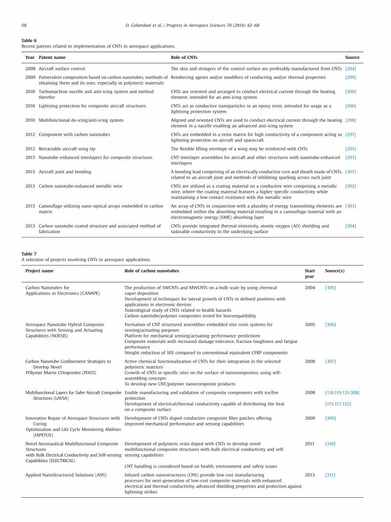
Table 6Recent patents related to implementation of CNTs in aerospace applications.
Year Patent name Role of CNTs Source
2008 Aircraft surface control The skin and stringers of the control surface are preferably manufactured from CNTs [294]
2009 Pulverulent composition based on carbon nanotubes, methods ofobtaining them and its uses, especially in polymeric materials
Reinforcing agents and/or modifiers of conducting and/or thermal properties [299]
2010 Turbomachine nacelle and anti-icing system and methodtherefor
CNTs are oriented and arranged to conduct electrical current through the heatingelement, intended for an anti-icing system
[300]
2010 Lightning protection for composite aircraft structures CNTs act as conductive nanoparticles in an epoxy resin, intended for usage as alightning protection system
[296]
2010 Multifunctional de-icing/anti-icing system Aligned and oriented CNTs are used to conduct electrical current through the heatingelement in a nacelle enabling an advanced anti-icing system
[298]
2012 Component with carbon nanotubes CNTs are embedded in a resin matrix for high conductivity of a component acting aslightning protection on aircraft and spacecraft
[297]
2012 Retractable aircraft wing tip The flexible lifting envelope of a wing may be reinforced with CNTs [295]
2013 Nanotube-enhanced interlayers for composite structures CNT interlayer assemblies for aircraft and other structures with nanotube-enhancedinterlayers
[293]
2013 Aircraft joint and bonding A bonding lead comprising of an electrically conductive core and sheath made of CNTs,related to an aircraft joint and methods of inhibiting sparking across such joint
[301]
2013 Carbon nanotube-enhanced metallic wire CNTs are utilized as a coating material on a conductive wire comprising a metallicwire, where the coating material features a higher specific conductivity whilemaintaining a low contact resistance with the metallic wire
[302]
2013 Camouflage utilizing nano-optical arrays embedded in carbonmatrix
An array of CNTs in conjunction with a plurality of energy transmitting elements areembedded within the absorbing material resulting in a camouflage material with anelectromagnetic energy (EME) absorbing layer
[303]
2013 Carbon nanotube coated structure and associated method offabrication
CNTs provide integrated thermal emissivity, atomic oxygen (AO) shielding andtailorable conductivity to the underlying surface
[304]
Table 7A selection of projects involving CNTs in aerospace applications.
Project name Role of carbon nanotubes Startyear
Source(s)
Carbon Nanotubes forApplications in Electronics (CANAPE)
The production of SWCNTs and MWCNTs on a bulk scale by using chemicalvapor deposition
2004 [305]
Development of techniques for lateral growth of CNTs in defined positions withapplications in electronic devicesToxicological study of CNTs related to health hazardsCarbon nanotube/polymer composites tested for biocompatibility
Aerospace Nanotube Hybrid CompositeStructures with Sensing and ActuatingCapabilities (NOESIS)
Formation of CNT structured assemblies embedded into resin systems forsensing/actuating purposesPlatform for mechanical sensing/actuating performance predictionsComposite materials with increased damage tolerance, fracture toughness and fatigueperformanceWeight reduction of 10% compared to conventional equivalent CFRP components
2005 [306]
Carbon Nanotube Confinement Strategies toDevelop Novel
POlymer Matrix COmposites (POCO)
Active chemical functionalization of CNTs for their integration in the selectedpolymeric matricesGrowth of CNTs in specific sites on the surface of nanocomposites, using self-assembling conceptsTo develop new CNT/polymer nanocomposite products
2008 [307]
Multifunctional Layers for Safer Aircraft CompositeStructures (LAYSA)
Enable manufacturing and validation of composite components with ice/fireprotection
2008 [116,119,121,308]
Development of electrical/thermal conductivity capable of distributing the heaton a composite surface
[115,117,122]
Innovative Repair of Aerospace Structures withCuring
Optimization and Life Cycle Monitoring Abilities(IAPETUS)
Development of CNTs doped conductive composite fiber patches offeringimproved mechanical performance and sensing capabilities
2009 [309]
Novel Aeronautical Multifunctional CompositeStructureswith Bulk Electrical Conductivity and Self-sensingCapabilities (ELECTRICAL)
Development of polymeric resin doped with CNTs to develop novelmultifunctional composite structures with bulk electrical conductivity and self-sensing capabilities
2011 [310]
CNT handling is considered based on health, environment and safety issues
Applied NanoStructured Solutions (ANS) Infused carbon nanostructures (CNS) provide low cost manufacturingprocesses for next-generation of low-cost composite materials with enhancedelectrical and thermal conductivity, advanced shielding properties and protection againstlightning strikes
2013 [311]
O. Gohardani et al. / Progress in Aerospace Sciences 70 (2014) 42–6858
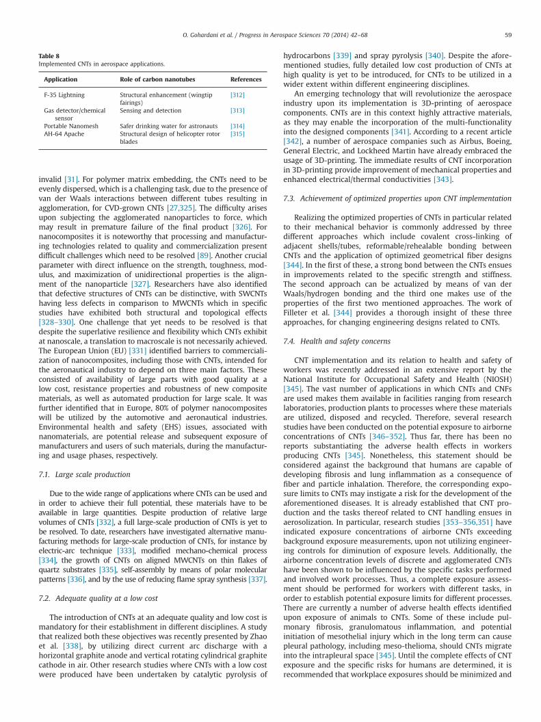
invalid [31]. For polymer matrix embedding, the CNTs need to beevenly dispersed, which is a challenging task, due to the presence ofvan der Waals interactions between different tubes resulting inagglomeration, for CVD-grown CNTs [27,325]. The difficulty arisesupon subjecting the agglomerated nanoparticles to force, whichmay result in premature failure of the final product [326]. Fornanocomposites it is noteworthy that processing and manufactur-ing technologies related to quality and commercialization presentdifficult challenges which need to be resolved [89]. Another crucialparameter with direct influence on the strength, toughness, mod-ulus, and maximization of unidirectional properties is the align-ment of the nanoparticle [327]. Researchers have also identifiedthat defective structures of CNTs can be distinctive, with SWCNTshaving less defects in comparison to MWCNTs which in specificstudies have exhibited both structural and topological effects[328–330]. One challenge that yet needs to be resolved is thatdespite the superlative resilience and flexibility which CNTs exhibitat nanoscale, a translation to macroscale is not necessarily achieved.The European Union (EU) [331] identified barriers to commerciali-zation of nanocomposites, including those with CNTs, intended forthe aeronautical industry to depend on three main factors. Theseconsisted of availability of large parts with good quality at alow cost, resistance properties and robustness of new compositematerials, as well as automated production for large scale. It wasfurther identified that in Europe, 80% of polymer nanocompositeswill be utilized by the automotive and aeronautical industries.Environmental health and safety (EHS) issues, associated withnanomaterials, are potential release and subsequent exposure ofmanufacturers and users of such materials, during the manufactur-ing and usage phases, respectively.
7.1. Large scale production
Due to the wide range of applications where CNTs can be used andin order to achieve their full potential, these materials have to beavailable in large quantities. Despite production of relative largevolumes of CNTs [332], a full large-scale production of CNTs is yet tobe resolved. To date, researchers have investigated alternative manu-facturing methods for large-scale production of CNTs, for instance byelectric-arc technique [333], modified mechano-chemical process[334], the growth of CNTs on aligned MWCNTs on thin flakes ofquartz substrates [335], self-assembly by means of polar molecularpatterns [336], and by the use of reducing flame spray synthesis [337].
7.2. Adequate quality at a low cost
The introduction of CNTs at an adequate quality and low cost ismandatory for their establishment in different disciplines. A studythat realized both these objectives was recently presented by Zhaoet al. [338], by utilizing direct current arc discharge with ahorizontal graphite anode and vertical rotating cylindrical graphitecathode in air. Other research studies where CNTs with a low costwere produced have been undertaken by catalytic pyrolysis of
hydrocarbons [339] and spray pyrolysis [340]. Despite the afore-mentioned studies, fully detailed low cost production of CNTs athigh quality is yet to be introduced, for CNTs to be utilized in awider extent within different engineering disciplines.
An emerging technology that will revolutionize the aerospaceindustry upon its implementation is 3D-printing of aerospacecomponents. CNTs are in this context highly attractive materials,as they may enable the incorporation of the multi-functionalityinto the designed components [341]. According to a recent article[342], a number of aerospace companies such as Airbus, Boeing,General Electric, and Lockheed Martin have already embraced theusage of 3D-printing. The immediate results of CNT incorporationin 3D-printing provide improvement of mechanical properties andenhanced electrical/thermal conductivities [343].
7.3. Achievement of optimized properties upon CNT implementation
Realizing the optimized properties of CNTs in particular relatedto their mechanical behavior is commonly addressed by threedifferent approaches which include covalent cross-linking ofadjacent shells/tubes, reformable/rehealable bonding betweenCNTs and the application of optimized geometrical fiber designs[344]. In the first of these, a strong bond between the CNTs ensuesin improvements related to the specific strength and stiffness.The second approach can be actualized by means of van derWaals/hydrogen bonding and the third one makes use of theproperties of the first two mentioned approaches. The work ofFilleter et al. [344] provides a thorough insight of these threeapproaches, for changing engineering designs related to CNTs.
7.4. Health and safety concerns
CNT implementation and its relation to health and safety ofworkers was recently addressed in an extensive report by theNational Institute for Occupational Safety and Health (NIOSH)[345]. The vast number of applications in which CNTs and CNFsare used makes them available in facilities ranging from researchlaboratories, production plants to processes where these materialsare utilized, disposed and recycled. Therefore, several researchstudies have been conducted on the potential exposure to airborneconcentrations of CNTs [346–352]. Thus far, there has been noreports substantiating the adverse health effects in workersproducing CNTs [345]. Nonetheless, this statement should beconsidered against the background that humans are capable ofdeveloping fibrosis and lung inflammation as a consequence offiber and particle inhalation. Therefore, the corresponding expo-sure limits to CNTs may instigate a risk for the development of theaforementioned diseases. It is already established that CNT pro-duction and the tasks thereof related to CNT handling ensues inaerosolization. In particular, research studies [353–356,351] haveindicated exposure concentrations of airborne CNTs exceedingbackground exposure measurements, upon not utilizing engineer-ing controls for diminution of exposure levels. Additionally, theairborne concentration levels of discrete and agglomerated CNTshave been shown to be influenced by the specific tasks performedand involved work processes. Thus, a complete exposure assess-ment should be performed for workers with different tasks, inorder to establish potential exposure limits for different processes.There are currently a number of adverse health effects identifiedupon exposure of animals to CNTs. Some of these include pul-monary fibrosis, granulomatous inflammation, and potentialinitiation of mesothelial injury which in the long term can causepleural pathology, including meso-thelioma, should CNTs migrateinto the intrapleural space [345]. Until the complete effects of CNTexposure and the specific risks for humans are determined, it isrecommended that workplace exposures should be minimized and
Table 8Implemented CNTs in aerospace applications.
Application Role of carbon nanotubes References
F-35 Lightning Structural enhancement (wingtipfairings)
[312]
Gas detector/chemicalsensor
Sensing and detection [313]
Portable Nanomesh Safer drinking water for astronauts [314]AH-64 Apache Structural design of helicopter rotor
blades[315]
O. Gohardani et al. / Progress in Aerospace Sciences 70 (2014) 42–68 59
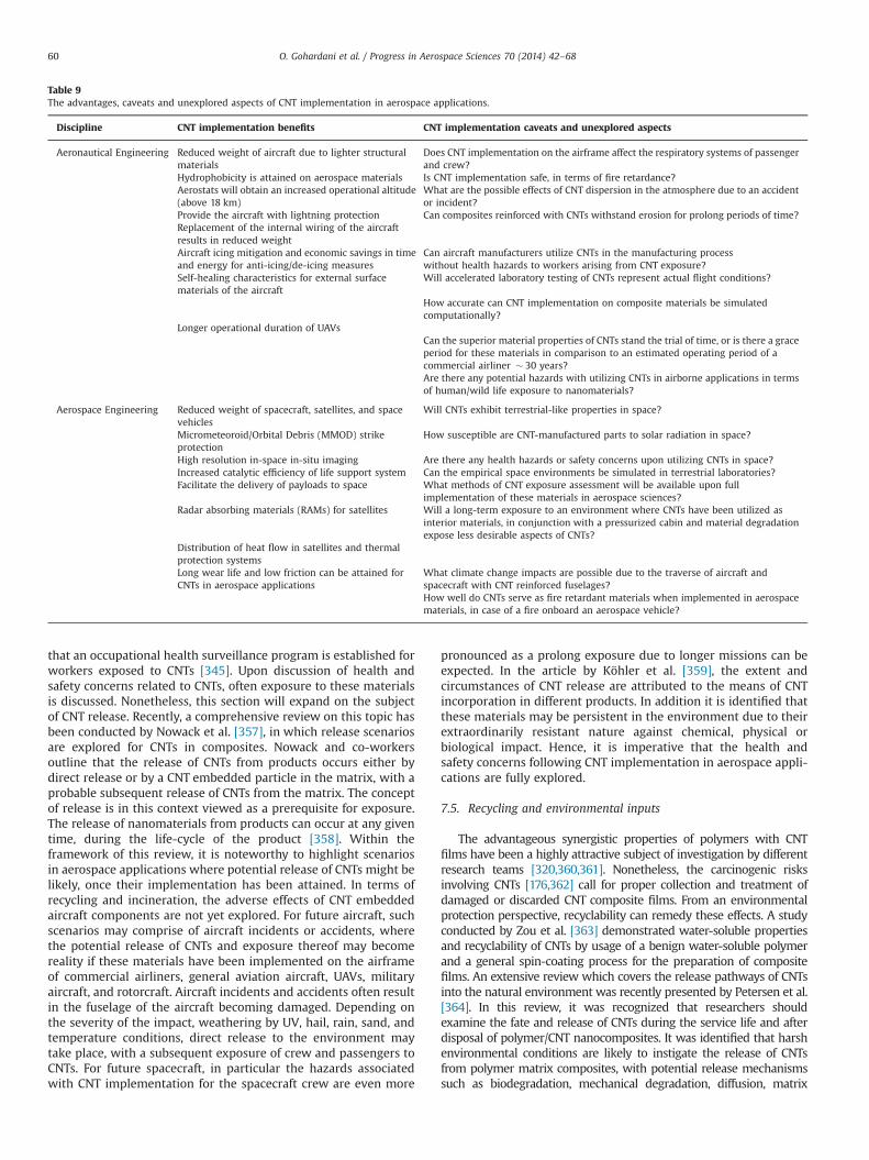
that an occupational health surveillance program is established forworkers exposed to CNTs [345]. Upon discussion of health andsafety concerns related to CNTs, often exposure to these materialsis discussed. Nonetheless, this section will expand on the subjectof CNT release. Recently, a comprehensive review on this topic hasbeen conducted by Nowack et al. [357], in which release scenariosare explored for CNTs in composites. Nowack and co-workersoutline that the release of CNTs from products occurs either bydirect release or by a CNT embedded particle in the matrix, with aprobable subsequent release of CNTs from the matrix. The conceptof release is in this context viewed as a prerequisite for exposure.The release of nanomaterials from products can occur at any giventime, during the life-cycle of the product [358]. Within theframework of this review, it is noteworthy to highlight scenariosin aerospace applications where potential release of CNTs might belikely, once their implementation has been attained. In terms ofrecycling and incineration, the adverse effects of CNT embeddedaircraft components are not yet explored. For future aircraft, suchscenarios may comprise of aircraft incidents or accidents, wherethe potential release of CNTs and exposure thereof may becomereality if these materials have been implemented on the airframeof commercial airliners, general aviation aircraft, UAVs, militaryaircraft, and rotorcraft. Aircraft incidents and accidents often resultin the fuselage of the aircraft becoming damaged. Depending onthe severity of the impact, weathering by UV, hail, rain, sand, andtemperature conditions, direct release to the environment maytake place, with a subsequent exposure of crew and passengers toCNTs. For future spacecraft, in particular the hazards associatedwith CNT implementation for the spacecraft crew are even more
pronounced as a prolong exposure due to longer missions can beexpected. In the article by Köhler et al. [359], the extent andcircumstances of CNT release are attributed to the means of CNTincorporation in different products. In addition it is identified thatthese materials may be persistent in the environment due to theirextraordinarily resistant nature against chemical, physical orbiological impact. Hence, it is imperative that the health andsafety concerns following CNT implementation in aerospace appli-cations are fully explored.
7.5. Recycling and environmental inputs
The advantageous synergistic properties of polymers with CNTfilms have been a highly attractive subject of investigation by differentresearch teams [320,360,361]. Nonetheless, the carcinogenic risksinvolving CNTs [176,362] call for proper collection and treatment ofdamaged or discarded CNT composite films. From an environmentalprotection perspective, recyclability can remedy these effects. A studyconducted by Zou et al. [363] demonstrated water-soluble propertiesand recyclability of CNTs by usage of a benign water-soluble polymerand a general spin-coating process for the preparation of compositefilms. An extensive review which covers the release pathways of CNTsinto the natural environment was recently presented by Petersen et al.[364]. In this review, it was recognized that researchers shouldexamine the fate and release of CNTs during the service life and afterdisposal of polymer/CNT nanocomposites. It was identified that harshenvironmental conditions are likely to instigate the release of CNTsfrom polymer matrix composites, with potential release mechanismssuch as biodegradation, mechanical degradation, diffusion, matrix
Table 9The advantages, caveats and unexplored aspects of CNT implementation in aerospace applications.
Discipline CNT implementation benefits CNT implementation caveats and unexplored aspects
Aeronautical Engineering Reduced weight of aircraft due to lighter structuralmaterials
Does CNT implementation on the airframe affect the respiratory systems of passengerand crew?
Hydrophobicity is attained on aerospace materials Is CNT implementation safe, in terms of fire retardance?Aerostats will obtain an increased operational altitude(above 18 km)
What are the possible effects of CNT dispersion in the atmosphere due to an accidentor incident?
Provide the aircraft with lightning protection Can composites reinforced with CNTs withstand erosion for prolong periods of time?Replacement of the internal wiring of the aircraftresults in reduced weightAircraft icing mitigation and economic savings in timeand energy for anti-icing/de-icing measures
Can aircraft manufacturers utilize CNTs in the manufacturing processwithout health hazards to workers arising from CNT exposure?
Self-healing characteristics for external surfacematerials of the aircraft
Will accelerated laboratory testing of CNTs represent actual flight conditions?
How accurate can CNT implementation on composite materials be simulatedcomputationally?
Longer operational duration of UAVsCan the superior material properties of CNTs stand the trial of time, or is there a graceperiod for these materials in comparison to an estimated operating period of acommercial airliner � 30 years?Are there any potential hazards with utilizing CNTs in airborne applications in termsof human/wild life exposure to nanomaterials?
Aerospace Engineering Reduced weight of spacecraft, satellites, and spacevehicles
Will CNTs exhibit terrestrial-like properties in space?
Micrometeoroid/Orbital Debris (MMOD) strikeprotection
How susceptible are CNT-manufactured parts to solar radiation in space?
High resolution in-space in-situ imaging Are there any health hazards or safety concerns upon utilizing CNTs in space?Increased catalytic efficiency of life support system Can the empirical space environments be simulated in terrestrial laboratories?Facilitate the delivery of payloads to space What methods of CNT exposure assessment will be available upon full
implementation of these materials in aerospace sciences?Radar absorbing materials (RAMs) for satellites Will a long-term exposure to an environment where CNTs have been utilized as
interior materials, in conjunction with a pressurized cabin and material degradationexpose less desirable aspects of CNTs?
Distribution of heat flow in satellites and thermalprotection systemsLong wear life and low friction can be attained forCNTs in aerospace applications
What climate change impacts are possible due to the traverse of aircraft andspacecraft with CNT reinforced fuselages?How well do CNTs serve as fire retardant materials when implemented in aerospacematerials, in case of a fire onboard an aerospace vehicle?
O. Gohardani et al. / Progress in Aerospace Sciences 70 (2014) 42–6860
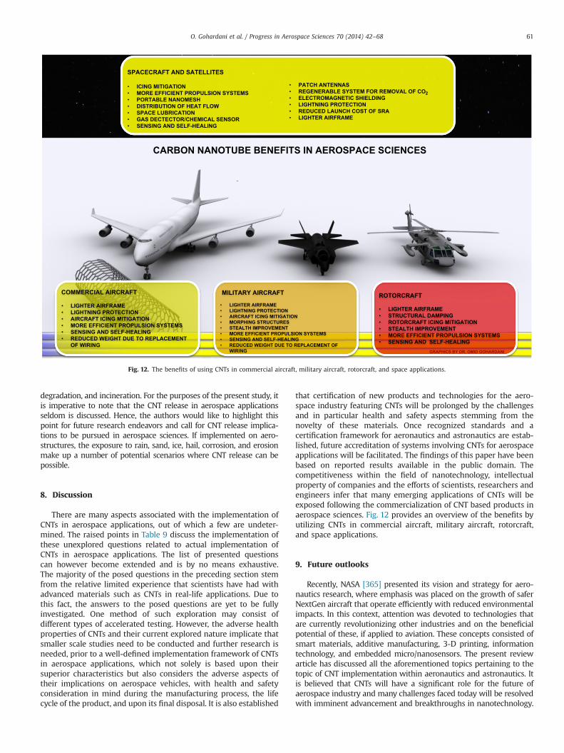
degradation, and incineration. For the purposes of the present study, itis imperative to note that the CNT release in aerospace applicationsseldom is discussed. Hence, the authors would like to highlight thispoint for future research endeavors and call for CNT release implica-tions to be pursued in aerospace sciences. If implemented on aero-structures, the exposure to rain, sand, ice, hail, corrosion, and erosionmake up a number of potential scenarios where CNT release can bepossible.
8. Discussion
There are many aspects associated with the implementation ofCNTs in aerospace applications, out of which a few are undeter-mined. The raised points in Table 9 discuss the implementation ofthese unexplored questions related to actual implementation ofCNTs in aerospace applications. The list of presented questionscan however become extended and is by no means exhaustive.The majority of the posed questions in the preceding section stemfrom the relative limited experience that scientists have had withadvanced materials such as CNTs in real-life applications. Due tothis fact, the answers to the posed questions are yet to be fullyinvestigated. One method of such exploration may consist ofdifferent types of accelerated testing. However, the adverse healthproperties of CNTs and their current explored nature implicate thatsmaller scale studies need to be conducted and further research isneeded, prior to a well-defined implementation framework of CNTsin aerospace applications, which not solely is based upon theirsuperior characteristics but also considers the adverse aspects oftheir implications on aerospace vehicles, with health and safetyconsideration in mind during the manufacturing process, the lifecycle of the product, and upon its final disposal. It is also established
that certification of new products and technologies for the aero-space industry featuring CNTs will be prolonged by the challengesand in particular health and safety aspects stemming from thenovelty of these materials. Once recognized standards and acertification framework for aeronautics and astronautics are estab-lished, future accreditation of systems involving CNTs for aerospaceapplications will be facilitated. The findings of this paper have beenbased on reported results available in the public domain. Thecompetitiveness within the field of nanotechnology, intellectualproperty of companies and the efforts of scientists, researchers andengineers infer that many emerging applications of CNTs will beexposed following the commercialization of CNT based products inaerospace sciences. Fig. 12 provides an overview of the benefits byutilizing CNTs in commercial aircraft, military aircraft, rotorcraft,and space applications.
9. Future outlooks
Recently, NASA [365] presented its vision and strategy for aero-nautics research, where emphasis was placed on the growth of saferNextGen aircraft that operate efficiently with reduced environmentalimpacts. In this context, attention was devoted to technologies thatare currently revolutionizing other industries and on the beneficialpotential of these, if applied to aviation. These concepts consisted ofsmart materials, additive manufacturing, 3-D printing, informationtechnology, and embedded micro/nanosensors. The present reviewarticle has discussed all the aforementioned topics pertaining to thetopic of CNT implementation within aeronautics and astronautics. Itis believed that CNTs will have a significant role for the future ofaerospace industry and many challenges faced today will be resolvedwith imminent advancement and breakthroughs in nanotechnology.
SPACECRAFT AND SATELLITES
• ICING MITIGATION• MORE EFFICIENT PROPULSION SYSTEMS• PORTABLE NANOMESH• DISTRIBUTION OF HEAT FLOW• SPACE LUBRICATION• GAS DECTECTOR/CHEMICAL SENSOR• SENSING AND SELF-HEALING
• PATCH ANTENNAS • REGENERABLE SYSTEM FOR REMOVAL OF CO2• ELECTROMAGNETIC SHIELDING• LIGHTNING PROTECTION• REDUCED LAUNCH COST OF SRA• LIGHTER AIRFRAME
COMMERCIAL AIRCRAFT
• LIGHTER AIRFRAME• LIGHTNING PROTECTION• AIRCRAFT ICING MITIGATION• MORE EFFICIENT PROPULSION SYSTEMS• SENSING AND SELF-HEALING• REDUCED WEIGHT DUE TO REPLACEMENT
OF WIRING
MILITARY AIRCRAFT
• LIGHTER AIRFRAME• LIGHTNING PROTECTION• AIRCRAFT ICING MITIGATION• MORPHING STRUCTURES• STEALTH IMPROVEMENT• MORE EFFICIENT PROPULSION SYSTEMS• SENSING AND SELF-HEALING• REDUCED WEIGHT DUE TO REPLACEMENT OF
WIRING GRAPHICS BY DR. OMID GOHARDANI
ROTORCRAFT
• LIGHTER AIRFRAME• STRUCTURAL DAMPING• ROTORCRAFT ICING MITIGATION• STEALTH IMPROVEMENT• MORE EFFICIENT PROPULSION SYSTEMS• SENSING AND SELF-HEALING
CARBON NANOTUBE BENEFITS IN AEROSPACE SCIENCES
Fig. 12. The benefits of using CNTs in commercial aircraft, military aircraft, rotorcraft, and space applications.
O. Gohardani et al. / Progress in Aerospace Sciences 70 (2014) 42–68 61
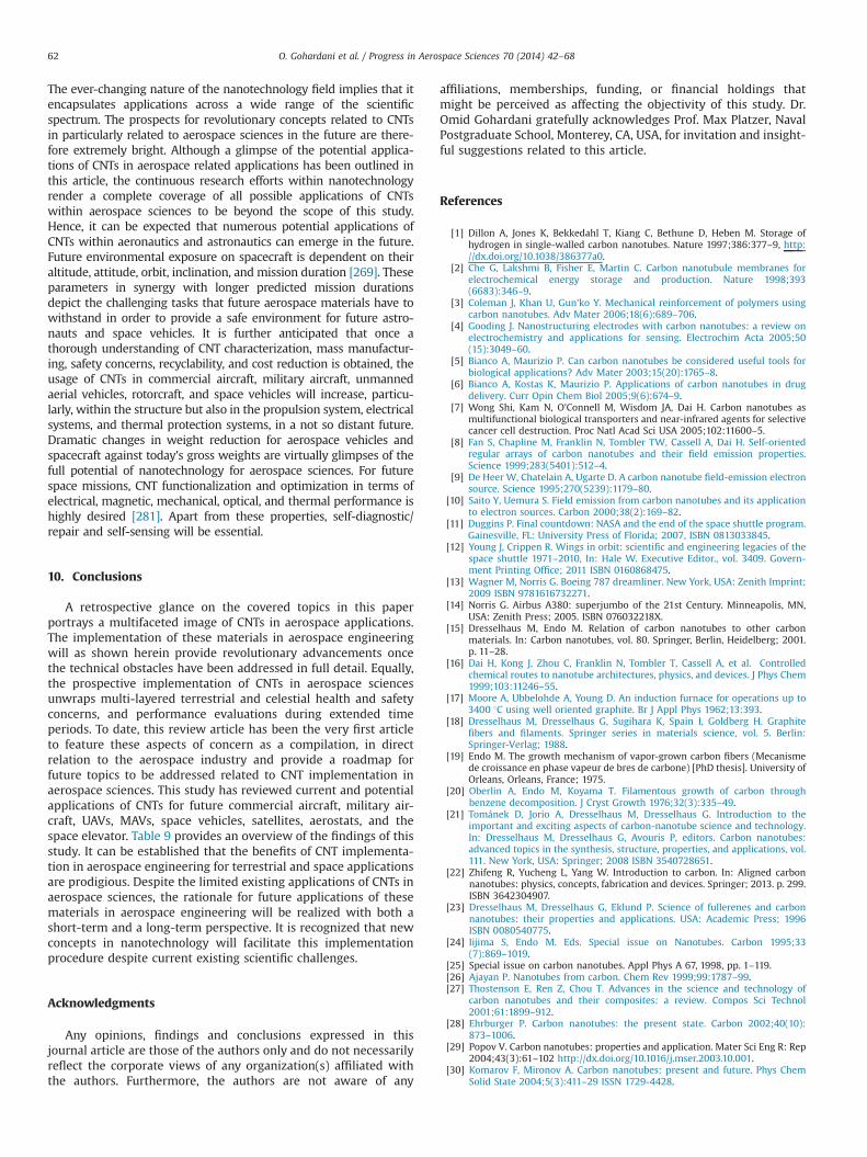
The ever-changing nature of the nanotechnology field implies that itencapsulates applications across a wide range of the scientificspectrum. The prospects for revolutionary concepts related to CNTsin particularly related to aerospace sciences in the future are there-fore extremely bright. Although a glimpse of the potential applica-tions of CNTs in aerospace related applications has been outlined inthis article, the continuous research efforts within nanotechnologyrender a complete coverage of all possible applications of CNTswithin aerospace sciences to be beyond the scope of this study.Hence, it can be expected that numerous potential applications ofCNTs within aeronautics and astronautics can emerge in the future.Future environmental exposure on spacecraft is dependent on theiraltitude, attitude, orbit, inclination, and mission duration [269]. Theseparameters in synergy with longer predicted mission durationsdepict the challenging tasks that future aerospace materials have towithstand in order to provide a safe environment for future astro-nauts and space vehicles. It is further anticipated that once athorough understanding of CNT characterization, mass manufactur-ing, safety concerns, recyclability, and cost reduction is obtained, theusage of CNTs in commercial aircraft, military aircraft, unmannedaerial vehicles, rotorcraft, and space vehicles will increase, particu-larly, within the structure but also in the propulsion system, electricalsystems, and thermal protection systems, in a not so distant future.Dramatic changes in weight reduction for aerospace vehicles andspacecraft against today's gross weights are virtually glimpses of thefull potential of nanotechnology for aerospace sciences. For futurespace missions, CNT functionalization and optimization in terms ofelectrical, magnetic, mechanical, optical, and thermal performance ishighly desired [281]. Apart from these properties, self-diagnostic/repair and self-sensing will be essential.
10. Conclusions
A retrospective glance on the covered topics in this paperportrays a multifaceted image of CNTs in aerospace applications.The implementation of these materials in aerospace engineeringwill as shown herein provide revolutionary advancements oncethe technical obstacles have been addressed in full detail. Equally,the prospective implementation of CNTs in aerospace sciencesunwraps multi-layered terrestrial and celestial health and safetyconcerns, and performance evaluations during extended timeperiods. To date, this review article has been the very first articleto feature these aspects of concern as a compilation, in directrelation to the aerospace industry and provide a roadmap forfuture topics to be addressed related to CNT implementation inaerospace sciences. This study has reviewed current and potentialapplications of CNTs for future commercial aircraft, military air-craft, UAVs, MAVs, space vehicles, satellites, aerostats, and thespace elevator. Table 9 provides an overview of the findings of thisstudy. It can be established that the benefits of CNT implementa-tion in aerospace engineering for terrestrial and space applicationsare prodigious. Despite the limited existing applications of CNTs inaerospace sciences, the rationale for future applications of thesematerials in aerospace engineering will be realized with both ashort-term and a long-term perspective. It is recognized that newconcepts in nanotechnology will facilitate this implementationprocedure despite current existing scientific challenges.
Acknowledgments
Any opinions, findings and conclusions expressed in thisjournal article are those of the authors only and do not necessarilyreflect the corporate views of any organization(s) affiliated withthe authors. Furthermore, the authors are not aware of any
affiliations, memberships, funding, or financial holdings thatmight be perceived as affecting the objectivity of this study. Dr.Omid Gohardani gratefully acknowledges Prof. Max Platzer, NavalPostgraduate School, Monterey, CA, USA, for invitation and insight-ful suggestions related to this article.
References
[1] Dillon A, Jones K, Bekkedahl T, Kiang C, Bethune D, Heben M. Storage ofhydrogen in single-walled carbon nanotubes. Nature 1997;386:377–9, http://dx.doi.org/10.1038/386377a0.
[2] Che G, Lakshmi B, Fisher E, Martin C. Carbon nanotubule membranes forelectrochemical energy storage and production. Nature 1998;393(6683):346–9.
[3] Coleman J, Khan U, Gun'ko Y. Mechanical reinforcement of polymers usingcarbon nanotubes. Adv Mater 2006;18(6):689–706.
[4] Gooding J. Nanostructuring electrodes with carbon nanotubes: a review onelectrochemistry and applications for sensing. Electrochim Acta 2005;50(15):3049–60.
[5] Bianco A, Maurizio P. Can carbon nanotubes be considered useful tools forbiological applications? Adv Mater 2003;15(20):1765–8.
[6] Bianco A, Kostas K, Maurizio P. Applications of carbon nanotubes in drugdelivery. Curr Opin Chem Biol 2005;9(6):674–9.
[7] Wong Shi, Kam N, O'Connell M, Wisdom JA, Dai H. Carbon nanotubes asmultifunctional biological transporters and near-infrared agents for selectivecancer cell destruction. Proc Natl Acad Sci USA 2005;102:11600–5.
[8] Fan S, Chapline M, Franklin N, Tombler TW, Cassell A, Dai H. Self-orientedregular arrays of carbon nanotubes and their field emission properties.Science 1999;283(5401):512–4.
[9] De Heer W, Chatelain A, Ugarte D. A carbon nanotube field-emission electronsource. Science 1995;270(5239):1179–80.
[10] Saito Y, Uemura S. Field emission from carbon nanotubes and its applicationto electron sources. Carbon 2000;38(2):169–82.
[11] Duggins P. Final countdown: NASA and the end of the space shuttle program.Gainesville, FL: University Press of Florida; 2007, ISBN 0813033845.
[12] Young J, Crippen R. Wings in orbit: scientific and engineering legacies of thespace shuttle 1971–2010, In: Hale W. Executive Editor., vol. 3409. Govern-ment Printing Office; 2011 ISBN 0160868475.
[13] Wagner M, Norris G. Boeing 787 dreamliner. New York, USA: Zenith Imprint;2009 ISBN 9781616732271.
[14] Norris G. Airbus A380: superjumbo of the 21st Century. Minneapolis, MN,USA: Zenith Press; 2005. ISBN 076032218X.
[15] Dresselhaus M, Endo M. Relation of carbon nanotubes to other carbonmaterials. In: Carbon nanotubes, vol. 80. Springer, Berlin, Heidelberg; 2001.p. 11–28.
[16] Dai H, Kong J, Zhou C, Franklin N, Tombler T, Cassell A, et al. Controlledchemical routes to nanotube architectures, physics, and devices. J Phys Chem1999;103:11246–55.
[17] Moore A, Ubbelohde A, Young D. An induction furnace for operations up to3400 1C using well oriented graphite. Br J Appl Phys 1962;13:393.
[18] Dresselhaus M, Dresselhaus G, Sugihara K, Spain I, Goldberg H. Graphitefibers and filaments. Springer series in materials science, vol. 5. Berlin:Springer-Verlag; 1988.
[19] Endo M. The growth mechanism of vapor-grown carbon fibers (Mecanismede croissance en phase vapeur de bres de carbone) [PhD thesis]. University ofOrleans, Orleans, France; 1975.
[20] Oberlin A, Endo M, Koyama T. Filamentous growth of carbon throughbenzene decomposition. J Cryst Growth 1976;32(3):335–49.
[21] Tománek D, Jorio A, Dresselhaus M, Dresselhaus G. Introduction to theimportant and exciting aspects of carbon-nanotube science and technology.In: Dresselhaus M, Dresselhaus G, Avouris P, editors. Carbon nanotubes:advanced topics in the synthesis, structure, properties, and applications, vol.111. New York, USA: Springer; 2008 ISBN 3540728651.
[22] Zhifeng R, Yucheng L, Yang W. Introduction to carbon. In: Aligned carbonnanotubes: physics, concepts, fabrication and devices. Springer; 2013. p. 299.ISBN 3642304907.
[23] Dresselhaus M, Dresselhaus G, Eklund P. Science of fullerenes and carbonnanotubes: their properties and applications. USA: Academic Press; 1996ISBN 0080540775.
[24] Iijima S, Endo M. Eds. Special issue on Nanotubes. Carbon 1995;33(7):869–1019.
[25] Special issue on carbon nanotubes. Appl Phys A 67, 1998, pp. 1–119.[26] Ajayan P. Nanotubes from carbon. Chem Rev 1999;99:1787–99.[27] Thostenson E, Ren Z, Chou T. Advances in the science and technology of
carbon nanotubes and their composites: a review. Compos Sci Technol2001;61:1899–912.
[28] Ehrburger P. Carbon nanotubes: the present state. Carbon 2002;40(10):873–1006.
[29] Popov V. Carbon nanotubes: properties and application. Mater Sci Eng R: Rep2004;43(3):61–102 http://dx.doi.org/10.1016/j.mser.2003.10.001.
[30] Komarov F, Mironov A. Carbon nanotubes: present and future. Phys ChemSolid State 2004;5(3):411–29 ISSN 1729-4428.
O. Gohardani et al. / Progress in Aerospace Sciences 70 (2014) 42–6862
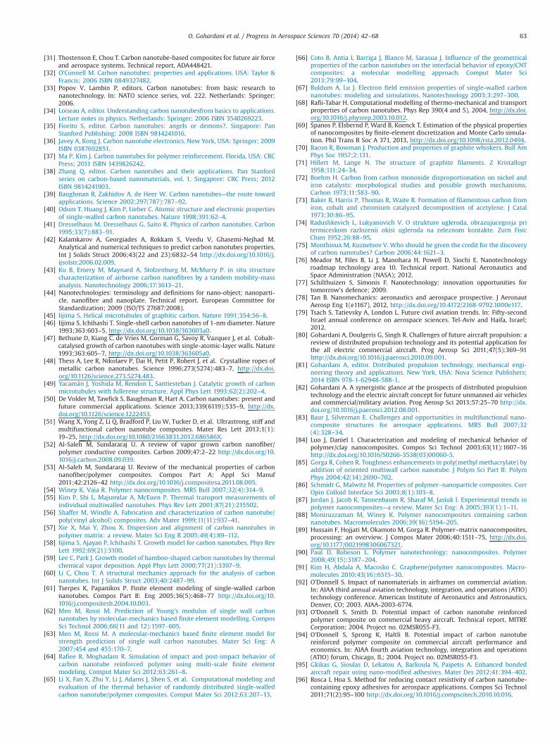
[31] Thostenson E, Chou T. Carbon nanotube-based composites for future air forceand aerospace systems. Technical report, ADA448421.
[32] O'Connell M. Carbon nanotubes: properties and applications. USA: Taylor &Francis; 2006 ISBN 0849327482.
[33] Popov V, Lambin P, editors. Carbon nanotubes: from basic research tonanotechnology. In: NATO science series, vol. 222. Netherlands: Springer;2006.
[34] Loiseau A, editor. Understanding carbon nanotubesfrom basics to applications.Lecture notes in physics. Netherlands: Springer; 2006 ISBN 3540269223.
[35] Fiorito S, editor. Carbon nanotubes: angels or demons?. Singapore: PanStanford Publishing; 2008 ISBN 9814241016.
[36] Javey A, Kong J. Carbon nanotube electronics. New York, USA: Springer; 2009ISBN 0387692851.
[37] Ma P, Kim J. Carbon nanotubes for polymer reinforcement. Florida, USA: CRCPress; 2011 ISBN 1439826242.
[38] Zhang Q, editor. Carbon nanotubes and their applications. Pan Stanfordseries on carbon-based nanomaterials, vol. 1. Singapore: CRC Press; 2012ISBN 9814241903.
[39] Baughman R, Zakhidov A, de Heer W. Carbon nanotubes—the route towardapplications. Science 2002;297(787):787–92.
[40] Odom T, Huang J, Kim P, Lieber C. Atomic structure and electronic propertiesof single-walled carbon nanotubes. Nature 1998;391:62–4.
[41] Dresselhaus M, Dresselhaus G, Saito R. Physics of carbon nanotubes. Carbon1995;33(7):883–91.
[42] Kalamkarov A, Georgiades A, Rokkam S, Veedu V, Ghasemi-Nejhad M.Analytical and numerical techniques to predict carbon nanotubes properties.Int J Solids Struct 2006;43(22 and 23):6832–54 http://dx.doi.org/10.1016/j.ijsolstr.2006.02.009.
[43] Ku B, Emery M, Maynard A, Stolzenburg M, McMurry P. in situ structurecharacterization of airborne carbon nanofibres by a tandem mobility-massanalysis. Nanotechnology 2006;17:3613–21.
[44] Nanotechnologies: terminology and definitions for nano-object; nanoparti-cle, nanofibre and nanoplate. Technical report. European Committee forStandardization; 2009 (ISO/TS 27687:2008).
[45] Iijima S. Helical microtubules of graphitic carbon. Nature 1991;354:56–8.[46] Iijima S, Ichihashi T. Single-shell carbon nanotubes of 1-nm diameter. Nature
1993;363:603–5, http://dx.doi.org/10.1038/363603a0.[47] Bethune D, Kiang C, de Vries M, Gorman G, Savoy R, Vazquez J, et al. Cobalt-
catalysed growth of carbon nanotubes with single-atomic-layer walls. Nature1993;363:605–7, http://dx.doi.org/10.1038/363605a0.
[48] Thess A, Lee R, Nikolaev P, Dai H, Petit P, Robert J, et al. Crystalline ropes ofmetallic carbon nanotubes. Science 1996;273(5274):483–7, http://dx.doi.org/10.1126/science.273.5274.483.
[49] Yacamán J, Yoshida M, Rendon L, Santiesteban J. Catalytic growth of carbonmicrotubules with fullerene structure. Appl Phys Lett 1993;62(2):202–4.
[50] De Volder M, Tawfick S, Baughman R, Hart A. Carbon nanotubes: present andfuture commercial applications. Science 2013;339(6119):535–9, http://dx.doi.org/10.1126/science.1222453.
[51] Wang X, Yong Z, Li Q, Bradford P, Liu W, Tucker D, et al. Ultrastrong, stiff andmultifunctional carbon nanotube composites. Mater Res Lett 2013;1(1):19–25, http://dx.doi.org/10.1080/21663831.2012.686586X.
[52] Al-Saleh M, Sundararaj U. A review of vapor grown carbon nanofiber/polymer conductive composites. Carbon 2009;47:2–22 http://dx.doi.org/10.1016/j.carbon.2008.09.039.
[53] Al-Saleh M, Sundararaj U. Review of the mechanical properties of carbonnanofiber/polymer composites. Compos Part A: Appl Sci Manuf2011;42:2126–42 http://dx.doi.org/10.1016/j.compositesa.2011.08.005.
[54] Winey K, Vaia R. Polymer nanocomposites. MRS Bull 2007;32(4):314–9.[55] Kim P, Shi L, Majumdar A, McEuen P. Thermal transport measurements of
individual multiwalled nanotubes. Phys Rev Lett 2001;87(21):215502.[56] Shaffer M, Windle A. Fabrication and characterization of carbon nanotube/
poly(vinyl alcohol) composites. Adv Mater 1999;11(11):937–41.[57] Xie X, Mai Y, Zhou X. Dispersion and alignment of carbon nanotubes in
polymer matrix: a review. Mater Sci Eng R 2005;49(4):89–112.[58] Iijima S, Ajayan P, Ichihashi T. Growth model for carbon nanotubes. Phys Rev
Lett 1992;69(21):3100.[59] Lee C, Park J. Growth model of bamboo-shaped carbon nanotubes by thermal
chemical vapor deposition. Appl Phys Lett 2000;77(21):3397–9.[60] Li C, Chou T. A structural mechanics approach for the analysis of carbon
nanotubes. Int J Solids Struct 2003;40:2487–99.[61] Tserpes K, Papanikos P. Finite element modeling of single-walled carbon
nanotubes. Compos Part B: Eng 2005;36(5):468–77 http://dx.doi.org/10.1016/j.compositesb.2004.10.003.
[62] Meo M, Rossi M. Prediction of Young's modulus of single wall carbonnanotubes by molecular-mechanics based finite element modelling. ComposSci Technol 2006;66(11 and 12):1597–605.
[63] Meo M, Rossi M. A molecular-mechanics based finite element model forstrength prediction of single wall carbon nanotubes. Mater Sci Eng: A2007;454 and 455:170–7.
[64] Rafiee R, Moghadam R. Simulation of impact and post-impact behavior ofcarbon nanotube reinforced polymer using multi-scale finite elementmodeling. Comput Mater Sci 2012;63:261–8.
[65] Li X, Fan X, Zhu Y, Li J, Adams J, Shen S, et al. Computational modeling andevaluation of the thermal behavior of randomly distributed single-walledcarbon nanotube/polymer composites. Comput Mater Sci 2012;63:207–13.
[66] Coto B, Antia I, Barriga J, Blanco M, Sarasua J. Influence of the geometricalproperties of the carbon nanotubes on the interfacial behavior of epoxy/CNTcomposites: a molecular modelling approach. Comput Mater Sci2013;79:99–104.
[67] Buldum A, Lu J. Electron field emission properties of single-walled carbonnanotubes: modeling and simulations. Nanotechnology 2003;3:297–300.
[68] Rafii-Tabar H. Computational modelling of thermo-mechanical and transportproperties of carbon nanotubes. Phys Rep 390(4 and 5), 2004, http://dx.doi.org/10.1016/j.physrep.2003.10.012.
[69] Spanos P, Elsbernd P, Ward B, Koenck T. Estimation of the physical propertiesof nanocomposites by finite-element discretization and Monte Carlo simula-tion. Phil Trans R Soc A 371, 2013, http://dx.doi.org/10.1098/rsta.2012.0494.
[70] Bacon R, Bowman J. Production and properties of graphite whiskers. Bull AmPhys Soc 1957;2:131.
[71] Hillert M, Lange N. The structure of graphite filaments. Z Kristallogr1958;111:24–34.
[72] Boehm H. Carbon from carbon monoxide disproportionation on nickel andiron catalysts: morphological studies and possible growth mechanisms.Carbon 1973;11:583–90.
[73] Baker R, Harris P, Thomas R, Waite R. Formation of filamentous carbon fromiron, cobalt and chromium catalyzed decomposition of acetylene. J Catal1973;30:86–95.
[74] Radushkevich L, Lukyanovich V. O strukture ugleroda, obrazujucegosja pritermiceskom razlozenii okisi ugleroda na zeleznom kontakte. Zurn FisicChim 1952;26:88–95.
[75] Monthioux M, Kuznetsov V. Who should be given the credit for the discoveryof carbon nanotubes? Carbon 2006;44:1621–3.
[76] Meador M, Files B, Li J, Manohara H, Powell D, Siochi E. Nanotechnologyroadmap technology area 10. Technical report. National Aeronautics andSpace Administration (NASA); 2012.
[77] Schilthuizen S, Simonis F. Nanotechnology: innovation opportunities fortomorrow's defence; 2009.
[78] Tan B. Nanomechanics: aeronautics and aerospace prospective. J AeronautAerosp Eng 1(e1167), 2012, http://dx.doi.org/10.4172/2168-9792.1000e117.
[79] Tsach S, Tatievsky A, London L. Future civil aviation trends. In: Fifty-secondIsrael annual conference on aerospace sciences. Tel-Aviv and Haifa, Israel;2012.
[80] Gohardani A, Doulgeris G, Singh R. Challenges of future aircraft propulsion: areview of distributed propulsion technology and its potential application forthe all electric commercial aircraft. Prog Aerosp Sci 2011;47(5):369–91http://dx.doi.org/10.1016/j.paerosci.2010.09.001.
[81] Gohardani A, editor. Distributed propulsion technology, mechanical engi-neering theory and applications. New York, USA: Nova Science Publishers;2014 ISBN 978-1-62948-588-1.
[82] Gohardani A. A synergistic glance at the prospects of distributed propulsiontechnology and the electric aircraft concept for future unmanned air vehiclesand commercial/military aviation. Prog Aerosp Sci 2013;57:25–70 http://dx.doi.org/10.1016/j.paerosci.2012.08.001.
[83] Baur J, Silverman E. Challenges and opportunities in multifunctional nano-composite structures for aerospace applications. MRS Bull 2007;32(4):328–34.
[84] Luo J, Daniel I. Characterization and modeling of mechanical behavior ofpolymer/clay nanocomposites. Compos Sci Technol 2003;63(11):1607–16http://dx.doi.org/10.1016/S0266-3538(03)00060-5.
[85] Gorga R, Cohen R. Toughness enhancements in poly(methyl methacrylate) byaddition of oriented multiwall carbon nanotube. J Polym Sci Part B: PolymPhys 2004;42(14):2690–702.
[86] Schmidt G, Malwitz M. Properties of polymer–nanoparticle composites. CurrOpin Colloid Interface Sci 2003;8(1):103–8.
[87] Jordan J, Jacob K, Tannenbaum R, Sharaf M, Jasiuk I. Experimental trends inpolymer nanocomposites—a review. Mater Sci Eng: A 2005;393(1):1–11.
[88] Moniruzzaman M, Winey K. Polymer nanocomposites containing carbonnanotubes. Macromolecules 2006;39(16):5194–205.
[89] Hussain F, Hojjati M, Okamoto M, Gorga R. Polymer–matrix nanocomposites,processing: an overview. J Compos Mater 2006;40:1511–75, http://dx.doi.org/10.1177/0021998306067321.
[90] Paul D, Robeson L. Polymer nanotechnology: nanocomposites. Polymer2008;49(15):3187–204.
[91] Kim H, Abdala A, Macosko C. Graphene/polymer nanocomposites. Macro-molecules 2010;43(16):6515–30.
[92] O'Donnell S. Impact of nanomaterials in airframes on commercial aviation.In: AIAA third annual aviation technology, integration, and operations (ATIO)technology conference. American Institute of Aeronautics and Astronautics,Denver, CO; 2003. AIAA-2003-6774.
[93] O'Donnell S, Smith D. Potential impact of carbon nanotube reinforcedpolymer composite on commercial heavy aircraft. Technical report. MITRECorporation; 2004. Project no. 02MSR055-F3.
[94] O'Donnell S, Sprong K, Haltli B. Potential impact of carbon nanotubereinforced polymer composite on commercial aircraft performance andeconomics. In: AIAA fourth aviation technology, integration and operations(ATIO) forum, Chicago, IL; 2004. Project no. 02MSR055-F3.
[95] Gkikas G, Sioulas D, Lekatou A, Barkoula N, Paipetis A. Enhanced bondedaircraft repair using nano-modified adhesives. Mater Des 2012;41:394–402.
[96] Rosca I, Hoa S. Method for reducing contact resistivity of carbon nanotube-containing epoxy adhesives for aerospace applications. Compos Sci Technol2011;71(2):95–100 http://dx.doi.org/10.1016/j.compscitech.2010.10.016.
O. Gohardani et al. / Progress in Aerospace Sciences 70 (2014) 42–68 63
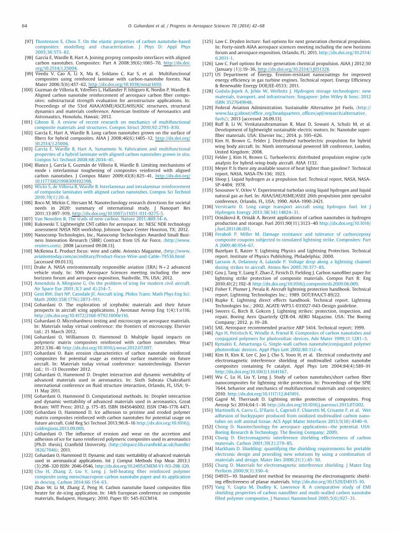
[97] Thostenson E, Chou T. On the elastic properties of carbon nanotube-basedcomposites: modelling and characterization. J Phys D: Appl Phys2003;36:573–82.
[98] García E, Wardle B, Hart A. Joining prepreg composite interfaces with alignedcarbon nanotubes. Composites: Part A 2008;39(6):1065–70, http://dx.doi.org/10.2514/1.25004.
[99] Veedu V, Cao A, Li X, Ma K, Soldano C, Kar S, et al. Multifunctionalcomposites using reinforced laminae with carbon-nanotube forests. NatMater 2006;5(6):457–62, http://dx.doi.org/10.1038/nmat1650.
[100] Guzman de Villoria R, Ydrefors L, Hallander P, Ishiguro K, Nordin P, Wardle B.Aligned carbon nanotube reinforcement of aerospace carbon fiber compo-sites: substructural strength evaluation for aerostructure applications. In:Proceedings of the 53rd AIAA/ASME/ASCE/AHS/ASC structures, structuraldynamics and materials conference, American Institute of Aeronautics andAstronautics, Honolulu, Hawaii; 2012.
[101] Gibson R. A review of recent research on mechanics of multifunctionalcomposite materials and structures. Compos Struct 2010;92:2793–810.
[102] García E, Hart A, Wardle B. Long carbon nanotubes grown on the surface offibers for hybrid composites. AIAA J 2008;46(6):1405–12, http://dx.doi.org/10.2514/1.25004.
[103] García E, Wardle B, Hart A, Yamamoto N. Fabrication and multifunctionalproperties of a hybrid laminate with aligned carbon nanotubes grown in situ.Compos Sci Technol 2008;68:2034–41.
[104] Blanco J, García E, Guzmán de Villoria R, Wardle B. Limiting mechanisms ofmode i interlaminar toughening of composites reinforced with alignedcarbon nanotubes. J Compos Mater 2009;43(8):825–41, http://dx.doi.org/10.1177/0021998309102398.
[105] Wicks S, de Villoria R, Wardle B. Interlaminar and intralaminar reinforcementof composite laminates with aligned carbon nanotubes. Compos Sci Technol2010;70(1):20–8.
[106] Roco M, Mirkin C, Hersam M. Nanotechnology research directions for societalneeds in 2020: summary of international study. J Nanopart Res2011;13:897–919, http://dx.doi.org/10.1007/s11051-011-0275-5.
[107] Van Noorden R. The trails of new carbon. Nature 2011;469:14–6.[108] Kukowski T. Lightweight CNT cables for aerospace. In: NESC NDE technology
assessment NASA NDI workshop, Johnson Space Center Houston, TX; 2012.[109] Nanocomp Technologies, Inc., Nanocomp Technologies Awarded Small Busi-
ness Innovation Research (SBIR) Contract from US Air Force, ⟨http://www.reuters.com⟩; 2008 [accessed 09.08.13].
[110] McKenna E. Product focus: wire and cable. Avionics Magazine, ⟨http://www.aviationtoday.com/av/military/Product-Focus-Wire-and-Cable-79536.html[accessed 09.01.13].
[111] Drake A. NASA environmentally responsible aviation (ERA) Nþ2 advancedvehicle study. In: 50th Aerospace Sciences meeting including the newhorizons forum and aerospace exposition, Nashville, TN, USA; 2012.
[112] Amendola A, Mingione G. On the problem of icing for modern civil aircraft.Air Space Eur 2001;3(3 and 4):214–7.
[113] Gent RW, Dart NP, Cansdale JT. Aircraft icing. Philos Trans: Math Phys Eng Sci:Math 2000;358(1776):2873–911.
[114] Gohardani O. The exploration of icephobic materials and their futureprospects in aircraft icing applications. J Aeronaut Aerosp Eng 1(4):1:e116,http://dx.doi.org/10.4172/2168-9792.1000e116.
[115] Gohardani O. Microhardness testing and microscopy on aerospace materials.In: Materials today virtual conference: the frontiers of microscopy. ElsevierLtd.; 21 March 2012.
[116] Gohardani O, Williamson D, Hammond D. Multiple liquid impacts onpolymeric matrix composites reinforced with carbon nanotubes. Wear2012:336–46 http://dx.doi.org/10.1016/j.wear.2012.07.007.
[117] Gohardani O. Rain erosion characteristics of carbon nanotube reinforcedcomposites for potential usage as external surface materials on futureaircraft. In: Materials today virtual conference: nanotechnology. ElsevierLtd.; 11–13 December 2012.
[118] Gohardani O, Hammond D. Droplet interaction and dynamic wettability ofadvanced materials used in aeronautics. In: Sixth Subrata Chakrabartiinternational conference on fluid structure interaction, Orlando, FL, USA; 9–11 May 2011.
[119] Gohardani O, Hammond D. Computational methods. In: Droplet interactionand dynamic wettability of advanced materials used in aeronautics, GreatBritain: WIT Press; 2012. p. 175–85. ISBN 1845646002. ISSN 1746-1776 4471.
[120] Gohardani O, Hammond D. Ice adhesion to pristine and eroded polymermatrix composites reinforced with carbon nanotubes for potential usage onfuture aircraft. Cold Reg Sci Technol 2013;96:8–16 http://dx.doi.org/10.1016/j.coldregions.2013.09.005.
[121] Gohardani O. The influence of erosion and wear on the accretion andadhesion of ice for nano reinforced polymeric composites used in aeronautics[Ph.D. thesis]. Cranfield University, ⟨http://dspace.lib.cranfield.ac.uk/handle/1826/7046⟩; 2011.
[122] Gohardani O, Hammond D. Dynamic and static wettability of advanced materialsused in aeronautical applications. Int J Comput Methods Exp Meas 2013;1(3):298–320 ISSN: 2046-0546, http://dx.doi.org/10.2495/CMEM-V1-N3-298-320.
[123] Chu H, Zhang Z, Liu Y, Leng J. Self-heating fiber reinforced polymercomposite using meso/macropore carbon nanotube paper and its applicationin deicing. Carbon 2014;66:154–63.
[124] Zhao W, Li M, Zhang Z, Peng H. Carbon nanotube based composites filmheater for de-icing application. In: 14th European conference on compositematerials, Budapest, Hungary; 2010. Paper ID: 545-ECCM14.
[125] Law C. Dryden lecture: fuel options for next generation chemical propulsion.In: Forty-ninth AIAA aerospace sciences meeting including the new horizonsforum and aerospace exposition, Orlando, FL; 2011. http://dx.doi.org/10.2514/6.2011-1.
[126] Law C. Fuel options for next-generation chemical propulsion. AIAA J 2012;50(January (1)):19–36, http://dx.doi.org/10.2514/1.J051328.
[127] US Department of Energy. Erosion-resistant nanocoatings for improvedenergy efficiency in gas turbine engines. Technical report. Energy Efficiency& Renewable Energy DOE/EE-0533; 2011.
[128] Godula-Jopek A, Jehle W, Wellnitz J. Hydrogen storage technologies: newmaterials, transport, and infrastructure. Singapore: John Wiley & Sons; 2012ISBN 3527649948.
[129] Federal Aviation Administration. Sustainable Alternative Jet Fuels, ⟨http://www.faa.g/about/office_org/headquarters_offices/apl/research/alternative_fuels/⟩; 2013 [accessed 26.09.13].
[130] Ruff B, Li W, Venkatasubramanian R, Mast D, Sowani A, Schulz M, et al.Development of lightweight sustainable electric motors. In: Nanotube super-fiber materials. USA: Elsevier Inc.; 2014. p. 595–626.
[131] Kim H, Brown G, Felder J. Distributed turboelectric propulsion for hybridwing body aircraft. In: Ninth international powered lift conference, London,United Kingdom; 2008.
[132] Felder J, Kim H, Brown G. Turboelectric distributed propulsion engine cycleanalysis for hybrid-wing-body aircraft. AIAA 1132.
[133] Meyer P. Is there any available source of heat lighter than gasoline?. Technicalreport. NASA, NASA-TN-136; 1923.
[134] Sloop J. Liquid hydrogen as a propulsion fuel. Technical report. NASA, NASA-SP-4404; 1978.
[135] Sosounov V, Orlov V. Experimental turbofan using liquid hydrogen and liquidnatural gas as fuel. In: AIAA/SAE/ASME/ASEE 26th propulsion joint specialistconference, Orlando, FL, USA; 1990. AIAA-1990-2421.
[136] Verstraete D. Long range transport aircraft using hydrogen fuel. Int JHydrogen Energy 2013;38(34):14824–31.
[137] Oriňáková R, Oriňák A. Recent applications of carbon nanotubes in hydrogenproduction and storage. Fuel 2011;90(11):3123–40 http://dx.doi.org/10.1016/j.fuel.2011.06.051.
[138] Feraboli P, Miller M. Damage resistance and tolerance of carbon/epoxycomposite coupons subjected to simulated lightning strike. Composites: PartA 2009;40:954–67.
[139] Bazelyan E, Raizer Y. Lightning Physics and Lightning Protection. Technicalreport. Institute of Physics Publishing, Philadelphia; 2000.
[140] Larsson A, Delannoy A, Lalande P. Voltage drop along a lightning channelduring strikes to aircraft. Atmos Res 2005;76:377–85.
[141] Gou J, Tang Y, Liang F, Zhao Z, Firsich D, Fielding J. Carbon nanofiber paper forlightning strike protection of composite materials. Compos Part B: Eng2010;41(2):192–8 http://dx.doi.org/10.1016/j.compositesb.2009.06.009.
[142] Fisher F, Plumer J, Perala R. Aircraft lightning protection handbook. Technicalreport. Lightning Technologies Inc.; 1989. DOT/FAA/CT-89/22.
[143] Rupke E. Lightning direct effects handbook. Technical report. LightningTechnologies Inc.; 2002. AGATE-WP3.1-031027-043-Design guideline.
[144] Sweers G, Birch B, Gokcen J. Lightning strikes: protection, inspection, andrepair, Boeing Aero Quarterly QTR-04. AERO Magazine. USA: The BoeingCompany; 2012. p. 19–28.
[145] SAE. Aerospace recommended practice ARP 5414. Technical report; 1999.[146] Ago H, Petritsch K, Windle A, Friend R. Composites of carbon nanotubes and
conjugated polymers for photovoltaic devices. Adv Mater 1999;11:1281–5.[147] Kymakis E, Amartunga G. Single-wall carbon nanotube/conjugated polymer
photovoltaic devices. Appl Phys Lett 2002;80:112–4.[148] Kim H, Kim K, Lee C, Joo J, Cho S, Yoon H, et al. Electrical conductivity and
electromagnetic interference shielding of multiwalled carbon nanotubecomposites containing Fe catalyst. Appl Phys Lett 2004;84(4):589–91http://dx.doi.org/10.1063/1.1641167.
[149] Wu C, Lu H, Liu Y, Leng J. Study of carbon nanotubes/short carbon fibernanocomposites for lightning strike protection. In: Proceedings of the SPIE7644, behavior and mechanics of multifunctional materials and composites;2010. http://dx.doi.org/10.1117/12.847491.
[150] Gagné M, Therriault D. Lightning strike protection of composites. ProgAerosp Sci 2014;64:1–16 http://dx.doi.org/10.1016/j.paerosci.2013.07.002.
[151] Martinelli A, Carru G, D'Ilario L, Caprioli F, Chiaretti M, Crisante F, et al. Wetadhesion of buckypaper produced from oxidized multiwalled carbon nano-tubes on soft animal tissue. ACS Appl Mater Interfaces 2013;5(10):4340–9.
[152] Chong D. Nanotechnology for aerospace applications—the potential. USA:Boeing Research & Technology, The Boeing Company; 2009.
[153] Chung D. Electromagnetic interference shielding effectiveness of carbonmaterials. Carbon 2001;39(2):279–85.
[154] Markham D. Shielding: quantifying the shielding requirements for portableelectronic design and providing new solutions by using a combination ofmaterials and design. Mater Des 2000;21(1):45–50.
[155] Chung D. Materials for electromagnetic interference shielding. J Mater EngPerform 2000;9(3):350–4.
[156] D4935—10. Standard test method for measuring the electromagnetic shield-ing effectiveness of planar materials. http://dx.doi.org/10.1520/D4935-10.
[157] Yang Y, Gupta M, Dudley K, Lawrence R. A comparative study of EMIshielding properties of carbon nanofiber and multi-walled carbon nanotubefilled polymer composites. J Nanosci Nanotechnol 2005;5(6):927–31.
O. Gohardani et al. / Progress in Aerospace Sciences 70 (2014) 42–6864
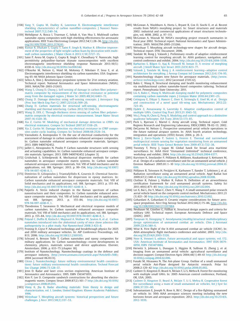
[158] Yang Y, Gupta M, Dudley K, Lawrence R. Electromagnetic interferenceshielding characteristics of carbon nanofiber-composites. J Nanosci Nano-technol 2007;7(2):549–54.
[159] Mehdipour A, Rosca I, Trueman C, Sebak A, Van Hoa S. Multiwall carbonnanotube–epoxy composites with high shielding effectiveness for aeronauticapplications. IEEE Trans Electromag Compat 2012;54(1):28–36, http://dx.doi.org/10.1109/TEMC.2011.2174241.
[160] Kumar R, Dhakate S, Gupta T, Saini P, Singh B, Mathur R. Effective improve-ment of the properties of light weight carbon foam by decoration with multi-wall carbon nanotubes. J Mater Chem A 2013;1(18):5727–35.
[161] Saini P, Arora M, Gupta G, Gupta B, Singh V, Choudhary V. Nanoscale, highpermittivity polyaniline–barium titanate nanocomposites with excellentelectromagnetic interference shielding response Nanoscale 2013;10(5):4330–6. http://dx.doi.org/10.1039/c3nr00634d.
[162] O'Rourke M, Nelson G, Waid M, Moloney P, Nikolaev P, Sosa E, et al.Electromagnetic interference shielding via carbon nanotubes. USA: Engineer-ing 65–66 NASA Johnson Space Center.
[163] Sehra A, Shin J. Revolutionary propulsion systems for 21st century aviation.Technical report. National Aeronautics and Space Administration (NASA);2003. NASA/TM–2003-212615.
[164] Wang S, Chung D, Chung J. Self-sensing of damage in carbon fiber polymer–matrix composite by measurement of the electrical resistance or potentialaway from the damaged region. J Mater Sci 2005;40(24):6463–72.
[165] Chung D. Damage detection using self-sensing concepts. J Aerospace Eng(Proc Inst Mech Eng Part G) 2007;221(G4):509–20.
[166] Chung D. Carbon materials for structural self-sensing, electromagneticshielding and thermal interfacing. Carbon 2012;50:3342–53.
[167] Wang D, DDL C. Through-thickness stress sensing of carbon fiber polymer–matrix composite by electrical resistance measurement. Smart Mater Struct2007;16:1320–30.
[168] Xia Z, Curtin W. Modeling of mechanical damage detection in CFRPs viaelectrical resistance. Compos Sci Technol 2007;67:1518–29.
[169] Xia Z, Curtin W. Damage detection via electrical resistance in CFRP compo-sites under cyclic loading. Compos Sci Technol 2008;68:2526–34.
[170] Vavouliotis A, Kostopoulos V. On the use of electrical conductivity for theassessment of damage in carbon nanotubes enhanced aerospace composites.In: Carbon nanotube enhanced aerospace composite materials. Springer;2013. ISBN 9400742452.
[171] Jaillet C, Alexopoulos N, Poulin P. Carbon nanotube structures with sensingand actuating capabilities. In: Carbon nanotube enhanced aerospace compo-site materials. Springer; 2013. ISBN 9400742452 [chapter 3].
[172] Grishchuk S, Schledjewski R. Mechanical dispersion methods for carbonnanotubes in aerospace composite matrix systems. In: Carbon nanotubeenhanced aerospace composite materials. Vol. VIII of Solid mechanics and itsapplications, vol. 188. Springer; 2013. p. 99–154, http://dx.doi.org/10.1007/978-94-007-4246-8_1.
[173] Dimitrios D, Giliopoulos J, Triantafyllidis K, Gournis D. Chemical functio-nalization of carbon nanotubes for dispersion in epoxy matrices. In:Carbon nanotube enhanced aerospace composite materials. Vol. VIII ofSolid mechanics and its applications, vol. 188. Springer; 2013. p. 155–84,http://dx.doi.org/10.1007/978-94-007-4246-8_1.
[174] Paipetis A. Stress induced changes in the Raman spectrum of carbonnanostructures and their composites. In: Carbon nanotube enhanced aero-space composite materials. Vol. VIII of Solid mechanics and its applications,vol. 188. Springer; 2013. p. 155–84, http://dx.doi.org/10.1007/978-94-007-4246-8_1.
[175] Theodosiou T, Saravanos D. Mechanical and electrical response models ofcarbon nanotubes. In: Carbon nanotube enhanced aerospace compositematerials. Vol. VIII of Solid mechanics and its applications, vol. 188. Springer;2013. p. 155–84, http://dx.doi.org/10.1007/978-94-007-4246-8_1.
[176] Poland C, Duffin R, Kinloch I, Maynard A, Wallace W, Seaton A, et al. Carbonnanotubes introduced into the abdominal cavity of mice show asbestos-likepathogenicity in a pilot study. Nat Nanotechnol 2008;3:423–8.
[177] Froning D, Czysz P. Advanced technology and breakthrough physics for 2025and 2050 military aerospace vehicles. In: AIP Conference Proceedings, vol.813; 2006. http://dx.doi.org/10.1063/1.2169305.
[178] Schrand A, Benson Tolle T. Carbon nanotubes and epoxy composites formilitary applications. In: Carbon nanotechnology—recent developments inchemistry, physics, materials science and device applications. Elsevier,Amsterdam; 2006. p. 633–75 [chapter 18].
[179] Institute of Nanotechnology. Nanotechnology coatings in the defence andaerospace industry, ⟨http://www.azonano.com/article.aspx?ArticleID=568⟩;2004 [accessed 06.10.13].
[180] Glenn J. Nanotechnology: future military environmental health considera-tions: future military environmental health consideration. Technol ForecastSoc Change 2006;73:128–37.
[181] Jenn D. Radar and laser cross section engineering. American Institute ofAeronautics and Astronautics; 1995. ISBN 1563471051.
[182] Kim P, Lee D. Composite sandwich constructions for absorbing the electro-magnetic waves. Compos Struct 2009;87(2):161–7 http://dx.doi.org/10.1016/j.compstruct.2008.05.015.
[183] Vinoy K, Jha R. Radar absorbing materials: from theory to design andcharacterization, vol. 1. London, United Kingdom: Kluwer Academic Publishers;1996.
[184] Weisshaar T. Morphing aircraft systems: historical perspectives and futurechallenges. J Aircr 2013;50(2):337–53.
[185] McGowan A, Washburn A, Horta L, Bryant R, Cox D, Siochi E, et al. Recentresults from NASA's morphing project. In: Smart structures and materials2002: industrial and commercial applications of smart structures technolo-gies, vol. 4698. 2002. p. 97–111.
[186] McGowan A, Waszak M. NASA's morphing project research summaries infiscal year 2002. Technical report. National Aeronautics and Space Adminis-tration; 2005. NASA/TM-2005-213266.
[187] Weisshaar T. Morphing aircraft technology-new shapes for aircraft design.Technical report. DTIC Document; 2006.
[188] Tandale M, Rong J, Valasek J. Preliminary results of adaptive reinforcementlearning control for morphing aircraft. In: AIAA guidance, navigation, andcontrol conference and exhibit; 2004. http://dx.doi.org/10.2514/6.2004-5358.
[189] Barbarino S, Bilgen O, Ajaj R, Friswell M, Inman D. A review of morphingaircraft. J Intell Mater Syst Struct 2011;22(9):823–77.
[190] Valasek J, Tandale M, Rong J. A reinforcement learning—adaptive controlarchitecture for morphing. J Aerosp Comput Inf Commun 2012;2(4):174–95.
[191] Nanotechnology shapes new future for aerospace materials, ⟨http://www.airforce-technology.com⟩; 2012 [accessed 27.01.12].
[192] Bakis C, Wang K. Structural damping and health monitoring enhancementvia multifunctional carbon nanotube-based composites tailoring. Technicalreport. Pennsylvania State University; 2011.
[193] Liu A, Bakis C, Wang K. Multiscale damping model for polymeric compositescontaining carbon nanotube ropes. J Compos Mater 2010;44:2301–23.
[194] Cetingsoy E, Dikyar S, Hancer C, Oner K, Sirimoglu E, Unel M, et al. Designand construction of a novel quad tilt-wing uav. Mechatronics 2012;22:723–45.
[195] Dydek Z, Annaswamy A, Lavretsky E. Adaptive configuration control ofmultiple UAVs. Control Eng Pract 2013;21:1043–52.
[196] Wu J, Peng H, Chen Q, Peng X. Modeling and control approach to a distinctivequadrotor helicopter. ISA Trans 2014;53:173–85.
[197] Peck L, Ryerson C, Martel C. Army aircraft icing. Technical report. ColdRegions Research and Engineering Laboratory, ERDC/CRREL TR-02-13; 2002.
[198] DeGarmo M, Nelson G. Prospective unmanned aerial vehicle operations inthe future national airspace system. In: AIAA fourth aviation technology,integration and operations (ATIO) forum; 2004. p. 20–3.
[199] Berni J, Zarco-Tejada P, Suárez L, Fereres E. Thermal and narrowbandmultispectral remote sensing for vegetation monitoring from an unmannedaerial vehicle. IEEE Trans Geosci Remote Sens 2009;47(3):722–38.
[200] Twomey T, Perry J, Logan M. Global hawk for broad area maritimesurveillance. In: AIAA third “Unmanned Unlimited” technical conference,workshop and exhibit; 2004. http://dx.doi.org/10.2514/6.2004-6377.
[201] Kurvinen K, Smolander P, Pöllänen R, Röllänen, Kuukankorpi S, Kettunen M,et al. Design of a radiation surveillance unit for an unmanned aerial vehicle. JEnviron Radioact 2005;81:1–10 http://dx.doi.org/10.1016/j.jenvrad.2004.10.009.
[202] Pöllänen R, Toivonen H, Peräjärvi K, Karhunen T, Ilander T, Lehtinen J, et al.Radiation surveillance using an unmanned aerial vehicle. Appl Radiat Isot2009;67(2):340–4 http://dx.doi.org/10.1016/j.apradiso.2008.10.008.
[203] Clothier R, Palmer J, Walker R, Fulton N. Definition of an airworthinesscertification framework for civil unmanned aircraft systems. Safety Sci2011;49(6):871–85 http://dx.doi.org/10.1016/j.ssci.2011.02.004.
[204] Lei X, Bai L, Du Y, Miao C, Chen Y, Wang T. A small unmanned polar researchaerial vehicle based on the composite control method. Mechatronics 2011;21(5):821–30 http://dx.doi.org/10.1016/j.mechatronics.2010.12.002.
[205] Gohardani A, Gohardani O. Ceramic engine considerations for future aero-space propulsion. Aircr Eng Aerosp Technol 2012;84(2):75–86, http://dx.doi.org/10.1108/00022661211207884.
[206] Neubauer M, Günther G, Füllhas K. Structural design aspects and criteria formilitary UAV. Technical report. European Aeronautic Defence and Space(EADS); 2007.
[207] Tianyuan H, Xiongqing Y. Aerodynamic/stealthy/structural multidisciplinarydesign optimization of unmanned combat air vehicle. Chin J Aeronaut2009;22(4):380–6.
[208] Wise K. First flight of the X-45A unmanned combat air vehicle (UCAV). In:AIAA atmospheric flight mechanics conference and exhibit; 2003. http://dx.doi.org/10.2514/6.2003-5320.
[209] Noor K, Venneri S, editors. Future aeronautical and space systems, vol. 172.USA: American Institute of Aeronautics and Astronautics; 1997 ISSN 0079-6050, ISBN 1563471884.
[210] Herwitz S, Johnson L, Dunagan S, Higgins R, Sullivan D, Zheng J, et al.Imaging from an unmanned aerial vehicle: agricultural surveillance anddecision support. Comput Electron Agric 2004;44(1):49–61 http://dx.doi.org/10.1016/j.compag.2004.02.006.
[211] Funaki M, Hirasawa N, The Ant-plane Group. Outline of a small unmannedaerial vehicle Ant-Plane designed for Antarctic research. Polar Sci2008;2:129–42 http://dx.doi.org/10.1016/j.polar.2008.05.002.
[212] Casbeer D, Kingston D, Beard A, Mclain T, Li S, Mehra R. Forest fire monitoringwith multiple small UAVs. In: 2005 American control conference, Portland,OR, USA; 2005.
[213] Casbeer D, Kingston D, Beard A, Mclain T, Li S, Mehra R. Cooperative forestfire surveillance using a team of small unmanned air vehicles. Int J Syst Sci2006;37:351–60.
[214] Subramaniam E, Joseph N, Rose A, Bil C. Design of a fire-fighting unmannedair vehicle. In: 50th AIAA aerospace sciences meeting including the newhorizons forum and aerospace exposition; 2012. http://dx.doi.org/10.2514/6.2012-1039.
O. Gohardani et al. / Progress in Aerospace Sciences 70 (2014) 42–68 65
[215] John A. Volpe national transportation systems center. Unmanned aircraftsystem (UAS) service demand 2015–2035: literature review and projectionsof future usage. Technical report. DOT-VNTSC-DoD-13-01. US Department ofTransportation; August 2013.
[216] Anderson J. Aircraft performance & design. McGraw-Hill; 1998 ISBN0070019711.
[217] Thomas J, Qidwai M. Mechanical design and performance of compositemultifunctional materials. Acta Mater 2004;52:2155–64.
[218] Thomas J, Qidwai M. The design and application of multifunctional structure-battery material systems. JOM 2005;57(3):18–24.
[219] Fu K, Yildiz O, Bhanushali H, Wang Y, Stano K, Xue L, et al. Aligned carbonnanotube-silicon sheets: a novel nano-architecture for flexible lithium ionbattery electrodes. Adv Mater. 2013;25(36):5109–14, http://dx.doi.org/10.1002/adma.201301920.
[220] Nascimento L. UAV lessons learned from OPERATION ALLIEDFORCE. Technicalreport. Center for Army Lessons Learned; January–February 2000.
[221] Unmanned aerial vehicle reliability study. Technical report. Office of theSecretary of Defense; 2003.
[222] Haslim L, Lee R. Electro-expulsive separation system. US 8,336,830 B2; 1985.[223] Battelle's anti-icing system for remotely piloted aircraft (RPAs), ⟨http://www.
battelle.org⟩; 2013 [accessed 14.08.13].[224] Barrera E, Shofner M, Corral E. Applications: composites. In: Meyyappan M,
editor. Carbon nanotubes: science and applications. USA: CRC Press LCC;2005 ISBN 0-8493-2111-5.
[225] Park C, Ounaies Z, Watson K, Pawlowski K, Lowther S, Connell J, et al.Polymer-single wall carbon nanotube composites for potential spacecraftapplications. Technical report. NASA/CR-2002-211940. ICASE report no.2002-36; 2002.
[226] NASA Ames Research Center, ⟨www.nasa.gov/centers/ames/home/index.html⟩;2013 [accessed 09.17.13].
[227] Files B. Applications of carbon nanotubes for human space exploration. In:Proceedings of the international conference on integrated nano/microtech-nology for space applications; 1998.
[228] Files B. NASA/JSC carbon nanotube project status. J Nanopart Res 1999;1(4):507–9.
[229] NASA Johnson Space Center. Thermal radiation impacts protection system,⟨http://www.nasa.gov/centers/ames/research/technology-onepagers/protective_shields.html⟩; 2008 [accessed 25.09.13].
[230] Nikolaev P, Sosa E, Arepalli S, Coughlin S, Moloney P, Boul P, et al. Materialsdevelopment and testing. In: Thermal radiation impacts protection system.Biennial research and technology development report. USA: National Aero-nautics and Space Administration; 2009. p. 77–8.
[231] NASA Johnson Space Center. Nano and micro fabrication process modeling,⟨http://www.nasa.gov/centers/ames/research/technology-onepagers/nano_fabrication_prt.html⟩; 2008 [accessed 25.09.13].
[232] NASA Johnson Space Center. Large-scale fabrication of carbon nanotubeprobe tips for space imaging and sensing applications, ⟨http://www.nasa.gov/centers/ames/research/technology-onepagers/carbon_nanotube_probe.html⟩; 2008 [accessed 25.09.13].
[233] Harris P. Carbon nanotube composites. Int Mater Rev 2004;49(1):31–43,http://dx.doi.org/10.1179/095066004225010505.
[234] NASA Johnson Space Center. Carbon nanotubes as vertical interconnects,⟨http://www.nasa.gov/centers/ames/research/technology-onepagers/carbon_nanotubes_vertical.html⟩; 2008 [accessed 24.09.13].
[235] NASA Johnson Space Center. Carbon nanotubes for removal of toxic gases inlife support systems, ⟨http://www.nasa.gov/centers/ames/research/technology-onepagers/carbon_nanotubes.html⟩; 2008 [accessed 25.09.13].
[236] Tsiolkovsky K. Grezy o Zemle i Nebe (i) Na Veste (Speculations about Earthand Sky and on Vesta). Izd-vo AN SSSR, Moscow; 1895.
[237] Artsutanov Y. V kosmos na Elektrovoze, Komosomolskava Pravda. Thecontents described in English by Lvov in Science 1967;158:946–7.
[238] Pearson J. The orbital tower: a spacecraft launcher using the earth'srotational energy. Acta Astronaut 1975;2:785–99.
[239] Issacs J, Vine A, Bradner H, Bacchus G. Satellite elongation into a trueskyhook. Science 1966;151:682–3.
[240] Pearson J. Anchored lunar satellites for cislunar transportation and commu-nication. J Astronaut Sci 1979;27:39–62.
[241] Artsutanov Y, Trakka Luna-Zemlya. Tech Molod 1979;4:21.[242] Edwards B. Design and deployment of a space elevator. Acta Astronaut
2000;47(10):735–44.[243] Smitherman Jr D, Tether G. Space elevators. Technical report. NASA, NASA/
CP-2000-210429; 2000.[244] Bolonkin A. Non-rocket earth–moon transport system. Adv Space Res
2003;31(11):2485–90.[245] Pearson J, Levin E, Oldson J, Wykes H. The lunar space elevator. In: Fifty-fifth
international astronautical congress; 2004.[246] Pug N. On the strength of the carbon nanotube-based space elevator cable:
from nanomechanics to megamechanics. J Phys: Condens Matter 2006;18(33):S1971–90.
[247] Wörle-Knirsch J, Pulskamp K, Krug H. Oops they did it again! Carbonnanotubes hoax scientists in viability assays. Nano Lett 2006;6(6):1261–8.
[248] Iannotta B. Space elevator. Aerosp Am 2006;31:30–5.[249] Avnet M. The space elevator in the context of current space exploration
policy. Space Policy 2006;22(2):133–9.[250] Dempsey J. System and method for space elevator. US patent no. US
6,981,674 B1.
[251] Pugno N. Space elevator: out of order?. Nano Today 2007;2(6):44–7.[252] Van Pelt M. Space elevators. In: Space tethers and space elevators. Springer
New York; 2009. p. 143–78.[253] Clarke A. The fountains of paradise. ISBN 0-575-02520-4.[254] Sheffield C. Web between worlds. Random House; 1988. ISBN 0345344359.[255] Westling E. The space elevator. Bc Edwards; 2003. ISBN 0974651710.[256] Ragan P, Edwards B. Leaving the planet by space elevator. Seattle, USA: Lulu;
2006. ISBN 143030006X.[257] Swan P. Space elevator systems architecture. Lulu; 2007. ISBN 1430314052.[258] Swan C, Swan P, Penny R. Space elevator survivability space debris mitiga-
tion. Lulu.com; 2011. ISBN 9780557964598.[259] Perek L. Space elevator: stability. Acta Astronaut 2008;62:514–20.[260] Pugno N, Schwarzbart M, Steindl A, Troger H. On the stability of the track of
the space elevator. Acta Astronaut 2009;64(5 and 6):524–37 http://dx.doi.org/10.1016/j.actaastro.2008.10.005.
[261] Woo P, Misra A. Dynamics of a partial space elevator with multiple climbers.Acta Astronaut 2010;67:753–63.
[262] Takeichi N. Geostationary station keeping control of a space elevator duringinitial cable deployment. Acta Astronaut 2012;70:85–94 http://dx.doi.org/10.1016/j.actaastro.2011.07.016.
[263] Jorgensen A, Patamia S, Gassend B. Passive radiation shielding considerationsfor the proposed space elevator. Acta Astronaut 2007;60:198–209.
[264] Engel K. Lunar transportation scenarios utilising the Space Elevator. ActaAstronaut 2005;57(2–8):277–87 http://dx.doi.org/10.1016/j.actaastro.2005.03.016.
[265] Swan C, Swan P. Why we need a space elevator. Space Policy 2006;22(2):86–91 http://dx.doi.org/10.1016/j.spacepol.2006.02.008.
[266] Ketsdever A, Young M, Mossman J. Overview of advanced concepts for spaceaccess. J Spacecr Rockets 2010;47(2):238–50.
[267] Bolonkin A. Non-rocket space launch and flight. Great Britain: Elsevier; 2010ISBN 0080458750.
[268] Quinea B, Seth R, Zhua Z. A free-standing space elevator structure: a practicalalternative to the space tether. Acta Astronaut 2009;65:365–75.
[269] Watson K, Connell J. Polymer and carbon nanotube composites for spaceapplications. In: Carbon nanotechnology—recent developments in chemistry,physics, materials science and device applications. Elsevier, Amsterdam;2006. p. 677–98 [chapter 19].
[270] Liu T, Musinski L, Patel P, Gallimore A, Gilchrist B, Keidar M. Nanoparticleelectric propulsion for space exploration. In: AIP conference proceedings, vol.880; 2007.
[271] Rayman M, Varghese P, Lehman D, Livesay L. Results from the deep space1 technology validation mission. Acta Astronaut 2000;47(2):475–87.
[272] Koppel C, Marchandise F, Prioul M, Estublier D, Darnon F. The SMART-1electric propulsion subsystem around the moon: in flight experience. In:Proceedings of the 41st AIAA/ASME/SAE/ASEE joint propulsion conference,Reston, VA; 2005. Paper no. AIAA-2005-3671.
[273] Kuninaka H, Nishiyama K, Funaki I, Yamada T, Shimizu Y, Kawaguchi J.Powered flight of HAYABUSA in deep space. In: Proceedings of the 42ndAIAA/ASME/SAE/ASEE joint propulsion conference, Reston, VA; 2006. Paperno. AIAA-2006-4318.
[274] Liu T, Morris D, Cionca C, Gallimore A, Gilchrist B, Clarke R. MEMS gatestructures for electric propulsion applications. In: Proceedings of the 42ndAIAA/ASME/SAE/ASEE joint propulsion conference, Reston, VA; 2006. Paperno. AIAA-2006-5011.
[275] Keller S, Zaghloul A. Carbon nanotube yarn and sheet antennas. In: Nanotubesuperfiber materials—changing engineering design. Boston: Elsevier, WilliamAndrew; 2014. p. 749–87, ⟨http://dx.doi.org/focus.lib.kth.se/10.1016/B978-1-4557-7863-8.00026-8⟩ [chapter 26].
[276] Jin S, Son G, Kim Y, Kim C. Enhanced durability of silanized multi-walledcarbon nanotube/epoxy nanocomposites under simulated low earth orbitspace environment. Compos Sci Technol 2013;87:224–31.
[277] Micheli D, Pastore R, Gradoni G, Mariani Primiani V, Moglie F, Marchetti M.Reduction of satellite electromagnetic scattering by carbon nanostructuredmultilayers. Acta Astronaut 2013;88:61–73.
[278] Khatiwada S, Laughman J, Armada C, Christiansen E, Barrera E. Hypervelocityimpact experiments on epoxy/ultra-high molecular weight polyethylenecomposite panels reinforced with nanotubes. In: Hypervelocity impactsymposium (HVIS 2012), NASA Johnson Space Center, Baltimore, MD, UnitedStates; 2012. JSC-CN-25499.
[279] Khatiwada S, Armada C, Barrera E. Hypervelocity impact experiments onepoxy/ultra-high molecular weight polyethylene fiber composites reinforcedwith single-walled carbon nanotubes. Proc Eng 2013;58:4–10.
[280] Street K. Jr, Miyoshi K. Application of carbon based nano-materials toaeronautics and space lubrication. Technical report. NASA, NASA/TM–2007-214473; 2007.
[281] Harris C, Shuart M, Gray H. A survey of emerging materials for revolutionaryaerospace vehicle structures and propulsion systems. Technical report.National Aeronautics and Space Administration, NASA/TM-2002-211664;2002.
[282] Talay T, Cerro J, Lepsch R, Gelhausen P, Guynn M. Systems analysis ofnanotube technology. In: Nanotube technology assessment. National Aero-nautics and Space Administration, Office of AeroSpace Technology, Washing-ton, DC; 2000.
[283] Hehr A, Song Y, Suberu B, Sullivan J, Shanov V, Schulz M. Embedded carbonnanotube sensor thread for structural health monitoring and strain sensing ofcomposite materials. In: Nanotube superfiber materials—changing engineering
O. Gohardani et al. / Progress in Aerospace Sciences 70 (2014) 42–6866
design. Elsevier, USA: William Andrew; 2014. p. 671–712. ISBN 978-1-4557-7863-8, http://dx.doi.org/10.1016/B978-1-4557-7863-8.00024-4 [chapter 24].
[284] Hagopian J, Getty S, Quijada M, Tveekrem J, Shiri R, Roman P, et al.Multiwalled carbon nanotubes for stray light suppression in space flightinstruments. In: Pribat D, Lee Y, Razeghi M, editors. Carbon nanotubes,graphene, and associated devices III, vol. 7761. USA: SPIE; 2010 77610F.
[285] Allada R, Moloney P, Nikolaev P, Sosa E, Arepalli S, Yowell L. Carbon dioxideremoval using carbon nanotubes. Engineering 63–64 NASA Johnson SpaceCenter, 2008.
[286] El Bounia N. Polymer materials containing dispersed carbon nanotubes. US2008/0207817 A1; 2008.
[287] Guereet O, El Bounia N, Poivet S, Nallet F, Fabre P, Papon E, et al. Adhesivecomposition for a humid medium, based on block copolymers comprising atleast one hydrophilic block. US 2006/0052545 A1; 2008.
[288] El Bounia N. Elemental carbon containing with organic component resin,rubber, or derivative thereof containing. US 2009/0121196 A1; 2009.
[289] El Bounia N. Compositions electrically conductive or emissive compositions.US 2009/0200517 A1; 2009.
[290] Brule B, Brule B, Devaux N, Piccione P, Gamache E, Bluteau C, et al.Conducting composite material containing a thermoplastic polymer andcarbon nanotubes. US 2010/0084616 A1; 2010.
[291] El Bounia N, Roussel T. Polymer-based cellular structure comprising carbonnanotubes, methods for its production and uses thereof. US 2011/0039089A1; 2011.
[292] Mcandrew T, Hochstetter G, Werth M, Bouilloux A, Brule B, Piccione P, et al.Polymer-based cellular structure comprising carbon nanotubes, methods forits production and uses thereof. US 2011/0251331 A1; 2011.
[293] Tsotsis T. Nanotube-enhanced interlayers for composite structures. US8,388,795 B2; 2013.
[294] González Gozalbo A, Verde Preckler J, Cabello Moreno J, Collado BriceñoJ, Llamas Sandín R. Aircraft control surface. 08864382.0; 2008.
[295] Eberhardt D. Retractable aircraft wing tip. US 8,336,830 B2; 2012.[296] Sequeiros Murciano F, Cano Pérez F, Quero Lopez M. Lightning protection for
composite aircraft structures. 10382307.6; 2010.[297] Lengsfeld H, Helfrich C, Marquardt H. Component with carbon nanotubes. US
8,146,861 B2; 2012.[298] Nordin P, Strindberg G. Multifunctional de-icing/anti-icing system.WO2011087412
A1, 2010.[299] Bordere S, Bourrigaud S, Cazaumayou S, Couvreur L, El Bounia N, Passade-
Boupat N, et al. Pulverulent composition based on carbon nanotubes,methods of obtaining them and its uses, especially in polymeric materials.US 2009/0176924 A1; 2008.
[300] Maheshwari M. Turbomachine nacelle and anti-icing system and methodtherefor. 10195197.8; 2010.
[301] West J, Sutton A. Aircraft joint and bonding. US 8,400,749 B2; 2013.[302] Tsotsis T, Huang J, Kim N, Humfeld K, Mitchel W, Mecham B. Carbon
nanotube-enhanced metallic wire. US 8,445,788 B1; 2013.[303] Jackson M, Spooner D. Camouflage utilizing nano-optical arrays embedded in
carbon matrix. US 2012/0318129 A1; 2012.[304] Streett A. Carbon nanotube coated structure and associated method of
fabrication. US 8,400,749 B2; 2013.[305] Carbon nanotubes for applications in electronics, catalysis, composites and
nano-biology (CANAPE). 12 Month periodic technical report, ⟨http://cordis.europa.eu/documents/documentlibrary/102583031EN6.pdf⟩; 2007 [accessed05.01.2013].
[306] Aerospace nanotube hybrid composite structures with sensing and actuatingcapabilities (NEOSIS), ⟨http://ec.europa.eu/research/transport/projects/items/noesis_en.htm⟩, 2005 [accessed 01.05.13].
[307] Carbon nanotube confinement strategies to develop novel POlymer MatrixCOmposites (POCO), ⟨http://www.poco-project.org/home.asp⟩; 2008 [accessed02.05.13].
[308] Multifunctional Layers for Safer Aircraft Composite Structures (LAYSA),⟨http://ec.europa.eu/research/transport/projects/items/laysa_en.htm⟩; 2008[accessed 06.26.13].
[309] Innovative repair of aerospace structures with curing optimization andlife cycle monitoring abilities (IAPETUS ), ⟨http://www.iapetus.eu⟩; 2009[accessed 13.08.13].
[310] Novel aeronautical multifunctional composite structures with bulk electricalconductivity and self-sensing capabilities, ⟨http://www.electrical-project.eu⟩;2010 [accessed 15.08.13].
[311] Lockheed Martin Corporation. Infused carbon nanotubes—manufacturingsolutions for next generation products, CET201302014, GS9509, ⟨www.lockheedmartin.com/nano⟩.
[312] Trimble S. Lockheed Martin reveals F-35 to feature nanocomposite struc-tures. Flight International; 2011.
[313] NASA Ames Research Center. Carbon nanotube sensors for gas detection,⟨www.nasa.gov⟩ [accessed 30.01.2012].
[314] Portable nanomesh creates safer drinking water. Technical report. Spinoff2008: 50 years of NASA-derived technologies (1958–2008), NASA/NP-2008-OL-527-HQ; 2008.
[315] US Army. Army researchers chase helicopter performance gains, ⟨www.army.mil/article/105134⟩; June 2013 [accessed 21.07.13].
[316] Siochi E, Lillehei P, Wise K, Park C, Rouse J. Design and characterization ofcarbon nanotube nanocomposites. Technical report. NASA Langley ResearchCenter; 2003.
[317] Stickler P. Composite materials for commercial transport: issues and futureresearch direction. In: Sun T, Kim H, editors. Proceedings of the AmericanSociety for Composites (ASC), 17th annual technical conference; 2002.
[318] Dalton A, Collins S, Munoz E, Razal J, Ebron V, Ferraris J, et al. Super-toughcarbon-nanotube fibres. Nature 2003;423(6941):703.
[319] Vigolo B, Poulin P, Lucas M, Launois P, Bernier P. Improved structure andproperties of single-wall carbon nanotube spun fibers. Appl Phys Lett2002;81(7):1210–2.
[320] Wu Z, Chen Z, Du X, Logan J, Sippel J, Nikolou M, et al. Transparent,conductive carbon nanotube films. Science 2004;305(5688):1273–6, http://dx.doi.org/10.1126/science.1101243.
[321] Endo M, Muramatsu H, Hayashi T, Kim Y, Terrones M, Dresselhaus M.Nanotechnology: ‘Buckypaper’ from coaxial nanotubes. Nature 2005;433(7025):476.
[322] Bagchi A, Nomura S. On the effective thermal conductivity of carbonnanotube reinforced polymer composites. Compos Sci Technol 2006;66(11and 12):1703–12.
[323] Gardiner G. Lightning strike protection for composite structures. High Per-form Compos 2006;14(4):44.
[324] Chou T. Microstructural design of fiber composites. In: Cambridge solid statescience series. Cambridge University Press; 2005. ISBN 0521019656.
[325] Thostenson E, Li C, Chou T. Nanocomposites in context. Compos Sci Technol2005;65(3):491–516.
[326] Jana S, Jain S. Dispersion of nanofillers in high performance polymers usingreactive solvents as processing aids. Polymer 2001;42:6897–905.
[327] Zhang B, Xie C, Hu J, Wang H, Gui Y. Novel 1-3 metal nanoparticle/polymercomposites induced by hybrid external fields. Compos Sci Technol2006;66:1558–63.
[328] Han J, Anantram M, Jaffe R, Kong J, Dai H. Observation and modeling ofsingle-wall carbon nanotube bend junctions. Phys Rev B 1998;57(23):14983.
[329] Han J, Jaffe R. Energetics and geometries of carbon nanoconic tips. J ChemPhys 1998;108(7):2817 http://dx.doi.org/10.1063/1.475672.
[330] Meyyappan M, editor. Carbon nanotubes: science and applications. USA:Taylor & Francis; 2004 ISBN 0203494938.
[331] European Union. ObservatoryNANO factsheets. Technical report. ⟨http://www.observatorynano.eu/project/⟩; March 2012 [accessed 01.08.13].
[332] Tennent H, Barber J, Hoch R. Carbon fibrils, method for producing same andadhesive compositions containing same. US patent no. 5,578,543; 1996.
[333] Journet C, Maser W, Bernier P, Loiseau A, Lamyde la Chapelle M, Lefrant S,et al. Large-scale production of single-walled carbon nanotubes by theelectric-arc technique. Nature 1977;388:756–8.
[334] Kónya Z, Vesselenyi I, Niesz K, Kukovecz A, Demortier A, Fonseca A, et al.Large scale production of short functionalized carbon nanotubes. Chem PhysLett 2002;360(5):429–35.
[335] Singh C, Shaffer M, Koziol K, Kinloch I, Windle A. Towards the production oflarge-scale aligned carbon nanotubes. Chem Phys Lett 2003;372:860–5.
[336] Rao S, Huang L, Setyawan W, Hong S. Nanotube electronics: large-scaleassembly of carbon nanotubes. Nature 2003;425(6953):36–7.
[337] Athanassiou E, Grass R, Stark W. Large-scale production of carbon-coatedcopper nanoparticles for sensor applications. Nanotechnology2006;17:1668–73.
[338] Zhao J, Wei L, Yang Z, Zhang Y. Continuous and low-cost synthesis of high-quality multi-walled carbon nanotubes by arc discharge in air. Phys E: Low-dimens Syst Nanostruct 2012;44(7):1639–43.
[339] Cheng H, Li F, Su G, Pan H, He L, Sun X, et al. Large-scale and low-costsynthesis of single-walled carbon nanotubes by the catalytic pyrolysis ofhydrocarbons. Appl Phys Lett 1998;72(25):3282–4.
[340] Sadeghian Z. Large-scale production of multi-walled carbon nanotubes bylow-cost spray pyrolysis of hexane. New Carbon Mater 2009;24(1):33–8.
[341] Campbell T, Williams C, Ivanova O, Garrett B. Could 3D printing change theworld? Technologies, potential, and implications of additive manufacturing.Technical report. Atlantic Council, Washington, DC; 2011.
[342] Tajdeh Y. 3D printing promises to revolutionize defense, aerospace indus-tries. National Defense Magazine; 20–23 March 2014.
[343] Campbell T, Ivanova O. 3D printing of multifunctional nanocomposites. NanoToday.
[344] Filleter T, Beese A, Roenbeck M, Wei X, Espinosa H. Tailoring the mechanicalproperties of carbon nanotube fibers. In: Nanotube superfiber materials—changing engineering design. USA: Elsevier, William Andrew; 2014. p. 61–85.ISBN 978-1-4557-7863-8, http://dx.doi.org/10.1016/B978-1-4557-7863-8.00003-7 [chapter 3].
[345] Current Intelligence Bulletin. Occupational exposure to carbon nanotubesand nanofibers. Technical report 65. National Institute for OccupationalSafety and Health. DHHS (NIOSH) publication no. 2013-145; April 2013.
[346] Maynard A, Baron P, M F, Shvedva A, Kisin E, V C. Exposure to carbonnanotube material: aerosol release during the handling of unrefined singlewalled carbon nanotube material. J Toxicol Environ Health 2004;67(1):87–107.
[347] Bello D, Wardle B, Yamamoto N, de Villora R, Garcia E, Hart A, et al. Exposureto nanoscale particles and fibers during machining of hybrid advancedcomposites containing carbon nanotubes. J Nanopart Res 2009;11(1):231–49.
[348] Tsai S, Hofmann M, Hallock M, Ada E, Kong J, Ellenbecker M. Characterizationand evaluation of nanoparticle release during the synthesis of single-walledand multiwalled carbon nanotubes by chemical vapor deposition. Environ SciTechnol 2009;43(15):6017–23.
O. Gohardani et al. / Progress in Aerospace Sciences 70 (2014) 42–68 67
[349] Bello D, Wardle B, Zhang J, Yamamoto N, Santeufemio C, Hallock M, et al.Characterization of exposures to nanoscale particles and fibers during solidcore drilling of hybrid carbon nanotubes advanced composites. Int J OccupEnviron Health 2010;16(6):434–50.
[350] Lee J, Lee S, Bae G, Jeon K, Yoon J, Ji J, et al. Exposure assessment ofcarbonnanotube manufacturing workplaces. Inhal Toxicol 2010;22(5):369–81.
[351] Cena L, Peters T. Characterization and control of airborne particles emittedduring production of epoxy/carbon nanotube nanocomposites. J OccupEnviron Hyg 2011;2(8):86–92.
[352] Dahm M, Evans D, Schubauer-Berigan M, Birch M, Fernback J. Occupationalexposure assessment in carbon nanotube and nanofiber primary andsecondary manufactures. Ann Occup Hyg 2012;56(5):542–6, http://dx.doi.org/10.1093/annhyg/mer110.
[353] Methner M, Birch M, Evans D, Ku B-K, Crouch K, Hoover M. Case study:identification and characterization of potential sources of worker exposure tocarbon nanofibers during polymer composite laboratory operations. J OccupEnviron Hyg 2007;4(12):D125–30.
[354] Han J, Lee E, Lee J, So K, Lee Y, Bae G, et al. Monitoring multiwalled carbonnanotube exposure in carbon nanotube research facility. Inhal Toxicol2008;20(8):741–9.
[355] Evans D, Ku B, Birch M, Dunn K. Aerosol monitoring during carbon nanofiberproduction: mobile direct-reading sampling. Ann Occup Hyg 2010;54(5):514–31.
[356] Johnson D, Methner M, Kennedy A, Steevens J. Potential for occupationalexposure to engineered carbon-based nanomaterials in environmentallaboratory studies. Environ Health Perspect 2010;118(1):49–54.
[357] Nowack B, David R, Fissan H, Morris H, Shatkin J, Stintz M, et al. Potentialrelease scenarios for carbon nanotubes used in composites. Environ Int2013;59:1–11.
[358] Upadhyayula V, Meyer D, Curran M, Gonzalez M. Life cycle assessment as atool to enhance the environmental performance of carbon nanotube pro-ducts: a review. J Clean Prod 2012;26:37–47.
[359] Köhler A, Som C, Helland A, Gottschalk F. Studying the potential release ofcarbon nanotubes throughout the application life cycle. J Clean Prod2008;16:927–37.
[360] Barraza H, Pompeo F, O'Rea E, Resasco D. SWNT-filled thermoplastic andelastomeric composites prepared by miniemulsion polymerization. NanoLett 2002;2(8):797–802.
[361] Zhang X, Liu T, Sreekumar T, Kumar S, Moore V, Hauge R, et al. Poly (vinylalcohol)/SWNT composite film. Nano Lett 2003;3(9):1285–8.
[362] Takagi A, Hirose A, Nishimura T, Fukumori N, Ogata A, Ohashi N, et al.Induction of mesothelioma in p53þ/- mouse by intraperitoneal applicationof multi-wall carbon nanotube. J Toxicol Sci 2008;33(1):105–16.
[363] Zou G, Jain M, Yang H, Zhang Y, Williams D, Jia Q. Recyclable and electricallyconducting carbon nanotube composite films. Nanoscale 2010;2(3):418–22.
[364] Petersen E, Zhang L, Mattison N, O'Carroll D, Whelton A, Uddin N, et al.Potential release pathways, environmental fate, and ecological risks ofcarbon nanotubes. Environ Sci Technol 2011;45(23):9837–56.
[365] Bolden Jr C. AIAA AVIATION 2013 keynote address—embracing a world ofchange: NASA's aeronautics research strategy, ⟨www.aiaa.org/Secondary.aspx?id=18498⟩; 2013 [accessed 10.10.13].
O. Gohardani et al. / Progress in Aerospace Sciences 70 (2014) 42–6868
Related Documents