Post-Tensioning Details for Long-Span Concrete Bridges •e• Clifford L. Freyermuth Executive Director Post-Tensioning Institute Phoenix, Arizona A t the turn of the century, J. A. L. Waddell was one of the pre- eminent bridge engineers in the United States. His volumes on "Bridge En- gineering," published around 1915, represent a comprehensive treatment of the art and science of bridge engineer- ing up to that time. In one of those vol- umes, he notes that the essence of bridge engineering lies in the devel- opment of good details. This observation remains unchanged today and thus much of the detailing for long-span concrete bridges relates to the installation and anchorage of post- NOTE: This paper is based on a presentation given at the Segmental Concrete Bridge Confer- ence in Kansas City, Missouri, March 9-10, 1982. The Conference was sponsored by the Associated Reinforcing Bar Producers — CRSI, Federal Highway Administration, Portland Cement Associ- ation, Post-Tensioning Institute, and Prestressed Concrete Institute. tensioning materials. For this reason, it seems appropriate to consider the most significant post-tensioning details for long-span concrete bridges, including some remarks on cable stays. TENDON ANCHORAGES Bearing Plate Anchorages Until the early 1970's, nearly all post-tensioned bridges in the United States and Canada were built using bearing plate type anchorages. In the United States, these anchorages were generally proportioned on the basis of the 3000-psi (20.68 MPa) bearing stress at service load contained in Section 1.6.6 (B)(4) of the "AASHTO Standard Specifications for Highway Bridges."r While these anchorages remain very serviceable for some aspects of post- tensioning of long-span concrete 48

Welcome message from author
This document is posted to help you gain knowledge. Please leave a comment to let me know what you think about it! Share it to your friends and learn new things together.
Transcript
Post-Tensioning Detailsfor Long-SpanConcrete Bridges
•e•Clifford L. FreyermuthExecutive DirectorPost-Tensioning InstitutePhoenix, Arizona
At the turn of the century, J. A. L.Waddell was one of the pre-
eminent bridge engineers in the UnitedStates. His volumes on "Bridge En-gineering," published around 1915,represent a comprehensive treatment ofthe art and science of bridge engineer-ing up to that time. In one of those vol-umes, he notes that the essence ofbridge engineering lies in the devel-opment of good details.
This observation remains unchangedtoday and thus much of the detailing forlong-span concrete bridges relates tothe installation and anchorage of post-
NOTE: This paper is based on a presentationgiven at the Segmental Concrete Bridge Confer-ence in Kansas City, Missouri, March 9-10, 1982.The Conference was sponsored by the AssociatedReinforcing Bar Producers — CRSI, FederalHighway Administration, Portland Cement Associ-ation, Post-Tensioning Institute, and PrestressedConcrete Institute.
tensioning materials. For this reason, itseems appropriate to consider the mostsignificant post-tensioning details forlong-span concrete bridges, includingsome remarks on cable stays.
TENDON ANCHORAGESBearing Plate Anchorages
Until the early 1970's, nearly allpost-tensioned bridges in the UnitedStates and Canada were built usingbearing plate type anchorages. In theUnited States, these anchorages weregenerally proportioned on the basis ofthe 3000-psi (20.68 MPa) bearing stressat service load contained in Section1.6.6 (B)(4) of the "AASHTO StandardSpecifications for Highway Bridges."r
While these anchorages remain veryserviceable for some aspects of post-tensioning of long-span concrete
48
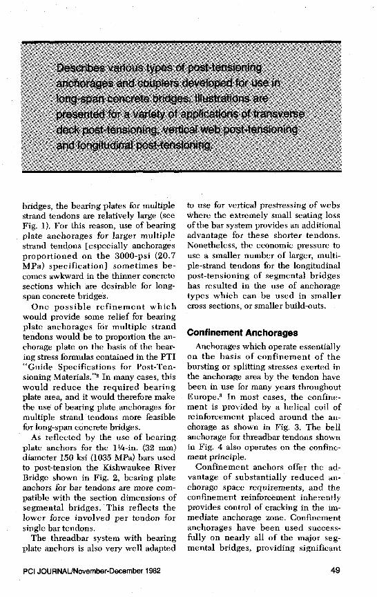
bridges, the bearing plates for multiplestrand tendons are relatively large (seeFig. 1). For this reason, use of bearingplate anchorages for larger multiplestrand tendons [especially anchoragesproportioned on the 3000-psi (20.7MPa) specification] sometimes be-comes awkward in the thinner concretesections which are desirable for long-span concrete bridges.
One possible refinement whichwould provide some relief for bearingplate anchorages for multiple strandtendons would be to proportion the an-chorage plate on the basis of the bear-ing stress formulas contained in the PTI"Guide Specifications for Post-Ten-sioning Materials." 2 In many cases, thiswould reduce the required bearingplate area, and it would therefore makethe use of bearing plate anchorages formultiple strand tendons more feasiblefor long-span concrete bridges.
As reflected by the use of bearing.plate anchors for the 1¼-in. (32 mm)diameter 150 ksi (1035 MPa) bars used;to post-tension the Kishwaukee RiverBridge shown in Fig. 2, bearing plateanchors for bar tendons are more com-patible with the section dimensions ofsegmental bridges. This reflects thelower force involved per tendon forsingle bar tendons.
The threadbar system with bearingplate anchors is also very well adapted
to use for vertical prestressing of webswhere the extremely small seating lossof the bar system provides an additionaladvantage for these shorter tendons.Nonetheless, the economic pressure touse a smaller number of larger, multi-ple-strand tendons for the longitudinalpost-tensioning of segmental bridgeshas resulted in the use of anchoragetypes which can be used in smallercross sections, or smaller build-outs.
Confinement AnchoragesAnchorages which operate essentially
on the basis of confinement of thebursting or splitting stresses exerted inthe anchorage area by the tendon havebeen in use for many years throughoutEurope .3 In most cases, the confine-ment is provided by a helical coil ofreinforcement placed around the an-chorage as shown in Fig. 3. The bellanchorage for threadbar tendons shownin Fig. 4 also operates on the confine-ment principle.
Confinement anchors offer the ad-vantage of substantially reduced an-chorage space requirements, and theconfinement reinforcement inherentlyprovides control of cracking in the im-mediate anchorage zone. Confinementanchorages have been used success-fully on nearly all of the major seg-mental bridges, providing significant
PCI JOURNAL/November-December 1982 49
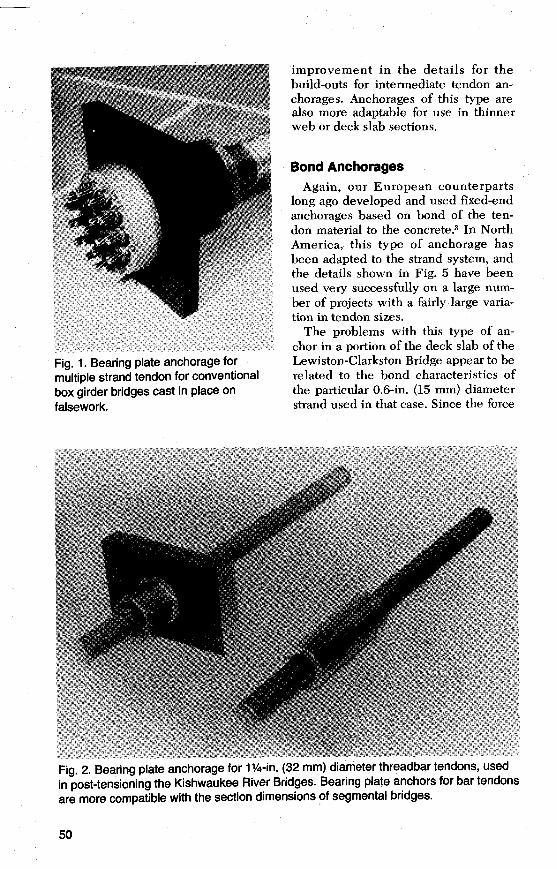
Fig. 1. Bearing plate anchorage formultiple strand tendon for conventionalbox girder bridges cast in place onfalsework.
improvement in the details for thebuild-outs for intermediate tendon an-chorages. Anchorages of this type arealso more adaptable for use in thinnerweb or deck slab sections.
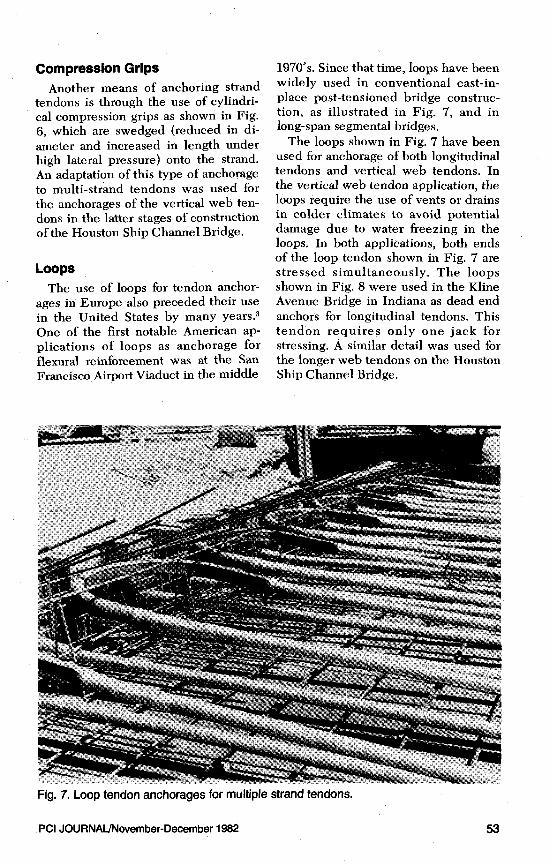
Bond AnchoragesAgain, our European counterparts
long ago developed and used fixed-endanchorages based on bond of the ten-don material to the concrete .3 In NorthAmerica, this type of anchorage hasbeen adapted to the strand system, andthe details shown in Fig. 5 have beenused very successfully on a large num-ber of projects with a fairly large varia-tion in tendon sizes.
The problems with this type of an-chor in a portion of the deck slab of theLewiston-Clarkston Bridge appear to berelated to the bond characteristics ofthe particular 0.6-in. (15 mm) diameterstrand used in that case. Since the force
Fig. 2. Bearing plate anchorage for 1 ¼-in. (32 mm) diameter threadbar tendons, usedin post-tensioning the Kishwaukee River Bridges. Bearing plate anchors for bar tendonsare more compatible with the section dimensions of segmental bridges.
50
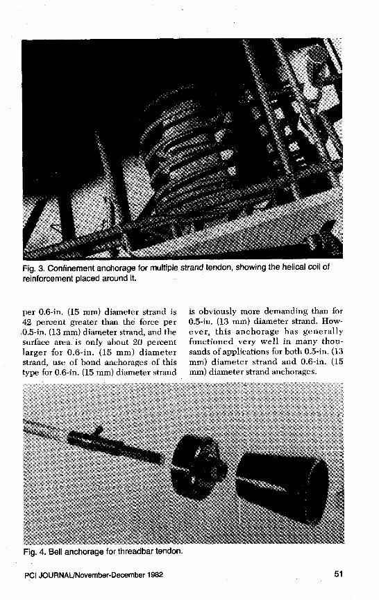
Fig. 3. Confinement anchorage for multiple strand tendon, showing the helical coil ofreinforcement placed around it.
per 0.6-in. (15 mm) diameter strand is42 percent greater than the force per0.5-in. (13 mm) diameter strand, and thesurface area is only about 20 percentlarger for 0.6-in. (15 mm) diameterstrand, use of bond anchorages of thistype for 0.6-in. (15 mm) diameter strand
is obviously more demanding than for0.5-in. (13 mm) diameter strand. How-ever, this anchorage has generallyfunctioned very well in many thou-sands of applications for both 0.5-in. (13mm) diameter strand and 0.6-in. (15mm) diameter strand anchorages.
Fig. 4. Bell anchorage for threadbar tendon.
PCI JOURNAL/November-December 1982 51
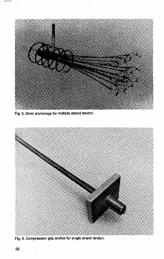
Fig. 5. Bond anchorage for multiple strand tendon.
Fig. 6. Compression grip anchor for single strand tendon.
52
Compression GripsAnother means of anchoring strand
tendons is through the use of cylindri-cal compression grips as shown in Fig.6, which are swedged (reduced in di-ameter and increased in length underhigh lateral pressure) onto the strand.An adaptation of this type of anchorageto multi-strand tendons was used forthe anchorages of the vertical web ten-dons in the latter stages of constructionof the Houston Ship Channel Bridge.
LoopsThe use of loops for tendon anchor-
ages in Europe also preceded their usein the United States by many years .3
One of the first notable American ap-plications of loops as anchorage forflexural reinforcement was at the SanFrancisco Airport Viaduct inthe middle
1970's. Since that time, loops have beenwidely used in conventional cast-in-place post-tensioned bridge construc-tion, as illustrated in Fig. 7, and inlong-span segmental bridges.
The loops shown in Fig. 7 have beenused for anchorage of both longitudinaltendons and vertical web tendons. Inthe vertical web tendon application, theloops require the use of vents or drainsin colder climates to avoid potentialdamage due to water freezing in theloops. In both applications, both endsof the loop tendon shown in Fig. 7 arestressed simultaneously. The loopsshown in Fig. 8 were used in the KlineAvenue Bridge in Indiana as dead endanchors for longitudinal tendons. Thistendon requires only one jack forstressing. A similar detail was used forthe longer web tendons on the HoustonShip Channel Bridge.
Fig. 7. Loop tendon anchorages for multiple strand tendons.
PCI JOURNAL/November-December 1982 53
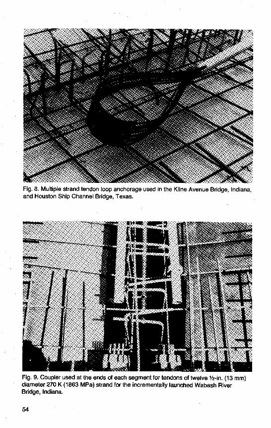
Fig. 8. Multiple strand tendon loop anchorage used in the Kline Avenue Bridge, Indiana,and Houston Ship Channel Bridge, Texas.
Fig. 9. Coupler used at the ends of each segment for tendons of twelve ½-in. (13 mm)diameter 270 K (1863 MPa) strand for the incrementally launched Wabash RiverBridge, Indiana.
54
Couplers
The use of couplers such as the oneshown in Fig. 2 is an integral part of thethreadbar system. Since couplers arecompact in dimension, they are easy toinstall. It is important that couplers de-velop the full strength of the threadbartendon. Couplers are also required forsome strand tendon applications.
The uniform prestress of the incre-mentally launched Wabash RiverBridge in Indiana provides a goodexample of a strand tendon application.Couplers in this bridge were used asillustrated in Fig. 9 at the ends of eachsegment for tendons of twelve 1 -in. (13mm) diameter 270 K (1863 MPa) strand.To extend the tendon for the next seg-ment, each strand is anchored to thecoupler casting in this detail by use ofa field-applied cylindrical compres-sion grip similar to the one shown inFig. 6.
CABLE STAYSPossibly the most demanding anchor-
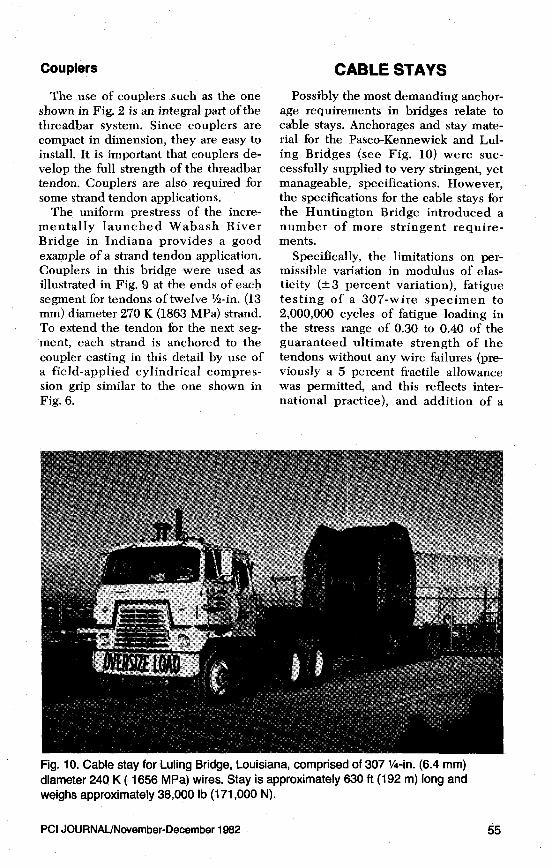
age requirements in bridges relate tocable stays. Anchorages and stay mate-rial for the Pasco-Kennewick and Lul-ing Bridges (see Fig. 10) were suc-cessfully supplied to very stringent, yetmanageable, specifications. However,the specifications for the cable stays forthe Huntington Bridge introduced anumber of more stringent require-ments.
Specifically, the limitations on per-missible variation in modulus of elas-ticity (±3 percent variation), fatiguetesting of a 307-wire specimen to2,000,000 cycles of fatigue loading inthe stress range of 0.30 to 0.40 of theguaranteed ultimate strength of thetendons without any wire failures (pre-viously a 5 percent fractile allowancewas permitted, and this reflects inter-national practice), and addition of a
Fig. 10. Cable stay for Luling Bridge, Louisiana, comprised of 307 ¼-in. (6.4 mm)diameter 240 K ( 1656 MPa) wires. Stay is approximately 630 ft (192 m) long andweighs approximately 38,000 lb (171,000 N).
PCI JOURNAL/November-December 1982 55
500,000 cycle fatigue test to a stressrange of 0.25 to 0.40 percent of theguaranteed ultimate strength of the testspecimen without wire breakage, are allsubstantially more stringent than previ-ous international requirements forcable stays.
Those requirements may also be in-compatible with the "Buy American"requirements of the construction spe-cial provisions. Specifications for cablestays that are compatible with interna-tional standards would seem more ap-propriate, even at the expense of somemodifications in other aspects of thedesign of cable stayed bridges.
TRANSVERSE DECKPOST-TENSIONING
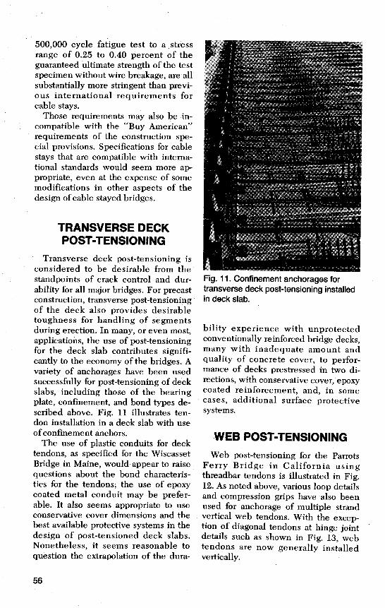
Transverse deck post-tensioning isconsidered to be desirable from thestandpoints of crack control and dur-ability for all major bridges. For precastconstruction, transverse post-tensioningof the deck also provides desirabletoughness for handling of segmentsduring erection. In many, or even most,applications, the use of post-tensioningfor the deck slab contributes signifi-cantly to the economy of the bridges. Avariety of anchorages have been usedsuccessfully for post-tensioning of deckslabs, including those of the bearingplate, confinement, and bond types de-scribed above. Fig. 11 illustrates ten-don installation in a deck slab with useof confinement anchors.
The use of plastic conduits for decktendons, as specified for the WiscassetBridge in Maine, would appear to raisequestions about the bond characteris-tics for the tendons; the use of epoxycoated metal conduit may be prefer-able. It also seems appropriate to useconservative cover dimensions and thebest available protective systems in thedesign of post-tensioned deck slabs.Nonetheless, it seems reasonable toquestion the extrapolation of the dura-
Fig. 11. Confinement anchorages fortransverse deck post-tensioning installedin deck slab.
bility experience with unprotectedconventionally reinforced bridge decks,many with inadequate amount andquality of concrete cover, to perfor-mance of decks prestressed in two di-rections, with conservative cover, epoxycoated reinforcement, and, in somecases, additional surface protectivesystems.
WEB POST-TENSIONINGWeb post-tensioning for the Parrots
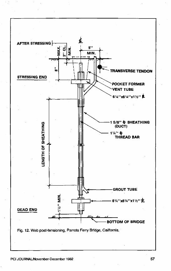
Ferry Bridge in California usingthreadbar tendons is illustrated in Fig.12. As noted above, various loop detailsand compression grips have also beenused for anchorage of multiple strandvertical web tendons. With the excep-tion of diagonal tendons at hinge jointdetails such as shown in Fig. 13, webtendons are now generally installedvertically.
56
kAFTER STRESSINGX -
V ZI 59P
Qg gN MIN.
~ TRANSVERSE TENDONSTRESSING END I
POCKET FORMERVENT TUBE
6 1/4 "x6 ¼"x11/2"
1 5/8" 0 SHEATHINGz (DUCT)H 1 1/q °'
w THREAD BARIcLL0II-C,zwJ
GROUT TUBE
z61/4"x61/a "x11/2
DEAD END r
N-- BOTTOM OF BRIDGE
Fig. 12. Web post-tensioning, Parrots Ferry Bridge, California.
PCI JOURNAL/November-December 1982 57
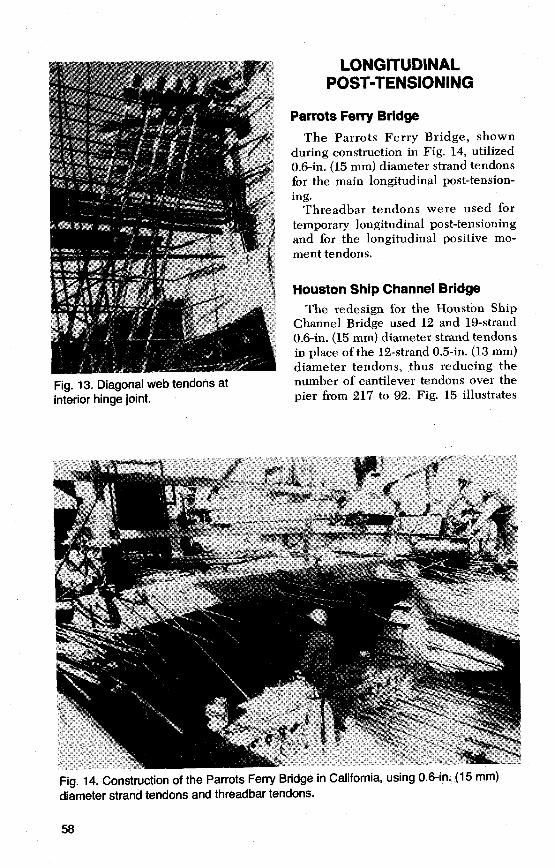
Fig. 13. Diagonal web tendons atinterior hinge joint.
LONGITUDINALPOST-TENSIONING
Parrots Ferry BridgeThe Parrots Ferry Bridge, shown
during construction in Fig. 14, utilized0.6-in. (15 mm) diameter strand tendonsfor the main longitudinal post-tension-ing.
Threadbar tendons were used fortemporary longitudinal post-tensioningand for the longitudinal positive mo-ment tendons.
Houston Ship Channel BridgeThe redesign for the Houston Ship
Channel Bridge used 12 and 19-strand0.6-in. (15 mm) diameter strand tendonsin place of the 12-strand 0.5-in. (13 mm)diameter tendons, thus reducing thenumber of cantilever tendons over thepier from 217 to 92. Fig. 15 illustrates
Fig. 14. Construction of the Parrots Ferry Bridge in California, using 0.6-in. (15 mm)diameter strand tendons and threadbar tendons.
58
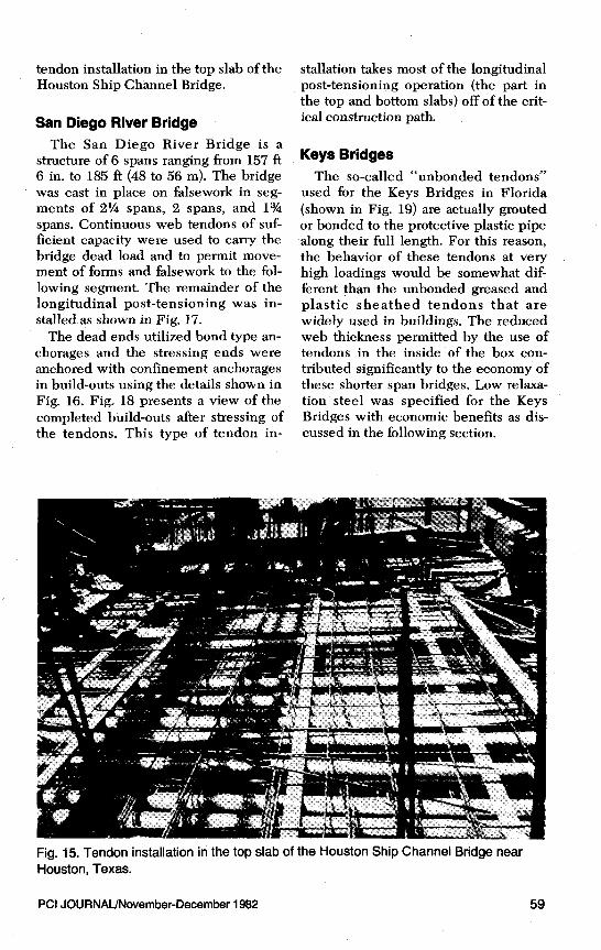
tendon installation in the top slab of theHouston Ship Channel Bridge.
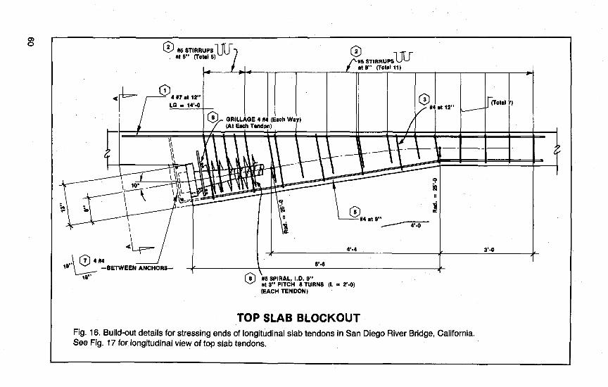
San Diego River BridgeThe San Diego River Bridge is a
structure of 6 spans ranging from 157 ft6 in. to 185 ft (48 to 56 m). The bridgewas cast in place on falsework in seg-ments of 2 1/4 spans, 2 spans, and 13/4
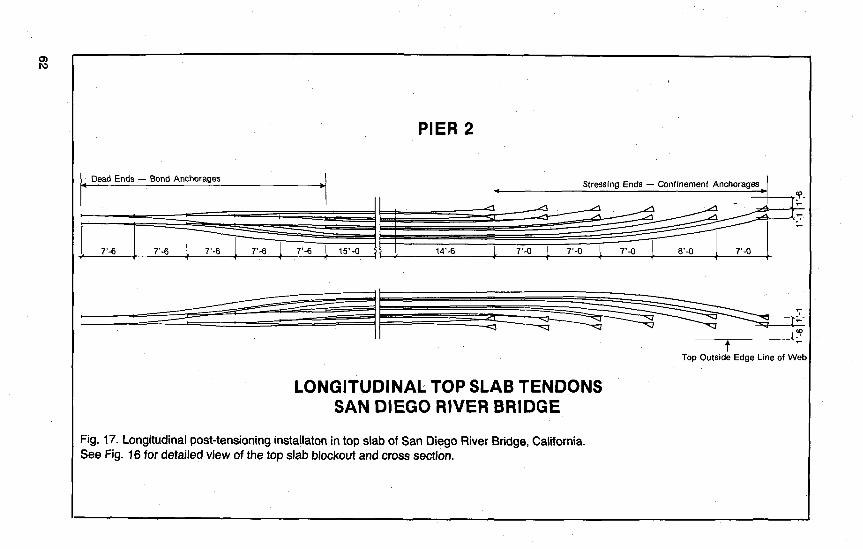
spans. Continuous web tendons of suf-ficient capacity were used to carry thebridge dead load and to permit move-ment of forms and falsework to the fol-lowing segment. The remainder of thelongitudinal post-tensioning was in-stalled as shown in Fig. 17.
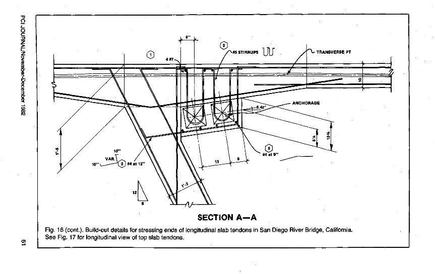
The dead ends utilized bond type an-chorages and the stressing ends wereanchored with confinement anchoragesin build-outs using the details shown inFig. 16. Fig. 18 presents a view of thecompleted build-outs after stressing ofthe tendons. This type of tendon in-
stallation takes most of the longitudinalpost-tensioning operation (the part inthe top and bottom slabs) off of the crit-ical construction path.
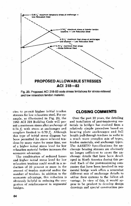
Keys BridgesThe so-called "unbonded tendons"
used for the Keys Bridges in Florida(shown in Fig. 19) are actually groutedor bonded to the protective plastic pipealong their full length. For this reason,the behavior of these tendons at veryhigh loadings would be somewhat dif-ferent than the unbonded greased andplastic sheathed tendons that arewidely used in buildings. The reducedweb thickness permitted by the use oftendons in the inside of the box con-tributed significantly to the economy ofthese shorter span bridges. Low relaxa-tion steel was specified for the KeysBridges with economic benefits as dis-cussed in the following section.
Fig. 15. Tendon installation in the top slab of the Houston Ship Channel Bridge nearHouston, Texas.
PCI JOURNAL/November-December 1982 59
rnO O2 #5 STIRRUPS ,^rat S" (Total 5) #5 STIRRUPS
at 9" (Total 11)
Q 4 aM7 t 12"LO = 14'-0
O#4 at 12" (Total 7)
O GRILLAGE 4 #4 (Each Wa )(At Each Tendon)
1111
Iljlr1 10* j1 y
r e7 5a N4etV
I s
QI ^ 4,_4 3,A
^74e'-6
—BETWEEN ANCHORS-18 OB M5 SPIRAL, I.D. 9"
at 3" PITCH 8 TURNS (L = 2'-0)(EACH TENDON)
TOP SLAB BLOCKOUTFig. 16. Build-out details for stressing ends of longitudinal slab tendons in San Diego River Bridge, California.See Fig. 17 for longitudinal view of top slab tendons.
0)J
SECTION A-AFig. 16 (cont.). Build-out details for stressing ends of longitudinal slab tendons in San Diego River Bridge, California.See Fig. 17 for longitudinal view of top slab tendons.
PIER 2
0)
Dead Ends — Bond Anchorages
7'-6 7'-6 7-6 7-6 7-6 15-0
Top Outside Edge Line of Web
LONGITUDINAL TOP SLAB TENDONSSAN DIEGO RIVER BRIDGE
Fig. 17. Longitudinal post-tensioning installaton in top slab of San Diego River Bridge, California.See Fig. 16 for detailed view of the top slab blackout and cross section.
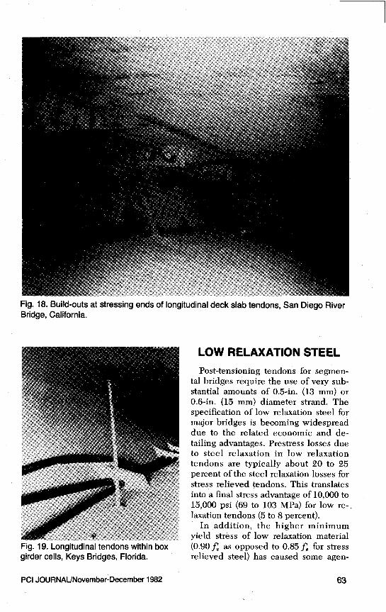
Fig. 18. Build-outs at stressing ends of longitudinal deck slab tendons, San Diego RiverBridge, California.
Fig. 19. Longitudinal tendons within boxgirder cells, Keys Bridges, Florida.
LOW RELAXATION STEELPost-tensioning tendons for segmen-
tal bridges require the use of very sub-stantial amounts of 0.5-in. (13 mm) or0.6-in. (15 mm) diameter strand. Thespecification of low relaxation steel formajor bridges is becoming widespreaddue to the related economic and de-tailing advantages. Prestress losses dueto steel relaxation in low relaxationtendons are typically about 20 to 25percent of the steel relaxation losses forstress relieved tendons. This translatesinto a final stress advantage of 10,000 to15,000 psi (69 to 103 MPa) for low re-.laxation tendons (5 to 8 percent).
In addition, the higher minimumyield stress of low relaxation material(0.90f as opposed to 0.85f for stressrelieved steel) has caused some agen-
PCI JOURNAUNovember-December 1982 63
___0.85 fg maximum temporary stress at anchorage —\ Low Relaxation Steel
0.74f$ maximum stress at interior tendonlocations - Low Relaxation Steel
0.70 maximum stress at anchoragesandnd couplers — Low —Lovew Relaxation Steel
4^ 0.70 fs maximum final stress—Stress Relieved Steel
PROPOSED ALLOWABLE STRESSESACI 318-83
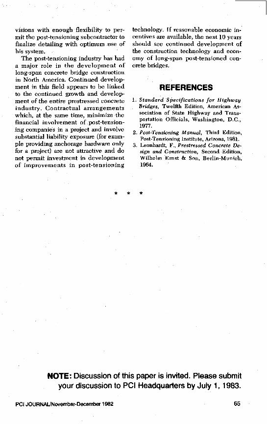
Fig. 20. Proposed ACI 318-83 code stress limitations for stress -relievedand low relaxation tendon material.
ties to permit higher initial tendonstresses for low relaxation steel. For ex-ample, as illustrated in Fig. 20, the1983 ACI 318 Building Code will per-mit a maximum stress after anchorage of0.74 f; with stress at anchorages andcouplers limited to 0.70 f8. Althoughthis type of initial stress diagram hasbeen permitted for stress relieved ten-dons by many states for some time, useof a higher initial stress level for lowrelaxation material further increases theeconomic advantage.
The combination of reduced lossesand higher initial stress level for lowrelaxation tendons could result in a re-duction of 10 percent or more in theamount of tendon material and/or thenumber of tendons. In addition to theeconomic advantage, this reduction isobviously helpful in reducing the con-gestion of reinforcement in segmentalbridges.
CLOSING COMMENTSOver the past 10 years, the detailing
and installation of post-tensioning ma-terials in bridges has evolved from arelatively simple procedure based onbearing plate anchorages and fulllength pull-through tendons in webs toa much more complex mix of types,tendon materials, and anchorage types.The AASHTO Specifications for an-chorage bearing stresses are obviouslyno longer sufficient to cover the an-chorage details that have been devel-oped in North America during this pe-riod. Each of the post-tensioning com-panies that have been involved in seg-mental bridge work offers a somewhatdifferent mix of anchorage details toutilize their systems to the fullest ad-vantage. In view of this, it would ap-pear to be prudent to develop designdrawings and special construction pro-
64
visions with enough flexibility to per-mit the post-tensioning subcontractor tofinalize detailing with optimum use ofhis system.
The post-tensioning industry has hada major role in the development oflong-span concrete bridge constructionin North America. Continued develop-ment in this field appears to be linkedto the continued growth and develop-ment of the entire prestressed concreteindustry. Contractual arrangementswhich, at the same time, minimize thefinancial involvement of post-tension-ing companies in a project and involvesubstantial liability exposure (for exam-ple providing anchorage hardware onlyfor a project) are not attractive and donot permit investment in developmentof improvements in post-tensioning
technology. If reasonable economic in-centives are available, the next 10 yearsshould see continued development ofthe construction technology and econ-omy of long-span post-tensioned con-crete bridges.
REFERENCES1. Standard Specifications for Highway
Bridges, Twelfth Edition, American As-sociation of State Highway and Trans-portation Officials, Washington, D.C.,1977.
2. Post-Tensioning Manual, Third Edition,Post-Tensioning Institute, Arizona, 1981.
3. Leonhardt, F., Prestressed Concrete De-sign and Construction, Second Edition,Wilhelm Ernst & Son, Berlin-Munich,1964.
NOTE: Discussion of this paper is invited. Please submityour discussion to PCI Headquarters by July 1, 1983.
PCI JOURNAL/November-December 1982 65
Related Documents