October 2007 Chapter 8 1 CHAPTER 8 Post-Construction Storm Water Control Measures Post-Construction Storm Water Control Measures ........... 3 Filtration Measures .............................................................. 9 Vegetated Swales................................................................... 11 Filter Strip (Post Construction) ............................................. 17 Filter Ridge ............................................................................ 19 Riparian Buffer Zones ........................................................... 21 Sand Filters ............................................................................ 27 Peat Filters (to be released later) .......................................... 35 Infiltration Measures.......................................................... 37 Pervious Concrete Systems ................................................... 39 Porous Asphalt Systems ........................................................ 53 Porous Paver Systems............................................................ 67 Infiltration Trench ................................................................. 79 Infiltration Basin.................................................................... 89 Bioretention Systems ............................................................. 99 Settling & Flocculation Measures ................................... 109 Dry Extended Detention Basins .......................................... 111 Wet Detention Ponds ........................................................... 119 Sediment Forebay Ponds ..................................................... 127 Constructed Storm Water Wetlands .................................... 131 Subsurface Detention .......................................................... 141

Welcome message from author
This document is posted to help you gain knowledge. Please leave a comment to let me know what you think about it! Share it to your friends and learn new things together.
Transcript
October 2007 Chapter 8 1
CHAPTER
8
Post-Construction Storm Water Control Measures
Post-Construction Storm Water Control Measures ........... 3
Filtration Measures .............................................................. 9 Vegetated Swales................................................................... 11 Filter Strip (Post Construction) ............................................. 17 Filter Ridge ............................................................................ 19 Riparian Buffer Zones ........................................................... 21 Sand Filters ............................................................................ 27 Peat Filters (to be released later) .......................................... 35
Infiltration Measures .......................................................... 37
Pervious Concrete Systems ................................................... 39 Porous Asphalt Systems ........................................................ 53 Porous Paver Systems............................................................ 67 Infiltration Trench ................................................................. 79 Infiltration Basin .................................................................... 89 Bioretention Systems ............................................................. 99
Settling & Flocculation Measures ................................... 109
Dry Extended Detention Basins .......................................... 111 Wet Detention Ponds ........................................................... 119 Sediment Forebay Ponds ..................................................... 127 Constructed Storm Water Wetlands .................................... 131 Subsurface Detention .......................................................... 141

2 Chapter 8 October 2007
CHAPTER 8
Proprietary Measures ...................................................... 145 Gravity Oil-Grit Separators ................................................... 147 Hydrodynamic Separators ..................................................... 151 Catch Basin Inserts With Treatment Medium ...................... 155
October 2007 Chapter 8 3
POST-CONSTRUCTION STORM WATER CONTROL MEASURES
What is Storm Water Runoff?
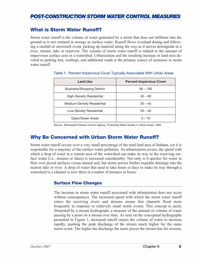
Storm water runoff is the volume of water generated by a storm that does not infiltrate into the ground or is not retained in storage as surface water. Runoff flows overland during and follow-ing a rainfall or snowmelt event, picking up material along the way as it moves downgrade to a river, stream, lake or reservoir. The volume of storm water runoff is related to the amount of impervious surface area in a watershed. Urbanization and the resulting increase in land area de-voted to parking lots, rooftops, and additional roads is the primary source of increases in storm water runoff.
Why Be Concerned with Urban Storm Water Runoff?
Storm water runoff occurs over a very small percentage of the total land area of Indiana, yet it is responsible for a majority of the surface water pollution. As urbanization occurs, the speed with which a drop of water in a remote area of the watershed can make its way to the receiving sur-face water (i.e., streams or lakes) is increased considerably. Not only is it quicker for water to flow over paved surfaces versus natural soil, but storm sewers further expedite drainage into the nearest lake or river. A drop of water that used to take hours or days to make its way through a watershed to a channel is now there in a matter of minutes or hours.
Surface Flow Changes
The increase in storm water runoff associated with urbanization does not occur without consequences. The increased speed with which the storm water runoff enters the receiving rivers and streams means that channels flood more frequently in response to relatively small storm events. This concept is easily illustrated by a stream hydrograph, a measure of the amount or volume of water passing by a point on a stream over time. As seen on the conceptual hydrographs presented in Figure 1, increased runoff causes the volume of water to increase rapidly, pushing the peak discharge of the stream much higher for the same storm event. The higher the discharge the more power the stream has for erosion,
Table 1: Percent Impervious Cover Typically Associated With Urban Areas
Land Use Percent Impervious Cover
Business/Shopping District 95 – 100
High-Density Residential 45 – 60
Medium-Density Residential 35 – 45
Low-Density Residential 20 – 40
Open/Green Areas 0 – 10
Source: Minnesota Pollution Control Agency, Protecting Water Quality in Urban Areas, 1989

4 Chapter 8 October 2007
POST-CONSTRUCTION STORM WATER CONTROL MEASURES
The same storm event results in two different runoff regimes. Increased development increases the area covered by imperme-able surfaces, so the volume of storm water runoff increases and also reaches its peak volume sooner after the initiation of the runoff event.
Pollutants
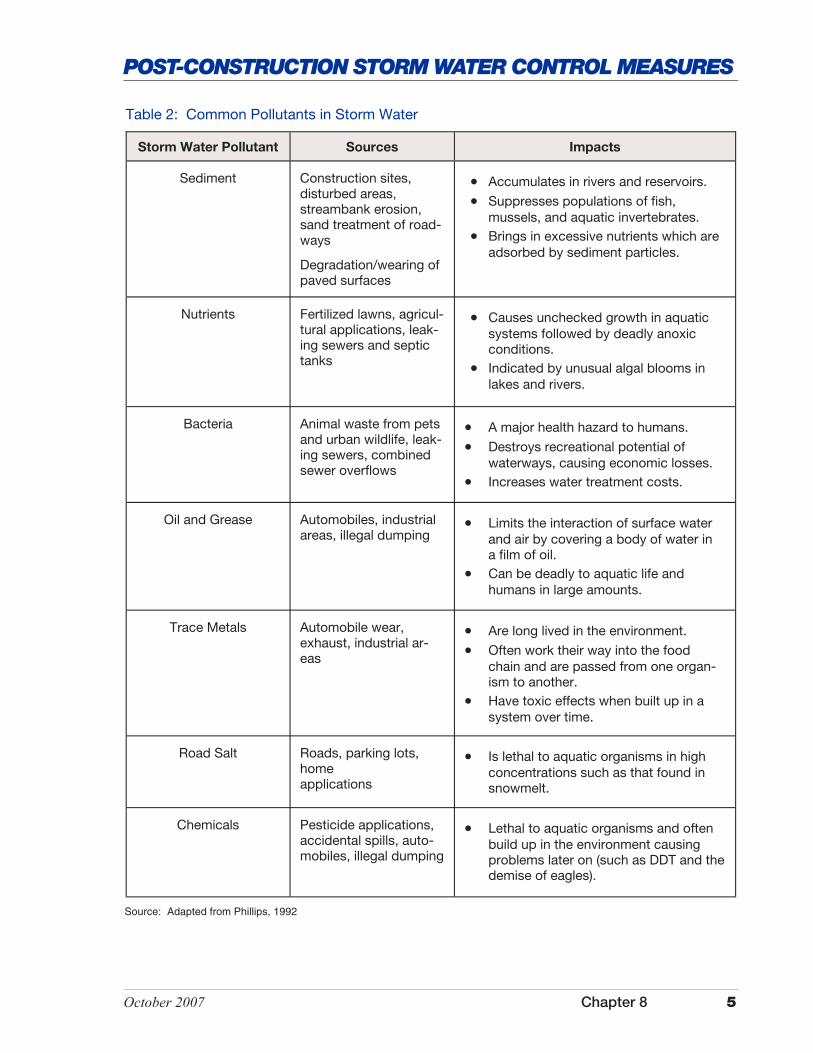
Storm water runoff picks up a variety of pollutants (see Table 2) that degrade the quality of Indiana’s surface waters. Sediment is by far the most visible and common pollutant carried by storm water runoff into rivers and streams. Sediment has drastic effects on aquatic life living in the stream and also causes increased dredging and decreased reservoir capacity over the long term.
The impacts to our waterways from unchecked storm water runoff are substan-tial. The consequences are not only biological, but economic as well as aesthetic. Populations of fish and other aquatic organisms decrease, recreation money is lost, and property values adjacent to polluted waterways decrease. Often, a blem-ish of sorts is placed on the reputation of the area where these impacts occur. There are, however, steps that can be taken to mitigate these impacts.
Figure 1: Preconstruction and post-development flood hydrographs illustrating storm water runoff in response to urbanization
Source: Schueler, 1992; Connecticut Stormwater Quality Manual, 2004; U.S. EPA, 2005, National Management Measures to Control Nonpoint Source Pollution
and thus the channel becomes unstable and begins to incise or widen to accom-modate the new peak discharge. Unstable channels jeopardize the stability of bridges and other structures located along stream channels.
October 2007 Chapter 8 5
POST-CONSTRUCTION STORM WATER CONTROL MEASURES
Sediment Construction sites, disturbed areas, streambank erosion, sand treatment of road-ways
Degradation/wearing of paved surfaces
�� Accumulates in rivers and reservoirs.
�� Suppresses populations of fish, mussels, and aquatic invertebrates.
�� Brings in excessive nutrients which are adsorbed by sediment particles.
Nutrients Fertilized lawns, agricul-tural applications, leak-ing sewers and septic tanks
�� Causes unchecked growth in aquatic systems followed by deadly anoxic conditions.
�� Indicated by unusual algal blooms in lakes and rivers.
Bacteria Animal waste from pets and urban wildlife, leak-ing sewers, combined sewer overflows
�� A major health hazard to humans.
�� Destroys recreational potential of waterways, causing economic losses.
�� Increases water treatment costs.
Oil and Grease Automobiles, industrial areas, illegal dumping
�� Limits the interaction of surface water and air by covering a body of water in a film of oil.
�� Can be deadly to aquatic life and humans in large amounts.
Trace Metals Automobile wear, exhaust, industrial ar-eas
�� Are long lived in the environment.
�� Often work their way into the food chain and are passed from one organ-ism to another.
�� Have toxic effects when built up in a system over time.
Road Salt Roads, parking lots, home applications
�� Is lethal to aquatic organisms in high concentrations such as that found in snowmelt.
Chemicals Pesticide applications, accidental spills, auto-mobiles, illegal dumping
�� Lethal to aquatic organisms and often build up in the environment causing problems later on (such as DDT and the demise of eagles).
Table 2: Common Pollutants in Storm Water
Storm Water Pollutant Sources Impacts
Source: Adapted from Phillips, 1992
6 Chapter 8 October 2007
POST-CONSTRUCTION STORM WATER CONTROL MEASURES
Choosing the Right Storm Water Management Measure
Post-construction storm water management measures include active methods that involve constructing a device (such as a detention pond) or changing a par-ticular pattern of activity (such as lawn fertilizing) that can decrease storm water impacts in a given area. Passive methods or source controls are mainly involved with the change in behavior of individuals and community “pre-planning” that involves decisions made prior to and during the construction of new develop-ment and redevelopment to limit storm water impact. There are four main storm water management issues that can be addressed with post-construction storm water management measures�sediment, nutrients, toxic chemicals, and storm water runoff.
Sediment
There are two main ways to remove sediment from storm water. One method is to exclude it from storm water drains using some sort of filter or mechanical treatment measure that removes sediment before it can en-ter the storm water drain. The second method is to slow down or detain the flow of large quantities of storm water so that the sediment settles out before reaching the storm drain. This is accomplished by using some type of storm water detention measure (e.g., dry extended detention basins, wet detention ponds, sediment forebay ponds, etc.). Access to the storm water measure for removal of accumulated sediment is a very important issue to consider when selecting a storm water management measure.
Nutrients In Indiana, the main nutrients in storm water are nitrogen and phospho-rous. Nitrogen is soluble in storm water, whereas phosphorous is usually adsorbed to sediments. In removing sediment, you also remove a tremen-dous amount of phosphorous from storm water. Soluble nitrogen, on the
Post-Construction Measures: What Can be Done?
Development is a fact of economic growth in our society and will continue long into the future. We now have the means to develop in ways that are much smarter, minimizing the impacts we have on surface waters both near and down-stream of developed and developing areas. There are a variety of design princi-ples, storm water quality measures, and storm water quantity measures that make it possible to minimize environmental impacts. In the specific case of storm wa-ter management, mitigating measures have been designed to limit and treat the storm water that is draining into our surface and subsurface waters. This portion of the Indiana Storm Water Quality Manual deals specifically with post con-struction storm water management measures that can be applied in communities of any age which did not previously have access to these development methods.
October 2007 Chapter 8 7
POST-CONSTRUCTION STORM WATER CONTROL MEASURES
Toxic Chemicals
Toxic chemicals include substances like oil and grease, metals, and various other chemicals that often find their way into storm water. Some hydrophobic materials (oil and grease for example) can be removed by structures placed in a storm drain such as oil-grit separators or hydrodynamic separators. Others, such as metals, can only be contained and cannot necessarily be removed to targeted levels. In-line filtration systems, wetlands, etc. are useful as part of a treatment train for keeping these pollutants from reaching sensitive rivers and lakes through storm water runoff.
Storm Water Runoff
Storm water itself is a concern when present in large quantities. Storm water can be detrimental to the environment due to the sheer volume of water that falls into an area. Storm water detention measures, porous pavement, and subsurface infiltration/detention measures all reduce the volume and speed of storm water entering natural systems. Storm water management measures that promote infil-tration and not just detention also promote ground water recharge, an important component often overlooked in storm water management plans.
Maintenance of Storm Water Management Measures
Maintenance is a critical component to the success or failure of post-construction storm water management measures. Storm water management measures must be sited and designed to allow access for inspection, maintenance and cleanout.
Managing Multiple Storm Water Impacts
Most storm water contains some degree of all the detrimental aspects mentioned above, so how can a single storm water management measure be applied to deal with all these factors? The answer is simple; it cannot. Most research indicates that multiple approaches are needed to treat and manage storm water effectively. For instance, a large dry extended detention basin may be constructed to retain and slowly release storm water into the local river to help reduce the size of the discharge spike during flooding. If this dry extended detention basin is also used as a soccer field, we do not want large amounts of sediment to enter the basin. We can construct a sediment forebay pond above the dry extended detention basin to catch the sediment, but not retain much of the water. What if the water contains an unusually high level of nutrients due to
other hand, is immobilized by plant uptake. Nitrogen is transformed into insolu-ble forms by plants. Therefore, an effective way to diminish soluble nitrogen levels is to pass the storm water through vegetated wetlands. Keep in mind the nitrogen does not disappear, but rather resides in a different form in the vegeta-tion. Thus, to really remove nitrogen, vegetation may periodically need to be harvested, especially in nutrient-rich environments.

8 Chapter 8 October 2007
POST-CONSTRUCTION STORM WATER CONTROL MEASURES
fertilizing practices at a local golf course? We can pass the storm water through a constructed wetland area prior to release into the river in order to remove some of those nutrients.
In exactly this way, storm water management measures can be coupled together to perform dif-ferent functions in a storm water management plan. Often there is considerable overlap between chosen methods, but one method is usually better at treating a certain aspect of storm water than another. Most aspects of storm water management can be addressed with multiple measures. Installation of multiple measures may not always be practical, especially in situations where space is limiting, as in older well-established neighborhoods.

October 2007 Chapter 8 9
FILTRATION MEASURES
F iltration measures operate on the principal that storm water runoff is intercepted and al-lowed to pass through a filtering medium such as sand, organic material, or soil for pollut-
ant removal. They are not intended for use as storm water retention measures. Filtration systems are typically used to treat runoff from small residential, commercial, and industrial sites and parking lots. There are two types of filtration systems: (1) surface flow filtration and (2) under-ground infiltration.
Surface flow filtration systems are typically designed to intercept sheet flow runoff and allow the runoff to pass through the filtering medium. These systems are similar to those used during the construction phase of a project. Surface filtration systems include measures such as compost filters, vegetated swales, and riparian buffer zones. Grass filters and compost mulch berms are two of the more common filtering mediums. In addition to conveying storm water runoff, vege-tated swales can provide some filtering of storm water runoff, especially during low flows. Ri-parian systems are effective filtration measures because part of the riparian zone includes a grass filter as part of the overall system.
Underground filtration systems are used to treat runoff below the surface. These systems are often used in areas with limited space because they can be placed under parking lots and other areas within a project site. Underground filtration systems are typically designed to provide for different levels of pollutant removal. After runoff is filtered it can either be returned to the con-veyance system or collected by an underdrain and allowed to percolate into the underlying soil material or infiltration medium. Underground systems include measures such as sand filters and peat filters.
The design of some of the measures identified in this section can be complex and generally re-quire detailed site investigation, including assessment of potential pollutants, and the applica-tion of sound engineering principles. A professional knowledgeable of storm water manage-ment and water quality principles and experienced in structural design should be consulted when using filtration measures.

This page was intentionally left blank.
October 2007 Chapter 8 11
FILTRATION MEASURES
Vegetated Swales
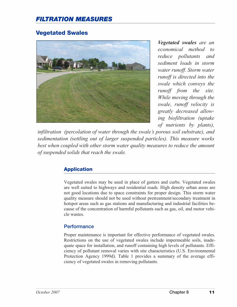
Vegetated swales are an economical method to reduce pollutants and sediment loads in storm water runoff. Storm water runoff is directed into the swale which conveys the runoff from the site. While moving through the swale, runoff velocity is greatly decreased allow-ing biofiltration (uptake of nutrients by plants),
infiltration (percolation of water through the swale’s porous soil substrate), and sedimentation (settling out of larger suspended particles). This measure works best when coupled with other storm water quality measures to reduce the amount of suspended solids that reach the swale.
Application
Vegetated swales may be used in place of gutters and curbs. Vegetated swales are well suited to highways and residential roads. High density urban areas are not good locations due to space constraints for proper design. This storm water quality measure should not be used without pretreatment/secondary treatment in hotspot areas such as gas stations and manufacturing and industrial facilities be-cause of the concentration of harmful pollutants such as gas, oil, and motor vehi-cle wastes.
Performance
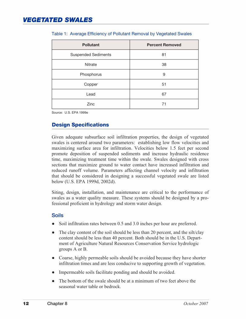
Proper maintenance is important for effective performance of vegetated swales. Restrictions on the use of vegetated swales include impermeable soils, inade-quate space for installation, and runoff containing high levels of pollutants. Effi-ciency of pollutant removal varies with site characteristics (U.S. Environmental Protection Agency 1999d). Table 1 provides a summary of the average effi-ciency of vegetated swales in removing pollutants.
12 Chapter 8 October 2007
VEGETATED SWALES
Table 1: Average Efficiency of Pollutant Removal by Vegetated Swales
Pollutant Percent Removed
Suspended Sediments 81
Nitrate 38
Phosphorus 9
Copper 51
Lead 67
Zinc 71
Source: U.S. EPA 1999e
Design Specifications
Given adequate subsurface soil infiltration properties, the design of vegetated swales is centered around two parameters: establishing low flow velocities and maximizing surface area for infiltration. Velocities below 1.5 feet per second promote deposition of suspended sediments and increase hydraulic residence time, maximizing treatment time within the swale. Swales designed with cross sections that maximize ground to water contact have increased infiltration and reduced runoff volume. Parameters affecting channel velocity and infiltration that should be considered in designing a successful vegetated swale are listed below (U.S. EPA 1999d, 2002d).
Siting, design, installation, and maintenance are critical to the performance of swales as a water quality measure. These systems should be designed by a pro-fessional proficient in hydrology and storm water design.
Soils
� Soil infiltration rates between 0.5 and 3.0 inches per hour are preferred.
� The clay content of the soil should be less than 20 percent, and the silt/clay content should be less than 40 percent. Both should be in the U.S. Depart-ment of Agriculture Natural Resources Conservation Service hydrologic groups A or B.
� Coarse, highly permeable soils should be avoided because they have shorter infiltration times and are less conducive to supporting growth of vegetation.
� Impermeable soils facilitate ponding and should be avoided.
� The bottom of the swale should be at a minimum of two feet above the seasonal water table or bedrock.
October 2007 Chapter 8 13
VEGETATED SWALES
� Less desirable soils can be amended to improve infiltration characteristics.
Cross Section Shape
� Parabolic or trapezoidal cross sections maximize infiltration.
� Triangular cross sections should be avoided as they concentrate flow and promote channel erosion.
� Side slopes should be relatively flat (3:1 or flatter).
� Channel bottom width should be between two feet and eight feet (based on cross-sectional area of flow for the channel).
Slopes and Swale Length
� Swale gradients (slopes) of one to two percent are recommended.
� Swale length should be a minimum of 200 feet to encourage deposition.
Vegetative Cover
� Vegetation should be limited to perennial grasses and grass-legume mixes.
� Species of vegetation chosen should have a dense growth habit and be able to tolerate extended periods of flooding.
� Vegetative species can be selected to target different types of pollutants.
� Vegetation height should be maintained at a minimum height of three to four inches.
Design Calculations
� Typical storm intensities should be calculated for each specific site location.
� Swale design should be based on flow rate, not volume. Runoff should pass from the upstream end to the downstream end of the swale in ten minutes.
� Swale should be designed to effectively handle runoff from a one-inch, 24-hour storm event and efficiently pass excess runoff from larger storms (e.g., 10-year storm events).
Note: Design procedures for this application may be found in “Design of Stormwater Filtering Systems” (Center for Watershed Protection, 1996).
Other Considerations
In heavy sediment situations, swale performance will benefit from the use of a sediment forebay pond to concentrate sediment at the head of the swale for easy cleanout. During high flow events, velocities within a swale should not exceed the maximum velocity for the type of vegetation cover that is used in order to
14 Chapter 8 October 2007
VEGETATED SWALES
Maintenance
Vegetated swales require little maintenance if properly designed (see Table 2). Mowing is the most frequent activity needed in order to maintain channel con-veyance.
Costs
Expenses for grass swales vary depending on the size and amount of site preparation needed. Vegetated swales are considered one of the more economi-cally efficient storm water quality measures. Maintenance costs vary, with regu-lar mowing being the standard expense. Poorly designed swales will incur higher maintenance costs over the long term due to erosion and sedimentation mainte-nance. Using an experienced professional to design the swale may be a higher initial investment, but it can prove to be more cost effective in the long run.
Dry swales are similar to a bioretention system. A dry swale requires the native soil to be replaced with an engineered soil/filter medium to promote infiltration and treatment of the storm water runoff. These systems will usually include an under drain system as part of the design. Storm water that is treated in the filter-ing medium flows into the under drain and is diverted to additional storm water quality measures or to a receiving water (U.S. EPA, National Menu of Best Management Practices, 2002).
Wet swales are similar to a storm water wetland treatment measure, but more linear in design characteristics. This modification of a conventional vegetated swale incorporates a shallow permanent pool and wetland vegetation to treat storm water runoff. Wet swales are not commonly used in residential and com-mercial settings due to the shallow standing water and the potential for the area to be a breeding ground for mosquitoes (U.S. EPA, National Menu of BMPs, 2002).
prevent erosion of the channel vegetation. Check dams may be used to slow ve-locity and promote infiltration within the channel. Check dams should not induce excessive ponding and precautions should be taken to limit scour directly down-stream of the check dam.
Design Modification
The most common approach to storm water treatment is to use a conventional vegetated swale with design modifications to increase the overall efficiency to remove pollutants from storm water runoff. There are also modifications to a conventional swale that may be considered based on site conditions and overall objectives. These two systems are dry swales and wet swales.
October 2007 Chapter 8 15
VEGETATED SWALES
Additional Information
Internet Keyword Search: grass waterways, vegetated swales, overflow channels
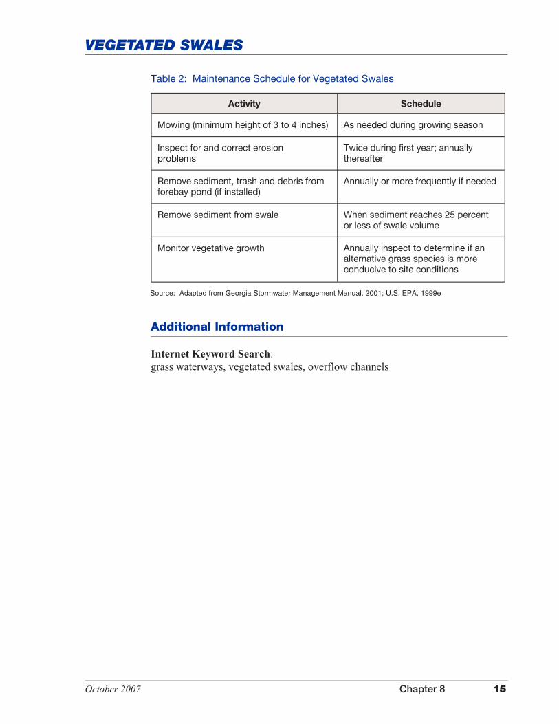
Table 2: Maintenance Schedule for Vegetated Swales
Activity Schedule
Mowing (minimum height of 3 to 4 inches) As needed during growing season
Inspect for and correct erosion problems
Twice during first year; annually thereafter
Remove sediment, trash and debris from forebay pond (if installed)
Annually or more frequently if needed
Remove sediment from swale When sediment reaches 25 percent or less of swale volume
Monitor vegetative growth Annually inspect to determine if an alternative grass species is more conducive to site conditions
Source: Adapted from Georgia Stormwater Management Manual, 2001; U.S. EPA, 1999e

This page was intentionally left blank.
October 2007 Chapter 8 17
FILTRATION MEASURES
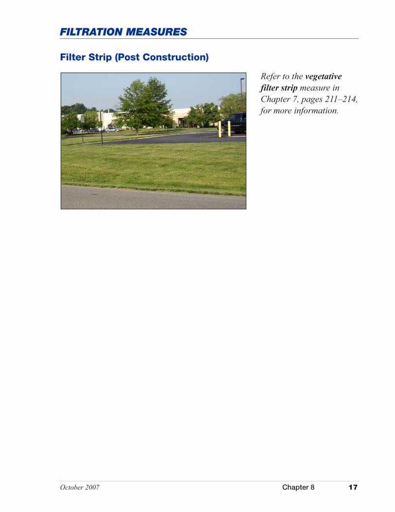
Refer to the vegetative filter strip measure in Chapter 7, pages 211–214, for more information.
Filter Strip (Post Construction)

This page was intentionally left blank.
October 2007 Chapter 8 19
FILTRATION MEASURES
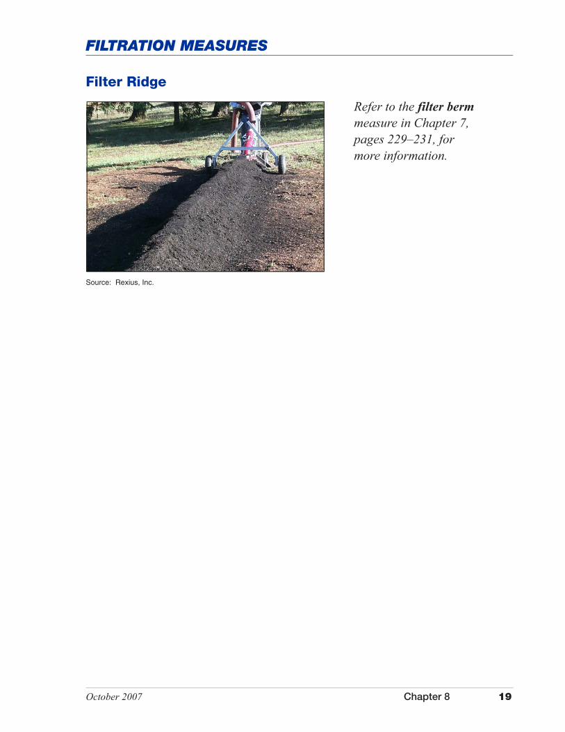
Refer to the filter berm measure in Chapter 7, pages 229–231, for more information.
Filter Ridge
Source: Rexius, Inc.

This page was intentionally left blank.
October 2007 Chapter 8 21
FILTRATION MEASURES
Application
Riparian Buffer Zones
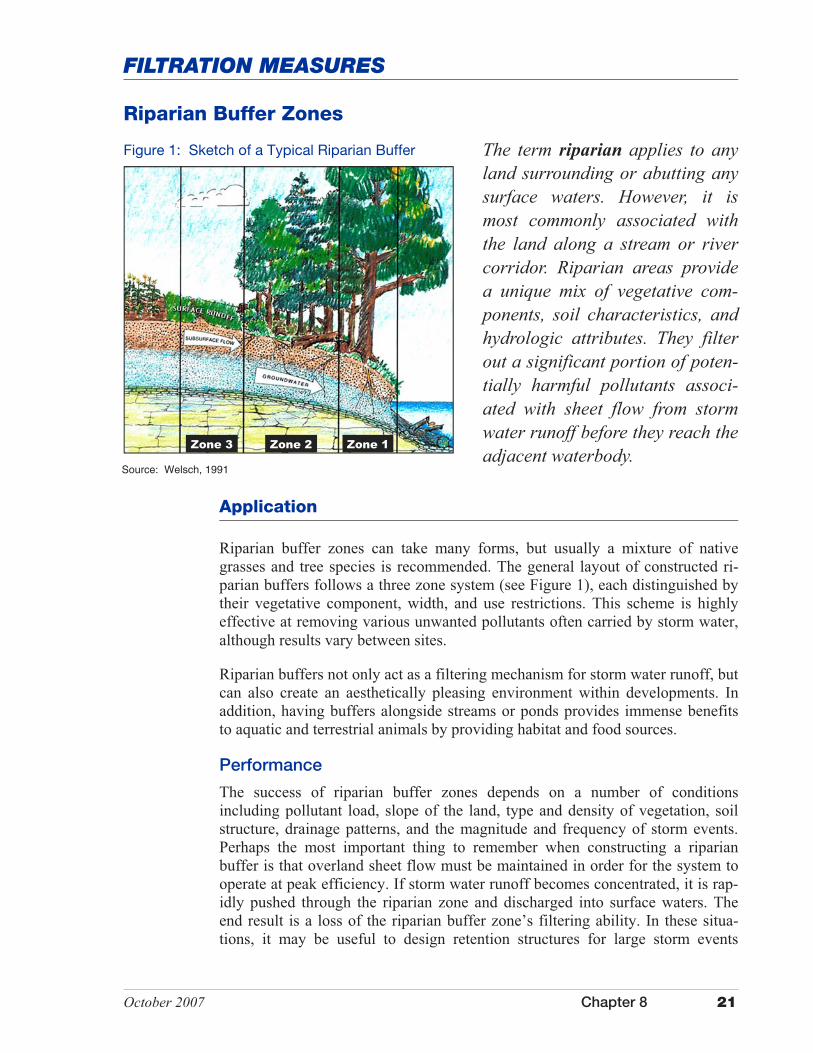
The term riparian applies to any land surrounding or abutting any surface waters. However, it is most commonly associated with the land along a stream or river corridor. Riparian areas provide a unique mix of vegetative com-ponents, soil characteristics, and hydrologic attributes. They filter out a significant portion of poten-tially harmful pollutants associ-ated with sheet flow from storm water runoff before they reach the adjacent waterbody.
Source: Welsch, 1991
Figure 1: Sketch of a Typical Riparian Buffer
Zone 1 Zone 2 Zone 3
Riparian buffer zones can take many forms, but usually a mixture of native grasses and tree species is recommended. The general layout of constructed ri-parian buffers follows a three zone system (see Figure 1), each distinguished by their vegetative component, width, and use restrictions. This scheme is highly effective at removing various unwanted pollutants often carried by storm water, although results vary between sites.
Riparian buffers not only act as a filtering mechanism for storm water runoff, but can also create an aesthetically pleasing environment within developments. In addition, having buffers alongside streams or ponds provides immense benefits to aquatic and terrestrial animals by providing habitat and food sources.
Performance
The success of riparian buffer zones depends on a number of conditions including pollutant load, slope of the land, type and density of vegetation, soil structure, drainage patterns, and the magnitude and frequency of storm events. Perhaps the most important thing to remember when constructing a riparian buffer is that overland sheet flow must be maintained in order for the system to operate at peak efficiency. If storm water runoff becomes concentrated, it is rap-idly pushed through the riparian zone and discharged into surface waters. The end result is a loss of the riparian buffer zone’s filtering ability. In these situa-tions, it may be useful to design retention structures for large storm events
22 Chapter 8 October 2007
RIPARIAN BUFFER ZONES
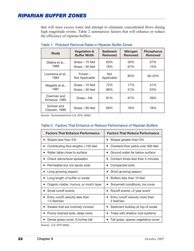
Table 1: Pollutant Removal Rates in Riparian Buffer Zones
Study Vegetation &
Buffer Width
Sediment
Removed
Nitrogen
Removed
Phosphorus
Removed
Dillaha et al., 1989
Grass – 15 feet
Grass – 30 feet
63%
78%
50%
67%
57%
74%
Lowrance et al., 1984
Forest – Not Applicable
Not Applicable 85% 30–42%
Magette et al., 1987
Grass – 15 feet
Grass – 30 feet
72%
86%
17%
51%
41%
53%
Overman and Schanze, 1985 Grass – NA 81% 67% 39%
Schwer and Clausen, 1989 Grass – 85 feet 89% 76% 78%
Source: Summarized from U.S. EPA, 2002c
Table 2: Factors That Enhance or Reduce Performance of Riparian Buffers
Factors That Enhance Performance Factors That Reduce Performance
�� Slopes less than 5% �� Slopes greater than 5%
�� Contributing flow lengths <150 feet �� Overland flow paths over 300 feet
�� Water table close to surface �� Ground water far below surface
�� Check dams/level spreaders �� Contact times less than 5 minutes
�� Permeable but not sandy soils �� Compacted soils
�� Long growing season �� Short growing season
�� Long length of buffer or swale �� Buffers less than 10 feet
�� Organic matter, humus, or mulch layer �� Snowmelt conditions, ice cover
�� Small runoff events �� Runoff events >2 year event
�� Entry runoff velocity less than 1.5 feet/sec
�� Entry runoff velocity more than 5 feet/sec
�� Swales that are routinely mowed �� Sediment buildup at top of swale
�� Poorly drained soils, deep roots �� Trees with shallow root systems
�� Dense grass cover, 6 inches tall �� Tall grass, sparse vegetative cover
Source: U.S. EPA 2002c
that will store excess water and attempt to eliminate concentrated flows during high magnitude events. Table 2 summarizes factors that will enhance or reduce the efficiency of riparian buffers.
October 2007 Chapter 8 23
RIPARIAN BUFFER ZONES
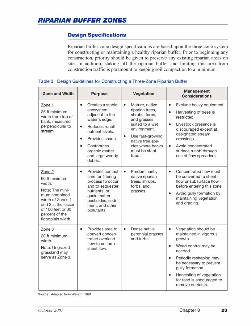
Design Specifications
Riparian buffer zone design specifications are based upon the three zone system for constructing or maintaining a healthy riparian buffer. Prior to beginning any construction, priority should be given to preserve any existing riparian areas on site. In addition, staking off the riparian buffer and limiting this area from construction traffic is paramount to keeping soil compaction to a minimum.
Table 3: Design Guidelines for Constructing a Three-Zone Riparian Buffer
Zone and Width Purpose Vegetation Management
Considerations
Zone 1
25 ft minimum width from top of bank, measured perpendicular to stream.
�� Creates a stable ecosystem adjacent to the water’s edge.
�� Reduces runoff nutrient levels.
�� Provides shade.
�� Contributes organic matter and large woody debris.
�� Mature, native riparian trees, shrubs, forbs, and grasses suited to a wet environment.
�� Use fast-growing native tree spe-cies where banks must be stabi-lized.
�� Exclude heavy equipment.
�� Harvesting of trees is restricted.
�� Livestock presence is discouraged except at designated stream crossings.
�� Avoid concentrated surface runoff through use of flow spreaders.
Zone 2
60 ft minimum width.
Note: The mini-mum combined width of Zones 1 and 2 is the lesser of 100 feet or 30 percent of the floodplain width.
�� Provides contact time for filtering process to occur and to sequester nutrients, or-ganic matter, pesticides, sedi-ment, and other pollutants.
�� Predominantly native riparian trees, shrubs, forbs, and grasses.
�� Concentrated flow must be converted to sheet flow or subsurface flow before entering this zone.
�� Avoid gully formation by maintaining vegetation and grading.
Zone 3
20 ft minimum width.
Note: Ungrazed grassland may serve as Zone 3.
�� Provides area to convert concen-trated overland flow to uniform sheet flow.
�� Dense native perennial grasses and forbs.
�� Vegetation should be maintained in vigorous growth.
�� Weed control may be needed.
�� Periodic reshaping may be necessary to prevent gully formation.
�� Harvesting of vegetation for feed is encouraged to remove nutrients.
Source: Adapted from Welsch, 1991
24 Chapter 8 October 2007
RIPARIAN BUFFER ZONES
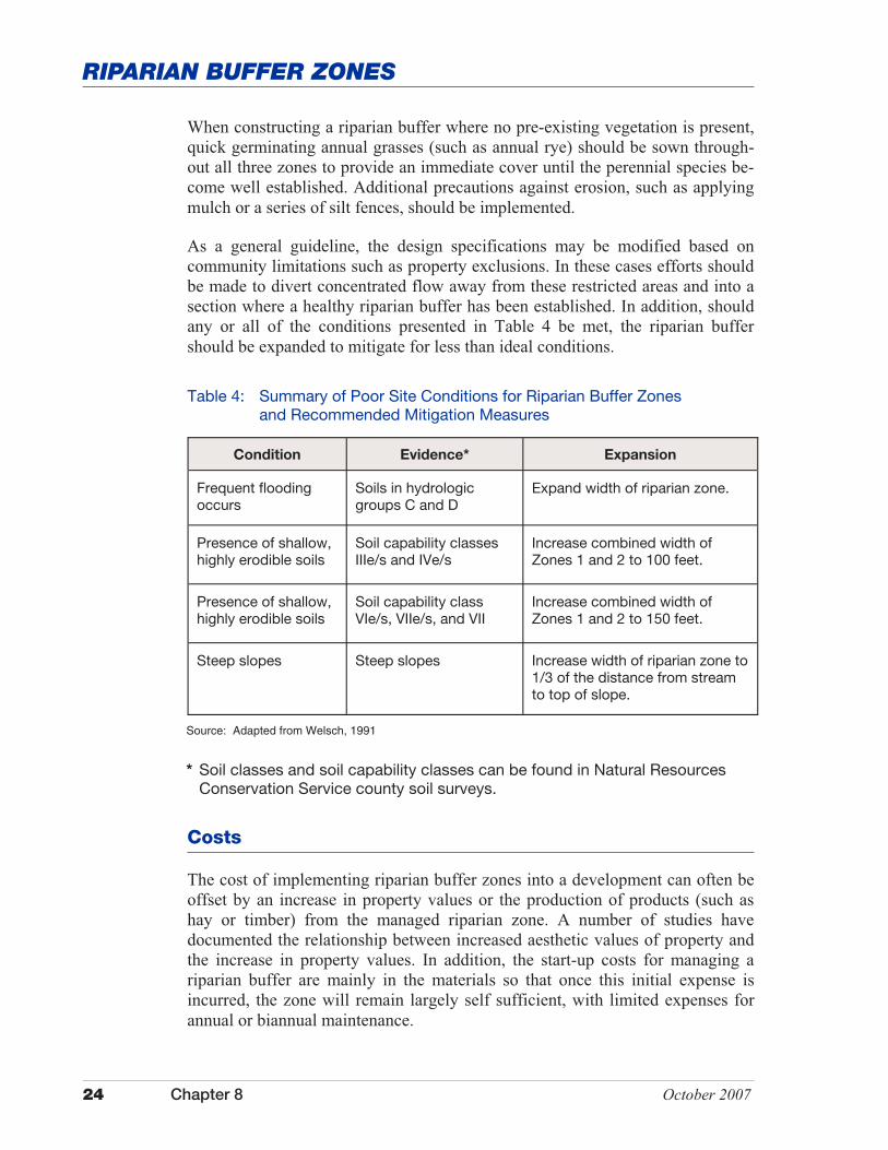
Table 4: Summary of Poor Site Conditions for Riparian Buffer Zones and Recommended Mitigation Measures
Condition Evidence* Expansion
Frequent flooding occurs
Soils in hydrologic groups C and D
Expand width of riparian zone.
Presence of shallow, highly erodible soils
Soil capability classes IIIe/s and IVe/s
Increase combined width of Zones 1 and 2 to 100 feet.
Presence of shallow, highly erodible soils
Soil capability class VIe/s, VIIe/s, and VII
Increase combined width of Zones 1 and 2 to 150 feet.
Steep slopes Steep slopes Increase width of riparian zone to 1/3 of the distance from stream to top of slope.
Costs
The cost of implementing riparian buffer zones into a development can often be offset by an increase in property values or the production of products (such as hay or timber) from the managed riparian zone. A number of studies have documented the relationship between increased aesthetic values of property and the increase in property values. In addition, the start-up costs for managing a riparian buffer are mainly in the materials so that once this initial expense is incurred, the zone will remain largely self sufficient, with limited expenses for annual or biannual maintenance.
Source: Adapted from Welsch, 1991
* Soil classes and soil capability classes can be found in Natural Resources Conservation Service county soil surveys.
When constructing a riparian buffer where no pre-existing vegetation is present, quick germinating annual grasses (such as annual rye) should be sown through-out all three zones to provide an immediate cover until the perennial species be-come well established. Additional precautions against erosion, such as applying mulch or a series of silt fences, should be implemented.
As a general guideline, the design specifications may be modified based on community limitations such as property exclusions. In these cases efforts should be made to divert concentrated flow away from these restricted areas and into a section where a healthy riparian buffer has been established. In addition, should any or all of the conditions presented in Table 4 be met, the riparian buffer should be expanded to mitigate for less than ideal conditions.

October 2007 Chapter 8 25
RIPARIAN BUFFER ZONES
Additional Information
Internet Keyword Search: riparian buffers, buffer strips, filter strips, riparian zones
Costs for materials, such as seed and tree stock, will vary among regions. Consulting a local cooperative extension service office, local soil and water con-servation district office, or U.S. Department of Agriculture Natural Resources Conservation Service office can provide a solid starting point for gauging which types of vegetation are best to plant given your region and where economical sources of materials can be found.

This page was intentionally left blank.

October 2007 Chapter 8 27
FILTRATION MEASURES
Sand Filters
Sand filters are structural storm water quality measures comprised of two or three chambers through which storm water runoff passes. Sand filters can be effective in removing sediments, coliform bacteria, and lowering biochemical oxy-gen demand by removing organic matter.
Source: Truong, H. V., 1989
There are three main types of sand filters in use. They vary in design, chamber placement, and drainage area treated. The Washington D.C. filter (see Figure 1) is a three-chamber system. The first chamber is used to remove surface pollut-ants and sediments.
The second chamber filters pollutants by allowing flow through a sand bed. The third chamber is for collection of filtered water, at which point the water pro-ceeds to a storm drainage system or directly to surface water. The Austin (see Figure 2) and Delaware (see Figure 3) filters are two-chamber systems. These systems are similar to the first two chambers of the Washington D.C. filter. The need for the third chamber is eliminated by the placement of a drainage medium in the bottom of the second chamber.
Figure 1: Diagram of a Washington D.C. Sand Filter Design
28 Chapter 8 October 2007
SAND FILTERS
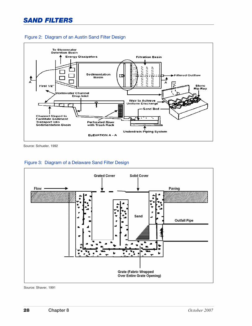
Source: Schueler, 1992
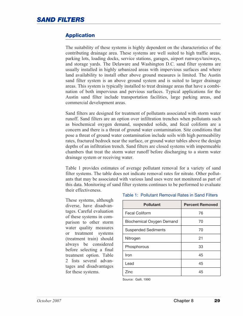
Source: Shaver, 1991
Figure 3: Diagram of a Delaware Sand Filter Design
Figure 2: Diagram of an Austin Sand Filter Design
October 2007 Chapter 8 29
SAND FILTERS
Application
The suitability of these systems is highly dependent on the characteristics of the contributing drainage area. These systems are well suited to high traffic areas, parking lots, loading docks, service stations, garages, airport runways/taxiways, and storage yards. The Delaware and Washington D.C. sand filter systems are usually installed in highly urbanized areas with impervious surfaces and where land availability to install other above ground measures is limited. The Austin sand filter system is an above ground system and is suited to larger drainage areas. This system is typically installed to treat drainage areas that have a combi-nation of both impervious and pervious surfaces. Typical applications for the Austin sand filter include transportation facilities, large parking areas, and commercial development areas.
Sand filters are designed for treatment of pollutants associated with storm water runoff. Sand filters are an option over infiltration trenches when pollutants such as biochemical oxygen demand, suspended solids, and fecal coliform are a concern and there is a threat of ground water contamination. Site conditions that pose a threat of ground water contamination include soils with high permeability rates, fractured bedrock near the surface, or ground water tables above the design depths of an infiltration trench. Sand filters are closed systems with impermeable chambers that treat the storm water runoff before discharging to a storm water drainage system or receiving water.
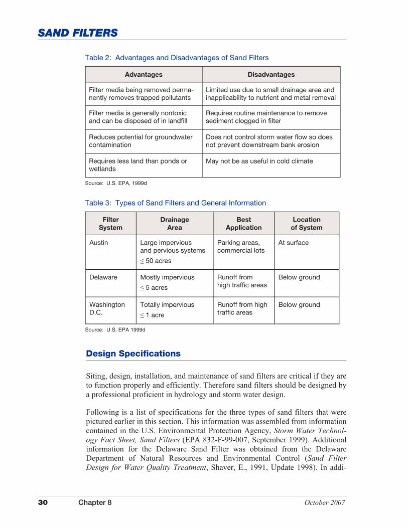
Table 1 provides estimates of average pollutant removal for a variety of sand filter systems. The table does not indicate removal rates for nitrate. Other pollut-ants that may be associated with various land uses were not monitored as part of this data. Monitoring of sand filter systems continues to be performed to evaluate their effectiveness.
Table 1: Pollutant Removal Rates in Sand Filters
Pollutant Percent Removed
Fecal Coliform 76
Biochemical Oxygen Demand 70
Suspended Sediments 70
Nitrogen 21
Phosphorous 33
Iron 45
Lead 45
Zinc 45
Source: Galli, 1990
These systems, although diverse, have disadvan-tages. Careful evaluation of these systems in com-parison to other storm water quality measures or treatment systems (treatment train) should always be considered before selecting a final treatment option. Table 2 lists several advan-tages and disadvantages for these systems.
30 Chapter 8 October 2007
SAND FILTERS
Design Specifications
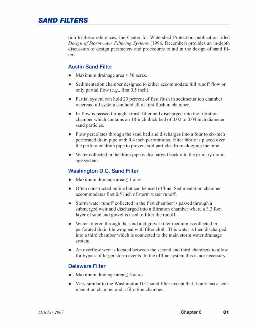
Table 2: Advantages and Disadvantages of Sand Filters
Advantages Disadvantages
Filter media being removed perma-nently removes trapped pollutants
Limited use due to small drainage area and inapplicability to nutrient and metal removal
Filter media is generally nontoxic and can be disposed of in landfill
Requires routine maintenance to remove sediment clogged in filter
Reduces potential for groundwater contamination
Does not control storm water flow so does not prevent downstream bank erosion
Requires less land than ponds or wetlands
May not be as useful in cold climate
Source: U.S. EPA, 1999d
Table 3: Types of Sand Filters and General Information
Filter
System
Drainage
Area
Best
Application
Location
of System
Austin Large impervious and pervious systems
� 50 acres
Parking areas, commercial lots
At surface
Delaware Mostly impervious
� 5 acres
Runoff from high traffic areas
Below ground
Washington D.C.
Totally impervious
� 1 acre
Runoff from high traffic areas
Below ground
Source: U.S. EPA 1999d
Siting, design, installation, and maintenance of sand filters are critical if they are to function properly and efficiently. Therefore sand filters should be designed by a professional proficient in hydrology and storm water design.
Following is a list of specifications for the three types of sand filters that were pictured earlier in this section. This information was assembled from information contained in the U.S. Environmental Protection Agency, Storm Water Technol-ogy Fact Sheet, Sand Filters (EPA 832-F-99-007, September 1999). Additional information for the Delaware Sand Filter was obtained from the Delaware Department of Natural Resources and Environmental Control (Sand Filter Design for Water Quality Treatment, Shaver, E., 1991, Update 1998). In addi-
October 2007 Chapter 8 31
SAND FILTERS
Austin Sand Filter
� Maximum drainage area � 50 acres.
� Sedimentation chamber designed to either accommodate full runoff flow or only partial flow (e.g., first 0.5 inch).
� Partial system can hold 20 percent of first flush in sedimentation chamber whereas full system can hold all of first flush in chamber.
� In-flow is passed through a trash filter and discharged into the filtration chamber which contains an 18-inch thick bed of 0.02 to 0.04 inch diameter sand particles.
� Flow percolates through the sand bed and discharges into a four to six-inch perforated drain pipe with 0.4 inch perforations. Filter fabric is placed over the perforated drain pipe to prevent soil particles from clogging the pipe.
� Water collected in the drain pipe is discharged back into the primary drain-age system.
Washington D.C. Sand Filter
� Maximum drainage area � 1 acre.
� Often constructed online but can be used offline. Sedimentation chamber accommodates first 0.5 inch of storm water runoff.
� Storm water runoff collected in the first chamber is passed through a submerged weir and discharged into a filtration chamber where a 3.3 foot layer of sand and gravel is used to filter the runoff.
� Water filtered through the sand and gravel filter medium is collected in perforated drain tile wrapped with filter cloth. This water is then discharged into a third chamber which is connected to the main storm water drainage system.
� An overflow weir is located between the second and third chambers to allow for bypass of larger storm events. In the offline system this is not necessary.
Delaware Filter
� Maximum drainage area � 5 acres.
� Very similar to the Washington D.C. sand filter except that it only has a sedi-mentation chamber and a filtration chamber.
tion to these references, the Center for Watershed Protection publication titled Design of Stormwater Filtering Systems (1996, December) provides an in-depth discussion of design parameters and procedures to aid in the design of sand fil-ters.

32 Chapter 8 October 2007
SAND FILTERS
For all design models, the life of the sand filter can be prolonged by stabilizing the drainage area so sediment load is reduced, providing adequate storm detention times to aid infiltration, and scheduling regular inspections and frequent maintenance.
Maintenance
All sand filter systems should provide easy access for inspection and mainte-nance activities that will be performed to maintain the system. These systems should be inspected after every significant storm event (.5 inches or more). Trash and other debris that accumulate in the chamber should be removed a minimum of every six months or as needed if the drainage area contributes significantly to this problem.
Filters will typically begin to experience clogging every three to five years (Northern Virginia Regional Commission, 1992; U.S. EPA, 1999d). The filter media (sand) will need to be removed periodically. According to U.S. EPA the contaminated media removed from these systems does not appear to be toxic and is environmentally safe to be disposed of in a permitted landfill facility. How-ever, as a precaution periodic testing of the material removed is recommended.
These systems will require regular inspection and maintenance. The operation life of the sand filter can be increased by:
� Inspecting the sand filter frequently to ensure operation.
� Stabilizing the contributing drainage area to reduce sediment loading.
� Removing leaves, debris, and grass clippings within the drainage area that is directed to the filter.
� Maintaining the capacity of the sand filter to enhance sedimentation and filtration.
� Storm water runoff passes through a grated cover to a sedimentation chamber where it passes over a weir and discharges into an 18-inch thick sand bed. If gravel is used in place of sand, the design must be modified.
� Volume of sedimentation chamber is sized, at least, for 540 ft3 of storage per acre of drainage area.
� Volume of filtration chamber equals volume of sedimentation chamber.
� Surface area of each chamber is 360 ft2 per acre of drainage area.
� Shallow depth of the structure (30 inches) is convenient for construction and maintenance.

October 2007 Chapter 8 33
SAND FILTERS
Additional Information
Internet Keyword Search: sand filters, peat filters
Costs
Installation costs vary based on the type of sand filter structure used. Annual maintenance costs should average about five percent (Schueler, 1997; U.S. EPA, 1999d) of the original construction costs.

This page was intentionally left blank.

October 2007 Chapter 8 35
FILTRATION MEASURES
Peat Filters
To be released at a later time

This page was intentionally left blank.
October 2007 Chapter 8 37
INFILTRATION MEASURES
I nfiltration measures are storm water management measures designed to collect storm water runoff and provide a suitable medium that allows the runoff to infiltrate into the ground.
Storm water infiltration measures reduce storm water volumes and the associated suspended solids and pollutants attached to suspended soil particles. Storm water infiltration measures also provide ground water recharge. These systems are not effective in removal of water soluble or dissolved pollutants.
Infiltration systems work on the principal that stored storm water runoff is slowly released to ground water. The permeability of the underlying soil material is critical in the implementation of this measure. Infiltration measures should be carefully sited and designed to minimize the risk of ground water contamination.
Storm water infiltration measures are best suited for treating storm water runoff generated from small residential areas and commercial developments. Infiltration systems should not be used in areas where the land use of the contributing drainage area is associated with chemical storage, high levels of pesticides, the washing and maintenance of vehicles or equipment, or where wastes are handled.
Infiltration measures are prone to sealing or plugging. Therefore, storm water runoff should be pretreated to remove solids, oil, grease, and floatables before allowing the runoff to discharge into the infiltration measure. Infiltration measures should not be used in areas with high sedi-ment loads or during construction, especially in situations where sediment-laden runoff from disturbed areas will be directed into the system.
The design of infiltration measures can be complex and generally requires detailed site investi-gation, including an assessment of potential pollutants and the application of sound engineering principles. A professional knowledgeable of storm water management and water quality princi-ples and experienced in design should be consulted when using infiltration measures.
Infiltration measures include but are not limited to porous pavement, porous paver systems, in-filtration trenches, and infiltration ponds.

This page was intentionally left blank.
October 2007 Chapter 8 39
INFILTRATION MEASURES
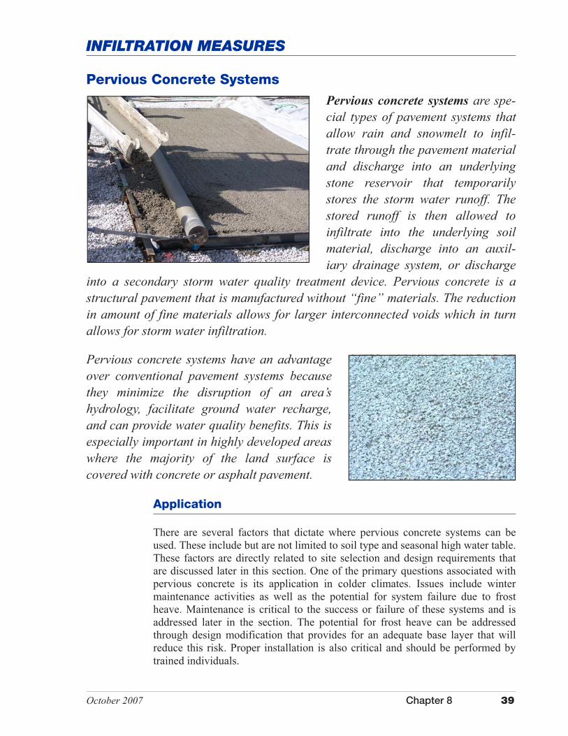
Pervious concrete systems are spe-cial types of pavement systems that allow rain and snowmelt to infil-trate through the pavement material and discharge into an underlying stone reservoir that temporarily stores the storm water runoff. The stored runoff is then allowed to infiltrate into the underlying soil material, discharge into an auxil-iary drainage system, or discharge
into a secondary storm water quality treatment device. Pervious concrete is a structural pavement that is manufactured without “fine” materials. The reduction in amount of fine materials allows for larger interconnected voids which in turn allows for storm water infiltration.
Pervious concrete systems have an advantage over conventional pavement systems because they minimize the disruption of an area’s hydrology, facilitate ground water recharge, and can provide water quality benefits. This is especially important in highly developed areas where the majority of the land surface is covered with concrete or asphalt pavement.
There are several factors that dictate where pervious concrete systems can be used. These include but are not limited to soil type and seasonal high water table. These factors are directly related to site selection and design requirements that are discussed later in this section. One of the primary questions associated with pervious concrete is its application in colder climates. Issues include winter maintenance activities as well as the potential for system failure due to frost heave. Maintenance is critical to the success or failure of these systems and is addressed later in the section. The potential for frost heave can be addressed through design modification that provides for an adequate base layer that will reduce this risk. Proper installation is also critical and should be performed by trained individuals.
Application
Pervious Concrete Systems

40 Chapter 8 October 2007
PERVIOUS CONCRETE SYSTEMS
The following land uses are commonly associated with pervious concrete systems.
Pedestrian Areas
Pervious concrete systems are ideal for sidewalks and other pedestrian walk-ways, rollerblade and bike pathways, and areas such as patios and common areas around residential buildings.
Transportation Areas
Pervious concrete systems are well suited for the construction of lightly used access roads, overflow parking areas, and low-volume traffic areas around office buildings, recreational areas, and shopping centers. Other areas where pervious concrete systems may be used include emergency stopping areas, traffic islands, vehicle crossovers on divided highways, and shoulders along roadways, airport taxiways, and airport runways. Pervious concrete systems have typically been restricted to the land uses listed above, however pervious concrete systems may accommodate higher volume traffic and heavier truck traffic use. To achieve these objectives, special mix designs and structural design modifications and placement techniques will be required.
Pervious concrete systems are poorly suited for use in areas where it is necessary to apply sand or other deicing agents to the pavement surface. Sand has a ten-dency to clog the surface of the pavement material, whereas other deicing agents may migrate into the ground water.
Ultra Urban Areas
Pervious concrete systems can be a good option in densely developed urban ar-eas which typically have little pervious surface area. Pervious concrete systems in this kind of setting allow infiltration of storm water which in a conventional setting would be lost because of lack of permeable surface areas and efficient storm water drainage systems.
Storm Water Hotspots
Infiltration of storm water into the underlying soil material is not recommended to treat runoff from designated storm water hotspots due to the potential for ground water contamination. Pervious concrete systems should not be used for industrial and manufacturing sites where there is a high concentration of soluble pollutants, pesticides, fertilizers, and heavy metals. Storm water hotspots include areas such as gas/fueling stations, truck stops, vehicle service and maintenance areas, vehicle and equipment washing/steam cleaning facilities, auto recycling facilities, loading and unloading facilities, commercial storage areas, outdoor container storage areas, public works storage areas, commercial nurseries, marinas, hazardous material generators, and industrial rooftops because these areas are frequently subject to the high risk of ground water contamination.

October 2007 Chapter 8 41
PERVIOUS CONCRETE SYSTEMS
Advantages
� Allows rain and snowmelt to pass through the pavement material.
� Provides water quality benefits by filtering pollutants (e.g., petroleum hydrocarbons, metals, organic matter, and nonpoint source pollutants such as phosphorous attached to fine soil particles) from storm water runoff via infiltration into the underlying soil substrate and through microbial action.
� Reduces the volume of storm water runoff and associated erosion potential (U.S. Environmental Protection Agency studies have shown that pervious concrete systems can reduce storm water runoff by as much as 80 percent).
� Attenuates peak discharge flows and reduces the amount of storm water entering storm drain systems.
� Provides some natural filtration capacity while maintaining the structural and functional features of the conventional pavement material it replaces.
� Stone reservoir can be lined with an impermeable liner, allowing storm water to be reused, stored, or treated through utilization of a secondary storm water treatment measure.
� Minimizes the disruption of the hydrology of an area by providing a reser-voir and percolation field for surface water to re-enter ground aquifers, recharges low flow in streams during dry periods, and reduces downstream flooding.
� Minimizes the amount of land consumption by reducing the need for tradi-tional storm water management structures, thereby saving open space for alternative uses.
� Minimizes construction and maintenance costs of street curbs and gutters, storm sewer systems typically required to carry storm water to an outfall, and other associated storm water management measures such as retention/ detention ponds.
� Improves roadway safety by reducing noise, improving visibility in wet weather conditions, and reducing risk of skidding/hydroplaning.
� Allows for pavement to extend under the dripline of trees.
� Cooler than black asphalt because of higher reflectivity and lower solar heat-gain from absorption and evapotranspiration.
� Cooler pavement temperatures allow for infiltration of cooler storm water into ground water.
42 Chapter 8 October 2007
PERVIOUS CONCRETE SYSTEMS
Disadvantages
� Pavement engineers and contractors may not possess the expertise and experience to apply this technology (generally requires special planning and expertise to install).
� Poorly suited for use in naturally occurring seasonal high water table soils.
� Poorly suited for use in wellhead protection areas.
� The pavement surface, if improperly installed and maintained, has a tendency to become clogged with particulate matter and debris.
� Not suitable for use in areas where materials applied to the roadway can clog or fill voids in the pervious concrete (e.g., chip and seal operations or application of sand to ice covered roadways).
� Poses a risk to ground water contamination. For example, pollutants such as nitrates and chlorides that are not easily trapped, absorbed, or reduced may continue to move through the soil profile and into ground water (dependant on soil conditions and aquifer susceptibility).
� Potential risk for vehicle fuels, oils, greases, and other substances to leak onto the pavement and leach into ground water.
� May cause frost heave of pavement if system is improperly designed, installed, or maintained.
� Pervious concrete systems typically have higher maintenance requirements than conventional pavement systems.
� Local building codes sometimes restrict the use of pervious concrete systems without special approval or variances.
Performance
The initial performance of porous/pervious pavement systems has been very good. However, according to the U.S. Environmental Protection Agency the fail-ure rate over time has been high. Failure has been attributed to poor design, inadequate construction techniques, poor siting, and poor maintenance. When these issues are addressed, it is anticipated that these systems can have a service life of 20 years or more.
Properly designed, installed, and maintained pervious concrete systems can be cost effective and provide a storm water management system that promotes infiltration and the removal of pollutants from storm water runoff flowing through the system. Pollutant removal mechanisms associated with these systems include absorption, straining, and microbiological decomposition. Pollutant removal effectiveness will vary depending on system design, soil sub-strate characteristics, and proper maintenance of the system. Sampling data for these systems, although limited, indicate a relatively high removal rate for total
October 2007 Chapter 8 43
PERVIOUS CONCRETE SYSTEMS
suspended solids, metals, and oil and grease. These systems can be installed as part of a treatment train to increase the overall efficiency of removal for targeted pollutants.
Design Specifications
Siting, design, installation, and maintenance of pervious concrete systems are critical if they are to function properly and efficiently. Therefore, pervious con-crete systems, and especially the storm water component, should be designed by a professional proficient in hydrology and storm water design. Installation should be performed by trained individuals (the concrete industry offers a certifi-cation program for installers). Design and installation should be in conformance with concrete industry standards and specifications.
Information in this section was assembled from a variety of sources including the U.S. Environmental Protection Agency’s storm water technical fact sheet entitled Porous Pavement (1999h); the U.S. EPA’s post-construction storm wa-ter management in new development and redevelopment fact sheet entitled Po-rous Pavement (2002k); the Indiana Ready Mix Concrete Association; and the Georgia Stormwater Management Manual (2001).
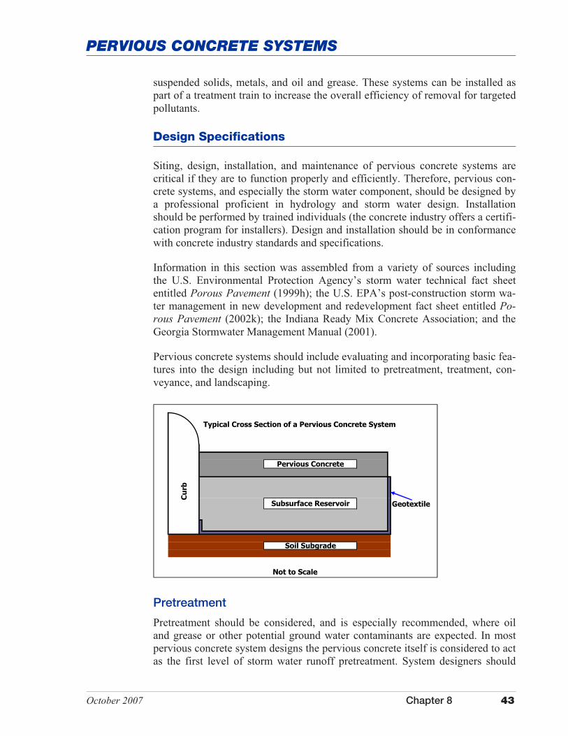
Pervious concrete systems should include evaluating and incorporating basic fea-tures into the design including but not limited to pretreatment, treatment, con-veyance, and landscaping.
Geotextile
Not to Scale
Cu
rb
Typical Cross Section of a Pervious Concrete System
Soil Subgrade
Pervious Concrete
Subsurface Reservoir
Pretreatment
Pretreatment should be considered, and is especially recommended, where oil and grease or other potential ground water contaminants are expected. In most pervious concrete system designs the pervious concrete itself is considered to act as the first level of storm water runoff pretreatment. System designers should

44 Chapter 8 October 2007
PERVIOUS CONCRETE SYSTEMS
take into account pollutants that are associated with the land use and apply ap-propriate pretreatment measures to target specific pollutants.
Adjacent areas that drain to a pervious concrete system should be stabilized and/or designed so that runoff from an adjacent area will not deposit sediment onto the pervious concrete surface. Otherwise, frequent maintenance of the pave-ment surface is critical to prevent clogging.
Treatment
A stone reservoir should be incorporated into systems where soil conditions are not favorable to promote infiltration. The reservoir, which lies immediately be-neath the pavement, should be designed and sized to attenuate and treat a small storm water runoff event (typically 0.5 inch to 1.5 inches). Storage capacity must be designed around the amount of air/pore space in the reservoir since this is the only area where water can be stored.
Conveyance
Pervious concrete systems need some method of conveying storm water runoff through the system. Pores in the pervious concrete allow storm water to infiltrate into the underlying stone reservoir. Water stored in the stone reservoir is then allowed to either infiltrate into the underlying soil substrate or held in an under-ground impermeable closed system that discharges to a secondary storm water management/treatment measure via subsurface drainage pipes.
Pervious concrete systems should be designed with some method to convey large storm events to the underlying stone reservoir. Setting storm drain inlets at strategic locations within the system design will allow larger storm water flows to enter the stone reservoir in the event that the infiltration rate of the pavement is insufficient to handle the storm event or the pavement surface becomes clogged.
Landscaping
Preventing sediment loads from clogging the pervious concrete surface is critical if the system is to function properly. Therefore, it is important to develop and implement a landscaping plan that will ensure that the contributing drainage area is stabilized. This is especially true during active construction, but is also appli-cable for post-construction activities.
Design of pervious concrete systems also requires evaluation and incorporation of several key elements such as, but not limited to, soil type, infiltration rate, depth to a limiting layer (e.g., bedrock, a seasonal high water table, glacial till), slope length and gradient, construction materials, and installation methods. Fol-lowing are several key design specifications that should be considered and evalu-ated when siting, designing, and installing pervious concrete systems.
October 2007 Chapter 8 45
PERVIOUS CONCRETE SYSTEMS
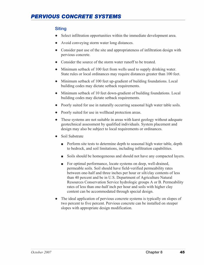
Siting
� Select infiltration opportunities within the immediate development area.
� Avoid conveying storm water long distances.
� Consider past use of the site and appropriateness of infiltration design with pervious concrete.
� Consider the source of the storm water runoff to be treated.
� Minimum setback of 100 feet from wells used to supply drinking water. State rules or local ordinances may require distances greater than 100 feet.
� Minimum setback of 100 feet up-gradient of building foundations. Local building codes may dictate setback requirements.
� Minimum setback of 10 feet down-gradient of building foundations. Local building codes may dictate setback requirements.
� Poorly suited for use in naturally occurring seasonal high water table soils.
� Poorly suited for use in wellhead protection areas.
� These systems are not suitable in areas with karst geology without adequate geotechnical assessment by qualified individuals. System placement and design may also be subject to local requirements or ordinances.
� Soil Substrate
� Perform site tests to determine depth to seasonal high water table, depth to bedrock, and soil limitations, including infiltration capabilities.
� Soils should be homogeneous and should not have any compacted layers.
� For optimal performance, locate systems on deep, well-drained, permeable soils. Soil should have field-verified permeability rates between one-half and three inches per hour or silt/clay contents of less than 40 percent and be in U.S. Department of Agriculture Natural Resources Conservation Service hydrologic groups A or B. Permeability rates of less than one-half inch per hour and soils with higher clay content can be accommodated through special design.
� The ideal application of pervious concrete systems is typically on slopes of two percent to five percent. Pervious concrete can be installed on steeper slopes with appropriate design modification.
46 Chapter 8 October 2007
PERVIOUS CONCRETE SYSTEMS
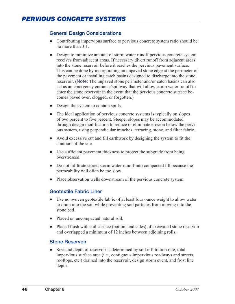
General Design Considerations
� Contributing impervious surface to pervious concrete system ratio should be no more than 3:1.
� Design to minimize amount of storm water runoff pervious concrete system receives from adjacent areas. If necessary divert runoff from adjacent areas into the stone reservoir before it reaches the pervious pavement surface. This can be done by incorporating an unpaved stone edge at the perimeter of the pavement or installing catch basins designed to discharge into the stone reservoir. (Note: The unpaved stone perimeter and/or catch basins can also act as an emergency entrance/spillway that will allow storm water runoff to enter the stone reservoir in the event that the pervious concrete surface be-comes paved over, clogged, or forgotten.)
� Design the system to contain spills.
� The ideal application of pervious concrete systems is typically on slopes of two percent to five percent. Steeper slopes may be accommodated through design modification to reduce or eliminate erosion below the pervi-ous system, using perpendicular trenches, terracing, stone, and filter fabric.
� Avoid excessive cut and fill earthwork by designing the system to fit the contours of the site.
� Use sufficient pavement thickness to protect the subgrade from being overstressed.
� Do not infiltrate stored storm water runoff into compacted fill because the permeability will often be too slow.
� Place observation wells downstream of the pervious concrete system.
Geotextile Fabric Liner � Use nonwoven geotextile fabric of at least four ounce weight to allow water
to drain into the soil while preventing soil particles from moving into the stone bed.
� Placed on uncompacted natural soil.
� Placed flush with soil surface (bottom and sides) of excavated stone reservoir and overlapped a minimum of 12 inches between adjoining rolls.
Stone Reservoir � Size and depth of reservoir is determined by soil infiltration rate, total
impervious surface area (i.e., contiguous impervious roadways and streets, rooftops, etc.) drained into the reservoir, design storm event, and frost line depth.

October 2007 Chapter 8 47
PERVIOUS CONCRETE SYSTEMS
� Depth of reservoir is based on design storage capacity and land use. Typically, the minimum reservoir depth is six inches.
� Twelve-hour minimum and 72-hour maximum draw-down time with a recommended draw-down time of 24 to 48 hours. (Note: Microbiological decomposition can be impeded if soils are unable to dry out and anaerobic conditions are allowed to develop between storm events.)
� Design storage capacity should not include those areas above the pavement. Designers may also choose to exclude the pervious concrete as part of the design storage capacity based on concrete industry specifications and regional climatic issues and the potential for frost heave.
� It is also important to design pervious concrete systems with a mechanism to discharge water from the stone reservoir in the event that its design storage capacity is exceeded. An exfiltration system should be incorporated into a system that is installed in soils with a permeability rate of less than one-half inch per hour or with a high clay content. The stone reservoir component of pervious concrete systems must be designed with an exfiltration system that allows large storm events to exit the reservoir. Drainage of excess water in the stone reservoir is typically accomplished in one of three ways: full exfil-tration, partial exfiltration, or water quality exfiltration.
� Full Exfiltration System – The stone reservoir is an enclosed system (i.e., no pipe outlets) that only allows runoff to exit the system via infiltration into the soil substrate. The reservoir storage capacity must be large enough to accommodate the entire runoff volume from the design storm. An aboveground emergency overflow channel such as a swale or raised curb is used to collect excess runoff from storm events greater than the design storm and divert it to an auxiliary storm water treatment device.
� Partial Exfiltration System – The stone reservoir is connected to an underground drainage system that includes regularly spaced, perforated pipes located in shallow depressions. The pipes collect the stored runoff and direct it to an infiltration basin or a central outlet. Size and spacing of the under-drain system should allow for passage of the design storm event.
� Water Quality Exfiltration System – The stone reservoir is designed to store the first flush (i.e., volume of runoff produced by a one-inch storm event or the design storm event) of runoff volume from the design storm event. Runoff volumes in excess of the first flush are not treated by the pervious concrete system, but are conveyed to an auxiliary or secondary storm water treatment measure.
� The bottom of the reservoir should be a minimum of three feet above any limiting layer (e.g., seasonal high water table, glacial till, bedrock).
� The base of the reservoir should be extended below the frost line to reduce the risk of frost heave.

48 Chapter 8 October 2007
PERVIOUS CONCRETE SYSTEMS
� The bottom of the reservoir should be level to allow even distribution and infiltration of storm water and prevent the development of preferential flow paths.
� The bottom and sides should be lined with geotextile fabric to prevent migra-tion of soil “fines” into the stone reservoir and reduce its storage capacity and ability to support the overlying pavement.
� The excavated reservoir should be filled with crushed, clean-washed, uniformly graded aggregate. Aggregate size is based on design and sized to maximize void space. Typical size is 1.5 inch to 2.5 inch aggregate.
� Water from the stone reservoir should not be allowed to infiltrate into mate-rial underlying adjacent conventional pavements as this could cause failure of the conventional pavement.
Pervious Concrete
� All permeable materials must meet applicable material quality specifications and requirements for compressive strength, water absorption, and freeze-thaw resistance. Mixes and/or installation methods should meet appropriate Ameri-can Society for Testing and Materials standards for public-use surfaces like parking lots and roads. (As of March 2007, ASTM standards do not exist for pervious concrete; however, these are in the process of being established.)
� Ensure paving material infiltration rates are greater than the peak design rainfall intensity.
� Specially formulated mixture of Portland cement, water, and uniform, open-graded coarse aggregate.
� Adequate void space (15 to 25 percent) to allow rapid percolation of storm water runoff. The porosity rate can be correlated with the proposed land use and therefore may require design modification.
� Typically four to six inches thick (typically 25 percent thicker than a conven-tional Portland cement pavement designed for the same traffic volume; mini-mum thickness of six inches for commercial uses such as automobiles with no truck traffic).
Regional Adaptations
� In cold climates, the base of the stone reservoir should be below the frost line or the system should be designed to facilitate drainage of storm water away from the aggregate recharge bed to reduce the risk of frost heave.
October 2007 Chapter 8 49
PERVIOUS CONCRETE SYSTEMS
Installation
The proper installation of pervious concrete systems is critical to its long-term performance as a storm water quality measure. Therefore, is important that the installation conform to concrete industry standards and specifications. In its on-going effort to educate and train installers, the concrete industry has developed a certification program. This program is designed to ensure that pervious concrete systems are designed and installed properly.
� Provide thorough construction oversight by trained individuals.
� Maintain erosion and sediment control measures until the site is stabilized. Active construction sites involve mass earthmoving and many activities that can generate sediment. It is often recommended to install these systems late in the construction phase of a project when there is less likelihood of sedi-ment discharge. (Sedimentation that discharges onto a pervious concrete system can result in failure of the infiltration system or require higher main-tenance.)
� Excavate the area for the stone reservoir, taking precautions to avoid compaction of the soil substrate and smearing of the exposed soil faces of the excavation. Scarify any areas where the soil face(s) has been smeared.
� Install geotextile fabric liner on the bottom and sides of the stone reservoir, overlapping adjoining rolls by 12 inches or more. If the system being installed is closed, install an appropriate impermeable membrane.
� Place aggregate as specified in the construction plans and compact in six- inch lifts.
� Install pavement materials to the dimensions and grades shown in the construction plans. Compact all pervious concrete materials to provide strength and resist densification under the intended traffic use.
� The same strike off equipment can be used as for conventional concrete, but finishing tools such as trowels and bullfloats should not be used. A heavy roller should be used to compress the material and to level the surface. Curing with a six millimeter plastic should begin within 20 minutes or less after material is discharged from the truck or as specified by concrete indus-try standards.
� Control joints are often used to prevent random cracking. However, due to the rough texture of the material joints are not always required. Control joints can be cut using a roller with a welded steel flange. Joints may also be cut with a saw, but the joints are less durable and there is more potential for raveling when saw cut. If joints are used to control cracking, the joints should be kept out of the vehicle wheel path as much as practicable. (Cracks in pervious concrete are less noticeable due to the texture of the pavement.)
50 Chapter 8 October 2007
PERVIOUS CONCRETE SYSTEMS
� The surface must be continuously cured for a minimum of seven days with impervious sheeting such as six millimeter plastic or burlene. Liquid-sprayed curing materials may be used to supplement, but not to replace, the sheeting. Curing sheets must be secured to prevent removal during the curing period.
Maintenance
Pervious concrete systems require additional maintenance as compared to conventional concrete. Failure of these systems can usually be attributed to poor design, poor construction, and/or poor maintenance.
During construction, the pervious concrete system should be inspected several times and design specifications should be stringently followed and enforced.
These systems should also be inspected several times during the first few months following completion of construction to ensure that the system was installed correctly and is functioning properly. Regularly scheduled inspection and maintenance can be performed thereafter. The following table lists several rou-tine maintenance activities and identifies recommended inspection and mainte-nance frequencies.
Measures should also be taken to avoid paving or resealing the pervious concrete surface with nonporous materials. Several options include but are not limited to signage on or adjacent to the pervious concrete surface and maintenance guide-lines. It is important that those involved with maintenance of a pervious concrete system understand that maintenance is critical to the success of this measure. A carefully worded maintenance agreement should be developed that provides specific guidance about how to conduct routine maintenance and how the surface should be repaved. Where practical, signs identifying the pervious concrete system should be posted on or adjacent to the site [e.g., Pervious Concrete Pave-ment Used on this Site - DO NOT Resurface with Nonporous Material or Film Forming Sealers. Call (xxx) xxx-xxxx for more information.]
In addition to regularly scheduled maintenance, the life expectancy of pervious concrete systems can usually be increased by implementing a stringent sediment control plan, pretreating storm water runoff, and placing restrictions on use by heavy vehicles. In cold climates, limit the use of sand and gravel to prevent clog-ging and wear. Use of deicing agents should be minimized to protect ground water. If snow is to be removed by mechanical means, set the blade of the snow plow one to two inches above the surface of the pavement.
Table 1 lists several routine maintenance activities and identifies recommended inspection and maintenance frequencies.
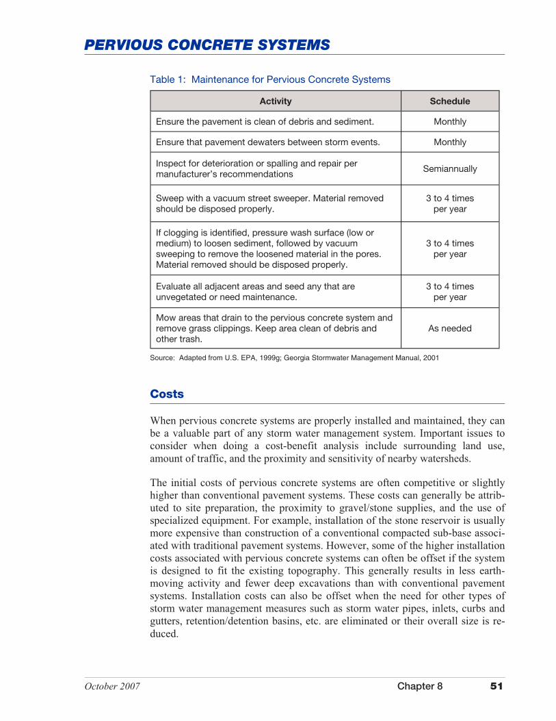
October 2007 Chapter 8 51
PERVIOUS CONCRETE SYSTEMS
Table 1: Maintenance for Pervious Concrete Systems
Activity Schedule
Ensure the pavement is clean of debris and sediment. Monthly
Ensure that pavement dewaters between storm events. Monthly
Inspect for deterioration or spalling and repair per manufacturer’s recommendations Semiannually
Sweep with a vacuum street sweeper. Material removed should be disposed properly.
3 to 4 times per year
If clogging is identified, pressure wash surface (low or medium) to loosen sediment, followed by vacuum sweeping to remove the loosened material in the pores. Material removed should be disposed properly.
3 to 4 times per year
Evaluate all adjacent areas and seed any that are unvegetated or need maintenance.
3 to 4 times per year
Mow areas that drain to the pervious concrete system and remove grass clippings. Keep area clean of debris and other trash.
As needed
Source: Adapted from U.S. EPA, 1999g; Georgia Stormwater Management Manual, 2001
Costs
When pervious concrete systems are properly installed and maintained, they can be a valuable part of any storm water management system. Important issues to consider when doing a cost-benefit analysis include surrounding land use, amount of traffic, and the proximity and sensitivity of nearby watersheds.
The initial costs of pervious concrete systems are often competitive or slightly higher than conventional pavement systems. These costs can generally be attrib-uted to site preparation, the proximity to gravel/stone supplies, and the use of specialized equipment. For example, installation of the stone reservoir is usually more expensive than construction of a conventional compacted sub-base associ-ated with traditional pavement systems. However, some of the higher installation costs associated with pervious concrete systems can often be offset if the system is designed to fit the existing topography. This generally results in less earth-moving activity and fewer deep excavations than with conventional pavement systems. Installation costs can also be offset when the need for other types of storm water management measures such as storm water pipes, inlets, curbs and gutters, retention/detention basins, etc. are eliminated or their overall size is re-duced.

52 Chapter 8 October 2007
PERVIOUS CONCRETE SYSTEMS
Maintenance costs of pervious concrete systems are also generally higher than conventional pavement systems. The cost of vacuum sweeping and pressure washing of the pavement may be substantial if a community or facility owner does not already perform these types of operations in their maintenance program activities.
Additional Information
Internet Keyword Search: porous pavement, porous pavement systems,

October 2007 Chapter 8 53
INFILTRATION MEASURES
Porous Asphalt Systems
Porous asphalt systems are special types of pavement systems that allow rain and snowmelt to infiltrate through the pavement material and discharge into an under-lying stone reservoir that temporarily stores the storm water runoff. The stored runoff is then allowed to infiltrate into the underlying soil material, discharge to an auxiliary drainage system, or discharge into a secondary storm water quality treatment device. Porous asphalt appears the same as its traditional counterpart but is manufactured without “fine” materials. The reduction in amount of fine materials allows for larger interconnected voids which in turn allows for storm water infiltration.
Porous asphalt systems generally have an advantage over conventional pavement systems because they minimize the disruption of an area’s hydrology, facilitate ground water recharge, and can provide water quality benefits. This is especially important in highly developed areas where the majority of the land surface is covered with concrete or asphalt pavement.
Figure 1: Diagram of Porous Pavement
Berm
Source: Adapted from Schueler, 1987
Undisturbed Soil
Filter Fabric Layer (along bottom and sides)
Observation Well
Gravel Filter Layer Overflow
Gravel Filter Layer
Stone Reservoir
Porous Pavement Course
Reverse Perforated Pipe Overflow
54 Chapter 8 October 2007
POROUS ASPHALT SYSTEMS
Application
There are several factors that dictate where porous asphalt systems can be used. These include but are not limited to soil type and seasonal high water table. These factors are directly related to site selection and design requirements that are discussed later in this section. One of the primary concerns that is associated with porous asphalt is its application in colder climates. Issues include winter maintenance activities as well as the potential for system failure due to frost heave. Maintenance is critical to the success or failure of these systems and is addressed later in the section. The potential for frost heave can be addressed through design modification that provides for an adequate base layer that will reduce this risk.
Pedestrian Areas
Porous asphalt systems are ideal for sidewalks and other pedestrian walkways, rollerblade and bike pathways, and areas such as patios and common areas around residential buildings.
Transportation Areas
Porous asphalt systems are well suited for the construction of lightly used access roads, overflow parking areas, and low-volume traffic areas around office build-ings, recreational areas, and shopping centers. Other areas where porous asphalt systems may be used include emergency stopping areas, traffic islands, vehicle crossovers on divided highways, and shoulders along roadways, airport taxi-ways, and airport runways.
Porous asphalt systems are poorly suited for use in areas with high traffic vol-umes or areas with significant truck traffic. They are also poorly suited for use in areas where it is necessary to apply sand or other deicing agents to the pavement surface. Sand has a tendency to clog the surface of the pavement material, whereas other deicing agents may migrate into the ground water.
Ultra Urban Areas
Porous asphalt systems can be a good option in densely developed urban areas which typically have little pervious surface area. Porous asphalt systems in this kind of setting allow infiltration of storm water which in a conventional setting would be lost because of lack of permeable surface areas and efficient storm wa-ter drainage systems.
Storm Water Hotspots
Infiltration of storm water into the underlying soil material is not recommended to treat runoff from designated storm water hotspots due to the potential for ground water contamination. Porous asphalt systems should not be used for in-
October 2007 Chapter 8 55
POROUS ASPHALT SYSTEMS
dustrial and manufacturing sites where there is a high concentration of soluble pollutants, pesticides, fertilizers, and heavy metals. Storm water hotspots include areas such as gas/fueling stations, truck stops, vehicle service and maintenance areas, vehicle and equipment washing/steam cleaning facilities, auto recycling facilities, loading and unloading facilities, commercial storage areas, outdoor container storage areas, public works storage areas, commercial nurseries, mari-nas, hazardous material generators, and industrial rooftops because these areas are frequently subject to the high risk of ground water contamination.
Advantages
� Allows rain and snowmelt to pass through the pavement material.
� Provides water quality benefits by filtering pollutants (e.g., petroleum hydro-carbons, metals, organic matter, and nonpoint source pollutants such as phos-phorous attached to fine soil particles) from storm water runoff via infiltra-tion into the underlying soil substrate and through microbial action.
� Reduces the volume of storm water runoff and associated erosion potential.
� Attenuates peak discharge flows and reduces the amount of storm water en-tering storm drain systems.
� Provides some natural filtration capacity while maintaining the structural and functional features of the conventional pavement material it replaces.
� Stone reservoir can be lined with an impermeable liner, allowing storm water to be reused, stored, or treated through utilization of a secondary storm water treatment measure.
� Minimizes the disruption of the hydrology of an area by providing a reser-voir and percolation field for surface water to re-enter ground aquifers, re-charges low flow in streams during dry periods, and reduces downstream flooding.
� Minimizes the amount of land consumption by reducing the need for tradi-tional storm water management structures, thereby saving open space for al-ternative uses.
� Minimizes construction and maintenance costs of street curbs and gutters, storm sewer systems typically required to carry storm water to an outfall, and other associated storm water management measures such as reten-tion/detention ponds.
� Improves roadway safety by reducing noise, improving visibility in wet weather conditions, and reducing risk of skidding/hydroplaning.
� Same mixing and application equipment can be used as for conventional as-phalt (only the formula for the paving material changes).
56 Chapter 8 October 2007
POROUS ASPHALT SYSTEMS
� Removal of fine particulates and soluble pollutants from storm water runoff via soil infiltration (degree of pollutant removal is related to the amount of runoff which exfiltrates the subsoil).
Disadvantages
� Pavement engineers and contractors may not possess the expertise and experience to apply this technology (generally requires special planning and expertise to install.)
� Potential for petroleum products to leach from asphalt and/or binder surface and contaminate ground water.
� Poorly suited for use in naturally occurring seasonal high water table soils.
� Poorly suited for use in wellhead protection areas.
� The pavement surface, if improperly installed and maintained, has a ten-dency to become clogged with particulate matter and debris.
� Not suitable for use in areas where materials applied to the roadway can clog or fill voids in the porous asphalt (e.g., chip and seal operations or applica-tion of sand to ice-covered roadways).
� Poses a risk to ground water contamination. For example, pollutants such as nitrates and chlorides that are not easily trapped, absorbed, or reduced may continue to move through the soil profile and into ground water (dependant on soil conditions and aquifer susceptibility).
� Potential risk for vehicle fuels, oils, greases, and other substances to leak onto the pavement and leach into ground water.
� May cause frost heave of pavement if system is improperly designed, installed, or maintained. Porous asphalt systems typically have higher maintenance requirements than conventional pavement systems.
� Local building codes may restrict the use of porous asphalt systems without special approval or variances.
� Amount of asphalt binder required is about six percent by weight, which is somewhat higher than required for standard conventional asphalt.
� Has less shear strength capability because of the reduced amount of “fines.”
Performance
The initial performance of porous asphalt systems has been very good. However, according to the U.S. Environmental Protection Agency the failure rate over time has been high. Failure has been attributed to poor design, inadequate construc-tion techniques, poor siting, and poor maintenance. When these issues are ad-dressed, it is anticipated that these systems can have a minimum service life of 20 years.

October 2007 Chapter 8 57
POROUS ASPHALT SYSTEMS
Sitting, design, installation, and maintenance of porous asphalt systems are criti-cal if they are to function properly and efficiently. Therefore, porous asphalt sys-tems, and especially the storm water component, should be designed by a profes-sional proficient in hydrology and storm water design. Design and installation should be in conformance with industry standards and specifications.
Information in this section was assembled from a variety of sources including the U.S. Environmental Protection Agency’s storm water technical fact sheet entitled Porous Pavement (1999h); the U.S. EPA’s post-construction storm wa-ter management in new development and redevelopment fact sheet entitled Po-rous Pavement (2002k); the Michigan Department of Environmental Quality, Surface Water Quality Division’s Guidebook of Best Management Practices for Michigan Watersheds (reprinted October, 1998); and the Georgia Stormwater Management Manual (2001).
Porous asphalt systems should include basic features in the design including but not limited to pretreatment, treatment, conveyance, and landscaping.
Pretreatment
Pretreatment should be considered, and is especially recommended, where oil and grease or other potential ground water contaminants are expected. In most porous asphalt system designs the pavement itself is considered to act as the first level of storm water runoff pretreatment. The fine aggregate layer immediately beneath the pavement and above the stone reservoir is generally considered as a secondary pretreatment element in the overall system. Effectiveness of both of these pretreatment measures is marginal at best. System designers should take into account the pollutants associated with the land use and apply appropriate pretreatment measures to target specific pollutants.
Adjacent areas that drain to the porous asphalt system should be stabilized and/or designed so that runoff from the adjacent area will not deposit sediment on the asphalt surface. Otherwise, frequent maintenance of the pavement surface is critical to prevent clogging.
Design Specifications
Properly designed, installed, and maintained porous asphalt systems can be cost effective and provide a storm water management system that promotes infiltra-tion and the removal of pollutants from storm water runoff flowing through the system. Pollutant removal mechanisms associated with these systems include absorption, straining, and microbiological decomposition. Pollutant removal effectiveness will vary depending on system design, soil substrate characteris-tics, and proper maintenance of the system. Sampling data for these systems, although limited, indicate a relatively high removal rate for total suspended solids, metals, and oil and grease.
58 Chapter 8 October 2007
POROUS ASPHALT SYSTEMS
Treatment
A stone reservoir, which lies immediately beneath the pavement and filter course, should be designed and sized to attenuate and treat a small storm water runoff event (typically 0.5 inch to 1.5 inches). Storage capacity must be designed around the amount of air/pore space in the reservoir since this is the only area where water can be stored.
Conveyance
Porous asphalt systems need some method of conveying storm water runoff through the system. Pores in the asphalt and filter course allow storm water to infiltrate into the underlying stone reservoir. Water stored in the stone reservoir is then allowed to either infiltrate into the underlying soil substrate or be held in an underground impermeable closed system that discharges to a secondary storm water management/treatment measure via subsurface drainage pipes. Porous asphalt systems should be designed with some method to convey large storm events to the underlying stone reservoir. Setting storm drain inlets at strategic locations within the system design will allow larger storm water flows to enter the stone reservoir in the event that the infiltration rate of the pavement is insuf-ficient to handle the storm event or the pavement surface becomes clogged.
Landscaping
Preventing sediment loads from clogging the porous asphalt surface is critical if the system is to function properly. Therefore, it is important to develop and implement a landscaping plan that will ensure that the contributing drainage area is stabilized.
Design of porous asphalt systems also requires evaluation and incorporation of several key elements such as, but not limited to, soil type, infiltration rate, depth to a limiting layer (e.g., bedrock, a seasonal high water table, glacial till), slope length and gradient, construction materials, and installation methods. Following are several key design specifications that should be considered and evaluated when siting, designing, and installing porous asphalt systems.
Siting
� Select infiltration opportunities within the immediate development area.
� Avoid conveying storm water long distances.
� Consider past use of the site and appropriateness of infiltration design with porous asphalt.
� Consider the source of the storm water runoff to be treated.
� Poorly suited for use in naturally occurring seasonal high water table soils.
October 2007 Chapter 8 59
POROUS ASPHALT SYSTEMS
� Minimum setback of 100 feet from wells used to supply drinking water. State rules or local ordinances may require distances greater than 100 feet.
� Minimum setback of 100 feet up-gradient of building foundations. Local building codes may dictate setback requirements.
� Minimum setback of 10 feet down-gradient of building foundations. Local building codes may dictate setback requirements.
� Poorly suited for use in wellhead protection areas.
� These systems are not suitable in areas with karst geology without adequate geotechnical assessment by qualified individuals. System placement and design may also be subject to local requirements or ordinances.
� The application for porous asphalt systems should not exceed five percent. Applications are best on flatter areas.
� Soil Substrate
� Perform site tests to determine depth to seasonal high water table, depth to bedrock, and soil limitations, including infiltration capabilities.
� Soils should be homogeneous and should not have any compacted layers. � For optimal performance, locate systems on deep, well-drained,
permeable soils. Soil should have field-verified permeability rates between one-half and three inches per hour or silt/clay contents of less than 40 percent and be in U.S. Department of Agriculture Natural Resources Conservation Service hydrologic groups A or B. Permeability rates of less than one-half inch per hour and soils with higher clay content can be accommodated through special design.
General Design Considerations
The design of porous asphalt consists of at least four layers: a layer of asphalt, a filter layer, a reservoir layer, a second filter layer (optional), and a layer of geo-textile material. Porous asphalt consists of standard bituminous asphalt in which the fines have been screened and reduced, creating void space to make it perme-able to water. The void space of porous asphalt is approximately 16 percent to 18 percent, as opposed to two percent to three percent for conventional asphalt.
� Contributing impervious surface to porous asphalt system ratio should be no more than 3:1.
� Design to minimize amount of storm water runoff porous asphalt system receives from adjacent areas. If necessary divert runoff from adjacent areas into the stone reservoir before it reaches the porous pavement surface. This can be done by incorporating an unpaved stone edge at the perimeter of the
60 Chapter 8 October 2007
POROUS ASPHALT SYSTEMS
pavement or installing catch basins designed to discharge into the stone reservoir. (Note: The unpaved stone perimeter and/or catch basins can also act as an emergency entrance/spillway that will allow storm water runoff to enter the stone reservoir in the event that the porous asphalt surface becomes paved over, clogged, or forgotten.)
� Design the system to contain spills.
� Avoid excessive cut and fill earthwork by designing the system to fit the contours of the site.
� Use quality base and sub-base materials that can serve as the wearing course for the intended use and in the case of traffic, support the applied loads.
� Use sufficient pavement thickness to protect the subgrade from being overstressed.
� Do not infiltrate stored storm water runoff into compacted fill because the permeability will often be too slow.
� Place observation wells downstream of the porous asphalt system.
Geotextile Fabric Liner
� Nonwoven geotextile fabric of at least four-ounce weight to allow water to drain into the soil while preventing soil particles from moving into the stone bed.
� Placed on uncompacted natural soil.
� Placed flush with soil surface (bottom and sides) of excavated stone reservoir and overlapped a minimum 12 inches between adjoining rolls.
Stone Reservoir
� Size and depth of reservoir is determined by soil infiltration rate, total impervious surface area (i.e., contiguous impervious roadways and streets, rooftops, etc.) drained into the reservoir, design storm event, and frost line depth.
� Twelve-hour minimum and 72-hour maximum draw-down time with a recommended draw-down time of 24 to 48 hours. (Note: Microbiological decomposition can be impeded if soils are unable to dry out and anaerobic conditions are allowed to develop between storm events.)
� Design storage capacity should not include those areas above the pavement. Storage volumes should be restricted to the stone reservoir for the system. Designers may also choose to exclude the porous asphalt as part of the design storage capacity based on industry specifications and regional climatic issues and the potential for frost heave.

October 2007 Chapter 8 61
POROUS ASPHALT SYSTEMS
� It is also important to design porous asphalt systems with a mechanism to discharge water from the stone reservoir in the event that its design storage capacity is exceeded. An exfiltration system should be incorporated into a system that is installed in soils with a permeability rate of less than one-half inch per hour or with a high clay content. The stone reservoir component of porous asphalt systems must be designed with an exfiltration system that allows large storm events to bypass the reservoir and prevent saturation of the overlying pavement. Bypass of excess water in the stone reservoir is typically accomplished in one of three ways: full exfiltration, partial exfiltra-tion, or water quality exfiltration.
� Full Exfiltration System – The stone reservoir is an enclosed system (i.e., no pipe outlets) that only allows runoff to exit the system via infiltration into the soil substrate. The reservoir storage capacity must be large enough to accommodate the entire runoff volume from the design storm. An aboveground emergency overflow channel such as a swale or raised curb is used to collect excess runoff from storm events greater than the design storm and divert it to an auxiliary storm water treatment device.
� Partial Exfiltration System – The stone reservoir is connected to an underground drainage system that includes regularly spaced, perforated pipes located in shallow depressions. The pipes collect the stored runoff and direct it to an infiltration basin or a central outlet. Size and spacing of the under-drain system should allow for passage of the design storm event.
� Water Quality Exfiltration System – The stone reservoir is designed to store the first flush (i.e., volume of runoff produced by a one inch storm event or the design storm event) of runoff volume from the design storm event. Runoff volumes in excess of the first flush are not treated by the porous asphalt system, but are conveyed to a conventional storm water treatment measure.
� The bottom of the reservoir should be a minimum of three feet above any limiting layer (e.g., seasonal high water table, glacial till, bedrock).
� The base of the reservoir should be extended below the frost line to reduce the risk of frost heave.
� The bottom of the reservoir should be designed to allow water to infiltrate over the largest area possible. (Note: A good rule-of-thumb is a ratio of 5:1 impervious surface area to infiltration area.)
� The bottom of the reservoir should be level to allow even distribution and infiltration of storm water and prevent the development of preferential flow paths.
62 Chapter 8 October 2007
POROUS ASPHALT SYSTEMS
� The bottom and sides should be lined with geotextile fabric to prevent migra-tion of soil “fines” into the stone reservoir and reduce its storage capacity and ability to support the overlying pavement.
� The excavated reservoir should be filled with crushed, clean-washed, uni-formly graded aggregate to maximize void space. Aggregate size is depend-ent on design criteria, but is typically 1.5 inch to 2.5 inch aggregate.
� Water from the stone reservoir should not be allowed to infiltrate into mate-rial underlying adjacent conventional pavements as this could cause failure of the conventional pavement.
Filter Course
� Placed on top of stone reservoir to lock up the surface of the stone substrate and provide a firm platform for the paving material.
� Crushed, clean-washed, uniformly graded aggregate. Size is based on design standards, but is typically one-half inch aggregate.
� Typically one to two inches thick.
Porous Asphalt
� All permeable materials must meet applicable material quality specifications and requirements for compressive strength, water absorption, and freeze-thaw resistance. Mixes and/or installation methods should meet appropriate American Society for Testing and Materials standards for public-use surfaces like parking lots and roads.
� Industry standards also specify 85 percent to 100 percent penetration grade to prevent surface scuffing by vehicle wheels.
� Standard bituminous asphalt mixture in which the aggregate fines (particles smaller than 600 micrometers, or the No. 30 sieve) have been screened and reduced.
� Sufficient bituminous asphalt content, typically 5.5 percent to 6 percent based on total weight to ensure pavement durability.
� Ensure paving material infiltration rates are greater than the peak design rainfall intensity.
� Polymers and/or fibers can be used in the asphalt mixture to regulate or con-trol drain-down time and improve durability and shear strength.
� The thickness of the pavement will be based on design requirements. A typical application is two to four inches thick, or according to industry standards.
October 2007 Chapter 8 63
POROUS ASPHALT SYSTEMS
Installation
Installation of porous asphalt systems is critical to its long-term performance as a storm water quality measure. Therefore, it is important that the installation conform to industry standards and specifications and that installers are trained. These systems are susceptible to failure, which can be costly and compromise water quality.
� Provide thorough construction oversight.
� Maintain erosion and sediment control measures until the site is stabilized. Active construction sites involve mass earthmoving and many activities that can generate sediment. It is often recommended to install these systems late in the construction phase of a project when there is less likelihood of sediment discharge. (Sedimentation that discharges onto a porous asphalt system can result in failure of the infiltration system.)
� Excavate the area for the stone reservoir, taking precautions to avoid compaction of the soil substrate and smearing of the exposed soil faces of the excavation. Scarify any areas where the soil face(s) has been smeared.
� Install geotextile fabric liner on the bottom and sides of the stone reservoir, overlapping adjoining rolls by 12 inches or more. If the system being installed is closed, install an appropriate impermeable membrane.
� Place aggregate and install pavement materials to the dimensions and grades shown in the construction plan.
� Install filter course as specified in the construction plan.
� Placement of the porous asphalt should occur when air temperature is above 50 degrees. The temperature of the paving material should range from 230 to 260 degrees.
� Install pavement material to the dimensions specified in the construction plan.
� Roll the asphalt using a traditional roller (typically one to two passes). Excessive rolling may reduce the infiltration capacity of the pavement.
� Compact all porous asphalt materials to provide strength and resist densifica-tion under the intended traffic use.
Regional Adaptations
� In cold climates, the base of the stone reservoir should be below the frost line or the system should be designed to facilitate drainage of storm water away from the aggregate recharge bed to reduce the risk of frost heave.
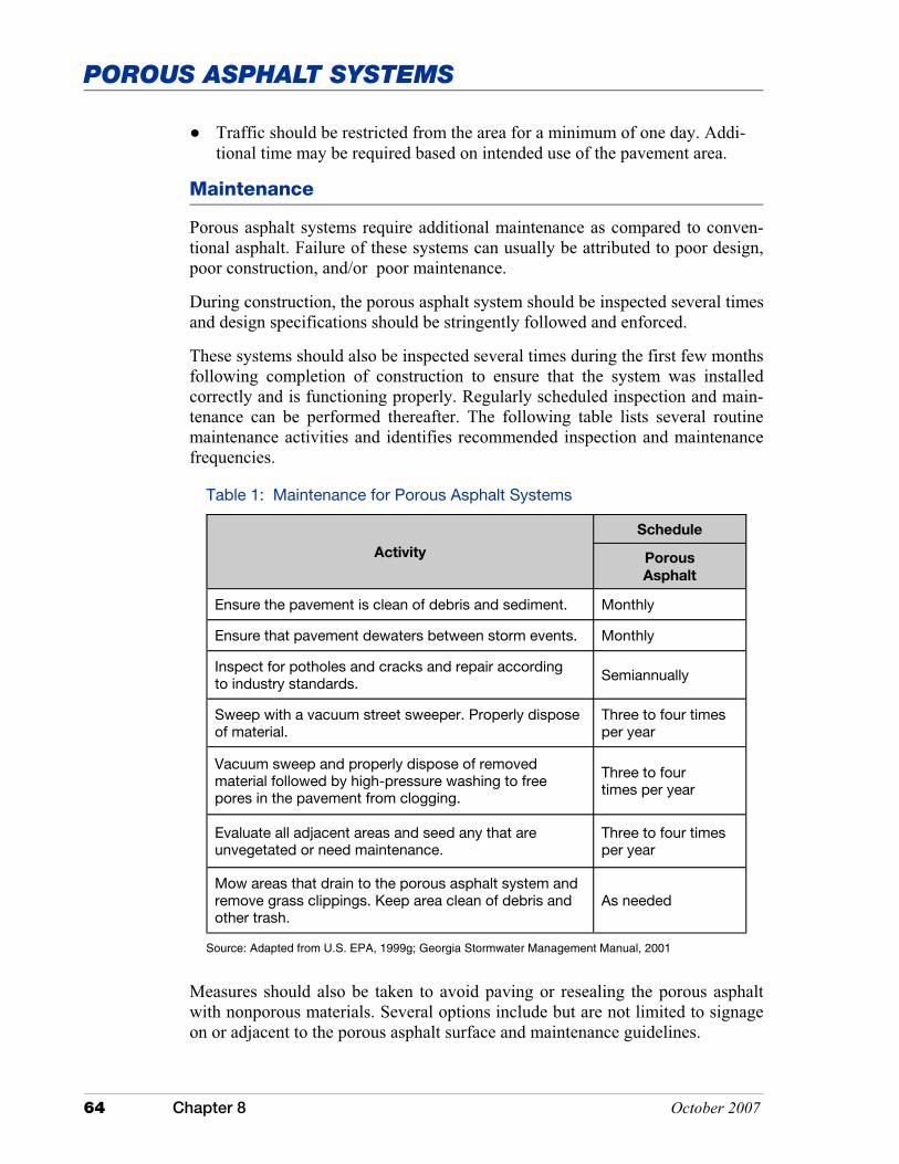
64 Chapter 8 October 2007
POROUS ASPHALT SYSTEMS
Table 1: Maintenance for Porous Asphalt Systems
Activity
Schedule
Porous
Asphalt
Ensure the pavement is clean of debris and sediment. Monthly
Ensure that pavement dewaters between storm events. Monthly
Inspect for potholes and cracks and repair according to industry standards. Semiannually
Sweep with a vacuum street sweeper. Properly dispose of material.
Three to four times per year
Vacuum sweep and properly dispose of removed material followed by high-pressure washing to free pores in the pavement from clogging.
Three to four times per year
Evaluate all adjacent areas and seed any that are unvegetated or need maintenance.
Three to four times per year
Mow areas that drain to the porous asphalt system and remove grass clippings. Keep area clean of debris and other trash.
As needed
Source: Adapted from U.S. EPA, 1999g; Georgia Stormwater Management Manual, 2001
� Traffic should be restricted from the area for a minimum of one day. Addi-tional time may be required based on intended use of the pavement area.
Maintenance
Porous asphalt systems require additional maintenance as compared to conven-tional asphalt. Failure of these systems can usually be attributed to poor design, poor construction, and/or poor maintenance.
During construction, the porous asphalt system should be inspected several times and design specifications should be stringently followed and enforced.
These systems should also be inspected several times during the first few months following completion of construction to ensure that the system was installed correctly and is functioning properly. Regularly scheduled inspection and main-tenance can be performed thereafter. The following table lists several routine maintenance activities and identifies recommended inspection and maintenance frequencies.
Measures should also be taken to avoid paving or resealing the porous asphalt with nonporous materials. Several options include but are not limited to signage on or adjacent to the porous asphalt surface and maintenance guidelines.
October 2007 Chapter 8 65
POROUS ASPHALT SYSTEMS
It is important that those involved with maintenance of a porous asphalt system understand that maintenance is critical to the success of this measure. A carefully worded maintenance agreement should be developed that provides specific guid-ance about how to conduct routine maintenance and how the surface should be repaved. Where practicable, signs identifying the porous asphalt system should be posted on or adjacent to the site [e.g., Porous Asphalt Pavement Used on this Site�DO NOT Resurface with Nonporous Material or Film Forming Sealers. Call (xxx) xxx-xxxx for more information].
In addition to regularly scheduled maintenance, the life expectancy of porous asphalt systems can usually be increased by implementing a stringent sediment control plan, pretreating storm water runoff, and placing restrictions on use by heavy vehicles. In cold climates, limit the use of sand and gravel to prevent clog-ging and wear. Use of deicing agents should be minimized to protect ground wa-ter. If snow is to be removed by mechanical means, set the blade of the snow plow one to two inches above the surface of the pavement.
Costs
When porous asphalt systems are properly installed and maintained, they can be a valuable part of any storm water management system. Important issues to consider when doing a cost-benefit analysis include surrounding land use, amount of traffic, and the proximity and sensitivity of nearby watersheds.
The initial costs of porous asphalt systems are often competitive or slightly higher than conventional pavement systems. These costs can generally be attrib-uted to site preparation, the proximity to gravel/stone supplies, and the use of specialized equipment. For example, installation of the stone reservoir is usually more expensive than construction of a conventional compacted sub-base associ-ated with traditional pavement systems. However, some of the higher installation costs associated with porous asphalt systems can often be offset if the system is designed to fit the existing topography. This generally results in less earth moving activity and fewer deep excavations than with conventional pavement systems. Installation costs can also be offset when the need for other types of storm water management measures such as storm water pipes, inlets, curbs and gutters, retention/detention basins, etc. are eliminated or their overall size is reduced.
Maintenance costs of porous asphalt systems are also generally higher than con-ventional pavement systems. The cost of vacuum sweeping and pressure wash-ing of the pavement may be substantial if a community or facility owner does not already perform these types of operations in their maintenance program activities.

66 Chapter 8 October 2007
POROUS ASPHALT SYSTEMS
Additional Information
Internet Keyword Search: porous pavement, porous pavement systems, porous asphalt, and pervious asphalt
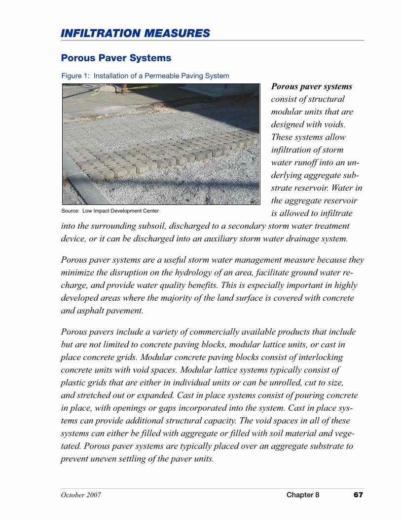
October 2007 Chapter 8 67
INFILTRATION MEASURES
Porous Paver Systems
Porous paver systems consist of structural modular units that are designed with voids. These systems allow infiltration of storm water runoff into an un-derlying aggregate sub-strate reservoir. Water in the aggregate reservoir is allowed to infiltrate
into the surrounding subsoil, discharged to a secondary storm water treatment device, or it can be discharged into an auxiliary storm water drainage system.
Porous paver systems are a useful storm water management measure because they minimize the disruption on the hydrology of an area, facilitate ground water re-charge, and provide water quality benefits. This is especially important in highly developed areas where the majority of the land surface is covered with concrete and asphalt pavement.
Porous pavers include a variety of commercially available products that include but are not limited to concrete paving blocks, modular lattice units, or cast in place concrete grids. Modular concrete paving blocks consist of interlocking concrete units with void spaces. Modular lattice systems typically consist of plastic grids that are either in individual units or can be unrolled, cut to size, and stretched out or expanded. Cast in place systems consist of pouring concrete in place, with openings or gaps incorporated into the system. Cast in place sys-tems can provide additional structural capacity. The void spaces in all of these systems can either be filled with aggregate or filled with soil material and vege-tated. Porous paver systems are typically placed over an aggregate substrate to prevent uneven settling of the paver units.
Figure 1: Installation of a Permeable Paving System
Source: Low Impact Development Center
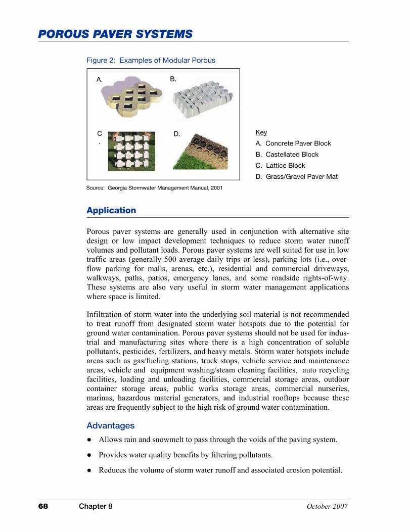
68 Chapter 8 October 2007
POROUS PAVER SYSTEMS
Porous paver systems are generally used in conjunction with alternative site design or low impact development techniques to reduce storm water runoff volumes and pollutant loads. Porous paver systems are well suited for use in low traffic areas (generally 500 average daily trips or less), parking lots (i.e., over-flow parking for malls, arenas, etc.), residential and commercial driveways, walkways, paths, patios, emergency lanes, and some roadside rights-of-way. These systems are also very useful in storm water management applications where space is limited.
Infiltration of storm water into the underlying soil material is not recommended to treat runoff from designated storm water hotspots due to the potential for ground water contamination. Porous paver systems should not be used for indus-trial and manufacturing sites where there is a high concentration of soluble pollutants, pesticides, fertilizers, and heavy metals. Storm water hotspots include areas such as gas/fueling stations, truck stops, vehicle service and maintenance areas, vehicle and equipment washing/steam cleaning facilities, auto recycling facilities, loading and unloading facilities, commercial storage areas, outdoor container storage areas, public works storage areas, commercial nurseries, marinas, hazardous material generators, and industrial rooftops because these areas are frequently subject to the high risk of ground water contamination.
Advantages
� Allows rain and snowmelt to pass through the voids of the paving system.
� Provides water quality benefits by filtering pollutants.
� Reduces the volume of storm water runoff and associated erosion potential.
Application
Key
A. Concrete Paver Block
B. Castellated Block
C. Lattice Block
D. Grass/Gravel Paver Mat
Figure 2: Examples of Modular Porous
A. B.
C.
D.
Source: Georgia Stormwater Management Manual, 2001
October 2007 Chapter 8 69
POROUS PAVER SYSTEMS
� Attenuates peak discharge flows and reduces the amount of storm water entering storm drain systems.
� Provides some natural filtration capacity while maintaining the structural and functional features of the conventional pavement material it replaces.
� Stone reservoir can be lined with an impermeable liner, allowing storm water to be reused, stored, or treated through utilization of a secondary storm water treatment measure.
� Minimizes the disruption of the hydrology of an area by providing a reser-voir and percolation field for surface water to re-enter ground water aquifers, recharges low flow in streams during dry periods, and reduces downstream flooding.
� Minimizes the amount of land consumption by reducing the need for tradi-tional storm water management structures, thereby saving open space for alternative uses.
� Minimizes construction and maintenance costs of street curbs and gutters, storm sewer systems typically required to carry storm water to an outfall, and other associated storm water management measures such as retention/ detention ponds.
� Aesthetically pleasing.
� When damaged, or clogged, small areas can be easily replaced.
Disadvantages
� Requires design and installation by experienced engineers and contractors.
� More costly than conventional pavement due to materials and installation.
� Requires soil infiltration rate of one-half inch per hour or greater.
� Snow removal is difficult since snow plow blades can damage or dislodge paver units, sand application can lead to premature clogging, and salt can result in ground water contamination.
� Not suitable for use in wellhead protection areas.
� Not suitable for areas that require wheelchair access.
� Poorly suited for use in naturally occurring seasonal high water table soils.
� The pavement surface, if improperly installed and maintained, has a tendency to become clogged with particulate matter and debris.
� Poses a risk to ground water contamination. For example, pollutants such as nitrates and chlorides that are not easily trapped, absorbed, or reduced may
70 Chapter 8 October 2007
POROUS PAVER SYSTEMS
continue to move through the soil profile and into ground water (dependant on soil conditions and aquifer susceptibility).
� Potential risk for vehicle fuels, oils, greases, and other substances to leak onto the pavement and leach into ground water.
� May cause frost heave of pavement if system is improperly designed, installed, or maintained.
� Typically have higher maintenance requirements than conventional pavement systems.
� Local building codes sometimes restrict the use of these systems without special approval or variances.
Performance
The initial performance of porous paver systems has been very good. The failure rate over time has been high. Failure has been attributed to poor design, inade-quate construction techniques, poor siting, and poor maintenance.
Properly designed, installed, and maintained porous paver systems can be cost effective and provide a storm water management system that promotes infiltra-tion and the removal of pollutants from storm water runoff flowing through the system. Pollutant removal mechanisms associated with these systems include absorption, straining, and microbiological decomposition. Pollutant removal effectiveness will vary depending on system design, soil substrate characteris-tics, and proper maintenance of the system. Sampling data for these systems,
Design Specifications
Design of porous paver systems is critical if they are to function properly and efficiently. Following are some basic requirements for the design and installation of porous paver systems.
Information in this section was assembled from a variety of sources including the U.S. Environmental Protection Agency’s post-construction storm water man-agement in new development and redevelopment fact sheet entitled Alternative Pavers (2002l); Metropolitan Council Environmental Services’ Minnesota Urban Small Sites BMP Manual (2001); and the Georgia Stormwater Manage-ment Manual (2001).
Pretreatment
Pretreatment should be considered, and is especially recommended, where oil and grease or other potential ground water contaminants are expected. System designers should take into account pollutants that are associated with the land use and apply appropriate pretreatment measures to target specific pollutants.

October 2007 Chapter 8 71
POROUS PAVER SYSTEMS
Adjacent areas that drain to a porous paver system should be stabilized and/or designed so that runoff from an adjacent area will not deposit sediment onto the porous paver surface. Otherwise, frequent maintenance of the pavement surface is critical to prevent clogging.
Treatment
A stone reservoir should be incorporated into systems where soil conditions are not favorable to promote infiltration. The reservoir, which lies immediately beneath the pavement, should be designed and sized to attenuate and treat a small storm water runoff event (typically 0.5 inch to 1.5 inches). Storage capac-ity must be designed around the amount of air/pore space in the reservoir since this is the only area where water can be stored.
Conveyance
Porous paver systems require some method of conveying storm water runoff through the system. Voids in the porous pavers allow storm water to infiltrate into the underlying stone reservoir. Water stored in the stone reservoir is then allowed to either infiltrate into the underlying soil substrate or be held in an underground impermeable closed system that discharges to a secondary storm water management/treatment measure via subsurface drainage pipes.
Porous paver systems should be designed with some method to convey large storm events to the underlying stone reservoir. Setting storm drain inlets at stra-tegic locations within the system design will allow larger storm water flows to enter the stone reservoir in the event that the infiltration rate of the pavement is insufficient to handle the storm event or the surface becomes clogged.
Landscaping
Preventing sediment loads from clogging the porous paver surface is critical if the system is to function properly. Therefore, it is important to develop and im-plement a landscaping plan that will ensure that the contributing drainage area is stabilized. This is especially true during active construction, but is also applica-ble for post-construction activities.
Design of porous paver systems also requires evaluation and incorporation of several key elements such as, but not limited to, soil type, infiltration rate, depth to a limiting layer (e.g., bedrock, a seasonal high water table, glacial till), slope length and gradient, construction materials, and installation methods. Following are several key design specifications that should be considered and evaluated when siting, designing, and installing porous paver systems.

72 Chapter 8 October 2007
POROUS PAVER SYSTEMS
Siting
� Select infiltration opportunities within the immediate development area.
� Avoid conveying storm water long distances.
� Consider the source of the storm water runoff to be treated.
� Poorly suited for use in wellhead protection areas.
� Minimum setback of 100 feet from wells used to supply drinking water. State rules or local ordinances may require distances greater than 100 feet.
� Minimum setback of 100 feet up-gradient of building foundations. Local building codes may dictate setback requirements.
� Minimum setback of 10 feet down-gradient of building foundations. Local building codes may dictate setback requirements.
� Poorly suited for use in naturally occurring seasonal high water table soils.
� These systems are not suitable in areas with karst geology without adequate geotechnical assessment by qualified individuals. System placement and design may also be subject to local requirements or ordinances.
� Soil Substrate
� Perform site tests to determine depth to seasonal high water table, depth to bedrock, and soil limitations, including infiltration capabilities.
� Soils should be homogeneous and should not have any compacted layers. � For optimal performance, locate systems on deep, well-drained,
permeable soils. Soil should have field-verified permeability rates between one-half and three inches per hour or silt/clay contents of less than 40 percent and be in U.S. Department of Agriculture Natural Resources Conservation Service hydrologic groups A or B. Permeability rates of less than one-half inch per hour and soils with higher clay content can be accommodated through special design.
� The ideal application of porous paver systems is typically on slopes of two percent or less.
General Design Considerations
Typical design of porous paver systems include geotextile liner, stone reservoir, geotextile liner (optional), a bedding course, and finally the paver.
� Design based on likely traffic loadings and projected life of the system.
October 2007 Chapter 8 73
POROUS PAVER SYSTEMS
To achieve performance, the following criteria should be applied:
� Subgrade to sustain traffic loading. � Granular capping and sub-base layers should have sufficient load bearing
to provide an adequate base for the overlying pavement selected. � Materials chosen should not crack or be subject to rutting. This is
controlled by horizontal tensile stress at the base of these layers. � The slope limitation may be overcome through terracing the porous paver
system.
� Do not infiltrate stored storm water runoff into compacted fill because the permeability will often be too slow.
� Place observation wells downstream of the porous paver system.
Geotextile Fabric Liner
� Nonwoven geotextile fabric of at least four ounce weight to allow water to drain into the soil while preventing soil particles from moving into the stone reservoir.
� Placed on uncompacted natural soil.
� Placed flush with soil surface (bottom and sides) of excavated stone reservoir and overlapped a minimum of 12 inches between adjoining rolls.
Stone Reservoir
� Size and depth of reservoir is determined by soil infiltration rate, total impervious surface area (i.e., contiguous impervious roadways and streets, rooftops, etc.) drained into the reservoir, design storm event, and frost line depth.
� Depth of reservoir is based on design storage capacity and land use. Typically, the minimum reservoir depth is nine inches.
� Twelve-hour minimum and 72-hour maximum draw-down time with a recommended draw-down time of 24 to 48 hours. (Note: Microbiological decomposition can be impeded if soils are unable to dry out and anaerobic conditions are allowed to develop between storm events.)
� Design storage capacity should not include those areas above the pavement. Designers should also exclude the porous pavers as part of the design storage capacity.
� It is also important to design porous paver systems with a mechanism to discharge water from the stone reservoir in the event that its design storage capacity is exceeded. An exfiltration system should be incorporated into a
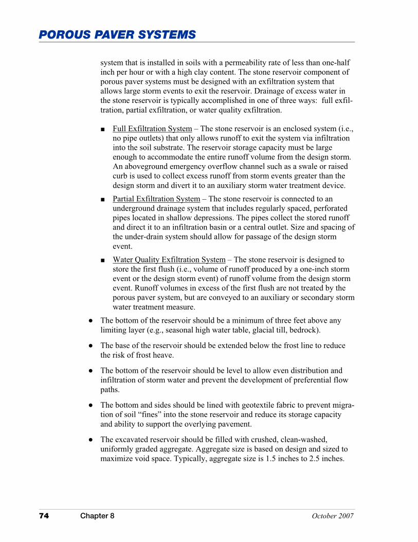
74 Chapter 8 October 2007
POROUS PAVER SYSTEMS
system that is installed in soils with a permeability rate of less than one-half inch per hour or with a high clay content. The stone reservoir component of porous paver systems must be designed with an exfiltration system that allows large storm events to exit the reservoir. Drainage of excess water in the stone reservoir is typically accomplished in one of three ways: full exfil-tration, partial exfiltration, or water quality exfiltration.
� Full Exfiltration System – The stone reservoir is an enclosed system (i.e., no pipe outlets) that only allows runoff to exit the system via infiltration into the soil substrate. The reservoir storage capacity must be large enough to accommodate the entire runoff volume from the design storm. An aboveground emergency overflow channel such as a swale or raised curb is used to collect excess runoff from storm events greater than the design storm and divert it to an auxiliary storm water treatment device.
� Partial Exfiltration System – The stone reservoir is connected to an underground drainage system that includes regularly spaced, perforated pipes located in shallow depressions. The pipes collect the stored runoff and direct it to an infiltration basin or a central outlet. Size and spacing of the under-drain system should allow for passage of the design storm event.
� Water Quality Exfiltration System – The stone reservoir is designed to store the first flush (i.e., volume of runoff produced by a one-inch storm event or the design storm event) of runoff volume from the design storm event. Runoff volumes in excess of the first flush are not treated by the porous paver system, but are conveyed to an auxiliary or secondary storm water treatment measure.
� The bottom of the reservoir should be a minimum of three feet above any limiting layer (e.g., seasonal high water table, glacial till, bedrock).
� The base of the reservoir should be extended below the frost line to reduce the risk of frost heave.
� The bottom of the reservoir should be level to allow even distribution and infiltration of storm water and prevent the development of preferential flow paths.
� The bottom and sides should be lined with geotextile fabric to prevent migra-tion of soil “fines” into the stone reservoir and reduce its storage capacity and ability to support the overlying pavement.
� The excavated reservoir should be filled with crushed, clean-washed, uniformly graded aggregate. Aggregate size is based on design and sized to maximize void space. Typically, aggregate size is 1.5 inches to 2.5 inches.

October 2007 Chapter 8 75
POROUS PAVER SYSTEMS
� Water from the stone reservoir should not be allowed to infiltrate into mate-rial underlying adjacent conventional pavements as this could cause failure of the conventional pavement.
Paver
� The type of paver should be selected based on the intended land use and the overall objective of the project.
� The contributing impervious surface to porous paver system ratio should be no more than 3:1.
� Design to minimize amount of storm water runoff the porous paver system receives from adjacent areas. If necessary divert runoff from adjacent areas into the stone reservoir before it reaches the porous paver surface. This can be done by incorporating an unpaved stone edge at the perimeter of the pave-ment or installing catch basins designed to discharge into the stone reservoir. (NOTE: The unpaved stone perimeter and/or catch basins can also act as an emergency entrance/spillway that will allow storm water runoff to enter the stone reservoir in the event that the porous paver becomes paved over, clogged, or forgotten.)
� Design the system to contain spills.
� Ensure paving material infiltration rates are greater than the peak design rainfall intensity.
� The porosity rate can be correlated with the proposed land use and therefore may require design modification.
Regional Adaptations
� In cold climates, the base of the stone reservoir should be below the frost line or the system should be designed to facilitate drainage of storm water away from the aggregate recharge bed to reduce the risk of frost heave.
Installation
Proper installation of porous paver systems is critical to its long-term perform-ance as a storm water quality measure. Therefore, it is important that the installa-tion conform to industry standards and specifications.
� Provide thorough construction oversight by trained individuals.
� Maintain erosion and sediment control measures until the site is stabilized. Active construction sites involve mass earthmoving and many activities that can generate sediment. It is often recommended to install these systems late in the construction phase of a project when there is less likelihood of sedi-

76 Chapter 8 October 2007
POROUS PAVER SYSTEMS
ment discharge. (Sedimentation that discharges onto a porous paver system can result in failure of the infiltration system or require higher maintenance.)
� Excavate the area for the stone reservoir, taking precautions to avoid com-paction of the soil substrate and smearing of the exposed soil faces of the excavation. Scarify any areas where the soil face(s) has been smeared.
� Install geotextile fabric liner on the bottom and sides of the stone reservoir, overlapping adjoining rolls by 12 inches or more. If the system being installed is closed, install an appropriate impermeable membrane.
� Place aggregate as specified in the construction plans. The aggregate should be placed in lifts and slightly compacted.
� Install geotextile liner (optional) based on design requirements and product.
� Install bedding course.
� Install pavers to the dimensions and grades shown in the construction plans.
� Infill should be based on use. Masonry sand has a high infiltration rate and is typically used when vegetation is not placed. Sandy loam material is pre-ferred for areas where vegetation is planned.
� For systems that are to be vegetated, exclude traffic from the porous paver system for at least one month after planting to allow for establishment of a dense stand of vegetation.
Maintenance
Maintenance of porous paver systems is relatively minimal but absolutely necessary to ensure efficient and proper operation of the system. Inspection of these systems should occur monthly for the first few months after installation. Inspection frequency can be extended once it is determined that the system is stable and functioning properly. Failure of these systems is often attributed to poor design, poor construction, heavy vehicular traffic, and poor maintenance.
Table 1 contains several recommended maintenance guidelines. The system manufacturer or designer may have alternative or specific requirements based on the system that has been installed.
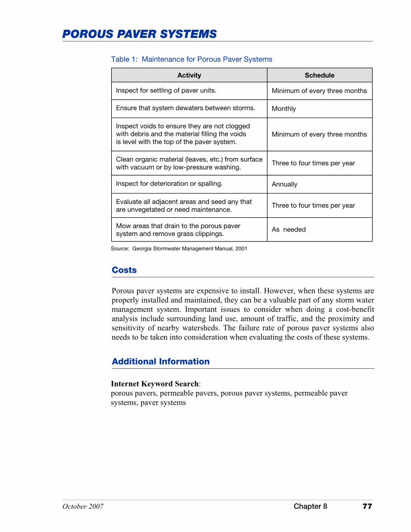
October 2007 Chapter 8 77
POROUS PAVER SYSTEMS
Additional Information
Internet Keyword Search: porous pavers, permeable pavers, porous paver systems, permeable paver systems, paver systems
Costs
Porous paver systems are expensive to install. However, when these systems are properly installed and maintained, they can be a valuable part of any storm water management system. Important issues to consider when doing a cost-benefit analysis include surrounding land use, amount of traffic, and the proximity and sensitivity of nearby watersheds. The failure rate of porous paver systems also needs to be taken into consideration when evaluating the costs of these systems.
Source: Georgia Stormwater Management Manual, 2001
Table 1: Maintenance for Porous Paver Systems
Activity Schedule
Inspect for settling of paver units. Minimum of every three months
Inspect voids to ensure they are not clogged with debris and the material filling the voids is level with the top of the paver system.
Minimum of every three months
Clean organic material (leaves, etc.) from surface with vacuum or by low-pressure washing.
Three to four times per year
Mow areas that drain to the porous paver system and remove grass clippings.
As needed
Inspect for deterioration or spalling. Annually
Evaluate all adjacent areas and seed any that are unvegetated or need maintenance.
Three to four times per year
Ensure that system dewaters between storms. Monthly

This page was intentionally left blank.
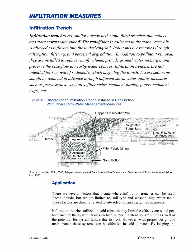
October 2007 Chapter 8 79
INFILTRATION MEASURES
Infiltration Trench
Infiltration trenches are shallow, excavated, stone-filled trenches that collect and store storm water runoff. The runoff that is collected in the stone reservoir is allowed to infiltrate into the underlying soil. Pollutants are removed through adsorption, filtering, and bacterial degradation. In addition to pollutant removal, they are installed to reduce runoff volume, provide ground water recharge, and preserve the base flow in nearby water courses. Infiltration trenches are not intended for removal of sediments, which may clog the trench. Excess sediments should be removed in advance through adjacent storm water quality measures such as grass swales, vegetative filter strips, sediment forebay ponds, sediment traps, etc.
Application
Source: Lowndes, M.A., 2000, Adapted from Maryland Department of the Environment, Sediment and Storm Water Administra-tion, 1985
Capped Observation Well
Vegetated Buffer Strip
Barrier
Aggregate Subbase
Sand Bottom
Filter Fabric Lining
Sheet Flow Runoff from Paved Area
Aggregate Surface Layer
Figure 1: Diagram of an Infiltration Trench Installed in Conjunction With Other Storm Water Management Measures
There are several factors that dictate where infiltration trenches can be used. These include, but are not limited to, soil type and seasonal high water table. These factors are directly related to site selection and design requirements.
Infiltration trenches utilized in cold climates may limit the effectiveness and per-formance of the system. Issues include winter maintenance activities as well as the potential for system failure due to frost. However, with proper design and maintenance these systems can be effective in cold climates. By keeping the

80 Chapter 8 October 2007
INFILTRATION TRENCH
trench surface free of compacted snow and ice, and by ensuring that part of the trench is constructed below the frost line, the performance of the trench during cold weather will be greatly improved (U.S. EPA, 1999c). Infiltration systems are poorly suited for use in areas where it is necessary to apply sand or other de-icing agents to the pavement surface. Sand may begin to clog the system, whereas other deicing agents may migrate into the ground water.
Infiltration trenches are an option in medium- to high-density residential, com-mercial, and institutional areas. The areas selected for the system must have natural occurring soils (no fill sites) with permeable subsoil to provide for infil-tration and a water table well below the trench bottom to prevent ground water contamination.
Infiltration of storm water into the underlying soil material is not recommended to treat runoff from designated storm water hotspots due to the potential for ground water contamination. Infiltration trenches should not be used for indus-trial and manufacturing sites where there is a high concentration of soluble pol-lutants, pesticides, fertilizers, and heavy metals. Storm water hotspots include areas such as gas/fueling stations, truck stops, vehicle service and maintenance areas, vehicle and equipment washing/steam cleaning facilities, auto recycling facilities, loading and unloading facilities, commercial storage areas, outdoor container storage areas, public works storage areas, commercial nurseries, marinas, hazardous material generators, and industrial rooftops because these areas are frequently subject to the high risk of ground water contamination.
Although efficient as a treatment system for a number of common pollutants, infiltration trenches are not well suited as a pollutant treatment measure in well-head protection areas or as a measure to treat runoff from storm water hotspots due to possible ground water contamination. Pretreatment that targets specific pollutants may address some of these issues provided the soils below the trench are adequate for the treatment of pollutants. In karst areas, this measure may not be suitable due to potential ground water contamination and the concern of sink-hole formation. Their use in karst areas should only be considered with adequate geotechnical assessment by qualified individuals. Installation of these systems may also be limited due to local requirements or ordinances.
Performance
Efficient performance of infiltration trenches is directly related to site character-istics and proper trench design, installation, and maintenance. Sites with appro-priate infiltration rates, limited bedrock, and a ground water table well below the trench will offer the best performance. Regular monitoring and maintenance to prevent clogging of the stone reservoir is critical to ensure performance. Table 1 summarizes performance data for an infiltration trench. To improve overall effectiveness, these systems can be installed as part of a treatment train to target specific pollutants. It is expected that the removal rate for nitrates, chlorides, and soluble metals will be lower, especially in sandy soils (Schueler, 1987).

October 2007 Chapter 8 81
INFILTRATION TRENCH
Table 1: Pollutants Removed Through Infiltration Trenches
Pollutant Percent Removed
Phosphorous 60
Nitrogen 60
Metals 90
Bacteria 90
Organics 90
Source: Schueler, 1992
Sediment 90
Biochemical Oxygen Demand 70 – 80
Design Specifications
Siting, design, installation, and maintenance of infiltration trenches are critical if they are to function properly and efficiently. Therefore, the trench, and especially the storm water component, should be designed by a professional proficient in hydrology and storm water design.
The decision to use an infiltration trench should include evaluating the site characteristics and incorporating basic elements into the design including, but not limited to, pretreatment, treatment, conveyance, and landscaping.
Pretreatment
Common concerns with the design and performance of infiltration trenches relate to trench clogging and filtering capacity. Pretreatment should be considered, and is recommended, where organic matter, oil and grease, sediment, or other potential ground water contaminants are expected in the runoff. Storm water management measures such as filter strips, grass channels, oil grit separators, and sediment trapping measures are a few options that should be installed to pretreat runoff
Adjacent areas that drain to an infiltration trench should be stabilized and/or designed so that runoff from an adjacent area will not convey sediment to the infiltration trench.
Treatment
A stone reservoir is a key element of an infiltration trench. The reservoir can either be at grade or below grade. At grade systems collect runoff from sheet flow and an underground system receives the runoff through pipes or other types

82 Chapter 8 October 2007
INFILTRATION TRENCH
of conveyances. The reservoir should be designed and sized to attenuate and treat a small storm water runoff event (typically 0.5 inch to 1.5 inches). Storage capacity must be designed around the amount of air/pore space in the reservoir since this is the only area where water can be stored.
Conveyance
Infiltration trenches will require some method of conveying storm water runoff to the treatment system. During construction of the overall system it is critical that all conveyance systems and land area above the infiltration system are stabilized with appropriate nonerosive cover. Vegetation is the preferred stabilization method as it will also provide additional pollutant removal.
Infiltration systems should be designed to treat small storms. The initial runoff from a storm event or first flush will typically carry the majority of the pollutants. Runoff that is in excess of the amount to be treated should bypass the infiltration trench and be diverted to a secondary storm water management device or to a stable outlet.
Landscaping
Preventing sediment from clogging the infiltration trench is critical if the system is to function properly. Therefore, it is important to develop and implement a landscaping plan that will ensure that the contributing drainage area is stabilized. This is especially true during active construction, but is also applicable for post construction activities. Unstable, non-vegetated slopes exposed during construc-tion can contribute excessive amounts of sediment to a newly installed trench. It is strongly recommended that infiltration trenches be installed during post construction phases after the site has been stabilized.
The siting and design of an infiltration trench requires evaluation of several key elements such as, but not limited to, soil type, infiltration rate, depth to a limiting layer (e.g., bedrock, a seasonal high water table), slope length and gradient, construction materials, and installation methods.
Siting
Infiltration trenches are poorly suited for use in naturally occurring seasonal high water table soils. For optimal performance, locate systems on deep, well drained, permeable soils.
These systems are not suitable for wellhead protection areas. Their use in areas with karst geology should also be limited without adequate geotechnical assessment by qualified individuals. System placement and design may also be subject to local requirements or ordinances.
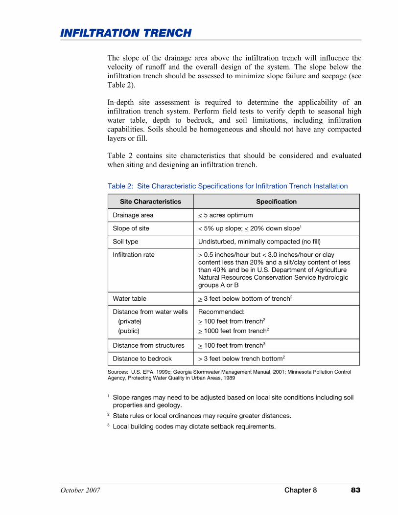
October 2007 Chapter 8 83
INFILTRATION TRENCH
Table 2: Site Characteristic Specifications for Infiltration Trench Installation
Site Characteristics Specification
Drainage area < 5 acres optimum
Slope of site < 5% up slope; < 20% down slope1
Soil type Undisturbed, minimally compacted (no fill)
Infiltration rate > 0.5 inches/hour but < 3.0 inches/hour or clay content less than 20% and a silt/clay content of less than 40% and be in U.S. Department of Agriculture Natural Resources Conservation Service hydrologic groups A or B
Water table > 3 feet below bottom of trench2
Distance from water wells
(private)
(public)
Recommended:
> 100 feet from trench2
> 1000 feet from trench2
Distance from structures > 100 feet from trench3
Distance to bedrock > 3 feet below trench bottom2
Sources: U.S. EPA, 1999c; Georgia Stormwater Management Manual, 2001; Minnesota Pollution Control Agency, Protecting Water Quality in Urban Areas, 1989
The slope of the drainage area above the infiltration trench will influence the velocity of runoff and the overall design of the system. The slope below the infiltration trench should be assessed to minimize slope failure and seepage (see Table 2).
In-depth site assessment is required to determine the applicability of an infiltration trench system. Perform field tests to verify depth to seasonal high water table, depth to bedrock, and soil limitations, including infiltration capabilities. Soils should be homogeneous and should not have any compacted layers or fill.
Table 2 contains site characteristics that should be considered and evaluated when siting and designing an infiltration trench.
1 Slope ranges may need to be adjusted based on local site conditions including soil properties and geology. 2 State rules or local ordinances may require greater distances. 3 Local building codes may dictate setback requirements.
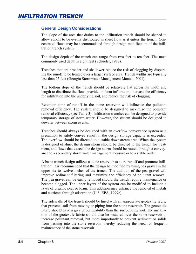
84 Chapter 8 October 2007
INFILTRATION TRENCH
General Design Considerations
The slope of the area that drains to the infiltration trench should be shaped to allow runoff to be evenly distributed in sheet flow as it enters the trench. Con-centrated flows may be accommodated through design modification of the infil-tration trench system.
The design depth of the trench can range from two feet to ten feet. The most commonly used depth is eight feet (Schueler, 1987).
Trenches that are broader and shallower reduce the risk of clogging by dispers-ing the runoff to be treated over a larger surface area. Trench widths are typically less than 25 feet (Georgia Stormwater Management Manual, 2001).
The bottom slope of the trench should be relatively flat across its width and length to distribute the flow, provide uniform infiltration, increase the efficiency for infiltration into the underlying soil, and reduce the risk of clogging.
Retention time of runoff in the stone reservoir will influence the pollutant removal efficiency. The system should be designed to maximize the pollutant removal efficiency (see Table 3). Infiltration trenches can be designed to provide temporary storage of storm water. However, the system should be designed to dewater between storm events.
Trenches should always be designed with an overflow conveyance system as a precaution to safely convey runoff if the design storage capacity is exceeded. The overflow should be directed to a stable downstream area. When the system is designed off-line, the design storm should be directed to the trench for treat-ment, and flows that exceed the design storm should be routed through a convey-ance to a secondary storm water management measure or to a stable outlet.
A basic trench design utilizes a stone reservoir to store runoff and promote infil-tration. It is recommended that the design be modified by using pea gravel in the upper six to twelve inches of the trench. The addition of the pea gravel will improve sediment filtering and maximize the efficiency of pollutant removal. The pea gravel can be easily removed should the trench require maintenance or become clogged. The upper layers of the system can be modified to include a layer of organic peat or loam. This addition may enhance the removal of metals and nutrients through adsorption (U.S. EPA, 1999c).
The sidewalls of the trench should be lined with an appropriate geotextile fabric that prevents soil from moving or piping into the stone reservoir. The geotextile fabric should have a greater permeability than the surrounding soil. The installa-tion of the geotextile fabric should also be installed over the stone reservoir to increase pollutant removal, but more importantly to prevent sediment or solids from passing into the stone reservoir thereby reducing the need for frequent maintenance of the stone reservoir.
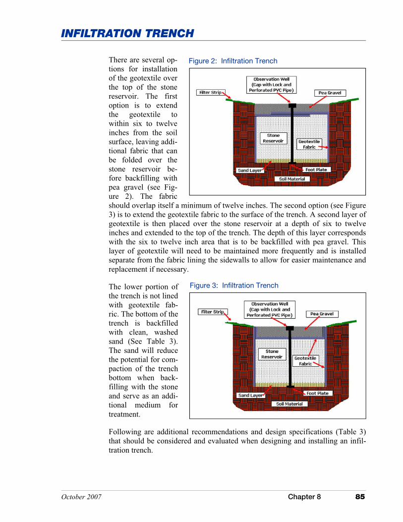
October 2007 Chapter 8 85
INFILTRATION TRENCH
There are several op-tions for installation of the geotextile over the top of the stone reservoir. The first option is to extend the geotextile to within six to twelve inches from the soil surface, leaving addi-tional fabric that can be folded over the stone reservoir be-fore backfilling with pea gravel (see Fig-ure 2). The fabric should overlap itself a minimum of twelve inches. The second option (see Figure 3) is to extend the geotextile fabric to the surface of the trench. A second layer of geotextile is then placed over the stone reservoir at a depth of six to twelve inches and extended to the top of the trench. The depth of this layer corresponds with the six to twelve inch area that is to be backfilled with pea gravel. This layer of geotextile will need to be maintained more frequently and is installed separate from the fabric lining the sidewalls to allow for easier maintenance and replacement if necessary.
The lower portion of the trench is not lined with geotextile fab-ric. The bottom of the trench is backfilled with clean, washed sand (See Table 3). The sand will reduce the potential for com-paction of the trench bottom when back-filling with the stone and serve as an addi-tional medium for treatment.
Following are additional recommendations and design specifications (Table 3) that should be considered and evaluated when designing and installing an infil-tration trench.
Figure 2: Infiltration Trench
Figure 3: Infiltration Trench

86 Chapter 8 October 2007
INFILTRATION TRENCH
Installation
It is best to install infiltration trenches only after the drainage area has been ade-quately stabilized to reduce the potential for sediments to enter the system and clog it prematurely. Trench installation should follow the design standards and specifications as outlined in the plans. It is important to note that these systems should be designed by qualified individuals and meet all state and local stan-dards and specifications.
� During excavation of the trench, equipment should be selected that will mini-mize the compaction of the soils adjacent to the excavation. During excava-tion of the trench, the bottom and sidewalls should be scarified and all large roots trimmed to provide a uniform sidewall.
� Install the geotextile fabric.
� Place the clean, washed sand into the bottom of the trench.
� Place the prewashed stone into the trench.
Table 3: Trench Characteristics
Trench
Characteristic Requirement
Aggregate size One to three inch, prewashed aggregate; upper one foot can be replaced with pea gravel
Sand layer 12-inch layer spread uniformly over the bottom of the trench
Filter fabric opening size
> 30 micrometers non-woven
Filter fabric depth Upper edge of fabric one foot below trench surface
Drainage time > 6 hours
Observation well Four to six inch diameter perforated pipe embedded vertically through aggregate with cap and secured foot plate; long trench lengths may require multiple observation wells (minimum 100 foot spacing)
Trench depth Standard 8 feet; can be calculated based on infiltra-tion rates, aggregate void space, and trench storage characteristics
Trench volume Calculations based on first one-half inch of runoff per acre of surface area draining to trench
Sources: U.S. EPA, 1999c; Lowdnes, 2000; Schueler, 1987; Georgia Stormwater Management Manual, 2001; Minnesota Pollution Control Agency, Protecting Water Quality in Urban Areas, 1989

October 2007 Chapter 8 87
INFILTRATION TRENCH
Maintenance
During the first year of installation, observation wells should be monitored after every significant storm event to ensure proper drainage of the trench. This measure can be monitored seasonally after the first year. To monitor the observation well, use a long stick or rod to check for standing water. Standing water in the well may indicate clogging of the trench. Recheck the well following several days of dry weather. It may be necessary to replace the pea gravel, stone in reservoir, and all or part of the geotextile fabric if the trench be-comes clogged. Maintenance should also be performed on storm water measures within the drainage area of the trench to ensure sediment and other solids are removed before runoff enters the trench. Regular inspection and maintenance is critical to maintaining proper functioning of infiltration trenches.
Costs
Annual maintenance costs are estimated at five to ten percent of the initial construction costs (Schueler, 1987). Major rehabilitation of the filter fabric and aggregate fill is often required every five to 15 years (U.S. EPA, 1999c).
Additional Information
Internet Keyword Search: infiltration trench
� Install the protective layer of geotextile fabric over the stone reservoir.
� The top surface of the trench, above the geotextile fabric, is backfilled with pea gravel. As an alternative, the trench can also be covered with permeable topsoil and planted with grass to improve the aesthetics and blend in with the adjacent landscape. It should be noted that the addition of topsoil may freeze during the winter months, reducing the ability of runoff to infiltrate into the trench.

This page was intentionally left blank.
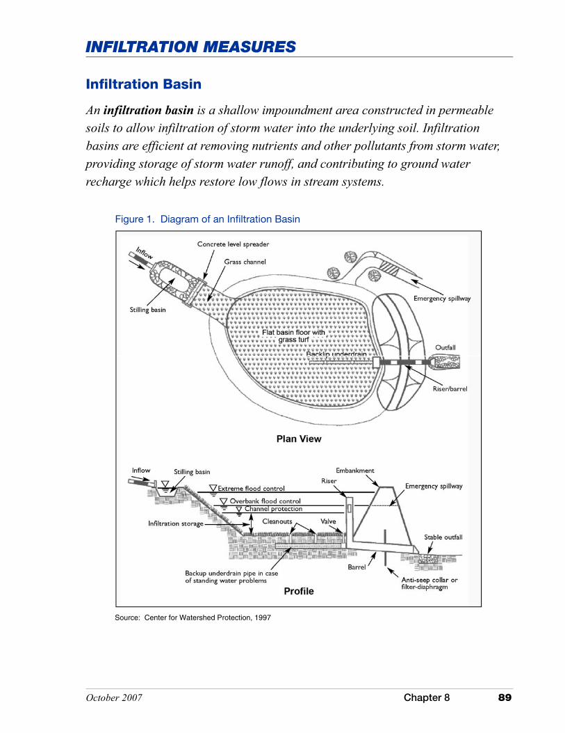
October 2007 Chapter 8 89
INFILTRATION MEASURES
Infiltration Basin
Source: Center for Watershed Protection, 1997
An infiltration basin is a shallow impoundment area constructed in permeable soils to allow infiltration of storm water into the underlying soil. Infiltration basins are efficient at removing nutrients and other pollutants from storm water, providing storage of storm water runoff, and contributing to ground water recharge which helps restore low flows in stream systems.
Figure 1. Diagram of an Infiltration Basin
90 Chapter 8 October 2007
INFILTRATION BASIN
Application
There are several factors that dictate where infiltration basins can be used. These include, but are not limited to, soil type and seasonal high water table. These fac-tors are directly related to site selection and design requirements. Infiltration ba-sins are an option in residential, commercial, and institutional areas. Their use is often restricted by concerns for ground water contamination, site feasibility, and the underlying soil material. The areas selected for an infiltration basin should have natural occurring soils. These measures are not typically placed in heavily urbanized areas due to the availability of soils that have not been altered, com-pacted, or filled.
These measures are typically installed to infiltrate storm water runoff. It is com-mon for these measures to be placed in areas where the infiltration properties of the soil are very high. Soils with high permeability rates will promote infiltration and work well. However, the guidance provided in this manual limits the range of permeability to three inches per hour. This limit is based on water quality benefits. Permeability rates above this limit will provide infiltration, but will reduce the effectiveness for pollutant removal.
Infiltration of storm water into the underlying soil material is not recommended to treat runoff from designated storm water hotspots due to the potential for ground water contamination. Infiltration basins should not be used for industrial and manufacturing sites where there is a high concentration of soluble pollutants, pesticides, fertilizers, and heavy metals. Storm water hotspots include areas such as gas/fueling stations, truck stops, vehicle service and maintenance areas, vehi-cle and equipment washing/steam cleaning facilities, auto recycling facilities, loading and unloading facilities, commercial storage areas, outdoor container storage areas, public works storage areas, commercial nurseries, marinas, haz-ardous material generators, and industrial rooftops because these areas are fre-quently subject to the high risk of ground water contamination.
Although efficient as a treatment system for a number of common pollutants, infiltration basins are not well suited as a pollutant treatment measure in well-head protection areas or as a measure to treat runoff from storm water hotspots due to possible ground water contamination. Pretreatment that targets specific pollutants may address some of these issues provided the soils within the basin are adequate for the treatment of pollutants. In karst areas, this measure may not be suitable due to potential ground water contamination and the concern of sink-hole formation. Installation of these systems may also be limited due to local re-quirements or ordinances.
Infiltration basins utilized in cold climates may limit the effectiveness and per-formance of the system. Issues include winter maintenance activities as well as the potential for system failure due to frost. However, with proper design and maintenance these systems can be effective in cold climates. Infiltration systems

October 2007 Chapter 8 91
INFILTRATION BASIN
Siting, design, installation, and maintenance of infiltration basins are critical if they are to function properly and efficiently. Therefore, the basin, and especially the storm water component, should be designed by a professional proficient in hydrology and storm water design.
Information in this section was assembled and adapted from a variety of sources including the U.S. Environmental Protection Agency, Post Construction Storm Water Management in New Development and Redevelopment, Infiltration Ba-sins (2002j); Wisconsin Department of Natural Resources, Wisconsin Storm Wa-
Table 1: Pollutants Removed by Infiltration Basins
Pollutant Percent Removed*
Sediment 74-90
Phosphorous 50-70
Nitrogen 45-60
Trace Metals 75-90
Bacteria 75-90
Source: Schueler, 1987
*Efficiency of pollutant removal depends on the volume of runoff from the first flush captured in the infiltration basin. The larger the volume captured, the more efficient the pollutant removal.
Performance
Performance of infiltration basins is directly related to site characteristics and proper design, installation, and maintenance. The efficiency of infiltration basins to filter pollutants from storm water runoff is highly dependent on soil type and the volume of runoff captured. Soils with higher permeability increase infiltra-tion but have a lower capacity for pollutant removal than soils with higher clay content. Regular monitoring and maintenance to prevent clogging of the basin is also critical to ensure performance. To improve overall effectiveness, these systems can be installed as part of a treatment train to target specific pollutants. Table 1 summarizes performance data for an infiltration basin.
Design Specifications
are poorly suited for use in areas where it is necessary to apply sand or other de-icing agents to the pavement surface. Sand may begin to clog the system, whereas other deicing agents may migrate into the ground water.
92 Chapter 8 October 2007
INFILTRATION BASIN
ter Manual (2000); Metropolitan Council Environmental Services, Minnesota Urban Small Sites Best Management Practices Manual (2001); and Minnesota Pollution Control Agency, Protecting Water Quality in Urban Areas (1989). The decision to use an infiltration basin should include evaluating the site char-acteristics and incorporating basic elements into the design including, but not limited to, pretreatment, treatment, conveyance, and landscaping.
Common concerns with the design and performance of infiltration basins are related to clogging and filtering capacity. Infiltration basins are not sediment control measures. The basin should be designed with appropriate pretreatment measures to trap sediments. Pretreatment should be considered, and is recom-mended, where organic matter, oil and grease, sediment, or other potential ground water contaminants are expected in the runoff. Storm water management measures such as filter strips, grass channels, oil grit separators, and sediment trapping measures are a few options that should be installed to treat runoff before it is directed to the basin.
Adjacent areas that drain to an infiltration basin should be stabilized and/or designed so that runoff from an adjacent area will not convey sediment to the infiltration basin.
Siting
The siting and design of an infiltration basin requires evaluation and analysis of several key elements such as, but not limited to, soil type, infiltration rate, depth to a limiting layer (e.g., bedrock, a seasonal high water table), slope length and gradient, construction materials, and installation methods. Perform field tests to verify depth to seasonal high water table, depth to bedrock, and soil limitations, including infiltration capabilities. Soils should be homogeneous and should not have any compacted layers or fill material.
Infiltration basins are poorly suited for use in naturally occurring seasonal high water table soils. For optimal performance, locate systems on deep, well drained, soils.
Following are site characteristics and criteria (Table 2) that should be considered and evaluated when siting and designing an infiltration basin.
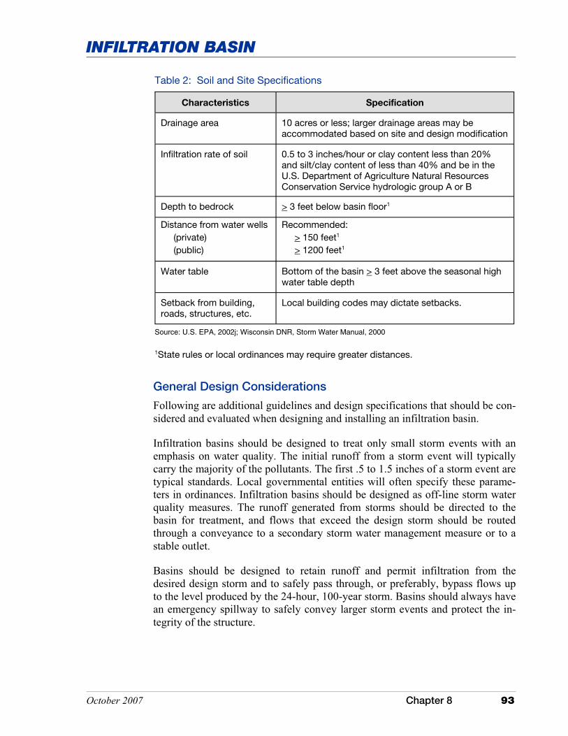
October 2007 Chapter 8 93
INFILTRATION BASIN
Table 2: Soil and Site Specifications
Characteristics Specification
Drainage area 10 acres or less; larger drainage areas may be accommodated based on site and design modification
Infiltration rate of soil 0.5 to 3 inches/hour or clay content less than 20% and silt/clay content of less than 40% and be in the U.S. Department of Agriculture Natural Resources Conservation Service hydrologic group A or B
Depth to bedrock > 3 feet below basin floor1
Distance from water wells (private) (public)
Recommended: > 150 feet1 > 1200 feet1
Water table Bottom of the basin > 3 feet above the seasonal high water table depth
Setback from building, roads, structures, etc.
Local building codes may dictate setbacks.
Source: U.S. EPA, 2002j; Wisconsin DNR, Storm Water Manual, 2000
1State rules or local ordinances may require greater distances.
General Design Considerations
Following are additional guidelines and design specifications that should be con-sidered and evaluated when designing and installing an infiltration basin.
Infiltration basins should be designed to treat only small storm events with an emphasis on water quality. The initial runoff from a storm event will typically carry the majority of the pollutants. The first .5 to 1.5 inches of a storm event are typical standards. Local governmental entities will often specify these parame-ters in ordinances. Infiltration basins should be designed as off-line storm water quality measures. The runoff generated from storms should be directed to the basin for treatment, and flows that exceed the design storm should be routed through a conveyance to a secondary storm water management measure or to a stable outlet.
Basins should be designed to retain runoff and permit infiltration from the desired design storm and to safely pass through, or preferably, bypass flows up to the level produced by the 24-hour, 100-year storm. Basins should always have an emergency spillway to safely convey larger storm events and protect the in-tegrity of the structure.

94 Chapter 8 October 2007
INFILTRATION BASIN
Calculate the required storage volume from infiltration rates and the desired in-filtration time. The majority, if not all infiltration, will occur through the bottom of the basin. It is recommended that the side slopes of the basin are not factored in this determination. This volume is relatively small. Designs should be based on careful evaluation and field testing. Testing and site conditions can be incon-sistent; the designer should always allow for a safety factor in calculating the infiltration capability of the soils within the basin.
Typical depths for infiltration basins are three to twelve feet, with the maximum depth based on the infiltration properties of the soils. Shallow basins with large surface areas are more effective than basins that are deep. The basin should be large enough that aerobic conditions are maintained. The basin should have a completely flat bottom and have a length to width ratio of at least 3:1.
Retention time within the basin will influence the pollutant removal efficiency. A minimum drainage time of six hours is recommended for satisfactory pollutant removal (Schueler, 1987; Wisconsin DNR, Storm Water Manual, 2000). The basin may also be designed to provide temporary storage, however the basin should be designed to dewater completely between storm events.
Storm water runoff should be conveyed through the treatment basin in a safe manner that minimizes erosion. Erosion and the deposition of sediment in the treatment area will do little for the performance of this measure. To promote uni-form dispersion of storm water runoff and to prevent channeling, the system should be designed with a grass filter strip, level spreader, or other system to promote sheet flow into the basin area.
The basin bottom and side slopes should be seeded to a fast growing permanent seed species. Deep rooted vegetation will increase infiltration. The species selected should be hardy and tolerant of both drought and wet conditions. A thick stand of vegetative cover will promote infiltration and provide stability to prevent erosion. The underlying soil, organic matter, and a grass cover with a sufficient root system will help to decompose and trap pollutants.
The side slopes of the basin should be no steeper than 3:1. Side slopes of 4:1 are preferred due to ease of maintenance.
Part of the system design also includes provisions for maintenance. The designer should provide a stable access point for equipment that will be utilized for main-tenance. The basin should also be designed with an under drain if it becomes clogged.
October 2007 Chapter 8 95
INFILTRATION BASIN
Installation
It is best to install infiltration basins only after the drainage area has been ade-quately stabilized to reduce the potential for sediments to enter the system and clog it prematurely. Installation should follow the design standards and specifi-cations as outlined in the plans. It is important to note that these systems should be designed by qualified individuals and meet all state and local standards and specifications. Following are guidelines that should be observed during installa-tion of the basin.
Preventing sediment from clogging the infiltration basin is critical if the system is to function properly. Therefore, it is important to develop and implement a landscaping plan that will ensure that the contributing drainage area is stabilized. This is especially true during active construction, but is also applicable for post construction activities. Unstable, nonvegetated slopes exposed during construc-tion can contribute excessive amounts of sediment to a newly installed basin. It is strongly recommended that the infiltration basin be installed during post con-struction phases after the site has been stabilized.
� Every effort should be made to direct surface runoff away from the basin until the structure and drainage area have been stabilized.
� Basins installed during construction or prior to final stabilization of the drainage area should not be excavated to the design depth. The excavation should be within one to two feet above the final grade. During excavation, equipment should be selected that will minimize the compaction of the soils. Upon stabilization of the drainage area final excavation of the basin can be completed and the basin stabilized.
� If the system is built during the construction phase it is not advisable to utilize the basin as a sediment control measure. The best alternative is to install appropriate erosion and sediment control measures within the drainage area to reduce sediment loading to the basin. If this is not practical or suc-cessful, the basin will require maintenance.
� Upon reaching final grade, the basin floor should be tilled to a depth of at least six inches to provide aeration. The addition and incorporation of com-post will also aid in infiltration and root growth.
� Construction traffic should also be restricted from the basin.
96 Chapter 8 October 2007
INFILTRATION BASIN
Maintenance
Maintenance of these measures is high and critical to performance. Appropriate steps must be taken to monitor and observe the operation of an infiltration basin. Poor maintenance will generally result in poor performance and high failure rates. Following are several maintenance tips and a suggested maintenance schedule (see Table 3) for infiltration basins.
� The basin should be evaluated to assess performance. As a general rule, standing water should not remain in the basin for more than two to three days. If the infiltration rates exceed three days, the system may be failing. If there is an indication of failure an assessment of the system should be made by a professional and where appropriate corrective action initiated. Mosquitoes may also become problematic where water does not infiltrate and ponds.
� Sediment accumulation in the basin will require periodic maintenance. This maintenance activity should be completed as needed based on accumulation rates. Remove sediment from the basin under dry conditions and restore original cross section. This activity should be performed with machinery that will minimize the compaction of the soils.
� The infiltration capability of the basin will decrease over time. Periodic tilling and replanting will help restore infiltration rates.
� Mowing is a standard maintenance requirement for basins. The grass should be maintained at a height of at least three inches. The grass should be mowed when the surface of the basin is dry. This will avoid potential problems with compaction and rutting of the basin floor. Mowing under wet conditions may also cause the grass to mat.
� Fertilization may be necessary to maintain healthy vegetation. It is recommended that the application be based on a soil test and applied at the appropriate rate. The use of low phosphorus and slow release fertilizers should also be considered.
� The basin should not be used for parking or as a recreational facility.
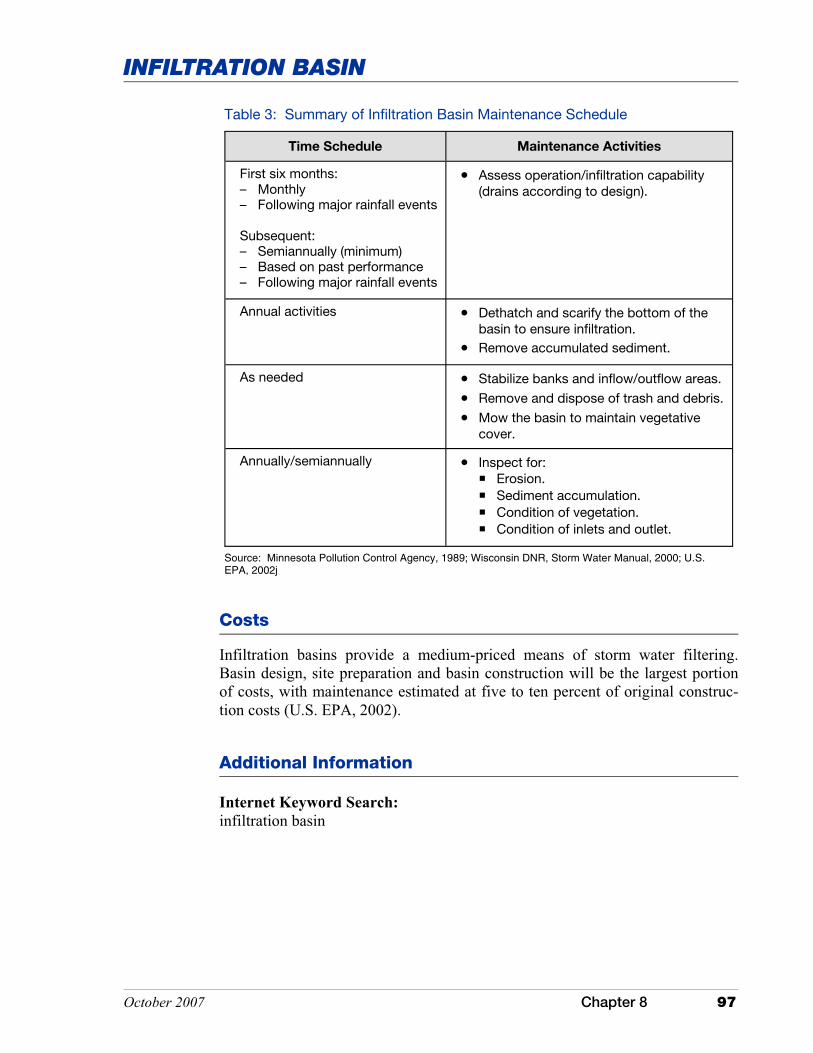
October 2007 Chapter 8 97
INFILTRATION BASIN
Table 3: Summary of Infiltration Basin Maintenance Schedule
Time Schedule Maintenance Activities
First six months: – Monthly – Following major rainfall events Subsequent: – Semiannually (minimum) – Based on past performance – Following major rainfall events
• Assess operation/infiltration capability (drains according to design).
Annual activities • Dethatch and scarify the bottom of the basin to ensure infiltration.
• Remove accumulated sediment.
As needed • Stabilize banks and inflow/outflow areas.
• Remove and dispose of trash and debris.
• Mow the basin to maintain vegetative cover.
Annually/semiannually • Inspect for: ��Erosion. ��Sediment accumulation. ��Condition of vegetation. ��Condition of inlets and outlet.
Source: Minnesota Pollution Control Agency, 1989; Wisconsin DNR, Storm Water Manual, 2000; U.S. EPA, 2002j
Costs
Infiltration basins provide a medium-priced means of storm water filtering. Basin design, site preparation and basin construction will be the largest portion of costs, with maintenance estimated at five to ten percent of original construc-tion costs (U.S. EPA, 2002).
Additional Information
Internet Keyword Search: infiltration basin

This page was intentionally left blank.
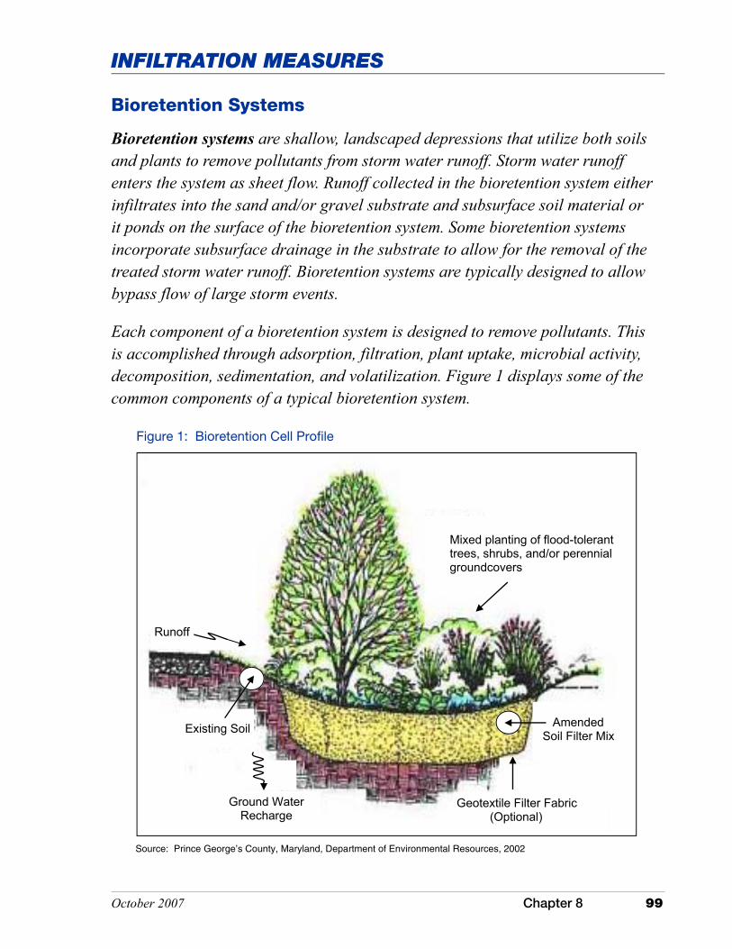
October 2007 Chapter 8 99
INFILTRATION MEASURES
Bioretention Systems
Bioretention systems are shallow, landscaped depressions that utilize both soils and plants to remove pollutants from storm water runoff. Storm water runoff enters the system as sheet flow. Runoff collected in the bioretention system either infiltrates into the sand and/or gravel substrate and subsurface soil material or it ponds on the surface of the bioretention system. Some bioretention systems incorporate subsurface drainage in the substrate to allow for the removal of the treated storm water runoff. Bioretention systems are typically designed to allow bypass flow of large storm events.
Each component of a bioretention system is designed to remove pollutants. This is accomplished through adsorption, filtration, plant uptake, microbial activity, decomposition, sedimentation, and volatilization. Figure 1 displays some of the common components of a typical bioretention system.
Figure 1: Bioretention Cell Profile
Source: Prince George’s County, Maryland, Department of Environmental Resources, 2002
Mixed planting of flood-tolerant trees, shrubs, and/or perennial groundcovers
Amended Soil Filter Mix Existing Soil
Geotextile Filter Fabric (Optional)
Ground Water Recharge
Runoff
100 Chapter 8 October 2007
BIORETENTION SYSTEMS
Application
Bioretention systems are designed to treat storm water runoff from impervious surfaces. Bioretention systems can be easily incorporated into the design of sev-eral filtration and infiltration storm water management systems. They are com-monly used in parking lot islands, median strips, and drainage swales. Bioreten-tion systems are not suited to storm water hotspots if infiltration is part of the treatment. To overcome this limitation, the system can be modified with an impermeable liner and subsurface drainage. It is important to ensure that the con-tributing drainage area is stabilized to lower the impact of sediment loading in the bioretention system treatment area. Following is a list of advantages and dis-advantages that should be considered when evaluating whether or not to use a bioretention system (Metropolitan Council Environmental Services, 2001, Min-nesota Urban Small Sites Best Management Practices Manual; Georgia Storm-water Management Manual, 2001).
Advantages
� Layout is flexible and aesthetically pleasing due to the incorporation of a variety of plants.
� Reduces volume of runoff from the drainage area.
� Effective at removing fine sediment, trace metals, nutrients, bacteria, and organics.
� Ideally suited to most impervious areas and can be easily adapted to many geologic and climatic environments.
� Reduces downstream flooding and protects channel integrity.
� Provides ground water recharge and base flow in local streams.
� Can be used as a storm water retrofit (modification of landscape or resurfacing a parking lot).
Disadvantages
� Not suitable for treatment of storm water runoff from large drainage areas.
� Clogging may be a problem, especially with high sediment loads.
� Occupies about five percent of the area draining into the system.
� Construction cost can be relatively high compared to other storm water management measures.
� Incorporating bioretention into a parking lot may reduce the availability of parking spaces.
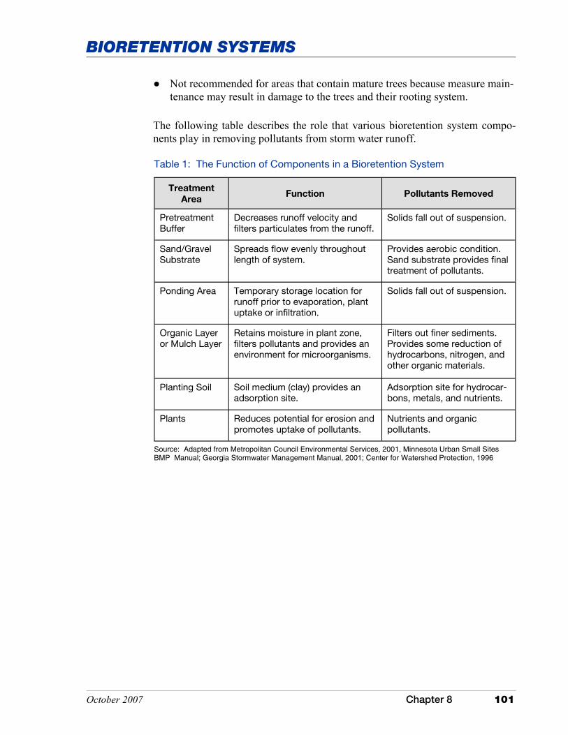
October 2007 Chapter 8 101
BIORETENTION SYSTEMS
The following table describes the role that various bioretention system compo-nents play in removing pollutants from storm water runoff.
Table 1: The Function of Components in a Bioretention System
Treatment
Area Function Pollutants Removed
Pretreatment Buffer
Decreases runoff velocity and filters particulates from the runoff.
Solids fall out of suspension.
Sand/Gravel Substrate
Spreads flow evenly throughout length of system.
Provides aerobic condition. Sand substrate provides final treatment of pollutants.
Ponding Area Temporary storage location for runoff prior to evaporation, plant uptake or infiltration.
Solids fall out of suspension.
Organic Layer or Mulch Layer
Retains moisture in plant zone, filters pollutants and provides an environment for microorganisms.
Filters out finer sediments. Provides some reduction of hydrocarbons, nitrogen, and other organic materials.
Planting Soil Soil medium (clay) provides an adsorption site.
Adsorption site for hydrocar-bons, metals, and nutrients.
Plants Reduces potential for erosion and promotes uptake of pollutants.
Nutrients and organic pollutants.
Source: Adapted from Metropolitan Council Environmental Services, 2001, Minnesota Urban Small Sites BMP Manual; Georgia Stormwater Management Manual, 2001; Center for Watershed Protection, 1996
� Not recommended for areas that contain mature trees because measure main-tenance may result in damage to the trees and their rooting system.

102 Chapter 8 October 2007
BIORETENTION SYSTEMS
Design Specifications
Siting, design, installation, and maintenance of bioretention systems are critical if they are to function properly and efficiently. Therefore bioretention systems should be designed by a professional proficient in hydrology and storm water design.
Following is a list of general guidelines that should be considered in the siting and design of a bioretention system. Table 2 provides additional guidelines that are specific to each of the components of a bioretention system. This information was assembled and adapted from a variety of sources including the Georgia Stormwater Management Manual (2001); Metropolitan Council Environmental Services, Minnesota Urban Small Sites Best Management Practices Manual (2001); and the Center for Watershed Protection, Design of Stormwater Filtering Systems (1996, December). The Center for Watershed Protection document listed above provides in-depth procedures to aid in the design of bioretention systems.
� The drainage area should not exceed five acres. Ideal drainage area is one-quarter acre to no greater than two acres, otherwise the system tends to become clogged with sediment. Multiple bioretention areas may be required for large drainage areas.
� The size of the bioretention area should be five percent to ten percent of the impervious surfaces within the drainage area. The recommended minimum
Source: Indiana Department of Natural Resources, Lake Michigan Coastal Program
Figure 2: Landscaped Bioretention

October 2007 Chapter 8 103
BIORETENTION SYSTEMS
dimensions for a bioretention area are 10 feet wide by 20 feet long. Any system wider than 20 feet should be at least twice as long to evenly distribute the flow.
� A ponding depth of six to nine inches is recommended. This depth is adequate for storage and prevents water from standing for an excessive amount of time.
� A bioretention system is engineered with specific media, and soil properties are usually not applicable unless the system is designed for infiltration, thereby allowing runoff to infiltrate into the undisturbed, underlying native subsoil (see the Infiltration Trench section on page 79).
� Slopes should be five percent or flatter.
� The bottom of the bioretention area should be three feet or more above the seasonal high water table to minimize the potential for ground water contamination. To accommodate higher water tables the designer may choose to utilize subsurface drainage.
� Bioretention areas intended for treatment of storm water runoff from parking lots or use as a snow storage area should contain salt-tolerant, non-woody plant species.
� Construction of bioretention systems is most cost efficient and environmen-tally friendly in sites that are already planned for excavation or landscape grading.
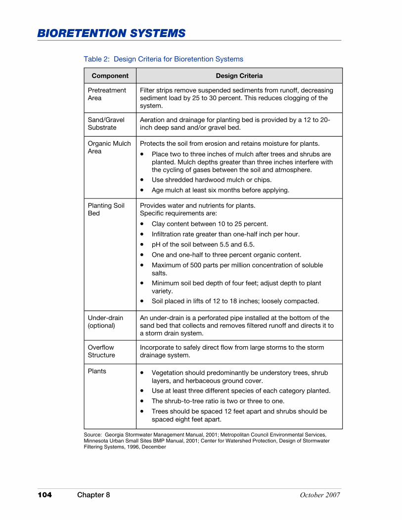
104 Chapter 8 October 2007
BIORETENTION SYSTEMS
Table 2: Design Criteria for Bioretention Systems
Component Design Criteria
Pretreatment Area
Filter strips remove suspended sediments from runoff, decreasing sediment load by 25 to 30 percent. This reduces clogging of the system.
Sand/Gravel Substrate
Aeration and drainage for planting bed is provided by a 12 to 20-inch deep sand and/or gravel bed.
Organic Mulch Area
Protects the soil from erosion and retains moisture for plants.
• Place two to three inches of mulch after trees and shrubs are planted. Mulch depths greater than three inches interfere with the cycling of gases between the soil and atmosphere.
• Use shredded hardwood mulch or chips.
• Age mulch at least six months before applying.
Planting Soil Bed
Provides water and nutrients for plants. Specific requirements are:
• Clay content between 10 to 25 percent.
• Infiltration rate greater than one-half inch per hour.
• pH of the soil between 5.5 and 6.5.
• One and one-half to three percent organic content.
• Maximum of 500 parts per million concentration of soluble salts.
• Minimum soil bed depth of four feet; adjust depth to plant variety.
• Soil placed in lifts of 12 to 18 inches; loosely compacted.
Under-drain (optional)
An under-drain is a perforated pipe installed at the bottom of the sand bed that collects and removes filtered runoff and directs it to a storm drain system.
Overflow Structure
Incorporate to safely direct flow from large storms to the storm drainage system.
Plants • Vegetation should predominantly be understory trees, shrub layers, and herbaceous ground cover.
• Use at least three different species of each category planted.
• The shrub-to-tree ratio is two or three to one.
• Trees should be spaced 12 feet apart and shrubs should be spaced eight feet apart.
Source: Georgia Stormwater Management Manual, 2001; Metropolitan Council Environmental Services, Minnesota Urban Small Sites BMP Manual, 2001; Center for Watershed Protection, Design of Stormwater Filtering Systems, 1996, December

October 2007 Chapter 8 105
BIORETENTION SYSTEMS
Table 3 shows laboratory and field results regarding the removal of pollutants in bioretention systems.
Table 3: Pollutant Removal Rates (Laboratory and Estimated Values)
Pollutant Removal Rate
Total Phosphorus 70% – 83%
Metals (Cu, Zn, Pb) 93% – 98%
Total Kjeldahl Nitrogen (TKN) 68% – 80%
Total Suspended Solids 90%
Organics 90%
Bacteria 90%
Source: U.S. EPA
Figure 2: Design of a Bioretention System
Source: Center for Watershed Protection
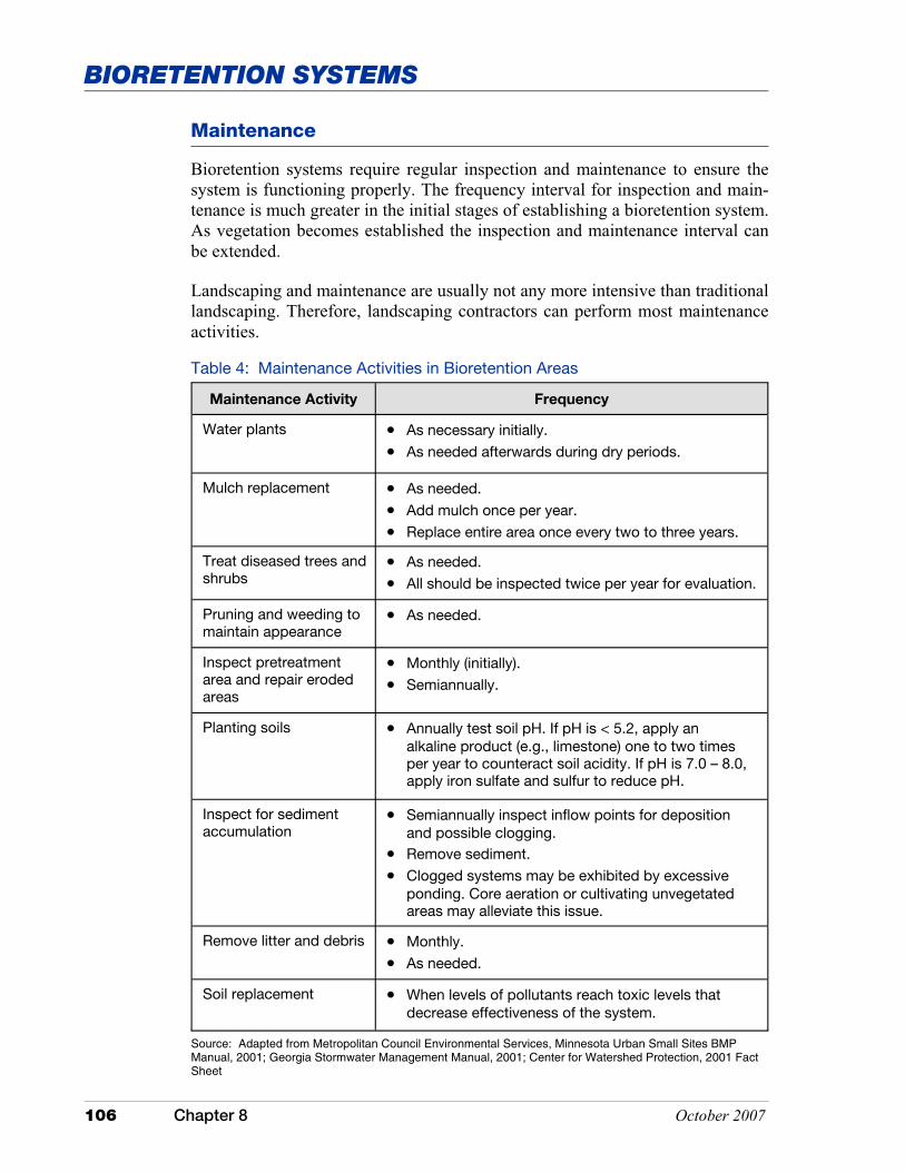
106 Chapter 8 October 2007
BIORETENTION SYSTEMS
Maintenance
Bioretention systems require regular inspection and maintenance to ensure the system is functioning properly. The frequency interval for inspection and main-tenance is much greater in the initial stages of establishing a bioretention system. As vegetation becomes established the inspection and maintenance interval can be extended.
Landscaping and maintenance are usually not any more intensive than traditional landscaping. Therefore, landscaping contractors can perform most maintenance activities.
Table 4: Maintenance Activities in Bioretention Areas
Maintenance Activity Frequency
Water plants • As necessary initially.
• As needed afterwards during dry periods.
Mulch replacement • As needed.
• Add mulch once per year.
• Replace entire area once every two to three years.
Treat diseased trees and shrubs
• As needed.
• All should be inspected twice per year for evaluation.
Pruning and weeding to maintain appearance
• As needed.
Inspect pretreatment area and repair eroded areas
• Monthly (initially).
• Semiannually.
Planting soils • Annually test soil pH. If pH is < 5.2, apply an alkaline product (e.g., limestone) one to two times per year to counteract soil acidity. If pH is 7.0 – 8.0, apply iron sulfate and sulfur to reduce pH.
Inspect for sediment accumulation
• Semiannually inspect inflow points for deposition and possible clogging.
• Remove sediment.
• Clogged systems may be exhibited by excessive ponding. Core aeration or cultivating unvegetated areas may alleviate this issue.
Remove litter and debris • Monthly.
• As needed.
Soil replacement • When levels of pollutants reach toxic levels that decrease effectiveness of the system.
Source: Adapted from Metropolitan Council Environmental Services, Minnesota Urban Small Sites BMP Manual, 2001; Georgia Stormwater Management Manual, 2001; Center for Watershed Protection, 2001 Fact Sheet

October 2007 Chapter 8 107
BIORETENTION SYSTEMS
Costs
The cost of constructing bioretention systems is only a little higher than the cost to landscape a new development. Costs are considerably higher to retrofit a site. This increase in costs includes demolition of any pre-existing structures and the placement of suitable soil material for the establishment of vegetation. Operation and maintenance costs for bioretention systems are similar to typical landscaping costs.
Additional Information
Internet Keyword Search: bioretention ponds, bioretention, biofiltration systems, infiltration systems, storm water filtration

This page was intentionally left blank.
October 2007 Chapter 8 109
SETTLING & FLOCCULATION MEASURES
S ettling and flocculation measures are typically storm water management measures that have been modified to allow for the settling or flocculation of suspended solids and pollutants
that may be attached to the solids. Most of the measures listed in this section of the manual can be effective at reducing peak discharges and flooding, but are relatively ineffective at removing water soluble pollutants. The removal of soluble pollutants may be achieved by selecting or in-corporating natural systems, such as storm water wetlands, into the overall design of the meas-ure. Measures in this category include but are not limited to dry ponds, wet ponds, and subsur-face detention structures. Sediment forebays and storm water wetlands have also been included in this section as they can achieve multiple objectives, including pollutant removal through up-take by vegetation. These systems can also be utilized as a pretreatment or secondary treatment measure with dry ponds, wet ponds, and subsurface detention.
The design of settling and flocculation measures can be complex and generally require detailed site investigation, including an assessment of potential pollutants and the application of sound engineering principles. A professional knowledgeable of storm water management and water quality principles and experienced in design should be consulted when using these measures.

This page was intentionally left blank.
October 2007 Chapter 8 111
SETTLING & FLOCCULATION MEASURES
Application
Dry extended detention basins, when carefully planned and constructed, are applicable in a wide variety of situations. The flexibility of basin design makes this measure one of the more versatile storm water management measures.
Dry extended detention basins should not be considered the final solution for pollutant removal. These structures have limited effectiveness for pollutant removal. The pollutants that are associated with runoff from the drainage area should be evaluated and considered when selecting and designing a measure. This will be particularly critical if the drainage area includes storm water hotspots. Therefore, consideration should be given to pretreatment storm water quality measures or alternative measures should be selected in place of dry detention that will meet the objectives for pollutant removal.
Following are several benefits and limitations associated with the use of extended dry detention basins (Georgia Stormwater Management Manual, 2001; Connecticut Stormwater Quality Manual, 2004; U.S. Environmental Protection Agency, 2002d).
Dry Extended Detention Basins
Dry extended detention and dry detention basins are constructed basins that collect, temporarily hold, and gradually release excess storm water from storm events. Detention is achieved through the use of an outlet control structure that regulates the rate of storm water outflow. Unlike wet ponds, dry detention basins are designed to drain completely between storm events, thereby attenuating peak flows associated with storm events. Dry extended detention basins are particu-larly effective at reducing downstream streambank erosion related to increased peak discharge associated with urbanization. Dry basins are usually designed to drain in less than 24 hours. Dry basins are limited in ability to retain sediment. Sediments that settle out are subject to resuspension. Dry extended detention basins are designed with a minimum retention time of 24 hours. Through careful design, dry extended detention basins can be effective at removing urban pollut-ants. Treatment is primarily achieved by the sedimentation process where sus-pended particles settle to the bottom of the basin. Based on this information, dry extended detention basins are the preferred option when choosing between an extended basin and a conventional dry basin.
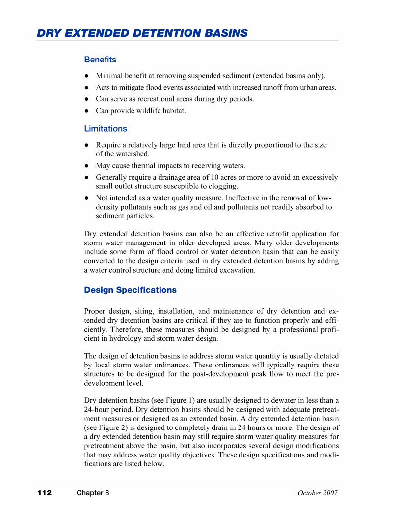
112 Chapter 8 October 2007
DRY EXTENDED DETENTION BASINS
Benefits
� Minimal benefit at removing suspended sediment (extended basins only). � Acts to mitigate flood events associated with increased runoff from urban areas. � Can serve as recreational areas during dry periods. � Can provide wildlife habitat.
Limitations
� Require a relatively large land area that is directly proportional to the size of the watershed.
� May cause thermal impacts to receiving waters. � Generally require a drainage area of 10 acres or more to avoid an excessively
small outlet structure susceptible to clogging. � Not intended as a water quality measure. Ineffective in the removal of low-
density pollutants such as gas and oil and pollutants not readily absorbed to sediment particles.
Dry extended detention basins can also be an effective retrofit application for storm water management in older developed areas. Many older developments include some form of flood control or water detention basin that can be easily converted to the design criteria used in dry extended detention basins by adding a water control structure and doing limited excavation.
Design Specifications
Proper design, siting, installation, and maintenance of dry detention and ex-tended dry detention basins are critical if they are to function properly and effi-ciently. Therefore, these measures should be designed by a professional profi-cient in hydrology and storm water design.
The design of detention basins to address storm water quantity is usually dictated by local storm water ordinances. These ordinances will typically require these structures to be designed for the post-development peak flow to meet the pre-development level.
Dry detention basins (see Figure 1) are usually designed to dewater in less than a 24-hour period. Dry detention basins should be designed with adequate pretreat-ment measures or designed as an extended basin. A dry extended detention basin (see Figure 2) is designed to completely drain in 24 hours or more. The design of a dry extended detention basin may still require storm water quality measures for pretreatment above the basin, but also incorporates several design modifications that may address water quality objectives. These design specifications and modi-fications are listed below.
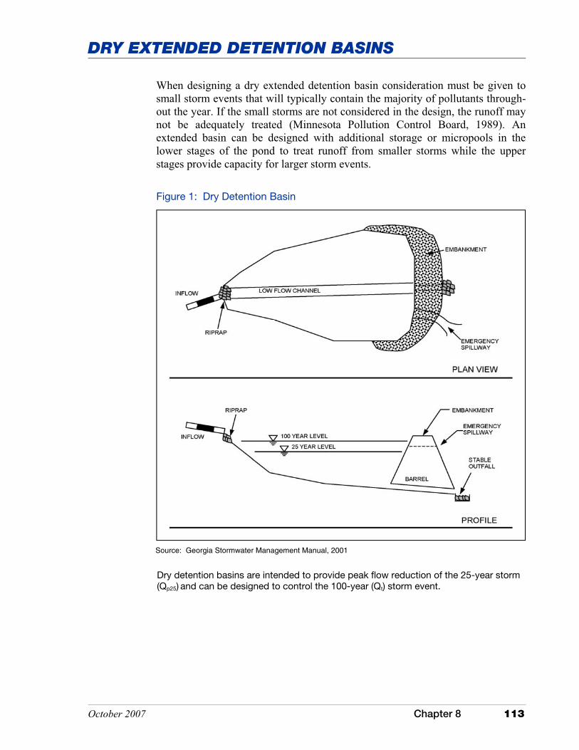
October 2007 Chapter 8 113
DRY EXTENDED DETENTION BASINS
Source: Georgia Stormwater Management Manual, 2001
Figure 1: Dry Detention Basin
Dry detention basins are intended to provide peak flow reduction of the 25-year storm (Qp25) and can be designed to control the 100-year (Qt) storm event.
When designing a dry extended detention basin consideration must be given to small storm events that will typically contain the majority of pollutants through-out the year. If the small storms are not considered in the design, the runoff may not be adequately treated (Minnesota Pollution Control Board, 1989). An extended basin can be designed with additional storage or micropools in the lower stages of the pond to treat runoff from smaller storms while the upper stages provide capacity for larger storm events.
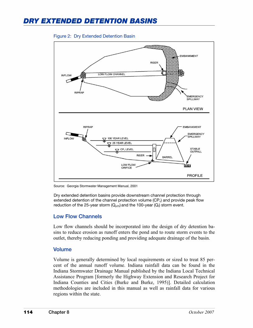
114 Chapter 8 October 2007
DRY EXTENDED DETENTION BASINS
Figure 2: Dry Extended Detention Basin
Low Flow Channels
Low flow channels should be incorporated into the design of dry detention ba-sins to reduce erosion as runoff enters the pond and to route storm events to the outlet, thereby reducing ponding and providing adequate drainage of the basin.
Volume
Volume is generally determined by local requirements or sized to treat 85 per-cent of the annual runoff volume. Indiana rainfall data can be found in the Indiana Stormwater Drainage Manual published by the Indiana Local Technical Assistance Program [formerly the Highway Extension and Research Project for Indiana Counties and Cities (Burke and Burke, 1995)]. Detailed calculation methodologies are included in this manual as well as rainfall data for various regions within the state.
Dry extended detention basins provide downstream channel protection through extended detention of the channel protection volume (CPv) and provide peak flow reduction of the 25-year storm (Qp25) and the 100-year (Qt) storm event.
Source: Georgia Stormwater Management Manual, 2001
October 2007 Chapter 8 115
DRY EXTENDED DETENTION BASINS
When designing for the storage of storm water runoff volume, it is important to consider local effects such as soil type and amount of impervious surfaces, and to include compensation for future increases in impervious areas. Extended basins should be sized with a storm water detention time of at least 24 hours, depending on the size of the storm event.
Siting
Extended dry basins should be limited to drainage areas of ten acres or more in order to maintain an orifice opening at the outlet that is sufficiently large to prevent clogging. Basins can be constructed on sites with slopes up to 15 per-cent, provided the slope within the basin can be made relatively flat to ensure proper design flow. Soils are rarely a limiting factor. Ideally, the basin should be sited on soils with infiltration rates of less than three inches per hour. Sites with highly permeable soils or in a karst landscape may require an impermeable liner or other modification to protect ground water, especially if the basin is being constructed for treatment of runoff from a “hotspot” area. In all cases, the ground water level should remain below the base of the pond at all times to allow the pond to dry out. Site selection should be chosen to maximize flow path length between the inlet and outlet and allow for maximum storm water deten-tion and release capability of the basin (see the pond configuration section of this measure).
Pond Configuration
• Inlet Energy dissipation is required at the basin inlet to reduce resuspension of accumulated sediment and to reduce the tendency for short-circuiting. This can be accomplished with the installation of a sediment forebay pond, or other upstream pretreatment measure. A sediment forebay is an inlet struc-ture separated from the rest of the basin. Sediment forebay ponds are designed to capture sediment before it enters the main body of the detention basin (see Figure 3). Sediment forebay ponds are usually separated from the main basin by a wall or berm. Sediment forebay structures act to concentrate sediment in a single area of the basin, making cleaning more efficient and less costly.
• Shape and Slope Dry extended detention basins should have a shape with a length to width ratio of at least 3:1 in order to maximize retention time and maximize the length of the flow path between the inlet and outlet. In the event that this shape is not feasible, engineered structures (baffles and internal grading) which convey the water through the basin with the desired flow rate and resi-dence time may be incorporated into the basin design.
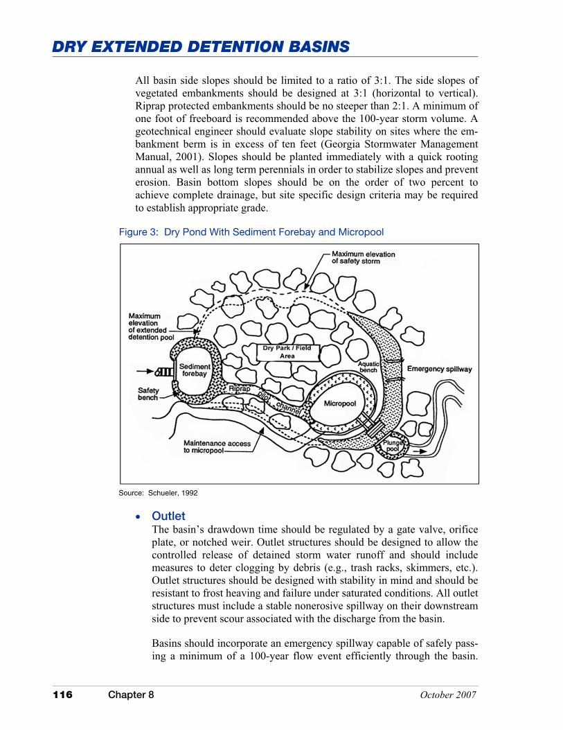
116 Chapter 8 October 2007
DRY EXTENDED DETENTION BASINS
All basin side slopes should be limited to a ratio of 3:1. The side slopes of vegetated embankments should be designed at 3:1 (horizontal to vertical). Riprap protected embankments should be no steeper than 2:1. A minimum of one foot of freeboard is recommended above the 100-year storm volume. A geotechnical engineer should evaluate slope stability on sites where the em-bankment berm is in excess of ten feet (Georgia Stormwater Management Manual, 2001). Slopes should be planted immediately with a quick rooting annual as well as long term perennials in order to stabilize slopes and prevent erosion. Basin bottom slopes should be on the order of two percent to achieve complete drainage, but site specific design criteria may be required to establish appropriate grade.
Figure 3: Dry Pond With Sediment Forebay and Micropool
Source: Schueler, 1992
• Outlet The basin’s drawdown time should be regulated by a gate valve, orifice plate, or notched weir. Outlet structures should be designed to allow the controlled release of detained storm water runoff and should include measures to deter clogging by debris (e.g., trash racks, skimmers, etc.). Outlet structures should be designed with stability in mind and should be resistant to frost heaving and failure under saturated conditions. All outlet structures must include a stable nonerosive spillway on their downstream side to prevent scour associated with the discharge from the basin.
Basins should incorporate an emergency spillway capable of safely pass-ing a minimum of a 100-year flow event efficiently through the basin.
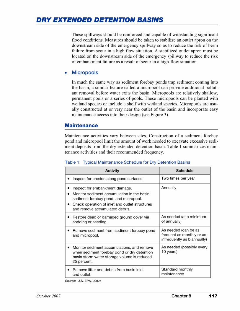
October 2007 Chapter 8 117
DRY EXTENDED DETENTION BASINS
Table 1: Typical Maintenance Schedule for Dry Detention Basins
Activity Schedule
• Inspect for erosion along pond surfaces. Two times per year
• Inspect for embankment damage.
• Monitor sediment accumulation in the basin, sediment forebay pond, and micropool.
• Check operation of inlet and outlet structures and remove accumulated debris.
Annually
• Restore dead or damaged ground cover via sodding or seeding.
As needed (at a minimum of annually)
• Remove sediment from sediment forebay pond and micropool.
As needed (can be as frequent as monthly or as infrequently as biannually)
• Monitor sediment accumulations, and remove when sediment forebay pond or dry detention basin storm water storage volume is reduced 25 percent.
As needed (possibly every 10 years)
• Remove litter and debris from basin inlet and outlet.
Standard monthly maintenance
Source: U.S. EPA, 2002d
These spillways should be reinforced and capable of withstanding significant flood conditions. Measures should be taken to stabilize an outlet apron on the downstream side of the emergency spillway so as to reduce the risk of berm failure from scour in a high flow situation. A stabilized outlet apron must be located on the downstream side of the emergency spillway to reduce the risk of embankment failure as a result of scour in a high-flow situation.
• Micropools
In much the same way as sediment forebay ponds trap sediment coming into the basin, a similar feature called a micropool can provide additional pollut-ant removal before water exits the basin. Micropools are relatively shallow, permanent pools or a series of pools. These micropools can be planted with wetland species or include a shelf with wetland species. Micropools are usu-ally constructed at or very near the outlet of the basin and incorporate easy maintenance access into their design (see Figure 3).
Maintenance
Maintenance activities vary between sites. Construction of a sediment forebay pond and micropool limit the amount of work needed to excavate excessive sedi-ment deposits from the dry extended detention basin. Table 1 summarizes main-tenance activities and their recommended frequency.
118 Chapter 8 October 2007
DRY EXTENDED DETENTION BASINS
Costs
According to the U.S. Environmental Protection Agency (2002d), dry detention basins are the least expensive storm water management measure based on a cost per unit area treated. Construction costs vary considerably depending on whether the basin is a cut or a fill design and other site specific criteria. According to a study by Brown and Schueler (1997) the cost of dry extended detention basins can be roughly estimated by the following equation:
Additional Information
Internet Keyword Search: dry pond, detention basin, extended detention pond, retention basin
Federal Resource: U.S. Department of Agriculture Natural Resources Conservation Service manuals
Indiana Resource: “Stormwater Drainage Manual” published by the Indiana Local Technical Assistance Program [formerly the Highway Extension and Research Project for Indiana Counties and Cities (Burke and Burke, 1995)]
C = 12.4V0.760
Where: C = Construction, design and permitting cost (dollars)
V = Volume needed for the 10-year storm event (ft3)
Annual maintenance costs of dry basins are usually estimated at three to five percent of the construction cost (U.S. EPA, 2002d). However, community participation in annual maintenance of the basin during dry periods can greatly reduce these costs. Given the relatively long life of these facilities [(20 years or more) U.S. EPA, 2002d], the initial investment is spread over a relatively long time period.
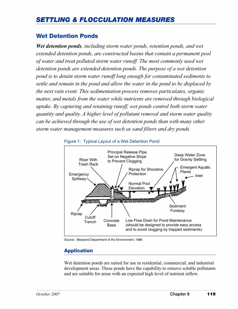
October 2007 Chapter 8 119
SETTLING & FLOCCULATION MEASURES
Wet Detention Ponds
Wet detention ponds, including storm water ponds, retention ponds, and wet extended detention ponds, are constructed basins that contain a permanent pool of water and treat polluted storm water runoff. The most commonly used wet detention ponds are extended detention ponds. The purpose of a wet detention pond is to detain storm water runoff long enough for contaminated sediments to settle and remain in the pond and allow the water in the pond to be displaced by the next rain event. This sedimentation process removes particulates, organic matter, and metals from the water while nutrients are removed through biological uptake. By capturing and retaining runoff, wet ponds control both storm water quantity and quality. A higher level of pollutant removal and storm water quality can be achieved through the use of wet detention ponds than with many other storm water management measures such as sand filters and dry ponds.
Application
Wet detention ponds are suited for use in residential, commercial, and industrial development areas. These ponds have the capability to remove soluble pollutants and are suitable for areas with an expected high level of nutrient inflow.
Figure 1: Typical Layout of a Wet Detention Pond
Source: Maryland Department of the Environment, 1986
Riser With Trash Rack
Normal Pool Elevation
Sediment Forebay
Low Flow Drain for Pond Maintenance (should be designed to provide easy access and to avoid clogging by trapped sediments)
Cutoff Trench
Riprap
Emergent Aquatic Plants
Inlet
Deep Water Zone for Gravity Settling
Riprap for Shoreline Protection
Concrete Base
Principal Release Pipe Set on Negative Slope to Prevent Clogging
Emergency Spillway

120 Chapter 8 October 2007
WET DETENTION PONDS
Table 1: Wet Pond Advantages and Disadvantages
Advantages Disadvantages
• Flood control for downstream areas by providing flood storage above the pool.
• Decreased potential for streambank erosion downstream.
• Once established, sediment removal from wet detention ponds is generally less frequent as compared to other storm water management measures.
• Improved water quality due to pollutant removal of: ��Suspended solids ��Metals ��Soluble pollutants ��Nutrients
• Pond can be aesthetically pleasing and increase the value of surround-ing properties.
• Provides wildlife habitat.
• Improper design, siting, or maintenance may result in: ��Adverse effects on water quality,
ground water, or wetlands. ��Release of nutrients and metals
from trapped sediments due to stratification and anoxic condi-tions.
• Precautions needed to prevent damage to wetlands during pond construction.
• Evaluation for potential of ground water contamination is required.
• Potential for thermal impacts downstream (temperature increase).
• High maintenance cost.
Source: U.S. EPA, 1999f; Connecticut Stormwater Manual, 2004; Metropolitan Council Environmental Services, 2001, Minnesota Urban Small Sites BMP Manual
Wet detention ponds remain one of the most effective storm water management measures for the removal of pollutants. The range in pollutant removal values is dependent upon the volume of the permanent pool in relation to the contributing watershed, the hydraulic residence times (i.e., the rate at which water moves through the pond), proper design, and proper maintenance of the pond. Sediment forebays or other pretreatment measures will increase the efficiency for pollutant removal. The addition of wetland or marsh areas (i.e., shallow pools with aquatic plantings) can also be incorporated to increase nutrient uptake.
These measures may be installed in areas where the contributing watershed is associated with a storm water hotspot. However, consideration should be given to a separation between the bottom of the pond and the seasonal high water table. A separation depth of three feet or more is usually sufficient. Wet detention ponds are suitable for use in karst topography, however there is a potential for ground water contamination or the formation of a sinkhole. There-fore, the design of the pond may require an impermeable liner to address one or more of these issues.
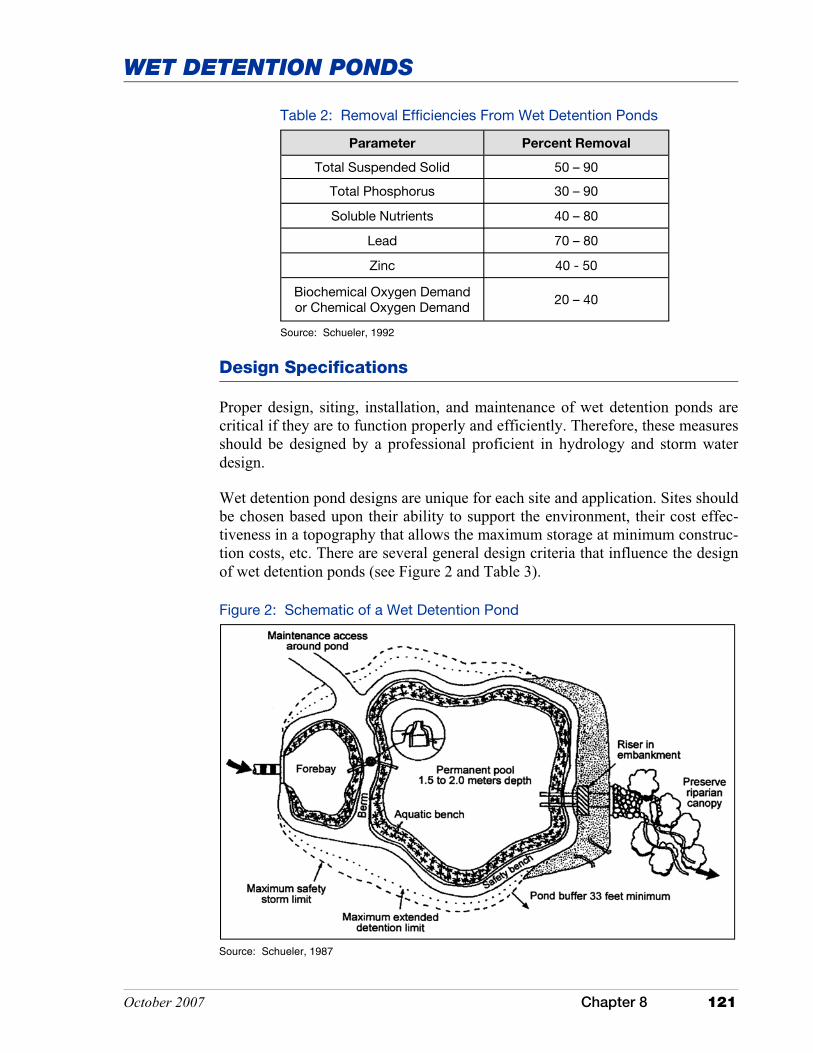
October 2007 Chapter 8 121
WET DETENTION PONDS
Table 2: Removal Efficiencies From Wet Detention Ponds
Parameter Percent Removal
Total Suspended Solid 50 – 90
Total Phosphorus 30 – 90
Soluble Nutrients 40 – 80
Lead 70 – 80
Zinc 40 - 50
Biochemical Oxygen Demand or Chemical Oxygen Demand 20 – 40
Source: Schueler, 1992
Design Specifications
Proper design, siting, installation, and maintenance of wet detention ponds are critical if they are to function properly and efficiently. Therefore, these measures should be designed by a professional proficient in hydrology and storm water design.
Wet detention pond designs are unique for each site and application. Sites should be chosen based upon their ability to support the environment, their cost effec-tiveness in a topography that allows the maximum storage at minimum construc-tion costs, etc. There are several general design criteria that influence the design of wet detention ponds (see Figure 2 and Table 3).
Source: Schueler, 1987
Figure 2: Schematic of a Wet Detention Pond

122 Chapter 8 October 2007
WET DETENTION PONDS
Table 3: General Design Specifications for Wet Detention Ponds
Parameter Design Criteria
Site Location • Underlying soils within hydrologic soil groups C and D should be adequate to maintain a permanent pool.
• Select site with adequate base-flow to maintain a permanent pool.
Drainage Area • The contributing drainage area should be adequate to maintain the minimum water level in the permanent pool. Typically, the drainage area will be a mini-mum of 25 acres. However, this may need to be adjusted based on design and site characteristics.
Storm Water Quantity Requirements
• Design to control post-development peak discharge rates to predevelopment levels.
• Design to control multiple types of storm events (e.g., two- and/or 10-year storms) and safely pass the 100-year storm event.
Storm Water Quality Requirements
• Removal efficiency of pollutants depends on the length of time that runoff remains in the pond (i.e., hydraulic residence times). Both sediment and biological uptake increase with longer HRT.
Dimensions of the pond must be calculated to achieve the HRT
• The depth of the permanent pool is typically between three to eight feet. If the pond is too deep, thermal stratification and anoxic conditions may develop. If it is too shallow, trapped sediments could become resuspended. Deeper depths near the outlet may yield cooler temperatures and mitigate downstream thermal impacts.
Pond Design: Volume Ratio
• VB/VR is the ratio of the permanent pool storage to the mean storm runoff. Larger VBs and smaller VRs create increased retention and treatment between storm events, whereas low VB/VR ratios result in poor pollutant removal.
Pond Design: Area Ratio
• A/As is the ratio of contributing drainage area to the permanent pool surface area. Area ratios of less than 100 have better pollutant removal efficiencies.
Pond Design: Length-to-Width Ratio
• 3:1 length-to-width ratio is used when water quality is of concern. High ratios will decrease the potential of short-circuiting and will increase sedimentation within the permanent pool. Also, features such as baffles can create longer routes through the pond and increase HRT.
Pond Design: Shoreline Slopes
• Shoreline slopes between 5:1 and 10:1 allow easy access for maintenance.
• The side slopes of the permanent pool should be no steeper than 3:1.
• Ponds should be wedge-shaped so flow enters the pond and gradually spreads out, thereby minimizing potential of little or no-flow zones.
• Ponds should have a bench or ledge below water level to stabilize pond slopes and provide safety.
Pond Design: Embankments
• During construction, the embankment should be overfilled by at least five percent to allow for subsidence and settling of the embankment.
• Minimize seepage (affects stability of embankments) by adding drains, anti-seepage collars, and core trenches.
• Minimum inner slope of 2:1, outer slope 3:1, and stabilized with vegetation or riprap to prevent erosion.
• Minimum top width of seven feet to aid in maintenance.
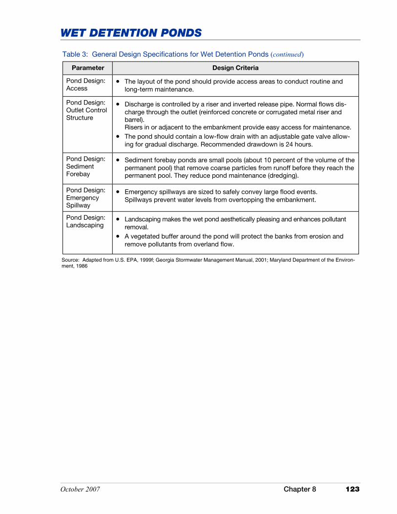
October 2007 Chapter 8 123
WET DETENTION PONDS
Parameter Design Criteria
Pond Design: Access
• The layout of the pond should provide access areas to conduct routine and long-term maintenance.
Pond Design: Outlet Control Structure
• Discharge is controlled by a riser and inverted release pipe. Normal flows dis-charge through the outlet (reinforced concrete or corrugated metal riser and barrel). Risers in or adjacent to the embankment provide easy access for maintenance.
• The pond should contain a low-flow drain with an adjustable gate valve allow-ing for gradual discharge. Recommended drawdown is 24 hours.
Pond Design: Sediment Forebay
• Sediment forebay ponds are small pools (about 10 percent of the volume of the permanent pool) that remove coarse particles from runoff before they reach the permanent pool. They reduce pond maintenance (dredging).
Pond Design: Emergency Spillway
• Emergency spillways are sized to safely convey large flood events. Spillways prevent water levels from overtopping the embankment.
Pond Design: Landscaping
• Landscaping makes the wet pond aesthetically pleasing and enhances pollutant removal.
• A vegetated buffer around the pond will protect the banks from erosion and remove pollutants from overland flow.
Table 3: General Design Specifications for Wet Detention Ponds (continued)
Source: Adapted from U.S. EPA, 1999f; Georgia Stormwater Management Manual, 2001; Maryland Department of the Environ-ment, 1986

124 Chapter 8 October 2007
WET DETENTION PONDS
There are several different design variations for wet detention ponds that are adaptable to various sites. Table 4 describes three of the most common design modifications.
Table 4: Alternative Designs for Traditional Wet Detention Ponds
Type of
Pond Description Characteristics
Wet Extended Detention Pond
Combines the treatment capabilities of dry extended detention basins and wet detention ponds. Water volume is split between the permanent pool and the detention storage. Water is retained during storm events and released into the perma-nent pool over 12 to 48 hours.
• Similar in pollutant removal efficiency to a wet detention pond and requires less space.
• Designed to maintain half the treatment volume of the permanent pool.
• Focus on attenuating peak runoff.
• Vegetation must withstand both dry and wet periods.
Micropool Extended Detention Pond
Micropools are typically used for peak runoff and utilize a small permanent pool pond near the outlet of the main pond.
• Less pollutant removal than wet detention ponds.
• Used where contributing drainage area is small and insufficient to maintain a larger pool area.
• Useful for sites with small spaces or a retrofit application.
Multiple Pond Systems
A series of constructed ponds, typically two or more.
• Multiple cells increase flow path length and improve pollutant removal efficiency.
• May reduce overall maintenance requirements; more frequent maintenance is performed in the first pool versus the large primary pool.
• Requires more land area to treat the same runoff volume as other measures.
Source: U.S. EPA, 2002; Connecticut Stormwater Manual, 2004; Georgia Stormwater Management Manual, 2001
Maintenance
The performance of a wet detention pond is highly dependant on the mainte-nance of the pond. If the pond is not properly maintained, the ability of the pond to remove pollutants will decrease. There are several types of maintenance activities required for a traditional wet detention pond.
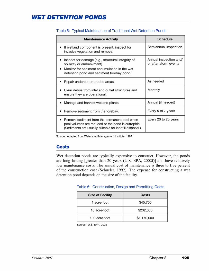
October 2007 Chapter 8 125
WET DETENTION PONDS
Table 5: Typical Maintenance of Traditional Wet Detention Ponds
Maintenance Activity Schedule
• If wetland component is present, inspect for invasive vegetation and remove.
Semiannual inspection
• Inspect for damage (e.g., structural integrity of spillway or embankment).
• Monitor for sediment accumulation in the wet detention pond and sediment forebay pond.
Annual inspection and/ or after storm events
• Repair undercut or eroded areas. As needed
• Clear debris from inlet and outlet structures and ensure they are operational.
Monthly
• Manage and harvest wetland plants. Annual (if needed)
• Remove sediment from the forebay. Every 5 to 7 years
• Remove sediment from the permanent pool when pool volumes are reduced or the pond is eutrophic. (Sediments are usually suitable for landfill disposal.)
Every 20 to 25 years
Costs
Wet detention ponds are typically expensive to construct. However, the ponds are long lasting [greater than 20 years (U.S. EPA, 2002f)] and have relatively low maintenance costs. The annual cost of maintenance is three to five percent of the construction cost (Schueler, 1992). The expense for constructing a wet detention pond depends on the size of the facility.
Table 6: Construction, Design and Permitting Costs
Size of Facility Costs
1 acre-foot $45,700
10 acre-foot $232,000
100 acre-foot $1,170,000
Source: U.S. EPA, 2002
Source: Adapted from Watershed Management Institute, 1997

126 Chapter 8 October 2007
WET DETENTION PONDS
Additional Information
Internet Keyword Search: wet ponds, detention basin, settling basin, retention pond
Federal Resource: U.S. Department of Agriculture Natural Resources Conservation Service manuals
Indiana Resource: “Stormwater Drainage Manual” published by the Indiana Local Technical Assis-tance Program [formerly the Highway Extension and Research Project for Indi-ana Counties and Cities (Burke and Burke, 1995)]
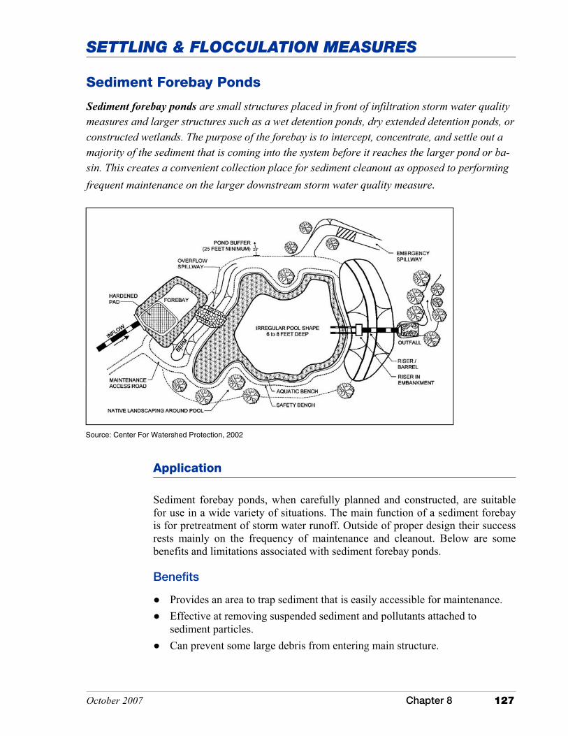
October 2007 Chapter 8 127
SETTLING & FLOCCULATION MEASURES
Sediment Forebay Ponds
Sediment forebay ponds are small structures placed in front of infiltration storm water quality measures and larger structures such as a wet detention ponds, dry extended detention ponds, or constructed wetlands. The purpose of the forebay is to intercept, concentrate, and settle out a majority of the sediment that is coming into the system before it reaches the larger pond or ba-sin. This creates a convenient collection place for sediment cleanout as opposed to performing frequent maintenance on the larger downstream storm water quality measure.
Application
Sediment forebay ponds, when carefully planned and constructed, are suitable for use in a wide variety of situations. The main function of a sediment forebay is for pretreatment of storm water runoff. Outside of proper design their success rests mainly on the frequency of maintenance and cleanout. Below are some benefits and limitations associated with sediment forebay ponds.
Benefits
� Provides an area to trap sediment that is easily accessible for maintenance. � Effective at removing suspended sediment and pollutants attached to
sediment particles. � Can prevent some large debris from entering main structure.
Source: Center For Watershed Protection, 2002

128 Chapter 8 October 2007
SEDIMENT FOREBAY PONDS
Limitations
� Must be inspected and cleaned on a regular basis because of small size. � Can be an eyesore if not properly maintained. � Treatment capacity is directly related to the size of the pond, often making
space the primary limiting factor.
Sediment forebays can easily be retrofitted to existing basins in older developed areas or areas where changing land use has introduced more sediment to the system.
Design Specifications
Proper design ensures maximum performance of sediment forebay ponds. Siting, design, installation, and maintenance of sediment forebays are critical if they are to perform properly and efficiently. Therefore, sediment forebays should be designed by a professional proficient in hydrology and storm water design. The design incorporates three important values: sizing, site selection, and pond configuration. Paramount to an efficiently designed sediment forebay pond is estimating the correct volume of storm water runoff that can pass through the basin and still remove the majority of sediment. Below are major design feature considerations of sediment forebay ponds.
Siting
Sediment forebay ponds should be positioned upstream of the larger pond or storm water management structure and located in an area with easy access for maintenance equipment. A forebay should be located at each inlet that contrib-utes ten percent or more of the design storm inflow (Georgia Stormwater Man-agement Manual, 2001).
Size
The size of the sediment forebay pond will vary based on the downstream struc-ture. About ten to 25 percent of the surface area of the downstream pond should be devoted to the forebay (Metropolitan Council Environmental Services, 2001, Minnesota Urban Small Sites Best Management Practices Manual). Typical depths associated with a forebay are four to six feet (Georgia Stormwater Man-agement Manual, 2001). The size of the forebay may be enlarged to increase detention of runoff and provide additional treatment.
Shape
The shape should be long and narrow if possible to facilitate settling of sus-pended particles. Design to avoid resuspension of previously settled material. Typical length to width ratios are 3:1 to facilitate retention time and removal efficiency.
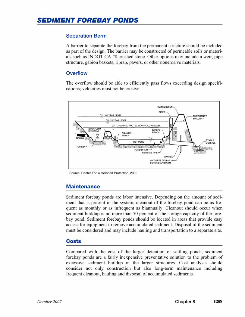
October 2007 Chapter 8 129
SEDIMENT FOREBAY PONDS
Maintenance
Sediment forebay ponds are labor intensive. Depending on the amount of sedi-ment that is present in the system, cleanout of the forebay pond can be as fre-quent as monthly or as infrequent as biannually. Cleanout should occur when sediment buildup is no more than 50 percent of the storage capacity of the fore-bay pond. Sediment forebay ponds should be located in areas that provide easy access for equipment to remove accumulated sediment. Disposal of the sediment must be considered and may include hauling and transportation to a separate site.
Costs
Compared with the cost of the larger detention or settling ponds, sediment forebay ponds are a fairly inexpensive preventative solution to the problem of excessive sediment buildup in the larger structures. Cost analysis should consider not only construction but also long-term maintenance including frequent cleanout, hauling and disposal of accumulated sediments.
Source: Center For Watershed Protection, 2002
CHANNEL PROTECTION VOLUME LEVEL
Separation Berm
A barrier to separate the forebay from the permanent structure should be included as part of the design. The barrier may be constructed of permeable soils or materi-als such as INDOT CA #8 crushed stone. Other options may include a weir, pipe structure, gabion baskets, riprap, pavers, or other nonerosive materials.
Overflow
The overflow should be able to efficiently pass flows exceeding design specifi-cations; velocities must not be erosive.

130 Chapter 8 October 2007
SEDIMENT FOREBAY PONDS
Additional Information
Internet Keyword Search: retention ponds, forebay ponds, dry ponds, detention basin
National Resource: U.S. Department of Agriculture Natural Resources Conservation Service manuals
Indiana Resource: “Stormwater Drainage Manual” published by the Indiana Local Technical Assis-tance Program [formerly the Highway Extension and Research Project for Indi-ana Counties and Cities (Burke and Burke, 1995)]
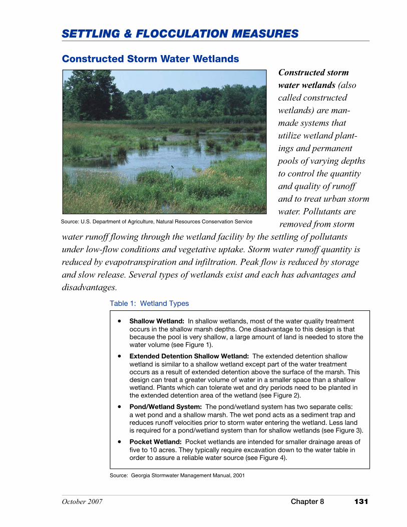
October 2007 Chapter 8 131
SETTLING & FLOCCULATION MEASURES
Constructed Storm Water Wetlands
Constructed storm water wetlands (also called constructed wetlands) are man-made systems that utilize wetland plant-ings and permanent pools of varying depths to control the quantity and quality of runoff and to treat urban storm water. Pollutants are removed from storm
water runoff flowing through the wetland facility by the settling of pollutants under low-flow conditions and vegetative uptake. Storm water runoff quantity is reduced by evapotranspiration and infiltration. Peak flow is reduced by storage and slow release. Several types of wetlands exist and each has advantages and disadvantages.
Table 1: Wetland Types
• Shallow Wetland: In shallow wetlands, most of the water quality treatment occurs in the shallow marsh depths. One disadvantage to this design is that because the pool is very shallow, a large amount of land is needed to store the water volume (see Figure 1).
• Extended Detention Shallow Wetland: The extended detention shallow wetland is similar to a shallow wetland except part of the water treatment occurs as a result of extended detention above the surface of the marsh. This design can treat a greater volume of water in a smaller space than a shallow wetland. Plants which can tolerate wet and dry periods need to be planted in the extended detention area of the wetland (see Figure 2).
• Pond/Wetland System: The pond/wetland system has two separate cells: a wet pond and a shallow marsh. The wet pond acts as a sediment trap and reduces runoff velocities prior to storm water entering the wetland. Less land is required for a pond/wetland system than for shallow wetlands (see Figure 3).
• Pocket Wetland: Pocket wetlands are intended for smaller drainage areas of five to 10 acres. They typically require excavation down to the water table in order to assure a reliable water source (see Figure 4).
Source: U.S. Department of Agriculture, Natural Resources Conservation Service
Source: Georgia Stormwater Management Manual, 2001
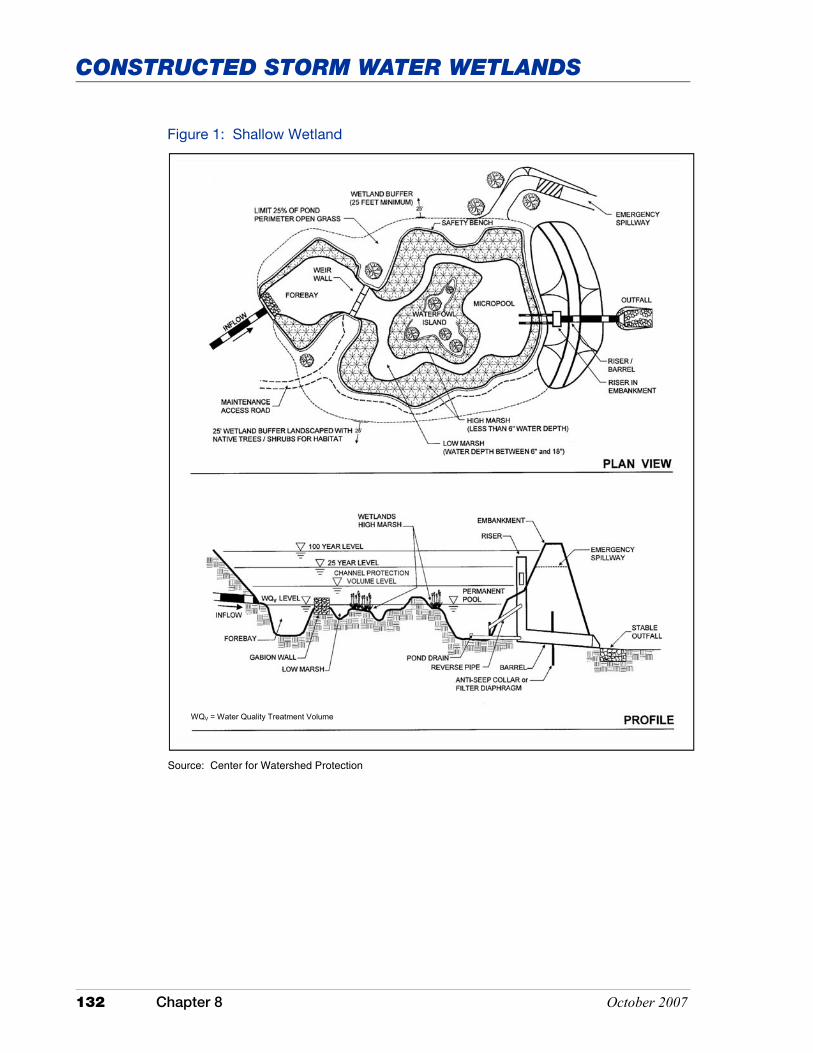
132 Chapter 8 October 2007
CONSTRUCTED STORM WATER WETLANDS
Source: Center for Watershed Protection
Figure 1: Shallow Wetland
WQV = Water Quality Treatment Volume
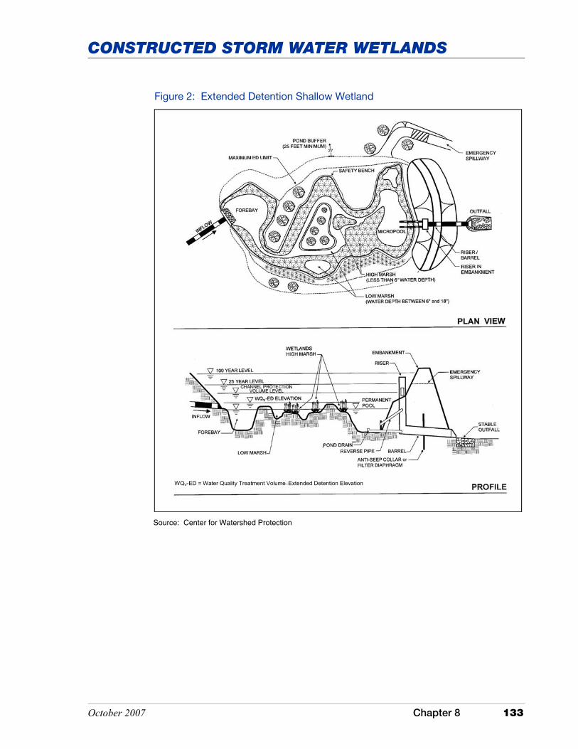
October 2007 Chapter 8 133
CONSTRUCTED STORM WATER WETLANDS
Source: Center for Watershed Protection
Figure 2: Extended Detention Shallow Wetland
WQV-ED = Water Quality Treatment Volume–Extended Detention Elevation

134 Chapter 8 October 2007
CONSTRUCTED STORM WATER WETLANDS
Figure 3: Pond/Wetland System
Source: Center for Watershed Protection
WQV = Water Quality Treatment Volume

October 2007 Chapter 8 135
CONSTRUCTED STORM WATER WETLANDS
Source: Center for Watershed Protection
Application
Storm water wetlands are well suited for a variety of land uses; however, the measure may have limitations in highly urbanized areas.
These measures may be installed in areas where the contributing watershed is associated with a storm water hotspot. However, consideration should be given to a separation between the bottom of the wetland and the seasonal high water table. A separation depth of three feet or more is usually sufficient.
Figure 4: Pocket Wetland
WQV = Water Quality Treatment Volume

136 Chapter 8 October 2007
CONSTRUCTED STORM WATER WETLANDS
Advantages Limitations
• Effective nutrient removal.
• Provides wildlife habitat.
• Relatively low maintenance costs.
• Require large land area.
• Needs continuous base flow, or a base outlet elevation that maintains a minimum water level.
• Require minimum drainage area of 10 acres for adequate water source.
Source: Adapted from Metropolitan Council Environmental Services, Urban Small Sites BMP Manual, 2001
Table 2: Constructed Storm Water Wetland Advantages and Limitations
The pollutant removal effectiveness of shallow wetlands and pond/wetland sys-tems has been well documented. However, the data available for extended deten-tion and pocket wetlands is limited. Table 3 provides the pollutant removal rates for wetlands as a whole (Center for Watershed Protection, 1997; U.S. EPA, 1999g).
Table 3: Performance of Storm Water Wetlands
Pollutant Percent Removal Rate
Total Suspended Solids 67
Total Phosphorous 49
Total Nitrogen 28
Organic Carbon 34
Petroleum Hydrocarbons 87
Cadmium 36
Copper 41
Lead 62
Zinc 45
Bacteria 77
Source: Center for Watershed Protection, 1997
Storm water wetlands are suitable for use in karst topography, however there is a potential for ground water contamination or the formation of a sinkhole. There-fore, the design of the wetland may require an impermeable liner to address one or more of these issues.
Constructed storm water wetlands are designed to maximize the removal of pollutants from storm water runoff. This is accomplished through several proc-esses�microbial breakdown of pollutants, settling and adsorption, retention, and plant uptake. Constructed storm water wetlands temporarily store storm water runoff in shallow pools designed to promote the processes discussed above. They offer many advantages over other storm water attenuation measures.

October 2007 Chapter 8 137
CONSTRUCTED STORM WATER WETLANDS
Design Specifications
Several criteria need to be taken into consideration when designing a constructed storm water wetland, including drainage area size and soil type. Siting, design, installation, and maintenance of storm water wetlands are critical if they are to function properly and efficiently. Therefore, storm water wetlands, and espe-cially the storm water component, should be designed by a professional profi-cient in hydrology and storm water design.
Design Criteria
� Minimum contributing drainage area of ten to 25 acres; one to ten acres for pocket wetlands.
� Minimum dry weather flow path ratio of 2:1 to 3:1 (preferred) (length to width) should be provided from inflow to outflow.
� Criteria for sizing wetlands vary from state to state. One recommendation is based on runoff treatment volume. The volume is determined as the quantity of runoff generated by 90 percent of the runoff producing storm (Metropolitan Council of Governments (Schueler), 1992b). The impervious surfaces within the watershed will also influence the runoff volume. The fol-lowing equations can be used to calculate the treatment volume.
Rv = .05 +.009 (I) Where: Rv = Runoff Volume I = Percent (as decimal) of site impervious area
Vt = [(RPs) (Rv) (A)/12] (43,560) Where: Vt = Treatment volume (cubic feet) RPs = Runoff producing storm in inches A = Contributing drainage area
Source: Metropolitan Council of Governments (Schueler), 1992b
This is only one alternative. Other design options are available from other agen-cies including, but not limited to, the U.S. Department of Agriculture, Natural Resources Conservation Service.
� Pretreatment of runoff should be provided by incorporating a sediment fore-bay pond or an equivalent measure upstream of the wetland.
� A site targeted for a storm water wetland must have an adequate watershed and soils to maintain sufficient water levels and vegetation. Permeable soils are not well suited to this measure. Soils within the Natural Resources Con-servation Service hydrologic soil groups B, C, and D are usually best suited
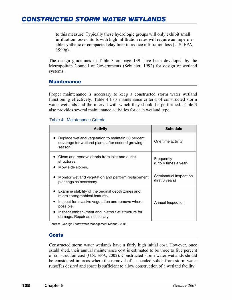
138 Chapter 8 October 2007
CONSTRUCTED STORM WATER WETLANDS
Table 4: Maintenance Criteria
Activity Schedule
• Replace wetland vegetation to maintain 50 percent coverage for wetland plants after second growing season.
One time activity
• Clean and remove debris from inlet and outlet structures.
• Mow side slopes.
Frequently (3 to 4 times a year)
• Monitor wetland vegetation and perform replacement plantings as necessary.
Semiannual Inspection (first 3 years)
• Examine stability of the original depth zones and micro-topographical features.
• Inspect for invasive vegetation and remove where possible.
• Inspect embankment and inlet/outlet structure for damage. Repair as necessary.
Annual Inspection
Source: Georgia Stormwater Management Manual, 2001
Costs
Constructed storm water wetlands have a fairly high initial cost. However, once established, their annual maintenance cost is estimated to be three to five percent of construction cost (U.S. EPA, 2002). Constructed storm water wetlands should be considered in areas where the removal of suspended solids from storm water runoff is desired and space is sufficient to allow construction of a wetland facility.
to this measure. Typically these hydrologic groups will only exhibit small infiltration losses. Soils with high infiltration rates will require an imperme-able synthetic or compacted clay liner to reduce infiltration loss (U.S. EPA, 1999g).
The design guidelines in Table 3 on page 139 have been developed by the Metropolitan Council of Governments (Schueler, 1992) for design of wetland systems.
Maintenance
Proper maintenance is necessary to keep a constructed storm water wetland functioning effectively. Table 4 lists maintenance criteria of constructed storm water wetlands and the interval with which they should be performed. Table 3 also provides several maintenance activities for each wetland type.
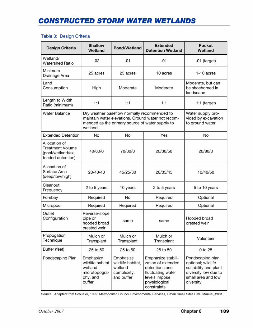
October 2007 Chapter 8 139
CONSTRUCTED STORM WATER WETLANDS
Table 3: Design Criteria
Design Criteria Shallow
Wetland Pond/Wetland
Extended
Detention Wetland
Wetland
Wetland/ Watershed Ratio .02 .01 .01 .01 (target)
Minimum Drainage Area 25 acres 25 acres 10 acres 1-10 acres
Land Consumption High Moderate Moderate
Moderate, but can be shoehorned in landscape
Water Balance Dry weather baseflow normally recommended to maintain water elevations. Ground water not recom-mended as the primary source of water supply to wetland
Water supply pro-vided by excavation to ground water
Extended Detention No No Yes No
Allocation of Treatment Volume (pool/wetland/ex-tended detention)
40/60/0 70/30/0 20/30/50 20/80/0
Allocation of Surface Area (deep/low/high)
20/40/40 45/25/30 20/35/45 10/40/50
Cleanout Frequency 2 to 5 years 10 years 2 to 5 years 5 to 10 years
Forebay Required No Required Optional
Micropool Required Required Required Optional
Outlet Configuration
Reverse-slope pipe or hooded broad crested weir
same same Hooded broad crested weir
Propogation Technique
Mulch or Transplant
Mulch or Transplant
Mulch or Transplant Volunteer
Buffer (feet) 25 to 50 25 to 50 25 to 50 0 to 25
Pondscaping Plan Emphasize wildlife habitat wetland microtopogra-phy, and buffer
Emphasize wildlife habitat, wetland complexity, and buffer
Emphasize stabili-zation of extended detention zone; fluctuating water levels impose physiological constraints
Pondscaping plan optional; wildlife suitability and plant diversity low due to small area and low diversity
Source: Adapted from Schueler, 1992; Metropolitan Council Environmental Services, Urban Small Sites BMP Manual, 2001
Length to Width Ratio (minimum) 1:1 1:1 1:1 1:1 (target)

140 Chapter 8 October 2007
CONSTRUCTED STORM WATER WETLANDS
Additional Information
Internet Keyword Search: storm water wetland, constructed storm water wetland, constructed wetland storm water control

October 2007 Chapter 8 141
SETTLING & FLOCCULATION MEASURES
Subsurface Detention/Retention
Subsurface detention systems are designed to store storm water runoff and release the storm water to a re-ceiving water. Reten-tion systems are de-signed to provide infil-tration, storm water storage, and ground water recharge where it would otherwise be impossible due to extensive impervious
surfaces. These systems primarily function to address peak runoff and are not installed as a storm water quality measure, although they may be retrofitted or used as part of a treatment train for this purpose. The lack of open space avail-able for the construction of aboveground structures, such as ponds and wetlands, for mitigating storm water runoff makes subsurface structures a very useful alter-native in these constraining situations.
These systems can be constructed of steel, concrete or high-density polymer. There are two main forms these structures take. The first is a subsurface full or semi-pipe network that may or may not be porous and allow for infiltration. The second is an engineered porous matrix, often constructed of high density polymers that can be designed to permit both detention and infiltration if necessary. Both forms allow for pavement to be placed over the top, or soil if a more natural covering is desired.
Application
These systems are not specifically designed as a storm water quality measure. Pollutant removal is minimal and is usually limited to settling of coarse sedi-ments. Resuspension and discharge of sediments during storm events is also a concern. These measures are often used as part of a treatment train.
Source: Marion County Soil and Water Conservation District
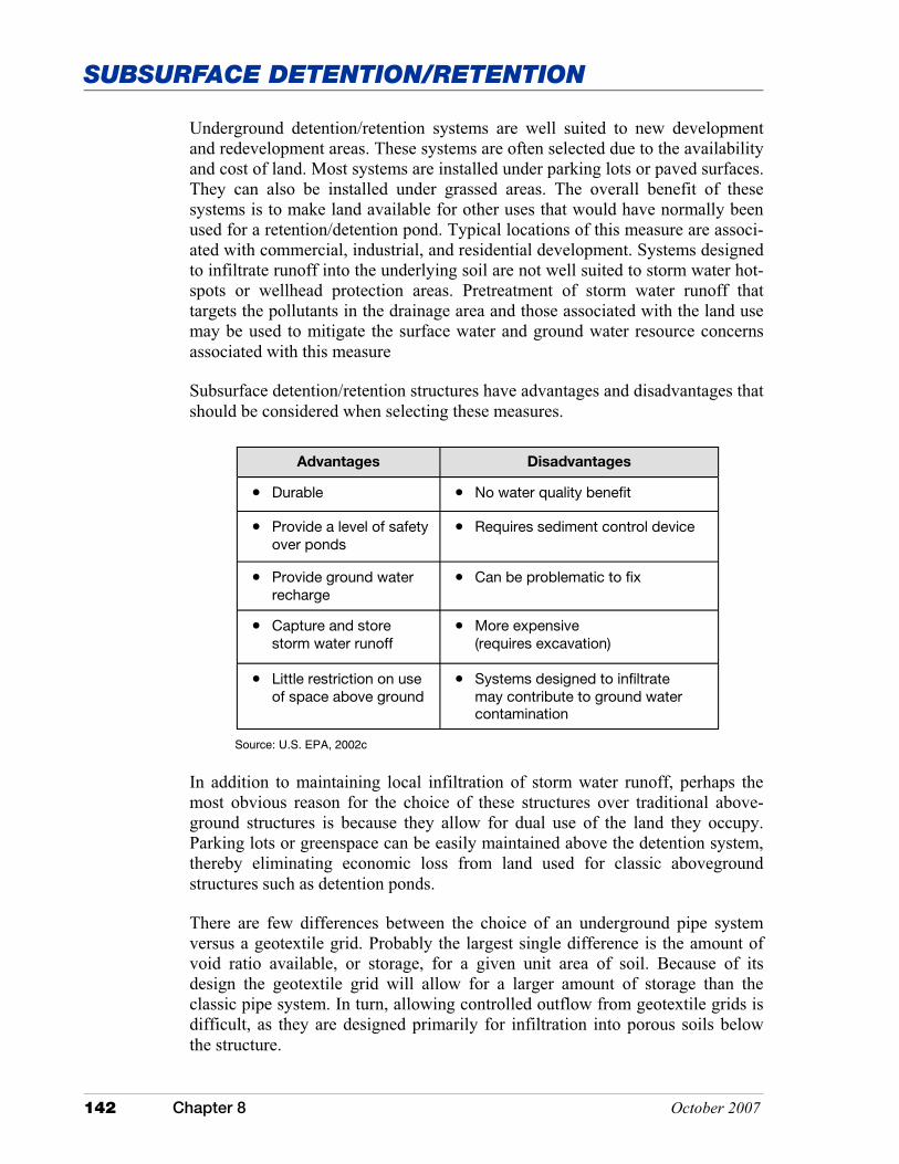
142 Chapter 8 October 2007
SUBSURFACE DETENTION/RETENTION
In addition to maintaining local infiltration of storm water runoff, perhaps the most obvious reason for the choice of these structures over traditional above-ground structures is because they allow for dual use of the land they occupy. Parking lots or greenspace can be easily maintained above the detention system, thereby eliminating economic loss from land used for classic aboveground structures such as detention ponds.
There are few differences between the choice of an underground pipe system versus a geotextile grid. Probably the largest single difference is the amount of void ratio available, or storage, for a given unit area of soil. Because of its design the geotextile grid will allow for a larger amount of storage than the classic pipe system. In turn, allowing controlled outflow from geotextile grids is difficult, as they are designed primarily for infiltration into porous soils below the structure.
Advantages Disadvantages
• Durable • No water quality benefit
• Provide a level of safety over ponds
• Requires sediment control device
• Provide ground water recharge
• Can be problematic to fix
• Capture and store storm water runoff
• More expensive (requires excavation)
• Little restriction on use of space above ground
• Systems designed to infiltrate may contribute to ground water contamination
Source: U.S. EPA, 2002c
Underground detention/retention systems are well suited to new development and redevelopment areas. These systems are often selected due to the availability and cost of land. Most systems are installed under parking lots or paved surfaces. They can also be installed under grassed areas. The overall benefit of these systems is to make land available for other uses that would have normally been used for a retention/detention pond. Typical locations of this measure are associ-ated with commercial, industrial, and residential development. Systems designed to infiltrate runoff into the underlying soil are not well suited to storm water hot-spots or wellhead protection areas. Pretreatment of storm water runoff that targets the pollutants in the drainage area and those associated with the land use may be used to mitigate the surface water and ground water resource concerns associated with this measure
Subsurface detention/retention structures have advantages and disadvantages that should be considered when selecting these measures.
October 2007 Chapter 8 143
SUBSURFACE DETENTION/RETENTION
Design Specifications
Siting, design, installation, and maintenance of subsurface detention/retention systems are critical if they are to function properly and efficiently. Therefore, these systems, and especially the storm water component, should be designed by a professional proficient in hydrology and storm water design. Listed below are design considerations common to both pipe systems and geotextile grids.
� Design size is usually for the 10-year, 24-hour event; bypass mechanisms should be in place to pass excessive or prolonged events.
� Retention systems designed to provide infiltration must consider the soil properties where the system will be installed. They are best suited to well-drained soils with a seasonal water table well below the structure to allow for infiltration. Typical soil infiltration rates should range from .5 to 3.0 inches per hour.
� To achieve a water quality benefit, pretreatment of storm water is required. Storm water may be pretreated by incorporating an oil-grit separator, hydro-dynamic separator, grass swales, wetland/pond system, or other measures into the design of the storage system.
� Areas should be as level as possible in order to maximize infiltration rates across the entire structure.
� Both grids and pipe systems have backfill requirements (which must be adhered to) specific to the device.
� Outflow locations (if used) must prevent concentrated flow conditions from developing within the subsurface storage unit.
� Maintenance “ports” should be installed at strategic points to allow for easy inspection and maintenance of the structures.
Maintenance
As mentioned, in high sediment flow conditions, pretreatment is necessary to reduce accumulation in the subsurface detention system. Maintenance of these pretreatment structures can be frequent. The structures themselves should remain relatively maintenance free if proper precautions are taken to limit the amount of sediment and debris that is allowed to accumulate inside the grid or pipe system. Once installed, these systems can have design lives that exceed 50 years, pro-vided they have no exposure to ultraviolet light (U.S. EPA, 2001).
Costs
Given the small amount of maintenance involved in this storm water manage-ment measure, a majority of the expense is incurred at the beginning of the pro-ject, mainly in materials and excavation and backfill costs. In addition to consid-ering construction costs, the value of available land above the structures should

144 Chapter 8 October 2007
SUBSURFACE DETENTION/RETENTION
Additional Information
Internet Keyword Search: storm water detention, subsurface detention, retention
also be considered based on an equivalent aboveground storm water manage-ment measure.

PROPRIETARY MEASURES
October 2007 Chapter 8 145
P roprietary measures are storm water management systems that incorporate one or more wa-ter quality treatment principles into a single storm water measure or measures. Proprietary
measures are manufactured systems designed to treat storm water runoff. There are a variety of proprietary systems available commercially. These systems consist of a wide variety of tech-nologies designed to remove pollutants from storm water runoff. The pollutant removal effi-ciency of these measures will vary. Some measures can be modified to increase pollutant re-moval efficiency by the installation of an in-line filtration system. Manufacturers will typically provide data on pollutant removal and efficiency. Many manufacturers provide independent testing as testimony to the performance of their product.
These systems should be installed according to the recommendations and specifications of the manufacturer. The design and installation of these measures will generally require detailed site investigation, including an assessment of the pollutants within the drainage area.

This page was intentionally left blank.
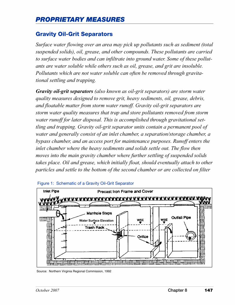
PROPRIETARY MEASURES
October 2007 Chapter 8 147
Gravity Oil-Grit Separators
Surface water flowing over an area may pick up pollutants such as sediment (total suspended solids), oil, grease, and other compounds. These pollutants are carried to surface water bodies and can infiltrate into ground water. Some of these pollut-ants are water soluble while others such as oil, grease, and grit are insoluble. Pollutants which are not water soluble can often be removed through gravita-tional settling and trapping.
Gravity oil-grit separators (also known as oil-grit separators) are storm water quality measures designed to remove grit, heavy sediments, oil, grease, debris, and floatable matter from storm water runoff. Gravity oil-grit separators are storm water quality measures that trap and store pollutants removed from storm water runoff for later disposal. This is accomplished through gravitational set-tling and trapping. Gravity oil-grit separator units contain a permanent pool of water and generally consist of an inlet chamber, a separation/storage chamber, a bypass chamber, and an access port for maintenance purposes. Runoff enters the inlet chamber where the heavy sediments and solids settle out. The flow then moves into the main gravity chamber where further settling of suspended solids takes place. Oil and grease, which initially float, should eventually attach to other particles and settle to the bottom of the second chamber or are collected on filter
Source: Northern Virginia Regional Commission, 1992
Figure 1: Schematic of a Gravity Oil-Grit Separator
Water Surface Elevation
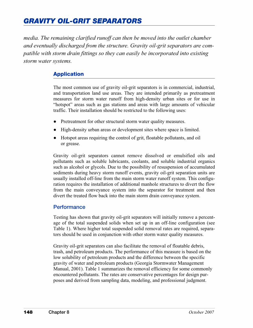
GRAVITY OIL-GRIT SEPARATORS
148 Chapter 8 October 2007
The most common use of gravity oil-grit separators is in commercial, industrial, and transportation land use areas. They are intended primarily as pretreatment measures for storm water runoff from high-density urban sites or for use in “hotspot” areas such as gas stations and areas with large amounts of vehicular traffic. Their installation should be restricted to the following uses:
� Pretreatment for other structural storm water quality measures.
� High-density urban areas or development sites where space is limited. � Hotspot areas requiring the control of grit, floatable pollutants, and oil
or grease.
Gravity oil-grit separators cannot remove dissolved or emulsified oils and pollutants such as soluble lubricants, coolants, and soluble industrial organics such as alcohol or glycols. Due to the possibility of resuspension of accumulated sediments during heavy storm runoff events, gravity oil-grit separation units are usually installed off-line from the main storm water runoff system. This configu-ration requires the installation of additional manhole structures to divert the flow from the main conveyance system into the separator for treatment and then divert the treated flow back into the main storm drain conveyance system.
Performance
Testing has shown that gravity oil-grit separators will initially remove a percent-age of the total suspended solids when set up in an off-line configuration (see Table 1). Where higher total suspended solid removal rates are required, separa-tors should be used in conjunction with other storm water quality measures.
Gravity oil-grit separators can also facilitate the removal of floatable debris, trash, and petroleum products. The performance of this measure is based on the low solubility of petroleum products and the difference between the specific gravity of water and petroleum products (Georgia Stormwater Management Manual, 2001). Table 1 summarizes the removal efficiency for some commonly encountered pollutants. The rates are conservative percentages for design pur-poses and derived from sampling data, modeling, and professional judgment.
Application
media. The remaining clarified runoff can then be moved into the outlet chamber and eventually discharged from the structure. Gravity oil-grit separators are com-patible with storm drain fittings so they can easily be incorporated into existing storm water systems.
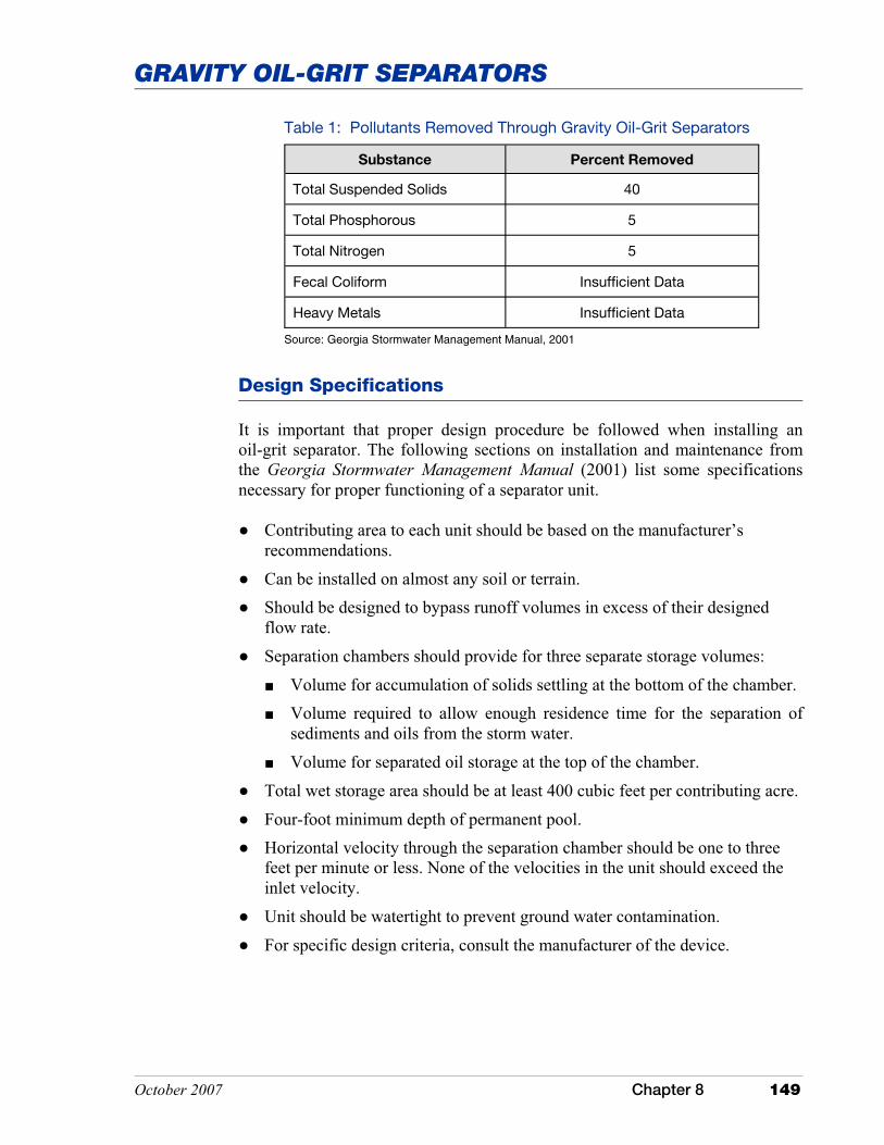
GRAVITY OIL-GRIT SEPARATORS
October 2007 Chapter 8 149
Table 1: Pollutants Removed Through Gravity Oil-Grit Separators
Substance Percent Removed
Total Suspended Solids 40
Total Phosphorous 5
Total Nitrogen 5
Fecal Coliform Insufficient Data
Heavy Metals Insufficient Data
Source: Georgia Stormwater Management Manual, 2001
Design Specifications
It is important that proper design procedure be followed when installing an oil-grit separator. The following sections on installation and maintenance from the Georgia Stormwater Management Manual (2001) list some specifications necessary for proper functioning of a separator unit.
� Contributing area to each unit should be based on the manufacturer’s recommendations.
� Can be installed on almost any soil or terrain. � Should be designed to bypass runoff volumes in excess of their designed
flow rate.
� Separation chambers should provide for three separate storage volumes:
� Volume for accumulation of solids settling at the bottom of the chamber. � Volume required to allow enough residence time for the separation of
sediments and oils from the storm water.
� Volume for separated oil storage at the top of the chamber.
� Total wet storage area should be at least 400 cubic feet per contributing acre.
� Four-foot minimum depth of permanent pool. � Horizontal velocity through the separation chamber should be one to three
feet per minute or less. None of the velocities in the unit should exceed the inlet velocity.
� Unit should be watertight to prevent ground water contamination.
� For specific design criteria, consult the manufacturer of the device.
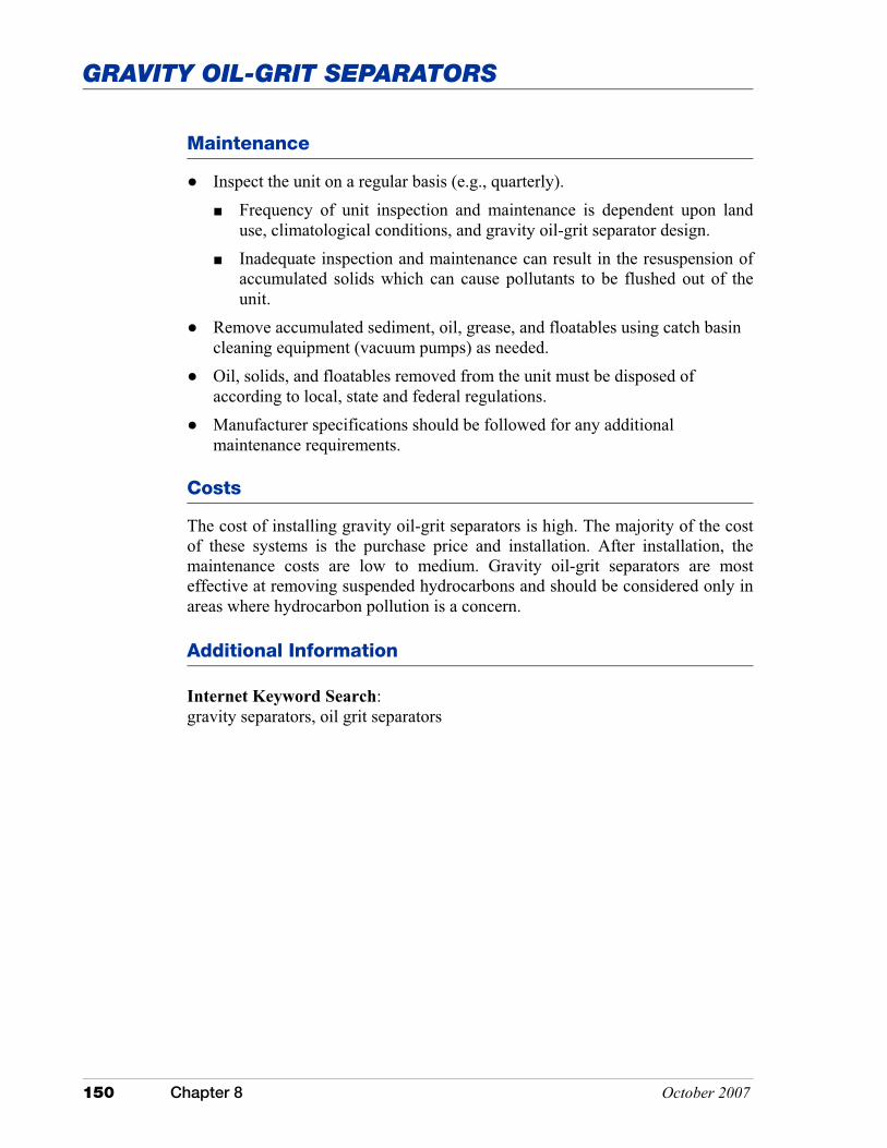
GRAVITY OIL-GRIT SEPARATORS
150 Chapter 8 October 2007
Maintenance
� Inspect the unit on a regular basis (e.g., quarterly). � Frequency of unit inspection and maintenance is dependent upon land
use, climatological conditions, and gravity oil-grit separator design. � Inadequate inspection and maintenance can result in the resuspension of
accumulated solids which can cause pollutants to be flushed out of the unit.
� Remove accumulated sediment, oil, grease, and floatables using catch basin cleaning equipment (vacuum pumps) as needed.
� Oil, solids, and floatables removed from the unit must be disposed of according to local, state and federal regulations.
� Manufacturer specifications should be followed for any additional maintenance requirements.
Costs
The cost of installing gravity oil-grit separators is high. The majority of the cost of these systems is the purchase price and installation. After installation, the maintenance costs are low to medium. Gravity oil-grit separators are most effective at removing suspended hydrocarbons and should be considered only in areas where hydrocarbon pollution is a concern.
Additional Information
Internet Keyword Search: gravity separators, oil grit separators

PROPRIETARY MEASURES
October 2007 Chapter 8 151
Hydrodynamic Separators
Hydrodynamic separators, also known as swirl concentrators, are modifications of traditional oil/grit separators that commonly rely on vortex-enhanced treatment of storm water runoff for pollutant removal. Installed in or adjacent to storm water drainage systems, they are very effective at removing coarse solids, trash, and oil. By concentrating the influent into a swirl or vortex, solids settle out via gravity and are stored in a chamber at the bottom of the separator structure. Most hydrodynamic separator structures also have chambers to trap oil and other floatables. Swirl concentration is the most common technology, however other units available commercially use circular screening or cylindrical sedimentation. Circular screening sys-tems utilize a combina-tion of screens, baffles, and inlet/outlet structures to remove debris, large particles, and large oil droplets. Cylindrical sedi-mentation systems utilize internal baffles and an oil and sediment storage com-partment (Connecticut Stormwater Quality Manual, 2004). The efficiency of hydrody-namic separators is highly dependant upon site-specific conditions but they do represent a valuable method for removing suspended solids from storm water runoff. Figure 1 shows several examples of common hydrodynamic separator designs. Source: Connecticut Stormwater Quality Manual, 2004
Figure 1: Common Hydrodynamic Separator Designs
HYDRODYNAMIC SEPARATORS
152 Chapter 8 October 2007
Application
Hydrodynamic separators are extremely effective on their own or in combination with other storm water quality measures. An arrangement where storm water runoff flows exceeding design specifications of the device are passed to a stor-age facility (extended detention ponds, etc.) for additional treatment can be par-ticularly effective. In addition, they can serve effectively in storm water hotspots such as gas stations, industrial sites, or high vehicle traffic areas where acute pol-lution is a concern. Their relatively small size makes them ideal for areas where space is a concern or for retrofitting existing sewer lines. All hydrodynamic separators are installed below grade, which minimizes safety issues and does not diminish aesthetics, especially in urban areas where this is often a concern.
Design Specifications
There are a number of structures on the market that utilize hydrodynamic separation technology. The most effective structures combine a swirl unit to remove oils and sediments. Some units have additional flow-through and filter mechanisms that remove oils, trash, and various other pollutants whose specific gravity does not lend them to settling out readily in the swirl concentrator. Differences do exist in the amount of treatment that occurs at full design flows as well as the location of material storage within the unit. These differences should be thoroughly investigated with the manufacturer for given site condi-tions. Due to the proprietary nature of these devices, hydrodynamic separators should be sited and installed according to the manufacturer’s recommendations. Hydrodynamic separator design should use accepted principles of fluid mechan-ics to demonstrate that the water surface inside the tank can be elevated to a predetermined level in order to prevent the re-entrainment of previously trapped buoyant and nonbuoyant particles. Upstream diversion structures can be used to bypass higher flows around the devices which in most cases are installed in an off-line configuration.
Hydrodynamic separators should be capable of capturing oil, trash, and a minimum of 80 percent of the total suspended solids from the first one-half inch to one and one-half inch rain event. Devices with less than 80 percent total sus-pended solids removal efficiency should be used in conjunction with other storm water quality measures. The removal efficiency of total suspended solids should be based on standard performance testing (using OK 110 sand) that has been conducted by an independent third party.
Hydrodynamic separators alone may not remove all the targeted pollutants from a site. For example, these systems alone may not remove 80 percent of the lead, copper, or zinc in addition to the polyaromatic hydrocarbons associated with fu-eling areas. A secondary in-line filter system may be required to achieve these objectives.
HYDRODYNAMIC SEPARATORS
October 2007 Chapter 8 153
Additional Information
Internet Keyword Search: swirl separators, hydrodynamic separators, vortex separator
When used in combination with detention systems, hydrodynamic separators should be installed upstream and should not be included in the calculations for the required detention volume.
Maintenance
Frequent inspection and cleanout is critical for proper operation of hydrody-namic separators. Recommended inspection and maintenance schedules vary with each manufacturer, but in general hydrodynamic separator structures need to be inspected quarterly and cleaned out accordingly. Hydrodynamic separators should have easy, unobstructed access from the top of the structure to allow for inspection, cleanout, and maintenance. Maintenance typically involves using a vacuum truck to remove accumulated oil, floatables, and sediment. Polluted wa-ter and sediment removed from these devices should be properly handled and disposed of in accordance with local, state, and federal regulations.
Costs
The ease of maintenance and long design life of hydrodynamic separators is such that costs, though initially high, should be weighed against similar storm water quality management measures over a long period of time. Costs should be broken down into treatment costs per acre which include operating expenses (maintenance costs and disposal expenses) separate from initial materials and installation costs. In addition, the expense of retrofitting should be examined as an alternative to other retrofit storm water quality management measures which may require more space to mirror the pollutant removal capabilities of these devices.

This page was intentionally left blank.
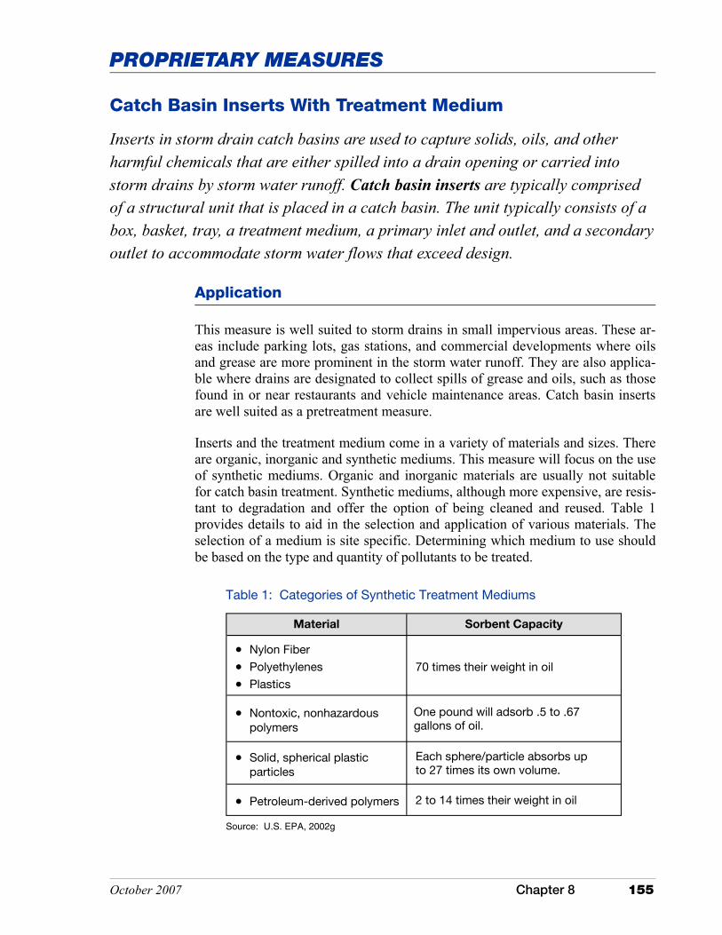
PROPRIETARY MEASURES
October 2007 Chapter 8 155
Catch Basin Inserts With Treatment Medium
Inserts in storm drain catch basins are used to capture solids, oils, and other harmful chemicals that are either spilled into a drain opening or carried into storm drains by storm water runoff. Catch basin inserts are typically comprised of a structural unit that is placed in a catch basin. The unit typically consists of a box, basket, tray, a treatment medium, a primary inlet and outlet, and a secondary outlet to accommodate storm water flows that exceed design.
Application
This measure is well suited to storm drains in small impervious areas. These ar-eas include parking lots, gas stations, and commercial developments where oils and grease are more prominent in the storm water runoff. They are also applica-ble where drains are designated to collect spills of grease and oils, such as those found in or near restaurants and vehicle maintenance areas. Catch basin inserts are well suited as a pretreatment measure.
Inserts and the treatment medium come in a variety of materials and sizes. There are organic, inorganic and synthetic mediums. This measure will focus on the use of synthetic mediums. Organic and inorganic materials are usually not suitable for catch basin treatment. Synthetic mediums, although more expensive, are resis-tant to degradation and offer the option of being cleaned and reused. Table 1 provides details to aid in the selection and application of various materials. The selection of a medium is site specific. Determining which medium to use should be based on the type and quantity of pollutants to be treated.
Table 1: Categories of Synthetic Treatment Mediums
Material Sorbent Capacity
�� Nylon Fiber
�� Polyethylenes
�� Plastics
70 times their weight in oil
�� Nontoxic, nonhazardous polymers
One pound will adsorb .5 to .67 gallons of oil.
�� Solid, spherical plastic particles
Each sphere/particle absorbs up to 27 times its own volume.
�� Petroleum-derived polymers 2 to 14 times their weight in oil
Source: U.S. EPA, 2002g
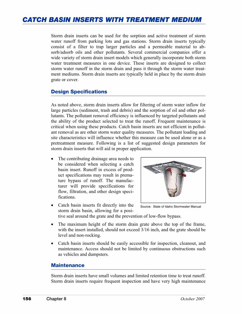
CATCH BASIN INSERTS WITH TREATMENT MEDIUM
156 Chapter 8 October 2007
Design Specifications
As noted above, storm drain inserts allow for filtering of storm water inflow for large particles (sediment, trash and debris) and the sorption of oil and other pol-lutants. The pollutant removal efficiency is influenced by targeted pollutants and the ability of the product selected to treat the runoff. Frequent maintenance is critical when using these products. Catch basin inserts are not efficient in pollut-ant removal as are other storm water quality measures. The pollutant loading and site characteristics will influence whether this measure can be used alone or as a pretreatment measure. Following is a list of suggested design parameters for storm drain inserts that will aid in proper application.
�� The contributing drainage area needs to be considered when selecting a catch basin insert. Runoff in excess of prod-uct specifications may result in prema-ture bypass of runoff. The manufac-turer will provide specifications for flow, filtration, and other design speci-fications.
�� Catch basin inserts fit directly into the storm drain basin, allowing for a posi-tive seal around the grate and the prevention of low-flow bypass.
�� The maximum height of the storm drain grate above the top of the frame, with the insert installed, should not exceed 3/16 inch, and the grate should be level and non-rocking.
�� Catch basin inserts should be easily accessible for inspection, cleanout, and maintenance. Access should not be limited by continuous obstructions such as vehicles and dumpsters.
Maintenance
Storm drain inserts have small volumes and limited retention time to treat runoff. Storm drain inserts require frequent inspection and have very high maintenance
Source: State of Idaho Stormwater Manual
Storm drain inserts can be used for the sorption and active treatment of storm water runoff from parking lots and gas stations. Storm drain inserts typically consist of a filter to trap larger particles and a permeable material to ab-sorb/adsorb oils and other pollutants. Several commercial companies offer a wide variety of storm drain insert models which generally incorporate both storm water treatment measures in one device. These inserts are designed to collect storm water runoff in the storm drain and pass it through the storm water treat-ment mediums. Storm drain inserts are typically held in place by the storm drain grate or cover.
CATCH BASIN INSERTS WITH TREATMENT MEDIUM
October 2007 Chapter 8 157
requirements. To remain in working order requires cleaning or replacement of the treatment medium. The manufacturer will usually provide information on maintenance requirements for their product. If not properly maintained, they can become clogged, resulting in blocked flow and flooding of up-slope areas. Moni-toring schedules should be on the order of at least once a month and after each one-half inch or greater storm event.
Costs
The cost of using absorbents in storm drains that are specifically designed to trap oils, grease and other hazardous materials is a minimal expense when compared to the long term protection that these measures can provide.
The use of a medium for the active treatment of storm water runoff carries a significant cost in terms of inspection frequency and maintenance. This is particularly true once the measure has reached or exceeded its storm water runoff treatment capacity and has to be cleaned or replaced.
Using catch basin insert storm drain treatment measures on a large scale is cost prohibitive and it is generally best to select an alternative storm water treatment measure(s).
Additional Information
Internet Keyword Search: drain absorbents, storm drain inserts, catch basin inserts, organic, synthetic, inorganic

This page was intentionally left blank.
Related Documents


