POSITIVE DISPLACEMENT BLOWER AERZEN CANNED MOTOR BLOWER FOR THE CONVEYANCE OF AIR AND GASES IN VACUUM TECHNOLOGY

Welcome message from author
This document is posted to help you gain knowledge. Please leave a comment to let me know what you think about it! Share it to your friends and learn new things together.
Transcript
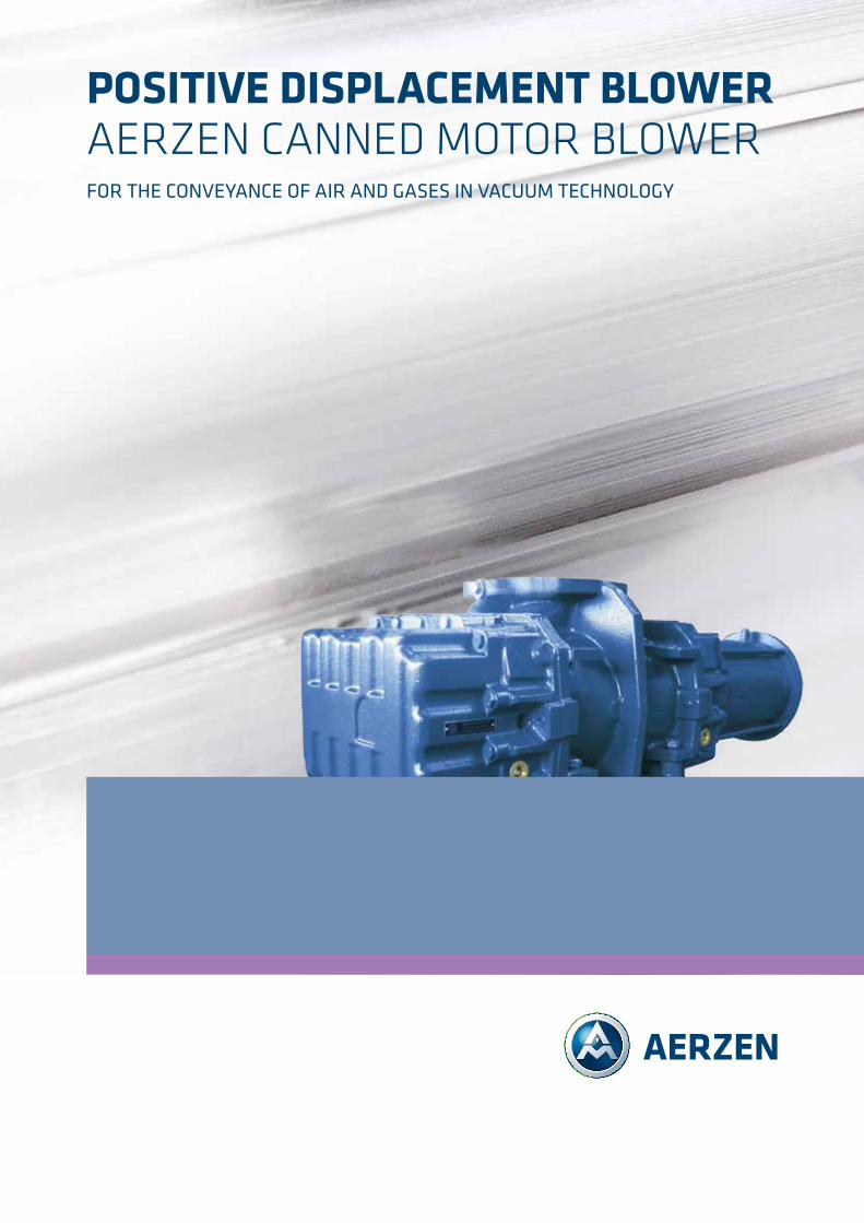
POSITIVE DISPLACEMENT BLOWER AERZEN CANNED MOTOR BLOWER For the conveyance oF air and gases in vacuum technology
2
Customer benefit through technical progressWith experience in the construction of positive displacement blowers since 1868, AERZEN continues to set new standards in quality and innovation in relation to twin-shaft positive displacement machines. As a result, AERZEN belongs to the pioneers in compressor technology, and is now one of the leading manufacturers worldwide.
AERZEN can look back on over 70 years of experience, particularly in the field of vacuum technology. Technical competence, expe-rienced employees and continuous exchange with customers form an excellent basis for successful new developments by AERZEN. AERZEN always gives priority to customer benefit. Innovative products by AERZEN ensure that plant manufac-turers and plant operators can achieve sustainable success in the market.
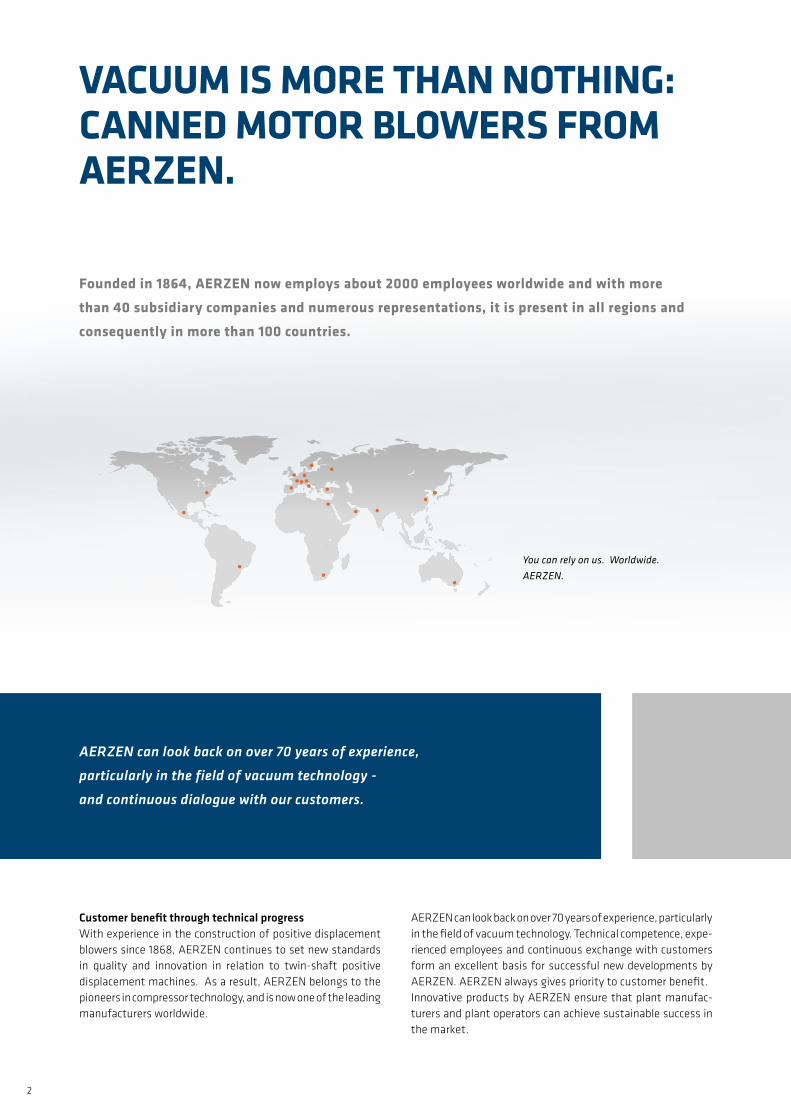
VACUUM IS MORE THAN NOTHING: CANNED MOTOR BLOWERS fROM AERZEN.
founded in 1864, AERZEN now employs about 2000 employees worldwide and with more than 40 subsidiary companies and numerous representations, it is present in all regions and consequently in more than 100 countries.
You can rely on us. Worldwide. AERZEN.
AERZEN can look back on over 70 years of experience,
particularly in the field of vacuum technology -
and continuous dialogue with our customers.
3
atmosphere
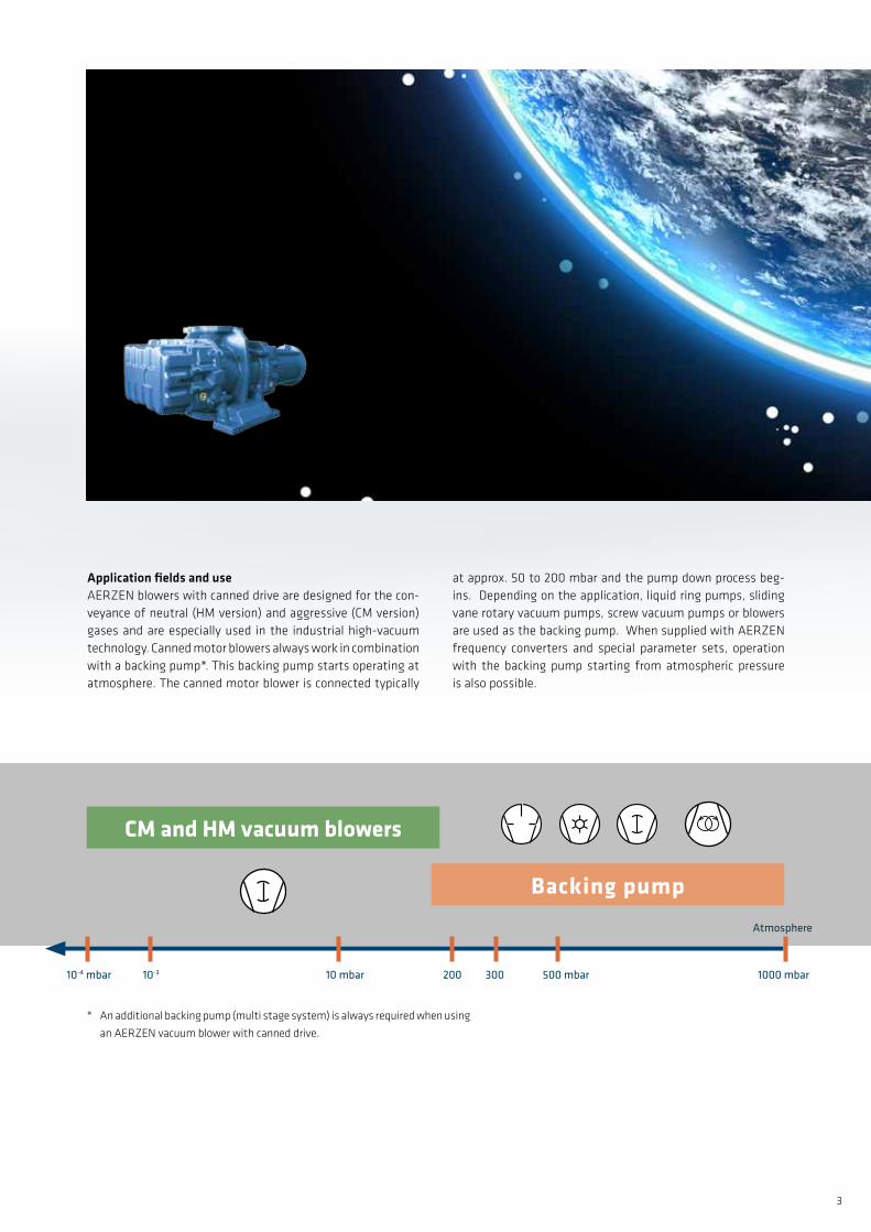
Application fields and useAERZEN blowers with canned drive are designed for the con-veyance of neutral (HM version) and aggressive (CM version) gases and are especially used in the industrial high-vacuum technology. Canned motor blowers always work in combination with a backing pump*. This backing pump starts operating at atmosphere. The canned motor blower is connected typically
at approx. 50 to 200 mbar and the pump down process beg-ins. Depending on the application, liquid ring pumps, sliding vane rotary vacuum pumps, screw vacuum pumps or blowers are used as the backing pump. When supplied with AERZEN frequency converters and special parameter sets, operation with the backing pump starting from atmospheric pressure is also possible.
Backing pump
CM and HM vacuum blowers
10-4 mbar 10-3 10 mbar 200 300 500 mbar 1000 mbar
* An additional backing pump (multi stage system) is always required when using
an AERZEN vacuum blower with canned drive.
4
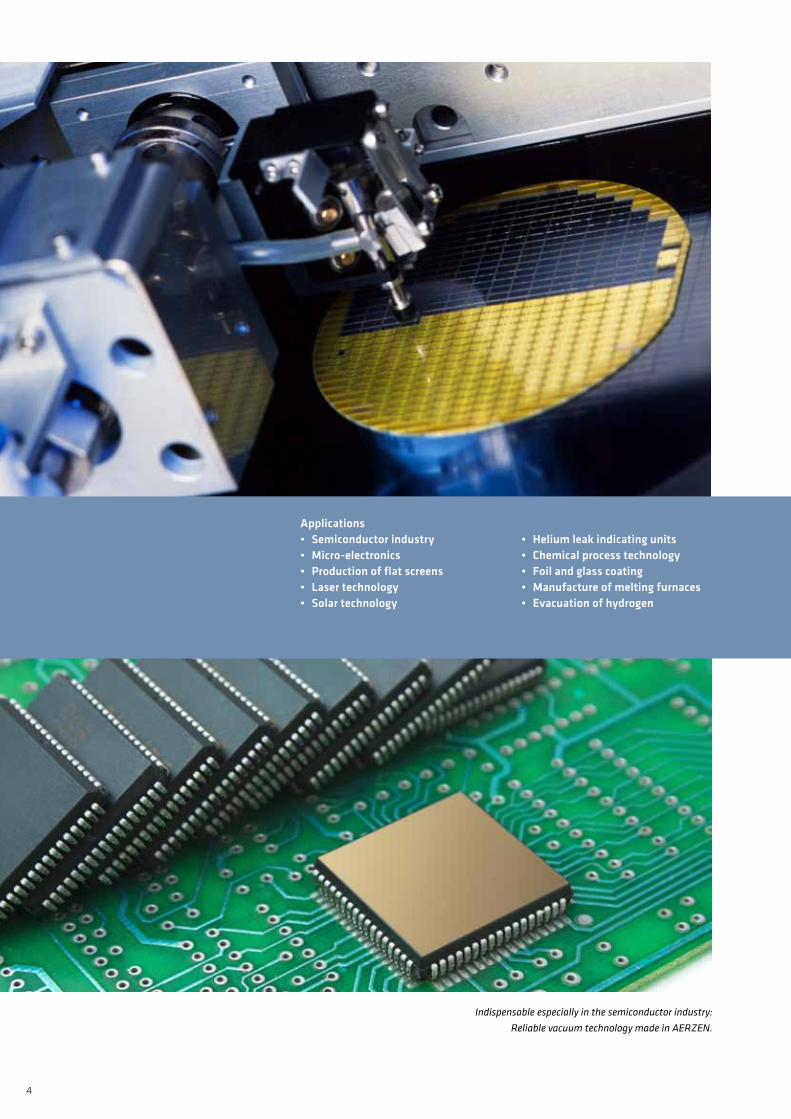
Applications • Semiconductorindustry•Micro-electronics• Productionofflatscreens• Lasertechnology• Solartechnology
•Heliumleakindicatingunits• Chemicalprocesstechnology• Foilandglasscoating•Manufactureofmeltingfurnaces• Evacuationofhydrogen
Indispensable especially in the semiconductor industry: Reliable vacuum technology made in AERZEN.
5
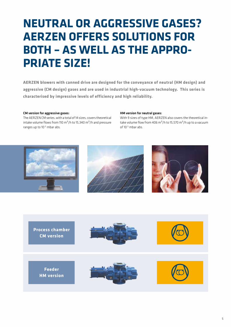
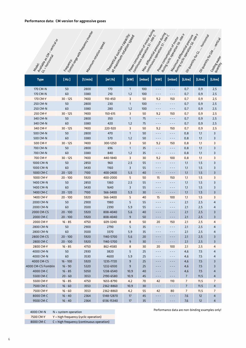
CMversionforaggressivegases:The AERZEN CM series, with a total of 14 sizes, covers theoretical intake volume flows from 110 m³/h to 15,340 m³/h and pressure ranges up to 10-5 mbar abs.
NEUTRAL OR AGGRESSIVE GASES? AERZEN OffERS SOLUTIONS fOR BOTH – AS WELL AS THE APPRO-PRIATE SIZE!
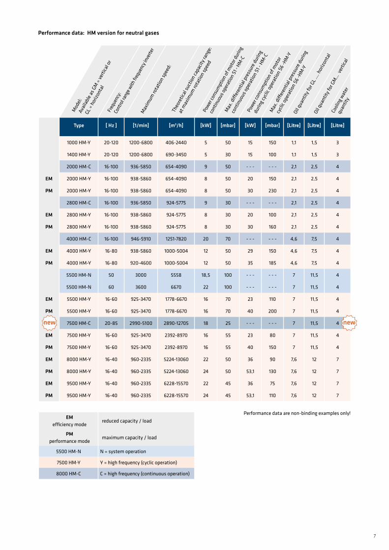
HMversionforneutralgases:With 9 sizes of type HM, AERZEN also covers the theoretical in-take volume flow from 406 m³/h to 15,570 m³/h up to a vacuum of 10-5 mbar abs.
AERZEN blowers with canned drive are designed for the conveyance of neutral (HM design) and aggressive (CM design) gases and are used in industrial high-vacuum technology. This series is characterised by impressive levels of efficiency and high reliability.
Process chamberCM version
feederHM version
6
Type [Hz] [1/min] [m3/h] [kW] [mbar] [kW] [mbar] [Litre] [Litre] [Litre]
170 cm-n 50 2800 170 1 100 - - - - - - 0,7 0,9 2,5170 cm-n 60 3380 210 1,2 100 - - - - - - 0,7 0,9 2,5170 cm-y 30 - 125 7400 110-450 3 50 9,2 150 0,7 0,9 2,5250 cm-n 50 2800 230 1 100 - - - - - - 0,7 0,9 2,5250 cm-n 60 3380 280 1,2 100 - - - - - - 0,7 0,9 2,5250 cm-y 30 - 125 7400 150-615 3 50 9,2 150 0,7 0,9 2,5340 cm-n 50 2800 350 1 75 - - - - - - 0,7 0,9 2,5340 cm-n 60 3380 420 1,2 75 - - - - - - 0,7 0,9 2,5340 cm-y 30 - 125 7400 220-920 3 50 9,2 150 0,7 0,9 2,5500 cm-n 50 2800 470 1 50 - - - - - - 0,8 1,1 3500 cm-n 60 3380 570 1,2 50 - - - - - - 0,8 1,1 3500 cm-y 30 - 125 7400 300-1250 3 50 9,2 150 0,8 1,1 3700 cm-n 50 2800 696 1 35 - - - - - - 0,8 1,1 3700 cm-n 60 3380 840 1,2 35 - - - - - - 0,8 1,1 3700 cm-y 30 - 125 7400 440-1840 3 30 9,2 100 0,8 1,1 3
1000 cm-n 50 2850 960 2,5 55 - - - - - - 1,1 1,5 31000 cm-n 60 3430 1160 3 55 - - - - - - 1,1 1,5 31000 cm-c 20 - 120 7100 400-2400 5,5 40 - - - - - - 1,1 1,5 31000 cm-y 20 - 100 5920 400-2000 5 50 15 150 1,1 1,5 31400 cm-n 50 2850 1360 2,5 55 - - - - - - 1,1 1,5 31400 cm-n 60 3430 1640 3 55 - - - - - - 1,1 1,5 31400 cm-c 20 - 120 7100 566-3400 5,5 30 - - - - - - 1,1 1,5 31400 cm-y 20 - 100 5920 566-3400 5 40 15 100 1,1 1,5 32000 cm-n 50 2900 1980 5 55 - - - - - - 2,1 2,5 42000 cm-n 60 3500 2390 5,9 55 - - - - - - 2,1 2,5 42000 cm-cs 20 - 100 5920 808-4040 5,6 40 - - - - - - 2,1 2,5 32000 cm-c 20 - 100 5920 808-4040 9 50 - - - - - - 2,1 2,5 32000 cm-y 16 - 85 4750 609-3240 8 50 20 150 2,1 2,5 42800 cm-n 50 2900 2790 5 35 - - - - - - 2,1 2,5 42800 cm-n 60 3500 3370 5,9 35 - - - - - - 2,1 2,5 42800 cm-cs 20 - 100 5920 1140-5700 5,6 20 - - - - - - 2,1 2,5 32800 cm-c 20 - 100 5920 1140-5700 9 30 - - - - - - 2,1 2,5 32800 cm-y 16 - 85 4750 862-4580 8 30 20 100 2,1 2,5 44000 cm-n 50 2930 3820 5 25 - - - - - - 4,6 7,5 44000 cm-n 60 3530 4600 5,9 25 - - - - - - 4,6 7,5 44000 cm-cs 16 - 100 5920 1235-7720 9 25 - - - - - - 4,6 7,5 3
4000 cm-cs Fomblin 16 - 90 5320 1232-6930 9 25 - - - - - - 4,6 7,5 34000 cm-c 16 - 85 5050 1238-6540 10,9 40 - - - - - - 4,6 7,5 45500 cm-c 20 - 60 3553 2190-6580 10,9 45 - - - - - - 7 11,5 45500 cm-y 16 - 85 4750 1655-8790 4,2 70 42 110 7 11,5 77500 cm-c 16 - 60 3553 2362-8860 10,9 30 - - - - - - 7 11,5 47500 cm-y 16 - 60 3553 2362-8860 4,2 55 42 80 7 11,5 78000 cm-c 16 - 40 2364 5148-12870 17 45 - - - - - - 7,6 12 49500 cm-c 16 - 40 2364 6136-15340 17 35 - - - - - - 7,6 12 4
4000 cm-n n = system operation7500 cm-y y = high frequency (cyclic operation)8000 cm-c c = high frequency (continuous operation)
Performancedata:CMversionforaggressivegases
oil q
uant
ity fo
r gl …
. hor
izont
al
max
. diff
eren
tial p
ress
ure d
urin
g
con
tinuo
us o
pera
tion
s1 -
hm-c
max
imum
rota
tion
spee
d:
mod
el:
ava
ilabl
e as g
m =
verti
cal o
r
gl
= h
orizo
ntal
Power
cons
umpt
ion
of m
otor
durin
g
con
tinuo
us o
pera
tion
s1 -
hm-c
theo
retic
al su
ctio
n ca
pacit
y:
at m
axim
um ro
tatio
n sp
eed
Power
cons
umpt
ion
of m
otor
dur
ing c
yclic
ope
ratio
n s6
-hm
-y
cool
ing w
ater
qua
ntity
oil q
uant
ity fo
r gm
…. v
ertic
al
max
imum
diff
eren
tial p
ress
ure
dur
ing c
yclic
ope
ratio
n s6
-hm
-y
Freq
uenc
y: c
ontro
l rang
e with
freq
uenc
y inv
erte
r
Performance data are non-binding examples only!
7
Type [Hz] [1/min] [m3/h] [kW] [mbar] [kW] [mbar] [Litre] [Litre] [Litre]
1000 hm-y 20-120 1200-6800 406-2440 5 50 15 150 1,1 1,5 3
1400 hm-y 20-120 1200-6800 690-3450 5 30 15 100 1,1 1,5 3
2000 hm-c 16-100 936-5850 654-4090 9 50 - - - - - - 2,1 2,5 4
EM 2000 hm-y 16-100 938-5860 654-4090 8 50 20 150 2,1 2,5 4
PM 2000 hm-y 16-100 938-5860 654-4090 8 50 30 230 2,1 2,5 4
2800 hm-c 16-100 936-5850 924-5775 9 30 - - - - - - 2,1 2,5 4
EM 2800 hm-y 16-100 938-5860 924-5775 8 30 20 100 2,1 2,5 4
PM 2800 hm-y 16-100 938-5860 924-5775 8 30 30 160 2,1 2,5 4
4000 hm-c 16-100 946-5910 1251-7820 20 70 - - - - - - 4,6 7,5 4
EM 4000 hm-y 16-80 938-5860 1000-5004 12 50 29 150 4,6 7,5 4
PM 4000 hm-y 16-80 920-4600 1000-5004 12 50 35 185 4,6 7,5 4
5500 hm-n 50 3000 5558 18,5 100 - - - - - - 7 11,5 4
5500 hm-n 60 3600 6670 22 100 - - - - - - 7 11,5 4
EM 5500 hm-y 16-60 925-3470 1778-6670 16 70 23 110 7 11,5 4
PM 5500 hm-y 16-60 925-3470 1778-6670 16 70 40 200 7 11,5 4
7500 hm-c 20-85 2990-5100 2890-12705 18 25 - - - - - - 7 11,5 4
EM 7500 hm-y 16-60 925-3470 2392-8970 16 55 23 80 7 11,5 4
PM 7500 hm-y 16-60 925-3470 2392-8970 16 55 40 150 7 11,5 4
EM 8000 hm-y 16-40 960-2335 5224-13060 22 50 36 90 7,6 12 7
PM 8000 hm-y 16-40 960-2335 5224-13060 24 50 53,1 130 7,6 12 7
EM 9500 hm-y 16-40 960-2335 6228-15570 22 45 36 75 7,6 12 7
PM 9500 hm-y 16-40 960-2335 6228-15570 24 45 53,1 110 7,6 12 7
oil q
uant
ity fo
r gl …
. hor
izont
al
max
. diff
eren
tial p
ress
ure d
urin
g
con
tinuo
us o
pera
tion
s1 -
hm-c
max
imum
rota
tion
spee
d:
mod
el:
ava
ilabl
e as g
m =
verti
cal o
r
gl
= h
orizo
ntal
Power
cons
umpt
ion of
mot
or du
ring
con
tinuo
us op
erat
ion s
1 - h
m-c
theo
retic
al su
ctio
n ca
pacit
y ran
ge:
at m
axim
um ro
tatio
n sp
eed
Power
cons
umpt
ion
of m
otor
dur
ing c
yclic
ope
ratio
n s6
-hm
-y
cool
ing w
ater
qua
ntity
oil q
uant
ity fo
r gm
... v
ertic
al
max
. diff
eren
tial p
ress
ure d
urin
g
cyc
lic o
pera
tion
s6 -h
m-y
EMefficiency mode
reduced capacity / load
PMperformance mode
maximum capacity / load
5500 hm-n n = system operation
7500 hm-y y = high frequency (cyclic operation)
8000 hm-c c = high frequency (continuous operation)
Performancedata:HMversionforneutralgases
Freq
uenc
y: c
ontro
l rang
e with
freq
uenc
y inv
erte
r
newnew
Performance data are non-binding examples only!
8
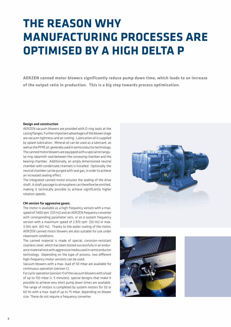
AERZEN canned motor blowers significantly reduce pump down time, which leads to an increase of the output ratio in production. This is a big step towards process optimisation.
THE REASON WHy MANUfACTURING PROCESSES ARE OPTIMISED By A HIGH DELTA P
Design and constructionAERZEN vacuum blowers are provided with O-ring seals at the casing flanges. Further important advantages of the blower stage are vacuum tightness and air cooling. Lubrication oil is supplied by splash lubrication. Mineral oil can be used as a lubricant, as well as the PFPE oil, generally used in semiconductor technology. The canned motor blowers are equipped with a special rectangu-lar ring-labyrinth-seal between the conveying chamber and the bearing chamber. Additionally, an amply dimensioned neutral chamber with condensate channels is installed. Optionally, the neutral chamber can be purged with seal gas, in order to achieve an increased sealing effect.The integrated canned motor ensures the sealing of the drive shaft. A shaft passage to atmosphere can therefore be omitted, making it technically possible to achieve significantly higher rotation speeds.
CMversionforaggressivegases:The motor is available as a high-frequency version with a max. speed of 7,400 rpm (125 Hz) and an AERZEN frequency converter with corresponding parameter sets, or as a system frequency version with a maximum speed of 2,970 rpm (50 Hz) or max. 3,565 rpm (60 Hz). Thanks to the water cooling of the motor, AERZEN canned motor blowers are also suitable for use under cleanroom conditions.The canned material is made of special, corrosion-resistant stainless steel, which has been tested successfully in an endur-ance material test with aggressive media used in semiconductor technology. Depending on the type of process, two different high-frequency motor versions can be used:Vacuum blowers with a max. load of 50 mbar are available for continuous operation (version C).For cyclic operation (version Y) of the vacuum blowers with a load of up to 150 mbar (< 5 minutes), special designs that make it possible to achieve very short pump down times are available. The range of motors is completed by system motors for 50 or 60 Hz with a max. load of up to 75 mbar, depending on blower size. These do not require a frequency converter.
9
0,01 0,1 1 10 100 10000
500
1000
1500
2000
2500
3000
3500
S [m³/h]
p [m
bar]
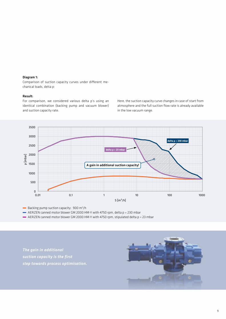
Backing pump suction capacity: 900 m3/h AERZEN canned motor blower GM 2000 HM-Y with 4750 rpm, delta p = 230 mbar AERZEN canned motor blower GM 2000 HM-Y with 4750 rpm, stipulated delta p = 23 mbar
Diagram1:Comparison of suction capacity curves under different me-chanical loads, delta p:
Result:For comparison, we considered various delta p‘s using an identical combination (backing pump and vacuum blower) and suction capacity rate.
Here, the suction capacity curve changes in case of start from atmosphere and the full suction flow rate is already available in the low vacuum range.
The gain in additional
suction capacity is the first
step towards process optimisation.
delta p = 23 mbar
delta p = 230 mbar
Againinadditionalsuctioncapacity!
10
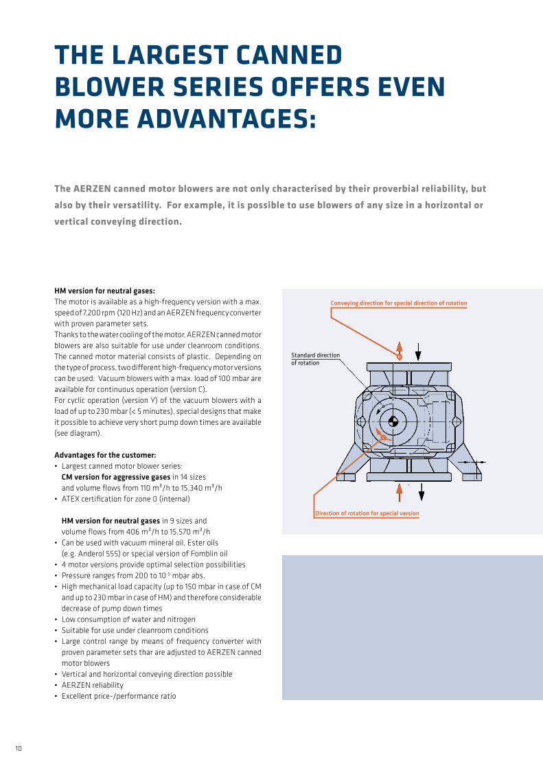
HMversionforneutralgases:The motor is available as a high-frequency version with a max. speed of 7,200 rpm (120 Hz) and an AERZEN frequency converter with proven parameter sets.Thanks to the water cooling of the motor, AERZEN canned motor blowers are also suitable for use under cleanroom conditions. The canned motor material consists of plastic. Depending on the type of process, two different high-frequency motor versions can be used: Vacuum blowers with a max. load of 100 mbar are available for continuous operation (version C). For cyclic operation (version Y) of the vacuum blowers with a load of up to 230 mbar (< 5 minutes), special designs that make it possible to achieve very short pump down times are available (see diagram).
Advantagesforthecustomer:• Largest canned motor blower series: CMversionforaggressivegases in 14 sizes and volume flows from 110 m³/h to 15,340 m³/h• ATEX certification for zone 0 (internal)
HMversionforneutralgases in 9 sizes and volume flows from 406 m³/h to 15,570 m³/h • Can be used with vacuum mineral oil, Ester oils (e.g. Anderol 555) or special version of Fomblin oil• 4 motor versions provide optimal selection possibilities• Pressure ranges from 200 to 10-5 mbar abs.• High mechanical load capacity (up to 150 mbar in case of CM
and up to 230 mbar in case of HM) and therefore considerable decrease of pump down times
• Low consumption of water and nitrogen• Suitable for use under cleanroom conditions• Large control range by means of frequency converter with
proven parameter sets thar are adjusted to AERZEN canned motor blowers
• Vertical and horizontal conveying direction possible• AERZEN reliability• Excellent price-/performance ratio
The AERZEN canned motor blowers are not only characterised by their proverbial reliability, but also by their versatility. for example, it is possible to use blowers of any size in a horizontal or vertical conveying direction.
THE LARGEST CANNEDBLOWER SERIES OffERS EVEN MORE ADVANTAGES:
standard direction of rotation
Conveyingdirectionforspecialdirectionofrotation
Directionofrotationforspecialversion
11
0 5 10 15 20 25 30 35 40
9,8 17,3
0,001
0,01
0,1
1
10
100
1000
t [s]
p [m
bar]
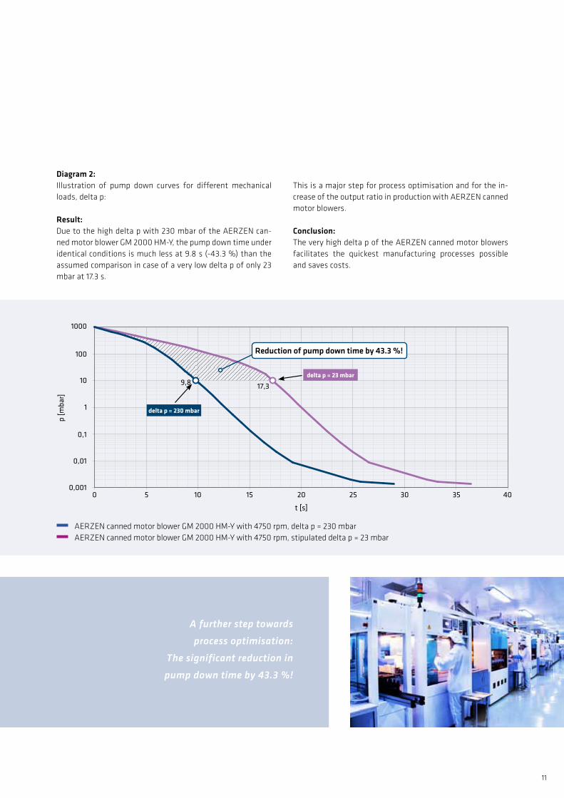
Diagram2: Illustration of pump down curves for different mechanical loads, delta p:
Result:Due to the high delta p with 230 mbar of the AERZEN can-ned motor blower GM 2000 HM-Y, the pump down time under identical conditions is much less at 9.8 s (-43.3 %) than the assumed comparison in case of a very low delta p of only 23 mbar at 17.3 s.
AERZEN canned motor blower GM 2000 HM-Y with 4750 rpm, delta p = 230 mbar AERZEN canned motor blower GM 2000 HM-Y with 4750 rpm, stipulated delta p = 23 mbar
This is a major step for process optimisation and for the in-crease of the output ratio in production with AERZEN canned motor blowers.
Conclusion:The very high delta p of the AERZEN canned motor blowers facilitates the quickest manufacturing processes possible and saves costs.
delta p = 23 mbar
delta p = 230 mbar
Reductionofpumpdowntimeby43.3%!
A further step towards
process optimisation:
The significant reduction in
pump down time by 43.3 %!
12
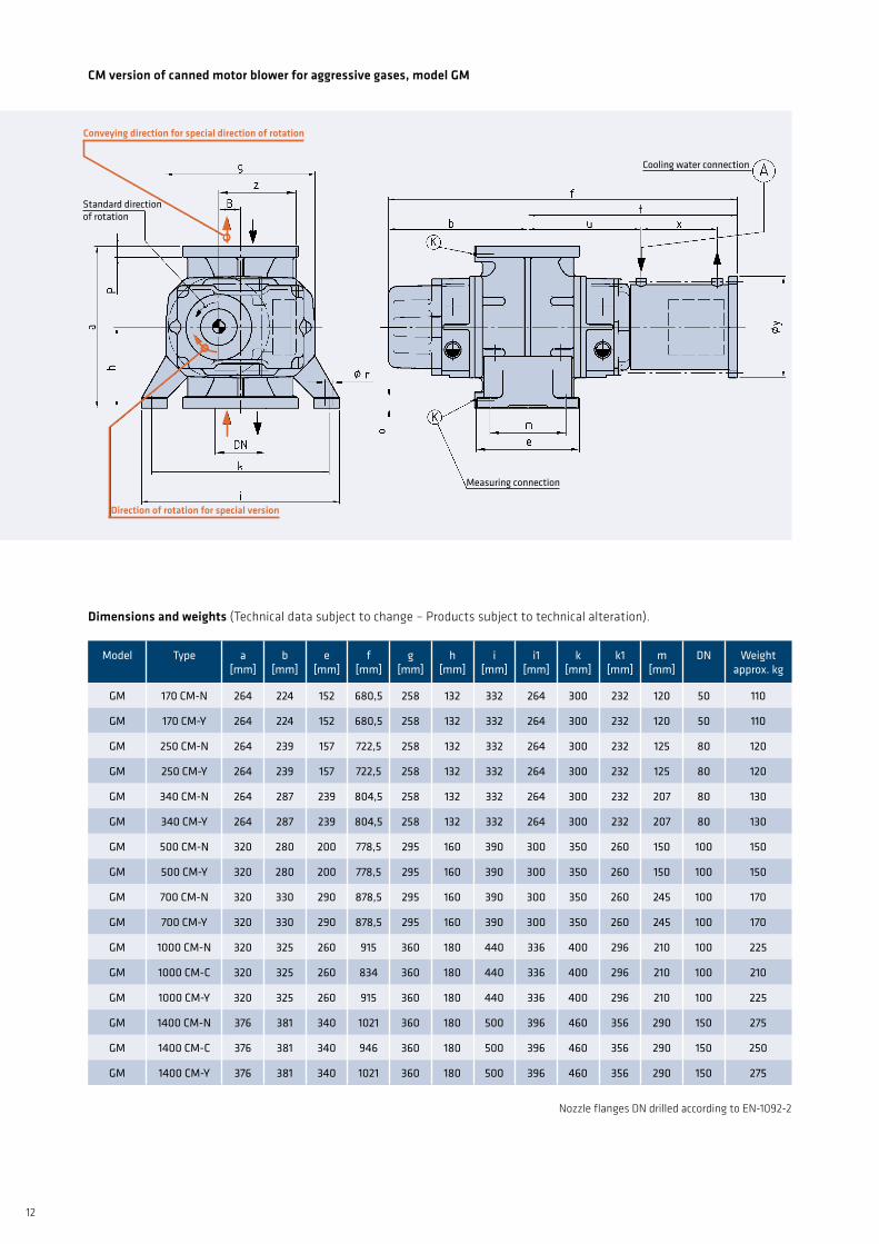
CMversionofcannedmotorblowerforaggressivegases,modelGM
model
type
a[mm]
b[mm]
e[mm]
f[mm]
g[mm]
h[mm]
i[mm]
i1[mm]
k[mm]
k1[mm]
m[mm]
dn
Weight approx. kg
gm 170 cm-n 264 224 152 680,5 258 132 332 264 300 232 120 50 110
gm 170 cm-y 264 224 152 680,5 258 132 332 264 300 232 120 50 110
gm 250 cm-n 264 239 157 722,5 258 132 332 264 300 232 125 80 120
gm 250 cm-y 264 239 157 722,5 258 132 332 264 300 232 125 80 120
gm 340 cm-n 264 287 239 804,5 258 132 332 264 300 232 207 80 130
gm 340 cm-y 264 287 239 804,5 258 132 332 264 300 232 207 80 130
gm 500 cm-n 320 280 200 778,5 295 160 390 300 350 260 150 100 150
gm 500 cm-y 320 280 200 778,5 295 160 390 300 350 260 150 100 150
gm 700 cm-n 320 330 290 878,5 295 160 390 300 350 260 245 100 170
gm 700 cm-y 320 330 290 878,5 295 160 390 300 350 260 245 100 170
gm 1000 cm-n 320 325 260 915 360 180 440 336 400 296 210 100 225
gm 1000 cm-c 320 325 260 834 360 180 440 336 400 296 210 100 210
gm 1000 cm-y 320 325 260 915 360 180 440 336 400 296 210 100 225
gm 1400 cm-n 376 381 340 1021 360 180 500 396 460 356 290 150 275
gm 1400 cm-c 376 381 340 946 360 180 500 396 460 356 290 150 250
gm 1400 cm-y 376 381 340 1021 360 180 500 396 460 356 290 150 275
Nozzle flanges DN drilled according to EN-1092-2
cooling water connection
measuring connection
standard direction of rotation
Conveyingdirectionforspecialdirectionofrotation
Directionofrotationforspecialversion
Dimensionsandweights(Technical data subject to change – Products subject to technical alteration).
13
model
type
a[mm]
b[mm]
e[mm]
f[mm]
g[mm]
h[mm]
i[mm]
i1[mm]
k[mm]
k1[mm]
m[mm]
dn
Weight approx. kg
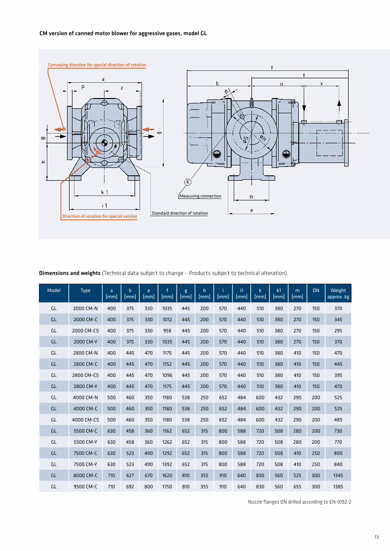
gl 2000 cm-n 400 375 330 1035 445 200 570 440 510 380 270 150 370
gl 2000 cm-c 400 375 330 1012 445 200 570 440 510 380 270 150 345
gl 2000 cm-cs 400 375 330 958 445 200 570 440 510 380 270 150 295
gl 2000 cm-y 400 375 330 1035 445 200 570 440 510 380 270 150 370
gl 2800 cm-n 400 445 470 1175 445 200 570 440 510 380 410 150 470
gl 2800 cm-c 400 445 470 1152 445 200 570 440 510 380 410 150 445
gl 2800 cm-cs 400 445 470 1096 445 200 570 440 510 380 410 150 395
gl 2800 cm-y 400 445 470 1175 445 200 570 440 510 380 410 150 470
gl 4000 cm-n 500 460 350 1180 538 250 652 484 600 432 290 200 525
gl 4000 cm-c 500 460 350 1180 538 250 652 484 600 432 290 200 525
gl 4000 cm-cs 500 460 350 1180 538 250 652 484 600 432 290 200 485
gl 5500 cm-c 630 458 360 1162 652 315 800 588 720 508 280 200 730
gl 5500 cm-y 630 458 360 1262 652 315 800 588 720 508 280 200 770
gl 7500 cm-c 630 523 490 1292 652 315 800 588 720 508 410 250 800
gl 7500 cm-y 630 523 490 1392 652 315 800 588 720 508 410 250 840
gl 8000 cm-c 710 627 670 1620 810 355 910 640 830 560 525 300 1345
gl 9500 cm-c 710 692 800 1750 810 355 910 640 830 560 655 300 1385
Nozzle flanges DN drilled according to EN-1092-2
CMversionofcannedmotorblowerforaggressivegases,modelGL
measuring connection
standard direction of rotation
Conveyingdirectionforspecialdirectionofrotation
Directionofrotationforspecialversion
Dimensionsandweights(Technical data subject to change – Products subject to technical alteration).
14
model
type
a[mm]
b[mm]
e[mm]
f[mm]
g[mm]
h[mm]
i[mm]
i1[mm]
k[mm]
k1[mm]
m[mm]
o[mm]
Weight approx. kg
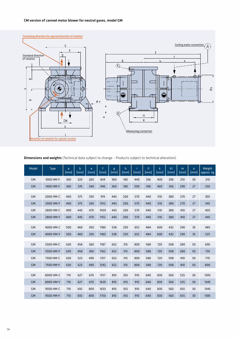
gm 1000 hm-y 360 320 260 834 360 180 440 336 400 296 210 30 210
gm 1400 hm-y 360 376 340 946 360 180 500 396 460 356 290 27 250
gm 2000 hm-c 400 375 330 919 445 200 570 440 510 380 270 27 305
gm 2000 hm-y 400 375 330 1012 445 200 570 440 510 380 270 27 345
gm 2800 hm-c 400 445 470 1059 445 200 570 440 510 380 410 27 405
gm 2800 hm-y 400 445 470 1152 445 200 570 440 510 380 410 27 445
gm 4000 hm-c 500 460 350 1180 538 250 652 484 600 432 290 35 485
gm 4000 hm-y 500 460 350 1180 538 250 652 484 600 432 290 35 525
gm 5500 hm-c 630 458 360 1187 652 315 800 588 720 508 280 50 690
gm 5500 hm-y 630 458 360 1162 652 315 800 588 720 508 280 50 730
gm 7500 hm-c 630 523 490 1317 652 315 800 588 720 508 410 50 770
gm 7500 hm-y 630 523 490 1292 652 315 800 588 720 508 410 50 800
gm 8000 hm-c 710 627 670 1517 810 355 910 640 830 560 525 30 1305
gm 8000 hm-y 710 627 670 1620 810 355 910 640 830 560 525 30 1345
gm 9500 hm-c 710 692 800 1633 810 355 910 640 830 560 655 30 1345
gm 9500 hm-y 710 692 800 1750 810 355 910 640 830 560 655 30 1385
cooling water connection
measuring connection
standard direction of rotation
Conveyingdirectionforspecialdirectionofrotation
Directionofrotationforspecialversion
CMversionofcannedmotorblowerforneutralgases,modelGM
Dimensionsandweights(Technical data subject to change – Products subject to technical alteration).
15
model
type
a[mm]
b[mm]
e[mm]
f[mm]
g[mm]
h[mm]
i[mm]
i1[mm]
k[mm]
k1[mm]
m[mm]
o[mm]
Weight approx. kg
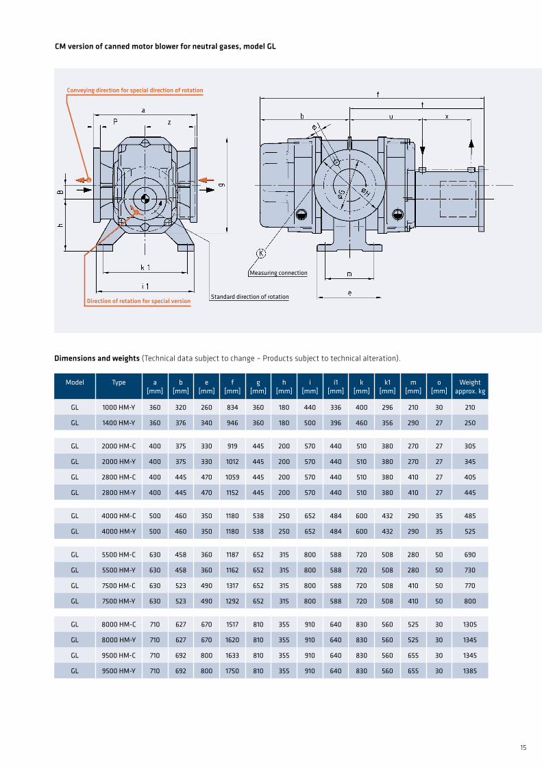
gl 1000 hm-y 360 320 260 834 360 180 440 336 400 296 210 30 210
gl 1400 hm-y 360 376 340 946 360 180 500 396 460 356 290 27 250
gl 2000 hm-c 400 375 330 919 445 200 570 440 510 380 270 27 305
gl 2000 hm-y 400 375 330 1012 445 200 570 440 510 380 270 27 345
gl 2800 hm-c 400 445 470 1059 445 200 570 440 510 380 410 27 405
gl 2800 hm-y 400 445 470 1152 445 200 570 440 510 380 410 27 445
gl 4000 hm-c 500 460 350 1180 538 250 652 484 600 432 290 35 485
gl 4000 hm-y 500 460 350 1180 538 250 652 484 600 432 290 35 525
gl 5500 hm-c 630 458 360 1187 652 315 800 588 720 508 280 50 690
gl 5500 hm-y 630 458 360 1162 652 315 800 588 720 508 280 50 730
gl 7500 hm-c 630 523 490 1317 652 315 800 588 720 508 410 50 770
gl 7500 hm-y 630 523 490 1292 652 315 800 588 720 508 410 50 800
gl 8000 hm-c 710 627 670 1517 810 355 910 640 830 560 525 30 1305
gl 8000 hm-y 710 627 670 1620 810 355 910 640 830 560 525 30 1345
gl 9500 hm-c 710 692 800 1633 810 355 910 640 830 560 655 30 1345
gl 9500 hm-y 710 692 800 1750 810 355 910 640 830 560 655 30 1385
measuring connection
standard direction of rotation
Conveyingdirectionforspecialdirectionofrotation
Directionofrotationforspecialversion
CMversionofcannedmotorblowerforneutralgases,modelGL
Dimensionsandweights(Technical data subject to change – Products subject to technical alteration).
aerzener maschinenfabrik gmbhreherweg 28 – 31855 aerzen / germanytelephone: +49 5154 81-0 – Fax: +49 5154 81-9191 [email protected] – www.aerzen.com
g1-093 – 06 – en – 2000 – 03.2015
AERZEN.Compressionassuccessfactor.AERZEN was founded in 1864 as Aerzener Maschinenfabrik. In 1868 we built Europe’s first rotary lobe blower. The first turbo blowers followed in 1911, the first screw compressors in 1943, and in 2010 the world’s first rotary lobe compressor unit. AERZEN innovations are a driving force behind the develop-ment of compressor technology. Today AERZEN is one of the world’s oldest and most important manufacturers of rotary lobe blowers, rotary lobe compressors, rotary lobe gas meters, screw compressors, and turbo blowers. And in many areas of application, AERZEN is among the undisputed leaders.
There are more than 2,000 experienced AERZEN employees in over 43 subsidiary companies worldwide working hard to advance compressor technology. Their technological exper-tise, our international network of experts, and the constant feedback from our customers are what make us successful. AERZEN products and services have become standards in the industry for reliability, lasting value, and efficiency. Go ahead: challenge us!
Related Documents