Positioning Control Training Manual

Welcome message from author
This document is posted to help you gain knowledge. Please leave a comment to let me know what you think about it! Share it to your friends and learn new things together.
Transcript

Positionin g Control
Training Manual

Cautions on Safety
Make sure to read the manuals and pay careful attention to safety when designing a system.In practice, pay attention to the following contents and handle any products or demonstrationunits correctly.
Cautions on practice
DANGER
• Never touch any terminal while the power is supplied. If you touch a terminal,you may get an electrical shock.
• Turn off the power before connecting / disconnecting units, or opening anysafety covers.
• Never insert your hand or any other object into a moving part.
CAUTION
• Never change the wiring or configuration of demonstration euipment withoutpermission or if you are unsure of how to configure a system correctly. Suchactions may cause failure, malfunction, injury or fire.
• If a simulation unit (such as an X-Y table) generates an abnormal smell orsound, immediately turn off the power switch.
• If you detect any abnormality, immediately turn off the power and contact aqualified engineer.
Positioning Control

i
Positioning Control
Manual number : JY992D89901
Manual revision : A
Date : July 2000
Positioning Control

Positioning Control
ii

FAX BACK
Mitsubishi has a world wide reputation for its efforts in continually developing and pushing backthe frontiers of industrial automation. What is sometimes overlooked by the user is the careand attention to detail that is taken with the documentation. However,to continue this processof improvement, the comments of the Mitsubishi users are always welcomed. This page hasbeen designed for you,the reader,to fill in your comments and fax them back to us. We look for-ward to hearing from you.
Fax numbers: Your name....................................................
Mitsubishi Electric.... .....................................................................
America (01) 847-478-2253 Your company ..............................................
Australia (02) 638-7072 .....................................................................
Germany (0 21 02) 4 86-1 12 Your location: ...............................................
South Africa (0 27) 11 444-0223 .....................................................................
United Kingdom (01707) 278-695
Please tick the box of your choice
What condition did the manual arrive in? �Good �Minor damage �Unusable
Will you be using a folder to store the manual?�Yes �No
What do you think to the manual presentation?�Tidy �Un-friendly
Are the explanations understandable? �Yes �Not too bad �Unusable
Which explanation was most difficult to understand: ......................................................................................................................................................................................................................
Are there any diagrams which are not clear? �Yes �No
If so,which:..................................................................................................................................
What do you think to the manual layout? �Good �Not too bad �Un-helpful
If there one thing you would like to see improved,what is it?..............................................................................................................................................................................................................................................................................................................................................................
Could you find the information you required easily using the index and/or the contents,if possi-ble please identify your experience: ...........................................................................................................................................................................................................................................................................................................................................................................................................................................................................................................................................................................................................................................................................................................
Do you have any comments in general about the Mitsubishi manuals?.....................................................................................................................................................................................................................................................................................................................................................................................................................................................................................................................................................................................................................................................
Thank you for taking the time to fill out this questionnaire. We hope you found both the productand this manual easy to use.
Positioning Control
iii

Positioning Control
iv

Positioning Control
Introduction
This manual describes basic operation for those who learn positioning control for the first time,the aim being so that they can get training using demonstration units of Mitsubishi FAequipment.
The following relevant manuals are available and should be referred to
Manual Name Number
FX-10GM/FX(E)-20GM Hardware and Programming manual JY992D60401
FX-10GM Users Guide JY992D68401
FX2N-10GM/FX2N-20GM Hardware and Programming manual JY992D77801
FX2N-10GM Users Guide JY992D77701
FX2N-20GM Users Guide JY992D77601
FX-PCS-VPS Win-E Software Manual JY992D86801
FX2N-10GM/FX2N-20GM Connection Manual JY992D81601
v

Positioning Control
vi

Positioning Control Contents
1. The World of Positioning Control...........................................................1-11.1 Welcome to the new world! ................................................................................. 1-11.2 Diversified actuators ............................................................................................ 1-21.3 Positioning method type ...................................................................................... 1-4
2. Positioning by AC Servo System...........................................................2-12.1 When an AC servo system is introduced............................................................. 2-12.2 Examples of AC servo systems........................................................................... 2-3
3. Components of Positioning Control and Their Roles ............................3-13.1 Positioning controller ........................................................................................... 3-4
3.1.1 Command pulse and feed quantity............................................................................ 3-43.1.2 Command pulse and feed speed .............................................................................. 3-43.1.3 Setting the acceleration/deceleration time ................................................................ 3-53.1.4 Backlash correction function ..................................................................................... 3-53.1.5 Zero point return function .......................................................................................... 3-6
3.2 Servo amplifier and servo motor.......................................................................... 3-73.2.1 Positioning control in accordance with command pulse ............................................ 3-73.2.2 Deviation counter function ......................................................................................... 3-73.2.3 Servo lock function .................................................................................................... 3-73.2.4 Regenerative brake function ..................................................................................... 3-83.2.5 Dynamic brake function ............................................................................................. 3-8
3.3 Drive mechanism................................................................................................. 3-93.3.1 Concept of drive system movement quantity ............................................................ 3-93.3.2 Setting the target position........................................................................................ 3-11
4. Advanced Positioning............................................................................4-14.1 Interpolation control ............................................................................................. 4-14.2 Other controls ...................................................................................................... 4-3
5. Actual Positioning..................................................................................5-15.1 Demonstration Equipment ................................................................................... 5-1
5.1.1 Basic Set ................................................................................................................... 5-15.1.2 Comprehensive Set ................................................................................................... 5-1
5.2 Operation of the demonstration equipment ......................................................... 5-25.2.1 Program example ...................................................................................................... 5-35.2.2 Writing the program................................................................................................... 5-45.2.3 Parameters ................................................................................................................ 5-55.2.4 Operation................................................................................................................... 5-7
6. Product Line up .....................................................................................6-16.1 Position controller ................................................................................................ 6-16.2 Servo amplifier..................................................................................................... 6-56.3 Servo motor ......................................................................................................... 6-7
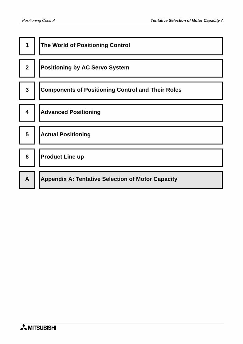
Appendix A: .............................................................................................. A-1A-1: Tentative Selection of Motor Capacity .................................................................A-1
A-1-1: Motor effective torque................................................................................................A-2A-1-2: Load inertia moment..................................................................................................A-4
vii

Positioning Control Contents
viii
Positioning Control
1 The World of Positioning Control
2 Positioning by AC Servo System
3 Components of Positioning Control and Their Roles
4 Advanced Positioning
5 Actual Positioning
6 Product Line up
A Appendix A: Tentative Selection of Motor Capacity
The World of Positioning Control 1


The World of Positioning Control 1Positioning Control
1. The World of Positioning Control
1.1 Welcome to the new world!
The positioning controller, together with the programmable controller, personal computer andoperator interface, is one of the four main units of FA (factory automation).
Among them, the positioning controller is important as the basis of FA, and regarded as thecenter of the mechatronics field in which many senior engineers have been playing activeparts.
Positioning is all about motion, and motion often involves speed and precision. As speed canbe related to productivity, it is an area of much development. But, when the machine speedincreases, a problem with the stop precision is often generated. In order to solve this problem,diversified grades of position controllers have been required and developed.
Improvement of the machine efficiency generates immeasurable added value, includingreduction of labour and the machine floor area for the same quantity of production.
If there are no problems related to the positioning aspect of a machine, it may mean that themachine is not running most efficiently. Here is where the science of developing an optimumpositioning control system comes in.
1-1

Positioning Control The World of Positioning Control 1
1.2 Diversified actuators
• A power source which moves an element in a system is called actuator. A unit which detectsa position of a work piece or moving part is called sensor.
• Diversified actuators and sensors, from simple ones to enhanced ones, are used inpositioning.
• This paragraph describes representative types, their features and weak points.
Pneumatic
• Air source and high grade piping are required.
• High torque is not available.• Multi-point positioning is complex and
very difficult to achieve.• Change in positioning is difficult.
Brake motor
• Positioning mechanism is simple.• Repeatability is poor.• Change in positioning is difficult.(When optical sensors or limit switches are used for stop)
Clutch brake
• Frequent positioning is available.• Life of friction plate is limited.• Change in positioning is difficult.(When optical sensors or limit switches are used for stop)
1-2

Positioning Control The World of Positioning Control 1
Stepping motor
• Positioning mechanism is simple.• If load is heavy, motor may step out and
displacement can occur.• Motor capacity is small.• Precision is poor at high speed.
DC servo system
• Positioning precision is good.• Maintenance is required for motor
brushes.• It is not suitable for rotation at high
speed.
General purpose inverter and general purpose motor
• Multi-speed positioning is available using high-speed counter.
• High precision positioning is not available.
• Large torque is not available at start. (Specialized inverter is required)
AC servo system
• Precision is good.• Maintenance is not required.• Positioning address can be easily
changed.• It is compact, and offers high power.
1-3

Positioning Control The World of Positioning Control 1
1.3 Positioning method type
1) There are three types of positioning method
*1 The stop precision shows a value in a case where low speed is 10 to 100 mm/s.
Control method Description Schematic drawing
Speed control
Limit switch method
Two limit switches are provided in places where a systems moving part passes. At the first limit switch, the motor speed is reduced. At the second limit switch, the motor turns off and the brake turns on, to stop the moving part.In this method, because position controllers are not required, the system configuration can be realized at reasonable cost.
(Guideline of stopping precision: Approximately ±1.0 to 5.0 mm)*
Pulse count method
A position detector (such as pulse encoder) is set up in a motor or rotation axis. The pulse number generated from the position detector is counted by a high-speed counter. When the pulse number reaches the preset value, the moving part stops.In this method, because limit switches are not used, the stop position can be easily changed.
Position control
Pulse command method
An AC servo motor which rotates in proportion to the input pulse number is used as the drive motor.When the pulse number corresponding to the movement distance is input to the servo amplifier of the AC servo motor, positioning can be performed at high speed in proportion to the pulse frequency.
B IM
INV
DC0 to 10V
High speed
Low speed
Limit switch forchangeover tolow speed
Limit switchfor stop
Ball screw
IM: Inductive motorB: BrakeINV: Inverter
Moving part
Movementdistance
PLG
High speed
Low speed
Ball screw
IM: Inductive motorPLG: Pulse generatorINV: InverterPLC: Programmable controller
Moving part
Movement distance
PC
High-speedcounter unit
DC0 to10V
Pulses arefed back.
IM
INV
PLG SM
Servoamplifier
Ball screw
SM: Servo motorPLG: Pulse generatorPLC: Programmable
controller
Moving part
Movement distance
PC
Position controller
Pulses arefed back.
Commandpulse
1-4
Positioning Control The World of Positioning Control 1
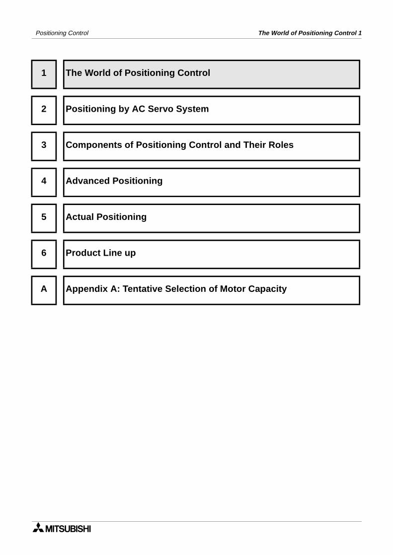
2) Positioning method and stop precision
< Limit switch method >
- When automatically stopping a movingpart driven by a motor, stop the motor by aposition signal, detected by a limit switch(in general conditions, turn on the brake atthe same time).
- The moving part continues by a coastingdistance until it completely stops, after thestop command is given. The coastingdistance is shaded in the figure.
- The stop precision is equivalent to thedispersion in the shaded area as shown inthe figure on the left.The dispersion is affected by the speedwhen the stop command is given, the loadsize and the time delay since the stopcommand is given, until speed reductionactually starts.
- If the required stop precision is notsat isfactory when stopping from thenormal operation speed, the most effectivemethod to improve the stop precision is toreduce the operation speed.
- However, if the operation speed is simplyreduced, the machine efficiency may alsobe reduced. In actual operation, the motorspeed can be reduced from high speed tolow speed once, then the motor stopped.
Velocity
Stop command StopTime
Coastingdistance
Velocity
S top com m and S topT im e
Light loadLarge inertia
S top
D ispers ionin s top
HeavyloadSm allinertia
Speed reduction startT im e delay
Velocity
Speed reduction command
Time
Stop command
Dispersionin stop
High speed
Dispersion inspeed reductiondistance
1-5

Positioning Control The World of Positioning Control 1
< Pulse count method >
- When a pulse encoder is attached to a moving part, and the motor speed is controlled bya number steps while the pulse number is counted, the movement quantity per pulse isdetermined in accordance with the relationship between the pulse number generated byone rotation of the encoder, and the movement quantity of the moving part (workpiece)realized by one rotation of the motor. The movement quantity per pulse is regarded asthe minimum unit for the stop command.
- However, the coasting distance at stop is not eliminated.
< Pulse command method >
- In this method using a servo system, the weak points described above are improved. Apulse encoder is attached to the servo motor, detecting the motor rotation quantity(workpiece movement distance), to continuously and directly control the speed from thehigh-speed operation to the target position, which allows the workpiece to stop with goodprecision.
- As the coasting distance at stop is eliminated, the positioning precision is improved.
1-6

Positioning Control
1 The World of Positioning Control
2 Positioning by AC Servo System
3 Components of Positioning Control and Their Roles
4 Advanced Positioning
5 Actual Positioning
6 Product Line up
A Appendix A: Tentative Selection of Motor Capacity
Positioning by AC Servo System 2

Positioning by AC Servo System 2Positioning Control
2. Positioning by AC Servo System
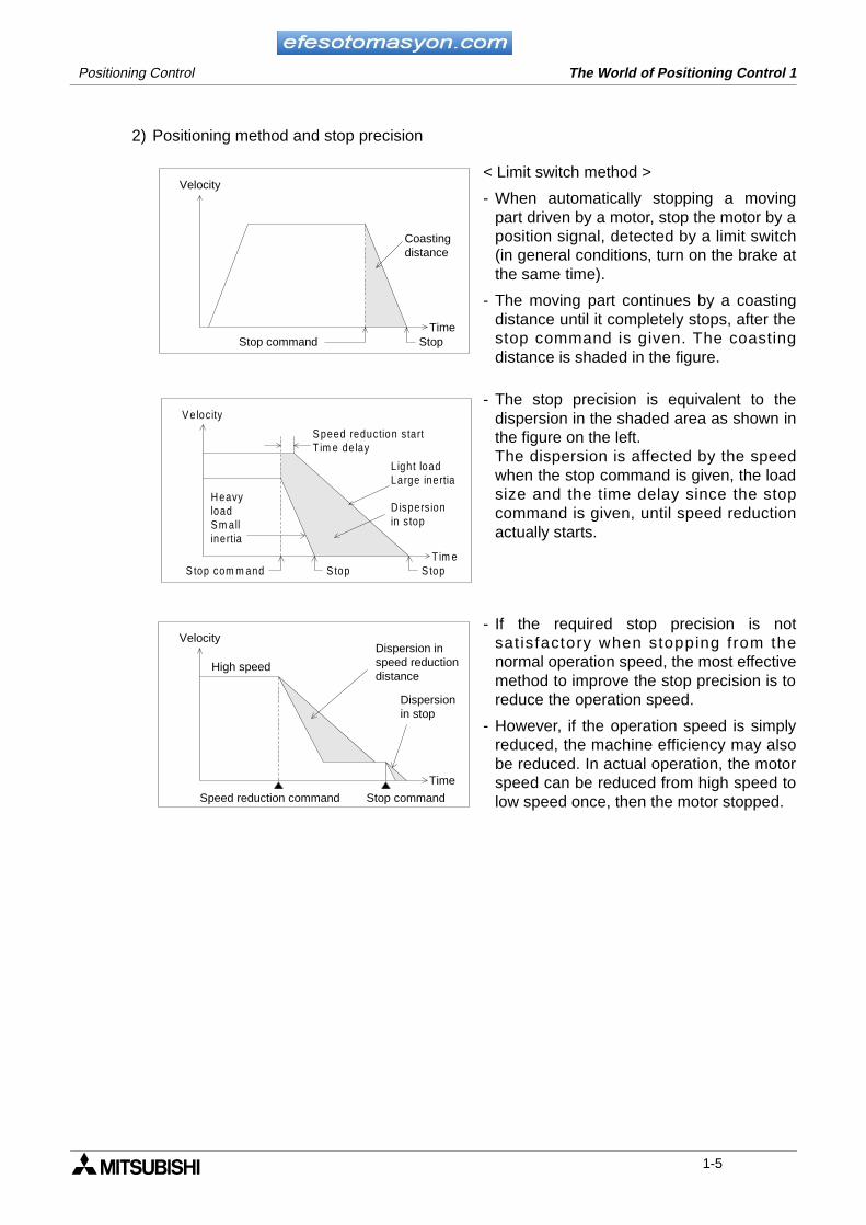
2.1 When an AC servo system is introduced
• Positioning can be performed by many diversified methods. Recently, AC servo methodswhich offer many advantages are often introduced.
• In the positioning system of an AC servo method, a position controller, servo amplifier andservo motor are generally required. The representative system configuration is shownbelow.
Positioncontroller
Deviationcounter
DC ACDCAC DC
ConverterSmoothing
circuit Inverter
PWM (pulse widthmodulation) control
Currentcontrol
Speedcommand Feedback
current
PLG
SM
Feedbackpulse
Encoder
Servomotor
Commandpulse
Servo amplifier
T h e p o s i t i o n c o n t r o l l e rg e n e r a t e s a s p e c i f i e dquantity of forward rotation(or reverse rotation) pulses ata specified frequency.
The command pulse numberis subtracted by the feedbackpulse number, and the speedcommand to drive the servom o t o r i s m a d e f r o m t h edeviation (accumulated pulsenumber).When the accumulated pulsenumber becomes 0, the servomotor stops.
The servo motor is equippedwith a built-in encoder (pulsegenerator), dedicated to highspeed response, and suitableto positioning control.
Commercialpower supply
� �
The AC servo system satisfies the needs formulti-model small-lot production through onlysimple changes in the program.
AC servo systems are easier to handle thanhydraulic equipment.
As an AC servo system can generate largetorque, it can satisfy the needs for down sizingand high power.
- Release from oil management
Robots in conjunction with an AC servo systemcan satisfy the needs for labor saving andautomation.
- Release from dangerous, hard and dirtyworking environments
Why is the AC servo system attracting attention?
2-1

Positioning Control Positioning by AC Servo System 2
In the latest AC servo systems, conventional weak points have been improved as follows.
- Though the latest systems are completely digital, they are equipped with parameters inconformance to diversified mechanical specifications and electrical specifications so thatsimple setting is possible.
- As frequent operation is enabled by a low inertia motor, the maximum torque isincreased and the system can be applied to diversified machines.
- The latest systems are equipped with an auto tuning function, with which the servoamplifier automatically detects the load inertia moment and adjusts the gain. This ispossible even if the load inertia moment is unknown.
Aspects described below are now incorperated to AC servo systems which offer markedimprovements from previous products.
In FA work place, a downsized AC servo system occupying less space is required!
Compact and light servo system
In accordance with sever operation conditions, a tougher AC servo system is required!
Robust servo system
An AC servo system anyone can handle easily is required! Even if the performance is good, the AC servo system cannot be accepted if it is difficult to handle.
Easy servo system
An AC servo system giving sufficient cost performance is required!
Good cost performance servo system
2-2
Positioning Control Positioning by AC Servo System 2
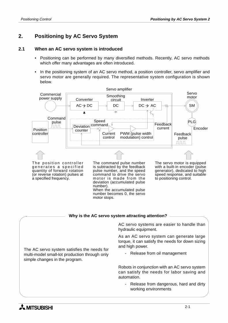
2.2 Examples of AC servo systems
• Positioning indicates the operation to move an element, such as a workpiece or tool (drill orcutter) from a certain position (point) to another target position (point) and stop it with highefficiency and high precision.
• In other words, the principle of positioning is the control of speed in accordance with theposition, performed to promptly eliminate the remaining distance to the target position. Theflexibility to change the target position electrically and easily is an important requirement.
• Several cases of positioning using an AC servo motor are systematically shown below.
Constant feed
In the press/shear process for cutting, punching, etc., the processed material is positioned with high precision to produce a constant sized product.
Tapping
In order to tap a workpiece, "1. Quick feed", "2. Cutting feed" and "3. Quick return" are repeatedly performed.
Drilling in steel sheet
In order to perform processing on a flat face, positioning with high precision is performed by two motors (X axis feed motor and Y axis feed motor).
2-3

Positioning Control Positioning by AC Servo System 2
Index table
The position of the circular table is indexed.The index position is set on the outside (digital switch) or the inside (program).Shortcut drive is performed depending on the index position.
Lifter moving-up/down
As negative load is applied on the servo motor in positioning of the lifter in the vertical direction, a regenerative option is used also.In order to hold the lifter stationery and prevent drop of the lifter by power interruption, a servo motor with electromagnetic brake is used.
Cart travel control
A servo motor is mounted in the travel cart as the drive source.A mechanism such as rack and pinion is adopted to prevent slippage between the wheels and rails.
Carrier robot
After the conveyor stops, the 2-axis servo system and the arm lifting mechanism transfer workpieces to a palette.The workpiece input positions on the palette can be set to many points so that setup change can be easily performed, even if the palette position and the palette shape change.
2-4

Positioning Control
1 The World of Positioning Control
2 Positioning by AC Servo System
3 Components of Positioning Control and Their Roles
4 Advanced Positioning
5 Actual Positioning
6 Product Line up
A Appendix A: Tentative Selection of Motor Capacity
Components of Positioning Control and Their Roles 3


Components of Positioning Control and Their Roles 3Positioning Control
3. Components of Positioning Control and Their Roles
Positioning control requires a number of components such as a positioning controller, servoamplifier, servo motor and drive mechanism. This section describes the role of eachcomponent.
3-1

Positioning Control Components of Positioning Control and Their Roles 3
Positioningcommand
control
Deviationcounter
Smoothingcircuit Inverter
PWM (pulse widthmodulation) control
Currentcontrol
Speedcommand
Feedbackcurrent
Feedback pulse
Servo amplifier
R
Regenerativebrake
Pulsemagnification
(Electronic gear)
Dynamicbrake
Counter clear
Zero pointreturncontrol
Parameter
Commandpulse
Position controller
Servoready
Main circuit
In some types, the limit switch signal
is wired to the position controller.
Zero point signal (PG0)
Converter
AC DC DC DC AC
Near point dog signal
Position controller
Power board
AC powersupply
Operation equipment
Servo amplifier
• Outputs the positioning speedand the movement quantity incommand pulses to the servoamplifier.
• Transfers signals between theprogrammable controller.
• Controls return to the zero point.
• Improves the power factorand cuts noise.
• Protects the power circuit.
• Rectifies the AC power of the main circuit intothe DC power in the converter, and smooths it inthe smoothing circuit.When the DC power is converted into AC powerin the inverter, the current supplied to the servomotor is changed by the PWM (pulse widthmodulation) control in the control circuit.
• The deviation counter receives and counts thecommand pulses from the positioning controller,subtracts the feedback pulses from them, thendrives the servo motor until the accumulatedpulse number becomes 0.
• Give inputs for manual/automaticmode, start/stop, zero point returncommand, manual forward rotation/reverse rotation and manual pulsegenera to r to the pos i t i on ingcontroller.
3-2

Positioning Control Components of Positioning Control and Their Roles 3
PLG
SM
Servomotor
Whenrequired
Electromagnetic brake
Cooling fan
In the case of large motor
Moving element
Ball screw
Auxiliary device such as chuck, drill and cylinder
Near pointdog switch
Limit switch(LS)
Limit switch(LS)
Drive mechanism
When a moving element goes beyond a limit
switch (LS), the motor stops.
Servo motor
Encoder(pulsegenerator)
Servo motor
Speedreducer
Setting / display unit
Sensor, actuator,auxiliary device
• The actuator (moving part drivemechanism) is equipped withspeed reducer, timing belt, ballscrew and limit switch.
• Diversified auxiliary devices arealso controlled in accordance withpositioning.
• The PLC or the positioningcontroller also controls auxiliarydevices.
• The auxiliary device operationcompleted signal is output to thePLC or the position controller.
• Used to write programs to thepos i t ion contro l le r, a l lowssetting and display of the data.
• Dedicated to high speed response optimal topositioning control, has large start torque, largemaximum torque and wide variable speed range1/1 or more (1/1,000 to 1/5,000).
Hand held Programmer
PersonalComputer Graphic
OperatorTerminal
3-3

Positioning Control Components of Positioning Control and Their Roles 3
3.1 Positioning controller
As the positioning controller gives position commands to the servo amplifier, positioningprograms should be created, and parameters defined. The contents related to programs andparameters are described below.
3.1.1 Command pulse and feed quantity
There are the following three types of command pulse output modes.
- PLS/SIGN mode
- CW/CCW mode
- A phase/B phase mode
From the three, the CW/CCW mode is picked up for explanation.
• When the servo motor encoder generates 8,192 pulses for one rotation, the commandpulse number "8,192" should be output to rotate the servo motor by 1 rotation. Theworkpiece feed quantity is in proportion to the pulse number.
3.1.2 Command pulse and feed speed
• When the servo motor encoder generates 8,192 pulses for one rotation, the commandpulse frequency (speed) "8,192 pulses/s" should be output to rotate the servo motor by 1rotation per second.
• Decrease the pulse frequency to rotate the servo motor at lower speed.
• Increase the pulse frequency to rotate the servo motor at higher speed.
0
-1 -2
< Reverse rotation command >
Forward rotation pulse output
Reverse rotation pulse output
(-8192) pulses
0
1 2
< Forward rotation command >
Forward rotation pulse output
Reverse rotation pulse output
(8192) pulses
0
P u lse num ber ou tpu t pe rsecond (frequency)
(8 192)pu lses
1
2
Forward ro ta tionpu lse ou tp u t
R everse ro ta tionpu lse ou tp u t
3-4

Positioning Control Components of Positioning Control and Their Roles 3
3.1.3 Setting the acceleration/deceleration time
• When the start command is given, acceleration, operation at constant speed anddeceleration are performed for positioning. Set the acceleration time and the decelerationtime in the parameters.
• This operation pattern is effective during return to the zero point, positioning and jogoperation.
3.1.4 Backlash correction function
• The positioning controller can output excessive pulses, only when the movement directionis inverted so that the backlash of the mechanical system is corrected.
Parameter:Acceleration
time
Actualacceleration
timeParameter:Deceleration
time
Actualdeceleration
time
Time
Positioning speed
Parameter:Max. speed
Speed
Table
Feed screw
Backlash
< Backlash correction >
3-5

Positioning Control Components of Positioning Control and Their Roles 3
3.1.5 Zero point return function
• There are two types of servo motor encoders, incremental type (pulse count method) andabsolute type (absolute position detection method).
• Incremental type is constructed so that the current value stored in the position controllerdoes not increase or decrease, even if the workpiece stop position changes by somereason while the power is turned off, therefore the positioning address is not assured.
• Accordingly, when the power is turned on, the machine should be moved to the referencepoint to update the zero point address. This operation is called return to zero point.
• Absolute type is constructed so that the current value stored in the position controllerincreases or decreases if the workpiece stop position changes while the power is turned off,thus the positioning address is assured. Accordingly, when the power is turned on, return tothe zero point is not required.However, when the machine is used for the first time, it should be returned to the zero pointso that it recognizes the zero point address.
< Operation to return to the zero point >
• The zero point return direction, returnspeed, deceleration time and creep speedare set by parameters in the positioningcontroller.
• There are several zero point returnmethods.For example, when the forward end of thedog reaches the dog switch, the motorresumes its creep speed. At the first zeropoint signal after the dog reaches thebackward end, the deviation counter clearsignal is output and the motor stops.
• The zero point address set by a parameteris written to the current value register ofthe position controller.
• In some models, if the zero point returnoperation is performed while the workpiece is stopped beyond the dog switch,the machine moves once until the limitswitch is actuated, inverts the direction,then returns to the zero point again (dogsearch function, zero point return retryfunction).
Dog
Dogswitch
Zero pointreturn direction
Zero pointreturn speed
Creepspeed
Initial position
Deceleration time
Dog
Backward endForward end
Zero point
Clear signal
*
The return point of the dog switch should be adjustedto a midpoint of the zero point signal (1 pulse perrotation of the motor).In this example, the dog length should not be less thanthe deceleration distance of the machine.
*
Limitswitch
Initialposition
Escape operation
Dogswitch
Zero point
3-6

Positioning Control Components of Positioning Control and Their Roles 3
3.2 Servo amplifier and servo motor
The servo amplifier controls the movement quantity and the speed in accordance withcommands given by the positioning controller. The servo motor transmits rotation to the drivemechanism after receiving a signal from the servo amplifier.
3.2.1 Positioning control in accordance with command pulse
• By PWM (pulse width modulation) control, performed to the servo amplifier main circuit withregard to the position command and the speed command, in accordance with the commandpulses of the position controller, the servo motor is driven. The rotation speed and therotation quantity are fed back from the encoder attached to the servo motor.
3.2.2 Deviation counter function
• The difference between the command pulses and the feedback pulses counted by thedeviation counter in the servo amplifier is called accumulated pulses.
• While the machine is operating at a constant speed, the accumulated pulse quantity isalmost constant. During acceleration and deceleration, the accumulated pulse quantitychanges more dramatically.
• When the accumulated pulse quantity becomes equivalent to or less than the specifiedquantity (in-position set value) after command pulses have stopped, the servo amplifieroutputs the positioning completed signal. The servo motor continues operation even after that. Then, when the accumulated pulsequantity becomes 0, the servo motor stops. The time after the servo motor outputs the positioning completed signal, until it stops iscalled stop settling time.
3.2.3 Servo lock function
• The servo motor is controlled so that the accumulated pulse quantity counted in thedeviation counter becomes 0.
• For example, if an external force for forward rotation is applied on the servo motor, theservo motor performs the reverse rotation operation to eliminate the accumulated pulses.
Accumulated pulses in deviation counter Servo motor
Minus pulses Reverse rotation operation
Plus pulses Forward rotation operation
0 (zero) Stop
Stop settling time
Motor speed
Speed
Accumulatedpulses
Command speed
Time
The accumulated pulse quantity is 0, andpositioning is completed.
3-7

Positioning Control Components of Positioning Control and Their Roles 3
3.2.4 Regenerative brake function
• During deceleration, because the servo motor rotates by the load inertia of the drivemechanism, it functions as a generator and electric power returns to the servo amplifier.The regenerative resistor absorbs this electric power, and functions as a brake (called aregenerative brake.)
• The regenerative brake is required to prevent regenerative over voltage in the servoamplifier when the load inertia is large and the operation is frequently performed.
• The regenerative resistor is required when the regenerative power generation quantityduring deceleration exceeds the allowable regenerative electric power of the servoamplifier.
3.2.5 Dynamic brake function
• When a circuit inside the servo amplifier is disabled by a power interruption in the AC powerof the main circuit or actuation of the protective circuit, the terminals of the servo motor areshort-circuited via resistors, the rotation energy is consumed as heat, then the motorimmediately stops without free run.
• When the motor stops by elimination of the rotation energy, the brake is not effective andthe motor runs freely.
Power: OFFContacts of dynamic brake: ON
Motor stop characteristics when thedynamic brake is actuated
Number ofrotations of motor
Time
When the dynamic brakeis not actuated
ConverterAC DC
SR
T
NFB
Deviationcounter
D/Aconversion
Positioncontroller
MaincircuitAC powersupply
VU
W
These contacts of thedynamic brake turn ONw h e n t h e p o w e r i sinterrupted.
SM PLGInverterDC AC� �
3-8

Positioning Control Components of Positioning Control and Their Roles 3
3.3 Drive mechanism
The drive mechanism converts the rotation motion of the servo motor into the reciprocating orvertical motion through a speed reducer, timing belt, ball screw, etc. to move the machine.
3.3.1 Concept of drive system movement quantity
1) Representative positioning system using AC servo motor
*2 In the structure design, parameters (such as ∆ and V0) should be determined inadvance.
a) The servo motor stops with the precision (±∆ ) which is within ±1 pulse against thecommand pulse.
b) The movement quantity of the work piece is"Output pulses from position controller × ∆ ". The moving part speed is "Command pulse frequency from position controller × ∆ ".
c) Either "mm", "inch", "degree" or "pulse" can be selected as the positioning commandunit. Accordingly, when data such as the movement quantity per pulse, positioning speedor the positioning address in accordance with the positioning command unit are set, thepulse trains calculated inside the positioning controller are output for the target address,and positioning is performed.
Speed
reducer
Servo
motor
Moving part
V0
PB
1nN0
Servo
amplifier
Position
controller
Pf
f0
Encoder
: Movement quantity per pulse (mm/pulse)
: Moving part speed during quick feed (mm/min)
: Number of rotations of motor during quick feed (r/min)
: Lead of ball screw (mm/rev)
: Speed reduction ratio
: Feedback pulse number (pulse/rev)
: Command pulse frequency during quick feed (pulse/s)
: Movement quantity per rotation of motor (mm/rev)
D
V0
N0
PB1n
Pf
f0
DS
3-9

Positioning Control Components of Positioning Control and Their Roles 3
2) Examples of calculation equations
a) Movement quantity per rotation of motor (mm/rev)
b) Number of rotations of motor (rev/min.)(The maximum number of rotations is realized during quick feed.)
Note:The number of rotations of a motor during quick feed should not exceed the ratednumber of rotations.The moving part speed during quick feed should not exceed the parameter "speed limitingvalue" of the positioning controller.
a) Movement quantity per pulse (mm/pulse)
b) Command pulse frequency during quick feed (pulse/s)
Note:The command pulse frequency during quick feed should not exceed the maximum inputpulse frequency of the servo amplifier.
a) Maximum movement distanceIn each of the absolute and incremental methods, the entire movement distance shouldnot exceed the maximum pulse number of the positioning controller.
Movementquantity perrotation of motor
Lead of ball screw (mm/rev) Speed reduction ratio= ×
Number ofrotations ofmotor
Moving part speed during quick feed (mm/min)
Movement quantity per rotation of motor
Rated number ofrotations ofservo motor
= <=
Movementquantityper pulse
Movement quantity per rotation of motor (mm/rev)
Feedback pulse number (pulse/rev)
Electronicgear ratio
= ×
60
Commandpulsefrequencyduringquick feed
Number of rotations of motorduring quick feed (r/min)
Movement quantity per pulse(mm/pulse)
=
Movement quantity perrotation of motor (mm/rev)
×
×
3-10

Positioning Control Components of Positioning Control and Their Roles 3
3.3.2 Setting the target position
In positioning control, the target position can be set by the following two methods.(Available command units are "mm", "inch", "degree" or "pulse".)
1) Absolute methodIn this method, a point (absolute address) is specified for positioning while the zero point isregarded as the reference. The start point is arbitrary.
2) Incremental methodIn this method, positioning is performed through specification of the movement directionand the movement quantity while the current stop position is regarded as the start point.
Address100
Address 150Address 100
Address 150
Address 150Address 100
Address 300
300Point C
150Point B
100Point A
0Zero point
Start point
End point
Movement quantity -100
300Point C
150Point B
100Point A
0Zero point
Movement quantity +50
Movement quantity -150Movement quantity +100
Movement quantity +100
Movement quantity+100
Movement quantity-100 Start point
End point
3-11

Positioning Control Components of Positioning Control and Their Roles 3
3-12
Positioning Control
1 The World of Positioning Control
2 Positioning by AC Servo System
3 Components of Positioning Control and Their Roles
4 Advanced Positioning
5 Actual Positioning
6 Product Line up
A Appendix A: Tentative Selection of Motor Capacity
Advanced Positioning 4


Advanced Positioning 4Positioning Control
4. Advanced Positioning
4.1 Interpolation control
The interpolation function controls two or more axes alternately or simultaneously. Linearinterpolation and circular interpolation are usually offered.
X axis
< 2-axis linear interpolation > End point
Start point
Yaxis
Start point
X axis
Y axis
End point
Z axis
< 3-axis linear interpolation >
Speed change in X axisSpeed
Time
< Linear interpolation >
- Linear interpolation controls two ormore axes so that the start point andthe end point (target position) areconnected in the shortest way.
- In this case, the locus is linear.
- Models applicable to 2-axis linearinterpolation control[FX-20GM,E-20GM,FX2N-20GM AD75P2/P3,AD75M2/M3, QD75P2/P4,QD75D2/D4, A171SH,A172SH,A173UH,A273UH]
- Models applicable to 3 or 4-axis linearinterpolation control[A171SH,A172SH,A173UH,A273UH]
- Application examples[Drilling on steel sheet, insertion ofparts into PCB, automatic warehouse,automatic crane, etc.]
4-1

Positioning Control Advanced Positioning 4
X axis
< Circular interpolation when an auxiliary point is specified >
End point
Start point
Yaxis
Auxiliaryline
X axis
< Circular interpolation when the radius is specified >
End point
Start point
Yaxis
Radius
X axis
< Circular interpolation when the center is specified >
End point
Start point
Y axis
Center
Speed change in X axisSpeed
Time
< Circular interpolation >
- Circular interpolation controls two ormore axes so that the start point andthe end point (target position) areconnected with circular arc.
- As there are innumerable number ofarc locus connecting two points, anauxiliary point, the arc radius, thecenter or the direction should bespecified in addition to the start pointand the end point to determine thecircular arc.
- Models applicable to 2-axis circularinterpolation control[FX-20GM,E-20GM,FX2N-20GM AD75P2/P3,AD75M2/M3, QD75P2/P4,QD75D2/D4, A171SH,A172SH,A173UH,A273UH]
- Models applicable to 3-axis circularinterpolation control[A171SH,A172SH,A273UH]
- Application examples[Steel sheet fusing, welder, applicator,crane, etc.]
4-2

Positioning Control Advanced Positioning 4
4.2 Other controls
In some models, controls in accordance with diversified special needs such as speed control,position follow-up control and three-dimensional interpolation control shown below areavailable.
X axis
Start point
Speed change in X axis
Speed
Time
X axis
Start point
Constantquantity
End point
Speed change in X axis
Speed
Time
< Speed control >
- After movement starts from the startpo in t , i t t hen con t inues a t thespec i f i ed speed un t i l t he s topcommand is input.
- Applicable models[FX-1PG,FX2N-1PG AD75P1/P2/P3,AD75M1/M2/M3, QD75P1/P2/P3,QD75D1/D2/D3, A171SH,A172SH,A173UH,A273UH]
- Application examples[Conveyor, carrier unit, roller feed,crane, etc.]
< Constant feed >
- After start, a workpiece moves by thespecified constant quantity, but thecurrent value does not increase evenif the operation is repeated.
- Applicable models[FX-10GM,FX-20GM,E-20GM, FX2N-10GM,FX2N-20GM AD75P1/P2/P3,AD75M1/M2/M3, A171SH,A172SH,A273UH]
- Application examples[Press, shear, conveyor, transfer unit,assembly line, etc.]
4-3
Positioning Control Advanced Positioning 4
X axis
Start point
1000mm/min
5000mm/min
300mm/min
Y axis
Endpoint
Speedchangeover point
Speed change in X axis
Speed
Time
X axis
Start point
Y axis
Passing point
Radius
Passing point
Endpoint
Speed change in X axis
Speed
Time
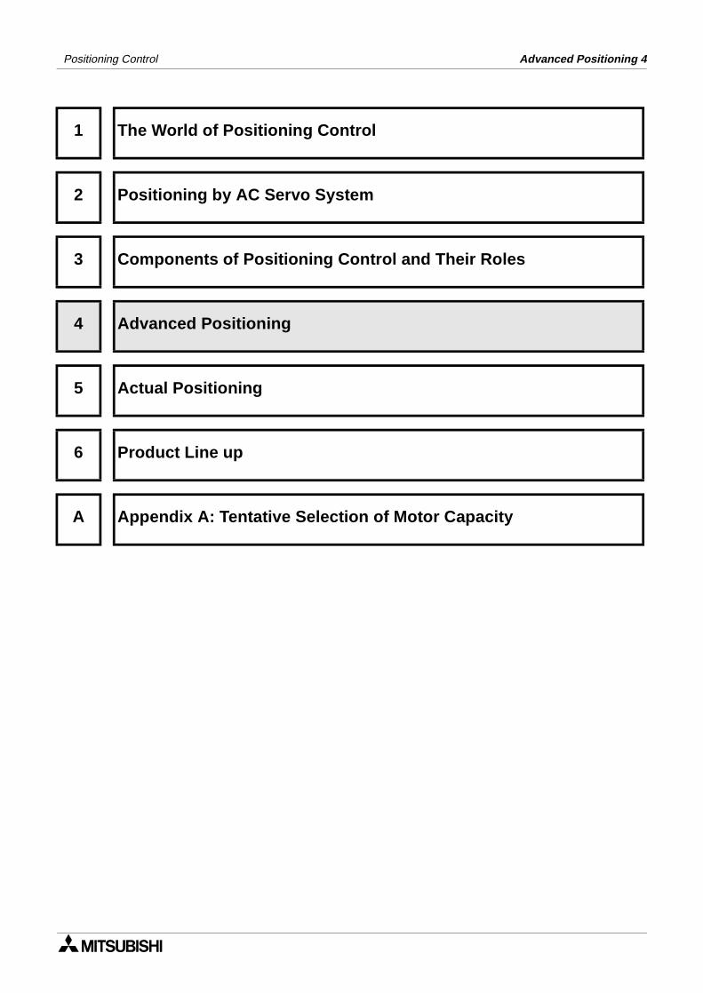
< Speed changeover control >
- From the start point which is thecurrent stop address, positioningcontrol is performed to the end pointaddress while the speed changes atspeed changeover points.
- The address for speed change can bedetermined in advance.
- Applicable models[FX2N-1PG,FX-10GM,FX-20GM, E-20GM,FX2N-10GM,FX2N-10GM, AD75P1/P2/P3,AD75M1/M2/M3, QD75P1/P2/P4,QD75D1/D2/D4, A171SH,A172SH,A173UH,A273UH]
- Application examples[Conveyor, carrier unit, roller feed,crane, etc.]
< Constant speed control >
- From the start point which is thecurrent stop address, positioningcontrol is performed to the end pointaddress at an equal speed by way ofpassing points.
- Passing points make small circulararc.
- Applicable models[AD75P1/P2/P3,AD75M1/M2/M3, QD75P1/P2/P3,QD75D1/D2/D4, A171SH,A172SH,A273UH]
- Application examples[Steel sheet fusing, welder, applicator,crane, transfer robot, etc.]
4-4

Positioning Control Advanced Positioning 4
X axis
Startpoint
Y axis
Originalend point
Changepoint
Changedend point
Speed change in X axis
Speed
Time
X axis
Start pointY axis
Endpoint
Z axis
Speed change in the Y axis
Speed
Time
< Position follow-up control >
- If the end point address is changedwhile a positioning control movementis being executed, posit ioning iscontro l led to the new end pointaddress.
- Applicable models[A171SH,A172SH,A273UH]
- Application examples[Product follow-up type, applicationline and welding line]
< Three-dimensional interpolation control >
- From the start point which is thecurrent stop address, 3-axis linearinterpolat ion contro l and 3-axiscircular interpolation control areperformed to the end point address byway of passing points.
- Applicable models[A171SH,A172SH,A273UH]
- Application examples[Assembly robot, welding robot,application robot and transfer robot]
4-5

Positioning Control Advanced Positioning 4
4-6

Positioning Control
1 The World of Positioning Control
2 Positioning by AC Servo System
3 Components of Positioning Control and Their Roles
4 Advanced Positioning
5 Actual Positioning
6 Product Line up
A Appendix A: Tentative Selection of Motor Capacity
Actual Positioning 5


Actual Positioning 5Positioning Control
5. Actual Positioning
Terms required for positioning control have been explained in the first three sections.In this section, let’s experience actual positioning control based on the knowledge you havelearned so far.
The position controller FX2N-20GM is used for the demonstration as show below. An FX-20GMcan also be used in place of the FX2N-20GM.
5.1 Demonstration Equipment
Two different levels of demonstration equipment can be used for this example, depending onwhat is available. The basic set utilizes the live monitoring function of the FX-PCS-VPSsoftware, where as, the more comprehensive set makes use of an X Y plotting table, toactually see the axes move, and draw the resulting locus.
5.1.1 Basic Set
The demonstration items required for the basic setup are as follows;
FX2N-20GMF2-422 CAB0 Communications cableFX-232AW(C) ConverterFX-232 CAB-1 Communications cablePersonal computerFX-PCS-VPS\Win software
5.1.2 Comprehensive Set
The demonstration items required for the comprehensive setup are as follows;
FX2N-20GMF2-422 CAB0 Communications cableFX-232AW(C) ConverterFX-232 CAB-1 Communications cablePersonal computerFX-PCS-VPS\Win softwarePlotter Communications cable (*1 Specific to plotter)X Y Plotting table
I/O MOTOR
PLC EXT
AUTO
MANU
POWER
READY
ERROR
CPU-E
START
STOP
ZRN
FWD
RVS
DOG
LSF
LSR
X0
X1
X2
X3
Y0�
Y1�
Y2�
Y3�
Y4�
Y5
SVRDY
SVEND
PGO
FP
RP
CLR
MITSUBISHIMELSEC FX2N-10GM FX-422CAB0 F2-232CAB-1FX-232AW(C)
I/O MOTOR
PLC EXT
AUTO
MANU
POWER
READY
ERROR
CPU-E
START
STOP
ZRN
FWD
RVS
DOG
LSF
LSR
X0
X1
X2
X3
Y0�
Y1�
Y2�
Y3�
Y4�
Y5
SVRDY
SVEND
PGO
FP
RP
CLR
MITSUBISHIMELSEC FX2N-10GM
F2-232CAB-1FX-232AW(C) Cable *1FX-422CAB0
Plotter
XY
5-1

Positioning Control Actual Positioning 5
5.2 Operation of the demonstration equipment
Source the required demonstration equipment, and setup as in section 5.1. If a plotter is beingused refer to the operations manual for the particular unit and setup accordingly.
Throughout this example it is assumed that you will have read and understood both the FX2N-20GM Hardware / Programming manual (JY992D77801) and the FX-PCS-VPS/Win-Esofttware manual (JY992D86801) or you will have then close at hand for reference.
For this example we will use the basic setup of Personal computer and FX2N-20GM.
Let’s draw the locus shown below driven by the X and Y axes simultaneously. The output Y0 isadded to imitate a pen, or other end effector.
A: Start point, this point can be anywhere.
B: (0,0), Zero point, wait for 2 seconds.
C: (80,100), Output Y0 turns ON, wait for 2 seconds.
D: (110,200).
E: (200,200).
F: (200,100).
G: (150,100), Output Y0 turns OFF, wait for 2 seconds.
H: (150,70), End point.
A to B - Return to Electrical Zero.B to C - High speed positioning.C to D - Linear interpolation.D to E - High speed positioning.E to F - Clockwise circular interpolation.F to G - High speed positioning.G to H - High speed positioning.
Start pointA
B
C
D E
FG
HEnd Point
5-2

Positioning Control Actual Positioning 5
5.2.1 Program example
The program below demonstrates basic positioning using the FX2N-20GM. As this program isdesigned to be used without a mechanical plotter, the electrical zero point is used forreference.
Many programs can be stored in a GM unit at onetime. This example uses program number 0.
This command is to move from the start point, tothe electrical zero point
Here the program waits for 2 seconds, using a10ms timer.
This command indicates the rapid command toposition C.
Here Y0 is turned on, to mimic the use of an endeffector tool.
This timer allows a tool to be activated, or anoperation executed.
This command is the start of a continuous steadypath, first using linear interpolation to position D
To position E, only the X axis need move.
For a smooth arc, circular interpolation is used.This example shows the start and end positions(F), as well as the radius and a speed f.
To position G, only the X axis need move.
Here Y0 is turned off, to mimic the the end of theend effector use.
Again a timer related to the operation above.
This command rapidly moves only the Y axis ashort distance to position H.
The end of the program, and a wait for the nextstart command.
5-3

Positioning Control Actual Positioning 5
5.2.2 Writing the program
Using FX-PCS-VPS\Win-E, re-create the flow chart program shown in section 5.2.1. If assistance is required in the operation of the software, please refer to the Software manualJY992D86801.
When opening a new file in VPS, choose ‘FX(2N)/E-20GM with simultaneous 2 axis’
The example program is designed to utilize the real time monitor function of VPS software. If amechanical plotter is being used substitute the ‘DRV Ret’ command for a ‘DRVZ’, return toorigin command. Be sure to set up the plotter in accordance with the instructions andguidelines applicable to and supplied with your specific plotter.
Along with the Flow chart, create a monitoring window similar to the one shown below.
All of the items on the monitoring window can be found under the insert tab on the main menuat the top of the screen.
Items inserted include:
Current PositionPlotting (double click on plot area to change the scale)Device Status (Y0)Manual Operation (Start, Stop, Jog -, Jog +, for both X and Y axes, each inserted separately)FX-GM Status
Plus, a rectangle from the drawing tool bar, to highlight the Y0 indicator.
5-4

Positioning Control Actual Positioning 5
5.2.3 Parameters
In addition to the preparation of a positioning program, diversified parameters should be set inthe FX2N-20GM.In this example, only a few parameters need be set. If a plotting table is used, the parametersshould be set in accordance with its mechanism. These will depend upon the specific plottertype, and should be found in the documentation provided with the plotter.
Below are the four positioning parameter windows from VPS, copy these settings into yourprogram. The values for both the X and Y axes are the same for all parameters.
The system of units we will be using is both mechanical and motor, so that the position can becontrolled in mm, deg, 1/10 inch etc. while the speed can be controlled by the number ofpulses. The system units should be set to ‘mm, and all other options left as default.
So that we can follow the path created by the FX2N-20GM, the Max speed should be set quitelow. Intern both the JOG speed and the Interpolation value must be reduced. In practice, it isimpossible to have the JOG speed faster than the Max speed setting.
Remember to change the setting for the Y axis also.
5-5

Positioning Control Actual Positioning 5
As we will not be connecting any mechanical hardware to the FX2N-20GM, the limit switch andDOG switch settings do not require setting. We do how ever need to reduce the Creep speedand the Zero return speed.
All of the parameter settings on this screen window can be left as their default values, they arealready optimized for our program.
If a plotter table is being used, all of the above parameters will need to be checked beforepower ON, or operation.
5-6

Positioning Control Actual Positioning 5
5.2.4 Operation
Now that your program has been written, check the communication cables between the FX2N-20GM and PC, then download your program to the FX2N-20GM. Make sure that the GM unit isin ‘MANU’ mode before download, or it will be impossible to communicate.
In VPS, start the Monitor mode by clicking the Monitor icon on the tool bar, shown below.
The Monitor mode screen will appear. Here, the flow icon menu and program map have beenremoved. Three windows are displayed;
Monitoring window: This is the window you created, and will use to control the FX2N-20GM andview the resulting locus.
Sub-task - Monitor mode: This window in not needed as we do not use any sub routines in ourprograms, it can be minimized to create more space on the screen.
X-axis and Y-axis - Monitor mode - At first this window will be empty, but as soon as you startyour program, the flow chart will appear, and scroll through, keeping the live instructionhighlighted in red.
After minimizing the Sub-task monitor window, resize the Monitoring window and then the X-axis and Y-axis window.
Now you are ready to begin.
Firstly set the start point, this can be done be either using the X and Y axis JOG buttons, or bydouble clicking on the current position display.
Double clicking the current position display bringsup this window;
For X, replace 0 with 50, and click on the ‘Write toFX-GM’ button.
For Y, replace 0 with 125, and click on the ‘Write toFX-GM’ button.
As you write that data to the GM, you will see ared line being drawn on the plot in the Monitoringwindow. This shows the current position.
We want a clean plot area to begin with, so doubleclick on the plotting area, and click on the clear button.
Monitor icon
5-7

Positioning Control Actual Positioning 5
The next step, it to switch the FX2N-20GM to ‘AUTO’ mode, so that the program can beexecuted.
Finally, on the Monitor screen click on either the X or Y axis start buttons. It does not matterwhich one, as both will start the program. Sit back and see what you have produced.
Your screen should look similar to the one shown below, the plot should be identical.
To run the program again, set a new start position (or let it start from where it is), clean the plotarea, and press start.
If your plot does not look the same as the one above, check your program against the one insection 5.2.1.
If it does, now is the time to experiment some more. Try a new program, perhaps include sub-tasks and multiple flow charts. Only a sample of the functionality available in VPS has be usedin this example program, try using some of the other programming aspects.
5-8

Positioning Control
1 The World of Positioning Control
2 Positioning by AC Servo System
3 Components of Positioning Control and Their Roles
4 Advanced Positioning
5 Actual Positioning
6 Product Line up
A Appendix A: Tentative Selection of Motor Capacity
Product Line up 6


Product Line up 6Positioning Control
6. Product Line up
We are offering diversified position controllers, servo amplifiers and servo motors. You canselect desired units in accordance with your system and application.For the derails, refer to the catalog of each product.
6.1 Position controller
1) Outline of position controller modelsIn the position controller, the positioning function is built in or extended. For some positioncontrollers, an PLC executes positioning programs. Other position controllers executeprograms using their unique positioning language without regard to any PLC.
Model name/unit name
Positioning language
Outline
FX Series
FX1S/FX1N Series PLC
FX sequence language
Pulse output type for independent 2 axesThrough application instructions in the PLC main unit, absolute position detection, return to mechanical zero point and one-speed constant positioning are available.
1-axis position controller FX-10GM FX2N-10GM
Dedicated language
Pulse output type for 1 axis
Easy sequence function is provided.Bus connection to FX Series PLC is available.(Position controller can be used independently also.)
2-axis position controller FX-20GM FX2N-20GM
Pulse output type for 2 axesIndependent 2 axes or simultaneous 2 axes (linear interpolation, circular interpolation)
2-axis position controller E-20GM
Easy sequence function is provided.(Position controller can be used independently also.)
1-axis pulse output block FX2N-1PG
FX sequence language
Pulse output block for FX2N Series PLCUsed as an extension block
A Series
1- to 3-axis position controller AD75P1 to AD75P3
A sequence language
+ Positioning
data
Pulse output type for 1 to 3 axesSimultaneous 1 to 3 axes, independent 1 to 3 axes, 2-axis linear interpolation, 2-axis circular interpolation
1- to 3-axis position controller AD75M1 to AD75M3
SSC net connection type for 1 to 3 axesSimultaneous 1 to 3 axes, independent 1 to 3 axes, 2-axis linear interpolation, 2-axis circular interpolation
Q Series
1- to 4-axis position controller QD75P1 to QD75P4
Q sequence language
+ Positioning
data
Pulse output type for 1 to 4 axes (open collector output)Simultaneous 1 to 4 axes, independent 1 to 4 axes, 2 to 4-axis linear interpolation, 2-axis circular interpolation
1- to 4-axis position controller QD75D1 to QD75D4
Pulse output type for 1 to 4 axes (differential output)Simultaneous 1 to 4 axes, independent 1 to 4 axes, 2 to 4-axis linear interpolation, 2-axis circular interpolation
6-1

Positioning Control Product Line up 6
Model name/unit name
Positioning language Outline
Motion controller
A171SHA172SHA173SH
Language dedicated to servo system[4-, 32-axis independent control, 2- to 4-axis linear interpolation control, 2-axis cir-cular interpolation control, speed control, equal speed control, position follow-up control]
NC language[Control using G codes]
Dedicated robot[Three-dimensional linear/circular interpo-lation control]
Mechanical support language[Synchronous operation control]
A171UHCPU (512 I/O points): 4-axis controlA172SHCPU (512 I/O points): 8-axis controlA173UHCPU (2,048 I/O points): 32-axis control
Servo amplifier(0.05 to 55 kw are dedicated to SSC net connection.)
A273UH
A3UCPU (2,048 I/O points): 32-axis control
Servo amplifier(0.05 to 0.6 kw allow built-in type also.)(0.05 to 55 kw are dedicated to SSC net connection.)
Mechanical support language in motion controller
Programming in virtual world
By simply connecting and laying out atransmission module and an outputmodule to a virtual main shaft on thescreen, whi le regarding divers i f iedsynchronous mechanism as softwaremechanical modules, you can easilyprogram a synchronous system.
A new world of synchronous mechanism is open.
6-2

Positioning Control Product Line up 6
1) When and which position controller?In addition to the PLC series, take into account the following contents to determine theposition controller to be used.
a) Determine the position controller to be used in accordance with the number of controlledaxes (motors).
A171SH, A172SH, A173UH, A273UH -----
1-axis control Position controller dedicated to 1 axis
FX-10GM, FX2N-10GM, FX2N-1PGAD75P1, AD75M1, QD75P1, QD75D1
Only 1 axis of 2-axis position controller
FX-20GM, E-20GM, FX2N-20GM, FX1S/FX1N Series PLCAD75P2, AD75M2, QD75P2, QD75D2
2-axis control 2-axis position controller
FX-20GM, E-20GM, FX2N-20GM, FX1S/FX1N Series PLCAD75P2, AD75M2, QD75P2, QD75D2
3-axis control 3-axis position controller
AD75P3, AD75M3
Combination of 1-axis position controller and 2-axis position controller
For 1-axis control, for 2-axis control
Control of 4-axes or more 4-axis position controller
Position controller for 4 axes or more
Combination of 1-axis position controller, 2-axis position controllerand 3-axis position controller
QD75P4, QD75D4, A171SH
for 1-axis control, for 2-axis control, for 3-axis control
6-3
Positioning Control Product Line up 6
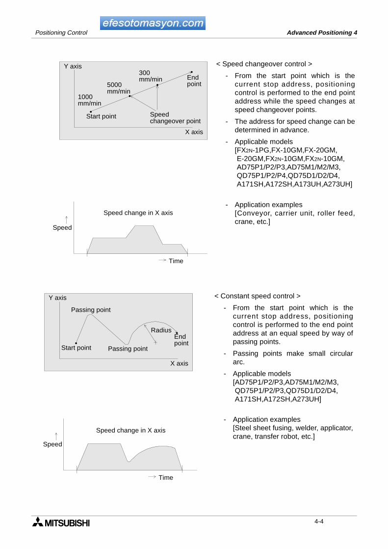
b) Determine the position controller to be used in accordance with the output pulsefrequency.However, the pulse frequency actually used inside the servo amplifier can be increasedby electronic gearing.
c) Determine the position controller to be used in accordance with handling of the feedbackpulse.
FX-10GM, FX-20GM, E-20GM, FX2N-10GM, FX2N-20GMAD75P�, QD75P�
100kp/sec When the required command pulse is 100 kpps or less
FX2N-1PG, FX1S/FX1N Series PLC
200kp/sec When the required command pulse is 200 kpps or less
400kp/sec When the required command pulse is 400 kpps or less
AD75P�, QD75P�
1Mkp/sec When the required command pulse is 1 Mpps or less
AD75M�, A171SH, A172SH, A173UH, A273UH
Feedbackpulse
Feedbackpulse
To servo amplifier The position controller only outputs pulses,and does not check feedback pulses.Accordingly, it is not confirmed whether ornot rotation in accordance with commandpulses is actually performed.
FX-10GM, FX-20GM, FX2N-1PG,E-20GM, FX2N-10GM, FX2N-20GM,FX1S/FX1N Series PLCAD75P�, QD75P�, QD75D�
Positioncontroller
Servoamplifier
Commandpulse
SM
Servomotor
PLG
Encoder
To position controller The position controller checks feedbackpulses. Accordingly, it is confirmed whetheror not rotation in accordance with commandpulses is actually performed.
AD75M�, A171SH A172SH,A173UH, A273UH
Positioncontroller
Servoamplifier
SSC netSM
Servomotor
PLG
Encoder
6-4

Positioning Control Product Line up 6
6.2 Servo amplifier
1) Outline of serve amplifier models
Model name Outline
MR-J2-Jr Series
• DC 24V• Size is extremely small, and capacity is small.• Applicable to 10 to 30 w.• Used for semiconductor manufacturing unit and small robots.• Setup software by personal computer is available.
MR-C Series
• General-purpose type optimal to use instead of stepping motor (dedicated to position control).
• Size is extremely small.• Applicable to 30 to 400 w.• Real-time auto tuning eliminates adjustment in setup.• Inertia is extremely low.• Speed can increase at constant torque without step out until high
speed area, and operation is smooth even at low speed.• Setup software by personal computer is available.
MR-J2/J2S Series
• General-purpose type in compact body easy to use.• Applicable to 50 w to 7 kw. 100 VAC input type is offered as a series.• Real-time auto tuning eliminates adjustment in setup.• Convenient test run function and diagnosis function are provided.• Applicable to low noise operation.• Setup software by personal computer is available.
MR-H Series
• General-purpose type of high performance and high response.• Applicable to 50 w to 55 kw.• Real-time auto tuning eliminates adjustment in setup.• Applicable to low noise operation.• Interactive parameters facilitate maintenance.• Setup software by personal computer is available.
MR-H-ACN Series
• 1-axis positioning function is built in.• Applicable to 50 w to 55 kw.• Frequent operation of high precision is available.• Real-time auto tuning eliminates adjustment in setup.• Applicable to low noise operation, absolute value and diversified ways
of return to zero point.
6-5

Positioning Control Product Line up 6
2) When and which servo amplifier?In addition to the series, take into account the following contents to determine the servoamplifier to be used.
a) Determine the servo amplifier to be used in accordance with the rated output of the servomotor.
b) Determine the servo amplifier to be used in accordance with the servo motor model.When the servo motor is determined in accordance with the purpose of use, the ratedtorque and the inertia moment, select a connectable servo amplifier while taking intoaccount the responsibility and the extensibility.
7kw or less Small capacity type servo amplifier
MR-J2�
400w or less Extremely small capacity type servo amplifier
MR-J2-Jr, MR-C
55kw or less Medium or large capacity type servo amplifier
MR-H-�
6-6

Positioning Control Product Line up 6
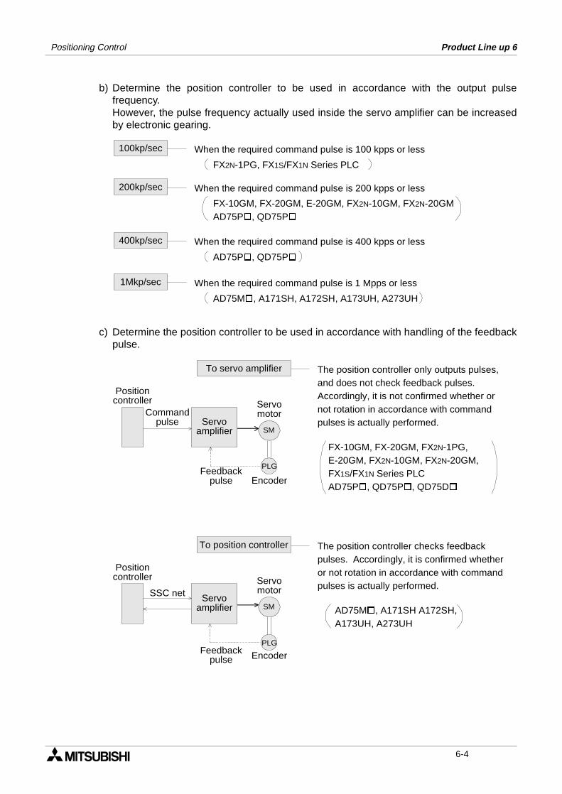
6.3 Servo motor
Servo motors are classified into series in accordance with the application, the outsidedimensions and the motor inertia moment. In each series, models of different output capacityare lined up.
Motor model name
(encoderresolution)
Ratedrotationspeed(r/min.)
Ratedoutput
capacityFeatures Application
HC-AQ(8192P/rev)
3000 10W to 30W
Extremely small size, small capacity and 24 VDC specification (compatible with speed reducer).Optimal to application for small capacity using servo amplifier MR-J2-JR.
• Small slider• Small actuator• Cylinder
HC-PQ(4000P/rev)
3000 30W to 400W
Extremely low inertia and small capacity (compatible with speed reducer).Optimal to use instead of stepping motor.
• Extremely small robot
• Tip of robot• In-circuit tester
HC-KF(8192P/rev)HC-KFS(131072P/rev)
3000 50W to 400W
Low inertia and small capacity (compatible with speed reducer).Optimal to machine with load inertia moment fluctuation and machine of low rigidity such as belt drive type because motor inertia moment is large.
• Belt drive, robot• Mounter, sawing
machine• X-Y table, food
machine
HC-MF(8192P/rev)HC-MFS(131072P/rev)
3000 50W to 750W
Extremely small inertia and small capacity (compatible with speed reducer).Optimal to frequent operation directly connected to ball screw because motor inertia moment is small.
• Inserter, mounter, bonder
• Drilling unit for PCB• Label printer, knit-
ting machine• Extremely small
robot
HA-FF(8192P/rev)
3000 50W to 600W
Small inertia and small capacity (compatible with speed reducer).Applicable to wide range of applications because control is stable from low speed to high speed.
• LCD/wafer carrier unit
• Food machine, printer
• Small robot, X-Y table
HC-SF(16384P/rev)HC-SFS(131072P/rev)
3000 500W to 3.5kWFor high speed Medium inertia and
medium capacity.Selectable in accordance with motor rated rotation speed from low speed to high speed.
• Winder, tension unit• Carrier unit, dedi-
cated machine• Robot, testing
machine• X-Y table, turret• Loader, unloader• Winder, tension unit
2000 500W to 7kW
For speed reducer(compatiblewith speedreducer)
1000 850W to 3kWFor high torque
6-7
Positioning Control Product Line up 6
*3 The model name "HC-��S" is compatible with the servo amplifier MR-J2S.
HC-RF(16384P/rev)HC-RFS(131072P/rev)
3000 1kW to 5kW
Low inertia and medium capacity (compatible with speed reducer).Optimal to frequent operation directly connected to ball screw because motor inertia moment is low.
• Frequent carrier unit• Roll feeder• Loader, unloader
HC-UF(16384P/rev)HC-UFS(131072P/rev)
3000 100W to 750WSmall capacity
Flat typeOptimal to application in which mounting is restricted.
• Robot• Food processor• Carrier unit• Winder, tension unit2000 750W to 5kW
Mediumcapacity
HA-LH(16384P/rev)
2000 11kW to 22kWLow inertia and large capacity.Suitable to frequent positioning because motor inertia is low.
• Press feeder, injection molding unit
• Semiconductor manufacturing unit, carrier line
• Press transfer unit• Lifter, automatic
warehouse
HA-LF(16384P/rev)
2000 30kW to 55kW
Large capacity and 400 VAC specification.Suitable to positioning requiring large force because motor capacity is large.
• Injection molding unit
• Semiconductor manufacturing unit
• Large carrier unit
Motor model name
(encoderresolution)
Ratedrotationspeed(r/min.)
Ratedoutput
capacityFeatures Application
6-8
Positioning Control
1 The World of Positioning Control
2 Positioning by AC Servo System
3 Components of Positioning Control and Their Roles
4 Advanced Positioning
5 Actual Positioning
6 Product Line up
A Appendix A: Tentative Selection of Motor Capacity
Tentative Selection of Motor Capacity A


Positioning Control
Appendix A:
A-1: Tentative Selection of Motor Capacity
Temporarily select the motor capacity at first while taking into account the following two points,and determine the model.
• The rated torque of the motor should be larger than the effective torque.
• The load inertia moment should not exceed approximately 10 times of the inertia moment ofthe motor itself.
A-1

Positioning Control
A-1-1: Motor effective torque
When the motor effective torque obtained by the calculation below does not exceed the ratedtorque (100%) of the servo motor specifications, it is suitable.
If the obtained effective torque exceeds 100%, increase the motor capacity and perform thecalculation again.
In the effective torque calculation equation, the torque during acceleration, constant speed,deceleration, the cycle time and the machine load are as follows.
1) The torque during acceleration is the torque required to reach the constant speed afterstartup and acceleration.
(Torque during acceleration)2 × Acceleration time +(Torque during constant speed)2 × Constant speed time ×
(Torque during deceleration)2 × Deceleration time
Cycle time (including rest time)Effective torque
(Trms)=
Torque during acceleration = Torque to accelerate load inertia moment + Load torque
(TL)(Ta)(TMa)
A-2

Positioning Control
2) The torque during constant speed is the torque required to move the load at the constantspeed.
3) The torque during deceleration is the torque required for deceleration and stop.
4) How to obtain the cycle timeThe representative machine operation pattern consists of acceleration, constant speed,deceleration and rest.The cycle time indicates the total time required for these actions.
Motor torque during constant speed = Load torque
(TL)(TML)
Torque during deceleration = Torque to decelerate load inertia moment + Load torque
(TL)(-Ta)(TMD)
A-3

Positioning Control
5) Machine load torque (TL)The rotation force required to move or cut an object is called load torque.During operation at constant speed, the motor is outputting the torque balancing this loadtorque.
• The calculation equation to obtain the load torque varies depending on the motion type(horizontal, rotation or vertical).
• In the case of rotation, the load torque is calculated based on the product of the rollingresistance coefficient of the bearing (ball bearing, for example) and the load applied in theradius direction of the bearing.
A-1-2: Load inertia moment
Difficulty to move a stationary object or difficulty to stop a moving object is called inertiamoment. As the inertia moment is larger, the load is more difficult to move and stop. In theservo motor, the inertia moment gives considerable effect especially at the time of start andstop.Accordingly, calculate the load inertia moment, then select a servo motor so that the obtainedload inertia moment does not exceed 10 times of the inertia moment of the servo motor itself.
Start
The motor starts to move an object while overcoming theinertia moment.
Operation at constant speed
The inertia moment gives no effect.
Stop (deceleration �� stop)
The motor stops an object while overcoming the inertiamoment.
A-4

Under no circumstances will Mitsubishi Electric be liable or responsible for anyconsequential damage that may arise as a result of the installation, use and/orprogramming of the products associated with this manual.All examples and diagrams shown in this manual are intended as an aid tounderstanding the text, not to guarantee operation. Mitsubishi Electric willaccept no responsibility for actual use of the product based on these illustrativeexamples.Owing to the very great variety of possible applications, users must satisfythemselves as to the suitability of each specific application.

HEAD OFFICE: MITSUBISHI DENKI BLDG MARUNOUCHI TOKYO 100-8310 TELEX: J24532 CABLE MELCO TOKYOHIMEJI WORKS: 840, CHIYODA CHO, HIMEJI, JAPAN
Global partner. Local friend.
ЗАО «Автоматика-Север»197376 Санкт-Петербург
Ул. Льва Толстого, 7, офис 311
Тел.: +7 812 303 9648Факс: +7 812 718 3239E-mail: [email protected]
www.avtomatika.info
JY992D89901A(MEE0007)
Effective July. 2000Specifications are subjectto change without notice.
Related Documents


