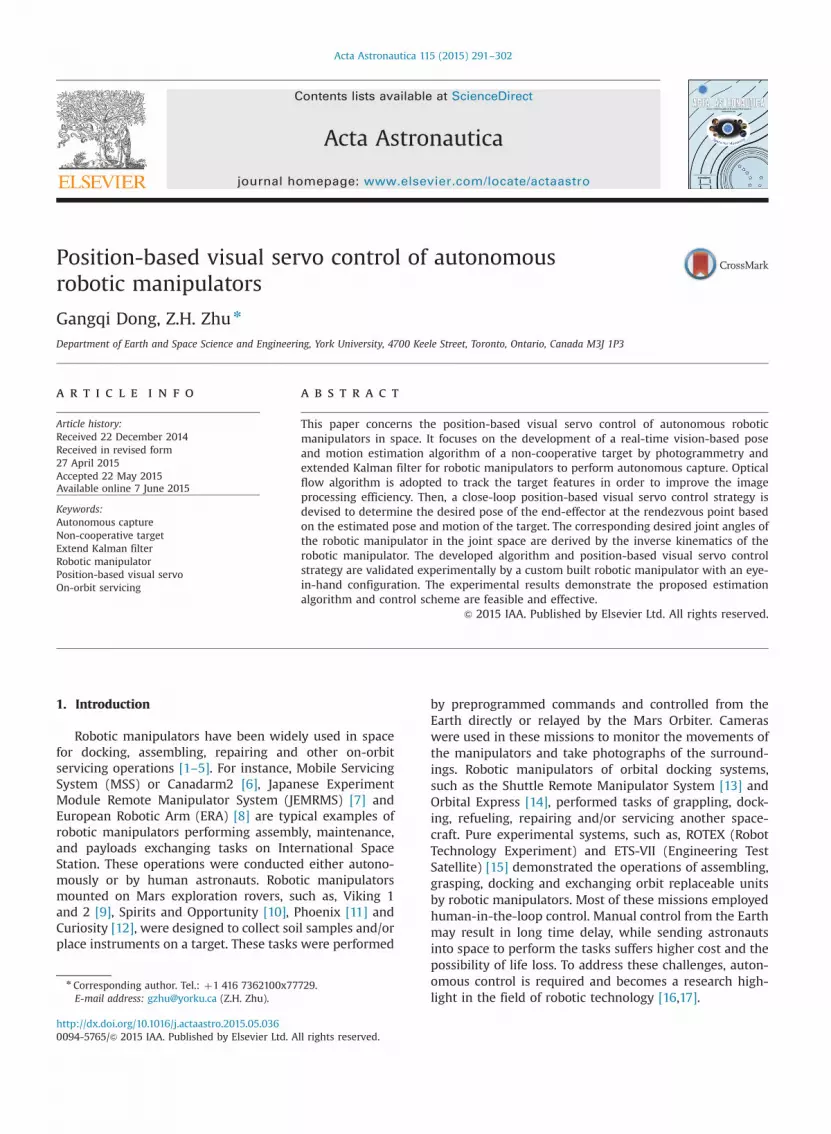
Position-based visual servo control of autonomous robotic manipulators Gangqi Dong, Z.H. Zhu n Department of Earth and Space Science and Engineering, York University, 4700 Keele Street, Toronto, Ontario, Canada M3J 1P3 article info Article history: Received 22 December 2014 Received in revised form 27 April 2015 Accepted 22 May 2015 Available online 7 June 2015 Keywords: Autonomous capture Non-cooperative target Extend Kalman filter Robotic manipulator Position-based visual servo On-orbit servicing abstract This paper concerns the position-based visual servo control of autonomous robotic manipulators in space. It focuses on the development of a real-time vision-based pose and motion estimation algorithm of a non-cooperative target by photogrammetry and extended Kalman filter for robotic manipulators to perform autonomous capture. Optical flow algorithm is adopted to track the target features in order to improve the image processing efficiency. Then, a close-loop position-based visual servo control strategy is devised to determine the desired pose of the end-effector at the rendezvous point based on the estimated pose and motion of the target. The corresponding desired joint angles of the robotic manipulator in the joint space are derived by the inverse kinematics of the robotic manipulator. The developed algorithm and position-based visual servo control strategy are validated experimentally by a custom built robotic manipulator with an eye- in-hand configuration. The experimental results demonstrate the proposed estimation algorithm and control scheme are feasible and effective. & 2015 IAA. Published by Elsevier Ltd. All rights reserved. 1. Introduction Robotic manipulators have been widely used in space for docking, assembling, repairing and other on-orbit servicing operations [1–5]. For instance, Mobile Servicing System (MSS) or Canadarm2 [6], Japanese Experiment Module Remote Manipulator System (JEMRMS) [7] and European Robotic Arm (ERA) [8] are typical examples of robotic manipulators performing assembly, maintenance, and payloads exchanging tasks on International Space Station. These operations were conducted either autono- mously or by human astronauts. Robotic manipulators mounted on Mars exploration rovers, such as, Viking 1 and 2 [9], Spirits and Opportunity [10], Phoenix [11] and Curiosity [12], were designed to collect soil samples and/or place instruments on a target. These tasks were performed by preprogrammed commands and controlled from the Earth directly or relayed by the Mars Orbiter. Cameras were used in these missions to monitor the movements of the manipulators and take photographs of the surround- ings. Robotic manipulators of orbital docking systems, such as the Shuttle Remote Manipulator System [13] and Orbital Express [14], performed tasks of grappling, dock- ing, refueling, repairing and/or servicing another space- craft. Pure experimental systems, such as, ROTEX (Robot Technology Experiment) and ETS-VII (Engineering Test Satellite) [15] demonstrated the operations of assembling, grasping, docking and exchanging orbit replaceable units by robotic manipulators. Most of these missions employed human-in-the-loop control. Manual control from the Earth may result in long time delay, while sending astronauts into space to perform the tasks suffers higher cost and the possibility of life loss. To address these challenges, auton- omous control is required and becomes a research high- light in the field of robotic technology [16,17]. Contents lists available at ScienceDirect journal homepage: www.elsevier.com/locate/actaastro Acta Astronautica http://dx.doi.org/10.1016/j.actaastro.2015.05.036 0094-5765/& 2015 IAA. Published by Elsevier Ltd. All rights reserved. n Corresponding author. Tel.: þ1 416 7362100x77729. E-mail address: [email protected] (Z.H. Zhu). Acta Astronautica 115 (2015) 291–302

Welcome message from author
This document is posted to help you gain knowledge. Please leave a comment to let me know what you think about it! Share it to your friends and learn new things together.
Transcript
Contents lists available at ScienceDirect
Acta Astronautica
Acta Astronautica 115 (2015) 291–302
http://d0094-57
n CorrE-m
journal homepage: www.elsevier.com/locate/actaastro
Position-based visual servo control of autonomousrobotic manipulators
Gangqi Dong, Z.H. Zhu n
Department of Earth and Space Science and Engineering, York University, 4700 Keele Street, Toronto, Ontario, Canada M3J 1P3
a r t i c l e i n f o
Article history:Received 22 December 2014Received in revised form27 April 2015Accepted 22 May 2015Available online 7 June 2015
Keywords:Autonomous captureNon-cooperative targetExtend Kalman filterRobotic manipulatorPosition-based visual servoOn-orbit servicing
x.doi.org/10.1016/j.actaastro.2015.05.03665/& 2015 IAA. Published by Elsevier Ltd. A
esponding author. Tel.: þ1 416 7362100x77ail address: [email protected] (Z.H. Zhu).
a b s t r a c t
This paper concerns the position-based visual servo control of autonomous roboticmanipulators in space. It focuses on the development of a real-time vision-based poseand motion estimation algorithm of a non-cooperative target by photogrammetry andextended Kalman filter for robotic manipulators to perform autonomous capture. Opticalflow algorithm is adopted to track the target features in order to improve the imageprocessing efficiency. Then, a close-loop position-based visual servo control strategy isdevised to determine the desired pose of the end-effector at the rendezvous point basedon the estimated pose and motion of the target. The corresponding desired joint angles ofthe robotic manipulator in the joint space are derived by the inverse kinematics of therobotic manipulator. The developed algorithm and position-based visual servo controlstrategy are validated experimentally by a custom built robotic manipulator with an eye-in-hand configuration. The experimental results demonstrate the proposed estimationalgorithm and control scheme are feasible and effective.
& 2015 IAA. Published by Elsevier Ltd. All rights reserved.
1. Introduction
Robotic manipulators have been widely used in spacefor docking, assembling, repairing and other on-orbitservicing operations [1–5]. For instance, Mobile ServicingSystem (MSS) or Canadarm2 [6], Japanese ExperimentModule Remote Manipulator System (JEMRMS) [7] andEuropean Robotic Arm (ERA) [8] are typical examples ofrobotic manipulators performing assembly, maintenance,and payloads exchanging tasks on International SpaceStation. These operations were conducted either autono-mously or by human astronauts. Robotic manipulatorsmounted on Mars exploration rovers, such as, Viking 1and 2 [9], Spirits and Opportunity [10], Phoenix [11] andCuriosity [12], were designed to collect soil samples and/orplace instruments on a target. These tasks were performed
ll rights reserved.
729.
by preprogrammed commands and controlled from theEarth directly or relayed by the Mars Orbiter. Cameraswere used in these missions to monitor the movements ofthe manipulators and take photographs of the surround-ings. Robotic manipulators of orbital docking systems,such as the Shuttle Remote Manipulator System [13] andOrbital Express [14], performed tasks of grappling, dock-ing, refueling, repairing and/or servicing another space-craft. Pure experimental systems, such as, ROTEX (RobotTechnology Experiment) and ETS-VII (Engineering TestSatellite) [15] demonstrated the operations of assembling,grasping, docking and exchanging orbit replaceable unitsby robotic manipulators. Most of these missions employedhuman-in-the-loop control. Manual control from the Earthmay result in long time delay, while sending astronautsinto space to perform the tasks suffers higher cost and thepossibility of life loss. To address these challenges, auton-omous control is required and becomes a research high-light in the field of robotic technology [16,17].
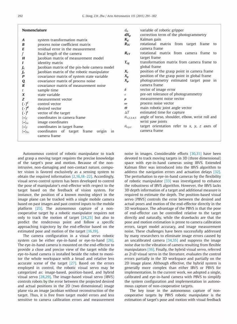
Nomenclature
A system transformation matrixB process noise coefficient matrixE residual error in the measurementf focal length of the cameraH Jacobian matrix of measurement modelI identity matrixJc Jacobian matrix of the pin-hole camera modelJr Jacobian matrix of the robotic manipulatorP covariance matrix of system state variableQ covariance matrix of process noiseR covariance matrix of measurement noiset sample timeX state variableZ measurement vector( . )C control vector( . )d desired vector( . )t vector of the target(∙)C coordinates in camera frame(∙)m image coordinates(∙)T coordinates in target frame(∙)To coordinates of target frame origin in
camera frame
d6 variable of robotic gripperdXp correction term of the photogrammetryKg Kalman gainRTC rotational matrix from target frame to
camera frameRCT rotational matrix from camera frame to
target frameTcg transformation matrix from camera frame to
global frameXc position of the grasp point in camera frameXg position of the grasp point in global frameXp photogrammetry estimated target pose in
camera frameδ vector of image errorε pre-set tolerance of photogrammetryμ measurement noise vectorω process noise vectorΘ main robotic joint angle vectorΔT estimated time for captureθ1,2,3,4,5 angle of torso, shoulder, elbow, wrist roll and
wrist yaw jointsθx,y,z target orientation refer to x, y, z axes of
camera frame
G. Dong, Z.H. Zhu / Acta Astronautica 115 (2015) 291–302292
Autonomous control of robotic manipulator to trackand grasp a moving target requires the precise knowledgeof the target's pose and motion. Because of the non-intrusive, non-damaging and non-contact nature, compu-ter vision is favored exclusively as a sensing system toobtain the required information [2,16,18–22]. Accordingly,visual servo control system has been developed to controlthe pose of manipulator's end-effector with respect to thetarget based on the feedback of vision system. Forinstance, the position of a known moving object in theimage plane can be tracked with a single mobile camerabased on past images and past control inputs to the mobileplatform [23]. The autonomous capture of a non-cooperative target by a robotic manipulator requires notonly to track the motion of target [24,25] but also topredict the rendezvous point and follow a specificapproaching trajectory by the end-effector based on theestimated pose and motion of the target [16,19].
The camera configuration in a visual servo roboticsystem can be either eye-in-hand or eye-to-hand [26].The eye-in-hand camera is mounted on the end-effector toprovide a close and precise view of the target while theeye-to-hand camera is installed beside the robot to moni-tor the whole workspace with a broad and relative lessaccurate scene of the target [27]. Based on the errorsemployed in control, the robotic visual servo may becategorized as: image-based, position-based, and hybridvisual servo [28,29]. The image-based visual servo (IBVS)controls robots by the error between the projected desiredand actual positions in the 2D (two dimensional) imageplane via an image Jacobian without reconstruction of thetarget. Thus, it is free from target model errors and lesssensitive to camera calibration errors and measurement
noise in images. Considerable efforts [30,31] have beendevoted to track moving targets in 3D (three dimensional)space with eye-in-hand cameras using IBVS. ExtendedKalman filter was introduced into the IBVS algorithm toaddress the navigation errors and actuation delays [32].The perturbation to eye-in-hand cameras by the flexibilityof robotic manipulator [33] was investigated to enhancethe robustness of IBVS algorithm. However, the IBVS lacks3D depth information of a target and additional measure isrequired to estimate the depth. The position-based visualservo (PBVS) controls the error between the desired andactual poses and motion of the end-effector directly in the3D workspace. The advantage of the PBVS is that the poseof end-effector can be controlled relative to the targetdirectly and naturally, while the drawbacks are that thepose and motion estimation is prone to camera calibrationerrors, target model accuracy, and image measurementnoise. These challenges have been successfully addressedby many researchers to eliminate image errors caused byan uncalibrated camera [34,35] and suppress the imagenoise due to the vibration of camera resulting from flexiblemanipulators [36]. Finally, the hybrid visual servo, referredas 2½D visual servo in the literature, evaluates the controlerrors partially in the 3D workspace and partially on the2D image plane. Although effective, the hybrid system isgenerally more complex than either IBVS or PBVS forimplementation. In the current work, we adopted a single,calibrated and eye-in-hand camera with PBVS to simplifythe system configuration and implementation in autono-mous capture of non-cooperative targets.
The key issue in the autonomous capture of non-cooperative targets by PBVS robotic manipulator is theestimation of target's pose and motion with visual feedback

G. Dong, Z.H. Zhu / Acta Astronautica 115 (2015) 291–302 293
to reconstruct the target in 3D space. The pose and motionestimated by the eye-in-hand camera in PBVS are prone toimage jittering, residual vibration and unexpected distur-bances of camera or the end-effector. Considerable effortshave been devoted to extract information from visualimages in the past decades [37–40]. Different methodologieshave been developed, such as, analytic or geometric method,learning-based method, offline method and filteringmethod. The geometric method, such as the photogramme-try, is widely used when the camera is properly calibratedand the target is known. It extracts six degrees of freedominformation (pose) of the target from 2D images. However,the geometric method is memoryless and its result is noisyif the image data is not smooth either due to the jittering ofimage processing or the mechanical disturbance of the end-effector in case of eye-in-hand camera. The learning-basedmethod requires a sufficient large set of images of target indifferent poses, which is usually not available when thetarget is non-cooperative. The offline methods are notsuitable for the robotic manipulator to track, approach andcapture the target in real-time. Another potential solutionfor the estimation of pose and motion is filtering. Kalmanfilter (KF) is a widely used filtering algorithm to estimateunknown variables based on a set of noisy measurementsobserved over time with initial conditions. Since beingproposed in 1960 [41], the KF has been applied widely withmany variations and extensions beyond the original pro-posed linear system [42]. Although the initial conditions donot change the convergence property of the KF, they doaffect the performance of the filter, especially when dealingwith the non-cooperative target in real-time where theinitial conditions are unknown.
The focus of this study is to improve the estimation ofpose and motion in real-time PBVS control to address thechallenges of image jittering and disturbances of cameracaused by the flexibility in joints, actuation delays andrough motion of stepper motor. In our previous PBVS work[16], the challenges were studied by a dual KF approachwhere the first KF was introduced in the image space andthe second KF was used in the 3D space. The first KF notonly reduces the image noise due to jittering to preventthe errors propagating into photogrammetry algorithmbut also provides substitute image data momentarily toenhance the tracking robustness in case of an outrage inthe vision system occurs. The second KF was designed tosuppress impact of the residual vibration and unexpecteddistribution of the camera and the sudden motion of atarget. Although effective, the approach is computationalcumbersome and increases the actuation delay. To addressthe issue, a new methodology was developed in thecurrent work to integrate the photogrammetry andextended Kalman filter (EKF) to estimate the target's poseand motion in real-time for PBVS. Combining with theinner closed-loop control of robotic manipulator, the visualestimation of pose and motion of a target as well as thecontrol errors in 3D space forms an outer closed-loopcontrol. It is worth pointing out that the effectiveness ofEKF in improving the robustness of visual servo [32,33] hasalso been demonstrated in IBVS. For instance, the EKFintroduced in the image space not only improves theestimation accuracy of target's kinematics state but also
substitutes state estimates when the target is lost locking[33]. These works showed that the introduction of EKF intoIBVS is effective to prevent the tracking failure in adynamic situation due to image noises and actuationdelay. The current approach is validated experimentallyby a custom-built robotic manipulator [16] with an eye-in-hand camera mounted closely to the end-effector. Theexperimental results demonstrate the effectiveness androbustness of the proposed approach by successfullytracking, approaching and capturing a non-cooperativetarget autonomously.
2. Position-based visual servo of robotic manipulator
2.1. Camera model and photogrammetry
The pose of a target can be described by the Cartesiancoordinates xTo; yTo; zTo
� �T of a target-fixed frame originand the Euler angles of that frame θx; θy; θz
� �T regarding tothe camera frame. The rotational matrix from the cameraframe to the target frame, RCT , can be developed byrotating x-axis of the camera frame by θx first and followedby rotating y-axis of the camera frame by θy and rotating z-axis of the camera frame by θz. Accordingly, the rotationalmatrix from the target frame to the camera frame can beexpressed as RTC ¼ RCT
T , such that
RTC ¼CyCz �CySz Sy
CxSz þ SxSyCz CxCz�SxSySz �SxCy
SxSz�CxSyCz SxCzþCxSySz CxCy
264
375 ð1Þ
Here, Sx ¼ sin θx; Sy ¼ sin θy; Sz ¼ sin θz Cx ¼cos θx;Cy ¼ cos θy;Cz ¼ cos θz:
Assume the coordinates, xT ; yT ; zT� �T , of a feature point
on the target are known in the target frame, which impliesthe vision system is calibrated in advance. Then, thehomogeneous relationship between the target and cameraframes can be described by
xCyCzC1
8>>><>>>:
9>>>=>>>;
¼RTC
xToyTozTo
0 0 0 1
266664
377775
xTyTzT1
8>>><>>>:
9>>>=>>>;
ð2Þ
where xC ; yC ; zC� �T is the coordinates of the same point in
the camera frame.Consider a pinhole camera model as shown in Fig. 1,
denote rij for elements of RTC . The feature point on thetarget is projected onto the image plane by Eq. (3), such as
xm ¼ � f xCyC � f ¼ � f r11xT þ r12yT þ r13zT þ xTo
r21xT þ r22yT þ r23zT þyTo � f
zm ¼ � f zCyC � f ¼ � f r31xT þ r32yT þ r33zT þ zTo
r21xT þ r22yT þ r23zT þyTo � f
8<: ð3Þ
where f stands for the focal length of the camera andxm; zmf gT denotes the projected image coordinates of thefeature point. For a calibrated camera, the focal length isknown in advance.
Defining η¼ yC� f in Eq. (3) leads to
ηxmþxCf ¼ 0ηzmþzCf ¼ 0
(ð4Þ

cx
cz
cy co
tx
tz
tyto
f
, , TC C Cx y z
Image Pl ane
Target
, Tm mx z
{ }
{ }
Fig. 1. Pin-hole camera model.
G. Dong, Z.H. Zhu / Acta Astronautica 115 (2015) 291–302294
Further define the left side of Eq. (4) by F ¼ ηxmþxCfand G¼ ηzmþzCf , where F and G are functions of the targetpose in the camera frame and the projected image coordi-nates of the feature point on the target. Linearizing F and Gby the Taylor expansion in the vicinity ofxm; zm; xTo; yTo; zTo; θx; θy; θz
� �T leads to
E2�1þδ2�1 ¼ Jc 2�6dXp 6�1 ð5Þwhere
E2�1 ¼dxmdzm
( ); δ2�1 ¼ 1
η
F0G0
( );
dXp 6�1 ¼ dxTo; dyTo; dzTo; dθx;dθy; dθz� �T
;
Jc 2�6 ¼ �1η
∂F∂xTo
� �0
∂F∂yTo
� �0
∂F∂zTo
� �0
∂F∂θx
� �0
∂F∂θy
� �0
∂F∂θz
� �0
∂G∂xTo
� �0
∂G∂yTo
� �0
∂G∂zTo
� �0
∂G∂θx
� �0
∂G∂θy
� �0
∂G∂θz
� �0
8><>:
9>=>;:
Eq. (5) contains two independent equations for sixunknowns (pose of target). Theoretically, one needs onlythree feature points to solve for the six unknowns. How-ever, this approach may result in four ambiguous poses[28,29]. To eliminate the ambiguity and increase therobustness, minimum four feature points are widelyadopted in literature, which leads to eight equations withsix unknowns, such that
E8�1þδ8�1 ¼ Jc 8�6dXp 6�1 ð6Þ
The unknowns are solved by an iterative least squareapproach assuming the zero residual error in the measure-ment, such that
E8�1 ¼ 0; dXp 6�1 ¼ ðJTc 8�6Jc 8�6Þ�1JTc 8�6δ8�1 ð7Þ
By inputting the known image coordinates of featurepoints and an initial guess of the target pose, the algorithmiterates to correct previous guess until the correction isless than a pre-set tolerance, i.e., ‖dXp‖rε. In practice, it iscommon to use the previous target pose as the initial
guess to reduce the iterations. As aforementioned, thephotogrammetry is memoryless and prone to the imagenoise, which may result in large fluctuation of estimatedtarget pose. Thus, the computational time of photogram-metry may increase if the initial guess, which is theprevious pose as mentioned, is far away from the currentpose. As a result, the sampling time-step of vision systemmay be adjusted, which is not desirable when dealing withreal-time pose estimation. Another shortcoming of thephotogrammetry is that it does not estimate the motion oftarget directly, which is an important parameter fortrajectory planning of the robotic manipulator to performautonomous capture in a dynamic environment. Toaddress these challenges, an extended Kalman filter(EKF) with photogrammetry is presented in the following.
2.2. Extended Kalman filter
The Kalman filter is an optimal estimation algorithm fora linear system with independent white noise of normaldistribution [41,42]. The camera model in Eq. (3) is highlynonlinear and the extended Kalman filter has beenadopted to estimate the pose and motion of a dynamictarget. Assume the motion of the target is approximatelyconstant within the sampling interval if the samplingtime-step is sufficiently small. Then, the motion of thetarget can be approximated by the first order equation ofmotion. Define the system variable vector as
X ¼ xTo; _xTo; yTo; _yTo; zTo; _zTo; θx; _θx; θy; _θy; θz; _θz� �T
By assuming the system's acceleration vectorω¼ €xTo; €yTo; €zTo; €θx; €θy; €θz
� �Tas the process noise with a
normal distribution with zero mean and covariance matrixQ , the system model is expressed as
Xk ¼ AXk�1þBωk�1 ð8Þ

G. Dong, Z.H. Zhu / Acta Astronautica 115 (2015) 291–302 295
where
A¼ diag A1 A1 A1 A1 A1 A1� �
; A1 ¼1 t
0 1
� ;
B¼ diag B1 B1 B1 B1 B1 B1� �
; B1 ¼t2=2t
( ):
k is sample time-step and t is the sample time.The measurement model is developed from the pin-
hole camera model in Eq. (3) for n feature points, such that
Zk ¼ h Xkð Þþμk
Z ¼ xm1; zm1;⋯xmn; zmnf gT ; h Uð Þ ¼ hx1;hz1;⋯hxn;hzn� �T
ð9Þand
hxi Xð Þ ¼ � f xCiηi ; hzi Xð Þ ¼ � f zCiηi ð10Þ
where μ is the measurement noise that obeys a normaldistribution with zero mean and covariance matrix R.
The EKF requires initial conditions and measurementsobserved over time. Since initial conditions of a non-cooperative target are unknown, an inappropriate initialguess may lead to poor performance of the EKF. Toimprove its performance and accelerate the convergencerate, we initialize the state variable vector by the photo-
Table 1Pose and motion estimation algorithm.
1. Given an initial guess of target pose: Xp ¼Xp0;2. Input measurement;3. Start photogrammetry loop4. {5. evaluate pin-hole camera model Jacobian Jc and im6.
calculate pseudo-inverse of Jacobian: Jcþ ¼ Jc
T Jc� �
7. calculate previous-guess-correction: dXp ¼ Jcþ δ;
8. if (‖dXp‖otolerance)9. {break;}10. else11. {Xp ¼XpþdXP;}12. }13. Return Xp;14. Augment to state variable: X0 ¼ Xp; _Xp
� �;
15. Initialize EKF: X0 (initial state variable),P0 (state variable covariance matrix),Q (process noise covariance matrix),R (measurement noise covariance matrix);
16. Start EKF loop17. {18. estimate next state variable and covariance matrix
Xkjk�1 ¼ AXk�1jk�1
Pkjk�1 ¼ APk�1jk�1AT þBQBT
19. evaluate Jacobian of measurement model: Hk ¼ ∂h
20. calculate Kalman gain:
Kg ¼ Pkjk�1HTk HkPkjk�1H
Tk þR
� ��1
21. update state variable and covariance matrix:Xkjk ¼Xkjk�1þKg Zk�h Xkjk�1
� �� �Pkjk ¼ Pkjk�1�KgHkPkjk�1
22. record and output: Xkjk , Pkjk;23. }
grammetry in the algorithm. Based on the above defini-tions, a recursive pose and motion estimation algorithm isderived as shown in Table 1, where H is the Jacobianmatrix formed by the first order partial differential of themeasurement model respect to system variable, Kg is theKalman gain at time step k, P is the covariance matrix ofthe system state variable, Q and R are the process andmeasurement noise covariance matrices.
2.3. Kinematics of robotic manipulator
The autonomous capture will be conducted by acustom-built six degrees of freedom (6DOF) roboticmanipulator with an eye-in-hand configuration as shownin Fig. 2. The robotic manipulator consists of three linksand one end-effector with five revolute and one prismaticjoints. The eye-in-hand camera is mounted closely to theend-effector. The first three revolute joints, namely torso(θ1), shoulder (θ2) and elbow (θ3), control the position ofthe end-effector while the last two revolute joints and oneprismatic joint, namely wrist roll (θ4), wrist yaw (θ5) andgripper (d6), provide dexterous orientation and gripingfunction for capture operation. Thus, the translation androtation of the end-effector can be considered separatelyfrom the wrist to simplify the controller design.
The kinematics of robotic manipulator provides theforward relationship from the joint angles to the position
age error vector δ;�1
JcT ;
:
Xð Þ=∂XX ¼ Xkjk� 1

G. Dong, Z.H. Zhu / Acta Astronautica 115 (2015) 291–302296
of the end-effector (the wrist center), such that
Xg ¼Kf Θð Þ ð11Þwhere Θ¼ θ1; θ2; θ3f gT .
Thus, the velocity of the end-effector can be derived bytaking the time derivative of Eq. (11)
_Xg ¼ Jr _Θ ð12Þwhere Jr is the Jacobian matrix of the robotic manipulatorformed by joint angles.
Eqs. (11) and (12) form the forward kinematics of therobotic manipulator. The actuators are step motors at joints,which drive the end-effector to the desired position byachieving the desired joint angles. Thus, the transformation
Fig. 2. The custom-built 6DOF robotic manipulator.
Fig. 3. Flowchart of the pose and m
of position to joint angles, namely inverse kinematics,should be derived in advance. It is well known that therobotic inverse kinematics may have multiple-solutions dueto the periodicity of trigonometric functions. In order toobtain a unique solution of joint angles based on Eq. (11),we introduced additional constraints, such as mechanicalconfiguration and motion limits as per [16] in addition tothe following inverse kinematics
Θ¼ ~K f�1
Xg ; _Θ¼ Jr�1 _Xg ð13Þ
2.4. Desired state of the end-effector
The desired state of the end-effector is defined as thepose and motion of a target in the dynamic PBVS. Since thepose and motion of a target are estimated relative to thecamera frame, they must be transformed to the globalframe first, such that
Xg ¼ TcgXc ð14Þ
_Xg ¼ _TcgXcþTcg_Xc ð15Þ
where Tcg is the transformation matrix from the cameraframe to the global frame.
Denote the position and velocity vectors of a target as
Xtc ¼ xTo; yTo; zTo
� �T; _X
tc ¼ _xTo; _yTo; _zTo
� �T ð16Þ
Then, the desired position and velocity of the end-effector in the global frame are determined by substitutingEqs. (14) and (15) into Eq. (16)
Xdg ¼ TcgXt
c ;_Xdg ¼ _TcgXt
cþTcg_Xtc ð17Þ
Accordingly, the desired joint angles and angular velo-cities of the first three joints of the robotic manipulator are
otion estimation algorithm.
G. Dong, Z.H. Zhu / Acta Astronautica 115 (2015) 291–302 297
determined by substituting Eq. (17) into Eq. (13), such as
θd1 θd2 θd3n oT
¼ ~K f�1
Xdg ; _θ
d1
_θd2
_θd3
n oT¼ Jr
�1 _Xdg
ð18Þ
The desired joint angles and angular velocities of thewrist roll and wrist yaw are defined as
θd4 θd5 _θd4
_θd5
n o¼ θy θz _θy _θzn o
ð19Þ
They will be determined separately by the capturestrategy defined below.
2.5. Capture strategy
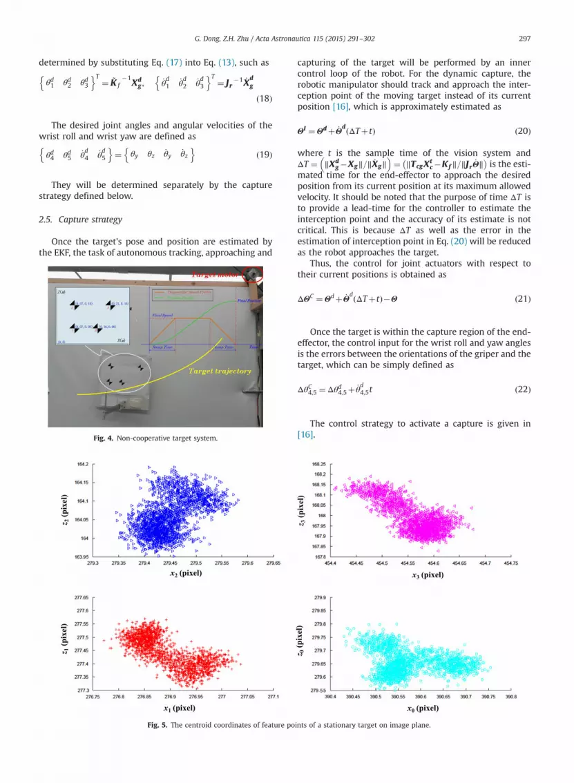
Once the target's pose and position are estimated bythe EKF, the task of autonomous tracking, approaching and
Fig. 4. Non-cooperative target system.
x1 (pixel)
x2 (pixel)
z 2(p
ixel
)z 1
(pix
el)
Fig. 5. The centroid coordinates of feature po
capturing of the target will be performed by an innercontrol loop of the robot. For the dynamic capture, therobotic manipulator should track and approach the inter-ception point of the moving target instead of its currentposition [16], which is approximately estimated as
ΘI ¼Θdþ _Θd ΔTþtð Þ ð20Þ
where t is the sample time of the vision system andΔT ¼ ‖Xd
g�Xg‖=‖ _Xg‖� �
¼ ‖TcgXtc�Kf ‖=‖Jr _Θ‖
� �is the esti-
mated time for the end-effector to approach the desiredposition from its current position at its maximum allowedvelocity. It should be noted that the purpose of time ΔT isto provide a lead-time for the controller to estimate theinterception point and the accuracy of its estimate is notcritical. This is because ΔT as well as the error in theestimation of interception point in Eq. (20) will be reducedas the robot approaches the target.
Thus, the control for joint actuators with respect totheir current positions is obtained as
ΔΘC ¼Θdþ _Θd ΔTþtð Þ�Θ ð21Þ
Once the target is within the capture region of the end-effector, the control input for the wrist roll and yaw anglesis the errors between the orientations of the griper and thetarget, which can be simply defined as
ΔθC4;5 ¼Δθd4;5þ _θd4;5t ð22Þ
The control strategy to activate a capture is given in[16].
x0 (pixel)
x3 (pixel)
z 0(p
ixel
)z 3
(pix
el)
ints of a stationary target on image plane.
G. Dong, Z.H. Zhu / Acta Astronautica 115 (2015) 291–302298
3. Experimental setup
3.1. Robotic manipulator system
The proposed pose and motion estimation algorithmfor the non-cooperative target and the PBVS autonomouscapture by the robotic manipulator are validated experi-mentally. A robotic manipulator with five revolute joints,one prismatic joint and an eye-in-hand camera mountedclosely to the end effector is custom built to conduct theautonomous PBVS capture operation, as shown in Fig. 2.The camera used in the experiment was a Logitechwebcam with 640�480 resolution and 2 mm focal length.The implementation of the pose and motion estimationand PBVS control has been done by the Microsoft Funda-mental Class (MFC) in order to obtain a friendly humanmachine interface. The flowchart of the implementation isshown in Fig. 3. Once the camera is activated, a separatethread is created simultaneously for the camera to acquireimage data and display them on the computer screen.After the target is locked, the imaging processing subrou-tine is activated to track the motion of feature points andoutput their pixel coordinates in sequence.
3.2. Non-cooperative target system
A target with a known pattern of four low-optical-noisefeatures is designed to facilitate a simple optical lockingand tracking. The target system as well as configuration offeature points is shown in Fig. 4. The target is driven by asingle stepper motor with programmable speed profile in
Fig. 6. Static test results: (a) pose estim
the tests. By programming the speed profile of the motorand isolating the target system from the robot system,several testing scenarios for the non-cooperative targetcan be generated.
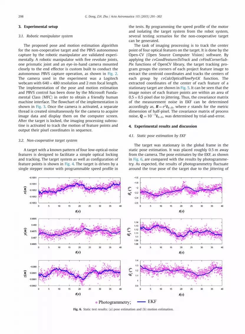
The task of imaging processing is to track the centerpoint of four optical features on the target. It is done by theOpen-CV (Open Source Computer Vision) software. Byapplying the cvGoodFeaturesToTrack and cvFindCornerSub-Pix functions of OpenCV library, the target tracking pro-gram groups the corners of each project feature image toextract the centroid coordinates and tracks the centers ofeach group by cvCalcOpticalFlowPyrLK function. Theextracted coordinates of the center of each feature of astationary target are shown in Fig. 5. It can be seen that theimage noises of each feature points are within an area of0.5�0.5 pixel due to jittering. Thus, the covariance matrixof the measurement noise in EKF can be determinedaccordingly as, R¼ e2I8�8, where e stands for the metricdimension of half-pixel. The covariance matrix of processnoise, Q ¼ 10�5I6�6, was determined by trial-and-error.
4. Experimental results and discussion
4.1. Static pose estimation by EKF
The target was stationary in the global frame in thestatic pose estimation. It was placed roughly 0.5 m awayfrom the camera. The pose estimates by the EKF, as shownin Fig. 6, are compared with the results by photogramme-try. As expected, the results of photogrammetry fluctuatearound the true pose of the target due to the jittering of
ation and (b) motion estimation.

Fig. 7. Dynamic test results: (a) pose estimation and (b) motion estimation.
G. Dong, Z.H. Zhu / Acta Astronautica 115 (2015) 291–302 299
pixel coordinates of features. The jitter distribution in theexperiments was observed as 70.5 pixel as shown inFig. 5. It resulted in roughly 0.1 mm translational and 0.41
rotational fluctuations in pose estimation as shown inFig. 6(a). This is because the photogrammetry does notconsider the measurement noises of images and
G. Dong, Z.H. Zhu / Acta Astronautica 115 (2015) 291–302300
propagates the noises down to the pose estimation. Incontrast, the poses estimated by the EKF are muchsmoother than the photogrammetry. The EKF suppressedthe spread of the measurement noises by considering theeffects of measurement noises. The motion estimated bythe EKF is stationary compared with the one estimatedbased on the numerical derivation of the photogrammetrydata, which is very noisy and unsuitable for roboticcontrol, see Fig. 6(b). This experiment demonstrates thenecessity of using the EKF in the PBVS of robots.
4.2. Dynamic pose and motion estimation by EKF
The dynamic pose and motion estimation was done bymanually translating and rotating the target along x; y; zaxes, while the target was roughly 0.5 m away from thecamera. The estimated pose and motion of the movingtarget are shown in Fig. 7 together with the results fromthe photogrammetry. Fig. 7(a) shows that the positionsestimated by the EKF and photogrammetry are in goodagreement. However, the orientations estimated by thephotogrammetry are noisier than the EKF. It is worthpointing out that the EKF requires the Jacobian matrix ofmeasurement model, which induces linearization error.The stronger the nonlinearity, the more error may beinduced. According to Eq. (3), the nonlinearity of y, θx, θzare relatively stronger than x, z, θy in the measurementmodel. Therefore, it can be seen the test results of y, θx, θzestimated by the EKF agree with the photogrammetrybetter than x, z, θy. In the latter case, the estimates bythe EKF show some delay in phase when the targetexperienced sudden motion. Fig. 7(b) shows the motion
Desired joint angle
Target searching& locking
Fig. 8. Test results of autonomou
estimated by the EKF. As a comparison, the motionobtained by a simple numerical derivation of the photo-grammetry data is also plotted. It shows clearly that theEKF results are much smoother than the photogrammetryand suitable for robotic tracking control.
4.3. Robotic autonomous capture enhanced by EKF
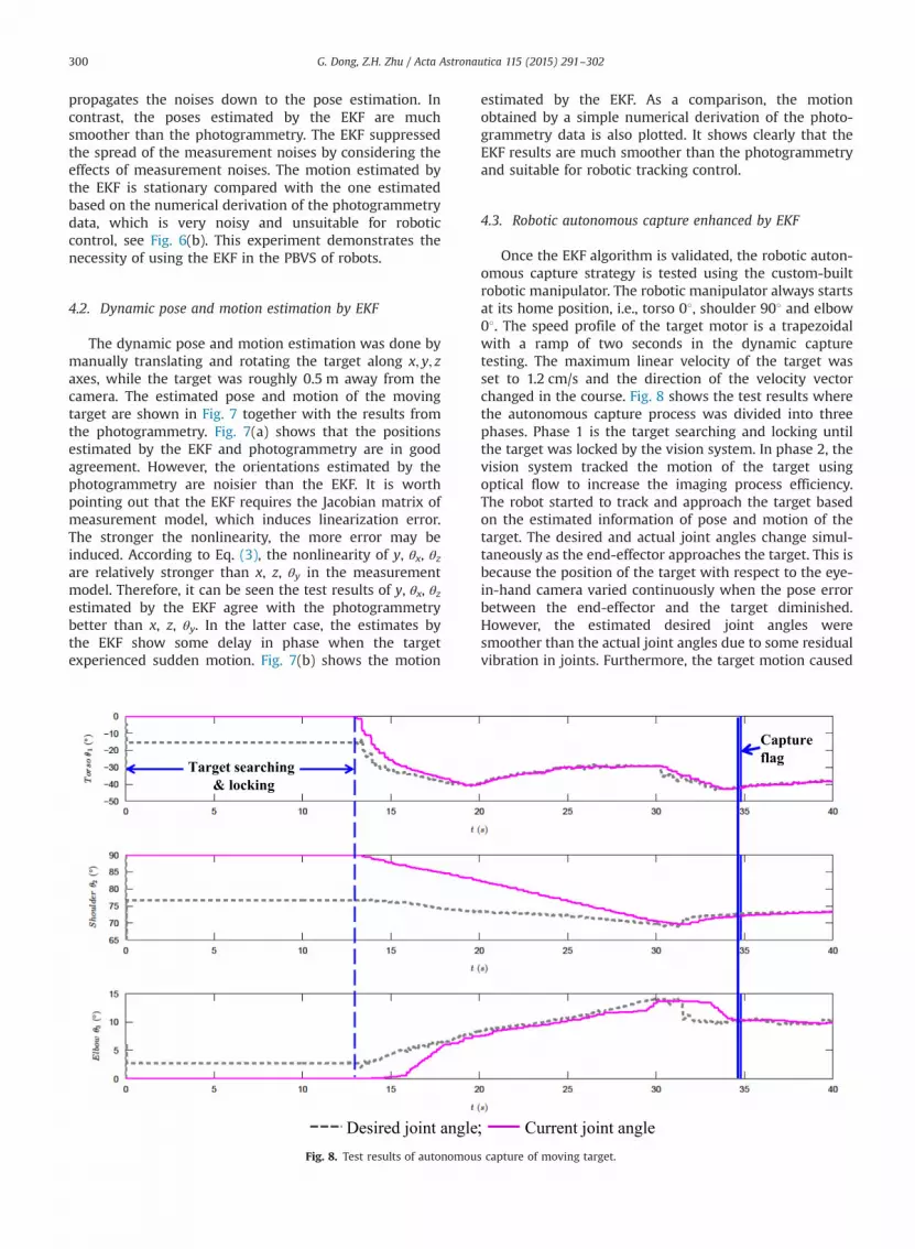
Once the EKF algorithm is validated, the robotic auton-omous capture strategy is tested using the custom-builtrobotic manipulator. The robotic manipulator always startsat its home position, i.e., torso 01, shoulder 901 and elbow01. The speed profile of the target motor is a trapezoidalwith a ramp of two seconds in the dynamic capturetesting. The maximum linear velocity of the target wasset to 1.2 cm/s and the direction of the velocity vectorchanged in the course. Fig. 8 shows the test results wherethe autonomous capture process was divided into threephases. Phase 1 is the target searching and locking untilthe target was locked by the vision system. In phase 2, thevision system tracked the motion of the target usingoptical flow to increase the imaging process efficiency.The robot started to track and approach the target basedon the estimated information of pose and motion of thetarget. The desired and actual joint angles change simul-taneously as the end-effector approaches the target. This isbecause the position of the target with respect to the eye-in-hand camera varied continuously when the pose errorbetween the end-effector and the target diminished.However, the estimated desired joint angles weresmoother than the actual joint angles due to some residualvibration in joints. Furthermore, the target motion caused
; Current joint angle
Captureflag
s capture of moving target.

G. Dong, Z.H. Zhu / Acta Astronautica 115 (2015) 291–302 301
the estimated desired joint angles to vary ahead of theactual joint angles as shown in Fig. 8 because the end-effector was approaching to the interception instead of thecurrent target position. Finally in phase 3, the manipulatorsuccessfully captured the moving target.
5. Conclusion
This paper proposed a real-time PBVS control of auton-omous robotic capture of a non-cooperative target. Avision-based pose and motion estimation algorithm of anon-cooperative target was developed by the photogram-metry and the extended Kalman filter for robotic manip-ulators to perform the PBVS autonomous capture. Thismethodology adopts the photogrammetry to initialize theEKF to improve its convergence rate when dealing withthe non-cooperative target case. Optical flow algorithm isemployed to track the target in order to increase theimaging processing speed for real-time pose and motionestimation of the non-cooperative target. This is beneficialfor reducing the time delaying in joint actuation. A close-loop PBVS control strategy is devised to determine thedesired pose and position of the end-effector at therendezvous point once the pose and motion of the targetare estimated. The proposed approach was validatedexperimentally on a custom-built robotic manipulatorwith an eye-in-hand configuration. The experimentalresults show that the EKF provided a smooth estimationof pose and motion of the target and enabled successfulcaptures of a non-cooperative target. The experimentsdemonstrated that the effectiveness and robustness ofthe proposed EKF enhanced pose and motion estimationand the PBVS control strategy.
Acknowledgment
This work is supported by the Natural Sciences andEngineering Research Council of Canada (NSERC).
References
[1] J. Yuh, Design and control of autonomous underwater robots: asurvey, Auton. Robots 8 (2000) 7–24.
[2] S.S. Mehta, T.F. Burks, Vision-based control of robotic manipulatorfor citrus harvesting, Comput. Electron. Agric. 102 (2014) 146–158.
[3] S.J. Lee, S.C. Lee, H.S. Ahn, Design and control of tele-matchedsurgery robot, Mechatronics 24 (2014) 395–406.
[4] L. Pedersen, D. Kortenkamp, D. Wettergreen, I. Nourbakhsh, A surveyof space robotics, in: Proceedings of the 7th International Sympo-sium on Artificial Intelligence, Robotics and Automation in Space,2003, pp. 19–23.
[5] K. Yoshida, Achievements in space robotics, IEEE Robot. Autom. Mag.16 (2009) 20–28.
[6] M. Robotics, Mobile Servicing System Data Sheet, MD Robotics,Brampton, Ontario, Canada, 2002.
[7] T. Matsueda, F. Kuwao, S. Motohasi, R. Okamura, Development ofJapanese experiment module remote manipulator system, in: Pro-ceedings of JPL, Third International Symposium on Artificial Intelli-gence, Robotics, and Automation for Space, 1994, pp. 183–186 (SEE N95-23672 07-63).
[8] R. Boumans, C. Heemskerk, The European robotic arm for theinternational space station, Robot. Auton. Syst. 23 (1998) 17–27.
[9] ⟨http://www.jpl.nasa.gov/news/fact_sheets/viking.pdf⟩.
[10] E. Tunstel, M. Maimone, A. Trebi-Ollennu, J. Yen, R. Petras, R. Willson,Mars exploration rover mobility and robotic arm operational per-formance, in: Proceedings of 2005 IEEE International Conference onSystems, Man and Cybernetics, IEEE, 2005, pp. 1807–1814.
[11] P.A.R. Billing, C.-A.R. Fleischner, Mars science laboratory robotic arm,in: Proceedings of the 14th European Space Mechanisms & TribilogySymposium-ESMATS, 2011.
[12] C. Covault, Curiosity's mission to Mars, Aerosp. Am. 49 (2011) 28–34.[13] ⟨http://www.ieee.ca/millennium/canadarm/canadarm_technical.
html⟩.[14] ⟨http://archive.darpa.mil/orbitalexpress/pdf/oe_fact_sheet_final.
pdf⟩.[15] G. Hirzinger, B. Brunner, K. Landzettel, N. Sporer, J. Butterfass,
M. Schedl, Space robotics—DLR's telerobotic concepts, lightweightarms and articulated hands, Auton. Robots 14 (2003) 127–145.
[16] B.P. Larouche, Z.H. Zhu, Autonomous robotic capture of non-cooperative target using visual servoing and motion predictivecontrol, Auton. Robots 37 (2014) 157–167.
[17] G. Moustris, S. Hiridis, K. Deliparaschos, K. Konstantinidis, Evolution ofautonomous and semi‐autonomous robotic surgical systems: a reviewof the literature, Int. J. Med. Robot. Comput. 7 (2011) 375–392.
[18] C. Liu, X.H. Huang, M. Wang, Target tracking for visual servoingsystems based on an adaptive Kalman filter, Int. J. Adv. Robot. Syst. 9(2012) 1–12.
[19] M. Kazemi, K. Gupta, M. Mehrandezh, Path planning for image-based control of wheeled mobile manipulators, in: Proceedings of2012 IEEE/RSJ International Conference on Intelligent Robots andSystems (IROS), IEEE, 2012, pp. 5306–5312.
[20] S. Hutchinson, G.D. Hager, P.I. Corke, A tutorial on visual servocontrol, IEEE Trans. Robot. Autom. 12 (1996) 651–670.
[21] D. Kragic, H.I. Christensen, Survey on Visual Servoing for Manip-ulationComputational Vision and Active Perception Laboratory,Fiskartorpsv.
[22] B. Espiau, F. Chaumette, P. Rives, A new approach to visual servoingin robotics, IEEE Trans. Robot. Autom. 8 (1992) 313–326.
[23] J.T. Feddema, C.S.G. Lee, Adaptive image feature prediction andcontrol for visual tracking with a hand-eye coordinated camera,IEEE Trans. Syst. Man Cybern. 20 (1990) 1172–1183.
[24] M.H. Ghasemi, N. Kashiri, M. Dardel, Time-optimal trajectory plan-ning of robot manipulators in point-to-point motion using anindirect method, Proc. Inst. Mech. Eng. C: J. Mech. Eng. Sci. 226(2011) 473–484.
[25] Q. Zhang, S.-R. Li, X.-S. Gao, Practical smooth minimum timetrajectory planning for path following robotic manipulators, in:Proceedings of the American Control Conference (ACC), IEEE, 2013,pp. 2778–2783.
[26] G. Flandin, F. Chaumette, E. Marchand, Eye-in-hand/eye-to-handcooperation for visual servoing, in: Proceedings of IEEE InternationalConference on Robotics and Automation, 2000, ICRA'00, IEEE, 2000,pp. 2741–2746.
[27] G.J. Garcia, J.A. Corrales, J. Pomares, F. Torres, Survey of visual andforce/tactile control of robots for physical interaction in Spain,Sensors 9 (2009) 9689–9733.
[28] F. Chaumette, S. Hutchinson, Visual servo control - Part I. Basicapproaches, IEEE Robot. Autom. Mag. 13 (2006) 82–90.
[29] F. Chaumette, S. Hutchinson, Visual servo control - Part II: advancedapproaches, IEEE Robot. Autom. Mag. 14 (2007) 109–118.
[30] A. De Luca, M. Ferri, G. Oriolo, P.R. Giordano, Visual servoing withexploitation of redundancy: an experimental study, in: Proceedingsof IEEE International Conference on Robotics and Automation, 2008,ICRA 2008, IEEE, 2008, pp. 3231–3237.
[31] P. Gasbarri, M. Sabatini, G.B. Palmerini, Ground tests for vision baseddetermination and control of formation flying spacecraft trajec-tories, Acta Astronaut. 102 (2014) 378–391.
[32] M. Sabatini, R. Monti, P. Gasbarri, G.B. Palmerini, Adaptive androbust algorithms and tests for visual-based navigation of a spacerobotic manipulator, Acta Astronaut. 83 (2013) 65–84.
[33] M. Sabatini, R. Monti, P. Gasbarri, G. Palmerini, Deployable spacemanipulator commanded by means of visual-based guidance andnavigation, Acta Astronaut. 83 (2013) 27–43.
[34] H.S. Wang, Y.H. Liu, W.D. Chen, Visual tracking of robots inuncalibrated environments, Mechatronics 22 (2012) 390–397.
[35] C. Cai, E. Dean-León, N. Somani, A. Knoll, 3D image-based dynamicvisual servoing with uncalibrated stereo cameras, in: Proceedings of2013 44th International Symposium on Robotics (ISR), IEEE, 2013,pp. 1–6.
[36] M. Sabatini, P. Gasbarri, R. Monti, G.B. Palmerini, Vibration control ofa flexible space manipulator during on orbit operations, ActaAstronaut. 73 (2012) 109–121.

G. Dong, Z.H. Zhu / Acta Astronautica 115 (2015) 291–302302
[37] C. Martínez, I.F. Mondragón, M.A. Olivares-Méndez, P. Campoy, On-board and ground visual pose estimation techniques for UAVcontrol, J. Intell. Robot. Syst. 61 (2011) 301–320.
[38] K. Konolige, M. Agrawal, J. Sola, Large-scale visual odometry forrough terrain M. Kanekom, Y. Nakamura, (Eds.), in: RoboticsResearch, Springer, 66,2011, pp. 201–212.
[39] F. Janabi-Sharifi, M. Marey, A. Kalman-Filter-Based, Method for poseestimation in visual servoing, IEEE Trans. Robot. 26 (2010) 939–947.
[40] G. Caron, A. Dame, E. Marchand, Direct model based visual trackingand pose estimation using mutual information, Image Vis. Comput.32 (2014) 54–63.
[41] R.E. Kalman, A new approach to linear filtering and predictionproblems, J. Basic Eng. 82 (1960) 35–45.
[42] S.Y. Chen, Kalman filter for robot vision: a survey, IEEE Trans. Ind.Electron. 59 (2012) 4409–4420.
Related Documents