The specifications and configurations contained in this document are subject to change without prior notice due to improvements we are making day in, day out. Manufactured by : NITTO KOHKI Co., Ltd. 2-9-4, Nakaikegami, Ohta-ku, Tokyo, 146-8555, Japan Tel : (81)-3-3755-1111 Fax : (81)-3-3753-8791 E-mail : [email protected] URL : www.nitto-kohki.co.jp Keep the manual handy – so you can use it whenever necessary. PORTABLE MAGNETIC DRILLING MACHINE Read this manual carefully before operating your Nitto Kohki Portable Magnetic Drilling Machine. Keep this manual with your machine. All users of the Nitto Kohki Portable Magnetic Drilling Machine must read this manual. ATRA ACE Model WA-3500 Professional Tool For One-Touch Type Annular Cutter Only (Side-Lock Type Annular Cutter cannot be used.) Specifications Model WA-3500 Power Supply (Single Phase) 220-240 V ~ 50/60 Hz Drill Motor Rated Power Consumption 1100 W Rated Current 5.1 A No-load Speed 950 min -1 Load Speed 580 min -1 Magnet Power Consumption 34 W Hole Capacity JETBROACH One-touch type φ 17.5 ~φ 35mm Plate thickness 35mm(50mm) HI-BROACH One-touch type φ 14 ~φ 35mm Plate thickness 25mm(50mm) Magnet Holding Power 7,056N Magnet Dimensions 92mm × 213mm Weight 20kg Short-Circuit Current Rating 5kA Original Instructions

Welcome message from author
This document is posted to help you gain knowledge. Please leave a comment to let me know what you think about it! Share it to your friends and learn new things together.
Transcript

The specifications and configurations contained in this document are subject to change without prior notice due to improvements we are making day in, day out.
Manufactured by :
NITTO KOHKI Co., Ltd.2-9-4, Nakaikegami, Ohta-ku, Tokyo, 146-8555, JapanTel : (81)-3-3755-1111 Fax : (81)-3-3753-8791E-mail : [email protected] : www.nitto-kohki.co.jp
Keep the manual handy – so you can use it whenever necessary.
PORTABLE MAGNETIC DRILLING MACHINERead this manual carefully before operating your Nitto Kohki Portable Magnetic Drilling Machine. Keep this manual with your machine. All users of the Nitto Kohki Portable Magnetic Drilling Machine must read this manual.
ATRA ACE Model WA-3500Professional Tool For One-Touch Type Annular Cutter Only
(Side-Lock Type Annular Cutter cannot be used.)
SpecificationsModel WA-3500
Power Supply (Single Phase) 220-240 V~ 50/60 Hz
Drill Motor
Rated Power Consumption 1100 WRated Current 5.1 ANo-load Speed 950 min-1
Load Speed 580 min-1
Magnet Power Consumption 34 W
Hole CapacityJETBROACH One-touch type φ 17.5~φ 35mm
Plate thickness 35mm(50mm)
HI-BROACH One-touch type φ 14~φ 35mmPlate thickness 25mm(50mm)
Magnet Holding Power 7,056NMagnet Dimensions 92mm× 213mmWeight 20kgShort-Circuit Current Rating 5kA
Original Instructions

1
Thank you very much for your purchase of Nitto Kohki product.Before using your machine, please read this manual carefully so that you may use it properly to get the most out of it.Please keep the manual handy - so you can use it whenever necessary.
・English :Please ask your dealer or distributor for instruction manual in local language(s).
・German :Bitte fragen Sie lhren Händler nach eine Betriebsanleitung in Landessprache.
・French :S'il vous plait, veuillez demandez á votre foumisseur de manuel instruction en langue locale.
・Spanish :Por favor, cantacte con su distribuidor para el manual de instrucciones en español.
・Portuguese :Por favor pessa ao seo agente ou distribuidor o manual de instrucces ih linguagen local.
・Italian :Per Manuale lstruzioni in lingua locale Vi preghiamo di rivolgervi al rivenditore o distributore.
・Dutch :Vraag uw handelaar om een nederladstalige gebruiksaanwijzing.
・Swedish :Be er lokala Åtreförsäljare eller distributör om manualer pá svenska.
・Danish :Venligst henvend Dem til den danske distributør for instructions manualer.
・Polish :Prosze pytac swojego dealera lub dystrybutora o instrukcje obslugi w jezyku localnym.
・中文 :
CONTENTS
GENERAL SAFETY RULES ………………………………… 2POWER TOOL SAFETY ……………………………………… 3ABOUT YOUR NITTO PORTABLE MAGNETIC DRILLING MACHINE ………………………………………… 4 1. APPLICATION …………………………………………… 7 2. RECEIVING INSPECTION ……………………………… 7 3. PART NAME ……………………………………………… 8 4. FUNCTIONS OF ELECTRONIC CONTROL ………… 9 5. MACHINE SETUP ……………………………………… 9 6. MACHINE OPERATION ……………………………… 11 7. TROUBLESHOOTING ………………………………… 14 8. MAINTENANCE/SERVICE …………………………… 15 9. OPTIONAL PARTS …………………………………… 1610. EXPLODED DIAGRAM: MACHINE ………………… 1911. ATRA ACE WA-3500 PARTS LIST …………………… 2012. EXPLODED DIAGRAM: DRILL MOTOR …………… 21
PICTOGRAM
・Sound Pressure Level :Maximum 85dB(A) according to Clause 1.7.4(f), Annex I, Machinery Directive.
・Sound Power Level :Maximum 98dB(A)・Operating Temperature :5˚C~ 40˚C・Operating Humidity :Maximum 90% at 25˚C・Over-voltage Category :Category Ⅱ according to
IEC664-1・Pollution Degree :Degree 3 according to IEC664-1・Wiring Diagram No. :TZW0055
The following Safety notations are used throughout the manual to highlight safety precautions for the user and for the machine.
DANGER: Indicates an imminently hazardous situation which, if not avoided by following the instructions given, will result in death or serious injury.
WARNING: Indicates a potentially hazardous situation which, if not avoided by following the instructions given, could result in death or serious injury.
CAUTION: Indicates a potentially hazardous situation which, if not avoided by following the instructions given, could result in injury or material damage.
Caution: Important precautions for machine or tool setup, operation and maintenance.
2
WARNINGSome dust created by power sanding, sawing, grinding, drilling and other construction activities contains chemicals known [to the State of California] to cause cancer, birth defects or other reproductive harm. Some examples of these chemicals are;・Lead from lead-based paints.・ Crystalline silica from bricks and cement and
other masonry products.・ Arsenic and chromium from chemically-treated
lumber.Your risk from these exposures varies, depending on how often you do this type of work. To reduce your exposure to these chemicals; work in a well ventilated area, and work within approved safety equipment, such as those dust masks that are specially designed to filter out microscopic particles.
GENERAL SAFETY RULES
TO OPERATORSAlways Wear Proper Clothing● Do not wear loose clothing. Loose clothing can
become caught in the drilling machine. This could cause severe injuries. Be careful that loose clothing does not come into contact with the machine.
● Wear non-skid footwear. If you lose your footing, you could contact moving portions of the machine. This could cause severe injuries. Always wear non-skid footwear and remain balanced when using the drilling machine.
● Be careful of long hair. Wear a hat or a hair net to contain long hair. Long hair can become caught in the drilling machine. This will cause severe injuries. Be careful that long hair does not come into contact with the drilling machine.
Always Wear Suitable eyeprotection● Always wear Suitable eyeprotection. The operation
of your drilling machine will cause flying chips and particles. These will cause severe eye injuries. You must always wear Suitable eyeprotection.
● Not all glasses are Suitable eyeprotection. Wear only Suitable eyeprotection that comply with ANSI standards. Not all of the lenses are shock resistant. Ordinary glasses will not provide sufficient eye protection.
Always Wear Suitable Hearing Protection● Always wear Suitable hearing protection. The
operation of your drilling machine will cause big sound occurs. These will cause severe hearing loss injuries. You must always wear Suitable hearing protection.
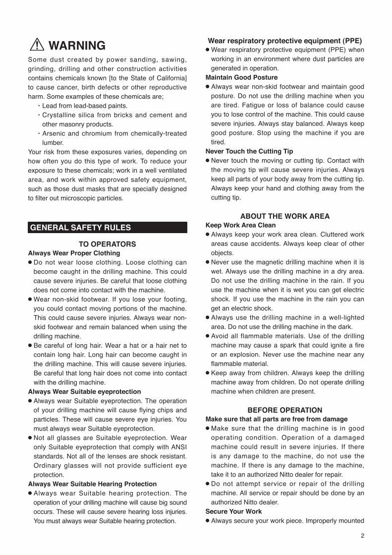
Wear respiratory protective equipment (PPE)● Wear respiratory protective equipment (PPE) when
working in an environment where dust particles are generated in operation.
Maintain Good Posture● Always wear non-skid footwear and maintain good
posture. Do not use the drilling machine when you are tired. Fatigue or loss of balance could cause you to lose control of the machine. This could cause severe injuries. Always stay balanced. Always keep good posture. Stop using the machine if you are tired.
Never Touch the Cutting Tip● Never touch the moving or cutting tip. Contact with
the moving tip will cause severe injuries. Always keep all parts of your body away from the cutting tip. Always keep your hand and clothing away from the cutting tip.
ABOUT THE WORK AREAKeep Work Area Clean● Always keep your work area clean. Cluttered work
areas cause accidents. Always keep clear of other objects.
● Never use the magnetic drilling machine when it is wet. Always use the drilling machine in a dry area. Do not use the drilling machine in the rain. If you use the machine when it is wet you can get electric shock. If you use the machine in the rain you can get an electric shock.
● Always use the drilling machine in a well-lighted area. Do not use the drilling machine in the dark.
● Avoid all flammable materials. Use of the drilling machine may cause a spark that could ignite a fire or an explosion. Never use the machine near any flammable material.
● Keep away from children. Always keep the drilling machine away from children. Do not operate drilling machine when children are present.
BEFORE OPERATIONMake sure that all parts are free from damage● Make sure that the drilling machine is in good
operating condition. Operation of a damaged machine could result in severe injuries. If there is any damage to the machine, do not use the machine. If there is any damage to the machine, take it to an authorized Nitto dealer for repair.
● Do not attempt service or repair of the drilling machine. All service or repair should be done by an authorized Nitto dealer.
Secure Your Work● Always secure your work piece. Improperly mounted

3
work can become loose. This can cause severe injuries. Always secure all work.
● Always use a vice or a clamp. Do not attempt to hold any work piece with your hand. Attempting to hold a work piece with your hand may cause severe injuries. Always use a vice or clamp to hold the work piece.
● Always secure your drilling machine. Improperly mounted drilling machine can come loose. This can cause severe injuries. Always secure the drilling machine.
Avoid Clutter● Always stay clear of other objects. Cluttered work
areas cause accidents. Always keep a clean work area and stay away from other objects.
A l w a y s R e m o v e S p a n n e r Wr e n c h e s a n d Adjustment Tools● Always remove spanner wrenches and adjustment
tools after adjustments have been made to the drilling machine. Always remove all adjustment tools before using the drilling machine.
Always Use a Cutter that is Appropriate for Your Work● Always use a cutter that is appropriate for your
work. Avoid heavy-duty work that is the beyond the capacity of your drilling machine. If the work exceeds the capacity of your drilling machine, this can cause accidents and severe injuries. Always use the drilling machine in accordance with its performance specifications.
SAFE HANDLING● Never leave the magnet ic dr i l l ing machine
unattended while it is running. When the machine is unattended, disconnect the power source. Do not leave the work area until the machine comes to a complete stop. Operating the machine while it is unattended can case accidents that may result in severe injuries.
HOW TO STORE YOUR MAGNETIC DRILLING MACHINE● Always store the machine in a dry area.● Always keep the machine out of the reach of
children.HOW TO CARRY YOUR MAGNETIC DRILLING MACHINE● Disconnect the power and turn off the machine
whenever you carry the machine.
MAINTENANCEDo not take apart or modify your magnetic drilling machine.● Do not attempt to disassemble or modify your
magnetic drilling machine. ● Do not modify your magnetic drilling machine.
Modifications can cause accident and severe injuries.
● All service and repairs must be performed by an authorized Nitto dealer. Any attempt to service or repair the machine yourself may result in an accident and severe injuries.
Check all Parts for Damage.● Always inspect the magnetic drilling machine before
use.● Always check that the pilot pin and cutter are in
good condition. Use of the machine with worn pilot pins or worn cutter can cause accidents and severe injuries.
● Inspect all cutter before you put them on the magnetic drilling machine.
● Do not operate the magnetic drilling machine with a damaged or worn cutter. Do not operate the machine with a damaged or worn pilot pin. Do not operate the machine with any damaged accessory. Operating the machine with any damaged part or accessory can cause accidents and severe injuries. If there is any damage to the magnetic drilling machine do not operate the machine. Take it to an authorized Nitto Dealer for repair.
● Always have the magnetic drilling machine repaired at an authorized Nitto dealer. Always take the magnetic drilling machine to an authorized Nitto dealer for service, repair and replacement parts. If you cannot locate an authorized Nitto dealer near you, please contact your sales representative.
● Always use Nitto genuine parts. The use of improper or non-Nitto parts can cause accidents and severe injuries. Never use unauthorized parts. To obtain genuine Nitto parts, contact your sales agent.
● Do not remove any nameplate from your magnetic drilling machine. Do not remove any labels from your magnetic drilling machine. If any label or nameplate is damaged contact your sales agent for a replacement.
POWER TOOL SAFETY
WARNING● Always make sure that the machine is properly
grounded. If the machine is not properly grounded, someone can get an electric shock.
● If you have any doubt about the grounding of the magnetic drilling machine, contact a licensed electrician.
● Never connect the grounding conductor to a gas

4
pipe. This will result in an explosion and severe injuries or death.
● Always check the grounding conductor. If you have any doubts about the grounding conductor contact a licensed electrician.
● Wiring connections to a grounding rod require the expertise of a licensed electrician. Do not attempt the wire connections yourself. Always contact a licensed electrician.
● Do not abuse the power cord. A damaged power cord can cause an electrocution. A damaged power cord can cause fires. Always inspect the cord. If the cord is damaged, do not use the magnetic drilling machine.
● Do not carry the machine by the cord. Do not pull the cord to disconnect it from a socket.
● The cord can become damaged from heat, contact with sharp objects or from being twisted. Always inspect the cord. Do not use the machine if the cord is damaged.
● Always use a ground fault circuit interrupter. The use of a ground fault circuit interrupter may be required by government regulations. The failure to use a ground fault circuit interrupter may result in electric shock.
● Avoid starting the magnetic drilling machine abruptly or unintentionally.
● Always make sure that the switch is turned off before connecting the power source.
● Always disconnect the power source and turn off the switch before setting up for work operations. Always disconnect the power and turn off the switch when inspecting work. Always disconnect the power and turn off the switch before attempting any maintenance. Failure to disconnect the power and turn off the switch during set up, inspection or maintenance can cause accidents and severe injuries.
ABOUT YOUR NITTO PORTABLE MAGNETIC DRILLING MACHINE
DANGERDo not use your portable drilling machine on the ceiling.● Use of the portable drilling machine on the ceiling
is dangerous. The machine could fall. The falling machine could cause severe injuries or death. (Fig.1)
Fig. 1
WARNINGDo not use the Magnet for more than five hours.● More than five hours of uninterrupted operation may
cause a fire. Five hours of uninterrupted operation generates extreme heat in the Magnet. This heat can cause a fire. Do not touch the Magnet. When the Magnet is hot, touching it will cause a severe burn injury. Never use the Magnet for more than five continuous hours. When you are not using the Magnet, turn the switch to the "OFF” position and pull the plug out of the power source.
Do not use the Drill Motor for over 30 minutes.● Uninterrupted operation of the Drill Motor for over 30
minutes generates heat. This heat can cause a fire. Never use the Drill Motor for over 30 minutes. When you are not using the Drill Motor, turn the switch to the "OFF' position and pull the plug from the power source.
Use only on magnetic materials.● Your portable drilling machine cannot be used
on non-magnetic materials, such as aluminum, stainless steel, copper or alloys. The Magnet will not work on non-magnetic materials. Attempting to use the Magnet on non-magnetic materials could cause an accident.
Use caution during wall operation.● When using your portable magnetic drilling machine
on a magnetic wall, always use caution. ● Never stand under the machine. * Never allow anyone to stand under the machine. * Never put any part of your body under the
machine. * If the machine falls, it could result in severe injury
or death.● Always remove cutting oil from the tank before using
the machine on a wall. You must manually apply cutting oil to the cutting tool.
5
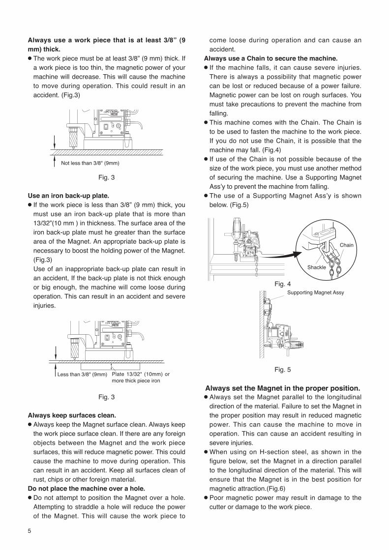
Always use a work piece that is at least 3/8” (9 mm) thick.● The work piece must be at least 3/8” (9 mm) thick. If
a work piece is too thin, the magnetic power of your machine will decrease. This will cause the machine to move during operation. This could result in an accident. (Fig.3)
Not less than 3/8" (9mm)
Fig. 3
Use an iron back-up plate.● If the work piece is less than 3/8” (9 mm) thick, you
must use an iron back-up plate that is more than 13/32”(10 mm ) in thickness. The surface area of the iron back-up plate must he greater than the surface area of the Magnet. An appropriate back-up plate is necessary to boost the holding power of the Magnet. (Fig.3)
Use of an inappropriate back-up plate can result in an accident, If the back-up plate is not thick enough or big enough, the machine will come loose during operation. This can result in an accident and severe injuries.
Less than 3/8" (9mm)
Plate 13/32" (10mm) or more thick piece iron
Fig. 3
Always keep surfaces clean.● Always keep the Magnet surface clean. Always keep
the work piece surface clean. If there are any foreign objects between the Magnet and the work piece surfaces, this will reduce magnetic power. This could cause the machine to move during operation. This can result in an accident. Keep all surfaces clean of rust, chips or other foreign material.
Do not place the machine over a hole.● Do not attempt to position the Magnet over a hole.
Attempting to straddle a hole will reduce the power of the Magnet. This will cause the work piece to
come loose during operation and can cause an accident.
Always use a Chain to secure the machine.● If the machine falls, it can cause severe injuries.
There is always a possibility that magnetic power can be lost or reduced because of a power failure. Magnetic power can be lost on rough surfaces. You must take precautions to prevent the machine from falling.
● This machine comes with the Chain. The Chain is to be used to fasten the machine to the work piece. If you do not use the Chain, it is possible that the machine may fall. (Fig.4)
● If use of the Chain is not possible because of the size of the work piece, you must use another method of securing the machine. Use a Supporting Magnet Assʼy to prevent the machine from falling.
● The use of a Supporting Magnet Assʼy is shown below. (Fig.5)
Fig. 4Supporting Magnet Assy
Fig. 5
Always set the Magnet in the proper position.● Always set the Magnet parallel to the longitudinal
direction of the material. Failure to set the Magnet in the proper position may result in reduced magnetic power. This can cause the machine to move in operation. This can cause an accident resulting in severe injuries.
● When using on H-section steel, as shown in the figure below, set the Magnet in a direction parallel to the longitudinal direction of the material. This will ensure that the Magnet is in the best position for magnetic attraction.(Fig.6)
● Poor magnetic power may result in damage to the cutter or damage to the work piece.
Shackle
Chain

6
Fig. 6
Be careful about chips.● Keep your hands away from the cutting area at all
times. During drilling, there will be chips. The chips are sharp. The chips are rotating with the cutter. Any contact with the chips can cause severe injuries.
Do not touch the slug.● Do not touch the slug. The slug is very hot. It will
cause severe burns. Make sure that no one touches the slug. Make sure that there is no one below the work area during operation. Hot slugs will fall. Hot slugs can cause severe burns, other severe injuries, or even death. Always wear protective equipment, including protective headgear, eye protection, hearing protection, and gloves. Do not allow any person without protective equipment to come near the machine.
Do not use your hands to remove chips.● Chips have sharp edges. Use a screwdriver to
remove chips. If you use your hands to remove chips, you can be injured, even if you are wearing gloves. Do not use your hands to remove chips under any circumstances.
The cutting edge is sharp.● The cutting edge is sharp. If you do not wear gloves,
you will be cut. Attempting to change the cutter can result in severe injuries.
Do not use Cutting Oil for other purposes.● Cutting Oil should be used only for drilling. Please
refer to Section 5-5 of this manual for further warnings and instructions about Cutting Oil.
The Drill Motor will stop automatically when drilling operation is completed. If the Drill Motor fails to stop automatically, turn off the Motor Switch to stop it and then contact sales agent from which you have purchased your machine or an authorized dealer near you for repair.
CAUTIONDo not use power that is generated by an engine-driven welder.● The use of an engine-driven welder as a power
source may cause your magnetic driven machine to
malfunction, Power from an engine-driven welder can damage the electronic circuits in your portable drilling machine.
Use a Proper extension cord.● Do not use an extension cord that is too thin. Do
not use an extension cord that is too long. Do not use an extension cord that is wound on a drum. Do not share an extension cord with other motor-driven tools. These uses can cause voltage to drop and can reduce the holding power of the magnet, causing the machine to move during operation. This can decrease performance and may cause damage to the machine. (Fig.7)
Extension Cord
Max lengthSize (nominal cross-section area of the conductor)
10 m (32.8ft) Min 1.25 mm2 (AWG16)20 m (65.6ft) Min 2 mm2 (AWG14)30 m (98.4ft) Min 3.5 mm2 (AWG12)
Fig. 7
Do not use this machine on the steel material being electrically welded.● When the electric welder is not properly grounded,
electricity will run through the Atra Ace machine v ia i ts Magnet , causing possib le fa i lure or malfunctioning, which in turn may cause accident.
Do not force to feed cutter when drilling manually.● Because the Hi-Broach and Jet-Broach have
rather thin cutting edges with less cutting pressure resistance as compared to twist drill, do not force to feed the cutter when drilling manually.
If you feed it with too much force, the cutter may break or end up with shorter life than otherwise.
Always use a compatible Pilot Pin.● The Pilot Pin must be compatible with the cutter. An
improper Pilot Pin may result in an accident. See Section 5-3 to identify compatible Pilot Pins and cutters. The proper Pilot Pin to be used will vary, depending on the type of cutter, the diameter of the cutter, and the length of the cutter.
Do not switch to auto while drilling in manual mode.● When you want automatic drilling, set the machine

7
to auto mode first and then start drilling. Do not switch over to auto mode in the middle of
manual drilling operation: the Drill Motor may come to a stop if you do so.
Do not apply manual force when feeding in auto mode.● Do not apply force to the Rod Handle when feeding
in auto mode (with the Rod Handle pushed toward the machine).
Do not start drilling with manual feed.● Do not start drilling with manual feed. Once you
have started with manual feed, however, you must not change mode to automatic feed half way through the operation because the Drill Motor may come to a stop making it impossible to complete the hole.
Leaving the machine alone in a subzero C˚ environment for many hours may cause Drill Motor start-up failure at the initial startup. This is nothing unusual. Set the auto-feed switch to OFF (with the Rod Handle pulled out toward the operator) and run the machine idly for a few minutes. That should take care of initial startup failure.
1. APPLICATION
This is a portable drilling machine with a Magnet, geared to drilling mild steel (or equivalent) using One-Touch type Jet-Broach or Hi-Broach. The machine will be mounted on the workpiece to be drilled with the Magnet securely fastening the machine to the workpiece while drilling takes place.
2. RECEIVING INSPECTION
Upon unpacking, check to see that the shipment is complete without damage or oil leakage in transport.Should you find any damage or short-shipment, please contact sales agent through which you have purchased your machine or an authorized dealer near you for corrective actions.
Package Contents Q’ty CheckATRA ACE 1setPilot Pin 08035 1Hex. Socket Screw Key 3 1Spanner 8X10 1Cutting Oil 0.5ℓ Can 1Side Handle 1Chain 1Guard 1Instruction Manual 1

8
3. PART NAME
Fig. 8

9
4. FUNCTIONS OF ELECTRONIC CONTROL
4-1. Overload Detecting FunctionWhen overload occurs during drilling operation, the overload detector puts the following functions to work. Please note, however, that there may be cases where the overload detector does not work properly if power is drawn from an engine generator with fluctuating output voltage, sometime tool high and sometime too low.
● Automatic Feed Rate Control FunctionAutomatic drill feed starts slowly for the first few seconds and then it picks up speed automatically to an appropriate level in terms of cutting load applied to the cutter. In addition, a cutter diameter factor is also taken into account for automatic feed rate control.
● Automatic Stop FunctionOver load to the Dr i l l Motor o r feed motor automatically stops the drill and ongoing feed, preventing possible damage to the machine and cutter. However, if a worn or blunt cutter is being used, it may break.
4-2. Automatic Cycle Stop FunctionWhen drilling operation is complete with the machine relieved of cutting load, the Drill Motor stops automatically.
4-3. Limit Switch FunctionEven if the automatic cycle stop function fails to operate and the drill continues to feed down, the Limit Switch will stop the down-feed near the lower limit of the stroke and the Drill Motor.
4-4. Lateral-Shifting Detection FunctionThis function stops drill feed and the Drill Motor when lateral shifting of the Magnet is detected.
4-5. Re-Start Prevention FunctionThe re-start prevention function comes into play when power failure is restored that has occurred during operation. Thanks to this feature, when a plug that has been disconnected during operation is re-plugged into the receptacle or when power failure is restored that has occurred during operation, the Drill Motor will NOT restart automatically preventing possible accident -- although Magnet lamp will come on and magnetic power restored. To resume operation, turn ON the Motor Switch on the side of the machine to start the Drill Motor.
4-6. Magnet Interlocking FunctionWhen the Magnet fails the Drill Motor will not start revolving. To repair defective Magnet, please contact sales agent through which you have purchased your machine or an authorized dealer near you.
5. MACHINE SETUP
WARNING● When setting up machine, turn off the Magnet
Switch and disconnect the power supply plug from power source.
5-1. Mounting Parts Mount the Side Handle on the Drill Motor.
5-2. Using Cutter
CAUTION● Use One-Touch type cutters only. ● For better workability and safety, do not use
worn or damaged cutters.
5-3. Combination of Cutter and Pilot Pin CAUTION● Do not use any other combinations than those
shown in the compatibility table.
Use a Pilot Pin appropriate for the cutter. (Fig.9)A Pilot Pin to be used varies depending on the cutter type, diameter, length (depth). A wrong combination of cutter and Pilot Pin would not allow slug to be ejected at the end of drilling and/or prevent Cutting Oil from reaching the cutting point, resulting in cutting tool damage.
06025 PN:TK01167
08025 PN:TJ12696
06050 PN:TK01166
0850 PN:TK00802
HBO 14 - 17 dia.Depth 25 mm
HBO 17.5 - 35 dia.Depth 25 mm
HBO 14 - 18 dia.Depth 50 mm
JBO 17.5 - 35 dia.Depth 35 mm
JBO 17.5 - 35 dia.Depth 50 mm
JBO 17.5 - 35 dia.Depth 75 mm
HBO 19 - 35 dia.Depth 50 mm
PILOT PIN HI-BROACH Cutters
PILOT PIN JETBROACH Cutters
08050 PN:TJ16019
08035 PN:TJ15859
08050 PN:TJ16019
08075 PN:TJ17436
6.35 dia.
6.35 dia.
8 dia.
100 mm
7 dia.
112 mm8 dia.
91 mm8 dia.
112 mm8 dia.
5 dia.
8 dia.
81 mm
76 mm
5 dia.
112 mm
133 mm8 dia.
Fig. 9

10
5-4. Mounting/Removing Cutter
WARNING● Do not use any other combinations of Pilot
Pin and cutter than those shown in the compatibility table.
● Wear safety gloves when replacing cutter.
(1) Bring the Drill Motor up by turning the Rod Handle clockwise. (Fig. 10)
Fig. 10
(2 ) I nse r t a P i l o t P in , appropriate for the cutter s ize, into the cutter. (Fig.11)
(3) Align the depression in the cutter with the white line on the Sleeve, and then insert the cutter.
When you insert the c u t t e r f a r e n o u g h the S leeve w i l l tu rn clockwise and lock with a clicking sound..
* W h e n y o u f i n d i t h a r d t o i n s e r t t h e cutter, turn the Sleeve counterclockwise and do over. (Fig.12)
(4) To remove the cutter, t u r n t h e S l e e v e counterclockwise.
The cutter will come off. (Fig.13)
5-5. Preparation of Cutting OilCutting Oil Safety Precautions
WARNING(1) Use● Use Cutting Oil for cutting purpose only. Do not use
it for household purposes(2) Handling Precautions ● The Cutting Oil contains amine. Do not mix it up
with rust inhibitor, etc. containing nitrite.● Wear safety glasses for eye protection when
handling Cutting Oil: eye injury may results if it gets into your eyes.
● Wear protective gloves for hand protection when handling Cutting Oil: skin injury may result if it comes into contact with your skin.
● Wear respirator when exposure to respiratory hazards with oil mist or vapor is anticipated. Inhalation of oil mist or vapor may make you feel sick.
● When diluting Cutting Oil, follow the instructions per the Operation Manual.
● Keep Cutting Oil out of reach of children.● Do not drink Cutting Oil.(3) First Aid● If Cutting Oil gets into your eyes, immediately open
your eyelids with your fingers and wash your eyes with plenty of water for at least 15 minutes. If your eyes feel irritated, consult with a medical doctor and follow his/her instructions.
● If Cutting Oil comes into contact with your skin, immediately wash it away with plenty of water and soap. Take off contaminated clothes. Clean the clothes if you need to wear it again. If your skin feels irritated, consult with a medical doctor for medical instructions.
● If someone inhales oil mist or vapor, immediately take him/her to an area where fresh air is abundant and wrap up his/her body with a blanket, etc. to keep body temperature. Have him/her take a rest and consult with a medical doctor for medical instructions.
● If someone drinks Cutting Oil, immediately make him/her drink plenty of water and vomit it. Consult with a medical doctor for medical instructions. When unconscious, do not pour water into his/her mouth nor induce him/her to vomit.
(4) Instructions in Case of Fire● If fire breaks out in the vicinity, wear PPE (personal
protective equipment) and use foam, powder or CO2 fire extinguisher to put the fire out from the windward.
Rod Handle
Downward Upward
Pull down out of the body
Fig. 11
Fig. 12
Fig. 13
Pilot pin
Cutter
Spindle Arbor
Turn the Sleeveto the left
Spindle Arbor
Pull out
Sleeve
White line
Depression
Align
Sleeve
11
(5) Storage● When storing Cutting Oil after use, put it into a
container and put a lid on for tight sealing so that dust or moisture, which is a catalyst for contamination, may not get in.
● Avoid direct sunlight, rainwater or the like and store Cutting Oil in a dim cool area.
(6) Disposal● For disposal of concentrate solution and used fluid,
request a waste-disposal company to dispose them as industrial waste in accordance with the local laws and regulations.
● Treat f lushing water through pH adjustment, condensation/sedimentation, activated sludge process, activated carbon adsorption, etc., and discharge it in accordance with the regulations of your local municipal bylaw.
● Residual dross will remain in an emptied container: be careful when handling an empty container.
(7) Others● When Cutting Oil is poured into another container
for use, post chemical and label information at the site where it is kept. At the same time, keep the Operation Manual handy so that it can be referred to whenever necessary.
● For further details, contact us for product safety data sheet.
● All the information and descriptions that have been provided are based on the currently available documents and information, which may be revised upon our new recognition and/or discovery.
● The precautions provided apply to regular handling. If special handling method is used, take safety measures that are suitable for your applications and usage.
● The information contained herein is for your reference purpose only, to which we make no warranty of any kind and for which we shall not be held responsible.
Preparation of Cutting Oil(1-1) Use our genuine-product Cutting Oil (blue).
I f other Cutt ing Oil is used, the cutt ing performance and service life of cutter would be decreased.
(1-2) Use tap water to dilute Cutting Oil by 8- to 10-fold. Do not use well water.
(1-3) The oil tank is of the stationary type.Remove the rubber cap and pour Cutting Oil from the Oil Tank inlet. Do not spill Cutting Oil on the machine.
5-6. Connecting the Power Supply Plug to Power Source
● Before connecting the power supply plug to power source, turn off the switch.
Always use the correct voltage for power source.
6. MACHINE OPERATION
WARNING● Always Wear Safety Glasses.● Always Wear Hearing Protection.● Wear respiratory protective equipment.● Never touch the mounted cutter and the rotating
parts of the machine such as the Spindle Arbor after the power cable is connected to power source.
CAUTION● Do not use hard material such as a screwdriver,
to operate the Motor Switch. This may damage the panel and switch, which would lead to machine failure.
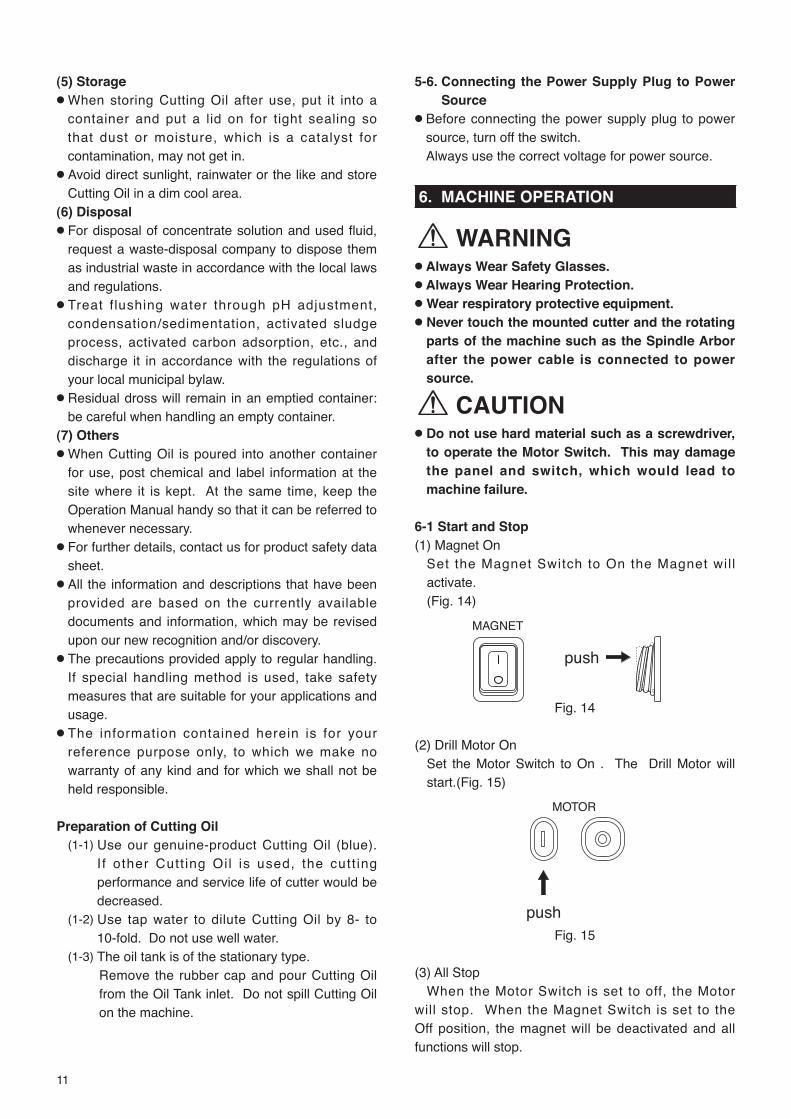
6-1 Start and Stop(1) Magnet On
Set the Magnet Switch to On the Magnet wil l activate.(Fig. 14)
MAGNET
push
Fig. 14
(2) Drill Motor On Set the Motor Switch to On . The Drill Motor will start.(Fig. 15)
MOTOR
pushFig. 15
(3) All StopWhen the Motor Switch is set to off, the Motor
will stop. When the Magnet Switch is set to the Off position, the magnet will be deactivated and all functions will stop.

12
6-2. Drilling Procedure(1) Punch Marking
Put a rather large punch mark in the workpiece by driving a punch down with a hammer. The punch mark will be used as a guide for drilling operation that follows, so it must be made in accurate position. (Fig.16)
Punch Mark
Fig. 16(2) Keep the Magnet and Workpiece Contacting
Surfaces Clean.
WARNING● Always keep surfaces clean.
Always keep the Magnet surface clean. Always keep the work piece surface clean. If there are any foreign objects between the Magnet and the work piece surfaces, this will reduce magnetic power. This could cause the machine to move during operation. This can result in an accident. Keep all surfaces clean of rust, chips or other foreign material.
(3) Aligning with Punch Mark.Turn the Rod Handle counterclockwise to slightly lower the cutter and align the tip of Pilot Pin to the punch mark. (Fig.17)
Fig. 17(4) Magnet ON
CAUTIONMake sure the magnet is clinging to the workpiece.
Set the Magnet Switch to On and the magnet will be activated. (Fig. 18)
push
MAGNET
(Fig. 18)
WARNING● Check to see that Magnetic power is at work.
Turn on the Magnet Switch. The switch lamp will glow and magnetic power will come on.
(5) Controlling Cutting Oil Flow.Open the P-Valve and turn the Rod Handle. The Pilot Pin will move up allowing Cutting Oil to flow.
(6) Mounting the GuardMounting the Guard as shown. (Fig.19)
Guard
Fig. 19
(7) Drill Motor ON
CAUTIONDo not touch the rotating parts.
Set the Motor Switch to On . The Drill Motor will start. (Fig. 20)
(Fig. 20)
WARNING● Do not touch revolving parts.
Press the Drill Motor ON Switch to start the Drill Motor
(8) DrillingAutomatic Feed
CAUTION● Once drilling feed has started, do not touch the
Rod Handle until drilling cycle is complete.
To start automatic feed, push the Rod Handle toward the machine. As the cutter will be fed at low speed at the start you do not have to use manual feed. (Fig.21)
Automatic feed
Fig. 21
Punch Mark
ONOFF
Rod Handle
MOTOR
push

13
CAUTION● Do not use automatic feed when the workpiece
has a tapered bottom surface through which a hole is to be drilled.
When putting a hole through workpiece with a tapered bottom surface or bottom surface with a radius, such as angle, channel, H-section steel, etc., use low feed rate at the start as well as toward the end of drilling operation where the likelihood of tool chipping is high. (Fig.22)
R
Fig. 22
(9) Finishing Drilling Operation
WARNING● When drilling cycle is complete, the Drill Motor
will stop automatically. If it does not, it is a machine failure. Turn off the Motor Switch and contact sales agent through which you have purchase your machine or an authorized dealer near you for repair.
● Be alert at the end of drilling operation when slug will automatically pop out. Do not touch slug: it is very hot and has sharp edges.
When drilling cycle is complete, the Drill Motor will come to a complete stop automatically. Once it has come to a stop, pull the Rod Handle outward away from the machine and turn off the automatic feed switch. Turn the Rod Handle clockwise to raise the Drill Motor. Then promptly turn off the Magnet Switch. If a Magnet is left alone with its switch turned on for many hours, electric current will keep flowing through the Magnet at the cost of shortened service life.
(10) Removing SlugDo not proceed to the next operation without removing the slug from the operation just finished. At the end of drilling operation slug will pop out automatically ejected by the spring-operated Pilot Pin. Should a slug left in the hold sticking, remove it from the hole by tapping the collar of the slug with a needle stick or something. (Fig.23)
Fig. 23
6-3. Drilling Oblong Hole
CAUTION● Always drill oblong hole manually and slowly.
Drill oblong hole in the order of ① , ② , ③ . For the steps ② and ③ , use manual feed and take care so that the cutter may not be fed into the workpiece with too much force. If automatic feed is used, damage to the cutter or unexpected accident may result. Use a file to take off any sock that is left unmachined. Spacing between each step of drilling operations should be so arranged that the Pilot Pin will always hit the sold material yet to be machined. (Fig.24)
Fig. 24
6-4. Drilling Stacked Plates
CAUTION● Remove slug as each plated is f inished:
otherwise, being blocked by the slug left unremoved, the cutter cannot cut into the next layer of plate, which results in the Magnet base being pushed up possibly causing accident.
● For stacked plates drilling, always use manual feed and drill slowly and carefully.
● Before drilling stacked plates, securely clamp the plates together in place.
● When drilling stacked plates, retract the cutter as each layer of plate is finished in order to remove slug from the drilling area, then put another hole in the next layer of plate.
File away any excesses

14
7. TROUBLESHOOTING
WARNING● Never attempt to repair machine yourself: injury or damage to equipment may result. ● Please feel free to consult the sales agent through which you have purchase your machine or an
authorized dealer, when the following symptoms appear or when you have any questions about our products.
This machine is electronically controlled. It will stop when it picks up noise from power source or when malfunction occurs to the electronic control. When you notice the following symptoms, pull the Rod Handle outward away from the machine to turn OFF automatic feed and raise the Drill Motor to ensure safety and conduct inspection.
Problem Causes Solutions
Switch lamp does not come on when Magnet Switch is turned on.
Power supply plug is not connected to socket.
Connect power supply plug to socket.
Dri l l Motor does not start when Motor Switch is turned on.
Magnet is disconnected. Request for repair.
Limit switch is activated near the lower limit of drill stroke.
Slightly raise Drill Motor and release limit switch.
Dr i l l Motor s tops dur ing d r i l l i ng . (Magnet i s no t working with Magnet lamp not illuminating.)
Power failure has occurred or power supply plug is disconnected.
After power failure is restored or power supply plug is re-connected, turn on Motor Switch again.
Drill Motor stops completely in the m idd le o f d r i l l i ng operation.
No Cutting Oil or insufficient Cutting Oil Increase flow rate of Cutting Oil.
Cutting edges jammed and stuck with cutting chips.
Remove.
Worn cutting edge. Regrind or replace with new one.Using cutter of other make Use Nitto brand cutter.Using Cutting Oil of other made. Use Nitto brand Cutting Oil.
Switching over to auto feed in the middle of operation that started with manual feed.
Use the automatic feed from the beginning.
Temporal glitch with electronic control. Restart .Overload protection triggered Restart .
Lateral shifting of Magnet is detected by lateral position sensor, bringing machine to a compete stop.
Workpiece too thin. Use back-up plate: thickness 13/32” (10 mm) or more.
Chips under Magnet base. Clean it up.Worn cutting edge. Regrind or replace with new one.Effective Magnetic force too weak. Ask for repair.
Drill Motor does not come to a stop when drilling operation is complete.
Near-exit restarting Normal.Motor Switch OFF
Almost no cutting pressure throughout drilling operation (workpiece too thin.)
Normal.Motor Switch OFF
No lubrication to Arbor Body or needle bearing.
Lubricate.
Dr i l l Mo to r s tops w i th in several seconds after Motor Switch is turned on.
Frozen machine Turn on and off the switch several times to warm up machine.

15
8. MAINTENANCE/SERVICE
WARNING ● Always disconnect the power and turn off the
switch before attempting any maintenance. Failure to disconnect the power and turn off the switch during set up, inspection or maintenance can cause accidents and severe injuries.
● Check to see periodically that mounting screws are tight. If you find them loose, retighten.
8-1. Tighten Set Screw When Machine is Not UsedFor the purpose of safety, when you do not use the machine temporally or on a long-term basis, raise the Drill Motor and set it in position with the Set Screw so that it will not come down on its own weight. If you leave the machine alone with the Drill Motor in a lowered position, the Pilot Pin and/or cutter may be damaged when the machine is relocated. (Fig.25)
8-2. Grease the Sliding Surfaces from Time to TimeGrease the machine body and Slide Board from time to time. (Fig.25)
8-3. Slide Board Clearance AdjustmentExcessive clearance between the machine body and Slide Board would deteriorate not only drilling performance but also cutting tool life to a substantial degree. If you find excessive clearance, make adjustment by tightening 5 slide board adjusting screws on the side of the machine using the same torque all round so that the Drill Motor will not come down on its own weight. (Fig.25)
8-4. Bracket Inspection and OilingAmong other things, drilling accuracy hinges on the Bracket that supports the Arbor Body. See that the (three Hexagon Socket) Bracket mounting bolts are tight, from time to time. (Fig.25)
��������
���� �
����
�������
������
��������
�����������
���
��������
���������
����������������!���������
���#
��#�������$ �������$
����$�����
�����������
Fig. 25
8-5. Keep the Tip of Pilot Pin SharpWhen the tip of Pilot Pin gets dull, it sometimes fails to seat into punched hole, causing drilling accuracy to deteriorate. See that the tip is sharp from time to time. If you find it too dull, regrind or replace as required. When regrinding do so carefully, for grinding with too much force may cause the tip to get dull or soften the material to such a degree that it is no longer usable. (Fig.26)
Fig. 26
8-6. Recovery Measures When Pilot Pin Gets Jammed
When you change cutting tool you also change Pilot Pin, which acts as a guide for the cutting tool. However there are times when the pin does not come off easy with cutting chips in the clearance between the cutting tool and pin, causing jamming. In such case, tap the tip of Pilot Pin with a wooden hammer, etc., and pull it off. (Fig.27)
Sharpenthe tip
Optimal angle 70°
Pilot Pin

16
Fig. 27
8-7. Cutter RegrindingWhen you need to regrind cutter, please contact sales agent through which you have purchased your machine or an authorized dealer near you.
8-8. Carbon Brushes Inspection and ReplacementCheck Carbon Brushes for wear periodically.When the length of Carbon Brushes gets as short as 5/16” (8 mm), replace it with a new one, for, if you do not, chances are that you will have a rectification problem which may cause machine failure. (Fig.28)(1) Loosen the tap screws to remove the cap.(2) Take out the Carbon Brush and replace it with a
new one.(3) Put the cover on and securely tighten the tap
screws. When tightening the tap screws, see that the tap screws are screwed in along the existing screw threads – without cutting new threads.
(4) After replacement, run the machine with no load for approx. 10 minutes.
Fig. 28
Fig. 29
9. OPTIONAL PARTS
9-1. Nitto-Brand Cutting Oil
CAUTIONUse Nitto-brand Cutting Oil for Atra Ace.
Part No. Part NameTB01507 Cutting Oil 2ℓ(Light Blue)
9-2. Pilot Pin(metric sizes)
Part No. Part Name Depth(mm) Applicable cutter (mm)
TK01167 Pilot Pin 0602525
Hi-broach 14 - 17 dia.
TJ12696 Pilot Pin 08025 Hi-broach 17.5 - 35 dia.TJ15859 Pilot Pin 08035 35 Jetbroach 17.5 - 35 dia.
TK01166 Pilot Pin 0605050
Hi-broach 14 - 18 dia.
TJ16019 Pilot Pin 08050 Hi-broach 19 - 35 dia.(TK00802) Pilot Pin 0850 Jetbroach 17.5 - 35 dia. ※ ( ):Special Order
9-3. Supporting Magnet Assʼy
Part No. Part NameTB04374 Supporting Magnet Ass’y
9-4. Sleeve 6.5 Assʼy for Twist Drills (Fig.30)
Part No. Part NameTB02536 Sleeve 6.5 Ass’y
Sleeve 6.5
Hex. Socket Set Screwwith Cup Point 6X5
Fig. 30
Cutting Chips
Pilot Pin
Cutter

17
9-5. Chip BreakerWhen chips are not smoothly discharged during drilling, the overload detection will be frequently triggered to stop the Drill Motor, particularly when plate thickness is 1-3/8” (25 mm) or thicker. In such case, an optional Chip Breaker may be used to ease chip congestion.
9-5-1. Mounting Chip Breaker
CAUTION● When setting Chip Breaker, see that the tip of
blade may not come into contact with cutting tool.
Chip Breaker breaks cutting chips formed in drilling into small pieces and facilitates chip discharging.
Hex. Socket Head Cap Screw 5X12
Hex. Socket Head Cap Screw 6X10
Blade Base
Blade
0.5-0.8mm
Fig. 31
(1) Mount Blade Base. (Fig.31)● Use two Hex. Socket head Cap Screws 6 X 10
to mount the Blade Base on the front face of Magnet.Here, see that the bottom face of the Blade Base is flush with the bottom face of Magnet. When the bottom face of the Blade Base sticks out from the bottom face of the Magnet, the magnetic force it sends out can not be made fully use of for secure fastening.
● Use the Hex. Socket head Cap Screws 5 ×12 to mount a blade to the Blade Base in the direction as shown in the figure.
(2) Mount cutter.Loosen the Hex. Socket head Cap Screws 5× 12 and pull the Blade in the direction as shown by the arrow until it no longer moves. And then, mount a cutter.
(3) Set the blade.Set the Blade in the way that the cutter and the blade will have a clearance of 0.5 mm - 0.8mm and fasten it securely to the Blade Base with Hex. Socket head Cap Screws 5× 12.
9-5-2. Chip Breaker Ass’yPart No. Part NameTB05186 Chip Breaker Ass’y
(TQ04949) Blade(TQ04950) Blade Base(TP14178) Hex. Socket Head Cap Screw 6×10(TP01945) Hex. Socket Head Cap Screw 5×12
The part number with ( )are include in the Ass’y parts written above them.

18
TK00355 31 × 25 TK00356 32 × 25 TK00357 33 × 25 TK00358 33.5× 25 TK00359 34 × 25 TK00360 34.5× 25 TK00361 35 × 25
TK00347 24.5× 25 TK00348 25 × 25 TK00349 26 × 25 TK00350 26.5× 25 TK00351 27 × 25 TK00352 28 × 25 TK00353 29 × 25 TK00354 30 × 25
TK00339 20 × 25 TK00340 21 × 25 TK00341 21.5× 25 TK00342 22 × 25 TK00343 22.5× 25 TK00344 23 × 25 TK00345 23.5× 25 TK00346 24 × 25
Part No. Diameter×Depth Part No. Diameter×Depth Part No. Diameter×Depth Part No. Diameter×Depth TK00700 14 × 25 TK00701 15 × 25 TK00702 16 × 25 TK00703 17 × 25 TK00335 17.5× 25 TK00336 18 × 25 TK00337 19 × 25 TK00338 19.5× 25
9-6 Ordering parts
Hi-Broach One-touch Type (metric sizes)
Jetbroach One-touch Type (metric sizes)
Jetbroach One-touch Type (metric sizes)
TK00325 33 × 35 TK00326 34 × 35 TK00327 34.5× 35 TK00328 35 × 35
Part No. Diameter×Depth Part No. Diameter×Depth Part No. Diameter×Depth Part No. Diameter×Depth TK00317 26 × 35 TK00318 26.5× 35 TK00319 27 × 35 TK00320 28 × 35 TK00321 29 × 35 TK00322 30 × 35 TK00323 31 × 35 TK00324 32 × 35
TK00309 21.5× 35 TK00310 22 × 35 TK00311 22.5× 35 TK00312 23 × 35 TK00313 23.5× 35 TK00314 24 × 35 TK00315 24.5× 35 TK00316 25 × 35
TK00301 17.5× 35 TK00302 18 × 35 TK00303 18.5× 35 TK00304 19 × 35 TK00305 19.5× 35 TK00306 20 × 35 TK00307 20.5× 35 TK00308 21 × 35
TK00387 21.5× 50 TK00388 22 × 50 TK00389 22.5× 50 TK00390 23 × 50 TK00391 23.5× 50 TK00392 24 × 50 TK00393 24.5× 50
TK00380 17.5× 50 TK00381 18 × 50 TK00382 19 × 50 TK00383 19.5× 50 TK00384 20 × 50 TK00385 20.5× 50 TK00386 21 × 50
Part No. Diameter×Depth Part No. Diameter×Depth Part No. Diameter×Depth Part No. Diameter×Depth TK00394 25 × 50 TK00395 26 × 50 TK00396 26.5× 50 TK00397 27 × 50 TK00398 28 × 50 TK00399 29 × 50 TK00400 30 × 50
TK00401 31 × 50 TK00402 32 × 50 TK00403 33 × 50 TK00404 34 × 50 TK00405 35 × 50
19
9694
106
9593
90
220V-240V
220V-240V
101104
101
104
102
102
109
8889
919297111
9798
2
6
5 4
6
7 7 11
13
103
14
15
16
17
18
19
20
21
22
80
12
8 8 3
1
110
112
9
10
81
57
58
59
23
24 78
79
60
54
31
29 26
25
27
28
30
53
35
32
33 37
36
38
34
55
55 56
56
61 62 63
65 66 64
41
46
5 4
47
39 40 38
41
42
43 44
45
48
49
50
51
50
52
99 99 77 108
107
36
35
82
83 84 85 86
87
67
68
69
70 71
7266 76 73 74 75
101
104
105
89
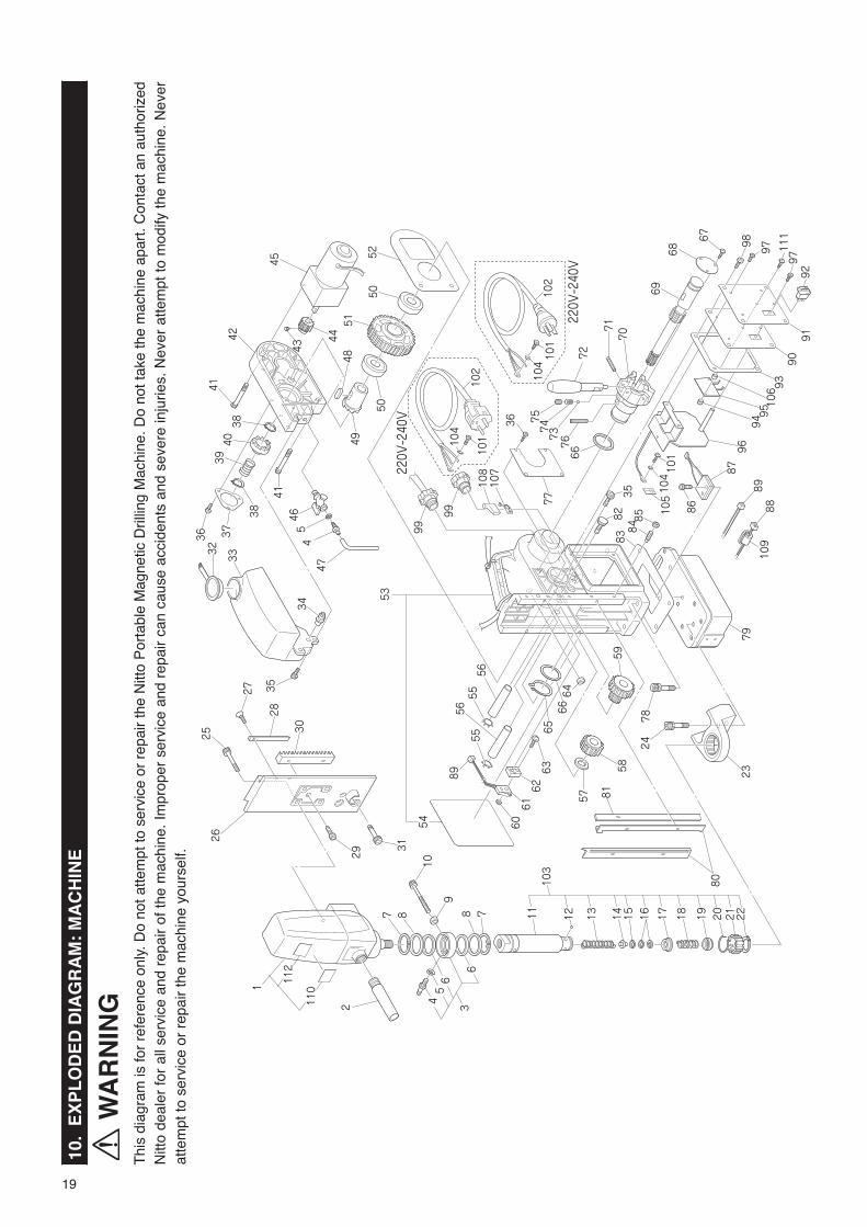
10.
EX
PL
OD
ED
DIA
GR
AM
: M
AC
HIN
E
WA
RN
ING
Thi
s di
agra
m is
for
refe
renc
e on
ly. D
o no
t atte
mpt
to s
ervi
ce o
r re
pair
the
Nitt
o P
orta
ble
Mag
netic
Dril
ling
Mac
hine
. Do
not t
ake
the
mac
hine
apa
rt. C
onta
ct a
n au
thor
ized
N
itto
deal
er fo
r al
l ser
vice
and
rep
air
of th
e m
achi
ne. I
mpr
oper
ser
vice
and
rep
air
can
caus
e ac
cide
nts
and
seve
re in
jurie
s. N
ever
atte
mpt
to m
odify
the
mac
hine
. Nev
er
atte
mpt
to s
ervi
ce o
r re
pair
the
mac
hine
you
rsel
f.

20
11.
AT
RA
AC
E W
A-3
500
PAR
TS
LIS
T
The
par
t num
bers
with
(
) a
re in
clud
ed in
the
Ass
'y p
arts
writ
ten
abov
e th
em.
No
.P
art
No
.P
art
Nam
eQ’ty
Price
1T
B05
148
Dril
l Mot
or A
ss’y
1set
110
(TQ
1156
5)La
bel A
rbor
War
ning
111
2(T
Q13
281)
Labe
l Sho
ck W
arni
ng1
-(T
B05
187)
Car
bon
Bru
sh A
ss’y
1set
2T
B02
534
Sid
e H
andl
e A
ss’y
1set
3T
B00
496
Oil
Rin
g S
ub A
ss’y
1set
4(T
P14
500)
Hos
e N
ippl
e2
5(C
P21
947)
Pac
king
S-4
.7×
8×
0.8
26
(TP
1449
9)O
il S
eal G
D38×
48×
42
7T
P14
969
Ext
erna
l Ret
aini
ng R
ing
ISTW
-38
28
TP
1277
3W
ashe
r 38
.5×
54×
12
9LP
1049
6H
ex. N
ut T
ype
1 M
61
10T
P05
469
Hex
. Soc
ket H
ead
Cap
Scr
ew 6×
451
103
TB
0512
1A
rbor
Bod
y A
ss’y
1set
11(T
Q06
755)
Arb
or B
ody
112
(TB
0167
2)B
all 5
/16
Ass’y
1set
13(T
P15
998)
Spr
ing
1.6×
16.2×
120
114
(TQ
0189
5)P
ilot S
pace
r1
15(T
P15
848)
Spa
cer
10.5×
19×
51
16(T
P13
905)
Inte
rnal
Ret
aini
ng R
ing
ISTW
-19
217
(TB
0134
8)W
ashe
r Ass’y
1set
18(T
Q01
898)
Spr
ing
0.8×
12×
311
19(T
B01
349)
Pus
h R
ing
Ass’y
1set
20(T
Q01
896)
Rot
atin
g S
prin
g1
21(T
Q01
897)
Sle
eve
122
(TP
1523
9)E
xter
nal R
etai
ning
Rin
g C
-28
123
TB
0540
7B
rack
et A
ss’y
1set
24T
Q03
344
Hex
. Soc
ket H
ead
Cap
Scr
ew
8×
20 W
ith S
prin
g W
ashe
r3
25T
P08
013
Hex
. Soc
ket H
ead
Cap
Scr
ew 5×
254
26T
Q06
753
Slid
e B
oard
127
TP
0011
2C
ount
ersu
nk H
ead
Scr
ew 4×
101
28T
Q06
754
Poi
nter
129
TP
1417
8H
ex. S
ocke
t Hea
d C
ap S
crew
6×
102
30T
Q02
496
Rac
k1
31T
P14
174
Hex.
Soc
ket H
ead
Cap
Scre
w 10×
251
32T
Q11
062
Rub
ber
Cap
133
TQ
0678
4O
il Ta
nk1
34T
Q06
786
Rub
ber
Plu
g1
35T
P04
715
Hex
. Soc
ket H
ead
Cap
Scr
ew 4×
85
36T
P12
819
Pan
Hea
d S
crew
4×
67
37T
Q06
777
Cov
er P
late
138
TP
0638
7E
xter
nal R
etai
ning
Rin
g G
V-1
62
39T
P06
374
Spr
ing
1
No
.P
art
No
.P
art
Nam
eQ’ty
Price
40T
P12
325
Clu
tch
A1
41T
Q06
770
Hex
. Soc
ket H
ead
Cap
Scr
ew 4×
358
42T
Q06
769
Gea
r B
ox1
43C
P26
427
Hex
. S
ocke
t S
et S
crew
W
ith
Cup
Poi
nt 8×
201
44T
Q06
788
Spu
r G
ear
1×
231
45T
Q06
767
Gea
red
Mot
or1
46T
P14
495
P-V
alve
PT
1/8
147
TB
0109
8Tu
be 4×
7×
3000
Ass’y(
200m
m)
1set
48T
Q06
765
Para
llel K
ey 8×
7 ×20
Bot
h en
ds ro
und
149
TQ
0676
3C
lutc
h B
150
TQ
0676
6B
all B
earin
g 69
06Z
Z2
51T
Q06
764
Spu
r G
ear
1×
881
52T
Q06
782
Pac
king
Gea
r B
ox1
53T
B08
778
Bod
y S
ub A
ss’y
1set
54(T
Q12
858)
Labe
l War
ning
110
5(L
P13
557)
Labe
l Ear
th1
55T
Q04
715
Inte
rnal
Ret
aini
ng R
ing
CR
TW-1
22
56T
Q06
776
Sha
ft2
57T
Q06
779
Was
her
12.2×
28×
11
58T
Q06
775
Spu
r G
ear
1.5×
261
59T
Q06
774
Spu
r G
ear
1.5×
14×
291
60T
P08
139
Hex
. Nut
Typ
e 1
M2.
32
61T
Q06
771
Lim
it S
witc
h A
BS
5634
318
162
TQ
0677
2F
ixtu
re F
or L
imit
Sw
itch
163
TP
0778
4P
an H
ead
Scr
ew 2
.3×
152
64T
Q00
394
Sea
l Bus
hing
165
TQ
0678
1E
xter
nal R
etai
ning
Rin
g IS
TW-3
21
66T
Q06
780
Was
her
32.2×
42×
22
67T
P08
598
Pan
Hea
d S
crew
3×
53
68T
Q06
762
Pla
te A
utom
atic
Fee
der
169
TQ
0676
0G
ear
Sha
ft1
70T
Q06
761
Han
dle
Ste
m1
71T
P12
821
Spr
ing
Pin
5×
26A
W D
oubl
e3
72T
Q00
680
Rod
Han
dle
373
CP
0112
3B
all 3
/16
374
TP
0639
6S
prin
g3
75T
P06
397
Hex
. S
ocke
t S
et S
crew
W
ith
Cup
Poi
nt 6×
83
76T
Q06
759
Spr
ing
Pin
8×
40A
W1
77T
Q12
845
Pla
te S
pec.
1
78T
Q03
345
Hex
. Soc
ket H
ead
Cap
Scr
ew
8×
25 W
ith S
prin
g W
ashe
r4
79T
B05
151
Squ
are
Pol
e A
ss’y
1set
No
.P
art
No
.P
art
Nam
eQ’ty
Price
80T
P12
777
Slid
e P
late
281
TQ
0677
3G
ib1
82T
P02
931
Set
Scr
ew1
83T
Q06
794
Pac
king
Pol
e1
84T
Q00
730
Hex
. S
ocke
t S
et S
crew
W
ith
Dog
Poi
nt 6×
205
85T
P07
419
Hex
. Nut
Typ
e 3
M6
586
TP
1060
0H
ex. S
ocke
t Hea
d C
ap S
crew
4×
182
87T
B01
363
Side
Slip
Det
ectio
n Fu
nctio
n As
s ’y1s
et88
TB
0057
3D
Cor
d A
ss’y
1set
89T
B05
154
F C
ord
Ass’y
1set
90T
Q07
304
Sw
itch
Pla
te1
91T
Q12
844
Pan
el S
heet
192
TQ
0730
6R
ocke
r S
witc
h1
93T
Q06
787
Pac
king
Bod
y1
94T
P02
639
Hex
. Nut
Typ
e 1
M4
295
TB
0513
3S
witc
h C
ontr
ol B
oard
Ass’y
1set
96T
B09
050
Con
trol
Boa
rd A
ss’y
1set
97T
P02
618
Pan
Hea
d S
crew
4×
83
98T
P02
419
Pan
Hea
d S
crew
6×
104
99T
Q06
795
Cab
le C
onne
ctor
321
72
101
LP08
489
Bin
ding
Hea
d S
crew
4×
62
102
TB
0589
6C
abty
re C
ord
Ass’y
220
-240
V1s
etT
B04
482
Cab
tyre
Cor
d A
ss’y
220
-240
V1s
et10
4T
P04
464
Toot
hed
Lock
Was
her
B M
42
106
TQ
1016
5S
pace
r 4.
5×
8×
32
107
TQ
0730
8Te
rmin
al #
250
4223
2-3
210
8T
Q07
309
Sle
eve
1708
91-1
210
9T
Q11
011
Hin
ged-
Cla
mp
Cor
e1
111
TP
0263
8P
an H
ead
Scr
ew 4×
122
The
par
t nu
mbe
rs w
ith (
)
are
incl
ude
in t
he A
ss’y
par
ts
writ
ten
abov
e th
em.
Acc
esso
ries
No
.P
art
No
.P
art
Nam
eQ’ty
Price
TP
0469
6H
ex. S
ocke
t Scr
ew K
ey 3
1
TP
1701
4S
pann
er 8×
101
TJ1
5859
Pilo
t Pin
080
351
TA99
027
Cha
in A
ss’y
1set
TB
0214
5C
uttin
g O
il 0.
5ℓ
Ass’y
1set
TB
0541
8G
uard
Ass’y
1set
TQ
1284
6In
stru
ctio
n M
anua
l1

21
12. EXPLODED DIAGRAM: DRILL MOTOR
WARNINGThis diagram is for reference only. Do not attempt to service or repair the Nitto Portable Magnetic Drilling Machine. Do not take the machine apart. Contact an authorized Nitto dealer for all service and repair of the machine. Improper service and repair can cause accidents and severe injuries. Never attempt to modify the machine. Never attempt to service or repair the machine yourself.
No. Part No. Part Name Q’ty Price201 TQ11172 Cap 1202 TQ06819 Self Tapping Screw HC4.8×38 4203 TB05195 Armature Ass’y 1set204 TP00468 Ball Bearing 608ZZ 1205 TP01036 Internal Retaining Ring C-28 1206 TB05193 Brush Holder Ass’y 2sets207 TB05187 Carbon Brush Ass’y 1set208 TQ06820 Spring Washer B4 2209 TQ06828 Screw ZM4×12 2210 TQ06838 Contact Washer 1211 TP04595 External Retaining Ring C-10 1212 TQ06839 O-Ring 22×2.5 1213 TQ12925 PT-Screw 5.0×50 4214 TP00498 Ball Bearing 6001ZZ 1215 TB05495 Bearing Bracket Ass’y 1set216 TB05496 Gear Case Ass’y 1set217 TQ06821 Intermediate Gear 34Z 1218 T006822 Pinion Shaft 10Z 1219 TQ06842 Notched Pin 4×12 1220 TQ06829 Ball Bearing 6003LLU 1
No. Part No. Part Name Q’ty Price221 TQ06823 Spindle 1223 TQ06824 Cord Protector 1224 TQ06843 Connecting Cable 1225 TQ06844 Gear Case Seal 1226 TQ06825 Grease Chamber 1227 TQ06845 Plug 1228 TQ06830 Ball Bearing 6203LLU 1229 TQ06826 Spindle Gear 43Z 1230 TQ06846 Fitting Washer 17×24×0.2 1231 TQ06847 External Retaining Ring C-17 1233 TQ06848 Air Guiding Ring 1234 TQ06849 Self Tapping Screw HC3.9×60 2235 TB05192 Stator Ass’y 1set236 TQ06850 Motor Housing 1237 TQ06851 Condenser 1238 TQ06852 Insulation Tubing 1239 TQ06853 Mounting Clip 1240 TQ06854 Disk 3.2 1241 TQ06855 Self Tapping Screw HC2.9×9.5 1
213
228
221
216
219220230229 231
226215 211
214205
227
217218
225
233234
238
234237
235
203
204
212
239240 241
236
201
202
224208209
210207
223
206


�Overseas Affiliates / Offices
NITTO KOHKI U.S.A ., Inc.
4525 Turnberry Drive, Hanover Park, IL 60133, U.S.A
Tel: (1)-630-924-9323 Fax:(1)-630-924-0303
http://www.nittokohki.com/index.html
NITTO KOHKI EUROPE Co., Ltd.
Unit 21, Empire Centre, Imperial Way,
Watford Hertfordshire, WD24 4TS, United Kingdom
Tel: (44)-01923-239668 Fax:(44)-01923-248815
http://www.nitto.co.uk/
NITTO KOHKI DEUTSCHLAND GmbH
Lerchenstr. 47, D-71144 Steinenbronn, Germany
Tel: (49)-7157-22436 Fax:(49)-7157-22437
http://www.nitto-kohki.de/
NITTO KOHKI AUSTRALIA Pty. Ltd.
77 Brandl Street, Eight Mile Plains QLD 4113,
Australia
Tel: (61)-7-3340-4600 Fax:(61)-7-3340-4640
http://www.nitto-australia.com.au/
NITTO KOHKI Co., Ltd. Singapore Branch
10 Ubi Crescent #01-62, Ubi Techpark Lobby D,
Singapore 408564
Tel: (65)-6227-5360 Fax:(65)-6227-0192
http://www.nitto-kohki.co.jp/e/nksb/
NITTO KOHKI Co., Ltd. Shanghai Representative Office
#1117 Ruijing Building, Maoming South Road,
Shanghai 200020 China
Tel: (86)-21-6415-3935 Fax:(86)-21-6472-6957
http://www.nitto-kohki.cn/
NITTO KOHKI Co., Ltd. Shenzhen Representative Office
#0726 International Culture Building, 3039, Shennan
Zhong Rd., FutianDistrict, Shenzhen, 518003 China
Tel: (86)-755-8375-2185 Fax:(86)-755-8375-2187
http://www.nitto-kohki.cn/
NITTO KOHKI Co., Ltd. Bangkok Representative Office
38Q, House Convent Bldg, 7th Floor, Unit 7A,
Convent Rd, Silom, Bangkok,10500 Thailand
Tel: (66)-2 -632-0307 Fax:(66)-2-632-0308
http://www.nittobkk.com/eng_index.htm
Printed in JAPAN TQ12846-6
Related Documents