WELDING RESEARCH JANUARY 2016 / WELDING JOURNAL 17-s Introduction Joining thick sections of Inconel® Alloy 690, a Ni-Cr-Fe alloy, is critical for the construction and repair of nu- clear power plants (Ref. 1). The cur- rent joining techniques include sub- merged arc welding (SAW) (Refs. 2, 3) and gas tungsten arc welding (GTAW) (Refs. 4–6). These traditional welding processes are widely available, but they are limited by slow welding speeds, high heat inputs, and shallow weld penetrations, which require a large number of passes to fabricate thick section components in excess of 6 mm (Ref. 4). Laser and hybrid laser-gas metal arc (GMA) welding processes produce deeper penetrations per pass and reduce the total heat input com- pared to arc welding, limiting distor- tion and heat-affected zone size (Ref. 7). While the advantages of laser and hybrid laser-arc welding show promise for joining Alloy 690, high levels of porosity hinder their wider deploy- ment in power plant component fabri- cation (Refs. 8–10). To identify and implement meth- ods to eliminate porosity in Alloy 690 welds, a combined experimental and modeling analysis of the process de- tailing the complex interactions occur- ring in the weld must be undertaken. Over a range of laser powers and weld- ing speeds, the effects of laser and hy- brid laser-gas metal arc welding processes on weld shape and size and porosity formation have been com- pared. X-ray computed tomography (CT) has been used to characterize the size and location of pores in the laser and hybrid laser-arc welds. The filler metal-molten pool mixing region and the heat transfer and fluid flow during welding are modeled to identify the porosity mechanism in hybrid welds and aid the development of remediation strategies. Utilizing an analytical model (Refs. 11–14), the di- mensions of the filler metal-molten pool mixing region can be estimated, and its effect on bubble escape ana- lyzed. A well-tested, three-dimensional (3D) heat transfer and fluid flow nu- merical model (Refs. 12, 15–17) is used to calculate the temperature and fluid velocity fields during laser and hybrid welding. The 3D weld pool Porosity in Thick Section Alloy 690 Welds – Experiments, Modeling, Mechanism, and Remedy Analyzing the characteristics of laser and hybrid laser-gas metal arc welded Alloy 690 with a compositionally identical filler metal BY J. J. BLECHER, T. A. PALMER, AND T. DEBROY ABSTRACT Laser and hybrid laser-arc welding present significant opportunities for thick sec- tion welding of nickel-based alloys during the construction and repair of nuclear power plant components. However, the impact of these welding processes on the fu- sion zone geometry and defect levels in Alloy 690 are not well understood. A series of laser and hybrid laser-gas metal arc welds were fabricated with varying laser powers and welding speeds. The internal macroporosity remaining after welding was charac- terized using x-ray computed tomography. While the porosity levels attributed to key- hole instability and collapse remained high in the laser welds for all power levels, the addition of the arc in the hybrid laser-arc welds inhibited the formation of porosity at laser powers in excess of 4 kW. A well-tested three-dimensional heat transfer and fluid flow model was used to determine both the geometry of the fusion zone and the region of mixing of the filler metal within the weld pool for various welding vari- ables. By correlating the geometries of the weld pool and the volume of the filler metal mixing region with the experimentally determined porosity, significant insight can be obtained about the mechanism of porosity reduction in hybrid laser-arc weld- ing. At lower laser powers, a combination of high-speed filler metal addition and small pool size prevented the bubbles from escaping. The experimental and calculated results show that porosity in Alloy 690 hybrid welds can be eliminated if the laser heat input and arc conditions are properly selected to avoid the bubble being trapped in the weld pool. The mechanistic understanding uncovered in the work is used to develop a process map showing the important combination of weld- ing variables for producing porosity-free hybrid welds. KEYWORDS • Alloy 690 • Ni-Based Alloy • Laser Welding • Hybrid Laser-Arc Welding • Porosity • X-Ray CT J. J. BLECHER, T. A. PALMER, and T. DEBROY are with the Department of Materials Science and Engineering, The Pennsylvania State University, University Park, Pa. PALMER is also with the Applied Research Laboratory, The Pennsylvania State University, University Park, Pa.

Welcome message from author
This document is posted to help you gain knowledge. Please leave a comment to let me know what you think about it! Share it to your friends and learn new things together.
Transcript
WELDING RESEARCH
JANUARY 2016 / WELDING JOURNAL 17-s
Introduction Joining thick sections of Inconel®Alloy 690, a Ni-Cr-Fe alloy, is criticalfor the construction and repair of nu-clear power plants (Ref. 1). The cur-rent joining techniques include sub-merged arc welding (SAW) (Refs. 2, 3)and gas tungsten arc welding (GTAW)
(Refs. 4–6). These traditional weldingprocesses are widely available, but theyare limited by slow welding speeds,high heat inputs, and shallow weldpenetrations, which require a largenumber of passes to fabricate thicksection components in excess of 6 mm(Ref. 4). Laser and hybrid laser-gasmetal arc (GMA) welding processes
produce deeper penetrations per passand reduce the total heat input com-pared to arc welding, limiting distor-tion and heat-affected zone size (Ref.7). While the advantages of laser andhybrid laser-arc welding show promisefor joining Alloy 690, high levels ofporosity hinder their wider deploy-ment in power plant component fabri-cation (Refs. 8–10). To identify and implement meth-ods to eliminate porosity in Alloy 690welds, a combined experimental andmodeling analysis of the process de-tailing the complex interactions occur-ring in the weld must be undertaken.Over a range of laser powers and weld-ing speeds, the effects of laser and hy-brid laser-gas metal arc weldingprocesses on weld shape and size andporosity formation have been com-pared. X-ray computed tomography(CT) has been used to characterize thesize and location of pores in the laserand hybrid laser-arc welds. The filler metal-molten pool mixingregion and the heat transfer and fluidflow during welding are modeled toidentify the porosity mechanism inhybrid welds and aid the developmentof remediation strategies. Utilizing ananalytical model (Refs. 11–14), the di-mensions of the filler metal-moltenpool mixing region can be estimated,and its effect on bubble escape ana-lyzed. A well-tested, three-dimensional(3D) heat transfer and fluid flow nu-merical model (Refs. 12, 15–17) isused to calculate the temperature andfluid velocity fields during laser andhybrid welding. The 3D weld pool
Porosity in Thick Section Alloy 690 Welds –Experiments, Modeling, Mechanism, and Remedy
Analyzing the characteristics of laser and hybrid lasergas metal arc weldedAlloy 690 with a compositionally identical filler metal
BY J. J. BLECHER, T. A. PALMER, AND T. DEBROY
ABSTRACT Laser and hybrid laserarc welding present significant opportunities for thick section welding of nickelbased alloys during the construction and repair of nuclearpower plant components. However, the impact of these welding processes on the fusion zone geometry and defect levels in Alloy 690 are not well understood. A series oflaser and hybrid lasergas metal arc welds were fabricated with varying laser powersand welding speeds. The internal macroporosity remaining after welding was characterized using xray computed tomography. While the porosity levels attributed to keyhole instability and collapse remained high in the laser welds for all power levels, theaddition of the arc in the hybrid laserarc welds inhibited the formation of porosity atlaser powers in excess of 4 kW. A welltested threedimensional heat transfer andfluid flow model was used to determine both the geometry of the fusion zone andthe region of mixing of the filler metal within the weld pool for various welding variables. By correlating the geometries of the weld pool and the volume of the fillermetal mixing region with the experimentally determined porosity, significant insightcan be obtained about the mechanism of porosity reduction in hybrid laserarc welding. At lower laser powers, a combination of highspeed filler metal addition andsmall pool size prevented the bubbles from escaping. The experimental andcalculated results show that porosity in Alloy 690 hybrid welds can be eliminated ifthe laser heat input and arc conditions are properly selected to avoid the bubblebeing trapped in the weld pool. The mechanistic understanding uncovered in thework is used to develop a process map showing the important combination of welding variables for producing porosityfree hybrid welds.
KEYWORDS • Alloy 690 • NiBased Alloy • Laser Welding • Hybrid LaserArc Welding • Porosity • XRay CT
J. J. BLECHER, T. A. PALMER, and T. DEBROY are with the Department of Materials Science and Engineering, The Pennsylvania State University, University Park,Pa. PALMER is also with the Applied Research Laboratory, The Pennsylvania State University, University Park, Pa.
BLECHER SUPP JAN 2016.qxp_Layout 1 12/11/15 10:33 AM Page 17

WELDING RESEARCH
WELDING JOURNAL / JANUARY 2016, VOL. 9518-s
geometry is an important factor inbubble entrapment and porosity for-mation and can be determined usingthe numerical model. In general, the keyhole formed dur-ing high-intensity beam welding is un-stable and the origin for macroporosi-ty observed in laser welds (Ref. 18).The mechanism controlling highporosity in hybrid welds is linked tothe consumable filler metal electrodeentering the molten weld pool at highspeeds greater than 1 m/s. When com-bined with low laser powers and shal-low weld pools, the filler metal addi-tion inhibits the upward motion ofbubbles and results in high levels ofporosity. At higher laser powers, thepool is deeper and larger, in general,compared to the region where fillermetal is entering the pool, so bubblesavoid being trapped in the advancingsolid-liquid interface due to the in-creased pool size and available liquidmetal below the filler metal-moltenpool mixing region. The remedy for high porosity re-quires appropriate selection of weldingparameters, including welding speed,laser power, arc current, arc voltage,wire feed speed, and wire electrode di-ameter. The principle for parameterselection is to increase the opening be-tween the bottom of the mixing re-gion, which depends on arc current,wire feed speed, and electrode diame-ter, and the bottom of the weld, whichis governed by welding speed and laserpower. The minimum opening is foundto be 3.2 mm, based on the experi-ments performed here. Based on the
experiments and modeling of thefiller metal-molten pool mixing re-gion, a process map has been con-structed, showing the combination ofprocess parameters that will result inlow porosity hybrid welds.
Background Several researchers have investi-gated the effects of laser welding onAlloy 690 weld geometry (Refs. 8–10,19–21) and porosity (Refs. 19–21).These previous studies have been lim-ited to laser powers of 5.5 kW or lessand resulted in complete joint pene-tration welds with a maximum depthof 3 mm and partial penetrationwelds with depths of 6 mm or less.These low-power laser welds in Alloy690 have a high depth-to-width ratio(Refs. 8–10, 19–21) similar to thatobserved in laser welding other com-mon structural alloys (Refs. 22, 23).Thick section joining on the order of12 mm or greater of Alloy 690 will re-quire higher laser powers than thoseavailable in the past. With increasingavailability of higher power laser sys-tems, deeper penetration welds arenow possible. However, these deeperpenetrations present other challengesand potential defects. Porosity has been found to be a ma-jor obstacle for the implementation oflaser welding Alloy 690 (Refs. 19–21).In general, there are three possible typesof porosity that can form during weld-ing. One type of porosity results fromthe high solubility of monatomic and di-atomic O, N, and H in molten metal and
their corresponding low solubility in thesolid metal (Ref. 24). During solidifica-tion, the solubility decreases, gas evolu-tion occurs, and the bubbles becometrapped as pores. Pore coalescence is an-other form of porosity in welds (Ref. 25)and is found in base metals with highpre-existing levels of porosity, such asdie-cast magnesium alloys. For example,Zhao and DebRoy (Ref. 25) found an in-crease in porosity compared to the basemetal during laser welding of die-castMg due to the expansion and coales-cence of pre-existing pores during laserwelding. The third form of porosity is pro-duced by keyhole instability, wherethe bottom tip of the keyhole fluctu-
Fig. 1 — The vapor pressuretemperaturerelations may explain why increased porosity is observed in Alloy 690 welds comparedto other common engineering alloys.
Fig. 2 — Laser and hybrid laserweld transverse crosssections of Alloy 690 are shown.The additional heat source in the hybrid welds produces much larger welds with loweraspect ratios.
Fig. 3 — Xray CT scans reveal the porosity in6 kW 10 mm/s. A — Laser weld; B — hybridweld. Hybrid welding significantly reducesthe amount of porosity in the weld. The solidmetal regions appear grey, while the poresare shown in a yellow color.
A
B
BLECHER SUPP JAN 2016.qxp_Layout 1 12/11/15 10:33 AM Page 18
WELDING RESEARCH
JANUARY 2016 / WELDING JOURNAL 19-s
ates during welding and causes thevapor column to collapse, producinglarge bubbles, which can be trappedin the solidifying metal. Keyholeporosity is limited to high-energybeam welding processes (Ref. 18) andis by far the largest cause of macrop-orosity in laser and hybrid laser-arcwelding (Refs. 26–29). Several re-searchers have investigated the ef-fects of laser welding on keyholeporosity in Alloy 690. Kuo et al. (Ref.9) found Alloy 690 to be more suscep-tible to the formation of keyholeporosity than AISI 304 stainless steelduring pulsed laser welding. Tucker etal. (Ref. 10) found that porosity couldonly be minimized through the selec-tion of laser defocus and weldingspeed but not entirely avoided. Equilibrium vapor pressure-temperature relations (Refs. 30, 31),such as those shown in Fig. 1, may ex-plain why Alloy 690 is more prone tokeyhole porosity. An ideal solution isassumed for the calculation of vaporpressure, which is the sum of the prod-uct of the alloying element mole frac-tion and the vapor pressure for the
pure substance (i.e., Fe, Cr, Ni, Ti, Al,and V) at each temperature. Near theboiling point at 1 atmosphere, thetemperature gradient of vapor pres-sure is higher for Alloy 690 as com-pared to other common structural al-loys. As a result, small changes in tem-perature at the keyhole wall, which willbe close to the boiling point, will pro-duce larger changes in pressure, result-ing in more instability and porosity. Power modulation (Ref. 10), a defo-cused beam, and increased weldingspeeds have been shown to help to re-duce porosity levels in laser welded Al-loy 690, but there is no generally ac-cepted methodology for eliminatingkeyhole porosity.
Experimental Methods Bead-on-plate laser and hybridlaser-GMA welds were made on 12.7-
mm-thick Alloy 690 plate. For boththe laser and hybrid welds examinedhere, the same combinations of laserwelding conditions were used. A 200-m-diameter transport fiber connect-ed an IPG Photonics® YLR-12000-Lfiber laser to a YW50 Precitec® weld-ing head. Within the head, the opticsincluded a 200- and 500-mm focallength collimating and focusing lenses,respectively. A PRIMES® focus moni-tor beam characterization tool meas-ured the beam diameter at focus andthe divergence angle as 0.52 mm and64 mrad, respectively. The focus position was placed 8mm below the top plate surface, so thebeam diameter at the top surface was0.73 mm. Consistent with beam char-acterization studies (Ref. 32), thebeam profile near focus was top hat,while one Rayleigh length (8.1 mm inthis case) or more from focus the beam
Table 1 — Composition of the Alloy 690 Base Metal and Filler Metal 52
Ni Cr Fe Mn Si Ti Al Cu C
Alloy 690 59.80 29.63 9.65 0.28 0.36 0 0 0.25 0.03 FM 52 60.88 29.22 8.65 0.24 0.14 0.38 0.4 0.01 0.02
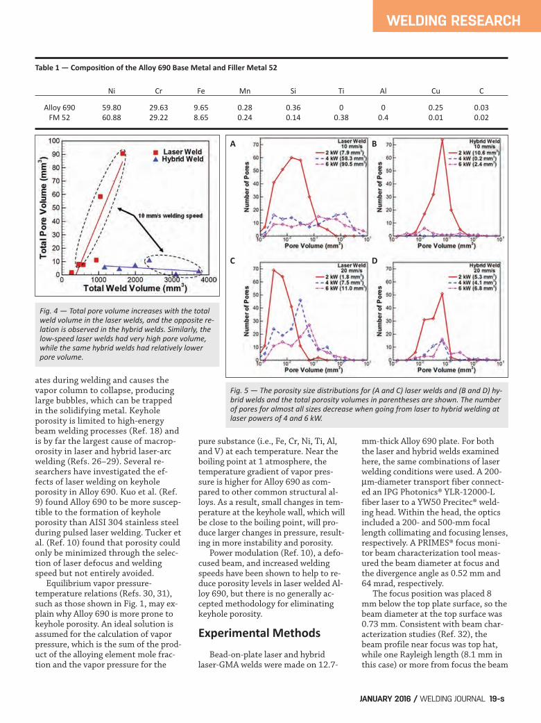
Fig. 4 — Total pore volume increases with the totalweld volume in the laser welds, and the opposite relation is observed in the hybrid welds. Similarly, thelowspeed laser welds had very high pore volume,while the same hybrid welds had relatively lowerpore volume.
Fig. 5 — The porosity size distributions for (A and C) laser welds and (B and D) hybrid welds and the total porosity volumes in parentheses are shown. The numberof pores for almost all sizes decrease when going from laser to hybrid welding atlaser powers of 4 and 6 kW.
A B
C D
BLECHER SUPP JAN 2016.qxp_Layout 1 12/11/15 10:33 AM Page 19

WELDING RESEARCH
WELDING JOURNAL / JANUARY 2016, VOL. 9520-s
profile had a Gaussian shape. Thewelding speed and laser power werevaried between 10 and 20 mm/s, and 2and 6 kW, respectively. For the hybrid welds, a LincolnElectric® Power Wave 455 M/STTpower source with a Binzel® WH 455Dwater-cooled welding gun were used.The torch angle was maintained at 15deg from vertical. A gas mixture of Ar-25% He shielded the weld from the at-mosphere at a 2.7 m3/h flow rate. In-conel® filler metal (FM) 52 wire with adiameter of 1.1 mm was used as theconsumable electrode and is composi-tionally identical to Alloy 690, asshown in Table 1. The wire feed speed was set to 121mm/s. The laser-arc separation dis-tance was held constant at 3 mm withthe laser leading. The arc voltage wasset to 32 V, and the current was esti-mated as 200 A based on the instanta-neous values displayed on the powersource, wire feed speed, and diameterof the filler metal wire. Standard met-allographic techniques were used toprepare and analyze transverse cross-
section samples removed from loca-tions in each weld where steady stateprocesses are expected. The sampleswere electrolytically etched in a 10 wt-% oxalic acid solution. A General Electric® v|tome|x x-ray CT system was used to inspectand characterize the internal porosityin each weld. X-ray CT provides a highdegree of spatial resolution for theprecise location and size of internaldefects, such as pores (Ref. 33). Anaccelerating voltage of 250 kV andcurrent of 200 A were used to imagethe laser welds. Because the hybridwelds were approximately 10 mmwider at the top surface of the weldthan the relatively narrow laserwelds, the voltage and current wereincreased to 285 kV and 230 A, re-spectively, during imaging of the hy-brid welds. Using these combinationsof accelerating voltage and current,the resolution in all directions was 50and 66 m for the laser and hybridwelds, respectively. DatosX® softwarereconstructed the individual x-ray im-ages into a 3D representation. Vol-
ume Graphics® VGStudio Max soft-ware with the defect detection mod-ule was used to measure the sizes andlocations of individual pores withinthe welds.
Results and Discussion
The fusion zone geometry is an im-portant characteristic for comparingpartial-penetration laser and hybridwelds. For example, the depth of theweld is related to the maximum weld-able plate thickness in a single pass,and the width than is related to theplate opening bridgeability, which al-lows for higher tolerances during platefitup before welding. Generally, hybridwelds have a greater width than and asimilar depth to laser welds. Trans-verse weld profiles obtained from a se-ries of laser and hybrid welds pro-duced here are shown in Fig. 2. The linear heat input during laserwelding was varied between 100 and600 W/mm. On the other hand, theheat input during hybrid laser-arcwelding was higher with the additionof the arc and ranged between 400 and1200 W/mm. Alloy 690 does not ex-hibit a distinct fusion zone similar tosteels since the nickel-based alloy doesnot undergo a phase transformationbelow the melting point and is provid-ed in the annealed state with relativelylarge grains. Some grain growth can beobserved near the fusion zone bound-ary in Fig. 2, especially at high heat inputs. The measured weld pool widths anddepths are shown in Table 2. For thelaser welds, the width and depth in-
Table 2 — Summary of Weld Widths and Depths as a Function of Laser Power, WeldingSpeed, and Welding Technique
Width (mm) Depth (mm) Power (kW) Speed (mm/s) Laser Hybrid Laser Hybrid
2 10 3.7 13.6 3.5 4.7 4 10 4.5 15.1 5.7 7.0 6 10 5.9 15.2 7.6 9.1
2 20 2.7 12.4 2.7 3.5 4 20 3.6 11.2 4.7 5.8 6 20 4.4 11.6 6.2 7.6
Fig. 6 — The calculated cylindrical volumetric heat source outline is overlaid on the 10 mm/s hybrid welds. The opening between the bottom of the heat source and weld bottom grows with laser power. The larger opening combined with a larger weld volume behind theopening led to more pores escaping in the 4 and 6kW welds.
BLECHER SUPP JAN 2016.qxp_Layout 1 12/11/15 10:33 AM Page 20

WELDING RESEARCH
WELDING JOURNAL / JANUARY 2016, VOL. 95 21-s
crease steadily with laser power, with amaximum width and depth of 5.9 and7.6 mm, respectively, for a weld madeat a laser power of 6 kW and a weldingspeed of 10 mm/s. Hybrid weld depthincreases with power up to 9.1 mm ata laser power of 6 kW, but the widthdoes not increase significantly andranges from 11.2 to 15.2 mm acrossthe power range from 2 to 6 kW. Thehybrid weld widths are significantlygreater than the laser weld widths dueto the addition of the arc, which actsas a broad heat source. The differencebetween the laser and hybrid welds inwidth is 5 mm or more in most cases,while the depths of the hybrid weldsare about 1 to 2 mm deeper than thelaser welds under similar conditions. Due to the addition of the arc andthe increased heat input, the hybridwelds also display a much larger cross-sectional area than the laser welds. Atlaser powers of 2 kW, the influence ofthe arc on the hybrid weld pool shapeis evident and dominates the charac-teristics of the weld pool. For example,the characteristic shape of a GMA weld(Ref. 34) is obvious at a welding speedof 20 mm/s, while at the very bottomof the weld, the finger penetrationrepresentative of a laser weld can beobserved. Since the arc parameters are31 V and about 200 A, the arc power ison the order of 6 kW, as compared to 2kW for the laser. At higher laser pow-ers of 4 and 6 kW, the influence of the
arc on the weld poolshape is diminisheddue to the parity inpower of the arc andlaser with only theincreased width ofthe arc being evident. Large pores in thesolidified weld metalare formed when bubbles from thebottom of the keyhole become trappedby the advancing solid-liquid interface(Ref. 18). The keyhole tip near the bot-tom of the weld pool fluctuates rapidlyand will pinch off regularly, creatingbubbles in the liquid. While the role ofthe laser-induced keyhole in the for-mation of porosity in laser welding isunderstood, the effects of the additionof an arc in hybrid laser-arc are not.Using AISI 304 stainless steel as thebase metal, Naito et al. (Ref. 35) foundthat keyhole-induced porosity is re-duced but not entirely eliminated inhybrid laser-GTA welding compared tolaser welding. This same relationshipin Alloy 690 is explored here. A comparison of porosity measuredwith x-ray CT in Alloy 690 laser andhybrid welds fabricated using the samelaser power and welding speed (6 kW,10 mm/s) is shown in Fig. 3. For thelaser and hybrid laser-arc welds shownin Fig. 3, the level of porosity detectedin the laser weld is much higher thanthat observed in the hybrid weld. Forexample, 103 pores were identified in
the x-ray CT scan with a median porevolume of 0.14 mm3, while only 17pores were detected in the hybrid weldwith a median pore volume of 0.02mm3. In the hybrid welds, the loca-tions of the detected pores is also im-portant. For example, outside thestart of the weld and the weld rein-forcement, there is only one pore inthe entire hybrid weld. This locationon the weld can be separated from theweld region of interest by adding a‘run-on/run-off’ tab that can be re-moved in a production environment. The relationships between the totalweld volume and the total pore volumeover 70 mm of the laser and hybridwelds are shown in Fig. 4. In the laserwelds, an increase in the total weldvolume leads to an increase in porevolume. The hybrid welds, in general,exhibit a decrease in total pore volumeas the welds become larger. In addi-tion, the lower speed welds in eachwelding technique lead to differentpore characteristics. The lowest porevolumes are found in the low-speedhybrid welds, while the highest porevolumes are found in the low-speed
Fig. 7 — The pore location distributions in laser and hybrid weldsfor 2 kW of laser power and 10 mm/s welding speed are shown.
Fig. 8 — The experimental and calculated weld profiles for thehybrid welds made at 10 mm/s welding speed show reasonable agreement. A — 2 kW; B — 6 kW. The temperature contours are in Kelvin.
A
B
BLECHER SUPP JAN 2016.qxp_Layout 1 12/11/15 10:33 AM Page 21
WELDING RESEARCH
WELDING JOURNAL / JANUARY 2016, VOL. 9522-s
laser welds. Total porosity volume and pore sizedistributions are important for under-standing mechanisms driving porosityformation in laser and hybrid welds.Comparisons between the pore vol-ume and pore size distributions inlaser and hybrid welds produced undera variety of conditions are shown inFig. 5. In the 4 and 6 kW cases, porosi-ty decreased when transitioning fromlaser to hybrid welding. Clearly, thetwo highest heat input hybrid welds (4and 6 kW and 10 mm/s) have the low-est porosity values. The 4-kW weld hasonly 3 pores with two of those locatedin the weld reinforcement. The laserwelds with the same laser power andwelding speed conditions show muchhigher overall porosity levels, whichare up to 90.5 mm3 in 1600 mm3 ofweld metal. These porosity levels aremany times higher than the hybridwelds, which can have porosity valuesas low as 0.2 mm3 in 3000 mm3 ofweld metal. However, the trends of decreasingporosity in hybrid welds do not holdconstant at lower powers. For exam-ple, the 2-kW, 10-mm/s hybrid welddoes not show the same low porosityas the 4- and 6- kW hybrid welds and,in fact, has a higher porosity level thanthe laser weld made with the sameconditions. The same is true in thewelds made at this same power but amore rapid welding speed of 20 mm/s.This difference in behavior may betraced to a combination of filler metal
addition and smallweld pool volume inthe 2-kW hybrid welds. The filler met-al is entering the molten pool at a rela-tively high rate of speed, on the orderof 1.5 m/s or faster (Ref. 11). Bubbles that form near the bottomof the keyhole need to move towardthe top of the weld pool to escape.This mobility toward the top is likelyhindered by the filler metal enteringthe pool at a high velocity. In addition,the pool volume is relatively smallcompared to the higher laser powerwelds, further limiting the bubble mo-bility toward the top of the pool. Thelaser welds exhibit a decrease in poros-ity with increasing speed and an in-crease in porosity with increasing laserpower, which is consistent with previ-ously reported experiments (Refs. 27,36). For similar processing conditions,the differences in porosity betweenthe laser and hybrid welds are relatedto the harmful or beneficial effects ofthe arc and impinging filler metal de-pending on the selected laser power. The size of the filler metal-weldpool interaction region can be estimat-ed using a cylindrical volumetric heatsource (VHS) model (Ref. 12). A de-tailed description of the VHS model isavailable in the literature (Refs. 13,14), and the equations necessary forthe calculations performed here areavailable in Appendix A. The model as-sumes that liquid droplets are acceler-ated from the end of the consumableelectrode, strike the molten pool, and
transfer heat and momentum to theweld. The height, depth, and energyintensity of the VHS can be calculatedbased on the material properties andwelding parameters. Knowledge of the relationship be-tween the arc current and droplet de-tachment frequency is an importantcomponent of the calculations. Espe-cially important is the transition cur-rent from globular to spray transfer.However, most studies of droplet de-tachment have focused on mild steelelectrodes with little attention paid toother filler metals, such as FM 52. Thewelding recommendations for spraytransfer mode from the FM 52 manu-facturer have been used to estimatethe transition currents (Ref. 37). Thetransition current for mild steel isaround 290 A, so a current of 300 A orgreater will lead to spray transfermode. The recommended parametersfor FM 52 suggest the transition cur-rent varies between 150 and 225 A,depending on the electrode diameter. Using the experimental welding pa-rameters and material properties, theVHS height and width can be comput-ed. The height and width, which areidentical for all hybrid welding cases,are calculated as 3.8 and 2.1 mm, re-spectively. The VHS profile has beenoverlaid on the transverse cross sec-tions of the 10-mm/s welding speedhybrid welds in Fig. 6. As the power increases, the opening
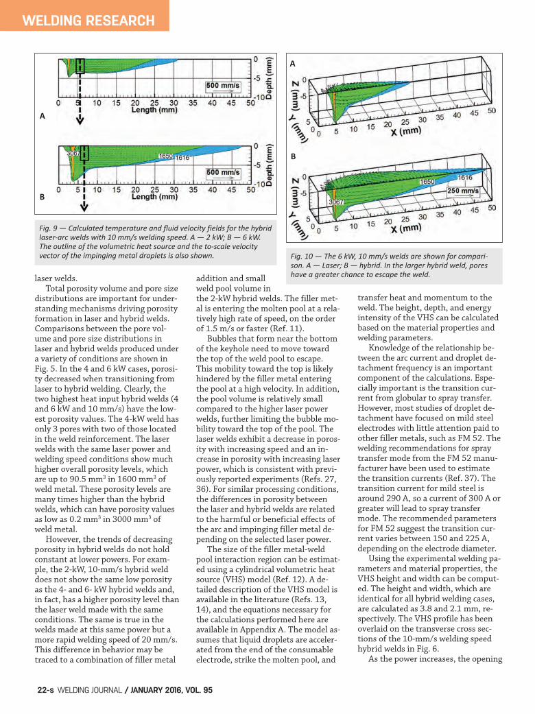
Fig. 9 — Calculated temperature and fluid velocity fields for the hybridlaserarc welds with 10 mm/s welding speed. A — 2 kW; B — 6 kW.The outline of the volumetric heat source and the toscale velocityvector of the impinging metal droplets is also shown. Fig. 10 — The 6 kW, 10 mm/s welds are shown for compari
son. A — Laser; B — hybrid. In the larger hybrid weld, poreshave a greater chance to escape the weld.
A
B
A
B
BLECHER SUPP JAN 2016.qxp_Layout 1 12/11/15 10:33 AM Page 22

WELDING RESEARCH
JANUARY 2016 / WELDING JOURNAL 23-s
between the bottom of the VHS andthe bottom of the weld increases from1 to more than 5 mm. The impingingdroplet velocity, which is expected tointerrupt pore motion through highfluid velocity turbulence, has a valueof 1.6 m/s. The maximum calculatedfluid flow velocity in a recent study ofhybrid welding of steel was less than0.3 m/s (Ref. 38), so the high velocityof the impinging droplets would havea significant impact on fluid flow inthe weld pool and would interrupt theupward motion of pores escaping fromthe weld pool. The evidence for this low mobilitymodel can be extracted from Fig. 5,which shows a shift to higher poresizes when going from laser to hybridwelding. This behavior is only seen in
the 2-kW welds and suggeststhat bubbles stay trapped atthe bottom of the weld andcombine to form larger bub-bles before they are entrappedas pores by the advancing so-lidification front. In addition,the bubbles in the hybridwelds should be trapped in thebottom part of the weld andnot show a great deal of varia-tion in location distributionsif the combination of the fillermetal addition and small poolvolume are limiting mobility.
Figure 7 shows the pore lo-cation distributions as a per-centage of the total depth inthe 2-kW, 10-mm/s laser andhybrid welds along with perti-nent portions of the relevantx-ray CT images. In bothwelds, more pores are locatednear the bottom of the weldpool. In the laser weld, the topthird of the weld contains 16%of the total number of thepores, but in the hybrid weld,zero pores are found in thesame third of the weld.
Heat transfer and fluid flowmodeling, which calculates thetemperature and fluid velocityfields during welding, hasbeen used successfully to sim-ulate spot welding (Refs. 15,39), arc welding (Ref. 12), andlaser and hybrid laser arcwelding for a variety of mate-rials (Refs. 16, 17, 40, 41). Thesame model used recently to
simulate laser welding of Alloy 690and hybrid laser-arc welding of steelhas been utilized here to calculate thetemperature and velocity fields duringhybrid laser-GMA welding of Alloy 690(Refs. 10, 38). The numerical modelsolves the equations of conservationof mass, momentum, and energy in3D for enthalpy and fluid velocities.The keyhole heat source geometry iscalculated using a point-by-point heatbalance at the keyhole wall and thenincluded into the 3D model. The addi-tion of filler metal is taken into ac-count as a volumetric heat source,while the arc is considered to have aGaussian distribution on the surface.A comparison of the experimental andcalculated fusion zone profiles for thehybrid welds made at 2- and 6-kW
laser power and 10-mm/s weld speedis shown in Fig. 8. The defocus in the 6kW has been decreased to 2 mm to ac-count for possible thermal lensing inthe laser optics (Ref. 32). There isgood agreement between the two val-ues. Figure 9 shows the central longitu-dinal plane of the 2- and 6-kW hybridwelds with 10-mm/s welding speed.The geometry of the VHS is outlined,and the large downward pointing ar-row is the to-scale velocity vector ofthe impinging metal droplets from theconsumable electrode. In the 2-kWweld, which had a high degree ofporosity, the VHS height is approxi-mately the depth of the pool 3 mm be-hind the laser beam. If a bubble formsnear the bottom of the keyhole, itcould easily be trapped in the advanc-ing solid-liquid interface before it hasa chance to escape. In the 6-kW weld,the minimum space between the bot-tom of the VHS and the pool below is1.7 mm, which allowed for most bub-bles to escape the pool and not betrapped in the solid as a pore. Laserwelds had a much greater amount ofporosity compared to the hybridwelds, especially at high laser powersand low welding speeds. One reason for this difference inporosity content could be the relative-ly low volume of the laser welds asshown in Fig. 10, which shows the cal-culated temperature and fluid velocityfields in the 6-kW, 10-mm/s laser andhybrid welds. Due to the arc, the hy-brid weld is not only wider but alsolonger by more than 20 mm. The lowweld volume leading to high porosityin laser welds is similar to the low vol-ume and filler metal addition leadingto high porosity in the low laser powerhybrid welds. Since the likelihood of low porosityin the hybrid welds can be related tothe distance between the bottom ofthe VHS and bottom of the weld, theweld depth and VHS height are two di-mensions, which can be related toporosity. Arc current, FM 52 electrodediameter, and linear laser heat inputare easily selectable welding parame-ters affecting these two important dimensions. Figure 11 shows the combined ef-fect of different combinations of thewelding parameters in the form of aprocess map with wire feed speed in-
Fig. 11 — A — The volumetric heat source height fordifferent arc currents and electrode diameters areshown. The laser heat inputs to provide differentporosity values is also featured; B — the relationbetween weld depth and laser heat input used in Ais shown.
A
B
BLECHER SUPP JAN 2016.qxp_Layout 1 12/11/15 10:33 AM Page 23

WELDING RESEARCH
WELDING JOURNAL / JANUARY 2016, VOL. 9524-s
creased linearly with current for calcu-lation purposes. The three nonsolidlines represent the effect of the cur-rent and electrode diameter on VHSheight on the left y-axis. The three re-gions predict linear laser heat inputsfor all electrode diameters that willlead to openings between the bottomof the VHS and the weld pool, corre-sponding to the openings observed inthe experimental welds shown in Fig.6 (0.9, 3.2, and 5.3 mm). Heat inputs in the lower region re-sult in openings of 0.9 mm, which wasexperimentally shown to have a highdegree of porosity. VHS height-welddepth openings of 3.2 and 5.3 mm inthe middle and top heat input regions,respectively, are expected to have a lowdegree of porosity. The solid lines ineach heat input region designate theexact electrode diameter dependentheat inputs.The weld depth-heat inputrelationship from the experimentalwelds is shown in Fig. 11B. The process map in Fig. 11A coversthe range of electrode diameters andarc currents suggested for FM 52 (Ref.37). For a given arc current and elec-trode diameter, a linear laser heat in-put is suggested to avoid porosity. Forexample, if a 1.6-mm electrode diame-ter and arc current of 300 A is select-ed, then the VHS height is predicted tobe 6.5 mm. According to the top tworegions, a laser heat input between630 and 830 J/mm would produce aweld depth between 9.7 and 11.8 mm,and weld depth-VHS height differ-ences between 3.2 and 5.3 mm, whichhave been shown experimentally tolead to low porosity. On the otherhand, a heat input of 410 J/mm yieldsa weld depth of 7.4 mm with only a 0.9mm difference between the VHSheight and weld depth. Based on ex-periments, this small difference is ex-pected to lead to a high porosity con-tent. As shown in Fig. 8, VHS height in-creases with both current and elec-trode diameter. According to thegraph, the minimum heat input fromthe laser for low porosity increaseswith both arc current and electrode di-ameter. The minimum heat input forthe 1.1-mm-diameter filler metal is460 J/mm. For the 0.9- and 1.6-mm-diameter electrodes, the minimumheat inputs are 310 and 550 J/mm, re-spectively. For a 10-mm/s welding
speed, reasonable laser powers of 5 to6 kW can be used to fabricate lowporosity welds up to 9.0 mm in depthwith any FM 52 electrode diameter.However, if greater productivity is de-sired in terms of welding speed or pen-etration depth, much higher powerswill be required. For example, an in-crease of the welding speed to 20mm/s would require 11-kW laser pow-er to make pore-free welds with 1.6-mm-diameter electrodes.
Summary and Conclusions The characteristics of laser and hy-brid laser-gas metal arc welded Alloy690 with a compositionally identicalfiller metal have been analyzed forseveral welding conditions experimen-tally and theoretically. Experimentalcharacterization of total porosityamounts was performed with x-ray CT.Transverse fusion zone geometriesand porosity resulting from keyholecollapse for both laser and hybridwelds have been compared and foundto have significant differences, thus af-fecting the choice of a suitable weldingprocess. The following conclusionswere drawn from this work. 1. An analysis of Alloy 690 vaporpressure at various temperatures showsthat the equilibrium vapor pressuresare very sensitive to small changes intemperature, making Alloy 690 suscep-tible to macroporosity due to keyholefluctuations during high-power laserwelding. X-ray CT data revealed signifi-cant levels of macroporosity in keyhole-mode laser welds for a wide variety ofwelding conditions. 2. The addition of an arc to a laserbeam significantly reduced porosity lev-els in the high-power welds. The lowestlevels of porosity were observed in thehybrid welds at powers of 4 and 6 kWand a welding speed of 10 mm/s. A min-imum porosity total of 0.2 mm3 in a to-tal weld volume of 3000 mm3 was foundin a hybrid weld with 4-kW laser powerand 10-mm/s welding speed. In con-trast, a laser weld made at a power of 6kW and a travel speed of 10 mm/s dis-played a porosity volume of 90.5 mm3 in1600 mm3 of weld metal. 3. A transition from high levels ofporosity to virtually no porosity wasobserved in the hybrid welds as powerincreased above 2 kW. The combina-tion of the experimental weld charac-
terization, calculations of the fillermetal-molten pool mixing region di-mensions, and three-dimensional heattransfer and fluid flow modeling sug-gests that the mechanism of this highporosity is linked to the relative sizesof the molten pool and filler metal-molten pool mixing region. Filler met-al transfer and low weld pool volumeat 2-kW laser power limit upward bub-ble mobility out of the pool by imped-ing bubble motion and restricting theregions in which the bubbles canmove. As the power increases, the sizeof the filler metal mixing region rela-tive to the weld pool decreases, allow-ing the bubbles to more easily escape. 4. Experimental evidence of thismechanism included a shift in the poresize distribution to larger pores whengoing from laser to hybrid welding andmore pores located at the bottom ofthe pool in hybrid welding comparedto laser welding. In addition, three di-mensional heat transfer and fluid flowmodeling showed no opening betweenthe bottom of the filler metal-moltenpool mixing region and the bottom ofthe weld pool, while at higher powers,this opening increases to 2 mm and al-lows easy escape of the bubbles duringwelding. The 2-mm-wide opening islarger than most, approximately 97%of the observed pore diameters. 5. The remedy for high porosity liesin a minimum opening between theweld depth and filler metal-weld poolmixing region. Calculations accountingfor the volumetric heat source dimen-sions, weld depths, and FM 52 elec-trode dimensions were incorporatedinto a process map to establish thecombinations of arc current, linearlaser heat input, and filler metal wirediameter needed to produce low-porosity hybrid laser-arc welds. Theminimum heat input varied between240 and 490 J/mm with greater heatinputs required for larger electrode di-ameters. With welding speeds of 10mm/s or less, no more than 5-kW laserpower would be required to producepore-free welds with every electrodediameter. Increasing welding speed orcurrent to improve productivity orfiller metal deposition would requirehigher laser powers. Based on the results of this study,hybrid welding is recommended forwelding thick sections of Alloy 690, es-pecially at laser powers above 2 kW.
BLECHER SUPP JAN 2016.qxp_Layout 1 12/11/15 10:33 AM Page 24

WELDING RESEARCH
JANUARY 2016 / WELDING JOURNAL 25-s
The large amounts of porosity in thelaser welds are mostly eliminatedwhen the arc is appropriately added tothe process using the proposed processmap. With optimized process parame-ters, macroporosity-free thick sectionwelds could be produced by hybridwelding.
The authors would like to thank JayTressler for performing the weldingexperiments and Ed Good for prepar-ing the metallographic and x-ray speci-mens. This research was performedusing funding received from the DOEOffice of Nuclear Energy’s Nuclear En-ergy University Programs under GrantNumber 120327.
1. Allen, T., Busby, J., Meyer, M., andPetti, D. 2010. Materials challenges for nu-clear systems. Mater. Today 13(12): 14–23. 2. Lee, H. T., and Kuo, T. Y. 1999. Ef-fects of niobium on microstructure, me-chanical properties, and corrosion behav-iour in weldments of Alloy 690. Sci. Tech-nol. Weld. Join. 4(4): 245–256. 3. Jeng, S.-L., Lee, H.-T., Huang, J.-Y.,and Kuo, R.-C. 2008. Effects of Nb on themicrostructure and elevated-temperaturemechanical properties of Alloy 690-SUS304L dissimilar welds. Mater. Trans. 49(6):1270–1277. 4. Lee, H. T., and Kuo, T. Y. 1999.Analysis of microstructure and mechanicalproperties in Alloy 690 weldments usingfiller metals I-82 and I-52. Sci. Technol.Weld. Join. 4(2): 94–103. 5. Lee, H. T., and Jeng, S. L. 2001. Char-acteristics of dissimilar welding of Alloy690 to 304L stainless steel. Sci. Technol.Weld. Join. 6(4): 225–234. 6. Jeng, S. L., Lee, H. T., Weirich, T. E.,and Rebach, W. P. 2007. Microstructuralstudy of the dissimilar joints of Alloy 690and SUS 304L stainless steel. Mater. Trans.48(3): 481–489. 7. Ribic, B., Palmer, T. A., and DebRoy,T. 2009. Problems and issues in laser-archybrid welding. Int. Mater. Rev. 54(4): 223–244. 8. Kuo, T.-Y. 2005. Effects of pulsed andcontinuous Nd–YAG laser beam waves onwelding of Inconel alloy. Sci. Technol. Weld.Join. 10(5): 557–565. 9. Kuo, T.-Y., and Lin, Y.-D. 2007. Ef-fects of different shielding gases and power
waveforms on penetration characteristicsand porosity formation in laser welding ofInconel 690 Alloy. Mater. Trans. 48(2):219–226. 10. Tucker, J. D., Nolan, T. K., Martin,A. J., and Young, G. A. 2012. Effect of trav-el speed and beam focus on porosity in Al-loy 690 laser welds. JOM 64(12): 1409–1417. 11. Jones, L. A., Eagar, T. W., and Lang,J. H. 1999. A dynamic model of drops de-taching from a gas metal arc welding elec-trode. J. Phys. D. Appl. Phys. 31(1): 107–123. 12. Kim, C. H., Zhang, W., and DebRoy,T. 2003. Modeling of temperature field andsolidified surface profile during gas-metalarc fillet welding. J. Appl. Phys. 94(4):2667–2679. 13. Lancaster, J. F. 1986. The Physics ofWelding. 2nd ed. Oxford: Pergamon. 14. Kumar, S., and Bhaduri, S. 1994.Three-dimensional finite element model-ing of gas metal-arc welding. Metall. Mater.Trans. B 25(3): 435–441. 15. Zhang, W., Roy, G. G., Elmer, J. W.,and DebRoy, T. 2003. Modeling of heattransfer and fluid flow during gas tungstenarc spot welding of low carbon steel. J.Appl. Phys. 93(5): 3022–3033. 16. Rai, R., Elmer, J. W., Palmer, T. A.,and DebRoy, T. 2007. Heat transfer andfluid flow during keyhole mode laser weld-ing of tantalum, Ti–6Al–4V, 304L stainlesssteel and vanadium. J. Phys. D. Appl. Phys.40(18): 5753–5766. 17. Ribic, B., Rai, R., and DebRoy, T.2008. Numerical simulation of heat trans-fer and fluid flow in GTA/Laser hybridwelding. Sci. Technol. Weld. Join. 13(8):683–693. 18. Matsunawa, A., Kim, J.-D., Seto, N.,Mizutani, M., and Katayama, S. 1998. Dy-namics of keyhole and molten pool in laserwelding. J. Laser Appl. 10(6): 247–254. 19. Blecher, J. J., Galbraith, C. M., VanVlack, C., Palmer, T. A., Fraser, J. M., Web-ster, P. J. L., and DebRoy, T. 2014. Realtime monitoring of laser beam weldingkeyhole depth by laser interferometry. Sci.Technol. Weld. Join. 19(7): 560–564. 20. Lee, H. T., Chen, C. T., and Wu, J. L.2010. 3D numerical study of effects oftemperature field on sensitisation of Alloy690 butt welds fabricated by gas tungstenarc welding and laser beam welding. Sci.Technol. Weld. Join. 15(7): 605–612. 21. Blecher, J. J., Palmer, T. A., and De-bRoy, T. 2013. Solidification map of a nick-el-base alloy. Metall. Mater. Trans. A 45(4):2142–2151. 22. Suder, W. J., and Williams, S. 2014.Power factor model for selection of weldingparameters in CW laser welding. Opt. LaserTechnol. 56: 223–229. 23. Quintino, L., Costa, A., Miranda, R.,Yapp, D., Kumar, V., and Kong, C. J. 2007.
Welding with high power fiber lasers – Apreliminary study. Mater. Des. 28(4):1231–1237. 24. Kou, S. 2003. Welding Metallurgy.2nd ed. Hoboken, N.J.: John Wiley & Sons,Inc. 25. Zhao, H., and DebRoy, T. 2001. Poreformation during laser beam welding ofdie-cast magnesium alloy AM60B — Mech-anism and remedy. Welding Journal 80(8):204-s to 210-s. 26. Katayama, S., Kobayashi, Y., Mizu-tani, M., and Matsunawa, A. 2001. Effectof vacuum on penetration and defects inlaser welding. J. Laser Appl. 13(5): 187–192. 27. Kawahito, Y., Mizutani, M., andKatayama, S. 2007. Elucidation of high-power fibre laser welding phenomena ofstainless steel and effect of factors on weldgeometry. J. Phys. D. Appl. Phys. 40(19):5854–5859. 28. Zhao, H., Martukanitz, R. P., andDebroy, T. 1999. Porosity, underfill andmagnesium loss during continuous waveNd: YAG laser welding of thin plates of alu-minum Alloys 5182 and 5754. WeldingJournal 78(6): 207-s to 216-s. 29. Zhao, H., and DebRoy, T. 2003.Macroporosity free aluminum alloy weld-ments through numerical simulation ofkeyhole mode laser welding. J. Appl. Phys.93(12): 10089–10096. 30. Smithells, C. 2004. Smithells MetalsReference Book. 8th ed. Boston: ElsevierButterworth-Heinemann. 31. Yaws, C. L. 2007. The Yaws Hand-book of Vapor Pressure: Antoine Coefficients.Houston: Gulf Publishing Co. 32. Blecher, J., Palmer, T. A., Kelly, S.M., and Martukanitz, R. P. 2012. Identify-ing performance differences in transmis-sive and reflective laser optics using beamdiagnostic tools. Welding Journal 91(7):204-s to 214-s. 33. Madison, J. D., and Aagesen, L. K.2012. Quantitative characterization ofporosity in laser welds of stainless steel.Scr. Mater. 67(9): 783–786. 34. Yang, Z., and Debroy, T. 1999. Mod-eling macro- and microstructures of gas-metal-arc welded HSLA-100 steel. Metall.Mater. Trans. B-Process Metall. Mater.Process. Sci. 30(3): 483–493. 35. Naito, Y., Katayama, S., and Mat-sunawa, A. 2003. Keyhole behavior and liq-uid flow in molten pool during laser-archybrid welding. Proc. SPIE 4831: 357–362. 36. Kawahito, Y., Mizutani, M., andKatayama, S. 2009. High quality welding ofstainless steel with 10 kW high power fibrelaser. Sci. Technol. Weld. Joining 14(4):288–294. 37. Special Metals Corp., “Joining,” accessed 30 April 2015, pg. 9, specialmetalswelding.com. 38. Wei, H. L., Blecher, J. J., Palmer, T.
References
Acknowledgments
BLECHER SUPP JAN 2016.qxp_Layout 1 12/11/15 10:33 AM Page 25

WELDING RESEARCH
WELDING JOURNAL / JANUARY 2016, VOL. 9526-s
A., and DebRoy, T. 2015. Fusion zone mi-crostructure and geometry in complete-joint-penetration laser-arc hybrid weldingof low-alloy steel. Welding Journal 94(4):135-s to 144-s. 39. He, X., Fuerschbach, P. W., and De-bRoy, T. 2003. Heat transfer and fluid flowduring laser spot welding of 304 stainlesssteel. J. Phys. D. Appl. Phys. 36(12): 1388–1398. 40. Rai, R., Roy, G. G., and Debroy, T.2007. A computationally efficient model ofconvective heat transfer and solidificationcharacteristics during keyhole mode laserwelding. J. Appl. Phys. 101(5): 054909. 41. Rai, R., Kelly, S. M., Martukanitz, R.P., and DebRoy, T. 2008. A convective heat-transfer model for partial and full penetra-tion keyhole mode laser welding of a struc-tural steel. Metall. Mater. Trans. A Phys.Metall. Mater. Sci. 39(1): 98–112. 42. Rhee, S., and Kannatey-Asibu, E.1992. Observation of metal transfer dur-ing gas metal arc welding. Welding Journal71(10): 381-s to 386-s. 43. Kim, G.-H., and Na, S.-J. 2001. Astudy of an arc sensor model for gas metalarc welding with rotating arc Part 1: dy-namic simulation of wire melting. Proc.Inst. Mech. Eng. Part B J. Eng. Manuf.215(9): 1271–1279. 44. Waszink, J. H., and Van Den Heuv-el, G. J. P. M. 1982. Heat generation andheat flow in the filler in GMA welding.Welding Journal 61(8): 269-s to 280-s.
Appendix A
Calculation of Volumetric HeatSource Dimensions
The volumetric heat source (VHS)calculation assumes a cylindrical shapewith dimensions of diameter andheight. The VHS is commonly used tomodel consumable electrode heattransfer during gas metal arc welding(Refs. 12, 14). In these experiments,spray metal transfer, where smalldroplets form at the end of the elec-trode and accelerate into the moltenpool, is expected. Several variables arerequired for the calculation, includingmaterial properties, welding parame-ters, and droplet frequency. The height of the VHS is given as d = hv – xv + Dd, where hv is height ofthe cavity formed by the impingingdroplets, xv is the distance traveled inthe cavity by each droplet before thearrival of the next impinging droplet,
and Dd is the droplet diameter. Thecavity height is
where is surface tension of the liquidmetal, is the liquid metal density, g isacceleration due to gravity, and vd isthe droplet impingement velocity. Thesurface tension and density of FM 52were taken as 1.1 N/m and 6500kg/m3, respectively. The distance trav-eled by each droplet is defined as
where t is the time interval betweenthe impingement of two droplets andcan be defined as t = 1/f. The fre-quency of droplets, f, is
where I (A) is the current and It is thetransition current from globular tospray transfer. The transition currentfor FM 52 has been estimated based onthe suggested process parameters bythe electrode manufacturer (Ref. 37). The frequency current relations areshown in Fig. A1 for three FM 52 elec-trode diameters and, for reference(Refs. 11, 42), a fitted line to experi-mental data for mild steel. The dropletshape is assumed to be spherical, andthe radius of the sphere is expressed as
where rw is the radius of the filler met-al wire and wf is the wire feed speed.The VHS diameter is four times thedroplet radius. The droplet velocity is
where v0 is the initial velocity, a is thedroplet acceleration, and La is the arclength. The calculation for the arc
length (Ref. 43) and measured elec-trode extension length (Ref. 44) areavailable in the literature. Accelerationis taken as
where vg is the velocity of the plasma,g is the density of the plasma, and Cd
is the drag coefficient. The plasmadensity was taken as 0.06 kg/m3. Thevelocity of the plasma is estimatedwith the effective velocity (in m/s),which is veff = k1 I, where k1 is a con-stant coefficient of ¼. The drag coeffi-cient is Cd = –242.74Re–2 + 59.67Re–1
+ 0.44793, where Re is the Reynoldsnumber, which is defined as Re = rdveff/vk. The variable vk is kinetic vis-cosity and is 3.4 10-3 m2/s. The ini-tial velocity is calculated as
hv = � 2�Dd�g
+ 2�Dd�g
���
��
2
+ Ddvd2
6g
�
���
�
���
�
�
�
xv = hv +2�Dd�g
���
��
1� cos ghv
���
���
1/2
�t�
���
�
���
�
��
��
��
f = �243.44
1+ exp I � It6.06437
���
���
+ 323.506 � 0.874I + 0.0025I2
rd =34rw
2wf / f3
vd = v02 +2aLa
a= 38
vg3�grd�
Cd + g
v0 = –0.33692 + 0.00854 (I /Dd ).
Fig. A1 — The currentdroplet detachmentfrequencies for FM 52 are not experimentally known. Based on suggested currents,voltages, shielding gases, and wire feedspeeds for different electrode diametersfrom the manufacturer, the relations havebeen estimated. The fit line for experimental data for steel in Ar5%CO2 shielding gasis shown for reference.
A1
A2
A3
A4
A5
A6
A7
BLECHER SUPP JAN 2016.qxp_Layout 1 12/11/15 10:33 AM Page 26
Related Documents