Porcelain bushings Medium voltage EN-IT-DE-ES-FR INSTRUCTION MANUAL

Welcome message from author
This document is posted to help you gain knowledge. Please leave a comment to let me know what you think about it! Share it to your friends and learn new things together.
Transcript
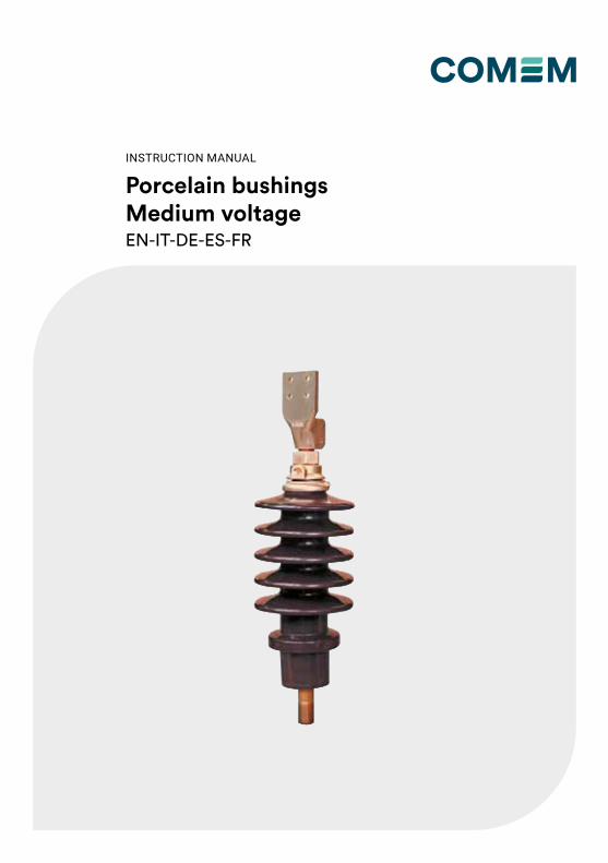
Porcelain bushingsMedium voltageEN-IT-DE-ES-FR
INSTRUCTION MANUAL
2
CONTENT INDEX
Content index
Safety ...........................................................4
Product description ......................................4
Installation ....................................................4
Electrical connection ....................................5
Assembly Dimensions on transformer tank .6
Technical features ........................................7
Operation and maintenance .........................9
Indice dei contenuti
Sicurezza ....................................................10
Descrizione del prodotto ............................10
Installazione ...............................................10
Connessione elettrica .................................11
Quote di montaggio sul trasformatore .......12
Caratteristiche tecniche .............................13
Funzionamento e manutenzione ................15
Inhalt
Sicherheit ...................................................16
Produktbeschreibung .................................16
Installation ..................................................16
Elektrischer Anschluss ...............................17
Montageabmessungen am Transformatortank ......................................18
Technische Merkmale ................................19
Montageanleitung ......................................21
Índice de contenidos
Seguridad ...................................................22
DescripciÓn del producto............................22
InstalaciÓn ..................................................22
ConexiÓn eléctrica ......................................23
Dimensiones del asemblaje en el tanque del transformador .......................................24
Carateristicas técnicas ...............................25
Funcionamento y mantenimiento ...............27
3
Index du contenu
Securitè ......................................................28
Description du produit ................................28
Installation ..................................................28
Connexion électrique ..................................29
Dimensiones de montaje de réservoir de transformateur ............................................30
Caractéristiques techniques .......................31
Exploitation et d’entretien ...........................33
4
Safety Product description
Installation
Safety instructionsMake sure that any person installing, taking into operation and operating the “porcelain bushing”:• is technically qualified and competent• fully comply with these assembling instructionsImproper operations or misuse could cause danger to:• life and limb• the equipment and other assets of the operator• the equipment proper functionSafety instructions in this manual are shown in three different forms to emphasize important information.
Safety notes on the equipment operationElectrical installation is subject to the relevant national safety rules.
This information indicates particular danger to life and health. Disregarding such a warning can lead to serious or fatal injury.
All relevant fire protection regulation must be strictly observed.
This information indicates particular danger to equipment or other property of the user. Serious or fatal injury cannot be excluded.
Installation, electrical connection and fitting the device may only be carried out by qualified personnel and only in accordance to this instruction manual. It is responsibility of the user to make sure that the device is used for specified application only. For safety matters, please avoid any unauthorized and improperly works.
The operating and installation requirements described in this manual must be strictly followed. If not, the device can be damaged or a malfunction may occur.
These notes give important or specific information concerning the equipment or as to work with the equipment.
WARNING
WARNING
CAUTION
CAUTION
CAUTION
NOTE
These instructions are applicable to Porcelain Bushings with rated voltages from 12 kV to 52 kV and rated currents from 250 A to 8000 A.These bushings are designed to operate with the upper part in air and the lower part immersed in the transformer oil. Porcelain bushings have been designed and produced in conformity with the IEC 60137 standard.
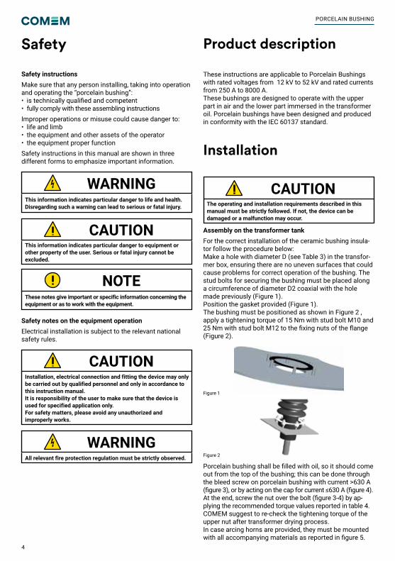
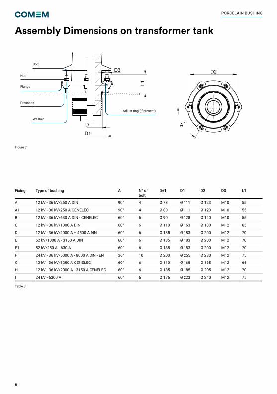
Assembly on the transformer tankFor the correct installation of the ceramic bushing insula-tor follow the procedure below:Make a hole with diameter D (see Table 3) in the transfor-mer box, ensuring there are no uneven surfaces that could cause problems for correct operation of the bushing. The stud bolts for securing the bushing must be placed along a circumference of diameter D2 coaxial with the hole made previously (Figure 1).Position the gasket provided (Figure 1).The bushing must be positioned as shown in Figure 2 , apply a tightening torque of 15 Nm with stud bolt M10 and 25 Nm with stud bolt M12 to the fixing nuts of the flange (Figure 2).
Figure 2
Figure 1
Porcelain bushing shall be filled with oil, so it should come out from the top of the bushing; this can be done through the bleed screw on porcelain bushing with current >630 A (figure 3), or by acting on the cap for current ≤630 A (figure 4). At the end, screw the nut over the bolt (figure 3-4) by ap-plying the recommended torque values reported in table 4.COMEM suggest to re-check the tightening torque of the upper nut after transformer drying process. In case arcing horns are provided, they must be mounted with all accompanying materials as reported in figure 5.
PORCELAIN BUSHING
5
Electrical connection
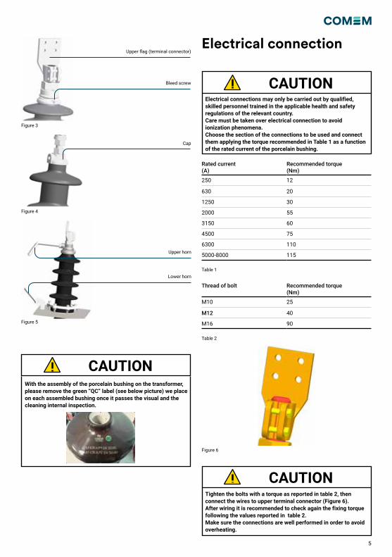
Electrical connections may only be carried out by qualified, skilled personnel trained in the applicable health and safety regulations of the relevant country. Care must be taken over electrical connection to avoid ionization phenomena. Choose the section of the connections to be used and connect them applying the torque recommended in Table 1 as a function of the rated current of the porcelain bushing.
Tighten the bolts with a torque as reported in table 2, then connect the wires to upper terminal connector (Figure 6). After wiring it is recommended to check again the fixing torque following the values reported in table 2. Make sure the connections are well performed in order to avoid overheating.
CAUTION
CAUTION
Figure 3
Figure 4
Figure 5
Upper flag (terminal connector)
Bleed screw
Cap
Upper horn
Lower horn
With the assembly of the porcelain bushing on the transformer, please remove the green “QC” label (see below picture) we place on each assembled bushing once it passes the visual and the cleaning internal inspection.
CAUTION
Rated current (A)
Recommended torque (Nm)
250 12
630 20
1250 30
2000 55
3150 60
4500 75
6300 110
5000-8000 115
Thread of bolt Recommended torque (Nm)
M10 25
M12 40
M16 90
Table 1
Table 2
Figure 6
6
Assembly Dimensions on transformer tank
Table 3
Figure 7
Fixing Type of bushing A N° of bolt
D±1 D1 D2 D3 L1
A 12 kV - 36 kV/250 A DIN 90° 4 Ø 78 Ø 111 Ø 123 M10 55
A1 12 kV - 36 kV/250 A CENELEC 90° 4 Ø 80 Ø 111 Ø 123 M10 55
B 12 kV - 36 kV/630 A DIN - CENELEC 60° 6 Ø 90 Ø 128 Ø 140 M10 55
C 12 kV - 36 kV/1000 A DIN 60° 6 Ø 110 Ø 163 Ø 180 M12 65
D 12 kV - 36 kV/2000 A ÷ 4500 A DIN 60° 6 Ø 135 Ø 183 Ø 200 M12 70
E 52 kV/1000 A - 3150 A DIN 60° 6 Ø 135 Ø 183 Ø 200 M12 70
E1 52 kV/250 A - 630 A 60° 6 Ø 135 Ø 183 Ø 200 M12 70
F 24 kV - 36 kV/5000 A - 8000 A DIN - EN 36° 10 Ø 200 Ø 255 Ø 280 M12 75
G 12 kV - 36 kV/1250 A CENELEC 60° 6 Ø 110 Ø 165 Ø 185 M12 65
H 12 kV - 36 kV/2000 A - 3150 A CENELEC 60° 6 Ø 135 Ø 185 Ø 205 M12 70
I 24 kV - 6300 A 60° 6 Ø 176 Ø 223 Ø 240 M12 75
M55x3
5535
105
14
2030
30
200
135
60°
70
M12
80
150
250
18
4070
40 70
90
M55X3
20
55115
40
100
25
223
679
20
20
222
210
183
120
9431
621
1
D3
L1
D
D1
A
D2
Silver platedexternal metal parts
FIXING DETAIL
A
A
Adjust ring (if present)
Bolt
Washer
Pressbits
Flange
Nut
PORCELAIN BUSHING
7
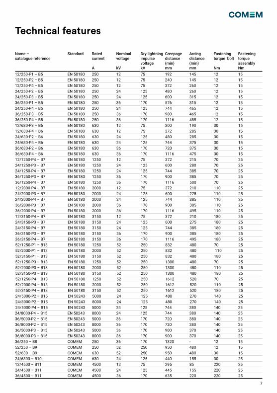
Technical features
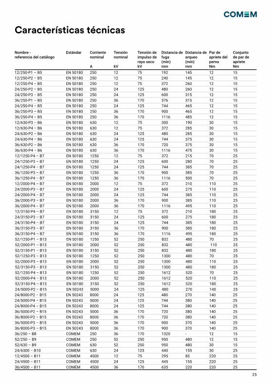
Name – catalogue reference
Standard Rated current
A
Nominal voltage
kV
Dry lightning impulse voltagekV
Creepage distance(min)mm
Arcing distance(min)mm
Fastening torque bolt
Nm
Fastening torque assemblyNm
12/250-P1 – B5 EN 50180 250 12 75 192 145 12 1512/250-P2 – B5 EN 50180 250 12 75 240 145 12 1512/250-P4 – B5 EN 50180 250 12 75 372 260 12 1524/250-P2 – B5 EN 50180 250 24 125 480 260 12 1524/250-P3 – B5 EN 50180 250 24 125 600 315 12 1536/250-P1 – B5 EN 50180 250 36 170 576 315 12 1524/250-P4 – B5 EN 50180 250 24 125 744 465 12 1536/250-P3 – B5 EN 50180 250 36 170 900 465 12 1536/250-P4 – B5 EN 50180 250 36 170 1116 485 12 1512/630-P3 – B6 EN 50180 630 12 75 300 190 30 1512/630-P4 – B6 EN 50180 630 12 75 372 285 30 1524/630-P2 – B6 EN 50180 630 24 125 480 285 30 1524/630-P4 – B6 EN 50180 630 24 125 744 375 30 1536/630-P2 – B6 EN 50180 630 36 170 720 375 30 1536/630-P4 – B6 EN 50180 630 36 170 1116 475 30 1512/1250-P4 – B7 EN 50180 1250 12 75 372 215 70 2524/1250-P3 – B7 EN 50180 1250 24 125 600 280 70 2524/1250-P4 – B7 EN 50180 1250 24 125 744 385 70 2536/1250-P3 – B7 EN 50180 1250 36 170 900 385 70 2536/1250-P4 – B7 EN 50180 1250 36 170 1116 500 70 2512/2000-P4 – B7 EN 50180 2000 12 75 372 210 110 2524/2000-P3 – B7 EN 50180 2000 24 125 600 275 110 2524/2000-P4 – B7 EN 50180 2000 24 125 744 385 110 2536/2000-P3 – B7 EN 50180 2000 36 170 900 385 110 2536/2000-P4 – B7 EN 50180 2000 36 170 1116 495 110 2512/3150-P4 – B7 EN 50180 3150 12 75 372 210 180 2524/3150-P3 – B7 EN 50180 3150 24 125 600 275 180 2524/3150-P4 – B7 EN 50180 3150 24 125 744 385 180 2536/3150-P3 – B7 EN 50180 3150 36 170 900 385 180 2536/3150-P4 – B7 EN 50180 3150 36 170 1116 495 180 2552/1250-P1 – B13 EN 50180 1250 52 250 832 480 70 2552/2000-P1 – B13 EN 50180 2000 52 250 832 480 110 2552/3150-P1 – B13 EN 50180 3150 52 250 832 480 180 2552/1250-P3 – B13 EN 50180 1250 52 250 1300 480 70 2552/2000-P3 – B13 EN 50180 2000 52 250 1300 480 110 2552/3150-P3 – B13 EN 50180 3150 52 250 1300 480 180 2552/1250-P4 – B13 EN 50180 1250 52 250 1612 520 70 2552/2000-P4 – B13 EN 50180 2000 52 250 1612 520 110 2552/3150-P4 – B13 EN 50180 3150 52 250 1612 520 180 2524/5000-P2 – B15 EN 50243 5000 24 125 480 270 140 2524/8000-P2 – B15 EN 50243 8000 24 125 480 270 140 2524/5000-P4 – B15 EN 50243 5000 24 125 744 380 140 2524/8000-P4 – B15 EN 50243 8000 24 125 744 380 140 2536/5000-P2 – B15 EN 50243 5000 36 170 720 380 140 2536/8000-P2 – B15 EN 50243 8000 36 170 720 380 140 2536/5000-P3 – B15 EN 50243 5000 36 170 900 370 140 2536/8000-P3 – B15 EN 50243 8000 36 170 900 370 140 2536/250 – B8 COMEM 250 36 170 1320 - 12 1552/250 – B9 COMEM 250 52 250 950 480 12 1552/630 – B9 COMEM 630 52 250 950 480 30 1524/6300 – B10 COMEM 630 24 125 440 155 30 2512/4500 – B11 COMEM 4500 12 75 295 85 220 2524/4500 – B11 COMEM 4500 24 125 445 155 220 2536/4500 – B11 COMEM 4500 36 170 635 220 220 25
8
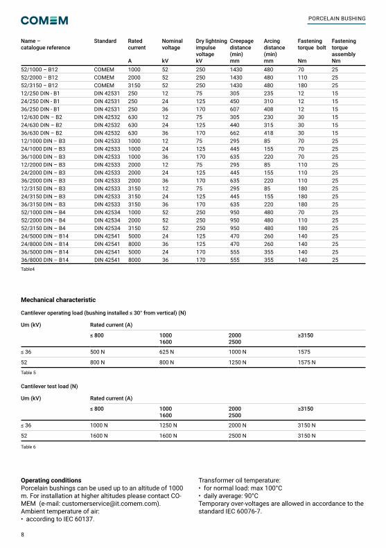
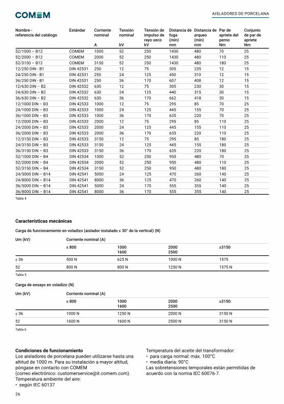
Name – catalogue reference
Standard Rated current
A
Nominal voltage
kV
Dry lightning impulse voltagekV
Creepage distance(min)mm
Arcing distance(min)mm
Fastening torque bolt
Nm
Fastening torque assemblyNm
52/1000 – B12 COMEM 1000 52 250 1430 480 70 2552/2000 – B12 COMEM 2000 52 250 1430 480 110 2552/3150 – B12 COMEM 3150 52 250 1430 480 180 2512/250 DIN - B1 DIN 42531 250 12 75 305 235 12 1524/250 DIN - B1 DIN 42531 250 24 125 450 310 12 1536/250 DIN - B1 DIN 42531 250 36 170 607 408 12 1512/630 DIN – B2 DIN 42532 630 12 75 305 230 30 1524/630 DIN – B2 DIN 42532 630 24 125 440 315 30 1536/630 DIN – B2 DIN 42532 630 36 170 662 418 30 1512/1000 DIN – B3 DIN 42533 1000 12 75 295 85 70 2524/1000 DIN – B3 DIN 42533 1000 24 125 445 155 70 2536/1000 DIN – B3 DIN 42533 1000 36 170 635 220 70 2512/2000 DIN – B3 DIN 42533 2000 12 75 295 85 110 2524/2000 DIN – B3 DIN 42533 2000 24 125 445 155 110 2536/2000 DIN – B3 DIN 42533 2000 36 170 635 220 110 2512/3150 DIN – B3 DIN 42533 3150 12 75 295 85 180 2524/3150 DIN – B3 DIN 42533 3150 24 125 445 155 180 2536/3150 DIN – B3 DIN 42533 3150 36 170 635 220 180 2552/1000 DIN – B4 DIN 42534 1000 52 250 950 480 70 2552/2000 DIN – B4 DIN 42534 2000 52 250 950 480 110 2552/3150 DIN – B4 DIN 42534 3150 52 250 950 480 180 2524/5000 DIN – B14 DIN 42541 5000 24 125 470 260 140 2524/8000 DIN – B14 DIN 42541 8000 36 125 470 260 140 2536/5000 DIN – B14 DIN 42541 5000 24 170 555 355 140 2536/8000 DIN – B14 DIN 42541 8000 36 170 555 355 140 25
Table 5
Table 6
Mechanical characteristic
Cantilever operating load (bushing installed ≤ 30° from vertical) (N)
Um (kV) Rated current (A)
≤ 800 10001600
20002500
≥3150
≤ 36 500 N 625 N 1000 N 1575
52 800 N 800 N 1250 N 1575 N
Cantilever test load (N)
Um (kV) Rated current (A)
≤ 800 10001600
20002500
≥3150
≤ 36 1000 N 1250 N 2000 N 3150 N
52 1600 N 1600 N 2500 N 3150 N
Operating conditionsPorcelain bushings can be used up to an altitude of 1000 m. For installation at higher altitudes please contact CO-MEM (e-mail: [email protected]).Ambient temperature of air: • according to IEC 60137.
Transformer oil temperature:• for normal load: max 100°C• daily average: 90°CTemporary over-voltages are allowed in accordance to the standard IEC 60076-7.
Table4
PORCELAIN BUSHING
9
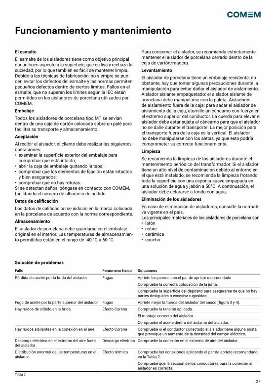
Operation and maintenance
The glaze
The glaze on the insulators is primarily intended to give a good surface appearance which is smooth and rejects dirt and is therefore also easy to keep clean. The glazing is not needed to stop moisture entering the insulator since the porcelain itself after firing is nonporous and does not absorb moisture. Due to manufacturing techniques, glaze defects cannot always be avoided and standards allow minor defects within certain limits. Glaze faults, not exceeding the limits according to IEC, are permitted on porcelain insulators used by COMEM on bushings.
Packaging
All porcelain bushings MT type are shipped inside a cardboard box positioned on a pallet to facilitate transport and storage.
Acceptance
Upon receiving the bushing, the Customer must carry out the following operations:examine the outer surface of the packaging to check that it is intact• open the packing crate removing the lid • check that the fastening elements are intact and well secured• check that there are no breakagesIf damages are found, please contact COMEM, providing the delivery note number or PO number or COMEM order acknowledgement number.
Rating data
The rating data is indicated on the mark placed on the porcelain in agreement with the relevant standard.
Storage
The porcelain bushing must be stored in the original packaging indoors. Permissible storage temperatures are in the range of -40 °C to 60°C. To preserve the bushing, it is strictly recom-mended to keep the porcelain bushing closed inside the cartoon/wood box.
Lifting
The porcelain bushing has a sturdy packaging; nonethe-less, some precautions must be taken during handling to prevent damaging the insulation bushing. Packaged insulation bushing: the ceramic bushing insulator must be handled using the pallet. Insulation bushings out of the crate: to remove the insu-lation bushing from the crate screw an eyebolt tightly into the upper end of the conductor. The rope for lifting the bu-shing must be fastened to the eyebolt so that the bushing cannot be damaged during transport. The best position for transport out of the crate is vertical. The bushing must not be handled using the sheds, as this could compromise correct operation.
Cleaning
Cleaning of the sheds during periodic maintenance of the transformer is recommended. If the bushing has a high level of pollution due to the environment in which it is installed, we recommend cleaning by rubbing the entire surface with a soft sponge soaked in a solution of soap and water at 50°C. The bushing must then be rinsed thoroughly with tap water.
Bushing disposal
In case of bushing disposal, refer to the country current regulation. Porcelain Bushing main materials are:• Brass• Copper• Ceramic• Rubber
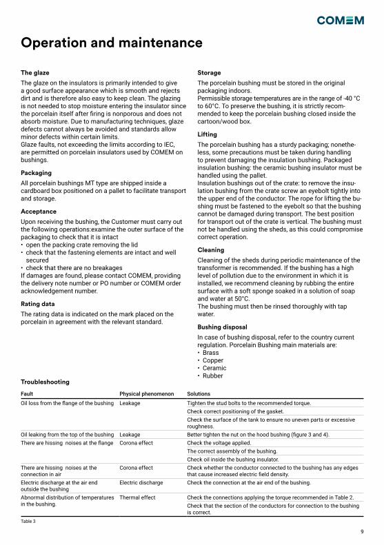
Troubleshooting
Table 3
Fault Physical phenomenon Solutions
Oil loss from the flange of the bushing Leakage Tighten the stud bolts to the recommended torque.Check correct positioning of the gasket.Check the surface of the tank to ensure no uneven parts or excessive roughness.
Oil leaking from the top of the bushing Leakage Better tighten the nut on the hood bushing (figure 3 and 4).There are hissing noises at the flange Corona effect Check the voltage applied.
The correct assembly of the bushing.Check oil inside the bushing insulator.
There are hissing noises at the connection in air
Corona effect Check whether the conductor connected to the bushing has any edges that cause increased electric field density.
Electric discharge at the air end outside the bushing
Electric discharge Check the connection at the air end of the bushing.
Abnormal distribution of temperatures in the bushing.
Thermal effect Check the connections applying the torque recommended in Table 2.Check that the section of the conductors for connection to the bushing is correct.
Mechanical characteristic
Cantilever operating load (bushing installed ≤ 30° from vertical) (N)
Um (kV) Rated current (A)
≤ 800 10001600
20002500
≥3150
≤ 36 500 N 625 N 1000 N 1575
52 800 N 800 N 1250 N 1575 N
10
Safety Descrizione del prodotto
Installazione
Istruzioni di sicurezzaAssicurarsi che il personale incaricato di installare e operare sull’isolatore:• sia tecnicamente qualificato e competente• rispetti pedissequamente queste istruzioni d’assemblaggioL’uso improprio di questi dispositivi potrebbe determinare pericolo per:• vita e arti• attrezzatura e altri beni dell’operatore• corretto funzionamento dell’attrezzaturaLe istruzioni di sicurezza di questo manuale sono riportate in tre diversi formati per sottolineare informazioni importanti.
Note di sicurezza sul funzionamento dell’apparecchiaturaL’installazione elettrica è soggetta alle leggi nazionali di sicurezza.
Questa informazione indica un particolare pericolo per la vita e la salute. Ignorare questo tipo di avvertimento potrebbe causare ferite gravi o fatali.
Il regolamento antincendio deve essere rigorosamente rispettato
Questa informazione indica un particolare pericolo per l'attrezzatura o altri beni dell'operatore. Ferite gravi o fatali non sono da escludersi.
L'installazione, la connessione elettrica e il montaggio del dispositivo devo essere effettuati da personale qualificato e solo secondo questo manuale di istruzione. E' responsabilità dell'utente assicurarsi che il dispositivo sia utilizzato per la sua corretta applicazione. Per questioni di sicurezza, evitare usi non autorizzati o impropri.
I requisiti di installazione e funzionamento presenti in questo manuale devono essere rigorosamente seguiti. In caso contrario, il dispositivo potrebbe essere danneggiato o potrebbe verificarsi un malfunzionamento.
Questa nota offre informazioni importanti o specifiche sull'attrezzatura o su come operarvi.
AVVERTIMENTO
AVVERTIMENTO
ATTENZIONE
ATTENZIONE
ATTENZIONE
NOTA
Queste istruzioni sono applicabili a Isolatori in porcellana con tensione nominale da 12 kv a 52 kV e correnti nomina-li da 250 a 8000 A. Questi isolatori sono progettati per operare con la parte superiore in aria e la parte inferiore immersa nell’olio del trasformatore. Gli isolatori in porcellana sono progettati e prodotti secondo la normativa IEC 60137.
Montaggio sul trasformatorePer una corretta installazione dell’isolatore in ceramica seguire la seguente procedura:Fare un foro di diametro D (vedi Tabella 3) sulla cassa del trasformatore,assicurandosi che non ci siano superfici irregolari che potrebbero casuare problemi per il corretto funzionamento dell’isolatore. I prigionieri per fissare l’iso-latore devono essere posizionati lungo una circonferenza di diametro D2 coassiale con il foro fatto in precedenza (Figura 1).Posizionare la guarnizione fornita (Figura 1). L’isolatore dev’essere posizionato come mostrato in figura 2, applicare una coppia di serraggio di 15 Nm con bullone M10 e 25 Nm con bullone M12 ai dadi di fissaggio della flangia (Figura 2).
Figura 2
Figura 1
L’isolatore in porcellana dev’essere riempito d’olio, fino alla sua fuoriuscita dalla parte superiore dell’isolatore; questo può essere fatto attraverso la vite di sfiato su isolatori con correnti > 630 A (figura 3), o agendo sulla cappa per correnti ≤ 630 A (figura 4). Alla fine, avvitare il dado sul tirante (figura 3-4) applicando i valori di coppia indicati nella tabella 4.COMEM suggerisce di riverificare la coppia di serraggio del dado superiore dopo il processo di essicazione del trasformazione. Nel caso in cui siano forniti gli scaricatori, questi devono essere montati con tutti i materiali forniti a corredo come riportato nella figura 5.
ISOLATORI IN PORCELLANA
11
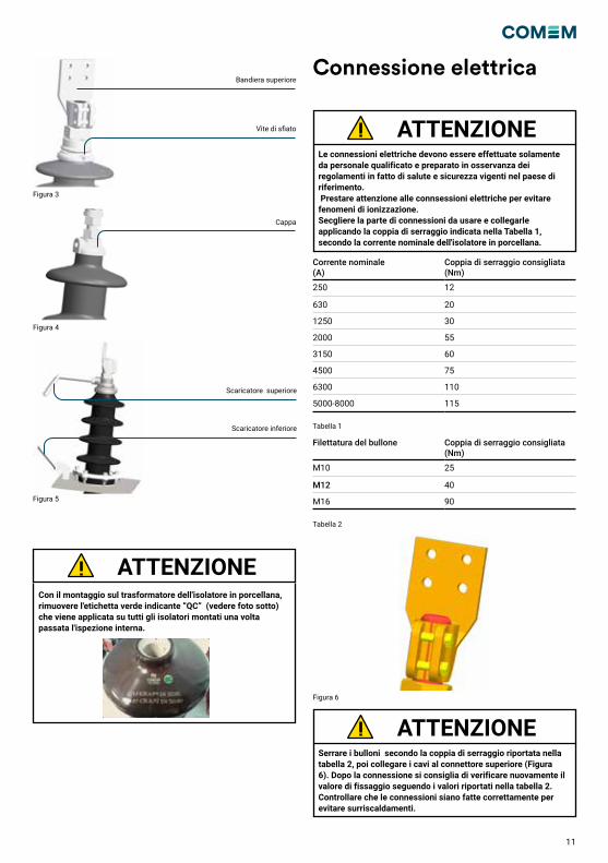
Connessione elettrica
Le connessioni elettriche devono essere effettuate solamente da personale qualificato e preparato in osservanza dei regolamenti in fatto di salute e sicurezza vigenti nel paese di riferimento. Prestare attenzione alle connsessioni elettriche per evitare fenomeni di ionizzazione. Secgliere la parte di connessioni da usare e collegarle applicando la coppia di serraggio indicata nella Tabella 1, secondo la corrente nominale dell'isolatore in porcellana.
Serrare i bulloni secondo la coppia di serraggio riportata nella tabella 2, poi collegare i cavi al connettore superiore (Figura 6). Dopo la connessione si consiglia di verificare nuovamente il valore di fissaggio seguendo i valori riportati nella tabella 2. Controllare che le connessioni siano fatte correttamente per evitare surriscaldamenti.
ATTENZIONE
ATTENZIONE
Figura 3
Figura 4
Figura 5
Bandiera superiore
Vite di sfiato
Cappa
Scaricatore superiore
Scaricatore inferiore
Con il montaggio sul trasformatore dell'isolatore in porcellana, rimuovere l'etichetta verde indicante “QC” (vedere foto sotto) che viene applicata su tutti gli isolatori montati una volta passata l'ispezione interna.
ATTENZIONE
Corrente nominale (A)
Coppia di serraggio consigliata (Nm)
250 12
630 20
1250 30
2000 55
3150 60
4500 75
6300 110
5000-8000 115
Filettatura del bullone Coppia di serraggio consigliata (Nm)
M10 25
M12 40
M16 90
Tabella 1
Tabella 2
Figura 6
12
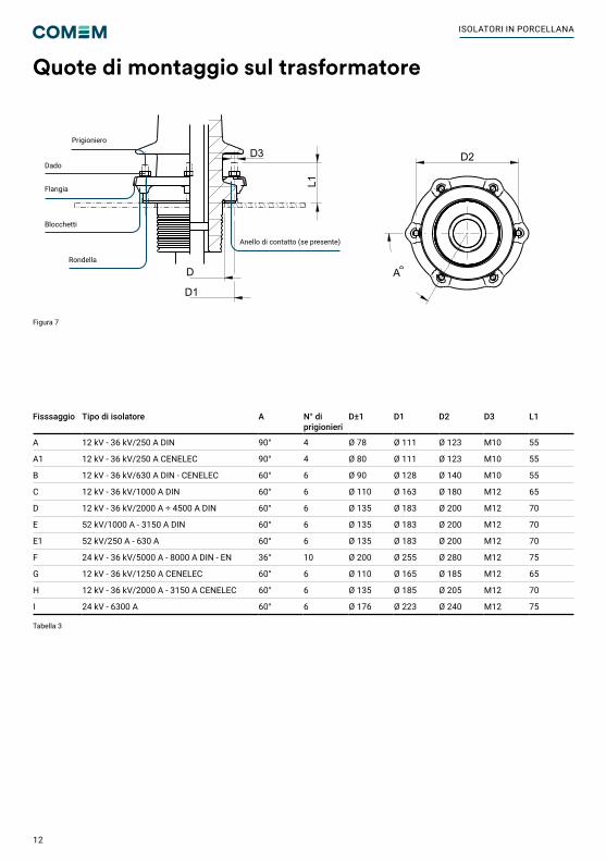
Quote di montaggio sul trasformatore
Tabella 3
Figura 7
Fisssaggio Tipo di isolatore A N° di prigionieri
D±1 D1 D2 D3 L1
A 12 kV - 36 kV/250 A DIN 90° 4 Ø 78 Ø 111 Ø 123 M10 55
A1 12 kV - 36 kV/250 A CENELEC 90° 4 Ø 80 Ø 111 Ø 123 M10 55
B 12 kV - 36 kV/630 A DIN - CENELEC 60° 6 Ø 90 Ø 128 Ø 140 M10 55
C 12 kV - 36 kV/1000 A DIN 60° 6 Ø 110 Ø 163 Ø 180 M12 65
D 12 kV - 36 kV/2000 A ÷ 4500 A DIN 60° 6 Ø 135 Ø 183 Ø 200 M12 70
E 52 kV/1000 A - 3150 A DIN 60° 6 Ø 135 Ø 183 Ø 200 M12 70
E1 52 kV/250 A - 630 A 60° 6 Ø 135 Ø 183 Ø 200 M12 70
F 24 kV - 36 kV/5000 A - 8000 A DIN - EN 36° 10 Ø 200 Ø 255 Ø 280 M12 75
G 12 kV - 36 kV/1250 A CENELEC 60° 6 Ø 110 Ø 165 Ø 185 M12 65
H 12 kV - 36 kV/2000 A - 3150 A CENELEC 60° 6 Ø 135 Ø 185 Ø 205 M12 70
I 24 kV - 6300 A 60° 6 Ø 176 Ø 223 Ø 240 M12 75
M55x3
5535
105
14
2030
30
200
135
60°
70
M12
80
150
250
18
4070
40 70
90
M55X3
20
55115
40
100
25
223
679
20
20
222
210
183
120
9431
621
1
D3
L1
D
D1
A
D2
Silver platedexternal metal parts
FIXING DETAIL
A
A
Anello di contatto (se presente)
Prigioniero
Rondella
Blocchetti
Flangia
Dado
ISOLATORI IN PORCELLANA
13
Caratteristiche tecniche
Nome – riferimento del catalogo
Normativa Corrente nominale
A
Tensione nominale
kV
Tenuta di impulso atmosfericokV
Distanza di dispersione(min)mm
Distanza tra gli scaricatori(min)mm
Coppia di serraggio del bulloneNm
Coppia di serraggio del montaggioNm
12/250-P1 – B5 EN 50180 250 12 75 192 145 12 1512/250-P2 – B5 EN 50180 250 12 75 240 145 12 1512/250-P4 – B5 EN 50180 250 12 75 372 260 12 1524/250-P2 – B5 EN 50180 250 24 125 480 260 12 1524/250-P3 – B5 EN 50180 250 24 125 600 315 12 1536/250-P1 – B5 EN 50180 250 36 170 576 315 12 1524/250-P4 – B5 EN 50180 250 24 125 744 465 12 1536/250-P3 – B5 EN 50180 250 36 170 900 465 12 1536/250-P4 – B5 EN 50180 250 36 170 1116 485 12 1512/630-P3 – B6 EN 50180 630 12 75 300 190 30 1512/630-P4 – B6 EN 50180 630 12 75 372 285 30 1524/630-P2 – B6 EN 50180 630 24 125 480 285 30 1524/630-P4 – B6 EN 50180 630 24 125 744 375 30 1536/630-P2 – B6 EN 50180 630 36 170 720 375 30 1536/630-P4 – B6 EN 50180 630 36 170 1116 475 30 1512/1250-P4 – B7 EN 50180 1250 12 75 372 215 70 2524/1250-P3 – B7 EN 50180 1250 24 125 600 280 70 2524/1250-P4 – B7 EN 50180 1250 24 125 744 385 70 2536/1250-P3 – B7 EN 50180 1250 36 170 900 385 70 2536/1250-P4 – B7 EN 50180 1250 36 170 1116 500 70 2512/2000-P4 – B7 EN 50180 2000 12 75 372 210 110 2524/2000-P3 – B7 EN 50180 2000 24 125 600 275 110 2524/2000-P4 – B7 EN 50180 2000 24 125 744 385 110 2536/2000-P3 – B7 EN 50180 2000 36 170 900 385 110 2536/2000-P4 – B7 EN 50180 2000 36 170 1116 495 110 2512/3150-P4 – B7 EN 50180 3150 12 75 372 210 180 2524/3150-P3 – B7 EN 50180 3150 24 125 600 275 180 2524/3150-P4 – B7 EN 50180 3150 24 125 744 385 180 2536/3150-P3 – B7 EN 50180 3150 36 170 900 385 180 2536/3150-P4 – B7 EN 50180 3150 36 170 1116 495 180 2552/1250-P1 – B13 EN 50180 1250 52 250 832 480 70 2552/2000-P1 – B13 EN 50180 2000 52 250 832 480 110 2552/3150-P1 – B13 EN 50180 3150 52 250 832 480 180 2552/1250-P3 – B13 EN 50180 1250 52 250 1300 480 70 2552/2000-P3 – B13 EN 50180 2000 52 250 1300 480 110 2552/3150-P3 – B13 EN 50180 3150 52 250 1300 480 180 2552/1250-P4 – B13 EN 50180 1250 52 250 1612 520 70 2552/2000-P4 – B13 EN 50180 2000 52 250 1612 520 110 2552/3150-P4 – B13 EN 50180 3150 52 250 1612 520 180 2524/5000-P2 – B15 EN 50243 5000 24 125 480 270 140 2524/8000-P2 – B15 EN 50243 8000 24 125 480 270 140 2524/5000-P4 – B15 EN 50243 5000 24 125 744 380 140 2524/8000-P4 – B15 EN 50243 8000 24 125 744 380 140 2536/5000-P2 – B15 EN 50243 5000 36 170 720 380 140 2536/8000-P2 – B15 EN 50243 8000 36 170 720 380 140 2536/5000-P3 – B15 EN 50243 5000 36 170 900 370 140 2536/8000-P3 – B15 EN 50243 8000 36 170 900 370 140 2536/250 – B8 COMEM 250 36 170 1320 - 12 1552/250 – B9 COMEM 250 52 250 950 480 12 1552/630 – B9 COMEM 630 52 250 950 480 30 1524/6300 – B10 COMEM 630 24 125 440 155 30 2512/4500 – B11 COMEM 4500 12 75 295 85 220 2524/4500 – B11 COMEM 4500 24 125 445 155 220 2536/4500 – B11 COMEM 4500 36 170 635 220 220 25
14
Nome – riferimento del catalogo
Normativa Corrente nominale
A
Tensione nominale
kV
Tenuta di impulso atmosfericokV
Distanza di dispersione(min)mm
Distanza tra gli scaricatori(min)mm
Coppia di serraggio del bulloneNm
Coppia di serraggio del montaggioNm
52/1000 – B12 COMEM 1000 52 250 1430 480 70 2552/2000 – B12 COMEM 2000 52 250 1430 480 110 2552/3150 – B12 COMEM 3150 52 250 1430 480 180 2512/250 DIN - B1 DIN 42531 250 12 75 305 235 12 1524/250 DIN - B1 DIN 42531 250 24 125 450 310 12 1536/250 DIN - B1 DIN 42531 250 36 170 607 408 12 1512/630 DIN – B2 DIN 42532 630 12 75 305 230 30 1524/630 DIN – B2 DIN 42532 630 24 125 440 315 30 1536/630 DIN – B2 DIN 42532 630 36 170 662 418 30 1512/1000 DIN – B3 DIN 42533 1000 12 75 295 85 70 2524/1000 DIN – B3 DIN 42533 1000 24 125 445 155 70 2536/1000 DIN – B3 DIN 42533 1000 36 170 635 220 70 2512/2000 DIN – B3 DIN 42533 2000 12 75 295 85 110 2524/2000 DIN – B3 DIN 42533 2000 24 125 445 155 110 2536/2000 DIN – B3 DIN 42533 2000 36 170 635 220 110 2512/3150 DIN – B3 DIN 42533 3150 12 75 295 85 180 2524/3150 DIN – B3 DIN 42533 3150 24 125 445 155 180 2536/3150 DIN – B3 DIN 42533 3150 36 170 635 220 180 2552/1000 DIN – B4 DIN 42534 1000 52 250 950 480 70 2552/2000 DIN – B4 DIN 42534 2000 52 250 950 480 110 2552/3150 DIN – B4 DIN 42534 3150 52 250 950 480 180 2524/5000 DIN – B14 DIN 42541 5000 24 125 470 260 140 2524/8000 DIN – B14 DIN 42541 8000 36 125 470 260 140 2536/5000 DIN – B14 DIN 42541 5000 24 170 555 355 140 2536/8000 DIN – B14 DIN 42541 8000 36 170 555 355 140 25
Tabella 5
Tabella 6
Caratteristiche meccaniche
Carico funzionamento ammissibile (isolatori installati a ≤ 30° dalla verticale) (N)
Um (kV) Corrente nominale (A)
≤ 800 10001600
20002500
≥3150
≤ 36 500 N 625 N 1000 N 1575
52 800 N 800 N 1250 N 1575 N
Carico di test (N)
Um (kV) Corrente nominale (A)
≤ 800 10001600
20002500
≥3150
≤ 36 1000 N 1250 N 2000 N 3150 N
52 1600 N 1600 N 2500 N 3150 N
Condizioni di funzionamentoGli isolatori in porcellana possono essere utilizzati fino a un’altitudine di 1000 m. Per installazioni ad altitudini supe-riori si prega di contattare COMEM (e-mail : [email protected]).Temperatura ambiente dell’aria: • secondo IEC 60137
Temperatura d’olio del trasformatore• per carico normale massimo: 100°C• media giornaliera: 90°C Sovratensioni temporanee sono permesse in accordo alla normativa IEC 60076-7.
Tabella 4
ISOLATORI IN PORCELLANA
15
Caratteristiche meccaniche
Carico funzionamento ammissibile (isolatori installati a ≤ 30° dalla verticale) (N)
Um (kV) Corrente nominale (A)
≤ 800 10001600
20002500
≥3150
≤ 36 500 N 625 N 1000 N 1575
52 800 N 800 N 1250 N 1575 N
Carico di test (N)
Um (kV) Corrente nominale (A)
≤ 800 10001600
20002500
≥3150
≤ 36 1000 N 1250 N 2000 N 3150 N
52 1600 N 1600 N 2500 N 3150 N
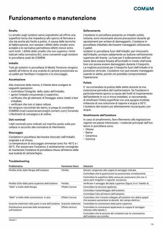
Funzionamento e manutenzione
Smalto
Lo smalto sugli isolatori serve soprattutto ad offrire una superficie liscia che impedisca allo sporco di fermarsi e che sia anche più facile a pulirsi. A causa delle tecniche di fabbricazione, non sempre i difetti dello smalto sono evitabili e le normative permettono difetti minori entro certi limiti. I difetti dello smalto che non superino i limiti indicati nella normativa IEC, sono consentiti sugli isolatori in porcellana usati da COMEM.
Imballo
Tutti gli isolatori in porcellana di Media Tensione vengono spediti all’interno di una scatola di cartone posizionata su un pallet per facilitare il trasporto e lo stoccaggio.
Accettazione
Alla ricezione della merce, il Cliente deve svolgere le seguenti operazioni: • controllare l’integrità dello stato dell’imballo;• aprire l’imballo rimuovendo il coperchio;• verificare che gli elementi di fissaggio siano intatti e ben imballati;• verificare che non ci siano rotture.Se vengono riscontrati dei danni, si prega di contattare COMEM (mail [email protected]) fornendo i riferimenti di consegna e di ordine.
Dati nominali
I dati nominali sono indicati sul marchio posto sulla por-cellana in accordo alla normativa di riferimento.
Stoccaggio
L’isolatore in pocellana dev’essere stoccato nell’imballo originale e al chiuso. Le temperature di stoccaggio ammesse sono fra -40°C e i 60°C. Per preservare l’isolatore, è strettamente consigliato di mantenere l‘isolatore di porcellana chiuso all’interno della sua scatola di cartone/legno.
Sollevamento
L’isolatore in porcellana presenta un imballo solido; tuttavia, sono necessarie alcune precauzioni durante gli spostamenti per evitare di danneggiarlo. L’isolatore in porcellana imballato dev’essere maneggiato utilizzando il pallet. Isolatori in porcellana fuori dall’imballo: per rimuoverlo dall’imballo, avvitare saldamente un bullone nell’estremità superiore del tirante. La fune per il sollevamento dell’iso-latore deve essere fissata all’occhiello in modo chel’isola-tore non possa essere danneggiato durante il trasporto. La migliore posizione per il trasporto fuori dall’imballo è la posizione verticale. L’isolatore non può essere maneggiato usando le alette, poichè ciò potrebbe compromettere l’operazione.
Pulizia
E’ raccomandata la pulizia delle alette durante la ma-nutenzione periodica del trasformatore. Se l’isolatore è particolarmente sporco a causa dei livelli di inquinamento dell’ambiente in cui si trova installato, si raccomanda di strofinare l’intera superficie con una spugna morbida imbevuta di una soluzione di sapone e acqua a 50°C. L’isolatore dev’essere poi attentamente risciacquato con acqua.
Smaltimento dell’isolatore
In caso di smaltimento, fare riferimento alla legislazione vigente nel paese interessato. I materiali principali dell’iso-latore in porcellana sono:• Ottone• Rame• Ceramica• Gomma
Troubleshooting
Tabella 7
Problematica Fenomeno fisico Soluzioni
Perdita d’olio dalla flangia dell’isolatore Perdita Serrare i prigionieri alla coppia di serraggio indicata.Controllare che la guarnizione sia posizionata correttamente.Controllare la superficie della cassa per assicurarsi che non ci siano parti irregolari o rugosità eccessiva.
Perdita d’olio dalla parte superiore dell’isolatore Perdita Verificare il serraggio del dado superiore (figura 3 e 4, Tabella 4).“Sibili” a livello della flangia Effetto Corona Controllare la tensione applicata.
Controllare l’assemblaggio dell’isolatore.Controllare l’olio all’interno dell’isolatore.
“Sibili” a livello della connessione in aria Effetto Corona Controllare che il tirante collegato all’isolatore non abbia spigoli che possano aumentare la densità del campo elettrico.
Scariche elettriche nella parte in aria dell’isolatore Scariche elettriche Controllare le connessioni della parte superiore. Distribuzione anomala delle temperature sull’isolatore
Effetto termico Controllare le connessioni applicando la coppia di serraggio indicata nella tabella 2.Controllare che la sezione dei conduttori per la connessione dell’isolatore sia corretta.
16
Sicherheit Produktbeschreibung
Installation
SicherheitshinweiseStellen Sie sicher, dass jegliche Person, die den „Porzellan-durchführungen“ installiert, in Betrieb nimmt und bedient:• technisch qualifiziert und kompetent ist• diese Montageanleitung in vollem Umfang beachtetUnsachgemäße Bedienung oder Fehlanwendungen könn-ten Folgendes gefährden:• Leib und Leben• das Gerät oder andere Anlagen des Betreibers• die korrekte GerätefunktionDie Sicherheitshinweise in diesem Handbuch werden auf drei unterschiedliche Arten abgebildet, um wichtige Informationen hervorzuheben.
Sicherheitshinweise zum GerätebetriebDie elektrische Installation unterliegt den einschlägigen nationalen Sicherheitsvorschriften.
Diese Informationen weisen auf besondere Gefahr für Leben und Gesundheit hin. Die Nichtbeachtung einer solchen Warnung kann zu schweren oder tödlichen Verletzungen führen.
Alle maßgeblichen Brandschutzvorschriften müssen streng beachtet werden.
Diese Informationen weisen auf besondere Gefahren für die Anlage oder anderes Eigentum des Benutzers hin. Schwere oder tödliche Verletzungen können nicht ausgeschlossen werden.
Installation, elektrischer Anschluss und Montage des Geräts dürfen nur von Fachpersonal und in Übereinstimmung mit dieser Betriebsanleitung vorgenommen werden. Es liegt in der Verantwortung des Benutzers sicherzustellen, dass das Gerät nur bestimmungsgemäß verwendet wird. Vermeiden Sie aus Sicherheitsgründen bitte jegliche unbefugten und unsachgemäßen Eingriffe.
Die in diesem Handbuch enthaltenen Betriebs- und Installationsvoraussetzungen sind streng zu beachten. Andernfalls kann es zu Schäden oder Funktionsstörungen am Gerät kommen.
Dieser Hinweis erteilt wichtige oder spezifische Informationen in Bezug auf die Anlage oder das Arbeiten mit der Anlage.
WARNUNG
WARNUNG
VORSICHT
VORSICHT
VORSICHT
HINWEIS
Diese Anleitung trifft für Porzellandurchführungen mit Nennspannungen von 12 kV bis 52 kV und Nennströmen von 250 A bis 8000 A zu.Der obere Teil dieser Durchführungen befindet sich in der Luft, der untere Teil ist dagegen in das Transformatorenöl eingetaucht. Die Porzellan-Durchführungen wurden nach den Vorschriften der DIN EN 60137 gestaltet und gefertigt.
Montage auf dem TransformatortankUm den Isolator der Porzellan-Durchführung fachgerecht zu installieren, die nachstehende Verfahrensanweisung befolgen:Ein Loch mit einem Durchmesser D (siehe Tabelle 3) in das Gehäuse des Transformators bohren. Dabei darauf achten, dass die Überfläche eben ist, da Unebenheiten die ordnungsgemäße Funktion der Durchführung beein-trächtigen könnten. Die Stiftschrauben zum Befestigen der Stiftschraube müssen entlang eines Kreises mit dem Dur-chmesser D2 um die zuvor erstellte Bohrung angeordnet werden (Abbildung 1). Den mitgelieferten Dichtungsring platzieren (Abbildung 1).Die Durchführung muss wie in Abbildung 2 angegeben po-sitioniert werden. Verwenden Sie ein Anzugsmoment von 15 Nm mit Stiftschraube M10 und 25 Nm mit Stiftschrau-be M12 zum Anbringen der Muttern auf dem Flansch (Abbildung 2).
Abbildung 2
Abbildung 1
Die Porzellandurchführung muss mit Öl gefüllt sein, damit es oben aus der Durchführung austritt. Dies kann durch die Entlüftungsschraube an der Porzellandurchführung mit einem Strom> 630 A erfolgen (Abbildung 3) oder durch Ein-wirken auf die Kappe bei einem Strom ≤ 630 A (Abbildung 4). Danach die Mutter auf dem Bolzen verschrauben (Abbildung 3-4) und dazu die empfohlenen Anzugsmomente aus Tabelle 4 anwenden. COMEM empfiehlt, das Anzugsmoment der oberen Mutter nach dem Trocknen des Transformators er-neut zu überprüfen. Werden Funkenhörner geliefert, müssen diese mit sämtlichen Begleitmaterialien montiert werden, wie in Abbildung 5 angegeben.
PORZELLANDURCHFÜHRUNGEN
17
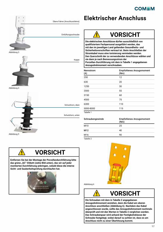
Elektrischer Anschluss
Die elektrischen Anschlüsse dürfen ausschließlich von qualifiziertem Fachpersonal ausgeführt werden, das mit den im jeweiligen Land geltenden Gesundheits- und Sicherheitsvorschriften vertraut ist. Beim Anschließen der Stromkabel muss eine Ionisierung vermieden werden.Den Querschnitt der zu verwendenden Anschlüsse wählen und sie dann je nach Bemessungsstrom der Porzellan-Durchführung mit dem in Tabelle 1 angegebenen Anzugsdrehmoment verschrauben.
Die Schrauben mit dem in Tabelle 2 angegebenen Anzugsdrehmoment anziehen, dann die Kabel am oberen Anschluss anschließen (Abbildung 6). Nachdem das Kabel angeschlossen wurde, sollte das Anzugsdrehmoment nochmals überprüft und mit den Werten in Tabelle 2 verglichen werden. Das Schraubenpaar wird anhand der Festigkeitsklasse der Schraube festgelegt, wobei darauf zu achten ist, dass es am Anschluss nicht zu einer Überhitzung kommt.
VORSICHT
VORSICHT
Abbildung 3
Abbildung 4
Abbildung 5
Obere Fahne (Anschlussfahne)
Entlüftungsschraube
Kappe
Schutzhorn, oben
Schutzhorn, unten
Entfernen Sie bei der Montage der Porzellandurchführung bitte das grüne „QC“-Etikett (siehe Bild unten), das wir auf jeder montierten Durchführung anbringen, sobald diese die interne Sicht- und Sauberkeitsprüfung durchlaufen hat.
VORSICHT
Nennstrom (A)
Empfohlenes Anzugsmoment (Nm)
250 12
630 20
1250 30
2000 55
3150 60
4500 75
6300 110
5000-8000 115
Schraubengewinde Empfohlenes Anzugsmoment (Nm)
M10 25
M12 40
M16 90
Tabelle 1
Tabelle 2
Abbildung 6
18
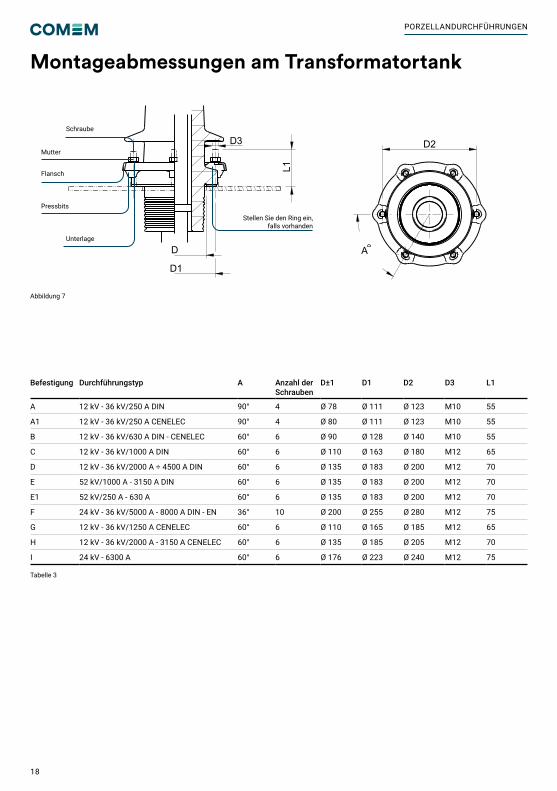
Montageabmessungen am Transformatortank
Tabelle 3
Abbildung 7
Befestigung Durchführungstyp A Anzahl der Schrauben
D±1 D1 D2 D3 L1
A 12 kV - 36 kV/250 A DIN 90° 4 Ø 78 Ø 111 Ø 123 M10 55
A1 12 kV - 36 kV/250 A CENELEC 90° 4 Ø 80 Ø 111 Ø 123 M10 55
B 12 kV - 36 kV/630 A DIN - CENELEC 60° 6 Ø 90 Ø 128 Ø 140 M10 55
C 12 kV - 36 kV/1000 A DIN 60° 6 Ø 110 Ø 163 Ø 180 M12 65
D 12 kV - 36 kV/2000 A ÷ 4500 A DIN 60° 6 Ø 135 Ø 183 Ø 200 M12 70
E 52 kV/1000 A - 3150 A DIN 60° 6 Ø 135 Ø 183 Ø 200 M12 70
E1 52 kV/250 A - 630 A 60° 6 Ø 135 Ø 183 Ø 200 M12 70
F 24 kV - 36 kV/5000 A - 8000 A DIN - EN 36° 10 Ø 200 Ø 255 Ø 280 M12 75
G 12 kV - 36 kV/1250 A CENELEC 60° 6 Ø 110 Ø 165 Ø 185 M12 65
H 12 kV - 36 kV/2000 A - 3150 A CENELEC 60° 6 Ø 135 Ø 185 Ø 205 M12 70
I 24 kV - 6300 A 60° 6 Ø 176 Ø 223 Ø 240 M12 75
M55x3
5535
105
14
2030
30
200
135
60°
70
M12
80
150
250
18
4070
40 70
90
M55X3
20
55115
40
100
25
223
679
20
20
222
210
183
120
9431
621
1
D3
L1
D
D1
A
D2
Silver platedexternal metal parts
FIXING DETAIL
A
A
Stellen Sie den Ring ein, falls vorhanden
Schraube
Unterlage
Pressbits
Flansch
Mutter
PORZELLANDURCHFÜHRUNGEN
19
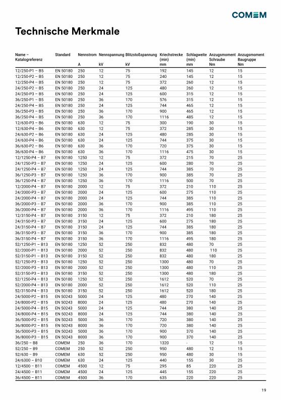
Technische Merkmale
Name – Katalogreferenz
Standard Nennstrom
A
Nennspannung
kV
Blitzstoßspannung
kV
Kriechstrecke(min)mm
Schlagweite(min)mm
Anzugsmoment SchraubeNm
Anzugsmoment BaugruppeNm
12/250-P1 – B5 EN 50180 250 12 75 192 145 12 1512/250-P2 – B5 EN 50180 250 12 75 240 145 12 1512/250-P4 – B5 EN 50180 250 12 75 372 260 12 1524/250-P2 – B5 EN 50180 250 24 125 480 260 12 1524/250-P3 – B5 EN 50180 250 24 125 600 315 12 1536/250-P1 – B5 EN 50180 250 36 170 576 315 12 1524/250-P4 – B5 EN 50180 250 24 125 744 465 12 1536/250-P3 – B5 EN 50180 250 36 170 900 465 12 1536/250-P4 – B5 EN 50180 250 36 170 1116 485 12 1512/630-P3 – B6 EN 50180 630 12 75 300 190 30 1512/630-P4 – B6 EN 50180 630 12 75 372 285 30 1524/630-P2 – B6 EN 50180 630 24 125 480 285 30 1524/630-P4 – B6 EN 50180 630 24 125 744 375 30 1536/630-P2 – B6 EN 50180 630 36 170 720 375 30 1536/630-P4 – B6 EN 50180 630 36 170 1116 475 30 1512/1250-P4 – B7 EN 50180 1250 12 75 372 215 70 2524/1250-P3 – B7 EN 50180 1250 24 125 600 280 70 2524/1250-P4 – B7 EN 50180 1250 24 125 744 385 70 2536/1250-P3 – B7 EN 50180 1250 36 170 900 385 70 2536/1250-P4 – B7 EN 50180 1250 36 170 1116 500 70 2512/2000-P4 – B7 EN 50180 2000 12 75 372 210 110 2524/2000-P3 – B7 EN 50180 2000 24 125 600 275 110 2524/2000-P4 – B7 EN 50180 2000 24 125 744 385 110 2536/2000-P3 – B7 EN 50180 2000 36 170 900 385 110 2536/2000-P4 – B7 EN 50180 2000 36 170 1116 495 110 2512/3150-P4 – B7 EN 50180 3150 12 75 372 210 180 2524/3150-P3 – B7 EN 50180 3150 24 125 600 275 180 2524/3150-P4 – B7 EN 50180 3150 24 125 744 385 180 2536/3150-P3 – B7 EN 50180 3150 36 170 900 385 180 2536/3150-P4 – B7 EN 50180 3150 36 170 1116 495 180 2552/1250-P1 – B13 EN 50180 1250 52 250 832 480 70 2552/2000-P1 – B13 EN 50180 2000 52 250 832 480 110 2552/3150-P1 – B13 EN 50180 3150 52 250 832 480 180 2552/1250-P3 – B13 EN 50180 1250 52 250 1300 480 70 2552/2000-P3 – B13 EN 50180 2000 52 250 1300 480 110 2552/3150-P3 – B13 EN 50180 3150 52 250 1300 480 180 2552/1250-P4 – B13 EN 50180 1250 52 250 1612 520 70 2552/2000-P4 – B13 EN 50180 2000 52 250 1612 520 110 2552/3150-P4 – B13 EN 50180 3150 52 250 1612 520 180 2524/5000-P2 – B15 EN 50243 5000 24 125 480 270 140 2524/8000-P2 – B15 EN 50243 8000 24 125 480 270 140 2524/5000-P4 – B15 EN 50243 5000 24 125 744 380 140 2524/8000-P4 – B15 EN 50243 8000 24 125 744 380 140 2536/5000-P2 – B15 EN 50243 5000 36 170 720 380 140 2536/8000-P2 – B15 EN 50243 8000 36 170 720 380 140 2536/5000-P3 – B15 EN 50243 5000 36 170 900 370 140 2536/8000-P3 – B15 EN 50243 8000 36 170 900 370 140 2536/250 – B8 COMEM 250 36 170 1320 - 12 1552/250 – B9 COMEM 250 52 250 950 480 12 1552/630 – B9 COMEM 630 52 250 950 480 30 1524/6300 – B10 COMEM 630 24 125 440 155 30 2512/4500 – B11 COMEM 4500 12 75 295 85 220 2524/4500 – B11 COMEM 4500 24 125 445 155 220 2536/4500 – B11 COMEM 4500 36 170 635 220 220 25
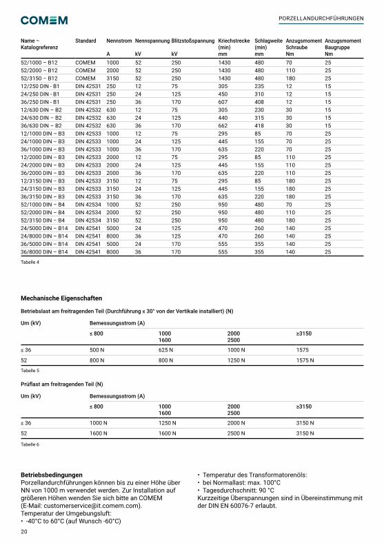
20
Name – Katalogreferenz
Standard Nennstrom
A
Nennspannung
kV
Blitzstoßspannung
kV
Kriechstrecke(min)mm
Schlagweite(min)mm
Anzugsmoment SchraubeNm
Anzugsmoment BaugruppeNm
52/1000 – B12 COMEM 1000 52 250 1430 480 70 2552/2000 – B12 COMEM 2000 52 250 1430 480 110 2552/3150 – B12 COMEM 3150 52 250 1430 480 180 2512/250 DIN - B1 DIN 42531 250 12 75 305 235 12 1524/250 DIN - B1 DIN 42531 250 24 125 450 310 12 1536/250 DIN - B1 DIN 42531 250 36 170 607 408 12 1512/630 DIN – B2 DIN 42532 630 12 75 305 230 30 1524/630 DIN – B2 DIN 42532 630 24 125 440 315 30 1536/630 DIN – B2 DIN 42532 630 36 170 662 418 30 1512/1000 DIN – B3 DIN 42533 1000 12 75 295 85 70 2524/1000 DIN – B3 DIN 42533 1000 24 125 445 155 70 2536/1000 DIN – B3 DIN 42533 1000 36 170 635 220 70 2512/2000 DIN – B3 DIN 42533 2000 12 75 295 85 110 2524/2000 DIN – B3 DIN 42533 2000 24 125 445 155 110 2536/2000 DIN – B3 DIN 42533 2000 36 170 635 220 110 2512/3150 DIN – B3 DIN 42533 3150 12 75 295 85 180 2524/3150 DIN – B3 DIN 42533 3150 24 125 445 155 180 2536/3150 DIN – B3 DIN 42533 3150 36 170 635 220 180 2552/1000 DIN – B4 DIN 42534 1000 52 250 950 480 70 2552/2000 DIN – B4 DIN 42534 2000 52 250 950 480 110 2552/3150 DIN – B4 DIN 42534 3150 52 250 950 480 180 2524/5000 DIN – B14 DIN 42541 5000 24 125 470 260 140 2524/8000 DIN – B14 DIN 42541 8000 36 125 470 260 140 2536/5000 DIN – B14 DIN 42541 5000 24 170 555 355 140 2536/8000 DIN – B14 DIN 42541 8000 36 170 555 355 140 25
Mechanische Eigenschaften
Betriebslast am freitragenden Teil (Durchführung ≤ 30° von der Vertikale installiert) (N)
Um (kV) Bemessungsstrom (A)
≤ 800 10001600
20002500
≥3150
≤ 36 500 N 625 N 1000 N 1575
52 800 N 800 N 1250 N 1575 N
Prüflast am freitragenden Teil (N)
Um (kV) Bemessungsstrom (A)
≤ 800 10001600
20002500
≥3150
≤ 36 1000 N 1250 N 2000 N 3150 N
52 1600 N 1600 N 2500 N 3150 N
BetriebsbedingungenPorzellandurchführungen können bis zu einer Höhe über NN von 1000 m verwendet werden. Zur Installation auf größeren Höhen wenden Sie sich bitte an COMEM(E-Mail: [email protected]).Temperatur der Umgebungsluft: • -40°C to 60°C (auf Wunsch -60°C)
• Temperatur des Transformatorenöls:• bei Normallast: max. 100°C• Tagesdurchschnitt: 90 °CKurzzeitige Überspannungen sind in Übereinstimmung mit der DIN EN 60076-7 erlaubt.
Tabelle 5
Tabelle 6
Tabelle 4
PORZELLANDURCHFÜHRUNGEN
21
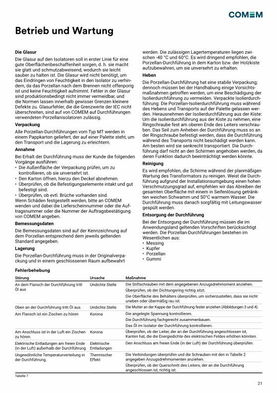
Betrieb und Wartung
Die GlasurDie Glasur auf den Isolatoren soll in erster Linie für eine gute Oberflächenbeschaffenheit sorgen, d. h. sie macht sie glatt und schmutzabweisend, wodurch sie leicht sauber zu halten ist. Die Glasur wird nicht benötigt, um das Eindringen von Feuchtigkeit in den Isolator zu verhin-dern, da das Porzellan nach dem Brennen nicht offenporig ist und keine Feuchtigkeit aufnimmt. Fehler in der Glasur sind produktionsbedingt nicht immer vermeidbar, und die Normen lassen innerhalb gewisser Grenzen kleinere Defekte zu. Glasurfehler, die die Grenzwerte der IEC nicht überschreiten, sind auf von COMEM auf Durchführungen verwendeten Porzellanisolatoren zulässig. VerpackungAlle Porzellan-Durchführungen vom Typ MT werden in einem Pappkarton geliefert, der auf einer Palette steht, um den Transport und die Lagerung zu erleichtern. AnnahmeBei Erhalt der Durchführung muss der Kunde die folgenden Vorgänge ausführen: • Die Außenfläche der Verpackung prüfen, um zu kontrollieren, ob sie unversehrt ist.• Den Karton öffnen, hierzu den Deckel abnehmen. • Überprüfen, ob die Befestigungselemente intakt und gut befestigt sind.• Überprüfen, ob evtl. Brüche vorhanden sind.Wenn Schäden festgestellt werden, bitte an COMEM wenden und dabei die Lieferscheinnummer oder die Auf-tragsnummer oder die Nummer der Auftragsbestätigung von COMEM angeben.BemessungsdatenDie Bemessungsdaten sind auf der Kennzeichnung auf dem Porzellan entsprechend dem jeweils geltenden Standard angegeben.LagerungDie Porzellan-Durchführung muss in der Originalverpa-ckung und in einem geschlossenen Raum aufbewahrt
werden. Die zulässigen Lagertemperaturen liegen zwi-schen -40 °C und 60°C. Es wird dringend empfohlen, die Porzellan-Durchführung in dem Karton bzw. der Holzkiste aufzubewahren, um sie unversehrt zu erhalten.HebenDie Porzellan-Durchführung hat eine stabile Verpackung; dennoch müssen bei der Handhabung einige Vorsichts-maßnahmen getroffen werden, um eine Beschädigung der Isolierdurchführung zu vermeiden. Verpackte Isolierdurch-führung: Die Porzellan-Isolierdurchführung muss während des Hebens und Transports auf der Palette gelassen wer-den. Herausnehmen der Isolierdurchführung aus der Kiste: Um die Isolierdurchführung aus der Kiste zu nehmen, eine Ringschraube fest am oberen Ende des Leiters verschrau-ben. Das Seil zum Anheben der Durchführung muss so an der Ringschraube befestigt werden, dass die Durchführung während des Transports nicht beschädigt werden kann.Am besten wird sie senkrecht transportiert. Die Durch-führung darf nicht an den Schirmen angehoben werden, da deren Funktion dadurch beeinträchtigt werden könnte.ReinigungEs wird empfohlen, die Schirme während der planmäßigen Wartung des Transformators zu reinigen. Weist die Durch-führung aufgrund der Installationsumgebung einen hohen Verschmutzungsgrad auf, empfehlen wir das Abreiben der gesamten Oberfläche mit einem in Seifenlösung getränk-ten weichen Schwamm und 50°C warmem Wasser. Die Durchführung muss danach sorgfältig mit Leitungswasser gespült werden.Entsorgung der DurchführungBei der Entsorgung der Durchführung müssen die im Anwendungsland geltenden Vorschriften berücksichtigt werden. Die Porzellan-Durchführungen bestehen im Wesentlichen aus:• Messing• Kupfer• Porzellan• Gummi
Fehlerbehebung
Störung Ursache Maßnahme
An dem Flansch der Durchführung tritt Öl aus
Undichte Stelle Die Stiftschrauben mit dem angegebenen Anzugsdrehmoment anziehen.Überprüfen, ob der Dichtungsring richtig sitzt.Die Oberfläche des Behälters überprüfen, um sicherzustellen, dass sie nicht uneben oder übermäßig rau ist.
Oben an der Durchführung tritt Öl aus Undichte Stelle Die Mutter an der Kappe der Durchführung fester anziehen (Abbildungen 3 und 4).
Am Flansch ist ein Zischen zu hören Korona Die angelegte Spannung kontrollieren.Die Durchführung fachgerecht zusammenbauen.Das Öl im Isolator der Durchführung kontrollieren.
Am Anschluss ist in der Luft ein Zischen zu hören.
Korona Überprüfen, ob der Leiter, der an der Durchführung angeschlossen ist, Kanten hat, die die Energiedichte des elektrischen Feldes erhöhen könnten.
Elektrische Entladungen am freien Ende (in der Luft) außerhalb der Durchführung
Elektrische Entladungen
Den Anschluss am freien Ende (in der Luft) der Durchführung überprüfen.
Ungewöhnliche Temperaturverteilung in der Durchführung.
Thermischer Effekt
Die Verbindungen überprüfen und die Schrauben mit den in Tabelle 2 angegeben Anzugsdrehmomenten anziehen.Überprüfen, ob der Querschnitt des Leiters, der an die Durchführung angeschlossen ist, richtig ist.
Mechanische Eigenschaften
Tabelle 7
22
Seguridad Descripción del producto
Instalación
Instrucciones de seguridadAsegúrese de que la persona que instale, ponga en funcio-namiento y trabaje con el aislador de porcelana:• posee las cualificaciones técnicas necesarias y es competente• cumple todas las instrucciones de montajeUnas operaciones no correctas o un mal uso puede supo-ner un peligro para:• la integridad física y los miembros del cuerpo• el equipo y otros activos del operador• el buen funcionamiento del equipoEn este manual, las instrucciones de seguridad se muestran de tres maneras diferentes para destacar la información importante.
Notas de seguridad sobre el funcionamiento del equipoLa instalación eléctrica está sujeta a relativas reglas de seguridad nacionales.
Esta información indica un peligro grave para la integridad física y la salud. Si no se tiene en cuenta esta advertencia, se pueden producir heridas graves o incluso mortales.
Deben respetarse estrictamente todas las normas de protección contra incendios pertinentes.
Esta información indica un daño especial al equipo u otras propiedades del usuario. No puede descartarse que se produzcan accidentes graves o incluso mortales.
La instalación, la conexión eléctrica y el montaje del equipo sólo pueden ser realizados por personal cualificado y de acuerdo con este manual de instrucciones. Es responsabilidad del usuario asegurarse de que el equipo se utilice únicamente para la aplicación especificada. Por cuestiones de seguridad, evite cualquier trabajo no autorizado e inadecuado.
Deben respetarse estrictamente los requisitos de funcionamiento e instalación descritos en este manual.Si no es así, puede dañarse el dispositivo o puede producirse un mal funcionamiento.
Estas notas ofrecen información importante o específica relativa al equipo o a cómo trabajar con el equipo.
ADVERTENCIA
ADVERTENCIA
PRECAUCIÓN
PRECAUCIÓN
PRECAUCIÓN
NOTA
Estas instrucciones son aplicables a los aisladores de porcelana con tensiones nominales de 12 kV a 52 kV y corrientes nominales de 250 A a 8000 A. Estos aisladores están diseñados para funcionar con la parte superior en el aire y la parte inferior sumergida en el aceite del transfor-mador. Los aisladores de porcelana han sido diseñados y fabricados de conformidad con la norma IEC 60137.
Montaje en la caja del transformadorPara la correcta instalación del aislante del aislador cerá-mico, siga el siguiente procedimiento:Realice un agujero de diámetro D (ver Tabla 3) en la caja del transformador, asegurándose de que no haya superficies irregulares que puedan causar problemas para el correcto funcionamiento del aislador. Los pernos para la fijación del aislador deben colocarse a lo largo de una circunferencia de diámetro D2, coaxial con el orificio realizado anteriormente (figura 1). Coloque la junta suministrada (Figura 1). El aislador debe colocarse como se muestra en la figura 2, aplique un par de apriete de 15 Nm con el perno M10 y 25 Nm con el perno M12 a las tuercas de fijación de la brida (figura 2).
Figura 2
Figura 1
El aislador de porcelana se llenará de aceite hasta que salga por su parte superior; esto se puede hacer a través del tornillo de purga en aisladores con corriente >630 A (figura 3) o actuando sobre el tapón para corrientes ≤ 630 A (figura 4). Al final, atornille la tuerca sobre el perno (figura 3-4) aplican-do los valores de par de apriete recomendados en la tabla 4. COMEM sugiere comprobar el par de apriete de la tuerca superior después del proceso de secado del transforma-dor. En caso de que se proporcionen cuernos, estos deben montarse con todos los materiales de acompañamiento como se informa en la figura 5.
AISLADORES DE PORCELANA

23
Conexión eléctrica
Las conexiones eléctricas sólo pueden ser realizadas por perso-nal cualificado y formado en las normas de seguridad e higiene del país correspondiente.Hay que tener cuidado con la conexión eléctrica para evitar fenómenos de ionización.Elija la sección de las conexiones a utilizar y conéctelas aplican-do el par de apriete recomendado en la Tabla 1 en función de la corriente nominal del aislador de porcelana.
Apriete los tornillos con el par de apriete indicado en la tabla 2 y conecte los cables al conector terminal superior (Figura 6). Después del cableado se recomienda comprobar de nuevo el par de apriete de fijación siguiendo los valores indicados en la tabla 2. Compruebe que las conexiones se realizan correctamente para evitar el sobrecalentamiento.
PRECAUCIÓN
PRECAUCIÓN
Figura 3
Figura 4
Figura 5
Bandera superior (conector terminal)
Tornillo de purga
Tapón
Cuerno superior
Cuerno inferior
Con el montaje del aislador de porcelana en el transformador, retire la etiqueta verde “QC” (ver imagen inferior) que coloca-mos en cada aislador montado una vez que pasa la inspección visual.
PRECAUCIÓN
Corriente nominal (A)
Par de apriete recomendado (Nm)
250 12
630 20
1250 30
2000 55
3150 60
4500 75
6300 110
5000-8000 115
Rosca del perno Par de apriete recomendado (Nm)
M10 25
M12 40
M16 90
Tabla 1
Tabla 2
Figura 6

24
Tabla 3
Figura 7
Fijación Tipo de aislador A N° de perno
D±1 D1 D2 D3 L1
A 12 kV - 36 kV/250 A DIN 90° 4 Ø 78 Ø 111 Ø 123 M10 55
A1 12 kV - 36 kV/250 A CENELEC 90° 4 Ø 80 Ø 111 Ø 123 M10 55
B 12 kV - 36 kV/630 A DIN - CENELEC 60° 6 Ø 90 Ø 128 Ø 140 M10 55
C 12 kV - 36 kV/1000 A DIN 60° 6 Ø 110 Ø 163 Ø 180 M12 65
D 12 kV - 36 kV/2000 A ÷ 4500 A DIN 60° 6 Ø 135 Ø 183 Ø 200 M12 70
E 52 kV/1000 A - 3150 A DIN 60° 6 Ø 135 Ø 183 Ø 200 M12 70
E1 52 kV/250 A - 630 A 60° 6 Ø 135 Ø 183 Ø 200 M12 70
F 24 kV - 36 kV/5000 A - 8000 A DIN - EN 36° 10 Ø 200 Ø 255 Ø 280 M12 75
G 12 kV - 36 kV/1250 A CENELEC 60° 6 Ø 110 Ø 165 Ø 185 M12 65
H 12 kV - 36 kV/2000 A - 3150 A CENELEC 60° 6 Ø 135 Ø 185 Ø 205 M12 70
I 24 kV - 6300 A 60° 6 Ø 176 Ø 223 Ø 240 M12 75
M55x3
5535
105
14
2030
30
200
135
60°
70
M12
80
150
250
18
4070
40 70
90
M55X3
20
55115
40
100
25
223
679
20
20
222
210
183
120
9431
621
1
D3
L1
D
D1
A
D2
Silver platedexternal metal parts
FIXING DETAIL
A
A
Anillo de ajuste
Prisionero
Arandela
Bloques
Brida
Tuerca
Dimensiones de montaje en el tanque del transformador
AISLADORES DE PORCELANA
25
Características técnicas
Nombre - referencia del catálogo
Estándar Corriente nominal A
Tensión nominal kV
Tensión de impulso de rayo seco kV
Distancia de fuga(mín) mm
Distancia de arqueo (mín) mm
Par de apriete del perno Nm
Conjunto de par de apriete Nm
12/250-P1 – B5 EN 50180 250 12 75 192 145 12 1512/250-P2 – B5 EN 50180 250 12 75 240 145 12 1512/250-P4 – B5 EN 50180 250 12 75 372 260 12 1524/250-P2 – B5 EN 50180 250 24 125 480 260 12 1524/250-P3 – B5 EN 50180 250 24 125 600 315 12 1536/250-P1 – B5 EN 50180 250 36 170 576 315 12 1524/250-P4 – B5 EN 50180 250 24 125 744 465 12 1536/250-P3 – B5 EN 50180 250 36 170 900 465 12 1536/250-P4 – B5 EN 50180 250 36 170 1116 485 12 1512/630-P3 – B6 EN 50180 630 12 75 300 190 30 1512/630-P4 – B6 EN 50180 630 12 75 372 285 30 1524/630-P2 – B6 EN 50180 630 24 125 480 285 30 1524/630-P4 – B6 EN 50180 630 24 125 744 375 30 1536/630-P2 – B6 EN 50180 630 36 170 720 375 30 1536/630-P4 – B6 EN 50180 630 36 170 1116 475 30 1512/1250-P4 – B7 EN 50180 1250 12 75 372 215 70 2524/1250-P3 – B7 EN 50180 1250 24 125 600 280 70 2524/1250-P4 – B7 EN 50180 1250 24 125 744 385 70 2536/1250-P3 – B7 EN 50180 1250 36 170 900 385 70 2536/1250-P4 – B7 EN 50180 1250 36 170 1116 500 70 2512/2000-P4 – B7 EN 50180 2000 12 75 372 210 110 2524/2000-P3 – B7 EN 50180 2000 24 125 600 275 110 2524/2000-P4 – B7 EN 50180 2000 24 125 744 385 110 2536/2000-P3 – B7 EN 50180 2000 36 170 900 385 110 2536/2000-P4 – B7 EN 50180 2000 36 170 1116 495 110 2512/3150-P4 – B7 EN 50180 3150 12 75 372 210 180 2524/3150-P3 – B7 EN 50180 3150 24 125 600 275 180 2524/3150-P4 – B7 EN 50180 3150 24 125 744 385 180 2536/3150-P3 – B7 EN 50180 3150 36 170 900 385 180 2536/3150-P4 – B7 EN 50180 3150 36 170 1116 495 180 2552/1250-P1 – B13 EN 50180 1250 52 250 832 480 70 2552/2000-P1 – B13 EN 50180 2000 52 250 832 480 110 2552/3150-P1 – B13 EN 50180 3150 52 250 832 480 180 2552/1250-P3 – B13 EN 50180 1250 52 250 1300 480 70 2552/2000-P3 – B13 EN 50180 2000 52 250 1300 480 110 2552/3150-P3 – B13 EN 50180 3150 52 250 1300 480 180 2552/1250-P4 – B13 EN 50180 1250 52 250 1612 520 70 2552/2000-P4 – B13 EN 50180 2000 52 250 1612 520 110 2552/3150-P4 – B13 EN 50180 3150 52 250 1612 520 180 2524/5000-P2 – B15 EN 50243 5000 24 125 480 270 140 2524/8000-P2 – B15 EN 50243 8000 24 125 480 270 140 2524/5000-P4 – B15 EN 50243 5000 24 125 744 380 140 2524/8000-P4 – B15 EN 50243 8000 24 125 744 380 140 2536/5000-P2 – B15 EN 50243 5000 36 170 720 380 140 2536/8000-P2 – B15 EN 50243 8000 36 170 720 380 140 2536/5000-P3 – B15 EN 50243 5000 36 170 900 370 140 2536/8000-P3 – B15 EN 50243 8000 36 170 900 370 140 2536/250 – B8 COMEM 250 36 170 1320 - 12 1552/250 – B9 COMEM 250 52 250 950 480 12 1552/630 – B9 COMEM 630 52 250 950 480 30 1524/6300 – B10 COMEM 630 24 125 440 155 30 2512/4500 – B11 COMEM 4500 12 75 295 85 220 2524/4500 – B11 COMEM 4500 24 125 445 155 220 2536/4500 – B11 COMEM 4500 36 170 635 220 220 25
26
Nombre - referencia del catálogo
Estándar Corriente nominal A
Tensión nominal kV
Tensión de impulso de rayo seco kV
Distancia de fuga(mín) mm
Distancia de arqueo (mín) mm
Par de apriete del perno Nm
Conjunto de par de apriete Nm
52/1000 – B12 COMEM 1000 52 250 1430 480 70 2552/2000 – B12 COMEM 2000 52 250 1430 480 110 2552/3150 – B12 COMEM 3150 52 250 1430 480 180 2512/250 DIN - B1 DIN 42531 250 12 75 305 235 12 1524/250 DIN - B1 DIN 42531 250 24 125 450 310 12 1536/250 DIN - B1 DIN 42531 250 36 170 607 408 12 1512/630 DIN – B2 DIN 42532 630 12 75 305 230 30 1524/630 DIN – B2 DIN 42532 630 24 125 440 315 30 1536/630 DIN – B2 DIN 42532 630 36 170 662 418 30 1512/1000 DIN – B3 DIN 42533 1000 12 75 295 85 70 2524/1000 DIN – B3 DIN 42533 1000 24 125 445 155 70 2536/1000 DIN – B3 DIN 42533 1000 36 170 635 220 70 2512/2000 DIN – B3 DIN 42533 2000 12 75 295 85 110 2524/2000 DIN – B3 DIN 42533 2000 24 125 445 155 110 2536/2000 DIN – B3 DIN 42533 2000 36 170 635 220 110 2512/3150 DIN – B3 DIN 42533 3150 12 75 295 85 180 2524/3150 DIN – B3 DIN 42533 3150 24 125 445 155 180 2536/3150 DIN – B3 DIN 42533 3150 36 170 635 220 180 2552/1000 DIN – B4 DIN 42534 1000 52 250 950 480 70 2552/2000 DIN – B4 DIN 42534 2000 52 250 950 480 110 2552/3150 DIN – B4 DIN 42534 3150 52 250 950 480 180 2524/5000 DIN – B14 DIN 42541 5000 24 125 470 260 140 2524/8000 DIN – B14 DIN 42541 8000 36 125 470 260 140 2536/5000 DIN – B14 DIN 42541 5000 24 170 555 355 140 2536/8000 DIN – B14 DIN 42541 8000 36 170 555 355 140 25
Características mecánicas
Carga de funcionamiento en voladizo (aislador instalado ≤ 30° de la vertical) (N)
Um (kV) Corriente nominal (A)
≤ 800 10001600
20002500
≥3150
≤ 36 500 N 625 N 1000 N 1575
52 800 N 800 N 1250 N 1575 N
Carga de ensayo en voladizo (N)
Um (kV) Corriente nominal (A)
≤ 800 10001600
20002500
≥3150
≤ 36 1000 N 1250 N 2000 N 3150 N
52 1600 N 1600 N 2500 N 3150 N
Condiciones de funcionamientoLos aisladores de porcelana pueden utilizarse hasta una altitud de 1000 m. Para su instalación a mayor altitud, póngase en contacto con COMEM(correo electrónico: [email protected]).Temperatura ambiente del aire: • según IEC 60137
Temperatura del aceite del transformador:• para carga normal: máx. 100°C• media diaria: 90°CLas sobretensiones temporales están permitidas de acuerdo con la norma IEC 60076-7.
Tabla 5
Tabla 6
Tabla 4
AISLADORES DE PORCELANA
27
Funcionamiento y mantenimiento
El esmalteEl esmalte de los aisladores tiene como objetivo principal dar un buen aspecto a la superficie, que es lisa y rechaza la suciedad, por lo que también es fácil de mantener limpia.Debido a las técnicas de fabricación, no siempre se pue-den evitar los defectos del esmalte y las normas permiten pequeños defectos dentro de ciertos límites. Fallos en el esmalte, que no superan los límites según la IEC están permitidos en los aisladores de porcelana utilizados por COMEM.EmbalajeTodos los aisladores de porcelana tipo MT se envían dentro de una caja de cartón colocada sobre un palé para facilitar su transporte y almacenamiento. AceptaciónAl recibir el aislador, el cliente debe realizar las siguientes operaciones: • examinar la superficie exterior del embalaje para comprobar que está intacto;• abrir la caja de embalaje quitando la tapa;• comprobar que los elementos de fijaciÓn están intactos y bien asegurados;• comprobar que no hay roturas. Si se detectan daños, póngase en contacto con COMEM, facilitando el número de albarán o de pedido.Datos de calificaciónLos datos de calificación se indican en la marca colocada en la porcelana de acuerdo con la norma correspondiente.AlmacenamientoEl aislador de porcelana debe guardarse en el embalaje original en el interior. Las temperaturas de almacenamien-to permitidas están en el rango de -40 °C a 60 °C.
Para conservar el aislador, se recomienda estrictamente mantener el aislador de porcelana cerrado dentro de la caja de cartón/madera.LevantamientoEl aislador de porcelana tiene un embalaje resistente; no obstante, hay que tomar algunas precauciones durante la manipulación para evitar dañar el aislador de aislamiento. Aislador aislante empaquetado: el aislador aislante de porcelana debe manipularse con la paleta. Aisladores de aislamiento fuera de la caja: para sacar el aislador de aislamiento de la caja, atornille un cáncamo con fuerza en el extremo superior del conductor. La cuerda para elevar el aislador debe estar sujeta al cáncamo para que el aislador no se dañe durante el transporte. La mejor posición para el transporte fuera de la caja es la vertical. El aislador no debe manipularse con los aletas, ya que esto podría comprometer su correcto funcionamiento.LimpiezaSe recomienda la limpieza de los aisladores durante el mantenimiento periódico del transformador. Si el aislador tiene un alto nivel de contaminación debido al entorno en el que está instalado, se recomienda la limpieza frotando toda la superficie con una esponja suave empapada en una solución de agua y jabón a 50°C. A continuación, el aislador debe aclararse a fondo con agua.Eliminación de los aisladoresEn caso de eliminación de aisladores, consulte la normati-va vigente en el país. Los principales materiales de los aisladores de porcelana son:• latón• cobre• cerámica• caucho.
Solución de problemas
Fallo Fenómeno físico Soluciones
Pérdida de aceite por la brida del aislador Fugas Apriete los pernos con el par de apriete recomendado.
Compruebe la correcta colocación de la junta.
Compruebe la superficie del depósito para asegurarse de que no hay partes desiguales o excesiva rugosidad.
Fuga de aceite por la parte superior del aislador Fugas Apriete mejor la tuerca del aislador del casco (figura 3 y 4).
Hay ruidos de silbido en la brida Efecto Corona Compruebe la tensión aplicada.
El montaje correcto del aislador.
Compruebe el aceite dentro del aislante del aislador.
Hay ruidos sibilantes en la conexión en el aire Efecto Corona Compruebe si el conductor conectado al aislador tiene alguna arista que provoque un aumento de la densidad del campo eléctrico.
Descarga eléctrica en el extremo del aire fuera del aislador
Descarga eléctrica Compruebe la conexión en el extremo de aire del aislador.
Distribución anormal de las temperaturas en el aislador.
Efecto térmico Compruebe las conexiones aplicando el par de apriete recomendado en la Tabla 2.
Compruebe que la sección de los conductores para la conexión al aislador es correcta.
Características mecánicas
Tabla 7
28
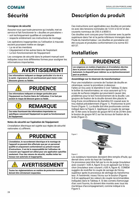
Sécurité Description du produit
Installation
Consignes de sécuritéAssurez-vous que toute personne qui installe, met en service et fait fonctionner le « douilles en porcelaine »• soit techniquement qualifiée et compétente• respecte entièrement ces instructions de montageLes opérations inappropriées ou l’utilisation à mauvais escient pourraient mettre en danger :• La vie et les membres • L’équipement et les autres biens de l’exploitant • Le bon fonctionnement de l’équipementLes consignes de sécurité dans le présent manuel sont indiquées sous trois différentes formes pour souligner les informations importantes.
Notes de sécurité sur l’opération de l’équipementL’installation électrique est sujette aux règles de sécurité nationales s’y afférent.
Ces informations indiquent un danger particulier à la vie et à la santé. L’ignorance de cet avertissement peut mener à des blessures graves ou fatales.
Toutes les réglementations en matière de protection incendie doivent être strictement respectées.
Ces informations indiquent un danger particulier pour l’équipement ou d’autres biens de l’utilisateur. Il ne faut pas exclure le risque de blessure grave ou fatale.
L’installation, le raccordement électrique et le montage de l’appareil ne peuvent être effectués que par un personnel qualifié et uniquement conformément au présent manuel d’instructions. Il est de la responsabilité de l’utilisateur de s’assurer que l’appareil est utilisé pour une application spécifiée seulement. Pour des raisons de sécurité, veuillez éviter les travaux non autorisés et inappropriés.
Les exigences en matière d’opération et d’installation décrites dans le présent manuel doivent être rigoureusement suivies. Autrement, le dispositif peut s'abîmer ou un dysfonctionnement peut se produire.
Ces notes fournissent des informations importantes ou spécifiques concernant l’équipement ou quant au fonctionnement de l’équipement.
AVERTISSEMENT
AVERTISSEMENT
PRUDENCE
PRUDENCE
PRUDENCE
REMARQUE
Ces instructions sont applicables aux douilles en porcelai-ne avec des tensions nominales de 12 kV à 52 kV et des courants nominaux de 250 A à 8000 A.Ces douilles sont conçues pour fonctionner avec la partie supérieure dans l’air et la partie inférieure immergée dans l’huile du transformateur. Les douilles en porcelaine ont été conçues et produites conformément à la norme IEC 60137.
Assemblage sur le réservoir du transformateurPour une installation correcte de l’isolant de douille en céramique, suivez la procédure ci-dessous :Faites un trou avec le diamètre D (voir Tableau 3) dans le boîtier du transformateur, en vous assurant qu’il n’y a pas de surfaces inégales qui pourraient causer des problèmes pour le bon fonctionnement de la douille. Les goujons de fixation de la douille doivent être placés le long d’une circonférence de diamètre D2 coaxial avec le trou réalisé précédemment (Figure 1). Positionnez le joint fourni (Figure 1). La douille doit être positionnée comme indiqué dans la Figure 2. Appliquez un couple de serrage de 15 Nm avec le boulon de goujon M10 et de 25 Nm avec le boulon de goujon M12 sur les écrous de fixation de la bride (Figure 2).
Figure 2
Figure 1
Les isolateurs traversees devraient être remplis d’huile, qui devrait donc sortir du haut de l’isolateur. Ce processus peut être fait par la vis de purge (insulateur avec courant > 630 A, figure 3) ou en agissant sur le bou-chon (insulateur avec courant ≤ 630 A, figure 4). COMEM suggère de revérifier le couple de serrage de l’écrou supérieur après le processus de séchage du transforma-teur. À l’extrémité, vissez l’écrou sur le boulon (Figures 3-4) en appliquant les valeurs de couple recommandées indiquées dans le Tableau 4. Si des cornets d’amorçage d’arc sont fournis, ils doivent être montés avec tous les ma-tériaux d’accompagnement, comme indiqué à la Figure 5.
DOUILLES EN PORCELAINE
29
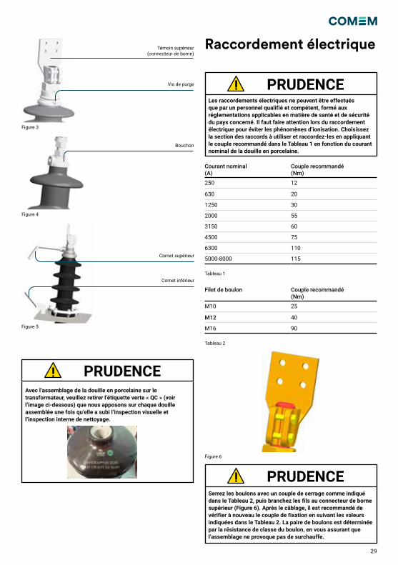
Raccordement électrique
Les raccordements électriques ne peuvent être effectués que par un personnel qualifié et compétent, formé aux réglementations applicables en matière de santé et de sécurité du pays concerné. Il faut faire attention lors du raccordement électrique pour éviter les phénomènes d’ionisation. Choisissez la section des raccords à utiliser et raccordez-les en appliquant le couple recommandé dans le Tableau 1 en fonction du courant nominal de la douille en porcelaine.
Serrez les boulons avec un couple de serrage comme indiqué dans le Tableau 2, puis branchez les fils au connecteur de borne supérieur (Figure 6). Après le câblage, il est recommandé de vérifier à nouveau le couple de fixation en suivant les valeurs indiquées dans le Tableau 2. La paire de boulons est déterminée par la résistance de classe du boulon, en vous assurant que l’assemblage ne provoque pas de surchauffe.
PRUDENCE
PRUDENCE
Figure 3
Figure 4
Figure 5
Témoin supérieur (connecteur de borne)
Vis de purge
Bouchon
Cornet supérieur
Cornet inférieur
Avec l’assemblage de la douille en porcelaine sur le transformateur, veuillez retirer l’étiquette verte « QC » (voir l’image ci-dessous) que nous apposons sur chaque douille assemblée une fois qu’elle a subi l’inspection visuelle et l’inspection interne de nettoyage.
PRUDENCE
Courant nominal (A)
Couple recommandé (Nm)
250 12
630 20
1250 30
2000 55
3150 60
4500 75
6300 110
5000-8000 115
Filet de boulon Couple recommandé (Nm)
M10 25
M12 40
M16 90
Tableau 1
Tableau 2
Figure 6
30
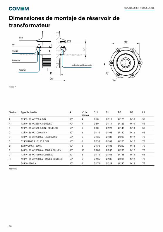
Tableau 3
Figure 7
Fixation Type de douille A N° de boulon
D±1 D1 D2 D3 L1
A 12 kV - 36 kV/250 A DIN 90° 4 Ø 78 Ø 111 Ø 123 M10 55
A1 12 kV - 36 kV/250 A CENELEC 90° 4 Ø 80 Ø 111 Ø 123 M10 55
B 12 kV - 36 kV/630 A DIN - CENELEC 60° 6 Ø 90 Ø 128 Ø 140 M10 55
C 12 kV - 36 kV/1000 A DIN 60° 6 Ø 110 Ø 163 Ø 180 M12 65
D 12 kV - 36 kV/2000 A ÷ 4500 A DIN 60° 6 Ø 135 Ø 183 Ø 200 M12 70
E 52 kV/1000 A - 3150 A DIN 60° 6 Ø 135 Ø 183 Ø 200 M12 70
E1 52 kV/250 A - 630 A 60° 6 Ø 135 Ø 183 Ø 200 M12 70
F 24 kV - 36 kV/5000 A - 8000 A DIN - EN 36° 10 Ø 200 Ø 255 Ø 280 M12 75
G 12 kV - 36 kV/1250 A CENELEC 60° 6 Ø 110 Ø 165 Ø 185 M12 65
H 12 kV - 36 kV/2000 A - 3150 A CENELEC 60° 6 Ø 135 Ø 185 Ø 205 M12 70
I 24 kV - 6300 A 60° 6 Ø 176 Ø 223 Ø 240 M12 75
M55x3
5535
105
14
2030
30
200
135
60°
70
M12
80
150
250
18
4070
40 70
90
M55X3
20
55115
40
100
25
223
679
20
20
222
210
183
120
9431
621
1
D3
L1
D
D1
A
D2
Silver platedexternal metal parts
FIXING DETAIL
A
A
Adjust ring (if present)
Bolt
Washer
Pressbits
Flange
Nut
Dimensiones de montaje de réservoir de transformateur
DOUILLES EN PORCELAINE
31
Caractéristiques techniques
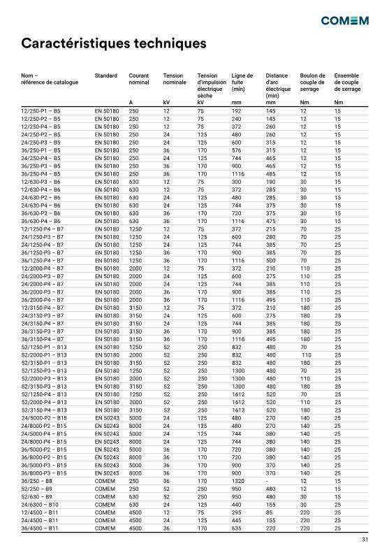
Nom – référence de catalogue
Standard Courant nominal A
Tension nominale kV
Tension d’impulsion électrique sèche kV
Ligne de fuite(min) mm
Distance d’arc électrique (min) mm
Boulon de couple de serrage Nm
Ensemble de couple de serrage Nm
12/250-P1 – B5 EN 50180 250 12 75 192 145 12 1512/250-P2 – B5 EN 50180 250 12 75 240 145 12 1512/250-P4 – B5 EN 50180 250 12 75 372 260 12 1524/250-P2 – B5 EN 50180 250 24 125 480 260 12 1524/250-P3 – B5 EN 50180 250 24 125 600 315 12 1536/250-P1 – B5 EN 50180 250 36 170 576 315 12 1524/250-P4 – B5 EN 50180 250 24 125 744 465 12 1536/250-P3 – B5 EN 50180 250 36 170 900 465 12 1536/250-P4 – B5 EN 50180 250 36 170 1116 485 12 1512/630-P3 – B6 EN 50180 630 12 75 300 190 30 1512/630-P4 – B6 EN 50180 630 12 75 372 285 30 1524/630-P2 – B6 EN 50180 630 24 125 480 285 30 1524/630-P4 – B6 EN 50180 630 24 125 744 375 30 1536/630-P2 – B6 EN 50180 630 36 170 720 375 30 1536/630-P4 – B6 EN 50180 630 36 170 1116 475 30 1512/1250-P4 – B7 EN 50180 1250 12 75 372 215 70 2524/1250-P3 – B7 EN 50180 1250 24 125 600 280 70 2524/1250-P4 – B7 EN 50180 1250 24 125 744 385 70 2536/1250-P3 – B7 EN 50180 1250 36 170 900 385 70 2536/1250-P4 – B7 EN 50180 1250 36 170 1116 500 70 2512/2000-P4 – B7 EN 50180 2000 12 75 372 210 110 2524/2000-P3 – B7 EN 50180 2000 24 125 600 275 110 2524/2000-P4 – B7 EN 50180 2000 24 125 744 385 110 2536/2000-P3 – B7 EN 50180 2000 36 170 900 385 110 2536/2000-P4 – B7 EN 50180 2000 36 170 1116 495 110 2512/3150-P4 – B7 EN 50180 3150 12 75 372 210 180 2524/3150-P3 – B7 EN 50180 3150 24 125 600 275 180 2524/3150-P4 – B7 EN 50180 3150 24 125 744 385 180 2536/3150-P3 – B7 EN 50180 3150 36 170 900 385 180 2536/3150-P4 – B7 EN 50180 3150 36 170 1116 495 180 2552/1250-P1 – B13 EN 50180 1250 52 250 832 480 70 2552/2000-P1 – B13 EN 50180 2000 52 250 832 480 110 2552/3150-P1 – B13 EN 50180 3150 52 250 832 480 180 2552/1250-P3 – B13 EN 50180 1250 52 250 1300 480 70 2552/2000-P3 – B13 EN 50180 2000 52 250 1300 480 110 2552/3150-P3 – B13 EN 50180 3150 52 250 1300 480 180 2552/1250-P4 – B13 EN 50180 1250 52 250 1612 520 70 2552/2000-P4 – B13 EN 50180 2000 52 250 1612 520 110 2552/3150-P4 – B13 EN 50180 3150 52 250 1612 520 180 2524/5000-P2 – B15 EN 50243 5000 24 125 480 270 140 2524/8000-P2 – B15 EN 50243 8000 24 125 480 270 140 2524/5000-P4 – B15 EN 50243 5000 24 125 744 380 140 2524/8000-P4 – B15 EN 50243 8000 24 125 744 380 140 2536/5000-P2 – B15 EN 50243 5000 36 170 720 380 140 2536/8000-P2 – B15 EN 50243 8000 36 170 720 380 140 2536/5000-P3 – B15 EN 50243 5000 36 170 900 370 140 2536/8000-P3 – B15 EN 50243 8000 36 170 900 370 140 2536/250 – B8 COMEM 250 36 170 1320 - 12 1552/250 – B9 COMEM 250 52 250 950 480 12 1552/630 – B9 COMEM 630 52 250 950 480 30 1524/6300 – B10 COMEM 630 24 125 440 155 30 2512/4500 – B11 COMEM 4500 12 75 295 85 220 2524/4500 – B11 COMEM 4500 24 125 445 155 220 2536/4500 – B11 COMEM 4500 36 170 635 220 220 25
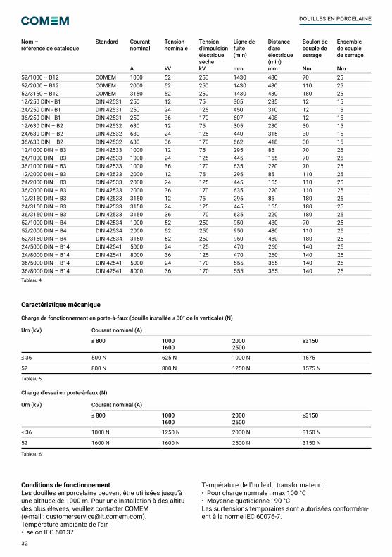
32
Nom – référence de catalogue
Standard Courant nominal A
Tension nominale kV
Tension d’impulsion électrique sèche kV
Ligne de fuite(min) mm
Distance d’arc électrique (min) mm
Boulon de couple de serrage Nm
Ensemble de couple de serrage Nm
52/1000 – B12 COMEM 1000 52 250 1430 480 70 2552/2000 – B12 COMEM 2000 52 250 1430 480 110 2552/3150 – B12 COMEM 3150 52 250 1430 480 180 2512/250 DIN - B1 DIN 42531 250 12 75 305 235 12 1524/250 DIN - B1 DIN 42531 250 24 125 450 310 12 1536/250 DIN - B1 DIN 42531 250 36 170 607 408 12 1512/630 DIN – B2 DIN 42532 630 12 75 305 230 30 1524/630 DIN – B2 DIN 42532 630 24 125 440 315 30 1536/630 DIN – B2 DIN 42532 630 36 170 662 418 30 1512/1000 DIN – B3 DIN 42533 1000 12 75 295 85 70 2524/1000 DIN – B3 DIN 42533 1000 24 125 445 155 70 2536/1000 DIN – B3 DIN 42533 1000 36 170 635 220 70 2512/2000 DIN – B3 DIN 42533 2000 12 75 295 85 110 2524/2000 DIN – B3 DIN 42533 2000 24 125 445 155 110 2536/2000 DIN – B3 DIN 42533 2000 36 170 635 220 110 2512/3150 DIN – B3 DIN 42533 3150 12 75 295 85 180 2524/3150 DIN – B3 DIN 42533 3150 24 125 445 155 180 2536/3150 DIN – B3 DIN 42533 3150 36 170 635 220 180 2552/1000 DIN – B4 DIN 42534 1000 52 250 950 480 70 2552/2000 DIN – B4 DIN 42534 2000 52 250 950 480 110 2552/3150 DIN – B4 DIN 42534 3150 52 250 950 480 180 2524/5000 DIN – B14 DIN 42541 5000 24 125 470 260 140 2524/8000 DIN – B14 DIN 42541 8000 36 125 470 260 140 2536/5000 DIN – B14 DIN 42541 5000 24 170 555 355 140 2536/8000 DIN – B14 DIN 42541 8000 36 170 555 355 140 25
Caractéristique mécanique
Charge de fonctionnement en porte-à-faux (douille installée ≤ 30° de la verticale) (N)
Um (kV) Courant nominal (A)
≤ 800 10001600
20002500
≥3150
≤ 36 500 N 625 N 1000 N 1575
52 800 N 800 N 1250 N 1575 N
Charge d’essai en porte-à-faux (N)
Um (kV) Courant nominal (A)
≤ 800 10001600
20002500
≥3150
≤ 36 1000 N 1250 N 2000 N 3150 N
52 1600 N 1600 N 2500 N 3150 N
Conditions de fonctionnementLes douilles en porcelaine peuvent être utilisées jusqu’à une altitude de 1000 m. Pour une installation à des altitu-des plus élevées, veuillez contacter COMEM(e-mail : [email protected]).Température ambiante de l’air : • selon IEC 60137
Température de l’huile du transformateur :• Pour charge normale : max 100 °C• Moyenne quotidienne : 90 °CLes surtensions temporaires sont autorisées conformém-ent à la norme IEC 60076-7.
Tableau 5
Tableau 6
Tableau 4
DOUILLES EN PORCELAINE
33
Utilisation et entretien
La glaçureLa glaçure sur les isolants est principalement destinée à donner un bon aspect de surface qui est lisse et rejette la saleté, et est donc également facile à garder propre.Le vitrage n’est pas nécessaire pour empêcher l’humidité de pénétrer dans l’isolant, car la porcelaine elle-même, après la cuisson, est non poreuse et n’absorbe pas l’humidité.En raison des techniques de fabrication, les défauts de glaçure ne peuvent pas toujours être évités et les normes permettent des défauts mineurs dans certaines limites. Les défauts de glaçure, ne dépassant pas les limites selon la norme IEC, sont autorisés sur les isolants en porcelaine utilisés par COMEM sur les douilles. EmballageToutes les douilles en porcelaine de type MT sont expéd-iées dans une boîte en carton positionnée sur une palette pour faciliter le transport et le stockage. AcceptationLors de la réception de la douille, le Client doit effectuer les opérations suivantes : examiner la surface extérieure de l’emballage pour vérifier qu’elle est intacte.• Ouvrir la caisse d’emballage en retirant le couvercle. • Vérifier que les éléments de fixation sont intacts et bien fixés.• Vérifier qu’il n’y a pas de ruptures.Si des dommages sont constatés, veuillez contacter COMEM, en indiquant le numéro du bon de livraison ou le numéro du bon de commande ou bien, le numéro d’accusé de réception COMEM.Données nominalesLes données nominales sont indiquées sur la marque apposée sur la porcelaine en accord avec la norme corre-spondante.StockageLa douille en porcelaine doit être conservée dans l’emballage d’origine à l’intérieur. Les températures de
stockage admissibles sont comprises entre -40 et 60 °C. Pour préserver la douille, il est strictement recommandé de garder la douille en porcelaine fermée à l’intérieur de la boîte en carton/bois.LevageLa douille en porcelaine a un emballage solide ; néanm-oins, certaines précautions doivent être prises pendant la manipulation pour éviter d’endommager la douille isolante. Douille isolante emballée : l’isolant de douille en céramique doit être manipulé à l’aide de la palette. Douil-les isolantes en dehors de la caisse : pour retirer la douille isolante de la caisse, vissez un boulon à œil fermement dans l’extrémité supérieure du conducteur. La corde de levage de la douille doit être fixée au boulon à œil de façon à ne pas endommager la douille pendant le transport. La meilleure position pour le transport hors de la caisse est la verticale. La douille ne doit pas être manipulée à l’aide des hangars, car cela pourrait compromettre le bon fonctionnement.NettoyageLe nettoyage des hangars pendant l’entretien périodique du transformateur est recommandé. Si la douille présente un niveau élevé de pollution en raison de l’environnement dans lequel elle est installée, nous recommandons de la nettoyer en frottant toute la surface avec une éponge douce imbibée d’une solution de savon et d’eau à 50 °C. La douille doit ensuite être rincée en profondeur à l’eau du robinet.Élimination de la douilleEn cas d’élimination de la douille, reportez-vous à la rég-lementation en vigueur dans le pays. Les principaux matériaux de la douille en porcelaine sont les suivants :• Laiton• Cuivre• Céramique• Caoutchouc
Dépannage
Défaut Phénomène physique Solutions
Perte d’huile de la bride de la douille
Fuite Serrez les boulons de goujon au couple recommandé.Vérifiez le bon positionnement du joint.Vérifiez la surface du réservoir pour vous assurer qu’il n’y a pas de parties inégales ou de rugosité excessive.
Fuite d’huile du haut de la douille Fuite Serrez mieux l’écrou sur la douille du capot (Figures 3 et 4).
Il y a des sifflements au niveau de la bride.
Effet Corona Vérifiez la tension appliquée.Vérifiez le bon assemblage de la douille.Vérifiez l’huile à l’intérieur de l’isolant de la douille.
Il y a des sifflements au niveau du raccord dans l’air.
Effet Corona Vérifiez si le conducteur raccordé à la douille a des bords qui provoquent une augmentation de la densité du champ électrique.
Décharge électrique à l’extrémité de l’air à l’extérieur de la douille
Décharge électrique Vérifiez la connexion à l’extrémité air de la douille.
Distribution anormale des températures dans la douille
Effet thermique Vérifiez les connexions en appliquant le couple recommandé dans le Tableau 2.Vérifiez que la section des conducteurs pour la connexion à la douille est correcte.
Caractéristique mécanique
Tableau 7


COMEM SpA
Localita’ Signolo 22, Sr11 36054 Montebello Vicentino Vicenza - Italy Tel +39 0444 449 311
www.comem.com The data and illustrations are not binding. We reserve the right to modify the contents of this document without prior notice following the technical and product developments.
Copyright 2021 COMEM. All rights reserved
Manual-05-2021
EN: This installation manual contains essential information for the user required to install & operate the product. In case you need any further information, contact us at [email protected]
IT: Questo manuale di installazione contiene informazioni essenziali per l’utente per installare e utilizzare il prodotto. Per ulteriori informazioni, contattare [email protected]
DE: Dieses Handbuch für Installation enthält wichtige Informationen für den Benutzer, die für die Installation und den Betrieb des Produkts erforderlich sind. Falls Sie weitere Informationen benötigen, kontaktieren Sie [email protected]
ES: Este manual de instalación contiene información esencial para el usuario que instale y trabaje con el producto. En caso de que necesite más información, póngase en contacto con [email protected]
FR: Ce manuel d’installation contient des informations essentielles pour l’utilisateur requis pour installer et utiliser le produit. Si vous avez besoin de plus d’informations, contactez-nous à [email protected]
Related Documents