POPCORN MACHINE SENIOR DESIGN PROJECT PROPOSAL ECE 4850: DESIGN III May 5, 2008 JOHN E. ARUMA Instructor Approval ________________________________________ __________________ Dr. YangQuan Chen Date Electrical and Computer Engineering Department Utah State University PDF Creator - PDF4Free v2.0 http://www.pdf4free.com

Welcome message from author
This document is posted to help you gain knowledge. Please leave a comment to let me know what you think about it! Share it to your friends and learn new things together.
Transcript

POPCORN MACHINE
SENIOR DESIGN PROJECT PROPOSAL
ECE 4850: DESIGN III
May 5, 2008
JOHN E. ARUMA
Instructor Approval ________________________________________ __________________
Dr. YangQuan Chen DateElectrical and Computer Engineering
DepartmentUtah State University
PDF Creator - PDF4Free v2.0 http://www.pdf4free.com

Table of contents
1 INTRODUCTION ....................................................................................................................... 3
2 PROBLEM DEFINITION .......................................................................................................... 3
3 OBJECTIVES.............................................................................................................................. 5
4 DELIVERABLES........................................................................................................................ 6
5 ENGINEERING APPROACH ................................................................................................... 7
5.1 Project Description .............................................................................................................. 8
6 PROJECT MANAGEMENT...................................................................................................... 9
6.1 Tasks................................................................................................................................... 11
6.2 Time Management and Scheduling.................................................................................. 23
6.3 Budget ................................................................................................................................ 24
7 CONCLUSION.......................................................................................................................... 25
8 ATTACHMENTS...................................................................................................................... 26
Table of FiguresFigure 1 Popcorn Controller comparison 7Figure 2 Tradition method 7Figure 3 Flow diagram 8Figure 4 Preliminary Block diagram 9Figure 5 Power diagram 10Figure 6 Schematic diagram of a microwave 10Figure 7 Schematic of modified oven 11Figure 8 Block diagram of Popcorn Controller 12Figure 9 Software flow diagram 14Figure 10 Sample GUI Screenshot 15Figure 11 Popup screen shots 16Figure 12 Signal processing module 17Figure 13 Filtered signal plots 18Figure 14 Modification section block diagram 22Figure 15 Gantt Chart 24Figure 16 Table of costs 25
PDF Creator - PDF4Free v2.0 http://www.pdf4free.com
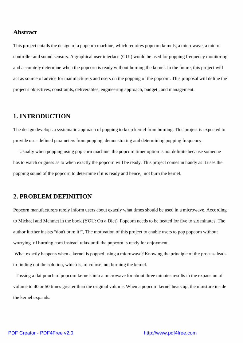
Abstract
This project entails the design of a popcorn machine, which requires popcorn kernels, a microwave, a micro-
controller and sound sensors. A graphical user interface (GUI) would be used for popping frequency monitoring
and accurately determine when the popcorn is ready without burning the kernel. In the future, this project will
act as source of advice for manufacturers and users on the popping of the popcorn. This proposal will define the
project's objectives, constraints, deliverables, engineering approach, budget , and management.
1. INTRODUCTION
The design develops a systematic approach of popping to keep kernel from burning. This project is expected to
provide user-defined parameters from popping, demonstrating and determining popping frequency.
Usually when popping using pop corn machine, the popcorn timer option is not definite because someone
has to watch or guess as to when exactly the popcorn will be ready. This project comes in handy as it uses the
popping sound of the popcorn to determine if it is ready and hence, not burn the kernel.
2. PROBLEM DEFINITION
Popcorn manufacturers rarely inform users about exactly what times should be used in a microwave. According
to Michael and Mehmet in the book (YOU: On a Diet). Popcorn needs to be heated for five to six minutes. The
author further insists “don't burn it!”, The motivation of this project to enable users to pop popcorn without
worrying of burning corn instead relax until the popcorn is ready for enjoyment.
What exactly happens when a kernel is popped using a microwave? Knowing the principle of the process leads
to finding out the solution, which is, of course, not burning the kernel.
Tossing a flat pouch of popcorn kernels into a microwave for about three minutes results in the expansion of
volume to 40 or 50 times greater than the original volume. When a popcorn kernel heats up, the moisture inside
the kernel expands.
PDF Creator - PDF4Free v2.0 http://www.pdf4free.com

There are three elements that make popcorn work.
1. Moisture inside the kernel
2. Starch inside the kernel
3. The hard shell surrounding the shell.
During the heating of the popcorn, in a microwave, the moisture inside the kernel expands. Moisture parameter
is vital to the popcorn kernel; unless the percentage of the moisture in the kernel is in the right proportion, the
kernel won't pop. When the pressure inside the hard shell becomes high enough, the kernel explodes.
Overcooking the popcorn, results in an unfavorable aroma and inconsumable popcorn. Analysis of the popcorn
popping sound frequency leads us to a new method of popping corn. The new design using Popcorn Controller
pops the corn at right time limit for the best quality. This design uses sound signal of pops to determine whether
the corn is ready hence switching off the microwave.
Summary of Design Process
The report contains the conclusion of the documentation detailing all of the design details integral to the
solution of popping or burning kernels. It covers the testing of DSK board, Reed Relay DIP switch, developed
GUI and also the refinement of entire design. The outcome of the design is a working prototype which if
scheduled to the next design process of mass production. The preliminary design and implementation phases of
this design are discussed in details herein.
Summary of results
The resulting elements of this design process could be categorized into the three sections: working design
consisting of a hardware section, the actual design that includes software design, and the finished design that
includes interpolation of hardware and software to come up with a pop corn controller system. The design of
Popcorn controller system was a complete success.
PDF Creator - PDF4Free v2.0 http://www.pdf4free.com
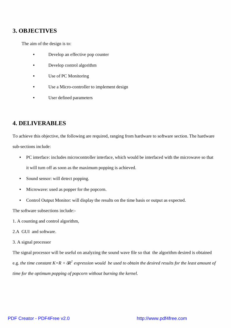
3. OBJECTIVES
The aim of the design is to:
• Develop an effective pop counter
• Develop control algorithm
• Use of PC Monitoring
• Use a Micro-controller to implement design
• User defined parameters
4. DELIVERABLES
To achieve this objective, the following are required, ranging from hardware to software section. The hardware
sub-sections include:
• PC interface: includes microcontroller interface, which would be interfaced with the microwave so that
it will turn off as soon as the maximum popping is achieved.
• Sound sensor: will detect popping.
• Microwave: used as popper for the popcorn.
• Control Output Monitor: will display the results on the time basis or output as expected.
The software subsections include:-
1. A counting and control algorithm,
2.A GUI and software.
3. A signal processor
The signal processor will be useful on analyzing the sound wave file so that the algorithm desired is obtained
e.g. the time constant K=R + ôR2 expression would be used to obtain the desired results for the least amount of
time for the optimum popping of popcorn without burning the kernel.
PDF Creator - PDF4Free v2.0 http://www.pdf4free.com
Social Implications
This design will change people’s lifestyles, as users will be able to pop popcorn without having to pay attention
or stand next to microwave for fear of burning the kernels. The popcorn Controller could be incorporated to the
normal microwave design or sold separately. Incorporating the Popcorn Controller into the microwave design
will raise the cost of microwave with a 5% margin:- the convenience and the purpose surpasses the cost
implications. A separate Popcorn Controller is 10% cost price of a Microwave.
Report Organization and Summary
The next sections of the design indicate the design process, addressing the preliminary design, ranging from
block-wise description to component level description. The decisions made to achieve the desired results will
be discussed and the final design tested and implemented. The project management and final budget will be
presented and final conclusive comments will be made including the accomplishments of the design and further
refinement if needed.
5. Engineering Approach
Preliminary design
This section consists of brainstorming on different ideas on how to design a Popcorn Controller. Different
techniques suggested were vetted. The main objective was to create a scalable design without compromising the
main objectives. The different methods of popping popcorn without burning the kernels;- flouted included:
Manual popcorn monitoring
Time setting on the microwave
Popcorn Controller machine
Manual popcorn monitoring;- requires a user to watch the microwave in case the pop corn burns. It requires
diligent and patient monitoring of the pop corn.
PDF Creator - PDF4Free v2.0 http://www.pdf4free.com
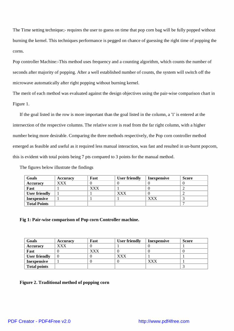
The Time setting technique;- requires the user to guess on time that pop corn bag will be fully popped without
burning the kernel. This techniques performance is pegged on chance of guessing the right time of popping the
corns.
Pop controller Machine:-This method uses frequency and a counting algorithm, which counts the number of
seconds after majority of popping. After a well established number of counts, the system will switch off the
microwave automatically after right popping without burning kernel.
The merit of each method was evaluated against the design objectives using the pair-wise comparison chart in
Figure 1.
If the goal listed in the row is more important than the goal listed in the column, a '1' is entered at the
intersection of the respective columns. The relative score is read from the far right column, with a higher
number being more desirable. Comparing the three methods respectively, the Pop corn controller method
emerged as feasible and useful as it required less manual interaction, was fast and resulted in un-burnt popcorn,
this is evident with total points being 7 pts compared to 3 points for the manual method.
The figures below illustrate the findings
Goals Accuracy Fast User friendly Inexpensive ScoreAccuracy XXX 0 0 0 0Fast 1 XXX 1 0 2User friendly 1 1 XXX 0 2Inexpensive 1 1 1 XXX 3Total Points 7
Fig 1: Pair-wise comparison of Pop corn Controller machine.
Goals Accuracy Fast User friendly Inexpensive ScoreAccuracy XXX 0 1 0 1Fast 0 XXX 0 0 0User friendly 0 0 XXX 1 1Inexpensive 1 0 0 XXX 1Total points 3
Figure 2. Traditional method of popping corn
PDF Creator - PDF4Free v2.0 http://www.pdf4free.com

The following is the preliminary algorithm diagram of the project:
Figure 3. Preliminary flow diagram of popcorn design
A device is required to detect the sound signal from the microwave which conveniently is microphone. The
sound signal detected from the microwave is fed to the microcontroller, which implements a new algorithm that
implements the Popcorn Controller. After the objective is achieved, there will be improved microwave user
interface, monitoring popping using a PC, and success of implementing the controller using the on-board
microprocessor.
PDF Creator - PDF4Free v2.0 http://www.pdf4free.com

Figure 4 shows the preliminary basic block diagram.
Figure 4. System Preliminary block diagram.
PDF Creator - PDF4Free v2.0 http://www.pdf4free.com
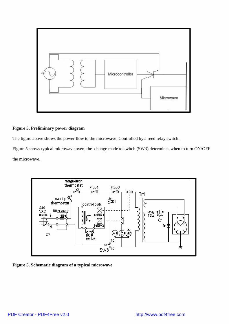
Figure 5. Preliminary power diagram
The figure above shows the power flow to the microwave. Controlled by a reed relay switch.
Figure 5 shows typical microwave oven, the change made to switch (SW3) determines when to turn ON/OFF
the microwave.
Figure 5. Schematic diagram of a typical microwave
PDF Creator - PDF4Free v2.0 http://www.pdf4free.com

A brief explanation of the circuit operation of the microwave oven is required so that the modification
suggested using the Popcorn Controller is understood.Generically Sw1 is the primary interlock switch (upper).
Sw2 is the secondary interlock switch. R1 is the monitor resistor. Sw3 is the interlock monitor switch. M1 is the
geared motor for the turntable where (the food to be cooked sits). M2 is a motor for the fan which draws air
through the oven and magnetron. Connected in parallel with M1 and M2 is the cavity lamp, which lights whilst
food is cooking. Fs2 is a high voltage fuse (typically 0.7A and 5kV breaking capacity). C1 is a high voltage
capacitor. D1 is a high voltage diode. The point of interest is the SW3 switch which is normally open. Instead of
using this switch as usual, this project introduce the Reed relay DIP switch, which would accept low voltage
from DSK board and turn on and off the Microwave as programmed, into the board.
The modified circuit diagram is shown in Figure 6.
Figure 7. Schematic of modified oven
After the modifications discussed above are made, the final design block diagram is finished as shown in Fig 8
PDF Creator - PDF4Free v2.0 http://www.pdf4free.com
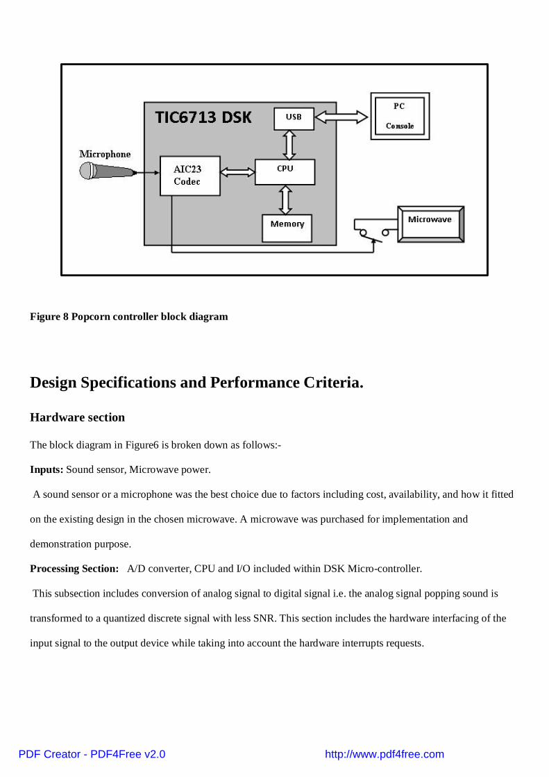
Figure 8 Popcorn controller block diagram
Design Specifications and Performance Criteria.
Hardware section
The block diagram in Figure6 is broken down as follows:-
Inputs: Sound sensor, Microwave power.
A sound sensor or a microphone was the best choice due to factors including cost, availability, and how it fitted
on the existing design in the chosen microwave. A microwave was purchased for implementation and
demonstration purpose.
Processing Section: A/D converter, CPU and I/O included within DSK Micro-controller.
This subsection includes conversion of analog signal to digital signal i.e. the analog signal popping sound is
transformed to a quantized discrete signal with less SNR. This section includes the hardware interfacing of the
input signal to the output device while taking into account the hardware interrupts requests.
PDF Creator - PDF4Free v2.0 http://www.pdf4free.com
Output section: Popped popcorn, PC GUI
This subsection consists of the product desired or end result. It’s the expectation from the user. It includes the
ready popped popcorn. Visual display the popping frequency and playing of some kind of music at the end of
the popping. There will be a pop up from the GUI indicating to the user that the popping is done or a warning to
not open the microwave during the popping period.
Software Algorithm
The choice of the programming language was dictated and supported by the board. The viable option with
respect to DSK board was C/ C++ language which enables communication between the systems. The
programming language is directly interfaced with MatLab by using #include ‘engine.h’ routine. This
information will be embedded inside the micro-controller chip for operation. This section entails popping
algorithm, development environment, and GUI improvements.
The popping algorithm consists of popping by time, popping by percentage and pop by average number of
kernels by bag size. The development environment consists of windows XP SP2, code composer studio-
developed by Texas Instruments interfaces with a TI DSP board.
Flow decisions are illustrated in the Figure7
PDF Creator - PDF4Free v2.0 http://www.pdf4free.com
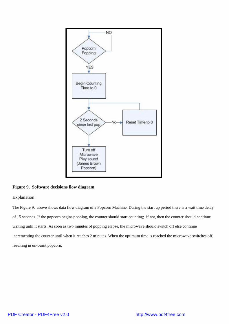
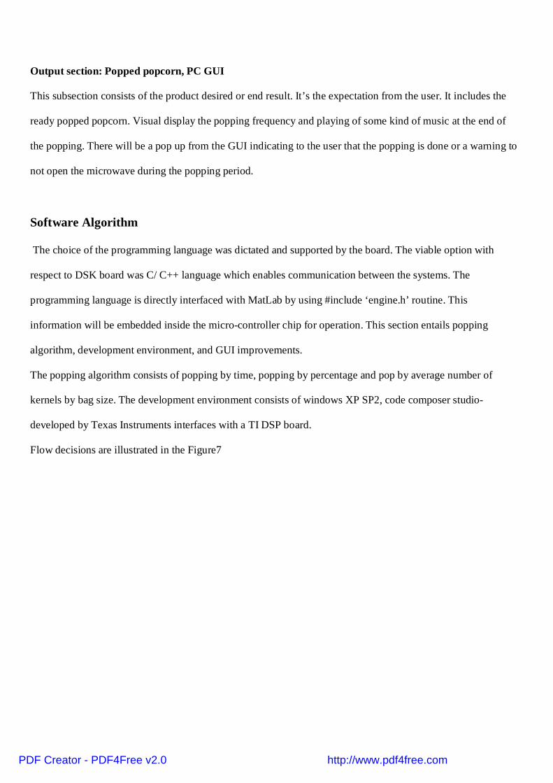
Figure 9. Software decisions flow diagram
Explanation:
The Figure 9, above shows data flow diagram of a Popcorn Machine. During the start up period there is a wait time delay
of 15 seconds. If the popcorn begins popping, the counter should start counting; if not, then the counter should continue
waiting until it starts. As soon as two minutes of popping elapse, the microwave should switch off else continue
incrementing the counter until when it reaches 2 minutes. When the optimum time is reached the microwave switches off,
resulting in un-burnt popcorn.
PDF Creator - PDF4Free v2.0 http://www.pdf4free.com
The Figure 10, shows plots of popping frequency and pop ups indicating different scenarios ranging from popping
frequency, sampling, and time delay for popping.
The screenshot below shows what the GUI will look like. The two criteria of popping are: popping by
percentage (i.e. popping the average number of kernels by bag size) and popping by maximum (popping the
maximum number of kernels without burning according to the sizes chosen). The black empty screen will
display the popping frequency if the user wants to view.
Figure 10. Sample GUI screenshot
PDF Creator - PDF4Free v2.0 http://www.pdf4free.com
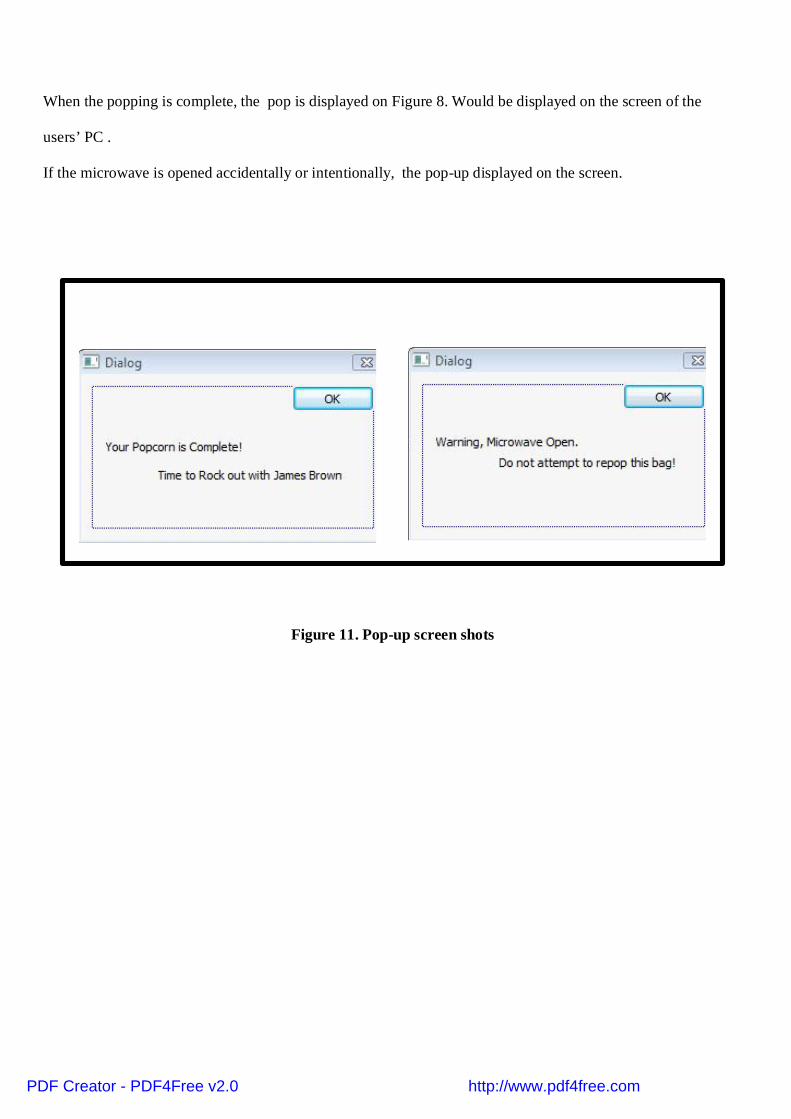
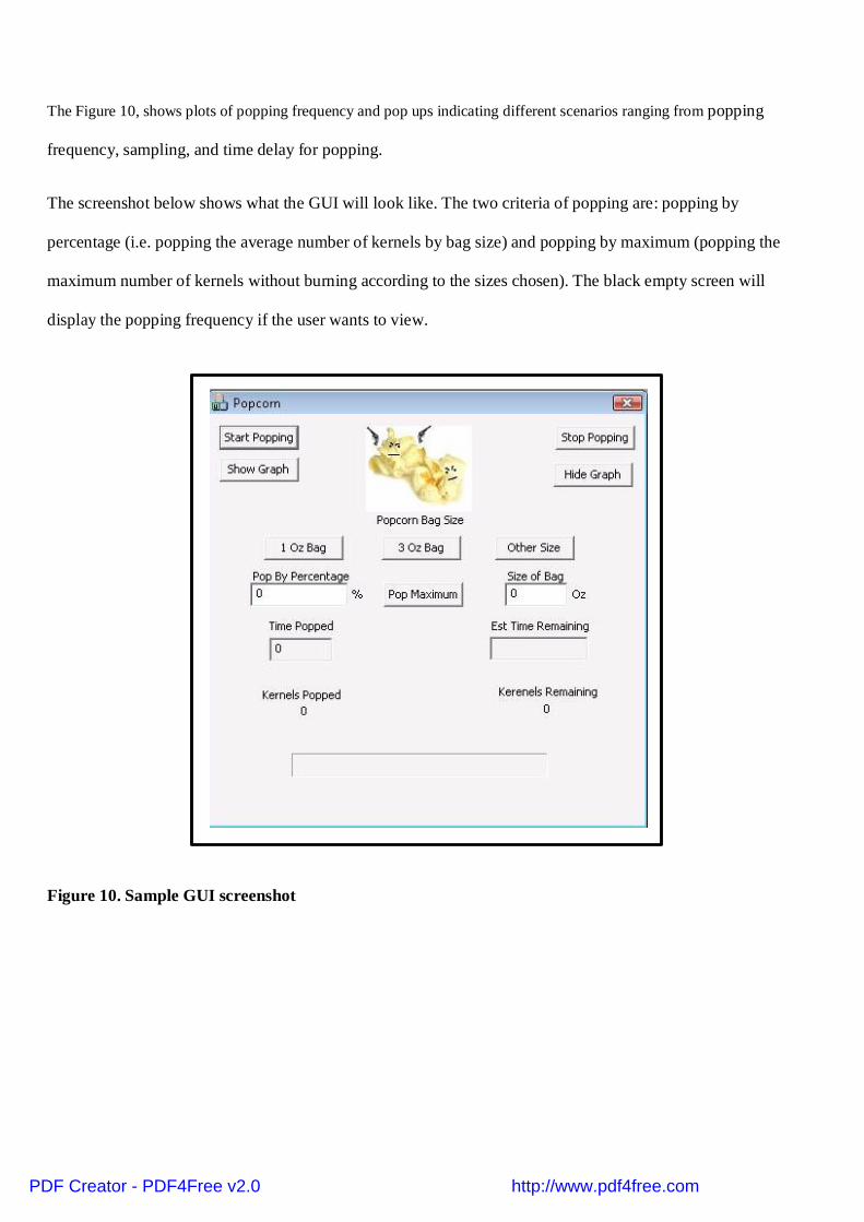
When the popping is complete, the pop is displayed on Figure 8. Would be displayed on the screen of the
users’ PC .
If the microwave is opened accidentally or intentionally, the pop-up displayed on the screen.
Figure 11. Pop-up screen shots
PDF Creator - PDF4Free v2.0 http://www.pdf4free.com
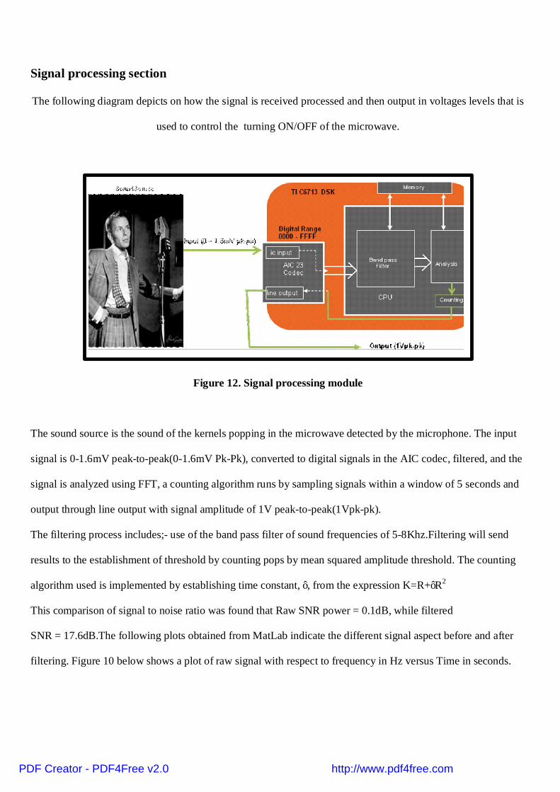
Signal processing section
The following diagram depicts on how the signal is received processed and then output in voltages levels that is
used to control the turning ON/OFF of the microwave.
Figure 12. Signal processing module
The sound source is the sound of the kernels popping in the microwave detected by the microphone. The input
signal is 0-1.6mV peak-to-peak(0-1.6mV Pk-Pk), converted to digital signals in the AIC codec, filtered, and the
signal is analyzed using FFT, a counting algorithm runs by sampling signals within a window of 5 seconds and
output through line output with signal amplitude of 1V peak-to-peak(1Vpk-pk).
The filtering process includes;- use of the band pass filter of sound frequencies of 5-8Khz.Filtering will send
results to the establishment of threshold by counting pops by mean squared amplitude threshold. The counting
algorithm used is implemented by establishing time constant, ô, from the expression K=R+ôR2
This comparison of signal to noise ratio was found that Raw SNR power = 0.1dB, while filtered
SNR = 17.6dB.The following plots obtained from MatLab indicate the different signal aspect before and after
filtering. Figure 10 below shows a plot of raw signal with respect to frequency in Hz versus Time in seconds.
PDF Creator - PDF4Free v2.0 http://www.pdf4free.com
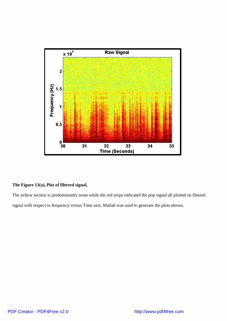
The Figure 13(a), Plot of filtered signal,
The yellow section is predominantly noise while the red strips indicated the pop signal all plotted on filtered
signal with respect to frequency versus Time axis. Matlab was used to generate the plots shown.
PDF Creator - PDF4Free v2.0 http://www.pdf4free.com

Figure 13(b). Signal plots
The Figure 12 below shows the plot of raw and filtered signals in the same plots for comparison. plots of Digital
Audio Amplitude versus Time seconds.
PDF Creator - PDF4Free v2.0 http://www.pdf4free.com
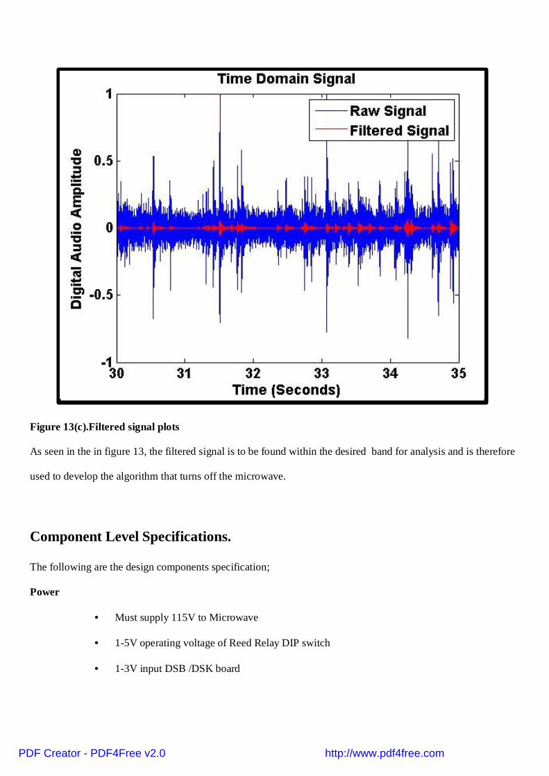
Figure 13(c).Filtered signal plots
As seen in the in figure 13, the filtered signal is to be found within the desired band for analysis and is therefore
used to develop the algorithm that turns off the microwave.
Component Level Specifications.
The following are the design components specification;
Power
• Must supply 115V to Microwave
• 1-5V operating voltage of Reed Relay DIP switch
• 1-3V input DSB /DSK board
PDF Creator - PDF4Free v2.0 http://www.pdf4free.com
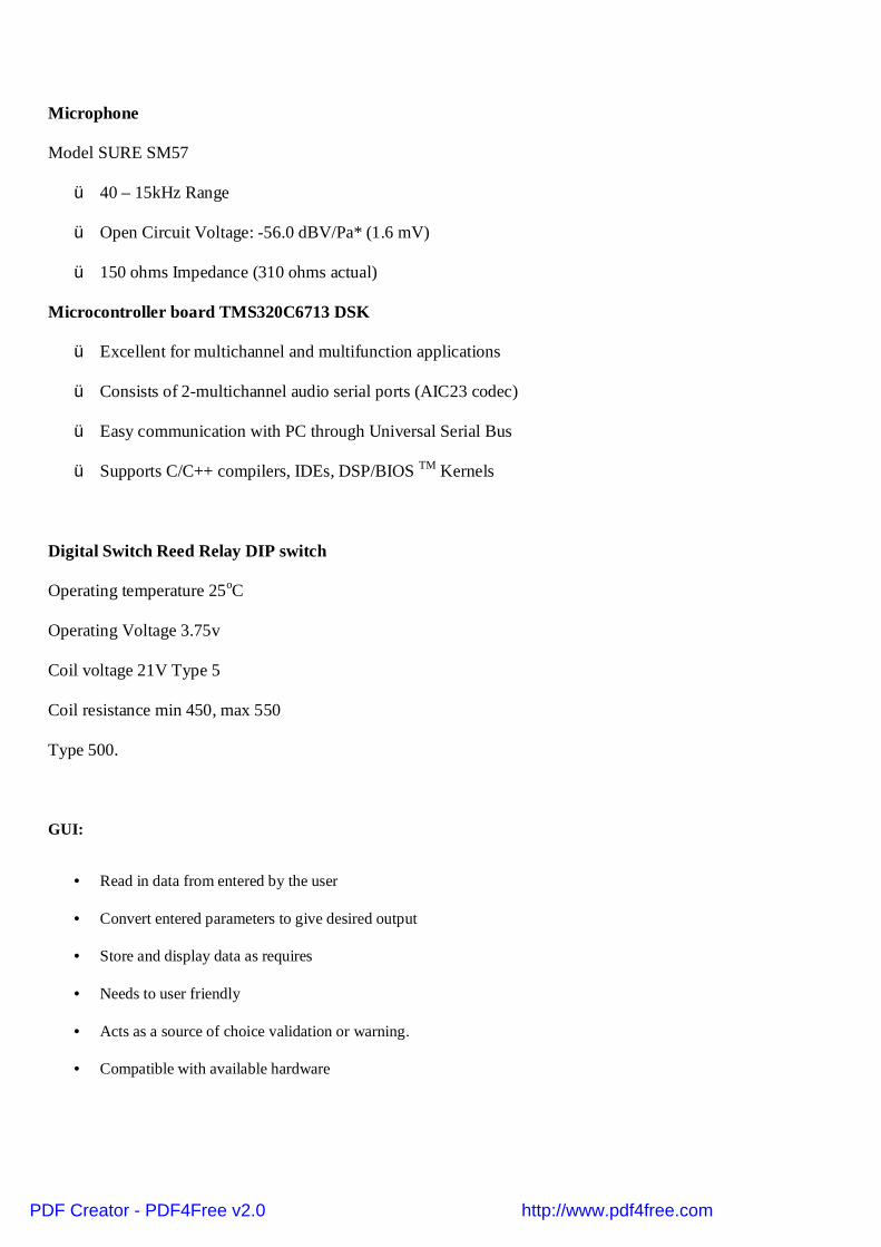
Microphone
Model SURE SM57
ü 40 – 15kHz Range
ü Open Circuit Voltage: -56.0 dBV/Pa* (1.6 mV)
ü 150 ohms Impedance (310 ohms actual)
Microcontroller board TMS320C6713 DSK
ü Excellent for multichannel and multifunction applications
ü Consists of 2-multichannel audio serial ports (AIC23 codec)
ü Easy communication with PC through Universal Serial Bus
ü Supports C/C++ compilers, IDEs, DSP/BIOS TM Kernels
Digital Switch Reed Relay DIP switch
Operating temperature 25oC
Operating Voltage 3.75v
Coil voltage 21V Type 5
Coil resistance min 450, max 550
Type 500.
GUI:
• Read in data from entered by the user
• Convert entered parameters to give desired output
• Store and display data as requires
• Needs to user friendly
• Acts as a source of choice validation or warning.
• Compatible with available hardware
PDF Creator - PDF4Free v2.0 http://www.pdf4free.com

Final design modifications
Many design decisions were modified from January 2008 to April 2008. Reasons for these changes varied in scope or
overall system effect, but all were deemed necessary by the design team. Among the last changes to be enforced was
using an amplifier to step up the voltage from the DSK board to the level that could operate the reed relay DIP switch.
The modifications can be seen in figure 12.
Figure 14. Modification block diagram
The bridge rectifier is used to smooth the AC ripples:- the amplifier raises the signal to 5 voltages. This is the
range of voltage that will turn on the dip switch to control the microwave.
Project Management
The following section includes the tasks, schedule, and budget of this budget. The goal of project management
is to constrain the project exactly to the weeks expected of a full semester.
Tasks
1. Project Definition: define all aspects of the project
a. Define Objectives - define the goals and objectives required
b. Define Constraints - define the constraints and limitations imposed
c. Conceptual Design - layout the conceptual design
d. Systems Charts - layout the necessary system charts
Bridge
RectifierAmplifier
Reed Relay DIP
switch
PDF Creator - PDF4Free v2.0 http://www.pdf4free.com
2. Proposal - refine the proposal
a. Actual Proposal - write the proposal
b. Project Timeline - plan and layout the project timeline
c. Work Breakdown Chart - plan and layout the personnel timeline
3. Subsystem Research - research and select optimum solutions
a. GUI - find the most efficient interface language and library
b. Data Structure - develop a program, fit to language
4. Interim Reporting - mid-project design review
a. Interim Communiqué - draft an interim notification letter
b. Interim Slideshow - present project progress and design choices
5. Final Design - integrate the complete design
a. Design Synthesis - write the program, compile on a computer
b. Design Testing - look for bugs, test speed and reliability
6. Final Report - draft and refine the final report
a. Actual Report - write the final report
b. Economic Analysis - run a cost analysis
c. Executive Summary - redefine the executive summary
MANAGEMENT
Assignment of duties and tasks to personnel, as outlined below:
Interfacing and system integration,-John Aruma;
Signal procession:- Tarnner Jones
Software development:- Khemmer Porter.
PDF Creator - PDF4Free v2.0 http://www.pdf4free.com
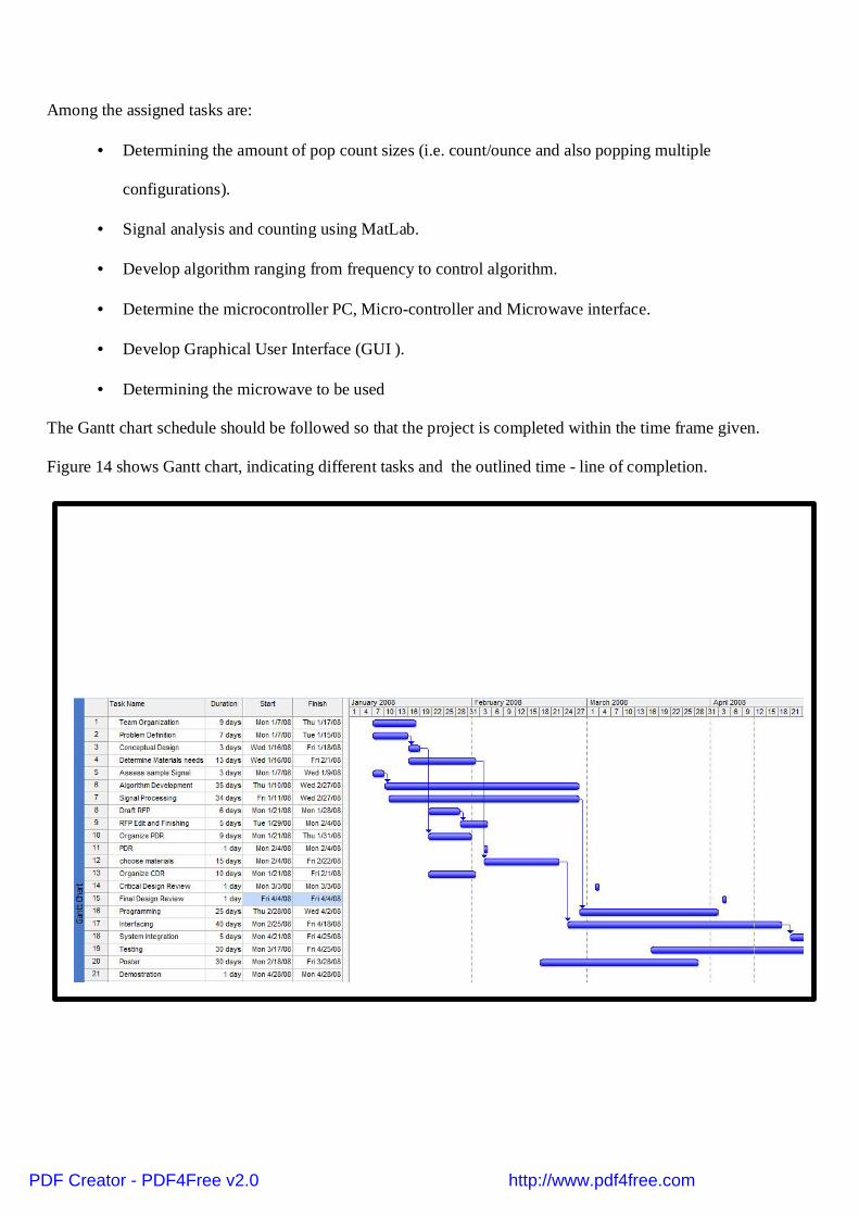
Among the assigned tasks are:
• Determining the amount of pop count sizes (i.e. count/ounce and also popping multiple
configurations).
• Signal analysis and counting using MatLab.
• Develop algorithm ranging from frequency to control algorithm.
• Determine the microcontroller PC, Micro-controller and Microwave interface.
• Develop Graphical User Interface (GUI ).
• Determining the microwave to be used
The Gantt chart schedule should be followed so that the project is completed within the time frame given.
Figure 14 shows Gantt chart, indicating different tasks and the outlined time - line of completion.
PDF Creator - PDF4Free v2.0 http://www.pdf4free.com

Materials and costs
Items Cost in USD
Microphone – Sure SM57 Already Owned
Microcontroller TMS320C6713
DSK
Issued
Popcorn 5
PC interface User’s Computer
Microwave 15
Reed Relay Switch 20
Man Hours 400 Coursework
Total 40
Figure 15. Table of costs
PDF Creator - PDF4Free v2.0 http://www.pdf4free.com
6. Conclusion
The main objective of this project is to create and implement algorithms that will prevent the overcooking of
popcorn. The algorithms will be realized using a micro-controller that will be interfaced with the microwave's
power control. All the objectives were met. The entire design was a success though the reed relay switch had to
be discarded and a higher power reed relay switch was used instead. The popped corn was tested by the
audience to verify the quality desired.
PDF Creator - PDF4Free v2.0 http://www.pdf4free.com
References:
1. Roizen, Michael, and Mehmet Oz. You:On Diet. 4. Prienceton:
2. http://recipes.howstuffworks.com/question255.htm
3. Sage, Andrew. Introduction to systems Engineering. III. New York: Wiley-interscience publication,
2000.
Attachments
The following are attachment:
Resume
Datasheets
Codes
Pictures
PDF Creator - PDF4Free v2.0 http://www.pdf4free.com

John E. [email protected]
Permanent 4357643195
549 E 200 N
Logan, UT 84321
OBJECTIVE To become an employee and to make significant contributions that will lead to
company profitability and personal career growth.
EDUCATION Utah State University, Logan, UT
Bachelor of Science, Electrical Engineering, December 2008
Second Major- Mathematics.
Jomo Kenyatta University of Agr. & Technology, Nairobi, Kenya Associate Degree
(Diploma), Electronics Engineering, December 2001.
CERTIFICATIONS Cisco Certified Network Associate Instructor (CCNA)
RELATED
PROJECTS
Design of Water Gage using 8088 Micro-controller FIR,IIR & Adaptive filters
implemented using C++ & Results verified using Matlab
TECHNICAL
SKILLS
Web Development - HTML, XML, Java Script, JSP, VB Script, PHP Operating
Systems and Networking - Windows NT, Windows XP, Windows Vista, MS SQL
Server, Cisco IOS, Apache, Unix, Linux Software - Visual Studio. NET,MS Office,
Adobe Photo shop, Dreamweaver MX, Flash MX, Oracle Hardware - Basic PC
upgrades/repairs, Network cabling, connectivity troubleshooting, hard drive recoveries,
component level replacements Programming Skills - C++, ASP, Visual Basic, SQL,
MySQL, HTML, Java Script
RELATED
EXPERIENCE
Young Electric Sign Co., Logan UT Aug, 2006 - Nov.2007 Title: Data/Quality
Control Technician. Responsibilities: Testing and troubleshooting Electronic boards,
Calibrating and ensuring that they meet prescribed specifications and quality. Telkom
Kenya Ltd, Nairobi Kenya Dec,2003 - March, 2005 Title: Telecommunications
Technician Responsibilities: Testing, repair and troubleshooting Telecommunications
equipments e.g. Telephones, faxes, xDSL, Bridges, routers Holy Rosary College,
Nairobi Kenya Dec, 2001 - Dec, 2003 Title: Instructor and System Administrator.
Responsibilities: Teaching IT courses e.g. Java Script, Computer maintenance and
installations, Network design and setup and application programs. Administering
College Network
HONORS AND
AWARDS
The Player of the Year-Volleyball Jomo Kenyatta University(Fall 2001)
PROFESSIONAL
MEMBERSHIPS
Member, Institute of Electrical and Electronics Engineers - 2006 to present
Chairman, Computer society -IEEE USU Chapter.
PDF Creator - PDF4Free v2.0 http://www.pdf4free.com
Related Documents