PONTIFÍCIA UNIVERSIDADE CATÓLICA DO RIO GRANDE DO SUL FACULDADE DE INFORMÁTICA PROGRAMA DE PÓS-GRADUAÇÃO EM CIÊNCIA DA COMPUTAÇÃO AUTOMATED EMULATION OF DISTRIBUTED SYSTEMS THROUGH SYSTEM MANAGEMENT AND VIRTUALIZATION RODRIGO N. CALHEIROS Tese apresentada como requisito parcial à obtenção do grau de Doutor em Ciência da Computação na Pontifícia Universidade Católica do Rio Grande do Sul. Orientador: Prof. César Augusto Fonticielha De Rose Co-orientador: Prof. Rajkumar Buyya Porto Alegre 2009

Welcome message from author
This document is posted to help you gain knowledge. Please leave a comment to let me know what you think about it! Share it to your friends and learn new things together.
Transcript
PONTIFÍCIA UNIVERSIDADE CATÓLICA DO RIO GRANDE DO SULFACULDADE DE INFORMÁTICA
PROGRAMA DE PÓS-GRADUAÇÃO EM CIÊNCIA DA COMPUTAÇÃO
AUTOMATED EMULATION OFDISTRIBUTED SYSTEMS THROUGH
SYSTEM MANAGEMENTAND VIRTUALIZATION
RODRIGO N. CALHEIROS
Tese apresentada como requisito parcial à
obtenção do grau de Doutor em Ciência da
Computação na Pontifícia Universidade Católica
do Rio Grande do Sul.
Orientador: Prof. César Augusto Fonticielha De Rose
Co-orientador: Prof. Rajkumar Buyya
Porto Alegre
2009


Aos meus pais, Alcides e Maria.

ACKNOWLEDGMENTS
I thank my supervisors, Professor César De Rose and Professor Rajkumar Buyya, the former in
Brazil and the later during my research visit to the University of Melbourne. Several times, Prof.
De Rose believed more than me in my work, and it enabled several positive results. Prof. Buyya
kindly received me in his CLOUDS Lab. I learned a lot with his character and experience in research
and coordination of a big research laboratory.
I’m very grateful to my friend Marco Aurélio Stelmar Netto. He dedicated a lot of his time
enabling my visit to Melbourne and assisting me during this time.
Very special thanks to people that made possible my research visit to the University of Melbourne:
Professor Fernando Gehm Moraes, Professor Avelino Francisco Zorzo, Professor Fernando Luís Dotti,
and Professor Philippe Olivier Alexandre Navaux.
I also want to thank Professor João Batista de Oliveira and Professor Francisco Brasileiro for
helping in giving directions for my research during thesis proposal evaluation. Their suggestions
were very useful and had a lot of impact in my research. Dr. Rajiv Ranjan also gave this work a
large contribution by supervising CloudSim development, and I’m also very grateful to him.
During the four years of my candidature, I had the opportunity to interact with a lot of people,
and some of them gave me some kind of technical, academic, logistic, emotional, or spiritual support
that influenced the work presented in this thesis. These people is listed alphabetically below, and I’m
grateful to all of them: Dr. Alexandre di Costanzo, Andriele Busato do Carmo, Anton Beloglazov,
Bhathiya Wickremasinghe, Dr. Christian Vecchiola, Prof. Carlos Varela, Élder Bernardi, Everton
Alexandre, Felipe Franciosi, Felipe Grazziotin, Guilherme da Cunha Rodrigues, Guilherme Fedrizzi,
Jean Orengo, Dr. Marcos Dias Assunção, Marcus Breda, Mauro Storch, Roberto Karpinski, Saurabh
Garg, Dr. Srikumar Venugopal, Tiago Ferreto, and Yves Shiga Casagrande.
I like to thank the whole Cloudbus team for their hospitality and friendship during my visit to
Melbourne Uni. I also thank the colleagues from LAD/IDEIA and Paleoprospec, to whom I had the
opportunity of work with for a few months after my return to Brazil.
I thank all my friends and family for their unconditional support during this time. I’m pretty sure
they understood my absences and eventual bad mood during some tough times, and I’m grateful to
them for that.
I thank sponsors of this research: HP Brazil R&D, CAPES (through PDEE Research Grant
1185-08-0), and Petrobras. Without their support, I would not have been able to carry out this
research.


EMULAÇÃO AUTOMÁTICA DE SISTEMAS DISTRIBUÍDOSATRAVÉS DE GERÊNCIA DE SISTEMAS E VIRTUALIZAÇÃO
RESUMO
Sistemas distribuídos são compostos de elementos computacionais geograficamente distribuídos que
pertencem a múltiplos domínios administrativos controlados por múltiplas entidades. Estas carac-
terísticas dificultam testes e avaliações nesta plataforma, porque dificilmente testadores adquirem
repetidamente os mesmo recursos pela mesmo período de tempo sob as mesmas condições de rede,
o que são requisitos fundamentais para testes reproduzíveis e controlados do software em desen-
volvimento. Uma alternativa a experimentos em plataformas reais é emulação, onde o modelo de
um sistema executa o software real sob teste. A tecnologia de virtualização possibilita o desen-
volvimento de emuladores eficientes porque ela oferece meios para multiplexação e isolamento de
recursos. Apesar da virtualização facilitar o desenvolvimento de emuladores, pouco esforço tem sido
feito para isolar testadores da operação das ferramentas e do ambiente virtualizado. Esta tese apre-
senta o Automated Emulation Framework (AEF), que aplica tecnologias de virtualização e gerência
de sistemas em um cluster de estações de trabalho a fim de oferecer uma ferramenta automatizada
para emulação de sistemas distribuídos. Três atividades principais são realizadas pelo AEF: primeiro,
ele realiza o mapeamento das máquinas virtuais que representam nós do ambiente distribuído emu-
lado para nós do cluster e dos links entre máquinas virtuais para caminhos na rede física; segundo,
ele realiza a instalação e configuração automática das máquinas virtuais no cluster e rede virtual na
rede do cluster; terceiro, ele realiza configuração e disparo automático de experimentos no sistema
emulado, monitoração e controle do ambiente e aplicações, e reconfiguração do sistema em caso de
violações nas demandas do testador. Em relação à primeira atividade, o problema de mapeamento é
definido formalmente e quatro herísticas para solução do problema são desenvolvidas e avaliadas com
o uso de simulação de eventos discretos. Em relação às duas últimas atividades, a arquitetura do
AEF é descrita em detalhes. Além do mais, um protótipo do AEF é desenvolvido e avaliado através
da realização de experimentos no contexto de grades computacionais. Experimentos mostram que
a arquitetura é realizável e que AEF pode ser uma ferramenta valiosa para experimentação repetida
e controlável de sistemas distribuídos.
Palavras-chave: Emulação; Mapeamento de Máquinas Virtuais; Virtualização; Gerência de Sis-
temas.


AUTOMATED EMULATION OF DISTRIBUTED SYSTEMS THROUGHSYSTEM MANAGEMENT AND VIRTUALIZATION
ABSTRACT
Distributed systems are composed of geographically distributed computing elements that belong to
multiple administrative domains and are controlled by multiple entities. These characteristics from
distributed systems make hard the task of testing and evaluating software for this platform, because
it is unlikely that testers are able to acquire repeatedly the same resources, for the same amount
of time, and under the same network conditions, which are paramount requirements for enabling
reproducible and controlled tests in software under development. An alternative to experiments in
real testbeds is emulation, where a model of a system hosts the actual software under test. Virtual-
ization technology enables development of efficient emulators because it offers means for resources
multiplexing and isolation. Even though virtualization makes easier development of emulators, there
are few efforts in isolating testers from operation of the virtualization tools and environment. This
thesis presents Automated Emulation Framework (AEF), which applies virtualization and systems
management technology in a cluster of workstations to provide testers with a tool for automated
emulation of distributed systems. Three main activities are performed by AEF. First, it performs
the mapping of virtual machines that represents nodes from the emulated distributed environment
to cluster nodes and emulated links between virtual machines to paths in the physical network;
second, it performs automated installation and configuration of virtual machines in the cluster and
virtual network in the cluster network; third, it performs automated configuration and triggering of
experiments in the emulated system, monitoring and control of environment and applications, and
system reconfiguration in case of violations in the tester demands. Regarding the first activity, the
mapping problem is formally defined and four heuristics for solution of the problem are developed
and evaluated with the use of discrete-event simulation. Regarding the last two activities, AEF
architecture is described in details. Furthermore, an AEF prototype is developed and evaluated by
execution of experiments in the context of grid computing. Experiment results show that imple-
mentation of the architecture is feasible and that AEF can be a valuable tool for repeatable and
controllable distributed systems experimentation.
Keywords: Emulation; Virtual Machines Mapping; Virtualization; System Management.


LIST OF FIGURES
Figure 2.1 Codesigned Virtual Machines. . . . . . . . . . . . . . . . . . . . . . . . . . 29
Figure 2.2 System virtual machine. . . . . . . . . . . . . . . . . . . . . . . . . . . . . 30
Figure 2.3 A generic model for virtualization-based emulation of distributed systems. . . 34
Figure 2.4 WBEM architecture. . . . . . . . . . . . . . . . . . . . . . . . . . . . . . . 36
Figure 2.5 OurGrid architecture. . . . . . . . . . . . . . . . . . . . . . . . . . . . . . 39
Figure 2.6 Effects of different provisioning policies on task execution. . . . . . . . . . . 42
Figure 3.1 Automated Emulation Framework architecture. . . . . . . . . . . . . . . . . 55
Figure 3.2 Document Type Definition (DTD) of AEF input. . . . . . . . . . . . . . . . 56
Figure 3.3 Example of an environment description. . . . . . . . . . . . . . . . . . . . . 58
Figure 3.4 Virtual environment corresponding to the description given in Figure 3.3. . . 59
Figure 3.5 AEF’s installation and configuration workflow. . . . . . . . . . . . . . . . . 60
Figure 3.6 Mapper module. . . . . . . . . . . . . . . . . . . . . . . . . . . . . . . . . 60
Figure 3.7 Example of a mapping. . . . . . . . . . . . . . . . . . . . . . . . . . . . . 62
Figure 3.8 Deployer module. . . . . . . . . . . . . . . . . . . . . . . . . . . . . . . . . 68
Figure 3.9 Network Manager module. . . . . . . . . . . . . . . . . . . . . . . . . . . . 70
Figure 4.1 Document Type Definition (DTD) of AEF input . . . . . . . . . . . . . . . 76
Figure 4.2 Experiment Manager module components. . . . . . . . . . . . . . . . . . . 77
Figure 4.3 Virtual Environment Manager. . . . . . . . . . . . . . . . . . . . . . . . . . 78
Figure 4.4 Monitor. . . . . . . . . . . . . . . . . . . . . . . . . . . . . . . . . . . . . 80
Figure 4.5 Events and actions list, handled by the Rebuilder. . . . . . . . . . . . . . . . 82
Figure 5.1 General operation of AEF prototype. . . . . . . . . . . . . . . . . . . . . . 86
Figure 5.2 Storch’s virtual network management architecture . . . . . . . . . . . . . . 89
Figure 5.3 Alexandre’s architecture for management of virtual machines . . . . . . . . . 90
Figure 5.4 Carmo’s Architecture for Monitoring and Control of Virtual Environments . . 92
Figure 5.5 Rebuilder prototype. . . . . . . . . . . . . . . . . . . . . . . . . . . . . . . 93
Figure 6.1 40 nodes cluster with 2-D torus network topology used in the evaluations. . . 96
Figure 6.2 HMN evaluation: average objective function for low-level scenarios. . . . . . 98
Figure 6.3 HMN evaluation: average objective function for high-level scenarios. . . . . . 99
Figure 6.4 HMN evaluation: average simulation time for low-level scenarios. . . . . . . 100
Figure 6.5 HMN evaluation: average simulation time for high-level scenarios. . . . . . . 101
Figure 6.6 Objective function for different heuristics. . . . . . . . . . . . . . . . . . . . 103
Figure 6.7 Mapping time for different heuristics. . . . . . . . . . . . . . . . . . . . . . 104
Figure 6.8 Resources used in the experiments. . . . . . . . . . . . . . . . . . . . . . . 109

LIST OF TABLES
Table 2.1 Classification of experimental methodologies proposed by Gustedt et al. . . . 25
Table 2.2 Comparison among methodologies for distributed systems experimentation. . 27
Table 2.3 Comparison among grid simulators and CloudSim. . . . . . . . . . . . . . . 44
Table 2.4 Comparison among emulators. . . . . . . . . . . . . . . . . . . . . . . . . . 47
Table 2.5 Comparison among virtualization-based emulators. . . . . . . . . . . . . . . 48
Table 2.6 Comparison among managers of virtualized environments. . . . . . . . . . . 50
Table 3.1 Summary of AEF modules and their function. . . . . . . . . . . . . . . . . . 59
Table 3.2 Heuristics for mapping VMs to hosts. . . . . . . . . . . . . . . . . . . . . . 66
Table 4.1 Events managed by the Monitor and their IDs. . . . . . . . . . . . . . . . . 80
Table 5.1 Comparison among deployment methods supported by AEF prototype. . . . 88
Table 6.1 Summary of simulation setup for HMN evaluation. . . . . . . . . . . . . . . 97
Table 6.2 Failures in finding a valid mapping for each heuristic. . . . . . . . . . . . . . 98
Table 6.3 Summary of simulation setup for heuristics comparison. . . . . . . . . . . . 102
Table 6.4 Observed makespan of jobs. . . . . . . . . . . . . . . . . . . . . . . . . . . 107


CONTENTS
1. INTRODUCTION 17
1.1 Motivation . . . . . . . . . . . . . . . . . . . . . . . . . . . . . . . . . . . . . . . 19
1.2 Research problems . . . . . . . . . . . . . . . . . . . . . . . . . . . . . . . . . . . 20
1.3 Thesis contributions . . . . . . . . . . . . . . . . . . . . . . . . . . . . . . . . . . 20
1.4 Thesis organization . . . . . . . . . . . . . . . . . . . . . . . . . . . . . . . . . . 21
2. BIBLIOGRAPHIC REVIEW 23
2.1 Background . . . . . . . . . . . . . . . . . . . . . . . . . . . . . . . . . . . . . . 23
2.1.1 Methodologies of experimentation in computer science . . . . . . . . . . . . 23
2.1.2 Emulation . . . . . . . . . . . . . . . . . . . . . . . . . . . . . . . . . . . 28
2.1.3 Virtualization . . . . . . . . . . . . . . . . . . . . . . . . . . . . . . . . . . 29
2.1.4 System virtualization . . . . . . . . . . . . . . . . . . . . . . . . . . . . . . 30
2.1.5 Virtualization as a support tool for distributed systems emulation . . . . . . 33
2.1.6 Network management . . . . . . . . . . . . . . . . . . . . . . . . . . . . . 34
2.1.7 Grid computing . . . . . . . . . . . . . . . . . . . . . . . . . . . . . . . . 37
2.1.8 Cloud computing . . . . . . . . . . . . . . . . . . . . . . . . . . . . . . . . 39
2.1.9 CloudSim Toolkit . . . . . . . . . . . . . . . . . . . . . . . . . . . . . . . 40
2.2 Related works . . . . . . . . . . . . . . . . . . . . . . . . . . . . . . . . . . . . . 42
2.2.1 Simulation . . . . . . . . . . . . . . . . . . . . . . . . . . . . . . . . . . . 43
2.2.2 Emulation . . . . . . . . . . . . . . . . . . . . . . . . . . . . . . . . . . . 44
2.2.3 Management of virtualized environments . . . . . . . . . . . . . . . . . . . 49
2.2.4 Virtual machines mapping . . . . . . . . . . . . . . . . . . . . . . . . . . . 50
2.3 Chapter remarks . . . . . . . . . . . . . . . . . . . . . . . . . . . . . . . . . . . . 52
3. INSTALLATION AND CONFIGURATION OF EMULATED DISTRIBUTED ENVIRON-
MENTS 53
3.1 Requirements of a distributed system emulator . . . . . . . . . . . . . . . . . . . . 53
3.2 Automated Emulation Framework: general overview . . . . . . . . . . . . . . . . . 54
3.3 Mapper module . . . . . . . . . . . . . . . . . . . . . . . . . . . . . . . . . . . . 59
3.3.1 Mapping problem definition . . . . . . . . . . . . . . . . . . . . . . . . . . 61
3.3.2 Heuristics for solving the mapping problem . . . . . . . . . . . . . . . . . . 64
3.4 Deployer module . . . . . . . . . . . . . . . . . . . . . . . . . . . . . . . . . . . . 67
3.5 Network Manager module . . . . . . . . . . . . . . . . . . . . . . . . . . . . . . . 69
3.6 Chapter remarks . . . . . . . . . . . . . . . . . . . . . . . . . . . . . . . . . . . . 70

4. MANAGEMENT AND RECONFIGURATION OF EMULATION EXPERIMENTS 73
4.1 Experiment Manager module: general overview . . . . . . . . . . . . . . . . . . . . 73
4.2 Virtual Environment Manager . . . . . . . . . . . . . . . . . . . . . . . . . . . . . 77
4.3 Monitor . . . . . . . . . . . . . . . . . . . . . . . . . . . . . . . . . . . . . . . . . 79
4.4 Rebuilder . . . . . . . . . . . . . . . . . . . . . . . . . . . . . . . . . . . . . . . . 81
4.5 Chapter remarks . . . . . . . . . . . . . . . . . . . . . . . . . . . . . . . . . . . . 83
5. AEF REALIZATION 85
5.1 AEF prototype overview . . . . . . . . . . . . . . . . . . . . . . . . . . . . . . . . 85
5.2 Mapper prototype . . . . . . . . . . . . . . . . . . . . . . . . . . . . . . . . . . . 86
5.3 Deployer prototype . . . . . . . . . . . . . . . . . . . . . . . . . . . . . . . . . . . 86
5.4 Network Manager prototype . . . . . . . . . . . . . . . . . . . . . . . . . . . . . . 88
5.5 Experiment Manager prototype . . . . . . . . . . . . . . . . . . . . . . . . . . . . 90
5.5.1 Virtual Environment Manager prototype . . . . . . . . . . . . . . . . . . . 90
5.5.2 Monitor prototype . . . . . . . . . . . . . . . . . . . . . . . . . . . . . . . 92
5.5.3 Rebuilder prototype . . . . . . . . . . . . . . . . . . . . . . . . . . . . . . 93
5.6 Chapter remarks . . . . . . . . . . . . . . . . . . . . . . . . . . . . . . . . . . . . 94
6. AEF PROTOTYPE EVALUATION 95
6.1 Evaluation of mapping heuristics . . . . . . . . . . . . . . . . . . . . . . . . . . . 95
6.1.1 Evaluation scenario . . . . . . . . . . . . . . . . . . . . . . . . . . . . . . 95
6.1.2 HMN evaluation and results . . . . . . . . . . . . . . . . . . . . . . . . . . 96
6.1.3 Heuristics comparison and results . . . . . . . . . . . . . . . . . . . . . . . 102
6.2 Evaluation of the emulated distributed system . . . . . . . . . . . . . . . . . . . . 105
6.3 Evaluation of execution, monitoring, and reconfiguration stage . . . . . . . . . . . . 108
6.4 Chapter remarks . . . . . . . . . . . . . . . . . . . . . . . . . . . . . . . . . . . . 110
7. CONCLUSIONS 111
7.1 Future directions . . . . . . . . . . . . . . . . . . . . . . . . . . . . . . . . . . . . 112
7.2 Publications . . . . . . . . . . . . . . . . . . . . . . . . . . . . . . . . . . . . . . 113
BIBLIOGRAPHY 115
17
1. INTRODUCTION
In the last decades, we have witnessed a slowly shift of paradigm applied in computer science:
mainstream computer architecture has been moved from a model where a huge, centralized com-
puting unit is used to supply computing power to a number of users to a model where distributed
and less powerful units are deployed to supply computing power to users. In the former model,
we have mainframes and supercomputers as examples of how this paradigm was applied in indus-
try and academia, respectively. In the later model, we have client/server architectures and grid
computing [FK99b] as significant examples of the model.
What enabled this shift in paradigm were the advances in computer networks technology reached
in the last decades. As a result from the paradigm shift, we have seen in the last years an outstanding
growth in research and development in topics such as grid computing, cloud computing [BYV+09],
utility computing [Rap04], and P2P computing [Ora01]. These technologies share special charac-
teristics not present in centralized architectures: control over all the elements of the distributed
architecture is not hold by any entity. Moreover, characteristics of resources may be hidden from
the user and may vary along the time.
These characteristics of distributed systems make harder development of software artifacts for
such systems, because developers may have difficulty in having access to components of the system
to install the artifact, and in enforcing conditions in the system to observe artifact behavior in the
presence of such conditions. It makes hard monitoring of state of elements that take part in the
distributed transactions. Also, it makes hard reproducing events observed during an experiment,
as those events may depend on condition found either in the network or in resources that cannot
be handled or measured. As a result, only a subset of the possible use cases are covered in the
evaluation, and even these cases are limited to a scale that tends to be smaller than the scale of the
environment that will host the system.
Together with development of new methodologies for organization of computing elements, new
methodologies for evaluation of software artifacts were also proposed. Nevertheless, the methodology
to be applied to evaluate an artifact depends on the stage of development such an artifact achieved.
In earlier stages of development, e.g., when a model or algorithm is proposed, abstract methods
of evaluation, such as formal methods [PA91,PBB07], may be applied. In such methods, both the
artifact behavior and the system behavior are described in terms of a formalism that is solved with
the use of mathematical tools. Nevertheless, outputs of such a method are also abstract, and it
requires a considerable effort both in modeling software and hardware and in interpretation of the
results.
Another technique to be applied in earlier stages of development of software artifacts is sim-
ulation, where both the application and the distributed system are modeled algorithmically and
execution of the software model is observed in the architecture model [GJQ09]. Both analytical
methods and simulation can accurately supply designers of the tested artifact with information that
18
allows them not only to choose a given algorithm among several possible choices, but also to under-
stand how an entity is affected by other entities or conditions. Nevertheless, there is a gap between
the results obtained in the evaluation and the results of the system in a real world. It happens
because during the modeling of the simulator or during the analytical modeling, several aspects that
would affect the real system are ignored, otherwise the experiment becomes too complex and would
be computationally intractable.
In a more advanced stage of development of the software artifact, when a prototype is available,
a suitable approach for evaluation of the software is emulation. In this approach, the actual software
is executed in a model of the environment [GJQ09]. Recently, several emulators were proposed
[GVV08,QJC07,CGMV07,AH06,CCW+06]. Because emulators allow testers to describe the exact
configuration and condition of the emulated environment, it is also possible not only to reuse a given
emulated environment but also to replicate tests.
However, development of emulators is not an easy task. Typically, one or more real hosts support
several emulated entities, therefore it is necessary to multiplex both host resources for guests running
on it and network resources. This complexity in providing multiplexing made most part of the early
distributed systems emulators [LXC04,DHN96,TMN+99,KBM+02] fail in achieving a development
stage on which they could be used to emulate arbitrary environments running arbitrary software on
them.
Recently, development of virtualization tools [BDF+03,DBR02] allowed a revisit in the develop-
ment of emulators. In virtualization-based emulation, clusters of workstations are used to host the
experiments, and virtualization is used in such a way that virtual machines correspond to emulated
computing nodes. The main advantage in using virtualization to develop emulation tools is that vir-
tualization allows a simpler implementation of the emulator, because host multiplexing and network
multiplexing are performed by the virtual machine monitor. Also, by using virtualization, each node
of the emulated system is a virtual machine with its own resources (e.g., memory, operating sys-
tem, CPU share), and therefore isolation of performance in emulated environments can be achieved.
Moreover, each virtual machine is isolated from the others, which means that a failure of a given
virtual machine does not affect execution of other virtual machines in the same host [SN05].
One issue that must be considered in virtualization-based emulators is the placement of virtual
machines in the hosts, because it limits the scalability of the environment, due to fragmentation
problems: because each virtual machine requires an amount of resources from the host, these
resources are a constraint to be considered. For example, even if the overall amount of free memory
in the testbed allows more virtual machines to be deployed in the environment, it is possible that no
single host has enough memory to support a new virtual machine. The same may happen not only
to other resources from the host (e.g., CPU, storage) but also to network resources (i.e., capacity
of links used by pairs of virtual machines communicating during the emulation). This placement
problem is computationally hard, because it encompasses solution of two different problems (hosts
and network assignment), each of them already a computationally complex problem.
The other issue to be considered is how to provide an automated building and configuration of
19
the emulated distributed system. Software developers may be not familiar with tools for managing
virtual environments. Thus, if they could only describe the system, and the emulator could provide
the means for creation of the system, the task of creating and managing a virtual distributed system
could be abstract from developers, which can focus in the main activity they are supposed to develop.
Finally, the issue of management of the system and applications during the test is also an issue
that has to be addressed. Considering that the emulated distributed system may contain hundreds
or thousands of elements, manual operation of such a system by the distributed system developers
may be a hard and counterproductive task. Therefore, automated management of the experiment is
also desirable to increase efficacy of the evaluation process, because it allows testers to spend more
time in the test itself than in the operation of the test platform.
In this thesis, we present the Automated Emulation Framework (AEF), which applies virtualiza-
tion and systems management technology in a cluster of workstations to address the listed issues
in order to provide testers with a tool for automated building, configuration, monitoring and re-
configuration of the environment and execution of distributed experiments. Throughout this thesis,
we present AEF design, prototype, and experiments evaluating such a prototype. Results of the
experiments show that by the application of the architecture and techniques presented in this thesis,
testers of distributed software have a valuable tool for leveraging quality of their artifacts through
its repeatable and controllable test and evaluation and therefore AEF goals are achieved.
1.1 Motivation
This work is motivated by the limitations verified in currently available tools for test and evalua-
tion of distributed software. When new distributed software, such as a middleware for grid computing,
is developed, it is important to evaluate its behavior in a system as close as possible from the target
environment. Testers may want to observe scalability of the software, or its behavior in different
operating systems or systems organization. For example, a tester can want to observe how the
middleware behaves in the presence of firewalls and NAT.
Furthermore, testers may want to modify the machines hosting the software under test, for
example, reducing the amount of memory of the machine. It is also possible that testers may want
to observe behavior of the software with different network conditions: high latency, low bandwidth,
or lost of connection with some component of the system.
What happens in real distributed systems is that system developers and testers do not have
access to the computing elements to modify the nodes in order to adapt it to the requirements
of the experiment. Furthermore, in some cases they do not have access to information about the
elements, so they do not know the exact configuration of the element. Elements can join and
leave the system without control from testers, therefore it is not guaranteed that the same set of
resources will be available more than once to the tester, what compromises capacity of reproduction
of experiments.
However, a bigger challenge concerns issues related to networking. Network conditions found in
20
Internet are hard to be reproduced and nearly impossible to be controlled. Thus testers do not have
a guarantee that network conditions are kept long enough to allow experiment completion. Even if
network conditions are kept in one test, if the same conditions are required later, for reproduction
of results observed in the test, testers do not know when it is going to happen.
Emulation overcomes these limitations by building a model of the distributed system in a cluster
of workstations. In the emulated distributed system, both computing and network elements may
be configured by testers. These emulated distributed environment hosts actual software being
tested. Use of virtualization technology enables isolation of performance and resources among
virtual elements.
Nevertheless, availability of tools for building of virtual distributed systems in a cluster is not
enough to enable reproducible and controllable distributed systems experiments: means for ab-
stracting manipulation of both cluster nodes and virtualization tools are also desirable, hence testers
does not need to have knowledge on operation of such tools and technologies in order to test their
artifacts.
1.2 Research problems
This thesis tackles the problem of how to provide an automated tool for experimentation of
distributed systems using emulation. The target environment of the tool is clusters of workstations,
which are virtualized with the use of system management technologies in such a way that virtual
machines correspond to emulated computing elements.
Towards this end, this thesis investigates mechanisms for automated assignment of physical ele-
ments to each emulated element; automated building and configuration of the emulated distributed
system; and automated execution and monitoring of the experiment and the emulated system be-
havior. Moreover, the only required interaction between the user of the proposed architecture—
called tester throughout the rest of this thesis—and the architecture happens through configuration
files describing both the cluster that hosts the experiment and the experiment itself. The rest of the
process proceeds without human intervention.
1.3 Thesis contributions
The contributions of this thesis are the following:
1. It proposes an architecture for automated installation and configuration of a virtual distributed
environment in a cluster of workstations. The proposed architecture applies virtualization and
systems management to achieve its purpose. Activities performed by the architecture are:
mapping of virtual machines representing emulated computers, and therefore having memory,
storage, and processing capacity defined by the tester, to cluster nodes; mapping of virtual
links between virtual machines to physical paths in the cluster, with the latency and bandwidth
determined by the tester; deployment of the virtual machines in the cluster nodes, according
21
to the assignment defined in the mapping stage; and configuration of the virtual network, in
such a way that virtual sites (LANs) are created and connected by virtual WANs [CSA+08];
2. It proposes an architecture for automated initialization of experiments in the emulated dis-
tributed system, monitoring of use of resources by physical and virtual elements, and recon-
figuration of the environment if any element does not respect the required configuration or
use of resources do not respect limits in utilization determined by the tester [CAdC+09];
3. It presents a formal definition of the problem of mapping VMs to hosts and virtual links to
physical paths [CBD09];
4. It presents heuristic solutions for the mapping problem defined in this thesis. Heuristics are
evaluated and compared [CBD10];
5. It presents a prototype of AEF. This prototype is evaluated by execution of experiments in the
context of grid computing [CBD10].
1.4 Thesis organization
The rest of this thesis is organized as follows.
• Chapter 2 presents the background relevant for the context of the thesis. Moreover, this
chapter presents related works and positions contributions of this thesis regarding related
works;
• Chapter 3 presents the architecture for automated installation and configuration of a virtual
distributed environment in a cluster of workstations; Moreover, it presents the formal definition
of the problem of mapping VMs to hosts and virtual links to physical paths and the heuristics
aimed at solving such a problem;
• Chapter 4 presents the architecture for automated execution of experiments, monitoring and
reconfiguration of the distributed environment;
• Chapter 5 presents the prototype of AEF that was developed based on the architecture pre-
sented in previous chapters;
• Chapter 6 presents experiments aiming at evaluating mapping heuristic developed in the con-
text of AEF, experiments aiming at evaluating different parts of AEF prototype, and experi-
ments showing application of AEF in experimentation in the context of grid computing.
• Chapter 7 presents conclusions, further works, and publications derived from the thesis and
from other works performed during doctorate candidature.

22
23
2. BIBLIOGRAPHIC REVIEW
This chapter presents concepts and technologies that are relevant for a better understanding of
the topics addressed in this thesis. Also, this chapter presents works that position and motivate
virtualization-based emulation of distributed systems. Later, this chapter presents other works that
relate to virtualization-based emulation of distributed systems, and the position of this thesis in
regards to them.
2.1 Background
In this section, concepts relevant for the better understanding of the topics addressed in this
thesis are presented. It starts with a discussion on the role of emulation in computer science
experimentation. Even though most discussions about this issue are found in the context of scientific
experimentation, the experimentation process discussed in this chapter is not limited to such a
context: it can also be applied for test of software prototypes. The work presented in this thesis
does not focus on any of these specific fields. Thus, we hope that results of this research are used
by both computer scientists and professionals. Throughout this thesis, we use the term “tester” to
refer to the user of AEF, without making any other consideration about the goals and applications
of the tester activity (either academia or industry).
2.1.1 Methodologies of experimentation in computer science
Experimentation has applications both in industry and academia. In the later, the goal is typically
to verify properties predicted or expected in a given system hold. In industry, experimentation has
an important role in software testing.
In spite of specific reasons for experimentation of a software artifact, such as an algorithm, a
software, a method, and so on, there are some attributes that testers expect to be offered by the
experimentation methodology. Gustedt et al. [GJQ09] presents the following attributes as relevant
for computer science experimentation:
Reproducibility. It is important that a methodology provides means to reproduction of conditions
and results of an experiment, in order to confirm results and/or findings of the experiment;
Extensibility. The methodology must provide means for testers to adapt the experiment to other
platforms or scenarios;
Applicability. The methodology must support applicable research, by allowing the experiments to
use realistic and representative data sets;

24
Revisability. A good methodology must provide means for testers identify the reasons why a re-
search hypothesis is not met, what are the errors in the experiment, and ways of improving
the experiment.
Together with these attributes, we present other relevant attributes for experimental method-
ologies:
Scalability. It is important that the methodology enables growing in the scale of the experiment, in
such a way that the artifact under evaluation is evaluated in the presence of more processors,
users, or other parameter defined by the tester;
Development effort. Another relevant attribute of the methodology is easy transition from the
version used in the tests to the production version. The ideal approach in this case is that
the methodology allows evaluation of a prototype of the production version of the artifact.
However, as we will discuss later, some methods use models of the software instead of the
software itself. In such a case, it is necessary the development of two versions of the artifact:
one that is used in the experiments and the other that is used in production;
Modeling effort. In the case of methods that require a model of the artifact to be tested, instead
of the actual artifact, it is desirable that this modeling stage is as easy as possible. Therefore,
the model is quickly developed, and thus more time is spent in the testing stage than in
the modeling stage. Furthermore, the easier to model the artifact, the smaller the chance
introducing errors in the model;
Accuracy. Finally, it is important that the methodology generates accurate results. By accurate,
we mean results that are compatible with those ones that would be obtained in the real
platform under same conditions. In some cases, a qualitative or a quantitative measurement
is enough for the experiment goals. In this case, the goal is to determine the relative behavior
among algorithms or other artifacts. For example, a qualitative experiment may be carried
out in order to verify which scheduling heuristic, among several options, would have a better
performance considering a specific scenario and workload. If the goal of the experiment is
to determine how much better than the others the scheduling heuristic is, than we have a
quantitative experiment [GJQ09].
Different methods for evaluation of computer science artifacts were largely discussed in the
literature, and each one offers the discussed attributes in different degrees. The most abstract
methodology for evaluation is formal methods [MPB+96, PBB07, PA91]. In this methodology, the
specific target of the evaluation process is modeled according to some formalism that is later solved
with the use of mathematical techniques. The outputs of the evaluation process have to be inter-
preted, because it is also some abstract output. For example, output of an evaluation using the
PEPS tool for solving Stochastic Automata Networks (SAN) [PA91] is a vector containing proba-
bilities of occurrence of each model state. Other approaches based on analytical methods, and a

25
Table 2.1 – Classification of experimental methodologies proposed by Gustedt et al. [GJQ09].Environment
Software Real ModelReal In-situ Emulation
Model Benchmarking Simulation
comparison among them, are presented by Planna et al. [PBB07]. One of the drawbacks of formal
methods for systems evaluation, as pointed by Planna, is the lack of structural information of the
models, what causes lost of information in the experiment.
To avoid errors in interpretation of the results caused by very abstract outputs, less abstract
methodologies for evaluation of algorithms and software are required. A classification of other
methodologies is proposed by Gustedt et al. [GJQ09]. This classification considers both the nature
of the environment (whether it is real or a model) and the nature of the tested application (also
whether it is a real application or a model). Such a classification is presented in Table 2.1.
According to Gustedt’s classification of experimental methodologies, we can define an emulator
as a system that provides a model of a computing system that is able to execute actual software.
The same classification defines a simulator as a system that provides a model of an environment
on which a model of software executes. So, it is clear that the difference between emulation and
simulation is the nature of the environment hosting the application under test.
It is worth noting that the experimental methodologies contemplated by Gustedt’s research
are complementary, and not exclusive: each method has a specific application. So, during the
development of some project, more than one of these strategies can be applied.
For example, consider the case of a new algorithm that is being developed for a specific goal (say,
scheduling of grid applications). In the very beginning of the development process, it is important
to ensure that the algorithm fulfills the goals it is being developed for. Suppose the goal of the
algorithm is to reduce execution time of applications. So, after the proposal of the algorithm, it
should be modeled and tested in a simulator. Using simulation, it is possible to model different
environments where the algorithm can be used. If results show that the algorithm tend to reach its
goals, it can be implemented in the form of a grid scheduler.
When the grid scheduler prototype is implemented, some bugs may be introduced in the code.
Furthermore, specific development decisions may insert some limitations in scalability and perfor-
mance of the software. In this stage, emulators are a good tool to evaluate the scheduler, because it
allows testers to analyze the actual software running in a controlled environment. Tests can be re-
produced and different environments can be considered. After tester is satisfied with the functioning
of the prototype, it can be put in production.
If the tester wants to know the efficiency of the scheduler, it is a good idea to know the limits of
the environment where the software is being used. One way to evaluate the environment is with the
use of benchmarks. So, by using a benchmark, it is possible to determine the maximum performance
of the environment, and so the tester can figure out how much overhead the scheduler inserts in
26
the application.
Finally, the scheduler can be tested in an in-situ experiment where the software behavior can be
observed in an actual environment.
Regarding the differences between simulation and emulation, McGregor [McG02] presents a
discussion about the role of simulators and emulators in systems modeling, their similarities and
differences, and when and where one or other is more suitable to be used. McGregor highlights the
high-speed execution and repeatability of simulation experiments against real-time execution and
robustness of emulation. Even though McGregor’s work focuses in different key aspects of both
methodologies, it agrees with the work of Gustedt et al. regarding applicability of both strategies.
Sulistio et al. [SYB04] proposed a taxonomy of computer simulations with focus on parallel and
distributed tools. The proposed taxonomy classifies simulations according to the area where they are
applied (industrial processes, environmental resources, parallel and distributed systems, and others).
Inside the parallel and distributed systems area, simulations are classified according to the parallel
and distributed system being simulated, according to the usage (simulation or emulation), according
to type of simulation (whether time is considered or not, whether the values are continuous or
discrete and whether the behavior is deterministic or probabilistic), and according to system design
(characteristics of simulation engine, modeling framework available to users, programming paradigm,
whether the tool is presented as a library or as a language, kind of user interface available and support
tools offered by the system).
So, oppositely to the previous works, Sulistio et al. considers emulation a special case of simu-
lation where the system is not modeled. Throughout the rest of this paper, we use McGregor’s and
Gustedt’s terminology to refer to simulation and emulation, because it highlights the difference in
applicability of both methodologies.
Both Sulistio et al. and Gustedt et al. focused their studies in the context of parallel and
distributed systems, which is the same target environment of this thesis. Experiments in distributed
systems are harder than experiments in other platforms because distributed systems are typically
composed of elements that are geographically spread. Furthermore, control of individual components
in distributed systems is decentralized, thus testers do not have access to remote components and
so a more precise control over configuration is not possible. Another issue of distributed systems
experiments is that they use the Internet to enable communication among the computer systems
used in the experiments. Because network conditions vary during the time, and are influenced by
several factors testers do not control, it is not possible to replicate exact conditions observed in a
previous experiment.
These problems with in-situ experiments in distributed systems motivate application of other
methodologies for experimentation in such a context. A comparison of the previously discussed
methodologies in the context of distributed systems and considering the attributes presented previ-
ously is given in Table 2.2.
As previously stated, in-situ experiments are hard to reproduce and extend. The same factors that
limit reproducibility and extensibility also compromise revisability of results, because it is also hard to

27
Table 2.2 – Comparison among methodologies for distributed systems experimentation.In-situ Simulation Emulation Benchmarking Formal methods
Reproducibility low high high low highExtensibility low high high medium lowApplicability low medium medium low mediumRevisability low high high low lowScalability low high medium low low
Development effort low high low high highModeling effort low high low high high
Accuracy high low high high low
assess conditions that led to specific results. Furthermore, results obtained in such experiments are
not directly applicable in other environments, because the several factors influencing the results may
not be the same in other environments. Also, testing another scenarios and scaling the experiment
require the set up of the whole experiment in other testbed, which may require getting access rights
to other systems, among other requirements. However, in-situ experiments do not require changes
in the software under evaluation, and so both modeling and development efforts are low. The same
limitations also affect benchmarking, because both approaches require the use of a real environment
for the experimentation. Nevertheless, benchmarking requires the extra effort of modeling the
application.
Formal methods offer good reproducibility and revisability, because in this methodology models
are evaluated with the use of exact mathematical methods. Nevertheless, extension and scaling of
experiments require a new modeling stage. Applicability of this method is fair, because virtually any
scenario can be modeled, even though the effort of this modeling, and consequently the effort for
implementation, tends to be big.
Simulation offers a high reproducibility, extensibility, scalability, and revisability, because the
hardware platform is modeled. Applicability in this method is fair, because representative data set
can be modeled, even though they tend to suffer some abstraction during the modeling stage and
it decreases applicability. However, simulation requires an extra effort in modeling, to represent the
artifact under evaluation in the simulation language. As in other techniques that model the software,
modeling the software in simulation includes extra effort in the development, because it is necessary
to develop both the model and the real product after the experiments. Accuracy of simulations tends
to be compromised by simplifications performed in the modeling of both application and environment
in order to allow execution of the models. If such simplifications are not performed, the model tends
to become very complex and hard to be described by the testers, and in this case the tool would
not be adopted.
Finally, emulation provides high reproducibility, extensibility, scalability, revisability, and accuracy,
because the actual software runs in a modeled version of the platform. As in the case of simulation,
applicability of this method is fair, because the environment may have some limitations regarding the
supported data sets and supported modeled environments. Because emulation enables the actual
28
software to be used in the modeled environment, further effort of development and modeling are
not required.
These advantages of emulation over other experimentation methods in the context of distributed
systems motivate this work. Thus, the next section provides a more detailed presentation of the
concept of emulation, with a focus on emulation of distributed systems.
2.1.2 Emulation
As stated in the previous section, an emulator (also known as direct execution simulator [DHN96])
is defined by Gustedt et al. as a methodology for experimentation where the actual application runs
on top of a model of the application’s target environment [GJQ09]. McGregor [McG02] defines
emulation as an experimentation technique where some functional parts of the model being tested
are replaced by a part of the actual system. Both definitions are equivalent if the whole software
model being tested is replaced by the actual software in an experiment.
Emulation is applied since the 60’s. Before its use to computer science experimentation, emu-
lation was used to allow applications developed to a given processing architecture to be executed
unmodified in another architecture [Mal73].
Regarding emulation in computer science experiments, one of the main justifications for its
utilization is the fact that emulation decreases the “credibility gap” between results obtained exper-
imentally and results obtained in in-situ experiments. The role of real components in emulations is
to make such a gap smaller than in simulations [McG02].
Because emulators execute real code of the artifact being tested, they are used in order to
evaluate artifacts under different conditions in a secure testing platform. Unlike simulators, that
allow control over the time passing of the experiments, because the software is also modeled in
such a way that it proceeds according to the simulator timing model (e.g., discrete, continuum),
emulators cannot assume a infinite processing time between events, because applications have timing
demands that must be respected. So, emulators have to either make decisions in a time that is
compatible with the time expected by applications [McG02] or implement some mechanism in order
to virtualize the time perceived by applications [LXC04].
Emulators may be either sequential, when a single processor is used to emulate all the components
of the model, or parallel, when several processors are used, each one emulating one or more system
components [DHN96]. Regarding the emulated platform, there are tools for network emulation
(such as Netbed [WLS+02] and ModelNet [VYW+02]), peer-to-peer emulation (P2PLab [NR06]),
grid emulation (MicroGrid [LXC04]), and arbitrary distributed systems, what include the previous
environments (V-DS [QJC07]). Typically, network emulators are used when it is important for
testers to consider effects of routing and other packet-related events in the experiment, like in the
case of comparing network protocols. The other distributed systems emulators are useful when
characteristics (number, localization) of processing elements are more important for the experiment
than routing and packing, like in the case of testing high-level applications.
The first proposals towards development of distributed systems emulators appeared in the 90’s

29
Figure 2.1 – Codesigned Virtual Machines.
[DHN96]. Nevertheless, it was only after the raise of modern system virtualization tools such as
Xen [BDF+03] and VMware [DBR02], which allow deployment of several isolated virtual machines
(VMs) in a single physical host, that distributed system emulators became popular and a very
exploited research subject. With the use of virtualization software, it is possible to have various nodes,
running different operating systems with different amount of resources in a single hardware [SN05].
Because of significance virtualization technology has in distributed systems emulation research,
virtualization technology is presented next.
2.1.3 Virtualization
Virtualization of computing platforms, i.e., the mapping of a system interface to the interface
of the same or other system [SN05] is used since 60’s, in special in IBM mainframes, as pointed by
Creasy [Cre81]. In fact, early works in this area were very practical, and the main target of these
works was IBM products. Virtualization worked by that time because of a combination of software
and hardware architectures which were developed to work together.
Virtualization may happen in one or more of several layers that compose a modern computing
system [SN05]. The lowest level of virtualization is that one that enables virtualization of a ma-
chine’s Instruction Set Architecture (ISA), as depicted in Figure 2.1. By applying this virtualization
technique, binary applications written to an architecture can be executed in another architecture
without modifications. These virtual machines are called Codesigned Virtual Machines [SN05]. An
example of this kind of virtualization is the Transmeta Crusoe processor [Kla00].
The highest level of virtualization is performed by high-level languages virtual machines [SN05].
An example of such virtualizer is the Java Virtual Machine (JVM) [LY99]. JVM is a user-level
application that translates a specific binary code (Java Bytecode) to a target operating system binary
code. Then, the same code generated by a Java compiler can be executed in several architectures,
if there is a JVM available to these architectures.
Another possible type of virtualization is the one that provides to higher levels layers the vision of
a complete computing environment, on which it is possible to run different operating systems [SN05].
The corresponding virtual machine, called System Virtual Machine (Figure 2.2), enables different
operating systems—called virtual machines (VMs)—to be executed concurrently in a same real

30
Figure 2.2 – System virtual machine.
machine (host). The virtualizer software is called, in this case, Virtual Machine Monitor (VMM),
and its goal is to control the use of hardware resources by each virtual machine. Xen [BDF+03] and
VMware [DBR02] ESX Server are examples of system virtualizers. This technique is detailed next.
2.1.4 System virtualization
System virtualization has been used since the 60’s, as previously stated. This technology was
put aside when personal computers became widely available. However, research and development in
this subject were retaken recently, with the development of Xen virtual machine monitor [BDF+03].
The motivation for such interest in virtualization are the facts that the currently available personal
computers have a capacity that most part of time is not completely used by typical applications
[BDF+03] and that the overhead brought by the virtualization layer does not compromise the overall
system performance.
The advantages of virtualization are the increasing in flexibility of the systems, possibility of load
balancing, security, high availability through migration of virtual machines to other hosts without
service interruption, and isolation of virtual machines, which restricts the damage caused by malicious
application running in a VM to the VM itself. Furthermore, virtualization1 enables different operating
systems, fulfilling different user requirements, to run in a single host [JBS06].
The operating systems running atop the VMM are developed to a specific hardware platform,
and do not have to be modified to run atop a VMM. However, it is well-known, since the beginning
of works on virtualization, that not all processors are able to support virtualization techniques,
and x86 are among those architectures that do not support the technology. Popek and Goldberg
[PG74] defines requirements a computer architecture must attend in order to support virtualization.
Basically, Popek and Goldberg defined as a condition of a computer architecture to be virtualizable
that all the sensitive instructions are privileged instructions. By sensitive instructions, Popek and
Goldberg mean instructions that change amount of available resources, instructions that change
the CPU mode, or instructions that are sensitive to the position in memory the program is hosted.
Privileged instruction, in Popek and Goldberg’s model, mean an instruction that causes a trap to
be called if it is executed in user context. It means that these instructions can be appropriately
1throughout the rest of this paper, the term virtualization is used as a synonym of system virtualization.

31
executed in system (supervisor) context. Attempts of running the instruction in user context cause
traps in the system, which switches context to supervisor mode before executing the operation.
Unfortunately, x86 architecture is not virtualizable, because there are sensitive instructions that
do not trap properly when executed in user context [BDF+03]. In order to run host virtual machines
in x86 architectures and other platforms that do not support virtualization, some workarounds
must be applied. VMware applies binary translation, on which sensitive operations executed by the
guest operating system are converted by the VMM to VM-safe [AA06] operations. However, this
translation introduces an overhead in the system.
Paravirtualization [BDF+03] is a special case of system virtualization where the virtualization of
the hardware platform is not completely abstracted from the operating system. Therefore, the guest
operating system needs some adaptations in order to support the VMM. This adaptation consists in
the removal of sensitive operation from the code or invocation of the VMM wherever some sensitive
operation is required. The advantage of such an approach is the enhancement in the performance
of virtual machines. Denali [WSG02] employs this strategy, even though it does not support Linux
and Windows virtual machines, two of the most used operating systems. This fact contributed for
a small adoption of such virtualization software. Xen [BDF+03], also adopted paravirtualization to
support x86, but unlikely Denali it supports Linux and Windows in virtual machines.
Processors currently available in the market offer hardware support for virtualization. Processors
“Pacifica” from AMD [AMD05] and Intel processors with the “VT” [NSL+06] technology are exam-
ples of virtualization-enabled hardware. With such hardware, operating systems do not have to be
modified to run in a virtualized environment.
Applications of Virtualization
Virtualization technology has several applications. In this thesis, we investigate its application
in distributed system emulation. In this section, we describe other applications of virtualization
technology.
Figueiredo et al. [FDF03] presented one of the first works considering application of virtual-
ization in grid computing. In such a work, it is argued that features enabled by virtualization
such as security, isolation, customization, resource control, and independence from operating sys-
tems overcome the overhead brought by this technology. Followed by this work, some practical
applications of virtualization were developed for the Globus Toolkit [FK99a], like Dynamic Virtual
Environment (DVE) [KDF04] and Virtual Workspace (VW) [FFK+06]. Furthermore, there are pro-
posals of abstract grid frameworks, like Distributed Virtual Computers (DVC) [TC04] and Grid
Gateway [CCO+05]. Finally, there are also standalone grid middlewares, like In-VIGO [ACC+05] and
VMPlants [KGZ+04].
Garfinkel et al. [GPC+03] considered applying virtualization technology to build a platform for
trusted computing. Whitaker et al. [WCG04] considered using virtualization to allow recovery from
failures caused by system misconfiguration. In such an approach, the system state is logged peri-
odically. Whenever a failure occurs, it is possible to analyze what files have been changed since the

32
last log, and then it is possible to recover the system working configuration.
VELNET [KHB04] is a virtualization-based environment supporting computer networks educa-
tion. It uses VMware to build a virtual environment using one or more physical hosts. It is a tool
supporting mainly network configuration aspects (i.e., how to configure network elements such as
routers, firewalls and servers).
Virtual Lab Automation (VLA) [VMw07] is an environment for test of systems deployment using
VMware. It supports load of previously stored configurations and test of services in the virtual
environment. VLA chooses machines able to host the VM and loads the later into the former. It
allows description of software-level environments (e.g., operating system and services running on
each VM). However, it does not allow description of software and hardware (e.g., amount of CPU
speed, amount of memory) configuration of the system, what makes VLA not suitable for distributed
systems experimentation.
Another application of virtualization is on emulation of local networks in overlay networks. This
application is addressed in several projects, such as VNET [SD04], WOW [GABF06], and VIOLIN
[RJXG05]. These projects vary on design decisions, such as whether middleware supplying the LAN
vision to VMs runs in VM-space or in VMM-space. Gupta et al. [GZS+06] shows that an additional
advantage of using such techniques of emulation of LANs in WANs is that the middleware supplying
the LAN vision to the distributed system can also perform network performance measurements and
topology optimization in such systems by analyzing user’s applications network traffic.
Notice that the former application of virtualization addresses a different problem than AEF. The
former concerns creation of methodologies to make applications that expect to execute in the same
local network, such as parallel applications, to execute in machines belonging to different networks.
The goal of this technique is allowing production software to run in an environment different from
the one it was originally designed for. AEF, on the other hand, was conceived to allow evaluation of
software prototypes. Because both emulation problems have different goals and applications, they
are not compared in this work.
Finally, virtualization is one of the key features enabling the current Cloud Computing [BYV+09]
platforms. Clouds are defined later in this chapter.
Xen
The virtual machine monitor used to implement AEF prototype is Xen. Xen Virtual Machine
Monitor was first presented in [BDF+03]. Since the year of its first paper (2003), the VMM has
passed for studies regarding its general performance [MST+05], migration performance [CFH+05],
I/O performance [CG05], and performance model [BFS+06]. A tool for VM monitoring (XenMon)
was also development in this period [GGC05] and incorporated in the Xen VMM later, as well
new scheduling heuristics [GCGV06]. In 2005, a new article describing modifications in the Xen
architecture was published [PFH+05].
Xen supports Linux, Windows XP, and BSD as guest operating systems. Because Xen is a
paravirtualizer, either these operating systems have to be modified to support Xen in a virtualized
33
environment, or a virtualization-enabled processor has to be used in the host.
The VMM—known as hypervisor in Xen’s terminology—coordinates execution of one or more
guests—known as domains in Xen’s terminology. One of these domains, called domain 0 or simply
dom0 is responsible for managing the other VMs (called domU—of unprivileged). Management of
virtual machines happens through specific commands for VMs creation, destruction, pause, resume,
or restart. The dom0 also allows monitoring of use of resources by each VM.
Amount of memory a VM uses from the physical machine is one parameter that has to be defined
during virtual machine creation. The amount of memory of a virtual machine can be dynamically
changed via dom0. Similarly, number of virtual CPUs allocated to a VM is another parameter
defined during VM creation.
The virtual machine monitor has a scheduler that controls sharing of CPU time among VMs. The
scheduling policy is determined in VMM’s boot time. CPU sharing of each VM can be dynamically
changed via dom0.
Network access in Xen is controlled via a Virtual Firewall-Router (VFR) [BDF+03] that forwards
network packages to the virtual network interfaces available in each VM. Besides providing simple
packet forwarding, VFR also allows specification of rules related to network packets, what enables
network packets filtering.
Access to I/O devices is also ruled by dom0. It accesses these devices through virtual block
devices. It means that all the accesses to I/O devices pass through the dom0, what leads to
overhead in I/O operations. Impact of such overhead in applications were presented in one of our
previous works [CRFD07] in the context of database applications.
2.1.5 Virtualization as a support tool for distributed systems emulation
Distributed systems emulators developed without the use of virtualization technologies have
several limitations. The first limitation is restrictions on supported applications: because these emu-
lators were developed in a specific platform, supporting specific operating systems, only applications
written for such an operating system can be tested.
Virtualization helps to overcome this limitation by providing means of allowing any application,
written to any operating system and requiring any piece of software, to be tested. In this case,
virtual machines providing the required operating system and software can be created and made
available to testers.
Another limitation of earlier emulators regards resources multiplexing: because typically exper-
iments require more virtual elements than the number of physical elements, computing nodes and
network have to be shared among virtual elements. Development of mechanisms to provide sharing
of resources and performance isolation among virtual elements is hard, because it requires interaction
of the emulator with operating systems kernel and device drivers.
Virtualizers, on the other hand, provide native support for resource sharing among virtual ele-
ments, as long each virtual element is modeled as one virtual machine.
34
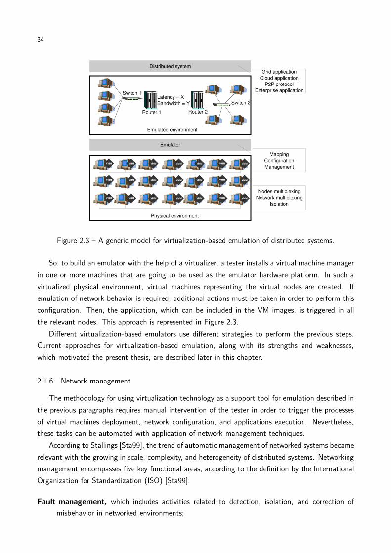
Figure 2.3 – A generic model for virtualization-based emulation of distributed systems.
So, to build an emulator with the help of a virtualizer, a tester installs a virtual machine manager
in one or more machines that are going to be used as the emulator hardware platform. In such a
virtualized physical environment, virtual machines representing the virtual nodes are created. If
emulation of network behavior is required, additional actions must be taken in order to perform this
configuration. Then, the application, which can be included in the VM images, is triggered in all
the relevant nodes. This approach is represented in Figure 2.3.
Different virtualization-based emulators use different strategies to perform the previous steps.
Current approaches for virtualization-based emulation, along with its strengths and weaknesses,
which motivated the present thesis, are described later in this chapter.
2.1.6 Network management
The methodology for using virtualization technology as a support tool for emulation described in
the previous paragraphs requires manual intervention of the tester in order to trigger the processes
of virtual machines deployment, network configuration, and applications execution. Nevertheless,
these tasks can be automated with application of network management techniques.
According to Stallings [Sta99], the trend of automatic management of networked systems became
relevant with the growing in scale, complexity, and heterogeneity of distributed systems. Networking
management encompasses five key functional areas, according to the definition by the International
Organization for Standardization (ISO) [Sta99]:
Fault management, which includes activities related to detection, isolation, and correction of
misbehavior in networked environments;
35
Accounting management, which includes activities related to appropriate charging for the use of
the networked environment, as well as control over resources usage;
Configuration and name management, which includes activities related to control, gathering
and supplying of data about the network components, in order to aid in the maintenance of
continuous operation of the environment;
Performance management, which includes activities related to evaluation of the behavior of
network components; and
Security management, which includes activities related to protection of data and components of
the networked system.
To perform such activities, network management systems contain distributed elements with
specific key functions: Managers, which have access and control over the managed elements of
the system; Agents, which query Managers in order to obtain information about, or request some
operation to be performed in one or more of the managed components; and an Information Base,
which contains information used both by Managers and by Agents to perform their activities [Sta99].
Management activities can be categorized in two groups [Sta99]: monitoring, which encompasses
activities related to observation and analysis of the managed elements, e.g., retrieve the current
amount of usage of CPU in a given host; and control, which encompasses activities related to
modification in the system component’s parameters, and requests of actions to be taken by the
managed elements; e.g., a request to an application to be started in a host.
To perform such management activities, the Simple Network Management Protocol (SNMP)
has been widely used for several years. According to Stallings [Sta99] SNMP is a collection of
specifications for network management. It is composed of the protocol itself, of the definition of the
relevant data structures, and of other associated concepts. Regarding the relevant data structures,
the most important is the Management Information Base (MIB). MIB is structured as a tree, which
gathers objects logically related. Each managed object has a unique numerical identifier which gives
the position of the element in the tree. For example, position of TCP-related managed elements are
grouped in the MIB below the object 1.3.6.1.1.2.1.6; then, the total number of TCP elements
received with errors in given by 1.3.6.1.1.2.1.6.14. Notice that the whole identifier but the last
element (14) is the TCP identifier. Similarly, other TCP-related components have the same eight
initial identifiers, but a unique last identifier. The managed elements are defined by a data type, like
Integer, Octet String, Sequence, and Null. There are standard MIBs available to management of
basic components, such as LANs. Furthermore, device vendors usually offer MIBs for their devices.
SNMP defines three basic operations: set (used for modifying a value in the managed compo-
nent), get (used to retrieve the current value of a management component), and trap (used to
inform the Agent about some event in the managed component). Further versions of the protocol
define operations for receiving information in bulks (get-bulk); and an enhanced security policy,
which is based in communities and unencrypted messages in the protocol’s first version.
36
Figure 2.4 – WBEM architecture.
Even these improvements in the SNMP protocol were not enough to overcome all the protocol’s
limitations. Issues related to limitations in MIB to describe complex data and relationships between
attributes and the impossibility of performing network management operations as transactions are
not solved in later versions of the protocol. Recently, a new specification has been proposed for
management. This new standard addresses the SNMP limitations and has support of several orga-
nizations. This new proposal is called Web-Based Enterprise Management (WBEM) [Har98]. As its
name suggests, application of such specification is not restricted to networked elements; virtually
any hardware or software component may be managed using such a specification. Furthermore, it
is expected that WBEM will be applied in other areas, such as in management of electric power
supply chain and telecommunications [Hob04].
WBEM provides both an architecture and a technology for network management. The level
of management provided by WBEM goes further than executing commands that machines can
understand and react to; it also encompasses service management, which includes higher level
management operations that translate to one or more operations in specific devices [Hob04].
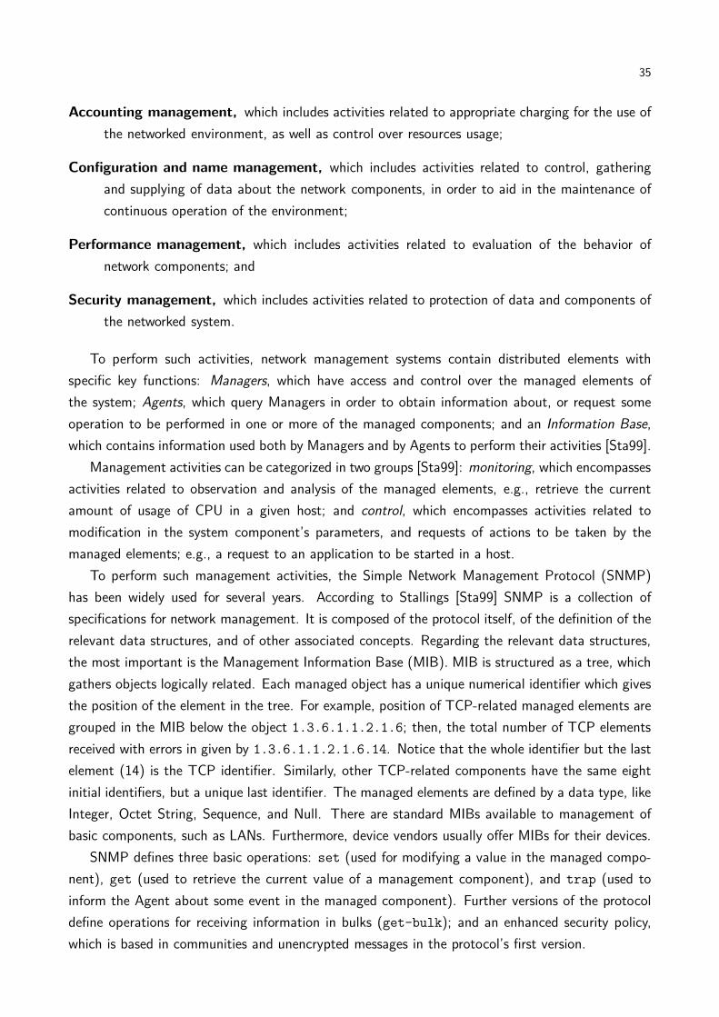
WBEM architecture is composed of the following components, as depicted in Figure 2.4: WBEM
Clients, WBEM Listeners, WBEM Servers, Providers, and Repository [Hob04]. WBEM Clients
request management operations, typically reacting to some operator’s request, to a WBEM Server.
Providers are the elements that actually perform the management operation in the managed device.
So, these components are device-specific and operate according to a protocol that are unknown by
the other components. WBEM Servers receive requests from Clients, via Web-Server operations,
and forward them to the listener associated to the requested operation. WBEM Listeners are
elements that receive information about events and alarms in the managed device. The Repository
stores properties of the managed device, which is used by the WBEM Server when replying for
management operations.
Another interesting feature of WBEM is that Providers can act as WBEM Clients to a Server,
by forwarding management operations to remote or low-level WBEM Servers [Hob04]. With this
model, it is possible to have WBEM Servers for specific sub-components of an architecture, which are
accessed by a Provider in the main component. This organization is especially useful when Clients
do not have direct access to the Server of some device, because of security or design limitations.
Then another Server act as a proxy for the Client and the Server.
37
The WBEM counterpart for SNMP’s MIB is the CIM (Common Interface Model). It is object-
oriented. Thus, new managed objects can be included as children of already defined objects; this
way, all the operations already defined for the parent class are automatically available for the new
object. Only operations that are different from parent’s operations have to be defined for the new
class, what makes simpler inclusion and management of new objects.
WBEM commands are encoded according to the xmlCIM specification, which defines XML el-
ements in Document Type Definition and CIM as a XML specification [Hob04]. Operations, in
WBEM, are part of the managed device specification. To transport operation messages, WBEM
supports several mechanisms, such as Web Services, http, xmlCIM, and application-specific proto-
cols.
Both SNMP and WBEM protocols were proposed before the large adoption of virtualized systems.
Therefore, these protocols do not have built-in support for this kind of environment. For example,
among standard MIBs for SNMP, there is no one able to handle virtualized objects. Similarly,
no standardized CIM for virtualized resources is available, even though there are some efforts in
this direction, such as the libvirt-CIM2, which is a CIM for VMM-independent management of
virtualized platforms based on Linux. In the same direction, vMIB [dCR08] has been proposed as
a VMM-independent MIB for virtualized environments. While standard information bases are not
available, developers of systems that require management activities must develop and use their own
bases, or rely on some incomplete and unstable draft of information base.
2.1.7 Grid computing
Evaluation of AEF—when one of the main platforms it was developed for—is Grid Computing
[FK99b] environments. Grids are distributed systems whose resources, which are either computing
resources (e.g., computers, storage) or general resources (e.g., microscopes, antennas) can be shared
and accessed in a secure and coordinated way.
Grids appeared in the 90’s. Initially, they were proposed as a solution to provide computing
services as utilities, in the same way electricity is supplied for domestic users [CB02]. Nevertheless,
this vision was never realized and, in practice, what Grids became was a collection of distributed
resources, typically academic and research infrastructures, which are accessed in a coordinated
manner, based on agreements among institutions sharing the resources. Each institution providing
distributed resources, referred throughout the rest of this thesis as site, allows access to its resources
to other Grid participants. Access to the resources may be via allocation, which is used especially
when the resources are Clusters of workstations [FKT01]; or may be via exploitation of idle cycles
of machines, in a opportunistic way. In the later model, unused resources are donated to the grid,
to be used while local users (e.g., users located in the same site than the resource) are not using
them. Another important aspect of Grids, according to Keahey et al. [KTMF09] is that control of
resources is held by the site, and not by the user.
2http://libvirt.org/CIM
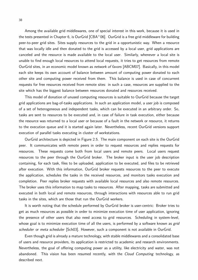
38
Among the available grid middlewares, one of special interest in this work, because it is used in
the tests presented in Chapter 6, is OurGrid [CBA+06]. OurGrid is a free grid middleware for building
peer-to-peer grid sites. Sites supply resources to the grid in a opportunistic way. When a resource
that was locally idle and then donated to the grid is accessed by a local user, grid applications are
canceled and the resource is made available to the local user. Similarly, whenever a local site is
unable to find enough local resources to attend local requests, it tries to get resources from remote
OurGrid sites, in an economic model known as network of favors [ABCM07]. Basically, in this model
each site keeps its own account of balance between amount of computing power donated to each
other site and computing power received from them. This balance is used in case of concurrent
requests for free resources received from remote sites: in such a case, resources are supplied to the
site which has the biggest balance between resources donated and resources received.
This model of donation of unused computing resources is suitable to OurGrid because the target
grid applications are bag-of-tasks applications. In such an application model, a user job is composed
of a set of heterogeneous and independent tasks, which can be executed in an arbitrary order. So,
tasks are sent to resources to be executed and, in case of failure in task execution, either because
the resource was returned to a local user or because of a fault in the network or resource, it returns
to the execution queue and it is started again later. Nevertheless, recent OurGrid versions support
execution of parallel tasks executing in cluster of workstations.
OurGrid architecture is depicted in Figure 2.5. The main component on each site is the OurGrid
peer. It communicates with remote peers in order to request resources and replies requests for
resources. These requests come both from local users and remote peers. Local users request
resources to the peer through the OurGrid broker. The broker input is the user job description
containing, for each task, files to be uploaded, application to be executed, and files to be retrieved
after execution. With this information, OurGrid broker requests resources to the peer to execute
the application, schedules the tasks in the received resources, and monitors tasks execution and
completion. Peer replies broker requests with available local resources and also remote resources.
The broker uses this information to map tasks to resources. After mapping, tasks are submitted and
executed in both local and remote resources, through interactions with resources able to run grid
tasks in the sites, which are those that run the OurGrid workers.
It is worth noting that the schedule performed by OurGrid broker is user-centric: Broker tries to
get as much resources as possible in order to minimize execution time of user application, ignoring
the presence of other users that also need access to grid resources. Scheduling in system-level,
whose goal is to minimize execution time of all the users, is performed by a software known as grid
scheduler or meta scheduler [Sch03]. However, such a component is not available in OurGrid.
Even though grid is already a mature technology, with stable middlewares and a consolidated base
of users and resource providers, its application is restricted to academic and research environments.
Nevertheless, the goal of offering computing power as a utility, like electricity and water, was not
abandoned. This vision has been resumed recently, with the Cloud Computing technology, as
described next.

39
Figure 2.5 – OurGrid architecture.
2.1.8 Cloud computing
Recently, the trend of delivering computing power as a utility has been raised with the Cloud
Computing technology [Wei07]. According to Buyya et al., a Cloud is a collection of virtualized
distributed resources that are delivered to users in a pay-per-use basis according to negotiated
SLAs [BYV+09]. Cloud resources are physically organized as data centers containing hundreds or
thousands of computers. One of the key differences between a grid and a cloud, according to Keahey
et al. [KTMF09] is that, in the later, control of resources are held by users, while control in the
former are held by resource owners.
One of the key technologies that enabled Cloud Computing is virtualization, because it allows
deployment of isolated virtual machines, containing any configuration required by the user, in a set
of hosts. Moreover, the exact characteristics of the host running the virtual machine are hidden
from the user. Hence, VMs can be migrated to allow consolidation or to increase performance of
users applications without service interruption and transparently. Furthermore, it is possible the
dynamically increase or decrease the amount of resources allocated to a client.
Services in a Cloud are offered in three different levels: Infrastructure as a Service (IaaS), where
users receive a share of a host to deploy their own virtual machines with any configuration and
software on it; Platform as a Service (PaaS), where users receive a platform where they can build
specific (typically web) applications without handling the virtual machine or the underlying software
supporting the platform; or Software as a Service (SaaS), where users pay to use a specific software
without handling details of the underlying architecture supporting the software.
Regarding access rights to a Cloud, a cloud can be public, when any user can subscribe to use
the services; private, when access to resources is restricted to users belonging to the organization

40
that built the Cloud; or hybrid, when a public cloud is used to supplement resources of a private
cloud [SMLF09]. Private clouds can be built with the use of software such as Aneka [CNJ+07] or
Eucalyptus [NWG+08]. Public cloud services are offered by providers such as Amazon EC23 (IaaS),
Google AppEngines4 (PaaS), and Salesforce5 (SaaS).
Even though Cloud Computing is a very promising technology, with potential to drastically change
the way companies and people use computers, there are several issues that have to be resolved before
a wide adoption of it as a replacement for local data centers and usersŠ desktops. Some of the tools
and methods presented in this thesis can be applied in Cloud environments to help to solve some
of these issues, because both the target physical environment of an emulator (a cluster running a
VMM) and a cloud data center have elements in common, even though the scale of the later tend to
be at least one order of magnitude bigger than the scale of the former. An evidence of applicability
of tools and methods in both areas is given next.
2.1.9 CloudSim Toolkit
An important part of the work presented in this thesis consists in automatically deploying virtual
machines in the hosts of a cluster. Several strategies can be used to perform the mapping, and the
goal is applying a strategy that optimizes the system usage according to a specific criterion. Thus,
an evaluation method was required in order to identify the best strategy among the available ones.
In the beginning of this chapter, several methods for distributed systems experimentation were
discussed and compared. The problem addressed in this thesis, emulation, is a suitable strategy
to evaluate prototypes, because emulation allows execution of actual software in a model of the
environment.
Consider now the problem of evaluating strategies for mapping VMs to hosts. In this case, the
evaluation of the strategies happens before implementation of the prototype of the mapper. Thus,
emulation is not the best experimentation method to be applied in this case. Simulation, on the
other hand, fits well this task: it allows testing of a model of a software (in this case, a model of the
strategies) in a model of the system. Furthermore, simulation allows a quick evaluation of different
scenarios and different mapping parameters. Therefore, the experimentation method we chose for
evaluation the strategies for mapping VMs to hosts is simulation.
Now, consider the scenario of the experimentation: a set of heterogeneous machines, on which
some virtual machines must be mapped to. Furthermore, VMs in the same host share CPU, and
thus the performance of applications in the VM decreases. Hence, effect of sharing of resources
must be evaluated together with the effect of the mapping itself.
Some of the abstractions required in this experiment, like machines with some CPU capacity,
and submission of tasks that incur some load in the hosts are offered by the existent Grid simulators.
However, the possibility of having VMs, which required sharing resources from the machine, is not
3http://www.aws.amazon.com/ec24http://code.google.com/appengine/5http://www.salesforce.com
41
contemplated by those existent simulators.
In order to enable evaluation of effects of virtual machines in a computing environment, the
GridSim grid simulation Toolkit [BM02] has been extended, enabling simulation of virtualized en-
vironments. This extension enabled simulation of sites containing hosts that can receive virtual
machines. Notice that it is exactly the concept of a Cloud data center presented previously: an in-
frastructure containing a number of hosts that run virtualization software in order to enable sharing
of the resources among users.
Because of this similarities between the target environment of our simulator and a Cloud infras-
tructure, further abstractions, related to Clouds, were added to our GridSim’s extension and the
result was the first release of the CloudSim Toolkit [BRC09].
The CloudSim Toolkit enables simulation of virtualized data centers, containing thousands of
virtualized hosts. Virtual machines are deployed in the data centers according to provisioning policies
that can be defined by the tester. These data centers belong either to the same provider, or to
different providers.
Users are also represented in the simulation. They require creation of virtual machines in the
data centers, and submit tasks to be executed in the virtual machines as in an IaaS cloud. Modeling
of policies to decide which data centers run which VMs is also delegated to the tester. Also, the
tester is responsible for defining scheduling policies of tasks to VMs.
Control of execution of tasks in the VMs is performed by CloudSim. Sharing of resources in
CloudSim happens in two levels: in the first level, a fraction of the CPUs on each host, which can
be multicore machines or SMP processors, is given to each VM. This level simulates the scheduling
policy of VMMs.
The second level of resource sharing is the sharing of the resources allocated to a VM among the
tasks running on it. This level simulates the operating system scheduler. In any level, it is possible
to apply a space-shared, time-shared, weighted time-shared, or other policies defined by the tester.
Differences in application of such algorithms on each level are depicted in Figure 2.6.
During execution of user tasks, data center controls resource utilization and use this information
to charge users for resource usage. So, different billing policies applied by different cloud providers
can also be simulated in CloudSim. It is possible to keep track of usage of resources by the VMs
(memory and bandwidth), usage of CPU by the tasks, and amount of time the VM executed. The
later is important to allow simulation of typical charging policies used by Cloud providers, where use
of virtual machines is charged according to the time it was running. Normally, the charge is at fixed
times, like in Amazon EC2, where use of VMs are charged in an hourly basis, rounded up. So, if a
virtual machine is used during one hour and one minute, user is charged for two hours of resource
usage. Nevertheless, CloudSim allows definition of other policies, either to allow effects of different
policies for Cloud users, or to allow modeling of new policies applied by real providers.
Other important features of CloudSim are listed below. Some of these features were added in
the recent version of the toolkit.
Network simulation. CloudSim allows simulation of bandwidth and delay in execution of applica-
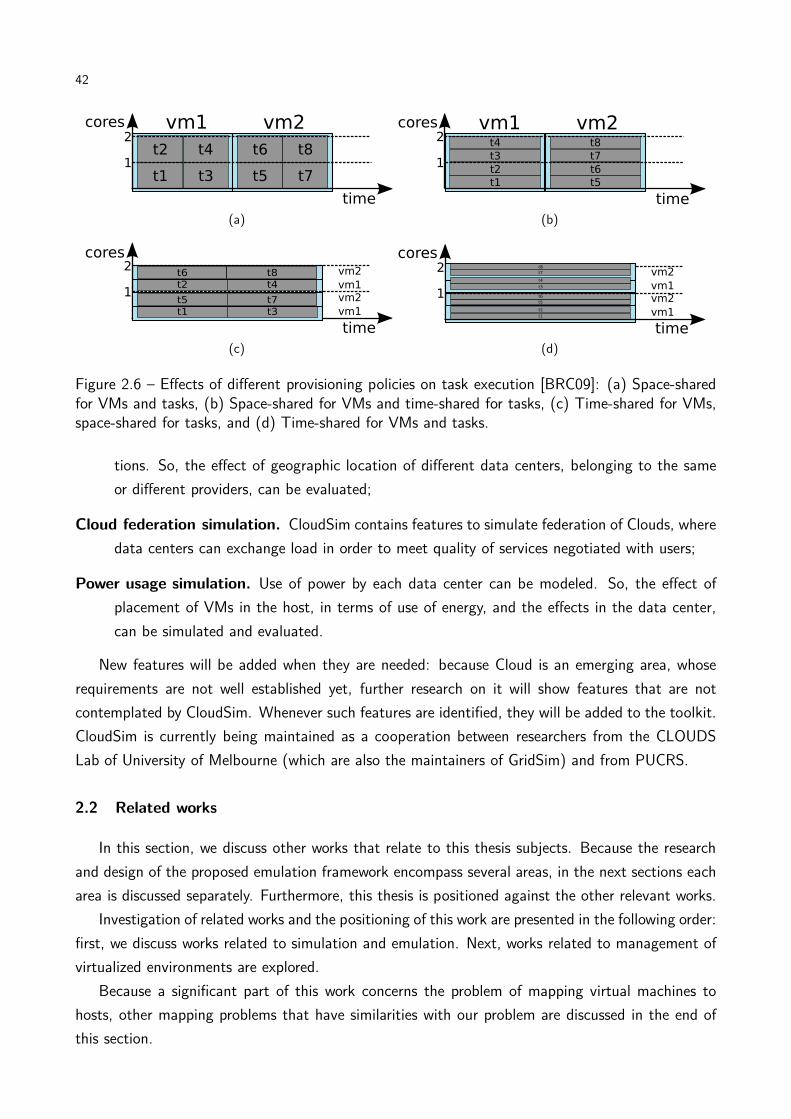
42
(a) (b)
(c) (d)
Figure 2.6 – Effects of different provisioning policies on task execution [BRC09]: (a) Space-sharedfor VMs and tasks, (b) Space-shared for VMs and time-shared for tasks, (c) Time-shared for VMs,space-shared for tasks, and (d) Time-shared for VMs and tasks.
tions. So, the effect of geographic location of different data centers, belonging to the same
or different providers, can be evaluated;
Cloud federation simulation. CloudSim contains features to simulate federation of Clouds, where
data centers can exchange load in order to meet quality of services negotiated with users;
Power usage simulation. Use of power by each data center can be modeled. So, the effect of
placement of VMs in the host, in terms of use of energy, and the effects in the data center,
can be simulated and evaluated.
New features will be added when they are needed: because Cloud is an emerging area, whose
requirements are not well established yet, further research on it will show features that are not
contemplated by CloudSim. Whenever such features are identified, they will be added to the toolkit.
CloudSim is currently being maintained as a cooperation between researchers from the CLOUDS
Lab of University of Melbourne (which are also the maintainers of GridSim) and from PUCRS.
2.2 Related works
In this section, we discuss other works that relate to this thesis subjects. Because the research
and design of the proposed emulation framework encompass several areas, in the next sections each
area is discussed separately. Furthermore, this thesis is positioned against the other relevant works.
Investigation of related works and the positioning of this work are presented in the following order:
first, we discuss works related to simulation and emulation. Next, works related to management of
virtualized environments are explored.
Because a significant part of this work concerns the problem of mapping virtual machines to
hosts, other mapping problems that have similarities with our problem are discussed in the end of
this section.

43
2.2.1 Simulation
As already described later in this chapter, emulation and simulation are two techniques for exper-
imentation in computer science that have different applications. As also already stated, algorithms
for mapping VMs to hosts presented in this thesis were evaluated with a simulator (CloudSim).
There are several tools for simulation of distributed systems available nowadays. They differ from
each other in the kind of environment they model and in the approach for modeling the software
being tested.
A very popular simulator of networks is ns-26. It is a discrete-event simulator of networks. It
supports simulation of network protocols in different layers (TCP, IP, routing protocols) and also
simulation of wireless networks. The main components of an ns-2 simulation are the nodes and
links. In the nodes, there are agents that send data via a specific protocol to another agent, or to
several other agents, because broadcast and multicast are also supported in the simulator. Even
though ns-2 is a suitable tool for simulation of low-level behavior of networks, it does not provide
abstractions to support higher-level elements, like users, tasks, and computers. So, for simulation
of applications, other tools may suit better.
DSSimulator [SB05] provides higher-level abstractions than ns-2. It is also a discrete-event sim-
ulator. Nevertheless, the target environments are overlays. So, in DSSimulator, the specific network
protocol in use, routers, switches, and other intermediate elements are not simulated. Instead, only
the relevant components of the overlay are simulated, and the bandwidth and latency between them
are considered during simulation of communication. Even though DSSimulator provides higher level
abstractions for networking than ns-2, it also does not provide support for direct representation of
applications and elements able to execute such applications.
Grid computing simulators allow modeling of applications and elements able to process and
generate them. One of such simulators is SimGrid [LMC03]. It is a toolkit for discrete-event
simulation of grid environments. It allows modeling of computers, networks, and applications,
including applications modeled as Direct Acyclic Graphs (DAGs). Simulations in SimGrid are agent-
oriented, what means that simulation elements able to perform actions are agents, which can take
scheduling decisions. Agents are described as their code, private data, and a location where they
execute. The agent location is another abstraction from the tool, and it is composed of a computing
resource and communication channels between other agents. The unit of execution of applications
is a task, and it is composed of the amount of processing power required by the application and an
amount of data to be transmitted.
GangSim [DF05] is a simulation tool for grid environments. The main difference from GangSim to
other approaches is that the former supports virtual organizations as a basic simulation component.
So, this tool is suitable to modeling and simulation of grids which use virtual organizations, such
as Globus grids. Other elements represented in a GangSim simulation are sites, which contains
resources (CPU and storage) and network; meta schedulers, user schedulers and data schedulers;
6http://www.isi.edu/nsnam/ns/

44
Table 2.3 – Comparison among grid simulators and CloudSim.SimGrid GangSim GridSim CloudSim
Network representation yes yes yes yesProcessing nodes representation yes yes yes yesSites representation yes yes yes yesVirtual organizations representation no yes no noEconomic modeling no no yes yesVMs representation no no no yesLanguage C, XML Perl Java Java
and policy enforcers, which ensure that policies defined on other components are respected during
the simulation.
GridSim [BM02] is a discrete-event simulation toolkit for grid applications. It supports modeling
of grid resources, which are described as an amount of processing elements with different processing
capacities, location of resource, cost for utilization, and scheduling policies for allocating processing
elements to the tasks in execution. Another component of the simulation is the user, which is
represented by its grid broker. Policies to submit user tasks to grid resources must be defined by
the testers and are implemented in the broker. Finally, a grid application is represented as a number
of tasks, each one containing the amount of processing power required to complete task execution,
amount of data to be transferred to the grid, and amount of data to be retrieved. Later versions of
GridSim support simulation of network elements, simulation of data grids, and modeling of faulty
elements.
These tools were conceived before the increase in interest by virtualization in the context of
grids and clouds, therefore they do not contain elements to simulate virtualized infrastructures. It
motivated us to develop the CloudSim toolkit [BRC09], which is based in the GridSim toolkit. A
comparison among the described Grid simulators and CloudSim is presented in Table 2.3.
Even though all the presented simulators provide mechanisms to model distributed environments,
they also require modeling of the applications being tested. If a tester wants to evaluate a prototype,
simulation is not the most fitted methodology for experimentation. In this case, emulation should
be used. Next, emulation tools are described and compared to the one proposed in this thesis.
2.2.2 Emulation
Several emulators were proposed along the time, with different purposes and using different
technologies.
LAPSE [DHN96] is an emulator of distributed systems supporting message-passing programs.
This emulator executes only in Intel Paragon machines. The emulated network model supports
either simple inclusion of latency in the messages sent through the network or a complex model
including the presence of switches. In LAPSE, multiplexing of nodes is very simple. There is a
module, which is part of the emulator, executing for each instance of the distributed application.
45
This module interacts with the emulator core to receive and deliver message to the application, at
specific times. No further control of resources is allowed by LAPSE. The problem of such limitation
in resource multiplexing is that it is not possible to evaluate the application in the presence of
specific amount of resources. Furthermore, it is not possible to completely isolate applications,
and thus applications sharing resources interfere in other applications (i.e., lack of performance
isolation among virtual elements executing in the same host) what is undesirable when evaluation
of applications is performed.
MicroGrid [LXC04] is an emulator for distributed systems environments. The physical infras-
tructure required by MicroGrid is a distributed environment, such as clusters, LANs, or mixed
environments composed by subnetworks and clusters. On top of such physical environment, Micro-
Grid builds a virtual grid, which applications can use, together with the grid middleware required by
the application, if any is required. MicroGrid supports applications using the MPI message-passing
library [GLDS96], if applications are compiled with a specific MicroGrid library. This library inter-
cepts systems calls that send messages and request the current time, so messages can be delayed
and the emulation time can be supplied instead of wall clock time. MicroGrid also supports grid
applications compatible with Globus Toolkit version 2 and Java applications. Network behavior is
given by a distributed network simulator called MaSSF. Nodes are multiplexed with the help of CPU
controllers. Controllers make processes be interrupted when they use all the CPU cycles they are
supposed to use, considering the difference of capacity between the actual machine running the ap-
plication and the emulated machine. Other resources cannot be controlled and therefore MicroGrid
cannot provide isolation among processes running in the same host, what is a major limitation of
the tool.
Panda [KBM+02] allows emulation of a wide-area network in a single cluster. Panda, which
was part of the Albatross project, has been developed to support testing of distributed applications
that run in multiple clusters. A unique characteristic of this kind of application is that some tasks,
which are running in the same cluster, communicate with low latency and high bandwidth, whereas
other tasks communicate with high latency and low latency, because they are in different clusters
and thus communicate through a WAN. Similarly to MicroGrid, Panda requires several libraries and
low-level tools running together with the applications to provide network emulation (i.e., emulation
of latency in the network messages). Furthermore, nodes multiplexing are not performed. Then,
there is neither performance isolation among tasks running in the same node nor emulation of nodes
with different CPU speeds.
ModelNet [VYW+02] is a network emulator that focuses in accurate emulation of network events.
Therefore, while other emulators only represent effects of the network as a delay in the packets
reception by remote nodes, ModelNet also emulates the presence of network elements, such as
routers and switches. Then, events related to packet flow (e.g., congestion, packet drops, etc.) are
also represented. The physical nodes supporting execution of ModelNet are divided in nodes for
emulating the network and nodes for executing the application. ModelNet supports only emulation
of the network. Therefore, it is not possible to multiplex the processing nodes, and so scalability of
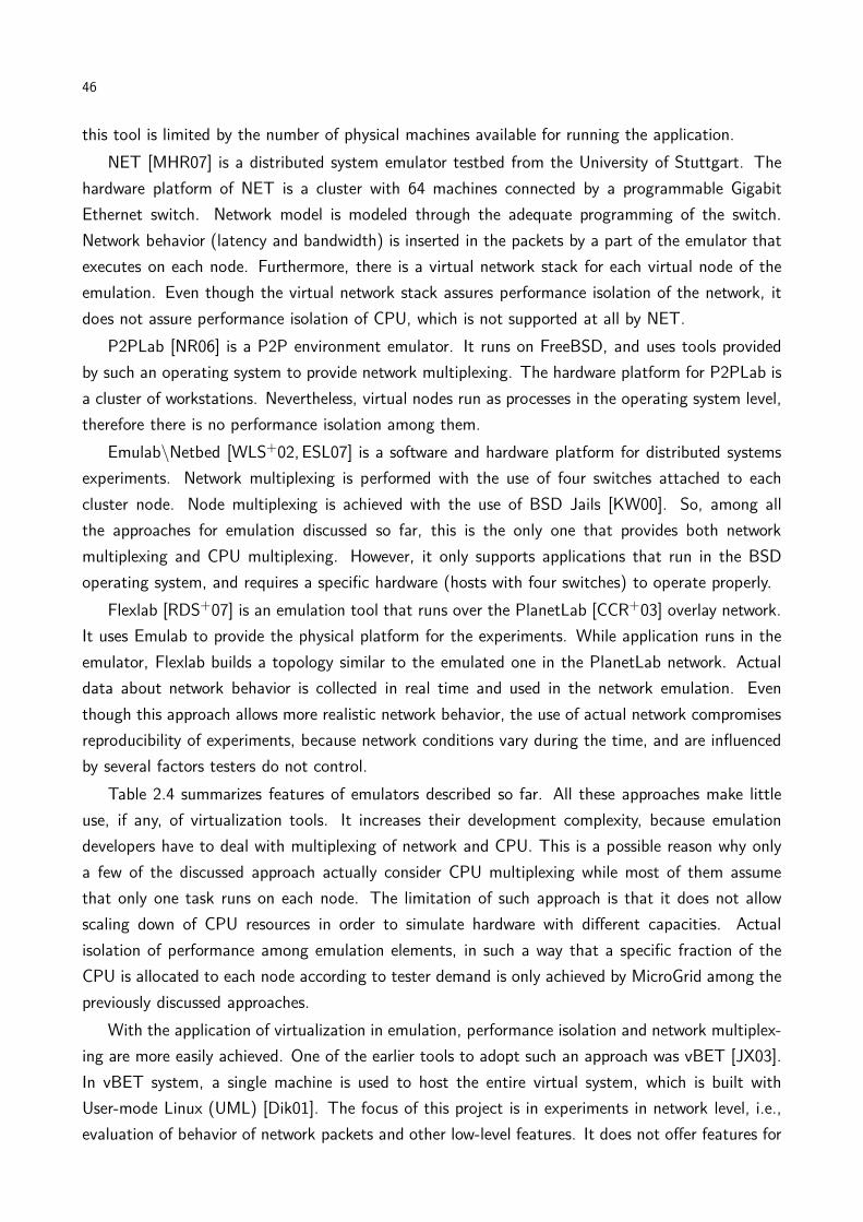
46
this tool is limited by the number of physical machines available for running the application.
NET [MHR07] is a distributed system emulator testbed from the University of Stuttgart. The
hardware platform of NET is a cluster with 64 machines connected by a programmable Gigabit
Ethernet switch. Network model is modeled through the adequate programming of the switch.
Network behavior (latency and bandwidth) is inserted in the packets by a part of the emulator that
executes on each node. Furthermore, there is a virtual network stack for each virtual node of the
emulation. Even though the virtual network stack assures performance isolation of the network, it
does not assure performance isolation of CPU, which is not supported at all by NET.
P2PLab [NR06] is a P2P environment emulator. It runs on FreeBSD, and uses tools provided
by such an operating system to provide network multiplexing. The hardware platform for P2PLab is
a cluster of workstations. Nevertheless, virtual nodes run as processes in the operating system level,
therefore there is no performance isolation among them.
Emulab\Netbed [WLS+02, ESL07] is a software and hardware platform for distributed systems
experiments. Network multiplexing is performed with the use of four switches attached to each
cluster node. Node multiplexing is achieved with the use of BSD Jails [KW00]. So, among all
the approaches for emulation discussed so far, this is the only one that provides both network
multiplexing and CPU multiplexing. However, it only supports applications that run in the BSD
operating system, and requires a specific hardware (hosts with four switches) to operate properly.
Flexlab [RDS+07] is an emulation tool that runs over the PlanetLab [CCR+03] overlay network.
It uses Emulab to provide the physical platform for the experiments. While application runs in the
emulator, Flexlab builds a topology similar to the emulated one in the PlanetLab network. Actual
data about network behavior is collected in real time and used in the network emulation. Even
though this approach allows more realistic network behavior, the use of actual network compromises
reproducibility of experiments, because network conditions vary during the time, and are influenced
by several factors testers do not control.
Table 2.4 summarizes features of emulators described so far. All these approaches make little
use, if any, of virtualization tools. It increases their development complexity, because emulation
developers have to deal with multiplexing of network and CPU. This is a possible reason why only
a few of the discussed approach actually consider CPU multiplexing while most of them assume
that only one task runs on each node. The limitation of such approach is that it does not allow
scaling down of CPU resources in order to simulate hardware with different capacities. Actual
isolation of performance among emulation elements, in such a way that a specific fraction of the
CPU is allocated to each node according to tester demand is only achieved by MicroGrid among the
previously discussed approaches.
With the application of virtualization in emulation, performance isolation and network multiplex-
ing are more easily achieved. One of the earlier tools to adopt such an approach was vBET [JX03].
In vBET system, a single machine is used to host the entire virtual system, which is built with
User-mode Linux (UML) [Dik01]. The focus of this project is in experiments in network level, i.e.,
evaluation of behavior of network packets and other low-level features. It does not offer features for

47
Table 2.4 – Comparison among emulators.LAPSE MicroGrid Panda ModelNet NET P2PLab Emulab/Flexlab
Techniquefor nodemultiplexing
multitasking controllers multitasking — multitasking multitasking BSD Jails
Techniquefor networkmultiplexing
library library library simulation middleware OS tools OS tools
Performanceisolation?
no yes no yes no no yes
CPU scal-ing?
no yes no no no no no
Distributed? yes yes yes yes yes yes yesTarget hard-ware infras-tructure
Intel Paragon clusters clusters clusters specific cluster clusters specific cluster
TargetApplications
distributed MPI distributed distributed distributed distributed distributed
testing applications and other high-level system elements. Furthermore, because only one physical
machine can be used to host the emulation, this tool has a limited scalability.
TestGrid [CCW+06] also applies virtualization to allow creation of simple emulated environments.
It allows testers to automatically deploy VM images of preconfigured types in a virtualized cluster,
enabling them to run grid application in an emulated network. This emulated network, however,
allows only isolation among grid sites, and not emulation of network parameters. It also does not
address mapping and deployment of VMs in hosts: testers have to manually decide where to create
each VM and do it with the help of the GridBuilder [CCM06] tool. Network configuration is not
performed. CPU multiplexing is achieved with the use of virtualization technology (Xen).
NEPTUNE [CGMV07] is another virtualization-based emulator that provides a Xen-based virtual
environment for distributed systems experiments. Network emulation is performed with the use of
tools supplied with Xen. CPU multiplexing and performance isolation is also supported natively by
Xen. There is no reference about capabilities of automatic configuration and installation based on
a tester-supplied specification. If these features are not available, testers have to manually map,
deploy, and configure the system.
DieCast [GVV08] is a distributed system emulator that applies the concept of time dilation
[GYM+06] to enable emulation of more resources than the amount actually available. The technique
of time dilation consists in using virtualization to slow down VMs, by delaying events (reception of
time interruptions) in their operating system kernel. So, for example, by delaying in 10 times the
reception of interruptions, and keeping the network flow at its regular speed, from the VM perspective
network is 10 times faster than its actual speed. The same can be achieved for CPU speed, whereas
the same achievement for disks requires the use of a disk simulator, which calculates the time an
I/O operation would take considering the simulation time rate. The goal of the VMM in the process
of time dilation is ensuring that signals are received by VMs at the expected rate. Even though
time dilation allows experimentation with a emulated environment containing more resources than
in the actual environment, the process slowdowns the experiment in the same rate the environment
“grows”, what can make an experiment take a long time to complete. Furthermore, DieCast requires
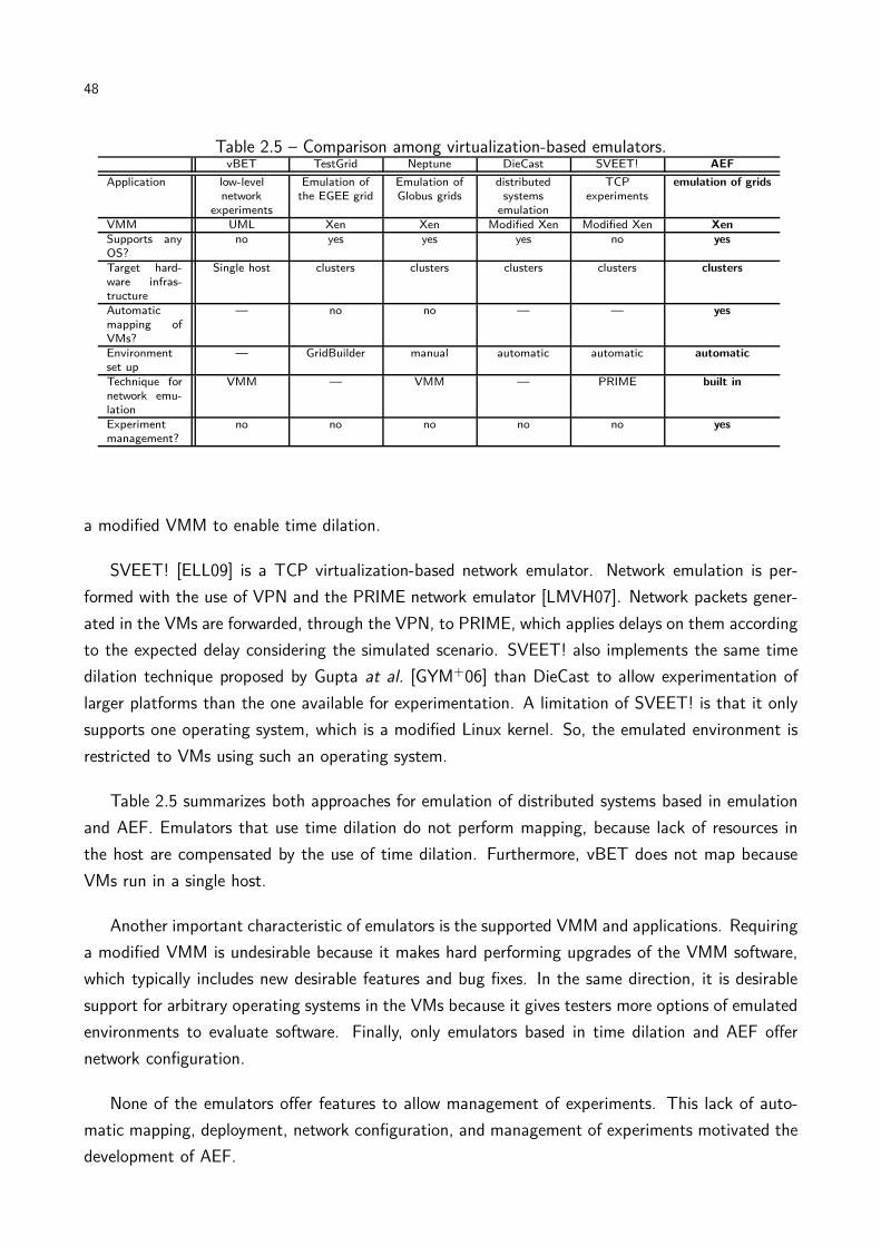
48
Table 2.5 – Comparison among virtualization-based emulators.vBET TestGrid Neptune DieCast SVEET! AEF
Application low-levelnetwork
experiments
Emulation ofthe EGEE grid
Emulation ofGlobus grids
distributedsystems
emulation
TCPexperiments
emulation of grids
VMM UML Xen Xen Modified Xen Modified Xen XenSupports anyOS?
no yes yes yes no yes
Target hard-ware infras-tructure
Single host clusters clusters clusters clusters clusters
Automaticmapping ofVMs?
— no no — — yes
Environmentset up
— GridBuilder manual automatic automatic automatic
Technique fornetwork emu-lation
VMM — VMM — PRIME built in
Experimentmanagement?
no no no no no yes
a modified VMM to enable time dilation.
SVEET! [ELL09] is a TCP virtualization-based network emulator. Network emulation is per-
formed with the use of VPN and the PRIME network emulator [LMVH07]. Network packets gener-
ated in the VMs are forwarded, through the VPN, to PRIME, which applies delays on them according
to the expected delay considering the simulated scenario. SVEET! also implements the same time
dilation technique proposed by Gupta at al. [GYM+06] than DieCast to allow experimentation of
larger platforms than the one available for experimentation. A limitation of SVEET! is that it only
supports one operating system, which is a modified Linux kernel. So, the emulated environment is
restricted to VMs using such an operating system.
Table 2.5 summarizes both approaches for emulation of distributed systems based in emulation
and AEF. Emulators that use time dilation do not perform mapping, because lack of resources in
the host are compensated by the use of time dilation. Furthermore, vBET does not map because
VMs run in a single host.
Another important characteristic of emulators is the supported VMM and applications. Requiring
a modified VMM is undesirable because it makes hard performing upgrades of the VMM software,
which typically includes new desirable features and bug fixes. In the same direction, it is desirable
support for arbitrary operating systems in the VMs because it gives testers more options of emulated
environments to evaluate software. Finally, only emulators based in time dilation and AEF offer
network configuration.
None of the emulators offer features to allow management of experiments. This lack of auto-
matic mapping, deployment, network configuration, and management of experiments motivated the
development of AEF.
49
2.2.3 Management of virtualized environments
Another significant part of AEF’s activities concerns management of virtualized environments. In
AEF, this technique is applied to allow emulation of distributed systems. Nevertheless, techniques for
management of virtualized environment are also applied in other contexts, especially for management
of data centers.
HARMONY [SKM08] applies management of virtualized environments to achieve load-balancing
in both storage and computing data centers. HARMONY provides an environment for monitoring
of data centers resources usage. Data centers resources are virtualized, both computing nodes
and storage nodes. System virtualization is performed by VMware, and storage management is
performed by IBM SAN Volume Controller. Furthermore, the physical infrastructure managed by
HARMONY is restricted to a specific topology, which is typically found in data centers built with
IBM software and hardware. When HARMONY is deployed in the data center, use of resources
is monitored. If conditions observed in a specific moment may lead to SLA violations, virtual
machines and virtual disks are remapped. These decisions are taken in real time and without
services interruption. HARMONY differs from AEF in the system goals, and so both approaches
are not interchangeable: AEF does not take remapping decisions in real time. When SLAs are
not observed, it stops execution of the experiment to rebuild it, using more time-costly remapping
strategies. But because HARMONY is applied in production data centers, services running in VMs
cannot be interrupted, and remapping must be as quick as possible, otherwise SLAs may be violated.
Khanna et al. [KBKK06] presents another solution for data centers management that, like HAR-
MONY, is based in IBM solutions. In this approach, the IBM Director software is used to manage
the virtualized infrastructure. However, unlike HARMONY that performs management of the net-
work between computing elements and storage elements, Khanna’s approach considers only the VM
management, and violations in SLAs related to usage of resources by VMs. In reaction to potential
SLAs violations, the system performs VM migrations. Decisions are made in such a way that the
number of migrations is minimized. The system decides that a SLA violation is about to occur when
resources usage achieves a threshold specified by the infrastructure manager. The main drawback
of this approach is that management decisions are limited to VM migrations. AEF, on the other
hand, can also modify the amount of resources allocated to VMs in order to improve performance
of applications running on it. Furthermore, Khanna’s approach does not manage network, and so
SLA violations caused by overload in some network links are neither detected nor fixed.
Usher [MGVV07] is an extensible and customizable virtual machine management system for
data centers. It allows creation of virtual clusters in the infrastructure. These virtual clusters
are composed of VMs that run the same software and have the same configuration. Usher was
developed to be used in arbitrary data centers, unlike the previous approaches that require specific
hardware and relies in proprietary software for infrastructure management. It implements operations
for management of the whole VM lifecycle—creation, migration, destruction, and interruption. It
also supplies tools for definition of provisioning policies, VM lifecycle management policies, power

50
Table 2.6 – Comparison among managers of virtualized environments.HARMONY Khanna’s Usher AEF
Managed topology specific specific arbitrary arbitraryVMM VMware VMware Xen XenManagement tools proprietary proprietary built in built inVM management? yes yes yes yesNetwork management? yes no no yesApplications management? no no no yesOn line system adaptation? yes yes yes noVM management actions supported migration only migration only user-defined user-defined
management, and load balancing. Usher supports virtualized environments build with Xen VMM.
Only VM attributes are monitored by Usher. So, load balancing and other management decisions
are made based on VMs, and, as in the previous case, SLA violations caused by overload in network
links are not detected. Usher allows the system administrators to express their own policies to set
actions on VMs. When a condition defined by the administrator is observed in the monitoring data,
the corresponding action set by the administrator is performed. AEF, on the other hand, allows
combination of policies and events to define complex actions for system reconfiguration. Also, in
AEF network events observed in the infrastructure also triggers reconfiguration events.
Table 2.6 summarizes the features of the virtual environment managers presented in this section
and AEF. HARMONY and Khanna’s approach work only on specific architectures, and so they are
not suitable to the context of emulation of distributed systems in arbitrary clusters. Usher is the
approach that has the most features in common with AEF. However, Usher manages no networks
or applications, and therefore considers only part of the management issues required by an emulator
and addressed by AEF.
2.2.4 Virtual machines mapping
The activities related to systems management, which enable automatic installation of the virtual
machines in the hosts and automatic execution of experiments, only take place after the decision of
where each VM must be created. This problem is an assignment problem: hosts available to the
emulation are assigned to each virtual machine. Furthermore, physical limitations in the amount of
resources available on the hosts and the resources required by each VM must be taken into account
when the assignment is performed.
In this thesis, this problem was modeled as a mapping problem, where VMs are mapped to hosts
to be executed. Furthermore, resources are constraints in the mapping problem, limiting the number
of valid mappings. In our formulation, which is detailed in the next chapter, the goal is mapping
VMs to hosts and links between VMs to paths in the physical cluster. Because a similar problem
was not found in the literature, we formulated the formal description of the problem and proposed
algorithms to solve it. Nevertheless, there are other problems that have some relation with the
problem we defined.
51
One of such a related problem is the Generic Adaptation Problem in Virtual Execution Environ-
ments (GAPVEE) [SSLD05,SSLD06a]. GAPVEE consists in, starting from a original distribution of
VMs in a WAN and paths between them, finding a new mapping of VMs to hosts in order to improve
throughput of applications running in the VMs. This problem is applied in the context of emulation
of local area networks in wide area networks. This problem differs from the mapping problem solved
by AEF in three main aspects. The first difference is the existence of an initial state in GAPVEE
where the solution starts from. So, if a new mapping that improves the throughput is not found,
there is already a configuration that can be used to execute applications. In our proposal, there
is no such an initial valid state. Nevertheless, our solution can be applied in GAPVEE to find an
initial valid state, which the solution presented by Sundararaj et al. [SSLD06b] is not able to do.
The second difference is the goal of the mapping, which is maximizing application throughput in
GAPVEE and load-balance of the environment in our proposal. Finally, there is a difference in the
application of both approaches (emulation of LANs in WANs in GAPVEE and emulation of WANs
and LANs in our approach), which leads to different formal models for each problem.
Another problem related to the mapping problem presented in this paper is the Network testbed
mapping problem defined by Ricci et al. [RAL03]. In this approach, hosts receive VMs according
to a limit given by the number of VMs they can receive, and not the amount of resources required
by each VM. So, amount of memory, storage, and CPU capacity of hosts are not considered during
mapping. Considering that, in the emulation process, VMs can have different requirements in terms
of resources, the Network testbed mapping problem in the way it is formulated cannot model the
problem addressed by AEF.
Liu et al. [LLXC05] also presents o model for a problem of mapping virtual nodes to physical
machines. However, in such a formulation each physical element can receive only one virtual element.
Even though constraints are considered during the mapping, allowing only one VM to execute in a
host limits the scalability of the infrastructure, thus this solution is also not suitable to be used in
AEF.
The last two approaches have their limitations because they were developed before modern
virtual machine monitors became widely spread. So, these approaches do not consider that host
resources can be allocated according to the requirements of each virtual node. Also, both solutions
have restrictions in the topology of the real environment they can map, while AEF allows arbitrary
network topologies of physical environments.
Several areas have problems that relate to the problem presented in this work. Some remarkable
examples are hardware/software codesign [YGS+05,LW06,KS97], heterogeneous computing [MS98],
grid computing [YBT05,BMAV05], and operational research [Hoo05, JG01]. Nevertheless, none of
them can completely contemplate the scenario proposed in this work. For example, models applied
in hardware/software codesign and heterogeneous computing do not model the network mapping
performed by AEF. Models for grid do not consider resources limitation, and they are driven to
minimize execution time of applications. Models applied in operational research can only describe
the VM mapping, not the network mapping. Task Mapping algorithms for different uses are compared

52
by Adam et al. [ACD74], Kwok [KA99], and Norman and Thanisch [NT93]. These models also do
not describe completely the problem addressed by AEF.
Even though these approaches cannot be used to solve the problem that AEF tackles, the study
of these models and their solutions was relevant to provide us insights on best approaches to model
and solve our own problem. For example, Sundararaj et al. [SSLD06b] demonstrates that GAPVEE
is an NP-Hard problem. Based on this fact, and the fact that both problems are very similar, we
decided to look for heuristics solution instead of exact solutions for the problem of mapping virtual
distributed environments to physical environments tackled by AEF.
2.3 Chapter remarks
In this chapter the context which this thesis is inserted was discussed. The proposal of a
virtualization-based emulator for distributed systems applications concerns several areas, and each
one was discussed in this chapter. First, we showed that, among the different methodologies for dis-
tributed systems experimentation, emulation—approach where actual software executes in a model
of a hardware environment—is the most appropriated for evaluating software prototypes. Enabling
emulators to support this application, however, requires the application of technologies such as vir-
tualization and network management. Finally, simulation—methodology where a model of software
runs in a model of a hardware environment—was also required during validation of some components
of this work, namely the mapping of VMs to hosts, because simulation is the most suitable approach
for testing algorithms prior development of the correspondent software. In this context, CloudSim, a
new simulator software, was developed, and it has been shown useful not only to simulate scenarios
of application of emulation, but also to cloud computing scenarios.
Another approaches for simulation, virtualized systems management, and mapping where pre-
sented, and the respective solutions proposed in this thesis were positioned against each existing
approach. Finally, other distributed systems emulators were described. The emulators that do not
use virtualization technology have limitations in scale and applicability that restricts their utilization.
Approaches based in virtualization, on the other hand, have fewer limitations. However, none of
the existing solutions allows automatic mapping, deployment, network management, and application
management. This is the main motivation of this work. Our approach for the problem of distributed
systems emulation is presented and evaluated in the following chapters of this thesis.
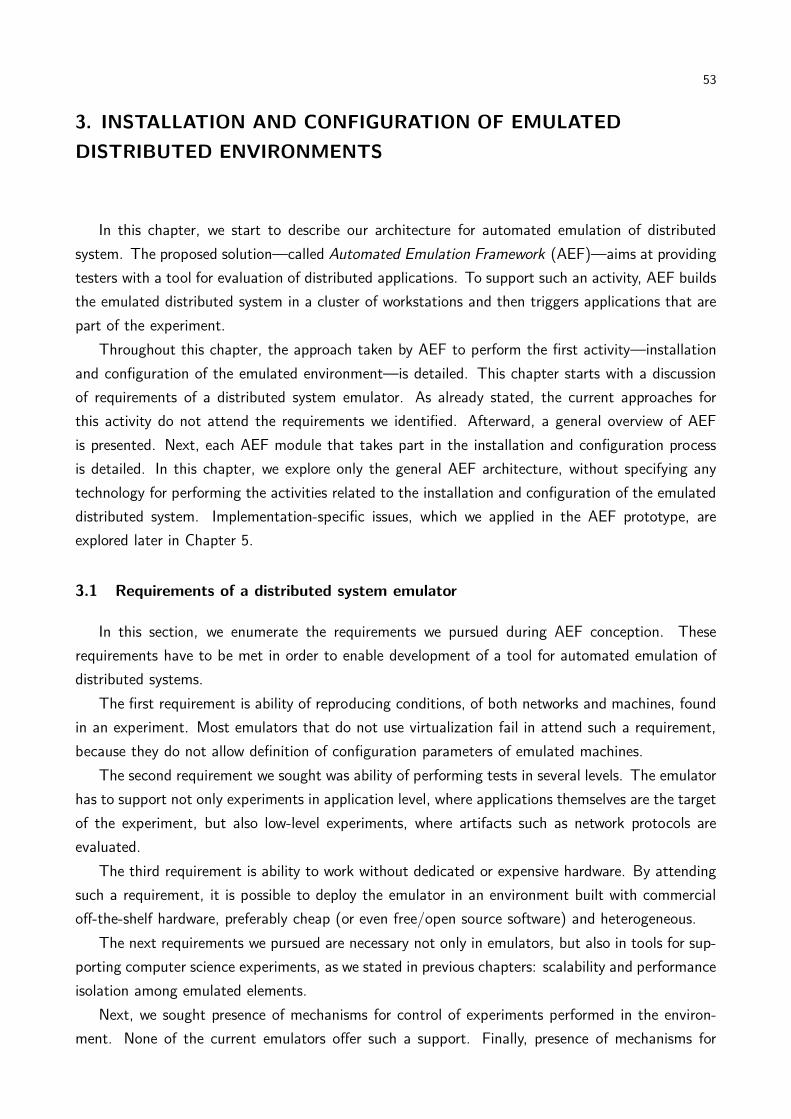
53
3. INSTALLATION AND CONFIGURATION OF EMULATED
DISTRIBUTED ENVIRONMENTS
In this chapter, we start to describe our architecture for automated emulation of distributed
system. The proposed solution—called Automated Emulation Framework (AEF)—aims at providing
testers with a tool for evaluation of distributed applications. To support such an activity, AEF builds
the emulated distributed system in a cluster of workstations and then triggers applications that are
part of the experiment.
Throughout this chapter, the approach taken by AEF to perform the first activity—installation
and configuration of the emulated environment—is detailed. This chapter starts with a discussion
of requirements of a distributed system emulator. As already stated, the current approaches for
this activity do not attend the requirements we identified. Afterward, a general overview of AEF
is presented. Next, each AEF module that takes part in the installation and configuration process
is detailed. In this chapter, we explore only the general AEF architecture, without specifying any
technology for performing the activities related to the installation and configuration of the emulated
distributed system. Implementation-specific issues, which we applied in the AEF prototype, are
explored later in Chapter 5.
3.1 Requirements of a distributed system emulator
In this section, we enumerate the requirements we pursued during AEF conception. These
requirements have to be met in order to enable development of a tool for automated emulation of
distributed systems.
The first requirement is ability of reproducing conditions, of both networks and machines, found
in an experiment. Most emulators that do not use virtualization fail in attend such a requirement,
because they do not allow definition of configuration parameters of emulated machines.
The second requirement we sought was ability of performing tests in several levels. The emulator
has to support not only experiments in application level, where applications themselves are the target
of the experiment, but also low-level experiments, where artifacts such as network protocols are
evaluated.
The third requirement is ability to work without dedicated or expensive hardware. By attending
such a requirement, it is possible to deploy the emulator in an environment built with commercial
off-the-shelf hardware, preferably cheap (or even free/open source software) and heterogeneous.
The next requirements we pursued are necessary not only in emulators, but also in tools for sup-
porting computer science experiments, as we stated in previous chapters: scalability and performance
isolation among emulated elements.
Next, we sought presence of mechanisms for control of experiments performed in the environ-
ment. None of the current emulators offer such a support. Finally, presence of mechanisms for

54
automated mapping, deployment, and network configuration is also desirable. As in the previous
case, current emulators fail in offer such a service.
Design and development of a tool that meets all the previous requirements demand significant
research. One of the main aspects in the AEF development—and one of its main differences from
other approaches—regards the automated building, configuration, and execution of the experiment,
starting from a description of the experiment. In the rest of this chapter we explore the process
towards meeting the requirement of automated building and configuration of the experiment. Next,
we present an overview of such an activity in AEF.
3.2 Automated Emulation Framework: general overview
The Automated Emulation Framework (AEF) is an emulation testbed for grid applications. It
allows testers to describe the distributed system required by the application, automatically deploys
a virtual infrastructure corresponding to such a system in a local cluster, and executes the user
experiment. The virtual infrastructure is composed of virtual machines, each one representing one
virtual element of the emulated distributed system. The use of a VMM allows each VM to have its
own share of computing resources—CPU, memory, storage. Each VM executes an operating system
with the software required by the experiment. Network connections between VMs are also configured
to behave according to tester demands. The overall AEF architecture is depicted in Figure 3.11.
AEF runs in the machine that is the cluster frontend. The cluster that hosts the experiment
may be either homogeneous or heterogeneous regarding nodes configuration, i.e., nodes can have
different architectures, different amounts of memory and storage, and different CPUs, regarding
both number of cores and clock speed. It also can have any network configuration. However, it is
required that each cluster node runs the same version of a Virtual Machine Monitor.
Cluster configuration, virtual network topology, and application parameters are stored to be used
by AEF. This information is sent to AEF via two XML files. Both use the same Document Type
Definition (DTD), which is based on SimGrid’s [LMC03] input file format and is presented in Figure
3.2. One of the files describes the cluster and is kept stored in a repository, while the other one
contains description of the virtual environment and experiment and is supplied by the tester. The
elements that are part of the description are the following:
network. This element represents a collection of CPUs. It represents the cluster hosting the experi-
ment in the cluster description file or each emulated site in the virtual environment description.
Each network is defined by a name, a network mask (required for network configuration pur-
poses), and a gateway. There are other definitions that are useful for defining sites with
variable number of computer nodes: maximum number of CPUs in the site, minimum number
of CPUs and relative number of hosts. These attributes are explained in the next chapter.
1Throughout this thesis, in figures that represent architectural aspects of AEF, and unless otherwise specified,boxes denote hardware or software components of the system and arrows denote directed interaction between com-ponents. In some cases, arrow’s label details the nature of interaction.

55
Figure 3.1 – Automated Emulation Framework architecture.
cpu. This element represents a computer—a node in the cluster or a VM in the emulated envi-
ronment. It is defined by its name, number of cores, power, amount of memory (in MB),
operating system, hardware address (MAC), and network address. The later two parameters
are used by AEF only for description of the cluster. Both values are generated by AEF in the
emulated environment description. Other attributes are used for management purposes and
are described in the next chapter.
network_link. This element represents types of network connection between CPUs (e.g., Ethernet,
WAN). They are defined by their name, bandwidth (in bits per second), and latency (in ms).
route. This element represents a connection between two CPUs. It is defined by the source and
destination of the connection. Because it is possible that two CPUs are connected by different
types of networks, a route is composed of one or more route elements, each one representing
one of such network connections between the CPUs. Other attributes are used for management
purposes and are described in the next chapter.
route_element. This element is associated to a route, to describe one specific type of network
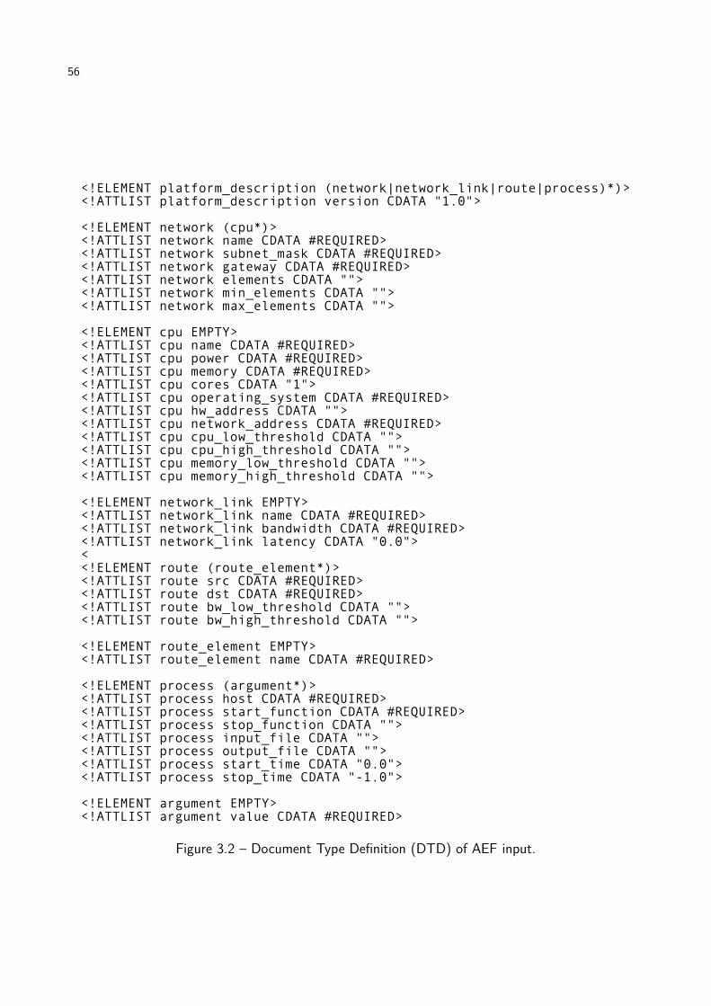
56
Figure 3.2 – Document Type Definition (DTD) of AEF input.
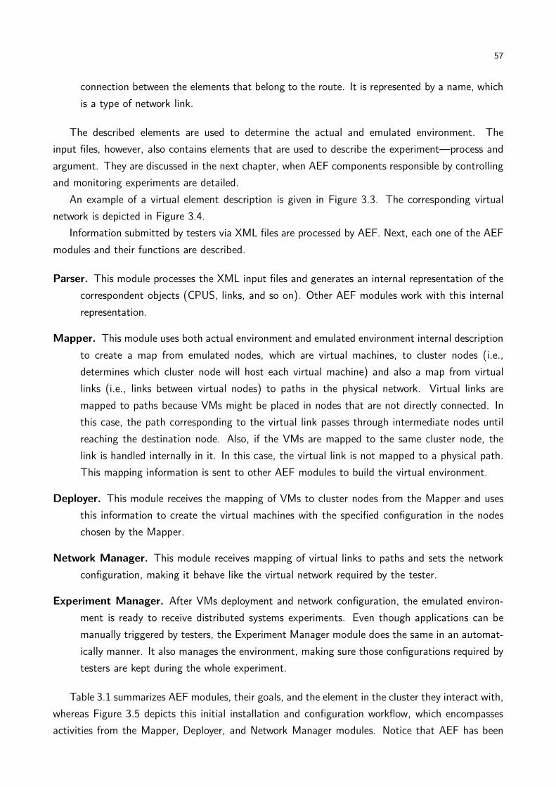
57
connection between the elements that belong to the route. It is represented by a name, which
is a type of network link.
The described elements are used to determine the actual and emulated environment. The
input files, however, also contains elements that are used to describe the experiment—process and
argument. They are discussed in the next chapter, when AEF components responsible by controlling
and monitoring experiments are detailed.
An example of a virtual element description is given in Figure 3.3. The corresponding virtual
network is depicted in Figure 3.4.
Information submitted by testers via XML files are processed by AEF. Next, each one of the AEF
modules and their functions are described.
Parser. This module processes the XML input files and generates an internal representation of the
correspondent objects (CPUS, links, and so on). Other AEF modules work with this internal
representation.
Mapper. This module uses both actual environment and emulated environment internal description
to create a map from emulated nodes, which are virtual machines, to cluster nodes (i.e.,
determines which cluster node will host each virtual machine) and also a map from virtual
links (i.e., links between virtual nodes) to paths in the physical network. Virtual links are
mapped to paths because VMs might be placed in nodes that are not directly connected. In
this case, the path corresponding to the virtual link passes through intermediate nodes until
reaching the destination node. Also, if the VMs are mapped to the same cluster node, the
link is handled internally in it. In this case, the virtual link is not mapped to a physical path.
This mapping information is sent to other AEF modules to build the virtual environment.
Deployer. This module receives the mapping of VMs to cluster nodes from the Mapper and uses
this information to create the virtual machines with the specified configuration in the nodes
chosen by the Mapper.
Network Manager. This module receives mapping of virtual links to paths and sets the network
configuration, making it behave like the virtual network required by the tester.
Experiment Manager. After VMs deployment and network configuration, the emulated environ-
ment is ready to receive distributed systems experiments. Even though applications can be
manually triggered by testers, the Experiment Manager module does the same in an automat-
ically manner. It also manages the environment, making sure those configurations required by
testers are kept during the whole experiment.
Table 3.1 summarizes AEF modules, their goals, and the element in the cluster they interact with,
whereas Figure 3.5 depicts this initial installation and configuration workflow, which encompasses
activities from the Mapper, Deployer, and Network Manager modules. Notice that AEF has been

58
Figure 3.3 – Example of an environment description.

59
Figure 3.4 – Virtual environment corresponding to the description given in Figure 3.3.
Table 3.1 – Summary of AEF modules and their function.Name Task Interacts with
Parser Parses XML input files MapperMapper Maps the virtual environment to
the physical oneDeployer, Network Manager, andExperiment Manager
Deployer Installs the VMs in the cluster VMM (or VMM manager)Network Manager Configures the virtual network Management agent in the VMMExperiment Manager Installs, configures, and monitors
the virtual environmentManagement agent in the VMM
designed to support one tester at a time. Thus, the whole cluster is available for a tester to scale
his or her experiment. Nevertheless, support of sharing of cluster resources is also possible. During
description of each module, we describe requirements for supporting sharing of cluster resources
among concurrent tests. Details on Mapper, Deployer, and Network Manager modules are provided
in the rest of this chapter. Operation of the Experiment Manager module is detailed in the next
chapter.
3.3 Mapper module
The Mapper module receives from the Parser a description of both the cluster and the system
to be emulated and defines where (maps) each virtual machine, representing each virtual node of
the experiment, runs in the experiment. The Mapper architecture is depicted in Figure 3.6.
Each emulation node corresponds to one virtual machine that will be created in the cluster. The
number of virtual machines created is typically orders of magnitude greater than the number of cluster
nodes. So, a bad mapping of virtual machines to cluster nodes may lead to fragmentation problems,
when there is enough resource in the cluster to create more VMs, but the amount of resources
required by a single virtual machine is not present in any host2. To avoid such a fragmentation
problem, and because the number of virtual machines to be mapped may be thousands of VMs, the
mapping must be performed automatically. Also, because AEF allows only one user at a time, the
goal of the mapping is running the experiment as quick as possible, to reduce the waiting time of
other AEF users. This limitation of one tester at a time is a design decision. Nonetheless, there
is no technological limitation for sharing of cluster resources among concurrent testers. If sharing
2In virtualization terminology, the physical machine that runs a VMM is called host. Because in AEF clusternodes run a VMM, we use both terms—host and cluster node—interchangeably throughout the rest of this thesis.
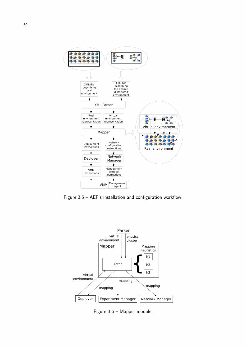
60
Figure 3.5 – AEF’s installation and configuration workflow.
Figure 3.6 – Mapper module.

61
is required, other mapping heuristic is preferred. For example, if resources are going to be space-
shared, a mapping that minimizes the number of hosts used by a single tester is preferred because
more hosts are available for other testers.
Another important aspect of the Mapper module concerns strategies for mapping VMs to hosts.
Different strategies can be applied for the mapping problem, and each one tends to behave differently
depending on the input parameters. Therefore, depending on the cluster infrastructure and the
virtual platform, one strategy may be more appropriate than others. Thus, the Mapper module has
to support not only inclusion of new mapping strategies, but also selection of available strategies.
The selected strategy is used by the Mapper’s Actor component, which uses the heuristic and the
environment description to define the mapping.
The mapping problem addressed by AEF’s Mapper module encompasses two activities. The first
one is mapping of VMs to hosts, balancing the load among hosts taking into account available host
resources and required VM resources. The second activity concerns mapping of virtual links between
VMs to physical paths in the physical cluster. In this mapping, it is also important to consider both
limitations in network resources availability, in this case the bandwidth of the physical links, and
limitation in the maximum acceptable latency in the emulated network.
One virtual link may correspond to zero or more physical links. Consider the situation where
there is a virtual link connecting two VMs that are mapped to the same host. In this case, the virtual
link is not mapped to any physical link, because this connection is handled internally by the VMM.
If a virtual link connects two VMs that are mapped to two hosts that have a physical connection
between them, the virtual link can be mapped to such a physical link. If the hosts that run the
VMs are not connected by a physical link, then the virtual link will correspond to a path connecting
the two hosts. These three cases are represented in Figure 3.7, where a virtual distributed system
containing two sites is mapped to a cluster with a SCI network [Gus92], that has a ring topology.
In this case, virtual links between VMs that are not mapped to adjacent nodes pass by the nodes
between those ones hosting the VMs.
Next, we formally define the mapping problem addressed by the Mapper module and present
heuristics to perform the task.
3.3.1 Mapping problem definition
Formal definition of AEF’s mapping problem models both the cluster and the emulated network.
The cluster is modeled as a graph c= (C,Ec), where C is a set of n hosts and Ec = {(si,di)|si,di ∈
C} is the set of links between hosts.
Host capacity is defined by functions proc :C→R,mem :C→N, stor :C→R, and cores :C→
N that describe the processing capacity, amount of memory, storage capacity, and number of cores,
respectively. The processing capacity of a host may be described either in terms of a benchmark
such as SPEC CPU3 or may be described in terms of relative performance among various hosts in
3http://www.spec.org/cpu2006/
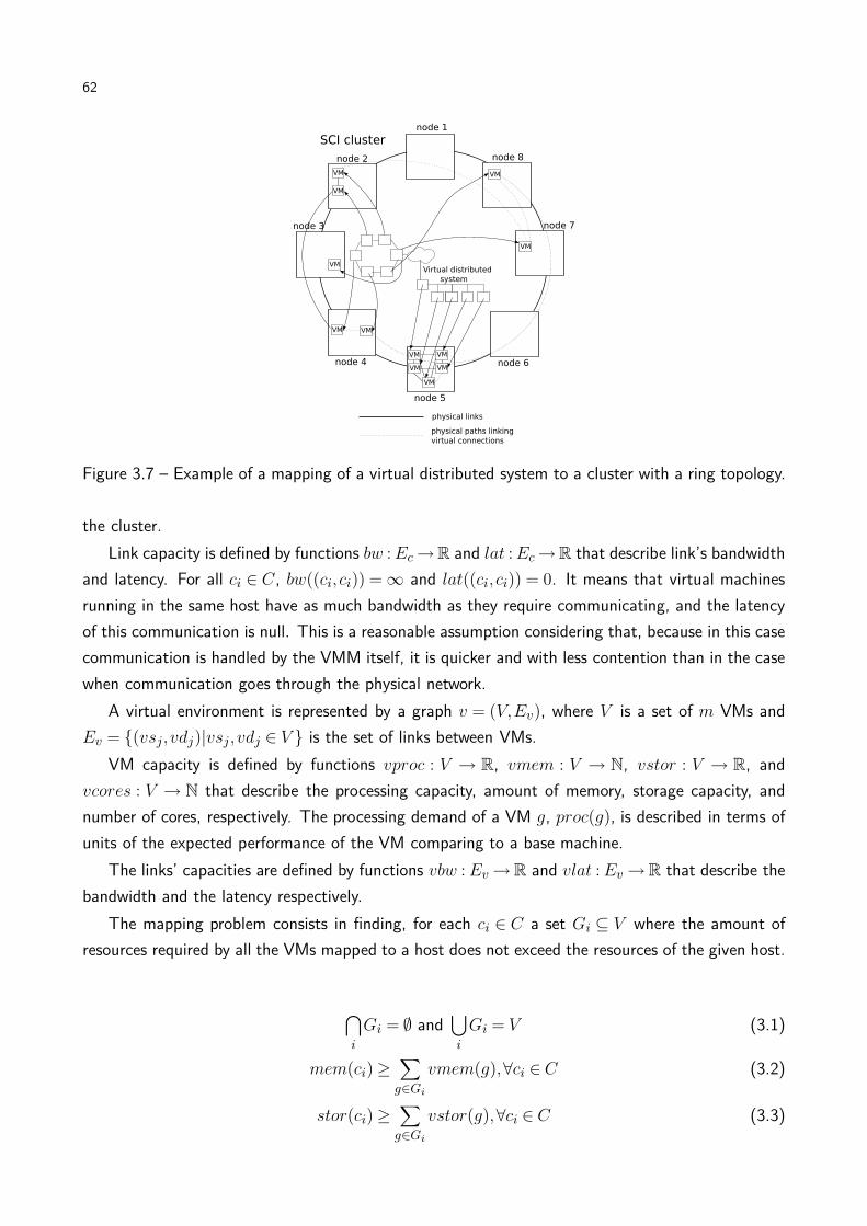
62
Figure 3.7 – Example of a mapping of a virtual distributed system to a cluster with a ring topology.
the cluster.
Link capacity is defined by functions bw :Ec→R and lat :Ec→R that describe link’s bandwidth
and latency. For all ci ∈ C, bw((ci, ci)) =∞ and lat((ci, ci)) = 0. It means that virtual machines
running in the same host have as much bandwidth as they require communicating, and the latency
of this communication is null. This is a reasonable assumption considering that, because in this case
communication is handled by the VMM itself, it is quicker and with less contention than in the case
when communication goes through the physical network.
A virtual environment is represented by a graph v = (V,Ev), where V is a set of m VMs and
Ev = {(vsj,vdj)|vsj,vdj ∈ V } is the set of links between VMs.
VM capacity is defined by functions vproc : V → R, vmem : V → N, vstor : V → R, and
vcores : V → N that describe the processing capacity, amount of memory, storage capacity, and
number of cores, respectively. The processing demand of a VM g, proc(g), is described in terms of
units of the expected performance of the VM comparing to a base machine.
The links’ capacities are defined by functions vbw :Ev→R and vlat :Ev→R that describe the
bandwidth and the latency respectively.
The mapping problem consists in finding, for each ci ∈ C a set Gi ⊆ V where the amount of
resources required by all the VMs mapped to a host does not exceed the resources of the given host.
⋂
i
Gi = ∅ and⋃
i
Gi = V (3.1)
mem(ci)≥∑
g∈Gi
vmem(g),∀ci ∈ C (3.2)
stor(ci)≥∑
g∈Gi
vstor(g),∀ci ∈ C (3.3)

63
cores(ci)≥ vcores(g),∀g ∈Gi,∀ci ∈ C (3.4)
In this formulation, CPU usage is the variable to be optimized, and not a constraint. Furthermore,
cores are not allocated to VMs, but it is guaranteed that the host has at least the same number of
cores required by VMs. This model has been chosen because (i) in the current VMMs it is easier
to control exact amount of memory and storage than the amount of CPU; and (ii) CPU capacity
is intrinsically harder to measure, define, and account for utilization. So, by minimizing the use of
CPUs by each host we expect the execution time of the experiment decreases. This hypothesis is
validated by the experiments presented later in Chapter 6.
For the network mapping, the goal is to find, for each pair (vsj,vdj) ∈ Ev, a sequence Pj =
((s1,d1),(s2,d2), ...,(sp,dp)),(si,di) ∈Ec where:
s1 = ci|vsj ∈Gi (3.5)
dp = ci|vdj ∈Gi (3.6)
sk = dk−1,k = 2, ...p (3.7)
for any (sl,dl),(sm,dm) ∈ Pj,sl 6= sm and dl 6= dm (3.8)
vlat((vsj ,vdj))≥∑
(sk,dk)∈Pj
lat((sk,dk)),∀(vsj ,vdj) ∈ Ev (3.9)
bw((si,di))≥∑
(vsj ,vdj)|(si,di)∈Pj
vbw((vsj,vdj)),∀(si,di) ∈Ec (3.10)
Therefore, this formulation guarantees that a virtual link is mapped to a sequence of real links,
where: (i) the first node in the sequence is the host where the origin in the virtual link is mapped,
(ii) the last host in the sequence is the host where the destination in the virtual link is mapped, (iii)
there is no loops in the sequence Pj , and (iv) there are enough network resources to comply with
tester requirements.
Because in AEF model the entire cluster is available for a single tester per time, it is desirable
that the execution of the experiment takes the minimum time possible. Moreover, it is undesirable
that a host has a high load, because it decreases the performance of the virtual machines running on
it, delaying the experiment. The objective function of the mapping tries to balance the utilization of
CPU on each host, considering that it can be applied in a heterogeneous environment, where hosts
may have different processing powers. Thus, instead of considering the amount of virtual machines
in each host as a load-balance metric, it is used the amount of CPU available on each host, after the
mapping, as the load-balance metric. The objective function then aims at minimizing the standard
deviation of the residual CPU in each host:
minimize
√
∑ni=1(rproc(ci)− rproc)2
n
where (3.11)
64
rproc(ci) = proc(ci)−∑
g∈Gi
vproc(g) (3.12)
(rproc) =
∑ni=1 rproc(ci)
n(3.13)
If sharing of cluster resources among testers is required, availability of resources of hosts and
links must be updated after every tester start its application, in order to take into account the use
of resources by the already running experiments. The rest of the mapping processing, as well as the
rest of the AEF installation, configuration, and execution, proceeds without modifications.
Sundararaj et al. [SSLD05] showed that the Generic Adaptation Problem in Virtual Execution
Environments (GAPVEE) is an NP-Hard problem. Because of similarities between GAPVEE and the
mapping problem solved by AEF, we decided to seek heuristics solutions for our problem instead of
exact solutions. This way, we are giving up obtaining the optimal mapping, but we are obtaining a
more timely solution for the mapping. Next, we present heuristics we developed to solve the AEF’s
mapping problem.
3.3.2 Heuristics for solving the mapping problem
Four heuristics were proposed to solve AEF’s mapping problem. Even though there are two map-
ping problems (VMs and virtual links) to be solved simultaneously, the second problem is considered
only to avoid that the mapping fail because of lack of network resources, because the function to
be optimized, load-balancing, relates to the first problem. The rationale behind this decision is that
the most optimized is the use of network, the biggest the chance that mapping succeeds.
In this direction, heuristics try to map VMs with higher communication to the same host, saving
physical network resources that would be consumed by high-bandwidth virtual links. To achieve
such a goal, a list containing the virtual links (Ev) is created by all the heuristics. Elements in this
list are sorted in descending order of bandwidth (ascending order of latency in case of draws). So,
the first elements from the list are the links with higher communication, and the hosts belonging to
these links are preferentially kept together.
Then, starting from the first element of the list, the unmapped VMs related to such a link are
chosen to be mapped. If none of the VMs was mapped, the heuristics try to map them to the same
host. The criterion to select the host varies on each heuristic. If VMs do not fit a single host, the
VM that requires more resources is mapped first. If the chosen host does not support the VM, the
next host, according to the heuristic criterion, is tested. If no host supports the VM, the mapping
fails.
If both VMs belonging to a link were already mapped, the link is removed from the list and the
process continues. If one of the VMs was already mapped, the other one is mapped in the same host
then the already mapped VM, if the host supports the new VM. Otherwise, the next host, according
to the heuristic criterion, is tested. If no host supports the VM, the mapping fails.
65
In all the heuristics, resources availability ra : C → R of a host ci is given by Equation 3.14,
while demand dem : V →R of a VM vj , when selecting the first one to be mapped, is measured as
a normalized sum of resources availability, as shown in Equation 3.15.
ra(ci) =mem(ci)
2×maxci∈C(mem(ci))+
stor(ci)
2×maxci∈C(stor(ci))(3.14)
dem(vj) =vmem(vj)
2×maxci∈C(mem(ci))+
vstor(vj)
2×maxci∈C(stor(ci))(3.15)
Proposed heuristics use different strategies to select the host to a given VM and different decisions
on whether a load-balance strategy is used after the initial mapping or not. To select the host to be
assigned to a given VM, a list of preferential hosts is built. Elements of such a list are tested from
the beginning of the list until a host with enough resources to receive the VM is found. How this
list is built is different on each heuristic:
HMN. In this heuristic, the host list is built in descending order of CPU capacity (proc(ci)) and
descending order of resources availability (Equation 3.14) in case of tie. A migration step is
performed after the initial mapping to increase the system load-balance. Because the goal of
this algorithm is to improve the load balance, a version of this heuristic without migration is
not evaluated. This was the first heuristic to be developed in the context of this thesis. It
has been named after the three stages of its operation: Hosting (where original placement
of VMs to hosts is defined), Migration (where the original placement is modified in order to
increase load-balance), and Networking (where virtual links are mapped to physical paths).
LM. In this heuristic, host list is built in descending order of resources availability, according to
Equation 3.14 (descending order of proc(ci) in case of ties), what means a worst-fit approach.
It means that the preferred host to receive the VMs (or VM) is the least used one, i.e., the
host that has more free resources. In this heuristic, after the mapping of all VMs, a migration
stage takes place. This heuristic, and the following ones, where named after strategy for
hosting and whether migration is used or not (Least used host with Migration).
LN. (Least used host and No migration). In this heuristic, host list is built in descending order
of resources availability (Equation 3.14), similarly to the previous heuristic. However, no
migration takes place after the initial mapping.
MN. (Most used host and No migration). In this heuristic the host list is built in ascending order
of resources availability (ascending order of proc(ci) in case of ties), what means a best-fit
approach. In this heuristic, the preferred host to receive the VMs (or VM) is the one that
has less availability of resources. The rationale is using the same hosts as much as possible.
Also, no migration happens after the initial mapping. Even though it leads to an imbalance
regarding the objective function, the hypothesis is that it could be able to find valid mappings
when the amount of resources required by the virtual system is close to the physical resources

66
Table 3.2 – Heuristics for mapping VMs to hosts.name hosts list sorted in... load-balance
migration inuse?
bandwidth reser-vation algorithm
LM descending order of ca-pacity
yes A*Prune
LN descending order of ca-pacity
no A*Prune
MN ascending order of ca-pacity
no A*Prune
HMN descending order ofCPU power
yes A*Prune
availability. Considering that the rationale behind this heuristic is reducing the number of used
hosts, and that application of migration would increase the number of used hosts, a version
of this heuristic with migration is not evaluated.
If a heuristic applies a load-balance strategy, it consists of a migration stage whose goal is to
enforce the load-balance among all hosts. In each iteration step, the most loaded host is selected
as the origin of the migration. The VM chosen to be migrated is the one with the smallest sum of
bandwidth of links to other VMs in the same host, in order to minimize utilization of physical links.
Then, starting from the least-loaded host, the load-balance factor (Equation 3.11) of the environment
if the migration had happened is calculated. If this value is smaller than the current load-balance
factor, and the chosen VM fits in the new host, the reassignment is performed. Otherwise, the next
least loaded host is considered. The process is repeated until a reassignment happen or all the hosts
are tested. The whole process is repeated while the objective function improves.
After selection of hosts to each VM and eventual migration to load-balancing the hosts, it is
necessary to map the links of the required virtual environment. Because several links have to be
mapped, it is desirable that, after mapping each link, the bottleneck bandwidth, i.e., the smallest
residual bandwidth among all the physical links, is as big as possible, to keep the possibility of
mapping more virtual links over the physical links. One step towards this direction is achieved
during the mapping of VMs, by mapping the ones with high communication demand in the same
host. The other step towards this direction is achieved with the choice of a suitable strategy for
mapping the links.
The strategy is the following: if the VMs are mapped to the same host, no further action is
required; otherwise, the chosen strategy is the modified A*Prune [LR01] algorithm presented in Al-
gorithm 1. A*Prune is an algorithm used to QoS routing in networks subject to technical constraints.
In our heuristics, A*Prune has been modified to select the path with the biggest bottleneck band-
width [SSLD05]. The distance metric for pruning inadmissible paths is the accumulated latency
in the Dijkstra path between a given host and the link destination. During the pruning process,
links whose available bandwidth is smaller than the required bandwidth are also pruned. Table 3.2

67
summarizes the four heuristics.
Algorithm 1: Modified 1-constrained A*Prune.Data: origin, destination, bandwidth, latencyResult: a path from origin to destination respecting bandwidth and latency constraintsfor ci ∈ C do
ar[ci] ← length of the Dijkstra path associated to latency from ci to destination;set ← (origin,∞) (set of feasible paths and their bottleneck bandwidths);while set 6= ∅ do
bestPath ← path with the greatest bottleneck bandwidth, removed from set;bbw ← bottleneck bandwidth of bestPath;d ← last element of bestPath;if d=destination then
return bestPath;endfor all hosts h connected to d do
if h 6∈ bestPath thenif bw((d,h))≥ bandwidth and lat((d,h))+ar[h]≤ latency thenset← set∪ (bestPath∪h,min(bw((d,h)), bbw));
endend
endend
end
If in some moment a path for a virtual link cannot be found, the heuristic fails and the tester is
notified about the event. If the mapping succeeds, the Deployer and Network Manager modules use
this information about placements of nodes and links to install the VMs in the chosen hosts and to
configure the network routes of the VMs, respectively. This process is detailed next.
3.4 Deployer module
After the mapping of VMs to hosts, it is necessary to start the virtual machines in the selected
hosts. This task is carried out by the AEF’s Deployer module (Figure 3.8). It receives the abstract
representation of the virtual environment generated by the Mapper module and uses this information
to trigger the process of creation of VMs, with the configuration specified by the user, in the hosts.
To make this module as independent as possible from specific deployment tools, and at same time
to allow selection of the deployment tools to be used, the Deployer is composed of two components:
the Converter and the Actor. The first one is part of AEF and translates the internal representation of
the virtual grid, received from the Mapper, to the language of the specific Actor in use. The internal
representation contains the machine specifications: name, amount of memory, relative amount of
CPU, disk image to be loaded, and MAC address (required to allow IP configuration though a virtual
DHCP server that is part of the services offered by the Network Manager module, as explained in
the next section).
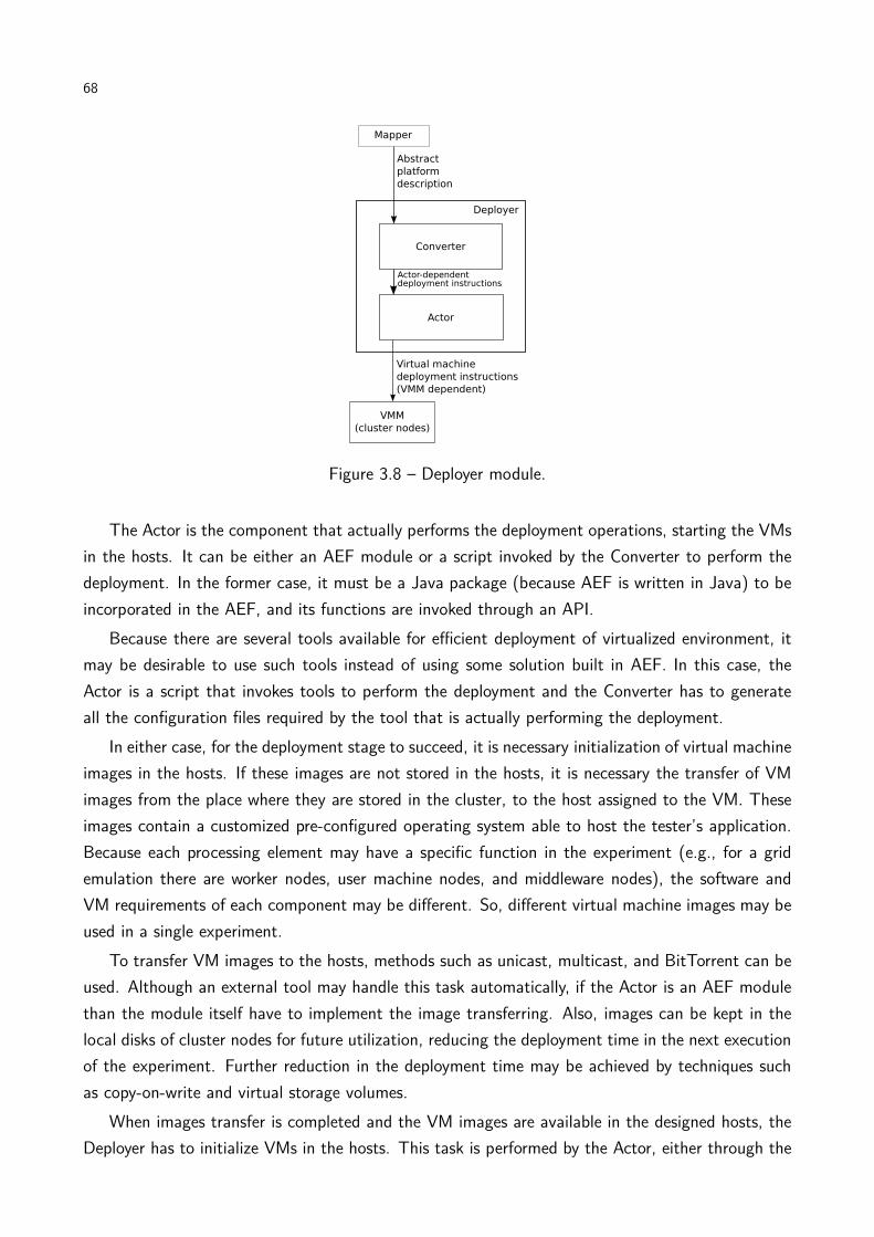
68
Figure 3.8 – Deployer module.
The Actor is the component that actually performs the deployment operations, starting the VMs
in the hosts. It can be either an AEF module or a script invoked by the Converter to perform the
deployment. In the former case, it must be a Java package (because AEF is written in Java) to be
incorporated in the AEF, and its functions are invoked through an API.
Because there are several tools available for efficient deployment of virtualized environment, it
may be desirable to use such tools instead of using some solution built in AEF. In this case, the
Actor is a script that invokes tools to perform the deployment and the Converter has to generate
all the configuration files required by the tool that is actually performing the deployment.
In either case, for the deployment stage to succeed, it is necessary initialization of virtual machine
images in the hosts. If these images are not stored in the hosts, it is necessary the transfer of VM
images from the place where they are stored in the cluster, to the host assigned to the VM. These
images contain a customized pre-configured operating system able to host the tester’s application.
Because each processing element may have a specific function in the experiment (e.g., for a grid
emulation there are worker nodes, user machine nodes, and middleware nodes), the software and
VM requirements of each component may be different. So, different virtual machine images may be
used in a single experiment.
To transfer VM images to the hosts, methods such as unicast, multicast, and BitTorrent can be
used. Although an external tool may handle this task automatically, if the Actor is an AEF module
than the module itself have to implement the image transferring. Also, images can be kept in the
local disks of cluster nodes for future utilization, reducing the deployment time in the next execution
of the experiment. Further reduction in the deployment time may be achieved by techniques such
as copy-on-write and virtual storage volumes.
When images transfer is completed and the VM images are available in the designed hosts, the
Deployer has to initialize VMs in the hosts. This task is performed by the Actor, either through the
69
VMM management API (if some is available) or through remote connection with the host (e.g., rsh
or ssh). The advantage of using the VMM management API is that it is accessible via Web services
or other high-level approaches, even though it may vary among releases of the VMM, what requires
an update in the Actor if a new version of VMM is installed in the cluster. Initialization of VMs
is made in such a way that, at the end of the process, VMs have the amount of resources defined
by the tester. After initialization of VMs to the assigned hosts, the Deployer module completed its
tasks. The next stage in the process of building and configuration of the emulated environment is
configuration of the network, which is performed by the Network Manager module and detailed in
the next chapter.
Notice that it is the possibility of replacing either the Converter or the Actor that makes AEF
independent of a specific virtualization technology: any VMMs can be used in AEF if there are
compatible deployment tools to be triggered by the Actor. Other AEF modules do not handle directly
virtual machines, and thus they are unaware of the specific virtualization technology executing in
the cluster nodes.
Sharing of cluster resources among testers does not affect the Deployer module: because it just
performs operations determined by the Mapper in the system (creation of VMs in the specified
hosts), operation of the Deployer module is independent of decisions regarding resource sharing.
3.5 Network Manager module
After the deployment of the virtual environment, the next step in the process of building and
configuration of the emulated environment is the configuration of the network. The AEF module
responsible for it is the Network Manager module. It has two functions. The first one is to provide
virtual links with network behavior. To provide such a behavior, the module isolates VMs that
virtually belong to different networks, and allows direct communication between machines that
virtually belong to the same site. Furthermore, virtual links that represent WAN connections are set
with the latency and bandwidth specified by the tester.
The second function of this module is to offer virtual services to the virtual environment. These
services are confined DHCP and DNS servers that run as threads of the emulator and thus avoid the
need of real DHCP and DNS servers to attend virtual nodes. Thus, every time virtual nodes want
to obtain their IP addresses, or want to make a DNS request, the corresponding network packets are
captured in the VMM and forwarded to the virtual services running with AEF. These virtual servers
answer the request according to emulation parameters (i.e., the IP assigned by the VM according
to its virtual network).
The Network Manager architecture is presented in Figure 3.9. It has a Converter component
whose task is to interpret the environment description received from the Mapper and to generate
the set of configuration tasks that have to be executed to generate the virtual environment. These
configuration instructions are converted to management protocol-specific instructions by the Con-
verter. Then, they are forwarded from the management Manager inside the module to management

70
Figure 3.9 – Network Manager module.
agents in the VMM on each node. Communication between Manager and agents happen according
to the management protocol in use, and so AEF does not have to handle it directly.
Support to different virtual machine monitors is provided with implementation of a management
agent that implements network configuration operations applied by AEF to the target VMM, making
possible isolation of machines and setting up of network links parameters.
Regarding enabling resource sharing among testers, the only modification required in the Network
Manager module is creation of new virtual services threads to other testers, so possible conflicts in
names of emulated servers are avoided. Other operations (configuration of links and networks) of
this module are determined by the Mapper, so only the later have to be aware of resource sharing.
3.6 Chapter remarks
Emulation is a technique for computer science experimentation that is suitable for evaluation of
distributed system software. In emulation, actual software is executed in a model of a distributed
system. Building of such a model in such a way that some requirements are met can be made easier
with application of virtualization technologies.
In this chapter, we described the requirements we sought to meet when developing a distributed
system emulator. This emulator—called Automated Emulation Framework (AEF)—builds and con-
figures an emulated distributed system in a cluster of workstations in an automated manner.
To achieve such a goal, three activities have to be accomplished. The first one is the mapping
of virtual machines to hosts and virtual links to physical paths in the cluster. The problem related
to this step was formally defined. Furthermore, four heuristics were proposed to solve the problem.
The second activity is deployment of virtual machines in the cluster. These virtual machines,
that have a 1:1 relation with emulated computing nodes, have to be created in the hosts assigned
to them and have to be set according to tester definitions.
71
Finally, network has to be configured, in order to enable isolation among machines that virtually
belong to different networks, WAN behavior in specific links, and virtual DNS and DHCP services.
It is achieved with the use of a management protocol.
Three AEF modules perform these tasks: Mapper, Deployer, and Network Manager, respectively.
After execution of these three steps, a cluster of workstations is hosting an emulated distributed
system. From this point, the system is ready to receive an emulation experiment. Execution of the
experiment may be manually triggered by testers. However, because the goal of AEF is to enable
automated installation and execution of the experiment, there is an AEF module, the Experiment
Manager module, which is responsible for automating the experiment execution and management
process. This module is discussed in the next chapter.

72
73
4. MANAGEMENT AND RECONFIGURATION OF EMULATION
EXPERIMENTS
In the last chapter, designing goals of AEF and the activities related to building and configuration
of the emulated environment were discussed. These activities—mapping, deployment, and network
configuration—are carried out by three AEF modules, Mapper, Deployer, and Network Manager.
In the end of the building and configuration process, the cluster is hosting a set of virtual
machines, which may have different configuration and different operating systems, organized in one
or more virtual networks. Furthermore, connections between virtual networks have a specific latency
and bandwidth.
This virtual environment supports tester application that is part of the emulation experiment.
However, it is necessary some mechanism to start applications in the specified machines. Depend-
ing on the way applications are configured, they start to run when virtual machines are initiated.
Alternatively, testers have to access each machine and trigger applications. Because an experiment
may require initialization of applications in hundreds of virtual machines, it is unpractical doing it
manually, and so an automated mechanism for initialization of applications is required.
Another concern is about enforcing of configuration parameters. Because the emulated environ-
ment may contain hundreds or thousands of virtual machines and virtual network connections, it is
possible that some misconfiguration situation arises. Then, it is necessary a mechanism to detect
such a problem and to react in order to fix it.
Finally, another possible scenario is one where a tester wants to explore the resources as much
as possible, but he or she may be unsure on the requirements of the application. So, if it is detected
that usage of resources on each virtual machine is low, resources used by each VM may be reduced,
number of virtual machine may be increased, and the experiment may proceed in a higher scale.
Conversely, if it is detected that resources allocated to VMs are not enough to a proper execution
of the application, amount of resources may be increased and the number of VMs decreased, to fit
the bigger VMs in the cluster. Once again, automated mechanisms to provide monitoring of use
of resources, to detect utilization rate and reconfigure the experiment if usage is not according to
tester requirements are useful because of the scale experiments achieve.
Mechanisms to support each scenario are provided by AEF’s Experiment Manager module. In
this chapter, this module is detailed. Initially, a general overview of the module is provided. Then,
each component of the module is detailed.
4.1 Experiment Manager module: general overview
The Experiment Manager module is the AEF module responsible for all the aspects of the
emulation experiment after the initial configuration and installation process. As already stated, it
encompasses three main activities:

74
Application execution management. The Experiment Manager module configures and monitors
application execution. It starts the applications in the VMs specified by the tester with the
required parameters. Furthermore, the module copies files generated by the experiments to a
repository where testers can access them. Similarly, files required by the experiment that are
not stored in the virtual machines are transferred from the AEF repository to the destination
virtual machines.
Environment monitoring. The Experiment Manager module enforces configuration required by
testers. Thus, it periodically monitors usage of resources by VMs and network links, in order
to make sure the required behavior is kept. Violations of configuration are fixed as soon as
detected. Furthermore, these violations are logged and presented to testers at the end of
experiment.
Experiment reconfiguration. The Experiment Manager module dynamically reconfigures the ex-
periment, scaling the system or resources up or down in order to make experiment compliant
with experiment parameters.
The later activity arises from a situation where testers are not sure about resources requirements
of applications. Because the amount of physical resources is fixed, number of virtual machines
that can be created in the environment depends on their resources requirements. So, if testers
overestimate the requirements of the application, virtual machines will have more resources than
what they actually need, and the experiment will have less VMs than the actual limit for the
experiment. Conversely, if testers underestimate requirements of applications, the lack of resources
for applications may compromise experiment results.
Because tester may be unsure of the exact requirements of a platform for his or her application,
AEF allows a partial description of the environment. With this strategy, an initial amount of resources
is allocated to each VM. Then, depending on the amount of resources actually used by applications,
the system is reconfigured, in order to scale the environment according to resources usage. It is
feasible because of the monitoring capabilities of the Execution Manager module.
Uncertainty about the requirements of a virtual machine is represented through a partial descrip-
tion of the experiment. In the partial description, the tester specifies, for each site, the minimum
and the maximum number of machines that are allowed to be deployed. Testers are also able to
specify the amount of resources from a site in relation to another site. Then, it is possible, for
example, to say that a given site will have twice the amount of resources of another one. In either
case, an initial guess of the number of machines in each site must be supplied by the tester. This
initial guess is used in the first deployment of the system.
Other inputs from the user are limits in resource usage by VMs and network accepted in the
experiment. For example, the tester can specify that use of CPU by virtual machines must stay below
90%. When this limit is achieved, AEF tries to reconfigure the system in order to reduce rate of
CPU usage, for example by increasing the amount of CPU of the VM. Because some reconfiguration
75
actions may require changing the number of virtual machines in the environment, AEF has to decide
which networks will lose or get more VMs. Definition of priorities when changing number of site
resources is also done through the input description file.
All these features are described in the input file. Figure 4.1, which is a reproduction of Figure
3.2 presented in last chapter, contains description of elements and attributes relevant to partial
description of experiments and execution of applications. They are highlighted in the figure and are
the following:
network. In this element, tester includes the minimum and maximum number of CPUs that can be
created in the site (min_elements and max_elements attributes, respectively). The initial
number of elements for the site is also supplied by testers (elements attribute). If the number
of elements is defined in relation to other site, than only the elements attribute is used, with
an expression describing the number of elements. For example, to say that a site called site1
has twice the number of machines of a site site2, the attribute elements of site1 has the
value 2*site2.
cpu. In this element, tester may specify thresholds for utilization of CPU and memory. These values
may be set both to hosts and VMs. Thresholds vary between 0.0 and 1.0, and they can relate
to maximum or minimum percentage of used resources allowed to each resource.
route. In this element, it is possible to specify thresholds for utilization of bandwidth.
process. This element represents an application to be executed in a virtual machine. It can have
parameters that are part from the command line related to execution of the application. Other
relevant attributes of this element are the host where the application run, command to be
executed, input and output data to be copied from and to the AEF repository, time to start
and stop execution of application, and command to stop application (if any).
argument. This element represents one string that is part of a parameter of an application.
These elements and attributes are also parsed by the Parser module and sent to the Mapper.
The later only forwards these information together with the mapping information, so the Experiment
Manager can keep track of the position of VMs in the cluster and of virtual links in the cluster
network, which is necessary for management purposes. Communication also happens in the opposite
direction—from the Experiment Manager to the Mapper—when it is detected violations in use of
resources that lead to system reconfiguration, in which case the later process is activated.
Each of the relevant actions taken by the Experiment Manager—virtual environment manage-
ment, system monitoring, and reconfiguration—is performed by a specific component of the module.
These components and their function are the following:
Virtual Environment Manager. This component from AEF’s Experiment Manager interacts with
actual elements, virtual elements, and applications, in order to obtain information about
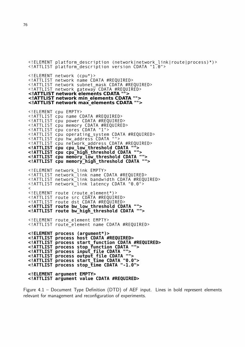
76
Figure 4.1 – Document Type Definition (DTD) of AEF input. Lines in bold represent elementsrelevant for management and reconfiguration of experiments.

77
Figure 4.2 – Experiment Manager module components (boxes). Also, it is shown the role of eachcomponent in the reconfiguration process. Arrows show flow of information between components.Arrow labels show the order on which interactions take place and the nature of information ex-changed.
resources usage and also to allow changing in configurable parameters and control over the
experiments being executed.
Monitor. This component monitors the environment, receiving information about state of emulation
elements and verifying and enforcing that states are compliant with tester requests. It also
generates logs about resources utilization, which may be accessed by testers.
Rebuilder. This component generates new virtual environments whenever usage of resources is
outside the intervals defined by testers. It interacts with the Mapper to verify if the proposed
new configuration is valid, and try new configurations either if the proposed one cannot be
mapped or if the new configuration does not meet tester requirements on usage of resources.
These components and its relation to the reconfiguration cycle are presented in Figure 4.2 and
are detailed in the rest of this chapter.
4.2 Virtual Environment Manager
The Virtual Environment Manager is the component from the Experiment Manager that acts
directly on both the physical and virtual environments. This component supplies Monitor with
services and controls the life cycle of virtual machines, i.e., activities related to creation, pause,
resume, configuration, and destruction of virtual machines. Moreover, it provides services to control
applications executing inside the virtual machines—start and stop of applications, transfer of input
files, and output retrieval.
Similarly to the Network Manager, this component uses a management protocol do perform its
operations in the emulation elements it controls. So, this component runs distributively through the
cluster running AEF: a part runs in the cluster frontend, and interacts with other AEF modules to
receive requests for management operations, while other part runs on each managed component,

78
Figure 4.3 – Virtual Environment Manager.
which may be virtual machines or cluster nodes, in order to control both configuration of the ele-
ments and applications. Communication between these parts is performed through the management
protocol in use.
Figure 4.3 presents the architecture of the Virtual Environment Manager component. It has two
parts:
Services Manager. This part runs in the cluster frontend, together with other Experiment Manager
components and AEF modules. Services Manager receives requests for management operations
to be performed in physical machines, emulated machines, and applications and activates the
process for execution of the operation. To execute the required management operation,
the Nodes Manager able to perform the task is contacted by an agent of the management
protocol that is part of this component. The contacted managers, on the other hand, are part
of the Nodes Manager component. When the requested operation encompasses returning a
response (e.g., current utilization of CPU by a VM), Service Manager also returns the required
information to the requester.
Nodes Manager. One instance of this component runs on virtual machine manager of each cluster
node. It is composed of a manager of a management protocol. It reacts to requests for
management operations, contacting the managed elements to perform the required operations.
Because some operations, like control of applications, require interaction with virtual machines,
a component from the management may be required inside the VMs to perform operations such

79
as trigger of an application, interruption of the application or transfer of files. Decision regarding
whether the managers are required inside the VMs or not depends not only on the exact management
technology in use but also on specific implementation of the virtualization technology used. If
managers are inside VMs, then an Agent from the management protocol may also be required in
the Node Manager.
While modification of VM attributes (e.g., changing the amount of memory of a VM) is performed
by the manager in the VMM, other operations in the VM, such as monitoring of resources usage,
may, depending on the VMM and management technology in use, be performed by a manager
inside the VM. Managers of applications running in VMs can be either specific providers for specific
applications or general application providers that receive some string representing the command to
be executed and execute the command in the VM.
Support to different VMMs in this module is obtained with implementation of managers and
agents to the specific VMM. Furthermore, applications may require their own managers in order to
allow their management. Support for sharing of resources among testers does not affect this module,
because it just reacts to requests from other modules. So, operation of the Virtual Environment
Manager is the same if resources are shared or exclusively allocated to a tester.
4.3 Monitor
The Monitor is the part of the Experiment Manager that is responsible for accounting and
monitoring of usage of resources in both physical and virtual environment.
Accounting is performed in order to allow testers to know amount of resources required by their
experiments or applications. Resources used by virtual machines, physical machines, and network
are stored in a log in AEF repository. This log file can be retrieved by testers after experiment
execution.
Monitoring is performed in order to ensure that resources usage respects the limits defined by
the tester during experiment configuration. This operation is performed in virtual machines, physical
machines, and network.
Monitor architecture is presented in Figure 4.4. Because both virtual and physical elements can
be managed, there are specific parts to handle each type of resource. Furthermore, manipulation
of the data, in order to log it or activate reconfiguration procedures, is carried out by the Data
Handling service.
Definition of minimum and maximum fraction of resources that are allowed to be used in physical
and virtual components of the experiment is recorded in the experiment description file supplied by
testers. The Monitor works in order to ensure these limits are respected. In the event of violations
in usage of resources by the experiment, this component generates an alarm and forwards it to the
Rebuilder, which tries to change configuration of virtual machines and virtual network in order to
avoid further violations in usage of resources.
Alarms are caused both by events related to physical components of the infrastructure and by
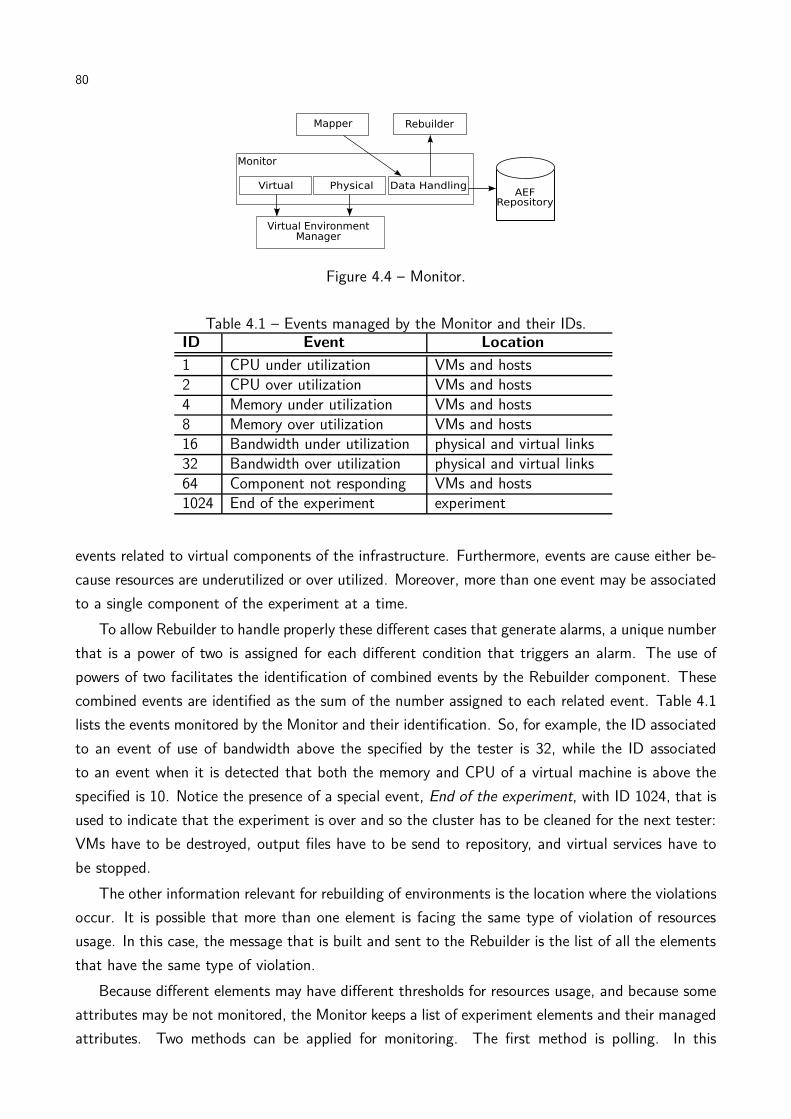
80
Figure 4.4 – Monitor.
Table 4.1 – Events managed by the Monitor and their IDs.ID Event Location
1 CPU under utilization VMs and hosts2 CPU over utilization VMs and hosts4 Memory under utilization VMs and hosts8 Memory over utilization VMs and hosts16 Bandwidth under utilization physical and virtual links32 Bandwidth over utilization physical and virtual links64 Component not responding VMs and hosts1024 End of the experiment experiment
events related to virtual components of the infrastructure. Furthermore, events are cause either be-
cause resources are underutilized or over utilized. Moreover, more than one event may be associated
to a single component of the experiment at a time.
To allow Rebuilder to handle properly these different cases that generate alarms, a unique number
that is a power of two is assigned for each different condition that triggers an alarm. The use of
powers of two facilitates the identification of combined events by the Rebuilder component. These
combined events are identified as the sum of the number assigned to each related event. Table 4.1
lists the events monitored by the Monitor and their identification. So, for example, the ID associated
to an event of use of bandwidth above the specified by the tester is 32, while the ID associated
to an event when it is detected that both the memory and CPU of a virtual machine is above the
specified is 10. Notice the presence of a special event, End of the experiment, with ID 1024, that is
used to indicate that the experiment is over and so the cluster has to be cleaned for the next tester:
VMs have to be destroyed, output files have to be send to repository, and virtual services have to
be stopped.
The other information relevant for rebuilding of environments is the location where the violations
occur. It is possible that more than one element is facing the same type of violation of resources
usage. In this case, the message that is built and sent to the Rebuilder is the list of all the elements
that have the same type of violation.
Because different elements may have different thresholds for resources usage, and because some
attributes may be not monitored, the Monitor keeps a list of experiment elements and their managed
attributes. Two methods can be applied for monitoring. The first method is polling. In this

81
method, in a specific time interval, the list of monitored elements and attributes is queried and the
corresponding values are checked in other to verify if it is inside the limits defined by testers.
In the second method, mechanisms for alarms may be configured. In this case, the mechanism
for alarms (such as the traps from SNMP or events from WBEM) is used to return a message every
time limits are violated. The specific method to be used depends on services offered by the Virtual
Environment Manager, because this is the component that actually accesses VMs and hosts.
After all the relevant information is obtained, elements that caused similar alarms are grouped
together to generate a single alarm related to that specific violation. Subsequently, each alarm
generated, together with the elements that caused them, is passed to the Rebuilder component to
take some action in order to fix the violation.
Use of different virtualization technologies or different management protocols does not affect the
Monitor, because it does not handle directly the elements. Instead, all the management operations
requested by this component are processed by the Virtual Environment Manager. Regarding support
for sharing of resources among testers, it also does not require modification in this component.
4.4 Rebuilder
The Rebuilder component is responsible for reconfiguring the environment in the event of vi-
olation in resources utilization. This component determines the characteristics of the new virtual
environment and verifies if such a new virtual environment can be mapped to the real environment.
To handle this tasks, Rebuilder receives the alarms from the Monitor, and, considering the specific
alarm, defines the action to be taken.
Alarms are caused both by resources under utilization and by resources over utilization. If the
monitored resource belongs to hosts, fixing the violation may require modification in the number of
virtual machines in the host. In the case of resources belonging to virtual machines, actions may
require modification in the amount of resources allocated to the VM. Nevertheless, there may have
exceptions: consider, for example, if the Monitor detects that the amount of CPU used by two VMs
is below the threshold. At the same time, Monitor detects that the bandwidth usage of the virtual
link between these VMs is overloaded. In this case, both violations may be fixed with a single action:
by increasing the bandwidth of the link, more communication between the VMs may flow, and it
may result in more work to the applications in the VM, what leads to increase in utilization of CPU
in the hosts.
If actions require more VMs to be assigned to a host, or if they require resources in the VMs
to be increased, the number of virtual machines in the environment may change. In this case, the
Rebuilder has to decide which site VMs are inserted, or removed from. The order in which the sites
are listed in the configuration file determines the preference for receiving more machines: first, they
are created in the first site, then in sites whose number of VMs depends on the previous site. For
removal of VMs, the inverse order is considered, and the Rebuilder starts from the last site described,
than from sites that have a relative amount of VMs. In any case, Rebuilder ensures that minimum
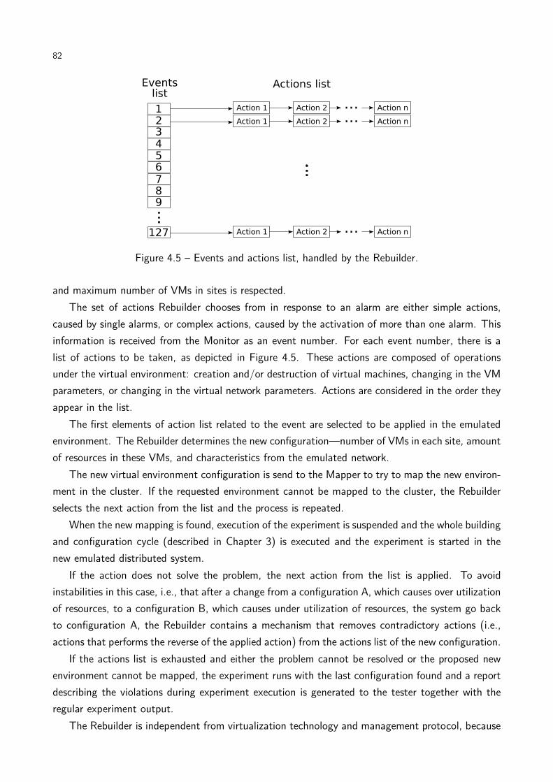
82
Figure 4.5 – Events and actions list, handled by the Rebuilder.
and maximum number of VMs in sites is respected.
The set of actions Rebuilder chooses from in response to an alarm are either simple actions,
caused by single alarms, or complex actions, caused by the activation of more than one alarm. This
information is received from the Monitor as an event number. For each event number, there is a
list of actions to be taken, as depicted in Figure 4.5. These actions are composed of operations
under the virtual environment: creation and/or destruction of virtual machines, changing in the VM
parameters, or changing in the virtual network parameters. Actions are considered in the order they
appear in the list.
The first elements of action list related to the event are selected to be applied in the emulated
environment. The Rebuilder determines the new configuration—number of VMs in each site, amount
of resources in these VMs, and characteristics from the emulated network.
The new virtual environment configuration is send to the Mapper to try to map the new environ-
ment in the cluster. If the requested environment cannot be mapped to the cluster, the Rebuilder
selects the next action from the list and the process is repeated.
When the new mapping is found, execution of the experiment is suspended and the whole building
and configuration cycle (described in Chapter 3) is executed and the experiment is started in the
new emulated distributed system.
If the action does not solve the problem, the next action from the list is applied. To avoid
instabilities in this case, i.e., that after a change from a configuration A, which causes over utilization
of resources, to a configuration B, which causes under utilization of resources, the system go back
to configuration A, the Rebuilder contains a mechanism that removes contradictory actions (i.e.,
actions that performs the reverse of the applied action) from the actions list of the new configuration.
If the actions list is exhausted and either the problem cannot be resolved or the proposed new
environment cannot be mapped, the experiment runs with the last configuration found and a report
describing the violations during experiment execution is generated to the tester together with the
regular experiment output.
The Rebuilder is independent from virtualization technology and management protocol, because
83
it only interacts with other the Mapper and the Monitor. Furthermore, because the mapping is
performed by the Mapper, presence or absence of cluster sharing among testers does not affect the
Rebuilder.
4.5 Chapter remarks
In this chapter, we presented the Experiment Manager module from AEF, which supports auto-
mated execution of experiments and monitoring of resources in emulated experiments. It is composed
of three components—Virtual Environment Manager, Monitor, and Rebuilder—that together allow
monitoring of use of resources by virtual and actual elements, execution of applications, detection
and correction of misconfiguration, and logging of events found in the experiment.
The information required as input by the Experiment Manager to perform these tasks, despite
environment and experiment description, is the interval of values (maximum and minimum values)
in which the utilization of resources (e.g., memory, bandwidth) are acceptable in the experiment.
With this information, the Monitor Module builds lists to determine which services from the Virtual
Environment Manager Module have to be accessed and periodically access them to verify system
behavior.
Thus, at a regular time interval defined by the tester, each service from the list is invoked. The
value received in response is analyzed to verify whether it is within the interval specified by the tester
or not. If not, a new alarm is generated, and the element in the system that caused the alarm is
associated to it.
After all the relevant information is obtained, elements that caused similar alarms are grouped
together to generate a single alarm related to that specific violation (e.g., CPU over utilization).
Subsequently, each alarm generated is passed to the Rebuilder Module.
Rebuilder receives all the alarms and queries its internal tables to look for the actions related to
the specific alarm. A new virtual environment, which contains the modifications proposed by the
action, is built and forwarded to the Mapper.
If a new mapping for a given environment is not found, the Rebuilder tries to apply another
action from the list. If the actions list is exhausted and either the problem cannot be resolved or
the proposed new environment cannot be mapped, the experiment runs with the last configuration
found and a report describing the violations during experiment execution is generated to the tester
together with the regular experiment output.
When the new mapping is found, services from the Virtual Environment Manager Module that
allow modification of VMs (destruction, migration or change of configuration, depending on the
action) are invoked by the Rebuilder Module. These commands are translated in management
actions that actually change the environment. When the new environment is ready, the Rebuilder
invokes services related to applications triggering in the VMs and the experiment starts again.
When the experiment runs from the beginning until the end without violations in the usage of
resources, only the regular experiment output and the execution logs are generated. If no further

84
actions is required, the cluster is cleared (VMs are destroyed) by the Virtual Environment Manager,
virtual DHCP and DNS servers are stopped and the AEF becomes available to the next tester.
So far, AEF has been discussed only in an abstract manner—no consideration has been made
regarding specific virtualization technology, management protocol, programming language, or vir-
tualization management tool should be used to develop AEF. In the next chapter, we describe a
concrete implementation of AEF, which is a prototype based in Java, Xen, SNMP and WBEM
management protocols. Results presented later in Chapter 6 are based in such a prototype.
85
5. AEF REALIZATION
The last two chapters presented an architecture for building and configuration of an emulated
distributed system and automated execution and management of the system and applications running
on it. The architecture and concepts presented so far do not consider any specific technology for
system virtualization, system management, or virtualization support.
This chapter presents a prototype of AEF that was developed in order to show that concepts
and architecture presented in the previous chapters are feasible to be implemented. The prototype
implements a subset of the whole architecture presented so far. During description of implementation
details, it is explained which functionalities are present and which functionalities are not.
Furthermore, during description of each AEF module prototype we present relevant technologies
that were useful for its development. Validation of the prototype is discussed in the next chapter.
5.1 AEF prototype overview
The AEF prototype is developed in Java. Modules are developed in different packages, in such
a way they can be replaced in case a more suitable implementation for a specific task is found.
Interaction between modules happens through invocation of methods from a class that implements
a specific module. The virtual machine manager used is Xen [BDF+03], which is an open source
virtual machine manager that supports different processor architectures and different operating
systems. The prototype does not support sharing of cluster resources among testers, which means
that testers have exclusive access to AEF cluster during the experiment.
Two management protocols are used: SNMP [Sta99] and WBEM [Hob04]. The former is used
for management of networks during the initial configuration and installation of the system, whereas
the later is used for management of the emulated system and application and also is an alternative
for deployment of virtual machines. Reasons for this decision are given in the corresponding sections
of the chapter.
Regarding techniques for deployment, network management, and experiment management, tech-
niques were developed in the context of this work, but with broader application than distributed
systems emulation. They were presented elsewhere [Sto08,Ale09,dC09].
General activity from the prototype is depicted in Figure 5.1. Coordination of invocation of each
module happens in a main Java method that calls the Parser twice: the first time to parse the
cluster description and generate the internal representation of the environment; the second time to
parse the experiment description and store it using a proper data structure.
Both outputs from the Parser are submitted to a Mapper. The mapping heuristic is chosen
by instantiation of the class that implements the selected heuristic. Mapper output is recorded in
another data structure, which is passed sequentially to each class that represents AEF modules. All
the classes return a value indicating failure in performing the operation. If it happens, it is com-

86
Figure 5.1 – General operation of AEF prototype.
municated to testers. Otherwise, each class performs the operation from the module it implements
and returns the control to the main method. Next, implementation of each module is detailed.
5.2 Mapper prototype
The Mapper is implemented as an abstract Java class. So, the Actor in Figure 3.6 corresponds
to the AbstractMapper from the prototype, whereas mapping heuristics are concrete classes that
extend AbstractMapper and implement the abstract method doMapping(). This method receives
parsed description of cluster and virtual environment, applies the mapping heuristic it implements,
and returns the mapping in an appropriate data structure. Then, the result is used by other modules
to actually perform the required actions in the system.
5.3 Deployer prototype
Different technologies for deployment are supported by the AEF’s prototype Deployer module.
The first one is a standalone deployer that does not require any specific virtualization support tool.
This simple Deployer requires that tester makes VM images available in AEF repository.
The Converter of this approach translates the output from the Mapper into a bash script that
87
makes deployment of Xen virtual machines. The bash script generates the files containing configura-
tion of each virtual machine. The script also copies the virtual machine images (via scp) from AEF
repository to the cluster hosts where they will run. To start the virtual machines, another script,
which acts as the Actor in the Deployer architecture, is executed by the Converter. This script logs
in (via ssh) in each node that run virtual machines and run Xen management commands on it to
start virtual machines.
Even though this solution does not require the use of any other tool for deployment of virtual
machines, it has some limitations. First, it requires copy of virtual machines from AEF repository
to nodes. These transfers are sequential, so, depending on the size of the image, it requires a
considerable amount of time to finish. The second limitation is that the script makes transfer and
execution of management commands to start virtual machines through a secure login. So, it is
required a user account in the cluster to perform these tasks.
The second approach for deployment requires the use of the XSM (Xen Site Manager) tool
[FOS+07] as the Actor. XSM is a tool for deployment and management of Xen virtual images
in Linux clusters. It applies widely-available Linux tools, such as SystemImager (for creation and
installation of Linux disk images), Ganglia (for monitoring), and the Xen management interface to
create and deploy the images in the cluster. Furthermore, a component called XSMd runs in each
cluster node to aid in the monitoring and further configuration of the system.
XSM operation has two main stages. In the first stage, a pre-configured image of the Xen VMM
is distributed to each node, installed, and executed. After this stage, each cluster node runs a VMM
that contains the XSMd and a description of the system. Such a description contains the virtual
machines in the cluster and location of each one in the cluster.
Further configuration requests are made with the dispatch of a new file with the new config-
uration. By comparing the previous configuration with the new one, XSMd decides the actions
to be taken: creation of VM—if the VM is listed in the file and in the previous configuration it
was not present—destruction of VM—if the VM is not listed in the file and it was in the previous
configuration—or VM migration—if the VM was listed in another host in the previous configuration,
or if VM is listed in another VM in the previous configuration. When the system is initialized there
is no previous configuration, so the configuration required is directly applied by each XSMd.
To use XSM as the Actor, Converter translates the output of the Mapper to a XSD system
description file, copies VM images to the VMM image, and triggers XSD. The drawback of this
approach is that it requires installation of the whole VMM image in the cluster, using unicast or
multicast, prior the experiment, what makes it slower than the previous method. However, this
method does not require either copy of VMs—because they are included in VMM image—or the use
of user accounts in the cluster, and is more tolerant to faults in the image transmissions, because
the underlying Linux tools used by XSM handle it automatically.
XSD (Xen Site Deployer), the third Actor supported by the Deployer, is an extension of XSM. It
makes transfer of VMM images quicker by the application of the BitTorrent P2P Protocol for im-
ages distribution. XSD does not use XSMd, so all the operations for deployment of the environment
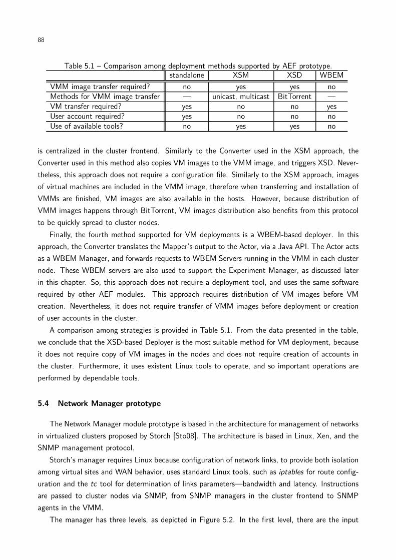
88
Table 5.1 – Comparison among deployment methods supported by AEF prototype.standalone XSM XSD WBEM
VMM image transfer required? no yes yes noMethods for VMM image transfer — unicast, multicast BitTorrent —VM transfer required? yes no no yesUser account required? yes no no noUse of available tools? no yes yes no
is centralized in the cluster frontend. Similarly to the Converter used in the XSM approach, the
Converter used in this method also copies VM images to the VMM image, and triggers XSD. Never-
theless, this approach does not require a configuration file. Similarly to the XSM approach, images
of virtual machines are included in the VMM image, therefore when transferring and installation of
VMMs are finished, VM images are also available in the hosts. However, because distribution of
VMM images happens through BitTorrent, VM images distribution also benefits from this protocol
to be quickly spread to cluster nodes.
Finally, the fourth method supported for VM deployments is a WBEM-based deployer. In this
approach, the Converter translates the Mapper’s output to the Actor, via a Java API. The Actor acts
as a WBEM Manager, and forwards requests to WBEM Servers running in the VMM in each cluster
node. These WBEM servers are also used to support the Experiment Manager, as discussed later
in this chapter. So, this approach does not require a deployment tool, and uses the same software
required by other AEF modules. This approach requires distribution of VM images before VM
creation. Nevertheless, it does not require transfer of VMM images before deployment or creation
of user accounts in the cluster.
A comparison among strategies is provided in Table 5.1. From the data presented in the table,
we conclude that the XSD-based Deployer is the most suitable method for VM deployment, because
it does not require copy of VM images in the nodes and does not require creation of accounts in
the cluster. Furthermore, it uses existent Linux tools to operate, and so important operations are
performed by dependable tools.
5.4 Network Manager prototype
The Network Manager module prototype is based in the architecture for management of networks
in virtualized clusters proposed by Storch [Sto08]. The architecture is based in Linux, Xen, and the
SNMP management protocol.
Storch’s manager requires Linux because configuration of network links, to provide both isolation
among virtual sites and WAN behavior, uses standard Linux tools, such as iptables for route config-
uration and the tc tool for determination of links parameters—bandwidth and latency. Instructions
are passed to cluster nodes via SNMP, from SNMP managers in the cluster frontend to SNMP
agents in the VMM.
The manager has three levels, as depicted in Figure 5.2. In the first level, there are the input

89
Figure 5.2 – Storch’s virtual network management architecture [Sto08].
files. This level is composed of two files, similarly to AEF. Nevertheless, these files contain only
information regarding network from the cluster and from the virtual clusters—which corresponds to
a description of a virtual distributed system. The information required are names, IPs, MACs, and
network elements belong. The later corresponds to the cluster for physical machines or the virtual
network for VMs.
Information is processed by the second level of the architecture, which generates a list of
SNMP commands to each SNMP agent that composes the third level from the architecture. The
Management Information Base used for apply network configuration in the virtual elements is the
vMIB [dCR08], which is a VMM-independent information management base.
In our Xen-based AEF prototype, the Converter is responsible by translating the output from
Mapper module to the two input files required by Storch’s manager and by invoking the proper
Java API for activating configuration operations. In our prototype, Manager is replaced by Storch’s
manager, which is invoked through the Java API.
SNMP agents are installed in Xen’s dom0, a special domain that has high privileges accessing
the system. Set up of bandwidth and latency is performed by the SNMP agents in the hosts’ VMM
with the execution of Linux network management tools—TBF for bandwidth control and NetEm
for latency control. Both are part of the Linux Traffic Control (tc) command for controlling network
traffic in the operating system kernel level.
The SNMP protocol was chosen because it is a fast and simple system management protocol,
even though powerful enough to support the low-level configuration required by the module.
Regarding implementation of network services for virtual machines during the experiment in the
AEF prototype, virtual DHCP runs as a thread of the AEF in the cluster frontend. To access this
service, the corresponding DHCP requests leaving the virtual machines are forwarded to a TCP port
listened by the virtual service in the cluster frontend, through configuration of the network in the
host’s VMM. Virtual DNS is not implemented, therefore machines are accessed via IP address in the
prototype. Virtual DHCP is started before the deployment of the virtual machines. Forwarding of
packets from VMs to this service is achieved with configuration of VMM’s firewall through iptables.
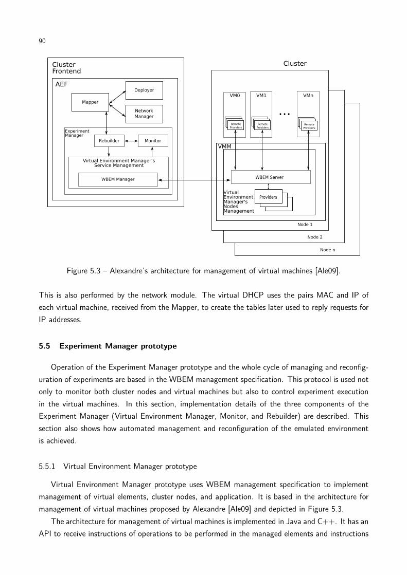
90
Figure 5.3 – Alexandre’s architecture for management of virtual machines [Ale09].
This is also performed by the network module. The virtual DHCP uses the pairs MAC and IP of
each virtual machine, received from the Mapper, to create the tables later used to reply requests for
IP addresses.
5.5 Experiment Manager prototype
Operation of the Experiment Manager prototype and the whole cycle of managing and reconfig-
uration of experiments are based in the WBEM management specification. This protocol is used not
only to monitor both cluster nodes and virtual machines but also to control experiment execution
in the virtual machines. In this section, implementation details of the three components of the
Experiment Manager (Virtual Environment Manager, Monitor, and Rebuilder) are described. This
section also shows how automated management and reconfiguration of the emulated environment
is achieved.
5.5.1 Virtual Environment Manager prototype
Virtual Environment Manager prototype uses WBEM management specification to implement
management of virtual elements, cluster nodes, and application. It is based in the architecture for
management of virtual machines proposed by Alexandre [Ale09] and depicted in Figure 5.3.
The architecture for management of virtual machines is implemented in Java and C++. It has an
API to receive instructions of operations to be performed in the managed elements and instructions

91
of querying elements states. Management of elements uses the OpenPegasus implementation of the
WBEM specification1. Because OpenPegasus is implemented in C++, most code of Alexandre’s
architecture is written in this language. Nevertheless, a Java API is available to allow integration of
the architecture with other tools written in Java.
As shown in Figure 5.3, the architecture uses a WBEM server and providers located in Xen’s
dom0. Providers control virtual elements and perform management operations through the Xen
management API. Management of applications in the virtual machines is performed by remote
providers located in the VM’s operating systems. Providers are threads that wait for services requests
from the server.
Services offered by the architecture are the following:
• Creation, destruction, pause, resume, and restart of virtual machines;
• Modification in the amount of memory allocated to a VM;
• Localization of a VM in the virtual infrastructure;
• Query of amount of memory, storage, and CPU used by a virtual machine;
• Query of amount of memory, and CPU allocated to a virtual machine;
• Query of amount of memory and CPU used by a host;
• Query of amount of storage available in a host;
• Execution of an application in a VM;
• Copy of files to and from VMs.
This architecture is incorporated to AEF by the development of a class that is able to invoke
the architecture’s API. Moreover, providers are installed in the VM images used in the experiment
and WBEM server and providers are also installed in Xen’s dom0 in cluster nodes. Therefore, when
virtual machines are created they have already the required providers that respond to management
requests from the server installed in dom0.
WBEM server is invoked by the architecture API. Nevertheless, other Experiment Manager
components do not access this API directly: to allow a replacement of the current architecture by
a new one in case of a better solution for monitoring of environment and application is available,
Monitor uses an AEF API that is translated to Alexandre architecture’s API.
1http://www.openpegasus.org

92
Figure 5.4 – Carmo’s Architecture for Monitoring and Control of Virtual Environments [dC09].
5.5.2 Monitor prototype
Monitor prototype is based in the Architecture for Monitoring and Control of Virtual Environ-
ments proposed by Carmo [dC09]. This architecture, depicted in Figure 5.4 aims at providing virtual
environments management based in the five functional areas of network management [Sta99]—
FCAPS, for Failure, Configuration, Accounting, Performance, and Security management.
It is worth noting that the general architecture of the Monitor presented in the previous chapter
is a subset of Carmo’s architecture. Nevertheless, Carmo’s architecture was designed to support
management of general virtualized environments. Therefore, it contains some management functions
that are not used in the context of AEF.
The architecture was developed in Java, and therefore its integration with AEF was straightfor-
ward. In the application of Carmo’s architecture in the development of AEF prototype, both User
and Infrastructure Administrator presented in Figure 5.4 are replaced by an integration class that
translates Mapper’s output to management commands that is send to Carmo’s architecture API.
When the Experiment Manager receives Mapper output, it generates a series of commands that
are sent to Monitor in order to specify which elements have to be monitored and which range of
values are allowed for them. These actions are performed by the integration element that replaces
Infrastructure Administrator.
Communication between this architecture and the Virtual Environment Manager happens through
an interface API, which is implemented in the management interface that composes the bottom
layer of each management service from the architecture. Carmo’s architecture generates an output
that is independent from any management tool. These instructions are translated to Alexandre’s
architecture by an adapter running in the Communication Interface.
Management in this architecture happens via polling. So, periodically Monitor activates a routine

93
Figure 5.5 – Rebuilder prototype.
for elements monitoring and checks whether use of resources is according to tester specification.
Monitor checks amount of resources used by the element and the amount of available resources, in
order to calculate usage rate.
Alarms detected by the architecture are returned to the integration layer that replaces Infras-
tructure Administrator in Figure 5.4, which translates alarms to an AEF’s alarm and forwards it to
the Rebuilder.
5.5.3 Rebuilder prototype
Figure 5.5 depicts the organization of the Rebuilder prototype. It has two components: the core,
which implements the API which Monitor uses to inform problems with the system configuration,
and the Environment Designer, which is responsible for creating the new environment and passing
the new configuration to the Mapper.
This design was chosen because it enables replacement of the Environment Designer without
changing the other components of AEF. A different Environment Designer could apply different
policies for creation of the Actions list that is used to store reconfiguration instructions.
Whenever the core receives an alarm from the Monitor, it simply forwards it to the Environment
Designer through the invocation of a method from the later. This method, processAlarm()
receives as parameter the list of alarms received from the monitor. This alarm is a data structure
data contains the ID of the alarm (as defined in Table 4.1) and the elements where this event was
observed.
When the method processAlarm() is called, the Environment Designer queries the array of IDs
of alarms and gets the list of actions configured to handle that alarm. The set of actions present
on each alarm is a characteristic of the concrete implementation of the Environment Designer. In
our prototype, only under utilization of memory and CPU by VMs are handled. The list of actions
includes doubling the amount of the resource; doubling the amount of the resource and reducing
the number of VMs by 50%; and doubling the amount of the resource and reducing the number of
VMs by 70%.
When Environment Designer decides the new system configuration, it invokes the doMapping()

94
method of Mapper. If mapping fails, the method returns false and the next action from the list is
tried. If the mapping succeeds, procedures for reconfiguration are called, and the whole cycle of
deployment, network management, and experiment manager is repeated.
5.6 Chapter remarks
In this chapter, an actual implementation of AEF architecture presented in the last chapters was
presented. This prototype is based in consolidated technologies such as the Linux operating system,
Xen virtual machine monitor, SNMP management protocol, OpenPegasus WBEM specification
implementation, and Java and C++ programming languages. Furthermore, tools for management
of virtualized environments such as XSM/XSD and other tools developed in the context of this project
were also used to perform activities related to deployment, network management, and experiment
management.
Parts are put together with adapters developed in Java, in such a way that these connectors
or the connected parts act according to roles specified in the AEF architecture description. Even
though this prototype does not implement all the cases AEF is supposed to support, it implements
enough features to be possible to show that AEF architecture is feasible and therefore it is possible
application of virtualization and system management to automate distributed systems emulated
experiments.
In the next chapter, experiments aiming at demonstrating the last statement are presented and
discussed.

95
6. AEF PROTOTYPE EVALUATION
In this chapter, evaluation of both mapping heuristics and AEF prototype is presented. This
chapter starts with evaluation of HMN mapping heuristic, which was the first heuristic developed
in the context of this work. Findings related to results of this first experiment led to development
of new heuristics, and therefore heuristics comparison is presented in the sequence. These first
experiments are performed with the use of discrete-event simulation.
Following mapping heuristics evaluation, the AEF prototype is evaluated. Firstly, it is presented
evaluation of the building and configuration stage and later evaluation of the execution, monitoring
and reconfiguration stage. The former is evaluated with a comparison to an in-situ experiment,
while the later is evaluated with a synthetic experiment.
6.1 Evaluation of mapping heuristics
Among the mapping heuristics developed in the context of this work, HMN was the first one
to be conceived. Therefore, it has been thoroughly evaluated in order to check contribution of
its different stages (Hosting, Migration, and Networking) in the mapping process. Findings of this
initial evaluation of HMN motivated development of other heuristics presented in Chapter 3.
In the first part of this section we present methodology, results, and conclusion of HMN evalua-
tion. Later, methodology, results, and conclusions of the comparison between all the heuristics are
presented.
6.1.1 Evaluation scenario
All the experiments for evaluation of heuristics use the same scenario. The simulation scenarios
are created by a random generator that receives as input the number of hosts, number of VMs, and
virtual network density and generates an output by creating links between nodes and assigning a
given amount of resources to each one. Amount of resources (memory, storage, CPU) are generated
randomly, based in a normal distribution.
The simulated physical environment is composed of two different cluster topologies. The first
one is a 2-D torus topology, as depicted in Figure 6.1. The second cluster topology is a switched
topology, in which hosts are connected to a 64-port switch. In both cases, connections between
hosts (or connections between a host and a switch) have 1GB of bandwidth and 5ms of latency. To
represent heterogeneity in the cluster, resources of each of the 40 hosts in the clusters are randomly
generated. Host memory varies uniformly between 1GB and 3GB. Storage varies between 1TB and
3TB and CPU capacity between 1000MIPS and 3000MIPS. A set of hosts created by the generator
are used with each topology in a simulation.
Regarding the distributed systems emulated in the cluster, two different use cases are considered:
a virtual environment for high-level applications and a virtual environment for low-level applications.

96
Figure 6.1 – 40 nodes cluster with 2-D torus network topology used in the evaluations.
The first case, which we refer as high-level scenario throughout this section, encompasses applica-
tions such as grid computing middleware, cloud computing middleware, and other cases where the
application runs in a system containing the operating system, the application, libraries, and sup-
porting software for applications (e.g., a database management system or a Java virtual machine),
which demand large amount of memory and storage. In this scenario, less VMs are created, but
each one uses a considerable amount of resources from the host they are running on. This scenario
resembles emulation experiments like the ones presented in the next section.
The second case considers an environment where the virtual machines run, for example P2P
protocols. In this case, there is no need for VMs running several applications demanding many
resources. Instead, smaller VMs with only the basic software can be used. Thus, in this case the
virtual machines require less memory and storage, and more VMs run on each host. This scenario
was based in emulated experiments presented by Quétier et al. [QJC07] and is referred throughout
this section as low-level scenario.
Evaluation is performed with the use of discrete-event simulation. The CloudSim [BRC09]
simulation toolkit is used in the tests. Both clusters, both distributed system workloads, and mapping
heuristics are modeled with CloudSim.
6.1.2 HMN evaluation and results
Because of the lack of heuristics for the problem handled by AEF, HMN heuristic is evaluated
in terms of effectiveness of each of its components. To allow us to evaluate effectiveness of the
Hosting stage of HMN, it is replaced by a mapping algorithm that randomly tries to map the guests
to hosts. The random algorithm fails if it cannot find a valid mapping after 100000 tries. Networking
is replaced by an algorithm that, for each link in Ev, applies a depth-first search (DFS) algorithm
to find a path connecting the hosts of vsi and vdi.
These alternative strategies for hosting and networking are combined with HMN in the following
way: first, a heuristic that applies both Random instead of HMN’s Hosting and DFS instead of
A*Prune is tested. This approach is referred as Random + DFS in the rest of this section. Another
approach applied replaces HMN’s hosting by the Random heuristic and keeps Networking as in
original HMN. This approach is referred as Random + A*Prune in the rest of this section. The
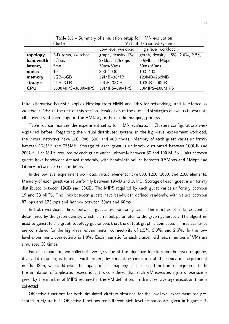
97
Table 6.1 – Summary of simulation setup for HMN evaluation.Cluster Virtual distributed systems
Low-level workload High-level workloadtopology 2-D torus, switched graph, density 1% graph, density 1.5%, 2.0%, 2.5%bandwidth 1Gbps 87kbps–175kbps 0.5Mbps–1Mbpslatency 5ms 30ms-60ms 30ms–60msnodes 40 800–2000 100–400memory 1GB–3GB 19MB–38MB 128MB–256MBstorage 1TB–3TB 19GB–38GB 100GB–200GBCPU 1000MIPS–3000MIPS 19MIPS–38MIPS 50MIPS–100MIPS
third alternative heuristic applies Hosting from HMN and DFS for networking, and is referred as
Hosting + DFS in the rest of this section. Evaluation of these mixed strategies allows us to evaluate
effectiveness of each stage of the HMN algorithm in the mapping process.
Table 6.1 summarizes the experiment setup for HMN evaluation. Clusters configurations were
explained before. Regarding the virtual distributed system, in the high-level experiment workload,
the virtual networks have 100, 200, 300, and 400 nodes. Memory of each guest varies uniformly
between 128MB and 256MB. Storage of each guest is uniformly distributed between 100GB and
200GB. The MIPS required by each guest varies uniformly between 50 and 100 MIPS. Links between
guests have bandwidth defined randomly, with bandwidth values between 0.5Mbps and 1Mbps and
latency between 30ms and 60ms.
In the low-level experiment workload, virtual elements have 800, 1200, 1600, and 2000 elements.
Memory of each guest varies uniformly between 19MB and 38MB. Storage of each guest is uniformly
distributed between 19GB and 38GB. The MIPS required by each guest varies uniformly between
19 and 38 MIPS. The links between guests have bandwidth defined randomly, with values between
87kbps and 175kbps and latency between 30ms and 60ms.
In both workloads, links between guests are randomly set. The number of links created is
determined by the graph density, which is an input parameter to the graph generator. The algorithm
used to generate the graph topology guarantees that the output graph is connected. Three scenarios
are considered for the high-level experiments: connectivity of 1.5%, 2.0%, and 2.5%. In the low-
level experiment, connectivity is 1.0%. Each heuristic for each cluster with each number of VMs are
simulated 30 times.
For each heuristic, we collected average value of the objective function for the given mapping,
if a valid mapping is found. Furthermore, by simulating execution of the emulation experiment
in CloudSim, we could evaluate impact of the mapping in the execution time of experiment. In
the simulation of application execution, it is considered that each VM executes a job whose size is
given by the number of MIPS required in the VM definition. In this case, average execution time is
collected.
Objective functions for both simulated clusters obtained for the low-level experiment are pre-
sented in Figure 6.2. Objective functions for different high-level scenarios are given in Figure 6.3.
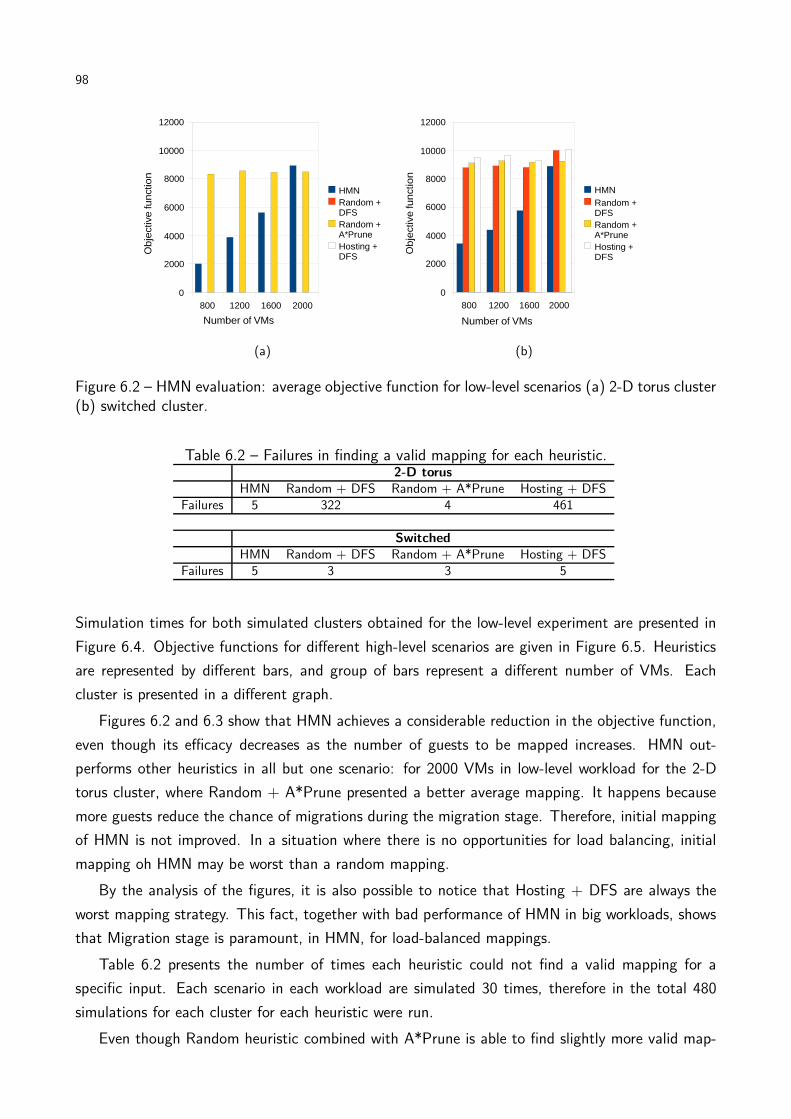
98
800 1200 1600 20000
2000
4000
6000
8000
10000
12000
HMNRandom + DFSRandom + A*PruneHosting + DFS
Number of VMs
Obje
ctiv
e fu
nct
ion
(a)
800 1200 1600 20000
2000
4000
6000
8000
10000
12000
HMNRandom + DFSRandom + A*PruneHosting + DFS
Number of VMs
Obje
ctiv
e fu
nct
ion
(b)
Figure 6.2 – HMN evaluation: average objective function for low-level scenarios (a) 2-D torus cluster(b) switched cluster.
Table 6.2 – Failures in finding a valid mapping for each heuristic.2-D torus
HMN Random + DFS Random + A*Prune Hosting + DFSFailures 5 322 4 461
SwitchedHMN Random + DFS Random + A*Prune Hosting + DFS
Failures 5 3 3 5
Simulation times for both simulated clusters obtained for the low-level experiment are presented in
Figure 6.4. Objective functions for different high-level scenarios are given in Figure 6.5. Heuristics
are represented by different bars, and group of bars represent a different number of VMs. Each
cluster is presented in a different graph.
Figures 6.2 and 6.3 show that HMN achieves a considerable reduction in the objective function,
even though its efficacy decreases as the number of guests to be mapped increases. HMN out-
performs other heuristics in all but one scenario: for 2000 VMs in low-level workload for the 2-D
torus cluster, where Random + A*Prune presented a better average mapping. It happens because
more guests reduce the chance of migrations during the migration stage. Therefore, initial mapping
of HMN is not improved. In a situation where there is no opportunities for load balancing, initial
mapping oh HMN may be worst than a random mapping.
By the analysis of the figures, it is also possible to notice that Hosting + DFS are always the
worst mapping strategy. This fact, together with bad performance of HMN in big workloads, shows
that Migration stage is paramount, in HMN, for load-balanced mappings.
Table 6.2 presents the number of times each heuristic could not find a valid mapping for a
specific input. Each scenario in each workload are simulated 30 times, therefore in the total 480
simulations for each cluster for each heuristic were run.
Even though Random heuristic combined with A*Prune is able to find slightly more valid map-
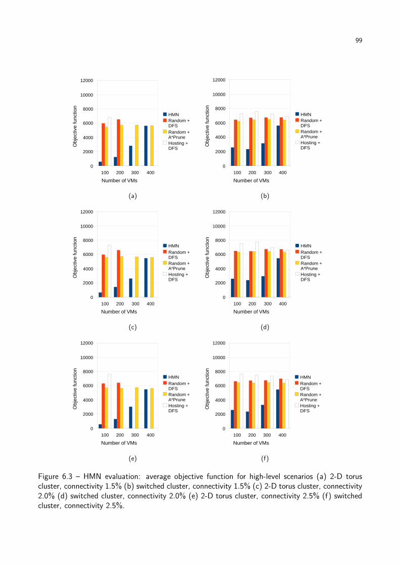
99
100 200 300 4000
2000
4000
6000
8000
10000
12000
HMNRandom + DFSRandom + A*PruneHosting + DFS
Number of VMs
Obje
ctiv
e fu
nct
ion
(a)
100 200 300 4000
2000
4000
6000
8000
10000
12000
HMNRandom + DFSRandom + A*PruneHosting + DFS
Number of VMs
Obje
ctiv
e fu
nct
ion
(b)
100 200 300 4000
2000
4000
6000
8000
10000
12000
HMNRandom + DFSRandom + A*PruneHosting + DFS
Number of VMs
Obje
ctiv
e fu
nct
ion
(c)
100 200 300 4000
2000
4000
6000
8000
10000
12000
HMNRandom + DFSRandom + A*PruneHosting + DFS
Number of VMs
Obje
ctiv
e fu
nct
ion
(d)
100 200 300 4000
2000
4000
6000
8000
10000
12000
HMNRandom + DFSRandom + A*PruneHosting + DFS
Number of VMs
Obje
ctiv
e fu
nct
ion
(e)
100 200 300 4000
2000
4000
6000
8000
10000
12000
HMNRandom + DFSRandom + A*PruneHosting + DFS
Number of VMs
Obje
ctiv
e fu
nct
ion
(f)
Figure 6.3 – HMN evaluation: average objective function for high-level scenarios (a) 2-D toruscluster, connectivity 1.5% (b) switched cluster, connectivity 1.5% (c) 2-D torus cluster, connectivity2.0% (d) switched cluster, connectivity 2.0% (e) 2-D torus cluster, connectivity 2.5% (f) switchedcluster, connectivity 2.5%.

100
800 1200 1600 20000
0.5
1
1.5
2
2.5
3
3.5
HMNRandom + DFSRandom + A*PruneHosting + DFS
Number of VMs
Sim
ula
tion
tim
e (
s)
(a)
800 1200 1600 20000
0.5
1
1.5
2
2.5
3
3.5
HMNRandom + DFSRandom + A*PruneHosting + DFS
Number of VMs
Sim
ula
tion
tim
e (
s)
(b)
Figure 6.4 – HMN evaluation: average simulation time for low-level scenarios (a) 2-D torus cluster(b) switched cluster.
pings than HMN, we argue that an initial hosting by network affinity is still the best choice. That is
because in the case of mapping virtual environment with a few links with high bandwidth demand,
or even with a demand that exceeds the capacity of the real links, HMN is able to produce a valid
mapping (by assigning those VMs to the same host), while an algorithm that does not group guests
with high communication might not be able to find a valid mapping.
Effectiveness of the objective function
Regarding the initial hypothesis that the chosen objective function (Equation 3.11) reduces
the experiment execution time, there is a correlation of 0.7 between the objective function and
the execution time of experiments in the simulated environment, what means that when objective
function decreases, execution time of experiments running in AEF also tends to decrease. It supports
the use of Equation 3.11 as a suitable representation of an objective function for a mapping aiming
at reducing the execution time of an emulation.
General conclusions about HMN
Results presented in Table 6.2 suggest that the main responsible for the success in finding a
mapping to the virtual environment is the A*Prune algorithm. It is evidenced both by the large
number of failures for Hosting + DFS heuristic, where A*Prune is not used for mapping of network
connections, and by the success rate of Random + A*Prune heuristic. The large number of failures
of Hosting + DFS compared to Random + DFS is because in the later approach, both mapping
of guests and of virtual links are retried, while in the former approach only the last one are retried;
therefore, if the initial mapping of guests does not allow a mapping of links, Hosting + DFS fails to
find a solution.
Even though HMN is effective to solve the problem it was designed for, it may fail in finding
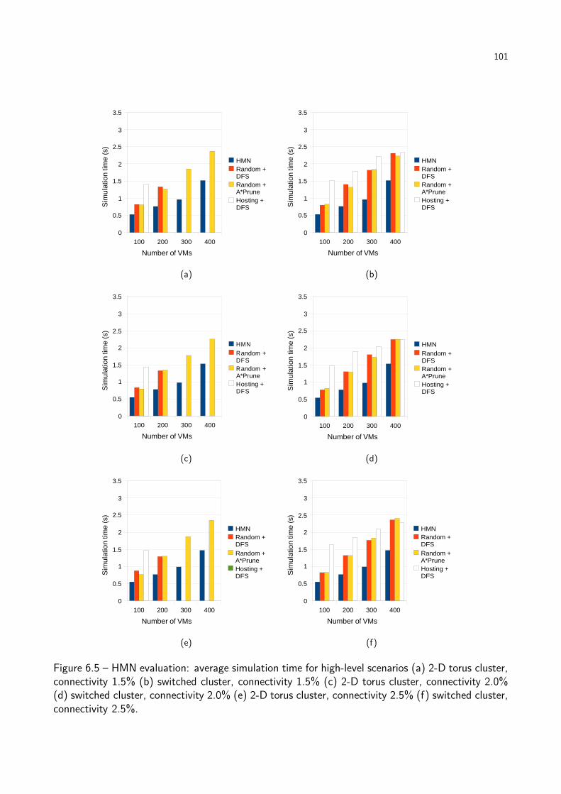
101
100 200 300 4000
0.5
1
1.5
2
2.5
3
3.5
HMNRandom + DFSRandom + A*PruneHosting + DFS
Number of VMs
Sim
ula
tion
tim
e (
s)
(a)
100 200 300 4000
0.5
1
1.5
2
2.5
3
3.5
HMNRandom + DFSRandom + A*PruneHosting + DFS
Number of VMs
Sim
ula
tion
tim
e (
s)
(b)
100 200 300 4000
0.5
1
1.5
2
2.5
3
3.5
HMNRandom + DFSRandom + A*PruneHosting + DFS
Number of VMs
Sim
ulat
ion
tim
e (s
)
(c)
100 200 300 4000
0.5
1
1.5
2
2.5
3
3.5
HMNRandom + DFSRandom + A*PruneHosting + DFS
Number of VMs
Sim
ula
tion
tim
e (
s)
(d)
100 200 300 4000
0.5
1
1.5
2
2.5
3
3.5
HMNRandom + DFSRandom + A*PruneHosting + DFS
Number of VMs
Sim
ula
tion
tim
e (
s)
(e)
100 200 300 4000
0.5
1
1.5
2
2.5
3
3.5
HMNRandom + DFSRandom + A*PruneHosting + DFS
Number of VMs
Sim
ula
tion
tim
e (
s)
(f)
Figure 6.5 – HMN evaluation: average simulation time for high-level scenarios (a) 2-D torus cluster,connectivity 1.5% (b) switched cluster, connectivity 1.5% (c) 2-D torus cluster, connectivity 2.0%(d) switched cluster, connectivity 2.0% (e) 2-D torus cluster, connectivity 2.5% (f) switched cluster,connectivity 2.5%.

102
Table 6.3 – Summary of simulation setup for heuristics comparison.Cluster Virtual distributed systems
Low-level applications High-level applicationstopology 2-D torus, switched graph, density 2.5% graph, density 2.5%bandwidth 1Gbps 87kbps–175kbps 0.5Mbps–1Mbpslatency 5ms 30ms-60ms 30ms–60msnodes 40 100–1000 100–500memory 1GB–3GB 19MB–38MB 128MB–256MBstorage 1TB–3TB 19GB–38GB 100GB–200GBCPU 1000MIPS–3000MIPS 19MIPS–38MIPS 50MIPS–100MIPS
a mapping in scenarios where the requirements of the virtual system are close to the resource
availability. Therefore, we sought better approaches for handling these specific cases.
Nevertheless, general directions for the new heuristic may be inferred from these results. First,
grouping of VMs by network affinity have to be kept in order to allow mapping of scenarios where
some links exceed real links capacity; Second, the A*Prune have to be used to map virtual links
to physical links because it is very effective for this task. Therefore, new heuristics to solve AEF’s
mapping problem should focus in the Hosting stage.
Research towards this direction led to development of LM, LN, and MN heuristics presented in
Chapter 3. Experiments aiming at comparing these heuristics and HMN are presented next.
6.1.3 Heuristics comparison and results
In this section we present evaluation and comparison among the heuristics presented in Chapter 3.
Table 6.3 summarizes the experiment setup. Clusters configurations were explained in the beginning
of this chapter. Regarding the virtual environment, in the high-level experiment workload, the virtual
networks have 100, 200, 300, 400, 450, and 500 nodes. Memory of each guest varied uniformly
between 128MB and 256MB. Storage of each guest was uniformly distributed between 100GB and
200GB. The MIPS required by each guest varied uniformly between 50 and 100 MIPS. Links between
guests had bandwidth defined randomly, with bandwidth values between 0.5Mbps and 1Mbps and
latency between 30ms and 60ms.
In the low-level applications workload, the number of VMs is between 100, 400, 600, and 1000.
Memory of each VM varies uniformly between 19MB and 38MB. Storage of each VM is uniformly
distributed between 19GB and 38GB. The MIPS required by each VM varies uniformly between
19 and 38 MIPS. The links between VMs have randomly defined bandwidth, with values between
87Kbps and 175Kbps and latency between 30ms and 60ms. In both workloads, links between VMs
are randomly set and graph density is 2.5%. The algorithm used to generate the graph topology
guaranteed that the output graph is connected.
Each scenario is simulated with each workload 50 times. Each time, a new cluster and a new
distributed system were randomly generated, according to the scenario parameters. The average
value of each output—mapping time and objective function—was collected.

103
100 400 600 10000
2000
4000
6000
8000
10000
12000
14000
LMLNMNHMN
Number of VMs
Obje
ctiv
e fu
nct
ion
(a)
100 400 600 10000
2000
4000
6000
8000
10000
12000
14000
LMLNMNHMN
Number of VMs
Obje
ctiv
e fu
nct
ion
(b)
100 200 300 400 450 5000
2000
4000
6000
8000
10000
12000
14000
LMLNMNHMN
Number of VMs
Obje
ctiv
e fu
nct
ion
(c)
100 200 300 400 450 5000
2000
4000
6000
8000
10000
12000
14000
LMLNMNHMN
Number of VMs
Obje
ctiv
e fu
nct
ion
(d)
Figure 6.6 – Objective function for different heuristics (a)Low-level workload, 2-D torus cluster(b) Low-level workload, switched cluster (c) High-level workload, 2-D torus cluster (d) High-levelworkload, switched cluster.
Figure 6.6 depicts the average objective function (Equation 3.11) observed for each heuristic in
each scenario.
In scenarios with less VMs, there are more opportunities for load-balancing migrations, and the
migrations contribute for improvements in the objective function of HMN and LM. Because LN and
MN do not have a load-balancing stage, the objective function for this heuristics is higher than for
the other heuristics. Also, because MN minimizes the number of hosts used, the imbalance, and
consequently the objective function, is higher regardless the number of machines used. Nevertheless,
MN was the only heuristic able to map 500 machines in the high-level scenario.
When the number of VMs is high, there are a few opportunities for migrations and then the
performance of LM and LN approaches. It happens because the initial mapping is the same for
both heuristics, and because only a few migrations happen, therefore heuristics tend to finish the
mapping with almost the same configuration.
The different approach for selecting the hosts in the HMN heuristics leads to better mappings

104
100 400 600 10000
1000
2000
3000
4000
5000
6000
7000
8000
9000
10000
LMLNMNHMN
Number of VMs
Mappin
g ti
me
(s)
(a)
100 400 600 10000
1
2
3
4
5
6
LMLNMNHMN
Number of VMs
Mappin
g ti
me
(s)
(b)
100 200 300 400 450 5000
500
1000
1500
2000
2500
3000
3500
LMLNMNHMN
Number of VMs
Mappin
g ti
me
(s)
(c)
100 200 300 400 450 5000
0.2
0.4
0.6
0.8
1
1.2
1.4
LMLNMNHMN
Number of VMs
Mappin
g ti
me
(s)
(d)
Figure 6.7 – Mapping time for different heuristics (a)Low-level workload, 2-D torus cluster (b) Low-level workload, switched cluster (c) High-level workload, 2-D torus cluster (d) High-level workload,switched cluster. Notice that each chart has a different scale on y axis.
when the number of hosts is small. However, in the presence of a bigger number of VMs, and less
opportunities for migrations, the initial choice of VMs performed by HMN leads to worst mappings.
Figure 6.7 shows the mapping time in each scenario. The time showed was obtained in a
Pentium 4 2.8GHz with 1MB of cache and 2560MB of RAM memory running Linux Debian Etch.
The mapping time is dominated by the time to execute the A*Prune algorithm and, ultimately, by
the determination of the shortest path for each virtual link. In the torus topology the number of
possible paths is bigger and then it requires more time comparing to the same scenarios with a
switched topology.
The large amount of time required by MN in the torus topology makes it not suitable for
utilization in some practical scenarios. Nevertheless, MN outperforms the other heuristics in the
switched cluster, and so it may be used in such topologies. LM is slower than LN because of the
migrations. HMN performs better than the other heuristics in most experiments in the torus cluster.
However, it is worst than LM and LN in some scenarios.

105
Mapping 1000 VMs (12487 virtual links) in a torus topology with 80 physical links requires up
to half an hour for LM and LN, two and a half hours in MN, and 45 minutes in HMN. In the
switched topology, as there is only one possible mapping for each virtual link (from the first host to
the cascaded switches and then to the second host), the mapping time is less than five seconds in
all scenarios.
The mapping time is not dependent on the number of hosts, or even on the number of links. In
fact, the mapping of VMs to hosts determines the mapping time. It is because when two VMs are
mapped to the same host, the link between them does not have to be mapped using the A*Prune
algorithm. Also, the use of the available bandwidth by the previous mapped links gradually reduces
the search space of the A*Prune algorithm when virtual links are successively mapped. So, the more
the links are used, the less they are likely to be used further, and with a smaller solution space to
be searched on, the execution time of A*Prune reduces, and so do the overall mapping time. That
is the reason why the mapping time reaches a peak at 400 VMs in the low-level workload and 200
VMs in the high-level scenario and then becomes smaller for greater number of VMs. And this is
another factor for the poor performance of MN: as more VMs are mapped to the same host in this
heuristic, the search space for the A*Prune is reduced in a smaller rate than in other strategies.
Concluding, no single heuristic is better than the others in all the scenarios. So, some criteria
must be applied to choose the fittest heuristic for each instance of the mapping problem. If the
amount of resources required by the virtual system is close to the amount of available resources,
MN is the best heuristic. For a small number of VMs, HMN provides a better, even though slower,
mapping than the other heuristics. However, HMN mapping is not stable, in the sense that when
the number of VMs increases the mapping looses quality, while LM keeps a nearly constant mapping
quality. So, if the rate VM/host is lower, HMN is a good choice. Otherwise, LM is the preferred
heuristic. LN performs always worst or equal as LM, and it is only slightly faster than LM. So it
does not worth applying such a heuristic in any scenario.
6.2 Evaluation of the emulated distributed system
In order to evaluate AEF prototype’s capacity of building and configuring a virtual distributed
environment, and also to investigate what kind of experiment is best suitable to be executed in
AEF, a grid computing experiment executed by the AEF prototype presented in the last chapter
was compared with a in-situ experiment. Such an in-situ experiment evaluates the measurement of
makespan of jobs running in a OurGrid [CBA+06] grid using the SRS scheduler [CFD09].
The environment used for the in-situ experiment is composed of 50 machines in two OurGrid
sites, each one located 4000 Km apart. One site is used as a resource consumer, and the other is used
as a resource provider. The resource provider hosts a cluster whose machines are opportunistically
delivered to the grid. The supplier has 48 grid machines plus one OurGrid peer. The machines are
11 Pentium 3 1.0GHz with 256MB of RAM memory, 10 Pentium 4 1.6GHz with 256MB of memory,
9 Dual Pentium 3 550MHz with 256MB of memory, 4 Dual Pentium 3 1GHz with 256MB of RAM

106
memory, 8 Pentium 4 2.8GHz with 2.5GB of RAM memory, and 6 Dual Xeon 3.6GHz with 2GB of
memory. Only one CPU of the dual machines is used. The consumer site has only one machine,
which contains both the OurGrid peer and the OurGrid broker.
The grid job executed in both experiments contains 12 tasks, each one sends a file, executes a
sleep call of 5 minutes, and receives a file of the same size of the file sent. The job is executed four
times: the first one without file transferring and the others with different file sizes: 100kB, 1MB,
and 10MB. To simulate the dynamism of a grid environment, resources are randomly removed from
the grid every ten minutes.
Network parameters used in the virtual network are obtained with the observation of the band-
width obtained in a data transfer between the two actual sites using scp (for the bandwidth) and with
the latency measured by the hping2 tool, which were respectively 2Mbps and 200ms. Each node in
the virtual network has 256 MB of RAM memory and 1GB of storage. Even though some machines
from the real environment have more memory than the machines in the emulated environment, it
does not compromise the experiment, because the application used less than 128MB of memory.
The cluster used to host the emulated environment is composed of eight Pentium 4 2.8GHz with
1MB of cache and 2560MB of RAM memory. Cluster machines are connected by a dedicated Fast
Ethernet switch. Machines run Xen VMM 3.1, and the Xen’s dom0 uses 328MB of the available
RAM memory. Thus, 2232MB were available to the VMs on each host. No network traffic but the
one generated by this experiment was present in the physical environment during the tests.
AEF builds, in the installation and configuration stage, the virtual environment using the whole
cluster. System reconfiguration is not used in this experiment, because the goal of this experiment
is evaluate installation and configuration of the distributed, and not the execution, monitoring, and
reconfiguration stage.
Table 6.4 presents the observed makespan of the job in both real and virtual environment. It
also shows the deviation, i.e., the percentage’s difference between the result observed in the real
environment and the result from the emulated environment. The deviation between the in-situ and
emulated results are less than 10% for all the cases. However, this value increases with the size of
the file being transferred. It happens because of cumulative error in the network emulation: when
small files are transferred, the network is less demanded, and the difference between the real and the
virtual network becomes smaller. However, the emulated network is faster than the real network. So,
when larger files are transferred, the difference between the emulated and the real network causes a
bigger influence in the results of the experiment. Causes of the deviation in the behavior of emulated
and real networks are the following:
Error in the acquisition of network parameters: Measurement of network parameters (latency
and bandwidth) is a difficult task, especially when it involves machines belonging to several
administrative domains, in which common methods to evaluate it (e.g., ICMP echo request
to measure latency) are blocked by systems administrators. To circumvent it, tools running
in the application layer were used. So, it is expected an inaccuracy in the values used to set
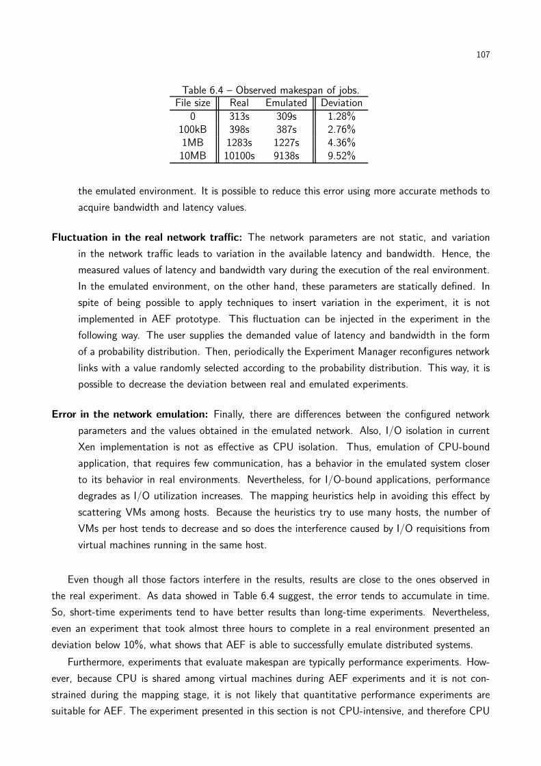
107
Table 6.4 – Observed makespan of jobs.File size Real Emulated Deviation
0 313s 309s 1.28%100kB 398s 387s 2.76%1MB 1283s 1227s 4.36%10MB 10100s 9138s 9.52%
the emulated environment. It is possible to reduce this error using more accurate methods to
acquire bandwidth and latency values.
Fluctuation in the real network traffic: The network parameters are not static, and variation
in the network traffic leads to variation in the available latency and bandwidth. Hence, the
measured values of latency and bandwidth vary during the execution of the real environment.
In the emulated environment, on the other hand, these parameters are statically defined. In
spite of being possible to apply techniques to insert variation in the experiment, it is not
implemented in AEF prototype. This fluctuation can be injected in the experiment in the
following way. The user supplies the demanded value of latency and bandwidth in the form
of a probability distribution. Then, periodically the Experiment Manager reconfigures network
links with a value randomly selected according to the probability distribution. This way, it is
possible to decrease the deviation between real and emulated experiments.
Error in the network emulation: Finally, there are differences between the configured network
parameters and the values obtained in the emulated network. Also, I/O isolation in current
Xen implementation is not as effective as CPU isolation. Thus, emulation of CPU-bound
application, that requires few communication, has a behavior in the emulated system closer
to its behavior in real environments. Nevertheless, for I/O-bound applications, performance
degrades as I/O utilization increases. The mapping heuristics help in avoiding this effect by
scattering VMs among hosts. Because the heuristics try to use many hosts, the number of
VMs per host tends to decrease and so does the interference caused by I/O requisitions from
virtual machines running in the same host.
Even though all those factors interfere in the results, results are close to the ones observed in
the real experiment. As data showed in Table 6.4 suggest, the error tends to accumulate in time.
So, short-time experiments tend to have better results than long-time experiments. Nevertheless,
even an experiment that took almost three hours to complete in a real environment presented an
deviation below 10%, what shows that AEF is able to successfully emulate distributed systems.
Furthermore, experiments that evaluate makespan are typically performance experiments. How-
ever, because CPU is shared among virtual machines during AEF experiments and it is not con-
strained during the mapping stage, it is not likely that quantitative performance experiments are
suitable for AEF. The experiment presented in this section is not CPU-intensive, and therefore CPU
108
sharing does not interfere in the results. In the case of applications that demand high amount of
computation, results obtained in AEF would tend to be not so close to real results.
Nevertheless, there are experiments that do not rely on performance measures. Consider, for
example, the experiment presented by Quétier et al. for evaluation of the V-DS emulator [QJC07].
In such an experiment, a peer-to-peer system is emulated and the routing structures generated by
three P2P libraries are compared. Even though time can be considered in this experiment, to allow
the evaluation of the strategy that builds the overlay in the smallest amount of time (as the authors
of such experiment actually considered), it is also possible to look only at qualitative aspects of
the results, e.g., connectivity reached by the overlay on each library, distance among neighbors, etc.
Because results from the later kind of experiments are independent from performance of virtual
machines, these kind of experiment is suitable to be performed in AEF.
From the experiment results and the above discussion, we conclude that AEF is a suitable
platform for qualitative distributed systems experiments. In the case of quantitative experiments,
especially those that are based in time measurement, AEF might be used if they require a few
processing capacity, as in the case presented in this section.
6.3 Evaluation of execution, monitoring, and reconfiguration stage
In this section we present results of an experiment to show that the AEF prototype’s Experiment
Manager Module effectively detects violations in resource usage by applications and reacts accord-
ingly, creating a new environment able to comply with tester’s specification. Four machines of the
cluster used to host the emulated environment described previously are used in this experiment.
The experiment input for the framework is a partial description of a local area network. The
original configuration proposed by the tester is composed of 32 virtual machines with 256MB of
memory each. According to the input rules, the system can be scaled down to two machines, and
can be scaled up without restrictions, as long as the use of memory on each virtual machine is
kept below 80%. Since each physical node has a limited memory capacity, to increase the memory
capacity of individual virtual machines mapped to this node AEF has to reduce the number of VMs
per host.
To force the alarm mechanism to be activated, experiment description includes instructions to
run an application that allocates 200MB of RAM memory on each virtual machine. With this
allocation request, it is assured that memory utilization on virtual machines is above the threshold
(in this case 80%) and consequently the alarm and reconfiguration mechanism will be activated.
Additionally, it enables observation of the mechanism for automatic triggering of applications inside
virtual machines in action.
The experiment description and the virtual environment description are supplied to the Auto-
mated Emulation Framework. The later builds the virtual environment through the regular installa-
tion and configuration stage described in Section 3.3. Then, the Experiment Manager is invoked to
run the experiment. The Experiment Manager, through the Virtual Environments Manager compo-

109
0
20
40
60
80
100
0 200 400 600 800 1000
Mem
ory
Usa
ge (
%)
Time (seconds)
Memory usage rateThreshold
(a)
0 5
10 15 20 25 30 35 40
0 200 400 600 800 1000
Num
ber
of V
irtua
l Mac
hine
s
Time (seconds)
Virtual Machines
(b)
Figure 6.8 – Resources used in the experiments (a) Memory utilization of one virtual machine (b)Number of virtual machines.
nent, triggers the application in the virtual machines.
Figure 6.8(a) shows the memory utilization of one virtual machine during the experiment and
Figure 6.8(b) shows the number of virtual machines running in the experiment. Initially, there is no
information about resource usage because this data has not been collected in any of the running
virtual machines. After three minutes (as defined by the tester in this experiment), information about
memory utilization is collected. The Monitor detects that memory utilization in the virtual machines
is above the configured threshold of 80% and triggers an alarm that activates the Rebuilder. The
first reconfiguration action considered (doubling the amount of memory on each VM) fails because
there are no enough physical hosts to accommodate 32 VMs with 512MB of RAM. The second
action, doubling the memory and reducing the number of VMs from 32 to 16, allows the Mapper to
find a valid mapping. In the new mapping, four virtual machines run in each host. Because a valid
mapping was found, reconfiguration procedures were triggered in the system.
After the reconfiguration of the environment, that finished at t=480s, the experiment and the
Monitor were started again. With this new configuration, the memory usage in the virtual machines
(detected three minutes later) was below the defined threshold and the experiment finished without
further reconfigurations, which is the expected behavior of the system.

110
6.4 Chapter remarks
In this section, experiments aimed at evaluating each one of the three main activities of AEF—
namely mapping of VMs to hosts and virtual links to physical paths, building and configuration
of emulated distributed system, and experiment execution, monitoring, and reconfiguration—were
presented.
Regarding experiments aimed at evaluating mapping strategies executed by AEF prototype,
the first series of tests showed that grouping VMs that have large communication requirements
between them, together with the A*Prune algorithm for networking are paramount for enabling
mapping of large systems in a cluster. Nevertheless, limitations found in HMN, the first heuristics
developed, motivated development of new heuristics. However, heuristics behave differently in
different scenarios, therefore each algorithm has scenarios where it should be preferred among others.
Experiment aimed at evaluating building and configuration of emulated distributed systems
showed that it is possible, by the use of virtualization and system management, to automatically
build an emulated distributed system. Furthermore, the emulated environment behaved similarly
to an actual distributed system used in a previous in-situ experiment. Results of both in-situ and
emulated experiment are similar. Hence, an emulated distributed system built with the techniques
presented in this thesis can replace in-situ experiments, with the advantage of giving testers better
control of experiments and capacity of reproducing and scaling their experiments.
Finally, tests aimed at evaluating experiment execution, monitoring, and reconfiguration showed
that techniques of virtualization and system management with WBEM architecture allow automated
execution of applications in an emulated distributed system. Use of resources by virtual machines
was monitored and violations in usage of resources by virtual elements were correctly detected and
fixed with reconfiguration of the environment. Hence, it is possible to free testers from the tasks
of controlling execution of applications and managing an emulated environment. This capacity is
especially useful in cases of large emulated environments, where management of the elements would
require considerable effort from the tester.
Results of the experiments presented in this chapter altogether show that AEF architecture
presented in Chapter 3 and Chapter 4, which is partially implemented by the prototype presented
in Chapter 5, is an effective tool for automated emulation of distributed systems and automated
execution of emulation experiments, and therefore it is a valuable tool for computer science experi-
mentation that may contribute to better practices for development of distributed systems software
artifacts.
111
7. CONCLUSIONS
Test and evaluation of distributed software artifacts are challenging tasks. Issues related to the
nature of distributed system, namely distributed control over computing elements, unpredictable
behavior of Internet, and big scale distributed systems tend to achieve, make hard execution of
repeatable, controllable, and scalable experiments in these platforms. Therefore, experiments that
require execution of real software in the actual system—known as in-situ experiments—are not
effective in case of distributed systems. Other approaches are available, but their application depends
on the stage of development of the artifact.
In early stages of conception of algorithms and protocols, analytical methods and simulation may
be applied. Nevertheless, when a prototype of the artifact is available, emulation is a more suitable
methodology for experimentation. In such a methodology, actual software is executed in a model of
the hardware platform. In case of distributed systems emulation, the model of the hardware platform
is built in a cluster of workstations.
Distributed systems emulation is leveraged by the use of virtualization technology, because the
later supports isolation and multiplexing of resources from cluster nodes, in such a way that it is
possible to create several virtual machines, each one with its own resources, in a same host. Logically,
these VMs can belong to different networks, and therefore a virtual distributed system composed of
many sites can be built in cluster nodes.
Even though virtualization enhances capacity of building emulated distributed systems, there is
still the need for operation of virtualization tools in order to build the emulated system. Because
this task diverts testers from the main purpose of their work, a tool that automatically builds a
system and executes experiments in the emulated environment is paramount for widely adoption of
emulation as a methodology for testing and evaluation of distributed software artifacts.
To achieve such a goal, three main activities have to be automatically performed:
Mapping of the virtual environment to the physical environment. This activity is composed
of two tasks: mapping of virtual machines to cluster nodes and mapping of virtual network
links to physical network paths. This issue has to be addressed because the virtual system may
contain hundreds or thousands of elements. Manual mapping of resources not only requires a
considerable amount of time, but also leads to fragmentation problems caused by inappropriate
placement of VMs in the hosts. Good mappings, on the other hand, optimize use of cluster
resources for the experiment and reduce execution time of experiments.
Building and configuration of emulated distributed system. This activity encompasses tasks
related to deployment of VMs in the cluster and configuration of the virtual network. Both
tasks have to be performed according to the mapping output. In the end of this activity, a vir-
tual distributed system is available for testers to perform emulation experiments of distributed
software artifacts.

112
Execution, monitoring, and reconfiguration of experiment. Finally, experiments have to be
automatically executed in the virtual distributed system. Furthermore, mechanisms aiming
at ensuring that the required configuration is kept are also required. In case of violations in
attending tester requirements, environment has to be reconfigured and application has to be
restarted. Furthermore, events have to be logged to be presented to tester in the end of the
experiment.
In this thesis, an architecture able to perform these three activities was proposed. This architec-
ture, called Automated Emulation Framework (AEF), applies virtualization and system management
technologies to achieve its goals. In AEF, the problem of mapping virtual environment to the cluster
is tackled with heuristics. Mapping of VMs to hosts happens according to four different criteria that
characterize each proposed heuristic. Mapping of virtual links to physical paths, on the other hand,
is performed using the same algorithm in all the heuristics. Contribution of this thesis in this field
includes not only heuristics definition, evaluation, and comparison but also a formal definition of the
mapping problem.
The last two activities are tackled with an architecture for building, configuration, execution,
and management of applications and virtual environment. The architecture is composed by several
modules, each one with a specific function. Some of these modules use system management tech-
nologies to work, whereas other modules use virtualization tools. Such an architecture for automated
emulation of distributed systems and experimentation is another major contribution of this thesis.
To validate AEF architecture, a prototype has been implemented. Evaluation of this proto-
type showed that the goals which motivated design of the architecture are achieved with a proper
application of the cited technologies and therefore AEF is a valuable tool for computer science exper-
imentation that may contribute to better practices for development of distributed systems software
artifacts.
7.1 Future directions
Next, we list and comment future directions of research derived from this work.
Development of new mapping heuristics. New mapping heuristics can be developed. Heuristics
may consider other functions to be optimized, for example, reduction of number of hosts
used. Another point to be explored is other strategies for the networking stage of resolution
of the mapping problem. Even though modified A*Prune is effective in enabling generation of
valid mappings, it is slow. Therefore, other approaches for networking quicker than modified
A*Prune would allow timely mapping in large-scale clusters, what contributes for a broader
applicability of AEF.
Development of an automated heuristic selector. Results from mapping heuristics evaluation
showed that different heuristics present different behavior in different scenarios. Furthermore,
no heuristic is better than all the others in all the scenarios. Hence, a selector of mapping

113
heuristics, able to analyze input characteristics and decide which heuristic would produce
the best mapping in that situation is a promising research direction. Utilization of such a
selector together with the mapping heuristics would provide further optimization of resources
utilization, according to the optimization goal in use.
Design of an architecture for interactive experimentation. AEF architecture supports auto-
mated execution of experiments in emulated distributed systems. Nevertheless, these experi-
ments are standalone applications that execute without tester intervention. In some situations,
testers might be interested in interact with the application in execution time, in order to pro-
vide other inputs, observe some graphical output or reconfigure applications. Currently, there
is no support in AEF for interactive execution of experiments, and improvements in the archi-
tecture in order to support it would add value to AEF, by expanding applicability scenarios of
the architecture.
Abstraction layer for software testing. Even though AEF makes easy execution of emulated
experiments by releasing testers from the task of accessing virtualization management tools,
it still required that testers have knowledge in distributed system, in such a way that they are
able to describe the system in details. Nevertheless, depending on the use case where AEF is
applied, testers may have no knowledge, or no interest, in describing the emulated distributed
system. A layer that abstracts distributed systems details would be useful in such scenarios
and is another possible future direction of AEF research.
Application of AEF modules in other contexts. Both the mapping problem and AEF architec-
ture consider the same type of physical environment, namely a cluster of workstation using
virtualization technology to host virtual machines. This scenario defines not only emulation
testbeds addressed in our problem but also other scenarios, such as Cloud Computing and vir-
tual clusters. Because of similarities between these environments, we believe that techniques
described in this thesis are directly applicable in such systems. Research towards proving this
assumption is other future direction of this work. In case these technologies are applicable
in other contexts, ways of applying techniques in other platforms in order to achieve some
benefit not possible without the technology have to be researched. Otherwise, means to make
possible application of technologies presented in this thesis in alternative contexts have to
be sought. With the increasing interest in virtualization technologies, it is likely that new
applications for both virtualization and AEF components will arise.
7.2 Publications
In this section, we list scientific production that derived from this thesis. Works are sorted in
chronological order.

114
Journal papers
Rodrigo N. Calheiros, Rajkumar Buyya, César A. F. De Rose, Building an automated and self-
configurable emulation testbed for grid applications, Software: Practice & Experience, ac-
cepted for publication.
Rodrigo N. Calheiros, Tiago Ferreto, César A. F. De Rose, Scheduling and management of virtual
resources in grid sites: the site resource scheduler, Parallel Processing Letters, 19(1):3–18,
World Scientific, March, 2009.
César A. F. De Rose, Tiago Ferreto, Rodrigo N. Calheiros, Walfredo Cirne, Lauro B. Costa, Daniel
Fireman,Allocation strategies for utilization of space shared resources in Bag-of-Tasks grids,
Future Generation Computer Systems, 25(5):331–341, Elsevier, May, 2008.
Conferences in English
Rodrigo N. Calheiros, Rajkumar Buyya, César A. F. De Rose, A Heuristic for Mapping Virtual
Machines and Links in Emulation Testbeds, Proceedings of the 38th International Conference
on Parallel Processing (ICPP 2009), Vienna, Austria, September, 2009.
Rodrigo N. Calheiros, Everton Alexandre, Andriele B. do Carmo, César A. F. De Rose, Rajkumar
Buyya, Towards Self-Managed Adaptive Emulation of Grid Environments, Proceedings of the
14th IEEE Symposium on Computers and Communications (ISCC 2009), Sousse, Tunisia,
July, 2009.
Rajkumar Buyya, Rajiv Ranjan, Rodrigo N. Calheiros, Modeling and Simulation of Scalable Cloud
Computing Environments and the CloudSim Toolkit: Challenges and Opportunities, Keynote
Paper, Proceedings of the 7th High Performance Computing and Simulation Conference
(HPCS 2009), Leipzig, Germany, June, 2009.
Rodrigo N. Calheiros, Mauro Storch, Everton Alexandre, César A. F. De Rose, Marcus Breda,
Applying virtualization and system management in a cluster to implement an automated
emulation testbed for grid applications, Proceedings of the 20th IEEE Symposium on Computer
Architecture and High Performance Computing (SBAC-PAD 2008), Campo Grande, Brazil,
October, 2008.
Conferences in Portuguese
Rodrigo N. Calheiros, Guilherme Rodrigues, Tiago Ferreto, César A. F. De Rose, Avaliando o am-
biente de virtualização Xen utilizando aplicações de bancos de dados (Evaluating Xen virtual-
ization environment using database applications), VIII Workshop em Sistemas Computacionais
de Alto Desempenho (WSCAD 2007), Gramado, Brazil, October, 2007.
115
BIBLIOGRAPHY
[AA06] Keith Adams and Ole Agesen. A comparison of software and hardware techniques for
x86 virtualization. In Proceedings of the 12th international conference on architectural
support for programming languages and operating systems, pages 2–13, San Jose, Oct.
2006. ACM.
[ABCM07] Nazareno Andrade, Francisco Brasileiro, Walfredo Cirne, and Miranda Mowbray. Auto-
matic grid assembly by promoting collaboration in peer-to-peer grids. Journal of Parallel
and Distributed Computing, 67(8):957–966, Aug. 2007.
[ACC+05] Sumalatha Adabala, Vineet Chadha, Puneet Chawla, Renato Figueiredo, José Fortes,
Ivan Krsul, Andrea Matsunaga, Mauricio Tsugawa, Jian Zhang, Ming Zhao, Liping Zhu,
and Xiaomin Zhu. From virtualized resources to virtual computing grids: the In-VIGO
system. Future Generation Computer Systems, 21(6):896–909, Jun. 2005.
[ACD74] Thomas L. Adam, K. M. Chandy, and J. R. Dickson. A comparison of list schedules for
parallel processing systems. Communications of the ACM, 17(12):685–690, Dec. 1974.
[AH06] George Apostolopoulos and Constantinos Hassapis. V-eM: A cluster of virtual machines
for robust, detailed, and high-performance network emulation. In 14th IEEE Interna-
tional Symposium on Modeling, Analysis, and Simulation of Computer and Telecom-
munication Systems, pages 117–126, Monterey, Sep. 2006. IEEE Computer Society.
[Ale09] Everton Batista Petró Alexandre. Uma arquitetura baseada em WBEM para o geren-
ciamento de um cluster de máquinas virtuais. Masters thesis, PUCRS, Porto Alegre,
Mar. 2009.
[AMD05] AMD. AMD64 virtualization codenamed “Pacifica” technology secure virtual machine
architecture reference manual. White Paper, 2005.
[BDF+03] Paul Barham, Boris Dragovic, Keir Fraser, Steven Hand, Tim Harris, Alex Ho, Rolf
Neugebauer, Ian Pratt, and Andrew Warfield. Xen and the art of virtualization. In
Proceedings of the 19th ACM Symposium on Operating Systems Principles, pages
164–177, Bolton Landing, Oct. 2003. ACM.
[BFS+06] Fabrício Benevenuto, César Fernandes, Matheus Santos, Virgílio Almeida, Jussara
Almeida, G. Janakiraman, and José Renato Santos. Performance models for virtual-
ized applications. In Frontiers of High Performance Computing and Networking – ISPA
2006 Workshops, volume 4331 of Lecture Notes in Computer Science, pages 427–439,
Sorrento, Dec. 2006. Springer.

116
[BM02] Rajkumar Buyya and Manzur Murshed. GridSim: a toolkit for the modeling and sim-
ulation of distributed resource management and scheduling for grid computing. Con-
currency and Computation: Practice and Experience, 14(13–15):1175–1220, Nov.,Dec.
2002.
[BMAV05] Rajkumar Buyya, Manzur Murshed, David Abramson, and Srikumar Venugopal.
Scheduling parameter sweep applications on global grids: a deadline and budget
constrained cost-time optimization algorithm. Software: Practice and Experience,
35(5):491–512, Apr. 2005.
[BRC09] Rajkumar Buyya, Rajiv Ranjan, and Rodrigo N. Calheiros. Modeling and simulation
of scalable Cloud computing environments and the CloudSim toolkit: Challenges and
opportunities. In Proceedings of the International Conference on High Performance
Computing & Simulation, pages 1–11, Leipzig, June 2009. IEEE Computer Society.
[BYV+09] Rajkumar Buyya, Chee Shin Yeo, Srikumar Venugopal, James Broberg, and Ivona
Brandic. Cloud computing and emerging IT platforms: Vision, hype, and reality for de-
livering computing as the 5th utility. Future Generation Computer Systems, 25(6):599–
616, June 2009.
[CAdC+09] Rodrigo N. Calheiros, Everton Alexandre, Andriele B. do Carmo, César A. F. De Rose,
and Rajkumar Buyya. Towards self-managed adaptive emulation of grid environments.
In Proceedings of the IEEE Symposium on Computers and Communications, pages
818–823, Sousse, Jul. 2009. IEEE Computer Society.
[CB02] Madhu Chetty and Rajkumar Buyya. Weaving computational grids: How analogous
are they with electrical grids? Computing in Science and Engineering, 4(4):61–71, Jul.
2002.
[CBA+06] Walfredo Cirne, Francisco Brasileiro, Nazareno Andrade, Lauro B. Costa, and Alisson
Andrade. Labs of the world, unite!!! Journal of Grid Computing, 4(3):225–246, Sep.
2006.
[CBD09] Rodrigo N. Calheiros, Rajkumar Buyya, and César A. F. De Rose. A heuristic for
mapping virtual machines and links in emulation testbeds. In Proceedings of the 38th
International Conference on Parallel Processing, page 8, Vienna, Sep. 2009. IEEE Com-
puter Society.
[CBD10] Rodrigo N. Calheiros, Rajkumar Buyya, and César A. F. De Rose. Building an automated
and self-configurable emulation testbed for grid applications. Software: Practice and
Experience, to appear, 2010.

117
[CCM06] Stephen Childs, Brian Coghlan, and Jason McCandless. GridBuilder: A tool for creating
virtual grid testbeds. In Proceedings of the 2nd IEEE International Conference on e-
Science and Grid Computing, pages 77–84, Amsterdam, Dec. 2006. IEEE Computer
Society.
[CCO+05] Stephen Childs, Brian Coghlan, David O’Callaghan, Geoff Quigley, and John Walsh. A
single-computer grid gateway using virtual machines. In Proceedings of the 19th Inter-
national Conference on Advanced Information Networking and Applications, volume 1,
pages 310–315, Taiwan, Mar. 2005. IEEE Computer Society.
[CCR+03] Brent Chun, David Culler, Timothy Roscoe, Andy Bavier, Larry Peterson, Mike Wawr-
zoniak, and Mic Bowman. PlanetLab: an overlay testbed for broad-coverage services.
SIGCOMM Computer Communication Review, 33(3):3–12, Jul. 2003.
[CCW+06] Stephen Childs, Brian Coghlan, John Walsh, David O’Callaghan, Geoff Quigley, and
Eamonn Kenny. A virtual TestGrid, or how to replicate a national grid. In The 15th
IEEE International Symposium on High Performance Distributed Computing, page 8,
Paris, Feb. 2006. IEEE Computer Society.
[CFD09] Rodrigo N. Calheiros, Tiago Ferreto, and César A. F. De Rose. Scheduling and manage-
ment of virtual resources in grid sites: the site resource scheduler. Parallel Processing
Letters, 19(1):3–18, Mar. 2009.
[CFH+05] Christopher Clark, Keir Fraser, Steven Hand, Jacob Gorm Hansen, Eric Jul, Christian
Limpach, Ian Pratt, and Andrew Warfield. Live migration of virtual machines. In 2nd
Symposium on Networked Systems Design and Implementation (NSDI 2005), pages
273–286, Boston, May 2005. USENIX.
[CG05] Ludmila Cherkasova and Rob Gardner. Measuring CPU overhead for I/O processing in
the Xen virtual machine monitor. In Proceedings of the 2005 USENIX Annual Technical
Conference, pages 387–390, Anaheim, Apr. 2005. USENIX.
[CGMV07] Roberto Canonico, Pasquale Di Gennaro, Vittorio Manetti, and Giorgio Ventre. Virtual-
ization techniques in network emulation systems. In Euro-Par 2007 Workshops: Parallel
Processing, volume 4854 of Lecture Notes in Computer Science, pages 144–153, Rennes,
Aug. 2007. Springer.
[CNJ+07] Xingchen Chu, Krishna Nadiminti, Chao Jin, Srikumar Venugopal, and Rajkumar Buyya.
Aneka: Next-generation enterprise grid platform for e-science and e-business applica-
tions. In Proceedings of the 3rd IEEE International Conference on e-Science and Grid
Computing, pages 151–159, Bangalore, Dec. 2007. IEEE Computer Society.
[Cre81] Robert J. Creasy. The origin of the VM/370 time-sharing system. IBM Journal of
Research and Development, 25(5):483–490, Sep. 1981.

118
[CRFD07] Rodrigo N. Calheiros, Guilherme Rodrigues, Tiago Ferreto, and César A. F. De Rose.
Avaliando o ambiente de virtualização Xen utilizando aplicações de bancos de dados.
In VIII Workshop em Sistemas Computacionais de Alto Desempenho, pages 171–178,
Gramado, Oct. 2007. SBC.
[CSA+08] Rodrigo N. Calheiros, Mauro Storch, Everton Alexandre, César A. F. De Rose, and
Marcus Breda. Applying virtualization and system management in a cluster to implement
an automated emulation testbed for grid applications. In Proceedings of the 20th
International Symposium on Computer Architecture and High Performance Computing,
pages 97–104, Campo Grande, Oct. 2008. IEEE Computer Society.
[DBR02] Scott W. Devine, Edouard Bugnion, and Mendel Rosenblum. Virtualization system
including a virtual machine monitor for a computer with a segmented architecture. US
Patent 6397242, May 2002.
[dC09] Andriele Bussatto do Carmo. Uma arquitetura para gerenciar ambientes virtualizados
baseada nos conceitos das áreas funcionais da gerência. Masters thesis, PUCRS, Porto
Alegre, Jan. 2009.
[dCR08] Guilherme da Cunha Rodrigues. vMIB: Uma MIB genérica para gerenciamento de
recursos virtuais. Masters thesis, PUCRS, Porto Alegre, Jan. 2008.
[DF05] Catalin L. Dumitrescu and Ian Foster. GangSim: a simulator for grid scheduling studies.
In IEEE International Symposium on Cluster Computing and the Grid, volume 2, pages
1151–1158, Cardiff, May 2005. IEEE Computer Society.
[DHN96] Phillip M. Dickens, Philip Heidelberger, and David M. Nicol. Parallelized direct execution
simulation of message-passing parallel programs. IEEE Transactions on Parallel and
Distributed Systems, 7(10):1090–1105, Oct. 1996.
[Dik01] Jeff Dike. User-mode Linux. In Proceedings of the 5th Annual Linux Showcase &
Conference, pages 3–14, Oakland, Nov. 2001. USENIX.
[ELL09] Miguel A. Erazo, Yue Li, and Jason Liu. SVEET! a scalable virtualized evaluation envi-
ronment for TCP. In Proceedings of the 5th International Conference on Testbeds and
Research Infrastructures for the Development of Networks and Communities, page 10,
Washington D. C., Apr. 2009. IEEE Computer Society.
[ESL07] Eric Eide, Leigh Stoller, and Jay Lepreau. An experimentation workbench for replayable
networking research. In Proceedings of the 4th Symposium on Networked Systems
Design and Implementation, pages 215–228, Cambridge, Apr. 2007. USENIX.
119
[FDF03] Renato J. Figueiredo, Peter A. Dinda, and José A. B. Fortes. A case for grid computing
on virtual machines. In Proceedings of the 23rd International Conference on Distributed
Computing Systems, pages 550–559, Gainesville, May 2003. IEEE Computer Society.
[FFK+06] Ian Foster, Tim Freeman, Kate Keahey, Doug Scheftner, Borja Sotomayor, and Xuehai
Zhang. Virtual clusters for grid communities. In Proceedings of the 6th IEEE Interna-
tional Symposium on Cluster Computing and the Grid, pages 513–520, Singapore, May
2006. IEEE Computer Society.
[FK99a] Ian Foster and Carl Kesselman. The Globus toolkit. In Ian Foster and Carl Kesselman,
editors, The Grid: Blueprint for a New Computing Infrastructure, chapter 11, pages
259–278. Morgan Kaufmann Publishers, San Francisco, 1999.
[FK99b] Ian Foster and Carl Kesselman, editors. The Grid: Blueprint for a New Computing
Infrastructure. Morgan Kaufmann Publishers, San Francisco, 1999.
[FKT01] Ian Foster, Carl Kesselman, and Steven Tuecke. The anatomy of the grid: Enabling scal-
able virtual organizations. The International Journal of High Performance Computing
Applications, 15(3):200–222, Aug. 2001.
[FOS+07] Felipe Franciosi, Jean Paulo Orengo, Mauro Storch, Felipe Grazziotin, Tiago Ferreto,
and César De Rose. Deploying and managing Xen sites with XSM. In Euro-Par 2007
Workshops: Parallel Processing, volume 4854 of Lecture Notes in Computer Science,
pages 195–204, Rennes, Aug. 2007. Springer.
[GABF06] Arijit Ganguly, Abhishek Agrawal, Patrick Oscar Boykin, and Renato Figueiredo. WOW:
Self-organizing wide area overlay networks of virtual workstations. In 15th IEEE Inter-
national Symposium on High Performance Distributed Computing, pages 30–42, Paris,
Jun. 2006. IEEE Computer Society.
[GCGV06] Diwaker Gupta, Ludmila Cherkasova, Rob Gardner, and Amin Vahdat. Enforcing per-
formance isolation across virtual machines in Xen. In Middleware 2006, volume 4290 of
Lecture Notes in Computer Science, pages 342–362, Melbourne, Nov. 2006. Springer.
[GGC05] Diwaker Gupta, Rob Gardner, and Ludmila Cherkasova. XenMon: QoS monitoring and
performance profiling tool. Technical Report HPL-2005-187, HP Laboratories Palo Alto,
Palo Alto, Oct. 2005.
[GJQ09] Jens Gustedt, Emmanuel Jeannot, and Martin Quinson. Experimental methodologies
for large-scale systems: a survey. Parallel Processing Letters, 19(3):399–418, Sep. 2009.
[GLDS96] William Gropp, Ewing Lusk, Nathan Doss, and Anthony Skjellum. A high-performance,
portable implementation of the MPI message passing interface standard. Parallel Com-
puting, 22(6):789–828, Jan. 1996.

120
[GPC+03] Tal Garfinkel, Ben Pfaff, Jim Chow, Mendel Rosenblum, and Dan Boneh. Terra: a
virtual machine-based platform for trusted computing. In Proceedings of the 19th ACM
Symposium on Operating Systems Principles, pages 193–206, Bolton Landing, Oct.
2003. ACM.
[Gus92] David B. Gustavson. The scalable coherent interface and related standards projects.
IEEE Micro, 12(1):10–22, Feb. 1992.
[GVV08] Diwaker Gupta, Kashi V. Vishwanath, and Amin Vahdat. DieCast: Testing distributed
systems with an accurate scale model. In Proceedings of the 5th USENIX Symposium
on Networked Systems Design and Implementation, pages 407–421, San Francisco, Apr.
2008. USENIX.
[GYM+06] Diwaker Gupta, Kenneth Yocum, Marvin McNett, Alex C. Snoeren, Amin Vahdat, and
Geoffrey M. Voelker. To infinity and beyond: Time-warped network emulation. In
Proceedings of the 3rd Symposium on Networked Systems Design & Implementation,
pages 87–100, San Jose, May 2006. USENIX.
[GZS+06] Ashish Gupta, Marcia Zangrilli, Ananth I. Sundararaj, Anne I. Huang, Peter A. Dinda,
and Bruce B. Lowekamp. Free network measurement for adaptive virtualized dis-
tributed computing. In 20th International Parallel and Distributed Processing Sym-
posium, page 10, Rhodes Island, Apr. 2006. IEEE Computer Society.
[Har98] Sean Harnedy. Web-Based Information Management: An Introduction to the Technol-
ogy and its Application. Prentice-Hall, Upper Saddle River, 1998.
[Hob04] Chris Hobbs. A practical approach to WBEM/CIM management. Auerbach, Boca
Raton, 2004.
[Hoo05] John N. Hooker. A hybrid method for the planning and scheduling. Constraints,
10(4):385–401, Oct. 2005.
[JBS06] William I. Bullers Jr., Stephen Burd, and Alessandro F. Seazzu. Virtual machines - an
idea whose time has returned: application to network, security, and database courses. In
Proceedings of the 37th SIGCSE technical symposium on computer science education,
pages 102–106, Houston, Mar. 2006. ACM.
[JG01] Vipul Jain and Ignacio E. Grossmann. Algorithms for hybrid MILP/CP models for a
class of optimization problems. INFORMS Journal on Computing, 13(4):258–276, Jun.
2001.
[JX03] Xuxian Jiang and Dongyan Xu. vBET: a VM-based emulation testbed. In Proceedings of
the ACM SIGCOMM workshop on models, methods and tools for reproducible network
research, pages 95–104, Karlsruhe, Aug. 2003. ACM.

121
[KA99] Yu-Kwong Kwok and Ishfaq Ahmad. Static scheduling algorithms for allocating directed
task graphs to multiprocessors. ACM Computing Surveys, 3(4):406–471, Dec. 1999.
[KBKK06] Gunjan Khanna, Kirk Beaty, Gautam Kar, and Andrzej Kochut. Application performance
management in virtualized server environments. In 10th IEEE/IFIP Network Operations
and Management Symposium, NOMS 2006, pages 373–381, Vancouver, Apr. 2006.
IEEE Computer Society.
[KBM+02] Thilo Kielmann, Henri E. Bal, Jason Maassen, Rob van Nieuwpoort, Lionel Eyraud, Rut-
ger Hofman, and Kees Verstoep. Programming environments for high-performance grid
computing: the Albatross project. Future Generation Computer Systems, 18(8):1113–
1125, Oct. 2002.
[KDF04] Katarzyna Keahey, Karl Doering, and Ian Foster. From sandbox to playground: Dynamic
virtual environments in the grid. In Proceedings of the 5th IEEE/ACM International
Workshop on Grid Computing, pages 34–42, Pittsburgh, Nov. 2004. IEEE Computer
Society.
[KGZ+04] Ivan Krsul, Arijit Ganguly, Jian Zhang, José A. B. Fortes, and Renato J. Figueiredo.
VMPlants: Providing and managing virtual machine execution environments for grid
computing. In Proceedings of the 2004 ACM/IEEE Conference on Supercomputing,
page 12, Pittsburgh, Nov. 2004. IEEE Computer Society.
[KHB04] Bruce Kneale, Ain Y. De Horta, and Ilona Box. Velnet (virtual environment for learning
networking). In Proceedings of the 6th conference on Australasian computing education,
pages 161–168, Dunedin, Jan. 2004. Australian Computer Society.
[Kla00] Alexander Klaiber. The technology behind Crusoe processors. Technical report, Trans-
meta Corporation, Santa Clara, Jan. 2000.
[KS97] Asawaree Kalavade and P. A. Subrahmanyam. Hardware/software partitioning for multi-
function systems. In Proceedings of the 1997 IEEE/ACM International Conference on
Computer-Aided Design, pages 516–521, San Jose, Nov. 1997. IEEE Computer Society.
[KTMF09] Katarzyna Keahey, Maurício Tsugawa, Andréa Matsunaga, and José A. B. Fortes. Sky
computing. IEEE Internet Computing, 13(5):43–51, Oct. 2009.
[KW00] Poul-Henning Kamp and Robert N. M. Watson. Jails: Confining the omnipotent root. In
Proceedings of the 2nd International System Administration and Networking Conference,
page 15, Maastricht, May 2000.
[LLXC05] Yi Liu, Yanping Li, Kaiping Xiao, and Huali Cui. Mapping resources for network emula-
tion with heuristic and genetic algorithms. In Proceedings of the 6th International Con-

122
ference on Parallel and Distributed Computing, Applications and Technologies, pages
670–674, Dalian, Dec. 2005. IEEE Computer Society.
[LMC03] Arnaud Legrand, Loris Marchal, and Henri Casanova. Scheduling distributed appli-
cations: the SimGrid simulation framework. In Proceedings of the 3rd IEEE/ACM
International Symposium on Cluster Computing and the Grid, pages 138–145, Tokyo,
May 2003. IEEE Computer Society.
[LMVH07] Jason Liu, Scott Mann, Nathanael Van Vorst, and Keith Hellman. An open and scalable
emulation infrastructure for large-scale real-time network simulations. In 26th IEEE
International Conference on Computer Communications., pages 2476–2480, Anchorage,
May 2007. IEEE Computer Society.
[LR01] Gang Liu and K. G. Ramakrishnan. A*Prune: An algorithm for finding K shortest
paths subject to multiple constraints. In Proceedings of the 20th Annual Joint Confer-
ence of the IEEE Computer and Communications Societies, volume 2, pages 743–749,
Anchorage, Apr. 2001. IEEE.
[LW06] Sin Ming Loo and B. Earl Wells. Task scheduling in a finite-resource, reconfigurable
hardware/software codesign environment. INFORMS Journal on Computing, 18(2):151–
172, Mar. 2006.
[LXC04] Xin Liu, Huaxia Xia, and Andrew A. Chien. Validating and scaling the MicroGrid: A
scientific instrument for grid dynamics. Journal of Grid Computing, 2(2):141–161, Jun.
2004.
[LY99] Tim Lindholm and Frank Yellin. The Java(TM) Virtual Machine Specification. Addison-
Wesley, Reading, 2 edition, 1999.
[Mal73] Efrem G. Mallach. On the relationship between virtual machines and emulators. In
Proceedings of the workshop on virtual computer systems, pages 117–126, Cambridge,
Mar. 1973. ACM.
[McG02] Ian McGregor. The relationship between simulation and emulation. In Proceedings of
the 2002 Winter Simulation Conference, volume 2, pages 1683–1688, San Diego, Dec.
2002. WSC.
[MGVV07] Marvin McNett, Diwaker Gupta, Amin Vahdat, and Geoffrey M. Voelker. Usher: An
extensible framework for managing clusters of virtual machines. In Proceedings of the
21st Large Installation System Administration Conference (LISA ’07), pages 167–181,
Dallas, Nov. 2007. USENIX.
123
[MHR07] Steffen Maier, Daniel Herrscher, and Kurt Rothermel. Experiences with node virtualiza-
tion for scalable network emulation. Computer Communications, 30(5):943–956, Mar.
2007.
[MPB+96] Giorgio De Michelis, Lucia Pomello, Eugenio Battisteri, Fioretta De Cindio, and Carla
Simone. Formal methods: A petri nets based approach. In Albert Y. H. ZoMaya, editor,
Parallel and Distributed Computing Handbook, chapter 3, pages 59–88. McGraw-Hill,
New York, 1996.
[MS98] Muthucumaru Maheswaran and Howard Jay Siegel. A dynamic matching and scheduling
algorithm for heterogeneous computing systems. In Proceedings of the Seventh Het-
erogeneous Computing Workshop, pages 57–69, Orlando, Mar. 1998. IEEE Computer
Society.
[MST+05] Aravind Menon, Jose Renato Santos, Yoshio Turner, Willy Zwaenepoel, and G. Janaki-
raman. Diagnosing performance overheads in the Xen virtual machine environment. In
Proceedings of the 1st ACM/USENIX International Conference on Virtual Execution
Environments, pages 13–23, Chicago, Jun. 2005. ACM.
[NR06] Lucas Nussbaum and Olivier Richard. Lightweight emulation to study peer-to-peer
systems. In 20th International Parallel and Distributed Processing Symposium, page 8,
Rhodes Island, Apr. 2006. IEEE Computer Society.
[NSL+06] Gil Neiger, Amy Santoni, Felix Leung, Dion Rodgers, and Rich Uhlig. Intel virtualization
technology: Hardware support for efficient processor virtualization. Intel Technology
Journal, 10(3):167–177, Aug. 2006.
[NT93] Michael G. Norman and Peter Thanisch. Models of machines and computation for
mapping in multicomputers. ACM Computing Surveys, 25(3):263–302, Sep. 1993.
[NWG+08] Daniel Nurmi, Rich Wolski, Chris Grzegorczyk, Graziano Obertelli, Sunil Soman, Lamia
Youseff, and Dmitrii Zagorodnov. The Eucalyptus open-source cloud-computing system.
In First workshop on Cloud Computing and its Applications, page 5, Chicago, Oct. 2008.
CCA.
[Ora01] Andy Oram. Peer-to-Peer : Harnessing the Power of Disruptive Technologies. O’Reilly,
Cambridge, 2001.
[PA91] Brigitte Plateau and Karim Atif. Stochastic automata network of modeling parallel
systems. IEEE Transactions on Software Engineering, 17(10):1093–1108, Oct. 1991.
[PBB07] Sabri Planna, Ivona Brandic, and Siegfried Benkner. Performance modeling and predic-
tion of parallel and distributed computing systems: A survey of the state of the art. In

124
1st International Conference on Complex, Intelligent and Software Intensive Systems,
pages 279–284, Vienna, Apr. 2007. IEEE Computer Society.
[PFH+05] Ian Pratt, Keir Fraser, Steven Hand, Christian Limpach, and Andrew Warfield. Xen 3.0
and the art of virtualization. In Proceedings of the Linux Symposium, volume 2, pages
65–77, Ottawa, Jul. 2005. Linux Symposium Inc.
[PG74] Gerald J. Popek and Robert P. Goldberg. Formal requirements for virtualizable third
generation architectures. Communications of the ACM, 17(7):412–421, Jul. 1974.
[QJC07] Benjamin Quétier, Mathieu Jan, and Franck Cappello. One step further in large-scale
evaluations: the V-DS environment. Research Report RR-6365, Institut National de
Recherche en Informatique et en Automatique, Dec. 2007.
[RAL03] Robert Ricci, Chris Alfeld, and Jay Lepreau. A solver for the network testbed mapping
problem. ACM SIGCOMM Computer Communication Review, 33(2):65–81, Apr. 2003.
[Rap04] Micheael A. Rappa. The utility business model and the future of computing services.
IBM Systems Journal, 43(1):32–42, Jan. 2004.
[RDS+07] Robert Ricci, Jonathon Duerig, Pramod Sanaga, Daniel Gebhardt, Mike Hibler, Kevin
Atkinson, Junxing Zhang, Sneha Kasera, and Jay Lepreau. The Flexlab approach to
realistic evaluation of networked systems. In Proceedings of the Fourth Symposium on
Networked Systems Design and Implementation, pages 201–214, Cambridge, Apr. 2007.
USENIX.
[RJXG05] Paul Ruth, Xuxian Jiang, Dongyan Xu, and Sebastien Goasguen. Virtual distributed
environments in a shared infrastructure. Computer, 38(5):63–69, May 2005.
[SB05] Jawwad Shamsi and Monica Brockmeyer. DSSimulator: achieving million node simula-
tion of distributed systems. In Proceedings of the 2005 Spring Simulation Multiconfer-
ence (SpringSim’05), page 6, San Diego, Apr. 2005. SCS.
[Sch03] Jennifer M. Schopf. Ten actions when grid scheduling. In Jarek Nabrzyski, Jennifer M.
Schopf, and Jan Weglarz, editors, Grid Resource Management: State of the Art and
Future Trends, chapter 2, pages 15–23. Kluwer Academic Publishers, Norwell, 2003.
[SD04] Ananth I. Sundararaj and Peter A. Dinda. Towards virtual networks for virtual machine
grid computing. In Proceedings of the 3rd Virtual Machine Research and Technology
Symposium, pages 177–190, San Jose, May 2004. USENIX.
[SKM08] Aameek Singh, Madhukar Korupolu, and Dushmanta Mohapatra. Server-storage virtu-
alization: integration and load balancing in data centers. In SC ’08: Proceedings of
the 2008 ACM/IEEE conference on Supercomputing, page 12, Austin, Nov. 2008. IEEE
Computer Society.
125
[SMLF09] Borja Sotomayor, Rubén S. Montero, Ignacio M Llorente, and Ian Foster. Virtual
infrastructure management in private and hybrid clouds. IEEE Internet Computing,
13(5):14–22, Oct. 2009.
[SN05] James E. Smith and Ravi Nair. Virtual Machines: Versatile platforms for systems and
processes. Morgan Kauffmann, San Francisco, 2005.
[SSLD05] Ananth I. Sundararaj, Manan Sanghi, John R. Lange, and Peter A. Dinda. An opti-
mization problem in adaptive virtual environments. ACM SIGMETRICS Performance
Evaluation Review, 33(2):6–8, Sep. 2005.
[SSLD06a] Ananth I. Sundararaj, Manan Sanghi, John R. Lange, and Peter A. Dinda. Hardness of
approximation and greedy algorithms for the adaptation problem in virtual environments.
In IEEE International Conference on Autonomic Computing, pages 291–292, Dublin,
Jun. 2006. IEEE Computer Society.
[SSLD06b] Ananth I. Sundararaj, Manan Sanghi, John R. Lange, and Peter A. Dinda. Hardness of
approximation and greedy algorithms for the adaptation problem in virtual environments.
Technical Report NWU-EECS-06-06, Northwestern University, Evanston, Jul. 2006.
[Sta99] Willian Stallings. SNMP, SNMPv2, SNMPv3, and RMON 1 and 2. Addison Wesley,
Reading, 3 edition, 1999.
[Sto08] Mauro Strelow Storch. Um arquitetura para gerência de rede de máquinas virtuais com
ênfase na emulação de sistemas distribuídos. Masters thesis, PUCRS, Porto Alegre,
Jan. 2008.
[SYB04] Anthony Sulistio, Chee Shin Yeo, and Rajkumar Buyya. A taxonomy of computer-
based simulations and its mapping to parallel and distributed systems simulation tools.
Software: Practice and Experience, 34(7):653–673, Apr. 2004.
[TC04] Nut Taesombut and Andrew A. Chien. Distributed virtual computers (DVC): simplifying
the development of high performance grid applications. In IEEE International Sympo-
sium on Cluster Computing and the Grid, 2004, pages 715–722, Chicago, Apr. 2004.
IEEE Computer Society.
[TMN+99] Atsuko Takefusa, Satoshi Matsuoka, Hidemoto Nakada, Kento Aida, and Umpei Na-
gashima. Overview of a performance evaluation system for global computing scheduling
algorithms. In Proceedings of the Eighth International Symposium on High Performance
Distributed Computing, pages 97–104, Redondo Beach, Aug. 1999. IEEE Computer So-
ciety.
[VMw07] VMware. Virtual lab automation. White Paper, 2007.

126
[VYW+02] Amin Vahdat, Ken Yocum, Kevin Walsh, Priya Mahadevan, Dejan Kostic, Jeff Chase,
and David Becker. Scalability and accuracy in a large-scale network emulator. ACM
SIGOPS Operating Systems Review, 36(SI):271–284, Dec. 2002.
[WCG04] Andrew Whitaker, Richard S. Cox, and Steven D. Gribble. Using time travel to diagnose
computer problems. In Proceedings of the 11th workshop on ACM SIGOPS European
workshop, page 16, Leuven, Sep. 2004. ACM.
[Wei07] Aaron Weiss. Computing in the clouds. netWorker, 11(4):16–25, Dec. 2007.
[WLS+02] Brian White, Jay Lepreau, Leigh Stoller, Robert Ricci, Shashi Guruprasad, Mac New-
bold, Mike Hibler, Chad Barb, and Abhijeet Joglekar. An integrated experimental
environment for distributed systems and networks. ACM SIGOPS Operating Systems
Review, 36(SI):255–270, Dec. 2002.
[WSG02] Andrew Whitaker, Marianne Shaw, and Steven D. Gribble. Scale and performance in
the Denali isolation kernel. SIGOPS Operating Systems Review, 36(SI):195–209, Dec.
2002.
[YBT05] Jia Yu, Rajkumar Buyya, and Chen Khong Tham. Cost-based scheduling of scientific
workflow applications on utility grids. In First International Conference on e-Science
and Grid Computing, page 8, Melbourne, Dec. 2005. IEEE Computer Society.
[YGS+05] Liang Yang, Pavel Ghosh, Devesh Sinha, Arunabha Sen, Andrea Richa, and Tushar Go-
had. Resource mapping and scheduling for heterogeneous network processor systems.
In Proceedings of the 2005 Symposium on Architecture for Networking and Communi-
cations Systems, pages 19–28, Princeton, Oct. 2005. ACM.
Related Documents


![Virtual Machine Provisioning Based on Analytical ...gridbus.csse.unimelb.edu.au/~raj/papers/VMProvisionCloud-ICPP201… · Cloud Provisioning [3] is the process of deployment and](https://static.cupdf.com/doc/110x72/5ed5c6a808214b19be6a1da7/virtual-machine-provisioning-based-on-analytical-rajpapersvmprovisioncloud-icpp201.jpg)

